· pdf file2 234553662357ˇ6 ˘˘˘ 3 dash disassembly scion xa 2004-2006 1. pull outward on...
TRANSCRIPT

CAUTION! All accessories, switches, climate controls panels, and especially air bag indicator lights must be connected before cycling the ignition. Also, do not remove the factory radio with the key in the on position, or while the vehicle is running.
The World’s best kits.® MetraOnline.com © COPYRIGHT 2017 METRA ELECTRONICS CORPORATION REV. 9/19/17 INST99-8209
I N S TA L L AT I O N I N S T R U C T I O N S99-8209
KIT FEATURES• DIN radio provision with pocket• ISO DIN radio provision with pocket
KIT COMPONENTS• A) Radio housing • B) Bracket set 1 • C) Bracket set 2 • D) ISO brackets • E) Trim plate
TOOLS REQUIRED• Panel removal tool • Phillips screwdriver• 10mm socket wrench
TABLE OF CONTENTSDash Disassembly– Scion xA 2004-2006 ...........................................2– Scion xB 2004-2007............................................ 3– Scion xB 2008-2015 ............................................ 3– Scion tC 2005-2010 .............................................4– Scion xD 2008-2014 ............................................5Kit Assembly– DIN radio provision with pocket........................6– ISO DIN radio provision with pocket ................. 7
WIRING & ANTENNA CONNECTIONS (sold separately)Wiring Harness: 70-1761Antenna Adapter: Not required
A B C D E
Scion xA 2004-2006, xB 2004-2015, tC 2005-2010, xD 2008-2014

1.800.221.0932 | MetraOnline.com2
DASH DISASSEMBLY
Scion xA 2004-2006
1. Pull outward on the (3) climate control knobs and remove. (Figure A)
2. Remove (2) Phillips screws from behind the outer two climate knobs. (Figure B)
3. Unsnap and remove the trim pieces on each side of the climate control/ashtray/pocket assembly. (Figure C)
4. Remove (2) Phillips screws from the bottom of the climate control/radio trim panel and unsnap and remove the entire panel. (Figure D)
5. Remove (4) 10mm bolts securing the radio. Unplug and remove the radio. (Figure E)
ContinuetoKitAssembly
OFF
HI
OFF
HI
(FigureA)
(FigureD) (FigureE)
(FigureB) (FigureC)
OFF
HI
OFF
HI

REV. 9/19/2017 INST99-8209 3
DASH DISASSEMBLY
Scion xB 2004-2007
1. Pull outward on the (3) climate control knobs and remove. (Figure A)
2. Remove (2) Phillips screws from behind the outer (2) knobs. (Figure B)
3. Unsnap and remove the entire panel surrounding the climate controls and the radio. (Figure C)
4. Remove (4) 10mm bolts securing the radio. Unplug and remove the radio.
ContinuetoKitAssembly
(FigureB)
(FigureC)
OFF
HI
OFF
HI
OFF
HI
Scion xB 2008-2015
1. Unclip and remove the trim panel around the radio including the A/C vents. (Figure A)
2. Unclip and remove the trim panel at the bottom edge of the dash cavity. (Figure A)
3. Remove (4) 10mm bolts securing the radio. Unplug and remove the radio. (Figure B)
ContinuetoKitAssembly(FigureA)
(FigureB)(FigureA)

1.800.221.0932 | MetraOnline.com4
DASH DISASSEMBLY
Scion tC 2005-2010
1. Unsnap trim from around shifter, not necessary to completely remove. (Figure A)
2. Unsnap and remove panel from around radio, including climate controls and radio door. (Figure B)
3. Remove (2) 10mm nuts from the top mounting locations and (2) Phillips screws from the bottom mounting locations to remove the radio. (Figure C)
ContinuetoKitAssembly
(FigureA) (FigureB) (FigureC)

REV. 9/19/2017 INST99-8209 5
DASH DISASSEMBLY
(FigureC)
Scion xD 2008-2014
1. Unclip radio trim panel. Unplug and remove panel. (Figure A)
2. Remove (4) Phillips screws securing the radio. Unplug and remove radio. (Figure B)
3. Remove factory brackets from radio. Retain brackets for use during kit assembly. (Figure C)
ContinuetoKitAssembly
(FigureA) (FigureB)

1.800.221.0932 | MetraOnline.com6
KIT ASSEMBLY
DIN radio provision with pocket
1. Slide the brackets onto the sides of the radiohousing until the side clips engage. (Figure A)
Note: Usebracketset1forxA,xB,andtC.Usebracketset2forthe2008xBandxD.
2. For bracketset1 cut and remove all mounting tabs except the tabs being used for your application. (Figure B)
Note: TabsaremarkedxA,xBandtC.Forbracketset2skiptostep3.
3. Remove the metal DIN sleeve from the aftermarket radio.
4. Slide the sleeve into the radiohousing and secure by bending the metal locking tabs outward. (Figure C)
5. Slide the radio back into the sleeve until it clicks in . (Figure D)
6. Locate the factory wiring harness and antenna connector in the dash and complete all necessary connections to the radio. Metra recommends using the proper mating adapter from Metra and/or AXXESS. Test the radio for proper operation.
7. Reassemble the dash in reverse order of disassembly.
(FigureB)
(FigureC)
(FigureD)
(FigureA)
sideclips
BracketSet1

REV. 9/19/2017 INST99-8209 7
KIT ASSEMBLY
ISO DIN radio provision with pocket
1. Slide the brackets onto the sides of the radiohousing until the side clips engage. (Figure A)
Note: Usebracketset1forxA,xB,andtC.Usebracketset2forthe2008xBandxD.
2. For bracketset1 cut and remove all mounting tabs except the tabs being used for your application. (Figure B)
Note: TabsaremarkedxA,xBandtC.Forbracketset2skiptostep3.
3. Remove the metal DIN sleeve and trim ring from the aftermarket radio.
4. Secure the ISObrackets to the radio using the screws supplied with the radio. (Figure C)
5. Slide the radio/bracket assembly into the radiohousing until it snaps into place. (Figure D)
6. Snap the trimplate onto the front of the radiohousing. (Figure D)
7. Locate the factory wiring harness and antenna connector in the dash and complete all necessary connections to the radio. Metra recommends using the proper mating adapter from Metra and/or AXXESS. Test the radio for proper operation.
8. Reassemble the dash in reverse order of disassembly.
(FigureC)(FigureA)
sideclips
(FigureB)
BracketSet1
(FigureD)

KNOWLEDGE IS POWEREnhance your installation and fabrication skills by enrolling in the most recognized and respected mobile electronics school in our industry.Log onto www.installerinstitute.com or call 800-354-6782 for more information and take steps toward a better tomorrow.
®
Metra recommends MECP certified technicians
IMPORTANTIf you are having difficulties with the installation of this product, please call our Tech Support line at 1-800-253-TECH. Before doing so, look over the instructions a second time, and make sure the installation was performed exactly as the instructions are stated. Please have the vehicle apart and ready to perform troubleshooting steps before calling.
The World’s best kits.® MetraOnline.com © COPYRIGHT 2017 METRA ELECTRONICS CORPORATION REV. 9/19/17 INST99-8209
I N S TA L L AT I O N I N S T R U C T I O N S99-8209

¡PRECAUCIÓN! Todos los accesorios, interruptores, paneles de controles de clima y especialmente las luces del indicador de las bolsas de aire deben estar conectados antes ciclar la ignición. Además, no quite el radio de fábrica con la llave en la posición o de encendido ni con el vehículo funcionando.
The World’s best kits.® MetraOnline.com © COPYRIGHT 2017 METRA ELECTRONICS CORPORATION REV. 9/19/17 INST99-8209
I N S T R U C C I O N E S D E I N S TA L AC I Ó N99-8209
CARACTERÍSTICAS DEL KIT• Provisión de radio DIN con cavidad• Provisión de radio ISO DIN con cavidad
COMPONENTES DEL KIT• A) Carcasa del radio • B) Juego de soportes 1 • C) Juego de soportes 2 • D) Soportes ISO • E) Placa de la moldura
HERRAMIENTAS REQUERIDAS• Herramienta para quitar paneles• Destornillador Phillips • llave de tubo 10mm
INDICEDesmontaje del tablero– Scion xA 2004-2006 ...........................................2– Scion xB 2004-2007............................................ 3– Scion xB 2008-2015 ............................................ 3– Scion tC 2005-2010 .............................................4– Scion xD 2008-2014 ...........................................5Ensamble del kit– Provisión de radio DIN con cavidad ..................6– Provisión de radio ISO DIN con cavidad ............ 7
CABLEADO Y CONEXIONES DE ANTENA (se venden por separado)Arnés de cableado: 70-1761Adaptador de antena: No se requiere
A B C D E
Scion xA 2004-2006, xB 2004-2015, tC 2005-2010, xD 2008-2014
1.800.221.0932 | MetraOnline.com2
DESMONTAJE DEL TABLERO
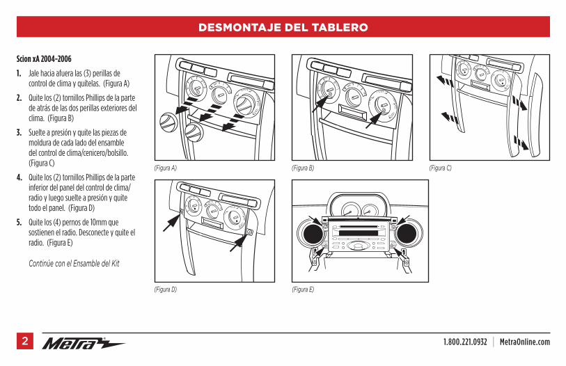
Scion xA 2004-2006
1. Jale hacia afuera las (3) perillas de control de clima y quítelas. (Figura A)
2. Quite los (2) tornillos Phillips de la parte de atrás de las dos perillas exteriores del clima. (Figura B)
3. Suelte a presión y quite las piezas de moldura de cada lado del ensamble del control de clima/cenicero/bolsillo. (Figura C)
4. Quite los (2) tornillos Phillips de la parte inferior del panel del control de clima/radio y luego suelte a presión y quite todo el panel. (Figura D)
5. Quite los (4) pernos de 10mm que sostienen el radio. Desconecte y quite el radio. (Figura E)
ContinúeconelEnsambledelKit
OFF
HI
OFF
HI
(FiguraA)
(FiguraD) (FiguraE)
(FiguraB) (FiguraC)
OFF
HI
OFF
HI

REV. 9/19/2017 INST99-8209 3
DESMONTAJE DEL TABLERO
Scion xB 2004-2007
1. Jale hacia afuera las (3) perillas de control de clima y quítelas. (Figura A)
2. Quite los (2) tornillos Phillips de la parte de atrás de las perillas exteriores (2). (Figura B)
3. Suelte a presión y quite todo el panel que rodea el radio y los controles del clima y aire acondicionado. (Figura C)
4. Quite los (4) pernos de 10mm que sostienen el radio. Desconecte y quite el radio.
ContinúeconelEnsambledelKit
(FiguraB)
(FiguraC)
OFF
HI
OFF
HI
OFF
HI
Scion xB 2008-2015
1. Desenganche y quite el panel de moldura que rodea el radio, incluyendo las rejillas del aire acondicionado. (Figura A)
2. Desenganche y quite el panel de moldura del borde inferior de la cavidad del tablero. (Figura A)
3. Quite los (4) pernos de 10mm que sostienen el radio. Desconecte y quite el radio. (Figura B)
ContinúeconelEnsambledelKit
(FiguraA)
(FiguraB)(FiguraA)
1.800.221.0932 | MetraOnline.com4
DESMONTAJE DEL TABLERO
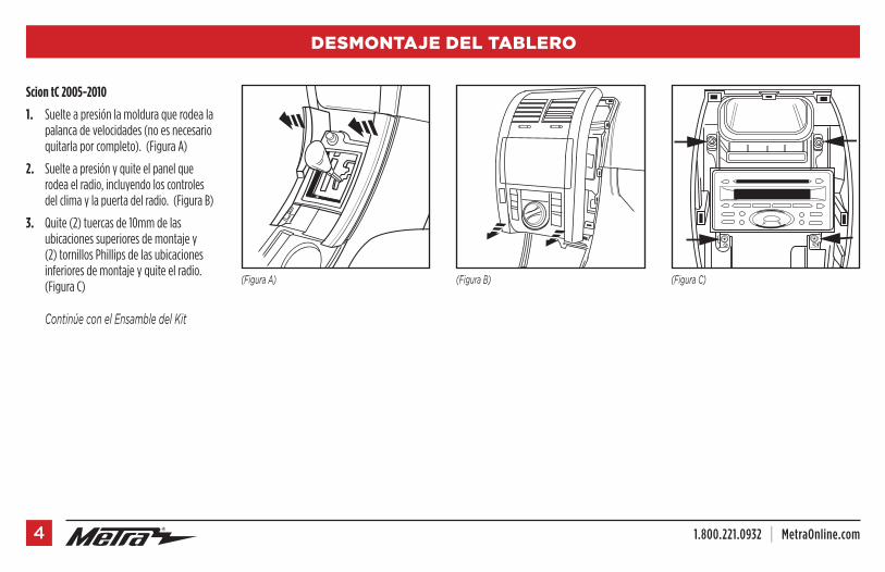
Scion tC 2005-2010
1. Suelte a presión la moldura que rodea la palanca de velocidades (no es necesario quitarla por completo). (Figura A)
2. Suelte a presión y quite el panel que rodea el radio, incluyendo los controles del clima y la puerta del radio. (Figura B)
3. Quite (2) tuercas de 10mm de las ubicaciones superiores de montaje y (2) tornillos Phillips de las ubicaciones inferiores de montaje y quite el radio. (Figura C)
ContinúeconelEnsambledelKit
(FiguraA) (FiguraB) (FiguraC)
REV. 9/19/2017 INST99-8209 5
DESMONTAJE DEL TABLERO
(FiguraC)
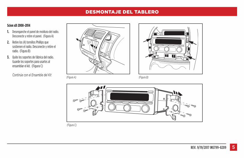
Scion xD 2008-2014
1. Desenganche el panel de moldura del radio. Desconecte y retire el panel. (Figura A)
2. Retire los (4) tornillos Phillips que sostienen el radio. Desconecte y retire el radio. (Figura B)
3. Quite los soportes de fábrica del radio. Guarde los soportes para usarlos al ensamblar el kit. (Figura C)
ContinúeconelEnsambledelKit(FiguraA) (FiguraB)

1.800.221.0932 | MetraOnline.com6
ENSAMBLE DEL KIT
Provisión de radio DIN con cavidad
1. Deslice los soportes en los lados de la carcasadelradio hasta que los ganchos laterales entren a presión. (Figura A)
Nota: Usejuegodesoportes1paraxA,xB,ytC.Usejuegodesoportes2parael2008xByxD.
2. Para juegodesoportes1 corte y quite todos las pestañas de montaje EXCEPTO las pestañas que se utiliza para su aplicación. (Figura B)
Nota: LaspestañasestánmarcadasconxA,xBytC.Paraeljuegodesoporte2,vayaalpaso3.
3. Quite la manga de metal DIN del radio de mercado secundario.
4. Deslice la manga en la carcasadelradio y sujétela doblando hacia abajo las pestañas de metal. (Figura C)
5. Deslice el radio de nuevo en la manga hasta que haga clic. (Figura D)
6. Localice el arnés de cableado de fábrica y el conector de la antena en el tablero y haga todas las conexiones necesarias al radio. Metra recomienda que use adaptadores adecuados de acoplamiento de Metra y/o de AXXESS. Pruebe el radio para verificar que funcione correctamente.
7. Vuelva a armar el tablero al revés de como lo desarmó.
(FiguraB)
(FiguraC)
(FiguraD)
(FiguraA)
ganchoslaterales
Conjuntodesoportes1
REV. 9/19/2017 INST99-8209 7
ENSAMBLE DEL KIT
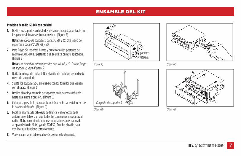
Provisión de radio ISO DIN con cavidad
1. Deslice los soportes en los lados de la carcasadelradio hasta que los ganchos laterales entren a presión. (Figura A)
Nota: Usejuegodesoportes1paraxA,xB,ytC.Usejuegodesoportes2parael2008xByxD.
2. Para juegodesoportes1 corte y quite todos las pestañas de montaje EXCEPTO las pestañas que se utiliza para su aplicación. (Figura B)
Nota: LaspestañasestánmarcadasconxA,xBytC.Paraeljuegodesoporte2,vayaalpaso3.
3. Quite la manga de metal DIN y el anillo de moldura del radio de mercado secundario
4. Sujete los soportesISO en el radio con los tornillos que vienen con el radio. (Figura C)
5. Deslice el radio/ensamble de soportes en la carcasadelradio hasta que entre a presión. (Figura D)
6. Coloque a presión la placadelamoldura en la parte delantera de la carcasadelradio. (Figura D)
7. Localice el arnés de cableado de fábrica y el conector de la antena en el tablero y haga todas las conexiones necesarias al radio. Metra recomienda que use adaptadores adecuados de acoplamiento de Metra y/o de AXXESS. Pruebe el radio para verificar que funcione correctamente.
8. Vuelva a armar el tablero al revés de como lo desarmó.
(FiguraC)(FiguraA)
(FiguraB)
Conjuntodesoportes1
(FiguraD)
ganchoslaterales
KNOWLEDGE IS POWEREnhance your installation and fabrication skills by enrolling in the most recognized and respected mobile electronics school in our industry.Log onto www.installerinstitute.com or call 800-354-6782 for more information and take steps toward a better tomorrow.
®
Metra recomienda técnicos con certificación del Programa de Certificación en Electrónica Móvil (Mobile Electronics Certification Program, MECP).
EL CONOCIMIENTO ES PODERMejore sus habilidades de instalación y fabricación inscribiéndose en la escuela de dispositivos electrónicos móviles más reconocida y respetada de nuestra industria. Regístrese en www.installerinstitute.com o llame al 800-354-6782 para obtener más información y avance hacia un futuro mejor.
IMPORTANTESi tiene dificultades con la instalación de este producto, llame a nuestra línea de soporte técnico al 1-800-253-TECH. Antes de hacerlo, revise las instrucciones por segunda vez y asegúrese de que la instalación se haya realizado exactamente como se indica en las instrucciones. Por favor tenga el vehículo desarmado y listo para ejecutar los pasos de resolución de problemas antes de llamar.
The World’s best kits.® MetraOnline.com © COPYRIGHT 2017 METRA ELECTRONICS CORPORATION REV. 9/19/17 INST99-8209
I N S T R U C C I O N E S D E I N S TA L AC I Ó N99-8209