217 railway technology latest technologies avalanche … · harmony with the environment and cost...
TRANSCRIPT
217Railway Technology Avalanche No.37, December 22, 2011
RailwayTechnologyAvalanche December 22, 2011 No.37
GENERAL INFOMATION
Newsletter on theLatest TechnologiesDeveloped by RTRI
1
RTRI’s Promotion of Research and Development in Recent Years
RTRI is now promoting research and development based on its Master plan for research policies, RESEARCH 2010, covering the period from 2010 through 2014. Research targets adopted include the improvement of railway safety and convenience, harmony with the environment and cost reduction in view of recent railway accidents/disasters and the current severe economic circumstances.(1) Improvement of railway safetyRailways place the highest priority on safety. Therefore, RTRI is promoting a number of research projects to prevent natural disasters caused by earthquakes or strong winds and ensure the safety of passengers and rolling stock in operation as well as other measures to guarantee the safety of railways.RTRI has developed a technique to estimate earthquake disas-ters at high precision using an algorithm to reflect the vibration amplifying characteristics of the ground. This is based on the perennial micro-vibration data in addition to that obtained with seismographs installed on the ground. RTRI also has developed a technique to extract the risk of the reduction of earthquake resistance of individual sections along the route, with structures represented by simplified models.(2) Harmony with the environmentResearch is under way to save energy and evaluate the effect of noise, vibration and electromagnetic fields generated by railways on the wayside environment and passenger car compartments. The research also includes determining measures to reduce the detrimental effect of these nuisances. RTRI has already developed high-efficiency induction motors to reduce losses by about 30% in medium and high-speed ranges.(3) Cost reductionTo cut the operating costs, RTRI is promoting research projects to improve the efficiency of maintenance work and methods for designing and construction work. RTRI has already completed an image processing program to evaluate the occurrence of cracks in tunnels.(4) Improvement of convenience for customersTo improve the convenience of railways, RTRI has developed
technologies to raise the train speeds of Shinkansen and narrow-gauge lines and also to improve transport services as a whole. Furthermore, RTRI is developing a linear motor type rail brake technology and a technique to predict passenger flows when transport has been disturbed.(5) Construction of simulators railway engineeringRTRI is making efforts to develop models to analyze the high-frequency vibration and interaction between wheel and rail at their contact point in detail and improve simulation technologies to analyze the motion of railway cars after derailment.In view of the aftermath of the Pacific Off-Shore Earthquake (Magnitude 9.0) that hit the Tohoku Area in March 2011, RTRI will also set/promote new themes in the future to predict the magnitudes of tsunamis after very large earthquakes.
ARTICLES
Ikuo WATANABEDirector, Research & Development Promotion Division
■ A Method to Measure the Contact Force of Pantographs through Image ProcessingTatsuya KOYAMA.............................................................................................................219
■ Wind Tunnel Test on Windbreak Fence Installed on Railway LinesKatsuji TANEMOTO.........................................................................................................220
■ A Ride Comfort Evaluation Method to Reflect the Effect of High-Fre-quency VibrationChizuru NAKAGAWA.......................................................................................................221
■ A Study of Non-Contact Power Supply SystemsTakayuki KASHIWAGI......................................................................................................222
■ RTRI’s Promotion of Research and Development in Recent YearsIkuo WATANABE.............................................................................................................217
■ The 11th China-Korea-Japan Railway Research Technical MeetingKazuhide YASHIRO..........................................................................................................218
Railway Technical Research Institute2-8-38 Hikari-cho, Kokubunji-shiTokyo 185-8540, JAPANURL: http://www.rtri.or.jp
Copyright © 2011 Railway Technical Reserch Institute.All rights reserved.Reproduction in whole or part without permission is prohibited. Printed in Japan.
Editorial Office: Ken-yusha, Inc.URL: http://www.kenf.or.jp/en/

218 Railway Technology Avalanche No.37, December 22, 2011
2
The 11th China-Korea-Japan Railway Research Technical Meeting
The China Academy of Railway Sciences (CARS) hosted the 11th China-Korea-Japan Railway Research Technical Meeting in Beijing, China, on November 16th to 17th, 2011. Since 2001, the meeting has been held annually and hosted in rotation by the three railway research organizations, i.e., CARS, Korea Railroad Research Institute (KRRI) and Railway Technical Research Institute (RTRI). Over 60 persons joined the meeting this time, including Mr. Kang, President of CARS with 39 participants therefrom, Mr. Hong, President of KRRI with 10 and Mr. Ichikawa, Executive Director of RTRI with 11 (Fig.1).To fully exchange information on our latest respective research work at the meeting, keynote speeches were made by representatives from each organization. They reported on what is going on with their research activities. At the workshop, three sessions were organized individually in the categories of civil engineering and environmental issues, rolling stock technologies, and safety improve-ment. At the session on civil engineering, technologies developed by CARS and KRRI to reinforce railroad tracks and embankments were outlined for high-speed rail. Even in railroad industries, environmental management has become an issue. Railroad premises have been polluted with chemicals including heavy metals and petroleum used in railroad operation for a long time. China Railway, Japan Railways and KoRail have the same problems with railroad track pollution. KRRI and RTRI have developed screen-ing methods for heavy metal and petroleum combined with a soil sampling technology to quickly find hot spots in railroad tracks.At the rolling stock session,
KRRI and RTRI pre-sented technologies to observe the conditions of the contact between pan tog raph and catenary. The issue is one of the hottest topics in high-speed train operation within the three countries. At the safety session, we discussed strategies for safer railroad op-eration. We tried to find a way to successfully organize analysis of incidents and accidents taking place in railroad operation.At the meeting, we decided to close six research themes at the end of 2011, promote two current projects and launch two new ones. We will meet in Tokyo in the autumn of 2012 to summarize the research results for the next year and encourage all researchers from the three organiza-tions.
Kazuhide YASHIROManager, R&D Planning, Research & Development Promotion Division
Fig.1. The.participants.in.the.11th.China-Korea-Japan.Research.Technical.Meeting.at.Beijing.in.November.2011
Fig.2. Casual.exchanges.over.drinks.after.the.discussions.at.technical.sessions
Fig.3. Discussions.with.co-workers.in.the.meeting
219Railway Technology Avalanche No.37, December 22, 2011
3
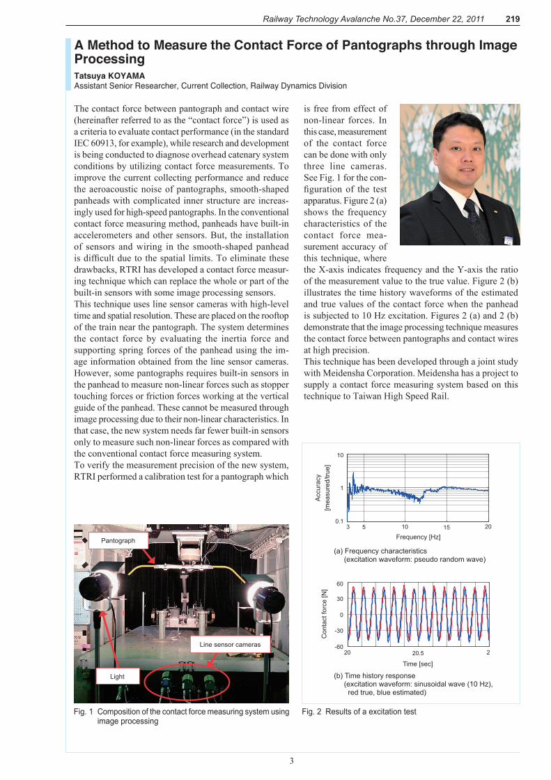
The contact force between pantograph and contact wire (hereinafter referred to as the “contact force”) is used as a criteria to evaluate contact performance (in the standard IEC 60913, for example), while research and development is being conducted to diagnose overhead catenary system conditions by utilizing contact force measurements. To improve the current collecting performance and reduce the aeroacoustic noise of pantographs, smooth-shaped panheads with complicated inner structure are increas-ingly used for high-speed pantographs. In the conventional contact force measuring method, panheads have built-in accelerometers and other sensors. But, the installation of sensors and wiring in the smooth-shaped panhead is difficult due to the spatial limits. To eliminate these drawbacks, RTRI has developed a contact force measur-ing technique which can replace the whole or part of the built-in sensors with some image processing sensors.This technique uses line sensor cameras with high-level time and spatial resolution. These are placed on the rooftop of the train near the pantograph. The system determines the contact force by evaluating the inertia force and supporting spring forces of the panhead using the im-age information obtained from the line sensor cameras. However, some pantographs requires built-in sensors in the panhead to measure non-linear forces such as stopper touching forces or friction forces working at the vertical guide of the panhead. These cannot be measured through image processing due to their non-linear characteristics. In that case, the new system needs far fewer built-in sensors only to measure such non-linear forces as compared with the conventional contact force measuring system.To verify the measurement precision of the new system, RTRI performed a calibration test for a pantograph which
is free from effect of non-linear forces. In this case, measurement of the contact force can be done with only three line cameras. See Fig. 1 for the con-figuration of the test apparatus. Figure 2 (a) shows the frequency characteristics of the contact force mea-surement accuracy of this technique, where the X-axis indicates frequency and the Y-axis the ratio of the measurement value to the true value. Figure 2 (b) illustrates the time history waveforms of the estimated and true values of the contact force when the panhead is subjected to 10 Hz excitation. Figures 2 (a) and 2 (b) demonstrate that the image processing technique measures the contact force between pantographs and contact wires at high precision.This technique has been developed through a joint study with Meidensha Corporation. Meidensha has a project to supply a contact force measuring system based on this technique to Taiwan High Speed Rail.
A Method to Measure the Contact Force of Pantographs through Image ProcessingTatsuya KOYAMAAssistant Senior Researcher, Current Collection, Railway Dynamics Division
Fig..2. Results.of.a.excitation.testFig..1. Composition.of.the.contact.force.measuring.system.using.image.processing
Line sensor cameras
Pantograph
Light
10 15 20
1
0.1
10
3 5
Acc
urac
y[m
easu
red/
true]
Frequency [Hz]
20 20.5 2
0
30
-30
-60
60
Con
tact
forc
e [N
]
Time [sec]
(a) Frequency characteristics (excitation waveform: pseudo random wave)
(b) Time history response (excitation waveform: sinusoidal wave (10 Hz), red true, blue estimated)

220 Railway Technology Avalanche No.37, December 22, 2011
4
To improve the safety and stability of railway transport under windy conditions, windbreak fences have been installed on more and more parts of railway lines in wind-exposed areas in Japan. To effectively and economically install windbreak fences, we need to know the relation between the perpendicular distance from a windbreak fence to the track and reduction in aerodynamic forces on railway vehicles. For that purpose, we conducted a wind tunnel test to measure the aerodynamic forces that act on a vehicle located at different perpendicular distances from the windbreak fence.We conducted the test for the 1/40 scale vehicle model of narrow gauge train series 103 under atmospheric boundary layer condition where representative wind speed is 30 m/s, using a large-scale low-noise wind tunnel (measure-ment section 5 x 3 x 20 m) at the Maibara Wind Tunnel Technical Center, RTRI. We installed a windbreak fence having a porosity of 40% at a height of 2 m (in full-scale dimensions) from the rail level on the windward side of a bridge/viaduct. A three-component aerodynamic force balance inside the vehicle model measured the side force and lift working on the model and the roll moment around the car-body center. The bridge model was actually composed of two sets of single-track bridges placed in parallel, the distance between the two of which could be varied. For the test on viaduct, we made several models with different widths. See Fig.1 for a photograph of the wind tunnel test on a viaduct.Figure 2 shows the relation between the side force coef-ficient (non-dimensional side force coefficient based on vehicle side area and dynamic pressure of wind) on an intermediate vehicle and the perpendicular distance from the windbreak fence. Where there are no fences, the coefficient of side force is approximately 1.4 both with bridges and viaducts. Where a fence exists, the value of
the coefficient at a dis-tance of 7 m from the fence is less than half that measured when there are no fences. At a distance of 13 m or over, the coefficient is larger with bridges than with viaducts, presumably because the two sets of single-track bridges are placed apart to allow air to flow in between.In the present wind tunnel test, we used the models of vehicle and bridges/viaducts all set in a static state. Accordingly, the relative motion of the vehicle and the bridges/viaducts, which occurs in full-scale situations, was not simulated in the test. We will further study this effect of the relative motion on the estimation of the ef-fectiveness of windbreak fences.
Wind Tunnel Test on Windbreak Fence Installed on Railway LinesKatsuji TANEMOTOSenior Researcher, Vehicle Aerodynamics, Environmental Engineering Division
Fig..1. A.photograph.of.the.wind.tunnel.test.on.a.viaduct
Fig..2. Relation.between.the.distance.from.the.windbreak.fence.and.the.of.side.force.coefficient.(for.bridge.and.viaduct)
Railway vehicle
Distance
Windbreak fence
Wind
Sid
e fo
rce
coef
ficie
nt (C
s)
No windbreak fences
Distance from the windbreak fence (m)
Intermediate vehicle, wind direction 90°, bridge and viaduct with a girder height of 1 m, windbreak fence (porosity 40% and height 2 m)
Viaduct with a windbreak fence
Viaduct with no windbreak fences
Bridge with a windbreak fence
Bridge with no windbreak fences
0.0
0.2
0.4
0.6
0.8
1.0
1.2
1.4
1.6
0 5 10 15 20 25 30
221Railway Technology Avalanche No.37, December 22, 2011
5
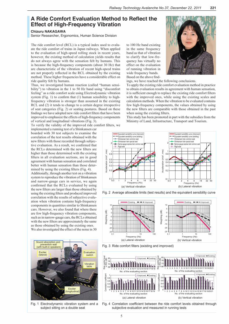
The ride comfort level (RCL) is a typical index used to evalu-ate the ride comfort of trains in Japan railways. When applied to the evaluation of high-speed rolling stock in recent years, however, the existing method of calculation yields results that do not always agree with the sensation felt by humans. This is because the high-frequency components (about 30 Hz) that are characteristic of the vibration of recent high-speed trains are not properly reflected in the RCL obtained by the existing method. These higher frequencies have a considerable effect on ride quality felt by humans.Thus, we investigated human reaction (called “human sensi-bility”) to vibration in the 1 to 50 Hz band using “discomfort feeling” as a ride comfort scale using Electrodynamic vibration system (Fig. 1) to confirm that (1) human sensibility to high-frequency vibration is stronger than assumed in the existing RCL and (2) it tends to change to a certain degree irrespective of seat categories (Fig. 2) or seating postures. Based on these findings we have adopted new ride comfort filters that have been improved to emphasize the effects of high-frequency components of vertical and longitudinal vibrations (Fig. 3).To verify the validity of the improved ride comfort filters, we implemented a running test of a Shinkansen car boarded with 30 test subjects to examine the correlation of the test results obtained with the new filters with those recorded through subjec-tive evaluation. As a result, we confirmed that the RCLs determined with the new filters are higher than those determined with the existing filters in all evaluation sections, are in good agreement with human sensation and correlated better with human sensation than those deter-mined by using the existing filters (Fig. 4).Additionally, through another test on a vibration system to reproduce the vibration of Shinkansen and narrow-gauge cars in service, we again confirmed that the RCLs evaluated by using the new filters are larger than those obtained by using the existing filters and produced improved correlation with the results of subjective evalu-ation when vibration contains high-frequency components in quantities similar to Shinkansen cars. However, we also found that where there are few high-frequency vibration components, such as in narrow-gauge cars, the RCLs obtained with the new filters are approximately the same as those obtained by using the existing ones. We also investigated the effect of the noise in 30
to 100 Hz band existing in the same frequency band as that of vibration to clarify that low-fre-quency has virtually no effect on the evaluation of running vibration in wide frequency bands.Based on the above find-ings, we have reached the following conclusions.To apply the existing ride comfort evaluation method in practice to obtain evaluation results in agreement with human sensation, it is sufficient enough to replace the existing ride comfort filters with the improved ones, while using the existing scales and calculation methods. When the vibration to be evaluated contains few high-frequency components, the values obtained by using the new filters are comparable with those obtained in the past when using the existing filters.This study has been promoted in part with the subsidies from the Ministry of Land, Infrastructure, Transport and Tourism.
A Ride Comfort Evaluation Method to Reflect the Effect of High-Frequency VibrationChizuru NAKAGAWASenior Researcher, Ergonomics, Human Science Division
Fig..2. Average.allowable.limits.(test.results).and.the.equivalent.sensibility.curve
Fig..1. Electrodynamic.vibration.system.and.a.subject.sitting.on.a.double.seat
Fig..3. Ride.comfort.filters.(existing.and.improved)
Fig..4. Correlation.coefficient.between.the.ride.comfort. levels.obtained.through.subjective.evaluation.and.measured.in.running.tests
Sound absorption and
(with built-in speakers)prevention wall
Exciter (lateral)
Vibration table
Exciter (longitudinal)
Evaluation switch
Lateral
Acc
eler
atio
n (m
/s2 ,
rms)
Acc
eler
atio
n (m
/s2 ,
rms)
Frequency (Hz) Frequency (Hz)
Rigid seatNarrow-gauge express train common seatShinkansen train special seatShinkansen train common seatEquivalent sensibility curve (existing)Equivalent sensibility curve (improved)
Rigid seatNarrow-gauge express train common seatShinkansen train special seatShinkansen train common seatEquivalent sensibility curve (existing)Equivalent sensibility curve (improved)
(b) Lateral vibration(a) Vertical vibration
-25
-20
-15
-10
-5
0
5
10
0.1 1 10 100-25
-20
-15
-10
-5
0
5
10
0.1 1 10 100
ImprovedExisting ImprovedExisting
-6.0dB/Octave
-2.7dB/Octave -6.0dB/Octave
-2.7dB/Octave
Frequency (Hz) Frequency (Hz)(a) Lateral vibration (b) Vertical vibration
Wei
ghtin
g (d
B)
Wei
ghtin
g (d
B)
68737883
1 2 3 4 5 6 7 8 9 10 11 121314 1516 1718 19
00.20.40.60.8
1
1 2 3 4 5 6 7 8 9 1011 1213141516171819
68737883
1 2 3 4 5 6 7 8 9 10 11 1213 141516 171819 2021
00.20.40.60.8
1
1 2 3 4 5 6 7 8 9 10 11 121314 15161718 192021
(a) Lateral vibration
Corre
lation
coef
ficien
t
Corre
lation
coef
ficien
t
No. of the evaluating section
No. of the evaluating section No. of the evaluating section
No. of the evaluating section
Ride
comf
ort le
vel
or R
CL (d
B)
Ride
comf
ort le
vel
or R
CL (d
B)Improved Existing
Improved Existing Improved Existing
Improved Existing
(b) Vertical vibration

222 Railway Technology Avalanche No.37, December 22, 2011
A non-contact power supply system has many potential advantages compared with a normal (contacting) power sup-ply system. A non-contact system significantly eliminates the danger of electric shocks or leaks and has low-noise and maintenance-free features. However, the transmission of energy through space tends to drop the energy supply efficiency and adversely affect system surroundings with leakage fluxes. Thus it is important to develop a higher efficiency system.We have started the development of a non-contact power supply system for rolling stock. As the energy storage equipment installed on battery EMUs and hybrid DMUs constitutes a significant portion of the total weight of the trains, it is important to make the equipment as lightweight as possible. A potential way to satisfy this requirement is to reduce the energy storage equipment capacity necessary for a day by frequently charging the equipment through the non-contact power supply system whenever trains stay at stations.Major factors that drop the efficiency of the non-contact pow-er supply system are the loss caused by the ON-resistance of the power converter to generate power for transmission and the copper loss in the power transmission/reception coils. Inverters using silicon carbide (SiC) for power elements are now being commercialized as power converters, and these are expected to reduce loss and improve efficiency. While reduction of loss is not expected much for coils, research to improve coil efficiency and reduce costs is proceed-
ing. Indeed, we have already confirmed that it is possible to improve efficiency and reduce costs by adopting sets of thin wires used for power cables of house-hold appliance in place of Litz wires, or the special wires used for high-frequency purposes (see Fig. 1).To apply the non-contact power supply system to railways, it is may be possible to install power supply coils between the bottom of cars and rails to ensure the precision of instal-lation. Unfortunately, as rails are magnetic and are close to the coils, the power supply characteristics are affected. The rails attract the magnetic fields and the resulting eddy currents cause significant losses. It may be possible to re-duce the nearest leakage magnetic field, however, by using coils of the low-leakage magnetic field type that contains bipolarity within the gauge (see Fig. 2). Based on the results of these discussions, we will manu-facture a power supply test machine aiming at commercial-ization of the system in the near future, implement power supply and running tests by using RTRI’s hybrid railway test vehicles with fuel cells and batteries (see Fig. 3) and establish the characteristics of non-contact power supply equipment that suits railway applications.
A Study of Non-Contact Power Supply Systems
Takayuki KASHIWAGIAssistant Senior Researcher, Electromagnetic Applications, Maglev Systems Technology Division
Fig..1. Efficiency.of.the.system.using.different.materials
Fig..2. A.case.of.magnetic.field.analysis.and.analysis.models.(flux.line.diagram)
Fig..3. Hybrid.railway.test.vehicles.with.fuel.cells.and.batteries
6
Thin wires used for power cables of household appliances (naked element wire)
Litz wire (insulated element wire)
Wire section
Effi
cien
cy w
ith th
e va
lue
at 1
.0 k
Hz
take
n as
uni
ty
Frequency (kHz)
0
2
4
6
8
10
1 10 100
Power collection coil(on car)
Power supply coil(on ground)
Rail
Power collection coil(on car)
Power supply coil(on ground)
Rail
(a) Conventional coil (b) Low-leakage magnetic field coil