212250000e10.pdf bts alarm dictionary
TRANSCRIPT

Alcatel-Lucent GSM
BTS Alarm Dictionary
BTS Document
Reference Guide
Release B10
3BK 21225 AAAA PCZZA Ed.10

Status RELEASED
Short title BTS Alarm Dictionary
All rights reserved. Passing on and copying of this document, useand communication of its contents not permitted without writtenauthorization from Alcatel.
BLANK PAGE BREAK
2 / 582 3BK 21225 AAAA PCZZA Ed.10

Contents
Contents
Preface . . . . . . . . . . . . . . . . . . . . . . . . . . . . . . . . . . . . . . . . . . . . . . . . . . . . . . . . . . . . . . . . . . . . . . . . . . . . . . . . . . . . . . . . . . 9
1 Introduction . . . . . . . . . . . . . . . . . . . . . . . . . . . . . . . . . . . . . . . . . . . . . . . . . . . . . . . . . . . . . . . . . . . . . . . . . . . . . . . 111.1 Overview . . . . . . . . . . . . . . . . . . . . . . . . . . . . . . . . . . . . . . . . . . . . . . . . . . . . . . . . . . . . . . . . . . . . . . . . . 121.2 Relationships Between SBLs and MOs . . . . . . . . . . . . . . . . . . . . . . . . . . . . . . . . . . . . . . . . . . . . . . 121.3 9153 OMC-R Alarm Surveillance Information . . . . . . . . . . . . . . . . . . . . . . . . . . . . . . . . . . . . . . . . . 141.4 LMT Alarm Messages . . . . . . . . . . . . . . . . . . . . . . . . . . . . . . . . . . . . . . . . . . . . . . . . . . . . . . . . . . . . . . 161.5 BTS Alarm Information . . . . . . . . . . . . . . . . . . . . . . . . . . . . . . . . . . . . . . . . . . . . . . . . . . . . . . . . . . . . . 19
2 Class 1: CLK Alarms . . . . . . . . . . . . . . . . . . . . . . . . . . . . . . . . . . . . . . . . . . . . . . . . . . . . . . . . . . . . . . . . . . . . . . 232.1 [1,1] OCXO-AL . . . . . . . . . . . . . . . . . . . . . . . . . . . . . . . . . . . . . . . . . . . . . . . . . . . . . . . . . . . . . . . . . . . . 242.2 [1,3] CLOCK-FREQ-AL . . . . . . . . . . . . . . . . . . . . . . . . . . . . . . . . . . . . . . . . . . . . . . . . . . . . . . . . . . . . . 262.3 [1,6] MCL-FATAL-AL . . . . . . . . . . . . . . . . . . . . . . . . . . . . . . . . . . . . . . . . . . . . . . . . . . . . . . . . . . . . . . . 302.4 [1,7] MCL-TEST-AL . . . . . . . . . . . . . . . . . . . . . . . . . . . . . . . . . . . . . . . . . . . . . . . . . . . . . . . . . . . . . . . . 342.5 [1,8] MCL-DRV-AL . . . . . . . . . . . . . . . . . . . . . . . . . . . . . . . . . . . . . . . . . . . . . . . . . . . . . . . . . . . . . . . . . 362.6 [1,11] MCLU-FAULT . . . . . . . . . . . . . . . . . . . . . . . . . . . . . . . . . . . . . . . . . . . . . . . . . . . . . . . . . . . . . . . . 382.7 [1,12] CLOCK-FAULT . . . . . . . . . . . . . . . . . . . . . . . . . . . . . . . . . . . . . . . . . . . . . . . . . . . . . . . . . . . . . . 402.8 [1,22] MCLR-EA-AL . . . . . . . . . . . . . . . . . . . . . . . . . . . . . . . . . . . . . . . . . . . . . . . . . . . . . . . . . . . . . . . . 442.9 [1,23] PCM-SYNC-AL . . . . . . . . . . . . . . . . . . . . . . . . . . . . . . . . . . . . . . . . . . . . . . . . . . . . . . . . . . . . . . 462.10 [1,31] MCL-XCLK . . . . . . . . . . . . . . . . . . . . . . . . . . . . . . . . . . . . . . . . . . . . . . . . . . . . . . . . . . . . . . . . . . 482.11 [1,234] IOM-DISCONNECTION . . . . . . . . . . . . . . . . . . . . . . . . . . . . . . . . . . . . . . . . . . . . . . . . . . . . . 512.12 [1,237] HW-DEGRADED . . . . . . . . . . . . . . . . . . . . . . . . . . . . . . . . . . . . . . . . . . . . . . . . . . . . . . . . . . . 522.13 [1,240] MISSING-ENTRY-IN-CPF . . . . . . . . . . . . . . . . . . . . . . . . . . . . . . . . . . . . . . . . . . . . . . . . . . . 572.14 [1,241] INCONSIST-ASSHW-ACTHW . . . . . . . . . . . . . . . . . . . . . . . . . . . . . . . . . . . . . . . . . . . . . . . 592.15 [1,246] CONFIG-FAIL . . . . . . . . . . . . . . . . . . . . . . . . . . . . . . . . . . . . . . . . . . . . . . . . . . . . . . . . . . . . . . 622.16 [1,247] RESET . . . . . . . . . . . . . . . . . . . . . . . . . . . . . . . . . . . . . . . . . . . . . . . . . . . . . . . . . . . . . . . . . . . . 642.17 [1,248] RESTART . . . . . . . . . . . . . . . . . . . . . . . . . . . . . . . . . . . . . . . . . . . . . . . . . . . . . . . . . . . . . . . . . . 672.18 [1,250] NO-ANSWER-DCL . . . . . . . . . . . . . . . . . . . . . . . . . . . . . . . . . . . . . . . . . . . . . . . . . . . . . . . . . 702.19 [1,255] Q1-RELAY-FAILURE . . . . . . . . . . . . . . . . . . . . . . . . . . . . . . . . . . . . . . . . . . . . . . . . . . . . . . . . 72
3 Class 2: OMU Alarms . . . . . . . . . . . . . . . . . . . . . . . . . . . . . . . . . . . . . . . . . . . . . . . . . . . . . . . . . . . . . . . . . . . . . . 753.1 [2,1] LOSS OF TWIN CONFIGURATION . . . . . . . . . . . . . . . . . . . . . . . . . . . . . . . . . . . . . . . . . . . . . 763.2 [2,247] RESET . . . . . . . . . . . . . . . . . . . . . . . . . . . . . . . . . . . . . . . . . . . . . . . . . . . . . . . . . . . . . . . . . . . . 783.3 [2,248] RESTART . . . . . . . . . . . . . . . . . . . . . . . . . . . . . . . . . . . . . . . . . . . . . . . . . . . . . . . . . . . . . . . . . . 83
4 Class 3: SW-AN Alarms . . . . . . . . . . . . . . . . . . . . . . . . . . . . . . . . . . . . . . . . . . . . . . . . . . . . . . . . . . . . . . . . . . . . 854.1 [3,0] UNKNOWN-UNIT . . . . . . . . . . . . . . . . . . . . . . . . . . . . . . . . . . . . . . . . . . . . . . . . . . . . . . . . . . . . . 864.2 [3,1] UNKNOWN-CMD-MSG . . . . . . . . . . . . . . . . . . . . . . . . . . . . . . . . . . . . . . . . . . . . . . . . . . . . . . . . 874.3 [3,2] UNKNOWN-ALARM . . . . . . . . . . . . . . . . . . . . . . . . . . . . . . . . . . . . . . . . . . . . . . . . . . . . . . . . . . . 884.4 [3,11] SW-PROBLEM . . . . . . . . . . . . . . . . . . . . . . . . . . . . . . . . . . . . . . . . . . . . . . . . . . . . . . . . . . . . . . 894.5 [3,13] TELECOM-CONFIG-FAIL . . . . . . . . . . . . . . . . . . . . . . . . . . . . . . . . . . . . . . . . . . . . . . . . . . . . 974.6 [3,14] WRONG-CONFIGURATION . . . . . . . . . . . . . . . . . . . . . . . . . . . . . . . . . . . . . . . . . . . . . . . . . . 994.7 [3,246] CONFIG-FAIL . . . . . . . . . . . . . . . . . . . . . . . . . . . . . . . . . . . . . . . . . . . . . . . . . . . . . . . . . . . . . 112
5 Class 4: FHU Alarms . . . . . . . . . . . . . . . . . . . . . . . . . . . . . . . . . . . . . . . . . . . . . . . . . . . . . . . . . . . . . . . . . . . . . 1215.1 [4,1] DUMMY-BURST-GEN-FAIL . . . . . . . . . . . . . . . . . . . . . . . . . . . . . . . . . . . . . . . . . . . . . . . . . . . 1225.2 [4,5] FN-AL . . . . . . . . . . . . . . . . . . . . . . . . . . . . . . . . . . . . . . . . . . . . . . . . . . . . . . . . . . . . . . . . . . . . . . 1245.3 [4,6] INTERNAL-FN . . . . . . . . . . . . . . . . . . . . . . . . . . . . . . . . . . . . . . . . . . . . . . . . . . . . . . . . . . . . . . . 1255.4 [4,10] FATAL-AL . . . . . . . . . . . . . . . . . . . . . . . . . . . . . . . . . . . . . . . . . . . . . . . . . . . . . . . . . . . . . . . . . . 1275.5 [4,14] FCLK-AL . . . . . . . . . . . . . . . . . . . . . . . . . . . . . . . . . . . . . . . . . . . . . . . . . . . . . . . . . . . . . . . . . . . 1295.6 [4,15] INT-FCLK-AL . . . . . . . . . . . . . . . . . . . . . . . . . . . . . . . . . . . . . . . . . . . . . . . . . . . . . . . . . . . . . . . 1315.7 [4,16] OBCLK-AL . . . . . . . . . . . . . . . . . . . . . . . . . . . . . . . . . . . . . . . . . . . . . . . . . . . . . . . . . . . . . . . . . 1335.8 [4,17] INTERNAL-OBCLK . . . . . . . . . . . . . . . . . . . . . . . . . . . . . . . . . . . . . . . . . . . . . . . . . . . . . . . . . 1355.9 [4,240] MISSING-ENTRY-IN-CPF . . . . . . . . . . . . . . . . . . . . . . . . . . . . . . . . . . . . . . . . . . . . . . . . . . 1365.10 [4,246] CONFIG-FAIL . . . . . . . . . . . . . . . . . . . . . . . . . . . . . . . . . . . . . . . . . . . . . . . . . . . . . . . . . . . . . 1385.11 [4,247] RESET . . . . . . . . . . . . . . . . . . . . . . . . . . . . . . . . . . . . . . . . . . . . . . . . . . . . . . . . . . . . . . . . . . . 1405.12 [4,250] NO-ANSWER-DCL . . . . . . . . . . . . . . . . . . . . . . . . . . . . . . . . . . . . . . . . . . . . . . . . . . . . . . . . 141
3BK 21225 AAAA PCZZA Ed.10 3 / 582
Contents
5.13 [4,255] Q1-RELAY-FAILURE . . . . . . . . . . . . . . . . . . . . . . . . . . . . . . . . . . . . . . . . . . . . . . . . . . . . . . . 143
6 Class 5: ENVIR Alarms . . . . . . . . . . . . . . . . . . . . . . . . . . . . . . . . . . . . . . . . . . . . . . . . . . . . . . . . . . . . . . . . . . . 1456.1 [5,0] POWER-SUPPLY . . . . . . . . . . . . . . . . . . . . . . . . . . . . . . . . . . . . . . . . . . . . . . . . . . . . . . . . . . . . 1466.2 [5,1] FAN-ALARM . . . . . . . . . . . . . . . . . . . . . . . . . . . . . . . . . . . . . . . . . . . . . . . . . . . . . . . . . . . . . . . . . 1526.3 [5,2] FAN-ALARM-U . . . . . . . . . . . . . . . . . . . . . . . . . . . . . . . . . . . . . . . . . . . . . . . . . . . . . . . . . . . . . . 1536.4 [5,3] FAN-ALARM-T . . . . . . . . . . . . . . . . . . . . . . . . . . . . . . . . . . . . . . . . . . . . . . . . . . . . . . . . . . . . . . . 1546.5 [5,4] BTS-TEMP-ALARM . . . . . . . . . . . . . . . . . . . . . . . . . . . . . . . . . . . . . . . . . . . . . . . . . . . . . . . . . . 1556.6 [5,5] CPLG-ALARM . . . . . . . . . . . . . . . . . . . . . . . . . . . . . . . . . . . . . . . . . . . . . . . . . . . . . . . . . . . . . . . 1576.7 [5,6] SU-POWER-AL . . . . . . . . . . . . . . . . . . . . . . . . . . . . . . . . . . . . . . . . . . . . . . . . . . . . . . . . . . . . . . 1596.8 [5,7] TRX-POWER-AL . . . . . . . . . . . . . . . . . . . . . . . . . . . . . . . . . . . . . . . . . . . . . . . . . . . . . . . . . . . . . 1616.9 [5,11] POWER-SUPPLY-U . . . . . . . . . . . . . . . . . . . . . . . . . . . . . . . . . . . . . . . . . . . . . . . . . . . . . . . . . 1636.10 [5,12] POWER-SUPPLY-NU . . . . . . . . . . . . . . . . . . . . . . . . . . . . . . . . . . . . . . . . . . . . . . . . . . . . . . . 1656.11 [5,13] CONTROL-UNIT-AL . . . . . . . . . . . . . . . . . . . . . . . . . . . . . . . . . . . . . . . . . . . . . . . . . . . . . . . . 1676.12 [5,14] MAINS-POWER-SUPPLY . . . . . . . . . . . . . . . . . . . . . . . . . . . . . . . . . . . . . . . . . . . . . . . . . . . . 1696.13 [5,15] BATT-DEEP-DISCHARGE . . . . . . . . . . . . . . . . . . . . . . . . . . . . . . . . . . . . . . . . . . . . . . . . . . . 1716.14 [5,20] MAINS-AL . . . . . . . . . . . . . . . . . . . . . . . . . . . . . . . . . . . . . . . . . . . . . . . . . . . . . . . . . . . . . . . . . 1736.15 [5,23] POWER-SHUTDOWN . . . . . . . . . . . . . . . . . . . . . . . . . . . . . . . . . . . . . . . . . . . . . . . . . . . . . . . 1756.16 [5,24] SUBRACK-POWER . . . . . . . . . . . . . . . . . . . . . . . . . . . . . . . . . . . . . . . . . . . . . . . . . . . . . . . . . 1786.17 [5,31] TEMPERATURE-WARNING . . . . . . . . . . . . . . . . . . . . . . . . . . . . . . . . . . . . . . . . . . . . . . . . . 1806.18 [5,32] FATAL TEMPERATURE . . . . . . . . . . . . . . . . . . . . . . . . . . . . . . . . . . . . . . . . . . . . . . . . . . . . . 1846.19 [5,237] HW-DEGRADED . . . . . . . . . . . . . . . . . . . . . . . . . . . . . . . . . . . . . . . . . . . . . . . . . . . . . . . . . . 1866.20 [5,239] HW-FAILURE . . . . . . . . . . . . . . . . . . . . . . . . . . . . . . . . . . . . . . . . . . . . . . . . . . . . . . . . . . . . . 193
7 Class 6: RF alarms . . . . . . . . . . . . . . . . . . . . . . . . . . . . . . . . . . . . . . . . . . . . . . . . . . . . . . . . . . . . . . . . . . . . . . . 199
7.1 [6,1] LNK-AL . . . . . . . . . . . . . . . . . . . . . . . . . . . . . . . . . . . . . . . . . . . . . . . . . . . . . . . . . . . . . . . . . . . . . 2007.2 [6,2] LNK-DBLE-AL . . . . . . . . . . . . . . . . . . . . . . . . . . . . . . . . . . . . . . . . . . . . . . . . . . . . . . . . . . . . . . . 2037.3 [6,5] RX-AL . . . . . . . . . . . . . . . . . . . . . . . . . . . . . . . . . . . . . . . . . . . . . . . . . . . . . . . . . . . . . . . . . . . . . . 2067.4 [6,6] RX-DBLE-AL . . . . . . . . . . . . . . . . . . . . . . . . . . . . . . . . . . . . . . . . . . . . . . . . . . . . . . . . . . . . . . . . 2087.5 [6,7] RX-SYN-AL . . . . . . . . . . . . . . . . . . . . . . . . . . . . . . . . . . . . . . . . . . . . . . . . . . . . . . . . . . . . . . . . . 2107.6 [6,8] RX-SYN-DBLE-AL . . . . . . . . . . . . . . . . . . . . . . . . . . . . . . . . . . . . . . . . . . . . . . . . . . . . . . . . . . . 2127.7 [6,9] VSWR-AL . . . . . . . . . . . . . . . . . . . . . . . . . . . . . . . . . . . . . . . . . . . . . . . . . . . . . . . . . . . . . . . . . . . 2147.8 [6,10] TX-POWER-AL . . . . . . . . . . . . . . . . . . . . . . . . . . . . . . . . . . . . . . . . . . . . . . . . . . . . . . . . . . . . . 2177.9 [6,11] TEMP-AL . . . . . . . . . . . . . . . . . . . . . . . . . . . . . . . . . . . . . . . . . . . . . . . . . . . . . . . . . . . . . . . . . . 2197.10 [6,13] TX-SYN-AL . . . . . . . . . . . . . . . . . . . . . . . . . . . . . . . . . . . . . . . . . . . . . . . . . . . . . . . . . . . . . . . . 2227.11 [6,14] FCLK-AL . . . . . . . . . . . . . . . . . . . . . . . . . . . . . . . . . . . . . . . . . . . . . . . . . . . . . . . . . . . . . . . . . . . 2247.12 [6,15] INTERNAL-FCLK . . . . . . . . . . . . . . . . . . . . . . . . . . . . . . . . . . . . . . . . . . . . . . . . . . . . . . . . . . . 2277.13 [6,16] OBCLK-AL . . . . . . . . . . . . . . . . . . . . . . . . . . . . . . . . . . . . . . . . . . . . . . . . . . . . . . . . . . . . . . . . . 2307.14 [6,17] INTERNAL-OBCLK . . . . . . . . . . . . . . . . . . . . . . . . . . . . . . . . . . . . . . . . . . . . . . . . . . . . . . . . . 2327.15 [6,18] REF-FREQ-AL . . . . . . . . . . . . . . . . . . . . . . . . . . . . . . . . . . . . . . . . . . . . . . . . . . . . . . . . . . . . . 2347.16 [6,19] INTERNAL-REF-FRQ . . . . . . . . . . . . . . . . . . . . . . . . . . . . . . . . . . . . . . . . . . . . . . . . . . . . . . . 2367.17 [6,34] ANTENNA-VSWR . . . . . . . . . . . . . . . . . . . . . . . . . . . . . . . . . . . . . . . . . . . . . . . . . . . . . . . . . . 2397.18 [6,35] FRONTEND-RELAY-AL . . . . . . . . . . . . . . . . . . . . . . . . . . . . . . . . . . . . . . . . . . . . . . . . . . . . . 2417.19 [6,36] FRONTEND-AL . . . . . . . . . . . . . . . . . . . . . . . . . . . . . . . . . . . . . . . . . . . . . . . . . . . . . . . . . . . . . 2437.20 [6,37] FATAL-FRONTEND-AL . . . . . . . . . . . . . . . . . . . . . . . . . . . . . . . . . . . . . . . . . . . . . . . . . . . . . . 2457.21 [6,38] BCCH-SWITCH . . . . . . . . . . . . . . . . . . . . . . . . . . . . . . . . . . . . . . . . . . . . . . . . . . . . . . . . . . . . 2477.22 [6,39] BCCH-SWITCH-FATAL . . . . . . . . . . . . . . . . . . . . . . . . . . . . . . . . . . . . . . . . . . . . . . . . . . . . . . 2497.23 [6,42] RTMA-ALARM . . . . . . . . . . . . . . . . . . . . . . . . . . . . . . . . . . . . . . . . . . . . . . . . . . . . . . . . . . . . . . 2517.24 [6,43] PERU-ALARM . . . . . . . . . . . . . . . . . . . . . . . . . . . . . . . . . . . . . . . . . . . . . . . . . . . . . . . . . . . . . . 2537.25 [6,45] TEST-ABORTED . . . . . . . . . . . . . . . . . . . . . . . . . . . . . . . . . . . . . . . . . . . . . . . . . . . . . . . . . . . 2557.26 [6,46] ALARM-TEST-FAILURE . . . . . . . . . . . . . . . . . . . . . . . . . . . . . . . . . . . . . . . . . . . . . . . . . . . . . 2577.27 [6,48] RF-FAULT . . . . . . . . . . . . . . . . . . . . . . . . . . . . . . . . . . . . . . . . . . . . . . . . . . . . . . . . . . . . . . . . . . 2607.28 [6,49] FRONTEND-AMP-AL . . . . . . . . . . . . . . . . . . . . . . . . . . . . . . . . . . . . . . . . . . . . . . . . . . . . . . . 2657.29 [6,50] DATA-INCONSIS-AL . . . . . . . . . . . . . . . . . . . . . . . . . . . . . . . . . . . . . . . . . . . . . . . . . . . . . . . . 2677.30 [6,51] RTC-OUT-OF-BAND-ALARM . . . . . . . . . . . . . . . . . . . . . . . . . . . . . . . . . . . . . . . . . . . . . . . . 2697.31 [6,52] RTC-FINE-TUNING-FAIL . . . . . . . . . . . . . . . . . . . . . . . . . . . . . . . . . . . . . . . . . . . . . . . . . . . . 2717.32 [6,53] RTC-PARKING-FAILURE . . . . . . . . . . . . . . . . . . . . . . . . . . . . . . . . . . . . . . . . . . . . . . . . . . . . 2737.33 [6,54] RTC-SELFTEST-FAILURE . . . . . . . . . . . . . . . . . . . . . . . . . . . . . . . . . . . . . . . . . . . . . . . . . . 275
4 / 582 3BK 21225 AAAA PCZZA Ed.10
Contents
7.34 [6,55] RTC-EXT-CONN-LOST . . . . . . . . . . . . . . . . . . . . . . . . . . . . . . . . . . . . . . . . . . . . . . . . . . . . . 2777.35 [6,56] RTC-DETECTOR-FAILURE . . . . . . . . . . . . . . . . . . . . . . . . . . . . . . . . . . . . . . . . . . . . . . . . . . 2797.36 [6,240] MISSING-ENTRY-IN-CPF . . . . . . . . . . . . . . . . . . . . . . . . . . . . . . . . . . . . . . . . . . . . . . . . . . 2817.37 [6,241] INCONSIST-ASSHW-ACTHW . . . . . . . . . . . . . . . . . . . . . . . . . . . . . . . . . . . . . . . . . . . . . . 2857.38 [6,246] CONFIG-FAIL . . . . . . . . . . . . . . . . . . . . . . . . . . . . . . . . . . . . . . . . . . . . . . . . . . . . . . . . . . . . . 2907.39 [6,247] RESET . . . . . . . . . . . . . . . . . . . . . . . . . . . . . . . . . . . . . . . . . . . . . . . . . . . . . . . . . . . . . . . . . . . 2947.40 [6,250] NO-ANSWER-DCL . . . . . . . . . . . . . . . . . . . . . . . . . . . . . . . . . . . . . . . . . . . . . . . . . . . . . . . . 2967.41 [6,251] SELF-TEST-AL . . . . . . . . . . . . . . . . . . . . . . . . . . . . . . . . . . . . . . . . . . . . . . . . . . . . . . . . . . . . 3007.42 [6,252] SELF-TEST-DBLE-AL (CU) . . . . . . . . . . . . . . . . . . . . . . . . . . . . . . . . . . . . . . . . . . . . . . . . . 3027.43 [6,255] Q1-RELAY-FAULT . . . . . . . . . . . . . . . . . . . . . . . . . . . . . . . . . . . . . . . . . . . . . . . . . . . . . . . . . 304
8 Class 7: FU Alarms . . . . . . . . . . . . . . . . . . . . . . . . . . . . . . . . . . . . . . . . . . . . . . . . . . . . . . . . . . . . . . . . . . . . . . . 309
8.1 [7,1] AL-LIST-ER . . . . . . . . . . . . . . . . . . . . . . . . . . . . . . . . . . . . . . . . . . . . . . . . . . . . . . . . . . . . . . . . . 3108.2 [7,3] MCL-LINK . . . . . . . . . . . . . . . . . . . . . . . . . . . . . . . . . . . . . . . . . . . . . . . . . . . . . . . . . . . . . . . . . . . 3138.3 [7,5] BSI-LINK-0 . . . . . . . . . . . . . . . . . . . . . . . . . . . . . . . . . . . . . . . . . . . . . . . . . . . . . . . . . . . . . . . . . . 3158.4 [7,6] BOTH-BSI-LINKS . . . . . . . . . . . . . . . . . . . . . . . . . . . . . . . . . . . . . . . . . . . . . . . . . . . . . . . . . . . . 3178.5 [7,7] FHI-LK0-FUL-UNV . . . . . . . . . . . . . . . . . . . . . . . . . . . . . . . . . . . . . . . . . . . . . . . . . . . . . . . . . . . 3198.6 [7,8] FHI-LK1-FUL-UNV . . . . . . . . . . . . . . . . . . . . . . . . . . . . . . . . . . . . . . . . . . . . . . . . . . . . . . . . . . . 3218.7 [7,14] FHU-DUMMY-BURST-GEN-FAIL . . . . . . . . . . . . . . . . . . . . . . . . . . . . . . . . . . . . . . . . . . . . . 3238.8 [7,31] HW-FAIL . . . . . . . . . . . . . . . . . . . . . . . . . . . . . . . . . . . . . . . . . . . . . . . . . . . . . . . . . . . . . . . . . . . 3258.9 [7,32] NR-SW-FAIL . . . . . . . . . . . . . . . . . . . . . . . . . . . . . . . . . . . . . . . . . . . . . . . . . . . . . . . . . . . . . . . 3278.10 [7,33] NR-SCP-MP-FAULT . . . . . . . . . . . . . . . . . . . . . . . . . . . . . . . . . . . . . . . . . . . . . . . . . . . . . . . . . 3288.11 [7,34] BOTH-FHI-LINKS . . . . . . . . . . . . . . . . . . . . . . . . . . . . . . . . . . . . . . . . . . . . . . . . . . . . . . . . . . . 3298.12 [7,35] BOTH-CLOCKS-LINKS . . . . . . . . . . . . . . . . . . . . . . . . . . . . . . . . . . . . . . . . . . . . . . . . . . . . . . 3328.13 [7,36] FU-FAULT . . . . . . . . . . . . . . . . . . . . . . . . . . . . . . . . . . . . . . . . . . . . . . . . . . . . . . . . . . . . . . . . . . 3358.14 [7,240] MISSING-ENTRY-IN-CPF . . . . . . . . . . . . . . . . . . . . . . . . . . . . . . . . . . . . . . . . . . . . . . . . . . 3368.15 [7,241] INCONSIST-ASSHW-ACTHW . . . . . . . . . . . . . . . . . . . . . . . . . . . . . . . . . . . . . . . . . . . . . . 3388.16 [7,242] INCONSIST-actHW-logConfig . . . . . . . . . . . . . . . . . . . . . . . . . . . . . . . . . . . . . . . . . . . . . . 3428.17 [7,243] INCONSIST-actHW-BTSparam . . . . . . . . . . . . . . . . . . . . . . . . . . . . . . . . . . . . . . . . . . . . . 3448.18 [7,245] SW-DLL-FAIL . . . . . . . . . . . . . . . . . . . . . . . . . . . . . . . . . . . . . . . . . . . . . . . . . . . . . . . . . . . . . 3468.19 [7,246] CONFIG-FAIL . . . . . . . . . . . . . . . . . . . . . . . . . . . . . . . . . . . . . . . . . . . . . . . . . . . . . . . . . . . . . 3488.20 [7,248] RESTART . . . . . . . . . . . . . . . . . . . . . . . . . . . . . . . . . . . . . . . . . . . . . . . . . . . . . . . . . . . . . . . . . 3508.21 [7,250] NO-ANSWER-DCL . . . . . . . . . . . . . . . . . . . . . . . . . . . . . . . . . . . . . . . . . . . . . . . . . . . . . . . . 352
9 Class 8: G-BTS Alarms . . . . . . . . . . . . . . . . . . . . . . . . . . . . . . . . . . . . . . . . . . . . . . . . . . . . . . . . . . . . . . . . . . . 3559.1 [8,3] RESYNCH . . . . . . . . . . . . . . . . . . . . . . . . . . . . . . . . . . . . . . . . . . . . . . . . . . . . . . . . . . . . . . . . . . 3569.2 [8,4] IGNORE EQUIPMENT OVER 12 TRE . . . . . . . . . . . . . . . . . . . . . . . . . . . . . . . . . . . . . . . . . 3579.3 [8,5] TOO MANY PLUGGED MODULES . . . . . . . . . . . . . . . . . . . . . . . . . . . . . . . . . . . . . . . . . . . . 3589.4 [8,6] TB-FAILURE . . . . . . . . . . . . . . . . . . . . . . . . . . . . . . . . . . . . . . . . . . . . . . . . . . . . . . . . . . . . . . . . 3599.5 [8,7] Q1-FAILURE . . . . . . . . . . . . . . . . . . . . . . . . . . . . . . . . . . . . . . . . . . . . . . . . . . . . . . . . . . . . . . . . 3619.6 [8,8] HW-RESYNCH . . . . . . . . . . . . . . . . . . . . . . . . . . . . . . . . . . . . . . . . . . . . . . . . . . . . . . . . . . . . . . 3639.7 [8,26] RACH-CATCHER-LOST . . . . . . . . . . . . . . . . . . . . . . . . . . . . . . . . . . . . . . . . . . . . . . . . . . . . . 3649.8 [8,30] BCB-LINK . . . . . . . . . . . . . . . . . . . . . . . . . . . . . . . . . . . . . . . . . . . . . . . . . . . . . . . . . . . . . . . . . . 3669.9 [8,31] IOM-LINK . . . . . . . . . . . . . . . . . . . . . . . . . . . . . . . . . . . . . . . . . . . . . . . . . . . . . . . . . . . . . . . . . . 3699.10 [8,32] MODULE-INSERTED . . . . . . . . . . . . . . . . . . . . . . . . . . . . . . . . . . . . . . . . . . . . . . . . . . . . . . . 3729.11 [8,246] CONFIG-FAIL . . . . . . . . . . . . . . . . . . . . . . . . . . . . . . . . . . . . . . . . . . . . . . . . . . . . . . . . . . . . . 3759.12 [8,247] RESET . . . . . . . . . . . . . . . . . . . . . . . . . . . . . . . . . . . . . . . . . . . . . . . . . . . . . . . . . . . . . . . . . . . 3789.13 [8,248] RESTART . . . . . . . . . . . . . . . . . . . . . . . . . . . . . . . . . . . . . . . . . . . . . . . . . . . . . . . . . . . . . . . . . 3829.14 [8,250] NO-ANSWER-DCL . . . . . . . . . . . . . . . . . . . . . . . . . . . . . . . . . . . . . . . . . . . . . . . . . . . . . . . . 3839.15 [8,251] SELF-TEST-AL . . . . . . . . . . . . . . . . . . . . . . . . . . . . . . . . . . . . . . . . . . . . . . . . . . . . . . . . . . . . 3869.16 [8,255] Q1-RELAY-FAULT . . . . . . . . . . . . . . . . . . . . . . . . . . . . . . . . . . . . . . . . . . . . . . . . . . . . . . . . . 389
10 Class 9: BTS-EXTERNAL Alarms . . . . . . . . . . . . . . . . . . . . . . . . . . . . . . . . . . . . . . . . . . . . . . . . . . . . . . . . . 39310.1 [9,1...56] EXT-ALARM . . . . . . . . . . . . . . . . . . . . . . . . . . . . . . . . . . . . . . . . . . . . . . . . . . . . . . . . . . . . 39410.2 [9,1] EXT-ALARM (Default) . . . . . . . . . . . . . . . . . . . . . . . . . . . . . . . . . . . . . . . . . . . . . . . . . . . . . . . . 39610.3 [9,2] EXT-ALARM (Default) . . . . . . . . . . . . . . . . . . . . . . . . . . . . . . . . . . . . . . . . . . . . . . . . . . . . . . . . 39810.4 [9,3] EXT-ALARM (Default) . . . . . . . . . . . . . . . . . . . . . . . . . . . . . . . . . . . . . . . . . . . . . . . . . . . . . . . . 40010.5 [9,4] EXT-ALARM (Default) . . . . . . . . . . . . . . . . . . . . . . . . . . . . . . . . . . . . . . . . . . . . . . . . . . . . . . . . 40310.6 [9,5] EXT-ALARM (Default) . . . . . . . . . . . . . . . . . . . . . . . . . . . . . . . . . . . . . . . . . . . . . . . . . . . . . . . . 405
3BK 21225 AAAA PCZZA Ed.10 5 / 582

Contents
10.7 [9,6] EXT-ALARM (Default) . . . . . . . . . . . . . . . . . . . . . . . . . . . . . . . . . . . . . . . . . . . . . . . . . . . . . . . . 40710.8 [9,7] EXT-ALARM (Default) . . . . . . . . . . . . . . . . . . . . . . . . . . . . . . . . . . . . . . . . . . . . . . . . . . . . . . . . 40910.9 [9,8] EXT-ALARM (Default) . . . . . . . . . . . . . . . . . . . . . . . . . . . . . . . . . . . . . . . . . . . . . . . . . . . . . . . . 41110.10 [9,9] EXT-ALARM (Default) . . . . . . . . . . . . . . . . . . . . . . . . . . . . . . . . . . . . . . . . . . . . . . . . . . . . . . . . 41310.11 [9,10] EXT-ALARM (Default) . . . . . . . . . . . . . . . . . . . . . . . . . . . . . . . . . . . . . . . . . . . . . . . . . . . . . . . 41510.12 [9,11] EXT-ALARM (Default) . . . . . . . . . . . . . . . . . . . . . . . . . . . . . . . . . . . . . . . . . . . . . . . . . . . . . . . 41710.13 [9,12] EXT-ALARM (Default) . . . . . . . . . . . . . . . . . . . . . . . . . . . . . . . . . . . . . . . . . . . . . . . . . . . . . . . 41910.14 [9,13] EXT-ALARM (Default) . . . . . . . . . . . . . . . . . . . . . . . . . . . . . . . . . . . . . . . . . . . . . . . . . . . . . . . 42110.15 [9,14] EXT-ALARM (Default) . . . . . . . . . . . . . . . . . . . . . . . . . . . . . . . . . . . . . . . . . . . . . . . . . . . . . . . 42310.16 [9,15] EXT-ALARM (Default) . . . . . . . . . . . . . . . . . . . . . . . . . . . . . . . . . . . . . . . . . . . . . . . . . . . . . . . 42510.17 [9,16] EXT-ALARM (Default) . . . . . . . . . . . . . . . . . . . . . . . . . . . . . . . . . . . . . . . . . . . . . . . . . . . . . . . 42710.18 [9,17] EXT-ALARM (Default) . . . . . . . . . . . . . . . . . . . . . . . . . . . . . . . . . . . . . . . . . . . . . . . . . . . . . . . 42910.19 [9,18] EXT-ALARM (Default) . . . . . . . . . . . . . . . . . . . . . . . . . . . . . . . . . . . . . . . . . . . . . . . . . . . . . . . 43110.20 [9,19] EXT-ALARM (Default) . . . . . . . . . . . . . . . . . . . . . . . . . . . . . . . . . . . . . . . . . . . . . . . . . . . . . . . 43310.21 [9,20] EXT-ALARM (Default) . . . . . . . . . . . . . . . . . . . . . . . . . . . . . . . . . . . . . . . . . . . . . . . . . . . . . . . 43510.22 [9,21] EXT-ALARM (Default) . . . . . . . . . . . . . . . . . . . . . . . . . . . . . . . . . . . . . . . . . . . . . . . . . . . . . . . 43710.23 [9,22] EXT-ALARM (Default) . . . . . . . . . . . . . . . . . . . . . . . . . . . . . . . . . . . . . . . . . . . . . . . . . . . . . . . 43910.24 [9,23] EXT-ALARM (Default) . . . . . . . . . . . . . . . . . . . . . . . . . . . . . . . . . . . . . . . . . . . . . . . . . . . . . . . 44110.25 [9,24] EXT-ALARM (Default) . . . . . . . . . . . . . . . . . . . . . . . . . . . . . . . . . . . . . . . . . . . . . . . . . . . . . . . 44310.26 [9,25] EXT-ALARM for 9110-E Micro BTS (Default) . . . . . . . . . . . . . . . . . . . . . . . . . . . . . . . . . . 44510.27 [9,26] EXT-ALARM for 9110-E Micro BTS (Default) . . . . . . . . . . . . . . . . . . . . . . . . . . . . . . . . . . 44510.28 [9,27] EXT-ALARM for 9110-E Micro BTS (Default) . . . . . . . . . . . . . . . . . . . . . . . . . . . . . . . . . . 44610.29 [9,28] EXT-ALARM for 9110-E Micro BTS (Default) . . . . . . . . . . . . . . . . . . . . . . . . . . . . . . . . . . 44610.30 [9,29] EXT-ALARM for 9110-E Micro BTS (Default) . . . . . . . . . . . . . . . . . . . . . . . . . . . . . . . . . . 44710.31 [9,30] EXT-ALARM for 9110-E Micro BTS (Default) . . . . . . . . . . . . . . . . . . . . . . . . . . . . . . . . . . 44710.32 [9,31] EXT-ALARM for 9110-E Micro BTS (Default) . . . . . . . . . . . . . . . . . . . . . . . . . . . . . . . . . . 44810.33 [9,32] EXT-ALARM for 9110-E Micro BTS (Default) . . . . . . . . . . . . . . . . . . . . . . . . . . . . . . . . . . 44810.34 [9,33] EXT-ALARM for 9110-E Micro BTS (Default) . . . . . . . . . . . . . . . . . . . . . . . . . . . . . . . . . . 44910.35 [9,34] EXT-ALARM for 9110-E Micro BTS (Default) . . . . . . . . . . . . . . . . . . . . . . . . . . . . . . . . . . 44910.36 [9,35] EXT-ALARM for 9110-E Micro BTS (Default) . . . . . . . . . . . . . . . . . . . . . . . . . . . . . . . . . . 45010.37 [9,36] EXT-ALARM for 9110-E Micro BTS (Default) . . . . . . . . . . . . . . . . . . . . . . . . . . . . . . . . . . 45010.38 [9,37] EXT-ALARM for 9110-E Micro BTS (Default) . . . . . . . . . . . . . . . . . . . . . . . . . . . . . . . . . . 45110.39 [9,38] EXT-ALARM for 9110-E Micro BTS (Default) . . . . . . . . . . . . . . . . . . . . . . . . . . . . . . . . . . 45110.40 [9,39] EXT-ALARM for 9110-E Micro BTS (Default) . . . . . . . . . . . . . . . . . . . . . . . . . . . . . . . . . . 45210.41 [9,40] EXT-ALARM for 9110-E Micro BTS (Default) . . . . . . . . . . . . . . . . . . . . . . . . . . . . . . . . . . 45210.42 [9,41] EXT-ALARM for 9110-E Micro BTS (Default) . . . . . . . . . . . . . . . . . . . . . . . . . . . . . . . . . . 45310.43 [9,42] EXT-ALARM for 9110-E Micro BTS (Default) . . . . . . . . . . . . . . . . . . . . . . . . . . . . . . . . . . 45310.44 [9,43] EXT-ALARM for 9110-E Micro BTS (Default) . . . . . . . . . . . . . . . . . . . . . . . . . . . . . . . . . . 45410.45 [9,44] EXT-ALARM for 9110-E Micro BTS (Default) . . . . . . . . . . . . . . . . . . . . . . . . . . . . . . . . . . 45410.46 [9,45] EXT-ALARM for 9110-E Micro BTS (Default) . . . . . . . . . . . . . . . . . . . . . . . . . . . . . . . . . . 45510.47 [9,46] EXT-ALARM for 9110-E Micro BTS (Default) . . . . . . . . . . . . . . . . . . . . . . . . . . . . . . . . . . 45510.48 [9,47] EXT-ALARM for 9110-E Micro BTS (Default) . . . . . . . . . . . . . . . . . . . . . . . . . . . . . . . . . . 45610.49 [9,48] EXT-ALARM for 9110-E Micro BTS (Default) . . . . . . . . . . . . . . . . . . . . . . . . . . . . . . . . . . 45610.50 [9,49] EXT-ALARM for 9110-E Micro BTS (Default) . . . . . . . . . . . . . . . . . . . . . . . . . . . . . . . . . . 45710.51 [9,50] EXT-ALARM for 9110-E Micro BTS (Default) . . . . . . . . . . . . . . . . . . . . . . . . . . . . . . . . . . 45710.52 [9,51] EXT-ALARM for 9110-E Micro BTS (Default) . . . . . . . . . . . . . . . . . . . . . . . . . . . . . . . . . . 45810.53 [9,52] EXT-ALARM for 9110-E Micro BTS (Default) . . . . . . . . . . . . . . . . . . . . . . . . . . . . . . . . . . 45810.54 [9,53] EXT-ALARM for 9110-E Micro BTS (Default) . . . . . . . . . . . . . . . . . . . . . . . . . . . . . . . . . . 45910.55 [9,54] EXT-ALARM for 9110-E Micro BTS (Default) . . . . . . . . . . . . . . . . . . . . . . . . . . . . . . . . . . 45910.56 [9,55] EXT-ALARM for 9110-E Micro BTS (Default) . . . . . . . . . . . . . . . . . . . . . . . . . . . . . . . . . . 46010.57 [9,56] EXT-ALARM for 9110-E Micro BTS (Default) . . . . . . . . . . . . . . . . . . . . . . . . . . . . . . . . . . 460
11 Class 10: RX-TX Alarms . . . . . . . . . . . . . . . . . . . . . . . . . . . . . . . . . . . . . . . . . . . . . . . . . . . . . . . . . . . . . . . . . . 46111.1 [10,1] RSL-LINK . . . . . . . . . . . . . . . . . . . . . . . . . . . . . . . . . . . . . . . . . . . . . . . . . . . . . . . . . . . . . . . . . . 46211.2 [10,3] RX-CABLE . . . . . . . . . . . . . . . . . . . . . . . . . . . . . . . . . . . . . . . . . . . . . . . . . . . . . . . . . . . . . . . . . 46511.3 [10,10] TRE-VSWR . . . . . . . . . . . . . . . . . . . . . . . . . . . . . . . . . . . . . . . . . . . . . . . . . . . . . . . . . . . . . . . 46911.4 [10,11] ANTENNA-VSWR-WARNING . . . . . . . . . . . . . . . . . . . . . . . . . . . . . . . . . . . . . . . . . . . . . . . 47211.5 [10,12] ANTENNA-VSWR-URGENT . . . . . . . . . . . . . . . . . . . . . . . . . . . . . . . . . . . . . . . . . . . . . . . . 476
6 / 582 3BK 21225 AAAA PCZZA Ed.10
Contents
11.6 [10,21] MODULE-FRAME-SIGNAL . . . . . . . . . . . . . . . . . . . . . . . . . . . . . . . . . . . . . . . . . . . . . . . . . 48011.7 [10,22] MODULE-CLOCK-SIGNAL . . . . . . . . . . . . . . . . . . . . . . . . . . . . . . . . . . . . . . . . . . . . . . . . . 48511.8 [10,51] MODULE-NOT-PRESENT . . . . . . . . . . . . . . . . . . . . . . . . . . . . . . . . . . . . . . . . . . . . . . . . . . 49011.9 [10,234] IOM-DISCONNECTION . . . . . . . . . . . . . . . . . . . . . . . . . . . . . . . . . . . . . . . . . . . . . . . . . . . 49511.10 [10,237] HW-DEGRADED . . . . . . . . . . . . . . . . . . . . . . . . . . . . . . . . . . . . . . . . . . . . . . . . . . . . . . . . . 50011.11 [10,239] HW-FAILURE . . . . . . . . . . . . . . . . . . . . . . . . . . . . . . . . . . . . . . . . . . . . . . . . . . . . . . . . . . . . 50711.12 [10,248] RESTART . . . . . . . . . . . . . . . . . . . . . . . . . . . . . . . . . . . . . . . . . . . . . . . . . . . . . . . . . . . . . . . . 51811.13 [10,248] RESTART (RA) . . . . . . . . . . . . . . . . . . . . . . . . . . . . . . . . . . . . . . . . . . . . . . . . . . . . . . . . . . . 521
12 Class 11: BTS-TRANS Alarms . . . . . . . . . . . . . . . . . . . . . . . . . . . . . . . . . . . . . . . . . . . . . . . . . . . . . . . . . . . . 523
12.1 [11,22] LOOP-TO-EQUIPMENT . . . . . . . . . . . . . . . . . . . . . . . . . . . . . . . . . . . . . . . . . . . . . . . . . . . . 52412.2 [11,50] LOSS-OF-INCOMING-SIGNAL . . . . . . . . . . . . . . . . . . . . . . . . . . . . . . . . . . . . . . . . . . . . . 52712.3 [11,66] AIS-2M . . . . . . . . . . . . . . . . . . . . . . . . . . . . . . . . . . . . . . . . . . . . . . . . . . . . . . . . . . . . . . . . . . . 53012.4 [11,81] LOSS-OF-FRAME-ALIGNMENT . . . . . . . . . . . . . . . . . . . . . . . . . . . . . . . . . . . . . . . . . . . . 53312.5 [11,86] LOSS-OF-CRC-MULTIFRAME-ALIGNMENT . . . . . . . . . . . . . . . . . . . . . . . . . . . . . . . . . 53612.6 [11,99] ERROR-RATE >E-3 . . . . . . . . . . . . . . . . . . . . . . . . . . . . . . . . . . . . . . . . . . . . . . . . . . . . . . . . 53912.7 [11,100] ERROR-RATE >E-4 . . . . . . . . . . . . . . . . . . . . . . . . . . . . . . . . . . . . . . . . . . . . . . . . . . . . . . 54212.8 [11,102] ERROR-RATE >E-6 . . . . . . . . . . . . . . . . . . . . . . . . . . . . . . . . . . . . . . . . . . . . . . . . . . . . . . 54512.9 [11,176] REMOTE-ALARM-INDICATION . . . . . . . . . . . . . . . . . . . . . . . . . . . . . . . . . . . . . . . . . . . . 548
13 BTS Alarm Additional Information . . . . . . . . . . . . . . . . . . . . . . . . . . . . . . . . . . . . . . . . . . . . . . . . . . . . . . . . . 55113.1 BTS Alarms with Additional Information . . . . . . . . . . . . . . . . . . . . . . . . . . . . . . . . . . . . . . . . . . . . . 55213.2 TLV Coding . . . . . . . . . . . . . . . . . . . . . . . . . . . . . . . . . . . . . . . . . . . . . . . . . . . . . . . . . . . . . . . . . . . . . . 554
3BK 21225 AAAA PCZZA Ed.10 7 / 582

Contents
8 / 582 3BK 21225 AAAA PCZZA Ed.10
Preface
Preface
Purpose The purpose of the alarm dictionary is to provide the operator with a structuredmethod for handling alarm messages generated by the BTS.
This document contains a list of all BTS alarms, and the actions required toremove them.
Alarms are displayed at the OMC-R terminal and at the LMT to inform theoperator of system faults.
Note: When a fault occurs, a number of alarms can be generated simultaneously.These alarms must be analyzed as a group to determine the precise fault.
What’s New In Edition 10Description improvement in [10,239] HW-FAILURE (TRE) (Section 11.11.1).
In Edition 09Corrective actions have been improved for alarms:
[1,237] HW-DEGRADED (Section 2.12)
Class 11: BTS-TRANS Alarms (Section 12).
In Edition 08For the alarm [5,239] HW-FAILURE, alarm number 4 was removed as it isnot used.
In Edition 07Update with the new equipment naming.
In Edition 06Description improvement for alarm [10,237] HW-DEGRADED (RA) (Section11.10.2).
In Edition 05Description improvement for alarm [8,248] RESTART (Section 9.13).
3BK 21225 AAAA PCZZA Ed.10 9 / 582

Preface
In Edition 04The following updates were performed:
For alarm [5,237] HW-DEGRADED (EACB) (Section 6.19.2) the alarm
numbers 11 to 17 were added
For alarm [10,237] HW-DEGRADED (RA) (Section 11.10.2) the alarm
number 13 was added.Update of system title.
In Edition 03Corrective action for alarm [2,1] LOSS OF TWIN CONFIGURATION (Section3.1) was updated.
In Edition 02The following updates were perfomed:
Alarm number 3 was added for alarm [8,247] RESET (BTS) (Section 9.12.1)
Alarm number 13 was added for alarm [10,237] HW-DEGRADED (TRE)
(Section 11.10.1).
In Edition 01First release of the document.
Audience This document is aimed at telecommunications operators responsible forperforming O&M fault handling and troubleshooting tasks.
Assumed Knowledge The operator must be familiar with the following:
Alcatel-Lucent O&M concepts for the BSS
Fault management
Use of OMC-R and BTS terminals
SBL hierarchies of the BTS
Telecommunications techniques including line transmission and switching.
10 / 582 3BK 21225 AAAA PCZZA Ed.10
1 Introduction
1 Introduction
This section describes the structure of the BTS alarm messages.
3BK 21225 AAAA PCZZA Ed.10 11 / 582

1 Introduction
1.1 OverviewThis alarm dictionary provides additional information that is not displayed in thealarm messages sent to the OMC-R, BSC or TSS terminals.
The dictionary contains alarm definitions for each alarm type produced bythe BSS.
Each definition describes the:
Alarm description
Impact on System
Methods for further fault isolation
Corrective actions.
The descriptions of the alarms in this document is MO based for OMC -Rterminal purpose. For BTS LMT purpose, the SBL related information isadded in brackets if applicable.
1.2 Relationships Between SBLs and MOsThe BSS generates SBL based alarm indicators. For the 9153 OMC-Rpurpose, this information is translated into MO format.
This section defines the relationships between SBL and MO formats.
1.2.1 SBL State to MO State Translation
The SBL state is translated into a related MO status according to following table:
SBL stateMO administrativestate
MO operationalstate MO availability state MO control state
OPR Locked No change {} {}
IT Unlocked Enabled {} {}
FIT Unlocked Enabled Degraded {}
FLT Unlocked Disabled Failed {}
EF Unlocked Disabled Dependency/failed {}
FOS Unlocked Disabled Off-line/failed {}
SOS Unlocked Disabled Dependency {}
UT Locked No change Under test {}
WTC Shutting down Enabled {} {}
MSD/MSA Unlocked No change {} suspended
Table 1: SBL state to MO state translation
12 / 582 3BK 21225 AAAA PCZZA Ed.10
1 Introduction
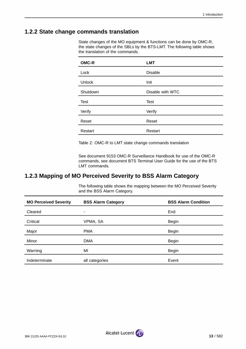
1.2.2 State change commands translation
State changes of the MO equipment & functions can be done by OMC-R,the state changes of the SBLs by the BTS-LMT. The following table showsthe translation of the commands.
OMC-R LMT
Lock Disable
Unlock Init
Shutdown Disable with WTC
Test Test
Verify Verify
Reset Reset
Restart Restart
Table 2: OMC-R to LMT state change commands translation
See document 9153 OMC-R Surveillance Handbook for use of the OMC-Rcommands, see document BTS Terminal User Guide for the use of the BTSLMT commands.
1.2.3 Mapping of MO Perceived Severity to BSS Alarm Category
The following table shows the mapping between the MO Perceived Severityand the BSS Alarm Category.
MO Perceived Severity BSS Alarm Category BSS Alarm Condition
Cleared - End
Critical VPMA, SA Begin
Major PMA Begin
Minor DMA Begin
Warning MI Begin
Indeterminate all categories Event
3BK 21225 AAAA PCZZA Ed.10 13 / 582

1 Introduction
1.3 9153 OMC-R Alarm Surveillance InformationIn the Alarm Surveillance of the 9153 OMC-R efficient means to control,supervise and manage equipment problems in the MFS are provided.
Alarms or Alarm notifications consist of messages sent by network resourcesthat have detected problems or failures in the network. These alarms aredisplayed in lists while alarm counters keep track of statistics. By clicking on analarm in the list, the operator gets detailed information. AS displays informationas described below.
1.3.1 Object Identification
The Object Identification identifies the resource that raised the alarm.
Object identification gives information about:
The resource type (Object Class)
The resource name (Friendly Name). For a board, the Friendly Name alsoshows the board’s location by rack, shelf and slot. For 9100 BTS outdoor
only: If the alarm message displays the RIT location A,0,0, the RIT islocated in the COMI/CODI side compartment.
14 / 582 3BK 21225 AAAA PCZZA Ed.10
1 Introduction
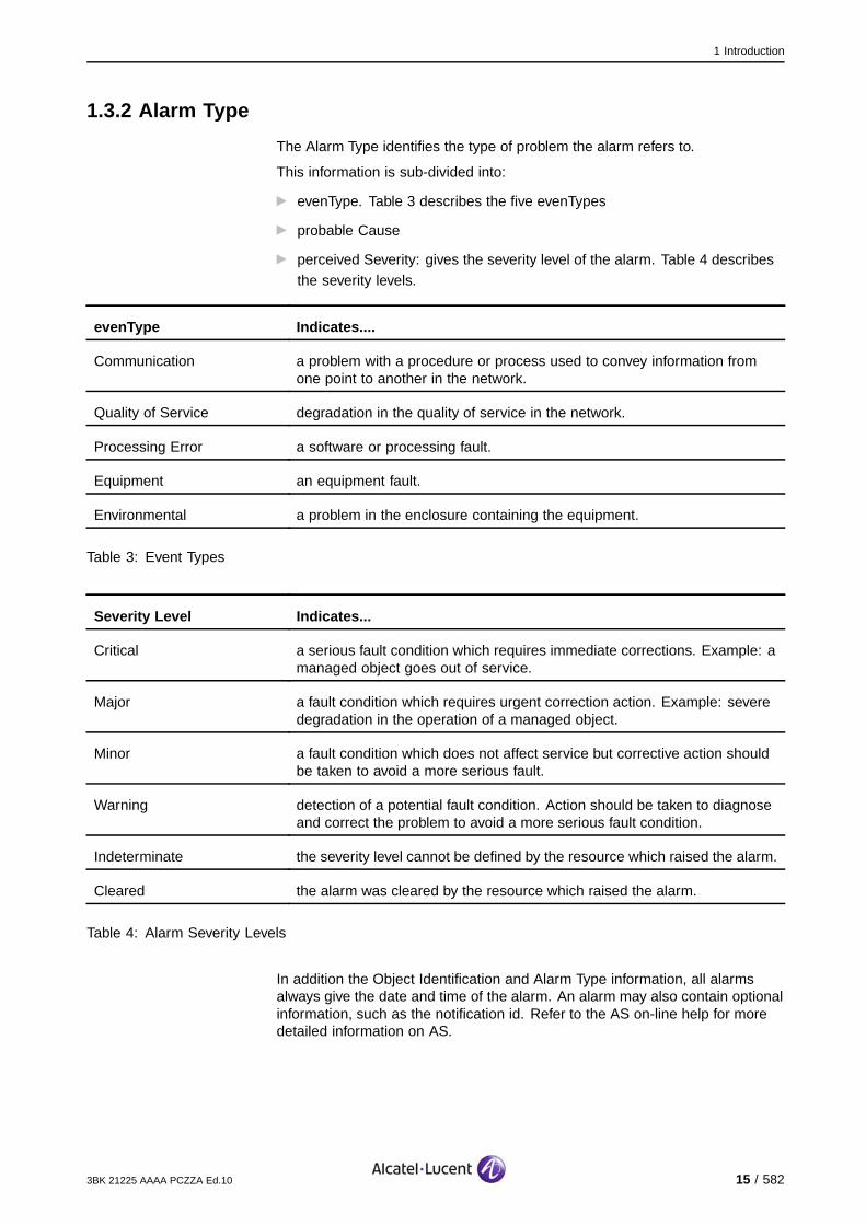
1.3.2 Alarm Type
The Alarm Type identifies the type of problem the alarm refers to.
This information is sub-divided into:
evenType. Table 3 describes the five evenTypes
probable Cause
perceived Severity: gives the severity level of the alarm. Table 4 describesthe severity levels.
evenType Indicates....
Communication a problem with a procedure or process used to convey information fromone point to another in the network.
Quality of Service degradation in the quality of service in the network.
Processing Error a software or processing fault.
Equipment an equipment fault.
Environmental a problem in the enclosure containing the equipment.
Table 3: Event Types
Severity Level Indicates...
Critical a serious fault condition which requires immediate corrections. Example: amanaged object goes out of service.
Major a fault condition which requires urgent correction action. Example: severedegradation in the operation of a managed object.
Minor a fault condition which does not affect service but corrective action shouldbe taken to avoid a more serious fault.
Warning detection of a potential fault condition. Action should be taken to diagnoseand correct the problem to avoid a more serious fault condition.
Indeterminate the severity level cannot be defined by the resource which raised the alarm.
Cleared the alarm was cleared by the resource which raised the alarm.
Table 4: Alarm Severity Levels
In addition the Object Identification and Alarm Type information, all alarmsalways give the date and time of the alarm. An alarm may also contain optionalinformation, such as the notification id. Refer to the AS on-line help for moredetailed information on AS.
3BK 21225 AAAA PCZZA Ed.10 15 / 582
1 Introduction
1.4 LMT Alarm MessagesThe format of Alarms displayed at a LMT differs from that in the OMC-R.
For more information about the BTS LMT see BTS Terminal User Guide.
1.4.1 BTS LMT Alarm Message Parameters
Depending on the type of alarm and in which window it is viewed, an alarmmessage contains all or most of the parameters listed in this section.
1.4.1.1 Message IdentityThe identity number given to the alarm message stored in the database.
1.4.1.2 Event TimeThe time the message was issued at its source or received at the BTS LMT.
1.4.1.3 ClassificationThe characteristics of the alarm, consisting of:
Alarm Class name and number - as shown in the Alarm Dictionary
Alarm Type name and number - as shown in the Alarm Dictionary
Alarm Number - dependent on the Alarm Class and Type. See theappropriate dictionary entry for the valid alarm numbers for a particular alarm
Alarm Condition - has one of the following values:
begin - alarm on. For fatal failures, the affected SBL changes state to
FLT or FOS. For non-fatal failures, the affected SBL changes state to FIT
end - alarm off. Indicates the successful recovery of the system. Theaffected SBL may not change state if other alarms related to the
SBL are on
event - occurrence of anomaly. No action is required unless it occurs
frequently. Event alarms are of short duration and the affected SBLdoes not change state. The system retry/recovery mechanism has
cleared the fault.
1.4.1.4 LocationThe origin of the alarm, consisting of:
Unit type
Unit number
SBL type
SBL number and subnumber, if appropriate.
16 / 582 3BK 21225 AAAA PCZZA Ed.10

1 Introduction
1.4.1.5 SBL StatesIf a fatal alarm occurs and the affected SBL changes state to FOS, the systemisolates the faulty equipment if it cannot be initialized. After a repair action, theoperator normally initializes the equipment.
If a fatal alarm occurs and the affected SBL changes state to FLT, the systemresets the faulty equipment. When the alarm ceases, the system automaticallyinitializes the equipment.
If a non-fatal alarm or event occurs, the affected SBL’s are put into the FIT state.In the worst situation, the equipment operates in a degraded mode.
An SBL has one of the following (current) states:
IT
FIT
Faulty
EF
FOS
OPR
SOS
WTC
UT
NEQ
MSD
MSD AUTO
Refer to the document Operations & Maintenance Principles for a descriptionof the states.
1.4.1.6 Suspected RITThe information for the suspected RIT is displayed if the system is able todetermine the location of the fault.
The information consists of:
Unit type
Unit number
RIT type
Physical location - the position of the RIT board within the cabinet,defined for the rack, shelf and slot. For 9100 BTS outdoor only: If the
alarm message displays the RIT location A,0,0, the RIT is located in theCOMI/CODI side compartment.
If more than one RIT is shown in the list, the RIT most likely to be causing thefault is indicated. Replace this RIT first and initialize it. If the fault persists,replace another RIT from the list and initialize it.
3BK 21225 AAAA PCZZA Ed.10 17 / 582
1 Introduction
1.4.1.7 Additional InformationSome alarms provide additional information. If the additional information isdisplayed as a text message, the original information from the BSS has beendecoded.
If the additional information is not decoded, it is displayed as pairs ofhexadecimal digits. At the BTS terminal, the additional information consistsof numbers in the range 0 to 255. Each number represents the contentsof one pair of digits.
Decoding additional information digits is described in section 13.
Decoding Additional Information from AlarmsDecoding BTS or BSC additional information must only be attempted byAlcatel-Lucent support personnel.If a fault persists after corrective actions have been taken, send a copy of thealarm message containing the additional information to the Alcatel-Lucentsupport office.
18 / 582 3BK 21225 AAAA PCZZA Ed.10
1 Introduction
1.5 BTS Alarm InformationThis section describes the definition of alarms as they appear on the OMC-Rand the alarm description given in the document.
1.5.1 Alarm Definition
The alarms are defined as follows:
1.5.1.1 specific ProblemsThis parameter, when present, identifies further refinements to the probableCause of the alarm. It qualifies the chosen probable Cause and may beused by the managed object class to specify a set of identifiers for use inmanaged object classes. The parameter is either a set of integers or a setof object identifiers.
1.5.1.2 eventTypeThe eventType attribute identifies the basic type of the alarm.
It provides a list of standard types:
Communication: associated with the procedures and/or processes required
to convey information from one point to another.
Quality of Service: associated with a degradation of the quality of service.
Processing Error: associated with a software or processing fault.
Equipment: associated with an equipment fault.
Environmental: associated with a condition relating to an enclosure inwhich the equipment resides.
1.5.1.3 probable CauseThis attribute defines the probable cause of the alarm. Its value belongs toa set of possible values either defined in recommendation X.721, M3100and GSM 11.12 or defined for a particular Telecommunication ManagementNetwork (TMN) project.
1.5.1.4 perceived SeverityThis attribute defines six severity levels. The severity levels indicate how thecapability of the managed object is affected.
The levels are:
Critical: indicates that an immediate corrective action is required. This
severity is reported, when a managed object becomes totally out of serviceand its capability must be restored.
Major: indicates that an urgent corrective action is required. This severity
is reported, when there is a severe degradation in the capability of themanaged object and its full capability must be restored.
Minor: indicates a non-service affecting fault condition and that corrective
action should be taken in order to prevent a more serious fault. This severityis reported, when the detected alarm condition is not currently degrading the
capacity of the managed object.
3BK 21225 AAAA PCZZA Ed.10 19 / 582

1 Introduction
Warning: indicates a potential or impending fault, before any significanteffect have been felt. Action(s) should be taken to further diagnose (if
necessary) and correct the problem in order to prevent it from becoming amore serious service affecting fault.
Indeterminate: indicates that the severity level cannot be defined by the
resource raising the alarm.
Cleared: indicates the clearing of one or more previously alarms for this
managed object with the same Alarm type, Probable Cause and Specificproblems (if given).
1.5.2 Alarm Description
1.5.2.1 BannerEach BSS alarm definition starts with an identification banner which allows thelocation of the appropriate definition. It takes the form:
[7,246] FU CONFIG-FAIL
1.5.2.2 Alarm DescriptionAlarm Description describes the alarm and, where appropriate, the differencesto the default perceived severities and alarm numbers.
1.5.2.3 Impact on SystemThe description of the impact on Telecom and O&M system contains a tableindicating which part of the system is affected by the fault in terms of loss,degradation or none.
For example, if a cell is affected, the cell column in the table contains acheck (X) in either the Loss or Degradation row. For different impact cases(redundancy, diversity, etc.) other symbols are used.
The table shows the worst case, even though redundancy may be provided.
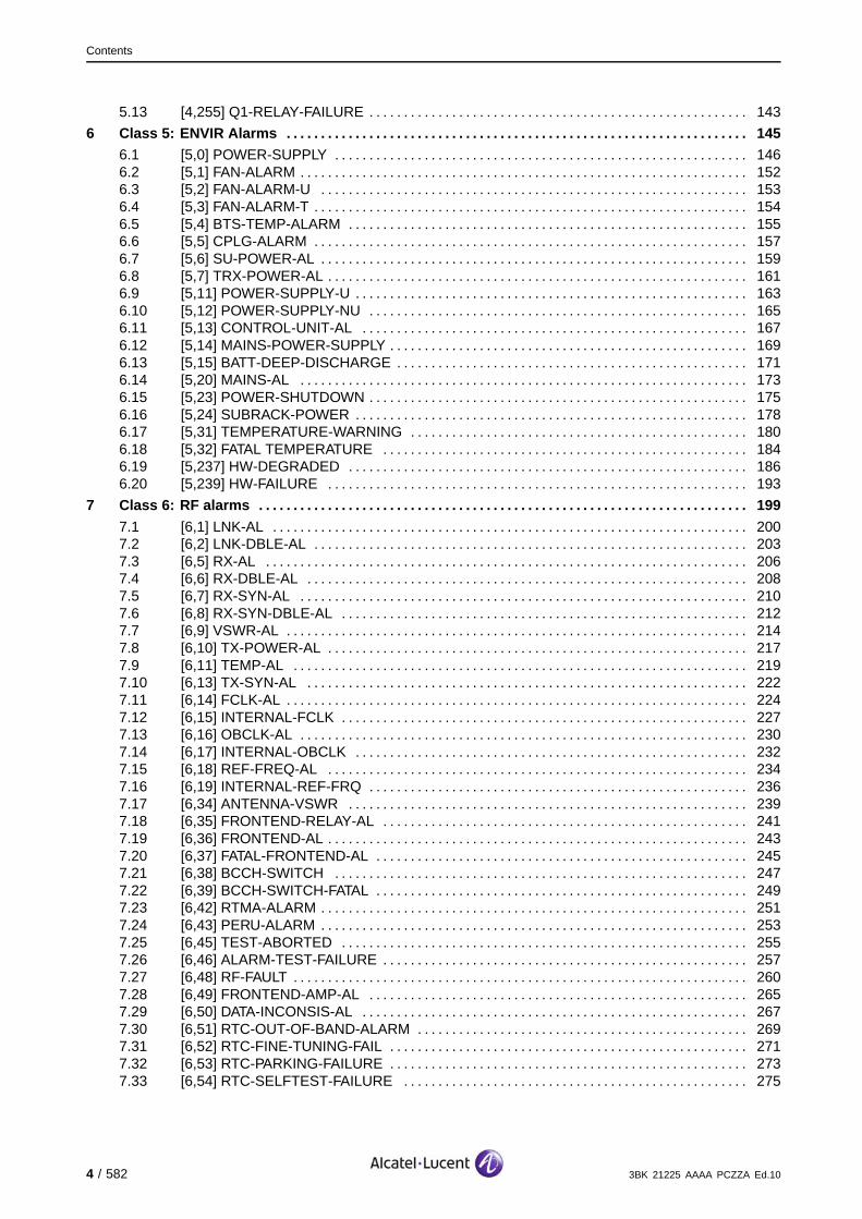
1.5.2.4 Corrective ActionsSo solve the current alarm a graphical workflow chart is used. It shows therequired procedures by checks, tests and actions to determine the fault andfinally to solve the alarm.
Checks, tests and thus resulting corrective actions are provided with apriority on remote at the OMC-R and then by service on-site, to minimize themaintenance effort.
By clicking on a dedicated action field, a link to the detailed description of thetask will be opened.
20 / 582 3BK 21225 AAAA PCZZA Ed.10

1 Introduction
[1,1] OCXO−AL
Alarmsolved
yesClock operational?
no
On−site
G1:Replace MCLU,
MCLR
On−site
no
ContactSystem Support
Lock Function CLLK
Unlock Function CLLK
G1:Replace MFG
G2:Replace STSE,
STSP, STSR
Clock operational?
yes Alarmsolved
On−site
OR OR
Start field with alarm numberand alarm name
Remote action fields
On−site action fields
End fields
Figure 1: Graphical workflow for corrective actions
This figure shows an example of a graphical workflow and describes thedifferent flowchart fields. Useful hints for safety and required tools are addedas appropriate.
3BK 21225 AAAA PCZZA Ed.10 21 / 582

1 Introduction
1.5.3 Additional Information
section BTS Alarm Additional Information (Section 13) describes the decodingof the additional information.
Some alarms provide additional information. If the additional information isdisplayed as a text message, the original information from the BSS has beendecoded.
If the additional information is not decoded, it is displayed as pairs ofhexadecimal digits. At the BSC terminal, the additional information consistsof numbers in the range 0 to 255. Each number represents the contentsof one pair of digits.
Decoding Additional Information from AlarmsDecoding BSC additional information must only be attempted by Alcatel-Lucentsupport personnel.If a fault persists after corrective actions have been taken, send a copy of thealarm message containing the additional information to the Alcatel-Lucentsupport office.
22 / 582 3BK 21225 AAAA PCZZA Ed.10
2 Class 1: CLK Alarms
2 Class 1: CLK Alarms
This section defines the alarms for the Class 1: CLK alarm class.
3BK 21225 AAAA PCZZA Ed.10 23 / 582
2 Class 1: CLK Alarms
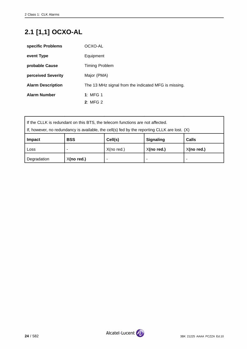
2.1 [1,1] OCXO-AL
specific Problems OCXO-AL
event Type Equipment
probable Cause Timing Problem
perceived Severity Major (PMA)
Alarm Description The 13 MHz signal from the indicated MFG is missing.
Alarm Number 1: MFG 1
2: MFG 2
If the CLLK is redundant on this BTS, the telecom functions are not affected.
If, however, no redundancy is available, the cell(s) fed by the reporting CLLK are lost. (X)
Impact BSS Cell(s) Signaling Calls
Loss - X(no red.) X(no red.) X(no red.)
Degradation X(no red.) - - -
24 / 582 3BK 21225 AAAA PCZZA Ed.10
2 Class 1: CLK Alarms
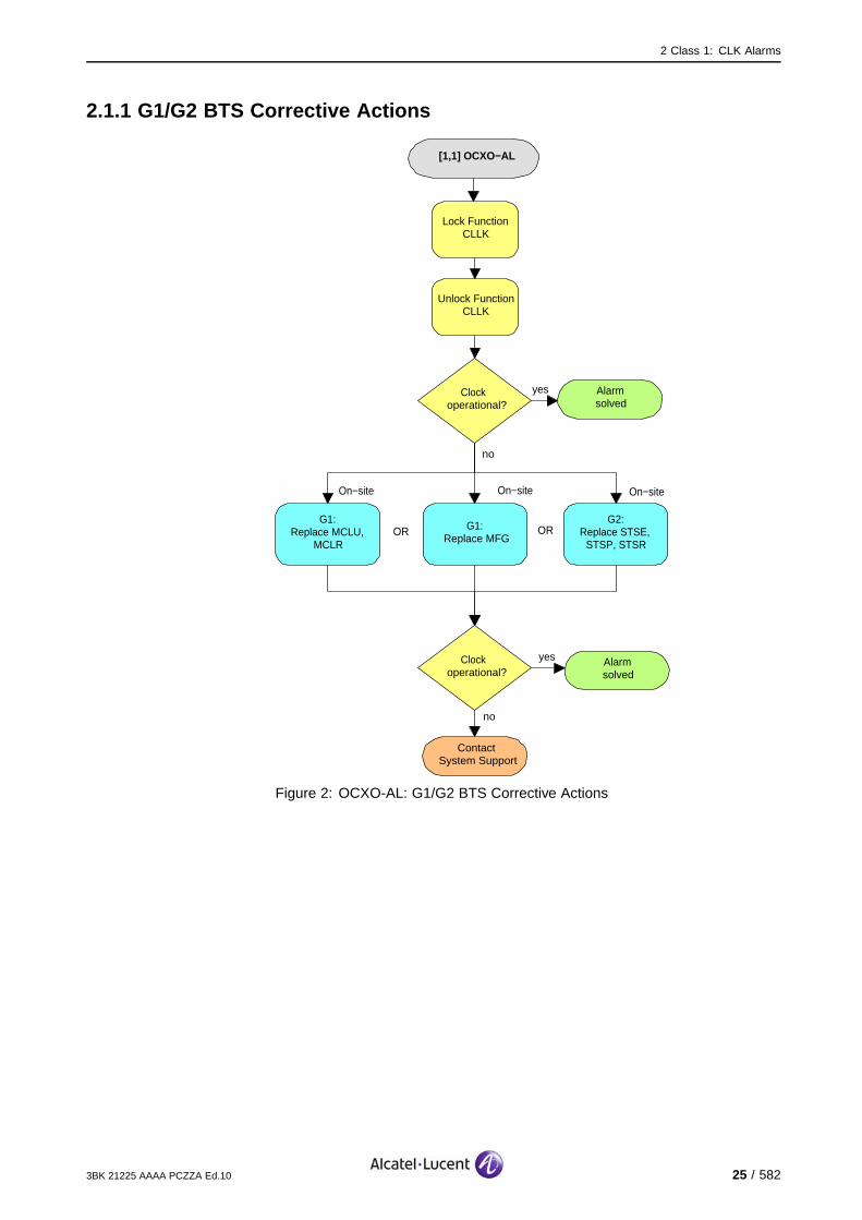
2.1.1 G1/G2 BTS Corrective Actions
[1,1] OCXO−AL
Alarmsolved
yesClock operational?
no
On−site
G1:Replace MCLU,
MCLR
On−site
no
ContactSystem Support
Lock Function CLLK
Unlock Function CLLK
G1:Replace MFG
G2:Replace STSE,
STSP, STSR
Clock operational?
yes Alarmsolved
On−site
OR OR
Figure 2: OCXO-AL: G1/G2 BTS Corrective Actions
3BK 21225 AAAA PCZZA Ed.10 25 / 582

2 Class 1: CLK Alarms
2.2 [1,3] CLOCK-FREQ-AL
specific Problems CLOCK-FREQ-AL
event Type Equipment
probable Cause Timing Problem
perceived Severity Major (PMA)
Alarm Description The clock signal from the MFG is not reliable due to the reason indicatedby the Alarm Number.
Alarm Number 1: Default value (G1 & G2 BTS: The problem cannot be analyzed further).
2: The operational temperature is outside the permitted limits (G2 BTS).
3: There is a tuning problem due to malfunctioning of the digital-analog-loop (G2 BTS).
4: EEPROM problems detected (G2 BTS).
If the CLLK is redundant on this BTS, the telecom functions are not affected.
If, however, no redundancy is available, the clock system is not reliable. Thus the telecom functions on thecell(s) fed by the indicated MFG can be affected. Degradation in transmission quality can arise on thesecell(s), e.g., BER increasing, interference and handover problems.
Impact BSS Cell(s) Signaling Calls
Loss - - - -
Degradation X(no red.) X(no red.) X(no red.) X(no red.)
Required tools and materials:
Thermometer
Replacement tools, see appropriate replacement procedure.
26 / 582 3BK 21225 AAAA PCZZA Ed.10
2 Class 1: CLK Alarms
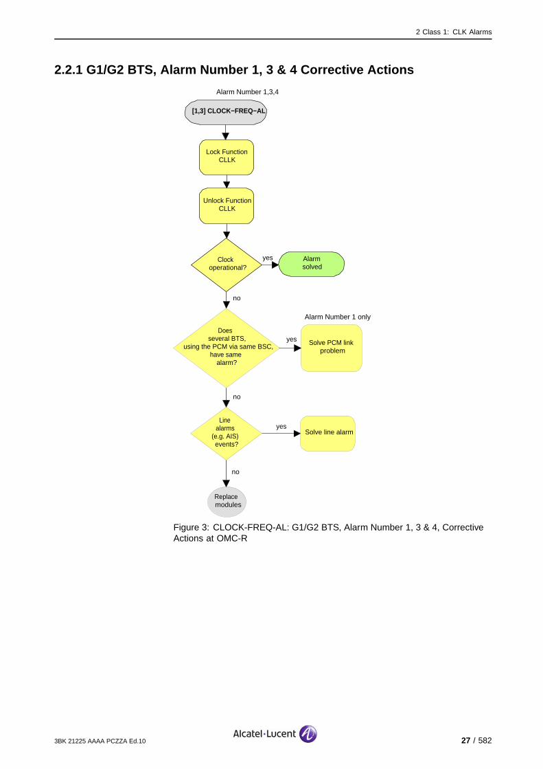
2.2.1 G1/G2 BTS, Alarm Number 1, 3 & 4 Corrective Actions
[1,3] CLOCK−FREQ−AL
Alarmsolved
yesClock operational?
no
Lock Function CLLK
Unlock Function CLLK
Does several BTS,
using the PCM via same BSC, have same
alarm?
Solve PCM link problem
yes
no
no
Line alarms
(e.g. AIS) events?
Solve line alarmyes
Replace modules
Alarm Number 1,3,4
Alarm Number 1 only
Figure 3: CLOCK-FREQ-AL: G1/G2 BTS, Alarm Number 1, 3 & 4, CorrectiveActions at OMC-R
3BK 21225 AAAA PCZZA Ed.10 27 / 582
2 Class 1: CLK Alarms
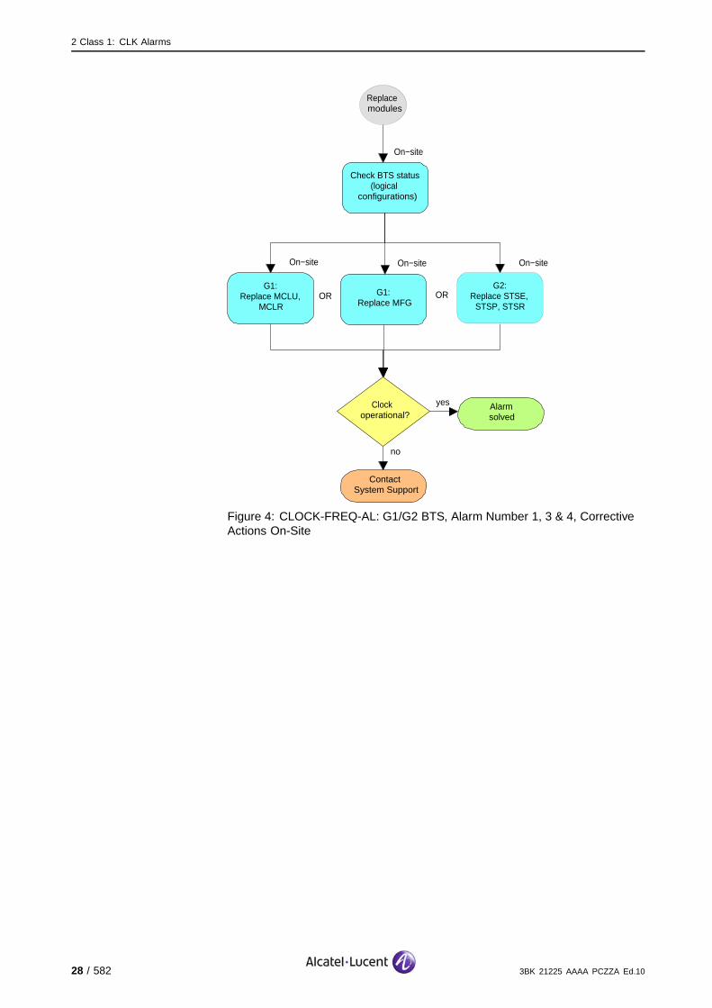
On−site
Check BTS status (logical
configurations)
On−site
no
ContactSystem Support
G1:Replace MCLU,
MCLR
G1:Replace MFG
Clock operational?
yes Alarmsolved
On−site
G2:Replace STSE,
STSP, STSR
On−site
Replace modules
OR OR
Figure 4: CLOCK-FREQ-AL: G1/G2 BTS, Alarm Number 1, 3 & 4, CorrectiveActions On-Site
28 / 582 3BK 21225 AAAA PCZZA Ed.10
2 Class 1: CLK Alarms
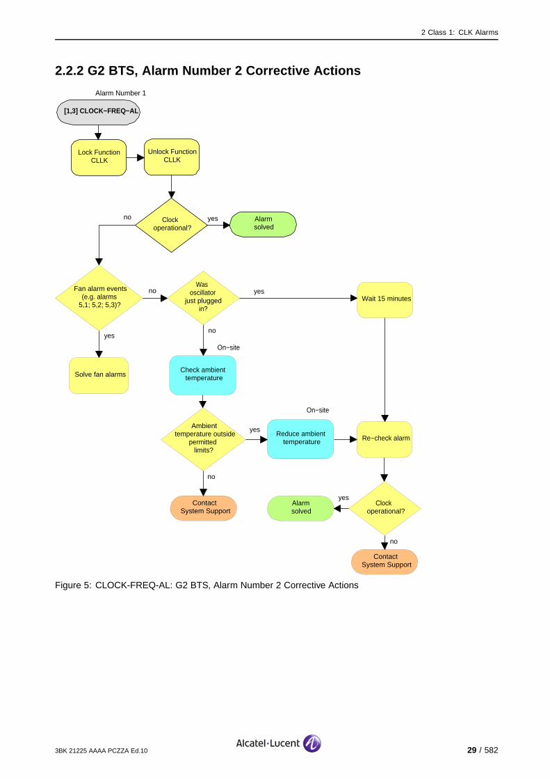
2.2.2 G2 BTS, Alarm Number 2 Corrective Actions
[1,3] CLOCK−FREQ−AL
Alarmsolved
yesClock operational?
no
Lock Function CLLK
Unlock Function CLLK
Fan alarm events (e.g. alarms 5,1; 5,2; 5,3)?
Solve fan alarms
yes
no
noWas
oscillator just plugged
in?
Wait 15 minutesyes
Re−check alarm
On−site
Check ambient temperature
no
ContactSystem Support
Clock operational?
yesAlarmsolved
Reduce ambient temperature
On−site
Ambient temperature outside
permitted limits?
no
yes
ContactSystem Support
Alarm Number 1
Figure 5: CLOCK-FREQ-AL: G2 BTS, Alarm Number 2 Corrective Actions
3BK 21225 AAAA PCZZA Ed.10 29 / 582

2 Class 1: CLK Alarms
2.3 [1,6] MCL-FATAL-AL
specific Problems MCL-FATAL-AL
event Type Equipment
probable Cause Equipment Malfunction
perceived Severity Major (PMA)
Alarm Description Fatal internal alarm on the Clock Unit.
If the CLLK is redundant on this BTS, the telecom functions are not affected.
If no redundancy is available however, the cell(s) fed by the reporting CLLK are lost.
9100 BTS: There is no clock redundancy available, so the cells fed by the reporting CLLK are lost, thusthe BTS is lost.
Impact BSS Cell(s) Signaling Calls
Loss - X(no red.) X(no red.) X(no red.)
Degradation X(no red.) - - -
30 / 582 3BK 21225 AAAA PCZZA Ed.10

2 Class 1: CLK Alarms
2.3.1 G1/G2 BTS Corrective Actions
[1,6] MCL−FATAL−AL
Alarmsolved
yesClock operational?
no
On−site
G1:Replace MCLU,
MCLR
On−site
no
ContactSystem Support
Lock Function CLLK
Unlock Function CLLK
G1:Replace MFG
G2:Replace STSE,
STSP, STSR
Clock operational?
yes Alarmsolved
On−site
On−site
Check BTS status (logical configuration)
OR OR
Figure 6: MCL-FATAL-AL: G1/G2 BTS Corrective Actions
3BK 21225 AAAA PCZZA Ed.10 31 / 582
2 Class 1: CLK Alarms
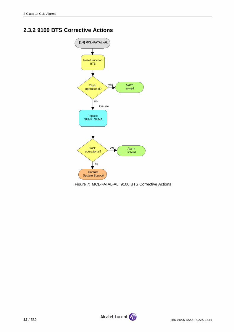
2.3.2 9100 BTS Corrective Actions
[1,6] MCL−FATAL−AL
Alarmsolved
yesClock operational?
no
On−site
no
ContactSystem Support
Reset Function BTS
Replace SUMP, SUMA
Clock operational?
yes Alarmsolved
Figure 7: MCL-FATAL-AL: 9100 BTS Corrective Actions
32 / 582 3BK 21225 AAAA PCZZA Ed.10
2 Class 1: CLK Alarms
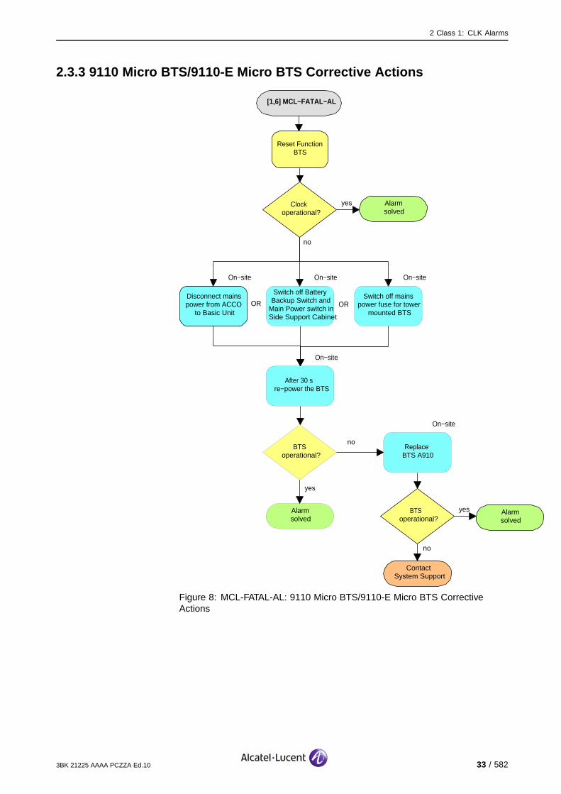
2.3.3 9110 Micro BTS/9110-E Micro BTS Corrective Actions
[1,6] MCL−FATAL−AL
Alarmsolved
yesClock operational?
no
On−site
no
ContactSystem Support
Reset Function BTS
Disconnect mains power from ACCO
to Basic Unit
BTS operational?
yes Alarmsolved
On−site
After 30 s re−power the BTS
On−site
Switch off Battery Backup Switch and
Main Power switch in Side Support Cabinet
On−site
Switch off mains power fuse for tower
mounted BTSOR OR
On−site
Replace BTS A910
noBTS
operational?
yes
Alarmsolved
Figure 8: MCL-FATAL-AL: 9110 Micro BTS/9110-E Micro BTS CorrectiveActions
3BK 21225 AAAA PCZZA Ed.10 33 / 582

2 Class 1: CLK Alarms
2.4 [1,7] MCL-TEST-AL
specific Problems MCL-TEST-AL
event Type Equipment
probable Cause Equipment Malfunction
perceived Severity Major (PMA)
Alarm Description There is an internal selftest alarm on a clock unit.
If the CLLK is redundant on this BTS the telecom functions are not affected.
If, however, no redundancy is available, the cell(s) fed by the reporting CLLK are lost.
Impact BSS Cell(s) Signaling Calls
Loss - X(no red.) X(no red.) X(no red.)
Degradation X(no red.) - - -
34 / 582 3BK 21225 AAAA PCZZA Ed.10

2 Class 1: CLK Alarms
2.4.1 Corrective Actions
[1,7] MCL−TEST−AL
Alarmsolved
yesClock operational?
no
On−site
G1:Replace MCLU,
MCLR
On−site
no
ContactSystem Support
Lock Function CLLK
Unlock Function CLLK
G1:Replace MFG
G2:Replace STSE,
STSP, STSR
Clock operational?
yes Alarmsolved
On−site
OR OR
Figure 9: MCL-TEST-AL: Corrective Actions
3BK 21225 AAAA PCZZA Ed.10 35 / 582
2 Class 1: CLK Alarms
2.5 [1,8] MCL-DRV-AL
specific Problems MCL-DRV-AL
event Type Equipment
probable Cause InputOutputDeviceError
perceived Severity Major (PMA)
Alarm Description There is a fault on the output drivers of a clock unit.
If the CLLK is redundant on this BTS the telecom functions are not affected.
If, however, no redundancy is available, the cell(s) fed by the reporting CLLK are lost.
Impact BSS Cell(s) Signaling Calls
Loss - X(no red.) X(no red.) X(no red.)
Degradation X(no red.) - - -
36 / 582 3BK 21225 AAAA PCZZA Ed.10
2 Class 1: CLK Alarms
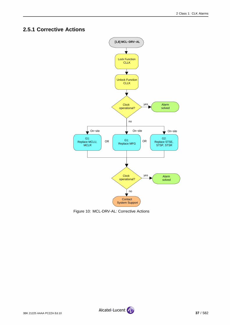
2.5.1 Corrective Actions
[1,8] MCL−DRV−AL
Alarmsolved
yesClock operational?
no
On−site
G1:Replace MCLU,
MCLR
On−site
no
ContactSystem Support
Lock Function CLLK
Unlock Function CLLK
G1:Replace MFG
G2:Replace STSE,
STSP, STSR
Clock operational?
yes Alarmsolved
On−site
OR OR
Figure 10: MCL-DRV-AL: Corrective Actions
3BK 21225 AAAA PCZZA Ed.10 37 / 582

2 Class 1: CLK Alarms
2.6 [1,11] MCLU-FAULT
specific Problems MCLU-FAULT
event Type Equipment
probable Cause Timing Problem
perceived Severity Minor (DMA)
Alarm Description The reporting clock unit has detected a fault on the MFG indicated.However, this fault has not yet been detected by the redundant clock unit.The input driver of the reporting clock unit may be faulty, or a replacementof a faulty MFG can still be underway.
Alarm Number 1: MFG 1
2: MFG 2
Telecom functions are not affected.
Impact BSS Cell(s) Signaling Calls
Loss - - - -
Degradation - - - -
38 / 582 3BK 21225 AAAA PCZZA Ed.10
2 Class 1: CLK Alarms
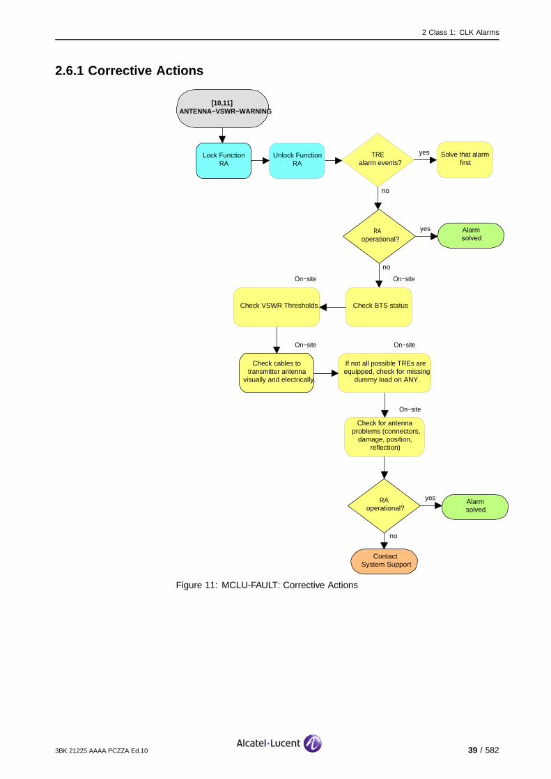
2.6.1 Corrective Actions
[10,11] ANTENNA−VSWR−WARNING
Alarmsolved
yesRA operational?
no
On−site
no
ContactSystem Support
Lock Function RA
Check cables to transmitter antenna
visually and electrically.
RAoperational?
yes Alarmsolved
On−site
Check VSWR Thresholds
On−site
Unlock Function RA
yesTRE alarm events?
no
Solve that alarm first
Check BTS status
On−site
If not all possible TREs are equipped, check for missing
dummy load on ANY.
On−site
Check for antenna problems (connectors,
damage, position, reflection)
Figure 11: MCLU-FAULT: Corrective Actions
3BK 21225 AAAA PCZZA Ed.10 39 / 582

2 Class 1: CLK Alarms
2.7 [1,12] CLOCK-FAULT
specific Problems CLOCK-FAULT
event Type Equipment
probable Cause Timing Problem
perceived Severity Major (PMA), Minor (DMA)
Alarm Description Major (PMA)/Minor (DMA): Fault on the clock signals detected by severalclock users in the BTS (e.g. FHU, CU, FU).
Major (PMA): If the CLLK alarm disappears and the OMU loses the alarminformation, this alarm is sent by the OMU as a dummy alarm. It indicatesthat the CLLK is FOS and requires operator initialization.
If the alarm has unknown cause, it indicates that more detailed alarmswere reported before and are available at OMC-R.
If the clock system is redundant on this BTS, the telecom functions are not affected.
If, however, no redundancy is available, the channels supported by the CLLK/CLDB are lost.
9100 BTS: There is no clock redundancy available, so the cells fed by the reporting CLLK are lost, thusthe BTS is lost.
Impact BSS Cell(s) Signaling Calls
Loss - X(no red.) X(no red.) X(no red.)
Degradation X(no red.) - - -
40 / 582 3BK 21225 AAAA PCZZA Ed.10

2 Class 1: CLK Alarms
2.7.1 G1/G2 BTS Corrective Actions
[1,12] CLOCK−FAULT
Alarmsolved
yes
Clock operational?
no
On−site
G1:Replace MCLU,
MCLR
On−site
no
ContactSystem Support
Lock Function CLLK
Unlock Function CLLK
G1:Replace MFG
G2:Replace STSE,
STSP, STSR
Clock operational?
yes Alarmsolved
On−site
Check cables amd connectors to
cabinet
On−site
Check CLDBs of cabinet
On−site
Alarmsolved
yesClock operational?
no
OR OR
Figure 12: CLOCK-FAULT: G1/G2 BTS Corrective Actions
3BK 21225 AAAA PCZZA Ed.10 41 / 582

2 Class 1: CLK Alarms
2.7.2 9100 BTS Corrective Actions
[1,12] CLOCK−FAULT
Alarmsolved
yesClock operational?
no
On−site
no
ContactSystem Support
Reset Function BTS
Replace SUMP, SUMA
Clock operational?
yes Alarmsolved
Figure 13: CLOCK-FAULT: 9100 BTS Corrective Actions
42 / 582 3BK 21225 AAAA PCZZA Ed.10

2 Class 1: CLK Alarms
2.7.3 9110 Micro BTS/9110-E Micro BTS Corrective Actions
[1,12] CLOCK−FAULT
Alarmsolved
yesClock operational?
no
On−site
no
ContactSystem Support
Reset Function BTS
Disconnect mains power from ACCO
to Basic Unit
BTS operational?
yes Alarmsolved
On−site
After 30 s re−power the BTS
On−site
Switch off Battery Backup Switch and
Main Power switch in Side Support Cabinet
On−site
Switch off mains power fuse for tower
mounted BTS
OR OR
On−site
Replace BTS A910
noBTS
operational?
yes
Alarmsolved
Figure 14: CLOCK-FAULT: 9110 Micro BTS/9110-E Micro BTS CorrectiveActions
3BK 21225 AAAA PCZZA Ed.10 43 / 582
2 Class 1: CLK Alarms
2.8 [1,22] MCLR-EA-AL
specific Problems MCL-EA-AL
event Type Equipment
probable Cause Timing Problem
perceived Severity Major (PMA)
Alarm Description At least one of the clock signals (Frame Number, Frame Clock, Octal BitClock, 2.6 MHz signal) sent by the clock unit in the master BTS (G1 BTS:MCLU, G2 BTS: STSE) is not received by the clock unit in the slave BTS(G1 BTS: MCLR, G2 BTS: STSR).
If an alarm on the feeding clock unit of the master BTS is still outstanding,the failure is due to external reasons.
If the CLLK is redundant on this BTS the telecom functions are not affected.
If, however, no redundancy is available, the cell(s) fed by the reporting CLLK are lost.
Impact BSS Cell(s) Signaling Calls
Loss - X(no red.) X(no red.) X(no red.)
Degradation X(no red.) - - -
44 / 582 3BK 21225 AAAA PCZZA Ed.10
2 Class 1: CLK Alarms
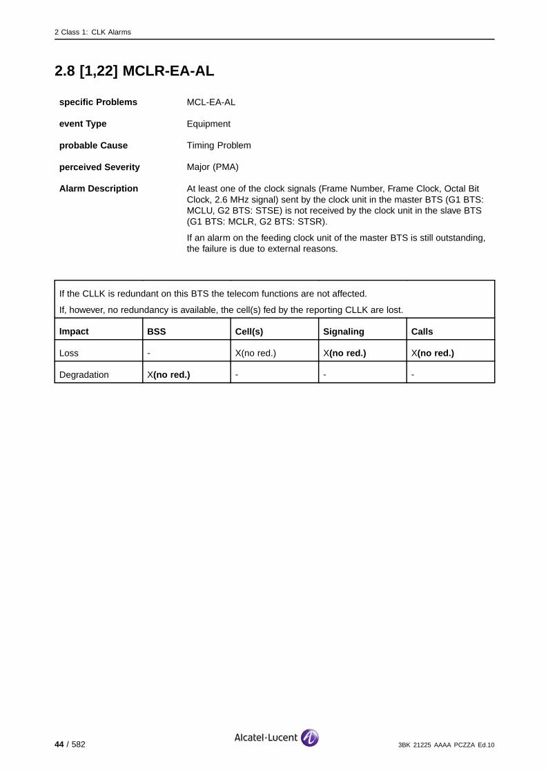
2.8.1 Corrective Actions
[1,22] MCLR−EA−AL
Alarmsolved
yesClock operational?
no
On−site
G1:Replace MCLU,
MCLR
On−site
no
ContactSystem Support
Lock Function CLLK
Unlock Function CLLK
G1:Replace MFG
G2:Replace STSE,
STSP, STSR
Clock operational?
yes Alarmsolved
On−site
yesMaster clock
alarm(s) events?
Solve Master clock alarm
no
OR OR
Figure 15: MCL-EA-AL: Corrective Actions
3BK 21225 AAAA PCZZA Ed.10 45 / 582

2 Class 1: CLK Alarms
2.9 [1,23] PCM-SYNC-AL
specific Problems PCM-SYNC-AL
event Type Communication
probable Cause Loss Of Signal
perceived Severity Minor (DMA)
Alarm Description The MFG has lost synchronisation with the signal from the PCM AbisHighway.
Telecom functions are not affected.
Impact BSS Cell(s) Signaling Calls
Loss - - - -
Degradation - - - -
46 / 582 3BK 21225 AAAA PCZZA Ed.10
2 Class 1: CLK Alarms
2.9.1 G1/G2 BTS Corrective Actions
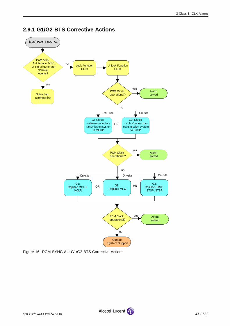
[1,23] PCM−SYNC−AL
Alarmsolved
yesPCM Clock operational?
no
On−site
G1:Replace MCLU,
MCLR
On−site
no
ContactSystem Support
Lock Function CLLK
Unlock Function CLLK
G1:Replace MFG
G2:Replace STSE,
STSP, STSR
PCM Clock operational?
yes Alarmsolved
On−site
yes
PCM Abis, A−Interface, MSC
or signal generator alarm(s) events?
Solve that alarm(s) first
no
OR OR
On−site
G1:Check cables/connectors
transmission system to MFGP
G2: Check cables/connectors
transmission system to STSP
On−site
OR
Alarmsolved
yesPCM Clock operational?
no
Figure 16: PCM-SYNC-AL: G1/G2 BTS Corrective Actions
3BK 21225 AAAA PCZZA Ed.10 47 / 582

2 Class 1: CLK Alarms
2.10 [1,31] MCL-XCLK
specific Problems MCL-XCLK
event Type Equipment
probable Cause Equipment Malfunction
perceived Severity Major (PMA)
Alarm Description An error has been detected in the input of the External Reference Clock.
Alarm Number 1: Loss of input signal clock from external reference clock, in slave mode.
2: Loss of Frame Number input, in slave mode.
3: Loss of Frame Signal, in slave mode.
If the CLLK is redundant on this BTS the telecom functions are not affected.
If, however, no redundancy is available, the cell(s) fed by the reporting CLLK are lost.
Impact BSS Cell(s) Signaling Calls
Loss - X(no red.) X(no red.) X(no red.)
Degradation X(no red.) - - -
48 / 582 3BK 21225 AAAA PCZZA Ed.10

2 Class 1: CLK Alarms
2.10.1 9100 BTS Corrective Actions
[1,31] MCL−XCLK
Alarmsolved
yesClock operational?
no
On−site
no
ContactSystem Support
Solve that alarm(s) first
Replace SUMP, SUMA
Clock operational?
yes Alarmsolved
On−site
Check cables/connectors between clock unit on master BTS and reporting clock unit
yes
Alarm on feeding clock unit
of master BTS events?
noReset Function
BTS
Figure 17: MCL-XCLK: 9100 BTS Corrective Actions
3BK 21225 AAAA PCZZA Ed.10 49 / 582

2 Class 1: CLK Alarms
2.10.2 9110 Micro BTS/9110-E Micro BTS Corrective Actions
[1,31] MCL−XCLK
On−site
no
ContactSystem Support
Disconnect mains power from ACCO
to Basic Unit
BTS operational?
yesAlarmsolved
On−site
After 30 s re−power the BTS
On−site
Switch off Battery Backup Switch and
Main Power switch in Side Support Cabinet
On−site
Switch off mains power fuse for tower
mounted BTS
OR
OR
On−site
Replace BTS A910
no BTSoperational?
yes
Alarmsolved
Alarmsolved
yes
Clock operational?
noSolve that alarm(s) first
On−site
Check cables/connectors between clock unit on master BTS and reporting clock unit
yes
Alarm on feeding clock unit
of master BTS events?
noReset Function
BTS
Figure 18: MCL-XCLK: 9110 Micro BTS/9110-E Micro BTS Corrective Actions
50 / 582 3BK 21225 AAAA PCZZA Ed.10

2 Class 1: CLK Alarms
2.11 [1,234] IOM-DISCONNECTION
specific Problems IOM-DISCONNECTION
event Type Equipment
probable Cause Equipment Malfunction
perceived Severity Minor (DMA)
Alarm Description There is a loss of communication with the clock on the IOM bus.
Telecom functions are not affected.
Impact BSS Cell(s) Signaling Calls
Loss - - - -
Degradation - - - -
2.11.1 Corrective Actions
Contact your Alcatel-Lucent system support.
3BK 21225 AAAA PCZZA Ed.10 51 / 582

2 Class 1: CLK Alarms
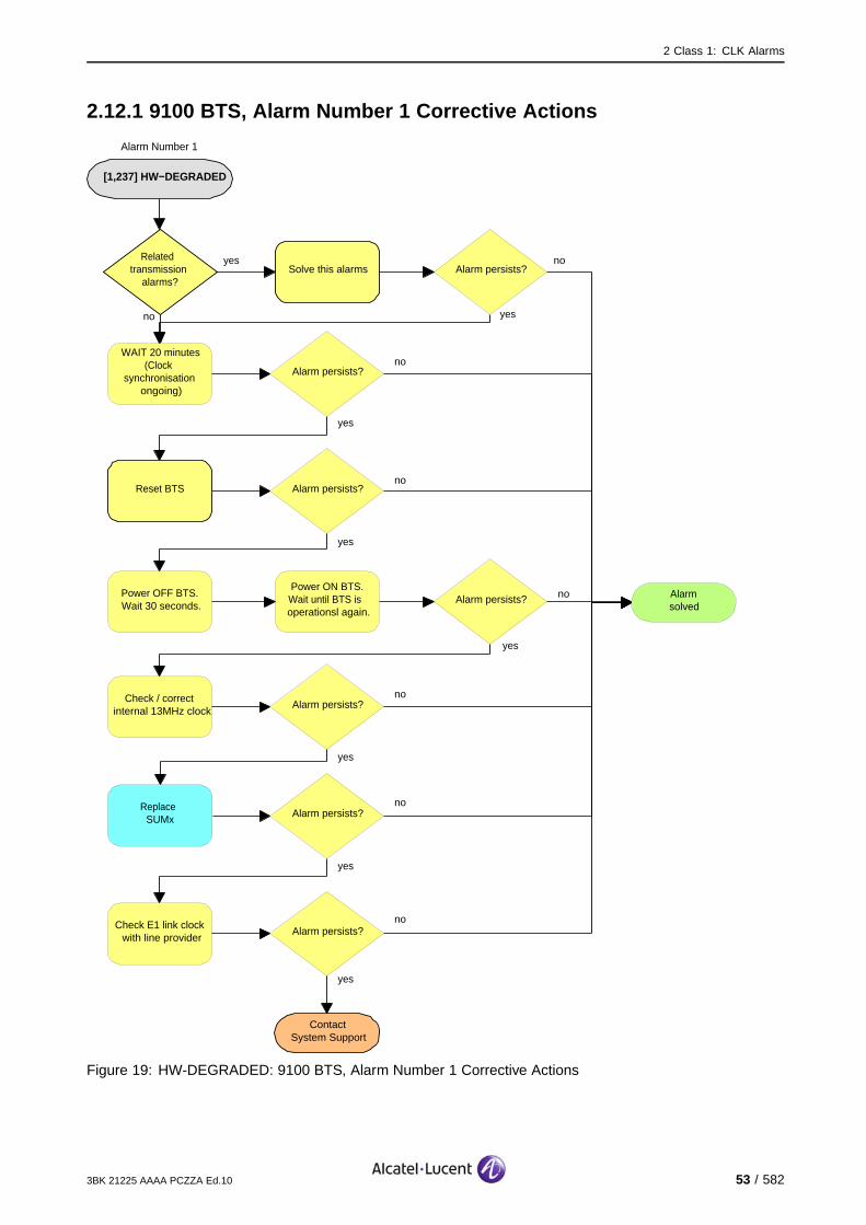
2.12 [1,237] HW-DEGRADED
specific Problems HW-DEGRADED
event Type Equipment
probable Cause Equipment Malfunction
perceived Severity Minor (DMA), Warning (MI)
Alarm Description The processing of the clock is degraded.
Alarm Number 1: The PCM synchronization is not available.
2: The GPS synchronization is lost.
Telecom functions are not affected.
Impact BSS Cell(s) Signaling Calls
Loss - - - -
Degradation - - - -
Required tools and materials:
PCM test tools
GPS test tools
Replacement tools, see appropriate replacement procedure.
52 / 582 3BK 21225 AAAA PCZZA Ed.10
2 Class 1: CLK Alarms
2.12.1 9100 BTS, Alarm Number 1 Corrective Actions
[1,237] HW−DEGRADED
no
ContactSystem Support
Reset BTS
yes
yesRelated transmission
alarms?
no
Solve this alarms
Alarmsolved
no
yes
Alarm Number 1
Alarm persists?
WAIT 20 minutes(Clock
synchronisation ongoing)
Alarm persists?
Alarm persists?
Power OFF BTS.Wait 30 seconds.
Power ON BTS.Wait until BTS is operationsl again.
Alarm persists?
Check / correct internal 13MHz clock
Alarm persists?
Check E1 link clock with line provider
Replace SUMx
Alarm persists?
Alarm persists?
yes
yes
yes
yes
yes
no
no
no
no
no
Figure 19: HW-DEGRADED: 9100 BTS, Alarm Number 1 Corrective Actions
3BK 21225 AAAA PCZZA Ed.10 53 / 582

2 Class 1: CLK Alarms
2.12.2 9100 BTS, Alarm Number 2 Corrective Actions
[1,237] HW−DEGRADED
Alarm Number 2
no
ContactSystem Support
Reset BTS
yes
yesRelated transmission
alarms?
no
Solve this alarms
Alarmsolved
no
yes
Alarm persists?
WAIT 20 minutes(Clock
synchronisation ongoing)
Alarm persists?
Alarm persists?
Power OFF BTS.Wait 30 seconds.
Power ON BTS.Wait until BTS is operationsl again.
Alarm persists?
Check / correct internal 13MHz clock
Alarm persists?
Check E1 link clock with line provider
Replace SUMx
Alarm persists?
Alarm persists?
yes
yes
yes
yes
yes
no
no
no
no
Check GPS equipment
Alarm persists?
yes
no
no
Figure 20: HW-DEGRADED: BTS 9100, Alarm Number 2 Corrective Actions
54 / 582 3BK 21225 AAAA PCZZA Ed.10

2 Class 1: CLK Alarms
2.12.3 9110 Micro BTS/9110-E Micro BTS , Alarm Number 1 CorrectiveActions
[1,237] HW−DEGRADED
no
ContactSystem Support
Reset BTS
yes
yesRelated transmission
alarms?
no
Solve this alarms
Alarmsolved
no
yes
Alarm Number 1
Alarm persists?
WAIT 20 minutes(Clock
synchronisation ongoing)
Alarm persists?
Alarm persists?
Power OFF BTS.Wait 30 seconds.
Power ON BTS.Wait until BTS is operationsl again.
Alarm persists?
Check / correct internal 13MHz clock
Alarm persists?
Check E1 link clock with line provider
Replace 9110 Micro BTS / 9110−E Micro BTS
Alarm persists?
Alarm persists?
yes
yes
yes
yes
yes
no
no
no
no
no
Figure 21: HW-DEGRADED: 9110 Micro BTS/9110-E Micro BTS , Alarm Number 1 Corrective Actions
3BK 21225 AAAA PCZZA Ed.10 55 / 582
2 Class 1: CLK Alarms
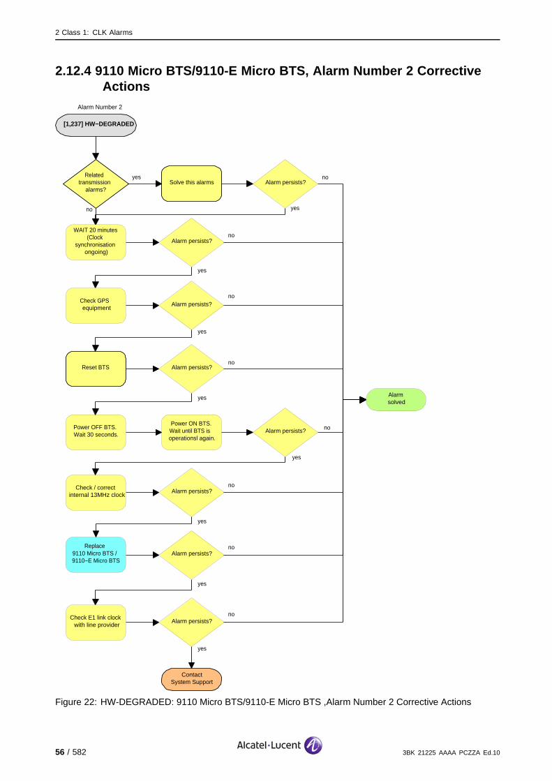
2.12.4 9110 Micro BTS/9110-E Micro BTS, Alarm Number 2 CorrectiveActions
[1,237] HW−DEGRADED
Alarm Number 2
no
ContactSystem Support
Reset BTS
yes
yesRelated transmission
alarms?
no
Solve this alarms
Alarmsolved
no
yes
Alarm persists?
WAIT 20 minutes(Clock
synchronisation ongoing)
Alarm persists?
Alarm persists?
Power OFF BTS.Wait 30 seconds.
Power ON BTS.Wait until BTS is operationsl again.
Alarm persists?
Check / correct internal 13MHz clock
Alarm persists?
Check E1 link clock with line provider
Replace 9110 Micro BTS / 9110−E Micro BTS
Alarm persists?
Alarm persists?
yes
yes
yes
yes
yes
no
no
no
no
Check GPS equipment
Alarm persists?
yes
no
no
Figure 22: HW-DEGRADED: 9110 Micro BTS/9110-E Micro BTS ,Alarm Number 2 Corrective Actions
56 / 582 3BK 21225 AAAA PCZZA Ed.10
2 Class 1: CLK Alarms
2.13 [1,240] MISSING-ENTRY-IN-CPF
specific Problems MISSING-ENTRY-IN-CPF
event Type Processor Error
probable Cause Configuration Or Customization Error
perceived Severity Major (PMA)
Alarm Description An expected entry in the OMU CPF was not found. Equipment identificationfor the MCLU/MCLR is not included in the OMU CPF.
If the BTS clock system has redundancy, telecom functions are not affected.
If there is no redundancy, the cell is lost.
Impact BSS Cell(s) Signaling Calls
Loss - X(no red.) X(no red.) X(no red.)
Degradation X(no red.) - - -
3BK 21225 AAAA PCZZA Ed.10 57 / 582

2 Class 1: CLK Alarms
2.13.1 Corrective Actions
[1,240] MISSING−ENTRY−IN−CPF
no
ContactSystem Support
Check existing hardware against populated hardware in the OMU CPF for wrong BTS family, characteristic
and parameter entries. Use:
Choose the correct CPFsettings by selecting the
appropriate BTS characteristics.
Use:
Clock operational?
yes Alarmsolved
Check Cell Activation
Check Cell Logical
Parameters
Check Cell Telecom Impact
Check Cell with Hardware
Change Cell Type
Modify BTS Characteristics
Modify BTS Hardware Capability
Figure 23: MISSING-ENTRY-IN-CPF: Corrective Actions
58 / 582 3BK 21225 AAAA PCZZA Ed.10

2 Class 1: CLK Alarms
2.14 [1,241] INCONSIST-ASSHW-ACTHW
specific Problems INCONSIST-ASSHW-ACTHW
event Type Processing Error
probable Cause Configuration Or Customization Error
perceived Severity Major (PMA)
Alarm Description The equipped BTS hardware does not match to the assumed hardwarecapabilities.
Alarm Number 3: There is a fault on the assumed hardware, the capability is that of amaster BTS but the actual capability is that of a slave (and vice versa).
5: The BTS hardware does not provide extended cell support, but it shouldbe configured as an extended cell.
If the BTS clock system has redundancy, telecom functions are not affected.
If there is no redundancy, the cell is lost.
Impact BSS Cell(s) Signaling Calls
Loss - X(no red.) X(no red.) X(no red.)
Degradation X(no red.) - - -
3BK 21225 AAAA PCZZA Ed.10 59 / 582

2 Class 1: CLK Alarms
2.14.1 Alarm Number 3 Corrective Actions
[1,241] INCONSIST−ASSHW−ACTHW
no
ContactSystem Support
Check assumed BTS hardware master/slave
capability against the clock units in the BTS.
Use:
Clock operational?
yes Alarmsolved
Check Cell with Hardware
Modify assumed BTS Hardware
Capability
Modify actual BTS hardware capability by replacing existing BTS entity by appropriate
BTS hardware entity, as descibed in the CMA
OR
On−site
On−site
G1:Replace MCLU,
MCLR
On−site
G1:Replace MFG
G2:Replace STSE,
STSP, STSR
On−site
OR OR
Alarm Number 3
Figure 24: INCONSIST-ASSHW-ACTHW, Alarm Number 3: Corrective Actions
60 / 582 3BK 21225 AAAA PCZZA Ed.10

2 Class 1: CLK Alarms
2.14.2 Alarm Number 5 Corrective Actions
[1,241] INCONSIST−ASSHW−ACTHW
no
ContactSystem Support
Check cell range definition against clock units.
Use:
Clock operational?
yes Alarmsolved
Check Cell with Hardware
Modify assumed BTS Hardware
Capability
Modify actual BTS hardware capability by replacing existing BTS entity by appropriate
BTS hardware entity, as descibed in the CMA
OR
On−site
G2:Replace STSE, STSP,
STSR
On−site
Alarm Number 5
Figure 25: INCONSIST-ASSHW-ACTHW, Alarm Number 5: Corrective Actions
3BK 21225 AAAA PCZZA Ed.10 61 / 582
2 Class 1: CLK Alarms
2.15 [1,246] CONFIG-FAIL
specific Problems CONFIG-FAIL
event Type Processing Error
probable Cause Configuration Or Customization Error
perceived Severity Major (PMA)
Alarm Description The configuration has failed for a Clock Unit.
If the clock system is redundant on this BTS and only one Clock Unit configuration failed, the telecomfunctions are not affected.
If, however, no redundancy is available or the configuration of both Clock Units on the BTS failed, thecell(s) fed by the clock system are lost.
Impact BSS Cell(s) Signaling Calls
Loss - X(no red.) X(no red.) X(no red.)
Degradation X(no red.) - - -
62 / 582 3BK 21225 AAAA PCZZA Ed.10

2 Class 1: CLK Alarms
2.15.1 Corrective Actions
[1,246] CONFIG−FAIL
no
ContactSystem Support
If both Clock Units in BTS report this alarm, there is a problem with the parameters(List of Clock Unit delays).If alarm is reported at power−up, there is alsoa Q1 failure, which provoked theconfiguration failure.
Clock operational?
yesAlarmsolved
Check validity of parameters (BTS hardware configuration)
on Clock Unit delays. Use Check Cell with Hardware
Modify assumed BTS Hardware Capability
Restart OMU
no
Clock operational?
yesAlarmsolved
On−site
G1:Replace MCLU,
MCLR
On−site
G1:Replace MFG
G2:Replace STSE,
STSP, STSR
On−site
OR OR
Figure 26: CONFIG-FAIL: Corrective Actions
3BK 21225 AAAA PCZZA Ed.10 63 / 582
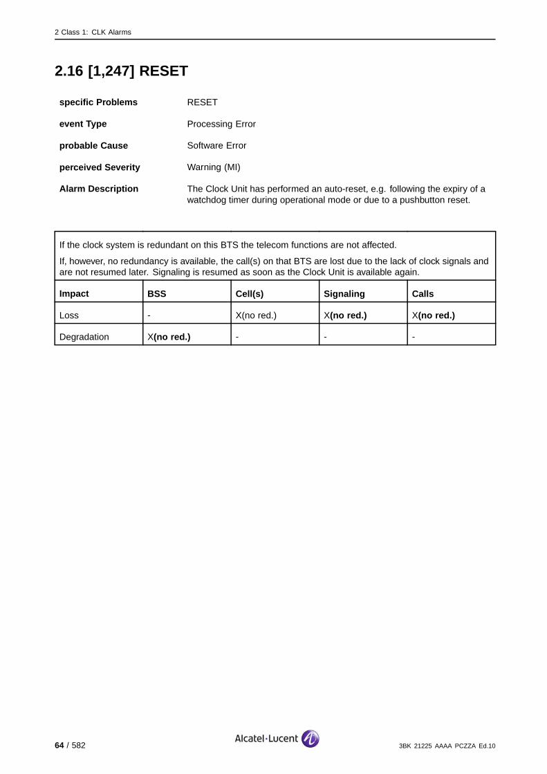
2 Class 1: CLK Alarms
2.16 [1,247] RESET
specific Problems RESET
event Type Processing Error
probable Cause Software Error
perceived Severity Warning (MI)
Alarm Description The Clock Unit has performed an auto-reset, e.g. following the expiry of awatchdog timer during operational mode or due to a pushbutton reset.
If the clock system is redundant on this BTS the telecom functions are not affected.
If, however, no redundancy is available, the call(s) on that BTS are lost due to the lack of clock signals andare not resumed later. Signaling is resumed as soon as the Clock Unit is available again.
Impact BSS Cell(s) Signaling Calls
Loss - X(no red.) X(no red.) X(no red.)
Degradation X(no red.) - - -
64 / 582 3BK 21225 AAAA PCZZA Ed.10
2 Class 1: CLK Alarms
2.16.1 9100 BTS Corrective Actions
[1,247] RESET
Alarmsolved
yesClock operational?
no
no
ContactSystem Support
Reset Function BTS
Replace SUMP, SUMA
Clock operational?
yes Alarmsolved
On−site
Alarm is reported very often on one
board?
no
yes
Figure 27: RESET: 9100 BTS Corrective Actions
3BK 21225 AAAA PCZZA Ed.10 65 / 582

2 Class 1: CLK Alarms
2.16.2 9110 Micro BTS/9110-E Micro BTS Corrective Actions
[1,247] RESET
Alarmsolved
yesClock operational?
no
no
Reset Function BTS
Clock operational?
yes
Alarmsolved
Alarm is reported very often on one
board?
no
yes
On−site
Disconnect mains power from ACCO
to Basic Unit
On−site
After 30 s re−power the BTS
On−site
Switch off Battery Backup Switch and
Main Power switch in Side Support Cabinet
On−site
Switch off mains power fuse for tower mounted
BTSOR OR
no
ContactSystem Support
BTS operational?
yes Alarmsolved
On−site
Replace BTS A910
Figure 28: RESET: 9110 Micro BTS/9110-E Micro BTS Corrective Actions
66 / 582 3BK 21225 AAAA PCZZA Ed.10
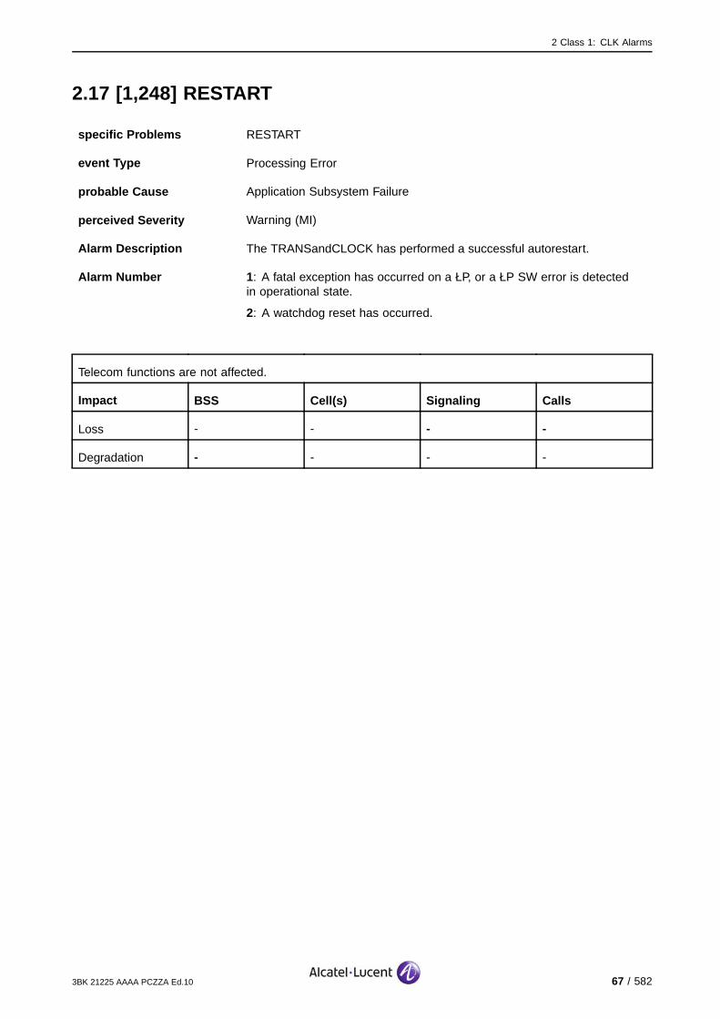
2 Class 1: CLK Alarms
2.17 [1,248] RESTART
specific Problems RESTART
event Type Processing Error
probable Cause Application Subsystem Failure
perceived Severity Warning (MI)
Alarm Description The TRANSandCLOCK has performed a successful autorestart.
Alarm Number 1 : A fatal exception has occurred on a ŁP, or a ŁP SW error is detectedin operational state.
2: A watchdog reset has occurred.
Telecom functions are not affected.
Impact BSS Cell(s) Signaling Calls
Loss - - - -
Degradation - - - -
3BK 21225 AAAA PCZZA Ed.10 67 / 582
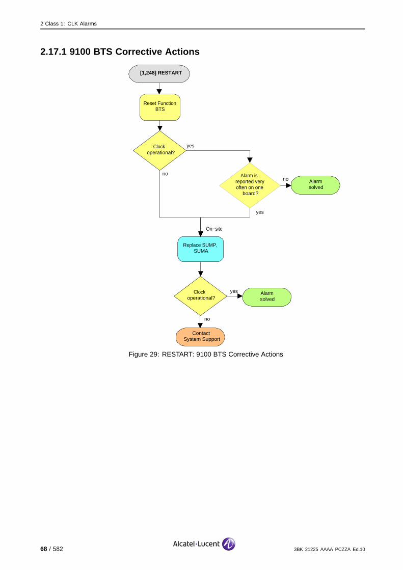
2 Class 1: CLK Alarms
2.17.1 9100 BTS Corrective Actions
[1,248] RESTART
Alarmsolved
yesClock operational?
no
no
ContactSystem Support
Reset Function BTS
Replace SUMP, SUMA
Clock operational?
yes Alarmsolved
On−site
Alarm is reported very often on one
board?
no
yes
Figure 29: RESTART: 9100 BTS Corrective Actions
68 / 582 3BK 21225 AAAA PCZZA Ed.10

2 Class 1: CLK Alarms
2.17.2 9110 Micro BTS/9110-E Micro BTS Corrective Actions
[1,248] RESTART
Alarmsolved
yesClock operational?
no
no
Reset Function BTS
Clock operational?
yes
Alarmsolved
Alarm is reported very often on one
board?
no
yes
On−site
Disconnect mains power from ACCO
to Basic Unit
On−site
After 30 s re−power the BTS
On−site
Switch off Battery Backup Switch and
Main Power switch in Side Support Cabinet
On−site
Switch off mains power fuse for tower mounted
BTSOR OR
no
ContactSystem Support
BTS operational?
yes Alarmsolved
On−site
Replace BTS A910
Figure 30: RESTART: 9110 Micro BTS/9110-E Micro BTS Corrective Actions
3BK 21225 AAAA PCZZA Ed.10 69 / 582
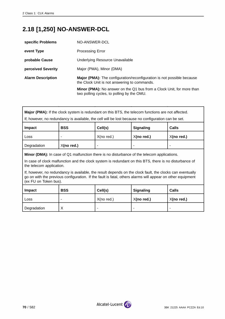
2 Class 1: CLK Alarms
2.18 [1,250] NO-ANSWER-DCL
specific Problems NO-ANSWER-DCL
event Type Processing Error
probable Cause Underlying Resource Unavailable
perceived Severity Major (PMA), Minor (DMA)
Alarm Description Major (PMA): The configuration/reconfiguration is not possible becausethe Clock Unit is not answering to commands.
Minor (PMA): No answer on the Q1 bus from a Clock Unit, for more thantwo polling cycles, to polling by the OMU.
Major (PMA): If the clock system is redundant on this BTS, the telecom functions are not affected.
If, however, no redundancy is available, the cell will be lost because no configuration can be set.
Impact BSS Cell(s) Signaling Calls
Loss - X(no red.) X(no red.) X(no red.)
Degradation X(no red.) - - -
Minor (DMA): In case of Q1 malfunction there is no disturbance of the telecom applications.
In case of clock malfunction and the clock system is redundant on this BTS, there is no disturbance ofthe telecom application.
If, however, no redundancy is available, the result depends on the clock fault, the clocks can eventuallygo on with the previous configuration. If the fault is fatal, others alarms will appear on other equipment(ex FU on Token bus).
Impact BSS Cell(s) Signaling Calls
Loss - X(no red.) X(no red.) X(no red.)
Degradation X - - -
70 / 582 3BK 21225 AAAA PCZZA Ed.10
2 Class 1: CLK Alarms
2.18.1 Corrective Actions
[1,250] NO−ANSWER−DCL
Alarmsolved
yes
Clock operational?
no
On−site
G1:Replace MCLU,
MCLR
On−site
no
ContactSystem Support
Lock Function CLLK
Unlock Function CLLK
G1:Replace MFG
G2:Replace STSE,
STSP, STSR
Clock operational?
yes Alarmsolved
On−site
On−site
Check Q1 bus cable and connectors
between OMU and Clock Unit
OR OR
Alarmsolved
yesClock operational?
no
Figure 31: NO-ANSWER-DCL: Corrective Actions
3BK 21225 AAAA PCZZA Ed.10 71 / 582
2 Class 1: CLK Alarms
2.19 [1,255] Q1-RELAY-FAILURE
specific Problems Q1-RELAY-FAILURE
event Type Equipment
probable Cause Equipment Malfunction
perceived Severity Minor (DMA)
Alarm Description The Clock Unit cannot disconnect itself from the Q1 Bus.
Telecom functions are not affected.
Impact BSS Cell(s) Signaling Calls
Loss - - - -
Degradation - - - -
72 / 582 3BK 21225 AAAA PCZZA Ed.10

2 Class 1: CLK Alarms
2.19.1 Corrective Actions
[1,255] Q1−RELAY−FAILURE
Alarmsolved
yesClock operational?
no
On−site
G1:Replace MCLU,
MCLR
On−site
no
ContactSystem Support
Lock Function CLLK
Unlock Function CLLK
G1:Replace MFG
G2:Replace STSE,
STSP, STSR
Clock operational?
yes Alarmsolved
On−site
OR OR
Figure 32: Q1-RELAY-FAILURE: Corrective Actions
3BK 21225 AAAA PCZZA Ed.10 73 / 582

2 Class 1: CLK Alarms
74 / 582 3BK 21225 AAAA PCZZA Ed.10
3 Class 2: OMU Alarms
3 Class 2: OMU Alarms
This section defines the alarms for the Class 2: OMU alarm class.
3BK 21225 AAAA PCZZA Ed.10 75 / 582

3 Class 2: OMU Alarms
3.1 [2,1] LOSS OF TWIN CONFIGURATION
specific Problems LOSS OF TWIN CONFIGURATION
event Type Processing Error
probable Cause softwareProgramAbnomallyTerminated
perceived Severity Warning (MI)
Alarm Description This event arrives in seldom circumstances where storage has beendestroyed or is no more readable.
Any other alarms should be checked and repaired first.
The OMU will apply the default twin configuration.
Alarm Number 1: OMU does not retrieve the twin configuration.
Telecom functions are not affected.
Impact BSS Cell(s) Signaling Calls
Loss - - - -
Degradation - - - -
76 / 582 3BK 21225 AAAA PCZZA Ed.10

3 Class 2: OMU Alarms
3.1.1 Corrective Actions
[2,1] LOSS OF TWIN CONFIGURATION
no
ContactSystem Support
Set the desired configuration from
OMC−R if selectable due to cabling
Alam cleared?yes
Alarmsolved
Alam cleared?
From BTS LMT perform the
modification of the HW configuration
Replace SUMA board
Alam cleared?yes
yes
no
no
On site
Figure 33: LOSS OF TWIN CONFIGURATION Corrective Actions
3BK 21225 AAAA PCZZA Ed.10 77 / 582
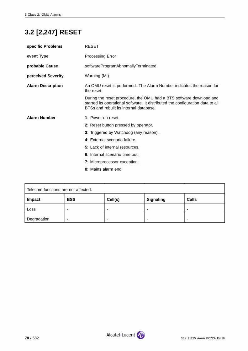
3 Class 2: OMU Alarms
3.2 [2,247] RESET
specific Problems RESET
event Type Processing Error
probable Cause softwareProgramAbnomallyTerminated
perceived Severity Warning (MI)
Alarm Description An OMU reset is performed. The Alarm Number indicates the reason forthe reset.
During the reset procedure, the OMU had a BTS software download andstarted its operational software. It distributed the configuration data to allBTSs and rebuilt its internal database.
Alarm Number 1: Power-on reset.
2: Reset button pressed by operator.
3: Triggered by Watchdog (any reason).
4: External scenario failure.
5: Lack of internal resources.
6: Internal scenario time out.
7: Microprocessor exception.
8: Mains alarm end.
Telecom functions are not affected.
Impact BSS Cell(s) Signaling Calls
Loss - - - -
Degradation - - - -
78 / 582 3BK 21225 AAAA PCZZA Ed.10

3 Class 2: OMU Alarms
3.2.1 Alarm Number 1,2 Corrective Actions
[2,247] RESET
Alarmsolved
yesPower−on reset?
no
no
ContactSystem Support
Check power supply
OMU operational?
yes Alarmsolved
On−site
Reset button pressed by operator?
no
yes
After automatic reset procedure OMU becomes
operational
Figure 34: RESET: Alarm Number 1,2 Corrective Actions
3BK 21225 AAAA PCZZA Ed.10 79 / 582

3 Class 2: OMU Alarms
3.2.2 Alarm Number 3 Corrective Actions
The hardware is faulty or there is a bug in the software. If only one BTS isconcerned or the alarm occurs repeatedly, replace the faulty hardware.
[2,247] RESET
On−site
G1:Replace OMUA
On−site
no
ContactSystem Support
G2:Replace SCFE
OMUoperational?
yes Alarmsolved
OR ORA9100:
Replace SUMP, SUMA
A910:Replace BTS A910
On−site On−site
OR
Figure 35: RESET: Alarm Number 3 Corrective Actions
3.2.3 Alarm Number 4 Corrective Actions
The communication with the BSC is disturbed.
[2,247] RESET
On−site
Check cables and connectors to BSC
no
ContactSystem Support
OMUoperational?
yes Alarmsolved
On−site
Figure 36: RESET: Alarm Number 4 Corrective Actions
80 / 582 3BK 21225 AAAA PCZZA Ed.10
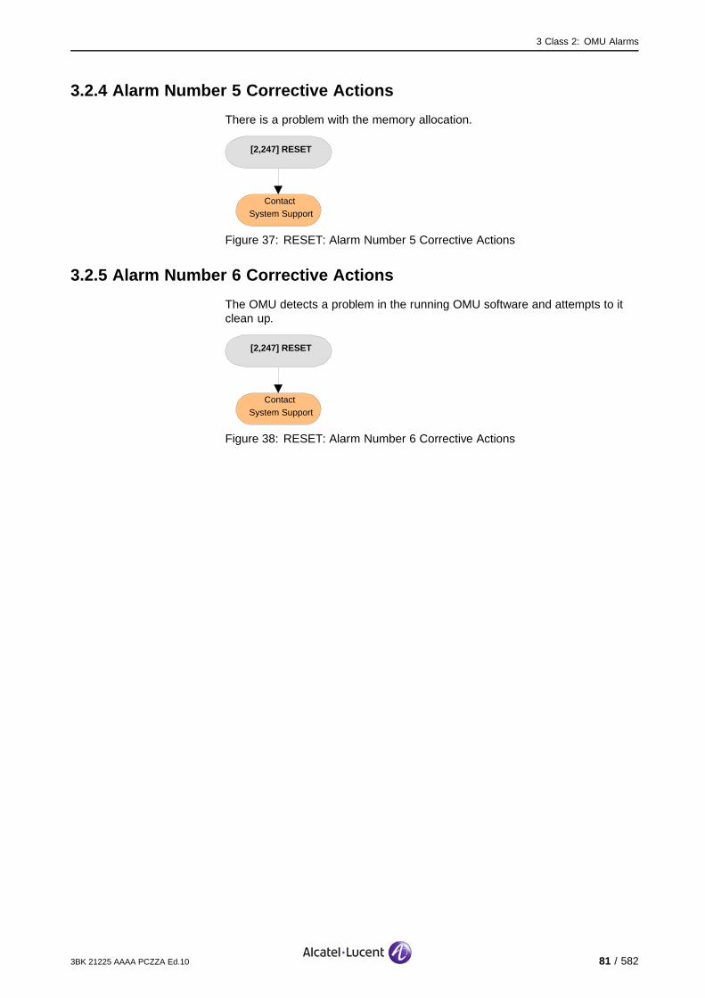
3 Class 2: OMU Alarms
3.2.4 Alarm Number 5 Corrective Actions
There is a problem with the memory allocation.
[2,247] RESET
ContactSystem Support
Figure 37: RESET: Alarm Number 5 Corrective Actions
3.2.5 Alarm Number 6 Corrective Actions
The OMU detects a problem in the running OMU software and attempts to itclean up.
[2,247] RESET
ContactSystem Support
Figure 38: RESET: Alarm Number 6 Corrective Actions
3BK 21225 AAAA PCZZA Ed.10 81 / 582

3 Class 2: OMU Alarms
3.2.6 Alarm Number 7 Corrective Actions
An interrupt caused by an address or by a bus problem.
If the alarm occurs repeatedly :
[2,247] RESET
no
ContactSystem Support
OMUoperational?
yes Alarmsolved
A9100:Replace SUMP,
SUMA
A910:Replace BTS A910
On−site On−site
OR
Figure 39: RESET: Alarm Number 7 Corrective Actions
3.2.7 Alarm Number 8 Corrective Actions
The power supply is again available for the BTS.
82 / 582 3BK 21225 AAAA PCZZA Ed.10

3 Class 2: OMU Alarms
3.3 [2,248] RESTART
specific Problems RESTART
event Type Processing Error
probable Cause Application Subsystem Failure
perceived Severity Warning (MI)
Alarm Description An OMU restart is performed successfully. The reason for the restart isindicated in the Alarm Number field.
During the restart procedure the OMU has restarted its software, distributedits configuration data to all BTS units, and re-built its internal database.
Alarm Number 1: Lack of internal resources, allocating the memory.
2: Triggered for OMU-CPF replacement.
3: The OMU detects an internal scenario time out in the running OMUsoftware, and attempts to clean it up.
4: Microprocessor exception - an interrupt is caused by an address ora bus problem.
Telecom functions are not affected.
Impact BSS Cell(s) Signaling Calls
Loss - - - -
Degradation - - - -
3.3.1 Corrective Actions
None. If the problem persists, a reset is triggered automatically.
3BK 21225 AAAA PCZZA Ed.10 83 / 582

3 Class 2: OMU Alarms
84 / 582 3BK 21225 AAAA PCZZA Ed.10
4 Class 3: SW-AN Alarms
4 Class 3: SW-AN Alarms
This section defines the alarms for the Class 3: SW-AN alarm class.
3BK 21225 AAAA PCZZA Ed.10 85 / 582
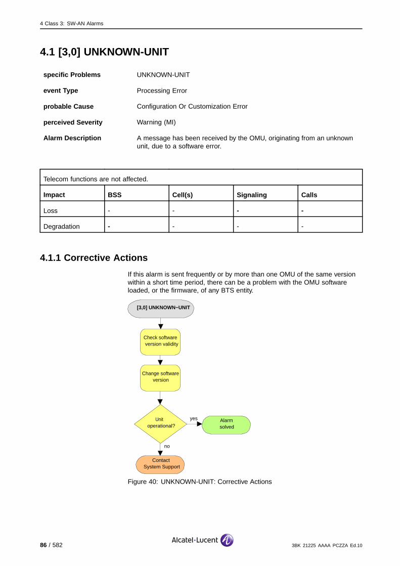
4 Class 3: SW-AN Alarms
4.1 [3,0] UNKNOWN-UNIT
specific Problems UNKNOWN-UNIT
event Type Processing Error
probable Cause Configuration Or Customization Error
perceived Severity Warning (MI)
Alarm Description A message has been received by the OMU, originating from an unknownunit, due to a software error.
Telecom functions are not affected.
Impact BSS Cell(s) Signaling Calls
Loss - - - -
Degradation - - - -
4.1.1 Corrective Actions
If this alarm is sent frequently or by more than one OMU of the same versionwithin a short time period, there can be a problem with the OMU softwareloaded, or the firmware, of any BTS entity.
[3,0] UNKNOWN−UNIT
no
ContactSystem Support
Check software version validity
Change software version
Unit operational?
yes Alarmsolved
Figure 40: UNKNOWN-UNIT: Corrective Actions
86 / 582 3BK 21225 AAAA PCZZA Ed.10
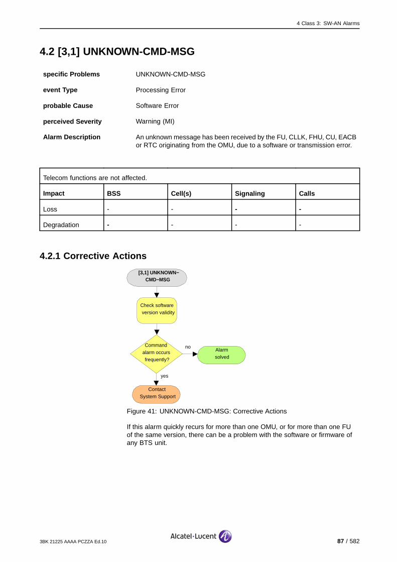
4 Class 3: SW-AN Alarms
4.2 [3,1] UNKNOWN-CMD-MSG
specific Problems UNKNOWN-CMD-MSG
event Type Processing Error
probable Cause Software Error
perceived Severity Warning (MI)
Alarm Description An unknown message has been received by the FU, CLLK, FHU, CU, EACBor RTC originating from the OMU, due to a software or transmission error.
Telecom functions are not affected.
Impact BSS Cell(s) Signaling Calls
Loss - - - -
Degradation - - - -
4.2.1 Corrective Actions
[3,1] UNKNOWN−CMD−MSG
no
ContactSystem Support
Check software version validity
Command alarm occurs frequently?
yes
Alarmsolved
Figure 41: UNKNOWN-CMD-MSG: Corrective Actions
If this alarm quickly recurs for more than one OMU, or for more than one FUof the same version, there can be a problem with the software or firmware ofany BTS unit.
3BK 21225 AAAA PCZZA Ed.10 87 / 582
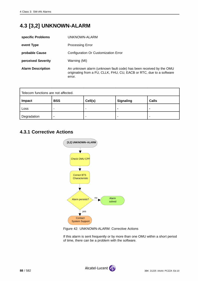
4 Class 3: SW-AN Alarms
4.3 [3,2] UNKNOWN-ALARM
specific Problems UNKNOWN-ALARM
event Type Processing Error
probable Cause Configuration Or Customization Error
perceived Severity Warning (MI)
Alarm Description An unknown alarm (unknown fault code) has been received by the OMUoriginating from a FU, CLLK, FHU, CU, EACB or RTC, due to a softwareerror.
Telecom functions are not affected.
Impact BSS Cell(s) Signaling Calls
Loss - - - -
Degradation - - - -
4.3.1 Corrective Actions
[3,2] UNKNOWN−ALARM
no
ContactSystem Support
Check OMU CPF
Correct BTS Characteristic
Alarm persists?
yes
Alarmsolved
Figure 42: UNKNOWN-ALARM: Corrective Actions
If this alarm is sent frequently or by more than one OMU within a short periodof time, there can be a problem with the software.
88 / 582 3BK 21225 AAAA PCZZA Ed.10
4 Class 3: SW-AN Alarms
4.4 [3,11] SW-PROBLEM
4.4.1 [3,11] SW-PROBLEM (CLLK)
specific Problems SW-PROBLEM
event Type Processing Error
probable Cause software Program Abnormally Terminated
perceived Severity Nbr 1...3:Major (PMA)
Nbr 4, 5: Minor (DMA), Warning (MI)
Alarm Description The software is corrupted or bad.
Alarm Number 1: Error detected during the configuration with saved parameters ininitialization state: saved parameters are corrupted and cannot be used forthe auto-restart sequence.
2: Error detected during the SW activation procedure in the fault localizationstate, or a check-sum error is detected in operational state.
3: A fatal exception has occurred on ŁP, or a ŁP SW error is detected in astate other than the operational state.
4: An error has occurred during the SW activation procedure, triggeredby the OMU in the initialization state. The alarm is not fatal because theTRANS&CLOCK uses the previous FW.
5: An error has occurred which is linked to a software download. Theerror was detected during the downloading procedure from the OMU ininitialization state (packet sequence, global file checksum). This alarm isnot fatal because the TRANS&CLOCK uses the previous FW.
If the CLLK is redundant on this BTS, the telecom functions are not affected.
For the 9100 BTS: there is no clock redundancy available, so the cells fed by the reporting CLLK arelost, thus the BTS is lost.
Impact BSS Cell(s) Signaling Calls
Loss - X(no red.) X(no red.) X(no red.)
Degradation X(no red.) - - -
3BK 21225 AAAA PCZZA Ed.10 89 / 582

4 Class 3: SW-AN Alarms
4.4.1.1 9100 BTS Corrective Actions
[3,11] SW−PROBLEM (CLLK)L
Alarmsolved
yesClock operational?
no
On−site
no
ContactSystem Support
Reset Function BTS
Replace SUMP, SUMA
Clock operational?
yes Alarmsolved
Figure 43: SW-PROBLEM (CLLK): 9100 BTS Corrective Actions
90 / 582 3BK 21225 AAAA PCZZA Ed.10

4 Class 3: SW-AN Alarms
4.4.1.2 9110 Micro BTS/9110-E Micro BTS Corrective Actions
[3,11] SW−PROBLEM (CLLK)
Alarmsolved
yesClock operational?
no
On−site
no
ContactSystem Support
Reset Function BTS
Disconnect mains power from ACCO
to Basic Unit
BTS operational?
yes Alarmsolved
On−site
After 30 s re−power the BTS
On−site
Switch off Battery Backup Switch and
Main Power switch in Side Support Cabinet
On−site
Switch off mains power fuse for tower
mounted BTSOR OR
On−site
Replace BTS A910
noBTS
operational?
yes
Alarmsolved
Figure 44: SW-PROBLEM (CLLK): 9110 Micro BTS/9110-E Micro BTSCorrective Actions
3BK 21225 AAAA PCZZA Ed.10 91 / 582
4 Class 3: SW-AN Alarms
4.4.2 [3,11] SW-PROBLEM (TRE)
specific Problems SW-PROBLEM
event Type Processing Error
probable Cause software Program Abnormally Terminated
perceived Severity Major (PMA), Warning (MI)
Alarm Description The software is corrupted or bad.
Alarm Number 1: An error is detected during the configuration with saved parameters ininitialization state: saved parameters are corrupted and cannot be used forthe auto-restart sequence.
Major (PMA): The local recovery fails.
Warning (MI): The local recovery is successful.
2: An error is detected during the SW activation procedure in the faultlocalization state or check-sum error detected in operational state.
Major (PMA): The local recovery fails.
Warning (MI): The local recovery is successful.
3: A fatal exception occurred on SCP or a SCP, the software error isdetected in another state than the operational state.
Major (PMA): The local recovery fails.
Warning (MI): The local recovery is successful.
4: An error detected during the software activation procedure, triggeredby the OMU in initialization state.
5: An error is linked to software down-load. The error is detected duringthe down-loading procedure from the SUM, in initialization state (packetsequence, global file check-sum, etc.).
6: A watchdog has occurred and an auto-restart has failed.
7: A bad parameter is detected in the TRE CPF.
The TRE is no longer usable. The associated eight channels are lost. Independent of frequency hoppingor not, the BSC reduces the number of channels supported by the cell.
If the TRE supporting the BCCH is not concerned, the cell is degraded, calls are lost. (#).
If the TRE supporting the BCCH is concerned and there is BCCH redundancy, recovery mechanismsregain the cell’s functionality. (*).
If the TRE supporting the BCCH is concerned and there is no BCCH redundancy, the complete cellis lost. (X).
Impact BSS Cell(s) Signaling Calls
Loss - X(no red.) X(no red.) X(no red.)#*
Degradation X(no red.) #* - -
92 / 582 3BK 21225 AAAA PCZZA Ed.10

4 Class 3: SW-AN Alarms
4.4.2.1 9100 BTS Corrective Actions
Disable RF PowerUse the BTS Terminal to disable RA before disconnecting RF cables.Initialize RA after work.
[3,11] SW−PROBLEM (TRE)
Alarmsolved
yesTRE operational?
no
On−site
no
ContactSystem Support
Lock Function TRE
Unlock Function TRE
Replace TRE
TREoperational?
yes Alarmsolved
Alarm is reported from more
than one TRE?
ContactSystem Support
yes
no
Figure 45: SW-PROBLEM (TRE): 9100 BTS Corrective Actions
3BK 21225 AAAA PCZZA Ed.10 93 / 582
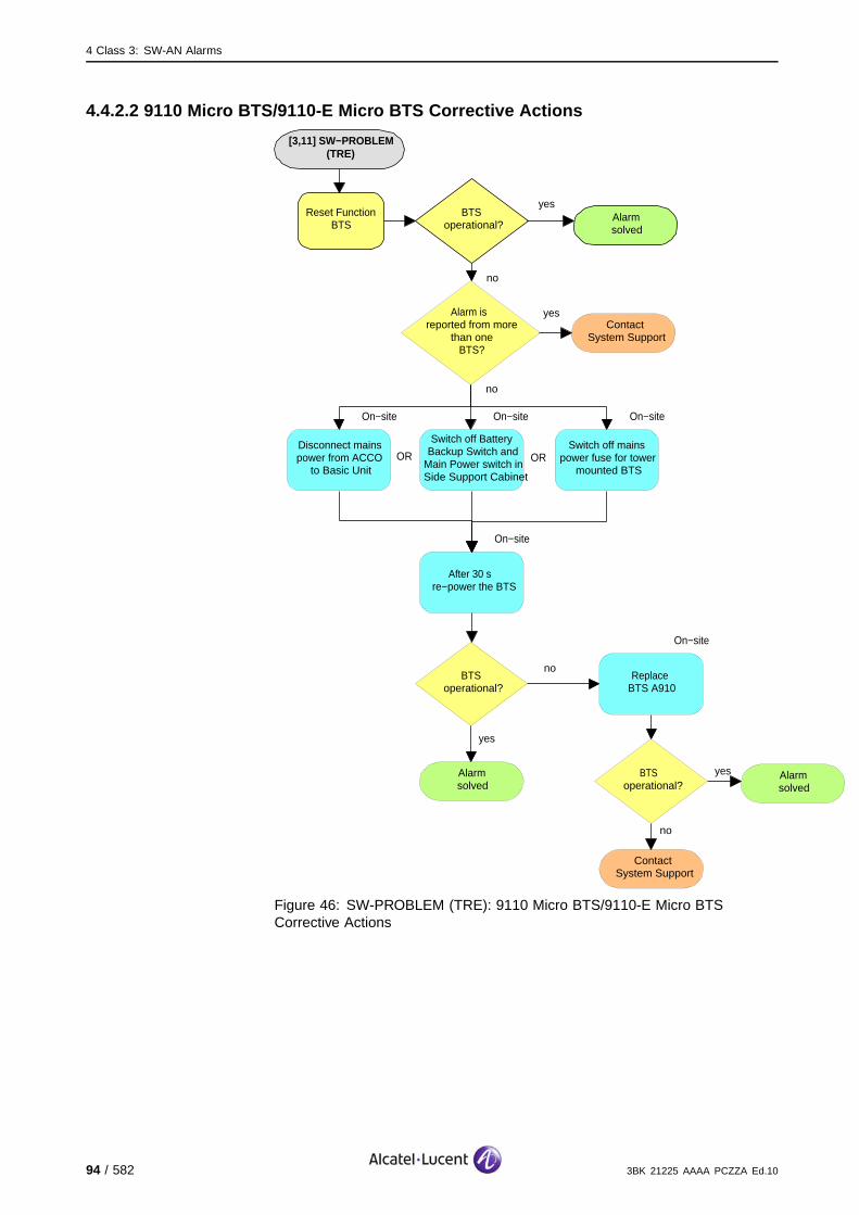
4 Class 3: SW-AN Alarms
4.4.2.2 9110 Micro BTS/9110-E Micro BTS Corrective Actions
[3,11] SW−PROBLEM (TRE)
Alarmsolved
yesBTS
operational?
no
Reset Function BTS
Alarm is reported from more
than one BTS?
ContactSystem Support
yes
no
On−site
no
ContactSystem Support
Disconnect mains power from ACCO
to Basic Unit
BTS operational?
yes Alarmsolved
On−site
After 30 s re−power the BTS
On−site
Switch off Battery Backup Switch and
Main Power switch in Side Support Cabinet
On−site
Switch off mains power fuse for tower
mounted BTSOR OR
On−site
Replace BTS A910
noBTS
operational?
yes
Alarmsolved
Figure 46: SW-PROBLEM (TRE): 9110 Micro BTS/9110-E Micro BTSCorrective Actions
94 / 582 3BK 21225 AAAA PCZZA Ed.10

4 Class 3: SW-AN Alarms
4.4.3 [3,11] SW-PROBLEM (RA)
specific Problems SW-PROBLEM
event Type Processing Error
probable Cause software Program Abnormally Terminated
perceived Severity Minor (DMA), Warning (MI)
Alarm Description The software is corrupted or bad.
Alarm Number 1: Error detected during the configuration with saved parameters ininitialization state: saved parameters are corrupted and cannot be used forthe auto-restart sequence.
2: Error detected during the SW activation procedure in the fault localizationstate or check-sum error detected in operational state.
3: A fatal exception occurred on SCP or a SCP, the SW error is detected inanother state than the operational state.
5: Error linked to software down-load. Error detected during thedown-loading procedure from the OMU, in initialization state (packetsequence, global file check-sum, etc.).
The transmission quality is degraded.
Impact BSS Cell(s) Signaling Calls
Loss - - - -
Degradation - - X X
3BK 21225 AAAA PCZZA Ed.10 95 / 582

4 Class 3: SW-AN Alarms
4.4.3.1 Corrective Actions
Disable RF PowerUse the BTS Terminal to disable RA before disconnecting RF cables.Initialize RA after work.
[3,11] SW−PROBLEM (RA)
Alarmsolved
yesRA operational?
no
On−site
no
ContactSystem Support
Lock Function RA
Unlock Function RA
Replace ANX, ANY, ANC
RAoperational?
yes Alarmsolved
Alarm is reported from more
than one BTS?
ContactSystem Support
yes
no
Figure 47: SW-PROBLEM (RA): Corrective Actions
96 / 582 3BK 21225 AAAA PCZZA Ed.10

4 Class 3: SW-AN Alarms
4.5 [3,13] TELECOM-CONFIG-FAIL
specific Problems TELECOM-CONFIG-FAIL
event Type Processing Error
probable Cause Configuration Or Customization Error
perceived Severity Warning (MI)
Alarm Description A Telecom Configuration Parameter error has been detected.
Alarm Number 1: There is a rejection of the telecom configuration parametersrelated to Hand-Over and Power Control (parameters includedin BS_POWER_CONTROL, MS_POWER_CONTROL orPREPROCESS_CONFIGURE messages) in the operational state.
A message is missing in the list of telecom messages received.
2: The TLC_CONFIG_T timer (supervision of reception of telecomconfiguration on RSL) has elapsed after an O&M configuration orre-configuration.
3: Incorrect sys info 3 parameters have been received in the operationalstate.
4: Inconsistent telecom configuration messages have been received fromthe BSC after an O&M reconfiguration.
5: No correct BCCH info messages have been received from the BSCafter an O&M reconfiguration.
Telecom functions are not affected. The old configuration is still running.
Impact BSS Cell(s) Signaling Calls
Loss - - - -
Degradation - - - -
3BK 21225 AAAA PCZZA Ed.10 97 / 582
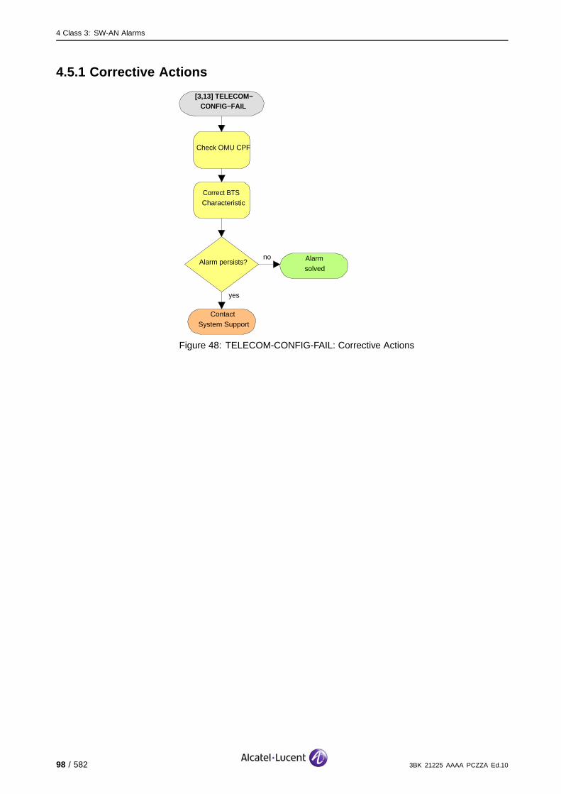
4 Class 3: SW-AN Alarms
4.5.1 Corrective Actions
[3,13] TELECOM−CONFIG−FAIL
no
ContactSystem Support
Check OMU CPF
Correct BTS Characteristic
Alarm persists?
yes
Alarmsolved
Figure 48: TELECOM-CONFIG-FAIL: Corrective Actions
98 / 582 3BK 21225 AAAA PCZZA Ed.10
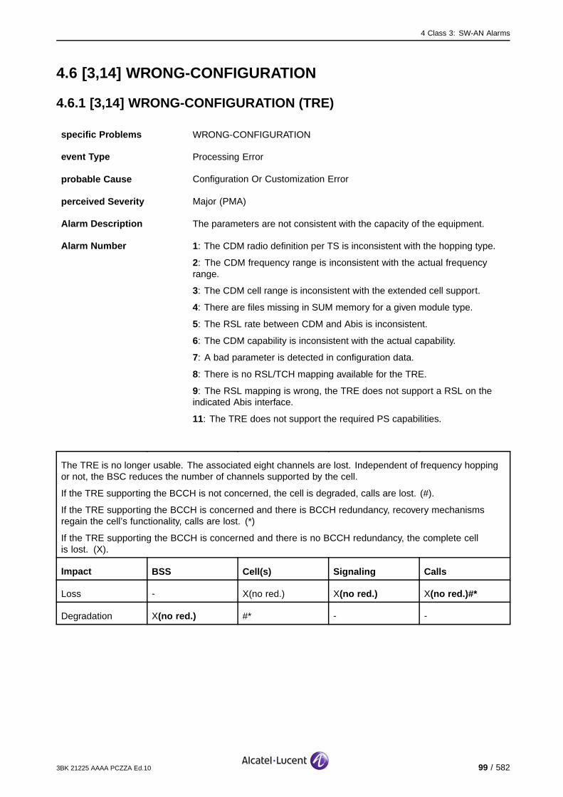
4 Class 3: SW-AN Alarms
4.6 [3,14] WRONG-CONFIGURATION
4.6.1 [3,14] WRONG-CONFIGURATION (TRE)
specific Problems WRONG-CONFIGURATION
event Type Processing Error
probable Cause Configuration Or Customization Error
perceived Severity Major (PMA)
Alarm Description The parameters are not consistent with the capacity of the equipment.
Alarm Number 1: The CDM radio definition per TS is inconsistent with the hopping type.
2: The CDM frequency range is inconsistent with the actual frequencyrange.
3: The CDM cell range is inconsistent with the extended cell support.
4: There are files missing in SUM memory for a given module type.
5: The RSL rate between CDM and Abis is inconsistent.
6: The CDM capability is inconsistent with the actual capability.
7: A bad parameter is detected in configuration data.
8: There is no RSL/TCH mapping available for the TRE.
9: The RSL mapping is wrong, the TRE does not support a RSL on theindicated Abis interface.
11: The TRE does not support the required PS capabilities.
The TRE is no longer usable. The associated eight channels are lost. Independent of frequency hoppingor not, the BSC reduces the number of channels supported by the cell.
If the TRE supporting the BCCH is not concerned, the cell is degraded, calls are lost. (#).
If the TRE supporting the BCCH is concerned and there is BCCH redundancy, recovery mechanismsregain the cell’s functionality, calls are lost. (*)
If the TRE supporting the BCCH is concerned and there is no BCCH redundancy, the complete cellis lost. (X).
Impact BSS Cell(s) Signaling Calls
Loss - X(no red.) X(no red.) X(no red.)#*
Degradation X(no red.) #* - -
3BK 21225 AAAA PCZZA Ed.10 99 / 582

4 Class 3: SW-AN Alarms
4.6.1.1 Alarm Number 1, 2, 3, 6, Corrective Actions
[3,14] WRONG−CONFIGURATION
(TRE)
no
ContactSystem Support
Compare CDM value with TRE
capability
Correct parameter values according to TRE
capability
Alarm persists?
yes
Alarmsolved
no
Other TRE alarms
event?
Solve TRE alarm(s) first
yes
Reset effected TCU
Figure 49: WRONG-CONFIGURATION (TRE): Alarm Number 1, 2, 3, 6,Corrective Actions
100 / 582 3BK 21225 AAAA PCZZA Ed.10

4 Class 3: SW-AN Alarms
4.6.1.2 Alarm Number 4, Corrective Actions
[3,14]WRONG−CONFIGURATION
(TRE)
no
ContactSystem Support
Download the masterfile and the application
file
Replace the masterfile
Alarm persists?
yes
Alarmsolved
no
Other TRE alarms
event?
Solve TRE alarm(s) first
yes
Reset effected TCU
Figure 50: WRONG-CONFIGURATION (TRE): Alarm Number 4, CorrectiveActions
3BK 21225 AAAA PCZZA Ed.10 101 / 582

4 Class 3: SW-AN Alarms
4.6.1.3 Alarm Number 5, Corrective Actions
[3,14] WRONG−CONFIGURATION
(TRE)
no
ContactSystem Support
Compare CDM value with RSL rate
Correct parameter values according to TRE
capability
Alarm persists?
yes
Alarmsolved
no
Other TRE alarms
event?
Solve TRE alarm(s) first
yes
Reset effected TCU
Figure 51: WRONG-CONFIGURATION (TRE): Alarm Number 5, CorrectiveActions
102 / 582 3BK 21225 AAAA PCZZA Ed.10

4 Class 3: SW-AN Alarms
4.6.1.4 Alarm Number 7, 9, Corrective Actions
[3,14] WRONG−CONFIGURATIO
N (TRE)
no
ContactSystem Support
Compare CDM value
Correct parameter values according to TRE
capability
Alarm persists?
yes
Alarmsolved
no
Other TRE alarms
event?
Solve TRE alarm(s) first
yes
Reset effected TCU
Figure 52: WRONG-CONFIGURATION (TRE): Alarm Number 7, 9, CorrectiveActions
3BK 21225 AAAA PCZZA Ed.10 103 / 582
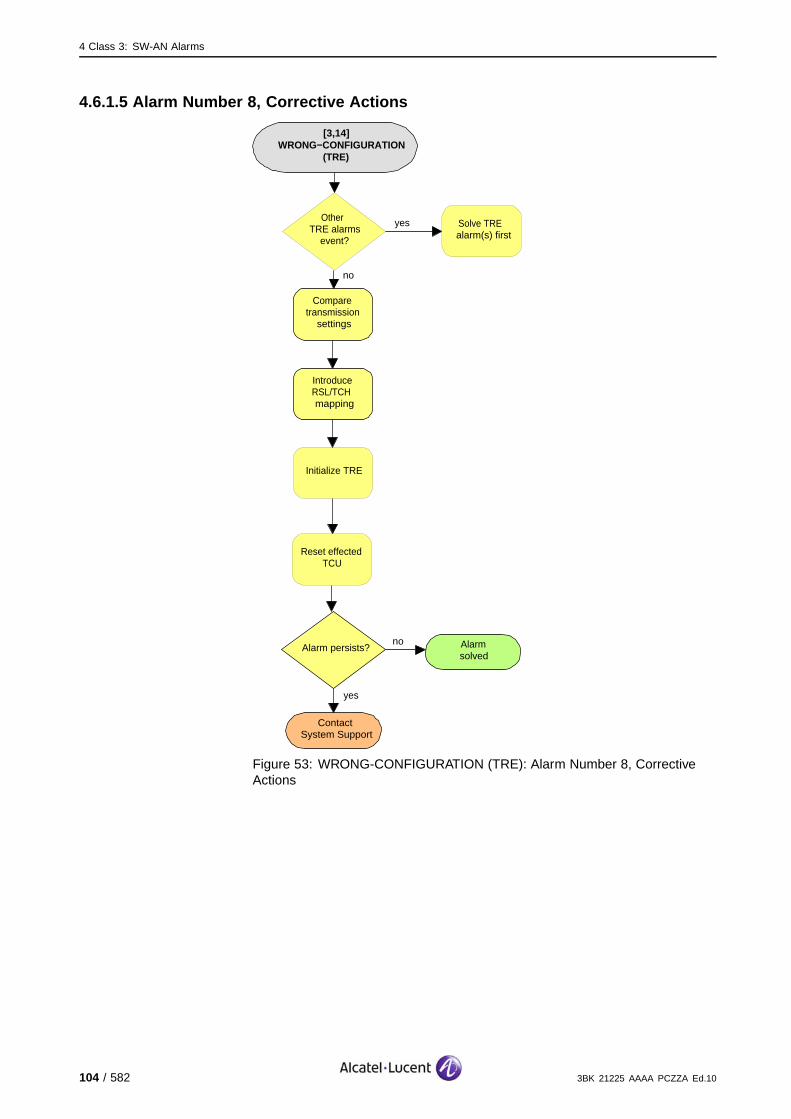
4 Class 3: SW-AN Alarms
4.6.1.5 Alarm Number 8, Corrective Actions
[3,14] WRONG−CONFIGURATION
(TRE)
no
ContactSystem Support
Compare transmission
settings
Introduce RSL/TCH mapping
Alarm persists?
yes
Alarmsolved
no
Other TRE alarms
event?
Solve TRE alarm(s) first
yes
Reset effected TCU
Initialize TRE
Figure 53: WRONG-CONFIGURATION (TRE): Alarm Number 8, CorrectiveActions
104 / 582 3BK 21225 AAAA PCZZA Ed.10
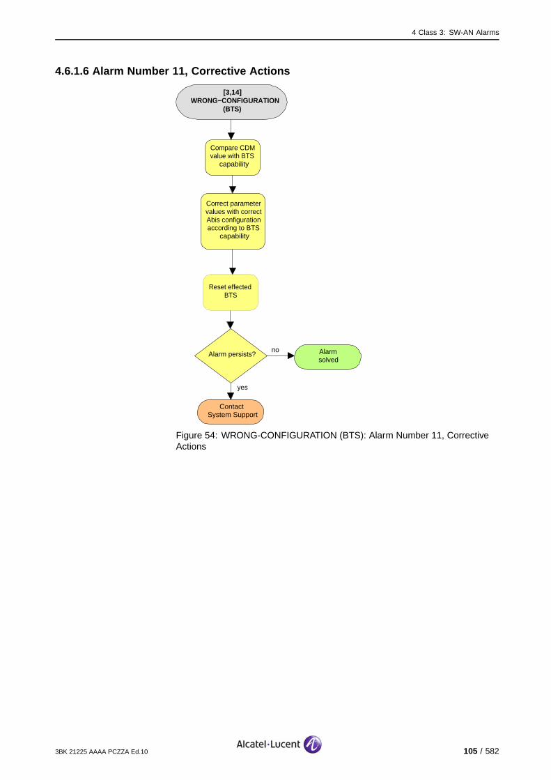
4 Class 3: SW-AN Alarms
4.6.1.6 Alarm Number 11, Corrective Actions
[3,14]WRONG−CONFIGURATION
(BTS)
no
ContactSystem Support
Compare CDM value with BTS
capability
Correct parameter values with correct Abis configuration according to BTS
capability
Alarm persists?
yes
Alarmsolved
Reset effected BTS
Figure 54: WRONG-CONFIGURATION (BTS): Alarm Number 11, CorrectiveActions
3BK 21225 AAAA PCZZA Ed.10 105 / 582
4 Class 3: SW-AN Alarms
4.6.2 [3,14] WRONG-CONFIGURATION (RA)
specific Problems WRONG-CONFIGURATION
event Type Processing Error
probable Cause Configuration Or Customization Error
perceived Severity Nbr. 2: Major (PMA)
Nbr. 4, 7, 10: Minor (DMA), Warning (MI)
Alarm Description The parameters are not consistent with the capacity of the equipment.
Alarm Number 2: The CDM frequency range is inconsistent with the actual frequencyrange.
4: There are files missing in OMU memory for a given module type.
7: A bad parameter is detected in configuration data.
The sector cannot provide the required maximum output power (SBL stateFIT, severity DMA).
10:
The sector cannot provide the required maximum output power (SBL
state FIT, severity DMA)
In case of cell shared, the power of secondary is lower than the oneof the main sector.
In unbalanced TRX output power configuration, at least one of the TREsof this sector cannot provide the requested output power.
Alarm number 2, 4 and 7: The transmission quality is degraded.
Alarm number 10: No disturbance of the telecom applications.
Impact BSS Cell(s) Signaling Calls
Loss - - - -
Degradation - - X(not Nb.10) X(not Nb.10)
106 / 582 3BK 21225 AAAA PCZZA Ed.10

4 Class 3: SW-AN Alarms
4.6.2.1 Alarm Number 2, 7, Corrective Actions
[3,14]WRONG−CONFIGURATION
(RA)
no
ContactSystem Support
Compare CDM value with RA
capability
Correct parameter values according to RA
capability
Alarm persists?
yes
Alarmsolved
Reset effected RA
Figure 55: WRONG-CONFIGURATION (RA): Alarm Number 2, 7, 10,Corrective Actions
3BK 21225 AAAA PCZZA Ed.10 107 / 582
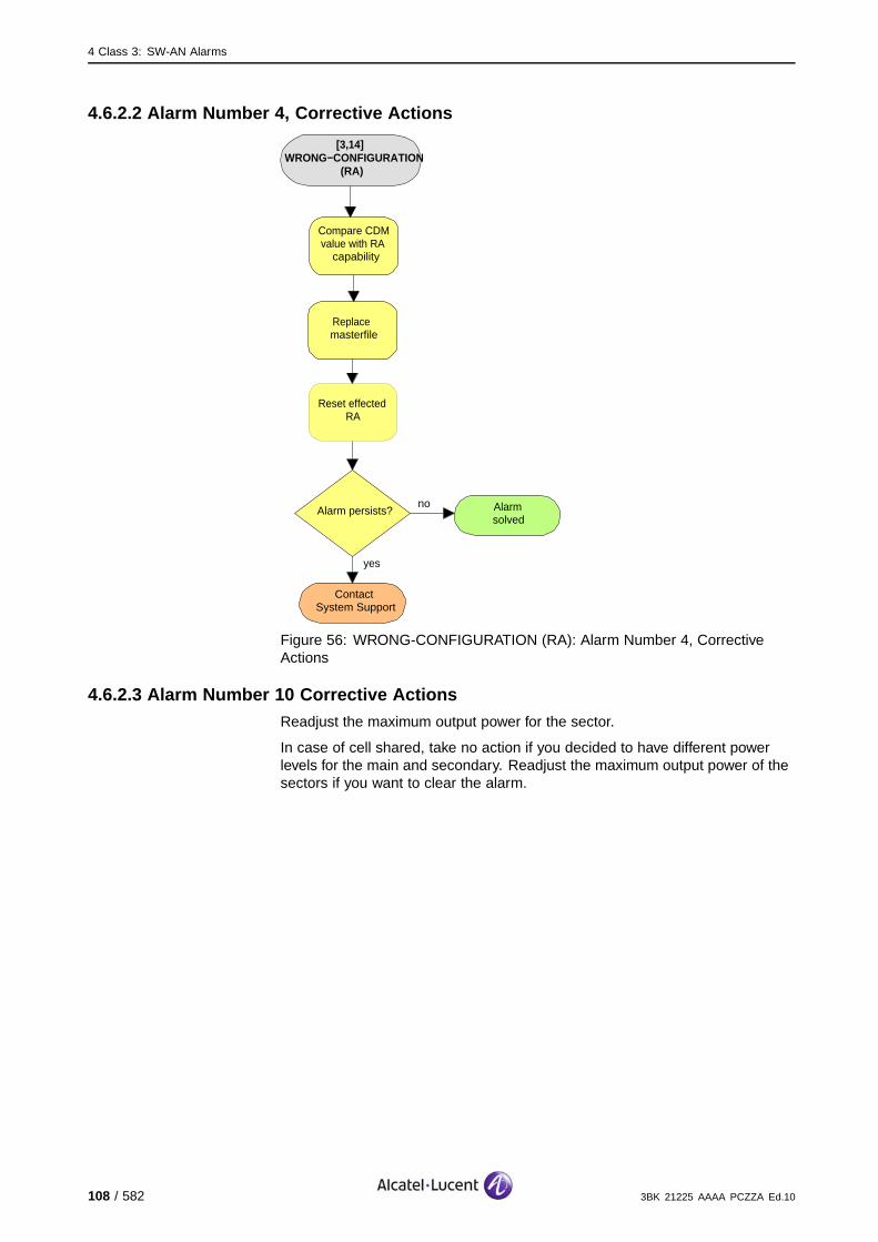
4 Class 3: SW-AN Alarms
4.6.2.2 Alarm Number 4, Corrective Actions
[3,14] WRONG−CONFIGURATION
(RA)
no
ContactSystem Support
Compare CDM value with RA
capability
Replace masterfile
Alarm persists?
yes
Alarmsolved
Reset effected RA
Figure 56: WRONG-CONFIGURATION (RA): Alarm Number 4, CorrectiveActions
4.6.2.3 Alarm Number 10 Corrective ActionsReadjust the maximum output power for the sector.
In case of cell shared, take no action if you decided to have different powerlevels for the main and secondary. Readjust the maximum output power of thesectors if you want to clear the alarm.
108 / 582 3BK 21225 AAAA PCZZA Ed.10
4 Class 3: SW-AN Alarms
4.6.3 [3,14] WRONG-CONFIGURATION (BTS, Alarm Number 12, 13, 14)
specific Problems WRONG-CONFIGURATION
event Type Processing Error
probable Cause Configuration Or Customization Error
perceived Severity Minor (DMA), Warning (MI)
Alarm Description The parameters are not consistent with the capacity of the equipment.
Alarm Number 12: A configuration with 2 PCM links is not supported.
13: The OML is not on Abis 1.
14: The configuration via the Qmux is not allowed with 2 PCM links.
There is no impact.
Impact BSS Cell(s) Signaling Calls
Loss - - - -
Degradation - - - -
3BK 21225 AAAA PCZZA Ed.10 109 / 582
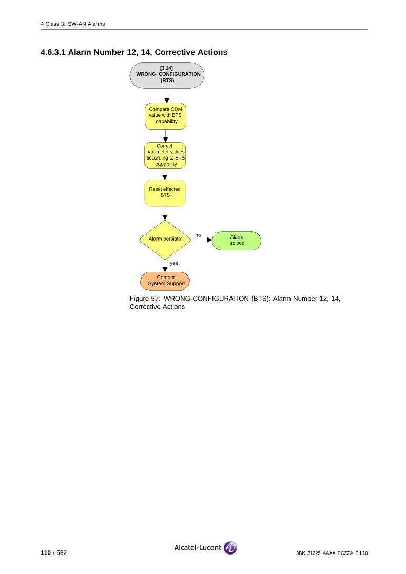
4 Class 3: SW-AN Alarms
4.6.3.1 Alarm Number 12, 14, Corrective Actions
[3,14] WRONG−CONFIGURATION
(BTS)
no
ContactSystem Support
Compare CDM value with BTS
capability
Correct parameter values according to BTS
capability
Alarm persists?
yes
Alarmsolved
Reset effected BTS
Figure 57: WRONG-CONFIGURATION (BTS): Alarm Number 12, 14,Corrective Actions
110 / 582 3BK 21225 AAAA PCZZA Ed.10
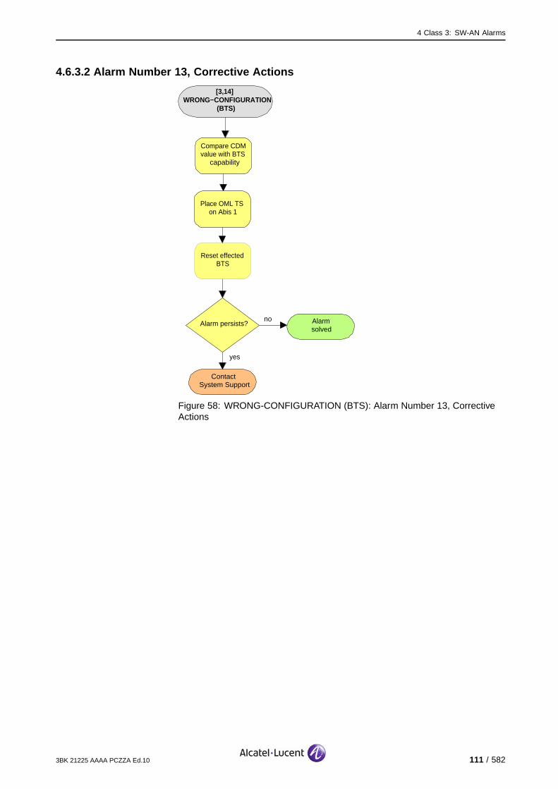
4 Class 3: SW-AN Alarms
4.6.3.2 Alarm Number 13, Corrective Actions
[3,14] WRONG−CONFIGURATION
(BTS)
no
ContactSystem Support
Compare CDM value with BTS
capability
Place OML TS on Abis 1
Alarm persists?
yes
Alarmsolved
Reset effected BTS
Figure 58: WRONG-CONFIGURATION (BTS): Alarm Number 13, CorrectiveActions
3BK 21225 AAAA PCZZA Ed.10 111 / 582

4 Class 3: SW-AN Alarms
4.7 [3,246] CONFIG-FAIL
4.7.1 [3,246] CONFIG-FAIL (CLLK)
specific Problems CONFIG-FAIL
event Type Processing Error
probable Cause Configuration Or Customization Error
perceived Severity Nbr 1: Major (PMA))
Nbr 3, 4: Minor (DMA), Warning (MI)
Alarm Description There is a scenario-failure for TRANS&CLOCK.
Alarm Number 1: An error in the initialization or re-configuration is detected, due to theabsence of an answer to the message "OMU, UNKNOWN_MESSAGE,inconvenient sub-state".
3: A SW downloading or SW activation failure is detected by theOMU, due to the absence of an answer to the message "OMU.UNKNOWN_MESSAGE, inconvenient sub -state". This alarm is not fatalbecause the TRANS&CLOCK uses the previous SW.
4: A transmission configuration failure is detected by the OMU due to noanswer to the OMU, an UNKNOWN MESSAGE or an inconvenient substate.This alarm has no fatal consequences, because the TRANS&CLOCK willuse the previous transmission settings.
If the CLLK is redundant on this BTS, the telecom functions are not affected.
For the 9100 BTS: there is no clock redundancy available, so the cells fed by the reporting CLLK arelost, thus the BTS is lost.
Impact BSS Cell(s) Signaling Calls
Loss - X(no red.) X(no red.) X(no red.)
Degradation X(no red.) - - -
112 / 582 3BK 21225 AAAA PCZZA Ed.10
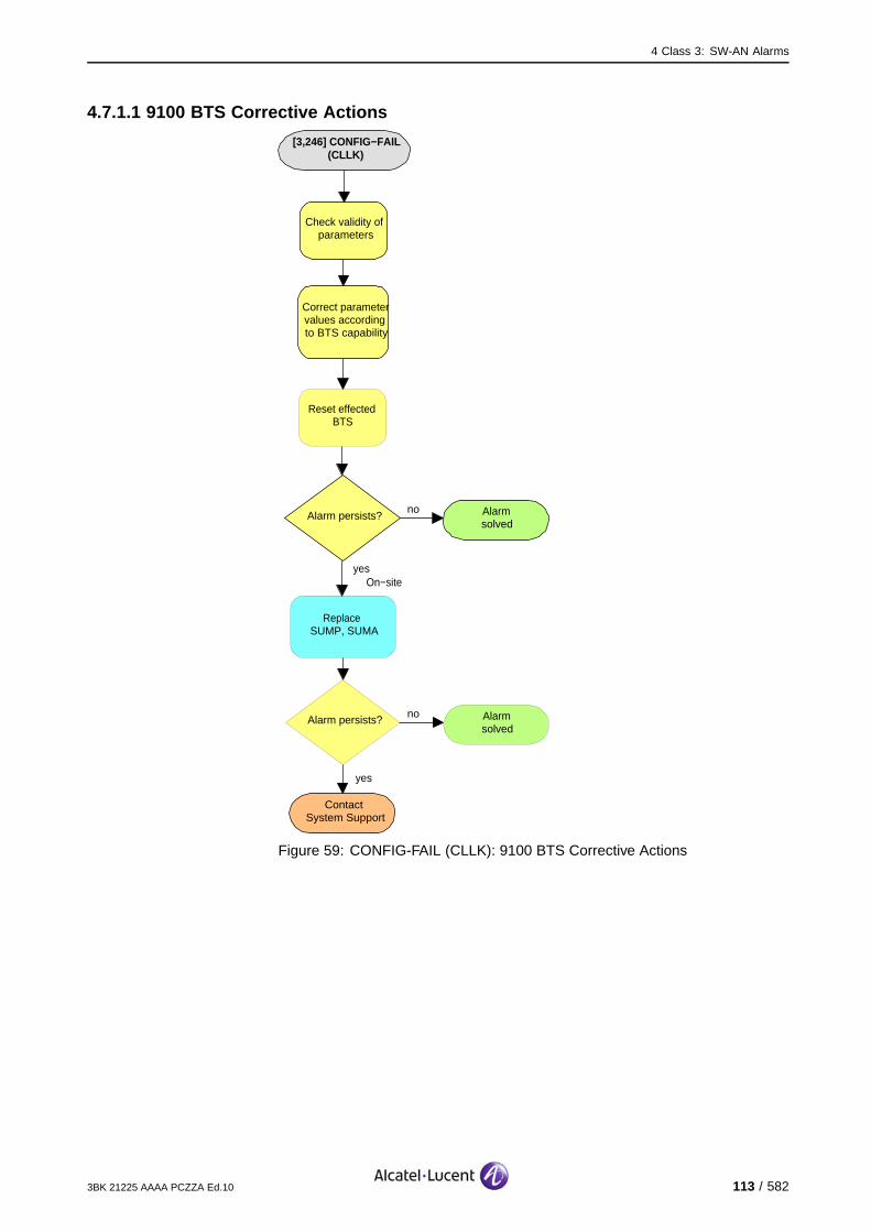
4 Class 3: SW-AN Alarms
4.7.1.1 9100 BTS Corrective Actions
[3,246] CONFIG−FAIL (CLLK)
no
ContactSystem Support
Check validity of parameters
Correct parameter values according to BTS capability
Alarm persists?
yes
Alarmsolved
Reset effected BTS
On−site
Replace SUMP, SUMA
noAlarm persists? Alarmsolved
yes
Figure 59: CONFIG-FAIL (CLLK): 9100 BTS Corrective Actions
3BK 21225 AAAA PCZZA Ed.10 113 / 582

4 Class 3: SW-AN Alarms
4.7.1.2 9110 Micro BTS/9110-E Micro BTS Corrective Actions
[3,246] CONFIG−FAIL (CLLK)
Alarmsolved
yes
no
On−site
no
ContactSystem Support
Disconnect mains power from ACCO
to Basic Unit
BTS operational?
yesAlarmsolved
On−site
After 30 s re−power the BTS
On−site
Switch off Battery Backup Switch and
Main Power switch in Side Support Cabinet
On−site
Switch off mains power fuse for tower mounted
BTSOR OR
On−site
Replace BTS A910
no BTSoperational?
yes
Alarmsolved
BTSoperational?
Reset Function BTS
Check validity of parameters
Correct parameter values according to BTS capability
Figure 60: CONFIG-FAIL (CLLK): 9110 Micro BTS/9110-E Micro BTS Corrective Actions
114 / 582 3BK 21225 AAAA PCZZA Ed.10
4 Class 3: SW-AN Alarms
4.7.2 [3,246] CONFIG-FAIL (RA)
specific Problems CONFIG-FAIL
event Type Processing Error
probable Cause Configuration Or Customization Error
perceived Severity Nbr 2: Major (PMA)
Nbr 1: Minor (DMA)
Alarm Description There is a scenario-failure for ANX or RA.
Alarm Number 1: An error in the initialization is detected due to no answer to OMU,UNKNOWN_MESSAGE, inconvenient sub-state.
2: An error in the initialization is detected due to failure in initialization of allTREs connected to this ANX or RA.
Telecom functions are not affected.
Impact BSS Cell(s) Signaling Calls
Loss - - - -
Degradation - - - -
3BK 21225 AAAA PCZZA Ed.10 115 / 582
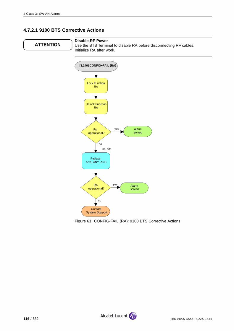
4 Class 3: SW-AN Alarms
4.7.2.1 9100 BTS Corrective Actions
Disable RF PowerUse the BTS Terminal to disable RA before disconnecting RF cables.Initialize RA after work.
[3,246] CONFIG−FAIL (RA)
Alarmsolved
yesRA operational?
no
On−site
no
ContactSystem Support
Lock Function RA
Unlock Function RA
Replace ANX, ANY, ANC
RAoperational?
yes Alarmsolved
Figure 61: CONFIG-FAIL (RA): 9100 BTS Corrective Actions
116 / 582 3BK 21225 AAAA PCZZA Ed.10
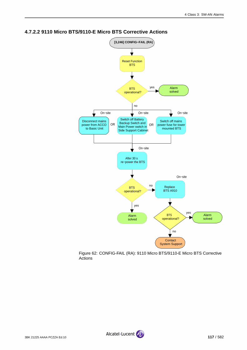
4 Class 3: SW-AN Alarms
4.7.2.2 9110 Micro BTS/9110-E Micro BTS Corrective Actions
[3,246] CONFIG−FAIL (RA)
Alarmsolved
yes
no
On−site
no
ContactSystem Support
Disconnect mains power from ACCO
to Basic Unit
BTS operational?
yesAlarmsolved
On−site
After 30 s re−power the BTS
On−site
Switch off Battery Backup Switch and
Main Power switch in Side Support Cabinet
On−site
Switch off mains power fuse for tower
mounted BTSOR OR
On−site
Replace BTS A910
noBTS
operational?
yes
Alarmsolved
BTSoperational?
Reset Function BTS
Figure 62: CONFIG-FAIL (RA): 9110 Micro BTS/9110-E Micro BTS CorrectiveActions
3BK 21225 AAAA PCZZA Ed.10 117 / 582
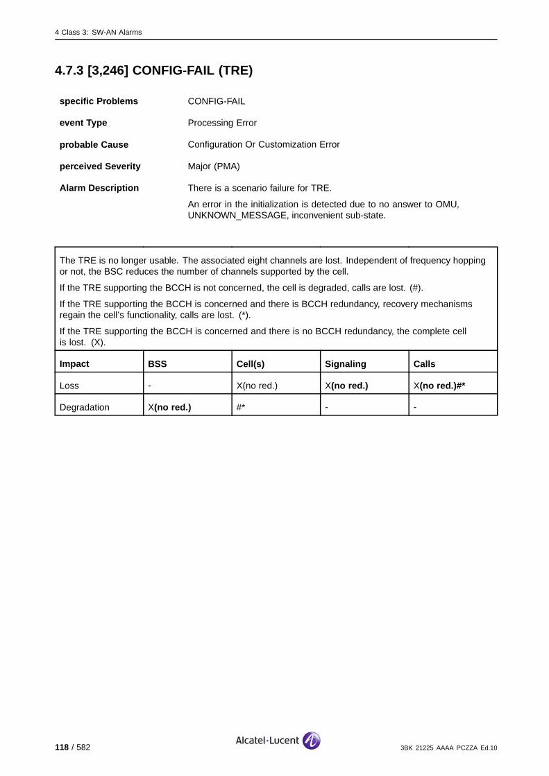
4 Class 3: SW-AN Alarms
4.7.3 [3,246] CONFIG-FAIL (TRE)
specific Problems CONFIG-FAIL
event Type Processing Error
probable Cause Configuration Or Customization Error
perceived Severity Major (PMA)
Alarm Description There is a scenario failure for TRE.
An error in the initialization is detected due to no answer to OMU,UNKNOWN_MESSAGE, inconvenient sub-state.
The TRE is no longer usable. The associated eight channels are lost. Independent of frequency hoppingor not, the BSC reduces the number of channels supported by the cell.
If the TRE supporting the BCCH is not concerned, the cell is degraded, calls are lost. (#).
If the TRE supporting the BCCH is concerned and there is BCCH redundancy, recovery mechanismsregain the cell’s functionality, calls are lost. (*).
If the TRE supporting the BCCH is concerned and there is no BCCH redundancy, the complete cellis lost. (X).
Impact BSS Cell(s) Signaling Calls
Loss - X(no red.) X(no red.) X(no red.)#*
Degradation X(no red.) #* - -
118 / 582 3BK 21225 AAAA PCZZA Ed.10

4 Class 3: SW-AN Alarms
4.7.3.1 9100 BTS Corrective Actions
Disable RF PowerUse the BTS Terminal to disable RA before disconnecting RF cables.Initialize RA after work.
[3,246] CONFIG−FAIL (TRE)
Alarmsolved
yesTREoperational?
no
On−site
no
ContactSystem Support
Lock Function TRE
Unlock Function TRE
Replace TRE
TREoperational?
yes Alarmsolved
Figure 63: CONFIG-FAIL (TRE): 9100 BTS Corrective Actions
3BK 21225 AAAA PCZZA Ed.10 119 / 582
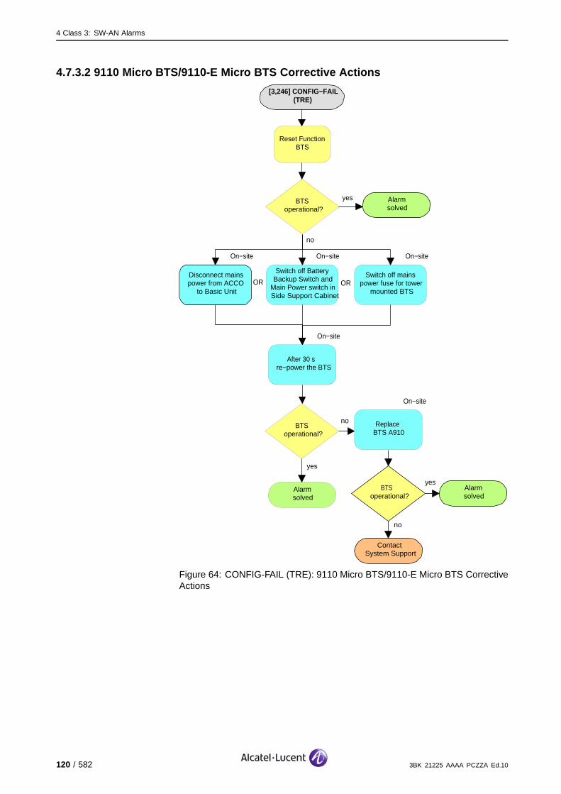
4 Class 3: SW-AN Alarms
4.7.3.2 9110 Micro BTS/9110-E Micro BTS Corrective Actions
[3,246] CONFIG−FAIL (TRE)
Alarmsolved
yes
no
On−site
no
ContactSystem Support
Disconnect mains power from ACCO
to Basic Unit
BTS operational?
yesAlarmsolved
On−site
After 30 s re−power the BTS
On−site
Switch off Battery Backup Switch and
Main Power switch in Side Support Cabinet
On−site
Switch off mains power fuse for tower
mounted BTSOR OR
On−site
Replace BTS A910
noBTS
operational?
yes
Alarmsolved
BTSoperational?
Reset Function BTS
Figure 64: CONFIG-FAIL (TRE): 9110 Micro BTS/9110-E Micro BTS CorrectiveActions
120 / 582 3BK 21225 AAAA PCZZA Ed.10

5 Class 4: FHU Alarms
5 Class 4: FHU Alarms
This section defines the alarms for the Class 4: FHU alarm class.
3BK 21225 AAAA PCZZA Ed.10 121 / 582
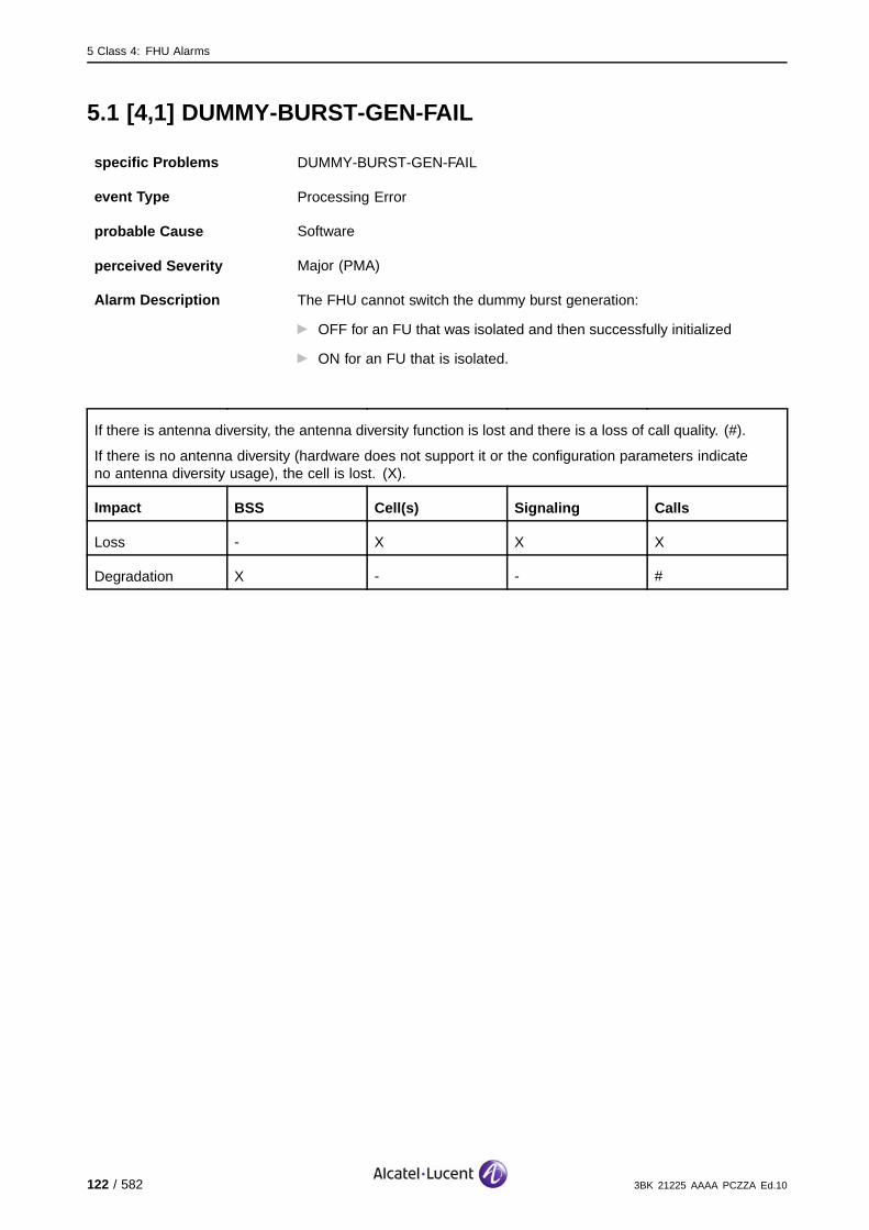
5 Class 4: FHU Alarms
5.1 [4,1] DUMMY-BURST-GEN-FAIL
specific Problems DUMMY-BURST-GEN-FAIL
event Type Processing Error
probable Cause Software
perceived Severity Major (PMA)
Alarm Description The FHU cannot switch the dummy burst generation:
OFF for an FU that was isolated and then successfully initialized
ON for an FU that is isolated.
If there is antenna diversity, the antenna diversity function is lost and there is a loss of call quality. (#).
If there is no antenna diversity (hardware does not support it or the configuration parameters indicateno antenna diversity usage), the cell is lost. (X).
Impact BSS Cell(s) Signaling Calls
Loss - X X X
Degradation X - - #
122 / 582 3BK 21225 AAAA PCZZA Ed.10
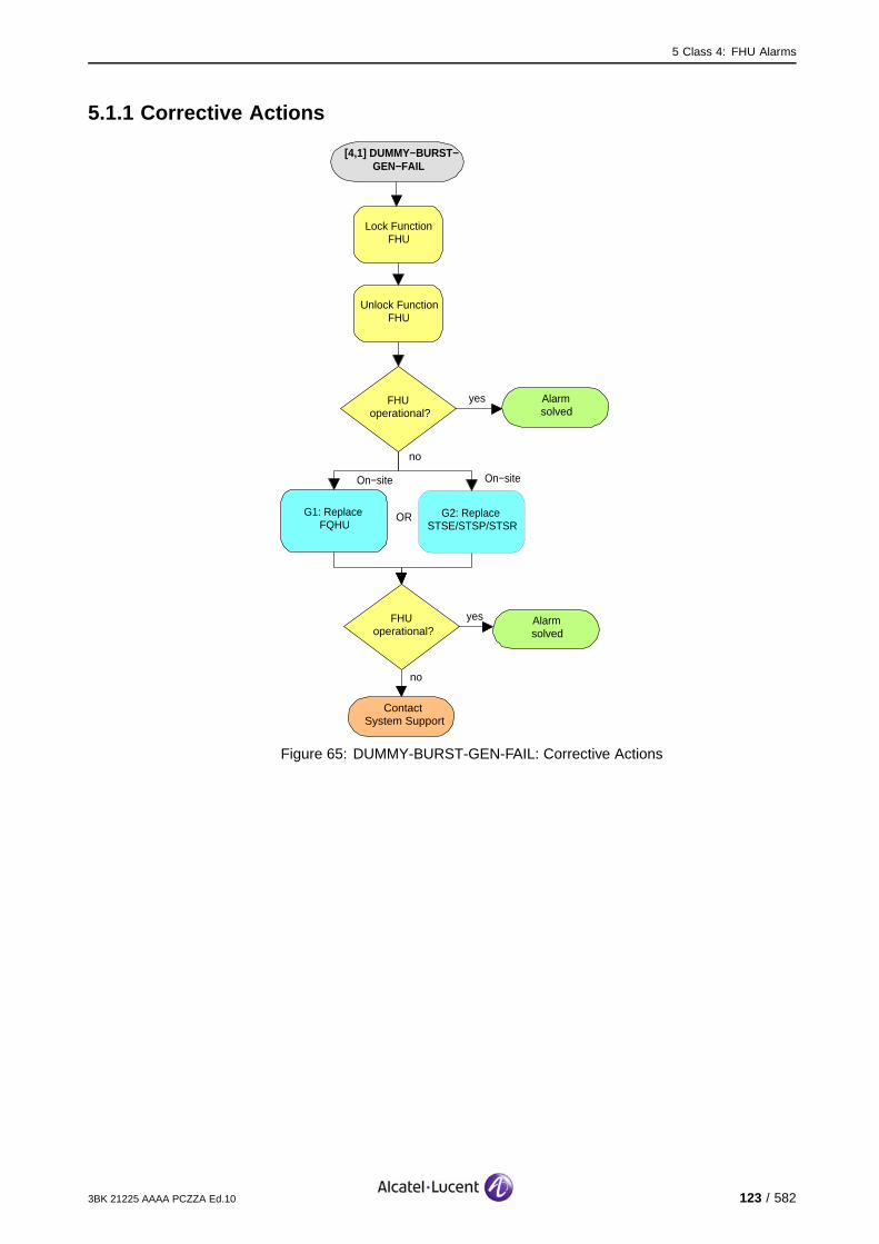
5 Class 4: FHU Alarms
5.1.1 Corrective Actions
[4,1] DUMMY−BURST−GEN−FAIL
Alarmsolved
yesFHUoperational?
no
On−site
no
ContactSystem Support
Lock Function FHU
Unlock Function FHU
G1: Replace FQHU
FHUoperational?
yes Alarmsolved
G2: Replace STSE/STSP/STSR
On−site
OR
Figure 65: DUMMY-BURST-GEN-FAIL: Corrective Actions
3BK 21225 AAAA PCZZA Ed.10 123 / 582

5 Class 4: FHU Alarms
5.2 [4,5] FN-AL
specific Problems FN-AL
event Type Equipment
probable Cause Timing Problem
perceived Severity Minor (DMA)
Alarm Description The FHU detects a bad Frame Number on one of the two clock linksbetween the Clock Unit and the FHU.
Alarm Number 1: Fault on Clock Link 1.
2: Fault on Clock Link 2.
Telecom functions are not affected.
Impact BSS Cell(s) Signaling Calls
Loss - - - -
Degradation - - - -
5.2.1 Corrective Actions
[4,5] FN−AL
Alarmsolved
yesFHU operational?
no
ContactSystem Support
Reconnect FHU to Clock Unit
Check cables and connectors between Clock Unit and FHU
On−site
Figure 66: FN-AL: Corrective Actions
124 / 582 3BK 21225 AAAA PCZZA Ed.10

5 Class 4: FHU Alarms
5.3 [4,6] INTERNAL-FN
specific Problems INTERNAL-FN
event Type Equipment
probable Cause Timing Problem
perceived Severity Major (PMA)
Alarm Description The FHU detects a bad Frame Number on both clock links between theClock Unit and the FHU.
If there is antenna diversity, the antenna diversity function is lost and there is a loss of call quality. (#)
If there is no antenna diversity (hardware does not support it or the configuration parameters indicateno antenna diversity usage), the cell is lost. ( X)
Impact BSS Cell(s) Signaling Calls
Loss - X X X
Degradation X - - #
3BK 21225 AAAA PCZZA Ed.10 125 / 582
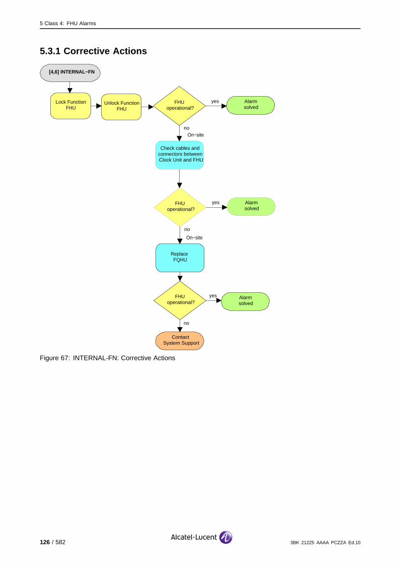
5 Class 4: FHU Alarms
5.3.1 Corrective Actions
[4,6] INTERNAL−FN
Alarmsolved
yesFHUoperational?
no
On−site
no
ContactSystem Support
Lock Function FHU
Unlock Function FHU
Replace FQHU
FHUoperational?
yes Alarmsolved
Alarmsolved
yesFHUoperational?
no
Check cables and connectors between Clock Unit and FHU
On−site
Figure 67: INTERNAL-FN: Corrective Actions
126 / 582 3BK 21225 AAAA PCZZA Ed.10
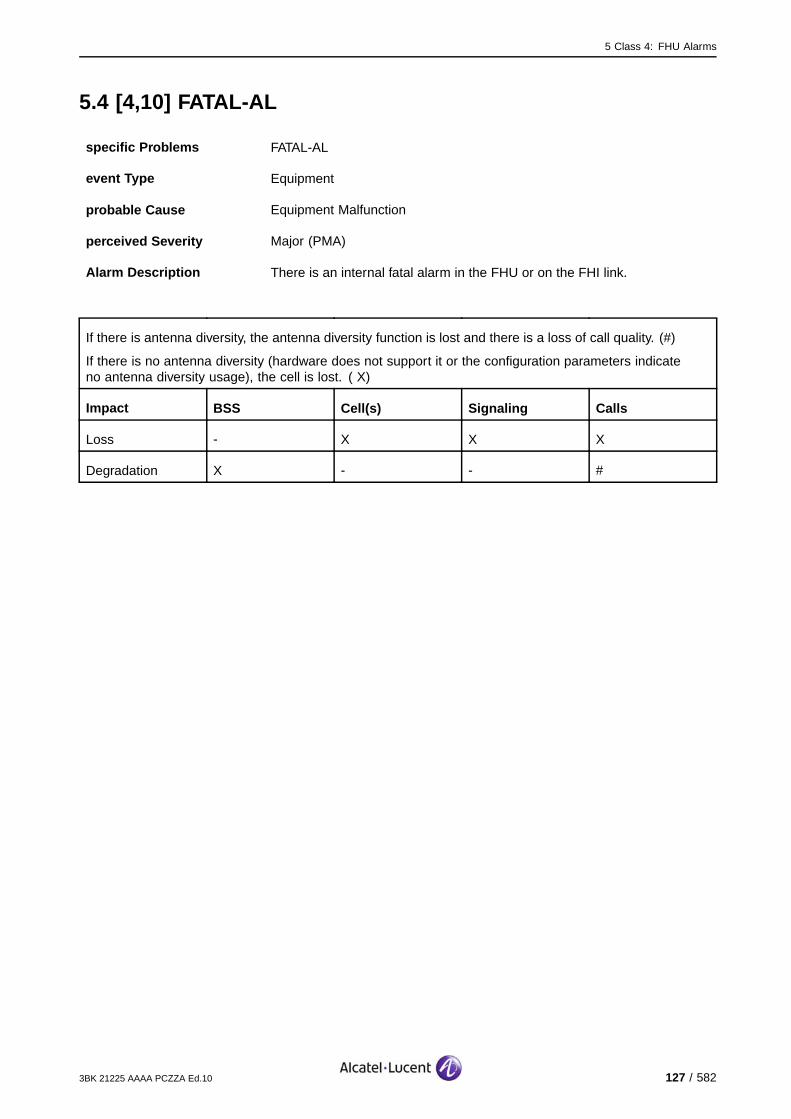
5 Class 4: FHU Alarms
5.4 [4,10] FATAL-AL
specific Problems FATAL-AL
event Type Equipment
probable Cause Equipment Malfunction
perceived Severity Major (PMA)
Alarm Description There is an internal fatal alarm in the FHU or on the FHI link.
If there is antenna diversity, the antenna diversity function is lost and there is a loss of call quality. (#)
If there is no antenna diversity (hardware does not support it or the configuration parameters indicateno antenna diversity usage), the cell is lost. ( X)
Impact BSS Cell(s) Signaling Calls
Loss - X X X
Degradation X - - #
3BK 21225 AAAA PCZZA Ed.10 127 / 582

5 Class 4: FHU Alarms
5.4.1 Corrective Actions
[4,10] FATAL−AL
Alarmsolved
yesFHUoperational?
no
On−site
no
ContactSystem Support
Lock Function FHU
Unlock Function FHU
G1: Replace FQHU
FHUoperational?
yes Alarmsolved
G2:Replace
STSE/STSP/STSR
On−site
Figure 68: FATAL-AL: Corrective Actions
128 / 582 3BK 21225 AAAA PCZZA Ed.10
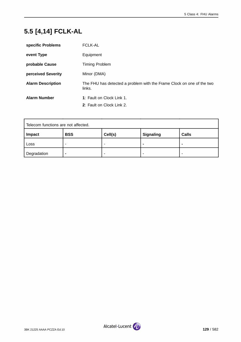
5 Class 4: FHU Alarms
5.5 [4,14] FCLK-AL
specific Problems FCLK-AL
event Type Equipment
probable Cause Timing Problem
perceived Severity Minor (DMA)
Alarm Description The FHU has detected a problem with the Frame Clock on one of the twolinks.
Alarm Number 1: Fault on Clock Link 1.
2: Fault on Clock Link 2.
Telecom functions are not affected.
Impact BSS Cell(s) Signaling Calls
Loss - - - -
Degradation - - - -
3BK 21225 AAAA PCZZA Ed.10 129 / 582

5 Class 4: FHU Alarms
5.5.1 Corrective Actions
[4,14] FCLK−AL
Alarmsolved
yesFHUoperational?
no
On−site
no
ContactSystem Support
Lock Function FHU
Unlock Function FHU
Replace FQHU
FHUoperational?
yes Alarmsolved
Alarmsolved
yesFHUoperational?
no
Check cables and connectors between Clock Unit and FHU
On−site
Figure 69: FCLK-AL: Corrective Actions
130 / 582 3BK 21225 AAAA PCZZA Ed.10

5 Class 4: FHU Alarms
5.6 [4,15] INT-FCLK-AL
specific Problems INT-FCLK-AL
event Type Equipment
probable Cause Timing Problem
perceived Severity Major (PMA)
Alarm Description The FHU has detected a problem on the Frame Clocks of both clock links.
If there is antenna diversity, the antenna diversity function is lost and there is a loss of call quality. (#)
If there is no antenna diversity (hardware does not support it or the configuration parameters indicateno antenna diversity usage), the cell is lost. (X).
Impact BSS Cell(s) Signaling Calls
Loss - X X X
Degradation X - - #
3BK 21225 AAAA PCZZA Ed.10 131 / 582
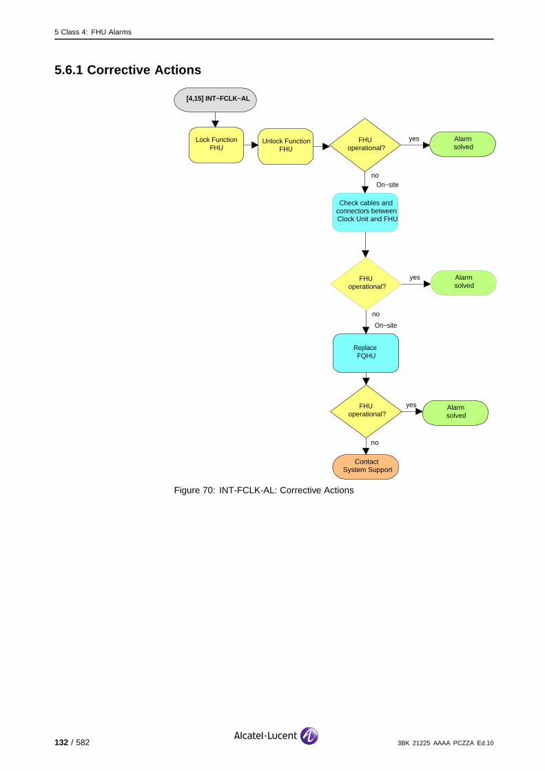
5 Class 4: FHU Alarms
5.6.1 Corrective Actions
[4,15] INT−FCLK−AL
Alarmsolved
yesFHUoperational?
no
On−site
no
ContactSystem Support
Lock Function FHU
Unlock Function FHU
Replace FQHU
FHUoperational?
yes Alarmsolved
Alarmsolved
yesFHUoperational?
no
Check cables and connectors between Clock Unit and FHU
On−site
Figure 70: INT-FCLK-AL: Corrective Actions
132 / 582 3BK 21225 AAAA PCZZA Ed.10

5 Class 4: FHU Alarms
5.7 [4,16] OBCLK-AL
specific Problems OBCLK-AL
event Type Equipment
probable Cause Timing Problem
perceived Severity Minor (DMA)
Alarm Description The FHU detects a problem with the OBCLK on one of the clock links.
Alarm Number 1: Fault on Clock Link 1.
2: Fault on Clock Link 2.
Telecom functions are not affected.
Impact BSS Cell(s) Signaling Calls
Loss - - - -
Degradation - - - -
3BK 21225 AAAA PCZZA Ed.10 133 / 582

5 Class 4: FHU Alarms
5.7.1 Corrective Actions
[4,16] OBCLK−AL
Alarmsolved
yesFHUoperational?
no
On−site
no
ContactSystem Support
Lock Function FHU
Unlock Function FHU
Replace FQHU
FHUoperational?
yes Alarmsolved
Alarmsolved
yesFHUoperational?
no
Check cables and connectors between Clock Unit and FHU
On−site
Figure 71: OBCLK-AL: Corrective Actions
134 / 582 3BK 21225 AAAA PCZZA Ed.10
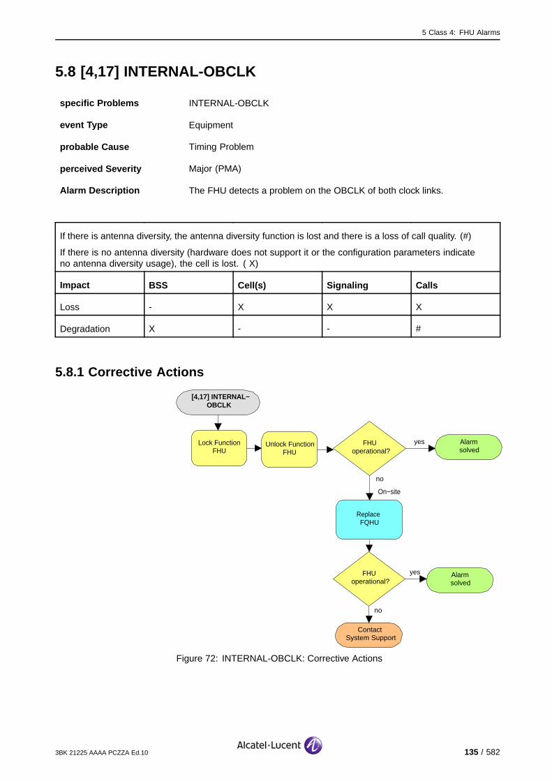
5 Class 4: FHU Alarms
5.8 [4,17] INTERNAL-OBCLK
specific Problems INTERNAL-OBCLK
event Type Equipment
probable Cause Timing Problem
perceived Severity Major (PMA)
Alarm Description The FHU detects a problem on the OBCLK of both clock links.
If there is antenna diversity, the antenna diversity function is lost and there is a loss of call quality. (#)
If there is no antenna diversity (hardware does not support it or the configuration parameters indicateno antenna diversity usage), the cell is lost. ( X)
Impact BSS Cell(s) Signaling Calls
Loss - X X X
Degradation X - - #
5.8.1 Corrective Actions
[4,17] INTERNAL−OBCLK
Alarmsolved
yesFHUoperational?
no
On−site
no
ContactSystem Support
Lock Function FHU
Unlock Function FHU
Replace FQHU
FHUoperational?
yes Alarmsolved
Figure 72: INTERNAL-OBCLK: Corrective Actions
3BK 21225 AAAA PCZZA Ed.10 135 / 582
5 Class 4: FHU Alarms
5.9 [4,240] MISSING-ENTRY-IN-CPF
specific Problems MISSING-ENTRY-IN-CPF
event Type Processor Error
probable Cause Configuration Or Customization Error
perceived Severity Major (PMA)
Alarm Description An expected entry in the OMU CPF was not found. The equipmentidentification for the FHU is not included in the OMU CPF.
If the FHU has redundancy, telecom functions are not affected.
If there is no redundancy, the cell is lost.
Impact BSS Cell(s) Signaling Calls
Loss - X(no red.) X(no red.) X(no red.)
Degradation X(no red.) - - -
136 / 582 3BK 21225 AAAA PCZZA Ed.10
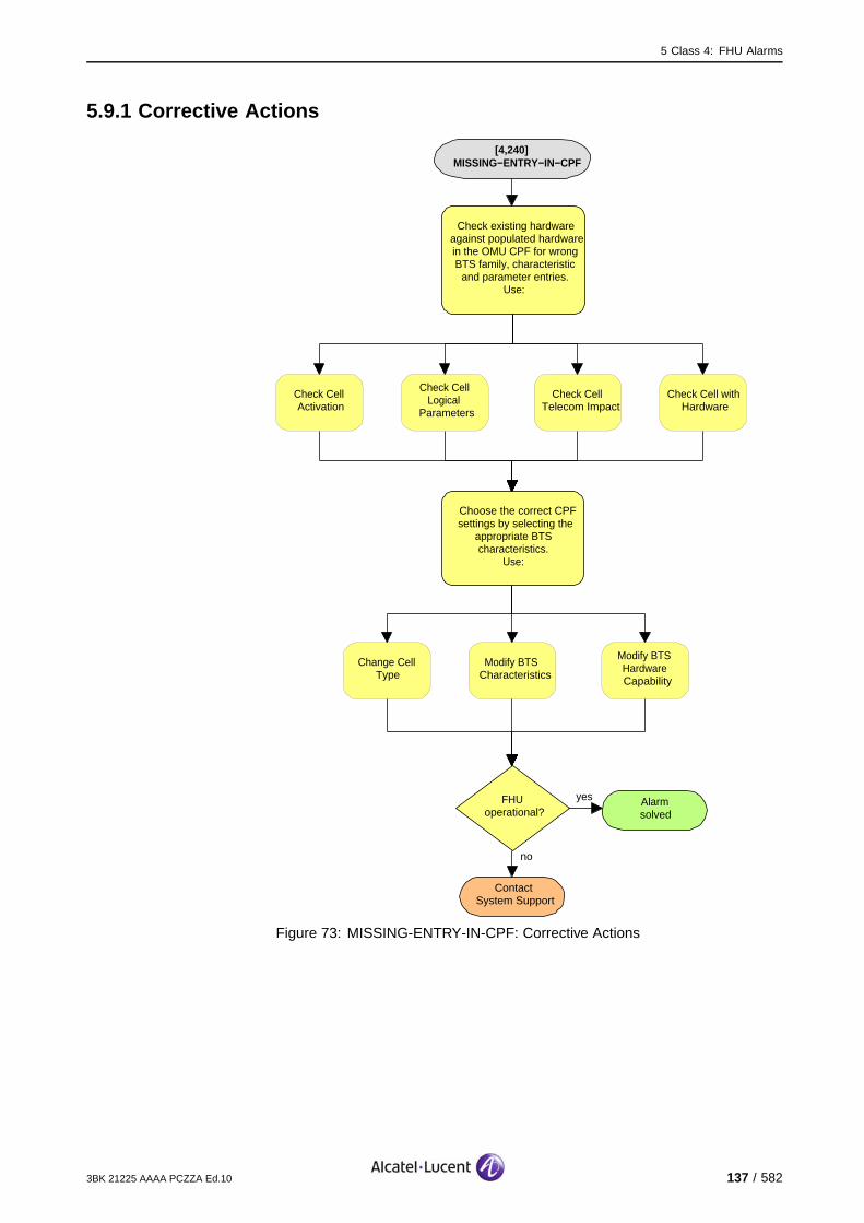
5 Class 4: FHU Alarms
5.9.1 Corrective Actions
[4,240] MISSING−ENTRY−IN−CPF
no
ContactSystem Support
Check existing hardware against populated hardware in the OMU CPF for wrong BTS family, characteristic
and parameter entries. Use:
Choose the correct CPFsettings by selecting the
appropriate BTS characteristics.
Use:
FHUoperational?
yes Alarmsolved
Check Cell Activation
Check Cell Logical
Parameters
Check Cell Telecom Impact
Check Cell with Hardware
Change Cell Type
Modify BTS Characteristics
Modify BTS Hardware Capability
Figure 73: MISSING-ENTRY-IN-CPF: Corrective Actions
3BK 21225 AAAA PCZZA Ed.10 137 / 582
5 Class 4: FHU Alarms
5.10 [4,246] CONFIG-FAIL
specific Problems CONFIG-FAIL
event Type Processing Error
probable Cause Configuration Or Customization Error
perceived Severity Major (PMA)
Alarm Description The configuration for an FHU fails.
If there is antenna diversity, the antenna diversity function is lost and there is a loss of call quality. (#)
If there is no antenna diversity (hardware does not support it or the configuration parameters indicateno antenna diversity usage), the cell is lost. (X).
Impact BSS Cell(s) Signaling Calls
Loss - X X X
Degradation X - - #
138 / 582 3BK 21225 AAAA PCZZA Ed.10
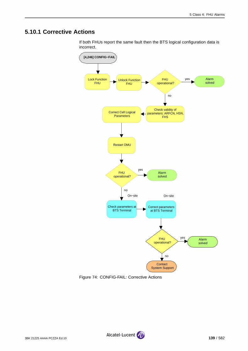
5 Class 4: FHU Alarms
5.10.1 Corrective Actions
If both FHUs report the same fault then the BTS logical configuration data isincorrect.
[4,246] CONFIG−FAIL
no
ContactSystem Support
FHUoperational?
yes Alarmsolved
Correct Cell Logical Parameters
Restart OMU
no
FHUoperational?
yesAlarmsolved
On−site
Check parameters at BTS Terminal
Alarmsolved
yesFHUoperational?
no
Lock Function FHU
Unlock Function FHU
Correct parameters at BTS Terminal
On−site
Check validity of parameters: ARFCN, HSN,
FHS
Figure 74: CONFIG-FAIL: Corrective Actions
3BK 21225 AAAA PCZZA Ed.10 139 / 582
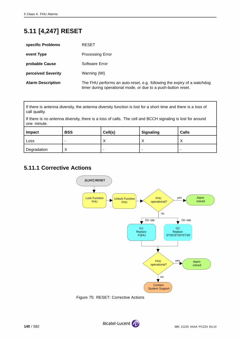
5 Class 4: FHU Alarms
5.11 [4,247] RESET
specific Problems RESET
event Type Processing Error
probable Cause Software Error
perceived Severity Warning (MI)
Alarm Description The FHU performs an auto-reset, e.g. following the expiry of a watchdogtimer during operational mode, or due to a push-button reset.
If there is antenna diversity, the antenna diversity function is lost for a short time and there is a loss ofcall quality.
If there is no antenna diversity, there is a loss of calls. The cell and BCCH signaling is lost for aroundone minute.
Impact BSS Cell(s) Signaling Calls
Loss - X X X
Degradation X - - -
5.11.1 Corrective Actions
[4,247] RESET
Alarmsolved
yesFHUoperational?
no
On−site
no
ContactSystem Support
Lock Function FHU
Unlock Function FHU
G1:Replace FQHU
FHUoperational?
yes Alarmsolved
On−site
G2:Replace
STSE/STSP/STSR
Figure 75: RESET: Corrective Actions
140 / 582 3BK 21225 AAAA PCZZA Ed.10
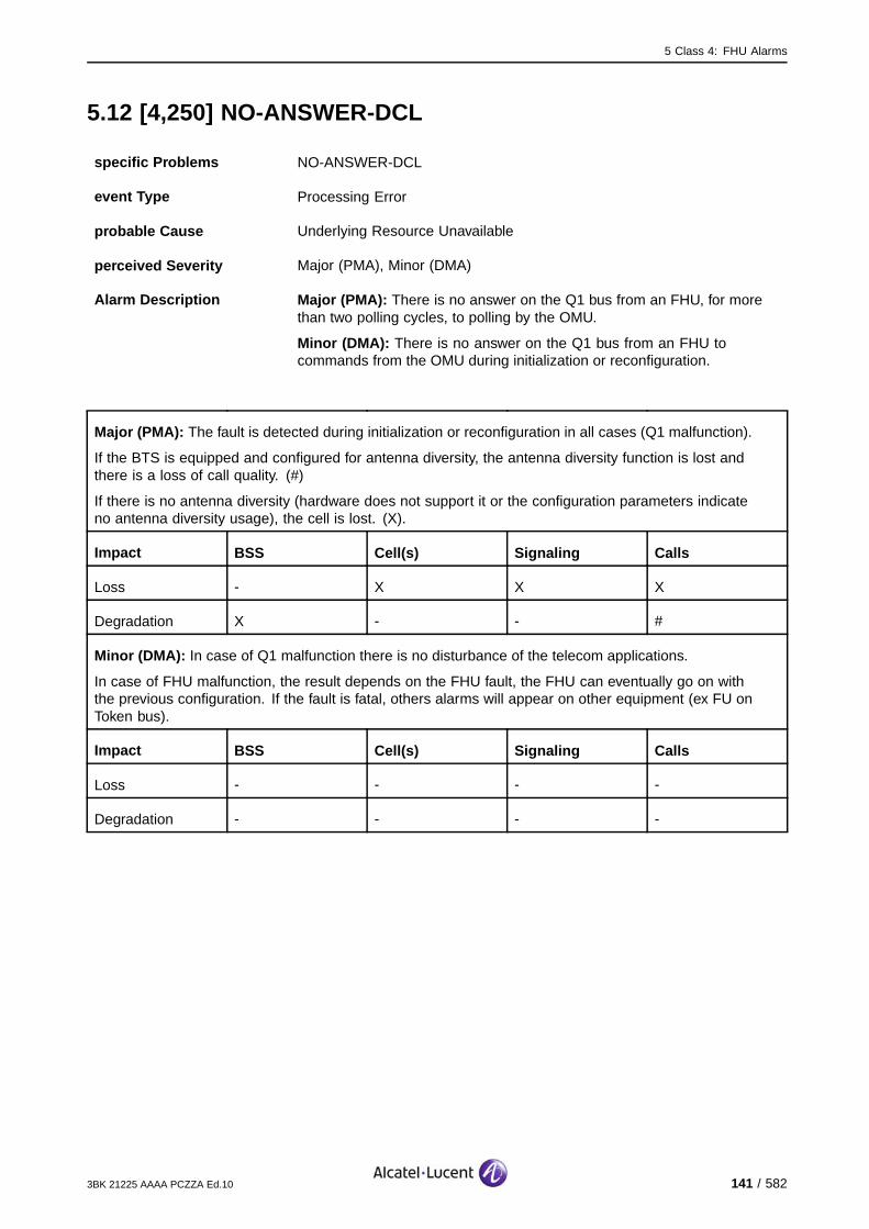
5 Class 4: FHU Alarms
5.12 [4,250] NO-ANSWER-DCL
specific Problems NO-ANSWER-DCL
event Type Processing Error
probable Cause Underlying Resource Unavailable
perceived Severity Major (PMA), Minor (DMA)
Alarm Description Major (PMA): There is no answer on the Q1 bus from an FHU, for morethan two polling cycles, to polling by the OMU.
Minor (DMA): There is no answer on the Q1 bus from an FHU tocommands from the OMU during initialization or reconfiguration.
Major (PMA): The fault is detected during initialization or reconfiguration in all cases (Q1 malfunction).
If the BTS is equipped and configured for antenna diversity, the antenna diversity function is lost andthere is a loss of call quality. (#)
If there is no antenna diversity (hardware does not support it or the configuration parameters indicateno antenna diversity usage), the cell is lost. (X).
Impact BSS Cell(s) Signaling Calls
Loss - X X X
Degradation X - - #
Minor (DMA): In case of Q1 malfunction there is no disturbance of the telecom applications.
In case of FHU malfunction, the result depends on the FHU fault, the FHU can eventually go on withthe previous configuration. If the fault is fatal, others alarms will appear on other equipment (ex FU onToken bus).
Impact BSS Cell(s) Signaling Calls
Loss - - - -
Degradation - - - -
3BK 21225 AAAA PCZZA Ed.10 141 / 582
5 Class 4: FHU Alarms
5.12.1 Corrective Actions
[4,250] NO−ANSWER−DCL
Alarmsolved
yesFHUoperational?
no
no
ContactSystem Support
Lock Function FHU
Unlock Function FHU
FHUoperational?
yes Alarmsolved
Alarmsolved
yesFHUoperational?
no
Check Q1 cables and connectors between
OMU and FHU
On−site
On−site
G1:Replace FQHU
On−site
G2:Replace
STSE/STSP/STSR
Figure 76: NO-ANSWER-DCL: Corrective Actions
142 / 582 3BK 21225 AAAA PCZZA Ed.10
5 Class 4: FHU Alarms
5.13 [4,255] Q1-RELAY-FAILURE
specific Problems Q1-RELAY-FAILURE
event Type Equipment
probable Cause Equipment Malfunction
perceived Severity Minor (DMA)
Alarm Description There is a failure on the Q1 relay. The FHU cannot disconnect itself fromthe Q1 bus.
Telecom functions are not affected.
Impact BSS Cell(s) Signaling Calls
Loss - - - -
Degradation - - - -
3BK 21225 AAAA PCZZA Ed.10 143 / 582
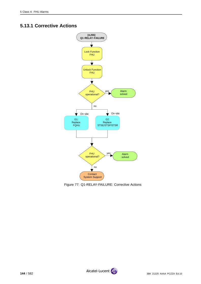
5 Class 4: FHU Alarms
5.13.1 Corrective Actions
[4,255] Q1−RELAY−FAILURE
Alarmsolved
yesFHUoperational?
no
no
ContactSystem Support
Lock Function FHU
Unlock Function FHU
FHUoperational?
yes Alarmsolved
On−site
G1:Replace FQHU
On−site
G2:Replace
STSE/STSP/STSR
Figure 77: Q1-RELAY-FAILURE: Corrective Actions
144 / 582 3BK 21225 AAAA PCZZA Ed.10

6 Class 5: ENVIR Alarms
6 Class 5: ENVIR Alarms
This section defines the alarms for the Class 5: ENVIR alarm class.
3BK 21225 AAAA PCZZA Ed.10 145 / 582

6 Class 5: ENVIR Alarms
6.1 [5,0] POWER-SUPPLY
6.1.1 [5,0] POWER-SUPPLY (CU)
specific Problems POWER-SUPPLY
event Type Equipment
probable Cause PowerProblem
perceived Severity Major (PMA), Minor (DMA)
Alarm Description Major (PMA): A CUPS Power Supply fails.
Minor (DMA): There is an AC/DC Power Supply problem.
The CU is no longer usable. The associated eight channels are lost. Independent of frequency hopping ornot, the BSC reduces the number of channels supported by the cell.
If the CU supporting the BCCH is not concerned, the cell is degraded, calls are lost. (#)
If the CU supporting the BCCH is concerned and there is BCCH redundancy, recovery mechanismsregain the cell’s functionality. (*)
If the CU supporting the BCCH is concerned and there is no BCCH redundancy, the complete cellis lost. (X).
Impact BSS Cell(s) Signaling Calls
Loss - X(no red.) X(no red.) X(no red.)#*
Degradation X(no red.) #* - -
146 / 582 3BK 21225 AAAA PCZZA Ed.10
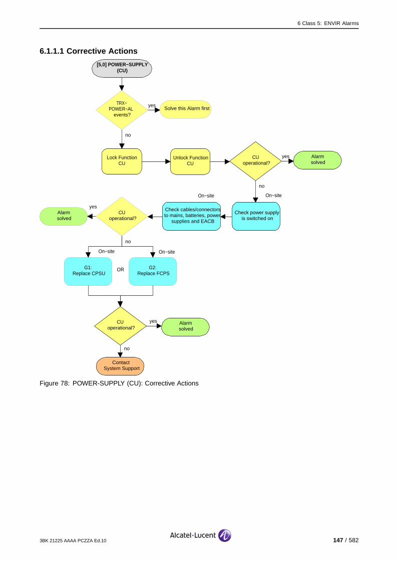
6 Class 5: ENVIR Alarms
6.1.1.1 Corrective Actions
[5,0] POWER−SUPPLY (CU)
Alarmsolved
yesCUoperational?
no
On−site
Check cables/connectors to mains, batteries, power
supplies and EACB
On−site
no
ContactSystem Support
Lock Function CU
Unlock Function CU
Check power supply is switched on
CUoperational?
yes Alarmsolved
Solve this Alarm firstyesTRX−
POWER−AL events?
no
On−site
G1:Replace CPSU
G2:Replace FCPS
On−site
OR
Alarmsolved
yesCU
operational?
no
Figure 78: POWER-SUPPLY (CU): Corrective Actions
3BK 21225 AAAA PCZZA Ed.10 147 / 582

6 Class 5: ENVIR Alarms
6.1.2 [5,0] POWER-SUPPLY (FU)
specific Problems POWER-SUPPLY
event Type Equipment
probable Cause PowerProblem
perceived Severity Major (PMA), Minor (DMA)
Alarm Description Major (PMA): A FUPS fails.
Minor (DMA): There is an AC/DC Power Supply problem.
The FU is no longer usable. The associated eight channels are lost. Independent of frequency hopping ornot, the BSC reduces the number of channels supported by the cell.
If the FU supporting the BCCH is not concerned, the cell is degraded, calls are lost. (#)
If the FU supporting the BCCH is concerned and there is BCCH redundancy, recovery mechanismsregain the cell’s functionality. (*)
If the FU supporting the BCCH is concerned and there is no BCCH redundancy, the complete cellis lost. (X).
Impact BSS Cell(s) Signaling Calls
Loss - X(no red.) X(no red.) X(no red.)#*
Degradation X(no red.) #* - -
148 / 582 3BK 21225 AAAA PCZZA Ed.10
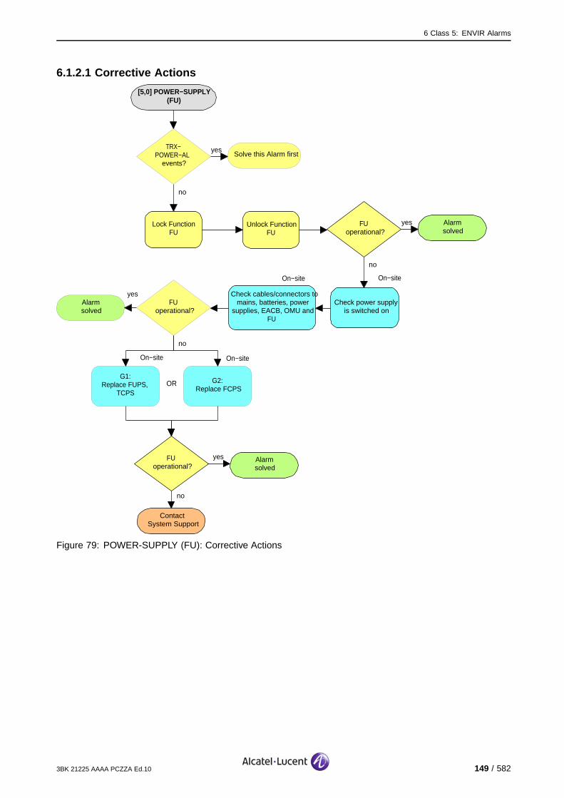
6 Class 5: ENVIR Alarms
6.1.2.1 Corrective Actions
[5,0] POWER−SUPPLY (FU)
Alarmsolved
yesFUoperational?
no
On−site
Check cables/connectors to mains, batteries, power
supplies, EACB, OMU and FU
On−site
no
ContactSystem Support
Lock Function FU
Unlock Function FU
Check power supply is switched on
FUoperational?
yes Alarmsolved
Solve this Alarm firstyesTRX−
POWER−AL events?
no
On−site
G1:Replace FUPS,
TCPS
G2:Replace FCPS
On−site
OR
Alarmsolved
yesFU
operational?
no
Figure 79: POWER-SUPPLY (FU): Corrective Actions
3BK 21225 AAAA PCZZA Ed.10 149 / 582
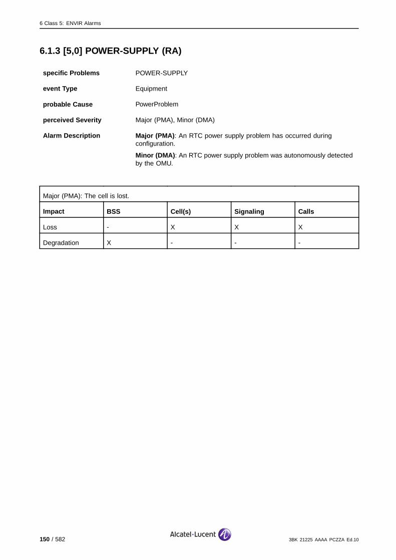
6 Class 5: ENVIR Alarms
6.1.3 [5,0] POWER-SUPPLY (RA)
specific Problems POWER-SUPPLY
event Type Equipment
probable Cause PowerProblem
perceived Severity Major (PMA), Minor (DMA)
Alarm Description Major (PMA): An RTC power supply problem has occurred duringconfiguration.
Minor (DMA): An RTC power supply problem was autonomously detectedby the OMU.
Major (PMA): The cell is lost.
Impact BSS Cell(s) Signaling Calls
Loss - X X X
Degradation X - - -
150 / 582 3BK 21225 AAAA PCZZA Ed.10
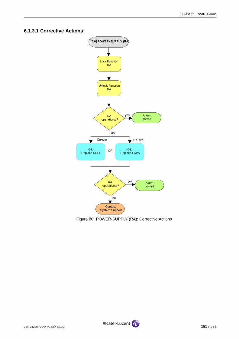
6 Class 5: ENVIR Alarms
6.1.3.1 Corrective Actions
[5,0] POWER−SUPPLY (RA)
Alarmsolved
yesRAoperational?
no
no
ContactSystem Support
Lock Function RA
Unlock Function RA
RAoperational?
yes Alarmsolved
On−site
G1:Replace CUPS
G2:Replace FCPS
On−site
OR
Figure 80: POWER-SUPPLY (RA): Corrective Actions
3BK 21225 AAAA PCZZA Ed.10 151 / 582
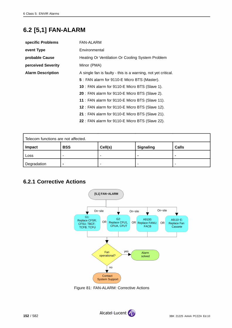
6 Class 5: ENVIR Alarms
6.2 [5,1] FAN-ALARM
specific Problems FAN-ALARM
event Type Environmental
probable Cause Heating Or Ventilation Or Cooling System Problem
perceived Severity Minor (PMA)
Alarm Description A single fan is faulty - this is a warning, not yet critical.
5 : FAN alarm for 9110-E Micro BTS (Master).
10 : FAN alarm for 9110-E Micro BTS (Slave 1).
20 : FAN alarm for 9110-E Micro BTS (Slave 2).
11 : FAN alarm for 9110-E Micro BTS (Slave 11).
12 : FAN alarm for 9110-E Micro BTS (Slave 12).
21 : FAN alarm for 9110-E Micro BTS (Slave 21).
22 : FAN alarm for 9110-E Micro BTS (Slave 22).
Telecom functions are not affected.
Impact BSS Cell(s) Signaling Calls
Loss - - - -
Degradation - - - -
6.2.1 Corrective Actions
[5,1] FAN−ALARM
no
ContactSystem Support
Fanoperational?
yes Alarmsolved
On−site
G1:Replace CFSR; CFSU; TBCF; TCFB; TCFU
G2:Replace CFU1, CFUA, CFUT
On−site
ORA9100:
Replace FANU; FACB
OR ORA9110−E:
Replace Fan Cassete
On−site
Figure 81: FAN-ALARM: Corrective Actions
152 / 582 3BK 21225 AAAA PCZZA Ed.10

6 Class 5: ENVIR Alarms
6.3 [5,2] FAN-ALARM-U
specific Problems FAN-ALARM-U
event Type Environmental
probable Cause HeatingOrVentilationOrCoolingSystemProblem
perceived Severity Major (PMA)
Alarm Description At least two fans are lost - urgent fan alarm.
Temperature problems are expected to occur. This can lead to a general degradation of the transmittedsignal quality.
Impact BSS Cell(s) Signaling Calls
Loss - - - -
Degradation X X X X
6.3.1 Corrective Actions
[5,1] FAN−ALARM
no
ContactSystem Support
Fanoperational?
yes Alarmsolved
On−site
G1:Replace CFSR; CFSU; TBCF; TCFB; TCFU
G2:Replace CFU1, CFUA, CFUT
On−site
ORA9100:
Replace FANU; FACB
OR ORA9110−E:
Replace Fan Cassete
On−site
Figure 82: FAN-ALARM-U: Corrective Actions
3BK 21225 AAAA PCZZA Ed.10 153 / 582

6 Class 5: ENVIR Alarms
6.4 [5,3] FAN-ALARM-T
specific Problems FAN-ALARM-T
event Type Environmental
probable Cause HeatingOrVentilationOrCoolingSystemProblem
perceived Severity Minor (DMA)
Alarm Description The fan temperature exceeds a given threshold. This is a warning butthe situation is not yet critical. FAN-ALARM-U [5,2] is issued when thesituation is critical.
Telecom functions are not affected.
Impact BSS Cell(s) Signaling Calls
Loss - - - -
Degradation - - - -
6.4.1 Corrective Actions
[5,1] FAN−ALARM
no
ContactSystem Support
Fanoperational?
yes Alarmsolved
On−site
G1:Replace CFSR; CFSU; TBCF; TCFB; TCFU
G2:Replace CFU1, CFUA, CFUT
On−site
ORA9100:
Replace FANU; FACB
OR ORA9110−E:
Replace Fan Cassete
On−site
Figure 83: FAN-ALARM-T: Corrective Actions
154 / 582 3BK 21225 AAAA PCZZA Ed.10

6 Class 5: ENVIR Alarms
6.5 [5,4] BTS-TEMP-ALARM
specific Problems BTS-TEMP-ALARM
event Type Environmental
probable Cause Temperature Unacceptable
perceived Severity Minor (DMA)
Alarm Description There is a temperature alarm for the complete BTS.
Temperature problems are expected to occur. This can lead to a general degradation of the transmittedsignal quality.
Impact BSS Cell(s) Signaling Calls
Loss - - - -
Degradation X X X X
3BK 21225 AAAA PCZZA Ed.10 155 / 582
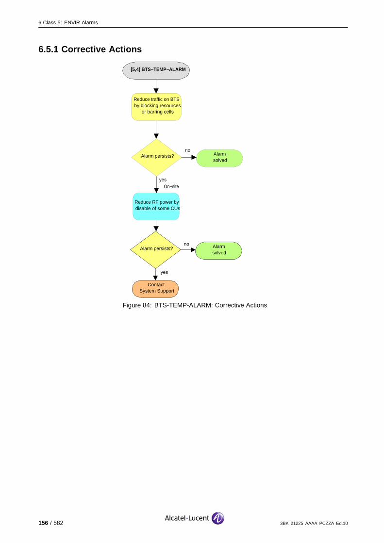
6 Class 5: ENVIR Alarms
6.5.1 Corrective Actions
[5,4] BTS−TEMP−ALARM
no
ContactSystem Support
Alarm persists?
yes
Alarmsolved
Reduce RF power by disable of some CUs
On−site
Reduce traffic on BTS by blocking resources
or barring cells
noAlarm persists?
yes
Alarmsolved
Figure 84: BTS-TEMP-ALARM: Corrective Actions
156 / 582 3BK 21225 AAAA PCZZA Ed.10
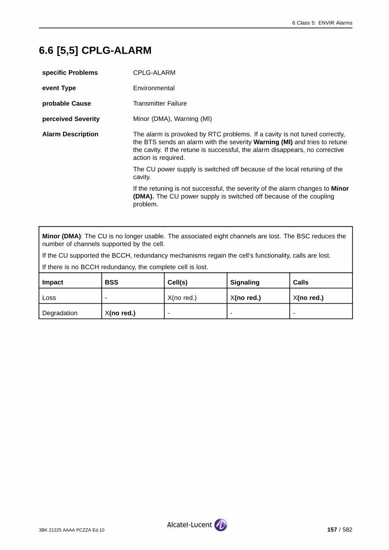
6 Class 5: ENVIR Alarms
6.6 [5,5] CPLG-ALARM
specific Problems CPLG-ALARM
event Type Environmental
probable Cause Transmitter Failure
perceived Severity Minor (DMA), Warning (MI)
Alarm Description The alarm is provoked by RTC problems. If a cavity is not tuned correctly,the BTS sends an alarm with the severity Warning (MI) and tries to retunethe cavity. If the retune is successful, the alarm disappears, no correctiveaction is required.
The CU power supply is switched off because of the local retuning of thecavity.
If the retuning is not successful, the severity of the alarm changes to Minor(DMA). The CU power supply is switched off because of the couplingproblem.
Minor (DMA): The CU is no longer usable. The associated eight channels are lost. The BSC reduces thenumber of channels supported by the cell.
If the CU supported the BCCH, redundancy mechanisms regain the cell’s functionality, calls are lost.
If there is no BCCH redundancy, the complete cell is lost.
Impact BSS Cell(s) Signaling Calls
Loss - X(no red.) X(no red.) X(no red.)
Degradation X(no red.) - - -
3BK 21225 AAAA PCZZA Ed.10 157 / 582
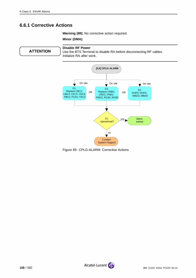
6 Class 5: ENVIR Alarms
6.6.1 Corrective Actions
Warning (MI) : No corrective action required.
Minor (DMA) :
Disable RF PowerUse the BTS Terminal to disable RA before disconnecting RF cables.Initialize RA after work.
[5,5] CPLG−ALARM
no
ContactSystem Support
CUoperational?
yes Alarmsolved
On−site
G1:Replace CBC2;
CBC4; CEC2; CEC4; FBC2; FCAV; FEC2
G2:Replace CRBG; CREG; FRBG;
FREG; RC4D; RC8D
On−site
ORG2:
DUPD; DUPG; WB2G; WB2D
On−site
OR
Figure 85: CPLG-ALARM: Corrective Actions
158 / 582 3BK 21225 AAAA PCZZA Ed.10
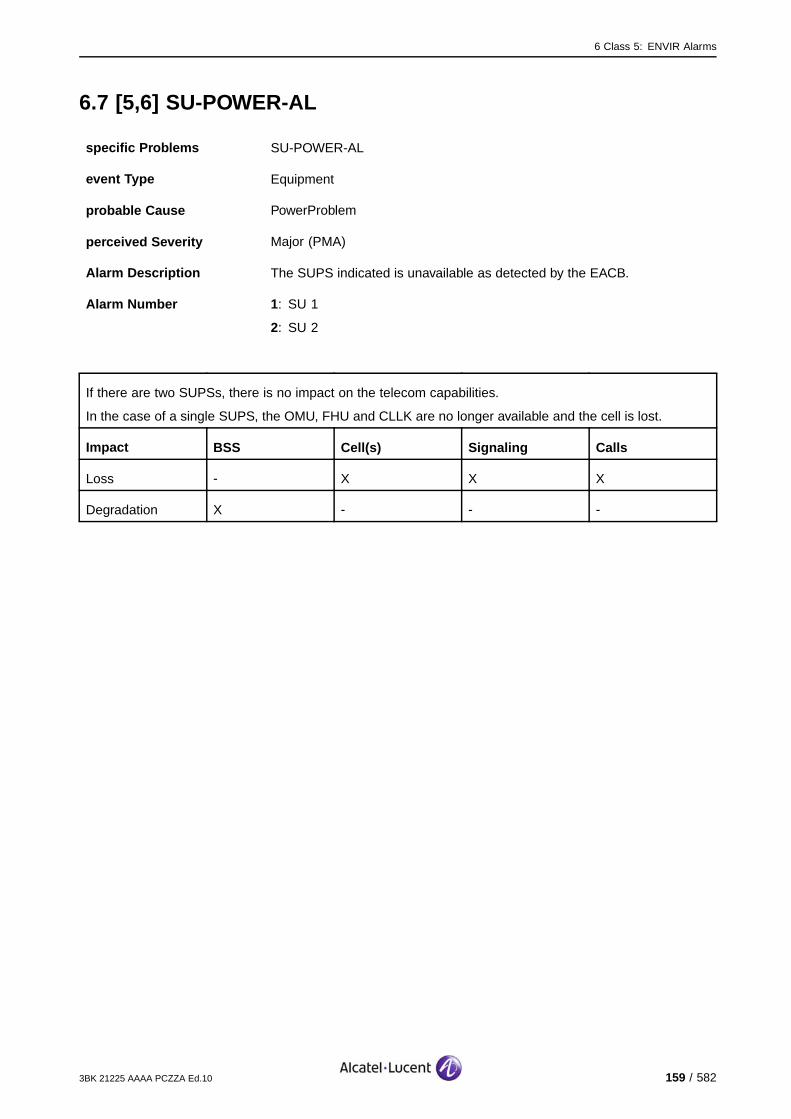
6 Class 5: ENVIR Alarms
6.7 [5,6] SU-POWER-AL
specific Problems SU-POWER-AL
event Type Equipment
probable Cause PowerProblem
perceived Severity Major (PMA)
Alarm Description The SUPS indicated is unavailable as detected by the EACB.
Alarm Number 1: SU 1
2: SU 2
If there are two SUPSs, there is no impact on the telecom capabilities.
In the case of a single SUPS, the OMU, FHU and CLLK are no longer available and the cell is lost.
Impact BSS Cell(s) Signaling Calls
Loss - X X X
Degradation X - - -
3BK 21225 AAAA PCZZA Ed.10 159 / 582

6 Class 5: ENVIR Alarms
6.7.1 Corrective Actions
[5,6] SU−POWER−AL
no
ContactSystem Support
SUoperational?
yes Alarmsolved
On−site
G1:Replace SUPS
G2:Replace ADPS in
MCO2/MCO4
On−site
ORG2:
Replace ADPS in MCI2
On−site
OR
Check Power Supplies are switched on
On−site
Check cables/connectors to
EACB and SUPS
On−site
no
SUoperational?
yes Alarmsolved
G2:Replace MBPS
On−site
OR
Figure 86: SU-POWER-AL: Corrective Actions
160 / 582 3BK 21225 AAAA PCZZA Ed.10

6 Class 5: ENVIR Alarms
6.8 [5,7] TRX-POWER-AL
specific Problems TRX-POWER-AL
event Type Equipment
probable Cause PowerProblem
perceived Severity Major (PMA)
Alarm Description A power supply (AC/DC) failure is resulting in the loss of power for FU andCU. The affected chain is indicated by the Alarm Number.
Alarm Number 1: CU 1 and FU 1.
2: CU 2 and FU 2.
n: CU n and FU n.
The affected equipment (CU, FU) is no longer usable. The associated eight channels are lost. Independentof frequency hopping or not, the BSC reduces the number of channels supported by the cell.
If the FU or CU supporting the BCCH is not concerned, the cell is degraded, calls are lost. (#).
If the FU or CU supporting the BCCH is concerned and there is BCCH redundancy, recovery mechanismsregain the cell’s functionality, calls are lost. (*)
If the FU or CU supporting the BCCH is concerned and there is no BCCH redundancy, the completecell is lost. (X).
Impact BSS Cell(s) Signaling Calls
Loss - X(no red.) X(no red.) X(no red.)#*
Degradation X(no red.) #* - -
3BK 21225 AAAA PCZZA Ed.10 161 / 582
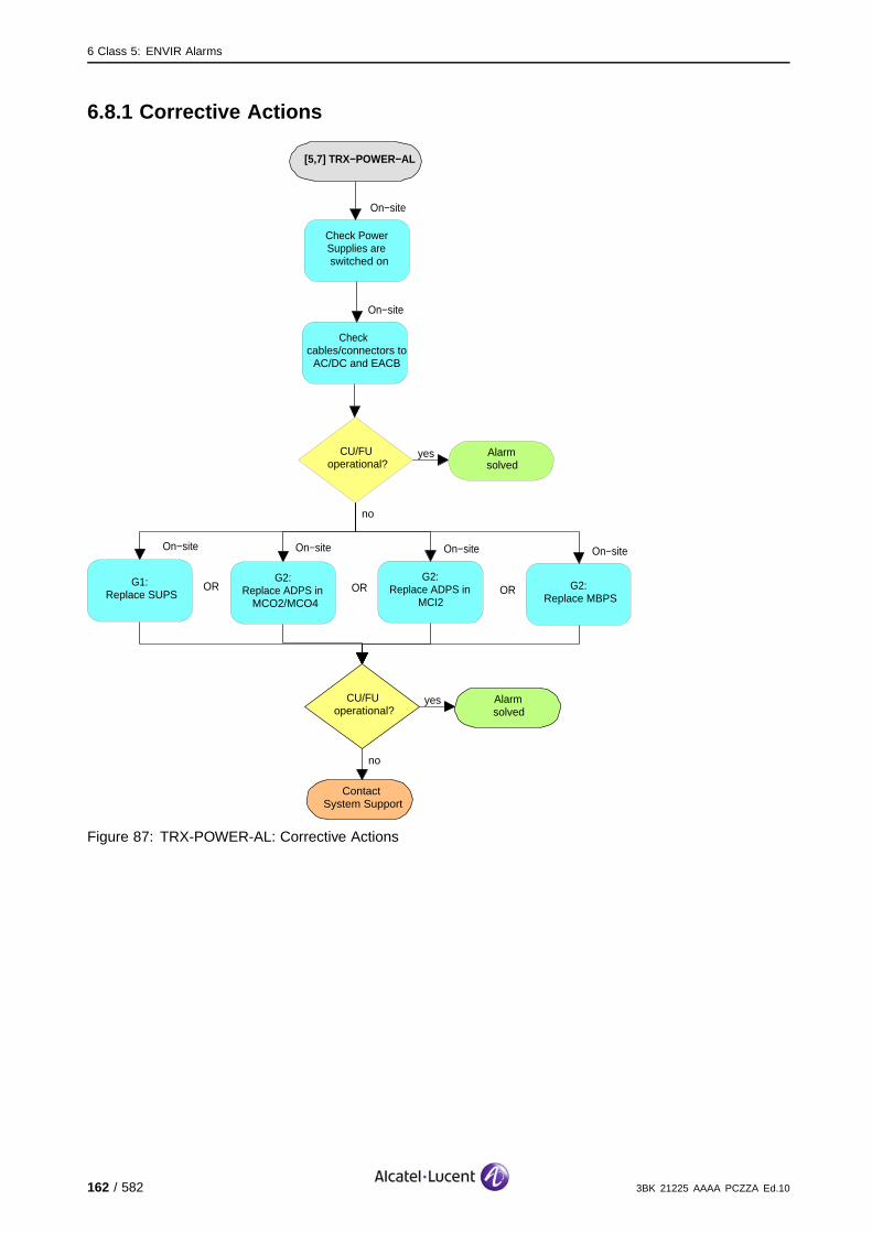
6 Class 5: ENVIR Alarms
6.8.1 Corrective Actions
[5,7] TRX−POWER−AL
no
ContactSystem Support
CU/FUoperational?
yes Alarmsolved
On−site
G1:Replace SUPS
G2:Replace ADPS in
MCO2/MCO4
On−site
ORG2:
Replace ADPS in MCI2
On−site
OR
Check Power Supplies are switched on
On−site
Check cables/connectors to
AC/DC and EACB
On−site
no
CU/FUoperational?
yes Alarmsolved
G2:Replace MBPS
On−site
OR
Figure 87: TRX-POWER-AL: Corrective Actions
162 / 582 3BK 21225 AAAA PCZZA Ed.10

6 Class 5: ENVIR Alarms
6.9 [5,11] POWER-SUPPLY-U
specific Problems POWER-SUPPLY-U
event Type Equipment
probable Cause PowerProblem
perceived Severity Critical (VPMA), Warning (MI)
Alarm Description At least two power supply modules have failed. Some TRE are switchedOFF autonomously by the BTS.
9100 BTS: At least one PM08/PM11 module is operational.
If PM12/PM18 used: The BTS uses the backup batteries and the availablePM12/PM18 modules.
During a defined delay, the configuration is kept, the Telecom functions are not affected.
After the end of the previous delay, a minimal configuration is selected with the TRE supporting theBCCH. (#).
If the battery is empty, the cells are lost. (X).
Impact BSS Cell(s) Signaling Calls
Loss - X X #X
Degradation #X # - -
3BK 21225 AAAA PCZZA Ed.10 163 / 582

6 Class 5: ENVIR Alarms
6.9.1 Corrective Actions
[5,11] POWER−SUPPLY−U
no
ContactSystem Support
Power supplyoperational?
yes Alarmsolved
On−site
G2: Replace ADPS in MCO2/MCO4
G2:Replace ADPS in
MCI2
On−site
ORA9100: Replace
PM08, which LED is off or red *
On−site
OR
Check Power Supplies are switched on
On−site
Check cables/connectors to control unit, power module and EACB
On−site
noAlarm persists?
yes
Alarmsolved
A9100: Replace PM11, which LED is
off or red *
On−site
ORA9100: Replace
PM12, which LED is off or red *
On−site
OR
* If RIT location is A,0,0, the RIT is located in A9100 COMI/CODI outdoor side compartment
A9100: Replace PM18, which LED is
off or red *OR
On−site
Figure 88: POWER-SUPPLY-U: Corrective Actions
164 / 582 3BK 21225 AAAA PCZZA Ed.10
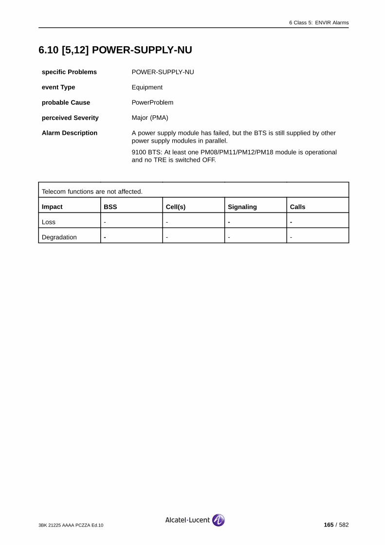
6 Class 5: ENVIR Alarms
6.10 [5,12] POWER-SUPPLY-NU
specific Problems POWER-SUPPLY-NU
event Type Equipment
probable Cause PowerProblem
perceived Severity Major (PMA)
Alarm Description A power supply module has failed, but the BTS is still supplied by otherpower supply modules in parallel.
9100 BTS: At least one PM08/PM11/PM12/PM18 module is operationaland no TRE is switched OFF.
Telecom functions are not affected.
Impact BSS Cell(s) Signaling Calls
Loss - - - -
Degradation - - - -
3BK 21225 AAAA PCZZA Ed.10 165 / 582
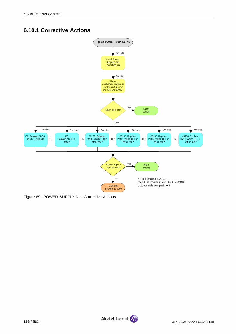
6 Class 5: ENVIR Alarms
6.10.1 Corrective Actions
[5,12] POWER−SUPPLY−NU
no
ContactSystem Support
Power supplyoperational?
yes Alarmsolved
On−site
G2: Replace ADPS in MCO2/MCO4
G2:Replace ADPS in
MCI2
On−site
ORA9100: Replace
PM08, which LED is off or red *
On−site
OR
Check Power Supplies are switched on
On−site
Check cables/connectors to control unit, power module and EACB
On−site
noAlarm persists?
yes
Alarmsolved
A9100: Replace PM11, which LED is
off or red *
On−site
ORA9100: Replace
PM12, which LED is off or red *
On−site
OR
* If RIT location is A,0,0, the RIT is located in A9100 COMI/CODI outdoor side compartment
A9100: Replace PM18, which LED is
off or red *OR
On−site
Figure 89: POWER-SUPPLY-NU: Corrective Actions
166 / 582 3BK 21225 AAAA PCZZA Ed.10

6 Class 5: ENVIR Alarms
6.11 [5,13] CONTROL-UNIT-AL
specific Problems CONTROL-UNIT-AL
event Type Equipment
probable Cause PowerProblem
perceived Severity Nbr 2: Critical (VPMA), Warning (MI)
Nbr 1: Major (PMA), Warning (MI)
Alarm Description There is a failure of the control unit that supervises the power modules.
Alarm Number 1: The battery capacity is faulty.
2: The battery charging voltage is faulty.
The battery is empty and is not used: the Telecom functions are not affected.
The battery is empty and is used: the cells are lost. (X)
Impact BSS Cell(s) Signaling Calls
Loss - X X X
Degradation X - - -
3BK 21225 AAAA PCZZA Ed.10 167 / 582
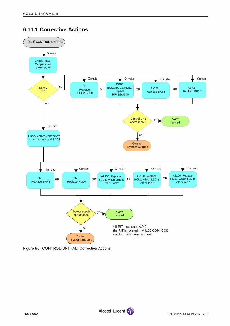
6 Class 5: ENVIR Alarms
6.11.1 Corrective Actions
[5,13] CONTROL−UNIT−AL
no
ContactSystem Support
Power supplyoperational?
yes Alarmsolved
On−site
G2: Replace BHPS
G2:Replace PM06
On−site
ORA9100: Replace
BCU1, which LED is off or red *
On−site
OR
Check Power Supplies are switched on
On−site
noBattery OK?
yes
A9100: Replace BCU2, which LED is
off or red *
On−site
ORA9100: Replace
PM12, which LED is off or red *
On−site
OR
* If RIT location is A,0,0, the RIT is located in A9100 COMI/CODI outdoor side compartment
Check cables/connectors to control unit and EACB
On−site
G2: Replace
BBU2/BU60
On−site
A9100 BCU1/BCU2, PM12:
Replace BU41/BU100
On−site
OR
no
ContactSystem Support
Control Unitoperational?
yes Alarmsolved
A9100: Replace BATS
On−site
OR A9100: Replace BU101
On−site
OR
Figure 90: CONTROL-UNIT-AL: Corrective Actions
168 / 582 3BK 21225 AAAA PCZZA Ed.10

6 Class 5: ENVIR Alarms
6.12 [5,14] MAINS-POWER-SUPPLY
specific Problems MAINS-POWER-SUPPLY
event Type Equipment
probable Cause PowerProblem
perceived Severity Critical (VPMA)
Alarm Description There is a mains power supply failure.
Alarm Number 1: There is a mains power supply failure on a standard G2 BTS.
There is no disturbance of the telecom applications as long as the battery is still working.
If the battery is empty, the cells are lost. (X).
Impact BSS Cell(s) Signaling Calls
Loss - X X X
Degradation X - - -
3BK 21225 AAAA PCZZA Ed.10 169 / 582

6 Class 5: ENVIR Alarms
6.12.1 G2 BTS Corrective Actions
[5,14]MAINS−POWER−SUPPLY
no
ContactSystem Support
Power supplyoperational?
yes Alarmsolved
On−site
G1: Replace SUPS
G2 in MCO2/MCO4: Replace ADPS
On−site
OR G2 in MCI2: Replace ADPS
On−site
OR G2: Replace MBPS
On−site
OR
Check cables/connectors to control unit, power module and EACB
On−site
Figure 91: MAINS-POWER-SUPPLY: G2 BTS Corrective Actions
170 / 582 3BK 21225 AAAA PCZZA Ed.10

6 Class 5: ENVIR Alarms
6.13 [5,15] BATT-DEEP-DISCHARGE
specific Problems BATT-DEEP-DISCHARGE
event Type Equipment
probable Cause PowerProblem
perceived Severity Major (PMA)
Alarm Description The battery is deep discharged.
There is no disturbance of the telecom applications as long as the battery is still working.
If there is no mains power supply and the battery is empty, the cells are lost. (X).
Impact BSS Cell(s) Signaling Calls
Loss - X X X
Degradation X - - -
3BK 21225 AAAA PCZZA Ed.10 171 / 582
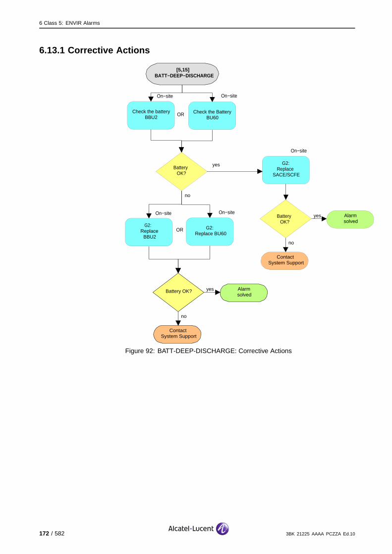
6 Class 5: ENVIR Alarms
6.13.1 Corrective Actions
[5,15]BATT−DEEP−DISCHARGE
no
ContactSystem Support
Battery OK? yes Alarmsolved
G2:Replace
SACE/SCFE
On−site
ORCheck the battery
BBU2
On−site
no
Battery OK?
yes
G2: Replace BBU2
On−site
G2:Replace BU60
On−site
OR
no
ContactSystem Support
yes Alarmsolved
Check the Battery BU60
On−site
Battery OK?
Figure 92: BATT-DEEP-DISCHARGE: Corrective Actions
172 / 582 3BK 21225 AAAA PCZZA Ed.10

6 Class 5: ENVIR Alarms
6.14 [5,20] MAINS-AL
specific Problems MAINS-AL
event Type Equipment
probable Cause PowerProblem
perceived Severity Critical (VPMA), Warning (MI)
Alarm Description There is a problem on the BTS mains power supply. No BTSPM08/PM11/PM12/PM18 power supply is operational. The BTS runs onthe backup batteries.
During a defined delay, the configuration is kept, the Telecom functions are not affected.
After the end of the previous delay, a minimal configuration is selected with the TRE supporting theBCCH. (#)
If the battery is empty, the cells are lost. (X).
Impact BSS Cell(s) Signaling Calls
Loss - X X #X
Degradation #X # - -
3BK 21225 AAAA PCZZA Ed.10 173 / 582

6 Class 5: ENVIR Alarms
6.14.1 Corrective Actions
[5,20] MAINS−AL
no
ContactSystem Support
Power supplyoperational?
yes Alarmsolved
A9100: Replace PM08, which LED is
off or red *
On−site
Check external BTS mains supply and fuses. Setup
supply and replace fuses if required
On−site
Check cables/connectors to control unit and BTS
On−site
noAlarm persists?
yes
Alarmsolved
A9100: Replace PM11, which LED is
off or red *
On−site
ORA9100: Replace
PM12, which LED is off or red *
On−site
OR
* If RIT location is A,0,0, the RIT is located in A9100 COMI/CODI outdoor side compartment
A9100: Replace PM18, which LED is
off or red *
On−site
OR
Figure 93: MAINS-AL: Corrective Actions
174 / 582 3BK 21225 AAAA PCZZA Ed.10
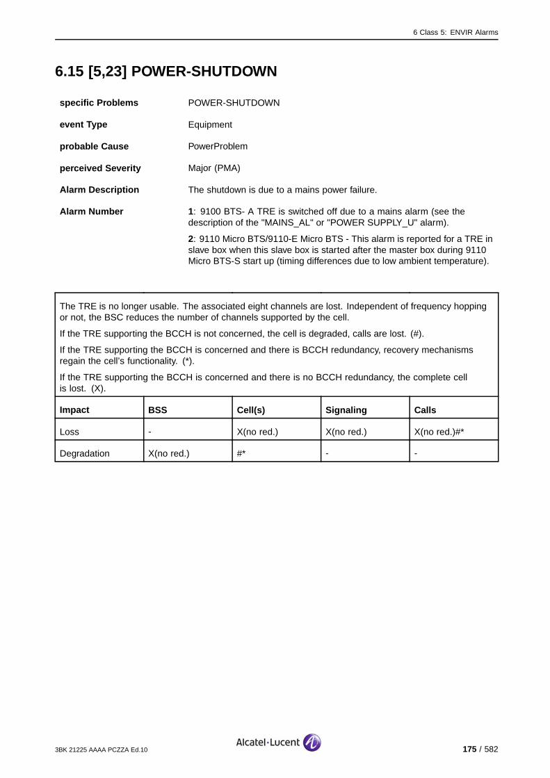
6 Class 5: ENVIR Alarms
6.15 [5,23] POWER-SHUTDOWN
specific Problems POWER-SHUTDOWN
event Type Equipment
probable Cause PowerProblem
perceived Severity Major (PMA)
Alarm Description The shutdown is due to a mains power failure.
Alarm Number 1: 9100 BTS- A TRE is switched off due to a mains alarm (see thedescription of the "MAINS_AL" or "POWER SUPPLY_U" alarm).
2: 9110 Micro BTS/9110-E Micro BTS - This alarm is reported for a TRE inslave box when this slave box is started after the master box during 9110Micro BTS-S start up (timing differences due to low ambient temperature).
The TRE is no longer usable. The associated eight channels are lost. Independent of frequency hoppingor not, the BSC reduces the number of channels supported by the cell.
If the TRE supporting the BCCH is not concerned, the cell is degraded, calls are lost. (#).
If the TRE supporting the BCCH is concerned and there is BCCH redundancy, recovery mechanismsregain the cell’s functionality. (*).
If the TRE supporting the BCCH is concerned and there is no BCCH redundancy, the complete cellis lost. (X).
Impact BSS Cell(s) Signaling Calls
Loss - X(no red.) X(no red.) X(no red.)#*
Degradation X(no red.) #* - -
3BK 21225 AAAA PCZZA Ed.10 175 / 582

6 Class 5: ENVIR Alarms
6.15.1 Alarm Number 1 Corrective Actions
[5,23] POWER−SHUTDOWN
no
ContactSystem Support
Power supplyoperational?
yes Alarmsolved
A9100: Replace PM08, which LED is
off or red *
On−site
Check external BTS mains supply and fuses. Setup
supply and replace fuses if required
On−site
Check cables/connectors to control unit and BTS
On−site
noAlarm persists?
yes
Alarmsolved
A9100: Replace PM11, which LED is
off or red *
On−site
ORA9100: Replace
PM12, which LED is off or red *
On−site
OR
* If RIT location is A,0,0, the RIT is located in A9100 COMI/CODI outdoor side compartment
Figure 94: POWER-SHUTDOWN: Alarm Number 1 Corrective Actions
176 / 582 3BK 21225 AAAA PCZZA Ed.10
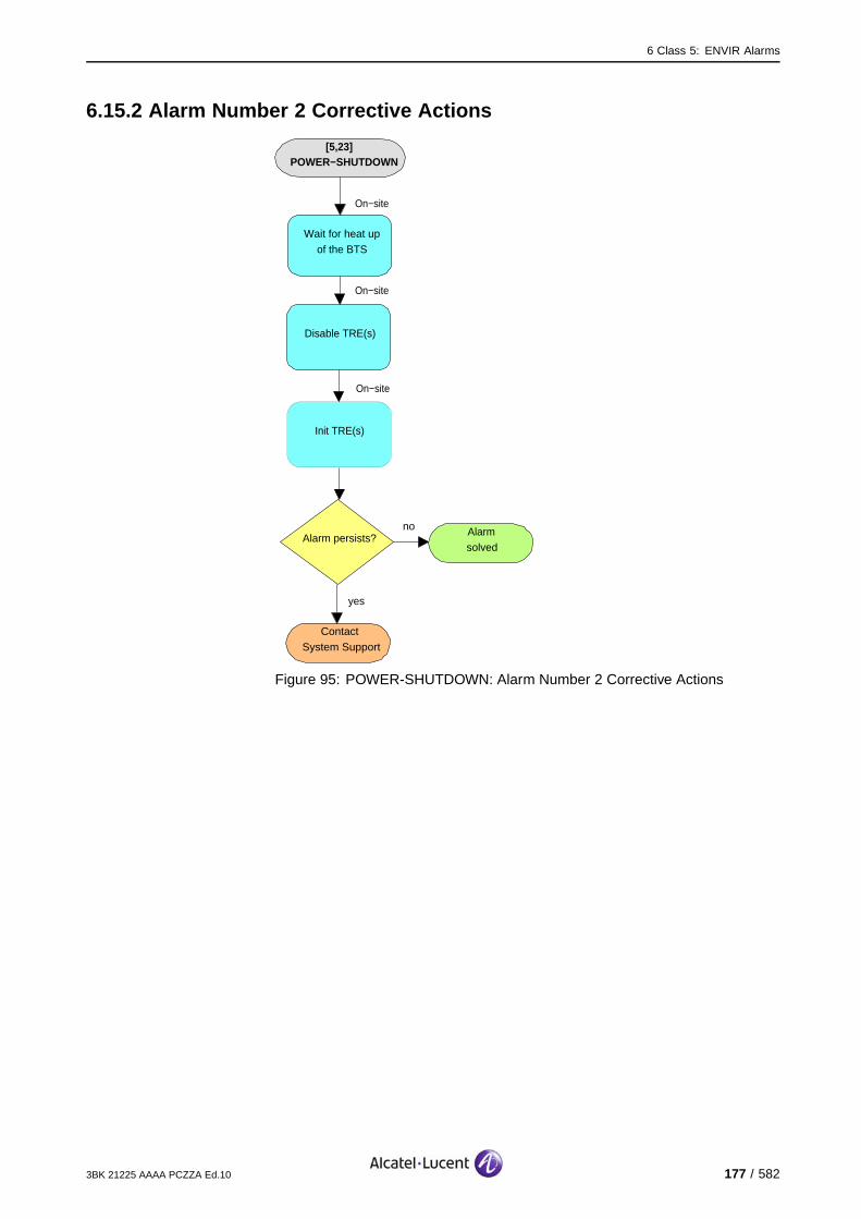
6 Class 5: ENVIR Alarms
6.15.2 Alarm Number 2 Corrective Actions
[5,23] POWER−SHUTDOWN
yes
ContactSystem Support
Disable TRE(s)
On−site
Wait for heat up of the BTS
On−site
noAlarm persists?
Alarmsolved
Init TRE(s)
On−site
Figure 95: POWER-SHUTDOWN: Alarm Number 2 Corrective Actions
3BK 21225 AAAA PCZZA Ed.10 177 / 582
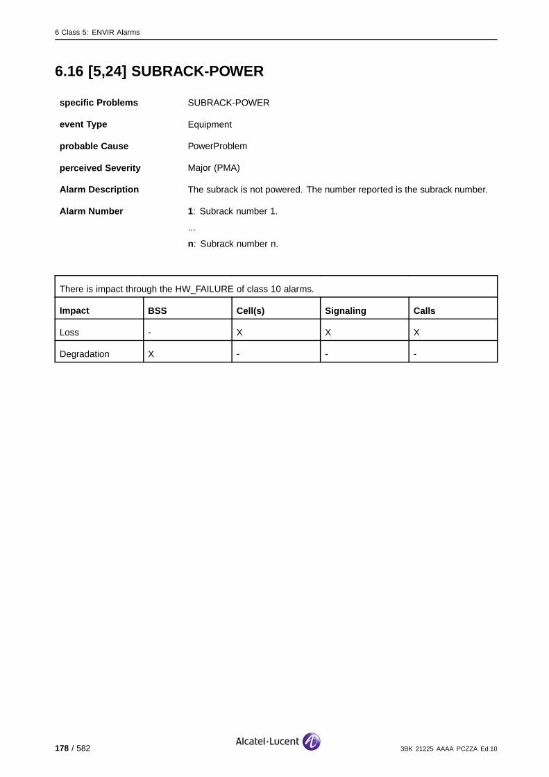
6 Class 5: ENVIR Alarms
6.16 [5,24] SUBRA CK-POWER
specific Problems SUBRACK-POWER
event Type Equipment
probable Cause PowerProblem
perceived Severity Major (PMA)
Alarm Description The subrack is not powered. The number reported is the subrack number.
Alarm Number 1: Subrack number 1.
...
n: Subrack number n.
There is impact through the HW_FAILURE of class 10 alarms.
Impact BSS Cell(s) Signaling Calls
Loss - X X X
Degradation X - - -
178 / 582 3BK 21225 AAAA PCZZA Ed.10

6 Class 5: ENVIR Alarms
6.16.1 Corrective Actions
[5,24] SUBRACK−POWER
no
ContactSystem Support
Power supplyoperational?
yes Alarmsolved
Check AC and DC Circuit Breakers. Switch breacker(s)
on if required.
On−site
Check cables/connectors to
subrack
On−site
noAlarm persists?
yes
Alarmsolved
Check for faulty RITs in class 10 HW_Failure alarms
on this BTS. Solve that alarm(s) before re−powering
the subrack.
Figure 96: SUBRACK-POWER: Corrective Actions
3BK 21225 AAAA PCZZA Ed.10 179 / 582

6 Class 5: ENVIR Alarms
6.17 [5,31] TEMPERATURE-WARNING
6.17.1 [5,31] TEMPERATURE-WARNING (BTS)
specific Problems TEMPERATURE-WARNING
event Type Environmental
probable Cause Temperature Unacceptable
perceived Severity Major (PMA), Warning (MI)
Alarm Description This is a temperature warning.
The temperature control of the hottest TRE in the BTS has reached thelow threshold value.
Telecom functions are not affected.
Impact BSS Cell(s) Signaling Calls
Loss - - - -
Degradation - - - -
180 / 582 3BK 21225 AAAA PCZZA Ed.10

6 Class 5: ENVIR Alarms
6.17.1.1 Corrective Actions
Required tools and materials :
Thermometer
Replacement and cleaning tools, see appropriate replacement procedure.
[5,31] TEMPERATURE−WARNING
(BTS)
no
ContactSystem Support
BTS Temperature
OK?
yes Alarmsolved
The ambient temperature must be
reduced.
On−site
no
Is ambient
temperature out of permitted
limits?
yes
Check and clean heat exchanger air
intake
Fan alarm events?Solve that
alarm(s) first
Check the ambient temperature.
On−site
On−site
no
ContactSystem Support
BTS Temperature
OK?
yes Alarmsolved
yes
no
Figure 97: TEMPERATURE-WARNING (BTS): Corrective Actions
3BK 21225 AAAA PCZZA Ed.10 181 / 582

6 Class 5: ENVIR Alarms
6.17.2 [5,31] TEMPERATURE-WARNING (TRE)
specific Problems TEMPERATURE-WARNING
event Type Environmental
probable Cause Temperature Unacceptable
perceived Severity Major (PMA), Warning (MI)
Alarm Description This is a temperature warning.
A MTRE inside the BTS has reached a temperature which is close to theshut off temperature.
Telecom functions are not affected.
Impact BSS Cell(s) Signaling Calls
Loss - - - -
Degradation - - - -
182 / 582 3BK 21225 AAAA PCZZA Ed.10

6 Class 5: ENVIR Alarms
6.17.2.1 Corrective Actions
Required tools and materials :
Thermometer
Replacement and cleaning tools, see appropriate replacement procedure.
[5,31] TEMPERATURE−WARNING (TRE)
no
ContactSystem Support
TRE Temperature
OK?
yes Alarmsolved
The ambient temperature must be
reduced.
On−site
no
Is ambient
temperature out of permitted
limits?
yes
Check and clean optional Fan
Module
Fan alarm events?
Solve that alarm(s) first
Check the ambient temperature.
On−site
On−site
no
ContactSystem Support
TRETemperature
OK?
yes Alarmsolved
yes
no
no
Optional Fan Module available?
yes
Add optional Fan Module
On−site
no
ContactSystem Support
TRE Temperature
OK?
yes Alarmsolved
Figure 98: TEMPERATURE-WARNING (TRE): Corrective Actions
3BK 21225 AAAA PCZZA Ed.10 183 / 582
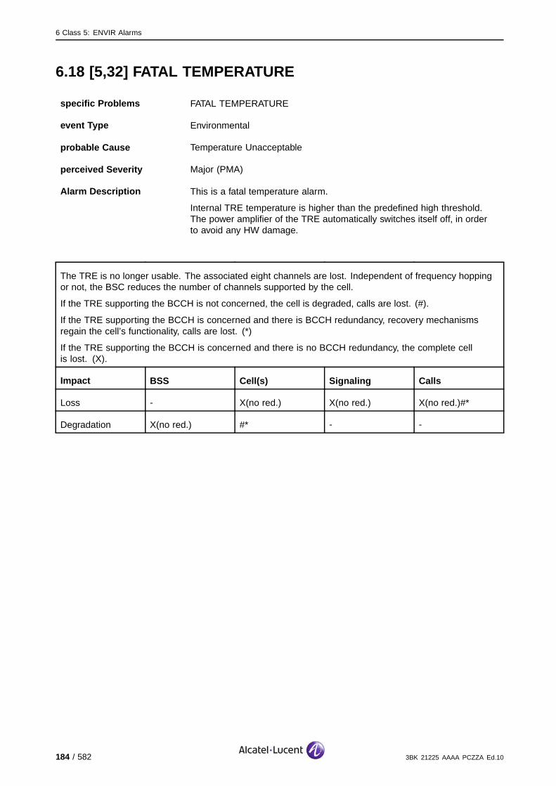
6 Class 5: ENVIR Alarms
6.18 [5,32] FATAL TEMPERATURE
specific Problems FATAL TEMPERATURE
event Type Environmental
probable Cause Temperature Unacceptable
perceived Severity Major (PMA)
Alarm Description This is a fatal temperature alarm.
Internal TRE temperature is higher than the predefined high threshold.The power amplifier of the TRE automatically switches itself off, in orderto avoid any HW damage.
The TRE is no longer usable. The associated eight channels are lost. Independent of frequency hoppingor not, the BSC reduces the number of channels supported by the cell.
If the TRE supporting the BCCH is not concerned, the cell is degraded, calls are lost. (#).
If the TRE supporting the BCCH is concerned and there is BCCH redundancy, recovery mechanismsregain the cell’s functionality, calls are lost. (*)
If the TRE supporting the BCCH is concerned and there is no BCCH redundancy, the complete cellis lost. (X).
Impact BSS Cell(s) Signaling Calls
Loss - X(no red.) X(no red.) X(no red.)#*
Degradation X(no red.) #* - -
184 / 582 3BK 21225 AAAA PCZZA Ed.10

6 Class 5: ENVIR Alarms
6.18.1 Corrective Actions
Required tools and materials :
Thermometer
Replacement and cleaning tools, see appropriate replacement procedure.
[5,32] FATAL TEMPERATURE
no
ContactSystem Support
TRE Temperature
OK?
yes Alarmsolved
The ambient temperature must be
reduced.
On−site
no
Is ambient
temperature out of permitted
limits?
yes
Check and clean heat exchanger air
intake
Fan alarm events?Solve that
alarm(s) first
Check the ambient temperature.
On−site
On−site
no
ContactSystem Support
TRETemperature
OK?
yes Alarmsolved
yes
no
Figure 99: FATAL TEMPERATURE: Corrective Actions
3BK 21225 AAAA PCZZA Ed.10 185 / 582
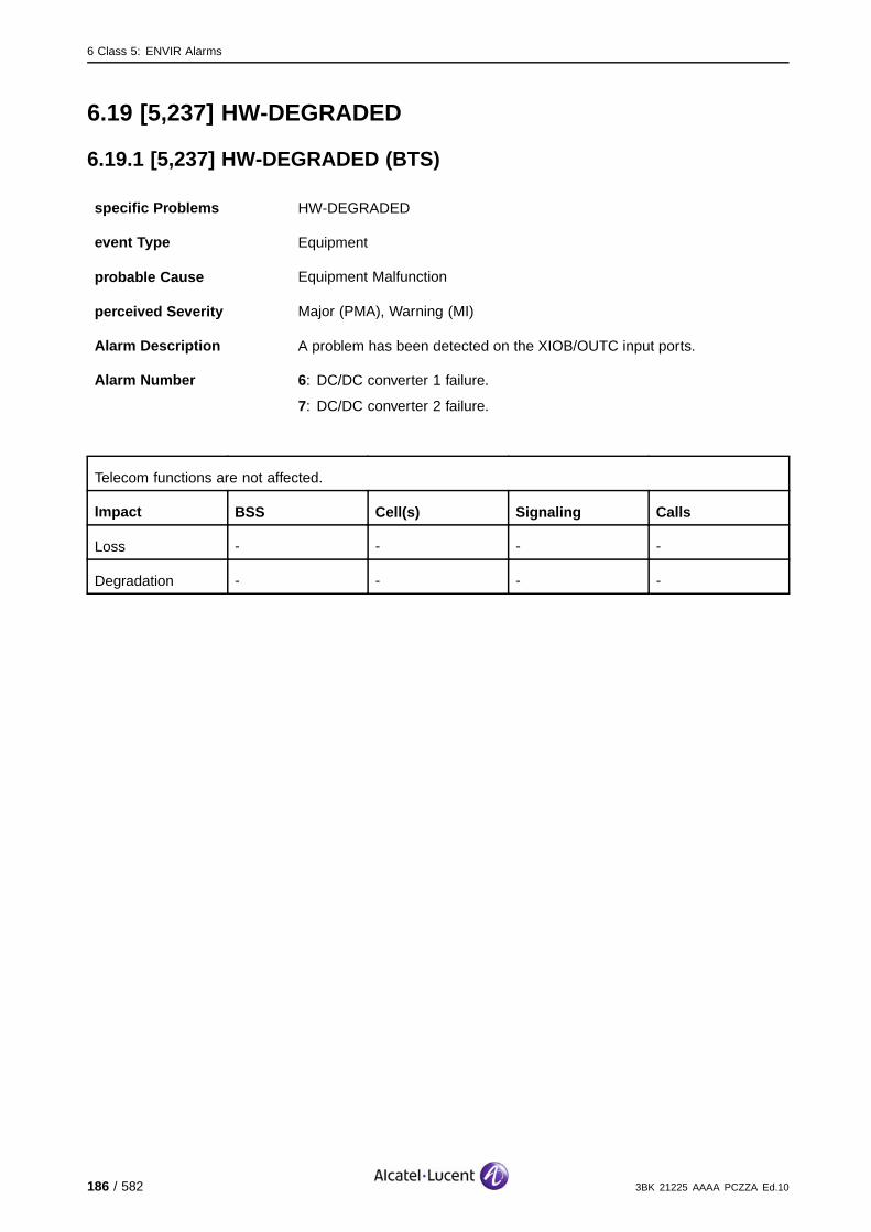
6 Class 5: ENVIR Alarms
6.19 [5,237] HW-DEGRADED
6.19.1 [5,237] HW-DEGRADED (BTS)
specific Problems HW-DEGRADED
event Type Equipment
probable Cause Equipment Malfunction
perceived Severity Major (PMA), Warning (MI)
Alarm Description A problem has been detected on the XIOB/OUTC input ports.
Alarm Number 6: DC/DC converter 1 failure.
7: DC/DC converter 2 failure.
Telecom functions are not affected.
Impact BSS Cell(s) Signaling Calls
Loss - - - -
Degradation - - - -
186 / 582 3BK 21225 AAAA PCZZA Ed.10
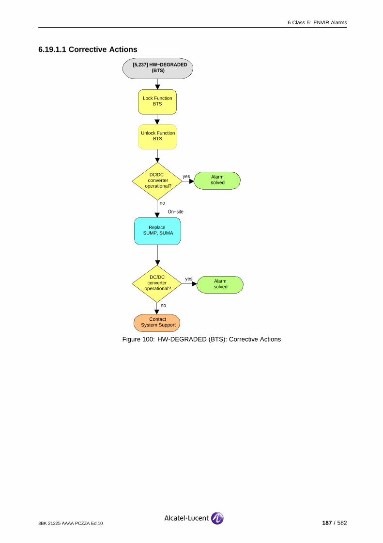
6 Class 5: ENVIR Alarms
6.19.1.1 Corrective Actions
[5,237] HW−DEGRADED(BTS)
Alarmsolved
yesDC/DC converter
operational?
no
On−site
no
ContactSystem Support
Lock Function BTS
Replace SUMP, SUMA
DC/DC converter
operational?
yes Alarmsolved
Unlock Function BTS
Figure 100: HW-DEGRADED (BTS): Corrective Actions
3BK 21225 AAAA PCZZA Ed.10 187 / 582

6 Class 5: ENVIR Alarms
6.19.2 [5,237] HW-DEGRADED (EACB)
specific Problems HW-DEGRADED
event Type Equipment
probable Cause Equipment Malfunction
perceived Severity Major (PMA)
Alarm Description A problem has been detected on the input ports
Alarm Number 10:9100 BTS: A problem has been detected on the XIOB/OUTC input ports.9110 Micro BTS/9110-E Micro BTS : A problem has been detected on theinput ports during tests with the MBTS-BCB unit.
11: TMA current supervision failure
12: TMA1 current too low
13: TMA1 current too high
14: TMA1 short circuit alarm
15: TMA2 current too low
16: TMA2 current too high
17: TMA2 short circuit alarm
Telecom functions are not affected.
Impact BSS Cell(s) Signaling Calls
Loss - - - -
Degradation - - - -
188 / 582 3BK 21225 AAAA PCZZA Ed.10
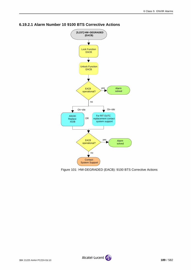
6 Class 5: ENVIR Alarms
6.19.2.1 Alarm Number 10 9100 BTS Corrective Actions
[5,237] HW−DEGRADED(EACB)
Alarmsolved
yesEACB operational?
no
On−site
no
ContactSystem Support
Lock Function EACB
A9100:Replace
XIOB
EACB operational?
yes Alarmsolved
Unlock Function EACB
For RIT OUTC replacement contact
system support
On−site
OR
Figure 101: HW-DEGRADED (EACB): 9100 BTS Corrective Actions
3BK 21225 AAAA PCZZA Ed.10 189 / 582

6 Class 5: ENVIR Alarms
6.19.2.2 Alarm Number 10 9110 Micro BTS/9110-E Micro BTS Corrective Actions
[5,237] HW−DEGRADED (EACB)
Alarmsolved
yesMicro−BTSoperational?
noOn−site
no
ContactSystem Support
Reset Function BTS
SwitchMicro−BTS
off
Switch Micro−BTS
on
yes Alarmsolved
On−site
no
yes Alarmsolved
ReplaceMicro−BTS
Micro−BTSoperational?
Micro−BTSoperational?
Figure 102: HW-DEGRADED (EACB): 9110 Micro BTS/9110-E Micro BTSCorrective Actions
190 / 582 3BK 21225 AAAA PCZZA Ed.10

6 Class 5: ENVIR Alarms
6.19.2.3 Alarm Number 11..17 Corrective Actions
[5,237] HW−DEGRADED(EACB)
Alarmsolved
yesEACB operational?
no
On−site
no
ContactSystem Support
Lock Function EACB
Replace TMA
EACB operational?
yes Alarmsolved
Unlock Function EACB
Figure 103: HW-DEGRADED (EACB): Corrective Actions
3BK 21225 AAAA PCZZA Ed.10 191 / 582
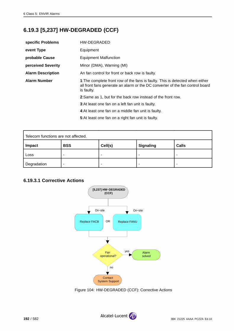
6 Class 5: ENVIR Alarms
6.19.3 [5,237] HW-DEGRADED (CCF)
specific Problems HW-DEGRADED
event Type Equipment
probable Cause Equipment Malfunction
perceived Severity Minor (DMA), Warning (MI)
Alarm Description An fan control for front or back row is faulty.
Alarm Number 1:The complete front row of the fans is faulty. This is detected when eitherall front fans generate an alarm or the DC converter of the fan control boardis faulty.
2:Same as 1, but for the back row instead of the front row.
3:At least one fan on a left fan unit is faulty.
4:At least one fan on a middle fan unit is faulty.
5:At least one fan on a right fan unit is faulty.
Telecom functions are not affected.
Impact BSS Cell(s) Signaling Calls
Loss - - - -
Degradation - - - -
6.19.3.1 Corrective Actions
[5,237] HW−DEGRADED (CCF)
On−site
ContactSystem Support
Replace FACB
no
yes Alarmsolved
Fanoperational?
On−site
Replace FANUOR
Figure 104: HW-DEGRADED (CCF): Corrective Actions
192 / 582 3BK 21225 AAAA PCZZA Ed.10
6 Class 5: ENVIR Alarms
6.20 [5,239] HW-FAILURE
6.20.1 [5,239] HW-FAILURE (EACB)
specific Problems HW-FAILURE
event Type Equipment
probable Cause Equipment Malfunction
perceived Severity Major (PMA)
Alarm Description A hardware failure has been detected.
Alarm Number 2: This alarm have an unknown cause and indicates that more detailedalarms were reported before and are available in the OMC.
3: The BCB detects the extraction of the module.
Telecom functions are not affected.
Impact BSS Cell(s) Signaling Calls
Loss - - - -
Degradation - - - -
3BK 21225 AAAA PCZZA Ed.10 193 / 582
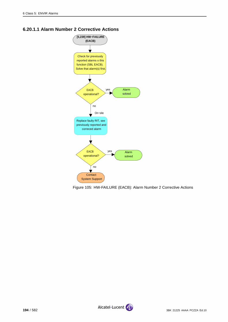
6 Class 5: ENVIR Alarms
6.20.1.1 Alarm Number 2 Corrective Actions
[5,239] HW−FAILURE (EACB)
Alarmsolved
yesEACB operational?
no
no
ContactSystem Support
Check for previously reported alarms o this function (SBL EACB). Solve that alarm(s) first.
EACB operational?
yes Alarmsolved
Replace faulty RIT, see previously reported and
correced alarm
On−site
Figure 105: HW-FAILURE (EACB): Alarm Number 2 Corrective Actions
194 / 582 3BK 21225 AAAA PCZZA Ed.10
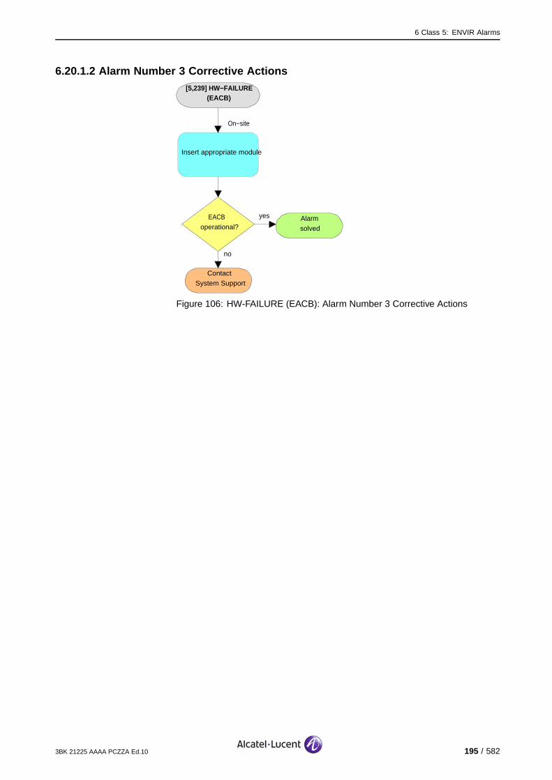
6 Class 5: ENVIR Alarms
6.20.1.2 Alarm Number 3 Corrective Actions[5,239] HW−FAILURE
(EACB)
no
ContactSystem Support
EACB operational?
yes Alarmsolved
Insert appropriate module
On−site
Figure 106: HW-FAILURE (EACB): Alarm Number 3 Corrective Actions
3BK 21225 AAAA PCZZA Ed.10 195 / 582
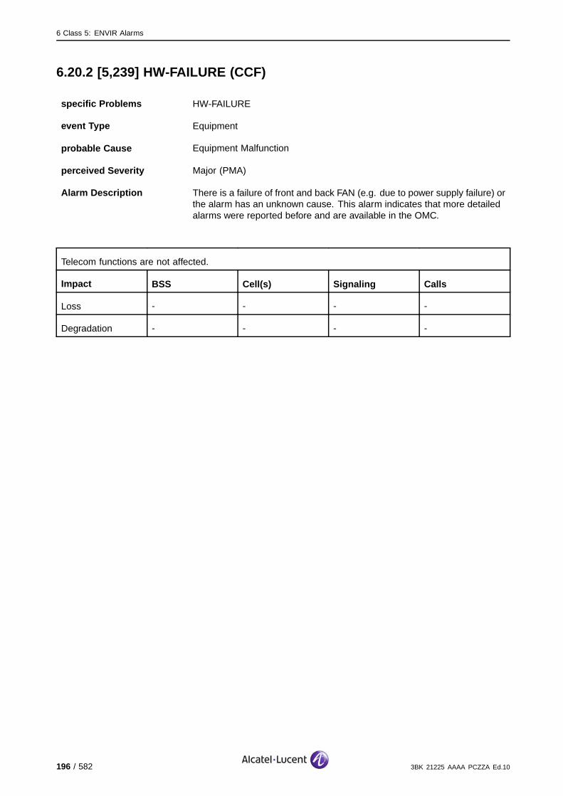
6 Class 5: ENVIR Alarms
6.20.2 [5,239] HW-FAILURE (CCF)
specific Problems HW-FAILURE
event Type Equipment
probable Cause Equipment Malfunction
perceived Severity Major (PMA)
Alarm Description There is a failure of front and back FAN (e.g. due to power supply failure) orthe alarm has an unknown cause. This alarm indicates that more detailedalarms were reported before and are available in the OMC.
Telecom functions are not affected.
Impact BSS Cell(s) Signaling Calls
Loss - - - -
Degradation - - - -
196 / 582 3BK 21225 AAAA PCZZA Ed.10
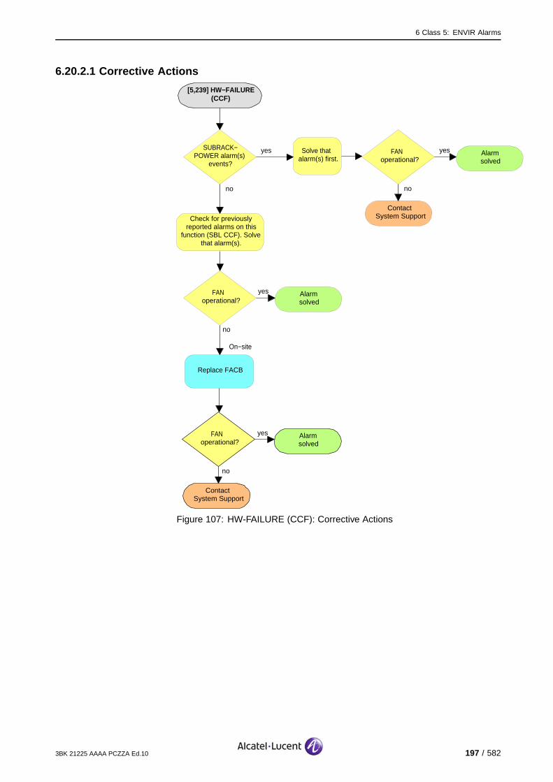
6 Class 5: ENVIR Alarms
6.20.2.1 Corrective Actions
[5,239] HW−FAILURE (CCF)
no
ContactSystem Support
FAN operational?
yes Alarmsolved
Replace FACB
On−site
no
SUBRACK−POWER alarm(s)
events?
yes Solve that alarm(s) first.
no
ContactSystem Support
FAN operational?
yes Alarmsolved
Check for previously reported alarms on this
function (SBL CCF). Solve that alarm(s).
no
FAN operational?
yes Alarmsolved
Figure 107: HW-FAILURE (CCF): Corrective Actions
3BK 21225 AAAA PCZZA Ed.10 197 / 582

6 Class 5: ENVIR Alarms
198 / 582 3BK 21225 AAAA PCZZA Ed.10

7 Class 6: RF alarms
7 Class 6: RF alarms
This section defines the alarms for the Class 6: RF alarm class.
3BK 21225 AAAA PCZZA Ed.10 199 / 582

7 Class 6: RF alarms
7.1 [6,1] LNK-AL
specific Problems LNK-AL
event Type Equipment
probable Cause Loss Of Signal
perceived Severity Minor (DMA)
Alarm Description A link between the FHU and a CU is faulty on the CU side.
Alarm Number 1: Fault on Link 1.
2: Fault on Link 2.
If there is antenna diversity, the antenna diversity function is lost and there is a loss of call quality. (#)
If there is no antenna diversity, the 8 channels supported by the CU are lost. The BCCH is regainedthrough recovery. (X).
Impact BSS Cell(s) Signaling Calls
Loss - - - X
Degradation - # X # X #
200 / 582 3BK 21225 AAAA PCZZA Ed.10

7 Class 6: RF alarms
7.1.1 G1 BTS Corrective Actions
[6,1] LNK−AL
Alarmsolved
yesCUoperational?
no
On−site
Replace Receiver
On−site
no
ContactSystem Support
Lock Function CU
Unlock Function CU
Replace Transmitter
CU operational?
yes Alarmsolved
OR
On−site
Check FHI cables and connectors to CU and
FHU
Figure 108: LNK-AL: G1 BTS Corrective Actions
3BK 21225 AAAA PCZZA Ed.10 201 / 582

7 Class 6: RF alarms
7.1.2 G2 BTS Corrective Actions
[6,1] LNK−AL
Alarmsolved
yesCUoperational?
no
On−site
Replace Receiver
On−site
no
ContactSystem Support
Lock Function CU
Unlock Function CU
Replace Transmitter
CU operational?
yes Alarmsolved
OR
Figure 109: LNK-AL: G2 BTS Corrective Actions
202 / 582 3BK 21225 AAAA PCZZA Ed.10

7 Class 6: RF alarms
7.2 [6,2] LNK-DBLE-AL
specific Problems LNK-DBLE-AL
event Type Equipment
probable Cause Loss Of Signal
perceived Severity Major (PMA)
Alarm Description Both links between the FHU and a CU are faulty.
The eight channels supported by the CU are lost. The BCCH is regained through recovery.
Impact BSS Cell(s) Signaling Calls
Loss - - - X
Degradation X X X -
3BK 21225 AAAA PCZZA Ed.10 203 / 582
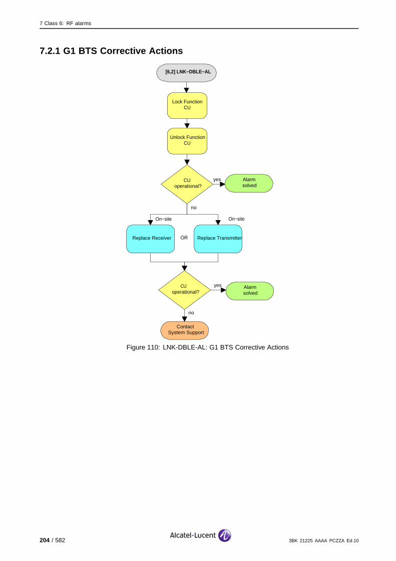
7 Class 6: RF alarms
7.2.1 G1 BTS Corrective Actions
[6,2] LNK−DBLE−AL
Alarmsolved
yesCUoperational?
no
On−site
Replace Receiver
On−site
no
ContactSystem Support
Lock Function CU
Unlock Function CU
Replace Transmitter
CU operational?
yes Alarmsolved
OR
Figure 110: LNK-DBLE-AL: G1 BTS Corrective Actions
204 / 582 3BK 21225 AAAA PCZZA Ed.10
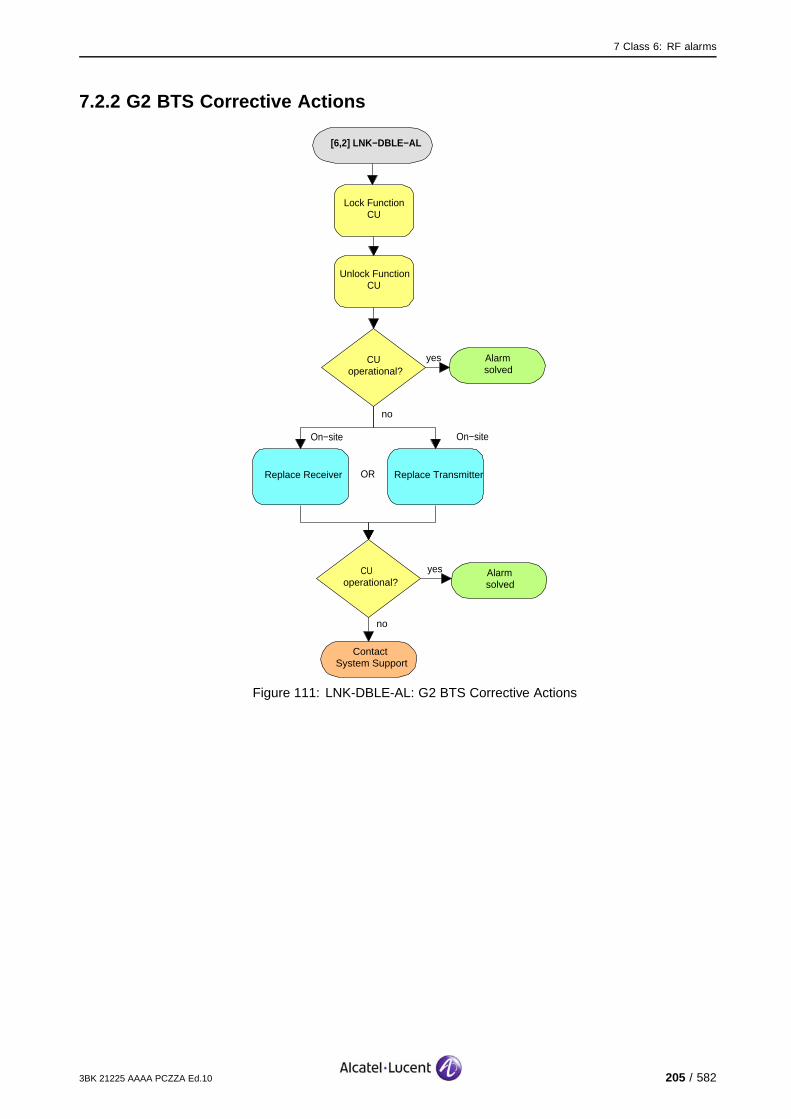
7 Class 6: RF alarms
7.2.2 G2 BTS Corrective Actions
[6,2] LNK−DBLE−AL
Alarmsolved
yesCUoperational?
no
On−site
Replace Receiver
On−site
no
ContactSystem Support
Lock Function CU
Unlock Function CU
Replace Transmitter
CU operational?
yes Alarmsolved
OR
Figure 111: LNK-DBLE-AL: G2 BTS Corrective Actions
3BK 21225 AAAA PCZZA Ed.10 205 / 582
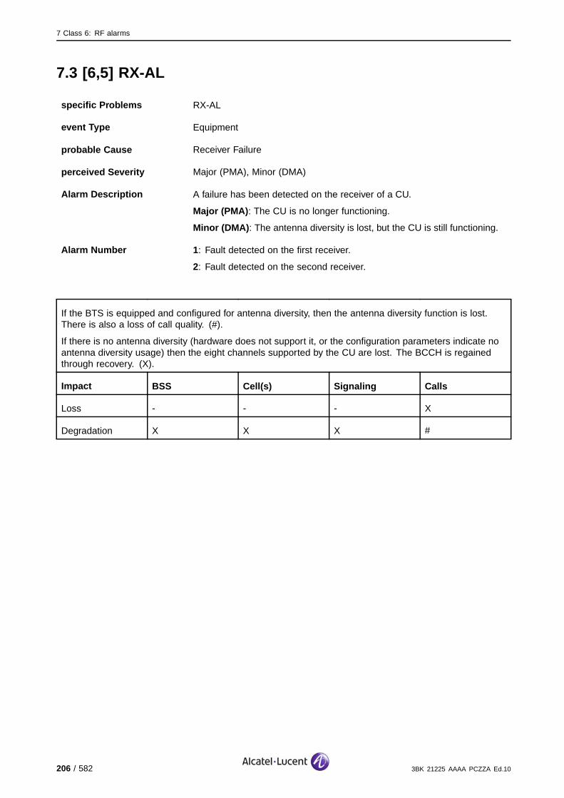
7 Class 6: RF alarms
7.3 [6,5] RX-AL
specific Problems RX-AL
event Type Equipment
probable Cause Receiver Failure
perceived Severity Major (PMA), Minor (DMA)
Alarm Description A failure has been detected on the receiver of a CU.
Major (PMA): The CU is no longer functioning.
Minor (DMA): The antenna diversity is lost, but the CU is still functioning.
Alarm Number 1: Fault detected on the first receiver.
2: Fault detected on the second receiver.
If the BTS is equipped and configured for antenna diversity, then the antenna diversity function is lost.There is also a loss of call quality. (#).
If there is no antenna diversity (hardware does not support it, or the configuration parameters indicate noantenna diversity usage) then the eight channels supported by the CU are lost. The BCCH is regainedthrough recovery. (X).
Impact BSS Cell(s) Signaling Calls
Loss - - - X
Degradation X X X #
206 / 582 3BK 21225 AAAA PCZZA Ed.10

7 Class 6: RF alarms
7.3.1 Corrective Actions
Disable RF PowerUse the BTS Terminal to disable RA before disconnecting RF cables.Initialize RA after work.
[6,5] RX−AL
yesDiversity configuration
OK?
no
On−site
Replace G1Receiver
On−site
no
ContactSystem Support
Check software and hardware configuration
for atenna diversity.
Replace G2Receiver
CU operational?
yes Alarmsolved
OR
Choose correct CPF by selecting
appropriate BTS characteristics.
Modify actual Antenna diversity
capability by replacing the
appropriate antenna entity
On−site
OR
Lock Function CU
Unlock Function CU
no
CU operational?
yesAlarmsolved
ContactSystem Support
no
CU operational?
yesAlarmsolved
Figure 112: RX-AL: Corrective Actions
The fault can be due to external interference.
3BK 21225 AAAA PCZZA Ed.10 207 / 582

7 Class 6: RF alarms
7.4 [6,6] RX-DBLE-AL
specific Problems RX-DBLE-AL
event Type Equipment
probable Cause Receiver Failure
perceived Severity Major (PMA)
Alarm Description A fatal failure is detected on both receivers of the same CU (only in thecase of antenna diversity).
The eight channels supported by the CU are lost. The BCCH is regained through recovery.
Impact BSS Cell(s) Signaling Calls
Loss - - - X
Degradation X X X -
208 / 582 3BK 21225 AAAA PCZZA Ed.10

7 Class 6: RF alarms
7.4.1 Corrective Actions
Disable RF PowerUse the BTS Terminal to disable RA before disconnecting RF cables.Initialize RA after work.
[6,6] RX−DBLE−AL
Alarmsolved
yesCUoperational?
no
On−site
Replace both G1 Receivers
On−site
no
ContactSystem Support
Lock Function CU
Unlock Function CU
Replace both G2 Receivers
CU operational?
yes Alarmsolved
OR
On−site
Figure 113: RX-DBLE-AL: Corrective Actions
3BK 21225 AAAA PCZZA Ed.10 209 / 582
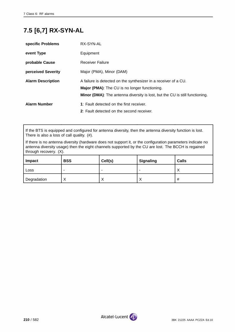
7 Class 6: RF alarms
7.5 [6,7] RX-SYN-AL
specific Problems RX-SYN-AL
event Type Equipment
probable Cause Receiver Failure
perceived Severity Major (PMA), Minor (DAM)
Alarm Description A failure is detected on the synthesizer in a receiver of a CU.
Major (PMA): The CU is no longer functioning.
Minor (DMA): The antenna diversity is lost, but the CU is still functioning.
Alarm Number 1: Fault detected on the first receiver.
2: Fault detected on the second receiver.
If the BTS is equipped and configured for antenna diversity, then the antenna diversity function is lost.There is also a loss of call quality. (#).
If there is no antenna diversity (hardware does not support it, or the configuration parameters indicate noantenna diversity usage) then the eight channels supported by the CU are lost. The BCCH is regainedthrough recovery. (X).
Impact BSS Cell(s) Signaling Calls
Loss - - - X
Degradation X X X #
210 / 582 3BK 21225 AAAA PCZZA Ed.10
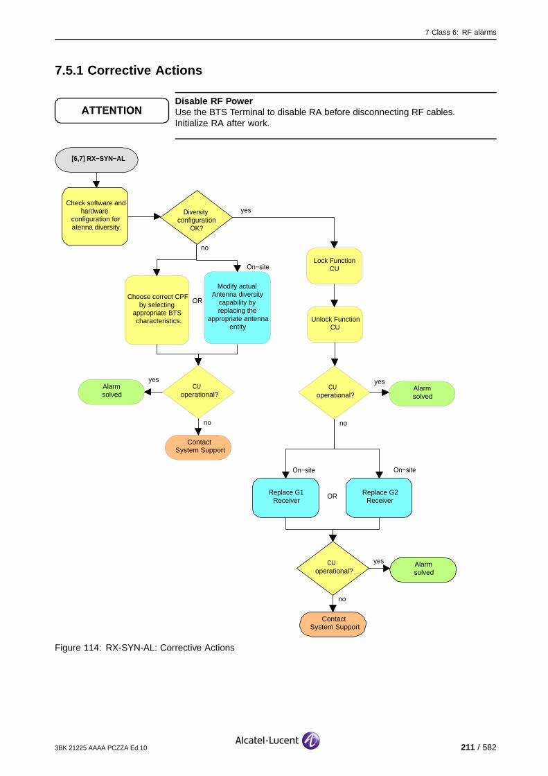
7 Class 6: RF alarms
7.5.1 Corrective Actions
Disable RF PowerUse the BTS Terminal to disable RA before disconnecting RF cables.Initialize RA after work.
[6,7] RX−SYN−AL
yesDiversity configuration
OK?
no
On−site
Replace G1Receiver
On−site
no
ContactSystem Support
Check software and hardware
configuration for atenna diversity.
Replace G2Receiver
CU operational?
yes Alarmsolved
OR
Choose correct CPF by selecting
appropriate BTS characteristics.
Modify actual Antenna diversity
capability by replacing the
appropriate antenna entity
On−site
OR
Lock Function CU
Unlock Function CU
no
CU operational?
yesAlarmsolved
ContactSystem Support
no
CU operational?
yesAlarmsolved
Figure 114: RX-SYN-AL: Corrective Actions
3BK 21225 AAAA PCZZA Ed.10 211 / 582

7 Class 6: RF alarms
7.6 [6,8] RX-SYN-DBLE-AL
specific Problems RX-SYN-DBLE-AL
event Type Equipment
probable Cause Receiver Failure
perceived Severity Major (PMA)
Alarm Description A fatal failure has been detected on both synthesizers in the receivers ofthe same CU (only in case of antenna diversity).
The eight channels supported by the CU are lost. The BCCH is regained through recovery.
Impact BSS Cell(s) Signaling Calls
Loss - - - X
Degradation X X X -
212 / 582 3BK 21225 AAAA PCZZA Ed.10
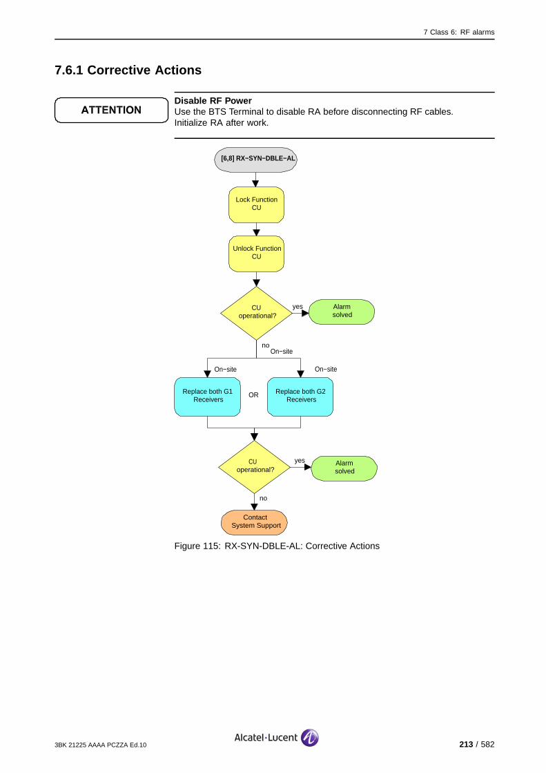
7 Class 6: RF alarms
7.6.1 Corrective Actions
Disable RF PowerUse the BTS Terminal to disable RA before disconnecting RF cables.Initialize RA after work.
[6,8] RX−SYN−DBLE−AL
Alarmsolved
yesCUoperational?
no
On−site
Replace both G1 Receivers
On−site
no
ContactSystem Support
Lock Function CU
Unlock Function CU
Replace both G2 Receivers
CU operational?
yes Alarmsolved
OR
On−site
Figure 115: RX-SYN-DBLE-AL: Corrective Actions
3BK 21225 AAAA PCZZA Ed.10 213 / 582
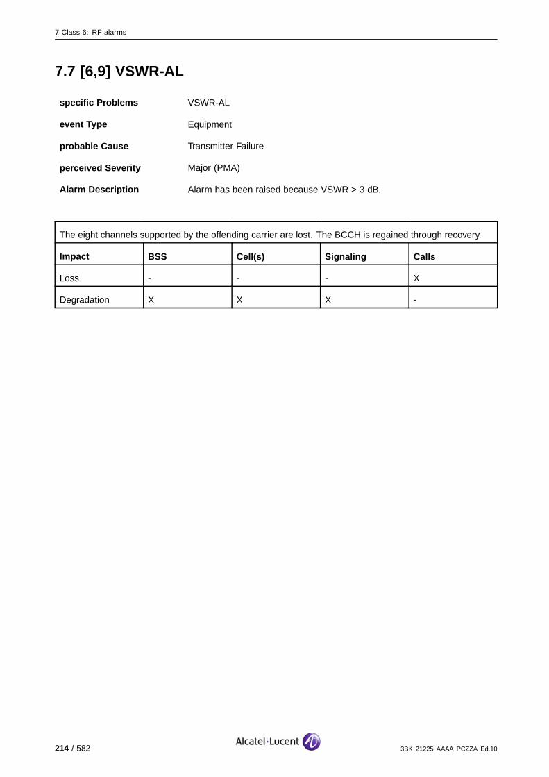
7 Class 6: RF alarms
7.7 [6,9] VSWR-AL
specific Problems VSWR-AL
event Type Equipment
probable Cause Transmitter Failure
perceived Severity Major (PMA)
Alarm Description Alarm has been raised because VSWR > 3 dB.
The eight channels supported by the offending carrier are lost. The BCCH is regained through recovery.
Impact BSS Cell(s) Signaling Calls
Loss - - - X
Degradation X X X -
214 / 582 3BK 21225 AAAA PCZZA Ed.10
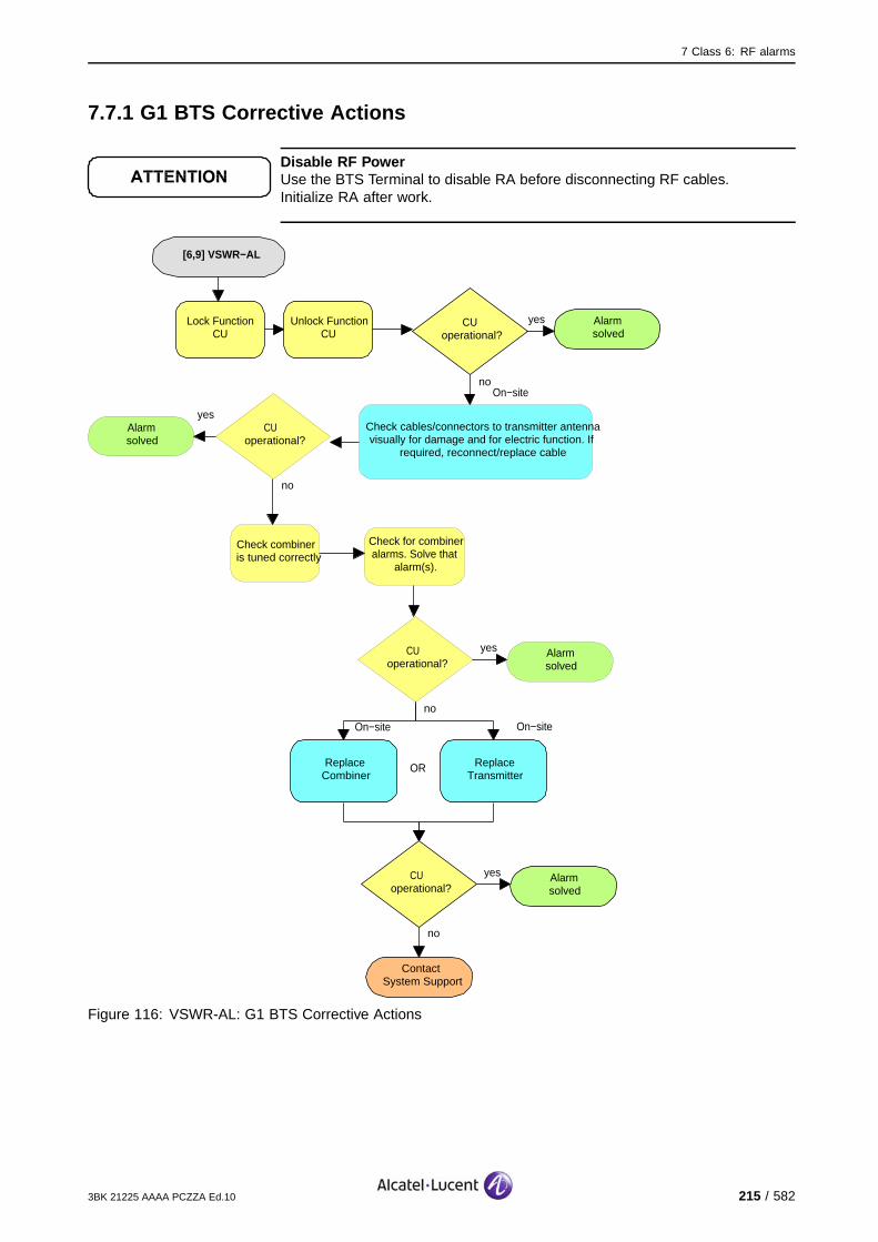
7 Class 6: RF alarms
7.7.1 G1 BTS Corrective Actions
Disable RF PowerUse the BTS Terminal to disable RA before disconnecting RF cables.Initialize RA after work.
[6,9] VSWR−AL
Alarmsolved
yesCUoperational?
no
On−site
ReplaceCombiner
On−site
no
ContactSystem Support
Lock Function CU
Unlock Function CU
ReplaceTransmitter
CU operational?
yes Alarmsolved
OR
On−site
Check cables/connectors to transmitter antenna visually for damage and for electric function. If
required, reconnect/replace cable
no
CU operational?
yesAlarmsolved
Check combiner is tuned correctly
Check for combiner alarms. Solve that
alarm(s).
no
CU operational?
yes Alarmsolved
Figure 116: VSWR-AL: G1 BTS Corrective Actions
3BK 21225 AAAA PCZZA Ed.10 215 / 582
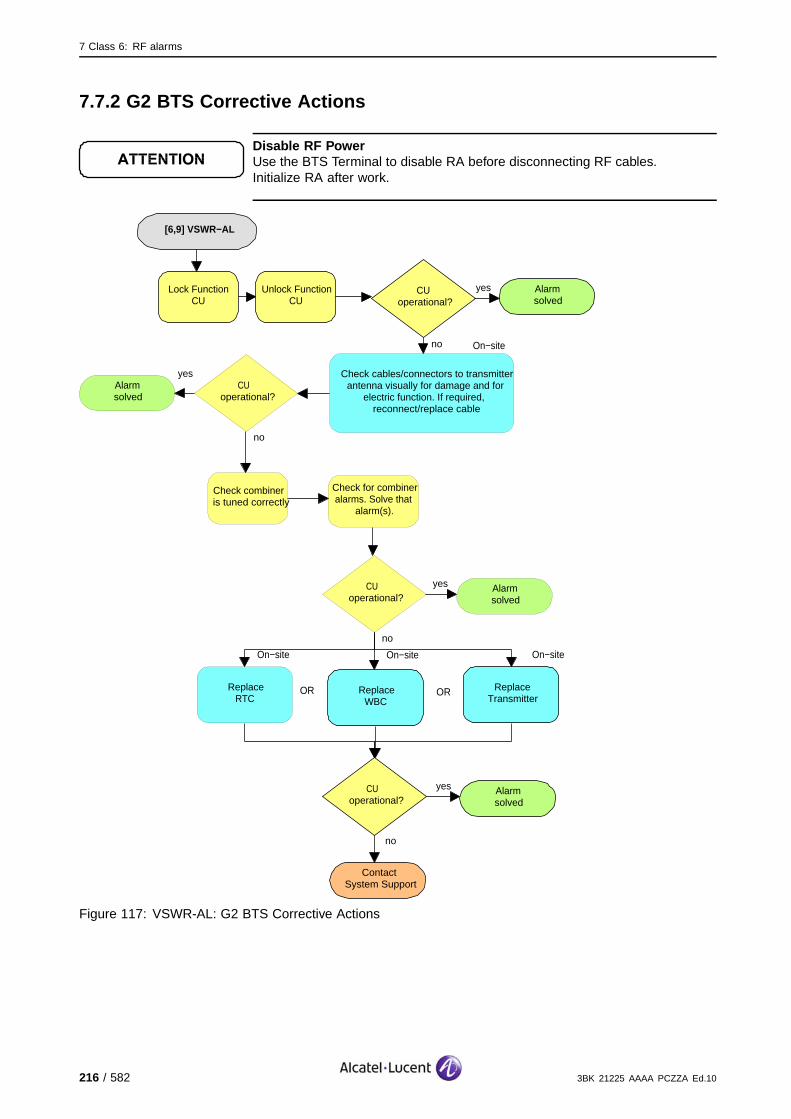
7 Class 6: RF alarms
7.7.2 G2 BTS Corrective Actions
Disable RF PowerUse the BTS Terminal to disable RA before disconnecting RF cables.Initialize RA after work.
[6,9] VSWR−AL
Alarmsolved
yesCUoperational?
no
On−site
ReplaceWBC
On−site
no
ContactSystem Support
Lock Function CU
Unlock Function CU
ReplaceTransmitter
CU operational?
yes Alarmsolved
OR
On−site
Check cables/connectors to transmitter antenna visually for damage and for
electric function. If required, reconnect/replace cable
no
CU operational?
yesAlarmsolved
Check combiner is tuned correctly
Check for combiner alarms. Solve that
alarm(s).
no
CU operational?
yes Alarmsolved
ReplaceRTC
On−site
OR
Figure 117: VSWR-AL: G2 BTS Corrective Actions
216 / 582 3BK 21225 AAAA PCZZA Ed.10
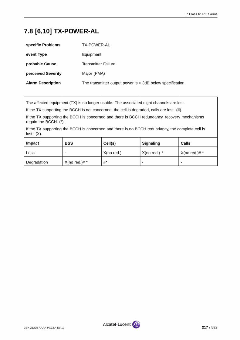
7 Class 6: RF alarms
7.8 [6,10] TX-POWER-AL
specific Problems TX-POWER-AL
event Type Equipment
probable Cause Transmitter Failure
perceived Severity Major (PMA)
Alarm Description The transmitter output power is > 3dB below specification.
The affected equipment (TX) is no longer usable. The associated eight channels are lost.
If the TX supporting the BCCH is not concerned, the cell is degraded, calls are lost. (#).
If the TX supporting the BCCH is concerned and there is BCCH redundancy, recovery mechanismsregain the BCCH. (*).
If the TX supporting the BCCH is concerned and there is no BCCH redundancy, the complete cell islost. (X).
Impact BSS Cell(s) Signaling Calls
Loss - X(no red.) X(no red.) * X(no red.)# *
Degradation X(no red.)# * #* - -
3BK 21225 AAAA PCZZA Ed.10 217 / 582
7 Class 6: RF alarms
7.8.1 Corrective Actions
Required tools and materials :
Combiner test tool (e.g. spectrum analyzer)
Replacement tools, see appropriate replacement procedure.
[6,10] TX−POWER−AL
Alarmsolved
yesCUoperational?
no
On−site
Replace G2 RTC
On−site
no
ContactSystem Support
Lock Function CU
Unlock Function CU
Replace G2 WBC
CU operational?
yes Alarmsolved
OR
On−site
Check cables/connectors toCU and combiner downlink.
If required, reconnect/replace cable
no
CU operational?
yesAlarmsolved
Check combiner is tuned correctly
no
CU operational?
yes Alarmsolved
Replace G1 Combiner
On−site
OR
Check for combiner alarms. Solve that
alarm(s).
On−site
Replace G2 Transmitter
Replace G1 Transmitter
On−site
OR
Figure 118: TX-POWER-AL: Corrective Actions
218 / 582 3BK 21225 AAAA PCZZA Ed.10

7 Class 6: RF alarms
7.9 [6,11] TEMP-AL
specific Problems TEMP-AL
event Type Environmental
probable Cause Temperature Unacceptable
perceived Severity Major (PMA), Minor (DMA)
Alarm Description Major (PMA): The temperature of the transmitter is higher than 80 o C. Thecorresponding CU power supply is switched off.
Minor (DMA): The temperature of the transmitter is higher than 75 o Cbut less than 80 o C.
Alarm Number 1: The Temperature has reached 75 o C.
2: The Temperature has reached 80 o C.
Major (PMA): If the transmitter supporting the BCCH is not concerned, the transmitter cannot be usedand the eight channels are lost. (#).
If the transmitter supporting the BCCH is concerned and there is BCCH redundancy:
the transmitter cannot be used and the eight channels are lost
recovery mechanisms regain the BCCH. (*).
If the TX supporting the BCCH is concerned and there is no BCCH redundancy, the complete cell islost. (X).
Impact BSS Cell(s) Signaling Calls
Loss - X(no red.) X(no red.) X(no red.)#*
Degradation X(no red.) #* * -
Minor (DMA): The quality of the transmission may be degraded.
3BK 21225 AAAA PCZZA Ed.10 219 / 582

7 Class 6: RF alarms
7.9.1 G1 BTS Corrective Actions
[6,11] TEMP−AL
no
ContactSystem Support
TRE Temperature
OK?
yes
Alarmsolved
The ambient temperature must be
reduced.
On−site
no
Is ambient
temperature out of permitted
limits?
yes
Check and clean heat exchanger air intake
Fan alarm events?
Solve that alarm(s) first
Check the ambient temperature.
On−site
On−site
no
ContactSystem Support
TransmitterTemperature
OK?
yes Alarmsolved
yes
no
Replace Cooling Fan
On−site
OR
Replace Transmitter no
TransmitterTemperature
OK?
yes Alarmsolved
On−site
Figure 119: TEMP-AL: G1 BTS Corrective Actions
220 / 582 3BK 21225 AAAA PCZZA Ed.10
7 Class 6: RF alarms
7.9.2 G2 BTS Corrective Actions
[6,11] TEMP−AL
no
ContactSystem Support
TRE Temperature
OK?
yes
Alarmsolved
The ambient temperature must be
reduced.
On−site
no
Is ambient
temperature out of permitted
limits?
yes
Check and clean heat exchanger air intake
Fan alarm events?
Solve that alarm(s) first
Check the ambient temperature.
On−site
On−site
no
ContactSystem Support
TransmitterTemperature
OK?
yes Alarmsolved
yes
no
Replace CFU
On−site
OR
Replace Transmitter no
TransmitterTemperature
OK?
yes Alarmsolved
On−site
Figure 120: TEMP-AL: G2 BTS Corrective Actions
3BK 21225 AAAA PCZZA Ed.10 221 / 582

7 Class 6: RF alarms
7.10 [6,13] TX-SYN-AL
specific Problems TX-SYN-AL
event Type Environmental
probable Cause Transmitter Failure
perceived Severity Major (PMA)
Alarm Description A failure has been detected on the transmitter synthesizer of a CU Thetransmitter synthesizer is not locked.
Transmission quality is degraded. Depending on the level of degradation, the eight channels supported bythe transmitter may be lost. The BCCH is regained through recovery.
Impact BSS Cell(s) Signaling Calls
Impact BSS Cell(s) Signaling Calls
Loss - - - X
Degradation X X X -
222 / 582 3BK 21225 AAAA PCZZA Ed.10

7 Class 6: RF alarms
7.10.1 Corrective Actions
[6,13] TX−SYN−AL
Alarmsolved
yesCUoperational?
no
On−site
G1: Replace Transmitter
On−site
no
ContactSystem Support
Lock Function CU
Unlock Function CU
G2:Replace Transmitter
CU operational?
yes Alarmsolved
OR
Figure 121: TX-SYN-AL: Corrective Actions
3BK 21225 AAAA PCZZA Ed.10 223 / 582
7 Class 6: RF alarms
7.11 [6,14] FCLK-AL
7.11.1 [6,14] FCLK-AL (CU)
specific Problems FCLK-AL
event Type Equipment
probable Cause Timing Problem
perceived Severity Minor (DMA)
Alarm Description A failure is detected on one of the clock links of a CU. The CU hasautomatically switched to the other clock link.
Alarm Number 1: Fault on Clock Link 1.
2: Fault on Clock Link 2.
Telecom functions are not affected.
Impact BSS Cell(s) Signaling Calls
Loss - - - -
Degradation - - - -
224 / 582 3BK 21225 AAAA PCZZA Ed.10
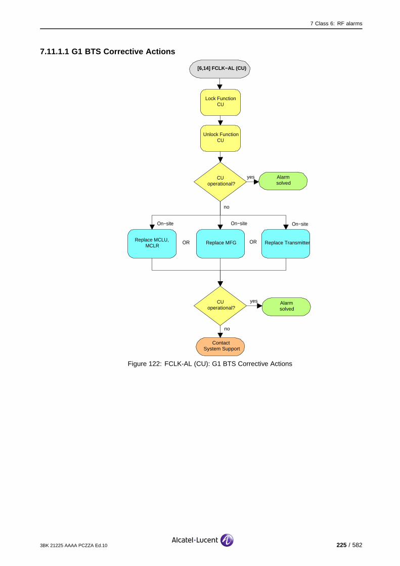
7 Class 6: RF alarms
7.11.1.1 G1 BTS Corrective Actions
[6,14] FCLK−AL (CU)
Alarmsolved
yesCUoperational?
no
On−site
Replace MCLU, MCLR
On−site
no
ContactSystem Support
Lock Function CU
Unlock Function CU
Replace MFG Replace Transmitter
CUoperational?
yes Alarmsolved
On−site
OR OR
Figure 122: FCLK-AL (CU): G1 BTS Corrective Actions
3BK 21225 AAAA PCZZA Ed.10 225 / 582

7 Class 6: RF alarms
7.11.1.2 G2 BTS Corrective Actions
[6,14] FCLK−AL (CU)
Alarmsolved
yesCUoperational?
no
On−site
Replace STSE, STSP, STSR
On−site
no
ContactSystem Support
Lock Function CU
Unlock Function CU
Replace Transmitter
CUoperational?
yes Alarmsolved
OR
Figure 123: FCLK-AL (CU): G2 BTS Corrective Actions
226 / 582 3BK 21225 AAAA PCZZA Ed.10

7 Class 6: RF alarms
7.12 [6,15] INTERNAL-FCLK
7.12.1 [6,15] INTERNAL-FCLK (CU)
specific Problems INTERNAL-FCLK
event Type Equipment
probable Cause Timing Problem
perceived Severity Major (PMA)
Alarm Description Both internal frame clock links of a CU are faulty.
The eight channels supported by the CU are lost. The BCCH is regained through recovery.
Impact BSS Cell(s) Signaling Calls
Loss - - - X
Degradation X X X -
3BK 21225 AAAA PCZZA Ed.10 227 / 582
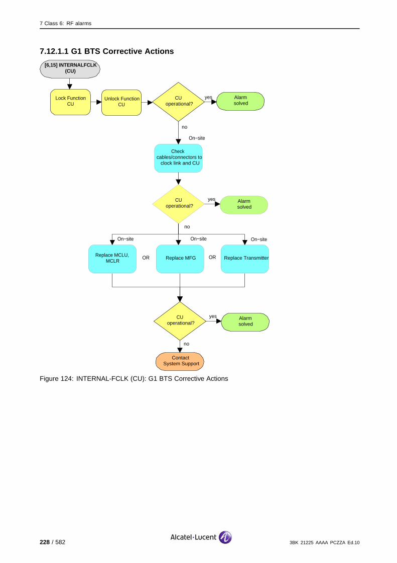
7 Class 6: RF alarms
7.12.1.1 G1 BTS Corrective Actions
[6,15] INTERNALFCLK (CU)
Alarmsolved
yesCUoperational?
no
no
ContactSystem Support
Lock Function CU
Unlock Function CU
CUoperational?
yes Alarmsolved
On−site
Check cables/connectors to
clock link and CU
no
CUoperational?
yes Alarmsolved
On−site
Replace MCLU, MCLR
On−site
Replace MFG Replace Transmitter
On−site
OR OR
Figure 124: INTERNAL-FCLK (CU): G1 BTS Corrective Actions
228 / 582 3BK 21225 AAAA PCZZA Ed.10

7 Class 6: RF alarms
7.12.1.2 G2 BTS Corrective Actions
[6,15] INTERNALFCLK (CU)
Alarmsolved
yesCUoperational?
no
On−site
Replace STSE, STSP, STSR
On−site
no
ContactSystem Support
Lock Function CU
Unlock Function CU
Replace Transmitter
CUoperational?
yes Alarmsolved
OR
On−site
Check cables/connectors to
clock link and CU
no
CUoperational?
yes Alarmsolved
Figure 125: INTERNAL-FCLK (CU): G2 BTS Corrective Actions
3BK 21225 AAAA PCZZA Ed.10 229 / 582

7 Class 6: RF alarms
7.13 [6,16] OBCLK-AL
7.13.1 [6,16] OBCLK-AL (CU)
specific Problems OBCLK-AL
event Type Equipment
probable Cause Timing Problem
perceived Severity Minor (DMA)
Alarm Description A failure is detected on one of the Octal Bit Clock Links of a CU. The CUis automatically switched to the other clock link.
Alarm Number 1: Fault on Clock Link 1.
2: Fault on Clock Link 2.
Telecom functions are not affected.
Impact BSS Cell(s) Signaling Calls
Loss - - - -
Degradation - - - -
230 / 582 3BK 21225 AAAA PCZZA Ed.10
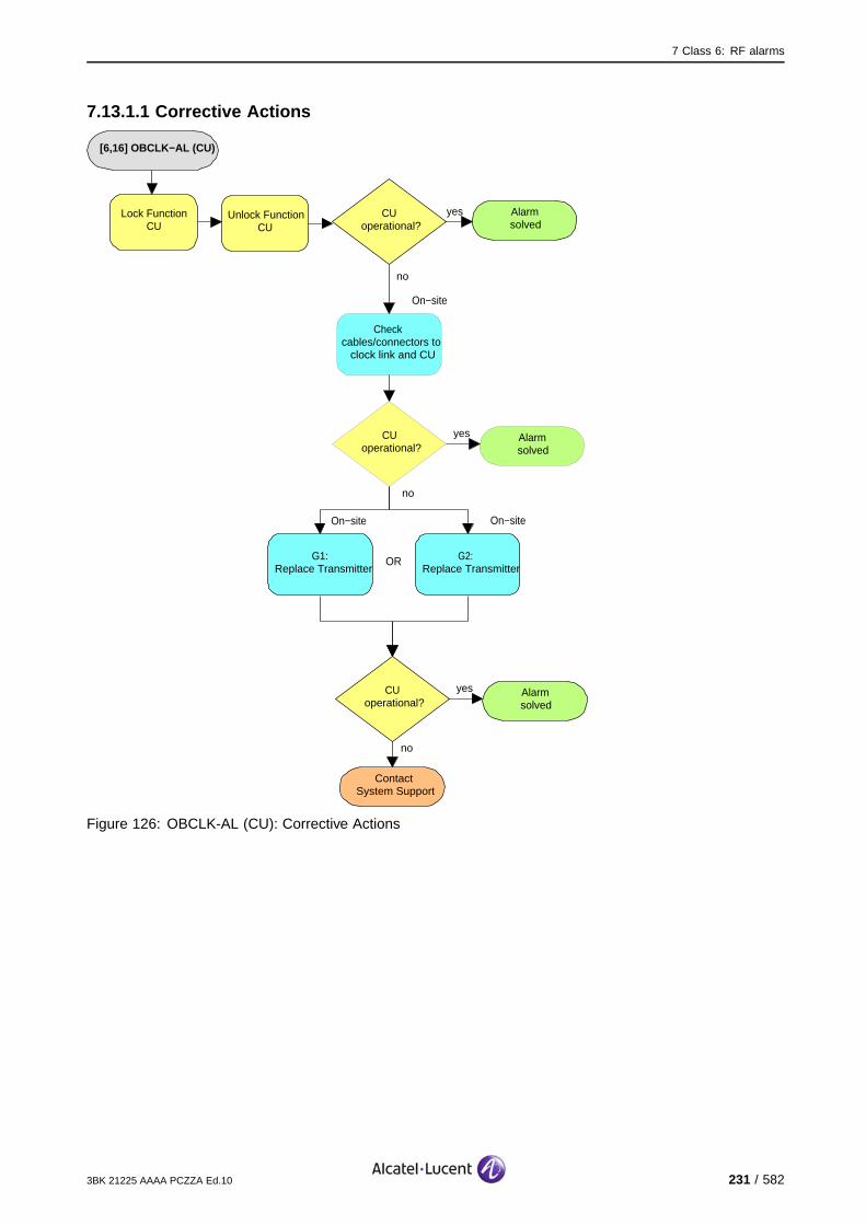
7 Class 6: RF alarms
7.13.1.1 Corrective Actions
[6,16] OBCLK−AL (CU)
Alarmsolved
yesCUoperational?
no
On−site
G1:Replace Transmitter
On−site
no
ContactSystem Support
Lock Function CU
Unlock Function CU
G2: Replace Transmitter
CUoperational?
yes Alarmsolved
OR
On−site
Check cables/connectors to
clock link and CU
no
CUoperational?
yes Alarmsolved
Figure 126: OBCLK-AL (CU): Corrective Actions
3BK 21225 AAAA PCZZA Ed.10 231 / 582

7 Class 6: RF alarms
7.14 [6,17] INTERNAL-OBCLK
7.14.1 [6,17] INTERNAL-OBCLK (CU)
specific Problems INTERNAL-OBCLK
event Type Equipment
probable Cause Timing Problem
perceived Severity Major (PMA)
Alarm Description Both Octal Bit Clock Links of a CU are faulty.
The eight channels supported by the CU are lost. The BCCH is regained through recovery.
Impact BSS Cell(s) Signaling Calls
Loss - - - X
Degradation X X X -
232 / 582 3BK 21225 AAAA PCZZA Ed.10

7 Class 6: RF alarms
7.14.1.1 Corrective Actions
[6,17] INTERNAL−OBCLK(CU)
Alarmsolved
yesCUoperational?
no
On−site
G1:Replace Transmitter
On−site
no
ContactSystem Support
Lock Function CU
Unlock Function CU
G2: Replace Transmitter
CUoperational?
yes Alarmsolved
OR
On−site
Check cables/connectors to
clock link and CU
no
CUoperational?
yes Alarmsolved
Figure 127: INTERNAL-OBCLK (CU): Corrective Actions
3BK 21225 AAAA PCZZA Ed.10 233 / 582

7 Class 6: RF alarms
7.15 [6,18] REF-FREQ-AL
7.15.1 [6,18] REF-FREQ-AL (CU)
specific Problems REF-FREQ-AL
event Type Equipment
probable Cause Timing Problem
perceived Severity Minor (DMA)
Alarm Description A failure is detected on one of the clock links carrying the referencefrequency of a CU.
The CU is automatically switched to the other clock link.
Alarm Number 1: Fault on Clock Link 1.
2: Fault on Clock Link 2.
Telecom functions are not affected.
Impact BSS Cell(s) Signaling Calls
Loss - - - -
Degradation - - - -
234 / 582 3BK 21225 AAAA PCZZA Ed.10
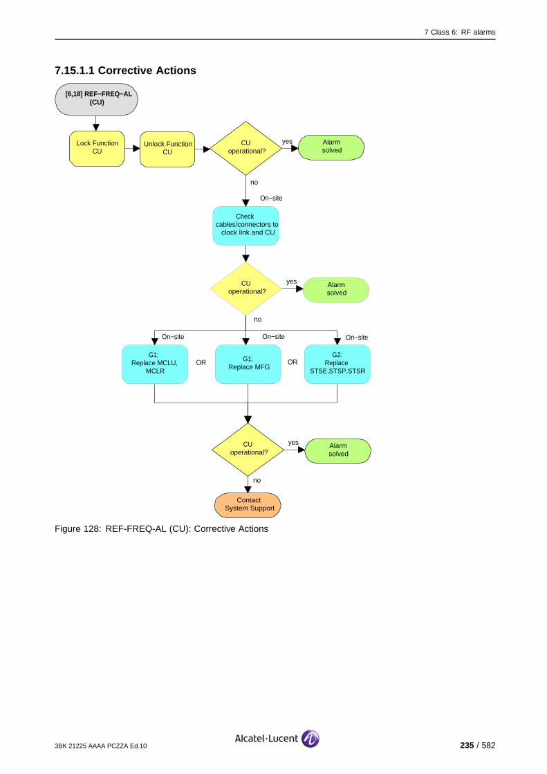
7 Class 6: RF alarms
7.15.1.1 Corrective Actions
[6,18] REF−FREQ−AL(CU)
Alarmsolved
yesCUoperational?
no
no
ContactSystem Support
Lock Function CU
Unlock Function CU
CUoperational?
yes Alarmsolved
On−site
Check cables/connectors to
clock link and CU
no
CUoperational?
yes Alarmsolved
On−site
G1: Replace MCLU,
MCLR
On−site
G1:Replace MFG
G2:Replace
STSE,STSP,STSR
On−site
OR OR
Figure 128: REF-FREQ-AL (CU): Corrective Actions
3BK 21225 AAAA PCZZA Ed.10 235 / 582
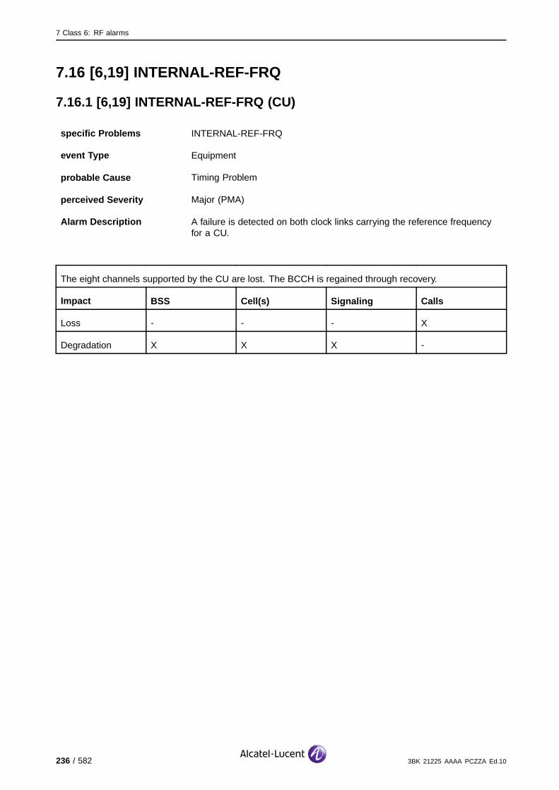
7 Class 6: RF alarms
7.16 [6,19] INTERNAL-REF-FRQ
7.16.1 [6,19] INTERNAL-REF-FRQ (CU)
specific Problems INTERNAL-REF-FRQ
event Type Equipment
probable Cause Timing Problem
perceived Severity Major (PMA)
Alarm Description A failure is detected on both clock links carrying the reference frequencyfor a CU.
The eight channels supported by the CU are lost. The BCCH is regained through recovery.
Impact BSS Cell(s) Signaling Calls
Loss - - - X
Degradation X X X -
236 / 582 3BK 21225 AAAA PCZZA Ed.10

7 Class 6: RF alarms
7.16.1.1 G1 BTS Corrective Actions
[6,19] INTERNAL−REF−FRQ
(CU)
Alarmsolved
yesCUoperational?
no
no
ContactSystem Support
Lock Function CU
Unlock Function CU
CUoperational?
yes Alarmsolved
On−site
Check cables/connectors to
clock link and CU
no
CUoperational?
yes Alarmsolved
On−site
Replace MCLU, MCLR
On−site
Replace MFG Replace Transmitter
On−site
OR OR
Figure 129: INTERNAL-REF-FRQ (CU): G1 BTS Corrective Actions
3BK 21225 AAAA PCZZA Ed.10 237 / 582
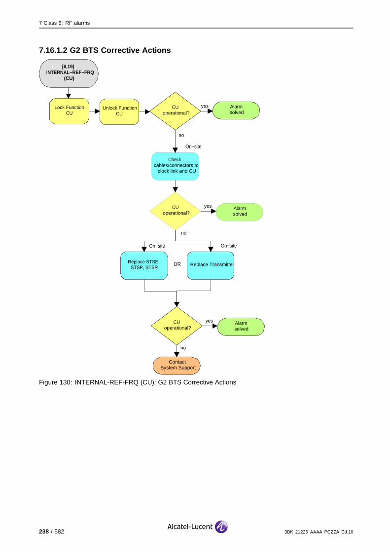
7 Class 6: RF alarms
7.16.1.2 G2 BTS Corrective Actions
[6,19] INTERNAL−REF−FRQ
(CU)
Alarmsolved
yesCUoperational?
no
On−site
Replace STSE, STSP, STSR
On−site
no
ContactSystem Support
Lock Function CU
Unlock Function CU
Replace Transmitter
CUoperational?
yes Alarmsolved
OR
On−site
Check cables/connectors to
clock link and CU
no
CUoperational?
yes Alarmsolved
Figure 130: INTERNAL-REF-FRQ (CU): G2 BTS Corrective Actions
238 / 582 3BK 21225 AAAA PCZZA Ed.10

7 Class 6: RF alarms
7.17 [6,34] ANTENNA-VSWR
specific Problems ANTENNA-VSWR
event Type Equipment
probable Cause Transmitter Failure
perceived Severity Major (PMA), Minor (DMA)
Alarm Description A fault is detected in the antenna VSWR.
Major (PMA): The VSWR has exceeded threshold level 2.
Minor (DMA): The VSWR has exceeded threshold level 1.
Alarm Number 1: The VSWR has exceeded threshold level 1.
2: The VSWR has exceeded threshold level 2.
Major (PMA): The complete cell is lost. (X)
Minor (DMA): The transmission quality is degraded. (#).
Impact BSS Cell(s) Signaling Calls
Loss - X X X
Degradation X - - #
7.17.1 Corrective Actions
Disable RF PowerUse the BTS Terminal to disable RA before disconnecting RF cables.Initialize RA after work.
Required tools and materialsAntenna Test Tools
3BK 21225 AAAA PCZZA Ed.10 239 / 582

7 Class 6: RF alarms
[6,34] ANTENNA−VSWR
Alarmsolved
yesRAoperational?
no
no
ContactSystem Support
Lock Function RA
Unlock Function RA
RA operational?
yes Alarmsolved
no
RA operational?
yes Alarmsolved
Check for combiner alarms. Solve that
alarm(s).
Reduce transmit power, so cell might come back in traffic. Solve
problem as soon as possible
temporarily
Check BTS status
Check VSWR threshold switch setting to 1.7 on
combiner front panel
Check cable/connectors to transmitter antenna for
damage and electric function.
no
Antenna network problems
events?
yes Solve antenna network problem
no
Antenna problems events?
yes Solve antenna problem
Figure 131: ANTENNA-VSWR: Corrective Actions
Reduced TX PowerIf the transmit power was reduced, set transmit power settings back to previousvalues when the problem is solved.
240 / 582 3BK 21225 AAAA PCZZA Ed.10

7 Class 6: RF alarms
7.18 [6,35] FRONTEND-RELAY-AL
specific Problems FRONTEND-RELAY-AL
event Type Equipment
probable Cause Equipment Malfunction
perceived Severity Minor (DMA)
Alarm Description A fault is detected on the RFE relay (For the G1 BTS this alarm is onlyissued if there is no antenna diversity).
Telecom functions are not affected.
Impact BSS Cell(s) Signaling Calls
Loss - - - -
Degradation - - - -
3BK 21225 AAAA PCZZA Ed.10 241 / 582

7 Class 6: RF alarms
7.18.1 Corrective Actions
Disable RF PowerUse the BTS Terminal to disable RA before disconnecting RF cables.Initialize RA after work.
[6,35] FRONTEND−RELAY−AL
Alarmsolved
yesRAoperational?
no
On−site
G1:Replace RFE
On−site
no
ContactSystem Support
Lock Function RA
Unlock Function RA
G2:Replace RFE
Check cables/connectors from receiver antenna visually and eletrically. Replace
cable if required.
RA operational?
yes Alarmsolved
On−site
OR
Figure 132: FRONTEND-RELAY-AL: Corrective Actions
242 / 582 3BK 21225 AAAA PCZZA Ed.10

7 Class 6: RF alarms
7.19 [6,36] FRONTEND-AL
specific Problems FRONTEND-AL
event Type Equipment
probable Cause Equipment Malfunction
perceived Severity Major (PMA), Minor (DMA)
Alarm Description One of the two amplifiers of a RFE is faulty.
Alarm Number 1: VSWR has exceeded threshold level 1.
2: VSWR has exceeded threshold level 2.
If the BTS is equipped and configured for antenna diversity, the antenna diversity function is lost. There is aloss of call quality. (#)
If there is no antenna diversity, the cell is lost. (X).
Impact BSS Cell(s) Signaling Calls
Loss - X X X
Degradation X - - #
3BK 21225 AAAA PCZZA Ed.10 243 / 582
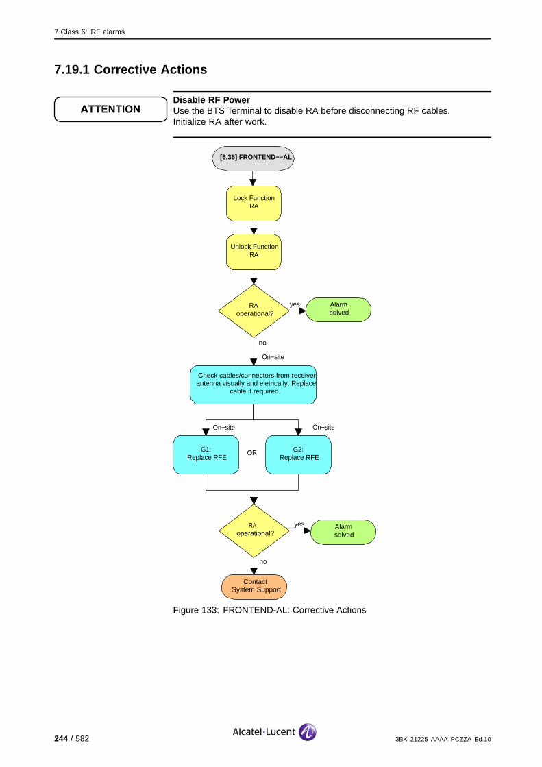
7 Class 6: RF alarms
7.19.1 Corrective Actions
Disable RF PowerUse the BTS Terminal to disable RA before disconnecting RF cables.Initialize RA after work.
[6,36] FRONTEND−−AL
Alarmsolved
yesRAoperational?
no
On−site
G1:Replace RFE
On−site
no
ContactSystem Support
Lock Function RA
Unlock Function RA
G2:Replace RFE
Check cables/connectors from receiver antenna visually and eletrically. Replace
cable if required.
RA operational?
yes Alarmsolved
On−site
OR
Figure 133: FRONTEND-AL: Corrective Actions
244 / 582 3BK 21225 AAAA PCZZA Ed.10

7 Class 6: RF alarms
7.20 [6,37] FATAL-FRONTEND-AL
specific Problems FATAL-FRONTEND-AL
event Type Equipment
probable Cause Equipment Malfunction
perceived Severity Major (PMA)
Alarm Description The RFE is faulty.
The cell is lost.
Impact BSS Cell(s) Signaling Calls
Loss - X X X
Degradation X - - -
3BK 21225 AAAA PCZZA Ed.10 245 / 582

7 Class 6: RF alarms
7.20.1 Corrective Actions
Disable RF PowerUse the BTS Terminal to disable RA before disconnecting RF cables.Initialize RA after work.
[6,37] FATAL−FRONTEND−−AL
Alarmsolved
yesRAoperational?
no
On−site
G1:Replace RFE
On−site
no
ContactSystem Support
Lock Function RA
Unlock Function RA
G2:Replace RFE
Check cables/connectors from receiver antenna visually and eletrically. Replace
cable if required.
RA operational?
yes Alarmsolved
On−site
OR
Figure 134: FATAL-FRONTEND-AL: Corrective Actions
246 / 582 3BK 21225 AAAA PCZZA Ed.10
7 Class 6: RF alarms
7.21 [6,38] BCCH-SWITCH
specific Problems BCCH-SWITCH
event Type Processing Error
probable Cause Configuration Or Customization Error
perceived Severity Minor (DMA)
Alarm Description The BCCH switch status is wrong. The actual BCCH relay position is notthe same as the required BCCH switch position in the CDM.
If failure of supervision functions causes the alarm, this has no impact on the telecom functions.
If the alarm is due to failure of the switch then the BCCH (and therefore the cell) is lost.
Impact BSS Cell(s) Signaling Calls
Loss - X X X
Degradation X - - -
3BK 21225 AAAA PCZZA Ed.10 247 / 582

7 Class 6: RF alarms
7.21.1 Corrective Actions
[6,38] BCCH−SWITCH
Alarmsolved
yesRAoperational?
no
On−site
G1:Replace EACB,
EAIB
On−site
no
ContactSystem Support
Lock Function RA
Unlock Function RA
G2:Replace SACE,
SCFE
Check cables/connectors between switch and EACB visually and electrically.
Replace cable if required.
RA operational?
yes Alarmsolved
On−site
OR
Figure 135: BCCH-SWITCH: Corrective Actions
248 / 582 3BK 21225 AAAA PCZZA Ed.10

7 Class 6: RF alarms
7.22 [6,39] BCCH-SWITCH-FATAL
specific Problems BCCH-SWITCH-FATAL
event Type Equipment
probable Cause Equipment Malfunction
perceived Severity Major (PMA)
Alarm Description The BCCH switch is faulty (configuration failed for BCCH switch and theswitch could not be switched).
The BCCH and therefore the cell is lost.
Impact BSS Cell(s) Signaling Calls
Loss - X X X
Degradation X - - -
3BK 21225 AAAA PCZZA Ed.10 249 / 582

7 Class 6: RF alarms
7.22.1 Corrective Actions
[6,38] BCCH−SWITCH−FATAL
Alarmsolved
yesRAoperational?
no
On−site
G1:Replace EACB,
EAIB
On−site
no
ContactSystem Support
Lock Function RA
Unlock Function RA
G2:Replace SACE,
SCFE
Check cables/connectors between switch and EACB visually and electrically. Replace
cable if required.
RA operational?
yes Alarmsolved
On−site
OR
Figure 136: BCCH-SWITCH-FATAL: Corrective Actions
250 / 582 3BK 21225 AAAA PCZZA Ed.10

7 Class 6: RF alarms
7.23 [6,42] RTMA-ALARM
specific Problems RTMA-ALARM
event Type Equipment
probable Cause Equipment Malfunction
perceived Severity Major (PMA), Minor (DMA)
Alarm Description A fault has been detected on the RTMA.
Major (PMA): Both amplifier systems do not function correctly.
Minor (DMA): One of the two amplifier systems does not function correctly.
Alarm Number 1: Indicates a fault in System 1.
2: Indicates a fault in System 2.
255: Indicates a fault in both systems.
Major (PMA): The complete cell is lost.
Minor (DMA): No impact on the telecom functions.
Impact BSS Cell(s) Signaling Calls
Loss - X X X
Degradation X - - -
3BK 21225 AAAA PCZZA Ed.10 251 / 582

7 Class 6: RF alarms
7.23.1 Corrective Actions
Disable RF PowerUse the BTS Terminal to disable RA before disconnecting RF cables.Initialize RA after work.
[6,42] RTMA−ALARM
no
ContactSystem Support
Lock Function RA
Unlock Function RA
RAoperational?
yes Alarmsolved
no
RAoperational?
yes Alarmsolved
On−site
G1:Replace RTMA
G2:Replace TMA
On−site
OR
Check cables/connectors to RTMA, amplifier, antenna, rack unit and tower mounted unit
visually and electrically.Replace cable if required.
On−site
Check antenna (DCS1800 only). Replace antenna if required.
On−site
G2:Replace RMC
On−site
OR
Figure 137: RTMA-ALARM: Corrective Actions
252 / 582 3BK 21225 AAAA PCZZA Ed.10
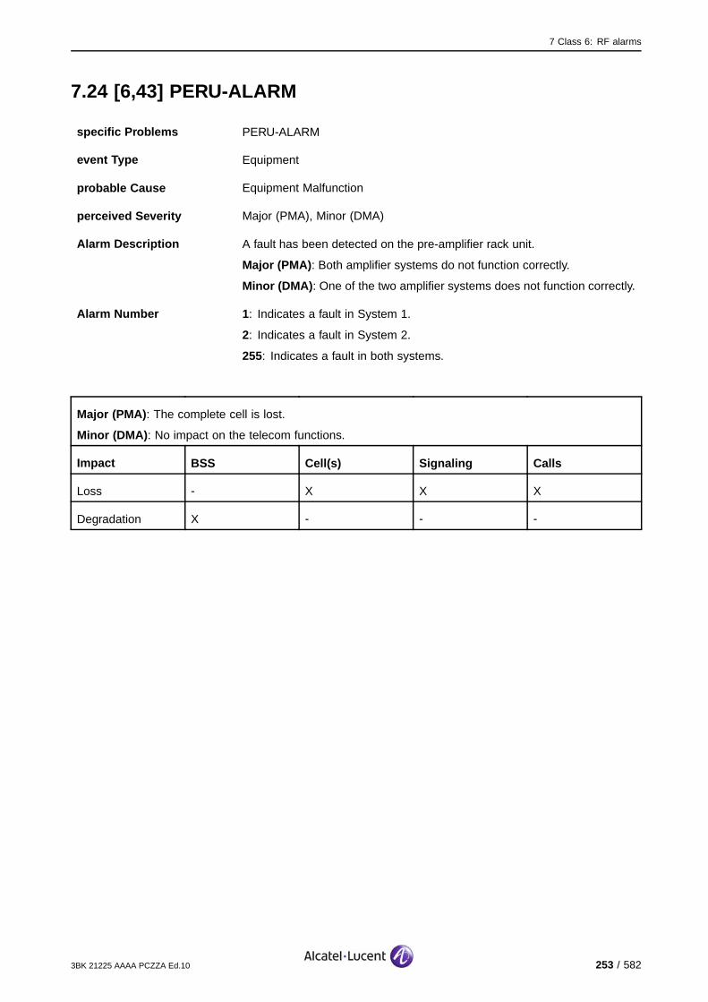
7 Class 6: RF alarms
7.24 [6,43] PERU-ALARM
specific Problems PERU-ALARM
event Type Equipment
probable Cause Equipment Malfunction
perceived Severity Major (PMA), Minor (DMA)
Alarm Description A fault has been detected on the pre-amplifier rack unit.
Major (PMA): Both amplifier systems do not function correctly.
Minor (DMA): One of the two amplifier systems does not function correctly.
Alarm Number 1: Indicates a fault in System 1.
2: Indicates a fault in System 2.
255: Indicates a fault in both systems.
Major (PMA): The complete cell is lost.
Minor (DMA): No impact on the telecom functions.
Impact BSS Cell(s) Signaling Calls
Loss - X X X
Degradation X - - -
3BK 21225 AAAA PCZZA Ed.10 253 / 582

7 Class 6: RF alarms
7.24.1 Corrective Actions
Disable RF PowerUse the BTS Terminal to disable RA before disconnecting RF cables.Initialize RA after work.
[6,43] PERU−ALARM
no
ContactSystem Support
Lock Function RA
Unlock Function RA
RAoperational?
yes Alarmsolved
no
RAoperational?
yes Alarmsolved
On−site
G1:Replace RTMA
G2:Replace TMA
On−site
OR
Check cables/connectors to RTMA, amplifier, antenna, rack unit and tower mounted unit
visually and electrically. Replace cable if required.
On−site
Check antenna (DCS1800 only). Replace antenna if required.
On−site
G2:Replace RMC
On−site
OR
Figure 138: PERU-ALARM: Corrective Actions
254 / 582 3BK 21225 AAAA PCZZA Ed.10
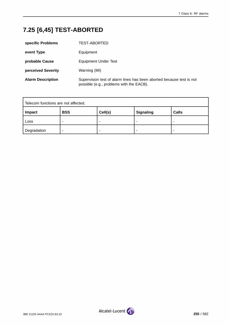
7 Class 6: RF alarms
7.25 [6,45] TEST-ABORTED
specific Problems TEST-ABORTED
event Type Equipment
probable Cause Equipment Under Test
perceived Severity Warning (MI)
Alarm Description Supervision test of alarm lines has been aborted because test is notpossible (e.g., problems with the EACB).
Telecom functions are not affected.
Impact BSS Cell(s) Signaling Calls
Loss - - - -
Degradation - - - -
3BK 21225 AAAA PCZZA Ed.10 255 / 582

7 Class 6: RF alarms
7.25.1 G1/G2 BTS Corrective Actions
Disable RF PowerUse the BTS Terminal to disable RA before disconnecting RF cables.Initialize RA after work.
[6,45] TEST−ABORTED
Alarmsolved
yesRAoperational?
no
On−site
G1:Replace EACB,
EAIB
On−site
no
ContactSystem Support
Lock Function RA
Unlock Function RA
G2:Replace SACE,
SCFE
Check cables/connectors between switchand EACB visually and electrically.
Replace cable if required.
RA operational?
yes Alarmsolved
On−site
OR
EACB alarm events?
no
yes Solve EACB alarm(s) first
Check OMU CPF against BTS hardware configuration
parameters
Figure 139: TEST-ABORTED: G1/G2 BTS Corrective Actions
256 / 582 3BK 21225 AAAA PCZZA Ed.10
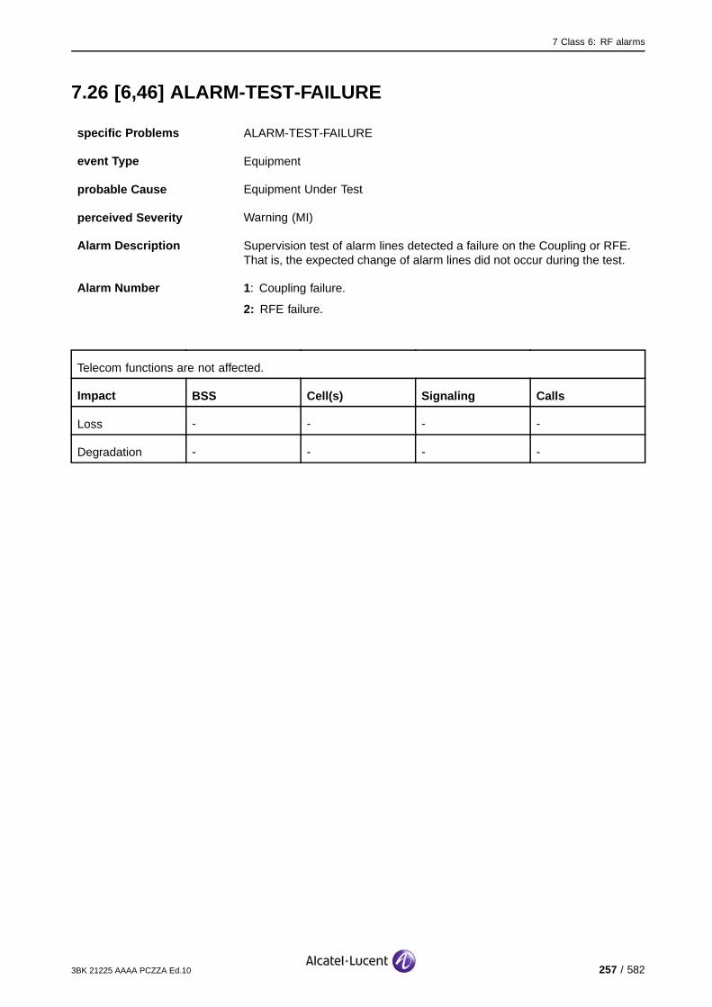
7 Class 6: RF alarms
7.26 [6,46] ALARM-TEST-FAILURE
specific Problems ALARM-TEST-FAILURE
event Type Equipment
probable Cause Equipment Under Test
perceived Severity Warning (MI)
Alarm Description Supervision test of alarm lines detected a failure on the Coupling or RFE.That is, the expected change of alarm lines did not occur during the test.
Alarm Number 1: Coupling failure.
2: RFE failure.
Telecom functions are not affected.
Impact BSS Cell(s) Signaling Calls
Loss - - - -
Degradation - - - -
3BK 21225 AAAA PCZZA Ed.10 257 / 582

7 Class 6: RF alarms
7.26.1 G1 BTS Corrective Actions
Disable RF PowerUse the BTS Terminal to disable RA before disconnecting RF cables.Initialize RA after work.
[6,46] ALARM−TEST−FAILURE
Alarmsolved
yesRAoperational?
no
On−site
Replace RFE
On−site
no
ContactSystem Support
Lock Function RA
Unlock Function RA
Replace EACB, EAIB
Check cables/connectors betweenswitch and EACB visually and electrically.
Replace cable if required.
RA operational?
yes Alarmsolved
On−site
OR
RFE, EACB
or combiner alarm events?
no
yes Solve that alarm(s) first
Check OMU CPF against BTS hardware configuration
parameters
On−site
Replace Combiner
OR
Figure 140: ALARM-TEST-FAILURE: G1 BTS Corrective Actions
258 / 582 3BK 21225 AAAA PCZZA Ed.10

7 Class 6: RF alarms
7.26.2 G2 BTS Corrective Actions
Disable RF PowerUse the BTS Terminal to disable RA before disconnecting RF cables.Initialize RA after work.
[6,46] ALARM−TEST−FAILURE
Alarmsolved
yesRAoperational?
no
On−site
Replace RFE
On−site
no
ContactSystem Support
Lock Function RA
Unlock Function RA
Replace SACE, SCFE
Check cables/connectors between switchand EACB visually and electrically.
Replace cable if required.
RA operational?
yes Alarmsolved
On−site
OR
RFE, EACB
or combiner alarm events?
no
yes Solve that alarm(s) first
Check OMU CPF against BTS hardware configuration
parameters
On−site
Replace RTC
OR
On−site
Replace WBC
OR
Figure 141: ALARM-TEST-FAILURE: G2 BTS Corrective Actions
3BK 21225 AAAA PCZZA Ed.10 259 / 582

7 Class 6: RF alarms
7.27 [6,48] RF-FAULT
7.27.1 [6,48] RF-FAULT (CU)
specific Problems RF-FAULT
event Type Equipment
probable Cause Equipment Malfunction
perceived Severity Major (PMA)
Alarm Description This alarm raised because the OMU has lost the state of the SBL CUand the BSC restored the state of the SBL RA to FOS. The alarm is putin the AIFL.
No further impact on the telecom functions, as the CU is isolated already.
Impact BSS Cell(s) Signaling Calls
Loss - - - -
Degradation - X - -
260 / 582 3BK 21225 AAAA PCZZA Ed.10

7 Class 6: RF alarms
7.27.1.1 G1 BTS Corrective Actions
Disable RF PowerUse the BTS Terminal to disable RA before disconnecting RF cables.Initialize RA after work.
[6,48] RF−FAULT (CU)
Alarmsolved
yesCUoperational?
no
no
ContactSystem Support
Lock Function CU
Unlock Function CU
CUoperational?
yes Alarmsolved
On−site
Replace Receiver Replace Transmitter
On−site
OR
Figure 142: RF-FAULT (CU): G1 BTS Corrective Actions
3BK 21225 AAAA PCZZA Ed.10 261 / 582

7 Class 6: RF alarms
7.27.1.2 G2 BTS Corrective Actions
Disable RF PowerUse the BTS Terminal to disable RA before disconnecting RF cables.Initialize RA after work.
[6,48] RF−FAULT (CU)
Alarmsolved
yesCUoperational?
no
no
ContactSystem Support
Lock Function CU
Unlock Function CU
CUoperational?
yes Alarmsolved
On−site
Replace Receiver Replace Transmitter
On−site
OR
Figure 143: RF-FAULT (CU): G2 BTS Corrective Actions
262 / 582 3BK 21225 AAAA PCZZA Ed.10
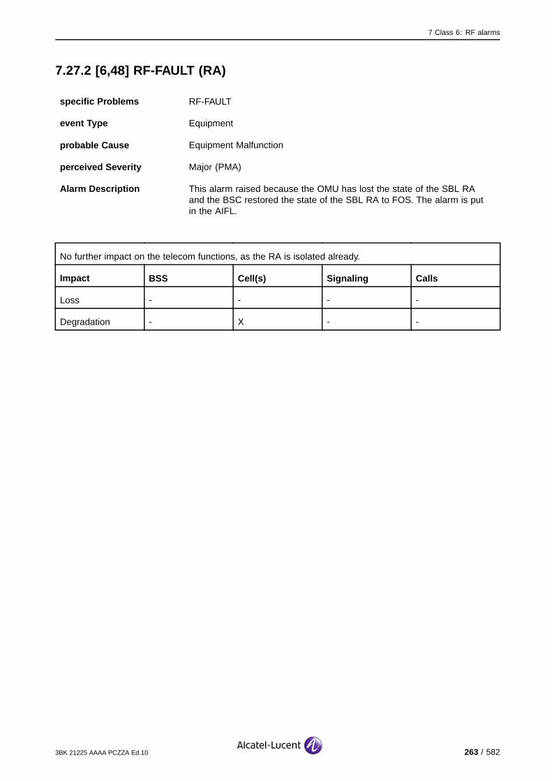
7 Class 6: RF alarms
7.27.2 [6,48] RF-FAULT (RA)
specific Problems RF-FAULT
event Type Equipment
probable Cause Equipment Malfunction
perceived Severity Major (PMA)
Alarm Description This alarm raised because the OMU has lost the state of the SBL RAand the BSC restored the state of the SBL RA to FOS. The alarm is putin the AIFL.
No further impact on the telecom functions, as the RA is isolated already.
Impact BSS Cell(s) Signaling Calls
Loss - - - -
Degradation - X - -
3BK 21225 AAAA PCZZA Ed.10 263 / 582

7 Class 6: RF alarms
7.27.2.1 Corrective Actions
Disable RF PowerUse the BTS Terminal to disable RA before disconnecting RF cables.Initialize RA after work.
[6,48] RF−FAULT (RA)
no
ContactSystem Support
RAoperational?
yes Alarmsolved
On−site
G1:Replace Combiner
G2:Replace RTC
On−site
OR G2:Replace WBC
On−site
OR
Lock FunctionRA
Unlock Function RA
Figure 144: RF-FAULT (RA): Corrective Actions
264 / 582 3BK 21225 AAAA PCZZA Ed.10

7 Class 6: RF alarms
7.28 [6,49] FRONTEND-AMP-AL
specific Problems FRONTEND-AMP-AL
event Type Equipment
probable Cause Equipment Malfunction
perceived Severity Minor (DMA)
Alarm Description One of the RFE amplifiers is faulty.
There is some disturbance to the telecom functions.
Impact BSS Cell(s) Signaling Calls
Loss - - - -
Degradation - X X X
3BK 21225 AAAA PCZZA Ed.10 265 / 582
7 Class 6: RF alarms
7.28.1 Corrective Actions
Disable RF PowerUse the BTS Terminal to disable RA before disconnecting RF cables.Initialize RA after work.
[6,49] FRONTEND−AMP−AL
Alarmsolved
yesRAoperational?
no
no
ContactSystem Support
Lock Function RA
Unlock Function RA
RAoperational?
yes Alarmsolved
On−site
G1:Replace RFE
G2:Replace RFE
On−site
OR
Figure 145: FRONTEND-AMP-AL: Corrective Actions
266 / 582 3BK 21225 AAAA PCZZA Ed.10
7 Class 6: RF alarms
7.29 [6,50] DATA-INCONSIS-AL
specific Problems DATA-INCONSIS-AL
event Type Equipment
probable Cause Indeterminate
perceived Severity Major (PMA)
Alarm Description An inconsistency of the populated data concerning the BCCH switch wasdetected. The inconsistency was between the data in the CDM, and thedata in the OMU CPF.
The BTS is unable to handle telecom traffic. The cell is lost.
Impact BSS Cell(s) Signaling Calls
Loss - X X X
Degradation X - - -
3BK 21225 AAAA PCZZA Ed.10 267 / 582
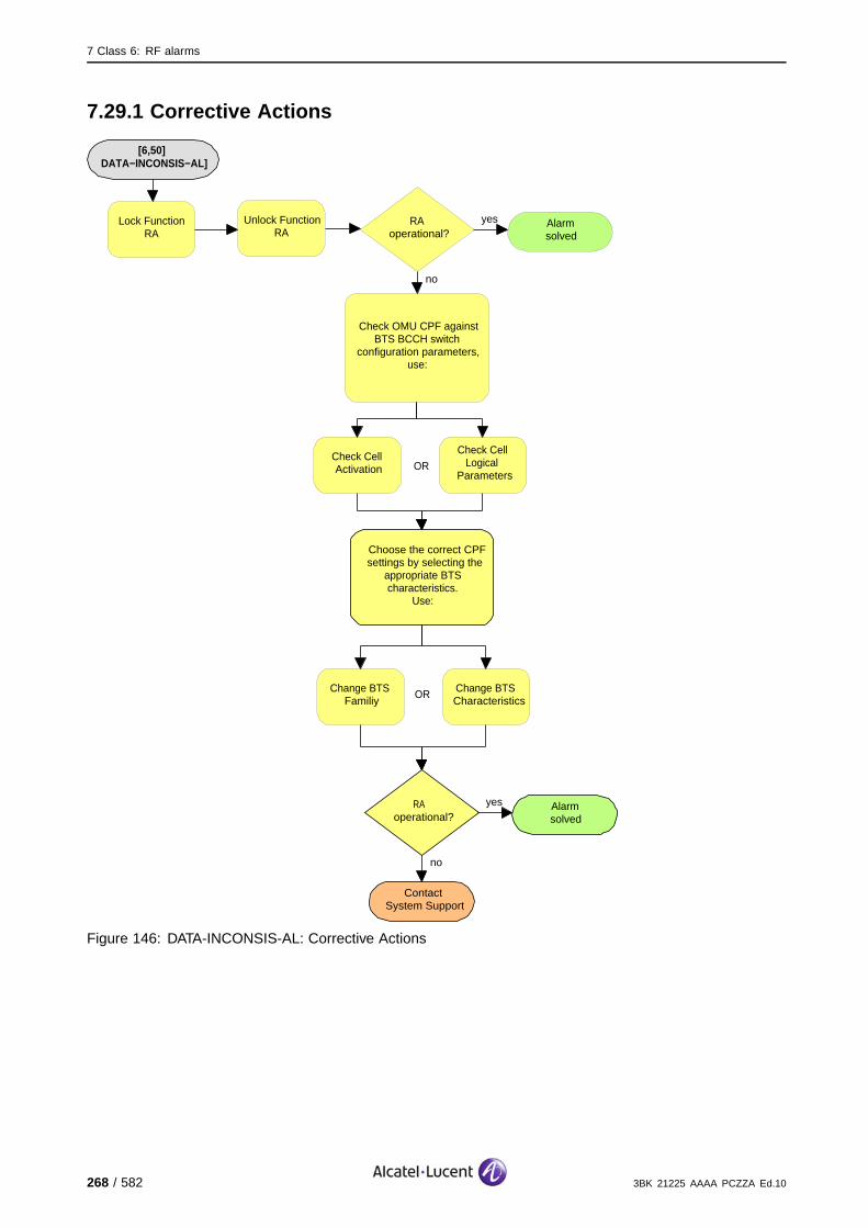
7 Class 6: RF alarms
7.29.1 Corrective Actions
[6,50] DATA−INCONSIS−AL]
no
ContactSystem Support
Choose the correct CPFsettings by selecting the
appropriate BTS characteristics.
Use:
RA operational?
yes Alarmsolved
Check Cell Activation
Check Cell Logical
Parameters
Change BTS Familiy
Change BTS Characteristics
Lock Function RA
Unlock Function RA
Check OMU CPF against BTS BCCH switch
configuration parameters, use:
OR
OR
no
RAoperational?
yes Alarmsolved
Figure 146: DATA-INCONSIS-AL: Corrective Actions
268 / 582 3BK 21225 AAAA PCZZA Ed.10
7 Class 6: RF alarms
7.30 [6,51] RTC-OUT-OF-BAND-ALARM
specific Problems RTC-OUT-OF-BAND-ALARM
event Type Equipment
probable Cause Transmitter Failure
perceived Severity Minor (DMA), Warning (MI)
Alarm Description Minor: The indicated cavity is out of bounds. Internal autonomous actionswere not able to correct the fault.
Warning: The indicated cavity was out of bounds, but internal autonomousactions were able to correct the fault.
Alarm Number Indicates the cavity number 1...8.
Minor (DMA): The eight channels supported by the failing cavity are lost. The BCCH is regained throughrecovery.
Impact BSS Cell(s) Signaling Calls
Loss - - - X
Degradation X X X -
Warning (MI): If frequency hopping is used, during the re-tuning period for the RTCs, the quality of thecalls routed through the modified cavity can be degraded (#).
If non-hopping, then eight calls are lost during this period. After re-tuning, all channels are available. (X).
Impact BSS Cell(s) Signaling Calls
Loss - - - X
Degradation - X X #
3BK 21225 AAAA PCZZA Ed.10 269 / 582

7 Class 6: RF alarms
7.30.1 Corrective Actions
Disable RF PowerUse the BTS Terminal to disable RA before disconnecting RF cables.Initialize RA after work.If the alarm severity (category) is Minor (DMA) or the alarm with severity(category) Warning (Mi) occurs frequently :
[6,51] RTC−OUT−OF−BAND−ALARM
no
ContactSystem Support
RAoperational?
yes Alarmsolved
On−site
G1:Replace Combiner
G2:Replace RTC
On−site
OR G2:Replace WBC
On−site
OR
Lock FunctionRA
Unlock Function RA
no
RAoperational?
yes Alarmsolved
Figure 147: RTC-OUT-OF-BAND-ALARM: Corrective Actions
270 / 582 3BK 21225 AAAA PCZZA Ed.10

7 Class 6: RF alarms
7.31 [6,52] RTC-FINE-TUNING-FAIL
specific Problems RTC-FINE-TUNING-FAIL
event Type Equipment
probable Cause Transmitter Failure
perceived Severity Minor (DMA), Warning (MI)
Alarm Description Minor: The indicated cavity has a fine tuning failure. Internal autonomousactions were not able to correct the fault.
Warning: The indicated cavity had a fine tuning failure, but internalautonomous actions were able to correct the fault.
Alarm Number Indicates the cavity number 1...8.
Minor (DMA): The eight channels supported by the failing cavity are lost. The BCCH is regained throughrecovery.
Impact BSS Cell(s) Signaling Calls
Loss - - - X
Degradation X X X -
Warning (MI): If frequency hopping is used, during the re-tuning period for the RTCs, the quality of thecalls routed through the modified cavity can be degraded (#).
If non-hopping, then eight calls are lost during this period. After re-tuning, all channels are available. (X).
Impact BSS Cell(s) Signaling Calls
Loss - - - X
Degradation - X X #
3BK 21225 AAAA PCZZA Ed.10 271 / 582

7 Class 6: RF alarms
7.31.1 Corrective Actions
Disable RF PowerUse the BTS Terminal to disable RA before disconnecting RF cables.Initialize RA after work.If the alarm severity (category) is Minor (DMA) or the alarm with severity(category) Warning (Mi) occurs frequently :
[6,52] RTC−FINE−TUNING−FAIL
no
ContactSystem Support
RAoperational?
yes Alarmsolved
On−site
G1:Replace Combiner
G2:Replace RTC
On−site
OR G2:Replace WBC
On−site
OR
Lock FunctionRA
Unlock Function RA
Restart OMU
RAoperational?
yes Alarmsolved
Figure 148: RTC-FINE-TUNING-FAIL: Corrective Actions
272 / 582 3BK 21225 AAAA PCZZA Ed.10
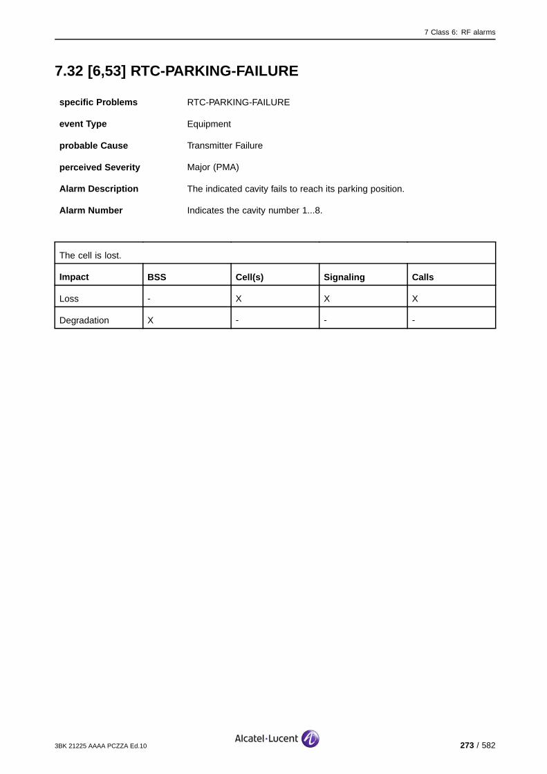
7 Class 6: RF alarms
7.32 [6,53] RTC-PARKING-FAILURE
specific Problems RTC-PARKING-FAILURE
event Type Equipment
probable Cause Transmitter Failure
perceived Severity Major (PMA)
Alarm Description The indicated cavity fails to reach its parking position.
Alarm Number Indicates the cavity number 1...8.
The cell is lost.
Impact BSS Cell(s) Signaling Calls
Loss - X X X
Degradation X - - -
3BK 21225 AAAA PCZZA Ed.10 273 / 582

7 Class 6: RF alarms
7.32.1 Corrective Actions
Disable RF PowerUse the BTS Terminal to disable RA before disconnecting RF cables.Initialize RA after work.
[6,53]RTC−PARKING−FAILURE
no
ContactSystem Support
RAoperational?
yes Alarmsolved
On−site
G1:Replace Combiner
G2:Replace RTC
On−site
OR G2:Replace WBC
On−site
OR
Lock FunctionRA
Unlock Function RA
no
RAoperational?
yes Alarmsolved
Figure 149: RTC-PARKING-FAILURE: Corrective Actions
274 / 582 3BK 21225 AAAA PCZZA Ed.10
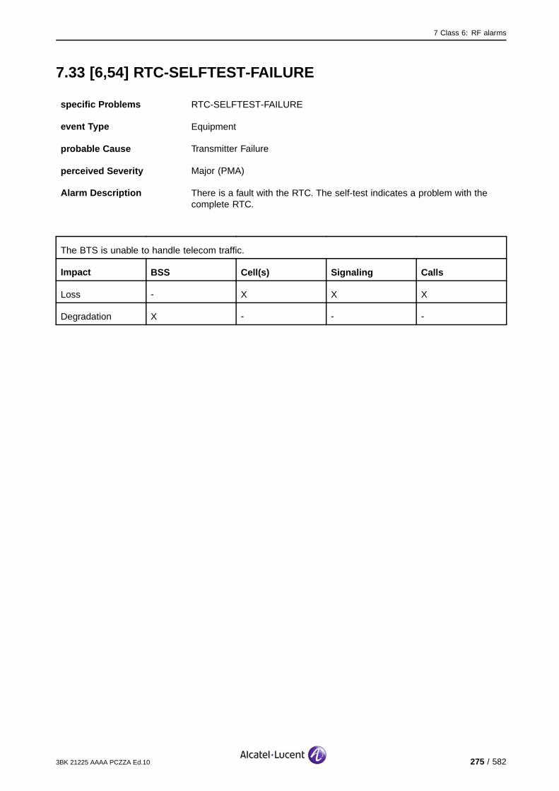
7 Class 6: RF alarms
7.33 [6,54] RTC-SELFTEST-FAILURE
specific Problems RTC-SELFTEST-FAILURE
event Type Equipment
probable Cause Transmitter Failure
perceived Severity Major (PMA)
Alarm Description There is a fault with the RTC. The self-test indicates a problem with thecomplete RTC.
The BTS is unable to handle telecom traffic.
Impact BSS Cell(s) Signaling Calls
Loss - X X X
Degradation X - - -
3BK 21225 AAAA PCZZA Ed.10 275 / 582

7 Class 6: RF alarms
7.33.1 Corrective Actions
Disable RF PowerUse the BTS Terminal to disable RA before disconnecting RF cables.Initialize RA after work.
[6,54]RTC−SELFTEST−FAILURE
no
ContactSystem Support
RAoperational?
yes Alarmsolved
On−site
G1:Replace Combiner
G2:Replace RTC
On−site
OR G2:Replace WBC
On−site
OR
Lock FunctionRA
Unlock Function RA
Check cables/connectors between basic and extension
unit
RAoperational?
yes Alarmsolved
On−site
no
Figure 150: RTC-SELFTEST-FAILURE: Corrective Actions
276 / 582 3BK 21225 AAAA PCZZA Ed.10

7 Class 6: RF alarms
7.34 [6,55] RTC-EXT-CONN-LOST
specific Problems RTC-EXT-CONN-LOST
event Type Equipment
probable Cause Transmitter Failure
perceived Severity Major (PMA)
Alarm Description The connection to the RTC extension unit is lost.
The channels supported by the RTC extension unit are lost (CU 5 - 8). The BCCH is maintained.
Impact BSS Cell(s) Signaling Calls
Loss - - - X
Degradation X X X -
3BK 21225 AAAA PCZZA Ed.10 277 / 582
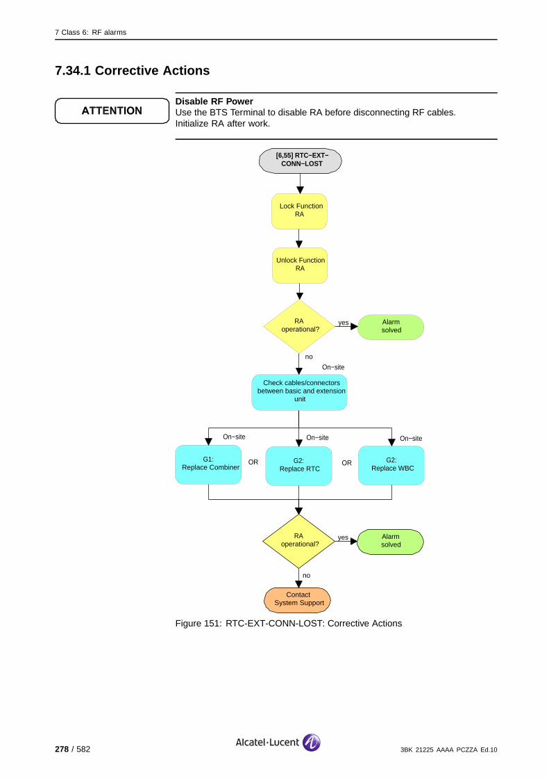
7 Class 6: RF alarms
7.34.1 Corrective Actions
Disable RF PowerUse the BTS Terminal to disable RA before disconnecting RF cables.Initialize RA after work.
[6,55] RTC−EXT−CONN−LOST
no
ContactSystem Support
RAoperational?
yes Alarmsolved
On−site
G1:Replace Combiner
G2:Replace RTC
On−site
OR G2:Replace WBC
On−site
OR
Lock FunctionRA
Unlock Function RA
Check cables/connectors between basic and extension
unit
RAoperational?
yes Alarmsolved
On−site
no
Figure 151: RTC-EXT-CONN-LOST: Corrective Actions
278 / 582 3BK 21225 AAAA PCZZA Ed.10

7 Class 6: RF alarms
7.35 [6,56] RTC-DETECTOR-FAILURE
specific Problems RTC-DETECTOR-FAILURE
event Type Equipment
probable Cause Transmitter Failure
perceived Severity Major (PMA)
Alarm Description The RTC detector is faulty.
Alarm Number 1: Failure in RTC basic unit.
2: Failure in RTC extension unit.
If the alarm number is 1, the channels supported by the reported RTC (CU 1 - 4) are lost. The BCCH islost if the basic unit is lost. (#).
If the alarm number is 2, the channels supported by the extension unit are lost (CU 5 - 8). (X).
Impact BSS Cell(s) Signaling Calls
Loss - - - X#
Degradation X# X# X# -
3BK 21225 AAAA PCZZA Ed.10 279 / 582
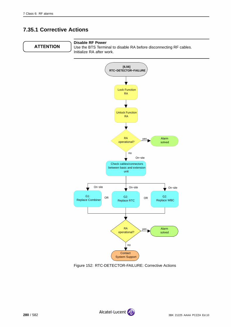
7 Class 6: RF alarms
7.35.1 Corrective Actions
Disable RF PowerUse the BTS Terminal to disable RA before disconnecting RF cables.Initialize RA after work.
[6,56]RTC−DETECTOR−FAILURE
no
ContactSystem Support
RAoperational?
yes Alarmsolved
On−site
G1:Replace Combiner
G2:Replace RTC
On−site
OR G2:Replace WBC
On−site
OR
Lock FunctionRA
Unlock Function RA
Check cables/connectors between basic and extension
unit
RAoperational?
yes Alarmsolved
On−site
no
Figure 152: RTC-DETECTOR-FAILURE: Corrective Actions
280 / 582 3BK 21225 AAAA PCZZA Ed.10
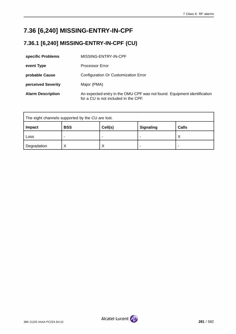
7 Class 6: RF alarms
7.36 [6,240] MISSING-ENTRY-IN-CPF
7.36.1 [6,240] MISSING-ENTRY-IN-CPF (CU)
specific Problems MISSING-ENTRY-IN-CPF
event Type Processor Error
probable Cause Configuration Or Customization Error
perceived Severity Major (PMA)
Alarm Description An expected entry in the OMU CPF was not found. Equipment identificationfor a CU is not included in the CPF.
The eight channels supported by the CU are lost.
Impact BSS Cell(s) Signaling Calls
Loss - - - X
Degradation X X - -
3BK 21225 AAAA PCZZA Ed.10 281 / 582
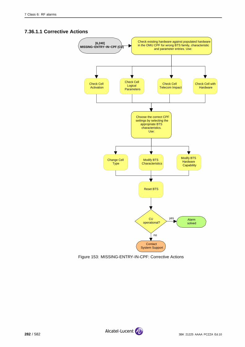
7 Class 6: RF alarms
7.36.1.1 Corrective Actions
[6,240] MISSING−ENTRY−IN−CPF (CU)
no
ContactSystem Support
Check existing hardware against populated hardware in the OMU CPF for wrong BTS family, characteristic
and parameter entries. Use:
Choose the correct CPFsettings by selecting the
appropriate BTS characteristics.
Use:
CUoperational?
yes Alarmsolved
Check Cell Activation
Check Cell Logical
Parameters
Check Cell Telecom Impact
Check Cell with Hardware
Change Cell Type
Modify BTS Characteristics
Modify BTS Hardware Capability
Reset BTS
Figure 153: MISSING-ENTRY-IN-CPF: Corrective Actions
282 / 582 3BK 21225 AAAA PCZZA Ed.10
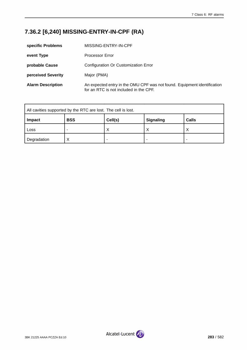
7 Class 6: RF alarms
7.36.2 [6,240] MISSING-ENTRY-IN-CPF (RA)
specific Problems MISSING-ENTRY-IN-CPF
event Type Processor Error
probable Cause Configuration Or Customization Error
perceived Severity Major (PMA)
Alarm Description An expected entry in the OMU CPF was not found. Equipment identificationfor an RTC is not included in the CPF.
All cavities supported by the RTC are lost. The cell is lost.
Impact BSS Cell(s) Signaling Calls
Loss - X X X
Degradation X - - -
3BK 21225 AAAA PCZZA Ed.10 283 / 582

7 Class 6: RF alarms
7.36.2.1 Corrective Actions
[6,240] MISSING−ENTRY−IN−CPF
(RA)
no
ContactSystem Support
Check existing hardware against populated hardware in the OMU CPF for wrong BTS family, characteristic
and parameter entries. Use:
Choose the correct CPFsettings by selecting the
appropriate BTS characteristics.
Use:
RAoperational?
yes Alarmsolved
Check Cell Activation
Check Cell Logical
Parameters
Check Cell Telecom Impact
Check Cell with Hardware
Change Cell Type
Modify BTS Characteristics
Modify BTS Hardware Capability
Reset BTS
Figure 154: MISSING-ENTRY-IN-CPF: Corrective Actions
284 / 582 3BK 21225 AAAA PCZZA Ed.10

7 Class 6: RF alarms
7.37 [6,241] INCONSIST-ASSHW-ACTHW
7.37.1 [6,241] INCONSIST-ASSHW-ACTHW (CU)
specific Problems INCONSIST-ASSHW-ACTHW
event Type Processing Error
probable Cause Configuration Or Customization Error
perceived Severity Major (PMA)
Alarm Description The equipped BTS hardware does not match to the assumed hardwarecapabilities.
Alarm Number 2: The hardware does not provide the requested frequency band.
4: The hardware does not provide advanced timing, but it is configured asthe outer cell of an extended cell.
The eight channels supported by the CU are lost.
Impact BSS Cell(s) Signaling Calls
Loss - - - X
Degradation X X - -
3BK 21225 AAAA PCZZA Ed.10 285 / 582

7 Class 6: RF alarms
7.37.1.1 Alarm Number 2 Corrective Actions
[6,241] INCONSIST−ASSHW−ACTHW
no
ContactSystem Support
Check the network type against CU hardware.
Use:
CUoperational?
yes Alarmsolved
Check Cell with Hardware
Modify assumed BTS Hardware
Capability
Modify actual BTS hardware capability by replacing existing BTS
entity by appropriate BTS hardware entity, as descibed in the CMA
OR
On−site
On−site
G1:Replace Receiver
On−site
G1:Replace Transmitter
G2:Replace Receiver
On−site
OR OR
Alarm Number 2
G2:Replace Transmitter
On−site
OR
Figure 155: INCONSIST-ASSHW-ACTHW: Alarm Number 2 Corrective Actions
286 / 582 3BK 21225 AAAA PCZZA Ed.10
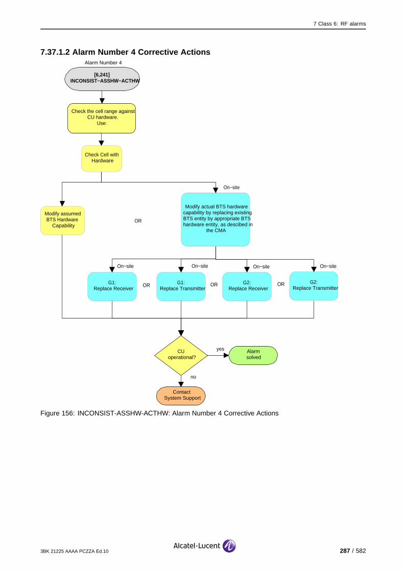
7 Class 6: RF alarms
7.37.1.2 Alarm Number 4 Corrective Actions
[6,241] INCONSIST−ASSHW−ACTHW
no
ContactSystem Support
Check the cell range against CU hardware.
Use:
CUoperational?
yes Alarmsolved
Check Cell with Hardware
Modify assumed BTS Hardware
Capability
Modify actual BTS hardware capability by replacing existing BTS entity by appropriate BTS hardware entity, as descibed in
the CMA
OR
On−site
On−site
G1:Replace Receiver
On−site
G1:Replace Transmitter
G2:Replace Receiver
On−site
OR OR
Alarm Number 4
G2:Replace Transmitter
On−site
OR
Figure 156: INCONSIST-ASSHW-ACTHW: Alarm Number 4 Corrective Actions
3BK 21225 AAAA PCZZA Ed.10 287 / 582

7 Class 6: RF alarms
7.37.2 [6,241] INCONSIST-ASSHW-ACTHW (RA)
specific Problems INCONSIST-ASSHW-ACTHW
event Type Processing Error
probable Cause Configuration Or Customization Error
perceived Severity Major (PMA)
Alarm Description The BTS hardware does not match the assumed hardware capabilities.The hardware does not provide the requested frequency band.
All cavities supported by the RTC are lost.
Impact BSS Cell(s) Signaling Calls
Loss - X X X
Degradation X - - -
288 / 582 3BK 21225 AAAA PCZZA Ed.10

7 Class 6: RF alarms
7.37.2.1 Corrective Actions
[6,241] INCONSIST−ASSHW−ACTHW
(RA)
no
ContactSystem Support
Check the network type against CU hardware.
Use:
RAoperational?
yes Alarmsolved
Check Cell with Hardware
Modify assumed BTS Hardware
Capability
Modify actual BTS hardware capability by replacing existing BTS
entity by appropriate BTS hardware entity, as descibed in the CMA
OR
On−site
On−site
G1:Replace Receiver
On−site
G1:Replace Transmitter
G2:Replace Receiver
On−site
OR OR G2:Replace Transmitter
On−site
OR
Figure 157: INCONSIST-ASSHW-ACTHW: Corrective Actions
3BK 21225 AAAA PCZZA Ed.10 289 / 582

7 Class 6: RF alarms
7.38 [6,246] CONFIG-FAIL
7.38.1 [6,246] CONFIG-FAIL (CU)
specific Problems CONFIG-FAIL
event Type Processing Error
probable Cause Configuration Or Customization Error
perceived Severity Major (PMA)
Alarm Description The configuration of the CU is unsuccessful due to a bad configurationparameter or CU problems.
The eight time slots supported by the reporting CU are lost. Through recovery, the BCCH is maintained.
Impact BSS Cell(s) Signaling Calls
Loss - - - X
Degradation X X X -
290 / 582 3BK 21225 AAAA PCZZA Ed.10

7 Class 6: RF alarms
7.38.1.1 Corrective Actions
[6,246] CONFIG−FAIL (CU)
Correct Configuration Parameters
Alarmsolved
yesCUoperational?
no
Lock Function CU
Unlock Function CU
Check validity of parameters: ARFN, BSCI
yesOther
CU alarm(s) events?
no
Solve CU alarm(s) first
yesMore
than one CU reports alarm?
no
On−site
G1:Replace Receiver
On−site
G1:Replace Transmitter
G2:Replace Receiver
On−site
OR OR G2:Replace Transmitter
On−site
OR
no
ContactSystem Support
CUoperational?
yes Alarmsolved
no
ContactSystem Support
CUoperational?
yes Alarmsolved
Figure 158: CONFIG-FAIL (CU): Corrective Actions
3BK 21225 AAAA PCZZA Ed.10 291 / 582

7 Class 6: RF alarms
7.38.2 [6,246] CONFIG-FAIL (RA)
specific Problems CONFIG-FAIL
event Type Processing Error
probable Cause Configuration Or Customization Error
perceived Severity Major (PMA)
Alarm Description The RTC configuration fails.
The BTS is unable to handle telecom traffic, the cell is lost.
Impact BSS Cell(s) Signaling Calls
Loss - X X X
Degradation X - - -
292 / 582 3BK 21225 AAAA PCZZA Ed.10

7 Class 6: RF alarms
7.38.2.1 Corrective Actions
Disable RF PowerUse the BTS Terminal to disable RA before disconnecting RF cables.Initialize RA after work.
[6,246] CONFIG−FAIL(RA)
Correct Cell Logical Parameters
Restart OMU
no
RAoperational?
yesAlarmsolved
Alarmsolved
yesRAoperational?
no
Lock Function RA
Unlock Function RA
Check validity of parameter ARFCN
On−site
G1:Replace Combiner
G2:Replace RTC
On−site
OR G2:Replace WBC
On−site
OR
no
ContactSystem Support
RAoperational?
yes Alarmsolved
Figure 159: CONFIG-FAIL (RA): Corrective Actions
3BK 21225 AAAA PCZZA Ed.10 293 / 582

7 Class 6: RF alarms
7.39 [6,247] RESET
7.39.1 [6,247] RESET (CU)
specific Problems RESET
event Type Processing Error
probable Cause Software Error
perceived Severity Warning (MI)
Alarm Description The CU auto-resets successfully. This is caused, for example, by theexpiration of a watchdog timer during operational mode.
If redundancy is used, there is no disturbance of the telecom applications.
If redundancy is not used there is a loss of calls, and the cell and BCCH signaling is lost for a shortperiod (0.5 - 1 minute). (X).
Impact BSS Cell(s) Signaling Calls
Loss - X X X
Degradation X - - -
294 / 582 3BK 21225 AAAA PCZZA Ed.10
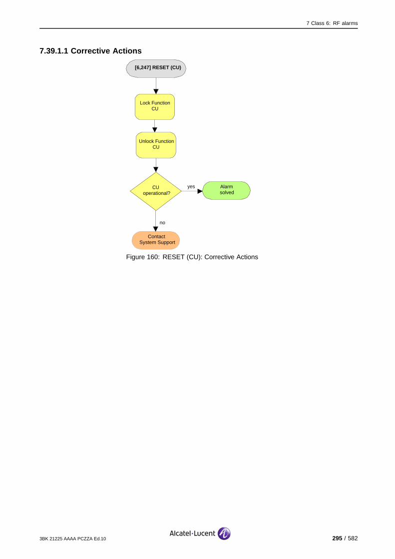
7 Class 6: RF alarms
7.39.1.1 Corrective Actions
[6,247] RESET (CU)
Alarmsolved
yesCUoperational?
Lock Function CU
Unlock Function CU
no
ContactSystem Support
Figure 160: RESET (CU): Corrective Actions
3BK 21225 AAAA PCZZA Ed.10 295 / 582

7 Class 6: RF alarms
7.40 [6,250] NO-ANSWER-DCL
7.40.1 [6,250] NO-ANSWER-DCL (CU)
specific Problems NO-ANSWER-DCL
event Type Processing Error
probable Cause Underlying Resource Unavailable
perceived Severity Major (PMA), Minor (DMA)
Alarm Description Major (PMA): No answer on the Q1 bus from a CU when a command issent from the OMU during initialization or reconfiguration.
Minor (DMA): No answer from a CU to two polls from the OMU on theQ1 bus.
Major (PMA): The fault is detected during initialization or reconfiguration in all the cases (Q1 or CUmalfunction). Eight channels which were to be supported by the CU are lost. (X).
Minor (DMA): In case of Q1 malfunction, there is no disturbance of telecom applications.
In case of CU malfunction, the result depends on the fault: the CU can eventually go on with the previousconfiguration. If the fault is fatal, other alarms will appear on other equipment.
Impact BSS Cell(s) Signaling Calls
Loss - - - X
Degradation X X X -
296 / 582 3BK 21225 AAAA PCZZA Ed.10

7 Class 6: RF alarms
7.40.1.1 Corrective Actions
[6,250] NO−ANSWER−DCL(CU)
Alarmsolved
yesCUoperational?
no
Lock Function CU
Unlock Function CU
Check Token Bus cables/connectors to
OMU and CU
yesAll CUs in
same cabinet report simultaneously
this alarm?
no
On−site
G1:Replace Receiver
On−site
G1:Replace Transmitter
G2:Replace Receiver
On−site
OR OR G2:Replace Transmitter
On−site
OR
no
ContactSystem Support
CUoperational?
yes Alarmsolved
no
ContactSystem Support
CUoperational?
yes Alarmsolved
Restart OMU
Alarm is provoked by loss of EACB as Q1
repeater
On−site
G1:Replace EACB/EAIB
Figure 161: NO-ANSWER-DCL (CU): Corrective Actions
3BK 21225 AAAA PCZZA Ed.10 297 / 582

7 Class 6: RF alarms
7.40.2 [6,250] NO-ANSWER-DCL (RA)
specific Problems NO-ANSWER-DCL
event Type Processing Error
probable Cause Underlying Resource Unavailable
perceived Severity Major (PMA), Minor (DMA)
Alarm Description Major (PMA): No answer on the Q1 bus from a RTC when a command issent from the OMU during initialization or reconfiguration.
Minor (DMA): No answer from an RTC to two polls from the OMU on theQ1 bus.
Major (PMA): The fault is detected during initialization or reconfiguration in all the cases (Q1 or RTCmalfunction). The BTS is lost. (X).
Minor (DMA): In case of Q1 malfunction, there is no disturbance of telecom applications.
In case of RTC malfunction, the result depends on the fault: the RTC can eventually go on with the previousconfiguration. If the fault is fatal, other alarms will appear on other equipment.
Impact BSS Cell(s) Signaling Calls
Loss - X X X
Degradation X - - -
298 / 582 3BK 21225 AAAA PCZZA Ed.10

7 Class 6: RF alarms
7.40.2.1 Corrective Actions
Disable RF PowerUse the BTS Terminal to disable RA before disconnecting RF cables.Initialize RA after work.
[6,250]NO−ANSWER−DCL
(RA)
Alarmsolved
yesRAoperational?
no
Lock Function RA
Unlock Function RA
Check Token Bus cables/connectors to
OMU and RTC
yesAll RTCs in
same cabinet report simultaneously
this alarm?
no
On−site
G1:Replace Combiner
G2:Replace RTC
On−site
OR G2:Replace WBC
On−site
OR
no
ContactSystem Support
RAoperational?
yes Alarmsolved
no
ContactSystem Support
RAoperational?
yes Alarmsolved
Restart OMU
Alarm is provoked by loss of EACB as Q1
repeater
On−site
G1:Replace EACB/EAIB
Figure 162: NO-ANSWER-DCL (RA): Corrective Actions
3BK 21225 AAAA PCZZA Ed.10 299 / 582
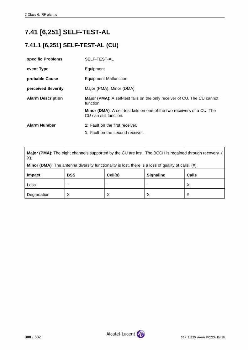
7 Class 6: RF alarms
7.41 [6,251] SELF-TEST-AL
7.41.1 [6,251] SELF-TEST-AL (CU)
specific Problems SELF-TEST-AL
event Type Equipment
probable Cause Equipment Malfunction
perceived Severity Major (PMA), Minor (DMA)
Alarm Description Major (PMA): A self-test fails on the only receiver of CU. The CU cannotfunction.
Minor (DMA): A self-test fails on one of the two receivers of a CU. TheCU can still function.
Alarm Number 1: Fault on the first receiver.
1: Fault on the second receiver.
Major (PMA): The eight channels supported by the CU are lost. The BCCH is regained through recovery. (X).
Minor (DMA): The antenna diversity functionality is lost, there is a loss of quality of calls. (#).
Impact BSS Cell(s) Signaling Calls
Loss - - - X
Degradation X X X #
300 / 582 3BK 21225 AAAA PCZZA Ed.10
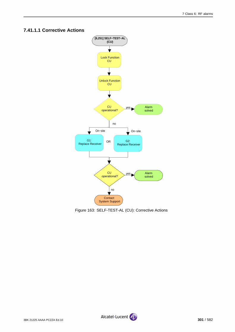
7 Class 6: RF alarms
7.41.1.1 Corrective Actions
[6,251] SELF−TEST−AL (CU)
no
ContactSystem Support
CUoperational?
yes Alarmsolved
On−site
G1:Replace Receiver
G2:Replace Receiver
On−site
OR
Lock FunctionCU
Unlock Function CU
no
CUoperational?
yes Alarmsolved
Figure 163: SELF-TEST-AL (CU): Corrective Actions
3BK 21225 AAAA PCZZA Ed.10 301 / 582

7 Class 6: RF alarms
7.42 [6,252] SELF-TEST-DBLE-AL (CU)
specific Problems SELF-TEST-DBLE-AL
event Type Equipment
probable Cause Equipment Malfunction
perceived Severity Major (PMA)
Alarm Description A self-test fails on both receivers of a CU.
The eight channels supported by the CU are lost. The BCCH is regained through recovery.
Impact BSS Cell(s) Signaling Calls
Loss - - - X
Degradation X X X -
302 / 582 3BK 21225 AAAA PCZZA Ed.10
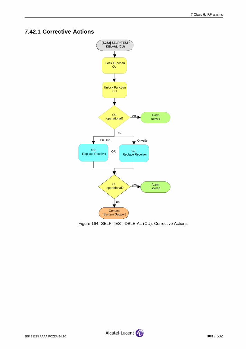
7 Class 6: RF alarms
7.42.1 Corrective Actions
[6,252] SELF−TEST−DBL−AL (CU)
no
ContactSystem Support
CUoperational?
yes Alarmsolved
On−site
G1:Replace Receiver
G2:Replace Receiver
On−site
OR
Lock FunctionCU
Unlock Function CU
no
CUoperational?
yes Alarmsolved
Figure 164: SELF-TEST-DBLE-AL (CU): Corrective Actions
3BK 21225 AAAA PCZZA Ed.10 303 / 582

7 Class 6: RF alarms
7.43 [6,255] Q1-RELAY-FAULT
7.43.1 [6,255] Q1-RELAY-FAULT (CU)
specific Problems Q1-RELAY-FAULT
event Type Equipment
probable Cause Equipment Malfunction
perceived Severity Minor (DMA)
Alarm Description Failure on the Q1 relay. The CU cannot disconnect itself from the Q1 bus.
Telecom functions are not affected.
Impact BSS Cell(s) Signaling Calls
Loss - - - -
Degradation - - - -
304 / 582 3BK 21225 AAAA PCZZA Ed.10

7 Class 6: RF alarms
7.43.1.1 G1 BTS Corrective Actions
Disable RF PowerUse the BTS Terminal to disable RA before disconnecting RF cables.Initialize RA after work.
[6,255] Q1−RELAY−FAULT (CU)
Alarmsolved
yesCUoperational?
no
On−site
Replace Receiver
On−site
no
ContactSystem Support
Lock Function CU
Unlock Function CU
Replace Transmitter
CU operational?
yes Alarmsolved
OR
Figure 165: Q1-RELAY-FAULT (CU): G1 BTS Corrective Actions
3BK 21225 AAAA PCZZA Ed.10 305 / 582
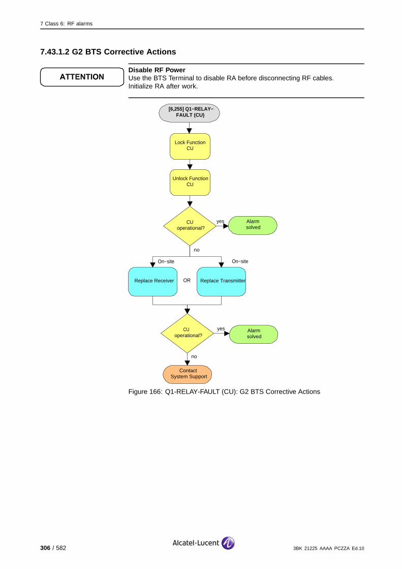
7 Class 6: RF alarms
7.43.1.2 G2 BTS Corrective Actions
Disable RF PowerUse the BTS Terminal to disable RA before disconnecting RF cables.Initialize RA after work.
[6,255] Q1−RELAY−FAULT (CU)
Alarmsolved
yesCUoperational?
no
On−site
Replace Receiver
On−site
no
ContactSystem Support
Lock Function CU
Unlock Function CU
Replace Transmitter
CU operational?
yes Alarmsolved
OR
Figure 166: Q1-RELAY-FAULT (CU): G2 BTS Corrective Actions
306 / 582 3BK 21225 AAAA PCZZA Ed.10

7 Class 6: RF alarms
7.43.2 [6,255] Q1-RELAY-FAULT (RA)
specific Problems Q1-RELAY-FAULT
event Type Equipment
probable Cause Equipment Malfunction
perceived Severity Minor (DMA)
Alarm Description Failure on the Q1 relay. The RTC cannot disconnect itself from the Q1 bus.
Telecom functions are not affected.
Impact BSS Cell(s) Signaling Calls
Loss - - - -
Degradation - - - -
3BK 21225 AAAA PCZZA Ed.10 307 / 582

7 Class 6: RF alarms
7.43.2.1 Corrective Actions
Disable RF PowerUse the BTS Terminal to disable RA before disconnecting RF cables.Initialize RA after work.
[6,255] Q1−RELAY−FAULT (RA)
no
ContactSystem Support
RAoperational?
yes Alarmsolved
On−site
G1:Replace Combiner
G2:Replace RTC
On−site
OR G2:Replace WBC
On−site
OR
Lock FunctionRA
Unlock Function RA
Figure 167: Q1-RELAY-FAULT (RA): Corrective Actions
308 / 582 3BK 21225 AAAA PCZZA Ed.10
8 Class 7: FU Alarms
8 Class 7: FU Alarms
This section defines the alarms for the Class 7: FU alarm class.
3BK 21225 AAAA PCZZA Ed.10 309 / 582
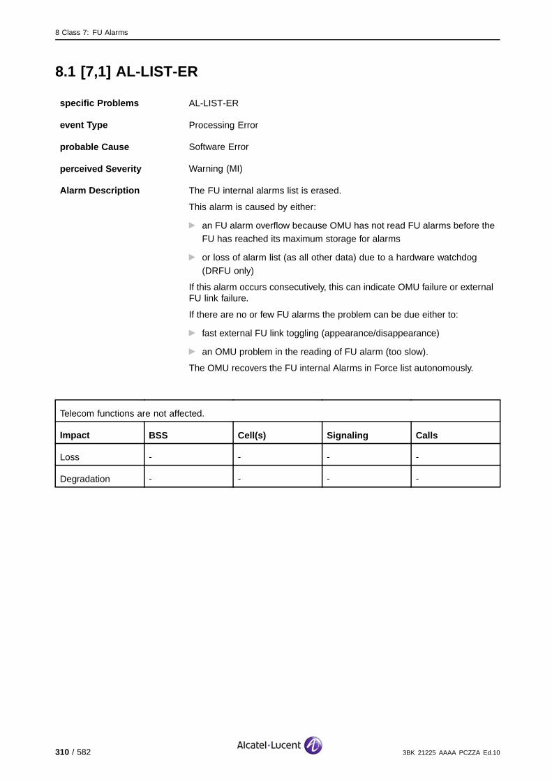
8 Class 7: FU Alarms
8.1 [7,1] AL-LIST-ER
specific Problems AL-LIST-ER
event Type Processing Error
probable Cause Software Error
perceived Severity Warning (MI)
Alarm Description The FU internal alarms list is erased.
This alarm is caused by either:
an FU alarm overflow because OMU has not read FU alarms before theFU has reached its maximum storage for alarms
or loss of alarm list (as all other data) due to a hardware watchdog
(DRFU only)
If this alarm occurs consecutively, this can indicate OMU failure or externalFU link failure.
If there are no or few FU alarms the problem can be due either to:
fast external FU link toggling (appearance/disappearance)
an OMU problem in the reading of FU alarm (too slow).
The OMU recovers the FU internal Alarms in Force list autonomously.
Telecom functions are not affected.
Impact BSS Cell(s) Signaling Calls
Loss - - - -
Degradation - - - -
310 / 582 3BK 21225 AAAA PCZZA Ed.10

8 Class 7: FU Alarms
8.1.1 DRFU Corrective Actions
[7,1] AL−LIST−ER
ContactSystem Support
Lock FunctionFU
Unlock Function FU
no
FUoperational?
yes Alarmsolved
no
Alarm 7,33 events?
yes Solve this alarm
Figure 168: AL-LIST-ER: DRFU Corrective Actions
3BK 21225 AAAA PCZZA Ed.10 311 / 582

8 Class 7: FU Alarms
8.1.2 OMU Corrective Actions
[7,1] AL−LIST−ER
ContactSystem Support
Lock FunctionFU
Unlock Function FU
no
FUoperational?
yes Alarmsolved
no
OMU alarm(s) events?
yes
Check for OMU alarm(s) (for example 6,247 RESET) to detemine if the OMU was not busy so the FU could not be polled (FU alarm not ready by OMU).
Solve this alarm.
Figure 169: AL-LIST-ER: OMU Corrective Actions
312 / 582 3BK 21225 AAAA PCZZA Ed.10

8 Class 7: FU Alarms
8.2 [7,3] MCL-LINK
specific Problems MCL-LINK
event Type Equipment
probable Cause Timing Problem
perceived Severity Minor (DMA)
Alarm Description A fault is detected on the clock link indicated. The other link is workingcorrectly.
Alarm Number 1: Clock Link 1.
2: Clock Link 2.
Telecom functions are not affected.
Impact BSS Cell(s) Signaling Calls
Loss - - - -
Degradation - - - -
3BK 21225 AAAA PCZZA Ed.10 313 / 582

8 Class 7: FU Alarms
8.2.1 Corrective Actions
[7,3] MCL−LINK
Alarmsolved
yesFUoperational?
no
On−site
G1:Replace Frame Unit
On−site
no
ContactSystem Support
Lock Function FU
Unlock Function FU
G2:Replace Frame Unit
FU operational?
yes Alarmsolved
OR
On−site
Check cables to clock system and FU
Figure 170: MCL-LINK: Corrective Actions
314 / 582 3BK 21225 AAAA PCZZA Ed.10

8 Class 7: FU Alarms
8.3 [7,5] BSI-LINK-0
specific Problems BSI-LINK-0
event Type Communication
probable Cause Loss Of Signal
perceived Severity Minor (DMA)
Alarm Description A fault is detected on the BSI link by the FU. This alarm is given whenthe fault appears.
If the fault is present during more than one BSI_TIMER (FU TIMER), anOFF alarm is sent and alarm [7,6] is generated.
BSI link redundancy is not supported (only BSI link 0 is connected betweenBIE and BTS).
Telecom functions can be affected.
Disturbances are dependent of telecom mechanism (timers, protocol,...) and duration of the fault(maximum is fixed by BSI_TIMER).
For example, calls will be released if this fault lasts more than T_SYNC (FU timer) due to remotetranscoder alarm.
Impact BSS Cell(s) Signaling Calls
Loss - - - -
Degradation X X - X
3BK 21225 AAAA PCZZA Ed.10 315 / 582
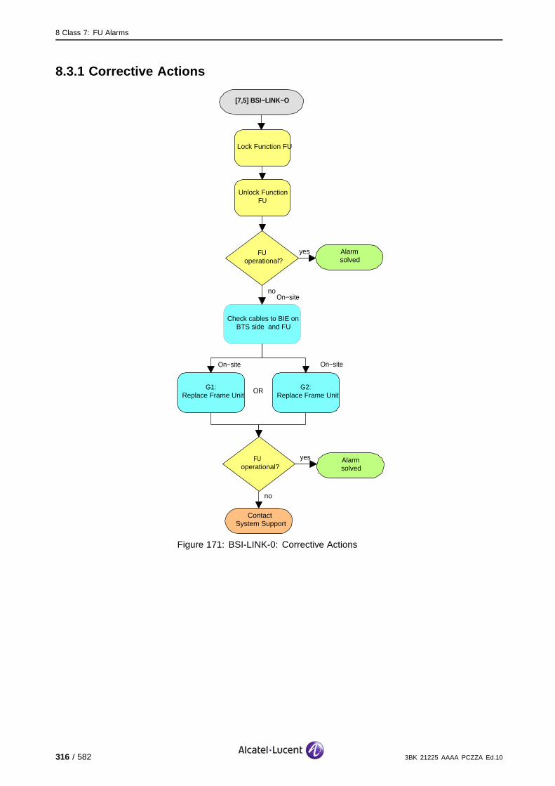
8 Class 7: FU Alarms
8.3.1 Corrective Actions
[7,5] BSI−LINK−O
Alarmsolved
yesFUoperational?
no
On−site
G1:Replace Frame Unit
On−site
no
ContactSystem Support
Lock Function FU
Unlock Function FU
G2:Replace Frame Unit
FU operational?
yes Alarmsolved
OR
On−site
Check cables to BIE on BTS side and FU
Figure 171: BSI-LINK-0: Corrective Actions
316 / 582 3BK 21225 AAAA PCZZA Ed.10
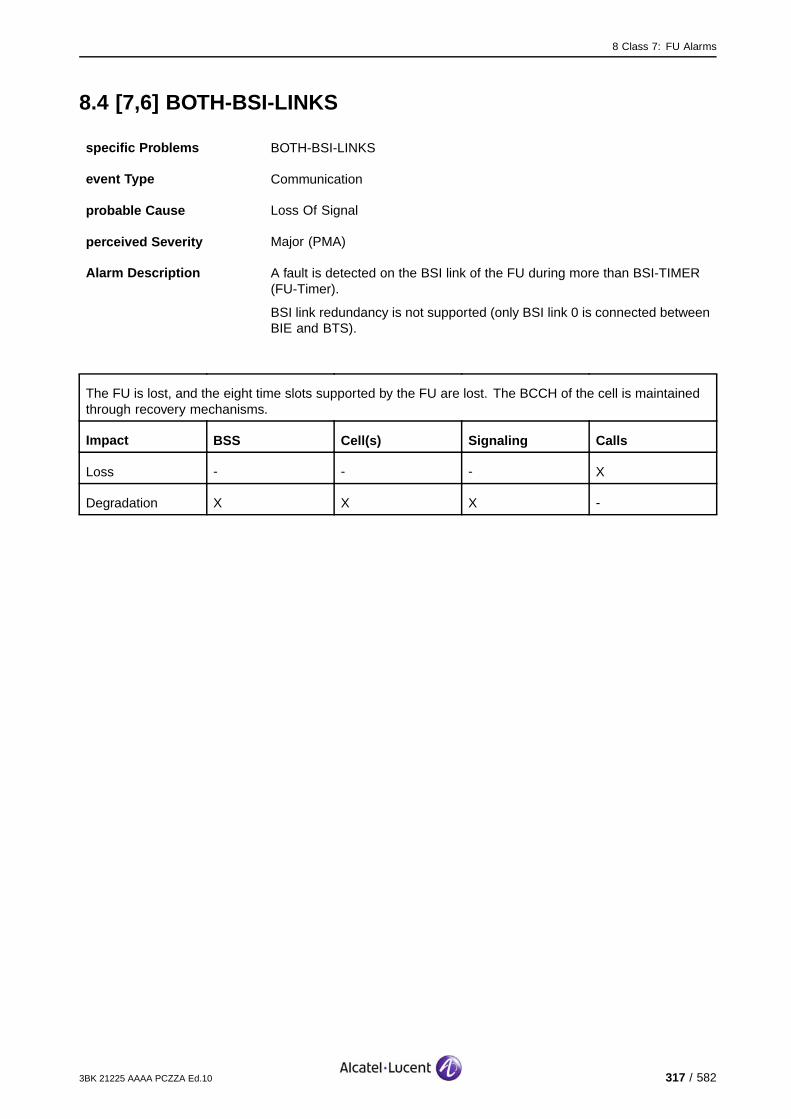
8 Class 7: FU Alarms
8.4 [7,6] BOTH-BSI-LINKS
specific Problems BOTH-BSI-LINKS
event Type Communication
probable Cause Loss Of Signal
perceived Severity Major (PMA)
Alarm Description A fault is detected on the BSI link of the FU during more than BSI-TIMER(FU-Timer).
BSI link redundancy is not supported (only BSI link 0 is connected betweenBIE and BTS).
The FU is lost, and the eight time slots supported by the FU are lost. The BCCH of the cell is maintainedthrough recovery mechanisms.
Impact BSS Cell(s) Signaling Calls
Loss - - - X
Degradation X X X -
3BK 21225 AAAA PCZZA Ed.10 317 / 582

8 Class 7: FU Alarms
8.4.1 Corrective Actions
[7,6] BOTH−BSI−LINKS
Alarmsolved
yesFUoperational?
no
On−site
G1:Replace Frame Unit
On−site
no
ContactSystem Support
Lock Function FU
Unlock Function FU
G2:Replace Frame Unit
FU operational?
yes Alarmsolved
OR
On−site
Check cables to BIE on BTS side and FU
Figure 172: BOTH-BSI-LINKS: Corrective Actions
318 / 582 3BK 21225 AAAA PCZZA Ed.10

8 Class 7: FU Alarms
8.5 [7,7] FHI-LK0-FUL-UNV
specific Problems FHI-LK0-FUL-UNV
event Type Communication
probable Cause Loss Of Signal
perceived Severity Minor (DMA)
Alarm Description The FHI link 0 is fully unavailable on uplink (eight time slots). This isdetected during a FU/CU loop test.
The antenna diversity capability is lost, the quality of calls are degraded.
Impact BSS Cell(s) Signaling Calls
Loss - - - -
Degradation - - X X
3BK 21225 AAAA PCZZA Ed.10 319 / 582
8 Class 7: FU Alarms
8.5.1 Corrective Actions
[7,7] FHI−LK0−FUL−UNV
Alarmsolved
yesFUoperational?
no
On−site
G1:Replace Frame Unit
On−site
no
ContactSystem Support
Lock Function FU
Unlock Function FU
G2:Replace Frame Unit
FU operational?
yes Alarmsolved
OR
On−site
Check cables between FHUs/CUs and FU
On−site
G2:Replace SACE,
SCFEOR
Figure 173: FHI-LK0-FUL-UNV: Corrective Actions
320 / 582 3BK 21225 AAAA PCZZA Ed.10
8 Class 7: FU Alarms
8.6 [7,8] FHI-LK1-FUL-UNV
specific Problems FHI-LK1-FUL-UNV
event Type Communication
probable Cause Loss Of Signal
perceived Severity Major (PMA)
Alarm Description The FHI link 1 is fully unavailable on uplink (eight time slots). This isdetected during a FU/CU loop test.
The antenna diversity capability is lost, the quality of calls are degraded.
Impact BSS Cell(s) Signaling Calls
Loss - - - -
Degradation - - X X
3BK 21225 AAAA PCZZA Ed.10 321 / 582

8 Class 7: FU Alarms
8.6.1 Corrective Actions
[7,8] FHI−LK1−FUL−UNV
Alarmsolved
yesFUoperational?
no
On−site
G1:Replace Frame Unit
On−site
no
ContactSystem Support
Lock Function FU
Unlock Function FU
G2:Replace Frame Unit
FU operational?
yes Alarmsolved
OR
On−site
Check cables between FHUs/CUs and FU
On−site
G2:Replace SACE,
SCFEOR
Figure 174: FHI-LK1-FUL-UNV: Corrective Actions
322 / 582 3BK 21225 AAAA PCZZA Ed.10

8 Class 7: FU Alarms
8.7 [7,14] FHU-DUMMY-BURST-GEN-FAIL
specific Problems FHU-DUMMY-BURST-GEN-FAIL
event Type Processing Error
probable Cause Software Error
perceived Severity Major (PMA)
Alarm Description Failure on switching off dummy burst generation for the FU.
The eight time slots supported by the reporting FU are lost. Through reconfiguration, the BCCH ismaintained.
Impact BSS Cell(s) Signaling Calls
Loss - - - X
Degradation X X X -
3BK 21225 AAAA PCZZA Ed.10 323 / 582

8 Class 7: FU Alarms
8.7.1 Corrective Actions
[7,14] FHU−DUMMY−BURST−GEN−FAIL
ContactSystem Support
Lock FunctionFU
Unlock Function FU
no
FUoperational?
yes Alarmsolved
no
Alarm 4,1events?
yes Solve this alarm.
Figure 175: FHU-DUMMY-BURST-GEN-FAIL: Corrective Actions
324 / 582 3BK 21225 AAAA PCZZA Ed.10
8 Class 7: FU Alarms
8.8 [7,31] HW-FAIL
specific Problems HW-FAIL
event Type Equipment
probable Cause Equipment Malfunction
perceived Severity Major (PMA), Warning (MI)
Alarm Description There is an internal hardware failure, or a failure on the external clock linksis detected on the FU during auto-test/test. The OMU makes one attemptto overcome the alarm situation autonomously and to reset the FU.
Major (PMA): The reset is unsuccessful and the Managed Object (SBL)FU is put to Unlocked/Disabled (FOS).
Warning (MI): The reset is successful.
Major (PMA): If there is a FU state change, the eight channels supported by the FU are lost. The BCCH isregained through recovery. (X).
Warning (MI): If there is no FU state change, there is no impact on the telecom capabilities. During theauto-test, the calls ongoing were lost. (#).
Impact BSS Cell(s) Signaling Calls
Loss - - - X#
Degradation X X X# -
3BK 21225 AAAA PCZZA Ed.10 325 / 582
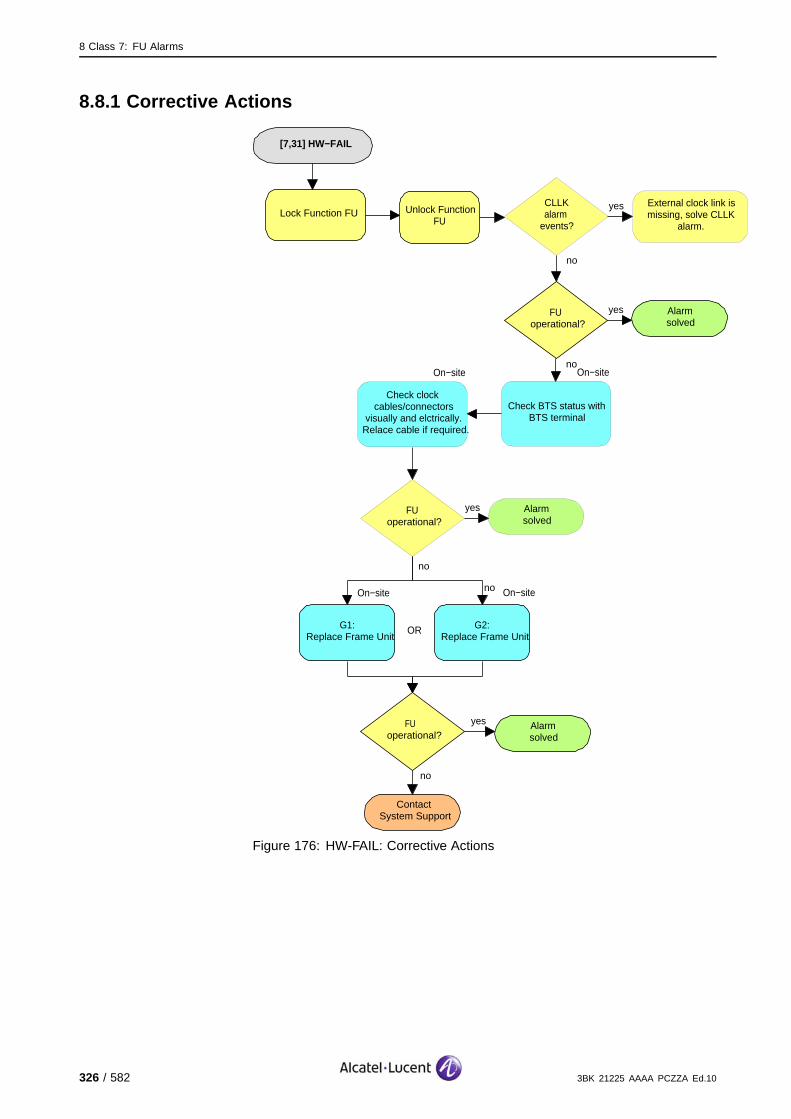
8 Class 7: FU Alarms
8.8.1 Corrective Actions
[7,31] HW−FAIL
Alarmsolved
yesFUoperational?
no
On−site
G1:Replace Frame Unit
On−site
no
ContactSystem Support
Lock Function FU Unlock Function FU
G2:Replace Frame Unit
FU operational?
yes Alarmsolved
OR
On−site
Check clock cables/connectors
visually and elctrically. Relace cable if required.
yesCLLK alarm events?
no
External clock link is missing, solve CLLK
alarm.
On−site
Check BTS status with BTS terminal
Alarmsolved
yesFUoperational?
no
no
Figure 176: HW-FAIL: Corrective Actions
326 / 582 3BK 21225 AAAA PCZZA Ed.10

8 Class 7: FU Alarms
8.9 [7,32] NR-SW-FAIL
specific Problems NR-SW-FAIL
event Type Processing Error
probable Cause software Program Abnormally Terminated
perceived Severity Major (PMA), Warning (MI)
Alarm Description A check-sum error was detected in one of the following during faultlocalization for:
the SCP of the FU
the software of the FU
the DSP
the saved parameters for FU configuration.
The OMU makes one attempt to overcome the alarm situationautonomously and to reset the FU.
Major (PMA): The reset is unsuccessful and the Managed Object (SBL)FU is put to Unlocked/Disabled (FOS).
Warning (MI): The reset is successful.
Major (PMA): If there is a FU state change, the eight channels supported by the FU are lost. The BCCH isregained through recovery (X).
Warning (MI): No impact on the telecom capabilities. The calls ongoing were lost.
Impact BSS Cell(s) Signaling Calls
Loss - - - X
Degradation X X X -
8.9.1 Corrective Actions
Contact your Alcatel-Lucent system support.
3BK 21225 AAAA PCZZA Ed.10 327 / 582
8 Class 7: FU Alarms
8.10 [7,33] NR-SCP-MP-FAULT
specific Problems NR-SCP-MP-FAULT
event Type Processing Error
probable Cause software Program Abnormally Terminated
perceived Severity Major (PMA), Warning (MI)
Alarm Description A non-recoverable FUCO SCP micro-processor fault has occurred. TheOMU makes one attempt to overcome the alarm situation and to resetthe FU.
Major (PMA): The reset is unsuccessful and the Managed Object (SBL)FU is put to Unlocked/Disabled (FOS).
Warning (MI): The reset is successful.
Major (PMA): If there is a FU state change, the eight channels supported by the FU are lost. The BCCH isregained through recovery (X).
Warning (MI): No impact on the telecom capabilities. The calls ongoing were lost.
Impact BSS Cell(s) Signaling Calls
Loss - - - X
Degradation X X X -
8.10.1 Corrective Actions
Contact your Alcatel-Lucent system support.
328 / 582 3BK 21225 AAAA PCZZA Ed.10
8 Class 7: FU Alarms
8.11 [7,34] BOTH-FHI-LINKS
specific Problems BOTH-FHI-LINKS
event Type Communication
probable Cause Loss Of Signal
perceived Severity Major (PMA)
Alarm Description Both FHI links are unavailable (eight time slots). The FU is unusable until atleast one link becomes available.
The eight time slots supported by the reporting FU are lost. Through recovery, the BCCH is maintained.
Impact BSS Cell(s) Signaling Calls
Loss - - - X
Degradation X X X -
3BK 21225 AAAA PCZZA Ed.10 329 / 582

8 Class 7: FU Alarms
8.11.1 G1 BTS Corrective Actions
[7,34] BOTH−FHI−LINKS
Alarmsolved
yesFUoperational?
no
On−site
no
ContactSystem Support
Lock Function FU
Unlock Function FU
G1:Replace Frame Unit
FU operational?
yes Alarmsolved
On−site
Check cables between FHUs/CUs and FU
On−site
G1:Replace FQHU
OR
Figure 177: BOTH-FHI-LINKS: G1 BTS Corrective Actions
330 / 582 3BK 21225 AAAA PCZZA Ed.10

8 Class 7: FU Alarms
8.11.2 G2 BTS Corrective Actions
[7,34] BOTH−FHI−LINKS
Alarmsolved
yesFUoperational?
no
On−site
no
ContactSystem Support
Lock Function FU
Unlock Function FU
G2:Replace Frame Unit
FU operational?
yes Alarmsolved
On−site
Check cables between FHUs/CUs and FU
On−site
G2:Replace STSE,
STSP, STSROR
Figure 178: BOTH-FHI-LINKS: G2 BTS Corrective Actions
3BK 21225 AAAA PCZZA Ed.10 331 / 582

8 Class 7: FU Alarms
8.12 [7,35] BOTH-CLOCKS-LINKS
specific Problems BOTH-CLOCKS-LINKS
event Type Equipment
probable Cause Timing Problem
perceived Severity Major (PMA)
Alarm Description The FU detects faults on both clock links. The FU is unusable until at leastone link becomes available.
The eight time slots supported by the reporting FU are lost. Through recovery, the BCCH is maintained.
Impact BSS Cell(s) Signaling Calls
Loss - - - X
Degradation X X X -
332 / 582 3BK 21225 AAAA PCZZA Ed.10

8 Class 7: FU Alarms
8.12.1 G1 BTS Corrective Actions
[7,35] BOTH−CLOCK−LINKS
Alarmsolved
yesFUoperational?
no
On−site
no
ContactSystem Support
Lock FunctionFU
Unlock Function FU
G1:Replace Frame Unit
FU operational?
yes Alarmsolved
On−site
Check cables between clock system and FU
On−site
G1:Replace FQHU
OR
Figure 179: BOTH-CLOCK-LINKS: G1 BTS Corrective Actions
3BK 21225 AAAA PCZZA Ed.10 333 / 582
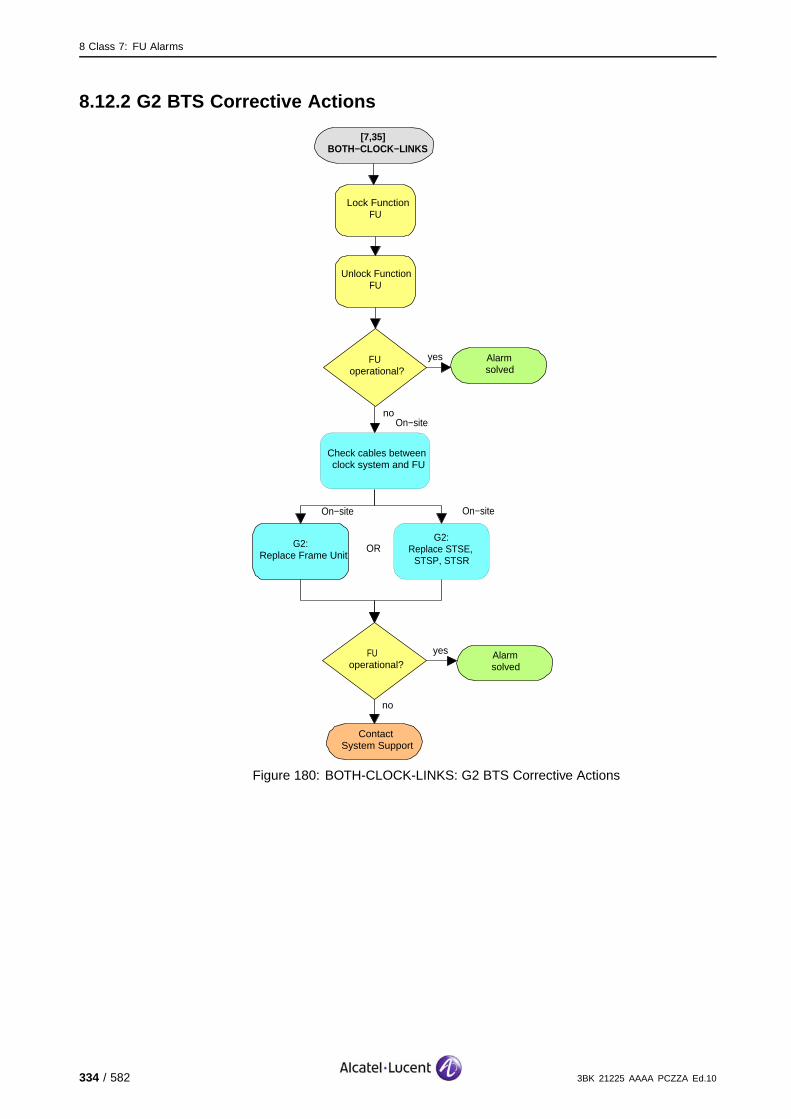
8 Class 7: FU Alarms
8.12.2 G2 BTS Corrective Actions
[7,35] BOTH−CLOCK−LINKS
Alarmsolved
yesFUoperational?
no
On−site
no
ContactSystem Support
Lock FunctionFU
Unlock Function FU
G2:Replace Frame Unit
FU operational?
yes Alarmsolved
On−site
Check cables between clock system and FU
On−site
G2:Replace STSE,
STSP, STSROR
Figure 180: BOTH-CLOCK-LINKS: G2 BTS Corrective Actions
334 / 582 3BK 21225 AAAA PCZZA Ed.10

8 Class 7: FU Alarms
8.13 [7,36] FU-FAULT
specific Problems FU-FAULT
event Type Equipment
probable Cause Equipment Malfunction
perceived Severity Warning (MI)
Alarm Description If the FU alarm disappears and the OMU loses the alarm information,FU-FAULT is sent by the OMU as a ’dummy alarm’. This indicates the FUis FOS and an operator initialization is required.
There is no further impact on the telecom capability.
Impact BSS Cell(s) Signaling Calls
Loss - - - -
Degradation - X X -
8.13.1 Corrective Actions
[7,36] FU−FAULT
Alarmsolved
yesFUoperational?
no
ContactSystem Support
Lock Function FU
Unlock Function FU
Figure 181: FU-FAULT: Corrective Actions
3BK 21225 AAAA PCZZA Ed.10 335 / 582
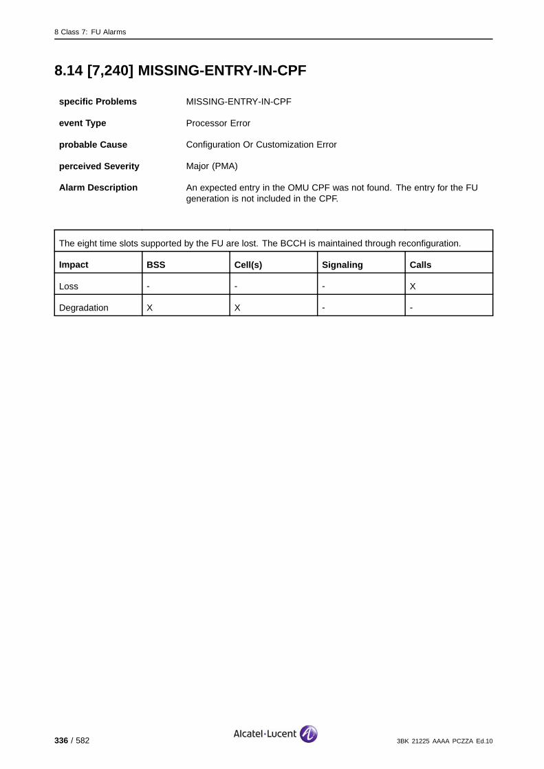
8 Class 7: FU Alarms
8.14 [7,240] MISSING-ENTRY-IN-CPF
specific Problems MISSING-ENTRY-IN-CPF
event Type Processor Error
probable Cause Configuration Or Customization Error
perceived Severity Major (PMA)
Alarm Description An expected entry in the OMU CPF was not found. The entry for the FUgeneration is not included in the CPF.
The eight time slots supported by the FU are lost. The BCCH is maintained through reconfiguration.
Impact BSS Cell(s) Signaling Calls
Loss - - - X
Degradation X X - -
336 / 582 3BK 21225 AAAA PCZZA Ed.10

8 Class 7: FU Alarms
8.14.1 Corrective Actions
[7,240] MISSING−ENTRY−IN−CPF
no
ContactSystem Support
Check existing hardware against populated hardware in the OMU CPF for wrong BTS family, characteristic
and parameter entries. Use:
Choose the correct CPFsettings by selecting the
appropriate BTS characteristics.
Use:
FUoperational?
yes Alarmsolved
Check Cell Activation
Check Cell Logical
Parameters
Check Cell Telecom Impact
Check Cell with Hardware
Change Cell Type
Modify BTS Characteristics
Modify BTS Hardware Capability
Reset BTS
Figure 182: MISSING-ENTRY-IN-CPF: Corrective Actions
3BK 21225 AAAA PCZZA Ed.10 337 / 582

8 Class 7: FU Alarms
8.15 [7,241] INCONSIST-ASSHW-ACTHW
specific Problems INCONSIST-ASSHW-ACTHW
event Type Processing Error
probable Cause Configuration Or Customization Error
perceived Severity Major (PMA)
Alarm Description The BTS hardware does not match the assumed hardware capabilities.
Alarm Number 1: The BTS hardware does not provide the requested ciphering algorithm.
8: The FU software package received from the OMC-R/BSC does notmatch the FU hardware.
9: The BTS hardware does not provide the requested configuration forfull-rate/half-rate channels.
Alarm number 1 or 9: The eight time slots supported by the FU are lost. The BCCH is maintained throughreconfiguration.
Alarm number 8: The FU cannot perform telecom functions as the configuration is incomplete.
Impact BSS Cell(s) Signaling Calls
Loss - - - X
Degradation X X - -
338 / 582 3BK 21225 AAAA PCZZA Ed.10

8 Class 7: FU Alarms
8.15.1 Alarm Number 1 Corrective Actions
[7,241] INCONSIST−ASSHW−ACTHW
no
ContactSystem Support
Check ciphering capability against BTS hardware.
Use:
FUoperational?
yes Alarmsolved
Check Cell with Hardware
Modify assumed BTS Hardware
Capability
Modify actual BTS hardware capability by replacing existing
BTS entity by appropriate BTS hardware entity.
OR
On−site
On−site
G1:Replace Frame Unit
G2:Replace Frame Unit
On−site
OR
Alarm Number 1
Alarmsolved
yesFUoperational?
no
Lock Function FU
Unlock Function FU
Figure 183: INCONSIST-ASSHW-ACTHW: Alarm Number 1 Corrective Actions
3BK 21225 AAAA PCZZA Ed.10 339 / 582
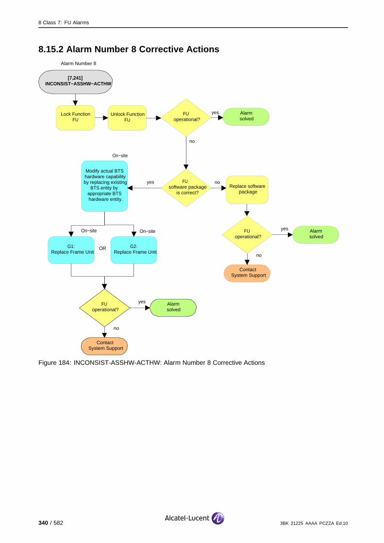
8 Class 7: FU Alarms
8.15.2 Alarm Number 8 Corrective Actions
[7,241] INCONSIST−ASSHW−ACTHW
no
ContactSystem Support
FUoperational?
yes Alarmsolved
Replace software package
Modify actual BTS hardware capability by replacing existing
BTS entity by appropriate BTS hardware entity.
On−site
On−site
G1:Replace Frame Unit
G2:Replace Frame Unit
On−site
OR
Alarm Number 8
Alarmsolved
yesFUoperational?
no
Lock Function FU
Unlock Function FU
yes FU software package
is correct?
no
no
ContactSystem Support
FUoperational?
yes Alarmsolved
Figure 184: INCONSIST-ASSHW-ACTHW: Alarm Number 8 Corrective Actions
340 / 582 3BK 21225 AAAA PCZZA Ed.10

8 Class 7: FU Alarms
8.15.3 Alarm Number 9 Corrective Actions
[7,241] INCONSIST−ASSHW−ACTHW
no
ContactSystem Support
Check hardware full−rate/half−rate capability
against FU hardware.Use:
FUoperational?
yes Alarmsolved
Check Cell with Hardware
Modify assumed BTS Hardware
Capability
Modify actual BTS hardware capability by replacing existing
BTS entity by appropriate BTS hardware entity.
OR
On−site
On−site
G1:Replace Frame Unit
G2:Replace Frame Unit
On−site
OR
Alarm Number 9
Alarmsolved
yesFUoperational?
no
Lock Function FU
Unlock Function FU
Figure 185: INCONSIST-ASSHW-ACTHW: Alarm Number 9 Corrective Actions
3BK 21225 AAAA PCZZA Ed.10 341 / 582

8 Class 7: FU Alarms
8.16 [7,242] INCONSIST-actHW-logConfig
specific Problems INCONSIST-actHW-logConfig
event Type Processing Error
probable Cause Configuration Or Customization Error
perceived Severity Major (PMA)
Alarm Description The BTS hardware does not match the logical configuration. The hardwaredoes not provide the requested baseband or radio hopping capability.
The eight time slots supported by the FU are lost. The BCCH is maintained through reconfiguration.
Impact BSS Cell(s) Signaling Calls
Loss - - - X
Degradation X X - -
342 / 582 3BK 21225 AAAA PCZZA Ed.10
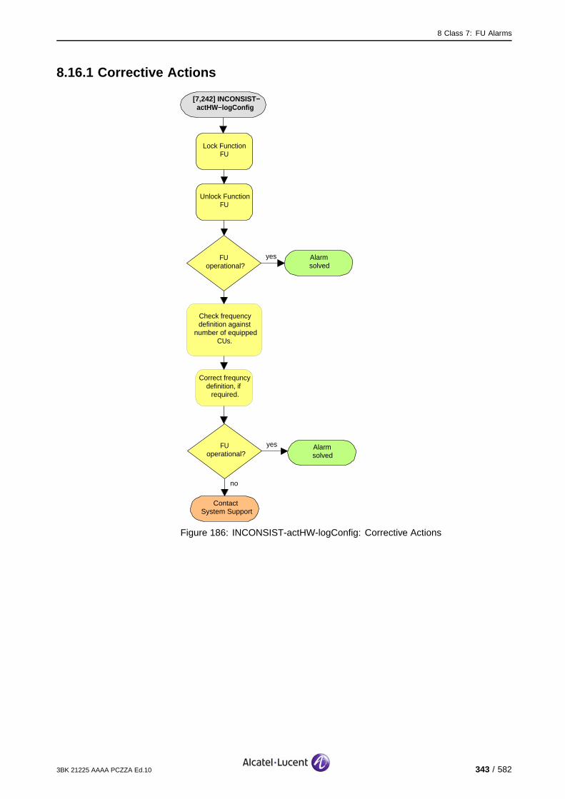
8 Class 7: FU Alarms
8.16.1 Corrective Actions
[7,242] INCONSIST−actHW−logConfig
Alarmsolved
yesFUoperational?
no
ContactSystem Support
Lock Function FU
Unlock Function FU
FUoperational?
yes Alarmsolved
Check frequency definition against
number of equipped CUs.
Correct frequncy definition, if
required.
Figure 186: INCONSIST-actHW-logConfig: Corrective Actions
3BK 21225 AAAA PCZZA Ed.10 343 / 582
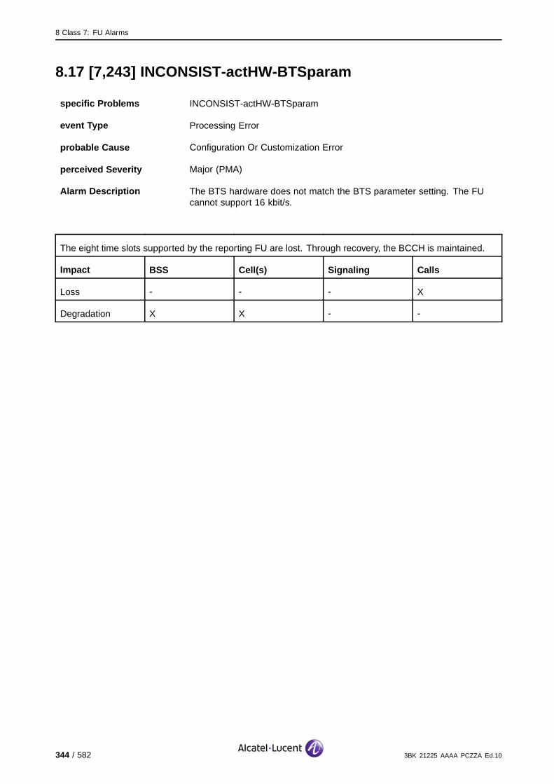
8 Class 7: FU Alarms
8.17 [7,243] INCONSIST-actHW-BTSparam
specific Problems INCONSIST-actHW-BTSparam
event Type Processing Error
probable Cause Configuration Or Customization Error
perceived Severity Major (PMA)
Alarm Description The BTS hardware does not match the BTS parameter setting. The FUcannot support 16 kbit/s.
The eight time slots supported by the reporting FU are lost. Through recovery, the BCCH is maintained.
Impact BSS Cell(s) Signaling Calls
Loss - - - X
Degradation X X - -
344 / 582 3BK 21225 AAAA PCZZA Ed.10
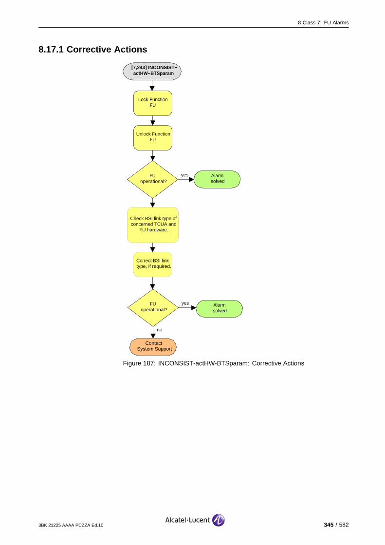
8 Class 7: FU Alarms
8.17.1 Corrective Actions
[7,243] INCONSIST−actHW−BTSparam
Alarmsolved
yesFUoperational?
no
ContactSystem Support
Lock Function FU
Unlock Function FU
FUoperational?
yes Alarmsolved
Check BSI link type of concerned TCUA and
FU hardware.
Correct BSI link type, if required.
Figure 187: INCONSIST-actHW-BTSparam: Corrective Actions
3BK 21225 AAAA PCZZA Ed.10 345 / 582
8 Class 7: FU Alarms
8.18 [7,245] SW-DLL-FAIL
specific Problems SW-DLL-FAIL
event Type Processing Error
probable Cause CorruptData
perceived Severity Major (PMA)
Alarm Description An error is detected during the software down-load from the OMU to the FU.
There is no further impact on the telecom capability of the system (the FU was not in service before thefault occurred). The FU remains isolated until the down-load and initialization is completed.
Impact BSS Cell(s) Signaling Calls
Loss - - - -
Degradation - X X -
346 / 582 3BK 21225 AAAA PCZZA Ed.10

8 Class 7: FU Alarms
8.18.1 Corrective Actions
[7,245] SW−DLL−FAIL
Alarmsolved
yesFUoperational?
no
ContactSystem Support
Lock Function FU
Unlock Function FU
FUoperational?
yes Alarmsolved
Check FU hardware/software
compatibility.
Correct compatibility, if
required.
Figure 188: SW-DLL-FAIL: Corrective Actions
3BK 21225 AAAA PCZZA Ed.10 347 / 582

8 Class 7: FU Alarms
8.19 [7,246] CONFIG-FAIL
specific Problems CONFIG-FAIL
event Type Processing Error
probable Cause Configuration Or Customization Error
perceived Severity Major (PMA)
Alarm Description The configuration of the FU is unsuccessful due to a bad configurationparameter or FU problems.
The eight time slots supported by the reporting FU are lost. Through recovery, the BCCH is maintained.
Impact BSS Cell(s) Signaling Calls
Loss - - - X
Degradation X X X -
348 / 582 3BK 21225 AAAA PCZZA Ed.10
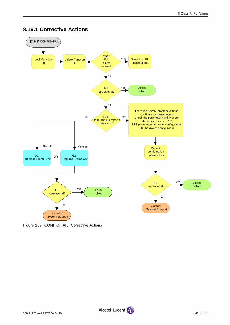
8 Class 7: FU Alarms
8.19.1 Corrective Actions
[7,246] CONFIG−FAIL
no
ContactSystem Support
FUoperational?
yes Alarmsolved
There is a severe problem with the configuration parameters.
Check the parameter validity of cell information elemtent 1/2,
BSS parameters, channel configuration, BTS hardware configuration.
On−site
G1:Replace Frame Unit
G2:Replace Frame Unit
On−site
OR
Alarmsolved
yesFUoperational?
no
Lock Function FU
Unlock Function FU
yesMore than one FU reports
this alarm?
no
no
ContactSystem Support
FUoperational?
yes Alarmsolved
yesotherFU
alarm events?
no
Solve that FU alarm(s) first
Correct configuration parameters
Figure 189: CONFIG-FAIL: Corrective Actions
3BK 21225 AAAA PCZZA Ed.10 349 / 582
8 Class 7: FU Alarms
8.20 [7,248] RESTART
specific Problems RESTART
event Type Processing Error
probable Cause Software Error
perceived Severity Warning (MI)
Alarm Description The FU restarts successfully and the trigger for the restart is indicatedwith the Alarm Number.
Alarm Number 1: No reason indicated.
10: SCP or DSP exception.
12: FU telecom configuration problem (e.g., time out or algorithmconfiguration parameters refused during FU initialization).
13: Other cases (e.g., spurious hardware problems or hardware problemsnot detected by self-testing).
14: Problems during TS configuration occurred.
15: System information 3 value out of range.
17: Push-button action by operator (no TLV 61 sent).
18: Failure of the LAP-D link for more than "BCCH cut" timer.
If the FU supporting the BCCH is not concerned, during the restart the FU loses all calls. After thesuccessful restart the FU is usable.
If the FU supporting the BCCH is concerned, during the restart the FU loses all calls. After the successfulrestart the FU is usable. The BCCH is regained through recovery.
Impact BSS Cell(s) Signaling Calls
Loss - - - X
Degradation - X X -
350 / 582 3BK 21225 AAAA PCZZA Ed.10

8 Class 7: FU Alarms
8.20.1 Corrective Actions
[7,248] RESTART
Check configuration parameters
Alarmsolved
yesFUoperational?
no
Lock Function FU
Unlock Function FU
no
ContactSystem Support
FUoperational?
yes Alarmsolved
Correct configuration parameters (not alarm
number 17)
Figure 190: RESTART: Corrective Actions
If the FU restarts repeatedly in a short period of time, there can be a hardwareproblem, wrong configuration parameters sent, or the FU software can becorrupt.
3BK 21225 AAAA PCZZA Ed.10 351 / 582
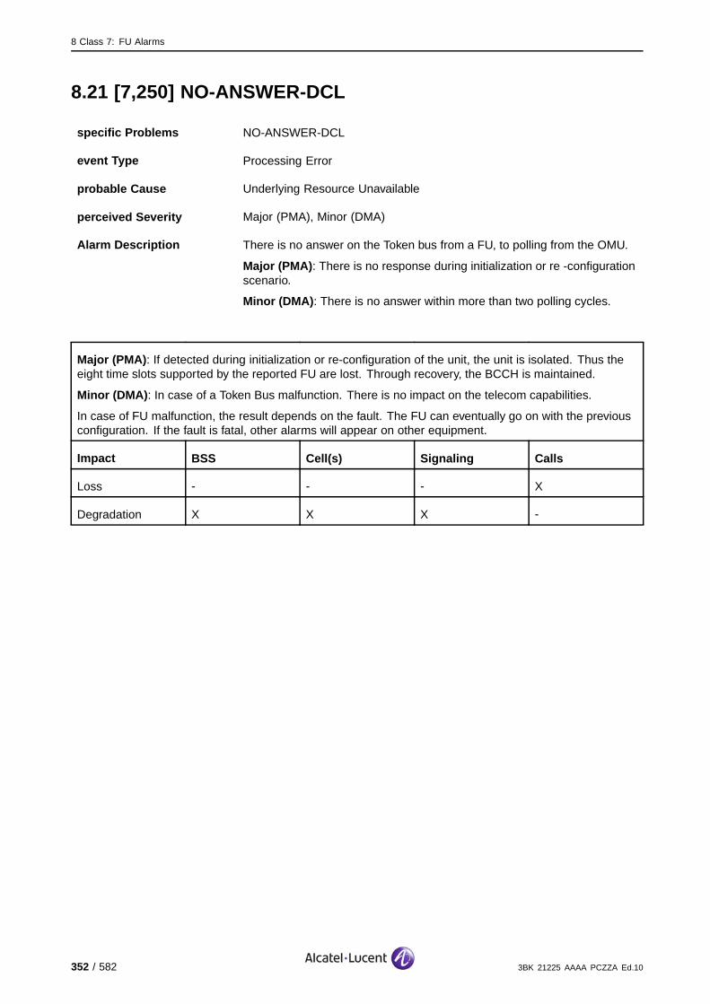
8 Class 7: FU Alarms
8.21 [7,250] NO-ANSWER-DCL
specific Problems NO-ANSWER-DCL
event Type Processing Error
probable Cause Underlying Resource Unavailable
perceived Severity Major (PMA), Minor (DMA)
Alarm Description There is no answer on the Token bus from a FU, to polling from the OMU.
Major (PMA): There is no response during initialization or re -configurationscenario.
Minor (DMA): There is no answer within more than two polling cycles.
Major (PMA): If detected during initialization or re-configuration of the unit, the unit is isolated. Thus theeight time slots supported by the reported FU are lost. Through recovery, the BCCH is maintained.
Minor (DMA): In case of a Token Bus malfunction. There is no impact on the telecom capabilities.
In case of FU malfunction, the result depends on the fault. The FU can eventually go on with the previousconfiguration. If the fault is fatal, other alarms will appear on other equipment.
Impact BSS Cell(s) Signaling Calls
Loss - - - X
Degradation X X X -
352 / 582 3BK 21225 AAAA PCZZA Ed.10
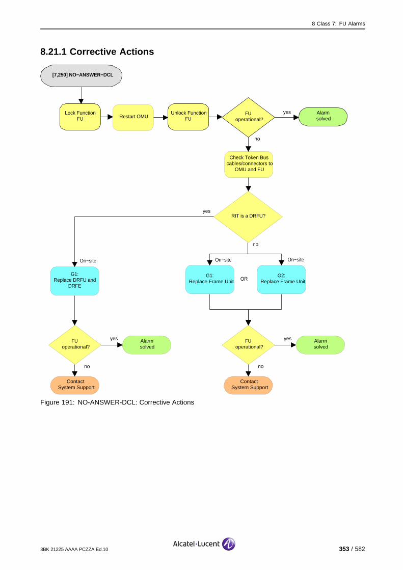
8 Class 7: FU Alarms
8.21.1 Corrective Actions
[7,250] NO−ANSWER−DCL
Alarmsolved
yesFUoperational?
no
Lock Function FU
Unlock Function FU
Check Token Bus cables/connectors to
OMU and FU
yesRIT is a DRFU?
no
On−site
G1:Replace Frame Unit
G2:Replace Frame Unit
On−site
OR
no
ContactSystem Support
FUoperational?
yes Alarmsolved
no
ContactSystem Support
FUoperational?
yes Alarmsolved
Restart OMU
On−site
G1:Replace DRFU and
DRFE
Figure 191: NO-ANSWER-DCL: Corrective Actions
3BK 21225 AAAA PCZZA Ed.10 353 / 582

8 Class 7: FU Alarms
354 / 582 3BK 21225 AAAA PCZZA Ed.10

9 Class 8: G-BTS Alarms
9 Class 8: G-BTS Alarms
This section defines the alarms for the Class 8: G-BTS alarm class.
3BK 21225 AAAA PCZZA Ed.10 355 / 582

9 Class 8: G-BTS Alarms
9.1 [8,3] RESYNCH
specific Problems RESYNCH
event Type Processing Error
probable Cause Configuration Or Customization Error
perceived Severity Warning (MI)
Alarm Description Discrepancies are detected between the BSC and OMU database and bothdatabases have been updated. The OMC-R triggers an update of its ownAlarms in Force and SBL state list.
Telecom functions are not affected.
Impact BSS Cell(s) Signaling Calls
Loss - - - -
Degradation - - - -
9.1.1 Corrective Actions
None required, the BTS is in service.
356 / 582 3BK 21225 AAAA PCZZA Ed.10
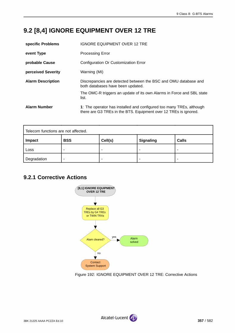
9 Class 8: G-BTS Alarms
9.2 [8,4] IGNORE EQUIPMENT OVER 12 TRE
specific Problems IGNORE EQUIPMENT OVER 12 TRE
event Type Processing Error
probable Cause Configuration Or Customization Error
perceived Severity Warning (MI)
Alarm Description Discrepancies are detected between the BSC and OMU database andboth databases have been updated.
The OMC-R triggers an update of its own Alarms in Force and SBL statelist.
Alarm Number 1: The operator has installed and configured too many TREs, althoughthere are G3 TREs in the BTS. Equipment over 12 TREs is ignored.
Telecom functions are not affected.
Impact BSS Cell(s) Signaling Calls
Loss - - - -
Degradation - - - -
9.2.1 Corrective Actions
[8,1] IGNORE EQUIPMENT OVER 12 TRE
no
ContactSystem Support
Replace all G3 TREs by G4 TREs
or TWIN TRXs
Alam cleared?yes Alarm
solved
Figure 192: IGNORE EQUIPMENT OVER 12 TRE: Corrective Actions
3BK 21225 AAAA PCZZA Ed.10 357 / 582

9 Class 8: G-BTS Alarms
9.3 [8,5] TOO MANY PLUGGED MODULES
specific Problems TOO MANY PLUGGED MODULES
event Type Equipment
probable Cause Configuration Or Customization Error
perceived Severity Warning (MI)
Alarm Description The installed HW configuration exceeds the power dissipation limits.
Alarm Number 1 : Too many TREs are plugged in the rack type.
There is no disturbance of the telecom applications.
Impact BSS Cell(s) Signaling Calls
Loss - - - -
Degradation - - - -
9.3.1 Corrective Actions
[8,5] TOO MANY PLUGGED MODULES
no
ContactSystem Support
Reduce the installed equipment
Alam cleared?yes Alarm
solved
Figure 193: TOO MANY PLUGGED MODULES: Corrective Actions
358 / 582 3BK 21225 AAAA PCZZA Ed.10

9 Class 8: G-BTS Alarms
9.4 [8,6] TB-FAILURE
specific Problems TB-FAILURE
event Type Equipment
probable Cause Equipment Malfunction
perceived Severity Major (PMA)
Alarm Description The communication with all units on the Token Bus, which are In Traffic,is faulty.
Telecom functions are not affected as long as no recovery is needed. If recovery is needed, the cell islost temporarily and all calls are lost.
Impact BSS Cell(s) Signaling Calls
Loss - - - -
Degradation - - - -
3BK 21225 AAAA PCZZA Ed.10 359 / 582

9 Class 8: G-BTS Alarms
9.4.1 G1/G2 Corrective Actions
[8,6] TB−FAILURE
Alarmsolved
yesBTSoperational?
no
Reset BTS
Check Token Bus cables/connectors at
OMU side
On−site
G1:Replace OMUA
G2:Replace
SACE/SCFE
On−site
OR
no
ContactSystem Support
BTSoperational?
yes Alarmsolved
Figure 194: TB-FAILURE: G1/G2 Corrective Actions
360 / 582 3BK 21225 AAAA PCZZA Ed.10
9 Class 8: G-BTS Alarms
9.5 [8,7] Q1-FAILURE
specific Problems Q1-FAILURE
event Type Equipment
probable Cause Equipment Malfunction
perceived Severity Major (PMA)
Alarm Description The communication with all units on the Q1 Bus, which are In Traffic,is faulty.
Telecom functions are not affected as long as no recovery is needed. If recovery is needed, the cell islost temporarily and all calls are lost.
Impact BSS Cell(s) Signaling Calls
Loss - - - -
Degradation - - - -
3BK 21225 AAAA PCZZA Ed.10 361 / 582
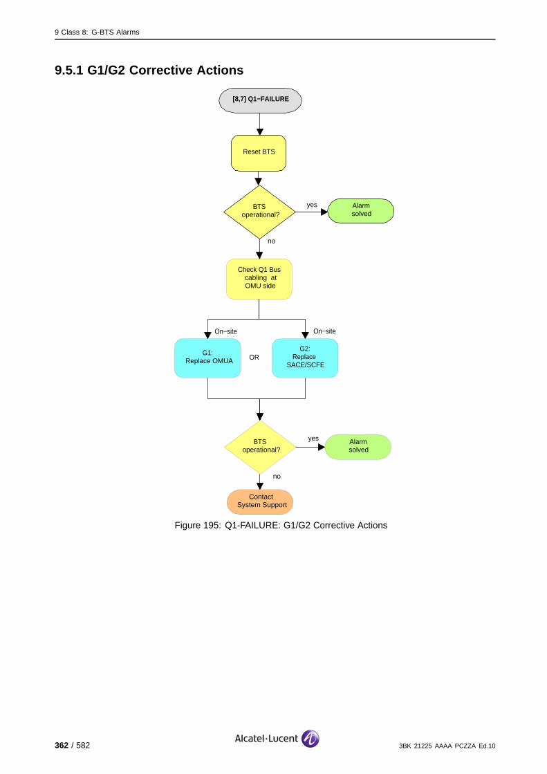
9 Class 8: G-BTS Alarms
9.5.1 G1/G2 Corrective Actions
[8,7] Q1−FAILURE
Alarmsolved
yesBTSoperational?
no
Reset BTS
Check Q1 Bus cabling atOMU side
On−site
G1:Replace OMUA
G2:Replace
SACE/SCFE
On−site
OR
no
ContactSystem Support
BTSoperational?
yes Alarmsolved
Figure 195: Q1-FAILURE: G1/G2 Corrective Actions
362 / 582 3BK 21225 AAAA PCZZA Ed.10

9 Class 8: G-BTS Alarms
9.6 [8,8] HW-RESYNCH
specific Problems HW-RESYNCH
event Type Processing Error
probable Cause Configuration Or Customization Error
perceived Severity Warning (MI)
Alarm Description The BTS detects an addition or reduction in SBLs or hardware modification(different RIT names). Consequently a hardware re-synchronization alarmis sent. This causes the OMC-R to trigger a hardware, state and alarmaudit. The audit aligns the OMC -R database with the new hardware.
Telecom functions are not affected.
Impact BSS Cell(s) Signaling Calls
Loss - - - -
Degradation - - - -
9.6.1 Corrective Actions
None required, the BTS is in service.
3BK 21225 AAAA PCZZA Ed.10 363 / 582

9 Class 8: G-BTS Alarms
9.7 [8,26] RACH-CATCHER-LOST
specific Problems RACH-CATCHER-LOST
event Type Equipment
probable Cause Receiver Failure
perceived Severity Major (PMA)
Alarm Description The RACH catcher function of an inner cell BTS is lost. This applies toextended cell configurations only.
Alarm Number 1: BCB link is unable to detect the presence of the modules.
2: BCB Power supply is faulty.
Outgoing calls are not possible for Mobile Stations in the inner cell that camp on the outer cell BCCHfrequency. Active calls are not affected.
Impact BSS Cell(s) Signaling Calls
Loss - - - -
Degradation - X (Inner Cell) X (Inner Cell) -
364 / 582 3BK 21225 AAAA PCZZA Ed.10

9 Class 8: G-BTS Alarms
9.7.1 Corrective Actions
[8,26] RACH−CATCHER−LOST
Alarmsolved
yesBTSoperational?
no
no
ContactSystem Support
Lock Function BTS
Unlock Function BTS
BTS operational?
yes Alarmsolved
Solve that alarm(s)
no
CU,FHU,FU or RA alarm(s)
events?
yes
Figure 196: RACH-CATCHER-LOST: Corrective Actions
3BK 21225 AAAA PCZZA Ed.10 365 / 582

9 Class 8: G-BTS Alarms
9.8 [8,30] BCB-LINK
specific Problems BCB-LINK
event Type Equipment
probable Cause Equipment Malfunction
perceived Severity Major (PMA), Warning (MI)
Alarm Description There is no communication on IOM link.
Alarm Number 1: The BCB link is unable to detect the presence of the modules.
2: The BCB Power supply is faulty.
The is no communication on the BCB.
Impact BSS Cell(s) Signaling Calls
Loss - - - -
Degradation - - - -
366 / 582 3BK 21225 AAAA PCZZA Ed.10

9 Class 8: G-BTS Alarms
9.8.1 9100 BTS Corrective Actions
Disable RF PowerUse the BTS Terminal to disable RA before disconnecting RF cables.Initialize RA after work.
[8,30] BCB−LINK
Alarmsolved
yesBTSoperational?
no
On−site
no
ContactSystem Support
Lock Function BTS
Unlock Function BTS
Replace SUMP/SUMA
BTSoperational?
yes Alarmsolved
On−site
Check BCB bus for shortcuts and interruptions
Figure 197: BCB-LINK: 9100 BTS Corrective Actions
3BK 21225 AAAA PCZZA Ed.10 367 / 582
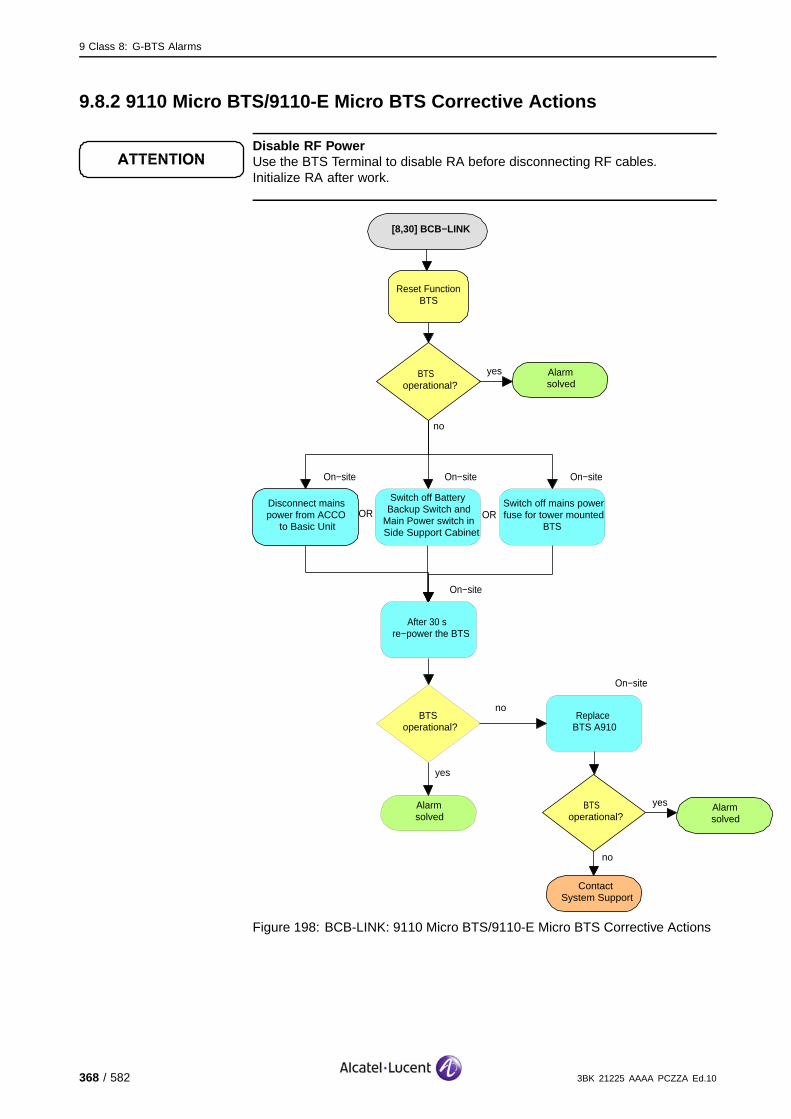
9 Class 8: G-BTS Alarms
9.8.2 9110 Micro BTS/9110-E Micro BTS Corrective Actions
Disable RF PowerUse the BTS Terminal to disable RA before disconnecting RF cables.Initialize RA after work.
[8,30] BCB−LINK
Alarmsolved
yesBTS operational?
no
On−site
no
ContactSystem Support
Reset Function BTS
Disconnect mains power from ACCO
to Basic Unit
BTS operational?
yes Alarmsolved
On−site
After 30 s re−power the BTS
On−site
Switch off Battery Backup Switch and
Main Power switch in Side Support Cabinet
On−site
Switch off mains power fuse for tower mounted
BTSOR OR
On−site
Replace BTS A910
noBTS
operational?
yes
Alarmsolved
Figure 198: BCB-LINK: 9110 Micro BTS/9110-E Micro BTS Corrective Actions
368 / 582 3BK 21225 AAAA PCZZA Ed.10
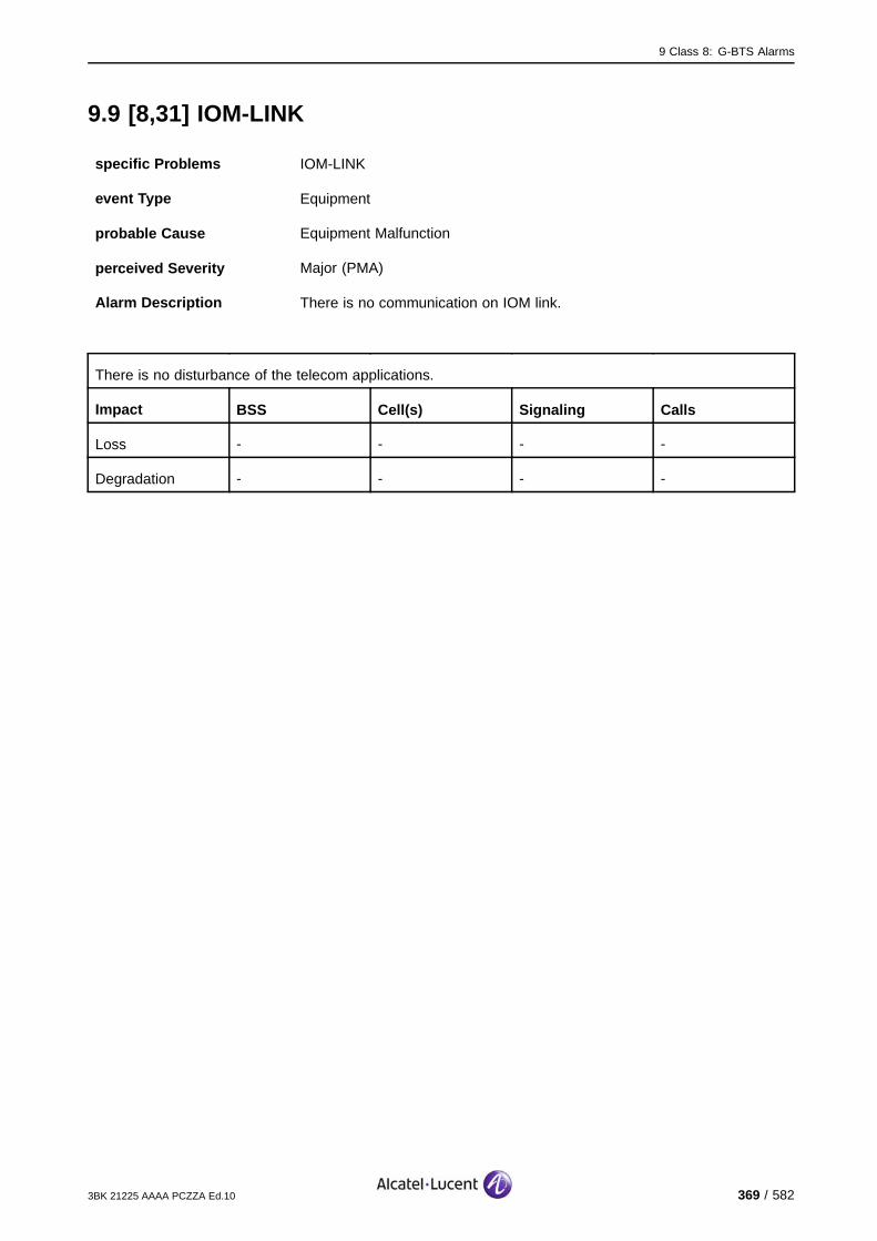
9 Class 8: G-BTS Alarms
9.9 [8,31] IOM-LINK
specific Problems IOM-LINK
event Type Equipment
probable Cause Equipment Malfunction
perceived Severity Major (PMA)
Alarm Description There is no communication on IOM link.
There is no disturbance of the telecom applications.
Impact BSS Cell(s) Signaling Calls
Loss - - - -
Degradation - - - -
3BK 21225 AAAA PCZZA Ed.10 369 / 582

9 Class 8: G-BTS Alarms
9.9.1 9100 BTS Corrective Actions
Disable RF PowerUse the BTS Terminal to disable RA before disconnecting RF cables.Initialize RA after work.
[8,31] IOM−LINK
Alarmsolved
yesBTSoperational?
no
On−site
no
ContactSystem Support
Lock Function BTS
Unlock Function BTS
Replace SUMP/SUMA
BTSoperational?
yes Alarmsolved
On−site
Check BSII bus for shortcuts and interruptions
Figure 199: IOM-LINK: 9100 BTS Corrective Actions
370 / 582 3BK 21225 AAAA PCZZA Ed.10

9 Class 8: G-BTS Alarms
9.9.2 9110 Micro BTS/9110-E Micro BTS Corrective Actions
Disable RF PowerUse the BTS Terminal to disable RA before disconnecting RF cables.Initialize RA after work.
[8,31] IOM−LINK
Alarmsolved
yesBTSoperational?
no
On−site
no
ContactSystem Support
Reset Function BTS
Disconnect mains power from ACCO
to Basic Unit
BTS operational?
yes Alarmsolved
On−site
After 30 s re−power the BTS
On−site
Switch off Battery Backup Switch and
Main Power switch in Side Support Cabinet
On−site
Switch off mains power fuse for tower mounted
BTSOR OR
On−site
Replace BTS A910
noBTS
operational?
yes
Alarmsolved
Figure 200: IOM-LINK: 9110 Micro BTS/9110-E Micro BTS Corrective Actions
3BK 21225 AAAA PCZZA Ed.10 371 / 582
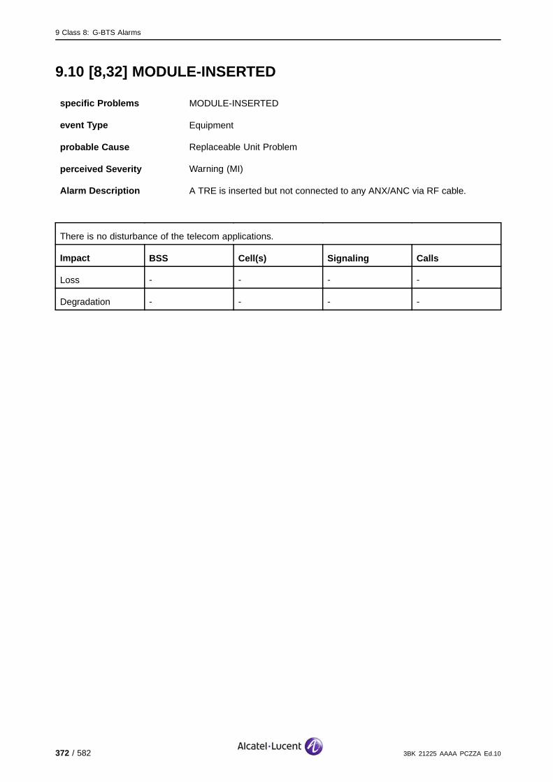
9 Class 8: G-BTS Alarms
9.10 [8,32] MODULE-INSERTED
specific Problems MODULE-INSERTED
event Type Equipment
probable Cause Replaceable Unit Problem
perceived Severity Warning (MI)
Alarm Description A TRE is inserted but not connected to any ANX/ANC via RF cable.
There is no disturbance of the telecom applications.
Impact BSS Cell(s) Signaling Calls
Loss - - - -
Degradation - - - -
372 / 582 3BK 21225 AAAA PCZZA Ed.10

9 Class 8: G-BTS Alarms
9.10.1 9100 BTS Corrective Actions
Disable RF PowerUse the BTS Terminal to disable RA before disconnecting RF cables.Initialize RA after work.
[8,32] MODULE−INSERTED
Alarmsolved
yesBTSoperational?
no
On−site
no
ContactSystem Support
Lock Function BTS
Replace ANX,ANY,ANC
BTS operational?
yes Alarmsolved
On−site
Replace TRE
On−site
Check RF cables and connectors to TRE and ANX/ANY/ANC visually and electrcally. Replace
cable, if required.
OR
If the module has been extracted previously and the same module inserted (without operator action), the connection of the module could be faulty
On−site
Check BTS status
Alarmsolved
yesBTSoperational?
no
Unlock Function BTS
Figure 201: MODULE-INSERTED: 9100 BTS Corrective Actions
3BK 21225 AAAA PCZZA Ed.10 373 / 582
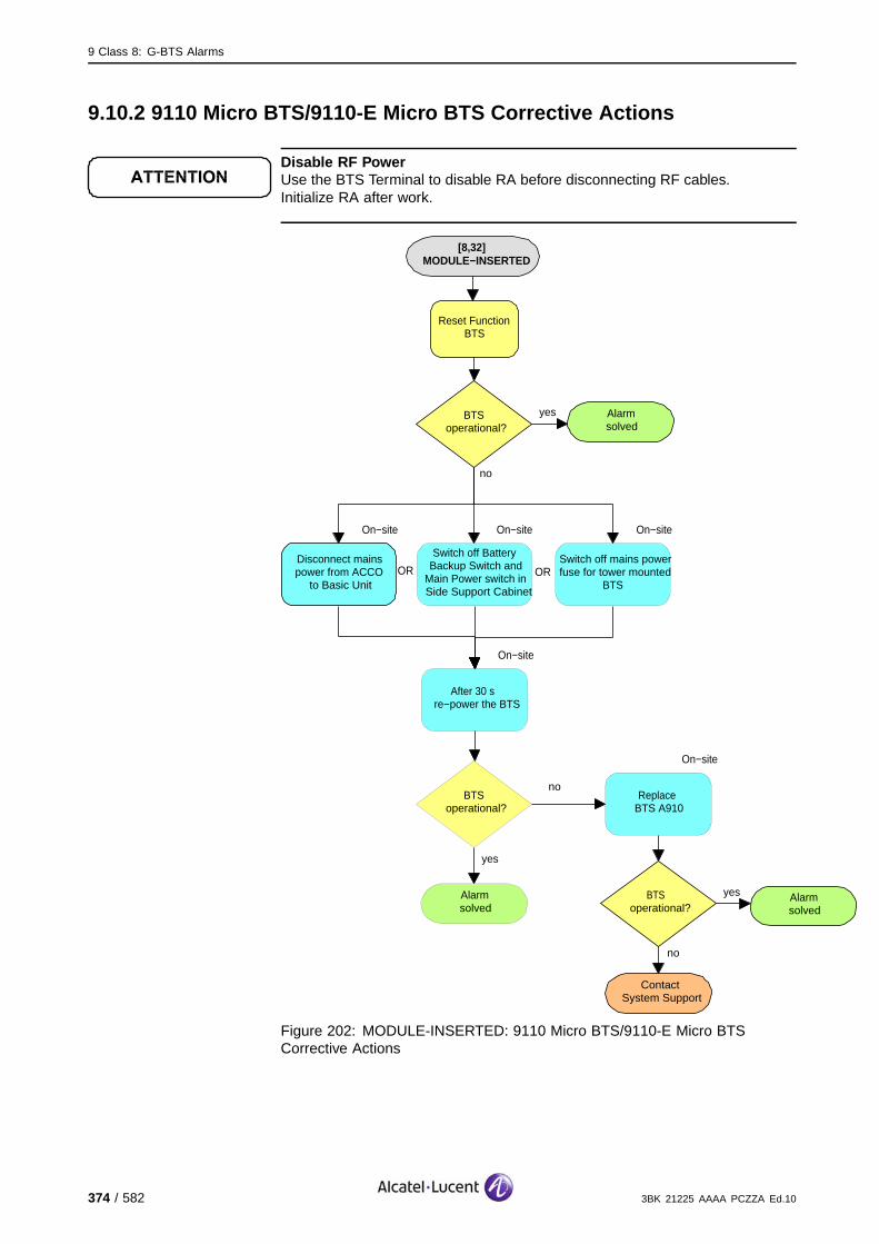
9 Class 8: G-BTS Alarms
9.10.2 9110 Micro BTS/9110-E Micro BTS Corrective Actions
Disable RF PowerUse the BTS Terminal to disable RA before disconnecting RF cables.Initialize RA after work.
[8,32] MODULE−INSERTED
Alarmsolved
yesBTSoperational?
no
On−site
no
ContactSystem Support
Reset Function BTS
Disconnect mains power from ACCO
to Basic Unit
BTS operational?
yes Alarmsolved
On−site
After 30 s re−power the BTS
On−site
Switch off Battery Backup Switch and
Main Power switch in Side Support Cabinet
On−site
Switch off mains power fuse for tower mounted
BTSOR OR
On−site
Replace BTS A910
noBTS
operational?
yes
Alarmsolved
Figure 202: MODULE-INSERTED: 9110 Micro BTS/9110-E Micro BTSCorrective Actions
374 / 582 3BK 21225 AAAA PCZZA Ed.10

9 Class 8: G-BTS Alarms
9.11 [8,246] CONFIG-FAIL
specific Problems CONFIG-FAIL
event Type Processing Error
probable Cause Configuration Or Customization Error
perceived Severity Major (PMA)
Alarm Description The configuration of an EACB has failed.
Telecom functions are not affected.
Impact BSS Cell(s) Signaling Calls
Loss - - - -
Degradation - - - -
3BK 21225 AAAA PCZZA Ed.10 375 / 582
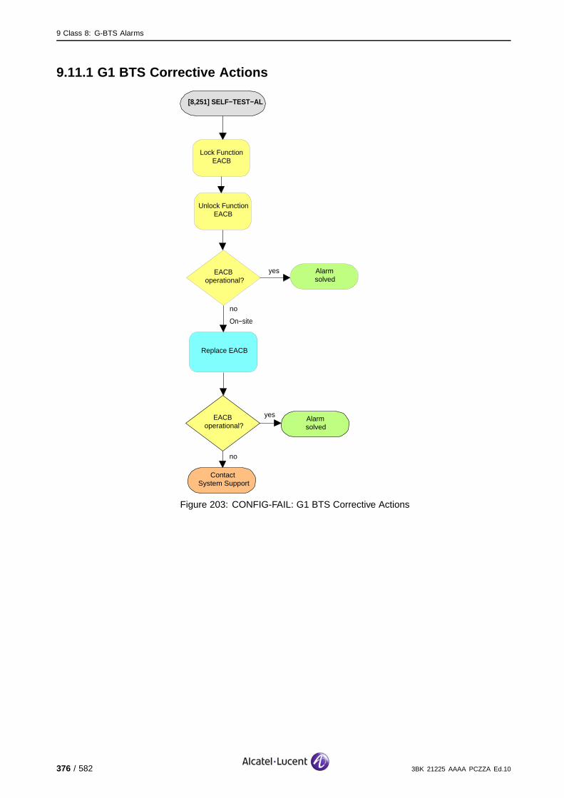
9 Class 8: G-BTS Alarms
9.11.1 G1 BTS Corrective Actions
[8,251] SELF−TEST−AL
no
ContactSystem Support
EACBoperational?
yes Alarmsolved
Alarmsolved
yesEACBoperational?
no
Lock Function EACB
Unlock Function EACB
Replace EACB
On−site
Figure 203: CONFIG-FAIL: G1 BTS Corrective Actions
376 / 582 3BK 21225 AAAA PCZZA Ed.10

9 Class 8: G-BTS Alarms
9.11.2 G2 BTS Corrective Actions
[8,246] CONFIG−FAIL
no
ContactSystem Support
EACBoperational?
yes Alarmsolved
Alarmsolved
yesEACBoperational?
no
Lock Function EACB
Unlock Function EACB
Replace SACE/SAFE
On−site
Figure 204: CONFIG-FAIL: G2 BTS Corrective Actions
3BK 21225 AAAA PCZZA Ed.10 377 / 582
9 Class 8: G-BTS Alarms
9.12 [8,247] RESET
9.12.1 [8,247] RESET (BTS)
specific Problems RESET
event Type Processing Error
probable Cause Software Error
perceived Severity Warning (MI)
Alarm Description The (power up) reset of the BTS has been performed successfully.
Alarm Number 1: BTS Power On.
2: SW discrepancy.
3: Operator command.
There is no disturbance of the telecom applications, because the BTS was powered down before.
Impact BSS Cell(s) Signaling Calls
Loss - - - -
Degradation - - - -
9.12.1.1 Corrective ActionsNone required, the BTS is now in service
378 / 582 3BK 21225 AAAA PCZZA Ed.10
9 Class 8: G-BTS Alarms
9.12.2 [8,247] RESET (EACB)
specific Problems RESET
event Type Processing Error
probable Cause Software Error
perceived Severity Warning (MI)
Alarm Description The auto-reset of the EACBs is successful. The auto-reset is triggered bythe watchdog or a push-button reset.
Telecom functions are not affected
Impact BSS Cell(s) Signaling Calls
Loss - - - -
Degradation - - - -
3BK 21225 AAAA PCZZA Ed.10 379 / 582

9 Class 8: G-BTS Alarms
9.12.2.1 G1 BTS Corrective Actions
[8,247] RESET (EACB)
no
ContactSystem Support
EACBoperational?
yes Alarmsolved
Alarmsolved
yesEACBoperational?
no
Lock Function EACB
Unlock Function EACB
Replace FQHU
On−siteno
EACBoperational?
yes Alarmsolved
Check EACB hardware
On−site
Figure 205: RESET (EACB): G1 BTS Corrective Actions
380 / 582 3BK 21225 AAAA PCZZA Ed.10
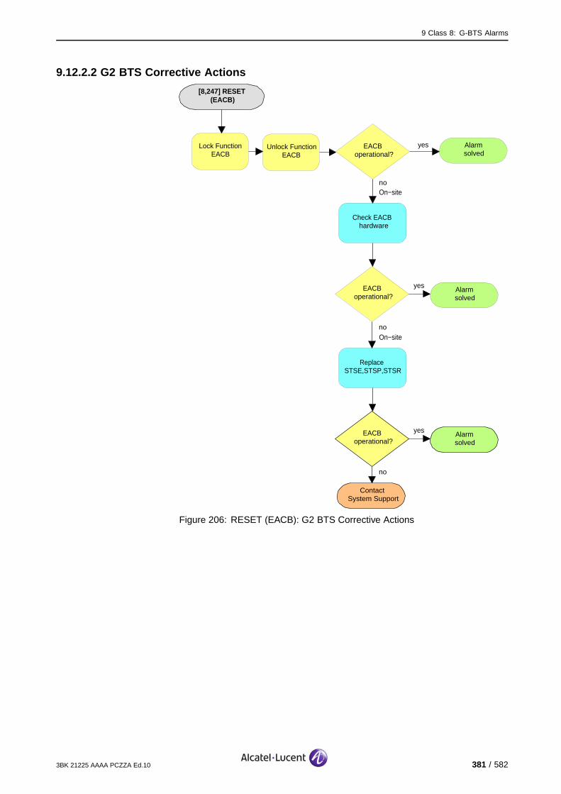
9 Class 8: G-BTS Alarms
9.12.2.2 G2 BTS Corrective Actions
[8,247] RESET (EACB)
no
ContactSystem Support
EACBoperational?
yes Alarmsolved
Alarmsolved
yesEACBoperational?
no
Lock Function EACB
Unlock Function EACB
Replace STSE,STSP,STSR
On−siteno
EACBoperational?
yes Alarmsolved
Check EACB hardware
On−site
Figure 206: RESET (EACB): G2 BTS Corrective Actions
3BK 21225 AAAA PCZZA Ed.10 381 / 582

9 Class 8: G-BTS Alarms
9.13 [8,248] RESTART
specific Problems RESTART
event Type Equipment
probable Cause Software Error
perceived Severity Warning (MI)
Alarm Description The BTS restarts successfully.
After the previous call interrupt, the BTS is now in service.
Impact BSS Cell(s) Signaling Calls
Loss - - - X
Degradation - - - -
9.13.1 Corrective Actions
None required.
382 / 582 3BK 21225 AAAA PCZZA Ed.10
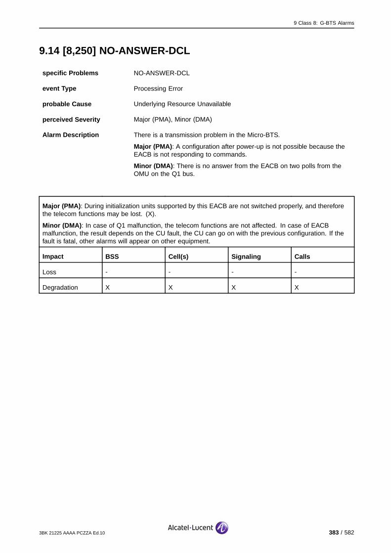
9 Class 8: G-BTS Alarms
9.14 [8,250] NO-ANSWER-DCL
specific Problems NO-ANSWER-DCL
event Type Processing Error
probable Cause Underlying Resource Unavailable
perceived Severity Major (PMA), Minor (DMA)
Alarm Description There is a transmission problem in the Micro-BTS.
Major (PMA): A configuration after power-up is not possible because theEACB is not responding to commands.
Minor (DMA): There is no answer from the EACB on two polls from theOMU on the Q1 bus.
Major (PMA): During initialization units supported by this EACB are not switched properly, and thereforethe telecom functions may be lost. (X).
Minor (DMA): In case of Q1 malfunction, the telecom functions are not affected. In case of EACBmalfunction, the result depends on the CU fault, the CU can go on with the previous configuration. If thefault is fatal, other alarms will appear on other equipment.
Impact BSS Cell(s) Signaling Calls
Loss - - - -
Degradation X X X X
3BK 21225 AAAA PCZZA Ed.10 383 / 582
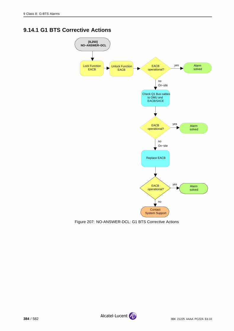
9 Class 8: G-BTS Alarms
9.14.1 G1 BTS Corrective Actions
[8,250]NO−ANSWER−DCL
no
ContactSystem Support
EACBoperational?
yesAlarmsolved
Alarmsolved
yesEACBoperational?
no
Lock Function EACB
Unlock Function EACB
Replace EACB
On−site
no
EACBoperational?
yesAlarmsolved
Check Q1 Bus cables to OMU and EACB/SACE
On−site
Figure 207: NO-ANSWER-DCL: G1 BTS Corrective Actions
384 / 582 3BK 21225 AAAA PCZZA Ed.10

9 Class 8: G-BTS Alarms
9.14.2 G2 BTS Corrective Actions
[8,250]NO−ANSWER−DCL
no
ContactSystem Support
EACBoperational?
yesAlarmsolved
Alarmsolved
yesEACBoperational?
no
Lock Function EACB
Unlock Function EACB
Replace SACE/SCFE
On−site
no
EACBoperational?
yesAlarmsolved
Check Q1 Bus cables to OMU and EACB/SACE
On−site
Figure 208: NO-ANSWER-DCL: G2 BTS Corrective Actions
3BK 21225 AAAA PCZZA Ed.10 385 / 582
9 Class 8: G-BTS Alarms
9.15 [8,251] SELF-TEST-AL
specific Problems SELF-TEST-AL
event Type Equipment
probable Cause Equipment Malfunction
perceived Severity Major (PMA)
Alarm Description This is a self-test alarm from the EACB after power-up, auto-reset, orreset command.
The units supported by this EACB are not switched properly, and therefore the telecom capabilities maybe lost.
Impact BSS Cell(s) Signaling Calls
Loss - - - X
Degradation X X X -
386 / 582 3BK 21225 AAAA PCZZA Ed.10
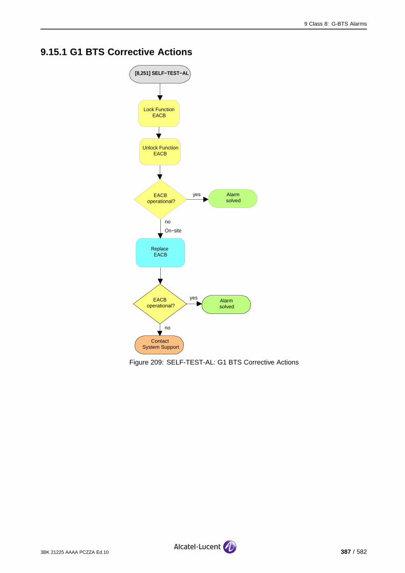
9 Class 8: G-BTS Alarms
9.15.1 G1 BTS Corrective Actions
[8,251] SELF−TEST−AL
no
ContactSystem Support
EACBoperational?
yes Alarmsolved
Alarmsolved
yesEACBoperational?
no
Lock Function EACB
Unlock Function EACB
Replace EACB
On−site
Figure 209: SELF-TEST-AL: G1 BTS Corrective Actions
3BK 21225 AAAA PCZZA Ed.10 387 / 582

9 Class 8: G-BTS Alarms
9.15.2 G2 BTS Corrective Actions
[8,251] SELF−TEST−AL
no
ContactSystem Support
EACBoperational?
yes Alarmsolved
Alarmsolved
yesEACBoperational?
no
Lock Function EACB
Unlock Function EACB
Replace SACE/SAFE
On−site
Figure 210: SELF-TEST-AL: G2 BTS Corrective Actions
388 / 582 3BK 21225 AAAA PCZZA Ed.10

9 Class 8: G-BTS Alarms
9.16 [8,255] Q1-RELAY-FAULT
specific Problems Q1-RELAY-FAULT
event Type Equipment
probable Cause Equipment Malfunction
perceived Severity Minor (DMA)
Alarm Description The EACB cannot disconnect from the Q1 interface due to relay problems.
Telecom functions are not affected.
Impact BSS Cell(s) Signaling Calls
Loss - - - -
Degradation - - - -
3BK 21225 AAAA PCZZA Ed.10 389 / 582
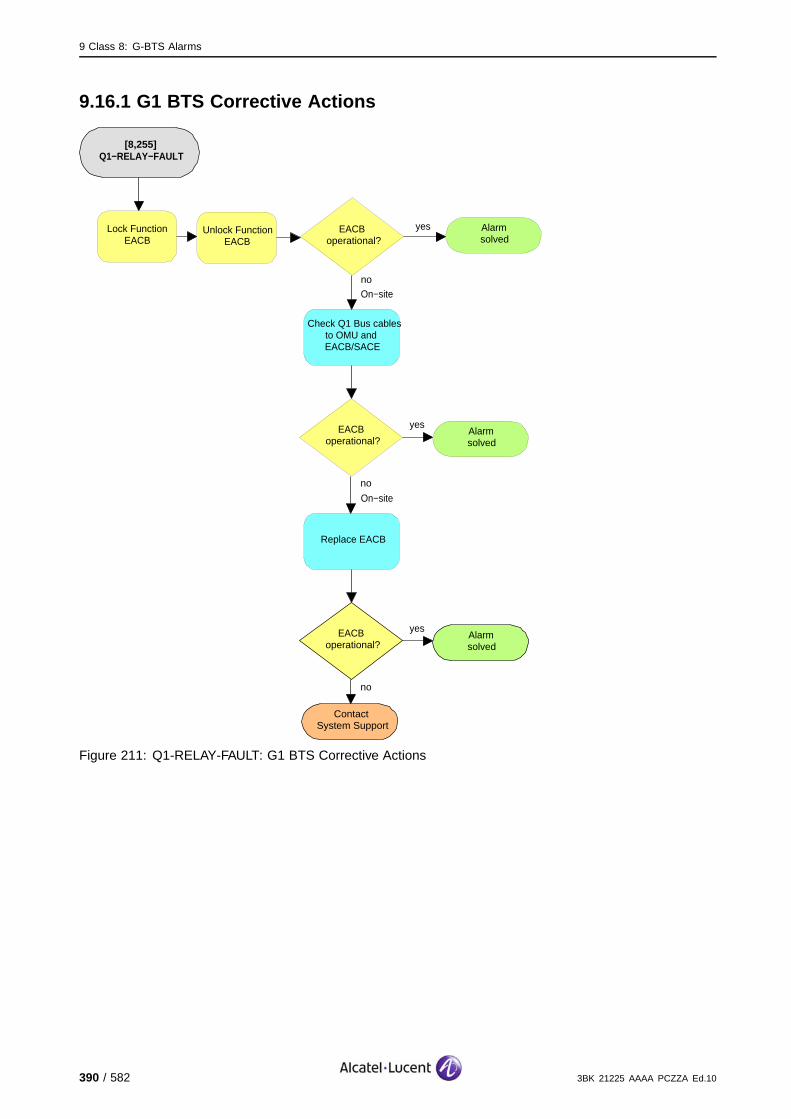
9 Class 8: G-BTS Alarms
9.16.1 G1 BTS Corrective Actions
[8,255]Q1−RELAY−FAULT
no
ContactSystem Support
EACBoperational?
yesAlarmsolved
Alarmsolved
yesEACBoperational?
no
Lock Function EACB
Unlock Function EACB
Replace EACB
On−site
no
EACBoperational?
yesAlarmsolved
Check Q1 Bus cables to OMU and EACB/SACE
On−site
Figure 211: Q1-RELAY-FAULT: G1 BTS Corrective Actions
390 / 582 3BK 21225 AAAA PCZZA Ed.10

9 Class 8: G-BTS Alarms
9.16.2 G2 BTS Corrective Actions
[8,255]Q1−RELAY−FAULT
no
ContactSystem Support
EACBoperational?
yesAlarmsolved
Alarmsolved
yesEACBoperational?
no
Lock Function EACB
Unlock Function EACB
Replace SACE/SCFE
On−site
no
EACBoperational?
yesAlarmsolved
Check Q1 Bus cables to OMU and EACB/SACE
On−site
Figure 212: Q1-RELAY-FAULT: G2 BTS Corrective Actions
3BK 21225 AAAA PCZZA Ed.10 391 / 582

9 Class 8: G-BTS Alarms
392 / 582 3BK 21225 AAAA PCZZA Ed.10

10 Class 9: BTS-EXTERNAL Alarms
10 Class 9: BTS-EXTERNAL Alarms
This section defines the alarms for the Class 9: BTS-EXTERNAL alarm class.
3BK 21225 AAAA PCZZA Ed.10 393 / 582

10 Class 9: BTS-EXTERNAL Alarms
10.1 [9,1...56] EXT-ALARM
specific Problems EXT-ALARM
event Type Equipment
probable Cause Indeterminate
perceived Severity Minor (DMA)
Alarm Description External Alarms are not linked to telecom part of the BTS, they are forseento announce events linked to the environment of the BTS.
G2 BTS: External alarm (e.g., door open, fire, water) detected from inputport [1 ... 24].
9100 BTS/9110 Micro BTS/9110-E Micro BTS : External alarm (e.g., dooropen, fire, water) detected from input port [1 ... 24].
External alarms [25 ... 56] can be raised only by the 9110 Micro BTS-E,and are applicable only in this case.
For Outdoor BTS, some of the 24 external alarms are allocated to thecabinet, they are already wired and reflect behaviour of other elements inthe BTS: AC main, Air Conditioning unit, door...
For 9100 Indoor BTS, the 24 external alarms are free (customer).
External alarms are seen only at the BTS and BSC terminals. At theOMC-R, they are translated into customer-defined ASCII text.
To simplify the external alarms declaration, default values are provided withan alarm translation table.
Telecom functions are not directly affected, if the detected problem is not disturbing the BTS function.
(#) VSWR and LNA alarms (if equipped), indicates a problem on the antenna output, and degradationmay occur.
Impact BSS Cell(s) Signaling Calls
Loss - - - -
Degradation - X# - X#
394 / 582 3BK 21225 AAAA PCZZA Ed.10
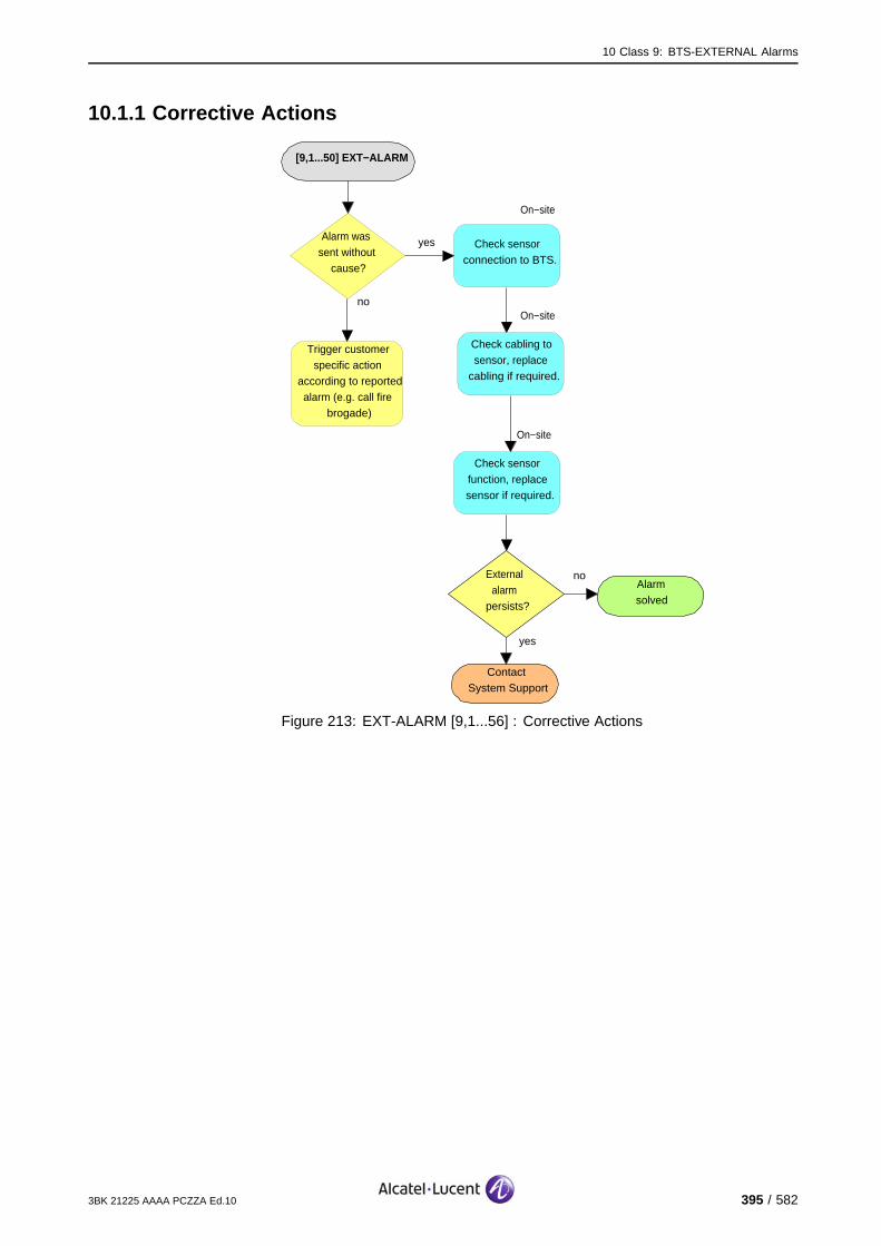
10 Class 9: BTS-EXTERNAL Alarms
10.1.1 Corrective Actions
[9,1...50] EXT−ALARM
no
ContactSystem Support
External alarm
persists?
yes
Alarmsolved
yesAlarm was sent without
cause?
no
Trigger customer specific action
according to reported alarm (e.g. call fire
brogade)
Check sensor function, replace sensor if required.
On−site
Check sensor connection to BTS.
On−site
Check cabling to sensor, replace
cabling if required.
On−site
Figure 213: EXT-ALARM [9,1...56] : Corrective Actions
3BK 21225 AAAA PCZZA Ed.10 395 / 582
10 Class 9: BTS-EXTERNAL Alarms
10.2 [9,1] EXT-ALARM (Default)
specific Problems EXT-ALARM
event Type Equipment
probable Cause Indeterminate
perceived Severity Critical (VPMA)
Alarm Description To simplify the external alarms declaration, default values are provided withan alarm translation table.
BTS G2/9100: There is a power supply rectifier failure.
Telecom functions are not directly affected, if the detected problem is not disturbing the BTS function.
Telecom functions are not directly affected, as long as the BTS is battery powered.
Impact BSS Cell(s) Signaling Calls
Loss - - - -
Degradation - - - -
396 / 582 3BK 21225 AAAA PCZZA Ed.10

10 Class 9: BTS-EXTERNAL Alarms
10.2.1 G2 BTS and 9100 BTS Corrective Actions
[9,1] EXT−ALARM
no
ContactSystem Support
External alarm
persists?
yes
Alarmsolved
yesAlarm was sent without
cause?
no
Trigger customer specific action
according to power supply rectifier alarm
Check sensor function, replace sensor if required.
On−site
Check sensor connection to BTS.
On−site
Check cabling to sensor, replace
cabling if required.
On−site
Figure 214: [9,1] EXT-ALARM: G2 BTS and 9100 BTS Default CorrectiveActions
3BK 21225 AAAA PCZZA Ed.10 397 / 582
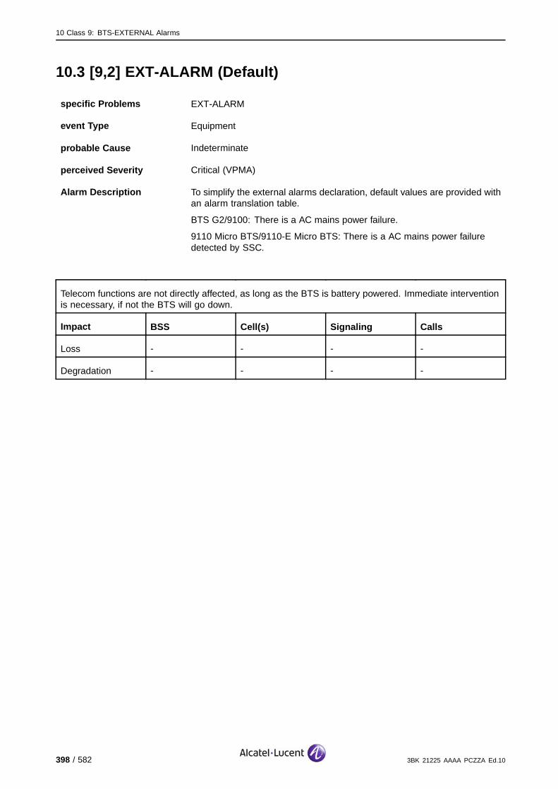
10 Class 9: BTS-EXTERNAL Alarms
10.3 [9,2] EXT-ALARM (Default)
specific Problems EXT-ALARM
event Type Equipment
probable Cause Indeterminate
perceived Severity Critical (VPMA)
Alarm Description To simplify the external alarms declaration, default values are provided withan alarm translation table.
BTS G2/9100: There is a AC mains power failure.
9110 Micro BTS/9110-E Micro BTS: There is a AC mains power failuredetected by SSC.
Telecom functions are not directly affected, as long as the BTS is battery powered. Immediate interventionis necessary, if not the BTS will go down.
Impact BSS Cell(s) Signaling Calls
Loss - - - -
Degradation - - - -
398 / 582 3BK 21225 AAAA PCZZA Ed.10
10 Class 9: BTS-EXTERNAL Alarms
10.3.1 Corrective Actions
[9,2] EXT−ALARM
no
ContactSystem Support
External alarm
persists?
yes
Alarmsolved
yesAlarm was sent without
cause?
no
Check sensor function, replace sensor if required.
On−site
Check sensor connection to BTS.
On−site
Check cabling to sensor, replace
cabling if required.
On−site
Check AC power supply fuses,
breakers, cabl%s, connectors
On−site
Ensure BTS AC power supply
On−site
no
ContactSystem Support
External alarm
persists?
yes
Alarmsolved
Figure 215: [9,2] EXT-ALARM: Default Corrective Actions
3BK 21225 AAAA PCZZA Ed.10 399 / 582

10 Class 9: BTS-EXTERNAL Alarms
10.4 [9,3] EXT-ALARM (Default)
specific Problems EXT-ALARM
event Type Equipment
probable Cause Indeterminate
perceived Severity Minor (DMA)
Alarm Description To simplify the external alarms declaration, default values are provided withan alarm translation table.
BTS G2/9100: This is a door/window alarm.
9110 Micro BTS/9110-E Micro BTS : This is a combined alarm for SSC,indicates problem/malfunction on one of the following SSC aspects:
Door contact
Power supplies
Battery charger
Inner fan alarm
Outer fan alarm
Temperature alarm
Battery back-up "OFF" alarm.
Telecom functions are not affected .
Impact BSS Cell(s) Signaling Calls
Loss - - - -
Degradation - - - -
400 / 582 3BK 21225 AAAA PCZZA Ed.10
10 Class 9: BTS-EXTERNAL Alarms
10.4.1 BTS G2 and 9100 Corrective Actions
[9,3] EXT−ALARM
no
ContactSystem Support
External alarm
persists?
yes
Alarmsolved
yesAlarm was sent without
cause?
no
Trigger customer specific action
according to reported alarm (e.g. call fire
brogade)
Check sensor function, replace sensor if required.
On−site
Check sensor connection to BTS.
On−site
Check cabling to sensor, replace
cabling if required.
On−site
Figure 216: [9,3] EXT-ALARM: BTS G2 and 9100 Default Corrective Actions
3BK 21225 AAAA PCZZA Ed.10 401 / 582
10 Class 9: BTS-EXTERNAL Alarms
10.4.2 9110 Micro BTS/9110-E Micro BTS Corrective Actions
[9,1] EXT−ALARM
no
ContactSystem Support
External alarm
persists?
yes
Alarmsolved
yesAlarm was sent without
cause?
no
Check sensor function, replace sensor if required.
On−site
Check sensor connection to BTS.
On−site
Check cabling to sensor, replace
cabling if required.
On−site
Check AC power supply fuses,
breakers, cabl%s, connectors
On−site
Ensure BTS AC power supply
On−site
Replace SSCPS
On−site
no
ContactSystem Support
External alarm
persists?
yes
Alarmsolved
Figure 217: [9,3] EXT-ALARM: 9110 Micro BTS/9110-E Micro BTS DefaultCorrective Actions
402 / 582 3BK 21225 AAAA PCZZA Ed.10
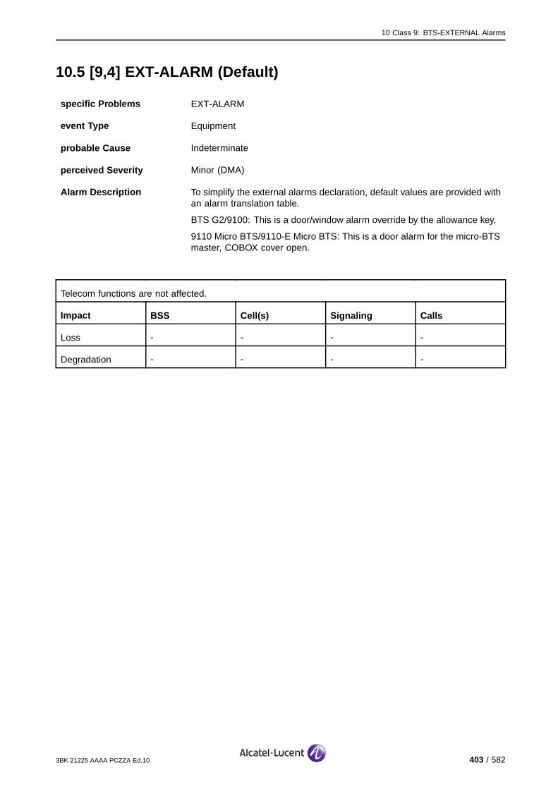
10 Class 9: BTS-EXTERNAL Alarms
10.5 [9,4] EXT-ALARM (Default)
specific Problems EXT-ALARM
event Type Equipment
probable Cause Indeterminate
perceived Severity Minor (DMA)
Alarm Description To simplify the external alarms declaration, default values are provided withan alarm translation table.
BTS G2/9100: This is a door/window alarm override by the allowance key.
9110 Micro BTS/9110-E Micro BTS: This is a door alarm for the micro-BTSmaster, COBOX cover open.
Telecom functions are not affected.
Impact BSS Cell(s) Signaling Calls
Loss - - - -
Degradation - - - -
3BK 21225 AAAA PCZZA Ed.10 403 / 582
10 Class 9: BTS-EXTERNAL Alarms
10.5.1 Corrective Actions
[9,4] EXT−ALARM
no
ContactSystem Support
External alarm
persists?
yes
Alarmsolved
yesAlarm was sent without
cause?
no
Trigger customer specific action
according to an open door or window alarm when allowance key is
used on−site.
Check sensor function, replace sensor if required.
On−site
Check sensor connection to BTS.
On−site
Check cabling to sensor, replace
cabling if required.
On−site
Figure 218: [9,4] EXT-ALARM: Default Corrective Actions
404 / 582 3BK 21225 AAAA PCZZA Ed.10
10 Class 9: BTS-EXTERNAL Alarms
10.6 [9,5] EXT-ALARM (Default)
specific Problems EXT-ALARM
event Type Equipment
probable Cause Indeterminate
perceived Severity Critical (VPMA)
Alarm Description To simplify the external alarms declaration, default values are provided withan alarm translation table.
BTS G2/9100: Fire alarm by detection of smoke detector inside the cabinet.
9110 Micro BTS/9110-E Micro BTS: This is a PMS alarm for the micro-BTSmaster, equipment not in vertical position.
Telecom functions are not directly affected.
Impact BSS Cell(s) Signaling Calls
Loss - - - -
Degradation - - - -
3BK 21225 AAAA PCZZA Ed.10 405 / 582
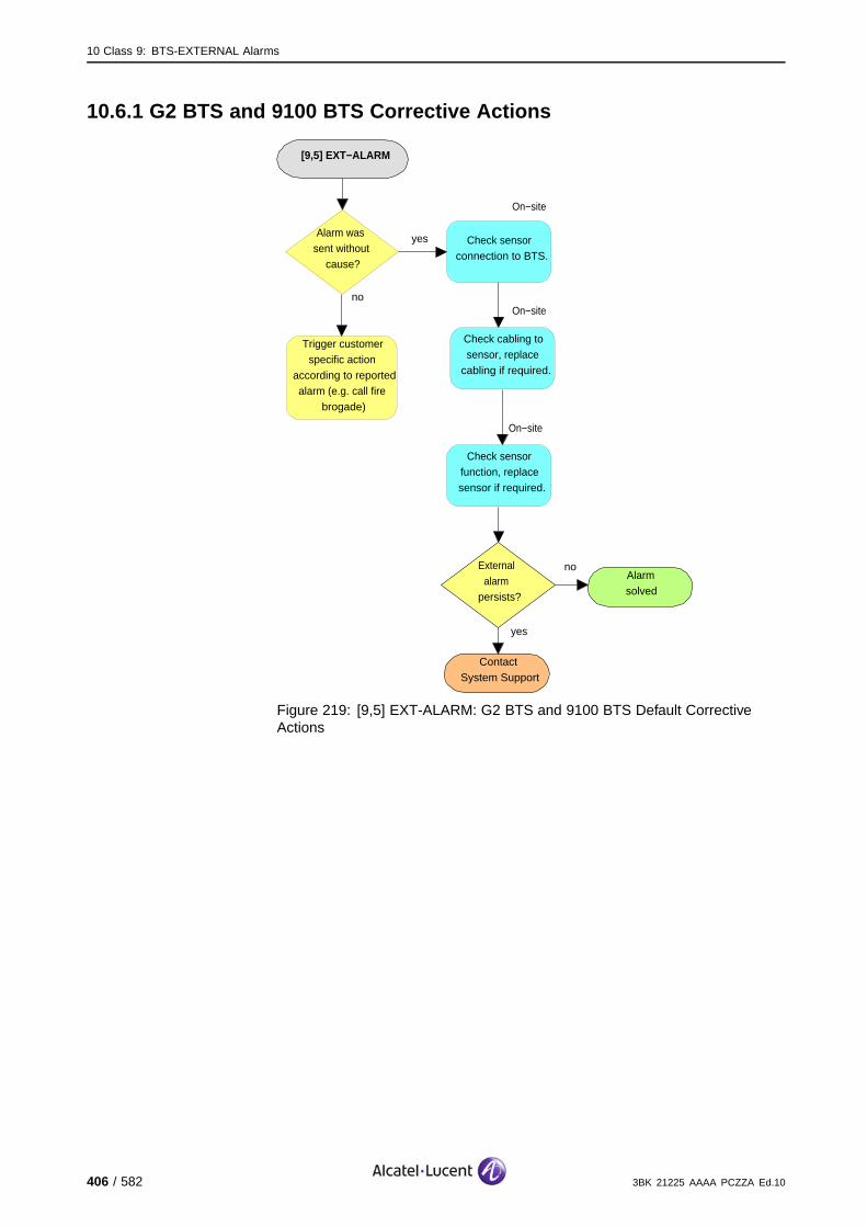
10 Class 9: BTS-EXTERNAL Alarms
10.6.1 G2 BTS and 9100 BTS Corrective Actions
[9,5] EXT−ALARM
no
ContactSystem Support
External alarm
persists?
yes
Alarmsolved
yesAlarm was sent without
cause?
no
Trigger customer specific action
according to reported alarm (e.g. call fire
brogade)
Check sensor function, replace sensor if required.
On−site
Check sensor connection to BTS.
On−site
Check cabling to sensor, replace
cabling if required.
On−site
Figure 219: [9,5] EXT-ALARM: G2 BTS and 9100 BTS Default CorrectiveActions
406 / 582 3BK 21225 AAAA PCZZA Ed.10

10 Class 9: BTS-EXTERNAL Alarms
10.7 [9,6] EXT-ALARM (Default)
specific Problems EXT-ALARM
event Type Equipment
probable Cause Indeterminate
perceived Severity Major (PMA)
Alarm Description To simplify the external alarms declaration, default values are provided withan alarm translation table.
BTS G2/9100: Water break-in by detection of water detection float switch.
Telecom functions are not directly affected.
Impact BSS Cell(s) Signaling Calls
Loss - - - -
Degradation - - - -
3BK 21225 AAAA PCZZA Ed.10 407 / 582
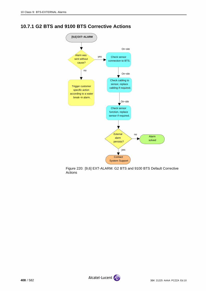
10 Class 9: BTS-EXTERNAL Alarms
10.7.1 G2 BTS and 9100 BTS Corrective Actions
[9,6] EXT−ALARM
no
ContactSystem Support
External alarm
persists?
yes
Alarmsolved
yesAlarm was sent without
cause?
no
Trigger customer specific action
according to a water break−in alarm.
Check sensor function, replace sensor if required.
On−site
Check sensor connection to BTS.
On−site
Check cabling to sensor, replace
cabling if required.
On−site
Figure 220: [9,6] EXT-ALARM: G2 BTS and 9100 BTS Default CorrectiveActions
408 / 582 3BK 21225 AAAA PCZZA Ed.10
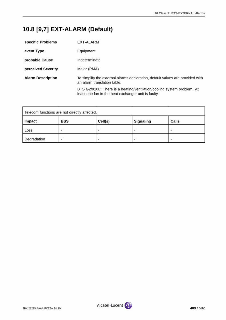
10 Class 9: BTS-EXTERNAL Alarms
10.8 [9,7] EXT-ALARM (Default)
specific Problems EXT-ALARM
event Type Equipment
probable Cause Indeterminate
perceived Severity Major (PMA)
Alarm Description To simplify the external alarms declaration, default values are provided withan alarm translation table.
BTS G2/9100: There is a heating/ventilation/cooling system problem. Atleast one fan in the heat exchanger unit is faulty.
Telecom functions are not directly affected.
Impact BSS Cell(s) Signaling Calls
Loss - - - -
Degradation - - - -
3BK 21225 AAAA PCZZA Ed.10 409 / 582

10 Class 9: BTS-EXTERNAL Alarms
10.8.1 G2 BTS and 9100 BTS Corrective Actions
[9,7] EXT−ALARM
no
ContactSystem Support
External alarm
persists?
yes
Alarmsolved
yesAlarm was sent without
cause?
no
Check sensor function, replace sensor if required.
On−site
Check sensor connection to BTS.
On−site
Check cabling to sensor, replace
cabling if required.
On−site
G2:Replace HEAT
On−site
no
ContactSystem Support
External alarm
persists?
yes
Alarmsolved
A9100:Replace HEAT2
On−site
OR
Figure 221: [9,7] EXT-ALARM: G2 BTS and 9100 BTS Default Corrective Actions
410 / 582 3BK 21225 AAAA PCZZA Ed.10

10 Class 9: BTS-EXTERNAL Alarms
10.9 [9,8] EXT-ALARM (Default)
specific Problems EXT-ALARM
event Type Equipment
probable Cause Indeterminate
perceived Severity Minor (DMA)
Alarm Description To simplify the external alarms declaration, default values are provided withan alarm translation table.
BTS G2/9100: The temperature in the equipment rack reached 35 0C.
Telecom functions are not directly affected.
Impact BSS Cell(s) Signaling Calls
Loss - - - -
Degradation - - - -
3BK 21225 AAAA PCZZA Ed.10 411 / 582
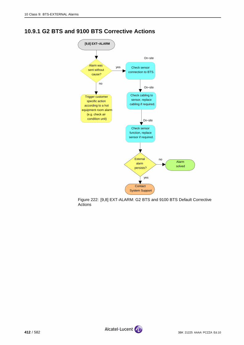
10 Class 9: BTS-EXTERNAL Alarms
10.9.1 G2 BTS and 9100 BTS Corrective Actions
[9,8] EXT−ALARM
no
ContactSystem Support
External alarm
persists?
yes
Alarmsolved
yesAlarm was sent without
cause?
no
Trigger customer specific action
according to a hot equipment room alarm
(e.g. check air condition unit)
Check sensor function, replace sensor if required.
On−site
Check sensor connection to BTS.
On−site
Check cabling to sensor, replace
cabling if required.
On−site
Figure 222: [9,8] EXT-ALARM: G2 BTS and 9100 BTS Default CorrectiveActions
412 / 582 3BK 21225 AAAA PCZZA Ed.10

10 Class 9: BTS-EXTERNAL Alarms
10.10 [9,9] EXT-ALARM (Default)
specific Problems EXT-ALARM
event Type Equipment
probable Cause Indeterminate
perceived Severity Minor (DMA)
Alarm Description To simplify the external alarms declaration, default values are provided withan alarm translation table.
BTS G2/9100: The temperature in the equipment room reached 40 0C.
Telecom functions are not directly affected.
Impact BSS Cell(s) Signaling Calls
Loss - - - -
Degradation - - - -
3BK 21225 AAAA PCZZA Ed.10 413 / 582

10 Class 9: BTS-EXTERNAL Alarms
10.10.1 Corrective Actions
[9,9] EXT−ALARM
no
ContactSystem Support
External alarm
persists?
yes
Alarmsolved
yesAlarm was sent without
cause?
no
Trigger customer specific action
according to a hot equipment room alarm
(e.g. check air condition unit)
Check sensor function, replace sensor if required.
On−site
Check sensor connection to BTS.
On−site
Check cabling to sensor, replace
cabling if required.
On−site
Figure 223: [9,9] EXT-ALARM: Default Corrective Actions
414 / 582 3BK 21225 AAAA PCZZA Ed.10

10 Class 9: BTS-EXTERNAL Alarms
10.11 [9,10] EXT-ALARM (Default)
specific Problems EXT-ALARM
event Type Equipment
probable Cause Indeterminate
perceived Severity Minor (DMA)
Alarm Description To simplify the external alarms declaration, default values are provided withan alarm translation table.
BTS G2/9100: The antenna mast warning light is faulty.
Telecom functions are not directly affected.
Impact BSS Cell(s) Signaling Calls
Loss - - - -
Degradation - - - -
3BK 21225 AAAA PCZZA Ed.10 415 / 582

10 Class 9: BTS-EXTERNAL Alarms
10.11.1 Corrective Actions
[9,10] EXT−ALARM
no
ContactSystem Support
External alarm
persists?
yes
Alarmsolved
yesAlarm was sent without
cause?
no
Check sensor function, replace sensor if required.
On−site
Check sensor connection to BTS.
On−site
Check cabling to sensor, replace
cabling if required.
On−site
Replace antenna mast warning light
On−site
no
ContactSystem Support
External alarm
persists?
yes
Alarmsolved
Figure 224: [9,10] EXT-ALARM: Default Corrective Actions
416 / 582 3BK 21225 AAAA PCZZA Ed.10

10 Class 9: BTS-EXTERNAL Alarms
10.12 [9,11] EXT-ALARM (Default)
specific Problems EXT-ALARM
event Type Equipment
probable Cause Indeterminate
perceived Severity Major (PMA)
Alarm Description To simplify the external alarms declaration, default values are provided withan alarm translation table.
BTS G2/9100 Indoor: The external battery (if equipped) is deep dischargedwhile supplying the BTS. The BTS will be switched off after 30 - 60 s.
Telecom functions are not directly affected, as long as the BTS is battery powered, but the BTS will beswitched off after 30 - 60 s.
Impact BSS Cell(s) Signaling Calls
Loss - - - -
Degradation - - - -
3BK 21225 AAAA PCZZA Ed.10 417 / 582

10 Class 9: BTS-EXTERNAL Alarms
10.12.1 G2 BTS and 9100 Corrective Actions
[9,11] EXT−ALARM
no
ContactSystem Support
External alarm
persists?
yes
Alarmsolved
yesAlarm was sent without
cause?
no
Check sensor function, replace sensor if required.
On−site
Check sensor connection to BTS.
On−site
Check cabling to sensor, replace
cabling if required.
On−site
no
ContactSystem Support
External alarm
persists?
yes
Alarmsolved
Powersupply alarm
events?
no
yes Solve power supply alarm first
Ensure BTS AC power supply
On−site
Check battery
On−site
G2: Replace BBU2
On−site
G2: Replace BU60
On−site
A9100:Replace BU41
On−site
A9100:Replace BU100
On−site
OR OR OR A9100:Replace BATS
On−site
ORA9100:
Replace BU101
On−site
OR
Figure 225: [9,11] EXT-ALARM: Default Corrective Actions
418 / 582 3BK 21225 AAAA PCZZA Ed.10
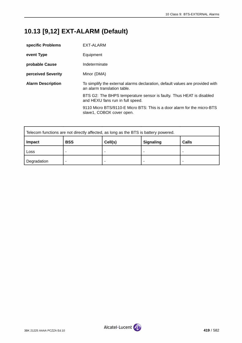
10 Class 9: BTS-EXTERNAL Alarms
10.13 [9,12] EXT-ALARM (Default)
specific Problems EXT-ALARM
event Type Equipment
probable Cause Indeterminate
perceived Severity Minor (DMA)
Alarm Description To simplify the external alarms declaration, default values are provided withan alarm translation table.
BTS G2: The BHPS temperature sensor is faulty. Thus HEAT is disabledand HEXU fans run in full speed.
9110 Micro BTS/9110-E Micro BTS: This is a door alarm for the micro-BTSslave1, COBOX cover open.
Telecom functions are not directly affected, as long as the BTS is battery powered.
Impact BSS Cell(s) Signaling Calls
Loss - - - -
Degradation - - - -
3BK 21225 AAAA PCZZA Ed.10 419 / 582

10 Class 9: BTS-EXTERNAL Alarms
10.13.1 G2 BTS Corrective Actions
[9,12] EXT−ALARM
no
ContactSystem Support
External alarm
persists?
yes
Alarmsolved
Check sensor function, replace sensor if required.
On−site
Check BHPS sensor connection.
On−site
Check cabling to sensor, replace
cabling if required.
On−site
Figure 226: [9,12] EXT-ALARM: G2 BTS Default Corrective Actions
420 / 582 3BK 21225 AAAA PCZZA Ed.10
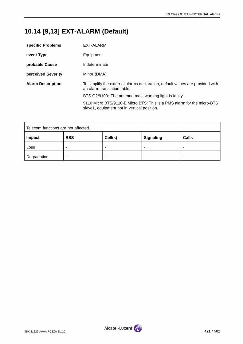
10 Class 9: BTS-EXTERNAL Alarms
10.14 [9,13] EXT-ALARM (Default)
specific Problems EXT-ALARM
event Type Equipment
probable Cause Indeterminate
perceived Severity Minor (DMA)
Alarm Description To simplify the external alarms declaration, default values are provided withan alarm translation table.
BTS G2/9100: The antenna mast warning light is faulty.
9110 Micro BTS/9110-E Micro BTS: This is a PMS alarm for the micro-BTSslave1, equipment not in vertical position.
Telecom functions are not affected.
Impact BSS Cell(s) Signaling Calls
Loss - - - -
Degradation - - - -
3BK 21225 AAAA PCZZA Ed.10 421 / 582
10 Class 9: BTS-EXTERNAL Alarms
10.14.1 BTS G2 and 9100 Corrective Actions
[9,13] EXT−ALARM
no
ContactSystem Support
External alarm
persists?
yes
Alarmsolved
yesAlarm was sent without
cause?
no
Check sensor function, replace sensor if required.
On−site
Check sensor connection to BTS.
On−site
Check cabling to sensor, replace
cabling if required.
On−site
Replace antenna mast warning light
On−site
no
ContactSystem Support
External alarm
persists?
yes
Alarmsolved
Figure 227: [9,13] EXT-ALARM: BTS G2 and 9100 Default Corrective Actions
422 / 582 3BK 21225 AAAA PCZZA Ed.10

10 Class 9: BTS-EXTERNAL Alarms
10.15 [9,14] EXT-ALARM (Default)
specific Problems EXT-ALARM
event Type Equipment
probable Cause Indeterminate
perceived Severity Minor (DMA)
Alarm Description To simplify the external alarms declaration, default values are provided withan alarm translation table.
BTS G2/9100: The antenna mast warning light is faulty.
Telecom functions are not affected.
Impact BSS Cell(s) Signaling Calls
Loss - - - -
Degradation - - - -
3BK 21225 AAAA PCZZA Ed.10 423 / 582

10 Class 9: BTS-EXTERNAL Alarms
10.15.1 G2 BTS and 9100 BTS Corrective Actions
[9,14] EXT−ALARM
no
ContactSystem Support
External alarm
persists?
yes
Alarmsolved
yesAlarm was sent without
cause?
no
Check sensor function, replace sensor if required.
On−site
Check sensor connection to BTS.
On−site
Check cabling to sensor, replace
cabling if required.
On−site
Replace antenna mast warning light
On−site
no
ContactSystem Support
External alarm
persists?
yes
Alarmsolved
Figure 228: [9,14] EXT-ALARM: G2 BTS and 9100 BTS Default CorrectiveActions
424 / 582 3BK 21225 AAAA PCZZA Ed.10
10 Class 9: BTS-EXTERNAL Alarms
10.16 [9,15] EXT-ALARM (Default)
specific Problems EXT-ALARM
event Type Equipment
probable Cause Indeterminate
perceived Severity Minor (DMA)
Alarm Description To simplify the external alarms declaration, default values are provided withan alarm translation table.
BTS G2/9100: This is a door alarm.
Telecom functions are not affected.
Impact BSS Cell(s) Signaling Calls
Loss - - - -
Degradation - - - -
3BK 21225 AAAA PCZZA Ed.10 425 / 582

10 Class 9: BTS-EXTERNAL Alarms
10.16.1 G2 BTS and 9100 BTS Corrective Actions
[9,15] EXT−ALARM
no
ContactSystem Support
External alarm
persists?
yes
Alarmsolved
yesAlarm was sent without
cause?
no
Trigger customer specific action according to
open door alarm
Check sensor function, replace sensor if required.
On−site
Check sensor connection to BTS.
On−site
Check cabling to sensor, replace
cabling if required.
On−site
Figure 229: [9,15] EXT-ALARM: G2 BTS and 9100 BTS Default CorrectiveActions
426 / 582 3BK 21225 AAAA PCZZA Ed.10

10 Class 9: BTS-EXTERNAL Alarms
10.17 [9,16] EXT-ALARM (Default)
specific Problems EXT-ALARM
event Type Equipment
probable Cause Indeterminate
perceived Severity Critical (VPMA)
Alarm Description To simplify the external alarms declaration, default values are provided withan alarm translation table.
BTS G2/9100: This is a power supply inverter alarm.
Telecom functions are not affected.
Impact BSS Cell(s) Signaling Calls
Loss - - - -
Degradation - - - -
3BK 21225 AAAA PCZZA Ed.10 427 / 582

10 Class 9: BTS-EXTERNAL Alarms
10.17.1 G2 BTS and 9100 BTS Corrective Actions
[9,16] EXT−ALARM
no
ContactSystem Support
External alarm
persists?
yes
Alarmsolved
yesAlarm was sent without
cause?
no
Trigger customer specific action
according to power supply inverter alarm
Check sensor function, replace sensor if required.
On−site
Check sensor connection to BTS.
On−site
Check cabling to sensor, replace
cabling if required.
On−site
Figure 230: [9,16] EXT-ALARM: G2 BTS and 9100 BTS Default CorrectiveActions
428 / 582 3BK 21225 AAAA PCZZA Ed.10

10 Class 9: BTS-EXTERNAL Alarms
10.18 [9,17] EXT-ALARM (Default)
specific Problems EXT-ALARM
event Type Equipment
probable Cause Indeterminate
perceived Severity Minor (DMA)
Alarm Description To simplify the external alarms declaration, default values are provided withan alarm translation table.
9100 BTS: This is a fatal REK alarm on TRX1, MAB detects a VSWRproblem.
(#) VSWR alarm indicates a problem on the antenna output, and degradation may occur.
Impact BSS Cell(s) Signaling Calls
Loss - - - -
Degradation - X# - X#
3BK 21225 AAAA PCZZA Ed.10 429 / 582

10 Class 9: BTS-EXTERNAL Alarms
10.18.1 Corrective Actions
[9,17] EXT−ALARM
no
ContactSystem Support
External alarm
persists?
yes
Alarmsolved
yesAlarm was sent without
cause?
no
Check sensor function, replace sensor if required.
On−site
Check sensor connection to BTS.
On−site
Check cabling to sensor, replace
cabling if required.
On−site
Check TRX to antenna cables
visually and electrically
On−site
Check antenna
On−site
Replace MAB of TRX1
On−site
no
ContactSystem Support
External alarm
persists?
yes
Alarmsolved
Figure 231: [9,17] EXT-ALARM: Default Corrective Actions
430 / 582 3BK 21225 AAAA PCZZA Ed.10

10 Class 9: BTS-EXTERNAL Alarms
10.19 [9,18] EXT-ALARM (Default)
specific Problems EXT-ALARM
event Type Equipment
probable Cause Indeterminate
perceived Severity Minor (DMA)
Alarm Description To simplify the external alarms declaration, default values are provided withan alarm translation table.
9100 BTS: This is a fatal REK alarm on TRX2, MAB detects a VSWRproblem.
(#) VSWR alarm indicates a problem on the antenna output, and degradation may occur.
Impact BSS Cell(s) Signaling Calls
Loss - - - -
Degradation - X# - X#
3BK 21225 AAAA PCZZA Ed.10 431 / 582
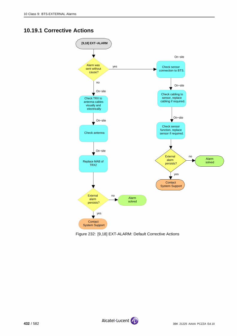
10 Class 9: BTS-EXTERNAL Alarms
10.19.1 Corrective Actions
[9,18] EXT−ALARM
no
ContactSystem Support
External alarm
persists?
yes
Alarmsolved
yesAlarm was sent without
cause?
no
Check sensor function, replace sensor if required.
On−site
Check sensor connection to BTS.
On−site
Check cabling to sensor, replace
cabling if required.
On−site
Check TRX to antenna cables
visually and electrically
On−site
Check antenna
On−site
Replace MAB of TRX2
On−site
no
ContactSystem Support
External alarm
persists?
yes
Alarmsolved
Figure 232: [9,18] EXT-ALARM: Default Corrective Actions
432 / 582 3BK 21225 AAAA PCZZA Ed.10

10 Class 9: BTS-EXTERNAL Alarms
10.20 [9,19] EXT-ALARM (Default)
specific Problems EXT-ALARM
event Type Equipment
probable Cause Indeterminate
perceived Severity Minor (DMA)
Alarm Description To simplify the external alarms declaration, default values are provided withan alarm translation table.
9100 BTS: This is a fatal REK alarm (if installed) on TRX3, MAB detects aVSWR problem.
(#) VSWR alarm indicates a problem on the antenna output, and degradation may occur.
Impact BSS Cell(s) Signaling Calls
Loss - - - -
Degradation - X# - X#
3BK 21225 AAAA PCZZA Ed.10 433 / 582

10 Class 9: BTS-EXTERNAL Alarms
10.20.1 Corrective Actions
[9,19] EXT−ALARM
no
ContactSystem Support
External alarm
persists?
yes
Alarmsolved
yesAlarm was sent without
cause?
no
Check sensor function, replace sensor if required.
On−site
Check sensor connection to BTS.
On−site
Check cabling to sensor, replace
cabling if required.
On−site
Check TRX to antenna cables
visually and electrically
On−site
Check antenna
On−site
Replace MAB of TRX3
On−site
no
ContactSystem Support
External alarm
persists?
yes
Alarmsolved
Figure 233: [9,19] EXT-ALARM: Default Corrective Actions
434 / 582 3BK 21225 AAAA PCZZA Ed.10

10 Class 9: BTS-EXTERNAL Alarms
10.21 [9,20] EXT-ALARM (Default)
specific Problems EXT-ALARM
event Type Equipment
probable Cause Indeterminate
perceived Severity Minor (DMA)
Alarm Description To simplify the external alarms declaration, default values are provided withan alarm translation table.
9100 BTS: This is a fatal REK alarm (if installed) on TRX4, MAB detects aVSWR problem.
9110 Micro BTS/9110-E Micro BTS: This is a door alarm for the micro-BTSslave 2, COBOX cover open.
(#) VSWR alarm indicates a problem on the antenna output, and degradation may occur.
Impact BSS Cell(s) Signaling Calls
Loss - - - -
Degradation - X# - X#
3BK 21225 AAAA PCZZA Ed.10 435 / 582

10 Class 9: BTS-EXTERNAL Alarms
10.21.1 9100 BTS Corrective Actions
[9,20] EXT−ALARM
no
ContactSystem Support
External alarm
persists?
yes
Alarmsolved
yesAlarm was sent without
cause?
no
Check sensor function, replace sensor if required.
On−site
Check sensor connection to BTS.
On−site
Check cabling to sensor, replace
cabling if required.
On−site
Check TRX to antenna cables
visually and electrically
On−site
Check antenna
On−site
Replace MAB of TRX4
On−site
no
ContactSystem Support
External alarm
persists?
yes
Alarmsolved
Figure 234: [9,20] EXT-ALARM: 9100 BTS Default Corrective Actions
436 / 582 3BK 21225 AAAA PCZZA Ed.10

10 Class 9: BTS-EXTERNAL Alarms
10.22 [9,21] EXT-ALARM (Default)
specific Problems EXT-ALARM
event Type Equipment
probable Cause Indeterminate
perceived Severity Minor (DMA)
Alarm Description To simplify the external alarms declaration, default values are provided withan alarm translation table.
9100 BTS: This is a fatal REK alarm (if installed) on TRX5, MAB detects aVSWR problem.
9110 Micro BTS/9110-E Micro BTS: This is a PMS alarm for the micro-BTSslave2, equipment not in vertical position.
(#) VSWR alarm indicates a problem on the antenna output, and degradation may occur.
Impact BSS Cell(s) Signaling Calls
Loss - - - -
Degradation - X# - X#
3BK 21225 AAAA PCZZA Ed.10 437 / 582

10 Class 9: BTS-EXTERNAL Alarms
10.22.1 9100 BTS Corrective Actions
[9,21] EXT−ALARM
no
ContactSystem Support
External alarm
persists?
yes
Alarmsolved
yesAlarm was sent without
cause?
no
Check sensor function, replace sensor if required.
On−site
Check sensor connection to BTS.
On−site
Check cabling to sensor, replace
cabling if required.
On−site
Check TRX to antenna cables
visually and electrically
On−site
Check antenna
On−site
Replace MAB of TRX5
On−site
no
ContactSystem Support
External alarm
persists?
yes
Alarmsolved
Figure 235: [9,21] EXT-ALARM: 9100 BTS Default Corrective Actions
438 / 582 3BK 21225 AAAA PCZZA Ed.10

10 Class 9: BTS-EXTERNAL Alarms
10.23 [9,22] EXT-ALARM (Default)
specific Problems EXT-ALARM
event Type Equipment
probable Cause Indeterminate
perceived Severity Minor (DMA)
Alarm Description To simplify the external alarms declaration, default values are provided withan alarm translation table.
9100 BTS: This is a fatal REK alarm (if installed) on TRX6, MAB detects aVSWR problem.
(#) VSWR alarm indicates a problem on the antenna output, and degradation may occur.
Impact BSS Cell(s) Signaling Calls
Loss - - - -
Degradation - X# - X#
3BK 21225 AAAA PCZZA Ed.10 439 / 582

10 Class 9: BTS-EXTERNAL Alarms
10.23.1 Corrective Actions
[9,22] EXT−ALARM
no
ContactSystem Support
External alarm
persists?
yes
Alarmsolved
yesAlarm was sent without
cause?
no
Check sensor function, replace sensor if required.
On−site
Check sensor connection to BTS.
On−site
Check cabling to sensor, replace
cabling if required.
On−site
Check TRX to antenna cables
visually and electrically
On−site
Check antenna
On−site
Replace MAB of TRX6
On−site
no
ContactSystem Support
External alarm
persists?
yes
Alarmsolved
Figure 236: [9,22] EXT-ALARM: Default Corrective Actions
440 / 582 3BK 21225 AAAA PCZZA Ed.10
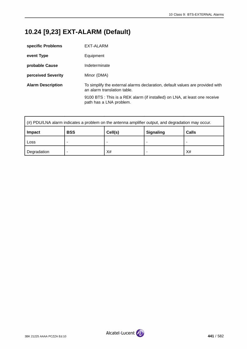
10 Class 9: BTS-EXTERNAL Alarms
10.24 [9,23] EXT-ALARM (Default)
specific Problems EXT-ALARM
event Type Equipment
probable Cause Indeterminate
perceived Severity Minor (DMA)
Alarm Description To simplify the external alarms declaration, default values are provided withan alarm translation table.
9100 BTS : This is a REK alarm (if installed) on LNA, at least one receivepath has a LNA problem.
(#) PDU/LNA alarm indicates a problem on the antenna amplifier output, and degradation may occur.
Impact BSS Cell(s) Signaling Calls
Loss - - - -
Degradation - X# - X#
3BK 21225 AAAA PCZZA Ed.10 441 / 582
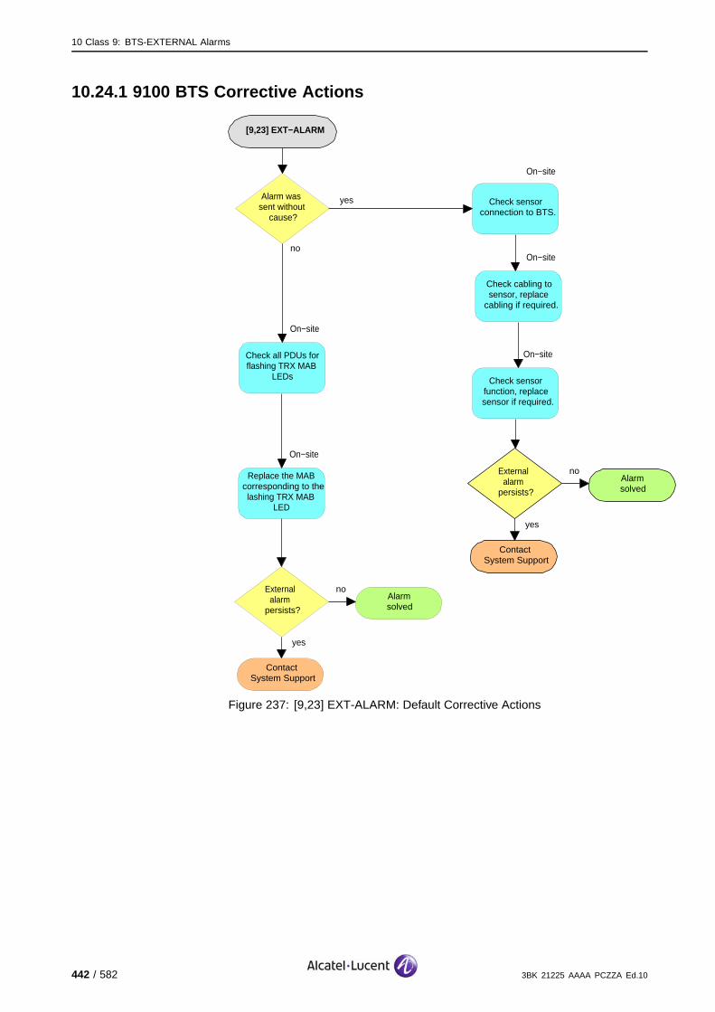
10 Class 9: BTS-EXTERNAL Alarms
10.24.1 9100 BTS Corrective Actions
[9,23] EXT−ALARM
no
ContactSystem Support
External alarm
persists?
yes
Alarmsolved
yesAlarm was sent without
cause?
no
Check sensor function, replace sensor if required.
On−site
Check sensor connection to BTS.
On−site
Check cabling to sensor, replace
cabling if required.
On−site
Check all PDUs for flashing TRX MAB
LEDs
On−site
Replace the MAB corresponding to the lashing TRX MAB
LED
On−site
no
ContactSystem Support
External alarm
persists?
yes
Alarmsolved
Figure 237: [9,23] EXT-ALARM: Default Corrective Actions
442 / 582 3BK 21225 AAAA PCZZA Ed.10
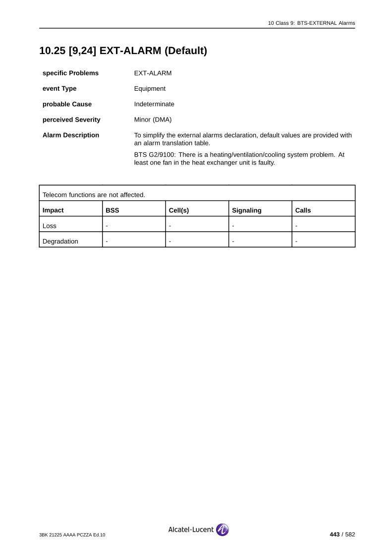
10 Class 9: BTS-EXTERNAL Alarms
10.25 [9,24] EXT-ALARM (Default)
specific Problems EXT-ALARM
event Type Equipment
probable Cause Indeterminate
perceived Severity Minor (DMA)
Alarm Description To simplify the external alarms declaration, default values are provided withan alarm translation table.
BTS G2/9100: There is a heating/ventilation/cooling system problem. Atleast one fan in the heat exchanger unit is faulty.
Telecom functions are not affected.
Impact BSS Cell(s) Signaling Calls
Loss - - - -
Degradation - - - -
3BK 21225 AAAA PCZZA Ed.10 443 / 582
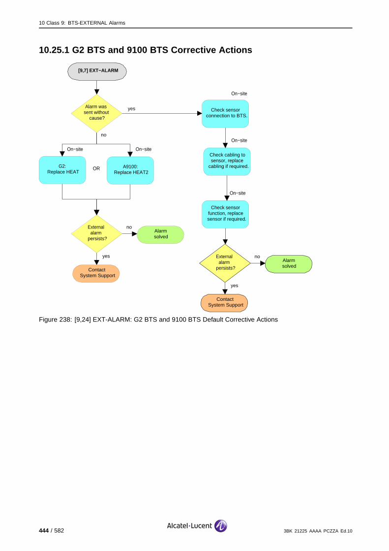
10 Class 9: BTS-EXTERNAL Alarms
10.25.1 G2 BTS and 9100 BTS Corrective Actions
[9,7] EXT−ALARM
no
ContactSystem Support
External alarm
persists?
yes
Alarmsolved
yesAlarm was sent without
cause?
no
Check sensor function, replace sensor if required.
On−site
Check sensor connection to BTS.
On−site
Check cabling to sensor, replace
cabling if required.
On−site
G2:Replace HEAT
On−site
no
ContactSystem Support
External alarm
persists?
yes
Alarmsolved
A9100:Replace HEAT2
On−site
OR
Figure 238: [9,24] EXT-ALARM: G2 BTS and 9100 BTS Default Corrective Actions
444 / 582 3BK 21225 AAAA PCZZA Ed.10

10 Class 9: BTS-EXTERNAL Alarms
10.26 [9,25] EXT-ALARM for 9110-E Micro BTS (Default)
Specific Problems EXT-ALARM
Event Type Equipment
Probable Cause Indeterminate
Minor (DMA) - in commercial use; complete Begin/End alert sequence..
Indeterminate - event, without End alert..
Perceived Severity
Warning - out of commercial use; complete Begin/End alert sequence..
Alarm Description 9110 Micro BTS-E: Available and not used.
10.27 [9,26] EXT-ALARM for 9110-E Micro BTS (Default)
Specific Problems EXT-ALARM
Event Type Equipment
Probable Cause Indeterminate
Minor (DMA) - in commercial use; complete Begin/End alert sequence..
Indeterminate - event, without End alert..
Perceived Severity
Warning - out of commercial use; complete Begin/End alert sequence..
Alarm Description 9110 Micro BTS-E: Available and not used.
3BK 21225 AAAA PCZZA Ed.10 445 / 582

10 Class 9: BTS-EXTERNAL Alarms
10.28 [9,27] EXT-ALARM for 9110-E Micro BTS (Default)
Specific Problems EXT-ALARM
Event Type Equipment
Probable Cause Indeterminate
Minor (DMA) - in commercial use; complete Begin/End alert sequence..
Indeterminate - event, without End alert.
Perceived Severity
Warning - out of commercial use; complete Begin/End alert sequence..
Alarm Description 9110 Micro BTS-E: Available and not used.
10.29 [9,28] EXT-ALARM for 9110-E Micro BTS (Default)
Specific Problems EXT-ALARM
Event Type Equipment
Probable Cause Indeterminate
Minor (DMA) - in commercial use; complete Begin/End alert sequence.
Indeterminate - event, without End alert.
Perceived Severity
Warning - out of commercial use; complete Begin/End alert sequence.
Alarm Description To simplify the external alarms declaration, default values are provided withan alarm translation table.
9110 Micro BTS-E: This is a door alarm for the micro-BTS slave 11,COBOX cover open.
446 / 582 3BK 21225 AAAA PCZZA Ed.10
10 Class 9: BTS-EXTERNAL Alarms
10.30 [9,29] EXT-ALARM for 9110-E Micro BTS (Default)
Specific Problems EXT-ALARM
Event Type Equipment
Probable Cause Indeterminate
Minor (DMA) - in commercial use; complete Begin/End alert sequence..
Indeterminate - event, without End alert..
Perceived Severity
Warning - out of commercial use; complete Begin/End alert sequence..
Alarm Description To simplify the external alarms declaration, default values are provided withan alarm translation table.
9110-E Micro BTS: This is a PMS alarm for the micro-BTS slave11,equipment not in vertical position.
10.31 [9,30] EXT-ALARM for 9110-E Micro BTS (Default)
Specific Problems EXT-ALARM
Event Type Equipment
Probable Cause Indeterminate
Minor (DMA) - in commercial use; complete Begin/End alert sequence..
Indeterminate - event, without End alert..
Perceived Severity
Warning - out of commercial use; complete Begin/End alert sequence..
Alarm Description 9110 Micro BTS-E: Available and not used.
3BK 21225 AAAA PCZZA Ed.10 447 / 582
10 Class 9: BTS-EXTERNAL Alarms
10.32 [9,31] EXT-ALARM for 9110-E Micro BTS (Default)
Specific Problems EXT-ALARM
Event Type Equipment
Probable Cause Indeterminate
Minor (DMA) - in commercial use; complete Begin/End alert sequence..
Indeterminate - event, without End alert..
Perceived Severity
Warning - out of commercial use; complete Begin/End alert sequence..
Alarm Description 9110 Micro BTS-E: Available and not used.
10.33 [9,32] EXT-ALARM for 9110-E Micro BTS (Default)
Specific Problems EXT-ALARM
Event Type Equipment
Probable Cause Indeterminate
Minor (DMA) - in commercial use; complete Begin/End alert sequence.
Indeterminate - event, without End alert.
Perceived Severity
Warning - out of commercial use; complete Begin/End alert sequence.
Alarm Description 9110 Micro BTS-E: Available and not used.
448 / 582 3BK 21225 AAAA PCZZA Ed.10

10 Class 9: BTS-EXTERNAL Alarms
10.34 [9,33] EXT-ALARM for 9110-E Micro BTS (Default)
Specific Problems EXT-ALARM
Event Type Equipment
Probable Cause Indeterminate
Minor (DMA) - in commercial use; complete Begin/End alert sequence..
Indeterminate - event, without End alert..
Perceived Severity
Warning - out of commercial use; complete Begin/End alert sequence..
Alarm Description 9110 Micro BTS-E: Available and not used.
10.35 [9,34] EXT-ALARM for 9110-E Micro BTS (Default)
Specific Problems EXT-ALARM
Event Type Equipment
Probable Cause Indeterminate
Minor (DMA) - in commercial use; complete Begin/End alert sequence..
Indeterminate - event, without End alert..
Perceived Severity
Warning - out of commercial use; complete Begin/End alert sequence..
Alarm Description 9110 Micro BTS-E: Available and not used.
3BK 21225 AAAA PCZZA Ed.10 449 / 582

10 Class 9: BTS-EXTERNAL Alarms
10.36 [9,35] EXT-ALARM for 9110-E Micro BTS (Default)
Specific Problems EXT-ALARM
Event Type Equipment
Probable Cause Indeterminate
Minor (DMA) - in commercial use; complete Begin/End alert sequence..
Indeterminate - event, without End alert..
Perceived Severity
Warning - out of commercial use; complete Begin/End alert sequence..
Alarm Description 9110 Micro BTS-E: Available and not used.
10.37 [9,36] EXT-ALARM for 9110-E Micro BTS (Default)
Specific Problems EXT-ALARM
Event Type Equipment
Probable Cause Indeterminate
Minor (DMA) - in commercial use; complete Begin/End alert sequence..
Indeterminate - event, without End alert..
Perceived Severity
Warning - out of commercial use; complete Begin/End alert sequence..
Alarm Description To simplify the external alarms declaration, default values are provided withan alarm translation table.
9110 Micro BTS-E: This is a door alarm for the micro-BTS slave 12,COBOX cover open.
450 / 582 3BK 21225 AAAA PCZZA Ed.10

10 Class 9: BTS-EXTERNAL Alarms
10.38 [9,37] EXT-ALARM for 9110-E Micro BTS (Default)
Specific Problems EXT-ALARM
Event Type Equipment
Probable Cause Indeterminate
Minor (DMA) - in commercial use; complete Begin/End alert sequence..
Indeterminate - event, without End alert..
Perceived Severity
Warning - out of commercial use; complete Begin/End alert sequence..
Alarm Description To simplify the external alarms declaration, default values are provided withan alarm translation table.
9110-E Micro BTS: This is a PMS alarm for the micro-BTS slave12,equipment not in vertical position.
10.39 [9,38] EXT-ALARM for 9110-E Micro BTS (Default)
Specific Problems EXT-ALARM
Event Type Equipment
Probable Cause Indeterminate
Minor (DMA) - in commercial use; complete Begin/End alert sequence..
Indeterminate - event, without End alert..
Perceived Severity
Warning - out of commercial use; complete Begin/End alert sequence..
Alarm Description 9110 Micro BTS-E: Available and not used.
3BK 21225 AAAA PCZZA Ed.10 451 / 582

10 Class 9: BTS-EXTERNAL Alarms
10.40 [9,39] EXT-ALARM for 9110-E Micro BTS (Default)
Specific Problems EXT-ALARM
Event Type Equipment
Probable Cause Indeterminate
Minor (DMA) - in commercial use; complete Begin/End alert sequence..
Indeterminate - event, without End alert..
Perceived Severity
Warning - out of commercial use; complete Begin/End alert sequence..
Alarm Description 9110 Micro BTS-E: Available and not used.
10.41 [9,40] EXT-ALARM for 9110-E Micro BTS (Default)
Specific Problems EXT-ALARM
Event Type Equipment
Probable Cause Indeterminate
Minor (DMA) - in commercial use; complete Begin/End alert sequence..
Indeterminate - event, without End alert..
Perceived Severity
Warning - out of commercial use; complete Begin/End alert sequence..
Alarm Description 9110 Micro BTS-E: Available and not used.
452 / 582 3BK 21225 AAAA PCZZA Ed.10

10 Class 9: BTS-EXTERNAL Alarms
10.42 [9,41] EXT-ALARM for 9110-E Micro BTS (Default)
Specific Problems EXT-ALARM
Event Type Equipment
Probable Cause Indeterminate
Minor (DMA) - in commercial use; complete Begin/End alert sequence..
Indeterminate - event, without End alert..
Perceived Severity
Warning - out of commercial use; complete Begin/End alert sequence..
Alarm Description 9110 Micro BTS-E: Available and not used.
10.43 [9,42] EXT-ALARM for 9110-E Micro BTS (Default)
Specific Problems EXT-ALARM
Event Type Equipment
Probable Cause Indeterminate
Minor (DMA) - in commercial use; complete Begin/End alert sequence..
Indeterminate - event, without End alert.
Perceived Severity
Warning - out of commercial use; complete Begin/End alert sequence..
Alarm Description 9110 Micro BTS-E: Available and not used.
3BK 21225 AAAA PCZZA Ed.10 453 / 582

10 Class 9: BTS-EXTERNAL Alarms
10.44 [9,43] EXT-ALARM for 9110-E Micro BTS (Default)
Specific Problems EXT-ALARM
Event Type Equipment
Probable Cause Indeterminate
Minor (DMA) - in commercial use; complete Begin/End alert sequence..
Indeterminate - event, without End alert..
Perceived Severity
Warning - out of commercial use; complete Begin/End alert sequence..
Alarm Description 9110 Micro BTS-E: Available and not used.
10.45 [9,44] EXT-ALARM for 9110-E Micro BTS (Default)
Specific Problems EXT-ALARM
Event Type Equipment
Probable Cause Indeterminate
Minor (DMA) - in commercial use; complete Begin/End alert sequence.
Indeterminate - event, without End alert.
Perceived Severity
Warning - out of commercial use; complete Begin/End alert sequence.
Alarm Description To simplify the external alarms declaration, default values are provided withan alarm translation table.
9110 Micro BTS-E: This is a door alarm for the micro-BTS slave 21,COBOX cover open.
454 / 582 3BK 21225 AAAA PCZZA Ed.10

10 Class 9: BTS-EXTERNAL Alarms
10.46 [9,45] EXT-ALARM for 9110-E Micro BTS (Default)
Specific Problems EXT-ALARM
Event Type Equipment
Probable Cause Indeterminate
Minor (DMA) - in commercial use; complete Begin/End alert sequence.
Indeterminate - event, without End alert.
Perceived Severity
Warning - out of commercial use; complete Begin/End alert sequence.
Alarm Description To simplify the external alarms declaration, default values are provided withan alarm translation table.
9110-E Micro BTS: This is a PMS alarm for the micro-BTS slave21,equipment not in vertical position.
10.47 [9,46] EXT-ALARM for 9110-E Micro BTS (Default)
Specific Problems EXT-ALARM
Event Type Equipment
Probable Cause Indeterminate
Minor (DMA) - in commercial use; complete Begin/End alert sequence.
Indeterminate - event, without End alert.
Perceived Severity
Warning - out of commercial use; complete Begin/End alert sequence.
Alarm Description 9110 Micro BTS-E: Available and not used.
3BK 21225 AAAA PCZZA Ed.10 455 / 582

10 Class 9: BTS-EXTERNAL Alarms
10.48 [9,47] EXT-ALARM for 9110-E Micro BTS (Default)
Specific Problems EXT-ALARM
Event Type Equipment
Probable Cause Indeterminate
Minor (DMA) - in commercial use; complete Begin/End alert sequence.
Indeterminate - event, without End alert.
Perceived Severity
Warning - out of commercial use; complete Begin/End alert sequence.
Alarm Description 9110 Micro BTS-E: Available and not used.
10.49 [9,48] EXT-ALARM for 9110-E Micro BTS (Default)
Specific Problems EXT-ALARM
Event Type Equipment
Probable Cause Indeterminate
Minor (DMA) - in commercial use; complete Begin/End alert sequence.
Indeterminate - event, without End alert.
Perceived Severity
Warning - out of commercial use; complete Begin/End alert sequence.
Alarm Description 9110 Micro BTS-E: Available and not used.
456 / 582 3BK 21225 AAAA PCZZA Ed.10

10 Class 9: BTS-EXTERNAL Alarms
10.50 [9,49] EXT-ALARM for 9110-E Micro BTS (Default)
Specific Problems EXT-ALARM
Event Type Equipment
Probable Cause Indeterminate
Minor (DMA) - in commercial use; complete Begin/End alert sequence.
Indeterminate - event, without End alert.
Perceived Severity
Warning - out of commercial use; complete Begin/End alert sequence.
Alarm Description 9110 Micro BTS-E: Available and not used.
10.51 [9,50] EXT-ALARM for 9110-E Micro BTS (Default)
Specific Problems EXT-ALARM
Event Type Equipment
Probable Cause Indeterminate
Minor (DMA) - in commercial use; complete Begin/End alert sequence.
Indeterminate - event, without End alert.
Perceived Severity
Warning - out of commercial use; complete Begin/End alert sequence.
Alarm Description 9110 Micro BTS-E: Available and not used.
3BK 21225 AAAA PCZZA Ed.10 457 / 582
10 Class 9: BTS-EXTERNAL Alarms
10.52 [9,51] EXT-ALARM for 9110-E Micro BTS (Default)
Specific Problems EXT-ALARM
Event Type Equipment
Probable Cause Indeterminate
Minor (DMA) - in commercial use; complete Begin/End alert sequence.
Indeterminate - event, without End alert.
Perceived Severity
Warning - out of commercial use; complete Begin/End alert sequence.
Alarm Description 9110 Micro BTS-E: Available and not used.
10.53 [9,52] EXT-ALARM for 9110-E Micro BTS (Default)
Specific Problems EXT-ALARM
Event Type Equipment
Probable Cause Indeterminate
Minor (DMA) - in commercial use; complete Begin/End alert sequence.
Indeterminate - event, without End alert.
Perceived Severity
Warning - out of commercial use; complete Begin/End alert sequence.
Alarm Description To simplify the external alarms declaration, default values are provided withan alarm translation table.
9110 Micro BTS-E: This is a door alarm for the micro-BTS slave 22,COBOX cover open.
458 / 582 3BK 21225 AAAA PCZZA Ed.10

10 Class 9: BTS-EXTERNAL Alarms
10.54 [9,53] EXT-ALARM for 9110-E Micro BTS (Default)
Specific Problems EXT-ALARM
Event Type Equipment
Probable Cause Indeterminate
Minor (DMA) - in commercial use; complete Begin/End alert sequence.
Indeterminate - event, without End alert.
Perceived Severity
Warning - out of commercial use; complete Begin/End alert sequence.
Alarm Description To simplify the external alarms declaration, default values are provided withan alarm translation table.
9110-E Micro BTS: This is a PMS alarm for the micro-BTS slave22,equipment not in vertical position.
10.55 [9,54] EXT-ALARM for 9110-E Micro BTS (Default)
Specific Problems EXT-ALARM
Event Type Equipment
Probable Cause Indeterminate
Minor (DMA) - in commercial use; complete Begin/End alert sequence.
Indeterminate - event, without End alert.
Perceived Severity
Warning - out of commercial use; complete Begin/End alert sequence.
Alarm Description 9110 Micro BTS-E: Available and not used.
3BK 21225 AAAA PCZZA Ed.10 459 / 582

10 Class 9: BTS-EXTERNAL Alarms
10.56 [9,55] EXT-ALARM for 9110-E Micro BTS (Default)
Specific Problems EXT-ALARM
Event Type Equipment
Probable Cause Indeterminate
Minor (DMA) - in commercial use; complete Begin/End alert sequence.
Indeterminate - event, without End alert.
Perceived Severity
Warning - out of commercial use; complete Begin/End alert sequence.
Alarm Description 9110 Micro BTS-E: Available and not used.
10.57 [9,56] EXT-ALARM for 9110-E Micro BTS (Default)
Specific Problems EXT-ALARM
Event Type Equipment
Probable Cause Indeterminate
Minor (DMA) - in commercial use; complete Begin/End alert sequence.
Indeterminate - event, without End alert.
Perceived Severity
Warning - out of commercial use; complete Begin/End alert sequence.
Alarm Description 9110 Micro BTS-E: Available and not used.
460 / 582 3BK 21225 AAAA PCZZA Ed.10
11 Class 10: RX-TX Alarms
11 Class 10: RX-TX Alarms
This section defines the BTS alarms for Class 10: RX-TX alarm class.
3BK 21225 AAAA PCZZA Ed.10 461 / 582

11 Class 10: RX-TX Alarms
11.1 [10,1] RSL-LINK
specific Problems RSL-LINK
event Type Communication
probable Cause Communications Protocol Error
perceived Severity Warning (MI)
Alarm Description The Lapd channel RSL between BSC and BTS TRE is faulty.
This can be due to transmission problem or to BSC TCU unavailability(faulty or operator disabled). In this situation, the TRE performs anauto-restart after having run a timer (BCCH_CUT_Timer).
The concerned TRE does not carry traffic as long as the Lapd RSL is not reestablished.
Impact BSS Cell(s) Signaling Calls
Loss - - - -
Degradation - X X X
462 / 582 3BK 21225 AAAA PCZZA Ed.10
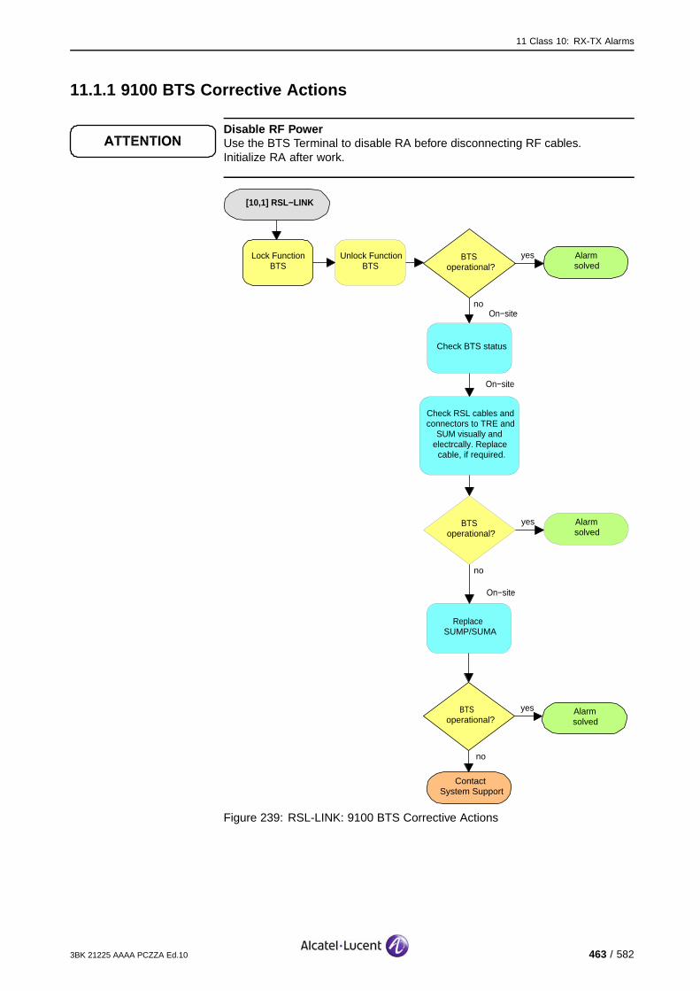
11 Class 10: RX-TX Alarms
11.1.1 9100 BTS Corrective Actions
Disable RF PowerUse the BTS Terminal to disable RA before disconnecting RF cables.Initialize RA after work.
[10,1] RSL−LINK
Alarmsolved
yesBTSoperational?
no
no
ContactSystem Support
Lock Function BTS
BTS operational?
yes Alarmsolved
On−site
Replace SUMP/SUMA
On−site
Check RSL cables and connectors to TRE and
SUM visually and electrcally. Replace
cable, if required.
On−site
Check BTS status
Alarmsolved
yesBTSoperational?
no
Unlock Function BTS
Figure 239: RSL-LINK: 9100 BTS Corrective Actions
3BK 21225 AAAA PCZZA Ed.10 463 / 582

11 Class 10: RX-TX Alarms
11.1.2 9110 Micro BTS/9110-E Micro BTS Corrective Actions
Disable RF PowerUse the BTS Terminal to disable RA before disconnecting RF cables.Initialize RA after work.
[10,1] RSL−LINK
Alarmsolved
yesBTSoperational?
no
On−site
no
ContactSystem Support
Reset Function BTS
Disconnect mains power from ACCO
to Basic Unit
BTS operational?
yes Alarmsolved
On−site
After 30 s re−power the BTS
On−site
Switch off Battery Backup Switch and
Main Power switch in Side Support Cabinet
On−site
Switch off mains power fuse for tower
mounted BTSOR OR
On−site
Replace BTS A910
noBTS
operational?
yes
Alarmsolved
Figure 240: RSL-LINK: G2 BTS Corrective Actions
464 / 582 3BK 21225 AAAA PCZZA Ed.10
11 Class 10: RX-TX Alarms
11.2 [10,3] RX-CABLE
11.2.1 [10,3] RX-CABLE (TRE)
specific Problems RX-CABLE
event Type Equipment
probable Cause Configuration Or Customization Error
perceived Severity Major (PMA)
Alarm Description An error has been detected in the cabling between a TRE and an ANX.
Alarm Number 1: The DC signal on RX0 has been lost.
2: The DC signal on RX1 has been lost.
5: The DC signal on RX0 & RX1 has been lost, or has been lost on RX0only, when antenna diversity is installed.
The cell is lost.
Impact BSS Cell(s) Signaling Calls
Loss - X X X
Degradation X - - -
3BK 21225 AAAA PCZZA Ed.10 465 / 582

11 Class 10: RX-TX Alarms
11.2.1.1 Corrective Actions
Disable RF PowerUse the BTS Terminal to disable RA before disconnecting RF cables.Initialize RA after work.
[10,3] RX−CABLE (TRE)
Alarmsolved
yesTRE operational?
no
On−site
no
ContactSystem Support
Lock Function TRE
Replace TRE
TRE operational?
yes Alarmsolved
On−site
Check RX cables to TRE and ANX/ANY/ANC
visually and electrically
On−site
Unlock Function TRE
yesANX/ANY/ANC alarm events?
no
Solve that alarm first
Check BTS status
Figure 241: RX-CABLE (TRE):Corrective Actions
466 / 582 3BK 21225 AAAA PCZZA Ed.10

11 Class 10: RX-TX Alarms
11.2.2 [10,3] RX-CABLE (RA)
specific Problems RX-CABLE
event Type Equipment
probable Cause Configuration Or Customization Error
perceived Severity Nbr 3: Major (PMA)
Nbr 4: Minor (DMA)
Alarm Description An error has been detected in the cabling between a TRE and an ANX/ANC.
Alarm Number 3: Several TREs connected to the same ANX/ANC have detected a cablingerror (cabling between TRE and ANX/ANC) on both RX paths, or on RX0path only, when antenna diversity is installed.
4: Several TREs connected to the same ANX/ANC have detected a cablingerror (cabling between TRE and ANX/ANC) on one RX path only, whenantenna diversity is installed.
The cell is lost.
Impact BSS Cell(s) Signaling Calls
Loss - X X X
Degradation X - - -
3BK 21225 AAAA PCZZA Ed.10 467 / 582
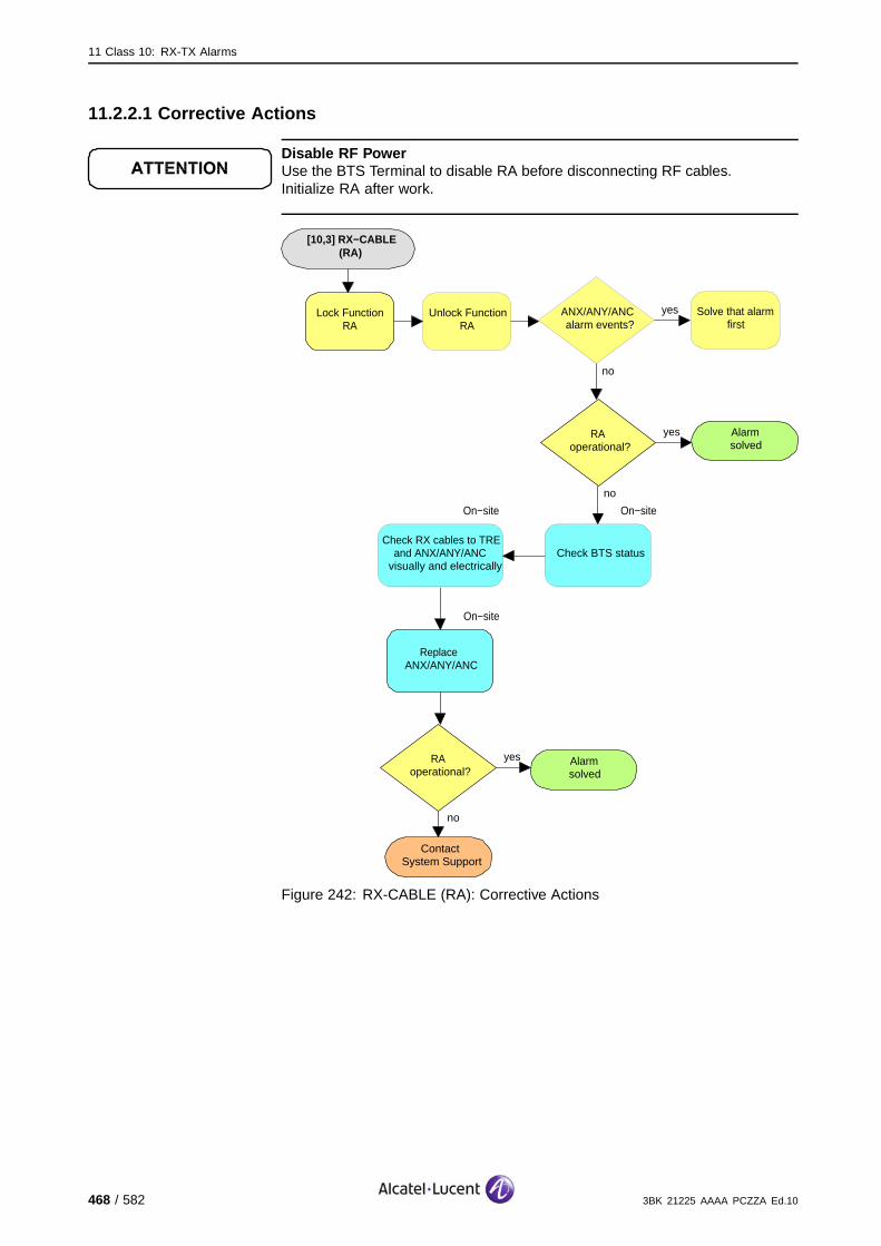
11 Class 10: RX-TX Alarms
11.2.2.1 Corrective Actions
Disable RF PowerUse the BTS Terminal to disable RA before disconnecting RF cables.Initialize RA after work.
[10,3] RX−CABLE (RA)
Alarmsolved
yesRAoperational?
no
On−site
no
ContactSystem Support
Lock Function RA
Replace ANX/ANY/ANC
RAoperational?
yes Alarmsolved
On−site
Check RX cables to TRE and ANX/ANY/ANC
visually and electrically
On−site
Unlock Function RA
yesANX/ANY/ANC alarm events?
no
Solve that alarm first
Check BTS status
Figure 242: RX-CABLE (RA): Corrective Actions
468 / 582 3BK 21225 AAAA PCZZA Ed.10

11 Class 10: RX-TX Alarms
11.3 [10,10] TRE-VSWR
specific Problems TRE-VSWR
event Type Equipment
probable Cause Transmitter Failure
perceived Severity Major (PMA)
Alarm Description A fault has been detected by the VSWR supervision on the TRE output(fault on a TX cable connected to ANX/ANY) during initialization oroperational states. The power amplifier of the TRE automatically switchesitself off, in order to avoid any HW damage.
The TRE is no longer usable. The associated eight channels are lost. Independent of frequency hoppingor not, the BSC reduces the number of channels supported by the cell.
If the TRE supporting the BCCH is not concerned, the cell is degraded, calls are lost. (#).
If the TRE supporting the BCCH is concerned and there is BCCH redundancy, recovery mechanismsregain the cell’s functionality. (*).
If the TRE supporting the BCCH is concerned and there is no BCCH redundancy, the complete cellis lost. (X).
Impact BSS Cell(s) Signaling Calls
Loss - X X X#*
Degradation X #* - -
3BK 21225 AAAA PCZZA Ed.10 469 / 582

11 Class 10: RX-TX Alarms
11.3.1 9100 BTS Corrective Actions
Disable RF PowerUse the BTS Terminal to disable RA before disconnecting RF cables.Initialize RA after work.
[10,10] TRE−VSWR
Alarmsolved
yesTRE operational?
no
On−site
no
ContactSystem Support
Lock Function TRE
Replace TRE
TRE operational?
yes Alarmsolved
On−site
Check TX cables to TRE and ANX/ANY/ANC
visually and electrically
On−site
Unlock Function TRE
yesANX/ANY/ANC alarm events?
no
Solve that alarm first
Check BTS status
Figure 243: TRE-VSWR: 9100 BTS Corrective Actions
470 / 582 3BK 21225 AAAA PCZZA Ed.10
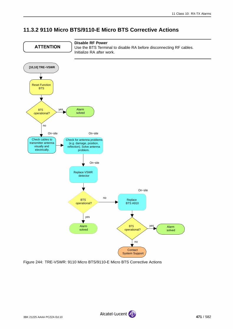
11 Class 10: RX-TX Alarms
11.3.2 9110 Micro BTS/9110-E Micro BTS Corrective Actions
Disable RF PowerUse the BTS Terminal to disable RA before disconnecting RF cables.Initialize RA after work.
[10,10] TRE−VSWR
Alarmsolved
yesBTS operational?
no
On−site
no
ContactSystem Support
Reset Function BTS
Check cables to transmitter antenna
visually and electrically.
BTS operational?
yes Alarmsolved
On−site
Replace VSWR detector
On−site
Check for antenna problems (e.g. damage, position,
reflection). Solve antenna problem.
On−site
Replace BTS A910
noBTS
operational?
yes
Alarmsolved
Figure 244: TRE-VSWR: 9110 Micro BTS/9110-E Micro BTS Corrective Actions
3BK 21225 AAAA PCZZA Ed.10 471 / 582

11 Class 10: RX-TX Alarms
11.4 [10,11] ANTENNA-VSWR-WARNING
Disable RF PowerUse the BTS Terminal to disable RA before disconnecting RF cables.Initialize RA after work.
Required tools and materials
Antenna Test Tools
Antenna Dummy Load
specific Problems ANTENNA-VSWR-WARNING
event Type Equipment
probable Cause Transmitter Failure
perceived Severity Minor (DMA), Warning (MI)
Alarm Description A fault has been detected concerning VSWR antenna supervision.
Alarm Number 1 (only for 9100 BTS): The LOW (first) threshold of antenna 1 VSWRhas been exceeded.
2 (only for 9100 BTS): The LOW (first) threshold of antenna 2 VSWRhas been exceeded.
3 (only for 9100 BTS): The LOW (first) thresholds on both antenna 1 and 2have been exceeded.
4 (only for 9110-E Micro BTS): VSWR 1 alarm for Master.
5 (only for 9110-E Micro BTS): VSWR 2 alarm for Master.
6 (only for 9110-E Micro BTS): VSWR 1 alarm for Slave 1.
7 (only for 9110-E Micro BTS): VSWR 2 alarm for Slave 1.
8 (only for 9110-E Micro BTS): VSWR 1 alarm for Slave 2.
9 (only for 9110-E Micro BTS): VSWR 2 alarm for Slave 2.
10 (only for 9110-E Micro BTS): VSWR 1 alarm for Slave 11.
11 (only for 9110-E Micro BTS): VSWR 2 alarm for Slave 11.
12 (only for 9110-E Micro BTS): VSWR 1 alarm for Slave 12.
13 (only for 9110-E Micro BTS): VSWR 2 alarm for Slave 12.
14 (only for 9110-E Micro BTS): VSWR 1 alarm for Slave 21.
15 (only for 9110-E Micro BTS): VSWR 2 alarm for Slave 21.
16 (only for 9110-E Micro BTS): VSWR 1 alarm for Slave 22.
17 (only for 9110-E Micro BTS): VSWR 2 alarm for Slave 22.
472 / 582 3BK 21225 AAAA PCZZA Ed.10

11 Class 10: RX-TX Alarms
Impact BSS Cell(s) Signaling Calls
Transmission quality is degraded
Loss - - - -
Degradation - - X X
3BK 21225 AAAA PCZZA Ed.10 473 / 582
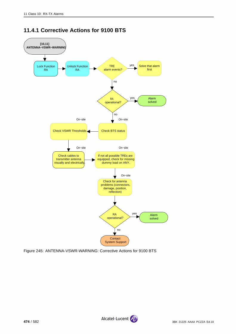
11 Class 10: RX-TX Alarms
11.4.1 Corrective Actions for 9100 BTS
[10,11] ANTENNA−VSWR−WARNING
Alarmsolved
yesRA operational?
no
On−site
no
ContactSystem Support
Lock Function RA
Check cables to transmitter antenna
visually and electrically.
RAoperational?
yes Alarmsolved
On−site
Check VSWR Thresholds
On−site
Unlock Function RA
yesTRE alarm events?
no
Solve that alarm first
Check BTS status
On−site
If not all possible TREs are equipped, check for missing
dummy load on ANY.
On−site
Check for antenna problems (connectors,
damage, position, reflection)
Figure 245: ANTENNA-VSWR-WARNING: Corrective Actions for 9100 BTS
474 / 582 3BK 21225 AAAA PCZZA Ed.10
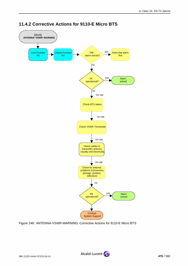
11 Class 10: RX-TX Alarms
11.4.2 Corrective Actions for 9110-E Micro BTS
[10,11] ANTENNA−VSWR−WARNING
Alarmsolved
yesRA operational?
no
On−site
no
ContactSystem Support
Lock Function RA
Check cables to transmitter antenna
visually and electrically.
RAoperational?
Alarmsolved
Check VSWR Thresholds
On−site
Unlock Function RA
yesTRE alarm events?
no
Solve that alarm first
Check BTS status
On−site
Check for antenna problems (connectors,
damage, position, reflection)
yes
On−site
Figure 246: ANTENNA-VSWR-WARNING: Corrective Actions for 9110-E Micro BTS
3BK 21225 AAAA PCZZA Ed.10 475 / 582

11 Class 10: RX-TX Alarms
11.5 [10,12] ANTENNA-VSWR-URGENT
specific Problems ANTENNA-VSWR-URGENT
event Type Equipment
probable Cause Transmitter Failure
perceived Severity Major (PMA)
Alarm Description A fault has been detected concerning VSWR antenna supervision.
Alarm Number 1: The High (second) threshold of antenna 1 VSWR has been exceeded.
2: The High (second) threshold of antenna 2 VSWR has been exceeded.
3: The High (second) thresholds on both antenna 1 and 2 have beenexceeded.
The cell is lost.
Impact BSS Cell(s) Signaling Calls
Loss - X X X
Degradation X - - -
476 / 582 3BK 21225 AAAA PCZZA Ed.10

11 Class 10: RX-TX Alarms
11.5.1 Corrective Actions
Disable RF PowerUse the BTS Terminal to disable RA before disconnecting RF cables.Initialize RA after work.
Required tools and materials :
Antenna Test Tools
Antenna Dummy Load.
[10,12] ANTENNA−VSWR−
URGENT
LockRA
REKused?
Solve REK alarm(s)
OMC−R
REKalarm(s)?
Alarmdisappears?
TRE−Alarms
Yes
Yes
No
VSWR−Alarmdisappears? Yes
UnlockRA
Yes Alarmsolved
Alarmsolved
No
No
No
Figure 247: ANTENNA-VSWR-URGENT: Corrective Actions
3BK 21225 AAAA PCZZA Ed.10 477 / 582
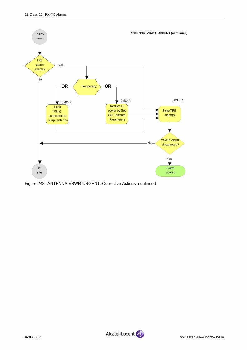
11 Class 10: RX-TX Alarms
TREalarm
events?
LockTRE(s)
connected to susp. antenna
OMC−R
4ReduceTXpower by Set Cell Telecom Parameters
Temporary:OR OR
Solve TRE alarm(s)
VSWR−Alarmdisappears?
On−site
Alarmsolved
Yes
No
OMC−ROMC−R
Yes
TRE−Alarms
ANTENNA−VSWR−URGENT (continued)
No
Figure 248: ANTENNA-VSWR-URGENT: Corrective Actions, continued
478 / 582 3BK 21225 AAAA PCZZA Ed.10

11 Class 10: RX-TX Alarms
On−site
ANTENNA−VSWR−URGENT (continued)
On−site
no
ContactSystem Support
Check cables to transmitter antenna visually and
electrically.
RAoperational?
yes Alarmsolved
On−site
Check VSWR Thresholds
On−site
Check BTS status
On−site
If not all possible TREs are equipped, check for missing
dummy load on ANY.
On−site
Check for antenna problems (connectors, damage, position,
reflection)
Figure 249: ANTENNA-VSWR-URGENT: Corrective Actions, continued
Reduced TX PowerIf the transmit power was reduced, set transmit power settings back to previousvalues when the problem is solved.
3BK 21225 AAAA PCZZA Ed.10 479 / 582

11 Class 10: RX-TX Alarms
11.6 [10,21] MODULE-FRAME-SIGNAL
11.6.1 [10,21] MODULE-FRAME-SIGNAL (TRE)
specific Problems MODULE-CLOCK-SIGNAL
event Type Equipment
probable Cause Loss Of Signal
perceived Severity Minor (DMA)
Alarm Description A fault is detected on a multiframe clock signal from SUM.
Transmission quality is degraded.
Impact BSS Cell(s) Signaling Calls
Loss - - - -
Degradation - - X X
480 / 582 3BK 21225 AAAA PCZZA Ed.10

11 Class 10: RX-TX Alarms
11.6.1.1 9100 BTS Corrective Actions
Disable RF PowerUse the BTS Terminal to disable RA before disconnecting RF cables.Initialize RA after work.
[10,21] MODULE−FRAME−SIGNAL
(TRE)
yesMore than one TRE sends
this alarm?
On−site
no
ContactSystem Support
Lock Function TRE
Check cables to TRE visually and electrically.
TREoperational?
yesAlarmsolved
Unlock Function TRE
yesTRE alarm events?
no
Solve that alarm first
On−site
Replace TRE
Solve that alarm first
no
SUM Clock alarm
events?
yes
On−site
Check SUM cables/connectors
On−site
Replace SUM
no
ContactSystem Support
TREoperational?
yes Alarmsolved
no
Figure 250: MODULE-FRAME-SIGNAL (TRE): 9100 BTS Corrective Actions
3BK 21225 AAAA PCZZA Ed.10 481 / 582

11 Class 10: RX-TX Alarms
11.6.1.2 9110 Micro BTS/9110-E Micro BTS Corrective Actions
Disable RF PowerUse the BTS Terminal to disable RA before disconnecting RF cables.Initialize RA after work.
[10,21] MODULE−FRAME−SIGNAL
(TRE)
Alarmsolved
yesBTS operational?
noOn−site
no
ContactSystem Support
Reset Function BTS
Check cables between master BTS and reporting slave BTS visually and
electrically.
BTS operational?
yes Alarmsolved
On−site
Replace BTS A910
noBTS
operational?
yes
Alarmsolved
yesMaster Clock alarm
events?
noSolve that
alarm(s) first
On−site
Disconnect mains power from ACCO
to Basic Unit
On−site
After 30 s re−power the BTS
On−site
Switch off Battery Backup Switch and
Main Power switch in Side Support Cabinet
On−site
Switch off mains power fuse for tower
mounted BTSOR OR
Figure 251: MODULE-FRAME-SIGNAL (TRE): 9110 Micro BTS/9110-E Micro BTS Corrective Actions
482 / 582 3BK 21225 AAAA PCZZA Ed.10

11 Class 10: RX-TX Alarms
11.6.2 [10,21] MODULE-FRAME-SIGNAL (RA)
specific Problems MODULE-FRAME-SIGNAL
event Type Equipment
probable Cause Loss Of Signal
perceived Severity Minor (DMA)
Alarm Description A fault is detected on a multiframe clock signal from SUM.
Transmission quality is degraded.
Impact BSS Cell(s) Signaling Calls
Loss - - - -
Degradation - - X X
3BK 21225 AAAA PCZZA Ed.10 483 / 582
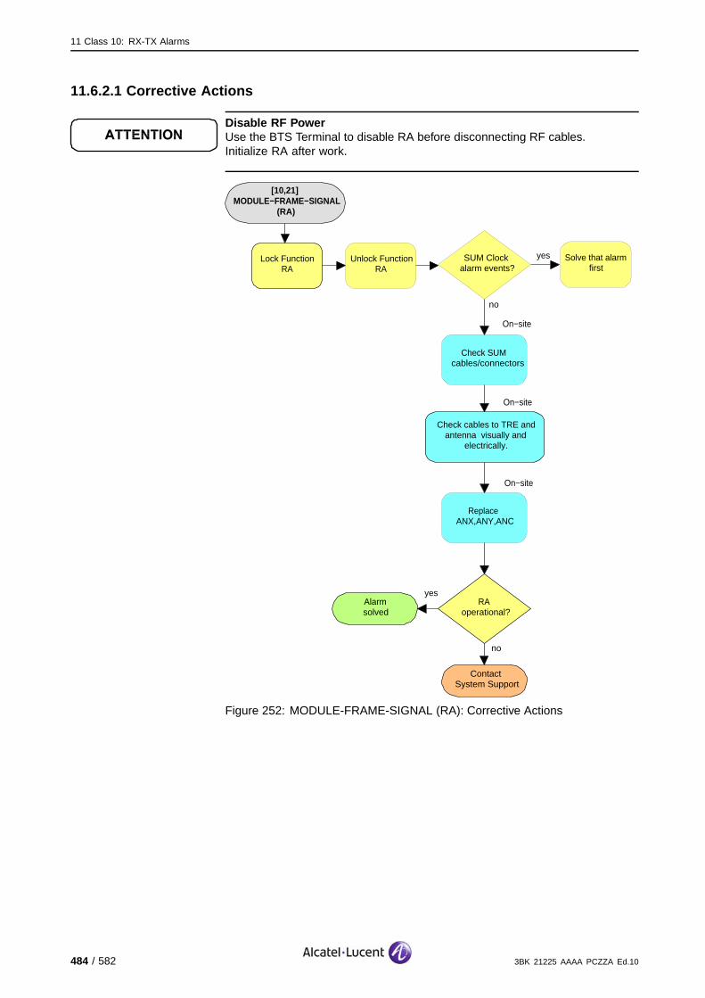
11 Class 10: RX-TX Alarms
11.6.2.1 Corrective Actions
Disable RF PowerUse the BTS Terminal to disable RA before disconnecting RF cables.Initialize RA after work.
[10,21] MODULE−FRAME−SIGNAL
(RA)
On−site
no
ContactSystem Support
Lock Function RA
Check cables to TRE and antenna visually and
electrically.
RAoperational?
yesAlarmsolved
Unlock Function RA
yesSUM Clock alarm events?
no
Solve that alarm first
On−site
Replace ANX,ANY,ANC
On−site
Check SUM cables/connectors
Figure 252: MODULE-FRAME-SIGNAL (RA): Corrective Actions
484 / 582 3BK 21225 AAAA PCZZA Ed.10

11 Class 10: RX-TX Alarms
11.7 [10,22] MODULE-CLOCK-SIGNAL
11.7.1 [10,22] MODULE-CLOCK-SIGNAL (TRE)
specific Problems MODULE-CLOCK-SIGNAL
event Type Equipment
probable Cause Loss Of Signal
perceived Severity Minor (DMA)
Alarm Description The input clock signal doesn’t allow the TRE module to work.
Alarm Number 1: Synchronization in clocks and FN has failed during initialization state.
2: CLKI master clock failure has been detected in the operational state.
The TRE is no longer usable. The associated eight channels are lost. Independent of frequency hoppingor not, the BSC reduces the number of channels supported by the cell.
If the TRE supporting the BCCH is not concerned, the cell is degraded, calls are lost. (#).
If the TRE supporting the BCCH is concerned and there is BCCH redundancy, recovery mechanismsregain the cell’s functionality. (*).
If the TRE supporting the BCCH is concerned and there is no BCCH redundancy, the complete cellis lost. (X).
Impact BSS Cell(s) Signaling Calls
Loss - X X X#*
Degradation X #* - -
3BK 21225 AAAA PCZZA Ed.10 485 / 582

11 Class 10: RX-TX Alarms
11.7.1.1 9100 BTS Corrective Actions
Disable RF PowerUse the BTS Terminal to disable RA before disconnecting RF cables.Initialize RA after work.
[10,22] MODULE−CLOCK−SIGNAL
(TRE)
yesMore than one TRE sends
this alarm?
On−site
no
ContactSystem Support
Lock Function TRE
Check cables to TRE visually and electrically.
TREoperational?
yesAlarmsolved
Unlock Function TRE
yesTRE alarm events?
no
Solve that alarm first
On−site
Replace TRE
Solve that alarm first
no
SUM Clock alarm
events?
yes
On−site
Check SUM cables/connectors
On−site
Replace SUM
no
ContactSystem Support
TREoperational?
yes Alarmsolved
no
Figure 253: MODULE-CLOCK-SIGNAL (TRE): 9100 BTS Corrective Actions
486 / 582 3BK 21225 AAAA PCZZA Ed.10

11 Class 10: RX-TX Alarms
11.7.1.2 9110 Micro BTS/9110-E Micro BTS Corrective Actions
Disable RF PowerUse the BTS Terminal to disable RA before disconnecting RF cables.Initialize RA after work.
[10,22]MODULE−CLOCK−SIGNAL
(TRE)
Alarmsolved
yesBTS operational?
noOn−site
no
ContactSystem Support
Reset Function BTS
Check cables between master BTS and reporting slave BTS visually and
electrically.
BTS operational?
yes Alarmsolved
On−site
Replace BTS A910
noBTS
operational?
yes
Alarmsolved
yesMaster Clock alarm
events?
noSolve that
alarm(s) first
On−site
Disconnect mains power from ACCO
to Basic Unit
On−site
After 30 s re−power the BTS
On−site
Switch off Battery Backup Switch and
Main Power switch in Side Support Cabinet
On−site
Switch off mains power fuse for tower
mounted BTS
OR OR
Figure 254: MODULE-CLOCK-SIGNAL (TRE): 9110 Micro BTS/9110-E Micro BTS Corrective Actions
3BK 21225 AAAA PCZZA Ed.10 487 / 582

11 Class 10: RX-TX Alarms
11.7.2 [10,22] MODULE-CLOCK-SIGNAL (RA)
specific Problems MODULE-CLOCK-SIGNAL
event Type Equipment
probable Cause Loss Of Signal
perceived Severity Minor (DMA)
Alarm Description The input clock signal on ANX is faulty.
Alarm Number 1: Synchronization in clocks and frame numbers has failed duringinitialization state.
2: CLKI master clock failure has been detected in the operational state.
Telecom functions are not affected.
Impact BSS Cell(s) Signaling Calls
Loss - - - -
Degradation - - - -
488 / 582 3BK 21225 AAAA PCZZA Ed.10

11 Class 10: RX-TX Alarms
11.7.2.1 Corrective Actions
Disable RF PowerUse the BTS Terminal to disable RA before disconnecting RF cables.Initialize RA after work.
[10,22] MODULE−CLOCK−SIGNAL
(RA)
On−site
no
ContactSystem Support
Lock Function RA
Check cables to TRE and antenna visually and
electrically.
RAoperational?
yesAlarmsolved
Unlock Function RA
yesSUM Clock alarm events?
no
Solve that alarm first
On−site
Replace ANX,ANY,ANC
On−site
Check SUM cables/connectors
Figure 255: MODULE-CLOCK-SIGNAL: Corrective Actions
3BK 21225 AAAA PCZZA Ed.10 489 / 582

11 Class 10: RX-TX Alarms
11.8 [10,51] MODULE-NOT-PRESENT
11.8.1 [10,51] MODULE-NOT-PRESENT (TRE)
specific Problems MODULE-NOT-PRESENT
event Type Equipment
probable Cause Replaceable Unit Problem
perceived Severity Major (PMA)
Alarm Description A TRE module was not initially present, or has recently been extracted.
Alarm Number 1: The BCB detects the extraction of the module.
2: There is no associated module for this SBL.
The TRE is no longer usable. The associated eight channels are lost. Independent of frequency hoppingor not, the BSC reduces the number of channels supported by the cell.
If the TRE supporting the BCCH is not concerned, the cell is degraded, calls are lost. (#).
If the TRE supporting the BCCH is concerned and there is BCCH redundancy, recovery mechanismsregain the cell’s functionality, calls are lost. (*)
If the TRE supporting the BCCH is concerned and there is no BCCH redundancy, the complete cellis lost. (X).
Impact BSS Cell(s) Signaling Calls
Loss - X X X#*
Degradation X #* - -
490 / 582 3BK 21225 AAAA PCZZA Ed.10

11 Class 10: RX-TX Alarms
11.8.1.1 9100 BTS Corrective Actions
Disable RF PowerUse the BTS Terminal to disable RA before disconnecting RF cables.Initialize RA after work.
[10,51] MODULE−NOT−PRESENT
(TRE)
no
ContactSystem Support
Lock Function TRE
TREoperational?
yes Alarmsolved
Unlock Function TRE
On−site
Initialize the TRE
On−site
Insert missing TRE module
no
TREoperational?
yes Alarmsolved
Figure 256: MODULE-NOT-PRESENT (TRE): 9100 BTS Corrective Actions
3BK 21225 AAAA PCZZA Ed.10 491 / 582
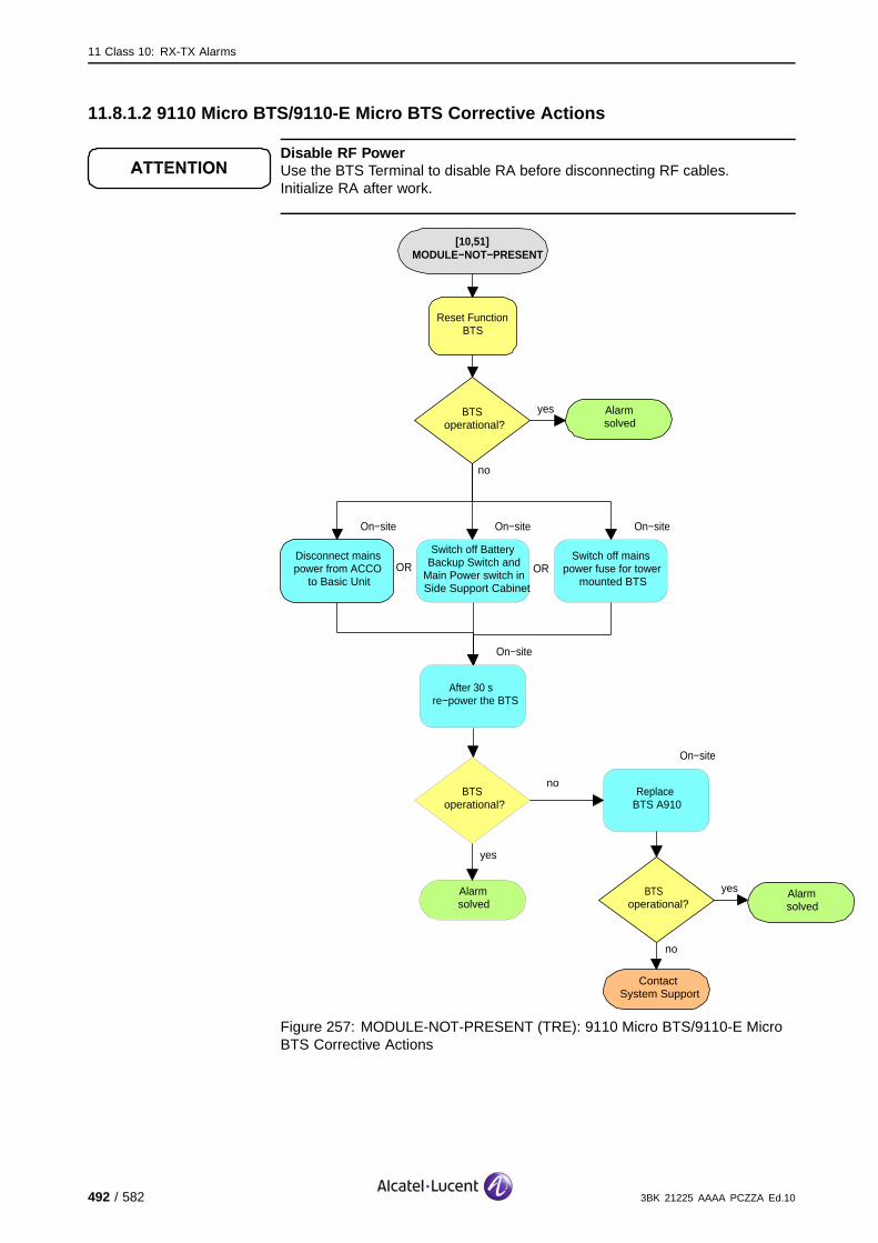
11 Class 10: RX-TX Alarms
11.8.1.2 9110 Micro BTS/9110-E Micro BTS Corrective Actions
Disable RF PowerUse the BTS Terminal to disable RA before disconnecting RF cables.Initialize RA after work.
[10,51] MODULE−NOT−PRESENT
Alarmsolved
yesBTSoperational?
no
On−site
no
ContactSystem Support
Reset Function BTS
Disconnect mains power from ACCO
to Basic Unit
BTS operational?
yes Alarmsolved
On−site
After 30 s re−power the BTS
On−site
Switch off Battery Backup Switch and
Main Power switch in Side Support Cabinet
On−site
Switch off mains power fuse for tower
mounted BTSOR OR
On−site
Replace BTS A910
noBTS
operational?
yes
Alarmsolved
Figure 257: MODULE-NOT-PRESENT (TRE): 9110 Micro BTS/9110-E MicroBTS Corrective Actions
492 / 582 3BK 21225 AAAA PCZZA Ed.10
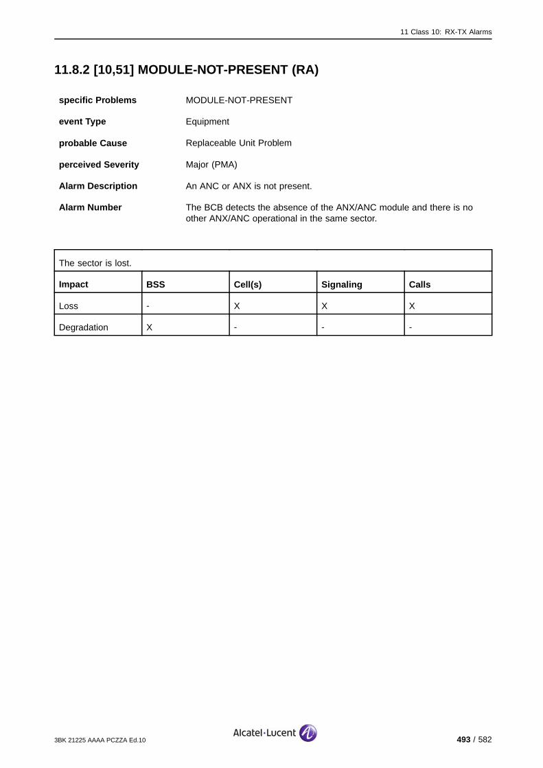
11 Class 10: RX-TX Alarms
11.8.2 [10,51] MODULE-NOT-PRESENT (RA)
specific Problems MODULE-NOT-PRESENT
event Type Equipment
probable Cause Replaceable Unit Problem
perceived Severity Major (PMA)
Alarm Description An ANC or ANX is not present.
Alarm Number The BCB detects the absence of the ANX/ANC module and there is noother ANX/ANC operational in the same sector.
The sector is lost.
Impact BSS Cell(s) Signaling Calls
Loss - X X X
Degradation X - - -
3BK 21225 AAAA PCZZA Ed.10 493 / 582

11 Class 10: RX-TX Alarms
11.8.2.1 Corrective Actions
Disable RF PowerUse the BTS Terminal to disable RA before disconnecting RF cables.Initialize RA after work.
[10,51] MODULE−NOT−PRESENT
(RA)
no
ContactSystem Support
Lock Function RA
TREoperational?
yes Alarmsolved
Unlock Function RA
On−site
Initialize the RAn
On−site
Insert missing ANX,ANY,ANC
module
no
TREoperational?
yes Alarmsolved
Figure 258: MODULE-NOT-PRESENT (RA): Corrective Actions
494 / 582 3BK 21225 AAAA PCZZA Ed.10

11 Class 10: RX-TX Alarms
11.9 [10,234] IOM-DISCONNECTION
11.9.1 [10,234] IOM-DISCONNECTION (TRE)
specific Problems IOM-DISCONNECTION
event Type Equipment
probable Cause Equipment Malfunction
perceived Severity Minor (DMA)
Alarm Description The IOM connection on BSII is faulty.
Telecom functions are not affected, as long as no commands on the Managed Objects (SBLs) TRE orRA are executed.
Impact BSS Cell(s) Signaling Calls
Loss - - - -
Degradation - - - -
3BK 21225 AAAA PCZZA Ed.10 495 / 582

11 Class 10: RX-TX Alarms
11.9.1.1 9100 BTS Corrective Actions
Disable RF PowerUse the BTS Terminal to disable RA before disconnecting RF cables.Initialize RA after work.
[10,234] IOM−DISCONNECTION
(TRE)
no
ContactSystem Support
Lock Function TRE
TREoperational?
yes Alarmsolved
Unlock Function TRE
On−site
Replace TRE
no
TREoperational?
yes Alarmsolved
Figure 259: IOM-DISCONNECTION (TRE): 9100 BTS Corrective Actions
496 / 582 3BK 21225 AAAA PCZZA Ed.10

11 Class 10: RX-TX Alarms
11.9.1.2 9110 Micro BTS/9110-E Micro BTS Corrective Actions
Disable RF PowerUse the BTS Terminal to disable RA before disconnecting RF cables.Initialize RA after work.
[10,234] IOM−DISCONNECTION
(TRE)
Alarmsolved
yesBTSoperational?
no
On−site
no
ContactSystem Support
Reset Function BTS
Disconnect mains power from ACCO
to Basic Unit
BTS operational?
yes Alarmsolved
On−site
After 30 s re−power the BTS
On−site
Switch off Battery Backup Switch and
Main Power switch in Side Support Cabinet
On−site
Switch off mains power fuse for tower mounted
BTS
OR OR
On−site
Replace BTS A910
noBTS
operational?
yes
Alarmsolved
Figure 260: IOM-DISCONNECTION (TRE): 9110 Micro BTS/9110-E MicroBTS Corrective Actions
3BK 21225 AAAA PCZZA Ed.10 497 / 582

11 Class 10: RX-TX Alarms
11.9.2 [10,234] IOM-DISCONNECTION (RA)
specific Problems IOM-DISCONNECTION
event Type Equipment
probable Cause Equipment Malfunction
perceived Severity Minor (DMA)
Alarm Description The IOM connection on BSII is faulty.
Telecom functions are not affected, as long as no commands on the Managed Objects (SBLs) TRE orRA are executed.
Impact BSS Cell(s) Signaling Calls
Loss - - - -
Degradation - - - -
11.9.2.1 Corrective Actions
Disable RF PowerUse the BTS Terminal to disable RA before disconnecting RF cables.Initialize RA after work.
498 / 582 3BK 21225 AAAA PCZZA Ed.10
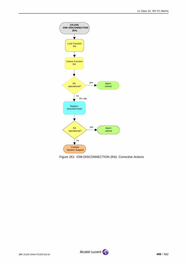
11 Class 10: RX-TX Alarms
[10,234] IOM−DISCONNECTION
(RA)
no
ContactSystem Support
Lock Function RA
RAoperational?
yes Alarmsolved
Unlock Function RA
On−site
Replace ANX/ANY/ANC
no
RAoperational?
yes Alarmsolved
Figure 261: IOM-DISCONNECTION (RA): Corrective Actions
3BK 21225 AAAA PCZZA Ed.10 499 / 582

11 Class 10: RX-TX Alarms
11.10 [10,237] HW-DEGRADED
11.10.1 [10,237] HW-DEGRADED (TRE)
specific Problems HW-DEGRADED
event Type Equipment
probable Cause Equipment Malfunction
perceived Severity Minor (DMA), Warning (MI)
Alarm Description Nbr 3: The BCB link to the module is faulty.
Nbr 12: This is an output power drop error.
Nbr 13: Hardware failure on unused part of twin (The twin in its currentconfiguration operates correctly. A problem will only occur when theconfiguration will be changed.)
The antenna diversity is lost and the quality of reception is degraded.
Impact BSS Cell(s) Signaling Calls
Loss - - - -
Degradation - - - X
500 / 582 3BK 21225 AAAA PCZZA Ed.10

11 Class 10: RX-TX Alarms
11.10.1.1 9100 BTS Corrective Actions
Disable RF PowerUse the BTS Terminal to disable RA before disconnecting RF cables.Initialize RA after work.
[10,237]HW−DEGRADED
(TRE)
no
ContactSystem Support
Lock Function TRE
Alarm persists?yes
Unlock Function TRE
On−site
Check BCB cables/connectors
noTREoperational?
yes
Alarmsolved
On−site
Disengage TRE
On−site
Re−engage TRE
On−site
Disengage, RIT by RIT, all TREs, ANYs, ANXs, the
SUM and the XIOB
no
Alarm persists?yes
On−site
Re−engage RIT
On−site
Replace TRE
On−site
Replace faulty RIT
no
Alarm persists?yes Replace BCB flat
cable
Alarmsolved
no
TRE operational?
yes Alarmsolved
ContactSystem Support
no
TRE operational?
yes Alarmsolved
On−site
Figure 262: HW-DEGRADED (TRE): 9100 BTS Corrective Actions
3BK 21225 AAAA PCZZA Ed.10 501 / 582
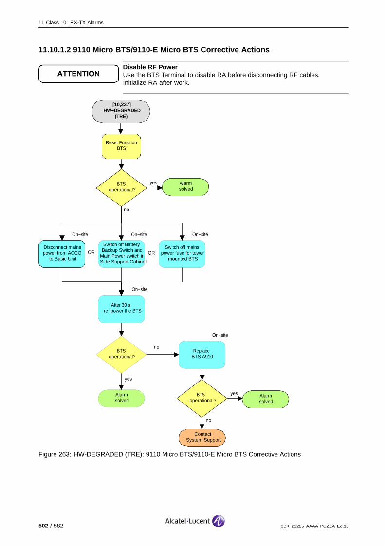
11 Class 10: RX-TX Alarms
11.10.1.2 9110 Micro BTS/9110-E Micro BTS Corrective Actions
Disable RF PowerUse the BTS Terminal to disable RA before disconnecting RF cables.Initialize RA after work.
[10,237]HW−DEGRADED
(TRE)
Alarmsolved
yesBTSoperational?
no
On−site
no
ContactSystem Support
Reset Function BTS
Disconnect mains power from ACCO
to Basic Unit
BTS operational?
yes Alarmsolved
On−site
After 30 s re−power the BTS
On−site
Switch off Battery Backup Switch and
Main Power switch in Side Support Cabinet
On−site
Switch off mains power fuse for tower
mounted BTSOR OR
On−site
Replace BTS A910
noBTS
operational?
yes
Alarmsolved
Figure 263: HW-DEGRADED (TRE): 9110 Micro BTS/9110-E Micro BTS Corrective Actions
502 / 582 3BK 21225 AAAA PCZZA Ed.10
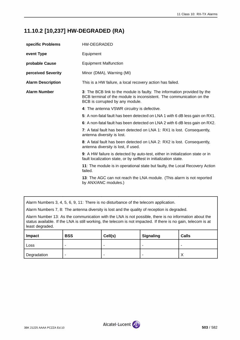
11 Class 10: RX-TX Alarms
11.10.2 [10,237] HW-DEGRADED (RA)
specific Problems HW-DEGRADED
event Type Equipment
probable Cause Equipment Malfunction
perceived Severity Minor (DMA), Warning (MI)
Alarm Description This is a HW failure, a local recovery action has failed.
Alarm Number 3: The BCB link to the module is faulty. The information provided by theBCB terminal of the module is inconsistent. The communication on theBCB is corrupted by any module.
4: The antenna VSWR circuitry is defective.
5: A non-fatal fault has been detected on LNA 1 with 6 dB less gain on RX1.
6: A non-fatal fault has been detected on LNA 2 with 6 dB less gain on RX2.
7: A fatal fault has been detected on LNA 1: RX1 is lost. Consequently,antenna diversity is lost.
8: A fatal fault has been detected on LNA 2: RX2 is lost. Consequently,antenna diversity is lost, if used.
9: A HW failure is detected by auto-test, either in initialization state or infault localization state, or by selftest in initialization state.
11: The module is in operational state but faulty, the Local Recovery Actionfailed.
13: The AGC can not reach the LNA module. (This alarm is not reportedby ANX/ANC modules.)
Alarm Numbers 3, 4, 5, 6, 9, 11: There is no disturbance of the telecom application.
Alarm Numbers 7, 8: The antenna diversity is lost and the quality of reception is degraded.
Alarm Number 13: As the communication with the LNA is not possible, there is no information about thestatus available. If the LNA is still working, the telecom is not impacted. If there is no gain, telecom is atleast degraded.
Impact BSS Cell(s) Signaling Calls
Loss - - - -
Degradation - - - X
3BK 21225 AAAA PCZZA Ed.10 503 / 582
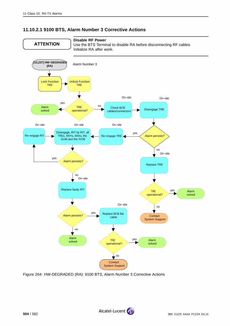
11 Class 10: RX-TX Alarms
11.10.2.1 9100 BTS, Alarm Number 3 Corrective Actions
Disable RF PowerUse the BTS Terminal to disable RA before disconnecting RF cables.Initialize RA after work.
[10,237] HW−DEGRADED (RA)
no
ContactSystem Support
Lock Function TRE
Alarm persists?yes
Unlock Function TRE
On−site
Check BCB cables/connectors
noTREoperational?
yes
Alarmsolved
On−site
Disengage TRE
On−site
Re−engage TRE
On−site
Disengage, RIT by RIT, all TREs, ANYs, ANXs, the
SUM and the XIOB
no
Alarm persists?yes
On−site
Re−engage RIT
On−site
Replace TRE
On−site
Replace faulty RIT
no
Alarm persists?yes Replace BCB flat
cable
Alarmsolved
no
TRE operational?
yes Alarmsolved
ContactSystem Support
no
TRE operational?
yes Alarmsolved
On−site
Alarm Number 3
Figure 264: HW-DEGRADED (RA): 9100 BTS, Alarm Number 3 Corrective Actions
504 / 582 3BK 21225 AAAA PCZZA Ed.10
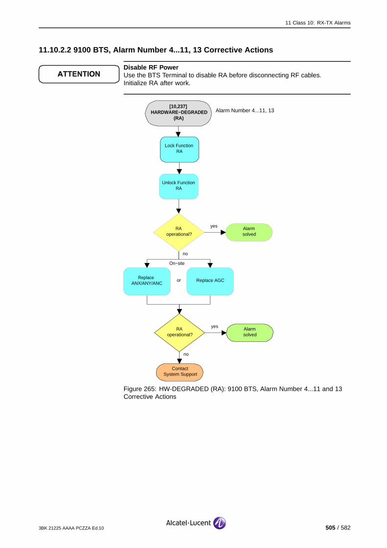
11 Class 10: RX-TX Alarms
11.10.2.2 9100 BTS, Alarm Number 4...11, 13 Corrective Actions
Disable RF PowerUse the BTS Terminal to disable RA before disconnecting RF cables.Initialize RA after work.
[10,237] HARDWARE−DEGRADED
(RA)
no
ContactSystem Support
Lock Function RA
RAoperational?
yes Alarmsolved
Unlock Function RA
On−site
Replace ANX/ANY/ANC
no
RAoperational?
yes Alarmsolved
Alarm Number 4...11, 13
Replace AGCor
Figure 265: HW-DEGRADED (RA): 9100 BTS, Alarm Number 4...11 and 13Corrective Actions
3BK 21225 AAAA PCZZA Ed.10 505 / 582
11 Class 10: RX-TX Alarms
11.10.2.3 9110 Micro BTS/9110-E Micro BTS Corrective Actions
Disable RF PowerUse the BTS Terminal to disable RA before disconnecting RF cables.Initialize RA after work.
[10,237] HARDWARE−DEGRADED
(RA)
Alarmsolved
yesBTS operational?
no
On−site
no
ContactSystem Support
Reset Function BTS
Check cables to transmitter antenna
visually and electrically.
BTS operational?
yes Alarmsolved
On−site
Replace VSWR detector
On−site
Check for antenna problems (e.g. damage, position,
reflection). Solve antenna problem.
On−site
Replace BTS A910
noBTS
operational?
yes
Alarmsolved
Figure 266: HW-DEGRADED (RA): 9100 BTS, Alarm Number 3 Corrective Actions
506 / 582 3BK 21225 AAAA PCZZA Ed.10

11 Class 10: RX-TX Alarms
11.11 [10,239] HW-FAILURE
11.11.1 [10,239] HW-FAILURE (TRE)
specific Problems HW-FAILURE
event Type Equipment
probable Cause Equipment Malfunction
perceived Severity Major (PMA), Minor (DMA)
Alarm Description Major (PMA): This is a HW failure, a local recovery action has failed.
Minor (DMA): The local recovery is successful.
Alarm Number 1: A HW failure is detected by the auto-test, either in initialization state orin fault localization state, or by selftest in initialization state (failures notcovered by other numbers).
2: The DC/DC converter has failed.
3: A fatal error has been reported by a layer 1 DSP concerning the radio.
4: A fault has been detected at the Entity Control Parallel Link (ECPL)interface management.
5: One DSP has reported a fatal error in its internal processing.
6: At least one DSP has not answered to the SCP polling.
7: A fatal error has been reported by a layer 1 DSP or the MBED on aserial internal interface.
8: The FN_SUP timer (FN supervision) elapsed: FCLK interrupt is missing.
9: The internal FNs from layer 1 are not consistent.
11: The module was not in an operational state (no more information isavailable). The OMU has performed a Local Recovery Action.
12: The module has no input power.
13: The front panel power switch is set off (Power Off) for the concernedmodule.
14: Unknown cause: alarm indicates that more detailed alarms werereported before and are available at OMC-R.
15: The TRE reported to OMU BSII a failure alarm. The OMU has thenperformed on TRE a Local Recovery Action which has failed.
3BK 21225 AAAA PCZZA Ed.10 507 / 582

11 Class 10: RX-TX Alarms
The TRE is no longer usable. The associated eight channels are lost. Independent of frequency hoppingor not, the BSC reduces the number of channels supported by the cell.
If the TRE supporting the BCCH is not concerned, the cell is degraded, calls are lost. (#).
If the TRE supporting the BCCH is concerned and there is BCCH redundancy, recovery mechanismsregain the cell’s functionality, calls are lost. (*)
If the TRE supporting the BCCH is concerned and there is no BCCH redundancy, the complete cellis lost. (X).
Impact BSS Cell(s) Signaling Calls
Loss - X X X#*
Degradation X #* - -
508 / 582 3BK 21225 AAAA PCZZA Ed.10

11 Class 10: RX-TX Alarms
11.11.1.1 9100 BTS, Alarm Number 1...11 and 15 Corrective Actions
Disable RF PowerUse the BTS Terminal to disable RA before disconnecting RF cables.Initialize RA after work.
[10,239] HW−FAILURE (TRE)
ContactSystem Support
Lock Function TRE
Unlock Function TRE
no
TREoperational?
yes Alarmsolved
On−site
Check BTS status
no
Alarm persists?yes
Replace TRE
Alarmsolved
no
TRE operational?
yes Alarmsolved
On−site
no
TRE alarm events?
yes Solve TRE alarm first
Alarm Number 1...11 & 15
Figure 267: HW-FAILURE (TRE): 9100 BTS, Alarm Number 1...11 and 15Corrective Actions
Additionally for alarm number 3: in case the alarm is reported by severalTREs and the additional info contains either DF 3B 03 20 1C 19 DF 3D 14 0115 00 00 00 00 00 00 00 00 00 00 01 00 00 00 00 00 00 00 or DF 3B 03 20 1C19 DF 3D 22 01 15 00 00 00 00 00 00 00 00 00 00 00 00 xx xx xx xx 00 01 0000 00 00 00 00 00 00 00 00 xx xx xx xx (whatever xx is) and thus indicating a“L1 status: LD_13MHz, no lock detection for 13 MHz synthesiser (ENCT)”,replace the SUMx board as this one causes the alarms.
3BK 21225 AAAA PCZZA Ed.10 509 / 582

11 Class 10: RX-TX Alarms
11.11.1.2 9100 BTS, Alarm Number 12 Corrective Actions
Disable RF PowerUse the BTS Terminal to disable RA before disconnecting RF cables.Initialize RA after work.
[10,239] HW−FAILURE (TRE)
ContactSystem Support
Alarmsolved
On−site
Check power supply. Ensure BTS is
powered correctly.
no
Alarm persists?yes
Replace TRE
Alarmsolved
no
TRE operational?
yes Alarmsolved
On−site
no
Power alarm events?
yes Solve power alarm first
Alarm Number 12
Alarm persists?noyes
Figure 268: HW-FAILURE (TRE): 9100 BTS, Alarm Number 12 CorrectiveActions
510 / 582 3BK 21225 AAAA PCZZA Ed.10
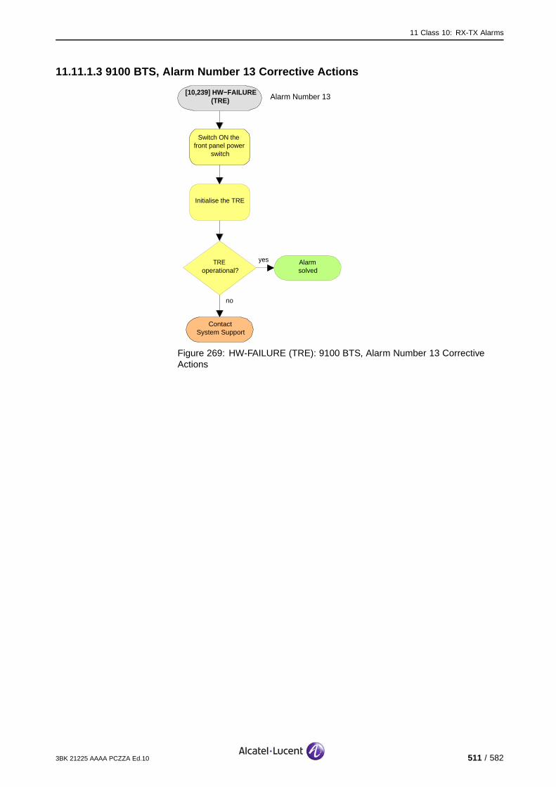
11 Class 10: RX-TX Alarms
11.11.1.3 9100 BTS, Alarm Number 13 Corrective Actions
[10,239] HW−FAILURE (TRE)
ContactSystem Support
Switch ON the front panel power
switch
Initialise the TRE
no
TREoperational?
yes Alarmsolved
Alarm Number 13
Figure 269: HW-FAILURE (TRE): 9100 BTS, Alarm Number 13 CorrectiveActions
3BK 21225 AAAA PCZZA Ed.10 511 / 582
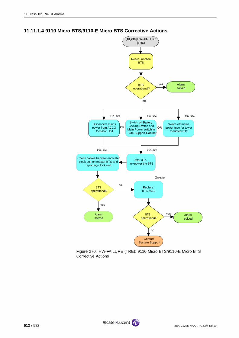
11 Class 10: RX-TX Alarms
11.11.1.4 9110 Micro BTS/9110-E Micro BTS Corrective Actions
[10,239] HW−FAILURE (TRE)
Alarmsolved
yesBTSoperational?
no
On−site
no
ContactSystem Support
Reset Function BTS
Disconnect mains power from ACCO
to Basic Unit
BTS operational?
yes Alarmsolved
On−site
After 30 s re−power the BTS
On−site
Switch off Battery Backup Switch and
Main Power switch in Side Support Cabinet
On−site
Switch off mains power fuse for tower
mounted BTSOR OR
On−site
Replace BTS A910
noBTS
operational?
yes
Alarmsolved
On−site
Check cables between indicated clock unit on master BTS and
reporting clock unit.
Figure 270: HW-FAILURE (TRE): 9110 Micro BTS/9110-E Micro BTSCorrective Actions
512 / 582 3BK 21225 AAAA PCZZA Ed.10

11 Class 10: RX-TX Alarms
11.11.2 [10,239] HW-FAILURE (RA)
specific Problems HW-FAILURE
event Type Equipment
probable Cause Equipment Malfunction
perceived Severity Major (PMA)
Alarm Description This is a HW failure, a local recovery action has failed.
Alarm Number 2: The DC/DC converter of the module failed.
10: A fatal fault has been detected on both LNA 1 and LNA2: RX1 andRX2 are lost. Or fault detected on LNA1 only if no antenna diversityconfiguration or on LNA2 only for 9110 Micro BTS in no antenna diversityconfiguration and MAN is configured with two sectors.
12: The module has no input power.
14: Unknown cause, alarm indicates that more detailed alarms werereported before and are available at OMC-R.
The sector is lost.
Impact BSS Cell(s) Signaling Calls
Loss - X X X
Degradation X - - -
3BK 21225 AAAA PCZZA Ed.10 513 / 582

11 Class 10: RX-TX Alarms
11.11.2.1 9100 BTS, Alarm Number 2 and 12 Corrective Actions
Disable RF PowerUse the BTS Terminal to disable RA before disconnecting RF cables.Initialize RA after work.
[10,239] HW−FAILURE (RA)
ContactSystem Support
Lock Function RA
Unlock Function RA
no
RAoperational?
yes Alarmsolved
On−site
Check power supply. Ensure ANX/ANC is powered correctly.
no
Alarm persists?yes Replace
ANX/ANY/ANC
Alarmsolved
no
RAoperational?
yes Alarmsolved
On−site
no
Power alarm events?
yes Solve power alarm first
Alarm Number 2 & 12
Figure 271: HW-FAILURE (RA): 9100 BTS, Alarm Number 2 and 12 CorrectiveActions
514 / 582 3BK 21225 AAAA PCZZA Ed.10

11 Class 10: RX-TX Alarms
11.11.2.2 9100 BTS, Alarm Number 10 Corrective Actions
Disable RF PowerUse the BTS Terminal to disable RA before disconnecting RF cables.Initialize RA after work.
[10,239] HW−FAILURE (RA)
ContactSystem Support
Lock Function RA
Unlock Function RA
no
RAoperational?
yes Alarmsolved
On−site
Check BTS status
no
Alarm persists?yes Replace
ANX/ANY/ANC
Alarmsolved
no
RAoperational?
yes Alarmsolved
On−site
no
Other TRE alarm
events?
yes Solve TRE alarm(s) first
Alarm Number 10
Figure 272: HW-FAILURE (RA): 9100 BTS, Alarm Number 10 CorrectiveActions
3BK 21225 AAAA PCZZA Ed.10 515 / 582

11 Class 10: RX-TX Alarms
11.11.2.3 9100 BTS, Alarm Number 14 Corrective Actions
Disable RF PowerUse the BTS Terminal to disable RA before disconnecting RF cables.Initialize RA after work.
[10,239] HW−FAILURE (RA)
ContactSystem Support
Lock Function RA
Unlock Function RA
no
RAoperational?
yes Alarmsolved
no
RAoperational?
yes Alarmsolved
no
Other related alarm
events?
yes Solve related alarm(s) first
Alarm Number 14
Figure 273: HW-FAILURE (RA): 9100 BTS, Alarm Number 14 CorrectiveActions
516 / 582 3BK 21225 AAAA PCZZA Ed.10

11 Class 10: RX-TX Alarms
11.11.2.4 9110 Micro BTS/9110-E Micro BTS Corrective Actions
Disable RF PowerUse the BTS Terminal to disable RA before disconnecting RF cables.Initialize RA after work.
[10,239] HW−FAILURE (RA)
Alarmsolved
yesBTSoperational?
no
On−site
no
ContactSystem Support
Reset Function BTS
Disconnect mains power from ACCO
to Basic Unit
BTS operational?
yes Alarmsolved
On−site
After 30 s re−power the BTS
On−site
Switch off Battery Backup Switch and
Main Power switch in Side Support Cabinet
On−site
Switch off mains power fuse for tower
mounted BTS
OR OR
On−site
Replace BTS A910
noBTS
operational?
yes
Alarmsolved
If an alarm on the feeding clock unit of the master BTS is still outstanding, the failure is due to external reasons.
Figure 274: HW-FAILURE (RA): 9110 Micro BTS/9110-E Micro BTS CorrectiveActions
3BK 21225 AAAA PCZZA Ed.10 517 / 582
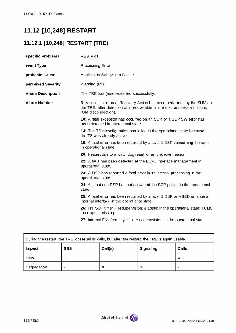
11 Class 10: RX-TX Alarms
11.12 [10,248] RESTART
11.12.1 [10,248] RESTART (TRE)
specific Problems RESTART
event Type Processing Error
probable Cause Application Subsystem Failure
perceived Severity Warning (MI)
Alarm Description The TRE has (auto)restarted successfully.
Alarm Number 3: A successful Local Recovery Action has been performed by the SUM onthe TRE, after detection of a recoverable failure (i.e., auto-restart failure,IOM disconnection).
10: A fatal exception has occurred on an SCP, or a SCP SW error hasbeen detected in operational state.
14: The TS reconfiguration has failed in the operational state becausethe TS was already active.
19: A fatal error has been reported by a layer 1 DSP concerning the radioin operational state.
20: Restart due to a watchdog reset for an unknown reason.
22: A fault has been detected at the ECPL interface management inoperational state.
23: A DSP has reported a fatal error in its internal processing in theoperational state.
24: At least one DSP has not answered the SCP polling in the operationalstate.
25: A fatal error has been reported by a layer 1 DSP or MBED on a serialinternal interface in the operational state.
26: FN_SUP timer (FN supervision) elapsed in the operational state: FCLKinterrupt is missing.
27: Internal FNs from layer 1 are not consistent in the operational state.
During the restart, the TRE looses all its calls, but after the restart, the TRE is again usable.
Impact BSS Cell(s) Signaling Calls
Loss - - - X
Degradation - X X -
518 / 582 3BK 21225 AAAA PCZZA Ed.10
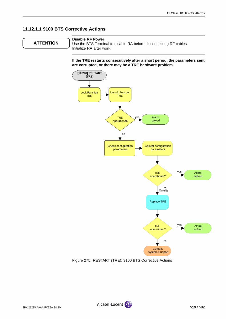
11 Class 10: RX-TX Alarms
11.12.1.1 9100 BTS Corrective Actions
Disable RF PowerUse the BTS Terminal to disable RA before disconnecting RF cables.Initialize RA after work.
If the TRE restarts consecutively after a short period, the parameters sentare corrupted, or there may be a TRE hardware problem.
[10,248] RESTART (TRE)
Check configuration parameters
Alarmsolved
yesTREoperational?
no
Lock Function TRE
Unlock Function TRE
no
TREoperational?
yes Alarmsolved
Correct configuration parameters
no
ContactSystem Support
TREoperational?
yes Alarmsolved
Replace TRE
On−site
Figure 275: RESTART (TRE): 9100 BTS Corrective Actions
3BK 21225 AAAA PCZZA Ed.10 519 / 582

11 Class 10: RX-TX Alarms
11.12.1.2 9110 Micro BTS/9110-E Micro BTS Corrective Actions
Disable RF PowerUse the BTS Terminal to disable RA before disconnecting RF cables.Initialize RA after work.
[10,248] RESTART (TRE)
Alarmsolved
yesBTSoperational?
no
On−site
no
ContactSystem Support
Reset Function BTS
Disconnect mains power from ACCO
to Basic Unit
BTS operational?
yes Alarmsolved
On−site
After 30 s re−power the BTS
On−site
Switch off Battery Backup Switch and
Main Power switch in Side Support Cabinet
On−site
Switch off mains power fuse for tower
mounted BTS
OR OR
On−site
Replace BTS A910
noBTS
operational?
yes
Alarmsolved
Figure 276: RESTART (TRE): 9110 Micro BTS/9110-E Micro BTS CorrectiveActions
520 / 582 3BK 21225 AAAA PCZZA Ed.10
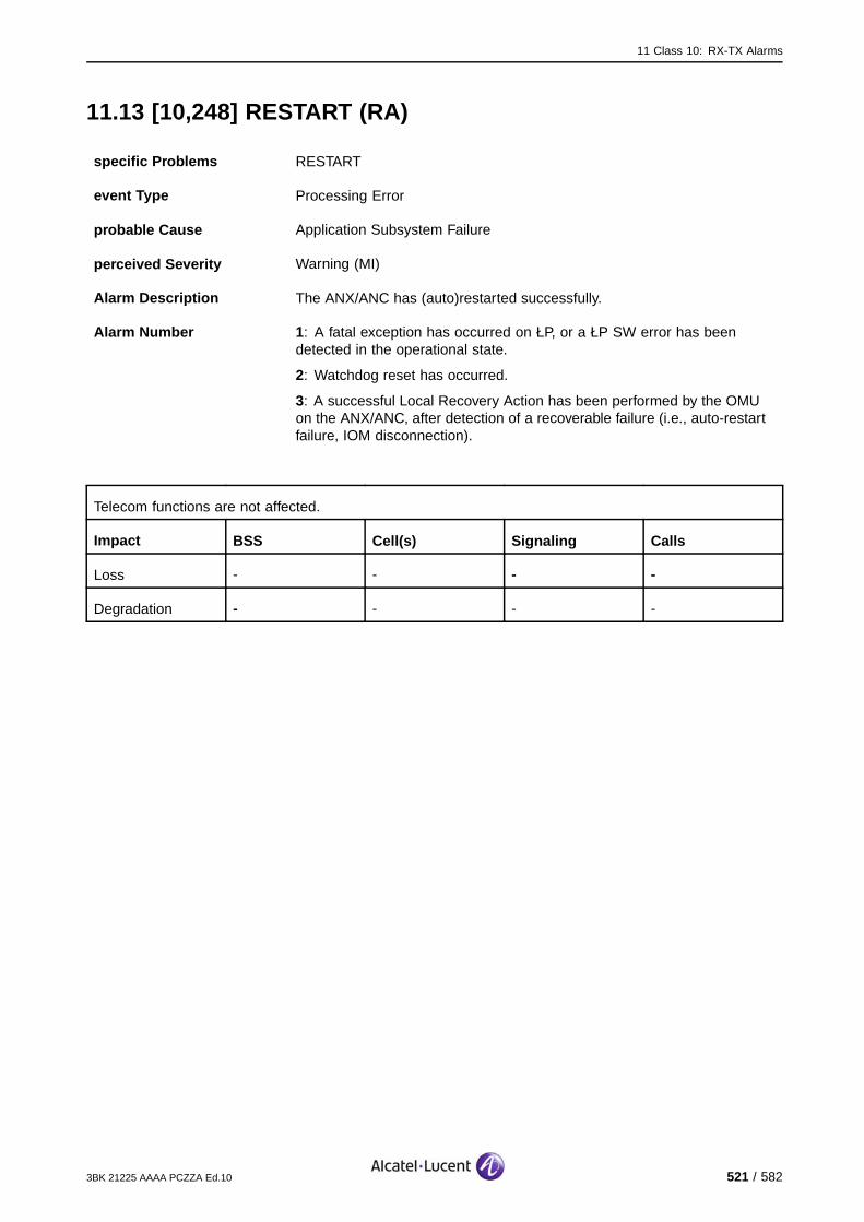
11 Class 10: RX-TX Alarms
11.13 [10,248] RESTART (RA)
specific Problems RESTART
event Type Processing Error
probable Cause Application Subsystem Failure
perceived Severity Warning (MI)
Alarm Description The ANX/ANC has (auto)restarted successfully.
Alarm Number 1 : A fatal exception has occurred on ŁP, or a ŁP SW error has beendetected in the operational state.
2: Watchdog reset has occurred.
3: A successful Local Recovery Action has been performed by the OMUon the ANX/ANC, after detection of a recoverable failure (i.e., auto-restartfailure, IOM disconnection).
Telecom functions are not affected.
Impact BSS Cell(s) Signaling Calls
Loss - - - -
Degradation - - - -
3BK 21225 AAAA PCZZA Ed.10 521 / 582

11 Class 10: RX-TX Alarms
11.13.1 Corrective Actions
Disable RF PowerUse the BTS Terminal to disable RA before disconnecting RF cables.Initialize RA after work.
If the ANX/ANC restarts consecutively after a short period, the parameterssent are corrupted, or there may be a ANX/ANC hardware problem.
[10,248] RESTART (RA)
ContactSystem Support
Lock Function RA
Unlock Function RA
no
RAoperational?
yes Alarmsolved
On−site
Check configuration parameters.
no
Alarm persists?yes Replace
ANX/ANY/ANC
Alarmsolved
no
RAoperational?
yes Alarmsolved
On−site
Figure 277: RESTART (RA): Corrective Actions
522 / 582 3BK 21225 AAAA PCZZA Ed.10

12 Class 11: BTS-TRANS Alarms
12 Class 11: BTS-TRANS Alarms
This section defines the BTS alarms for Class 11: BTS-TRANS alarm class.
3BK 21225 AAAA PCZZA Ed.10 523 / 582

12 Class 11: BTS-TRANS Alarms
12.1 [11,22] LOOP-TO-EQUIPMENT
specific Problems LOOP-TO-EQUIPMENT
event Type Equipment
probable Cause Indeterminate
perceived Severity Major (PMA), Warning (MI)
Alarm Description An external loop is closed on an interface of the module. All channels onthis interface (OML, RSL, TCH) are looped back.
Alarm Number 1: An external loop is closed (in DSWICH) on Abis interface of the module.
2: An external loop is closed (in DSWICH) on BSII interface of the module.
As long as the loop is closed, the concerned channels are not available.
Impact BSS Cell(s) Signaling Calls
Loss - X X X
Degradation - - - -
524 / 582 3BK 21225 AAAA PCZZA Ed.10

12 Class 11: BTS-TRANS Alarms
12.1.1 9100 BTS Corrective Actions
[11,22] LOOP−TO−EQUIPMENT
ContactSystem Support
no
yes
Solve this alarmsRelated BTS alarms?Alarm
persists?
Related BSC alarms? Solve this alarms Alarm persists?
Alarmsolved
no
yes
yes
yes
yes
no
no
no
SBL in fault?Inhibit / allow alarm
reportingAlarm
persists?
no
yesyes
no
Check related SBL (OML, RSL)
BTS TRANS settings ok (CRC4)?
Correct BTS TRANS settings
Alarm persists?
no
yesyes
no
Loop back BTS originated E1 link at
BTS site
Alarm persists?
Loop back BTS originated E1 link at
BSC site
Alarm persists?
Alarm persists?
Solve cabling problem
Replace SUMx
Alarm persists?
Local cabling OK?
No BSS problem; Check E1 link with
line provider.
Check BSC local cabling
yes
yes
yes yes
nono
no
Figure 278: LOOP-TO-EQUIPMENT: 9100 BTS Corrective Actions
3BK 21225 AAAA PCZZA Ed.10 525 / 582
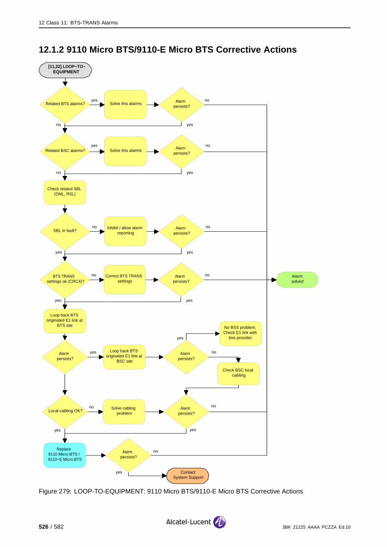
12 Class 11: BTS-TRANS Alarms
12.1.2 9110 Micro BTS/9110-E Micro BTS Corrective Actions
[11,22] LOOP−TO−EQUIPMENT
ContactSystem Support
no
yes
Solve this alarmsRelated BTS alarms?Alarm
persists?
Related BSC alarms? Solve this alarms Alarm persists?
Alarmsolved
no
yes
yes
yes
yes
no
no
no
SBL in fault?Inhibit / allow alarm
reportingAlarm
persists?
no
yesyes
no
Check related SBL (OML, RSL)
BTS TRANS settings ok (CRC4)?
Correct BTS TRANS settings
Alarm persists?
no
yesyes
no
Loop back BTS originated E1 link at
BTS site
Alarm persists?
Loop back BTS originated E1 link at
BSC site
Alarm persists?
Alarm persists?
Solve cabling problem
Replace 9110 Micro BTS / 9110−E Micro BTS
Alarm persists?
Local cabling OK?
No BSS problem; Check E1 link with
line provider.
Check BSC local cabling
yes
yes
yes yes
nono
no
Figure 279: LOOP-TO-EQUIPMENT: 9110 Micro BTS/9110-E Micro BTS Corrective Actions
526 / 582 3BK 21225 AAAA PCZZA Ed.10

12 Class 11: BTS-TRANS Alarms
12.2 [11,50] LOSS-OF-INCOMING-SIGNAL
specific Problems LOSS-OF-INCOMING-SIGNAL
event Type Equipment
probable Cause Indeterminate
perceived Severity Major (PMA), Warning (MI)
Alarm Description There is a loss of incoming 2 Mbit/s signal on the Abis link.
LMT:
The corresponding Abis link is lost. If the link towards the BSC is concerned, the BTS is lost (if noredundancy).
OMC:
Case 1, the link towards the BSC is concerned: The Abis link to the BTS was lost. The Abis link isreestablished and allows the alarm reception (otherwise, without Abis link, no alarms are reported tothe OMC).
Case 2, link in other direction is concerned: The other BTS in the chain are lost.
Impact BSS Cell(s) Signaling Calls
Loss - X X X
Degradation - - - -
3BK 21225 AAAA PCZZA Ed.10 527 / 582

12 Class 11: BTS-TRANS Alarms
12.2.1 9100 BTS Corrective Actions
[11,50] LOSS−OF−INCOMING−SIGNAL
ContactSystem Support
no
yes
Solve this alarmsRelated BTS alarms?Alarm
persists?
Related BSC alarms? Solve this alarms Alarm persists?
Alarmsolved
no
yes
yes
yes
yes
no
no
no
SBL in fault?Inhibit / allow alarm
reportingAlarm
persists?
no
yesyes
no
Check related SBL (OML, RSL)
BTS TRANS settings ok (CRC4)?
Correct BTS TRANS settings
Alarm persists?
no
yesyes
no
Loop back BTS originated E1 link at
BTS site
Alarm persists?
Loop back BTS originated E1 link at
BSC site
Alarm persists?
Alarm persists?
Solve cabling problem
Replace SUMx
Alarm persists?
Local cabling OK?
No BSS problem; Check E1 link with
line provider.
Check BSC local cabling
yes
yes
yes yes
nono
no
Figure 280: LOSS-OF-INCOMING-SIGNAL: 9100 BTS Corrective Actions
528 / 582 3BK 21225 AAAA PCZZA Ed.10
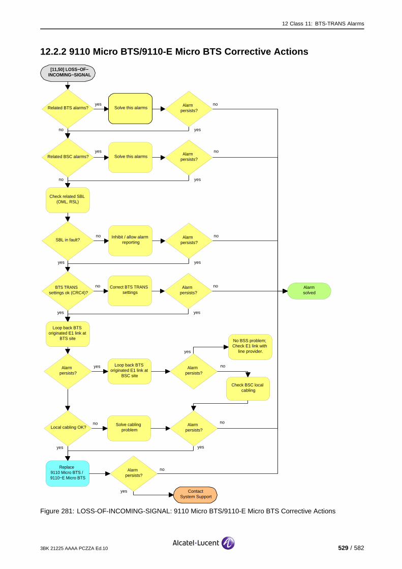
12 Class 11: BTS-TRANS Alarms
12.2.2 9110 Micro BTS/9110-E Micro BTS Corrective Actions
[11,50] LOSS−OF−INCOMING−SIGNAL
ContactSystem Support
no
yes
Solve this alarmsRelated BTS alarms?Alarm
persists?
Related BSC alarms? Solve this alarms Alarm persists?
Alarmsolved
no
yes
yes
yes
yes
no
no
no
SBL in fault?Inhibit / allow alarm
reportingAlarm
persists?
no
yesyes
no
Check related SBL (OML, RSL)
BTS TRANS settings ok (CRC4)?
Correct BTS TRANS settings
Alarm persists?
no
yesyes
no
Loop back BTS originated E1 link at
BTS site
Alarm persists?
Loop back BTS originated E1 link at
BSC site
Alarm persists?
Alarm persists?
Solve cabling problem
Replace 9110 Micro BTS / 9110−E Micro BTS
Alarm persists?
Local cabling OK?
No BSS problem; Check E1 link with
line provider.
Check BSC local cabling
yes
yes
yes yes
nono
no
Figure 281: LOSS-OF-INCOMING-SIGNAL: 9110 Micro BTS/9110-E Micro BTS Corrective Actions
3BK 21225 AAAA PCZZA Ed.10 529 / 582

12 Class 11: BTS-TRANS Alarms
12.3 [11,66] AIS-2M
specific Problems AIS-2M
event Type Equipment
probable Cause Indeterminate
perceived Severity Minor (DMA), Warning (MI)
Alarm Description The 2 Mbit/s interface is receiving a AIS signal (all one indication).
LMT:
The corresponding Abis link is lost. If the link towards the BSC is concerned, the BTS is lost (if noredundancy).
OMC:
Case 1, the link towards the BSC is concerned: The Abis link to the BTS was lost. The Abis link isreestablished and allows the alarm reception (otherwise, without Abis link, no alarms are reported tothe OMC).
Case 2, link in other direction is concerned: The other BTS in the chain are lost.
Impact BSS Cell(s) Signaling Calls
Loss - X X X
Degradation - - - -
530 / 582 3BK 21225 AAAA PCZZA Ed.10
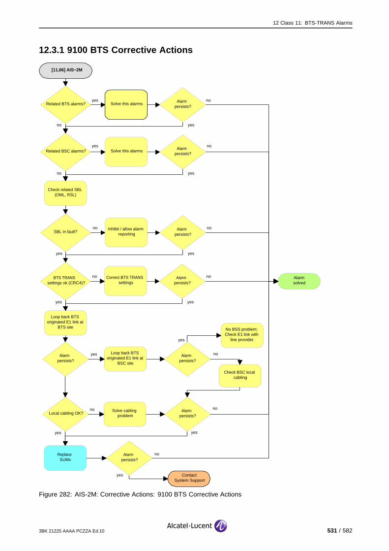
12 Class 11: BTS-TRANS Alarms
12.3.1 9100 BTS Corrective Actions
[11,66] AIS−2M
ContactSystem Support
no
yes
Solve this alarmsRelated BTS alarms?Alarm
persists?
Related BSC alarms? Solve this alarms Alarm persists?
Alarmsolved
no
yes
yes
yes
yes
no
no
no
SBL in fault?Inhibit / allow alarm
reportingAlarm
persists?
no
yesyes
no
Check related SBL (OML, RSL)
BTS TRANS settings ok (CRC4)?
Correct BTS TRANS settings
Alarm persists?
no
yesyes
no
Loop back BTS originated E1 link at
BTS site
Alarm persists?
Loop back BTS originated E1 link at
BSC site
Alarm persists?
Alarm persists?
Solve cabling problem
Replace SUMx
Alarm persists?
Local cabling OK?
No BSS problem; Check E1 link with
line provider.
Check BSC local cabling
yes
yes
yes yes
nono
no
Figure 282: AIS-2M: Corrective Actions: 9100 BTS Corrective Actions
3BK 21225 AAAA PCZZA Ed.10 531 / 582

12 Class 11: BTS-TRANS Alarms
12.3.2 9110 Micro BTS/9110-E Micro BTS Corrective Actions
[11,66] AIS−2M
ContactSystem Support
no
yes
Solve this alarmsRelated BTS alarms?Alarm
persists?
Related BSC alarms? Solve this alarms Alarm persists?
Alarmsolved
no
yes
yes
yes
yes
no
no
no
SBL in fault?Inhibit / allow alarm
reportingAlarm
persists?
no
yesyes
no
Check related SBL (OML, RSL)
BTS TRANS settings ok (CRC4)?
Correct BTS TRANS settings
Alarm persists?
no
yesyes
no
Loop back BTS originated E1 link at
BTS site
Alarm persists?
Loop back BTS originated E1 link at
BSC site
Alarm persists?
Alarm persists?
Solve cabling problem
Replace 9110 Micro BTS / 9110−E Micro BTS
Alarm persists?
Local cabling OK?
No BSS problem; Check E1 link with
line provider.
Check BSC local cabling
yes
yes
yes yes
nono
no
Figure 283: AIS-2M: 9110 Micro BTS/9110-E Micro BTS Corrective Actions
532 / 582 3BK 21225 AAAA PCZZA Ed.10

12 Class 11: BTS-TRANS Alarms
12.4 [11,81] LOSS-OF-FRAME-ALIGNMENT
specific Problems LOSS-OF-FRAME-ALIGNMENT
event Type Equipment
probable Cause Indeterminate
perceived Severity Major (PMA), Warning (MI)
Alarm Description There is a loss of frame alignment on the Abis link.
LMT:
The corresponding Abis link is lost. If the link towards the BSC is concerned, the BTS is lost (if noredundancy).
OMC:
Case 1, the link towards the BSC is concerned: The Abis link to the BTS was lost. The Abis link isreestablished and allows the alarm reception (otherwise, without Abis link, no alarms are reported tothe OMC).
Case 2, link in other direction is concerned: The other BTS in the chain are lost.
Impact BSS Cell(s) Signaling Calls
Loss - X X X
Degradation - - - -
3BK 21225 AAAA PCZZA Ed.10 533 / 582

12 Class 11: BTS-TRANS Alarms
12.4.1 9100 BTS Corrective Actions
[11,81] LOSS−OF−FRAME−ALIGNMENT
ContactSystem Support
no
yes
Solve this alarmsRelated BTS alarms?Alarm
persists?
Related BSC alarms? Solve this alarms Alarm persists?
Alarmsolved
no
yes
yes
yes
yes
no
no
no
SBL in fault?Inhibit / allow alarm
reportingAlarm
persists?
no
yesyes
no
Check related SBL (OML, RSL)
BTS TRANS settings ok (CRC4)?
Correct BTS TRANS settings
Alarm persists?
no
yesyes
no
Loop back BTS originated E1 link at
BTS site
Alarm persists?
Loop back BTS originated E1 link at
BSC site
Alarm persists?
Alarm persists?
Solve cabling problem
Replace SUMx
Alarm persists?
Local cabling OK?
No BSS problem; Check E1 link with
line provider.
Check BSC local cabling
yes
yes
yes yes
nono
no
Figure 284: LOSS-OF-FRAME-ALIGNMENT: 9100 BTS Corrective Actions
534 / 582 3BK 21225 AAAA PCZZA Ed.10

12 Class 11: BTS-TRANS Alarms
12.4.2 9110 Micro BTS/9110-E Micro BTS Corrective Actions
[11,81] LOSS−OF−FRAME−ALIGNMENT
ContactSystem Support
no
yes
Solve this alarmsRelated BTS alarms?Alarm
persists?
Related BSC alarms? Solve this alarms Alarm persists?
Alarmsolved
no
yes
yes
yes
yes
no
no
no
SBL in fault?Inhibit / allow alarm
reportingAlarm
persists?
no
yesyes
no
Check related SBL (OML, RSL)
BTS TRANS settings ok (CRC4)?
Correct BTS TRANS settings
Alarm persists?
no
yesyes
no
Loop back BTS originated E1 link at
BTS site
Alarm persists?
Loop back BTS originated E1 link at
BSC site
Alarm persists?
Alarm persists?
Solve cabling problem
Replace 9110 Micro BTS / 9110−E Micro BTS
Alarm persists?
Local cabling OK?
No BSS problem; Check E1 link with
line provider.
Check BSC local cabling
yes
yes
yes yes
nono
no
Figure 285: LOSS-OF-FRAME-ALIGNMENT: 9110 Micro BTS/9110-E Micro BTS Corrective Actions
3BK 21225 AAAA PCZZA Ed.10 535 / 582

12 Class 11: BTS-TRANS Alarms
12.5 [11,86] LOSS-OF-CRC-MULTIFRAME-ALIGNMENT
specific Problems LOSS-OF-CRC-MULTIFRAME-ALIGNMENT
event Type Equipment
probable Cause Indeterminate
perceived Severity Major (PMA), Warning (MI)
Alarm Description The CRC is not used at the remote end or there may be interferences onthe connection.
The CRC multiframe alignment on the Abis link is lost.
LMT:
The corresponding Abis link is lost. If the link towards the BSC is concerned, the BTS is lost (if noredundancy).
OMC:
Case 1, the link towards the BSC is concerned: The Abis link to the BTS was lost. The Abis link isreestablished and allows the alarm reception (otherwise, without Abis link, no alarms are reported tothe OMC).
Case 2, link in other direction is concerned: The other BTS in the chain are lost.
Impact BSS Cell(s) Signaling Calls
Loss - X X X
Degradation - - - -
536 / 582 3BK 21225 AAAA PCZZA Ed.10

12 Class 11: BTS-TRANS Alarms
12.5.1 9100 BTS Corrective Actions
[11,86] LOSS−OF−CRC−MULTIFRAME−
ALIGNMENT
ContactSystem Support
no
yes
Solve this alarmsRelated BTS alarms?Alarm
persists?
Related BSC alarms? Solve this alarms Alarm persists?
Alarmsolved
no
yes
yes
yes
yes
no
no
no
SBL in fault?Inhibit / allow alarm
reportingAlarm
persists?
no
yesyes
no
Check related SBL (OML, RSL)
BTS TRANS settings ok (CRC4)?
Correct BTS TRANS settings
Alarm persists?
no
yesyes
no
Loop back BTS originated E1 link at
BTS site
Alarm persists?
Loop back BTS originated E1 link at
BSC site
Alarm persists?
Alarm persists?
Solve cabling problem
Replace SUMx
Alarm persists?
Local cabling OK?
No BSS problem; Check E1 link with
line provider.
Check BSC local cabling
yes
yes
yes yes
nono
no
Figure 286: LOSS-OF-CRC-MULTIFRAME-ALIGNMENT: 9100 BTS Corrective Actions
3BK 21225 AAAA PCZZA Ed.10 537 / 582

12 Class 11: BTS-TRANS Alarms
12.5.2 9110 Micro BTS/9110-E Micro BTS Corrective Actions
[11,86] LOSS−OF−CRC−MULTIFRAME−
ALIGNMENT
ContactSystem Support
no
yes
Solve this alarmsRelated BTS alarms?Alarm
persists?
Related BSC alarms? Solve this alarms Alarm persists?
Alarmsolved
no
yes
yes
yes
yes
no
no
no
SBL in fault?Inhibit / allow alarm
reportingAlarm
persists?
no
yesyes
no
Check related SBL (OML, RSL)
BTS TRANS settings ok (CRC4)?
Correct BTS TRANS settings
Alarm persists?
no
yesyes
no
Loop back BTS originated E1 link at
BTS site
Alarm persists?
Loop back BTS originated E1 link at
BSC site
Alarm persists?
Alarm persists?
Solve cabling problem
Replace 9110 Micro BTS / 9110−E Micro BTS
Alarm persists?
Local cabling OK?
No BSS problem; Check E1 link with
line provider.
Check BSC local cabling
yes
yes
yes yes
nono
no
Figure 287: LOSS-OF-CRC-MULTIFRAME-ALIGNMENT: 9110 Micro BTS/9110-E Micro BTS CorrectiveActions
538 / 582 3BK 21225 AAAA PCZZA Ed.10

12 Class 11: BTS-TRANS Alarms
12.6 [11,99] ERROR-RATE >E-3
specific Problems ERROR-RATE>E-3
event Type Equipment
probable Cause Indeterminate
perceived Severity Major (PMA), Warning (MI)
Alarm Description The error rate of the incoming main system signal on the Abis link is worsethan the threshold value E-3.
LMT:
The corresponding Abis link is lost. If the link towards the BSC is concerned, the BTS is lost (if noredundancy).
OMC:
Case 1, the link towards the BSC is concerned: The Abis link to the BTS was lost. The Abis link isreestablished and allows the alarm reception (otherwise, without Abis link, no alarms are reported tothe OMC).
Case 2, link in other direction is concerned: The other BTS in the chain are lost.
Impact BSS Cell(s) Signaling Calls
Loss - X X X
Degradation - - - -
3BK 21225 AAAA PCZZA Ed.10 539 / 582
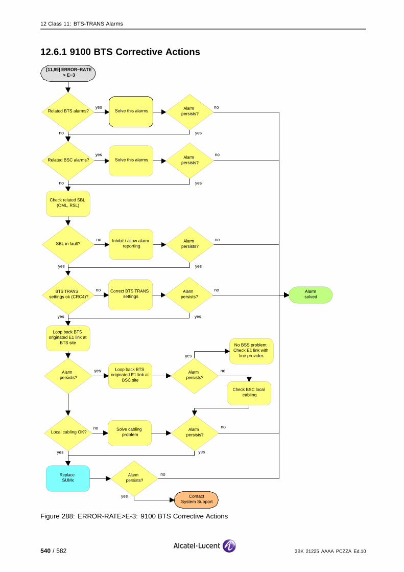
12 Class 11: BTS-TRANS Alarms
12.6.1 9100 BTS Corrective Actions
[11,99] ERROR−RATE > E−3
ContactSystem Support
no
yes
Solve this alarmsRelated BTS alarms?Alarm
persists?
Related BSC alarms? Solve this alarms Alarm persists?
Alarmsolved
no
yes
yes
yes
yes
no
no
no
SBL in fault?Inhibit / allow alarm
reportingAlarm
persists?
no
yesyes
no
Check related SBL (OML, RSL)
BTS TRANS settings ok (CRC4)?
Correct BTS TRANS settings
Alarm persists?
no
yesyes
no
Loop back BTS originated E1 link at
BTS site
Alarm persists?
Loop back BTS originated E1 link at
BSC site
Alarm persists?
Alarm persists?
Solve cabling problem
Replace SUMx
Alarm persists?
Local cabling OK?
No BSS problem; Check E1 link with
line provider.
Check BSC local cabling
yes
yes
yes yes
nono
no
Figure 288: ERROR-RATE>E-3: 9100 BTS Corrective Actions
540 / 582 3BK 21225 AAAA PCZZA Ed.10

12 Class 11: BTS-TRANS Alarms
12.6.2 9110 Micro BTS/9110-E Micro BTS Corrective Actions
[11,99] ERROR−RATE > E−3
ContactSystem Support
no
yes
Solve this alarmsRelated BTS alarms?Alarm
persists?
Related BSC alarms? Solve this alarms Alarm persists?
Alarmsolved
no
yes
yes
yes
yes
no
no
no
SBL in fault?Inhibit / allow alarm
reportingAlarm
persists?
no
yesyes
no
Check related SBL (OML, RSL)
BTS TRANS settings ok (CRC4)?
Correct BTS TRANS settings
Alarm persists?
no
yesyes
no
Loop back BTS originated E1 link at
BTS site
Alarm persists?
Loop back BTS originated E1 link at
BSC site
Alarm persists?
Alarm persists?
Solve cabling problem
Replace 9110 Micro BTS / 9110−E Micro BTS
Alarm persists?
Local cabling OK?
No BSS problem; Check E1 link with
line provider.
Check BSC local cabling
yes
yes
yes yes
nono
no
Figure 289: ERROR-RATE>E-3: 9110 Micro BTS/9110-E Micro BTS Corrective Actions
3BK 21225 AAAA PCZZA Ed.10 541 / 582
12 Class 11: BTS-TRANS Alarms
12.7 [11,100] ERROR-RATE >E-4
specific Problems ERROR-RATE>E-4
event Type Equipment
probable Cause Indeterminate
perceived Severity Minor (DMA), Event (Mi)
Alarm Description The error rate of the incoming main system signal on the Abis link is worsethan the threshold value E-4.
LMT:
The corresponding Abis link is degraded.
OMC:
Case 1, the link towards the BSC is concerned: The Abis link to the BTS is degraded.
Case 2, link in other direction is concerned: The link to the other BTS in the chain is degraded.
Impact BSS Cell(s) Signaling Calls
Loss - - - -
Degradation - - X X
542 / 582 3BK 21225 AAAA PCZZA Ed.10

12 Class 11: BTS-TRANS Alarms
12.7.1 9100 BTS Corrective Actions
[11,100] ERROR−RATE > E−4
ContactSystem Support
no
yes
Solve this alarmsRelated BTS alarms?Alarm
persists?
Related BSC alarms? Solve this alarms Alarm persists?
Alarmsolved
no
yes
yes
yes
yes
no
no
no
SBL in fault?Inhibit / allow alarm
reportingAlarm
persists?
no
yesyes
no
Check related SBL (OML, RSL)
BTS TRANS settings ok (CRC4)?
Correct BTS TRANS settings
Alarm persists?
no
yesyes
no
Loop back BTS originated E1 link at
BTS site
Alarm persists?
Loop back BTS originated E1 link at
BSC site
Alarm persists?
Alarm persists?
Solve cabling problem
Replace SUMx
Alarm persists?
Local cabling OK?
No BSS problem; Check E1 link with
line provider.
Check BSC local cabling
yes
yes
yes yes
nono
no
Figure 290: ERROR-RATE>E-4: 9100 BTS Corrective Actions
3BK 21225 AAAA PCZZA Ed.10 543 / 582
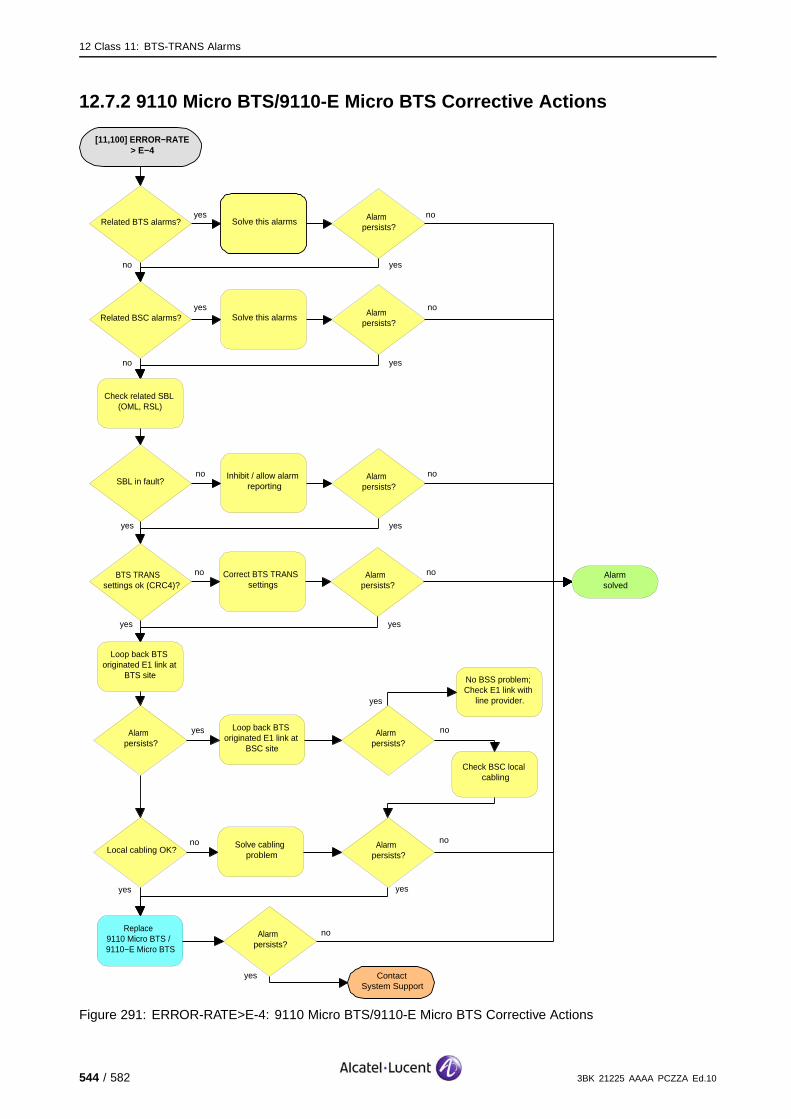
12 Class 11: BTS-TRANS Alarms
12.7.2 9110 Micro BTS/9110-E Micro BTS Corrective Actions
[11,100] ERROR−RATE > E−4
ContactSystem Support
no
yes
Solve this alarmsRelated BTS alarms?Alarm
persists?
Related BSC alarms? Solve this alarms Alarm persists?
Alarmsolved
no
yes
yes
yes
yes
no
no
no
SBL in fault?Inhibit / allow alarm
reportingAlarm
persists?
no
yesyes
no
Check related SBL (OML, RSL)
BTS TRANS settings ok (CRC4)?
Correct BTS TRANS settings
Alarm persists?
no
yesyes
no
Loop back BTS originated E1 link at
BTS site
Alarm persists?
Loop back BTS originated E1 link at
BSC site
Alarm persists?
Alarm persists?
Solve cabling problem
Replace 9110 Micro BTS / 9110−E Micro BTS
Alarm persists?
Local cabling OK?
No BSS problem; Check E1 link with
line provider.
Check BSC local cabling
yes
yes
yes yes
nono
no
Figure 291: ERROR-RATE>E-4: 9110 Micro BTS/9110-E Micro BTS Corrective Actions
544 / 582 3BK 21225 AAAA PCZZA Ed.10
12 Class 11: BTS-TRANS Alarms
12.8 [11,102] ERROR-RATE >E-6
specific Problems ERROR-RATE>E-6
event Type Equipment
probable Cause Indeterminate
perceived Severity Minor (DMA), Warning (MI)
Alarm Description The error rate of the incoming main system signal in Abis is worse than thethreshold value E-6.
LMT:
The corresponding Abis link is possibly degraded.
OMC:
Case 1, the link towards the BSC is concerned: The Abis link to the BTS is possibly degraded.
Case 2, link in other direction is concerned: The link to the other BTS in the chain is possibly degraded.
Impact BSS Cell(s) Signaling Calls
Loss - - - -
Degradation - - (X) (X)
3BK 21225 AAAA PCZZA Ed.10 545 / 582

12 Class 11: BTS-TRANS Alarms
12.8.1 9100 BTS Corrective Actions
[11,102] ERROR−RATE > E−6
ContactSystem Support
no
yes
Solve this alarmsRelated BTS alarms?Alarm
persists?
Related BSC alarms? Solve this alarms Alarm persists?
Alarmsolved
no
yes
yes
yes
yes
no
no
no
SBL in fault?Inhibit / allow alarm
reportingAlarm
persists?
no
yesyes
no
Check related SBL (OML, RSL)
BTS TRANS settings ok (CRC4)?
Correct BTS TRANS settings
Alarm persists?
no
yesyes
no
Loop back BTS originated E1 link at
BTS site
Alarm persists?
Loop back BTS originated E1 link at
BSC site
Alarm persists?
Alarm persists?
Solve cabling problem
Replace SUMx
Alarm persists?
Local cabling OK?
No BSS problem; Check E1 link with
line provider.
Check BSC local cabling
yes
yes
yes yes
nono
no
Figure 292: ERROR-RATE>E-6: 9100 BTS Corrective Actions
546 / 582 3BK 21225 AAAA PCZZA Ed.10

12 Class 11: BTS-TRANS Alarms
12.8.2 9110 Micro BTS/9110-E Micro BTS Corrective Actions
[11,102] ERROR−RATE > E−6
ContactSystem Support
no
yes
Solve this alarmsRelated BTS alarms?Alarm
persists?
Related BSC alarms? Solve this alarms Alarm persists?
Alarmsolved
no
yes
yes
yes
yes
no
no
no
SBL in fault?Inhibit / allow alarm
reportingAlarm
persists?
no
yesyes
no
Check related SBL (OML, RSL)
BTS TRANS settings ok (CRC4)?
Correct BTS TRANS settings
Alarm persists?
no
yesyes
no
Loop back BTS originated E1 link at
BTS site
Alarm persists?
Loop back BTS originated E1 link at
BSC site
Alarm persists?
Alarm persists?
Solve cabling problem
Replace 9110 Micro BTS / 9110−E Micro BTS
Alarm persists?
Local cabling OK?
No BSS problem; Check E1 link with
line provider.
Check BSC local cabling
yes
yes
yes yes
nono
no
Figure 293: ERROR-RATE>E-6: 9110 Micro BTS/9110-E Micro BTS Corrective Actions
3BK 21225 AAAA PCZZA Ed.10 547 / 582

12 Class 11: BTS-TRANS Alarms
12.9 [11,176] REMOTE-ALARM-INDICATION
specific Problems REMOTE-ALARM-INDICATION
event Type Equipment
probable Cause Indeterminate
perceived Severity Minor (DMA), Event (Mi)
Alarm Description An alarm indication from the remote end is detected. The remote endhas set RAI bit in TS0 or F bit in TS 1...31 in order to indicate receptionproblems.
LMT:
The corresponding Abis link is lost. If the link towards the BSC is concerned, the BTS is lost (if noredundancy).
OMC:
Case 1, the link towards the BSC is concerned: The Abis link to the BTS was lost. The Abis link isreestablished and allows the alarm reception (otherwise, without Abis link, no alarms are reported tothe OMC).
Case 2, link in other direction is concerned: The other BTS in the chain are lost.
Impact BSS Cell(s) Signaling Calls
Loss - X X X
Degradation - - - -
548 / 582 3BK 21225 AAAA PCZZA Ed.10
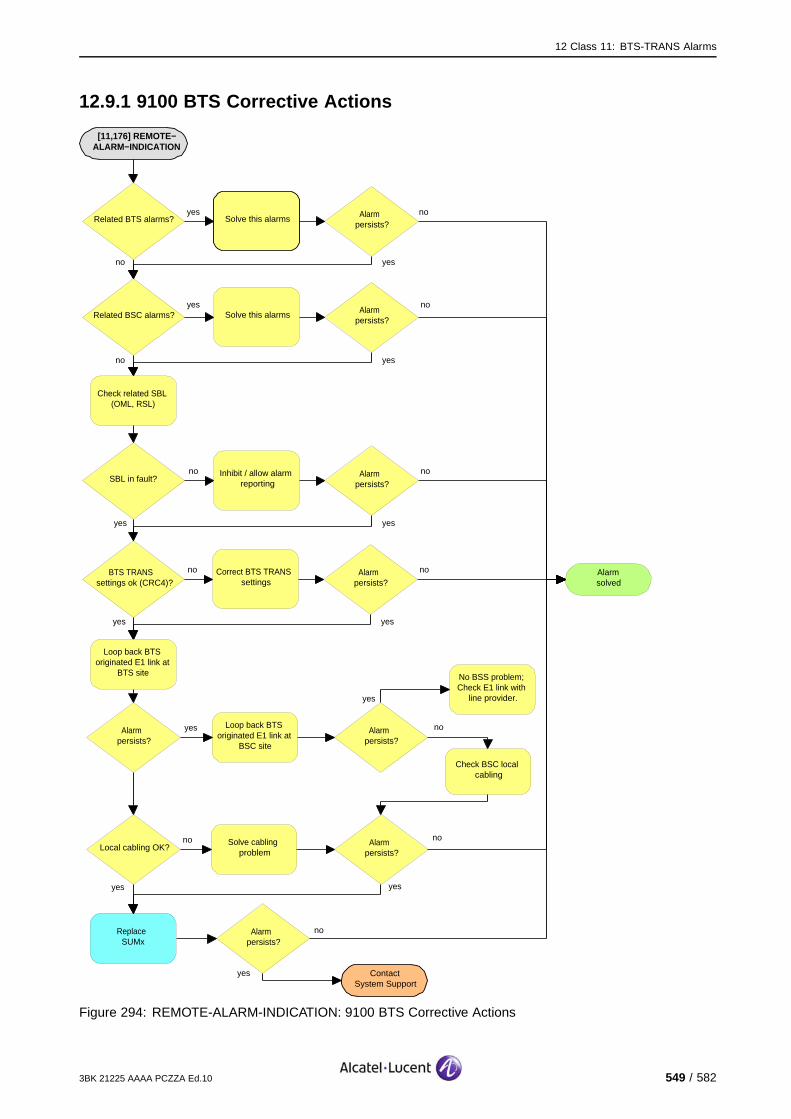
12 Class 11: BTS-TRANS Alarms
12.9.1 9100 BTS Corrective Actions
[11,176] REMOTE−ALARM−INDICATION
ContactSystem Support
no
yes
Solve this alarmsRelated BTS alarms?Alarm
persists?
Related BSC alarms? Solve this alarms Alarm persists?
Alarmsolved
no
yes
yes
yes
yes
no
no
no
SBL in fault?Inhibit / allow alarm
reportingAlarm
persists?
no
yesyes
no
Check related SBL (OML, RSL)
BTS TRANS settings ok (CRC4)?
Correct BTS TRANS settings
Alarm persists?
no
yesyes
no
Loop back BTS originated E1 link at
BTS site
Alarm persists?
Loop back BTS originated E1 link at
BSC site
Alarm persists?
Alarm persists?
Solve cabling problem
Replace SUMx
Alarm persists?
Local cabling OK?
No BSS problem; Check E1 link with
line provider.
Check BSC local cabling
yes
yes
yes yes
nono
no
Figure 294: REMOTE-ALARM-INDICATION: 9100 BTS Corrective Actions
3BK 21225 AAAA PCZZA Ed.10 549 / 582
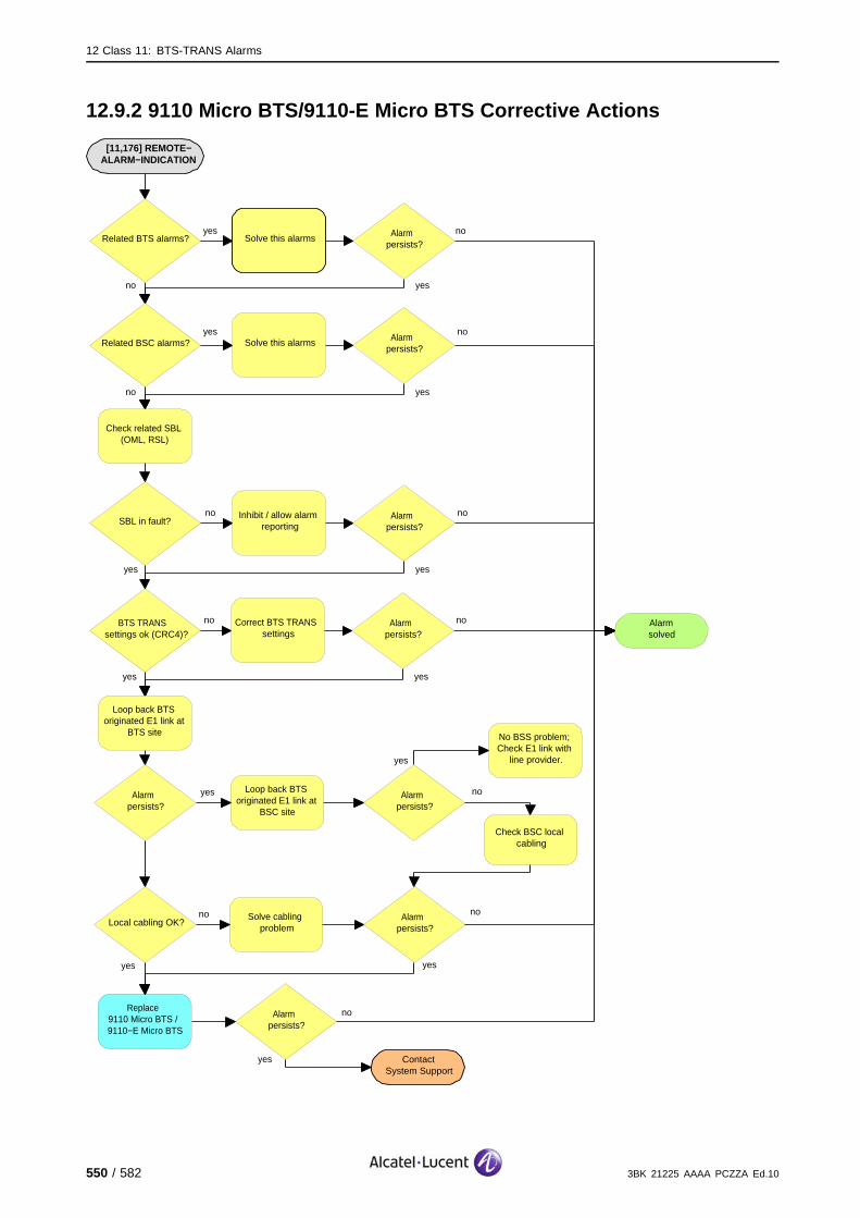
12 Class 11: BTS-TRANS Alarms
12.9.2 9110 Micro BTS/9110-E Micro BTS Corrective Actions
[11,176] REMOTE−ALARM−INDICATION
ContactSystem Support
no
yes
Solve this alarmsRelated BTS alarms?Alarm
persists?
Related BSC alarms? Solve this alarms Alarm persists?
Alarmsolved
no
yes
yes
yes
yes
no
no
no
SBL in fault?Inhibit / allow alarm
reportingAlarm
persists?
no
yesyes
no
Check related SBL (OML, RSL)
BTS TRANS settings ok (CRC4)?
Correct BTS TRANS settings
Alarm persists?
no
yesyes
no
Loop back BTS originated E1 link at
BTS site
Alarm persists?
Loop back BTS originated E1 link at
BSC site
Alarm persists?
Alarm persists?
Solve cabling problem
Replace 9110 Micro BTS / 9110−E Micro BTS
Alarm persists?
Local cabling OK?
No BSS problem; Check E1 link with
line provider.
Check BSC local cabling
yes
yes
yes yes
nono
no
550 / 582 3BK 21225 AAAA PCZZA Ed.10

13 BTS Alarm Additional Information
13 BTS Alarm Additional Information
This section describes the additional information supplied by some BTS alarms.
3BK 21225 AAAA PCZZA Ed.10 551 / 582

13 BTS Alarm Additional Information
13.1 BTS Alarms with Additional InformationThis section describes the BTS alarms that can provide additional information.Depending on the alarm, the additional information can comprise one ormore TLV codes.
13.1.1 [2,247]
The coding of the additional information for this alarm depends on the alarmnumber, as shown in Table 5. This information is only provided if the OMU hasbattery backup for its RAM.
Alarm Number Bytes Coding
4 1 - 5
6 - 24
TLV120
TLV83
5 1 - 5
6 - 37
TLV120
TLV84
6 1 - 5
6 - 24
TLV120
TLV83
7 1 - 5
6 - 176
TLV120
TLV82
Table 5: Alarm [2,247] TLV Codes
13.1.2 [2,248]
The coding of the additional information for this alarm depends on the alarmnumber, as shown in Table 6.
Alarm Number Bytes Coding
1 1 - 5
6 - 37
TLV120
TLV84
3 1 - 5
6 - 24
TLV120
TLV83
4 1 - 5
6 - 176
TLV120
TLV82
Table 6: Alarm [2,248] TLV Codes
13.1.3 [7,1]
The additional information for this alarm is TLV53 coded.
552 / 582 3BK 21225 AAAA PCZZA Ed.10
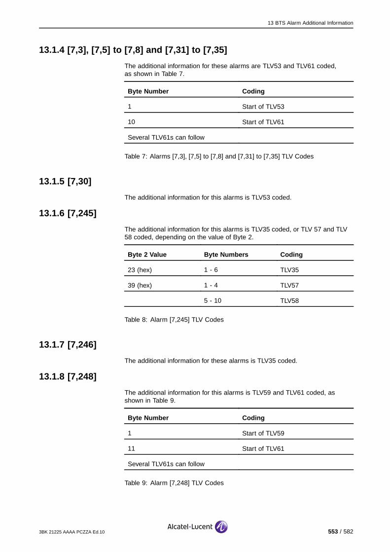
13 BTS Alarm Additional Information
13.1.4 [7,3], [7,5] to [7,8] and [7,31] to [7,35]
The additional information for these alarms are TLV53 and TLV61 coded,as shown in Table 7.
Byte Number Coding
1 Start of TLV53
10 Start of TLV61
Several TLV61s can follow
Table 7: Alarms [7,3], [7,5] to [7,8] and [7,31] to [7,35] TLV Codes
13.1.5 [7,30]
The additional information for this alarms is TLV53 coded.
13.1.6 [7,245]
The additional information for this alarms is TLV35 coded, or TLV 57 and TLV58 coded, depending on the value of Byte 2.
Byte 2 Value Byte Numbers Coding
23 (hex) 1 - 6 TLV35
39 (hex) 1 - 4 TLV57
5 - 10 TLV58
Table 8: Alarm [7,245] TLV Codes
13.1.7 [7,246]
The additional information for these alarms is TLV35 coded.
13.1.8 [7,248]
The additional information for this alarms is TLV59 and TLV61 coded, asshown in Table 9.
Byte Number Coding
1 Start of TLV59
11 Start of TLV61
Several TLV61s can follow
Table 9: Alarm [7,248] TLV Codes
3BK 21225 AAAA PCZZA Ed.10 553 / 582
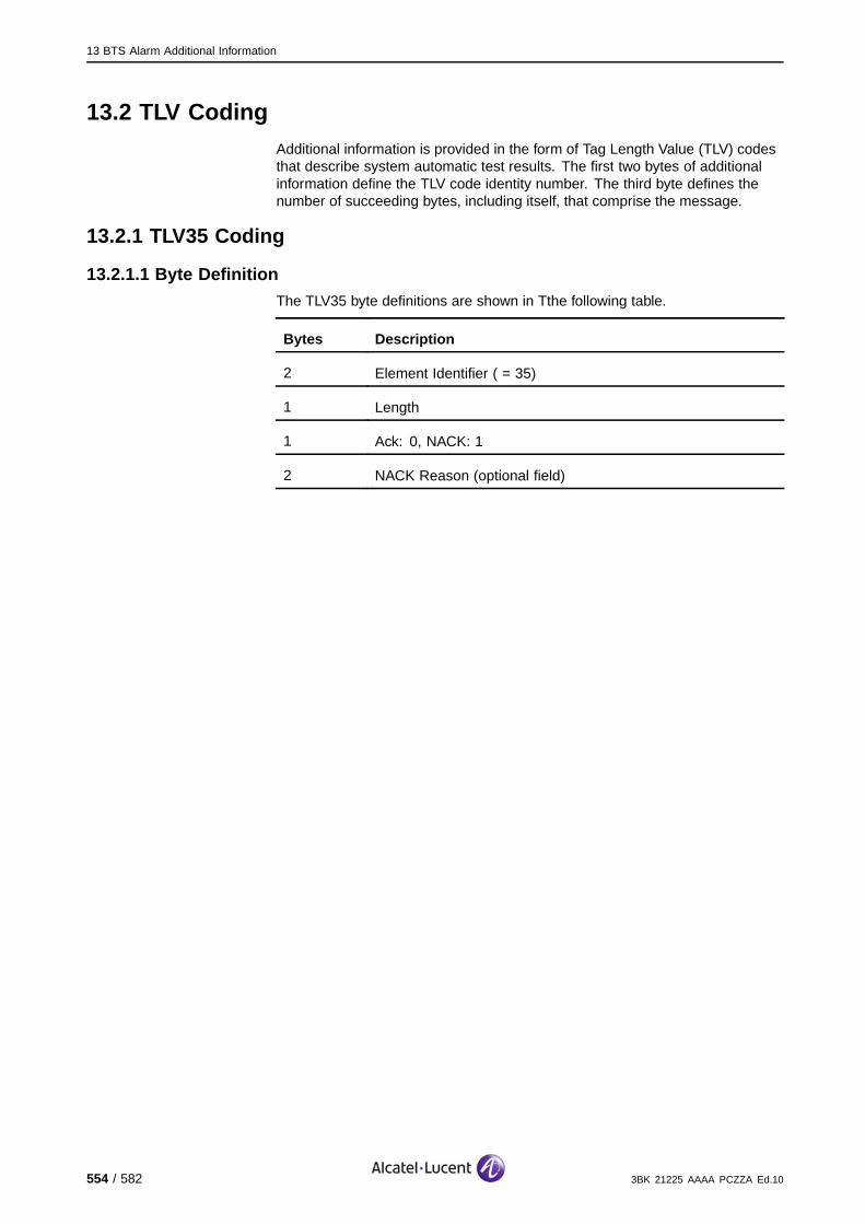
13 BTS Alarm Additional Information
13.2 TLV CodingAdditional information is provided in the form of Tag Length Value (TLV) codesthat describe system automatic test results. The first two bytes of additionalinformation define the TLV code identity number. The third byte defines thenumber of succeeding bytes, including itself, that comprise the message.
13.2.1 TLV35 Coding
13.2.1.1 Byte DefinitionThe TLV35 byte definitions are shown in Tthe following table.
Bytes Description
2 Element Identifier ( = 35)
1 Length
1 Ack: 0, NACK: 1
2 NACK Reason (optional field)
554 / 582 3BK 21225 AAAA PCZZA Ed.10

13 BTS Alarm Additional Information
13.2.1.2 NACK ReasonThe NACK Reason field provides more information concerning the messagerejection.
When messages are received from the OMU, the FU uses the two-byte NACKReason field as follows:
The first byte defines the NACK Type, as shown in Table 10
The second byte defines the Error Number, as shown in Table 11.
NACKType Description
1 An unknown message was received.
2 The FU was not in a convenient substate when the message was received.
3 Error during software downloading.
4 Error during configuration file downloading or configuration messages sequencing error.
5 Wrong parameter in the configuration file.
6 Wrong parameter in the CONFIGURATION DATA message.
7 Wrong parameter in the FUIF LINK SELECT message.
Table 10: NACK Types for TLV35
NACKType Error Number Description
1 Not relevant.
2 Not relevant.
1 Record sequence number error.
2 File header error.
3 Record type error.
4 Sequence error.
5 Software checksum error.
6 Time out error at the beginning of the SCP downloading.
7 Block sequence number error.
8 File length error.
9 Record length error.
3
10 Time out error from an FU entity.
3BK 21225 AAAA PCZZA Ed.10 555 / 582

13 BTS Alarm Additional Information
NACKType Error Number Description
1 Record sequence number error.
2 File header error.
3 Record type error.
4 Sequence error.
4
8 File length error.
The identity of the wrong parameter is given in brackets.
1 Maximum number of PAGING REQUEST messages out of range(PG_FULL).
2 Polling period of FUIF is zero (FUISUP_PR).
3 Time out for FUIF response is zero (FUISUP_TO).
4 Polling period of MFP is zero (MFPSUP_PR).
5 Time out for MFP response is zero (MFPSUP_TO).
6 I_LAPD_MAX_RX out of range.
7 AG_FULL out of range.
8 I_LAPD_MAX_TX out of range.
9 UI_LAPD_MAX_TX out of range.
10 Wrong checking for T_MEAS.
11 Wrong checking for T_Sync.
5
12 BSI_TIMER = 0.
The name of the wrong parameter is given in brackets.
1 Interference band value out of range (INTFBDi).
2 Wrong order between two interference band values (INTFBDi).
6
3 Channel configuration value out of range (CHCCONFi).
6 4 Channel configuration value not allowed.
556 / 582 3BK 21225 AAAA PCZZA Ed.10
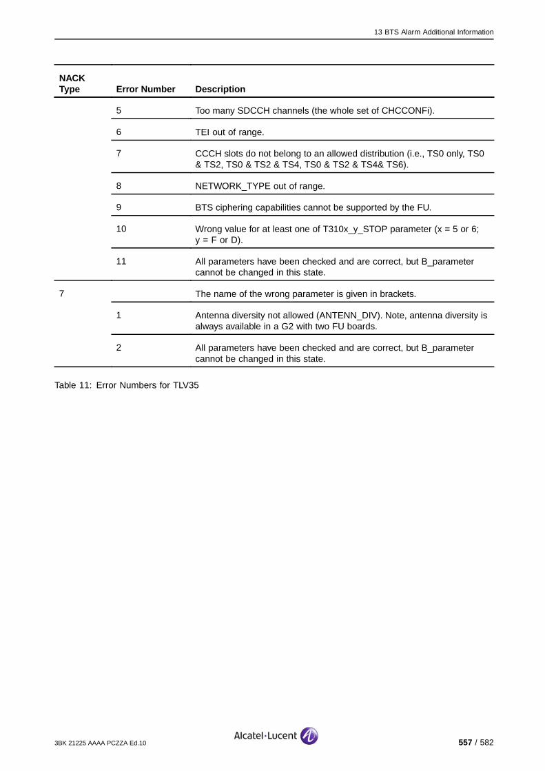
13 BTS Alarm Additional Information
NACKType Error Number Description
5 Too many SDCCH channels (the whole set of CHCCONFi).
6 TEI out of range.
7 CCCH slots do not belong to an allowed distribution (i.e., TS0 only, TS0& TS2, TS0 & TS2 & TS4, TS0 & TS2 & TS4& TS6).
8 NETWORK_TYPE out of range.
9 BTS ciphering capabilities cannot be supported by the FU.
10 Wrong value for at least one of T310x_y_STOP parameter (x = 5 or 6;y = F or D).
11 All parameters have been checked and are correct, but B_parametercannot be changed in this state.
The name of the wrong parameter is given in brackets.
1 Antenna diversity not allowed (ANTENN_DIV). Note, antenna diversity isalways available in a G2 with two FU boards.
7
2 All parameters have been checked and are correct, but B_parametercannot be changed in this state.
Table 11: Error Numbers for TLV35
3BK 21225 AAAA PCZZA Ed.10 557 / 582

13 BTS Alarm Additional Information
13.2.2 TLV49 Coding
The TLV49 byte definitions are shown in the following table.
Bytes Description - FU HW Capability
2 Element Identifier ( = 49)
1 Length (=4)
1 FU Generation 0 = G1 FU, G2 FU3
1 = G2 FU2
2 = G2 9110 Micro BTS
3 = DR-FU
4 = 9100 TRE
FF = unknown
1 FR/DR bits 7 to 3 - unused (bit 7 is hi-order bit on the left)
bit 2 Enhanced Full Rate -Not Provided (0) Provided (1)
bit 1 Full Rate -Not Provided (0) Provided (1
bit 0 Half Rate -Not Provided (0) Provided (1)
1 FU CIPHERINGCAPABILITY
bit 7 Encryption with A5/7 algorithm - Not Provided (0) Provided (1)
bit 6 Encryption with A5/6 algorithm - Not Provided (0) Provided (1)
bit 5 Encryption with A5/5 algorithm - Not Provided (0) Provided (1)
bit 4 Encryption with A5/4 algorithm - Not Provided (0) Provided (1)
bit 3 Encryption with A5/3 algorithm - Not Provided (0) Provided (1)
bit 2 Encryption with A5/2 algorithm - Not Provided (0) Provided (1)
bit 1 Encryption with A5/1 algorithm - Not Provided (0) Provided (1)
bit 0 No Encryption - always 1 = provided (always possible)
FF = all algorithms supported. )) never sent by the FUunknown.
1 RSL RATECAPABILITY
bits 7 to 2 - unused (bit 7 is hi-order bit on the left)
bit 1 = 64 Kb/sec - Not Provided (0) Provided (1)
bit 0 = 16 Kb/sec - Not Provided (0) Provided (1)
FF = unknown
558 / 582 3BK 21225 AAAA PCZZA Ed.10
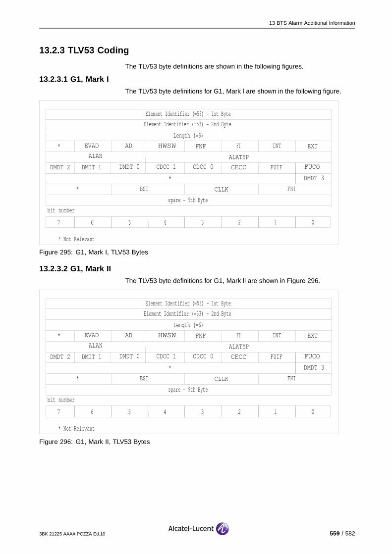
13 BTS Alarm Additional Information
13.2.3 TLV53 Coding
The TLV53 byte definitions are shown in the following figures.
13.2.3.1 G1, Mark IThe TLV53 byte definitions for G1, Mark l are shown in the following figure.
Element Identifier (=53) − 1st Byte
Element Identifier (=53) − 2nd Byte
Length (=6)
* Not Relevant
bit number
spare − 9th Byte
*
*
*
EVAD AD HWSW FNF FI INT EXT
ALAN ALATYP
DMDT 2 DMDT 1 DMDT 0 CDCC 1 CDCC 0 CECC FUIF FUCO
DMDT 3
CLLKBSI FHI
7 6 5 4 3 2 1 0
Figure 295: G1, Mark I, TLV53 Bytes
13.2.3.2 G1, Mark IIThe TLV53 byte definitions for G1, Mark ll are shown in Figure 296.
Element Identifier (=53) − 1st Byte
Element Identifier (=53) − 2nd Byte
Length (=6)
* Not Relevant
bit number
spare − 9th Byte
*
*
*
EVAD AD HWSW FNF FI INT EXT
ALAN ALATYP
DMDT 2 DMDT 1 DMDT 0 CDCC 1 CDCC 0 CECC FUIF FUCO
DMDT 3
CLLKBSI FHI
7 6 5 4 3 2 1 0
Figure 296: G1, Mark II, TLV53 Bytes
3BK 21225 AAAA PCZZA Ed.10 559 / 582
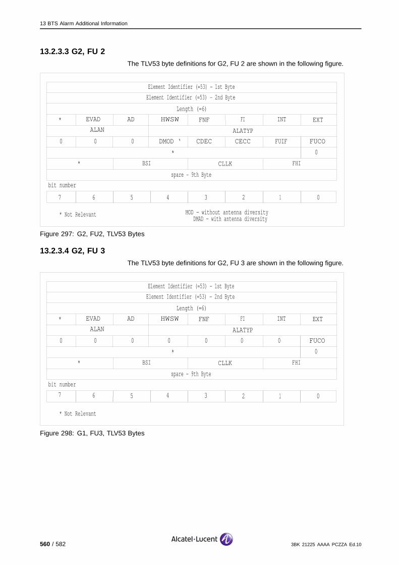
13 BTS Alarm Additional Information
13.2.3.3 G2, FU 2The TLV53 byte definitions for G2, FU 2 are shown in the following figure.
Element Identifier (=53) − 1st Byte
Element Identifier (=53) − 2nd Byte
Length (=6)
* Not Relevant
bit number
spare − 9th Byte
*
*
*
EVAD AD HWSW FNF FI INT EXT
ALAN ALATYP
0 DMOD ‘ CDEC CECC FUIF FUCO
0
CLLKBSI FHI
7 6 5 4 3 2 1 0
0 0
�MOD − without antenna diversity DMAD − with antenna diversity
Figure 297: G2, FU2, TLV53 Bytes
13.2.3.4 G2, FU 3The TLV53 byte definitions for G2, FU 3 are shown in the following figure.
Element Identifier (=53) − 1st Byte
Element Identifier (=53) − 2nd Byte
Length (=6)
* Not Relevant
bit number
spare − 9th Byte
*
*
*
EVAD AD HWSW FNF FI INT EXT
ALAN ALATYP
0 0 0 0 0 FUCO
0
CLLKBSI FHI
7 6 5 4 3 2 1 0
0 0
Figure 298: G1, FU3, TLV53 Bytes
560 / 582 3BK 21225 AAAA PCZZA Ed.10
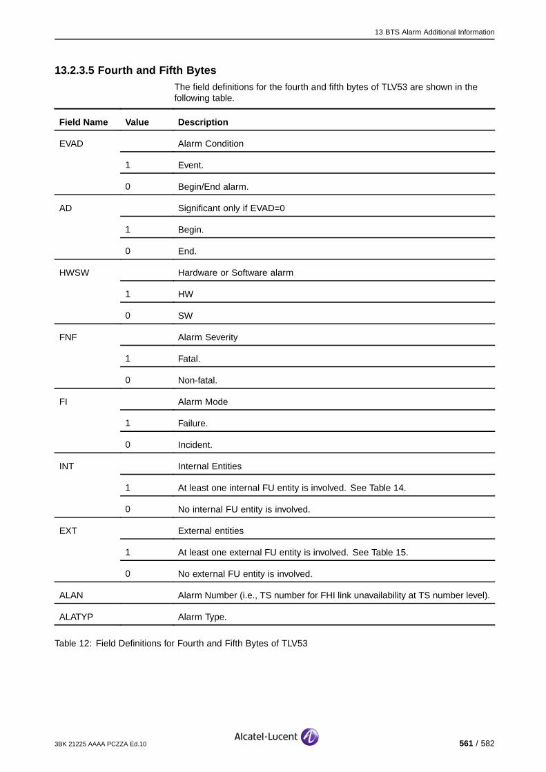
13 BTS Alarm Additional Information
13.2.3.5 Fourth and Fifth BytesThe field definitions for the fourth and fifth bytes of TLV53 are shown in thefollowing table.
Field Name Value Description
Alarm Condition
1 Event.
EVAD
0 Begin/End alarm.
Significant only if EVAD=0
1 Begin.
AD
0 End.
Hardware or Software alarm
1 HW
HWSW
0 SW
Alarm Severity
1 Fatal.
FNF
0 Non-fatal.
Alarm Mode
1 Failure.
FI
0 Incident.
Internal Entities
1 At least one internal FU entity is involved. See Table 14.
INT
0 No internal FU entity is involved.
External entities
1 At least one external FU entity is involved. See Table 15.
EXT
0 No external FU entity is involved.
ALAN Alarm Number (i.e., TS number for FHI link unavailability at TS number level).
ALATYP Alarm Type.
Table 12: Field Definitions for Fourth and Fifth Bytes of TLV53
3BK 21225 AAAA PCZZA Ed.10 561 / 582

13 BTS Alarm Additional Information
13.2.3.6 AlarmsThe FU alarms and alarm types for TLV53 are shown in Table 13.
ALATYP ALAN Name of Fault Code Description of Fault Code
G1, G2FU2/FU3DRFU Micr o-BTS
1 0 SCP-MP-FAULT SCP micro-processor fault, detectedin operational state.
X X
2 0 NON-SCP-MP-FAULT Non-SCP micro-processor fault,detected in operational state.
X X
3 0 AL-LIST-ER Alarm list erased, detected inoperational state.
X X
4 0 LAPD-LINK LAPD link lost. X X
5 0 MCLU-LINK-1 MCLU link 0 lost. X -
6 0 MCLU-LINK-2 MCLU link 1 lost. X -
7 0 BSI-LINK-0 BSI link 0 lost. X -
8 0 BOTH-BSI-LINK Both BSI links lost. X -
9 0 FHI-LNK-0-FUL-UN FHI link 0 fully available uplink. X -
10 0 FHI-LNK-1-FUL-UN FHI link 1 fully available uplink. X -
11 0 FHI-LINK-0-UN-TDMA FHI link 0 unavailable at TDMA framelevel.
X -
12 0 FHI-LINK-1-UN-TDMA FHI link 1 unavailable at TDMA framelevel.
X -
16 0 INT-HW-FAIL Hardware failure. X -
17 0 NR-SCP-MP-FAULT Non-recoverable SCPmicro-processor fault. (FU isnot in operational state.)
X -
18 0 NR-SW-FAILURE Non-recoverable software failure.(Bad checksum.)
X -
19 0 AL-LIST-ER Alarm list erased. (Detected in stateother than operational.)
X X
- TELECOM-REJ FU rejects telecom parameters fromBSC.
0 TELECOM-REJ (0) One or more messages missing:preprocess configure, MS powercontrol, BS power control.
X X
21
1 TELECOM-REJ (1) Irrelevant parameters. X X
562 / 582 3BK 21225 AAAA PCZZA Ed.10

13 BTS Alarm Additional Information
ALATYP ALAN Name of Fault Code Description of Fault Code
G1, G2FU2/FU3DRFU Micr o-BTS
22 0 BOTH-MCLU-LINKS Both MCLU links failed. X -
23 0 BOTH-FHI-LINKS Both FHI links failed. X -
- FATAL-FUB-FAULT Fatal FUB fault. - -
0 FATAL-FUB-FAULT(0)
Hardware failure detected by autotest. - X
1 FATAL-FUB-FAULT(1)
Non-recoverable SCPmicro-processor fault. (FU notin operational state.)
- X
2 FATAL-FUB-FAULT(2)
Non-recoverable SCP software failure.(Checksum error detected duringfault localization state, FU-RESTARTsequences for SCP/DSP FUSW, or saved parameters for FUconfiguration.)
- X
25
3
4
FATAL-FUB-FAULT(3)
FATAL-FUB-FAULT(4)
Clock failure during initialization.
FN failure during initialization.
-
-
X
X
26 0 FUB-BBSI-LINK-FAULT BBSI link problem still exists afterBBSI-TIMER expires. (Equivalent toG1/G2: BOTH-BSI-LINKS.)
- X
27 0 FUB-BBSI-LINK-TROUBLEBBSI link problem existed for lessthan BBSI-TIMER period.
- X
Table 13: FU Alarms and Alarm Type for TLV53
13.2.3.7 Sixth and Seventh BytesIf the INT bit in the fourth byte of TLV53 has a value of 1, the bits FUCO, FUIF,CECC, CDCC 0, CDCC 1, DMDT 0, DMDT 1, DMDT 2, DMDT 3, DMOD,FICE, DADE, and DEDE indicate the fault situation of the board in terms ofinternal entities to the FU.
The definition of each bit, correlated with the FI bit in the fourth byte, is shownin the following table.
Bit Value Description
0 and FI = 0 The board has not detected any fault.
0 and FI = 1 The board is not faulty.
3BK 21225 AAAA PCZZA Ed.10 563 / 582

13 BTS Alarm Additional Information
Bit Value Description
1 and FI = 0 The board has detected a fault.
1 and FI = 1 The board is faulty.
Table 14: Bit value description (6th and 7th byte)
13.2.3.8 Eighth ByteIf the EXT bit in the fourth byte of TLV53 has a value of 1, the BSI, CLLK andFHI fields indicate the fault situation in terms of external entities to the FU.
The definition of each field in the eighth byte is shown in the following table.
Field Name Value Description
BSI BSIA Inputs
00 No link is faulty.
01 Only link 0 is faulty.
10 Not relevant.
11 Both links (0 & 1) are faulty.
CLLK FCLU Inputs
00 No clock links are faulty.
01 Clock link 0 is faulty.
10 Clock link 1 is faulty.
11 Both clock links (0 & 1) are faulty.
FHI FU Inputs
00 No FHI links are faulty.
01 FHI link 0 is faulty.
10 FHI link 1 is faulty.
11 Both FHI links (0 & 1) are faulty.
Table 15: 8th byte description
564 / 582 3BK 21225 AAAA PCZZA Ed.10
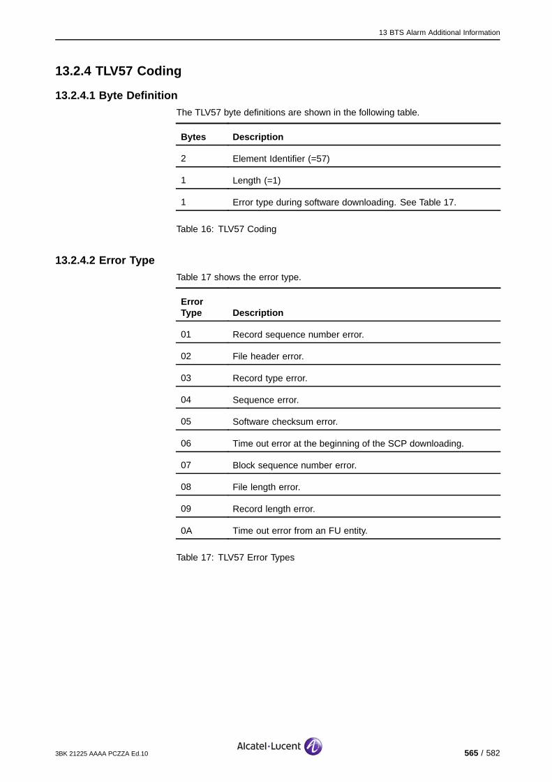
13 BTS Alarm Additional Information
13.2.4 TLV57 Coding
13.2.4.1 Byte DefinitionThe TLV57 byte definitions are shown in the following table.
Bytes Description
2 Element Identifier (=57)
1 Length (=1)
1 Error type during software downloading. See Table 17.
Table 16: TLV57 Coding
13.2.4.2 Error TypeTable 17 shows the error type.
ErrorType Description
01 Record sequence number error.
02 File header error.
03 Record type error.
04 Sequence error.
05 Software checksum error.
06 Time out error at the beginning of the SCP downloading.
07 Block sequence number error.
08 File length error.
09 Record length error.
0A Time out error from an FU entity.
Table 17: TLV57 Error Types
3BK 21225 AAAA PCZZA Ed.10 565 / 582
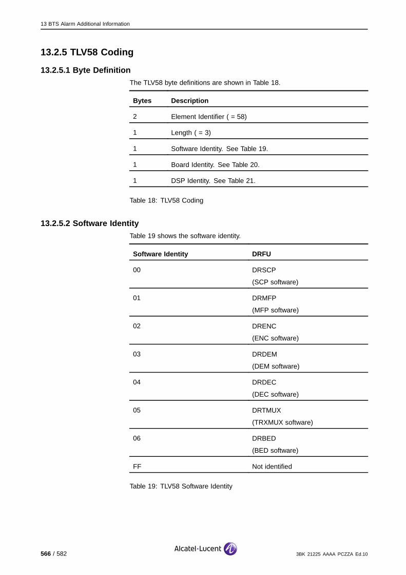
13 BTS Alarm Additional Information
13.2.5 TLV58 Coding
13.2.5.1 Byte DefinitionThe TLV58 byte definitions are shown in Table 18.
Bytes Description
2 Element Identifier ( = 58)
1 Length ( = 3)
1 Software Identity. See Table 19.
1 Board Identity. See Table 20.
1 DSP Identity. See Table 21.
Table 18: TLV58 Coding
13.2.5.2 Software IdentityTable 19 shows the software identity.
Software Identity DRFU
00 DRSCP
(SCP software)
01 DRMFP
(MFP software)
02 DRENC
(ENC software)
03 DRDEM
(DEM software)
04 DRDEC
(DEC software)
05 DRTMUX
(TRXMUX software)
06 DRBED
(BED software)
FF Not identified
Table 19: TLV58 Software Identity
566 / 582 3BK 21225 AAAA PCZZA Ed.10

13 BTS Alarm Additional Information
13.2.5.3 Board IdentityTable 20 shows the board identity.
Board Identity G1 MKII DRFU
00 FUCO DRFU (G1)
01 FUIF -
02 CECC -
03 CDEC -
04 CDEC -
05 DMOD/DMAD -
06 DMOD/DMAD -
07 DMAD -
08 DMAD -
Table 20: TLV58 Board Identity
Note: If several boards are concerned, only the board with the shortest mnemonic isidentified.
13.2.5.4 DSP IdentityTable 21 shows the DSP identity.
Type Description
G1 FU/G2 FU3 FUCO board:
00 - SCP
01 - MFP
FUE boards: Bit i refers to DSP number i.
DRFU DEM and DEC processors: Bit i refers to DSP number i.
SCP, MFP, and RXP processors, and BED and TRXMUXFPGAs: DSP identification is meaningless because there isone specific software package for each processor.
Table 21: TLV58 DSP Identity
3BK 21225 AAAA PCZZA Ed.10 567 / 582

13 BTS Alarm Additional Information
13.2.6 TLV59 Coding
TLV59 is used for reporting FU Alarm Type 20 (G1/G2 and Micro-BTS) and forTRE, AN and TRANS&CLOCK Alarm Type for BTS.
The TLV59 codes have the same definitions as TLV53, as described inSection 13.2.3., except that the ALAN and ALATYP fields each occupy aseparate byte. Consequently, there are 10 bytes in TLV59 codes compared to9 bytes for TLV53 codes.
As an example, the TLV59 byte definitions for G1, Mark l are shown in Figure299.
Element Identifier (=53) − 1st Byte
Element Identifier (=53) − 2nd Byte
Length (=6)
* Not Relevant
bit number
spare − 10th Byte
*
*
*
EVAD AD HWSW FNF FI INT EXT
ALAN
ALATYP
DMDT 2 DMDT 1 DMDT 0 CDCC 1 CDCC 0 CECC FUIF FUCO
DMDT 3
CLLKBSI FHI
7 6 5 4 3 2 1 0
Figure 299: G1, Mark I TLV59 Bytes
568 / 582 3BK 21225 AAAA PCZZA Ed.10
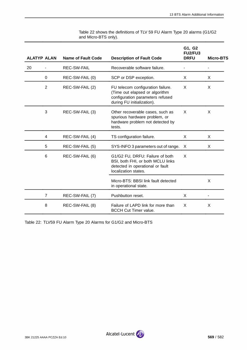
13 BTS Alarm Additional Information
Table 22 shows the definitions of TLV 59 FU Alarm Type 20 alarms (G1/G2and Micro-BTS only).
ALATYP ALAN Name of Fault Code Description of Fault Code
G1, G2FU2/FU3DRFU Micr o-BTS
20 - REC-SW-FAIL Recoverable software failure. - -
0 REC-SW-FAIL (0) SCP or DSP exception. X X
2 REC-SW-FAIL (2) FU telecom configuration failure.(Time out elapsed or algorithmconfiguration parameters refusedduring FU initialization).
X X
3 REC-SW-FAIL (3) Other recoverable cases, such asspurious hardware problem, orhardware problem not detected bytests.
X X
4 REC-SW-FAIL (4) TS configuration failure. X X
5 REC-SW-FAIL (5) SYS-INFO 3 parameters out of range. X X
G1/G2 FU, DRFU: Failure of bothBSI, both FHI, or both MCLU linksdetected in operational or faultlocalization states.
X6 REC-SW-FAIL (6)
Micro-BTS: BBSI link fault detectedin operational state.
X
7 REC-SW-FAIL (7) Pushbutton reset. X -
8 REC-SW-FAIL (8) Failure of LAPD link for more thanBCCH Cut Timer value.
X X
Table 22: TLV59 FU Alarm Type 20 Alarms for G1/G2 and Micro-BTS
3BK 21225 AAAA PCZZA Ed.10 569 / 582

13 BTS Alarm Additional Information
Table 23 shows the definitions of TLV 59 for the TRE faults (9100BTS only). EVAD indicates the faultcondition: 1 = Eventtype(EV), 0 = Appearance/Disappearance type (AD). AD indicates theAppearance/Disappearance state; 1 = Appearance (ON), 0 = Disappearance(OFF).
ALATYP ALAN EVAD Description of Fault Code
1 0 AD CLKI clock failure (1)
5 0 AD CLKI frame failure
6 0 AD RSL LAPD link failure
9 0 AD Non fatal temperature failure
13 0 AD TRE VSWR failure (1)
20 Recoverable failure
0 EV Microprocessor failure
21 EV BCCH failure
22 EV Algorithm failure
23 EV TLC_CONFIG_T expiry
24 EV TS reconfiguration failure
25 EV SYS INFO 3 failure
27 EV BCCH_CUT timeout
28 EV Radio failure
29 EV ECPL failure
30 EV L1 DSP failure
31 EV L1 DSP no response failure
32 EV Internal serial interface failure
33 EV FCLK IT failure
34 EV Internal FN failure
21 Handover/Power control algorithms configuration refused
0 EV Missing message
25 TRE fatal failure (1)
0 AD Microprocessor failure
1 AD HW failure
570 / 582 3BK 21225 AAAA PCZZA Ed.10

13 BTS Alarm Additional Information
ALATYP ALAN EVAD Description of Fault Code
2 AD SW failure
3 AD CLKI synchronization failure
4 AD Autoreconfiguration failure
5 AD Configuration failure
6 AD BSII failure (2)
7 AD IOM LAPD link failure
8 AD SW activation failure
9 AD Downloading failure
10 AD HW watchdog reset
11 AD Configuration file failure
20 AD Temperature failure
28 AD Radio failure
29 AD ECPL failure
30 AD L1 DSP failure
31 AD L1 DSP no response failure
32 AD Internal serial interface failure
33 AD FCLK IT failure
34 AD Internal FN failure
Table 23: TLV59 for TRE faults of 9100 BTS
(1) As this alarm is fatal for the module, no alarm disappearance indication issupplied. The alarm disappearance is detected on Alarm In Force List report.
(2) As the link connection is lost, the failure cannot be spontaneously reportedto the OMU/SUM. But the corresponding alarm is stored in the Alarms In ForceList and may be obtained by the OMU/SUM on Alarm In Force List report (if thefailure has disappeared), as long as the module stays in out of order state (asthe reason for which the OUT OF ORDER state has been entered).
3BK 21225 AAAA PCZZA Ed.10 571 / 582
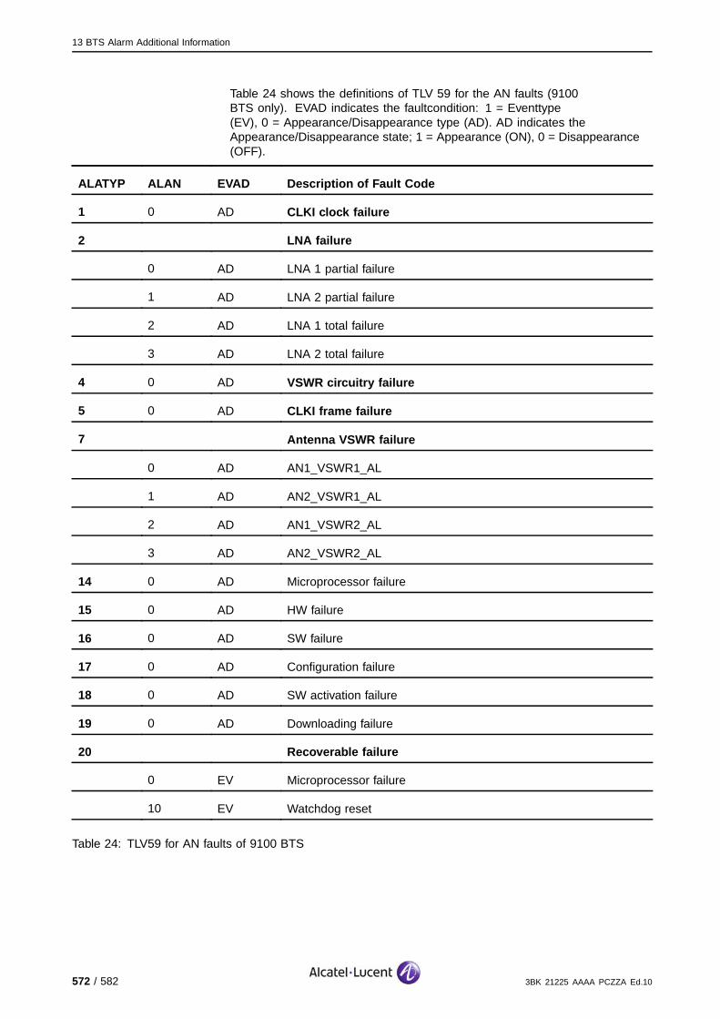
13 BTS Alarm Additional Information
Table 24 shows the definitions of TLV 59 for the AN faults (9100BTS only). EVAD indicates the faultcondition: 1 = Eventtype(EV), 0 = Appearance/Disappearance type (AD). AD indicates theAppearance/Disappearance state; 1 = Appearance (ON), 0 = Disappearance(OFF).
ALATYP ALAN EVAD Description of Fault Code
1 0 AD CLKI clock failure
2 LNA failure
0 AD LNA 1 partial failure
1 AD LNA 2 partial failure
2 AD LNA 1 total failure
3 AD LNA 2 total failure
4 0 AD VSWR circuitry failure
5 0 AD CLKI frame failure
7 Antenna VSWR failure
0 AD AN1_VSWR1_AL
1 AD AN2_VSWR1_AL
2 AD AN1_VSWR2_AL
3 AD AN2_VSWR2_AL
14 0 AD Microprocessor failure
15 0 AD HW failure
16 0 AD SW failure
17 0 AD Configuration failure
18 0 AD SW activation failure
19 0 AD Downloading failure
20 Recoverable failure
0 EV Microprocessor failure
10 EV Watchdog reset
Table 24: TLV59 for AN faults of 9100 BTS
572 / 582 3BK 21225 AAAA PCZZA Ed.10
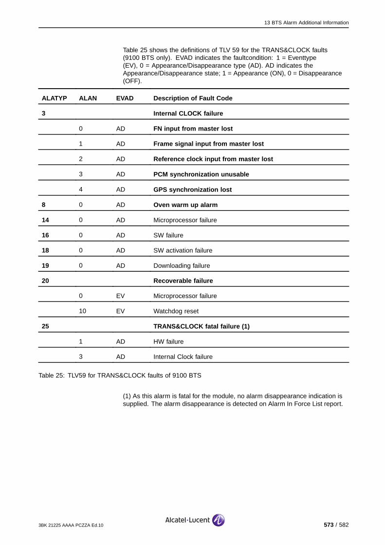
13 BTS Alarm Additional Information
Table 25 shows the definitions of TLV 59 for the TRANS&CLOCK faults(9100 BTS only). EVAD indicates the faultcondition: 1 = Eventtype(EV), 0 = Appearance/Disappearance type (AD). AD indicates theAppearance/Disappearance state; 1 = Appearance (ON), 0 = Disappearance(OFF).
ALATYP ALAN EVAD Description of Fault Code
3 Internal CLOCK failure
0 AD FN input from master lost
1 AD Frame signal input from master lost
2 AD Reference clock input from master lost
3 AD PCM synchronization unusable
4 AD GPS synchronization lost
8 0 AD Oven warm up alarm
14 0 AD Microprocessor failure
16 0 AD SW failure
18 0 AD SW activation failure
19 0 AD Downloading failure
20 Recoverable failure
0 EV Microprocessor failure
10 EV Watchdog reset
25 TRANS&CLOCK fatal failure (1)
1 AD HW failure
3 AD Internal Clock failure
Table 25: TLV59 for TRANS&CLOCK faults of 9100 BTS
(1) As this alarm is fatal for the module, no alarm disappearance indication issupplied. The alarm disappearance is detected on Alarm In Force List report.
3BK 21225 AAAA PCZZA Ed.10 573 / 582

13 BTS Alarm Additional Information
13.2.7 TLV61 Coding
The TLV61 byte definitions are shown in Table 26.
Bytes Description
2 Element Identifier (=61)
1 or 2 Length (2 bytes if length > 127 (1)
2 Board Identification
1 Result type
Variable Results (maximum length is 40 bytes).
Table 26: TLV61 Bytes
(1) For TRE, only one byte is forseen, because the length of the data is <127 bytes.
TLV61, even if indicated, may not appear in an alarm message. Internal FUproblems, such as a blocked internal bus or a hardware fault, can prevent theFU controller from receiving it. Several TLV61s can be sent.
The definition of the Board Identification bytes for G1, G2 and Micro -BTS isshown in Table 27. A bit set to 1 identifies the board at the origin of the faultdetection.
G1 G2
Bit Number MARK II FU 3 FU 4 Micr o-BTS
0 FUCO FUCO FUCO MBPG/MBEGMBPD/MBED
1 FUIF FICE DRFU MBPG/MBEGMBPD/MBED
2 CECC FICE DRFU MBPG/MBEGMBPD/MBED
3 CDEC DEDE/DADE DRFU MBPG/MBEGMBPD/MBED
4 CDEC DEDE/DADE DRFU MBPG/MBEGMBPD/MBED
5 DMOD/DMAD DEDE/DADE DRFU MBPG/MBEGMBPD/MBED
6 DMOD/DMAD DEDE/DADE DRFU MBPG/MBEGMBPD/MBED
574 / 582 3BK 21225 AAAA PCZZA Ed.10
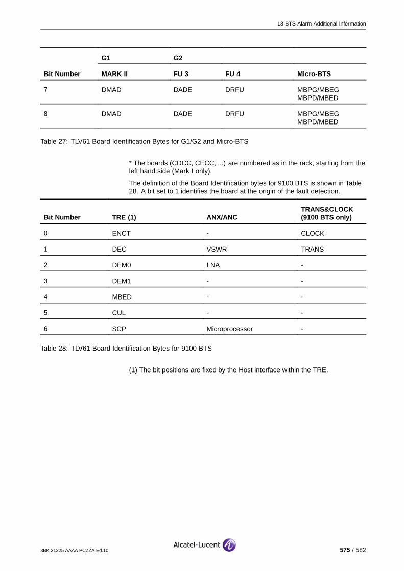
13 BTS Alarm Additional Information
G1 G2
Bit Number MARK II FU 3 FU 4 Micr o-BTS
7 DMAD DADE DRFU MBPG/MBEGMBPD/MBED
8 DMAD DADE DRFU MBPG/MBEGMBPD/MBED
Table 27: TLV61 Board Identification Bytes for G1/G2 and Micro-BTS
* The boards (CDCC, CECC, ...) are numbered as in the rack, starting from theleft hand side (Mark I only).
The definition of the Board Identification bytes for 9100 BTS is shown in Table28. A bit set to 1 identifies the board at the origin of the fault detection.
Bit Number TRE (1) ANX/ANCTRANS&CLOCK(9100 BTS only)
0 ENCT - CLOCK
1 DEC VSWR TRANS
2 DEM0 LNA -
3 DEM1 - -
4 MBED - -
5 CUL - -
6 SCP Microprocessor -
Table 28: TLV61 Board Identification Bytes for 9100 BTS
(1) The bit positions are fixed by the Host interface within the TRE.
3BK 21225 AAAA PCZZA Ed.10 575 / 582
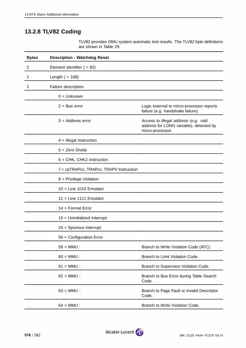
13 BTS Alarm Additional Information
13.2.8 TLV82 Coding
TLV82 provides OMU system automatic test results. The TLV82 byte definitionsare shown in Table 29.
Bytes Description - Watchdog Reset
2 Element identifier ( = 82)
1 Length ( = 168)
1 Failure description
0 = Unknown
2 = Bus error Logic external to micro-processor reportsfailure (e.g. handshake failure).
3 = Address error Access to illegal address (e.g. oddaddress for LONG variable), detected bymicro-processor.
4 = Illegal Instruction
5 = Zero Divide
6 = CHK, CHK2 Instruction
7 = cpTRAPcc, TRAPcc, TRAPV Instruction
8 = Privilege Violation
10 = Line 1010 Emulator
11 = Line 1111 Emulator
14 = Format Error
15 = Uninitialized Interrupt
24 = Spurious Interrupt
56 = Configuration Error
59 = MMU : Branch to Write Violation Code (ATC).
60 = MMU : Branch to Limit Violation Code.
61 = MMU : Branch to Supervisor Violation Code.
62 = MMU : Branch to Bus Error during Table SearchCode.
63 = MMU : Branch to Page Fault or Invalid DescriptorCode.
64 = MMU : Branch to Write Violation Code.
576 / 582 3BK 21225 AAAA PCZZA Ed.10
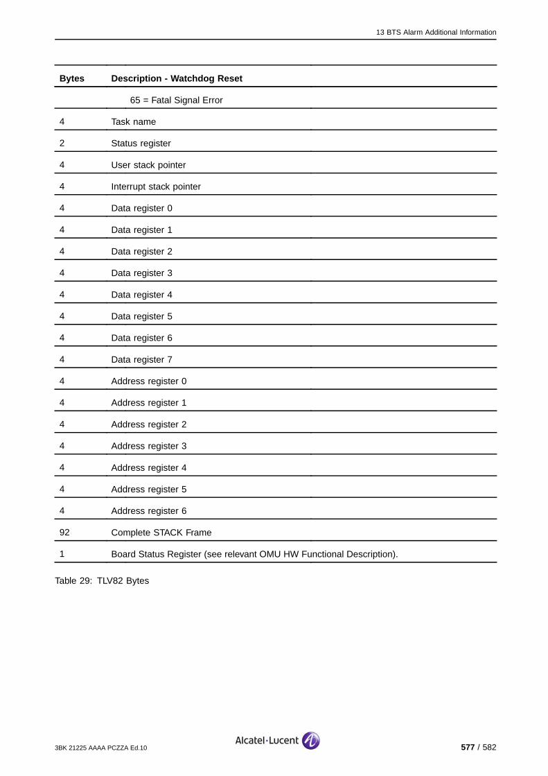
13 BTS Alarm Additional Information
Bytes Description - Watchdog Reset
65 = Fatal Signal Error
4 Task name
2 Status register
4 User stack pointer
4 Interrupt stack pointer
4 Data register 0
4 Data register 1
4 Data register 2
4 Data register 3
4 Data register 4
4 Data register 5
4 Data register 6
4 Data register 7
4 Address register 0
4 Address register 1
4 Address register 2
4 Address register 3
4 Address register 4
4 Address register 5
4 Address register 6
92 Complete STACK Frame
1 Board Status Register (see relevant OMU HW Functional Description).
Table 29: TLV82 Bytes
3BK 21225 AAAA PCZZA Ed.10 577 / 582
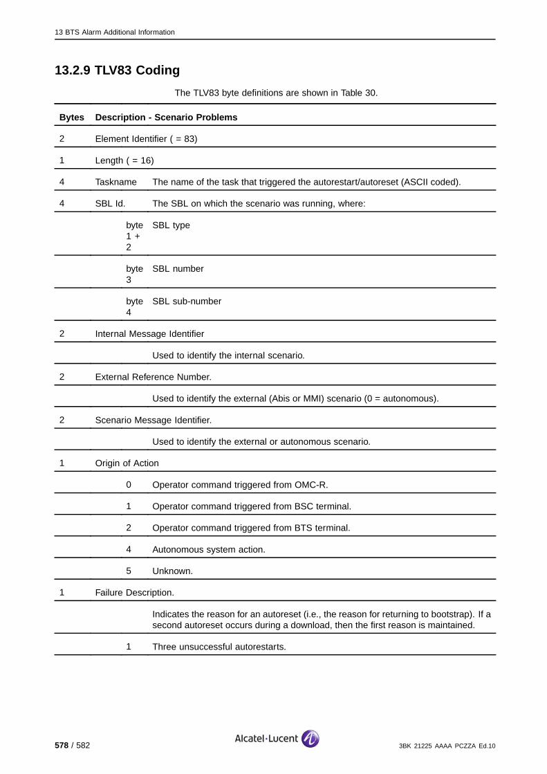
13 BTS Alarm Additional Information
13.2.9 TLV83 Coding
The TLV83 byte definitions are shown in Table 30.
Bytes Description - Scenario Problems
2 Element Identifier ( = 83)
1 Length ( = 16)
4 Taskname The name of the task that triggered the autorestart/autoreset (ASCII coded).
4 SBL Id. The SBL on which the scenario was running, where:
byte1 +2
SBL type
byte3
SBL number
byte4
SBL sub-number
2 Internal Message Identifier
Used to identify the internal scenario.
2 External Reference Number.
Used to identify the external (Abis or MMI) scenario (0 = autonomous).
2 Scenario Message Identifier.
Used to identify the external or autonomous scenario.
1 Origin of Action
0 Operator command triggered from OMC-R.
1 Operator command triggered from BSC terminal.
2 Operator command triggered from BTS terminal.
4 Autonomous system action.
5 Unknown.
1 Failure Description.
Indicates the reason for an autoreset (i.e., the reason for returning to bootstrap). If asecond autoreset occurs during a download, then the first reason is maintained.
1 Three unsuccessful autorestarts.
578 / 582 3BK 21225 AAAA PCZZA Ed.10

13 BTS Alarm Additional Information
Bytes Description - Scenario Problems
2 No download after being in bootstrap for > 24 hours (sending BTS-OMU-STARTED).This is the behaviour of the release 1 and 2 OMU PROM (and should be changedwith the next PROM release).
FF(hex)
No information (e.g. for restart due to internal scenario Time out).
Table 30: TLV83 Bytes
13.2.10 TLV84 Coding
The TLV84 byte definitions are shown in Table 31.
Bytes Description - Lack of Resources
2 Element Identifier ( = 84)
1 Length ( = 69)
4 Taskname The name of the task that triggered the autorestart/autoreset(ASCII coded).
1 Required Memory Region.
The requested memory region.
0 Message buffer.
1 Memory allocation.
2 Memory re-allocation.
4 Required Memory Size.
The requested memory size in octets.
60 Stackinfo Information taken directly from the stack:
Supervisor mode - the system stack
User mode - the stack of a particular task.
Table 31: TLV84 Bytes
3BK 21225 AAAA PCZZA Ed.10 579 / 582

13 BTS Alarm Additional Information
13.2.11 TLV120 Coding
The TLV120 byte definitions are shown in Table 32.
Bytes Description
2 Element Identifier ( = 120)
1 Length ( = 3)
1 Hardware revision:
0 - Hardware 1 (serial test interface, volatile memory).
1 - Hardware 2 (parallel test interface, non-volatile memory).
1 RAM size - given as the number of 4 Mbyte blocks.
1 Flash EPROM:
0 - Not equipped or not accessible.
1 - Equipped.
Table 32: TLV120 Bytes
580 / 582 3BK 21225 AAAA PCZZA Ed.10
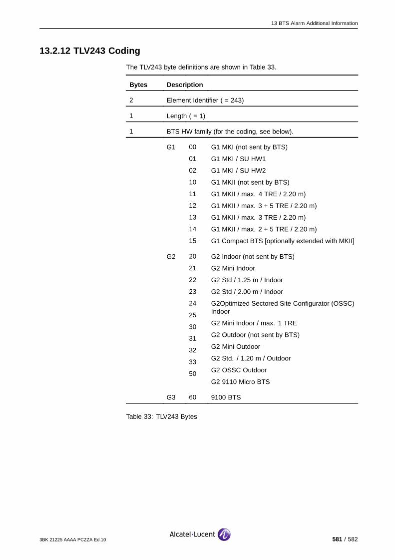
13 BTS Alarm Additional Information
13.2.12 TLV243 Coding
The TLV243 byte definitions are shown in Table 33.
Bytes Description
2 Element Identifier ( = 243)
1 Length ( = 1)
1 BTS HW family (for the coding, see below).
G1 00
01
02
10
11
12
13
14
15
G1 MKI (not sent by BTS)
G1 MKI / SU HW1
G1 MKI / SU HW2
G1 MKII (not sent by BTS)
G1 MKII / max. 4 TRE / 2.20 m)
G1 MKII / max. 3 + 5 TRE / 2.20 m)
G1 MKII / max. 3 TRE / 2.20 m)
G1 MKII / max. 2 + 5 TRE / 2.20 m)
G1 Compact BTS [optionally extended with MKII]
G2 20
21
22
23
24
25
30
31
32
33
50
G2 Indoor (not sent by BTS)
G2 Mini Indoor
G2 Std / 1.25 m / Indoor
G2 Std / 2.00 m / Indoor
G2Optimized Sectored Site Configurator (OSSC)Indoor
G2 Mini Indoor / max. 1 TRE
G2 Outdoor (not sent by BTS)
G2 Mini Outdoor
G2 Std. / 1.20 m / Outdoor
G2 OSSC Outdoor
G2 9110 Micro BTS
G3 60 9100 BTS
Table 33: TLV243 Bytes
3BK 21225 AAAA PCZZA Ed.10 581 / 582

13 BTS Alarm Additional Information
BLANK PAGE BREAK
582 / 582 3BK 21225 AAAA PCZZA Ed.10