2.1 nsls-ii injection requirements€¦ · 2.1 nsls-ii injection requirements the nsls-ii injection...
TRANSCRIPT

Accelerator Chapter 2: Injection Systems 2-1
NSLS-II Preliminary Design Report
2 INJECTION SYSTEMS
2.1 NSLS-II Injection Requirements
The NSLS-II injection system must meet several user requirements:
maintain a stable level of the ring current in order to maintain a constant intensity to experiments and heat load on beamline optics
minimize frequency of interruptions of user experiments, especially for those involving long scans that cannot accommodate interruptions in beam intensity
minimize the disturbance of the beam during and immediately after injection due to the residual orbit perturbation from an incompletely closed injection bump and/or transients in fast magnets
minimize bunch-to-bunch variation of current in order to minimize intensity-correlated orbit oscillations due to uneven bunch patterns [1]
fill the storage ring from zero to full charge in a reasonable amount of time
These requirements must all be accomplished in a way that is as transparent to the users as possible. They are summarized in Table 2.1.1.
Table 2.1.1 User Requirements.
Stability of average current <1% Time between injections >1 min Bunch-to-bunch variation of current <20% Time to fill ring from zero to full charge <5 min
To achieve these requirements, NSLS-II will utilize a full-energy injection system that will operate in top-off mode with minimal disturbance to the circulating beam. The technical specifications for the NSLS-II injection system are summarized in Table 2.1.2. As follows from that table, the NSLS-II injection system must supply approximately 7.3 nC of charge once per minute, assuming a lifetime of 3 hours. For single-bunch injection mode and a moderate repetition rate of a few Hz, replenishing this amount of charge would take a few seconds, occupying a significant fraction of the overall beam time. Therefore, multi-bunch injection has been adopted, leading to minimal disturbance for user experiments and lower power consumption by the injection system.
The main ring contains 1,320 RF buckets at 500 MHz. To alleviate the problems of ion trapping in the stored electron beam, approximately one-fifth of the buckets must be left empty. The exact number of buckets to fill is difficult to predict and will be determined empirically during commissioning. Feedback systems and the ultimate vacuum conditions in the ring will determine what requirements will be imposed on the bunch structure. In any case, to keep the current constant with high accuracy, considerable flexibility and accuracy must be built in to the bunch transfer timing system, the single-bunch capability, and the current and bunch structure measurement system of the main ring.

2-2 Part 1: Accelerator Systems
Table 2.1.2 Storage Ring Parameters Related to the NSLS-II Injector.
Parameter Value Energy [GeV] 3.0
Circulating current [A] 0.5 Circumference [m] 791.96
Revolution period [μs] 2.64 RF frequency [MHz] 499.68
Circulating charge [μC] 1.32 Total number of buckets 1320
Number of filled buckets at 80% filling 1080 Charge per bucket [nC] 1.22 Current per bucket [mA] 0.46
Lifetime [min] 180 Interval between top-off cycles [min] 1
Current variation between top-off cycles [%] 0.55 Current variation between top-off cycles [mA] 2.77 Charge variation between top-off cycles [nC] 7.31
2.1.1 Future Upgrades of the Bunch Pattern Formats As described above, the NSLS-II injector must support uniform filling pattern in the storage ring starting with
the beginning of operations. Two basic patterns were considered (Figure 2.1.1, two upper plots): uniform fill with the ion-clearing gap of about 20% and multiple uniform bunch trains with mini-gaps between them. Both of these bunch patterns are in the baseline design of the NSLS-II project.
Also, in response to NSLS user requests, consideration is being given to specialized bunch patterns that are not a part of the baseline design; these will be developed during later stages of the project. In addition to the nominal uniform fill, users require a single high-current bunch (“camshaft” bunch, two lower plots in Figure 2.1.1) located in the middle of the ion-clearing gap, as well as multiple camshaft bunches whose repetition rate is matched to the pulse format of modern pump lasers.
Figure 2.1.1 User requirements on the storage ring bunch patterns.
NSLS-II Baseline
“Camshaft”
“Complex”
Future upgrades: I
N, I1, dI1 I
I
4/5 1/5 I
x I1, dI1 y
z y dI0
t
t
t
t t

Accelerator Chapter 2: Injection Systems 2-3
NSLS-II Preliminary Design Report
User experiments set the following conditions for the time intervals and current stability of these complex bunch patterns:
time interval separating regular pattern from the camshaft bunch (y) more than 20ns
number of camshaft bunches (N) is about 5
current stability in the regular bunch pattern (dI0) is less than 1%
current stability in camshaft bunch(es) is less than a few percent
The maximum current of the camshaft bunch(es) will be determined by calculating thresholds of single-bunch instabilities.
For simplification of filling and maintaining current in the camshaft bunches, as well as for enhancing capabilities of the “hunt-and-peck” mode of operation, we have considered including a second gun that would operate exclusively in the single-bunch mode. Electron beam from the second gun would enter into and be accelerated in the same linac using a dog-leg merging system. This is not included in the baseline design and is slated as a possible future upgrade of the injector.
The baseline scope for the NSLS-II project includes developing an injector that will enable initial fill and maintaining of 500 mA of the circulating current in the top-off mode. Support of the complex bunch patterns is foreseen as a future upgrade.
2.1.2 Injection Sequence The initial fill occurs at the rate of 1 Hz, and 40 bunches are transferred to the main ring, nominally, at each
injection (this number can be increased to 150 bunches) to fill consecutively 1,080 of the 1,320 RF buckets available. The number of bunches in the injected train is constrained to about 40 minimum (based on beam loading physics) and a maximum of 150 (limited by the booster circumference).
Bunch trains from the injector enter the ring in sequence, starting with the front of the ring train and stepping sequentially back in time along the ring train until the end is reached, then skipping over the empty section and starting again at the head of the train, until the required current has been established.
Assuming the same amount of charge per injection (7.3 nC per bunch train) as for top-off mode, the duration of the initial fill will be about 3 minutes with the injection system running at a 1 Hz repetition rate.
Top-off operation to keep the current within 0.55% of the nominal value will be the standard operating mode of NSLS-II. The frequency of operation to keep the current within these boundaries depends on the beam lifetime and is expected to take place about once per minute. The injected bunch trains from the booster are stepped sequentially around the ring bunch structure. Users expect bunches to stay relatively constant in charge relative to each other (a difference of ±10% has been adopted). We are considering several possible techniques for providing a filling pattern with sufficient uniformity.
NSLS-II users have provided feedback regarding possible top-off formats, which is summarized in Figure 2.1.2.

2-4 Part 1: Accelerator Systems
Figure 2.1.2 Format of top-off injections: Dependence of the injected beam current vs time in minutes. 30 msec corresponds to the value of the damping time, during which the stored beam will be disturbed by the injection process.
The first scenario corresponds to the nominal case, when charge increments of 7.3 nC are injected once a minute. The second scenario allows reducing the amount of injected charge in half; however, the time interval between top-off cycles (1 second given by the injector repetition rate) is unusable for the user experiments.
Other scenarios are unacceptable for users. In one scenario involving a few low-charge, consecutive top-off injections, user experiments could be disabled for a substantial fraction of the total time. Another foreseeable scenario would be maintaining the ring current at the stability level of 0.1%. In this case, unperturbed beamtime reduces down to a few seconds, which is unacceptably short for majority of users.
2.1.2 Injector scope There are several possible basic schemes for the injection system that can meet the requirements stated above.
One is to use a full-energy linear accelerator, which would require no booster synchrotron at all; another is to use a booster synchrotron fed by a small linac.
A full-energy linac would provide flexible injection operations in a single bunch mode at the repetition rate of about 50 Hz[1]. However, performance and reliability of storage ring kickers and septa at this repetition rate may present a technically challenging problem together with frequent disturbances for the storage ring current, which can lead to a charge loss. On the other hand, operating in multi-bunch mode is difficult, due to significant beam loading in the linac structures at the amount of charge that is specific for the NSLS-II injector. Another disadvantage would be the high cost for the linac and the additional cost of a building to house the linac and transport line. In addition, a full-energy linac is likely to have lower reliability and a higher operations cost than a full-energy booster. A highly reliable injection system is especially important for NSLS-II, given its short beam lifetime.
For these reasons, a full-energy booster was selected as the NSLS-II injector. Two approaches were considered for its design. In the first approach, the booster was located in the storage ring tunnel [2]. This results in a much larger circumference for the booster, but most of this is taken up by small stainless steel vacuum pipe. In the second, a “compact” booster design was evaluated [3]. Comparing both approaches [4] revealed a substantially higher total cost for the compact booster due to the extra costs of constructing and shielding a separate building to house it. However, the concerns, regarding 1) potential cross-talk between the “same-tunnel” booster and storage ring, and 2) potential schedule conflicts from installing, testing, and commissioning of both machines located in the same tunnel as well as future booster troubleshooting have lead to the choice of the compact booster as the NSLS-II injector. Therefore, the NSLS-II design employs a compact booster located in a separate tunnel.
The 200MeV linac is specified for injection into the booster. Higher injection energy is advantageous from the following points of view:
1 Limited by an interval of few damping times in the storage ring between consecutive bunch injections
Iinj
1min
1min
Iinj 1sec
30 ms
Nominal “Fall-back”

Accelerator Chapter 2: Injection Systems 2-5
NSLS-II Preliminary Design Report
Relatively high value of magnetic field in the booster elements at injection
Lower losses due to booster vacuum
Energy redundancy (if one klystron goes down, injection can still be accomplished)
Higher energy linac produces beam with lower energy spread and emittance, which is easier to inject into the booster
Two transport lines will be constructed: one to connect the linac to the booster and a second to connect the booster to the main ring. A full set of beam diagnostics will be installed for commissioning and routine operations of the injection system.
Strategically, BNL is developing the complete preliminary design of the injector and then procuring the major components of the injector (linac and booster) from vendors. The vendors will install the equipment and jointly commission it with BNL staff. BNL will design, procure, install, and commission the transport lines and injection straight section.
Figure 2.1.3 Layout of the NSLS-II injector.
Figure 2.1.3 demonstrates the injector layout, where the linac and booster are housed in separate tunnels and the injector service area is adjacent to these accelerators and the ring injection straight section.
In this chapter we describe all the components of the NSLS-II injection system in the following order: linac and electron gun, linac-to-booster transport line, booster with booster-to-storage ring transport line, and injector service area.

2-6 Part 1: Accelerator Systems
References
1 http://accelconf.web.cern.ch/AccelConf/e04/PAPERS/THPLT186.PDF 2 NSLS-II Conceptual Design report, 2006 3 T. Shaftan et al., “Design of 3 GeV Booster for NSLS-II,” Proc. of PAC-2005, p. 3473. 4 D. Hatton et al., “Considerations of the in-tunnel versus compact booster design”, NSLS-II Tech. note-2007

Accelerator Chapter 2: Injection Systems 2-7
NSLS-II Preliminary Design Report
2.2 Linac
2.2.1 Linac Scope The NSLS-II storage ring requires approximately 7 nC of charge to be delivered in top-off mode once every
minute to replace charge lost through Touschek scattering. This charge should be delivered in a single booster cycle, so that the storage ring beam is disturbed only for the duration of the ring damping time (tens of milliseconds) each minute. Details of this will be presented later in this section. In addition, future storage ring requirements may include single camshaft bunch or timing bunches for user experiments or machine studies. To meet these requirements, two modes of linac operation are envisioned: single-pulse mode with about 1 nC charge per bunch, and multi-bunch mode, delivering bunches by tens of pC up to more than 100 pC, totaling 15 nC of charge. To inject bunch trains into a booster with a 500 MHz RF system, a 3GHz linac bunch structure must fit into the booster buckets of ~1 ns length, separated by 2 ns.
To minimize the booster cost, the aperture of the magnets is kept small. To keep the injection efficiency high given the small magnet aperture, a reasonably small emittance is required. Likewise, a small energy spread is needed to prevent beam loss in the high-dispersion regions of the booster lattice. An additional requirement is that the linac be able to provide sharp edges to the electron bunch train, to avoid injecting electrons into the ion clearing gap.
Thales and ACCEL have produced turn-key linac systems for Soleil and Diamond, respectively. The Soleil linac, using CERN “LIL” 3.5m structures, has a smaller energy spread that meets the NSLS-II design specification. An approach similar to the Soleil linac is used as a baseline and described below (Figure 2.2.1). The Diamond injector uses the DESY 2.2m accelerator structures, resulting in a slightly longer linac. To keep both options open in the preliminary design phase, the linac building has been designed to accommodate either four 5.2m tanks or five CERN 3.5m structures.
Figure 2.2.1 Layout of the 200 MeV linear accelerator.
The linear accelerator [1] consists of the following subsystems:
100 kV triode gun (e.g., Eimac Y-845) with a 500MHz modulation at the gun grid and a high-voltage deck
four shielded lenses, situated between the gun and the buncher
a 500MHz subharmonic pre-bunching cavity with ± 25 kV modulation
a 3GHz pre-bunching cavity with ±10kV modulation (100 W power)

2-8 Part 1: Accelerator Systems
a 3GHz stationary wave buncher surrounded by two shielded coils (1.2 m long, 5.5 MW, energy gain of 15 MeV)
five traveling wave-accelerating structures at 3 GHz in the 2π/3 mode and with a length of 3.5 m (flange to flange)
a Glazer lens between the buncher and the first accelerating structure
two focusing doublets
three Klystrons (TH2100, 35 MW) and their modulators
low-level RF controls
Objects colored in grey in Figure 2.2.1 represent elements of the linac that are considered as a future upgrade. As discussed in the introduction, the injector must possess sufficient flexibility in order to support complex bunch patterns. For filling and maintaining current in these, we considered including a second gun that will work exclusively in the single-bunch mode. Beam after the second gun is prebunched and accelerated in the following gun buncher system and injected in the linac at an energy of about 15 MeV using a dog-leg. Also depicted in grey is a test stand for klystrons testing.
2.2.2 Physics Design and Parameters Although a range of parameters will meet the requirements, we focus here on a specific case of approximately
375 pC per bunch in bunch trains of 40 bunches for a total of 15 nC to provide details on the injector design. Having about a factor of two greater than the charge required in the storage ring top-off allows for faster initial fills and for losses in the injection process. Studies of booster injection and extraction losses will be included at the next design stage.
The energy spread must be controlled throughout the acceleration process. The maximum horizontal size of the beam injected into the booster (Section 2.5) is dominated by the energy spread. For ε = 125 nm-rad (2σ emittance) and maximum βx = 12 m at the maximum dispersion, η = 0.35, and energy spread, ΔE/E = 0.5%, the maximum RMS beam size is Δσx ≈ ηΔE/E ≈ 1.75 mm.
Recent experience at SOLEIL [2.3] has shown that industry can produce turn-key linac systems that meet these specifications. Because the approach taken may differ significantly from one machine to the next, only the salient points of a generic linac are presented.
A planar triode electron gun, the EIMAC Y845 [2.4], is used with a fast-pulser cathode driver. In single-bunch mode, the cathode is pulsed to create ~1 ns pulses of ~0.5 nC. The DC gun inherently has small energy spread. However, to compress the gun pulse for acceleration in the 2.998 GHz linac and capture it in the 500 MHz booster RF, we need to prevent nonlinearities in the RF from increasing the energy spread beyond the 0.5% (RMS) requirement. This translates into a requirement on the length of the micro-bunches exiting the linac to be less than ~11 ps.
To create these short bunches, a bunching system is required. First, a 500MHz subharmonic buncher is used to compress the charge into bunch lengths less than 1 ns to match the 500MHz booster bucket. This is followed by a 2.988GHz pre-buncher that micro-bunches the 1.5ns bunch train to ≤11 ps bunches within the linac buckets. A final buncher simultaneously accelerates the electrons to 3 MeV to increase capture efficiency. In bunch-train mode, the cathode is pulsed on for the duration of the train, up to 200 ns, and is bunched in the process described above. During the preliminary design phase, system performance will be confirmed by E-Gun [2] and Parmela [3] simulations, and cathode driver experiments at the NSLS electron gun test stand.

Accelerator Chapter 2: Injection Systems 2-9
NSLS-II Preliminary Design Report
The main accelerator is comprised of 3GHz traveling wave structures, with an energy gain of:
[ ] 12.5 [ ]E MeV P MW=
(2.2-1)
The accelerating structures being considered obtain 52 MeV per tank for an input power of 17.5 MW. Using readily available 35MW klystrons, the first klystron is power split, with about 5.5 MW feeding the 3GHz pre-buncher and buncher. The latter has an energy gain of more than 15 MeV. The remaining power feeds the first linac structure. Individual waveguide phase shifters and attenuators are used for adjusting amplitude and phase between elements.
The remaining four tanks are powered by two klystrons for an energy gain of an additional 52 MeV each. Thus, a total of 255 MeV energy gain is possible. For redundancy, two waveguide switches can connect the second klystron to power the two bunchers and first tank. In this scheme, an energy of 170 MeV can be achieved if one klystron fails. This will be explored in the next design phase.
The bunch charge and train current—although not beyond that which has been achieved in other applications [4, 5]—is sufficient to warrant close attention to beam-loading issues. For traveling wave tanks, the voltage induced along the bunch train on short time scales (compared to the fill time of the cavity) is given by:
1
0 [(1 )(1 ) ]x xbV ir L e xeτ ττ − − −= − − − +
(2.2-2)
where r0 is the shunt impedance, τ the attenuation constant in nepers, L the length of the tank, and x the ratio t/tf, where t is the time duration of the macro-pulse and tf the fill time of the structure.
For forty 375 pC bunches separated by 2 ns (187.5 mA), this corresponds to about 1.6% in the correlated energy spread along the bunch train. There are several methods of reducing this beam loading. For a given beam current, the beam loading compensation can be achieved by sending the beam during the filling time of the second structure. This approach has been successfully implemented at SOLEIL [4] for a 300ns-long train current of 9 nC. Alternatively, the effect of beam loading can be diminished by lengthening the macro-pulse, either by simply lengthening the pulse and proportionally reducing the charge per bunch, or by pulsing the gun once every fourth, sixth, or eighth 500MHz bucket with constant charge per bunch to reduce the effect by the corresponding factor. For example, by filling 150 bunches of 100 pC each, the average current falls to 50 mA and the energy spread due to beam loading drops to 0.5%.
2.2.3 Klystron Modulators and Power Supplies Pulsed 3GHz high-power klystrons are a mature technology and several manufacturers can meet or exceed the
35MW power requirement. The klystrons are powered by pulsed modulators. The traditional approach is to use Pulse Forming Networks with hard-tube (thyratron) switches to produce RF pulses between 2 and 4 microseconds long. NSLS has recently designed and built such a modulator for the 45MW tube installed at its DUVFEL facility. Our own experience and studies of reliability at SLAC/PEP-II and Pohang Light Source have shown that the mean time between failure (MTBF) and mean time to repair (MTTR) of the PFN/hard tube modulator dominate the linac downtime, with rates three times those of the klystron tube and its filament/core bias power supplies [6, 7]. For this reason, solid-state modulators are being explored for NSLS-II. Several competing designs have been developed for both medical linacs and the X-band International Linear Collider. One such example is the design by Scandi-nova [8], which uses a multi-turn primary pulse transformer, reducing the modulator voltage from about 40 kV to 3 kV, further increasing reliability by limiting the high voltage to only the pulse transformer and klystron cathode assembly in the oil tank [9]. These systems are also between one-half and one-third the size of similar PFN-type modulators. The decision to use a solid state or a PFN-hard tube modulator will be made during the preliminary design phase.

2-10 Part 1: Accelerator Systems
The 500MHz subharmonic pre-buncher requires about 6 kW (for a shunt impedance of 250 kΩ) to reach 36 kV. This is well within the range of solid-state RF amplifiers.
The 3GHz pre-buncher is a single cell with ±10 kV modulation, requiring only 100 W of RF power.
The 3GHz final buncher is a standing wave structure, requiring 5.5 MW of RF power, and delivering an energy gain of 15 MeV.
The low-level RF can be a duplicate of the DUVFEL RF system [10], with a master clock in common with the booster and storage rings driving a 2.988GHz DRO-based synthesizer whose output is split and feeds direct I/Q modulators for the amplitude and phase control of the individual klystrons. The 500 MHz will be derived from the booster RF that is synthesized in a similar way. Complimentary I/Q demodulators can be used to down-convert to baseband and close amplitude and phase loops around the cavity fields.
2.2.4 Diagnostics/Instrumentation for Linac Table 2.4.1 shows beam diagnostics for the electron source and linac.
Table 2.4.1 Linac Diagnostics.
System Quantity Monitor Type Measured beam parameter Electron source 3 Wall current monitor intensity, longitudinal beam characteristics Linac 3 Fluorescent screens position, profile 2 Current transformers intensity
The gun diagnostics consist of three resistive wall current monitors (WCM) to observe the longitudinal profile of the electron bunches after the gun, pre-buncher, and buncher. The WCM is formed by equally spaced broadband ceramic resistors mounted on a flexible circuit board, wrapped around a short ceramic break [11].
The bunch charge, produced by the gun and accelerated by the linac, is monitored by five fast current transformers [12]. The current transformers will monitor beam losses in the linac. Three fluorescent screens installed between the linac tanks will be used to observe the transverse profile and the position of the electron beam [13].

Accelerator Chapter 2: Injection Systems 2-11
NSLS-II Preliminary Design Report
References
1 http://cern.ch/AccelConf/p07/PAPERS/TUPMS081.PDF 2 W. B. Herrmannsfeldt, “EGUN – An Electron Optics and Gun Design Program,” SLAC 331, 1988. 3 Parmela, Ver. 3, by Lloyd M. Young , Documentation by James H. Billen, Los Alamos Nat. Lab. 4 A. Setty, et al., “Commissioning of the 100 MeV Preinjector HELIOS for the SOLEIL Synchrotron,”
EPAC06. 5 C. Christou, et al., “Commissioning of the Diamond Pre-Injector Linac,” EPAC06. 6 C.W. Allen et al., “PEP-II Hardware Reliability,” SLAC-PUB-10835. 7 S.S. Park et al., “Reliability Analysis of the PLS Klystron-Modulator System,” Proc. of the Second APAC,
Bejing, 2001. 8 http://www.sc-nova.com/ 9 W. Crewson, “A new solid-state high-power pulsed modulator,” 5th Modulator-Klystron Workshop for
Future Linear Colliders MDK-2001 Geneva, 25-27 April 2001. 10 J. Rose, et al., “Radio-Frequency Control System for the DUVFEL,” PAC03.
http://epaper.kek.jp/p03/PAPERS/TPAB006.PDF 11 B. Fellenz, and J. Crisp, “An Improved Resistive Wall Monitor,” Proc. of Beam Instrumentation Workshop
1998, AIP Conf. Proc. 451, pp. 446–453. 12 http://www.bergoz.com 13 E. Johnson, W.S. Graves, and K.E. Robinson, “Periscope Pop-In Monitor,” Proc. of Beam Instrumentation
Workshop 1998, AIP Conf. Proc. 451, pp. 479–484.

2-12 Part 1: Accelerator Systems

Accelerator Chapter 2: Injection Systems 2-13
NSLS-II Preliminary Design Report
2.3 Booster
2.3.1 Booster Scope The NSLS-II booster is required to produce a 3 GeV bunch train with an extracted charge of about 7.5 nC
at a repetition rate of 1 Hz and a geometric emittance around 30 nm-rad. Injection in the booster ring takes place at an energy of 200 MeV. The booster magnetic field and RF voltage are ramped for 400 ms to accelerate the electron beam from the injection energy to the nominal energy of 3 GeV. At the maximum field of the ramp, the electron beam is extracted from the booster and injected into the main ring. As mentioned in section 5.2.1 we allow for a maximum beam loss of 30% during injection, a 20% maximum loss during acceleration and extraction, and 10% maximum loss for injection into the storage ring. Thus the charge to be accelerated in the booster is 10 nC which corresponds to an average beam current of 19 mA.
Since the storage ring Dynamic Aperture is limited, the injected beam quality has received serious consideration. In particular, the booster emittance may impact on the injection efficiency, which is a concern, in particular, because of frequent top-off cycles (see Chapter 4) carrying a high charge.
During the last 10 years many 3rd generation synchrotron light facilities have been put into operation. Nearly all of these facilities have chosen a full energy booster synchrotron as an infector together with a low energy linac as preinjector. The main parameters of several modern booster synchrotrons are listed in Table 2.3.1.
Table 2.3.1 Modern Boosters. ASP DIAMOND SOLEIL SLS ALBA BINP Energy, GeV 3 3 2.75 2.4 3 2.5 Tunnel separate Separate separate same same separate Circumference, m 130.2 157 157 270 249.6 132 Lattice 4-fold 2-fold 2-fold 3-fold 4-fold 2-fold Rep rate, Hz 1 5 3 3 3 1 Emittance, nm 34 144 150 9 9 50 Tunes, X/Y 9.2/3.3 6.8/4.6 6.4/4.4 12.4/8.4 12.4/7.4 9.1/9.1 Chromaticity, X/Y -8.8/-11.5 -8.4/-6.2 -15/-12 -17/-10 -11.6/-11.4 RF freq., MHz 500 500 352 500 500 181 Damping times, X/Y/E 2.7/3.5/2.0 5.4/5.5/2.7 6.3/5.7/2.7 11/19/14 4.5/8.0/1.8 4.4/4.2/2.1 Current, mA 7 20 15 1 5 50 Source of info [ASP] [DIA] [SOL] [SLS1] [ALB] [BINP]
Modern boosters with energies around 3 GeV have natural horizontal emittances of the extracted beam in the
10–150 nm range. For example DIAMOND and SOLEIL boosters (located in separate buildings) have emittance of 140 nm; SLS and ALBA boosters (located in the ring tunnel) have emittances of 9 nm. The recently commissioned booster for the Australian light source (ASP) with a circumference of 130.2 m has emittance of 33 nm. The relatively low ASP booster emittance in combination with rather small circumference and conventional choice of a combined-function FODO lattice, looks attractive from the point of view of the design optimization level. A series of injection tracking simulations for the storage ring convincingly demonstrated the adequacy of the booster emittance in the range of 30-50 nm to the low-loss injection with sufficient margins for injection errors. Thus we have chosen the ASP booster model to serve as a basis for the NSLS-II booster development. To minimize the cost of the booster turn-key procurement, we are working to keep the NSLS-II booster design as close to that of the ASP booster. However, there are a few major differences between the NSLS-II and the ASP design:

2-14 Part 1: Accelerator Systems
The NSLS-II booster injection energy is 200 MeV (in contrast with 100 MeV at ASP)
The maximum dipole field is chosen to be 1 T (in contrast to 1.25 T at ASP)
The NSLS-II booster circumference is 158.4 m (one-fifth of the storage ring circumference)
Straight section length is 7.05 m, compared with 5.8 m at ASP
The NSLS-II booster current is expected to be 20 mA (in contrast to 5 mA at ASP)
The booster revolution period of 528 ns restricts the length of the injected bunch train to be shorter than about 300 ns because of finite rise- and fall-time of the injection and extraction kickers. Therefore the longest bunch train generated by the linac will consists of 150 bunches.
One of the important requirements for the NSLS-II booster is in high efficiency of the charge transport through the booster. Therefore careful job must be done for optimization of the booster injection and extraction, expansion of booster magnet tolerances, design of robust orbit correction system and adequacy of Dynamic Aperture. In the next chapter we discuss the NSLS-II booster model in detail.
2.3.2 Booster lattice The four-fold symmetry lattice is designed with five identical cells together with two modified cells
containing dispersion suppressors. This results in a sufficiently low horizontal emittance of 26.5 nm-rad at the nominal energy of 3.0 GeV. The booster lattice is presented in Figure 2.3.1.
Figure 2.3.1 : One-quarter of NSLS-II booster lattice.
The lattice consists of four long (7.05 m) straight sections with low dispersion (less than 12 cm) suitable for
the installation of RF cavity, injection, and extraction systems. Low lattice emittance results in the low level of dispersion and stronger focusing, which increases natural chromaticity (horizontal: -13.8, vertical -18.9), and thus sextupolar gradients integrated in the combined function dipoles. Beta-functions are limited to 25 m, which corresponds to the maximum injected beam size of about 1.7 mm RMS in the vertical plane.
The lattice is composed of two families of combined-function dipoles, together with three families of quadrupoles: QF, QD and QG (Figure 2.3.2). Three separate power supplies for the booster quadrupoles provide freedom in optimizing the lattice and controlling tunes, dispersion, and chromaticity.

Accelerator Chapter 2: Injection Systems 2-15
NSLS-II Preliminary Design Report
Figure 2.3.2 Elements in one-quarter of the NSLS-II booster lattice.
Chromaticity correction is implemented by introducing sextupolar gradients into the dipole pole tips. In addition, four discrete sextupoles are introduced in every booster quadrant, shown as SSF and SSD in Figure 2.3.2. Separate power supplies for both sextupole families enable independent adjustments of horizontal and vertical chromaticity.
Table 2.3.2 Part count/Magnetic Element Parameters.
Parameter ASP Booster NSLS-II Booster Dipole parameters Number, BF/BD 28/32 28/32 Length, BF/BD 1.35/1.15 m 1.35/1.4 m Angle, BF/BD 3.43/8.25° 3.43/8.25° Injection energy 100 MeV 200 MeV Field, BF/BD (inj) 0.015/0.042 T 0.030/0.069 T Field, BF/BD (ext) 0.443/1.25 T 0.443/1.00 T Quadrupole K1, BF/BD (ext) 0.82595/-0.66977 m-2 0.82800/-0.63831 m-2 Sextupole K2, BF/BD (ext) 3.54/-4.925 m-3 4.10/-5.65 m-3 Quadrupole parameters Number, QF/QD/QG 8/8 8/8/8 Length, QF/QD/QG 0.25/0.15 m 0.45/0.15/0.15 m Quadrupole K1, QF/QD/QG (inj) -0.0784/0.0133 m-2 0.1229/0.0581/-0.0869 m-2 Quadrupole K1, QF/QD/QG (ext) -2.351/0.400 m-2 1.8442/0.87119/-1.3028 m-2 Sextupole parameters Number, SF/SD 8/8 8/8 Length, SF/SD 0.2/0.2 m 0.15/0.15 m Sextupole K2, SF/SD (ext) 50/-30 m-3 40/-40 m-3
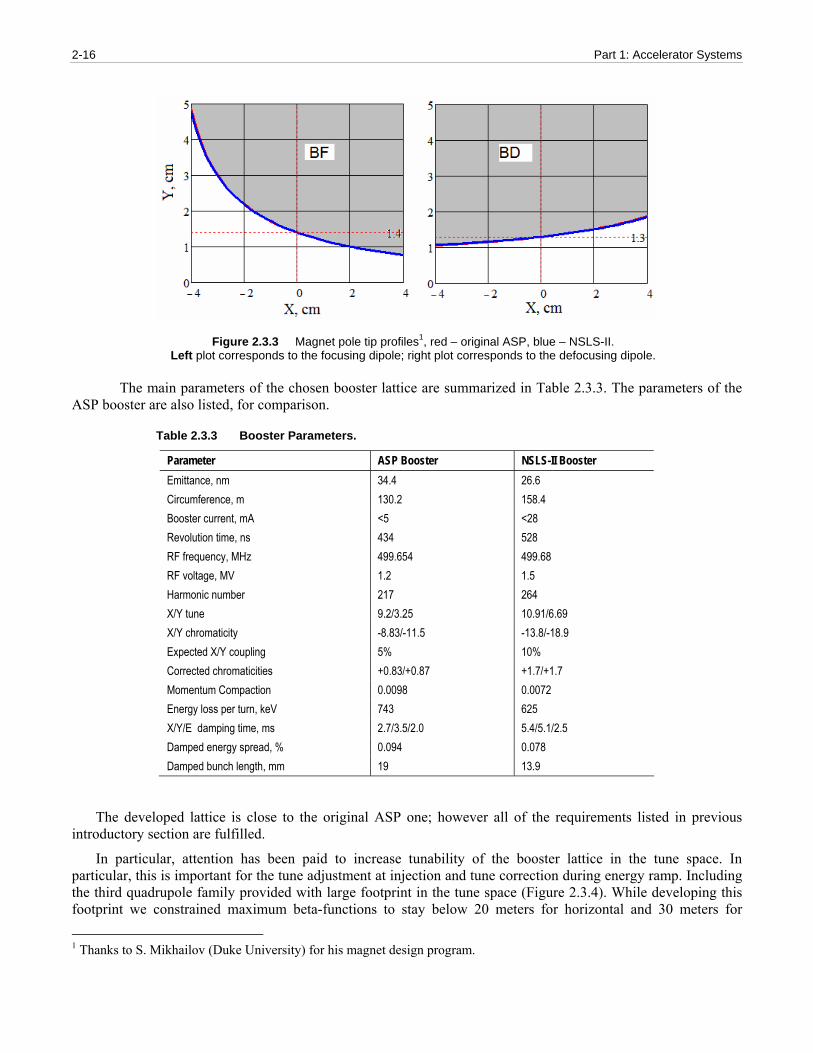
Table 2.3.2 illustrates the main parameters of the booster elements in comparison with them in the ASP booster lattice [ASP]. Reducing the booster cost we kept parameters of the focusing dipoles to be close to the original design (see Figure 2.3.3). Defocusing dipoles are similar to the ASP ones but longer (1.4 meters versus 1.15 meters), which shall require reworking hardware for the lamination stacking. Increasing the injection energy from 100 to 200 MeV significantly increased the magnet fields at injection, which simplifies achieving required field quality of the combine-function dipoles.
2-16 Part 1: Accelerator Systems
Figure 2.3.3 Magnet pole tip profiles1, red – original ASP, blue – NSLS-II. Left plot corresponds to the focusing dipole; right plot corresponds to the defocusing dipole.
The main parameters of the chosen booster lattice are summarized in Table 2.3.3. The parameters of the
ASP booster are also listed, for comparison.
Table 2.3.3 Booster Parameters.
Parameter ASP Booster NSLS-II Booster Emittance, nm 34.4 26.6 Circumference, m 130.2 158.4 Booster current, mA <5 <28 Revolution time, ns 434 528 RF frequency, MHz 499.654 499.68 RF voltage, MV 1.2 1.5 Harmonic number 217 264 X/Y tune 9.2/3.25 10.91/6.69 X/Y chromaticity -8.83/-11.5 -13.8/-18.9 Expected X/Y coupling 5% 10% Corrected chromaticities +0.83/+0.87 +1.7/+1.7 Momentum Compaction 0.0098 0.0072 Energy loss per turn, keV 743 625 X/Y/E damping time, ms 2.7/3.5/2.0 5.4/5.1/2.5 Damped energy spread, % 0.094 0.078 Damped bunch length, mm 19 13.9
The developed lattice is close to the original ASP one; however all of the requirements listed in previous introductory section are fulfilled.
In particular, attention has been paid to increase tunability of the booster lattice in the tune space. In particular, this is important for the tune adjustment at injection and tune correction during energy ramp. Including the third quadrupole family provided with large footprint in the tune space (Figure 2.3.4). While developing this footprint we constrained maximum beta-functions to stay below 20 meters for horizontal and 30 meters for
1 Thanks to S. Mikhailov (Duke University) for his magnet design program.

Accelerator Chapter 2: Injection Systems 2-17
NSLS-II Preliminary Design Report
vertical. This, in turn, has constrained the booster emittance to be below 50 nm for the whole upper half of the tune footprint (right plot on Figure 2.3.5). As follows from Figure 2.3.4, two defocusing quadrupole families are redundant with respect to each other, in the sense that there exist solutions (not necessarily optimal), which may be accomplished by only a single defocusing family.
1 0 1 0 .5 1 1 1 1 .5 1 2 1 2 .5 1 3 1 3 .54 .5
5
5 .5
6
6 .5
7
7 .5
Figure 2.3.4 Tunability of the booster lattice. The plot shows a footprint of the existing lattice solutions under constraints imposed on beta-functions. Green point points the working tune location.
Large tuning range of the booster optics is also beneficial from the Dynamic Aperture optimization. The left plot on Figure 2.3.5 exhibits tune scan for DA optimization. In the peak the booster DA reaches ±10 mm in both planes, which should be sufficient for low-loss injection. We will continue optimizing the DA on the next stage of the design.
νX
ν Y
Dynamic Aperture scan
10.5 11 11.5 12 12.5
5.5
6
6.5
7
0
50
100
150
200
250
300
350mm2
νX
ν Y
Horizontal emittance
10.5 11 11.5 12 12.5
5.5
6
6.5
7
30
40
50
60
70
80
nm
Figure 2.3.5 Tune scan for Dynamic Aperture in mm2. Left: abscissa – horizontal tune, ordinate – vertical tune. Right: corresponding emittance scan in nm·rad (right plot).
Preliminary consideration has been given to evaluation of the magnet tolerances and orbit correction system. The following tolerances for the magnet alignment and fields were assumed (Table 2.3.4). Tolerances on the magnet parameters were developed using analytical estimates that assumed normally distributed random errors in all magnets.

2-18 Part 1: Accelerator Systems
Table 2.3.4 Magnet Tolerances.
Source of error Tolerance Dipole length (relative) 0.1% Dipole field (relative) 0.1% Dipole long. displacement 1mm Dipole transverse misalignment 0.1mm Quad transverse misalignment 0.1mm Quad gradient (relative) 0.2%
Orbit correction is implemented using 20 beam position monitors and 20 horizontal and 12 vertical trim magnets. The trim fields will follow the energy ramp, enabling orbit correction at all energies. The developed trim–BPM arrangement allows correcting the booster orbit down to a mm maximum deviation in each plane (Figure 2.3.6). This requires below 0.75 mrad (maximum value) in the corrector strength, making its design simple, with low magnet weight and size. This orbit correction system results in alignment tolerances for the dipoles and quadrupoles summarized in Table 2.3.4. These tolerances can be relaxed further by further optimizing the trim arrangement and adding one more vertical trim per quadrant.
0 20 40 60 80 100 120 140 160
-6
-4
-2
0
2
4
6
Uncorrected orbits
Distance, m
Orb
it de
viat
ion,
mm
Horizontal orbitsVertical orbits
0 20 40 60 80 100 120 140 160
-6
-4
-2
0
2
4
6
Corrected orbits
Distance, m
Orb
it de
viat
ion,
mm
Horizontal orbitsVertical orbits
-1 -0.5 0 0.5 10
5
10
15
20
25
Corrector angle, mrad
Num
ber o
f eve
nts
-0.4 -0.3 -0.2 -0.1 0 0.1 0.2 0.30
5
10
15
Corrector strength, mrad
Num
ber o
f eve
nts
Figure 2.3.6 Uncorrected (left upper plot) and corrected (right upper plot) booster orbits. The two lower plots correspond to the statistics of the corrector angles. Red and blue traces and histograms correspond to horizontal and vertical orbits and and correctors, respectively.

Accelerator Chapter 2: Injection Systems 2-19
NSLS-II Preliminary Design Report
Figure 2.3.7 shows envelopes of the beam injected from the linac. Linac beam parameters were chosen according to values in chapter 2.2. Electron beam phase space ellipse was matched to that of the circulating beam at the booster injection point.
Figure 2.3.7 RMS injected beam envelopes in mm (solid curves). Dashed lines show approximate location of the dipole vacuum chamber (magnified ten times).
Short damping time at the maximum booster energy leads to the fully damped beam at the end of the ramp (Fig. 2.3.8). Here we assumed a sinusoidal ramp profile with the injection point “on the fly”, i.e. on the rising slope of the energy ramp.
Figure 2.3.8 Booster energy ramp (in units of γ/100, blue curve) and dependence of the horizontal booster emittance versus ramp time (in nm·rad, red curve). Dashed line shows damped value of the booster emittance at 3 GeV.

2-20 Part 1: Accelerator Systems
Figure 2.3.9 shows the estimated beam loss throughout the energy ramp due to residual gas (mainly elastic scattering on the gas nuclei). Total relative charge loss is expected to be about 0.2% at the average value of the booster vacuum of 10-7 torr. We estimate the beam lifetime at the injection energy of 200 MeV to be around 10 seconds.
Figure 2.3.9 Relative gas-scattering losses in % of the charge throughout energy ramp.
For an estimate of the chromaticity driven by eddy currents (Figure 2.3.10), we used a formalism developed in [Edd]. For the given lattice parameters, the estimated maximum value of the sextupolar moment is 0.085 m-3 at 1 Hz of repetition rare. Corresponding calculated values of chromaticity are +0.5 horizontally and –1.4 vertically, which is much smaller than the natural chromaticity and can be compensated by local modification of the sextupole ramp.
Figure 2.3.10 Eddy-currents induced chromaticity during the energy ramp
Concluding this section, we note that the developed booster design is close to the existing ASP booster except for a few important differences between the two designs that are specific for the NSLS-II and were discussed in the introduction. These were realized in the current booster layout and the overall design appears to be feasible and cost-effective.
In the line of future work, we will pay close attention to the optimization of the Dynamic Aperture and perform modeling of the ring at injection and particle tracking, for evaluating and mitigating potential injection losses. In addition we will explore high average current effects that may be of interest at the maximum value of the booster current.

Accelerator Chapter 2: Injection Systems 2-21
NSLS-II Preliminary Design Report
2.3.3 RF Acceleration System The booster RF acceleration system must capture the bunch train injected from the 3 GHz linac, accelerate a
beam charge of 10 nC (19 mA average current) to 3 GeV, and transfer the bunch train to the storage ring 500 MHz RF buckets (Table 2.3.5). At maximum energy a bucket height of 0.85% is necessary (see Figure 2.3.12) which translates into a necessary accelerating voltage of 1.5 MV. At injection energy this rf voltage can provide a much larger bucket height so that the energy spread of the accepted beam is limited by the physical aperture and/or the transverse off energy dynamic aperture of the lattice and not by the rf system.
Table 2.3.5 RF and Beam Parameters for the Booster.
RF frequency [MHz] 499.68 Loss per turn (3 GeV) [keV] 625 Overvoltage 2 Accelerating voltage [MV] 1.5 Momentum compaction 0.0072 Bunch charge [pC] RF acceptance %
1375 0.85
Number of bunches Nominal beam current [mA]
40-150
Nominal beam power at 3 GeV [kW] 12
Figure 2.3.11: RF separatrix for 1.5 MV RF field at 3 GeV, with radiation losses (red curve) and the stationary bucket without losses (blue curve). The separatrix provides an energy acceptance ot 0.85% at 3 GeV.
As the rf voltage requirement of 1.5 MV is significantly more demanding compared with the beam power requirement of 12 kW a multicell cavity is the appropriate choice, e.g. the PETRA type 5-cell cavity with a shuntimpedance of 15 MOhm. With a single PETRA type cavity the total necessary rf power (cavity wall losses, beam power, 10% transmission losses and safety margin) is in excess of 100 kW. For this reason two PETRA 5-cell cavities will be used. The geometry of this cavity is shown schematically in Figure 5.3.11

2-22 Part 1: Accelerator Systems
Figure 2.3.12 The five-cell PETRA cavity.
Klystrons and inductive output tubes (IOT) are available as rf power sources at 500 MHz to generate the necessary rf power. In the power range from several ten kW to 80 kW the klystron market became rather small in recent years as these tubes have been replaced by IOTs for TV applications with the consequence of significant increase in cost. IOTs have a higher efficiency (typically 65%) than klystrons and tube cost are about 30% lower as compared to klystrons. For these reasons the baseline power source will be a modified broadcast IOT transmitter capable of 80 kW output power at 499.68 MHz. Since a few years such transmitters are in use at several synchrotron light source facilities. Similar as klystrons IOTs can operate safely only under matched load conditions. Therefore a circulator is necessary between the transmitter and the cavities. Figure 2.3.13 shows a footprint of the cavity section and the IOT transmitter system including the rf power feeding line and the circulator.
The IOT transmitter utilizes a broadcast IOT tube. Several tubes are available to provide 80 kW at 500 MHz, including the THALES TH793, E2V e2v2130, and Communication and Power Industries K5H90W. Tube parameters for the TH793 are given in Table 2.3.7.
Table 2.3.7 Tube Parameters for TH793 IOT.
Beam voltage [kV] 36 Beam current [A] 3.2 Maximum output power [kW] 90 Maximum collector dissipation [kW] 70
For the HV power supply of the transmitter two technical options are in use to provide the DC power to the IOT transmitter: a standard broadcast transformer-rectifier or a Pulse-Step-Modulated switching power supply. The PSM supply has lower ripple, which results in lower residual modulation of the beam and a lower stored energy. These attributes, combined with the fast turn-off capability, eliminate the need for a hard-tube crowbar circuit.

Accelerator Chapter 2: Injection Systems 2-23
NSLS-II Preliminary Design Report
Figure 2.3.13: Footprint of the cavity section and the IOT transmitter system including the rf power feeding line
2.3.4 Booster Injection System The booster injection system consists of the pulsed septum and kicker with their power supplies (Figure
2.3.14). It is a simple single turn on-orbit injection, allowing a maximum of about 150 consecutive bunches to be injected into the booster RF buckets. The bend angle of the septum is 140 mrad and that of the kicker is 10 mrad, making the total bend angle the same as that of the other LtB TL dipoles. This solution is viable and gives very reasonable field values for the pulsed magnets.
Separation of the trajectory of the injected beam orbit at the end of the septum and the closed orbit of the booster is 20 mm, placing the inside edge of the injection septum at 16 mm from the nominal booster orbit.
Thought is also being given to making the kicker angle larger, thus allowing the septum to be placed further away from the circulating beam in the booster and possibly replacing the pulsed septum with a well-shielded DC magnet.
Figure 2.3.14 Booster injection system layout.
The basic magnet parameters are shown in Table 2.3.8.
2-24 Part 1: Accelerator Systems
Table 2.3.8 Booster Injection System Pulsed Magnet Parameters.
Injection Energy 200 MeV Booster Injection Septum Booster Injection Kicker Magnetic Field (T) 0.0933 0.02 Magnetic Field (T) 0.0933 0.02 Length (m) 1.0 0.3 H x V (mm x mm) 20 x 15 50 x 25 Bend angle (mR) 140 10.0 Inductance (μH) 1.676 0.754 Peak Current (A) 1200 450 Drive Capacitor (μF) 340 70 m transmission line Voltage (kV) 0.08 5.4 Pulse Shape 75 μsec half sine 100 nsec risetime, 300 nsec flat-top 100 nsec fall time Magnetic Materia ¼ mm Si steel CMD5005 Ceramic chamber Coat N/A 2 – 3 Ω/ Ti
The capacitor banks or transmission line PFN’s are charged with voltage regulated DC power supplies with
up to, at least for the extraction system and ring injection system, 16-bit resolution voltage regulation. The transmission line for the injection kicker is terminated with a de-Q’ing circuit to pull the current/field down before the head of the injected bunch train re-enters the kicker after completing a booster orbit. The system impedances need to be matched carefully to prevent excessive ringing, although the requirements for the booster injection system are not very stringent. Damping during the ramp will erase all memory of injection abnormalities; these will not be translated into extraction orbit displacements.
While searching for ways of reducing charge requirements on the NSLS-II linac we are considering the possibility of the booster injection system to allow stacking of the low-energy beam at the maximum linac repetition rate of 10 Hz. Tracking calculations are in progress for attempting to stack two consecutive bunch trains (separated by 0.1 seconds or more) transversely in the booster by injecting them with ~½ of the nominal kicker strength. Recharging the capacitor banks/transmission line for 10Hz operational capability may require high current supplies and will most likely run more cost effectively at a slower rate to allow the power supplies to settle at the required voltage. As mentioned above, a larger angle for the kicker may allow replacement of the pulsed septum and its large capacitor bank with a DC magnet, eliminating this problem. Further optimization is in progress.
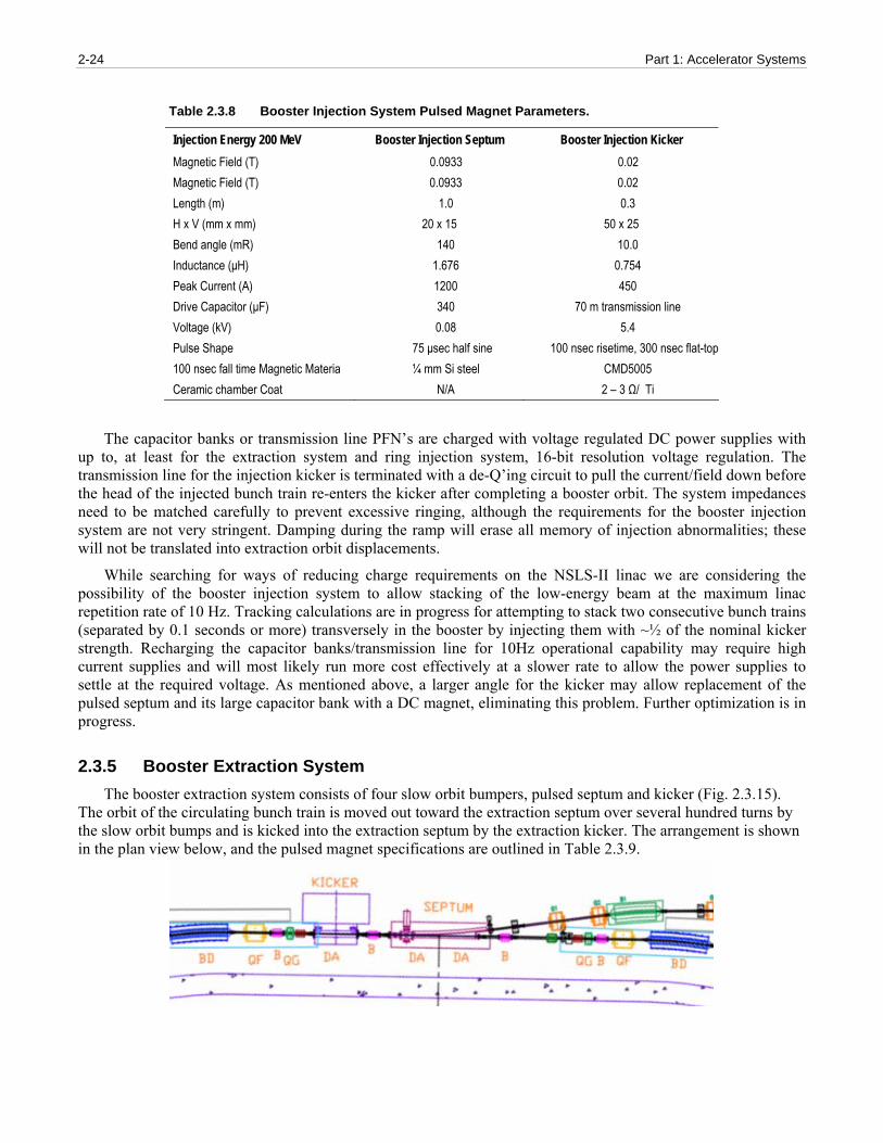
2.3.5 Booster Extraction System The booster extraction system consists of four slow orbit bumpers, pulsed septum and kicker (Fig. 2.3.15).
The orbit of the circulating bunch train is moved out toward the extraction septum over several hundred turns by the slow orbit bumps and is kicked into the extraction septum by the extraction kicker. The arrangement is shown in the plan view below, and the pulsed magnet specifications are outlined in Table 2.3.9.

Accelerator Chapter 2: Injection Systems 2-25
NSLS-II Preliminary Design Report
Figure 2.3.15 Booster extraction system layout. B -- orbit bumps.
Table 2.3.9 Booster Extraction System Pulsed Magnet Parameters (at the Extraction Energy of 3 GeV).
Extraction Septum Slow Bumps Extraction Kicker Magnetic Field [T] 0.8 0.4 0.05 Magnetic Field [T] 0.8 0.4 0.05 Length (m) 1.75 0.2 1.0 H x V [mm x mm] 20 x 15 50 x 25 50 x 25 Bend angle [mR] 140 7.5 5.0 Inductance [μH] 2.932 201 2.513 Peak Current [A] 10,000 400 in 20 turns 1.0 Drive Capacitor [μ]) 125 505 65 m transmission line Voltage [kV) 1.465 0.3 19.75 Pulse Shape 60 μsec half sine 1000 μsec half sine <200 nsec risetime, 300 nsec flat-top Magnetic Material ¼ mm Si steel ¼ mm Si steel laminate CMD5005 Ceramic chamber Coat N/A N/A 0.5 Ω/
The slow orbit bumps use 20 turns of conductor carrying a current of up to 400 A. Consideration to power these in series is under discussion at the moment. The steel laminations will be made of grain oriented heat-treated Si transformer steel with thin insulating coating on one side to reduce eddy currents. A 1.1 T septum with a 75μsec half-sine wave excitation has been running at NSLS for many years.
The extraction septum entrance is 16 mm outside of the central closed orbit of the booster; during extraction the displaced orbit is pushed to coast as close to the extraction septum as possible without incurring beam loss.
The kicker is a full-aperture device producing a field of 500 Gauss, and will be driven by a circuit similar to the one shown below (Figure 2.3.16). It turns on and reaches full flat-top field during the gap in the booster bunch train.

2-26 Part 1: Accelerator Systems
Figure 2.3.16 Booster extraction system layout.
2.3.6 Booster Diagnostics and Instrumentation This section describes diagnostics and instrumentation for the booster ring. The following parameters will be
monitored:
orbit
working point (tunes in both planes)
circulating current and filling pattern
emittances
bunch length
Booster diagnostics are summarized in Table 2.3.10.

Accelerator Chapter 2: Injection Systems 2-27
NSLS-II Preliminary Design Report
Table 2.3.10 Beam Diagnostics for the Booster Ring.
Monitor Quantity Beam parameter DC current transformer 1 Beam current 4-button pick-ups 20 Beam position Fluorescent screens 6 Injection position, profile Stripline set and amplifier 2 Betatron tune and bunch
cleaning system Fast current transformer 1 Filling pattern Optical beamline with streak-camera 1 Bunch length Firewire camera 1 Beam position, profile
Six fluorescent screens will be used to observe shape and position of the injected electron beam during the first turn. The screen material will be YAG:Ce. This was chosen because it results in an excellent resolution of the beam image and exhibits high sensitivity and high radiation hardness.
The booster orbit will be monitored with 20 pick-up electrodes instrumented with Libera receivers. The receivers are the same as used for the storage ring and have the specifications shown in Table 2.3.11 [ite]:
Table 2.3.11 RF BPM Specifications.
Beam intensity range [dB] >70 Input signals 0 dBm –70 dBm, 50 Ω Operating frequency [MHz] 500 MHz Noise RMS for k=10 mm [μm] <3 (1.15 MHz BW) @ -20 dBm <15 (1.15 MHz BW) @ –44 dBm Beam current dependence 0…-50 dBm [μm] 1 Fill pattern dependence 100%-20% [μm] 1
The booster current will be measured with a parametric current transformer, such as the one manufactured by Bergoz [ber1]. Its radiation-hardened sensor head is equipped with 30 m cable and its inner diameter of 115 mm is sufficient to fit over the flange. The parametric current transformer has the following specifications:
Table 2.3.12 Booster Current Monitor Specifications.
Full scale ranges ±20 mA, ±200 mA, ±2 A, ±20 A Range control 2 TTL lines Output [V] ±10 Output bandwidth (–3 dB) 8 kHz in 20 mA range, 10 kHz other ranges Response time (at 90%) [μs] <50 Resolution [μA/Hz½] <5 Output accuracy [%] ±0.1 Linearity error [%] <0.1 Output impedance [Ω] 100
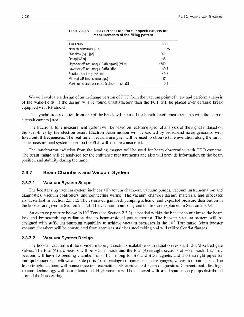
The filling pattern will be monitored with a fast current transformer. For example, the Bergoz FCT has the following specifications [ber2]:
2-28 Part 1: Accelerator Systems
Table 2.3.13 Fast Current Transformer specifications for measurements of the filling pattern.
Turns ratio 20:1 Nominal sensitivity [V/A] 1.25 Rise time (typ.) [ps] 200 Droop [%/μs] <6 Upper cutoff frequency (–3 dB typical) [MHz] 1750 Lower cutoff frequency (–3 dB) [kHz] <9.5 Position sensitivity [%/mm] <0.2 Minimal L/R time constant [μs] 17 Maximum charge per pulse (pulses<1 ns) [μC] 0.4
We will evaluate a design of an in-flange version of FCT from the vacuum point of view and perform analysis of the wake-fields. If the design will be found unsatisfactory then the FCT will be placed over ceramic break equipped with RF shield.
The synchrotron radiation from one of the bends will be used for bunch-length measurements with the help of a streak camera [stca].
The fractional tune measurement system will be based on real-time spectral analysis of the signal induced on the strip-lines by the electron beam. Electron beam motion will be excited by broadband noise generator with fixed cutoff frequencies. The real-time spectrum analyzer will be used to observe tune evolution along the ramp. Tune measurement system based on the PLL will also be considered.
The synchrotron radiation from the bending magnet will be used for beam observation with CCD cameras. The beam image will be analyzed for the emittance measurements and also will provide information on the beam position and stability during the ramp.
2.3.7 Beam Chambers and Vacuum System
2.3.7.1 Vacuum System Scope The booster ring vacuum system includes all vacuum chambers, vacuum pumps, vacuum instrumentation and
diagnostics, vacuum controllers, and connecting wiring. The vacuum chamber design, materials, and processes are described in Section 2.3.7.2. The estimated gas load, pumping scheme, and expected pressure distribution in the booster are given in Section 2.3.7.3. The vacuum monitoring and control are explained in Section 2.3.7.4.
An average pressure below 1x10⁻⁷ Torr (see Section 2.3.2) is needed within the booster to minimize the beam loss and bremsstrahlung radiation due to beam-residual gas scattering. The booster vacuum system will be designed with sufficient pumping capability to achieve vacuum pressures in the 10-8 Torr range. Most booster vacuum chambers will be constructed from seamless stainless steel tubing and will utilize Conflat flanges.
2.3.7.2 Vacuum System Design The booster vacuum will be divided into eight sections isolatable with radiation-resistant EPDM-sealed gate
valves. The four (4) arc sectors will be ~ 33 m each and the four (4) straight sections of ~6 m each. Each arc sections will have 15 bending chambers of ~ 1.5 m long for BF and BD magnets, and short straight pipes for multipole magnets, bellows and side ports for appendage components such as gauges, valves, ion pumps, etc. The four straight sections will house injection, extraction, RF cavities and beam diagnostics. Conventional ultra high vacuum technology will be implemented. High vacuum will be achieved with small sputter ion pumps distributed around the booster ring.

Accelerator Chapter 2: Injection Systems 2-29
NSLS-II Preliminary Design Report
The booster will accelerate the 200MeV bunch train from the linac to the full energy of 3 GeV at 1 Hz repetition rate. To minimize the eddy currents during the fast ramping fields (and the associated sextupole effect), the vacuum chambers will be made of thin-wall stainless steel. A wall thickness of about 0.7 mm is sufficiently strong for a bending chamber with an elliptical cross section of 24 mm (V) × 40 mm (H), while having sufficiently low eddy currents. The 60 bending chambers will be about 1.5 m long with bending radii of 10 m and 23m for defocusing and focusing chambers, respectively. They will be made from seamless stainless tubing, drawn and pressed into elliptical shape, then roll-curved to give the required bend angles. The ends of the bending chambers will be tapered from elliptical to round cross-section and welded to Conflat flanges. The maximum stress and deflection of the bending chamber under the external atmospheric pressure occurs at the top and bottom of the chambers. Using finite element analysis, the stress and deflection are found to be 11000 psi and 0.2 mm, respectively (Figure 2.3.17), which is well within acceptable ranges with large safety margins.
The straight drift pipes between bending chambers will have an inner radius of 20mm and made of thin wall stainless steel. Each drift pipe is approximately 0.8m long consisting a section for multipole magnets, a precision machined block for mounting of the four BPM buttons, a cross for vacuum pumps and gauges, and a short bellows. Conflat flanges (size DN38) will be used throughout the booster ring.
Figure 2.3.17 Calculated stress of the thin-wall bending chamber under vacuum load. The high stress is at the side of the tube along the horizontal plane with maximum stress of less than 11kpsi. The calculated deflection is ~0.2 mm.
After proper chemical cleaning, the completed chambers and drift pipes will be vacuum degassed at 450ºC in a vacuum furnace for several days to remove any trace of surface contaminants and to reduce outgassing, eliminating the need for in-situ baking. The chambers and the pipes are then assembled into the magnets, welded with end flanges, and tested prior to installation in the tunnel. Once they are installed and connected to other beam pipes, two gate valves will be mounted at the end of arc sections, so each section can be pumped down to high vacuum.
2.3.7.3 Vacuum Pumping and Pressure Distribution The thermal outgassing of the clean stainless chamber surface will be less than 1x10⁻¹⁰ Torr-l/s/cm2, 24 hours
after pumping down. This is equivalent to a total thermal gas load of ~2x10⁻⁵ Torr-l/s for the whole booster ring, excluding the contributions from RF, injection, extraction, and diagnostics. The pressure in the booster will be

2-30 Part 1: Accelerator Systems
dominated by the synchrotron radiation-induced desorption during the filling of the storage ring. This effect will be much less pronounced during the topoff injection mode due to low duty factor. Assuming a 25 mA multi-bunch beam accelerated to 3.0 GeV in the booster during the 0.4 sec acceleration cycle, the average synchrotron radiation power on the vacuum chamber wall will be less than 2000 W for the whole ring, concentrated at the downstream end of the dipole chambers, with a linear power density less than 40 W/m. No observable temperature rise at the chamber wall is expected.
The average photon flux during acceleration is approximately 1×10¹⁹ photons/sec. Assuming a PSD yield of η = 2×10⁻⁴ molecules/photon, the total photon-desorbed gas load will be about 1×10⁻⁴ Torr-l/s, which is much higher than the thermal desorption gas load. Desorption yield of η = 2×10⁻⁴ mol/ph can be achieved with an integrated dosage of 1019 ph/meter, reached in a few hours of continuous booster operation. Both the thermal- and photon-desorbed gas load will be handled with the 30 l/s ion pumps at the downstream end of each bending chamber. The pressure distribution in booster arc section can be estimated using standard linear conductance formulae and super imposing photon stimulated desorption over the thermal desorption. The pressure distributions of a 10 m long arc section for three different pumping schemes are plotted in Figure 2.3.18, with one 30 l/s ion pump downstream of each bending chambers (~ 2.2m pump spacing); with one 100 l/s ion pumps downstream of each bending chamber; and with one 30 l/s ion pump at every other bending chambers (~ 4.4m pump spacing). The average pressure for 1st case is about 1.2×10⁻⁷ Torr and 25% lower with 100 l/s ion pumps. Due to the limited conductivity of the small-diameter beam pipes, the average pressure will improve with shorter pump spacing, rather than with larger ion pumps, as illustrated in the 3rd case, where pressure increases by factor of 3 when number of pumps is halved. The average pressure will improve rapidly to mid 10-8 Torr within a week, since η decreases with integrated beam dose and thermal outgassing decreases with time.
Figure 2.3.18 Pressure distribution in booster arc sections from both thermal desorption and photon-stimulated desorption. Each arc sectionl will have fifteen (15) 30 l/s ion pumps, at downstream end of each bending chamber. Due to the limited linear conductance of the small diameter beam pipes, the average pressure only decreases by 25% if 100 l/s ion pumps are used in place of the 30 l/s pumps. The average pressure will increase three folds if only one ion pump is installed for every two bending chambers.
The booster ring vacuum sectors will be roughed down from atmospheric pressure with portable turbo-pumps (TMP) backed with dry mechanical pumps before transferring to the sputter ion pumps. Two right-angle, all-metal valves will be mounted at each vacuum sector for roughing, bleed-up, and for other vacuum diagnostics. The TMP stations will have their own vacuum gauges and an electro-pneumatic valve to isolate the TMP from the vacuum section in the event of pump or power failures. The TMPs will be manually isolated with valves, once each booster ring sector is at high vacuum. Large ion pumps of about 200 l/s, identical to those deployed in the storage ring, will provide sufficient UHV pumping speed at the straight sections for RF cavities, injection, extraction, and diagnostics.

Accelerator Chapter 2: Injection Systems 2-31
NSLS-II Preliminary Design Report
2.3.7.4 Vacuum Monitoring and Controls Power supplies and controllers for linac and booster vacuum systems will be located in the satellite electrical
racks in the Injector service area. Commercial dual ion pump controllers and vacuum gauge controllers with local and remote capabilities will power, monitor, and control the ion pumps and vacuum gauges, and interface with the PLC and control computers. Ion pump currents and the vacuum gauges will provide information on the pressure distribution in the booster ring.
2.3.7.4.1 Vacuum Monitoring The booster vacuum will be monitored and interlocked with the ion pump current and the vacuum gauge
readings. Each arc vacuum section will have a convection-enhanced Pirani gauge (TCG), two inverted-magnetron cold cathode gauges as the primary gauges, and 15 30 l/s ion pumps. One set of vacuum gauges and two large ion pumps will be installed at the short straight sections to handle the extra outgassing from RF cavities, kickers, septums and diagnostics. Residual gas analyzer heads will also be installed at short straight sections for diagnostics during operation and maintenance periods. A residual gas analyzer head may be mounted on the portable TMP stations to assist the pumpdown and troubleshooting of arc vacuum sections. Table 2.3.14 presents a list of booster vacuum devices, together with those for linac and beam transport lines.
Table 2.3.14 List of Vacuum Components for the Linac and Booster Vacuum Systems.
IP (30 l/s) IP (200 l/s) TCG CCG TMP RGA GV E-gun 2 2 2 2 1 1 2 GtL 2 1 2 1 2 Linac 8 4 8 1 1 2 LtB 4 2 4 1 2 Booster 60 8 8 12 4 3 8 BtSR 6 1 2 1 1 2 Total 72 20 18 30 10 6 18
2.3.7.4.2 Vacuum Controls The vacuum control system will interface with vacuum devices while being part of the machine control. Due
to the high radiation levels in the tunnel, all the vacuum devices will be located at the satellite control racks. These vacuum devices (such as gauge controllers, ion pump controllers, RGA, etc.), with local and remote capabilities, will communicate with the machine control system through RS232 or Ethernet links for remote monitoring, operation, and control. The low-level vacuum control will consist of dedicated vacuum programmable logic controllers. Each PLC has both digital and analog I/O modules with inputs from various vacuum devices, and provides the logic for the operation of the sector gate valves, the interlocks for other subsystem devices, and generation of the beam permits. For the gate valve control, a voting scheme with inputs from the setpoint contacts of several ion pumps will be used to initiate the interlock functions, therefore minimizing false triggering due to the failure of a single pump.
2.3.8 Booster PS Since the booster system is foreseen as a turn-key procurement, power supplies will be design to match our
requirements on the booster magnet lattice. Given that our magnet design is close to that at the existing ASP booster we expect that the dipole and quadrupole power supplies specifications will be close to that at the ASP (Table 2.3.15).

2-32 Part 1: Accelerator Systems
Table 2.3.15 Preliminary specifications for the booster power supplies.
Name Number Io, A Vo, V
Dipole BF 1 900 220 Dipole BD 2 900 400 Quadrupole QD 1 100 50 Quadrupole QF 1 200 50 Quadrupole QG 1 100 50 Sextupole SXV 8 21 73 Sextupole SXH 8 18 45 Corrector 32 12 25
2.6.8.1 Power Supply Interlocks All power supplies will have sufficient interlocks to prevent the power supply from damage due to changes in
cooling conditions, AC power disturbances, and out-of-range setpoints. All magnet coils will have an over-temperature interlock if damage can occur due to a change in cooling or operating conditions. All power supplies will have an electrical safety interlock that will prevent the power system from turning on if the machine safety system requirements so warrant.
2.6.8.2 Electrical Safety All power supplies will conform to the latest BNL safety requirements, especially concerning arc flash
protection. Whenever possible, NRTL-listed equipment will be used.
2.6.8.3 Cable Tray The cable tray for the magnet circuits will be located inside the main tunnel, on the ceiling. All cables will be
tray-rated. Power cables will be arranged to minimize pickup from other circuits. All power cables will be separated from signal cables. All cables and trays will meet NEC requirements.
2.6.8.4 Power Supply Instrumentation Redundant DCCTs or shunts will be used to confirm the power supply current reproducibility. High-precision
DMMs and scanners will be used to monitor the power system current, the redundant current sensor, and the analog current setpoint. This equipment will ensure long-term stability and reproducibility. Temperature monitoring of the magnet coils and power system environment will be accomplished using low-cost digital temperature sensors. With such system, a problem can be identified before it becomes an emergency, making it possible for repairs to be scheduled more conveniently and economically.
2.6.8.5 Power Supply Controls Each booster power supply circuit will require a Waveform Function Generator. These VME device cards
will be located in a control system’s VME chassis, mounted in one of the power supply system racks. The WFGs will generate the reference current profiles, input analog data, and perform digital state control and status readbacks. A timing system will be needed to synchronize all the WFGs. The output of the WFGs is connected via fiber optics to a Power Supply Interface. The PSI has a precision digital-to-analog converter for generating the reference current, and a multi-channel analog-to-digital converter for inputting power system signals. The PSI also has digital IO for state control and status readbacks of the power supply.
The other controls will include the operation of the high-precision DMM and scanner, and readout of the digital temperature sensors.

Accelerator Chapter 2: Injection Systems 2-33
NSLS-II Preliminary Design Report
2.3.9 Injection System Service Building In the following we briefly describe the injector service building layout (Figure 2.3.19). The service area will
contain all injector equipment including that for the linac, transport lines, booster and the SR injection straight section. It will also include rooms for utility distribution system, workbenches and local control room.
Figure 2.3.19 Layout of the injector service area

2-34 Part 1: Accelerator Systems
Service areas in the injector service building are listed below. 1. Booster service area
three dipole power supplies
three quadrupole power supplies
two sextupole power supplies
40 corrector power supplies
vacuum power supplies
Injection Pulsed Magnets
Extraction Pulsed Magnets (bumps, kicker and septum)
Diagnostics: two racks
2. LbTL Service Area
Nine racks altogether
3. B-SR TL Service Area (all areas with power supplies, vacuum equipment and diagnostics)
Storage ring injection system Area
Timing System
B-SR: ten racks altogether
SRIS: four racks (bumps), three racks (septa)
TS: two racks
4. AC power disconnects/ switch gear + stay-clear area eight panels + stay-clear area during switch operation
5. two entry labyrinths 7. bathroom 8. local Injection System Control Room 10. equipment storage area (spare parts and test instruments) 11. electronic/mechanical workshop 12. water and air distribution area (linac) 13. booster RF area Total for building 610m²

Accelerator Chapter 2: Injection Systems 2-35
NSLS-II Preliminary Design Report
2.3.10 Linac and Booster Utilities System The cooling water for both the linac and booster ring will be provided from one of the Mechanical Equipment
Rooms (MERs), whose process water system will be sized such that it will supply the necessary capacity for the linac and booster, as well as the MERs’ respective copper and aluminum systems. The total heat load for this MER will be ~1.2 MW, with the linac requiring cooling for ~100 KW and the booster needing ~400 KW cooling capacity.
Both a supply and return pipe will originate from the MER and travel to both the linac and booster, at which point the necessary connection points will be supplied so as to allow their respective components to be connected to the process water. The process water will have the following thermal hydraulic parameters:
supply (inlet) pressure ~ 120 psig
supply (inlet) temperature ~80 F
supply (inlet) temperature stability ± 1°F
The booster piping will be sized for ~212 gpm and the linac piping will be sized for ~53 gpm; this results from a temperature differential across the components of ~13°F.
The water will be clean with a resistivity of ~ 1 MOhm-cm.
Compressed air is expected to serve only for a few applications, such as, powering the phosphor screens and will be discussed in details during the next stage of the design.
References
[asp] http://ieeexplore.ieee.org/iel5/10603/33511/01591747.pdf?arnumber=1591747 asp [dia] http://accelconf.web.cern.ch/AccelConf/e02/PAPERS/TUPRI097.pdf [sol] http://ieeexplore.ieee.org/iel5/10603/33511/01591041.pdf?arnumber=1591041 [sls] The SLS booster synchrotron, W. Joho, M. Muñoz and A. Streun, Nucl. Instrum. and Meth. A, Vol. 562-1, pp. 1-11 [alb] http://epaper.kek.jp/e06/PAPERS/THPLS057.PDF [binp] http://ieeexplore.ieee.org/iel5/10603/33511/01590651.pdf?arnumber=1590651 [Edd] M. Munoz and V. Joho, Eddy current effects in the SLS booster:
http://slsbd.psi.ch/pub/slsnotes/tmeta9810/eddy.html [ite] http://www.i-tech.si/products.php [ber1] http://www.bergoz.com/products/NPCT/PCT-downloads/files/NPCTflyer.pdf [ber2] http://www.bergoz.com/products/FCT/d-fct.html [stca] http://www.optronis.com/

Accelerator Chapter 2: Injection Systems 2-37
NSLS-II Preliminary Design Report
2.4 Transport Lines 2.4.1 Linac-to-Booster Transport Line
2.4.1.1 Scope The main function of the linac-to-booster (LtB) transfer line is to transport the 200MeV electron beam from
the linac to the booster. A schematic diagram of the transport line in relation to the booster is shown in Figure 2.4.1.
Figure 2.4.1 Schematic diagram of the LtB beam transport line. The beamline starts at the exit of the linac (30 cm upstream of Q1 shown in the figure) and ends at the exit of the injection septum which is part of the booster synchrotron. A section of the booster is shown at the left side of the figure.
The LtB line is defined between the exit point of the 200MeV linac, located 30 cm upstream of Q1, as shown in Figure 2.4.1, and the “booster injection point,” located at the exit of the injection septum, shown also in same figure. The beamline has been partitioned into three sections, which are briefly discussed below.
The linac to achromatic section: This section of the beamline transports the beam from the exit of the linac to the beginning of the “achromatic section.” It consists of four quadrupoles and two dipoles, which each bend the beam to the right by 150 mrad. The beam is achromatic at the exit of this section.
The achromatic section: The transported beam in this section is achromatic, and consists of six quadrupoles.
The Injection-matching section: This is the last section of the line, and matches the transported beam to the circulating beam of the booster at the injection point, which is located at the exit point of the septum (Figure 2.4.1). This section of the line consists of a “bend to the left” dipole of 150 mrad, the injection septum, which also is a 150mrad “bend to the left” dipole, and two quadrupoles.
2.4.1.2 Beam Constraints along the LtB Line The main beam constraints of the LtB line is to transport the extracted beam from the exit of the linac to the
booster injection point, and match the beam parameters of the beam at the booster injection point to those of the circulating beam in the booster. The beam parameters [SOLL] at the linac’s exit and booster injection point are shown in Table 2.4.1. The values of vertical dispersion and angular dispersion functions at these two points are zero.
Table 2.4.1 Beam Parameters at the Linac Exit Point and Booster Injection Point.
αx βx ,m ηx ,m η'x αy βy, m
Linac exit point -1.7 40.0 0.0 0.0 -1.7 40.0
Booster Injection point 7.212 8.027 -0.128 0.0 -0.523 3.043

2-38 Part 1: Accelerator Systems
The following additional constraints are also imposed on the LtB transport line.
The maximum values of the horizontal and vertical beta function along the line should be less than 100 m (βx,y<100 m). Similarly, the absolute values of the horizontal dispersion should be below 0.5 m (|ηx|<0.5 m) at any point along the line. This will make the size of the beam along the line compatible with the physical aperture of the line. The geometrical projected beam emittance is 50π mm·mrad in both the horizontal and vertical directions.
The “achromatic section” of the line is designed to provide an achromatic beam in both the horizontal and vertical directions. This section of the line will be used to characterize the transported beam by measuring its projected emittance and the beam parameters at any point upstream of this section. The beam characterization can be performed by utilizing the “nominal” settings of the quadrupoles that are used to transport the beam or by altering the settings of the quadrupoles.
2.4.1.3 Beam Optics of the LtB Beam Transport Line The beam optics of the LtB line must satisfy the constraints mentioned earlier. The beam optics were
calculated with the MAD computer code, Version 8b.
The calculated values of the beta functions (βx,y), and dispersion function (ηx) are plotted in Figure 2.4.2. The horizontal and vertical beam envelopes that correspond to geometrical projected beam emittances εx=50π mm·mrad and εy=50πmm·mrad are plotted in Figure 2.4.3. The projected beam emittances εx and εy correspond to two standard deviation of the beam intensity.
Figure 2.4.2 The βx,y (black and red lines) and ηx function (green line) at the beginning and the end of each magnetic element. The large black rectangles shown on the top of the figure represent the dipoles, and the thin black rectangles represent the quadrupoles.

Accelerator Chapter 2: Injection Systems 2-39
NSLS-II Preliminary Design Report
Figure 2.4.3 Half of the horizontal and vertical beam envelopes (black and red lines) that correspond to 2σx,y beam emittance. The black rectangles at the top of the figure represent the dipoles and the quadrupoles magnets.
2.4.1.4 Magnetic elements of the LtB beam transport line In this section we provide a table with the geometry (length, aperture) and the strength of the dipoles and
quadrupoles of the LtB line. Table 2.4.2 shows all the main magnetic elements of the LtB line that are used to generate the line’s first-order optics, discussed in the previous section. Each magnetic element has its own power supply.
Table 2.4.2 Length, Aperture and Strength of the Main Magnetic Elements of the LtB Line.
Element Name Type L [m] Gap/Rad[cm] Strength [rad] or [m-1] Power Supply Q1 Quadrupole 0.150 2.0 -0.09548 P Q1 Q2 Quadrupole 0.150 2.0 1.02667 P Q2 Q3 Quadrupole 0.150 2.0 0.90802 P Q3 B1 Dipole 0.350 3.0 0.150 P B1 Q4 Quadrupole 0.150 2.0 1.17679 P Q5 B2 Dipole 0.350 3.0 0.150 P B2 Q5 Quadrupole 0.15 2.0 -1.04264 P Q5 Q6 Quadrupole 0.150 2.0 1.15803 P Q6 Q7 Quadrupole 0.150 2.0 -0.04559 P Q7 Q8 Quadrupole 0.150 2.0 0.32202 P Q8 Q9 Quadrupole 0.150 2.0 -0.95966 P Q9 Q10 Quadrupole 0.150 2.0 1.10812 P Q10 B3 Dipole 0.350 3.0 -0.150 P B3 Q11 Quadrupole 0.150 2.0 -1.09038 P Q11 Q12 Quadrupole 0.150 2.0 1.70708 P Q12 BUMP Dipole 0.350 3.0 -0.150 P BUMP
2.4.1.5 Linac-to-Booster Power Supplies The LtB power supplies are connected to dipoles, quadrupoles, and vertical/horizontal correctors. The
supplies will stay at the nominal setpoint only during the ring fill. For energy savings, it is anticipated that the supplies’ output will be lowered during the dwell time in top-off mode and brought back to the operating point slightly before the fill cycle.

2-40 Part 1: Accelerator Systems
2.4.1.5.1 Power Supply Control Each transfer line power supply will be set by its analog programming interface. Either a micro-controller or
PLC could be used to control the supply. Analog output voltages from the control system will be used to control the current setpoint of the supply, and the digital-to-analog converter will have a resolution of at least 16 bits. Both supply output voltage and current will be read back by medium-speed analog-to-digital converters with a resolution of 16 bits. Monitoring of the supply outputs should be able to detect transients as short as 1 ms. Long-term monitoring of drift will be done by an independent external shunt connected to a high-precision analog channel.
2.4.1.5.2 Interlock An external power distribution unit will be installed in each power supply rack and will contain a primary
contactor that can be controlled remotely and independently. This contactor will be controlled by the Personnel Safety System and will be independent of the power supply controller. Each power supply will have its own circuit breaker and power receptacle. The breaker will be sized to withstand turn-on in-rush power and to limit steady-state current to the line cord rating.
2.4.1.6 Allowed Misalignment Error of the Magnetic Elements of the LtB Transport Line The placement of the magnets along the LtB line is subject to misalignment errors: the transverse and
longitudinal placement errors DX, DY, and DS; the angular placement errors about the transverse axes DPHI and DTHETA; and angular error about the longitudinal axes, DPSI.
The results of a study to determine the maximum allowed error of each geometrical misalignment appear in Table 2.4.3. In the study we assumed that any misalignment error should not generate transverse beam displacement larger than ±1.5 mm nor measurable beam coupling effects.
Table 2.4.3 shows the upper limits of the allowed errors in the placement of the magnetic elements of the LtB line. The first three quantities DX, DY, and DS, correspond to the lateral and longitudinal position error. The last three quantities, DPHI, DTHETA, and DPSI, correspond to the rotation error about the transverse axes.
Table 2.4.3 Upper Limits of the Allowed Error in the Placement of the Magnets.
DX [mm]
DY [mm]
DS [mm]
DPHI [mrad]
DTHETA [mrad]
DPSI [mrad]
Dipoles ±1.0 ±1.0 ±1.0 ±2.0 ±2.0 ±0.5
Quadrupoles ±0.5 ±0.5 ±2.0 ±2.0 ±2.0 ±5.0
2.4.1.7 LtB Transport Line Instrumentation and Diagnostics The beam instrumentation that will be used for the commissioning and normal operation of the LtB line are
the horizontal and vertical corrector dipole magnets (HC,VC), the beam position monitors (HBPM, VBPM), the Fluorescent screens (FS), the current transformer (CXF). The relative location of these devices along the LtB line is presented in Table 2.4.4. The first column contains the location of the beam instrumentation, which is identified in the second column.
Table 2.4.4 Beam Instrumentation (Column 2) at Various Locations (Column 1) along the LtB Line.
Location Instrumentation Comment
UpStrm of Q1 line FS1, HC1, VC1, HBPM1, VBPM1 Fluor. Screen Retractable

Accelerator Chapter 2: Injection Systems 2-41
NSLS-II Preliminary Design Report
DownStrm of Q4 FS2, HC2, VC2, Fluor. Screen Retractable
DownStrm of Q7 FS3, HC3, VC3, HBPM2, VBPM2 Fluor. Screen Retractable
UpStrm Q8 FS4 Fluor. Screen Retractable
UpStrm B3 HC4, VC4
DownStrm B3 HC5, VC5
UpStrm BUMP FS5, HC6, VC6, CXF, HBPM3, VBPM3 Fluor. Screen Retractable
Any deviations of the actual beam trajectory from the ideal trajectory due to magnet misalignment errors will
be corrected with the six horizontal and six vertical dipole correctors.
The first dipole in the LtB achromatic bend is used to steer the beam either to the booster or emittance measurement setup and also serves as an energy spectrometer. Two fluorescent screens provide for coarse and fine (with switched-off achromatic quadrupole) measurements of energy spread. The beam dumps can include Faraday cups for charge measurement. With the first dipole switched off, the electron beam is directed to the emittance measurement system.
Two additional fluorescent screens after the second dipole of the achromatic bend will be used to measure electron beam size and position. The beam trajectory during normal operations is monitored by three pick-up electrodes equipped with Libera beam position monitors (BPM) [ber3, itc]. An integrating current transformer will measure the amount of charge passing through the transport line.
2.4.1.8 Shielding The radiological study of the NSLS-II building complex is documented in [shie]. In this study, three
radiological enclosures separate the linac, the booster and the storage ring. The radiological enclosure that separates the linac from the booster partitions the LtB line into two sections. The partition of the LtB line by the radiological enclosure occurs at the straight section between quadrupoles Q7 and Q8, as shown in Figure 2.4.1. The wall thickness of the enclosure that separates the linac from the booster is sufficient to attenuate any radiation levels that can be produced by a fault condition in the linac enclosure, to radiation levels less than 2.5 μSv/h at the area of the booster enclosure.
It is therefore possible for personnel to occupy the booster area while the linac is operating, under the condition that the safety devices of the LtB line (see next section) are fully functioning and the critical devices of the LtB line have been LOTO’ed (Lock-out Tag-out).
2.4.1.9 Linac-to-Booster Critical Devices The linac-to-booster radiation transport will have two critical devices to stop the electron beam from entering
the booster, to protect personnel from prompt radiation hazard in the booster area. This redundant pair of stops will consist of a shutter mechanism and a bending magnet.
The stop will be constructed of a block of material engineered to effectively stop all the radiation produced by the linac when the block is placed in the beam path. The stop will be redundantly monitored by the interlock system using two switches. The switches monitor the closed position of the shutter: one switch for chain A, and one for chain B. When in the closed position, the stop will block all radiation from entering the booster ring.
The bending magnet upstream of the stop will provide another safety function: when it is not powered, it allows the beam to follow a straight path into a beam dump area. This will prevent the electron beam from entering the booster tunnel area. When it is safe to allow beam in the booster area, the magnet will be powered and will bend the beam into the booster ring. The magnet will be redundantly monitored by the interlock system: for current by chain A, and voltage by chain B. In the event of the stop or bending magnet failing to reach a safe state when required to do so, the interlock system will reach back and shut off the linac and gun.

2-42 Part 1: Accelerator Systems
5.4.2 Booster-to-Storage Ring Transport Line
2.4.2.1 Scope The main function of the booster-to-storage ring (BtS) transport line is to transport the 3GeV electron bunches
from the booster to the storage ring (SR). A schematic diagram of the transport line, in relation to the booster and storage ring, is shown in Figure 2.4.4. The BtS line is defined between the “booster extraction point,” which is located at the entrance point of the “BR1” local beam-bump-dipole, and the “storage ring injection point,” which is located at the exit of the injection kicker “IS.” Both magnets, BR1 and S1, are shown in Figure 2.4.4.
Figure 2.4.4 Schematic diagram of the BtS beam transport line. The arc at the bottom of the figure is a section of the booster, and at the top of the picture the green elements are part of the storage ring. The dark green rectangles on the BtS line are the fluorescent screens/ visual flags (VF).
For reasons, of easing the optical design, the beamline has been partitioned into three sections, which are briefly discussed below.
The extraction section: This section of the beamline contains, the extraction devices, (extraction bumps, and extraction kicker, and extraction septum), two dipoles of 120 mrad bend each, that both form a horizontal “dogleg”, and three quadrupoles. The two 120 mrad dipoles which form the horizontal “dogleg” and the three quadrupoles serve to generate an achromatic beam and also adjust the beam parameters, at the end of the extraction section.
The achromatic section: This section of the beamline follows the extraction section, and consists of five quadrupoles. The transported beam in this section is achromatic. The secondary function of this section is to be used for measuring the projected beam emittance and the beam parameters, with the help of four visual flags installed along this section.
The injection section: This is the last section of the line, and matches the transported beam to the circulating beam of the storage ring at the injection point which is located at the exit point of the Injection kicker SI. This section of the line consists of two “bend to the right” dipoles of 120 mrad each, the injection septum and the injection kicker, both bending to the right. It also includes six quadrupoles for the required beam matching at the injection point.
IS
BR1
Fluor. Screens Fluor. Screens

Accelerator Chapter 2: Injection Systems 2-43
NSLS-II Preliminary Design Report
2.4.2.2 Beam Constraints along the BtS Line The main beam constraints of the BtS line is to transport the extracted beam from the Booster to the Storage
ring and match the beam parameters of the beam at the Injection point to those of the circulating beam. The beam parameters at the extraction and injection point are shown in Table 2.4.5. The values of vertical dispersion and angular dispersion functions of booster and storage ring lattices at these two points are zero therefore do not appear on the Table 2.4.5.
Table 2.4.5 Beam Parameters at the Booster Extraction Point, and Storage Ring Injection Point. The values of the vertical dispersion and angular dispersion functions of the booster and storage ring lattices at these two points are zero.
αx βx ,m ηx ,m η'x αy βy ,m
Booster extraction point 0.0 5.0 0.1 0.0 0.0 3.0
Storage ring injection point 0.0 5.0 0.0 0.0 0.0 3.0
The following additional constraints are also imposed on the BtS transport line.
The maximum values of the horizontal and vertical beta function along the line should be less than 100 m (βx,y<100 m). Similarly the absolute value of the horizontal dispersion function should be below 2 m (|ηx|<2 m) at any point along the line. This will make the size of the beam along the line compatible with the physical aperture of the line. The geometric projected beam emittance is 27π nm-rad and 3π nm-rad in the horizontal and vertical directions respectively.
The “achromatic section” of the line is designed to provide an achromatic beam in both the horizontal and vertical directions. This section of the line will be used to characterize the transported beam by measuring its projected emittance and the beam parameters at any point upstream of this section. The beam characterization can be performed by utilizing the “Nominal” settings of the quadrupoles that are used to transport the beam or by altering the settings of the quadrupoles.
2.4.2.3 Beam Optics of the BtS Beam Transport Line The beam optics of the BtS line must satisfy the constraints mentioned earlier. The beam optics was
calculated with the MAD computer code, version 8b.
The calculated values of the beta functions (βx,y), and dispersion function (ηx) are plotted in Figure 2.4.5. The horizontal and vertical beam envelopes that correspond to the geometric projected beam emittances εx=50π nm-rad and εy=3π nm-rad are plotted in Figure 2.4.6. The projected beam sizes correspond to one standard deviation of the beam intensity.

2-44 Part 1: Accelerator Systems
0
10
20
30
β [m
]
βx,y ηx,y vs. Distxtr3Q_AchFODO5Q_inj6Q
XY
0 10 20 30 40S [m]
−0.75
−0.25
0.25
0.75
1.25
η [m
]
Figure 2.4.5 The βx,y (black and red lines) and ηx function (green line) at the beginning and the end of each magnetic element. The large blue rectangles represent the dipoles and the thin blue rectangles indicate the quadrupoles.
X and T 1σ Beam Envelope vs. Dist.
0 10 20 30 40S [m]
−0.5
0
0.5
1
2
Bea
m−E
nvel
ope(
1σ)
[mm
]
X−profileY−profile
εx(1σ) = 0.027 π[mm.mrad]
εy(1σ) = 0.003 π[mm.mrad]
δ p/p(1σ) = 0.001
Figure 2.4.6 Half of the horizontal and vertical beam envelopes (black and red lines) that corresponds to 1σx,y beam emittance. The green rectangles at the bottom of the figure represent the dipoles and the quadrupoles.
2.4.2.4 Magnetic Elements of the BtS Transport Line In this section we provide a table with the geometry (length, aperture) and the strength of the dipoles and
quadrupoles of the BtS line. Table 2.4.6 shows all the main magnetic elements of the BtS line that are used to generate the line’s first order optics which is discussed in the previous section. Each magnetic element has its own power supply except the B3I and B4I dipoles which are connected in series with a single power supply.
Table 2.4.6 Length, Aperture and Strength of the Main Magnetic Elements of BtS Line.
Element Name Type L [m] Gap/Rad[cm] Strength [rad] or [m-1] Power Supply BR1X Dipole 0.200 3.0 -0.080 P BR1X

Accelerator Chapter 2: Injection Systems 2-45
NSLS-II Preliminary Design Report
KIX Dipole 1.000 3.0 -0.005 P KIX BR2X Dipole 0.200 3.0 0.080 P BR2X ESX Dipole 1.750 3.0 -0.140 P ESX Q1X Quadrupole 0.300 2.0 -0.372582 P Q1X Q2X Quadrupole 0.300 2.0 0.5835372 P Q2X B1X Dipole 1.000 3.0 0.120 P B1X Q3X Quadrupole 0.300 2.0 -0.4201152 P Q3X B2X Dipole 1.000 3.0 -0.120 P B2X Q1A Quadrupole 0.300 2.0 0.6153693 P Q1A Q2A Quadrupole 0.300 2.0 -0.4201239 P Q2A Q3A Quadrupole 0.300 2.0 0.4269711 P Q3A Q4A Quadrupole 0.300 2.0 -0.350637 P Q4A Q5A Quadrupole 0.300 2.0 0.3244197 P Q5A B3I Dipole 1.000 3.0 0.120 P BI Q1I Quadrupole 0.300 2.0 -0.3434886 P Q1X Q2I Quadrupole 0.300 2.0 0.3373026 P Q2X B4I Dipole 1.000 3.0 0.120 P BI Q3I Quadrupole 0.300 2.0 -0.4447095 P Q3X Q4I Quadrupole 0.300 2.0 0.4081164 P Q4X Q5I Quadrupole 0.300 2.0 0.6599952 P Q5X Q6I Quadrupole 0.300 2.0 -0.6455421 P Q6X PSI Dipole 2.0 3.0 0.150 P PSI ISI Dipole 2.0 3.0 0.080 P ISI
2.4.2.5 Booster-to-Storage Ring Transport Line Power Supplies The BtSR power supplies are connected to dipoles, quadrupoles, and vertical/horizontal correctors. The
supplies will be operated around a static operating point, eliminating the need for significant voltage head room. For energy savings, we anticipate that the supply’s output will be lowered during the dwell time in top-off mode and brought back to the operating point slightly before the top-off cycle. Unmodified commercial power supplies are currently used at NSLS in its transfer lines and are analog programmed by 14-bit digital-to-analog converters. The supplies are operated in current mode with shunt feedbacks.
2.4.2.5.1 Power Supply Control Each transfer line power supply will be set by its analog programming interface. Either a micro-controller or
PLC could be used to control the supply. Analog output voltages from the control system will be used to control the current setpoint of the supply, and the digital-to-analog converter will have a resolution of at least 16 bits. Both supply output voltage and current will be read back by medium-speed analog-to-digital converters with a resolution of 16 bits. Monitoring of the supply outputs should be able to detect transients as short as 1 ms. Long-term monitoring of drift will be done by an independent external shunt connected to a high-precision analog channel.
2.4.2.5.2 Interlock An external power distribution unit will be installed in each power supply rack and will contain a primary
contactor that can be controlled remotely and independently. This contactor will be controlled by the personal safety system and will be independent of the power supply controller. Each power supply will have its own circuit

2-46 Part 1: Accelerator Systems
breaker and power receptacle. The breaker will be sized to withstand turn-on in-rush power and to limit steady-state current to the line cord rating.
2.4.2.6 Misalignment Error of the Magnetic Elements of the BtS Transport Line The placement of the magnets along the BtS line is subject to misalignment errors, which are the transverse
and longitudinal placement errors DX, DY, and DS; the angular placement errors about the transverse axes, DPHI and DTHETA; and angular error about the longitudinal axes, DPSI.
The results of a study to determine the maximum allowed error of each geometrical misalignment appear in Table 2.4.7. In the study we assumed that any misalignment error should not generate transverse beam displacement larger than ±1.5 mm.
Table 2.4.7 shows the upper limits of the allowed errors in the placement of the magnetic elements of the BtS line. The first three quantities DX, DY, and DS, correspond to the lateral and longitudinal position error, and the last three quantities, DPHI, DTHETA, and DPSI, to the rotation error about the transverse axes (columns 5 and 6) and the longitudinal axis, (column 7).
Table 2.4.7 The Upper Limits of the Allowed Error in the Placement of the Magnets.
DX [mm]
DY [mm]
DS [mm]
DPHI [mrad]
DTHETA [mrad]
DPSI [mrad]
Dipoles ±1.0 ±1.0 ±1.0 ±2.0 ±2.0 ±1.0
Quadrupoles ±0.5 ±0.5 ±2.0 ±2.0 ±2.0 ±5.0
Next, we give an example of how the corrector dipoles can be used to minimize the transverse beam displacement caused by random misalignments of the quadrupoles. Figure 2.4.7 shows the horizontal (black line) and vertical (red dashed line) displacements of the beam due to random misalignments of the quadrupoles. The possible misalignments of the quadrupoles are shown in Table 2.4.7 (columns 2 to 7), and the maximum value of each random misalignment is taken from the third row of Table 2.4.7. Figure 2.4.8 is similar to Figure 2.4.7, but with the corrector magnets excited, to minimize the horizontal and vertical displacements of the beam along the BtS line.
−4
−2
0
2
4
x(c
o) ,
y(co
) [m
m]]
Xcod and Ycod vs. Dist.
XY
0 10 20 30 40S [m]
−1−0.500.511.52
η [m
]
Figure 2.4.7 The X (black line) and Y (red dashed line) beam displacements along the BtS line caused by random misalignments of the quadrupoles. The possible misalignments are shown in Table 2.4.8 (columns 2 to 7) and the maximum value of a particular random misalignment is shown in the third row of Table 2.4.8.

Accelerator Chapter 2: Injection Systems 2-47
NSLS-II Preliminary Design Report
−0.4
−0.2
0
0.2
0.4
x(c
o) ,
y(co
) [m
m]]
Xcod and Ycod vs. Dist.
XY
0 10 20 30 40S [m]
−1−0.500.511.52
η [m
]
Figure 2.4.8 Same as Figure 2.4.7 but the X (black line) and Y (red dashed line) beam displacements along the BtS line are minimized by the use of the horizontal and vertical correctors.
2.4.2.7 BtS Transport Line Instrumentation and Diagnostics
The beam instrumentation that will be used for the commissioning and normal operation of the BtS line includes the horizontal and vertical corrector dipole magnets (HC, VC), the beam position monitors (HBPM, VBPM), the visual flags (VF), and the current transformer (CXF). The relative locations of these devices along the BtS line are presented in Table 2.4.8. The first column contains the location of the beam instrumentation, which is identified in the second column.
Table 2.4.8 Beam Instrumentation (Column 2) at Various Locations (Column 1) along the BtS Line.
Location Instrumentation Comments Downstream of Extraction Septum VF2, VC1, HBPM1, VBPM1 Visual Flag Retractable
Downstream of Q1X HC1
Downstream of B1X dipole VC2, HBPM2, VBPM2
Downstream of Q3X HC2
Downstream of Q1A VF3, HC3, HBPM3, VBPM3 Visual Flag Retractable Downstream of Q2A VF4 Visual Flag Retractable Downstream of Q3A VF5, VC3 Visual Flag Retractable Downstream of Q4A VF6 Visual Flag Retractable Downstream of Q5A HBPM4, VBPM4 Downstream of Q2I HC4, HBPM5, VBPM5 Downstream of Q3I HC5, HBPM5, VBPM5 Downstream of Q4I VC5 Upstream of Q5I VF7, HC6, VC6, HBPM6, VBPM6, CXF Visual Flag Retractable

2-48 Part 1: Accelerator Systems
Six fluorescent screens (VF), accompanied by six RF beam position monitors, will be used to measure the beam position and size. We plan to use Libera BPM receivers, which have up to 1 micrometer resolution in the single-shot mode, for processing signals from the pick-up electrodes. An integrating current transformer will be used for monitoring the injected bunch charge and injection efficiency. We are considering the possibility of installing two gated cameras with external triggers for observing the electron beam with radiation from the bending magnet.
2.4.2.8 Shielding The radiological study of the NSLS-II building complex is documented in [shie]. In this study, three
radiological enclosures separate the linac, the booster, and the storage ring. The radiological enclosure that separates the booster from the storage ring partitions the StR line into two sections. The partition of the BtS line by the radiological enclosure occurs at the straight section between quadrupoles Q3A and Q4A, as shown in Figure 2.4.1. The wall thickness of the enclosure that separates the booster from the storage ring is sufficient to attenuate any radiation levels that can be produced by a fault condition in the booster enclosure, to radiation levels less than 2.5 μSv/h at the storage ring enclosure.
It is therefore possible for personnel to occupy the storage ring area while the booster is operating, under the condition that the safety devices of the BtS line (see next section) are fully functioning and the critical devices of the BtS line have been LOTO’ed.
2.4.2.9 Booster-to-Storage Ring Critical Devices The BtSR radiation transport will have two critical devices to stop the electron beam from entering the storage
ring. These two devices will protect personnel from prompt radiation hazard in the storage ring area. This redundant pair of stops will consist of a shutter mechanism and a bending magnet.
The stop will be constructed of a block of material engineered to effectively block all the radiation produced by the booster when the block is placed in the beam path. The stop will be redundantly monitored by the interlock system using two switches that monitor the closed position of the shutter: one switch for chain A and one for chain B. When in the closed position, the stop will block all radiation from entering the storage ring.
The bending magnet upstream of the stop will provide another safety function: when it is not powered, the beam will follow a straight path to a beam dump area. This will prevent the electron beam from entering the storage ring tunnel area. When it is safe to allow beam in the storage ring area the magnet will be powered and will bend the beam into the storage ring. The magnet will be redundantly monitored by the interlock system—for current by chain A, and voltage by chain B. In the event of the stop or bending magnet failing to reach a safe state when required to do so, the interlock system will reach back and shut off the booster RF, linac, and gun.
References
[SOLL]http://ieeexplore.ieee.org/Xplore/login.jsp?url=/iel5/10603/33511/01590552.pdf?arnumber=1590552 [ber3] http://www.gmw.com/beam_diagnostics/Bergoz/bpm/pdf/GMW-DS-BPM-UHV-50_B.pdf [shie] Technical Note “Preliminary Radiological Considerations for the Design and Operation of NSLS II Accelerator Enclosures” by P.K. Job and W.R. Casey [sls2] http://slsbd.psi.ch/pub/slsnotes/sls1697

Accelerator Chapter 2: Injection Systems 2-49
NSLS-II Preliminary Design Report
2.5 Storage Ring Injection Straight Section
2.5.1 Scope The injection straight is situated in one of the “long” straight sections of the storage ring. The total straight
section length is 9.3 m long from steel to steel from the adjacent magnetic elements. The injection scheme is to displace the circulating orbit a distance of 15 mm toward the septum magnet (which at its closest approach to the beam is 17 mm away from the normal closed orbit), using two pulsed orbit bump magnets, followed by two identical bumps to place the circulating beam plus the injected bunches back on the normal orbit. Ideally, if all the bumps are identical, if the current pulses are all alike, if the pulse timing is perfect and if the survey to place the magnets is perfect, this procedure should be invisible to the users except for the halo of injected electrons (horizontally) which damps down with a time constant of a few tens of milliseconds. A slightly less than ideal but still acceptable condition is when the residual orbit disturbance is below the resolution capability of the user optics and experimental apparatus. An estimate of the required precision in alignment and operation of the injection magnets was done for the SLS by C.H. Gough and A. Streun [sls2].
Some methods that may be able to compensate for the errors in alignment, variation of magnetic fields of the kickers due to magnetic material differences, excessive stray field of the injection septum are under consideration.
2.5.2 Ring injection straight section layout At present there are commercially available pulsed magnets with their power supplies that could be procured
as a turn-key system. Outsourcing of pulsed magnets is a viable option, which, together with designing and building pulsed systems in-house, received careful consideration during preliminary design. Below we discuss parameters and performance of feasible injection straight components that can be developed using either option. Their feasibility is confirmed by comparison with kickers and septa of other light sources.
Figure 2.5.1 Injection straight layout.
The pulsed magnets contained in the injection straight are outlined in Table 2.5.1 below. These are the basic specifications required. The revolution time of the electrons in NSLS-II is 5.2 μsec, so with this configuration, the injection takes place in one turn. It is planned to inject no more than 150 bunches at one time, a train 300 nsec long. This is easily done with a 5 μsec long half sine wave pulse. However since the fractional tune for the ring is ~0.3, longer bump pulses (in units of ring revolution period) may be used, lessening the voltage requirements for the magnets and reducing the stringent timing requirements, one of the more important causes of residual beam motion caused by the injection transient. However, in this case, the beam will make several passes through the possibly not quite closed injection bump system. This may cancel some errors and lead to lower beam disturbance or it may aggravate the errors. Further studies are necessary; at this point a 5 μsec-long orbit bump is the baseline.

2-50 Part 1: Accelerator Systems
Table 2.5.1 Ring Injection System pulsed magnet parameters.
Injection Septum Thick Septum Injection Bump
Magnetic field [T] 0.4 0.833 0.165 Length [m] 2.0 1.8 0.5 H x V [mm x mm] 20 x 15 20 x 15 60 x 23 Bend angle [mR] 80 150 8.25 Inductance [μH] 3.5 3.02 1.64 Peak current [A] 5,000 10,000 3.15 Drive capacitor [μF] 18.9 84.1 1.55 Voltage [kV] 2.1 1.9 3.1 Pulse shape 50 μsec full sine 100 μsec full sine 5 μsec half sine Magnetic material CMD5005 or ¼ mm Si steel ¼ mm Si steel laminate CMD5005 Ceramic chamber coat N/A N/A 0.5 Ω/
2.5.3 Residual Orbit Jitter The stringent performance and alignment and positioning parameters of the injection components of the
NSLS-II synchrotron were alluded to above. Preliminary analysis of the required parameters showed very tight tolerances in placement of the orbit bumps not only in pitch and yaw and especially in roll (which produces vertical orbit distortions) but also in transverse placement and even longitudinal position. Inhomogeneities in the magnetic material used for the orbit bumps contribute magnetic field errors. Temperature changes alter the permeability of the ferrite in unpredictable ways.
Correcting coils, orbit measurement-based feed-forward of voltages on the charge capacitors and stringent control of bump timing will be imperative. Correction trims and auxiliary windings on beam bumps will most likely be necessary and extreme care must be taken in mechanical manufacturing of bump magnetic structures, ceramic chamber coating and support structures. High resolution survey during installation and accurate placement of components will be required.
To be able to attack the residual beam oscillation problem, several capabilities should be built into the injection straight section. Provisions should be made for four dedicated correction trim bumps, up to six places for precision orbit position monitors in the straight section itself and especially at the downstream end where the orbit disturbance both in position and angle must be reduced to zero, and for winding small correction coils on the bumps to possibly compensate for unwanted field components.
The correction kickers or correction coils should be driven with current pulses that exactly mimic the drive pulses of the main bumps, possibly using operational current amplifiers controlled by signals derived from the current pulses in the main magnets. Response matrices for the correctors have to be determined and algorithms to reduce the orbit errors of the circulating beam to zero at the output of the injection straight need to be developed.
The important part is that as much of this work as possible should be done on the assembled girder before installation; For these reasons, a laboratory and electronics shop dedicated to the pulsed magnets is needed to not only verify the performance of any manufactured pulsed magnets, but also to ascertain the optimum design of these devices.

Accelerator Chapter 2: Injection Systems 2-51
NSLS-II Preliminary Design Report
The following activities regarding pulsed magnets of the NSLS-II need to be performed so that the injection system component design and specifications can be determined and verified and further to ultimately determine performance parameters and acceptance testing of delivered components, no matter where they are manufactured:
1. Prototyping of kickers and septa for verification of pulsed magnet current, voltage, pulse length to achieve required parameters.
2. Determination of optimum (lowest inductance) pulsed magnet driver configuration.
3. Evaluation and testing of ferrite magnetic properties (permeability, loss factor, electrical conductivity).
4. Risetime, pulse shape/flat-top design verification of booster injection and extraction kicker magnets.
5. Elimination of causes of timing jitter and other noise in magnet current and field pulses.
6. Testing and evaluation of uniformity of conductive coating on inside of ceramic chambers for kicker magnets.
7. Measurement and acceptance testing of pulsed magnets received from vendor before installation in accelerators.
8. Tuning of the main ring injection straight section as a unit and setting up corrector bumps pulse shapes for minimum disturbance of circulating beam.
9. Measurements and compensation of fringing fields from pulsed components placed closely to the main ring circulating beam.
10. Training of technical staff for future upgrades and servicing of pulsed magnet systems.
11. Test bed for novel ideas in pulsed magnet technology.
The final adjustments would occur during commissioning with the actual beam, and time stability for feed-forward systems will be established.
Proposed possible correction kicker configurations are shown in Table 2.5.2 below. It is possible to wind horizontal and vertical correction windings on the same ferrite yoke, necessitating only two additional ceramic chambers in the injection straight.
Table 2.5.2 Kicker parameters for proposed correction scheme.
Horizontal Correction Kicker Vertical Correction Kicker
Magnetic Field [T] 0.04 0.04 Length [m] 0.2 0.2 H x V [mm x mm] 60 x 23 30 x 60 Bend angle [mR] 1 1 Inductance [μH] 0.656 0.126 Peak Current [A] <750 1900 Drive Capacitor [μF] 3.86 20 Voltage [kV] 0.31 0.15 Pulse Shape 5 μsec half sine 5 μsec half sine Magnetic Material CMD5005 CMD5005 Ceramic chamber Coat 0.5 Ω/ Ti 0.5 Ω/ Ti

2-52 Part 1: Accelerator Systems
The capacitor banks for all magnets in the ring injection straight should have at least 16-bit voltage resolution and if it is feasible to use longer excitation pulses, all kickers could be driven in series due to lower voltage requirements and the pulse transmission time through the kicker string becomes a negligible fraction of the kicker system pulse length.
References
[sls2] http://slsbd.psi.ch/pub/slsnotes/sls1697.