2.1 continuous fuel injection system contents - … info...2.1 continuous fuel injection system...
TRANSCRIPT
2.1 Continuous Fuel Injection System Contents
2.1 Engines 104, 119
Diagnosis PageDiagnostic Trouble Code (DTC) Readout 11/1Complaint Related Diagnostic Chart 12/1
Electrical Test ProgramComponent Locations 21/1Preparation for Test 22/1Test 23/1
Hydraulic Test Program
Testing Fuel System Pressure and Internal LeakagePreparation for Test 31/1Test 32/1
Testing Starting SystemPreparation for Test 33/1Test 34/1
Testing Fuel PumpsPreparation for Test 35/1Test 36/1
Testing Cold StartPreparation for Test 37/1Test 38/1
b Diagnostic Manual • Engines • 09/00 2.1 CFI C/1

2.1 Continuous Fuel Injection System Engines 104, 119 CFI
Diagnosis – Diagnostic Trouble Code (DTC) Memory
The individual test steps (e.g. ECT sensor, IAT sensor, etc.) are combinedinto a test program. If a complaint is confirmed during engine diagnosis inVolume 1 and a reference is made to a particular test step, only performthat test step (with respective time allowed) and not the entire test program.
a) On-off Ratio Test, Ignition: ONIn this test, the input signals to the CFI control module are tested in therespective component’s static state (ignition: ON). This readout mode canalso be used for a quick test of the signals being monitored.
Test Note:Connect impulse counter scan tool according to connection diagram, seesection 0, Connection und Use of Test Equipment.For information on performing the On-off Ratio Test as well as recalling theDTC’s with the impulse counter scan tool, see volume 1, section B 1.
A fixed on-off ratio of 50% indicates that all input signals are OK.If a different on-off ratio is displayed, see Malfunction Table.
Malfunction Table On-off Ratio Test, Ignition: ON
On–off Ratio % Possible cause Test step/Remedy 1)
0 Not used. –
10 CTP contact of WOT/CTP switch (S29/2) open. 23 O 17.0
20 WOT contact of WOT/CTP switch (S29/2) closed. 23 O 12.0
30 ECT not between 70 and 100 oC 23 O 13.0
1) Observe Preparation for Test, see 22.
b Diagnostic Manual • Engines • 09/00 2.1 CFI 11/1

2.1 Continuous Fuel Injection System Engines 104, 119 CFI
Diagnosis – Diagnostic Trouble Code (DTC) Memory
Malfunction Table On-off Ratio Test, Ignition: ON (continued)
On–off Ratio % Possible cause Test step/Remedy 1)
40 VAF sensor (B2) plate deflected. 23 O 14.0
50 Input signals OK. –
60 Recognition of vehicle speed signal from electronic speedometer (A1p8). 23 O 18.0
70 Starter signal (circuit 50) recognized. 23 O 36.0 2)
80 Transmission engaged in gear. –
90 Electrohydraulic actuator (Y1) current implausible 23 O 10.0 – 11.0
100 Not used. –
1) Observe Preparation for Test, see 22.2) See DI control module.
b Diagnostic Manual • Engines • 09/00 2.1 CFI 11/2

2.1 Continuous Fuel Injection System Engines 104, 119 CFI
Diagnosis – Diagnostic Trouble Code (DTC) Memory
b) On-off Ratio Test, Engine: at IdleIn this test, the input signals to the CFI control module are checked forplausibility with the engine running at idle.If the indicator oscillates, then there is no malfunction in the system.
If a fixed on-off ratio is displayed, see Malfunction Table.Malfunctions are indicated in ascending order of on-off ratio.
Malfunction Table On-off Ratio Test, Engine: at Idle
On–off Ratio % Possible cause Test step/Remedy 1)
0 Open circuit at socket 2 of 9-pole diagnostic socket (X11).Open circuit in wire to socket 3 or 6 of 9-pole diagnostic socket (X11) or on-offratio tester defective.Mixture adjustment too rich.
Ground connection,Wiring,
See DM, Engines Volume 1 – B 2 31 O 6
10 VAF sensor (B2) polarity reversed or defective.Terminals of WOT/CTP switch (S29/2) connector reversed or short circuit,WOT contact closed with insufficient air flow.
23 O 14.0 23 O 12.0 23 O 17.0
20 WOT contact defective or WOT/CTP switch (S29/2) polarity reversed.20% indicated only if WOT/CTP switch (S29/2) is activated.
23 O 12.0
1) Observe Preparation for Test, see 22.
b Diagnostic Manual • Engines • 09/00 2.1 CFI 11/3

2.1 Continuous Fuel Injection System Engines 104, 119 CFI
Diagnosis – Diagnostic Trouble Code (DTC) Memory
Malfunction Table On-off Ratio Test, Engine: at Idle (continued)
On–off Ratio % Possible cause Test step/Remedy 1)
30 Short or open circuit between CFI control module (N3) and 4-pole ECT sensor(B11/2), or 4-pole ECT sensor (B11/2) defective or greater deviation oftemperature values as compared with DI control module (N1/3).
23 O 13.0
40 Wire to VAF sensor (B2) has open or short circuit, or VAF sensor (B2)defective.
23 O 14.0
50 O2S 1 (before TWC) (G3/2) not operational or defective, open circuit. 23 O 21.0
60 Vehicle speed signal at CFI control module (N3) implausible. 23 O 18.0
70 TNA-signal (rpm signal) at CFI control module (N3) implausible. 23 O 15.0
80 Data exchange DI control module (N1/3) R CFI control module (N3) defective. 23 O 19.0
90 Current to electrohydraulic actuator (Y1) implausible. 23 O 10.0 – 11.0
95 Deceleration shut-off active. 23 O 37.0
100 Current or ground at CFI control module (N3) not present or CFI controlmodule defective.On-off ratio tester defective.Mixture adjustment too lean.O2S 1 (before TWC) (G3/2) defective (short to circuit 31 [ground]).
23 O 1.0 – 3.0
See DM, Engines Volume 1 – B 2 31 O 6 23 O 21.0 – 22.0
Needleoscillates
No malfunction of signals monitored. –
1) Observe Preparation for Test, see 22.
b Diagnostic Manual • Engines • 09/00 2.1 CFI 11/4

2.1 Continuous Fuel Injection System Engines 104, 119 CFI
Diagnosis – Diagnostic Trouble Code (DTC) Memory
c) CFI Control Module (N3) DTC Readout
DTC
NPossible cause Test step/Remedy 1)
I No malfunction in system. –
2 WOT contact, WOT/CTP switch (S29/2) implausible. 23 O 12.0
3 ECT in CFI control module (N3) implausible. 23 O 13.0
4 VAF sensor (B2) potentiometer current implausible. 23 O 14.0
5 O2S 1 (before TWC) (G3/2) signal implausible 23 O 21.0 – 22.0
6 Not used. –
7 TNA-signal (rpm signal) at CFI control module (N3) implausible. 23 O 15.0
8 Altitude correction signal from DI control module (N1/3) implausible. See DI control module, section 5.1.
9 Current to electrohydraulic actuator (Y1) implausible. 23 O 10.0 – 11.0
I0 CTP contact, WOT/CTP switch (S29/2) implausible. 23 O 17.0
II Secondary air injection system implausible. 23 O 30.0
I2 MAP values from DI control module (N1/3) implausible. See DI control module, section 5.1.
1) Observe Preparation for Test, see 22.
b Diagnostic Manual • Engines • 09/00 2.1 CFI 11/5
2.1 Continuous Fuel Injection System Engines 104, 119 CFI
Diagnosis – Diagnostic Trouble Code (DTC) Memory
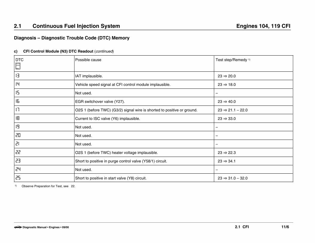
c) CFI Control Module (N3) DTC Readout (continued)
DTC
NPossible cause Test step/Remedy 1)
I3 IAT implausible. 23 O 20.0
I4 Vehicle speed signal at CFI control module implausible. 23 O 18.0
I5 Not used. –
I6 EGR switchover valve (Y27). 23 O 40.0
I7 O2S 1 (before TWC) (G3/2) signal wire is shorted to positive or ground. 23 O 21.1 – 22.0
I8 Current to ISC valve (Y6) implausible. 23 O 33.0
I9 Not used. –
20 Not used. –
2I Not used. –
22 O2S 1 (before TWC) heater voltage implausible. 23 O 22.3
23 Short to positive in purge control valve (Y58/1) circuit. 23 O 34.1
24 Not used. –
25 Short to positive in start valve (Y8) circuit. 23 O 31.0 – 32.0
1) Observe Preparation for Test, see 22.
b Diagnostic Manual • Engines • 09/00 2.1 CFI 11/6

2.1 Continuous Fuel Injection System Engines 104, 119 CFI
Diagnosis – Diagnostic Trouble Code (DTC) Memory
c) CFI Control Module (N3) DTC Readout (continued)
DTC
NPossible cause Test step/Remedy 1)
26 Short to positive in upshift delay solenoid valve (Y3/2) circuit. 23 O 44.0
27 Data exchange CFI control module (N3) R DI control module (N1/3) defective. 23 O 19.0,Matching N3 R N1/3.
28 Intermittent contact in ECT sensor (B11/2) circuit. 23 O 13.0
29 Difference in ECT between CFI control module (N3) and DI control module (N1/3)
23 O 13.0,See DI control module, section 5.1.
30 Not used. –
3I Intermittent contact in IAT sensor (B17/2) circuit. 23 O 20.0
32 Not used. –
33 Not used. –
34 ECT from DI control module (N1/3) implausible. See DI control module, section 5.1.
1) Observe Preparation for Test, see 22.
b Diagnostic Manual • Engines • 09/00 2.1 CFI 11/7

2.1 Continuous Fuel Injection System Engines 104, 119 CFI
Diagnosis – Diagnostic Trouble Code (DTC) Memory
d) Engine Systems Control Module (N16) DTC Readout
DTC
NPossible cause Test step/Remedy 1)
I No malfunction in system. –
2 Fuel pump relay not functioning. Replace engine systems control module (N16)
3 TD-signal interrupted (no longer implemented as of approx. 5/90 production). 23 O 16.0
4 Output for O2S 1 (before TWC) heater control defective. 23 O 22.0
5 Output for secondary air injection pump control defective. 23 O 30.0
6 Output for kickdown switch control defective. Replace engine systems control module (N16)
7 Not used. –
8 Not used. –
9 Not used (implemented as of approx. 5/90 production for open circuit in O2S 1 (before TWC) heater 23 O 22.0
I0 Not used. –
II A/C compressor engagement signal missing. 23 O 29.0
I2 Output for A/C compressor control defective. See DM, Climate Control, Volume 1.
I3 A/C compressor slippage too great. See DM, Climate Control, Volume 1.
I4 Vehicle speed signal implausible. 23 O 18.0
I5 Short circuit detected in fuel pump circuit. 23 O 8.0 – 9.0
1) Observe Preparation for Test, see 22.
b Diagnostic Manual • Engines • 09/00 2.1 CFI 11/8

2.1 Continuous Fuel Injection System Engines 104, 119 CFI
Diagnosis – Complaint Related Diagnostic Chart 2)
Complaint/Problem Possible cause Test step/Remedy 1)
Engine does not start or starts poorly i.e. does not run. Rest position of air flow sensor plate.ECT sensor.After-start enrichment.Fuel pressures.
Repair instructions 07.3 – 1612, 23 O 13.0, 34 O 2.0, 32 O 4.0
Engine is sluggish (poor transition) VAF sensor position indicator.Fuel pressures.ECT sensor.
23 O 14.0, 32 O 4.0 23 O 13.0,
Insufficient engine output Fuel pressures.WOT/CTP switch, full load/idleMixture control (lambda)
32 O 4.0 26 O 12.0,See DM, Engines, Volume 1 – B 2 31 O 6
1) Observe Preparation for Test, see 22.2) The following conditions must be met in order to use the Diagnostic Chart:
• The ignition system and the engine must be in proper operating condition,• All electrical connectors must fit properly,• Prescribed reference resistor must be installed.
b Diagnostic Manual • Engines • 09/00 2.1 CFI 12/1
2.1 Continuous Fuel Injection System Engines 104, 119 CFI
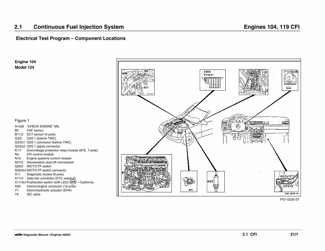
Electrical Test Program – Component Locations
P07-0230-57
Engine 104Model 124
Figure 1A1e26 “CHECK ENGINE” MILB2 VAF sensorB11/2 ECT sensor (4-pole)G3/2 O2S 1 (before TWC)G3/2x1 O2S 1 connector (before TWC)G3/2x2 O2S 1 signal connectorK1/1 Overvoltage protection relay module (87E, 7-pole)N3 CFI control moduleN16 Engine systems control moduleS27/2 Deceleration shut-off microswitchS29/2 WOT/CTP switchS29/2x1WOT/CTP switch connectorX11 Diagnostic socket (9-pole)X11/4 Data link connector (DTC readout)X11/4s1Pushbutton switch (with LED) I – CaliforniaX26 Interior/engine connector (12-pole)Y1 Electrohydraulic actuator (EHA)Y6 ISC valve
b Diagnostic Manual • Engines •09/00 2.1 CFI 21/1

2.1 Continuous Fuel Injection System Engines 104, 119 CFI
Electrical Test Program – Component Locations
P07-0137-57
Engine 104Model 129
Figure 2B2 VAF sensorB11/2 ECT sensor (4-pole)G3/2 O2S 1 (before TWC)G3/2x1 O2S 1 connector (before TWC)K1/1 Overvoltage protection relay module (87E, 7-pole)N3 CFI control moduleN16 Engine systems control moduleS27/2 Deceleration shut-off microswitchS29/2 WOT/CTP switchS29/2x1WOT/CTP switch connectorX11 Diagnostic socket (9-pole)X11/4 Data link connector (DTC readout)X11/4s1Pushbutton switch (with LED) I – CaliforniaX26 Interior/engine connector (12-pole)X30/1 Multi-function connector blockY1 Electrohydraulic actuator (EHA)Y6 ISC valveY27 EGR switchover valveY32 AIR pump switchover valve
b Diagnostic Manual • Engines •09/00 2.1 CFI 21/2
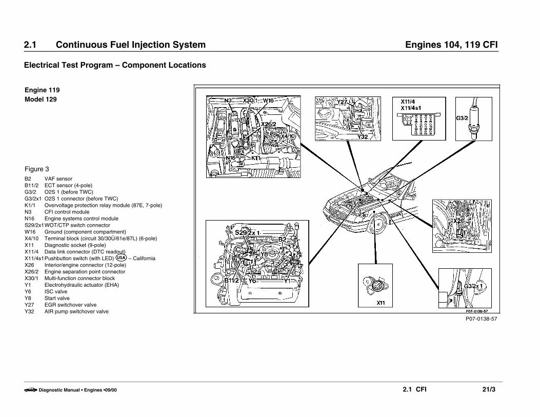
2.1 Continuous Fuel Injection System Engines 104, 119 CFI
Electrical Test Program – Component Locations
P07-0138-57
Engine 119Model 129
Figure 3B2 VAF sensorB11/2 ECT sensor (4-pole)G3/2 O2S 1 (before TWC)G3/2x1 O2S 1 connector (before TWC)K1/1 Overvoltage protection relay module (87E, 7-pole)N3 CFI control moduleN16 Engine systems control moduleS29/2x1WOT/CTP switch connectorW16 Ground (component compartment)X4/10 Terminal block (circuit 30/30Ü/61e/87L) (6-pole)X11 Diagnostic socket (9-pole)X11/4 Data link connector (DTC readout)X11/4s1Pushbutton switch (with LED) I – CaliforniaX26 Interior/engine connector (12-pole)X26/2 Engine separation point connectorX30/1 Multi-function connector blockY1 Electrohydraulic actuator (EHA)Y6 ISC valveY8 Start valveY27 EGR switchover valveY32 AIR pump switchover valve
b Diagnostic Manual • Engines •09/00 2.1 CFI 21/3

2.1 Continuous Fuel Injection System Engines 104, 119 CFI
Electrical Test Program – Preparation for Test
Special Tools
Test cable
102 589 04 63 00
35-pin socket box
124 589 00 21 00
Test cable
104 589 00 63 00
Electrical connecting set
201 589 00 99 00
Pulse counter
124 589 19 21 00
Tester
201 589 13 21 00
126-pin socket box
129 589 00 21 00
22-pin test cable
129 589 05 63 00
b Diagnostic Manual • Engines • 09/00 2.1 CFI 22/1

2.1 Continuous Fuel Injection System Engines 104, 119 CFI
Remote thermometer
124 589 07 21 00
Ohm decade
124 589 09 63 00
On-Off Ratio Tester
909 589 09 21 00
b Diagnostic Manual • Engines • 09/00 2.1 CFI 22/2
2.1 Continuous Fuel Injection System Engines 104, 119 CFI
Electrical Test Program – Preparation for Test
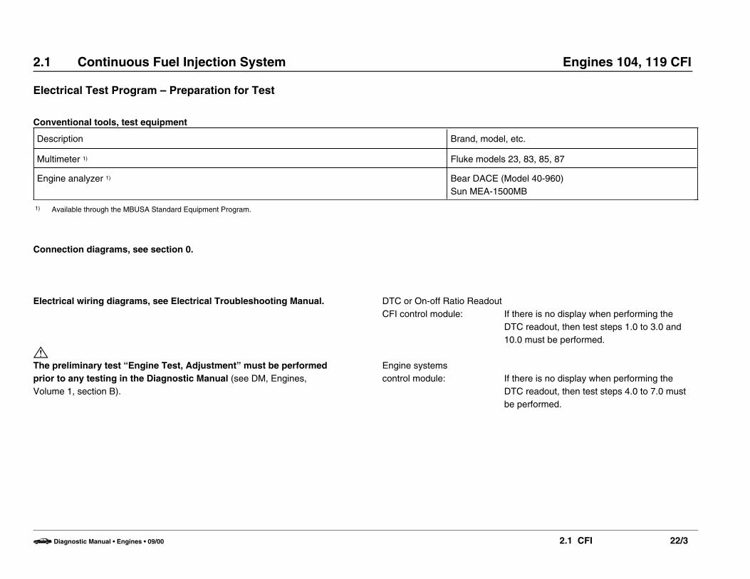
Conventional tools, test equipment
Description Brand, model, etc.
Multimeter 1) Fluke models 23, 83, 85, 87
Engine analyzer 1) Bear DACE (Model 40-960)Sun MEA-1500MB
1) Available through the MBUSA Standard Equipment Program.
Connection diagrams, see section 0.
Electrical wiring diagrams, see Electrical Troubleshooting Manual.
MThe preliminary test “Engine Test, Adjustment” must be performedprior to any testing in the Diagnostic Manual (see DM, Engines, Volume 1, section B).
DTC or On-off Ratio ReadoutCFI control module: If there is no display when performing the
DTC readout, then test steps 1.0 to 3.0 and10.0 must be performed.
Engine systemscontrol module: If there is no display when performing the
DTC readout, then test steps 4.0 to 7.0 mustbe performed.
b Diagnostic Manual • Engines • 09/00 2.1 CFI 22/3
2.1 Continuous Fuel Injection System Engines 104, 119 CFI
Electrical Test Program – Preparation for Test
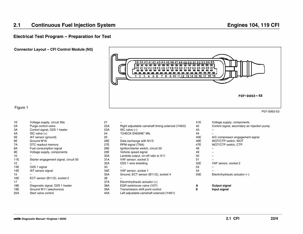
P07-0063-53
Connector Layout – CFI Control Module (N3)
� � � � � � � � � � � � � � � � � � � � � � � � � � � � � � � � � � � � � � � � � � � � � � � � � � � � � � � � � �
� � � � � � � � � � � � � � � � � � � � � � � � � � � � � � � � � � � � � � � � � � � � � � � � � � � � � � � � � �
� � � � � � � � � � � � � � � � � � � � � � � � � � � � � � � � � � � � � � � � � � � � � � � � � � � � � � � � � �
� � � � � � � � � � � � � � � � � � � � � � � � � � � � � � � � � � � � � � � � � � � � � � � � � � � � � � � � � �
Figure 1
21 –22A Right adjustable camshaft timing solenoid (Y49/2)23A ISC valve (–)24 “CHECK ENGINE” MIL25 –26E Data exchange with N1/327E RPM signal (TNA)28E Ignition/starter switch, circuit 5029E Vehicle speed signal30A Lambda output, on-off ratio to X1131A VAF sensor, socket 332A O2S 1 wire shielding33 –34E VAF sensor, socket 135A Ground, ECT sensor (B11/2), socket 436 –37A Electrohydraulic actuator (+)38A EGR switchover valve (Y27)39A Transmission shift point control40A Left adjustable camshaft solenoid (Y49/1)
1E Voltage supply, circuit 30a2A Purge control valve3A Control signal, O2S 1 heater4A ISC valve (+)5E IAT sensor (ground)6E Ground W167A DTC readout memory8A Fuel consumption signal9E Voltage supply, components10 –11E Starter engagement signal, circuit 5012 –13E O2S 1 signal14E IAT sensor signal15 –16E ECT sensor (B11/2), socket 217 –18E Diagnostic signal, O2S 1 heater19E Ground W11 (electronics)20A Start valve control
41E Voltage supply, components42 Control signal, secondary air injection pump43 –44 –45E A/C compressor engagement signal46E WOT/CTP switch, WOT47E WOT/CTP switch, CTP48 –49 –50 –51 –52E VAF sensor, socket 253 –54 –55E Electrohydraulic actuator (–)
A Output signalE Input signal
b Diagnostic Manual • Engines • 09/00 2.1 CFI 22/4

2.1 Continuous Fuel Injection System Engines 104, 119 CFI
Electrical Test Program – Preparation for Test
Connector Layout – Engine Systems Control Module
Figure 21E Voltage supply, circuit 302A Fuel pump relay3E A/C compressor control signal4E Circuit 31, ground5E RPM signal (+) for A/C compressor6E RPM signal (–) for A/C compressor7E Kickdown shut-off8A Diagnostic signal, O2S 1 heater9A A/C compressor engagement signal10E Voltage supply, circuit 15 unfused (ignition)11A TNA-signal (engine rpm)12E Starter signal13E Engine 104: Not used
Engine 119: Vehicle speed signal14A Diagnostics – DTC readout15 Not used16E TN-signal from DI control module17E Secondary air injection pump – input18E O2S 1 heater – input19A Secondary air injection pump – output20A O2S 1 heater – output21E Voltage supply, circuit 15 fused (ignition)22A A/C compressor clutch – output
A Output signalE Input signalArrow Safety lock
P07-0730-13
b Diagnostic Manual • Engines • 09/00 2.1 CFI 22/5

2.1 Continuous Fuel Injection System Engines 104, 119 CFI
Electrical Test Program – Test
O N Test scope Test connection Test condition Nominal value Possible cause/Remedy
1.0 1) Ground, engine (W11)(connection point for groundwires)Model 124
Model 129
N3k19 w
N3k19 w
c
c
mcir. 30
X4/10cir. 30
–
–
11 – 14 V
11 – 14 V
Wiring,Ground connection W11 (Figure 21) loose.
Wiring,Ground connection W11 (Figure 21) loose.
1.1 Ground, battery (W10)Model 124
Ground, componentcompartment (W16)Model 129
N3k6 w
N3k6 w
c
c
mcir. 30
X4/10cir. 30
–
–
11 – 14 V
11 – 14 V
Wiring,Ground connection W10 (Figure 20) loose.
Wiring,Ground connection W16 (Figure 23) loose.
1) On-off ratio 100% when measured with on-off ratio tester.
b Diagnostic Manual • Engines • 09/00 2.1 CFI 23/1

2.1 Continuous Fuel Injection System Engines 104, 119 CFI
Electrical Test Program – Test
O N Test scope Test connection Test condition Nominal value Possible cause/Remedy
2.0 1) CFI control module (N3)Voltage supply,Circuit 30a 19 w
N3k
c L 1
– 11 – 14 V Wiring,Overvoltage protection relaymodule (K1/1) fuse,K1/1.
2.1 Wiring from N3 to K1/1 N3k
1 w bK1/1L 4
CFI control module (N3)unplugged.
< 1 ] Wiring.
2.2 Wiring from circuit 30 to K1/1 N3k
6 w cK1/1L 1
– 11 – 14 V Wiring.
2.3 Wiring from circuit 30 to K1/1 X4/10cir. 30 b
K1/1L 1
– < 1 ] Wiring.
3.0 1) CFI control module (N3)Voltage supply,Circuit 87E 19 w
N3k
c L 41
Ignition: ONOvervoltage protection relaymodule (K1/1) plugged in.
11 – 14 V Wiring,Connected components areshorted to circuit 31 (ground).
1) On-off ratio 100% when measured with on-off ratio tester.
b Diagnostic Manual • Engines • 09/00 2.1 CFI 23/2
2.1 Continuous Fuel Injection System Engines 104, 119 CFI
Electrical Test Program – Test
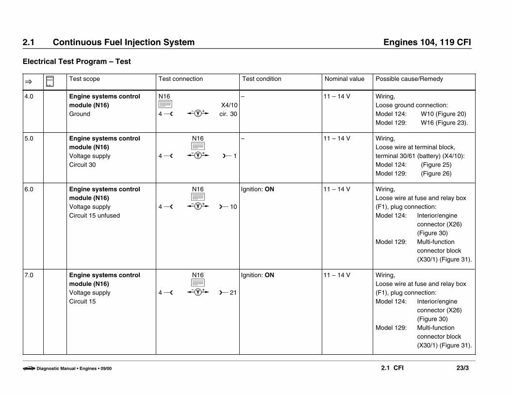
O N Test scope Test connection Test condition Nominal value Possible cause/Remedy
4.0 Engine systems controlmodule (N16)Ground
N16k4 w c
X4/10cir. 30
– 11 – 14 V Wiring,Loose ground connection:Model 124: W10 (Figure 20)Model 129: W16 (Figure 23).
5.0 Engine systems controlmodule (N16)Voltage supplyCircuit 30
4 w
N16k
c L 1
– 11 – 14 V Wiring,Loose wire at terminal block,terminal 30/61 (battery) (X4/10):Model 124: (Figure 25)Model 129: (Figure 26)
6.0 Engine systems controlmodule (N16)Voltage supplyCircuit 15 unfused
4 w
N16k
c L 10
Ignition: ON 11 – 14 V Wiring,Loose wire at fuse and relay box(F1), plug connection:Model 124: Interior/engine
connector (X26)(Figure 30)
Model 129: Multi-functionconnector block(X30/1) (Figure 31).
7.0 Engine systems controlmodule (N16)Voltage supplyCircuit 15
4 w
N16k
c L 21
Ignition: ON 11 – 14 V Wiring,Loose wire at fuse and relay box(F1), plug connection:Model 124: Interior/engine
connector (X26)(Figure 30)
Model 129: Multi-functionconnector block(X30/1) (Figure 31).
b Diagnostic Manual • Engines • 09/00 2.1 CFI 23/3

2.1 Continuous Fuel Injection System Engines 104, 119 CFI
Electrical Test Program – Test
O N Test scope Test connection Test condition Nominal value Possible cause/Remedy
8.0 Fuel pumps (M3m1, M3m2)Operation
4 w
N16k
c L 21
Ignition: OFFEngine systems controlmodule (N16) unplugged.
Ignition: ON
11 – 14 V Wiring,FP harness connector (X36):Model 124: (Figure 32)Model 129: (Figure 33)M3m1 or M3m2.
9.0 Fuel pumps (M3m1, M3m2)Control
4 w
N16k
c L 2
N16 plugged in.Connector 2 of DI controlmodule unplugged (Figure 7).Engine: Crank
10 ± 2Vwhile cranking
O 9.1,N16.
9.1 Control signal,Circuit 50
4 w
N16k
c L 12
Connector 2 of DI controlmodule unplugged (Figure 7).Engine: Crank
10 ± 2Vwhile cranking
Wiring,Model 124: Interior/engine
connector (X26)(Figure 30)defective,
Model 129: AT/engineconnector(X22/2)(Figure 29)defective.
b Diagnostic Manual • Engines • 09/00 2.1 CFI 23/4
2.1 Continuous Fuel Injection System Engines 104, 119 CFI
Electrical Test Program – Test
O N Test scope Test connection Test condition Nominal value Possible cause/Remedy
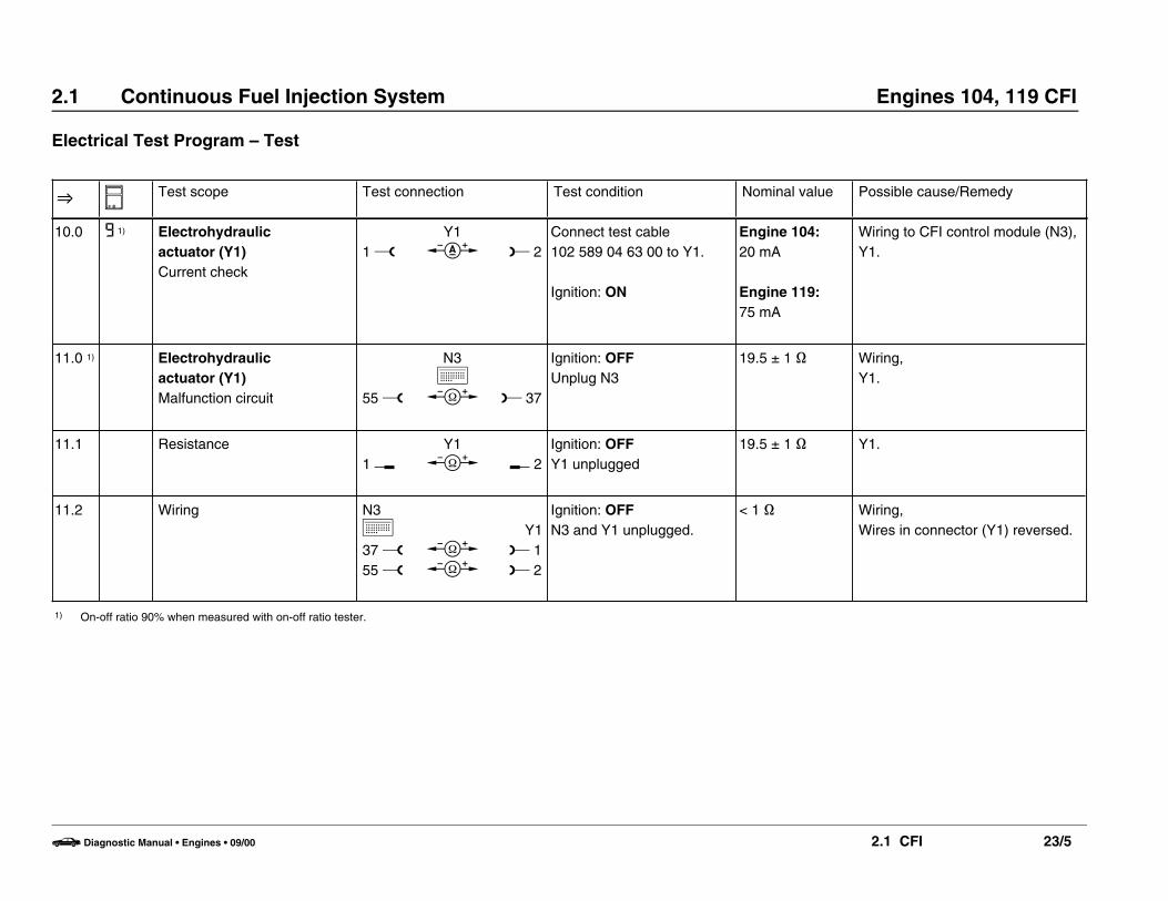
10.0 9 1) Electrohydraulic actuator (Y1)Current check
1 wY1
d L 2Connect test cable 102 589 04 63 00 to Y1.
Ignition: ON
Engine 104:20 mA
Engine 119:75 mA
Wiring to CFI control module (N3),Y1.
11.0 1) Electrohydraulic actuator (Y1)Malfunction circuit 55 w
N3k
b L 37
Ignition: OFFUnplug N3
19.5 ± 1 ] Wiring,Y1.
11.1 Resistance1 v
Y1b K 2
Ignition: OFFY1 unplugged
19.5 ± 1 ] Y1.
11.2 Wiring N3k37 w55 w
bb
Y1L 1L 2
Ignition: OFFN3 and Y1 unplugged.
< 1 ] Wiring,Wires in connector (Y1) reversed.
1) On-off ratio 90% when measured with on-off ratio tester.
b Diagnostic Manual • Engines • 09/00 2.1 CFI 23/5

2.1 Continuous Fuel Injection System Engines 104, 119 CFI
Electrical Test Program – Test
O N Test scope Test connection Test condition Nominal value Possible cause/Remedy
12.0 2 1) 2) WOT/CTP switch (S29/2)Malfunction circuit – WOT contact 19 w
N3k
b L 46
Ignition: OFFUnplug CFI control module(N3) connector and connec-tor “B” (Figure 7) of DIcontrol module (N1/3).Ignition: ON (ASR only)
Accelerator pedal in CTP
Disconnect AT controlpressure cable on vehicleswithout ASR.
Accelerator pedal in WOTposition.
g ]
< 1 ]
Wiring,WOT contact,S29/2,Polarity reversed at connectorS29/2x1:Engine 104: (Figure 18),Engine 119: (Figure 19).
12.1 WOT contact2 v
S29/2x1b K 3
Ignition: ON (ASR only)Connector (S29/2x1)unplugged:Engine 104: (Figure 18)Engine 119: (Figure 19)
Accelerator pedal in CTP
Accelerator pedal in WOTposition.
g ]
< 1 ]
Adjust or replace S29/2.
1) On-off ratio 20% when measured with on-off ratio tester.2) On-off ratio 10% when measured with on-off ratio tester.
b Diagnostic Manual • Engines • 09/00 2.1 CFI 23/6

2.1 Continuous Fuel Injection System Engines 104, 119 CFI
Electrical Test Program – Test
O N Test scope Test connection Test condition Nominal value Possible cause/Remedy
12.2 Wiring N3k46 w b
S29/2x1L 3
Ignition: OFFCFI control module (N3)unplugged.
< 1 ] Wiring.
12.3 Wiring W11o b
S29/2x1L 2
Ignition: OFF < 1 ] Wiring,Ground connection (W11) loose(Figure 21).
b Diagnostic Manual • Engines • 09/00 2.1 CFI 23/7

2.1 Continuous Fuel Injection System Engines 104, 119 CFI
Electrical Test Program – Test
O N Test scope Test connection Test condition Nominal value Possible cause/Remedy
13.0 3
28
29 1)
ECT sensor (B11/2)Malfunction circuit
35 w
N3k
c L 16
Ignition: ON See Table I Wiring,B11/2,CFI control module (N3).
13.1 B11/21 v
2 v
B11/2b
B11/2b
K 3
K 4
B11/2 connector unplugged.Measure connectionsdiagonally and compareboth values (Figure 12).
See Table I(both valuesmust be thesame).
B11/2.
13.2 Wiring N3k
16 w35 w
bb
B11/2L 2L 4
Ignition: OFFN3 connector unplugged.Terminal layout ofconnector (B11/2, Figure 12).
< 1 ] Wiring.
1) On-off ratio 30% when measured with on-off ratio tester.
b Diagnostic Manual • Engines • 09/00 2.1 CFI 23/8

2.1 Continuous Fuel Injection System Engines 104, 119 CFI
Electrical Test Program – Test
O N Test scope Test connection Test condition Nominal value Possible cause/Remedy
14.0 4 1) 2) VAF sensor (B2)Malfunction circuit
34 w
34 w
N3k
c
N3k
c
L 31
L 52
Engine: at Idleand at operatingtemperature. 4.6 –5.1 V
0. 55 – 0.95 V
B2, CFI control module (N3),
Wiring, N3B2.
14.1 B21 v
B2b K 3
Ignition: OFFConnector on B2unplugged.
3.6 – 4.4 k] B2.
14.2 B21 v
B2b K 2
Slowly deflect air flowsensor plate by hand.
]-valueincreasescontinuously upto 2/3 of travel,then decreasesagain.
B2.
14.3 Wiring N3k34 w52 w31 w
bbb
B2L 1L 2L 3
Ignition: OFFN3 connector unplugged.
< 1 ] Wiring.
1) On-off ratio 40% when measured with on-off ratio tester.2) On-off ratio 10% when measured with on-off ratio tester.
b Diagnostic Manual • Engines • 09/00 2.1 CFI 23/9

2.1 Continuous Fuel Injection System Engines 104, 119 CFI
Electrical Test Program – Test
O N Test scope Test connection Test condition Nominal value Possible cause/Remedy
15.0 7 1) TN-signal
19 w
N3k
c L 27
Engine: at Idle 5 – 7 V Wiring,O 16.2,TN-signal implausible,other connected componentsdefective.
15.1 Wiring N3k
27 w b
N16kL 11
Ignition: OFF < 1 ] Wiring.
16.0 TN-signal
4 w
N16k
c L 16
Engine: at Idle 5 – 7 V Wiring,DI control module (N1/3).
16.1 TN-signal wireN1/34 w(A)
b
N16kL 16
Ignition: OFFConnector (A) of N1/3unplugged (Figure 7).
< 1 ] Wiring.
16.2 Engine systems controlmodule (N16)
4 w
N16k
c L 11
Ignition: OFFConnector (A) of N1/3connected.Engine: at Idle
5 – 7 V N16.
1) On-off ratio 70% when measured with on-off ratio tester.
b Diagnostic Manual • Engines • 09/00 2.1 CFI 23/10

2.1 Continuous Fuel Injection System Engines 104, 119 CFI
Electrical Test Program – Test
O N Test scope Test connection Test condition Nominal value Possible cause/Remedy
17.0 I0 1) WOT/CTP switch (S29/2)Malfunction circuit – CTP contact 19 w
N3k
b L 47
Ignition: OFFCFI control module (N3)unplugged.
Accelerator pedal in CTP
Depress accelerator pedal
< 1 ]
g ]
Wiring,CTP contact.
17.1 22 CTP contact1 v
S29/2x1b K 2
Ignition: OFFConnector (S29/2x1)unplugged.Engine 104: (Figure 18)Engine 119: (Figure 19)
Accelerator pedal in CTP
Accelerator pedal in WOTposition
< 1 ]
g ]
Adjust or replace S29/2.
17.2 Wiring N3k
47 w bS29/2x1
L 1
Ignition: OFFN3 unplugged.
< 1 ] Wiring.
1) On-off ratio 10% when measured with on-off ratio tester.
b Diagnostic Manual • Engines • 09/00 2.1 CFI 23/11

2.1 Continuous Fuel Injection System Engines 104, 119 CFI
Electrical Test Program – Test
O N Test scope Test connection Test condition Nominal value Possible cause/Remedy
17.3 WiringW11 b
S29/2x1L 2
Ignition: OFFConnector (S29/2x1)unplugged.
< 1 ] Wiring,Ground connection (W11) loose(Figure 21).
18.0 I4 1) Vehicle speed signal
19 w
N3k
c L 29
Ignition: OFFASR control module (N30/1)connector unplugged.
Engine: StartDrive vehicle onto chassisdynamometer, “drive”vehicle at > 20 km/h (> 13 mph).
Model 124:Ignition: ONRoll vehicle approx. 1meter.
< 1 V
Needle oscil-lates: 0 – 12 V (0 – 9 V withconsumers)
Wiring,Model 124: Hall-effect speed
sensor (B6),Model 129: Electronic
speedometer(A1p8).
18.1 WiringModel 124
N3k
19 w bX53/5
L
Ignition: OFFCFI control module (N3)and Hall-effect sensormultipoint connector (X53/5)unplugged.
< 1 ] Wiring,Hall-effect speed sensor (B6).
1) On-off ratio 60% when measured with on-off ratio tester.
b Diagnostic Manual • Engines • 09/00 2.1 CFI 23/12

2.1 Continuous Fuel Injection System Engines 104, 119 CFI
Electrical Test Program – Test
O N Test scope Test connection Test condition Nominal value Possible cause/Remedy
[18.1] Model 129 N3k
29 w bX30/1K 3
(A2)
Ignition: OFFCFI control module (N3)and connector A2 of multi-function connector block(X30/1) (Figure 31)unplugged.
< 1 ] Wiring,Check X30/1 (Figure 31).
18.2 WiringModel 129
X30/13 w(A2)
bA1p8L 1
(1)
Ignition: OFFConnector (1) of A1p8unplugged.
< 1 ] Wiring,Check A1p8, see DM, body andaccessories, Vol. 1 – 1.2.
19.0 27 1) Data lineCFI control module (N3) RDI control module (N1/3)
N3k
26 w bN1/3L 7
(A)
Ignition: OFFConnector (A) of N1/3unplugged (Figure 7).
< 1 ] Wiring,Check for correct part no.matching of control modules N3and N1/3.
20.0 I3
3I
IAT sensor (B17/2)Malfunction circuit
5 w
N3k
c L 14
Ignition: ON See Table I Wiring,Engine 104: (Figure 1),Engine 119: (Figure 2),B17/2,N3.
1) On-off ratio 80% when measured with on-off ratio tester.
b Diagnostic Manual • Engines • 09/00 2.1 CFI 23/13

2.1 Continuous Fuel Injection System Engines 104, 119 CFI
Electrical Test Program – Test
O N Test scope Test connection Test condition Nominal value Possible cause/Remedy
20.1 Resistance2 v
B17/2b K 3
Ignition: OFFConnector of B17/2unplugged.
See Table I B17/2.
20.2 Wiring N3k
5 w14 w
bb
B17/2L 2L 3
Ignition: OFFCFI control module (N3)and B17/2 unplugged.
< 1 ] Wiring.
21.0 5 1) O2S 1 (beforeTWC) (G3/2)Malfunction circuit
19 w
N3k
c L 13
Engine: at Idleand at operatingtemperature.
Oscillatesbetween0.1 – 0.9 V
Wiring,G3/2,N3,O 35.0Check mixture adjustment.
21.1 I7 Insulation,O2S 1 wire
32 w
N3k
b 5 13
Ignition: OFFN3 connector and O2S 1signal connector (G3/2x2)orO2S 1 connector(G3/2x1) unplugged.Model 124: (Figure 13)Model 129: (Figure 14).
g ] Wiring.
1) On-off ratio 50% when measured with on-off ratio tester.
b Diagnostic Manual • Engines • 09/00 2.1 CFI 23/14
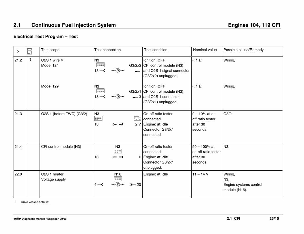
2.1 Continuous Fuel Injection System Engines 104, 119 CFI
Electrical Test Program – Test
O N Test scope Test connection Test condition Nominal value Possible cause/Remedy
21.2 I7 O2S 1 wire 1)
Model 124
Model 129
N3k
13 w
N3k
13 w
b
b
G3/2x2K
G3/2x1K 3
Ignition: OFFCFI control module (N3)and O2S 1 signal connector(G3/2x2) unplugged.
Ignition: OFFCFI control module (N3)and O2S 1 connector(G3/2x1) unplugged.
< 1 ]
< 1 ]
Wiring,
Wiring.
21.3 O2S 1 (before TWC) (G3/2) N3k13 u
j2 V
On-off ratio testerconnected.Engine: at IdleConnector G3/2x1connected.
0 – 10% at on-off ratio testerafter 30seconds.
G3/2.
21.4 CFI control module (N3)
13
N3k
u 6
On-off ratio testerconnected.Engine: at IdleConnector G3/2x1unplugged.
90 – 100% aton-off ratio testerafter 30seconds.
N3.
22.0 O2S 1 heaterVoltage supply
4 w
N16k
c L 20
Engine: at Idle 11 – 14 V Wiring,N3,Engine systems control module (N16).
1) Drive vehicle onto lift.
b Diagnostic Manual • Engines • 09/00 2.1 CFI 23/15
2.1 Continuous Fuel Injection System Engines 104, 119 CFI
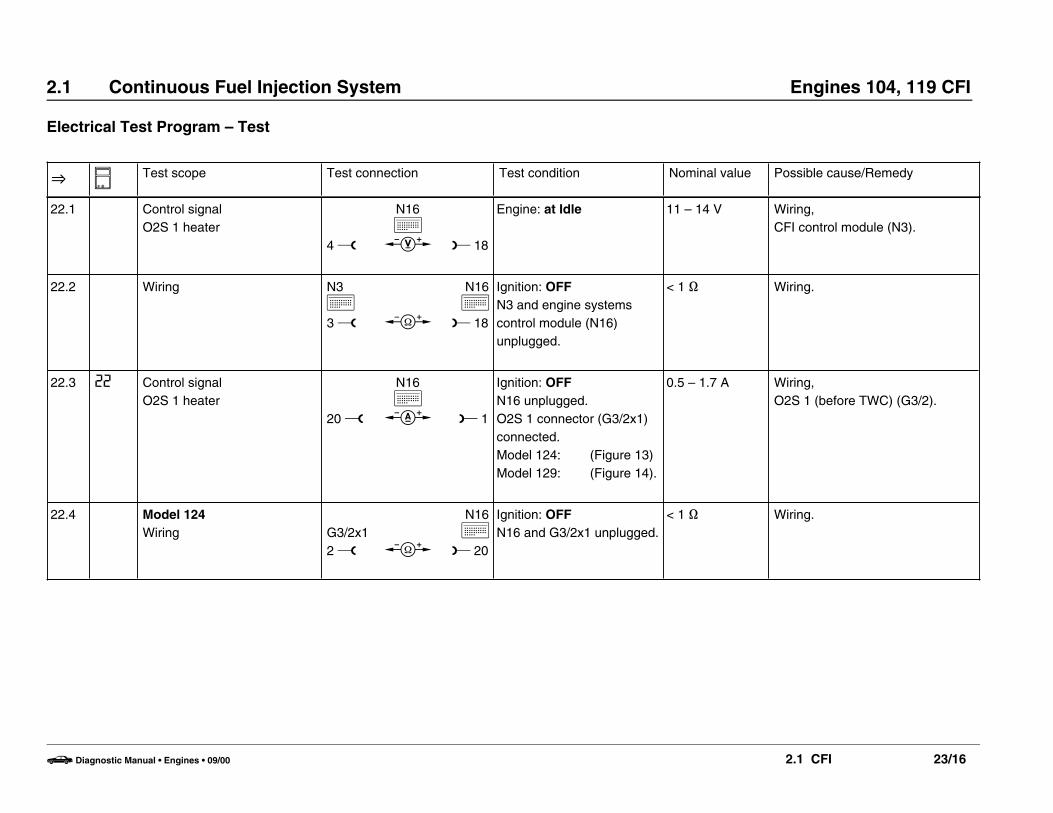
Electrical Test Program – Test
O N Test scope Test connection Test condition Nominal value Possible cause/Remedy
22.1 Control signalO2S 1 heater
4 w
N16k
c L 18
Engine: at Idle 11 – 14 V Wiring,CFI control module (N3).
22.2 Wiring N3k3 w b
N16k
L 18
Ignition: OFFN3 and engine systemscontrol module (N16)unplugged.
< 1 ] Wiring.
22.3 22 Control signalO2S 1 heater
20 w
N16k
d L 1
Ignition: OFFN16 unplugged.O2S 1 connector (G3/2x1)connected.Model 124: (Figure 13)Model 129: (Figure 14).
0.5 – 1.7 A Wiring,O2S 1 (before TWC) (G3/2).
22.4 Model 124Wiring G3/2x1
2 w b
N16k
L 20
Ignition: OFFN16 and G3/2x1 unplugged.
< 1 ] Wiring.
b Diagnostic Manual • Engines • 09/00 2.1 CFI 23/16
2.1 Continuous Fuel Injection System Engines 104, 119 CFI
Electrical Test Program – Test
O N Test scope Test connection Test condition Nominal value Possible cause/Remedy
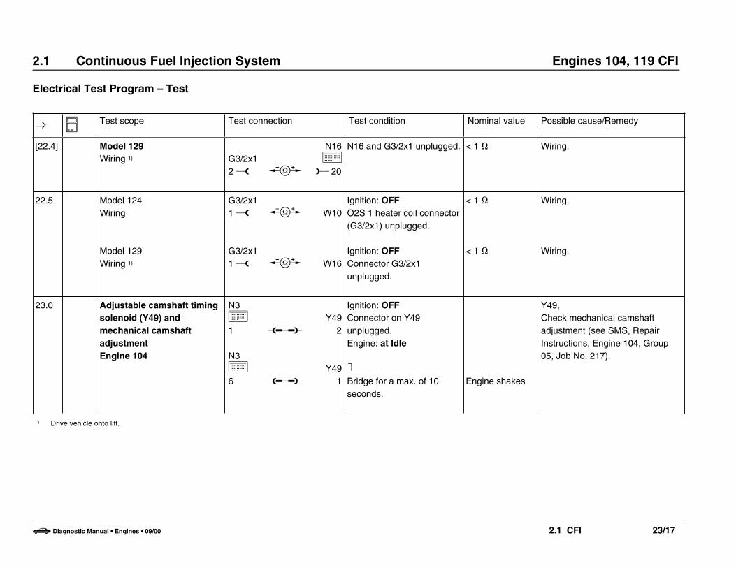
[22.4] Model 129Wiring 1) G3/2x1
2 w b
N16k
L 20
N16 and G3/2x1 unplugged. < 1 ] Wiring.
22.5 Model 124Wiring
Model 129Wiring 1)
G3/2x11 w
G3/2x11 w
b
b
W10
W16
Ignition: OFFO2S 1 heater coil connector(G3/2x1) unplugged.
Ignition: OFFConnector G3/2x1unplugged.
< 1 ]
< 1 ]
Wiring,
Wiring.
23.0 Adjustable camshaft timingsolenoid (Y49) andmechanical camshaftadjustmentEngine 104
N3k1
N3k6
u
u
Y492
Y491
Ignition: OFFConnector on Y49unplugged.Engine: at Idle
7
Bridge for a max. of 10seconds.
Engine shakes
Y49,Check mechanical camshaftadjustment (see SMS, RepairInstructions, Engine 104, Group05, Job No. 217).
1) Drive vehicle onto lift.
b Diagnostic Manual • Engines • 09/00 2.1 CFI 23/17

2.1 Continuous Fuel Injection System Engines 104, 119 CFI
Electrical Test Program – Test
O N Test scope Test connection Test condition Nominal value Possible cause/Remedy
24.0 Engine 104Camshaft adjustment(electrical) (Y49)
1 wY49
d L 2Ignition: OFFConnect test cable 102 589 04 63 00 toadjustable camshaft timingsolenoid (Y49).Engine: Start
Increase engine speed toapprox. 2000 rpm.
Briefly 1.5 A,then 1 A
Wiring,Y49,CFI control module (N3).
25.0 Engine 119Left adjustable camshafttiming solenoid (Y49/1) andleft mechanical camshafttiming adjustment
N3k1
N3k6
u
u
Y49/12
Y49/11
Ignition: OFFConnector on Y49/1unplugged.Engine: at Idle
MBridge for a max. of 10seconds.
Engine shakes
Y49/1,Check mechanical camshaftadjustment (see SMS, RepairInstructions, Engine 119, Group05, Job No. 217).
26.0 Engine 119Left camshaft adjustment(electrical) (Y49/1)
1 wY49/1
d L 2Ignition: OFFConnect test cable 102 589 04 63 00 toadjustable camshaft timingsolenoid (Y49/1).Engine: Start
Increase engine speed toapprox. 3000 rpm.
Briefly 1.5 A,then 1 A
Wiring,Y49/1,Chech contacts at engineseparation point connector(X26/2),CFI control module (N3).
b Diagnostic Manual • Engines • 09/00 2.1 CFI 23/18

2.1 Continuous Fuel Injection System Engines 104, 119 CFI
Electrical Test Program – Test
O N Test scope Test connection Test condition Nominal value Possible cause/Remedy
26.1 Left camshaft adjustmentControl
40 w
N3k
c L 41
Increase engine speed toapprox. 3000 rpm.
Briefly 7.5 Vthen approx. 5 V
If nominal value is greater than 11 V, check CFI control module(N3) wiring for open circuit,O 26.2.
26.2 Left adjustable camshafttiming solenoid (Y49/1) 1 v
Y49/1b K 2
Ignition: OFFConnector on Y49/1unplugged.
5 ± 1 ] Y49/1.
26.3 Wiring N3k41 w40 w
bb
Y49/1L 2L 1
Ignition: OFFCFI control module (N3)and connector on Y49/1unplugged.
< 1 ] Wiring
b Diagnostic Manual • Engines • 09/00 2.1 CFI 23/19

2.1 Continuous Fuel Injection System Engines 104, 119 CFI
Electrical Test Program – Test
O N Test scope Test connection Test condition Nominal value Possible cause/Remedy
27.0 Engine 119Right adjustable camshafttiming solenoid (Y49/2) andright mechanical camshaftadjustment
N3k1
N3k6
u
u
Y49/22
Y49/21
Ignition: OFFConnector on Y49/2unplugged.Engine: at Idle
MBridge for a max. of 10seconds.
Engine shakes
Y49/2,Check mechanical camshaftadjustment (see SMS, RepairInstructions, Engine 119, Group05, Job No. 217).
28.0 Right camshaft adjustment(electrical) (Y49/2) 1 w
Y49/2d L 2
Ignition: OFFConnect test cable 102 589 04 63 00 toadjustable camshaft timingsolenoid (Y49/2).Engine: Start
Increase engine speed toapprox. 3000 rpm.
Briefly 1.5 A,then 1 A Wiring,
Y49/2,CFI control module (N3).
28.1 Right camshaft adjustmentControl
22 w
N3k
c L 41
Increase engine speed toapprox. 3000 rpm.
Briefly 7.5 Vthen approx. 5 V
Wiring,Y49/2,N3.
28.2 Right adjustable camshafttiming solenoid (Y49/2) 1 v
Y49/2b K 2
Ignition: OFFConnector on Y49/2unplugged.
5 ± 1 ] Y49/2.
b Diagnostic Manual • Engines • 09/00 2.1 CFI 23/20
2.1 Continuous Fuel Injection System Engines 104, 119 CFI
Electrical Test Program – Test
O N Test scope Test connection Test condition Nominal value Possible cause/Remedy
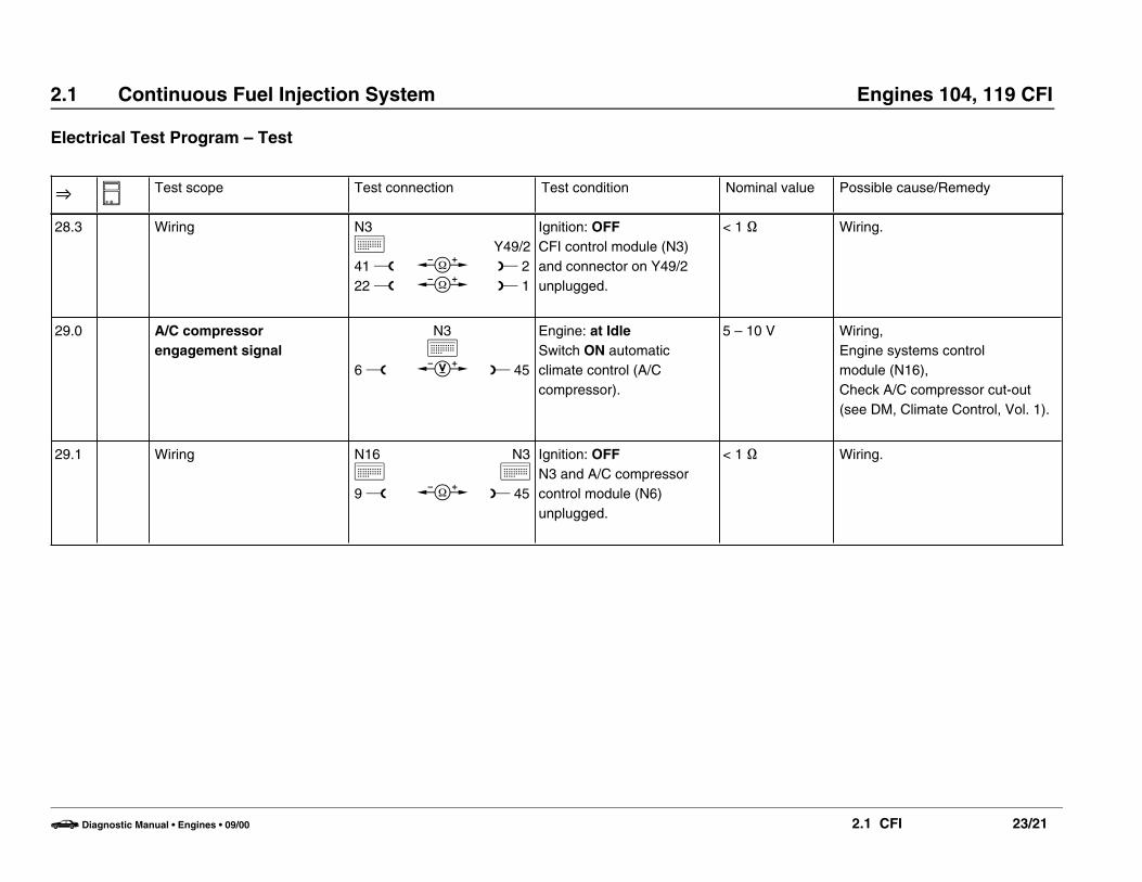
28.3 Wiring N3k41 w22 w
bb
Y49/2L 2L 1
Ignition: OFFCFI control module (N3)and connector on Y49/2unplugged.
< 1 ] Wiring.
29.0 A/C compressorengagement signal
6 w
N3k
c L 45
Engine: at IdleSwitch ON automaticclimate control (A/Ccompressor).
5 – 10 V Wiring,Engine systems control module (N16),Check A/C compressor cut-out(see DM, Climate Control, Vol. 1).
29.1 Wiring N16k9 w b
N3k
L 45
Ignition: OFFN3 and A/C compressorcontrol module (N6)unplugged.
< 1 ] Wiring.
b Diagnostic Manual • Engines • 09/00 2.1 CFI 23/21
2.1 Continuous Fuel Injection System Engines 104, 119 CFI
Electrical Test Program – Test
O N Test scope Test connection Test condition Nominal value Possible cause/Remedy
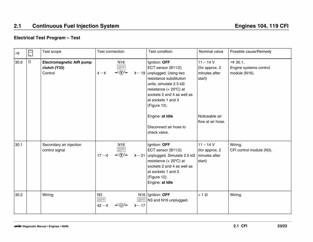
30.0 II Electromagnetic AIR pumpclutch (Y33)Control 4 w
N16k
c L 19
Ignition: OFFECT sensor (B11/2)unplugged. Using tworesistance substitutionunits, simulate 2.5 k]resistance (+ 20oC) atsockets 2 and 4 as well asat sockets 1 and 3 (Figure 12).
Engine: at Idle
Disconnect air hose tocheck valve.
11 – 14 V(for approx. 2minutes afterstart)
Noticeable airflow at air hose.
O 30.1,Engine systems control module (N16).
30.1 Secondary air injectioncontrol signal
17 w
N16k
c L 21
Ignition: OFFECT sensor (B11/2)unplugged. Simulate 2.5 k]resistance (+ 20oC) atsockets 2 and 4 as well asat sockets 1 and 3 (Figure 12).Engine: at Idle
11 – 14 V(for approx. 2minutes afterstart)
Wiring,CFI control module (N3).
30.2 Wiring N3k42 w b
N16k
L 17
Ignition: OFFN3 and N16 unplugged.
< 1 ] Wiring.
b Diagnostic Manual • Engines • 09/00 2.1 CFI 23/22

2.1 Continuous Fuel Injection System Engines 104, 119 CFI
Electrical Test Program – Test
O N Test scope Test connection Test condition Nominal value Possible cause/Remedy
30.3 AIR pump switchover valve (Y32)Control
1 wY32
c L 2Ignition: OFFECT sensor (B11/2)unplugged. Simulate 2.5 k]resistance (+ 20oC) atsockets 2 and 4 as well asat sockets 1 and 3 (Figure 12).Connector on Y32unplugged.Engine: at Idle
11 – 14 V(for approx. 2minutes afterstart)
Wiring to Y32 (located in enginecompartment):Model 124: (Figure 5),Model 129: (Figure 6).
30.4 AIR pump switchover valve (Y32) 1 v
Y32b K 2
Ignition: OFFConnector on Y32unplugged.
25 ± 5 ] Y32.
30.5 Electromagnetic AIR pumpclutch (Y33)Control
1 wY33
c L 2Ignition: OFFECT sensor (B11/2)unplugged. Simulate 2.5 k]resistance (+ 20oC) atsockets 2 and 4 as well asat sockets 1 and 3 (Figure 12).Connector on Y33unplugged.Engine: at Idle
11 – 14 V(for approx. 2minutes afterstart)
Wiring to Y33 (located in harnesschannel in front of right springtower).
30.6 Electromagnetic AIR pumpclutch (Y33) 1 v
Y33b K 2
Connector on Y32unplugged.
5 ± 1 ] Y33.
b Diagnostic Manual • Engines • 09/00 2.1 CFI 23/23
2.1 Continuous Fuel Injection System Engines 104, 119 CFI
Electrical Test Program – Test
O N Test scope Test connection Test condition Nominal value Possible cause/Remedy
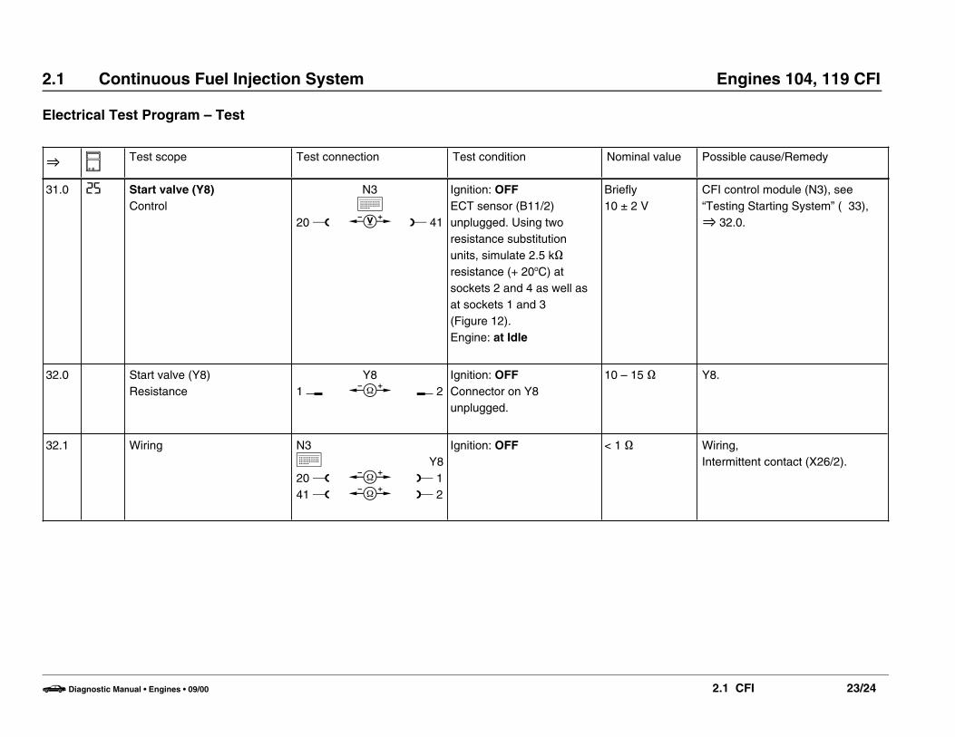
31.0 25 Start valve (Y8)Control
20 w
N3k
c L 41
Ignition: OFFECT sensor (B11/2)unplugged. Using tworesistance substitutionunits, simulate 2.5 k]resistance (+ 20oC) atsockets 2 and 4 as well asat sockets 1 and 3 (Figure 12).Engine: at Idle
Briefly10 ± 2 V
CFI control module (N3), see“Testing Starting System” ( 33),O 32.0.
32.0 Start valve (Y8)Resistance 1 v
Y8b K 2
Ignition: OFFConnector on Y8unplugged.
10 – 15 ] Y8.
32.1 Wiring N3k20 w41 w
bb
Y8L 1L 2
Ignition: OFF < 1 ] Wiring,Intermittent contact (X26/2).
b Diagnostic Manual • Engines • 09/00 2.1 CFI 23/24
2.1 Continuous Fuel Injection System Engines 104, 119 CFI
Electrical Test Program – Test
O N Test scope Test connection Test condition Nominal value Possible cause/Remedy
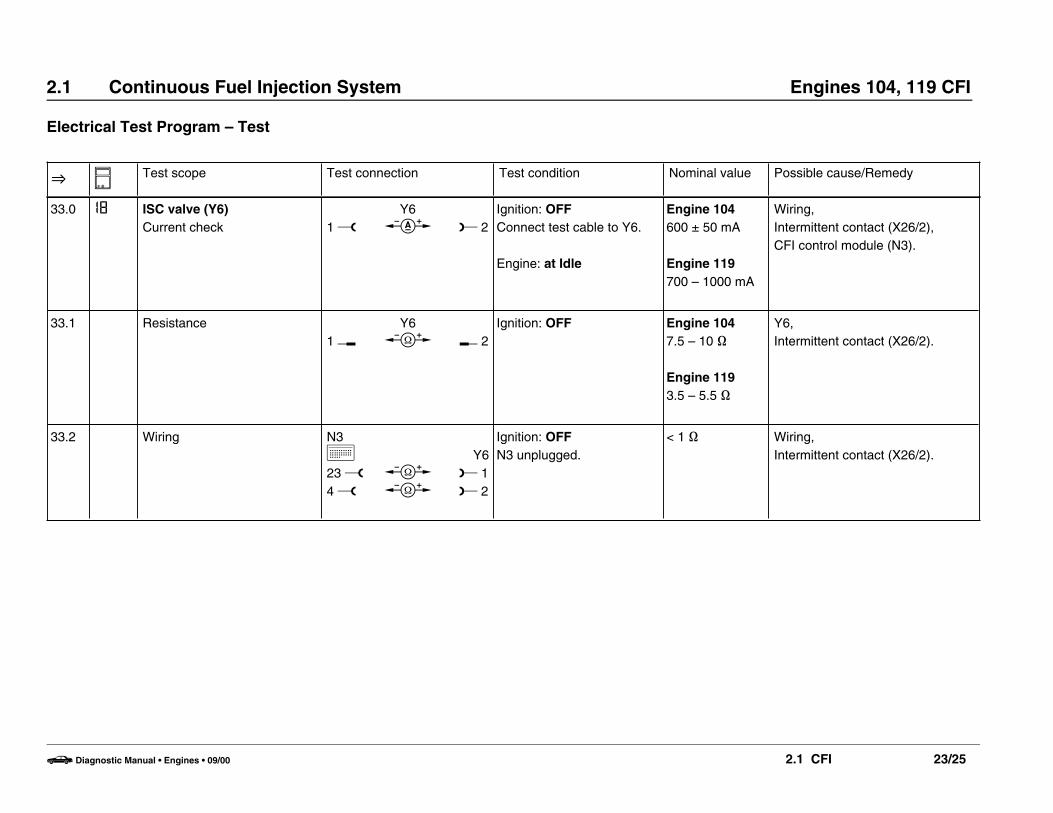
33.0 I8 ISC valve (Y6)Current check 1 w
Y6d L 2
Ignition: OFFConnect test cable to Y6.
Engine: at Idle
Engine 104600 ± 50 mA
Engine 119700 – 1000 mA
Wiring,Intermittent contact (X26/2),CFI control module (N3).
33.1 Resistance1 v
Y6b K 2
Ignition: OFF Engine 1047.5 – 10 ]
Engine 1193.5 – 5.5 ]
Y6,Intermittent contact (X26/2).
33.2 Wiring N3k23 w4 w
bb
Y6L 1L 2
Ignition: OFFN3 unplugged.
< 1 ] Wiring,Intermittent contact (X26/2).
b Diagnostic Manual • Engines • 09/00 2.1 CFI 23/25

2.1 Continuous Fuel Injection System Engines 104, 119 CFI
Electrical Test Program – Test
O N Test scope Test connection Test condition Nominal value Possible cause/Remedy
34.0 Charcoal canister purgingOperation
Note to Test connection:Connect vacuum tester toside connection (B) ofpurge valve (53):Model 124: (Figure 8),Model 129: (Figure 9,
11).
Ignition: OFFPurge line (B, Figures 8, 9or 11) disconnected fromcharcoal canister at purgevalve.Engine: at Idle and atoperating temperature.Slowly increase enginespeed to a maximum of3000 rpm.
Vacuumincreases withincreasing rpm.
Wiring,CFI control module (N3),Purge control valve (Y58/1),Check vacuum lines,O 13.0,Intermittent contact (X26/2).
34.1 23 Purge control valve (Y58/1)Control
2 w
N3k
c L 41
Engine: at IdleIncrease engine speed to > 800 rpm
11 – 14 V Wiring,N3,Y58/1,Intermittent contact (X26/2).
34.2 Purge control valve (Y58/1)1 v
Y58/1b K 2
Ignition: OFFConnector on Y58/1(Figures 8, 10) unplugged.
25 ± 5 ] Y58/1.
b Diagnostic Manual • Engines • 09/00 2.1 CFI 23/26

2.1 Continuous Fuel Injection System Engines 104, 119 CFI
Electrical Test Program – Test
O N Test scope Test connection Test condition Nominal value Possible cause/Remedy
34.3 Wiring N3k2 w41 w
bb
Y58/1L 1L 2
Ignition: OFFN3 unplugged.
< 1 ] Wiring,Intermittent contact (X26/2).
35.0 Non-USA vehicles.Continue to next test step.
36.0 1) Circuit 50Activation
6 w
N3k
c L 11
Plug 2 on DI control module(N1/3) disconnected (Figure 7).Engine: Start
10 ± 2 V whilecranking
Wiring (circuit 50).
1) On-off ratio 70% when measured with on-off ratio tester.
b Diagnostic Manual • Engines • 09/00 2.1 CFI 23/27

2.1 Continuous Fuel Injection System Engines 104, 119 CFI
Electrical Test Program – Test
O N Test scope Test connection Test condition Nominal value Possible cause/Remedy
37.0 Deceleration shut-offEngine 104
Note to Test connection:Connect j to diagnostic socket (X11).
Engine: StartIncrease engine speed to2000 – 2500 rpm, thenclose throttle valve.
On-off ratiomomentarilyjumps up to95%.
Wiring,Check adjustment of linkage andthrottle valve switch,S27/2.
37.1 Deceleration shut-offmicroswitch (S27/2)
10 w
N3k
b L 6
Ignition: OFFCFI control module (N3)unplugged.Accelerator pedal in CTP.
Depress accelerator pedal.
< 1 ]
g ]
Open circuit, S27/2.
Short circuit, S27/2.
37.2 Vehicles with ASRIdle speed switching signal
6 w
N3k
c L 41
Ignition: ONAccelerator pedal in CTP.
Depress accelerator pedal.
11 – 14 V
< 1 V
ACCelerator pedal position sensor,Check EA/CC/ISC control module(N4/1), see DM, Engines, Vol. 2 – 6.1.
b Diagnostic Manual • Engines • 09/00 2.1 CFI 23/28

2.1 Continuous Fuel Injection System Engines 104, 119 CFI
Electrical Test Program – Test
O N Test scope Test connection Test condition Nominal value Possible cause/Remedy
37.3 Electrohydraulic actuator (Y1)Current check 1 w
Y1d L 2
Ignition: OFFConnect test cable102 589 04 63 00 toelectrohydraulic actuator.
Engine: StartIncrease engine speed to2000 – 2500 rpm and closethrottle valve.
Momentarilyapprox. – 60 mAuntil combustionresumes.
O 1.0 – 3.0 and O 10.0,N3.
38.0 Engine 104Kickdown cut-outMalfunction circuit
Engine 119Kickdown cut-outMalfunction circuit
7 w
N16k
d L 1
Ignition: OFFEngine systems controlmodule (N16) unplugged.Kickdown switch (S16/6)activated.
Engine 104:450 ± 50 mA 1)
850 ± 50 mA 1)
Engine 119:450 ± 50 mA 1)
250 ± 50 mA 1)
Wiring,S16/6,AT kickdown valve (Y3, Figure 4).
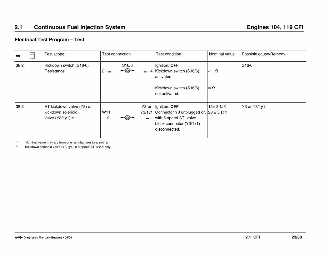
38.1 Kickdown switch (S16/6)Voltage supply
7 w
N16k
c L 1
Ignition: OFFN16 unplugged.
Ignition: ONAccelerator pedal in CTP.
Accelerator pedal inkickdown position.
< 1 V
11 – 14 V
s16/6,AT kickdown valve (Y3, Figure 4).Wiring,O 38.2.
1) Nominal value may ary from one nanufacturer to annother.
b Diagnostic Manual • Engines • 09/00 2.1 CFI 23/29
2.1 Continuous Fuel Injection System Engines 104, 119 CFI
Electrical Test Program – Test
O N Test scope Test connection Test condition Nominal value Possible cause/Remedy
38.2 Kickdown switch (S16/6)Resistance 2 v
S16/6b K 4
Ignition: OFFKickdown switch (S16/6)activated.
Kickdown switch (S16/6)not activated.
< 1 ]
g ]
S16/6.
38.3 AT kickdown valve (Y3) orkickdown solenoid valve (Y3/1y1) 2)
W11 w b
Y3 or Y3/1y1
K
Ignition: OFFConnector Y3 unplugged or,with 5-speed AT, valveblock connector (Y3/1x1)disconnected.
12± 3 ] 1)
28 ± 5 ] 1)
Y3 or Y3/1y1.
1) Nominal value may ary from one nanufacturer to annother.2) Kickdown solenoid valve (Y3/1y1) in 5-speed AT 722.5 only.
b Diagnostic Manual • Engines • 09/00 2.1 CFI 23/30
2.1 Continuous Fuel Injection System Engines 104, 119 CFI
Electrical Test Program – Test
O N Test scope Test connection Test condition Nominal value Possible cause/Remedy
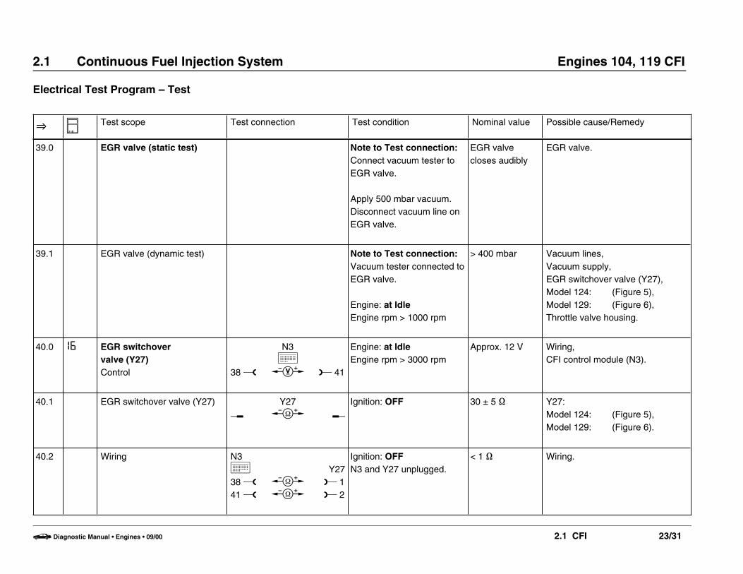
39.0 EGR valve (static test) Note to Test connection:Connect vacuum tester toEGR valve.
Apply 500 mbar vacuum.Disconnect vacuum line onEGR valve.
EGR valvecloses audibly
EGR valve.
39.1 EGR valve (dynamic test) Note to Test connection:Vacuum tester connected toEGR valve.
Engine: at IdleEngine rpm > 1000 rpm
> 400 mbar Vacuum lines,Vacuum supply,EGR switchover valve (Y27),Model 124: (Figure 5),Model 129: (Figure 6),Throttle valve housing.
40.0 I6 EGR switchover valve (Y27)Control 38 w
N3k
c L 41
Engine: at IdleEngine rpm > 3000 rpm
Approx. 12 V Wiring,CFI control module (N3).
40.1 EGR switchover valve (Y27)v
Y27b K
Ignition: OFF 30 ± 5 ] Y27:Model 124: (Figure 5),Model 129: (Figure 6).
40.2 Wiring N3k38 w41 w
bb
Y27L 1L 2
Ignition: OFFN3 and Y27 unplugged.
< 1 ] Wiring.
b Diagnostic Manual • Engines • 09/00 2.1 CFI 23/31

2.1 Continuous Fuel Injection System Engines 104, 119 CFI
Electrical Test Program – Test
O N Test scope Test connection Test condition Nominal value Possible cause/Remedy
41.0 Non-USA vehicles.Continue to next test step.
42.0 Non-USA vehicles.Continue to next test step.
43.0 Non-USA vehicles.Continue to next test step.
b Diagnostic Manual • Engines • 09/00 2.1 CFI 23/32

2.1 Continuous Fuel Injection System Engines 104, 119 CFI
Electrical Test Program – Test
O N Test scope Test connection Test condition Nominal value Possible cause/Remedy
44.0 Transmission upshift delayrelay module (K29)Solenoid valve (Y3/2)Control
W11o c
Y3/2L
Ignition: OFFECT sensor (B11/2)unplugged. Using tworesistance substitutionunits, simulate 2.5 k]resistance (+ 20oC) atsockets 2 and 4 as well asat sockets 1 and 3 (Figure 12).Engine: at Idle
11 – 14 VEngine 104:max. 80 sec.
Engine 119:max. 120 sec.
O 44.1,O 44.2,O 44.3,O 44.4,CFI control module (N3),K29.
44.1 Transmission upshift delayrelay module (K29)Voltage supply
W11o
W11o
c
c
K29L 3
K29L 4
Ignition: OFFK29 unplugged:Model 124: (Figure 16),Model 129: (Figure 17).Ignition: ON
11 – 14 V
11 – 14 V
Overvoltage protection relay(K1/1),Wiring.
b Diagnostic Manual • Engines • 09/00 2.1 CFI 23/33

2.1 Continuous Fuel Injection System Engines 104, 119 CFI
Electrical Test Program – Test
O N Test scope Test connection Test condition Nominal value Possible cause/Remedy
44.2 Wiring to solenoid valve(Y3/2) 1
W11o
K29u
c
4
Y3/2x1L
Ignition: OFFTransmission upshift delayrelay (K29) unplugged:Model 124: Figure 16Model 129: Figure 17Solenoid valve connector(Y3/2x1) unplugged.Ignition: ON
11 – 14 V Open circuit.
44.3 Solenoid valve (Y3/2)o b
Y3/2K
Ignition: OFFSolenoid valve connector(Y3/2x1) unplugged.
10 – 18 ] Y3/2.
44.4 Wiring from CFI controlmodule (N3) to transmissionupshift delay relay module (K29)
K29
5 w b
N3k
L 39
Ignition: OFFSocket box connected to N3.K29 unplugged.
< 1 ] Open circuit.
b Diagnostic Manual • Engines • 09/00 2.1 CFI 23/34

2.1 Continuous Fuel Injection System Engines 104, 119 CFI
Electrical Test Program – Test
O N Test scope Test connection Test condition Nominal value Possible cause/Remedy
45.0 Transmission upshift delayswitchover valve (Y3/3)Operation
Note to Test connection:Disconnect vacuum line(Figure 38) on Y3/3.
Connect vacuum tester withY-distributor to Y3/3.
Ignition: OFFECT sensor (B11/2)unplugged. Using tworesistance substitutionunits, simulate 2.5 k]resistance (+ 20oC) atsockets 2 and 4 as well asat sockets 1 and 3 (Figure 12).Engine: at Idle
> 400 mbar (fora maximum of80 seconds)
Control of Y3/3,Short/open circuit,Y3/3 defective,Vacuum element for transmissionupshift delay,Vacuum line.
b Diagnostic Manual • Engines • 09/00 2.1 CFI 23/35

2.1 Continuous Fuel Injection System Engines 104, 119 CFI
Electrical Test Program – Test
O N Test scope Test connection Test condition Nominal value Possible cause/Remedy
45.1 Control W11o
Y3/31 w
c
c
Y3/3L 2
+m
Ignition: OFFConnector of Y3/3 (Figure38) unplugged. Using tworesistance substitutionunits, simulate 2.5 k]resistance (+ 20oC) atsockets 2 and 4 as well asat sockets 1 and 3 (Figure 12).
Engine: Start
11 – 14 V
11 – 14 V (for amaximum of 80seconds)
Overvoltage protection relaymodule (K1/1),Short/open circuit.
Short/open circuit,CFI control module (N3).
45.2 Coil resistance Y3/31 v b
Y3/3K 2
Ignition: OFFConnector of Y3/3 (Figure38) unplugged.
25 – 40 ] Y3/3 defective.
b Diagnostic Manual • Engines • 09/00 2.1 CFI 23/36

2.1 Continuous Fuel Injection System Engines 104, 119 CFI
Electrical Test Program – Test
Temperature (oC) Resistance (]) Voltage (V) at IAT sensor (B17/2) Voltage (V) at ECT sensor (B11/2)
– 20 15700 2.85 – 3.49 5.12 – 5.60
– 10 10000 2.50 – 3.06 4.49 – 5.11
0 5900 2.10 – 2.56 4.12 – 4.48
10 3700 1.69 – 2.07 3.77 – 4.11
20 2500 1.32 – 1.62 3.36 – 3.76
30 1700 1.03 – 1.25 2.92 – 3.35
40 1170 0.77 – 0.94 2.51 – 2.91
50 830 0.57 – 0.69 2.09 – 2.50
60 600 0.42 – 0.52 1.69 – 2.08
70 435 0.32 – 0.40 1.36 – 1.68
80 325 0.25 – 0.31 1.09 – 1.35
90 245 0.18 – 0.22 0.88 – 1.08
100 185 0.14 – 0.17 0.75 – 0.87
b Diagnostic Manual • Engines • 09/00 2.1 CFI 23/37

2.1 Continuous Fuel Injection System Engines 104, 119 CFI
Electrical Test Program – Test
P07-2359-13
Figure 1Engine 104
B17/2 IAT sensor
Figure 3
B11/2 ECT sensor (4-pole)
P07-2361-13
Figure 2Engine 119
B17/2 IAT sensor
P15-0171-13
b Diagnostic Manual • Engines • 09/00 2.1 CFI 23/38

2.1 Continuous Fuel Injection System Engines 104, 119 CFI
Electrical Test Program – Test
P27-2161-13A
Figure 4
Y3 Kickdown valve (AT)
P07-2070-13
Figure 6Model 129
Y27 EGR switchover valve
Y32 AIR pump switchover valve
P07-2363-13
Figure 5Model 124
Y27 EGR switchover valve
Y32 AIR pump switchover valve
b Diagnostic Manual • Engines • 09/00 2.1 CFI 23/39

2.1 Continuous Fuel Injection System Engines 104, 119 CFI
Electrical Test Program – Test
P15-2030-13A
Figure 7DI control module
1 Knock sensor
2 CKP sensor (L5)
3 Reference resistor
4 Vacuum connection
A 8-pole plug connection
B 8-pole plug connection
P47-2011-13
Figure 9Engine 104, Model 129
53 Purge valve
Y58/1 Follow vacuum line “C“ for location
P47-2040-13
Figure 8Engine 104, Model 124
53 Purge valve
Y58/1 Purge control valve
A Purge line (to throttle valve)
B Purge line (to charcoal canister)
C Purge control valve vacuum line
b Diagnostic Manual • Engines • 09/00 2.1 CFI 23/40
2.1 Continuous Fuel Injection System Engines 104, 119 CFI
Electrical Test Program – Test
P47-2012-13
Figure 10Engine 119, Model 129
Y58/1 Purge control valve
U07-2022-13
Figure 12Model 124
B11/2 ECT sensor (4-pole), terminal layout
P47-2011-13
Figure 11Engine 119, Model 129
53 Purge valveA Purge line (to throttle valve)
B Purge line (to charcoal canister)
C Purge control valve vacuum line
b Diagnostic Manual • Engines • 09/00 2.1 CFI 23/41

2.1 Continuous Fuel Injection System Engines 104, 119 CFI
Electrical Test Program – Test
P07-2364-13
Figure 13Model 124
G3/2x2 O2S 1 signal connector
P07-2029-13A
Figure 15Model 129
1 O2S 2 signal
2 O2S 1 heater
G3/2x1 O2S 1 connector (before TWC)
P14-2011-13
Figure 14Model 129
G3/2x1 O2S 1 connector (before TWC)
b Diagnostic Manual • Engines • 09/00 2.1 CFI 23/42

2.1 Continuous Fuel Injection System Engines 104, 119 CFI
Electrical Test Program – Test
P54-0056-56
Figure 17Model 129
K29 Transmission upshift delay relay module (location E)
P15-2105-13A
Figure 16Model 124
K29 Transmission upshift delay relay module
b Diagnostic Manual • Engines • 09/00 2.1 CFI 23/43

2.1 Continuous Fuel Injection System Engines 104, 119 CFI
Electrical Test Program – Test
P07-2360-13
Figure 18Engine 104
S29/2x1 WOT/CTP switch connector
P54-2121-13B
Figure 20Model 124
W10 Ground (battery)
P07-2362-13
Figure 19Engine 119
S29/2x1 WOT/CTP switch connector
b Diagnostic Manual • Engines • 09/00 2.1 CFI 23/44

2.1 Continuous Fuel Injection System Engines 104, 119 CFI
Electrical Test Program – Test
P54-2017-13
Figure 21
W11 Ground (engine - connection point for ground wires)
P07-2020-13A
Figure 23Model 129
W16 Ground (component compartment)
P83-2270-13
Figure 22Model 124
W12 Ground (center console)
b Diagnostic Manual • Engines • 09/00 2.1 CFI 23/45

2.1 Continuous Fuel Injection System Engines 104, 119 CFI
Electrical Test Program – Test
P54-2045-13
Figure 24Model 129
W17 Ground (right rear storage area)
P07-2021-13
Figure 26Model 129
X4/10 Terminal block (circuit 30/30Ü/61e/87L) (6-pole)
P54-2121-13B
Figure 25Model 124
X4/10 Terminal block (circuit 30/30Ü/61e/87L) (6-pole)
b Diagnostic Manual • Engines • 09/00 2.1 CFI 23/46

2.1 Continuous Fuel Injection System Engines 104, 119 CFI
Electrical Test Program – Test
P07-2372-13
Figure 27Model 124
X11/4 Data link connector (DTC readout)
P54-2032-13
Figure 29Model 129
X22/2 AT/engine connector (8-pole)
P07-2033-13
Figure 28Model 129
X11/4 Data link connector (DTC readout)
b Diagnostic Manual • Engines • 09/00 2.1 CFI 23/47

2.1 Continuous Fuel Injection System Engines 104, 119 CFI
Electrical Test Program – Test
P54-2059-13A
Figure 30Model 124
X26 Interior/engine connector (12-pole)
P54-2255-13
Figure 32Model 124
X36 FP harness connector (1-pole)
P07-2020-13
Figure 31Model 129
X30/1 Multi-function connector block
b Diagnostic Manual • Engines • 09/00 2.1 CFI 23/48

2.1 Continuous Fuel Injection System Engines 104, 119 CFI
Electrical Test Program – Test
P54-2060-13
Figure 33Model 129
X36 FP harness connector (1-pole)
P54-2036-13
Figure 35Model 129
X36/3 FP harness connector (2-pole)
P54-2008-13A
Figure 34Model 124
X36/3 FP harness connector (2-pole)
b Diagnostic Manual • Engines • 09/00 2.1 CFI 23/49
2.1 Continuous Fuel Injection System Engines 104, 119 CFI
Electrical Test Program – Test
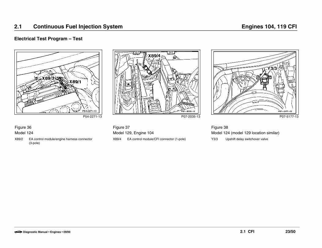
P54-2271-13
Figure 36Model 124
X89/2 EA control module/engine harness connector (3-pole)
P07-5177-13
Figure 38Model 124 (model 129 location similar)
Y3/3 Upshift delay switchover valve
P07-2035-13
Figure 37Model 129, Engine 104
X89/4 EA control module/CFI connector (1-pole)
b Diagnostic Manual • Engines • 09/00 2.1 CFI 23/50

2.1 Continuous Fuel Injection System Engines 104, 119 CFI
Hydraulic Test Program – Preparation forTest (Testing Fuel System Pressure and Internal Leakage)
Preliminary work:Removal/installation of air filter . . . . . . . . . . . . . . . . . . . . . . . . . . . . . . . . . . . . . . . . 09-400
Special Tools
Double connection
102 589 06 63 00
Ohm decade
124 589 09 63 00
Electrical connecting set
201 589 00 99 00
Tester
103 589 00 21 00
Note:• The leakage test should only be performed in cases of starting
complaints.• If there is no reaction to test steps 6 and 7, then perform
23 O 1.0 – 3.0 first.
b Diagnostic Manual • Engines • 09/00 2.1 CFI 31/1

2.1 Continuous Fuel Injection System Engines 104, 119 CFI
Hydraulic Test Program – Preparation forTest (Testing Fuel System Pressure and Internal Leakage)
U07-0075-55
Connection Diagram – Engine 104
Figure 1038 Resistance substitution unit043 Pressure gauge, part no. 103 589 00 21 00044 Adaptor, part no. 102 589 06 63 00B11/2 ECT sensor (connector)
b Diagnostic Manual • Engines • 09/00 2.1 CFI 31/2

2.1 Continuous Fuel Injection System Engines 104, 119 CFI
Hydraulic Test Program – Preparation forTest (Testing Fuel System Pressure and Internal Leakage)
U07-0258-57
Connection Diagram – Engine 119
Figure 2038 Resistance substitution unit043 Pressure gauge, part no. 103 589 00 21 00044 Adaptor, part no. 102 589 06 63 00B11/2 ECT sensor (connector)
b Diagnostic Manual • Engines • 09/00 2.1 CFI 31/3

2.1 Continuous Fuel Injection System Engines 104, 119 CFI
Hydraulic Test Program – Test (Testing Fuel System Pressure and Internal Leakage)
O N A Test scope Test connection Test condition Nominal value Possible cause/Remedy
1.0 Fuel connections Check for leakage.
2.0 Check for ease of movementof air flow sensor plate (4)with lever (1) and controlplunger (2) in fuel distributor( 32, Figure 1).
Switch on ignition briefly tobuild up fuel pressure.
Depress air flow sensorplate (4) by hand (Figure 1).
Release air flow sensorplate (4) quickly.
Uniformresistanceshould be feltduring its entiretravel.
No resistanceshould be feltsince the slowto react controlplunger (2) liftsoff the lever (1,Figure 1).
Center/replace air flow sensorplate,O 2.1.
Replace air flow sensor.
b Diagnostic Manual • Engines • 09/00 2.1 CFI 32/1

2.1 Continuous Fuel Injection System Engines 104, 119 CFI
Hydraulic Test Program – Test (Testing Fuel System Pressure and Internal Leakage)
O N A Test scope Test connection Test condition Nominal value Possible cause/Remedy
2.1 Control plunger Depress air flow sensorplate (4) by hand.
Release air flow sensorplate (4) slowly.
Control plunger(2) shouldremain incontact with thelever (1).
Replace fuel distributor.
3.0 Check control plunger (2, Figure 1) in fuel distributorfor leakage.
Press air flow sensor plate(4) completely down andhold in this position(illuminate intake withborescope).
Slight seepage(drops) ispermissible.
Replace fuel distributor.
4.0 Fuel pressures Note to Test connection:Connect pressure gauge.Connect hose “A“ to lowerchamber using adaptor(044), connect hose “B“ toupper chamber, 31,Figures 1 or 2.aWhen connecting pressuregauge, do not contact airflow sensor with wrench.
b Diagnostic Manual • Engines • 09/00 2.1 CFI 32/2
2.1 Continuous Fuel Injection System Engines 104, 119 CFI
Hydraulic Test Program – Test (Testing Fuel System Pressure and Internal Leakage)
O N A Test scope Test connection Test condition Nominal value Possible cause/Remedy
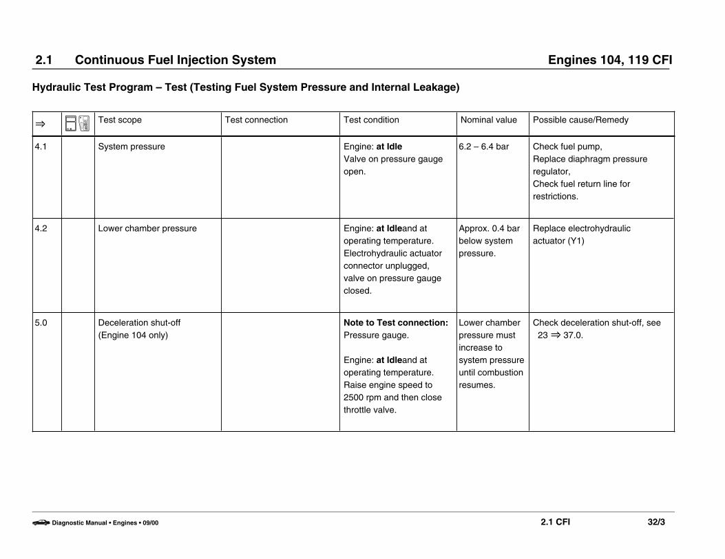
4.1 System pressure Engine: at IdleValve on pressure gaugeopen.
6.2 – 6.4 bar Check fuel pump,Replace diaphragm pressureregulator,Check fuel return line forrestrictions.
4.2 Lower chamber pressure Engine: at Idleand atoperating temperature.Electrohydraulic actuatorconnector unplugged,valve on pressure gaugeclosed.
Approx. 0.4 barbelow systempressure.
Replace electrohydraulic actuator (Y1)
5.0 Deceleration shut-off(Engine 104 only)
Note to Test connection:Pressure gauge.
Engine: at Idleand atoperating temperature.Raise engine speed to2500 rpm and then closethrottle valve.
Lower chamberpressure mustincrease tosystem pressureuntil combustionresumes.
Check deceleration shut-off, see 23 O 37.0.
b Diagnostic Manual • Engines • 09/00 2.1 CFI 32/3

2.1 Continuous Fuel Injection System Engines 104, 119 CFI
Hydraulic Test Program – Test (Testing Fuel System Pressure and Internal Leakage)
O N A Test scope Test connection Test condition Nominal value Possible cause/Remedy
6.0 Acceleration enrichment Note to Test connection:Pressure gauge.
Ignition: OFFECT sensor (B11/2)unplugged. Using tworesistance substitutionunits, simulate 2.5 k]resistance (+ 20oC) atsockets 2 and 4 as well asat sockets 1 and 3 ( 32,Figures 2 and 3).
Engine: at Idle
Rev engine abruptly.
Approx. 0.5 barbelow systempressure
Pressure inlower chambermust decreaseto < 5.5 bar.
23 O 1.0, 23 O 10.0, 23 O 14.0.
7.0 Fuel system leakage Note to Test connection:Pressure gauge.
Engine: OFF
System pressuredrops belowopening pres-sure of injectorsto approx. 3.5 bar.
If pressure drops immediately to 0 bar, replace check valve in fuelpump.If pressure drops slowly below 3.5bar, O 7.1 – 7.4
b Diagnostic Manual • Engines • 09/00 2.1 CFI 32/4
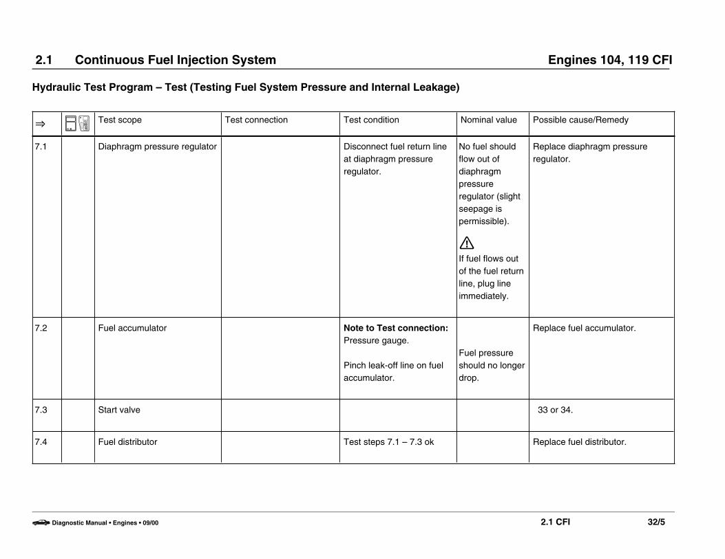
2.1 Continuous Fuel Injection System Engines 104, 119 CFI
Hydraulic Test Program – Test (Testing Fuel System Pressure and Internal Leakage)
O N A Test scope Test connection Test condition Nominal value Possible cause/Remedy
7.1 Diaphragm pressure regulator Disconnect fuel return lineat diaphragm pressureregulator.
No fuel shouldflow out ofdiaphragmpressureregulator (slightseepage ispermissible).
aIf fuel flows outof the fuel returnline, plug lineimmediately.
Replace diaphragm pressureregulator.
7.2 Fuel accumulator Note to Test connection:Pressure gauge.
Pinch leak-off line on fuelaccumulator.
Fuel pressureshould no longerdrop.
Replace fuel accumulator.
7.3 Start valve 33 or 34.
7.4 Fuel distributor Test steps 7.1 – 7.3 ok Replace fuel distributor.
b Diagnostic Manual • Engines • 09/00 2.1 CFI 32/5

2.1 Continuous Fuel Injection System Engines 104, 119 CFI
Hydraulic Test Program – Test (Testing Fuel System Pressure and Internal Leakage)
O N A Test scope Test connection Test condition Nominal value Possible cause/Remedy
7.5 External leakage Disconnect pressuregauge, wiping up any spiltfuel with a rag. Reconnectfuel lines.Engine: at Idle
All fuelconnectionsmust be tight(no leaks).
Table I Fuel pressures
System pressure with engine cold or at operating temperature bar 6.2 – 6.4
Lower chamberpressure
with engine at operating temperature
at a coolant temperature of + 20oC
durind deceleration shut-off
below the previously measuredsystem pressure
at idle, below the previouslymeasured system pressure
bar
bar
bar
approx. 0.4
approx. 0.5
Lower chamber pressureequals system pressure
Sustained systempressure
30 minutes after shutting off engine bar minimum 2.8
b Diagnostic Manual • Engines • 09/00 2.1 CFI 32/6

2.1 Continuous Fuel Injection System Engines 104, 119 CFI
Electrical Test Program – Test
P07-0074-15
Figure 1
1 Lever
2 Control plunger
4 Air flow sensor plate
Figure 3
ECT sensor (4-pole)
U07-2022-13
Figure 2
B11/2 ECT sensor (4-pole)
P15-0171-13
b Diagnostic Manual • Engines • 09/00 2.1 CFI 32/7
2.1 Continuous Fuel Injection System Engines 104, 119 CFI
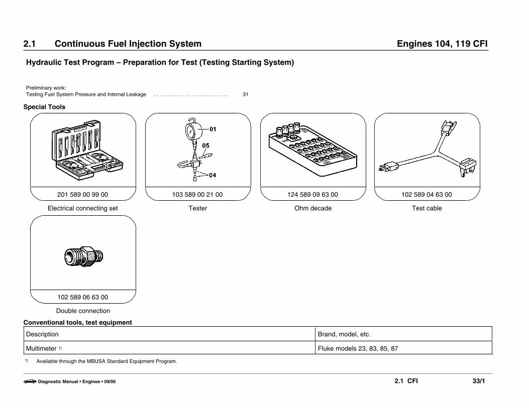
Hydraulic Test Program – Preparation for Test (Testing Starting System)
Preliminary work:Testing Fuel System Pressure and Internal Leakage . . . . . . . . . . . . . . . . . . . . . . . . . . 31
Special Tools
Electrical connecting set
201 589 00 99 00
Tester
103 589 00 21 00
Ohm decade
124 589 09 63 00
Test cable
102 589 04 63 00
Double connection
102 589 06 63 00
Conventional tools, test equipment
Description Brand, model, etc.
Multimeter 1) Fluke models 23, 83, 85, 87
1) Available through the MBUSA Standard Equipment Program.
b Diagnostic Manual • Engines • 09/00 2.1 CFI 33/1

2.1 Continuous Fuel Injection System Engines 104, 119 CFI
Hydraulic Test Program – Preparation for Test (Testing Starting System)
U07-0187-57A
Connection Diagram – Engine 104
Figure 1003 Multimeter033 Test cable038 Resistance substitution unitB11/2 ECT sensor (connector)
b Diagnostic Manual • Engines • 09/00 2.1 CFI 33/2

2.1 Continuous Fuel Injection System Engines 104, 119 CFI
Hydraulic Test Program – Preparation for Test (Testing Starting System)
U07-0260-57
Connection Diagram – Engine 119
Figure 2003 Multimeter033 Test cable038 Resistance substitution unitB11/2 ECT sensor (connector)
b Diagnostic Manual • Engines • 09/00 2.1 CFI 33/3
2.1 Continuous Fuel Injection System Engines 104, 119 CFI
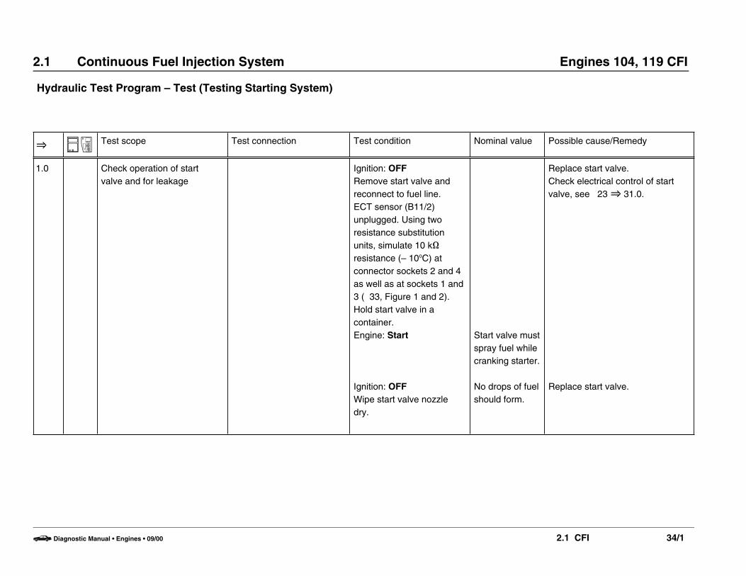
Hydraulic Test Program – Test (Testing Starting System)
O N A Test scope Test connection Test condition Nominal value Possible cause/Remedy
1.0 Check operation of startvalve and for leakage
Ignition: OFFRemove start valve andreconnect to fuel line.ECT sensor (B11/2)unplugged. Using tworesistance substitutionunits, simulate 10 k]resistance (– 10oC) atconnector sockets 2 and 4as well as at sockets 1 and3 ( 33, Figure 1 and 2).Hold start valve in acontainer.Engine: Start
Ignition: OFFWipe start valve nozzledry.
Start valve mustspray fuel whilecranking starter.
No drops of fuelshould form.
Replace start valve.Check electrical control of startvalve, see 23 O 31.0.
Replace start valve.
b Diagnostic Manual • Engines • 09/00 2.1 CFI 34/1

2.1 Continuous Fuel Injection System Engines 104, 119 CFI
Hydraulic Test Program – Test (Testing Starting System)
O N A Test scope Test connection Test condition Nominal value Possible cause/Remedy
2.0 After-start enrichment1 w
Y1d L 2
Ignition: OFFConnect test cable (033) toelectrohydraulic actuator(Y1).ECT sensor (B11/2)unplugged. Using tworesistance substitutionunits, simulate 10 k]resistance (– 10oC) atconnector sockets 2 and 4as well as at sockets 1 and3 ( 33, Figure 1 and 2).Engine: Start
See Table I forcurrent values.
23 O 13.0.
b Diagnostic Manual • Engines • 09/00 2.1 CFI 34/2

2.1 Continuous Fuel Injection System Engines 104, 119 CFI
Hydraulic Test Program – Test (Testing Starting System)
Table I Test and Adjustment Data
Engine Current at EHA with ignition ON (mA) After-start enrichment at an engine coolant temperature of + 20oC (mA)
104 20 3 – 5 1)
119 75 5 – 8 1)
1) Read value 0 – 15 seconds after startup.
b Diagnostic Manual • Engines • 09/00 2.1 CFI 34/3

2.1 Continuous Fuel Injection System Engines 104, 119 CFI
Hydraulic Test Program – Preparation for Test (Testing Fuel Pumps)
Preliminary work:Check system pressure (see Testing Fuel System Pressure and Internal Leakage . . . . . . 31
Special Tools
Tester
103 589 00 21 00
Adapter
103 589 02 63 00
Double connection
102 589 06 63 00
Electrical connecting set
201 589 00 99 00
Elbow fitting
000 589 01 91 00
b Diagnostic Manual • Engines • 09/00 2.1 CFI 35/1
2.1 Continuous Fuel Injection System Engines 104, 119 CFI
Hydraulic Test Program – Preparation for Test (Testing Fuel Pumps)
Conventional tools, test equipment
Description Brand, model, etc.
Multimeter 1) Fluke models 23, 83, 85, 87
Fuel hose, 500 mm (20 in.) long Local purchase
Measuring glass (1 liter minimum capacity) Local purchase
Stop watch Local purchase
1) Available through the MBUSA Standard Equipment Program.
b Diagnostic Manual • Engines • 09/00 2.1 CFI 35/2

2.1 Continuous Fuel Injection System Engines 104, 119 CFI
Hydraulic Test Program – Preparation for Test (Testing Fuel Pumps)
U07-0192-57A
Connection Diagram – Delivery TestEngine 104
Figure 1003 Multimeter004 Socket box (35-pole)041 Stop watch051 Connector, engine systems control module052 Test cable055 Measuring glass056 Fuel hoseN16 Engine systems control module
b Diagnostic Manual • Engines • 09/00 2.1 CFI 35/3
2.1 Continuous Fuel Injection System Engines 104, 119 CFI
Hydraulic Test Program – Preparation for Test (Testing Fuel Pumps)
U07-0257-57
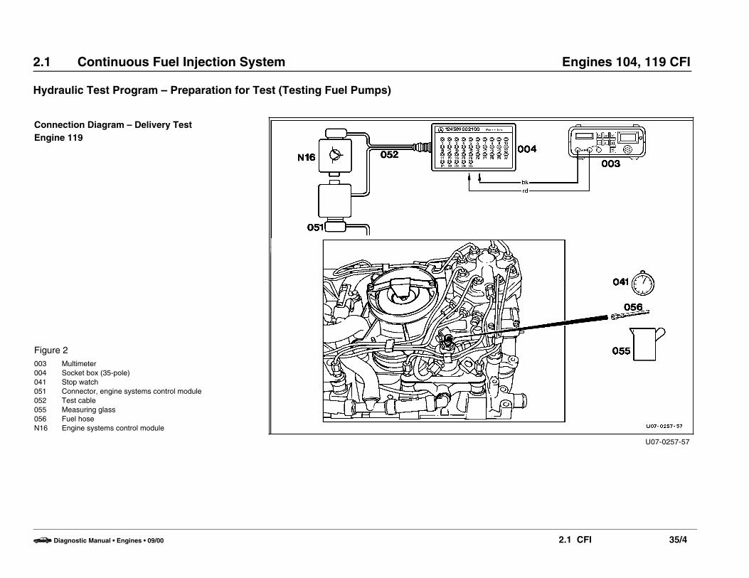
Connection Diagram – Delivery TestEngine 119
Figure 2003 Multimeter004 Socket box (35-pole)041 Stop watch051 Connector, engine systems control module052 Test cable055 Measuring glass056 Fuel hoseN16 Engine systems control module
b Diagnostic Manual • Engines • 09/00 2.1 CFI 35/4

2.1 Continuous Fuel Injection System Engines 104, 119 CFI
Hydraulic Test Program – Preparation for Test (Testing Fuel Pumps)
U07-0191-57
Connection Diagram – Fuel Pump Pressure TestEngines 104, 119
Figure 3043 Pressure gauge, part no. 103 589 00 21 00045 Adaptor, part no. 103 589 02 63 0055 Fuel filter57 Fuel accumulatorM3m1 Fuel pump 1M3m2 Fuel pump 2
b Diagnostic Manual • Engines • 09/00 2.1 CFI 35/5

2.1 Continuous Fuel Injection System Engines 104, 119 CFI
Hydraulic Test Program – Test (Testing Fuel Pumps)
O N A Test scope Test connection Test condition Nominal value Possible cause/Remedy
1.0 Delivery capacity
4 w
2 w
N16k
c
N16k
d
L 2
L 1
Ignition: OFFConnect special tool fitting,part no. 000 589 01 91 00,and fuel hose (056) todiaphragm pressureregulator instead of fuelreturn line ( 35, Figure 1or 2). Place other end offuel hose (056) inmeasuring glass.
Ignition: ON
Engine systems controlmodule (N16) unplugged.
MEnd test after maximum of40 seconds
11 – 14 V(indicated onlybriefly)
1 liter aftermax. 40seconds,current draw6 – 10 A
Check battery voltage
• Check strainer in fuel inletfitting of fuel distributor forrestrictions, clean or replacefuel inlet fitting.
• Check fuel lines for restrictions(kinks and dents). Repair asrequired.
• Pinch leak-off line between fuelaccumulator and suctiondamper with clamp. repeat fueldelivery test. If correct deliveryis attained, replace fuelaccumulator.
• Replace fuel filter.• O 2.0.
b Diagnostic Manual • Engines • 09/00 2.1 CFI 36/1
2.1 Continuous Fuel Injection System Engines 104, 119 CFI
Hydraulic Test Program – Test (Testing Fuel Pumps)
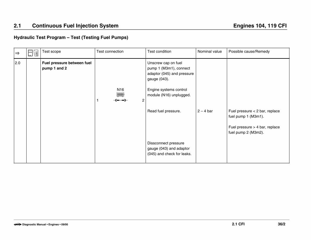
O N A Test scope Test connection Test condition Nominal value Possible cause/Remedy
2.0 Fuel pressure between fuelpump 1 and 2
1
N16E
u 2
Unscrew cap on fuel pump 1 (M3m1), connectadaptor (045) and pressuregauge (043).
Engine systems controlmodule (N16) unplugged.
Read fuel pressure.
Dissconnect pressuregauge (043) and adaptor(045) and check for leaks.
2 – 4 bar Fuel pressure < 2 bar, replacefuel pump 1 (M3m1).
Fuel pressure > 4 bar, replacefuel pump 2 (M3m2).
b Diagnostic Manual • Engines • 09/00 2.1 CFI 36/2

2.1 Continuous Fuel Injection System Engines 104, 119 CFI
Fuel pump test values
Bosch no./MB no. 0 580 254 951/002 091 88 01
Measurement specification with engine stopped and voltage at the fuel pump min. V 11.5
Delivery capacity Measurement location: at the fuel line after the diaphragm pressure regulator. min. l/sFuel tank at least half full.
1/40
Current draw Amps 6 – 10
b Diagnostic Manual • Engines • 09/00 2.1 CFI 36/3
2.1 Continuous Fuel Injection System Engines 104, 119 CFI
Hydraulic Test Program – Preparation for Test (Testing Cold Start)
Preliminary work:Testing starting system . . . . . . . . . . . . . . . . . . . . . . . . . . . . . . . . . . . . . . . . . . . . . . . . . 34
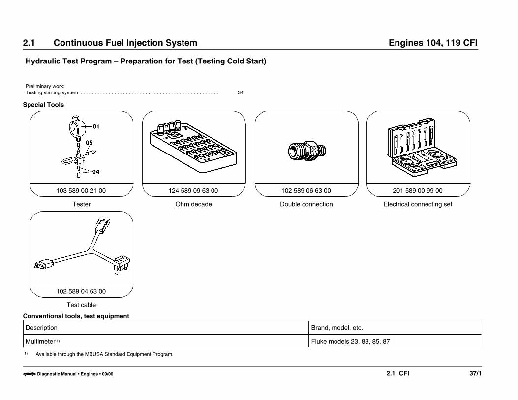
Special Tools
Tester
103 589 00 21 00
Ohm decade
124 589 09 63 00
Double connection
102 589 06 63 00
Electrical connecting set
201 589 00 99 00
Test cable
102 589 04 63 00
Conventional tools, test equipment
Description Brand, model, etc.
Multimeter 1) Fluke models 23, 83, 85, 87
1) Available through the MBUSA Standard Equipment Program.
b Diagnostic Manual • Engines • 09/00 2.1 CFI 37/1

2.1 Continuous Fuel Injection System Engines 104, 119 CFI
Hydraulic Test Program – Preparation for Test (Testing Cold Start)
U07-0194-57
Connection diagram – Engine 104
Figure 1003 Multtimeter033 Test cable, part no. 102 589 04 63 00038 Resistance substitution unit043 Pressure gauge, part no. 103 589 00 21 00044 Adaptor, part no. 102 589 06 63 00053 Cooling fanB11/2 Connector, coolant temperature sensor
b Diagnostic Manual • Engines • 09/00 2.1 CFI 37/2
2.1 Continuous Fuel Injection System Engines 104, 119 CFI
Hydraulic Test Program – Preparation for Test (Testing Cold Start)
U07-0259-57
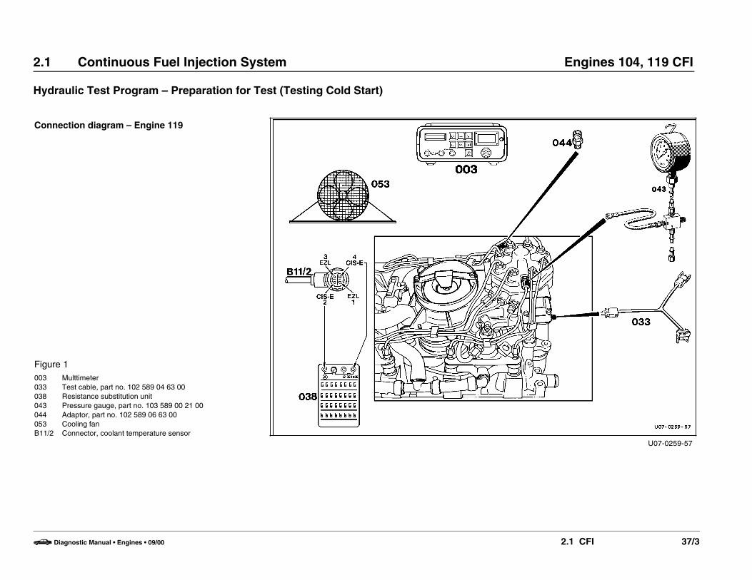
Connection diagram – Engine 119
Figure 1003 Multtimeter033 Test cable, part no. 102 589 04 63 00038 Resistance substitution unit043 Pressure gauge, part no. 103 589 00 21 00044 Adaptor, part no. 102 589 06 63 00053 Cooling fanB11/2 Connector, coolant temperature sensor
b Diagnostic Manual • Engines • 09/00 2.1 CFI 37/3

2.1 Continuous Fuel Injection System Engines 104, 119 CFI
Electrical Test Program – Test (Testing Cold Start)
O A Test scope Test connection Test condition Nominal value Possible cause/Remedy
1.0 Connect hose “A“ to lowerchamber using adaptor(044), connect hose “B“ toupper chamber.( 37, Figure 1 or 2)
Ignition: OFFConnect pressure gauge.Run engine to build uppressure. Turn off engine,check for leaks
O 1.1,
2.01 w
Y1d L 2
Ignition: OFFConnect test cable (033) toelectro-hydraulic actuator(Y1).Cool engine with coolingfan (053) or let standovernight.
3.0 Cold start Engine: Start For fuelpressures seeTable I.For currentvalues seeTable II.
Test fuel system pressure andinternal leakage, 32.
23 O 10.0 23 O 11.0 23 O 13.0 23 O 14.0
b Diagnostic Manual • Engines • 09/00 2.1 CFI 38/1

2.1 Continuous Fuel Injection System Engines 104, 119 CFI
Electrical Test Program – Test (Testing Cold Start)
Test and Adjustment Data
Table I Fuel Pressures
System pressure with engine cold or at operating temperature bar 6.2 – 6.4
Lower chamber pressure with engine at operating temperature bar approx. 0.4 1)
at idle with coolant temperature < + 20 oC bar 0.5 1)
during deceleration shut-off bar Lower chamber pressure equals system pressure.
1) Observe Preparation for Test, see 22.
Table II Current Values
Engine Current at EHA withIgnition: ON (mA)
After-start enrichment at anengine coolant temperature of+ 20 oC (mA) 1)
After-start enrichment at anengine coolant temp. between0 and + 20 oC (mA) 1)
After-start enrichment at an engine coolanttemp. between 0 and – 20 oC (mA) 1)
104 20 3 – 5 2) 3 – 45 3) 38 – 80 3)
119 75 5 – 8 2) 5 – 42 3) 42 – 100 3)
1) For resistance substitution unit resistance values, see 23, Table I.2) Read value 0 – 8 seconds after startup.3) Note the following: • Read value immediately after startup.
• Selector lever position P/N.• Throttle valve closed.
b Diagnostic Manual • Engines • 09/00 2.1 CFI 38/2