21-10-2015 challenge the future delft university of technology laser swarm mid term review group 13,...
TRANSCRIPT
20-04-23
Challenge the future
DelftUniversity ofTechnology
Laser SwarmMid term review
Group 13, Aerospace Engineering
2Mid term – Laser Swarm
Contents
• Project plan
• Key requirements
• Trade-off method
• Subsystem Trade-offs
• Orbit design
• Software tool

3Mid term – Laser Swarm
1.Project plan

4Mid term – Laser Swarm
Mission need statement
Demonstrate that a satellite constellation, consisting of a single emitter and several receivers, will perform superior (in terms of cost, lifetime and performance) to existing spaceborne laser altimetry systems.
5Mid term – Laser Swarm
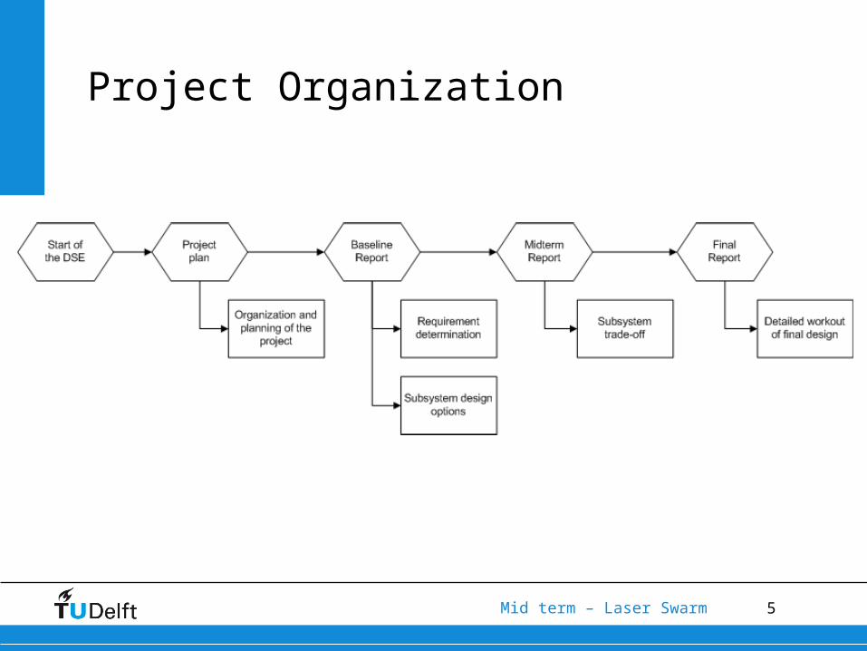
Project Organization
6Mid term – Laser Swarm
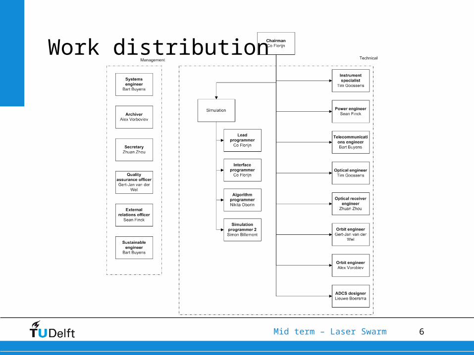
Work distribution
7Mid term – Laser Swarm
2.Key requirements

8Mid term – Laser Swarm
Key Requirements
• Low cost
• Lifetime of ~ 5 yrs
• Performance equivalent to ICESat

9Mid term – Laser Swarm
Additional Requirements
• Mass ≤ existing spaceborne laser altimetry systems
• No scanner may be used
• Recreation of the DEM
• Extraction of the BRDF

10Mid term – Laser Swarm
3.Tradeoff method
11Mid term – Laser Swarm
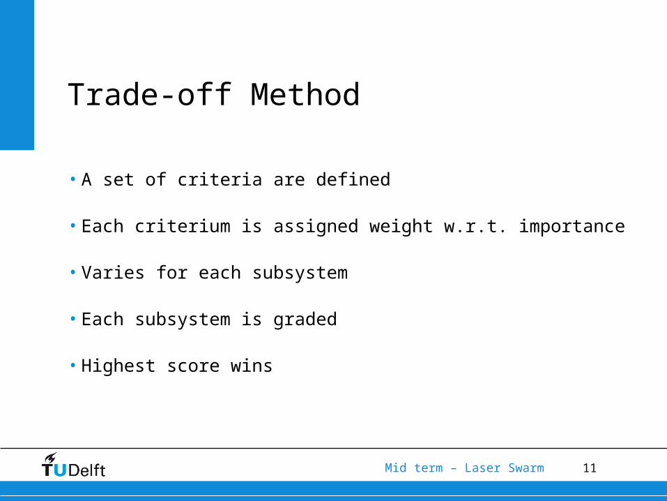
Trade-off Method
• A set of criteria are defined
• Each criterium is assigned weight w.r.t. importance
• Varies for each subsystem
• Each subsystem is graded
• Highest score wins
12Mid term – Laser Swarm
4.Subsystem trade off
13Mid term – Laser Swarm
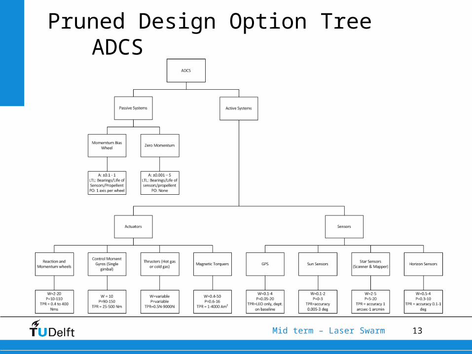
Pruned Design Option Tree ADCS
14Mid term – Laser Swarm
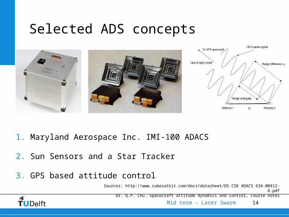
Selected ADS concepts
1. Maryland Aerospace Inc. IMI-100 ADACS
2. Sun Sensors and a Star Tracker
3. GPS based attitude controlSources: http://www.cubesatkit.com/docs/datasheet/DS CSK ADACS 634-00412-A.pdf
Dr. Q.P. Chu. Spacecraft attitude dynamics and control, course notes

15Mid term – Laser Swarm
Trade-off ADS
Criteria Weight Factor
Concept 1 Concept 2 Concept 3
Accuracy 9 4 8 4
Size 7 2 6 4
Power 7 6 5 7
Price 3 3 5 4
Development 5 8 4 5
Weighed total
141 184 150
16Mid term – Laser Swarm
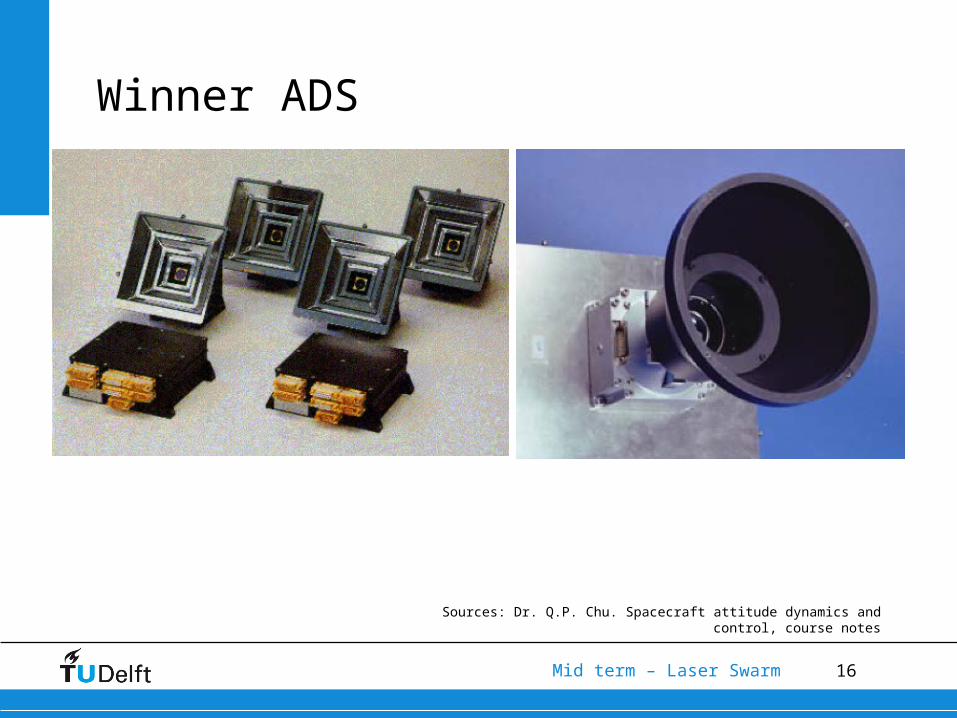
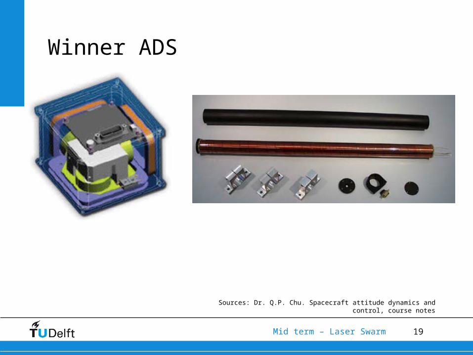
Winner ADS
Sources: Dr. Q.P. Chu. Spacecraft attitude dynamics and control, course notes
17Mid term – Laser Swarm
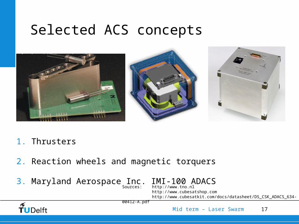
Selected ACS concepts
1. Thrusters
2. Reaction wheels and magnetic torquers
3. Maryland Aerospace Inc. IMI-100 ADACSSources: http://www.tno.nl
http://www.cubesatshop.comhttp://www.cubesatkit.com/docs/datasheet/DS_CSK_ADACS_634-00412-
A.pdf
18Mid term – Laser Swarm
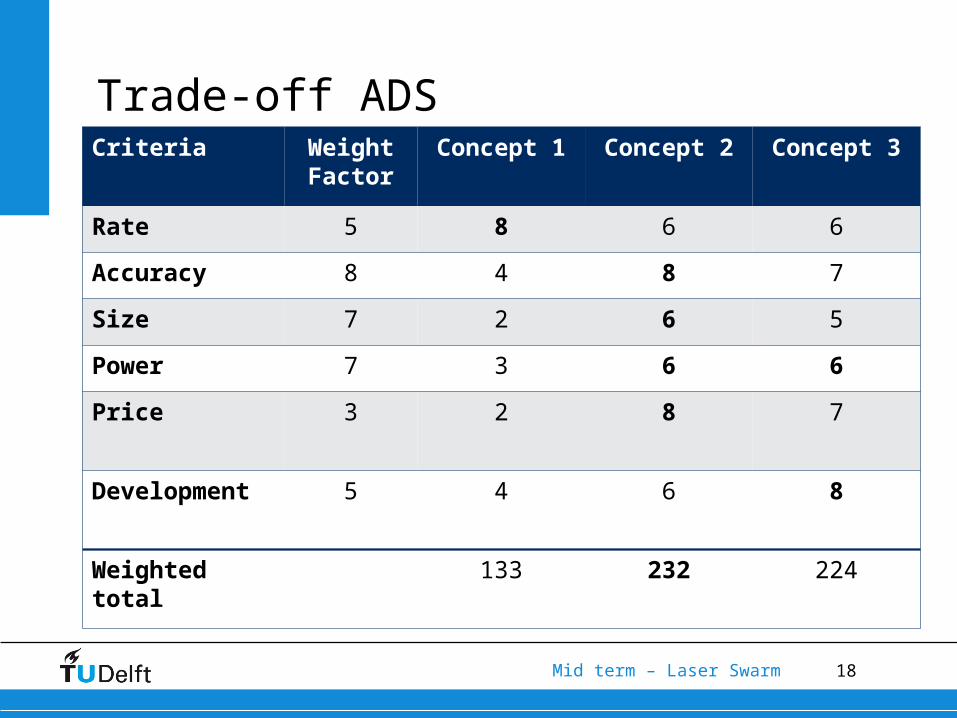
Trade-off ADSCriteria Weight
FactorConcept 1 Concept 2 Concept 3
Rate 5 8 6 6
Accuracy 8 4 8 7
Size 7 2 6 5
Power 7 3 6 6
Price 3 2 8 7
Development 5 4 6 8
Weighted total
133 232 224
19Mid term – Laser Swarm
Winner ADS
Sources: Dr. Q.P. Chu. Spacecraft attitude dynamics and control, course notes
20Mid term – Laser Swarm
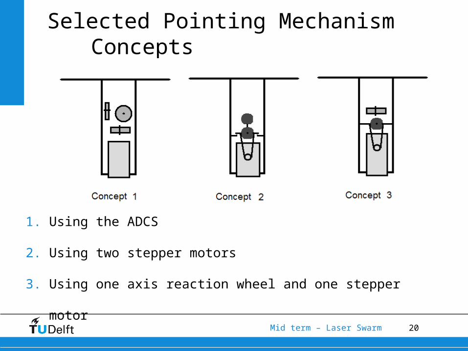
Selected Pointing Mechanism Concepts
1. Using the ADCS
2. Using two stepper motors
3. Using one axis reaction wheel and one stepper motor
21Mid term – Laser Swarm
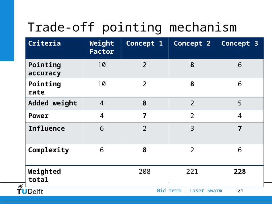
Trade-off pointing mechanismCriteria Weight
FactorConcept 1 Concept 2 Concept 3
Pointing accuracy
10 2 8 6
Pointing rate 10 2 8 6
Added weight
4 8 2 5
Power 4 7 2 4
Influence 6 2 3 7
Complexity 6 8 2 6
Weighted total
208 221 228
22Mid term – Laser Swarm
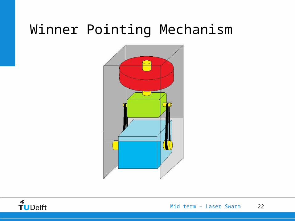
Winner Pointing Mechanism

23Mid term – Laser Swarm
Communications
•Communications architecture•Frequency bands
•Ground-space link•Intersatellite link
•Antenna configuration•Tracking
Aspects considered
24Mid term – Laser Swarm
Communications
•Communications architecture•Frequency bands
•Ground-space link•Intersatellite link
•Antenna configuration•Tracking
Aspects considered
25Mid term – Laser Swarm
Communications
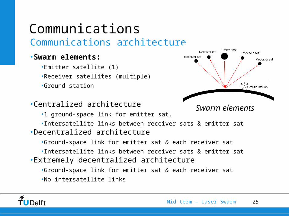
•Swarm elements:•Emitter satellite (1)
•Receiver satellites (multiple)
•Ground station
•Centralized architecture•1 ground-space link for emitter sat.
•Intersatellite links between receiver sats & emitter sat•Decentralized architecture
•Ground-space link for emitter sat & each receiver sat
•Intersatellite links between receiver sats & emitter sat•Extremely decentralized architecture
•Ground-space link for emitter sat & each receiver sat
•No intersatellite links
Communications architecture
Swarm elements

26Mid term – Laser Swarm
Communications
•Swarm elements:•Emitter satellite (1)
•Receiver satellites (multiple)
•Ground station
•Centralized architecture•1 ground-space link for emitter sat.
•Intersatellite links between receiver sats & emitter sat•Decentralized architecture
•Ground-space link for emitter sat & each receiver sat
•Intersatellite links between receiver sats & emitter sat•Extremely decentralized architecture
•Ground-space link for emitter sat & each receiver sat
•No intersatellite links
Communications architecture
Centralized
27Mid term – Laser Swarm
Communications
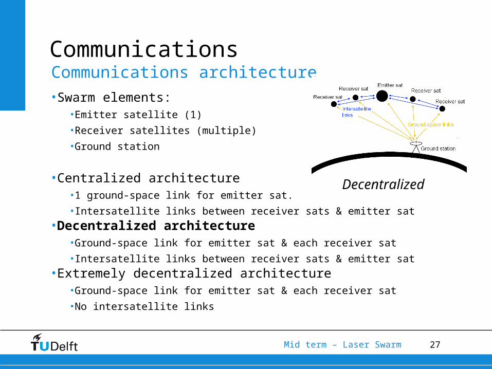
•Swarm elements:•Emitter satellite (1)
•Receiver satellites (multiple)
•Ground station
•Centralized architecture•1 ground-space link for emitter sat.
•Intersatellite links between receiver sats & emitter sat•Decentralized architecture
•Ground-space link for emitter sat & each receiver sat
•Intersatellite links between receiver sats & emitter sat•Extremely decentralized architecture
•Ground-space link for emitter sat & each receiver sat
•No intersatellite links
Communications architecture
Decentralized
28Mid term – Laser Swarm
Communications
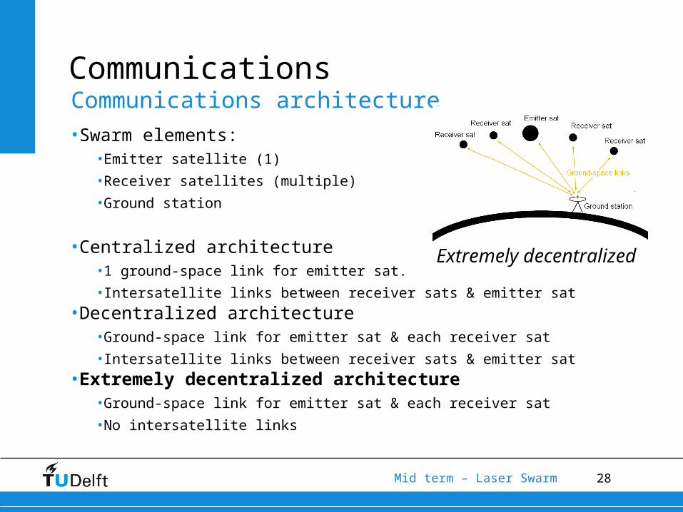
•Swarm elements:•Emitter satellite (1)
•Receiver satellites (multiple)
•Ground station
•Centralized architecture•1 ground-space link for emitter sat.
•Intersatellite links between receiver sats & emitter sat•Decentralized architecture
•Ground-space link for emitter sat & each receiver sat
•Intersatellite links between receiver sats & emitter sat•Extremely decentralized architecture
•Ground-space link for emitter sat & each receiver sat
•No intersatellite links
Communications architecture
Extremely decentralized
29Mid term – Laser Swarm
Communications
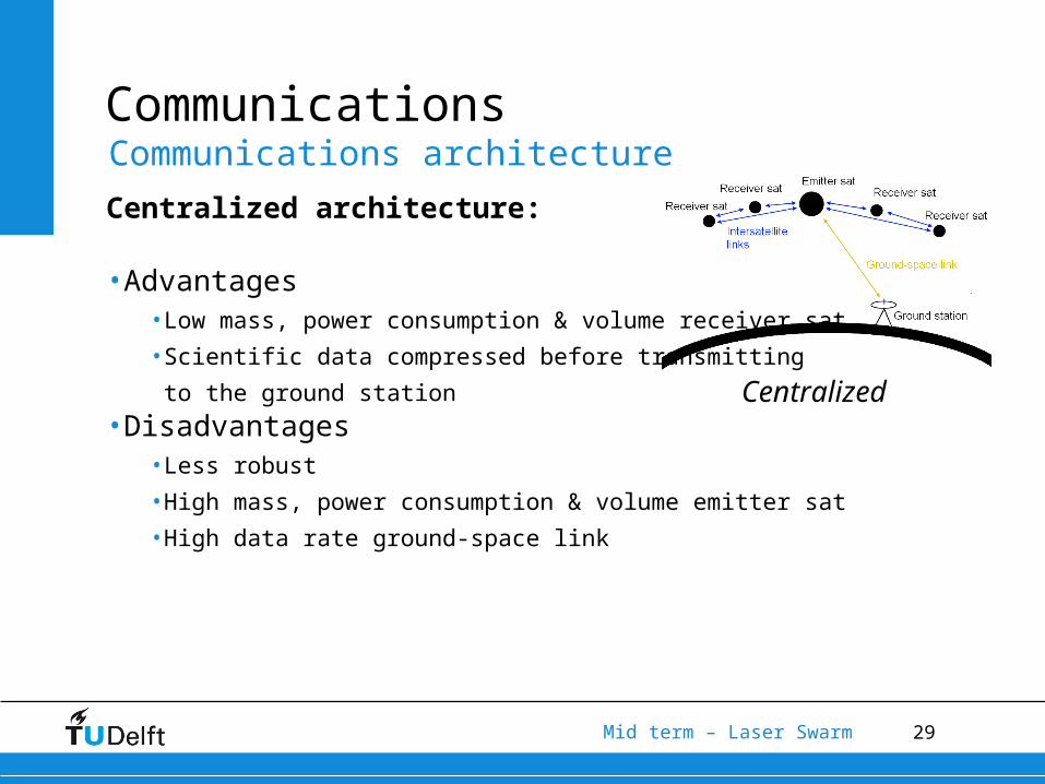
Centralized architecture:
•Advantages•Low mass, power consumption & volume receiver sat
•Scientific data compressed before transmitting
to the ground station•Disadvantages
•Less robust
•High mass, power consumption & volume emitter sat
•High data rate ground-space link
Communications architecture
Centralized
30Mid term – Laser Swarm
Communications
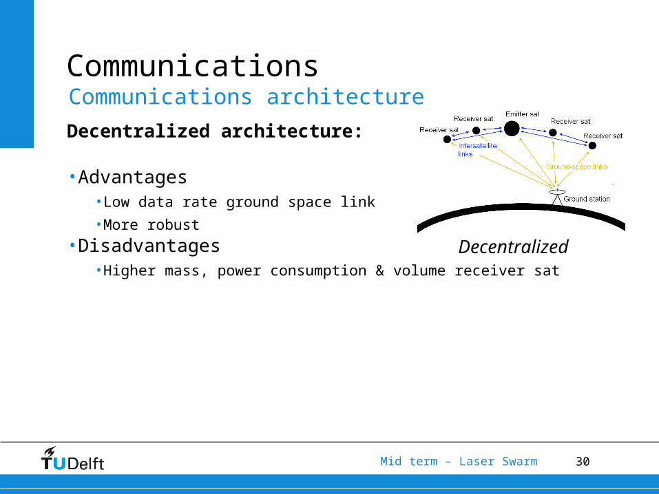
Decentralized architecture:
•Advantages•Low data rate ground space link
•More robust•Disadvantages
•Higher mass, power consumption & volume receiver sat
Communications architecture
Decentralized

31Mid term – Laser Swarm
Communications
Extremely decentralized architecture:
•Advantages•Low data rate ground space link
•No frequency allocation required for
intersatellite links•Disadvantages
•Higher mass, power consumption & volume receiver sat
•Desynchronization
Communications architecture
Extremely decentralized
32Mid term – Laser Swarm
Communications
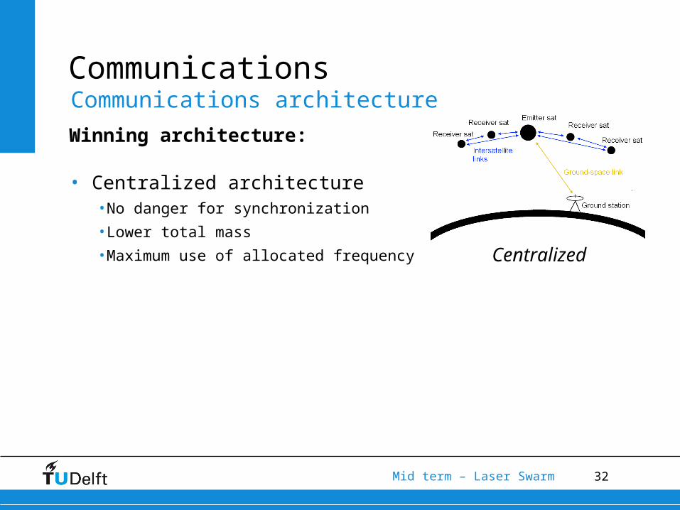
Winning architecture:
• Centralized architecture•No danger for synchronization
•Lower total mass
•Maximum use of allocated frequency
Communications architecture
Centralized

33Mid term – Laser Swarm
Communications
•Communications architecture•Frequency bands
•Ground-space link•Intersatellite link
•Antenna configuration•Tracking
Aspects considered
34Mid term – Laser Swarm
Communications
Ground space link:
• Possible frequency bands•C-band
•S-band
•X-band
•Ku-band
•Ka-band
•SHF/EHF-band
Frequency allocation
35Mid term – Laser Swarm
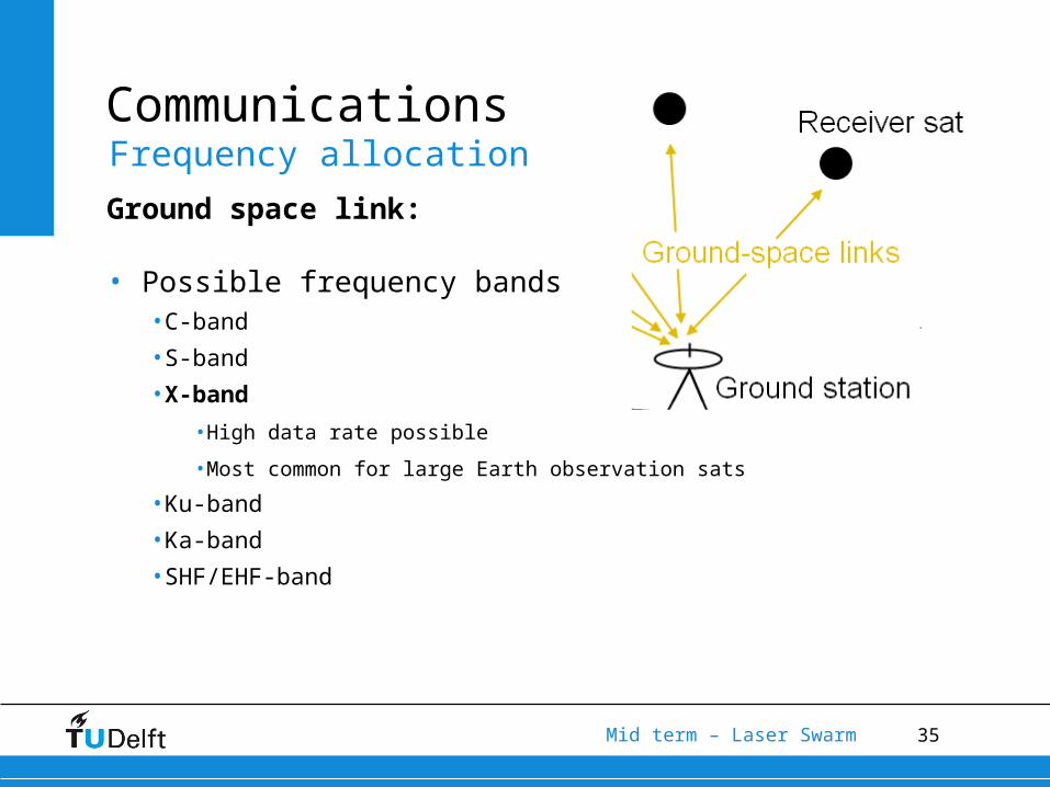
Communications
Ground space link:
• Possible frequency bands•C-band
•S-band
•X-band
•High data rate possible
•Most common for large Earth observation sats
•Ku-band
•Ka-band
•SHF/EHF-band
Frequency allocation
36Mid term – Laser Swarm
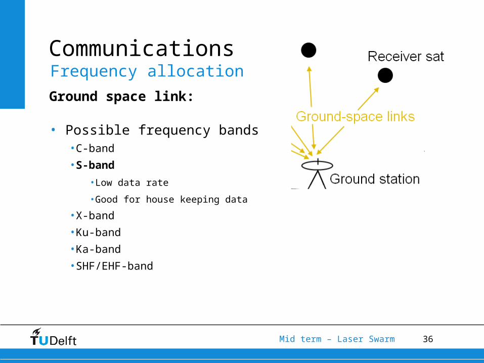
Communications
Ground space link:
• Possible frequency bands•C-band
•S-band
•Low data rate
•Good for house keeping data
•X-band
•Ku-band
•Ka-band
•SHF/EHF-band
Frequency allocation
37Mid term – Laser Swarm
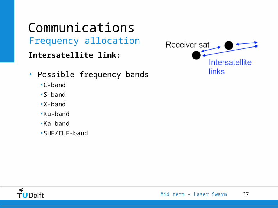
Communications
Intersatellite link:
• Possible frequency bands•C-band
•S-band
•X-band
•Ku-band
•Ka-band
•SHF/EHF-band
Frequency allocation
38Mid term – Laser Swarm
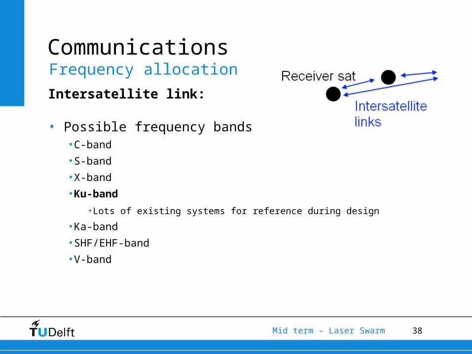
Communications
Intersatellite link:
• Possible frequency bands•C-band
•S-band
•X-band
•Ku-band
•Lots of existing systems for reference during design
•Ka-band
•SHF/EHF-band
•V-band
Frequency allocation
39Mid term – Laser Swarm
Communications
•Communications architecture•Frequency bands
•Ground-space link•Intersatellite link
•Antenna configuration•Tracking
Aspects considered
40Mid term – Laser Swarm
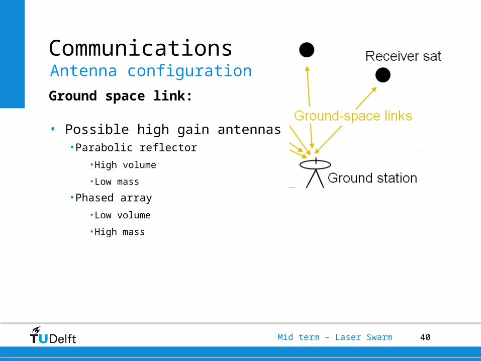
Communications
Ground space link:
• Possible high gain antennas•Parabolic reflector
•High volume
•Low mass
•Phased array
•Low volume
•High mass
Antenna configuration
41Mid term – Laser Swarm
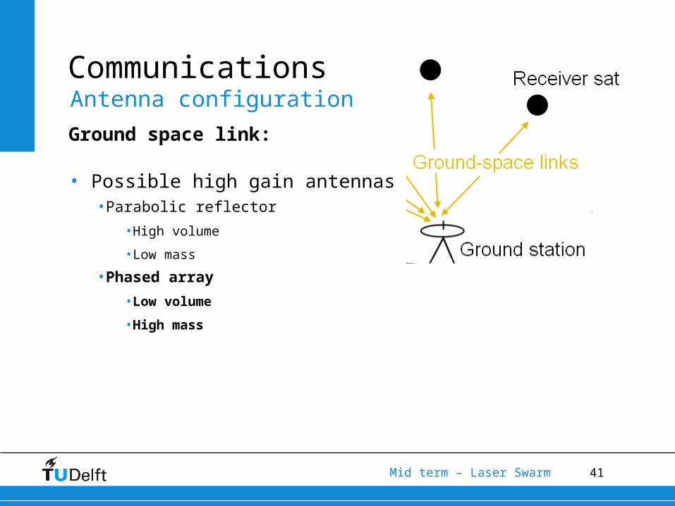
Communications
Ground space link:
• Possible high gain antennas•Parabolic reflector
•High volume
•Low mass
•Phased array
•Low volume
•High mass
Antenna configuration

42Mid term – Laser Swarm
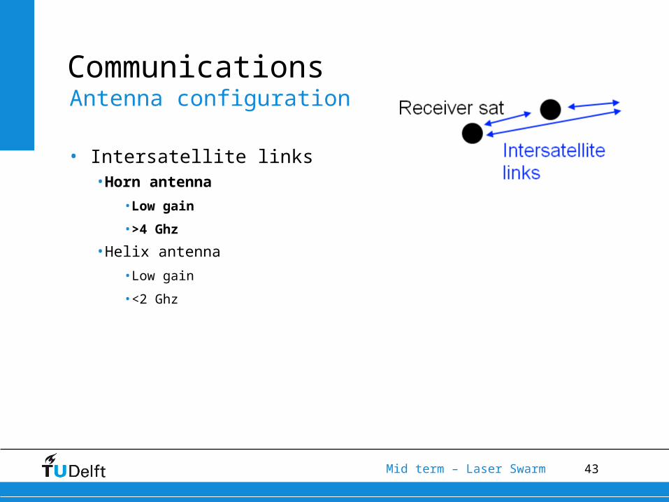
Communications
• Intersatellite links•Horn antenna
•Low gain
•>4 Ghz
•Helix antenna
•Low gain
•<2 Ghz
Antenna configuration
43Mid term – Laser Swarm
Communications
• Intersatellite links•Horn antenna
•Low gain
•>4 Ghz
•Helix antenna
•Low gain
•<2 Ghz
Antenna configuration

44Mid term – Laser Swarm
Communications
•Communications architecture•Frequency bands
•Ground-space link•Intersatellite link
•Antenna configuration•Tracking
Aspects considered
45Mid term – Laser Swarm
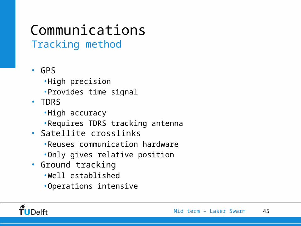
Communications
• GPS•High precision•Provides time signal
• TDRS•High accuracy•Requires TDRS tracking antenna
• Satellite crosslinks•Reuses communication hardware•Only gives relative position
• Ground tracking•Well established•Operations intensive
Tracking method
46Mid term – Laser Swarm
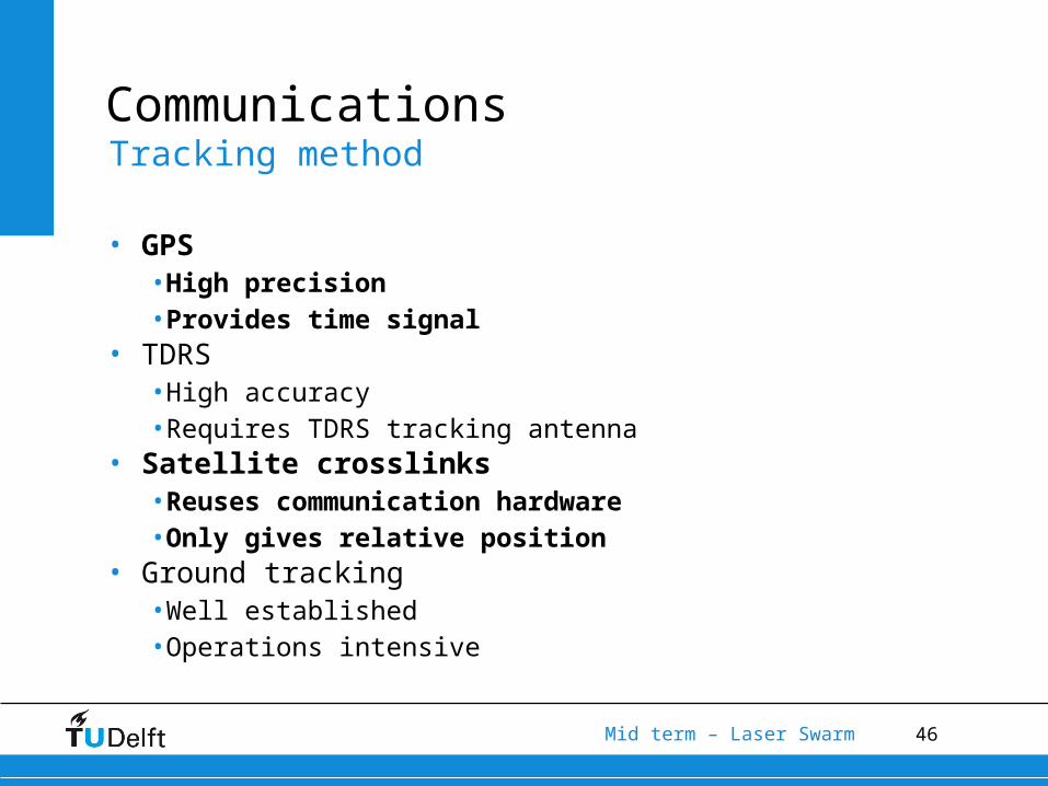
Communications
• GPS•High precision•Provides time signal
• TDRS•High accuracy•Requires TDRS tracking antenna
• Satellite crosslinks•Reuses communication hardware•Only gives relative position
• Ground tracking•Well established•Operations intensive
Tracking method
47Mid term – Laser Swarm
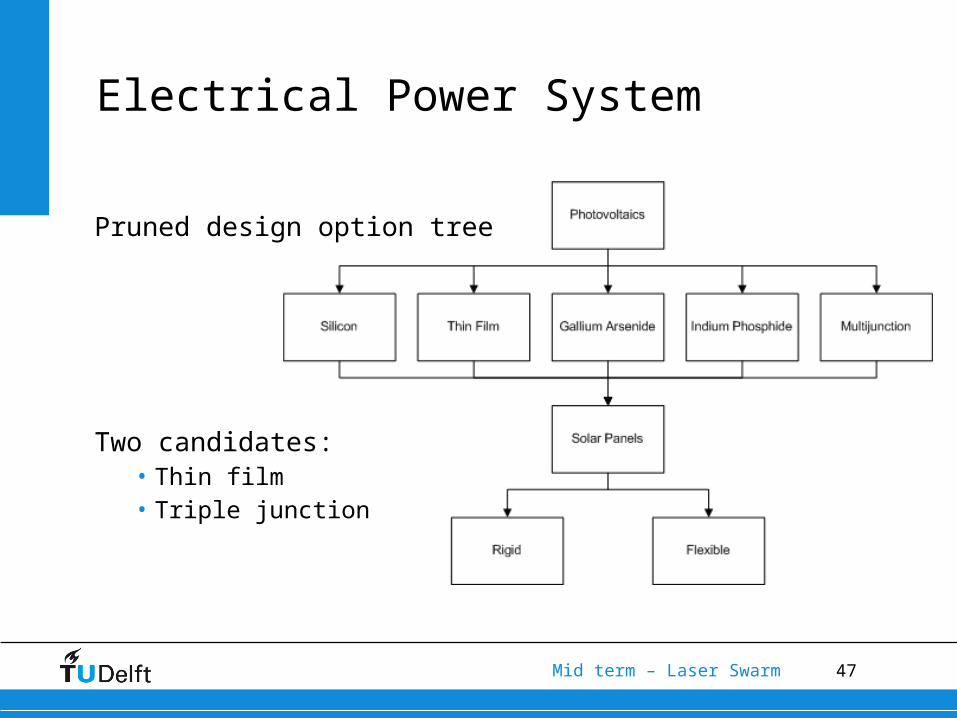
Pruned design option tree
Two candidates:• Thin film• Triple junction
Electrical Power System

48Mid term – Laser Swarm
• Multiple layers of thin photovoltaic material
• Copper-Indium-Gallium-Selenium absorber
• Low efficiency
• Low production cost
• High absorptance coefficient
EPS – Thin Film CIGS

49Mid term – Laser Swarm
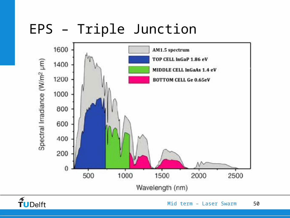
• Multiple pn-junctions
• High efficiency
• High production cost
• Larger covering of the solar spectrum
EPS – Triple Junction
50Mid term – Laser Swarm
EPS – Triple Junction
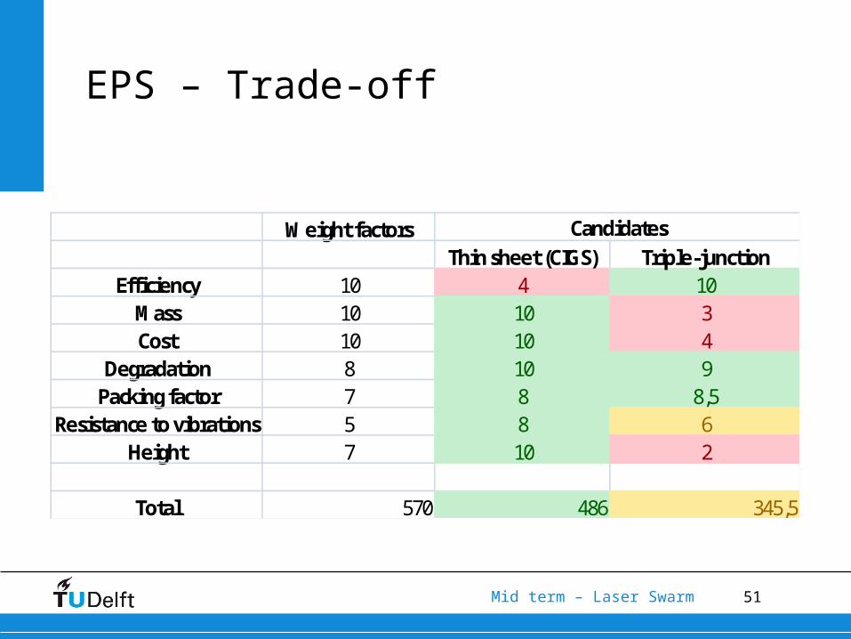
51Mid term – Laser Swarm
Weight factorsThin sheet (CIGS) Triple-junction
Efficiency 10 4 10Mass 10 10 3Cost 10 10 4
Degradation 8 10 9Packing factor 7 8 8,5
Resistance to vibrations 5 8 6Height 7 10 2
Total 570 486 345,5
Candidates
EPS – Trade-off
52Mid term – Laser Swarm
Optical Receiving Payload
•Single-Photon Detection• Photonmultiplier tube• Single Photon Avalanche Diode (SPAD)
•Wavelength Estimation• Atmospheric transmittance
• Wavelength ratio
53Mid term – Laser Swarm
Optical Receiving Payload
Single-Photon Detection
• Convert light (photons) to measurable quantity (Voltage or current)
• Multiple ways• Photomultiplier tube• SPAD• Quantum dot (underdeveloped)
54Mid term – Laser Swarm
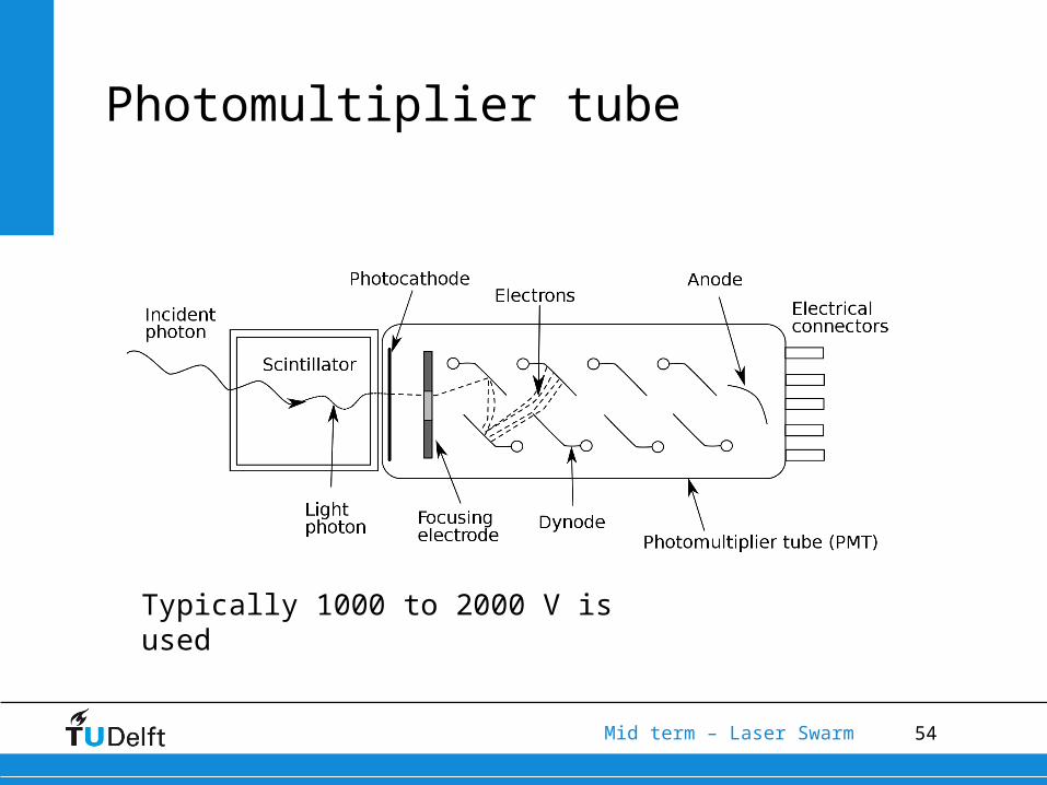
Photomultiplier tube
Typically 1000 to 2000 V is used
55Mid term – Laser Swarm
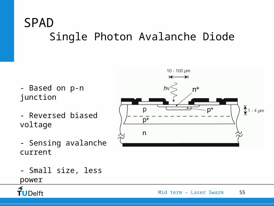
SPADSingle Photon Avalanche Diode
- Based on p-n junction
- Reversed biased voltage
- Sensing avalanche current
- Small size, less power
56Mid term – Laser Swarm
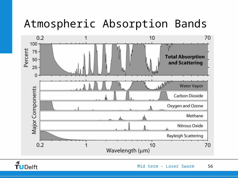
Atmospheric Absorption Bands
57Mid term – Laser Swarm
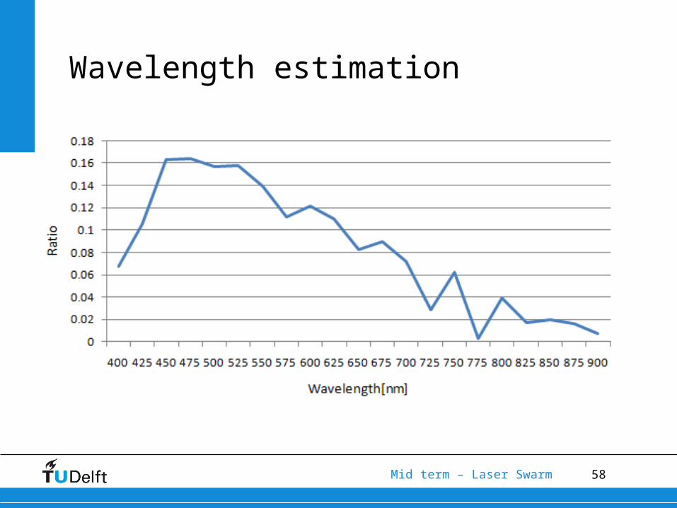
Wavelength estimation
• General sufficient wavelength range 400nm to 900nm
• Atmospheric transmittance Vs. Photon detection efficiency
• Wavelength ratio R = transmittance^2*efficiency
58Mid term – Laser Swarm
Wavelength estimation
59Mid term – Laser Swarm
Laser Optics
• To get the desired footprint.
• Three options:• No optics• Two lenses• Mirrors
60Mid term – Laser Swarm
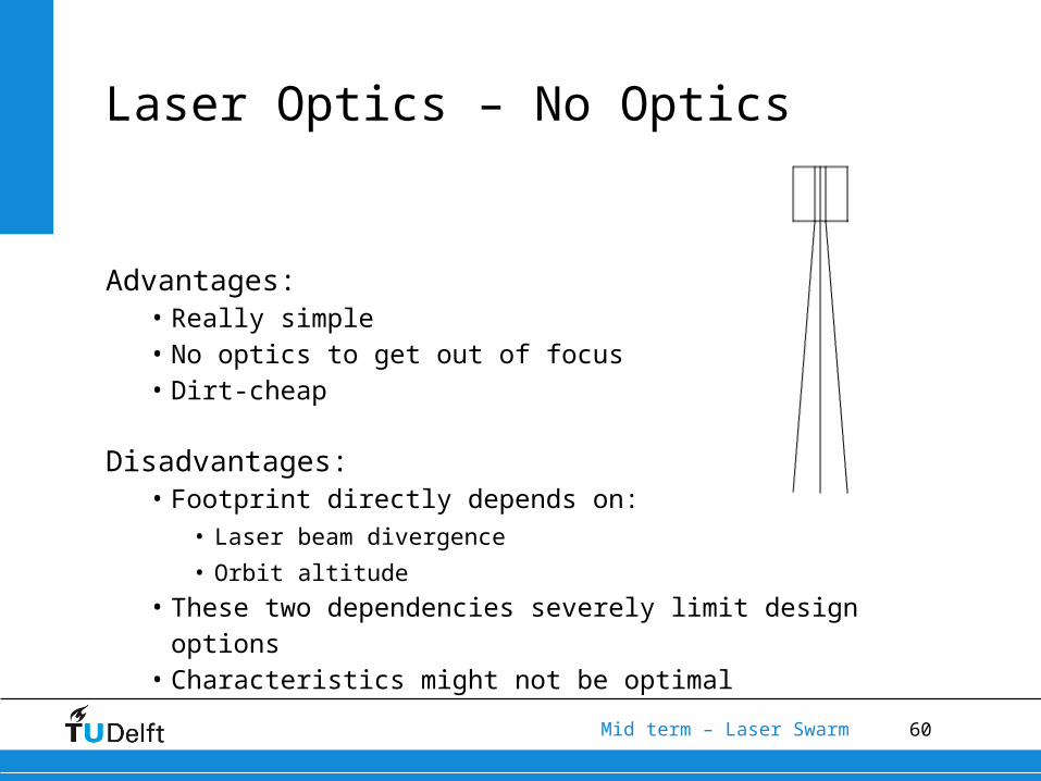
Laser Optics – No Optics
Advantages:• Really simple• No optics to get out of focus• Dirt-cheap
Disadvantages:• Footprint directly depends on:
• Laser beam divergence
• Orbit altitude
• These two dependencies severely limit design options• Characteristics might not be optimal
61Mid term – Laser Swarm
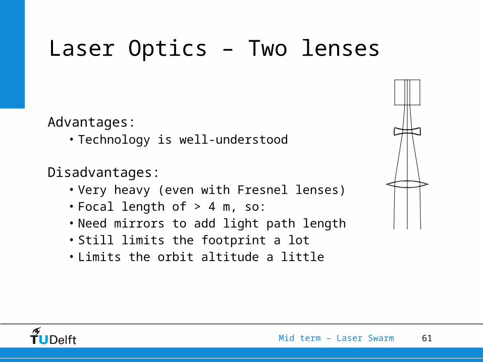
Advantages:• Technology is well-understood
Disadvantages:• Very heavy (even with Fresnel lenses)• Focal length of > 4 m, so:• Need mirrors to add light path length• Still limits the footprint a lot• Limits the orbit altitude a little
Laser Optics – Two lenses
62Mid term – Laser Swarm
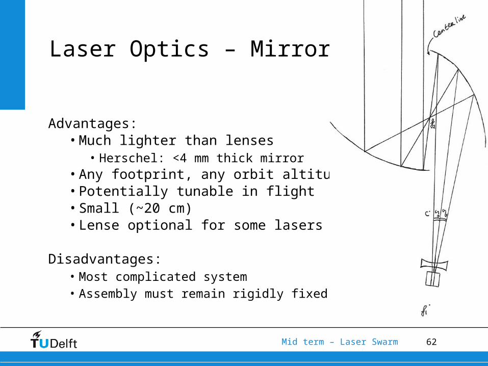
Advantages:• Much lighter than lenses
• Herschel: <4 mm thick mirror• Any footprint, any orbit altitude• Potentially tunable in flight• Small (~20 cm)• Lense optional for some lasers
Disadvantages:• Most complicated system• Assembly must remain rigidly fixed
Laser Optics – Mirrors
63Mid term – Laser Swarm
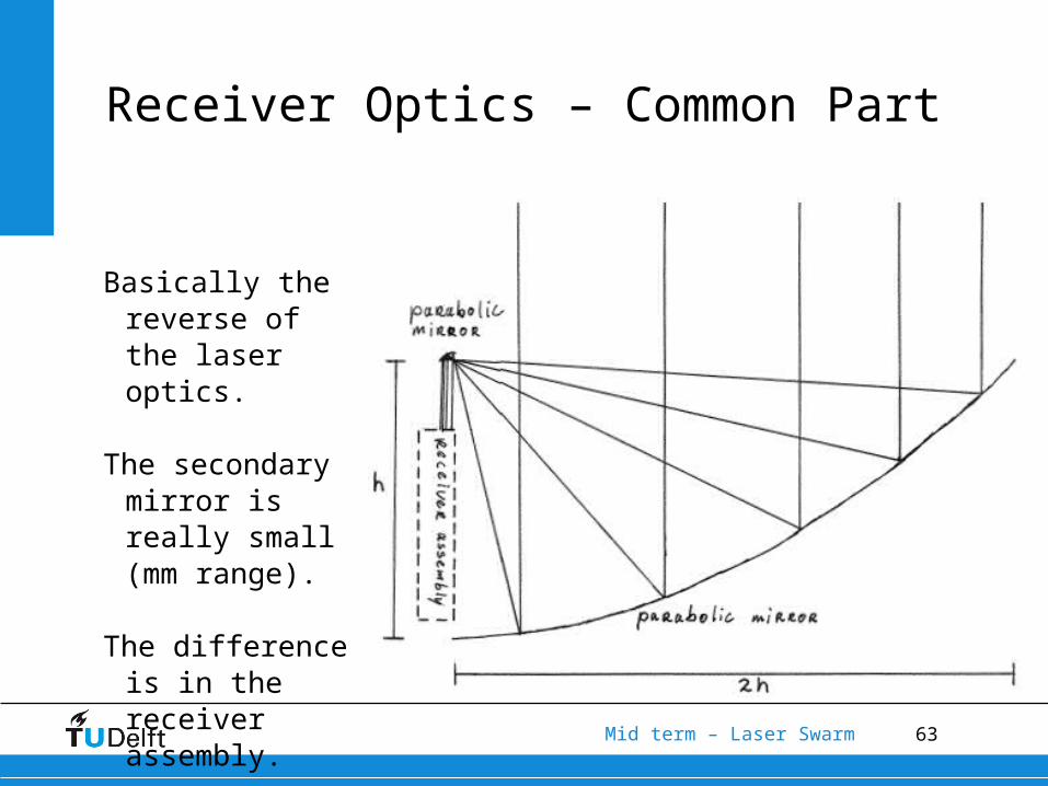
Basically the reverse of the laser optics.
The secondary mirror is really small (mm range).
The difference is in the receiver assembly.
Receiver Optics – Common Part
64Mid term – Laser Swarm
Fill factor = ~2%.Then fraction of light detected is:QDE x FF = 37% x 2% = 0.74%
This is clearly unacceptable. Therefore, we need focusing optics after the main collector.
Receiver Optics – Fill Factor
65Mid term – Laser Swarm
As the Sun bombards the Earth with photons, we need to filter the light, to prevent an unacceptable SNR.
Optical filters degrade fast and also filter put some of the wanted photons.
Therefore, we will use a prism to filter out unwanted noise.
Receiver Optics – Noise
66Mid term – Laser Swarm
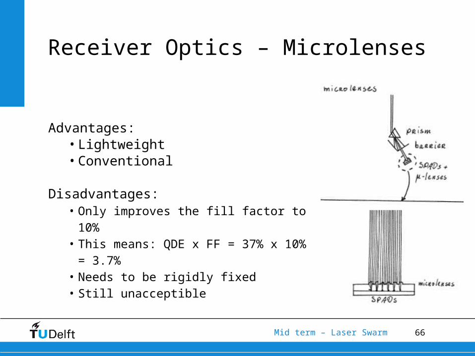
Advantages:• Lightweight• Conventional
Disadvantages:• Only improves the fill factor to 10%• This means: QDE x FF = 37% x 10% =
3.7%• Needs to be rigidly fixed• Still unacceptible
Receiver Optics – Microlenses
67Mid term – Laser Swarm
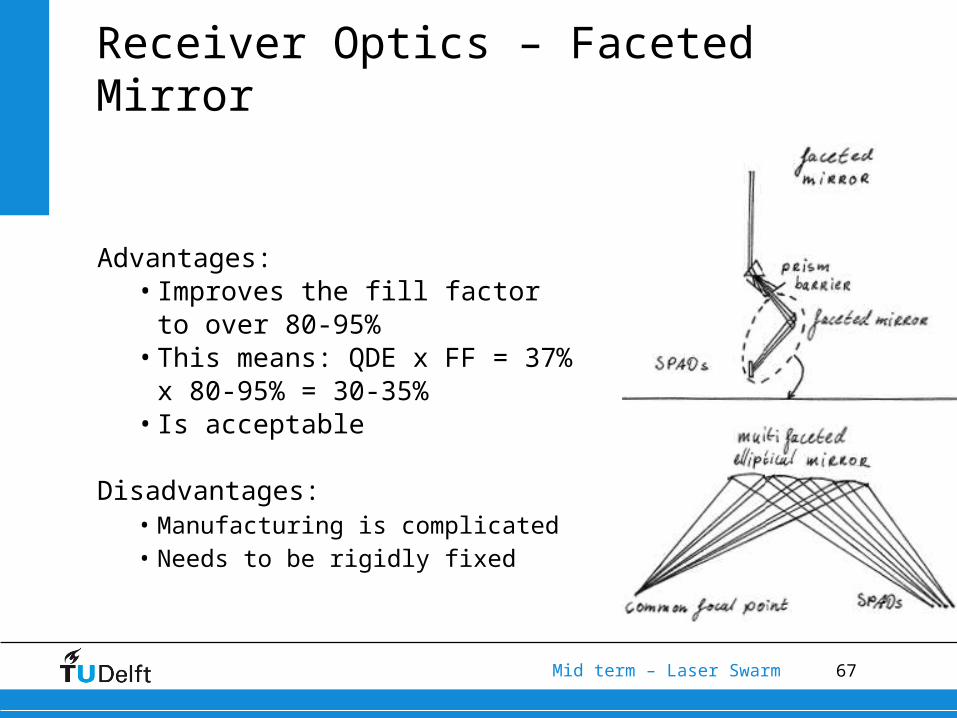
Advantages:• Improves the fill factor to over
80-95%• This means: QDE x FF = 37% x
80-95% = 30-35%• Is acceptable
Disadvantages:• Manufacturing is complicated• Needs to be rigidly fixed
Receiver Optics – Faceted Mirror
68Mid term – Laser Swarm
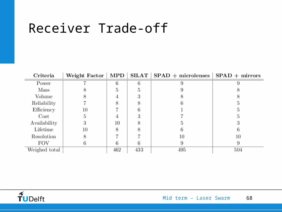
Receiver Trade-off
69Mid term – Laser Swarm
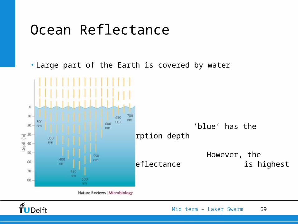
Ocean Reflectance
• Large part of the Earth is covered by water
‘blue’ has the highest absorption depth
However, the fractional reflectance
is highest
70Mid term – Laser Swarm
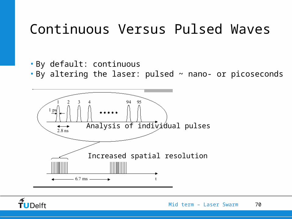
Continuous Versus Pulsed Waves
• By default: continuous• By altering the laser: pulsed ~ nano- or picoseconds
Analysis of individual pulses
Increased spatial resolution
71Mid term – Laser Swarm
Blue types of laser
• Optimum wavelength according to analysis ~ 425 – 500 [nm]
• Possible ‘blue’ lasers• Gas lasers
• Wavelength: 441.6 [nm] (Helium-Cadmium)
• Wavelength: 488 [nm] (Argon)
• Solid-State laser (Nd-YAG: Neodymium-doped Yttrium Aluminium Garnet)
• Wavelength: 946 [nm]
• Diode laser
• Difficult to produce for lifetimes > 1 year
72Mid term – Laser Swarm
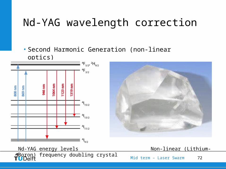
Nd-YAG wavelength correction
• Second Harmonic Generation (non-linear optics)
Nd-YAG energy levels Non-linear (Lithium-Boron) frequency doubling crystal
73Mid term – Laser Swarm
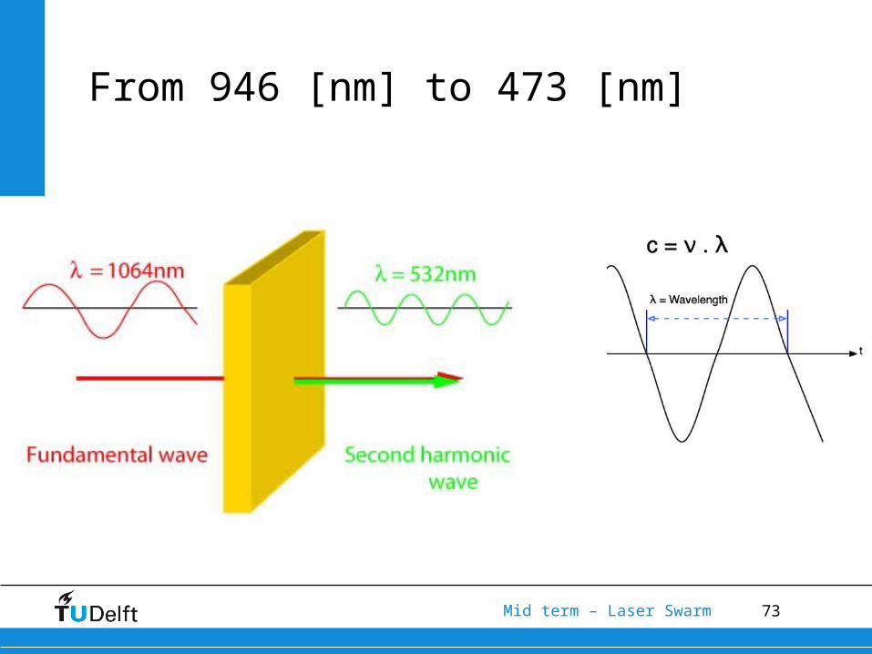
From 946 [nm] to 473 [nm]
74Mid term – Laser Swarm
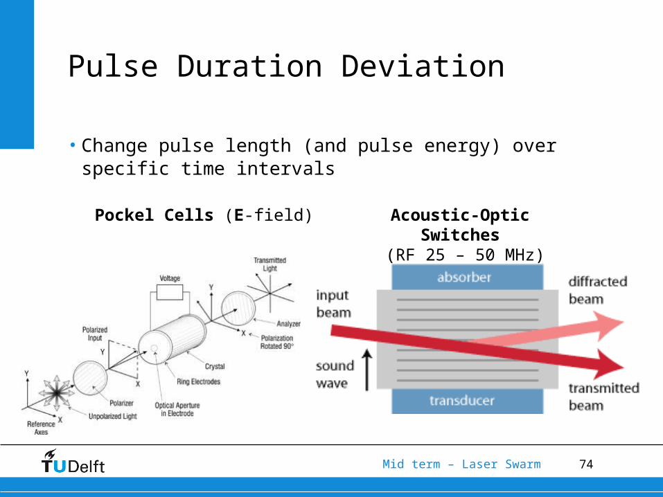
Pulse Duration Deviation
• Change pulse length (and pulse energy) over specific time intervals
Pockel Cells (E-field) Acoustic-Optic Switches (RF 25 – 50 MHz)
75Mid term – Laser Swarm
5.Orbit design
76Mid term – Laser Swarm
Special orbits types
• Polar orbit
• Repeat orbit
• Sun Synchronous orbit
• Frozen orbit
77Mid term – Laser Swarm
Special orbits types
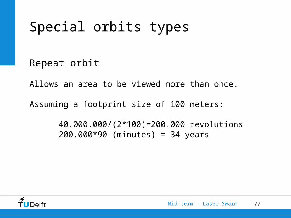
Repeat orbit
Allows an area to be viewed more than once.
Assuming a footprint size of 100 meters:
40.000.000/(2*100)=200.000 revolutions200.000*90 (minutes) = 34 years
78Mid term – Laser Swarm
Special orbits types
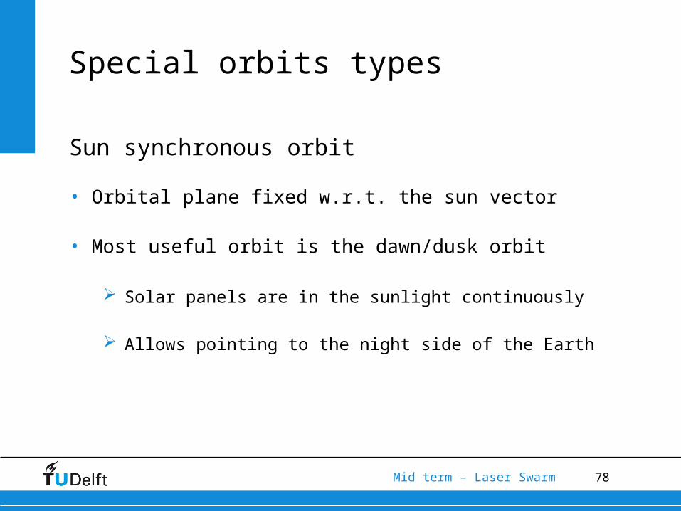
Sun synchronous orbit
• Orbital plane fixed w.r.t. the sun vector
• Most useful orbit is the dawn/dusk orbit
Solar panels are in the sunlight continuously
Allows pointing to the night side of the Earth
79Mid term – Laser Swarm
Special orbits types
Frozen orbit
• Reduces the need for orbit station keeping.
• A constellation in formation flight has strict constraints.
A frozen orbit helps meet these constraints
80Mid term – Laser Swarm
Special orbits types
3
3 2 23
3 51 sin cos sin 1
2 4eqJ r
e e n i ip
3
2332
3 5cos cos sin 1
2 41
eJ n Rdie i i
dt ae
2
2222
3 51 sin41
eRJ ni F
ae
2 2 2
3
22
sin cos sin1
sin2 1eJ R i e i
Fa i eJ e
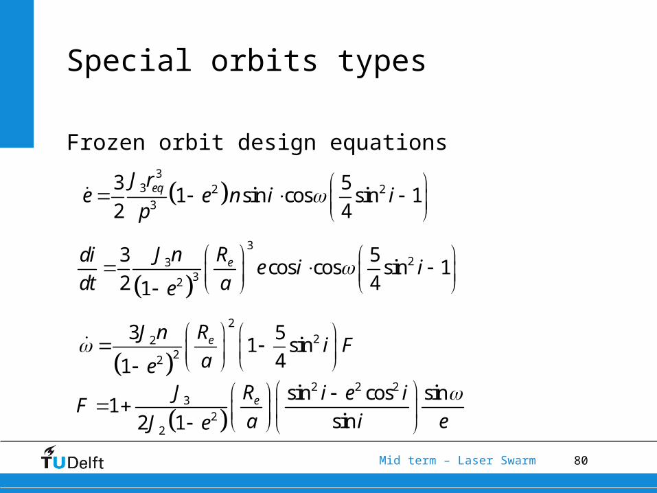
Frozen orbit design equations
81Mid term – Laser Swarm
Special orbits types
3
2332
3 5cos cos sin 1 0
2 41
eJ n Rdie i i
dt ae
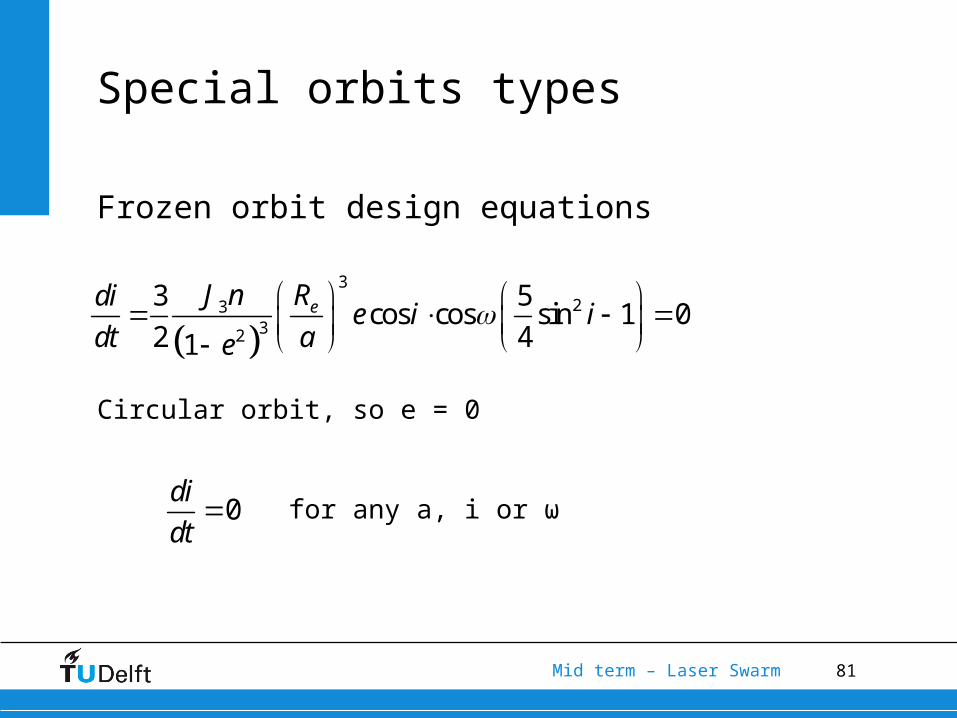
Frozen orbit design equations
Circular orbit, so e = 0
for any a, i or ω0di
dt
82Mid term – Laser Swarm
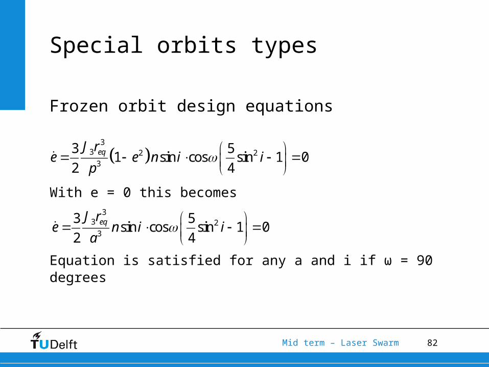
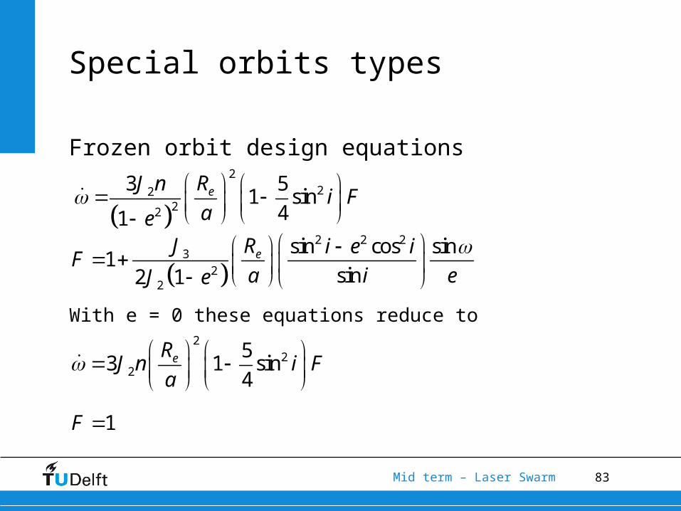
Frozen orbit design equations
With e = 0 this becomes
Equation is satisfied for any a and i if ω = 90 degrees
Special orbits types
3
3 2 23
3 51 sin cos sin 1 0
2 4eqJ r
e e n i ip
33 23
3 5sin cos sin 1 0
2 4eqJ r
e n i ia
83Mid term – Laser Swarm
Special orbits types
Frozen orbit design equations
With e = 0 these equations reduce to
2
2222
3 51 sin41
eRJ ni F
ae
2 2 2
3
22
sin cos sin1
sin2 1eJ R i e i
Fa i eJ e
22
2
53 1 sin
4eRJ n i Fa
1F
84Mid term – Laser Swarm
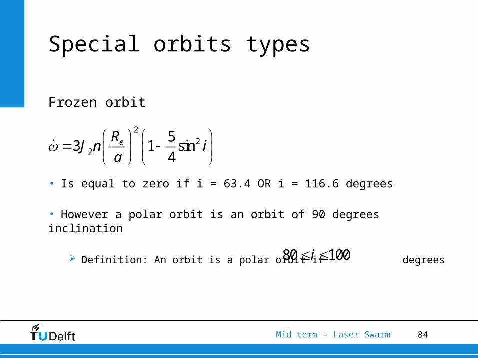
Frozen orbit
• Is equal to zero if i = 63.4 OR i = 116.6 degrees
• However a polar orbit is an orbit of 90 degrees inclination
Definition: An orbit is a polar orbit if degrees
Special orbits types
22
2
53 1 sin
4eRJ n ia
80 100i
85Mid term – Laser Swarm
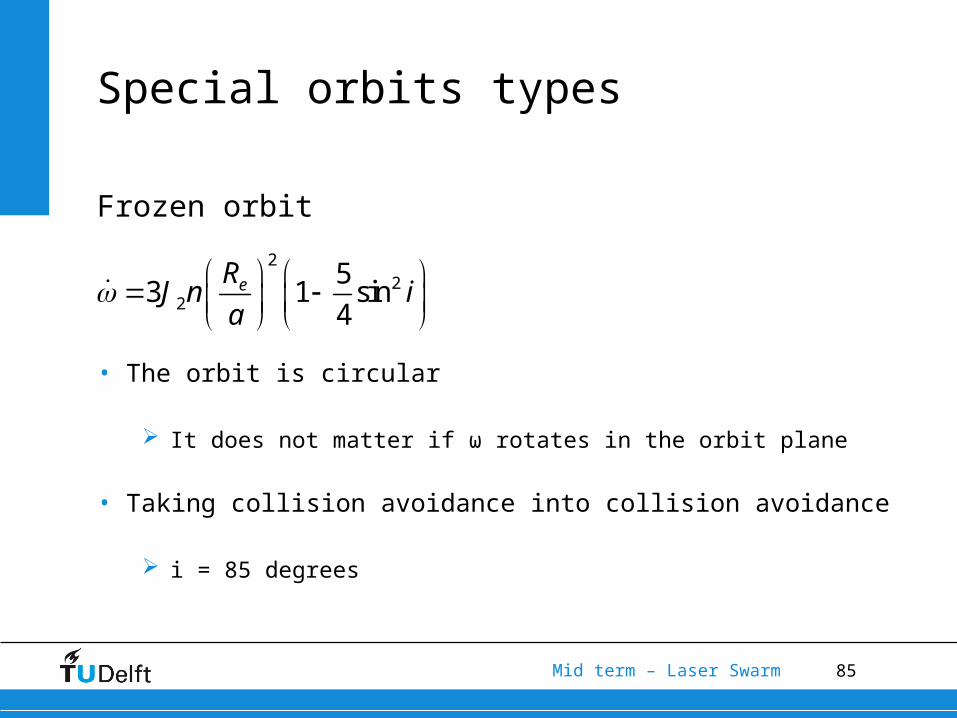
Frozen orbit
• The orbit is circular
It does not matter if ω rotates in the orbit plane
• Taking collision avoidance into collision avoidance
i = 85 degrees
Special orbits types
22
2
53 1 sin
4eRJ n ia
86Mid term – Laser Swarm
Special orbits types
Summary
• Sun synchronous is not required
• Repeat orbit is unfeasible
• The end result is a
Frozen, polar orbit with
e = 0 degrees i = 90 degrees ω = 90 degrees
87Mid term – Laser Swarm
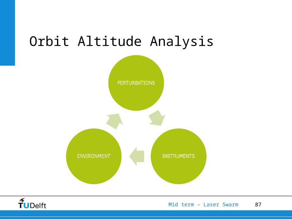
Orbit Altitude Analysis
88Mid term – Laser Swarm
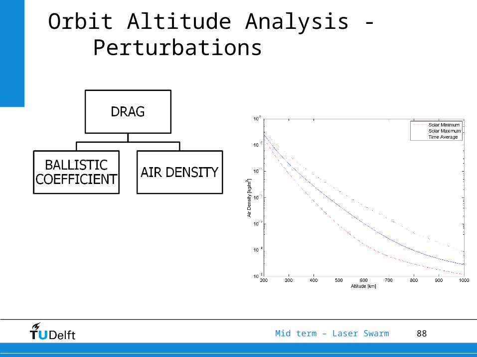
Orbit Altitude Analysis - Perturbations
89Mid term – Laser Swarm
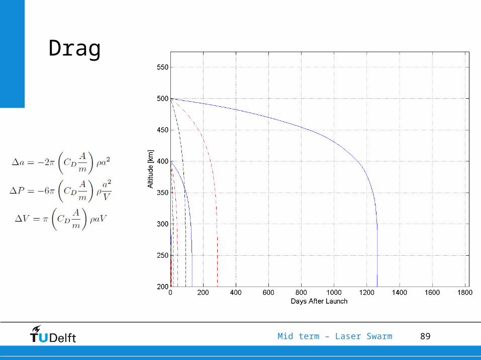
Drag

90Mid term – Laser Swarm
Drag - ΔV
91Mid term – Laser Swarm
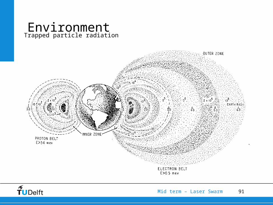
EnvironmentTrapped particle radiation
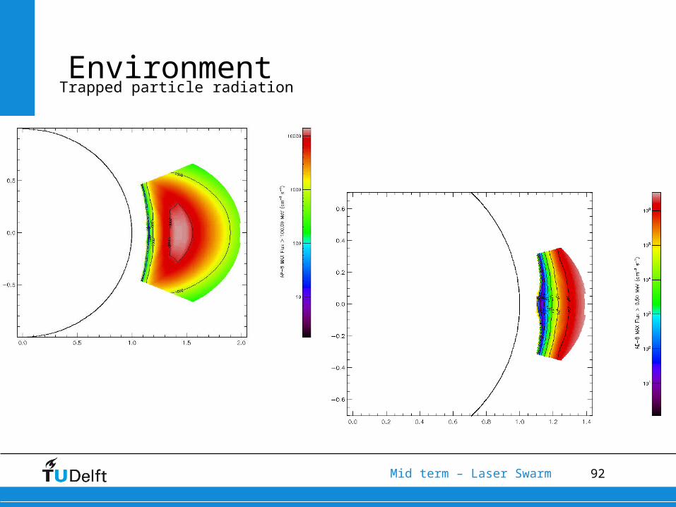
92Mid term – Laser Swarm
EnvironmentTrapped particle radiation

93Mid term – Laser Swarm
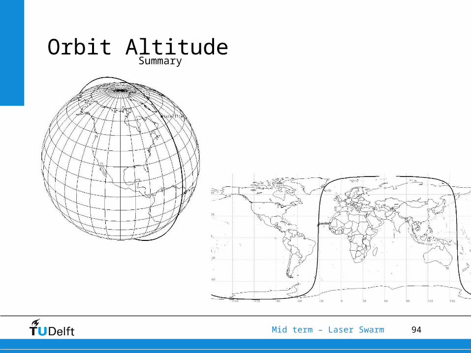
Orbit AltitudeSummary
• As high as possible to reduce propellant mass• Mission timeframe is crucial – solar min/max• Keep ballistic coefficient close
94Mid term – Laser Swarm
Orbit AltitudeSummary
95Mid term – Laser Swarm
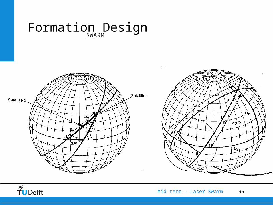
Formation DesignSWARM
96Mid term – Laser Swarm
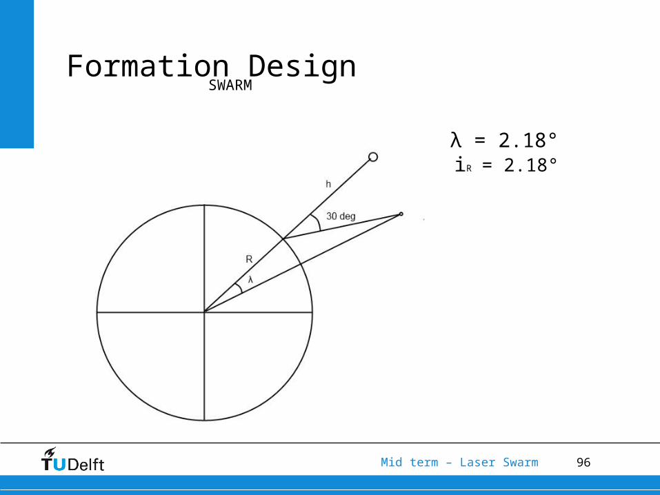
Formation DesignSWARM
λ = 2.18°iR = 2.18°
97Mid term – Laser Swarm
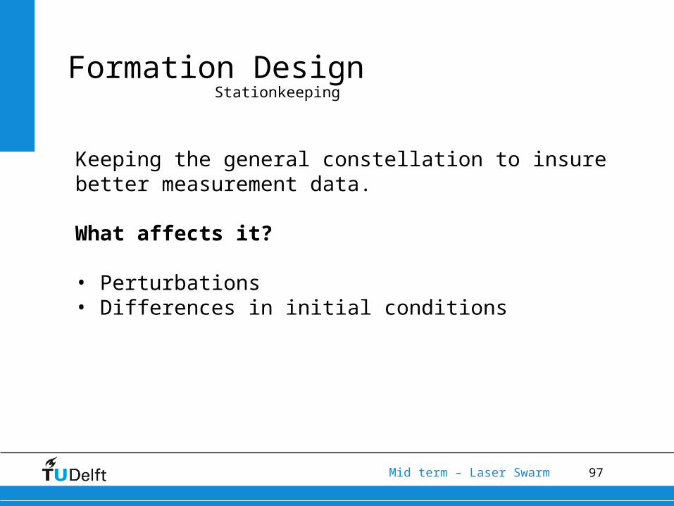
Formation DesignStationkeeping
Keeping the general constellation to insure better measurement data.
What affects it?
• Perturbations• Differences in initial conditions
98Mid term – Laser Swarm
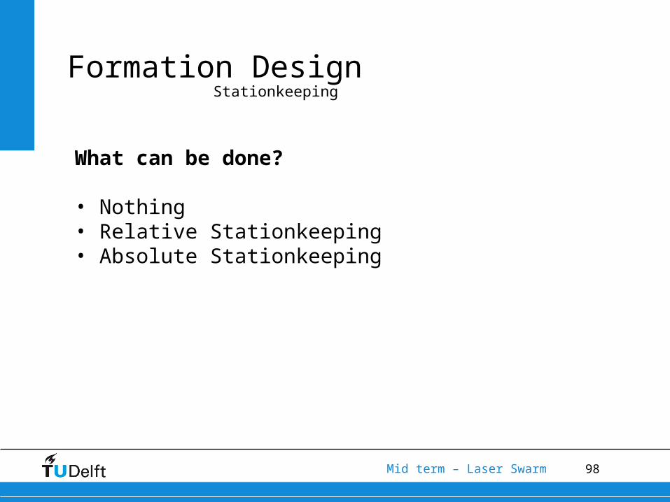
Formation DesignStationkeeping
What can be done?
• Nothing• Relative Stationkeeping• Absolute Stationkeeping
99Mid term – Laser Swarm
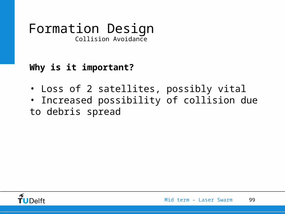
Formation DesignCollision Avoidance
Why is it important?
• Loss of 2 satellites, possibly vital• Increased possibility of collision due to debris spread
100Mid term – Laser Swarm
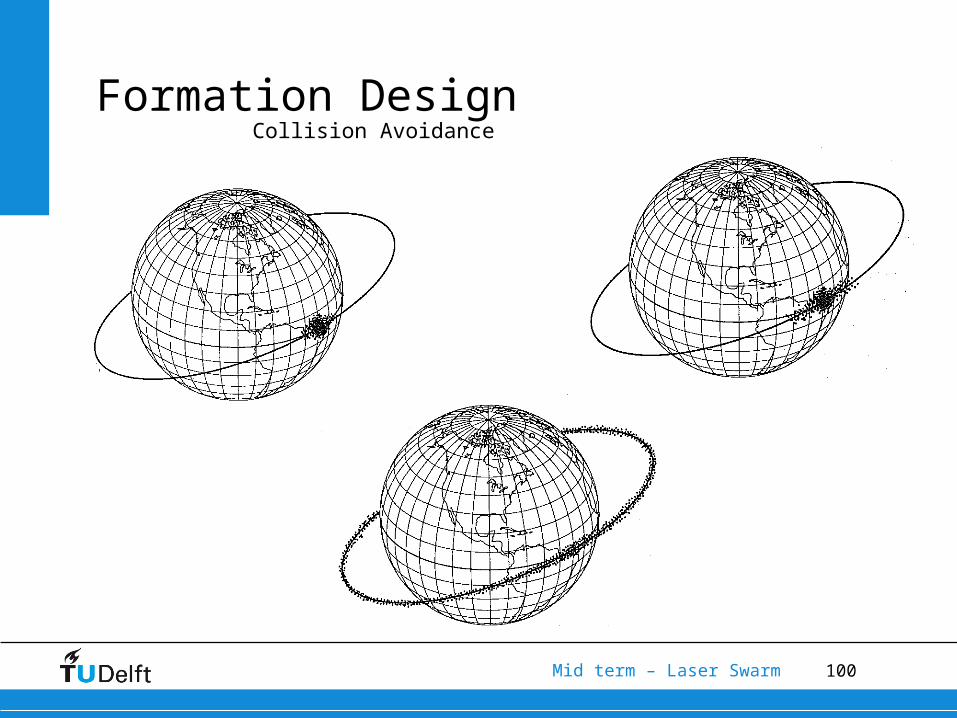
Formation DesignCollision Avoidance
101Mid term – Laser Swarm
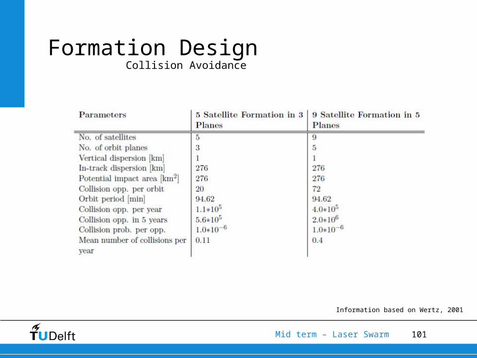
Formation DesignCollision Avoidance
Information based on Wertz, 2001
102Mid term – Laser Swarm
6.Software tool
103Mid term – Laser Swarm
Software tool
Two parts
• SimulationSimulate the laser pulse photons and noise as received by the
sensor.
• Data analysisReconstructing the digital elevation model and BRDF from the
received time series.
104Mid term – Laser Swarm
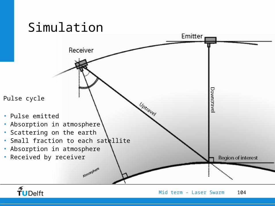
Pulse cycle
• Pulse emitted• Absorption in atmosphere• Scattering on the earth• Small fraction to each satellite• Absorption in atmosphere• Received by receiver
Simulation
105Mid term – Laser Swarm
Noise
• Noise is introduced into the system
• Sources are the Earth and the Sun
• In a selective wavelength band
• Strong dependence on• Receiver footprint area• Receiver sensitivity band• Constellation altitude

106Mid term – Laser Swarm
Photon count variation with altitude
• Exponential decrease in photon count with altitude
• Lower is better
• Higher altitudes:• larger receiver aperture
• higher emitter power
0.0052 0.6558altphotons e

107Mid term – Laser Swarm
Solar noise photons fraction
Orbit at 450 km, 33W laser, 10 nm filter
Simulation results:
• Pulses sent: 24989 (about 5s)• Photons from pulses received: 12289 (86.5%)• Sun noise photons received: 1930 (13.5%)• Total photons received: 14219
Majority of the photons from the emitter laserNoise can be filtered out (constellation)
108Mid term – Laser Swarm
•Define time range
•Find the peaks
•Calculate altitudes
•Find the most common altitude
Terrain Reconstruction Algorithm
109Mid term – Laser Swarm
Defining Range
• Known:• Time pulse sent• Time SOME pulse received
• Window : 1/5000 sec = 200 micro sec
• Offset: 500km/c*2 = 3.333 milliseconds travel time
• Height range: 60 km

110Mid term – Laser Swarm
Find the Peaks
• The peaks correspond to received pulses
• Noise introduced creates “false” peaks
• N*mean threshold
• Intermediate step for BRDF determination
111Mid term – Laser Swarm
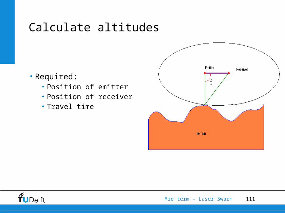
Calculate altitudes
• Required:• Position of emitter• Position of receiver• Travel time
112Mid term – Laser Swarm
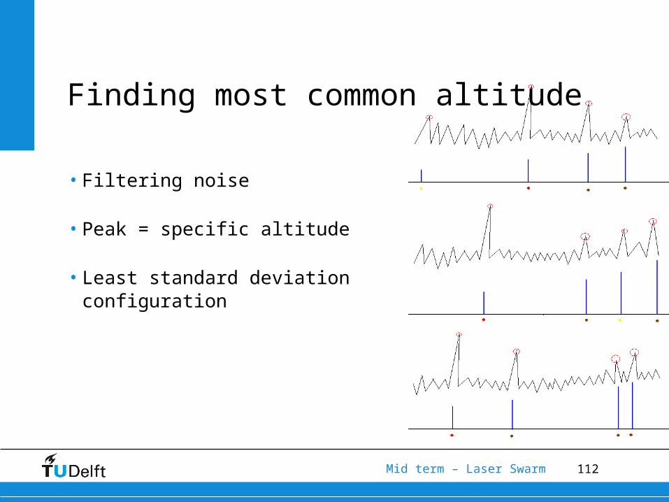
Finding most common altitude
• Filtering noise
• Peak = specific altitude
• Least standard deviation configuration
113Mid term – Laser Swarm
7.Summary and conclusions
114Mid term – Laser Swarm
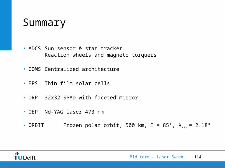
Summary
• ADCS Sun sensor & star tracker Reaction wheels and magneto torquers
• COMS Centralized architecture
• EPS Thin film solar cells
• ORP 32x32 SPAD with faceted mirror
• OEP Nd-YAG laser 473 nm
• ORBIT Frozen polar orbit, 500 km, I = 85°, λmax = 2.18°