2055-38 joint ictp/iaea school on physics and technology
TRANSCRIPT
2055-38
Joint ICTP/IAEA School on Physics and Technology of Fast ReactorsSystems
M. Vijayalakshmi
9 - 20 November 2009
Indira Gandhi Center for Atomic ResearchKalpakkam
India
Introduction to structural materials and their behaviour in a fast reactor fuelassembly
2 Radiation Damage Principles of Design of Radiation Resistant Materials for Fast Reactor Fuel
Assembly

Introduction to structural materials and their behaviour in a fast reactor fuel assembly
2. Radiation Damage2. Radiation Damage
Principles of Design of Radiation Resistant Materials for Fast Reactor Fuel Assembly

IRRADIATIONCREEP
IRRADIATIONHARDENING
IRRADIATIONEMBRITTLEMENT
IRRADIATIONGROWTH
VOID SWELLING
MATERIALS DEGRADATION
INREACTORS
DISTORTION IN SHAPERETAINING SAME VOLUME
MODULE 2: RADIATION DAMAGE MODULE 2: RADIATION DAMAGE ‐‐SCOPE SCOPE
• DOSE;• TEMPERATURE;• DOSE RATE;• COLD WORK• CHEMISTRY

VOID SWELLING: NUCLEATION & VOID SWELLING: NUCLEATION & GROWTH OF VOIDSGROWTH OF VOIDS
DO ALL SINKS REACT WITH DEFECTS THE SAME WAY?
NATURE OF SINKS IN VOID GROWTH;

TYPE OF SINKS: NEUTRAL, BIASED &
VARIABLE BIAS
NEUTRAL
G.B.’s
INCOHERENTPRECIPITATES
absorption α Di.v & (C i/v xal – C i/v sink surface ) rate
BIASED SINKS BIASED SINKS ‐‐ DISLOCATIONSDISLOCATIONS
2% more bias For I’s than V’s.
I’s drift towards Core driven byStress gradient
I’s enhance climb; So unsaturable sink

TYPE OF SINKS VARIABLE BIAS SINKS: COHERENT PRECIPITATES & IMPURITY ATOMS
TTiiCC pprreecciippiittaattee
AAuusstteenniittee mmaattrriixx
CAPTURES I OR V’s ; RETAINS ITS IDENTITY TILL IT ANNIHILATES WITH THE OPPOSITE !!!!
INCREASES RATE OF V + I RECOMBINATION PROBABILITY

VOID SWELLING: solution to growth rate equations
ρV = ∫ ρV ® dR
Total Number Density of voids Number of voids / cm2 of
radii R & R+dR
Rav = (1/ ρV ) ∫ R ρV ® dR
Volumetric swelling rate
dV/dt = 4Π R2 (dR/dt)
∆V / V = (4/3) Π Rav3 ρV

VOID SWELLING
DOSE;
TEMPERATURE;
COLD WORK &
DOSE RATE.

Void swelling – dose dependence
• LOW DOSES ‐ LOW AMOUNT PRODUCTION OF POINT DEFECTS ; NOT ENOUGH TO FORM MORE VOIDS & ALLOW THE AMBRYOS TO GROW.
• HIGH DOSES ‐‐ LOSSES TERM TO (RECOMBINATION + SINKS)
IS OFFSET BY PRODUCTION
Transient Swelling Regime
Threshold
dose
Linear Swelling Regime
Sw
ellin
g
Fluence (dpa)
JOB OF MATERIALS SCIENTISTS JOB OF MATERIALS SCIENTISTS ---- IDENTIFY A MATERIAL WITH IDENTIFY A MATERIAL WITH AS HIGH THRESHOLD AS POSSIBLEAS HIGH THRESHOLD AS POSSIBLE

VOID SWELLING: TEMPERATURE DEPENDENCEVOID SWELLING: TEMPERATURE DEPENDENCE
STRONG DEPENDENCE ON TEMPERATURE
• VACANCY DIFFUSION COEFFICIENT ‐ DDvv
• EQUILIBRIUM THERMAL VANCANCY CONCENTRATION –CCvv
00

LOW TEMPERATURE
• LOW (Dv)MOBILITY OF VACANCY CONCENTRATION
• BUILD UP OF FREE VACANCIES & INTERSTITIALS
• HIGHER RECOMBINATIONS
• NO EXCESS CONCETRATION OF VACANCIES
• LESS VOIDS

HIGH TEMPERATURE
• DEFECT CONCENTRATION ~ THERMAL EQUILIBRIUM CONCENTRATION
• LESS SUPERSATURATION (S = CV / CV0 )
• LESS DRIVING FORCE FOR VOID FORMATION
• EMISSION OF VACANCIES FROM VOIDS;
• LESS NO OF VOIDS

Regularity of swellingRegularity of swelling
The dependence of swelling on The dependence of swelling on irradiation temperature of steelirradiation temperature of steelChSChS--68 68 of fuel pinof fuel pin cladding material of the first modernization cladding material of the first modernization
corecore ofof BNBN--600600..
0
5
10
15
20
25
30
35
400 420 440 460 480 500 520 540 560 580 600
Temperature (0С)
Swel
ling
(%)
–– D = 60D = 60 dpadpa–– D = 70D = 70 dpadpa–– D = 80D = 80 dpadpa–– D = 90D = 90 dpadpa
13

TEMPERATURE EFFECT
AS ‘T’ INCREASES, VACANCIES BECOME MORE AND MORE MOBILE; NET ARRIVAL OF VACANCIES TO VOIDS INCREASE; VOIDS GROW.
AT HIGH ENOUGH TEMPERATURES, CV0 INCREASES, S REDUCES, THERMAL EMISSION OF VACANCIES FROM VOID SURFACE INCREASES. VOID SHRINKS.
BALANCE IS VOID GROWTH.

VOID SWELLING: EFFECT OF DOSE RATE

1010--44……1010--2 2 dpa/sdpa/s
11⋅⋅1010--77…… 22⋅⋅1010--33 dpa/sdpa/s
1010--1010……1010--66 dpa/sdpa/s300 (800)300 (800)
11⋅⋅10101111
11⋅⋅10101515
3333
33⋅⋅10101515
66⋅⋅10101919
44⋅⋅1010 55 (Fe(Fe++))99⋅⋅1010 55 (Cr(Cr++))
22⋅⋅10101414
22⋅⋅10101616
Damage cross-section, barn10 10 2 10 3 10 4 10 5 10 61
DOSE RATE DIFFERENCE USING DIFFERENT INCIDENT PROJECTILESDOSE RATE DIFFERENCE USING DIFFERENT INCIDENT PROJECTILESDOSE RATE DIFFERENCE USING DIFFERENT INCIDENT PROJECTILES
Flux density, particle/(cm2⋅s)
10 10 10 12 10 14 10 16 10 18 10 2010 8
nnn
e-ee--
i+ii++
[ ]224
22
101 cmbarnscm
particlecmsdpa
Фk−=
⎥⎦⎤
⎢⎣⎡
⋅⋅=⎥⎦
⎤⎢⎣⎡
⋅=σ
1515

Electrons Light ions Heavy ions
High dose rate(10-3 dpa/s)
High dose rate
no cascades
Very limited depth of penetration
Strongly peaked damage profile
Cascade production
moderate dose rate(10-4 dpa/s)
Good depth of penetration
Flat damage profile over tens of μm
Smaller, widely separated cascades
Insitu analysis (TEM)
Fast Reactor

Time to build up dose: Reactor vs other irradiation sources
• 10‐6 to 10‐7 dpa/s in a reactor
• Time for 10 dpa – 4 to 5 months against one day in heavy ion accelerator
• few hrs in HIGH VOLTAGE electron microscope

Void Swelling : - Dose Rate
Peak Swelling Temperature depends on Irradiation Dose rate
⎟⎟⎠
⎞⎜⎜⎝
⎛ΦΦ
=1
2
2
1 lnATT

WHY ? OF DOSE RATE BEHAVIOUR
• HIGHER DOSE RATE INCREASES RATE OF PRODUCTION OF CONCENTRATION OF POINT DEFECTS ;
• RECOMBINATION RATE α PRODUCTION RATE ‐ DOSE RATE;
• SUPERSATURATION REDUCES & HIGHER TEMPERATURE IS REQUIRED TO INTRODUCE THE DIFFERENCE IN THE PRODUCTION / LOSS TERM, TO ACHIEVE REQUIRED SUPERSATURATION
• Tmax SHIFTS TO HIGHER TEMP.

EFFECT OF DISLOCATIONS
dRo/dt = [(Ko (Zi-Zv)ρd Ω ] / [R ( Zv ρd + 4π R ρv + 4π Rcp ρcp)]
Void growth rate in a lattice with biased sinks, like dislocations
Bias due to dislocations Vacancies absorption at dislocations
If Zi= Zv , voids do not grow.

EFFECT OF DISLOCATIONS
Q : RATIO OF SINK STRENGTH
Let Q = dislocation sink strength / void sink strength
VOIDG
ROWTH
RATE
LOW DISLOCATION DENSITYHIGH VOID DENSITY
HIGH DISLOCATION DENSITYLOW VOID DENSITY
MAX. SWELLINGMAX. SWELLING

Void Swelling : Temperature & Dislocation Density
Low Mobility
Super saturation difficult
Thermal Emission of Vacancies from voids

Hyderabad, July 2-4, 2008
Structural approach – dislocation factor
Влияние степени х.д. на распухание
0
2
4
6
8
10
12
14
16
0 10 20 30 40 50 60
Степень х .д., %
Распу
хани
е, %
ε = 15 %
ε = 18 ±2 %
ε = 20 ±3 %
ε = 20-25 %
Effect of cold work level on EI847 swelling
BN-350 , 500 0C, 60 dpa
Cold work level, %
Progress in c.w. levelof austenitic steel
Swel
ling,
%
What is the limiting doseat which the favourableeffect of C.W. increasedisappears?

METHODS TO STUDY VOID SWELLING
•• MODELLING : MODELLING : MONTE‐CARLO METHODS, MOLECULAR DYNAMICS, CONTINUUM MECHANICS, RATE THEORY, DISLOCATION DYNAMICS
•• EXPERIMENTAL METHODS: EXPERIMENTAL METHODS: DENSITY MEASURE‐MENTS, STEP‐HEIGHT , POSITRON ANNIHILATION, RESISTIVITY, TEM UNDER NEUTRON, ION IRRADIATION CONDITIONS.

METHODS TO STUDY VOID SWELLINGMETHODS TO STUDY VOID SWELLING
0 30000 60000 90000 120000 150000120
130
140
150
160
Posi
tron
lifet
ime
(ps)
Annealing time (s)
623 k
573 k
523 k
POSITRON STUDIESPOSITRON STUDIES
450 500 550 600 650 7000.0
0.5
1.0
1.5
2.0
2.5
3.0
3.5
4.0
Swel
ling
(%)
Temperature (oC)
30 ppm He, 100 dpa
STEP HEIGHT AFTER Ni ION IRRADIATION IN AN ACCELERATOR

Materials ModelingMaterials Modeling
Molecular Dynamics
Density Functional Theory calculation of Physical Properties
Car- Parinello MD
ABINIT
VASP
SIESTA
WIEN-2K
MDCASK
Codes Installed, Codes Installed, ParallelisedParallelisedCascades for 5, 10, and 100 keV cascades in Cu at 100K

Hot cells at for PIE of FBTR Fuel & Structural Materials

IN-SERVICE PERFORMANCE – WRAPPER OF FBTR
VOIDS in 20 % CW 316 SS AFTER 40 dpa
200nmNi3Si – G Phase formed ONLY during irradiation – due to RIS

VOID SWELLINGDOSE;
TEMPERATURE;
COLD WORK &
DOSE RATE.
IRRADIATIONCREEP
IRRADIATIONHARDENING
IRRADIATIONEMBRITTLEMENT
IRRADIATIONGROWTH
VOID SWELLING
MATERIALS DEGRADATION
INREACTORS

IRRADIATION GROWTH
30 CM
1 CM0.58 CM
10 CM 1020 n/cm2
Volume remains sameVolume remains sameDistortion increasesDistortion increases
shape changesshape changesHCP LATTICE
BASAL PLANE – (0001) - VACANCY LOOPS
PYRAMIDAL PLANE –(11. 0) –
INTERSTITIAL LOOPS
ATOMS ARE REMOVED FROM BASAL PLANES & DEPOSITED IN THE (11-0) PLANES

IRRADIATION HARDENINGMECHANICAL BEHAVIOUR OF MATERIALS (FORGET IRRADIATION FOR A MOMENT)
Generation of dislocationsGeneration of dislocations
Pinning by obstaclesPinning by obstacles
Unpinning of immobile dislocationsUnpinning of immobile dislocations
Build up of stress ahead of pileBuild up of stress ahead of pile--upup
crackingcracking

IRRADIATION HARDENING
n + =
= source hardening + friction hardening
Unpin the immobiledislocations
Obstacle to mobile disolcations

IRRADIATION HARDENING
Δσsirrad. = (ϕ t )1/2

Effect of dpa
IN-SERVICE PERFORMANCE – WRAPPER OF FBTR Tensile Testing of Irradiated Cladding
Remote tensile test system
Shear Punch testing of Irradiated WrapperSmall disk specimen extracted in hot cell
Test machine with lead shielding
0.0 0.2 0.4 0.6 0.8 1.00123456789
Unirradiated
2 dpa
56 dpa
Load
, kN
Punch Displacement, mm
Shear punch test plot for various dpa
Stress-strain curves for various dpa and test temperatures
Effect of Test Temperature
0.00 0.05 0.10 0.15
100
300
500
700Unirradiated Clad (T = 470C)
(50 dpa,450C)(56 dpa,
430C)Stre
ss, M
PaStrain
Test Temperature = Irradiation Temperature

IRRADIATION CREEP
• WHAT IS CREEP ?
• WHAT ARE CREEP MECHANISMS ?
• WHAT IS IRRAD. CREEP ?
• SIPN & SIPA – IRRAD. CREEP MECHANISMS
• IDENTIFICATION OF IRRAD. CREEP
Typical Creep-curve: THERMAL ONLY

CREEP MECHANISMS
HARDENING MECHANISMSGRAIN BOUNDARY CREEP MECHANISMS

IRRADIATION CREEP
• AUGMENTATION OF THERMAL CREEP BY IRRADIATION OR
• INTRODUCING CREEP AT T’s WHERE THERMAL CREEP IS KNOWN ‘NOT TO OCCUR’
• CREEP RATE CHANGED WITH DOSE, DOSE RATE – SIGN OF IRRAD. CREEP

IRRADIATION CREEP IN EBR‐II

IRRADIATION CREEP MECHANISMS: SIPA & SIPN• V ‘s & I’s ABSORBED PREFERENTIALLY
• I’s TO ⊥ s WITH EXTRA HALF PLANE ⊥ σ
• V’s TO OTHER ⊥s
σ⊥
⊥
⊥
⊥
⊥
• LOOPS NUCLEATE PREFERENTIALLY
• (INT.LOOPS)PLANES ⊥ σtensile >>>
same in planes ll σtensile
• (VAC.LOOPS)PLANES ⊥ σtensile<<<<<
same in planes ll σtensile
σtensile () () () ()
()
()
σtensile() ()
()
()()()

Swelling assisted creep•• Swelling enhances creep rate at smaller dose Swelling enhances creep rate at smaller dose levelslevels
•• Creep disappears beyond certain doseCreep disappears beyond certain dose
•• After this dose, swelling continues, creep After this dose, swelling continues, creep disappearsdisappears

•• when voids form, V + I are absorbed in large numbers by when voids form, V + I are absorbed in large numbers by the voids.the voids.
•• Less I flow to dislocations Less I flow to dislocations ‐‐ creep reducescreep reduces
•• Swelling saturates due to low excess vacancy absorptionSwelling saturates due to low excess vacancy absorption
Swelling assisted creep: Mechanisms
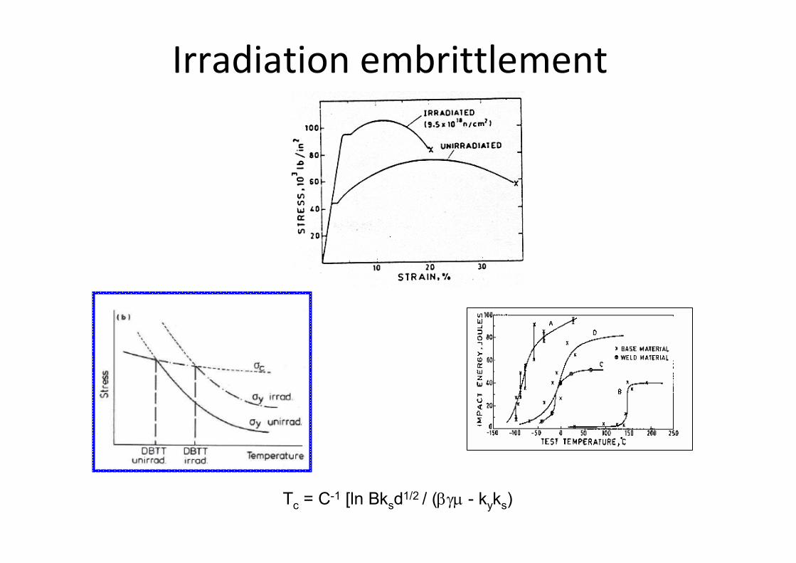
Irradiation embrittlement
Tc = C-1 [ln Bksd1/2 / (βγμ - kyks)

RADIATION DAMAGERADIATION DAMAGE
IRRADIATIONCREEP
IRRADIATIONHARDENING
IRRADIATIONEMBRITTLEMENT
IRRADIATIONGROWTH
VOID SWELLING
MATERIALS DEGRADATION
INREACTORS
THANQ 4 THANQ 4 UR ATTENTIONUR ATTENTION
Introduction to structural materials and their behaviour in a fast reactor fuel assembly
Radiation Damage
Principles of Design of Principles of Design of Radiation Resistant Materials for Radiation Resistant Materials for
Fast Reactor Fuel AssemblyFast Reactor Fuel Assembly