2019 dodge challenger owner's manual · dear customer, congratulations on selecting your new...
TRANSCRIPT

ChallengerO W N E R ’ S M A N U A L
Second EditionPrinted in the U.S.A.
19LA-126-AB©2018 FCA US LLC. All Rights Reserved.Dodge is a registered trademark of FCA US LLC.
2 0 1 9
Ch
allen
ger
20
19
VEHICLES SOLD IN CANADAWith respect to any Vehicles Sold in Canada, the nameFCA US LLC shall be deemed to be deleted and the nameFCA Canada Inc. used in substitution therefore.
DRIVING AND ALCOHOLDrunken driving is one of the most frequent causes ofaccidents.Your driving ability can be seriously impaired with bloodalcohol levels far below the legal minimum. If you aredrinking, don’t drive. Ride with a designated non-drinking driver, call a cab, a friend, or use public trans-portation.
WARNING!
Driving after drinking can lead to an accident.Your perceptions are less sharp, your reflexes areslower, and your judgment is impaired when youhave been drinking. Never drink and then drive.
This manual illustrates and describes the operation offeatures and equipment that are either standard or op-tional on this vehicle. This manual may also include adescription of features and equipment that are no longeravailable or were not ordered on this vehicle. Pleasedisregard any features and equipment described in thismanual that are not on this vehicle.
FCA US LLC reserves the right to make changes in designand specifications, and/or make additions to or improve-ments to its products without imposing any obligationupon itself to install them on products previously manu-factured.
Copyright © 2018 FCA US LLC

TABLE OF CONTENTSSECTION PAGE
1 INTRODUCTION . . . . . . . . . . . . . . . . . . . . . . . . . . . . . . . . . . . . . . . . . . . . . . . . . . . . . . . . . . . . . . . . . . . 3
2 GRAPHICAL TABLE OF CONTENTS . . . . . . . . . . . . . . . . . . . . . . . . . . . . . . . . . . . . . . . . . . . . . . . . . . . . . . 7
3 GETTING TO KNOW YOUR VEHICLE . . . . . . . . . . . . . . . . . . . . . . . . . . . . . . . . . . . . . . . . . . . . . . . . . . . 13
4 GETTING TO KNOW YOUR INSTRUMENT PANEL . . . . . . . . . . . . . . . . . . . . . . . . . . . . . . . . . . . . . . . . . 101
5 SAFETY . . . . . . . . . . . . . . . . . . . . . . . . . . . . . . . . . . . . . . . . . . . . . . . . . . . . . . . . . . . . . . . . . . . . . . . . 129
6 STARTING AND OPERATING . . . . . . . . . . . . . . . . . . . . . . . . . . . . . . . . . . . . . . . . . . . . . . . . . . . . . . . . . 205
7 IN CASE OF EMERGENCY . . . . . . . . . . . . . . . . . . . . . . . . . . . . . . . . . . . . . . . . . . . . . . . . . . . . . . . . . . . 279
8 SERVICING AND MAINTENANCE . . . . . . . . . . . . . . . . . . . . . . . . . . . . . . . . . . . . . . . . . . . . . . . . . . . . . 335
9 TECHNICAL SPECIFICATIONS . . . . . . . . . . . . . . . . . . . . . . . . . . . . . . . . . . . . . . . . . . . . . . . . . . . . . . . . 403
10 MULTIMEDIA . . . . . . . . . . . . . . . . . . . . . . . . . . . . . . . . . . . . . . . . . . . . . . . . . . . . . . . . . . . . . . . . . . . . 417
11 CUSTOMER ASSISTANCE . . . . . . . . . . . . . . . . . . . . . . . . . . . . . . . . . . . . . . . . . . . . . . . . . . . . . . . . . . . . 505
12 INDEX . . . . . . . . . . . . . . . . . . . . . . . . . . . . . . . . . . . . . . . . . . . . . . . . . . . . . . . . . . . . . . . . . . . . . . . . . . 511
1
2
3
4
5
6
7
8
9
10
11
12

INTRODUCTION
CONTENTS� INTRODUCTION . . . . . . . . . . . . . . . . . . . . . . . . .4
� HOW TO USE THIS MANUAL . . . . . . . . . . . . . . .5
▫ Essential Information . . . . . . . . . . . . . . . . . . . . . .5
▫ Symbols . . . . . . . . . . . . . . . . . . . . . . . . . . . . . . .5
� WARNINGS AND CAUTIONS . . . . . . . . . . . . . . . .5
� VEHICLE MODIFICATIONS/ALTERATIONS . . . . .5
1

INTRODUCTION
Dear Customer,
Congratulations on selecting your new vehicle. Be assuredthat it represents precision workmanship, distinctive styl-ing, and high quality. This Owner’s Manual has beenprepared with the assistance of service and engineeringspecialists to acquaint you with the operation and mainte-nance of your vehicle. It is supplemented by WarrantyInformation, and customer oriented documents. In theattached Warranty Booklet, you will find a description ofthe services that FCA offers to its customers, the WarrantyCertificate and the details of the terms and conditions formaintaining its validity. Please take the time to read all ofthese publications carefully before driving your vehicle forthe first time. Following the instructions, recommenda-tions, tips, and important warnings in this manual willhelp assure safe and enjoyable operation of your vehicle.Be sure you are familiar with all vehicle controls, particu-larly those used for braking, steering, transmission, andtransfer case shifting (if equipped). Learn how your vehiclehandles on different road surfaces. Your driving skills willimprove with experience.
This Owner’s Manual describes all versions of this vehicle.Options and equipment dedicated to specific markets orversions are not expressly indicated in the text. Therefore,you should only consider the information which is relatedto the trim level, engine, and version that you havepurchased. Any content introduced throughout the Own-er’s Information, that may or may not be applicable to yourvehicle, will be identified with the wording “If Equipped”.All data contained in this publication are intended to helpyou use your vehicle in the best possible way. FCA aims ata constant improvement of the vehicles produced. For thisreason, it reserves the right to make changes to the modeldescribed for technical and/or commercial reasons. Forfurther information, contact an authorized dealer.
NOTE: After reviewing the Owner’s Information, it shouldbe stored in the vehicle for convenient referencing, andremain with the vehicle when sold.
When it comes to service, remember that an authorizeddealer knows your vehicle best, has factory-trained techni-cians and genuine MOPAR® parts, and cares about yoursatisfaction.
4 INTRODUCTION
HOW TO USE THIS MANUAL
Essential Information
Consult the Table of Contents to determine which sectioncontains the information you desire.
Since the specification of your vehicle depends on the itemsof equipment ordered, certain descriptions and illustra-tions may differ from your vehicle’s equipment.
The detailed index at the back of this Owner’s Manualcontains a complete listing of all subjects.
Symbols
Some vehicle components have colored labels whose sym-bols indicate precautions to be observed when using thiscomponent. Refer to “Warning Lights and Messages” in“Getting To Know Your Instrument Panel” for furtherinformation on the symbols used in your vehicle.
WARNINGS AND CAUTIONS
This Owner’s Manual contains WARNINGS against oper-ating procedures that could result in a collision, bodilyinjury and/or death. It also contains CAUTIONS againstprocedures that could result in damage to your vehicle. Ifyou do not read this entire Owner’s Manual, you may missimportant information. Observe all Warnings and Cau-tions.
VEHICLE MODIFICATIONS/ALTERATIONS
WARNING!
Any modifications or alterations to this vehicle couldseriously affect its roadworthiness and safety and maylead to a collision resulting in serious injury or death.
1
INTRODUCTION 5

GRAPHICAL TABLE OF CONTENTS
CONTENTS� FRONT VIEW . . . . . . . . . . . . . . . . . . . . . . . . . . . .8
� REAR VIEW . . . . . . . . . . . . . . . . . . . . . . . . . . . . .9
� INSTRUMENT PANEL . . . . . . . . . . . . . . . . . . . . .10
� INTERIOR . . . . . . . . . . . . . . . . . . . . . . . . . . . . . .11
2
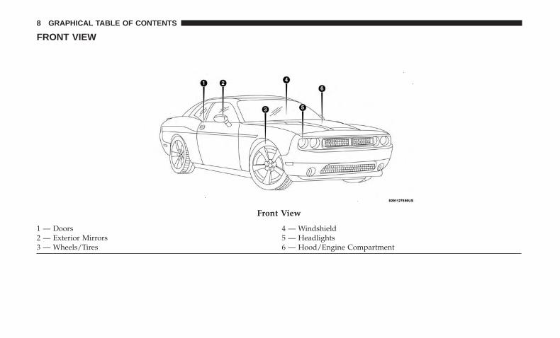
FRONT VIEW
Front View
1 — Doors 4 — Windshield2 — Exterior Mirrors 5 — Headlights3 — Wheels/Tires 6 — Hood/Engine Compartment
8 GRAPHICAL TABLE OF CONTENTS
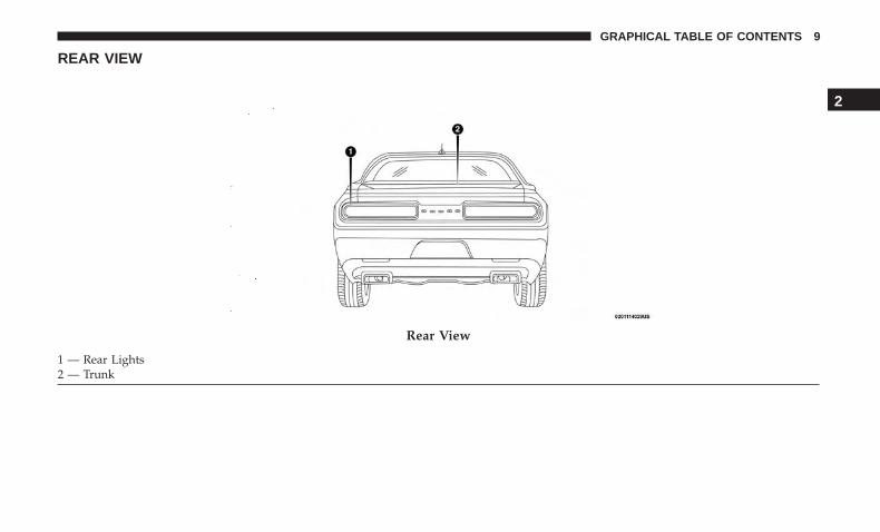
REAR VIEW
Rear View
1 — Rear Lights2 — Trunk
2
GRAPHICAL TABLE OF CONTENTS 9
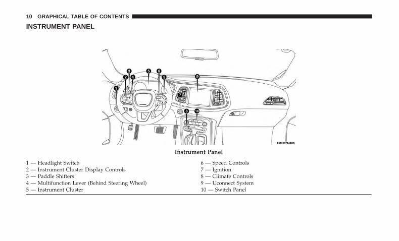
INSTRUMENT PANEL
Instrument Panel
1 — Headlight Switch 6 — Speed Controls2 — Instrument Cluster Display Controls 7 — Ignition3 — Paddle Shifters 8 — Climate Controls4 — Multifunction Lever (Behind Steering Wheel) 9 — Uconnect System5 — Instrument Cluster 10 — Switch Panel
10 GRAPHICAL TABLE OF CONTENTS
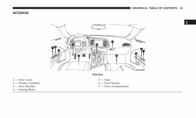
INTERIOR
Interior
1 — Door Locks 5 — Seats2 — Window Switches 6 — Gear Selector3 — Door Handles 7 — Glove Compartment4 — Parking Brake
2
GRAPHICAL TABLE OF CONTENTS 11

GETTING TO KNOW YOUR VEHICLE
CONTENTS� VEHICLE USER GUIDE — IF EQUIPPED . . . . . . .17
� KEYS . . . . . . . . . . . . . . . . . . . . . . . . . . . . . . . . .18
▫ Key Fob . . . . . . . . . . . . . . . . . . . . . . . . . . . . . .18
� IGNITION SWITCH . . . . . . . . . . . . . . . . . . . . . . .26
▫ Keyless Push Button Ignition . . . . . . . . . . . . . . .26
▫ Vehicle On Message . . . . . . . . . . . . . . . . . . . . .28
� REMOTE START — IF EQUIPPED . . . . . . . . . . . . .29
▫ How To Use Remote Start — If Equipped . . . . . .29
▫ Remote Start Abort Message On The InstrumentCluster Display — If Equipped . . . . . . . . . . . . . .30
▫ To Enter Remote Start Mode . . . . . . . . . . . . . . . .30
▫ To Exit Remote Start Mode Without Driving TheVehicle . . . . . . . . . . . . . . . . . . . . . . . . . . . . . . .30
▫ To Exit Remote Start Mode And Drive TheVehicle . . . . . . . . . . . . . . . . . . . . . . . . . . . . . . .31
▫ Remote Start Comfort Systems — If Equipped . . .31
▫ General Information . . . . . . . . . . . . . . . . . . . . .32
� SENTRY KEY . . . . . . . . . . . . . . . . . . . . . . . . . . .32
▫ Key Programming . . . . . . . . . . . . . . . . . . . . . .33
▫ Replacement Keys . . . . . . . . . . . . . . . . . . . . . . .33
▫ General Information . . . . . . . . . . . . . . . . . . . . .33
� VEHICLE SECURITY ALARM — IF EQUIPPED . . .33
▫ To Arm The System . . . . . . . . . . . . . . . . . . . . .34
▫ To Disarm The System . . . . . . . . . . . . . . . . . . . .34
▫ Rearming Of The System . . . . . . . . . . . . . . . . . .35
▫ Tamper Alert . . . . . . . . . . . . . . . . . . . . . . . . . . .35
� DOORS . . . . . . . . . . . . . . . . . . . . . . . . . . . . . . .35
▫ Manual Door Locks . . . . . . . . . . . . . . . . . . . . . .35
▫ Power Door Locks . . . . . . . . . . . . . . . . . . . . . .36
3
▫ Keyless Enter-N-Go — Passive Entry . . . . . . . . .37
▫ Automatic Unlock Doors On Exit . . . . . . . . . . . .41
▫ Automatic Door Locks — If Equipped . . . . . . . .41
� SEATS . . . . . . . . . . . . . . . . . . . . . . . . . . . . . . . .42
▫ Manual Adjustment (Front Seats) —If Equipped . . . . . . . . . . . . . . . . . . . . . . . . . . .42
▫ Manual Adjustment (Rear Seats) . . . . . . . . . . . . .44
▫ Power Seats — If Equipped . . . . . . . . . . . . . . . .45
▫ Heated Seats — If Equipped . . . . . . . . . . . . . . .46
▫ Front Ventilated Seats — If Equipped . . . . . . . . .48
▫ Vehicles Without Passenger Seating Installed . . . .49
▫ Passenger Seat Easy Entry . . . . . . . . . . . . . . . . .50
� HEAD RESTRAINTS . . . . . . . . . . . . . . . . . . . . . .51
▫ Reactive Head Restraints — Front Seats . . . . . . .51
▫ Rear Head Restraints . . . . . . . . . . . . . . . . . . . . .53
▫ Vehicles Without Passenger Seating Installed . . . .53
� STEERING WHEEL . . . . . . . . . . . . . . . . . . . . . . .54
▫ Manual Tilt/Telescoping Steering Column —If Equipped . . . . . . . . . . . . . . . . . . . . . . . . . . .54
▫ Power Tilt/Telescoping Steering Column —If Equipped . . . . . . . . . . . . . . . . . . . . . . . . . . .55
▫ Heated Steering Wheel — If Equipped. . . . . . . . .56
� MIRRORS . . . . . . . . . . . . . . . . . . . . . . . . . . . . . .57
▫ Automatic Dimming Mirror . . . . . . . . . . . . . . . .57
▫ Outside Mirrors . . . . . . . . . . . . . . . . . . . . . . . .58
▫ Power Mirrors . . . . . . . . . . . . . . . . . . . . . . . . .58
▫ Heated Mirrors — If Equipped . . . . . . . . . . . . .59
▫ Illuminated Vanity Mirrors . . . . . . . . . . . . . . . .59
� EXTERIOR LIGHTS . . . . . . . . . . . . . . . . . . . . . . .60
▫ Headlight Switch . . . . . . . . . . . . . . . . . . . . . . .60
▫ Multifunction Lever . . . . . . . . . . . . . . . . . . . . .60
▫ Daytime Running Lights (DRL) — If Equipped . .60
▫ High/Low Beam Switch . . . . . . . . . . . . . . . . . .61
▫ Automatic High Beam Headlamp Control —If Equipped . . . . . . . . . . . . . . . . . . . . . . . . . . .61
14 GETTING TO KNOW YOUR VEHICLE

▫ Flash-To-Pass . . . . . . . . . . . . . . . . . . . . . . . . . .61
▫ Automatic Headlights . . . . . . . . . . . . . . . . . . . .61
▫ Parking Lights . . . . . . . . . . . . . . . . . . . . . . . . .62
▫ Headlights On With Wipers . . . . . . . . . . . . . . . .62
▫ Headlight Time Delay . . . . . . . . . . . . . . . . . . . .62
▫ Lights-On Reminder . . . . . . . . . . . . . . . . . . . . .62
▫ Fog Lights — If Equipped . . . . . . . . . . . . . . . . .63
▫ Turn Signals . . . . . . . . . . . . . . . . . . . . . . . . . . .63
▫ Lane Change Assist — If Equipped . . . . . . . . . .63
� INTERIOR LIGHTS . . . . . . . . . . . . . . . . . . . . . . .64
▫ Map/Reading Lights . . . . . . . . . . . . . . . . . . . . .64
▫ Dimmer Controls . . . . . . . . . . . . . . . . . . . . . . .65
� WINDSHIELD WIPERS AND WASHERS . . . . . . . .66
▫ Wiper Operation . . . . . . . . . . . . . . . . . . . . . . . .66
▫ Rain Sensing Wipers — If Equipped . . . . . . . . . .68
� CLIMATE CONTROLS . . . . . . . . . . . . . . . . . . . . .68
▫ Automatic Climate Control Overview . . . . . . . . .69
▫ Climate Control Functions . . . . . . . . . . . . . . . . .75
▫ Automatic Temperature Control (ATC) . . . . . . . .76
▫ Operating Tips . . . . . . . . . . . . . . . . . . . . . . . . .77
� WINDOWS . . . . . . . . . . . . . . . . . . . . . . . . . . . . .79
▫ Power Window Controls . . . . . . . . . . . . . . . . . .79
▫ Wind Buffeting . . . . . . . . . . . . . . . . . . . . . . . . .80
� POWER SUNROOF — IF EQUIPPED . . . . . . . . . .80
▫ Opening Sunroof . . . . . . . . . . . . . . . . . . . . . . . .81
▫ Closing Sunroof. . . . . . . . . . . . . . . . . . . . . . . . .81
▫ Wind Buffeting . . . . . . . . . . . . . . . . . . . . . . . . .82
▫ Sunshade Operation. . . . . . . . . . . . . . . . . . . . . .82
▫ Pinch Protect Feature . . . . . . . . . . . . . . . . . . . .82
▫ Sunroof Maintenance . . . . . . . . . . . . . . . . . . . .82
▫ Ignition Off Operation . . . . . . . . . . . . . . . . . . . .82
� HOOD . . . . . . . . . . . . . . . . . . . . . . . . . . . . . . . .83
▫ To Open The Hood . . . . . . . . . . . . . . . . . . . . . .83
▫ To Close The Hood . . . . . . . . . . . . . . . . . . . . . .84
3
GETTING TO KNOW YOUR VEHICLE 15

� TRUNK . . . . . . . . . . . . . . . . . . . . . . . . . . . . . . .84
▫ Opening . . . . . . . . . . . . . . . . . . . . . . . . . . . . .84
▫ Closing . . . . . . . . . . . . . . . . . . . . . . . . . . . . . .86
▫ Trunk Safety . . . . . . . . . . . . . . . . . . . . . . . . . . .86
� GARAGE DOOR OPENER — IF EQUIPPED . . . . .87
▫ Before You Begin Programming HomeLink . . . . .87
▫ Canadian/Gate Operator Programming . . . . . . . .90
▫ Using HomeLink . . . . . . . . . . . . . . . . . . . . . . . .91
▫ Security . . . . . . . . . . . . . . . . . . . . . . . . . . . . . .91
▫ Troubleshooting Tips . . . . . . . . . . . . . . . . . . . . .91
▫ General Information. . . . . . . . . . . . . . . . . . . . . .92
� INTERNAL EQUIPMENT . . . . . . . . . . . . . . . . . . .93
▫ Storage . . . . . . . . . . . . . . . . . . . . . . . . . . . . . .93
▫ Cupholders . . . . . . . . . . . . . . . . . . . . . . . . . . . .94
▫ Electrical Power Outlets . . . . . . . . . . . . . . . . . .95
▫ Wireless Charging Pad — If Equipped . . . . . . . .98
16 GETTING TO KNOW YOUR VEHICLE
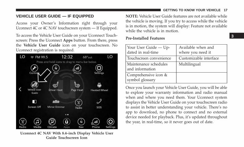
VEHICLE USER GUIDE — IF EQUIPPED
Access your Owner’s Information right through yourUconnect 4C or 4C NAV touchscreen system — If Equipped.
To access the Vehicle User Guide on your Uconnect Touch-screen: Press the Uconnect Apps button. From there, pressthe Vehicle User Guide icon on your touchscreen. NoUconnect registration is required.
NOTE: Vehicle User Guide features are not available whilethe vehicle is moving. If you try to access while the vehicleis in motion, the system will display: Feature not availablewhile the vehicle is in motion.
Pre-Installed Features
Your User Guide — Up-dated in real-time
Available when andwhere you need it
Touchscreen convenience Customizable interfaceMaintenance schedulesand information
Multilingual
Comprehensive icon &symbol glossary
Once you launch your Vehicle User Guide, you will be ableto explore your warranty information and radio manualwhen and where you need them. Your Uconnect systemdisplays the Vehicle User Guide on your touchscreen radioto assist in better understanding your vehicle. There’s noapp to download, no phone to connect and no externaldevice needed for playback. Plus, it’s updated throughoutthe year, in real-time, so it never goes out of date.
Uconnect 4C NAV With 8.4–inch Display Vehicle UserGuide Touchscreen Icon
3
GETTING TO KNOW YOUR VEHICLE 17
Features/Benefits
• Pre-installed on your Uconnect touchscreen radio
• Enhanced search and browsing capability
• Robust NAV application — If Equipped
• Add selected topics to a fast-access Favorites category
• Icon and symbol glossary
• Warranty information
• Crucial driver information and assistance:
Operating Instructions Maintenance SchedulesWarranty Information Emergency ProceduresFluid Level Standards 911 Contact and More
Tip: When viewing a topic, tap the star icon to add it toyour Favorites, for easy access in the future.
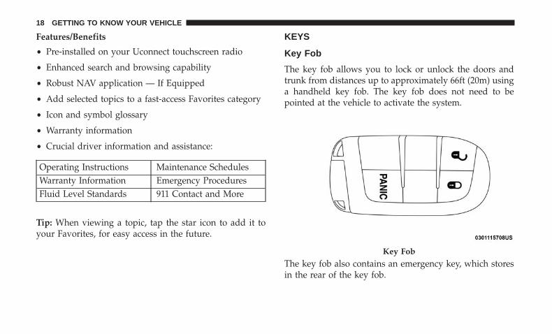
KEYS
Key Fob
The key fob allows you to lock or unlock the doors andtrunk from distances up to approximately 66ft (20m) usinga handheld key fob. The key fob does not need to bepointed at the vehicle to activate the system.
The key fob also contains an emergency key, which storesin the rear of the key fob.
Key Fob
18 GETTING TO KNOW YOUR VEHICLE

The emergency key allows for entry into the vehicle shouldthe battery in the vehicle or the key fob go dead. Theemergency key is also for locking/unlocking the glovecompartment. You can keep the emergency key with youwhen valet parking.
To remove the emergency key, slide the mechanical releasebutton on the back of the key fob sideways with yourthumb and then pull the key out with your other hand.
NOTE: In case the ignition switch does not change withthe push of a button, the key fob may have a low or fullydepleted battery. A low key fob battery can be verified byreferring to the instrument cluster, which will displaydirections to follow.
Emergency Key Emergency Key Removal Process
1 — Mechanical Release Button2 — Emergency Key
3
GETTING TO KNOW YOUR VEHICLE 19
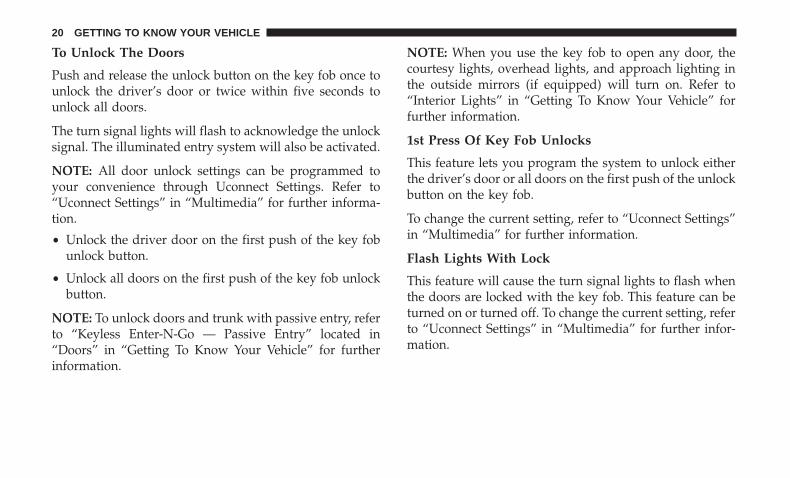
To Unlock The Doors
Push and release the unlock button on the key fob once tounlock the driver’s door or twice within five seconds tounlock all doors.
The turn signal lights will flash to acknowledge the unlocksignal. The illuminated entry system will also be activated.
NOTE: All door unlock settings can be programmed toyour convenience through Uconnect Settings. Refer to“Uconnect Settings” in “Multimedia” for further informa-tion.
• Unlock the driver door on the first push of the key fobunlock button.
• Unlock all doors on the first push of the key fob unlockbutton.
NOTE: To unlock doors and trunk with passive entry, referto “Keyless Enter-N-Go — Passive Entry” located in“Doors” in “Getting To Know Your Vehicle” for furtherinformation.
NOTE: When you use the key fob to open any door, thecourtesy lights, overhead lights, and approach lighting inthe outside mirrors (if equipped) will turn on. Refer to“Interior Lights” in “Getting To Know Your Vehicle” forfurther information.
1st Press Of Key Fob Unlocks
This feature lets you program the system to unlock eitherthe driver’s door or all doors on the first push of the unlockbutton on the key fob.
To change the current setting, refer to “Uconnect Settings”in “Multimedia” for further information.
Flash Lights With Lock
This feature will cause the turn signal lights to flash whenthe doors are locked with the key fob. This feature can beturned on or turned off. To change the current setting, referto “Uconnect Settings” in “Multimedia” for further infor-mation.
20 GETTING TO KNOW YOUR VEHICLE
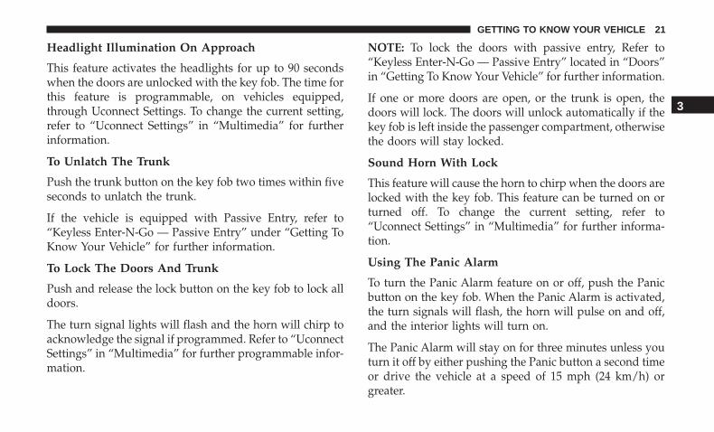
Headlight Illumination On Approach
This feature activates the headlights for up to 90 secondswhen the doors are unlocked with the key fob. The time forthis feature is programmable, on vehicles equipped,through Uconnect Settings. To change the current setting,refer to “Uconnect Settings” in “Multimedia” for furtherinformation.
To Unlatch The Trunk
Push the trunk button on the key fob two times within fiveseconds to unlatch the trunk.
If the vehicle is equipped with Passive Entry, refer to“Keyless Enter-N-Go — Passive Entry” under “Getting ToKnow Your Vehicle” for further information.
To Lock The Doors And Trunk
Push and release the lock button on the key fob to lock alldoors.
The turn signal lights will flash and the horn will chirp toacknowledge the signal if programmed. Refer to “UconnectSettings” in “Multimedia” for further programmable infor-mation.
NOTE: To lock the doors with passive entry, Refer to“Keyless Enter-N-Go — Passive Entry” located in “Doors”in “Getting To Know Your Vehicle” for further information.
If one or more doors are open, or the trunk is open, thedoors will lock. The doors will unlock automatically if thekey fob is left inside the passenger compartment, otherwisethe doors will stay locked.
Sound Horn With Lock
This feature will cause the horn to chirp when the doors arelocked with the key fob. This feature can be turned on orturned off. To change the current setting, refer to“Uconnect Settings” in “Multimedia” for further informa-tion.
Using The Panic Alarm
To turn the Panic Alarm feature on or off, push the Panicbutton on the key fob. When the Panic Alarm is activated,the turn signals will flash, the horn will pulse on and off,and the interior lights will turn on.
The Panic Alarm will stay on for three minutes unless youturn it off by either pushing the Panic button a second timeor drive the vehicle at a speed of 15 mph (24 km/h) orgreater.
3
GETTING TO KNOW YOUR VEHICLE 21

NOTE:
• The interior lights will turn off if you place the ignitionin the ACC or ON/RUN position while the Panic Alarmis activated. However, the exterior lights and horn willremain on.
• You may need to be less than 35 ft (11 m) from thevehicle when using the key fob to turn off the PanicAlarm due to the radio frequency noises emitted by thesystem.
Key Fob Battery Replacement
The recommended replacement battery is one CR2032battery.
NOTE:
• Perchlorate Material — special handling may apply. Seewww.dtsc.ca.gov/hazardouswaste/perchlorate for fur-ther information.
• Do not touch the battery terminals that are on the backhousing or the printed circuit board.
1. Remove the emergency key by sliding the mechanicallatch on the back of the key fob sideways with yourthumb and then pull the emergency key out with yourother hand.
2. Separate the key fob halves using the tip of the emer-gency key, a #2 flat blade screwdriver, or a coin andgently pry the two halves of the key fob apart. Makesure not to damage the seal during removal.
Emergency Key Removal
1 — Emergency Key Release Button2 — Emergency Key
22 GETTING TO KNOW YOUR VEHICLE
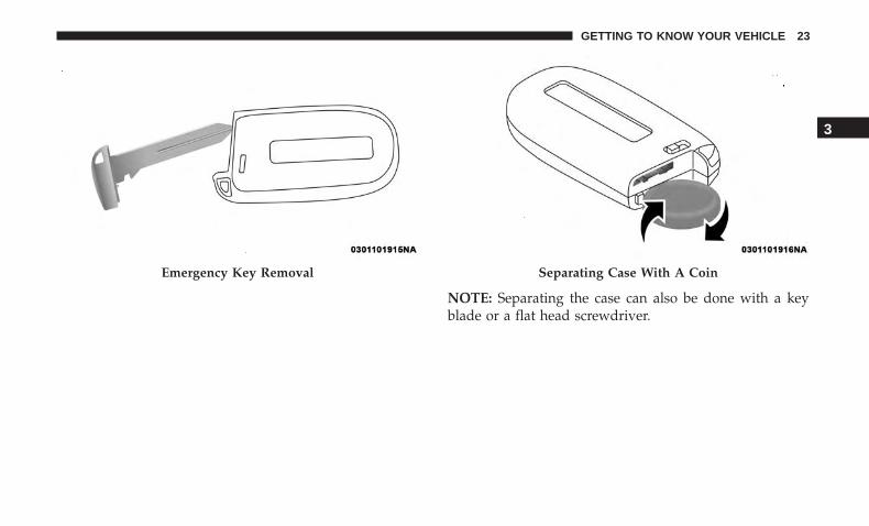
Emergency Key Removal Separating Case With A Coin
NOTE: Separating the case can also be done with a keyblade or a flat head screwdriver.
3
GETTING TO KNOW YOUR VEHICLE 23
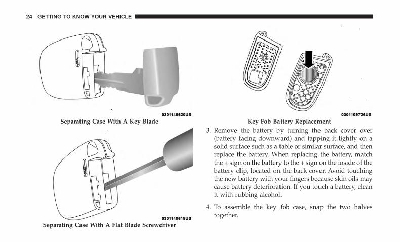
3. Remove the battery by turning the back cover over(battery facing downward) and tapping it lightly on asolid surface such as a table or similar surface, and thenreplace the battery. When replacing the battery, matchthe + sign on the battery to the + sign on the inside of thebattery clip, located on the back cover. Avoid touchingthe new battery with your fingers because skin oils maycause battery deterioration. If you touch a battery, cleanit with rubbing alcohol.
4. To assemble the key fob case, snap the two halvestogether.
Separating Case With A Key Blade
Separating Case With A Flat Blade Screwdriver
Key Fob Battery Replacement
24 GETTING TO KNOW YOUR VEHICLE
Programming Additional Key Fobs
Programming the key fob may be performed by an autho-rized dealer.
NOTE: Once a key fob is programmed to a vehicle, itcannot be repurposed and reprogrammed to another ve-hicle.
Request For Additional Remote Controls
NOTE: Only key fobs that are programmed to the vehicleelectronics can be used to start and operate the vehicle.Once a key fob is programmed to a vehicle, it cannot beprogrammed to any other vehicle.
WARNING!
• Always remove the key fobs from the vehicle andlock all doors when leaving the vehicle unattended.
• For vehicles equipped with Keyless Enter-N-Go —Ignition, always remember to place the ignition inthe OFF mode.
Duplication of key fobs may be performed at an authorizeddealer. This procedure consists of programming a blankkey fob to the vehicle electronics. A blank key fob is onethat has never been programmed.
NOTE: When having the Sentry Key Immobilizer Systemserviced, bring all vehicle keys with you to an authorizeddealer.
General Information
The following regulatory statement applies to all radiofrequency (RF) devices equipped in this vehicle:
This device complies with Part 15 of the FCC Rules andwith Industry Canada license-exempt RSS standard(s).Operation is subject to the following two conditions:
1. This device may not cause harmful interference, and
2. This device must accept any interference received, in-cluding interference that may cause undesired opera-tion.
NOTE: Changes or modifications not expressly approvedby the party responsible for compliance could void theuser’s authority to operate the equipment.
3
GETTING TO KNOW YOUR VEHICLE 25
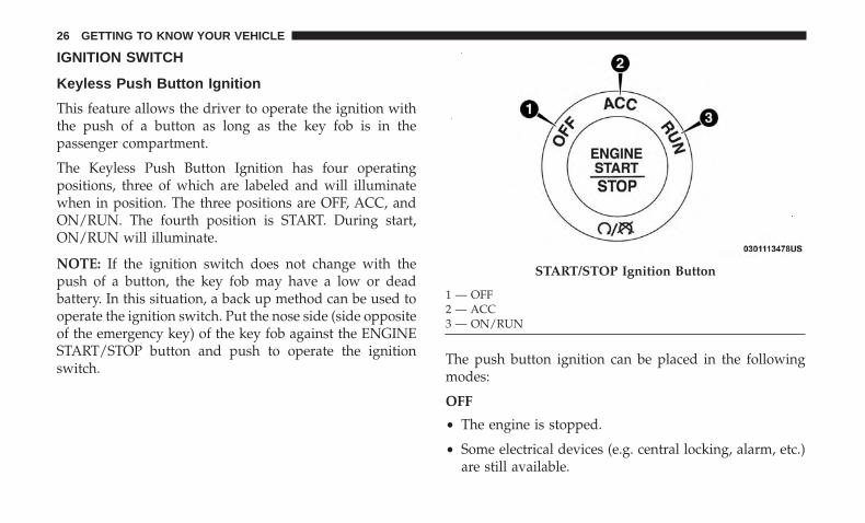
IGNITION SWITCH
Keyless Push Button Ignition
This feature allows the driver to operate the ignition withthe push of a button as long as the key fob is in thepassenger compartment.
The Keyless Push Button Ignition has four operatingpositions, three of which are labeled and will illuminatewhen in position. The three positions are OFF, ACC, andON/RUN. The fourth position is START. During start,ON/RUN will illuminate.
NOTE: If the ignition switch does not change with thepush of a button, the key fob may have a low or deadbattery. In this situation, a back up method can be used tooperate the ignition switch. Put the nose side (side oppositeof the emergency key) of the key fob against the ENGINESTART/STOP button and push to operate the ignitionswitch.
The push button ignition can be placed in the followingmodes:
OFF
• The engine is stopped.
• Some electrical devices (e.g. central locking, alarm, etc.)are still available.
START/STOP Ignition Button
1 — OFF2 — ACC3 — ON/RUN
26 GETTING TO KNOW YOUR VEHICLE

ACC
• Engine is not started.
• Some electrical devices are available.
ON/RUN
• Driving position.
• All the electrical devices are available.
START
• The engine will start.
WARNING!
• When exiting the vehicle, always remove the key fobfrom the vehicle and lock your vehicle.
• Never leave children alone in a vehicle, or withaccess to an unlocked vehicle.
• Allowing children to be in a vehicle unattended isdangerous for a number of reasons. A child or otherscould be seriously or fatally injured. Childrenshould be warned not to touch the parking brake,brake pedal or the gear selector.
(Continued)
WARNING! (Continued)• Do not leave the key fob in or near the vehicle, or in
a location accessible to children, and do not leave theignition of a vehicle equipped with Keyless Enter-N-Go in the ON/RUN mode. A child could operatepower windows, other controls, or move the vehicle.
• Do not leave children or animals inside parkedvehicles in hot weather. Interior heat build-up maycause serious injury or death.
CAUTION!
An unlocked vehicle is an invitation for thieves. Al-ways remove key fob from the vehicle and lock alldoors when leaving the vehicle unattended.
NOTE: Refer to �Starting The Engine,� in �Starting AndOperating� for further information.
3
GETTING TO KNOW YOUR VEHICLE 27
Vehicle On Message
When opening the driver’s door and the ignition is inON/RUN (engine not running) position, a chime willsound to remind you to place the ignition in the OFFposition.
In addition to the chime, the Vehicle On message willdisplay in the cluster (if equipped).
NOTE: The power window switches and power sunroof (ifequipped) will remain active for three minutes after theignition is cycled to the OFF position. Opening either frontdoor will cancel this feature. The time for this feature isprogrammable.
WARNING!
• Before exiting a vehicle, always come to a completestop, then shift the automatic transmission intoPARK, apply the parking brake, place the engine inthe OFF position, remove the key fob from thevehicle and lock your vehicle. If equipped withKeyless Enter-N-Go, always make sure the keylessignition is in “OFF” position, remove the key fobfrom the vehicle and lock the vehicle.
(Continued)
WARNING! (Continued)• Never leave children alone in a vehicle, or with
access to an unlocked vehicle.• Allowing children to be in a vehicle unattended is
dangerous for a number of reasons. A child or otherscould be seriously or fatally injured. Childrenshould be warned not to touch the parking brake,brake pedal or the gear selector.
• Do not leave the key fob in or near the vehicle, or ina location accessible to children, and do not leave theignition of a vehicle equipped with Keyless Enter-N-Go in the ON/RUN mode. A child could operatepower windows, other controls, or move the vehicle.
• Do not leave children or animals inside parkedvehicles in hot weather. Interior heat build-up maycause serious injury or death.
CAUTION!
An unlocked vehicle is an invitation for thieves. Al-ways remove key fob from the vehicle and lock alldoors when leaving the vehicle unattended.
28 GETTING TO KNOW YOUR VEHICLE

REMOTE START — IF EQUIPPED
How To Use Remote Start — If Equipped
Push remote start button on the key fob twicewithin five seconds. Pushing the remote startbutton a third time shuts the engine off.
To drive the vehicle, push the unlock button, and push theignition to the ON/RUN position.
NOTE:
• With remote start, the engine will only run for 15minutes (timeout) unless the ignition is placed in theON/RUN position.
• The vehicle must be started with the key after twoconsecutive timeouts.
All of the following conditions must be met before theengine will remote start:
• Gear selector in PARK
• Doors closed
• Hood closed
• Trunk closed
• Hazard switch off
• Brake switch inactive (brake pedal not pushed)
• Battery at an acceptable charge level
• Check engine light shall not be present
• PANIC button not pushed
• System not disabled from previous remote start event
• Vehicle alarm system indicator flashing
• Ignition in STOP/OFF position
• Fuel level meets minimum requirement
• Vehicle Security Alarm is not signaling an intrusion
WARNING!
• Do not start or run an engine in a closed garage orconfined area. Exhaust gas contains Carbon Monox-ide (CO) which is odorless and colorless. CarbonMonoxide is poisonous and can cause serious injuryor death when inhaled.
• Keep key fobs away from children. Operation of theRemote Start System, windows, door locks or othercontrols could cause serious injury or death.
3
GETTING TO KNOW YOUR VEHICLE 29

Remote Start Abort Message On The InstrumentCluster Display — If Equipped
The following messages will display in the instrumentcluster display if the vehicle fails to remote start or exitsremote start prematurely:
• Remote Start Aborted — Door Open
• Remote Start Aborted — Hood Open
• Remote Start Aborted — Fuel Low
• Remote Start Aborted — Trunk Open
• Remote Start Disabled — Start Vehicle To Reset
The message will stay active until the ignition is turned tothe ON/RUN position.
To Enter Remote Start Mode
Push and release the remote start button on the key fobtwice within five seconds. The vehicle doors will lock, theparking lights will flash, and the horn will chirp twice (ifprogrammed). Then, the engine will start, and the vehiclewill remain in the Remote Start mode for a 15-minute cycle.
NOTE:
• If an engine fault is present or fuel level is low, thevehicle will start and then shut down in 10 seconds.
• The park lamps will turn on and remain on duringRemote Start mode.
• For security, power window and power sunroof opera-tion (if equipped) are disabled when the vehicle is in theRemote Start mode.
• The engine can be started two consecutive times withthe key fob. However, the ignition must be cycled bypushing the START/STOP button twice (or the ignitionswitch must be cycled to the ON/RUN position) beforeyou can repeat the start sequence for a third cycle.
To Exit Remote Start Mode Without Driving TheVehicle
Push and release the remote start button one time or allowthe engine to run for the entire 15-minute cycle.
NOTE: To avoid unintentional shutdowns, the system willdisable with a one time push of the remote start button fortwo seconds after receiving a valid remote start request.
30 GETTING TO KNOW YOUR VEHICLE
To Exit Remote Start Mode And Drive The Vehicle
Before the end of 15-minute cycle, push and release theunlock button on the key fob to unlock the doors anddisarm the vehicle security alarm (if equipped). Then, priorto the end of the 15-minute cycle, push and release theSTART/STOP button. If the START/STOP button is notpresent, insert the key fob into the ignition switch and turnthe switch to the ON/RUN position.
NOTE:
• For vehicles not equipped with the Keyless Enter-N-Go— Passive Entry feature, the ignition switch must be inthe ON/RUN position in order to drive the vehicle.
• For vehicles not equipped with the Keyless Enter-N-Go— Passive Entry feature, the message “Remote StartActive — Insert Key and Turn To Run” will show in theinstrument cluster display until you insert the key.
• For vehicles equipped with the Keyless Enter-N-Go —Passive Entry feature, the message “Remote Start Active— Push Start Button” will show in the instrumentcluster display until you push the START button.
To Cancel Remote Start
Remote Starting will also cancel if any of the followingoccur:
• The engine stalls or engine speed exceeds 2500 rpm.
• Any engine warning lights come on.
• Low Fuel Light turns on.
• The hood is opened.
• The hazard switch is pushed.
• The gear selector is moved out of PARK.
• The brake pedal is pushed.
Remote Start Comfort Systems — If Equipped
When remote start is activated, the heated steering wheeland driver heated seat features will automatically turn onin cold weather. In warm weather, the driver vented seatfeature will automatically turn on when the remote start isactivated. These features will stay on through the durationof remote start or until the ignition switch is cycled to theON/RUN position.
3
GETTING TO KNOW YOUR VEHICLE 31

General Information
The following regulatory statement applies to all radiofrequency (RF) devices equipped in this vehicle:
This device complies with Part 15 of the FCC Rules andwith Industry Canada license-exempt RSS standard(s).Operation is subject to the following two conditions:
1. This device may not cause harmful interference, and
2. This device must accept any interference received, in-cluding interference that may cause undesired operation.
NOTE: Changes or modifications not expressly approvedby the party responsible for compliance could void theuser’s authority to operate the equipment.
SENTRY KEY
The Sentry Key Immobilizer system prevents unauthorizedvehicle operation by disabling the engine. The system doesnot need to be armed or activated. Operation is automatic,regardless of whether the vehicle is locked or unlocked.
The system uses a key fob, keyless push button ignitionand a RF receiver to prevent unauthorized vehicle opera-tion. Therefore, only key fobs that are programmed to thevehicle can be used to start and operate the vehicle. The
system cannot reprogram a key fob obtained from anothervehicle.
After turning the ignition switch to the ON/RUN position,the vehicle security light will turn on for three seconds fora bulb check. If the light remains on after the bulb check, itindicates that there is a problem with the electronics. Inaddition, if the light begins to flash after the bulb check, itindicates that someone attempted to start the engine withan invalid key fob. In the event that a valid key fob is usedto start the engine but there is an issue with the vehicleelectronics, the engine will start and shut off after twoseconds.
If the vehicle security light turns on during normal vehicleoperation (vehicle running for longer than ten seconds), itindicates that there is a fault in the electronics. Should thisoccur, have the vehicle serviced as soon as possible by anauthorized dealer.
CAUTION!
The Sentry Key Immobilizer system is not compatiblewith some aftermarket remote starting systems. Use ofthese systems may result in vehicle starting problemsand loss of security protection.
32 GETTING TO KNOW YOUR VEHICLE
All of the key fobs provided with your new vehicle havebeen programmed to the vehicle electronics.
Key Programming
Programming key fobs may be performed at an authorizeddealer.
Replacement Keys
NOTE: Only key fobs that are programmed to the vehicleelectronics can be used to start and operate the vehicle.Once a key fob is programmed to a vehicle, it cannot beprogrammed to any other vehicle.
CAUTION!
• Always remove the key fobs from the vehicle andlock all doors when leaving the vehicle unattended.
• For vehicles equipped with Keyless Enter-N-Go —Ignition, always remember to place the ignition inthe OFF position.
NOTE: Duplication of key fobs may be performed at anauthorized dealer. This procedure consists of programminga blank key fob to the vehicle electronics. A blank key fobis one that has never been programmed.
When having the Sentry Key Immobilizer System serviced,bring all vehicle keys with you to an authorized dealer.
General Information
The following regulatory statement applies to all radiofrequency (RF) devices equipped in this vehicle:
This device complies with Part 15 of the FCC Rules andwith Industry Canada license-exempt RSS standard(s).Operation is subject to the following two conditions:
1. This device may not cause harmful interference, and
2. This device must accept any interference received, in-cluding interference that may cause undesired opera-tion.
NOTE: Changes or modifications not expressly approvedby the party responsible for compliance could void theuser’s authority to operate the equipment.
VEHICLE SECURITY ALARM — IF EQUIPPED
The vehicle security alarm monitors the vehicle doors forunauthorized entry and the keyless push button ignitionfor unauthorized operation. While the vehicle securityalarm is armed, interior switches for door locks and trunkrelease are disabled. If something triggers the alarm, the
3
GETTING TO KNOW YOUR VEHICLE 33

vehicle security alarm will provide the following audibleand visible signals: the horn will pulse, the park lampsand/or turn signals will flash, and the vehicle security lightin the instrument cluster will flash.
To Arm The System
Follow these steps to arm the vehicle security alarm:
1. Make sure the vehicle’s ignition is placed in the OFFmode. Refer to �Ignition Switch� in “Getting To KnowYour Vehicle” for further information.
2. Perform one of the following methods to lock thevehicle:
• Push lock on the interior power door lock switch withthe driver and/or passenger door open.
• Push the lock button on the exterior Passive EntryDoor Handle with a valid key fob available in the sameexterior zone (refer to �Keyless Enter-N-Go — PassiveEntry,� located in “Doors” in “Getting To Know YourVehicle� for further information).
• Push the lock button on the key fob.
3. If any doors are open, close them.
NOTE: Security System Manual Override
The vehicle security alarm will not arm if you lock thedoors using the manual door lock plunger.
To Disarm The System
The vehicle security alarm can be disarmed using any ofthe following methods:
• Push the unlock button on the key fob.
• Grasp the Passive Entry Unlock Door Handle, ifequipped. Refer to “Keyless Enter-N-Go — PassiveEntry,” located in “Doors” in “Getting To Know YourVehicle” for further information.
• Push the Keyless Enter-N-Go ignition button (requires atleast one valid key fob in the vehicle).
NOTE:
• The driver’s door key cylinder and the trunk button onthe key fob cannot arm or disarm the vehicle securityalarm.
• When the vehicle security alarm is armed, the interiorpower door lock switches will not unlock the doors.
The vehicle security alarm is designed to protect yourvehicle. However, you can create conditions where thesystem will give you a false alarm. If one of the previouslydescribed arming sequences has occurred, the vehicle
34 GETTING TO KNOW YOUR VEHICLE
security alarm will arm regardless of whether you are inthe vehicle or not. If you remain in the vehicle and open adoor, the alarm will sound. If this occurs, disarm thevehicle security alarm.
If the vehicle security alarm is armed and the batterybecomes disconnected, the vehicle security alarm willremain armed when the battery is reconnected; the exteriorlights will flash, the horn will sound. If this occurs, disarmthe vehicle security alarm.
Rearming Of The System
If something triggers the alarm, and no action is taken todisarm it, the vehicle security alarm will turn the horn offafter 29 seconds, five seconds between cycles, up to eightcycles if the trigger remains active and the vehicle securityalarm will rearm itself.
Tamper Alert
If something has triggered the vehicle security alarm inyour absence, the horn will sound three times and theexterior lights will blink three times when you disarm thevehicle security alarm. Check the vehicle for tampering.
DOORS
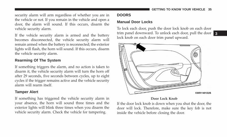
Manual Door Locks
To lock each door, push the door lock knob on each doortrim panel downward. To unlock each door, pull the doorlock knob on each door trim panel upward.
If the door lock knob is down when you shut the door, thedoor will lock. Therefore, make sure the key fob is notinside the vehicle before closing the door.
Door Lock Knob
3
GETTING TO KNOW YOUR VEHICLE 35
WARNING!
• For personal security and safety in the event of acollision, lock the vehicle doors before you drive aswell as when you park and leave the vehicle.
• Before exiting a vehicle, always shift the automatictransmission into PARK or the manual transmissioninto FIRST gear or REVERSE, apply the parkingbrake, turn the vehicle OFF, remove the key fobsfrom the vehicle and lock all doors, and lock yourvehicle.
• When leaving the vehicle, always remove the keyfrom the ignition and lock your vehicle. Unsuper-vised use of vehicle equipment may cause severepersonal injuries and death.
• Never leave children alone in a vehicle, or withaccess to an unlocked vehicle. Allowing children tobe in a vehicle unattended is dangerous for a numberof reasons. A child or others could be seriously orfatally injured. Children should be warned not totouch the parking brake, brake pedal or gear selector.
• Do not leave the key fob in or near the vehicle, or ina location accessible to children, and do not leave the
(Continued)
WARNING! (Continued)ignition of a vehicle equipped with Keyless Enter-N-Go in the ACC or ON/RUN mode. A child couldoperate power windows, other controls, or move thevehicle.
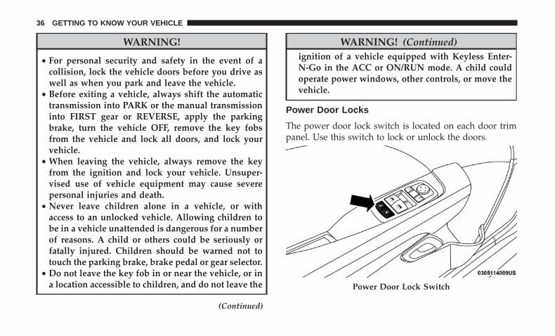
Power Door Locks
The power door lock switch is located on each door trimpanel. Use this switch to lock or unlock the doors.
Power Door Lock Switch
36 GETTING TO KNOW YOUR VEHICLE
The doors can also be locked and unlocked with theKeyless Enter-N-Go — Passive Entry system. Refer to“Keyless Enter-N-Go — Passive Entry” located in “Doors”in “Getting To Know Your Vehicle” for further information.
If you push the power door lock switch while the ignitionis on, and either door is open, the power locks will notoperate. This prevents you from accidentally locking thekey fob in the vehicle. Turning off the ignition or closingthe door will allow the locks to operate. If a door is openwith the ignition either cycled to ACC or ON/RUN (enginenot running), a chime will sound as a reminder.
Keyless Enter-N-Go — Passive Entry
The Passive Entry system is an enhancement to the vehi-cle’s Remote Keyless Entry system and a feature of KeylessEnter-N-Go. This feature allows you to lock and unlock thevehicle’s door(s) without having to push the key fob lockor unlock buttons.
NOTE:
• Passive Entry may be programmed on or off; refer to“Uconnect Settings” in “Multimedia” in the Owner’sManual for further information.
• If wearing gloves on your hands, or if it has beenraining/snowing on the Passive Entry door handle, theunlock sensitivity can be affected, resulting in a slowerresponse time.
• If the vehicle is unlocked by Passive Entry and no dooris opened within 60 seconds, the vehicle will re-lock andif equipped will arm the security alarm.
• The key fob may not be able to be detected by the vehiclePassive Entry system if it is located next to a mobilephone, laptop or other electronic device; these devicesmay block the key fob’s wireless signal and prevent thePassive Entry handle from locking/unlocking the vehicle.
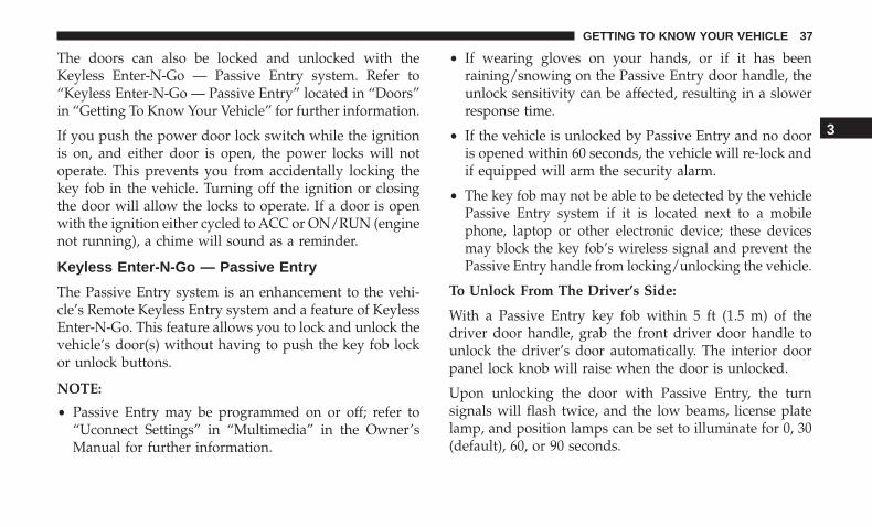
To Unlock From The Driver’s Side:
With a Passive Entry key fob within 5 ft (1.5 m) of thedriver door handle, grab the front driver door handle tounlock the driver’s door automatically. The interior doorpanel lock knob will raise when the door is unlocked.
Upon unlocking the door with Passive Entry, the turnsignals will flash twice, and the low beams, license platelamp, and position lamps can be set to illuminate for 0, 30(default), 60, or 90 seconds.
3
GETTING TO KNOW YOUR VEHICLE 37

NOTE: If “Unlock All Doors 1st Press” is programmed alldoors will unlock when you grab hold of the front driver’sdoor handle. To select between “Unlock Driver Door 1stPress” and “Unlock All Doors 1st Press,” refer to“Uconnect Settings” in “Multimedia” in the Owner’sManual for further information.
To Unlock From The Passenger Side:
With a Passive Entry key fob within 5 ft (1.5 m) of thepassenger door handle, grab the front passenger doorhandle to unlock both doors automatically. The interiordoor panel lock knob will raise when the door is unlocked.
NOTE: All doors will unlock when the front passengerdoor handle is grabbed regardless of the driver’s doorunlock preference setting (“Unlock Driver Door 1st Press”or “Unlock All Doors 1st Press”).
Preventing Inadvertent Locking Of Passive Entry KeyFob In Vehicle (FOBIK-Safe)
To minimize the possibility of unintentionally locking aPassive Entry key fob inside your vehicle, the Passive Entrysystem is equipped with an automatic door unlock featurewhich will function if the ignition is in the OFF position.
FOBIK-Safe only executes in vehicles with passive entry.There are three situations that trigger a FOBIK-Safe searchin any passive entry vehicle.
1. A lock request is made by a valid Passive Entry key fobwhile a door is open.
2. A lock request is made by the Passive Entry door handlewhile a door is open.
3. A lock request is made by the door panel switch whilethe door is open.
When any of these situations occur, after all open doors areshut, the FOBIK-Safe search will be executed. If it finds a
Grab The Door Handle To Unlock
38 GETTING TO KNOW YOUR VEHICLE
Passive Entry key fob inside the car, and it does not findany Passive Entry key fobs outside the car, the car willunlock and alert the customer.
NOTE: The vehicle will only unlock the doors when a validPassive Entry key fob is detected inside the vehicle, and novalid Passive Entry key fob is detected outside the vehicle.The vehicle will not unlock the doors when any of thefollowing conditions are true:
• The doors are manually locked using the door lockknobs.
• There is a valid Passive Entry key fob outside the vehicleand within 5 ft (1.5 m) of either Passive Entry doorhandle.
• Three attempts are made to lock the doors using thedoor panel switch and then close the doors.
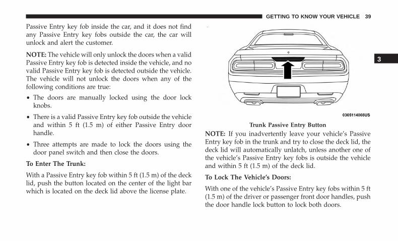
To Enter The Trunk:
With a Passive Entry key fob within 5 ft (1.5 m) of the decklid, push the button located on the center of the light barwhich is located on the deck lid above the license plate.
NOTE: If you inadvertently leave your vehicle’s PassiveEntry key fob in the trunk and try to close the deck lid, thedeck lid will automatically unlatch, unless another one ofthe vehicle’s Passive Entry key fobs is outside the vehicleand within 5 ft (1.5 m) of the deck lid.
To Lock The Vehicle’s Doors:
With one of the vehicle’s Passive Entry key fobs within 5 ft(1.5 m) of the driver or passenger front door handles, pushthe door handle lock button to lock both doors.
Trunk Passive Entry Button
3
GETTING TO KNOW YOUR VEHICLE 39
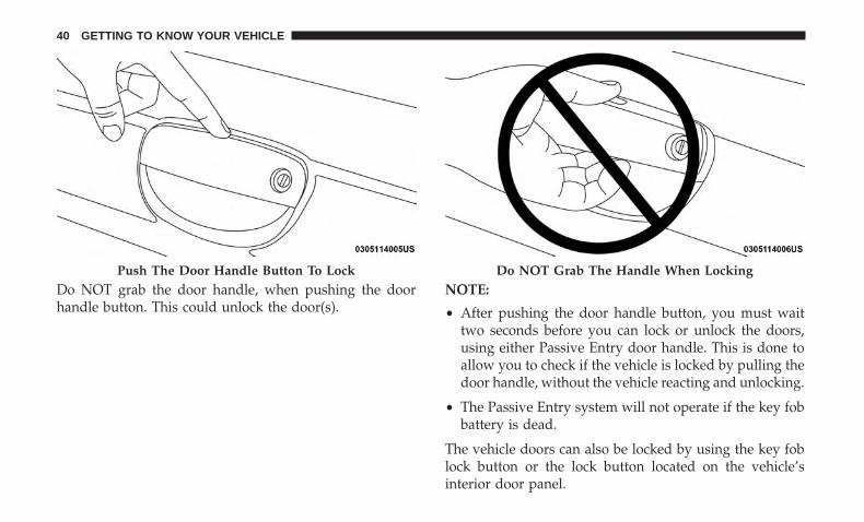
Do NOT grab the door handle, when pushing the doorhandle button. This could unlock the door(s).
NOTE:
• After pushing the door handle button, you must waittwo seconds before you can lock or unlock the doors,using either Passive Entry door handle. This is done toallow you to check if the vehicle is locked by pulling thedoor handle, without the vehicle reacting and unlocking.
• The Passive Entry system will not operate if the key fobbattery is dead.
The vehicle doors can also be locked by using the key foblock button or the lock button located on the vehicle’sinterior door panel.
Push The Door Handle Button To Lock Do NOT Grab The Handle When Locking
40 GETTING TO KNOW YOUR VEHICLE
General Information
The following regulatory statement applies to all radiofrequency (RF) devices equipped in this vehicle:
This device complies with Part 15 of the FCC Rules andwith Industry Canada license-exempt RSS standard(s).Operation is subject to the following two conditions:
1. This device may not cause harmful interference, and
2. This device must accept any interference received, in-cluding interference that may cause undesired opera-tion.
NOTE: Changes or modifications not expressly approvedby the party responsible for compliance could void theuser’s authority to operate the equipment.
Automatic Unlock Doors On Exit
The doors will unlock automatically on vehicles withpower door locks if:
1. The Automatic Unlock Doors On Exit feature is enabled.
2. The vehicle was in motion, then speed returned to0 mph (0 km/h) and the transmission is placed in PARK.
3. The driver door is opened.
4. The doors were not previously unlocked.
NOTE: Automatic Unlock Doors On Exit Programming
To change the current setting, refer to “Uconnect Settings”in “Multimedia” for further information.
Use the Automatic Unlock Doors On Exit feature in accor-dance with local laws.
Automatic Door Locks — If Equipped
The auto door lock feature default condition is enabled.When enabled, the door locks will lock automatically whenthe vehicle’s speed exceeds 15 mph (24 km/h). The autodoor lock feature can be enabled or disabled by an autho-rized dealer per written request of the customer. Please seean authorized dealer for service.
3
GETTING TO KNOW YOUR VEHICLE 41
SEATS
Seats are a part of the Occupant Restraint System of thevehicle.
WARNING!
• It is dangerous to ride in a cargo area, inside oroutside of a vehicle. In a collision, people riding inthese areas are more likely to be seriously injured orkilled.
• Do not allow people to ride in any area of yourvehicle that is not equipped with seats and seat belts.In a collision, people riding in these areas are morelikely to be seriously injured or killed.
• Be sure everyone in your vehicle is in a seat andusing a seat belt properly.
Manual Adjustment (Front Seats) — If Equipped
WARNING!
• Adjusting a seat while the vehicle is moving isdangerous. The sudden movement of the seat couldcause you to lose control. The seat belt might not beadjusted properly and you could be injured. Adjustthe seat only while the vehicle is parked.
• Do not ride with the seatback reclined so that theshoulder belt is no longer resting against your chest.In a collision you could slide under the seat belt andbe seriously or even fatally injured. Use the reclineronly when the vehicle is parked.
Manual Front Seats Forward/Rearward Adjustment
The adjusting bar is located at the front of the seat, near thefloor. Pull the bar upward to move the seat forward orrearward. Release the bar once the seat is in the desiredposition. Using body pressure, move forward and rear-ward on the seat to be sure that the seat adjusters havelatched.
42 GETTING TO KNOW YOUR VEHICLE

WARNING!
• Adjusting a seat while driving may be dangerous.Moving a seat while driving could result in loss ofcontrol which could cause a collision and seriousinjury or death.
• Seats should be adjusted before fastening the seatbelts and while the vehicle is parked. Serious injuryor death could result from a poorly adjusted seat belt.
Manual Front Seat Recline
To adjust the seatback, lift the lever located on the outboardside of the seat, lean back to the desired position andrelease the lever. To return the seatback, lift the lever, leanforward and release the lever. WARNING!
Do not ride with the seatback reclined so that theshoulder belt is no longer resting against your chest. Ina collision you could slide under the seat belt, whichcould result in serious injury or death.
Recline Lever
3
GETTING TO KNOW YOUR VEHICLE 43

Manual Adjustment (Rear Seats)
Folding Rear Seat
The rear seatbacks can be folded forward to provideadditional storage area. Pull on the loops located on theupper part of the rear seatback to fold down either or bothseatbacks. These loops can be tucked away when not inuse.
NOTE: You may experience deformation in the seat cush-ion from the seat belt buckles if the seats are left folded foran extended period of time. This is normal and, by simplyopening the seats to the open position, over time the seatcushion will return to its normal shape. Folding Rear Seatback Loop
44 GETTING TO KNOW YOUR VEHICLE
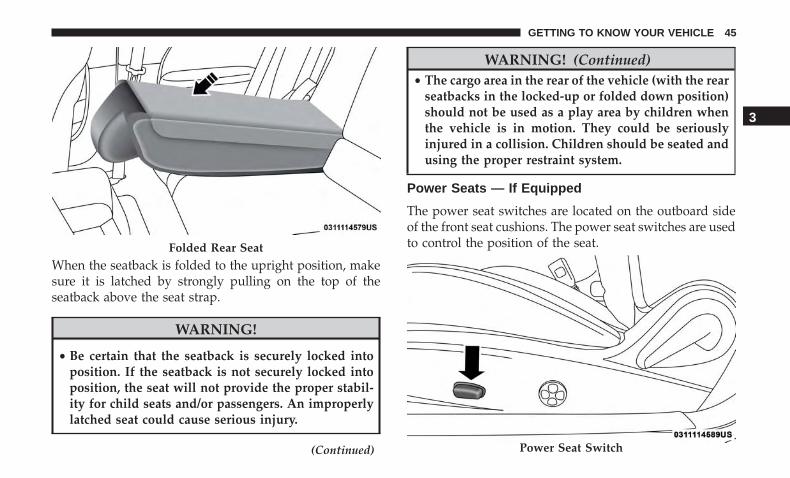
When the seatback is folded to the upright position, makesure it is latched by strongly pulling on the top of theseatback above the seat strap.
WARNING!
• Be certain that the seatback is securely locked intoposition. If the seatback is not securely locked intoposition, the seat will not provide the proper stabil-ity for child seats and/or passengers. An improperlylatched seat could cause serious injury.
(Continued)
WARNING! (Continued)• The cargo area in the rear of the vehicle (with the rear
seatbacks in the locked-up or folded down position)should not be used as a play area by children whenthe vehicle is in motion. They could be seriouslyinjured in a collision. Children should be seated andusing the proper restraint system.
Power Seats — If Equipped
The power seat switches are located on the outboard sideof the front seat cushions. The power seat switches are usedto control the position of the seat.Folded Rear Seat
Power Seat Switch
3
GETTING TO KNOW YOUR VEHICLE 45
Adjusting The Seat Forward Or Rearward
The seat can be adjusted both forward and rearward. Pushthe seat switch forward or rearward. The seat will move inthe direction of the switch. Release the switch when thedesired position has been reached.
Adjusting The Seat Up Or Down
The height of the seats can be adjusted up or down. Pullupward or push downward on the seat switch; the seat willmove in the direction of the switch. Release the switchwhen the desired position has been reached.
Tilting The Seat Up Or Down
The angle of the seat cushion can be adjusted up or down.Pull upward or push downward on the front of the seatswitch. The front of the seat cushion will move in thedirection of the switch. Release the switch when thedesired position has been reached.
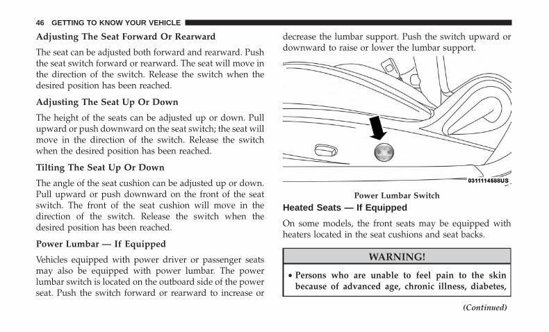
Power Lumbar — If Equipped
Vehicles equipped with power driver or passenger seatsmay also be equipped with power lumbar. The powerlumbar switch is located on the outboard side of the powerseat. Push the switch forward or rearward to increase or
decrease the lumbar support. Push the switch upward ordownward to raise or lower the lumbar support.
Heated Seats — If Equipped
On some models, the front seats may be equipped withheaters located in the seat cushions and seat backs.
WARNING!
• Persons who are unable to feel pain to the skinbecause of advanced age, chronic illness, diabetes,
(Continued)
Power Lumbar Switch
46 GETTING TO KNOW YOUR VEHICLE

WARNING! (Continued)spinal cord injury, medication, alcohol use, exhaus-tion or other physical condition must exercise carewhen using the seat heater. It may cause burns evenat low temperatures, especially if used for longperiods of time.
• Do not place anything on the seat or seatback thatinsulates against heat, such as a blanket or cushion.This may cause the seat heater to overheat. Sitting ina seat that has been overheated could cause seriousburns due to the increased surface temperature of theseat.
Front Heated Seats
The front heated seat control buttons are located within theclimate or controls screen of the touchscreen.
You can choose from HI, LO, or OFF heat settings. Theindicator arrows in touchscreen buttons indicate the levelof heat in use. Two indicator arrows will illuminate for HI,and one for LO. Turning the heating elements off willreturn the user to the radio screen.
• Press the heated seat button once to turn the HIsetting on.
• Press the heated seat button a second time to turnthe LO setting on.
• Press the heated seat button a third time to turn theheating elements off.
If the HI-level setting is selected, the system will automati-cally switch to LO-level after approximately 60 minutes ofcontinuous operation. At that time, the display will changefrom HI to LO, indicating the change. The LO-level settingwill turn off automatically after approximately 45 minutes.
NOTE:
• Once a heat setting is selected, heat will be felt withintwo to five minutes.
• The engine must be running for the heated seats tooperate.
Vehicles Equipped With Remote Start
On models that are equipped with remote start, the heatedseats can be programmed to come on during a remote start.
This feature can be programmed through the Uconnectsystem. Refer to “Uconnect Settings” in “Multimedia” forfurther information.
3
GETTING TO KNOW YOUR VEHICLE 47
WARNING!
• Persons who are unable to feel pain to the skinbecause of advanced age, chronic illness, diabetes,spinal cord injury, medication, alcohol use, exhaus-tion or other physical condition must exercise carewhen using the seat heater. It may cause burns evenat low temperatures, especially if used for longperiods of time.
• Do not place anything on the seat or seatback thatinsulates against heat, such as a blanket or cushion.This may cause the seat heater to overheat. Sitting ina seat that has been overheated could cause seriousburns due to the increased surface temperature of theseat.
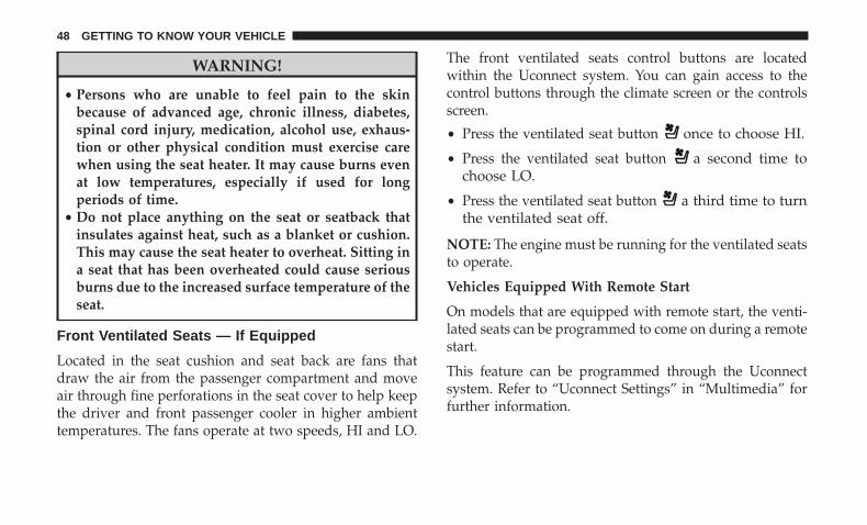
Front Ventilated Seats — If Equipped
Located in the seat cushion and seat back are fans thatdraw the air from the passenger compartment and moveair through fine perforations in the seat cover to help keepthe driver and front passenger cooler in higher ambienttemperatures. The fans operate at two speeds, HI and LO.
The front ventilated seats control buttons are locatedwithin the Uconnect system. You can gain access to thecontrol buttons through the climate screen or the controlsscreen.
• Press the ventilated seat button once to choose HI.
• Press the ventilated seat button a second time tochoose LO.
• Press the ventilated seat button a third time to turnthe ventilated seat off.
NOTE: The engine must be running for the ventilated seatsto operate.
Vehicles Equipped With Remote Start
On models that are equipped with remote start, the venti-lated seats can be programmed to come on during a remotestart.
This feature can be programmed through the Uconnectsystem. Refer to “Uconnect Settings” in “Multimedia” forfurther information.
48 GETTING TO KNOW YOUR VEHICLE
Vehicles Without Passenger Seating Installed
All passenger occupants within the vehicle must be in aseat equipped with a Seat Belt System and Head Restraintfor the safety of the passenger. If the passenger and/or rearseats have been removed, do not ride in those areas.
This vehicle has been designed to maximize total perfor-mance. In doing so, the deletion of passenger seats and/orrear seat may affect the NVH (Noise, Vibration, andHarshness) characteristics. As a result, the interior (drivercockpit) Noise, Vibration, and Harshness (NVH) will belouder overall.
WARNING!
• If the passenger and/or rear seats have been re-moved, do not ride in those areas. In a collision,people riding in these areas are more likely to beseriously injured or killed.
• If this vehicle was not factory equipped with apassenger seat, NEVER attempt to install a passengerseat because the safety systems, including the airbags and seatbelt, may not properly protect you.
(Continued)
WARNING! (Continued)• It is dangerous to ride in a cargo area, inside or
outside of a vehicle. In a collision, people riding inthis area are more likely to be seriously injured orkilled.
• Only ride in available seating positions equippedwith seat belt systems. Always properly wear yourseat belt. Failure to do so could result in an increasedrisk of serious injury or death in the event of anaccident.
• Be sure everyone in your vehicle is in a seat andusing a seat belt properly. Occupants, including thedriver, should always wear their seat belts whetheror not an air bag is also provided at their seatingpositions to minimize the risk of severe injury ordeath in the event of a crash.
• All occupants, including the driver, should not oper-ate a vehicle or sit in a vehicle’s seat if the headrestraints are not in place of their proper positions inorder to minimize the risk of neck injury in the eventof a crash.
(Continued)
3
GETTING TO KNOW YOUR VEHICLE 49
WARNING! (Continued)• Head restraints should never be adjusted while the
vehicle is in motion. Driving a vehicle with the headrestraints improperly adjusted or removed couldcause serious injury or death in the event of acollision.
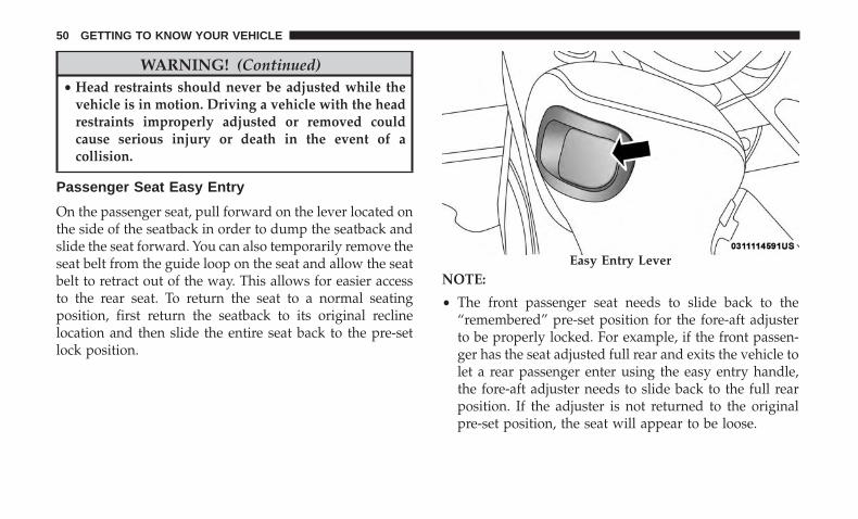
Passenger Seat Easy Entry
On the passenger seat, pull forward on the lever located onthe side of the seatback in order to dump the seatback andslide the seat forward. You can also temporarily remove theseat belt from the guide loop on the seat and allow the seatbelt to retract out of the way. This allows for easier accessto the rear seat. To return the seat to a normal seatingposition, first return the seatback to its original reclinelocation and then slide the entire seat back to the pre-setlock position.
NOTE:
• The front passenger seat needs to slide back to the“remembered” pre-set position for the fore-aft adjusterto be properly locked. For example, if the front passen-ger has the seat adjusted full rear and exits the vehicle tolet a rear passenger enter using the easy entry handle,the fore-aft adjuster needs to slide back to the full rearposition. If the adjuster is not returned to the originalpre-set position, the seat will appear to be loose.
Easy Entry Lever
50 GETTING TO KNOW YOUR VEHICLE
• Also, if the front passenger uses the easy entry handleand then lifts up the recliner handle without moving theseat back to its original pre-set position, the recliner willnot lock until it is moved to the full recline position.
HEAD RESTRAINTS
Head restraints are designed to reduce the risk of injury byrestricting head movement in the event of a rear-impact.Head restraints should be adjusted so that the top of thehead restraint is located above the top of your ear.
WARNING!
• All occupants, including the driver, should not oper-ate a vehicle or sit in a vehicle’s seat until the headrestraints are placed in their proper positions inorder to minimize the risk of neck injury in the eventof a crash.
• Head restraints should never be adjusted while thevehicle is in motion. Driving a vehicle with the headrestraints improperly adjusted or removed couldcause serious injury or death in the event of acollision.
NOTE: Do not reverse the head restraints (making the rearof the head restraint face forward) in an attempt to gainadditional clearance to the back of your head.
Reactive Head Restraints — Front Seats
The front driver and passenger seats are equipped withReactive Head Restraints (RHR). In the event of a rearimpact, the RHRs will automatically extend forward mini-mizing the gap between the back of the occupants headand the RHR.
The RHRs will automatically return to their normal positionfollowing a rear impact. If the RHRs do not return to theirnormal position, see your authorized dealer immediately.
3
GETTING TO KNOW YOUR VEHICLE 51

To raise the head restraint, pull upward on the headrestraint. To lower the head restraint, push the adjustmentbutton located at the base of the head restraint and pushdownward on the head restraint.
To remove the head restraint, remove the seat belt from theseat belt loop. Raise the head restraint as far as it can go.Then, push the adjustment button and the release button atthe base of each post while pulling the head restraint up. To
reinstall the head restraint, put the head restraint posts intothe holes while pushing the adjustment button and releasebutton. Then, adjust it to the appropriate height.
NOTE: It may be necessary to recline the front seat beforeremoving the head restraint to provide enough clearancefrom the roof.
WARNING!
• A loose head restraint thrown forward in a collisionor hard stop could cause serious injury or death tooccupants of the vehicle. Always securely stow re-moved head restraints in a location outside theoccupant compartment.
• ALL the head restraints MUST be reinstalled in thevehicle to properly protect the occupants. Follow there-installation instructions above prior to operatingthe vehicle or occupying a seat.
• Do not place items over the top of the Reactive HeadRestraint, such as coats, seat covers or portable DVDplayers. These items may interfere with the opera-tion of the Reactive Head Restraint in the event of acollision and could result in serious injury or death.
Head Restraint1 — Release Button2 — Adjustment Button3 — Seat Belt Loop
52 GETTING TO KNOW YOUR VEHICLE
Rear Head Restraints
The rear outboard head restraints are non-adjustable andare designed to reduce the risk of injury by restricting headmovement in the event of a rear impact.
Vehicles Without Passenger Seating Installed
All passenger occupants within the vehicle must be in aseat equipped with a Seat Belt System and Head Restraintfor the safety of the passenger. If the passenger and/or rearseats have been removed, do not ride in those areas.
This vehicle has been designed to maximize total perfor-mance. In doing so, the deletion of passenger seats and/orrear seat may affect the NVH (Noise, Vibration, andHarshness) characteristics. As a result, the interior (drivercockpit) Noise, Vibration, and Harshness (NVH) will belouder overall.
WARNING!
• If the passenger and/or rear seats have been re-moved, do not ride in those areas. In a collision,people riding in these areas are more likely to beseriously injured or killed.
(Continued)
WARNING! (Continued)• If this vehicle was not factory equipped with a
passenger seat, NEVER attempt to install a passengerseat because the safety systems, including the airbags and seatbelt, may not properly protect you.
• It is dangerous to ride in a cargo area, inside oroutside of a vehicle. In a collision, people riding inthis area are more likely to be seriously injured orkilled.
• Only ride in available seating positions equippedwith seat belt systems. Always properly wear yourseat belt. Failure to do so could result in an increasedrisk of serious injury or death in the event of anaccident.
• Be sure everyone in your vehicle is in a seat andusing a seat belt properly. Occupants, including thedriver, should always wear their seat belts whetheror not an air bag is also provided at their seatingpositions to minimize the risk of severe injury ordeath in the event of a crash.
(Continued)
3
GETTING TO KNOW YOUR VEHICLE 53
WARNING! (Continued)• All occupants, including the driver, should not oper-
ate a vehicle or sit in a vehicle’s seat if the headrestraints are not in place of their proper positions inorder to minimize the risk of neck injury in the eventof a crash.
• Head restraints should never be adjusted while thevehicle is in motion. Driving a vehicle with the headrestraints improperly adjusted or removed couldcause serious injury or death in the event of acollision.
STEERING WHEEL
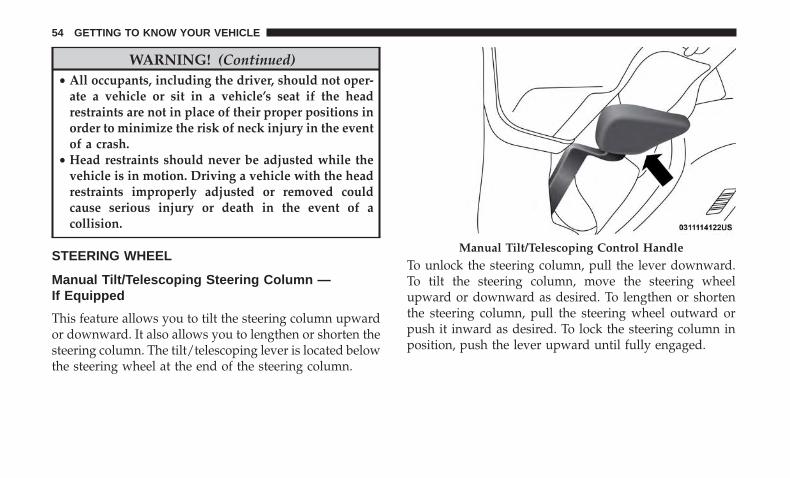
Manual Tilt/Telescoping Steering Column —If Equipped
This feature allows you to tilt the steering column upwardor downward. It also allows you to lengthen or shorten thesteering column. The tilt/telescoping lever is located belowthe steering wheel at the end of the steering column.
To unlock the steering column, pull the lever downward.To tilt the steering column, move the steering wheelupward or downward as desired. To lengthen or shortenthe steering column, pull the steering wheel outward orpush it inward as desired. To lock the steering column inposition, push the lever upward until fully engaged.
Manual Tilt/Telescoping Control Handle
54 GETTING TO KNOW YOUR VEHICLE

WARNING!
Do not adjust the steering column while driving.Adjusting the steering column while driving or driv-ing with the steering column unlocked, could cause thedriver to lose control of the vehicle. Failure to followthis warning may result in serious injury or death.
Power Tilt/Telescoping Steering Column —If Equipped
This feature allows you to tilt the steering column upwardor downward. It also allows you to lengthen or shorten thesteering column. The power tilt/telescoping steering col-umn switch is located below the multifunction switch onthe steering column.
To tilt the steering column, move the switch up or down asdesired. To lengthen or shorten the steering column, pullthe switch toward you or push the switch away from youas desired.
WARNING!
Do not adjust the steering column while driving.Adjusting the steering column while driving or driv-ing with the steering column unlocked, could cause thedriver to lose control of the vehicle. Failure to followthis warning may result in serious injury or death.
Power Tilt/Telescoping Switch
3
GETTING TO KNOW YOUR VEHICLE 55
Heated Steering Wheel — If Equipped
The steering wheel contains a heating element that helpswarm your hands in cold weather. The heated steeringwheel has only one temperature setting. Once the heatedsteering wheel has been turned on, it will stay on for anaverage of 80 minutes before automatically shutting off.This time will vary based on environmental temperatures.The heated steering wheel can shut off early or may notturn on when the steering wheel is already warm.
The heated steering wheel control button is located withinthe Uconnect system. You can gain access to the controlbutton through the climate screen or the controls screen.
• Press the heated steering wheel button once to turnthe heating element on.
• Press the heated steering wheel button a second timeto turn the heating element off.
NOTE: The engine must be running for the heated steeringwheel to operate.
Vehicles Equipped With Remote Start
On models that are equipped with remote start, the heatedsteering wheel can be programmed to come on during aremote start through the Uconnect system. Refer to“Uconnect Settings” in “Multimedia” for further informa-tion.
WARNING!
• Persons who are unable to feel pain to the skinbecause of advanced age, chronic illness, diabetes,spinal cord injury, medication, alcohol use, exhaus-tion, or other physical conditions must exercise carewhen using the steering wheel heater. It may causeburns even at low temperatures, especially if usedfor long periods.
• Do not place anything on the steering wheel thatinsulates against heat, such as a blanket or steeringwheel covers of any type and material. This maycause the steering wheel heater to overheat.
56 GETTING TO KNOW YOUR VEHICLE

MIRRORS
Automatic Dimming Mirror
The mirror head can be adjusted up, down, left, and rightfor various drivers. The mirror should be adjusted to centeron the view through the rear window.
This mirror automatically adjusts for headlight glare fromvehicles behind you.
NOTE: The Automatic Dimming feature is disabled whenthe vehicle is in REVERSE to improve rear view viewing.
The Automatic Dimming feature can be turned on or offthrough the touchscreen.
• Press the mirror dimmer button once to turn the featureon. The soft key button will illuminate when activated.
• Press the mirror dimmer button a second time to turnthe feature off, and the soft key button will no longer beilluminated.
CAUTION!
To avoid damage to the mirror during cleaning, neverspray any cleaning solution directly onto the mirror.Apply the solution onto a clean cloth and wipe themirror clean.
Automatic Dimming Mirror
3
GETTING TO KNOW YOUR VEHICLE 57
Outside Mirrors
To receive maximum benefit, adjust the outside mirror(s) tocenter on the adjacent lane of traffic and a slight overlap ofthe view obtained from the inside mirror.
NOTE: The passenger side convex outside mirror will givea much wider view to the rear, and especially of the lanenext to your vehicle.
WARNING!
Vehicles and other objects seen in an outside convexmirror will look smaller and farther away than theyreally are. Relying too much on side convex mirrorscould cause you to collide with another vehicle or otherobject. Use your inside mirror when judging the size ordistance of a vehicle seen in a side convex mirror.
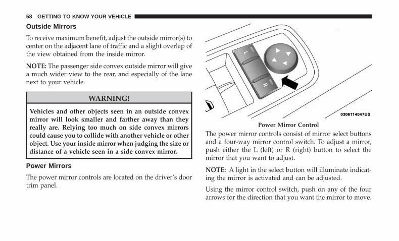
Power Mirrors
The power mirror controls are located on the driver’s doortrim panel.
The power mirror controls consist of mirror select buttonsand a four-way mirror control switch. To adjust a mirror,push either the L (left) or R (right) button to select themirror that you want to adjust.
NOTE: A light in the select button will illuminate indicat-ing the mirror is activated and can be adjusted.
Using the mirror control switch, push on any of the fourarrows for the direction that you want the mirror to move.
Power Mirror Control
58 GETTING TO KNOW YOUR VEHICLE

Heated Mirrors — If Equipped
These mirrors are heated to melt frost or ice. Thisfeature will be activated whenever you turn on the
rear window defroster (if equipped). Refer to “ClimateControls” in “Getting To Know Your Vehicle” for furtherinformation.
Illuminated Vanity Mirrors
An illuminated vanity mirror is on the sun visor. To use themirror, rotate the sun visor downward and swing themirror cover upward. The light turns on automatically.Close the mirror cover to turn off the light.
“Slide-On-Rod” And Extender Features Of SunVisor
To use the “Slide-On-Rod” feature of the sun visor, rotatethe sun visor downward and swing the sun visor so it isparallel to the side window, pull the sun visor rearwardsuntil it is in the desired position. To use the extenderfeature of the sun visor, grab the extender which is locatedat the rear of the visor and pull rearward.
Illuminated Vanity Mirror
Slide-On-Rod Extender
3
GETTING TO KNOW YOUR VEHICLE 59
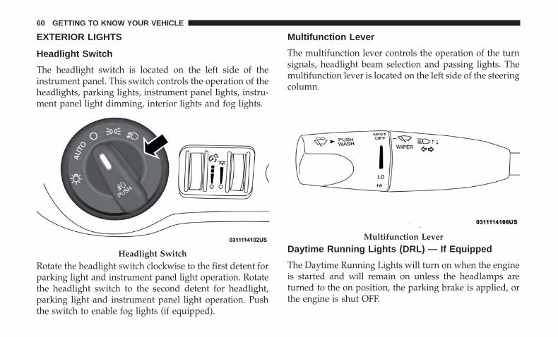
EXTERIOR LIGHTS
Headlight Switch
The headlight switch is located on the left side of theinstrument panel. This switch controls the operation of theheadlights, parking lights, instrument panel lights, instru-ment panel light dimming, interior lights and fog lights.
Rotate the headlight switch clockwise to the first detent forparking light and instrument panel light operation. Rotatethe headlight switch to the second detent for headlight,parking light and instrument panel light operation. Pushthe switch to enable fog lights (if equipped).
Multifunction Lever
The multifunction lever controls the operation of the turnsignals, headlight beam selection and passing lights. Themultifunction lever is located on the left side of the steeringcolumn.
Daytime Running Lights (DRL) — If Equipped
The Daytime Running Lights will turn on when the engineis started and will remain on unless the headlamps areturned to the on position, the parking brake is applied, orthe engine is shut OFF.
Headlight Switch
Multifunction Lever
60 GETTING TO KNOW YOUR VEHICLE
NOTE: If allowed by law in the country in which thevehicle was purchased, the Daytime Running Lights can beturned on and off using the Uconnect System, refer to“Uconnect Settings” in “Multimedia” for further informa-tion.
High/Low Beam Switch
Push the multifunction lever away from you to switch theheadlights to high beam. Pull the multifunction levertoward you to switch the headlights back to low beam.
Automatic High Beam Headlamp Control — IfEquipped
The Automatic High Beam Headlamp Control systemprovides increased forward lighting at night by automat-ing high beam control through the use of a digital cameramounted on the windshield. This camera detects vehiclespecific light and automatically switches from high beamsto low beams until the approaching vehicle is out of view.
NOTE:
• The Automatic High Beam Headlamp Control can beturned on or off using the Uconnect System. Refer to“Uconnect Settings” in “Multimedia” for further infor-mation.
• Broken, muddy, or obstructed headlights and taillightsof vehicles in the field of view will cause headlights toremain on longer (closer to the vehicle). Also, dirt, film,and other obstructions on the windshield or camera lenswill cause the system to function improperly.
If the windshield or Automatic High Beam HeadlampControl mirror is replaced, the mirror must be re-aimed toensure proper performance. See your local authorizeddealer.
Flash-To-Pass
You can signal another vehicle with your headlights bylightly pulling the multifunction lever toward you. Thiswill turn on the high beam headlights until the lever isreleased.
NOTE: If the multifunction lever is held in the flash-to passposition for more than 20 seconds, the high beams will shutoff.
Automatic Headlights
This system automatically turns the headlights on or offaccording to ambient light levels. To turn the system on,rotate the headlight switch counterclockwise to the AUTOposition. When the system is on, the headlight time delayfeature is also on. This means the headlights will stay on
3
GETTING TO KNOW YOUR VEHICLE 61
for up to 90 seconds after you place the ignition into theOFF position. The headlight time delay can be pro-grammed 0/30/60/90 seconds.
Refer to “Uconnect Settings” in “Multimedia” for furtherinformation.
To turn the automatic system off, move the headlightswitch out of the AUTO position.
NOTE: The engine must be running before the headlightswill come on in the automatic mode.
Parking Lights
Turn the headlight switch knob to the first detent to turnthe parking lights on. This also turns on all instrumentpanel lighting.
Headlights On With Wipers
When this feature is active, the headlights will turn on afterthe wipers are turned on if the headlight switch is placed inthe AUTO position and programmable feature is set to on.In addition, the headlights will turn off when the wipersare turned off if they were turned on by this feature.
NOTE: The “Headlights On With Wipers” feature can beturned on or off using the Uconnect System. Refer to“Uconnect Settings” in “Multimedia” for further information.
Headlight Time Delay
This feature provides the safety of headlight illuminationfor up to 90 seconds when leaving your vehicle in an unlitarea with the headlight switch in the O (off) position.
To activate the delay feature, turn OFF the ignition switchwhile the headlights are still on. Then, turn off the head-lights within 45 seconds. The delay interval begins whenthe headlight switch is turned off.
NOTE: The lights must be turned off within 45 seconds ofturning the ignition OFF to activate this feature.
If you turn the headlights, park lights or ignition switchON again, the system will cancel the delay.
If you turn the headlights off before the ignition, they willturn off in the normal manner.
NOTE: The Headlight Time Delay is programmable usingthe Uconnect System, refer to “Uconnect Settings” in“Multimedia” for further information.
Lights-On Reminder
If the headlights or parking lights are on after the ignitionis placed in the OFF position, a chime will sound to alertthe driver when the driver’s door is opened.
62 GETTING TO KNOW YOUR VEHICLE
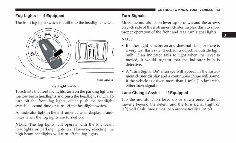
Fog Lights — If Equipped
The front fog light switch is built into the headlight switch.
To activate the front fog lights, turn on the parking lights orthe low beam headlights and push the headlight switch. Toturn off the front fog lights, either push the headlightswitch a second time or turn off the headlight switch.
An indicator light in the instrument cluster display illumi-nates when the fog lights are turned on.
NOTE: The fog lights will operate with the low beamheadlights or parking lights on. However, selecting thehigh beam headlights will turn off the fog lights.
Turn Signals
Move the multifunction lever up or down and the arrowson each side of the instrument cluster display flash to showproper operation of the front and rear turn signal lights.
NOTE:
• If either light remains on and does not flash, or there isa very fast flash rate, check for a defective outside lightbulb. If an indicator fails to light when the lever ismoved, it would suggest that the indicator bulb isdefective.
• A “Turn Signal On” message will appear in the instru-ment cluster display and a continuous chime will soundif the vehicle is driven more than 1 mile (1.6 km) witheither turn signal on.
Lane Change Assist — If Equipped
Tap the multifunction lever up or down once, withoutmoving beyond the detent, and the turn signal (right orleft) will flash three times then automatically turn off.
Fog Light Switch
3
GETTING TO KNOW YOUR VEHICLE 63
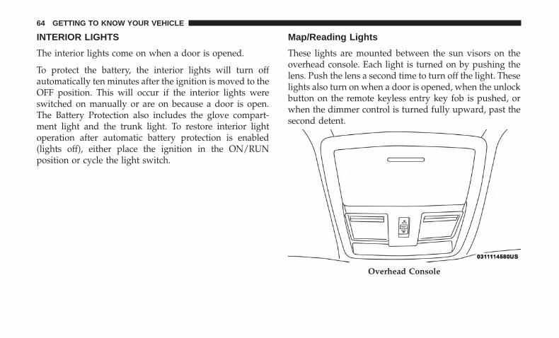
INTERIOR LIGHTS
The interior lights come on when a door is opened.
To protect the battery, the interior lights will turn offautomatically ten minutes after the ignition is moved to theOFF position. This will occur if the interior lights wereswitched on manually or are on because a door is open.The Battery Protection also includes the glove compart-ment light and the trunk light. To restore interior lightoperation after automatic battery protection is enabled(lights off), either place the ignition in the ON/RUNposition or cycle the light switch.
Map/Reading Lights
These lights are mounted between the sun visors on theoverhead console. Each light is turned on by pushing thelens. Push the lens a second time to turn off the light. Theselights also turn on when a door is opened, when the unlockbutton on the remote keyless entry key fob is pushed, orwhen the dimmer control is turned fully upward, past thesecond detent.
Overhead Console
64 GETTING TO KNOW YOUR VEHICLE
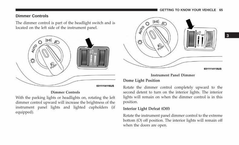
Dimmer Controls
The dimmer control is part of the headlight switch and islocated on the left side of the instrument panel.
With the parking lights or headlights on, rotating the leftdimmer control upward will increase the brightness of theinstrument panel lights and lighted cupholders (ifequipped).
Dome Light Position
Rotate the dimmer control completely upward to thesecond detent to turn on the interior lights. The interiorlights will remain on when the dimmer control is in thisposition.
Interior Light Defeat (Off)
Rotate the instrument panel dimmer control to the extremebottom (O) off position. The interior lights will remain offwhen the doors are open.
Dimmer Controls
Instrument Panel Dimmer
3
GETTING TO KNOW YOUR VEHICLE 65
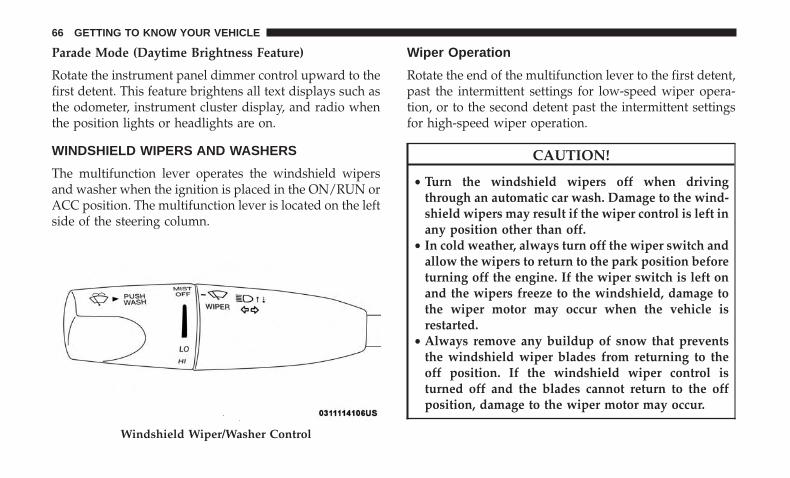
Parade Mode (Daytime Brightness Feature)
Rotate the instrument panel dimmer control upward to thefirst detent. This feature brightens all text displays such asthe odometer, instrument cluster display, and radio whenthe position lights or headlights are on.
WINDSHIELD WIPERS AND WASHERS
The multifunction lever operates the windshield wipersand washer when the ignition is placed in the ON/RUN orACC position. The multifunction lever is located on the leftside of the steering column.
Wiper Operation
Rotate the end of the multifunction lever to the first detent,past the intermittent settings for low-speed wiper opera-tion, or to the second detent past the intermittent settingsfor high-speed wiper operation.
CAUTION!
• Turn the windshield wipers off when drivingthrough an automatic car wash. Damage to the wind-shield wipers may result if the wiper control is left inany position other than off.
• In cold weather, always turn off the wiper switch andallow the wipers to return to the park position beforeturning off the engine. If the wiper switch is left onand the wipers freeze to the windshield, damage tothe wiper motor may occur when the vehicle isrestarted.
• Always remove any buildup of snow that preventsthe windshield wiper blades from returning to theoff position. If the windshield wiper control isturned off and the blades cannot return to the offposition, damage to the wiper motor may occur.
Windshield Wiper/Washer Control
66 GETTING TO KNOW YOUR VEHICLE
Intermittent Wiper System
Use the intermittent wiper when weather conditions makea single wiping cycle with a variable pause between cyclesdesirable. Rotate the end of the multifunction lever to thefirst detent position, and then turn the end of the lever toselect the desired delay interval. There are four delaysettings, which allow you to regulate the wipe intervalfrom a minimum of one cycle every second to a maximumof approximately 36 seconds between cycles. The delayintervals will double in duration when the vehicle speed is10 mph (16 km/h) or less.
Windshield Washers
To use the washer, push the multifunction lever inward(toward the steering column) and hold it for as long aswasher spray is desired.
If you activate the washer while the windshield wipercontrol is in the delay range, the wipers will operate fortwo wipe cycles after releasing the lever and then resumethe intermittent interval previously selected.
If you activate the washer while the windshield wiper isturned off, the wipers will operate for three wipe cyclesand then turn off.
WARNING!
Sudden loss of visibility through the windshield couldlead to a collision. You might not see other vehicles orother obstacles. To avoid sudden icing of the wind-shield during freezing weather, warm the windshieldwith the defroster before and during windshieldwasher use.
Mist Feature
Rotate the end of the lever downward to the MIST positionto activate a single wipe cycle to clear off road mist or sprayfrom a passing vehicle. The wipers will continue to operateuntil you release the multifunction lever.
NOTE: The mist feature does not activate the washerpump; therefore, no washer fluid will be sprayed on thewindshield. The wash function must be used in order tospray the windshield with washer fluid.
3
GETTING TO KNOW YOUR VEHICLE 67
Rain Sensing Wipers — If Equipped
This feature senses rain or snowfall on the windshield andautomatically activates the wipers for the driver. Thefeature is especially useful for road splash or oversprayfrom the windshield washers of the vehicle ahead. Rotatethe end of the multifunction lever to one of four settings toactivate this feature.
The sensitivity of the system can be adjusted with themultifunction lever. Wiper delay position 1 is the leastsensitive, and wiper delay position 4 is the most sensitive.Setting 3 should be used for normal rain conditions.Settings 1 and 2 can be used if the driver desires less wipersensitivity. Setting 4 can be used if the driver desires moresensitivity. Place the wiper switch in the off position whennot using the system.
NOTE:
• The Rain Sensing feature will not operate when thewiper switch is in the low or high-speed position.
• The Rain Sensing feature may not function properlywhen ice, or dried salt water is present on the wind-shield.
• Use of Rain-X or products containing wax or siliconemay reduce Rain Sensing performance.
The Rain Sensing system has protection features for thewiper blades and arms, and will not operate under thefollowing conditions:
• Low Ambient Temperature — When the ignition is firstturned ON, the Rain Sensing system will not operateuntil the wiper switch is moved, vehicle speed is greaterthan 0 mph (0 km/h), or the outside temperature isgreater than 32°F (0°C).
• Transmission In NEUTRAL Position — When the igni-tion is ON, and the transmission is in the NEUTRALposition, the Rain Sensing system will not operate untilthe wiper switch is moved, vehicle speed is greater than3 mph (5 km/h), or the gear selector is moved out of theNEUTRAL position.
NOTE: Rain Sensing can be turned on and off using theUconnect System, refer to “Uconnect Settings” in “Multi-media” for further information.
CLIMATE CONTROLS
The Climate Control System allows you to regulate thetemperature, air flow, and direction of air circulatingthroughout the vehicle. The controls are located on thetouchscreen (if equipped) and on the instrument panelbelow the radio.
68 GETTING TO KNOW YOUR VEHICLE
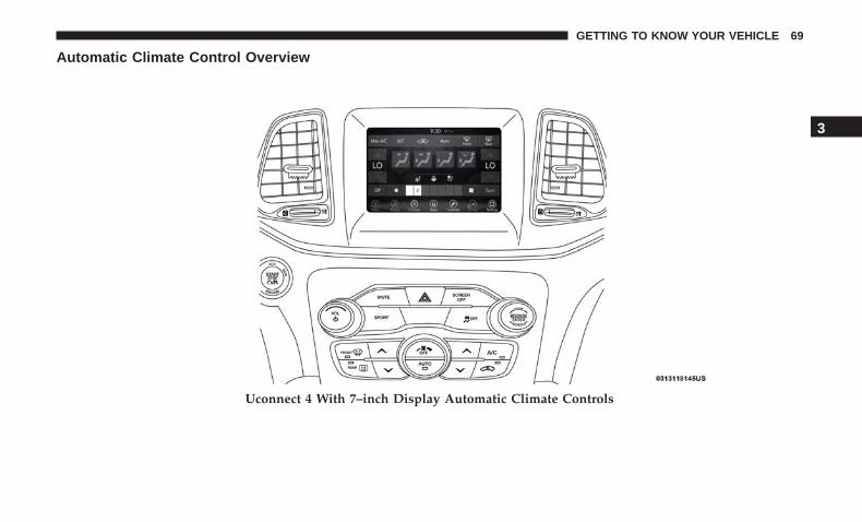
Automatic Climate Control Overview
Uconnect 4 With 7–inch Display Automatic Climate Controls
3
GETTING TO KNOW YOUR VEHICLE 69

NOTE: Interior trims may vary. 6.4L vehicles will receive a“SRT” button rather than a �Sport” button on the Instru-ment Panel.
Uconnect 4C/4C NAV With 8.4–inch Display Automatic Climate Controls
70 GETTING TO KNOW YOUR VEHICLE
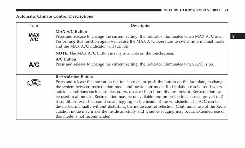
Automatic Climate Control Descriptions
Icon DescriptionMAX A/C ButtonPress and release to change the current setting, the indicator illuminates when MAX A/C is on.Performing this function again will cause the MAX A/C operation to switch into manual modeand the MAX A/C indicator will turn off.
NOTE: The MAX A/C button is only available on the touchscreen.A/C ButtonPress and release to change the current setting, the indicator illuminates when A/C is on.
Recirculation ButtonPress and release this button on the touchscreen, or push the button on the faceplate, to changethe system between recirculation mode and outside air mode. Recirculation can be used whenoutside conditions such as smoke, odors, dust, or high humidity are present. Recirculation canbe used in all modes. Recirculation may be unavailable (button on the touchscreen greyed out)if conditions exist that could create fogging on the inside of the windshield. The A/C can bedeselected manually without disturbing the mode control selection. Continuous use of the Recir-culation mode may make the inside air stuffy and window fogging may occur. Extended use ofthis mode is not recommended.
3
GETTING TO KNOW YOUR VEHICLE 71

Icon DescriptionAUTO ButtonAutomatically controls the interior cabin temperature by adjusting airflow distribution andamount. Toggling this function will cause the system to switch between manual mode and auto-matic modes.Refer to “Automatic Operation” within this section for more information.Front Defrost ButtonPress and release to change the current airflow setting to Defrost mode. The indicator illumi-nates when this feature is on. Air comes from the windshield and side window demist outlets.When the defrost button is selected, the blower level may increase. Use Defrost mode withmaximum temperature settings for best windshield and side window defrosting and defogging.When toggling the Front Mode Defrost button, the climate system will return to the previoussetting.Rear Defrost ButtonPush and release the Rear Defrost Control button to turn on the rear window defroster and theheated outside mirrors (if equipped). An indicator will illuminate when the rear window de-froster is on. The rear window defroster automatically turns off after ten minutes.Driver And Passenger Temperature Up And Down ButtonsProvides the driver and passenger with independent temperature control. Push the red buttonon the faceplate or touchscreen or press and slide the temperature bar towards the red arrowbutton on the touchscreen for warmer temperature settings. Push the blue button on the face-plate or touchscreen or press and slide the temperature bar towards the blue arrow on thetouchscreen for cooler temperature settings.
72 GETTING TO KNOW YOUR VEHICLE

Icon DescriptionSYNC ButtonPress the Sync button on the touchscreen to toggle the Sync feature on/off. The Sync indicator isilluminated when this feature is enabled. Sync is used to synchronize the passenger temperaturesetting with the driver temperature setting. Changing the passenger temperature setting whilein Sync will automatically exit this feature.
NOTE: The Sync button is only available on the touchscreen.Faceplate Knob
TouchscreenButtons
Blower ControlBlower Control is used to regulate the amount of air forced through the climate system. Thereare seven blower speeds available. The speeds can be selected using either the blower controlknob on the faceplate or the buttons on the touchscreen.• Faceplate: The blower speed increases as you turn the blower control knob clockwise from
the lowest blower setting. The blower speed decreases as you turn the blower control knobcounterclockwise.
• Touchscreen: Use the small blower icon to reduce the blower setting, and the large blowericon to increase the blower setting. Blower can also be selected by pressing the blower bararea between the icons.
3
GETTING TO KNOW YOUR VEHICLE 73
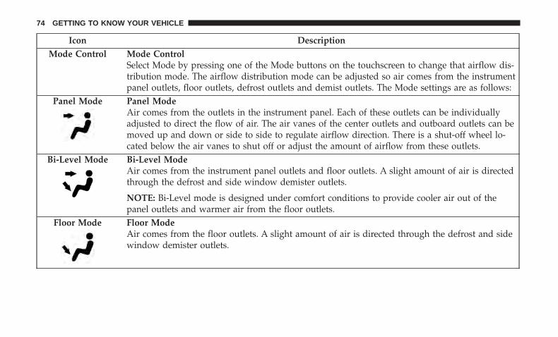
Icon DescriptionMode Control Mode Control
Select Mode by pressing one of the Mode buttons on the touchscreen to change that airflow dis-tribution mode. The airflow distribution mode can be adjusted so air comes from the instrumentpanel outlets, floor outlets, defrost outlets and demist outlets. The Mode settings are as follows:
Panel Mode Panel ModeAir comes from the outlets in the instrument panel. Each of these outlets can be individuallyadjusted to direct the flow of air. The air vanes of the center outlets and outboard outlets can bemoved up and down or side to side to regulate airflow direction. There is a shut-off wheel lo-cated below the air vanes to shut off or adjust the amount of airflow from these outlets.
Bi-Level Mode Bi-Level ModeAir comes from the instrument panel outlets and floor outlets. A slight amount of air is directedthrough the defrost and side window demister outlets.
NOTE: Bi-Level mode is designed under comfort conditions to provide cooler air out of thepanel outlets and warmer air from the floor outlets.
Floor Mode Floor ModeAir comes from the floor outlets. A slight amount of air is directed through the defrost and sidewindow demister outlets.
74 GETTING TO KNOW YOUR VEHICLE
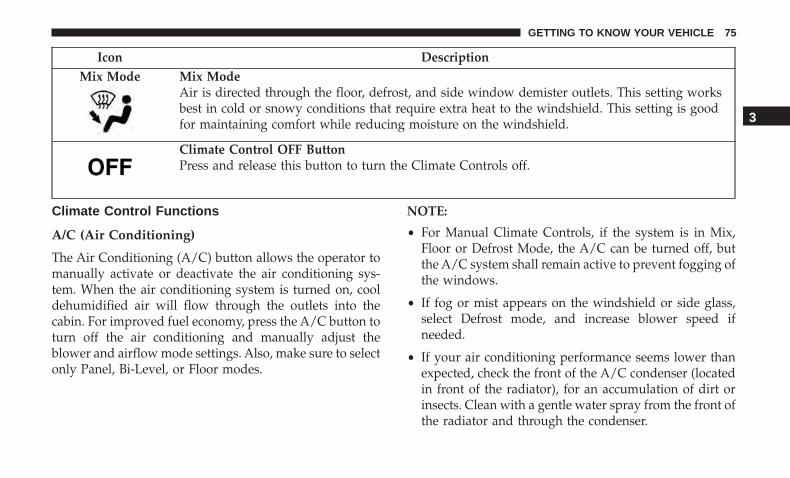
Icon DescriptionMix Mode Mix Mode
Air is directed through the floor, defrost, and side window demister outlets. This setting worksbest in cold or snowy conditions that require extra heat to the windshield. This setting is goodfor maintaining comfort while reducing moisture on the windshield.
Climate Control OFF ButtonPress and release this button to turn the Climate Controls off.
Climate Control Functions
A/C (Air Conditioning)
The Air Conditioning (A/C) button allows the operator tomanually activate or deactivate the air conditioning sys-tem. When the air conditioning system is turned on, cooldehumidified air will flow through the outlets into thecabin. For improved fuel economy, press the A/C button toturn off the air conditioning and manually adjust theblower and airflow mode settings. Also, make sure to selectonly Panel, Bi-Level, or Floor modes.
NOTE:
• For Manual Climate Controls, if the system is in Mix,Floor or Defrost Mode, the A/C can be turned off, butthe A/C system shall remain active to prevent fogging ofthe windows.
• If fog or mist appears on the windshield or side glass,select Defrost mode, and increase blower speed ifneeded.
• If your air conditioning performance seems lower thanexpected, check the front of the A/C condenser (locatedin front of the radiator), for an accumulation of dirt orinsects. Clean with a gentle water spray from the front ofthe radiator and through the condenser.
3
GETTING TO KNOW YOUR VEHICLE 75

MAX A/C
MAX A/C sets the control for maximum cooling perfor-mance.
Press and release to toggle between MAX A/C and theprior settings. The button illuminates when MAX A/C ison.
In MAX A/C, the blower level and mode position can beadjusted to desired user settings. Pressing other settingswill cause the MAX A/C operation to switch to the selectedsetting and MAX A/C to exit.
Recirculation
In cold weather, use of Recirculation mode may lead toexcessive window fogging. The Recirculation feature maybe unavailable (button on the touchscreen greyed out) ifconditions exist that could create fogging on the inside ofthe windshield.
Automatic Temperature Control (ATC)
Automatic Operation
1. Push the AUTO button on the faceplate, or the AUTObutton on the touchscreen on the Automatic Tempera-ture Control (ATC) Panel.
2. Next, adjust the temperature that you would like thesystem to maintain by adjusting the driver and passen-ger temperature control buttons. Once the desired tem-perature is displayed, the system will achieve andautomatically maintain that comfort level.
3. When the system is set up for your comfort level, it isnot necessary to change the settings. You will experiencethe greatest efficiency by simply allowing the system tofunction automatically.
NOTE:
• It is not necessary to move the temperature settings forcold or hot vehicles. The system automatically adjuststhe temperature, mode, and blower speed to providecomfort as quickly as possible.
• The temperature can be displayed in U.S. or Metric unitsby selecting the US/Metric customer-programmable fea-ture. Refer to the “Uconnect Settings” in “Multimedia”for further information.
To provide you with maximum comfort in the Automaticmode during cold start-ups, the blower fan will remain onlow until the engine warms up. The blower will increase inspeed and transition into Auto mode.
76 GETTING TO KNOW YOUR VEHICLE
Manual Operation Override
This system offers a full complement of manual overridefeatures. The AUTO symbol in the front ATC display willbe turned off when the system is being used in the manualmode.
Operating Tips
NOTE: Refer to the chart at the end of this section forsuggested control settings for various weather conditions.
Summer Operation
The engine cooling system must be protected with ahigh-quality antifreeze coolant to provide proper corrosionprotection and to protect against engine overheating. OATcoolant (conforming to MS.90032) is recommended.
Winter Operation
To ensure the best possible heater and defroster perfor-mance, make sure the engine cooling system is functioningproperly and the proper amount, type, and concentrationof coolant is used. Use of the Air Recirculation modeduring Winter months is not recommended, because it maycause window fogging.
Vacation/Storage
Before you store your vehicle, or keep it out of service (i.e.,vacation) for two weeks or more, run the air conditioningsystem at idle for about five minutes, in fresh air with theblower setting on high. This will ensure adequate systemlubrication to minimize the possibility of compressor dam-age when the system is started again.
Window Fogging
Vehicle windows tend to fog on the inside in mild, rainy,and/or humid weather. To clear the windows, select De-frost or Mix mode and increase the front blower speed. Donot use the Recirculation mode without A/C for longperiods, as fogging may occur.
CAUTION!
Failure to follow these cautions can cause damage tothe heating elements:• Use care when washing the inside of the rear win-
dow. Do not use abrasive window cleaners on theinterior surface of the window. Use a soft cloth and a
(Continued)
3
GETTING TO KNOW YOUR VEHICLE 77
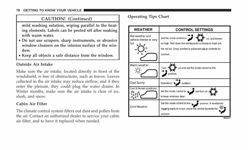
CAUTION! (Continued)mild washing solution, wiping parallel to the heat-ing elements. Labels can be peeled off after soakingwith warm water.
• Do not use scrapers, sharp instruments, or abrasivewindow cleaners on the interior surface of the win-dow.
• Keep all objects a safe distance from the window.
Outside Air Intake
Make sure the air intake, located directly in front of thewindshield, is free of obstructions, such as leaves. Leavescollected in the air intake may reduce airflow, and if theyenter the plenum, they could plug the water drains. InWinter months, make sure the air intake is clear of ice,slush, and snow.
Cabin Air Filter
The climate control system filters out dust and pollen fromthe air. Contact an authorized dealer to service your cabinair filter, and to have it replaced when needed.
Operating Tips Chart
78 GETTING TO KNOW YOUR VEHICLE

WINDOWS
Power Window Controls
The window controls on the driver’s door control all thedoor windows.
There are single window controls on the passenger doortrim panel, which operate the passenger door window. Thewindow controls will operate only when the ignition is inthe ACC or ON/RUN position.
NOTE: For vehicles equipped with the Uconnect system,the power window switches will remain active for up toten minutes after the ignition is placed in the OFF position.Opening either front door will cancel this feature. The timeis programmable. Refer to “Uconnect Settings” in “Multi-media” for further information.
WARNING!
Never leave children unattended in a vehicle, and donot let children play with power windows. Do notleave the key fob in or near the vehicle, or in a locationaccessible to children, and do not leave the ignition ofa vehicle equipped with Keyless Enter-N-Go in theACC or ON/RUN mode. Occupants, particularly unat-tended children, can become entrapped by the win-dows while operating the power window switches.Such entrapment may result in serious injury or death.
Power Window Switches
3
GETTING TO KNOW YOUR VEHICLE 79
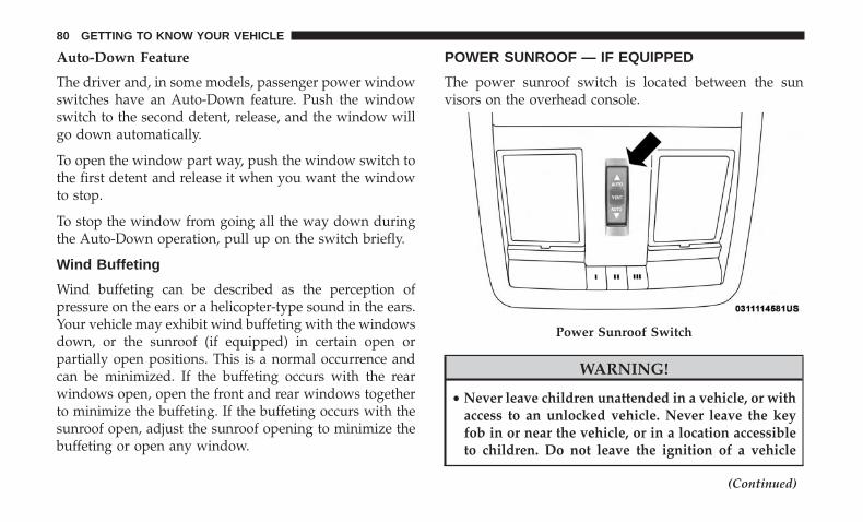
Auto-Down Feature
The driver and, in some models, passenger power windowswitches have an Auto-Down feature. Push the windowswitch to the second detent, release, and the window willgo down automatically.
To open the window part way, push the window switch tothe first detent and release it when you want the windowto stop.
To stop the window from going all the way down duringthe Auto-Down operation, pull up on the switch briefly.
Wind Buffeting
Wind buffeting can be described as the perception ofpressure on the ears or a helicopter-type sound in the ears.Your vehicle may exhibit wind buffeting with the windowsdown, or the sunroof (if equipped) in certain open orpartially open positions. This is a normal occurrence andcan be minimized. If the buffeting occurs with the rearwindows open, open the front and rear windows togetherto minimize the buffeting. If the buffeting occurs with thesunroof open, adjust the sunroof opening to minimize thebuffeting or open any window.
POWER SUNROOF — IF EQUIPPED
The power sunroof switch is located between the sunvisors on the overhead console.
WARNING!
• Never leave children unattended in a vehicle, or withaccess to an unlocked vehicle. Never leave the keyfob in or near the vehicle, or in a location accessibleto children. Do not leave the ignition of a vehicle
(Continued)
Power Sunroof Switch
80 GETTING TO KNOW YOUR VEHICLE
WARNING! (Continued)equipped with Keyless Enter-N-Go in the ACC orON/RUN mode. Occupants, particularly unattendedchildren, can become entrapped by the power sun-roof while operating the power sunroof switch. Suchentrapment may result in serious injury or death.
• In a collision, there is a greater risk of being thrownfrom a vehicle with an open sunroof. You could alsobe seriously injured or killed. Always fasten yourseat belt properly and make sure all passengers arealso properly secured.
• Do not allow small children to operate the sunroof.Never allow your fingers, other body parts, or anyobject, to project through the sunroof opening. In-jury may result.
Opening Sunroof
Express
Push the switch rearward and release it within one-halfsecond, the sunroof and sunshade will open automaticallyand stop at full open position. During Express Openoperation any other actuation of the sunroof switches willstop the sunroof in a partially open position.
Manual Mode
Push and hold the switch rearward, the sunroof andsunshade will open and automatically stop at full openposition. Releasing the switch while the sunroof is inmotion will stop the sunroof in a partially open position.
Vent Open
Push and release the Vent switch within one half secondand the sunroof will open to the vent position. DuringExpress Vent operation any other actuation of the sunroofswitches will stop the sunroof operation.
Closing Sunroof
Express
Push the switch forward and release it within one-halfsecond and the sunroof will close automatically from anyposition. During Express Close operation any other actua-tion of the sunroof switches will stop the sunroof in apartially open position.
Manual Mode
Push and hold the switch forward and the sunroof willclose from any position and stop at a full closed position.Releasing the switch while the sunroof is in motion willstop the sunroof in a partially open position.
3
GETTING TO KNOW YOUR VEHICLE 81
Wind Buffeting
Wind buffeting can be described as the perception ofpressure on the ears or a helicopter-type sound in the ears.Your vehicle may exhibit wind buffeting with the windowsdown, or the sunroof (if equipped) in certain open orpartially open positions. This is a normal occurrence andcan be minimized. If the buffeting occurs with the rearwindows open, then open the front and rear windowstogether to minimize the buffeting. If the buffeting occurswith the sunroof open, adjust the sunroof opening tominimize the buffeting or open any window.
Sunshade Operation
The sunshade can be opened manually. However, thesunshade will open automatically as the sunroof opens.
NOTE: The sunshade cannot be closed if the sunroof isopen.
Pinch Protect Feature
This feature will detect an obstruction in the closing of thesunroof during the Express Close operation. If an obstruc-tion in the path of the sunroof is detected, the sunroof willautomatically retract. Remove the obstruction if this occurs.
NOTE: If three consecutive sunroof close attempts result inPinch Protect reversals, Pinch Protect will disable and thesunroof must be closed in Manual Mode.
Sunroof Maintenance
Use only a non-abrasive cleaner and a soft cloth to clean theglass panel.
Ignition Off Operation
NOTE:
• The power sunroof switch can remain active in Acces-sory Delay for up to approximately 10 minutes after thevehicle’s ignition is placed to the OFF position. Openingeither front door will cancel this feature.
• This feature is programmable using the Uconnect Sys-tem. Refer to “Uconnect Settings” in “Multimedia” forfurther information.
82 GETTING TO KNOW YOUR VEHICLE
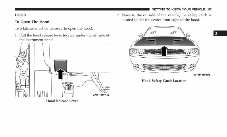
HOOD
To Open The Hood
Two latches must be released to open the hood.
1. Pull the hood release lever located under the left side ofthe instrument panel.
2. Move to the outside of the vehicle, the safety catch islocated under the center front edge of the hood.
Hood Release Lever
Hood Safety Catch Location
3
GETTING TO KNOW YOUR VEHICLE 83

3. Push the safety catch to the left.
To Close The Hood
WARNING!
Be sure the hood is fully latched before driving yourvehicle. If the hood is not fully latched, it could openwhen the vehicle is in motion and block your vision.Failure to follow this warning could result in seriousinjury or death.
CAUTION!
To prevent possible damage, do not slam the hood toclose it. Lower hood to approximately 12 inches (30 cm)and drop the hood to close. Make sure hood is fullyclosed for both latches. Never drive vehicle unlesshood is fully closed, with both latches engaged.
TRUNK
Opening
The trunk can be opened from inside the vehicle using thepower trunk button located on the instrument panel to theleft of the steering wheel.
The trunk lid can be released from outside the vehicle bypushing the trunk button on the key fob twice within fiveseconds or by using the external release switch located onthe underside of the decklid overhang. The release featurewill function only when the vehicle is in the unlockcondition.
With the ignition in the ON/RUN position, the trunk opensymbol will display in the instrument cluster indicatingthat the trunk is open. The odometer display will reappearonce the trunk is closed.
Hood Safety Catch
84 GETTING TO KNOW YOUR VEHICLE
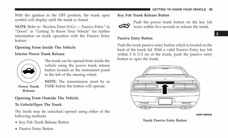
With the ignition in the OFF position, the trunk opensymbol will display until the trunk is closed.
NOTE: Refer to “Keyless Enter-N-Go — Passive Entry” in”Doors” in “Getting To Know Your Vehicle” for furtherinformation on trunk operation with the Passive Entryfeature.
Opening From Inside The Vehicle
Interior Power Trunk Release
The trunk can be opened from inside thevehicle using the power trunk releasebutton located on the instrument panelto the left of the steering wheel.
NOTE: The transmission must be inPARK before the button will operate.
Opening From Outside The Vehicle
To Unlock/Open The Trunk
The trunk may be unlocked/opened using either of thefollowing methods:
• Key Fob Trunk Release Button
• Passive Entry Button
Key Fob Trunk Release Button
Push the power trunk button on the key fobtwice within five seconds to release the trunk.
Passive Entry Button
Push the trunk passive entry button which is located on theback of the trunk lid. With a valid Passive Entry key fobwithin 5 ft (1.5 m) of the trunk, push the passive entrybutton to open the trunk.
Power TrunkRelease
Trunk Passive Entry Button
3
GETTING TO KNOW YOUR VEHICLE 85
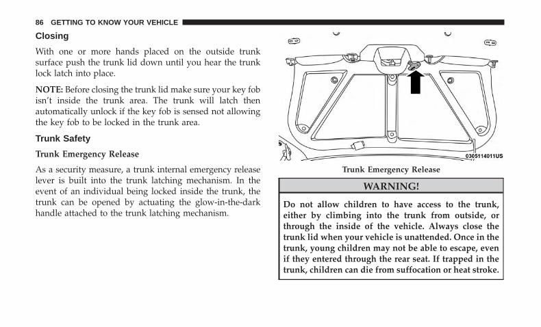
Closing
With one or more hands placed on the outside trunksurface push the trunk lid down until you hear the trunklock latch into place.
NOTE: Before closing the trunk lid make sure your key fobisn’t inside the trunk area. The trunk will latch thenautomatically unlock if the key fob is sensed not allowingthe key fob to be locked in the trunk area.
Trunk Safety
Trunk Emergency Release
As a security measure, a trunk internal emergency releaselever is built into the trunk latching mechanism. In theevent of an individual being locked inside the trunk, thetrunk can be opened by actuating the glow-in-the-darkhandle attached to the trunk latching mechanism.
WARNING!
Do not allow children to have access to the trunk,either by climbing into the trunk from outside, orthrough the inside of the vehicle. Always close thetrunk lid when your vehicle is unattended. Once in thetrunk, young children may not be able to escape, evenif they entered through the rear seat. If trapped in thetrunk, children can die from suffocation or heat stroke.
Trunk Emergency Release
86 GETTING TO KNOW YOUR VEHICLE

GARAGE DOOR OPENER — IF EQUIPPED
HomeLink replaces up to three hand-held transmitters thatoperate devices such as garage door openers, motorizedgates, lighting, or home security systems. The HomeLinkunit is powered by your vehicle’s battery.
The HomeLink buttons that are located in the overheadconsole designate the three different HomeLink channels.The HomeLink indicator is located on the left side of thefirst button.
NOTE: HomeLink is disabled when the Vehicle SecurityAlarm is active.
Before You Begin Programming HomeLink
Be sure that your vehicle is parked outside of the garagebefore you begin programming.
For more efficient programming and accurate transmissionof the radio-frequency signal it is recommended that a newbattery be placed in the hand-held transmitter of the devicethat is being programmed to the HomeLink system.
To erase the channels, place the ignition in the ON/RUNposition, and push and hold the two outside HomeLinkbuttons (I and III) for up to 20 seconds or until the orangeindicator flashes.
NOTE:
• Erasing all channels should only be performed whenprogramming HomeLink for the first time. Do not erasechannels when programming additional buttons.
• If you have any problems, or require assistance, pleasecall toll-free 1-800-355-3515 or, on the Internet atHomeLink.com for information or assistance.
HomeLink Buttons
3
GETTING TO KNOW YOUR VEHICLE 87

Programming A Rolling Code
For programming garage door openers that were manufac-tured after 1995. These garage door openers can be identi-fied by the “LEARN” or “TRAIN” button located wherethe hanging antenna is attached to the garage door opener.
NOTE: It is NOT the button that is normally used to openand close the door. The name and color of the button mayvary by manufacturer.
1. Place the ignition in the ON/RUN position.
2. Place the hand-held transmitter 1 to 3 inches (3 to 8 cm)away from the HomeLink button you wish to programwhile keeping the HomeLink indicator light in view.
3. Push and hold the HomeLink button you want toprogram while you push and hold the hand-held trans-mitter button.
4. Continue to hold both buttons and observe the indicatorlight. The HomeLink indicator will flash slowly andthen rapidly after HomeLink has received the frequencysignal from the hand-held transmitter. Release bothbuttons after the indicator light changes from slow torapid.
5. At the garage door opener motor (in the garage), locatethe “LEARN” or “TRAINING” button. This can usuallybe found where the hanging antenna wire is attached tothe garage door opener/device motor. Firmly push andrelease the “LEARN” or “TRAINING” button. On somegarage door openers/devices there may be a light thatblinks when the garage door opener/device is in theLEARN/TRAIN mode.
NOTE: You have 30 seconds in which to initiate the nextstep after the LEARN button has been pushed.
Training The Garage Door Opener1 — Door Opener2 — Training Button
88 GETTING TO KNOW YOUR VEHICLE
6. Return to the vehicle and push the programmedHomeLink button twice (holding the button for twoseconds each time). If the garage door opener/deviceactivates, programming is complete.
NOTE: If the garage door opener/device does not activate,push the button a third time (for two seconds) to completethe training.
To program the remaining two HomeLink buttons, repeateach step for each remaining button. DO NOT erase thechannels.
Reprogramming A Single HomeLink Button (RollingCode)
To reprogram a channel that has been previously trained,follow these steps:
1. Cycle the ignition to the ON/RUN position.
2. Push and hold the desired HomeLink button until theindicator light begins to flash after 20 seconds. Do notrelease the button.
3. Without releasing the button proceed with “Program-ming A Rolling Code” step 2 and follow all remainingsteps.�
Programming A Non-Rolling Code
For programming Garage Door Openers manufacturedbefore 1995.1. Cycle the ignition to the ON/RUN position.
2. Place the hand-held transmitter 1 to 3 inches (3 to 8 cm)away from the HomeLink button you wish to programwhile keeping the HomeLink indicator light in view.
3. Press and hold the HomeLink button you want toprogram while you press and hold the hand-held trans-mitter button.
4. Continue to hold both buttons and observe the indicatorlight. The HomeLink indicator will flash slowly and thenrapidly after HomeLink has received the frequency signalfrom the hand-held transmitter. Release both buttonsafter the indicator light changes from slow to rapid.
5. Press and hold the programmed HomeLink button andobserve the indicator light.• If the indicator light stays on constantly, programming
is complete and the garage door/device should acti-vate when the HomeLink button is pressed.
• To program the two remaining HomeLink buttons,repeat each step for each remaining button. DO NOTerase the channels.
3
GETTING TO KNOW YOUR VEHICLE 89
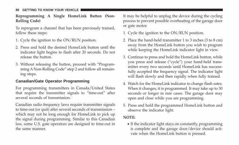
Reprogramming A Single HomeLink Button (Non-Rolling Code)
To reprogram a channel that has been previously trained,follow these steps:
1. Cycle the ignition to the ON/RUN position.
2. Press and hold the desired HomeLink button until theindicator light begins to flash after 20 seconds. Do notrelease the button.
3. Without releasing the button, proceed with “Program-ming A Non-Rolling Code” step 2 and follow all remain-ing steps.
Canadian/Gate Operator Programming
For programming transmitters in Canada/United Statesthat require the transmitter signals to “time-out” afterseveral seconds of transmission.
Canadian radio frequency laws require transmitter signalsto time-out (or quit) after several seconds of transmission –which may not be long enough for HomeLink to pick upthe signal during programming. Similar to this Canadianlaw, some U.S. gate operators are designed to time-out inthe same manner.
It may be helpful to unplug the device during the cyclingprocess to prevent possible overheating of the garage dooror gate motor.
1. Cycle the ignition to the ON/RUN position.
2. Place the hand-held transmitter 1 to 3 inches (3 to 8 cm)away from the HomeLink button you wish to programwhile keeping the HomeLink indicator light in view.
3. Continue to press and hold the HomeLink button, whileyou press and release (“cycle”) your hand-held trans-mitter every two seconds until HomeLink has success-fully accepted the frequency signal. The indicator lightwill flash slowly and then rapidly when fully trained.
4. Watch for the HomeLink indicator to change flash rates.When it changes, it is programmed. It may take up to 30seconds or longer in rare cases. The garage door mayopen and close while you are programming.
5. Press and hold the programmed HomeLink button andobserve the indicator light.
NOTE:
• If the indicator light stays on constantly, programmingis complete and the garage door/device should acti-vate when the HomeLink button is pressed.
90 GETTING TO KNOW YOUR VEHICLE

• To program the two remaining HomeLink buttons,repeat each step for each remaining button. DO NOTerase the channels.
If you unplugged the garage door opener/device forprogramming, plug it back in at this time.
Reprogramming A Single HomeLink Button (Canadian/Gate Operator)
To reprogram a channel that has been previously trained,follow these steps:
1. Cycle the ignition to the ON/RUN position.
2. Press and hold the desired HomeLink button until theindicator light begins to flash after 20 seconds. Do notrelease the button.
3. Without releasing the button, proceed with “Canadian/Gate Operator Programming” step 2 and follow allremaining steps.
Using HomeLink
To operate, push and release the programmed HomeLinkbutton. Activation will now occur for the programmeddevice (i.e. garage door opener, gate operator, security sys-tem, entry door lock, home/office lighting, etc.). The hand-held transmitter of the device may also be used at any time.
Security
It is advised to erase all channels before you sell or turn inyour vehicle.
To do this, push and hold the two outside buttons for 20seconds until the orange indicator flashes. Note that allchannels will be erased. Individual channels cannot beerased.
The HomeLink Universal Transceiver is disabled when theVehicle Security Alarm is active.
Troubleshooting Tips
If you are having trouble programming HomeLink, hereare some of the most common solutions:
• Replace the battery in the Garage Door Opener hand-held transmitter.
• Push the LEARN button on the Garage Door Opener tocomplete the training for a Rolling Code.
• Did you unplug the device for programming and re-member to plug it back in?
If you have any problems, or require assistance, please calltoll-free 1-800-355-3515 or, on the Internet atHomeLink.com for information or assistance.
3
GETTING TO KNOW YOUR VEHICLE 91
WARNING!
• Vehicle exhaust contains carbon monoxide, a danger-ous gas. Do not run your vehicle in the garage whileprogramming the transceiver. Exhaust gas can causeserious injury or death.
• Your motorized door or gate will open and closewhile you are programming the universal trans-ceiver. Do not program the transceiver if people, petsor other objects are in the path of the door or gate.Only use this transceiver with a garage door openerthat has a “stop and reverse” feature as required byFederal safety standards. This includes most garagedoor opener models manufactured after 1982. Do notuse a garage door opener without these safety fea-tures. Call toll-free 1-800-355-3515 or, on the Internetat HomeLink.com for safety information or assis-tance.
General Information
The following regulatory statement applies to all RadioFrequency (RF) devices equipped in this vehicle:
This device complies with Part 15 of the FCC Rules andwith Innovation, Science and Economic DevelopmentCanada license-exempt RSS standard(s). Operation is sub-ject to the following two conditions:
1. This device may not cause harmful interference, and
2. This device must accept any interference received, in-cluding interference that may cause undesired opera-tion.
NOTE: Changes or modifications not expressly approvedby the party responsible for compliance could void theuser’s authority to operate the equipment.
92 GETTING TO KNOW YOUR VEHICLE

INTERNAL EQUIPMENT
Storage
Glove Compartment
The glove compartment is located on the passenger side ofthe instrument panel.
To open the glove compartment, pull the release handle.
Glove Compartment
Opened Glove Compartment
3
GETTING TO KNOW YOUR VEHICLE 93

Console Storage
The center console has a storage compartment locatedunderneath the armrest. The compartment contains a 12Volt power outlet, and is also equipped with a USB portfeaturing active charging, which will continue chargingyour device up to 60 minutes after the ignition is turnedoff. The USB port also may be equipped with an IPOD/USB control, or Apple CarPlay and Android Auto. Refer to“IPOD/USB/MP3 Control – If Equipped” in “Multimedia”for further information. If equipped with Apple CarPlayand Android Auto, refer to the Uconnect Owner’s ManualSupplement.
WARNING!
Do not operate this vehicle with a console compart-ment lid in the open position. Driving with the consolecompartment lid open may result in injury in a colli-sion.
Cupholders
The front cupholders are located in the center console andin the door panels.
Center Console
Front Cupholders
94 GETTING TO KNOW YOUR VEHICLE
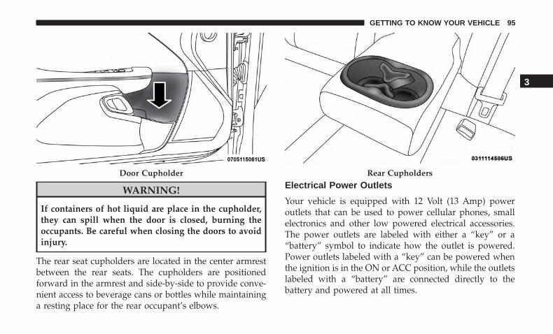
WARNING!
If containers of hot liquid are place in the cupholder,they can spill when the door is closed, burning theoccupants. Be careful when closing the doors to avoidinjury.
The rear seat cupholders are located in the center armrestbetween the rear seats. The cupholders are positionedforward in the armrest and side-by-side to provide conve-nient access to beverage cans or bottles while maintaininga resting place for the rear occupant’s elbows.
Electrical Power Outlets
Your vehicle is equipped with 12 Volt (13 Amp) poweroutlets that can be used to power cellular phones, smallelectronics and other low powered electrical accessories.The power outlets are labeled with either a “key” or a“battery” symbol to indicate how the outlet is powered.Power outlets labeled with a “key” can be powered whenthe ignition is in the ON or ACC position, while the outletslabeled with a “battery” are connected directly to thebattery and powered at all times.
Door Cupholder Rear Cupholders
3
GETTING TO KNOW YOUR VEHICLE 95

These power outlets can also operate a conventional cigarlighter unit.
The front power outlet is located next to the storage area onthe integrated center stack of the instrument panel.
NOTE:
• The front integrated center stack power outlet can bechanged from switched “ignition” to constant “battery”powered all the time by moving the integrated centerstack fuse #12 in the Rear Power Distribution Centerfrom fuse location “IGN” to “B+.” Refer to “Fuses” in“In Case Of Emergency.”
In addition to the front center stack power outlet, there isalso a power outlet located in the center console to the leftof the media hub.
NOTE: All accessories connected to these powered outletsshould be removed or turned off when the vehicle is not inuse to protect the battery against discharge.
Power Outlet — Integrated Center Stack Front
Power Outlet — Center Console
96 GETTING TO KNOW YOUR VEHICLE

WARNING!
To avoid serious injury or death:• Only devices designed for use in this type of outlet
should be inserted into any 12 Volt outlet.• Do not touch with wet hands.
(Continued)
WARNING! (Continued)• Close the lid when not in use and while driving the
vehicle.• If this outlet is mishandled, it may cause an electric
shock and failure.
CAUTION!
• Do not exceed the maximum power of 160 Watts(13 Amps) at 12 Volts. If the 160 Watt (13 Amp) powerrating is exceeded the fuse protecting the system willneed to be replaced.
• Power outlets are designed for accessory plugs only.Do not insert any other object in the power outlets asthis will damage the outlet and blow the fuse.Improper use of the power outlet can cause damagenot covered by your New Vehicle Limited Warranty.
Power Outlet Fuse Locations
1 — #12 Fuse 20A Yellow Power Outlet Integrated Center Stack2 — #38 Fuse 20A Yellow Power Outlet Center Console
3
GETTING TO KNOW YOUR VEHICLE 97

CAUTION!
• Many accessories that can be plugged in draw powerfrom the vehicle’s battery, even when not in use (i.e.,cellular phones, etc.). Eventually, if plugged in longenough, the vehicle’s battery will discharge suffi-ciently to degrade battery life and/or prevent theengine from starting.
• Accessories that draw higher power (i.e., coolers,vacuum cleaners, lights, etc.), will degrade the bat-tery even more quickly. Only use these intermit-tently and with greater caution.
• After the use of high power draw accessories, or longperiods of the vehicle not being started (with acces-sories still plugged in), the vehicle must be driven asufficient length of time to allow the alternator torecharge the vehicle’s battery.
• Power outlets are designed for accessory plugs only.Do not hang any type of accessory or accessorybracket from the plug. Improper use of the poweroutlet can cause damage.
Wireless Charging Pad — If Equipped
Your vehicle may be equipped with an Open Dots compat-ible wire-free phone charging surface located in the centerconsole. The wireless charger features continuous wirelesscharging during vehicle operation and allows for uninter-rupted Bluetooth streaming to properly equipped vehicleaudio systems.
In order to enjoy the convenience of Open Dots wire-freecharging, you must obtain an aftermarket wireless-enabledcase and then install the case on your phone. Set the phone
Wireless Charging Pad
98 GETTING TO KNOW YOUR VEHICLE
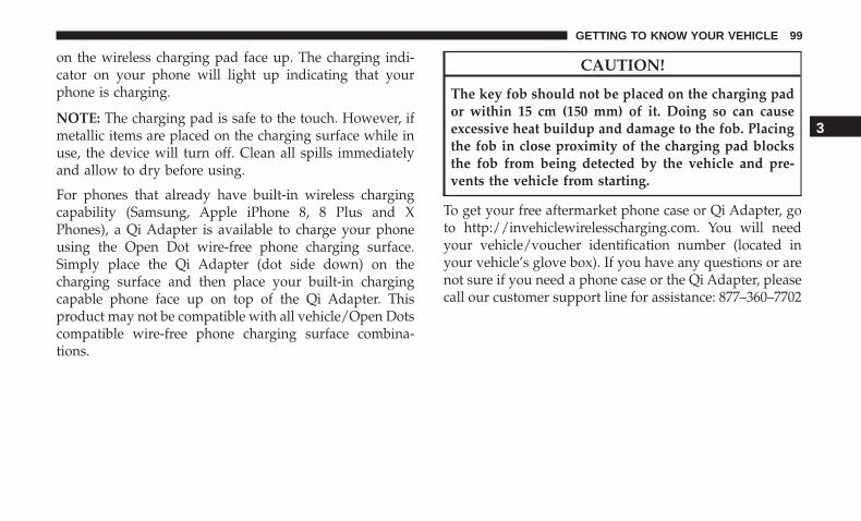
on the wireless charging pad face up. The charging indi-cator on your phone will light up indicating that yourphone is charging.
NOTE: The charging pad is safe to the touch. However, ifmetallic items are placed on the charging surface while inuse, the device will turn off. Clean all spills immediatelyand allow to dry before using.
For phones that already have built-in wireless chargingcapability (Samsung, Apple iPhone 8, 8 Plus and XPhones), a Qi Adapter is available to charge your phoneusing the Open Dot wire-free phone charging surface.Simply place the Qi Adapter (dot side down) on thecharging surface and then place your built-in chargingcapable phone face up on top of the Qi Adapter. Thisproduct may not be compatible with all vehicle/Open Dotscompatible wire-free phone charging surface combina-tions.
CAUTION!
The key fob should not be placed on the charging pador within 15 cm (150 mm) of it. Doing so can causeexcessive heat buildup and damage to the fob. Placingthe fob in close proximity of the charging pad blocksthe fob from being detected by the vehicle and pre-vents the vehicle from starting.
To get your free aftermarket phone case or Qi Adapter, goto http://invehiclewirelesscharging.com. You will needyour vehicle/voucher identification number (located inyour vehicle’s glove box). If you have any questions or arenot sure if you need a phone case or the Qi Adapter, pleasecall our customer support line for assistance: 877–360–7702
3
GETTING TO KNOW YOUR VEHICLE 99

GETTING TO KNOW YOUR INSTRUMENT PANEL
CONTENTS� INSTRUMENT CLUSTER . . . . . . . . . . . . . . . . . .102
▫ Instrument Cluster Descriptions. . . . . . . . . . . . .103
� INSTRUMENT CLUSTER DISPLAY . . . . . . . . . . .105
▫ Location And Controls . . . . . . . . . . . . . . . . . . .105
▫ Engine Oil Life Reset . . . . . . . . . . . . . . . . . . . .107
▫ Performance Shift Indicator (PSI) —If Equipped . . . . . . . . . . . . . . . . . . . . . . . . . . .108
▫ Instrument Cluster Display Selectable MenuItems . . . . . . . . . . . . . . . . . . . . . . . . . . . . . . .108
▫ Battery Saver On/Battery Saver ModeMessage — Electrical Load Reduction Actions —If Equipped . . . . . . . . . . . . . . . . . . . . . . . . . .113
� WARNING LIGHTS AND MESSAGES . . . . . . . . .115
▫ Red Warning Lights . . . . . . . . . . . . . . . . . . . . .115
▫ Yellow Warning Lights . . . . . . . . . . . . . . . . . . .119
▫ Yellow Indicator Lights . . . . . . . . . . . . . . . . . . .123
▫ Green Indicator Lights . . . . . . . . . . . . . . . . . . .123
▫ White Indicator Lights . . . . . . . . . . . . . . . . . . .124
▫ Blue Indicator Lights . . . . . . . . . . . . . . . . . . . .125
� ONBOARD DIAGNOSTIC SYSTEM — OBD II . . .125
▫ Onboard Diagnostic System (OBD II)Cybersecurity . . . . . . . . . . . . . . . . . . . . . . . . .126
� EMISSIONS INSPECTION AND MAINTENANCEPROGRAMS . . . . . . . . . . . . . . . . . . . . . . . . . . .126
4
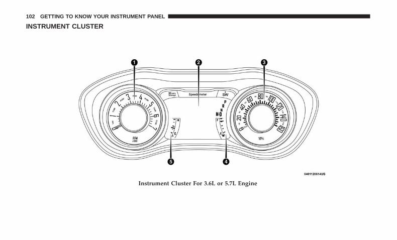
INSTRUMENT CLUSTER
Instrument Cluster For 3.6L or 5.7L Engine
102 GETTING TO KNOW YOUR INSTRUMENT PANEL
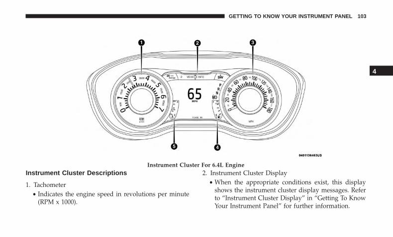
Instrument Cluster Descriptions
1. Tachometer• Indicates the engine speed in revolutions per minute
(RPM x 1000).
2. Instrument Cluster Display• When the appropriate conditions exist, this display
shows the instrument cluster display messages. Referto “Instrument Cluster Display” in “Getting To KnowYour Instrument Panel” for further information.
Instrument Cluster For 6.4L Engine
4
GETTING TO KNOW YOUR INSTRUMENT PANEL 103
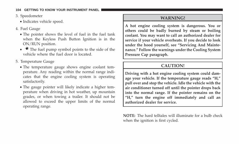
3. Speedometer• Indicates vehicle speed.
4. Fuel Gauge• The pointer shows the level of fuel in the fuel tank
when the Keyless Push Button Ignition is in theON/RUN position.
• The fuel pump symbol points to the side of thevehicle where the fuel door is located.
5. Temperature Gauge• The temperature gauge shows engine coolant tem-
perature. Any reading within the normal range indi-cates that the engine cooling system is operatingsatisfactorily.
• The gauge pointer will likely indicate a higher tem-perature when driving in hot weather, up mountaingrades, or when towing a trailer. It should not beallowed to exceed the upper limits of the normaloperating range.
WARNING!
A hot engine cooling system is dangerous. You orothers could be badly burned by steam or boilingcoolant. You may want to call an authorized dealer forservice if your vehicle overheats. If you decide to lookunder the hood yourself, see “Servicing And Mainte-nance.” Follow the warnings under the Cooling SystemPressure Cap paragraph.
CAUTION!
Driving with a hot engine cooling system could dam-age your vehicle. If the temperature gauge reads “H,”pull over and stop the vehicle. Idle the vehicle with theair conditioner turned off until the pointer drops backinto the normal range. If the pointer remains on the“H,” turn the engine off immediately and call anauthorized dealer for service.
NOTE: The hard telltales will illuminate for a bulb checkwhen the ignition is first cycled.
104 GETTING TO KNOW YOUR INSTRUMENT PANEL
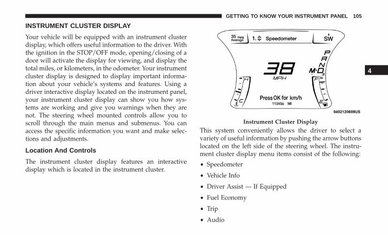
INSTRUMENT CLUSTER DISPLAY
Your vehicle will be equipped with an instrument clusterdisplay, which offers useful information to the driver. Withthe ignition in the STOP/OFF mode, opening/closing of adoor will activate the display for viewing, and display thetotal miles, or kilometers, in the odometer. Your instrumentcluster display is designed to display important informa-tion about your vehicle’s systems and features. Using adriver interactive display located on the instrument panel,your instrument cluster display can show you how sys-tems are working and give you warnings when they arenot. The steering wheel mounted controls allow you toscroll through the main menus and submenus. You canaccess the specific information you want and make selec-tions and adjustments.
Location And Controls
The instrument cluster display features an interactivedisplay which is located in the instrument cluster.
This system conveniently allows the driver to select avariety of useful information by pushing the arrow buttonslocated on the left side of the steering wheel. The instru-ment cluster display menu items consist of the following:
• Speedometer
• Vehicle Info
• Driver Assist — If Equipped
• Fuel Economy
• Trip
• Audio
Instrument Cluster Display
4
GETTING TO KNOW YOUR INSTRUMENT PANEL 105
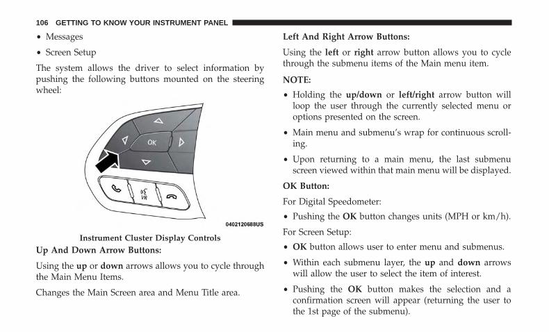
• Messages
• Screen Setup
The system allows the driver to select information bypushing the following buttons mounted on the steeringwheel:
Up And Down Arrow Buttons:
Using the up or down arrows allows you to cycle throughthe Main Menu Items.
Changes the Main Screen area and Menu Title area.
Left And Right Arrow Buttons:
Using the left or right arrow button allows you to cyclethrough the submenu items of the Main menu item.
NOTE:
• Holding the up/down or left/right arrow button willloop the user through the currently selected menu oroptions presented on the screen.
• Main menu and submenu’s wrap for continuous scroll-ing.
• Upon returning to a main menu, the last submenuscreen viewed within that main menu will be displayed.
OK Button:
For Digital Speedometer:
• Pushing the OK button changes units (MPH or km/h).
For Screen Setup:
• OK button allows user to enter menu and submenus.
• Within each submenu layer, the up and down arrowswill allow the user to select the item of interest.
• Pushing the OK button makes the selection and aconfirmation screen will appear (returning the user tothe 1st page of the submenu).
Instrument Cluster Display Controls
106 GETTING TO KNOW YOUR INSTRUMENT PANEL
• Pushing the left arrow button will exit each submenulayer and return to the main menu.
For the Trip and Fuel Economy menus (and new Perfor-mance Timers):
• Information is reset by pushing and holding the OKbutton.
Engine Oil Life Reset
Oil Change Required
Your vehicle is equipped with an engine oil change indi-cator system. The “Oil Change Required” message willdisplay in the instrument cluster display for five secondsafter a single chime has sounded, to indicate the nextscheduled oil change interval. The engine oil change indi-cator system is duty cycle based, which means the engineoil change interval may fluctuate, dependent upon yourpersonal driving style.
Unless reset, this message will continue to display eachtime you place the ignition in the ON/RUN position. Toturn off the message temporarily, push and release the OKor arrow buttons. To reset the oil change indicator system(after performing the scheduled maintenance), refer to thefollowing procedure.
Vehicles Equipped With Keyless Enter-N-Go — Ignition
Use the steering wheel instrument cluster display controlsfor the following procedure(s):
1. Without pressing the brake pedal, push the ENGINESTART/STOP button and place the ignition in theON/RUN position (do not start the engine).
2. Push and release the down arrow button to scrolldownward through the main menu to “Vehicle Info.”
3. Push and release the right arrow button to access the”Oil Life” screen.
4. Push and hold the OK button to reset oil life. Ifconditions are met, the gauge and numeric display willupdate to show 100%. If conditions are not met a popupmessage of �To reset oil life engine must be off withignition in run� will be displayed (for five seconds), andthe user will remain at the Oil Life screen.
5. Push and release the up or down arrow button to exitthe submenu screen.
NOTE: If the indicator message illuminates when youstart the vehicle, the oil change indicator system did notreset. If necessary, repeat this procedure.
4
GETTING TO KNOW YOUR INSTRUMENT PANEL 107

Secondary Method Of Resetting Engine Oil Life
1. Without pressing the brake pedal, push the ENGINESTART/STOP button and place the ignition to theON/RUN position (do not start the engine).
2. Fully press the accelerator pedal, slowly, three timeswithin ten seconds.
3. Without pushing the brake pedal, push the ENGINESTART/STOP button once to return the ignition to theOFF/LOCK position.
NOTE: If the indicator message illuminates when you startthe vehicle, the oil change indicator system did not reset. Ifnecessary, repeat this procedure.
Performance Shift Indicator (PSI) — If Equipped
The Performance Shift Indicator (PSI) is enabled on ve-hicles with manual transmission, or when a vehicle withautomatic transmission is in manual shift mode. The PSIprovides the driver with a visual indication within theinstrument cluster display when the driver configured gearshift point has been reached and the driver is still acceler-ating. This indication notifies the driver to change gearcorresponding to the configured RPMs in the head unit.
Instrument Cluster Display Selectable Menu Items
Push and release the up or down arrow button until thedesired Selectable Menu item is displayed in the instru-ment cluster display.
Follow the Menu or submenu prompts as desired.
Speedometer
Push and release the up or down arrow button until thespeedometer menu is displayed in the instrument clusterdisplay. Push and release the OK button to toggle units(km/h or MPH) of the speedometer.
Vehicle Info
Push and release the up or down arrow button until the“Vehicle Info” menu is displayed in the instrument clusterdisplay. Push and release the right or left arrow button toscroll through the sub menus items of “Vehicle Info.”Follow the directional prompts to access or reset any of thefollowing “Vehicle Info” sub menu items:
Tire Pressure Monitor
If tire pressure is OK for all tires, a vehicle ICON isdisplayed with tire pressure values in each corner of theICON.
108 GETTING TO KNOW YOUR INSTRUMENT PANEL
If one or more tires have low pressure, “Inflate Tire To XX”is displayed with the vehicle ICON and the tire pressurevalues in each corner of the ICON with the pressure valueof the low tire are displayed in a different color than theother tire pressure value.
If the Tire Pressure system requires service, “Service TirePressure System” is displayed.
Tire PSI is an information only function and cannot bereset. Refer to “Tire Pressure Monitoring System (TPMS)”under “Safety” for further information.
Coolant Temp
• Displays the actual coolant temperature.
Trans Temp
• Displays the actual transmission temperature.
Oil Temp
• Displays the actual oil temperature.
Oil Pressure
• Displays the actual oil pressure.
Oil Life
To reset the Oil Life, you must hold the OK button. The“Hold OK to Reset” instruction will be displayed at alltimes, but the following conditions will need to be met inorder to reset Oil Life:
• The vehicle must be off
• The ignition must be in the ON/RUN position
If the conditions are met, holding the OK button will resetthe gauge and the numeric display will return to 100%.
If the conditions are not met, a popup message will displayfor 5 seconds, describing the required conditions, and thenthe Oil Life screen will reappear.
Battery Voltage
• Displays the actual battery voltage.
Driver Assist — If Equipped
Adaptive Cruise Control (ACC) Menu
The instrument cluster display displays the current ACCsystem settings. The information displayed depends onACC system status.
4
GETTING TO KNOW YOUR INSTRUMENT PANEL 109
Push the ADAPTIVE CRUISE CONTROL (ACC) ON/OFFbutton (located on the steering wheel) until one of thefollowing displays in the instrument cluster display:
Adaptive Cruise Control Off
When ACC is deactivated, the display will read “AdaptiveCruise Control Off.”
Adaptive Cruise Control Ready
When ACC is activated but the vehicle speed setting hasnot been selected, the display will read “Adaptive CruiseControl Ready.”
Push the SET + or the SET- button (located on the steeringwheel) and the following will display in the instrumentcluster display:
ACC SET
When ACC is set, the set speed will display in theinstrument cluster.
The ACC screen may display once again if any ACCactivity occurs, which may include any of the following:
• Distance Setting Change
• System Cancel
• Driver Override
• System Off
• ACC Proximity Warning
• ACC Unavailable Warning
• The instrument cluster display will return to the lastdisplay selected after five seconds of no ACC displayactivity.
For further information, refer to “Adaptive Cruise Control(ACC) — If Equipped” in “Starting And Operating.”
Fuel Economy
Two submenu pages; one with Current Value (instanta-neous calculation of the fuel economy) displayed and onewithout the Current Value displayed (toggle the left orright arrow button to select one):
• Current Fuel Economy (MPG, L/100 km, or km/L).
• Range To Empty (miles or km).
• Average Fuel Economy (MPG, L/100 km, or km/L).
• The Max and Min values will correspond to the particu-lar engine requirements.
110 GETTING TO KNOW YOUR INSTRUMENT PANEL
• Lower end of gauge will be displayed in an amber colorand turn green as Fuel Economy improves.
• Hold the OK button to reset average fuel economyinformation.
Trip Info
Push and release the up or down arrow button until theTrip Menu item is displayed in the instrument clusterdisplay. Toggle the left or right arrow button to select TripA or Trip B. The Trip information will display the follow-ing:
• Distance – Shows the total distance (mi or km) traveledfor Trip A or Trip B since the last reset.
• Average Fuel Economy – Shows the average fueleconomy (MPG, L/100km or km/L) of Trip A or Trip Bsince the last reset.
• Elapsed Time – Shows the total elapsed time of travelsince the last reset.
Hold the OK button to reset feature information.
Audio
This menu displays the Audio information of the currentlyplaying audio source (e.g. FM radio).
Messages
This feature shows the number of stored warning mes-sages, if any. Pushing the right or left arrow button willallow you to scroll through the stored messages.
Screen Setup
Push and release the up or down arrow button until theScreen Setup Menu displays in the instrument clusterdisplay. Push and release the OK button to enter thesubmenus. The Screen Setup feature allows you to changewhat information is displayed in the instrument cluster aswell as the location that information is displayed.
1. Upper Left• Compass (default)• Outside Temp.• Time (default)• Range to Empty (default)• Average (MPG, L/100 km, or km/L)• Current (MPG, L/100 km, or km/L)• Trip A Distance• Trip B Distance• None
4
GETTING TO KNOW YOUR INSTRUMENT PANEL 111
2. Upper Right• Compass• Outside Temp (default)• Time• Range to Empty• Average (MPG, L/100 km, or km/L)• Current (MPG, L/100 km, or km/L)• Trip A Distance• Trip B Distance• None
3. Center• Menu Title (default)• Compass• Outside Temp.• Time• Range to Empty• Average (MPG, L/100 km, or km/L)• Current (MPG, L/100 km, or km/L)
• Trip A Distance• Trip B Distance• Audio Information• Digital Speed• None
4. Current Gear• On• Off (default)
5. Odometer• Show (default)• Hide
6. Gear Display• Full (default)• Single
7. Restore Defaults• Ok• Cancel
112 GETTING TO KNOW YOUR INSTRUMENT PANEL
Battery Saver On/Battery Saver Mode Message —Electrical Load Reduction Actions — If Equipped
This vehicle is equipped with an Intelligent Battery Sensor(IBS) to perform additional monitoring of the electricalsystem and status of the vehicle battery.
In cases when the IBS detects charging system failure, orthe vehicle battery conditions are deteriorating, electricalload reduction actions will take place to extend the drivingtime and distance of the vehicle. This is done by reducingpower to or turning off non-essential electrical loads.
Load reduction is only active when the engine is running.It will display a message if there is a risk of batterydepletion to the point where the vehicle may stall due tolack of electrical supply, or will not restart after the currentdrive cycle.
When load reduction is activated, the message “BatterySaver On” or “Battery Saver Mode” will appear in theinstrument cluster.
These messages indicate the vehicle battery has a low stateof charge and continues to lose electrical charge at a ratethat the charging system cannot sustain.
NOTE:
• The charging system is independent from load reduc-tion. The charging system performs a diagnostic on thecharging system continuously.
• If the Battery Charge Warning Light is on it may indicatea problem with the charging system. Refer to “BatteryCharge Warning Light” in “Getting To Know YourInstrument Panel” for further information.
The electrical loads that may be switched off (if equipped),and vehicle functions which can be affected by loadreduction:
• Heated Seat/Vented Seats/Heated Wheel
• Heated/Cooled Cup Holders — If Equipped
• Rear Defroster And Heated Mirrors
• HVAC System
• 115V AC Power Inverter System
• Audio and Telematics System
4
GETTING TO KNOW YOUR INSTRUMENT PANEL 113
Loss of the battery charge may indicate one or more of thefollowing conditions:
• The charging system cannot deliver enough electricalpower to the vehicle system because the electrical loadsare larger than the capability of the charging system. Thecharging system is still functioning properly.
• Turning on all possible vehicle electrical loads (e.g.HVAC to max settings, exterior and interior lights,overloaded power outlets +12V, 115V AC, USB ports)during certain driving conditions (city driving, towing,frequent stopping).
• Installing options like additional lights, upfitter electri-cal accessories, audio systems, alarms and similar de-vices.
• Unusual driving cycles (short trips separated by longparking periods).
• The vehicle was parked for an extended period of time(weeks, months).
• The battery was recently replaced and was not chargedcompletely.
• The battery was discharged by an electrical load left onwhen the vehicle was parked.
• The battery was used for an extended period with theengine not running to supply radio, lights, chargers,+12V portable appliances like vacuum cleaners, gameconsoles and similar devices.
What to do when an electrical load reduction actionmessage is present (“Battery Saver On” or “Battery SaverMode”)
During a trip:
• Reduce power to unnecessary loads if possible:– Turn off redundant lights (interior or exterior)– Check what may be plugged in to power outlets +12V,
115V AC, USB ports– Check HVAC settings (blower, temperature)– Check the audio settings (volume)
After a trip:
• Check if any aftermarket equipment was installed (ad-ditional lights, upfitter electrical accessories, audio sys-tems, alarms) and review specifications if any (load andIgnition Off Draw currents).
• Evaluate the latest driving cycles (distance, driving timeand parking time).
114 GETTING TO KNOW YOUR INSTRUMENT PANEL
• The vehicle should have service performed if the mes-sage is still present during consecutive trips and theevaluation of the vehicle and driving pattern did nothelp to identify the cause.
WARNING LIGHTS AND MESSAGES
The warning/indicator lights will illuminate in the instru-ment panel together with a dedicated message and/oracoustic signal when applicable. These indications areindicative and precautionary and as such must not beconsidered as exhaustive and/or alternative to the infor-mation contained in the Owner’s Manual, which you areadvised to read carefully in all cases. Always refer to theinformation in this chapter in the event of a failure indica-tion. All active telltales will display first if applicable. Thesystem check menu may appear different based uponequipment options and current vehicle status. Some tell-tales are optional and may not appear.
Red Warning Lights
— Seat Belt Reminder Warning Light
This warning light indicates when the driver or passengerseat belt is unbuckled. When the ignition is first placed inthe ON/RUN or ACC/ON/RUN position and if thedriver’s seat belt is unbuckled, a chime will sound and the
light will turn on. When driving, if the driver or frontpassenger seat belt remains unbuckled, the Seat Belt Re-minder Light will flash or remain on continuously and achime will sound.
Refer to “Occupant Restraint Systems” in “Safety” forfurther information.
— Air Bag Warning Light
This warning light will illuminate to indicate a fault withthe air bag, and will turn on for four to eight seconds as abulb check when the ignition is placed in the ON/RUN orACC/ON/RUN position. This light will illuminate with asingle chime when a fault with the air bag has beendetected, it will stay on until the fault is cleared. If the lightis either not on during startup, stays on, or turns on whiledriving, have the system inspected at an authorized dealeras soon as possible.
— Brake Warning Light
This warning light monitors various brake functions, in-cluding brake fluid level and parking brake application. Ifthe brake light turns on it may indicate that the parkingbrake is applied, that the brake fluid level is low, or thatthere is a problem with the anti-lock brake system reser-voir.
4
GETTING TO KNOW YOUR INSTRUMENT PANEL 115

If the light remains on when the parking brake has beendisengaged, and the fluid level is at the full mark on themaster cylinder reservoir, it indicates a possible brakehydraulic system malfunction or that a problem with theBrake Booster has been detected by the Anti-Lock BrakeSystem (ABS) / Electronic Stability Control (ESC) system.In this case, the light will remain on until the condition hasbeen corrected. If the problem is related to the brakebooster, the ABS pump will run when applying the brake,and a brake pedal pulsation may be felt during each stop.
The dual brake system provides a reserve braking capacityin the event of a failure to a portion of the hydraulicsystem. A leak in either half of the dual brake system isindicated by the Brake Warning Light, which will turn onwhen the brake fluid level in the master cylinder hasdropped below a specified level.
The light will remain on until the cause is corrected.
NOTE: The light may flash momentarily during sharpcornering maneuvers, which change fluid level conditions.The vehicle should have service performed, and the brakefluid level checked.
If brake failure is indicated, immediate repair is necessary.
WARNING!
Driving a vehicle with the red brake light on isdangerous. Part of the brake system may have failed. Itwill take longer to stop the vehicle. You could have acollision. Have the vehicle checked immediately.
Vehicles equipped with the Anti-Lock Brake System (ABS)are also equipped with Electronic Brake Force Distribution(EBD). In the event of an EBD failure, the Brake WarningLight will turn on along with the ABS Light. Immediaterepair to the ABS system is required.
Operation of the Brake Warning Light can be checked byturning the ignition switch from the OFF position to theON/RUN position. The light should illuminate for ap-proximately two seconds. The light should then turn offunless the parking brake is applied or a brake fault isdetected. If the light does not illuminate, have the lightinspected by an authorized dealer.
The light also will turn on when the parking brake isapplied with the ignition switch in the ON/RUN position.
NOTE: This light shows only that the parking brake isapplied. It does not show the degree of brake application.
116 GETTING TO KNOW YOUR INSTRUMENT PANEL
— Vehicle Security Warning Light — If Equipped
This light will flash at a fast rate for approximately 15seconds when the vehicle security alarm is arming, andthen will flash slowly until the vehicle is disarmed.
— Engine Coolant Temperature Warning Light
This warning light warns of an overheated engine condi-tion. If the engine coolant temperature is too high, thisindicator will illuminate and a single chime will sound. Ifthe temperature reaches the upper limit, a continuouschime will sound for four minutes or until the engine isable to cool: whichever comes first.
If the light turns on while driving, safely pull over and stopthe vehicle. If the A/C system is on, turn it off. Also, shiftthe transmission into NEUTRAL and idle the vehicle. If thetemperature reading does not return to normal, turn theengine off immediately and call for service.
Refer to “If Your Engine Overheats” in “In Case OfEmergency” for further information.
— Battery Charge Warning Light
This warning light will illuminate when the battery is notcharging properly. If it stays on while the engine is run-ning, there may be a malfunction with the charging system.Contact an authorized dealer as soon as possible.
This indicates a possible problem with the electrical systemor a related component.
— Oil Pressure Warning Light
This warning light will illuminate to indicate low engineoil pressure. If the light turns on while driving, stop thevehicle, shut off the engine as soon as possible, and contactan authorized dealer. A chime will sound when this lightturns on.
Do not operate the vehicle until the cause is corrected. Thislight does not indicate how much oil is in the engine. Theengine oil level must be checked under the hood.
— Oil Temperature Warning Light
This warning light will illuminate to indicate the engine oiltemperature is high. If the light turns on while driving,stop the vehicle and shut off the engine as soon as possible.Wait for oil temperature to return to normal levels.
— Electronic Throttle Control (ETC) WarningLight
This warning light will illuminate to indicate a problemwith the Electronic Throttle Control (ETC) system. If aproblem is detected while the vehicle is running, the lightwill either stay on or flash depending on the nature of the
4
GETTING TO KNOW YOUR INSTRUMENT PANEL 117

problem. Cycle the ignition when the vehicle is safely andcompletely stopped and the transmission is placed in thePARK position. The light should turn off. If the lightremains on with the vehicle running, your vehicle willusually be drivable; however, see an authorized dealer forservice as soon as possible.
NOTE: This light may turn on if the accelerator and brakepedals are pressed at the same time.
If the light continues to flash when the vehicle is running,immediate service is required and you may experiencereduced performance, an elevated/rough idle, or enginestall and your vehicle may require towing. The light willcome on when the ignition is placed in the ON/RUN orACC/ON/RUN position and remain on briefly as a bulbcheck. If the light does not come on during starting, havethe system checked by an authorized dealer.
— Transmission Temperature Warning Light —If Equipped
This warning light will illuminate to warn of a hightransmission fluid temperature. This may occur withstrenuous usage such as trailer towing. If this light turnson, stop the vehicle and run the engine at idle or slightlyfaster, with the transmission in PARK or NEUTRAL, until
the light turns off. Once the light turns off, you maycontinue to drive normally.
WARNING!
If you continue operating the vehicle when the Trans-mission Temperature Warning Light is illuminated youcould cause the fluid to boil over, come in contact withhot engine or exhaust components and cause a fire.
CAUTION!
Continuous driving with the Transmission Tempera-ture Warning Light illuminated will eventually causesevere transmission damage or transmission failure.
— Electric Power Steering Fault Warning Light
This warning light will turn on when there’s a fault withthe EPS (Electric Power Steering) system. Refer to “PowerSteering” in “Starting And Operating” for further informa-tion.
118 GETTING TO KNOW YOUR INSTRUMENT PANEL
WARNING!
Continued operation with reduced assist could pose asafety risk to yourself and others. Service should beobtained as soon as possible.
— Door Open Warning Light
This indicator will illuminate when a door is ajar/open andnot fully closed.
NOTE: If the vehicle is moving, there will also be a singlechime.
— Trunk Open Warning Light
This indicator will illuminate when the trunk is open andnot fully closed.
NOTE: If the vehicle is moving, there will also be a singlechime.
Yellow Warning Lights
— Engine Check/Malfunction Indicator WarningLight (MIL)
The Engine Check/Malfunction Indicator Light (MIL) is apart of an Onboard Diagnostic System called OBD II that
monitors engine and automatic transmission control sys-tems. This warning light will illuminate when the ignitionis in the ON/RUN position before engine start. If the bulbdoes not come on when turning the ignition switch fromOFF to ON/RUN, have the condition checked promptly.
Certain conditions, such as a loose or missing gas cap, poorquality fuel, etc., may illuminate the light after engine start.The vehicle should be serviced if the light stays on throughseveral typical driving styles. In most situations, the ve-hicle will drive normally and will not require towing.
When the engine is running, the MIL may flash to alertserious conditions that could lead to immediate loss ofpower or severe catalytic converter damage. The vehicleshould be serviced by an authorized dealer as soon aspossible if this occurs.
WARNING!
A malfunctioning catalytic converter, as referencedabove, can reach higher temperatures than in normaloperating conditions. This can cause a fire if you driveslowly or park over flammable substances such as dryplants, wood, cardboard, etc. This could result in deathor serious injury to the driver, occupants or others.
4
GETTING TO KNOW YOUR INSTRUMENT PANEL 119

CAUTION!
Prolonged driving with the Malfunction IndicatorLight (MIL) on could cause damage to the vehiclecontrol system. It also could affect fuel economy anddriveability. If the MIL is flashing, severe catalyticconverter damage and power loss will soon occur.Immediate service is required.
— Electronic Stability Control (ESC) ActiveWarning Light — If Equipped
This warning light will indicate when the Electronic Sta-bility Control system is Active. The “ESC Indicator Light”in the instrument cluster will come on when the ignition isplaced in the ON/RUN or ACC/ON/RUN position, andwhen ESC is activated. It should go out with the enginerunning. If the “ESC Indicator Light” comes on continu-ously with the engine running, a malfunction has beendetected in the ESC system. If this warning light remainson after several ignition cycles, and the vehicle has beendriven several miles (kilometers) at speeds greater than30 mph (48 km/h), see an authorized dealer as soon aspossible to have the problem diagnosed and corrected.
• The “ESC Off Indicator Light” and the “ESC IndicatorLight” come on momentarily each time the ignition isplaced in the ON/RUN or ACC/ON/RUN position.
• The ESC system will make buzzing or clicking soundswhen it is active. This is normal; the sounds will stopwhen ESC becomes inactive.
• This light will come on when the vehicle is in an ESCevent.
— Electronic Stability Control (ESC) Off WarningLight — If Equipped
This warning light indicates the Electronic Stability Control(ESC) is off.
Each time the ignition is turned to ON/RUN or ACC/ON/RUN, the ESC system will be on, even if it was turned offpreviously.
— Low Washer Fluid Warning Light —If Equipped
This warning light will illuminate when the windshieldwasher fluid is low.
120 GETTING TO KNOW YOUR INSTRUMENT PANEL
— Tire Pressure Monitoring System (TPMS)Warning Light
The warning light switches on and a message is displayedto indicate that the tire pressure is lower than the recom-mended value and/or that slow pressure loss is occurring.In these cases, optimal tire duration and fuel consumptionmay not be guaranteed.
Should one or more tires be in the condition mentionedabove, the display will show the indications correspondingto each tire.
CAUTION!
Do not continue driving with one or more flat tires ashandling may be compromised. Stop the vehicle,avoiding sharp braking and steering. If a tire punctureoccurs, repair immediately using the dedicated tirerepair kit and contact an authorized dealer as soon aspossible.
Each tire, including the spare (if provided), should bechecked monthly when cold and inflated to the inflationpressure recommended by the vehicle manufacturer on thevehicle placard or tire inflation pressure label. (If yourvehicle has tires of a different size than the size indicated
on the vehicle placard or tire inflation pressure label, youshould determine the proper tire inflation pressure forthose tires.)
As an added safety feature, your vehicle has beenequipped with a Tire Pressure Monitoring System (TPMS)that illuminates a low tire pressure telltale when one ormore of your tires is significantly under-inflated. Accord-ingly, when the low tire pressure telltale illuminates, youshould stop and check your tires as soon as possible, andinflate them to the proper pressure. Driving on a signifi-cantly under-inflated tire causes the tire to overheat andcan lead to tire failure. Under-inflation also reduces fuelefficiency and tire tread life, and may affect the vehicle’shandling and stopping ability.
Please note that the TPMS is not a substitute for proper tiremaintenance, and it is the driver’s responsibility to main-tain correct tire pressure, even if under-inflation has notreached the level to trigger illumination of the TPMS lowtire pressure telltale.
Your vehicle has also been equipped with a TPMS malfunc-tion indicator to indicate when the system is not operatingproperly. The TPMS malfunction indicator is combinedwith the low tire pressure telltale. When the system detectsa malfunction, the telltale will flash for approximately one
4
GETTING TO KNOW YOUR INSTRUMENT PANEL 121
minute and then remain continuously illuminated. Thissequence will continue upon subsequent vehicle start-upsas long as the malfunction exists. When the malfunctionindicator is illuminated, the system may not be able todetect or signal low tire pressure as intended. TPMSmalfunctions may occur for a variety of reasons, includingthe installation of replacement or alternate tires or wheelson the vehicle that prevent the TPMS from functioningproperly. Always check the TPMS malfunction telltale afterreplacing one or more tires or wheels on your vehicle toensure that the replacement or alternate tires and wheelsallow the TPMS to continue to function properly.
CAUTION!
The TPMS has been optimized for the original equip-ment tires and wheels. TPMS pressures and warninghave been established for the tire size equipped onyour vehicle. Undesirable system operation or sensordamage may result when using replacement equip-ment that is not of the same size, type, and/or style.Aftermarket wheels can cause sensor damage. Usingaftermarket tire sealants may cause the Tire Pressure
(Continued)
CAUTION! (Continued)Monitoring System (TPMS) sensor to become inoper-able. After using an aftermarket tire sealant it isrecommended that you take your vehicle to your au-thorized dealer to have your sensor function checked.
— Anti-Lock Brake (ABS) Warning Light
This warning light monitors the Anti-Lock Brake System(ABS). The light will turn on when the ignition is placed inthe ON/RUN or ACC/ON/RUN position and may stay onfor as long as four seconds.
If the ABS light remains on or turns on while driving, thenthe Anti-Lock portion of the brake system is not function-ing and service is required as soon as possible. However,the conventional brake system will continue to operatenormally, assuming the Brake Warning Light is not also on.
If the ABS light does not turn on when the ignition isplaced in the ON/RUN or ACC/ON/RUN position, havethe brake system inspected by an authorized dealer.
— Low Fuel Warning Light
When the fuel level reaches approximately 2 gal (7.5 L), thislight will turn on and a chime will sound. The light willremain on until fuel is added.
122 GETTING TO KNOW YOUR INSTRUMENT PANEL

— Service Forward Collision Warning (FCW)Light — If Equipped
This warning light will illuminate to indicate a fault in theForward Collision Warning System. Contact an authorizeddealer for service.
Refer to �Forward Collision Warning (FCW)� in �Safety� forfurther information.
— Loose Fuel Filler Cap Warning Light —If Equipped
This warning light will illuminate when the fuel filler capis loose. Properly close the filler cap to disengage the light.If the light does not turn off, please see an authorizeddealer.
— Service AWD Warning Light — If Equipped
This telltale will turn on to indicate the All Wheel Drive(AWD) system is not functioning properly and that serviceis required. Contact your authorized dealer.
— Service Adaptive Cruise Control WarningLight — If Equipped
This light will turn on when a ACC is not operating andneeds service. Refer to “Adaptive Cruise Control (ACC)” in“Starting And Operating” for further information.
Yellow Indicator Lights
— Forward Collision Warning Off Indicator Light— If Equipped
This indicator light illuminates to indicate that ForwardCollision Warning is off.
Green Indicator Lights
— Front Fog Indicator Light — If Equipped
This indicator light will illuminate when the front foglights are on.
— Park/Headlight On Indicator Light
This indicator light will illuminate when the park lights orheadlights are turned on.
— ECO Mode Indicator Light
This light will turn on when ECO Mode is active.
— Turn Signal Indicator Lights
When the left or right turn signal is activated, the turnsignal indicator will flash independently and the corre-sponding exterior turn signal lamps will flash. Turn signalscan be activated when the multifunction lever is moveddown (left) or up (right).
4
GETTING TO KNOW YOUR INSTRUMENT PANEL 123
NOTE:
• A continuous chime will sound if the vehicle is drivenmore than 1 mile (1.6 km) with either turn signal on.
• Check for an inoperative outside light bulb if eitherindicator flashes at a rapid rate.
— Cruise Control Set Indicator Light —If Equipped
This indicator light will illuminate when the cruise controlis set to the desired speed. Refer to “Speed Control” in“Starting And Operating” for further information.
— Adaptive Cruise Control (ACC) Set WithTarget Vehicle Light — If Equipped
This will display when the ACC is set and a target vehicleis detected. Refer to “Adaptive Cruise Control (ACC)” in“Starting And Operating” for further information.
— Adaptive Cruise Control (ACC) Set WithoutTarget Vehicle Light — If Equipped
This will display the distance setting for the ACC systemwhen the system is engaged. Refer to “Adaptive CruiseControl (ACC)” in “Starting And Operating” for furtherinformation.
— Sport Mode Indicator Light
This light will turn on when Sport Mode is active.
White Indicator Lights
— Speed Warning Indicator Light
The indicator light will illuminate white along with anotification text message (Speed Warning Set to XX fol-lowed by unit). When the set speed is just exceeded, asingle chime will sound along with pop up message ofSpeed Warning Exceeded. When the set speed is exceededby 2 mph (3 km/h) or more, the indicator will light upyellow and flash along with a continuous chime (up to 10seconds or until the speed is no longer exceeded).
NOTE: The number “31” is only an example of a speed thatcan be selected.
— Cruise Control Ready Indicator
This indicator light will illuminate when the cruise controlis ready, but not set. Refer to “Speed Control” in “StartingAnd Operating” for further information.
124 GETTING TO KNOW YOUR INSTRUMENT PANEL

— Adaptive Cruise Control (ACC) Ready Light —If Equipped
This light will turn on when Adaptive Cruise Control(ACC) has been turned on, but is not set. Refer to “Adap-tive Cruise Control (ACC)” in “Starting And Operating”for further information.
Blue Indicator Lights
— High Beam Indicator Light
This indicator light will illuminate to indicate that the highbeam headlights are on. With the low beams activated,push the multifunction lever forward (toward the front ofthe vehicle) to turn on the high beams. Pull the multifunc-tion lever rearward (toward the rear of the vehicle) to turnoff the high beams. If the high beams are off, pull the levertoward you for a temporary high beam on, �flash to pass�scenario.
ONBOARD DIAGNOSTIC SYSTEM — OBD II
Your vehicle is equipped with a sophisticated OnboardDiagnostic system called OBD II. This system monitors theperformance of the emissions, engine, and transmissioncontrol systems. When these systems are operating prop-erly, your vehicle will provide excellent performance andfuel economy, as well as engine emissions well withincurrent government regulations.
If any of these systems require service, the OBD II systemwill turn on the Malfunction Indicator Light (MIL). It willalso store diagnostic codes and other information to assistyour service technician in making repairs. Although yourvehicle will usually be drivable and not need towing, seean authorized dealer for service as soon as possible.
CAUTION!
• Prolonged driving with the MIL on could causefurther damage to the emission control system. Itcould also affect fuel economy and driveability. Thevehicle must be serviced before any emissions testscan be performed.
(Continued)
4
GETTING TO KNOW YOUR INSTRUMENT PANEL 125

CAUTION! (Continued)• If the MIL is flashing while the vehicle is running,
severe catalytic converter damage and power losswill soon occur. Immediate service is required.
Onboard Diagnostic System (OBD II) Cybersecurity
Your vehicle is required to have an Onboard Diagnosticsystem (OBD II) and a connection port to allow access toinformation related to the performance of your emissionscontrols. Authorized service technicians may need to ac-cess this information to assist with the diagnosis andservice of your vehicle and emissions system.
WARNING!
• ONLY an authorized service technician should con-nect equipment to the OBD II connection port inorder to read the VIN, diagnose, or service yourvehicle.
• If unauthorized equipment is connected to the OBDII connection port, such as a driver-behavior trackingdevice, it may:
(Continued)
WARNING! (Continued)• Be possible that vehicle systems, including safety
related systems, could be impaired or a loss ofvehicle control could occur that may result in anaccident involving serious injury or death.
• Access, or allow others to access, informationstored in your vehicle systems, including personalinformation.
For further information, refer to “Cybersecurity” in “Mul-timedia”.
EMISSIONS INSPECTION AND MAINTENANCEPROGRAMS
In some localities, it may be a legal requirement to pass aninspection of your vehicle’s emissions control system.Failure to pass could prevent vehicle registration.
For states that require an Inspection and Main-tenance (I/M), this check verifies the “Malfunc-tion Indicator Light (MIL)” is functioning and isnot on when the engine is running, and that the
OBD II system is ready for testing.
126 GETTING TO KNOW YOUR INSTRUMENT PANEL

Normally, the OBD II system will be ready. The OBD IIsystem may not be ready if your vehicle was recentlyserviced, recently had a dead battery or a battery replace-ment. If the OBD II system should be determined not readyfor the I/M test, your vehicle may fail the test.
Your vehicle has a simple ignition actuated test, which youcan use prior to going to the test station. To check if yourvehicle’s OBD II system is ready, you must do the follow-ing:
1. Cycle the ignition switch to the ON position, but do notcrank or start the engine.
NOTE: If you crank or start the engine, you will have tostart this test over.
2. As soon as you cycle the ignition switch to the ONposition, you will see the “Malfunction Indicator Light(MIL)” symbol come on as part of a normal bulb check.
3. Approximately 15 seconds later, one of two things willhappen:
• The MIL will flash for about ten seconds and then returnto being fully illuminated until you turn OFF the igni-tion or start the engine. This means that your vehicle’sOBD II system is not ready and you should not proceedto the I/M station.
• The MIL will not flash at all and will remain fullyilluminated until you place the ignition in the off posi-tion or start the engine. This means that your vehicle’sOBD II system is ready and you can proceed to the I/Mstation.
If your OBD II system is not ready, you should see anauthorized dealer or repair facility. If your vehicle wasrecently serviced or had a battery failure or replacement,you may need to do nothing more than drive your vehicleas you normally would in order for your OBD II system toupdate. A recheck with the above test routine may thenindicate that the system is now ready.
Regardless of whether your vehicle’s OBD II system isready or not, if the MIL is illuminated during normalvehicle operation you should have your vehicle servicedbefore going to the I/M station. The I/M station can failyour vehicle because the MIL is on with the enginerunning.
4
GETTING TO KNOW YOUR INSTRUMENT PANEL 127


SAFETY
CONTENTS� SAFETY FEATURES . . . . . . . . . . . . . . . . . . . . . .130
▫ Anti-Lock Brake System (ABS) . . . . . . . . . . . . .130
▫ Electronic Brake Control System (EBC) . . . . . . .131
� AUXILIARY DRIVING SYSTEMS . . . . . . . . . . . . .139
▫ Blind Spot Monitoring (BSM) — If Equipped . . .139
▫ Forward Collision Warning (FCW) Operation . . .146
▫ Tire Pressure Monitoring System (TPMS) . . . . . .149
� OCCUPANT RESTRAINT SYSTEMS . . . . . . . . . .155
▫ Occupant Restraint Systems Features . . . . . . . .155
▫ Important Safety Precautions . . . . . . . . . . . . . .155
▫ Seat Belt Systems . . . . . . . . . . . . . . . . . . . . . .157
▫ Supplemental Restraint Systems (SRS) . . . . . . . .167
▫ Child Restraints . . . . . . . . . . . . . . . . . . . . . . .180
▫ Transporting Pets . . . . . . . . . . . . . . . . . . . . . .201
� SAFETY TIPS . . . . . . . . . . . . . . . . . . . . . . . . . . .201
▫ Transporting Passengers . . . . . . . . . . . . . . . . . .201
▫ Exhaust Gas . . . . . . . . . . . . . . . . . . . . . . . . . .201
▫ Safety Checks You Should Make Inside TheVehicle . . . . . . . . . . . . . . . . . . . . . . . . . . . . . .202
▫ Periodic Safety Checks You Should MakeOutside The Vehicle . . . . . . . . . . . . . . . . . . . .204
5

SAFETY FEATURES
Anti-Lock Brake System (ABS)
The Anti-Lock Brake System (ABS) provides increasedvehicle stability and brake performance under most brak-ing conditions. The system automatically prevents wheellock, and enhances vehicle control during braking.
The ABS performs a self-check cycle to ensure that the ABSis working properly each time the vehicle is started anddriven. During this self-check, you may hear a slightclicking sound as well as some related motor noises.
ABS is activated during braking when the system detectsone or more wheels begin to lock. Road conditions such asice, snow, gravel, bumps, railroad tracks, loose debris, orpanic stops may increase the likelihood of ABS activation(s).
You also may experience the following when ABS activates:
• The ABS motor noise (it may continue to run for a shorttime after the stop).
• The clicking sound of solenoid valves.
• Brake pedal pulsations.
• A slight drop of the brake pedal at the end of the stop.
These are all normal characteristics of ABS.
WARNING!
• The ABS contains sophisticated electronic equip-ment that may be susceptible to interference causedby improperly installed or high output radio trans-mitting equipment. This interference can cause pos-sible loss of anti-lock braking capability. Installationof such equipment should be performed by qualifiedprofessionals.
• Pumping of the Anti-Lock Brakes will diminish theireffectiveness and may lead to a collision. Pumpingmakes the stopping distance longer. Just press firmly onyour brake pedal when you need to slow down or stop.
• The ABS cannot prevent the natural laws of physicsfrom acting on the vehicle, nor can it increase brak-ing or steering efficiency beyond that afforded by thecondition of the vehicle brakes and tires or thetraction afforded.
• The ABS cannot prevent collisions, including thoseresulting from excessive speed in turns, followinganother vehicle too closely, or hydroplaning.
• The capabilities of an ABS equipped vehicle mustnever be exploited in a reckless or dangerous mannerthat could jeopardize the user’s safety or the safety ofothers.
130 SAFETY
ABS is designed to function with the OEM tires. Modifica-tion may result in degraded ABS performance.
Anti-Lock Brake Warning Light
The yellow “Anti-Lock Brake Warning Light” will turn onwhen the ignition is turned to the ON/RUN mode andmay stay on for as long as four seconds.
If the “Anti-Lock Brake Warning Light” remains on orcomes on while driving, it indicates that the anti-lockportion of the brake system is not functioning and thatservice is required. However, the conventional brake sys-tem will continue to operate normally if the “Anti-LockBrake Warning Light” is on.
If the “Anti-Lock Brake Warning Light” is on, the brakesystem should be serviced as soon as possible to restore thebenefits of anti-lock brakes. If the “Anti-Lock Brake Warn-ing Light” does not come on when the ignition is turned tothe ON/RUN mode, have the light repaired as soon aspossible.
Electronic Brake Control System (EBC)
Your vehicle is equipped with an advanced ElectronicBrake Control system (EBC). This system includes Elec-tronic Brake Force Distribution (EBD), Anti-Lock BrakeSystem (ABS), Brake Assist System (BAS), Hill Start Assist
(HSA), Traction Control System (TCS), Electronic StabilityControl (ESC), and Electronic Roll Mitigation (ERM). Thesesystems work together to enhance both vehicle stabilityand control in various driving conditions.
Your vehicle may also be equipped with Ready AlertBraking (RAB), and Rain Brake Support (RBS).
Brake Assist System (BAS)
The BAS is designed to optimize the vehicle’s brakingcapability during emergency braking maneuvers. The sys-tem detects an emergency braking situation by sensing therate and amount of brake application and then appliesoptimum pressure to the brakes. This can help reducebraking distances. The BAS complements the anti-lockbrake system (ABS). Applying the brakes very quicklyresults in the best BAS assistance. To receive the benefit ofthe system, you must apply continuous braking pressureduring the stopping sequence, (do not “pump” the brakes).Do not reduce brake pedal pressure unless braking is nolonger desired. Once the brake pedal is released, the BAS isdeactivated.
5
SAFETY 131
WARNING!
The Brake Assist System (BAS) cannot prevent thenatural laws of physics from acting on the vehicle, norcan it increase the traction afforded by prevailing roadconditions. BAS cannot prevent collisions, includingthose resulting from excessive speed in turns, drivingon very slippery surfaces, or hydroplaning. The capa-bilities of a BAS-equipped vehicle must never beexploited in a reckless or dangerous manner, whichcould jeopardize the user’s safety or the safety ofothers.
Brake System Warning Light
The red “Brake System Warning Light” will turn on whenthe ignition is turned to the ON/RUN mode and may stayon for as long as four seconds.
If the “Brake System Warning Light” remains on or comeson while driving, it indicates that the brake system is notfunctioning properly and that immediate service is re-quired. If the “Brake System Warning Light” does not comeon when the ignition is turned to the ON/RUN mode, havethe light repaired as soon as possible.
Electronic Brake Force Distribution (EBD)
This function manages the distribution of the brakingtorque between the front and rear axles by limiting brakingpressure to the rear axle. This is done to prevent overslip ofthe rear wheels to avoid vehicle instability, and to preventthe rear axle from entering ABS before the front axle.
Electronic Roll Mitigation (ERM)
This system anticipates the potential for wheel lift bymonitoring the driver’s steering wheel input and the speedof the vehicle. When ERM determines that the rate ofchange of the steering wheel angle and vehicle’s speed aresufficient to potentially cause wheel lift, it then applies theappropriate brake and may also reduce engine power tolessen the chance that wheel lift will occur. ERM can onlyreduce the chance of wheel lift occurring during severe orevasive driving maneuvers; it cannot prevent wheel liftdue to other factors, such as road conditions, leaving theroadway, or striking objects or other vehicles.
NOTE: ERM is disabled anytime the ESC is in “Full Off”mode (if equipped). Refer to “Electronic Stability Control(ESC)” in this section for a complete explanation of theavailable ESC modes.
132 SAFETY

WARNING!
Many factors, such as vehicle loading, road conditionsand driving conditions, influence the chance thatwheel lift or rollover may occur. ERM cannot preventall wheel lift or roll overs, especially those that involveleaving the roadway or striking objects or other ve-hicles. The capabilities of an ERM-equipped vehiclemust never be exploited in a reckless or dangerousmanner which could jeopardize the user’s safety or thesafety of others.
Electronic Stability Control (ESC)
This system enhances directional control and stability ofthe vehicle under various driving conditions. ESC correctsfor oversteering or understeering of the vehicle by apply-ing the brake of the appropriate wheel(s) to assist incounteracting the oversteer or understeer condition. En-gine power may also be reduced to help the vehiclemaintain the desired path.
ESC uses sensors in the vehicle to determine the vehiclepath intended by the driver and compares it to the actualpath of the vehicle. When the actual path does not match
the intended path, ESC applies the brake of the appropriatewheel to assist in counteracting the oversteer or understeercondition.
• Oversteer — when the vehicle is turning more thanappropriate for the steering wheel position.
• Understeer — when the vehicle is turning less thanappropriate for the steering wheel position.
The “ESC Activation/Malfunction Indicator Light” locatedin the instrument cluster will start to flash as soon as theESC system becomes active. The “ESC Activation/Malfunction Indicator Light” also flashes when the TCS isactive. If the “ESC Activation/Malfunction IndicatorLight” begins to flash during acceleration, ease up on theaccelerator and apply as little throttle as possible. Be sure toadapt your speed and driving to the prevailing roadconditions.
WARNING!
• Electronic Stability Control (ESC) cannot prevent thenatural laws of physics from acting on the vehicle,nor can it increase the traction afforded by prevailing
(Continued)
5
SAFETY 133
WARNING! (Continued)road conditions. ESC cannot prevent accidents, in-cluding those resulting from excessive speed inturns, driving on very slippery surfaces, or hydro-planing. ESC also cannot prevent accidents resultingfrom loss of vehicle control due to inappropriatedriver input for the conditions. Only a safe, attentive,and skillful driver can prevent accidents. The capa-bilities of an ESC equipped vehicle must never beexploited in a reckless or dangerous manner whichcould jeopardize the user’s safety or the safety ofothers.
• Vehicle modifications, or failure to properly main-tain your vehicle, may change the handling charac-teristics of your vehicle, and may negatively affectthe performance of the ESC system. Changes to thesteering system, suspension, braking system, tiretype and size or wheel size may adversely affect ESCperformance. Improperly inflated and unevenlyworn tires may also degrade ESC performance. Anyvehicle modification or poor vehicle maintenancethat reduces the effectiveness of the ESC system canincrease the risk of loss of vehicle control, vehiclerollover, personal injury and death.
ESC Operating Modes
NOTE: Depending upon model and mode of operation, theESC system may have multiple operating modes.
ESC On
This is the normal operating mode for the ESC. Wheneverthe vehicle is started, the ESC system will be in this mode.This mode should be used for most driving conditions.Alternate ESC modes should only be used for specificreasons as noted in the following paragraphs.
Partial Off
The “Partial Off” mode is intended for times when a morespirited driving experience is desired. This mode maymodify TCS and ESC thresholds for activation, whichallows for more wheel spin than normally allowed. Thismode may be useful if the vehicle becomes stuck.
To enter the “Partial Off” mode, momentarily push the“ESC Off” switch and the “ESC Off Indicator Light” willilluminate. To turn the ESC on again, momentarily pushthe “ESC Off” switch and the “ESC Off Indicator Light”will turn off.
134 SAFETY
WARNING!
When in “Partial Off” mode, the TCS functionality ofESC, (except for the limited slip feature described inthe TCS section), has been disabled and the “ESC OffIndicator Light” will be illuminated. When in “PartialOff” mode, the engine power reduction feature of TCSis disabled, and the enhanced vehicle stability offeredby the ESC system is reduced.
NOTE:
• For vehicles with multiple partial ESC modes a momen-tary button push will toggle the ESC mode. Multiplemomentary button pushed may be required to return toESC On.
• Trailer Sway control (TSC) is disabled when the ESCsystem is in the “Partial Off” mode.
• If Equipped — �ESC Sport� and �ESC Track� are ESCpartial off mode(s).
Full Off – If Equipped
This mode is intended for off-highway or off-road use onlyand should not be used on any public roadways. In thismode, TCS and ESC features are turned OFF. To enter the
“Full Off” mode, push and hold the “ESC Off” switch forfive seconds while the vehicle is stopped with the enginerunning. After five seconds, a chime will sound, the “ESCOff Indicator Light” will illuminate, and the “ESC OFF”message will display in the instrument cluster. To turn ESCON again, momentarily push the “ESC Off” switch.
WARNING!
• In the ESC “Full Off” mode, the engine torquereduction and stability features are disabled. There-fore, enhanced vehicle stability offered by the ESCsystem is unavailable. In an emergency evasive ma-neuver, the ESC system will not engage to assist inmaintaining stability. ESC “Full Off” mode is in-tended for off-highway or off-road use only.
• The Electronic Stability Control (ESC) cannot pre-vent the natural laws of physics from acting on thevehicle, nor can it increase the traction afforded byprevailing road conditions. ESC cannot prevent allaccidents, including those resulting from excessivespeed in turns, driving on very slippery surfaces, orhydroplaning. ESC also cannot prevent collisions.
5
SAFETY 135

ESC Activation/Malfunction Indicator Light AndESC OFF Indicator Light
The “ESC Activation/Malfunction IndicatorLight” in the instrument cluster will come onwhen the ignition is turned to the ON mode. Itshould go out with the engine running. If the
“ESC Activation/Malfunction Indicator Light” comes oncontinuously with the engine running, a malfunction hasbeen detected in the ESC system. If this light remains onafter several ignition cycles, and the vehicle has beendriven several miles (kilometers) at speeds greater than30 mph (48 km/h), see an authorized dealer as soon aspossible to have the problem diagnosed and corrected.
The “ESC Activation/Malfunction Indicator Light” (lo-cated in the instrument cluster) starts to flash as soon as thetires lose traction and the ESC system becomes active. The“ESC Activation/Malfunction Indicator Light” also flasheswhen TCS is active. If the “ESC Activation/MalfunctionIndicator Light” begins to flash during acceleration, easeup on the accelerator and apply as little throttle as possible.Be sure to adapt your speed and driving to the prevailingroad conditions.
NOTE:
• The “ESC Activation/Malfunction Indicator Light” andthe “ESC OFF Indicator Light” come on momentarilyeach time the ignition is turned ON.
• Each time the ignition is turned ON, the ESC system willbe on even if it was turned off previously.
• The ESC system will make buzzing or clicking soundswhen it is active. This is normal; the sounds will stopwhen ESC becomes inactive following the maneuverthat caused the ESC activation.
The “ESC OFF Indicator Light” indicates thecustomer has elected to have the Electronic Sta-bility Control (ESC) in a reduced mode.
Hill Start Assist (HSA)
The HSA system is designed to mitigate roll back from acomplete stop while on an incline. If the driver releases thebrake while stopped on an incline, HSA will continue tohold the brake pressure for a short period. If the driverdoes not apply the throttle before this time expires, thesystem will release brake pressure and the vehicle will rolldown the hill as normal.
136 SAFETY
The following conditions must be met in order for HSA toactivate:
• The feature must be enabled.
• The vehicle must be stopped.
• Park brake must be off.
• Driver door must be closed.
• The vehicle must be on a sufficient grade.
• The gear selection must match vehicle uphill direction(i.e., vehicle facing uphill is in forward gear; vehiclebacking uphill is in REVERSE gear).
• HSA will work in REVERSE gear and all forward gears.The system will not activate if the transmission is inPARK or NEUTRAL. For vehicles equipped with amanual transmission, if the clutch is pressed, HSA willremain active.
WARNING!
There may be situations where the Hill Start Assist(HSA) will not activate and slight rolling may occur,such as on minor hills or with a loaded vehicle, or
(Continued)
WARNING! (Continued)while pulling a trailer. HSA is not a substitute foractive driving involvement. It is always the driver’sresponsibility to be attentive to distance to other ve-hicles, people, and objects, and most importantly brakeoperation to ensure safe operation of the vehicle underall road conditions. Your complete attention is alwaysrequired while driving to maintain safe control of yourvehicle. Failure to follow these warnings can result ina collision or serious personal injury.
Towing With HSA
HSA will also provide assistance to mitigate roll back whiletowing a trailer.
WARNING!
• If you use a trailer brake controller with your trailer,the trailer brakes may be activated and deactivatedwith the brake switch. If so, there may not be enoughbrake pressure to hold both the vehicle and thetrailer on a hill when the brake pedal is released. In
(Continued)
5
SAFETY 137
WARNING! (Continued)order to avoid rolling down an incline while resum-ing acceleration, manually activate the trailer brakeor apply more vehicle brake pressure prior to releas-ing the brake pedal.
• HSA is not a parking brake. Always apply theparking brake fully when exiting your vehicle. Also,be certain to place the transmission in PARK.
• Failure to follow these warnings can result in acollision or serious personal injury.
Disabling And Enabling HSA
This feature can be turned on or turned off. To change thecurrent setting, proceed as follows:
• If disabling HSA using your instrument cluster display,refer to “Instrument Cluster Display” in “Getting ToKnow Your Instrument Panel” for further information.
• If disabling HSA using Uconnect Settings, refer to“Uconnect Settings” in “Multimedia” for further infor-mation.
For vehicles not equipped with an instrument clusterdisplay, perform the following steps:
1. Center the steering wheel (front wheels pointingstraight forward).
2. Shift the transmission into PARK.
3. Apply the parking brake.
4. Start the engine.
5. Rotate the steering wheel slightly more than one-halfturn to the left.
6. Push the “ESC Off” button located in the lower switchbank below the climate control four times within 20seconds. The “ESC Off Indicator Light” should turn onand turn off two times.
7. Rotate the steering wheel back to center and then anadditional slightly more than one-half turn to the right.
8. Turn the ignition to the OFF mode and then back to ON.If the sequence was completed properly, the “ESC OffIndicator Light” will blink several times to confirm HSAis disabled.
9. Repeat these steps if you want to return this feature toits previous setting.
138 SAFETY
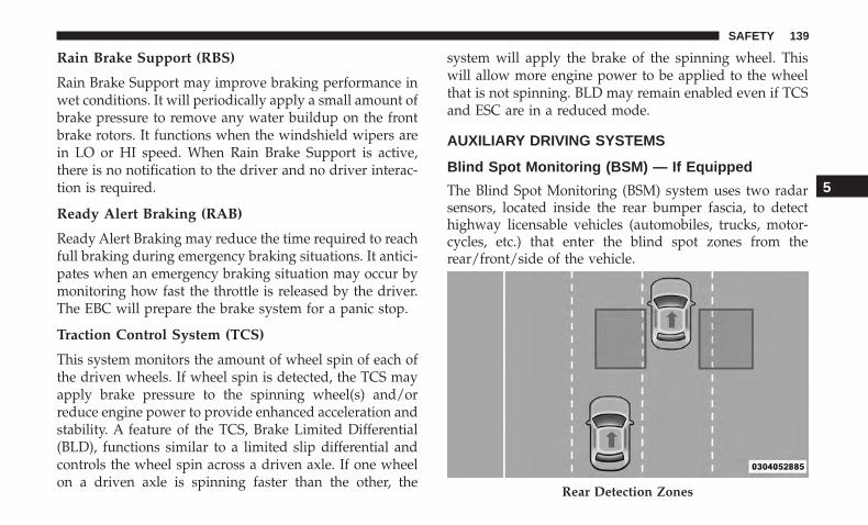
Rain Brake Support (RBS)
Rain Brake Support may improve braking performance inwet conditions. It will periodically apply a small amount ofbrake pressure to remove any water buildup on the frontbrake rotors. It functions when the windshield wipers arein LO or HI speed. When Rain Brake Support is active,there is no notification to the driver and no driver interac-tion is required.
Ready Alert Braking (RAB)
Ready Alert Braking may reduce the time required to reachfull braking during emergency braking situations. It antici-pates when an emergency braking situation may occur bymonitoring how fast the throttle is released by the driver.The EBC will prepare the brake system for a panic stop.
Traction Control System (TCS)
This system monitors the amount of wheel spin of each ofthe driven wheels. If wheel spin is detected, the TCS mayapply brake pressure to the spinning wheel(s) and/orreduce engine power to provide enhanced acceleration andstability. A feature of the TCS, Brake Limited Differential(BLD), functions similar to a limited slip differential andcontrols the wheel spin across a driven axle. If one wheelon a driven axle is spinning faster than the other, the
system will apply the brake of the spinning wheel. Thiswill allow more engine power to be applied to the wheelthat is not spinning. BLD may remain enabled even if TCSand ESC are in a reduced mode.
AUXILIARY DRIVING SYSTEMS
Blind Spot Monitoring (BSM) — If Equipped
The Blind Spot Monitoring (BSM) system uses two radarsensors, located inside the rear bumper fascia, to detecthighway licensable vehicles (automobiles, trucks, motor-cycles, etc.) that enter the blind spot zones from therear/front/side of the vehicle.
Rear Detection Zones
5
SAFETY 139
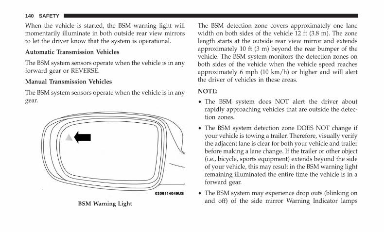
When the vehicle is started, the BSM warning light willmomentarily illuminate in both outside rear view mirrorsto let the driver know that the system is operational.
Automatic Transmission Vehicles
The BSM system sensors operate when the vehicle is in anyforward gear or REVERSE.
Manual Transmission Vehicles
The BSM system sensors operate when the vehicle is in anygear.
The BSM detection zone covers approximately one lanewidth on both sides of the vehicle 12 ft (3.8 m). The zonelength starts at the outside rear view mirror and extendsapproximately 10 ft (3 m) beyond the rear bumper of thevehicle. The BSM system monitors the detection zones onboth sides of the vehicle when the vehicle speed reachesapproximately 6 mph (10 km/h) or higher and will alertthe driver of vehicles in these areas.
NOTE:
• The BSM system does NOT alert the driver aboutrapidly approaching vehicles that are outside the detec-tion zones.
• The BSM system detection zone DOES NOT change ifyour vehicle is towing a trailer. Therefore, visually verifythe adjacent lane is clear for both your vehicle and trailerbefore making a lane change. If the trailer or other object(i.e., bicycle, sports equipment) extends beyond the sideof your vehicle, this may result in the BSM warning lightremaining illuminated the entire time the vehicle is in aforward gear.
• The BSM system may experience drop outs (blinking onand off) of the side mirror Warning Indicator lampsBSM Warning Light
140 SAFETY

when a motorcycle or any small object remains at theside of the vehicle for extended periods of time (morethan a couple of seconds).
The area on the rear fascia where the radar sensors arelocated must remain free of snow, ice and dirt/roadcontamination so that the BSM system can function prop-erly. Do not block the area of the rear fascia where the radarsensors are located with foreign objects (bumper stickers,bicycle racks, etc.).
The BSM system notifies the driver of objects in thedetection zones by illuminating the BSM warning lightlocated in the outside mirrors in addition to sounding an
audible (chime) alert and reducing the radio volume. Referto “Modes Of Operation” for further information.
The BSM system monitors the detection zone from threedifferent entry points (side, rear, front) while driving to seeif an alert is necessary. The BSM system will issue an alertduring these types of zone entries.
Entering From The Side
Vehicles that move into your adjacent lanes from eitherside of the vehicle.
Sensor LocationSide Monitoring
5
SAFETY 141

Entering From The Rear
Vehicles that come up from behind your vehicle on eitherside and enter the rear detection zone with a relative speedof less than 31 mph (50 km/h).
Overtaking Traffic
If you pass another vehicle slowly (with a relative speed ofless than 15 mph (24 km/h)) and the vehicle remains in theblind spot for approximately 1.5 seconds, the warning lightwill be illuminated. If the difference in speed between thetwo vehicles is greater than 15 mph (24 km/h), the warninglight will not illuminate.
Rear Monitoring
Overtaking/Approaching
142 SAFETY
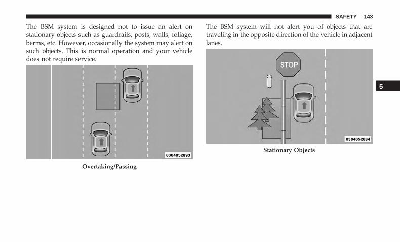
The BSM system is designed not to issue an alert onstationary objects such as guardrails, posts, walls, foliage,berms, etc. However, occasionally the system may alert onsuch objects. This is normal operation and your vehicledoes not require service.
The BSM system will not alert you of objects that aretraveling in the opposite direction of the vehicle in adjacentlanes.
Overtaking/Passing
Stationary Objects
5
SAFETY 143

WARNING!
The Blind Spot Monitoring system is only an aid tohelp detect objects in the blind spot zones. The BSMsystem is not designed to detect pedestrians, bicyclists,or animals. Even if your vehicle is equipped with theBSM system, always check your vehicle’s mirrors,glance over your shoulder, and use your turn signalbefore changing lanes. Failure to do so can result inserious injury or death.
Rear Cross Path — If Equipped
The Rear Cross Path (RCP) feature is intended to aid thedrivers when backing out of parking spaces where theirvision of oncoming vehicles may be blocked. Proceedslowly and cautiously out of the parking space until therear end of the vehicle is exposed. The RCP system willthen have a clear view of the cross traffic and, if anoncoming vehicle is detected, alert the driver.
Opposing Traffic
RCP Detection Zones
144 SAFETY
RCP monitors the rear detection zones on both sides of thevehicle, for objects that are moving toward the side of thevehicle with a minimum speed of approximately 3 mph(5 km/h), to objects moving a maximum of approximately20 mph (32 km/h), such as in parking lot situations.
NOTE: In a parking lot situation, oncoming vehicles canbe obscured by vehicles parked on either side. If thesensors are blocked by other structures or vehicles, thesystem will not be able to alert the driver.
When RCP is on and the vehicle is in REVERSE, the driveris alerted using both the visual and audible alerts, includ-ing reducing the radio volume so that the alert can bebetter heard.
WARNING!
Rear Cross Path Detection (RCP) is not a back up aidsystem. It is intended to be used to help a driver detectan oncoming vehicle in a parking lot situation. Driversmust be careful when backing up, even when usingRCP. Always check carefully behind your vehicle, lookbehind you, and be sure to check for pedestrians,
WARNING! (Continued)animals, other vehicles, obstructions, and blind spotsbefore backing up. Failure to do so can result in seriousinjury or death.
Modes Of Operation
Three selectable modes of operation are available in theUconnect System. Refer to “Uconnect Settings/CustomerProgrammable Features” in “Multimedia” for further in-formation.
Blind Spot Alert Lights Only
When operating in Blind Spot Alert mode, the BSM systemwill provide a visual alert in the appropriate side viewmirror based on a detected object. However, when thesystem is operating in Rear Cross Path mode, the systemwill respond with both visual and audible alerts when adetected object is present. Whenever an audible alert isrequested, the radio volume is reduced so that the alert canbe better heard.
5
SAFETY 145

Blind Spot Alert Lights/Chime
When operating in Blind Spot Alert Lights/Chime mode,the BSM system will provide a visual alert in the appro-priate side view mirror based on a detected object. If theturn signal is then activated, and it corresponds to an alertpresent on that side of the vehicle, an audible chime willalso be sounded. Whenever a turn signal and detectedobject are present on the same side at the same time, boththe visual and audio alerts will be issued. In addition to theaudible alert the radio (if on) volume will be reduced sothat the alert can be better heard.
When the system is in RCP, the system shall respond withboth visual and audible alerts when a detected object ispresent. Whenever an audible alert is requested, the radiovolume is reduced so that the alert can be better heard.
Blind Spot Alert Off
When the BSM system is turned off there will be no visualor audible alerts from either the BSM or RCP systems.
NOTE: The BSM system will store the current operatingmode when the vehicle is shut off. Each time the vehicle isstarted the previously stored mode will be recalled andused.
General Information
The following regulatory statement applies to all RadioFrequency (RF) devices equipped in this vehicle:
This device complies with Part 15 of the FCC Rules andwith Industry Canada license-exempt RSS standard(s).Operation is subject to the following two conditions:
1. This device may not cause harmful interference.
2. This device must accept any interference received, in-cluding interference that may cause undesired opera-tion.
NOTE: Changes or modifications not expressly approvedby the party responsible for compliance could void theuser’s authority to operate the equipment.
Forward Collision Warning (FCW) Operation
The Forward Collision Warning (FCW) system providesthe driver with audible warnings, visual warnings (withinthe instrument cluster display), to warn the driver when itdetects a potential frontal collision. The warnings areintended to provide the driver with enough time to react,avoid or mitigate the potential collision.
146 SAFETY
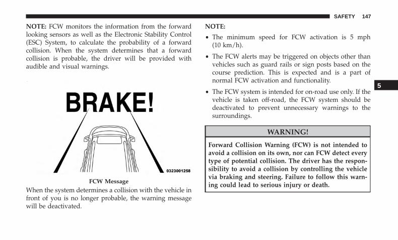
NOTE: FCW monitors the information from the forwardlooking sensors as well as the Electronic Stability Control(ESC) System, to calculate the probability of a forwardcollision. When the system determines that a forwardcollision is probable, the driver will be provided withaudible and visual warnings.
When the system determines a collision with the vehicle infront of you is no longer probable, the warning messagewill be deactivated.
NOTE:
• The minimum speed for FCW activation is 5 mph(10 km/h).
• The FCW alerts may be triggered on objects other thanvehicles such as guard rails or sign posts based on thecourse prediction. This is expected and is a part ofnormal FCW activation and functionality.
• The FCW system is intended for on-road use only. If thevehicle is taken off-road, the FCW system should bedeactivated to prevent unnecessary warnings to thesurroundings.
WARNING!
Forward Collision Warning (FCW) is not intended toavoid a collision on its own, nor can FCW detect everytype of potential collision. The driver has the respon-sibility to avoid a collision by controlling the vehiclevia braking and steering. Failure to follow this warn-ing could lead to serious injury or death.FCW Message
5
SAFETY 147
Turning FCW On Or Off
NOTE: The default status of FCW is on; this allows thesystem to warn you of a possible collision with the vehiclein front of you.
The Forward Collision activation/deactivation is located in�Uconnect Settings� under �Safety And Driving Assistance�.Forward Collision can be checked or unchecked.
When FCW is selected off, there will be an �FCW OFF� iconthat appears in the instrument cluster display.
Changing the FCW status to off prevents the system fromwarning you of a possible collision with the vehicle in frontof you.
NOTE: The FCW system’s default state is on. The FCWsystem state is kept in memory from one ignition cycle tothe next. If the system is turned OFF, it will remain offwhen the vehicle is restarted.
Changing FCW Status
The FCW Sensitivity Settings are programmable throughthe Uconnect System. Refer to “Uconnect Settings” in“Multimedia” for further information.
The default status of FCW is the “Far” setting in the “On”setting. This allows the system to warn you of a possiblecollision with the vehicle in front of you when you arefarther away and it applies limited braking. This gives youthe most reaction time to avoid a possible collision.
Changing the FCW status to the “Near” setting, allows thesystem to warn you of a possible collision with the vehiclein front of you when you are much closer. This settingprovides less reaction time than the “Far” setting, whichallows for a more dynamic driving experience.
NOTE:
• The system will retain the last setting selected by thedriver after ignition shut down.
• FCW may not react to irrelevant objects such as over-head objects, ground reflections, objects not in the pathof the vehicle, stationary objects that are far away,oncoming traffic, or leading vehicles with the same orhigher rate of speed.
• FCW will be disabled like ACC, with the unavailablescreens.
148 SAFETY
Service FCW Warning
If the system turns off, and the instrument cluster displayreads:
• ACC/FCW Unavailable Service Required
• Cruise/FCW Unavailable Service Required
This indicates there is an internal system fault. Althoughthe vehicle is still drivable under normal conditions, havethe system checked by an authorized dealer.
General Information
The following regulatory statement applies to all RadioFrequency (RF) devices equipped in this vehicle:
This device complies with Part 15 of the FCC Rules andwith Industry Canada license-exempt RSS standard(s).Operation is subject to the following two conditions:
1. This device may not cause harmful interference.
2. This device must accept any interference received, in-cluding interference that may cause undesired opera-tion.
NOTE: Changes or modifications not expressly approvedby the party responsible for compliance could void theuser’s authority to operate the equipment.
Tire Pressure Monitoring System (TPMS)
The Tire Pressure Monitor System (TPMS) will warn thedriver of a low tire pressure based on the vehicle recom-mended cold placard pressure.
The tire pressure will vary with temperature by about 1 psi(7 kPa) for every 12°F (6.5°C). This means that when theoutside temperature decreases, the tire pressure will de-crease. Tire pressure should always be set based on coldinflation tire pressure. This is defined as the tire pressureafter the vehicle has not been driven for at least threehours, or driven less than 1 mile (1.6 km) after a three hourperiod. The cold tire inflation pressure must not exceed themaximum inflation pressure molded into the tire sidewall.Refer to “Tires” in “Servicing And Maintenance” for infor-mation on how to properly inflate the vehicle’s tires. Thetire pressure will also increase as the vehicle is driven - thisis normal and there should be no adjustment for thisincreased pressure.
The TPMS will warn the driver of a low tire pressure if thetire pressure falls below the low-pressure warning limit forany reason, including low temperature effects and naturalpressure loss through the tire.
The TPMS will continue to warn the driver of low tirepressure as long as the condition exists, and will not turn
5
SAFETY 149

off until the tire pressure is at or above the recommendedcold placard pressure. Once the low tire pressure warning(TPMS Warning Light) illuminates, you must increase thetire pressure to the recommended cold placard pressure inorder for the TPMS Warning Light to turn off. The systemwill automatically update and the TPMS Warning Lightwill turn off once the system receives the updated tirepressures. The vehicle may need to be driven for up to 20minutes above 15 mph (24 km/h) in order for the TPMS toreceive this information.
NOTE: When filling warm tires, the tire pressure may needto be increased up to an additional 4 psi (28 kPa) above therecommended cold placard pressure in order to turn theTPMS Warning Light off.
For example, your vehicle may have a recommended cold(parked for more than three hours) placard pressure of 30psi (207 kPa). If the ambient temperature is 68°F (20°C) andthe measured tire pressure is 27 psi (186 kPa), a tempera-ture drop to 20°F (-7°C) will decrease the tire pressure toapproximately 23 psi (158 kPa). This tire pressure is suffi-ciently low enough to turn on the TPMS Warning Light.Driving the vehicle may cause the tire pressure to rise toapproximately 27 psi (186 kPa), but the TPMS WarningLight will still be on. In this situation, the TPMS Warning
Light will turn off only after the tires are inflated to thevehicle’s recommended cold placard pressure value.
CAUTION!• The TPMS has been optimized for the original
equipment tires and wheels. TPMS pressures andwarning have been established for the tire sizeequipped on your vehicle. Undesirable system op-eration or sensor damage may result when usingreplacement equipment that is not of the same size,type, and/or style. The TPM sensor is not designedfor use on aftermarket wheels and may contribute toa poor overall system performance or sensor damage.Customers are encouraged to use OEM wheels toassure proper TPM feature operation.
• Using aftermarket tire sealants may cause the TirePressure Monitoring System (TPMS) sensor to be-come inoperable. After using an aftermarket tiresealant it is recommended that you take your vehicleto your authorized dealer to have your sensor func-tion checked.
• After inspecting or adjusting the tire pressure alwaysreinstall the valve stem cap. This will prevent mois-ture and dirt from entering the valve stem, whichcould damage the TPMS sensor.
150 SAFETY
NOTE:
• The TPMS is not intended to replace normal tire care andmaintenance or to provide warning of a tire failure orcondition.
• The TPMS should not be used as a tire pressure gaugewhile adjusting your tire pressure.
• Driving on a significantly under-inflated tire causes thetire to overheat and can lead to tire failure. Under-inflation also reduces fuel efficiency and tire tread life,and may affect the vehicle’s handling and stoppingability.
• The TPMS is not a substitute for proper tire mainte-nance, and it is the driver’s responsibility to maintaincorrect tire pressure using an accurate tire pressuregauge, even if under-inflation has not reached the levelto trigger illumination of the TPMS Warning Light.
• Seasonal temperature changes will affect tire pressure,and the TPMS will monitor the actual tire pressure in thetire.
Premium System
The Tire Pressure Monitor System (TPMS) uses wirelesstechnology with wheel rim mounted electronic sensors tomonitor tire pressure levels. Sensors, mounted to eachwheel as part of the valve stem, transmit tire pressurereadings to the receiver module.
NOTE: It is particularly important for you to check the tirepressure in all of the tires on your vehicle monthly and tomaintain the proper pressure.
The TPMS consists of the following components:
• Receiver module
• Four tire pressure monitoring sensors
• Various tire pressure monitoring system messages,which display in the instrument cluster
• Tire Pressure Monitoring System Warning Light
5
SAFETY 151
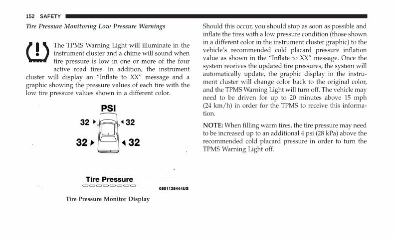
Tire Pressure Monitoring Low Pressure Warnings
The TPMS Warning Light will illuminate in theinstrument cluster and a chime will sound whentire pressure is low in one or more of the fouractive road tires. In addition, the instrument
cluster will display an “Inflate to XX” message and agraphic showing the pressure values of each tire with thelow tire pressure values shown in a different color.
Should this occur, you should stop as soon as possible andinflate the tires with a low pressure condition (those shownin a different color in the instrument cluster graphic) to thevehicle’s recommended cold placard pressure inflationvalue as shown in the “Inflate to XX” message. Once thesystem receives the updated tire pressures, the system willautomatically update, the graphic display in the instru-ment cluster will change color back to the original color,and the TPMS Warning Light will turn off. The vehicle mayneed to be driven for up to 20 minutes above 15 mph(24 km/h) in order for the TPMS to receive this informa-tion.
NOTE: When filling warm tires, the tire pressure may needto be increased up to an additional 4 psi (28 kPa) above therecommended cold placard pressure in order to turn theTPMS Warning Light off.
Tire Pressure Monitor Display
152 SAFETY

Service Tire Pressure System Warning
If a system fault is detected, the Tire Pressure MonitoringSystem (TPMS) Warning Light will flash on and off for 75seconds and then remain on solid. The system fault willalso sound a chime. In addition, the instrument cluster willdisplay a �Service Tire Pressure System� message for aminimum of five seconds and then display dashes (- -) inplace of the pressure value to indicate which sensor is notbeing received.
If the ignition switch is cycled, this sequence will repeat,providing the system fault still exists. If the system fault no
longer exists, the TPMS Warning Light will no longer flash,and the �Service Tire Pressure System� message will nolonger display, and a pressure value will display in place ofthe dashes. A system fault can occur due to any of thefollowing:
• Signal interference due to electronic devices or drivingnext to facilities emitting the same radio frequencies asthe TPM sensors.
• Accumulation of snow or ice around the wheels orwheel housings.
• Using tire chains on the vehicle.
• Using wheels/tires not equipped with TPM sensors.
Vehicles With Compact Spare
1. The compact spare tire or non-matching full size doesnot have a tire pressure monitoring sensor. Therefore,the TPMS will not monitor the pressure in the compactor non-matching full size spare tire.
2. If you install the compact or non-matching full sizespare tire in place of a road tire that has a pressure belowthe low-pressure warning limit, upon the next ignitionkey cycle, the TPMS Warning Light will remain on anda chime will sound. In addition, the graphic in the
Low Tire Pressure Monitor Display
5
SAFETY 153
instrument cluster will still display a different colorpressure value and an �Inflate to XX� message.
3. After driving the vehicle for up to 20 minutes above15 mph (24 km/h), the TPMS Warning Light will flashon and off for 75 seconds and then remain on solid. Inaddition, the instrument cluster will display a “ServiceTire Pressure System” message for five seconds and thendisplay dashes (- -) in place of the pressure value.
4. For each subsequent ignition key cycle, a chime willsound, the TPMS Warning Light will flash on and off for75 seconds and then remain on solid, and the instrumentcluster will display a “Service Tire Pressure System”message for five seconds and then display dashes (- -) inplace of the pressure value.
5. Once you repair or replace the original road tire andreinstall it on the vehicle in place of the compact spare ornon-matching full size, the TPMS will update automati-cally. In addition, the TPMS Warning Light will turn offand the graphic in the instrument cluster will display anew pressure value instead of dashes (- -), as long as notire pressure is below the low-pressure warning limit inany of the four active road tires. The vehicle may need tobe driven for up to 20 minutes above 15 mph (24 km/h)in order for the TPMS to receive this information.
TPMS Deactivation — If Equipped
The Tire Pressure Monitoring System (TPMS) can be deac-tivated if replacing all four wheel and tire assemblies (roadtires) with wheel and tire assemblies that do not haveTPMS Sensors, such as when installing winter wheel andtire assemblies on your vehicle.
To deactivate the TPMS, first replace all four wheel and tireassemblies (road tires) with tires not equipped with TirePressure Monitoring (TPM) Sensors. Then, drive the ve-hicle for 20 minutes above 15 mph (24 km/h). The TPMSwill chime, the TPMS Warning Light will flash on and offfor 75 seconds and then remain on. The instrument clusterwill display the “Service Tire Pressure System” messageand then display dashes (--) in place of the pressure values.
Beginning with the next ignition cycle, the TPMS will nolonger chime or display the “Service Tire Pressure System”message in the instrument cluster but dashes (- -) willremain in place of the pressure values.
To reactivate the TPMS, replace all four wheel and tireassemblies (road tires) with tires equipped with TPMsensors. Then, drive the vehicle for up to 20 minutes above15 mph (24 km/h). The TPMS will chime, the TPMSWarning Light will flash on and off for 75 seconds and thenturn off. The instrument cluster will display the “Service
154 SAFETY

Tire Pressure System” message and then display pressurevalues in place of the dashes. On the next ignition cycle the�Service Tire Pressure System� message will no longer bedisplayed as long as no system fault exists.
General Information
The following regulatory statement applies to all radiofrequency (RF) devices equipped in this vehicle:
This device complies with Part 15 of the FCC Rules andwith Industry Canada license-exempt RSS standard(s).Operation is subject to the following two conditions:
(1) This device may not cause harmful interference, and
(2) This device must accept any interference received,including interference that may cause undesired operation.
NOTE: Changes or modifications not expressly approvedby the party responsible for compliance could void theuser’s authority to operate the equipment.
OCCUPANT RESTRAINT SYSTEMS
Some of the most important safety features in your vehicleare the restraint systems:
Occupant Restraint Systems Features
• Seat Belt Systems
• Supplemental Restraint Systems (SRS) Air Bags
• Child Restraints
Some of the safety features described in this section may bestandard equipment on some models, or may be optionalequipment on others. If you are not sure, ask an authorizeddealer.
Important Safety Precautions
Please pay close attention to the information in this section.It tells you how to use your restraint system properly, tokeep you and your passengers as safe as possible.
Here are some simple steps you can take to minimize therisk of harm from a deploying air bag:
1. Children 12 years old and under should always ridebuckled up in the rear seat of a vehicle with a rear seat.
5
SAFETY 155
If your vehicle is not equipped with a rear seat, FCArecommends that you do not allow children 12 years oldand under to ride in your vehicle.
2. A child who is not big enough to wear the vehicle seatbelt properly (refer to “Child Restraints” in this sectionfor further information) must be secured in the appro-priate child restraint or belt-positioning booster seat in arear seating position.
3. If a child from 2 to 12 years old (not in a rear-facing childrestraint) must ride in the front passenger seat, move theseat as far back as possible and use the proper childrestraint. (refer to “Child Restraints” in this section forfurther information).
4. Never allow children to slide the shoulder belt behindthem or under their arm.
5. You should read the instructions provided with yourchild restraint to make sure that you are using itproperly.
6. All occupants should always wear their lap and shoul-der belts properly.
7. The driver and front passenger seats should be movedback as far as practical to allow the front air bags roomto inflate.
8. Do not lean against the door or window. If your vehiclehas side air bags, and deployment occurs, the side airbags will inflate forcefully into the space between occu-pants and the door and occupants could be injured.
9. If the air bag system in this vehicle needs to be modifiedto accommodate a disabled person, refer to the “Cus-tomer Assistance” section for customer service contactinformation.
WARNING!
• Never place a rear-facing child restraint in front of anair bag. A deploying passenger front air bag cancause death or serious injury to a child 12 years oryounger, including a child in a rear-facing childrestraint.
• Never install a rear-facing child restraint in the frontseat of a vehicle. Only use a rear-facing child re-straint in the rear seat. If the vehicle does not have arear seat, do not transport a rear-facing child restraintin that vehicle.
156 SAFETY

Seat Belt Systems
Buckle up even though you are an excellent driver, even onshort trips. Someone on the road may be a poor driver andcould cause a collision that includes you. This can happenfar away from home or on your own street.
Research has shown that seat belts save lives, and they canreduce the seriousness of injuries in a collision. Some of theworst injuries happen when people are thrown from thevehicle. Seat belts reduce the possibility of ejection and therisk of injury caused by striking the inside of the vehicle.Everyone in a motor vehicle should be belted at all times.
Vehicles Without Passenger Seating Installed
If your vehicle does not have a factory installed frontpassenger seat and/or rear passenger seats, the featuresdescribed in this section may not be available in your vehicle.
This vehicle has been designed to maximize total perfor-mance. In doing so, the deletion of passenger seats mayaffect the NVH (Noise, Vibration, and Harshness) charac-teristics. As a result, the interior (driver cockpit) Noise,Vibration, and Harshness (NVH) will be louder overall.Furthermore, the rear seats and seat belt system are deletedand the front passenger seat and seat belt system may bedeleted to increase vehicle performance.
WARNING!
• If the passenger and/or rear seats have been re-moved, do not ride in those areas. In a collision,people riding in these areas are more likely to beseriously injured or killed.
• If this vehicle was not factory equipped with apassenger seat, NEVER attempt to install a passengerseat because the safety systems, including the airbags and seatbelt, may not properly protect you.
• It is dangerous to ride in a cargo area, inside or outsideof a vehicle. In a collision, people riding in this areaare more likely to be seriously injured or killed.
• Only ride in available seating positions equippedwith seat belt systems. Always properly wear yourseat belt. Failure to do so could result in an increasedrisk of serious injury or death in the event of anaccident.
• Be sure everyone in your vehicle is in a seat andusing a seat belt properly. Occupants, including thedriver, should always wear their seat belts whetheror not an air bag is also provided at their seatingpositions to minimize the risk of severe injury ordeath in the event of a crash.
(Continued)
5
SAFETY 157
WARNING! (Continued)• All occupants, including the driver, should not oper-
ate a vehicle or sit in a vehicle’s seat if the headrestraints are not in place of their proper positions inorder to minimize the risk of neck injury in the eventof a crash.
• Head restraints should never be adjusted while thevehicle is in motion. Driving a vehicle with the headrestraints improperly adjusted or removed couldcause serious injury or death in the event of acollision.
Enhanced Seat Belt Use Reminder System (BeltAlert)
Driver and Passenger BeltAlert (if equipped)
BeltAlert is a feature intended to remind the driverand outboard front seat passenger (if equipped withoutboard front passenger seat BeltAlert) to buckle theirseat belts. The Belt Alert feature is active whenever theignition switch is in the START or ON/RUN position.
Initial Indication
If the driver is unbuckled when the ignition switch is firstin the START or ON/RUN position, a chime will signal fora few seconds. If the driver or outboard front seat passen-
ger (if equipped with outboard front passenger seatBeltAlert) is unbuckled when the ignition switch is first inthe START or ON/RUN position the Seat Belt ReminderLight will turn on and remain on until both outboard frontseat belts are buckled. The outboard front passenger seatBeltAlert is not active when an outboard front passengerseat is unoccupied.
BeltAlert Warning Sequence
The BeltAlert warning sequence is activated when thevehicle is moving above a specified vehicle speed rangeand the driver or outboard front seat passenger is unbuck-led (if equipped with outboard front passenger seatBeltAlert) (the outboard front passenger seat BeltAlert isnot active when the outboard front passenger seat isunoccupied). The BeltAlert warning sequence starts byblinking the Seat Belt Reminder Light and sounding anintermittent chime. Once the BeltAlert warning sequencehas completed, the Seat Belt Reminder Light will remain onuntil the seat belts are buckled. The BeltAlert warningsequence may repeat based on vehicle speed until thedriver and occupied outboard front seat passenger seatbelts are buckled. The driver should instruct all occupantsto buckle their seat belts.
158 SAFETY
Change of Status
If the driver or outboard front seat passenger (if equippedwith outboard front passenger seat BeltAlert) unbucklestheir seat belt while the vehicle is traveling, the BeltAlertwarning sequence will begin until the seat belts are buck-led again.
The outboard front passenger seat BeltAlert is not activewhen the outboard front passenger seat is unoccupied.BeltAlert may be triggered when an animal or other itemsare placed on the outboard front passenger seat or whenthe seat is folded flat (if equipped). It is recommended thatpets be restrained in the rear seat (if equipped) in petharnesses or pet carriers that are secured by seat belts, andcargo is properly stowed.
BeltAlert can be activated or deactivated by an authorizeddealer. FCA US LLC does not recommend deactivatingBeltAlert.
NOTE: If BeltAlert has been deactivated and the driver oroutboard front seat passenger (if equipped with outboardfront passenger seat BeltAlert) is unbuckled the Seat BeltReminder Light will turn on and remain on until the driverand outboard front seat passenger seat belts are buckled.
Lap/Shoulder Belts
All seating positions in your vehicle are equipped withlap/shoulder belts.
The seat belt webbing retractor will lock only during verysudden stops or collisions. This feature allows the shoulderpart of the seat belt to move freely with you under normalconditions. However, in a collision the seat belt will lockand reduce your risk of striking the inside of the vehicle orbeing thrown out of the vehicle.
WARNING!
• Relying on the air bags alone could lead to moresevere injuries in a collision. The air bags work withyour seat belt to restrain you properly. In somecollisions, the air bags won’t deploy at all. Alwayswear your seat belt even though you have air bags.
• In a collision, you and your passengers can suffermuch greater injuries if you are not properly buckledup. You can strike the interior of your vehicle orother passengers, or you can be thrown out of thevehicle. Always be sure you and others in yourvehicle are buckled up properly.
(Continued)
5
SAFETY 159
WARNING! (Continued)• It is dangerous to ride in a cargo area, inside or
outside of a vehicle. In a collision, people riding inthese areas are more likely to be seriously injured orkilled.
• Do not allow people to ride in any area of yourvehicle that is not equipped with seats and seat belts.
• Be sure everyone in your vehicle is in a seat andusing a seat belt properly. Occupants, including thedriver, should always wear their seat belts whetheror not an air bag is also provided at their seatingposition to minimize the risk of severe injury ordeath in the event of a crash.
• Wearing your seat belt incorrectly could make yourinjuries in a collision much worse. You might sufferinternal injuries, or you could even slide out of theseat belt. Follow these instructions to wear your seatbelt safely and to keep your passengers safe, too.
• Two people should never be belted into a single seatbelt. People belted together can crash into one an-other in a collision, hurting one another badly. Neveruse a lap/shoulder belt or a lap belt for more than oneperson, no matter what their size.
WARNING!
• A lap belt worn too high can increase the risk ofinjury in a collision. The seat belt forces won’t be atthe strong hip and pelvic bones, but across yourabdomen. Always wear the lap part of your seat beltas low as possible and keep it snug.
• A twisted seat belt may not protect you properly. Ina collision, it could even cut into you. Be sure the seatbelt is flat against your body, without twists. If youcan’t straighten a seat belt in your vehicle, take it toan authorized dealer immediately and have it fixed.
• A seat belt that is buckled into the wrong buckle willnot protect you properly. The lap portion could ridetoo high on your body, possibly causing internalinjuries. Always buckle your seat belt into thebuckle nearest you.
• A seat belt that is too loose will not protect youproperly. In a sudden stop, you could move too farforward, increasing the possibility of injury. Wearyour seat belt snugly.
• A seat belt that is worn under your arm is dangerous.Your body could strike the inside surfaces of thevehicle in a collision, increasing head and neck
(Continued)
160 SAFETY
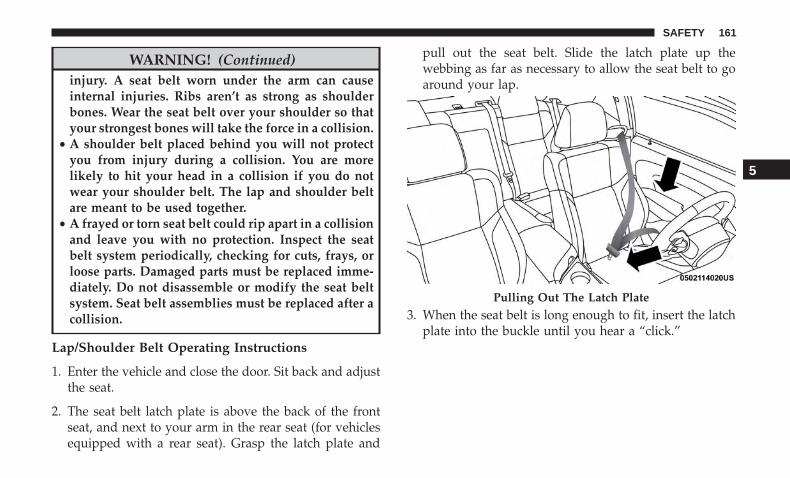
WARNING! (Continued)injury. A seat belt worn under the arm can causeinternal injuries. Ribs aren’t as strong as shoulderbones. Wear the seat belt over your shoulder so thatyour strongest bones will take the force in a collision.
• A shoulder belt placed behind you will not protectyou from injury during a collision. You are morelikely to hit your head in a collision if you do notwear your shoulder belt. The lap and shoulder beltare meant to be used together.
• A frayed or torn seat belt could rip apart in a collisionand leave you with no protection. Inspect the seatbelt system periodically, checking for cuts, frays, orloose parts. Damaged parts must be replaced imme-diately. Do not disassemble or modify the seat beltsystem. Seat belt assemblies must be replaced after acollision.
Lap/Shoulder Belt Operating Instructions
1. Enter the vehicle and close the door. Sit back and adjustthe seat.
2. The seat belt latch plate is above the back of the frontseat, and next to your arm in the rear seat (for vehiclesequipped with a rear seat). Grasp the latch plate and
pull out the seat belt. Slide the latch plate up thewebbing as far as necessary to allow the seat belt to goaround your lap.
3. When the seat belt is long enough to fit, insert the latchplate into the buckle until you hear a “click.”
Pulling Out The Latch Plate
5
SAFETY 161

4. Position the lap belt so that it is snug and lies low acrossyour hips, below your abdomen. To remove slack in thelap belt portion, pull up on the shoulder belt. To loosenthe lap belt if it is too tight, tilt the latch plate and pullon the lap belt. A snug seat belt reduces the risk ofsliding under the seat belt in a collision.
5. Position the shoulder belt across the shoulder and chestwith minimal, if any slack so that it is comfortable andnot resting on your neck. The retractor will withdrawany slack in the shoulder belt.
6. To release the seat belt, push the red button on thebuckle. The seat belt will automatically retract to itsstowed position. If necessary, slide the latch plate downthe webbing to allow the seat belt to retract fully.
Inserting Latch Plate Into Buckle Positioning The Lap Belt
162 SAFETY
Lap/Shoulder Belt Untwisting Procedure
Use the following procedure to untwist a twisted lap/shoulder belt.
1. Position the latch plate as close as possible to the anchorpoint.
2. At about 6 to 12 inches (15 to 30 cm) above the latchplate, grasp and twist the seat belt webbing 180 degreesto create a fold that begins immediately above the latchplate.
3. Slide the latch plate upward over the folded webbing.The folded webbing must enter the slot at the top of thelatch plate.
4. Continue to slide the latch plate up until it clears thefolded webbing and the seat belt is no longer twisted.
Seat Belt Extender
If a seat belt is not long enough to fit properly, even whenthe webbing is fully extended and the adjustable uppershoulder belt anchorage (if equipped) is in its lowestposition, an authorized dealer can provide you with a SeatBelt Extender. The Seat Belt Extender should be used onlyif the existing seat belt is not long enough. When the Seat
Belt Extender is not required for a different occupant, itmust be removed.
WARNING!
• ONLY use a Seat Belt Extender if it is physicallyrequired in order to properly fit the original seat beltsystem. DO NOT USE the Seat Belt Extender if,when worn, the distance between the front edge ofthe Seat Belt Extender buckle and the center of theoccupant’s body is LESS than 6 inches.
• Using a Seat Belt Extender when not needed canincrease the risk of serious injury or death in acollision. Only use the Seat Belt Extender when thelap belt is not long enough and only use in therecommended seating positions. Remove and storethe Seat Belt Extender when not needed.
5
SAFETY 163
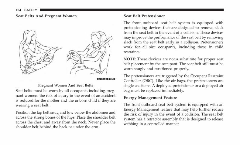
Seat Belts And Pregnant Women
Seat belts must be worn by all occupants including preg-nant women: the risk of injury in the event of an accidentis reduced for the mother and the unborn child if they arewearing a seat belt.
Position the lap belt snug and low below the abdomen andacross the strong bones of the hips. Place the shoulder beltacross the chest and away from the neck. Never place theshoulder belt behind the back or under the arm.
Seat Belt Pretensioner
The front outboard seat belt system is equipped withpretensioning devices that are designed to remove slackfrom the seat belt in the event of a collision. These devicesmay improve the performance of the seat belt by removingslack from the seat belt early in a collision. Pretensionerswork for all size occupants, including those in childrestraints.
NOTE: These devices are not a substitute for proper seatbelt placement by the occupant. The seat belt still must beworn snugly and positioned properly.
The pretensioners are triggered by the Occupant RestraintController (ORC). Like the air bags, the pretensioners aresingle use items. A deployed pretensioner or a deployed airbag must be replaced immediately.
Energy Management Feature
The front outboard seat belt system is equipped with anEnergy Management feature that may help further reducethe risk of injury in the event of a collision. The seat beltsystem has a retractor assembly that is designed to releasewebbing in a controlled manner.
Pregnant Women And Seat Belts
164 SAFETY
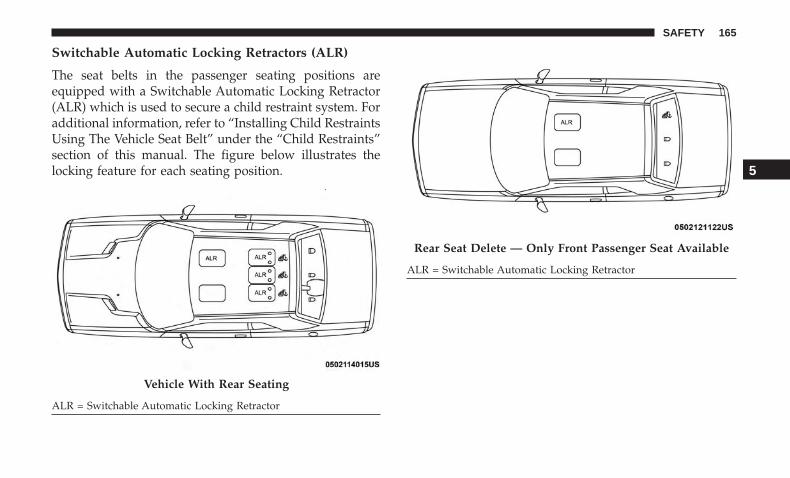
Switchable Automatic Locking Retractors (ALR)
The seat belts in the passenger seating positions areequipped with a Switchable Automatic Locking Retractor(ALR) which is used to secure a child restraint system. Foradditional information, refer to “Installing Child RestraintsUsing The Vehicle Seat Belt” under the “Child Restraints”section of this manual. The figure below illustrates thelocking feature for each seating position.
Vehicle With Rear Seating
ALR = Switchable Automatic Locking Retractor
Rear Seat Delete — Only Front Passenger Seat Available
ALR = Switchable Automatic Locking Retractor
5
SAFETY 165
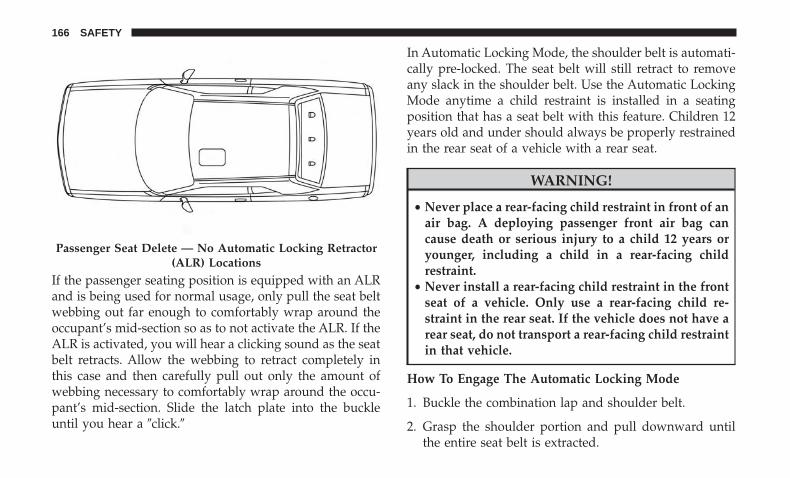
If the passenger seating position is equipped with an ALRand is being used for normal usage, only pull the seat beltwebbing out far enough to comfortably wrap around theoccupant’s mid-section so as to not activate the ALR. If theALR is activated, you will hear a clicking sound as the seatbelt retracts. Allow the webbing to retract completely inthis case and then carefully pull out only the amount ofwebbing necessary to comfortably wrap around the occu-pant’s mid-section. Slide the latch plate into the buckleuntil you hear a �click.�
In Automatic Locking Mode, the shoulder belt is automati-cally pre-locked. The seat belt will still retract to removeany slack in the shoulder belt. Use the Automatic LockingMode anytime a child restraint is installed in a seatingposition that has a seat belt with this feature. Children 12years old and under should always be properly restrainedin the rear seat of a vehicle with a rear seat.
WARNING!
• Never place a rear-facing child restraint in front of anair bag. A deploying passenger front air bag cancause death or serious injury to a child 12 years oryounger, including a child in a rear-facing childrestraint.
• Never install a rear-facing child restraint in the frontseat of a vehicle. Only use a rear-facing child re-straint in the rear seat. If the vehicle does not have arear seat, do not transport a rear-facing child restraintin that vehicle.
How To Engage The Automatic Locking Mode
1. Buckle the combination lap and shoulder belt.
2. Grasp the shoulder portion and pull downward untilthe entire seat belt is extracted.
Passenger Seat Delete — No Automatic Locking Retractor(ALR) Locations
166 SAFETY
3. Allow the seat belt to retract. As the seat belt retracts,you will hear a clicking sound. This indicates the seatbelt is now in the Automatic Locking Mode.
How To Disengage The Automatic Locking Mode
Unbuckle the combination lap/shoulder belt and allow itto retract completely to disengage the Automatic LockingMode and activate the vehicle sensitive (emergency) lock-ing mode.
WARNING!
• The seat belt assembly must be replaced if theswitchable Automatic Locking Retractor (ALR) fea-ture or any other seat belt function is not workingproperly when checked according to the proceduresin the Service Manual.
• Failure to replace the seat belt assembly could in-crease the risk of injury in collisions.
• Do not use the Automatic Locking Mode to restrainoccupants who are wearing the seat belt or childrenwho are using booster seats. The locked mode is onlyused to install rear-facing or forward-facing childrestraints that have a harness for restraining thechild.
Supplemental Restraint Systems (SRS)
All passenger occupants within the vehicle must be in aseat equipped with a Seat Belt System and Head Restraintfor the safety of the passenger.
Non-SRT Vehicles
If the passenger and/or rear seats have been removed donot ride in those areas.
Some of the safety features described in this section may bestandard equipment on some models, or may be optionalequipment on others. If you are not sure, ask an authorizeddealer.
The air bag system must be ready to protect you in acollision. The Occupant Restraint Controller (ORC) moni-tors the internal circuits and interconnecting wiring asso-ciated with the electrical Air Bag System Components.Your vehicle may be equipped with the following Air BagSystem Components:
Air Bag System Components
• Occupant Restraint Controller (ORC)
• Air Bag Warning Light
• Steering Wheel and Column
5
SAFETY 167

• Instrument Panel
• Knee Impact Bolsters
• Driver and Front Passenger Air Bags
• Seat Belt Buckle Switch
• Supplemental Side Air Bags
• Front and Side Impact Sensors
• Seat Belt Pretensioners
• Seat Track Position Sensors
Non-SRT Vehicles
NOTE: Vehicles with front passenger seat deleted will notbe equipped with the Seat Belt Buckle Switch, Seat BeltPretensioner, Supplemental Seat Mounted Side Airbag, andSeat Track Position Sensors for the front passenger.
If the passenger and/or rear seats have been removed donot ride in those areas.
All passenger occupants within the vehicle must be in aseat equipped with a Seat Belt System and Head Restraintfor the safety of the passenger.
Air Bag Warning Light
The ORC monitors the readiness of the electronicparts of the air bag system whenever the ignitionswitch is in the START or ON/RUN position. Ifthe ignition switch is in the OFF position or in the
ACC position, the air bag system is not on and the air bagswill not inflate.
The ORC contains a backup power supply system that maydeploy the air bag system even if the battery loses power orit becomes disconnected prior to deployment.
The ORC turns on the Air Bag Warning Light in theinstrument panel for approximately four to eight secondsfor a self-check when the ignition switch is first in theON/RUN position. After the self-check, the Air Bag Warn-ing Light will turn off. If the ORC detects a malfunction inany part of the system, it turns on the Air Bag WarningLight, either momentarily or continuously. A single chimewill sound to alert you if the light comes on again afterinitial startup.
The ORC also includes diagnostics that will illuminate theinstrument panel Air Bag Warning Light if a malfunction isdetected that could affect the air bag system. The diagnos-tics also record the nature of the malfunction. While the air
168 SAFETY

bag system is designed to be maintenance free, if any of thefollowing occurs, have an authorized dealer service the airbag system immediately.
• The Air Bag Warning Light does not come on during thefour to eight seconds when the ignition switch is first inthe ON/RUN position.
• The Air Bag Warning Light remains on after the four toeight-second interval.
• The Air Bag Warning Light comes on intermittently orremains on while driving.
NOTE: If the speedometer, tachometer, or any enginerelated gauges are not working, the Occupant RestraintController (ORC) may also be disabled. In this conditionthe air bags may not be ready to inflate for your protection.Have an authorized dealer service the air bag systemimmediately.
WARNING!
Ignoring the Air Bag Warning Light in your instrumentpanel could mean you won’t have the air bag system toprotect you in a collision. If the light does not come on
(Continued)
WARNING! (Continued)as a bulb check when the ignition is first turned on,stays on after you start the vehicle, or if it comes on asyou drive, have an authorized dealer service the air bagsystem immediately.
Redundant Air Bag Warning Light
If a fault with the Air Bag Warning Light isdetected, which could affect the SupplementalRestraint System (SRS), the Redundant Air BagWarning Light will illuminate on the instrument
panel. The Redundant Air Bag Warning Light will stay onuntil the fault is cleared. In addition, a single chime willsound to alert you that the Redundant Air Bag WarningLight has come on and a fault has been detected. If theRedundant Air Bag Warning Light comes on intermittentlyor remains on while driving have an authorized dealerservice the vehicle immediately.
For additional information regarding the Redundant AirBag Warning Light refer to “Getting To Know Your Instru-ment Panel” section of this manual.
5
SAFETY 169

Front Air Bags
This vehicle has front air bags and lap/shoulder belts forboth the driver and front passenger. The front air bags are asupplement to the seat belt restraint systems. The driverfront air bag is mounted in the center of the steering wheel.The passenger front air bag is mounted in the instrumentpanel, above the glove compartment. The words “SRS AIR-BAG” or “AIRBAG” are embossed on the air bag covers.
WARNING!
• Being too close to the steering wheel or instrumentpanel during front air bag deployment could causeserious injury, including death. Air bags need roomto inflate. Sit back, comfortably extending your armsto reach the steering wheel or instrument panel.
• Never place a rear-facing child restraint in front of anair bag. A deploying passenger front air bag cancause death or serious injury to a child 12 years oryounger, including a child in a rear-facing childrestraint.
• Never install a rear-facing child restraint in the frontseat of a vehicle. Only use a rear-facing child re-straint in the rear seat. If the vehicle does not have arear seat, do not transport a rear-facing child restraintin that vehicle.
Driver And Passenger Front Air Bag Features
The Advanced Front Air Bag system has multistage driverand front passenger air bags. This system provides outputappropriate to the severity and type of collision as deter-mined by the Occupant Restraint Controller (ORC), whichmay receive information from the front impact sensors (ifequipped) or other system components.
Front Air Bags/Knee Impact Bolster Locations1 — Driver And Passenger Front Air Bags2 — Passenger Knee Impact Bolster3 — Driver Knee Impact Bolster
170 SAFETY

The first stage inflator is triggered immediately during animpact that requires air bag deployment. A low energyoutput is used in less severe collisions. A higher energyoutput is used for more severe collisions.
This vehicle may be equipped with a driver and/or frontpassenger seat belt buckle switch that detects whether thedriver or front passenger seat belt is buckled. The seat beltbuckle switch may adjust the inflation rate of the Ad-vanced Front Air Bags.
This vehicle may be equipped with driver and/or frontpassenger seat track position sensors that may adjust theinflation rate of the Advanced Front Air Bags based uponseat position.
WARNING!
• No objects should be placed over or near the air bagon the instrument panel or steering wheel becauseany such objects could cause harm if the vehicle is ina collision severe enough to cause the air bag toinflate.
• Do not put anything on or around the air bag coversor attempt to open them manually. You may damage
(Continued)
WARNING! (Continued)the air bags and you could be injured because the airbags may no longer be functional. The protectivecovers for the air bag cushions are designed to openonly when the air bags are inflating.
• Relying on the air bags alone could lead to moresevere injuries in a collision. The air bags work withyour seat belt to restrain you properly. In somecollisions, air bags won’t deploy at all. Always wearyour seat belts even though you have air bags.
Front Air Bag Operation
Front Air Bags are designed to provide additional protec-tion by supplementing the seat belts. Front air bags are notexpected to reduce the risk of injury in rear, side, orrollover collisions. The front air bags will not deploy in allfrontal collisions, including some that may produce sub-stantial vehicle damage — for example, some pole colli-sions, truck underrides, and angle offset collisions.
On the other hand, depending on the type and location ofimpact, front air bags may deploy in crashes with littlevehicle front-end damage but that produce a severe initialdeceleration.
5
SAFETY 171

Because air bag sensors measure vehicle deceleration overtime, vehicle speed and damage by themselves are notgood indicators of whether or not an air bag should havedeployed.
Seat belts are necessary for your protection in all collisions,and also are needed to help keep you in position, awayfrom an inflating air bag.
When the ORC detects a collision requiring the front airbags, it signals the inflator units. A large quantity ofnon-toxic gas is generated to inflate the front air bags.
The steering wheel hub trim cover and the upper passen-ger side of the instrument panel separate and fold out ofthe way as the air bags inflate to their full size. The front airbags fully inflate in less time than it takes to blink youreyes. The front air bags then quickly deflate while helpingto restrain the driver and front passenger.
Knee Impact Bolsters
The Knee Impact Bolsters help protect the knees of thedriver and front passenger, and position the front occu-pants for improved interaction with the front air bags.
WARNING!
• Do not drill, cut, or tamper with the knee impactbolsters in any way.
• Do not mount any accessories to the knee impactbolsters such as alarm lights, stereos, citizen bandradios, etc.
Supplemental Side Air Bags
Supplemental Seat-Mounted Side Air Bags (SABs)
This vehicle is equipped with Supplemental Seat-MountedSide Air Bags (SABs).
Supplemental Seat-Mounted Side Air Bags (SABs) arelocated in the outboard side of the front seats. The SABs aremarked with “SRS AIRBAG” or “AIRBAG” on a label or onthe seat trim on the outboard side of the seats.
The SABs may help to reduce the risk of occupant injuryduring certain side impacts, in addition to the injuryreduction potential provided by the seat belts and bodystructure.
172 SAFETY
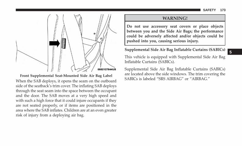
When the SAB deploys, it opens the seam on the outboardside of the seatback’s trim cover. The inflating SAB deploysthrough the seat seam into the space between the occupantand the door. The SAB moves at a very high speed andwith such a high force that it could injure occupants if theyare not seated properly, or if items are positioned in thearea where the SAB inflates. Children are at an even greaterrisk of injury from a deploying air bag.
WARNING!
Do not use accessory seat covers or place objectsbetween you and the Side Air Bags; the performancecould be adversely affected and/or objects could bepushed into you, causing serious injury.
Supplemental Side Air Bag Inflatable Curtains (SABICs)
This vehicle is equipped with Supplemental Side Air BagInflatable Curtains (SABICs).
Supplemental Side Air Bag Inflatable Curtains (SABICs)are located above the side windows. The trim covering theSABICs is labeled “SRS AIRBAG” or “AIRBAG.”
Front Supplemental Seat-Mounted Side Air Bag Label
5
SAFETY 173

SABICs may help reduce the risk of head and other injuriesto front and rear seat outboard occupants in certain sideimpacts, in addition to the injury reduction potentialprovided by the seat belts and body structure.
The SABIC deploys downward, covering the side win-dows. An inflating SABIC pushes the outside edge of theheadliner out of the way and covers the window. TheSABICs inflate with enough force to injure occupants ifthey are not belted and seated properly, or if items are
positioned in the area where the SABICs inflate. Childrenare at an even greater risk of injury from a deploying airbag.
The SABICs may help reduce the risk of partial or completeejection of vehicle occupants through side windows incertain side impact events.
WARNING!
• Do not mount equipment, or stack luggage or othercargo up high enough to block the deployment of theSABICs. The trim covering above the side windowswhere the SABIC and its deployment path are lo-cated should remain free from any obstructions.
• In order for the SABICs to work as intended, do notinstall any accessory items in your vehicle whichcould alter the roof. Do not add an aftermarketsunroof to your vehicle. Do not add roof racks thatrequire permanent attachments (bolts or screws) forinstallation on the vehicle roof. Do not drill into theroof of the vehicle for any reason.
Supplemental Side Air Bag Inflatable Curtain (SABIC)Label Location
174 SAFETY
Side Impacts
The Side Air Bags are designed to activate in certain sideimpacts. The Occupant Restraint Controller (ORC) deter-mines whether the deployment of the Side Air Bags in aparticular impact event is appropriate, based on the sever-ity and type of collision. The side impact sensors aid theORC in determining the appropriate response to impactevents. The system is calibrated to deploy the Side Air Bagson the impact side of the vehicle during impacts thatrequire Side Air Bag occupant protection. In side impacts,the Side Air Bags deploy independently; a left side impactdeploys the left Side Air Bags only and a right-side impactdeploys the right Side Air Bags only. Vehicle damage byitself is not a good indicator of whether or not Side AirBags should have deployed.
The Side Air Bags will not deploy in all side collisions,including some collisions at certain angles, or some sidecollisions that do not impact the area of the passengercompartment. The Side Air Bags may deploy duringangled or offset frontal collisions where the front air bagsdeploy.
Side Air Bags are a supplement to the seat belt restraintsystem. Side Air Bags deploy in less time than it takes toblink your eyes.
WARNING!
• Occupants, including children, who are up against orvery close to Side Air Bags can be seriously injuredor killed. Occupants, including children, shouldnever lean on or sleep against the door, side win-dows, or area where the side air bags inflate, even ifthey are in an infant or child restraint.
• Seat belts (and child restraints where appropriate)are necessary for your protection in all collisions.They also help keep you in position, away from aninflating Side Air Bag. To get the best protectionfrom the Side Air Bags, occupants must wear theirseat belts properly and sit upright with their backsagainst the seats. Children must be properly re-strained in a child restraint or booster seat that isappropriate for the size of the child.
5
SAFETY 175
WARNING!
• Side Air Bags need room to inflate. Do not leanagainst the door or window. Sit upright in the centerof the seat.
• Being too close to the Side Air Bags during deploy-ment could cause you to be severely injured orkilled.
• Relying on the Side Air Bags alone could lead tomore severe injuries in a collision. The Side Air Bagswork with your seat belt to restrain you properly. Insome collisions, Side Air Bags won’t deploy at all.Always wear your seat belt even though you haveSide Air Bags.
NOTE: Air bag covers may not be obvious in the interiortrim, but they will open during air bag deployment.
Rollover Events
Side Air Bags are designed to activate in certain rolloverevents. The ORC determines whether the deployment ofthe Side Air Bags in a particular rollover event is appro-priate, based on the severity and type of collision. Vehicledamage by itself is not a good indicator of whether or notSide Air Bags should have deployed.
The Side Air Bags will not deploy in all rollover events. Therollover sensing system determines if a rollover event maybe in progress and whether deployment is appropriate. Inthe event the vehicle experiences a rollover or near rolloverevent, and deployment of the Side Air Bags is appropriate,the rollover sensing system will also deploy the seat beltpretensioners on both sides of the vehicle.
The SABICs may help reduce the risk of partial or completeejection of vehicle occupants through side windows incertain rollover or side impact events.
Air Bag System Components
NOTE: The Occupant Restraint Controller (ORC) monitorsthe internal circuits and interconnecting wiring associatedwith electrical Air Bag System Components listed below:
• Occupant Restraint Controller (ORC)
• Air Bag Warning Light
• Steering Wheel and Column
• Instrument Panel
• Knee Impact Bolsters
• Driver and Front Passenger Air Bags
• Seat Belt Buckle Switch
176 SAFETY

• Supplemental Side Air Bags
• Front and Side Impact Sensors
• Seat Belt Pretensioners
• Seat Track Position Sensors
Non-SRT Vehicles
NOTE: Vehicles with front passenger seat deleted will notbe equipped with the Seat Belt Buckle Switch, Seat BeltPretensioner, Supplemental Seat Mounted Side Airbag, andSeat Track Position Sensors for the front passenger.
All passenger occupants within the vehicle must be in aseat equipped with a Seat Belt System and Head Restraintfor the safety of the passenger. If the passenger and/or rearseats have been removed do not ride in those areas.
If A Deployment Occurs
The front air bags are designed to deflate immediately afterdeployment.
NOTE: Front and/or side air bags will not deploy in allcollisions. This does not mean something is wrong with theair bag system.
If you do have a collision which deploys the air bags, anyor all of the following may occur:
• The air bag material may sometimes cause abrasionsand/or skin reddening to the occupants as the air bagsdeploy and unfold. The abrasions are similar to frictionrope burns or those you might get sliding along a carpetor gymnasium floor. They are not caused by contact withchemicals. They are not permanent and normally healquickly. However, if you haven’t healed significantlywithin a few days, or if you have any blistering, see yourdoctor immediately.
• As the air bags deflate, you may see some smoke-likeparticles. The particles are a normal by-product of theprocess that generates the non-toxic gas used for air baginflation. These airborne particles may irritate the skin,eyes, nose, or throat. If you have skin or eye irritation,rinse the area with cool water. For nose or throatirritation, move to fresh air. If the irritation continues,see your doctor. If these particles settle on your clothing,follow the garment manufacturer’s instructions forcleaning.
5
SAFETY 177

Do not drive your vehicle after the air bags have deployed.If you are involved in another collision, the air bags willnot be in place to protect you.
WARNING!
Deployed air bags and seat belt pretensioners cannotprotect you in another collision. Have the air bags, seatbelt pretensioners, and the seat belt retractor assem-blies replaced by an authorized dealer immediately.Also, have the Occupant Restraint Controller Systemserviced as well.
NOTE:
• Air bag covers may not be obvious in the interior trim,but they will open during air bag deployment.
• After any collision, the vehicle should be taken to anauthorized dealer immediately.
Enhanced Accident Response System
In the event of an impact, if the communication networkremains intact, and the power remains intact, dependingon the nature of the event, the ORC will determine whetherto have the Enhanced Accident Response System performthe following functions:
• Cut off fuel to the engine (If Equipped)
• Cut off battery power to the electric motor (If Equipped)
• Flash hazard lights as long as the battery has power
• Turn on the interior lights, which remain on as long asthe battery has power or for 15 minutes from theintervention of the Enhanced Accident Response Sys-tem.
• Unlock the power door locks.
Your vehicle may also be designed to perform any of theseother functions in response to the Enhanced AccidentResponse System:
• Turn off the Fuel Filter Heater, Turn off the HVACBlower Motor, Close the HVAC Circulation Door
• Cut off battery power to the:• Engine• Electric Motor (if equipped)• Electric power steering• Brake booster• Electric park brake• Automatic transmission gear selector• Horn
178 SAFETY
• Front wiper• Headlamp washer pump
NOTE: After an accident, remember to cycle the ignitionto the STOP (OFF/LOCK) position and remove the keyfrom the ignition switch to avoid draining the battery.Carefully check the vehicle for fuel leaks in the enginecompartment and on the ground near the engine compart-ment and fuel tank before resetting the system and startingthe engine. If there are no fuel leaks or damage to thevehicle electrical devices (e.g. headlights) after an accident,reset the system by following the procedure describedbelow. If you have any doubt, contact an authorized dealer.
Enhanced Accident Response System ResetProcedure
In order to reset the Enhanced Accident Response Systemfunctions after an event, the ignition switch must bechanged from ignition START or ON/RUN to ignition OFF.Carefully check the vehicle for fuel leaks in the enginecompartment and on the ground near the engine compart-ment and fuel tank before resetting the system and startingthe engine.
Maintaining Your Air Bag System
WARNING!
• Modifications to any part of the air bag system couldcause it to fail when you need it. You could beinjured if the air bag system is not there to protectyou. Do not modify the components or wiring, in-cluding adding any kind of badges or stickers to thesteering wheel hub trim cover or the upper passengerside of the instrument panel. Do not modify the frontbumper, vehicle body structure, or add aftermarketside steps or running boards.
• It is dangerous to try to repair any part of the air bagsystem yourself. Be sure to tell anyone who works onyour vehicle that it has an air bag system.
• Do not attempt to modify any part of your air bagsystem. The air bag may inflate accidentally or maynot function properly if modifications are made.Take your vehicle to an authorized dealer for any airbag system service. If your seat, including your trimcover and cushion, needs to be serviced in any way(including removal or loosening/tightening of seatattachment bolts), take the vehicle to an authorized
(Continued)
5
SAFETY 179
WARNING! (Continued)dealer. Only manufacturer approved seat accessoriesmay be used. If it is necessary to modify the air bagsystem for persons with disabilities, contact an au-thorized dealer.
Event Data Recorder (EDR)
This vehicle is equipped with an event data recorder(EDR). The main purpose of an EDR is to record, in certaincrash or near crash-like situations, such as an air bagdeployment or hitting a road obstacle, data that will assistin understanding how a vehicle’s systems performed. TheEDR is designed to record data related to vehicle dynamicsand safety systems for a short period of time, typically 30seconds or less. The EDR in this vehicle is designed torecord such data as:
• How various systems in your vehicle were operating;
• Whether or not the driver and passenger safety beltswere buckled/fastened;
• How far (if at all) the driver was depressing the accel-erator and/or brake pedal; and,
• How fast the vehicle was traveling.
These data can help provide a better understanding of thecircumstances in which crashes and injuries occur.
NOTE: EDR data are recorded by your vehicle only if anon-trivial crash situation occurs; no data are recorded bythe EDR under normal driving conditions and no personaldata (e.g., name, gender, age, and crash location) arerecorded. However, other parties, such as law enforcement,could combine the EDR data with the type of personallyidentifying data routinely acquired during a crash investi-gation.
To read data recorded by an EDR, special equipment isrequired, and access to the vehicle or the EDR is needed. Inaddition to the vehicle manufacturer, other parties, such aslaw enforcement, that have the special equipment, can readthe information if they have access to the vehicle or theEDR.
Child Restraints
Everyone in your vehicle needs to be buckled up at alltimes, including babies and children. Every state in theUnited States, and every Canadian province, requires thatsmall children ride in proper restraint systems. This is thelaw, and you can be prosecuted for ignoring it.
180 SAFETY

Children 12 years or younger should ride properly buckledup in a rear seat, if available.
If your vehicle is not equipped with a rear seat, FCArecommends that you do not allow children 12 years oldand under to ride in your vehicle. If the rear seats are notpresent in your vehicle, NEVER install a child restraint inthese positions.
According to crash statistics, children are safer whenproperly restrained in the rear seats rather than in the front.
WARNING!
In a collision, an unrestrained child can become aprojectile inside the vehicle. The force required to holdeven an infant on your lap could become so great thatyou could not hold the child, no matter how strong youare. The child and others could be badly injured orkilled. Any child riding in your vehicle should be in aproper restraint for the child’s size.
There are different sizes and types of restraints for childrenfrom newborn size to the child almost large enough for anadult safety belt. Always check the child seat Owner’sManual to make sure you have the correct seat for yourchild. Carefully read and follow all the instructions andwarnings in the child restraint Owner’s Manual and on allthe labels attached to the child restraint.
Before buying any restraint system, make sure that it has alabel certifying that it meets all applicable Safety Stan-dards. You should also make sure that you can install it inthe vehicle where you will use it.
NOTE:
• For additional information, refer to http://www.nhtsa.gov/parents-and-caregivers or call: 1–888–327–4236
• Canadian residents should refer to Transport Canada’s web-site for additional information: http://www.tc.gc.ca/eng/motorvehiclesafety/safedrivers-childsafety-index-53.htm
5
SAFETY 181
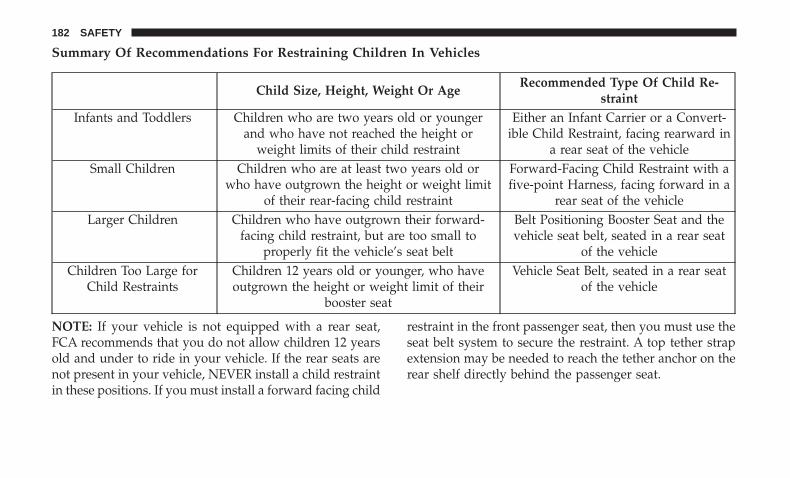
Summary Of Recommendations For Restraining Children In Vehicles
Child Size, Height, Weight Or AgeRecommended Type Of Child Re-
straintInfants and Toddlers Children who are two years old or younger
and who have not reached the height orweight limits of their child restraint
Either an Infant Carrier or a Convert-ible Child Restraint, facing rearward in
a rear seat of the vehicleSmall Children Children who are at least two years old or
who have outgrown the height or weight limitof their rear-facing child restraint
Forward-Facing Child Restraint with afive-point Harness, facing forward in a
rear seat of the vehicleLarger Children Children who have outgrown their forward-
facing child restraint, but are too small toproperly fit the vehicle’s seat belt
Belt Positioning Booster Seat and thevehicle seat belt, seated in a rear seat
of the vehicleChildren Too Large for
Child RestraintsChildren 12 years old or younger, who haveoutgrown the height or weight limit of their
booster seat
Vehicle Seat Belt, seated in a rear seatof the vehicle
NOTE: If your vehicle is not equipped with a rear seat,FCA recommends that you do not allow children 12 yearsold and under to ride in your vehicle. If the rear seats arenot present in your vehicle, NEVER install a child restraintin these positions. If you must install a forward facing child
restraint in the front passenger seat, then you must use theseat belt system to secure the restraint. A top tether strapextension may be needed to reach the tether anchor on therear shelf directly behind the passenger seat.
182 SAFETY

Infant And Child Restraints
Safety experts recommend that children ride rear-facing inthe vehicle until they are two years old or until they reacheither the height or weight limit of their rear-facing childrestraint. Two types of child restraints can be used rear-facing: infant carriers and convertible child seats.
The infant carrier is only used rear-facing in the vehicle. Itis recommended for children from birth until they reachthe weight or height limit of the infant carrier. Convertiblechild seats can be used either rear-facing or forward-facingin the vehicle. Convertible child seats often have a higherweight limit in the rear-facing direction than infant carriersdo, so they can be used rear-facing by children who haveoutgrown their infant carrier but are still less than at leasttwo years old. Children should remain rear-facing untilthey reach the highest weight or height allowed by theirconvertible child seat.
WARNING!
• Never place a rear-facing child restraint in front of anair bag. A deploying passenger front air bag cancause death or serious injury to a child 12 years or
(Continued)
WARNING! (Continued)younger, including a child in a rear-facing childrestraint.
• Never install a rear-facing child restraint in the frontseat of a vehicle. Only use a rear-facing child re-straint in the rear seat. If the vehicle does not have arear seat, do not transport a rear-facing child restraintin that vehicle.
Older Children And Child Restraints
NOTE: If your vehicle is not equipped with a rear seat,FCA recommends that you do not allow children 12 yearsold and under to ride in your vehicle. If the rear seats arenot present in your vehicle, NEVER install a child restraintin these positions. If you must install a forward facing childrestraint in the front passenger seat, then you must use theseat belt system to secure the restraint. A top tether strapextension may be needed to reach the tether anchor on therear shelf directly behind the passenger seat.
Children who are two years old or who have outgrowntheir rear-facing convertible child seat can ride forward-facing in the vehicle. Forward-facing child seats and con-vertible child seats used in the forward-facing direction arefor children who are over two years old or who have
5
SAFETY 183

outgrown the rear-facing weight or height limit of theirrear-facing convertible child seat. Children should remainin a forward-facing child seat with a harness for as long aspossible, up to the highest weight or height allowed by thechild seat.
All children whose weight or height is above the forward-facing limit for the child seat should use a belt-positioningbooster seat until the vehicle’s seat belts fit properly. If thechild cannot sit with knees bent over the vehicle’s seatcushion while the child’s back is against the seatback, theyshould use a belt-positioning booster seat. The child andbelt-positioning booster seat are held in the vehicle by theseat belt.
WARNING!
• Improper installation can lead to failure of an infantor child restraint. It could come loose in a collision.The child could be badly injured or killed. Followthe child restraint manufacturer’s directions exactlywhen installing an infant or child restraint.
• After a child restraint is installed in the vehicle, donot move the vehicle seat forward or rearward be-cause it can loosen the child restraint attachments.
(Continued)
WARNING! (Continued)Remove the child restraint before adjusting the ve-hicle seat position. When the vehicle seat has beenadjusted, reinstall the child restraint.
• When your child restraint is not in use, secure it inthe vehicle with the seat belt or LATCH anchorages,or remove it from the vehicle. Do not leave it loose inthe vehicle. In a sudden stop or accident, it couldstrike the occupants or seatbacks and cause seriouspersonal injury.
Children Too Large For Booster Seats
NOTE: If your vehicle is not equipped with a rear seat,FCA recommends that you do not allow children 12 yearsold and under to ride in your vehicle. If the rear seats arenot present in your vehicle, NEVER install a child restraintin these positions.
Children who are large enough to wear the shoulder beltcomfortably, and whose legs are long enough to bend overthe front of the seat when their back is against the seatback,should use the seat belt in a rear seat. Use this simple 5-steptest to decide whether the child can use the vehicle’s seatbelt alone:
184 SAFETY

1. Can the child sit all the way back against the back of thevehicle seat?
2. Do the child’s knees bend comfortably over the front ofthe vehicle seat – while the child is still sitting all theway back?
3. Does the shoulder belt cross the child’s shoulder be-tween the neck and arm?
4. Is the lap part of the belt as low as possible, touching thechild’s thighs and not the stomach?
5. Can the child stay seated like this for the whole trip?
If the answer to any of these questions was “no,” then thechild still needs to use a booster seat in this vehicle. If thechild is using the lap/shoulder belt, check seat belt fitperiodically and make sure the seat belt buckle is latched.A child’s squirming or slouching can move the belt out ofposition. If the shoulder belt contacts the face or neck,
move the child closer to the center of the vehicle, or use abooster seat to position the seat belt on the child correctly.
WARNING!
Never allow a child to put the shoulder belt under anarm or behind their back. In a crash, the shoulder beltwill not protect a child properly, which may result inserious injury or death. A child must always wear boththe lap and shoulder portions of the seat belt correctly.
Non-SRT Vehicles
WARNING!
If the rear or front passenger seats are not present inyour vehicle, NEVER install a child restraint in thesepositions.
5
SAFETY 185
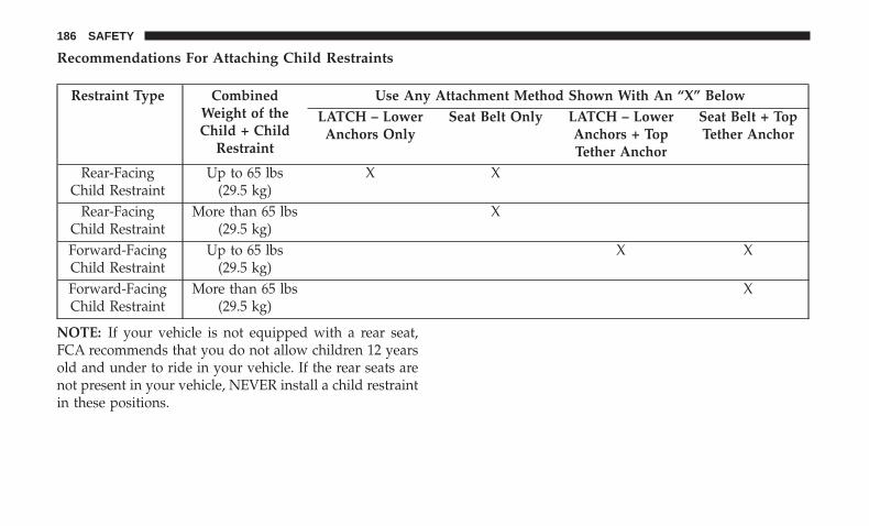
Recommendations For Attaching Child Restraints
Restraint Type CombinedWeight of theChild + Child
Restraint
Use Any Attachment Method Shown With An “X” BelowLATCH – Lower
Anchors OnlySeat Belt Only LATCH – Lower
Anchors + TopTether Anchor
Seat Belt + TopTether Anchor
Rear-FacingChild Restraint
Up to 65 lbs(29.5 kg)
X X
Rear-FacingChild Restraint
More than 65 lbs(29.5 kg)
X
Forward-FacingChild Restraint
Up to 65 lbs(29.5 kg)
X X
Forward-FacingChild Restraint
More than 65 lbs(29.5 kg)
X
NOTE: If your vehicle is not equipped with a rear seat,FCA recommends that you do not allow children 12 yearsold and under to ride in your vehicle. If the rear seats arenot present in your vehicle, NEVER install a child restraintin these positions.
186 SAFETY
Lower Anchors And Tethers For CHildren (LATCH)Restraint System
Your vehicle is equipped with the child restraint anchoragesystem called LATCH, which stands for Lower Anchorsand Tethers for CHildren. The LATCH system has threevehicle anchor points for installing LATCH-equipped childseats. There are two lower anchorages located at the backof the seat cushion where it meets the seatback and one toptether anchorage located behind the seating position. Theseanchorages are used to install LATCH-equipped child seatswithout using the vehicle’s seat belts. Some seating posi-tions may have a top tether anchorage but no loweranchorages. In these seating positions, the seat belt must be
used with the top tether anchorage to install the childrestraint. Please see the following table for moreinformation.
LATCH Positions For Installing Child Restraints InThis Vehicle
Non-SRT Vehicles
WARNING!
If the rear or front passenger seats are not present inyour vehicle, NEVER install a child restraint in thesepositions.
Vehicles Without Rear Seating Installed
If your vehicle is not equipped with a rear passenger seat,your vehicle is not equipped with LATCH anchorages. Ifyour vehicle is not equipped with a rear seat, FCA recom-mends that you do not allow children 12 years old andunder to ride in your vehicle. If the rear seats are notpresent in your vehicle, NEVER install a child restraint inthese positions. If you must install a forward facing childrestraint in the front passenger seat, then you must use theseat belt system to secure the restraint. A top tether strap
LATCH Label
5
SAFETY 187

extension may be needed to reach the tether anchor on therear shelf directly behind the passenger seat.
WARNING!
• Never place a rear-facing child restraint in front of anair bag. A deploying passenger front air bag cancause death or serious injury to a child 12 years oryounger, including a child in a rear-facing childrestraint.
• Never install a rear-facing child restraint in the frontseat of a vehicle. Only use a rear-facing child re-straint in the rear seat. If the vehicle does not have arear seat, do not transport a rear-facing child restraintin that vehicle.
Vehicle With Rear Seating — LATCH Positions ForInstalling Child Restraints
Lower Anchorage Symbol (2 Anchorages Per Seating Position)Top Tether Anchorage Symbol
188 SAFETY

Rear Seat Delete — No LATCH Positions In This Vehicle
Top Tether Anchorage Symbol
Passenger Seats Deleted — No LATCH Positions In ThisVehicle
5
SAFETY 189
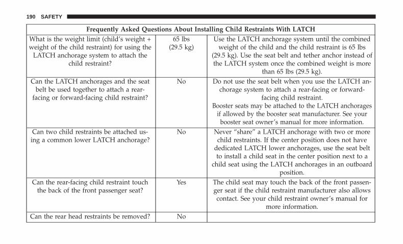
Frequently Asked Questions About Installing Child Restraints With LATCHWhat is the weight limit (child’s weight +weight of the child restraint) for using the
LATCH anchorage system to attach thechild restraint?
65 lbs(29.5 kg)
Use the LATCH anchorage system until the combinedweight of the child and the child restraint is 65 lbs
(29.5 kg). Use the seat belt and tether anchor instead ofthe LATCH system once the combined weight is more
than 65 lbs (29.5 kg).Can the LATCH anchorages and the seat
belt be used together to attach a rear-facing or forward-facing child restraint?
No Do not use the seat belt when you use the LATCH an-chorage system to attach a rear-facing or forward-
facing child restraint.Booster seats may be attached to the LATCH anchorages
if allowed by the booster seat manufacturer. See yourbooster seat owner’s manual for more information.
Can two child restraints be attached us-ing a common lower LATCH anchorage?
No Never “share” a LATCH anchorage with two or morechild restraints. If the center position does not have
dedicated LATCH lower anchorages, use the seat beltto install a child seat in the center position next to a
child seat using the LATCH anchorages in an outboardposition.
Can the rear-facing child restraint touchthe back of the front passenger seat?
Yes The child seat may touch the back of the front passen-ger seat if the child restraint manufacturer also allowscontact. See your child restraint owner’s manual for
more information.Can the rear head restraints be removed? No
190 SAFETY

Locating The LATCH Anchorages
Non-SRT Vehicles
WARNING!
If the rear or front passenger seats are not present inyour vehicle, NEVER install a child restraint in thesepositions.
The lower anchorages are round bars that are found at therear of the seat cushion where it meets theseatback, below the anchorage symbols on theseatback. They are just visible when you lean intothe rear seat to install the child restraint. You will
easily feel them if you run your finger along the gapbetween the seatback and seat cushion.
Non-SRT Vehicles
WARNING!
If the rear or front passenger seats are not present inyour vehicle, NEVER install a child restraint in thesepositions.
LATCH Anchorages
5
SAFETY 191

Locating The Upper Tether Anchorages
There are tether strap anchorages behind eachrear seating position located in the panel be-tween the rear seatback and the rear window.They are found under a plastic cover with the
tether anchorage symbol on it.
LATCH-compatible child restraint systems will beequipped with a rigid bar or a flexible strap on each side.Each will have a hook or connector to attach to the loweranchorage and a way to tighten the connection to theanchorage. Forward-facing child restraints and some rear-facing child restraints will also be equipped with a tether
strap. The tether strap will have a hook at the end to attachto the top tether anchorage and a way to tighten the strapafter it is attached to the anchorage.
Center Seat LATCH
If a child restraint installed in the center position blocks theseat belt webbing or buckle for the outboard position, donot use that outboard position. If a child seat in the centerposition blocks the outboard LATCH anchors or seat belt,do not install a child seat in that outboard position.
WARNING!
Never use the same lower anchorage to attach morethan one child restraint. Please refer to “To Install ALATCH-Compatible Child Restraint” for typical instal-lation instructions.
Always follow the directions of the child restraint manu-facturer when installing your child restraint. Not all childrestraint systems will be installed as described here.
Tether Strap Anchorages
192 SAFETY
To Install A LATCH-Compatible Child Restraint
If the selected seating position has a Switchable AutomaticLocking Retractor (ALR) seat belt, stow the seat belt,following the instructions below. See the section “InstallingChild Restraints Using the Vehicle Seat Belt” to check whattype of seat belt each seating position has.
1. Loosen the adjusters on the lower straps and on thetether strap of the child seat so that you can more easilyattach the hooks or connectors to the vehicle anchor-ages.
2. Place the child seat between the lower anchorages forthat seating position. For some second row seats, youmay need to recline the seat and / or raise the headrestraint (if adjustable) to get a better fit. If the rear seatcan be moved forward and rearward in the vehicle, youmay wish to move it to its rear-most position to makeroom for the child seat. You may also move the front seatforward to allow more room for the child seat.
3. Attach the lower hooks or connectors of the childrestraint to the lower anchorages in the selected seatingposition.
4. If the child restraint has a tether strap, connect it to thetop tether anchorage. See the section “Installing ChildRestraints Using the Top Tether Anchorage” for direc-tions to attach a tether anchor.
5. Tighten all of the straps as you push the child restraintrearward and downward into the seat. Remove slack inthe straps according to the child restraint manufactur-er’s instructions.
6. Test that the child restraint is installed tightly by pullingback and forth on the child seat at the belt path. Itshould not move more than 1 inch (25.4 mm) in anydirection.
How To Stow An Unused Switchable-ALR (ALR)Seat Belt:
When using the LATCH attaching system to install a childrestraint, stow all ALR seat belts that are not being used byother occupants or being used to secure child restraints. Anunused belt could injure a child if they play with it andaccidentally lock the seat belt retractor. Before installing achild restraint using the LATCH system, buckle the seatbelt behind the child restraint and out of the child’s reach.If the buckled seat belt interferes with the child restraintinstallation, instead of buckling it behind the child re-straint, route the seat belt through the child restraint belt
5
SAFETY 193
path and then buckle it. Do not lock the seat belt. Remindall children in the vehicle that the seat belts are not toys andthat they should not play with them.
WARNING!
• Improper installation of a child restraint to theLATCH anchorages can lead to failure of the re-straint. The child could be badly injured or killed.Follow the child restraint manufacturer’s directionsexactly when installing an infant or child restraint.
• Child restraint anchorages are designed to withstandonly those loads imposed by correctly-fitted childrestraints. Under no circumstances are they to beused for adult seat belts, harnesses, or for attachingother items or equipment to the vehicle.
Installing Child Restraints Using The Vehicle SeatBelt
NOTE: If your vehicle is not equipped with a rear seat,FCA recommends that you do not allow children 12 yearsold and under to ride in your vehicle. If the rear seats arenot present in your vehicle, NEVER install a child restraintin these positions.
Child restraint systems are designed to be secured invehicle seats by lap belts or the lap belt portion of alap/shoulder belt.
WARNING!
• Never place a rear-facing child restraint in front of anair bag. A deploying passenger front air bag cancause death or serious injury to a child 12 years oryounger, including a child in a rear-facing childrestraint.
• Never install a rear-facing child restraint in the frontseat of a vehicle. Only use a rear-facing child re-straint in the rear seat. If the vehicle does not have arear seat, do not transport a rear-facing child restraintin that vehicle.
WARNING!
• Improper installation or failure to properly secure achild restraint can lead to failure of the restraint. Thechild could be badly injured or killed.
• Follow the child restraint manufacturer’s directionsexactly when installing an infant or child restraint.
194 SAFETY
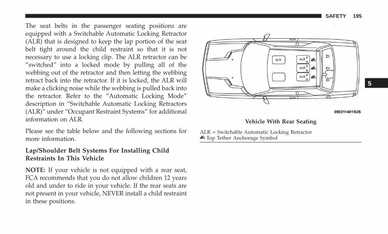
The seat belts in the passenger seating positions areequipped with a Switchable Automatic Locking Retractor(ALR) that is designed to keep the lap portion of the seatbelt tight around the child restraint so that it is notnecessary to use a locking clip. The ALR retractor can be“switched” into a locked mode by pulling all of thewebbing out of the retractor and then letting the webbingretract back into the retractor. If it is locked, the ALR willmake a clicking noise while the webbing is pulled back intothe retractor. Refer to the “Automatic Locking Mode”description in “Switchable Automatic Locking Retractors(ALR)” under “Occupant Restraint Systems” for additionalinformation on ALR.
Please see the table below and the following sections formore information.
Lap/Shoulder Belt Systems For Installing ChildRestraints In This Vehicle
NOTE: If your vehicle is not equipped with a rear seat,FCA recommends that you do not allow children 12 yearsold and under to ride in your vehicle. If the rear seats arenot present in your vehicle, NEVER install a child restraintin these positions.
Vehicle With Rear Seating
ALR = Switchable Automatic Locking RetractorTop Tether Anchorage Symbol
5
SAFETY 195

Rear Seat Delete — Only Front Passenger Seat Available
ALR = Switchable Automatic Locking RetractorTop Tether Anchorage Symbol
Passenger Seat Delete — No Automatic Locking Retractor(ALR) Locations
196 SAFETY

Frequently Asked Questions About Installing Child Restraints With Seat BeltsWhat is the weight limit (child’s weight +weight of the child restraint) for using the
Tether Anchor with the seat belt to attach aforward facing child restraint?
Weight limit of theChild Restraint
Always use the tether anchor when using theseat belt to install a forward facing child re-straint, up to the recommended weight limit
of the child restraint.Can the rear-facing child restraint touch the
back of the front passenger seat?Yes Contact between the front passenger seat and
the child restraint is allowed, if the child re-straint manufacturer also allows contact.
Can the rear head restraints be removed? NoCan the buckle stalk be twisted to tighten the
seat belt against the belt path of the childrestraint?
No Do not twist the buckle stalk in a seating po-sition with an ALR retractor.
Installing A Child Restraint With A SwitchableAutomatic Locking Retractor (ALR):
Child restraint systems are designed to be secured invehicle seats by lap belts or the lap belt portion of alap/shoulder belt.
WARNING!
• Improper installation or failure to properly secure achild restraint can lead to failure of the restraint. Thechild could be badly injured or killed.
(Continued)
WARNING! (Continued)• Follow the child restraint manufacturer’s directions
exactly when installing an infant or child restraint.
1. Place the child seat in the center of the seating position.For some second row seats, you may need to recline theseat and/or raise the head restraint (if adjustable) to geta better fit. If the rear seat can be moved forward andrearward in the vehicle, you may wish to move it to itsrear-most position to make room for the child seat. You
5
SAFETY 197

may also move the front seat forward to allow moreroom for the child seat.
2. Pull enough of the seat belt webbing from the retractorto pass it through the belt path of the child restraint. Donot twist the belt webbing in the belt path.
3. Slide the latch plate into the buckle until you hear a“click.”
4. Pull on the webbing to make the lap portion tightagainst the child seat.
5. To lock the seat belt, pull down on the shoulder part ofthe belt until you have pulled all the seat belt webbingout of the retractor. Then, allow the webbing to retractback into the retractor. As the webbing retracts, you willhear a clicking sound. This means the seat belt is now inthe Automatic Locking mode.
6. Try to pull the webbing out of the retractor. If it islocked, you should not be able to pull out any webbing.If the retractor is not locked, repeat step 5.
7. Finally, pull up on any excess webbing to tighten the lapportion around the child restraint while you push thechild restraint rearward and downward into the vehicleseat.
8. If the child restraint has a top tether strap and theseating position has a top tether anchorage, connect thetether strap to the anchorage and tighten the tetherstrap. See the section “Installing Child Restraints Usingthe Top Tether Anchorage” for directions to attach atether anchor.
9. Test that the child restraint is installed tightly by pullingback and forth on the child seat at the belt path. Itshould not move more than 1 inch (25.4 mm) in anydirection.
Any seat belt system will loosen with time, so check thebelt occasionally, and pull it tight if necessary.
Installing Child Restraints Using The Top TetherAnchorage:
Non-SRT Vehicles
WARNING!
If the rear or front passenger seats are not present inyour vehicle, NEVER install a child restraint in thesepositions.
198 SAFETY
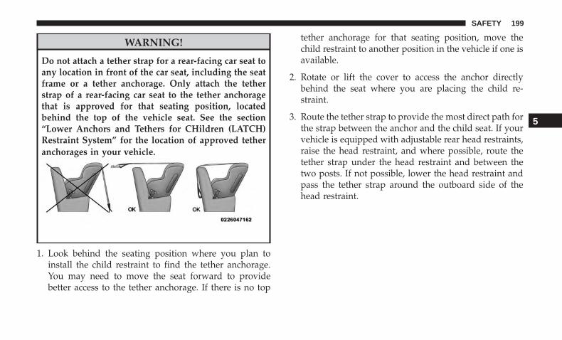
WARNING!
Do not attach a tether strap for a rear-facing car seat toany location in front of the car seat, including the seatframe or a tether anchorage. Only attach the tetherstrap of a rear-facing car seat to the tether anchoragethat is approved for that seating position, locatedbehind the top of the vehicle seat. See the section“Lower Anchors and Tethers for CHildren (LATCH)Restraint System” for the location of approved tetheranchorages in your vehicle.
1. Look behind the seating position where you plan toinstall the child restraint to find the tether anchorage.You may need to move the seat forward to providebetter access to the tether anchorage. If there is no top
tether anchorage for that seating position, move thechild restraint to another position in the vehicle if one isavailable.
2. Rotate or lift the cover to access the anchor directlybehind the seat where you are placing the child re-straint.
3. Route the tether strap to provide the most direct path forthe strap between the anchor and the child seat. If yourvehicle is equipped with adjustable rear head restraints,raise the head restraint, and where possible, route thetether strap under the head restraint and between thetwo posts. If not possible, lower the head restraint andpass the tether strap around the outboard side of thehead restraint.
5
SAFETY 199

4. Attach the tether strap hook of the child restraint to thetop tether anchorage as shown in the diagram.
5. Remove slack in the tether strap according to the childrestraint manufacturer’s instructions.
NOTE: If your vehicle is not equipped with a rear seat,FCA recommends that you do not allow children 12 yearsold and under to ride in your vehicle. If the rear seats arenot present in your vehicle, NEVER install a child restraintin these positions. If you must install a forward facing childrestraint in the front passenger seat, then you must use theseat belt system to secure the restraint. A top tether strapextension may be needed to reach the tether anchor on therear shelf directly behind the passenger seat.
WARNING!
• An incorrectly anchored tether strap could lead toincreased head motion and possible injury to thechild. Use only the anchorage position directly be-hind the child seat to secure a child restraint toptether strap.
• If your vehicle is equipped with a split rear seat,make sure the tether strap does not slip into theopening between the seatbacks as you remove slackin the strap.
Tether Strap Mounting
1 — Cover A — Tether Strap Hook3 — Attaching Strap B — Tether Anchor
200 SAFETY
Transporting Pets
Air Bags deploying in the front seat could harm your pet.An unrestrained pet will be thrown about and possiblyinjured, or injure a passenger during panic braking or in acollision.
Pets should be restrained in the rear seat (if equipped) inpet harnesses or pet carriers that are secured by seat belts.
SAFETY TIPS
Transporting Passengers
NEVER TRANSPORT PASSENGERS IN THE CARGO AREA.
WARNING!
• Do not leave children or animals inside parkedvehicles in hot weather. Interior heat build-up maycause serious injury or death.
• It is extremely dangerous to ride in a cargo area,inside or outside of a vehicle. In a collision, peopleriding in these areas are more likely to be seriouslyinjured or killed.
• Do not allow people to ride in any area of yourvehicle that is not equipped with seats and seat belts.
(Continued)
WARNING! (Continued)• Be sure everyone in your vehicle is in a seat and
using a seat belt properly.
Exhaust Gas
WARNING!
Exhaust gases can injure or kill. They contain carbonmonoxide (CO), which is colorless and odorless.Breathing it can make you unconscious and can even-tually poison you. To avoid breathing (CO), followthese safety tips:• Do not run the engine in a closed garage or in
confined areas any longer than needed to move yourvehicle in or out of the area.
• If you are required to drive with the trunk/liftgate/rear doors open, make sure that all windows areclosed and the climate control BLOWER switch is setat high speed. DO NOT use the recirculation mode.
• If it is necessary to sit in a parked vehicle with theengine running, adjust your heating or cooling con-trols to force outside air into the vehicle. Set theblower at high speed.
5
SAFETY 201

The best protection against carbon monoxide entry into thevehicle body is a properly maintained engine exhaustsystem.
Whenever a change is noticed in the sound of the exhaustsystem, when exhaust fumes can be detected inside thevehicle, or when the underside or rear of the vehicle isdamaged, have a competent mechanic inspect the completeexhaust system and adjacent body areas for broken, dam-aged, deteriorated, or mispositioned parts. Open seams orloose connections could permit exhaust fumes to seep intothe passenger compartment. In addition, inspect the ex-haust system each time the vehicle is raised for lubricationor oil change. Replace as required.
Safety Checks You Should Make Inside The Vehicle
Seat Belts
Inspect the seat belt system periodically, checking for cuts,frays, and loose parts. Damaged parts must be replacedimmediately. Do not disassemble or modify the system.
Front seat belt assemblies must be replaced after a collision.Rear seat belt assemblies must be replaced after a collisionif they have been damaged (i.e., bent retractor, torn web-bing, etc.). If there is any question regarding seat belt orretractor condition, replace the seat belt.
Air Bag Warning Light
The Air Bag warning light will turn on for four toeight seconds as a bulb check when the ignition switchis first turned to ON/RUN. If the light is either not onduring starting, stays on, or turns on while driving,have the system inspected at an authorized dealer assoon as possible. After the bulb check, this light willilluminate with a single chime when a fault with the AirBag System has been detected. It will stay on until thefault is removed. If the light comes on intermittently orremains on while driving, have an authorized dealerservice the vehicle immediately.
Refer to “Occupant Restraint Systems” in “Safety” forfurther information.
Defroster
Check operation by selecting the defrost mode and placethe blower control on high speed. You should be able tofeel the air directed against the windshield. See an autho-rized dealer for service if your defroster is inoperable.
Floor Mat Safety Information
Always use floor mats designed to fit your vehicle. Onlyuse a floor mat that does not interfere with the operation ofthe accelerator, brake or clutch pedals. Only use a floor mat
202 SAFETY
that is securely attached using the floor mat fasteners so itcannot slip out of position and interfere with the accelera-tor, brake or clutch pedals or impair safe operation of yourvehicle in other ways.
WARNING!
An improperly attached, damaged, folded, or stackedfloor mat, or damaged floor mat fasteners may causeyour floor mat to interfere with the accelerator, brake,or clutch pedals and cause a loss of vehicle control. Toprevent SERIOUS INJURY or DEATH:• ALWAYS securely attach your floor mat using the
floor mat fasteners. DO NOT install your floor matupside down or turn your floor mat over. Lightly pullto confirm mat is secured using the floor mat fasten-ers on a regular basis.
• ALWAYS REMOVE THE EXISTING FLOOR MATFROM THE VEHICLE before installing any otherfloor mat. NEVER install or stack an additional floormat on top of an existing floor mat.
• ONLY install floor mats designed to fit your vehicle.NEVER install a floor mat that cannot be properlyattached and secured to your vehicle. If a floor mat
(Continued)
WARNING! (Continued)needs to be replaced, only use a FCA approved floormat for the specific make, model, and year of yourvehicle.
• ONLY use the driver’s side floor mat on the driver’sside floor area. To check for interference, with thevehicle properly parked with the engine off, fullydepress the accelerator, the brake, and the clutchpedal (if present) to check for interference. If yourfloor mat interferes with the operation of any pedal,or is not secure to the floor, remove the floor matfrom the vehicle and place the floor mat in yourtrunk.
• ONLY use the passenger’s side floor mat on thepassenger’s side floor area.
• ALWAYS make sure objects cannot fall or slide intothe driver’s side floor area when the vehicle ismoving. Objects can become trapped under accelera-tor, brake, or clutch pedals and could cause a loss ofvehicle control.
• NEVER place any objects under the floor mat (e.g.,towels, keys, etc.). These objects could change the
(Continued)
5
SAFETY 203
WARNING! (Continued)position of the floor mat and may cause interferencewith the accelerator, brake, or clutch pedals.
• If the vehicle carpet has been removed and re-installed, always properly attach carpet to the floorand check the floor mat fasteners are secure to thevehicle carpet. Fully depress each pedal to check forinterference with the accelerator, brake, or clutchpedals then re-install the floor mats.
• It is recommended to only use mild soap and waterto clean your floor mats. After cleaning, always checkyour floor mat has been properly installed and issecured to your vehicle using the floor mat fastenersby lightly pulling mat.
Periodic Safety Checks You Should Make OutsideThe Vehicle
Tires
Examine tires for excessive tread wear and uneven wearpatterns. Check for stones, nails, glass, or other objectslodged in the tread or sidewall. Inspect the tread for cutsand cracks. Inspect sidewalls for cuts, cracks, and bulges.Check the wheel nuts for tightness. Check the tires (includ-ing spare) for proper cold inflation pressure.
Lights
Have someone observe the operation of brake lights andexterior lights while you work the controls. Check turnsignal and high beam indicator lights on the instrumentpanel.
Door Latches
Check for proper closing, latching, and locking.
Fluid Leaks
Check area under the vehicle after overnight parking forfuel, coolant, oil, or other fluid leaks. Also, if gasolinefumes are detected or if fuel, or brake fluid leaks aresuspected. The cause should be located and correctedimmediately.
204 SAFETY

STARTING AND OPERATING
CONTENTS� STARTING THE ENGINE . . . . . . . . . . . . . . . . . .208
▫ Manual Transmission — If Equipped . . . . . . . . .208
▫ Automatic Transmission — If Equipped . . . . . .208
▫ Normal Starting . . . . . . . . . . . . . . . . . . . . . . .209
▫ Cold Weather Operation(Below –22°F Or −30°C) . . . . . . . . . . . . . . . . . .212
▫ If Engine Fails To Start . . . . . . . . . . . . . . . . . .213
▫ After Starting. . . . . . . . . . . . . . . . . . . . . . . . . .213
� ENGINE BLOCK HEATER — IF EQUIPPED . . . .213
� ENGINE BREAK-IN RECOMMENDATIONS . . . .214
� PARKING BRAKE . . . . . . . . . . . . . . . . . . . . . . .215
� MANUAL TRANSMISSION — IF EQUIPPED . . .218
▫ Six-Speed Manual Transmission. . . . . . . . . . . . .218
▫ Shifting . . . . . . . . . . . . . . . . . . . . . . . . . . . . . .219
▫ Recommended Shift Speeds. . . . . . . . . . . . . . . .220
▫ 1–4 Skip Shift . . . . . . . . . . . . . . . . . . . . . . . . .221
▫ Downshifting. . . . . . . . . . . . . . . . . . . . . . . . . .221
� AUTOMATIC TRANSMISSION —IF EQUIPPED . . . . . . . . . . . . . . . . . . . . . . . . . .222
▫ Ignition Park Interlock . . . . . . . . . . . . . . . . . . .223
▫ Brake/Transmission Shift Interlock System . . . .223
▫ Eight-Speed Automatic Transmission . . . . . . . . .224
� SPORT MODE — WITHOUT PERFORMANCECONTROL . . . . . . . . . . . . . . . . . . . . . . . . . . . .232
� FUEL SAVER TECHNOLOGY 5.7L AND6.4L ONLY — IF EQUIPPED . . . . . . . . . . . . . . . .232
� POWER STEERING . . . . . . . . . . . . . . . . . . . . . .232
� SPEED CONTROL — IF EQUIPPED . . . . . . . . . .233
▫ To Activate . . . . . . . . . . . . . . . . . . . . . . . . . . .234
6

▫ To Set A Desired Speed . . . . . . . . . . . . . . . . . .234
▫ To Vary The Speed Setting . . . . . . . . . . . . . . . .234
▫ To Accelerate For Passing . . . . . . . . . . . . . . . . .235
▫ To Resume Speed . . . . . . . . . . . . . . . . . . . . . .236
▫ To Deactivate . . . . . . . . . . . . . . . . . . . . . . . . .236
� ADAPTIVE CRUISE CONTROL (ACC) —IF EQUIPPED . . . . . . . . . . . . . . . . . . . . . . . . . .236
▫ Adaptive Cruise Control (ACC) Operation . . . . .238
▫ Activating Adaptive Cruise Control (ACC) . . . . .239
▫ To Activate/Deactivate . . . . . . . . . . . . . . . . . . .239
▫ To Set A Desired ACC Speed. . . . . . . . . . . . . . .240
▫ To Cancel . . . . . . . . . . . . . . . . . . . . . . . . . . . .240
▫ To Turn Off . . . . . . . . . . . . . . . . . . . . . . . . . . .241
▫ To Resume . . . . . . . . . . . . . . . . . . . . . . . . . . .241
▫ To Vary The Speed Setting . . . . . . . . . . . . . . . .241
▫ Setting The Following Distance In ACC . . . . . . .243
▫ Overtake Aid . . . . . . . . . . . . . . . . . . . . . . . . . .246
▫ Adaptive Cruise Control (ACC) Menu . . . . . . . .246
▫ Display Warnings And Maintenance . . . . . . . . .247
▫ Precautions While Driving With ACC. . . . . . . . .248
▫ General Information . . . . . . . . . . . . . . . . . . . . .252
▫ Normal (Fixed Speed) Cruise Control Mode . . . .252
� PARKSENSE REAR PARK ASSIST —IF EQUIPPED . . . . . . . . . . . . . . . . . . . . . . . . . .254
▫ ParkSense Sensors . . . . . . . . . . . . . . . . . . . . . .255
▫ ParkSense Warning Display. . . . . . . . . . . . . . . .255
▫ ParkSense Display . . . . . . . . . . . . . . . . . . . . . .255
▫ Enabling And Disabling ParkSense . . . . . . . . . .259
▫ Service The ParkSense Rear Park Assist System. .259
▫ Cleaning The ParkSense System. . . . . . . . . . . . .260
▫ ParkSense System Usage Precautions . . . . . . . . .260
� PARKVIEW REAR BACK UP CAMERA . . . . . . . .261
� REFUELING THE VEHICLE . . . . . . . . . . . . . . . .263
▫ Loose Fuel Filler Cap Message . . . . . . . . . . . . .264
206 STARTING AND OPERATING

� VEHICLE LOADING . . . . . . . . . . . . . . . . . . . . .265
▫ Vehicle Certification Label . . . . . . . . . . . . . . . .265
▫ Gross Vehicle Weight Rating (GVWR) . . . . . . . .265
▫ Gross Axle Weight Rating (GAWR) . . . . . . . . . .265
▫ Overloading . . . . . . . . . . . . . . . . . . . . . . . . . .265
▫ Loading . . . . . . . . . . . . . . . . . . . . . . . . . . . . .266
� TRAILER TOWING . . . . . . . . . . . . . . . . . . . . . .266
▫ Common Towing Definitions. . . . . . . . . . . . . . .267
▫ Trailer Hitch Classification . . . . . . . . . . . . . . . .269
▫ Trailer Towing Weights (Maximum TrailerWeight Ratings) . . . . . . . . . . . . . . . . . . . . . . .269
▫ Trailer And Tongue Weight . . . . . . . . . . . . . . .270
▫ Towing Requirements . . . . . . . . . . . . . . . . . . .270
▫ Towing Tips . . . . . . . . . . . . . . . . . . . . . . . . . .275
� RECREATIONAL TOWING(BEHIND MOTORHOME, ETC.) . . . . . . . . . . . . .276
� DRIVING TIPS . . . . . . . . . . . . . . . . . . . . . . . . . .276
▫ Driving On Slippery Surfaces . . . . . . . . . . . . . .276
▫ Driving Through Water . . . . . . . . . . . . . . . . . .2776
STARTING AND OPERATING 207

STARTING THE ENGINE
Before starting your vehicle, adjust your seat, adjust theinside and outside mirrors, fasten your seat belt, and ifpresent, instruct all other occupants to buckle their seatbelts.
WARNING!
• When exiting the vehicle, always make sure theignition is in “OFF” mode, remove the key fob fromthe vehicle and lock the vehicle.
• Never leave children alone in a vehicle, or withaccess to an unlocked vehicle. Leaving children in avehicle unattended is dangerous for a number ofreasons. A child or others could be seriously orfatally injured. Children should be warned not totouch the parking brake, brake pedal or the trans-mission gear selector.
• Do not leave the key fob in or near the vehicle (or ina location accessible to children), and do not leavethe ignition (of a vehicle equipped with KeylessEnter-N-Go) in the ACC or ON/RUN mode. A childcould operate power windows, other controls, ormove the vehicle.
(Continued)
WARNING! (Continued)• Do not leave children or animals inside parked
vehicles in hot weather. Interior heat build-up maycause serious injury or death.
Manual Transmission — If Equipped
Apply the parking brake, place the gear selector in NEU-TRAL and press the clutch pedal before starting vehicle.This vehicle is equipped with a clutch interlocking ignitionsystem. It will not start unless the clutch pedal is pressed tothe floor.
Automatic Transmission — If Equipped
The gear selector must be in the PARK position before youcan start the engine. Apply the brakes before shifting intoany driving gear.
CAUTION!
Damage to the transmission may occur if the followingprecautions are not observed:• Shift into or out of PARK or REVERSE only after the
vehicle has come to a complete stop.
(Continued)
208 STARTING AND OPERATING
CAUTION! (Continued)• Do not shift between PARK, REVERSE, NEUTRAL,
or DRIVE when the engine is above idle speed.• Before shifting into any gear, make sure your foot is
firmly pressing the brake pedal.
Tip Start Feature — Automatic Transmission
Place the ignition in the START mode and release it as thestarter engages. The starter motor will automatically dis-engage itself once engine is running. If the engine fails tostart, the starter will disengage automatically in 10 sec-onds. If this occurs:
1. Place the ignition in the OFF mode.
2. Wait 10 to 15 seconds.
3. Repeat the “Normal Starting” procedure.
Normal Starting
To Turn On The Engine Using The ENGINESTART/STOP Button — Manual Transmission Only
1. Press and hold the clutch pedal while pushing andholding the ENGINE START/STOP button.
2. Release the button when the engine starts. If the vehiclefails to start within 15 seconds, release the button, wait10 to 15 seconds, then repeat the “Normal Starting”procedure.
3. If you wish to stop the cranking of the engine prior tothe engine starting, release the button.
NOTE: Normal starting of either a cold or a warm engineis obtained without pumping or pressing the acceleratorpedal.
To Turn On The Engine Using The ENGINESTART/STOP Button — Automatic TransmissionOnly
1. The transmission must be in PARK.
2. Press and hold the brake pedal while pushing theENGINE START/STOP button once.
3. The system takes over and attempts to start the vehicle.If the vehicle fails to start, the starter will disengageautomatically after 10 seconds.
4. If you wish to stop the cranking of the engine prior tothe engine starting, push the button again.
6
STARTING AND OPERATING 209
NOTE: Normal starting of either a cold or a warm engineis obtained without pumping or pressing the acceleratorpedal.
To Turn Off The Engine Using ENGINESTART/STOP Button — Manual Transmission Only
1. With the vehicle stopped, place the gear selector inNEUTRAL, then push and release the ENGINE START/STOP button.
2. The ignition will return to the OFF mode.
3. Place the gear selector in first gear or REVERSE and thenapply the parking brake.
NOTE:
• If the ignition switch is left in the ACC position, thesystem will automatically time out after 30 minutes ofinactivity and the ignition will switch to the OFF posi-tion.
• If the ignition switch is left in the RUN position, thesystem will automatically time out after 30 minutes ofinactivity if the vehicle speed is 0 mph (0 km/h) and theengine is not running.
• If the vehicle speed is above 5 mph (8 km/h), theENGINE START/STOP button must be held for twoseconds or three short pushes in a row before the enginewill shut off. The ignition switch position will remain inthe ACC position until the vehicle is stopped, placed inpark and the button is pushed twice to the OFF position.
To Turn Off The Engine Using ENGINESTART/STOP Button — Automatic TransmissionOnly
1. Place the gear selector in PARK, then push and releasethe ENGINE START/STOP button.
2. The ignition will return to the OFF mode.
3. If the gear selector is not in PARK, the ENGINE START/STOP button must be held for two seconds or three shortpushes in a row with the vehicle speed above 5 mph(8 km/h) before the engine will shut off. The ignitionwill remain in the ACC mode until the gear selector is inPARK and the button is pushed twice to the OFF mode.If the gear selector is not in PARK and the ENGINESTART/STOP button is pushed once, the instrumentcluster will display a “Vehicle Not In Park” message andthe engine will remain running. Never leave a vehicleout of the PARK position, or it could roll.
210 STARTING AND OPERATING

NOTE: If the ignition switch is left in the ACC or RUN(engine not running) position and the transmission is inPARK, the system will automatically time out after 30minutes of inactivity and the ignition will switch to theOFF position.
AutoPark
AutoPark is a supplemental feature to assist in placing thevehicle in PARK should the situations on the followingpages occur. It is a back up system and should not be reliedupon as the primary method by which the driver shifts thevehicle into PARK.
The conditions under which AutoPark will engage areoutlined on the following pages.
WARNING!
• Driver inattention could lead to failure to place thevehicle in PARK. ALWAYS DO A VISUAL CHECKthat your vehicle is in PARK by verifying that a solid(not blinking) “P” is indicated in the instrumentcluster display and on the gear selector. If the �P�indicator is blinking, your vehicle is not in PARK. As
(Continued)
WARNING! (Continued)an added precaution, always apply the parking brakewhen exiting the vehicle.
• AutoPark is a supplemental feature. It is not de-signed to replace the need to shift your vehicle intoPARK. It is a back up system and should not berelied upon as the primary method by which thedriver shifts the vehicle into PARK.
If the vehicle is not in PARK and the driver turns off theengine, the vehicle may AutoPark.
AutoPark will engage when all of these conditions are met:
• Vehicle is equipped with an 8-speed transmission
• Vehicle is not in PARK
• Vehicle Speed is 1.2 MPH (1.9 km/h) or less
• Ignition switched from RUN to ACC
NOTE: For Keyless Go equipped vehicles, The engine willturn off and the ignition switch will change to ACC mode.After 30 minutes the ignition switches to OFF automati-cally, unless the driver turns the ignition switch OFF.
6
STARTING AND OPERATING 211

If the vehicle is not in PARK and the driver exits thevehicle with the engine running, the vehicle may Au-toPark.
AutoPark will engage when all of these conditions are met:
• Vehicle is equipped with an 8-speed transmission
• Vehicle is not in PARK
• Vehicle speed is 1.2 MPH (1.9 km/h) or less
• Driver’s seat belt is unbuckled
• Driver’s door is ajar
• Brake Pedal is not depressed
The MESSAGE “ AutoPark Engaged Shift to P then Shiftto Gear”will display in the instrument cluster.
NOTE: In some cases the ParkSense graphic will bedisplayed in the instrument cluster. In these cases, theshifter must be returned to “P” to select desired gear.
If the driver shifts into PARK while moving, the vehiclemay AutoPark.
AutoPark will engage ONLY when vehicle speed is1.2 MPH (1.9 km/h) or less.
The MESSAGE “ Vehicle Speed is Too High to Shift toP”will be displayed in the instrument cluster if vehiclespeed is above 1.2 MPH (1.9 km/h).
WARNING!
If vehicle speed is above 1.2 MPH (1.9 km/h), thetransmission will default to NEUTRAL until the ve-hicle speed drops below 1.2 MPH (1.9 km). A vehicleleft in the NEUTRAL position can roll. As an addedprecaution, always apply the parking brake whenexiting the vehicle.
ALWAYS DO A VISUAL CHECK that your vehicle is inPARK by looking for the �P� in the instrument clusterdisplay and on the shifter. As an added precaution, alwaysapply the parking brake when exiting the vehicle.
Cold Weather Operation (Below –22°F Or −30°C)
To ensure reliable starting at these temperatures, use of anexternally powered electric engine block heater (availablefrom your authorized dealer) is recommended.
212 STARTING AND OPERATING

If Engine Fails To Start
If the engine fails to start after you have followed the�Normal Starting� or �Extreme Cold Weather� procedure itmay be flooded. Push the accelerator pedal all the way tothe floor and hold it there. Crank the engine for no morethan 15 seconds. This should clear any excess fuel in casethe engine is flooded. Leave the ignition key in the RUNposition, release the accelerator pedal and repeat the “Nor-mal Starting” procedure.
WARNING!
• Never pour fuel or other flammable liquid into thethrottle body air inlet opening in an attempt to startthe vehicle. This could result in flash fire causingserious personal injury.
• Do not attempt to push or tow your vehicle to get itstarted. Vehicles equipped with an automatic trans-mission cannot be started this way. Unburned fuelcould enter the catalytic converter and once theengine has started, ignite and damage the converterand vehicle.
• If the vehicle has a discharged battery, booster cablesmay be used to obtain a start from a booster battery
(Continued)
WARNING! (Continued)or the battery in another vehicle. This type of startcan be dangerous if done improperly. Refer to “JumpStarting Procedure” in “In Case Of Emergency” forfurther information.
CAUTION!
To prevent damage to the starter, do not continuouslycrank the engine for more than 25 seconds at a time.Wait 60 seconds before trying again.
After Starting
The idle speed is controlled automatically, and it willdecrease as the engine warms up.
ENGINE BLOCK HEATER — IF EQUIPPED
The engine block heater warms the engine, and permitsquicker starts in cold weather. Connect the cord to astandard 110-115 Volt AC electrical outlet with a grounded,three-wire extension cord.
The engine block heater must be plugged in at least onehour to have an adequate warming effect on the engine.
6
STARTING AND OPERATING 213

The engine block heater cord is routed under the hood onthe driver side of the vehicle. It has a removable cap that islocated near the air box.
WARNING!
Remember to disconnect the engine block heater cordbefore driving. Damage to the 110-115 Volt electricalcord could cause electrocution.
ENGINE BREAK-IN RECOMMENDATIONS
For vehicles equipped with the 3.6L or 5.7L use thefollowing engine break-in recommendations:
A long break-in period is not required for the drivetrain(engine, transmission, clutch, and rear axle) in your newvehicle.
Drive moderately during the first 300 miles (500 km). Afterthe initial 60 miles (100 km), speeds up to 50 or 55 mph (80or 90 km/h) are desirable.
While cruising, brief full-throttle acceleration within thelimits of local traffic laws contributes to a good break-in.However, wide-open throttle acceleration in low gear canbe detrimental and should be avoided.
The engine oil, transmission fluid, and axle lubricantinstalled at the factory is high-quality and energy-conserving. Oil, fluid, and lubricant changes should beconsistent with anticipated climate and conditions underwhich vehicle operations will occur. For the recommendedviscosity and quality grades, refer to “Fluids And Lubri-cants” in “Technical Specifications”.
CAUTION!
Never use Non-Detergent Oil or Straight Mineral Oilin the engine or damage may result.
NOTE: A new engine may consume some oil during itsfirst few thousand miles (kilometers) of operation. Thisshould be considered a normal part of the break-in and notinterpreted as an indication of difficulty. Please check youroil level with the engine oil indicator often during thebreak in period. Add oil as required.
For vehicles equipped with the 6.4L use the followingengine break-in recommendations:
Despite modern technology and World Class manufactur-ing methods, the moving parts of the vehicle must stillwear in with each other. This wearing in occurs mainlyduring the first 500 miles (805 km) and continues throughthe first oil change interval.
214 STARTING AND OPERATING
It is recommended for the operator to observe the follow-ing driving behaviors during the new vehicle break-inperiod:
0 to 100 miles (0 to 161 km):
• Do not allow the engine to operate at idle for anextended period of time.
• Press the accelerator pedal slowly and not more thanhalfway to avoid rapid acceleration.
• Avoid aggressive braking.
• Drive with the engine speed less than 3,500 RPM.
• Maintain vehicle speed below 55 mph (88 km/h) andobserve local speed limits.
100 to 300 miles (161 to 483 km):
• Press the accelerator pedal slowly and not more thanhalfway to avoid rapid acceleration in lower gears (1st to3rd gears).
• Avoid aggressive braking.
• Drive with the engine speed less than 5,000 RPM.
• Maintain vehicle speed below 70 mph (112 km/h) andobserve local speed limits.
300 to 500 miles (483 to 805 km):
• Exercise the full engine rpm range, shifting manually(paddles or gear shift) at higher rpms when possible.
• Do not perform sustained operation with the acceleratorpedal at wide open throttle.
• Maintain vehicle speed below 85 mph (136 km/h) andobserve local speed limits.
For the first 1500 miles (2414 km):
• Do not participate in track events, sport driving schools,or similar activities during the first 1500 miles (2414 km).
NOTE: Check engine oil with every refueling and add ifnecessary. Oil and fuel consumption may be higherthrough the first oil change interval.
PARKING BRAKE
Before leaving the vehicle, make sure that the parkingbrake is fully applied and place the gear selector in thePARK or REVERSE (manual transmission only) position.
When the parking brake is applied and the ignition switchis in the ON/RUN position, the “Brake Warning Light” inthe instrument cluster will illuminate.
6
STARTING AND OPERATING 215
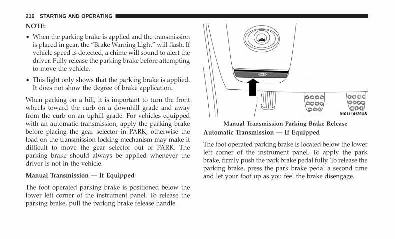
NOTE:
• When the parking brake is applied and the transmissionis placed in gear, the “Brake Warning Light” will flash. Ifvehicle speed is detected, a chime will sound to alert thedriver. Fully release the parking brake before attemptingto move the vehicle.
• This light only shows that the parking brake is applied.It does not show the degree of brake application.
When parking on a hill, it is important to turn the frontwheels toward the curb on a downhill grade and awayfrom the curb on an uphill grade. For vehicles equippedwith an automatic transmission, apply the parking brakebefore placing the gear selector in PARK, otherwise theload on the transmission locking mechanism may make itdifficult to move the gear selector out of PARK. Theparking brake should always be applied whenever thedriver is not in the vehicle.
Manual Transmission — If Equipped
The foot operated parking brake is positioned below thelower left corner of the instrument panel. To release theparking brake, pull the parking brake release handle.
Automatic Transmission — If Equipped
The foot operated parking brake is located below the lowerleft corner of the instrument panel. To apply the parkbrake, firmly push the park brake pedal fully. To release theparking brake, press the park brake pedal a second timeand let your foot up as you feel the brake disengage.
Manual Transmission Parking Brake Release
216 STARTING AND OPERATING
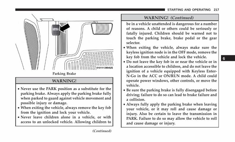
WARNING!
• Never use the PARK position as a substitute for theparking brake. Always apply the parking brake fullywhen parked to guard against vehicle movement andpossible injury or damage.
• When exiting the vehicle, always remove the key fobfrom the ignition and lock your vehicle.
• Never leave children alone in a vehicle, or withaccess to an unlocked vehicle. Allowing children to
(Continued)
WARNING! (Continued)be in a vehicle unattended is dangerous for a numberof reasons. A child or others could be seriously orfatally injured. Children should be warned not totouch the parking brake, brake pedal or the gearselector.
• When exiting the vehicle, always make sure thekeyless ignition node is in the OFF mode, remove thekey fob from the vehicle and lock the vehicle.
• Do not leave the key fob in or near the vehicle or ina location accessible to children, and do not leave theignition of a vehicle equipped with Keyless Enter-N-Go in the ACC or ON/RUN mode. A child couldoperate power windows, other controls, or move thevehicle.
• Be sure the parking brake is fully disengaged beforedriving; failure to do so can lead to brake failure anda collision.
• Always fully apply the parking brake when leavingyour vehicle, or it may roll and cause damage orinjury. Also be certain to leave the transmission inPARK. Failure to do so may allow the vehicle to rolland cause damage or injury.
Parking Brake
6
STARTING AND OPERATING 217

CAUTION!
If the Brake Warning Light remains on with the park-ing brake released, a brake system malfunction isindicated. Have the brake system serviced by an au-thorized dealer immediately.
MANUAL TRANSMISSION — IF EQUIPPED
Six-Speed Manual Transmission
WARNING!
You or others could be injured if you leave the vehicleunattended without having the park brake fully ap-plied. The park brake should always be applied whenthe driver is not in the vehicle, especially on an incline.
CAUTION!
• Never drive with your foot resting on the clutchpedal, or try to hold the vehicle on a hill with theclutch pedal partially engaged, as this will causeabnormal wear on the clutch. Refer to “ElectronicBrake Control System/Hill Start Assist” in “Safety”for further information.
• Failure to press the clutch pedal fully to the floormay cause increased shift efforts, and may result indamage to the clutch and transmission.
• Do not rest your hand on the shift lever whiledriving, as this may result in transmission synchro-nizer damage.
• Do not attempt to shift the transmission if the rearwheels are spinning due to loss of traction. Damageto the transmission may occur.
218 STARTING AND OPERATING
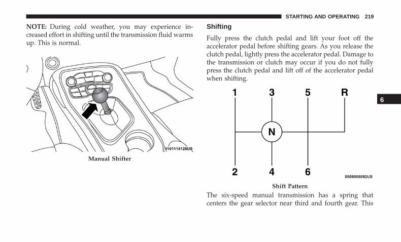
NOTE: During cold weather, you may experience in-creased effort in shifting until the transmission fluid warmsup. This is normal.
Shifting
Fully press the clutch pedal and lift your foot off theaccelerator pedal before shifting gears. As you release theclutch pedal, lightly press the accelerator pedal. Damage tothe transmission or clutch may occur if you do not fullypress the clutch pedal and lift off of the accelerator pedalwhen shifting.
The six-speed manual transmission has a spring thatcenters the gear selector near third and fourth gear. This
Manual Shifter
Shift Pattern
6
STARTING AND OPERATING 219
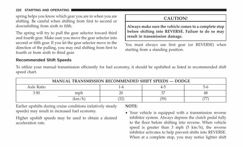
spring helps you know which gear you are in when you areshifting. Be careful when shifting from first to second ordownshifting from sixth to fifth.
The spring will try to pull the gear selector toward thirdand fourth gear. Make sure you move the gear selector intosecond or fifth gear. If you let the gear selector move in thedirection of the pulling, you may end shifting from first tofourth or from sixth to third gear.
CAUTION!
Always make sure the vehicle comes to a complete stopbefore shifting into REVERSE. Failure to do so mayresult in transmission damage.
You must always use first gear (or REVERSE) whenstarting from a standing position.
Recommended Shift Speeds
To utilize your manual transmission efficiently for fuel economy, it should be upshifted as listed in recommended shiftspeed chart.
MANUAL TRANSMISSION RECOMMENDED SHIFT SPEEDS — DODGEAxle Ratio 1-4 4-5 5-6
3.90 mph 20 37 48(km/h) (32) (59) (77)
Earlier upshifts during cruise conditions (relatively steadyspeeds) may result in increased fuel economy.
Higher upshift speeds may be used to obtain a desiredacceleration rate.
NOTE:
• Your vehicle is equipped with a transmission reverseinhibitor system. Always depress the clutch pedal fullyto the floor before shifting into reverse. When vehiclespeed is greater than 3 mph (5 km/h), the reverseinhibitor activates to help prevent shifts into REVERSE.When at a complete stop, you may notice lighter shift
220 STARTING AND OPERATING
efforts into REVERSE with the ignition switch in the ONposition (RUN position for Keyless Enter-N-Go), ascompared to the ignition LOCK position (OFF positionfor Keyless Enter-N-Go). This is normal operation of thetransmission reverse inhibitor system.
• Due to the high performance nature of your drivetrain,you may hear your transmission. This can be mostnoticeable when the vehicle is idling in NEUTRAL withthe clutch engaged (clutch pedal released), but it mayalso be heard when driving at low engine RPM. Also,this may be more noticeable when the transmission iswarm. This is a normal condition and is not an indica-tion of a problem with your clutch or transmission.
1–4 Skip Shift
In Auto Drive Mode, Default, or Street Drive Modes, thereare times when you must shift the transmission directlyfrom first gear to fourth gear instead of from first gear tosecond gear. This is to help you get the best possible fueleconomy from your vehicle. This occurs when the enginecoolant (antifreeze) is higher than 106°F (41°C), vehiclespeed is greater than 19 mph (30 km/h) but less than21 mph (34 km/h), and the transmission is in first gear, andthe accelerator is at ¼ throttle or less.
NOTE: The 1 - 4 Skip Shift feature is disabled whenselecting Sport Mode. Refer to “Performance Pages — IfEquipped” in the “Multimedia” section for further descrip-tions of this mode.
After you shift the transmission to fourth gear, you canpress the clutch in and shift to another forward gear.
Downshifting
To maintain a safe speed and prolong brake life, downshiftto maintain a safe speed when descending a steep grade.
WARNING!
Skipping more than one gear while downshifting,could cause you to lose control of your vehicle. Youcould have a collision.
CAUTION!
• If you skip more than one gear while downshiftingor downshift at too high an engine speed, you coulddamage the engine, transmission, or clutch.
• Do not downshift into first gear when the vehicle ismoving faster than 15 mph (24 km/h), as you coulddamage the engine and/or clutch.
6
STARTING AND OPERATING 221

AUTOMATIC TRANSMISSION — IF EQUIPPED
WARNING!
• Never use the PARK position as a substitute for theparking brake. Always apply the parking brake fullywhen exiting the vehicle to guard against vehiclemovement and possible injury or damage.
• Your vehicle could move and injure you and others ifit is not in PARK. Check by trying to move thetransmission gear selector out of PARK with thebrake pedal released. Make sure the transmission isin PARK before exiting the vehicle.
• The transmission may not engage PARK if the ve-hicle is moving. Always bring the vehicle to acomplete stop before shifting to PARK, and verifythat the transmission gear position indicator solidlyindicates PARK (P) without blinking. Ensure that thevehicle is completely stopped, and the PARK posi-tion is properly indicated, before exiting the vehicle.
• It is dangerous to shift out of PARK or NEUTRAL ifthe engine speed is higher than idle speed. If yourfoot is not firmly pressing the brake pedal, thevehicle could accelerate quickly forward or in re-
(Continued)
WARNING! (Continued)verse. You could lose control of the vehicle and hitsomeone or something. Only shift into gear when theengine is idling normally and your foot is firmlypressing the brake pedal.
• Unintended movement of a vehicle could injurethose in or near the vehicle. As with all vehicles, youshould never exit a vehicle while the engine isrunning. Before exiting a vehicle, always come to acomplete stop, then apply the parking brake, shiftthe transmission into PARK, and turn the ignitionOFF. When the ignition is in the OFF mode, thetransmission is locked in PARK, securing the vehicleagainst unwanted movement.
• When exiting the vehicle, always make sure theignition is in the OFF mode, remove the key fob fromthe vehicle, and lock the vehicle.
• Never leave children alone in a vehicle, or withaccess to an unlocked vehicle. Allowing children tobe in a vehicle unattended is dangerous for a numberof reasons. A child or others could be seriously orfatally injured. Children should be warned not to
(Continued)
222 STARTING AND OPERATING

WARNING! (Continued)touch the parking brake, brake pedal or the trans-mission gear selector.
• Do not leave the key fob in or near the vehicle (or ina location accessible to children), and do not leavethe ignition in the ACC or ON/RUN mode. A childcould operate power windows, other controls, ormove the vehicle.
CAUTION!
Damage to the transmission may occur if the followingprecautions are not observed:• Shift into or out of PARK or REVERSE only after the
vehicle has come to a complete stop.• Do not shift between PARK, REVERSE, NEUTRAL,
or DRIVE when the engine is above idle speed.• Before shifting into any gear, make sure your foot is
firmly pressing the brake pedal.
NOTE: You must press and hold the brake pedal whileshifting out of PARK.
Ignition Park Interlock
This vehicle is equipped with an Ignition Park Interlockwhich requires the transmission to be in PARK before theignition can be turned to the OFF mode. This helps thedriver avoid inadvertently leaving the vehicle withoutplacing the transmission in PARK. This system also locksthe transmission in PARK whenever the ignition is in theOFF mode.
NOTE: The transmission is NOT locked in PARK when theignition is in the ACC mode (even though the engine willbe off). Ensure that the transmission is in PARK, and theignition is OFF (not in ACC mode) before exiting thevehicle.
Brake/Transmission Shift Interlock System
This vehicle is equipped with a Brake Transmission ShiftInterlock system (BTSI) that holds the transmission gearselector in PARK unless the brakes are applied. To shift thetransmission out of PARK, the engine must be running andthe brake pedal must be pressed. The brake pedal mustalso be pressed to shift from NEUTRAL into DRIVE orREVERSE when the vehicle is stopped or moving at lowspeeds.
6
STARTING AND OPERATING 223
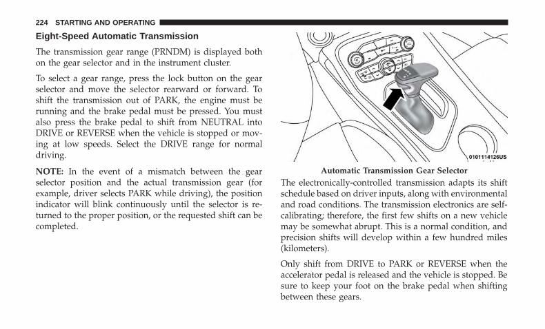
Eight-Speed Automatic Transmission
The transmission gear range (PRNDM) is displayed bothon the gear selector and in the instrument cluster.
To select a gear range, press the lock button on the gearselector and move the selector rearward or forward. Toshift the transmission out of PARK, the engine must berunning and the brake pedal must be pressed. You mustalso press the brake pedal to shift from NEUTRAL intoDRIVE or REVERSE when the vehicle is stopped or mov-ing at low speeds. Select the DRIVE range for normaldriving.
NOTE: In the event of a mismatch between the gearselector position and the actual transmission gear (forexample, driver selects PARK while driving), the positionindicator will blink continuously until the selector is re-turned to the proper position, or the requested shift can becompleted.
The electronically-controlled transmission adapts its shiftschedule based on driver inputs, along with environmentaland road conditions. The transmission electronics are self-calibrating; therefore, the first few shifts on a new vehiclemay be somewhat abrupt. This is a normal condition, andprecision shifts will develop within a few hundred miles(kilometers).
Only shift from DRIVE to PARK or REVERSE when theaccelerator pedal is released and the vehicle is stopped. Besure to keep your foot on the brake pedal when shiftingbetween these gears.
Automatic Transmission Gear Selector
224 STARTING AND OPERATING

The transmission gear selector provides PARK, REVERSE,NEUTRAL, DRIVE, and MANUAL (AutoStick) shift posi-tions. Manual shifts can be made using the AutoStick shiftcontrol. Toggling the gear selector forward (-) or rearward(+) while in the MANUAL (AutoStick) position (beside theDRIVE position) will manually select the transmissiongear, and will display the current gear in the instrumentcluster as M1, M2, M3, etc. Refer to �AutoStick� in thissection for further information.
NOTE: If the gear selector cannot be moved to the PARK,REVERSE, or NEUTRAL position (when pushed forward)it is probably in the MANUAL (AutoStick, +/-) position(beside the DRIVE position). In MANUAL (AutoStick)mode, the transmission gear is displayed in the instrumentcluster (as M1, M2, M3, etc.). Move the gear selector to theright (into the DRIVE [D] position) for access to PARK,REVERSE, and NEUTRAL.
Gear Ranges
Do not depress the accelerator pedal when shifting fromPARK or NEUTRAL into another gear range.
NOTE: After selecting any gear range, wait a moment toallow the selected gear to engage before accelerating. Thisis especially important when the engine is cold.
PARK (P)
This range supplements the parking brake by locking thetransmission. The engine can be started in this range.Never attempt to use PARK while the vehicle is in motion.Apply the parking brake when exiting the vehicle in thisrange.
When parking on a level surface, you may shift thetransmission into PARK first, and then apply the parkingbrake.
When parking on a hill, apply the parking brake beforeshifting the transmission to PARK. As an added precau-tion, turn the front wheels toward the curb on a downhillgrade and away from the curb on an uphill grade.
When exiting the vehicle, always:
• Apply the parking brake.
• Shift the transmission into PARK.
• Turn the ignition OFF.
• Remove the key fob from the vehicle.
6
STARTING AND OPERATING 225
WARNING!
• Never use the PARK position as a substitute for theparking brake. Always apply the parking brake fullywhen exiting the vehicle to guard against vehiclemovement and possible injury or damage.
• Your vehicle could move and injure you and others ifit is not in PARK. Check by trying to move thetransmission gear selector out of PARK with thebrake pedal released. Make sure the transmission isin PARK before exiting the vehicle.
• The transmission may not engage PARK if the ve-hicle is moving. Always bring the vehicle to acomplete stop before shifting to PARK, and verifythat the transmission gear position indicator solidlyindicates PARK (P) without blinking. Ensure that thevehicle is completely stopped, and the PARK posi-tion is properly indicated, before exiting the vehicle.
• It is dangerous to shift out of PARK or NEUTRAL ifthe engine speed is higher than idle speed. If yourfoot is not firmly pressing the brake pedal, thevehicle could accelerate quickly forward or in re-verse. You could lose control of the vehicle and hitsomeone or something. Only shift into gear when the
(Continued)
WARNING! (Continued)engine is idling normally and your foot is firmlypressing the brake pedal.
• Unintended movement of a vehicle could injurethose in or near the vehicle. As with all vehicles, youshould never exit a vehicle while the engine isrunning. Before exiting a vehicle, always come to acomplete stop, then apply the parking brake, shiftthe transmission into PARK, and turn the ignitionOFF. When the ignition is in the OFF mode, thetransmission is locked in PARK, securing the vehicleagainst unwanted movement.
• When exiting the vehicle, always make sure theignition is in the OFF mode, remove the key fob fromthe vehicle, and lock the vehicle.
• Never leave children alone in a vehicle, or withaccess to an unlocked vehicle. Allowing children tobe in a vehicle unattended is dangerous for a numberof reasons. A child or others could be seriously orfatally injured. Children should be warned not totouch the parking brake, brake pedal or the trans-mission gear selector.
(Continued)
226 STARTING AND OPERATING
WARNING! (Continued)• Do not leave the key fob in or near the vehicle (or in
a location accessible to children), and do not leavethe ignition in the ACC or ON/RUN mode. A childcould operate power windows, other controls, ormove the vehicle.
CAUTION!
• Before moving the transmission gear selector out ofPARK, you must start the engine, and also press thebrake pedal. Otherwise, damage to the gear selectorcould result.
• DO NOT race the engine when shifting from PARKor NEUTRAL into another gear range, as this candamage the drivetrain.
The following indicators should be used to ensure that youhave properly engaged the transmission into the PARKposition:
• When shifting into PARK, push the lock button on thegear selector and firmly move the selector all the wayforward until it stops and is fully seated.
• Look at the transmission gear position display andverify that it indicates the PARK position (P), and is notblinking.
• With the brake pedal released, verify that the gearselector will not move out of PARK.
REVERSE (R)
This range is for moving the vehicle backward. Shift intoREVERSE only after the vehicle has come to a completestop.
NEUTRAL (N)
Use this range when the vehicle is standing for prolongedperiods with the engine running. Apply the parking brakeand shift the transmission into PARK if you must exit thevehicle.
WARNING!
Do not coast in NEUTRAL and never turn off theignition to coast down a hill. These are unsafe practicesthat limit your response to changing traffic or roadconditions. You might lose control of the vehicle andhave a collision.
6
STARTING AND OPERATING 227

CAUTION!
Towing the vehicle, coasting, or driving for any otherreason with the transmission in NEUTRAL can causesevere transmission damage.Refer to “Recreational Towing” in “Starting And Op-erating” and “Towing A Disabled Vehicle” in “In CaseOf Emergency” for further information.
DRIVE (D)
This range should be used for most city and highwaydriving. It provides the smoothest upshifts and downshifts,and the best fuel economy. The transmission automaticallyupshifts through all forward gears. The DRIVE positionprovides optimum driving characteristics under all normaloperating conditions.
When frequent transmission shifting occurs (such as whenoperating the vehicle under heavy loading conditions, inhilly terrain, traveling into strong head winds, or whiletowing a heavy trailer), use the AutoStick shift control (ifequipped, refer to “AutoStick” in this section for furtherinformation) to select a lower gear. Under these conditions,using a lower gear will improve performance and extendtransmission life by reducing excessive shifting and heatbuildup.
During extremely cold temperatures (-22°F [-30°C] or be-low), transmission operation may be modified dependingon engine and transmission temperature as well as vehiclespeed. Normal operation will resume once the transmis-sion temperature has risen to a suitable level.
MANUAL (M)
The MANUAL (M, +/-) position (beside the DRIVE posi-tion) enables full manual control of transmission shifting(also known as AutoStick mode; refer to “AutoStick” in thissection for further information). Toggling the gear selectorforward (-) or rearward (+) while in the MANUAL(AutoStick) position will manually select the transmissiongear, and will display the current gear in the instrumentcluster as M1, M2, M3, etc.
Transmission Limp Home Mode
Transmission function is monitored electronically for ab-normal conditions. If a condition is detected that couldresult in transmission damage, Transmission Limp HomeMode is activated. In this mode, the transmission mayoperate only in certain gears, or may not shift at all. Vehicleperformance may be severely degraded and the enginemay stall. In some situations, the transmission may notre-engage if the engine is turned off and restarted. TheMalfunction Indicator Light (MIL) may be illuminated. A
228 STARTING AND OPERATING

message in the instrument cluster will inform the driver ofthe more serious conditions, and indicate what actions maybe necessary.
In the event of a momentary problem, the transmission canbe reset to regain all forward gears by performing thefollowing steps:
NOTE: In cases where the instrument cluster messageindicates the transmission may not re-engage after engineshutdown, perform this procedure only in a desired loca-tion (preferably, at an authorized dealer).
1. Stop the vehicle.
2. Shift the transmission into PARK, if possible. If not, shiftthe transmission to NEUTRAL.
3. Push and hold the ignition switch until the engine turnsOFF.
4. Wait approximately 30 seconds.
5. Restart the engine.
6. Shift into the desired gear range. If the problem is nolonger detected, the transmission will return to normaloperation.
NOTE: Even if the transmission can be reset, we recom-mend that you visit an authorized dealer at your earliestpossible convenience. An authorized dealer has diagnosticequipment to assess the condition of your transmission.
If the transmission cannot be reset, authorized dealerservice is required.
AutoStick
AutoStick is a driver-interactive transmission feature pro-viding manual shift control, giving you more control of thevehicle. AutoStick allows you to maximize engine braking,eliminate undesirable upshifts and downshifts, and im-prove overall vehicle performance.
This system can also provide you with more control duringpassing, city driving, cold slippery conditions, mountaindriving, trailer towing, and many other situations.
Operation
When the gear selector is in the DRIVE (D) position, thetransmission will operate automatically, shifting betweenthe eight available gears. To activate AutoStick, move thegear selector into the MANUAL (M) position (beside theDRIVE position). The current transmission gear will bedisplayed in the instrument cluster, along with a high-lighted �M� (Manual) indication. When the gear selector is
6
STARTING AND OPERATING 229

in the MANUAL (M) position, tap the gear selector for-ward (-) (or tap the (-) shift paddle on the steering wheel,if equipped) to downshift the transmission to the nextlower gear, or tap the lever rearward (+) (or tap the (+) shiftpaddle, if equipped) to command an upshift.
NOTE:
• Tapping one of the steering wheel-mounted shiftpaddles (+/-), if equipped, while the gear selector is in
DRIVE, will activate a temporary AutoStick mode. Tap-ping (-) to enter AutoStick mode will downshift thetransmission to the next lower gear, while tapping (+) toenter AutoStick mode will retain the current gear. Thecurrent gear will be displayed in the instrument cluster,but the �M� will not be highlighted. The transmissionwill revert back to normal operation (if the gear selectorremains in DRIVE) after a period of time, depending onaccelerator pedal activity.
• In some models, the shift paddles may be disabled (orre-enabled, as desired) using Drive Mode Set-Up, ac-cessed by selecting Performance Control from the Appsmenu in the Uconnect screen.
In AutoStick mode, the transmission will shift up or downwhen (+/-) is manually selected by the driver (using thegear selector, or the shift paddles [if equipped]), unless anengine lugging or overspeed condition would result. It willremain in the selected gear until another upshift or down-shift is chosen, except as described below.
• In temporary AutoStick mode (gear selector in DRIVE),the transmission will automatically shift up when maxi-mum engine speed is reached. If the accelerator is fullydepressed, the transmission will downshift when pos-sible (based on current vehicle speed and gear, except
Shifter Paddles
1 — (–) Shift Paddle2 — (+) Shift Paddle
230 STARTING AND OPERATING

6.4L models). Lack of accelerator pedal activity willcause the transmission to revert to automatic operation.
• If normal AutoStick mode is engaged (gear selector inMANUAL position), manual gear selection will be main-tained until the gear selector is returned to DRIVE, or asdescribed below. The transmission will not upshift auto-matically at redline in this mode, nor will downshifts beobtained if the accelerator pedal is pressed to the floor.
• The transmission will automatically downshift as thevehicle slows (to prevent engine lugging) and willdisplay the current gear.
• The transmission will automatically downshift to firstgear when coming to a stop. After a stop, the drivershould manually upshift (+) the transmission as thevehicle is accelerated.
• You can start out, from a stop, in first or second gear.Tapping (+) (at a stop) will allow starting in second gear.Starting out in second gear can be helpful in snowy oricy conditions.
• If a requested downshift would cause the engine toover-speed, that shift will not occur.
• The system will ignore attempts to upshift at too low ofa vehicle speed.
• Holding the (-) paddle depressed (if equipped), orholding the gear selector in the (-) position, will down-shift the transmission to the lowest gear possible at thecurrent speed.
• Transmission shifting will be more noticeable whenAutoStick is enabled.
• The system may revert to automatic shift mode if a faultor overheat condition is detected.
To disengage AutoStick mode, return the gear selector tothe DRIVE position, or press and hold the (+) shift paddle(if equipped, and the gear selector is already in DRIVE)until “D” is once again indicated in the instrument cluster.You can shift in or out of the AutoStick mode at any timewithout taking your foot off the accelerator pedal.
WARNING!
Do not downshift for additional engine braking on aslippery surface. The drive wheels could lose their gripand the vehicle could skid, causing a collision orpersonal injury.
6
STARTING AND OPERATING 231

SPORT MODE — WITHOUT PERFORMANCECONTROL
Your vehicle is equipped with a Sport Mode feature. Thismode is a configuration set up for typical enthusiastdriving. The engine, transmission (when equipped withautomatic transmission), and steering systems are all set totheir SPORT settings. Sport Mode will provide improvedthrottle response and modified shifting for an enhanceddriving experience, as well the greatest amount of steeringfeel. This mode may be activated and deactivated bypushing the Sport button on the instrument panel switchbank.
NOTE: If equipped with a manual transmission, the 1 - 4Skip Shift Feature is disabled in SPORT Mode.
For vehicles equipped with Drive Modes or a “SUPERTRACK PAK” button, refer to “Performance Pages — IfEquipped” in “Multimedia” for further information.
FUEL SAVER TECHNOLOGY 5.7L AND 6.4L ONLY— IF EQUIPPED
This feature offers improved fuel economy by shutting offfour of the engine’s eight cylinders during light load andcruise conditions. The system is automatic with no driverinputs or additional driving skills required.
NOTE: This system may take some time to return to fullfunctionality after a battery disconnect.
POWER STEERING
The electric power steering system will give you goodvehicle response and increased ease of maneuverability intight spaces. The system will vary its assist to provide lightefforts while parking and good feel while driving. If theelectric steering system experiences a fault that prevents itfrom providing assist, you will still have the ability to steerthe vehicle manually.
WARNING!
Continued operation with reduced assist could pose asafety risk to yourself and others. Service should beobtained as soon as possible.
Alternate electric power steering efforts can be selectedthrough the Uconnect System. Refer to ”Customer Pro-grammable Features” within “Uconnect Settings” in “Mul-timedia” for further information.
If the Electric Power Steering warning icon isdisplayed and the “SERVICE POWER STEER-ING” or the “POWER STEERING ASSIST OFF –
232 STARTING AND OPERATING

SERVICE SYSTEM” message is displayed within the in-strument cluster display, this indicates the vehicle needs tobe taken to the dealer for service. Refer to “Warning LightsAnd Messages” in “Getting To Know Your InstrumentPanel” for further information.
NOTE:
• Even if the power steering assistance is no longeroperational, it is still possible to steer the vehicle. Underthese conditions there will be a substantial increase insteering effort, especially at low speeds and duringparking maneuvers.
• If the condition persists, see your authorized dealer forservice.
If the Steering icon is displayed and the “POWER STEER-ING SYSTEM OVER TEMP” message is displayed on theinstrument cluster screen, they indicate that extreme steer-ing maneuvers may have occurred which caused an overtemperature condition in the power steering system. Oncedriving conditions are safe, pull over and let the vehicleidle for a few moments until the icon and message turn off.
SPEED CONTROL — IF EQUIPPED
When engaged, the Speed Control takes over acceleratoroperations at speeds greater than 25 mph (40 km/h) or20 mph (32 km/h), depending on engine size and axleratio.
The Speed Control buttons are located on the right side ofthe steering wheel.
Speed Control Buttons
1 — On/Off 4 — SET (-)/Decel2 — SET (+)/Accel 5 — CANC/Cancel3 — RES/Resume
6
STARTING AND OPERATING 233

NOTE: In order to ensure proper operation, the SpeedControl System has been designed to shut down if multipleSpeed Control functions are operated at the same time. Ifthis occurs, the Speed Control System can be reactivated bypushing the Speed Control on/off button and resetting thedesired vehicle set speed.
To Activate
Push the on/off button to activate the Speed Control.“CRUISE CONTROL READY” will appear in the instru-ment cluster display to indicate the Speed Control is on. Toturn the system off, push the on/off button a second time.“CRUISE CONTROL OFF” will appear in the instrumentcluster display to indicate the Speed Control is off. Thesystem should be turned off when not in use.
WARNING!
Leaving the Speed Control system on when not in useis dangerous. You could accidentally set the system orcause it to go faster than you want. You could losecontrol and have an accident. Always leave the systemOFF when you are not using it.
To Set A Desired Speed
Turn the Speed Control on. When the vehicle has reachedthe desired speed, push the SET (+) or SET (-) button andrelease. Release the accelerator and the vehicle will operateat the selected speed. Once a speed has been set, a message“CRUISE CONTROL SET TO MPH (km/h)” will appearindicating what speed was set. A cruise indicator lamp,along with set speed will also appear and stay on in theinstrument cluster when the speed is set.
To Vary The Speed Setting
To Increase Speed
When the Speed Control is set, you can increase speed bypushing the SET (+) button.
The driver’s preferred units can be selected through theinstrument cluster display. Refer to “Getting To Know YourInstrument Panel” for more information. The speed incre-ment shown is dependant on the chosen speed unit of U.S.(mph) or Metric (km/h):
U.S. Speed (mph)
• Pushing the SET (+) button once will result in a 1 mphincrease in set speed. Each subsequent tap of the buttonresults in an increase of 1 mph.
234 STARTING AND OPERATING

• If the button is continually pushed, the set speed willcontinue to increase until the button is released, then thenew set speed will be established.
Metric Speed (km/h)
• Pushing the SET (+) button once will result in a 1 km/hincrease in set speed. Each subsequent tap of the buttonresults in an increase of 1 km/h.
• If the button is continually pushed, the set speed willcontinue to increase until the button is released, then thenew set speed will be established.
To Decrease Speed
When the Speed Control is set, you can decrease speed bypushing the SET (-) button.
The driver’s preferred units can be selected through theinstrument cluster display. Refer to “Getting To Know YourInstrument Panel” for more information. The speed decre-ment shown is dependant on the chosen speed unit of U.S.(mph) or Metric (km/h):
U.S. Speed (mph)
• Pushing the SET (-) button once will result in a 1 mphdecrease in set speed. Each subsequent tap of the buttonresults in a decrease of 1 mph.
• If the button is continually pushed, the set speed willcontinue to decrease until the button is released, then thenew set speed will be established.
Metric Speed (km/h)
• Pushing the SET (-) button once will result in a 1 km/hdecrease in set speed. Each subsequent tap of the buttonresults in a decrease of 1 km/h.
• If the button is continually pushed, the set speed willcontinue to decrease until the button is released, then thenew set speed will be established.
To Accelerate For Passing
Press the accelerator as you would normally. When thepedal is released, the vehicle will return to the set speed.
Using Speed Control On Hills
The transmission may downshift on hills to maintain thevehicle set speed.
NOTE: The Speed Control system maintains speed up anddown hills. A slight speed change on moderate hills isnormal.
On steep hills, a greater speed loss or gain may occur so itmay be preferable to drive without Speed Control.
6
STARTING AND OPERATING 235

WARNING!
Speed Control can be dangerous where the systemcannot maintain a constant speed. Your vehicle couldgo too fast for the conditions, and you could losecontrol and have an accident. Do not use Speed Controlin heavy traffic or on roads that are winding, icy,snow-covered or slippery.
To Resume Speed
To resume a previously set speed, push the RES button andrelease. Resume can be used at any speed above 20 mph(32 km/h).
To Deactivate
A soft tap on the brake pedal, pushing the CANC button,or normal brake pressure while slowing the vehicle willdeactivate the Speed Control without erasing the set speedfrom memory.
Pushing the on/off button or turning the ignition switchOFF erases the set speed from memory.
ADAPTIVE CRUISE CONTROL (ACC) —IF EQUIPPED
Adaptive Cruise Control (ACC) increases the driving con-venience provided by cruise control while traveling onhighways and major roadways. However, it is not a safetysystem and not designed to prevent collisions. SpeedControl function performs differently. Please refer to theproper section within this chapter.
ACC will allow you to keep cruise control engaged in lightto moderate traffic conditions without the constant need toreset your cruise control. ACC utilizes a radar sensor and aforward facing camera designed to detect a vehicle directlyahead of you.
NOTE:
• If the sensor does not detect a vehicle ahead of you, ACCwill maintain a fixed set speed.
• If the ACC sensor detects a vehicle ahead, ACC willapply limited braking or accelerate (not to exceed theoriginal set speed) automatically to maintain a presetfollowing distance, while matching the speed of thevehicle ahead.
236 STARTING AND OPERATING
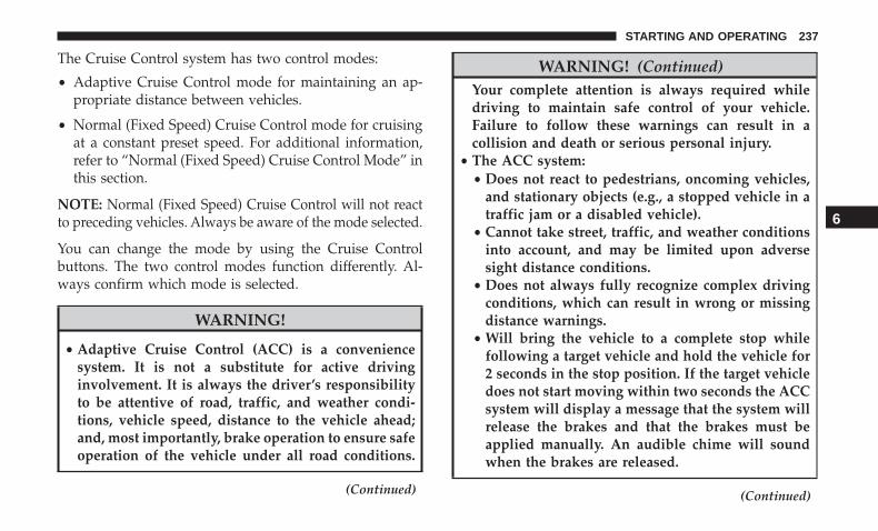
The Cruise Control system has two control modes:
• Adaptive Cruise Control mode for maintaining an ap-propriate distance between vehicles.
• Normal (Fixed Speed) Cruise Control mode for cruisingat a constant preset speed. For additional information,refer to “Normal (Fixed Speed) Cruise Control Mode” inthis section.
NOTE: Normal (Fixed Speed) Cruise Control will not reactto preceding vehicles. Always be aware of the mode selected.
You can change the mode by using the Cruise Controlbuttons. The two control modes function differently. Al-ways confirm which mode is selected.
WARNING!
• Adaptive Cruise Control (ACC) is a conveniencesystem. It is not a substitute for active drivinginvolvement. It is always the driver’s responsibilityto be attentive of road, traffic, and weather condi-tions, vehicle speed, distance to the vehicle ahead;and, most importantly, brake operation to ensure safeoperation of the vehicle under all road conditions.
(Continued)
WARNING! (Continued)Your complete attention is always required whiledriving to maintain safe control of your vehicle.Failure to follow these warnings can result in acollision and death or serious personal injury.
• The ACC system:• Does not react to pedestrians, oncoming vehicles,
and stationary objects (e.g., a stopped vehicle in atraffic jam or a disabled vehicle).
• Cannot take street, traffic, and weather conditionsinto account, and may be limited upon adversesight distance conditions.
• Does not always fully recognize complex drivingconditions, which can result in wrong or missingdistance warnings.
• Will bring the vehicle to a complete stop whilefollowing a target vehicle and hold the vehicle for2 seconds in the stop position. If the target vehicledoes not start moving within two seconds the ACCsystem will display a message that the system willrelease the brakes and that the brakes must beapplied manually. An audible chime will soundwhen the brakes are released.
(Continued)
6
STARTING AND OPERATING 237
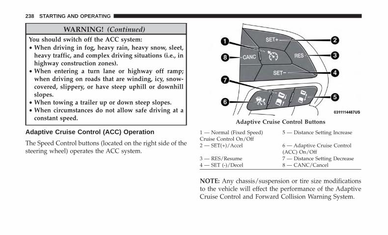
WARNING! (Continued)You should switch off the ACC system:• When driving in fog, heavy rain, heavy snow, sleet,
heavy traffic, and complex driving situations (i.e., inhighway construction zones).
• When entering a turn lane or highway off ramp;when driving on roads that are winding, icy, snow-covered, slippery, or have steep uphill or downhillslopes.
• When towing a trailer up or down steep slopes.• When circumstances do not allow safe driving at a
constant speed.
Adaptive Cruise Control (ACC) Operation
The Speed Control buttons (located on the right side of thesteering wheel) operates the ACC system.
NOTE: Any chassis/suspension or tire size modificationsto the vehicle will effect the performance of the AdaptiveCruise Control and Forward Collision Warning System.
Adaptive Cruise Control Buttons
1 — Normal (Fixed Speed)Cruise Control On/Off
5 — Distance Setting Increase
2 — SET(+)/Accel 6 — Adaptive Cruise Control(ACC) On/Off
3 — RES/Resume 7 — Distance Setting Decrease4 — SET (-)/Decel 8 — CANC/Cancel
238 STARTING AND OPERATING

Activating Adaptive Cruise Control (ACC)
You can only engage ACC if the vehicle speed is above20 mph (32 km/h).
The system will cancel when the vehicle speed drops below15 mph (24 km/h).
The minimum set speed for the ACC system is 20 mph(32 km/h).
When the system is turned on and in the “ready” state, theinstrument cluster display will read “ACC Ready.”
When the system is off, the instrument cluster display willread “Adaptive Cruise Control (ACC) Off.”
NOTE: You cannot engage ACC under the following con-ditions:
• When you apply the brakes.
• When the parking brake is applied.
• When the automatic transmission is in PARK, REVERSEor NEUTRAL.
• When the vehicle speed is outside of the speed range.
• When the brakes are overheated.
To Activate/Deactivate
Push and release the Adaptive Cruise Control (ACC)on/off button. The ACC menu in the instrument clusterdisplays “ACC Ready.”
To turn the system off, push and release the AdaptiveCruise Control (ACC) on/off button again. At this time, thesystem will turn off and the instrument cluster displays“Adaptive Cruise Control (ACC) Off.”
Adaptive Cruise Control Ready
6
STARTING AND OPERATING 239

WARNING!
Leaving the Adaptive Cruise Control (ACC) system onwhen not in use is dangerous. You could accidentallyset the system or cause it to go faster than you want.You could lose control and have a collision. Alwaysleave the system off when you are not using it.
To Set A Desired ACC Speed
When the vehicle reaches the speed desired, push theSET (+) button or the SET (-) button and release. Theinstrument cluster display will show the set speed.
If the system is set when the vehicle speed is above 20 mph(32 km/h), the set speed shall be the current speed of thevehicle.
Remove your foot from the accelerator pedal. If you do not,the vehicle may continue to accelerate beyond the setspeed. If this occurs:
• The message “DRIVER OVERRIDE” will show in theinstrument cluster display.
• The system will not be controlling the distance betweenyour vehicle and the vehicle ahead. The vehicle speed willonly be determined by the position of the accelerator pedal.
To Cancel
The following conditions cancel the system:
• The brake pedal is applied.
• The CANC (cancel) button is pushed.
• The vehicle speed goes below 15 mph (24 km/h).
• An Anti-Lock Brake System (ABS) event occurs.
• The gear selector is removed from the Drive position.
• The Electronic Stability Control/Traction Control Sys-tem (ESC/TCS) activates.
• The vehicle parking brake is applied.
Adaptive Cruise Control Off
240 STARTING AND OPERATING
To Turn Off
The system will turn off and clear the set speed in memoryif:
• The Adaptive Cruise Control (ACC) on/off button ispushed.
• The Normal (Fixed Speed) Cruise Control on/off buttonis pushed.
• The ignition is turned OFF.
To Resume
If there is a set speed in memory push the RES (resume)button and then remove your foot from the accelerator pedal.The instrument cluster display will display the last set speed.
NOTE: ACC cannot be resumed if there is a stationaryvehicle in-front of your vehicle in close proximity.
WARNING!
The Resume function should only be used if trafficand road conditions permit. Resuming a set speed thatis too high or too low for prevailing traffic and roadconditions could cause the vehicle to accelerate or
(Continued)
WARNING! (Continued)decelerate too sharply for safe operation. Failure tofollow these warnings can result in a collision anddeath or serious personal injury.
To Vary The Speed Setting
To Increase Speed
While ACC is set, you can increase the set speed bypushing the SET (+) button.
The driver’s preferred units can be selected through theinstrument cluster display. Refer to “Getting To Know YourInstrument Panel” for more information. The speed incre-ment shown is dependant on the chosen speed unit of U.S.(mph) or Metric (km/h):
U.S. Speed (mph)
• Pushing the SET (+) button once will result in a 1 mphincrease in set speed. Each subsequent tap of the buttonresults in an increase of 1 mph.
• If the button is continually pushed, the set speed willcontinue to increase in 5 mph increments until thebutton is released. The increase in set speed is reflectedin the instrument cluster display.
6
STARTING AND OPERATING 241
Metric Speed (km/h)
• Pushing the SET (+) button once will result in a 1 km/hincrease in set speed. Each subsequent tap of the buttonresults in an increase of 1 km/h.
• If the button is continually pushed, the set speed willcontinue to increase in 10 km/h increments until thebutton is released. The increase in set speed is reflectedin the instrument cluster display.
To Decrease Speed
While ACC is set, the set speed can be decreased bypushing the SET (-) button.
The driver’s preferred units can be selected through theinstrument cluster display. Refer to “Getting To Know YourInstrument Panel” for more information. The speed decre-ment shown is dependant on the chosen speed unit of U.S.(mph) or Metric (km/h):
U.S. Speed (mph)
• Pushing the SET (-) button once will result in a 1 mphdecrease in set speed. Each subsequent tap of the buttonresults in a decrease of 1 mph.
• If the button is continually pushed, the set speed willcontinue to decrease in 5 mph increments until the
button is released. The decrease in set speed is reflectedin the instrument cluster display.
Metric Speed (km/h)
• Pushing the SET (-) button once will result in a 1 km/hdecrease in set speed. Each subsequent tap of the buttonresults in a decrease of 1 km/h.
• If the button is continually pushed, the set speed willcontinue to decrease in 10 km/h increments until thebutton is released. The decrease in set speed is reflectedin the instrument cluster display.
NOTE:
• When you override and push the SET (+) button or SET(-) buttons, the new Set Speed will be the current speedof the vehicle.
• When you use the SET (-) button to decelerate, if theengine’s braking power does not slow the vehicle suffi-ciently to reach the set speed, the brake system willautomatically slow the vehicle.
• The ACC system applies the brake down to 15 mph(24 km/h) when following a target vehicle.
• The ACC system maintains set speed when driving uphill and down hill. However, a slight speed change on
242 STARTING AND OPERATING

moderate hills is normal. In addition, downshifting mayoccur while climbing uphill or descending downhill.This is normal operation and necessary to maintain setspeed. When driving up hill and down hill, the ACCsystem will cancel if the braking temperature exceedsnormal range (overheated).
Setting The Following Distance In ACC
The specified following distance for ACC can be set byvarying the distance setting between four bars (longest),three bars (long), two bars (medium) and one bar (short).Using this distance setting and the vehicle speed, ACCcalculates and sets the distance to the vehicle ahead. Thisdistance setting will show in the instrument cluster display.
Distance Setting 4 Bars (Longest)
6
STARTING AND OPERATING 243

Distance Setting 3 Bars (Long) Distance Setting 2 Bars (Medium)
244 STARTING AND OPERATING
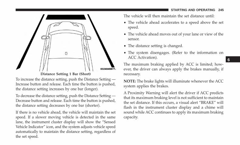
To increase the distance setting, push the Distance Setting —Increase button and release. Each time the button is pushed,the distance setting increases by one bar (longer).
To decrease the distance setting, push the Distance Setting —Decrease button and release. Each time the button is pushed,the distance setting decreases by one bar (shorter).
If there is no vehicle ahead, the vehicle will maintain the setspeed. If a slower moving vehicle is detected in the samelane, the instrument cluster display will show the “SensedVehicle Indicator” icon, and the system adjusts vehicle speedautomatically to maintain the distance setting, regardless ofthe set speed.
The vehicle will then maintain the set distance until:
• The vehicle ahead accelerates to a speed above the setspeed.
• The vehicle ahead moves out of your lane or view of thesensor.
• The distance setting is changed.
• The system disengages. (Refer to the information onACC Activation).
The maximum braking applied by ACC is limited; how-ever, the driver can always apply the brakes manually, ifnecessary.
NOTE: The brake lights will illuminate whenever the ACCsystem applies the brakes.
A Proximity Warning will alert the driver if ACC predictsthat its maximum braking level is not sufficient to maintainthe set distance. If this occurs, a visual alert “BRAKE” willflash in the instrument cluster display and a chime willsound while ACC continues to apply its maximum brakingcapacity.
Distance Setting 1 Bar (Short)
6
STARTING AND OPERATING 245
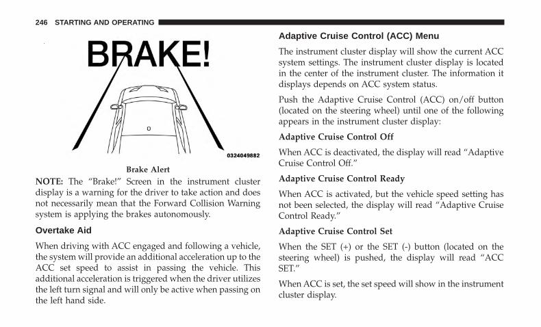
NOTE: The “Brake!” Screen in the instrument clusterdisplay is a warning for the driver to take action and doesnot necessarily mean that the Forward Collision Warningsystem is applying the brakes autonomously.
Overtake Aid
When driving with ACC engaged and following a vehicle,the system will provide an additional acceleration up to theACC set speed to assist in passing the vehicle. Thisadditional acceleration is triggered when the driver utilizesthe left turn signal and will only be active when passing onthe left hand side.
Adaptive Cruise Control (ACC) Menu
The instrument cluster display will show the current ACCsystem settings. The instrument cluster display is locatedin the center of the instrument cluster. The information itdisplays depends on ACC system status.
Push the Adaptive Cruise Control (ACC) on/off button(located on the steering wheel) until one of the followingappears in the instrument cluster display:
Adaptive Cruise Control Off
When ACC is deactivated, the display will read “AdaptiveCruise Control Off.”
Adaptive Cruise Control Ready
When ACC is activated, but the vehicle speed setting hasnot been selected, the display will read “Adaptive CruiseControl Ready.”
Adaptive Cruise Control Set
When the SET (+) or the SET (-) button (located on thesteering wheel) is pushed, the display will read “ACCSET.”
When ACC is set, the set speed will show in the instrumentcluster display.
Brake Alert
246 STARTING AND OPERATING
The ACC screen may display once again if any ACCactivity occurs, which may include any of the following:
• System Cancel
• Driver Override
• System Off
• ACC Proximity Warning
• ACC Unavailable Warning• The instrument cluster display will return to the last
display selected after five seconds of no ACC displayactivity
Display Warnings And Maintenance
“Wipe Front Radar Sensor In Front Of Vehicle”Warning
The “ACC/FCW Unavailable Wipe Front Radar Sensor”warning will display and also a chime will indicate whenconditions temporarily limit system performance.
This most often occurs at times of poor visibility, such as insnow or heavy rain. The ACC system may also becometemporarily blinded due to obstructions, such as mud, dirtor ice. In these cases, the instrument cluster display willdisplay “ACC/FCW Unavailable Wipe Front Radar Sen-sor” and the system will deactivate.
The “ACC/FCW Unavailable Wipe Front Radar Sensor”message can sometimes be displayed while driving inhighly reflective areas (i.e. tunnels with reflective tiles, orice and snow). The ACC system will recover after thevehicle has left these areas. Under rare conditions, whenthe radar is not tracking any vehicles or objects in its paththis warning may temporarily occur.
NOTE: If the “ACC/FCW Unavailable Wipe Front RadarSensor” warning is active Normal (Fixed Speed) CruiseControl is still available. For additional information refer to“Normal (Fixed Speed) Cruise Control Mode” in this section.
If weather conditions are not a factor, the driver shouldexamine the sensor. It may require cleaning or removal ofan obstruction. The sensor is located in the center of thevehicle behind the lower grille.
To keep the ACC System operating properly, it is importantto note the following maintenance items:
• Always keep the sensor clean. Carefully wipe the sensorlens with a soft cloth. Be cautious not to damage thesensor lens.
• Do not remove any screws from the sensor. Doing socould cause an ACC system malfunction or failure andrequire a sensor realignment.
6
STARTING AND OPERATING 247
• If the sensor or front end of the vehicle is damaged dueto a collision, see your authorized dealer for service.
• Do not attach or install any accessories near the sensor,including transparent material or aftermarket grilles.Doing so could cause an ACC system failure or malfunc-tion.
When the condition that deactivated the system is nolonger present, the system will return to the “AdaptiveCruise Control Off” state and will resume function bysimply reactivating it.
NOTE:
• If the “ACC/FCW Unavailable Wipe Front Radar Sen-sor” message occurs frequently (e.g. more than once onevery trip) without any snow, rain, mud, or otherobstruction, have the radar sensor realigned at yourauthorized dealer.
• Installing a snow plow, front-end protector, an aftermar-ket grille or modifying the grille is not recommended.Doing so may block the sensor and inhibit ACC/FCWoperation.
Service ACC/FCW Warning
If the system turns off, and the instrument cluster displays“ACC/FCW Unavailable Service Required” or “Cruise/FCW Unavailable Service Required”, there may be aninternal system fault or a temporary malfunction thatlimits ACC functionality. Although the vehicle is stilldrivable under normal conditions, ACC will be temporar-ily unavailable. If this occurs, try activating ACC againlater, following an ignition cycle. If the problem persists,see your authorized dealer.
Precautions While Driving With ACC
In certain driving situations, ACC may have detectionissues. In these cases, ACC may brake late or unexpectedly.The driver needs to stay alert and may need to intervene.
Towing A Trailer
Towing a trailer is not advised when using ACC.
248 STARTING AND OPERATING

Offset Driving
ACC may not detect a vehicle in the same lane that is offsetfrom your direct line of travel, or a vehicle merging in froma side lane. There may not be sufficient distance to thevehicle ahead. The offset vehicle may move in and out ofthe line of travel, which can cause your vehicle to brake oraccelerate unexpectedly.
Turns And Bends
When driving on a curve with ACC engaged, the systemmay decrease the vehicle speed and acceleration for stabil-ity reasons, with no target vehicle detected. Once thevehicle is out of the curve the system will resume youroriginal set speed. This is a part of normal ACC systemfunctionality.
NOTE: On tight turns ACC performance may be limited.
Offset Driving Condition Example
Turn Or Bend Example
6
STARTING AND OPERATING 249

Using ACC On Hills
When driving on hills, ACC may not detect a vehicle inyour lane. Depending on the speed, vehicle load, trafficconditions, and the steepness of the hills, ACC perfor-mance may be limited.
Lane Changing
ACC may not detect a vehicle until it is completely in thelane in which you are traveling. In the illustration shown,ACC has not yet detected the vehicle changing lanes and itmay not detect the vehicle until it’s too late for the ACCsystem to take action. ACC may not detect a vehicle until itis completely in the lane. There may not be sufficientdistance to the lane-changing vehicle. Always be attentiveand ready to apply the brakes if necessary.
ACC Hill Example
Lane Changing Example
250 STARTING AND OPERATING
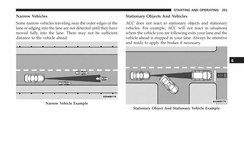
Narrow Vehicles
Some narrow vehicles traveling near the outer edges of thelane or edging into the lane are not detected until they havemoved fully into the lane. There may not be sufficientdistance to the vehicle ahead.
Stationary Objects And Vehicles
ACC does not react to stationary objects and stationaryvehicles. For example, ACC will not react in situationswhere the vehicle you are following exits your lane and thevehicle ahead is stopped in your lane. Always be attentiveand ready to apply the brakes if necessary.
Narrow Vehicle ExampleStationary Object And Stationary Vehicle Example
6
STARTING AND OPERATING 251
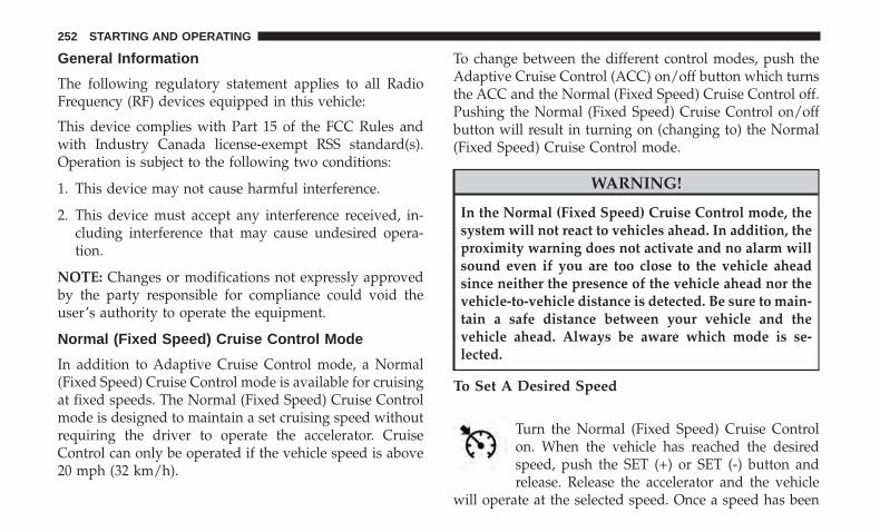
General Information
The following regulatory statement applies to all RadioFrequency (RF) devices equipped in this vehicle:
This device complies with Part 15 of the FCC Rules andwith Industry Canada license-exempt RSS standard(s).Operation is subject to the following two conditions:
1. This device may not cause harmful interference.
2. This device must accept any interference received, in-cluding interference that may cause undesired opera-tion.
NOTE: Changes or modifications not expressly approvedby the party responsible for compliance could void theuser’s authority to operate the equipment.
Normal (Fixed Speed) Cruise Control Mode
In addition to Adaptive Cruise Control mode, a Normal(Fixed Speed) Cruise Control mode is available for cruisingat fixed speeds. The Normal (Fixed Speed) Cruise Controlmode is designed to maintain a set cruising speed withoutrequiring the driver to operate the accelerator. CruiseControl can only be operated if the vehicle speed is above20 mph (32 km/h).
To change between the different control modes, push theAdaptive Cruise Control (ACC) on/off button which turnsthe ACC and the Normal (Fixed Speed) Cruise Control off.Pushing the Normal (Fixed Speed) Cruise Control on/offbutton will result in turning on (changing to) the Normal(Fixed Speed) Cruise Control mode.
WARNING!
In the Normal (Fixed Speed) Cruise Control mode, thesystem will not react to vehicles ahead. In addition, theproximity warning does not activate and no alarm willsound even if you are too close to the vehicle aheadsince neither the presence of the vehicle ahead nor thevehicle-to-vehicle distance is detected. Be sure to main-tain a safe distance between your vehicle and thevehicle ahead. Always be aware which mode is se-lected.
To Set A Desired Speed
Turn the Normal (Fixed Speed) Cruise Controlon. When the vehicle has reached the desiredspeed, push the SET (+) or SET (-) button andrelease. Release the accelerator and the vehicle
will operate at the selected speed. Once a speed has been
252 STARTING AND OPERATING
set a message “CRUISE CONTROL SET TO MPH (km/h)”will appear indicating what speed was set. This light willturn on when the system is turned on via the on/offcontrol. It turns green when the cruise control is set.
To Vary The Speed Setting
To Increase Speed
When the Normal (Fixed Speed) Cruise Control is set, youcan increase speed by pushing the SET (+) button.
The driver’s preferred units can be selected through theinstrument cluster display. Refer to “Getting To Know YourInstrument Panel” for more information. The speed incre-ment shown is dependant on the speed of U.S. (mph) orMetric (km/h) units:
U.S. Speed (mph)
• Pushing the SET (+) button once will result in a 1 mphincrease in set speed. Each subsequent tap of the buttonresults in an increase of 1 mph.
• If the button is continually pushed, the set speed willcontinue to increase in 5 mph increments until thebutton is released. The increase in set speed is reflectedin the instrument cluster display.
Metric Speed (km/h)
• Pushing the SET (+) button once will result in a 1 km/hincrease in set speed. Each subsequent tap of the buttonresults in an increase of 1 km/h.
• If the button is continually pushed, the set speed willcontinue to increase in 10 km/h increments until thebutton is released. The increase in set speed is reflectedin the instrument cluster display.
To Decrease Speed
When the Normal (Fixed Speed) Cruise Control is set, youcan decrease speed by pushing the SET (-) button.
The driver’s preferred units can be selected through theinstrument cluster display. Refer to “Getting To Know YourInstrument Panel” for more information. The speed decre-ment shown is dependant on the speed of U.S. (mph) orMetric (km/h) units:
U.S. Speed (mph)
• Pushing the SET (-) button once will result in a 1 mphdecrease in set speed. Each subsequent tap of the buttonresults in a decrease of 1 mph.
• If the button is continually pushed, the set speed willcontinue to decrease in 5 mph decrements until the
6
STARTING AND OPERATING 253

button is released. The decrease in set speed is reflectedin the instrument cluster display.
Metric Speed (km/h)
• Pushing the SET (-) button once will result in a 1 km/hdecrease in set speed. Each subsequent tap of the buttonresults in a decrease of 1 km/h.
• If the button is continually pushed, the set speed willcontinue to decrease in 10 km/h decrements until thebutton is released. The decrease in set speed is reflectedin the instrument cluster display.
To Cancel
The following conditions will cancel the Normal (FixedSpeed) Cruise Control without clearing the memory:
• The brake pedal is applied.
• The CANC button is pushed.
• The Electronic Stability Control/Traction Control Sys-tem (ESC/TCS) activates.
• The vehicle parking brake is applied.
• The braking temperature exceeds normal range (over-heated).
• The gear selector is removed from the DRIVE position.
To Resume Speed
To resume a previously set speed, push the RES button andrelease. Resume can be used at any speed above 20 mph(32 km/h).
To Turn Off
The system will turn off and erase the set speed in memoryif:
• The Normal (Fixed Speed) Cruise Control on/off buttonis pushed.
• The ignition is turned OFF.
• The Adaptive Cruise Control (ACC) on/off button ispushed.
PARKSENSE REAR PARK ASSIST — IF EQUIPPED
The ParkSense Rear Park Assist system provides visual andaudible indications of the distance between the rear fasciaand a detected obstacle when backing up, e.g. during aparking maneuver.
Refer to “ParkSense System Usage Precautions” in thissection for limitations of this system and recommenda-tions.
254 STARTING AND OPERATING
ParkSense will retain the last system state (enabled ordisabled) from the last ignition cycle when the ignition ischanged to the ON/RUN position.
ParkSense can be active only when the gear selector is inREVERSE. If ParkSense is enabled at this gear selectorposition, the system will remain active until the vehiclespeed is increased to approximately 7 mph (11 km/h) orabove. The system will become active again if the vehiclespeed is decreased to speeds less than approximately6 mph (9 km/h).
ParkSense Sensors
The four ParkSense sensors, located in the rear fascia/bumper, monitor the area behind the vehicle that is withinthe sensors’ field of view. The sensors can detect obstaclesfrom approximately 12 inches (30 cm) up to 79 inches(200 cm) from the rear fascia/bumper in the horizontaldirection, depending on the location, type and orientationof the obstacle.
ParkSense Warning Display
The ParkSense Warning screen will only be displayed if“Sound and Display” is selected from the Customer -Programmable Features section of the Uconnect System.Refer to �Uconnect Settings” in “Multimedia” for furtherinformation.
The ParkSense Warning screen is located within the instru-ment cluster display. It provides visual warnings to indi-cate the distance between the rear fascia/bumper and thedetected obstacle. Refer to “Instrument Cluster Display” in“Getting To Know Your Instrument Panel” for furtherinformation.
ParkSense Display
When the vehicle is in REVERSE, the warning display willturn on indicating the system status.
The system will indicate a detected obstacle by showing asingle arc in one or more regions based on the obstacle’sdistance and location relative to the vehicle.
If an obstacle is detected in the center rear region, thedisplay will show a single solid arc in the center rear regionand will produce a one-half second tone. As the vehiclemoves closer to the obstacle, the display will show the
6
STARTING AND OPERATING 255
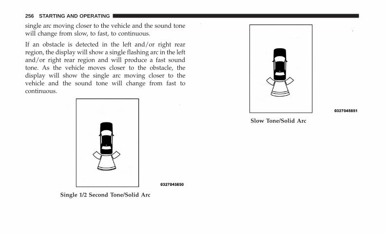
single arc moving closer to the vehicle and the sound tonewill change from slow, to fast, to continuous.
If an obstacle is detected in the left and/or right rearregion, the display will show a single flashing arc in the leftand/or right rear region and will produce a fast soundtone. As the vehicle moves closer to the obstacle, thedisplay will show the single arc moving closer to thevehicle and the sound tone will change from fast tocontinuous.
Single 1/2 Second Tone/Solid Arc
Slow Tone/Solid Arc
256 STARTING AND OPERATING

The vehicle is close to the obstacle when the warningdisplay shows one flashing arc and sounds a continuoustone. The following chart shows the warning alert opera-tion when the system is detecting an obstacle:
Fast Tone/Flashing Arc Continuous Tone/Flashing Arc
6
STARTING AND OPERATING 257

WARNING ALERTSRear
Distance(in/cm)
Greaterthan
79 inches(200 cm)
79-59 inches(200-150
cm)
59-47 inches(150-120
cm)
47-39 inches(120-100
cm)
39-25 inches(100-65 cm)
25-12 inches(65-30 cm)
Less than12 inches(30 cm)
AudibleAlert
Chime
None Single 1/2-Second
Tone(for rear
center only)
Slow(for rear
center only)
Slow(for rear
center only)
Fast(for rear
center only)
Fast Continuous
Arc — LeftRear
None None None None None 2nd Flash-ing
1st Flashing
Arc — Cen-ter Rear
None 6th Solid 5th Solid 4th Solid 3rd Flash-ing
2nd Flash-ing
1st Flashing
Arc — RightRear
None None None None None 2nd Flash-ing
1st Flashing
RadioVolumeReduced
No Yes Yes Yes Yes Yes Yes
258 STARTING AND OPERATING

Enabling And Disabling ParkSense
ParkSense can be enabled and disabled with the ParkSenseswitch, located on the switch panel below the Uconnectdisplay.
When the ParkSense switch is pushed to disablethe system, the instrument cluster will displaythe “ParkSense Off” message for approximatelyfive seconds. When the gear selector is moved to
REVERSE and the system is disabled, the instrumentcluster display will display the “ParkSense Off” messagefor as long as the vehicle is in REVERSE.
Refer to “Instrument Cluster Display” in “Getting To KnowYour Instrument Panel” for further information.
The ParkSense switch LED will be on when ParkSense isdisabled or defective. The ParkSense switch LED will be offwhen the system is enabled. If the ParkSense switch ispushed and the system is disabled or requires service, theParkSense switch LED will blink momentarily and then theLED will be on.
Service The ParkSense Rear Park Assist System
During vehicle start up, when the ParkSense Rear ParkAssist System has detected a faulted condition, the instru-ment cluster will actuate a single chime, once per ignition
cycle and it will display the “PARKSENSE UNAVAILABLEWIPE REAR SENSORS” or “PARKSENSE UNAVAILABLESERVICE REQUIRED” message for five seconds. Refer to“Instrument Cluster Display” in “Getting To Know YourInstrument Panel” for further information.
When the gear selector is moved to REVERSE and thesystem has detected a faulted condition, the instrumentcluster display will display the “PARKSENSE UNAVAIL-ABLE WIPE REAR SENSORS” or “PARKSENSE UN-AVAILABLE SERVICE REQUIRED” message for as long asthe vehicle is in REVERSE. Under this condition, ParkSensewill not operate.
If “PARKSENSE UNAVAILABLE WIPE REAR SENSORS”appears in the instrument cluster display, make sure theouter surface and the inside of the rear fascia/bumper isclean and clear of snow, ice, mud, dirt or other obstruction,and then cycle the ignition. If the message continues toappear see an authorized dealer.
If “PARKSENSE UNAVAILABLE SERVICE REQUIRED”appears in the instrument cluster display, see an autho-rized dealer.
6
STARTING AND OPERATING 259
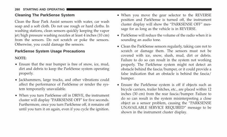
Cleaning The ParkSense System
Clean the Rear Park Assist sensors with water, car washsoap and a soft cloth. Do not use rough or hard cloths. Inwashing stations, clean sensors quickly keeping the vaporjet/high pressure washing nozzles at least 4 inches (10 cm)from the sensors. Do not scratch or poke the sensors.Otherwise, you could damage the sensors.
ParkSense System Usage Precautions
NOTE:
• Ensure that the rear bumper is free of snow, ice, mud,dirt and debris to keep the ParkSense system operatingproperly.
• Jackhammers, large trucks, and other vibrations couldaffect the performance of ParkSense or render the sys-tem temporarily unavailable.
• When you turn ParkSense off in DRIVE, the instrumentcluster will display �PARKSENSE OFF� for five seconds.Furthermore, once you turn ParkSense off, it remains offuntil you turn it on again, even if you cycle the ignition.
• When you move the gear selector to the REVERSEposition and ParkSense is turned off, the instrumentcluster display will show the “PARKSENSE OFF” mes-sage for as long as the vehicle is in REVERSE.
• ParkSense will reduce the volume of the radio when it issounding an audio tone.
• Clean the ParkSense sensors regularly, taking care not toscratch or damage them. The sensors must not becovered with ice, snow, slush, mud, dirt or debris.Failure to do so can result in the system not workingproperly. The ParkSense system might not detect anobstacle behind the fascia/bumper, or it could provide afalse indication that an obstacle is behind the fascia/bumper.
• Ensure the ParkSense system is off if objects such asbicycle carriers, trailer hitches, etc., are placed within 12inches (30 cm) from the rear fascia/bumper. Failure todo so can result in the system misinterpreting a closeobject as a sensor problem, causing the “PARKSENSEUNAVAILABLE SERVICE REQUIRED” message to beshown in the instrument cluster display.
260 STARTING AND OPERATING

WARNING!
Drivers must be careful when backing up even whenusing the Rear Park Assist system. Always checkcarefully behind your vehicle, and be sure to check forpedestrians, animals, other vehicles, obstructions, orblind spots before backing up. You are responsible forthe safety of your surroundings and must continue topay attention while backing up. Failure to do so canresult in serious injury or death.
CAUTION!
• ParkSense is only a parking aid and it is unable torecognize every obstacle, including small obstacles.Parking curbs might be temporarily detected or notdetected at all. Obstacles located above or below thesensors will not be detected when they are in closeproximity.
• The vehicle must be driven slowly when usingParkSense in order to be able to stop in time when anobstacle is detected. It is recommended that thedriver looks over his/her shoulder when usingParkSense.
PARKVIEW REAR BACK UP CAMERA
Your vehicle is equipped with the ParkView Rear Back UpCamera that allows you to see an on-screen image of therear surroundings of your vehicle whenever the gearselector is put into REVERSE. The ParkView camera islocated on the rear of the vehicle above the rear licenseplate. The image will be displayed in the touchscreendisplay along with a caution note to “check entire sur-roundings” across the top of the screen. After five seconds,this note will disappear.
Manual Activation Of The Rear View Camera:
1. Press the �Controls� button located on the bottom of theUconnect display.
2. Press the �Backup Camera� button to turn the Rear ViewCamera system on.
NOTE: The ParkView Rear Back Up Camera has program-mable modes of operation that may be selected through theUconnect System. Refer to “Uconnect Settings” in “Multi-media” for further information.
If your vehicle is equipped with the Camera Delay featureand it is turned on, the rear camera image will be displayedfor up to 10 seconds when the vehicle is shifted out ofREVERSE. However, this feature is canceled if the forward
6
STARTING AND OPERATING 261

vehicle speed exceeds 8 mph (13 km/h), the transmission isshifted into PARK, the vehicle’s ignition is cycled to OFF, orby pressing the image defeat [X] button.
When the vehicle is shifted out of REVERSE (with CameraDelay turned off), the rear camera mode is exited and thelast touchscreen appears again.
When enabled, active guide lines are overlaid on the imageto illustrate the width of the vehicle and its projectedbackup path based on the steering wheel position. Theactive guide lines will show separate zones that will helpindicate the distance to the rear of the vehicle.
When manually activated, a counter will be initiated afterthe vehicle speed is above 8 mph (13 km/h). The rear viewcamera image will turn off when this counter reaches 10seconds. The counter will be reset when the vehicle speedis 8 mph (13 km/h) or below.
If the vehicle speed remains below 8 mph (13 km/h), therear view camera image will continue to be displayed untilthe transmission is shifted into PARK, the vehicle’s ignitionis cycled to the OFF position, or the image defeat [X] buttonis pressed.
Different colored zones indicate the distance to the rear ofthe vehicle.
The following table shows the approximate distances foreach zone:
Zone Distance To The Rear Of The VehicleRed 0 - 1 ft (0 - 30 cm)
Yellow 1 ft - 6.5 ft (30 cm - 2 m)Green 6.5 ft or greater (2 m or greater)
WARNING!
Drivers must be careful when backing up even whenusing the ParkView Rear Back Up Camera. Alwayscheck carefully behind your vehicle, and be sure tocheck for pedestrians, animals, other vehicles, obstruc-tions, or blind spots before backing up. You are re-sponsible for the safety of your surroundings and mustcontinue to pay attention while backing up. Failure todo so can result in serious injury or death.
262 STARTING AND OPERATING
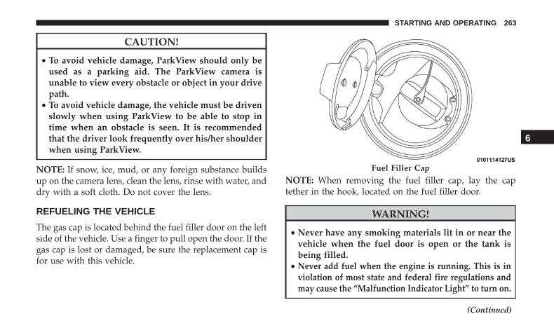
CAUTION!
• To avoid vehicle damage, ParkView should only beused as a parking aid. The ParkView camera isunable to view every obstacle or object in your drivepath.
• To avoid vehicle damage, the vehicle must be drivenslowly when using ParkView to be able to stop intime when an obstacle is seen. It is recommendedthat the driver look frequently over his/her shoulderwhen using ParkView.
NOTE: If snow, ice, mud, or any foreign substance buildsup on the camera lens, clean the lens, rinse with water, anddry with a soft cloth. Do not cover the lens.
REFUELING THE VEHICLE
The gas cap is located behind the fuel filler door on the leftside of the vehicle. Use a finger to pull open the door. If thegas cap is lost or damaged, be sure the replacement cap isfor use with this vehicle.
NOTE: When removing the fuel filler cap, lay the captether in the hook, located on the fuel filler door.
WARNING!
• Never have any smoking materials lit in or near thevehicle when the fuel door is open or the tank isbeing filled.
• Never add fuel when the engine is running. This is inviolation of most state and federal fire regulations andmay cause the “Malfunction Indicator Light” to turn on.
(Continued)
Fuel Filler Cap
6
STARTING AND OPERATING 263

WARNING! (Continued)• A fire may result if fuel is pumped into a portable
container that is inside of a vehicle. You could beburned. Always place fuel containers on the groundwhile filling.
CAUTION!
• Damage to the fuel system or emissions controlsystem could result from using an improper fueltank filler tube cap.
• A poorly fitting fuel filler cap could let impuritiesinto the fuel system.
• A poorly fitting fuel filler cap may cause the “Mal-function Indicator Light (MIL)” to turn on.
• To avoid fuel spillage and overfilling, do not “topoff” the fuel tank after filling. When the fuel nozzle“clicks” or shuts off, the fuel tank is full.
NOTE:
• When the fuel nozzle “clicks” or shuts off, the fuel tankis full.
• Tighten the gas cap until you hear a “clicking” sound.This is an indication that the gas cap is tightenedproperly. The MIL in the instrument cluster may turn onif the gas cap is not secured properly. Make sure that thegas cap is tightened each time the vehicle is refueled.
Loose Fuel Filler Cap Message
If the vehicle diagnostic system determines that the fuelfiller cap is loose, improperly installed, or damaged, a”gASCAP” message will display in the odometer or a“Check Gascap” message will display in the instrumentcluster. If this occurs, tighten the fuel filler cap properlyand press the Trip Odometer button to turn off the mes-sage. If the problem continues, the message will appear thenext time the vehicle is started.
A loose, improperly installed, or damaged fuel filler capmay also turn on the MIL.
264 STARTING AND OPERATING
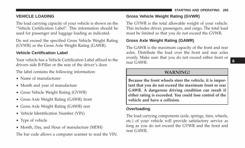
VEHICLE LOADING
The load carrying capacity of your vehicle is shown on the“Vehicle Certification Label”. This information should beused for passenger and luggage loading as indicated.
Do not exceed the specified Gross Vehicle Weight Rating(GVWR) or the Gross Axle Weight Rating (GAWR).
Vehicle Certification Label
Your vehicle has a Vehicle Certification Label affixed to thedrivers side B-Pillar or the rear of the driver’s door.
The label contains the following information:
• Name of manufacturer
• Month and year of manufacture
• Gross Vehicle Weight Rating (GVWR)
• Gross Axle Weight Rating (GAWR) front
• Gross Axle Weight Rating (GAWR) rear
• Vehicle Identification Number (VIN)
• Type of vehicle
• Month, Day, and Hour of manufacture (MDH)
The bar code allows a computer scanner to read the VIN.
Gross Vehicle Weight Rating (GVWR)
The GVWR is the total allowable weight of your vehicle.This includes driver, passengers, and cargo. The total loadmust be limited so that you do not exceed the GVWR.
Gross Axle Weight Rating (GAWR)
The GAWR is the maximum capacity of the front and rearaxles. Distribute the load over the front and rear axlesevenly. Make sure that you do not exceed either front orrear GAWR.
WARNING!
Because the front wheels steer the vehicle, it is impor-tant that you do not exceed the maximum front or rearGAWR. A dangerous driving condition can result ifeither rating is exceeded. You could lose control of thevehicle and have a collision.
Overloading
The load carrying components (axle, springs, tires, wheels,etc.) of your vehicle will provide satisfactory service aslong as you do not exceed the GVWR and the front andrear GAWR.
6
STARTING AND OPERATING 265

The best way to figure out the total weight of your vehicleis to weigh it when it is fully loaded and ready foroperation. Weigh it on a commercial scale to ensure that itis not over the GVWR.
Figure out the weight on the front and rear of the vehicleseparately. It is important that you distribute the loadevenly over the front and rear axles.
Overloading can cause potential safety hazards andshorten useful service life. Heavier axles or suspensioncomponents do not necessarily increase the vehicle’sGVWR.
Loading
To load your vehicle properly, first figure out its emptyweight, axle-by-axle and side-by-side. Store heavier itemsdown low and be sure you distribute their weight asevenly as possible. Stow all loose items securely beforedriving. If weighing the loaded vehicle shows that youhave exceeded either GAWR, but the total load is withinthe specified GVWR, you must redistribute the weight.Improper weight distribution can have an adverse effect onthe way your vehicle steers and handles and the way thebrakes operate.
NOTE: Refer to the “Vehicle Certification Label” affixed tothe rear of the driver’s door for your vehicle’s GVWR andGAWRs.
TRAILER TOWING
In this section, you will find safety tips and information onlimits to the type of towing you can reasonably do withyour vehicle. Before towing a trailer, carefully review thisinformation to tow your load as efficiently and safely aspossible.
To maintain warranty coverage, follow the requirementsand recommendations in this manual concerning vehiclesused for trailer towing.
Manual Transmission — If Equipped
Trailer towing with this vehicle is not recommended.
266 STARTING AND OPERATING

Common Towing Definitions
The following trailer towing related definitions will assistyou in understanding the following information:
Gross Vehicle Weight Rating (GVWR)
The GVWR is the total allowable weight of your vehicle.This includes driver, passengers, cargo and tongue weight.The total load must be limited so that you do not exceedthe GVWR. Refer to “Vehicle Loading/Vehicle CertificationLabel” in “Starting And Operating” for further informa-tion.
Gross Trailer Weight (GTW)
The GTW is the weight of the trailer plus the weight of allcargo, consumables, and equipment (permanent or tempo-rary) loaded in or on the trailer in its �loaded and ready foroperation� condition.
The recommended way to measure GTW is to put yourfully loaded trailer on a vehicle scale. The entire weight ofthe trailer must be supported by the scale.
Gross Combination Weight Rating (GCWR)
The GCWR is the total allowable weight of your vehicleand trailer when weighed in combination.
Gross Axle Weight Rating (GAWR)
The GAWR is the maximum capacity of the front and rearaxles. Distribute the load over the front and rear axlesevenly. Make sure that you do not exceed either front orrear GAWR. Refer to “Vehicle Loading/Vehicle Certifica-tion Label” in “Starting And Operating” for further infor-mation.
WARNING!
It is important that you do not exceed the maximumfront or rear GAWR. A dangerous driving conditioncan result if either rating is exceeded. You could losecontrol of the vehicle and have a collision.
Tongue Weight (TW)
The tongue weight is the downward force exerted on thehitch ball by the trailer. You must consider this as part ofthe load on your vehicle.
Trailer Frontal Area
The frontal area is the maximum height multiplied by themaximum width of the front of a trailer.
6
STARTING AND OPERATING 267
Trailer Sway Control
The trailer sway control can be a mechanical telescopinglink that can be installed between the hitch receiver and thetrailer tongue that typically provides adjustable frictionassociated with the telescoping motion to dampen anyunwanted trailer swaying motions while traveling.
If equipped, the electronic Trailer Sway Control (TSC)recognizes a swaying trailer and automatically appliesindividual wheel brakes and/or reduces engine power toattempt to eliminate the trailer sway.
Weight-Carrying Hitch
A weight-carrying hitch supports the trailer tongue weight,just as if it were luggage located at a hitch ball or someother connecting point of the vehicle. These kinds ofhitches are the most popular on the market today and theyare commonly used to tow small and medium sizedtrailers.
Weight-Distributing Hitch
A weight-distributing system works by applying leveragethrough spring (load) bars. They are typically used forheavier loads to distribute trailer tongue weight to the towvehicle’s front axle and the trailer axle(s). When used inaccordance with the manufacturer’s directions, it provides
for a more level ride, offering more consistent steering andbrake control thereby enhancing towing safety. The addi-tion of a friction/hydraulic sway control also dampenssway caused by traffic and crosswinds and contributespositively to tow vehicle and trailer stability. Trailer swaycontrol and a weight distributing (load equalizing) hitchare recommended for heavier Tongue Weights (TW) andmay be required depending on vehicle and trailerconfiguration/loading to comply with Gross Axle WeightRating (GAWR) requirements.
WARNING!
• An improperly adjusted Weight Distributing Hitchsystem may reduce handling, stability, braking per-formance, and could result in a collision.
• Weight Distributing Systems may not be compatiblewith Surge Brake Couplers. Consult with your hitchand trailer manufacturer or a reputable RecreationalVehicle dealer for additional information.
268 STARTING AND OPERATING

Trailer Hitch ClassificationThe following chart provides the industry standard for the maximum trailer weight a given trailer hitch class can tow andshould be used to assist you in selecting the correct trailer hitch for your intended towing condition.
Trailer Hitch Classification DefinitionsClass Max. Trailer Hitch Industry Standards
Class I - Light Duty 2,000 lbs (907 kg)Class II - Medium Duty 3,500 lbs (1,587 kg)Class III - Heavy Duty 5,000 lbs (2,267 kg)
Class IV - Extra Heavy Duty 10,000 lbs (4,535 kg)Refer to the “Trailer Towing Weights (Maximum Trailer Weight Ratings)” chart for the Maximum Gross Trailer Weight(GTW) towable for your given drivetrain.All trailer hitches should be professionally installed on your vehicle.
Trailer Towing Weights (Maximum Trailer Weight Ratings)
Engine/Transmission Frontal AreaMax. GTW (Gross Trailer
Wt.)Max. Tongue Wt.
3.6L Automatic 12 sq ft (1.11 sq m) 1,000 lbs (454 kg) 100 lbs (45 kg)5.7L Automatic 12 sq ft (1.11 sq m) 1,000 lbs (454 kg) 100 lbs (45 kg)
Refer to local laws for maximum trailer towing speeds.
Trailer towing with the 6.4L engine is not recommended.
6
STARTING AND OPERATING 269

Trailer And Tongue Weight
Never exceed the maximum tongue weight stamped onyour bumper or trailer hitch.
CAUTION!
Always load a trailer with 60% of the weight in thefront of the trailer. This places 10% of the GTW on thetow hitch of your vehicle. Loads balanced over thewheels or heavier in the rear can cause the trailer tosway severely side to side which will cause loss of
(Continued)
CAUTION! (Continued)control of the vehicle and trailer. Failure to load trailersheavier in front is the cause of many trailer collisions.
Consider the following items when computing the weighton the rear axle of the vehicle:
• The tongue weight of the trailer.
• The weight of any other type of cargo or equipment putin or on your vehicle.
• The weight of the driver and all passengers.
NOTE: Remember that everything put into or on thetrailer adds to the load on your vehicle. Also, additionalfactory-installed options or dealer-installed options mustbe considered as part of the total load on your vehicle.Refer to the “Tire And Loading Information” placard forthe maximum combined weight of occupants and cargo foryour vehicle.
Towing Requirements
To promote proper break-in of your new vehicle drivetraincomponents, the following guidelines are recommended.
Weight Distribution
270 STARTING AND OPERATING

WARNING!
Improper towing can lead to a collision. Follow theseguidelines to make your trailer towing as safe as possible:• Make certain that the load is secured in the trailer
and will not shift during travel. When traileringcargo that is not fully secured, dynamic load shiftscan occur that may be difficult for the driver tocontrol. You could lose control of your vehicle andhave a collision.
• When hauling cargo or towing a trailer, do notoverload your vehicle or trailer. Overloading cancause a loss of control, poor performance or damageto brakes, axle, engine, transmission, steering, sus-pension, chassis structure or tires.
• Safety chains must always be used between yourvehicle and trailer. Always connect the chains to thehook retainers of the vehicle hitch. Cross the chainsunder the trailer tongue and allow enough slack forturning corners.
• Vehicles with trailers should not be parked on agrade. When parking, apply the parking brake on thetow vehicle. Put the tow vehicle transmission inPARK. Always, block or �chock� the trailer wheels.
(Continued)
WARNING! (Continued)• GCWR must not be exceeded.• Total weight must be distributed between the tow
vehicle and the trailer such that the following fourratings are not exceeded:
1. Max loading as defined on the “Tire and LoadingInformation” placard.
2. GTW
3. GAWR
4. Tongue weight rating for the trailer hitch utilized.
Perform the maintenance listed in the “Scheduled Servic-ing”. Refer to “Scheduled Servicing” in “Servicing AndMaintenance” for the proper maintenance intervals. Whentowing a trailer, never exceed the GAWR or GCWR ratings.
CAUTION!
• Do not tow a trailer at all during the first 500 miles(805 km) the new vehicle is driven. The engine, axleor other parts could be damaged.
(Continued)
6
STARTING AND OPERATING 271
CAUTION! (Continued)• Then, during the first 500 miles (805 km) that a trailer
is towed, do not drive over 50 mph (80 km/h) and donot make starts at full throttle. This helps the engineand other parts of the vehicle wear in at the heavierloads.
Towing Requirements — Tires
• Do not attempt to tow a trailer while using a compactspare tire.
• Do not drive more than 50 mph (80 km/h) when towingwhile using a full size spare tire.
• Proper tire inflation pressures are essential to the safeand satisfactory operation of your vehicle. Refer to“Tires” in “Servicing And Maintenance” for proper tireinflation procedures.
• Check the trailer tires for proper tire inflation pressuresbefore trailer usage.
• Check for signs of tire wear or visible tire damage beforetowing a trailer. Refer to “Tires” in “Servicing AndMaintenance” for the proper inspection procedure.
• When replacing tires, refer to “Tires” in “Servicing AndMaintenance” for the proper tire replacement proce-dures. Replacing tires with a higher load carrying capac-ity will not increase the vehicle’s GVWR and GAWRlimits.
Towing Requirements — Trailer Brakes
• Do not interconnect the hydraulic brake system orvacuum system of your vehicle with that of the trailer.This could cause inadequate braking and possible per-sonal injury.
• An electronically actuated trailer brake controller isrequired when towing a trailer with electronically actu-ated brakes. When towing a trailer equipped with ahydraulic surge actuated brake system, an electronicbrake controller is not required.
• Trailer brakes are recommended for trailers over1,000 lbs (453 kg) and required for trailers in excess of2,000 lbs (907 kg).
272 STARTING AND OPERATING
WARNING!
• Do not connect trailer brakes to your vehicle’s hy-draulic brake lines. It can overload your brake sys-tem and cause it to fail. You might not have brakeswhen you need them and could have an accident.
• Towing any trailer will increase your stopping dis-tance. When towing, you should allow for additionalspace between your vehicle and the vehicle in frontof you. Failure to do so could result in an accident.
CAUTION!
If the trailer weighs more than 1,000 lbs (453 kg)loaded, it should have its own brakes and they shouldbe of adequate capacity. Failure to do this could lead toaccelerated brake lining wear, higher brake pedaleffort, and longer stopping distances.
Towing Requirements — Trailer Lights And Wiring
Whenever you pull a trailer, regardless of the trailer size,stoplights and turn signals on the trailer are required formotoring safety.
The Trailer Tow Package may include a four- and seven-pinwiring harness. Use a factory approved trailer harness andconnector.
NOTE: Do not cut or splice wiring into the vehicle’s wiringharness.
The electrical connections are all complete to the vehiclebut you must mate the harness to a trailer connector. Referto the following illustrations.
NOTE:
• Disconnect trailer wiring connector from the vehiclebefore launching a boat (or any other device pluggedinto vehicle’s electrical connect) into water.
• Be sure to reconnect after clear from water area.
6
STARTING AND OPERATING 273

Four-Pin Connector
1 — Female Pins 4 — Park2 — Male Pin 5 — Left Stop/Turn3 — Ground 6 — Right Stop/Turn
Seven-Pin Connector
1 — Battery 5 — Ground2 — Backup Lamps 6 — Left Stop/Turn3 — Right Stop/Turn 7 — Running Lamps4 — Electric Brakes
274 STARTING AND OPERATING
Towing Tips
Before setting out on a trip, practice turning, stopping, andbacking up the trailer in an area located away from heavytraffic.
Automatic Transmission — If Equipped
Select the DRIVE range when towing. The transmissioncontrols include a drive strategy to avoid frequent shiftingwhen towing. However, if frequent shifting does occurwhile in DRIVE, you can use the AutoStick shift control tomanually select a lower gear.
NOTE: Using a lower gear while operating the vehicleunder heavy loading conditions will improve performanceand extend transmission life by reducing excessive shiftingand heat buildup. This action will also provide betterengine braking.
Speed Control — If Equipped
• Do not use on hilly terrain or with heavy loads.
• When using the speed control, if you experience speeddrops greater than 10 mph (16 km/h), disengage untilyou can get back to cruising speed.
• Use speed control in flat terrain and with light loads tomaximize fuel efficiency.
AutoStick
• When using the AutoStick shift control, select the high-est gear that allows for adequate performance andavoids frequent downshifts. For example, choose “5” ifthe desired speed can be maintained. Choose “4” or “3”if needed to maintain the desired speed.
• To prevent excess heat generation, avoid continuousdriving at high RPM. Reduce vehicle speed as necessaryto avoid extended driving at high RPM. Return to ahigher gear or vehicle speed when grade and roadconditions allow.
Cooling System
To reduce potential for engine and transmission overheat-ing, take the following actions:
City Driving
• In city traffic — while stopped, place the transmission inNEUTRAL, but do not increase engine idle speed.
Highway Driving
• Reduce speed.
• Temporarily turn off air conditioning.
6
STARTING AND OPERATING 275
RECREATIONAL TOWING (BEHIND MOTORHOME,ETC.)
Recreational towing (with all four wheels on the ground, orusing a tow dolly) is NOT ALLOWED. The only accept-able method for towing this vehicle (behind another ve-hicle) is on a vehicle trailer with all four wheels OFF theground.
CAUTION!
Towing this vehicle in violation of the above require-ments can cause severe engine, transmission and/ortransfer case damage. Damage from improper towingis not covered under the New Vehicle Limited War-ranty.
DRIVING TIPS
Driving On Slippery Surfaces
Information in this section will aid in safe controlledlaunches in adverse conditions.
Acceleration
Rapid acceleration on snow covered, wet, or other slipperysurfaces may cause the driving wheels to pull erratically to
the right or left. This phenomenon occurs when there is adifference in the surface traction under the rear (driving)wheels.
WARNING!
Rapid acceleration on slippery surfaces is dangerous.Unequal traction can cause sudden pulling of the rearwheels. You could lose control of the vehicle andpossibly have a collision. Accelerate slowly and care-fully whenever there is likely to be poor traction (ice,snow, wet, mud, loose sand, etc.).
Traction
When driving on wet or slushy roads, it is possible for awedge of water to build up between the tire and roadsurface. This is known as hydroplaning and may causepartial or complete loss of vehicle control and stoppingability. To reduce this possibility, the following precautionsshould be observed:
• Slow down during rainstorms or when the roads areslushy.
• Slow down if the road has standing water or puddles.
276 STARTING AND OPERATING

• Replace tires when tread wear indicators first becomevisible.
• Keep tires properly inflated.
• Maintain sufficient distance between your vehicle andthe vehicle in front of you to avoid a collision in asudden stop.
Your vehicle may be equipped with a Limited Slip Differ-ential (LSD) that reduces, but does not eliminate, theamount of wheel slip across a given axle for improvedhandling.
Driving Through Water
Driving through water more than a few inches/centimetersdeep will require extra caution to ensure safety and pre-vent damage to your vehicle.
Flowing/Rising Water
WARNING!
Do not drive on or across a road or path where water isflowing and/or rising (as in storm run-off). Flowingwater can wear away the road or path’s surface andcause your vehicle to sink into deeper water. Further-more, flowing and/or rising water can carry your ve-hicle away swiftly. Failure to follow this warning mayresult in injuries that are serious or fatal to you, yourpassengers, and others around you.
6
STARTING AND OPERATING 277
Shallow Standing Water
Although your vehicle is capable of driving through shal-low standing water, consider the following Cautions andWarnings before doing so.
WARNING!
• Driving through standing water limits your vehicle’straction capabilities. Do not exceed 5 mph (8 km/h)when driving through standing water.
• Driving through standing water limits your vehicle’sbraking capabilities, which increases stopping dis-tances. Therefore, after driving through standingwater, drive slowly and lightly press on the brakepedal several times to dry the brakes.
• Failure to follow these warnings may result in inju-ries that are serious or fatal to you, your passengers,and others around you.
CAUTION!
• Always check the depth of the standing water beforedriving through it. Never drive through standingwater that is deeper than the bottom of the tire rimsmounted on the vehicle.
• Determine the condition of the road or the path thatis under water and if there are any obstacles in theway before driving through the standing water.
• Do not exceed 5 mph (8 km/h) when driving throughstanding water. This will minimize wave effects.
• Driving through standing water may cause damageto your vehicle’s drivetrain components. Always in-spect your vehicle’s fluids (i.e., engine oil, transmis-sion, axle, etc.) for signs of contamination (i.e., fluidthat is milky or foamy in appearance) after drivingthrough standing water. Do not continue to operatethe vehicle if any fluid appears contaminated, as thismay result in further damage. Such damage is notcovered by the New Vehicle Limited Warranty.
• Getting water inside your vehicle’s engine can causeit to lock up and stall out, and cause serious internaldamage to the engine. Such damage is not covered bythe New Vehicle Limited Warranty.
278 STARTING AND OPERATING

IN CASE OF EMERGENCY
CONTENTS� HAZARD WARNING FLASHERS . . . . . . . . . . . .281
� ASSIST AND SOS MIRROR — IF EQUIPPED . . . .281
� BULB REPLACEMENT . . . . . . . . . . . . . . . . . . . .286
▫ Replacement Bulbs . . . . . . . . . . . . . . . . . . . . .286
▫ Replacing Exterior Bulbs . . . . . . . . . . . . . . . . . .288
� FUSES . . . . . . . . . . . . . . . . . . . . . . . . . . . . . . . .290
▫ General Information . . . . . . . . . . . . . . . . . . . . .291
▫ Underhood Fuses . . . . . . . . . . . . . . . . . . . . . .291
▫ Rear Interior Fuses . . . . . . . . . . . . . . . . . . . . .295
� JACKING AND TIRE CHANGING . . . . . . . . . . .301
▫ Jack Location/Spare Tire Stowage . . . . . . . . . . .301
▫ Preparations For Jacking . . . . . . . . . . . . . . . . .303
▫ Jacking And Changing A Tire . . . . . . . . . . . . . .303
▫ Road Tire Installation . . . . . . . . . . . . . . . . . . .308
� TIRE SERVICE KIT — IF EQUIPPED . . . . . . . . . .308
▫ Tire Service Kit Storage . . . . . . . . . . . . . . . . . .309
▫ Tire Service Kit Components And Operation . . .309
▫ Tire Service Kit Usage Precautions . . . . . . . . . .310
▫ Sealing A Tire With Tire Service Kit . . . . . . . . .312
� TIRE SERVICE KIT — IF EQUIPPED . . . . . . . . . .316
▫ Tire Service Kit Storage . . . . . . . . . . . . . . . . . .317
▫ Tire Service Kit Components And Operation . . .317
▫ Tire Service Kit Usage Precautions . . . . . . . . . .318
▫ Sealing A Tire With Tire Service Kit . . . . . . . . .320
� JUMP STARTING . . . . . . . . . . . . . . . . . . . . . . . .324
▫ Preparations For Jump Start . . . . . . . . . . . . . . .325
▫ Jump Starting Procedure . . . . . . . . . . . . . . . . .326
� IF YOUR ENGINE OVERHEATS . . . . . . . . . . . . .327
7
� MANUAL PARK RELEASE — 8–SPEEDTRANSMISSION . . . . . . . . . . . . . . . . . . . . . . . .328
� FREEING A STUCK VEHICLE . . . . . . . . . . . . . .330
� TOWING A DISABLED VEHICLE . . . . . . . . . . . .332
▫ All Wheel Drive (AWD) Models . . . . . . . . . . . .333
▫ Rear-Wheel Drive (RWD) Models . . . . . . . . . . .334
� ENHANCED ACCIDENT RESPONSE SYSTEM(EARS) . . . . . . . . . . . . . . . . . . . . . . . . . . . . . . .334
� EVENT DATA RECORDER (EDR) . . . . . . . . . . . .334
280 IN CASE OF EMERGENCY
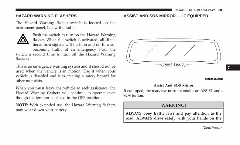
HAZARD WARNING FLASHERS
The Hazard Warning flasher switch is located on theinstrument panel, below the radio.
Push the switch to turn on the Hazard Warningflasher. When the switch is activated, all direc-tional turn signals will flash on and off to warnoncoming traffic of an emergency. Push the
switch a second time to turn off the Hazard Warningflashers.
This is an emergency warning system and it should not beused when the vehicle is in motion. Use it when yourvehicle is disabled and it is creating a safety hazard forother motorists.
When you must leave the vehicle to seek assistance, theHazard Warning flashers will continue to operate eventhough the ignition is placed in the OFF position.
NOTE: With extended use, the Hazard Warning flashersmay wear down your battery.
ASSIST AND SOS MIRROR — IF EQUIPPED
If equipped, the rearview mirror contains an ASSIST and aSOS button.
WARNING!
ALWAYS obey traffic laws and pay attention to theroad. ALWAYS drive safely with your hands on the
(Continued)
Assist And SOS Mirror
7
IN CASE OF EMERGENCY 281

WARNING! (Continued)steering wheel. You have full responsibility and as-sume all risks related to the use of the Uconnect andSiriusXM Guardian features and applications in thisvehicle. Only use Uconnect features and SiriusXMGuardian services when it is safe to do so. Failure to doso may result in an accident involving serious injury ordeath.
NOTE:
• Your vehicle may be transmitting data as authorized bythe subscriber.
• The SOS and ASSIST buttons will only function if youare connected to an operable LTE (voice/data) or 4G(data) network. Other Uconnect services will only beoperable if your SiriusXM Guardian service is active andyou are connected to an operable LTE (voice/data) or 4G(data) network.
ASSIST Call
The ASSIST Button is used to automatically connect you toany one of the following support centers:
• Roadside Assistance – If you get a flat tire, or need a tow,just push the ASSIST button and you will be connected
to a representative for assistance. Roadside Assistancewill know what vehicle you’re driving and its location.Additional fees may apply for roadside Assistance.
• SiriusXM Guardian Customer Care – In-vehicle supportfor SiriusXM Guardian.
• Vehicle Customer Care – Total support for all othervehicle issues.
SOS Call
1. Push the SOS Call button on the Rearview Mirror.
NOTE: In case the SOS Call button is pushed in error, therewill be a ten second delay before the SOS Call systeminitiates a call to a SOS operator. To cancel the SOS Callconnection, push the SOS call button on the RearviewMirror or press the cancellation button on the DeviceScreen. Termination of the SOS Call will turn off the greenLED light on the Rearview Mirror.
2. The LED light located between the ASSIST and SOSbuttons on the Rearview Mirror will turn green once aconnection to a SOS operator has been made.
282 IN CASE OF EMERGENCY

3. Once a connection between the vehicle and a SOSoperator is made, the SOS Call system may transmit thefollowing important vehicle information to a SOS op-erator:
• Indication that the occupant placed a SOS Call.
• The vehicle brand.
• The last known GPS coordinates of the vehicle.
4. You should be able to speak with the SOS operatorthrough the vehicle audio system to determine if addi-tional help is needed.
WARNING!
ALWAYS obey traffic laws and pay attention to theroad. ALWAYS drive safely with your hands on thesteering wheel. You have full responsibility and as-sume all risks related to the use of the Uconnect andSiriusXM Guardian features and applications in thisvehicle. Only use Uconnect features and SiriusXMGuardian services when it is safe to do so. Failure to doso may result in an accident involving serious injury ordeath.
NOTE:
• Your vehicle may be transmitting data as authorizedby the subscriber.
• Once a connection is made between the vehicle’s SOSCall system and the SOS operator, the SOS operator maybe able to open a voice connection with the vehicle todetermine if additional help is needed. Once the SOSoperator opens a voice connection with the vehicle’sSOS Call system, the operator should be able to speakwith you or other vehicle occupants and hear soundsoccurring in the vehicle. The vehicle’s SOS Call systemwill attempt to remain connected with the SOS operatoruntil the SOS operator terminates the connection.
5. The SOS operator may attempt to contact appropriateemergency responders and provide them with impor-tant vehicle information and GPS coordinates.
WARNING!
• If anyone in the vehicle could be in danger (e.g., fireor smoke is visible, dangerous road conditions orlocation), do not wait for voice contact from an
(Continued)
7
IN CASE OF EMERGENCY 283

WARNING! (Continued)Emergency Services Agent. All occupants should exitthe vehicle immediately and move to a safe location.
• Never place anything on or near the vehicle’s oper-able network and GPS antennas. You could preventoperable network and GPS signal reception, whichcan prevent your vehicle from placing an emergencycall. An operable network and GPS signal receptionis required for the SOS Call system to functionproperly.
• The SOS Call system is embedded into the vehicle’selectrical system. Do not add aftermarket electricalequipment to the vehicle’s electrical system. Thismay prevent your vehicle from sending a signal toinitiate an emergency call. To avoid interference thatcan cause the SOS Call system to fail, never addaftermarket equipment (e.g., two-way mobile radio,CB radio, data recorder, etc.) to your vehicle’s electri-cal system or modify the antennas on your vehicle. IFYOUR VEHICLE LOSES BATTERY POWER FORANY REASON (INCLUDING DURING OR AFTERAN ACCIDENT), THE UCONNECT FEATURES,
(Continued)
WARNING! (Continued)APPS AND SERVICES, AMONG OTHERS, WILLNOT OPERATE.
• Modifications to any part of the SOS Call systemcould cause the air bag system to fail when you needit. You could be injured if the air bag system is notthere to help protect you.
SOS Call System Limitations
Vehicles sold in Mexico DO NOT have SOS Call systemcapabilities.
SOS or other emergency line operators in Mexico may notanswer or respond to SOS system calls.
If the SOS Call system detects a malfunction, any of thefollowing may occur at the time the malfunction is de-tected, and at the beginning of each ignition cycle:
• The Rearview Mirror light located between the ASSISTand SOS buttons will continuously be illuminated red.
• The Device Screen will display the following message“Vehicle device requires service. Please contact yourdealer.”
284 IN CASE OF EMERGENCY
• An In-Vehicle Audio message will state “Vehicle devicerequires service. Please contact your dealer.”
WARNING!
• Ignoring the Rearview Mirror light could mean youwill not have SOS Call services. If the RearviewMirror light is illuminated, have an authorizeddealer service the SOS Call system immediately.
• The Occupant Restraint Control module turns on theair bag Warning Light on the instrument panel if amalfunction in any part of the system is detected. Ifthe Air Bag Warning Light is illuminated, have anauthorized dealer service the Occupant RestraintControl system immediately.
Even if the SOS Call system is fully functional, factorsbeyond FCA US LLC’s control may prevent or stop the SOSCall system operation. These include, but are not limitedto, the following factors:
• Delayed accessories mode is active.
• The ignition is in the OFF position.
• The vehicle’s electrical systems are not intact.
• The SOS Call system software and/or hardware aredamaged during a crash.
• The vehicle battery loses power or becomes discon-nected during a vehicle crash.
• LTE (voice/data) or 4G (data) network and/or GlobalPositioning Satellite signals are unavailable or ob-structed.
• Equipment malfunction at the SOS operator facility.
• Operator error by the SOS operator.
• LTE (voice/data) or 4G (data) network congestion.
• Weather.
• Buildings, structures, geographic terrain, or tunnels.
WARNING!
ALWAYS obey traffic laws and pay attention to theroad. ALWAYS drive safely with your hands on thesteering wheel. You have full responsibility and as-sume all risks related to the use of the Uconnect andSiriusXM Guardian features and applications in thisvehicle. Only use Uconnect features and SiriusXMGuardian services when it is safe to do so. Failure to doso may result in an accident involving serious injury ordeath.
7
IN CASE OF EMERGENCY 285
NOTE:
• Your vehicle may be transmitting data as authorized bythe subscriber.
• Never place anything on or near the vehicle’s LTE(voice/data) or 4G (data) and GPS antennas. You couldprevent LTE (voice/data) or 4G (data) and GPS signalreception, which can prevent your vehicle from placingan emergency call. An operable LTE (voice/data) or 4G(data) network connection and a GPS signal is requiredfor the SOS Call system to function properly.
General Information
This device complies with Part 15 of the FCC Rules.Operation is subject to the following two conditions: (1)This device may not cause harmful interference, and (2)this device must accept any interference received, includ-ing interference that may cause undesired operation.
NOTE: Changes or modifications not expressly approvedby the party responsible for compliance could void theuser’s authority to operate the equipment.
CAUTION!
To avoid damage to the mirror during cleaning, neverspray any cleaning solution directly onto the mirror.Apply the solution onto a clean cloth and wipe themirror clean.
BULB REPLACEMENT
Replacement Bulbs
All of the interior bulbs are glass wedge base or glasscartridge types. Aluminum base bulbs are not approvedand should not be used for replacement.
286 IN CASE OF EMERGENCY

Interior Bulbs
Bulb NumberRear Courtesy/Reading Lamps W5WRear Compartment (Trunk) Lamp 562Overhead Console Reading Lamps 578Visor Vanity Lamps A6220Glove Compartment Lamp – If Equipped 194Door Courtesy 562Shift Indicator Lamp JKLE14140Optional Door Map Pocket/Cupholder LED (Serviced At Authorized Dealer)For lighted switches, see your authorized dealer for replacement instructions.
Exterior Bulbs
Bulb NumberHeadlamp – High Intensity Discharge (HID) D3S (Serviced At Authorized Dealer) *Halogen Headlamp HIR2LLFront Park/Turn Lamp LED (Serviced At Authorized Dealer)Front Fog Lamp H11LLFront Side Marker LED (Serviced At Authorized Dealer)Tail Lamp LED (Serviced At Authorized Dealer)Stop/Turn Lamp LED (Serviced At Authorized Dealer)
7
IN CASE OF EMERGENCY 287

Bulb NumberRear Side Marker LED (Serviced At Authorized Dealer)Backup Lamp LED (Serviced At Authorized Dealer)Center High-Mount Stop Lamp (CHMSL) LED (Serviced At Authorized Dealer)License LED (Serviced At Authorized Dealer)
* The headlamps are a type of high-voltage discharge tube.High voltage can remain in the circuit even with theheadlamp switch off and the key removed. Because of this,you should not attempt to service a headlamp bulb your-self. If a headlamp bulb fails, take your vehicle to anauthorized dealer for service.
Replacing Exterior Bulbs
Low Beam Headlamp, High Beam Headlamp —Models With Halogen Headlamps — If Equipped
To replace the passenger side lamps:
1. Open the hood.
2. Remove the trim panel to access the headlamp assembly.
3. Reach behind the passenger headlamp assembly.
NOTE: The park/turn lamps can also be accessed at thispoint.
4. Turn the headlamp access cap counterclockwise to re-move.
5. Remove bulb by turning it counter clockwise and dis-connect.
6. Install new bulb by turning it clockwise and reconnect.
7. Reinstall headlamp access cap by turning it clockwiseand then reinstall headlamp cover.
To replace the driver side lamps:
1. Open the hood.
2. Remove the air cleaner filter cover by removing threefasteners and loosening the clean air inlet clamp andthen rotate cover off to the side.
NOTE: The cover has an electrical connector that does notneed to be disconnected if the cover is rotated off to theside.
288 IN CASE OF EMERGENCY
3. Remove one fastener on the lower air box to remove andaccess the rear of the headlamp assembly.
4. Reach behind the passenger headlamp assembly.
5. Remove the headlamp cover.
6. Turn the headlamp access cap counterclockwise to re-move.
7. Remove bulb by turn it counter clockwise and discon-nect.
8. Install new bulb by turning it clockwise and reconnect.
9. Reinstall headlamp access cap by turning it clockwiseand then reinstall headlamp cover.
10. Reinstall engine air cleaner assembly.
Low Beam Headlamp, High Beam Headlamp —Models With High Intensity Discharge (HID)Headlamps — If Equipped
The headlamps are a type of high voltage discharge tube.High voltage can remain in the circuit even with theheadlamp switch off and the key removed. Because of this,you should not attempt to service a headlamp bulbyourself. If a headlamp bulb fails, take your vehicle to anauthorized dealer for service.
WARNING!
A transient high voltage occurs at the bulb sockets ofHID headlamps when the headlamp switch is turnedON. It may cause serious electrical shock or electrocu-tion if not serviced properly. See your authorizeddealer for service.
NOTE: On vehicles equipped with HID headlamps, whenthe headlamps are turned on, there is a blue hue to thelamps. This diminishes and becomes more white afterapproximately ten seconds, as the system charges.
Front Park/Signature Lamp
The Front Park/Signature function is part of the headlampassembly and use LED lamps that are not serviceableseparately. The headlamps must be replaced as an assem-bly, see your authorized dealer.
Front Turn/DRL Lamp
The Front Turn/DRL function is part of the headlampassembly and use LED lamps that are not serviceableseparately. The headlamps must be replaced as an assem-bly, see your authorized dealer.
7
IN CASE OF EMERGENCY 289
Front/Rear Side Marker Lamp
The Side Markers use LED lamps that are not serviceableseparately. The Side Markers must be replaced as anassembly, see your authorized dealer.
Tail/Turn And Stop Lamp
The Tail/Turn and Stop Lamps use LED lamps that are notserviceable separately. The Tail/Turn and Stop Lamps mustbe replaced as an assembly, see your authorized dealer.
Center Tail/Backup Lamp
The Center Tail/Backup Lamp use LED lamps that are notserviceable separately. The Center Tail/Backup Lamp mustbe replaced as an assembly; see your authorized dealer.
Center High Mounted Stop Lamp (CHMSL)
The CHMSL Lamp uses LED sources that are not service-able separately. The CHMSL Lamp must be replaced as anassembly; see your authorized dealer.
License Lamp
The License Lamp uses an LED source that is not service-able separately. The License Lamp must be replaced as anassembly; see your authorized dealer.
FUSES
WARNING!
• When replacing a blown fuse, always use an appro-priate replacement fuse with the same amp rating asthe original fuse. Never replace a fuse with anotherfuse of higher amp rating. Never replace a blownfuse with metal wires or any other material. Do notplace a fuse inside a circuit breaker cavity or viceversa. Failure to use proper fuses may result inserious personal injury, fire and/or property damage.
• Before replacing a fuse, make sure that the ignition isoff and that all the other services are switched offand/or disengaged.
• If the replaced fuse blows again, contact an autho-rized dealer.
• If a general protection fuse for safety systems (airbag system, braking system), power unit systems(engine system, transmission system) or steeringsystem blows, contact an authorized dealer.
290 IN CASE OF EMERGENCY

General Information
The fuses protect electrical systems against excessive cur-rent.
When a device does not work, you must check the fuseelement inside the blade fuse for a break/melt.
Also, please be aware that when using power outlets forextended periods of time with the engine off may result invehicle battery discharge.
Underhood Fuses
The Front Power Distribution Center is located in theengine compartment. This module contains fuses andrelays. Fuse cavity location and descriptions are printed onthe inside of the power distribution center cover.
Blade Fuses1 — Fuse Element2 — Blade Fuse with a good/functional fuse element.3 — Blade fuse with a NOT functional / BAD fuse element (blown fuse).
Front Power Distribution Center
7
IN CASE OF EMERGENCY 291

CAUTION!
• When installing the power distribution center cover,it is important to ensure the cover is properly posi-tioned and fully latched. Failure to do so may allowwater to get into the power distribution center andpossibly result in an electrical system failure.
(Continued)
CAUTION! (Continued)• When replacing a blown fuse, it is important to use
only a fuse having the correct amperage rating. Theuse of a fuse with a rating other than indicated mayresult in a dangerous electrical system overload. If aproperly rated fuse continues to blow, it indicates aproblem in the circuit that must be corrected.
Cavity Cartridge Fuse Mini-Fuse Description1 – – Fuse – Spare2 40 Amp Green – Radiator Fan #1 – (Non 6.2L Supercharged)3 50 Amp Red – Electric Power Steering #1 – If Equipped4 30 Amp Pink – Starter5 40 Amp Green – Anti Lock Brake6 30 Amp Pink – Anti Lock Brake7 20 Amp Blue – Police Ignition Run / ACC #18 50 Amp Red / 20 Amp
Blue– Radiator Fan (6.2L Supercharged) / Police Ignition
Run / ACC # 29 – 20 Amp Yellow All-Wheel Drive Module – If Equipped10 – 10 Amp Red Intrusion MOD (300) – If Equipped / Under Hood
Lamp – Police
292 IN CASE OF EMERGENCY
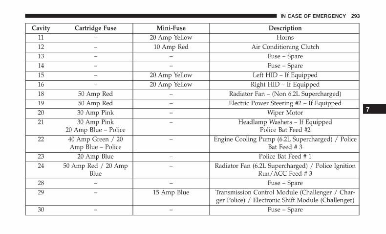
Cavity Cartridge Fuse Mini-Fuse Description11 – 20 Amp Yellow Horns12 – 10 Amp Red Air Conditioning Clutch13 – – Fuse – Spare14 – – Fuse – Spare15 – 20 Amp Yellow Left HID – If Equipped16 – 20 Amp Yellow Right HID – If Equipped18 50 Amp Red – Radiator Fan – (Non 6.2L Supercharged)19 50 Amp Red – Electric Power Steering #2 – If Equipped20 30 Amp Pink – Wiper Motor21 30 Amp Pink
20 Amp Blue – Police– Headlamp Washers – If Equipped
Police Bat Feed #222 40 Amp Green / 20
Amp Blue – Police– Engine Cooling Pump (6.2L Supercharged) / Police
Bat Feed # 323 20 Amp Blue – Police Bat Feed # 124 50 Amp Red / 20 Amp
Blue– Radiator Fan (6.2L Supercharged) / Police Ignition
Run/ACC Feed # 328 – – Fuse – Spare29 – 15 Amp Blue Transmission Control Module (Challenger / Char-
ger Police) / Electronic Shift Module (Challenger)30 – – Fuse – Spare
7
IN CASE OF EMERGENCY 293
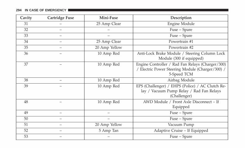
Cavity Cartridge Fuse Mini-Fuse Description31 – 25 Amp Clear Engine Module32 – – Fuse – Spare33 – – Fuse – Spare34 – 25 Amp Clear Powertrain #135 – 20 Amp Yellow Powertrain #236 – 10 Amp Red Anti-Lock Brake Module / Steering Column Lock
Module (300 if equipped)37 – 10 Amp Red Engine Controller / Rad Fan Relays (Charger/300)
/ Electric Power Steering Module (Charger/300) /5-Speed TCM
38 – 10 Amp Red Airbag Module39 – 10 Amp Red EPS (Challenger) / EHPS (Police) / AC Clutch Re-
lay / Vacuum Pump Relay / Rad Fan Relays(Challenger)
48 – 10 Amp Red AWD Module / Front Axle Disconnect – IfEquipped
49 – – Fuse – Spare50 – – Fuse – Spare51 – 20 Amp Yellow Vacuum Pump52 – 5 Amp Tan Adaptive Cruise – If Equipped53 – – Fuse – Spare
294 IN CASE OF EMERGENCY
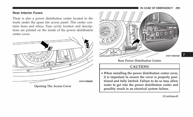
Rear Interior Fuses
There is also a power distribution center located in thetrunk under the spare tire access panel. This center con-tains fuses and relays. Fuse cavity location and descrip-tions are printed on the inside of the power distributioncenter cover.
CAUTION!
• When installing the power distribution center cover,it is important to ensure the cover is properly posi-tioned and fully latched. Failure to do so may allowwater to get into the power distribution center andpossibly result in an electrical system failure.
(Continued)
Opening The Access Cover
Rear Power Distribution Center
7
IN CASE OF EMERGENCY 295

CAUTION! (Continued)• When replacing a blown fuse, it is important to use
only a fuse having the correct amperage rating. Theuse of a fuse with a rating other than indicated mayresult in a dangerous electrical system overload. If aproperly rated fuse continues to blow, it indicates aproblem in the circuit that must be corrected.
Cavity Cartridge Fuse Mini-Fuse Description2 60 Amp Yellow – Front PDC Feed #13 – – Fuse – Spare4 60 Amp Yellow – Front PDC Feed #25 30 Amp Pink
20 Amp Blue – Police– Sunroof/Dome Lamp – Police
6 40 Amp Green – Exterior Lighting #17 40 Amp Green – Exterior Lighting #28 30 Amp Pink – Interior Lighting9 40 Amp Green – Power Locks
10 30 Amp Pink – Driver Door Control Module11 30 Amp Pink – Passenger Door Control Module12 – 20 Amp Yellow Dual USB Center Console Rear/
Cigar Lighter IP – If Equipped
296 IN CASE OF EMERGENCY
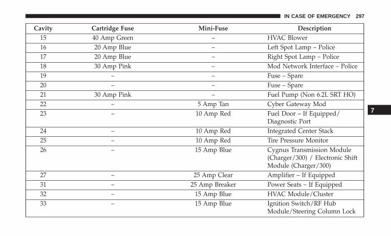
Cavity Cartridge Fuse Mini-Fuse Description15 40 Amp Green – HVAC Blower16 20 Amp Blue – Left Spot Lamp – Police17 20 Amp Blue – Right Spot Lamp – Police18 30 Amp Pink – Mod Network Interface – Police19 – – Fuse – Spare20 – – Fuse – Spare21 30 Amp Pink – Fuel Pump (Non 6.2L SRT HO)22 – 5 Amp Tan Cyber Gateway Mod23 – 10 Amp Red Fuel Door – If Equipped/
Diagnostic Port24 – 10 Amp Red Integrated Center Stack25 – 10 Amp Red Tire Pressure Monitor26 – 15 Amp Blue Cygnus Transmission Module
(Charger/300) / Electronic ShiftModule (Charger/300)
27 – 25 Amp Clear Amplifier – If Equipped31 – 25 Amp Breaker Power Seats – If Equipped32 – 15 Amp Blue HVAC Module/Cluster33 – 15 Amp Blue Ignition Switch/RF Hub
Module/Steering Column Lock
7
IN CASE OF EMERGENCY 297

Cavity Cartridge Fuse Mini-Fuse Description(300) – If Equipped
34 – 10 Amp Red Steering Column Module/Clock(300)
35 – 5 Amp Tan Battery Sensor36 – 15 Amp Blue Electronic Exhaust Valve – If
Equipped37 – 20 Amp Yellow Radio38 – 20 Amp Yellow Power Outlet Inside Arm Rest/
Console Media Hub40 30 Amp Pink – Fuel Pump (6.2L SRT HO – If
Equipped)41 30 Amp Pink – Fuel Pump (6.2L SRT HO – If
Equipped)42 30 Amp Pink – Rear Defrost43 – 20 Amp Yellow Comfort Seat And Steering
Wheel Module (Heated SteeringWheel/RR Heated Seats)
44 – 10 Amp Red Park Assist / Blind Spot / RearView Camera
298 IN CASE OF EMERGENCY
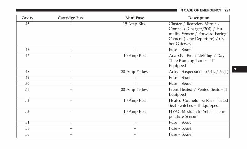
Cavity Cartridge Fuse Mini-Fuse Description45 – 15 Amp Blue Cluster / Rearview Mirror /
Compass (Charger/300) / Hu-midity Sensor / Forward FacingCamera (Lane Departure) / Cy-ber Gateway
46 – – Fuse – Spare47 – 10 Amp Red Adaptive Front Lighting / Day
Time Running Lamps – IfEquipped
48 – 20 Amp Yellow Active Suspension – (6.4L / 6.2L)49 – – Fuse – Spare50 – – Fuse – Spare51 – 20 Amp Yellow Front Heated / Vented Seats – If
Equipped52 – 10 Amp Red Heated Cupholders/Rear Heated
Seat Switches – If Equipped53 – 10 Amp Red HVAC Module/In Vehicle Tem-
perature Sensor54 – – Fuse – Spare55 – – Fuse – Spare56 – – Fuse – Spare
7
IN CASE OF EMERGENCY 299

Cavity Cartridge Fuse Mini-Fuse Description57 – – Fuse – Spare58 – 10 Amp Red Airbag Module59 – 20 Amp Yellow Adjustable Pedals – Police60 – – Fuse – Spare61 – – Fuse – Spare62 – – Fuse – Spare63 – – Fuse – Spare64 – 25 Amp Breaker Rear Windows (Charger/300)65 – 10 Amp Red Airbag Module66 – – Fuse – Spare67 – 10 Amp Red Rain and Light Sensor / Sunroof
/ Inside RR View Mirror / Po-lice Run Acc Relay
68 – 10 Amp Red Dual USB Power Outlet – R/ASense (Charger/300) Rear Sun-shade (Charger/300) RR USBTimer
69 – – Fuse – Spare70 – – Fuse – Spare
300 IN CASE OF EMERGENCY
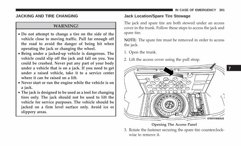
JACKING AND TIRE CHANGING
WARNING!
• Do not attempt to change a tire on the side of thevehicle close to moving traffic. Pull far enough offthe road to avoid the danger of being hit whenoperating the jack or changing the wheel.
• Being under a jacked-up vehicle is dangerous. Thevehicle could slip off the jack and fall on you. Youcould be crushed. Never put any part of your bodyunder a vehicle that is on a jack. If you need to getunder a raised vehicle, take it to a service centerwhere it can be raised on a lift.
• Never start or run the engine while the vehicle is ona jack.
• The jack is designed to be used as a tool for changingtires only. The jack should not be used to lift thevehicle for service purposes. The vehicle should bejacked on a firm level surface only. Avoid ice orslippery areas.
Jack Location/Spare Tire Stowage
The jack and spare tire are both stowed under an accesscover in the trunk. Follow these steps to access the jack andspare tire.
NOTE: The spare tire must be removed in order to accessthe jack.
1. Open the trunk.
2. Lift the access cover using the pull strap.
3. Rotate the fastener securing the spare tire counterclock-wise to remove it.
Opening The Access Panel
7
IN CASE OF EMERGENCY 301
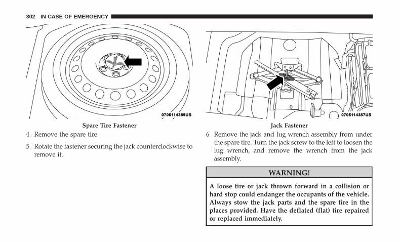
4. Remove the spare tire.
5. Rotate the fastener securing the jack counterclockwise toremove it.
6. Remove the jack and lug wrench assembly from underthe spare tire. Turn the jack screw to the left to loosen thelug wrench, and remove the wrench from the jackassembly.
WARNING!
A loose tire or jack thrown forward in a collision orhard stop could endanger the occupants of the vehicle.Always stow the jack parts and the spare tire in theplaces provided. Have the deflated (flat) tire repairedor replaced immediately.
Spare Tire Fastener Jack Fastener
302 IN CASE OF EMERGENCY
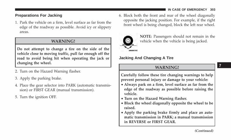
Preparations For Jacking
1. Park the vehicle on a firm, level surface as far from theedge of the roadway as possible. Avoid icy or slipperyareas.
WARNING!
Do not attempt to change a tire on the side of thevehicle close to moving traffic, pull far enough off theroad to avoid being hit when operating the jack orchanging the wheel.
2. Turn on the Hazard Warning flasher.
3. Apply the parking brake.
4. Place the gear selector into PARK (automatic transmis-sion) or FIRST GEAR (manual transmission).
5. Turn the ignition OFF.
6. Block both the front and rear of the wheel diagonallyopposite the jacking position. For example, if the rightfront wheel is being changed, block the left rear wheel.
NOTE: Passengers should not remain in thevehicle when the vehicle is being jacked.
Jacking And Changing A Tire
WARNING!
Carefully follow these tire changing warnings to helpprevent personal injury or damage to your vehicle:• Always park on a firm, level surface as far from the
edge of the roadway as possible before raising thevehicle.
• Turn on the Hazard Warning flasher.• Block the wheel diagonally opposite the wheel to be
raised.• Apply the parking brake firmly and place an auto-
matic transmission in PARK; a manual transmissionin REVERSE or FIRST GEAR.
(Continued)
7
IN CASE OF EMERGENCY 303
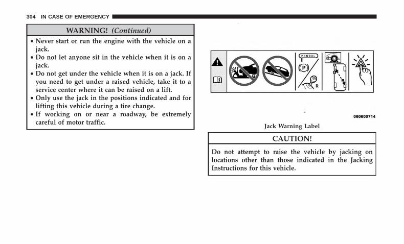
WARNING! (Continued)• Never start or run the engine with the vehicle on a
jack.• Do not let anyone sit in the vehicle when it is on a
jack.• Do not get under the vehicle when it is on a jack. If
you need to get under a raised vehicle, take it to aservice center where it can be raised on a lift.
• Only use the jack in the positions indicated and forlifting this vehicle during a tire change.
• If working on or near a roadway, be extremelycareful of motor traffic.
CAUTION!
Do not attempt to raise the vehicle by jacking onlocations other than those indicated in the JackingInstructions for this vehicle.
Jack Warning Label
304 IN CASE OF EMERGENCY

1. Remove the spare tire, jack, and lug wrench.
NOTE: When the following label is present, the spare tiremust be used for the rear wheel(s) only. For a flat front tire,you must first install the spare on one of the rear tires.Then, follow the jacking instructions for front tire replace-ment and replace the front road wheel with the wheelremoved from the rear of the vehicle.
2. If equipped with aluminum wheels where the center capcovers the lug nuts, use the lug wrench to pry the centercap off carefully before raising the vehicle.
3. Before raising the vehicle, use the lug wrench to loosen,but not remove, the lug nuts on the wheel with the flattire. Turn the lug nuts counterclockwise one turn whilethe wheel is still on the ground.
4. Place the jack underneath the lift area that is closest tothe flat tire. Turn the jack screw clockwise to firmlyengage the jack saddle with the lift area of the sill flange.
Jack Engagement Locations Spare Tire Label
7
IN CASE OF EMERGENCY 305

NOTE: If the vehicle is too low for jack placement, slide thejack on its side and rotate it up into position.
5. Raise the vehicle just enough to remove the flat tire andinstall the spare tire.
WARNING!
Raising the vehicle higher than necessary can make thevehicle less stable. It could slip off the jack and hurtsomeone near it. Raise the vehicle only enough toremove the tire.
6. Remove the lug nuts and tire.
Front Jacking Location
Rear Jacking Location
306 IN CASE OF EMERGENCY

7. Mount the spare tire.
CAUTION!
Do not attempt to raise the vehicle by jacking onlocations other than those indicated.
NOTE:
• For vehicles so equipped, do not attempt to install acenter cap or wheel cover on the compact spare.
• Refer to “Compact Spare Tire” and to “Limited-UseSpare” under “Tires—General Information” in “Servic-ing And Maintenance” for additional warnings, cau-tions, and information about the spare tire, its use, andoperation.
8. Install the lug nuts with the cone shaped end of the lugnut toward the wheel. Lightly tighten the lug nuts.
WARNING!
To avoid the risk of forcing the vehicle off the jack, donot tighten the wheel nuts fully until the vehicle hasbeen lowered. Failure to follow this warning mayresult in serious injury.
9. Lower the vehicle to the ground by turning the jackhandle counterclockwise.
10. Refer to “Torque Specifications” in “Technical Specifi-cations” section for proper lug nut torque.
Mounting Spare Tire
7
IN CASE OF EMERGENCY 307
11. Stow the jack, tools and flat tire. Make sure the base ofthe jack faces the front of the vehicle before tighteningdown the fastener.
WARNING!
A loose tire or jack thrown forward in a collision orhard stop could endanger the occupants of the vehicle.Always stow the jack parts and the spare tire in theplaces provided. Have the deflated (flat) tire repairedor replaced immediately.
Road Tire Installation
1. Mount the road tire on the axle.
2. Install the remaining lug nuts with the cone shaped endof the nut toward the wheel. Lightly tighten the lugnuts.
WARNING!
To avoid the risk of forcing the vehicle off the jack, donot tighten the wheel nuts fully until the vehicle hasbeen lowered. Failure to follow this warning mayresult in serious injury.
3. Lower the vehicle to the ground by turning the jackhandle counterclockwise.
4. Refer to “Torque Specifications” in “Technical Specifica-tions” for proper lug nut torque.
5. After 25 miles (40 km), check the lug nut torque with atorque wrench to ensure that all lug nuts are properlyseated against the wheel.
TIRE SERVICE KIT — IF EQUIPPED
Small punctures up to 1/4 inch (6 mm) in the tire tread canbe sealed with Tire Service Kit. Foreign objects (e.g., screwsor nails) should not be removed from the tire. Tire ServiceKit can be used in outside temperatures down to approxi-mately -4°F (-20°C).
This kit will provide a temporary tire seal, allowing you todrive your vehicle up to 100 miles (160 km) with amaximum speed of 50 mph (80 km/h).
308 IN CASE OF EMERGENCY
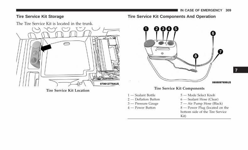
Tire Service Kit Storage
The Tire Service Kit is located in the trunk.
Tire Service Kit Components And Operation
Tire Service Kit Location Tire Service Kit Components
1 — Sealant Bottle 5 — Mode Select Knob2 — Deflation Button 6 — Sealant Hose (Clear)3 — Pressure Gauge 7 — Air Pump Hose (Black)4 — Power Button 8 — Power Plug (located on the
bottom side of the Tire ServiceKit)
7
IN CASE OF EMERGENCY 309
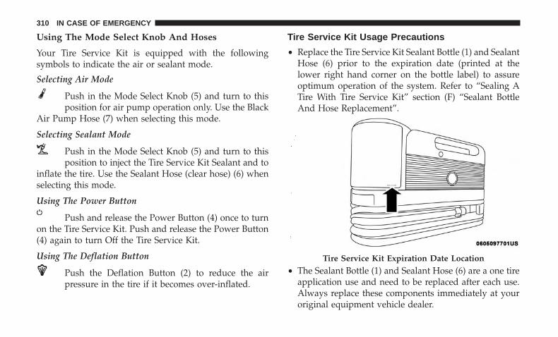
Using The Mode Select Knob And Hoses
Your Tire Service Kit is equipped with the followingsymbols to indicate the air or sealant mode.
Selecting Air Mode
Push in the Mode Select Knob (5) and turn to thisposition for air pump operation only. Use the Black
Air Pump Hose (7) when selecting this mode.
Selecting Sealant Mode
Push in the Mode Select Knob (5) and turn to thisposition to inject the Tire Service Kit Sealant and to
inflate the tire. Use the Sealant Hose (clear hose) (6) whenselecting this mode.
Using The Power Button
Push and release the Power Button (4) once to turnon the Tire Service Kit. Push and release the Power Button(4) again to turn Off the Tire Service Kit.
Using The Deflation Button
Push the Deflation Button (2) to reduce the airpressure in the tire if it becomes over-inflated.
Tire Service Kit Usage Precautions
• Replace the Tire Service Kit Sealant Bottle (1) and SealantHose (6) prior to the expiration date (printed at thelower right hand corner on the bottle label) to assureoptimum operation of the system. Refer to “Sealing ATire With Tire Service Kit” section (F) “Sealant BottleAnd Hose Replacement”.
• The Sealant Bottle (1) and Sealant Hose (6) are a one tireapplication use and need to be replaced after each use.Always replace these components immediately at youroriginal equipment vehicle dealer.
Tire Service Kit Expiration Date Location
310 IN CASE OF EMERGENCY
• When the Tire Service Kit sealant is in a liquid form,clean water and a damp cloth will remove the materialfrom the vehicle or tire and wheel components. Once thesealant dries, it can easily be peeled off and properlydiscarded.
• For optimum performance, make sure the valve stem onthe wheel is free of debris before connecting the TireService Kit.
• You can use the Tire Service Kit air pump to inflatebicycle tires. The kit also comes with two needles,located in the Accessory Storage Compartment (on thebottom of the air pump) for inflating sport balls, rafts, orsimilar inflatable items. However, use only the Air PumpHose (7) and make sure the Mode Select Knob (5) is inthe Air Mode when inflating such items to avoid inject-ing sealant into them. The Tire Service Kit Sealant is onlyintended to seal punctures less than 1/4 inch (6 mm)diameter in the tread of your tire.
• Do not lift or carry the Tire Service Kit by the hoses.
WARNING!
• Do not attempt to seal a tire on the side of the vehicleclosest to traffic. Pull far enough off the road to avoidthe danger of being hit when using the Tire ServiceKit.
• Do not use Tire Service Kit or drive the vehicle underthe following circumstances:– If the puncture in the tire tread is approximately
1/4 inch (6 mm) or larger.– If the tire has any sidewall damage.– If the tire has any damage from driving with
extremely low tire pressure.– If the tire has any damage from driving on a flat
tire.– If the wheel has any damage.– If you are unsure of the condition of the tire or the
wheel.• Keep Tire Service Kit away from open flames or heat
source.• A loose Tire Service Kit thrown forward in a collision
or hard stop could endanger the occupants of thevehicle. Always stow the Tire Service Kit in the placeprovided. Failure to follow these warnings can result
(Continued)
7
IN CASE OF EMERGENCY 311
WARNING! (Continued)in injuries that are serious or fatal to you, yourpassengers, and others around you.
• Take care not to allow the contents of Tire Service Kitto come in contact with hair, eyes, or clothing. TireService Kit sealant is harmful if inhaled, swallowed,or absorbed through the skin. It causes skin, eye, andrespiratory irritation. Flush immediately with plentyof water if there is any contact with eyes or skin.Change clothing as soon as possible, if there is anycontact with clothing.
• Tire Service Kit Sealant solution contains latex. Incase of an allergic reaction or rash, consult a physi-cian immediately. Keep Tire Service Kit out of reachof children. If swallowed, rinse mouth immediatelywith plenty of water and drink plenty of water. Donot induce vomiting! Consult a physician immedi-ately.
Sealing A Tire With Tire Service Kit
(A) Whenever You Stop To Use Tire Service Kit:
1. Pull over to a safe location and turn on the vehicle’sHazard Warning flashers.
2. Verify that the valve stem (on the wheel with thedeflated tire) is in a position that is near to the ground.This will allow the Tire Service Kit Hoses (6) and (7) toreach the valve stem and keep the Tire Service Kit flat onthe ground. This will provide the best positioning of thekit when injecting the sealant into the deflated tire andrunning the air pump. Move the vehicle as necessary toplace the valve stem in this position before proceeding.
3. Place the transmission in PARK (auto transmission) or inGear (manual transmission) and place the ignition in theOFF position.
4. Apply the parking brake.
(B) Setting Up To Use Tire Service Kit:
1. Push in the Mode Select Knob (5) and turn to the SealantMode position.
2. Uncoil the Sealant Hose (6) and then remove the capfrom the fitting at the end of the hose.
3. Place the Tire Service Kit flat on the ground next to thedeflated tire.
4. Remove the cap from the valve stem and then screw thefitting at the end of the Sealant Hose (6) onto the valvestem.
312 IN CASE OF EMERGENCY
5. Uncoil the Power Plug (8) and insert the plug into thevehicle’s 12 Volt power outlet.
NOTE: Do not remove foreign objects (e.g., screws ornails) from the tire.
(C) Injecting Tire Service Kit Sealant Into TheDeflated Tire:
• Always start the engine before turning ON the TireService Kit.
NOTE: Manual transmission vehicles must have the park-ing brake engaged and the gear selector in NEUTRAL.
• After pushing the Power Button (4), the sealant (whitefluid) will flow from the Sealant Bottle (1) through theSealant Hose (6) and into the tire.
NOTE: Sealant may leak out through the puncture in thetire.
If the sealant (white fluid) does not flow within 0 – 10seconds through the Sealant Hose (6):
1. Push the Power Button (4) to turn Off the Tire ServiceKit. Disconnect the Sealant Hose (6) from the valve stem.Make sure the valve stem is free of debris. Reconnect theSealant Hose (6) to the valve stem. Check that the Mode
Select Knob (5) is in the Sealant Mode position and notAir Mode. Push the Power Button (4) to turn On the TireService Kit.
2. Connect the Power Plug (8) to a different 12 Volt poweroutlet in your vehicle or another vehicle, if available.Make sure the engine is running before turning ON theTire Service Kit.
3. The Sealant Bottle (1) may be empty due to previoususe. Call for assistance.
NOTE: If the Mode Select Knob (5) is on Air Mode and thepump is operating, air will dispense from the Air PumpHose (7) only, not the Sealant Hose (6).
If the sealant (white fluid) does flow through the SealantHose (6):
1. Continue to operate the pump until sealant is no longerflowing through the hose (typically takes 30 - 70 sec-onds). As the sealant flows through the Sealant Hose (6),the Pressure Gauge (3) can read as high as 70 psi(4.8 Bar). The Pressure Gauge (3) will decrease quicklyfrom approximately 70 psi (4.8 Bar) to the actual tirepressure when the Sealant Bottle (1) is empty.
7
IN CASE OF EMERGENCY 313
2. The pump will start to inject air into the tire immedi-ately after the Sealant Bottle (1) is empty. Continue tooperate the pump and inflate the tire to the pressureindicated on the tire pressure label on the driver-sidelatch pillar (recommended pressure). Check the tirepressure by looking at the Pressure Gauge (3).
If the tire does not inflate to at least 26 psi (1.8 Bar)pressure within 15 minutes:
• The tire is too badly damaged. Do not attempt to drivethe vehicle further. Call for assistance.
NOTE: If the tire becomes overinflated, push the DeflationButton (2) to reduce the tire pressure to the recommendedinflation pressure before continuing.
If the tire inflates to the recommended pressure or is atleast 26 psi (1.8 Bar) pressure within 15 minutes:
1. Push the Power Button (4) to turn off the Tire ServiceKit.
2. Remove the Speed Limit sticker from the top of theSealant Bottle (1) and place the sticker on the instrumentpanel.
3. Immediately disconnect the Sealant Hose (6) from thevalve stem, reinstall the cap on the fitting at the end ofthe hose, and place the Tire Service Kit in the vehiclestorage location. Quickly proceed to (D) “Drive Ve-hicle.”
CAUTION!
• The metal end fitting from Power Plug (8) may gethot after use, so it should be handled carefully.
• Failure to reinstall the cap on the fitting at the end ofthe Sealant Hose (6) can result in sealant contactingyour skin, clothing, and the vehicle’s interior. It canalso result in sealant contacting internal Tire ServiceKit components which may cause permanent damageto the kit.
(D) Drive Vehicle:
Immediately after injecting sealant and inflating the tire,drive the vehicle 5 miles (8 km) or ten minutes to ensuredistribution of the Tire Service Kit Sealant within the tire.Do not exceed 50 mph (80 km/h).
314 IN CASE OF EMERGENCY

WARNING!
Tire Service Kit is not a permanent flat tire repair. Havethe tire inspected and repaired or replaced after usingTire Service Kit. Do not exceed 50 mph (80 km/h) untilthe tire is repaired or replaced. Failure to follow thiswarning can result in injuries that are serious or fatalto you, your passengers, and others around you.
(E) After Driving:
Pull over to a safe location. Refer to “(A) Whenever YouStop To Use Tire Service Kit” before continuing.
1. Push in the Mode Select Knob (5) and turn to the AirMode position.
2. Uncoil the power plug and insert the plug into thevehicle’s 12 Volt power outlet.
3. Uncoil the Air Pump Hose (7) (black in color) and screwthe fitting at the end of hose (7) onto the valve stem.
4. Check the pressure in the tire by reading the PressureGauge (3).
If tire pressure is less than 19 psi (1.3 Bar):
The tire is too badly damaged. Do not attempt to drive thevehicle further. Call for assistance.
If the tire pressure is 19 psi (1.3 Bar) or higher:
1. Push the Power Button (4) to turn on Tire Service Kitand inflate the tire to the pressure indicated on the tireand loading information label on the driver-side dooropening.
NOTE: If the tire becomes over-inflated, push the DeflationButton (2) to reduce the tire pressure to the recommendedinflation pressure before continuing.
2. Disconnect the Tire Service Kit from the valve stem,reinstall the cap on the valve stem and unplug from 12Volt outlet.
3. Place the Tire Service Kit in its proper storage area in thevehicle.
4. Have the tire inspected and repaired or replaced at theearliest opportunity at an authorized dealer or tireservice center.
5. Remove the Speed Limit sticker from the instrumentpanel after the tire has been repaired.
7
IN CASE OF EMERGENCY 315
6. Replace the Sealant Bottle (1) and Sealant Hose (6)assembly at an authorized dealer as soon as possible.Refer to “(F) Sealant Bottle And Hose Replacement”.
NOTE: When having the tire serviced, advise the autho-rized dealer or service center that the tire has been sealedusing the Tire Service Kit.
(F) Sealant Bottle And Hose Replacement:
1. Uncoil the Sealant Hose (6) (clear in color).
2. Locate the round Sealant Bottle release button in therecessed area under the sealant bottle.
3. Push the Sealant Bottle release button. The Sealant Bottle(1) will pop up. Remove the bottle and dispose of itaccordingly.
4. Clean any remaining sealant from the Tire Service Kithousing.
5. Position the new Sealant Bottle (1) in the housing so thatthe Sealant Hose (6) aligns with the hose slot in the frontof the housing. Push the bottle into the housing. Anaudible click will be heard indicating the bottle is lockedinto place.
6. Verify that the cap is installed on the fitting at the end ofthe Sealant Hose (6) and return the hose to its storagearea (located on the bottom of the air pump).
7. Return the Tire Service Kit to its storage location in thevehicle.
TIRE SERVICE KIT — IF EQUIPPED
Small punctures up to 1/4 inch (6 mm) in the tire tread canbe sealed with Tire Service Kit. Foreign objects (e.g., screwsor nails) should not be removed from the tire. Tire ServiceKit can be used in outside temperatures down to approxi-mately -4°F (-20°C).
This kit will provide a temporary tire seal, allowing you todrive your vehicle up to 100 miles (160 km) with amaximum speed of 50 mph (80 km/h).
316 IN CASE OF EMERGENCY

Tire Service Kit Storage
The Tire Service Kit is located in the trunk.
Tire Service Kit Components And Operation
Tire Service Kit Location Tire Service Kit Components
1 — Power Button 4 — Sealant Bottle 7 — Power Plug2 — Mode SelectKnob
5 — Air Pump Hose(Black)
8 — Pressure Gauge
3 — Sealant Hose(Clear)
6 — Sealant BottleRelease Button
9 — Deflation Button
7
IN CASE OF EMERGENCY 317

Using The Mode Select Knob And Hoses
Your Tire Service Kit is equipped with the followingsymbols to indicate the air or sealant mode.
Selecting Air Mode
Push in the Mode Select Knob (2) and turn to thisposition for air pump operation only. Use theBlack Air Pump Hose (5) when selecting thismode.
Selecting Sealant Mode
Push in the Mode Select Knob (2) and turn to thisposition to inject the Tire Service Kit Sealant andto inflate the tire. Use the Sealant Hose (clearhose) (3) when selecting this mode.
Using The Power Button
Push and release the Power Button (1) once toturn on the Tire Service Kit. Push and release thePower Button (1) again to turn Off the TireService Kit.
Using The Deflation Button
Push the Deflation Button (9) to reduce the airpressure in the tire if it becomes over-inflated.
Tire Service Kit Usage Precautions
• Replace the Tire Service Kit Sealant Bottle (4) and SealantHose (3) prior to the expiration date (printed at theupper right hand corner on the bottle label) to assureoptimum operation of the system. Refer to “Sealing ATire With Tire Service Kit” section (F) “Sealant BottleAnd Hose Replacement”.
Tire Service Kit Sealant Expiration Date Location
318 IN CASE OF EMERGENCY

• The Sealant Bottle (4) and Sealant Hose (3) are a one tireapplication use and need to be replaced after each use.Always replace these components immediately at youroriginal equipment vehicle dealer.
• When the Tire Service Kit sealant is in a liquid form,clean water and a damp cloth will remove the materialfrom the vehicle or tire and wheel components. Once thesealant dries, it can easily be peeled off and properlydiscarded.
• For optimum performance, make sure the valve stem onthe wheel is free of debris before connecting the TireService Kit.
• You can use the Tire Service Kit air pump to inflatebicycle tires. The kit also comes with two needles,located in the Accessory Storage Compartment (on thebottom of the air pump) for inflating sport balls, rafts, orsimilar inflatable items. However, use only the Air PumpHose (5) and make sure the Mode Select Knob (2) is inthe Air Mode when inflating such items to avoid inject-ing sealant into them. The Tire Service Kit Sealant is onlyintended to seal punctures less than 1/4 inch (6 mm)diameter in the tread of your tire.
• Do not lift or carry the Tire Service Kit by the hoses.
WARNING!
• Do not attempt to seal a tire on the side of the vehicleclosest to traffic. Pull far enough off the road to avoidthe danger of being hit when using the Tire ServiceKit.
• Do not use Tire Service Kit or drive the vehicle underthe following circumstances:– If the puncture in the tire tread is approximately
1/4 inch (6 mm) or larger.– If the tire has any sidewall damage.– If the tire has any damage from driving with
extremely low tire pressure.– If the tire has any damage from driving on a flat
tire.– If the wheel has any damage.– If you are unsure of the condition of the tire or the
wheel.• Keep Tire Service Kit away from open flames or heat
source.• A loose Tire Service Kit thrown forward in a collision
or hard stop could endanger the occupants of thevehicle. Always stow the Tire Service Kit in the placeprovided. Failure to follow these warnings can result
(Continued)
7
IN CASE OF EMERGENCY 319

WARNING! (Continued)in injuries that are serious or fatal to you, yourpassengers, and others around you.
• Take care not to allow the contents of Tire Service Kitto come in contact with hair, eyes, or clothing. TireService Kit sealant is harmful if inhaled, swallowed,or absorbed through the skin. It causes skin, eye, andrespiratory irritation. Flush immediately with plentyof water if there is any contact with eyes or skin.Change clothing as soon as possible, if there is anycontact with clothing.
• Tire Service Kit Sealant solution contains latex. Incase of an allergic reaction or rash, consult a physi-cian immediately. Keep Tire Service Kit out of reachof children. If swallowed, rinse mouth immediatelywith plenty of water and drink plenty of water. Donot induce vomiting! Consult a physician immedi-ately.
Sealing A Tire With Tire Service Kit
(A) Whenever You Stop To Use Tire Service Kit:
1. Pull over to a safe location and turn on the vehicle’sHazard Warning flashers.
2. Verify that the valve stem (on the wheel with thedeflated tire) is in a position that is near to the ground.This will allow the Tire Service Kit Hoses (3) and (5) toreach the valve stem and keep the Tire Service Kit flat onthe ground. This will provide the best positioning of thekit when injecting the sealant into the deflated tire andrunning the air pump. Move the vehicle as necessary toplace the valve stem in this position before proceeding.
3. Place the transmission in PARK (auto transmission) or inGear (manual transmission) and place the ignition in theOFF position.
4. Apply the parking brake.
(B) Setting Up To Use Tire Service Kit:
1. Push in the Mode Select Knob (2) and turn to the SealantMode position.
2. Uncoil the Sealant Hose (3) and then remove the capfrom the fitting at the end of the hose.
3. Place the Tire Service Kit flat on the ground next to thedeflated tire.
4. Remove the cap from the valve stem and then screw thefitting at the end of the Sealant Hose (3) onto the valvestem.
320 IN CASE OF EMERGENCY

5. Uncoil the Power Plug (7) and insert the plug into thevehicle’s 12 Volt power outlet.
NOTE: Do not remove foreign objects (e.g., screws ornails) from the tire.
(C) Injecting Tire Service Kit Sealant Into TheDeflated Tire:
• Always start the engine before turning ON the TireService Kit.
NOTE: Manual transmission vehicles must have the park-ing brake engaged and the gear selector in NEUTRAL.
• After pushing the Power Button (1), the sealant (whitefluid) will flow from the Sealant Bottle (4) through theSealant Hose (3) and into the tire.
NOTE: Sealant may leak out through the puncture in thetire.
If the sealant (white fluid) does not flow within 0 – 10seconds through the Sealant Hose (3):
1. Push the Power Button (1) to turn Off the Tire ServiceKit. Disconnect the Sealant Hose (3) from the valve stem.Make sure the valve stem is free of debris. Reconnect theSealant Hose (3) to the valve stem. Check that the Mode
Select Knob (2) is in the Sealant Mode position and notAir Mode. Push the Power Button (1) to turn On the TireService Kit.
2. Connect the Power Plug (7) to a different 12 Volt poweroutlet in your vehicle or another vehicle, if available.Make sure the engine is running before turning ON theTire Service Kit.
3. The Sealant Bottle (4) may be empty due to previoususe. Call for assistance.
NOTE: If the Mode Select Knob (2) is on Air Mode and thepump is operating, air will dispense from the Air PumpHose (5) only, not the Sealant Hose (3).
If the sealant (white fluid) does flow through the SealantHose (3):
1. Continue to operate the pump until sealant is no longerflowing through the hose (typically takes 30 - 70 sec-onds). As the sealant flows through the Sealant Hose (3),the Pressure Gauge (8) can read as high as 70 psi(4.8 Bar). The Pressure Gauge (8) will decrease quicklyfrom approximately 70 psi (4.8 Bar) to the actual tirepressure when the Sealant Bottle (4) is empty.
7
IN CASE OF EMERGENCY 321

2. The pump will start to inject air into the tire immedi-ately after the Sealant Bottle (4) is empty. Continue tooperate the pump and inflate the tire to the pressureindicated on the tire pressure label on the driver-sidelatch pillar (recommended pressure). Check the tirepressure by looking at the Pressure Gauge (8).
If the tire does not inflate to at least 26 psi (1.8 Bar)pressure within 15 minutes:
• The tire is too badly damaged. Do not attempt to drivethe vehicle further. Call for assistance.
NOTE: If the tire becomes overinflated, push the DeflationButton to reduce the tire pressure to the recommendedinflation pressure before continuing.
If the tire inflates to the recommended pressure or is atleast 26 psi (1.8 Bar) pressure within 15 minutes:
1. Push the Power Button (1) to turn off the Tire ServiceKit.
2. Remove the Speed Limit sticker from the top of theSealant Bottle (4) and place the sticker on the instrumentpanel.
3. Immediately disconnect the Sealant Hose (3) from thevalve stem, reinstall the cap on the fitting at the end ofthe hose, and place the Tire Service Kit in the vehiclestorage location. Quickly proceed to (D) “Drive Ve-hicle.”
CAUTION!
• The metal end fitting from Power Plug (8) may gethot after use, so it should be handled carefully.
• Failure to reinstall the cap on the fitting at the end ofthe Sealant Hose (6) can result in sealant contactingyour skin, clothing, and the vehicle’s interior. It canalso result in sealant contacting internal Tire ServiceKit components which may cause permanent damageto the kit.
(D) Drive Vehicle:
Immediately after injecting sealant and inflating the tire,drive the vehicle 5 miles (8 km) or ten minutes to ensuredistribution of the Tire Service Kit Sealant within the tire.Do not exceed 50 mph (80 km/h).
322 IN CASE OF EMERGENCY

WARNING!
Tire Service Kit is not a permanent flat tire repair. Havethe tire inspected and repaired or replaced after usingTire Service Kit. Do not exceed 50 mph (80 km/h) untilthe tire is repaired or replaced. Failure to follow thiswarning can result in injuries that are serious or fatalto you, your passengers, and others around you.
(E) After Driving:
Pull over to a safe location. Refer to “(A) Whenever YouStop To Use Tire Service Kit” before continuing.
1. Push in the Mode Select Knob (2) and turn to the AirMode position.
2. Uncoil the power plug and insert the plug into thevehicle’s 12 Volt power outlet.
3. Uncoil the Air Pump Hose (5) (black in color) and screwthe fitting at the end of hose onto the valve stem.
4. Check the pressure in the tire by reading the PressureGauge (8).
If tire pressure is less than 19 psi (1.3 Bar):
The tire is too badly damaged. Do not attempt to drive thevehicle further. Call for assistance.
If the tire pressure is 19 psi (1.3 Bar) or higher:
1. Push the Power Button (1) to turn on Tire Service Kitand inflate the tire to the pressure indicated on the tireand loading information label on the driver-side dooropening.
NOTE: If the tire becomes over-inflated, push the DeflationButton to reduce the tire pressure to the recommendedinflation pressure before continuing.
2. Disconnect the Tire Service Kit from the valve stem,reinstall the cap on the valve stem and unplug from 12Volt outlet.
3. Place the Tire Service Kit in its proper storage area in thevehicle.
4. Have the tire inspected and repaired or replaced at theearliest opportunity at an authorized dealer or tireservice center.
5. Remove the Speed Limit sticker from the instrumentpanel after the tire has been repaired.
7
IN CASE OF EMERGENCY 323

6. Replace the Sealant Bottle (4) and Sealant Hose (3)assembly at an authorized dealer as soon as possible.Refer to “(F) Sealant Bottle And Hose Replacement”.
NOTE: When having the tire serviced, advise the autho-rized dealer or service center that the tire has been sealedusing the Tire Service Kit.
(F) Sealant Bottle And Hose Replacement:
1. Uncoil the Sealant Hose (3) (clear in color).
2. Locate the red colored round Sealant Bottle releasebutton at the lower right hand corner of the kit.
3. Push and hold the Sealant Bottle release button, thenpull out the bottle holding the button.
4. Clean any remaining sealant from the Tire Service Kithousing.
5. Position the new Sealant Bottle (4) in the housing so thatthe Sealant Hose (3) aligns with the hose slot in the frontof the housing. Push and hold the Sealant Bottle releasebutton, then push the bottle into the housing by holdingthe button. An audible click will be heard indicating thebottle is locked into place. Release the button.
6. Verify that the cap is installed on the fitting at the end ofthe Sealant Hose (3) and return the hose to its storagearea (located on top of the housing).
7. Return the Tire Service Kit to its storage location in thevehicle.
JUMP STARTING
If your vehicle has a discharged battery, it can be jumpstarted using a set of jumper cables and a battery in anothervehicle, or by using a portable battery booster pack. Jumpstarting can be dangerous if done improperly, so pleasefollow the procedures in this section carefully.
WARNING!
Do not attempt jump starting if the battery is frozen. Itcould rupture or explode and cause personal injury.
CAUTION!
Do not use a portable battery booster pack or any otherbooster source with a system voltage greater than 12Volts or damage to the battery, starter motor, alternatoror electrical system may occur.
324 IN CASE OF EMERGENCY
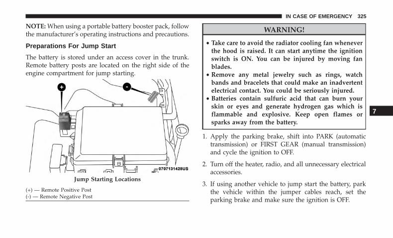
NOTE: When using a portable battery booster pack, followthe manufacturer’s operating instructions and precautions.
Preparations For Jump Start
The battery is stored under an access cover in the trunk.Remote battery posts are located on the right side of theengine compartment for jump starting.
WARNING!
• Take care to avoid the radiator cooling fan wheneverthe hood is raised. It can start anytime the ignitionswitch is ON. You can be injured by moving fanblades.
• Remove any metal jewelry such as rings, watchbands and bracelets that could make an inadvertentelectrical contact. You could be seriously injured.
• Batteries contain sulfuric acid that can burn yourskin or eyes and generate hydrogen gas which isflammable and explosive. Keep open flames orsparks away from the battery.
1. Apply the parking brake, shift into PARK (automatictransmission) or FIRST GEAR (manual transmission)and cycle the ignition to OFF.
2. Turn off the heater, radio, and all unnecessary electricalaccessories.
3. If using another vehicle to jump start the battery, parkthe vehicle within the jumper cables reach, set theparking brake and make sure the ignition is OFF.
Jump Starting Locations
(+) — Remote Positive Post(-) — Remote Negative Post
7
IN CASE OF EMERGENCY 325
WARNING!
Do not allow vehicles to touch each other as this couldestablish a ground connection and personal injurycould result.
Jump Starting Procedure
WARNING!
Failure to follow this jump starting procedure couldresult in personal injury or property damage due tobattery explosion.
CAUTION!
Failure to follow these procedures could result indamage to the charging system of the booster vehicleor the discharged vehicle.
Connecting The Jumper Cables
1. Connect the positive (+) end of the jumper cable to theremote positive (+) post of the vehicle with the dis-charged battery.
2. Connect the opposite end of the positive (+) jumpercable to the positive (+) post of the booster battery.
3. Connect the negative (-) end of the jumper cable to thenegative (-) post of the booster battery.
4. Connect the opposite end of the negative (-) jumpercable to the remote negative (-) post of the vehicle withthe discharged battery.
WARNING!
Do not connect the jumper cable to the negative (-) postof the discharged battery. The resulting electrical sparkcould cause the battery to explode and could result inpersonal injury. Only use the specific ground point, donot use any other exposed metal parts.
5. Start the engine in the vehicle that has the boosterbattery, let the engine idle a few minutes, and then startthe engine in the vehicle with the discharged battery.
CAUTION!
Do not run the booster vehicle engine above 2,000 rpmsince it provides no charging benefit, wastes fuel, andcan damage booster vehicle engine.
326 IN CASE OF EMERGENCY
6. Once the engine is started, remove the jumper cables inthe reverse sequence:
Disconnecting The Jumper Cables
1. Disconnect the negative (-) end of the jumper cable fromthe remote negative (-) post of the vehicle with thedischarged battery.
2. Disconnect the opposite end of the negative (-) jumpercable from the negative (-) post of the booster battery.
3. Disconnect the positive (+) end of the jumper cable fromthe positive (+) post of the booster battery.
4. Disconnect the opposite end of the positive (+) jumpercable from the remote positive (+) post of the vehiclewith the discharged battery.
If frequent jump starting is required to start your vehicleyou should have the battery and charging system in-spected at an authorized dealer.
CAUTION!
Accessories plugged into the vehicle power outletsdraw power from the vehicle’s battery, even when notin use (i.e., cellular devices, etc.). Eventually, if plugged
(Continued)
CAUTION! (Continued)in long enough without engine operation, the vehicle’sbattery will discharge sufficiently to degrade batterylife and/or prevent the engine from starting.
IF YOUR ENGINE OVERHEATS
In any of the following situations, you can reduce thepotential for overheating by taking the appropriate action.
• On the highways — slow down.
• In city traffic — while stopped, place the transmission inNEUTRAL, but do not increase the engine idle speedwhile preventing vehicle motion with the brakes.
NOTE: There are steps that you can take to slow down animpending overheat condition:
• If your air conditioner (A/C) is on, turn it off. The A/Csystem adds heat to the engine cooling system andturning the A/C off can help remove this heat.
• You can also turn the temperature control to maximumheat, the mode control to floor and the blower control tohigh. This allows the heater core to act as a supplement
7
IN CASE OF EMERGENCY 327
to the radiator and aids in removing heat from theengine cooling system.
WARNING!
You or others can be badly burned by hot enginecoolant (antifreeze) or steam from your radiator. If yousee or hear steam coming from under the hood, do notopen the hood until the radiator has had time to cool.Never try to open a cooling system pressure cap whenthe radiator or coolant bottle is hot.
CAUTION!
Driving with a hot cooling system could damage yourvehicle. If the temperature gauge reads HOT (H), pullover and stop the vehicle. Idle the vehicle with the airconditioner turned off until the pointer drops backinto the normal range. If the pointer remains on HOT(H), and you hear continuous chimes, turn the engineoff immediately and call for service.
MANUAL PARK RELEASE — 8–SPEEDTRANSMISSION
WARNING!
Always secure your vehicle by fully applying theparking brake before activating the Manual Park Re-lease. In addition, you should be seated in the driver’sseat with your foot firmly on the brake pedal whenactivating the Manual Park Release. Activating theManual Park Release will allow your vehicle to rollaway if it is not secured by the parking brake, or byproper connection to a tow vehicle. Activating theManual Park Release on an unsecured vehicle couldlead to serious injury or death for those in or aroundthe vehicle.
In order to move the vehicle in cases where the transmis-sion will not shift out of PARK (such as a dead battery), aManual Park Release is available.
328 IN CASE OF EMERGENCY

Follow these steps to use the Manual Park Release:
1. Firmly apply the parking brake.
2. Remove the console storage bin to access the ManualPark Release lever.
3. Using a small screwdriver or similar tool, fish the tetherstrap up through the opening in the console base.
4. Press and maintain firm pressure on the brake pedal.
5. Insert the screwdriver into the slot in the center of thelever, and disengage the lever locking tab by pushing itto the right.
Console Storage BinLocking Tab
7
IN CASE OF EMERGENCY 329
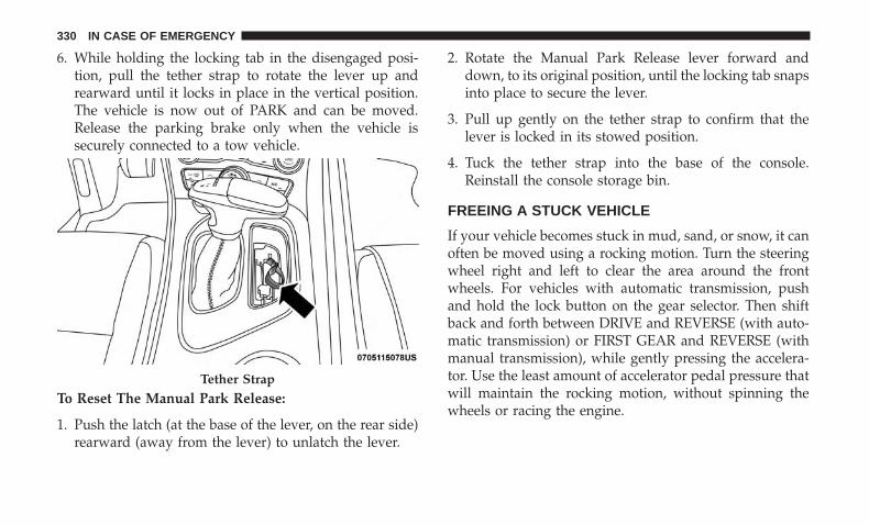
6. While holding the locking tab in the disengaged posi-tion, pull the tether strap to rotate the lever up andrearward until it locks in place in the vertical position.The vehicle is now out of PARK and can be moved.Release the parking brake only when the vehicle issecurely connected to a tow vehicle.
To Reset The Manual Park Release:
1. Push the latch (at the base of the lever, on the rear side)rearward (away from the lever) to unlatch the lever.
2. Rotate the Manual Park Release lever forward anddown, to its original position, until the locking tab snapsinto place to secure the lever.
3. Pull up gently on the tether strap to confirm that thelever is locked in its stowed position.
4. Tuck the tether strap into the base of the console.Reinstall the console storage bin.
FREEING A STUCK VEHICLE
If your vehicle becomes stuck in mud, sand, or snow, it canoften be moved using a rocking motion. Turn the steeringwheel right and left to clear the area around the frontwheels. For vehicles with automatic transmission, pushand hold the lock button on the gear selector. Then shiftback and forth between DRIVE and REVERSE (with auto-matic transmission) or FIRST GEAR and REVERSE (withmanual transmission), while gently pressing the accelera-tor. Use the least amount of accelerator pedal pressure thatwill maintain the rocking motion, without spinning thewheels or racing the engine.
Tether Strap
330 IN CASE OF EMERGENCY
NOTE: For vehicles with automatic transmission: Shiftsbetween DRIVE and REVERSE can only be achieved atwheel speeds of 5 mph (8 km/h) or less. Whenever thetransmission remains in NEUTRAL for more than twoseconds, you must press the brake pedal to engage DRIVEor REVERSE.
CAUTION!
Racing the engine or spinning the wheels may lead totransmission overheating and failure. Allow the en-gine to idle with the transmission in NEUTRAL for atleast one minute after every five rocking-motioncycles. This will minimize overheating and reduce therisk of clutch or transmission failure during prolongedefforts to free a stuck vehicle.
NOTE: Push the “ESC Off” switch (if necessary), to placethe Electronic Stability Control (ESC) system in “PartialOff” mode, before rocking the vehicle. Refer to “ElectronicBrake Control System” in “Safety” for further information.Once the vehicle has been freed, push the �ESC Off� switchagain to restore “ESC On” mode.
WARNING!
Fast spinning tires can be dangerous. Forces generatedby excessive wheel speeds may cause damage, or evenfailure, of the axle and tires. A tire could explode andinjure someone. Do not spin your vehicle’s wheelsfaster than 30 mph (48 km/h) or for longer than 30seconds continuously without stopping when you arestuck and do not let anyone near a spinning wheel, nomatter what the speed.
CAUTION!
• When “rocking” a stuck vehicle by shifting betweenDRIVE / FIRST GEAR and REVERSE, do not spinthe wheels faster than 15 mph (24 km/h), or drive-train damage may result.
• Revving the engine or spinning the wheels too fastmay lead to transmission overheating and failure. Itcan also damage the tires. Do not spin the wheelsabove 30 mph (48 km/h) while in gear (no transmis-sion shifting occurring).
7
IN CASE OF EMERGENCY 331
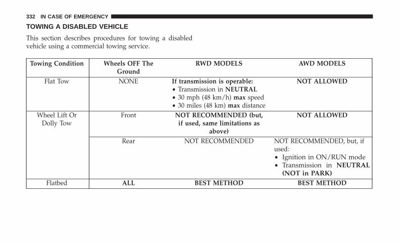
TOWING A DISABLED VEHICLE
This section describes procedures for towing a disabledvehicle using a commercial towing service.
Towing Condition Wheels OFF TheGround
RWD MODELS AWD MODELS
Flat Tow NONE If transmission is operable:• Transmission in NEUTRAL• 30 mph (48 km/h) max speed• 30 miles (48 km) max distance
NOT ALLOWED
Wheel Lift OrDolly Tow
Front NOT RECOMMENDED (but,if used, same limitations as
above)
NOT ALLOWED
Rear NOT RECOMMENDED NOT RECOMMENDED, but, ifused:• Ignition in ON/RUN mode• Transmission in NEUTRAL
(NOT in PARK)Flatbed ALL BEST METHOD BEST METHOD
332 IN CASE OF EMERGENCY
Proper towing or lifting equipment is required to preventdamage to your vehicle. Use only tow bars and otherequipment designed for this purpose, following equipmentmanufacturer’s instructions. Use of safety chains is man-datory. Attach a tow bar or other towing device to mainstructural members of the vehicle, not to bumpers orassociated brackets. State and local laws regarding vehiclesunder tow must be observed.
If you must use the accessories (wipers, defrosters, etc.)while being towed, the ignition must be in the ON/RUNmode, not the ACC mode.
If the key fob is unavailable, or the vehicle’s battery isdischarged, refer to �Manual Park Release� in this sectionfor instructions on shifting the transmission out of PARKfor towing.
CAUTION!
• Do not use sling type equipment when towing.Vehicle damage may occur.
• When securing the vehicle to a flat bed truck, do notattach to front or rear suspension components. Dam-age to your vehicle may result from improper towing.
(Continued)
CAUTION! (Continued)• The manufacturer does not recommend towing this
vehicle using a tow dolly. Vehicle damage may occur.
All Wheel Drive (AWD) Models
The manufacturer recommends towing your vehicle withall four wheels OFF the ground using a flatbed.
If the transmission and driveline are operable, AWD mod-els can also be towed with the ignition in the ON/RUNmode, the transmission in NEUTRAL (not in PARK!), andthe rear wheels OFF the ground with no limitation onspeed or distance. Since the ignition MUST be in theON/RUN mode to tow in this manner, AWD vehicles mustbe towed with ALL FOUR wheels OFF the ground (e.g. ona flatbed truck) if the key fob is unavailable.
CAUTION!
• Towing this vehicle using any other method cancause severe transmission and/or transfer case dam-age.
• Damage from improper towing is not covered underthe New Vehicle Limited Warranty.
7
IN CASE OF EMERGENCY 333

Rear-Wheel Drive (RWD) Models
The manufacturer recommends towing your vehicle withall four wheels OFF the ground using a flatbed.
If flatbed equipment is not available, and the transmissionis operable, the vehicle may be flat towed (with all fourwheels on the ground) under the following conditions:
• The transmission must be in NEUTRAL. Refer to�Manual Park Release� in this section for instructions onshifting the automatic transmission to NEUTRAL whenthe engine is off.
• The towing distance must not exceed 30 miles (48 km).
• The towing speed must not exceed 30 mph (48 km/h).
If the transmission is not operable, or the vehicle must betowed faster than 30 mph (48 km/h) or farther than 30miles (48 km), then the only acceptable method of towingis with a flatbed truck.
CAUTION!
Towing this vehicle in violation of the above require-ments can cause severe engine and/or transmissiondamage. Damage from improper towing is not coveredunder the New Vehicle Limited Warranty.
ENHANCED ACCIDENT RESPONSE SYSTEM(EARS)
This vehicle is equipped with an Enhanced AccidentResponse System.
Please refer to “Occupant Restraint Systems” in “Safety”for further information on the Enhanced Accident Re-sponse System (EARS) function.
EVENT DATA RECORDER (EDR)
This vehicle is equipped with an Event Data Recorder(EDR). The main purpose of an EDR is to record data thatwill assist in understanding how a vehicle’s systems per-formed under certain crash or near crash-like situations,such as an air bag deployment or hitting a road obstacle.
Please refer to “Occupant Restraint Systems” in “Safety”for further information on the Event Data Recorder (EDR).
334 IN CASE OF EMERGENCY
SERVICING AND MAINTENANCE
CONTENTS� SCHEDULED SERVICING . . . . . . . . . . . . . . . . .337
▫ 3.6L And 5.7L Engines . . . . . . . . . . . . . . . . . . .337
▫ 6.4L Engine . . . . . . . . . . . . . . . . . . . . . . . . . .341
� ENGINE COMPARTMENT . . . . . . . . . . . . . . . . .345
▫ 3.6L Engine . . . . . . . . . . . . . . . . . . . . . . . . . .345
▫ 5.7L Engine . . . . . . . . . . . . . . . . . . . . . . . . . .346
▫ 6.4L Engine . . . . . . . . . . . . . . . . . . . . . . . . . .347
▫ Checking Oil Level — 3.6L And 5.7L Engine . . .348
▫ Checking Oil Level — 6.4L Engine. . . . . . . . . . .348
▫ Adding Washer Fluid . . . . . . . . . . . . . . . . . . .349
▫ Maintenance-Free Battery . . . . . . . . . . . . . . . . .349
� DEALER SERVICE . . . . . . . . . . . . . . . . . . . . . . .350
▫ Engine Oil . . . . . . . . . . . . . . . . . . . . . . . . . . .351
▫ Engine Oil Filter . . . . . . . . . . . . . . . . . . . . . . .355
▫ Engine Air Cleaner Filter . . . . . . . . . . . . . . . . .355
▫ Air Conditioner Maintenance . . . . . . . . . . . . . .356
▫ Accessory Drive Belt Inspection . . . . . . . . . . . .359
▫ Body Lubrication . . . . . . . . . . . . . . . . . . . . . .360
▫ Windshield Wiper Blades . . . . . . . . . . . . . . . . .361
▫ Exhaust System . . . . . . . . . . . . . . . . . . . . . . . .363
▫ Cooling System . . . . . . . . . . . . . . . . . . . . . . . .365
▫ Brake System . . . . . . . . . . . . . . . . . . . . . . . . .369
▫ Clutch Hydraulic System — ManualTransmission (If Equipped) . . . . . . . . . . . . . . . .371
▫ Manual Transmission — If Equipped . . . . . . . .371
▫ Automatic Transmission — If Equipped . . . . . .371
▫ All Wheel Drive (AWD) — If Equipped . . . . . . .373
▫ Rear Axle . . . . . . . . . . . . . . . . . . . . . . . . . . . .373
8
� RAISING THE VEHICLE . . . . . . . . . . . . . . . . . .373
� TIRES . . . . . . . . . . . . . . . . . . . . . . . . . . . . . . . .374
▫ Tire Safety Information . . . . . . . . . . . . . . . . . .374
▫ Tires — General Information . . . . . . . . . . . . . .383
▫ Tire Types . . . . . . . . . . . . . . . . . . . . . . . . . . . .389
▫ Spare Tires — If Equipped . . . . . . . . . . . . . . . .390
▫ Wheel And Wheel Trim Care . . . . . . . . . . . . . .393
▫ Tire Chains (Traction Devices) . . . . . . . . . . . . .394
▫ Tire Rotation Recommendations. . . . . . . . . . . . .395
� DEPARTMENT OF TRANSPORTATIONUNIFORM TIRE QUALITY GRADES . . . . . . . . . .396
▫ Treadwear . . . . . . . . . . . . . . . . . . . . . . . . . . . .396
▫ Traction Grades . . . . . . . . . . . . . . . . . . . . . . . .396
▫ Temperature Grades . . . . . . . . . . . . . . . . . . . . .396
� VEHICLE STORAGE . . . . . . . . . . . . . . . . . . . . .397
� BODYWORK . . . . . . . . . . . . . . . . . . . . . . . . . . .397
▫ Protection From Atmospheric Agents . . . . . . . .397
▫ Body And Underbody Maintenance . . . . . . . . . .398
▫ Preserving The Bodywork . . . . . . . . . . . . . . . . .398
� INTERIORS . . . . . . . . . . . . . . . . . . . . . . . . . . . .399
▫ Seats And Fabric Parts . . . . . . . . . . . . . . . . . . .399
▫ Plastic And Coated Parts. . . . . . . . . . . . . . . . . .400
▫ Leather Parts . . . . . . . . . . . . . . . . . . . . . . . . . .400
▫ Glass Surfaces . . . . . . . . . . . . . . . . . . . . . . . . .401
336 SERVICING AND MAINTENANCE
SCHEDULED SERVICING
3.6L And 5.7L Engines
Your vehicle is equipped with an automatic oil changeindicator system. The oil change indicator system willremind you that it is time to take your vehicle in forscheduled maintenance.
Based on engine operation conditions, the oil changeindicator message will illuminate. This means that serviceis required for your vehicle. Operating conditions such asfrequent short-trips, trailer tow, extremely hot or coldambient temperatures, and E85 fuel usage will influencewhen the “Change Oil” or “Oil Change Required” messageis displayed. Severe Operating Conditions can cause thechange oil message to illuminate as early as 3,500 miles(5,600 km) since last reset. Have your vehicle serviced assoon as possible, within the next 500 miles (800 km).
The “Oil Change Required” message will be displayed inthe instrument cluster and a single chime will sound,indicating that an oil change is necessary.
Your authorized dealer will reset the oil change indicatormessage after completing the scheduled oil change. If ascheduled oil change is performed by someone other thanyour authorized dealer, the message can be reset by
referring to “Instrument Cluster Display” in “Getting ToKnow Your Instrument Panel” for further information.
NOTE: Under no circumstances should oil change inter-vals exceed 10,000 miles (16,000 km), 12 months or 350hours of engine run time, whichever comes first. The 350hours of engine run or idle time is generally only a concernfor fleet customers.
Severe Duty All Models
Change Engine Oil at 4,000 miles (6,500 km) or 350 hours ofengine run time if the vehicle is operated in a dusty andoff-road environment, or is operated predominantly at idleor only very low engine RPM’s. This type of vehicle use isconsidered Severe Duty.
Once A Month Or Before A Long Trip:• Check engine oil level.• Check windshield washer fluid level.• Check tire pressure and look for unusual wear or
damage. Rotate tires at the first sign of irregular wear,even if it occurs before your next scheduled service.
• Check the fluid levels of the coolant reservoir, brakemaster cylinder, and power steering (if equipped) andfill as needed.
• Check function of all interior and exterior lights.
8
SERVICING AND MAINTENANCE 337
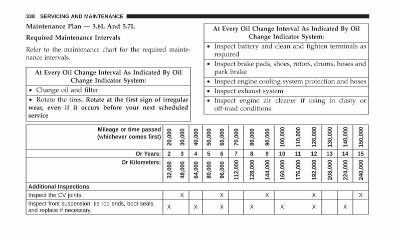
Maintenance Plan — 3.6L And 5.7L
Required Maintenance Intervals
Refer to the maintenance chart for the required mainte-nance intervals.
At Every Oil Change Interval As Indicated By OilChange Indicator System:
• Change oil and filter• Rotate the tires. Rotate at the first sign of irregularwear, even if it occurs before your next scheduledservice
At Every Oil Change Interval As Indicated By OilChange Indicator System:
• Inspect battery and clean and tighten terminals asrequired
• Inspect brake pads, shoes, rotors, drums, hoses andpark brake
• Inspect engine cooling system protection and hoses• Inspect exhaust system• Inspect engine air cleaner if using in dusty or
off-road conditions
Mileage or time passed(whichever comes first)
20,0
00
30,0
00
40,0
00
50,0
00
60,0
00
70,0
00
80,0
00
90,0
00
100,
000
110,
000
120,
000
130,
000
140,
000
150,
000
Or Years: 2 3 4 5 6 7 8 9 10 11 12 13 14 15Or Kilometers:
32,0
00
48,0
00
64,0
00
80,0
00
96,0
00
112,
000
128,
000
144,
000
160,
000
176,
000
192,
000
208,
000
224,
000
240,
000
Additional InspectionsInspect the CV joints. X X X X XInspect front suspension, tie rod ends, boot sealsand replace if necessary. X X X X X X X
338 SERVICING AND MAINTENANCE
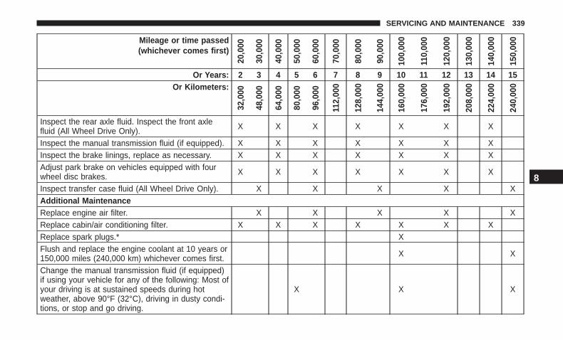
Mileage or time passed(whichever comes first)
20,0
00
30,0
00
40,0
00
50,0
00
60,0
00
70,0
00
80,0
00
90,0
00
100,
000
110,
000
120,
000
130,
000
140,
000
150,
000
Or Years: 2 3 4 5 6 7 8 9 10 11 12 13 14 15Or Kilometers:
32,0
00
48,0
00
64,0
00
80,0
00
96,0
00
112,
000
128,
000
144,
000
160,
000
176,
000
192,
000
208,
000
224,
000
240,
000
Inspect the rear axle fluid. Inspect the front axlefluid (All Wheel Drive Only). X X X X X X X
Inspect the manual transmission fluid (if equipped). X X X X X X XInspect the brake linings, replace as necessary. X X X X X X XAdjust park brake on vehicles equipped with fourwheel disc brakes. X X X X X X X
Inspect transfer case fluid (All Wheel Drive Only). X X X X XAdditional MaintenanceReplace engine air filter. X X X X XReplace cabin/air conditioning filter. X X X X X X XReplace spark plugs.* XFlush and replace the engine coolant at 10 years or150,000 miles (240,000 km) whichever comes first. X X
Change the manual transmission fluid (if equipped)if using your vehicle for any of the following: Most ofyour driving is at sustained speeds during hotweather, above 90°F (32°C), driving in dusty condi-tions, or stop and go driving.
X X X
8
SERVICING AND MAINTENANCE 339

Mileage or time passed(whichever comes first)
20,0
00
30,0
00
40,0
00
50,0
00
60,0
00
70,0
00
80,0
00
90,0
00
100,
000
110,
000
120,
000
130,
000
140,
000
150,
000
Or Years: 2 3 4 5 6 7 8 9 10 11 12 13 14 15Or Kilometers:
32,0
00
48,0
00
64,0
00
80,0
00
96,0
00
112,
000
128,
000
144,
000
160,
000
176,
000
192,
000
208,
000
224,
000
240,
000
Change the transfer case fluid; if using your vehiclefor any of the following: police, taxi, fleet, off-road,or frequent trailer towing. (All Wheel Drive Only).
X X
Change the rear axle fluid and on models equippedwith All Wheel Drive (AWD) change the front axlefluid if using your vehicle for any of the following:police, taxi, fleet, off-road, or frequent trailer towing.
X X X
Inspect and replace PCV valve if necessary. X
* The spark plug change interval is mileage based only,yearly intervals do not apply.
WARNING!
• You can be badly injured working on or around amotor vehicle. Do only service work for which youhave the knowledge and the right equipment. If youhave any doubt about your ability to perform a
(Continued)
WARNING! (Continued)service job, take your vehicle to a competent me-chanic.
• Failure to properly inspect and maintain your vehiclecould result in a component malfunction and effectvehicle handling and performance. This could causean accident.
340 SERVICING AND MAINTENANCE
Heavy Duty Use Of The Vehicle
Change engine oil at 4,000 miles (6,500 km) or 350 hours ofengine run time if the vehicle is operated in a dusty and offroad environment or is operated predominately at idle oronly very low engine RPM’s. This type of vehicle use isconsidered Severe Duty.
6.4L Engine
The scheduled maintenance services listed in this manualmust be done at the times or mileages specified to protectyour vehicle warranty and ensure the best vehicle perfor-mance and reliability. More frequent maintenance may beneeded for vehicles in severe operating conditions, such asdusty areas and very short trip driving. Inspection andservice should also be done anytime a malfunction issuspected.
The oil change indicator system will remind you that it istime to take your vehicle in for scheduled maintenance.
A “Oil Change Required” message will be displayed in theinstrument cluster and a single chime will sound, indicat-ing that an oil change is necessary.
Based on engine operation conditions, the oil changeindicator message will illuminate. This means that serviceis required for your vehicle. Have your vehicle serviced assoon as possible, within the next 500 miles (800 km).
NOTE:
• The oil change indicator message will not monitor thetime since the last oil change. Change your vehicle’s oilif it has been six months since your last oil change, evenif the oil change indicator message is NOT illuminated.
• Change your engine oil more often if you drive yourvehicle off-road/track usage for an extended period oftime.
• Under no circumstances should oil change intervalsexceed 6,000 miles (10,000 km) or six months, whichevercomes first.
An authorized dealer will reset the oil change indicatormessage after completing the scheduled oil change. If ascheduled oil change is performed by someone other thanan authorized dealer, the message can be reset by referringto the steps described under “Instrument Cluster Display”in “Getting To Know Your Instrument Panel” for furtherinformation.
8
SERVICING AND MAINTENANCE 341

At Each Stop For Fuel
• Check the engine oil level. Refer to “Engine Compart-ment” in this chapter for further information.
• Check the windshield washer solvent and add if required.
Once A Month
• Check tire pressure and look for unusual wear ordamage.
• Inspect the battery, and clean and tighten the terminalsas required.
• Check the fluid levels of the coolant reservoir, brakemaster cylinder, and add as needed.
• Check all lights and other electrical items for correctoperation.
At Each Oil Change
• Change the engine oil filter.
• Inspect the brake hoses and lines.
CAUTION!
Failure to perform the required maintenance itemsmay result in damage to the vehicle.
Maintenance Plan — 6.4L
Miles:
6,00
0
12,0
00
18,0
00
24,0
00
30,0
00
36,0
00
42,0
00
48,0
00
54,0
00
60,0
00
66,0
00
72,0
00
78,0
00
84,0
00
90,0
00
96,0
00
102,
000
108,
000
114,
000
120,
000
126,
000
132,
000
138,
000
144,
000
150,
000
Or Months: 6 12 18 24 30 36 42 48 54 60 66 72 78 84 90 96 102 108 114 120 126 132 138 144 150
Or Kilometers:
10,0
00
20,0
00
30,0
00
40,0
00
50,0
00
60,0
00
70,0
00
80,0
00
90,0
00
100,
000
110,
000
120,
000
130,
000
140,
000
150,
000
160,
000
170,
000
180,
000
190,
000
200,
000
210,
000
220,
000
230,
000
240,
000
250,
000
Change the engine oil and engine oilfilter. X X X X X X X X X X X X X X X X X X X X X X X X X
Rotate the tires, rotate at the first signof irregular wear, even if it occurs be-fore scheduled maintenance.
X X X X X X X X X X X X X X X X X X X X X X X X X
342 SERVICING AND MAINTENANCE
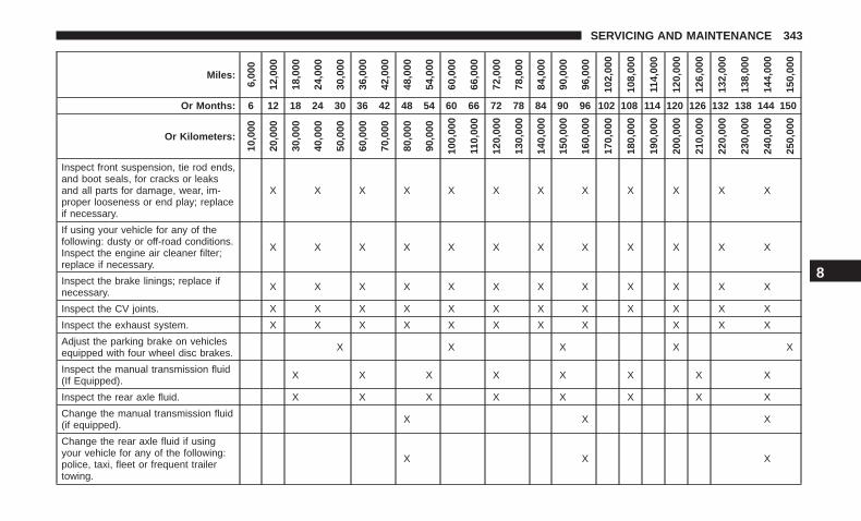
Miles:
6,00
0
12,0
00
18,0
00
24,0
00
30,0
00
36,0
00
42,0
00
48,0
00
54,0
00
60,0
00
66,0
00
72,0
00
78,0
00
84,0
00
90,0
00
96,0
00
102,
000
108,
000
114,
000
120,
000
126,
000
132,
000
138,
000
144,
000
150,
000
Or Months: 6 12 18 24 30 36 42 48 54 60 66 72 78 84 90 96 102 108 114 120 126 132 138 144 150
Or Kilometers:
10,0
00
20,0
00
30,0
00
40,0
00
50,0
00
60,0
00
70,0
00
80,0
00
90,0
00
100,
000
110,
000
120,
000
130,
000
140,
000
150,
000
160,
000
170,
000
180,
000
190,
000
200,
000
210,
000
220,
000
230,
000
240,
000
250,
000
Inspect front suspension, tie rod ends,and boot seals, for cracks or leaksand all parts for damage, wear, im-proper looseness or end play; replaceif necessary.
X X X X X X X X X X X X
If using your vehicle for any of thefollowing: dusty or off-road conditions.Inspect the engine air cleaner filter;replace if necessary.
X X X X X X X X X X X X
Inspect the brake linings; replace ifnecessary. X X X X X X X X X X X X
Inspect the CV joints. X X X X X X X X X X X X
Inspect the exhaust system. X X X X X X X X X X X
Adjust the parking brake on vehiclesequipped with four wheel disc brakes. X X X X X
Inspect the manual transmission fluid(If Equipped). X X X X X X X X
Inspect the rear axle fluid. X X X X X X X X
Change the manual transmission fluid(if equipped). X X X
Change the rear axle fluid if usingyour vehicle for any of the following:police, taxi, fleet or frequent trailertowing.
X X X
8
SERVICING AND MAINTENANCE 343
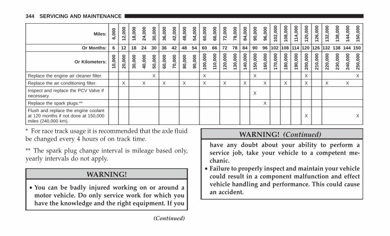
Miles:
6,00
0
12,0
00
18,0
00
24,0
00
30,0
00
36,0
00
42,0
00
48,0
00
54,0
00
60,0
00
66,0
00
72,0
00
78,0
00
84,0
00
90,0
00
96,0
00
102,
000
108,
000
114,
000
120,
000
126,
000
132,
000
138,
000
144,
000
150,
000
Or Months: 6 12 18 24 30 36 42 48 54 60 66 72 78 84 90 96 102 108 114 120 126 132 138 144 150
Or Kilometers:
10,0
00
20,0
00
30,0
00
40,0
00
50,0
00
60,0
00
70,0
00
80,0
00
90,0
00
100,
000
110,
000
120,
000
130,
000
140,
000
150,
000
160,
000
170,
000
180,
000
190,
000
200,
000
210,
000
220,
000
230,
000
240,
000
250,
000
Replace the engine air cleaner filter. X X X X X
Replace the air conditioning filter. X X X X X X X X X X X X
Inspect and replace the PCV Valve ifnecessary. X
Replace the spark plugs.** X
Flush and replace the engine coolantat 120 months if not done at 150,000miles (240,000 km).
X X
* For race track usage it is recommended that the axle fluidbe changed every 4 hours of on track time.
** The spark plug change interval is mileage based only,yearly intervals do not apply.
WARNING!
• You can be badly injured working on or around amotor vehicle. Do only service work for which youhave the knowledge and the right equipment. If you
(Continued)
WARNING! (Continued)have any doubt about your ability to perform aservice job, take your vehicle to a competent me-chanic.
• Failure to properly inspect and maintain your vehiclecould result in a component malfunction and effectvehicle handling and performance. This could causean accident.
344 SERVICING AND MAINTENANCE

ENGINE COMPARTMENT3.6L Engine
1 — Remote Jump Start (Positive Battery Post)2 — Power Distribution Center (Fuses)3 — Remote Jump Start (Negative Battery Post)4 — Brake Fluid Reservoir Access Cover5 — Engine Coolant Pressure Cap
6 — Engine Coolant Reservoir7 — Air Cleaner Filter8 — Engine Oil Fill9 — Engine Oil Dipstick10 — Washer Fluid Reservoir
8
SERVICING AND MAINTENANCE 345

5.7L Engine
1 — Washer Fluid Reservoir2 — Power Distribution Center (Fuses)3 — Engine Oil Dipstick4 — Engine Oil Fill
5 — Engine Coolant Pressure Cap6 — Brake Fluid Reservoir Access Cover7 — Engine Coolant Reservoir8 — Air Cleaner Filter
346 SERVICING AND MAINTENANCE
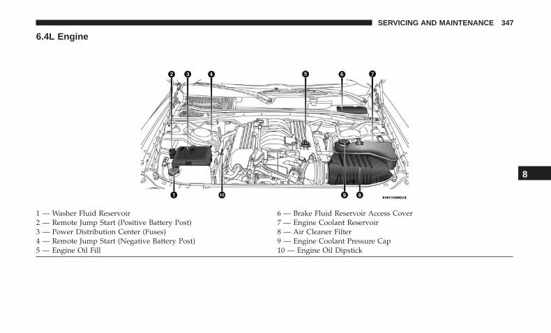
6.4L Engine
1 — Washer Fluid Reservoir 6 — Brake Fluid Reservoir Access Cover2 — Remote Jump Start (Positive Battery Post) 7 — Engine Coolant Reservoir3 — Power Distribution Center (Fuses) 8 — Air Cleaner Filter4 — Remote Jump Start (Negative Battery Post) 9 — Engine Coolant Pressure Cap5 — Engine Oil Fill 10 — Engine Oil Dipstick
8
SERVICING AND MAINTENANCE 347
Checking Oil Level — 3.6L And 5.7L Engine
To assure proper engine lubrication, the engine oil must bemaintained at the correct level. Check the oil level atregular intervals, such as every month. The best time tocheck the engine oil level is about five minutes after a fullywarmed up engine is shut off.
Checking the oil while the vehicle is on level ground willimprove the accuracy of the oil level readings.
There are three possible dipstick types,
• Crosshatched zone.
• Crosshatched zone marked SAFE.
• Crosshatched zone marked with MIN at the low end ofthe range and MAX at the high end of the range.
NOTE: Always maintain the oil level within the crosshatchmarkings on the dipstick.
Adding 1 quart (1.0 liters) of oil when the reading is at thelow end of the dipstick range will raise the oil level to thehigh end of the range marking.
CAUTION!
Overfilling or underfilling the crankcase will causeaeration or loss of oil pressure. This could damage yourengine.
Checking Oil Level — 6.4L Engine
To assure proper engine lubrication, the engine oil must bemaintained at the correct level. Check the oil level atregular intervals, such as once a month. The best time tocheck the engine oil level is about five minutes after a fullywarmed engine is shut off.
Checking the oil while the vehicle is on level ground willimprove the accuracy of the oil level readings. Maintain theoil level in the “SAFE” range. Adding 1.0 quart (1 liter) ofoil when the reading is at the bottom of the “SAFE” rangewill result in an oil level at the top of the “SAFE” range onthese engines.
CAUTION!
Overfilling or underfilling the crankcase will causeaeration or loss of oil pressure. This could damage yourengine.
348 SERVICING AND MAINTENANCE
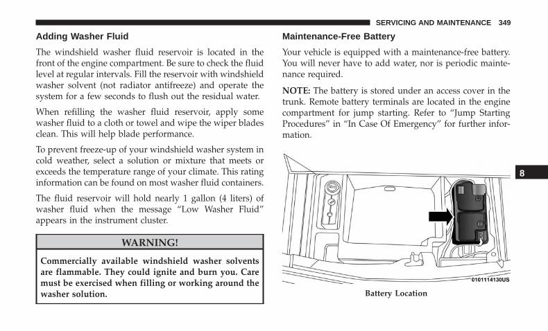
Adding Washer Fluid
The windshield washer fluid reservoir is located in thefront of the engine compartment. Be sure to check the fluidlevel at regular intervals. Fill the reservoir with windshieldwasher solvent (not radiator antifreeze) and operate thesystem for a few seconds to flush out the residual water.
When refilling the washer fluid reservoir, apply somewasher fluid to a cloth or towel and wipe the wiper bladesclean. This will help blade performance.
To prevent freeze-up of your windshield washer system incold weather, select a solution or mixture that meets orexceeds the temperature range of your climate. This ratinginformation can be found on most washer fluid containers.
The fluid reservoir will hold nearly 1 gallon (4 liters) ofwasher fluid when the message “Low Washer Fluid”appears in the instrument cluster.
WARNING!
Commercially available windshield washer solventsare flammable. They could ignite and burn you. Caremust be exercised when filling or working around thewasher solution.
Maintenance-Free Battery
Your vehicle is equipped with a maintenance-free battery.You will never have to add water, nor is periodic mainte-nance required.
NOTE: The battery is stored under an access cover in thetrunk. Remote battery terminals are located in the enginecompartment for jump starting. Refer to “Jump StartingProcedures” in “In Case Of Emergency” for further infor-mation.
Battery Location
8
SERVICING AND MAINTENANCE 349
WARNING!
• Battery fluid is a corrosive acid solution and canburn or even blind you. Do not allow battery fluid tocontact your eyes, skin, or clothing. Do not lean overa battery when attaching clamps. If acid splashes ineyes or on skin, flush the area immediately withlarge amounts of water. Refer to “Jump StartingProcedure” in “In Case Of Emergency” for furtherinformation.
• Battery gas is flammable and explosive. Keep flameor sparks away from the battery. Do not use a boosterbattery or any other booster source with an outputgreater than 12 Volts. Do not allow cable clamps totouch each other.
• Battery posts, terminals, and related accessories con-tain lead and lead compounds. Wash hands afterhandling.
• The battery in this vehicle has a vent hose thatshould not be disconnected and should only bereplaced with a battery of the same type (vented).
CAUTION!
• It is essential when replacing the cables on thebattery that the positive cable is attached to thepositive post and the negative cable is attached to thenegative post. Battery posts are marked positive (+)and negative (-) and are identified on the batterycase. Cable clamps should be tight on the terminalposts and free of corrosion.
• If a “fast charger” is used while the battery is in thevehicle, disconnect both vehicle battery cables beforeconnecting the charger to the battery. Do not use a“fast charger” to provide starting voltage.
DEALER SERVICE
An authorized dealer has the qualified service personnel,special tools, and equipment to perform all service opera-tions in an expert manner. Service Manuals are availablewhich include detailed service information for your ve-hicle. Refer to these Service Manuals before attempting anyprocedure yourself.
NOTE: Intentional tampering with emissions control sys-tems may void your warranty and could result in civilpenalties being assessed against you.
350 SERVICING AND MAINTENANCE
WARNING!
You can be badly injured working on or around amotor vehicle. Only do service work for which youhave the knowledge and the proper equipment. If youhave any doubt about your ability to perform a servicejob, take your vehicle to a competent mechanic.
Engine Oil
Change Engine Oil — 3.6L And 5.7L Engine
The oil change indicator system will remind you that it istime to take your vehicle in for scheduled maintenance.Refer to “Scheduled Servicing” in this section for theproper maintenance intervals.
NOTE: Under no circumstances should oil change inter-vals exceed 10,000 miles (16,000 km), 12 months or 350hours of engine run time, whichever comes first. The 350hours of engine run or idle time is generally only a concernfor fleet customers.
Change Engine Oil — 6.4L Engine
The oil change indicator system will remind you that it istime to take your vehicle in for scheduled maintenance.Refer to “Scheduled Servicing” in this section for theproper maintenance intervals.
NOTE: Under no circumstances should oil change inter-vals exceed 6,000 miles (10,000 km) or six months, which-ever occurs first.
Engine Oil Selection — 3.6L And 5.7L Engine
For best performance and maximum protection under alltypes of operating conditions, the manufacturer only rec-ommends engine oils that are API Certified and meet therequirements of FCA Material Standard MS-6395.
8
SERVICING AND MAINTENANCE 351

American Petroleum Institute (API) Engine OilIdentification Symbol
This symbol means that the oil hasbeen certified by the American Pe-troleum Institute (API). The manu-facturer only recommends API Cer-tified engine oils.
This symbol certifies 0W-20, 5W-20,0W-30, 5W-30 and 10W-30 engineoils.
CAUTION!
Do not use chemical flushes in your engine oil as thechemicals can damage your engine. Such damage is notcovered by the New Vehicle Limited Warranty.
Engine Oil Selection — 6.4L Engine
For best performance and maximum protection under alltypes of operating conditions, the manufacturer only rec-ommends full synthetic engine oils that meet the AmericanPetroleum Institute (API) categories of SN.
The manufacturer recommends the use of a full syntheticSAE 0W-40 engine oil or equivalent meeting the require-ments of FCA Material Standard MS-12633.
CAUTION!
Do not use chemical flushes in your engine oil as thechemicals can damage your engine. Such damage is notcovered by the New Vehicle Limited Warranty.
Engine Oil Viscosity (SAE Grade) — 3.6L Engine
Mopar SAE 5W-20 engine oil approved to FCA MaterialStandard MS-6395 such as Pennzoil, Shell Helix Ultra orequivalent is recommended for all operating temperatures.This engine oil improves low temperature starting andvehicle fuel economy.
The engine oil filler cap also shows the recommendedengine oil viscosity for your engine. For information onengine oil filler cap location, refer to the “Engine Compart-ment” illustration in this section.
NOTE: Mopar SAE 5W-30 engine oil approved to FCAMaterial Standard MS-6395 such as Pennzoil, Shell HelixUltra or equivalent may be used when SAE 5W-20 engineoil meeting MS-6395 is not available.
352 SERVICING AND MAINTENANCE

Lubricants which do not have both the engine oil certifi-cation mark and the correct SAE viscosity grade numbershould not be used.
Engine Oil Viscosity (SAE Grade) — 5.7L Engine
Mopar SAE 5W-20 engine oil approved to FCA MaterialStandard MS-6395 such as Pennzoil, Shell Helix Ultra orequivalent is recommended for all operating temperatures.This engine oil improves low temperature starting andvehicle fuel economy.
The engine oil filler cap also shows the recommendedengine oil viscosity for your engine. For information onengine oil filler cap location, refer to the “Engine Compart-ment” illustration in this section.
NOTE: Vehicles equipped with a 5.7L engine must use SAE5W-20 oil. Failure to do so may result in improper opera-tion of the Fuel Saver Technology. Refer to “Fuel SaverTechnology – If Equipped” in “Starting And Operating” forfurther information.
Lubricants which do not have both the engine oil certifi-cation mark and the correct SAE viscosity grade numbershould not be used.
Engine Oil Viscosity — 6.4L Engine
Use Pennzoil Ultra Platinum 0W-40 engine or equivalentMopar oil meeting the FCA Material Standard MS-12633for use in all operating temperatures.
The engine oil filler cap also shows the recommendedengine oil viscosity for your engine. For information onengine oil filler cap location, refer to “Engine Compart-ment” in this section for further information.
Synthetic Engine Oils
You may use synthetic engine oils provided the recom-mended oil quality requirements are met, and the recom-mended maintenance intervals for oil and filter changes arefollowed.
Synthetic engine oils which do not have both the engine oilcertification mark and the correct SAE viscosity gradenumber should not be used.
Shaker Hood — If Equipped
Shaker Hood Oil Filler
For vehicles equipped with a “Shaker Hood”, the upperscoop will need to be removed so that oil can be properlyadded to the engine.
8
SERVICING AND MAINTENANCE 353

To do this, you will need follow the procedure below:
1. Remove the four nuts with the Shaker tool located inglove compartment.
2. Lift off the upper scoop.
NOTE: Be sure to clean off all debris around or inside forthe shaker assembly.
3. Locate the oil fill cover in base assembly to expose theoil fill cap.
4. Remove oil fill cap to add oil.
5. Re-install shaker assembly.
Shaker Hood Air Filter Cleaning
1. Remove the air filter from the intake and set the filterclamp a side.
2. Measure the length of the filter media.
3. Fill a bucket with warm clean water to the depthmatching the filter media measurement and add a mildhousehold detergent or air filter cleaning solution.
4. Without allowing the solution to flow back into theinside of the air filter, submerge the filter media in to thewater and let it soak for ten minutes.
5. Empty the bucket filled with dirty water and repeatsteps 3 and 4.
6. Refill the bucket with clean warm water and rinse thefilter by rotating the filter.
NOTE: The water should be clean with no signs of dirt inthe bucket.
7. Allow the filter to air dry. Re-install the filter on theintake system once it is dry.
Shaker Hood Removal And Cleaning
1. Remove the four nuts with the Shaker tool located inglove compartment.
2. Lift off the upper scoop.
NOTE: Be sure to clean off all debris around or inside forthe shaker assembly.
3. Using a water and mild detergent clean the followinglocations.
— The water drain slot located at the front forward edge ofthe shaker assembly.
— The seals attached to the scoop and air box.
354 SERVICING AND MAINTENANCE

— Lower water drains located in the lower shaker assem-bly and air box as well as the hood interface areas for theseals. Apply Mopar Leather, Rubber & Vinyl Protectantafter cleaning to seals.
4. Re-install shaker assembly.
Materials Added To Engine Oil
The manufacturer strongly recommends against the addi-tion of any additives (other than leak detection dyes) to theengine oil. Engine oil is an engineered product and itsperformance may be impaired by supplemental additives.
Disposing Of Used Engine Oil And Oil Filters
Care should be taken in disposing of used engine oil andoil filters from your vehicle. Used oil and oil filters,indiscriminately discarded, can present a problem to theenvironment. Contact an authorized dealer, service stationor governmental agency for advice on how and where usedoil and oil filters can be safely discarded in your area.
Engine Oil Filter
The engine oil filter should be replaced with a new filter atevery engine oil change.
Engine Oil Filter Selection
This manufacturer’s engines have a full-flow type dispos-able oil filter. Use a filter of this type for replacement. Thequality of replacement filters varies considerably. Onlyhigh quality filters should be used to assure most efficientservice. Mopar engine oil filters are high quality oil filtersand are recommended.
Engine Air Cleaner Filter
Refer to the “Maintenance Plan” in this section for theproper maintenance intervals.
NOTE: Be sure to follow the “Severe Duty Conditions”maintenance interval if applicable.
WARNING!
The air induction system (air cleaner, hoses, etc.) canprovide a measure of protection in the case of enginebackfire. Do not remove the air induction system (aircleaner, hoses, etc.) unless such removal is necessary forrepair or maintenance. Make sure that no one is near theengine compartment before starting the vehicle with theair induction system (air cleaner, hoses, etc.) removed.Failure to do so can result in serious personal injury.
8
SERVICING AND MAINTENANCE 355
Engine Air Cleaner Filter Selection
The quality of replacement engine air cleaner filters variesconsiderably. Only high quality filters should be used toassure most efficient service. Mopar engine air cleanerfilters are a high quality filter and are recommended.
T/A Air Filter Maintenance — If Equipped
Clean Engine Air Filter
The scheduled air filter cleaning interval is 30,000 miles(48,280 km), or if in a dusty environment the engine air filtershould be checked periodically to ensure optimal air flow.
Cleaning your engine air filter with the recommendedMopar Performance Air Filter Service Kit is not required ifyou can still see any part the wire screen on the entire airfilter regardless of how dirty it may appear. When any partof the wire screen is no longer visible on the air filter, thatis an indication it is time to clean the air filter.
1. Spray the air filter with the recommended Mopar airfilter cleaner and let sit for at least 10 minutes to loosendirt, before rinsing.
NOTE: Never use strong detergents, high pressure, orgasoline on air filter.
2. Rinse the air filter with cool low-pressure water appliedfrom the inside (clean side) out in order to flush the dirtout of the filter. Continue to rinse the filter until alltraces of the cleaner have been removed.
NOTE: It may be necessary to repeat steps 1 and 2 if the airfilter is not completely clean.
3. After rinsing the air filter, gently shake off the excesswater and allow air filter to dry naturally. Do not applyoil until air filter is completely dry.
NOTE: Do not use forced air pressure as it may damage thefiltering capabilities of the filter’s microfibers and also voidits warranty.
4. Using the Mopar Performance Air Filter Service Kit, sprayoil evenly along the crown of each filter pleat holding thenozzle about 3 inches (76mm) away from the air filter. Onespray per 2 square inches (1,290 square mm) of air filter.With one complete coat of oil, let it wick (saturate) forabout 20 minutes, and if required touch up any light areason either side of the filter.
Air Conditioner Maintenance
For best possible performance, your air conditioner shouldbe checked and serviced by an authorized dealer at thestart of each warm season. This service should include
356 SERVICING AND MAINTENANCE
cleaning of the condenser fins and a performance test.Drive belt tension should also be checked at this time.
WARNING!
• Use only refrigerants and compressor lubricants ap-proved by the manufacturer for your air conditioningsystem. Some unapproved refrigerants are flam-mable and can explode, injuring you. Other unap-proved refrigerants or lubricants can cause the sys-tem to fail, requiring costly repairs. Refer toWarranty Information Book, for further warrantyinformation.
• The air conditioning system contains refrigerant un-der high pressure. To avoid risk of personal injury ordamage to the system, adding refrigerant or anyrepair requiring lines to be disconnected should bedone by an experienced technician.
CAUTION!
Do not use chemical flushes in your air conditioningsystem as the chemicals can damage your air condition-ing components. Such damage is not covered by theNew Vehicle Limited Warranty.
Refrigerant Recovery And Recycling R-134a —If Equipped
R-134a Air Conditioning Refrigerant is a hydrofluoro-carbon (HFC) that is an ozone-friendly substance. Themanufacturer recommends that air conditioning service beperformed by an authorized dealer or other service facili-ties using recovery and recycling equipment.
NOTE: Use only manufacturer approved A/C system PAGcompressor oil and refrigerants.
Refrigerant Recovery And Recycling R-1234yf —If Equipped
R–1234yf Air Conditioning Refrigerant is a hydrofluo-roolefin (HFO) that is endorsed by the EnvironmentalProtection Agency and is an ozone-friendly substance witha low global-warming potential. The manufacturer recom-mends that air conditioning service be performed by anauthorized dealer using recovery and recycling equipment.
NOTE: Use only manufacturer approved A/C systemPAG compressor oil, and refrigerants.
8
SERVICING AND MAINTENANCE 357

A/C Air Filter
The filter is located in the fresh air inlet under the hood,behind a removable panel in the cowl on the passenger sideof the vehicle, next to the windshield wipers. When install-ing a new filter, ensure its proper orientation.
1. Remove the access door in the cowl screen by pressingthe retaining clips.
2. Unsnap both ends and lift the filter access cover.
3. Remove the used filter.
4. Install the new filter with arrows pointing in the direc-tion of airflow, which is toward the rear of the vehicle(text and arrows on the filter will indicate this).
Access Door
Filter Access Cover
358 SERVICING AND MAINTENANCE

5. Close the filter access cover.
Refer to “Scheduled Servicing” in this section for theproper maintenance intervals.
Accessory Drive Belt Inspection
WARNING!
• Do not attempt to inspect an accessory drive beltwith vehicle running.
(Continued)
WARNING! (Continued)• When working near the radiator cooling fan, discon-
nect the fan motor lead. The fan is temperaturecontrolled and can start at any time regardless ofignition mode. You could be injured by the movingfan blades.
• You can be badly injured working on or around amotor vehicle. Only do service work for which youhave the knowledge and the proper equipment. Ifyou have any doubt about your ability to perform aservice job, take your vehicle to a competent me-chanic.
When inspecting accessory drive belts, small cracks thatrun across ribbed surface of belt from rib to rib, areconsidered normal. These are not a reason to replace belt.However, cracks running along a rib (not across) are notnormal. Any belt with cracks running along a rib must bereplaced. Also have the belt replaced if it has excessivewear, frayed cords or severe glazing.
A/C Air Filter 8
SERVICING AND MAINTENANCE 359
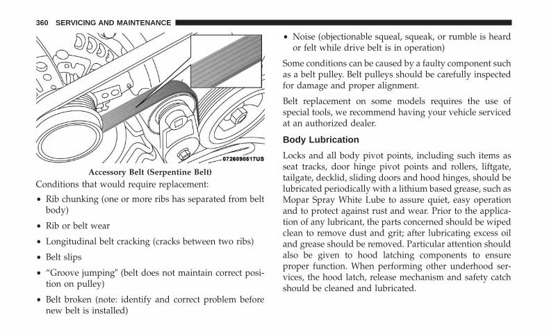
Conditions that would require replacement:
• Rib chunking (one or more ribs has separated from beltbody)
• Rib or belt wear
• Longitudinal belt cracking (cracks between two ribs)
• Belt slips
• “Groove jumping� (belt does not maintain correct posi-tion on pulley)
• Belt broken (note: identify and correct problem beforenew belt is installed)
• Noise (objectionable squeal, squeak, or rumble is heardor felt while drive belt is in operation)
Some conditions can be caused by a faulty component suchas a belt pulley. Belt pulleys should be carefully inspectedfor damage and proper alignment.
Belt replacement on some models requires the use ofspecial tools, we recommend having your vehicle servicedat an authorized dealer.
Body Lubrication
Locks and all body pivot points, including such items asseat tracks, door hinge pivot points and rollers, liftgate,tailgate, decklid, sliding doors and hood hinges, should belubricated periodically with a lithium based grease, such asMopar Spray White Lube to assure quiet, easy operationand to protect against rust and wear. Prior to the applica-tion of any lubricant, the parts concerned should be wipedclean to remove dust and grit; after lubricating excess oiland grease should be removed. Particular attention shouldalso be given to hood latching components to ensureproper function. When performing other underhood ser-vices, the hood latch, release mechanism and safety catchshould be cleaned and lubricated.
Accessory Belt (Serpentine Belt)
360 SERVICING AND MAINTENANCE

The external lock cylinders should be lubricated twice ayear, preferably in the Fall and Spring. Apply a smallamount of a high quality lubricant, such as Mopar LockCylinder Lubricant directly into the lock cylinder.
Windshield Wiper Blades
Clean the rubber edges of the wiper blades and thewindshield periodically with a sponge or soft cloth and amild nonabrasive cleaner. This will remove accumulationsof salt or road film.
Operation of the wipers on dry glass for long periods maycause deterioration of the wiper blades. Always use washerfluid when using the wipers to remove salt or dirt from adry windshield.
Avoid using the wiper blades to remove frost or ice fromthe windshield. Keep the blade rubber out of contact withpetroleum products such as engine oil, gasoline, etc.
NOTE: Life expectancy of wiper blades varies dependingon geographical area and frequency of use. Poor perfor-mance of blades may be present with chattering, marks,water lines or wet spots. If any of these conditions arepresent, clean the wiper blades or replace as necessary.
Wiper Blade Removal/Installation
CAUTION!Do not allow the wiper arm to spring back against theglass without the wiper blade in place or the glass maybe damaged.
1. Lift the wiper arm to raise the wiper blade off of theglass, until the wiper arm is in the full up position.
Wiper Blade With Release Tab In Locked Position1 — Wiper Blade2 — Wiper Arm3 — Release Tab
8
SERVICING AND MAINTENANCE 361

2. To disengage the wiper blade from the wiper arm, pressthe release tab on the wiper blade and while holding thewiper arm with one hand, slide the wiper blade downtowards the base of the wiper arm.
3. With the wiper blade disengaged, remove the wiperblade from the wiper arm.
4. Gently lower the wiper arm onto the glass.
Installing The Front Wipers
1. Lift the wiper arm off of the glass, until the wiper arm isin the full up position.
2. Position the wiper blade near the hook on the tip of thewiper arm.
Wiper Blade With Release Tab In Unlocked Position
1 — Wiper Blade2 — Wiper Arm3 — Release Tab
Wiper Blade Removed From Wiper Arm
1 — Wiper Blade2 — Wiper Arm3 — Release Tab
362 SERVICING AND MAINTENANCE

3. Insert the hook on the tip of the arm through theopening in the wiper blade.
4. Slide the wiper blade up into the hook on the wiper arm,latch engagement will be accompanied by an audibleclick.
5. Gently lower the wiper blade onto the glass.
Exhaust System
The best protection against carbon monoxide entry into thevehicle body is a properly maintained engine exhaustsystem.
If you notice a change in the sound of the exhaust system;or if the exhaust fumes can be detected inside the vehicle;or when the underside or rear of the vehicle is damaged;have an authorized technician inspect the complete ex-haust system and adjacent body areas for broken, dam-aged, deteriorated, or mispositioned parts. Open seams orloose connections could permit exhaust fumes to seep intothe passenger compartment. In addition, have the exhaustsystem inspected each time the vehicle is raised for lubri-cation or oil change. Replace as required.
WARNING!
• Exhaust gases can injure or kill. They contain carbonmonoxide (CO), which is colorless and odorless.Breathing it can make you unconscious and caneventually poison you. To avoid breathing CO, referto “Safety Tips” in “Safety” for further information.
• A hot exhaust system can start a fire if you park overmaterials that can burn. Such materials might begrass or leaves coming into contact with your exhaustsystem. Do not park or operate your vehicle in areaswhere your exhaust system can contact anything thatcan burn.
CAUTION!
• The catalytic converter requires the use of unleadedfuel only. Leaded gasoline will destroy the effective-ness of the catalyst as an emissions control deviceand may seriously reduce engine performance andcause serious damage to the engine.
• Damage to the catalytic converter can result if yourvehicle is not kept in proper operating condition. In
(Continued)
8
SERVICING AND MAINTENANCE 363
CAUTION! (Continued)the event of engine malfunction, particularly involv-ing engine misfire or other apparent loss of perfor-mance, have your vehicle serviced promptly. Contin-ued operation of your vehicle with a severemalfunction could cause the converter to overheat,resulting in possible damage to the converter andvehicle.
Under normal operating conditions, the catalytic converterwill not require maintenance. However, it is important tokeep the engine properly tuned to assure proper catalystoperation and prevent possible catalyst damage.
NOTE: Intentional tampering with emissions control sys-tems can result in civil penalties being assessed againstyou.
In unusual situations involving grossly malfunctioningengine operation, a scorching odor may suggest severe andabnormal catalyst overheating. If this occurs, stop thevehicle, turn off the engine and allow it to cool. Service,including a tune-up to manufacturer’s specifications,should be obtained immediately.
To minimize the possibility of catalytic converter damage:
• Do not shut off the engine or interrupt the ignition whenthe transmission is in gear and the vehicle is in motion.
• Do not try to start the engine by pushing or towing thevehicle.
• Do not idle the engine with any spark plug wiresdisconnected or removed, such as when diagnostictesting, or for prolonged periods during very rough idleor malfunctioning operating conditions.
NOTE: Your vehicle’s exhaust system may be equippedwith an Electronic Exhaust Valve (EEV) system, if theexhaust system is replaced with aftermarket products aMalfunction Indicator Lamp (MIL) will illuminate.
364 SERVICING AND MAINTENANCE
Cooling System
WARNING!
• You or others can be badly burned by hot enginecoolant (antifreeze) or steam from your radiator. Ifyou see or hear steam coming from under the hood,do not open the hood until the radiator has had timeto cool. Never open a cooling system pressure capwhen the radiator or coolant bottle is hot.
• Keep hands, tools, clothing, and jewelry away fromthe radiator cooling fan when the hood is raised. Thefan starts automatically and may start at any time,whether the engine is running or not.
• When working near the radiator cooling fan, discon-nect the fan motor lead or turn the ignition to theOFF mode. The fan is temperature controlled and canstart at any time the ignition is in the ON mode.
Coolant Checks
Check engine coolant (antifreeze) protection every 12months (before the onset of freezing weather, where appli-cable). If coolant is dirty or rusty in appearance, the systemshould be drained, flushed, and refilled with fresh coolant.Check the front of the radiator for any accumulation of
bugs, leaves, etc. If dirty, clean by gently spraying waterfrom a garden hose vertically down the face of the con-denser.
Check the coolant recovery bottle tubing for brittle rubber,cracking, tears, cuts, and tightness of the connection at thebottle and radiator. Inspect the entire system for leaks. DONOT REMOVE THE COOLANT PRESSURE CAP WHENTHE COOLING SYSTEM IS HOT.
Cooling System — Drain, Flush And Refill
NOTE: Some vehicles require special tools to add coolantproperly. Failure to fill these systems properly could lead tosevere internal engine damage. If any coolant is needed tobe added to the system please contact an authorized dealer.
If the engine coolant (antifreeze) is dirty or contains visiblesediment, have an authorized dealer clean and flush withOAT coolant (antifreeze) (conforming to MS.90032).
Refer to the “Maintenance Plan” in this section for theproper maintenance intervals.
Selection Of Coolant
Refer to “Fluids And Lubricants” in “Technical Specifica-tions” for further information.
8
SERVICING AND MAINTENANCE 365

NOTE:
• Mixing of engine coolant (antifreeze) other than speci-fied Organic Additive Technology (OAT) engine coolant(antifreeze), may result in engine damage and maydecrease corrosion protection. Organic Additive Tech-nology (OAT) engine coolant is different and should notbe mixed with Hybrid Organic Additive Technology(HOAT) engine coolant (antifreeze) or any “globallycompatible” coolant (antifreeze). If a non-OAT enginecoolant (antifreeze) is introduced into the cooling systemin an emergency, the cooling system will need to bedrained, flushed, and refilled with fresh OAT coolant(conforming to MS.90032), by an authorized dealer assoon as possible.
• Do not use water alone or alcohol-based engine coolant(antifreeze) products. Do not use additional rust inhibi-tors or antirust products, as they may not be compatiblewith the radiator engine coolant and may plug theradiator.
• This vehicle has not been designed for use with propyl-ene glycol-based engine coolant (antifreeze). Use ofpropylene glycolbased engine coolant (antifreeze) is notrecommended.
• Some vehicles require special tools to add coolant prop-erly. Failure to fill these systems properly could lead tosevere internal engine damage. If any coolant is neededto be added to the system please contact an authorizeddealer.
Adding Coolant
Your vehicle has been built with an improved enginecoolant (OAT coolant conforming to MS.90032) that allowsextended maintenance intervals. This engine coolant (anti-freeze) can be used up to ten years or 150,000 miles(240,000 km) before replacement. To prevent reducing thisextended maintenance period, it is important that you usethe same engine coolant (OAT coolant conforming toMS.90032) throughout the life of your vehicle.
Please review these recommendations for using OrganicAdditive Technology (OAT) engine coolant (antifreeze)that meets the requirements of FCA Material StandardMS.90032. When adding engine coolant (antifreeze):
• We recommend using Mopar Antifreeze/Coolant 10Year/150,000 Mile (240,000 km) Formula OAT (OrganicAdditive Technology) that meets the requirements ofFCA Material Standard MS.90032.
366 SERVICING AND MAINTENANCE

• Mix a minimum solution of 50% OAT engine coolantthat meets the requirements of FCA Material StandardMS.90032 and distilled water. Use higher concentrations(not to exceed 70%) if temperatures below −34°F (−37°C)are anticipated. Please contact an authorized dealer forassistance.
• Use only high purity water such as distilled or deionizedwater when mixing the water/engine coolant (anti-freeze) solution. The use of lower quality water willreduce the amount of corrosion protection in the enginecooling system.
NOTE:
• It is the owner’s responsibility to maintain the properlevel of protection against freezing according to thetemperatures occurring in the area where the vehicle isoperated.
• Some vehicles require special tools to add coolant prop-erly. Failure to fill these systems properly could lead tosevere internal engine damage. If any coolant is neededto be added to the system, please contact a local autho-rized dealer.
• Mixing engine coolant (antifreeze) types is not recom-mended and can result in cooling system damage. If
HOAT and OAT coolant are mixed in an emergency,have a authorized dealer drain, flush, and refill withOAT coolant (conforming to MS.90032) as soon as pos-sible.
Cooling System Pressure Cap
The cap must be fully tightened to prevent loss of enginecoolant (antifreeze), and to ensure that engine coolant(antifreeze) will return to the radiator from the coolantexpansion bottle/recovery tank if so equipped.
The cap should be inspected and cleaned if there is anyaccumulation of foreign material on the sealing surfaces.
WARNING!
• Do not open hot engine cooling system. Never addengine coolant (antifreeze) when the engine is over-heated. Do not loosen or remove the cap to cool anoverheated engine. Heat causes pressure to build upin the cooling system. To prevent scalding or injury,do not remove the pressure cap while the system ishot or under pressure.
• Do not use a pressure cap other than the one speci-fied for your vehicle. Personal injury or enginedamage may result.
8
SERVICING AND MAINTENANCE 367
Disposal Of Used Coolant
Used ethylene glycol-based coolant (antifreeze) is a regu-lated substance requiring proper disposal. Check with yourlocal authorities to determine the disposal rules for yourcommunity. To prevent ingestion by animals or children,do not store ethylene glycol-based coolant in open contain-ers or allow it to remain in puddles on the ground. Ifingested by a child or pet, seek emergency assistanceimmediately. Clean up any ground spills immediately.
Coolant Level
The coolant bottle provides a quick visual method fordetermining that the engine coolant (antifreeze) level isadequate. With the engine OFF and cold, the level of theengine coolant (antifreeze) in the bottle should be betweenthe ranges indicated on the bottle.
The radiator normally remains completely full, so there isno need to remove the radiator cap unless checking forengine coolant (antifreeze) freeze point or replacing enginecoolant (antifreeze). Advise your service attendant of this.As long as the engine operating temperature is satisfactory,the coolant bottle need only be checked once a month.
When additional engine coolant (antifreeze) is needed tomaintain the proper level, it should be added to the coolantbottle. Do not overfill.
Points To Remember
NOTE: When the vehicle is stopped after a few miles/kilometers of operation, you may observe vapor comingfrom the front of the engine compartment. This is normallya result of moisture from rain, snow, or high humidityaccumulating on the radiator and being vaporized whenthe thermostat opens, allowing hot engine coolant (anti-freeze) to enter the radiator.
If an examination of your engine compartment shows noevidence of radiator or hose leaks, the vehicle may besafely driven. The vapor will soon dissipate.
• Do not overfill the coolant expansion bottle.
• Check the coolant freeze point in the radiator and in thecoolant expansion bottle. If engine coolant (antifreeze)needs to be added, the contents of the coolant expansionbottle must also be protected against freezing.
• If frequent engine coolant (antifreeze) additions arerequired, the cooling system should be pressure testedfor leaks.
368 SERVICING AND MAINTENANCE

• Maintain engine coolant (antifreeze) concentration at aminimum of 50% OAT coolant (conforming toMS.90032) and distilled water for proper corrosion pro-tection of your engine which contains aluminum com-ponents.
• Make sure that the coolant expansion bottle overflowhoses are not kinked or obstructed.
• Keep the front of the radiator clean. If your vehicle isequipped with air conditioning, keep the front of thecondenser clean.
• Do not change the thermostat for Summer or Winteroperation. If replacement is ever necessary, install ONLYthe correct type thermostat. Other designs may result inunsatisfactory engine coolant (antifreeze) performance,poor gas mileage, and increased emissions.
Brake System
In order to assure brake system performance, all brakesystem components should be inspected periodically. Referto the “Maintenance Plan” in this section for the propermaintenance intervals.
WARNING!
Riding the brakes can lead to brake failure and possi-bly a collision. Driving with your foot resting or ridingon the brake pedal can result in abnormally high braketemperatures, excessive lining wear, and possiblebrake damage. You would not have your full brakingcapacity in an emergency.
Fluid Level Check — Brake Master Cylinder
Check the fluid level in the master cylinder immediately ifthe brake system warning light indicates system failure.
Check the fluid level in the master cylinder when perform-ing underhood services.
Clean the top of the master cylinder area before removingthe cap. Add fluid to bring the level up to the top of the“FULL” mark on the side of the master cylinder reservoir.
Overfilling of fluid is not recommended because it maycause leaking in the system.
8
SERVICING AND MAINTENANCE 369
Add enough fluid to bring the level up to the requirementsdescribed on the brake fluid reservoir. With disc brakes,fluid level can be expected to fall as the brake pads wear.However, low fluid level may be caused by a leak and acheckup may be needed.
Use only brake fluid that has been recommended by themanufacturer, and has been kept in a tightly closed con-tainer to avoid contamination from foreign matter ormoisture.
Refer to “Fluids And Lubricants” in “Technical Specifica-tions” for further information.
WARNING!
• Use only manufacturer’s recommended brake fluid.Refer to “Fluids And Lubricants” in “TechnicalSpecifications” for further information. Using thewrong type of brake fluid can severely damage yourbrake system and/or impair its performance. Theproper type of brake fluid for your vehicle is alsoidentified on the original factory installed hydraulicmaster cylinder reservoir.
(Continued)
WARNING! (Continued)• To avoid contamination from foreign matter or mois-
ture, use only new brake fluid or fluid that has beenin a tightly closed container. Keep the master cylin-der reservoir cap secured at all times. Brake fluid ina open container absorbs moisture from the airresulting in a lower boiling point. This may cause itto boil unexpectedly during hard or prolonged brak-ing, resulting in sudden brake failure. This couldresult in a collision.
• Overfilling the brake fluid reservoir can result inspilling brake fluid on hot engine parts, causing thebrake fluid to catch fire. Brake fluid can also damagepainted and vinyl surfaces, care should be taken toavoid its contact with these surfaces.
• Do not allow petroleum based fluid to contaminatethe brake fluid. Brake seal components could bedamaged, causing partial or complete brake failure.This could result in a collision.
370 SERVICING AND MAINTENANCE
Clutch Hydraulic System — Manual Transmission(If Equipped)
The clutch hydraulic system is fed by a segregated volume offluid within the brake system master cylinder reservoir. Inthe event of leakage or wear, use only the manufacturer’srecommended brake fluid. Refer to “Fluids And Lubricants”in “Technical Specifications” for further information.
Manual Transmission — If Equipped
Fluid Level Check
Check the fluid level by removing the fill plug on the leftside of the transmission. The fluid level should be 1/4 inch(6.4mm) below the bottom of the fill hole. Add fluid, ifnecessary, to maintain the proper level. Refer to “FluidsAnd Lubricants” in “Technical Specifications” for furtherinformation.
CAUTION!
Using a transmission fluid other than the manufactur-er’s recommended fluid may cause deterioration intransmission shift quality and/or damage to the trans-mission. Refer to “Fluids And Lubricants” in “Techni-cal Specifications” for fluid specifications.
Change Transmission Fluid
If contaminated with water, change the fluid immediately.See your authorized dealer for service.
Refer to the “Maintenance Plan” in this section for theproper maintenance intervals.
Automatic Transmission — If Equipped
Selection Of Lubricant
It is important to use the proper transmission fluid toensure optimum transmission performance and life. Useonly the manufacturer’s specified transmission fluid. Referto “Fluids And Lubricants” in “Technical Specifications”for fluid specifications. It is important to maintain thetransmission fluid at the correct level using the recom-mended fluid.
NOTE: No chemical flushes should be used in any trans-mission; only the approved lubricant should be used.
CAUTION!
Using a transmission fluid other than the manufactur-er’s recommended fluid may cause deterioration in
(Continued)
8
SERVICING AND MAINTENANCE 371
CAUTION! (Continued)transmission shift quality and/or torque convertershudder. Refer to “Fluids And Lubricants” in “Techni-cal Specifications” for fluid specifications.
Special Additives
The manufacturer strongly recommends against using anyspecial additives in the transmission. Automatic Transmis-sion Fluid (ATF) is an engineered product and its perfor-mance may be impaired by supplemental additives. There-fore, do not add any fluid additives to the transmission.Avoid using transmission sealers as they may adverselyaffect seals.
CAUTION!
Do not use chemical flushes in your transmission asthe chemicals can damage your transmission compo-nents. Such damage is not covered by the New VehicleLimited Warranty.
Fluid Level Check
The fluid level is preset at the factory and does not requireadjustment under normal operating conditions. Routine
fluid level checks are not required; therefore the transmis-sion has no dipstick. An authorized dealer can check yourtransmission fluid level using special service tools. If younotice fluid leakage or transmission malfunction, visit anauthorized dealer immediately to have the transmissionfluid level checked. Operating the vehicle with an im-proper fluid level can cause severe transmission damage.
CAUTION!
If a transmission fluid leak occurs, visit an authorizeddealer immediately. Severe transmission damage mayoccur. An authorized dealer has the proper tools toadjust the fluid level accurately.
Fluid And Filter Changes
Under normal operating conditions, the fluid installed atthe factory will provide satisfactory lubrication for the lifeof the vehicle.
Routine fluid and filter changes are not required. However,change the fluid and filter if the fluid becomes contami-nated (with water, etc.), or if the transmission is disas-sembled for any reason.
372 SERVICING AND MAINTENANCE
All Wheel Drive (AWD) — If Equipped
The all wheel drive system consists of a transfer case andfront differential. The exterior surface of these componentsshould be inspected for evidence of fluid leaks. Confirmedleaks should be repaired as soon as possible.
The transfer case fluid fill/inspection plug is located in themiddle of the rear housing. To inspect the transfer casefluid level, remove the fill/inspection plug. The fluid levelshould be even with the bottom of the hole. Use this plugto add fluid as required.
The front differential fill plug is located on the outer covernear the halfshaft attachment. To inspect the differentialfluid level, remove the fill plug. The fluid level should beeven with or slightly below the bottom of the hole.
Fluid Changes
Refer to “Scheduled Servicing” in “Servicing And Mainte-nance” for the proper maintenance intervals.
Rear Axle
Fluid Level Check
Checking the fluid level while the vehicle is on levelground and has been stationary for 15 minutes will im-prove the accuracy of the fluid level reading.
Check the fluid level by removing the fill plug on the axle.The fluid level should be 1-2.5 mm below the fill plug. Addfluid, if necessary, to maintain the proper level. Refer to“Fluids And Lubricants” in �Servicing And Maintenance”for further information.
Change Axle Fluid
Refer to “Scheduled Servicing” in “Servicing And Mainte-nance” for the proper maintenance intervals.
RAISING THE VEHICLE
In the case where it is necessary to raise the vehicle, go toan authorized dealer or service station.
8
SERVICING AND MAINTENANCE 373
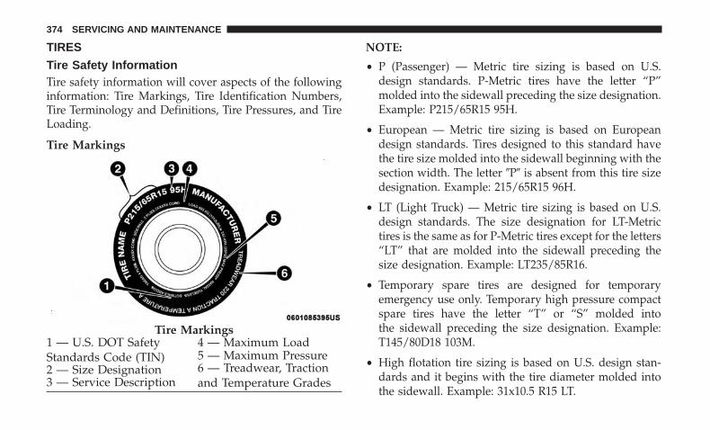
TIRES
Tire Safety InformationTire safety information will cover aspects of the followinginformation: Tire Markings, Tire Identification Numbers,Tire Terminology and Definitions, Tire Pressures, and TireLoading.
Tire Markings
NOTE:
• P (Passenger) — Metric tire sizing is based on U.S.design standards. P-Metric tires have the letter “P”molded into the sidewall preceding the size designation.Example: P215/65R15 95H.
• European — Metric tire sizing is based on Europeandesign standards. Tires designed to this standard havethe tire size molded into the sidewall beginning with thesection width. The letter �P� is absent from this tire sizedesignation. Example: 215/65R15 96H.
• LT (Light Truck) — Metric tire sizing is based on U.S.design standards. The size designation for LT-Metrictires is the same as for P-Metric tires except for the letters“LT” that are molded into the sidewall preceding thesize designation. Example: LT235/85R16.
• Temporary spare tires are designed for temporaryemergency use only. Temporary high pressure compactspare tires have the letter “T” or “S” molded intothe sidewall preceding the size designation. Example:T145/80D18 103M.
• High flotation tire sizing is based on U.S. design stan-dards and it begins with the tire diameter molded intothe sidewall. Example: 31x10.5 R15 LT.
Tire Markings1 — U.S. DOT SafetyStandards Code (TIN)
4 — Maximum Load
2 — Size Designation5 — Maximum Pressure
3 — Service Description6 — Treadwear, Tractionand Temperature Grades
374 SERVICING AND MAINTENANCE

Tire Sizing Chart
EXAMPLE:Example Size Designation: P215/65R15XL 95H, 215/65R15 96H, LT235/85R16C, T145/80D18 103M, 31x10.5 R15 LTP = Passenger car tire size based on U.S. design standards, or�....blank....� = Passenger car tire based on European design standards, orLT = Light truck tire based on U.S. design standards, orT or S = Temporary spare tire or31 = Overall diameter in inches (in)215, 235, 145 = Section width in millimeters (mm)65, 85, 80 = Aspect ratio in percent (%)– Ratio of section height to section width of tire, or10.5 = Section width in inches (in)R = Construction code– �R� means radial construction, or– �D� means diagonal or bias construction15, 16, 18 = Rim diameter in inches (in)Service Description:95 = Load Index– A numerical code associated with the maximum load a tire can carry
8
SERVICING AND MAINTENANCE 375
EXAMPLE:H = Speed Symbol– A symbol indicating the range of speeds at which a tire can carry a load corresponding to its load index under cer-
tain operating conditions– The maximum speed corresponding to the speed symbol should only be achieved under specified operating condi-
tions (i.e., tire pressure, vehicle loading, road conditions, and posted speed limits)Load Identification:Absence of the following load identification symbols on the sidewall of the tire indicates a Standard Load (SL) tire:• XL = Extra load (or reinforced) tire, or• LL = Light load tire or• C, D, E, F, G = Load range associated with the maximum load a tire can carry at a specified pressureMaximum Load – Maximum load indicates the maximum load this tire is designed to carryMaximum Pressure – Maximum pressure indicates the maximum permissible cold tire inflation pressure for this tire
376 SERVICING AND MAINTENANCE

Tire Identification Number (TIN)The TIN may be found on one or both sides of the tire;however, the date code may only be on one side. Tires withwhite sidewalls will have the full TIN, including the datecode, located on the white sidewall side of the tire. Look for
the TIN on the outboard side of black sidewall tires asmounted on the vehicle. If the TIN is not found on theoutboard side, then you will find it on the inboard side ofthe tire.
EXAMPLE:DOT MA L9 ABCD 0301
DOT = Department of Transportation– This symbol certifies that the tire is in compliance with the U.S. Department of Transportation tire safety standards
and is approved for highway useMA = Code representing the tire manufacturing location (two digits)L9 = Code representing the tire size (two digits)ABCD = Code used by the tire manufacturer (one to four digits)03 = Number representing the week in which the tire was manufactured (two digits)– 03 means the 3rd week01 = Number representing the year in which the tire was manufactured (two digits)– 01 means the year 2001– Prior to July 2000, tire manufacturers were only required to have one number to represent the year in which the
tire was manufactured. Example: 031 could represent the 3rd week of 1981 or 1991
8
SERVICING AND MAINTENANCE 377

Tire Terminology And Definitions
Term DefinitionB-Pillar The vehicle B-Pillar is the structural member of the body located be-
hind the front door.Cold Tire Inflation Pressure Cold tire inflation pressure is defined as the tire pressure after the
vehicle has not been driven for at least three hours, or driven lessthan 1 mile (1.6 km) after sitting for a minimum of three hours. In-flation pressure is measured in units of PSI (pounds per square inch)or kPa (kilopascals).
Maximum Inflation Pressure The maximum inflation pressure is the maximum permissible coldtire inflation pressure for this tire. The maximum inflation pressure ismolded into the sidewall.
Recommended Cold Tire Inflation Pressure Vehicle manufacturer’s recommended cold tire inflation pressure asshown on the tire placard.
Tire Placard A label permanently attached to the vehicle describing the vehicle’sloading capacity, the original equipment tire sizes and the recom-mended cold tire inflation pressures.
378 SERVICING AND MAINTENANCE

Tire Loading And Tire Pressure
NOTE: The proper cold tire inflation pressure is listed onthe driver’s side B-Pillar or the rear edge of the driver’sside door.
Check the inflation pressure of each tire, including thespare tire (if equipped), at least monthly and inflate to therecommended pressure for your vehicle.
Example Tire Placard Location (Door)
Example Tire Placard Location (B-Pillar) 8
SERVICING AND MAINTENANCE 379
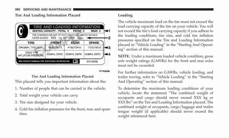
Tire And Loading Information Placard
This placard tells you important information about the:
1. Number of people that can be carried in the vehicle.
2. Total weight your vehicle can carry.
3. Tire size designed for your vehicle.
4. Cold tire inflation pressures for the front, rear, and sparetires.
Loading
The vehicle maximum load on the tire must not exceed theload carrying capacity of the tire on your vehicle. You willnot exceed the tire’s load carrying capacity if you adhere tothe loading conditions, tire size, and cold tire inflationpressures specified on the Tire and Loading Informationplacard in “Vehicle Loading” in the “Starting And Operat-ing” section of this manual.
NOTE: Under a maximum loaded vehicle condition, grossaxle weight ratings (GAWRs) for the front and rear axlesmust not be exceeded.
For further information on GAWRs, vehicle loading, andtrailer towing, refer to “Vehicle Loading” in the “StartingAnd Operating” section of this manual.
To determine the maximum loading conditions of yourvehicle, locate the statement “The combined weight ofoccupants and cargo should never exceed XXX kg orXXX lbs” on the Tire and Loading Information placard. Thecombined weight of occupants, cargo/luggage and trailertongue weight (if applicable) should never exceed theweight referenced here.
Tire And Loading Information Placard
380 SERVICING AND MAINTENANCE
Steps For Determining Correct Load Limit—
(1) Locate the statement “The combined weight ofoccupants and cargo should never exceed XXX kg orXXX lbs.” on your vehicle’s placard.
(2) Determine the combined weight of the driver andpassengers that will be riding in your vehicle.
(3) Subtract the combined weight of the driver andpassengers from XXX kg or XXX lbs.
(4) The resulting figure equals the available amount ofcargo and luggage load capacity. For example, if “XXX”amount equals 1400 lbs. and there will be five 150 lbpassengers in your vehicle, the amount of availablecargo and luggage load capacity is 650 lbs. (1400-750(5x150) = 650 lbs.)
(5) Determine the combined weight of luggage andcargo being loaded on the vehicle. That weight may notsafely exceed the available cargo and luggage loadcapacity calculated in Step 4.
(6) If your vehicle will be towing a trailer, load fromyour trailer will be transferred to your vehicle. Consult
this manual to determine how this reduces the availablecargo and luggage load capacity of your vehicle.
Metric Example For Load Limit
For example, if “XXX” amount equals 635 kg and there willbe five 68 kg passengers in your vehicle, the amount ofavailable cargo and luggage load capacity is 295 kg (635-340 (5x68) = 295 kg) as shown in step 4.
NOTE:
• If your vehicle will be towing a trailer, load from yourtrailer will be transferred to your vehicle. The followingtable shows examples on how to calculate total load,cargo/luggage, and towing capacities of your vehiclewith varying seating configurations and number andsize of occupants. This table is for illustration purposesonly and may not be accurate for the seating and loadcarry capacity of your vehicle.
• For the following example, the combined weight ofoccupants and cargo should never exceed 865 lbs(392 kg).
8
SERVICING AND MAINTENANCE 381

WARNING!
Overloading of your tires is dangerous. Overloadingcan cause tire failure, affect vehicle handling, andincrease your stopping distance. Use tires of the rec-ommended load capacity for your vehicle. Never over-load them.
382 SERVICING AND MAINTENANCE

Tires — General Information
Tire Pressure
Proper tire inflation pressure is essential to the safe andsatisfactory operation of your vehicle. Four primary areasare affected by improper tire pressure:
• Safety and Vehicle Stability
• Economy
• Tread Wear
• Ride Comfort
Safety
WARNING!
• Improperly inflated tires are dangerous and cancause collisions.
• Underinflation increases tire flexing and can resultin overheating and tire failure.
• Overinflation reduces a tire’s ability to cushionshock. Objects on the road and chuckholes can causedamage that result in tire failure.
(Continued)
WARNING! (Continued)• Overinflated or underinflated tires can affect vehicle
handling and can fail suddenly, resulting in loss ofvehicle control.
• Unequal tire pressures can cause steering problems.You could lose control of your vehicle.
• Unequal tire pressures from one side of the vehicleto the other can cause the vehicle to drift to the rightor left.
• Always drive with each tire inflated to the recom-mended cold tire inflation pressure.
Both under-inflation and over-inflation affect the stabilityof the vehicle and can produce a feeling of sluggishresponse or over responsiveness in the steering.
NOTE:
• Unequal tire pressures from side to side may causeerratic and unpredictable steering response.
• Unequal tire pressure from side to side may cause thevehicle to drift left or right.
8
SERVICING AND MAINTENANCE 383

Fuel Economy
Underinflated tires will increase tire rolling resistanceresulting in higher fuel consumption.
Tread Wear
Improper cold tire inflation pressures can cause abnormalwear patterns and reduced tread life, resulting in the needfor earlier tire replacement.
Ride Comfort And Vehicle Stability
Proper tire inflation contributes to a comfortable ride.Over-inflation produces a jarring and uncomfortable ride.
Tire Inflation Pressures
The proper cold tire inflation pressure is listed on thedriver’s side B-Pillar or rear edge of the driver’s side door.
At least once a month:
• Check and adjust tire pressure with a good qualitypocket-type pressure gauge. Do not make a visualjudgement when determining proper inflation. Tiresmay look properly inflated even when they are under-inflated.
• Inspect tires for signs of tire wear or visible damage.
CAUTION!
After inspecting or adjusting the tire pressure, alwaysreinstall the valve stem cap. This will prevent moistureand dirt from entering the valve stem, which coulddamage the valve stem.
Inflation pressures specified on the placard are always“cold tire inflation pressure”. Cold tire inflation pressure isdefined as the tire pressure after the vehicle has not beendriven for at least three hours, or driven less than 1 mile(1.6 km) after sitting for a minimum of three hours. Thecold tire inflation pressure must not exceed the maximuminflation pressure molded into the tire sidewall.
Check tire pressures more often if subject to a wide rangeof outdoor temperatures, as tire pressures vary with tem-perature changes.
Tire pressures change by approximately 1 psi (7 kPa) per12°F (7°C) of air temperature change. Keep this in mindwhen checking tire pressure inside a garage, especially inthe Winter.
Example: If garage temperature = 68°F (20°C) and theoutside temperature = 32°F (0°C) then the cold tire inflation
384 SERVICING AND MAINTENANCE

pressure should be increased by 3 psi (21 kPa), whichequals 1 psi (7 kPa) for every 12°F (7°C) for this outsidetemperature condition.
Tire pressure may increase from 2 to 6 psi (13 to 40 kPa)during operation. DO NOT reduce this normal pressurebuild up or your tire pressure will be too low.
Tire Pressures For High Speed Operation
The manufacturer advocates driving at safe speeds andwithin posted speed limits. Where speed limits or condi-tions are such that the vehicle can be driven at high speeds,maintaining correct tire inflation pressure is very impor-tant. Increased tire pressure and reduced vehicle loadingmay be required for high-speed vehicle operation. Refer toan authorized tire dealer or original equipment vehicledealer for recommended safe operating speeds, loadingand cold tire inflation pressures.
WARNING!
High speed driving with your vehicle under maximumload is dangerous. The added strain on your tires couldcause them to fail. You could have a serious collision.Do not drive a vehicle loaded to the maximum capacityat continuous speeds above 75 mph (120 km/h).
Radial Ply Tires
WARNING!
Combining radial ply tires with other types of tires onyour vehicle will cause your vehicle to handle poorly.The instability could cause a collision. Always useradial ply tires in sets of four. Never combine themwith other types of tires.
Tire Repair
If your tire becomes damaged, it may be repaired if it meetsthe following criteria:• The tire has not been driven on when flat.
• The damage is only on the tread section of your tire(sidewall damage is not repairable).
• The puncture is no greater than a ¼ of an inch (6 mm).
Consult an authorized tire dealer for tire repairs andadditional information.
Damaged Run Flat tires, or Run Flat tires that have experi-enced a loss of pressure should be replaced immediately withanother Run Flat tire of identical size and service description(Load Index and Speed Symbol). Replace the tire pressuresensor as well as it is not designed to be reused.
8
SERVICING AND MAINTENANCE 385
Run Flat Tires — If Equipped
Run Flat tires allow you the capability to drive 50 miles(80 km) at 50 mph (80 km/h) after a rapid loss of inflationpressure. This rapid loss of inflation is referred to as theRun Flat mode. A Run Flat mode occurs when the tireinflation pressure is of/or below 14 psi (96 kPa). Once aRun Flat tire reaches the run flat mode it has limiteddriving capabilities and needs to be replaced immediately.A Run Flat tire is not repairable. When a run flat tire ischanged after driving with underinflated tire condition,please replace the TPM sensor as it is not designed to bereused when driven under run flat mode (14 psi (96 kPa))condition.
NOTE: TPM Sensor must be replaced after driving thevehicle on a flat tire condition.
It is not recommended driving a vehicle loaded at fullcapacity or to tow a trailer while a tire is in the run flatmode.
See the tire pressure monitoring section for more informa-tion.
Tire Spinning
When stuck in mud, sand, snow, or ice conditions, do notspin your vehicle’s wheels above 30 mph (48 km/h) or forlonger than 30 seconds continuously without stopping.
Refer to “Freeing A Stuck Vehicle” in “In Case Of Emer-gency” for further information.
WARNING!
Fast spinning tires can be dangerous. Forces generatedby excessive wheel speeds may cause tire damage orfailure. A tire could explode and injure someone. Donot spin your vehicle’s wheels faster than 30 mph(48 km/h) for more than 30 seconds continuously whenyou are stuck, and do not let anyone near a spinningwheel, no matter what the speed.
Tread Wear Indicators
Tread wear indicators are in the original equipment tires tohelp you in determining when your tires should be re-placed.
386 SERVICING AND MAINTENANCE

These indicators are molded into the bottom of the treadgrooves. They will appear as bands when the tread depthbecomes a 1/16 of an inch (1.6 mm). When the tread isworn to the tread wear indicators, the tire should bereplaced.
Refer to “Replacement Tires” in this section for furtherinformation.
Life Of Tire
The service life of a tire is dependent upon varying factorsincluding, but not limited to:
• Driving style.
• Tire pressure - Improper cold tire inflation pressures cancause uneven wear patterns to develop across the tiretread. These abnormal wear patterns will reduce treadlife, resulting in the need for earlier tire replacement.
• Distance driven.
• Performance tires, tires with a speed rating of V orhigher, and Summer tires typically have a reduced treadlife. Rotation of these tires per the vehicle scheduledmaintenance is highly recommended.
WARNING!
Tires and the spare tire should be replaced after sixyears, regardless of the remaining tread. Failure tofollow this warning can result in sudden tire failure.You could lose control and have a collision resulting inserious injury or death.
NOTE: Wheel Valve Stem must be replaced as well wheninstalling new tires due to wear and tear in existing tires.
Tire Tread
1 — Worn Tire2 — New Tire
8
SERVICING AND MAINTENANCE 387
Keep dismounted tires in a cool, dry place with as littleexposure to light as possible. Protect tires from contact withoil, grease, and gasoline.
Replacement Tires
The tires on your new vehicle provide a balance of manycharacteristics. They should be inspected regularly forwear and correct cold tire inflation pressures. The manu-facturer strongly recommends that you use tires equivalentto the originals in size, quality and performance whenreplacement is needed. Refer to the paragraph on “TreadWear Indicators” in this section. Refer to the Tire andLoading Information placard or the Vehicle CertificationLabel for the size designation of your tire. The Load Indexand Speed Symbol for your tire will be found on theoriginal equipment tire sidewall.
See the Tire Sizing Chart example found in the “Tire SafetyInformation” section of this manual for more informationrelating to the Load Index and Speed Symbol of a tire.
It is recommended to replace the two front tires or two reartires as a pair. Replacing just one tire can seriously affectyour vehicle’s handling. If you ever replace a wheel, makesure that the wheel’s specifications match those of theoriginal wheels.
It is recommended you contact an authorized tire dealer ororiginal equipment dealer with any questions you mayhave on tire specifications or capability. Failure to useequivalent replacement tires may adversely affect thesafety, handling, and ride of your vehicle.
WARNING!
• Do not use a tire, wheel size, load rating, or speedrating other than that specified for your vehicle.Some combinations of unapproved tires and wheelsmay change suspension dimensions and perfor-mance characteristics, resulting in changes to steer-ing, handling, and braking of your vehicle. This cancause unpredictable handling and stress to steeringand suspension components. You could lose controland have a collision resulting in serious injury ordeath. Use only the tire and wheel sizes with loadratings approved for your vehicle.
• Never use a tire with a smaller load index or capacity,other than what was originally equipped on yourvehicle. Using a tire with a smaller load index couldresult in tire overloading and failure. You could losecontrol and have a collision.
(Continued)
388 SERVICING AND MAINTENANCE

WARNING! (Continued)• Failure to equip your vehicle with tires having ad-
equate speed capability can result in sudden tirefailure and loss of vehicle control.
CAUTION!
Replacing original tires with tires of a different sizemay result in false speedometer and odometer read-ings.
Tire Types
All Season Tires — If Equipped
All Season tires provide traction for all seasons (Spring,Summer, Fall, and Winter). Traction levels may vary be-tween different all season tires. All season tires can beidentified by the M+S, M&S, M/S or MS designation on thetire sidewall. Use all season tires only in sets of four; failureto do so may adversely affect the safety and handling ofyour vehicle.
Summer Or Three Season Tires — If Equipped
Summer tires provide traction in both wet and dry condi-tions, and are not intended to be driven in snow or on ice.If your vehicle is equipped with Summer tires, be awarethese tires are not designed for Winter or cold drivingconditions. Install Winter tires on your vehicle when am-bient temperatures are less than 40°F (5°C) or if roads arecovered with ice or snow. For more information, contact anauthorized dealer.
Summer tires do not contain the all season designation ormountain/snowflake symbol on the tire sidewall. UseSummer tires only in sets of four; failure to do so mayadversely affect the safety and handling of your vehicle.
WARNING!
Do not use Summer tires in snow/ice conditions. Youcould lose vehicle control, resulting in severe injury ordeath. Driving too fast for conditions also creates thepossibility of loss of vehicle control.
8
SERVICING AND MAINTENANCE 389
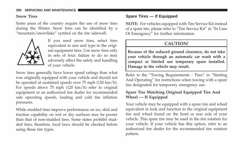
Snow Tires
Some areas of the country require the use of snow tiresduring the Winter. Snow tires can be identified by a“mountain/snowflake” symbol on the tire sidewall.
If you need snow tires, select tiresequivalent in size and type to the origi-nal equipment tires. Use snow tires onlyin sets of four; failure to do so mayadversely affect the safety and handlingof your vehicle.
Snow tires generally have lower speed ratings than whatwas originally equipped with your vehicle and should notbe operated at sustained speeds over 75 mph (120 km/h).For speeds above 75 mph (120 km/h) refer to originalequipment or an authorized tire dealer for recommendedsafe operating speeds, loading and cold tire inflationpressures.
While studded tires improve performance on ice, skid andtraction capability on wet or dry surfaces may be poorerthan that of non-studded tires. Some states prohibit stud-ded tires; therefore, local laws should be checked beforeusing these tire types.
Spare Tires — If Equipped
NOTE: For vehicles equipped with Tire Service Kit insteadof a spare tire, please refer to “Tire Service Kit” in “In CaseOf Emergency” for further information.
CAUTION!
Because of the reduced ground clearance, do not takeyour vehicle through an automatic car wash with acompact or limited use temporary spare installed.Damage to the vehicle may result.
Refer to the “Towing Requirements - Tires” in “StartingAnd Operating” for restrictions when towing with a sparetire designated for temporary emergency use.
Spare Tire Matching Original Equipped Tire AndWheel — If Equipped
Your vehicle may be equipped with a spare tire and wheelequivalent in look and function to the original equipmenttire and wheel found on the front or rear axle of yourvehicle. This spare tire may be used in the tire rotation foryour vehicle. If your vehicle has this option, refer to anauthorized tire dealer for the recommended tire rotationpattern.
390 SERVICING AND MAINTENANCE

Compact Spare Tire — If Equipped
The compact spare is for temporary emergency use only. Youcan identify if your vehicle is equipped with a compact spareby looking at the spare tire description on the Tire andLoading Information Placard located on the driver’s sidedoor opening or on the sidewall of the tire. Compact sparetire descriptions begin with the letter “T” or “S” precedingthe size designation. Example: T145/80D18 103M.
T, S = Temporary Spare Tire
Since this tire has limited tread life, the original equipmenttire should be repaired (or replaced) and reinstalled onyour vehicle at the first opportunity.
Do not install a wheel cover or attempt to mount aconventional tire on the compact spare wheel, since thewheel is designed specifically for the compact spare tire.Do not install more than one compact spare tire and wheelon the vehicle at any given time.
WARNING!
Compact and collapsible spares are for temporaryemergency use only. With these spares, do not drive
(Continued)
WARNING! (Continued)more than 50 mph (80 km/h). Temporary use spareshave limited tread life. When the tread is worn to thetread wear indicators, the temporary use spare tireneeds to be replaced. Be sure to follow the warnings,which apply to your spare. Failure to do so could resultin spare tire failure and loss of vehicle control.
Collapsible Spare Tire — If Equipped
The collapsible spare is for temporary emergency use only.You can identify if your vehicle is equipped with a collaps-ible spare by looking at the spare tire description on theTire and Loading Information Placard located on thedriver’s side door opening or on the sidewall of the tire.
Collapsible spare tire description example: 165/80-17 101P.
Since this tire has limited tread life, the original equipmenttire should be repaired (or replaced) and reinstalled onyour vehicle at the first opportunity.
Inflate collapsible tire only after the wheel is properlyinstalled to the vehicle. Inflate the collapsible tire using theelectric air pump before lowering the vehicle.
8
SERVICING AND MAINTENANCE 391
Do not install a wheel cover or attempt to mount aconventional tire on the collapsible spare wheel, since thewheel is designed specifically for the collapsible spare tire.
WARNING!
Compact and Collapsible spares are for temporaryemergency use only. With these spares, do not drivemore than 50 mph (80 km/h). Temporary use spareshave limited tread life. When the tread is worn to thetread wear indicators, the temporary use spare tireneeds to be replaced. Be sure to follow the warnings,which apply to your spare. Failure to do so could resultin spare tire failure and loss of vehicle control.
Full Size Spare — If Equipped
The full size spare is for temporary emergency use only.This tire may look like the originally equipped tire on thefront or rear axle of your vehicle, but it is not. This sparetire may have limited tread life. When the tread is worn tothe tread wear indicators, the temporary use full size sparetire needs to be replaced. Since it is not the same as youroriginal equipment tire, replace (or repair) the originalequipment tire and reinstall on the vehicle at the firstopportunity.
Limited Use Spare — If Equipped
The limited use spare tire is for temporary emergency useonly. This tire is identified by a label located on the limiteduse spare wheel. This label contains the driving limitationsfor this spare. This tire may look like the original equippedtire on the front or rear axle of your vehicle, but it is not.Installation of this limited use spare tire affects vehiclehandling. Since it is not the same as your original equip-ment tire, replace (or repair) the original equipment tireand reinstall on the vehicle at the first opportunity.
WARNING!
Limited use spares are for emergency use only. Instal-lation of this limited use spare tire affects vehiclehandling. With this tire, do not drive more than thespeed listed on the limited use spare wheel. Keepinflated to the cold tire inflation pressures listed onyour Tire and Loading Information Placard located onthe driver’s side B-Pillar or the rear edge of the driver’sside door. Replace (or repair) the original equipmenttire at the first opportunity and reinstall it on yourvehicle. Failure to do so could result in loss of vehiclecontrol.
392 SERVICING AND MAINTENANCE

Wheel And Wheel Trim Care
All wheels and wheel trim, especially aluminum and chromeplated wheels, should be cleaned regularly using mild (neu-tral Ph) soap and water to maintain their luster and toprevent corrosion. Wash wheels with the same soap solutionrecommended for the body of the vehicle and remember toalways wash when the surfaces are not hot to the touch.
Your wheels are susceptible to deterioration caused by salt,sodium chloride, magnesium chloride, calcium chloride,etc., and other road chemicals used to melt ice or controldust on dirt roads. Use a soft cloth or sponge and mild soapto wipe away promptly. Do not use harsh chemicals or astiff brush. They can damage the wheel’s protective coatingthat helps keep them from corroding and tarnishing.
CAUTION!
Avoid products or automatic car washes that use acidicsolutions or strong alkaline additives or harsh brushes.Many aftermarket wheel cleaners and automatic carwashes may damage the wheel’s protective finish.Such damage is not covered by the New VehicleLimited Warranty. Only car wash soap, Mopar WheelCleaner or equivalent is recommended.
When cleaning extremely dirty wheels including excessivebrake dust, care must be taken in the selection of tire andwheel cleaning chemicals and equipment to prevent dam-age to the wheels. Mopar Wheel Treatment or MoparChrome Cleaner or their equivalent is recommended orselect a non-abrasive, non-acidic cleaner for aluminum orchrome wheels.
CAUTION!
Do not use scouring pads, steel wool, a bristle brush,metal polishes or oven cleaner. These products maydamage the wheel’s protective finish. Such damage isnot covered by the New Vehicle Limited Warranty.Only car wash soap, Mopar Wheel Cleaner or equiva-lent is recommended.
NOTE: If you intend parking or storing your vehicle for anextended period after cleaning the wheels with wheelcleaner, drive your vehicle and apply the brakes to removethe water droplets from the brake components. This activ-ity will remove the red rust on the brake rotors and preventvehicle vibration when braking.
8
SERVICING AND MAINTENANCE 393
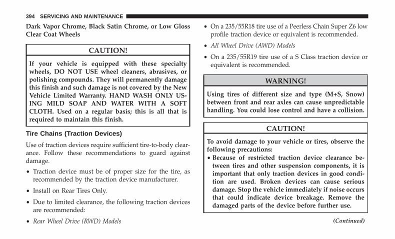
Dark Vapor Chrome, Black Satin Chrome, or Low GlossClear Coat Wheels
CAUTION!
If your vehicle is equipped with these specialtywheels, DO NOT USE wheel cleaners, abrasives, orpolishing compounds. They will permanently damagethis finish and such damage is not covered by the NewVehicle Limited Warranty. HAND WASH ONLY US-ING MILD SOAP AND WATER WITH A SOFTCLOTH. Used on a regular basis; this is all that isrequired to maintain this finish.
Tire Chains (Traction Devices)
Use of traction devices require sufficient tire-to-body clear-ance. Follow these recommendations to guard againstdamage.
• Traction device must be of proper size for the tire, asrecommended by the traction device manufacturer.
• Install on Rear Tires Only.
• Due to limited clearance, the following traction devicesare recommended:
• Rear Wheel Drive (RWD) Models
• On a 235/55R18 tire use of a Peerless Chain Super Z6 lowprofile traction device or equivalent is recommended.
• All Wheel Drive (AWD) Models
• On a 235/55R19 tire use of a S Class traction device orequivalent is recommended.
WARNING!
Using tires of different size and type (M+S, Snow)between front and rear axles can cause unpredictablehandling. You could lose control and have a collision.
CAUTION!
To avoid damage to your vehicle or tires, observe thefollowing precautions:• Because of restricted traction device clearance be-
tween tires and other suspension components, it isimportant that only traction devices in good condi-tion are used. Broken devices can cause seriousdamage. Stop the vehicle immediately if noise occursthat could indicate device breakage. Remove thedamaged parts of the device before further use.
(Continued)
394 SERVICING AND MAINTENANCE

CAUTION! (Continued)• Install device as tightly as possible and then re-
tighten after driving about ½ mile (0.8 km).• Do not exceed 30 mph (48 km/h).• Drive cautiously and avoid severe turns and large
bumps, especially with a loaded vehicle.• Do not drive for prolonged period on dry pavement.• Observe the traction device manufacturer’s instruc-
tions on the method of installation, operating speed,and conditions for use. Always use the suggestedoperating speed of the device manufacturer’s if it isless than 30 mph (48 km/h).
• Do not use traction devices on a compact spare tire.
Tire Rotation Recommendations
Tires on the front and rear axles of vehicles operate atdifferent loads and perform different steering, driving, andbraking functions. For these reasons, they wear at unequalrates.
These effects can be reduced by timely rotation of tires. Thebenefits of rotation are especially worthwhile with aggres-sive tread designs such as those on all season type tires.
Rotation will increase tread life, help to maintain mud,snow and wet traction levels, and contribute to a smooth,quiet ride.
Refer to “Scheduled Servicing” in “Servicing And Mainte-nance” for the proper maintenance intervals. The reasonsfor any rapid or unusual wear should be corrected prior torotation being performed.
The suggested rotation method is the “rearward cross”shown in the following diagram. This rotation pattern doesnot apply to some directional tires that must not bereversed.
Tire Rotation
8
SERVICING AND MAINTENANCE 395
DEPARTMENT OF TRANSPORTATION UNIFORMTIRE QUALITY GRADES
The following tire grading categories were establishedby the National Highway Traffic Safety Administration.The specific grade rating assigned by the tire’s manu-facturer in each category is shown on the sidewall of thetires on your vehicle.
All passenger vehicle tires must conform to Federalsafety requirements in addition to these grades.
Treadwear
The Treadwear grade is a comparative rating, based onthe wear rate of the tire when tested under controlledconditions on a specified government test course. Forexample, a tire graded 150 would wear one and one-halftimes as well on the government course as a tire graded100. The relative performance of tires depends upon theactual conditions of their use, however, and may departsignificantly from the norm due to variations in drivinghabits, service practices, and differences in road charac-teristics and climate.
Traction Grades
The Traction grades, from highest to lowest, are AA, A,B, and C. These grades represent the tire’s ability to stop
on wet pavement, as measured under controlled condi-tions on specified government test surfaces of asphaltand concrete. A tire marked C may have poor tractionperformance.
WARNING!
The traction grade assigned to this tire is based onstraight-ahead braking traction tests, and does notinclude acceleration, cornering, hydroplaning, orpeak traction characteristics.
Temperature Grades
The Temperature grades are A (the highest), B, and C,representing the tire’s resistance to the generation ofheat and its ability to dissipate heat, when tested undercontrolled conditions on a specified indoor laboratorytest wheel.
Sustained high temperature can cause the material ofthe tire to degenerate and reduce tire life, and excessivetemperature can lead to sudden tire failure. The grade Ccorresponds to a level of performance, which all pas-senger vehicle tires must meet under the Federal MotorVehicle Safety Standard No. 109. Grades B and A
396 SERVICING AND MAINTENANCE

represent higher levels of performance on the laboratorytest wheel, than the minimum required by law.
WARNING!
The temperature grade for this tire is established fora tire that is properly inflated and not overloaded.Excessive speed, under-inflation, or excessive load-ing, either separately or in combination, can causeheat buildup and possible tire failure.
VEHICLE STORAGE
If you are leaving your vehicle dormant for more than 21days, you may want to take these steps to protect yourbattery.
• Disconnect the negative cable from the battery.
• Anytime you store your vehicle, or keep it out of service(e.g., vacation) for two weeks or more, run the airconditioning system at idle for about five minutes in thefresh air and high blower setting. This will ensureadequate system lubrication to minimize the possibilityof compressor damage when the system is started again.
BODYWORK
Protection From Atmospheric Agents
Vehicle body care requirements vary according to geo-graphic locations and usage. Chemicals that make roadspassable in snow and ice and those that are sprayed on treesand road surfaces during other seasons are highly corrosiveto the metal in your vehicle. Outside parking, whichexposes your vehicle to airborne contaminants, road sur-faces on which the vehicle is operated, extreme hot or coldweather and other extreme conditions will have an adverseeffect on paint, metal trim, and underbody protection.
The following maintenance recommendations will enableyou to obtain maximum benefit from the corrosion resis-tance built into your vehicle.
What Causes Corrosion?
Corrosion is the result of deterioration or removal of paintand protective coatings from your vehicle.
The most common causes are:
• Road salt, dirt and moisture accumulation.
• Stone and gravel impact.
• Insects, tree sap and tar.
8
SERVICING AND MAINTENANCE 397

• Salt in the air near seacoast localities.
• Atmospheric fallout/industrial pollutants.
Body And Underbody Maintenance
Cleaning Headlights
Your vehicle is equipped with plastic headlights and foglights that are lighter and less susceptible to stone breakagethan glass headlights.
Plastic is not as scratch resistant as glass and thereforedifferent lens cleaning procedures must be followed.
To minimize the possibility of scratching the lenses andreducing light output, avoid wiping with a dry cloth. Toremove road dirt, wash with a mild soap solution followedby rinsing.
Do not use abrasive cleaning components, solvents, steelwool or other aggressive material to clean the lenses.
Preserving The Bodywork
Washing
• Wash your vehicle regularly. Always wash your vehiclein the shade using Mopar Car Wash, or a mild car washsoap, and rinse the panels completely with clear water.
• If insects, tar, or other similar deposits have accumulatedon your vehicle, use Mopar Super Kleen Bug and TarRemover to remove.
• Use a high quality cleaner wax, such as Mopar CleanerWax to remove road film, stains and to protect yourpaint finish. Take care never to scratch the paint.
• Avoid using abrasive compounds and power buffingthat may diminish the gloss or thin out the paint finish.
CAUTION!
• Do not use abrasive or strong cleaning materials suchas steel wool or scouring powder that will scratchmetal and painted surfaces.
• Use of power washers exceeding 1,200 psi (8,274 kPa)can result in damage or removal of paint and decals.
Special Care
• If you drive on salted or dusty roads or if you drive nearthe ocean, hose off the undercarriage at least once amonth.
• It is important that the drain holes in the lower edges ofthe doors, rocker panels, and trunk be kept clear andopen.
398 SERVICING AND MAINTENANCE
• If you detect any stone chips or scratches in the paint,touch them up immediately. The cost of such repairs isconsidered the responsibility of the owner.
• If your vehicle is damaged due to a collision or similarcause that destroys the paint and protective coating,have your vehicle repaired as soon as possible. The costof such repairs is considered the responsibility of theowner.
• If you carry special cargo such as chemicals, fertilizers,de-icer salt, etc., be sure that such materials are wellpackaged and sealed.
• If a lot of driving is done on gravel roads, consider mudor stone shields behind each wheel.
• Use Mopar Touch Up Paint on scratches as soon aspossible. An authorized dealer has touch up paint tomatch the color of your vehicle.
INTERIORS
Seats And Fabric Parts
Use Mopar Total Clean to clean fabric upholstery andcarpeting.
WARNING!
Do not use volatile solvents for cleaning purposes.Many are potentially flammable, and if used in closedareas they may cause respiratory harm.
Seat Belt Maintenance
Do not bleach, dye, or clean the belts with chemicalsolvents or abrasive cleaners. This will weaken the fabric.Sun damage can also weaken the fabric.
If the belts need cleaning, use Mopar Total Clean, a mildsoap solution, or lukewarm water. Do not remove the beltsfrom the vehicle to wash them. Dry with a soft cloth.
Replace the belts if they appear frayed or worn or if thebuckles do not work properly.
8
SERVICING AND MAINTENANCE 399
WARNING!
A frayed or torn belt could rip apart in a collision andleave you with no protection. Inspect the belt systemperiodically, checking for cuts, frays, or loose parts.Damaged parts must be replaced immediately. Do notdisassemble or modify the system. Seat belt assembliesmust be replaced after a collision if they have beendamaged (i.e., bent retractor, torn webbing, etc.).
Plastic And Coated Parts
Use Mopar Total Clean to clean vinyl upholstery.
CAUTION!
• Direct contact of air fresheners, insect repellents,suntan lotions, or hand sanitizers to the plastic,painted, or decorated surfaces of the interior maycause permanent damage. Wipe away immediately.
• Damage caused by these type of products may not becovered by your New Vehicle Limited Warranty.
Cleaning Plastic Instrument Cluster Lenses
The lenses in front of the instruments in this vehicle aremolded in clear plastic. When cleaning the lenses, caremust be taken to avoid scratching the plastic.
1. Clean with a wet soft cloth. A mild soap solution may beused, but do not use high alcohol content or abrasivecleaners. If soap is used, wipe clean with a clean dampcloth.
2. Dry with a soft cloth.
Leather Parts
Mopar Total Clean is specifically recommended for leatherupholstery.
Your leather upholstery can be best preserved by regularcleaning with a damp soft cloth. Small particles of dirt canact as an abrasive and damage the leather upholstery andshould be removed promptly with a damp cloth. Stubbornsoils can be removed easily with a soft cloth and MoparTotal Clean. Care should be taken to avoid soaking yourleather upholstery with any liquid. Please do not usepolishes, oils, cleaning fluids, solvents, detergents, orammonia-based cleaners to clean your leather upholstery.Application of a leather conditioner is not required tomaintain the original condition.
400 SERVICING AND MAINTENANCE

NOTE: If equipped with light colored leather, it tends toshow any foreign material, dirt, and fabric dye transfermore so than darker colors. The leather is designed for easycleaning, and FCA recommends Mopar total care leathercleaner applied on a cloth to clean the leather seats asneeded.
CAUTION!
Do not use Alcohol and Alcohol-based and/or Ketonebased cleaning products to clean leather upholstery, asdamage to the upholstery may result.
Glass Surfaces
All glass surfaces should be cleaned on a regular basis withMopar Glass Cleaner, or any commercial household-typeglass cleaner. Never use an abrasive type cleaner. Usecaution when cleaning the inside rear window equippedwith electric defrosters or windows equipped with radioantennas. Do not use scrapers or other sharp instrumentsthat may scratch the elements.
When cleaning the rear view mirror, spray cleaner on thetowel or cloth that you are using. Do not spray cleanerdirectly on the mirror.
8
SERVICING AND MAINTENANCE 401

TECHNICAL SPECIFICATIONS
CONTENTS� IDENTIFICATION DATA. . . . . . . . . . . . . . . . . . .404
▫ Vehicle Identification Number . . . . . . . . . . . . .404
� BRAKE SYSTEM . . . . . . . . . . . . . . . . . . . . . . . .404
� WHEEL AND TIRE TORQUE SPECIFICATIONS . .405
▫ Torque Specifications . . . . . . . . . . . . . . . . . . . .405
� FUEL REQUIREMENTS . . . . . . . . . . . . . . . . . . .406
▫ 3.6L Engine . . . . . . . . . . . . . . . . . . . . . . . . . .406
▫ 5.7L Engine (With Automatic Transmission) . . . .407
▫ 5.7L Engine (With Manual Transmission) . . . . . .407
▫ 6.4L Engine . . . . . . . . . . . . . . . . . . . . . . . . . . .408
▫ Reformulated Gasoline . . . . . . . . . . . . . . . . . .408
▫ Materials Added To Fuel . . . . . . . . . . . . . . . . .408
▫ Gasoline/Oxygenate Blends . . . . . . . . . . . . . . .409
▫ Do Not Use E-85 In Non-Flex Fuel Vehicles . . . .409
▫ CNG And LP Fuel System Modifications . . . . . .410
▫ MMT In Gasoline . . . . . . . . . . . . . . . . . . . . . . .410
▫ Fuel System Cautions . . . . . . . . . . . . . . . . . . . .410
▫ Carbon Monoxide Warnings . . . . . . . . . . . . . . .411
� FLUID CAPACITIES . . . . . . . . . . . . . . . . . . . . . .411
� FLUIDS AND LUBRICANTS . . . . . . . . . . . . . . . .413
▫ Engine . . . . . . . . . . . . . . . . . . . . . . . . . . . . . .413
▫ Chassis . . . . . . . . . . . . . . . . . . . . . . . . . . . . .415
9
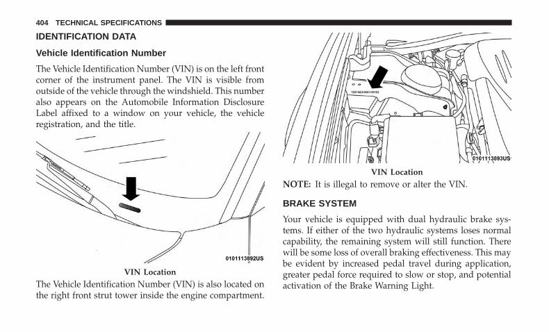
IDENTIFICATION DATA
Vehicle Identification Number
The Vehicle Identification Number (VIN) is on the left frontcorner of the instrument panel. The VIN is visible fromoutside of the vehicle through the windshield. This numberalso appears on the Automobile Information DisclosureLabel affixed to a window on your vehicle, the vehicleregistration, and the title.
The Vehicle Identification Number (VIN) is also located onthe right front strut tower inside the engine compartment.
NOTE: It is illegal to remove or alter the VIN.
BRAKE SYSTEM
Your vehicle is equipped with dual hydraulic brake sys-tems. If either of the two hydraulic systems loses normalcapability, the remaining system will still function. Therewill be some loss of overall braking effectiveness. This maybe evident by increased pedal travel during application,greater pedal force required to slow or stop, and potentialactivation of the Brake Warning Light.
VIN Location
VIN Location
404 TECHNICAL SPECIFICATIONS

In the event power assist is lost for any reason (forexample, repeated brake applications with the engineOFF), the brakes will still function. The effort required tobrake the vehicle will be much greater than that requiredwith the power system operating.
WHEEL AND TIRE TORQUE SPECIFICATIONS
Proper lug nut/bolt torque is very important to ensure thatthe wheel is properly mounted to the vehicle. Any time awheel has been removed and reinstalled on the vehicle, thelug nuts/bolts should be torqued using a properly cali-brated torque wrench using a high quality six sided (hex)deep wall socket.
Torque Specifications
Lug Nut/BoltTorque
**Lug Nut/BoltSize
Lug Nut/BoltSocket Size
130 Ft-Lbs(176 N·m)
M14 x 1.50 22 mm
**Use only your authorized dealer recommended lug nuts/bolts and clean or remove any dirt or oil before tightening.
Inspect the wheel mounting surface prior to mounting thetire and remove any corrosion or loose particles.
Tighten the lug nuts/bolts in a star pattern until eachnut/bolt has been tightened twice. Ensure that the socket isfully engaged on the lug nut/bolt (do not insert it halfway).
NOTE: If in doubt about the correct tightness, have themchecked with a torque wrench by your authorized dealer orservice station.
After 25 miles (40 km), check the lug nut/bolt torque to besure that all the lug nuts/bolts are properly seated againstthe wheel.
Wheel Mounting Surface
9
TECHNICAL SPECIFICATIONS 405
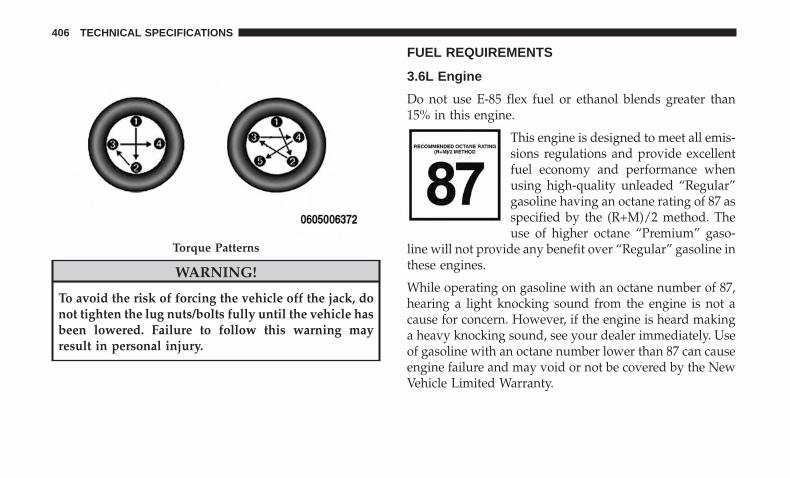
WARNING!
To avoid the risk of forcing the vehicle off the jack, donot tighten the lug nuts/bolts fully until the vehicle hasbeen lowered. Failure to follow this warning mayresult in personal injury.
FUEL REQUIREMENTS
3.6L Engine
Do not use E-85 flex fuel or ethanol blends greater than15% in this engine.
This engine is designed to meet all emis-sions regulations and provide excellentfuel economy and performance whenusing high-quality unleaded “Regular”gasoline having an octane rating of 87 asspecified by the (R+M)/2 method. Theuse of higher octane “Premium” gaso-
line will not provide any benefit over “Regular” gasoline inthese engines.
While operating on gasoline with an octane number of 87,hearing a light knocking sound from the engine is not acause for concern. However, if the engine is heard makinga heavy knocking sound, see your dealer immediately. Useof gasoline with an octane number lower than 87 can causeengine failure and may void or not be covered by the NewVehicle Limited Warranty.
Torque Patterns
406 TECHNICAL SPECIFICATIONS
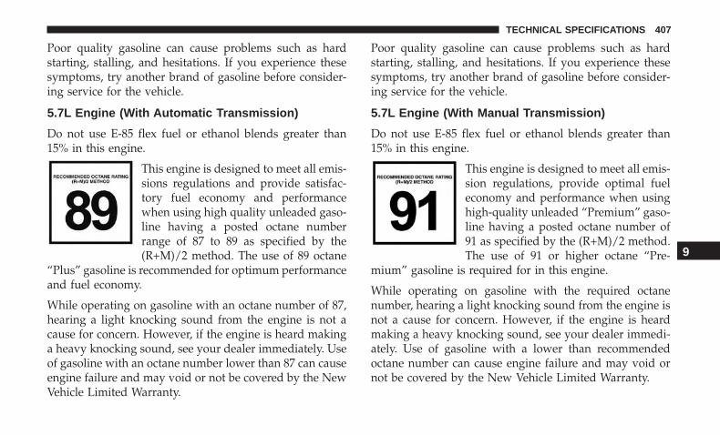
Poor quality gasoline can cause problems such as hardstarting, stalling, and hesitations. If you experience thesesymptoms, try another brand of gasoline before consider-ing service for the vehicle.
5.7L Engine (With Automatic Transmission)
Do not use E-85 flex fuel or ethanol blends greater than15% in this engine.
This engine is designed to meet all emis-sions regulations and provide satisfac-tory fuel economy and performancewhen using high quality unleaded gaso-line having a posted octane numberrange of 87 to 89 as specified by the(R+M)/2 method. The use of 89 octane
“Plus” gasoline is recommended for optimum performanceand fuel economy.
While operating on gasoline with an octane number of 87,hearing a light knocking sound from the engine is not acause for concern. However, if the engine is heard makinga heavy knocking sound, see your dealer immediately. Useof gasoline with an octane number lower than 87 can causeengine failure and may void or not be covered by the NewVehicle Limited Warranty.
Poor quality gasoline can cause problems such as hardstarting, stalling, and hesitations. If you experience thesesymptoms, try another brand of gasoline before consider-ing service for the vehicle.
5.7L Engine (With Manual Transmission)
Do not use E-85 flex fuel or ethanol blends greater than15% in this engine.
This engine is designed to meet all emis-sion regulations, provide optimal fueleconomy and performance when usinghigh-quality unleaded “Premium” gaso-line having a posted octane number of91 as specified by the (R+M)/2 method.The use of 91 or higher octane “Pre-
mium” gasoline is required for in this engine.
While operating on gasoline with the required octanenumber, hearing a light knocking sound from the engine isnot a cause for concern. However, if the engine is heardmaking a heavy knocking sound, see your dealer immedi-ately. Use of gasoline with a lower than recommendedoctane number can cause engine failure and may void ornot be covered by the New Vehicle Limited Warranty.
9
TECHNICAL SPECIFICATIONS 407

Poor quality gasoline can cause problems such as hardstarting, stalling, and hesitations. If you experience thesesymptoms, try another brand of gasoline before consider-ing service for the vehicle.
6.4L Engine
Do not use E-85 flex fuel or ethanol blends greater than15% in this engine.
This engine is designed to meet all emis-sion regulations, provide optimal fueleconomy and performance when usinghigh-quality unleaded “Premium” gaso-line having a posted octane number of91 as specified by the (R+M)/2 method.The use of 91 or higher octane “Pre-
mium” gasoline is required for in this engine.
While operating on gasoline with the required octanenumber, hearing a light knocking sound from the engine isnot a cause for concern. However, if the engine is heardmaking a heavy knocking sound, see your dealer immedi-ately. Use of gasoline with a lower than recommendedoctane number can cause engine failure and may void ornot be covered by the New Vehicle Limited Warranty.
Poor quality gasoline can cause problems such as hardstarting, stalling, and hesitations. If you experience thesesymptoms, try another brand of gasoline before consider-ing service for the vehicle.
Reformulated Gasoline
Many areas of the country require the use of cleanerburning gasoline referred to as “Reformulated Gasoline”.Reformulated gasoline contains oxygenates and are specifi-cally blended to reduce vehicle emissions and improve airquality.
The use of reformulated gasoline is recommended. Prop-erly blended reformulated gasoline will provide improvedperformance and durability of engine and fuel systemcomponents.
Materials Added To Fuel
Besides using unleaded gasoline with the proper octanerating, gasolines that contain detergents, corrosion andstability additives are recommended. Using gasolines thathave these additives will help improve fuel economy,reduce emissions, and maintain vehicle performance.
408 TECHNICAL SPECIFICATIONS
Designated TOP TIER Detergent Gaso-line contains a higher level of detergentsto further aide in minimizing engineand fuel system deposits. When avail-able, the usage of TOP TIER Detergentgasoline is recommended. Visitwww.toptiergas.com for a list of TOP
TIER Detergent Gasoline Retailers.
Indiscriminate use of fuel system cleaning agents should beavoided. Many of these materials intended for gum andvarnish removal may contain active solvents or similaringredients. These can harm fuel system gasket and dia-phragm materials.
Gasoline/Oxygenate Blends
Some fuel suppliers blend unleaded gasoline with oxygen-ates such as ethanol.
CAUTION!
DO NOT use E-85, gasoline containing methanol, orgasoline containing more than 15% ethanol (E-15). Useof these blends may result in starting and drivabilityproblems, damage critical fuel system components,
(Continued)
CAUTION! (Continued)cause emissions to exceed the applicable standard,and/or cause the Malfunction Indicator Light to illu-minate. Please observe pump labels as they shouldclearly communicate if a fuel contains greater than 15%ethanol (E-15).
Problems that result from using gasoline containing morethan 15% ethanol (E-15) or gasoline containing methanolare not the responsibility of the manufacturer and mayvoid or not be covered under New Vehicle Limited War-ranty.
Do Not Use E-85 In Non-Flex Fuel Vehicles
Non-Flex Fuel Vehicles (FFV) are compatible with gasolinecontaining up to 15% ethanol (E-15). Use of gasoline withhigher ethanol content may void the New Vehicle LimitedWarranty.
If a Non-FFV vehicle is inadvertently fueled with E-85 fuel,the engine will have some or all of these symptoms:
• Operate in a lean mode.
• OBD II Malfunction Indicator Light on.
• Poor engine performance.
9
TECHNICAL SPECIFICATIONS 409
• Poor cold start and cold drivability.
• Increased risk for fuel system component corrosion.
CNG And LP Fuel System Modifications
Modifications that allow the engine to run on CompressedNatural Gas (CNG) or Liquid Propane (LP) may result indamage to the engine, emissions, and fuel system compo-nents. Problems that result from running CNG or LP arenot the responsibility of the manufacturer and may void ornot be covered under the New Vehicle Limited Warranty.
MMT In Gasoline
Methylcyclopentadienyl Manganese Tricarbonyl (MMT) isa manganese-containing metallic additive that is blendedinto some gasoline to increase octane. Gasoline blendedwith MMT provides no performance advantage beyondgasoline of the same octane number without MMT. Gaso-line blended with MMT reduces spark plug life andreduces emissions system performance in some vehicles.The manufacturer recommends that gasoline withoutMMT be used in your vehicle. The MMT content ofgasoline may not be indicated on the gasoline pump;therefore, you should ask your gasoline retailer whetherthe gasoline contains MMT. MMT is prohibited in Federaland California reformulated gasoline.
Fuel System Cautions
CAUTION!
Follow these guidelines to maintain your vehicle’sperformance:• The use of leaded gasoline is prohibited by Federal
law. Using leaded gasoline can impair engine perfor-mance and damage the emissions control system.
• An out-of-tune engine or certain fuel or ignitionmalfunctions can cause the catalytic converter tooverheat. If you notice a pungent burning odor orsome light smoke, your engine may be out of tune ormalfunctioning and may require immediate service.Contact an authorized dealer for service assistance.
• The use of fuel additives, which are now being soldas octane enhancers, is not recommended. Most ofthese products contain high concentrations of metha-nol. Fuel system damage or vehicle performanceproblems resulting from the use of such fuels oradditives is not the responsibility of the manufac-turer and may void or not be covered under the NewVehicle Limited Warranty.
NOTE: Intentional tampering with the emissions controlsystem can result in civil penalties being assessed against you.
410 TECHNICAL SPECIFICATIONS
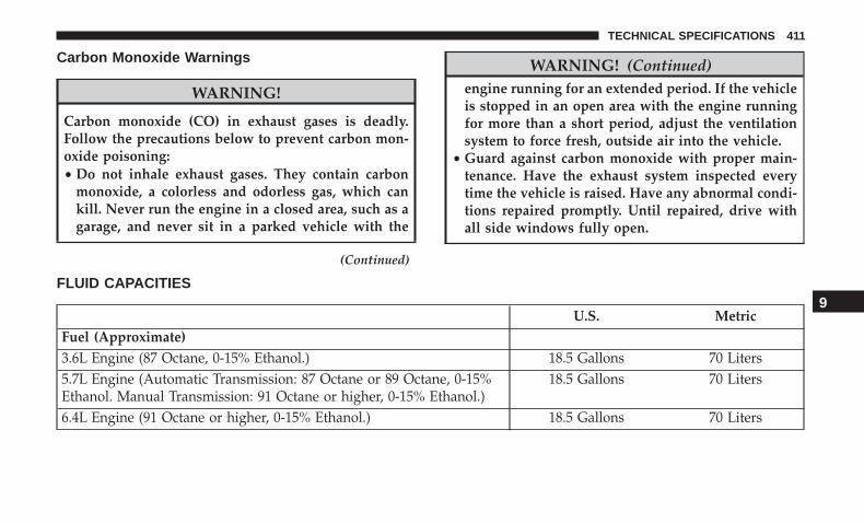
Carbon Monoxide Warnings
WARNING!
Carbon monoxide (CO) in exhaust gases is deadly.Follow the precautions below to prevent carbon mon-oxide poisoning:• Do not inhale exhaust gases. They contain carbon
monoxide, a colorless and odorless gas, which cankill. Never run the engine in a closed area, such as agarage, and never sit in a parked vehicle with the
(Continued)
WARNING! (Continued)engine running for an extended period. If the vehicleis stopped in an open area with the engine runningfor more than a short period, adjust the ventilationsystem to force fresh, outside air into the vehicle.
• Guard against carbon monoxide with proper main-tenance. Have the exhaust system inspected everytime the vehicle is raised. Have any abnormal condi-tions repaired promptly. Until repaired, drive withall side windows fully open.
FLUID CAPACITIES
U.S. MetricFuel (Approximate)3.6L Engine (87 Octane, 0-15% Ethanol.) 18.5 Gallons 70 Liters5.7L Engine (Automatic Transmission: 87 Octane or 89 Octane, 0-15%Ethanol. Manual Transmission: 91 Octane or higher, 0-15% Ethanol.)
18.5 Gallons 70 Liters
6.4L Engine (91 Octane or higher, 0-15% Ethanol.) 18.5 Gallons 70 Liters
9
TECHNICAL SPECIFICATIONS 411
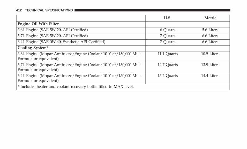
U.S. MetricEngine Oil With Filter3.6L Engine (SAE 5W-20, API Certified) 6 Quarts 5.6 Liters5.7L Engine (SAE 5W-20, API Certified) 7 Quarts 6.6 Liters6.4L Engine (SAE 0W-40, Synthetic API Certified) 7 Quarts 6.6 LitersCooling System*3.6L Engine (Mopar Antifreeze/Engine Coolant 10 Year/150,000 MileFormula or equivalent)
11.1 Quarts 10.5 Liters
5.7L Engine (Mopar Antifreeze/Engine Coolant 10 Year/150,000 MileFormula or equivalent)
14.7 Quarts 13.9 Liters
6.4L Engine (Mopar Antifreeze/Engine Coolant 10 Year/150,000 MileFormula or equivalent)
15.2 Quarts 14.4 Liters
* Includes heater and coolant recovery bottle filled to MAX level.
412 TECHNICAL SPECIFICATIONS

FLUIDS AND LUBRICANTS
Engine
Component Fluid, Lubricant, or Genuine PartEngine Coolant We recommend you use Mopar Antifreeze/Coolant 10 Year/150,000
(240,000 km)Mile Formula OAT (Organic Additive Technology).Engine Oil – 3.6L & 5.7L Engine We recommend you use API Certified SAE 5W-20 Engine Oil, meeting the
requirements of FCA Material Standard MS-6395 such as Mopar SAE 5W-20,Pennzoil SAE 5W-20, and Pennzoil gold 5W-20 semi-synthetic oil. Refer toyour engine oil filler cap for correct SAE grade.
Engine Oil – 6.4L Engine For best performance and maximum protection under all types of operatingconditions, the manufacturer only recommends full synthetic engine oils.The manufacturer recommends the use of Pennzoil Ultra Platinum 0W-40 orequivalent Mopar engine oil meeting the requirements of FCA Material Stan-dard MS-12633 for use in all operating temperatures.
Engine Oil Filter We recommend you use Mopar Engine Oil Filters.Spark Plugs We recommend you use Mopar Spark Plugs.Fuel Selection – 3.6 Engine 87 Octane, 0-15% Ethanol.Fuel Selection – 5.7 Engine With Au-tomatic Transmission
89 Octane recommended – 87 Octane acceptable, 0-15% Ethanol.
Fuel Selection – 6.4L Engine & 5.7Engine With Manual Transmission
91 Octane or higher, 0-15% Ethanol.
9
TECHNICAL SPECIFICATIONS 413
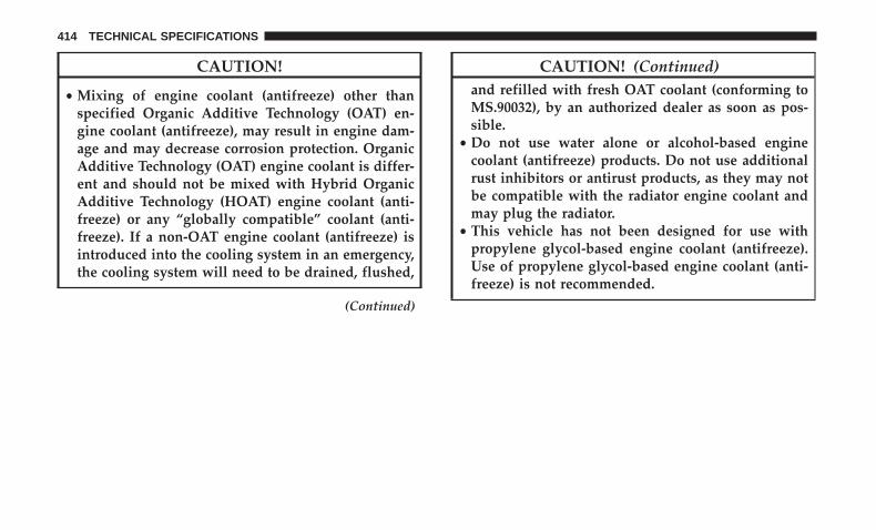
CAUTION!
• Mixing of engine coolant (antifreeze) other thanspecified Organic Additive Technology (OAT) en-gine coolant (antifreeze), may result in engine dam-age and may decrease corrosion protection. OrganicAdditive Technology (OAT) engine coolant is differ-ent and should not be mixed with Hybrid OrganicAdditive Technology (HOAT) engine coolant (anti-freeze) or any “globally compatible” coolant (anti-freeze). If a non-OAT engine coolant (antifreeze) isintroduced into the cooling system in an emergency,the cooling system will need to be drained, flushed,
(Continued)
CAUTION! (Continued)and refilled with fresh OAT coolant (conforming toMS.90032), by an authorized dealer as soon as pos-sible.
• Do not use water alone or alcohol-based enginecoolant (antifreeze) products. Do not use additionalrust inhibitors or antirust products, as they may notbe compatible with the radiator engine coolant andmay plug the radiator.
• This vehicle has not been designed for use withpropylene glycol-based engine coolant (antifreeze).Use of propylene glycol-based engine coolant (anti-freeze) is not recommended.
414 TECHNICAL SPECIFICATIONS
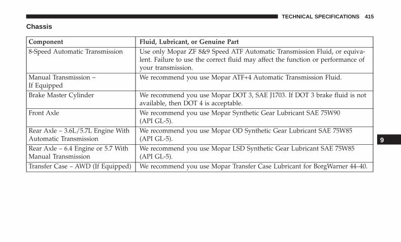
Chassis
Component Fluid, Lubricant, or Genuine Part8-Speed Automatic Transmission Use only Mopar ZF 8&9 Speed ATF Automatic Transmission Fluid, or equiva-
lent. Failure to use the correct fluid may affect the function or performance ofyour transmission.
Manual Transmission –If Equipped
We recommend you use Mopar ATF+4 Automatic Transmission Fluid.
Brake Master Cylinder We recommend you use Mopar DOT 3, SAE J1703. If DOT 3 brake fluid is notavailable, then DOT 4 is acceptable.
Front Axle We recommend you use Mopar Synthetic Gear Lubricant SAE 75W90(API GL-5).
Rear Axle – 3.6L/5.7L Engine WithAutomatic Transmission
We recommend you use Mopar OD Synthetic Gear Lubricant SAE 75W85(API GL-5).
Rear Axle – 6.4 Engine or 5.7 WithManual Transmission
We recommend you use Mopar LSD Synthetic Gear Lubricant SAE 75W85(API GL-5).
Transfer Case – AWD (If Equipped) We recommend you use Mopar Transfer Case Lubricant for BorgWarner 44–40.
9
TECHNICAL SPECIFICATIONS 415


MULTIMEDIA
CONTENTS� UCONNECT SYSTEMS . . . . . . . . . . . . . . . . . . .419
� DRAG & DROP MENU BAR . . . . . . . . . . . . . . . .419
� CYBERSECURITY . . . . . . . . . . . . . . . . . . . . . . .420
� UCONNECT SETTINGS . . . . . . . . . . . . . . . . . . .421
▫ Customer Programmable Features —Uconnect 4 Settings . . . . . . . . . . . . . . . . . . . . .422
▫ Customer Programmable Features —Uconnect 4C/4C NAV Settings . . . . . . . . . . . . .443
▫ Performance Pages — If Equipped. . . . . . . . . . .463
▫ Performance Control — If Equipped . . . . . . . . .473
� STEERING WHEEL AUDIO CONTROLS —IF EQUIPPED . . . . . . . . . . . . . . . . . . . . . . . . . .482
▫ Radio Operation. . . . . . . . . . . . . . . . . . . . . . . .482
▫ Media Mode . . . . . . . . . . . . . . . . . . . . . . . . . .482
� IPOD/USB/MP3 CONTROL — IF EQUIPPED . . .483
� RADIO OPERATION AND MOBILE PHONES . . .483
▫ Regulatory And Safety Information . . . . . . . . . .483
� UCONNECT VOICE RECOGNITION QUICKTIPS . . . . . . . . . . . . . . . . . . . . . . . . . . . . . . . . .485
▫ Introducing Uconnect . . . . . . . . . . . . . . . . . . . .485
▫ Get Started . . . . . . . . . . . . . . . . . . . . . . . . . . .486
▫ Basic Voice Commands . . . . . . . . . . . . . . . . . . .487
▫ Radio . . . . . . . . . . . . . . . . . . . . . . . . . . . . . . .487
▫ Media . . . . . . . . . . . . . . . . . . . . . . . . . . . . . . .488
▫ Phone . . . . . . . . . . . . . . . . . . . . . . . . . . . . . . .490
▫ Voice Text Reply — If Equipped . . . . . . . . . . . .491
▫ Climate . . . . . . . . . . . . . . . . . . . . . . . . . . . . . .492
▫ Navigation (4C NAV) . . . . . . . . . . . . . . . . . . . .494
▫ SiriusXM Guardian (4C/4C NAV) —If Equipped . . . . . . . . . . . . . . . . . . . . . . . . . . .495
10

▫ Register (4C/4C NAV) . . . . . . . . . . . . . . . . . . .495
▫ Vehicle Health Report/Alert (4C/4C NAV) . . . . .496
▫ Mobile App (4C/4C NAV) . . . . . . . . . . . . . . . .496
▫ SiriusXM Travel Link (4C NAV). . . . . . . . . . . . .497
▫ Siri Eyes Free — If Equipped . . . . . . . . . . . . . .498
▫ Do Not Disturb . . . . . . . . . . . . . . . . . . . . . . . .499
▫ Android Auto — If Equipped . . . . . . . . . . . . . .500
▫ Apple CarPlay — If Equipped. . . . . . . . . . . . . .501
▫ General Information . . . . . . . . . . . . . . . . . . . . .503
▫ Additional Information . . . . . . . . . . . . . . . . . . .503
418 MULTIMEDIA

UCONNECT SYSTEMS
For detailed information about your Uconnect system,refer to your Uconnect Owner’s Manual Supplement.
NOTE: Uconnect screen images are for illustration pur-poses only and may not reflect exact software for yourvehicle.
DRAG & DROP MENU BAR
The Uconnect features and services in the main menu barare easily changed for your convenience. Simply followthese steps:
1. Press the “Apps ” button to open the App screen.
2. Press and hold, then drag the selected App to replace anexisting shortcut in the main menu bar.
The new app shortcut, that was dragged down onto themain menu bar, will now be an active App/shortcut.
NOTE: This feature is only available if the vehicle is inpark.Uconnect 4 Main Menu
Uconnect 4C/4C NAV Main Menu 10
MULTIMEDIA 419
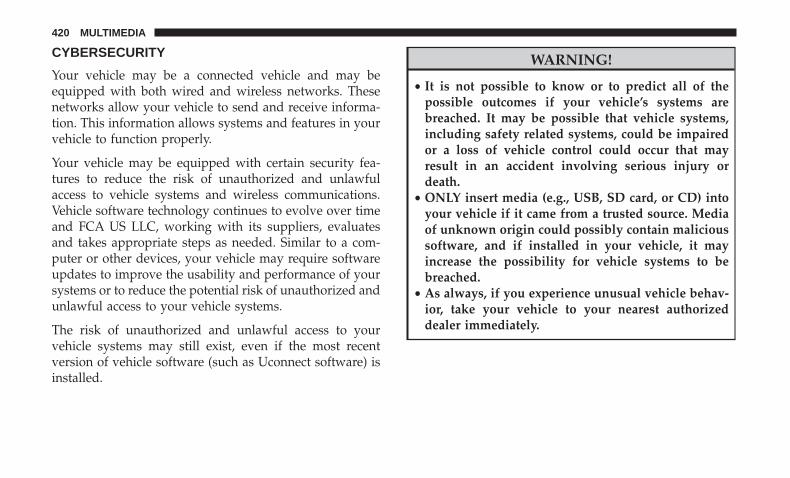
CYBERSECURITY
Your vehicle may be a connected vehicle and may beequipped with both wired and wireless networks. Thesenetworks allow your vehicle to send and receive informa-tion. This information allows systems and features in yourvehicle to function properly.
Your vehicle may be equipped with certain security fea-tures to reduce the risk of unauthorized and unlawfulaccess to vehicle systems and wireless communications.Vehicle software technology continues to evolve over timeand FCA US LLC, working with its suppliers, evaluatesand takes appropriate steps as needed. Similar to a com-puter or other devices, your vehicle may require softwareupdates to improve the usability and performance of yoursystems or to reduce the potential risk of unauthorized andunlawful access to your vehicle systems.
The risk of unauthorized and unlawful access to yourvehicle systems may still exist, even if the most recentversion of vehicle software (such as Uconnect software) isinstalled.
WARNING!
• It is not possible to know or to predict all of thepossible outcomes if your vehicle’s systems arebreached. It may be possible that vehicle systems,including safety related systems, could be impairedor a loss of vehicle control could occur that mayresult in an accident involving serious injury ordeath.
• ONLY insert media (e.g., USB, SD card, or CD) intoyour vehicle if it came from a trusted source. Mediaof unknown origin could possibly contain malicioussoftware, and if installed in your vehicle, it mayincrease the possibility for vehicle systems to bebreached.
• As always, if you experience unusual vehicle behav-ior, take your vehicle to your nearest authorizeddealer immediately.
420 MULTIMEDIA
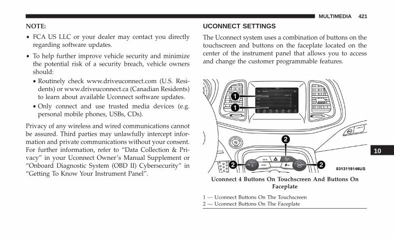
NOTE:
• FCA US LLC or your dealer may contact you directlyregarding software updates.
• To help further improve vehicle security and minimizethe potential risk of a security breach, vehicle ownersshould:• Routinely check www.driveuconnect.com (U.S. Resi-
dents) or www.driveuconnect.ca (Canadian Residents)to learn about available Uconnect software updates.
• Only connect and use trusted media devices (e.g.personal mobile phones, USBs, CDs).
Privacy of any wireless and wired communications cannotbe assured. Third parties may unlawfully intercept infor-mation and private communications without your consent.For further information, refer to “Data Collection & Pri-vacy” in your Uconnect Owner’s Manual Supplement or“Onboard Diagnostic System (OBD II) Cybersecurity” in“Getting To Know Your Instrument Panel”.
UCONNECT SETTINGS
The Uconnect system uses a combination of buttons on thetouchscreen and buttons on the faceplate located on thecenter of the instrument panel that allows you to accessand change the customer programmable features.
Uconnect 4 Buttons On Touchscreen And Buttons OnFaceplate
1 — Uconnect Buttons On The Touchscreen2 — Uconnect Buttons On The Faceplate
10
MULTIMEDIA 421

NOTE: Interior trims may vary. 6.4L vehicles will receive a“SRT” button rather than a “Sport” button on the Instru-ment Panel.
Customer Programmable Features — Uconnect 4Settings
Press the “Settings” button on the bottom bar, or press the“Apps ” button, then press the “Settings” button onthe touchscreen to display the menu setting screen. Inthis mode the Uconnect system allows you to access allof the available programmable features.
NOTE: Depending on the vehicle’s options, feature set-tings may vary.
When making a selection, press the button on the touch-screen to enter the desired mode. Once in the desiredmode, press and release the preferred setting “option” untila check-mark appears next to the setting, showing thatsetting has been selected. Once the setting is complete,press the “X” button on the touchscreen to close out of thesettings screen. Pressing the Up or Down Arrow button onthe right side of the screen will allow you to toggle up ordown through the available settings.
The following tables list the settings that may be foundwithin the Uconnect 4 radio, along with the selectableoptions pertaining to each setting.
Uconnect 4C/4C NAV Buttons On Touchscreen AndButtons On Faceplate
1 — Uconnect Buttons On The Touchscreen2 — Uconnect Buttons On The Faceplate
422 MULTIMEDIA
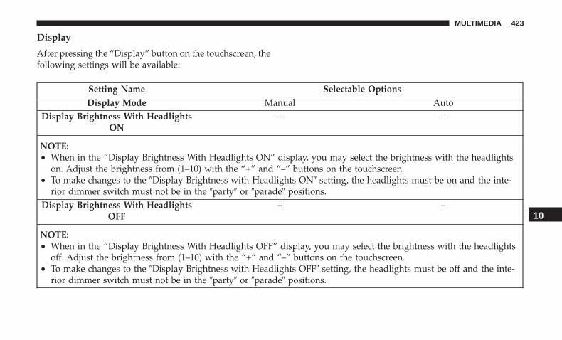
Display
After pressing the “Display” button on the touchscreen, thefollowing settings will be available:
Setting Name Selectable OptionsDisplay Mode Manual Auto
Display Brightness With HeadlightsON
+ –
NOTE:• When in the “Display Brightness With Headlights ON” display, you may select the brightness with the headlights
on. Adjust the brightness from (1–10) with the “+” and “–” buttons on the touchscreen.• To make changes to the �Display Brightness with Headlights ON� setting, the headlights must be on and the inte-
rior dimmer switch must not be in the �party� or �parade� positions.Display Brightness With Headlights
OFF+ –
NOTE:• When in the “Display Brightness With Headlights OFF” display, you may select the brightness with the headlights
off. Adjust the brightness from (1–10) with the “+” and “–” buttons on the touchscreen.• To make changes to the �Display Brightness with Headlights OFF� setting, the headlights must be off and the inte-
rior dimmer switch must not be in the �party� or �parade� positions.
10
MULTIMEDIA 423

Setting Name Selectable OptionsSet Theme On Off
NOTE:When in the “Set Theme” display, you may select the theme for the display screen. To make your selection, press the�Set Theme� button on the touchscreen, then select the desired theme option button until a check-mark appears show-ing that the setting has been selected.
AutoShow Smartphone DisplayUpon Connection
On Off
Touchscreen Beep On OffControls Screen Time-Out — If
EquippedOn Off
NOTE:When the “Control Screen Time Out” feature is selected, the controls screen will stay open for five seconds before thescreen times out. With the feature deselected, the screen will stay open until it is manually closed.Navigation Turn-By-Turn Displayed
In Cluster — If EquippedOn Off
NOTE:When the “Navigation Turn-By-Turn Displayed In Cluster” feature is selected, the turn-by-turn directions will appearin the instrument cluster display as the vehicle approaches a designated turn within a programmed route.
424 MULTIMEDIA

Units
After pressing the “Units” button on the touchscreen youmay select each unit of measure independently displayedin the instrument cluster display, and navigation system (ifequipped). The following selectable units of measure arelisted below:
Setting Name Selectable OptionsUnits US Metric CustomSpeed MPH km/h
Distance mi kmFuel Consumption MPG (US) MPG (UK) L/100 km km/L
Pressure psi kPa barTemperature °F °C
Voice
After pressing the “Voice” button on the touchscreen, thefollowing settings will be available:
Setting Name Selectable OptionsVoice Response Length Brief DetailedShow Command List Always With Help Never
10
MULTIMEDIA 425

Clock
After pressing the “Clock” button on the touchscreen, thefollowing settings will be available:
Setting Name Selectable OptionsSync Time With GPS — If
EquippedOn Off
NOTE:The “Sync Time With GPS” feature will allow you to automatically have the radio set the time.
Set Time Hours + –Set Time Minutes + –
Time Format 12 hrs 24 hrsShow Time In Status Bar — If
EquippedOn Off
NOTE:The “Show Time In Status Bar” feature will allow you to turn on or shut off the digital clock in the status bar.
426 MULTIMEDIA
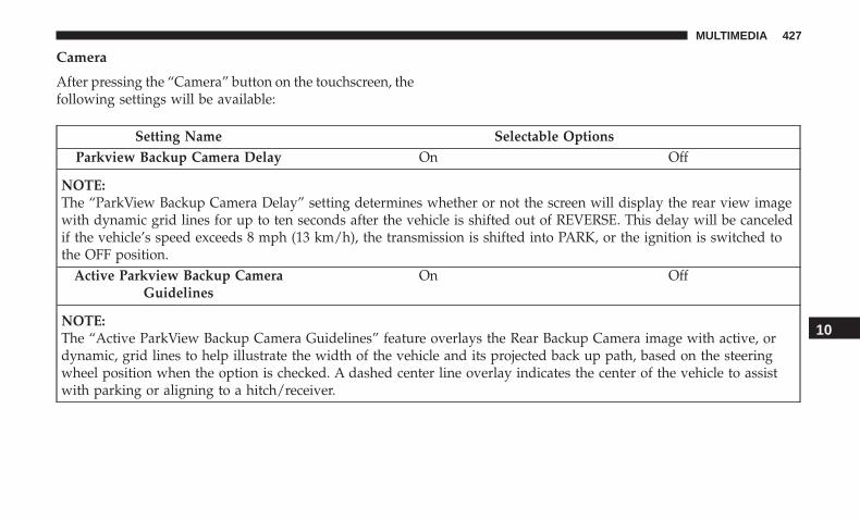
Camera
After pressing the “Camera” button on the touchscreen, thefollowing settings will be available:
Setting Name Selectable OptionsParkview Backup Camera Delay On Off
NOTE:The “ParkView Backup Camera Delay” setting determines whether or not the screen will display the rear view imagewith dynamic grid lines for up to ten seconds after the vehicle is shifted out of REVERSE. This delay will be canceledif the vehicle’s speed exceeds 8 mph (13 km/h), the transmission is shifted into PARK, or the ignition is switched tothe OFF position.
Active Parkview Backup CameraGuidelines
On Off
NOTE:The “Active ParkView Backup Camera Guidelines” feature overlays the Rear Backup Camera image with active, ordynamic, grid lines to help illustrate the width of the vehicle and its projected back up path, based on the steeringwheel position when the option is checked. A dashed center line overlay indicates the center of the vehicle to assistwith parking or aligning to a hitch/receiver.
10
MULTIMEDIA 427
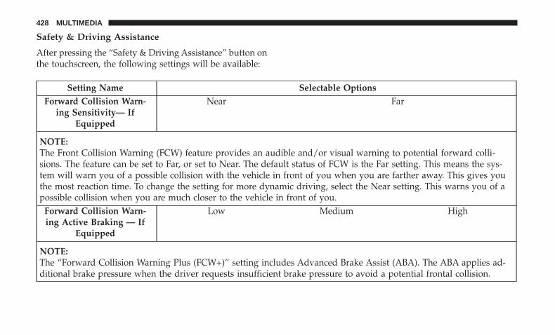
Safety & Driving Assistance
After pressing the “Safety & Driving Assistance” button onthe touchscreen, the following settings will be available:
Setting Name Selectable OptionsForward Collision Warn-
ing Sensitivity— IfEquipped
Near Far
NOTE:The Front Collision Warning (FCW) feature provides an audible and/or visual warning to potential forward colli-sions. The feature can be set to Far, or set to Near. The default status of FCW is the Far setting. This means the sys-tem will warn you of a possible collision with the vehicle in front of you when you are farther away. This gives youthe most reaction time. To change the setting for more dynamic driving, select the Near setting. This warns you of apossible collision when you are much closer to the vehicle in front of you.
Forward Collision Warn-ing Active Braking — If
Equipped
Low Medium High
NOTE:The “Forward Collision Warning Plus (FCW+)” setting includes Advanced Brake Assist (ABA). The ABA applies ad-ditional brake pressure when the driver requests insufficient brake pressure to avoid a potential frontal collision.
428 MULTIMEDIA

Setting Name Selectable OptionsElectric Power SteeringDefault— If Equipped
Sport Normal Comfort
NOTE:When �Electric Power Steering Default� is selected, it allows you to change the default setting of your vehicle to eithernormal, sport, or comfort.ParkSense — If Equipped Sound Only Sound and Display
NOTE:The ParkSense system will scan for objects behind the vehicle when the gear selector is in REVERSE and the vehiclespeed is less than 7 mph (11 km/h). It will provide an alert (audible and/or visual) to indicate the proximity to otherobjects. The system can be enabled with Sound Only, or Sound and Display.Rear ParkSense Volume —
If EquippedLow Medium High
NOTE:The Rear ParkSense Chime Volume settings can be selected from the instrument cluster display or Uconnect System.The chime volume settings include LOW, MEDIUM, and HIGH. The factory default volume setting is MEDIUM. Tomake your selection, press the “Rear ParkSense Vol.” button on the touchscreen, until a check-mark appears next tosetting, indicating that the setting had been selected. ParkSense will retain its last known configuration state throughignition cycles.
Rear ParkSense BrakingAssist— If Equipped
On Off
10
MULTIMEDIA 429
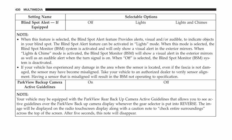
Setting Name Selectable OptionsBlind Spot Alert — If
EquippedOff Lights Lights and Chimes
NOTE:• When this feature is selected, the Blind Spot Alert feature Provides alerts, visual and/or audible, to indicate objects
in your blind spot. The Blind Spot Alert feature can be activated in “Lights” mode. When this mode is selected, theBlind Spot Monitor (BSM) system is activated and will only show a visual alert in the exterior mirrors. When“Lights & Chime” mode is activated, the Blind Spot Monitor (BSM) will show a visual alert in the exterior mirrorsas well as an audible alert when the turn signal is on. When “Off” is selected, the Blind Spot Monitor (BSM) sys-tem is deactivated.
• If your vehicle has experienced any damage in the area where the sensor is located, even if the fascia is not dam-aged, the sensor may have become misaligned. Take your vehicle to an authorized dealer to verify sensor align-ment. Having a sensor that is misaligned will result in the BSM not operating to specification.
ParkView Backup CameraActive Guidelines
On Off
NOTE:Your vehicle may be equipped with the ParkView Rear Back Up Camera Active Guidelines that allows you to see ac-tive guidelines over the ParkView Back up camera display whenever the gear selector is put into REVERSE. The im-age will be displayed on the radio touchscreen display along with a caution note to “check entire surroundings”across the top of the screen. After five seconds, this note will disappear.
430 MULTIMEDIA

Setting Name Selectable OptionsParkView Backup Camera
DelayOn Off
NOTE:When the vehicle is shifted out of REVERSE (with camera delay turned OFF), the rear camera mode is exited and thenavigation or audio screen appears again. When the vehicle is shifted out of REVERSE (with camera delay turnedON), the rear view image with dynamic grid lines will be displayed for up to ten seconds after shifting out of “RE-VERSE” unless the forward vehicle speed exceeds 8 mph (12 km/h), the transmission is shifted into “PARK” or theignition is switched to the OFF position. To set the ParkView Backup Camera Delay, press the “Controls” button onthe touchscreen, the “settings” button on the touchscreen, then the “Safety & Driving Assistance” button on thetouchscreen.Rain Sensing Auto Wipers On Off
NOTE:When this feature is selected and the wipers are on, the system will automatically activate the windshield wipers if itsenses moisture on the windshield.
Hill Start Assist — IfEquipped
On Off
NOTE:When this feature is selected, the Hill Start Assist (HSA) system is active.
10
MULTIMEDIA 431
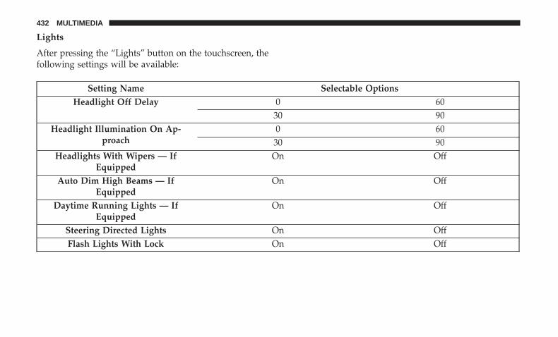
Lights
After pressing the “Lights” button on the touchscreen, thefollowing settings will be available:
Setting Name Selectable OptionsHeadlight Off Delay 0 60
30 90Headlight Illumination On Ap-
proach0 60
30 90Headlights With Wipers — If
EquippedOn Off
Auto Dim High Beams — IfEquipped
On Off
Daytime Running Lights — IfEquipped
On Off
Steering Directed Lights On OffFlash Lights With Lock On Off
432 MULTIMEDIA
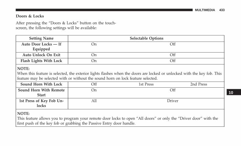
Doors & Locks
After pressing the “Doors & Locks” button on the touch-screen, the following settings will be available:
Setting Name Selectable OptionsAuto Door Locks — If
EquippedOn Off
Auto Unlock On Exit On OffFlash Lights With Lock On Off
NOTE:When this feature is selected, the exterior lights flashes when the doors are locked or unlocked with the key fob. Thisfeature may be selected with or without the sound horn on lock feature selected.
Sound Horn With Lock Off 1st Press 2nd PressSound Horn With Remote
StartOn Off
1st Press of Key Fob Un-locks
All Driver
NOTE:This feature allows you to program your remote door locks to open “All doors” or only the “Driver door” with thefirst push of the key fob or grabbing the Passive Entry door handle.
10
MULTIMEDIA 433
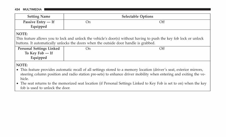
Setting Name Selectable OptionsPassive Entry — If
EquippedOn Off
NOTE:This feature allows you to lock and unlock the vehicle’s door(s) without having to push the key fob lock or unlockbuttons. It automatically unlocks the doors when the outside door handle is grabbed.Personal Settings Linked
To Key Fob — IfEquipped
On Off
NOTE:• This feature provides automatic recall of all settings stored to a memory location (driver’s seat, exterior mirrors,
steering column position and radio station pre-sets) to enhance driver mobility when entering and exiting the ve-hicle.
• The seat returns to the memorized seat location (if Personal Settings Linked to Key Fob is set to on) when the keyfob is used to unlock the door.
434 MULTIMEDIA
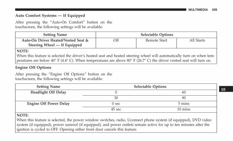
Auto Comfort Systems — If Equipped
After pressing the “Auto-On Comfort” button on thetouchscreen, the following settings will be available:
Setting Name Selectable OptionsAuto-On Driver Heated/Vented Seat &
Steering Wheel — If EquippedOff Remote Start All Starts
NOTE:When this feature is selected the driver’s heated seat and heated steering wheel will automatically turn on when tem-peratures are below 40° F (4.4° C). When temperatures are above 80° F (26.7° C) the driver vented seat will turn on.
Engine Off Options
After pressing the “Engine Off Options” button on thetouchscreen, the following settings will be available:
Setting Name Selectable OptionsHeadlight Off Delay 0 60
30 90Engine Off Power Delay 0 sec 5 mins
45 sec 10 mins
NOTE:When this feature is selected, the power window switches, radio, Uconnect phone system (if equipped), DVD videosystem (if equipped), power sunroof (if equipped), and power outlets remain active for up to ten minutes after theignition is cycled to OFF. Opening either front door cancels this feature.
10
MULTIMEDIA 435

Compass Settings — If Equipped
After pressing the “Compass Settings” button on thetouchscreen, the following settings will be available:
NOTE: Before compass calibration is performed, the com-pass variance zone should be set for best results.
Setting Name Selectable OptionsCompass Variance 1 2 3 4 5 6 7 8 9 10 11 12 13 14 15
NOTE:When the “Compass Variance” feature is selected, it allows the compass variance to be set to any number from 1 to15 per the compass variance zone map figure.Compass Variance is the difference between Magnetic North and Geographic North. To compensate for the differ-ences, the variance should be set for the zone where the vehicle is being driven, illustrated in the zone map. Onceproperly set, the compass will automatically compensate for the differences when calibrated, and provide the mostaccurate compass headings.
436 MULTIMEDIA

Compass Calibration Yes
NOTE:Press “Compass Calibration” on the touchscreen to enter calibration. To start calibration of the compass, press the “Yes” but-ton on the touchscreen and complete one or more 360-degree turns (in an area free from large metal or metallic objects). Amessage will appear on the touchscreen when the compass has been successfully calibrated.Keep magnetic materials away from the rear view mirror, such as Mobile Phones, Laptops and Radar Detectors. This iswhere the compass module is located, and it can cause interference with the compass sensor, and it may give false readings.
Compass Variance Zone Map 10
MULTIMEDIA 437

Audio
After pressing the “Audio” button on the touchscreen, thefollowing settings will be available:
Setting Name Selectable OptionsEqualizer + -
NOTE:When in the “Equalizer” display you may adjust the Bass, Mid and Treble settings. Adjust the settings with the “+”and “–” buttons on the touchscreen or by selecting any point on the scale between the “+” and “–” buttons on thetouchscreen.
Balance/Fade Arrow Buttons “C” icon
NOTE:The “Balance/Fade” feature allows you to adjust the Balance and Fade settings. Press and drag the speaker icon oruse the arrows to adjust, tap the “C” icon to readjust to the center.Speed Adjusted Vol-
umeOff 1 2 3
NOTE:The “Speed Adjusted Volume” feature increases or decreases volume relative to vehicle speed. To change the SpeedAdjusted Volume press the “Speed Adjusted Volume” button on the touchscreen and select from “Off,” “1,” “2” or“3” buttons on the touchscreen.
438 MULTIMEDIA

Setting Name Selectable OptionsSurround Sound —
If EquippedOn Off
NOTE:The “Surround Sound” feature provides simulated surround sound mode. To make your selection, press the “Sur-round Sound” button on the touchscreen, and select “On” or “Off.”AUX Volume Offset
— If Equipped+ –
NOTE:The “AUX Volume Offset” feature provides the ability to tune the audio level for portable devices connected throughthe AUX input. To make your selection, press the “AUX Volume Offset” button on the touchscreen, select “+” and“–”.
Auto Play — IfEquipped
On Off
NOTE: The Auto Play feature allows a media device to begin playing when the media device is plugged in. To makeyour selection, press the On or Off buttons to activate or deactivate Auto Play.
10
MULTIMEDIA 439

Phone/Bluetooth
After pressing the “Phone/Bluetooth” button on the touch-screen, the following settings will be available:
Setting Name Selectable OptionsDo Not Disturb List of Settings
NOTE: Press “Do Not Disturb” to access the available settings. The following settings are: Auto Reply (both, text,call), Auto Reply Message (custom, default), and Custom Auto Reply Message (create message).
Paired Phones/Devices List of Paired Phones/Devices
NOTE:This feature shows which phones are paired to the Phone/Bluetooth system. For further information, refer to theUconnect Owner’s Manual Supplement.
SiriusXM Setup — If Equipped
After pressing the “SiriusXM Setup” button on the touch-screen, the following settings will be available:
Setting Name Selectable OptionsTune Start On Off
Channel Skip Name of Channel
NOTE: SiriusXM can be programmed to skip channels. To make your selection, press the “Channel Skip” button onthe touchscreen, select the channels you would like to skip.
440 MULTIMEDIA

Setting Name Selectable OptionsSubscription Information Subscription Info
NOTE:New vehicle purchasers or lessees will receive a free limited time subscription to SiriusXM Satellite Radio with yourradio. Following the expiration of the free services, it will be necessary to access the information on the SubscriptionInformation screen to re-subscribe.
1. Press the “Subscription Info” button on the touchscreen to access the Subscription Information screen.
2. Write down the SIRIUS ID numbers for your receiver. To reactivate your service, either call the number listed on thescreen or visit the provider online.
Restore Settings
After pressing the “Restore Settings” button on the touch-screen, the following settings will be available:
Setting Name Selectable OptionsRestore Settings Yes Cancel
NOTE:When the “Restore Settings” feature is selected it will reset the Display, Clock, Audio, and Radio Settings to their de-fault settings. If “Yes” is selected, a pop-up will appear asking �Are you sure you want to reset your settings to de-fault?” Select “Yes” to restore, or “Cancel” to exit.
10
MULTIMEDIA 441

Setting Name Selectable OptionsReset App Drawer to Default Order Ok Cancel
NOTE:When this feature is selected, it will reset all settings to their default settings. To restore the settings to their defaultsetting, press the “Restore Settings” button on the touchscreen. A pop-up will appear asking �Are you sure you wantto reset your settings to default?”
Restore Apps Ok CancelClear Personal Data Yes Cancel
NOTE: When the “Clear Personal Data” feature is selected it will remove all personal data including Clock, Audio,Radio, Bluetooth devices, Apps, and Favorites.
Modem Reset Ok Cancel
Clear Personal Data
After pressing the “Clear Personal Data Settings” button onthe touchscreen, the following settings will be available:
Setting Name Selectable OptionsClear Personal Data Yes Cancel
NOTE:When this feature is selected it will remove all personal data including Bluetooth devices and presets. If “Yes” is se-lected a pop-up will appear asking �Are you sure you want to clear all personal data?” select “Yes” to Clear, or “Can-cel” to exit.
442 MULTIMEDIA
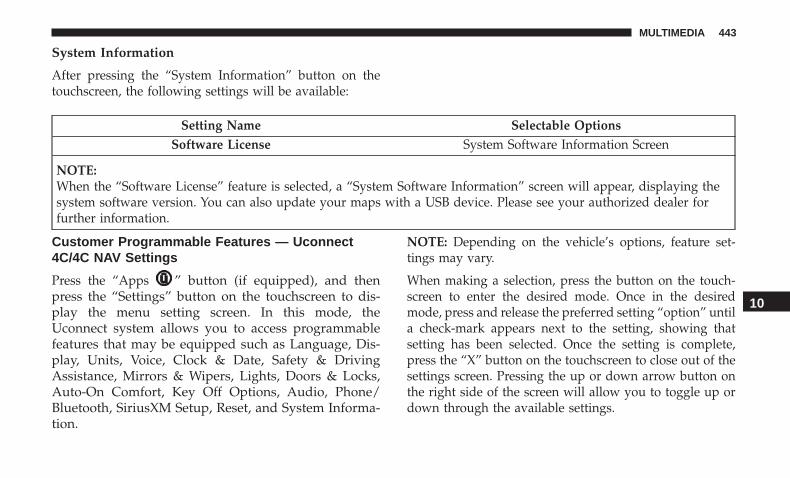
System Information
After pressing the “System Information” button on thetouchscreen, the following settings will be available:
Setting Name Selectable OptionsSoftware License System Software Information Screen
NOTE:When the “Software License” feature is selected, a “System Software Information” screen will appear, displaying thesystem software version. You can also update your maps with a USB device. Please see your authorized dealer forfurther information.
Customer Programmable Features — Uconnect4C/4C NAV Settings
Press the “Apps ” button (if equipped), and thenpress the “Settings” button on the touchscreen to dis-play the menu setting screen. In this mode, theUconnect system allows you to access programmablefeatures that may be equipped such as Language, Dis-play, Units, Voice, Clock & Date, Safety & DrivingAssistance, Mirrors & Wipers, Lights, Doors & Locks,Auto-On Comfort, Key Off Options, Audio, Phone/Bluetooth, SiriusXM Setup, Reset, and System Informa-tion.
NOTE: Depending on the vehicle’s options, feature set-tings may vary.
When making a selection, press the button on the touch-screen to enter the desired mode. Once in the desiredmode, press and release the preferred setting “option” untila check-mark appears next to the setting, showing thatsetting has been selected. Once the setting is complete,press the “X” button on the touchscreen to close out of thesettings screen. Pressing the up or down arrow button onthe right side of the screen will allow you to toggle up ordown through the available settings.
10
MULTIMEDIA 443
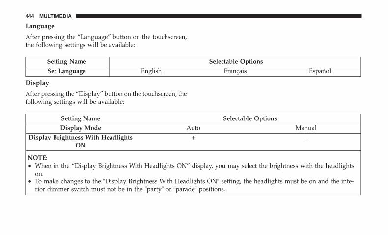
Language
After pressing the “Language” button on the touchscreen,the following settings will be available:
Setting Name Selectable OptionsSet Language English Français Español
Display
After pressing the “Display” button on the touchscreen, thefollowing settings will be available:
Setting Name Selectable OptionsDisplay Mode Auto Manual
Display Brightness With HeadlightsON
+ –
NOTE:• When in the “Display Brightness With Headlights ON” display, you may select the brightness with the headlights
on.• To make changes to the �Display Brightness With Headlights ON� setting, the headlights must be on and the inte-
rior dimmer switch must not be in the �party� or �parade� positions.
444 MULTIMEDIA
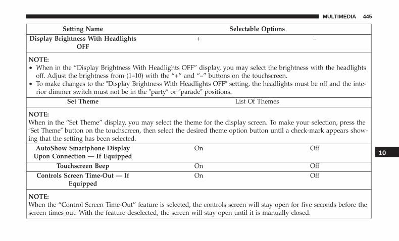
Setting Name Selectable OptionsDisplay Brightness With Headlights
OFF+ –
NOTE:• When in the “Display Brightness With Headlights OFF” display, you may select the brightness with the headlights
off. Adjust the brightness from (1–10) with the “+” and “–” buttons on the touchscreen.• To make changes to the �Display Brightness With Headlights OFF� setting, the headlights must be off and the inte-
rior dimmer switch must not be in the �party� or �parade� positions.Set Theme List Of Themes
NOTE:When in the “Set Theme” display, you may select the theme for the display screen. To make your selection, press the�Set Theme� button on the touchscreen, then select the desired theme option button until a check-mark appears show-ing that the setting has been selected.
AutoShow Smartphone DisplayUpon Connection — If Equipped
On Off
Touchscreen Beep On OffControls Screen Time-Out — If
EquippedOn Off
NOTE:When the “Control Screen Time-Out” feature is selected, the controls screen will stay open for five seconds before thescreen times out. With the feature deselected, the screen will stay open until it is manually closed.
10
MULTIMEDIA 445

Setting Name Selectable OptionsNavigation Next Turn Pop-Ups Dis-
played In Cluster — If EquippedOn Off
NOTE:When the “Navigation Turn-By-Turn Displayed In Cluster” feature is selected, the turn-by-turn directions will appearin the instrument cluster display as the vehicle approaches a designated turn within a programmed route.
Units
After pressing the “Units” button on the touchscreen, youmay select each unit of measure independently displayedin the instrument cluster display, and navigation system (ifequipped). The following selectable units of measure arelisted below:
Setting Name Selectable OptionsUnits US Metric Custom
NOTE: When the “Custom” setting is selected, units will appear according to your personally configured settings. Toconfigure these settings, press the “Custom” bar. The following settings will appear:
Speed MPH km/hDistance mi km
Fuel Consumption MPG (US) MPG (UK) L/100 km km/LPressure psi kPa bar
Temperature °F °C
446 MULTIMEDIA

Voice
After pressing the “Voice” button on the touchscreen, thefollowing settings will be available:
Setting Name Selectable OptionsVoice Response Length Brief DetailedShow Command List Never w/Help Always
Clock & Date
After pressing the “Clock & Date” button on the touch-screen, the following settings will be available:
Setting Name Selectable OptionsSync Time With GPS — If
EquippedOn Off
NOTE:The “Sync Time With GPS” feature will allow you to automatically have the radio set the time.
Set Time Hours + –Set Time Minutes + –
Time Format 12 hrs 24 hrsAM PM
10
MULTIMEDIA 447

Setting Name Selectable OptionsShow Time In Status Bar — If
EquippedOn Off
NOTE:The “Show Time In Status Bar” feature will allow you to turn on or shut off the digital clock in the status bar.
Safety & Driving Assistance
After pressing the “Safety & Driving Assistance” button onthe touchscreen, the following settings will be available:
Setting Name Selectable OptionsParkView Backup Camera
DelayOn Off
NOTE:The “ParkView Backup Camera Delay” setting determines whether or not the screen will display the rear view imagewith dynamic grid lines for up to ten seconds after the vehicle is shifted out of REVERSE. This delay will be canceledif the vehicle’s speed exceeds 8 mph (13 km/h), the transmission is shifted into PARK, or the ignition is switched tothe OFF position.
448 MULTIMEDIA
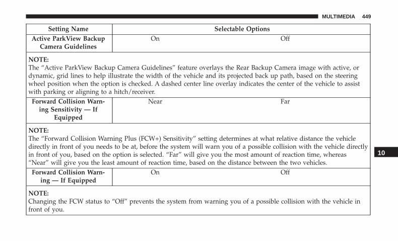
Setting Name Selectable OptionsActive ParkView Backup
Camera GuidelinesOn Off
NOTE:The “Active ParkView Backup Camera Guidelines” feature overlays the Rear Backup Camera image with active, ordynamic, grid lines to help illustrate the width of the vehicle and its projected back up path, based on the steeringwheel position when the option is checked. A dashed center line overlay indicates the center of the vehicle to assistwith parking or aligning to a hitch/receiver.
Forward Collision Warn-ing Sensitivity — If
Equipped
Near Far
NOTE:The “Forward Collision Warning Plus (FCW+) Sensitivity” setting determines at what relative distance the vehicledirectly in front of you needs to be at, before the system will warn you of a possible collision with the vehicle directlyin front of you, based on the option is selected. “Far” will give you the most amount of reaction time, whereas“Near” will give you the least amount of reaction time, based on the distance between the two vehicles.
Forward Collision Warn-ing — If Equipped
On Off
NOTE:Changing the FCW status to “Off” prevents the system from warning you of a possible collision with the vehicle infront of you.
10
MULTIMEDIA 449

Setting Name Selectable OptionsThe FCW system state is kept in memory from one ignition cycle to the next. If the system is turned OFF, it will re-main off when the vehicle is restarted.
Forward Collision Warn-ing Active Braking — If
Equipped
On Off
NOTE:The “Forward Collision Warning Plus (FCW+)” setting includes Advanced Brake Assist (ABA). The ABA applies ad-ditional brake pressure when the driver requests insufficient brake pressure to avoid a potential frontal collision.
Electric Power SteeringDefault — If Equipped
Sport Normal Comfort
NOTE:When �Electric Power Steering Default� is selected, it allows you to change the default setting of your vehicle to eithernormal, sport, or comfort.ParkSense — If Equipped Sound Only Sound & Display
NOTE:The ParkSense system will scan for objects behind the vehicle when the gear selector is in REVERSE and the vehiclespeed is less than 7 mph (11 km/h). It will provide an alert (audible and/or visual) to indicate the proximity to otherobjects. The system can be enabled with Sound Only, or Sound and Display.
450 MULTIMEDIA

Setting Name Selectable OptionsRear ParkSense Volume —
If EquippedLow Med High
NOTE:The Rear ParkSense Chime Volume settings can be selected from the instrument cluster display or Uconnect System.The chime volume settings include LOW, MEDIUM, and HIGH. The factory default volume setting is MEDIUM. Tomake your selection, press the “Rear ParkSense Vol.” button on the touchscreen, until a check-mark appears next tosetting, indicating that the setting had been selected. ParkSense will retain its last known configuration state throughignition cycles.
Blind Spot Alert — IfEquipped
Off Lights Lights & Chime
NOTE:• When this feature is selected, the Blind Spot Alert feature Provides alerts, visual and/or audible, to indicate objects
in your blind spot. The Blind Spot Alert feature can be activated in “Lights” mode. When this mode is selected, theBlind Spot Monitor (BSM) system is activated and will only show a visual alert in the exterior mirrors. When“Lights & Chime” mode is activated, the Blind Spot Monitor (BSM) will show a visual alert in the exterior mirrorsas well as an audible alert when the turn signal is on. When “Off” is selected, the Blind Spot Monitor (BSM) sys-tem is deactivated.
• If your vehicle has experienced any damage in the area where the sensor is located, even if the fascia is not dam-aged, the sensor may have become misaligned. Take your vehicle to an authorized dealer to verify sensor align-ment. Having a sensor that is misaligned will result in the BSM not operating to specification.
10
MULTIMEDIA 451
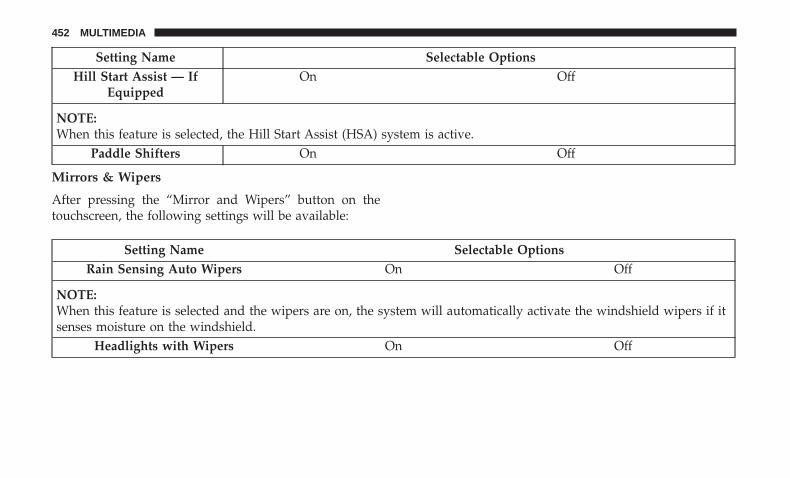
Setting Name Selectable OptionsHill Start Assist — If
EquippedOn Off
NOTE:When this feature is selected, the Hill Start Assist (HSA) system is active.
Paddle Shifters On Off
Mirrors & Wipers
After pressing the “Mirror and Wipers” button on thetouchscreen, the following settings will be available:
Setting Name Selectable OptionsRain Sensing Auto Wipers On Off
NOTE:When this feature is selected and the wipers are on, the system will automatically activate the windshield wipers if itsenses moisture on the windshield.
Headlights with Wipers On Off
452 MULTIMEDIA
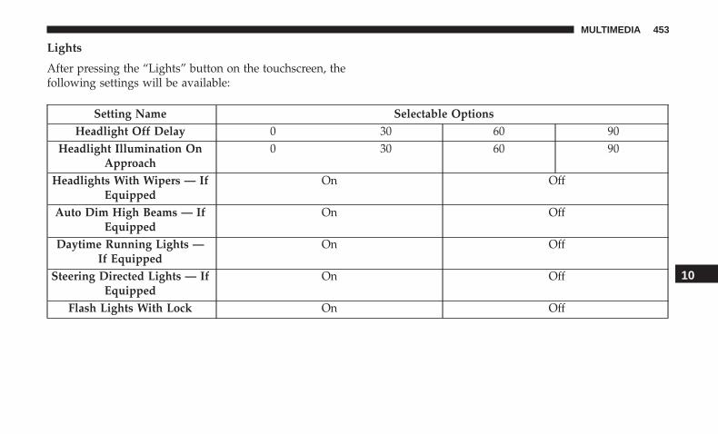
Lights
After pressing the “Lights” button on the touchscreen, thefollowing settings will be available:
Setting Name Selectable OptionsHeadlight Off Delay 0 30 60 90
Headlight Illumination OnApproach
0 30 60 90
Headlights With Wipers — IfEquipped
On Off
Auto Dim High Beams — IfEquipped
On Off
Daytime Running Lights —If Equipped
On Off
Steering Directed Lights — IfEquipped
On Off
Flash Lights With Lock On Off
10
MULTIMEDIA 453
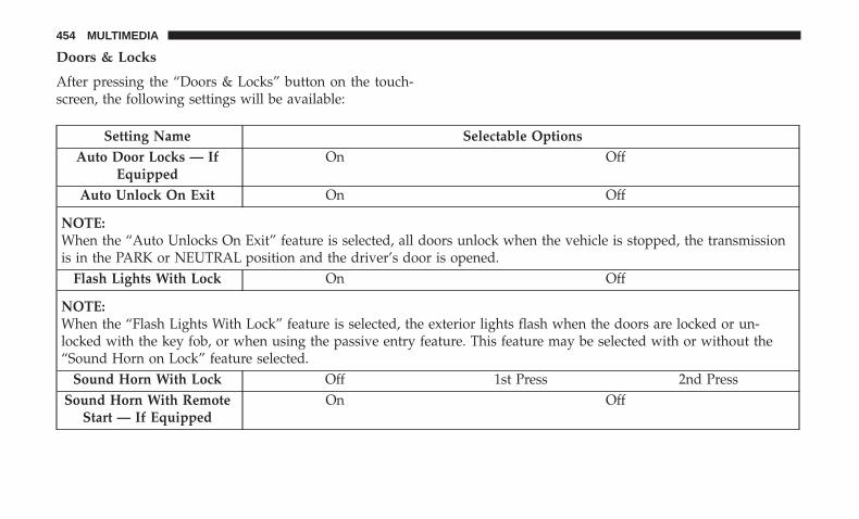
Doors & Locks
After pressing the “Doors & Locks” button on the touch-screen, the following settings will be available:
Setting Name Selectable OptionsAuto Door Locks — If
EquippedOn Off
Auto Unlock On Exit On Off
NOTE:When the “Auto Unlocks On Exit” feature is selected, all doors unlock when the vehicle is stopped, the transmissionis in the PARK or NEUTRAL position and the driver’s door is opened.
Flash Lights With Lock On Off
NOTE:When the “Flash Lights With Lock” feature is selected, the exterior lights flash when the doors are locked or un-locked with the key fob, or when using the passive entry feature. This feature may be selected with or without the“Sound Horn on Lock” feature selected.
Sound Horn With Lock Off 1st Press 2nd PressSound Horn With Remote
Start — If EquippedOn Off
454 MULTIMEDIA
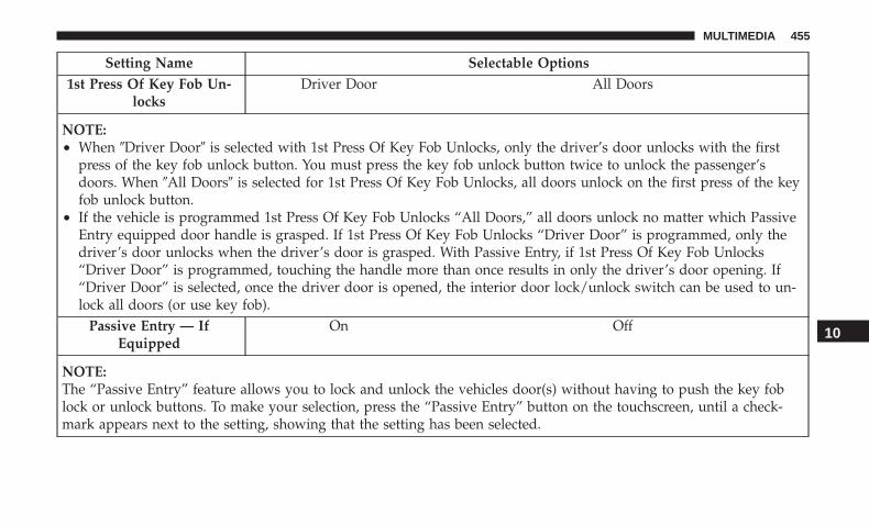
Setting Name Selectable Options1st Press Of Key Fob Un-
locksDriver Door All Doors
NOTE:• When �Driver Door� is selected with 1st Press Of Key Fob Unlocks, only the driver’s door unlocks with the first
press of the key fob unlock button. You must press the key fob unlock button twice to unlock the passenger’sdoors. When �All Doors� is selected for 1st Press Of Key Fob Unlocks, all doors unlock on the first press of the keyfob unlock button.
• If the vehicle is programmed 1st Press Of Key Fob Unlocks “All Doors,” all doors unlock no matter which PassiveEntry equipped door handle is grasped. If 1st Press Of Key Fob Unlocks “Driver Door” is programmed, only thedriver’s door unlocks when the driver’s door is grasped. With Passive Entry, if 1st Press Of Key Fob Unlocks“Driver Door” is programmed, touching the handle more than once results in only the driver’s door opening. If“Driver Door” is selected, once the driver door is opened, the interior door lock/unlock switch can be used to un-lock all doors (or use key fob).
Passive Entry — IfEquipped
On Off
NOTE:The “Passive Entry” feature allows you to lock and unlock the vehicles door(s) without having to push the key foblock or unlock buttons. To make your selection, press the “Passive Entry” button on the touchscreen, until a check-mark appears next to the setting, showing that the setting has been selected.
10
MULTIMEDIA 455
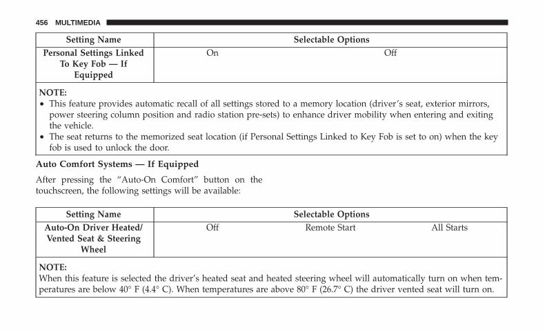
Setting Name Selectable OptionsPersonal Settings Linked
To Key Fob — IfEquipped
On Off
NOTE:• This feature provides automatic recall of all settings stored to a memory location (driver’s seat, exterior mirrors,
power steering column position and radio station pre-sets) to enhance driver mobility when entering and exitingthe vehicle.
• The seat returns to the memorized seat location (if Personal Settings Linked to Key Fob is set to on) when the keyfob is used to unlock the door.
Auto Comfort Systems — If Equipped
After pressing the “Auto-On Comfort” button on thetouchscreen, the following settings will be available:
Setting Name Selectable OptionsAuto-On Driver Heated/Vented Seat & Steering
Wheel
Off Remote Start All Starts
NOTE:When this feature is selected the driver’s heated seat and heated steering wheel will automatically turn on when tem-peratures are below 40° F (4.4° C). When temperatures are above 80° F (26.7° C) the driver vented seat will turn on.
456 MULTIMEDIA
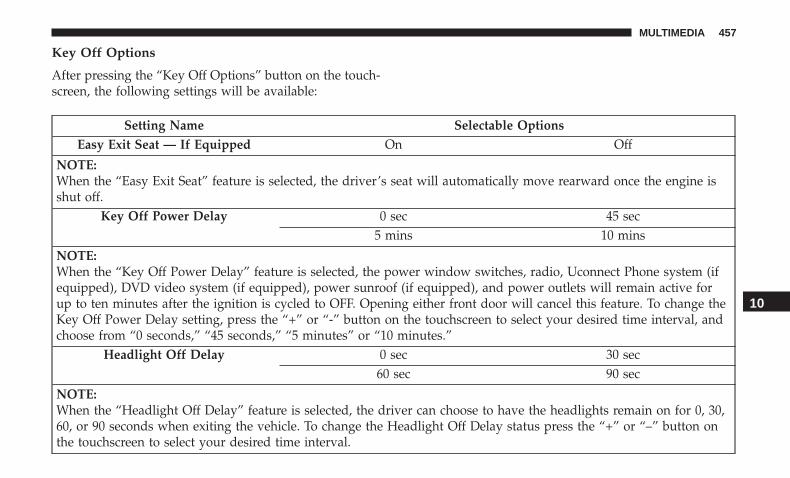
Key Off Options
After pressing the “Key Off Options” button on the touch-screen, the following settings will be available:
Setting Name Selectable OptionsEasy Exit Seat — If Equipped On Off
NOTE:When the “Easy Exit Seat” feature is selected, the driver’s seat will automatically move rearward once the engine isshut off.
Key Off Power Delay 0 sec 45 sec5 mins 10 mins
NOTE:When the “Key Off Power Delay” feature is selected, the power window switches, radio, Uconnect Phone system (ifequipped), DVD video system (if equipped), power sunroof (if equipped), and power outlets will remain active forup to ten minutes after the ignition is cycled to OFF. Opening either front door will cancel this feature. To change theKey Off Power Delay setting, press the “+” or “-” button on the touchscreen to select your desired time interval, andchoose from “0 seconds,” “45 seconds,” “5 minutes” or “10 minutes.”
Headlight Off Delay 0 sec 30 sec60 sec 90 sec
NOTE:When the “Headlight Off Delay” feature is selected, the driver can choose to have the headlights remain on for 0, 30,60, or 90 seconds when exiting the vehicle. To change the Headlight Off Delay status press the “+” or “–” button onthe touchscreen to select your desired time interval.
10
MULTIMEDIA 457
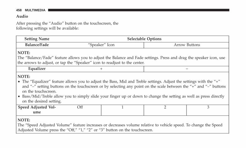
Audio
After pressing the “Audio” button on the touchscreen, thefollowing settings will be available:
Setting Name Selectable OptionsBalance/Fade “Speaker” Icon Arrow Buttons
NOTE:The “Balance/Fade” feature allows you to adjust the Balance and Fade settings. Press and drag the speaker icon, usethe arrows to adjust, or tap the “Speaker” icon to readjust to the center.
Equalizer + –
NOTE:• The “Equalizer” feature allows you to adjust the Bass, Mid and Treble settings. Adjust the settings with the “+”
and “–” setting buttons on the touchscreen or by selecting any point on the scale between the “+” and “–” buttonson the touchscreen.
• Bass/Mid/Treble allow you to simply slide your finger up or down to change the setting as well as press directlyon the desired setting.
Speed Adjusted Vol-ume
Off 1 2 3
NOTE:The “Speed Adjusted Volume” feature increases or decreases volume relative to vehicle speed. To change the SpeedAdjusted Volume press the “Off,” “1,” “2” or “3” button on the touchscreen.
458 MULTIMEDIA
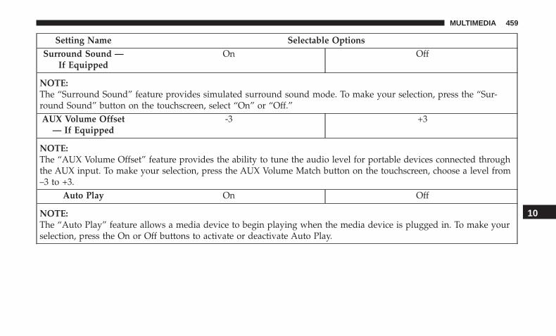
Setting Name Selectable OptionsSurround Sound —
If EquippedOn Off
NOTE:The “Surround Sound” feature provides simulated surround sound mode. To make your selection, press the “Sur-round Sound” button on the touchscreen, select “On” or “Off.”AUX Volume Offset
— If Equipped-3 +3
NOTE:The “AUX Volume Offset” feature provides the ability to tune the audio level for portable devices connected throughthe AUX input. To make your selection, press the AUX Volume Match button on the touchscreen, choose a level from–3 to +3.
Auto Play On Off
NOTE:The “Auto Play” feature allows a media device to begin playing when the media device is plugged in. To make yourselection, press the On or Off buttons to activate or deactivate Auto Play.
10
MULTIMEDIA 459
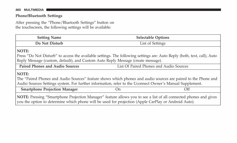
Phone/Bluetooth Settings
After pressing the “Phone/Bluetooth Settings” button onthe touchscreen, the following settings will be available:
Setting Name Selectable OptionsDo Not Disturb List of Settings
NOTE:Press “Do Not Disturb” to access the available settings. The following settings are: Auto Reply (both, text, call), AutoReply Message (custom, default), and Custom Auto Reply Message (create message).
Paired Phones and Audio Sources List Of Paired Phones and Audio Sources
NOTE:The “Paired Phones and Audio Sources” feature shows which phones and audio sources are paired to the Phone andAudio Sources Settings system. For further information, refer to the Uconnect Owner’s Manual Supplement.
Smartphone Projection Manager On Off
NOTE: Pressing “Smartphone Projection Manager” feature allows you to see a list of all connected phones and givesyou the option to determine which phone will be used for projection (Apple CarPlay or Android Auto).
460 MULTIMEDIA
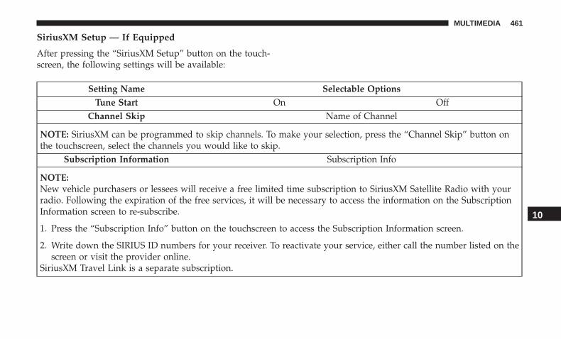
SiriusXM Setup — If Equipped
After pressing the “SiriusXM Setup” button on the touch-screen, the following settings will be available:
Setting Name Selectable OptionsTune Start On Off
Channel Skip Name of Channel
NOTE: SiriusXM can be programmed to skip channels. To make your selection, press the “Channel Skip” button onthe touchscreen, select the channels you would like to skip.
Subscription Information Subscription Info
NOTE:New vehicle purchasers or lessees will receive a free limited time subscription to SiriusXM Satellite Radio with yourradio. Following the expiration of the free services, it will be necessary to access the information on the SubscriptionInformation screen to re-subscribe.
1. Press the “Subscription Info” button on the touchscreen to access the Subscription Information screen.
2. Write down the SIRIUS ID numbers for your receiver. To reactivate your service, either call the number listed on thescreen or visit the provider online.
SiriusXM Travel Link is a separate subscription.
10
MULTIMEDIA 461

Reset
After pressing the “Reset” button on the touchscreen, thefollowing settings will be available:
Setting Name Selectable OptionsReset App Drawer to De-
faultOK Cancel
Restore Apps OK CancelRestore Settings to Default OK Cancel X
NOTE:When this feature is selected, it will reset all of the radio features to their default settings. To restore the settings totheir default setting, press the “Restore Settings” button on the touchscreen. A pop-up will appear asking �Are yousure you want to reset your settings to default?”
Clear Personal Data OK Cancel X
NOTE:When this feature is selected, it will remove all personal data including Bluetooth devices and presets. To remove per-sonal information, press the “Clear Personal Data” button and a pop-up will appear asking �Are you sure you wantto clear all personal data?”
Modem Reset OK Cancel
462 MULTIMEDIA
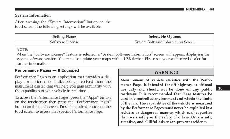
System Information
After pressing the “System Information” button on thetouchscreen, the following settings will be available:
Setting Name Selectable OptionsSoftware License System Software Information Screen
NOTE:When the “Software License” feature is selected, a “System Software Information” screen will appear, displaying thesystem software version. You can also update your maps with a USB device. Please see your authorized dealer forfurther information.
Performance Pages — If Equipped
Performance Pages is an application that provides a dis-play for performance indicators, as received from theinstrument cluster, that will help you gain familiarity withthe capabilities of your vehicle in real-time.
To access the Performance Pages, press the “Apps” buttonon the touchscreen then press the “Performance Pages”button on the touchscreen. Press the desired button on thetouchscreen to access that specific Performance Page.
WARNING!
Measurement of vehicle statistics with the Perfor-mance Pages is intended for off-highway or off-roaduse only and should not be done on any publicroadways. It is recommended that these features beused in a controlled environment and within the limitsof the law. The capabilities of the vehicle as measuredby the Performance Pages must never be exploited in areckless or dangerous manner, which can jeopardizethe user’s safety or the safety of others. Only a safe,attentive, and skillful driver can prevent accidents.
10
MULTIMEDIA 463

The Performance Pages include the following:
• Home
• Timers
• Gauges
• G-Force
• Engine
• Dyno
If a USB drive is installed in the media hub, press theCamera icon on the top right of the touchscreen whenusing Performance Pages. A screen shot of the page will betaken and saved onto the USB.
The following describes each feature and its operation:
Home
When Home is selected, a series of widgets (gauges) can becustomized by the user. Follow these steps to change awidget:
1. Press any of the gauges to change them.
Performance Pages — Home
464 MULTIMEDIA
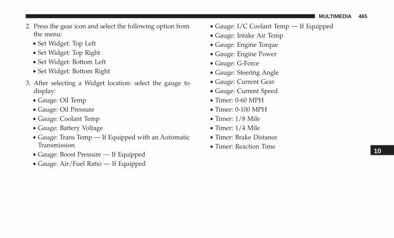
2. Press the gear icon and select the following option fromthe menu:• Set Widget: Top Left• Set Widget: Top Right• Set Widget: Bottom Left• Set Widget: Bottom Right
3. After selecting a Widget location: select the gauge todisplay:• Gauge: Oil Temp• Gauge: Oil Pressure• Gauge: Coolant Temp• Gauge: Battery Voltage• Gauge: Trans Temp — If Equipped with an Automatic
Transmission• Gauge: Boost Pressure — If Equipped• Gauge: Air/Fuel Ratio — If Equipped
• Gauge: I/C Coolant Temp — If Equipped• Gauge: Intake Air Temp• Gauge: Engine Torque• Gauge: Engine Power• Gauge: G-Force• Gauge: Steering Angle• Gauge: Current Gear• Gauge: Current Speed• Timer: 0-60 MPH• Timer: 0-100 MPH• Timer: 1/8 Mile• Timer: 1/4 Mile• Timer: Brake Distance• Timer: Reaction Time
10
MULTIMEDIA 465

Timers When the Timers Page is selected, you will be able to selectfrom following “Tickets”:
• Current
Pressing the “Current” button displays a “real time” sum-mary of performance timers.
• Last
Pressing the “Last” button displays the last recorded run ofperformance timers.
• Best
Pressing the “Best” button displays the best recorded runof performance timers, except for braking data.
Performance Pages — Timers
466 MULTIMEDIA
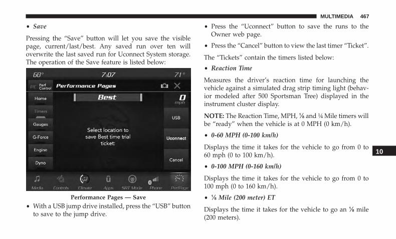
• Save
Pressing the “Save” button will let you save the visiblepage, current/last/best. Any saved run over ten willoverwrite the last saved run for Uconnect System storage.The operation of the Save feature is listed below:
• With a USB jump drive installed, press the “USB” buttonto save to the jump drive.
• Press the “Uconnect” button to save the runs to theOwner web page.
• Press the “Cancel” button to view the last timer “Ticket”.
The “Tickets” contain the timers listed below:
• Reaction Time
Measures the driver’s reaction time for launching thevehicle against a simulated drag strip timing light (behav-ior modeled after 500 Sportsman Tree) displayed in theinstrument cluster display.
NOTE: The Reaction Time, MPH, ⅛ and ¼ Mile timers willbe “ready” when the vehicle is at 0 MPH (0 km/h).
• 0-60 MPH (0-100 km/h)
Displays the time it takes for the vehicle to go from 0 to60 mph (0 to 100 km/h).
• 0-100 MPH (0-160 km/h)
Displays the time it takes for the vehicle to go from 0 to100 mph (0 to 160 km/h).
• ⅛ Mile (200 meter) ET
Displays the time it takes for the vehicle to go an ⅛ mile(200 meters).
Performance Pages — Save
10
MULTIMEDIA 467
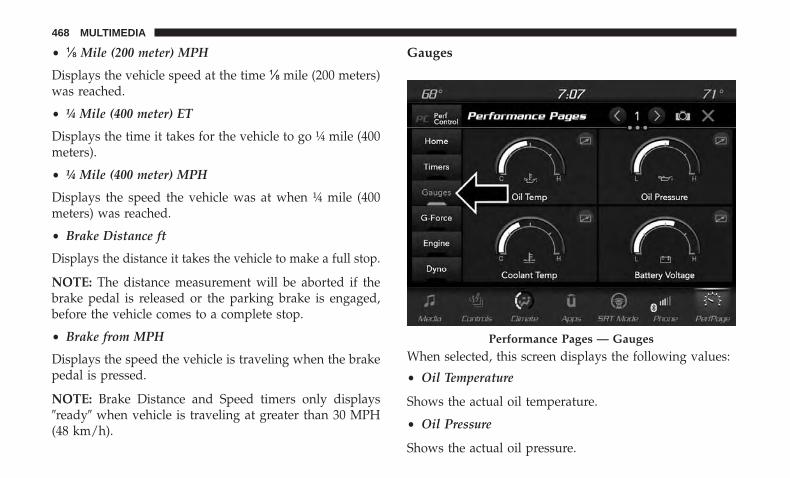
• ⅛ Mile (200 meter) MPH
Displays the vehicle speed at the time ⅛ mile (200 meters)was reached.
• ¼ Mile (400 meter) ET
Displays the time it takes for the vehicle to go ¼ mile (400meters).
• ¼ Mile (400 meter) MPH
Displays the speed the vehicle was at when ¼ mile (400meters) was reached.
• Brake Distance ft
Displays the distance it takes the vehicle to make a full stop.
NOTE: The distance measurement will be aborted if thebrake pedal is released or the parking brake is engaged,before the vehicle comes to a complete stop.
• Brake from MPH
Displays the speed the vehicle is traveling when the brakepedal is pressed.
NOTE: Brake Distance and Speed timers only displays�ready� when vehicle is traveling at greater than 30 MPH(48 km/h).
Gauges
When selected, this screen displays the following values:
• Oil Temperature
Shows the actual oil temperature.
• Oil Pressure
Shows the actual oil pressure.
Performance Pages — Gauges
468 MULTIMEDIA

• Coolant Temperature
Shows the actual coolant temperature.
• Battery Voltage
Shows the actual battery voltage
• Trans Oil Temp — If Equipped with an AutomaticTransmission
Shows the actual transmission oil temperature.
• Boost Pressure — If Equipped
Shows actual boost pressure.
• Air Fuel Ratio — If Equipped
Shows current air fuel ratio
• I/C Coolant Temp — If Equipped
Shows actual I/C Coolant temperature.
• Intake Air Temperature
Shows the actual intake air temperature.
If a gauge is selected, the Gauge Detail View page willappear on the screen. This page shows further informationon the selected gauge.
Press the left and right arrows will cycle through the detailsfor each of the gauges. Pressing the minimize button abovethe graph will return to the gauge menu.
Gauge Detail View Page
10
MULTIMEDIA 469
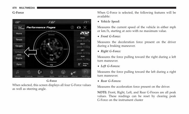
G-Force
When selected, this screen displays all four G-Force valuesas well as steering angle.
When G-Force is selected, the following features will beavailable:
• Vehicle Speed:
Measures the current speed of the vehicle in either mphor km/h, starting at zero with no maximum value.
• Front G-Force:
Measures the deceleration force present on the driverduring a braking maneuver.
• Right G-Force:
Measures the force pulling toward the right during a leftturn maneuver.
• Left G-Forces:
Measures the force pulling toward the left during a rightturn maneuver.
• Rear G-Forces:
Measures the acceleration force present on the driver.
NOTE: Front, Right, Left, and Rear G-Froces are all peakvalues. These readings can be reset by clearing peakG-Force on the instrument cluster
G-Force
470 MULTIMEDIA
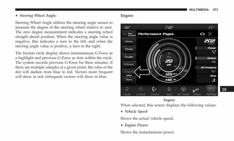
• Steering Wheel Angle:
Steering Wheel Angle utilizes the steering angle sensor tomeasure the degree of the steering wheel relative to zero.The zero degree measurement indicates a steering wheelstraight ahead position. When the steering angle value isnegative, this indicates a turn to the left, and when thesteering angle value is positive, a turn to the right.
The friction circle display shows instantaneous G-Force asa highlight and previous G-Force as dots within the circle.The system records previous G-Force for three minutes. Ifthere are multiple samples at a given point, the color of thedot will darken from blue to red. Vectors more frequentwill show in red; infrequent vectors will show in blue.
Engine
When selected, this screen displays the following values:
• Vehicle Speed
Shows the actual vehicle speed.
• Engine Power
Shows the instantaneous power.
Engine
10
MULTIMEDIA 471
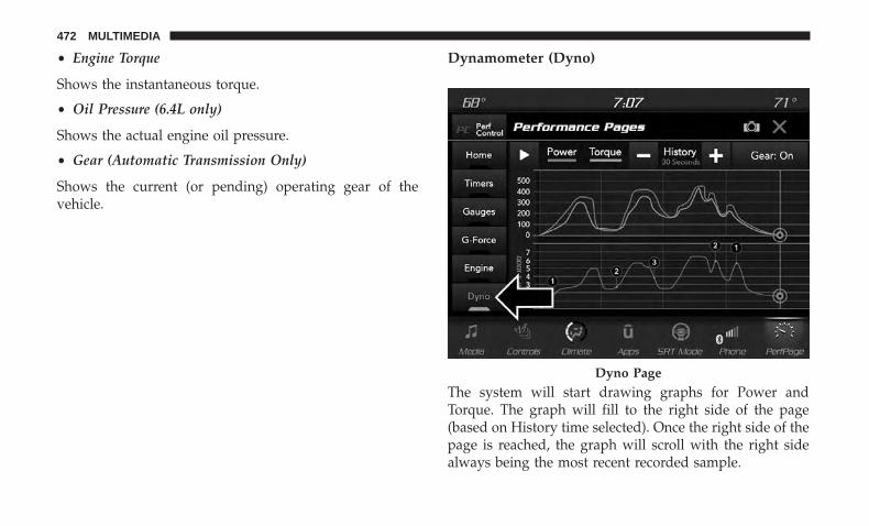
• Engine Torque
Shows the instantaneous torque.
• Oil Pressure (6.4L only)
Shows the actual engine oil pressure.
• Gear (Automatic Transmission Only)
Shows the current (or pending) operating gear of thevehicle.
Dynamometer (Dyno)
The system will start drawing graphs for Power andTorque. The graph will fill to the right side of the page(based on History time selected). Once the right side of thepage is reached, the graph will scroll with the right sidealways being the most recent recorded sample.
Dyno Page
472 MULTIMEDIA

The following options can be selected:
• Pressing the STOP button will freeze the graph. SelectingPlay will clear the graph and restart the process over
• Press the “+” or “–” buttons to change the history of thegraph. The selectable options are 30, 60, 90, 120 seconds.The graph will expand or constrict depending on thesetting selected.
• Select the “Gear” display setting to turn the graph gearmarkers on and off.
NOTE: The Gear on/off feature will only display if yourvehicle is equipped with an Automatic Transmission.
Performance Control — If Equipped
Your vehicle is equipped with a Performance Controlfeature which allows for coordinating the operation ofvarious vehicle systems depending upon the type of driv-ing behavior desired. The Performance Control feature iscontrolled through the Uconnect system and may be ac-cessed by performing any of the following:
• Pushing the Super Track Pack button on the instrumentpanel switch bank.
• Selecting “Performance Control” from the “Apps”menu.
• Selecting “Performance Control” from within the Perfor-mance Pages menu.
You will be able to enable, disable, and customize thefunctionality of the Launch Control and Performance Con-trol Set-Up features within Performance Control.
Descriptions of these features are provided below. Toaccess information about the functionality of these featuresthrough the Uconnect system, press the “Info” button onthe touchscreen.
NOTE: Scat and Widebody Dodge vehicles equipped witha 6.4L engine will use SRT Drive Modes rather than theDodge Performance Control Pages. Please refer to theOwner’s Manual Supplement for further information onthe SRT Drive Modes.
10
MULTIMEDIA 473
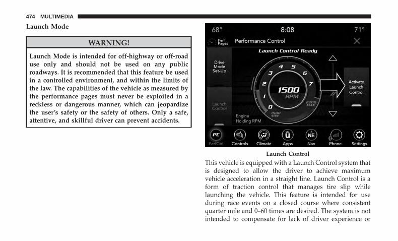
Launch Mode
WARNING!
Launch Mode is intended for off-highway or off-roaduse only and should not be used on any publicroadways. It is recommended that this feature be usedin a controlled environment, and within the limits ofthe law. The capabilities of the vehicle as measured bythe performance pages must never be exploited in areckless or dangerous manner, which can jeopardizethe user’s safety or the safety of others. Only a safe,attentive, and skillful driver can prevent accidents.
This vehicle is equipped with a Launch Control system thatis designed to allow the driver to achieve maximumvehicle acceleration in a straight line. Launch Control is aform of traction control that manages tire slip whilelaunching the vehicle. This feature is intended for useduring race events on a closed course where consistentquarter mile and 0–60 times are desired. The system is notintended to compensate for lack of driver experience or
Launch Control
474 MULTIMEDIA
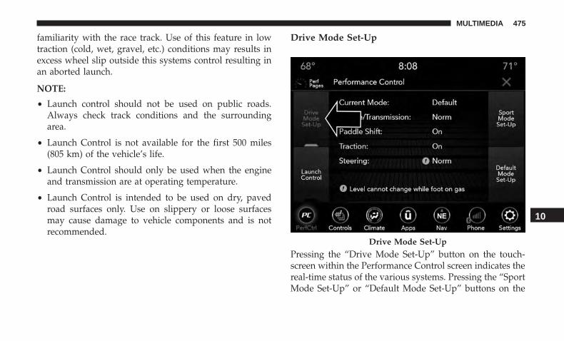
familiarity with the race track. Use of this feature in lowtraction (cold, wet, gravel, etc.) conditions may results inexcess wheel slip outside this systems control resulting inan aborted launch.
NOTE:
• Launch control should not be used on public roads.Always check track conditions and the surroundingarea.
• Launch Control is not available for the first 500 miles(805 km) of the vehicle’s life.
• Launch Control should only be used when the engineand transmission are at operating temperature.
• Launch Control is intended to be used on dry, pavedroad surfaces only. Use on slippery or loose surfacesmay cause damage to vehicle components and is notrecommended.
Drive Mode Set-Up
Pressing the “Drive Mode Set-Up” button on the touch-screen within the Performance Control screen indicates thereal-time status of the various systems. Pressing the “SportMode Set-Up” or “Default Mode Set-Up” buttons on the
Drive Mode Set-Up
10
MULTIMEDIA 475
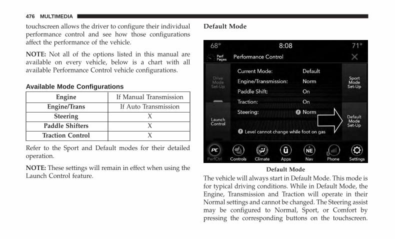
touchscreen allows the driver to configure their individualperformance control and see how those configurationsaffect the performance of the vehicle.
NOTE: Not all of the options listed in this manual areavailable on every vehicle, below is a chart with allavailable Performance Control vehicle configurations.
Available Mode Configurations
Engine If Manual TransmissionEngine/Trans If Auto Transmission
Steering XPaddle Shifters XTraction Control X
Refer to the Sport and Default modes for their detailedoperation.
NOTE: These settings will remain in effect when using theLaunch Control feature.
Default Mode
The vehicle will always start in Default Mode. This mode isfor typical driving conditions. While in Default Mode, theEngine, Transmission and Traction will operate in theirNormal settings and cannot be changed. The Steering assistmay be configured to Normal, Sport, or Comfort bypressing the corresponding buttons on the touchscreen.
Default Mode
476 MULTIMEDIA

The Paddle Shifters may be enabled or disabled while inthis mode.
Sport Mode
Sport Mode is a configuration set-up for typical enthusiastdriving. The Transmission and Steering are both set to theirSport settings. The steering wheel paddle switches areenabled. The Traction Control defaults to Normal. Any ofthese four settings may be changed to the driver’s prefer-ences by pressing the buttons on the touchscreen. Push theSport button on the instrument panel switch bank to put
Default Mode Set-Up Sport Mode
10
MULTIMEDIA 477

the vehicle in Sport Mode and activate these settings. Thecustomized settings will only be active when the Sportbutton is active.
Possible Performance Control configurations are listedbelow with accompanying descriptions. The informationcontained in the list below can also be accessed from withinthe mode Set-Up menus. To access the information, pressthe “Info” button on the touchscreen from the mode Set-Upmenu, and use the left/right arrows to toggle through
available descriptions. The title for each system in theSet-Up menu can be pressed, which provides the descrip-tions for each function of that system.
Engine (If Equipped With Manual Transmission)
• Sport
Press the “Sport” button on the touchscreen for improvedthrottle response for an enhanced driving experience.
Sport Mode Set-Up
Engine
478 MULTIMEDIA

• Normal
Press the “Norm” button on the touchscreen for standardthrottle response for normal driving.
Engine/Trans (If Equipped With Automatic Transmission)
• SPORT
Press the “Sport” button on the touchscreen for improvedthrottle response and modified shifting for an enhanceddriving experience.
• NORMAL
Press the “Norm” button on the touchscreen for a balanceof throttle response, shift comfort and economy for normaldriving.
Engine/Trans
10
MULTIMEDIA 479

Paddle Shifters — If Equipped With AutomaticTransmission
• ONPress the “ON” button on the touchscreen to enablesteering wheel Paddle Shifters.
• OFFPress the “OFF” button on the touchscreen to disablesteering wheel Paddle Shifters.
Traction
• SPORT
Press the “Sport” button on the touchscreen to turn offtraction control and reduce stability control.
Paddle – Automatic Transmission Traction Control
480 MULTIMEDIA

• NORMAL
Press the “Norm” button on the touchscreen to provide fulltraction control and full stability control.
Steering
• SPORT
Press the “Sport” button on the touchscreen to provide anincreased amount of steering feel, requiring a higheramount of steering effort.
• NORMAL
Press the “Norm” button on the touchscreen to provide abalanced steering feel and steering effort. This is also yourvehicles pre-set steering setting.
• COMFORT
Press the “Comf” button on the touchscreen to provide alower steering effort.
Steering
10
MULTIMEDIA 481
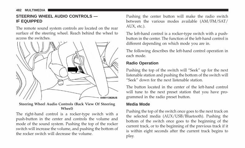
STEERING WHEEL AUDIO CONTROLS —IF EQUIPPED
The remote sound system controls are located on the rearsurface of the steering wheel. Reach behind the wheel toaccess the switches.
The right-hand control is a rocker-type switch with apush-button in the center and controls the volume andmode of the sound system. Pushing the top of the rockerswitch will increase the volume, and pushing the bottom ofthe rocker switch will decrease the volume.
Pushing the center button will make the radio switchbetween the various modes available (AM/FM/SAT/AUX, etc.).
The left-hand control is a rocker-type switch with a push-button in the center. The function of the left-hand control isdifferent depending on which mode you are in.
The following describes the left-hand control operation ineach mode.
Radio Operation
Pushing the top of the switch will “Seek” up for the nextlistenable station and pushing the bottom of the switch will“Seek” down for the next listenable station.
The button located in the center of the left-hand controlwill tune to the next preset station that you have pro-grammed in the radio preset button.
Media Mode
Pushing the top of the switch once goes to the next track onthe selected media (AUX/USB/Bluetooth). Pushing thebottom of the switch once goes to the beginning of thecurrent track, or to the beginning of the previous track if itis within eight seconds after the current track begins toplay.
Steering Wheel Audio Controls (Back View Of SteeringWheel)
482 MULTIMEDIA
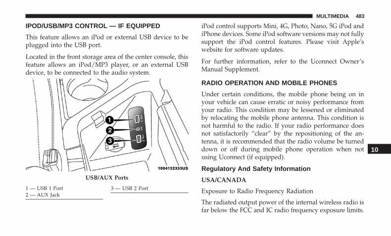
IPOD/USB/MP3 CONTROL — IF EQUIPPED
This feature allows an iPod or external USB device to beplugged into the USB port.
Located in the front storage area of the center console, thisfeature allows an iPod/MP3 player, or an external USBdevice, to be connected to the audio system.
iPod control supports Mini, 4G, Photo, Nano, 5G iPod andiPhone devices. Some iPod software versions may not fullysupport the iPod control features. Please visit Apple’swebsite for software updates.
For further information, refer to the Uconnect Owner’sManual Supplement.
RADIO OPERATION AND MOBILE PHONES
Under certain conditions, the mobile phone being on inyour vehicle can cause erratic or noisy performance fromyour radio. This condition may be lessened or eliminatedby relocating the mobile phone antenna. This condition isnot harmful to the radio. If your radio performance doesnot satisfactorily “clear” by the repositioning of the an-tenna, it is recommended that the radio volume be turneddown or off during mobile phone operation when notusing Uconnect (if equipped).
Regulatory And Safety Information
USA/CANADA
Exposure to Radio Frequency Radiation
The radiated output power of the internal wireless radio isfar below the FCC and IC radio frequency exposure limits.
USB/AUX Ports
1 — USB 1 Port2 — AUX Jack
3 — USB 2 Port
10
MULTIMEDIA 483

Nevertheless, the wireless radio will be used in such amanner that the radio is 8 in (20 cm) or further from thehuman body.
The internal wireless radio operates within guidelinesfound in radio frequency safety standards and recommen-dations, which reflect the consensus of the scientific com-munity.
The radio manufacturer believes the internal wireless radiois safe for use by consumers. The level of energy emitted isfar less than the electromagnetic energy emitted by wire-less devices such as mobile phones. However, the use ofwireless radios may be restricted in some situations orenvironments, such as aboard airplanes. If you are unsureof restrictions, you are encouraged to ask for authorizationbefore turning on the wireless radio.
The following regulatory statement applies to all RadioFrequency (RF) devices equipped in this vehicle:
This device complies with Part 15 of the FCC Rules andwith Industry Canada license-exempt RSS standard(s).Operation is subject to the following two conditions:
1. This device may not cause harmful interference, and
2. This device must accept any interference received, includ-ing interference that may cause undesired operation.
NOTE: Changes or modifications not expressly approvedby the party responsible for compliance could void theuser’s authority to operate the equipment.
NOTE:
• This equipment has been tested and found to complywith the limits for a Class B digital device, pursuant toPart 15 of the FCC Rules. These limits are designed toprovide reasonable protection against harmful interfer-ence in a residential installation. This equipment gener-ates, uses and can radiate radio frequency energy and, ifnot installed and used in accordance with the instruc-tions, may cause harmful interference to radio commu-nications. However, there is no guarantee that interfer-ence will not occur in a particular installation.
• If this equipment does cause harmful interference toradio or television reception, which can be determinedby turning the equipment off and on, the user is encour-aged to try to correct the interference by one or more ofthe following measures:
1. Increase the separation between the equipment andreceiver.
2. Consult an authorized dealer or an experienced radiotechnician for help.
484 MULTIMEDIA

UCONNECT VOICE RECOGNITION QUICK TIPS
Introducing Uconnect
Start using Uconnect Voice Recognition with these helpfulquick tips. It provides the key Voice Commands and tipsyou need to know to control your Uconnect system.
NOTE: If you see the NAV icon on the bottom bar, or in theApps menus, of your touchscreen, you have the Uconnect4C NAV system. If not, you have a Uconnect 4C system.
Uconnect 4
Uconnect 4C/4C NAV 10
MULTIMEDIA 485

Get Started
All you need to control your Uconnect system with yourvoice are the buttons on your steering wheel.
Helpful hints for using Voice Recognition:
• Visit UconnectPhone.com to check mobile device andfeature compatibility and to find phone pairing instruc-tions.
• Reduce background noise. Wind and passenger conver-sations are examples of noise that may impact recogni-tion.
• Speak clearly at a normal pace and volume while facingstraight ahead. The microphone is positioned on therearview mirror and aimed at the driver.
• Each time you give a Voice Command, you must firstpush either the Voice Recognition (VR) or Phone button,wait until after the beep, then say your Voice Command.
• You can interrupt the help message or system promptsby pushing the VR or Phone button and saying a VoiceCommand from the current category.
Uconnect Voice Command Buttons
1 — Push To Initiate Or To Answer A Phone Call, Send Or ReceiveA Text2 — For All Radios: Push To Begin Voice Commands3 — Push To End Call
486 MULTIMEDIA
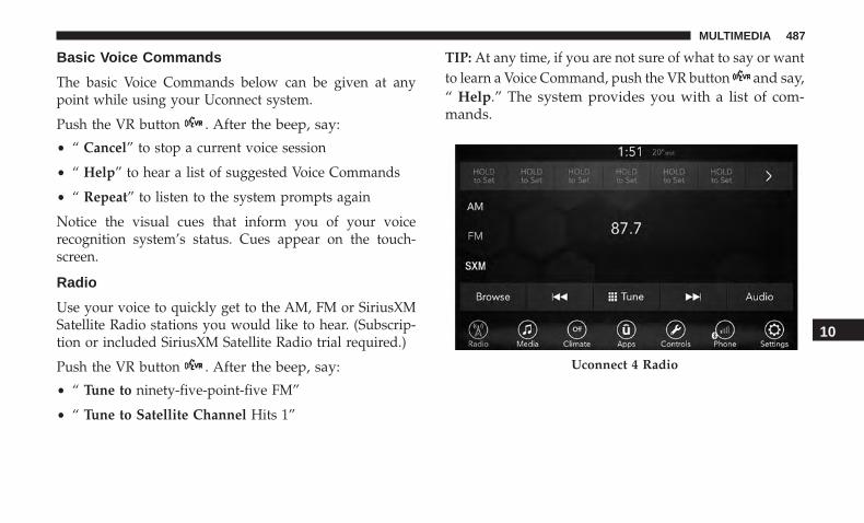
Basic Voice Commands
The basic Voice Commands below can be given at anypoint while using your Uconnect system.
Push the VR button . After the beep, say:
• “ Cancel” to stop a current voice session
• “ Help” to hear a list of suggested Voice Commands
• “ Repeat” to listen to the system prompts again
Notice the visual cues that inform you of your voicerecognition system’s status. Cues appear on the touch-screen.
Radio
Use your voice to quickly get to the AM, FM or SiriusXMSatellite Radio stations you would like to hear. (Subscrip-tion or included SiriusXM Satellite Radio trial required.)
Push the VR button . After the beep, say:
• “ Tune to ninety-five-point-five FM”
• “ Tune to Satellite Channel Hits 1”
TIP: At any time, if you are not sure of what to say or wantto learn a Voice Command, push the VR button and say,“ Help.” The system provides you with a list of com-mands.
Uconnect 4 Radio
10
MULTIMEDIA 487

Media
Uconnect offers connections via USB, Bluetooth and auxil-iary ports (if equipped). Voice operation is only availablefor connected USB and AUX devices.
Push the VR button . After the beep, say one of thefollowing commands and follow the prompts to switchyour media source or choose an artist.
• “ Change source to Bluetooth”
• “ Change source to AUX”
• “ Change source to USB”
• “ Play artist Beethoven”; “ Play album Greatest Hits”; “Play song Moonlight Sonata”; “ Play genre Classical”
Uconnect 4C/4C NAV Radio
488 MULTIMEDIA
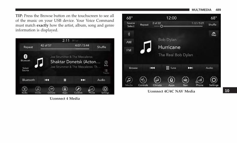
TIP: Press the Browse button on the touchscreen to see allof the music on your USB device. Your Voice Commandmust match exactly how the artist, album, song and genreinformation is displayed.
Uconnect 4 Media
Uconnect 4C/4C NAV Media 10
MULTIMEDIA 489
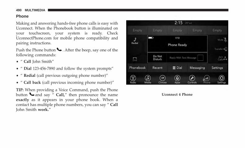
Phone
Making and answering hands-free phone calls is easy withUconnect. When the Phonebook button is illuminated onyour touchscreen, your system is ready. CheckUconnectPhone.com for mobile phone compatibility andpairing instructions.
Push the Phone button . After the beep, say one of thefollowing commands:
• “ Call John Smith”
• “ Dial 123-456-7890 and follow the system prompts”
• “ Redial (call previous outgoing phone number)”
• “ Call back (call previous incoming phone number)”
TIP: When providing a Voice Command, push the Phonebutton and say “ Call,” then pronounce the nameexactly as it appears in your phone book. When acontact has multiple phone numbers, you can say “ CallJohn Smith work.”
Uconnect 4 Phone
490 MULTIMEDIA

Voice Text Reply — If Equipped
Uconnect announces incoming text messages. Push the VRbutton or Phone button (if enabled) and say “Listen.” (Must have compatible mobile phone paired toUconnect system.)
1. Once an incoming text message is read to you, push theVR button or Phone button (if enabled). Afterthe beep, say: “ Reply.”
2. Listen to the Uconnect prompts. After the beep, repeatone of the pre-defined messages and follow the systemprompts.
PRE-DEFINED VOICE TEXT REPLY RESPONSESYes. Stuck in traffic. See you later.No. Start without
me.I’ll be late.
Okay. Where are you? I will be 5 <or10, 15, 20, 25, 30,45, 60> minutes
late.
Call me. Are you thereyet?
I’ll call you later. I need direc-tions.
See you in 5 <or10, 15, 20, 25, 30,45, 60> minutes.I’m on my way. Can’t talk right
now.I’m lost. Thanks.
NOTE: Only use the numbering listed, otherwise thesystem does not transpose the message.
Uconnect 4C/4C NAV Phone 10
MULTIMEDIA 491

TIP: Your mobile phone must have the full implementationof the Message Access Profile (MAP) to take advantage ofthis feature. For details about MAP, visitUconnectPhone.com.
Apple iPhone iOS 6 or later supports reading incomingtext messages only. To enable this feature on your AppleiPhone, follow these four simple steps:
TIP: Voice Text Reply is not compatible with iPhone, but ifyour vehicle is equipped with Siri Eyes Free, you can useyour voice to send a text message.
Climate
Too hot? Too cold? Adjust vehicle temperatures hands-freeand keep everyone comfortable while you keep movingahead. (If vehicle is equipped with climate control.)
Push the VR button . After the beep, say one of thefollowing commands:
• “ Set driver temperature to 70 degrees”
• “ Set passenger temperature to 70 degrees”
TIP: Voice Command for Climate may only be used toadjust the interior temperature of your vehicle. VoiceCommand will not work to adjust the heated seats orsteering wheel if equipped.
iPhone Notification Settings
1 — Select “Settings”2 — Select “Bluetooth”3 — Select The (i) For The Paired Vehicle4 — Turn On “Show Notifications”
492 MULTIMEDIA
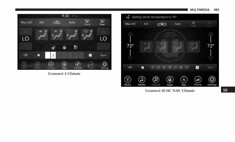
Uconnect 4 Climate
Uconnect 4C/4C NAV Climate 10
MULTIMEDIA 493

Navigation (4C NAV)
The Uconnect navigation feature helps you save time andbecome more productive when you know exactly how toget to where you want to go.
1. To enter a destination, push the VR button . After thebeep, say: “ Find address 800 Chrysler Drive AuburnHills, Michigan.”
2. Then follow the system prompts.
TIP: To start a POI search, push the VR button . Afterthe beep, say: “ Find nearest coffee shop.”
Uconnect 4C NAV With 8.4–inch Display Navigation
494 MULTIMEDIA

SiriusXM Guardian (4C/4C NAV) — If Equipped
CAUTION!
Some SiriusXM Guardian services, including SOS Calland Roadside Assistance Call will NOT work withoutan operable LTE (voice/data) or 3G or 4G (data) net-work connection compatible with your device.
NOTE: Your vehicle may be transmitting data as autho-rized by the subscriber.
An included trial and/or subscription is required to takeadvantage of the SiriusXM Guardian services in the nextsection of this guide. To register with SiriusXM Guardian,press the Apps button on the Uconnect 4C/4C NAVtouchscreen to get started.
NOTE: SiriusXM Guardian is available only on equippedvehicles purchased within the continental United States,Alaska, Hawaii and Canada. Services can only be usedwhere coverage is available; see coverage map for details.
SOS Call
Theft Alarm Notification
Remote Door Lock/Unlock
Send & Go
Vehicle Finder
Stolen Vehicle Assistance
Remote Vehicle Start**
Remote Horn & Lights
Roadside Assistance Call
Vehicle Health Reports**
Vehicle Health Alert**
Performance Pages Plus**
**If vehicle is equipped.
Register (4C/4C NAV)
To unlock the full potential of SiriusXM Guardian in yourvehicle, you must activate your SiriusXM Guardian ser-vices.
1. Press the Apps icon on the bottom of your in-vehicletouchscreen.
2. Select the Activate Services icon from your list of apps.
10
MULTIMEDIA 495

3. Select “Customer Care” to speak with a SiriusXMGuardian Customer Care agent who will activate ser-vices in your vehicle, or select “Enter Email” to activateon the web.
• U.S. residents visit: www.siriusxm.com/guardian.
• Canadian residents visit: www.siriusxm.ca/guardian.
Vehicle Health Report/Alert (4C/4C NAV)
Your vehicle will send you a monthly email report, whichsummarizes the performance of your vehicle’s key systemsso you can stay on top of your vehicle’s maintenance needsif you are registered for SiriusXM Guardian. Your vehiclewill also send you Vehicle Health Alerts when it detectsissues with its key systems that need your attention. Forfurther information, refer to your Uconnect Owner’sManual Supplement.
Mobile App (4C/4C NAV)
You’re only a few steps away from using remote com-mands and sending a destination from your phone to yourvehicle.
To use the Uconnect Mobile App:
1. Once you have registered your SiriusXM Guardianservices, download the Uconnect App to your mobiledevice. Use your Owner Account login and password toopen the app.
2. Once on the “Remote” screen, you can begin usingRemote Door Lock/Unlock, Remote Vehicle Start, andactivate your horn and lights remotely, if equipped.
Mobile App
496 MULTIMEDIA
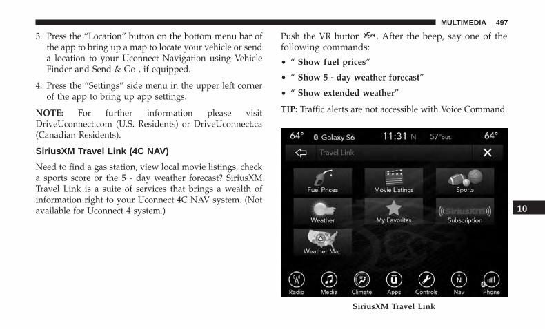
3. Press the “Location” button on the bottom menu bar ofthe app to bring up a map to locate your vehicle or senda location to your Uconnect Navigation using VehicleFinder and Send & Go , if equipped.
4. Press the “Settings” side menu in the upper left cornerof the app to bring up app settings.
NOTE: For further information please visitDriveUconnect.com (U.S. Residents) or DriveUconnect.ca(Canadian Residents).
SiriusXM Travel Link (4C NAV)
Need to find a gas station, view local movie listings, checka sports score or the 5 - day weather forecast? SiriusXMTravel Link is a suite of services that brings a wealth ofinformation right to your Uconnect 4C NAV system. (Notavailable for Uconnect 4 system.)
Push the VR button . After the beep, say one of thefollowing commands:
• “ Show fuel prices”
• “ Show 5 - day weather forecast”
• “ Show extended weather”
TIP: Traffic alerts are not accessible with Voice Command.
SiriusXM Travel Link
10
MULTIMEDIA 497
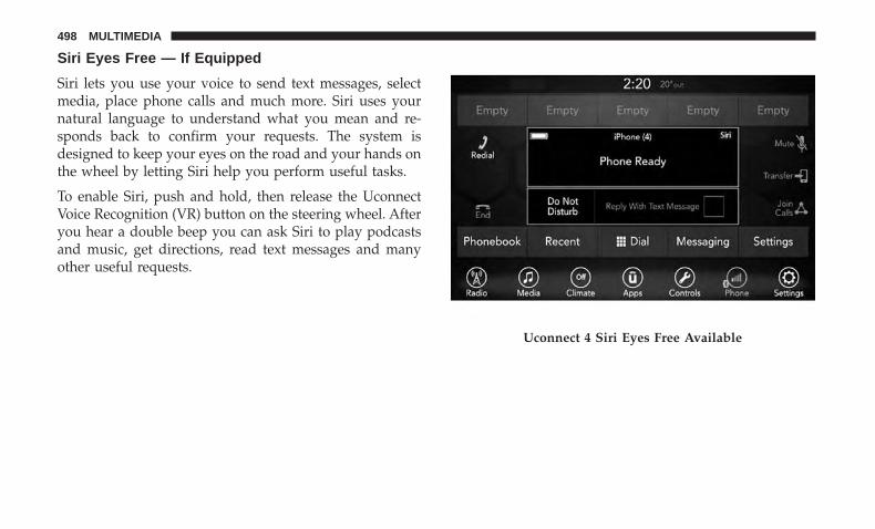
Siri Eyes Free — If Equipped
Siri lets you use your voice to send text messages, selectmedia, place phone calls and much more. Siri uses yournatural language to understand what you mean and re-sponds back to confirm your requests. The system isdesigned to keep your eyes on the road and your hands onthe wheel by letting Siri help you perform useful tasks.
To enable Siri, push and hold, then release the UconnectVoice Recognition (VR) button on the steering wheel. Afteryou hear a double beep you can ask Siri to play podcastsand music, get directions, read text messages and manyother useful requests.
Uconnect 4 Siri Eyes Free Available
498 MULTIMEDIA
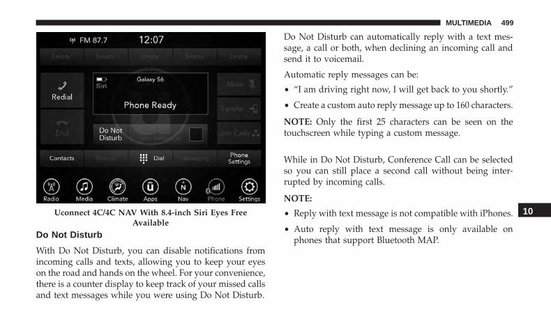
Do Not Disturb
With Do Not Disturb, you can disable notifications fromincoming calls and texts, allowing you to keep your eyeson the road and hands on the wheel. For your convenience,there is a counter display to keep track of your missed callsand text messages while you were using Do Not Disturb.
Do Not Disturb can automatically reply with a text mes-sage, a call or both, when declining an incoming call andsend it to voicemail.
Automatic reply messages can be:
• “I am driving right now, I will get back to you shortly.”
• Create a custom auto reply message up to 160 characters.
NOTE: Only the first 25 characters can be seen on thetouchscreen while typing a custom message.
While in Do Not Disturb, Conference Call can be selectedso you can still place a second call without being inter-rupted by incoming calls.
NOTE:
• Reply with text message is not compatible with iPhones.
• Auto reply with text message is only available onphones that support Bluetooth MAP.
Uconnect 4C/4C NAV With 8.4-inch Siri Eyes FreeAvailable
10
MULTIMEDIA 499

Android Auto — If Equipped
NOTE: Feature availability depends on your carrier andmobile phone manufacturer. Some Android Auto featuresmay or may not be available in every region and/orlanguage.
Android Auto allows you to use your voice to interact withAndroid’s best-in-class speech technology through yourvehicle’s voice recognition system, and use your smart-phone’s data plan to project your Android powered smart-phone and a number of its apps onto your Uconnecttouchscreen. Connect your Android 5.0 (Lollipop), orhigher, to one of the media USB ports, using the factory-provided USB cable, and press the new Android Auto iconthat replaces your “Phone” icon on the main menu bar tobegin Android Auto. Push and hold the VR button on thesteering wheel, or press and hold the “Microphone” iconwithin Android Auto, to activate Android’s VR, whichrecognizes natural voice commands, to use a list of yoursmartphone’s features:
• Maps
• Music
• Phone
• Text Messages
• Additional Apps
Android Auto On 7-inch Display
500 MULTIMEDIA

Refer to your Uconnect Owner’s Manual Supplement forfurther information.
NOTE: Requires compatible smartphone running Android5.0 Lollipop or higher and download app on Google Play.Android, Android Auto, and Google Play are trademarksof Google Inc.
Apple CarPlay — If Equipped
NOTE: Feature availability depends on your carrier andmobile phone manufacturer. Some Apple CarPlay featuresmay or may not be available in every region and/orlanguage.
Apple CarPlay allows you to use your voice to interactwith Siri through your vehicle’s voice recognition system,and use your smartphone’s data plan to project youriPhone and a number of its apps onto your Uconnecttouchscreen. Connect your iPhone 5, or higher, to one ofthe media USB ports, using the factory-provided Lightningcable, and press the new CarPlay icon that replaces your“Phone” icon on the main menu bar to begin AppleCarPlay. Push and hold the VR button on the steeringwheel, or press and hold the “Home” button within AppleCarPlay, to activate Siri, which recognizes natural voicecommands to use a list of your iPhone’s features:
• Phone
• Music
Android Auto On 8.4-inch Display 10
MULTIMEDIA 501

• Messages
• Maps — if equipped
• Additional Apps — if equipped
Refer to your Uconnect Owner’s Manual Supplement forfurther information.
NOTE: Requires compatible iPhone. See dealer for phonecompatibility. Data plan rates apply. Vehicle user interfaceis a product of Apple. Apple CarPlay is a trademark ofApple Inc. iPhone is a trademark of Apple Inc., registeredin the US and other countries. Apple terms of use andprivacy statements apply.
Apple CarPlay On 7-inch Display Apple CarPlay On 8.4-inch Display
502 MULTIMEDIA
General Information
The following regulatory statement applies to all RadioFrequency (RF) devices equipped in this vehicle:
This device complies with Part 15 of the FCC Rules andwith Industry Canada license-exempt RSS standard(s).Operation is subject to the following two conditions:
1. This device may not cause harmful interference, and
2. This device must accept any interference received, in-cluding interference that may cause undesired opera-tion.
NOTE: Changes or modifications not expressly approvedby the party responsible for compliance could void theuser’s authority to operate the equipment.
Additional Information
© 2018 FCA US LLC. All rights reserved. Mopar andUconnect are registered trademarks and Mopar OwnerConnect is a trademark of FCA US LLC. Android is atrademark of Google Inc. SiriusXM and all related marksand logos are trademarks of SiriusXM Radio Inc.
Uconnect System Support:
• U.S. residents visit www.DriveUconnect.com or call:1-877-855-8400(24 hours a day 7 days a week)
• Canadian residents visit www.DriveUconnect.ca or call:1-800-465-2001(English) or 1-800-387-9983(French)
SiriusXM Guardian services support:
• U.S. residents visit www.siriusxm.com/guardian or call:1-844-796-4827
• Canadian residents visit www.siriusxm.ca/guardian orcall: 1-877-324-9091
10
MULTIMEDIA 503

CUSTOMER ASSISTANCE
CONTENTS� SUGGESTIONS FOR OBTAINING SERVICE FOR
YOUR VEHICLE . . . . . . . . . . . . . . . . . . . . . . . .506
▫ Prepare For The Appointment . . . . . . . . . . . . . .506
▫ Prepare A List . . . . . . . . . . . . . . . . . . . . . . . . .506
▫ Be Reasonable With Requests . . . . . . . . . . . . . .506
� IF YOU NEED ASSISTANCE . . . . . . . . . . . . . . . .506
▫ FCA US LLC Customer Center . . . . . . . . . . . . .507
▫ FCA Canada Inc. Customer Center. . . . . . . . . . .507
▫ In Mexico Contact . . . . . . . . . . . . . . . . . . . . . .507
▫ Puerto Rico And U.S. Virgin Islands. . . . . . . . . .507
▫ Customer Assistance For The Hearing Or SpeechImpaired (TDD/TTY) . . . . . . . . . . . . . . . . . . . .508
▫ Service Contract . . . . . . . . . . . . . . . . . . . . . . .508
� WARRANTY INFORMATION . . . . . . . . . . . . . . .509
� MOPAR PARTS . . . . . . . . . . . . . . . . . . . . . . . . .509
� REPORTING SAFETY DEFECTS . . . . . . . . . . . . .509
▫ In The 50 United States And Washington, D.C. . .509
▫ In Canada . . . . . . . . . . . . . . . . . . . . . . . . . . . .510
� PUBLICATION ORDER FORMS . . . . . . . . . . . . .51011

SUGGESTIONS FOR OBTAINING SERVICE FORYOUR VEHICLE
Prepare For The Appointment
If you are having warranty work done, be sure to have theright papers with you. Take your warranty folder. All workto be performed may not be covered by the warranty.Discuss additional charges with the service manager. Keepa maintenance log of your vehicle’s service history. Thiscan often provide a clue to the current problem.
Prepare A List
Make a written list of your vehicle’s problems or thespecific work you want done. If you’ve had an accident orwork done that is not on your maintenance log, let theservice advisor know.
Be Reasonable With Requests
If you list a number of items and you must have yourvehicle by the end of the day, discuss the situation with theservice advisor and list the items in order of priority. Atmany authorized dealers, you may obtain a rental vehicleat a minimal daily charge. If you need a rental, it isadvisable to make these arrangements when you call for anappointment.
IF YOU NEED ASSISTANCE
The manufacturer and its authorized dealer are vitallyinterested in your satisfaction. We want you to be happywith our products and services.
Warranty service must be done by an authorized dealer. Westrongly recommend that you take the vehicle to an autho-rized dealer. They know your vehicle the best, and are mostconcerned that you get prompt and high quality service.The manufacturer’s authorized dealer have the facilities,factory-trained technicians, special tools, and the latestinformation to ensure the vehicle is fixed correctly and in atimely manner.
This is why you should always talk to an authorized dealerservice manager first. Most matters can be resolved withthis process.
• If for some reason you are still not satisfied, talk to thegeneral manager or owner of the authorized dealer.They want to know if you need assistance.
• If an authorized dealer is unable to resolve the concern,you may contact the manufacturer’s customer center.
506 CUSTOMER ASSISTANCE

Any communication to the manufacturer’s customer centershould include the following information:
• Owner’s name and address
• Owner’s telephone number (home and office)
• Authorized dealer name
• Vehicle Identification Number (VIN)
• Vehicle delivery date and mileage
FCA US LLC Customer Center
P.O. Box 21–8004
Auburn Hills, MI 48321–8004
Phone: (800) 423-6343
FCA Canada Inc. Customer Center
P.O. Box 1621
Windsor, Ontario N9A 4H6
Phone: (800) 465-2001 English / (800) 387-9983 French
In Mexico Contact
Av. Prolongacion Paseo de la Reforma, 1240
Sante Fe C.P. 05109
Mexico, D. F.
In Mexico City: 800-505-1300
Outside Mexico City: +(52)55 50817568
Puerto Rico And U.S. Virgin Islands
FCA Caribbean LLC
P.O. Box 191857
San Juan 00919-1857
Phone: (800) 423-6343
Fax: (787) 782-3345
11
CUSTOMER ASSISTANCE 507

Customer Assistance For The Hearing Or SpeechImpaired (TDD/TTY)
To assist customers who have hearing difficulties, themanufacturer has installed special TDD (Telecommunica-tion Devices for the Deaf) equipment at its customer center.Any hearing or speech impaired customer, who has accessto a TDD or a conventional teletypewriter (TTY) in theUnited States, can communicate with the manufacturer bydialing 1-800-380-CHRY.
Canadian residents with hearing difficulties that requireassistance can use the special needs relay service offered byBell Canada. For TTY teletypewriter users, dial 711 and forVoice callers, dial 1-800-855-0511 to connect with a BellRelay Service operator.
Service Contract
You may have purchased a service contract for a vehicle tohelp protect you from the high cost of unexpected repairsafter the manufacturer’s New Vehicle Limited Warrantyexpires. The manufacturer stands behind only the manu-facturer’s service contracts. If you purchased a manufac-turer’s service contract, you will receive Plan Provisionsand an Owner Identification Card in the mail within threeweeks of the vehicle delivery date. If you have any
questions about the service contract, call the manufactur-er’s Service Contract National Customer Hotline at 1-800-521-9922 (Canadian residents, call (800) 465-2001 English /(800) 387-9983 French).
The manufacturer will not stand behind any service con-tract that is not the manufacturer’s service contract. It is notresponsible for any service contract other than the manu-facturer’s service contract. If you purchased a servicecontract that is not a manufacturer’s service contract, andyou require service after the manufacturer’s New VehicleLimited Warranty expires, please refer to the contractdocuments, and contact the person listed in those docu-ments.
We appreciate that you have made a major investmentwhen you purchased the vehicle. An authorized dealer hasalso made a major investment in facilities, tools, andtraining to assure that you are absolutely delighted withthe ownership experience. You will be pleased with theirsincere efforts to resolve any warranty issues or relatedconcerns.
508 CUSTOMER ASSISTANCE

WARNING!
Engine exhaust (internal combustion engines only),some of its constituents, and certain vehicle compo-nents contain, or emit, chemicals known to the State ofCalifornia to cause cancer and birth defects, or otherreproductive harm. In addition, certain fluids con-tained in vehicles and certain products of componentwear contain, or emit, chemicals known to the State ofCalifornia to cause cancer and birth defects, or otherreproductive harm.
WARRANTY INFORMATION
See the Warranty Information Booklet for the terms andprovisions of FCA US LLC warranties applicable to thisvehicle and market.
MOPAR PARTS
Mopar fluids, lubricants, parts, and accessories are avail-able from an authorized dealer. They are recommended foryour vehicle in order to help keep the vehicle operating atits best.
REPORTING SAFETY DEFECTS
In The 50 United States And Washington, D.C.
If you believe that your vehicle has a defect that couldcause a crash or cause injury or death, you shouldimmediately inform the National Highway TrafficSafety Administration (NHTSA) in addition to notifyingFCA US LLC.
If NHTSA receives similar complaints, it may open aninvestigation, and if it finds that a safety defect exists ina group of vehicles, it may order a recall and remedycampaign. However, NHTSA cannot become involvedin individual problems between you, an authorizeddealer or FCA US LLC.
To contact NHTSA, you may call the Vehicle SafetyHotline toll free at 1-888-327-4236 (TTY: 1-800-424-9153);or go to http://www.safercar.gov; or write to: Admin-istrator, NHTSA, 1200 New Jersey Avenue, SE., WestBuilding, Washington, D.C. 20590. You can also obtainother information about motor vehicle safety fromhttp://www.safercar.gov.
11
CUSTOMER ASSISTANCE 509
In Canada
If you believe that your vehicle has a safety defect, youshould contact the Customer Service Department imme-diately. Canadian customers who wish to report a safetydefect to the Canadian government should contactTransport Canada, Motor Vehicle Defect Investigationsand Recalls at 1-800-333-0510 or go to http://www.tc.gc.ca/roadsafety/.
PUBLICATION ORDER FORMS
To order the following manuals, you may use either thewebsite or the phone numbers listed below.
Service Manuals
These comprehensive Service Manuals provide the infor-mation that students and professional technicians need indiagnosing/troubleshooting, problem solving, maintain-ing, servicing, and repairing FCA US LLC vehicles. Acomplete working knowledge of the vehicle, system,and/or components is written in straightforward languagewith illustrations, diagrams, and charts.
Diagnostic Procedure Manuals
Diagnostic Procedure Manuals are filled with diagrams,charts and detailed illustrations. These practical manualsmake it easy for students and technicians to find and fixproblems on computer-controlled vehicle systems and fea-tures. They show exactly how to find and correct problemsthe first time, using step-by-step troubleshooting and driv-ability procedures, proven diagnostic tests and a completelist of all tools and equipment.
Owner’s Manuals
These Owner’s Manuals have been prepared with theassistance of service and engineering specialists to acquaintyou with specific FCA US LLC vehicles. Included arestarting, operating, emergency and maintenance proce-dures as well as specifications, capabilities and safety tips.
Call toll free at:
• 1-800-890-4038 (U.S.)
• 1-800-387-1143 (Canada)
Or
Visit us on the Worldwide Web at:
• www.techauthority.com (U.S.)
510 CUSTOMER ASSISTANCE

INDEX
12

About Your Brakes . . . . . . . . . . . . . . . . . . . . . .215, 404Adaptive Cruise Control (ACC) (Cruise Control) . . . .236Adding Engine Coolant (Antifreeze) . . . . . . . . . . . . .366Adding Washing Fluid . . . . . . . . . . . . . . . . . . . . . . .349Additives, Fuel . . . . . . . . . . . . . . . . . . . . . . . . . . . .408Adjust
Forward . . . . . . . . . . . . . . . . . . . . . . . . . . . . .42, 46Rearward . . . . . . . . . . . . . . . . . . . . . . . . . . . .42, 46
Air Bag . . . . . . . . . . . . . . . . . . . . . . . . . . . . . . . . .170Advance Front Air Bag . . . . . . . . . . . . . . . . . . . .170Air Bag Operation . . . . . . . . . . . . . . . . . . . . . . . .171Air Bag Warning Light . . . . . . . . . . . . . . . . . . . . .168Enhanced Accident Response . . . . . . . . . . . . .178, 334Event Data Recorder (EDR) . . . . . . . . . . . . . . . . .334Front Air Bag . . . . . . . . . . . . . . . . . . . . . . . . . . .170If Deployment Occurs . . . . . . . . . . . . . . . . . . . . .177Knee Impact Bolsters . . . . . . . . . . . . . . . . . . . . . .172Maintaining Your Air Bag System . . . . . . . . . . . . .179Maintenance . . . . . . . . . . . . . . . . . . . . . . . . . . . .179Redundant Air Bag Warning Light . . . . . . . . . . . .169Side Air Bags . . . . . . . . . . . . . . . . . . . . . . . . . . .172Transporting Pets . . . . . . . . . . . . . . . . . . . . . . . .201
Air Bag Light . . . . . . . . . . . . . . . . . . . . . . .115, 168, 202Air Cleaner, Engine (Engine Air Cleaner Filter). . . . . .355Air Conditioner Maintenance . . . . . . . . . . . . . . . . . .356
Air Conditioner Refrigerant . . . . . . . . . . . . . . . .356, 357Air Conditioner System . . . . . . . . . . . . . . . . . . . . . .356Air Conditioning . . . . . . . . . . . . . . . . . . . . . . . . .69, 75Air Conditioning Filter . . . . . . . . . . . . . . . . . . . .78, 358Air Conditioning, Operating Tips . . . . . . . . . . . . . . . .77Air Conditioning System . . . . . . . . . . . . . . . . . . . . . .69Air Filter . . . . . . . . . . . . . . . . . . . . . . . . . . . . .355, 356Air Pressure
Tires . . . . . . . . . . . . . . . . . . . . . . . . . . . . . . . . . .384Alarm
Arm The System . . . . . . . . . . . . . . . . . . . . . . .34, 35Panic . . . . . . . . . . . . . . . . . . . . . . . . . . . . . . . . . .21Rearm The System . . . . . . . . . . . . . . . . . . . . . . . .35Security Alarm . . . . . . . . . . . . . . . . . . . . . . . .33, 117
Alarm SystemSecurity Alarm . . . . . . . . . . . . . . . . . . . . . . . . . . .33
All Wheel DriveTowing . . . . . . . . . . . . . . . . . . . . . . . . . . . . . . . .333
All Wheel Drive (AWD) . . . . . . . . . . . . . . . . . . . . . .373Alterations/Modifications
Vehicle . . . . . . . . . . . . . . . . . . . . . . . . . . . . . . . . .5Android Auto . . . . . . . . . . . . . . . . . . . . . . . . . . . . .500Antifreeze (Engine Coolant) . . . . . . . . . . . . . . . .365, 411
Disposal . . . . . . . . . . . . . . . . . . . . . . . . . . . . . . .368Anti-Lock Brake System (ABS) . . . . . . . . . . . . . . . . .130
512 INDEX
Anti-Lock Warning Light . . . . . . . . . . . . . . . . . . . . .122Apple CarPlay . . . . . . . . . . . . . . . . . . . . . . . . . . . .501Arming System
Security Alarm . . . . . . . . . . . . . . . . . . . . . . . . . . .33Assist, Hill Start . . . . . . . . . . . . . . . . . . . . . . . . . . .136Audio Systems (Radio). . . . . . . . . . . . . . . . . . . . . . .419Auto Down Power Windows . . . . . . . . . . . . . . . . . . .80Automatic Door Locks. . . . . . . . . . . . . . . . . . . . . . . .41Automatic Headlights . . . . . . . . . . . . . . . . . . . . . . . .61Automatic High Beams . . . . . . . . . . . . . . . . . . . . . . .61Automatic Temperature Control (ATC) . . . . . . . . . . . .76Automatic Transmission . . . . . . . . . . . . . . . . . . . . . .224
Adding Fluid . . . . . . . . . . . . . . . . . . . . .372, 413, 415Fluid And Filter Change . . . . . . . . . . . . . . . . . . .372Fluid Change . . . . . . . . . . . . . . . . . . . . . . . . . . .372Fluid Level Check . . . . . . . . . . . . . . . . . . . . .371, 372Fluid Type . . . . . . . . . . . . . . . . . . . . . . .371, 413, 415Special Additives . . . . . . . . . . . . . . . . . . . . . . . . .372
Automatic Transmission Limp Home Mode . . . . .41, 228AutoPark . . . . . . . . . . . . . . . . . . . . . . . . . . . . . . . .211Autostick
Operation . . . . . . . . . . . . . . . . . . . . . . . . . . . . . .229AWD
Towing . . . . . . . . . . . . . . . . . . . . . . . . . . . . . . . .333Axle Fluid . . . . . . . . . . . . . . . . . . . . . . . . . . . .413, 415
Axle Lubrication . . . . . . . . . . . . . . . . . . . . . . . .413, 415
Back-Up . . . . . . . . . . . . . . . . . . . . . . . . . . . . . . . . .261Battery . . . . . . . . . . . . . . . . . . . . . . . . . . . . . . .117, 349
Charging System Light . . . . . . . . . . . . . . . . . . . . .117Keyless Key Fob Replacement . . . . . . . . . . . . . . . .22Location . . . . . . . . . . . . . . . . . . . . . . . . . . . . . . .349
Belts, Seat . . . . . . . . . . . . . . . . . . . . . . . . . . . . . . . .202Blind Spot Monitoring . . . . . . . . . . . . . . . . . . . . . . .139Body Mechanism Lubrication . . . . . . . . . . . . . . . . . .360B-Pillar Location . . . . . . . . . . . . . . . . . . . . . . . . . . .379Brake Assist System. . . . . . . . . . . . . . . . . . . . . . . . .131Brake Control System. . . . . . . . . . . . . . . . . . . . . . . .131Brake Fluid . . . . . . . . . . . . . . . . . . . . . . . .369, 413, 415Brake System . . . . . . . . . . . . . . . . . . . . . . . . . .369, 404
Fluid Check . . . . . . . . . . . . . . . . . . . . . .369, 413, 415Master Cylinder . . . . . . . . . . . . . . . . . . . . . . . . .369Parking . . . . . . . . . . . . . . . . . . . . . . . . . . . . . . .215Warning Light . . . . . . . . . . . . . . . . . . . . . . .115, 404
Brake/Transmission Interlock . . . . . . . . . . . . . . . . . .223Break-In Recommendations, New Vehicle. . . . . . . . . .214Brightness, Interior Lights . . . . . . . . . . . . . . . . . . . . .65Bulb Replacement . . . . . . . . . . . . . . . . . . . . . . . . . .286Bulbs, Light . . . . . . . . . . . . . . . . . . . . . . . . . . .204, 286
12
INDEX 513
Camera, Rear . . . . . . . . . . . . . . . . . . . . . . . . . . . . .261Capacities, Fluid . . . . . . . . . . . . . . . . . . . . . . . . . . .411Caps, Filler
Fuel . . . . . . . . . . . . . . . . . . . . . . . . . . . . . . . . . .263Oil (Engine) . . . . . . . . . . . . . . . . . . . . . . . . .345, 353Radiator (Coolant Pressure) . . . . . . . . . . . . . . . . .367
Carbon Monoxide Warning . . . . . . . . . . . . . . . .201, 411Cargo
Vehicle Loading . . . . . . . . . . . . . . . . . . . . . . . . . .265Car Washes. . . . . . . . . . . . . . . . . . . . . . . . . . . . . . .398Cellular Phone . . . . . . . . . . . . . . . . . . . . . . . . . . . .483Certification Label . . . . . . . . . . . . . . . . . . . . . . . . . .265Chains, Tire . . . . . . . . . . . . . . . . . . . . . . . . . . . . . .394Changing A Flat Tire . . . . . . . . . . . . . . . . . . . . . . . .373Charging
Wireless . . . . . . . . . . . . . . . . . . . . . . . . . . . . . . . .98Chart, Tire Sizing. . . . . . . . . . . . . . . . . . . . . . . . . . .375Check Engine Light (Malfunction Indicator Light). . . .126Checking Your Vehicle For Safety . . . . . . . . . . . . . . .201Checks, Safety . . . . . . . . . . . . . . . . . . . . . . . . . . . . .201Child Restraint . . . . . . . . . . . . . . . . . . . . . . . . . . . .180Child Restraints
Booster Seats . . . . . . . . . . . . . . . . . . . . . . . . . . . .184Child Seat Installation . . . . . . . . . . . . . . . . . . . . .197How To Stow An unused ALR Seat Belt . . . . . . . .193
Infant And Child Restraints . . . . . . . . . . . . . . . . .183Lower Anchors And Tethers For Children . . . . . . .187Older Children And Child Restraints . . . . . . . . . . .183Seating Positions . . . . . . . . . . . . . . . . . . . . . . . . .186
Clean Air Gasoline . . . . . . . . . . . . . . . . . . . . . . . . .408Cleaning
Wheels . . . . . . . . . . . . . . . . . . . . . . . . . . . . . . . .393Climate Control . . . . . . . . . . . . . . . . . . . . . . . . . . . .68Cold Weather Operation. . . . . . . . . . . . . . . . . . . . . .212Compact Spare Tire . . . . . . . . . . . . . . . . . . . . . . . . .391Contract, Service . . . . . . . . . . . . . . . . . . . . . . . . . . .508Cooling Pressure Cap (Radiator Cap) . . . . . . . . . . . .367Cooling System . . . . . . . . . . . . . . . . . . . . . . . . . . . .365
Adding Coolant (Antifreeze) . . . . . . . . . . . . . . . . .366Coolant Level . . . . . . . . . . . . . . . . . . . . . . . .365, 368Cooling Capacity . . . . . . . . . . . . . . . . . . . . . . . . .411Disposal Of Used Coolant . . . . . . . . . . . . . . . . . .368Drain, Flush, And Refill . . . . . . . . . . . . . . . . . . . .365Inspection . . . . . . . . . . . . . . . . . . . . . . . . . . . . . .368Points To Remember . . . . . . . . . . . . . . . . . . . . . .368Pressure Cap . . . . . . . . . . . . . . . . . . . . . . . . . . . .367Radiator Cap . . . . . . . . . . . . . . . . . . . . . . . . . . .367Selection Of Coolant (Antifreeze) . . . . . . .365, 411, 413
Corrosion Protection . . . . . . . . . . . . . . . . . . . . . . . .397Cruise Control (Speed Control). . . . . . . . . . . . . .233, 236
514 INDEX

Cruise Light . . . . . . . . . . . . . . . . . . . . . . . . . . .124, 125Customer Assistance . . . . . . . . . . . . . . . . . . . . . . . .506Customer Programmable Features . . . . . . . . . . . . . . .421Cybersecurity . . . . . . . . . . . . . . . . . . . . . . . . . . . . .420
Daytime Running Lights . . . . . . . . . . . . . . . . . . . . . .60Dealer Service . . . . . . . . . . . . . . . . . . . . . . . . . . . . .350Deck Lid
Power Release . . . . . . . . . . . . . . . . . . . . . . . . . . .84Defroster, Windshield. . . . . . . . . . . . . . . . . . . . . . . .202Delay (Intermittent) Wipers . . . . . . . . . . . . . . . . . . . .67Diagnostic System, Onboard . . . . . . . . . . . . . . . . . . .125Dimmer Switch
Headlight . . . . . . . . . . . . . . . . . . . . . . . . . . . . . . .61Dipsticks
Oil (Engine) . . . . . . . . . . . . . . . . . . . . . . . . . . . .348Disabled Vehicle Towing . . . . . . . . . . . . . . . . . . . . .332Disposal
Antifreeze (Engine Coolant) . . . . . . . . . . . . . . . . .368Do Not Disturb . . . . . . . . . . . . . . . . . . . . . . . . . . . .499Door Ajar . . . . . . . . . . . . . . . . . . . . . . . . . . . . . . . .119Door Ajar Light . . . . . . . . . . . . . . . . . . . . . . . . . . . .119Door Locks
Automatic . . . . . . . . . . . . . . . . . . . . . . . . . . . . . .41Door Opener, Garage. . . . . . . . . . . . . . . . . . . . . . . . .87
Doors. . . . . . . . . . . . . . . . . . . . . . . . . . . . . . . . . . . .35Drag And Drop Menu . . . . . . . . . . . . . . . . . . . . . . .419Drive Modes . . . . . . . . . . . . . . . . . . . . . . . . . . . . . .473Driver’s Seat Back Tilt . . . . . . . . . . . . . . . . . . . . . . . .42Driving
Through Flowing, Rising, Or Shallow StandingWater . . . . . . . . . . . . . . . . . . . . . . . . . . . . . . . . .277
Electrical Power Outlets. . . . . . . . . . . . . . . . . . . . . . .95Electric Brake Control System . . . . . . . . . . . . . . . . . .131
Anti-Lock Brake System . . . . . . . . . . . . . . . . . . . .130Electronic Roll Mitigation . . . . . . . . . . . . . . .132, 139
Electric Remote Mirrors . . . . . . . . . . . . . . . . . . . . . . .58Electronic Power Distribution Center (Fuses) . . . . . . .291Electronic Speed Control (Cruise Control) . . . . . . . . .234Electronic Stability Control (ESC) . . . . . . . . . . . . . . .133Electronic Throttle Control Warning Light . . . . . . . . .117Emergency, In Case Of
Freeing Vehicle When Stuck . . . . . . . . . . . . . . . . .330Jacking . . . . . . . . . . . . . . . . . . . . . . . . . . . .301, 373Jump Starting . . . . . . . . . . . . . . . . . . . .324, 325, 326Towing . . . . . . . . . . . . . . . . . . . . . . . . . . . . . . . .332
Emission Control System Maintenance. . . . . . . . . . . .126Engine . . . . . . . . . . . . . . . . . . . . . . . . . . .345, 346, 347
Air Cleaner . . . . . . . . . . . . . . . . . . . . . . . . . . . . .355
12
INDEX 515

Block Heater . . . . . . . . . . . . . . . . . . . . . . . . . . . .213Break-In Recommendations . . . . . . . . . . . . . . . . .214Checking Oil Level . . . . . . . . . . . . . . . . . . . . . . .348Compartment . . . . . . . . . . . . . . . . . . . .345, 346, 347Compartment Identification . . . . . . . . . . . . . . . . .345Coolant (Antifreeze) . . . . . . . . . . . . . . . . . . .365, 413Cooling . . . . . . . . . . . . . . . . . . . . . . . . . . . . . . .365Exhaust Gas Caution . . . . . . . . . . . . . . . . . . .201, 411Fails To Start . . . . . . . . . . . . . . . . . . . . . . . . . . . .213Flooded, Starting . . . . . . . . . . . . . . . . . . . . . . . . .213Fuel Requirements . . . . . . . . . . . . . . . . . . . . . . . .406Jump Starting . . . . . . . . . . . . . . . . . . . .324, 325, 326Oil . . . . . . . . . . . . . . . . . . . . . . . . . . . .351, 411, 413Oil Filler Cap . . . . . . . . . . . . . . . . . . . . . . . .345, 353Oil Filter . . . . . . . . . . . . . . . . . . . . . . . . . . . . . . .355Oil Selection . . . . . . . . . . . . . . . . . . . . . . . . .351, 411Oil Synthetic . . . . . . . . . . . . . . . . . . . . . . . . . . . .353Overheating . . . . . . . . . . . . . . . . . . . . . . . . . . . .327Starting . . . . . . . . . . . . . . . . . . . . . . . . . . . .208, 209
Engine Oil Viscosity . . . . . . . . . . . . . . . . . . . . .352, 353Engine Oil Viscosity Chart . . . . . . . . . . . . . . . . . . . .352Enhanced Accident Response Feature . . . . . . . . .178, 334Ethanol. . . . . . . . . . . . . . . . . . . . . . . . . . . . . . . . . .409Exhaust Gas Cautions . . . . . . . . . . . . . . . . . . . .201, 411Exhaust System . . . . . . . . . . . . . . . . . . . . . . . .201, 363
Exterior Lighting. . . . . . . . . . . . . . . . . . . . . . . . . . . .60Exterior Lights . . . . . . . . . . . . . . . . . . . . . . . . . .60, 204
Filler Location Fuel . . . . . . . . . . . . . . . . . . . . . . . . .263Filters
Air Cleaner . . . . . . . . . . . . . . . . . . . . . . . . . . . . .355Air Conditioning . . . . . . . . . . . . . . . . . . . . . .78, 358Engine Oil . . . . . . . . . . . . . . . . . . . . . . . . . .355, 413Engine Oil Disposal . . . . . . . . . . . . . . . . . . . . . . .355
Flashers . . . . . . . . . . . . . . . . . . . . . . . . . . . . . . . . .281Hazard Warning . . . . . . . . . . . . . . . . . . . . . . . . .281Turn Signals . . . . . . . . . . . . . . . . . . . . . .63, 123, 204
Flash-To-Pass . . . . . . . . . . . . . . . . . . . . . . . . . . . . . .61Flooded Engine Starting . . . . . . . . . . . . . . . . . . . . . .213Fluid, Brake . . . . . . . . . . . . . . . . . . . . . . . . . . .413, 415Fluid Capacities. . . . . . . . . . . . . . . . . . . . . . . . . . . .411Fluid Leaks. . . . . . . . . . . . . . . . . . . . . . . . . . . . . . .204Fluid Level Checks
Brake . . . . . . . . . . . . . . . . . . . . . . . . . . . . . . . . .369Cooling System . . . . . . . . . . . . . . . . . . . . . . . . . .365Engine Oil . . . . . . . . . . . . . . . . . . . . . . . . . . . . .348Transfer Case . . . . . . . . . . . . . . . . . . . . . . . . . . .373
Fluids And Lubricants . . . . . . . . . . . . . . . . . . . . . . .413Fog Lights . . . . . . . . . . . . . . . . . . . . . . . . . . . . . . . .63Fold-Flat Seats . . . . . . . . . . . . . . . . . . . . . . . . . . .42, 44
516 INDEX
Forward Collision Warning. . . . . . . . . . . . . . . . . . . .146Freeing A Stuck Vehicle . . . . . . . . . . . . . . . . . . . . . .330Fuel . . . . . . . . . . . . . . . . . . . . . . . . . . . . . . . . . . . .406
Additives . . . . . . . . . . . . . . . . . . . . . . . . . . . . . .408Clean Air . . . . . . . . . . . . . . . . . . . . . . . . . . . . . .408Ethanol . . . . . . . . . . . . . . . . . . . . . . . . . . . . . . .409Filler Cap (Gas Cap) . . . . . . . . . . . . . . . . . . . . . .263Gasoline . . . . . . . . . . . . . . . . . . . . . . . . . . . . . . .406Materials Added . . . . . . . . . . . . . . . . . . . . . . . . .408Methanol . . . . . . . . . . . . . . . . . . . . . . . . . . . . . .409Octane Rating . . . . . . . . . . . . . . . . . . . . . . . .406, 413Requirements . . . . . . . . . . . . . . . . . . . . . . . . . . .406Specifications . . . . . . . . . . . . . . . . . . . . . . . . . . .413Tank Capacity . . . . . . . . . . . . . . . . . . . . . . . . . . .411
Fueling. . . . . . . . . . . . . . . . . . . . . . . . . . . . . . . . . .263Fuses . . . . . . . . . . . . . . . . . . . . . . . . . . . . . . . . . . .290
Garage Door Opener (HomeLink) . . . . . . . . . . . . . . . .87Gas Cap (Fuel Filler Cap) . . . . . . . . . . . . . . . . . . . . .263Gasoline, Clean Air . . . . . . . . . . . . . . . . . . . . . . . . .408Gasoline, Reformulated . . . . . . . . . . . . . . . . . . . . . .408Gear Ranges . . . . . . . . . . . . . . . . . . . . . . . . . . . . . .225Glass Cleaning . . . . . . . . . . . . . . . . . . . . . . . . . . . .401Gross Axle Weight Rating . . . . . . . . . . . . . . . . .265, 267Gross Vehicle Weight Rating . . . . . . . . . . . . . . .265, 267
GVWR . . . . . . . . . . . . . . . . . . . . . . . . . . . . . . . . . .265
HazardDriving Through Flowing, Rising, Or ShallowStanding Water . . . . . . . . . . . . . . . . . . . . . . . . . .277
Hazard Warning Flashers . . . . . . . . . . . . . . . . . . . . .281Headlights
Automatic . . . . . . . . . . . . . . . . . . . . . . . . . . . . . .61Cleaning . . . . . . . . . . . . . . . . . . . . . . . . . . . . . . .398High Beam/Low Beam Select Switch . . . . . . . . . . .61Lights On Reminder . . . . . . . . . . . . . . . . . . . . . . .62On With Wipers . . . . . . . . . . . . . . . . . . . . . . . . . .62Passing . . . . . . . . . . . . . . . . . . . . . . . . . . . . . . . .61Switch . . . . . . . . . . . . . . . . . . . . . . . . . . . . . . . . .60Time Delay . . . . . . . . . . . . . . . . . . . . . . . . . . . . . .62Washers . . . . . . . . . . . . . . . . . . . . . . . . . . . . . . .349
Head Restraints . . . . . . . . . . . . . . . . . . . . . . . . . . . .51Head Rests . . . . . . . . . . . . . . . . . . . . . . . . . . . . . . . .51Heated Mirrors . . . . . . . . . . . . . . . . . . . . . . . . . . . . .59Heater . . . . . . . . . . . . . . . . . . . . . . . . . . . . . . . . . . .69Heater, Engine Block . . . . . . . . . . . . . . . . . . . . . . . .213High Beam/Low Beam Select (Dimmer) Switch . . . . . .61Hill Start Assist . . . . . . . . . . . . . . . . . . . . . . . . . . . .136Hitches
Trailer Towing . . . . . . . . . . . . . . . . . . . . . . . . . . .269
12
INDEX 517
HomeLink (Garage Door Opener) . . . . . . . . . . . . . . . .87Hood Prop . . . . . . . . . . . . . . . . . . . . . . . . . . . . . . . .83Hood Release . . . . . . . . . . . . . . . . . . . . . . . . . . . . . .83
Ignition . . . . . . . . . . . . . . . . . . . . . . . . . . . . . . . . . .26Switch . . . . . . . . . . . . . . . . . . . . . . . . . . . . . . . . .26
Information Center, Vehicle . . . . . . . . . . . . . . . . . . .105Inside Rearview Mirror . . . . . . . . . . . . . . . . . . . .57, 281Instrument Cluster
Descriptions . . . . . . . . . . . . . . . . . . . . . . . . .102, 123Display . . . . . . . . . . . . . . . . . . . . . . . . . . . .105, 108
Instrument Panel Lens Cleaning . . . . . . . . . . . . . . . .400Interior Appearance Care . . . . . . . . . . . . . . . . . . . . .399Interior Lights. . . . . . . . . . . . . . . . . . . . . . . . . . . . . .64Intermittent Wipers (Delay Wipers) . . . . . . . . . . . . . . .67Introduction . . . . . . . . . . . . . . . . . . . . . . . . . . . . . . . .4In Vehicle Help
Vehicle User Guide . . . . . . . . . . . . . . . . . . . . . . . .17iPod/USB/MP3 Control . . . . . . . . . . . . . . . . . . . . . .483
Bluetooth Streaming Audio . . . . . . . . . . . . . . . . .483
Jacking Instructions . . . . . . . . . . . . . . . . . . . . . . . . .303Jack Location . . . . . . . . . . . . . . . . . . . . . . . . . . . . .301Jack Operation . . . . . . . . . . . . . . . . . . . . . . . . .303, 373
Jump Starting . . . . . . . . . . . . . . . . . . . . . .324, 325, 326
Key FobArm The System . . . . . . . . . . . . . . . . . . . . . . . . . .34Panic Alarm . . . . . . . . . . . . . . . . . . . . . . . . . . . . .21Programming Additional Key Fobs . . . . . . . . . .25, 33Unlatch The Trunk . . . . . . . . . . . . . . . . . . . . . . . .21
Key Fob Battery Service (Remote Keyless Entry) . . . . .22Key Fob Programming (Remote Keyless Entry) . . . . . .25Key-In Reminder. . . . . . . . . . . . . . . . . . . . . . . . . . . .28Keyless Enter-N-Go. . . . . . . . . . . . . . . . . . . . . . . . . .37
Enter The Trunk . . . . . . . . . . . . . . . . . . . . . . . . . .21Keys . . . . . . . . . . . . . . . . . . . . . . . . . . . . . . . . . . . .18
Replacement . . . . . . . . . . . . . . . . . . . . . . . . . .25, 33
Lane Change And Turn Signals . . . . . . . . . . . . . . . . .63Lane Change Assist . . . . . . . . . . . . . . . . . . . . . . . . . .63Lap/Shoulder Belts . . . . . . . . . . . . . . . . . . . . . . . . .159Latches. . . . . . . . . . . . . . . . . . . . . . . . . . . . . . . . . .204
Hood . . . . . . . . . . . . . . . . . . . . . . . . . . . . . . . . . .83Lead Free Gasoline . . . . . . . . . . . . . . . . . . . . . . . . .406Leaks, Fluid . . . . . . . . . . . . . . . . . . . . . . . . . . . . . .204Life Of Tires . . . . . . . . . . . . . . . . . . . . . . . . . . . . . .387Light Bulbs . . . . . . . . . . . . . . . . . . . . . . . . . . .204, 286Lights. . . . . . . . . . . . . . . . . . . . . . . . . . . . . . . . . . .204
518 INDEX
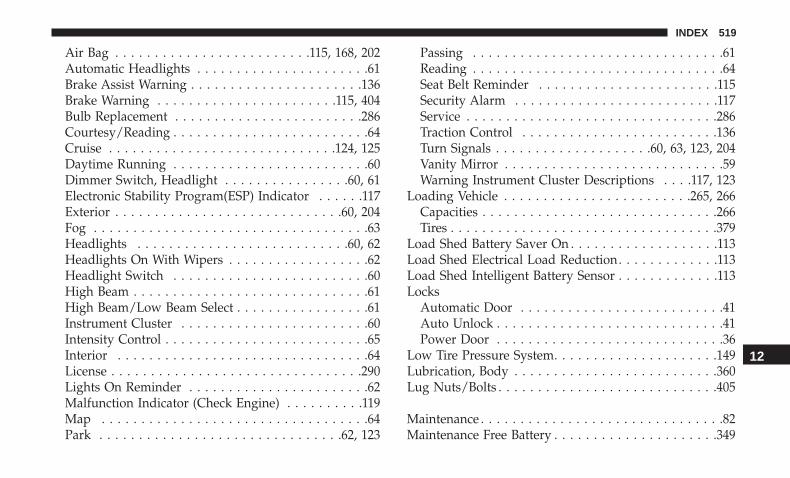
Air Bag . . . . . . . . . . . . . . . . . . . . . . . . .115, 168, 202Automatic Headlights . . . . . . . . . . . . . . . . . . . . . .61Brake Assist Warning . . . . . . . . . . . . . . . . . . . . . .136Brake Warning . . . . . . . . . . . . . . . . . . . . . . .115, 404Bulb Replacement . . . . . . . . . . . . . . . . . . . . . . . .286Courtesy/Reading . . . . . . . . . . . . . . . . . . . . . . . . .64Cruise . . . . . . . . . . . . . . . . . . . . . . . . . . . . .124, 125Daytime Running . . . . . . . . . . . . . . . . . . . . . . . . .60Dimmer Switch, Headlight . . . . . . . . . . . . . . . .60, 61Electronic Stability Program(ESP) Indicator . . . . . .117Exterior . . . . . . . . . . . . . . . . . . . . . . . . . . . . .60, 204Fog . . . . . . . . . . . . . . . . . . . . . . . . . . . . . . . . . . .63Headlights . . . . . . . . . . . . . . . . . . . . . . . . . . .60, 62Headlights On With Wipers . . . . . . . . . . . . . . . . . .62Headlight Switch . . . . . . . . . . . . . . . . . . . . . . . . .60High Beam . . . . . . . . . . . . . . . . . . . . . . . . . . . . . .61High Beam/Low Beam Select . . . . . . . . . . . . . . . . .61Instrument Cluster . . . . . . . . . . . . . . . . . . . . . . . .60Intensity Control . . . . . . . . . . . . . . . . . . . . . . . . . .65Interior . . . . . . . . . . . . . . . . . . . . . . . . . . . . . . . .64License . . . . . . . . . . . . . . . . . . . . . . . . . . . . . . . .290Lights On Reminder . . . . . . . . . . . . . . . . . . . . . . .62Malfunction Indicator (Check Engine) . . . . . . . . . .119Map . . . . . . . . . . . . . . . . . . . . . . . . . . . . . . . . . .64Park . . . . . . . . . . . . . . . . . . . . . . . . . . . . . . .62, 123
Passing . . . . . . . . . . . . . . . . . . . . . . . . . . . . . . . .61Reading . . . . . . . . . . . . . . . . . . . . . . . . . . . . . . . .64Seat Belt Reminder . . . . . . . . . . . . . . . . . . . . . . .115Security Alarm . . . . . . . . . . . . . . . . . . . . . . . . . .117Service . . . . . . . . . . . . . . . . . . . . . . . . . . . . . . . .286Traction Control . . . . . . . . . . . . . . . . . . . . . . . . .136Turn Signals . . . . . . . . . . . . . . . . . . . .60, 63, 123, 204Vanity Mirror . . . . . . . . . . . . . . . . . . . . . . . . . . . .59Warning Instrument Cluster Descriptions . . . .117, 123
Loading Vehicle . . . . . . . . . . . . . . . . . . . . . . . .265, 266Capacities . . . . . . . . . . . . . . . . . . . . . . . . . . . . . .266Tires . . . . . . . . . . . . . . . . . . . . . . . . . . . . . . . . . .379
Load Shed Battery Saver On . . . . . . . . . . . . . . . . . . .113Load Shed Electrical Load Reduction. . . . . . . . . . . . .113Load Shed Intelligent Battery Sensor . . . . . . . . . . . . .113Locks
Automatic Door . . . . . . . . . . . . . . . . . . . . . . . . . .41Auto Unlock . . . . . . . . . . . . . . . . . . . . . . . . . . . . .41Power Door . . . . . . . . . . . . . . . . . . . . . . . . . . . . .36
Low Tire Pressure System. . . . . . . . . . . . . . . . . . . . .149Lubrication, Body . . . . . . . . . . . . . . . . . . . . . . . . . .360Lug Nuts/Bolts . . . . . . . . . . . . . . . . . . . . . . . . . . . .405
Maintenance . . . . . . . . . . . . . . . . . . . . . . . . . . . . . . .82Maintenance Free Battery . . . . . . . . . . . . . . . . . . . . .349
12
INDEX 519

Maintenance Schedule . . . . . . . . . . . . .337, 338, 341, 342Malfunction Indicator Light (Check Engine). . . . .119, 126Manual
Backward . . . . . . . . . . . . . . . . . . . . . . . . . . . .42, 43Forward . . . . . . . . . . . . . . . . . . . . . . . . . . . . .42, 43Park Release . . . . . . . . . . . . . . . . . . . . . . . . . . . .328Rearward . . . . . . . . . . . . . . . . . . . . . . . . . . . . . . .42Service . . . . . . . . . . . . . . . . . . . . . . . . . . . . . . . .510Tilt . . . . . . . . . . . . . . . . . . . . . . . . . . . . . . . . . . .43
Manual Transmission . . . . . . . . . . . . . . . . .218, 371, 373Fluid Level Check . . . . . . . . . . . . . . . . . . . . .371, 373
Map/Reading Lights . . . . . . . . . . . . . . . . . . . . . . . . .64Methanol . . . . . . . . . . . . . . . . . . . . . . . . . . . . . . . .409Mirrors . . . . . . . . . . . . . . . . . . . . . . . . . . . . . . . . . .57
Electric Powered . . . . . . . . . . . . . . . . . . . . . . . . . .58Electric Remote . . . . . . . . . . . . . . . . . . . . . . . . . . .58Heated . . . . . . . . . . . . . . . . . . . . . . . . . . . . . . . . .59Outside . . . . . . . . . . . . . . . . . . . . . . . . . . . . . . . .58Rearview . . . . . . . . . . . . . . . . . . . . . . . . . . . .57, 281Vanity . . . . . . . . . . . . . . . . . . . . . . . . . . . . . . . . .59
Modifications/AlterationsVehicle . . . . . . . . . . . . . . . . . . . . . . . . . . . . . . . . .5
Monitor, Tire Pressure System. . . . . . . . . . . . . . . . . .149Mopar Parts . . . . . . . . . . . . . . . . . . . . . . . . . . . . . .509
Multi-Function Control Lever . . . . . . . . . . . . . . . . . . .60
New Vehicle Break-In Period . . . . . . . . . . . . . . . . . .214
Occupant Restraints . . . . . . . . . . . . . . . . . . . . . . . . .155Octane Rating, Gasoline (Fuel) . . . . . . . . . . . . . .406, 413Oil Change Indicator . . . . . . . . . . . . . . . . . . . . . . . .107
Reset . . . . . . . . . . . . . . . . . . . . . . . . . . . . . . . . .107Oil, Engine . . . . . . . . . . . . . . . . . . . . . . . . . . . .351, 413
Capacity . . . . . . . . . . . . . . . . . . . . . . . . . . . . . . .411Change Interval . . . . . . . . . . . . . . . . . . . . . . . . .351Checking . . . . . . . . . . . . . . . . . . . . . . . . . . . . . .348Dipstick . . . . . . . . . . . . . . . . . . . . . . . . . . . . . . .348Disposal . . . . . . . . . . . . . . . . . . . . . . . . . . . . . . .355Filter . . . . . . . . . . . . . . . . . . . . . . . . . . . . . .355, 413Filter Disposal . . . . . . . . . . . . . . . . . . . . . . . . . . .355Identification Logo . . . . . . . . . . . . . . . . . . . . . . .352Materials Added To . . . . . . . . . . . . . . . . . . . . . . .355Pressure Warning Light . . . . . . . . . . . . . . . . . . . .117Recommendation . . . . . . . . . . . . . . . . . . . . .351, 411Synthetic . . . . . . . . . . . . . . . . . . . . . . . . . . . . . .353Viscosity . . . . . . . . . . . . . . . . . . . . . . . .352, 353, 411
Oil Filter, Change . . . . . . . . . . . . . . . . . . . . . . . . . .355Oil Filter, Selection. . . . . . . . . . . . . . . . . . . . . . . . . .355Oil Pressure Light . . . . . . . . . . . . . . . . . . . . . . . . . .117
520 INDEX

Onboard Diagnostic System . . . . . . . . . . . . . . . . . . .125Operating Precautions . . . . . . . . . . . . . . . . . . . . . . .125Operator Manual
Owner’s Manual . . . . . . . . . . . . . . . . . . . . . . .5, 510Outside Rearview Mirrors . . . . . . . . . . . . . . . . . . . . .58Overheating, Engine . . . . . . . . . . . . . . . . . . . . . . . .327Owner’s Manual (Operator Manual). . . . . . . . . . . . . . .5
Paddle Shifters . . . . . . . . . . . . . . . . . . . . . . . . . . . .229Paddle Shift Mode. . . . . . . . . . . . . . . . . . . . . . . . . .229Paint Care. . . . . . . . . . . . . . . . . . . . . . . . . . . . . . . .397Panic Alarm . . . . . . . . . . . . . . . . . . . . . . . . . . . . . . .21Parking Brake . . . . . . . . . . . . . . . . . . . . . . . . . . . . .215ParkSense System, Rear . . . . . . . . . . . . . . . . . . . . . .254Passenger Seat
Easy Entry . . . . . . . . . . . . . . . . . . . . . . . . . . . . . .50Passing Light . . . . . . . . . . . . . . . . . . . . . . . . . . . . . .61Personalized Main Menu . . . . . . . . . . . . . . . . . . . . .419Pets . . . . . . . . . . . . . . . . . . . . . . . . . . . . . . . . . . . .201Pinch Protection . . . . . . . . . . . . . . . . . . . . . . . . . . . .82Placard, Tire And Loading Information . . . . . . . . . . .379Power
Brakes . . . . . . . . . . . . . . . . . . . . . . . . . . . . . . . .404Deck Lid Release . . . . . . . . . . . . . . . . . . . . . . . . .84Distribution Center (Fuses) . . . . . . . . . . . . . . . . . .295
Door Locks . . . . . . . . . . . . . . . . . . . . . . . . . . . . . .36Mirrors . . . . . . . . . . . . . . . . . . . . . . . . . . . . . . . .58Outlet (Auxiliary Electrical Outlet) . . . . . . . . . . . . .95Seats . . . . . . . . . . . . . . . . . . . . . . . . . . . . . . . . . .45Steering . . . . . . . . . . . . . . . . . . . . . . . . . . . . . . .232Sunroof . . . . . . . . . . . . . . . . . . . . . . . . . . . . . . . .80Tilt/Telescoping Steering Column . . . . . . . . . . . . . .55Windows . . . . . . . . . . . . . . . . . . . . . . . . . . . . . . .79
Power SeatsForward . . . . . . . . . . . . . . . . . . . . . . . . . . . . . . . .46Lumbar . . . . . . . . . . . . . . . . . . . . . . . . . . . . . . . .46Rearward . . . . . . . . . . . . . . . . . . . . . . . . . . . . . . .46
Power Steering Fluid. . . . . . . . . . . . . . . . . . . . .413, 415Pregnant Women And Seat Belts . . . . . . . . . . . . . . . .164Preparation For Jacking . . . . . . . . . . . . . . . . . . . . . .303Pretensioners
Seat Belts . . . . . . . . . . . . . . . . . . . . . . . . . . . . . .164Programmable Features . . . . . . . . . . . . . . . . . . . . . .421
Radial Ply Tires . . . . . . . . . . . . . . . . . . . . . . . . . . . .385Radiator Cap (Coolant Pressure Cap). . . . . . . . . . . . .367Radio Frequency
General Information . . . . . . . . . . . . . . . .25, 32, 33, 41Radio Operation . . . . . . . . . . . . . . . . . . . . . . . . . . .483Rain Sensitive Wiper System . . . . . . . . . . . . . . . . . . .68
12
INDEX 521

Rear Camera . . . . . . . . . . . . . . . . . . . . . . . . . . . . . .261Rear ParkSense System . . . . . . . . . . . . . . . . . . . . . .254Rear Seats, Folding . . . . . . . . . . . . . . . . . . . . . . . . . .44Recreational Towing. . . . . . . . . . . . . . . . . . . . . . . . .276Reformulated Gasoline. . . . . . . . . . . . . . . . . . . . . . .408Refrigerant . . . . . . . . . . . . . . . . . . . . . . . . . . . . . . .357Release, Hood. . . . . . . . . . . . . . . . . . . . . . . . . . . . . .83Reminder, Lights On . . . . . . . . . . . . . . . . . . . . . . . . .62Reminder, Seat Belt . . . . . . . . . . . . . . . . . . . . . . . . .158Remote Keyless Entry
Arm The Alarm . . . . . . . . . . . . . . . . . . . . . . . . . .34Panic Alarm . . . . . . . . . . . . . . . . . . . . . . . . . . . . .21Programming Additional Key Fobs . . . . . . . . . .25, 33Unlatch The Trunk . . . . . . . . . . . . . . . . . . . . . . . .21
Remote StartingExit Remote Start Mode . . . . . . . . . . . . . . . . . . . . .30Uconnect Customer Programmable Features . . .31, 435Uconnect Settings . . . . . . . . . . . . . . . . . . . . . .31, 435
Remote Trunk Release . . . . . . . . . . . . . . . . . . . . . . . .84Replacement Bulbs . . . . . . . . . . . . . . . . . . . . . . . . .286Replacement Keys . . . . . . . . . . . . . . . . . . . . . . . .25, 33Replacement Tires . . . . . . . . . . . . . . . . . . . . . . . . . .388Reporting Safety Defects . . . . . . . . . . . . . . . . . . . . .509Restraints, Child . . . . . . . . . . . . . . . . . . . . . . . . . . .180Restraints, Head . . . . . . . . . . . . . . . . . . . . . . . . . . . .51
Rocking Vehicle When Stuck. . . . . . . . . . . . . . . . . . .330Rotation, Tires . . . . . . . . . . . . . . . . . . . . . . . . . . . . .395
Safety Checks Inside Vehicle . . . . . . . . . . . . . . . . . . .202Safety Checks Outside Vehicle . . . . . . . . . . . . . . . . .204Safety Defects, Reporting . . . . . . . . . . . . . . . . . . . . .509Safety, Exhaust Gas . . . . . . . . . . . . . . . . . . . . . . . . .201Safety Information, Tire . . . . . . . . . . . . . . . . . . . . . .374Safety Tips . . . . . . . . . . . . . . . . . . . . . . . . . . . . . . .201Schedule, Maintenance . . . . . . . . . . . . . . . .337, 338, 341Seat Belt Reminder . . . . . . . . . . . . . . . . . . . . . . . . .115Seat Belts . . . . . . . . . . . . . . . . . . . . . . . . . . . . .157, 202
Automatic Locking Retractor (ALR) . . . . . . . . . . .165Child Restraints . . . . . . . . . . . . . . . . . . . . . . . . .180Energy Management Feature . . . . . . . . . . . . . . . .164Extender . . . . . . . . . . . . . . . . . . . . . . . . . . . . . . .163Front Seat . . . . . . . . . . . . . . . . . . . . . . .157, 159, 161Inspection . . . . . . . . . . . . . . . . . . . . . . . . . . . . . .202Lap/Shoulder Belt Operation . . . . . . . . . . . . . . . .161Lap/Shoulder Belts . . . . . . . . . . . . . . . . . . . . . . .159Lap/Shoulder Belt Untwisting . . . . . . . . . . . . . . .163Operating Instructions . . . . . . . . . . . . . . . . . . . . .161Pregnant Women . . . . . . . . . . . . . . . . . . . . . . . . .164Pretensioners . . . . . . . . . . . . . . . . . . . . . . . . . . .164Rear Seat . . . . . . . . . . . . . . . . . . . . . . . . . . . . . .159
522 INDEX

Reminder . . . . . . . . . . . . . . . . . . . . . . . . . . . . . .158Seat Belt Extender . . . . . . . . . . . . . . . . . . . . . . . .163Seat Belt Pretensioner . . . . . . . . . . . . . . . . . . . . .164Untwisting Procedure . . . . . . . . . . . . . . . . . . . . .163
Seat Belts Maintenance. . . . . . . . . . . . . . . . . . . . . . .399Seats . . . . . . . . . . . . . . . . . . . . . . . . . . . . .42, 46, 47, 50
Adjustment . . . . . . . . . . . . . . . . . . . . . . . . . . .42, 46Head Restraints . . . . . . . . . . . . . . . . . . . . . . . . . .51Heated . . . . . . . . . . . . . . . . . . . . . . . . . . . . . . . . .47Height Adjustment . . . . . . . . . . . . . . . . . . . . . . . .45Power . . . . . . . . . . . . . . . . . . . . . . . . . . . . . . . . .45Rear Folding . . . . . . . . . . . . . . . . . . . . . . . . . .42, 44Seatback Release . . . . . . . . . . . . . . . . . . . . . . .42, 44Tilting . . . . . . . . . . . . . . . . . . . . . . . . . . . .42, 45, 50Vented . . . . . . . . . . . . . . . . . . . . . . . . . . . . . . . . .48Ventilated . . . . . . . . . . . . . . . . . . . . . . . . . . . . . . .48
Security Alarm . . . . . . . . . . . . . . . . . . . . . . . . . .33, 117Arm The System . . . . . . . . . . . . . . . . . . . . . . . . . .34
Selection Of Coolant (Antifreeze) . . . . . . . . . . . . . . .413Sentry Key
Key Programming . . . . . . . . . . . . . . . . . . . . . . . . .33Sentry Key (Immobilizer) . . . . . . . . . . . . . . . . . . . . . .32Sentry Key Replacement . . . . . . . . . . . . . . . . . . . .25, 33Service Assistance . . . . . . . . . . . . . . . . . . . . . . . . . .506Service Contract . . . . . . . . . . . . . . . . . . . . . . . . . . .508
Service Manuals . . . . . . . . . . . . . . . . . . . . . . . . . . .510Shift Indicator Light. . . . . . . . . . . . . . . . . . . . . . . . .221Shifting . . . . . . . . . . . . . . . . . . . . . . . . . . . . . . . . .222
Automatic Transmission . . . . . . . . . . . . . . . .222, 224Shoulder Belts . . . . . . . . . . . . . . . . . . . . . . . . . . . . .159Side View Mirror Adjustment. . . . . . . . . . . . . . . . . . .58Signals, Turn . . . . . . . . . . . . . . . . . . . . . . . .63, 123, 204Siri. . . . . . . . . . . . . . . . . . . . . . . . . . . . . . . . . . . . .498SiriusXM Guardian
Vehicle Health Alert . . . . . . . . . . . . . . . . . . . . . . .496Snow Chains (Tire Chains) . . . . . . . . . . . . . . . . . . . .394Snow Tires . . . . . . . . . . . . . . . . . . . . . . . . . . . . . . .390Spare Tires . . . . . . . . . . . . . . . . . . . . .301, 390, 391, 392Spark Plugs . . . . . . . . . . . . . . . . . . . . . . . . . . . . . .413Specifications
Fuel (Gasoline) . . . . . . . . . . . . . . . . . . . . . . . . . .413Oil . . . . . . . . . . . . . . . . . . . . . . . . . . . . . . . . . . .413
Speed ControlAccel/Decel . . . . . . . . . . . . . . . . . . . . . . . . .234, 235Cancel . . . . . . . . . . . . . . . . . . . . . . . . . . . . . . . .236Resume . . . . . . . . . . . . . . . . . . . . . . . . . . . . . . .236Set . . . . . . . . . . . . . . . . . . . . . . . . . . . . . . . . . . .234
Speed Control (Cruise Control) . . . . . . . . . .233, 234, 236Sport Mode. . . . . . . . . . . . . . . . . . . . . . . . . . . . . . .232Starting . . . . . . . . . . . . . . . . . . . . . . . . . . . . . .208, 209
12
INDEX 523

Automatic Transmission . . . . . . . . . . . . . . . . . . . .208Button . . . . . . . . . . . . . . . . . . . . . . . . . . . . . . . . .26Cold Weather . . . . . . . . . . . . . . . . . . . . . . . . . . .212Engine Fails To Start . . . . . . . . . . . . . . . . . . . . . .213
Starting And Operating . . . . . . . . . . . . . . . . . . .208, 209Starting Procedures . . . . . . . . . . . . . . . . . . . . . .208, 209Steering . . . . . . . . . . . . . . . . . . . . . . . . . . . . . . . . . .54
Column Lock . . . . . . . . . . . . . . . . . . . . . . . . . . . .54Power . . . . . . . . . . . . . . . . . . . . . . . . . . . . . . . .232Tilt Column . . . . . . . . . . . . . . . . . . . . . . . . . . .54, 55Wheel, Heated . . . . . . . . . . . . . . . . . . . . . . . . . . .56Wheel, Tilt . . . . . . . . . . . . . . . . . . . . . . . . . . .54, 55
Steering Wheel Audio Controls . . . . . . . . . . . . . . . . .482Steering Wheel Mounted Sound System Controls . . . .482Storage . . . . . . . . . . . . . . . . . . . . . . . . . . . . . . .93, 397Storage, Vehicle . . . . . . . . . . . . . . . . . . . . . . . . .77, 397Storing Your Vehicle . . . . . . . . . . . . . . . . . . . . . . . .397Stuck, Freeing . . . . . . . . . . . . . . . . . . . . . . . . . . . . .330Sun Roof . . . . . . . . . . . . . . . . . . . . . . . . . . . . . . .80, 82Supplemental Restraint System – Air Bag. . . . . . . . . .170Synthetic Engine Oil . . . . . . . . . . . . . . . . . . . . . . . .353
Telescoping Steering Column . . . . . . . . . . . . . . . .54, 55Temperature Control, Automatic (ATC) . . . . . . . . . . . .76Tilt Steering Column . . . . . . . . . . . . . . . . . . . . . .54, 55
Time DelayHeadlight . . . . . . . . . . . . . . . . . . . . . . . . . . . . . . .62
Tire And Loading Information Placard. . . . . . . . . . . .379Tire Markings . . . . . . . . . . . . . . . . . . . . . . . . . . . . .374Tires . . . . . . . . . . . . . . . . . . . . . . . . . .204, 383, 390, 396
Aging (Life Of Tires) . . . . . . . . . . . . . . . . . . . . . .387Air Pressure . . . . . . . . . . . . . . . . . . . . . . . . . . . .383Chains . . . . . . . . . . . . . . . . . . . . . . . . . . . . . . . .394Changing . . . . . . . . . . . . . . . . . . . .301, 303, 308, 373Compact Spare . . . . . . . . . . . . . . . . . . . . . . . . . .391Flat Changing . . . . . . . . . . . . . . . . . . . . . . . . . . .308General Information . . . . . . . . . . . . . . . . . . .383, 390High Speed . . . . . . . . . . . . . . . . . . . . . . . . . . . . .385Inflation Pressure . . . . . . . . . . . . . . . . . . . . . . . .384Jacking . . . . . . . . . . . . . . . . . . . . . . . . . . . .303, 373Life Of Tires . . . . . . . . . . . . . . . . . . . . . . . . . . . .387Load Capacity . . . . . . . . . . . . . . . . . . . . . . .379, 380Pressure Monitoring System (TPMS) . . . . . . . .121, 149Quality Grading . . . . . . . . . . . . . . . . . . . . . . . . .396Radial . . . . . . . . . . . . . . . . . . . . . . . . . . . . . . . .385Replacement . . . . . . . . . . . . . . . . . . . . . . . . .308, 388Rotation . . . . . . . . . . . . . . . . . . . . . . . . . . . . . . .395Safety . . . . . . . . . . . . . . . . . . . . . . . . . . . . .374, 383Sizes . . . . . . . . . . . . . . . . . . . . . . . . . . . . . . . . .375Snow Tires . . . . . . . . . . . . . . . . . . . . . . . . . . . . .390
524 INDEX

Spare Tires . . . . . . . . . . . . . . . . . . . . . .301, 390, 392Spinning . . . . . . . . . . . . . . . . . . . . . . . . . . . . . . .386Trailer Towing . . . . . . . . . . . . . . . . . . . . . . . . . . .272Tread Wear Indicators . . . . . . . . . . . . . . . . . . . . .386Wheel Mounting . . . . . . . . . . . . . . . . . . . . . . . . .308Wheel Nut Torque . . . . . . . . . . . . . . . . . . . . . . . .405
Tire Safety Information. . . . . . . . . . . . . . . . . . . . . . .374Tire Service Kit . . . . . . . . . . .308, 309, 310, 312, 316, 317,
318, 320, 322, 324Tongue Weight/Trailer Weight . . . . . . . . . . . . . . . . .270To Open Hood . . . . . . . . . . . . . . . . . . . . . . . . . . . . .83Towing . . . . . . . . . . . . . . . . . . . . . . . . . . . . . . . . . .266
Disabled Vehicle . . . . . . . . . . . . . . . . . . . . . . . . .332Guide . . . . . . . . . . . . . . . . . . . . . . . . . . . . . . . . .269Recreational . . . . . . . . . . . . . . . . . . . . . . . . . . . .276Weight . . . . . . . . . . . . . . . . . . . . . . . . . . . . . . . .269
Towing Behind A Motorhome . . . . . . . . . . . . . . . . . .276Traction . . . . . . . . . . . . . . . . . . . . . . . . . . . . . . . . .276Traction Control . . . . . . . . . . . . . . . . . . . . . . . . . . .139Trailer Towing. . . . . . . . . . . . . . . . . . . . . . . . . . . . .266
Cooling System Tips . . . . . . . . . . . . . . . . . . . . . .275Hitches . . . . . . . . . . . . . . . . . . . . . . . . . . . . . . . .269Minimum Requirements . . . . . . . . . . . . . . . . . . . .270Tips . . . . . . . . . . . . . . . . . . . . . . . . . . . . . . . . . .275Trailer And Tongue Weight . . . . . . . . . . . . . . . . . .270
Wiring . . . . . . . . . . . . . . . . . . . . . . . . . . . . . . . .273Trailer Towing Guide . . . . . . . . . . . . . . . . . . . . . . . .269Trailer Weight . . . . . . . . . . . . . . . . . . . . . . . . . . . . .269Transfer Case
Fluid . . . . . . . . . . . . . . . . . . . . . . . . . . .373, 413, 415Maintenance . . . . . . . . . . . . . . . . . . . . . . . . . . . .373
Transmission . . . . . . . . . . . . . . . . . . . . . . . . . . . . . .224Automatic . . . . . . . . . . . . . . . . . . . . . . .222, 224, 371Fluid . . . . . . . . . . . . . . . . . . . . . . . . . . . . . .413, 415Maintenance . . . . . . . . . . . . . . . . . . . . . . . . . . . .371Manual . . . . . . . . . . . . . . . . . . . . . . . . . . . . . . . .218Shifting . . . . . . . . . . . . . . . . . . . . . . . . . . . . . . .222
Transporting Pets . . . . . . . . . . . . . . . . . . . . . . . . . .201Tread Wear Indicators . . . . . . . . . . . . . . . . . . . . . . .386Trunk Lid (Deck Lid). . . . . . . . . . . . . . . . . . . . . . . . .84Trunk Release Remote Control . . . . . . . . . . . . . . . . . .84Turn Signals. . . . . . . . . . . . . . . . . . . . . . . . . . . .63, 123
UconnectUconnect Settings . . . . . . . . . . . . . . . . .20, 21, 31, 435
Uconnect 4C/4C Nav With 8.4-Inch Display. . . . . . . .443Uconnect 4 With 7-Inch Display . . . . . . . . . . . . . . . .422Uconnect Settings
Customer Programmable Features . . . . . . . . . .31, 435Uniform Tire Quality Grades . . . . . . . . . . . . . . . . . .396
12
INDEX 525

Unleaded Gasoline . . . . . . . . . . . . . . . . . . . . . . . . .406Untwisting Procedure, Seat Belt . . . . . . . . . . . . . . . .163
Vanity Mirrors . . . . . . . . . . . . . . . . . . . . . . . . . . . . .59Vehicle Certification Label . . . . . . . . . . . . . . . . . . . .265Vehicle Identification Number (VIN) . . . . . . . . . . . . .404Vehicle Loading . . . . . . . . . . . . . . . . . . . . .265, 266, 380Vehicle Modifications/Alterations. . . . . . . . . . . . . . . . .5Vehicle Security Alarm. . . . . . . . . . . . . . . . . . . . . . . .33Vehicle Storage. . . . . . . . . . . . . . . . . . . . . . . . . .77, 397Vehicle User Guide
In Vehicle Help . . . . . . . . . . . . . . . . . . . . . . . . . . .17Navigation . . . . . . . . . . . . . . . . . . . . . . . . . . . . . .17Operating Instructions . . . . . . . . . . . . . . . . . . . . . .17Searching User Guide . . . . . . . . . . . . . . . . . . . . . .17
Viscosity, Engine Oil . . . . . . . . . . . . . . . . . . . . .352, 353Voice Command . . . . . . . . . . . . . . . . . . . . . . . . . . .485Voice Recognition System (VR) . . . . . . . . . . . . . . . . .485
Warning Lights (Instrument Cluster Descriptions). . . .120Warnings And Cautions . . . . . . . . . . . . . . . . . . . . . . .5Warranty Information . . . . . . . . . . . . . . . . . . . . . . .509Washer
Adding Fluid . . . . . . . . . . . . . . . . . . . . . . . . . . .349Washers, Windshield. . . . . . . . . . . . . . . . . . . . . .67, 349
Washing Vehicle . . . . . . . . . . . . . . . . . . . . . . . . . . .398Water
Driving Through . . . . . . . . . . . . . . . . . . . . . . . . .277Wheel And Wheel Tire Care . . . . . . . . . . . . . . . . . . .393Wheel And Wheel Tire Trim . . . . . . . . . . . . . . . . . . .393Wind Buffeting . . . . . . . . . . . . . . . . . . . . . . . . . .80, 82Window Fogging . . . . . . . . . . . . . . . . . . . . . . . . . . .77Windows . . . . . . . . . . . . . . . . . . . . . . . . . . . . . . . . .79
Power . . . . . . . . . . . . . . . . . . . . . . . . . . . . . . . . .79Windshield Defroster . . . . . . . . . . . . . . . . . . . . . . . .202Windshield Washers . . . . . . . . . . . . . . . . . . . . . . .66, 67
Fluid . . . . . . . . . . . . . . . . . . . . . . . . . . . . . . . . .349Windshield Wiper Blades . . . . . . . . . . . . . . . . . . . . .361Windshield Wipers . . . . . . . . . . . . . . . . . . . . . . . . . .66Wipers Blade Replacement . . . . . . . . . . . . . . . . . . . .361Wipers, Intermittent . . . . . . . . . . . . . . . . . . . . . . . . .67Wipers, Rain Sensitive . . . . . . . . . . . . . . . . . . . . . . . .68Wireless Charging Pad. . . . . . . . . . . . . . . . . . . . . . . .98
526 INDEX
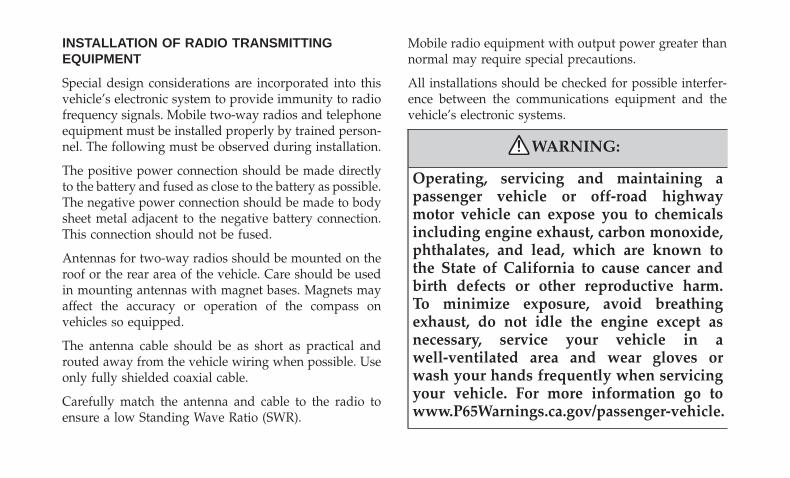
INSTALLATION OF RADIO TRANSMITTINGEQUIPMENT
Special design considerations are incorporated into thisvehicle’s electronic system to provide immunity to radiofrequency signals. Mobile two-way radios and telephoneequipment must be installed properly by trained person-nel. The following must be observed during installation.
The positive power connection should be made directlyto the battery and fused as close to the battery as possible.The negative power connection should be made to bodysheet metal adjacent to the negative battery connection.This connection should not be fused.
Antennas for two-way radios should be mounted on theroof or the rear area of the vehicle. Care should be usedin mounting antennas with magnet bases. Magnets mayaffect the accuracy or operation of the compass onvehicles so equipped.
The antenna cable should be as short as practical androuted away from the vehicle wiring when possible. Useonly fully shielded coaxial cable.
Carefully match the antenna and cable to the radio toensure a low Standing Wave Ratio (SWR).
Mobile radio equipment with output power greater thannormal may require special precautions.
All installations should be checked for possible interfer-ence between the communications equipment and thevehicle’s electronic systems.
WARNING:
Operating, servicing and maintaining apassenger vehicle or off-road highwaymotor vehicle can expose you to chemicalsincluding engine exhaust, carbon monoxide,phthalates, and lead, which are known tothe State of California to cause cancer andbirth defects or other reproductive harm.To minimize exposure, avoid breathingexhaust, do not idle the engine except asnecessary, service your vehicle in awell-ventilated area and wear gloves orwash your hands frequently when servicingyour vehicle. For more information go towww.P65Warnings.ca.gov/passenger-vehicle.
ChallengerO W N E R ’ S M A N U A L
Second EditionPrinted in the U.S.A.
19LA-126-AB©2018 FCA US LLC. All Rights Reserved.Dodge is a registered trademark of FCA US LLC.
2 0 1 9
Ch
allen
ger
20
19