2015 zips sae baja brakes and throttle system
TRANSCRIPT

The University of AkronIdeaExchange@UAkron
Honors Research Projects The Dr. Gary B. and Pamela S. Williams HonorsCollege
Spring 2015
2015 Zips SAE Baja Brakes and Throttle SystemPhilip A. BennettUniversity of Akron Main Campus, [email protected]
Please take a moment to share how this work helps you through this survey. Your feedback will beimportant as we plan further development of our repository.Follow this and additional works at: http://ideaexchange.uakron.edu/honors_research_projects
Part of the Applied Mechanics Commons, Computer-Aided Engineering and Design Commons,and the Manufacturing Commons
This Honors Research Project is brought to you for free and open access by The Dr. Gary B. and Pamela S. WilliamsHonors College at IdeaExchange@UAkron, the institutional repository of The University of Akron in Akron, Ohio,USA. It has been accepted for inclusion in Honors Research Projects by an authorized administrator ofIdeaExchange@UAkron. For more information, please contact [email protected], [email protected].
Recommended CitationBennett, Philip A., "2015 Zips SAE Baja Brakes and Throttle System" (2015). Honors Research Projects. 31.http://ideaexchange.uakron.edu/honors_research_projects/31

The University of Akron
SAE Baja Zips Off
2015 Brakes & Throttle System
Philip Bennett, Candidate BSME
Design Advisor: Dr. Richard Gross, Associate Professor Emeritus
The University of Akron
SAE Baja Zips Off-Road Racing Team
2015 Brakes & Throttle System
Philip Bennett, Candidate BSME
Advisor: Dr. Richard Gross, Associate Professor Emeritus
May 2015
Road Racing Team
Advisor: Dr. Richard Gross, Associate Professor Emeritus

1
Contents
Executive Summary . . . . . . . . . . . . . . . . . . . . . . . . . . . . . . . . . . . . . . . . . . . . . . . . . . . . . 2
Baja SAE Guidelines and System Requirements . . . . . . . . . . . . . . . . . . . . . . . . . . . . . . . 2
Brake System Overview. . . . . . . . . . . . . . . . . . . . . . . . . . . . . . . . . . . . . . . . . . . . . . . . . . .3
- Main components. . . . . . . . . . . . . . . . . . . . . . . . . . . . . . . . . . . . . . . . . . . . . . .4
- Simple Braking System Overview. . . . . . . . . . . . . . . . . . . . . . . . . . . . . . . . . .4
2014 Vehicle Performance Review. . . . . . . . . . . . . . . . . . . . . . . . . . . . . . . . . . . . . . . . . . 6
Design Goals. . . . . . . . . . . . . . . . . . . . . . . . . . . . . . . . . . . . . . . . . . . . . . . . . . . . . . . . . . . 6
Component Design and Selection . . . . . . . . . . . . . . . . . . . . . . . . . . . . . . . . . . . . . . . . . . .9
- Initial Component Selection and Design. . . . . . . . . . . . . . . . . . . . . . . . . . . . . . . . 9
- System Performance Calculations. . . . . . . . . . . . . . . . . . . . . . . . . . . . . . . . . . . . .15
- Design Iteration and Optimization. . . . . . . . . . . . . . . . . . . . . . . . . . . . . . . . . . . . .16
- Brake and Throttle Pedal Design. . . . . . . . . . . . . . . . . . . . . . . . . . . . . . . . . . . . . .17
Competition Results and Adjustments. . . . . . . . . . . . . . . . . . . . . . . . . . . . . . . . . . . . . . . .21
Conclusion . . . . . . . . . . . . . . . . . . . . . . . . . . . . . . . . . . . . . . . . . . . . . . . . . . . . . . . . . . . . .22
Appendices. . . . . . . . . . . . . . . . . . . . . . . . . . . . . . . . . . . . . . . . . . . . . . . . . . . . . . . . . . . . .23
- Appendix A - Additional Figures. . . . . . . . . . . . . . . . . . . . . . . . . . . . . . . . . . . . . .23
- Appendix B - FEA Analysis and Results. . . . . . . . . . . . . . . . . . . . . . . . . . . . . . . .24
- Appendix C – Theory and Derivations. . . . . . . . . . . . . . . . . . . . . . . . . . . . . . . . . 27
- Appendix D – 2015 SAE Baja Competition Regulations. . . . . . . . . . . . . . . . . . . 34
2
Executive Summary
The SAE Baja student design team at The University of Akron is one of the longest-
standing design teams at the university. The purpose of this team is to design, manufacture, test,
and race an off-road vehicle within the guidelines of competition established by the Society of
Automotive Engineers. The vehicle is made up of a small number of subsystems including
frame, drivetrain, suspension, steering, and braking. The following will discuss all aspects of the
design process of the braking and throttle system of the 2015 Zips Baja car. This process
includes several steps and considerations such as design goals, system performance calculations,
stress analysis, and manufacturability. Once the final design is established, the manufacturing
process will be outlined. The performance of the finished system will be analyzed and the
necessary changes will be made to optimize design, and therefore, performance.
Baja SAE Guidelines and System Requirements
The Society of Automotive Engineers lays out an extensive document of rules and
guidelines for the SAE Baja competition. These rules cover all aspects of the vehicle including
frame tube thicknesses, safety equipment specifications, allowable materials, and many other
details. Much of this document is created for the purpose of driver safety, but the level of
regulation given to even the smallest details of the car also serve as a test of engineering
precision and attention to detail during the design process. There are several rules and
specifications that are directly related to the brakes and throttle systems. The rules pertaining to
these systems are the following (The braking section of the official 2015 Baja SAE Series Rules
document can be found in Appendix D):
THROTTLE:
• Only mechanical foot-operated pedals are allowed.
• A wide-open throttle stop must be incorporated at the pedal.
• Controls must be designed to return to idle-stop in the event of failure.
• Throttle cable must be sheathed between its forward mounting and the firewall.
• Foot pedals must be positioned so as to avoid foot entrapment in any position.
BRAKES:
• Vehicle must have hydraulic braking system that acts on all wheels and is
operated by a single foot pedal.
• Pedal must directly actuate the master cylinder through a rigid link.
• System must be capable of locking all four wheels in both static and dynamic
situations on both pavement and on unpaved surfaces.
• System must be segregated into at least two independent hydraulic circuits with
their own fluid reservoirs.
• Brakes on the driven axle must operate through the final drive.
3
• All brake lines must be mounted securely and not fall below any portion of the
vehicle (frame, swing arm, A-arms, etc.)
• Vehicle must be equipped with a red LED brake light that is SAE “S” or “U”
rated as marked on the lens. Light must be completely illuminated when brake
system is actuated and completely extinguished when brake is released.
• Brake light must be mounted minimum of one meter above the ground and must
be mounted such that it shines parallel to the ground.
All of these criteria will be extensively checked at the technical inspection that is performed on
all cars at each competition. If any of these criteria are not met, the inspection will be failed and
the team will not be able to compete unless the necessary changes are made.
There is also an event at the competition that is used to directly test the braking system.
In this dynamic brake test, the driver must bring the vehicle to its maximum speed, then engage
the braking system to cause all four wheels to lock up. In this test, there is one judge assigned to
watch each wheel (four total judges). If any of the wheels continue to spin for any amount of
time after the brake system has been engaged, the test is failed. This event is particularly
important because no other competition events can be attempted until the brake test is
successfully completed. Since there is only one day to complete dynamic events such as
suspension test, maneuverability, acceleration, and tractor pull, the time lost with unsuccessful
brake tests can lead to “Did Not Finish” status on events leading to zero points for the team. If
the brake test is not passed at all, none of these events nor the endurance race can be completed.
Brake and Throttle System Overview
The essential purpose of the brake and throttle systems of the vehicle are extremely
simple. The throttle needs to make the car accelerate at the driver’s will, and the brake system
needs to make the car decelerate at the driver’s will. However, the overall capability of the
system transcends this simple definition. For example, a low quality braking system will only be
able to achieve “no brake” and “full brake.” A quality braking system must be able to achieve
intermediate ranges of braking that allows the driver to feather the brakes when moving around
corners and when approaching a ramp-type obstacle that could send the vehicle airborne.
Other considerations that must be taken into account in a braking and throttle system is
are ergonomics and component interference. In terms of ergonomics, the driver must be able to
comfortably use the brake and throttle pedals for an extended period of time. The endurance
race at the Baja SAE competitions are four hours long, and poorly placed pedals can cause
discomfort for extended periods of time. Component interference is also a concern. The pedals
and brake assembly features located in the front box must share space with steering system
components such as the rack and pinion and the steering column. The rotors and brake calipers
located at the wheels can interfere with the connection points of suspension components, steering
components, and even with the wheel itself. If potential interferences are not identified during

the design stage, there can be serious problems and significant lost time during the
manufacturing stage to make components fit together. This is one of the biggest testaments to
the importance of communication between designers of
absolute necessity of three-dimensional co
Major System Components
A typical braking system is made up of only a few main components. These components
are the pedal, master cylinder, brake reservoir, brake li
system is made up of the pedal, throttle cable, mechanical stopping device, and return spring.
Simple Brake/Throttle System
The main premise of a hydraulic braking system is very simple: driver force applied at
the brake pedal is transferred hydraulically to locations at the wheels or axle to reduce rotational
speed and therefore vehicle speed. This simple task is completed using the short list of
components given in the previous section.
Beginning the process from the driver’s effort to push one end of the brake pedal, the movement
of the pedal actuates the plunge rod that is attached to the other end of the pedal. This plunge
rod moves a plunger inside the master cylinder and decreases the volume within the cyl
increasing the pressure of the fluid inside.
foot force location and the actuation of the push rod.
As seen above, the driver force is applied at the foot
and the push rod is pushed further into the master cylinder, decreasing the volume occupied by
the fluid and therefore increasing the pressure.
4
the design stage, there can be serious problems and significant lost time during the
manufacturing stage to make components fit together. This is one of the biggest testaments to
the importance of communication between designers of different vehicle components and the
dimensional computer modelling of the design.
A typical braking system is made up of only a few main components. These components
are the pedal, master cylinder, brake reservoir, brake lines, rotors, and calipers. The throttle
system is made up of the pedal, throttle cable, mechanical stopping device, and return spring.
Simple Brake/Throttle System
The main premise of a hydraulic braking system is very simple: driver force applied at
brake pedal is transferred hydraulically to locations at the wheels or axle to reduce rotational
speed and therefore vehicle speed. This simple task is completed using the short list of
components given in the previous section.
om the driver’s effort to push one end of the brake pedal, the movement
of the pedal actuates the plunge rod that is attached to the other end of the pedal. This plunge
rod moves a plunger inside the master cylinder and decreases the volume within the cyl
increasing the pressure of the fluid inside. Figure (1) below shows the relationship between the
foot force location and the actuation of the push rod.
Figure 1: Basic Pedal Diagram.
driver force is applied at the foot bad. The pedal pivots about the pivot point
and the push rod is pushed further into the master cylinder, decreasing the volume occupied by
the fluid and therefore increasing the pressure.
the design stage, there can be serious problems and significant lost time during the
manufacturing stage to make components fit together. This is one of the biggest testaments to
onents and the
A typical braking system is made up of only a few main components. These components
nes, rotors, and calipers. The throttle
system is made up of the pedal, throttle cable, mechanical stopping device, and return spring.
The main premise of a hydraulic braking system is very simple: driver force applied at
brake pedal is transferred hydraulically to locations at the wheels or axle to reduce rotational
speed and therefore vehicle speed. This simple task is completed using the short list of
om the driver’s effort to push one end of the brake pedal, the movement
of the pedal actuates the plunge rod that is attached to the other end of the pedal. This plunge
rod moves a plunger inside the master cylinder and decreases the volume within the cylinder,
shows the relationship between the
bad. The pedal pivots about the pivot point
and the push rod is pushed further into the master cylinder, decreasing the volume occupied by

Since pressure within the entire system is essentially uniform, th
cylinder is also experienced in the brake all the way to the
fluid between the master cylinder and the calipers of a basic brake system.
Figure 2:
Within each brake caliper there are
caliper varies between models and manufacturers)
small cylinders (shown as “cylinder
pads, causing them to push onto the brake rotor from both sides. The friction force created
between the brake pads and the brake rotors cause the deceleration of the rotors, which are
rigidly attached to either a wheel or a
assembly are displayed well in Figure (3):
Figure 3:
Rotor
5
system is essentially uniform, the pressure increase in the master
cylinder is also experienced in the brake all the way to the calipers. Figure (2) shows
fluid between the master cylinder and the calipers of a basic brake system.
Figure 2: Basic brake system fluid route.
Within each brake caliper there are small piston/cylinder assemblies (the amount of pistons in a
caliper varies between models and manufacturers). When the fluid pressure increases in these
(shown as “cylinder B” in Figure (2)), the pistons travel and push on the brake
pads, causing them to push onto the brake rotor from both sides. The friction force created
between the brake pads and the brake rotors cause the deceleration of the rotors, which are
rigidly attached to either a wheel or a drive shaft. The inner workings of this caliper/rotor
Figure (3):
e pressure increase in the master
calipers. Figure (2) shows the path of
(the amount of pistons in a
. When the fluid pressure increases in these
s travel and push on the brake
pads, causing them to push onto the brake rotor from both sides. The friction force created
between the brake pads and the brake rotors cause the deceleration of the rotors, which are
The inner workings of this caliper/rotor
Caliper /
assembly.
6
The throttle system is even simpler than a basic braking system. The gas pedal and the throttle
lever on the engine are attached via a cable. When the gas pedal is pushed forward, the cable
pulls the engine throttle to an open position. When force is removed from the gas pedal, a return
spring attached to the engine’s throttle arm pulls the arm back to the idle position.
2014 Vehicle Performance Review
The 2014 Zips Baja season was the most successful campaign for the team in almost ten
years. However, problems with several components of the car combined to leave a sense of
underachievement based on the overall potential of the car. The brake system itself did not
experience any failures. Although it took several attempts to pass the brake test at the first
competition due to a lack of system testing (the building of the car was finished and assembly of
the brake system was done at the competition itself), the test was passed at both competitions.
The throttle system experienced more difficulty due to issues with the throttle cable becoming
kinked and not returning into the cable sleeve properly.
Although the brake system did not fail, the design was by no means perfect. Many issues
needed to be corrected to optimize design and allow the team to move into the upper tier of
competitive teams. The biggest issue is that the system was overdesigned in terms of size in
almost every way. Rotors, pedals, tabs, gussets, hardware, and cylinder-mounting components
were all oversized and were able to endure much more force and many more cycles than the
system would ever see. Strength is not a bad thing, but overdesign can take away from other
important aspects of the vehicle such as weight and ergonomic considerations.
The issues with the throttle cable also need to be addressed. Throttle problems that
potentially lead to not running the engine at full throttle are extremely costly, considering the
engine is stock and governed at only ten horsepower. There have been acceleration competitions
in the past where the difference between first place and fiftieth place has been only 0.3 seconds.
Achieving less than full throttle during this competition would clearly be an enormous
disadvantage.
2015 System Design Goals
The most basic level of design of the new vehicle begins with a few main parameters of
the car such as weight, wheel base, track, ride height, etc. Table (1) on the next page shows the
2015 design goals compared to the actual values of the 2014 vehicle.

Table 1: Comparison of 2014
It is nearly impossible to facilitate all subsystem needs
values. For example, the ideal wheel base for the suspension system may not be the same as the
ideal wheel base for the steering system. However, these basic goals serve as a “best prediction”
for the final vehicle properties, which is needed in order to begin calculations and analysis used
in the design of all subsystems.
The main overall design goals of the 2015 vehicle are based on weight reduction
integration, and an earlier manufacturing completion date
characteristic in terms of how competitive a vehicle will be. Since every team must run the same
stock engine, lighter cars will obviously be able to accelerate faster and have a higher top speed
(assuming the drive train is appropriately designed).
System integration is an issue that has been brought up to the team
sessions with competition design judges for several years. The consensus among these engineers
has been that it is readily apparent tha
the car. For example, the vehicle appears to be five completely independent subsystems (frame,
drive train, suspension, steering, and brakes/throttle) that have been bolted together. Instead of
this, a well-designed car will look more like one complete vehicle than a group of subsystems.
System designers must work together to create more system crossover such as the sharing of
mounting tubes and tabs between multiple systems and make design com
best use of space. These spatial design considerations can also potentially lead to an overall
reduction is vehicle size, and therefore vehicle weight.
The manufacturing completion date is also a very important characteristic of the car.
Missed design and manufacturing deadlines have plagued the team for many years and has led to
habitual mediocrity. Not only do late finishes take away from valuable tes
work with competitions looming can also lead to careless manufacturing mistakes. These
mistakes can lead to component failure during competition and can also be difficult or
impossible to correct between competitions when there is ad
Multiple examples of this have occurred in the past couple of years. In 2014, the guard system
for the powertrain was fabricated on
sheet metal and fasteners that took almost an hour to remove.
7
Comparison of 2014 actual vehicle parameters and 2015 goal parameters.
It is nearly impossible to facilitate all subsystem needs while maintaining these goal parameter
values. For example, the ideal wheel base for the suspension system may not be the same as the
ideal wheel base for the steering system. However, these basic goals serve as a “best prediction”
properties, which is needed in order to begin calculations and analysis used
The main overall design goals of the 2015 vehicle are based on weight reduction
integration, and an earlier manufacturing completion date. Weight is by far the most important
characteristic in terms of how competitive a vehicle will be. Since every team must run the same
stock engine, lighter cars will obviously be able to accelerate faster and have a higher top speed
in is appropriately designed).
System integration is an issue that has been brought up to the team during feedback
sessions with competition design judges for several years. The consensus among these engineers
has been that it is readily apparent that different individuals designed the different components of
the car. For example, the vehicle appears to be five completely independent subsystems (frame,
drive train, suspension, steering, and brakes/throttle) that have been bolted together. Instead of
designed car will look more like one complete vehicle than a group of subsystems.
System designers must work together to create more system crossover such as the sharing of
mounting tubes and tabs between multiple systems and make design compromises to make the
These spatial design considerations can also potentially lead to an overall
reduction is vehicle size, and therefore vehicle weight.
The manufacturing completion date is also a very important characteristic of the car.
Missed design and manufacturing deadlines have plagued the team for many years and has led to
habitual mediocrity. Not only do late finishes take away from valuable testing time, but rushed
work with competitions looming can also lead to careless manufacturing mistakes. These
mistakes can lead to component failure during competition and can also be difficult or
impossible to correct between competitions when there is additional time to work on the vehicle.
Multiple examples of this have occurred in the past couple of years. In 2014, the guard system
for the powertrain was fabricated on-site at the first competition and the result was a puzzle of
rs that took almost an hour to remove.
actual vehicle parameters and 2015 goal parameters.
while maintaining these goal parameter
values. For example, the ideal wheel base for the suspension system may not be the same as the
ideal wheel base for the steering system. However, these basic goals serve as a “best prediction”
properties, which is needed in order to begin calculations and analysis used
The main overall design goals of the 2015 vehicle are based on weight reduction, system
Weight is by far the most important
characteristic in terms of how competitive a vehicle will be. Since every team must run the same
stock engine, lighter cars will obviously be able to accelerate faster and have a higher top speed
during feedback
sessions with competition design judges for several years. The consensus among these engineers
t different individuals designed the different components of
the car. For example, the vehicle appears to be five completely independent subsystems (frame,
drive train, suspension, steering, and brakes/throttle) that have been bolted together. Instead of
designed car will look more like one complete vehicle than a group of subsystems.
System designers must work together to create more system crossover such as the sharing of
promises to make the
These spatial design considerations can also potentially lead to an overall
The manufacturing completion date is also a very important characteristic of the car.
Missed design and manufacturing deadlines have plagued the team for many years and has led to
ting time, but rushed
work with competitions looming can also lead to careless manufacturing mistakes. These
mistakes can lead to component failure during competition and can also be difficult or
ditional time to work on the vehicle.
Multiple examples of this have occurred in the past couple of years. In 2014, the guard system
site at the first competition and the result was a puzzle of

8
When the CVT (Continuously Variable Transmission) had to be adjusted during the four-hour
endurance race, almost two hours were lost from simply removing and reassembling the
powertrain guard. The 2013 car featured a unique manual transmission that was connected to the
engine for the first time at competition. The lack of troubleshooting time led to the drive having
to be welded into a single gear for the entire competition. When the competition was over, the
damage to the gear and other components was not correctable. These examples show how
important it is to set ambitious deadlines for design and manufacturing and to hit these deadlines
at all costs. In some cases this meant using purchased components as opposed to custom and
also trusting elements of the 2014 car that proved to be reliable.
The overall design goals of the vehicle became the focus of the braking system design
goals. The primary goal of the system is to reduce as much weight as possible while still being
able to perform the brake test and other events without failure. This would mean decreasing the
size of almost all components, especially the rotors and component mounting materials. The
biggest potential weight decrease would be from changing the rear braking system to a single
inboard caliper compared to two outboard calipers. Although the size of the inboard rotor and
caliper would be greater than that of the individual outboard units, the inboard system would be
much lighter than the combined rear units.
The main design goals of the system are the following:
• Use single inboard rear brake assembly.
• Use thinnest rotors allowed according to caliper manufacturer specifications.
• Lower profile of assembly into front box further out of driver’s vision.
• Mount system without adding any tubes to the frame.
• Customize pedal placement to facilitate driver comfort at most common position
(full throttle, no brake).
• Mount proportioning valve in a location easily accessible to the driver.
• Achieve partial braking ability (minimum of approximately 0%, 33%, 67%, and
100%).
• Make direct line of action for the throttle cable (no tight radii in cable sleeve
between pedal and engine throttle arm).
• Route brake lines such that they are inconspicuous and protected from moving
elements such as suspension components, tie rods, and the driver.

9
Component Design and Selection
System components such as the calipers, master cylinder, and rotors must be able
to provide enough braking force to pass the static and dynamic brake test, as well as provide the
response that the driver needs to race competitively. However, there are too many unknown
parameters in the system to choose every system characterisic based on calculations alone. In
order to reduce the number of unknown paramters, a small number of design decisions and
component selections had to be made prior to the calculation process.
Deciding whether a certain system characteristic would be chosen prior to calculations is
a tedious process. Initial selections were made based on available components that could best
satisfy the design goals of weight, ergonomics, and reliability. Based on these considerations,
the front caliper model, rotor diameters, and master cylinder were selected. These decisions are
then used to calculate unknown system characteristics and make the remaining design decisions.
At that point, the initial decisions can be verified and iterated if necessary. The next few sections
outline the design and selection rationale of these system components.
INITIAL COMPONENT SELECTION AND DESIGN
ROTORS
Rotors were a logical component to design in the early stages of the total system design
because the range of possible diameters are already limited by other parts of the vehicle.
Because the front brake circuit is an outboard system, the assemblies dwell inside the rims of the
wheels. The rotor diameter is limited by the inner diameter of the rims and the clearance that the
front calipers will need to fit inside the rim with the possibility of a reasonable amount of rim
deformation. Within this upper diameter limit, it was a matter of braking ability versus weight
savings. A larger diameter rotor would be able to apply a bigger moment to the wheel and
provide more braking ability, but a smaller diameter would weigh less. The weight savings were
initially assumed to be insignificant compared to providing maximum braking ability, which
could be the difference between passing and not passing the brake test at competition. When the
front caliper model was selected, the exact weight savings by using smaller rotors could be
calculated based on the minimum rotor diameter allowed by the caliper manufacturer
specifications (after calipers were selected, the total weight that could potentially be saved by
using the minimum diameter was 0.12 lbs. per rotor, which was considered negligible compared
to the increased braking ability provided by the larger diameter).
The maximum diameter of the rear rotors were also limited by other components of the
vehicle. Since the rear circuit was to utilize an inboard brake system, the brake caliper needed to
be mounted to the gear box. The diameter of the rear rotor was limited by the highest location
(in the elevation plane) on the gearbox that could be used to mount the rear caliper. Because the
design of the gear box and the design of the brake system took place simultaneously, estimates
10
had to be made by the braking and drivetrain designers as to the final dimensions of the gearbox.
As design progressed and more final estimates could be made, the dimensions were updated such
that the rear rotor would have the largest possible diameter. The decision to use the largest
possible diameter rotor as opposed to a smaller, lighter one was made based on braking ability
and the overall weight savings that were made from using an inboard system compared to an
outboard system. Although single inboard rotor is larger than each individual outboard rotor
from the 2014 car, the inboard rotor is much lighter than the outboard rotors combined. Figure
(13) in Appendix (A) shows the weight comparisons of various components of the system
between the 2014 and 2015 cars.
FRONT CALIPERS
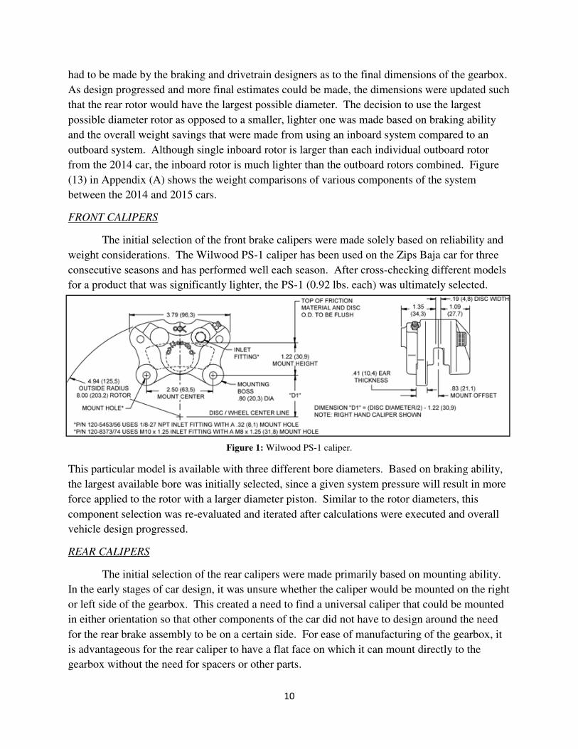
The initial selection of the front brake calipers were made solely based on reliability and
weight considerations. The Wilwood PS-1 caliper has been used on the Zips Baja car for three
consecutive seasons and has performed well each season. After cross-checking different models
for a product that was significantly lighter, the PS-1 (0.92 lbs. each) was ultimately selected.
Figure 1: Wilwood PS-1 caliper.
This particular model is available with three different bore diameters. Based on braking ability,
the largest available bore was initially selected, since a given system pressure will result in more
force applied to the rotor with a larger diameter piston. Similar to the rotor diameters, this
component selection was re-evaluated and iterated after calculations were executed and overall
vehicle design progressed.
REAR CALIPERS
The initial selection of the rear calipers were made primarily based on mounting ability.
In the early stages of car design, it was unsure whether the caliper would be mounted on the right
or left side of the gearbox. This created a need to find a universal caliper that could be mounted
in either orientation so that other components of the car did not have to design around the need
for the rear brake assembly to be on a certain side. For ease of manufacturing of the gearbox, it
is advantageous for the rear caliper to have a flat face on which it can mount directly to the
gearbox without the need for spacers or other parts.

11
Extra parts not only take more time and money to manufacture, but a tolerance stack-up of
multiple parts could lead to rotor misalignment in the caliper. With these design considerations
in mind and also the desire to remain with one manufacturer for the calipers and master cylinder,
the Wilwood Billet Go-Kart caliper was selected.
Figure 2: Wilwood Billet Go-Kart caliper.
MASTER CYLINDER
The major decision that has to be made when selection a master cylinder is whether to
use separate cylinders for the front and the rear circuits or to use one tandem cylinder that serves
both. The Baja SAE Rules document states that the front and rear circuits must be completely
independent of each other so that if a leak should occur in one circuit, the other one will remain
in working order. Both types of systems fulfill this requirement, but the pros and cons of each
have to be considered before making a selection.
The first type of system is one with two separate cylinders. This type of system has
historically been the most common at past SAE Baja competitions. These cylinders can be very
small with reservoirs mounted directly to the top. This is advantageous in terms of weight and
ergonomics. One disadvantage is the need for a bias bar system. Since weight is transferred
during deceleration, there is generally a need for different braking abilities in the front and rear
circuits, leading to the need for different pressures. Since there is only one brake pedal, there
must be a way to adjust the amount of pressure being created in each circuit. A bias bar is
essentially an adjustable linkage between the brake pedal and the two cylinders. The bar can be
angled such that more or less of the overall pressure created by the stroke of the foot is made in
each cylinder. Disadvantages of this assembly include difficulty of adjustment, space
consumption, and creating extra system components that can be broken during competition.

12
The second type of system is one with a single tandem cylinder. Although there is only
one cylinder, it houses two separate chambers, each with their own reservoir inlet and circuit
outlet, that are pressurized by the same plunge rod. Figure (3) shows a schematic of the inside of
a tandem master cylinder.
Figure 3: Tandem master cylinder
schematic.
As shown in Figure (3), the same force pushes on both pistons and pressurized both the front and
rear circuits. Although the diagram shows a leak in the front circuit, the rear circuit remains
fully functional. The overall size of a tandem master cylinder is comparable to the combined
size of two separate single cylinders. One disadvantage of the tandem cylinder could possibly be
its orientation, depending on the setup of the front box of the vehicle. Separate single cylinders
are able to be mounted side by side and can often fit behind the brake pedal from the perspective
of the driver. The tandem master cylinder is long in comparison and cannot fit behind the pedals
without severely compromising the design of the front end of the car. The possible disadvantage
of a tandem master cylinder’s shape could be avoided by orienting it such that the cylinder and
the driver’s foot acted on opposite sides of the pivot point. Figure (4) below illustrates the
possible orientations of the cylinder in relation to the pivot point of the pedal.
13
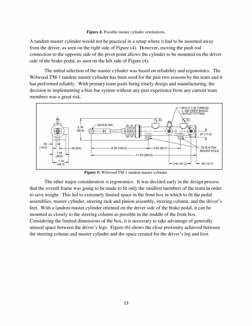
Figure 4: Possible master cylinder orientations.
A tandem master cylinder would not be practical in a setup where it had to be mounted away
from the driver, as seen on the right side of Figure (4). However, moving the push rod
connection to the opposite side of the pivot point allows the cylinder to be mounted on the driver
side of the brake pedal, as seen on the left side of Figure (4).
The initial selection of the master cylinder was based on reliability and ergonomics. The
Wilwood TM-1 tandem master cylinder has been used for the past two seasons by the team and it
has performed reliably. With primary team goals being timely design and manufacturing, the
decision to implementing a bias bar system without any past experience from any current team
members was a great risk.
Figure 5: Wilwood TM-1 tandem master cylinder.
The other major consideration is ergonomics. It was decided early in the design process
that the overall frame was going to be made to fit only the smallest members of the team in order
to save weight. This led to extremely limited space in the front box in which to fit the pedal
assemblies, master cylinder, steering rack and pinion assembly, steering column, and the driver’s
feet. With a tandem master cylinder oriented on the driver side of the brake pedal, it can be
mounted as closely to the steering column as possible in the middle of the front box.
Considering the limited dimensions of the box, it is necessary to take advantage of generally
unused space between the driver’s legs. Figure (6) shows the close proximity achieved between
the steering column and master cylinder and the space created for the driver’s leg and foot.

14
PROPORTIONING VALVE
The decision to use a tandem master cylinder necessitated the use of a proportioning
valve. A proportioning valve essentially regulates the fluid flow in a circuit by partially blocking
the fluid passage.
Figure 7: Wilwood
Adjustable Proportioning Valve.
Since a proportioning valve can only be used to decrease the amount of pressure in a line, it must
be integrated into the rear circuit because it will require less pressure than the front circuit. This
particular model is able to decrease pressure to 57% of the full circuit pressure. When full
calculations were performed, the final estimated front and rear pressures were checked to make
sure that the rear pressure value was at least 57% of the front pressure value.
Figure 6: Top view of front box and cylinder orientation.
15
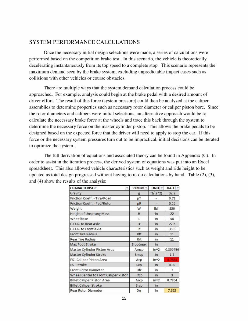
SYSTEM PERFORMANCE CALCULATIONS
Once the necessary initial design selections were made, a series of calculations were
performed based on the competition brake test. In this scenario, the vehicle is theoretically
decelerating instantaneously from its top speed to a complete stop. This scenario represents the
maximum demand seen by the brake system, excluding unpredictable impact cases such as
collisions with other vehicles or course obstacles.
There are multiple ways that the system demand calculation process could be
approached. For example, analysis could begin at the brake pedal with a desired amount of
driver effort. The result of this force (system pressure) could then be analyzed at the caliper
assemblies to determine properties such as necessary rotor diameter or caliper piston bore. Since
the rotor diameters and calipers were initial selections, an alternative approach would be to
calculate the necessary brake force at the wheels and trace this back through the system to
determine the necessary force on the master cylinder piston. This allows the brake pedals to be
designed based on the expected force that the driver will need to apply to stop the car. If this
force or the necessary system pressures turn out to be impractical, initial decisions can be iterated
to optimize the system.
The full derivation of equations and associated theory can be found in Appendix (C). In
order to assist in the iteration process, the derived system of equations was put into an Excel
spreadsheet. This also allowed vehicle characteristics such as weight and ride height to be
updated as total design progressed without having to re-do calculations by hand. Table (2), (3),
and (4) show the results of the analysis:

16
Table 2: System
parameters from Excel calculation spreadsheet.
Table 3: Calculated results from Excel calculation sheet.
Table 4: Braking force results from Excel calculation sheet.
DESIGN ITERATION AND OPTIMIZATION
Once results are generated, it is necessary to check several values in order to verify initial
design decisions. The primary values that need to be checked are the front and rear circuit
pressures. Due to weight transfer during deceleration, the braking force needed in the rear circuit
of vehicles is always less than the force needed in the front. Since proportioning valves can only
be used to decrease circuit pressure, and therefore decrease braking ability, they are almost
exclusively installed in rear brake circuits. If the rear circuit pressure is greater than the front
circuit pressure, the proportioning valve would have to be installed in the front circuit. Installing
this valve in the front circuit would most likely draw criticism from competition judges and is
not generally good engineering practice.

17
After the first iteration of calculations, the rear pressure was indeed greater than the front
pressure. This was primarily due to the limitation of the rear rotor diameter. Since the rear rotor
diameter was already at the maximum value allowed by other subsystems, the rear line pressure
had to be reduced relative to the front line pressure another way. Because of the limited options
in the rear system components, the front system would have to be changed to fix the problem.
Since the rear circuit pressure needed to decrease relative to the front circuit pressure, the same
result could be achieved by leaving the rear system unchanged and increasing the pressure in the
front circuit. There are two main changes that can be made to increase the necessary pressure in
the circuit. One way is to decrease the rotor diameter. Since the moment arm between the
caliper and the center of the wheel would be decreased, the force applied to the rotor would have
to be increased by increasing the pressure.
However, at this point in design, the upright onto which the caliper mounts was in the late
stages of design, and changing the caliper mounting hole location due to a change in rotor
diameter would add weeks to the design process. In the interest time, the circuit pressure had to
be increased another way. This alternative way to increase necessary circuit pressure is to
decrease the caliper bore size. A decrease in the piston area would require more pressure in
order to achieve the same caliper force. The initially selected front caliper (Wilwood PS-1) is
available in several different bore sizes while maintaining the same outer dimensions and
mounting hole locations. Tables (2), (3), and (4) show the results of the calculations with the
new caliper. The cell highlighted red in Table (2) shows the caliper piston area of the new
caliper, which has a bore diameter of 1.00 inches compared to the initial choice caliper that had a
bore diameter of 1.12 inches. The cells highlighted blue in Table (3) show the pressures in the
front and rear circuits. The rear pressure is lower than the front pressure, and the proportioning
valve would then be installed in the rear circuit provide the lower pressure. It is also seen that
the rear pressure is at least 57% as high as the front pressure, which justifies the particular model
of valve that was initially selected and is shown on Page 13.
BRAKE & THROTTLE PEDAL DESIGN
Once the system calculation process was complete and the necessary force applied by the
master cylinder’s plunge rod is known, the brake pedal could be designed. Two performance
characteristics were considered during the design process. One is the force that needs to be
applied by the driver. A very high force is inconvenient for the driver and can become
exhausting over the course of a four-hour endurance race. Also, because of the placement of the
master cylinder (towards the center of the front box), the pedal had to be designed in an “L”
shape such that the driver’s foot could be oriented in a natural position (See Figure (10). This
pedal shape will cause bending about multiple axes and would require a very robust design if
large forces were required every time the driver wanted to stop the car. The other performance
consideration is the foot stroke. One criticism of last year’s car was that the brake pedal had a

18
stroke of almost zero, and this was the biggest contributor to the “all or nothing” braking ability
of the car. If the design goal of having intermediate braking capabilities was to be achieved, the
pedal stroke needed to be increased.
Both of the performance characteristics could be achieved by selecting a favorable
mechanical advantage. A brake pedal such that the location of the driver’s applied force and the
attachment to the master cylinder are on opposite sides of the pivot point is shown in Figure (8).
Figure 8: Schematic of generic brake pedal.
Taking moments about the pivot point and manipulating yields the following:
�
��
���
����
The ratio given above is the mechanical advantage of the pedal, or pedal ratio. The inverse of
this ratio is also the ratio of the stroke of the foot to the stroke of the cylinder:
�
��
���
��
It can be seen that a higher pedal ratio would be advantageous for both the driver’s force and the
pedal stroke. A higher ratio will result in lower driver force and longer foot stroke. Using the
calculated master cylinder force and a desired driver force, the ideal ratio is found. With this
number, any combination of A and B dimensions can be chosen to satisfy the pedal ratio based
on the available space in the vehicle.
A few considerations had to be made when selecting the A and B dimensions. One is the
vertical space limitations. One of the system design goals was to have the entire brake assembly
sit lower in the front box in order to improve the driver’s view out of the front of the car. This
limits the location of the of the attachment point between the pedal and the master cylinder in the

elevation plane. The bottom of the pedal is constrained by the size of the driver’s foot. The
contact point between the driver’s foot and the pedal must be at a comfortable height for th
driver such that the appropriate amount of force can be applied easily for extended periods of
time. At the beginning of the design process, a replica of the frame was made out of foam
members to ensure that the design would be comfortable and to check
relative to the driver in compliance with official Baja SAE regulations. Using this replica, the
ideal position of the brake and throttle pedals and the ideal strokes were measured
drivers were sitting in the frame repli
Figure 9:
These measurements gave the location of the bottom of the brake pedal in the elevation plane
and also a desired value for the foot stroke (approximately one inch). Using the
stroke of the master cylinder when the system was fully pres
inches. Using this as an estimate for the 2015 car, the necessary pedal ratio according to stroke
preferences was approximately 2.67
checked in terms of forces. With the estimated master cylinder force being 173.78 lbs.
Table 3) a pedal ratio of 2.67 would result in a necessary driver effort of approximately
This driver force is low enough to be easily applied
the driver can still have a feel for the peda
With an appropriate pedal ratio and ideal locations for the top and bottom of
the final distances between the foot location, pivot point, and master cylinder connection were
established.
The final step of pedal design was to
stress analysis. This analysis consisted of several FEA trials until an appropriate safety factor
was reached with respect to yielding when using a worst
lbs. of force applied by the driver. Adjustments between trials consisted of adjusting thickness
19
elevation plane. The bottom of the pedal is constrained by the size of the driver’s foot. The
contact point between the driver’s foot and the pedal must be at a comfortable height for th
driver such that the appropriate amount of force can be applied easily for extended periods of
time. At the beginning of the design process, a replica of the frame was made out of foam
o ensure that the design would be comfortable and to check certain frame dimensions
relative to the driver in compliance with official Baja SAE regulations. Using this replica, the
brake and throttle pedals and the ideal strokes were measured
replica.
Foam frame replica used in early design process.
These measurements gave the location of the bottom of the brake pedal in the elevation plane
red value for the foot stroke (approximately one inch). Using the
stroke of the master cylinder when the system was fully pressurized was measured to be 0.375
inches. Using this as an estimate for the 2015 car, the necessary pedal ratio according to stroke
preferences was approximately 2.67. Before this could be finalized, the ratio needed to be
With the estimated master cylinder force being 173.78 lbs.
would result in a necessary driver effort of approximately
low enough to be easily applied in a full-brake situation and high enough that
for the pedal’s location during intermediate braking situations
With an appropriate pedal ratio and ideal locations for the top and bottom of the pedal identified,
distances between the foot location, pivot point, and master cylinder connection were
The final step of pedal design was to find the necessary dimensions of the pedals through
nsisted of several FEA trials until an appropriate safety factor
was reached with respect to yielding when using a worst-case emergency brake scenario of 300
lbs. of force applied by the driver. Adjustments between trials consisted of adjusting thickness
elevation plane. The bottom of the pedal is constrained by the size of the driver’s foot. The
contact point between the driver’s foot and the pedal must be at a comfortable height for the
driver such that the appropriate amount of force can be applied easily for extended periods of
time. At the beginning of the design process, a replica of the frame was made out of foam
certain frame dimensions
relative to the driver in compliance with official Baja SAE regulations. Using this replica, the
brake and throttle pedals and the ideal strokes were measured while the
These measurements gave the location of the bottom of the brake pedal in the elevation plane
red value for the foot stroke (approximately one inch). Using the 2014 car, the
surized was measured to be 0.375
inches. Using this as an estimate for the 2015 car, the necessary pedal ratio according to stroke
ould be finalized, the ratio needed to be
With the estimated master cylinder force being 173.78 lbs. (see
would result in a necessary driver effort of approximately 65 lbs.
and high enough that
during intermediate braking situations.
the pedal identified,
distances between the foot location, pivot point, and master cylinder connection were
find the necessary dimensions of the pedals through
nsisted of several FEA trials until an appropriate safety factor
case emergency brake scenario of 300
lbs. of force applied by the driver. Adjustments between trials consisted of adjusting thickness

20
and depth
of the main
arm of the
pedal as
well as
adjusting
the sizes
and spacing
of weight-
saving
cutouts.
Figure (10)
shows the
initial pedal
geometry
and the
final design
of the brake
pedal. Full FEA analysis results can be seen in Appendix (B).
Figure 10: (LEFT) Initial dimensions based on pedal ratio. (RIGHT) Final brake pedal design.
21
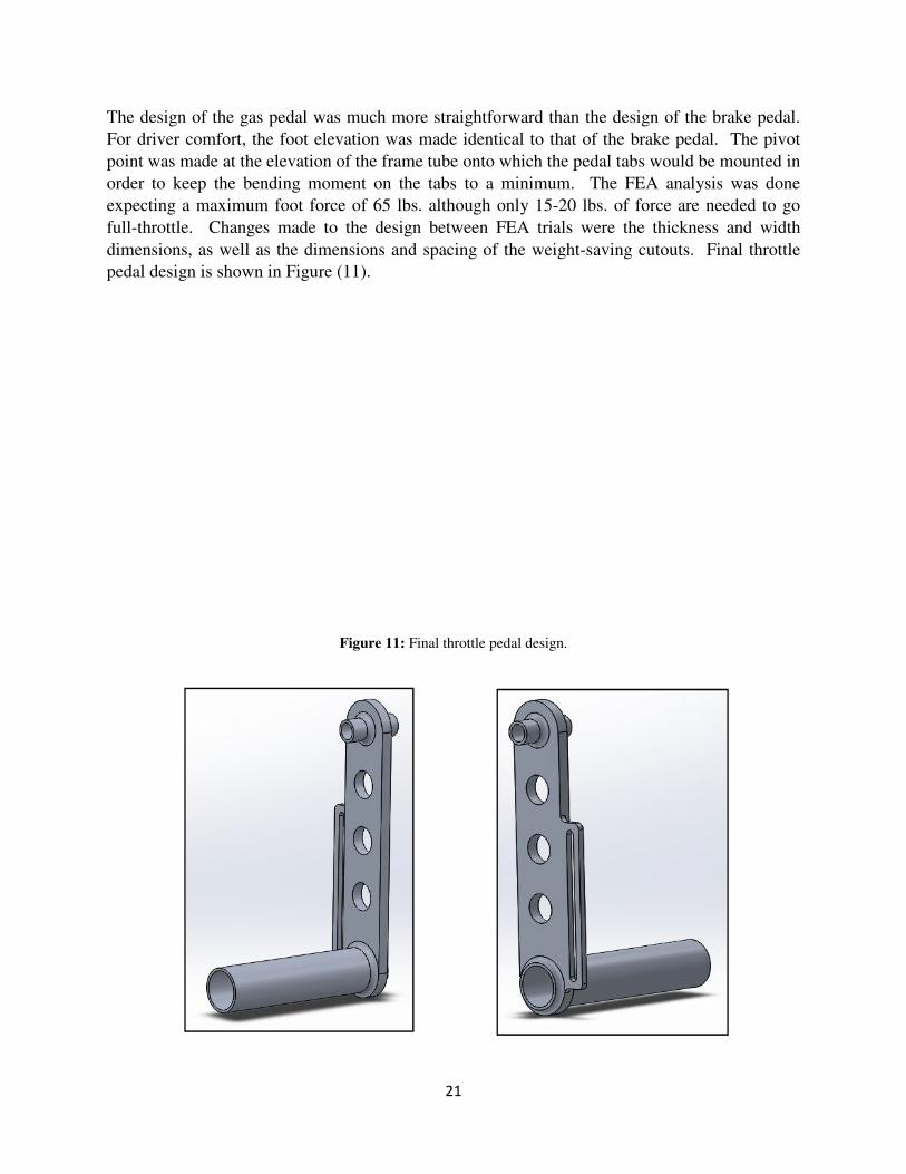
The design of the gas pedal was much more straightforward than the design of the brake pedal.
For driver comfort, the foot elevation was made identical to that of the brake pedal. The pivot
point was made at the elevation of the frame tube onto which the pedal tabs would be mounted in
order to keep the bending moment on the tabs to a minimum. The FEA analysis was done
expecting a maximum foot force of 65 lbs. although only 15-20 lbs. of force are needed to go
full-throttle. Changes made to the design between FEA trials were the thickness and width
dimensions, as well as the dimensions and spacing of the weight-saving cutouts. Final throttle
pedal design is shown in Figure (11).
Figure 11: Final throttle pedal design.

22
Competition Results and Adjustments
The 2015 Zips SAE Baja car raced in the first of three national competitions in Auburn,
Alabama in mid-April. None of the subsystems experienced catastrophic failure during the
competition as the team earned a 37th
place finish overall out of 105 teams with strong 7th
place
and 13th
place finishes in the suspension and hill climb events, respectively. Both the static and
dynamic brake tests were passed on the first attempt. By the end of the competition, however, it
was clear that several changes needed to be made to the brake and throttle system.
First, both the brake and throttle pedals had been deformed due to torsion. This was
expected to an extent because of the L-shaped design, but the cross-sectional dimensions of both
pedals were increased for the next competition.
The biggest problem of the entire event was the throttle cable. The cable pulled out of its
rear connection multiple times during competition which resulted in time spent racing at less
than full-throttle. The tab in the front box that holds the end of the cable sleeve was also
severely bent, which caused the cable to not return properly into the sleeve. To fix these issues,
a new tab was made for the sleeve that spans between two tubes in the front box instead of being
cantilevered from one tube like the original tab. This adjustment will significantly decrease the
risk of bending during competition, especially if the tab is inadvertently kicked by the driver. It
was discovered that the cable was pulling out of its rear attachment because the set-screw that is
used to hold the cable in place was not making sufficient contact with the cable. To fix this, a
small piece of metal was placed in the set-screw hole before the screw was put in and tightened.
This resulted in a greater contact area with the cable and less slippage.
The other major problem was the wear of the front rotors and front brake pads. By the
end of the competition, there was no brake pad material left at all, and the rotors had worn by
several thousandths. It is believed that the cutout pattern of the rotors possessed too many edges
on which the brake pad could scrape. For the next competition, the cutout pattern has been
changed to feature less edges, and the thickness of the rotors was increased slightly to ensure that
the rotor will still be above the minimum thickness specified by the caliper manufacturer even if
they are worn during competition. The original front rotor design used at the first competition
and the modified design that will be used at the second competition are shown in Figure (12) on
the next page.

Figure 12: (LEFT) Original front rotor design. (RIGHT) Modified front rotor design.
All of these changes will be monitored very carefully during testing leading up to the second
competition in order to verify that sufficient adjustments have been made.
Conclusion
The SAE Baja student design team allows BSME candidates to execute all aspects of a
design project from start to finish. Beginning with the full design process, the tea
goals that reflected the desired performance characteristics of the car. A full CAD model was
generated and stress analysis was performed on all components. During the manufacturing
process, the team machined and fabricated many elements of
students also had to deal with business and logistical issues such as acquiring raw materials and
commercial parts, communicating
and metal cutting, and coordinating with other university groups to get time in the machine shop.
In competition, the team found success, but also identified modifications that needed to be made
to optimize the performance of the car. The performance of the vehicle with these modi
will be closely monitored during testing and competition and optimization will continue this year
and in years to come.
The design and manufacturing processes of the braking and throttle system in particular
has been a similarly iterative process. Modifications were made during the design process as
concessions had to be made with other subsystems according to the best int
the overall design goals. The initial design process and the modification process after analyzing
the system’s performance have brought the system closer to optimal, but this iterative
optimization process will theoretically continue
the next group of system designers and the process will continue, as The University of Akron
Zips SAE Baja Team grows closer to the perennially elite
23
(LEFT) Original front rotor design. (RIGHT) Modified front rotor design.
All of these changes will be monitored very carefully during testing leading up to the second
competition in order to verify that sufficient adjustments have been made.
The SAE Baja student design team allows BSME candidates to execute all aspects of a
design project from start to finish. Beginning with the full design process, the tea
goals that reflected the desired performance characteristics of the car. A full CAD model was
generated and stress analysis was performed on all components. During the manufacturing
process, the team machined and fabricated many elements of the car. Besides the physical work,
students also had to deal with business and logistical issues such as acquiring raw materials and
communicating with businesses that provided services such as gear machining
dinating with other university groups to get time in the machine shop.
In competition, the team found success, but also identified modifications that needed to be made
the car. The performance of the vehicle with these modi
will be closely monitored during testing and competition and optimization will continue this year
The design and manufacturing processes of the braking and throttle system in particular
has been a similarly iterative process. Modifications were made during the design process as
concessions had to be made with other subsystems according to the best interests of the car and
The initial design process and the modification process after analyzing
the system’s performance have brought the system closer to optimal, but this iterative
optimization process will theoretically continue indefinitely. The knowledge has been passed to
the next group of system designers and the process will continue, as The University of Akron
eam grows closer to the perennially elite status.
(LEFT) Original front rotor design. (RIGHT) Modified front rotor design.
All of these changes will be monitored very carefully during testing leading up to the second
The SAE Baja student design team allows BSME candidates to execute all aspects of a
design project from start to finish. Beginning with the full design process, the team set design
goals that reflected the desired performance characteristics of the car. A full CAD model was
generated and stress analysis was performed on all components. During the manufacturing
the car. Besides the physical work,
students also had to deal with business and logistical issues such as acquiring raw materials and
businesses that provided services such as gear machining
dinating with other university groups to get time in the machine shop.
In competition, the team found success, but also identified modifications that needed to be made
the car. The performance of the vehicle with these modifications
will be closely monitored during testing and competition and optimization will continue this year
The design and manufacturing processes of the braking and throttle system in particular
has been a similarly iterative process. Modifications were made during the design process as
erests of the car and
The initial design process and the modification process after analyzing
the system’s performance have brought the system closer to optimal, but this iterative
indefinitely. The knowledge has been passed to
the next group of system designers and the process will continue, as The University of Akron

24
APPENDIX A
ADDITIONAL GRAPHS AND FIGURES
Figure 13: Weight comparisons between 2014 and 2015 Zips Baja vehicles.

25
APPENDIX B
FEA ANALYSIS AND RESULTS
BRAKE PEDAL:
The brake pedal FEA analysis was conducted with a hinge connection at the pivot point, a fixed
geometry connection at the master cylinder connection location, and an external force at the foot
bar. A force of 300 lbs. was used to simulate an emergency stop situation. A final safety factor
of 1.8 was achieved with respect to yield in the worst-case scenario.

26
THROTTLE PEDAL:
The throttle pedal FEA analysis was conducted with a hinge connection at the pivot point, a
fixed geometry connection at the location of the mechanical stop, and an external force at the
foot bar. A force of 65 lbs. was used to simulate three-times as much force as needed to fully
engage the throttle. A final safety factor of 2.2 as achieved with respect to yielding.
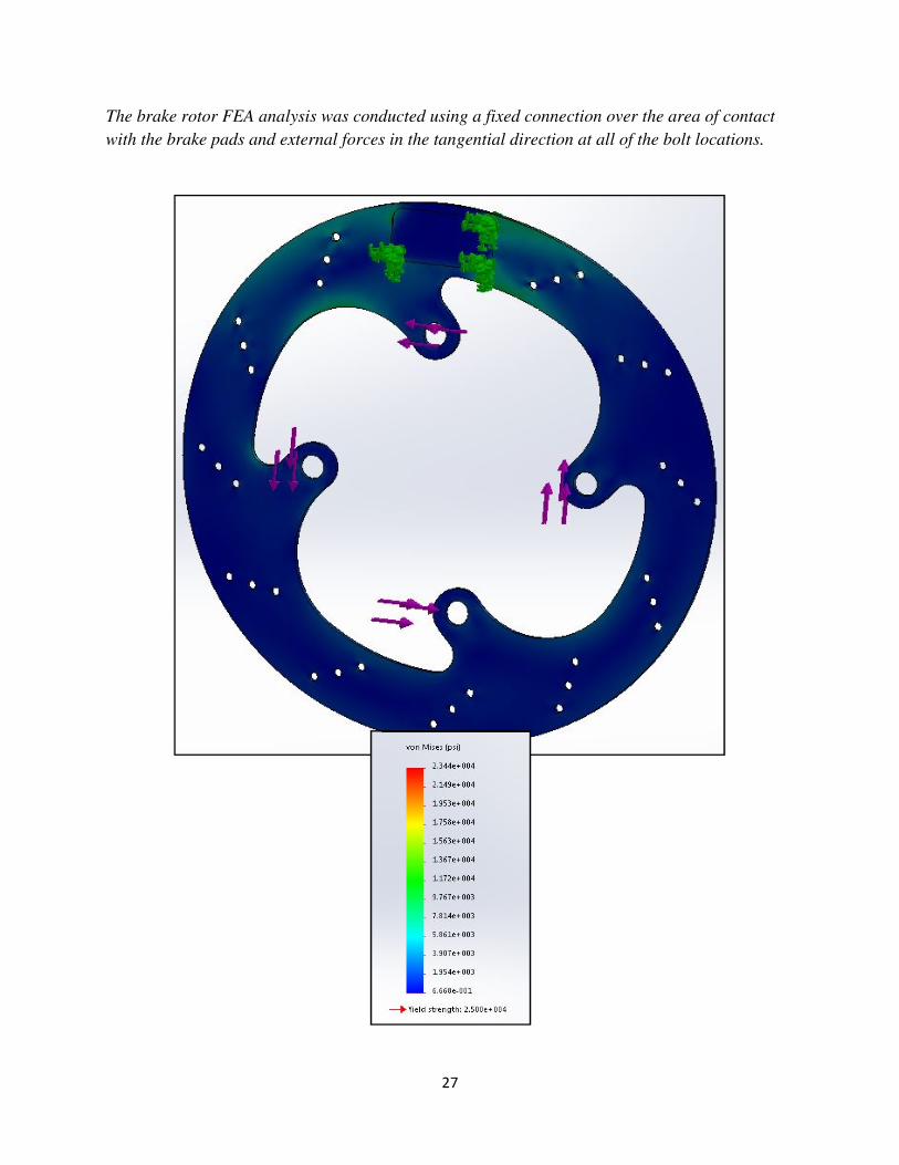
BRAKE ROTORS:
27
The brake rotor FEA analysis was conducted using a fixed connection over the area of contact
with the brake pads and external forces in the tangential direction at all of the bolt locations.
28
APPENDIX C
THEORY & DERIVATIONS
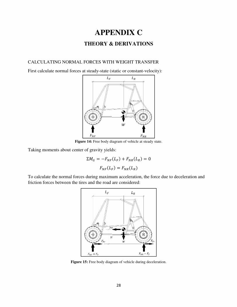
CALCULATING NORMAL FORCES WITH WEIGHT TRANSFER
First calculate normal forces at steady-state (static or constant-velocity):
Figure 14: Free body diagram of vehicle at steady state.
Taking moments about center of gravity yields:
� � �������� � ������� � 0
������� � �������
To calculate the normal forces during maximum acceleration, the force due to deceleration and
friction forces between the tires and the road are considered:
Figure 15: Free body diagram of vehicle during deceleration.
29
(1)
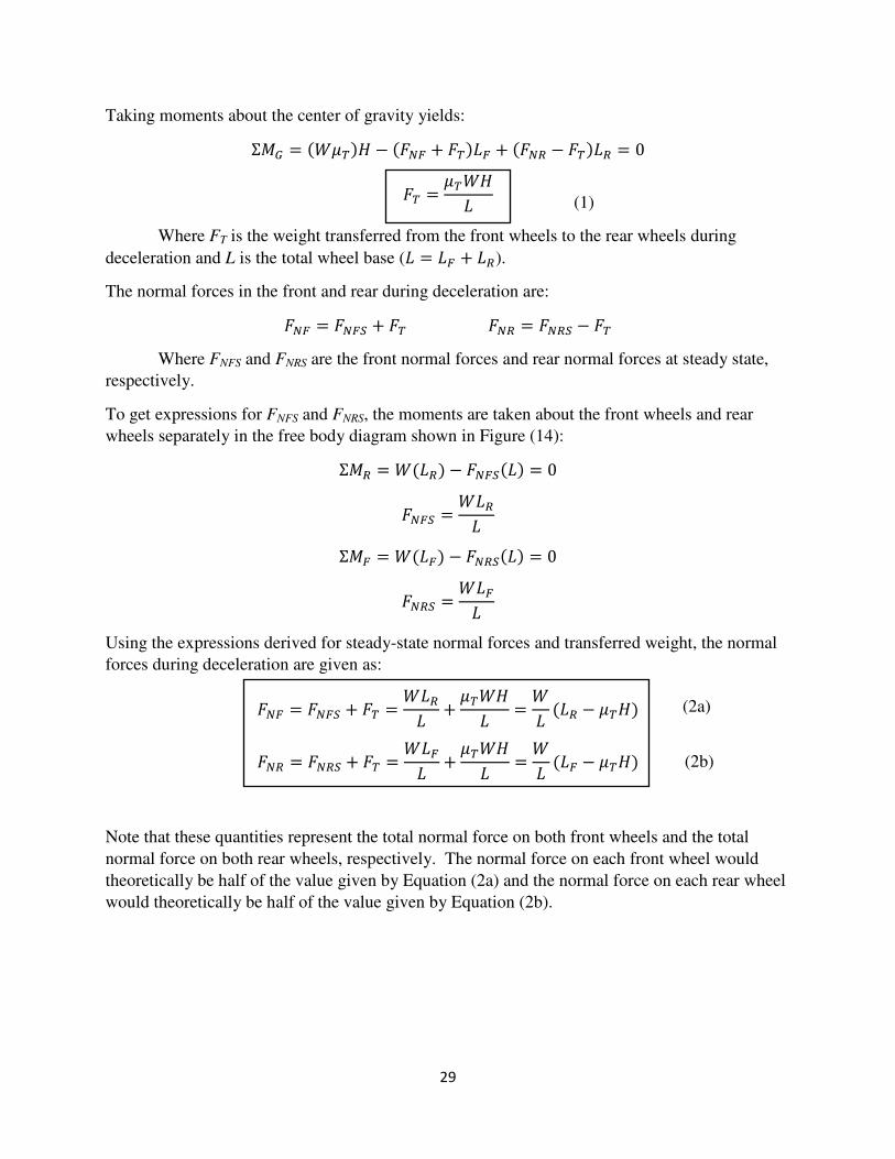
Taking moments about the center of gravity yields:
� � ������ � ���� � ����� � ���� � ����� � 0
�� �����
�
Where FT is the weight transferred from the front wheels to the rear wheels during
deceleration and L is the total wheel base (� � �� � ��).
The normal forces in the front and rear during deceleration are:
��� � ���� � �� ��� � ���� � ��
Where FNFS and FNRS are the front normal forces and rear normal forces at steady state,
respectively.
To get expressions for FNFS and FNRS, the moments are taken about the front wheels and rear
wheels separately in the free body diagram shown in Figure (14):
�� � ����� � ������� � 0
���� ����
�
�� � ����� � ������� � 0
���� ����
�
Using the expressions derived for steady-state normal forces and transferred weight, the normal
forces during deceleration are given as:
��� � ���� � �� ����
��
����
��
�
���� � ����
��� � ���� � �� ����
��
����
��
�
���� � ����
Note that these quantities represent the total normal force on both front wheels and the total
normal force on both rear wheels, respectively. The normal force on each front wheel would
theoretically be half of the value given by Equation (2a) and the normal force on each rear wheel
would theoretically be half of the value given by Equation (2b).
(2a)
(2b)

30
CALCULATING FRONT CALIPER FORCES AND FRONT CIRCUIT PRESSURE
To calculate the necessary force applied by the caliper squeezing onto the rotor, consider the free
body diagram of the front wheel assemblies during deceleration:
Figure 16: Free body diagram of front wheel assemblies during deceleration. (Courtesy of Dr. R. Gross)
Taking moments about the center of the wheel gives:
�� � ���������� � ����������
���� �����������
����
This force represents the force that is applied in the tangential direction when the caliper clamps
onto the rotor. This force acts at a distance from the center of the wheel that is equal to the
average diameter of the rotor, where the brake pads make contact with the rotor. Note that this
force represents the total force on both front assemblies combined (due to all four brake pads).
This force can also be written in terms of the friction force between the brake pads and the rotor
using the normal force of the caliper pistons and the friction coefficient between the pads and
rotor:
���� � �� �����
Where FNFCP is the force applied by all four front caliper pistons perpendicular to the face of the
brake rotor. This force applied by the pistons can also be found in terms of the piston area and
the pressure in the front brake circuit:
����� � !��4 �����
Where AFCP is the bore of the front calipers and pF is the pressure in the front brake circuit.
(3a)
(3b)
(3c)

31
Combining Equations (3a), (3b), and (3c) gives the pressure needed in the front circuit:
!� ������
4����
�����
4������
���������
�������4 �����
!� ���������
�������4 �����
Once the master cylinder is selected, the force that needs to be applied to the master cylinder
piston in order to create the necessary pressure can be calculated:
���� � !����
CALCULATING REAR CALIPER FORCES AND REAR CIRCUIT PRESSURE
First consider the torque applied to the rear wheel assemblies due to the friction between the tire
and the road:
Figure 17: Free body diagram of rear wheel assemblies during deceleration. (Courtesy of Dr. R. Gross)
In Figure (17), the torque, T, applied to the wheel is applied by the axle that is experiencing
angular deceleration due to the inboard rear brake. The rear brake is applied to the final output
shaft of the gear box. This torque is transmitted to the wheels as it is shown in the figure above
through the CV axles.
Taking moments about the center of the wheel gives:
�� � ���������� � # � 0
# � ����������
(3)
(5a)
(4)

32
This torque represents the total torque that needs to be applied by the axles on the rear wheel
assemblies. Figure (18) shows the free body diagram of the rear brake assembly that is attached
to the final output axle of the gear box.
Figure 18: Free body diagram of rear brake assembly.
The torque shown in in Figure (18) is the torque applied on the axle by the friction force acting
between the tires and the ground. This is the same torque magnitude as the one described in
Figure (17) on the axle. This torque is essentially generated on the axle by the opposing
moments of the friction force between the wheels and the ground and the tangential force applied
by the caliper on the rear rotor (which is rigidly attached to the axle).
Taking the moment about the center of the shaft gives:
�� � # � �������� � 0
# � ��������
Setting Equations (5a) and (5b) equal and rearranging gives:
���� �����������
����
This force can also be written in terms of the friction force between the brake pads and the rotor
using the normal force of the caliper pistons and the friction coefficient between the pads and
rotor:
���� � �� �����
Where FNRCP is the force applied by both rear caliper pistons perpendicular to the face of the
brake rotor. This force applied by the pistons can also be found in terms of the piston area and
the pressure in the rear brake circuit:
����� � !��2 �����
Where ARCP is the bore of the rear caliper and pR is the pressure in the rear brake circuit.
(5b)
(5)
(6b)
(6a)
33
Combining Equations (5), (6a), and (6b) gives the pressure needed in the rear circuit:
!� ������
2����
�����
2������
���������
�������2 �����
!� ���������
�������2 �����
Since a tandem master cylinder is being used, the force of the master cylinder piston is applied to
the front and rear circuits. The theoretical pressure created by this force in the rear circuit is
given as:
!� �����
���
Note that this pressure is not necessarily (and not likely) the same as the necessary pressure
given by Equation (6). The weight transfer of the vehicle from rear to front during deceleration
leads to a greater necessary braking force in the front and, most likely, more pressure. For this
reason, the proportioning valve is built into the rear circuit to reduce the pressure in the rear
circuit.
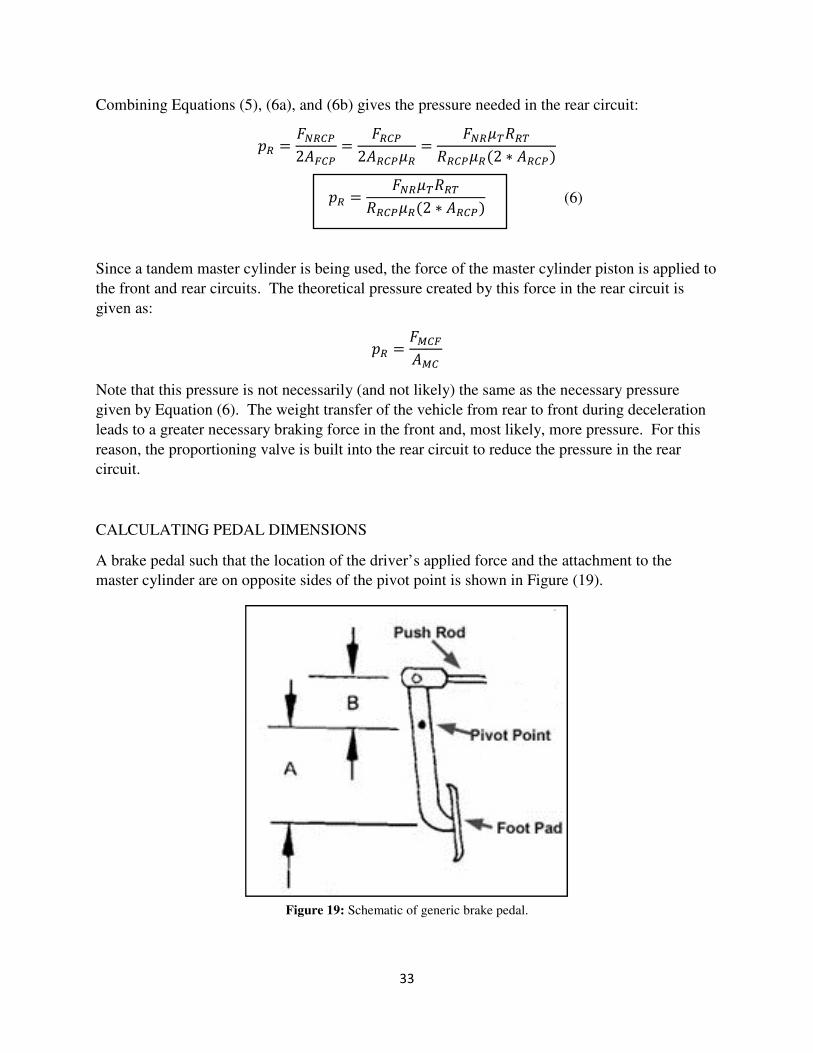
CALCULATING PEDAL DIMENSIONS
A brake pedal such that the location of the driver’s applied force and the attachment to the
master cylinder are on opposite sides of the pivot point is shown in Figure (19).
Figure 19: Schematic of generic brake pedal.
(6)
34
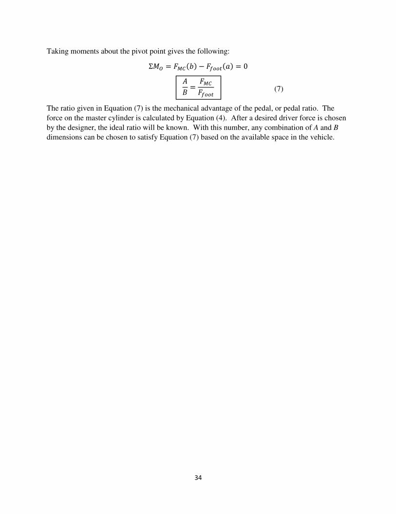
Taking moments about the pivot point gives the following:
�� � ����%� � �����&� � 0
�
��
���
����
The ratio given in Equation (7) is the mechanical advantage of the pedal, or pedal ratio. The
force on the master cylinder is calculated by Equation (4). After a desired driver force is chosen
by the designer, the ideal ratio will be known. With this number, any combination of A and B
dimensions can be chosen to satisfy Equation (7) based on the available space in the vehicle.
(7)

35
APPENDIX D
2015 SAE BAJA COMPETITION REGULATIONS
ARTICLE 11: BRAKING SYSTEM
ARTICLE 11: BRAKING SYSTEM B11.1 Foot Brake
The vehicle must have hydraulic braking system that acts on all wheels and is operated by a single foot pedal. The pedal
must directly actuate the master cylinder through a rigid link (i.e., cables are not allowed). The brake system must be
capable of locking ALL FOUR wheels, both in a static condition as well as from speed on pavement AND on unpaved
surfaces.
B11.2 Independent Brake Circuits
The braking system must be segregated into at least two (2) independent hydraulic circuits such that in case of a leak or
failure at any point in the system, effective braking power shall be maintained on at least two wheels. Each hydraulic
circuit must have its own fluid reserve either through separate reservoirs or by the use of a dammed, OEM-style reservoir.
B11.3 Brake(s) Location
The brake(s) on the driven axle must operate through the final drive. Inboard braking through universal joints is permitted.
Braking on a jackshaft through an intermediate reduction stage is prohibited
B11.4 Cutting Brakes
Hand or feet operated “cutting brakes” are permitted provided the section (B11.1) on “foot brakes” is also satisfied. A
primary brake must be able to lock all four wheels with a single foot. If using two separate pedals to lock 2 wheels apiece;
the pedals must be close enough to use one foot to lock all four wheels. No brake, including cutting brakes, may operate
without lighting the brake light.
B11.5 Brake Lines
All brake lines must be securely mounted and not fall below any portion of the vehicle (frame, swing arm, A-arms, etc.)
Ensure they do not rub on any sharp edges. Plastic brake lines are prohibited