2014 hydraulic power packs ac & dc compact · 2019. 9. 10. · °option: relief valve, starter...
TRANSCRIPT

2014Hydraulic Power Packs
AC & DC Compact

± Complete focus on hydraulic components & modular power packs design, continuous research, development and innovation
± Expertise on hydraulic applications; design and development of customised solutions, including special manifolds, ex-proof units, proportional systems,...
± Organization fully based on processes and Total Quality Management principles, certified ISO 9001:2008 and ISO 50001:2011
± Lean and energy efficient product design and manufacturing
± Mass production and cost optimization: hundreds of thousands of Hydronit modular power packs are now reliably running worldwide
± Flexible marketing policy: supply of loose hydraulic components and power packs either in kit or fully assembled and tested in accordance with Machine Directive 2006/42/CE
± Distributors, associate companies and partners in over 50 countries worldwide
Why choose [email protected] · +39 02 320 625 145

Hydronit - The sustainable factory
± Production is carried out in a building of 313000 m requiring almost no use of
fossil fuels to operate
± The hyper insulation of the structure through the use of materials, mainly natural, such as wood and cork, ensures
3a consumption of only 7,4 kWh/m /year for winter heating and for summer cooling
3only 3,2 kWh/m /year
± A heat pump provides high efficiency thermal regulation
± A system of 60 solar panels on the roof of the offices provides 13,8 kW of electrical power that contributes about 60% of the electricity consumed by the plant for its own operation
± Solar thermal panels provide hot water
± The automatic wharehouses and the line of semi-automatic assembly increase efficiency, reduce process paperwork and human errors, thus ensuring compliance with stringent quality standards and repeatable test results
[email protected] · +39 02 320 625 145

Continuous innovation
Hydronit Srl, in the pursuit of excellence, have dedicated a large part of their profits to research and continuous development of the product, in order to increase the performance, efficiency, durability and reliability over time, and for the continuous improvement of the organization, constantly monitoring parameters over thirty indicators of the efficiency and effectiveness of the organization as a whole.
Exposure to salt spray > 300 hours
Treated manifold Nanotech Standard manifold
Nanotechnology surface treatment
Product Configurator
Hydronit Srl, in partnership with research institutions and external bodies, co-financed by the Lombardy Region, has initiated some years ago a project for the development of advanced applications of plasma surface treatment of metallic materials. In short it is the application of nanotechnology to hydraulic equipment to improve the performance of our units. We have obtained excellent results in the following fields: improvement of the pressure tightness of the aluminum die-casting; improvement of the characteristics of surface hardness of the treated components and a remarkable increase in the corrosion resistance of the surface. More information is available by contacting our sales department.
Hydronit Srl has developed over the years a smart Product Configurator which allows the user, from a PC or mobile device web browser:- to simply and quickly create the speaking code of the unit starting from the customer's specific requirements- to limit the possible errors in the product configuration- to obtain quickly the unit description and parts list, the hydraulic diagram, instant 3D preview, weight, dimensions, price and terms of sale. This facilitates a reduced time-to-market and provides full information on the power unit to be realized.
The access to the web configurator is offered free of charge to official partners of Hydronit Srl.
[email protected] · +39 02 320 625 145

Hydronit hydraulic range
Three main families: Power Pack Micro, Power Pack Compact, Electropumps Bull sharing the most core components allowing mass production and stock optimization.Design, research & development according to flexibility, modularity and efficiency principles.
° 0,15 ~ 4 kW, 12V e 24V DC motors (same used in Compact and Micro power packs)
° Forced ventilation for high cycle times° 0,19 ~ 7,9 cc/rev gear pumps (same used in Compact
and Micro power packs. Available also lateral ports pumps)
° Option: relief valve, starter witch, thermal protection, foot mounting support
AC & DC MICRO hydraulic power packs
DC electropumps
AC & DC COMPACT hydraulic power packs
° Extremely compact and lightweight° Flow: 0,2 ~ 6 l/min° Pressure up to 250 bar° DC motors up to 2,2 kW° AC motors up to 1,8 kW° High modularity: single & double acting & reversible
circuits from the same micro central manifold° Main valves on one side in most configurations for
enhanced positioning in small machines
° Over 10 years of serial production° Hundred of thousands of power packs running worldwide° Flow: 0,2 ~ 25 l/min° Low pressure drop° Pressure up to 300 bar (or more in special application)° DC motors up to 4 kW° AC motors up to 7,5 kW° High modularity: single & double acting & reversible
circuits from the same micro central manifold° Ideal choice for hydraulic distributors & assemblers
[email protected] · +39 02 320 625 145

POWER PACKS COMPACT speaking code
UB
Electric motor or Mounting kit
Power Pack Compact
Cavity 1Cavity 0Gear pumpCentral manifold
Cavity 2 Cavity 3 Cavity 4
PPC 2,2 24DC_S K1,2 J D_310 R5 U
Cav. 5 Cav. 6 Cav. 7 Cav. 8
X XXA24DC X
DC Motors
0,15 12DC 12VDC 150W
0,15 24DC 24VDC 150W
0,3 12DC 12VDC 300W
0,3 24DC 24VDC 300W
0,5 12DC 12VDC 500W
0,5 24DC 24VDC 500W
0,8 12DC 12VDC 800W
0,8 24DC 24VDC 800W
1,6 12DC 12VDC 1600W
2,1 12DC 12VDC 2100W
2,2 24DC 24VDC 2200W
3 24DC 24VDC 3000W
4 24DC 24VDC 4000W
2,5HD 12DC 12VDC 2500W
3HD 24DC 24VDC 3000W
4HD 24DC 24VDC 4000W
AC Motors Mounting Kits
XB14 71-0 B14 frame 71 + pump gr. 0
XB14 80-0 B14 frame 80 + pump gr. 0
XB14 71-1 B14 frame 71 + pump gr. 1
XB14 80-1 B14 frame 80 + pump gr. 1
XB14 90-1 B14 frame 80 + pump gr. 1
XB14 100-1 B14 frame 100/112 + p. gr. 1
X56C-0 Nema 56C + pump gr. 0
X56C-1 Nema 56C + pump gr. 1
XPU1401-0 pulley + pump gr. 0
XPU1401-1 pulley + pump gr. 1
DC Motors Options
_T thermal switch
_S starter switch
_FP fan cooler 1,6÷4kW
_MC plastic cover
AC 3 Phase Motors
E0,37AC 34 71 0,37kW S3 3 ph 4 poles
E0,55AC 34 71 0,55kW S3 3 ph 4 poles
E0,75AC 34 71 0,75kW S3 3 ph 4 poles
E1,1AC 34 80 1,1kW S3 3 ph 4 poles
E1,5AC 34 90 1,5kW S3 3 ph 4 poles
E2,2AC 34 90 2,2kW S3 3 ph 4 poles
E3,0AC 34 90 3kW S3 3 ph 4 poles
E4,0AC 34 100 4kW S3 3 ph 4 poles
E5,5AC 34 100 5,5kW S3 3 ph 4 poles
B14 7,5AC 34 112 7,5kW S3 3 ph 4 poles
AC Single Phase Motors
E0,37AC S4 71 0,37kW S3 1 ph 4 poles
E0,55AC S4 71 0,55kW S3 1 ph 4 poles
E0,75AC S4 80 0,75kW S3 1 h 4 poles
E1,1AC S4 90 1,1kW S3 1 ph 4 poles
E1,5AC S4 90 1,5kW S3 1 ph 4 poles
E2,2AC S4 90 2,2kW S3 1 ph 4 poles
E3,0AC S4 100 3kW S3 1 ph 4 poles
Central Manifolds
UA Universal A type with 3 lateral cavities
UB Universal B type with 5 lateral cavities
U4 Universal 4 type for 4 way cartridge valves
UR Universal R type for reversible pump
Cavity 0 Valves
J check valve 3/4-16UNF
S flow control valve
L plug 3/4-16UNF
N open plug with 1/4 BSPP open port
Cavity 1 Valves
D_* relief valve P (*= bar max)
XP closed plug for relief valve cavity
Cavity 0 options
MIR63*EM* pressure gauge +shut-off(*=bar max)
F401*W pressure switch (*=bar max)
Cavity 2 and Cavity 4 Valves
A NC 2/2 way poppet valve
B NC 2/2 way poppet valve + emergency
Q NO 2/2 way poppet valve
C NO 2/2 way poppet valve + emergency
D NC 2/2 way double poppet valve + emerg.
E lever operated 2/2 valve
EM lever operated 2/2 with microswitch
Z 2 way emergency button
S flow control valve
T* proportional flow control valve (*=VDC)
U hand pump 2cc/stroke
G closed plug
H closed plug with 1/4 BSPP exit port
N open plug with 1/4 BSPP open port
P plug passing through 1/4 BSPP exit port
L plug 3/4-16UNF
J check valve 3/4-16UNF
Cavity 3 Valves
AR NC 2/2 way poppet valve reverse flow
BR NC 2/2 way poppet valve+em. reverse flow
CR NO 2/2 way poppet valve+em. reverse flow
D NC 2/2 way double poppet valve+emerg.
Z 2 way emergency button
F* fixed pressure comp. flow control (*=l/min)
R* pressure comp. flow control (*=l/min)
S flow control valve
P* prop. relief valve + emergency (*= bar max)
V* relief valve (*= bar max)
G closed plug
H closed plug with 1/4 BSPP exit port
N open plug with 1/4 BSPP open port
P plug passing through 1/4 BSPP exit port
L plug 3/4-16UNF
J check valve 3/4-16UNF
Cavity 2 Valves (U4 Central Manifolds)
4VA11C 4/2 way directional valve
4VA2 4/3 way directional valve , center P to T
4VB2 4/3 way directional valve, closed center
4VC2 4/3 way directional valve, H center
4VE2 4/3 way directional valve, center A-B to T
Solenoid Valves Coils
12DC 12V direct current
24DC 24V direct current
24AC 24V alternate current 50 or 60Hz
115AC 115V alternate current 50 or 60Hz
230AC 230V alternate current 50 or 60Hz
Cavity 5 - 6 - 7 - 8 Valves
1(04) 1 l/min pres. comp. flow cont. ø 12,7
1,5(04) 1,5 l/min pres.comp.flow cont. ø12,7
2(04) 2 l/min pres. comp. flow cont. ø 12,7
3(04) 3 l/min pres. comp. flow cont. ø 12,7
5(04) 5 l/min pres. comp. flow cont. ø 12,7
7(04) 7 l/min pres. comp. flow cont. ø 12,7
10(04) 10 l/min pres.comp.flow cont. ø 12,7
13(04) 13 l/min pres.comp.flow cont. ø 12,7
17(04) 17 l/min pres.comp.flow cont. ø 12,7
22(04) 22 l/min pres.comp.flow cont. ø 12,7
1(01) 1 l/min 1/4 BSPP p. comp. flow ctrl
1,5(01) 1,5 l/min 1/4 BSPP p. comp. flow
2(01) 2 l/min 1/4 BSPP p. comp. flow ctrl
3(01) 3 l/min 1/4 BSPP p. comp. flow ctrl
5(01) 5 l/min 1/4 BSPP p. comp. flow ctrl
7(01) 7 l/min 1/4 BSPP p. comp. flow ctrl
10(01) 10 l/min 1/4 BSPP p. comp. flow ctrl
13(01) 13 l/min 1/4 BSPP p. comp. flow ctrl
17(01) 17 l/min 1/4 BSPP p. comp. flow ctrl
22(01) 22 l/min 1/4 BSPP p. comp. flow ctrl
P01 1/4 BSPP plug
RETURN-KIT suction/return line pipe
PP01370 suction/return line pipe
RF01 return line immersed filter
Central Manifolds Options
US SAE06 port for North American market
Gear Pumps
K0,2 0,26 cc/rev gr0
K0,4 0,38 cc/rev gr0
K0,6 0,64 cc/rev gr0
K0,9 0,89 cc/rev gr1
K1,2 1,27 cc/rev gr1
K1,6 1,66 cc/rev gr1
K2,1 2,17 cc/rev gr1
K2,7 2,8 cc/rev gr1
K3,2 3,3 cc/rev gr1
K3,7 3,8 cc/rev gr1
K4,2 4,3 cc/rev gr1
K5,0 5,1 cc/rev gr1
K6,0 6,0 cc/rev gr1
K7,9 7,9 cc/rev gr1
G9,8 9,8 cc/rev gr1
High Pressure Gear Pumps
H1,2 1,2 cc/rev gr1
H1,7 1,7 cc/rev gr1
H2,2 2,2 cc/rev gr1
H2,6 2,6 cc/rev gr1
H3,2 3,2 cc/rev gr1
H3,8 3,8 cc/rev gr1
H4,2 4,3 cc/rev gr1
H4,7 4,7 cc/rev gr1
H6,0 6,0 cc/rev gr1
H7,4 7,4 cc/rev gr1
Low Noise Gear Pumps
S2,2 2,2 cc/rev low N gr1
S3,2 3,2 cc/rev low N gr1
S4,3 4,3 cc/rev low N gr1
S6,4 6,4 cc/rev low N gr1
S8,3 8,3 cc/rev low N gr1
S10 10,2 cc/rev low N gr1
S13 12,9 cc/rev low N gr1
Gear Pumps Options
HL double pump with hi-lo circuit
Reversible Gear Pumps
R0,3 0,32 cc/rev revers. gr0
R0,5 0,49 cc/rev revers. gr0
R0,7 0,64 cc/rev revers. gr0
R0,9 0,88 cc/rev revers. gr0
R1,3 1,25 cc/rev revers. gr0
R1,5 1,54 cc/rev revers. gr0
R2,1 2,1 cc/rev revers. gr1
R2,6 2,6 cc/rev revers. gr1
R3,2 3,2 cc/rev revers. gr1
R4,3 4,3 cc/rev revers. gr1
R6,5 6,5 cc/rev revers. gr1 This page contains only most common codes and options.
For the full available range please check following pages.
Standard mounting positioning rules:· Filler cap tank side ports P and T· Electric box AC motor side cavity 2· Poles of DC motors and solenoid side cavity 2· For horizontal mounting units, suction filter side mounting foot holes
Lacking any specific requests by the customer, all power units are supplied assembled according with these rules.
[email protected] · +39 02 320 625 145

Tank & mounting style External blocksCavity 9
X
External valves
E60543006
Accessories
SD03A2 24DCE604030105BV
Steel Tanks
1,5A 1,5l cylindrical steel
2,5A 2,5l cylindrical steel
5B 5l cylindrical steel
10B 10l cylindrical steel
12B 12l cylindrical steel
10C 10l square steel
22C 22l square steel
3EV 3l square steel
7EV 7l square steel
8EV 8l square steel
15EV 15l square steel
20EV 20l square steel
30EV 30l square steel
F80000001 steel tank adapter
Plastic Tanks
1,5L 1,5l square plastic
3L 3l square plastic
6L 6l square plastic
5M 5l square plastic
8M 8l square plastic
5P 5l round plastic
7P 7l round plastic
9P 9l round plastic
11P 11l round plastic
Tanks Options
V vertical mounting
External Blocks NG6 (cetop3) PPC
E60403004 28mm spacer subplate
E60403002 49mm 90° rotation manifold
E60403005DF 90° rotation manifold double face
E60403039 additional single acting manifold
E60403001 Ng6 (Cetop3) parallel block rear ports
E60403010 Ng6 (Cetop3) parallel block lateral ports
E60403011 Ng6 (Cetop3) series block lateral ports
E60413001 Ng6 (Cetop3) manifold with p.o. check v.
E60403020 spin-on return line filter block
E60403025 filter in pressure block
PM04 hand pump 4 cc/stroke manifold block
PM09 hand pump 8,8 cc/stroke manifold block
E60403030 SAE08 2-way cartridge manifold block
E60403031 SAE08 3-way cartridge manifold block
Piastre Di Adattamento
E60403006 adapter PPC-SD01
E60403006DN adapter PPC-SD02
E60403008M adapter PPC-PPM
External Blocks NG3 PPM
M60403004 23mm spacer subplate
M60403005 90° rotation manifold
M60403010 Ng3 MICRO parallel block lateral ports
M60413001 Ng3 MICRO manifold with p.o. check v.
Blocks Options
/US SAE06 exit ports for North American market
Accessories
MIR63060EM pressure gauge 60bar + shut-off
MIR63160EM pressure gauge 160bar + shut-off
MIR63250EM pressure gauge 250bar + shut-off
MIR63315EM pressure gauge 315bar + shut-off
F401050W pressure switch 5-50bar
F401100W pressure switch 10-100bar
F401200W pressure switch 20-200bar
F401400W pressure switch 50-400bar
P0201 remote 2 buttons control box
P0202 remote 4 buttons control box
VPC00 PWM driver for proportional valves
E60543006 foot mounting support
E60543007 foot mounting support - tall type
VUR01C in-line check valve 1/4 BSPP
VUR02C in-line check valve 3/8 BSPP
VURSAE06C in-line check valve 9/16-18UNF
STU01 in-line unidirectional flow valve 1/4 BSPP
STU02 in-line unidirectional flow valve 3/8 BSPP
STUSAE06 in-line unidirectional flow valve 9/16-18UNF
STB01 in-line bidirectional flow valve 1/4 BSPP
STB02 in-line bidirectional flow valve 3/8 BSPP
STBSAE06 in-line bidirectional flow valve 9/16-18UNF
BFCSAE0801 In-line mounting SAE08 manifold 1/4 BSPP
BFCSAE0802 In-line mounting SAE08 manifold 3/8 BSPP
Solenoid Directional Valves
SD00A11C NG3 MICRO directional valve 4/2
SD00A2 NG3 MICRO directional valve 4/3 center P to T
SD00B2 NG3 MICRO directional valve 4/3 closed center
SD00C2 NG3 MICRO directional valve 4/3 H center
SD00E2 Ng3 MICRO directional valve 4/3 center A-B to T
SD01A11C Stackable directional valve 4/2
SD01A2 Stackable directional valve 4/3 P to T
SD01B2 Stackable directional valve 4/3 closed center
SD01C2 Stackable directional valve 4/3 H center
SD01E2 Stackable directional valve 4/3 center A-B to T
SD02C2RP Stackable dir. valve 4/3 H center + p.o. check valves
SD02E2RP Stackable dir. valve4/3center A-B to T + p.o. check valves
SD02A2TP Stackable dir. valve 4/3 + cavity SAE08 P to T
SD02B2TP St ackable dir. valve 4/3 closed center + cavity SAE08
SD02C2TP Stackable dir. valve 4/3 center + cavity SAE08 H
SD02E2TP Stackable dir. valve 4/3 A-B to T + cavity SAE08
SD03A11C NG6 (cetop 3) directional valve 4/2
SD03A2 NG6 (cetop 3) directional valve 4/3 center P to T
SD03B2 NG6 (cetop3) directional valve 4/3 closed center
SD03C2 NG6 (cetop3) directional valve 4/3 H center
SD03E2 NG6 (cetop3) directional valve 4/3 center A-B to T
Hand Operated Directional Valves
HD03A1 NG6 (cetop3) manual dir. valve spring centered, P to T
HD03A2 NG6 (cetop3) manual dir. v. spring centered closed center
HD03A3 NG6 (cetop3) manual dir. valve spring centered, H center
HD03A10 NG6 (cetop3) manual dir. valve spring centered, A-B to T
HD03D1 NG6 (cetop3) manual dir. valve with detent, P to T
HD03D2 NG6 (cetop3) manual dir. valve with detent, closed center
HD03D3 NG6 (cetop3) manual dir. valve with detent, H center
HD03D10 NG6 (cetop3) manual dir. v. with detent, center A-B to T
Sandwich Modular Valves
E60423001 NG6 (cetop3) sandwich modular valve with relief valves
E60433001 NG6 (cetop3) sandwich modular valve with throttle valves
Note: not all the voltages are available on some valve codes
Solenoid Directional Valves Coils
12DC 12V direct current
24DC 24V direct current
24AC 24V alternate current 50 or 60Hz
115AC 115V alternate current 50 or 60Hz
230AC 230V alternate current 50 or 60Hz
Reference hydraulic scheme UB central manifold(see section B for all central manifolds executions)
P T
1
2 37
58
M
0
4
69
Cavity 9 Start up Under Load Valve
S01C 2~3l/min for 1ph AC motor
S01D 3~4l/min for 1ph AC motor
S01E 4~5,5l/min for 1ph AC motor
S01F 5,5~7l/min for 1ph AC motor
S01G 7~9l/min for 1ph AC motor
S01H 9~10,5l/min for 1ph AC motor
S01I 10,5~12,5l/min for 1ph AC motor
S01L 12,5~14l/min for 1ph AC motor
S01N 14~15,5l/min for 1ph AC motor
[email protected] · +39 02 320 625 145

Some typical applications
The high level of modularity and circuit flexibility of Hydronit hydraulic power packs and electropumps allows you to use them in the most varied applications: in addition to typical applications of lifting equipment and hydraulic vehicles (dump trucks, tail lifts, ...) and in the industrial (presses, machine tools, hoists, hydraulic brakes, ...), even in the automotive industry (drive doors and hood, suspension, campervan ...), marine (bridges, cranes, doors, ...), in the alternative energy sector, in agricultural equipment, in the field of construction machinery, in elevator equipment, in explosions proof environments. Hydronit has also developed solutions for improvement to equipment previously available on the market, including the use of proportional components and electronics for forklift trucks, snow plows, brake and transmission equipment, loading ramps.
DC applications
AC applications
[email protected] · +39 02 320 625 145

INDEX
AC & DC electric motorsDC motors
0,15 12DC_T 12VDC motor - 150W - Ø 80 + thermal switch
0,15 24DC_T 24VDC motor - 150W - Ø 80 + thermal switch
0,3 12DC_T 12VDC motor - 300W - Ø 80 + thermal switch
0,3 24DC_T 24VDC motor - 300W - Ø 80 + thermal switch
0,5 12DC 12VDC motor - 500W - Ø 80
0,5 24DC 24VDC motor - 500W - Ø 80
0,5 12DC_T 12VDC motor - 500W - Ø 80 + thermal switch
0,5 24DC_T 24VDC motor - 500W - Ø 80 + thermal switch
0,8 12DC 12VDC motor - 800W - Ø 80
0,8 24DC 24VDC motor - 800W - Ø 80
0,8 12DC_T 12VDC motor - 800W - Ø 80 + thermal switch
0,8 24DC_T 24VDC motor - 800W - Ø 80 + thermal switch
1,6 12DC_T 12VDC motor - 1600W - Ø 114 + thermal switch
2,1 12DC_T 12VDC motor - 2100W - Ø 114 + thermal switch
2,2 24DC_T 24VDC motor - 2200W - Ø 114 + thermal switch
3 24DC_T 24VDC motor - 3000W - Ø 125 + thermal switch
4 24DC_T 24VDC motor - 4000W - Ø 125 + thermal switch
2,5HD 12DC_T 12VDC motor - 2500W - Ø 151 fan cooled B14-90 frame + thermal switch
3HD 24DC_T 24VDC motor - 3000W - Ø 151 fan cooled B14-90 frame + thermal switch
4HD 24DC_T 24VDC motor - 4000W - Ø 151 fan cooled B14-90 frame + thermal switch
AC motors: three-phase 4 poles (~1450 rpm @ 50Hz / ~1750 rpm @ 60Hz)
E0,37AC 34 71 integral motor 0,37kW S3 3-ph 4-pole 220/380V 50/60Hz frame 71
E0,55AC 34 71 integral motor 0,55kW S3 3-ph 4-pole 220/380V 50/60Hz frame 71
E0,75AC 34 71 integral motor 0,75kW S3 3-ph 4-pole 220/380V 50/60Hz frame 71
E1,1AC 34 80 integral motor 1,1kW S3 3-ph 4-pole 220/380V 50/60Hz frame 80
E1,5AC 34 90 integral motor 1,5kW S3 3-ph 4-pole 220/380V 50/60Hz frame 90
E2,2AC 34 90 integral motor 2,2kW S3 3-ph 4-pole 220/380V 50/60Hz frame 90
E3,0AC 34 90 integral motor 3kW S3 3-ph 4-pole 220/380V 50/60Hz frame 90
E4,0AC 34 100 integral motor 4kW S3 3-ph 4-pole 220/380V 50/60Hz frame 100
E5,5AC 34 100 integral motor 5,5kW S3 3-ph 4-pole 220/380V 50/60Hz frame 100
AC motors: single-phase 4 poles (~1450 rpm @ 50Hz)
2 pole and special execution motors (High starting torque, high IP, with thermal protector,...) available on request
E0,37AC S4 71 integral motor 0,37kW S3 1-ph 4-pole 220V 50Hz frame 71
E0,55AC S4 71 integral motor 0,55kW S3 1-ph 4-pole 220V 50Hz frame 71
E0,75AC S4 80 integral motor 0,75kW S3 1-ph 4-pole 220V 50Hz frame 71
E1,10AC S4 90 integral motor 1,1kW S3 1-ph 4-pole 220V 50Hz frame 90
E1,50AC S4 90 integral motor 1,5kW S3 1-ph 4-pole 220V 50Hz frame 90
E2,20AC S4 90 integral motor 2,2kW S3 1-ph 4-pole 220V 50Hz frame 90
E3,00AC S4 100 integral motor 3kW S3 1-ph 4-pole 220V 50Hz frame 90
Section A
[email protected] · +39 02 320 625 145
PPC2014/1-01www.hydronit.com

AC & DC electric motors
Electric motors options
Universal central manifold
B14 AC motors
DC motors options
International execution (1/4" BSP exit ports)
USA execution (SAE 06 exit ports)
No motor: B14 Flange + coupling kit
B14 7,5AC 32 112 B14 motor 7,5kW S3 3-ph 2-poles 220/380V 50/60Hz frame 112
B14 7,5AC 34 112 B14 motor 5,5kW S3 3-ph 4-poles 220/380V 50/60Hz frame 112
XB14 71-0 mounting kit PPC for B14 motors frame 71 with pump group 0
XB14 80-0 mounting kit PPC for B14 motors frame 80 with pump group 0
XB14 71-1 mounting kit PPC for B14 motors frame 71 with pump group 1
XB14 80-1 mounting kit PPC for B14 motors frame 80 with pump group 1
XB14 90-1 mounting kit PPC for B14 motors frame 90 with pump group 1
XB14 100-1 mounting kit PPC for B14 motors frame 100/112 with pump group 1
X56C-0 mounting kit PPC for Nema 56C-face motors with pump group 0
X56C-1 mounting kit PPC for Nema 56C-face motors with pump group 1
XPU1401-0 kit drag pulley PPC with pump group 0
XPU1401-1 kit drag pulley PPC with pump group 1
S150 12DC 80 starting relay 12VDC 150A with mounting kit for Ø 80 motors
S150 24DC 80 starting relay 24VDC 150A with mounting kit for Ø 80 motors
R100 12DC 80 starting relay with reverse gear 12VDC 100A
R100 24DC 80 starting relay with reverse gear 24VDC 100A
S150 12DC 112 starting relay 12VDC 150A with mounting kit for Ø 112-114 motors
S150 24DC 112 starting relay 24VDC 150A with mounting kit for Ø 112-114 motors
S200 12DC 125_151 starting relay 12VDC 200A with mounting kit for Ø 125-151 motors
S200 24DC 125_151 starting relay 24VDC 200A with mounting kit for Ø 125-151 motors
FP forced ventilation system for motors Ø 114 and Ø 125
MC plastic protection for motor protection DC Ø112-114
UA Universal A type PPC body with 3 lateral cavities
UB Universal B type PPC body with 5 lateral cavities
U4 Universal 4 type PPC body for 4 way cartridge valves
UR Universal R type PPC body for reversible pump
UAUS Universal A type PPC body with 3 lateral cavities US execution
UBUS Universal B type PPC body with 5 lateral cavities US execution
U4US Universal 4 type PPC body for 4 way cartridge valves US execution
URUS Universal R type PPC body for reversible pump US execution
Section B
INDEX
[email protected] · +39 02 320 625 145
www.hydronit.com
PPC2014/1-02

Section C
G0,1 gear pump group 0 – 0,19 cc/rev G series + adaptor flange for group 0 pump
G0,2 gear pump group 0 – 0,26 cc/rev G series + adaptor flange for group 0 pump
G0,4 gear pump group 0 – 0,38 cc/rev G series + adaptor flange for group 0 pump
G0,6 gear pump group 0 – 0,64 cc/rev G series + adaptor flange for group 0 pump
G0,8 gear pump group 1 – 0,85 cc/rev G series
G1,1 gear pump group 1 – 1,15 cc/rev G series
G1,3 gear pump group 1 – 1,3 cc/rev G series
G1,6 gear pump group 1 – 1,6 cc/rev G series
G2,1 gear pump group 1 – 2,1 cc/rev G series
G2,6 gear pump group 1 – 2,6 cc/rev G series
G3,2 gear pump group 1 – 3,2 cc/rev G series
G3,7 gear pump group 1 – 3,7 cc/rev G series
G4,2 gear pump group 1 – 4,2 cc/rev G series
G4,9 gear pump group 1 – 4,9 cc/rev G series
G6,0 gear pump group 1 – 6,0 cc/rev G series
G7,9 gear pump group 1 – 7,9 cc/rev G series
G9,8 gear pump group 1 – 9,8 cc/rev G series
K0,2 gear pump group 0 – 0,26 cc/rev K series + adaptor flange for group 0 pump
K0,4 gear pump group 0 – 0,38 cc/rev K series + adaptor flange for group 0 pump
K0,6 gear pump group 0 – 0,64 cc/rev K series + adaptor flange for group 0 pump
K0,9 gear pump group 1 – 0,89 cc/rev K series
K1,2 gear pump group 1 – 1,27 cc/rev K series
K1,6 gear pump group 1 – 1,66 cc/rev K series
K2,1 gear pump group 1 – 2,17 cc/rev K series
K2,7 gear pump group 1 – 2,8 cc/rev K series
K3,2 gear pump group 1 – 3,3 cc/rev K series
K3,7 gear pump group 1 – 3,8 cc/rev K series
K4,2 gear pump group 1 – 4,3 cc/rev K series
K5,0 gear pump group 1 – 5,1 cc/rev K series
K6,0 gear pump group 1 – 6,0 cc/rev K series
K7,9 gear pump group 1 – 7,9 cc/rev K series
H1,2 gear pump group 1 high pressure – 1,2 cc/rev H series
H1,7 gear pump group 1 high pressure – 1,7 cc/rev H series
H2,2 gear pump group 1 high pressure – 2,2 cc/rev H series
H2,6 gear pump group 1 high pressure – 2,6 cc/rev H series
H3,2 gear pump group 1 high pressure – 3,2 cc/rev H series
H3,8 gear pump group 1 high pressure – 3,8 cc/rev H series
H4,2 gear pump group 1 high pressure – 4,3 cc/rev H series
H4,7 gear pump group 1 high pressure – 4,7 cc/rev H series
H6,0 gear pump group 1 high pressure – 6,0 cc/rev H series
H7,4 gear pump group 1 high pressure – 7,4 cc/rev H series
Gear pumps
INDEX
[email protected] · +39 02 320 625 145
www.hydronit.com
PPC2014/1-03

Gear pumps
Integral components: Cavity 0
Double gear pumps with Hi-Lo system
Components in central manifold cavity 0
Bidirectional gear pumps
Helical rotor pumps for high pressure and low noise and low pulsation applications
K0,9+3,2HL HI-LO double pump - 0,9 + 3,3cc/rev K series
K1,2+5HL HI-LO double pump - 1,2 + 5cc/rev K series
R0,3 Reversible gear pump group 0 - 0,32 cc/rev R series + adaptor flange for group 0 pump
R0,5 Reversible gear pump group 0 - 0,49 cc/rev R series + adaptor flange for group 0 pump
R0,7 Reversible gear pump group 0 - 0,64 cc/rev R series + adaptor flange for group 0 pump
R0,9 Reversible gear pump group 0 - 0,88 cc/rev R series + adaptor flange for group 0 pump
R1,3 Reversible gear pump group 0 - 1,25 cc/rev R series + adaptor flange for group 0 pump
R1,5 Reversible gear pump group 0 - 1,54 cc/rev R series + adaptor flange for group 0 pump
R2,1 Reversible gear pump group 1 - 2,2 cc/rev R series
R2,6 Reversible gear pump group 1 - 2,6 cc/rev R series
R3,2 Reversible gear pump group 1 - 3,2 cc/rev R series
R4,3 Reversible gear pump group 1 - 4,3 cc/rev R series
R6,5 Reversible gear pump group 1 - 6,5 cc/rev R series
S2,2 low noise helical rotor pump group 1 - 2,2 cc/rev S series
S3,2 low noise helical rotor pump group 1 - 3,2 cc/rev S series
S4,3 low noise helical rotor pump group 1 - 4,3 cc/rev S series
S5,0 low noise helical rotor pump group 1 - 5,0 cc/rev S series
S6,4 low noise helical rotor pump group 1 - 6,4 cc/rev S series
S8,3 low noise helical rotor pump group 1 - 8,3 cc/rev S series
S10 low noise helical rotor pump group 1 - 10,2 cc/rev S series
S13 low noise helical rotor pump group 1 - 12,9 cc/rev S series
J check valve ball type 3/4-16UNF
JF check valve ball type 3/4-16UNF with exit port P static F 1/4 BSPP
S flow control valve 3/4-16UNF with screw
L plug 3/4-16UNF basic
N plug 3/4-16UNF open passage with 1/4”BSPP exit port
Cavity 0 option
P01 plug TCE 1/4 BSPP with copper washer
EM90 pressure gauge shut-off valve 90° F-F spinning + nipples M-M 1/4 BSPP
EMIL pressure gauge shut-off valve F-F spinning + nipples M-M 1/4 BSPP
MIR63***EM90 pressure gauge Ø63 where *** = P max (060-160-250-315 bar) + EM90
MIR63***EMIL pressure gauge Ø63 where *** = P max (060-160-250-315 bar) + EMIL
F401***W pressure switch 1/4 BSPP where *** = P max (050-100-200-400 bar)
V-CSB handwheel for CSB
Section D
INDEX
[email protected] · +39 02 320 625 145
www.hydronit.com
PPC2014/1-04

Integral components: Cavity 2 and Cavity 4Components in central manifold cavity 2 and cavity 4
Cavity 2 and 4 options
A NC solenoid 2/2 way 3/4-16UNF poppet valve
B NC solenoid 2/2 way 3/4-16UNF poppet valve with emergency
Q NO solenoid 2/2 way 3/4-16UNF poppet valve
C NO solenoid 2/2 way 3/4-16UNF poppet valve with emergency
D NC solenoid 2/2 way 3/4-16UNF double poppet valve with emergency
E lever operated 2/2 way valve without micro-switch
EM lever operated 2/2 way valve with micro-switch
Z 2 way emergency button valve
S bidirectional flow control valve 3/4-16UNF with screw
T12DC proportional flow control valve poppet type 15l/min 315 bar + coil 12VDC ED100%
T24DC proportional flow control valve poppet type 15l/min 315 bar + coil 24VDC ED100%
U hand pump 3/4-16UNF 2 cc/stroke + suction/return line pipe 1/4”BSP 370mm
G closed plug 3/4-16UNF
H plug 3/4-16UNF with 1/4”BSPP exit port
N plug 3/4-16UNF open passage with 1/4”BSPP exit port
P plug 3/4-16UNF passing through 1/4”BSPP
L plug 3/4-16UNF basic
J check valve ball type 3/4-16UNF
4VA11C 4/2way solenoid directional valve, closed center transient (only for cav.2 in U4manifolds)
4VA2 4/3 way solenoid directional valve, center P to T (only for cavity 2 in U4 manifolds)
4VB2 4/3 way solenoid directional valve, closed center (only for cavity 2 in U4 manifolds)
4VC2 4/3 way solenoid directional valve, H center (only for cavity 2 in U4 manifolds)
4VE2 4/3 way solenoid directional valve, center A-B to T (only for cavity 2 in U4 manifolds)
V-CSB handwheel for CSB
P01 plug TCE 1/4 BSPP with copper washer
EM90 pressure gauge shut-off valve 90° F-F spinning + nipples M-M 1/4 BSPP
EMIL pressure gauge shut-off valve F-F spinning + nipples M-M 1/4 BSPP
MIR63***EM90 pressure gauge Ø63 where *** = P max (060-160-250-315 bar) + EM90
MIR63***EMIL pressure gauge Ø63 where *** = P max (060-160-250-315 bar) + EMIL
F401***W pressure switch 1/4 BSPP where *** = P max (050-100-200-400 bar)
VPC00 PWM driver for proportional valves 12/24VDC
Cavity 1 option
2 handwheel M8 for valves VMDC35/VMDC20/VCF6
3 steel cap for valve VMDC35
4 plastic seal for VMDC35 relief valve
INDEX
[email protected] · +39 02 320 625 145
Integral components: Cavity 1Components in central manifold cavity 1
D_60 guided needle relief valve M20x1,5 - 5÷60 bar - socket screw adj.
D_180 guided needle relief valve M20x1,5 - 10÷180 bar - socket screw adj.
D_310 guided needle relief valve M20x1,5 - 35÷310 bar - socket screw adj.
XP closed plug for relief valve M20x1,5 cavity
www.hydronit.com
PPC2014/1-05

Integral components: Cavity 3Components in central manifold cavity 3
F1 fixed pressure compensated flow control valve 3/4-16UNF flow - 1l/min
F1,5 fixed pressure compensated flow control valve 3/4-16UNF flow - 1,5l/min
F2 fixed pressure compensated flow control valve 3/4-16UNF flow - 2l/min
F3 fixed pressure compensated flow control valve 3/4-16UNF flow - 3l/min
F5 fixed pressure compensated flow control valve 3/4-16UNF flow - 5l/min
F7 fixed pressure compensated flow control valve 3/4-16UNF flow - 7l/min
F10 fixed pressure compensated flow control valve 3/4-16UNF flow - 10l/min
F13 fixed pressure compensated flow control valve 3/4-16UNF flow - 13l/min
F17 fixed pressure compensated flow control valve 3/4-16UNF flow - 17l/min
F22 fixed pressure compensated flow control valve 3/4-16UNF flow - 22l/min
R2 compensated flow control valve 3/4-16UNF with screw - 1 ÷ 2,2 l/min
R3 compensated flow control valve 3/4-16UNF with screw - 1,6 ÷ 4 l/min
R4 compensated flow control valve 3/4-16UNF with screw - 2,5 ÷ 5 l/min
R5 compensated flow control valve 3/4-16UNF with screw - 3 ÷ 7 l/min
R6 compensated flow control valve 3/4-16UNF with screw - 4,9 ÷ 10,8 l/min
R7 compensated flow control valve 3/4-16UNF with screw - 8 ÷ 18,5 l/min
S flow control valve 3/4-16UNF with screw
Z 2 way emergency button valve
AR NC solenoid 2/2 way 3/4-16UNF poppet valve with reversible flow
BR NC solenoid 2/2 way 3/4-16UNF poppet valve +emergency with reversible flow
CR NO solenoid 2/2 way 3/4-16UNF poppet valve +emergency with reversible flow
D NC solenoid 2/2 way 3/4-16UNF double poppet valve with emergency
J check valve ball type 3/4-16UNF
G closed plug 3/4-16UNF
H plug 3/4-16UNF with 1/4”BSPP exit port
N plug 3/4-16UNF open passage with 1/4”BSPP exit port
P plug 3/4-16UNF passing through 1/4”BSPP
L basic plug 3/4-16UNF
P***12DC prop. relief valve 3/4-16UNF with em. 12VDC where *** = max pressure (80-250 bar)
P***24DC prop. relief valve 3/4-16UNF with em. 24VDC where *** = max pressure (80-250 bar)
V*** relief valve 3/4-16UNF where ** = max pressure (40-110-250-350 bar) - socket screw
INDEX
[email protected] · +39 02 320 625 145
www.hydronit.com
PPC2014/1-06
Cavity 3 option
2 handwheel M8 for valves VMDC35/VMDC20/VCF6
V-CSB handwheel for CSB
P01 plug TCE 1/4 BSPP with copper wahser
EM90 pressure gauge shut-off valve 90° F-F spinning + nipples M-M 1/4 BSPP
EMIL pressure gauge shut-off valve F-F spinning + nipples M-M 1/4 BSPP
MIR63***EM90 pressure gauge Ø63 where *** = P max (060-160-250-315 bar) + EM90
MIR63***EMIL pressure gauge Ø63 where *** = P max (060-160-250-315 bar) + EMIL
F401***W pressure switch 1/4 BSPP where *** = P max (050-100-200-400 bar)
VPC00 PWM driver for proportional valves 12/24VDC

INDEX
[email protected] · +39 02 320 625 145
www.hydronit.com
PPC2014/1-07
Integral components: Cavity 5, Cavity 6 and Cavity 8Components in central manifold cavity 5, cavity 6 and cavity 8
P01 1/4” BSPP plug with copper washer
PP01370 suction/return line pipe 1/4”BSP 370mm
RETURN-KIT 1/4” BSP holder for SF12 + flexible plastic pipe 12 mm for return line / price per meter
RF01 return line tank immersed filter + drain pipe 1/4 BSPP
1(01) fixed pressure compensated flow control valve 1/4"BSPP - 1l/min
1,5(01) fixed pressure compensated flow control valve 1/4"BSPP - 1,5l/min
2(01) fixed pressure compensated flow control valve 1/4"BSPP - 2l/min
3(01) fixed pressure compensated flow control valve 1/4"BSPP - 3l/min
5(01) fixed pressure compensated flow control valve 1/4"BSPP - 5l/min
7(01) fixed pressure compensated flow control valve 1/4"BSPP - 7l/min
10(01) fixed pressure compensated flow control valve 1/4"BSPP - 10l/min
13(01) fixed pressure compensated flow control valve 1/4"BSPP - 13l/min
17(01) fixed pressure compensated flow control valve 1/4"BSPP - 17l/min
22(01) fixed pressure compensated flow control valve 1/4"BSPP - 22l/min
Integral components: Cavity 7
Components in central manifold cavity 7
1(04) fixed pressure compensated flow control valve Ø 12,7 con o-ring - 1l/min
1,5(04) fixed pressure compensated flow control valve Ø 12,7 con o-ring - 1,5l/min
2(04) fixed pressure compensated flow control valve Ø 12,7 con o-ring - 2l/min
3(04) fixed pressure compensated flow control valve Ø 12,7 con o-ring - 3l/min
5(04) fixed pressure compensated flow control valve Ø 12,7 con o-ring - 5l/min
7(04) fixed pressure compensated flow control valve Ø 12,7 con o-ring - 7l/min
10(04) fixed pressure compensated flow control valve Ø 12,7 con o-ring - 10l/min
13(04) fixed pressure compensated flow control valve Ø 12,7 con o-ring - 13l/min
17(04) fixed pressure compensated flow control valve Ø 12,7 con o-ring - 17l/min
22(04) fixed pressure compensated flow control valve Ø 12,7 con o-ring - 22l/min
Integral components: Cavity 9Components in central manifold cavity 9
S01C starting valve for single-phase motors for flow from 2 to 3 lt/min
S01D starting valve for single-phase motors for flow from 3 to 4 lt/min
S01E starting valve for single-phase motors for flow from 4 to 5,5 lt/min
S01F starting valve for single-phase motors for flow from 5,5 to 7 lt/min
S01G starting valve for single-phase motors for flow from 7 to 9 lt/min
S01H starting valve for single-phase motors for flow from 9 to 10,5 lt/min
S01I starting valve for single-phase motors for flow from 10,5 to 12,5 lt/min
S01L starting valve for single-phase motors for flow from 12,5 to 14 lt/min
S01N starting valve for single-phase motors for flow from 14 to 15,5 lt/min

INDEX
[email protected] · +39 02 320 625 145
www.hydronit.com
PPC2014/1-08
Serbatoio in metallo
1,5A 1,5l cylindrical steel tank horizontal mounting + 1/2"BSPP std filler & breather plug
1,5AV 1,5l cylindrical steel tank vertical mounting + 1/2"BSPP std filler & breather plug
2,5A 2,5l cylindrical steel tank horizontal mounting + 1/2"BSPP std filler & breather plug
2,5AV 2,5l cylindrical steel tank vertical mounting + 1/2"BSPP std filler & breather plug
5B 5l cylindrical steel tank horizontal mounting + 1/2"BSPP std filler & breather plug
5BV 5l cylindrical steel tank vertical mounting + 1/2"BSPP std filler & breather plug
10B 10l cylindrical steel tank horizontal mounting + 1/2"BSPP std filler & breather plug
10BV 10l cylindrical steel tank vertical mounting + 1/2"BSPP std filler & breather plug
12B 12l cylindrical steel tank horizontal mounting + 1/2"BSPP std filler & breather plug
12BV 12l cylindrical steel tank vertical mounting + 1/2"BSPP std filler & breather plug
10C 10l square steel tank horizontal mounting + 1/2"BSPP std filler & breather plug
10CV 10l square steel tank vertical mounting + 1/2"BSPP std filler & breather plug
22C 22l square steel tank horizontal mounting + 3/4"BSPP std filler & breather plug
22CV 22l square steel tank vertical mounting + 3/4"BSPP std filler & breather plug
3EV 3l square steel tank vertical mounting + 1/2"BSPP std filler & breather plug
7EV 7l square steel tank vertical mounting + 1/2"BSPP std filler & breather plug
8EV 8l square steel tank vertical mounting + 3/4"BSPP std filler & breather plug
15EV 15l square steel tank vertical mounting + 3/4"BSPP std filler & breather plug
20EV 20l square steel tank vertical mounting + 3/4"BSPP std filler & breather plug and level
30EV 30l square steel tank vertical mounting + 3/4"BSPP std filler & breather plug and level
F80000001 steel tank adapter for PPC - to be welded on custom made tanks
1,5L 1,5l square plastic tank type L horizontal mounting + 3/4"BSPP F filler & breather plug
1,5LV 1,5l square plastic tank type L vertical mounting + 3/4”BSPP F filler & breather plug
3L 3l square plastic tank type L horizontal mounting + 3/4"BSPP F filler & breather plug
3LV 3l square plastic tank type L vertical mounting + 3/4”BSPP F filler & breather plug
6L 6l square plastic tank type L horizontal mounting + 3/4”BSPP F filler & breather plug
6LV 6l square plastic tank type L vertical mounting + 3/4”BSPP F filler & breather plug
5M 5l square plastic tank 170mm type M horizontal mounting + 3/4”BSPP F filler & breather
5MV 5l square plastic tank 170mm type M vertical mounting + 3/4”BSPP F filler & breather
8M 8l square plastic tank 170mm type M horizontal mounting + 3/4”BSPP F filler & breather
8MV 8l square plastic tank 170mm type M vertical mounting + 3/4”BSPP F filler & breather
5P 5l round plastic tank for PPC Ø195mm horizontal mounting + 1/2"BSPP filler & breather
5PV 5l round plastic tank for PPC Ø195mm vertical mounting + 1/2"BSPP filler & breather
7P 7l round plastic tank for PPC Ø195mm horizontal mounting + 1/2"BSPP filler & breather
7PV 7l round plastic tank for PPC Ø195mm vertical mounting + 1/2"BSPP filler & breather
9P 9l round plastic tank for PPC Ø195mm horizontal mounting + 1/2"BSPP filler & breather
9PV 9l round plastic tank for PPC Ø195mm vertical mounting + 1/2"BSPP filler & breather
11P 11l round plastic tank for PPC Ø195mm horizontal mounting + 1/2"BSPP filler & breather
11PV 11l round plastic tank for PPC Ø195mm vertical mounting + 1/2"BSPP filler & breather
Plastic tanks
Tanks Section E

INDEX
[email protected] · +39 02 320 625 145
www.hydronit.com
PPC2014/1-09
AccessoriesAccessories
E60543006 foot mounting h 47 mm
E60543007 foot mounting h 67 mm
EM90 pressure gauge shut-off valve 90° F-F spinning + nipples M-M 1/4 BSPP
EMIL pressure gauge shut-off valve F-F spinning + nipples M-M 1/4 BSPP
MIR63***EM90 pressure gauge Ø63 where *** = P max (060-160-250-315 bar) + EM90
MIR63***EMIL pressure gauge Ø63 where *** = P max (060-160-250-315 bar) + EMIL
F401***W pressure switch 1/4 BSPP where *** = P max (050-100-200-400 bar)
F4R0M3 pressure switch 1/8” BSPP 0,2-2,5bar for filter manifold E60403020
MIR4010 pressure gauge Ø40 10bar max for filter manifold E60403020
DPE04400 differential pressure switch electric 1/2 BSPP to block filter under pressure - 0÷400 bar
DPV04400 differential pressure switch visual 1/2 BSPP to block filter under pressure - 0÷400 bar
P0201 remote up/down control with 3m flying cable for single/double acting cylinder
P0202 remote 4 buttons control with 3m flying cable for 2 double acting cylinders
PORTMF0001 P port 1/4 BSPP F for modular blocks
BFCSAE080* in-line manifold SAE08 3/4-16UNF 2 way
BM***PPC02 in-line manifold for modular blocks + relief valve, where ***=P max (100-250bar)
External blocksExternal blocks
E60403004 28mm spacer subplate
E60403002 90° rotation manifold 49 mm
E60403005DF 90° rotation manifold double face 79 mm
E60403001 NG6 (cetop 3) parallel block - 3/8” BSPP rear ports
E60403010 NG6 (cetop 3) parallel block - 3/8” BSPP lateral PORTS
E60403011 NG6 (cetop 3) series block - 3/8” BSPP lateral ports
E60413002 NG6 (cetop 3) manifold with piloted check valve on A
E60413001 NG6 (cetop 3) manifold with piloted check valve on A and B
E60413003 NG6 (cetop 3) manifold with piloted check valve on B
E60403027 modular manifold with piloted check valves on A and B
E60403028 modular manifold with check valve for differential area cylinder
E60403020 modular basic manifold for spin-on return filter on T line
E60403025 modular basic manifold for spin-on pressure filter on P line
PM04 hand pump 4,0 cc/stroke – cartridge only + base modular manifold
PM09 hand pump 8,8 cc/stroke – cartridge only + base modular manifold
E60403006 PPC to SD01 converter (needed to mount SD01 stackable valves)
E60403006DN PPC to SD02 converter (needed to mount SD02 stackable valves)
E60403008M PPC to PPM base converter (needed to mount SD00 NG3 MICRO valves)
M60403010 PPM NG3 MICRO modular manifold with 1/4" BSPP lateral ports
M60403004 PPM spacer element 23 mm
M60403005 PPM 90° rotation manifold 39,5 mm
M60413002 PPM NG3 MICRO modular manifold with piloted check valves on A
M60413001 PPM NG3 MICRO modular manifold with piloted check valves on A and B
M60413003 PPM NG3 MICRO modular manifold with piloted check valves on B
E60403030 manifold for MSV or MDV 2/2 way cartridge valves
E60403031 manifold for MSV3V 3/2 way cartridge valve
E60403039 manifold simple circuit additive effect
Section F

INDEX
[email protected] · +39 02 320 625 145
www.hydronit.com
PPC2014/1-10
External valvesValvole esterne
MSV3V4000000 3/2 way solenoid cartridge valve, A to T de-energized
MSV3000000 NC solenoid 2/2 way 3/4-16UNF poppet valve
MSV30E0000 NC solenoid 2/2 way 3/4-16UNF poppet valve with emergency
MSV3100000 NO solenoid 2/2 way 3/4-16UNF poppet valve
MSV31E0000 NO solenoid 2/2 way 3/4-16UNF poppet valve with emergency
MDV30E0000 NC solenoid 2/2 way 3/4-16UNF double poppet valve with emergency
SD00A11C NG3 MICRO solenoid directional valve 4 way, 2 positions
SD00A2 NG3 MICRO solenoid directional valve 4 way, 3 pos. center P to T
SD00B2 NG3 MICRO solenoid directional valve 4 way, 3 pos. closed center
SD00C2 NG3 MICRO solenoid directional valve 4 way, 3 pos. H center
SD00E2 NG3 MICRO solenoid directional valve 4 way, 3 pos. center A-B to T
SD01A11C Stackable solenoid directional valve 4 way, 2 positions
SD01A2 Stackable solenoid directional valve 4 way, 3 pos. center P to T
SD01B2 Stackable solenoid directional valve 4 way, 3 pos. closed center
SD01C2 Stackable solenoid directional valve 4 way, 3 pos. H center
SD01E2 Stackable solenoid directional valve 4 way, 3 pos. center A-B to T
SD01A11CC Stackable solenoid directional valve 4 way, 2 positions - upper closing element
SD01A2C Stackable solenoid directional valve 4 way, 3 pos. center P to T - upper closing element
SD01B2C Stackable solenoid directional valve 4 way, 3 pos. closed center - upper closing element
SD01C2C Stackable solenoid directional valve 4 way, 3 pos. H center - upper closing element
SD01E2C Stackable solenoid directional valve 4 way, 3 pos. H center - upper closing element
SD02A11C Stackable solenoid directional valve 4 way, 2 positions lateral ports
SD02A2 Stackable solenoid directional valve 4 way, 3 pos. center P to T lateral ports
SD02B2 Stackable solenoid directional valve 4 way, 3 pos. closed center lateral ports
SD02C2 Stackable solenoid directional valve 4 way, 3 pos. H center lateral ports
SD02E2 Stackable solenoid directional valve 4 way, 3 pos. center A-B to T lateral ports
SD02C2RP Stackable solenoid directional valve 4 way, 3 pos. H center + piloted check valves
SD02E2RP Stackable solenoid directional valve 4 way, 3 pos. center A-B to T + piloted check valves
SD02A11CTP Stackable solenoid directional valve 4 way, 2 pos. + cavity 3/4-16UNF for add valves
SD02A2TP Stack. solenoid direct. valve 4 way,3 pos.center P to T+cavity 3/4-16UNF for add valves
SD02B2TP Stack. solenoid direct. valve 4 way,3 pos.closed center + cavity3/4-16UNF for add valves
SD02C2TP Stack. solenoid direct. valve 4 way,3 pos. H center + cavity 3/4-16UNF for add valves
SD02E2TP Stack. solenoid direct. valve 4 way,3 pos. center A-BtoT+cavity3/4-16UNF for add valves
SD03A11C NG6 (cetop3) solenoid directional valve 4 way, 2 positions
SD03A2 NG6 (cetop3) solenoid directional valve 4 way, 3 pos. center P to T
SD03B2 NG6 (cetop3) solenoid directional valve 4 way, 3 pos. closed center
SD03C2 NG6 (cetop3) solenoid directional valve 4 way, 3 pos. H CENTER
SD03E2 NG6 (cetop3) solenoid directional valve 4 way, 3 pos. center A-B to T
HD03A1 NG6 (cetop3) manual directional valve, spring centered P to T
HD03A2 NG6 (cetop3) manual directional valve, spring centered closed center
HD03A3 NG6 (cetop3) manual directional valve, spring centered H center
HD03A10 NG6 (cetop3) manual directional valve, spring centered A-B to T
HD03D1 NG6 (cetop3) manual directional valve, detent, center P to T
HD03D2 NG6 (cetop3) manual directional valve, detent, closed center
HD03D3 NG6 (cetop3) manual directional valve, detent, H center
HD03D10 NG6 (cetop3) manual directional valve, detent, center A-B to T
Section G

INDEX
[email protected] · +39 02 320 625 145
www.hydronit.com
PPC2014/1-11
E60423001L NG6 (cetop3) sandwich type modular valve with relief valve on A & B 60bar max
E60423001A NG6 (cetop3) sandwich type modular valve with relief valve on A & B 180bar max
E60423001B NG6 (cetop3) sandwich type modular valve with relief valve on A & B 310bar max
E60423002L NG6 (cetop3) sandwich type modular valve with relief valve on A 60bar max
E60423002A NG6 (cetop3) sandwich type modular valve with relief valve on A 180bar max
E60423002B NG6 (cetop3) sandwich type modular valve with relief valve on A 310bar max
E60423003L NG6 (cetop3) sandwich type modular valve with relief valve on B 60bar max
E60423003A NG6 (cetop3) sandwich type modular valve with relief valve on B 180bar max
E60423003B NG6 (cetop3) sandwich type modular valve with relief valve on B 310bar max
E60433000 NG6 (cetop3) sandwich type modular valve for unidirectional throttle valve
E60433001 NG6 (cetop3) sandwich type modular valve with unidirectional throttle valve on A & B
E60433002 NG6 (cetop3) sandwich type modular valve with unidirectional throttle valve on A
E60433003 Ng6 (cetop3) sandwich type modular valve with unidirectional throttle valve on B
External valvesExternal valves
Coils
External SD01 valves coils
12DC_M120 coil 12V DC 22W ED100% + Electric connector DIN 43650-A
24DC_M120 coil 24V DC 22W ED100% + Electric connector DIN 43650-A
24RAC_M120 coil 24V DC 22W ED100% + Electric connector with rectifier 24 V
220RAC_M120 coil 220V RAC 26W ED100% + Electric connector with rectifier 230 V
External SD00 valves coils
12DC_M100 coil 12V DC 16W ED100% + Electric connector DIN 43650-A
24DC_M100 coil 24V DC 16W ED100% + Electric connector DIN 43650-A
24RAC_M100 coil 24V DC 16W ED100% + Electric connector with rectifier 24 V
External SD02 and SD03 valves coils
12DC_M160 coil 12V DC 26W ED100% + Electric connector DIN 43650-A
24DC_M160 coil 24V DC 26W ED100% + Electric connector DIN 43650-A
24RAC_M160 coil 24V DC 26W ED100% + Electric connector with rectifier 24 V
110RAC_M160 coil 110V RAC 26W ED100% + Electric connector with rectifier 115 V
220RAC_M160 coil 220V RAC 26W ED100% + Electric connector with rectifier 230 V
External cartridge valves coils
12DC_M630 coil 12V DC ED100% + Electric connector DIN 43650-A
24DC_M630 coil 24V DC ED100% + Electric connector DIN 43650-A
24AC_M631 coil 24V AC ED100% with integrated rectifier + Electric connector DIN 43650-A
115AC_M631 coil 115V AC ED100% with integrated rectifier + Electric connector DIN 43650-A
230AC_M631 coil 230V AC ED100% with integrated rectifier + Electric connector DIN 43650-A
12DC_M130 Coil 12V DC 18W ED75% for MSV30-31 + Electric connector DIN 43650-A
115_50AC_M130 Coil 115V/50Hz AC 28VA ED75% only for MSV30 + Electric connector DIN 43650-A
110RAC_M130 Coil 110V RAC 18W ED75% for MSV30-31 + Electric connector with rectifier 115 V
220RAC_M130 Coil 220V RAC 18W ED75% for MSV30-31 + Electric connector with rectifier 230 V

INDEX
[email protected] · +39 02 320 625 145
www.hydronit.com
PPC2014/1-12
General application
Install location Whatever you do, paying attention to the correct position of the suction filter
Room temperature -15 ÷ +50°C
Hydraulic fluid Fluid for hydraulic use mineral based or synthetic
2 ISO 6743/4 / DIN 51519, viscosity 15 ÷ 100 mm /s ISO 34482 (recommended viscosity 22 ÷ 46 mm /s)
Fluid temperature -10° ÷ +70°C
Able contamination Must be higher than the class 18/14 ISO 4406
Instructions for the first start
After connecting the electric motor and the suction tube, check the direction of rotation of ·the pump with small goodwill of 1÷2 sec. For standard pumps the direction of motor rotation must be clockwise as viewed from the side of the fan motor.
Flush the oil at atmospheric pressure so as to remove any impurities and air bubbles from ·the circuit.
Connect all devices to the system and very gradually bring the circuit under pressure.·
Check the oil level and, if necessary, fill up to the maximum level.·
To ensure a correct and lasting operation, check the oil and replace it after the first 100h ·and every 3000h of work and/or at most every year.
Torques recommended
M5: 4÷5,5 Nm·
M5 for pumps gr.0,5: 8÷9,5 Nm·
M6: 8÷10 Nm·
M8: 16÷20 Nm·
M8 for pumps gr.1: 21÷25 Nm·
M10: 30÷40 Nm·
Valves and plugs 1/4 BSPP: 6÷20 Nm·
Valves and plugs 3/4-16 UNF: 15÷40 Nm·
Relief valves M20x1,5: 50 Nm·
Tank’s plugs 1/2 BSPP: max 10 Nm·

SECTION A
AC & DC ELECTRIC MOTORS
Are there special requirements to mount IEC B14 motors?No special tools are required. Please carefully follow motor side coupling mounting dimension tolerance per the relevant drawings. Failure to do so may cause malfunction of the power pack and even breakage of the coupling and pump.
Are AC motors compliant with the European Union Minimum Energy Performance Standards?Hydronit AC motors are manufactured in Italy using the best technologies currently available and are specifically designed for mini power pack duties, typically intermittent. Hydronit motors have higher power density, lower weight and lower cost, compared with standard IE2/IE3 motors on the market. Due to the specific field of application, Hydronit motors are not included in the requirements of the above mentioned Standard since they are specifically and solely manufactured for mini power pack intermittent duties. For continuous duty applications IE2 motors (IEC 60034-30) must be applied. Ask our sales office.
Can I start single phase AC motors under load?Single phase motors have a reduced starting torque due to their intrinsic design. Starting torque is around 30-40% of the nominal torque at full power output. When designing circuits where a single phase motor must start under load, a proper calculation must be done followed by a field test to ensure proper starting. High starting torque «HT» motors are available. Ask our technical office. Alternatively, you can overcome the problem with the startup valve SUV.
Integral AC motors: the engineered solution for compact and optimised power units from 0,25 to 4 kW, single or three phase, 4 or 2 poles. These AC motors are directly flanged on the central manifold for extra compactness. A single tang drive coupling can suit all frame sizes and powers.We suggest that you adopt these advanced motors because of their advantages over standard B14 AC motors and because they are designed specifically for our hydraulic mini power packs, offering a higher power density and high starting torque than market standard motors. These motors are intended for intermittent duty (S3 40%), which is normal for most mini-power pack applications. In emergency situations they may be used continuously to 70% of their nominal power. Given their particular construction, single-phase motors must not be operated without load for a long period, to avoid overheating.
Frame 151 DC motors: heavy duty motors, with fan cooling, thermal protector and running time of 16 min or over. Power from 2,5kW 12VDC up to 4kW 24VDC.
Frame 114 DC motors: the most popular choice. Power up to 2,1kW 12VDC and 2,2kW 24VDC. All motors have thermal protector switch as standard.
Coupling with integrated fan cooling: for DC motors frame 114 and 125.
[email protected] · +39 02 320 625 145
PPC2014/1-A000www.hydronit.com
B14 IEC standard AC motors: the standard solution easily available in every market from 0,25 to 7,5 kW, single or three phase. These motors are normally procured by the customer himself. Hydronit provides adaptor flanges and twopiece coupling for frame sizes: 71, 80, 90, 100 and 112.
How do I dimension a DC motor?DC motors are normally for intermittent duty. It is important to know the required flow in l/min, working pressure in bar and the duty charge. Then, following the table instructions, a proper motor/pump combination can be selected.

Weight 500W/800W: 2,6 kg (without starter)Weight 150W: 2 kg (without starter)
Permanent magnet
Starting switch option
Thermal protection
25,5
2,5 19
6,5
Ø 1
6
M6
Ø 6
3,4
5
Ø 8
0
L
10,5
89,5
Ø 7
Protection degree: IP54Insulation class: F
INTEGRAL DC MOTORS Ø80
Code
Options & couplings
Notes:The starting switch mounting kit is provided when specifying the /S150 as motor option in the PPC assembly code.When ordering spare starting switches, they must be ordered separately (code: M47SK0801).The coupling is already included when specifying the motor in the PPC assembly code.It is to be indicated only when ordering PPC with no motor but with a coupling.
DescriptionAssembly
codeSpare part
codeNominal duty
cycleNominal speed
Nominal current
L
150W 12V DC + thermal protection 0,15 12DC_T M46C1ST01S2: 20 min
S3: 30% ED1200 rpm 28 A 108 mm
150W 24V DC + thermal protection 0,15 24DC_T M46C2ST01S2: 20 min
S3: 30% ED1650 rpm 12 A 108 mm
300W 12V DC + thermal protection 0,3 12DC_T M46C1ST03S2: 9 min
S3: 18% ED1800 rpm 39 A 137 mm
300W 24V DC + thermal protection 0,3 24DC_T M46C2ST03S2: 9 min
S3: 18% ED1800 rpm 20 A 137 mm
500W 12V DC500W 12V DC + thermal protection
0,5 12DC0,5 12DC_T
M46C1S005M46C1ST05
S2: 5 minS3: 15% ED
2400 rpm 68 A 137 mm
500W 24V DC500W 24V DC + thermal protection
0,5 24DC0,5 24DC_T
M46C2S005M46C2ST05
S2: 5 minS3: 15% ED
2500 rpm 31 A 137 mm
800W 12V DC800W 12V DC + thermal protection
0,8 12DC0,8 12DC_T
M46C1S008M46C1ST08
S2: 3 minS3: 10% ED
2800 rpm 119 A 137 mm
800W 24V DC800W 24V DC + thermal protection
0,8 24DC0,8 24DC_T
M46C2S008M46C2ST08
S2: 3 minS3: 10% ED
3100 rpm 52 A 137 mm
Description Assembly code Spare part code
12V DC 150 Amp start switch + mounting kit S150 12DC 80 M47SC0001+M47SK0801
24V DC 150 Amp start switch + mounting kit S150 24DC 80 M47SC0002+M47SK0801
12VDC 100 Amp start switch (reversible) R100 12DC* M47NB0001
24VDC 100 Amp start switch (reversible) R100 24DC* M47NB0002
Remote wired control with 2 buttons and 3m cable P0201 (single acting)
Remote wired control with 4 buttons and 3m cable P0202 (double acting)
Coupling for Ø 80 DC motors and gr.1 pump E36200002
Coupling for Ø 80 DC motors and gr.0 pump E36200006
Coupling E36200002 Coupling E36200006
6,4
515
5
43,3
52,8 Weight: 0,063 kg
6,47
37
514
Weight: 0,041 kg
Rotation
SECTION A
[email protected] · +39 02 320 625 145
IMPROVED
The reversible start switch cannot be mounted on the motor. It must be fixed on the machine
PPC2014/1-A010www.hydronit.com

Coupling E36200001 Coupling E36200005
20
5
14
710,5 6,4
5,5 43,5
49
Weight 0,094: kg
Options & couplings
Description Assembly code Spare part
12V DC 150 Amp start switch + mounting kit S150 12DC 112 M47SC0001 + M47SK1121
24V DC 150 Amp start switch + mounting kit S150 24DC 112 M47SC0002 + M47SK1121
Protezione in plastica per motori DC MC F16000001
Modular kit for forced fan FP M46FP1125
Coupling for Ø114 motors and gr.0 pump E36200005
Coupling forØ114 motors-Ø125DC motors and gr.1pump E36200001
Remote wired control with 2 buttons and 3m cable P0201 (single acting)
Remote wired control with 4 buttons and 3m cable P0202 (double acting)
Notes: the starting switch mounting kit is provided when specifying the /S150 as motor option in PPC assembly code.When ordering spare starting switches, it must be ordered separately (code: M47SK1121).
The coupling is already included when specifying the motor in PPC assembly code.It is to be indicated only when ordering PPC with no motor but with coupling.
INTEGRAL DC MOTORS Ø114
Series woundProtection degree: IP54Insulation class: FWeight: 7,05 kg (without starter)
Code
Description Assembly code Spare part codeNominal duty
cycleNominal speed
Nominal current
1600W 12V DC + thermal protection 1,6 12DC_T M46C1ST16S2: 3 min
S3: 10% ED2800 rpm 210 A
2100W 12V DC + thermal protection 2,1 12DC_T M46C1ST21S2: 2,5 minS3: 10% ED
2400 rpm 300 A
2200W 24V DC + thermal protection 2,2 24DC_T M46C2ST22S2: 3,5 minS3: 15% ED
2400 rpm 130 A
5
14
6,4
5,5
5
61,5
Weight: 0,068 kg
Starting switch option
Ø 4
2
Ø 9
8,4
90±0.2
12
5,7
3,5
Ø 1
5
6,4
5
162
Ø 1
14
Rotation
[email protected] · +39 02 320 625 145
*If there is mounted the modular kit forced fan the protection degree become IP20.
M8
www.hydronit.com
PPC2014/1-A020
SECTION A

INTEGRAL DC MOTORS Ø125
Compound woundProtection degree: IP20Insulation class: FWeight: 11kg (without starter)
5,7
3,5
Ø 1
5
6,4
5
Code
20514
710,5 6,4
5,5 43,5
49Weight: 0,093 kg
236
Ø 1
25
Ø 4
2
Ø 1
02
4X
M6
Ø110
9
Coupling E36200001
Options & couplings
Description Assembly code Spare part code
24V DC 200 Amp start switch + mounting kit S200 24DC 125_151 M47ZC0002 + M47SK1251
Modular kit for forced fan FP M46FP1125
Coupling forØ114 motors-Ø125DC motors and gr.1pump E36200001
Remote wired control with 2 buttons and 3m cable P0201 (single acting)
Remote wired control with 4 buttons and 3m cable P0202 (double acting)
The coupling is already included when specifying the motor in PPC assembly code.It is to be indicated on the order only when ordering PPC with no motor but with coupling.
DescriptionAssembly
codeSpare part
codeNomional duty
cycleNominal speed
Nominal current
3000W 24 V DC + thermal protection 3 24DC_T M46C2ST30S2: 4min
S3: 10% ED2600 rpm 180 A
4000W 24 V DC + thermal protection 4 24DC_T M46C2ST40S2: 3min
S3: 8% ED3500 rpm 230 A
Rotation
[email protected] · +39 02 320 625 145
IMPROVED
M10
PPC2014/1-A030www.hydronit.com
SECTION A

HEAVY DUTY DC MOTORS Ø 151 WITH FAN COOLING
Other B14 DC motors for heavy duty or special applicationsThey are available in sizes Ø125, Ø151 or Ø191 in multiple executions, engineered to perform heavy duty cycles and tailor made to suit each specific application, with or without fan cooling or thermal protection. They are normally mounted on the central manifold with B14 standard mounting kits.To properly select these motors, the following minimum information must be provided: 1) motor power and voltage, 2) application type, 3) duty factors: S2 [min] - continuous running time and S3 [%] - percentage of running time on total cycle time, 4) required motor speed, 5) quantity to be supplied.
Mounting kit & options
Code
Series woundProtection degree: Ip20Insulation class: FWeight: 21,5 kg
Front attachment:IEC B14-90
27
Ø1
51
Ø2
4 j6
Ø1
62
31651
Ø1
51
95
115
45° 45°
N°4 M8 8
The mounting kit is already included when specifying the motor in PPC assembly code.When ordering spare motors, the mounting kit must be ordered separately.
For B14 motors the relay is not normally mounted on the motor.
Rotation
DescriptionAssembly
codeSpare part
codeNominal
duty cycleNominal speed
Nominal current
Mounting kit
2500W 12V DC motor + thermal protection & fan
2,5HD 12DC_T MB14C1ST25S2:16 minS3: 20%
1700 rpm 290 A XB14 90-1
3000W 12V DC motor + thermal protection & fan
3HD 24DC_T MB14C2ST30S2: 16 minS3: 20%
1700 rpm 170 A XB14 90-1
4000W 12V DC motor + thermal protection & fan
4HD 24DC_T MB14C2ST40S2: 10 minS3: 15%
2000 rpm 240A XB14 90-1
Description Assembly code Spare part code
12V DC 200 Amp start switch + mounting kit S200 24DC 125_151 M47ZC0001 + M47SK1251
24V DC 200 Amp start switch + mounting kit S200 24DC 125_151 M47ZC0002 + M47SK1251
Remote wired control with 2 buttons and 3m cable P0201 (single acting)
Remote wired control with 4 buttons and 3m cable P0202 (double acting)
Mounting kit for motors B14 IEC frame 90 XB14 90-1 E36100003 + E36100000 + F27010003
[email protected] · +39 02 320 625 145
M10
www.hydronit.com
PPC2014/1-A040
SECTION A

Ø110
Ø98,4
3
40
52
117,4
117
,4
Ø90
Ø102
MODULAR KIT FOR FORCED VENTILATION DC MOTORS Ø114 E Ø125
PLASTIC COVER DC MOTORS Ø114
Ø148180
127
203
Spare part code
F16000001
Assembly code
MC
Available also for DC motors Ø114 and Ø125. Modular kit should be mounted between the motor and the central manifold.This will increase the S2 time by 25-30% compared to the non-ventilated motor.
[email protected] · +39 02 320 625 145
Assembly code Spare part code
FP M46FP1125
Weight: 0,45 kg
Weight: 0,27 kg
NEW
PPC2014/1-A050www.hydronit.com
SECTION A

DC MOTOR OPTIONS
Weight: 0,60 kgProtection degree: IP65
60
12
4
60
190
Description Spare part code
Remote wired control with 2 buttons single/double acting
P0201
Remote wired control with 4 buttons double acting
P0202
Starting relay 150A for motors diameter 80 and 114
Starting relay (reversible) 100A
for reversible motors and pumps
Starting relay 200Afor motors diameter 125 and 151
Weight 0,5 : kg Protection degree: IP54Nominal current: 150APeak current (5sec): 300ACurrent drawn by the solenoid: 3,6A 12V - 2,0A 24V
Weight: 0,50 kg Protection degree: IP65Nominal current: 100A (S3 25%)Peak current (40ms): 400ACurrent drawn by the solenoid: 1A 12V - 0,5A 24V
Weight: 0.5 kg 12V - 0,7 kg 24V Protection degree: IP54Nominal current: 200APeak current (5sec): 800ACurrent drawn by the solenoid: 1,6A 12V - 0,7A 24V
Spare part code
M47ZC0001 (12V DC)M47ZC0002 (24V DC)
Spare part code
M47SC0001 (12V DC)M47SC0002 (24V DC)
Spare part code
M47NB0001 (12V DC)M47NB0002 (24V DC)
[email protected] · +39 02 320 625 145
NEW
www.hydronit.com
PPC2014/1-A060
SECTION A

DC MOTOR CHOICE AND ELECTRIC CONNECTION SCHEME
Example:
DC motors choiceOnce required pressure, flow and available voltage (12 or 24V DC) are known, you can select the motor checking on each diagram shown later in this catalogue if a pump displacement is available at the intersection of pressure and flow values. On the relevant “I” curve you obtain the absorbed current. When the intersection point is not exactly on a pump curve, choose the closest smaller pump. On the right hand diagram, from the current value, you can easily obtain the maximum allowed S2 time (min) and S3 (%) values. S2 gives the allowable motor continuous running time in minutes, S3 gives the allowable running time in % of the total cycle. If the obtained S2 and S3 values are not sufficient for the required duty cycle, choose a higher power or heavier duty motor and repeat the calculation on the new motor curves.
For our application we have following data:flow = 4 l/min, max pressure = 195 bar, but the duty cycle is not clearly defined.- We check on 1,6 Kw 12V DC motor diagram and see the 1,66 cc pump is suitable.
3- We choose from curves a 1,66 cm /rev pump. On the corresponding “I” curve we read 200 A absorbed current at 195 bar. - Transferring these conditions to the S2 / S3 diagram we read that the DC motor can work for maximum 3 min (S2) and that S3 is about 9% of the total cycle, i.e. after 3 min working, the motor should cool down for at least 30 min.- The total cycle time is calculated by adding the working time and the idle time (9% working time plus 91% idle time), in this case 33 min. If this duty cycle is not adequate for our application, we must choose a higher power or higher duty DC motor and check the relevant diagram again.
Electric connection scheme
+
M
+
+ +
-
- -
Starting switch
M
Starting switch
+
+
+-
-
-Directional
valve (a second
directional valve for left/right
movement can be attached)
Remote control P0201 (2 buttons)for one double acting cylinderor P0202 (4 buttons)for two double acting cylinders
Red
Blue
Green (down)
Black (up)
Thermal protection
M
Starting switch
+
+
+-
-
-
MSV
Remote control P0201Red
Red
Black
Black
White
Green
Thermal protection
[email protected] · +39 02 320 625 145
M47SC000* e M47ZC000* M47NB000*
M1 M2
A1 A2
+
M
+-
+-
Single acting cylinder Double acting cylinder
PPC2014/1-A070www.hydronit.com
SECTION A
0
40
80
120
160
200
240
280
0
2
4
6
8
10
12
14
16
18
20
0 50 100 150 200 250 300
I (A)Q (l/min)
P (bar)
1600W 12VDC M46C1ST16
2,17
2,17
2,8
2,8
3,3
3,33,84,3
3,84,3
0,89
0,89
1,66
1,27
1,66 1,27
S3S2
4 8 12 16 20 24
2 4 6 8 10 12S2(min)
S3(%)

Tests made with rectified current supplied at nominal motor voltage (measured at the motor connection terminals) and oil ISO VG46 at 40°C
DC MOTORS Ø80 DIAGRAMS
[email protected] · +39 02 320 625 145
www.hydronit.com
PPC2014/1-A080
SECTION A
S3S2
24 28 32 36S2(min)
S3(%)
40 44
25 30 35 40 45 50
24 28 32 36S2(min)
S3(%)
40 44
S3S2
25 30 35 40 45 50
0
10
20
30
40
50
60
0
0,4
0,8
1,2
1,6
2
2,4
2,8
3,2
3,6
0 50 100 150 200 250
I (A)Q (l/min)
P (bar)
300W 12VDC M46C1ST03
0,26
0,19
0,89
1,27
0,260,38
0,64
0,38
0,640,89
1,27
0,19
0
5
10
15
20
25
30
35
0
0,2
0,4
0,6
0,8
1
1,2
1,4
1,6
1,8
2
2,2
0 50 100 150 200 250
I (A)Q (l/min)
P (bar)
150W 12VDC M46C1ST01
0,89
0,64
0,38
0,26
0,19
0,89 0,64 0,38
0,26
0,19
S3S2
4 8 12 16S2(min)
S3(%)
20 24
10 14 18 22 26 30
0
2
4
6
8
10
12
14
16
18
0
0,2
0,4
0,6
0,8
1
1,2
1,4
1,6
1,8
2
2,2
0 50 100 150 200 250
I (A)Q (l/min)
P (bar)
150W 24VDC M46C2ST01
0,19
0,89 0,64 0,38 0,26
0,89
0,64
0,38
0,26
0,19

DC MOTORS Ø80 DIAGRAMS
Tests made with rectified current supplied at nominal motor voltage (measured at the motor connection terminals) and oil ISO VG46 at 40°C
[email protected] · +39 02 320 625 145
PPC2014/1-A090www.hydronit.com
SECTION A
0
5
10
15
20
25
30
35
40
45
00,5
11,5
22,5
33,5
44,5
55,5
66,5
7
0 50 100 150 200 250
I (A)Q (l/min)
P (bar)
500W 24VDC M46C2ST05
0
10
20
30
40
50
60
70
80
90
0
0,5
1
1,5
2
2,5
3
3,5
4
4,5
5
5,5
6
0 50 100 150 200 250
I (A)Q (l/min)
P (bar)
500W 12VDC M46C1ST05
S3S2
10 14 18 22 26 30
2 4 6 8 10 12S2(min)
S3(%)
S3S2
10 14 18 22 26 30
2 4 6 8 10 12S2(min)
S3(%)
1,66 1,27 0,89 0,64 0,38
0,26
1,66
1,27
0,89
0,64
0,380,26
2,17 1,66 1,27 0,89
0,64 0,38
0,262,17
1,66
1,27
0,89
0,64
0,38 0,26
10 14 18 22 26 30
S3S2
4 8 12 16S2(min)
S3(%)
20 240
5
10
15
20
25
30
0
0,4
0,8
1,2
1,6
2
2,4
2,8
3,2
3,6
0 50 100 150 200 250
I (A)Q (l/min)
P (bar)
300W 24VDC M46C2ST03
0,26
0,19
0,380,640,891,27
0,89
0,260,38
0,64
1,27
0,19
0,19
0,19
0,19
0,19

DC MOTORS Ø80 DIAGRAMS
Tests made with rectified current supplied at nominal motor voltage (measured at the motor connection terminals) and oil ISO VG46 at 40°C
[email protected] · +39 02 320 625 145
www.hydronit.com
PPC2014/1-A100
SECTION A
0
10
20
30
40
50
60
70
0
1
2
3
4
5
6
7
8
9
0 50 100 150 200 250
I (A)Q (l/min)
P (bar)
800W 24VDC M46C2ST08
0
20
40
60
80
100
120
140
0
1
2
3
4
5
6
7
8
9
0 50 100 150 200 250
I (A)Q (l/min)
P (bar)
800W 12VDC M46C1ST08
2,17 1,66 1,27 0,89 0,64
0,38
0,262,17
1,66
1,27
0,890,64
0,380,26
1,662,17 1,27 0,89 0,64 0,38
0,26
1,66
2,17
1,27
0,89
0,64
0,260,38
S3S2
4 8 12 16 20 24
2 4 6 8 10 12S2(min)
S3(%)
S3S2
4 8 12 16 20 24
2 4 6 8 10 12S2(min)
S3(%)
0,19
0,19
0,19
0,19

DC MOTORS Ø114 DIAGRAMS
Tests made with rectified current supplied at nominal motor voltage (measured at the motor connection terminals) and oil ISO VG46 at 40°C
[email protected] · +39 02 320 625 145
PPC2014/1-A110www.hydronit.com
SECTION A
0
50
100
150
200
250
300
350
0
2
4
6
8
10
12
14
16
18
20
0 50 100 150 200 250 300
I (A)Q (l/min)
P (bar)
2100W 12VDC M46C1ST21
0
20
40
60
80
100
120
140
160
0
2
4
6
8
10
12
14
16
18
20
22
24
0 50 100 150 200 250 300
I (A)Q (l/min)
P (bar)
2200W 24VDC M46C2ST22
0
40
80
120
160
200
240
280
0
2
4
6
8
10
12
14
16
18
20
0 50 100 150 200 250 300
I (A)Q (l/min)
P (bar)
1600W 12VDC M46C1ST16
2,17
2,17
2,8
2,8
3,3
3,33,84,3
3,84,3
0,89
0,89
1,66
1,27
1,66 1,27
2,17
2,17
2,8
2,8
3,3
3,33,84,3
3,8
4,3
0,89
0,89
1,661,27
1,66
1,27
S3S2
4 8 12 16 20 24
2 4 6 8 10 12S2(min)
S3(%)
S3S2
4 8 12 16 20 24
2 4 6 8 10 12S2(min)
S3(%)
4 8 12 16 20 24
2 4 6 8 10 12S2(min)
S3(%)
S3S2
2,17
2,17
2,8
2,8
3,3
3,33,84,35,1
3,8
4,3
5,1
0,89
0,89
1,661,27
1,66
1,27

Tests made with rectified current supplied at nominal motor voltage (measured at the motor connection terminals) and oil ISO VG46 at 40°C
DC MOTORS Ø125 DIAGRAMS
[email protected] · +39 02 320 625 145
www.hydronit.com
PPC2014/1-A120
SECTION A
0
30
60
90
120
150
180
210
240
270
0
5
10
15
20
25
30
35
0 50 100 150 200 250 300
I (A)Q (l/min)
P (bar)
4000W 24VDC M46C2ST40
0
30
60
90
120
150
180
210
0
2
4
6
8
10
12
14
16
18
20
22
0 50 100 150 200 250 300
I (A)Q (l/min)
P (bar)
3000W 24VDC M46C2ST30
4 8 12 16 20 24
2 4 6 8 10 12S2(min)
S3(%)
S3S2
4 8 12 16 20 24
2 4 6 8 10 12S2(min)
S3(%)
S3S22,172,8
3,33,84,3
1,66
5,06,0
2,172,8
3,33,8
4,3
1,66
5,0
6,0
3,33,8
4,3
5,0
2,17
2,8
1,66
2,172,83,33,84,3
1,66
5,0

Tests made with rectified current supplied at nominal motor voltage (measured at the motor connection terminals) and oil ISO VG46 at 40°C
DC MOTORS Ø151 DIAGRAMS
[email protected] · +39 02 320 625 145
PPC2014/1-A130www.hydronit.com
SECTION A
30
60
90
120
150
180
210
240
270
2468
10121416182022242628
I (A)Q (l/min) 4000W 24VDC MB14C2ST40
0
20
40
60
80
100
120
140
160
180
02468
10121416182022242628
0 50 100 150 200 250 300
I (A)Q (l/min)
P (bar)
3000W 24VDC MB14C2ST30
0
30
60
90
120
150
180
210
240
270
300
02468
101214161820222426
0 50 100 150 200 250 300
I (A)Q (l/min)
P (bar)
2500W 12VDC MB14C1ST25
S3S2
6 12 18 24 30 36
5 10 15 20 25 30S2(min)
S3(%)
2,8
2,8
3,3
3,3
3,84,35,16,0
3,84,3
5,1
6,0
7,9
7,99,8
9,8
2,17
2,17
2,8
2,8
3,3
3,33,84,35,16,0
3,84,3
5,16,0
7,9
7,99,8
9,8
2,17
2,17
2,8
2,8
3,3
3,33,84,35,16,0
3,84,3
5,1
6,0
7,9
1,661,27
1,66
1,27
S3S2
8 16 24 32 40 48
S2(min)
S3(%)
10 20 30 40 50 60
S3S2
8 16 24 32 40 48
10 20 30 40 50 60S2(min)
S3(%)
7,9
000 50 100 150 200 250 300
P (bar)

INTEGRAL AC MOTORS
29,6133
C
72 ~ 84 4 holes ø9 on ø166 PCD
B
Ø A
Ø 110
8
AC integral motor
Maximum Power [kW]
Phase: 3 = three phase S = single phase
Frame
Poles: 4 = four poles 2 = two poles
Alternate current
PPC motor assembly code
E
E36100000
Coupling code
For gr.1 pumps For gr.0 pumps
1,5
3
90
4
AC
6,5
L
Protection degree: IP54Insulation class: FType of duty: S3 = intermittent duty
See a table of available codes on next table page
Weight: 0,046 Kg
5
8
20
74,4
20,1
24,5
24 ~ 26 72 ~ 8435 ~ 42
8
515
5,5
31,9
36,3
Weight: 0,040 kg
E36100006
Coupling code
Drawings show typical three phase motors.Single phase motors have a larger wiring box which also contains the capacitor(s) or can have an external capacitor(s).
A single coupling will fit all motor frame sizes. This is the same coupling ( p u m p s i d e ) i n c l u d e d i n t h e B 1 4 m o t o r s m o u n t i n g k i t .The coupling is already included when specifying an integral AC motor in the PPC assembly code. When ordering spare motors, the coupling is not included and must be ordered separately.
Integral motors: these are motors specifically engineered and manufactured for our mini power packs, featuring high power density and direct connection to to the PPC central manifold. They are available in single phase or three phase execution, in frame 71, 80 and 90, with square flange and tang drive shaft. A single coupling fits all dimensions. High starting torque single phase «HT» executions available.
[email protected] · +39 02 320 625 145
Other powers and/or special designs are available on request. Standard motors are for intermittent use: S3 40% is a typical work cycle consisting of up to six cycles (on-off) in one hour with the motor ON and OFF for 4 min to 6 min. These motors can be used in emergency situations even in continuous use at a reduced power (30% less than the nominal value S3).
IMPROVED
www.hydronit.com
SECTION A
OPTIONS
NEW
It allows single-phase motors starting under load, overcoming the inherent limitation of single phase induction motors. It should be mounted in cavity 9 of the central manifold, after appropriate machining have been made.For more details see table D080.
Start-up valve for single phase electric motors
www.hydronit.com
PPC2014/1-A140

[email protected] · +39 02 320 625 145
INTEGRAL AC MOTORS
Frame size
Maximum Power (S3 40%)
Assembly codeSpare part code Ø A B C L
Weight kg
710,37kW (0,5HP) E0,37AC S4 71 E037ACS41S3 17 138 180 214 6,5
0,55kW (0,75HP) E0,55AC S4 71 E055ACS41S3 17 138 180 214 7,2
80 0,75kW (1HP) E0,75AC S4 80 E075ACS42S3 19 156 202 251 10
90
1,1kW (1,5HP) E1,1AC S4 90 E110ACS43S3 24 176 217 277 13
1,5kW (2HP) E1,5AC S4 90 E150ACS43S3 24 176 217 277 15
2,2kW (3HP) E2,2AC S4 90 E220ACS43S3 24 176 217 277 15,5
100 3kW (4HP) E3,0AC S4 100 E300ACS44S3 25 191 248 321 25
Frame size
Maximum Power (S3 40%)
Assembly codeSpare part code Ø A B C L
Weightkg
710,55kW (0,75HP) E0,55AC 32 71 E055AC321S3 17 138 180 214 5
0,75kW (1HP) E0,75AC 32 71 E075AC321S3 17 138 180 214 5
80
1,1kW (1,5HP) E1,1AC 32 80 E110AC322S3 19 156 202 251 10
1,5kW (2HP) E1,5AC 32 80 E150AC322S3 19 156 202 251 11
2,2kW (3HP) E2,2AC 32 80 E220AC322S3 19 156 202 251 12
903kW (4HP) E3,0AC 32 90 E300AC323S3 24 176 217 277 16
4kW (5HP) E4,0AC 32 90 E400AC323S3 24 176 217 277 16
100 5,5kW (7,5HP) E5,5AC 32 100 E550AC324S3 25 191 248 321 35
Three-phase 4 poles (~1450 rpm at 50Hz)
Single-phases 4 poles (~1450 rpm at 50Hz)
Three-phase 2 poles (~2900 rpm at 50Hz)
Single-phase 2 poles (~2900 rpm at 50Hz)
Frame size
Maximum Power (S3 40%)
Assembly codeSpare part code Ø A B C L
Weightkg
71
0,37kW (0,5HP) E0,37AC 34 71 E037AC341S3 17 138 180 214 5,5
0,55kW (0,75HP) E0,55AC 34 71 E055AC341S3 17 138 180 214 5,5
0,75kW (1HP) E0,75AC 34 71 E075AC341S3 17 138 180 214 5,5
80 1,1kW (1,5HP) E1,1AC 34 80 E110AC342S3 19 156 202 251 10,5
90
1,5kW (2HP) E1,5AC 34 90 E150AC343S3 24 176 217 277 14
2,2kW (3HP) E2,2AC 34 90 E220AC343S3 24 176 217 277 15
3kW (4HP) E3,0AC 34 90 E300AC343S3 24 176 217 277 16
1004kW (5,5HP) E4,0AC 34 100 E400AC344S3 25 191 248 321 25
5,5kW (7,5HP) E5,5AC 34 100 E550AC344S3 25 191 248 321 32
Frame size
Maximum Power (S3 40%)
Assembly codeSpare part code Ø A B C L
Weightkg
710,55kW (0,75HP) E0,55AC S2 71 E055ACS21S3 17 138 180 214 6
0,75kW (1HP) E0,75AC S2 71 E075ACS21S3 17 138 180 214 6,5
801,1kW (1,5HP) E1,1AC S2 80 E110ACS22S3 19 156 202 251 10
1,5kW (2HP) E1,5AC S2 80 E150ACS22S3 19 156 202 251 11
90 2,2kW (3HP) E2,2AC S2 90 E220ACS23S3 24 176 217 277 15
PPC2014/1-A150www.hydronit.com
SECTION A
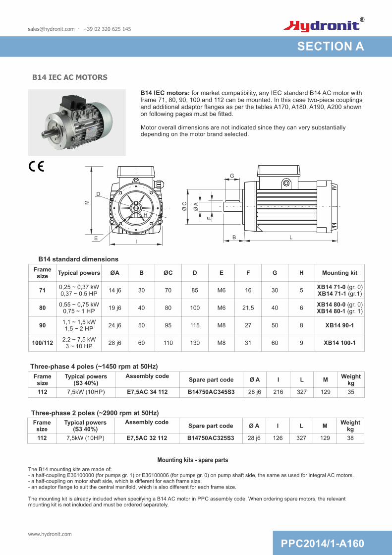
[email protected] · +39 02 320 625 145
B14 IEC motors: for market compatibility, any IEC standard B14 AC motor with frame 71, 80, 90, 100 and 112 can be mounted. In this case two-piece couplings and additional adaptor flanges as per the tables A170, A180, A190, A200 shown on following pages must be fitted.
Motor overall dimensions are not indicated since they can very substantially depending on the motor brand selected.
B LI
G
Ø A
F
Ø CM
D
H
E
B14 standard dimensions
Mounting kits - spare parts
The B14 mounting kits are made of:- a half-coupling E36100000 (for pumps gr. 1) or E36100006 (for pumps gr. 0) on pump shaft side, the same as used for integral AC motors.- a half-coupling on motor shaft side, which is different for each frame size.- an adaptor flange to suit the central manifold, which is also different for each frame size.
The mounting kit is already included when specifying a B14 AC motor in PPC assembly code. When ordering spare motors, the relevant mounting kit is not included and must be ordered separately.
B14 IEC AC MOTORS
Frame size
Typical powers(S3 40%)
Assembly codeSpare part code Ø A I L M
Weightkg
112 7,5kW (10HP) E7,5AC 34 112 B14750AC345S3 28 j6 216 327 129 35
Frame size
Typical powers(S3 40%)
Assembly codeSpare part code Ø A I L M
Weightkg
112 7,5kW (10HP) E7,5AC 32 112 B14750AC325S3 28 j6 126 327 129 38
Three-phase 4 poles (~1450 rpm at 50Hz)
Three-phase 2 poles (~2900 rpm at 50Hz)
Frame size
Typical powers ØA B ØC D E F G H Mounting kit
710,25 ~ 0,37 kW0,37 ~ 0,5 HP
14 j6 30 70 85 M6 16 30 5XB14 71-0 (gr. 0)XB14 71-1 (gr.1)
800,55 ~ 0,75 kW
0,75 ~ 1 HP19 j6 40 80 100 M6 21,5 40 6
XB14 80-0 (gr. 0)XB14 80-1 (gr. 1)
901,1 ~ 1,5 kW1,5 ~ 2 HP
24 j6 50 95 115 M8 27 50 8 XB14 90-1
100/1122,2 ~ 7,5 kW3 ~ 10 HP
28 j6 60 110 130 M8 31 60 9 XB14 100-1
www.hydronit.com
PPC2014/1-A160
SECTION A

MOUNTING KIT FOR FRAME 71 B14 IEC MOTORS
Assembly code*
XB14 71-0 (gr.0)-1 (gr.1)
* Note: The coupling+flange kit is already included when specifying a B14 motor in PPC assembly code. XB1471 code has to be indicated only when ordering PPC with no motor but with coupling+flange kit.
E36100001
E36100006 (gr.0)E36100000 (gr.1)
Spare part code
F27010001
Description
B14 71 motor side half-coupling
B14 pump side half-coupling
B14 71 adaptor flange
Pump side (group1) E36100000 Weight: 0,05 Kg
Motor side E36100001 Weight: 0,08 Kg
Adaptor flange
132
132
117,4
117,4
9,6
20
Ø110
Ø6,5Ø9,5
Ø85
Ø70
Weight: 0,18 Kg
5
Ø20
74,4
20,1
24,5
Ø24
Ø14
4,5
42,5
M6
5
Ø15
5,5
31,9
36,3
30
Ø1
4
29,6 -0,2
Pump side (group0) E36100006 Weigh: 0,04 Kg
Kit weight: 0,32 Kg
Couplings
Attention! When assembling frame 71 B14 motors with XB14 flange+couplings kit, please respect positioning tolerances as per top drawing. Failure to do so can cause malfunctioning or component failure.
[email protected] · +39 02 320 625 145
PPC2014/1-A170www.hydronit.com
SECTION A

MOUNTING KIT FOR FRAME 80 B14 IEC MOTORS
Assembly code*
XB14 80
* Note: The coupling+flange kit is already included when specifying a B14 motor in PPC assembly code. XB1480 code has to be indicated only when ordering PPC with no motor but with coupling+flange kit.
E36100002
Spare part code
F27010002
Description
B14 80 motor side half-coupling
B14 pump side half-coupling
B14 80 adaptor flange
M6
Motor side E36100002 Weight: 0,12 Kg
Adaptor flange
Ø6,5Ø9,5
132
117,4
132
117,4
Ø100
Ø80
Ø110
9,6
22
Ø30
Ø19
41,5
Weight: 0,21 Kg
-0 (gr.0)-1 (gr.1)
Pump side (group1) E36100000 Weight: 0,05 Kg
5
Ø20
74,4
20,1
24,5
5
Ø15
5,5
31,9
36,3
Pump side (group0) E36100006 Weight: 0,04 Kg
40
Ø1
9
29,6 -0,2
Kit weight: 0,36 Kg
Couplings
E36100006 (gr.0)E36100000 (gr.1)
Attention! When assembling frame 80 B14 motors with XB14 flange+couplings kit, please respect positioning tolerances as per top drawing. Failure to do so can cause malfunctioning or component failure.
[email protected] · +39 02 320 625 145
www.hydronit.com
PPC2014/1-A180
SECTION A

MOUNTING KIT FOR FRAME 90 B14 IEC MOTORS
Assembly code*
XB14 90-1
* Note: The coupling+flange kit is already included when specifying a B14 motor in PPC assembly code. XB1490 code have to be indicated only when ordering PPC with no motor but with coupling+flange kit.
E36100003
E36100000
Spare part code
F27010003
Description
B14 90 motor side half-coupling
B14 pump side half-coupling
B14 90 adaptor flange
Pump side E36100000 Weight: 0,05 Kg
Motor side E36100003 Weight: 0,22 Kg
Ø8,5Ø9,5
132
117,4
132
32
117,4
Ø115
Ø95
Ø110
Kit weight: 0,59 Kg
Weight: 0,35 Kg
Ø38
Ø24
50
M6
5
Ø20
74,4
20,1
24,5
51,4
ø24
29,6 -0,2
Souplings
Attention! When assembling frame 90 B14 motors with XB14 flange+coupling kit, please respect positioning tolerances as per top drawing. Failure to do so can cause malfunctioning or component failure.
[email protected] · +39 02 320 625 145
Adaptor flange
PPC2014/1-A190www.hydronit.com
SECTION A
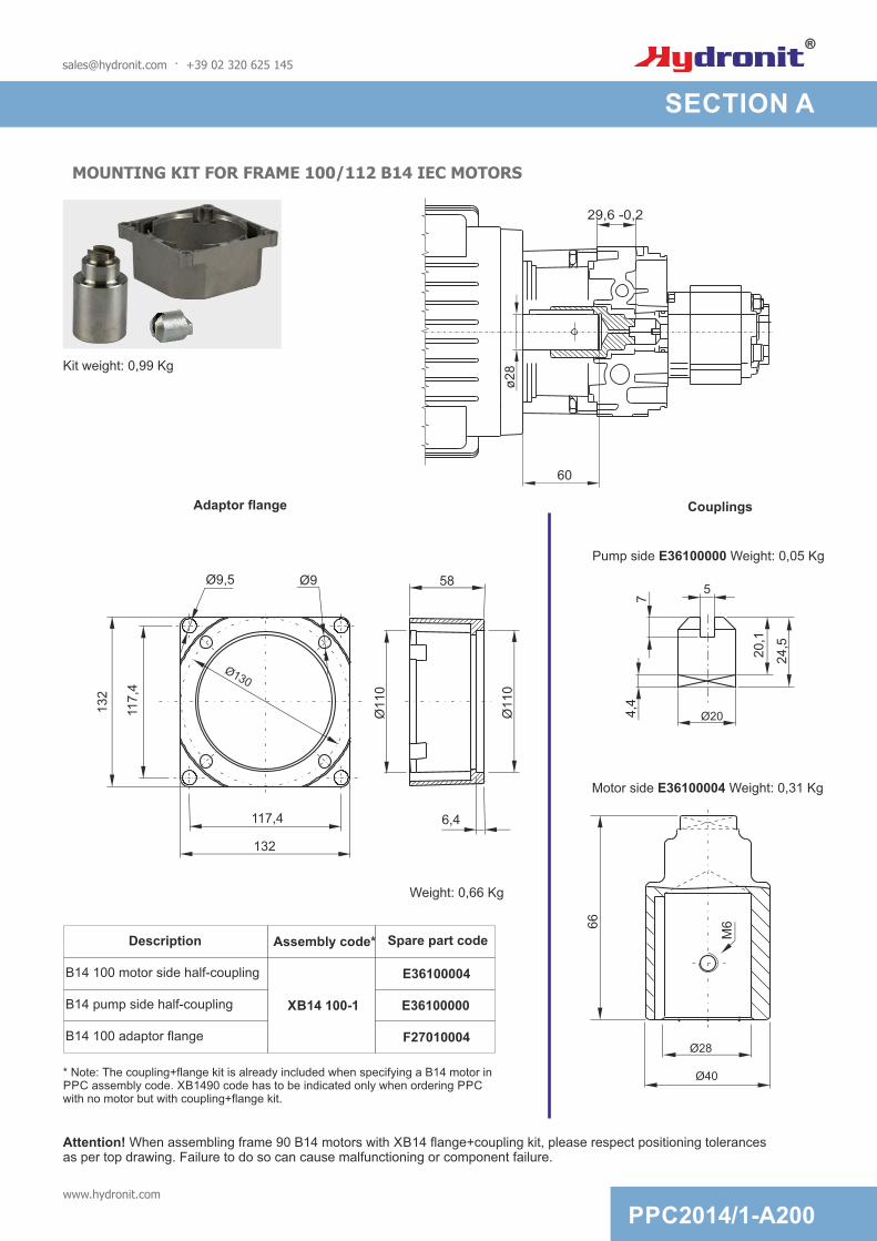
MOUNTING KIT FOR FRAME 100/112 B14 IEC MOTORS
Assembly code*
XB14 100-1
* Note: The coupling+flange kit is already included when specifying a B14 motor in PPC assembly code. XB1490 code has to be indicated only when ordering PPC with no motor but with coupling+flange kit.
E36100004
E36100000
Spare part code
F27010004
Description
B14 100 motor side half-coupling
B14 pump side half-coupling
B14 100 adaptor flange
Couplings
Pump side E36100000 Weight: 0,05 Kg
Motor side E36100004 Weight: 0,31 Kg
Kit weight: 0,99 Kg
Adaptor flange
Ø9Ø9,5 58
132
117,4
132
6,4117,4
Ø130
Ø110
Ø110
Ø40
66
Ø28
Weight: 0,66 Kg
5
Ø20
74,4
20,1
24,5
ø2
8
60
29,6 -0,2
Attention! When assembling frame 90 B14 motors with XB14 flange+coupling kit, please respect positioning tolerances as per top drawing. Failure to do so can cause malfunctioning or component failure.
[email protected] · +39 02 320 625 145
M6
www.hydronit.com
PPC2014/1-A200
SECTION A

on Ø149,3 (5,88)3/8-16 UNF4 holes
45°45°
337 (13,25)
Ø 1
82,6
(7,1
9)
52,3 (2,06)
Ø 1
14
,3 (
4,5
)
Ø1
5,8
7
(0
,62
5)
Ø 1
65
,1 (
6,5
0)
35 (1,38) Length4,8 (0,19) Key
Motor attachment
Typical range power
Pump group
Assembly code mounting kit
Spare part code Description
56C0,18 ~ 1,5 kW0,25 ~ 2,0 HP
0 X56C-0
E36156C01 Nema 56C face motor side half-coupling
E36100006 gr.0 pump half-coupling
F27056C01 Nema 56C face adaptor flange
1 X56C-1
E36156C01 Nema 56C face motor side half-coupling
E36100000 gr.1 pump half-coupling
F27056C01 Nema 56C face adaptor flange
NEMA 56C AC MOTORS
Motor overall dimensions can vary substantially depending on the motor brand.These dimensions are given only as general indicative references.
Nema motors: for market compatibility, any Nema 56C face standard AC motor can be mounted. These motors are NOT supplied by Hydronit and are normally procured by the customer himself. In this case Hydronit can supply a two-piece coupling and additional adaptor flange as per the table on the following page.
[email protected] · +39 02 320 625 145
PPC2014/1-A210www.hydronit.com
SECTION A

MOUNTING KIT FOR NEM 56C AC MOTORS
Motor side E36156C01 Weight: 0,12 Kg
Adaptor flangeø
16,9
(0,6
6)
Kit weight: 0,54 (1,2 lbs)
Weight: 0,35kg (0,77 lbs)
5 (0,2)
Ø20 (0,79)
7 (
0,2
7)
4,4
(0,1
7)
20,1
(0,7
9)
24,5
(0,9
6)
32(1,26)
Ø11
0 (
4,3
3)
Ø1
14
,3 (
4,5
)
Ø10,5 (0,41)
Ø9,5 (0,37)
Ø1
65
(6
,5)
117
,4 (
4,6
2)
117,4 (4,62)
Ø149,4 (5,88)
Ø27,5 (1,08)
Ø15,87 (0,62)
44,5
(1,7
5)
M6
29,6 -0,2 (1,16 -0,01)
Attention! When assembling Nema 56C-face motors with XB56C-1 flange+couplings kit, please respect positioning tolerances as per top drawing. Failure to do so can cause malfunctioning or component failure.
Assembly code*
* Note: The coupling+flange kit is already included when specifying a Nema 56C motor in PPC assembly code. Nema 56C code has to be indicated only when ordering PPC with no motor but with coupling+flange kit.
E36156C01
Spare part code
F27056C01
Description
Nema 56C motor side half-coupling
Pump side half-coupling
Nema 56C adaptor flange
-0 (pumps gr.0)-1 (pumps gr.1)
X56CE36100006 (gr.0)E36100000 (gr.1)
Ø15 (5,9)
5,5
(0
,22
)
31
,9 (
1,2
5)
36
,3 (
1,4
3)
5 (0,2)
Pump side gr.0 E36100006 Weight: 0,04 Kg
Pump side gp.1 side E36100000 Weight: 0,05 Kg
Couplings
[email protected] · +39 02 320 625 145
www.hydronit.com
PPC2014/1-A220
SECTION A

Description Assembly code Spare part code
Kit shaft and flange for mounting pulley
XPU1401-0(pompa gr.0)
XPU1401-1(pompa gr.1)
P46FP1401
B14 pump side half-couplingE36100006 (gr. 0)E36100000 (gr. 1)
B14 71 adaptor flange F27010001
DRIVE A PULLEY
[email protected] · +39 02 320 625 1451
32
132
117
,4
117,4 36
72
Ø1
10
4xØ9,5
100X1Aoptional
Weight: 0,70 Kg
Pump side gr. 1 E36100000
5
20
7
4,4
20,1
24,5
Couplings
5,5
Pump side gr. 0E36100006
5
15
31,9
36,3
For pulleys mounted on shaftØ14mm with key 5mm
Note: The pulley kit excludes the pulley which is available on request.The standard model has 100X1A code, suitable for V-belts Nominal diameter 100mm, 1 throat, section type A.Pulley weight 100X1A: 0,265 kg
ØP
100
NEW
PPC2014/1-A230www.hydronit.com
SECTION A

SUMMARY TABLE - PUMP/MOTOR COUPLING KITS
PumpMotor
Group 0 pumpSeries G - K - R
Group 1 pumpSeries G - K - H - S - R
DC Ø 80 E36200006 E36200002
DC Ø 114 E36200005 E36200001
DC Ø 125 E36200005 E36200001
DC Ø 151 n/a XB1490-1
INTEGRAL AC E36100006 E36100000
AC B14 71XB14 71-0
(E36100001+E36100006+F27010001)XB14 71-1
(E36100001+E36100000+F27010001)
AC B14 80XB1480-0
(E36100002+E36100006+F27010002)XB1480-1
(E36100002+E36100000+F27010002)
AC B14 90 n/aXB1490-1
(E36100003+E36100000+F27010003)
AC B14 100/112 n/aXB14100-1
(E36100004+E36100000+F27010004)
AC NEMA 56CX56C-0
(E36156C01+E36100006+F27056C01)X56C-1
(E36156C01+E36100000+F27056C01)
PULLEYXPU1401-0
(P46FP1401+E36100006+F27010001)XPU1401-1
(P46FP1401+E36100000+F27010001)
[email protected] · +39 02 320 625 145
www.hydronit.com
PPC2014/1-A240
SECTION A


SECTION B
UNIVERSAL CENTRAL MANIFOLDS
Which universal central manifold execution should I choose?UA type is the most widely applied for single acting or double acting circuits. UB is the real «Universal» central manifold since in addition to UA type features there are two extra lateral cavities to mount, for example, an integrated emergency hand pump and an externally adjustable flow control. U4 is recommended for compact and cost effective double acting circuits with a single cylinder while UR is for bidirectional pumps.
Do I need special tools to assemble the components within the central manifold?No. All the valves are screw-in type in a single piece construction (no loose nuts, washers, springs; nothing difficult to assemble or fall apart). The components can be easily assembled with simple hand tools and hexagon keys.
Is the central manifold available as a loose component?Yes. We can supply either fully assembled and tested power packs or kits of loose components which can be kept in stock by our worldwide distributors and easily assembled to satisfy local market demand quickly and effectively. Central manifolds and other components are 100% tested even when supplied as loose parts.
A single universal die-cast aluminium central manifold in 4 different executions is the core part from which all power units in industrial, mobile and marine fields are made. It features the highest integration and flexibility on the market, with up to nine devices which can be fitted inside, plus a wide selection of manifold blocks which can be connected externally to suit spool or cartridge type valves
Lateral cavities are conform to SAE08 standard (3/4-16UNF), except for the main relief valve cavity which is M20x1,5
Maximum flow is 25 l/min, with a low pressure drop. Maximum motor power is 7,5kW, well above the average of other alternative products on the marketClockwise (our standard) or counterclockwise tang
drive shaft standard gear pumps can be mounted. Double pumps, including those with an integral HI-LO circuit, are also available
The interfaces to tanks and motors are standardised. All plastic or steel tanks have the same interface and can be easily interchanged.All AC or DC motors can be fitted easily either directly to the central manifold or through adaptor flanges (B14 IEC standard motors)
The interface to hose fittings or external additional manifolds is standardised. The P and T port threads for direct connection of hose fittings are 1/4" BSPP (International standard) or 9/16-18UNF (SAE06) for the American standard version.
[email protected] · +39 02 320 625 145
PPC2014/1-B000www.hydronit.com

UNIVERSAL CENTRAL MANIFOLDS «UA» - VALVE COMBINATIONS
E70100003
E70100006
H
P
E70100002N
VUC20J
VSC04 Modular blocks(See section F)
2
P T
5 8
PP RT
MSV30E
CSPC15
MSV30
B
T
A
CM04MEM
CM04LE
U PMC02
MSV31E
MDV30E
C
D
CPE04Z
CSB04
CSB04
S
S
E70100004
E70100005
L
G
9
VUC20J
0
7
[email protected] · +39 02 320 625 145
85
VSC01 *
7 VSC04 *
9 SUV01 *
E70100010 XP
VMDC35 D/*
1
Hydraulic scheme
P T
1
2 7
58
M
90
PPC2014/1-B010www.hydronit.com
SECTION B

3
A B
TP
1
2
8
0
Hydraulic scheme
UNIVERSAL CENTRAL MANIFOLDS «U4» - VALVE COMBINATIONS
E70100010 XP
VMDC35 D/*
Modular manifold with check valves
(See section F)
2
1
A B
8
PP
9
VUC20J
0
3
E70100004
CSB04
VCF6
L
R
SS
RT
CSB04S
[email protected] · +39 02 320 625 145
VSC6 F
E70100006 P
8 VSC01 *
9 SUV01 *
9
42
3 1
42
3 1
42
3 1
MSV4VA11C
MSV4VE2
MSV4VC2
MSV4VB2
MSV4VA2
4VC2
4VA11C
4VB2
4VA2
4VE2
42
3 1
42
3 1
PPC2014/1-B020www.hydronit.com
SECTION B
M

SECTION B
UNIVERSAL CENTRAL MANIFOLDS «UB» AND «UR» - VALVE COMBINATIONS
E70100004
E70100005
CSB04
CPE04
Modular blocks
L
G
S
Z
S
(See section F)
VMPC2 P/*
VUC20J
CSB04S
E70100002
E70100003
VSC6
32
4
0 1
MDV30E
5 8
6
P
P
P T1T
VMDC20 V/*
D
N
H
F
E70100010 XP
VMDC35 D/*
P
B
E70100003
E70100004
E70100005
H
L
G
E70100002N
VUC20J
E70100006P
9
7
VCF6 R
MSV30E
MSV30
B
A
CM04MEM
CM04LE
U PMC02
MSV31E
MDV30E
C
D
CPE04Z
CSB04S
CSPC15T
[email protected] · +39 02 320 625 145
E70100006 P
UR typeUB type
UR type is for reversible pumps.
865
VSC01 *
7 VSC04 *
9 SUV01 *
VSC04
3
P T
1
24 7
65
8
09
Dra
in
R-P
L-P
L-S R-S
A B
3
MM
1
24
PB
Hydraulic scheme
PPC2014/1-B030www.hydronit.com
RT

UNIVERSAL CENTRAL MANIFOLDS - OVERALL DIMENSIONS
Cavity
3/4-16 UNF (SAE08)
1/4 BSPP9/16-18UNF (SAE06) tipo US
2 screws M10x187/16-20UNF type US
1/4 BSPP (threadedon request only)
1/4 BSPP (9 threadedon request only)
4 screws M8x25
4 screws M6x14
2 screws M6x14 or tie rods M6
2 screws M8(see pump lenghts on
the relevant tables)
4 screws M5x45
0, 2, 3, 4
P-T
1
T1
5, 6, 8, 9
FixingsTank
FixingsDirect mountAC motors
Fixings DC motors
FixingsPump
Fixings for coverof PMC hand pump or CM lever valve
Fixings - External manifolds
FixingsMounting Foot
2 tie rods M84 tie rods M6
M20x1,5 (relief valve)
Thread
Type Spare part code
UA E60104020
UB E60104021
U4 E60104022
UR E60104023
UAUS E60104020US
UBUS E60104021US
U4US E60104022US
URUS E60104023USType UB** only
Type UB** only
P
P
B
P
Weight: 1,1 kg (2,42 lb)
Tank side view
Only UR** type
Motor side view
82 (3,23)
Ø 98,4 (3,87)
Ø 110 (4,33)
15
,5 (
0,6
1)
35
,5 (
1,4
0)
55
,5 (
2,1
8)
58
(2
,28
)
61
,5 (
2,4
2)
40
(1
,57
)
Ø 123 (4,84)
10
2,5
(4
,04
)
117
,4 (
4,6
2)
13
3 (
5,2
4)
102,5 (4,04)
117,4 (4,62)
133 (5,24)
1
3
35,5 (1,40)
33
,5 (
1,3
2)
32
(1
,26
)
PT
T1
30 (1,18)
20
(0
,79
)2
0 (
0,7
9)
50 (1,97)
10,5 (0,41) 12 (0,47)
10 (0,39)
43 (1,69)
5 (
0,2
0)
7,5
(0
,30
)
7,4
3 (
0,2
9)
3 (
0,1
2)
14
(0
,55
)1
4 (
0,5
5)
35
,5 (
1,3
8)
0
25,5 (1)
25,5 (1)
25
,5 (
1)
25
,5 (
1)
5 (
0,2
0)
32
(1
,26
)
4
2
Ø 90 (3,54)
Ø 110 (4,33)
49,02 (1,93)
14
,06
(0
,55
)
117
,4 (
4,6
2)
117,4 (4,62)
14,06 (0,55)
3,92 (0,15)
49
,02
(1
,93
)
44
,83
(1
,76
)
J
8
5
6
9
Notes:- codes ending with US are destined for the American market and are machined with 9/16-18 UNF (SAE06) exit ports.- all dimensions in mm + (inches)
[email protected] · +39 02 320 625 145
PPC2014/1-B040www.hydronit.com
SECTION B


SECTION C
PUMPS
Why are pressure balanced gear pumps better than fixed clearance gear pumps used by some competitors?Pressure balanced gear pumps are built with lateral pressure plates which reduce the mechanical clearance on the gears with the increase of the pressure on the outlet, thus greatly improving the hydrodynamic efficiency, reducing heat generation and energy consumption. The mechanical efficiency is kept at an optimal level too.
How can we mount both group 0 and group 1 pumps on the same Universal central manifold?The group 1 pumps fit directly on the central manifold and are fixed by two bolts provided with the pump.The group 0 pumps are fitted by adaptor plate E60513025, which adapts the pump front flange to to the central manifold.
Why do the pump technical specifications show three maximum pressure levels?Our pumps have three ratings for the maximum allowable pressure: 1-Peak: is the and can be allowed for a maximum cycle of 2 seconds. 2-Intermittent: it can be applied on the pump for a maximum cycle of 20 seconds; 3-Continuous: it can be applied to the pump at all times.
H series. It features an oversized shaft and a higher number of teeth for high pressure applications, up to 280 bar peak.
K series. The standard pressure balanced design for cost effective solutions. Also available as a double pump with or without HI-LO circuit integrated within the pump itself
R series. Bidirectional pumps with integrated suction check valves and two front outlet ports.They can be fitted on UR type central manifold.
G series. The lightweight, pressure balanced, low noise and high efficiency pump specifically designed for mini power packs
[email protected] · +39 02 320 625 145
PPC2014/1-C000www.hydronit.com

G TYPE GEAR PUMPS, GROUP 1
E60 60 30 **
Size:see below table
Pump type:60 = Group 1
Pump type:G = G type
Nominal displacement:(cc/rev) see below table1,1
G
71
Ø9
Ø 1
2,8
3/8
B
SP
P
N
86
23218
Ø 3
0
n.2 Ø 8,6
Ø 1
2
Spare part code Assembly code
Available range
Main features
Peak pressure: cycle 2 s ON Intermittent pressure: cycle 20 s ON
Continuous pressure: cycle always ON
Pressure definition
0,7 < P < 3,0 bar (absolute pressure)Inlet pressure
2 x M8 8.8 class steel tightening torque: 21 ÷ 25 Nm
Fixing bolts
Oil temperature -15 ÷ +80 °C
Standard rotation direction: clockwise (from shaft side). Counterclockwise rotation pumps can be mounted on request.Ask our sales department.
Nominal displacement
[cc/rev]
Peak pressure
[bar]
Intermittent pressure
[bar]
Continuous pressure
[bar]
Max speed[rpm]
N[mm]
Bolts*[mm]
Code marked on pump
Spare part codeWeight
[Kg]
0,8 250 230 210 6000 35,8 M8x50 EK1PD1.3G E60603001 0,49
1,1 250 230 210 6000 36,8 M8x50 EK1PD1.6G E60603002 0,50
1,3 250 230 210 6000 37,8 M8x50 EK1PD2G E60603003 0,51
1,6 250 230 210 6000 38,8 M8x55 EK1PD2.5G E60603035 0,52
2,1 250 230 210 6000 40,8 M8x55 EK1PD3.3G E60603004 0,54
2,6 250 230 210 6000 42,3 M8x60 EK1PD4.2G E60603005 0,56
3,2 230 210 190 5000 43,8 M8x60 EK1PD5G E60603006 0,58
3,7 230 210 190 4500 45,8 M8x60 EK1PD5.8G E60603007 0,61
4,2 230 210 190 4000 47,3 M8x60 EK1PD6.7G E60603008 0,63
4,9 210 190 170 3500 49,3 M8x65 EK1PD7.5G E60603009 0,65
6,0 210 190 170 3000 51,3 M8x65 EK1PD9.2G E60603010 1,01
7,9 200 180 160 2100 88,0 M8x100 K1PD11.5G E60603012 1,12
9,8 170 150 130 1700 95,0 M8x110 K1PD14.5G E60603014 1,27
* A washer is always fitted to ensure correct bolt engagement
[email protected] · +39 02 320 625 145
PPC2014/1-C010www.hydronit.com
SECTION C

55
1 /4
BS
PP
N
9,5
5
Ø 2
2Ø
8
Ø9
,6
Ø5
,5
50
16
n.2 Ø 5,5
62
60
Aluminium adapter flange for group 0
n.2 Ø 8,5
n.2 M5
Code: E60513025
Weight: 0,07 KgStandard rotation direction: clockwise (from shaft side). Counterclockwise rotation pumps can be mounted on request.Ask our sales department.
Nominal displacement
[cc/rev]
Peak pressure
[bar]
Intermittent pressure
[bar]
Continuous pressure
[bar]
Max speed[rpm]
N[mm]
Bolts*[mm]
Code marked on pump
Spare part codeWeight
[Kg]
0,1 230 210 190 7000 44,5 M5x55 UK0,25D18G E60503001 0,49
0,2 230 210 190 7000 44,5 M5x55 UK0,25D24G E60503002 0,50
0,4 230 210 190 7000 47,5 M5x55 UK0,25D36G E60503004 0,51
0,6 230 210 190 7000 51,5 M5x65 UK0,25D0,75G E60503006 0,52
Available range
Spare part code Assembly code
Pump type:G = G type
Nominal displacement:(cc/rev) see below table0,4
G
Size:see below table
Pump type:50 = Group 0
E60 50 30 **
Main features
Peak pressure: cycle 2 s ON Intermittent pressure: cycle 20 s ON
Continuous pressure: cycle always ON
Pressure definition
0,7 < P < 3,0 bar (absolute pressure)Inlet pressure
2 x M5 8.8 class steel tightening torque: 8 ÷ 9,5 Nm
Fixing bolts
Oil temperature -15 ÷ +80 °C
PPC2014/1-C020www.hydronit.com
* A washer is always fitted to ensure correct bolt engagement
SECTION C
[email protected] · +39 02 320 625 145
G TYPE GEAR PUMPS, GROUP 0

K TYPE GEAR PUMPS, GROUP 1
E60 60 40 **
Size:see below table
Pump type:60 = Group 1
71
Ø9
Ø12,8
3/8
BS
PP
N96
23
21
8
Ø 3
2
n.2 Ø 8,6
Ø 1
0
Pump type:K = K type
Nominal displacement:(cc/rev) see below table1,2
K
Available range
Spare part code Assembly code
Standard rotation direction: clockwise (from shaft side). Counterclockwise rotation pumps can be mounted on request.Ask our sales department.
Nominal displacement
[cc/rev]
Peak pressure
[bar]
Intermittent pressure [bar]
Continuous pressure
[bar]
Max speed[rpm]
N[mm]
Bolts*[mm]
Spare part codeWeight
[Kg]
0,9 250 230 210 4500 61,3 M8x75 E60604001 0,73
1,2 250 230 210 4500 62,8 M8x75 E60604002 0,75
1,6 250 230 210 4500 64,3 M8x80 E60604035 0,77
2,1 250 230 210 4500 66,0 M8x80 E60604004 0,79
2,7 250 230 210 4500 68,5 M8x80 E60604005 0,82
3,2 250 230 210 4500 70,0 M8x85 E60604006 0,86
3,7 230 210 180 3600 72,0 M8x85 E60604007 0,88
4,2 230 210 180 3600 74,0 M8x85 E60604008 0,90
5,0 210 180 140 3000 77,0 M8x90 E60604009 0,94
6,0 210 180 140 3000 81,0 M8x100 E60604010 0,98
7,9 180 140 100 3000 88,5 M8x100 E60604012 1,10
[email protected] · +39 02 320 625 145
Main features
Peak pressure: cycle 2 s ON Intermittent pressure: cycle 20 s ON
Continuous pressure: cycle always ON
Pressure definition
0,7 < P < 3,0 bar (absolute pressure)Inlet pressure
2 x M8 8.8 class steel tightening torque: 21 ÷ 25 Nm
Fixing bolts
Oil temperature -15 ÷ +80 °C
PPC2014/1-C030www.hydronit.com
SECTION C
* A washer is always fitted to ensure correct bolt engagement

K TYPE GEAR PUMPS, GROUP 0
55
1/4
B
SP
P
N
9,5
5
Ø 2
2Ø
8
Ø9,6
62
60
Ø5,5
50
16
n.2 Ø 5,5
Pump type:K = K type
Nominal displacement:(cc/rev) see below table0,4
K
n.2 Ø 8,5
n.2 M5Weight: 0,07 Kg
E60 50 40 **
Size:see below table
Pump type:50 = Group 0
Available range
Aluminium adapter flange for group 0
Code: E60513025
Spare part code Assembly code
Standard rotation direction: clockwise (from shaft side). Counterclockwise rotation pumps can be mounted on request.Ask our sales department.
Nominal displacement
[cc/rev]
Peak pressure
[bar]
Intermittent pressure [bar]
Continuous pressure
[bar]
Max speed[rpm]
N[mm]
Bolts*[mm]
Spare part codeWeight
[Kg]
0,2 200 180 160 6000 45,5 M5x60 E60504002 0,33
0,4 200 180 160 6000 47,5 M5x65 E60504004 0,35
0,6 200 180 160 6000 51,5 M5x65 E60504006 0,40
[email protected] · +39 02 320 625 145
Main features
Peak pressure: cycle 2 s ON Intermittent pressure: cycle 20 s ON
Continuous pressure: cycle always ON
Pressure definition
0,7 < P < 3,0 bar (absolute pressure)Inlet pressure
2 x M5 8.8 class steel tightening torque: 8 ÷ 9,5 Nm
Fixing bolts
Oil temperature -15 ÷ +80 °C
PPC2014/1-C040www.hydronit.com
SECTION C
Other pumps with different pressure/speed are available on request.
* A washer is always fitted to ensure correct bolt engagement

H TYPE GEAR PUMPS, GROUP 1
E60 60 50 **
Size:see below table
Pump type:60 = Group 1
Pump type:H = H type
Nominal displacement:(cc/rev) see below table6,0
H
71
Ø9
Ø12,8
3/8
BS
PP
N96
23
21
8
Ø 3
2
n.2 Ø 8,6
Ø 1
3
Available range
Spare part code Assembly code
Standard rotation direction: clockwise (from shaft side). Counterclockwise rotation pumps can be mounted on request.Ask our sales department.
Nominal displacement
[cc/rev]
Peak pressure[bar]
Intermittent pressure [bar]
Continuous pressure
[bar]
Max speed[rpm]
N[mm]
Bolts*[mm]
Spare part codeWeight
[Kg]
1,2 280 270 250 5000 39,5 M8x55 E60605002 0,50
1,7 280 270 250 4500 41,3 M8x55 E60605035 0,52
2,2 280 270 250 4500 44,2 M8x60 E60605004 0,54
2,6 280 270 250 4500 45,7 M8x60 E60605005 0,56
3,2 280 270 250 4000 51,9 M8x65 E60605006 0,58
3,8 280 270 250 3800 54,1 M8x70 E60605007 0,61
4,2 280 270 250 3500 82,0 M8x100 E60605008 1,05
4,7 260 250 240 3200 83,5 M8x100 E60605009 1,12
6,0 230 220 210 3000 94,3 M8x110 E60605010 1,22
7,4 230 210 190 2000 97,5 M8x110 E60605012 1,80
[email protected] · +39 02 320 625 145
Main features
Peak pressure: cycle 2 s ON Intermittent pressure: cycle 20 s ON
Continuous pressure: cycle always ON
Pressure definition
0,7 < P < 3,0 bar (absolute pressure)Inlet pressure
2 x M8 8.8 class steel tightening torque: 21 ÷ 25 Nm
Fixing bolts
Oil temperature -15 ÷ +80 °C
IMPROVED
PPC2014/1-C050www.hydronit.com
SECTION C
* A washer is always fitted to ensure correct bolt engagement

R TYPE BIDIRECTIONAL GEAR PUMPS, GROUP 0
E60 50 45 **
Size:see below table
Pump type:50 = Group 0
Pump type:R = R type
Nominal displacement:(cc/rev) see below table
1,3
R
55
Ø9,6
Ø5,5
1/4
BS
PP
N50
16
9,5
5
Ø 2
2
n.2 Ø 5,5
Ø 8
Available range
Spare part code Assembly code
62
60
n.2 Ø 8,5
n.2 M5Weight: 0,07 Kg
Aluminium adapter flange for group 0
Code: E60513025
Nominal displacement
[cc/rev]
Peak pressure
[bar]
Intermittent pressure [bar]
Continuous pressure
[bar]
Max speed[rpm]
N[mm]
Bolts*[mm]
Spare part codeWeight
[Kg]
0,3 200 180 160 6000 52,7 M5x60 E60504503 0,46
0,5 200 180 160 6000 54 M5x60 E60504505 0,48
0,7 200 180 160 6000 55,2 M5x65 E60504506 0,49
0,9 200 180 160 5000 57,1 M5x65 E60504509 0,50
1,3 200 180 160 3900 60,2 M5x70 E60504513 0,51
1,5 200 180 160 3900 62,3 M5x70 E60504515 0,52
[email protected] · +39 02 320 625 145
Main features
Peak pressure: cycle 2 s ON Intermittent pressure: cycle 20 s ON
Continuous pressure: cycle always ON
Pressure definition
0,7 < P < 3,0 bar (absolute pressure)Inlet pressure
2 x M5 8.8 class steel tightening torque: 8 ÷ 9,5 Nm
Fixing bolts
Oil temperature -15 ÷ +80 °C
IMPROVED
PPC2014/1-C060www.hydronit.com
SECTION C
Other pumps with different pressure/speed are available on request.
* A washer is always fitted to ensure correct bolt engagement

72
3/8
BS
PP
N
12
7
Ø 3
2
R TYPE BIDIRECTIONAL GEAR PUMPS, GROUP 1
E60 60 35 **
Size:see below table
Pump type:60 = Group 1
Pump type:R = R type
Nominal displacement:(cc/rev) see below table
3,2
R
Available range
Spare part code Assembly code
Nominal displacement
[cc/rev]
Peak pressure
[bar]
Intermittent pressure [bar]
Continuous pressure
[bar]
Max speed[rpm]
N[mm]
Bolts*[mm]
Spare part codeWeight
[Kg]
2,1 270 260 250 4000 54,5 8x70 E60603504 0,92
2,6 270 260 250 4000 56,5 8x70 E60603505 0,95
3,2 240 230 220 4000 58,5 8x75 E60603506 0,98
4,3 150 140 130 4000 62,5 8x75 E60603508 1,05
6,5 120 110 100 3500 71,5 8x85 E60603510 1,32
Other pumps with different pressure/speed are available on request.
Main features
Peak pressure: cycle 2 s ON Intermittent pressure: cycle 20 s ON
Continuous pressure: cycle always ON
Pressure definition
0,7 < P < 3,0 bar (absolute pressure)Inlet pressure
2 x M8 8.8 class steel tightening torque: 21 ÷ 25 Nm
Fixing bolts
Oil temperature -15 ÷ +80 °C
Ø12,8
Ø9
68
23
n.2 Ø 8,5
NEW
PPC2014/1-C070www.hydronit.com
SECTION C
[email protected] · +39 02 320 625 145
* A washer is always fitted to ensure correct bolt engagement

K TYPE DOUBLE GEAR PUMPS, GROUP 1
71
3/8
BS
PP
69
23
n.2 Ø 8,6
12
8
Ø 3
2Ø
10
Shaft max torque 21,5 Nm
54
Ø9
Ø1
2,8
Common 3/8’’ BSPP inlet port (on the rear cover) alternatively individual side inlet ports are available
[email protected] · +39 02 320 625 145
E60 60 ** ** HL
Size:see below table
Pump type:60 = Group 1
Spare part code Assembly code
Pump type:K = K type
Displacement 2nd section
Displacement 1st section
Option:Hi - Lo execution
1,2
HL
K
5
+
High PLow P
HI-LO pump
Example: UA type body
5
P
T
2
8
M
Choosing the right pump combination:
- Check that the power absorption of the front element is equal to or higher than the rear one- Pump performance and features are the same as the details of the corresponding single pumps- Double pump maximum rotation speed is determined by the lowest speed among maximum rotation speeds of each single pump.- Torque applied on the shaft of the front pump is the sum of the torques absorbed by the two pumps (see above diagram); this value must never go over the limit allowed for the shaft (21,5 Nm).
Available range
Nominal displacemen
t [cc/rev]
Peak pressure
[bar]
Intermittent pressure [bar]
Continuous pressure
[bar]
Unloading pressure
[bar]
Max speed[rpm]
N[mm]
Bolts*[mm]
Spare part codeWeight
[Kg]
0,9 + 3,2 250 230 210 42±5 1750 128,3 M8x160 E60600932HL 2,12
1,2 + 5,0 250 230 210 42±5 1750 141,3 M8x160 E60601250HL 2,29
p [bar]50
2
0
4
6
8
10
12
14
16
18
20 7,9
100 150 200 250
Torq
ue
[N
m]
Torque absorbed
1,2
0,9 [cc/rev]
1,6
2,1
2,73,2
3,7
4,25,0
6,0 HI-LOThis is an efficient and energy saving solution for applications where a fast approach and a high pressure working phase are needed (industrial presses, garbage compactors, balers,...).During the high speed phase both pumps are supplying flow to the system while during the high pressure phase, the low pressure pump is discharged back to tank with no load.This solution can be conveniently assembled with our UA or UB or U4 central manifold without any additional kit. Ask to our technical office for more details.
Other pumps with different pressure/speed are available on request.
Main features
Peak pressure: cycle 2 s ON Intermittent pressure: cycle 20 s ON
Continuous pressure: cycle always ON
Pressure definition
0,7 < P < 3,0 bar (absolute pressure)Inlet pressure
2 x M8 8.8 class steel tightening torque: 21 ÷ 25 Nm
Fixing bolts
Oil temperature -15 ÷ +80 °C
PPC2014/1-C080www.hydronit.com
SECTION C
* A washer is always fitted to ensure correct bolt engagement

SECTION C
S SERIES HELICAL ROTOR PUMPS FOR HIGH PRESSURE, HIGH FLOW AND LOW NOISEAPPLICATIONS, GROUP 1
S60 60 30 **
Size:see below table
Pump type:60 = Group 1
Available range
73
Ø9
Ø15,3
3/8
BS
PP
N
64
23
12
8
Ø 3
2
Ø 1
0
n.2 Ø 8,25
Nois
e le
vel [
dB
A]
[rpm]
55
60
65
70
1000 1500 2000
Helical rotor pumpsS type
Gear pumpsG and K type
100%
100 200
Volumetric
[Bar]
60%
70%
80%
90%
50 150 250
Effic
ien
cy
MechanicalOverall
Nominal displacement
[cc/rev]
Peak pressure[bar]
Intermittent pressure [bar]
Continuous pressure
[bar]
Max speed[rpm]
N[mm]
Bolts*[mm]
Noise level[dbA]**
Spare part codeWeight
[Kg]
2,2 270 250 210 3000 66,2 M8x80 50 S60603004 0,85
3,2 270 250 210 3000 69,9 M8x85 51 S60603006 0,9
4,3 270 250 210 3000 81,6 M8x100 52 S60603008 0,95
5,0 270 250 210 3000 83,8 M8x100 52 S60603009 1,1
6,4 250 200 200 3600 93,6 M8x110 57 S60603010 2,03
8,3 215 195 153 3600 98,6 M8x120 57 S60603012 2,08
10 190 170 126 3600 103,6 M8x120 57 S60603014 2,12
13 160 140 99 3600 110,5 M8x140 57 S60603016 2,15
Note: reference values measured at 1500rpm with oil ISO VG 46 cSt at 40 ° C.
[email protected] · +39 02 320 625 145
Pump type:S = S type
Nominal displacement:(cc/rev) see below table6,4
S
Spare part code Assembly code
Standard rotation direction: clockwise (from shaft side). Counterclockwise rotation pumps can be mounted on request.Ask our sales department.
Main features
Peak pressure: cycle 2 s ON Intermittent pressure: cycle 20 s ON
Continuous pressure: cycle always ON
Pressure definition
0,7 < P < 3,0 bar (absolute pressure)Inlet pressure
2 x M8 8.8 class steel tightening torque: 21 ÷ 25 Nm
Fixing bolts
Oil temperature -15 ÷ +80 °C
IMPROVED
** The noise level is for guidance only since it depends on the values of the resonance of the mounting structure and other components of the system.
PPC2014/1-C090www.hydronit.com
* A washer is always fitted to ensure correct bolt engagement

SECTION D
INTEGRAL COMPONENTS
How does the coding of the power pack works?The power packs are coded with a speaking code, which is basically the list of sub-assemblies which make up the power pack (motor, pump, valves, tank,...). Integral components are those fitting inside central manifold cavities and are numbered from 0 to 9. Each component has an assembly code, normally a single letter, which build up the speaking code. It also has a spare part code in case it is ordered as a loose component. The numbered cavities are indicated in the hydraulic scheme too, so that it is easy to draw the schematic diagram starting from the speaking code itself.
There are several different coils and connectors for the cartridge solenoid valves. How do I choose the proper ones?Normally closed 2-way solenoid valves (MSV30*) use M130/M140/M63 series of coils either DC or directly AC. Normally open 2-way solenoid valves (MSV31E) can only use DC or RC (rectified current) coils due to their internal construction. When choosing a RC coil, a rectifying connector must be fitted (KA132R***). MSV4V 4-way cartridge valves use the new M63* series coils. M630 are for DC supply voltage, while M631 are rectified coils with integral rectifying circuit to be supplied with AC current. A standard KA13200000 connector must be always used in this case. On page D180 you will find the coil table for all valves.
Two way positive seat solenoid valves SAE08 (3/4-16UNF) are available in Normally Closed, Normally Open, single and double locking types. Manual override also available.
The main relief valve is fitted in a M20x1,5 cavity. It is built with a guided poppet to improve pressure setting, stability and to avoid the noise typical of lower cost alternatives.
The main check valve fits in a SAE08 (3/4-16UNF) standard cavity and can be easily removed from the outside for easy cleaning and servicing
The PMC02 cartridge hand pump SAE08 (3/4-16UNF), 2 cc/stroke is an affordable and easy way to add an emergency function to your power pack.
All cartridges are single piece valves, easily fitted with no loose parts.
Pressure and flow proportional control valves are available as standard, also with integrated PWM driver
Which are the mostly used plugs?G or H plugs are normally fitted in cavity 2 and 4, of types UA and UB central manifolds when these cavities are not used. H type has a 1/4"BSP connection port to allow mounting of a pressure gauge or switch. L type plug fits cavity 3 of U4 and UB manifolds when this cavity is not used.
[email protected] · +39 02 320 625 145
PPC2014/1-D000www.hydronit.com

VMDC35 - DIRECT ACTING MAIN RELIEF VALVES
Main featuresNominal size: 35 = 35 l/min
Option: 1 = screw (std) 2 = handwheel 3 = with cap 4 = plastic seal
VMDC
35
1
Working range: L = 5 ÷ 60 bar A = 10 ÷ 180 bar B = 35 ÷ 310 bar
B
Note: Values measured on valve alone (no cavity) with an oil viscosity of 46 cSt at 50 °C. Pressure drop may change depending on fluid viscosity and temperature
Main relief valve
B
A
Pressure vs Flow
P [bar]
Flow [l / min]
70
140
210
07 14 21 28 35
280
350
420
L
Minimum setting pressure
B
A
L
7 14 21 28 35Flow [l / min]
10
20
30
0
40
50
60
P [bar]
3
2
Hex. 13
Max 65
Ø 4
0
Max 80
1P
T
Hex. 13
Hex. 4
Hex. 22 Hex. 24
Max 50
M2
0 x
1,5
50
P T
Recommended tightening torque: 50 NmRecommended filtration: 25 ÷ 50 µOil temperature: -30 ÷ + 80 °C
Spare part code
Max pressure 450 bar
Max flow 35 l/min
Weight 0,16 kg
[email protected] · +39 02 320 625 145
Mounting cavities
1
2
0
5 6 7 8
3 4
Note: cavities 3, 4 and 6 are present on central manifold type UB only.
where *** stands for max setting pressure [bar]. eg. D_310
where is the option
D_***¨
¨
Assembly code
IMPROVED
PPC2014/1-D010www.hydronit.com
SECTION D

VMDC20 - DIRECT ACTING RELIEF VALVES
V*** ¨
P [bar]
Flow [l / min]
70
140
210
04 8 12 16 20
280
350
420
C
D
B
Flow [l / min]
15
30
45
04 8 12 16 20
60
75
90
P [bar]
C
D
B
0 1
2
5 6 7 8
3 4
Note: cavities 3, 4 and 6 are present on central manifold type UB only.
where *** stands for max setting pressure [bar]. Ex. V250
Mounting cavities
where is the option¨
Relief valveVMDC
Nominal size: 20 = 20 l/min
Option: 1 = screw (std) V = handwheel
20
1
Working range: B = 20 ÷ 120 bar C = 30 ÷ 250 bar D = 70 ÷ 350 bar
B
Recommended tightening torque: 40 NmRecommended filtration: 25 ÷ 50 µOil temperature: -30 ÷ + 80 °C
Spare part code Assembly code
P T
Max pressure 350 bar
Max flow 20 l/min
Weight 0,14 kg
P
T
30,533,5
3/4
16
UN
F -
2A
ø 1
2,7
Hex. 24Hex. 4
17,6
1
Pressure vs FlowMinimum setting pressure
Note: Values measured on valve alone (no cavity) with an oil viscosity of 46 cSt at 50 °C. Pressure drop may change depending on fluid viscosity and temperature
Main features
[email protected] · +39 02 320 625 145
PPC2014/1-D020
www.hydronit.com
IMPROVED
SECTION D

VCF6 - PRESSURE COMPENSATED FLOW CONTROL VALVES
P [bar]
Flo
w [l /
min
]
00 50 100 150 200 250 300 350
5
10
15
20
A B
1 2*R
0 1
2
5 6 7 8
3 4
Flow control valvepressurecompensated
Nominal dimension:see below table
VCF6
*
Adjustment: C = screw (std) V = handwheel
C
33,5
60
26,5
3/4
-16
UN
F -
2A
Ø 1
2,7
Hex. 24
1
2V
CÆ
ø 2
5
Where * stands for nominal dimension
Pressure drop diagramRange available
Max pressure 350 bar
Max flow 18 l/min
Weight 0,11 kg
Assembly codeSpare part code
Mounting cavities
Recommended tightening torque: 40 NmRecommended filtration: 25 ÷ 50 µOil temperature: -30 ÷ + 80 °C
Note: cavities 3, 4 and 6 are present on central manifold type UB only.
Main features
Note: Values measured on valve alone (no cavity) with an oil viscosity of 46 cSt at 50 °C. Pressure drop may change depending on fluid viscosity and temperature
[email protected] · +39 02 320 625 145
Nominal dimension Æ C
Controlled flowat 100 bar ± 10% l/min
2 0,6 1,0 ÷ 2,2
3 1,0 1,6 ÷ 4,0
4 1,2 2,5 ÷ 5,0
5 1,8 3,0 ÷ 7,0
6 2,8 4,9 ÷ 10,8
7 4,8 8,0 ÷ 18,5
PPC2014/1-D030www.hydronit.com
SECTION D

CSB - BIDIRECTIONAL FLOW CONTROL VALVES
Flow [l / min]
P [bar]
5
0
10
10
15
20
20
1
2
0 1
2
5 6 7 8
3 4
SFlow control valveCSB
Nominal size: 04 = 3/4-16 UNF
04
Adjustment: C = screw (std) V = handwheel
C
1 2
3/4
-16
UN
F -
2A
26,5 29,5
36,5
11,5
Ø 1
2,7
Hex. 24
10,5 max
Ø 3
0
Ch. 6
C
V
1
2
Max pressure 300 bar
Max flow 15 l/min
Weight 0,08 kg
Assembly codeSpare part code
Mounting cavities
Pressure drop diagram
Main features
Recommended tightening torque: 25 NmRecommended filtration: 25 ÷ 50 µOil temperature: -30 ÷ + 80 °C
Note: cavities 3, 4 and 6 are present on central manifold type UB only.
Note: Values measured on valve alone (no cavity) with an oil viscosity of 46 cSt at 50 °C. Pressure drop may change depending on fluid viscosity and temperature
[email protected] · +39 02 320 625 145
PPC2014/1-D040www.hydronit.com
SECTION D
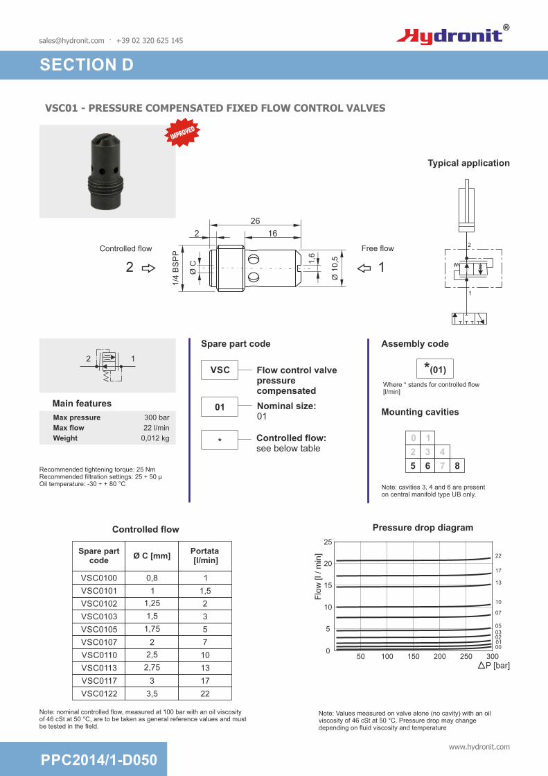
VSC01 - PRESSURE COMPENSATED FIXED FLOW CONTROL VALVES
0 1
2
5 6 7 8
3 4
Typical application
1
2
Max pressure 300 bar
Max flow 22 l/min
Weight 0,012 kg
2 1
Mounting cavities
Note: cavities 3, 4 and 6 are present on central manifold type UB only.
Recommended tightening torque: 25 NmRecommended filtration settings: 25 ÷ 50 µOil temperature: -30 ÷ + 80 °C
Main features
[email protected] · +39 02 320 625 145
Controlled flow
Spare partcode
Portata [l/min]
Ø C [mm]
VSC0100
VSC0101
VSC0102
VSC0103
VSC0105
VSC0107
VSC0110
VSC0113
VSC0117
VSC0122
0,8
1
1,25
1,5
1,75
2
2,5
2,75
3
3,5 22
1
1,5
2
3
5
7
10
13
17
Note: nominal controlled flow, measured at 100 bar with an oil viscosity of 46 cSt at 50 °C, are to be taken as general reference values and must be tested in the field.
Flow control valvepressurecompensated
Nominal size:01
VSC
01
Controlled flow:see below table
*
Spare part code
Note: Values measured on valve alone (no cavity) with an oil viscosity of 46 cSt at 50 °C. Pressure drop may change depending on fluid viscosity and temperature
Pressure drop diagram
P [bar]
Flo
w [l /
min
]
0100 150 200 250 300
0001020305
07
10
13
22
17
5
10
15
20
50
25
*(01)
Where * stands for controlled flow [l/min]
Assembly code
IMPROVED
PPC2014/1-D050www.hydronit.com
SECTION D
Free flowControlled flow
Ø 1
0,51,6
12 Ø C
26
2 16
1/4
BS
PP

VSC04 - PRESSURE COMPENSATED FIXED FLOW CONTROL VALVES
1
2
Typical application
Max pressure 300 bar
Max flow 22 l/min
Weight 0,012 kg
Mounting in cavity: 12,7 H8Recommended filtration settings: 25 ÷ 50 µOil temperature: -30 ÷ + 80 °C
[email protected] · +39 02 320 625 145
Mounting cavities
Flow control valvepressurecompensated
Nominal size:04
VSC
04
Controlled flow:see below table
*
Spare part code
0 1
2
5 6 7 8
3 4
2 1
Main features
Controlled flow
Spare partcode
Portata [l/min]
Ø C [mm]
VSC0400
VSC0401
VSC0402
VSC0403
VSC0405
VSC0407
VSC0410
VSC0413
VSC0417
VSC0422
0,8
1
1,25
1,5
1,75
2
2,5
2,75
3
3,5 22
1
1,5
2
3
5
7
10
13
17
Note: nominal controlled flow, measured at 100 bar with an oil viscosity of 46 cSt at 50 °C, are to be taken as general reference values and must be tested in the field.
Note: Values measured on valve alone (no cavity) with an oil viscosity of 46 cSt at 50 °C. Pressure drop may change depending on fluid viscosity and temperature
Pressure drop diagram
P [bar]
Flo
w [l /
min
]
0100 150 200 250 300
0001020305
07
10
13
22
17
5
10
15
20
50
25
*(04)
Where * stands for controlled flow [l/min]
Assembly code
Note: cavities 3, 4 and 6 are present on central manifold type UB only.
IMPROVED
PPC2014/1-D060www.hydronit.com
SECTION D
Free flowControlled flow
Ø 1
0,5
12 Ø C
Ø 1
2,7
1
25
17,6

VSC6 - PRESSURE COMPENSATED FIXED FLOW CONTROL VALVES
0 1
2
5 6 7 8
3 4
38
26,5
3/4
-16
UN
F -
2A
Ø 1
2,7
1
2
Hex. 22
Max pressure 350 bar
Max flow 22 l/min
Weight 0,06 kg
1 2
Main features
Note: cavities 3, 4 and 6 are present on central manifold type UB only.
Note: Values measured on valve alone (no cavity) with an oil viscosity of 46 cSt at 50 °C. Pressure drop may change depending on fluid viscosity and temperature
Mounting cavities
Recommended tightening torque: 25 NmRecommended filtration: 25 ÷ 50 µOil temperature: -30 ÷ + 80 °C
[email protected] · +39 02 320 625 145
Controlled flow
Spare partcode
Portata [l/min]
Ø C [mm]
VSC600
VSC601
VSC602
VSC603
VSC605
VSC607
VSC610
VSC613
VSC617
VSC622
0,8
1
1,25
1,5
1,75
2
2,5
2,75
3
3,5 22
1
1,5
2
3
5
7
10
13
17
Note: nominal controlled flow, measured at 100 bar with an oil viscosity of 46 cSt at 50 °C, are to be taken as general reference values and must be tested in the field..
Ø C
Flow control valvepressurecompensated
Nominal size:6
VSC
6
Controlled flow:see below table
*
Spare part code
Pressure drop diagram
P [bar]
Flo
w [l /
min
]
0100 150 200 250 300
0001020305
07
10
13
22
17
5
10
15
20
50
25
F*Where * stands for controlled flow [l/min]
Assembly code
IMPROVED
PPC2014/1-D070www.hydronit.com
SECTION D

SUV01 - START-UP VALVE FOR SINGLE PHASE ELECTRIC MOTORS
NEW
0
Q [l/min]
Fluid T [°C]Suggested fluid viscosity grade basing on temperature range
10
1
2
3
4
5
6
7
8
9
10
11
12
13
14
15
16
-10-20 20 30 40 50 60 70 80 90 100
SUV01C
SUV01D
SUV01E
SUV01F
SUV01G
SUV01H
SUV01I
SUV01L
SUV01N
ISO VG15 ISO VG60ISO VG46
It is intended to be mounted in cavity 9 of the central manifold, after an appropriate machining (drilling and threading) is made on it. The function of this valve is to discharge the pressure inside the central manifold between the pump and the check valve in cavity 0, when the power pack is off. It is typically used with single-phase motor starting under load, overcoming the inherent limitation of single phase induction motors.
0 1
2
5 6 7 8 9
3 4
Max pressure 300 bar
Max flow 17 l/min
Weight 0,025 kg
Main features
Note: cavities 3, 4 and 6 are present on central manifold type UB only.
Mounting cavities
Recommended tightening torque: 25 NmRecommended filtration: 25 ÷ 50 µOil temperature: -10 ÷ + 80 °C
Start-up valve for singlephase electric motors
Nominal size:01 = 1/4 BSPP
SUV
01
Flow reference:see below table for the proper choice depending on pump flow and fluid temperature
G
Spare part code
S01*
Where * stands for the setting
Assembly code
1/4
BS
PP
27
11,5
1
PPC2014/1-D080www.hydronit.com
[email protected] · +39 02 320 625 145
SECTION D

VUC20 - BASIC CHECK VALVES
0 1
2
5 6 7 8
3 4
12
Check valve
Nominal size: 20
Options:- = no optionsF = pressure port M 1/4 BSPP
VUC
20
The optional pressure port “F” may be used to connect a gauge to measure static pressures. Due to the nature of this Check Valve it will not always capture instantaneous pressure.
Hex. 22
27,5
12
38
3/4
-16
UN
F-2
A
Ø 1
2,7
2
1
Max pressure 350 bar
Max flow 25 l/min
Weight 0,052 kg
Pressione di apertura 0,5 bar
2
0 5 10 15 20 25
Portata [l / min]
4
6
8
P [bar]
1 2
Pressure drop diagram
Note: Values measured on valve alone (no cavity) with an oil viscosity of 46 cSt at 50 °C. Pressure drop may change depending on fluid viscosity and temperature
Assembly codeSpare part code
Mounting cavities
Main features
Recommended tightening torque: 25 NmRecommended filtration: 25 ÷ 50 µOil temperature: -30 ÷ + 80 °C
Note: cavities 3, 4 and 6 are present on central manifold type UB only.
30
[email protected] · +39 02 320 625 145
SECTION D
PPC2014/1-D090www.hydronit.com
J *where * is the option
*

[email protected] · +39 02 320 625 145
CPE - MANUAL EMERGENCY VALVES
1
2
0
2
5 6 7 8
3 4
1
Z
2
1
3/4-16 UNF-2A
61,5
26,525
Hex. 22
Ø 2
0
Max pressure 300 bar
Max flow 25 l/min
Weight 0,12 kg
Pressure drop diagram
Flow [l / min]
P [bar]
4
2
0
6
8
10
12
105 15 20 25
2 1
1 2
Operating force (daN)on the button
bar
daN
1 2
2 1
0
2,5
5
7,5
10
200100 300 400
Recommended tightening torque: 25 NmRecommended filtration: 25 ÷ 50 µOil temperature: -30 ÷ + 80 °C
Assembly code
Two-way manualemergency valve
CPE
Operating device: P = press button
P
Nominal size: 04 = 3/4-16 UNF
04
Spare part code
Mounting cavities
Main features
Note: cavities 3, 4 and 6 are present on central manifold type UB only.
Note: Values measured on valve alone (no cavity) with an oil viscosity of 46 cSt at 50 °C. Pressure drop may change depending on fluid viscosity and temperature
SECTION D
PPC2014/1-D100www.hydronit.com

[email protected] · +39 02 320 625 145
CM - MANUAL LEVER VALVES
Flow [l / min]
P [bar]
4
2
0
6
8
10
12
105 15 20 25
2 1
1 2
2
1
CM04MCM04L
2
1
0 1
2
5 6 7 8
3 4
E (CM04L)EM (CM04M)
Two-waymanual levervalve
Nominal size: 04 = 3/4-16 UNF
CM
04
Type: L = lever (std) M = lever+micro switch
L
26
1
2Optional
Micro switch
Open valve
Motor switch off, valve closed
Motor switch on
25
0
63
,5
3/4
-16
UN
F-2
A
ø1
2,7
58 29
30°
4xM
5
37
Max pressure 300 bar
Max flow 25 l/min
Weight 0,34 kg
Max current 10 A - 400 V
Protection IP20 (up to IP65
on request)
Room temp. -25°C ÷ +85°C(higher temperature
on request)
Fixing screws 4 x M5x45 (torque 5Nm)Cartridge tightening torque 20MnRecommended filtration: 25 ÷ 50 µOil temperature: -30 ÷ + 80 °C
Pressure drop diagram
M
Startingswitch
Microswitch
+
+-
-
Connectionexample
Assembly codeSpare part code
Mounting cavities
Main features
Note: cavities 3, 4 and 6 are present on central manifold type UB only.
Note: Values measured on valve alone (no cavity) with an oil viscosity of 46 cSt at 50 °C. Pressure drop may change depending on fluid viscosity and temperature
IMPROVED
SECTION D
PPC2014/1-D110www.hydronit.com

PMC - CARTRIDGE HAND PUMPS
0 1
2
5 6 7 8
3 4
Hand pump
Nominal size: 02 = 2 cc/stroke
PMC
02
L Type: L = lever (std)
U
25
0
63
,5
3/4
-16
UN
F-2
A
ø1
2,7
58
pump suction
29
30°
S
P
4xM
5
37
Max pressure 200 bar
Max flow -
Weight 0,34 kg
S
P
Effort (daN)operating on the lever end
Pressure [bar]
Effort
[daN
]
Assembly codeSpare part code
Mounting cavities
Main features
Note: cavities 3, 4 and 6 are present on central manifold type UB only.
Fixing bolts: 4x M5x45 (tightening torque: 5 Nm)Recommended cartridge tightening torque: 15 NmRecommended filtration: 25 ÷ 50 µOil temperature: -30 ÷ + 80 °C
Note: Values measured on valve alone (no cavity) with an oil viscosity of 46 cSt at 50 °C. Pressure drop may change depending on fluid viscosity and temperature
[email protected] · +39 02 320 625 145
SECTION D
PPC2014/1-D120www.hydronit.com

MSV - PILOT OPERATED TWO-WAY SINGLE LOCKING SOLENOID VALVES
P [bar]
Flow [l / min]
3
0
6
9
12
15
10 20 30 40
1 2
0 1
2
5 6 7 8
3 4
Pressure drop diagram
Pilot Operated 2-waySingle Locking Valve
Operation: 30 = normally closed 31 = normally open
Supply voltage: 0000 = no coil (std) see D190 table
MSV
30
0000
Emergency override: 0 = no emergency (std) E = emergency
Options: R = with reversible flow A = for AC coil
0
-
Max pressure up to 350 bar
Max flow up to 40 l/min
Weight 0,11 Kg (without coil)
Internal leakage 5 drops/min at 350bar
Response time30ms (energizing)
50ms (de-energizing)
Available voltages
12VDC24VDC24VAC
110RAC220RAC
Coils (see page D180)M130 seriesM630 seriesM631 series
Standards
EN50081-1/EN50082-2(89/336 CEE
electromagnetic comp.)73/23/CEE / 96/68/CEE
(low voltage)
Note: cavities 3, 4 and 6 are present on central manifold type UB only.
Note: Values measured on valve alone (no cavity) with an oil viscosity of 46 cSt at 50 °C. Pressure drop may change depending on fluid viscosity and temperature
Assembly codeSpare part code
Main features
[email protected] · +39 02 320 625 145
Recommended tightening torque: 25 NmRecommended filtration settings: 25 ÷ 50 µOil temperature: -30 ÷ + 80 °C
SECTION D
PPC2014/1-D130www.hydronit.com
MSV31E MSVR31*
1 1
2 2
1
2
MSV31
MSV30E MSVR30*
1 1
2 2
1
2
MSV30
Options
4 mm stroke
20
78
Screwemergency
Ø 3
3
2858
98
59
Reversible flow(optional)
Hex. 24
3/4
-16
UN
F-2
A
2
1
Normally closed
Screwemergency
4 mm stroke
16
74
Ø 3
3
2759
100
59
Reversible flow(optional)
Hex. 24
3/4
-16
UN
F-2
A
2
1
Normally open
Eg: A12DC
A (MSV30) VoltageB (MSV30E) VoltageQ (MSV31) VoltageC (MSV31E) Voltage
Mounting cavities

MDV - DIRECT OPERATED TWO-WAY DOUBLE BLOCKING SOLENOID VALVES
Flow [l / min]
P [bar]
0
10
5
15
20
5 10 15
1 2
1
2
0 1
2
5 6 7 8
3 4
Two-waydouble blockingsolenoid valveOperation: 30 = normally closed
MDV
30
0000
Option: E = emergency (std)
E
Supply voltage: 0000 = no coil (std) see D190 table
Pressure drop diagram
D Voltage
eg: D24DC
Max pressure up to 250 bar
Max flow up to 40 l/min
Weight 0,11 Kg (without coil)
Internal leakage 5 drops/min at 350bar
Response time30ms (energizing)
50ms (de-energizing)
Available voltage
12VDC24VDC24VAC
110RAC220RAC
Coils (see page D180)M130 seriesM630 seriesM631 series
Normatives
EN50081-1/EN50082-2(89/336 CEE
electromagnetic comp.)73/23/CEE / 96/68/CEE
(low voltage)
Mounting cavities
Note: cavities 3, 4 and 6 are present on central manifold type UB only.
Note: Values measured on valve alone (no cavity) with an oil viscosity of 46 cSt at 50 °C. Pressure drop may change depending on fluid viscosity and temperature
Assembly codeSpare part code
Main features
[email protected] · +39 02 320 625 145
Recommended tightening torque: 25 NmRecommended filtration: 25 ÷ 50 µOil temperature: -30 ÷ + 80 °C
SECTION D
PPC2014/1-D140www.hydronit.com
Ø 3
32762
94
59
Reversible flow(optional)
Hex. 24
3/4
-16
UN
F-2
A
2
1
Emergency override (push)

MSV4V - DIRECT OPERATED 4/3 OR 4/2 DIRECTIONAL SPOOL SOLENOID VALVES
0 1
2
5 6 7 8
3 4
4VA2 Voltage
Ex: 4VA2 24DC
4/3 or 4/2directional spool solenoid valve
Spool configuration: see side table
Note: cavities 3, 4 and 6 are present on central manifold type UB only.
Note: MS4V may only be fitted to type U4 central manifold
Code3 1
2 4
Double solenoid
C2
B2
E2
A2
Single solenoid
transitory
ba 0
Option: 00 = std
MSV4V
A2
00
Supply voltage: see D190 table
24DC
A11C
Max pressure 210 bar
Max flow 11,5 l/min
Weight0,37 Kg (1 solenoid)0,64 Kg (2 solenoid)
Internal leakage 278 cc/min at 210 bar
Minimum pull-involtage
85% of nominal
Available voltage
12VDC24VDC24VAC
110RAC220RAC
Bobine (vedere tabella pag. D180)
serie M630serie M631
Normatives
EN50081-1/EN50082-2(89/336 CEE
electromagnetic comp.)73/23/CEE / 96/68/CEE
(low voltage)
Mounting cavities
Assembly codeSpare part codeMain features
4
4
4
4
2
2
2
2
3
3
3
3
1
1
1
1
Spool
[email protected] · +39 02 320 625 145
S1 S2
42
3 1
Recommended tightening torque: 25 NmRecommended filtration: 25 ÷ 50 µOil temperature: -30 ÷ + 80 °C
SECTION D
PPC2014/1-D150www.hydronit.com
Only for three-position spool
1
4 23
3/4-16 UNF-2A 4 ways
S1 S2
Ø 3
3
5585
48
59
158

VMPC2 - PROPORTIONAL PRESSURE RELIEF VALVES
0 1
2
5 6 7 8
3 4
P*** VoltageDirect acting proportional relief valve
VMPC
Nominal size: 2 = 2 l/min
Supply voltage: - 0000 = no coil - 12DC - 24DC
2
0000
Working range: A = 2 ÷ 80 bar C = 4 ÷ 250 bar
C
Options:E = emergency std
E
1 2
where *** stands for max setting pressure [bar]. eg. P25012DC
Note: Supplying current to the coil from 0 to I max (see diagram), a proportional pressure variation is obtained on port P.
For the controller see table D180
Supply Voltage
Code for Coil
Code forConnector
12DC 098001190 KA132000B1
24DC 098002190 KA132000B1
Sezione bobine
Max pressure
350 bar
Max flow 2l/min
Weight 0,46 Kg
PWM 120Hz
Hysteresis 5%
Duty cycle ED 100%
Voltage +/- 10% nominal voltage
NormativesEN50081-1/EN50082-2(89/336
CEE electr. comp.) - 73/23/CEE / 96/68/CEE (low voltage)
Mounting cavities
Note: cavities 3, 4 and 6 are present on central manifold type UB only.
Assembly codeSpare part code
Main features
Note: Values measured on valve alone (no cavity) with an oil viscosity of 46 cSt at 50 °C. Pressure drop may change depending on fluid viscosity and temperature
Recommended tightening torque: 25NmRecommended filtration: 25 ÷ 50 µOil temperature: -30 ÷ + 80 °C
[email protected] · +39 02 320 625 145
SECTION D
Pre
ssure
[bar]
Flow [l/min]
3
6
9
01 2 3 4 5
C
A
12
15
18
Pressure drop diagram Pressure vs current
Pre
ssure
[bar]
50
100
150
200
C
A
250
300
Current [A]
0
0
0,2
0,4
0,4
0,8
0,6
1,2
0,8
1,6
1
2
24V DC
12V DC
PPC2014/1-D160www.hydronit.com
113
89 27
ø 3
8
2
1
Hex. 20
3/4
-16
UN
F-2
B
59

CSPC15 - PROPORTIONAL FLOW CONTROL VALVES
0 1
2
5 6 7 8
3 4
eg: T12DC
T*** VoltageProportional flow control valve
CSPC
Nominal size: 15 = 15 l/min
Supply voltage: - 0000 = no coil - 12DC - 24DC
15
0000
Option: 0 = no option
0
For the controller see table D180
Mounting cavities
Note: cavities 3, 4 and 6 are present on central manifold type UB only.
Spare part code
Main features
Assembly code
Max press. 210 bar
Max flow 22 l/min
Weight 0,1 Kg (without coil)
PWM 120Hz
Hysteresis 5% (10% above 85% Imax)
Duty cycle ED 100%
Voltage +/- 10% nominal voltage
NormativesEN50081-1/EN50082-2
(89/336 CEE)73/23/CEE / 96/68/CEE
Oil temperature
-40 - +120°C
Filtration 10 ÷ 25 µ
Tightening torque
30Nm
Flow vs currentat different pressure drops
Flo
w [
l/min
] [g
pm
]
37.9/10.0
34.1/9.0
30.3/8.0
26.5/7.0
22.7/6.0
18.9/5.0
15.2/4.0
11.4/3.0
7.6/2.0
3.8/1.0
0
207 bar3000 psi
104 bar1500 psi
35 bar500 psi
17 bar250 psi
0,120
0,20,340
0,60,560
1,00,780
1,40,9100 % of max I
I [A] coil 12DCI [A] coil 24DC
1,8
P [bar]
/[psi
]
Q [l/min] [gpm]
Pressure Drop 2 > 1with fully open valve
3.4/50
6.9/100
10.3/150
13.8/200
17.2/250
20.7/300
24.1/350
27.6/400
31.0/450
7.62
15.14
22.76
30.38
Coil selection
Supply voltage
Spare part code
12DC M6306012
24DC M6306024
Note: Values measured on valve alone (no cavity) with an oil viscosity of 46 cSt at 50 °C. Pressure drop may change depending on fluid viscosity and temperature
[email protected] · +39 02 320 625 145
SECTION D
PPC2014/1-D170www.hydronit.com
Ø 3
3
2847
88
59
Hex. 24
3/4
-16
UN
F-2
A
2
1
Hex. 19

VPC - ELECTRONIC AMPLIFIER FOR PROPORTIONAL SOLENOID VALVES
Electronic amplifierfor solenoid valves
VPC
Options00
Electric circuit
2
+-
3
POT
1
Spare part codeMain features
Suitable for: - CSPC15**** proportional flow control valve- VMPC2**** proportional pressure relief valve
I(A
)
I(A
)
t sec t sec0
--
+
+
0
Ramp adjustment (up) Ramp adjustment (down)
Instruction for use:1) turn the “I MIN” trimmer fully counterclockwise;2) adjust the external voltage input signal to the desired initial regulating (flow or pressure) value; 3) turn “I MIN” trimmer in a clockwise direction until valve just starts regulating; 4) adjust the external voltage input signal to the max value and adjust “I MAX” trimmer until the valve regulates the maximum flow or pressure on the hydraulic system.
3996
75
ISO 4400 / DIN 43650-A
PWMFreq
I.min
I.max
Ramp
+
+
+
+
+
Ramp
Supply voltage 12 / 24V DC
Voltage input signal range
0 ~ 10 V
Max current range 2,5A
PWM(optionally adjustable)
120 Hz(50 ÷ 400 Hz)
Ramp adjustment (independent)
5%
Input impedance 100 kohm
Voltage+/- 10% nominal
voltage
Weight 0,11 kg
Normatives
EN50081-1/EN50082-2(89/336 CEE
electromagnetic comp.)73/23/CEE / 96/68/CEE
(low voltage)
[email protected] · +39 02 320 625 145
SECTION D
PPC2014/1-D180www.hydronit.com

Supplyvoltage
[V]
Assembly code
Coil typeSpare part
code
Spare connector
code
Holding Power
[W]
Duty charge ED [%]
Prot. class
Wt[g]
Suitable for
valves
12DC 12DC_M630 DC M6306012 KA132000B1 18W 100 H 130
MSV30/31MDV
MSV4VCSPC15
24DC 24DC_M630 DC M6306024 KA132000B1 18W 100 H 130
MSV30/31MDV
MSV4VCSPC15
24AC 24AC_M631RC with
integrated rectifying bridge
M6316024 KA132000B1 18W 100 H 130MSV30/31
MDVMSV4V
115AC 115AC_M631RC with
integrated rectifying bridge
M6316115 KA132000B1 18W 100 H 130MSV30/31
MDVMSV4V
230AC 230AC_M631RC with
integrated rectifying bridge
M6316230 KA132000B1 18W 100 H 130MSV30/31
MDVMSV4V
12DC 12DC_M130 DC M13040001 KA132000B1 18W 75 H 139MSV30MSV31MDV
115AC 50Hz
115AC_50AC_M130
AC - not usable on
N Open valvesM13040006 KA132000B1 28VA 75 H 139 MSV30
MDV
115AC 110RAC_M130RC - needs
external rectifying connector
M13040004 KA132R12B1 18W 75 H 139MSV30MSV31MDV
230AC220RAC_M13
0
RC - needs external rectifying
connectorM13040005 KA132R13B1 18W 75 H 139
MSV30MSV31MDV
12DCEmbedded code in
the code proportional valve VMPC2
DC 098001190 KA132000B1 36W 100 H 257 VMPC2
24DCEmbedded code in
the code proportional valve VMPC2
DC 098002190 KA132000B1 36W 100 H 247 VMPC2
Other voltages and electric connector types (Amp Junior, flying leads,...) available on request.Inrush power consumption can be up to 3,5 times higher than holding power.Coil thermal insulation: Class H. Electric connection: DIN 43650-A / ISO 4400. Coil protection degree: Ip65
COILS FOR VALVES
[email protected] · +39 02 320 625 145
M630* / M631* 09800*M130*
SECTION D
PPC2014/1-D190www.hydronit.com

PLUGS
Note: cavities 3, 4 and 6 are present on central manifold type UB only.
P T
49,5
M20 x
1,5
Hex. 22
37
Hex.
22
12,7
3/4
-16 U
NF
26,510,5
1/4
BS
PP
Spare part code
Hydraulic symbol
E70100005
Spare part code
Hydraulic symbol
E70100002
Spare part code
Hydraulic symbol
E70100010
Spare part code
Hydraulic symbol
E70100003
37
Hex.
22
12,7
3/4
-16 U
NF
26,510,5
Mounting cavities
Assembly code
G
0
0
0
1
2
5 6 7 8
3 4
Mounting cavities
Assembly code
H
1
2
5 6 7 8
3 4
Mounting cavities
Assembly code
N
0 1
2
5 6 7 8
3 4
Mounting cavities
Assembly code
XP
0 1
2
5 6 7 8
3 4
37
Hex.
22
12,7
3/4
-16 U
NF
26,510,5
1/4
BS
PP
2 3
P
PSpare part code
Hydraulic symbol
E70100006
Mounting cavities
Assembly code
P
1
2
5 6 7 8
3 4
3/4
-16 U
NF
Ø 2
5
Ch. 10
11,53
Spare part code
Hydraulic symbol
E70100004
Mounting cavities
Assembly code
L
10
2
5 6 7 8
3 4
Weight: 0,047 Kg
Weight: 0,042 Kg
Weight: 0,045 Kg
Weight: 0,027 Kg
Weight: 0,110 Kg
Weight: 0,066 Kg
22
Hex.
22
3/4
-16 U
NF
11,510,5
1/4
BS
PP
[email protected] · +39 02 320 625 145
SECTION D
PPC2014/1-D200www.hydronit.com


SECTION E
TANKS
Plastic or steel tanks?Plastic tanks have various advatanges: they do not rust, the oil level is visible and they do not damage easily if bumped,... On the other hand steel tanks are preferable in case of ultra high or ultra low temperatures. They are the only choice for volumes over 11 l.
Is it possible to use custom made tanks?Yes. We can provide an adaptor flange (F80000001) which can be welded by a customer on a custom made tank.
How do I order spare tanks?Tanks can be ordered without accessories just by adding a J in front of the relevant code (e.g. JE60303015 instead of E60303015). When ordered with the normal code (e.g. E60303015) they include the relevant accesories such as: plugs, filler breather, oil level gauge, fixing devices,... depending on the kind of tank. Tanks specified in PPC speaking code (e.g. 5BV) always include all the relevant accessories.
Cylindrical steel tanks from 1,5 to 12 l, for horizontal and vertical mounting
Square steel tanks from 3 to 30 l
Round plastic tanks with 5 or 11 l volume, for horizontal or vertical mounting.
Square plastic tanks, from 1,5 to 8 l, for horizontal or vertical mounting
[email protected] · +39 02 320 625 145
PPC2014/1-E000www.hydronit.com

CYLINDRICAL STEEL TANKS A & B SERIES
Notes: the piping kit, standard suction filter, filler/breather and drain plug are included when specifying the tank in PPC assembly code. When ordering spare parts, only the drain plug and filler/breather are included.
1/2 BSPP
132,5130 -
13
2,5
13
0 -
102,5
117,4
10
2,5
117
,4Ø123
1/2 BSPP
42
L
42
ø1
30
Ø123
All dimensions are in mm
Material Fe P04-EN10130 steel sheet 1,5mm thickness
Mineral based oil ISO/DIN 6743/4
Recommended tighteningtorque for Filler Cap: 5 Nm
Recommended tighteningtorque for Filler Cap: 5 Nm
-15 / +70°C
Fluid
Working temperature
E60303001 150 0,78 Kg
1,04 Kg235E60303004
Spare partcode
WeightL
(mm)Assembly code
1,5A / 1,5AV
2,5A / 2,5AV
Description
1,5 l cylindrical horizontal / vertical mounting
2,5 l cylindrical horizontal / vertical mounting
1,0
2,0
Horizontal Vertical
Actual filling volume (lt)
1,5
2,5
1,82 Kg
2,01 Kg
2,47 Kg
Weight
E60303006
E60303011
E60303012
Spare partcode
Assembly code
5B / 5BV
10B / 10BV
12B / 12BV
Description
5 l cylindrical horizontal / vertical mounting
10 l cylindrical horizontal / vertical mounting
12 l cylindrical horizontal / vertical mounting
300
262
380
L(mm)
180
220
220
ØD(mm)
5,1
6,3
10,9
Horiz. Vert.
Actual fillingvolume (lt)
6,3
8,3
12,5
[email protected] · +39 02 320 625 145
SECTION E
PPC2014/1-E010www.hydronit.com
36,5
36,5
132,5130 -
132,5
130 -
102,5
117,4
102,5
117,4
L
1/2 BSPP
1/2 BSPP
ØD

HORIZONTAL/VERTICAL SQUARE WELDED STEEL TANKS C SERIES
34
50
r=5,5
25
1/2
BS
PP
L
B
B
=
=
=
=d
123
210(10C) - 245(22C)
13
0
102,5
Ø
117,5
Notes: the piping kit, standard suction filter, filler/breather and drain plug are included when specifying the tank in PPC assembly code. When ordering spare parts, only the drain plug and filler/breather are included.
On request special square welded tanks can be manufactured. An inquiry must be sent to our technical department with indication of quantities.
All dimensions are in mm
20
5
14
6
15
6==
E60303042
E60303044
Spare partcode
Assembly code
10C / 10CV
22C / 22CV
Description
10 l square horiz. / vert. mounting
22 l square horiz. / vert. mounting
L(mm)
330
470
Weight
5,50 Kg
6,80 Kg
B(mm) d
185
223
1/2 BSPP
3/4 BSPP
Horiz. Vertical
Actual fillingvolume (lt)
9,6
20,6
8,1
18,5
Material Fe P04-EN10130 steel sheet 1,5mm thickness
Mineral based oil ISO/DIN 6743/4
-15 / +70°C
Fluid
Working temperature
[email protected] · +39 02 320 625 145
PPC2014/1-E020www.hydronit.com
SECTION E

SMALL SIZE SQUARE WELDED STEEL TANKS E SERIES
Notes: the piping kit, standard suction filter, filler/breather and drain plug are included when specifying the tank in PPC assembly code. When ordering spare parts, only the drain plug and filler/breather are included.
All dimensions are in mm
Material Fe P04-EN10130 steel sheet 1,5mm thickness
Mineral based oil ISO/DIN 6743/4
-15 / +70°C
Fluid
Working temperature
276
30
A
160
30
1/2 BSPP
N. 4 bolts M6
1/2 BSPP
25
30
15
=
=
=
=
123
130
102,5
Ø
117,5
165 10550,560,5
E60303053
E60303057
Spare partcode
Assembly code
3EV
7EV
Description
3 l square vertical mounting
7 l square vertical mounting
A
98 mm
190 mm
Weight
3,09 Kg
4,32 Kg
-
-
4,2
8,3
Horizontal Vertical
Actual filling volume (lt)
[email protected] · +39 02 320 625 145
SECTION E
PPC2014/1-E030www.hydronit.com

SMALL SIZE SQUARE WELDED STEEL TANKS E SERIES
N. 4 holes ø 11
Notes: the piping kit, standard suction filter, filler/breather and drain plug are included when specifying the tank in PPC assembly code. When ordering spare parts, only the drain plug and filler/breather are included.
All dimensions are in mm
Material Fe P04-EN10130 steel sheet 1,5mm thickness
Mineral based oil ISO/DIN 6743/4
-15 / +70°C
Fluid
Working temperature
146
156
306
32
32
205
328
A
256
1/2 BSPP
25
355
115
26
= =
= =
123
130
102,5
Ø
117,5
3/4 BSPP
24,5
Description
8 l square vertical mounting
15 l square vertical mounting
A
133 mm
237 mm
Weight
4,50 Kg
5,20 Kg
-
-
10,4
18,5
Horizontal VerticalActual filling volume (lt)
[email protected] · +39 02 320 625 145
E60303041
E60303014
Spare partcode
Assembly code
8EV
15EV
SECTION E
PPC2014/1-E040www.hydronit.com

SQUARE WELDED STEEL TANKS E SERIES
A
50
320
Notes: the piping kit, standard suction strainer, filler/breather, level gauge and drain plug are included when specifying the tank in PPC assembly code.When ordering spare tanks, only the drain plug, filler/breather and level gauge are included.
On request special square welded tanks can be manufactured. An inquiry must be sent to our technical department with indication of quantities.
26
30
76
1/2 BSPP
MaterialFe P04-EN10130 steel sheet 2,5mm thickness
on top and side, 1,5mm thickness front and rear
Mineral based oil ISO/DIN 6743/4
-15 / +70°C
Fluid
Working temperature
28
0 ==
30
15
350
3/4 BSPP
30
60
115N. 4 holes Ø11
15
15 15
123
13
0
102,5
Ø
117,5
E60303015
E60303048
Spare partcode
Assembly code
20EV
30EV
Description
20 l squared vertical mounting
30 l squared vertical mounting
A
293 mm
423 mm
Weight
6,50 Kg
8,50 Kg
-
-
20,8
33,5
Horizontal VerticalActual filling volume (lt)
[email protected] · +39 02 320 625 145
SECTION E
PPC2014/1-E050www.hydronit.com
All dimensions are in mm

SQUARE PLASTIC TANKS L & M SERIES
Material PE-HD neutral / transparent colour (DO NOT EXPOSE TO DIRECT SUNLIGHT)
Mineral based oil ISO/DIN 6743/4
-15 / +70°C
Fluid
Working temperature
33
L
45°
10
2,5
102,5
140
=
=
=
=
17
0
Ø123
Notes: the piping kit, standard suction strainer and filler/breather are included when specifying the tank in PPC assembly code. When ordering spare tanks, only the filler/breather C86100003 or C86100001 and clamp band are included. Discharge ports are normally moulded blind.
15
H60303016 135 2,4
4,4
6,2
1,5
4,2
6,6
250
350
H60303018
H60303020
Spare partcode
L(mm)
Assembly code
1,5L / 1,5LV
3L / 3LV
6L / 6LV
Description
1,5 l square horizontal / vertical mounting
3 l square horizontal / vertical mounting
6 l square horizontal / vertical mounting
WeightHorizontal Vertical
0,32 Kg
0,42 Kg
0,63 Kg
Actual filling volume (lt)
L
40130
45°
10
2,5
102,5
170
=
=
=
=
17
0
15
Ø123
only for 8M tank
5M / 5MV5 l square horizontal / vertical mounting
8M / 8MV8 l square horizontal / vertical mounting
H60303025 270
375H60303033
Spare partcode
L(mm)
Assembly codeDescription WeightHorizontal VerticalActual filling volume (lt)
0,60 Kg
0,76 Kg
5,8
8,1
5,7
8,8
[email protected] · +39 02 320 625 145
SECTION E
PPC2014/1-E060www.hydronit.com

CYLINDRICAL PLASTIC TANKS P SERIES
L
40
ø 1
95
Ø123
Spare partcode
L(mm)
Assembly codeDescription WeightHorizontal Vertical
5P / 5PV5 l cylindrical horizontal / vertical mounting
7P / 7PV
9P / 9PV
11P / 11PV
7 l cylindrical horizontal / vertical mounting
9 l cylindrical horizontal / vertical mounting
11 l cylindrical horizontal / vertical mounting
H60303028 219
271
323
453
H60303030
H60303032
H60303035
Actual filling volume (lt)
0,60 Kg
0,61 Kg
0,76 Kg
1,06 Kg
5,0
6,0
7,2
9,0
4,2
5,5
6,5
10,5
Material PE-HD neutral / transparent colour (DO NOT EXPOSE TO DIRECT SUNLIGHT)
Mineral based oil ISO/DIN 6743/4
-15 / +70°C
Fluid
Working temperature
Notes: the piping kit, standard suction strainer and filler/breather are included when specifying the tank in PPC assembly code. When ordering spare tanks, only the filler/breather C86100003 or C86100001 and clamp band are included. Discharge ports are normally moulded blind. On request these tanks are available with an offset collar. Enquire for details.
[email protected] · +39 02 320 625 145
IMPROVED
SECTION E
PPC2014/1-E070www.hydronit.com

TANKS PLUGS AND ACCESSORIES
ø B
A
DC
C86100001 (1/2 BSPP)C86100002 (3/4 BSPP)
Suitable for B/BV type tanks (1/2” BSPP)Suitable for EV type tanks (3/4” BSPP)
Filler breather1/2” - 3/4” BSPP
B
A
C
47
21 17
30
10 17
D
1/2”
1/2”
3/4”
3/4”
Spare part code
TCNB0800 (plastic)TB050801 (steel)
Suitable for all steel tanks
Drain plug
½” BSPP
ø 30
Hex 105
AA
15TCNB0800
TB050801 19
Spare part code
Suitable for L/M type tanksonly upon request and for small batches
C86200002
Filler breather slip-in
ø 36
ø 20
ø 24
41
Spare part code
3/4” BSPP femaledrain plug
Spare part code
E60513005
Suitable for all series plastic tanks
ø 36
3/4 BSPP
11,5
16,5
Filler breather3/4” BSPP female
Spare part code
C86100003
Suitable for all series plastic tanks
ø 37,5
3/4 BSPP
191
0
To fit inlet strainers C34100005 to Gr.1 pumps
Spare part code
3/8’’ suction pipe
PP02**
3/8
BS
PT
3/8
BS
PP
L
1/4
BS
PT
3/8
BS
PP
L
Spare part code
Recommended for horizontal tanks
90° elbow for suction pipeM 1/4” & 3/8’’ BSPT - M 3/8’’ BSPP
PP0*E**
40
40
1/4 BSPT
1/4 BSPT
3/8 BSPT
3/8 BSPT
77
77
PP01E40
PP02E40
PP01E77
PP02E77
L D
Filter not included
in the code
32,5
3/8 BSPP
D
L
30
80
120
PP0130
PP0180
PP01120
L
PP01**
1/4’’ - 3/8" suction pipe
To fit inlet strainers C34100005 to Gr.0 pumps
Spare part code
1/4” suction/return pipe
Spare part code
PP01370
370PP01370
L1
/4 B
SP
P
1/4
BS
PP
L
Recommended as suction pipe for PMC02 hand pumps and as return
pipe with C3420001 return filter.
[email protected] · +39 02 320 625 145
4268
PP0242
PP0268
PP02105
PP02125
PP02180
PP02142
PP02237
PP02190
PP02165
105125
165
180
142
237
L
PP02370 370
190
Weight: 0,02 Kg
Weight: 0,01 Kg Weight: 0,01 Kg Weight: 0,04 Kg
Weight: 0,01 Kg Weight: 0,02 Kg Weight: 0,01 Kg
Weight: 0,04 Kg
Weight: 0,01 KgWeight: 0,02 Kg
SECTION E
PPC2014/1-E080www.hydronit.com

27
44
1/2 BSPP
1/2
BS
PP
Standard inlet strainer filtersFiltration degree: 90 micron
Weight: 0,01 Kg
C34100005
Spare part code
60
24
3/8 BSPT
130
Unpainted, to be welded on custom made tanks
123
28102,5
117,5
Ø
Bare steel tank adapter
Weight: 0,18 Kg
F80000001
Spare part code
Inlet eccentric filtersFiltration degree: 90 micron
Recommended for 1,5 l tanks horizontal mounting
Weight: 0,13 Kg
C34100001
Spare part code
3/8 BSPT
ø8
0 15
2126
126
1/4 BSPP
ø 32
Return filterFiltration degree: 90 micron
Weight: 0,09 Kg
C34200001
Spare part code
Suitable for all tanks over 3l
1/4 BSPP
to be fitted in
20
12,4
It reduces foam and noise when relief valve is working
Recommended for all vertical mounted tanks.
Relief valve diffuserTo be mounted in cavity Tr
Weight: 0,01 Kg
SFEP01D
Spare part code
46
,5
10
1/4 BSPT
Ø11,8
Flexible plastic pipe holderfor return line 1/4’’ BSPT
Weight: 0,01 Kg
TR0112
Spare part code
90° adapter for vertical tanks
Weight: 0,02 Kg
E60513004
Spare part code
L
Ø12
Ø17
Recommended as standard return pipe.To be fixed with TR01-12 and cut to correct length.To be ordered in meters.
Flexible plastic pipe
Weight: 0,18 Kg/meter
SF12
Spare part code
[email protected] · +39 02 320 625 145
TANK ACCESSORIES
Micro inlet filtersFiltration degree: 90 micron
Recommended for pumps gr. 0
Weight: 0,01 Kg
C34100100
Spare part code
1/4
BS
PP
151/4 BSPP
SECTION E
PPC2014/1-E090www.hydronit.com

SECTION F
EXTERNAL MANIFOLDS & ACCESSORIES
How many types of external manifold blocks can be mounted?The central manifold exit face allows the mounting of two different block systems, fixed by 2x M8 bolts (normally used for cetop3 modular manifolds stacks) or 4x M6 bolts (for modular manifolds for cartridge valves). The two types of bolt systems cannot be mixed on the same stack. For every product code the fixing system type is clearly displayed in following tables. To mount stackable directional valves or NG3 MICRO directional valves an adaptor plate is required. See section G for the relevant valve details.
When do I need to mount the 28mm spacer block?Whenever a big motor is mounted on the power pack. Normally the E60403004 spacer must be mounted below the stack of Cetop3 blocks with AC motors with frame 80 or higher and with DC motors with frame 125 or higher.
When are the modular manifolds for differential area cylinders used?With UR central manifolds, for reversible pump circuits, the exit port are A and B instead of P and T. With differential area cylinders, when the bidirectional pump flow is outputting to B port, there will be more flow returning to A port, connected to the piston side of the cylinder, than that going to B port, connected to the rod side, due to the cylinder differential area ratio. This function of this block is to discharge the extra flow generated to tank as this cannot be absorbed by the pump itself.
Pilot operated check valves can be integrated within modular manifold blocks for NG6 (Cetop 3) valves, thus avoiding the extra modular Cetop 3 sandwich type valve between the base block and the spool valve
Standard NG6 (Cetop 3) base modular manifold blocks with parallel or series connections, rear or lateral ports. They can be stacked one upon the other. Top manifold P and T ports can be plugged with simple 1/4" or 1/8" BSP plugs
The pressure line or return line filters are mounted in a modular manifold which can be stacked under NG6 (Cetop 3) modular manifolds
A full set of accessories is available to complete the power pack configuration
The NG3 MICRO set of blocks and valves is an ultracompact and cost effective alternative to NG6 (Cetop3), up to 15 l/min. They can be mounted thanks to the PPC-to-PPM adaptor
External hand pumps of 4 cc or 8,8 cc/stroke can be fixed between the central manifold and the Cetop3 modular block. The lever may be rotated 360° enabling you to set it to the best position
[email protected] · +39 02 320 625 145
PPC2014/1-F000www.hydronit.com
The PPC-to-SD01 stackable valve converter lets you mount our range of modular stackable valves. This is an up-to-date and lightweight alternative to NG6 (Cetop3) directional valves

EXTERNAL MANIFOLDS & VALVE MOUNTING EXAMPLES
PPC + NG6 (CETOP 3) BLOCKS & VALVES
PPC + NG3 MICRO BLOCKS & VALVESPPC + SD02 STACKABLE VALVES
0 1 2
3
4 4.1
5 5.1
0
12
2.3
2.1
2.2
34
4.13.1
3.2
5
3.1
The mini powerpack external manifolds and valves are arranged following a stack level logic. Each stack is numbered eg. n, n.1, n.2, n.3,... where n is the basic manifold stack number, n.1 is the first valve mounted on top of manifold n; n.2 is the second one mounted on top of n.1,... See above self-explanatory drawings where are coloured in manifolds orange and in valves green. Stack levels redare numbered in .
PPC TO SD02 STACKABLE VALVE CONVERTER
CLOSED END PLATE SD02
PPC TO PPMCONVERTER
SD00
SD03
M60403004
E60403004
M60403005
E60403002
E60423001**
E60433001
E60403001 E60403010 E60413001
M60403010
[email protected] · +39 02 320 625 145
PPC2014/1-F010www.hydronit.com
SECTION F
0 1
1.21.1
2.22.1
3.23.1
4.24.1
2 3 4 5
SD02
X.1 side A portX.2 side B port(only TP version)
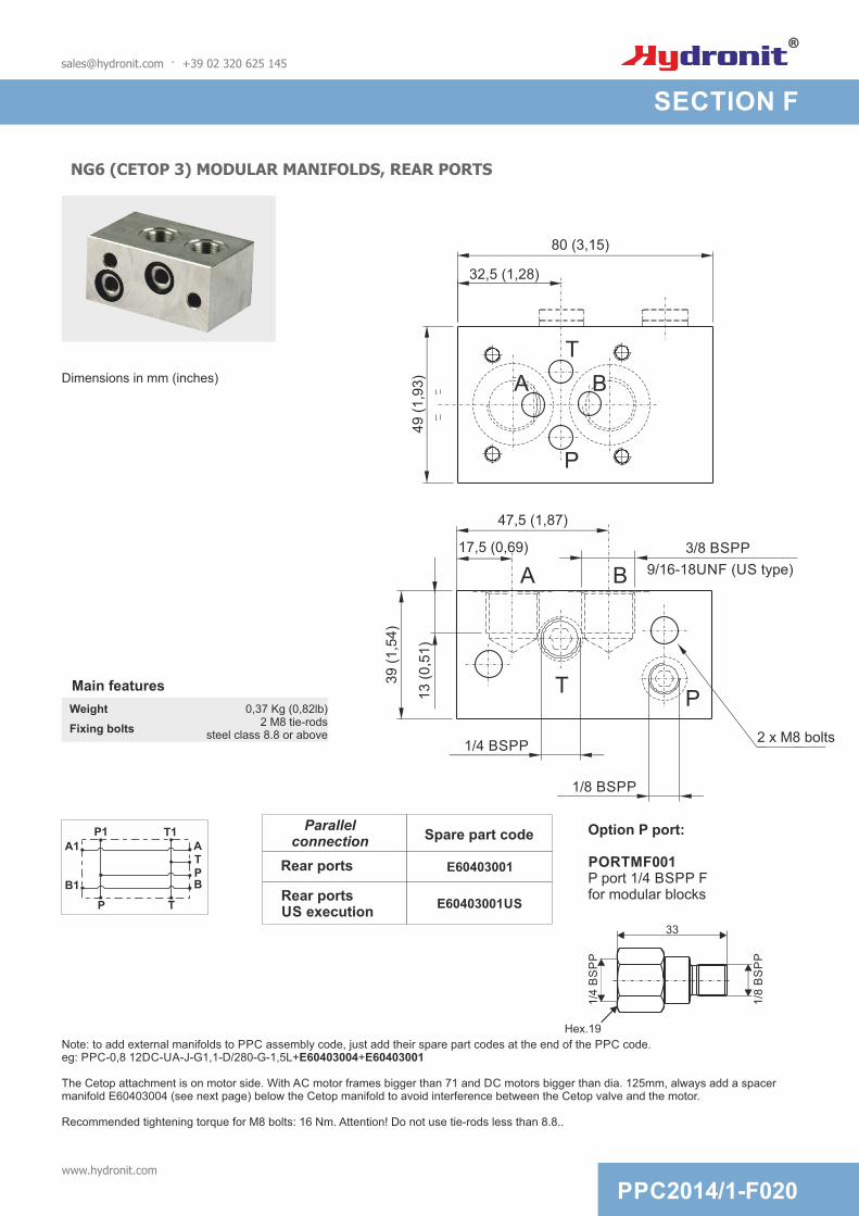
NG6 (CETOP 3) MODULAR MANIFOLDS, REAR PORTS
3/8 BSPP
Note: to add external manifolds to PPC assembly code, just add their spare part codes at the end of the PPC code. eg: PPC-0,8 12DC-UA-J-G1,1-D/280-G-1,5L+E60403004+E60403001
The Cetop attachment is on motor side. With AC motor frames bigger than 71 and DC motors bigger than dia. 125mm, always add a spacer manifold E60403004 (see next page) below the Cetop manifold to avoid interference between the Cetop valve and the motor.
Recommended tightening torque for M8 bolts: 16 Nm. Attention! Do not use tie-rods less than 8.8..
9/16-18UNF (US type)
1/4 BSPP
1/8 BSPP
2 x M8 bolts
47,5 (1,87)
17,5 (0,69)
49 (
1,9
3)
39 (
1,5
4)
13 (
0,5
1)
80 (3,15)
32,5 (1,28)
B
B
A
A
P
P
T
T
Dimensions in mm (inches)
Main features
Weight 0,37 Kg (0,82lb)
Fixing bolts2 M8 tie-rods
steel class 8.8 or above
[email protected] · +39 02 320 625 145
PPC2014/1-F020www.hydronit.com
SECTION F
Hex.19
Option P port:
PORTMF001P port 1/4 BSPP Ffor modular blocks
A
B1
P1 T1
P
P
A1
B
T
T
1/4
BS
PP
33
1/8
BS
PP
E60403001
Spare part codeParallel
connection
Rear ports
E60403001USRear portsUS execution

NG6 (CETOP 3) MODULAR MANIFOLDS, LATERAL PORTS
3/8
BS
PP
A
B1
P1 T1
P
P
A1
B
T
T
Option P port:
PORTMF0001P port for modular blocks
A
B1
P1 T1
P
P
A1
B
T
T
Hex.19
1/4
BS
PP
33
1/8
BS
PP
1/4 BSPP
1/8 BSPP2 x M8 bolts
9/1
6-1
8U
NF
(U
S t
ype)
55 (
2,1
6)
16 (
0,6
3)
49 (
1,9
3)
80 (3,15)
13 (0,51)
BA
P
T
BA
P
T
E60403010
Spare part codeParallel
connection
Rear ports
E60403010USRear port
US execution
Spare part codeSeries connection
E60403011Rear ports
E60403011USRear port
US execution
Note: to add external manifolds to PPC assembly code, just add their spare part codes at the end of the PPC code. Ex: PPC-0,8 12DC-UA-J-G1,1-D/280-G-1,5L+E60403004+E60403010
The Cetop attachment is on motor side. With AC motor frames bigger than 71 and DC motors bigger than dia. 125mm, always add a spacer manifold E60403004 (see next page) below the Cetop manifold to avoid interference between the Cetop valve and the motor.
Recommended tightening torque for M8 bolts: 16 Nm. Attention! Do not use tie-rods less than 8.8.
Main features
Weight 0,56 Kg (1,2lb)
Fixing bolts2 M8 tie-rods
steel class 8.8 or above
[email protected] · +39 02 320 625 145
PPC2014/1-F030www.hydronit.com
SECTION F
Dimensions in mm (inches)

NG6 (CETOP 3) MODULAR MANIFOLDS WITH INTEGRAL PILOT OPERATED CHECK VALVES
*: US execution with 9/16-18UNF SAE06 exit portsCode does not include the Cetop solenoid valve.Recommended tightening torque for M8 bolts: 16 Nm. Attention! Don’t use tie-rods less than 8.8.
A B
E60413001
E60413001US*
A B
E60413002
E60413002US*
Spare part code
A B
E60413003
E60413003US*
Main features
Weight 0,71 Kg (1,56lb)
Fixing bolts2 M8 tie-rods
steel class 8.8 or above
48 (
1,8
9)
1/4
BS
PP
9/1
6-1
8 U
NF
(U
S t
ype)
58 (
2,2
8)
23 (
0,9
1)
24 (
0,9
4)
108 (4,25)
80 (3,15)
BA
P
T
Spare part code Spare part code
2 X M8 bolts
[email protected] · +39 02 320 625 145
PPC2014/1-F040www.hydronit.com
SECTION F
Dimensions in mm (inches)

MODULAR MANIFOLDS WITH PILOT OPERATED CHECK VALVES
1/4
BS
PP
A B
E60403027
Spare part code
E60403027US*
A B
Available on:Central manifold U4Central manifold UR
9/1
6-1
8 U
NF
(U
S t
ype)
58 (
2,2
8)
108 (4,25)
32 (
1,2
6)
80 (3,15)
*: US execution with 9/16-18UNF SAE06 exit portsRecommended tightening torque for M8 bolts: 16 Nm.Attention! Do not use tie-rods less than 8.8.
Main features
Weight 0,5 Kg (1,1lb)
Fixing bolts2 M8 tie-rods
steel class 8.8 or above
2 X M8 bolts
[email protected] · +39 02 320 625 145
PPC2014/1-F050www.hydronit.com
SECTION F
Dimensions in mm (inches)

SPACER ELEMENTS
E60403004
Spare part code
P1 T1
P T
Suitable for all central manifolds with AC motors with frame bigger than 71and DC motors with frame bigger than Ø125.
Mounting example
E60403004
80 (3,15)
28
(1
,10
)40 (
1,5
7)
2 x M8 bolts
Main features
Weight 0,23 Kg (0,5lb)
Fixing bolts2 M8 tie-rods
steel class 8.8 or above
Attention! Do not use tie-rods less than 8.8.
[email protected] · +39 02 320 625 145
P
T
PPC2014/1-F060www.hydronit.com
SECTION F
Dimensions in mm (inches)

90° ROTATION MANIFOLDS 49MM
E60403002
Spare part code
P1
T1
P T
Main features
Weight 0,72 Kg (1,59lb)
Fixing bolts2 M8 tie-rods
steel class 8.8 or above
Attention! Do not use tie-rods less than 8.8.
For AC motor with frame 90 or above and DC motor Ø151 or abovemuste be used with E60403004.
[email protected] · +39 02 320 625 145
Mounting example
E60403002
IMPROVED
PPC2014/1-F070www.hydronit.com
SECTION F
Dimensions in mm (inches)
80 (3,15)
49,5
(1,9
5)
P
T
2 x M8 bolts
44,5 (1,75)
P1/4 BSPP

P
T
90° ROTATION MANIFOLDS WITH DOUBLE-SIDED ATTACHMENT P & T 79MM
E60403005DF
Spare part code
Mounting example
E60403005DF
Main features
Weight 0,72 Kg
Fixing bolts2 M8 tie-rods
steel class 8.8 or above
Attention! Do not use tie-rods less than 8.8.
For AC motor with frame 90 or above and DC motor Ø151 or abovemust be used with E60403004.
[email protected] · +39 02 320 625 145
P
P1
T1
T
T2
P2
44 (1,73)93 (3,66)
2 x M8 bolts
79 (
3,1
1)
NEW
PPC2014/1-F080www.hydronit.com
SECTION F
Dimensions in mm (inches)
P1/4 BSPP

Attention! Do not use tie-rods less than 8.8.
MANIFOLD FOR ADDITIONAL SINGLE ACTING CIRCUIT
[email protected] · +39 02 320 625 145
Note: to add external manifolds to PPC assembly code, just add their spare part codes at the end of the PPC code.eg: PPC-0,8 12DC-UA-J-G1,1-D/280-G-1,5L+E60403039-D24DC-A24DC-6(04) see application example
The valve attachment is on the motor side. With AC motor frames bigger than 71 and DC motors bigger than dia. 125, always add a spacer manifold (page PPC2013/1-F060) below the modular block to avoid interference between the valve and the motor.
Recommended tightening torque for M8 bolts: 16 Nm.
1/4
BS
PP
(9/1
6-1
8U
NF
)
2 x M8 bolts
A
35 (1,38)
17 (0,67)
45 (
1,7
7)P
T
80 (3,15)
60
(2
,36
)
1/8 BSPP
1/8 BSPP
3 VSC04 *
A
E70100006 P
E70100002N
2
1
P
T
MSV30E
MSV30E
CSPC15
CSPC15
MSV30
MSV30
B
B
T
T
A
A
MSV31E
MSV31E
MDV30E
C
C
D
CPEZ
CSBS
E70100004L
3
E70100003
E70100005
MDV30E
CSB
CPE
D
H
G
S
Z
CSB S
Main featuresWeight 0,39 Kg (1,47lb)
Fixing bolts2 M8 tie-rods
steel class 8.8 or above
ASSEMBLY CODE - example
Cavity 1:For alternativesee code below
Cavity 2:For alternativesee code below
Cavity 3:For alternativesee code below
Optional
Cavity 1
3 cavity block
E60403039 D24DC-Cavity 2
A24DC-Cavity 3
6 (04)-
Can be used to create a single acting circuitin parallel with a double acting circuit
Application example
NEW
E60403039
Spare part code
E60403039US*
PPC2014/1-F090www.hydronit.com
SECTION F
Dimensions in mm (inches)
P
AP1 T1
2 3
T
1
Hydraulic scheme
A2 B2P
P1 A
T
T1

MODULAR MANIFOLD WITH CHECK VALVE FOR DIFFERENTIAL AREA CYLINDER
E60403028
Spare part code
A B
A B T
115 (4,53)
120 (4,72)
39
(1
,54
)4
5 (
1,7
7)
Suitable for: UR manifold with differential cylinders
Main features
Weight 0,23 Kg (0,5lb)
Fixing bolts2 M8 tie-rods
steel class 8.8 or above
Recommended tightening torque for M8 bolts: 16 Nm.Attention! Do not use tie-rods less than 8.8.
2 X M8 bolts
Provides for the drilling of the T1 port.
[email protected] · +39 02 320 625 145
PPC2014/1-F100www.hydronit.com
SECTION F
Dimensions in mm (inches)

PM09 HAND PUMP MODULAR MANIFOLD
P1 P
T
55 (
2,1
7)
12
6,9
(5
,0)
45°
80 (3,15)
350 (13,78)
1/4
BS
PP
1/4 BSPP
1/8 BSPP
Block thickness: 39mm (1,54)
Recommended tightening torque for M8 bolts: 16 Nm. Attention! Do not use tie-rods less than 8.8.
Commissioning: the pump must be bled by opening the plug of the unused pressure port (P or P1), pumping a few times until oil comes out, then tightening the plug again.
Main features
Mounting example
Spacer block (optional)
PM0*
Additional valves (optional)
2 X M8 bolts
Max pressure 210 bar
Weight 1,8kg (3,97lb)
Fixing bolts 2 M8 tie-rodssteel class 8.8 or above
Filtration grade 25 ÷ 50 µ
Working temperature -20 ÷ +70°C
[email protected] · +39 02 320 625 145
IMPROVED
CARTPM04L
CARTPM09L
hand pump cartidge 4cc 7/8-14 UNF + lever
hand pump cartidge 8,8cc 7/8-14 UNF + lever
Spare part code without block
PPC2014/1-F110www.hydronit.com
SECTION F
Dimensions in mm (inches)
PM04
PM09
Effort (daN)operating on the top of the lever
Effort
[daN
]
PM04
P
P1
T
PM09
Displacementcc/stroke
4
8,8
Spare part code
Pressure [bar]
Note: Values are measured only on the valve (no cavity) with oil viscosity of 46 cSt at 50 °C. The drop of the pressure can change by the fluid viscosity and fluid temperature.

RETURN LINE FILTER MODULAR MANIFOLD
68
(2
,68
)
80 (3,15)
1/8’ BSPT
114 (4,49)
52
(2
,05
)
Ø4
7,5
P1 T1
P T
E60403020 Modular manifold with return filter on T
FO201385
Main features Spare part code
Open by-pass valve press. 1 bar
Max flow 20 l/min
Filtration grade 15 µ
Working temperature -30 ÷ + 80 °C
Weight 0,87 kg
Fixing bolts 2 M8 bolts steel class 8.8 or above
Hydraulic scheme
Note: standard code does not include the MIR40 pressure gauge or F4 pressure switch
Recommended tightening torque for M8 bolts: 16 Nm.Recommended tightening torque for spin on cartridge: 10 Nm.Attention! Do not use tie-rods less than 8.8.
Spare part code
F4R0M3
48
78
1/8 BSPTNO/NC
Weight
Max load
Electric switch
Hysteresis
Protection degree
0,05 Kg
0,5 A a 250 VAC
10 15 % ÷
0,2 2,5 bar ÷
IP 65
Setting range
Pressure gauge for return filter manifold
Pressure switch for return filter manifold
Mounting example
Weight: 0,1 Kg
Spare part code
MIR4010
optional
Optional E
60403004
E60403020
Optio
nal v
alv
es
[email protected] · +39 02 320 625 145
OPTIONS
Replacement cartridge part code
PPC2014/1-F120www.hydronit.com
SECTION F
Dimensions in mm (inches)
Ø40
1/8 BSPT
0,5
1
Bar
1,5
2
2,5

MODULAR BLOCK WITH PRESSURE FILTER
E60403025
HPFEHY15
Main features Spare part codeHydraulic scheme
Note: standard code does not include the differential electric or visual pressure switch
Recommended tightening torque for M8 bolts: 16 Nm.Recommended tightening torque for spin on cartridge: 45 Nm.Attention! Do not use tie-rods less than 8.8.
Differential pressure switch Mounting example
P1 T1
P T
optional
optional
[email protected] · +39 02 320 625 145
85
(3
,35
)
80 (3,15)21 (0,83)
27 (1,06)
27 (2,32)
40
(1
,57
)32
,5 (
1,2
8)
Ø50 (1,97) 27 (1,06)
12
5 (
4,9
2)
Optio
nal E
60403004
E60403025
Optio
nal v
alv
es
NEW
OPTIONS
Note: other filtration grades available upon request
Filter cartridge 15 micron fiber reinforced inorganic not included. To be ordered separately.
Modular manifold with return filter on P
NO/NC
Weight
Max load
Electric switch
Tollerance
Protection degree
0,16 Kg
0,5 A a 250 VAC
10 %
1,3 8 bar ÷
IP 65
Setting range
69
1/2 BSPP
Hex. 30
31
26
,5
Spare part code
DPE04400
37
1/2 BSPP
Hex. 30
28
26
,5
Spare part code
DPV04400
Differential pressure visualindicator
Backpressure allowable 21 bar
Max pressure 400 bar
Max flow 32 l/min
Filtration grade 15 µ
Oil temperature -30 ÷ + 80 °C
Weight 4,0 kg
Fixing bolts 2xM8 steel 8.8 or better
PPC2014/1-F130www.hydronit.com
SECTION F
Dimensions in mm (inches)

BASE MANIFOLD CONVERTERS
PPC TO SD01 STACKABLE VALVE CONVERTER(needed to mount SD01 stackable valves)
PPC TO PPM BASE CONVERTER(needed to mount PPM NG3 MICRO blocks range)
PPC TO SD02 STACKABLE VALVE CONVERTER(needed to mount SD02 stackable valves)
E60403006 E60403006DN
Spare part code Spare part code
Recommended tightening torque for M8 bolts: 16 Nm.Attention! Do not use tie-rods less than 8.8.
[email protected] · +39 02 320 625 145
Fixing system: 2 M8x20 bolts steel class 8.8 or aboveWeight: 0,22 Kg
Fixing system: 2 M8x20 bolts steel class 8.8 or aboveWeight: 0,22 Kg
PPC M6 fixing bolts
PPM fixing bolts
E60403008M
Spare part code
Fixing system: 3 M6x20 bolts steel class 8.8 or aboveWeight: 0,11 Kg
13,5
19 (
0,7
5)
19 (
0,7
5)
14 (
0,5
5)
6 (
0,2
4)
6 (
0,2
4)
8,5
13,5
8,5
60
(2
,36
)
40
(1
,57
)
80 (3,15)
80 (3,15)
P
T
60
(2
,36
)
80 (3,15)
P
T
3 x M6 tappings3 x M6 tappings
Measures in mm (inches)
PPC2014/1-F140www.hydronit.com
SECTION F
NEW
Dimensions in mm (inches) Dimensions in mm (inches)

PPM NG3 MICRO MODULAR MANIFOLD, LATERAL PORTS
Recommended tightening torque for M8 bolts: 16 Nm.
Attention! Do not use tie-rods less than 8.8.
Note: to add NG3 MICRO external manifolds to PPC a base converter assembly code, just add their spare part codes at the end of the PPM code. eg: PPC-0,8 12DC-MB-J-K0,6-D/280-G-1,5L+M60403004+M60403010
The NG3 micro valve attachment is on motor side.
BA
P
T
39
,5 (
1,5
6)
70
46 (1,81)
19,5
(0,7
7)
35 (1,38)
2 x 1/4 BSPP ports
16 (
0,6
3)
5,5
(0,2
2)
5,5
(0,2
2)
21 (
0,8
3)
20 (0,79)
5 (0,20) 5 (0,20)
5 (0,20)
1/4
BS
PP
9/1
6-1
8 U
NF
(U
S t
ype
)AB
Main features
Weight 0,21 kg
Fixing bolts 2 M8 bolts steel class 8.8 or above
2 X M8 bolts
[email protected] · +39 02 320 625 145
16 (0,63)
PPC2014/1-F150www.hydronit.com
SECTION F
Dimensions in mm (inches)
A
B1
P1 T1
P
P
A1
B
T
TM60403010
Spare part codeParallelconnection
Rear ports
M60403010USRear portsUS execution

NG3 MODULAR MANIFOLD WITH INTEGRAL PILOT OPERATED CHECK VALVES
A B
M60413001
M60413001US*
A B
M60413002
M60413002US*
Spare part code
A B
M60413003
M60413003US*
1/4
BS
PP
9/1
6-1
8 U
NF
(U
S t
ype
)
Main features
Weight 0,26 kg
Fixing bolts 2 M8 bolts steel class 8.8 or above
*: US execution with 9/16-18UNF SAE06 exit portsCode does not include the NG3 valve.Recommended tightening torque for M8 bolts: 16 Nm. Attention! Do not use tie-rods less than 8.8.
2 x M8 bolts
Spare part code Spare part code
[email protected] · +39 02 320 625 145
103 (4,06)
69
(2
,72
)
AB
P
T
70 (2,76)
19 (
0,7
5)
38 (
1,5
0)
NEW
PPC2014/1-F160www.hydronit.com
SECTION F
Dimensions in mm (inches)

PPM SPACER ELEMENT 23MM
M60403004
Spare part code
P1 T1
P T
Mounting example
M60403004
70 (2,76)
23 (0,91)
36
P T
2 x M8 bolts
NG3 (MICRO)
Plate PPC-PPM
Main features
Weight 0,14 kg
Fixing bolts 2 M8 bolts steel class 8.8 or above
Recommended tightening torque for M8 bolts: 16 Nm.Attention! Do not use tie-rods less than 8.8.
[email protected] · +39 02 320 625 145
PPC2014/1-F170www.hydronit.com
SECTION F
Dimensions in mm (inches)

PPM 90° ROTATION MANIFOLD
M60403005
Spare part code
P1
T1
P T
Mounting example
M60403005
Plate PPC-PPM
NG3 (MICRO)
PT
39,5
(1,5
6)
39,5
(1,5
6)
70 (2,76)
2 x M8 bolts
2 x M8 bolts
Main features
Weight 0,26 kg (0,57lb)
Fixing bolts 2 M8 bolts steel class 8.8 or above
Recommended tightening torque for M8 bolts: 16 Nm.Attention! Do not use tie-rods less than 8.8.
[email protected] · +39 02 320 625 145
PPC2014/1-F180www.hydronit.com
SECTION F
Dimensions in mm (inches)

MODULAR MANIFOLD FOR 3/4-16 UNF CARTRIDGES, TWO WAY
3/4
-16 U
NF
1/4
BS
PP
E6
04
03
03
0E
60
40
30
30
P
T
T
M
XX
X
XX
Mounting example
Note: code does not include the MSV or MDV solenoid valve.
9/1
6-1
8U
NF
(U
S t
ype)
80 (3,15)
38 (
1,5
0)
1/8 BSPP 1/8 BSPP
P
T
2 x M8 bolts
50 (
1,9
7)
Circuit example
Main features
Weight 0,35 kg (0,78lb)
Fixing bolts 2 M8 bolts steel class 8.8 or above
Recommended tightening torque for M8 bolts: 16 Nm.Attention! Do not use tie-rods less than 8.8.*: US execution with 9/16-18 UNF SAE06 exit ports.The blocks can be mounted in series but cannot be used with the modular blocks for cetop 3 because the mounting interface is different.
[email protected] · +39 02 320 625 145
PPC2014/1-F190www.hydronit.com
SECTION F
Dimensions in mm (inches)
IMPROVED
E60403030
E60403030US*
Codice componente
P1
P
P2C2/T2
T
C
x
T1

MODULAR MANIFOLD FOR 3/4-16 UNF CARTRIDGES, THREE WAY
1/8 BSPP
50 (
1,9
7)
1/8 BSPP
P
T
Holes for 2 x M8 bolts
72 (2,83)
59
(2
,52
)
3/4
-16
UN
F
1/4
BS
PP
1/4 BSPP
1/8 BSPP
Circuit example
E6
04
03
03
1
P T
ME60403031
Spare part code
P1
T2
T1
P T
A
Mounting example
Note: code does not include the MSV3V solenoid valve.
Recommended tightening torque for M6 bolts: 8 Nm
Main features
Weight 0,32 kg (0,7lb)
Fixing bolts 2 M8 bolts steel class 8.8 or above
Recommended tightening torque for M8 bolts: 16 Nm.Attention! Do not use tie-rods less than 8.8.Note: 3/4-16 UNF manifolds can be stacked one upon the other but cannot be used with cetop 3 modular manifolds since the tie rod bolt pattern is different. The three way block is not compatible with square vertical tanks.
[email protected] · +39 02 320 625 145
E60403031US*
PPC2014/1-F200www.hydronit.com
SECTION F
Dimensions in mm (inches)

[email protected] · +39 02 320 625 145
ACCESSORIES
80 (3,15)
39 (1,53)
40 (
1,5
7)
3/8
BS
PP
3/8
BS
PP
1/4 BSPP
68 (2,67)
58
(2
,28
)
3/8
BS
PP
3/8
BS
PP 7
0 (
2,7
5)
2 x M5 boltsMain features
40 l/minWeight 0,8 Kg (1,76lb)
Fixing bolts2 M5 bolts steel class 8.8 or
above
Base plate in-line mounting of modular blocks + relief valve
Dimensions in mm (inches)
T2
P2
M
P T
P1 T1
BM100PPC02
BM250PPC02
Relief valve
100 bar
250 bar
Spare part code
Max flow
M
P1
P2
T2
T1
NEW
Allows you to mount the entire system of Hydronit on-line modular blocks
A typical example is the application of a conventional system where the control block and the valve are separated from the engine driven pump.
PPC2014/1-F210www.hydronit.com
SECTION F

ACCESSORIES
In line mounting SAE 8 manifold
50 (1,97)
D
38 (1,50) 6 (0.24)
50 (
1,9
7)
30 (
1,1
8)
D
30 (
1,1
8)
3/4-16 UNF
2 x M6 bolts
E60543006 E60543007
E60543007E60543006
Spare part code
Foot mounting support
140
140Ø8,5 - n. 4
ø11 - n. 2124
124
82
E60543006: suitable for all tanks except E60303044
Weight: 0,5 Kg Weight: 0,6 Kg
Spare part code D Peso
BFCSAE0801 1/4 BSPP 0,16 Kg
BFCSAE0802 3/8 BSPP 0,16 Kg
67
2,5
47 2,5
IMPROVED
[email protected] · +39 02 320 625 145
PPC2014/1-F220www.hydronit.com
SECTION F
Dimensions in mm (inches)

ACCESSORIES
Pressure gauge
29 Ø63
1/4 BSPP
40020
40
Psi
Bar
60
80
100
800
1200
Spare part code
MIR63*** ***: max pressure in bar (60, 160, 250, 315 bar)
Spare part code
***: max pressure in bar (050, 100, 200, 400 bar)
Pressure switch
F401***
48
1/4 BSPP
78
Protection degree IP 65
Hysteresis 15 ÷ 25%
Weight 0,05 Kg
Max load 0,5A a 250VAC
Working temperature -25 ÷ +85°C
Accuracy ±4% full scale at 20°C
Electric switch NO / NC
Protection degree IP 65
Thermal drift ±0,04%/1K a 20°C
Weight 0,206 Kg
Static working pressure 75% end of scale
Peak working pressure end of scale
Working temperature -10 ÷ +60°C
Precision class cl. 1.6 EN837-1
[email protected] · +39 02 320 625 145
PPC2014/1-F230www.hydronit.com
SECTION F

ACCESSORIES
Spare part code
EM9001C / EMIL01C
EMIL01C EM9001C
Gauge isolator F-F
Weight: 0,14 Kg. Max working pressure: 400 bar
32
DD
38
1 2
HexL
62
L L25 (0,98) 25 (0,98)
D D
E E
1/4 BSPP
1/4
BS
PP
54
38
1/4
BS
PP
1/4
BS
PP
In-line check valve
In-line bidirectional flow control valveIn-line unidirectional flow control valve
Spare part code D E L Weight
STU01 1/4 BSPP 68 66 0,34 kg
STU02 3/8 BSPP 68 77 0,36 kg
STUSAE069/16-
18UNF68
(2,68)70,5
(2,78)0,38 kg(0,84 lb)
Spare part code D E L Weight
STB01 1/4 BSPP 68 54 0,29 kg
STB02 3/8 BSPP 68 54 0,27 kg
STBSAE06 9/16-18UNF68
(2,68)54
(2,13)0,30 kg(0,66 lb)
Spare part code D Ch L Weight
VUR01C 1/4 BSPP 19 55 0,10 kg
VUR02C 3/8 BSPP 24 65 0,18 kg
VURSAE06C9/16-
18UNF19
(0,75)58
(2,28)0,10 kg(0,22 lb)
[email protected] · +39 02 320 625 145
PPC2014/1-F240www.hydronit.com
SECTION F


SECTION G
EXTERNAL VALVES
What are the advantages of NG3 MICRO directional valves and stackable directional valves compared to NG6 (Cetop 3) valves?Lower weight, smaller dimensions, lower cost. Each stackable valve height of just 31mm allows you build a stack of, for example, 7 valves in 217mm. A similar stack made with cetop 3 valves would be nearly double the height. NG6 (Cetop3) directional valves are to be preferred when other valves (pilot operated check valves, flow controls, pressure controls,...) are added to the hydraulic circuit. Ng3 MICRO valves are currently available with 12V or 24V DC coils.
Is it possible to manufacture special manifold blocks with customized valve combinations for specific applications?Yes. Whenever quantities justify the investment in design and manufacturing. Ask our sales department first.
Which coils and connectors do I select for the spool type directional control valves?Ng3 MICRO valves SD00* series use the M100 series of coils, 12 or 24 VDC. Stackable valves SD01* series use DC or RC M120 coils. NG6 (Cetop3) valves SD03* series use M160 series of coils either DC or RC (rectified current). When choosing a RC coil, a rectifying bridge connector must be chosen (KA132R***). A standard KA13200000 connector must be always used with DC coils.
STACKABLE directional valves: the alternative solution to reduce power pack dimensions and weight. A and B threaded ports are directly machined in to the valve body
NG3 MICRO directional valves: the optimized solution for top performance with ultra compact dimensions. Each valve requires a base modular manifold
NG6 (Cetop 3) valves: the conventional choice for market compatibility and universal service around the world. Each valve requires a base modular manifold.
NG6 (Cetop 3) modular sandwich valves for flow and pressure control. These valves use the same cartridges as those in the power pack central manifold
Cartridge valves in external blocks: the cost effective and lightweight solution
[email protected] · +39 02 320 625 145
PPC2014/1-G000www.hydronit.com

SECTION G
STACKABLE DIRECTIONAL SOLENOID VALVES
Spool configuration: see table below
SD01
A2
Position type:-
Supply voltage:see G100 table
24DC
Spare part codeMain features
Max pressure 250 bar
Press. max port T 210 bar static, 140 bar dynamic
Max flow 20 l/min
Weight 0,89 Kg (1 solenoid) 1,09 Kg (2 solenoid)
Fixing bolts 3 x M6 tie-rods 6 Nm torque. 10.9 class steel or above
Coil insulation Class H
Electric connection DIN 43650-A / ISO 4400
Protection class IP 65 / DIN 40050
Duty cycle ED 100%
Voltage required +/- 10% nominal voltage
Manual overide included as standard
Standards EN50081-1 / EN50082-2(89/336 CEE electromagnetic comp.)73/23/CEE / 96/68/CEE (low voltage)
Working temperature -20°C +80°C
[email protected] · +39 02 320 625 145
56
26
17231
1/4 BSPP
30
- = intermediateC = closing end valvewith P and T closed
Type C valve must be used to blank off the valve stack. If only 1 valve in stack then type C must be used.
CodeP T
A B
Double solenoid
C2
B2
E2
A2
Single solenoid
transitory
ba 0 A11C
B
B
B
B
A
A
A
A
P
P
P
P
T
T
T
T
Spool
S2
BA
P TS1
PPC2014/1-G010www.hydronit.com
Stackable directional solenoid valve

37
STACKABLE MODULAR DIRECTIONAL SOLENOID VALVES WITH REAR PORTS
[email protected] · +39 02 320 625 145
Max pressure 250 bar
Max pressure on T port 50 bar
Max flow 25 l/min
Weight 1,67 Kg (1 solenoid) 1,37 Kg (2 solenoid)
Internal leakage 0,02 l/min at 200bar
Fixing bolts 3 TCEI M8 tie-rods 15 Nm torque. 8.8 class steel or above
Coil insulation Class H
Electric connection DIN 43650-A / ISO 4400
Protection class IP 65 / DIN 40050
Duty cycle ED 100%
Voltage required +/- 10% nominal voltage
Manual Overide included as standard
Standards EN50081-1 / EN50082-2(89/336 CEE electromagnetic comp.)73/23/CEE / 96/68/CEE (low voltage)
Working temperature -20°C +80°C
65
85
180
SD02
Spool configuration: see below table
E2
Supply voltage: see table G100
24DC
Option:RP
- = free outputsRP = outputs with piloted check valves (only spool E2 and C2)
Spare part codeMain features
Code RP
Option
ba 0
P T
A B
RP
S1 S2
CodeS2
a
P
A B
0
T
b
S1
C2
B2
E2
A2
Double solenoid
Spool
A
A
A
A
P
P
P
P
B
B
B
B
T
T
T
T
A11C
Single solenoid
transitory
A
P
B
T
DescriptionSpare part
code
Closure plate, to be used as the last element
SD02TOP
Kit 3 tie rods + nut M8 8.8 (x = number of element)
SD020x
Options
NEW
1/4 BSPP
SECTION G
PPC2014/1-G020www.hydronit.com
Stackable modular directionalsolenoid valve

3/8 BSPP
37
10
4
75
221
16
0
STACKABLE SOLENOID VALVES WITH 3/4-16UNF CAVITY FOR ADDITIONAL VALVES
[email protected] · +39 02 320 625 145
Spare part codeMain features
Max pressure 250 bar
Max pressure on T port 50 bar
Max flow 25 l/min
Weight 2,38 Kg (1 solenoid) 2,08 Kg (2 solenoid)
Internal leakage 0,02 l/min at 200bar
Fixing bolts 3 x M8 tie-rods 15 Nm torque. 8.8 class steel or above
Coil insulation Class H
Electric connection DIN 43650-A / ISO 4400
Protection class IP 65 / DIN 40050
Duty cycle ED 100%
Voltage required +/- 10% nominal voltage
Manual Overide included as standard
Standards EN50081-1 / EN50082-2(89/336 CEE electromagnetic comp.)73/23/CEE / 96/68/CEE (low voltage)
Working temperature -20°C +80°C
Version:TP
TP = parallel ports with 3/4-16 UNF cavity
Supply voltage: see G100 table
24DC
Spool configuration: see table below
E2
SD02
Code
Cavity
ba 0
P T
A
1
2B
option Cavity A Cavity B
1
2C2
B2
E2
A2
Double solenoid
Spool
A
A
A
A
P
P
P
P
B
B
B
B
T
T
T
T
A11C
Single solenoid
transitory
A
P
B
T
Cavity A:AR24DC
X = open cavityL = closed plugARxx = valve 2/2 NC (xx = voltage)S = check flow bidirectional valve
Cavity B:AR24DC
X = open cavityL = closed plugARxx = valve 2/2 NC (xx = voltage)S = bidirectional flow control valve
DescriptionSpare part
code
Closure plate, to be used as the last element
SD02TOP
Kit 3 tie rods + nut M8 8.8 (x = number of element)
SD020x
Options
CodeS2
a
P
A B
0
T
b
S1
NEW
S1
A B
S2
SECTION G
PPC2014/1-G030www.hydronit.com
Stackable modular directionalsolenoid valve + cavity 3/4-16UNFfor additional valves

NG3 MICRO DIRECTIONAL SOLENOID VALVES
NG3 micro directionalsolenoid valve
Spool configuration: see table below
Options: - = std
SD00
A2
-
Supply voltage: see G100 table
24DC
Spare part code
PB
T T
A
10
203 holes ø 4,5
Mean features
Max pressure 315 bar
Max pressure on T port 100 bar
Max flow 15 l/min
Weight 0,7 kg (2 solenoid)0,55 kg (1 solenoid)
Internal leakage < 0,01 l/min at 200bar
Fixing bolts3 TCEI M4x30 bolts 2,8 Nm
torque. 10,9 class steel or above
Coil insulation Class H
Electric connection DIN 43650-A / ISO 4400
Protection class IP 65 / DIN 40050
Duty cycle ED 100%
Voltage required +/- 10% nominal voltage
Manual Overide included as standard
Standards EN50081-1 / EN50082-2(89/336 CEE electromagnetic comp.)73/23/CEE / 96/68/CEE (low voltage)
151
67
21
25
11
[email protected] · +39 02 320 625 145
S1 S2
CodeP T
A B
Double solenoid
C2
B2
E2
A2
Single solenoid
transitory
ba 0 A11C
B
B
B
B
A
A
A
A
P
P
P
P
T
T
T
T
Spool
S2
BA
P TS1
SECTION G
PPC2014/1-G040www.hydronit.com

NG6 (CETOP 3) DIRECTIONAL SOLENOID VALVES
Cetop 3 directionalsolenoid valve
Spool configuration: see table below
Options: - = std
SD03
A2
-
Supply voltage: see G100 table
24DC
Spare part code
PB
T
A31
40,5
181
65 5858
194 holes ø 5,5
32,5
46
84
Mean features
Max pressure 250 bar
Max pressure on T port 210 bar static, 180 bar dinamic
Max flow 40 l/min
Weight1,43 kg (2 solenoid)1,16 kg (1 solenoid)
Internal leakage 0,04 l/min at 200bar
Fixing bolts4 M5x30 bolts. 5Nm torque
10,9 class steel or above
Coil insulation Class H
Electric connection DIN 43650-A / ISO 4400
Protection class IP 65 / DIN 40050
Duty cycle ED 100%
Voltage required +/- 10% tensione nominale
Manual Overide inclusa come standard
Standards EN50081-1 / EN50082-2(89/336 CEE electromagnetic comp.)73/23/CEE / 96/68/CEE (low voltage)
[email protected] · +39 02 320 625 145
S1 S2
CodeS2
a
P
A
0
T
B
b
S1
C2
B2
E2
A2
Double solenoid
Spool
A
A
A
A
P
P
P
P
B
B
B
B
T
T
T
T
A11C
Single solenoid
transitory
A
P
B
T
SECTION G
PPC2014/1-G050www.hydronit.com

NG6 (CETOP 3) MANUAL DIRECTIONAL CONTROL VALVES
Spring centered
Detented
Spool control
AAba 0
Dba 0
Code ba 0
P T
A B
Cetop 3 manual directional control valve
Spool control: see table below
Options:- = std
HD03
A
-
Spool configuration see table below
1
Ø 9,5
65
Ø 5,5
47
a b
52 18
46
16
02
57
,5
Spare part codeMean features
Max pressure 300 bar
Max pressure on T port 150 bar
Max flow 30 l/min
Weight 1,32 kg
Fixing bolts4 M5x30 bolts
5Nm torque10,9 class steel or above
Temperature -20 ÷ +80°C
Filtration degree 25 50 µ÷
4 holes ø 5,5
[email protected] · +39 02 320 625 145
3
2
4
1B
B
B
B
A
A
A
A
P
P
P
P
T
T
T
T
Spool
SECTION G
PPC2014/1-G060www.hydronit.com

NG6 (CETOP 3) SANDWICH FLOW CONTROL VALVES
40
45
90
BA
P
T
N°4 holes Ø5,5
48,5 5
C
V
Mounting example
E6043300*
E60403010
E60403004
SD03*****
E60433001*
Spare part code
A BP T
E60433002*
Spare part code
A BP T
E60433003*
Spare part code
A BP T
Cetop3 sandwichmeter-out flow control valve
E60433001*
Adjusting device: - = screw (std) V = handwheel
-
Mean features
Notes: code does not include the Cetop solenoid valve. ** length depends on number of modular blocks and type of valve.
Max pressure 300 bar
Max flow 15 l/min
Weight Single valve: 0,52 kgDouble valve: 0,64 kg
Fixing bolts 4 M5x** bolts. 5Nm torque10,9 class steel or above
Temperature -20 ÷ +80°C
Filtration degree 25 50 µ÷
[email protected] · +39 02 320 625 145
Spare part code
SECTION G
PPC2014/1-G070www.hydronit.com
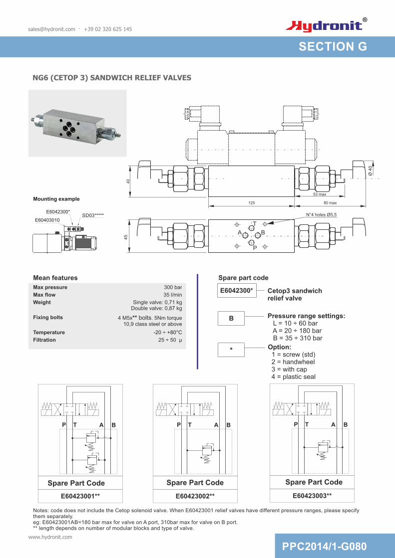
SECTION G
NG6 (CETOP 3) SANDWICH RELIEF VALVES
40
45
125
BA
P
T
Notes: code does not include the Cetop solenoid valve. When E60423001 relief valves have different pressure ranges, please specify them separately. eg: E60423001AB=180 bar max for valve on A port, 310bar max for valve on B port.** length depends on number of modular blocks and type of valve.
N°4 holes Ø5,5
E60423001**
A BP T
E60423002**
A BP T
E60423003**
Spare Part CodeSpare Part CodeSpare Part Code
A BP T
Ø 4
0
53 max
80 max
E6042300*
E60403010SD03*****
Cetop3 sandwich relief valve
E6042300*
Pressure range settings: L = 10 ÷ 60 bar A = 20 ÷ 180 bar B = 35 ÷ 310 bar
B
Option: 1 = screw (std) 2 = handwheel 3 = with cap 4 = plastic seal
*
Mean features
Mounting example
Max pressure 300 bar
Max flow 35 l/min
Weight Single valve: 0,71 kgDouble valve: 0,87 kg
Fixing bolts 4 M5x** bolts. 5Nm torque10,9 class steel or above
Temperature -20 ÷ +80°C
Filtration 25 50 µ÷
[email protected] · +39 02 320 625 145
Spare part code
SECTION G
PPC2014/1-G080www.hydronit.com

MSV3V - DIRECT OPERATED 3/2 WAY DIRECTIONAL SPOOL SOLENOID CARTRIDGE
2 2
13
Three-waydirect actingsolenoid valve
Spool type: 40 = std
Supply voltage: 0000 = no coil (std) see G100 table
MSV3V
40
0000
Options: 0 = no options (std) E = manual overide
0
Spare part code
Mean features
Max pressure 21 bar0
Max flow 12 l/min (20 l/min without block)
Weight 0,35 Kg (with coil)
Coil insulation Class H
Electric connection DIN 43650-A / ISO 4400
Protection class IP 65 / DIN 40050
Duty cycle ED 100%
Voltage required +/- 10% nominal voltage
Torque recommended 30 Nm
Oil temperature -25 +70°C÷
Pressure drop diagram
Flow [l / min]
P [bar]
0
5
10
5 10 15 20
P A
A T
[email protected] · +39 02 320 625 145
SECTION G
PPC2014/1-G090www.hydronit.com
113
Hex. 24
40
1
3/4-16 UNF-2A
23
ø 1
4,2
2
ø 1
5,8
107
59
ø 3
3

M100 M120
VALVE COILS
M630/M631 M160
Supply voltage
[V]Assembly code Coil type
Spare part code
Spare connector
code
Holding power
[W]
Duty cycle
ED [%]
Coil insulati
on
Weight
[g]
Suitable for
valves
12DC 12DC_M100 DC M10040001 KA132000B1 16W 100 H 121 SD00
24DC 24DC_M100 DC M10040002 KA132000B1 16W 100 H 121 SD00
24AC 24RAC_M100RC - needs
external rectifying connector
M10040002 KA132R11B1 16W 100 H 121 SD00
12DC 12DC_M120 DC M12040001 KA132000B1 22W 100 H 134 SD01
24DC 24DC_M120 DC M12040002 KA132000B1 22W 100 H 134 SD01
24AC 24RAC_M120RC - needs
external rectifying connector
M12040002 KA132R11B1 22W 100 H 134 SD01
230AC 220RAC_M120RC - needs
external rectifying connector
M12040005 KA132R13B1 22W 100 H 134 SD01
12DC 12DC_M160 DC M16040001 KA132000B1 26W 100 H 190 SD03
24DC 24DC_M160 DC M16040002 KA132000B1 26W 100 H 190 SD03
24AC 24RAC_M160RC - needs
external rectifying connector
M16040002 KA132R11B1 26W 100 H 190 SD03
115AC 110RAC_M160RC - needs
external rectifying connector
M16040004 KA132R12B1 26W 100 H 190 SD03
230AC 220RAC_M160RC - needs
external rectifying connector
M16040005 KA132R13B1 26W 100 H 190 SD03
12DC 12DC_M630 DC M6306012 KA132000B1 18W 100 H 130MSV3V
MSV30/31SD02
24DC 24DC_M630 DC M6306024 KA132000B1 18W 100 H 130MSV3V
MSV30/31SD02
24AC 24AC_M631RC with integrated
rectifying bridgeM6316024 KA132000B1 18W 100 H 130
MSV3VMSV30/31
SD02
115AC 115AC_M631RC with integrated
rectifying bridgeM6316115 KA132000B1 18W 100 H 130
MSV3VMSV30/31
SD02
230AC 230AC_M631RC with integrated
rectifying bridgeM6316230 KA132000B1 18W 100 H 130
MSV3VMSV30/31
SD02
Standard electric connector: ISO 4400 DIN 43650-A. Other voltages and electric connector types (Amp Junior, flying leads,...) available on request.Inrush power consumption can be up to 3,5 times higher than the holding power.Electric connector: DIN 43650-A / ISO 4400. Coil protection class: Ip65.
[email protected] · +39 02 320 625 145
SECTION G
PPC2014/1-G100www.hydronit.com

Hydronit communicates only with eco-friendly paper
Important NOTE: All information contained in this catalogue is subject to change without notice. Images are not to scale. The terms and conditions of sale, downloaded from www.hydronit.com, including limitations of our liability shall be applied to all products and services sold.
© Hydronit Srl - All rights reservedPrinted in Italy. Edition 2014-01EN
via Pastrengo 6220814 Varedo (MB), Italy☎: +39 0232 0625 145 +39 0362 1841 210: +39 0362 1841 214 : [email protected]
www.minipowerpacks.comwww.hydronit.it