2013 revisions
TRANSCRIPT

UNIFORM STANDARD SPECIFICATIONS CLARK COUNTY AREA, NEVADA
YEAR 2013 REVISIONS
SECTION TITLE AND REVISION SUMMARY EFFECTIVE DATE
502 Concrete Structures – Specification revised to
modify the reference to high early strength concrete mix designs.
07/01/13
704 Base Aggregates – Specification revised to incorporate recycled asphalt pavement and recycled concrete for aggregate base material.
01/01/13

502
502-1
SECTION 502
CONCRETE STRUCTURES
DESCRIPTION
502.01.01 GENERAL
A. This work shall consist of furnishing and placing Portland cement concrete in bridges, culverts, headwalls, retaining walls, barrier rail, and all other types of concrete structures.
B. The concrete structures shall be constructed to the lines and grades given by the Engineer and in accordance with the design shown on the plans.
C. The concrete shall be of the class or classes of concrete specified in the contract documents and shall conform to the requirements of Section 501, "Portland Cement Concrete," unless otherwise specified.
MATERIALS
502.02.01 GENERAL
A. The materials used shall be those prescribed for the several items which constitute the finished work and shall conform to the requirements for such materials in the following sections:
Materials Section Portland Cement Concrete 501
Concrete Curing Materials and Admixtures 702
Joint Material 707
Reinforcement 713
Miscellaneous Metal 712
Elastomeric Bearing Pads 725
CONSTRUCTION
502.03.01 DEPTH OF FOOTINGS
A. The elevation of the bottoms of footings as shown on the plans shall be considered as approximate only and the Engineer may order, in writing, such changes in dimensions or elevations of footings as may be necessary to secure a satisfactory foundation.
502.03.02 FORMS
A. All forms shall be built mortar tight and of sufficient rigidity to prevent distortion due to the pressure of the concrete and other loads incidental to the construction operations.
1. Forms previously used shall be thoroughly cleaned of all dirt, mortar, and foreign matter before being reused.
2. Before concrete is placed in forms, all inside surfaces of the forms shall be thoroughly coated with an approved coating or form oil.
3. Coating or form oil shall leave no film on the surface of the form that can be absorbed by the concrete.

502 CONCRETE STRUCTURES
502-2
4. When required by the Engineer and immediately before placing concrete, the forms shall be thoroughly wetted with water.
B. When requested by the Engineer, the Contractor shall submit detailed plans of form work for examination by the Engineer. If such plans are not satisfactory to the Engineer, the Contractor shall make such changes as may be required, but it is understood that the Engineer's concurrence in the use of the plans as submitted or corrected shall in no way relieve the Contractor of responsibility in obtaining satisfactory results.
C. The forms shall be substantial and unyielding and shall be so designed that the finished concrete will conform to the proper dimensions and contours.
1. The design of the forms shall take into account the effect of vibration on the concrete as it is placed.
2. Forms shall be filleted at all exposed corners unless corners are rounded as hereinafter provided.
a. Triangular molding used for fillets shall have 2 equal sides.
b. In general, the width of the equal sides of moldings shall be 3/4 inch.
c. For massive work, such as heavy pier copings and columns, the width shall be 1-1/2 to 2 inches.
d. Top edges of walls may be filleted or rounded as hereinafter provided for curbs.
e. Top edges of curbs and slabs shall be rounded with an edging tool to a radius of 1/2 inch to 3/4 inch.
D. When concrete is placed in excavation, forms shall be provided for all vertical surfaces unless otherwise permitted by the Engineer.
1. On thin walls, such as abutments, wing walls, and retaining walls, the forms on 1 face may be built up as the concrete is poured, but only to such elevation as will permit proper placing and thorough spading, and in no case greater than the height which can be placed in 1 day's run.
2. Ports shall be provided in high, thin walls to permit thorough cleaning before placing concrete.
3. If the forms develop any defects, such as bulging or sagging, after the concrete has been placed, that portion of the work shall be corrected in a manner satisfactory to the Engineer, without additional compensation to the Contractor.
4. During the erection and after the completion of the forms, the forms shall be protected in such a manner as to preclude shrinkage, warping, curling, and distortion.
5. Form lumber used a second time shall be free from bulge or warp and shall be thoroughly cleaned.
E. Forms for concrete over or in the vicinity of operating railroads shall be so constructed and placed that standard clearances demanded by the railroad company will be maintained at all times.
F. The falsework and forms supporting the bottom slab of the superstructure of box girder structures shall remain in place until the curing period of the deck of the superstructure has expired.

CONCRETE STRUCTURES 502
502-3
1. Unless otherwise permitted by the Engineer, forms for the webs of box girders shall be removed before the deck slab is poured.
2. All interior forms in box girders, except those permitted to remain in place, shall be completely removed and the inside of the box girder cleared of all loose material and swept clean.
G. Side Forms:
1. Side forms for beams, girders, columns, railing, or other members of the structure wherein the forms do not resist dead load bending may be removed as specified in Subsection 502.03.11, "Removal of Falsework Forms."
2. The side forms for arch rings, columns, and piers shall be removed before the members of the structure which the forms support are poured or placed, so that the quality of the concrete may be inspected.
3. All such side forms shall be so constructed that the forms may be removed without disturbing other forms which resist direct load or bending stresses.
H. The condition of the forms will have a direct bearing upon the amount of finishing required.
I. Form Requirements and Physical Design:
1. Full pieces of forms shall be used and shall extend from the bottom to the top of the wall or post.
2. Curved surfaces shall be formed to provide a smooth surface without visible breaks.
3. The forms shall be so constructed that portions, where finishing is required, may be removed without disturbing portions of forms to remain.
4. Forms shall be of sufficient strength to carry the dead weight of the concrete as a liquid without a deflection in excess of L/270, and if such deflection occurs, the deflection shall be sufficient cause for rejection of the work.
5. Forms for girders and slabs shall be cambered in such amounts as may be required by the Engineer.
6. Approved form clamps or bolts shall be used to fasten forms. The use of ties consisting of twisted wire loops to hold forms in position during the placing of concrete will not be permitted.
7. Bolts or form clamps shall be positive in action and shall be of sufficient strength and number to prevent spreading of the forms.
a. The clamps shall be of such type that the clamps can be entirely removed or cut back sufficiently to allow finishing of the concrete.
b. All forms for the outside surfaces shall be constructed with stiff wales at right angles to the studs and all form clamps shall extend through and fasten such wales.
8. Plywood for forms shall be "exterior type" of the grade Concrete-Form Exterior.
a. Plywood form panels shall be furnished and placed in 4-foot widths and in uniform lengths of not less than 8 feet, except where the dimensions of the member form are less than the specified panel dimensions.
b. Where form panels are attached directly to the studding of joints, the panel shall not be less than 5/8 inch thick.

502 CONCRETE STRUCTURES
502-4
c. Form panels less than 5/8 inch thick, otherwise conforming to the requirement herein specified, may be used with continuous backing of 1 inch nominal thickness surfaced material.
d. All form panels shall be placed in a neat symmetrical pattern subject to the approval of the Engineer.
e. The panel shall be placed with the long dimensions perpendicular to the studs.
9. Plywood for left-in-place forms in box girders may be of any grade and thickness that will satisfy the other requirements of this subsection.
10. Fabricated stay-in-place metal forms may be used for concrete floor slabs at the Contractor's option when so noted on the plans.
11. Metal forms to remain in place for concrete floor slabs shall be fabricated from steel conforming to ASTM A466 (Grades A through E) having a coating class of G165.
12. The following criteria shall govern the design of permanent stay-in-place steel bridge deck forms:
a. The steel forms shall be designed on the basis of dead load of form, reinforcement, and plastic concrete plus 50 pounds per square foot for construction loads. The unit working stress in the steel sheet shall not be more than 0.725 of the specified minimum yield strength of the material furnished, but shall not exceed 36,000 pounds per square inch.
b. Deflection under the weight of the forms, the plastic concrete and reinforcement shall not exceed L/180 of the form span or 1/2 inch, whichever is less, but in no case shall this loading be less than 120 psf total.
c. The permissible form camber shall be based on the actual dead load condition. Camber shall not be used to compensate for deflection in excess of foregoing limits.
d. The design span of the form sheets shall be the clear span of the form plus 2 inches measured parallel to the form flutes.
e. Physical design properties shall be computed in accordance with requirements of the American Iron and Steel Institute Specification for the Design of Cold Formed Steel Structural Members, latest published edition.
f. All reinforcement shall have minimum concrete cover of 1 inch.
g. The plan dimensions of both layers of primary deck reinforcement from the top surface of the concrete deck shall be maintained.
h. Permanent steel bridge deck form shall not be considered as lateral bracing for compression flanges of supporting structural members.
i. Permanent steel bridge deck form shall not be used in panels where longitudinal deck construction joints are located between stringers.
j. Welding shall not be permitted to flanges in tension or to structural steel bridge elements fabricated from nonweldable grades of steel.
J. Fabricator's shop and erection drawings shall be submitted to the Engineer for approval. These drawings shall indicate the material properties and grade of steel, the properties of geometric sections for all permanent steel bridge deck form sheets, and all locations where the forms are in the vicinity of steel beam flanges subject to tensile stresses.

CONCRETE STRUCTURES 502
502-5
K. Form Supports:
1. Form sheets shall not be permitted to rest directly on the top of the stringer or floor beam flanges.
2. Sheets shall be securely fastened to form supports and shall have a minimum bearing length of 1 inch at each end.
3. Form supports shall be placed in direct contact with the flange of stringer or floor beam.
4. All attachments shall be made by permissible welds, bolts, clips, or other approved means.
5. Welding of form supports to flanges of steel not considered weldable and to portions of flange subject to tensile stresses shall not be permitted.
6. Welding and welds shall be in accordance with the provisions of AWS D2.0 pertaining to fillet welds except that 1/8-inch fillet welds will be permitted.
L. Any permanently exposed form metal where the galvanized coating has been damaged shall be thoroughly cleaned, wire brushed, and painted with 2 coats of zinc oxide zinc dust primer, Federal Specification TT-P-641D, Type II, no color added, to the satisfaction of the Engineer. Minor heat discoloration in areas of welds need not be touched up.
M. Transverse construction joints shall be located at the bottom of the flute and 1/4-inch weep holes shall be field drilled at not more than 12 inches on center along the line of the joint.
N. Emphasis shall be placed on proper vibration of the concrete to avoid honeycomb and voids.
1. Pouring sequences, procedures, and mixes shall be approved by the Engineer.
2. Calcium chloride or any other admixture containing chloride salts shall not be used in the concrete placed on permanent steel bridge deck forms.
O. The Contractor's method of construction shall be carefully observed during all phases of the construction of the bridge deck slab.
1. These phases include installation of the metal forms; location and fastening of the reinforcement; composition of concrete items; mixing procedures, concrete placement, and vibration; and finishing of the bridge deck.
2. Should the Engineer determine that the procedures used during the placement of the concrete warrant inspection of the underside of the deck, the Contractor shall remove at least 1 section of the forms at a location and time selected by the Engineer for each span in the contract.
3. This should be done as soon after placing the concrete as practicable in order to provide visual evidence that the concrete mix and the Contractor's procedures are obtaining the desired results.
4. An additional section shall be removed if the Engineer determines that there has been any change in the concrete mix or procedures warranting additional inspection.
P. After the deck concrete has been in place for a minimum period of 2 days, the concrete shall be tested for soundness and bonding of the forms by sounding with a hammer as directed by the Engineer.

502 CONCRETE STRUCTURES
502-6
1. If areas of doubtful soundness are disclosed by this procedure, the Contractor will be required to remove the forms from such areas for visual inspection after the pour has attained adequate strength.
2. This removal of the permanent steel bridge deck forms shall be at no additional cost to the Contracting Agency.
3. At locations where sections of the forms are removed, the Contractor will not be required to replace the forms, but the adjacent metal forms and supports shall be repaired to present a neat appearance and ensure their satisfactory retention.
4. As soon as the form is removed, the concrete surfaces will be examined for cavities, honeycombing and other defects.
5. If irregularities are found, and it is determined by the Engineer that these irregularities do not justify rejection of the work, the concrete shall be repaired as the Engineer may direct and shall be given an Ordinary Surface Finish.
6. If the concrete where the form is removed is unsatisfactory, additional forms, as necessary, shall be removed to inspect and repair the slab, and the Contractor's methods of construction shall be modified as required to obtain satisfactory concrete in the slab.
7. All unsatisfactory concrete shall be removed or repaired as directed by the Engineer.
Q. The amount of sounding and form removal may be moderated, at the Engineer's discretion, after a substantial amount of slab has been constructed and inspected, if the Contractor's methods of construction and the results of the inspections as outlined above indicate that sound concrete is being obtained throughout the slabs.
502.03.03 FALSEWORK
A. Detailed plans of the falsework or centering shall be furnished by the Contractor to the Engineer in accordance with Subsection 105.02, "Plans and Working Drawings," for any structures having a clear cast-in-place span of 20 feet or over or any cast-in-place structure over traffic. If such plans are not satisfactory to the Engineer, the Contractor shall make such changes in the plans as may be required.
B. In addition to the detailed drawings of the falsework or centering which are to be furnished to the Engineer as specified herein, the Contractor shall also furnish the Engineer with a copy of falsework or centering design calculations.
C. All falsework or centering shall be designed and constructed to provide the necessary rigidity and to support the loads.
1. Falsework for the support of superstructures for box girder spans shall be designed to support the loads that would be superimposed were the entire superstructure poured at 1 time.
2. For designing falsework and centering, a weight of 150 pounds per cubic foot shall be assumed for green concrete (120 pounds for lightweight concrete) and an allowance of not less than 25 pounds per cubic foot for forms, live load, and impact.
3. Falsework or forms shall be constructed to produce in the finished structure the lines and grades indicated on the plans.

CONCRETE STRUCTURES 502
502-7
4. Suitable screw jacks or wedges in pairs shall be used in connection with falsework or centering to set the forms to grade or cambered as shown on the plans, or to take up any settlement in the form work either before or during the placing of concrete.
5. Excessive use of blocking and shims shall be cause for rejection of the falsework.
6. Falsework failures shall become the sole responsibility of the Contractor.
D. Immediately prior to placing bridge or slab concrete, the Contractor shall check all falsework and wedges or jacks and shall make all necessary adjustments.
1. Care shall be exercised to ensure that settlement and deflection due to the added weight of the deck or slab concrete will be minimal.
2. Suitable means such as telltales shall be provided by the Contractor to permit ready measurement of settlement and deflection as it occurs.
E. Falsework or centering shall be founded on a solid footing safe from undermining and protected from softening. Falsework which cannot be founded on a satisfactory footing shall be supported on piling which will be spaced, driven, and removed in a manner approved by the Engineer.
F. Arch span shall be removed uniformly and gradually beginning at the crown and working toward the spring, to permit the arch to take its load slowly and evenly. Centering for bridges having 2 or more adjacent arch spans will be struck simultaneously.
G. Falsework supporting the main carrying members of all continuous structures shall not be removed from any span until all spans between expansion joints are cured.
H. Falsework and forms left in place in the cells of box girders shall not exceed 12 pounds per square foot of deck. All supports between the top and bottom slabs in the cells of box girders shall be water soaked for a period of not less than 48 hours.
502.03.04 REINFORCEMENT
A. Reinforcing shall be furnished and placed as shown on the plans and in accordance with the applicable provisions of Section 505, "Reinforcing Steel," of these specifications.
502.03.05 COFFERDAMS AND CRIBS
A. Cofferdams for foundation construction shall be carried well below the bottom of the footings and shall be well braced and as watertight as practical. The interior dimensions of cofferdams shall be such as to provide sufficient clearance for constructing forms and, when no seal is placed, to permit pumping outside the forms.
B. The Contractor shall submit for approval, drawings showing proposed method of construction of cofferdams or cribs in accordance with Subsection 105.02, "Plans and Working Drawings."
1. Approval of such drawings shall in no way relieve the Contractor of Contractor's responsibility under the contract for the successful completion of the improvement.
2. Cofferdam construction shall not start before the submitted drawings are approved and returned.
C. After the completion of the substructure, the cofferdams with all sheeting and bracing shall be removed to 1 foot below the stream bed, by the Contractor, and such removal shall be performed in such a manner as not to disturb or mar the finished concrete foundation.

502 CONCRETE STRUCTURES
502-8
Removal of cofferdams, sheeting, and bracing shall be considered subsidiary to other pay items of work and no further payment will be made therefor.
502.03.06 PUMPING WATER
A. Pumping from the interior of any foundation enclosure shall be done in such a manner as to preclude the possibility of the movement of water through any fresh concrete.
B. No pumping will be permitted during the placing of concrete or for a period of at least 24 hours thereafter, unless it be done from a suitable pump separated from the concrete work by a watertight wall or other effective means.
C. Pumping to dewater a sealed cofferdam shall not commence until the seal has set sufficiently to withstand the hydrostatic pressure.
502.03.07 MIXING CONCRETE
A. All concrete shall be mixed and proportioned as specified in Section 501, "Portland Cement Concrete."
502.03.08 HANDLING AND PLACING CONCRETE
A. General. In preparation for the placing of concrete, all sawdust, chips, and other construction debris and extraneous matter shall be removed from the interior of forms.
1. Struts, stays, and braces serving temporarily to hold the forms in correct shape and alignment, pending the placing of concrete at their locations, shall be removed when the concrete placing has reached an elevation rendering their service unnecessary.
2. These temporary members shall be entirely removed from the forms and not buried in the concrete.
B. No concrete shall be used which does not reach its final position in the forms within the time and temperature stipulated under Section 501, "Portland Cement Concrete."
C. Surfaces on which concrete is to be placed shall be thoroughly moistened with water immediately before placing concrete.
D. Concrete shall be placed so as to avoid segregation of the material and the displacement of the reinforcement.
1. The use of long troughs, chutes, and pipes for conveying concrete from the mixer to the forms shall be permitted only on written authorization of the Engineer.
2. In case an inferior quality of concrete is produced by the use of such conveyors, the Engineer may order discontinuance of their use and the substitution of a satisfactory method of placing.
3. Open troughs and chutes shall be of metal or metal lined; where steep slopes are required, the chutes shall be equipped with baffles or be in short lengths that reverse the direction of movement.
4. All chutes, troughs, and pipes shall be kept clean and free from coatings of hardened concrete by thoroughly flushing with water after each run; water used for flushing shall be discharged clear of the structure.
E. When placing operations would involve dropping the concrete more than 5 feet, concrete shall be deposited through sheet metal or other approved pipes, except when placing

CONCRETE STRUCTURES 502
502-9
concrete for thin vertical walls less than 15 inches thick, double belting may be used in lieu of adjustable pipes or elephant trunks.
1. As far as practicable, the pipes shall be kept full of concrete during placing and the lower ends of pipe shall be kept buried in the newly placed concrete.
2. After initial set of the concrete, the forms shall not be jarred and no strain shall be placed on the projecting ends of reinforcement bars.
F. All concrete placed in concrete structures, except tremie seal concrete, shall be compacted by means of mechanical vibration subject to the following provisions:
1. The number of vibrators employed shall be ample to consolidate incoming concrete to a proper degree within 15 minutes after concrete is deposited in the forms. In all cases, at least 2 vibrators shall be available at the site of the structures in which more than 25 cubic yards is being placed.
2. The vibration shall be internal unless special authorization of other methods is given by the Engineer or as provided herein.
3. Vibrators shall be capable of transmitting vibration to the concrete at frequencies of not less than 4,500 impulses per minute.
4. The intensity of vibration shall be such as to visibly affect a mass of concrete of 1-inch slump over a radius of at least 18 inches.
5. Vibrators shall be manipulated to thoroughly work the concrete around the reinforcement and imbedded fixtures and into the corners and angles of the forms.
6. Vibration shall be applied at the point of deposit and in the area of freshly deposited concrete. The vibrators shall be inserted and withdrawn out of the concrete slowly.
7. The vibration shall be of sufficient duration and intensity to thoroughly compact the concrete, but shall not be continued at any 1 point to the extent that localized areas of grout are formed.
8. Application of vibrators shall be at points uniformly spaced and not farther apart than twice the radius over which the vibration is visibly effective.
9. Vibration shall not be applied directly or through the reinforcement to sections or layers of concrete which have hardened to the degree that the concrete ceases to be plastic under vibration.
10. Vibration shall not be used to make concrete flow in the forms over distances so great as to cause segregation, and vibrators shall not be used to transport concrete in the forms.
11. Vibration shall be supplemented by such spading as is necessary to ensure smooth surfaces and dense concrete, along form surfaces and in corners and locations impossible to reach with the vibrators.
12. The provisions of this article shall apply to the filler concrete for steel grid floor except that the vibrator shall be applied to the steel.
G. Immediately following the discontinuance of placing concrete, all accumulations of mortar splashed upon the reinforcement steel and the surface of forms shall be removed.
1. Dried mortar chips and dust shall not be puddled into the unset concrete.

502 CONCRETE STRUCTURES
502-10
2. If the accumulations are not removed prior to the concrete becoming set, care shall be exercised not to injure or break the concrete-steel bond at and near the surface of the concrete while cleaning the reinforcement steel.
H. Culverts.
1. The base slab or footings of box culverts shall be placed and allowed to set before the remainder of the culvert is constructed. Suitable provisions shall be made for bonding the sidewalls to the culvert base.
2. Walls and top slab shall not be constructed as a monolith on box culverts where the depth of pour below the bottom of the top slab exceeds 4 feet unless approved in writing by the Engineer. When this method of construction is used, any necessary construction joints shall be vertical and at right angles to the axis of the culvert.
3. When walls are poured separately, in non-rigid frame box culverts, the concrete in the walls shall be placed and allowed to set a minimum of 2 hours before the top slab is placed.
4. When walls are poured separately, in rigid frame box culverts, the concrete in the walls shall be placed and allowed to set a minimum of 12 hours before the top slab is placed.
5. Each wing wall shall be constructed, if possible, as a monolith. Construction joints, where unavoidable, shall be horizontal and so located that no joint will be visible in the exposed face of the wing wall above the ground line.
I. Girders, Slabs, and Columns.
1. When the height of a web in a "T" beam is more than 3 feet, the top slab shall be poured independently.
2. When the distance from a construction joint to the top of the web in a box girder exceeds 3 feet, the top slab shall be poured independently.
3. Concrete in slab spans shall be placed in 1 continuous operation for each span unless otherwise specified.
4. Concrete in columns shall be placed in 1 continuous operation, unless otherwise specified. The concrete shall be allowed to set at least 12 hours before the succeeding pour is started.
5. Before pouring concrete for superstructure, the forms on base of columns shall be exposed sufficiently to determine the character of the concrete in the columns.
502.03.09 CONCRETE DEPOSITED UNDER WATER
A. If conditions render it impossible or inadvisable, in the opinion of the Engineer, to dewater excavation before placing concrete, the Contractor shall deposit under water, by means of a tremie or underwater bottom dump bucket, a seal course of concrete of sufficient thickness to thoroughly seal the cofferdam.
1. The concrete shall be carefully placed in a compact mass and shall not be disturbed after being deposited.
2. Still water shall be maintained at the point of deposit.
B. The use of an aluminum tremie for placing concrete is prohibited.

CONCRETE STRUCTURES 502
502-11
C. A tremie shall consist of a watertight tube having a diameter of not less than 10 inches with a hopper at the top.
1. The tube shall be equipped with a device that will prevent water from entering the tube while charging the tube with concrete.
2. The tremie shall be supported so as to permit free movement of the discharge end over the entire top surface of the work and to permit rapid lowering when necessary to retard or stop the flow of concrete.
3. The tremie shall be filled by a method that will prevent washing of the concrete.
4. The discharge end shall be completely submerged in concrete at all times and the tremie tube shall contain sufficient concrete to prevent any water entry.
5. When a batch is dumped into the hopper, the flow of concrete shall be induced by slightly raising the discharge end, always keeping it in the deposited concrete.
6. The flow shall be continuous until the work is completed and the resulting concrete seal shall be monolithic and homogeneous.
D. The underwater bucket shall have an open top and the bottom doors shall open freely and outward when tripped.
1. The bucket shall be completely filled and slowly lowered to avoid backwash and shall not be dumped until it rests on the surface upon which the concrete is to be deposited.
2. After discharge, the bucket shall be raised slowly until well above the concrete.
E. Concrete deposited in water shall be in accordance with Section 501, "Portland Cement Concrete," with 10 percent extra cement added.
1. The exact thickness of the seal will depend upon the hydrostatic head, bond, and spacing of piles, size of cofferdam, and other related factors, but in no case shall the seal be less than 2 feet in thickness, unless otherwise shown on the plans.
2. Before dewatering, the concrete in the seal shall be allowed to cure for not less than 5 days after placing.
F. If a seal which is to withstand hydrostatic pressure is placed in water having a temperature below 45 degrees F, the curing time before dewatering shall be increased.
1. Periods of time during which the temperature of the water has been continuously below 38 degrees F shall not be considered as curing time.
2. After sufficient time has elapsed to ensure adequate strength in the concrete seal, the cofferdam shall be dewatered and the top of the concrete cleaned of all scum, laitance, and sediment.
3. Before fresh concrete is deposited, local high spots shall be removed as necessary to provide proper clearance for reinforcing steel.
502.03.10 CONSTRUCTION JOINTS
A. Construction joints shall be made only where located on the plans or shown in the pouring schedule, unless otherwise approved by the Engineer.
B. Construction joints where the placing of concrete is delayed until the concrete has taken its initial set and for which no expansion is provided, shall be planned in advance and shall be subject to approval by the Engineer.

502 CONCRETE STRUCTURES
502-12
1. The placing of concrete shall be continuous from joint to joint.
2. These joints shall be perpendicular to the principal lines of stress and, in general, located at points of minimum shear.
3. Only joints shown on the plans will be permitted in a cantilevered member.
4. Horizontal joints at piers and abutments, except where specified, shall be avoided, and when used shall not be located within 2 feet of the normal water level.
C. Unless otherwise specified, construction joints shall be struck off but not troweled.
D. When making a horizontal construction joint, care shall be taken to have the concrete as dry as possible, and any excess water or creamy material shall be drawn off before the concrete sets. On all exposed surfaces, the line of the proposed joint shall be made straight by placing a temporary straightedge on the inside of the form and pouring the concrete so that it will set flush with the edge as provided.
E. To avoid visible joints as far as possible upon exposed faces, the top surfaces of the concrete adjacent to the forms shall be smoothed with a trowel. Where a "feather edge" might be produced at a construction joint, as in the slope top surface of a wing wall, an insert form block shall be used to produce a blocked out portion in the proceeding layer which shall produce an edge thickness of not less than 6 inches in the succeeding layer.
F. When the work is unexpectedly interrupted by breakdowns, storm, or other causes, and the concrete as placed would produce an improper construction joint, the Contractor shall either rearrange the freshly deposited concrete or continue by hand mixing, if necessary, until a suitable arrangement is made for a construction joint. When such a joint occurs at a section on which there is shearing stress, the Contractor shall provide adequate mechanical bond across the joint by inserting reinforcing steel or by some other means satisfactory to the Engineer, which will prevent a plane of weakness.
G. In resuming work, the surface of the concrete previously placed shall be thoroughly cleaned of dirt, scum, laitance, or other soft or porous materials by 1 of the following methods:
1. Concrete surface of fresh concrete (not more than 8 hours after placement) shall be cleaned with air and water jets in such a manner that the surface is thoroughly cleaned and the aggregate is not loosened.
2. Hardened concrete surface (more than 8 hours after placement) shall be cleaned by abrasive blast methods in such a manner that the aggregate is not loosened or the edges of the concrete shattered.
H. The surface of the joint shall be thoroughly washed with clean water and the forms tightened to close contact with the previously placed work, after which the concreting may proceed. The surface of the joint shall be wet just prior to placing new concrete.
502.03.11 REMOVAL OF FALSEWORK AND FORMS
A. General.
1. Methods of form removal likely to cause overstressing of the concrete shall not be used.
a. Forms and their supports shall not be removed without the approval of the Engineer.

CONCRETE STRUCTURES 502
502-13
b. Supports shall be removed in such a manner as to permit the concrete to uniformly and gradually take the stresses due to its own weight.
2. Compressive strengths will be determined by ASTM C39 and ASTM C31 and will be considered information tests only and not acceptance tests as described in Subsection 501.02.04, "Concrete Making Properties."
3. Comply with Subsection 501.03.09, "Curing."
B. Falsework.
1. Where stresses will be placed on the concrete, in arch centers, centering under beams and girders, and in floor slabs, falsework shall not be removed until the concrete has reached an age of 10 days and it has reached 75 percent of the required 28-day compressive strength.
2. In the event of cold weather, the 10-day time requirements shall be increased 1 day for every day the curing time is increased as prescribed in Subsection 501.03.10.B, "Cold Weather — General."
3. In case the concrete does not reach the desired strength within the time specified, the Engineer shall determine when the strength is adequate to allow removal of falsework.
4. Form removal and replacement with shoring will not be permitted.
C. Forms.
1. Forms on parapets and curbs shall not be removed until concrete has set sufficiently to prevent distorting or cracking.
2. Forms for columns, walls, side of beams, girders and all other parts that are not subjected to stress shall not be removed until the concrete has reached a minimum age of 40 hours unless authorized by the Engineer.
3. Forms that are subjected to stresses shall not be removed until the requirements of Subsection 502.03.11.B have been satisfied, unless otherwise approved by the Engineer.
502.03.12 EXPANSION AND FIXED JOINTS AND BEARINGS
A. All joints shall be constructed according to details shown on the plans and as specified in this subsection.
B. Open Joints.
1. Open joints shall be placed in the locations shown on the plans and shall be constructed by the insertion and subsequent removal of a wood strip, metal plate, or other approved material.
2. The insertion and removal of the template shall be accomplished without chipping or breaking the corners of the concrete.
3. Reinforcement shall not extend across an open joint unless so specified on the plans.
C. Filled Joints.
1. Poured expansion joints shall be constructed similar to open joints.
502 CONCRETE STRUCTURES
502-14
2. When premolded types are specified, the filler shall be placed in correct position before concrete is placed against the filler.
3. Holes and joints in the filler shall be filled with mastic to prevent the passage of mortar or concrete from 1 side of the joint to the other.
4. The edges of the concrete at the joint shall be edger finished.
D. Steel Joints.
1. The plates, angles, or other structural shapes shall be accurately shaped, at the shop, to conform to the section of the concrete floor.
2. The fabrication and painting shall conform to the requirements of these specifications covering those items.
3. When called for on the plans or in the Special Provisions, the materials shall be galvanized in lieu of painting.
4. Care shall be taken to ensure that the surface in the finished plane is true and free of warping.
5. Positive methods shall be employed in placing the joints to keep the joints in correct position during the placing of the concrete.
6. The opening at expansion joints shall be that designated on the plans at normal temperature, and care shall be taken to avoid impairment of the clearance in any manner.
E. Waterstops.
1. Waterstops shall be furnished and installed in accordance with the details shown on the plans.
2. The edge of the waterstop shall be supported in a manner satisfactory to the Engineer.
3. Waterstops shall be manufactured from either natural rubber, synthetic rubber, or polyvinyl chloride (PVC) at the option of the Contractor.
4. Waterstops shall be manufactured with an integral cross section which shall be uniform within ±1/8 inch in width, and the web thickness or bulb diameter, within +1/16 inch and -1/32 inch .
a. No splices will be permitted in straight strips.
b. Strips and special connection pieces shall be well cured in a manner such that any cross section shall be dense, homogeneous, and free from porosity.
c. Junctions in the special connection pieces shall be fully molded.
d. During the vulcanizing period, the joint shall be securely held by suitable clamps.
e. The material at the splices shall be dense and homogeneous throughout the cross section.
5. Field splices for either natural or synthetic rubber waterstops shall be either vulcanized, mechanical, using stainless steel parts, or made with a rubber splicing union of the same stock as the waterstop, at the option of the Contractor. All finished splices shall have a full size tensile strength of 600x (width in inches) pounds.

CONCRETE STRUCTURES 502
502-15
6. Field splices for polyvinyl chloride waterstops shall be formed by heat sealing the adjacent surfaces in accordance with the manufacturer's recommendations.
a. A thermostatically controlled electric source of heat shall be used to make all splices.
b. The heat shall be sufficient to melt but not char the plastic.
7. Waterstops, when being installed, shall be cut and spliced at changes in direction as may be necessary to avoid buckling or distortion of the web or flange.
F. Bearing Devices.
1. Bearing plates, bars, rockers, assemblies, and other expansion or fixed devices shall be constructed in accordance with the details shown on the plans and shall be hot-dip galvanized after fabrication in accordance with Section 715, "Galvanizing."
2. Structural steel and cast steel shall conform to the provisions in Section 506, "Steel Structures," for those items.
3. The bearing plates shall be set level and the rockers or other expansion devices shall be set to conform to the temperature at the time of erection or to the setting specified.
4. When bearing assemblies or masonry plates are shown on the plans to be placed (not embedded) directly on concrete, the concreted bearing area shall be constructed slightly above grade and shall be finished by grinding or other approved means to a true level plane which shall not vary perceptibly from a straightedge placed in any direction across the area. The finished plane shall not vary more than 1/8 inch from the elevation shown on the plans.
5. When elastomeric bearing pads, elastic bearing pads, preformed fabric pads, or asbestos sheet packing are shown on the plans, the concrete surfaces on which pads or packing are to be placed shall be wood float finished to a level plane which shall not vary more than 1/16 inch from a straightedge placed in any direction across the area. The finished plane shall not vary more than 1/8 inch from the elevation shown on the plans.
6. Where bearing assemblies or masonry plates are shown on the plans to be placed on grout pads, they shall be placed in accordance with the provisions in Subsection 506.03.25, "Bearing and Anchorage."
G. Elastomeric Bearing Pads.
1. Pads over 1 inch in thickness shall be laminated.
2. Laminated pads shall consist of alternate laminations of elastomer and metal or elastomer and fabric bonded together.
3. All elastomeric bearing pads shall be 50 durometer.
4. Pads shall be installed where designated on the plans.
502.03.13 CURING
A. Curing of formed concrete shall conform to the requirements of Subsection 501.03.09, "Curing."

502 CONCRETE STRUCTURES
502-16
502.03.14 PATCHING
A. After removal of forms, all metal ties except those to be used to aid future forming shall be cut back and patched.
1. Honeycomb shall be removed and patched.
2. When honeycomb is determined by the Engineer to be excessive, the excessive honeycombing shall be sufficient cause for rejection of all or a part of the structure.
B. Loose or broken material shall be chipped away until a dense, uniform surface exposing solid coarse aggregate is obtained.
1. Feather edges shall be cut away to form a face perpendicular to the surface being patched.
2. All surfaces of the cavity shall be thoroughly saturated with water.
3. Contact surfaces shall be coated with an approved bonding agent.
4. Bonding agent may be mixed with mortar in lieu of coating the contact surfaces.
C. Patching mortar shall consist of 1 part cement and 3 parts sand.
1. White cement or other approved tinting materials shall be used on all surfaces where an "ordinary finish" is final.
2. For patching large or deep areas, coarse aggregate shall be added to the patching mortar.
D. The patching mortar shall be thoroughly tamped into place.
1. Mortar may be placed pneumatically when approved by the Engineer.
2. The surface of the mortar shall be floated with a wooden float before initial set takes place.
3. The patch shall present a neat and workmanlike appearance.
E. The patched surface shall be cured by 1 of the methods described in Subsection 501.03.09, "Curing."
F. Patching is the only treatment required for those portions of the structure below ground.
502.03.15 FINISH OF HORIZONTAL SURFACES
A. Concrete bridge decks shall be struck off with a template immediately after pouring to provide the proper crown and shall be finished to a smooth even surface by means of both longitudinal and transverse wooden floats, or other suitable means.
1. When a transversely broomed finish is used, the allowable variations noted herein shall be independent of the depth of the broom marks.
2. No variations will be permitted that will tend to prevent complete drainage on all parts of the deck.
3. The surface shall be corrected by grinding off the high spots, or other approved method, as may be required to conform to these limits.
4. An edging tool shall be used at expansion joints and deck edges not armored.
B. Approach slabs to concrete bridges shall be finished to the tolerances specified for bridge decks.

CONCRETE STRUCTURES 502
502-17
C. Finishing Bridge Decks.
1. A smooth riding surface of uniform texture, true to the required grade and cross section, shall be obtained on all bridge roadway decks.
2. The Contractor may use hand tools, or finishing machines, or a combination of both, conforming to the requirements specified herein for finishing bridge roadway deck concrete.
3. Finishing of concrete placed in bridge decks shall consist of striking off the surface of the concrete as placed and floating with longitudinal floats the surface so struck off.
4. The placing of concrete in bridge roadway decks will not be permitted until the Engineer is satisfied that:
a. The rate of producing and placing concrete will be sufficient to complete the proposed placing and finishing operations within the scheduled time.
b. Experienced finishing machine operators and concrete finishers are employed to finish the deck.
c. Fogging equipment and all necessary finishing tools and equipment are on hand at the site of the work and in satisfactory condition for use.
5. Finishing machines shall be set up sufficiently in advance of use to permit inspection by the Engineer during the daylight hours before each pour.
6. The adjustment and operation of deck finishing machines shall be verified by moving the machine over the full length of the deck section to be placed and traversing the float completely across all end bulkheads before placement of concrete is begun.
7. Unless adequate lighting facilities are provided by the Contractor, the placing of concrete in bridge decks shall cease at such time that finishing operations can be completed during daylight hours.
8. Rails for the support and operation of finishing machines and headers for hand-operated strike off devices shall be completely in place and firmly secured for the scheduled length for concrete placement before placing of concrete will be permitted.
a. Rails for finishing machines shall extend beyond both ends of the scheduled length for concrete placement a sufficient distance that will permit the float of the finishing machine to fully clear the concrete to be placed.
b. Rails or headers shall be adjustable for elevation and shall be set to elevations, with allowance for anticipated settlement, camber, and deflection of falsework, as required to obtain a bridge roadway deck true to the required grade and cross section.
c. Rails or headers shall be of a type and shall be so installed that no springing or deflection will occur under the weight of the finishing equipment, and shall be so located that finishing equipment may operate without interruption over the entire bridge roadway deck being finished.
d. Rails or headers shall be adjusted as necessary to correct for unanticipated settlement or deflection which may occur during finishing operations.

502 CONCRETE STRUCTURES
502-18
9. Should settlement or other unanticipated events occur, which in the opinion of the Engineer would prevent obtaining a bridge deck conforming to the requirements of these specifications, placing of deck concrete shall be discontinued until corrective measures satisfactory to the Engineer are provided.
a. In the event satisfactory measures are not provided prior to initial set of the concrete in the affected area, the placing of concrete shall be discontinued and a bulkhead installed at the location determined by the Engineer.
b. All concrete in place ahead of the bulkhead shall be removed.
10. Unless otherwise permitted by the Engineer, bridge deck concrete shall be placed in a uniform heading approximately parallel to the bridge pier or bent caps. The rate of placing concrete shall be limited to that which can be finished before the beginning of initial set, except that concrete for the deck surface shall not be placed more than 10 feet ahead of strike-off.
11. After the concrete has been placed and consolidated, the surface of the concrete shall be carefully struck off by means of a hand-operated strike board operating on headers, or by a finishing machine operating on rails. A uniform deck surface true to the required grade and cross section shall be obtained.
12. Following strike off, the surface of the concrete shall be floated longitudinally.
a. In the event strike off is performed by means of a hand-operated strike board, 2 separate hand-operated float boards for longitudinal floating shall be provided.
b. The first float shall be placed in operation as soon as the condition of the concrete will permit and the second float shall be operated as far back of the first float as the workability of the concrete will permit.
13. In the event the strike off is performed with a finishing machine, longitudinal floating of the concrete shall be performed by means of a hand-operated float board or a finishing machine equipped with a longitudinal wooden float.
a. The longitudinal wooden float on the finishing machine shall have a length of not less than 8 feet nor more than 12 feet.
b. When both strike off and longitudinal floating are to be performed by finishing machines, 1 machine, with operator, shall be used for strike off and a second machine, with second operator, shall be used for longitudinal floating.
c. Longitudinal floating may be performed with the same finishing machine that is used for strike off provided that the length of deck unit being placed is not more than 30 feet and the strike off operation is completed for the deck unit before the condition of the concrete requires that longitudinal floating be started.
14. Finishing machines used for strike off having a wheel base 6 feet or less shall be followed by 2 separate hand-operated float boards for longitudinal floating. All the provisions in this section pertaining to hand-operated float boards shall apply to the 2 separate float boards for longitudinal floating.
15. Longitudinal floats, either hand-operated or machine-operated, shall be used with the long axis of the float parallel to the centerline of the bridge roadway.

CONCRETE STRUCTURES 502
502-19
a. The float shall be operated with a combined longitudinal and transverse motion planing off the high areas and floating the material removed into the low areas.
b. Each pass of the float shall lap the previous pass by 1/2 the length of the float.
c. Floating shall be continued until a smooth riding surface is obtained.
D. In advance of curing operations, the surface of the concrete shall be textured by brooming with a stiff bristled broom or by other suitable devices which will result in uniform scoring. Brooming shall be performed transversely from finishing bridges.
E. Hand-operated float boards shall be from 12 feet to 16 feet long, ribbed and trussed as necessary to provide a rigid float and shall be equipped with adjustable handles at each end.
1. The float shall be wood, not less than 1 inch thick and from 4 inches to 8 inches wide.
2. Adjusting screws spaced at not to exceed 24 inches on centers shall be provided between the float and the rib.
3. The float board shall be maintained true and free of twist.
F. Hand-operated float boards shall be operated from transverse finishing bridges.
1. The finishing bridges shall span completely the roadway area being floated and a sufficient number of finishing bridges shall be provided to permit operation of the floats without undue delay.
2. Not less than 2 transverse finishing bridges shall be provided when hand-operated float boards are used.
3. When a finishing machine is used for longitudinal floating, 1 finishing bridge equivalent to the transverse finishing bridge specified herein shall be furnished for use by the Engineer.
G. Finishing bridges shall be of rigid construction and shall be free of wobble and springing when used by the operators of longitudinal floats and shall be easily moved.
H. Fogging equipment furnished shall be capable of applying water to the concrete in the form of a fine fog mist in sufficient quantity to curb the effects of rapid evaporation of mixing water from the concrete on the deck. The fog mist shall be applied at the time and in the manner approved by the Engineer.
I. Immediately following completion of the deck finishing operations, the concrete in the deck shall be cured as specified in Subsection 501.03.09, "Curing."
J. The finished surface of the concrete shall be tested by means of a straightedge 12 feet long.
1. The surface shall not vary more than 0.01 foot from the lower edge of the straightedge.
2. All high areas in the hardened surface in excess of 0.01 foot as indicated by testing shall be removed by abrasive means.
3. After grinding by abrasive means has been performed, the surface of the concrete shall not be smooth or polished, but shall have a surface texture satisfactory to the Engineer.

502 CONCRETE STRUCTURES
502-20
4. Ground areas shall be of uniform texture and shall present neat and approximately rectangular patterns.
K. Where the concrete of the bridge deck is to be covered by bituminous surfacing, earth, or other cover, 1 inch or more in thickness, the surface of the concrete shall not vary more than 0.03 feet from the lower edge of the 12-foot straightedge.
L. Bridge deck surfaces under the curbs, railings, and sidewalks shall be struck off to the same plane as the roadway and left undisturbed when future widening is shown on the plans.
M. The top and face of the finished parapet and curb shall be true and straight, and the top surface shall be of uniform width, free from humps, sags, or other irregularities. When a straightedge 12 feet long is laid on top of the face of the curb or on the face of the parapet, the surface shall not vary more than 1/8 inch from the theoretical grade or alignment in 12 feet, except that proper allowance shall be made for curves and camber.
N. Manual methods, other than specified in this subsection, or other machine methods for finishing bridge deck concrete may be permitted in accordance with the provisions in Subsection 108.05, "Character of Workmen; Methods and Equipment."
502.03.16 FORMED SURFACES REQUIRING FINISHING
A. Structures requiring a "fine surface finish (F.S.F.)" will be noted on the plans.
B. All structures not requiring a fine surface finish shall be given an ordinary surface finish.
C. Only exposed surfaces of structures will require finishing (ordinary or fine).
D. Exposed surfaces are defined as follows:
1. Exterior vertical faces of slab spans, rigid frames, arches, and box girders.
2. The underside of overhanging slabs to point of junction of the supporting beams.
3. Vertical surfaces of piers, columns, bent caps, abutments, wing walls, and retaining walls which are exposed to view after all backfill and embankment is placed. Exposed surfaces in this case are considered to extend to 1 foot below finished grade.
4. The inside of culvert barrels over 4 feet in height for the same distance as the height of the opening when seen from a traveled way.
5. The underside of superstructures in urban areas.
502.03.17 ORDINARY SURFACE FINISH
A. The surface shall have all holes left by form ties and all other holes 1/4 inch or more in largest diameter repaired in accordance with Subsection 502.03.14, "Patching." The surface shall be true and even, free from stone pockets, depressions, or projections beyond the surface.
B. All fins and projections shall be knocked off or ground flush. Offsets greater than 1/8 inch shall be filled or tapered back to present a smooth appearance. A uniform color and appearance shall be obtained on all patched surfaces.
502.03.18 FINE SURFACE FINISH
A. Where it is indicated on the plans that a fine surface finish is required, the finish shall conform to the requirements for "Bonded Grout Finish" as specified below.
CONCRETE STRUCTURES 502
502-21
1. Before the finish is applied, the surface shall be true and even and free from stone pockets, depressions, or projections beyond the surface.
2. All fins and projections shall be knocked off or ground flush.
3. Offsets greater than 1/8 inch shall be filled or tapered back to present a smooth appearance.
4. All holes 1/4 inch or more in largest diameter shall be patched in accordance with Subsection 502.03.14, "Patching."
B. Bonded Grout Finish.
1. This finish shall be an application of grout consisting of sand and other pigments and mineral fillers combined with a suitable binder.
a. The sand shall pass a No. 30 sieve.
b. The binder shall be either an epoxy, acrylic, vinyl, or phenolic resin.
c. This mixture may be thinned by not more than 25 percent water by volume.
2. The finish shall be of such consistency and composition that it will provide a uniform appearance in color and texture when applied as specified below, and shall meet the requirements set forth in Section 727, "Concrete Surface Finishing Material."
3. At least 30 days in advance of placing bonded grout finish, the Contractor shall furnish the Engineer a quart sample or larger, of the complete mixture for testing.
a. The Contractor shall also furnish 2 certificates, issued by the manufacturer, certifying that the product complies with the specifications.
b. The certificates shall be delivered to the Engineer at least 30 days in advance of placing the material.
4. The grout shall be applied by spray, using conventional spray equipment with a 1/4-inch round spray head.
a. Material shall be supplied by either a surge pump with a 12-to-1 ratio or an auger type pump, with air pressure sufficient to achieve uniform texture.
b. Worn spray heads shall be replaced as required to achieve a uniform finish.
5. Application shall be at the rate of 25-40 square feet per gallon.
6. The finish surface shall present a uniform appearance.
7. Color of fine surface finish to be applied will be shown on the plans. Where the color of the fine surface finish that is to be applied is not indicated on the plans, it shall conform to Federal Color No. 37875 as shown in Table I of Federal Standard No. 595.
8. Surfaces of concrete shall be thoroughly cleaned just before applying fine surface finish. This may be accomplished by:
a. Application of a 10 percent solution of muriatic acid or a 25 percent zinc sulfate solution, which shall be applied to completely remove oily film and to lightly etch the surface, or
b. Thorough cleaning by an approved abrasive as required to remove all oily film.

502 CONCRETE STRUCTURES
502-22
9. Following cleaning, the surface shall be thoroughly rinsed with clean water. Surface to be finished need not be completely dry, but may be damp, prior to application of finish.
10. CAUTION: Do not apply finish unless temperature is at least 40 degrees F and is rising. Application shall be stopped if temperature is 40 degrees F and is dropping.
502.03.19 LIVE LOADS
A. Live loads such as traffic or superimposed earth loads shall not be allowed on the structure until concrete has reached an age of 14 days and has reached the 28-day compressive strength required.
B. Live loads may be allowed on the structure, with the approval of the Engineer, when the concrete has reached an age of 8 days and/or the 28-day compressive strength required in cases where the use of a special high-early strength concrete mix design has been approved.
C. Approach slabs shall be treated as concrete paving under Section 409, "Portland Cement Concrete Pavement."
D. In the event of cold weather, the above specified time requirement shall be increased 1 day for every day the curing time is increased as prescribed in the Subsection 501.03.10.B, "Cold Weather — General."
E. In case the concrete does not reach the desired strength within the time specified, the Engineer shall determine when the strength is adequate to carry live loads.
METHOD OF MEASUREMENT
502.04.01 MEASUREMENT
A. The estimated quantity shown on the plans, plus or minus quantities covered by approved changes will be the quantity used for payment.
1. The Contractor may, however, request a final measurement and calculation.
2. The Contractor's request for final measurement and calculation shall be in writing.
3. Final measurement will be made according to the dimensions shown on the plans plus or minus approved changes and quantities derived therefrom will be the quantity used for payment.
4. Each class of concrete will be considered separately.
5. Furthermore, when the Contractor requests final measurement and calculations and the quantities thus determined are the same or less than the planned quantities plus authorized changes, the Contractor shall reimburse the Contracting Agency for the Agency's expenses incurred by such final measurements and calculations.
B. Box culverts, bridges, and other miscellaneous concrete structures that are identified on the plans or in the Special Provisions as major structures will be paid for at the contract unit price bid for "Class _____ Concrete (Major)," or "Class _____ Concrete Modified (Major)" as the case may be.
C. Pipe headwalls, endwalls, drop inlets, and other miscellaneous concrete structures that are identified on the plans or in the Special Provisions as minor structures will be paid for at the contract unit price bid for "Class _____ Concrete (Minor)."

CONCRETE STRUCTURES 502
502-23
D. In the event any class of Portland cement concrete is placed and is shown by test to be below any specified 28-day compressive strength, a determination shall be made by the Engineer as to whether the concrete shall be removed and replaced or allowed to remain in place.
E. This determination shall be based on an evaluation of the durability and other qualities of the concrete necessary to the integrity of the structure.
1. If the concrete is allowed to remain in place, it is agreed by the parties to the contract that the Contracting Agency will deduct from money due, or to become due the Contractor from the Contracting Agency, a percentage of the contract unit bid price.
2. This deduction shall be considered to be liquidated damages and shall be at a rate of 5 percent of the contract unit bid price for each 50 psi or portion thereof below the specified minimum compressive strength, to a maximum of 50 percent, as set forth in the following example for the class of concrete shown:
Specified 28-Day Compressive Strength
Liquidated Damages (Per Unit Bid Price)
psi Percent
3000 0
2999-2950 5
2949-2900 10
2899-2850 15
2849-2800 20
2799-2750 25
2749-2700 30
2699-2650 35
2649-2600 40
2599-2550 45
2549-2500 50
Below 2500 Remove
F. The reduced price shall apply to all concrete represented by the strength tests below the specified minimum compressive strength.
G. When a compressive strength test falls below the specified 28-day compressive strength, the Contracting Agency may determine that an alternate strength test is required or the Contractor may request such a test.
1. When the Contracting Agency determines an alternate strength test is required, the Contractor will not be liable for the cost of such test.
2. In case the Contracting Agency has not determined that an alternate strength test is necessary and the Contractor elects to have an alternate strength test made, the Contracting Agency will then make such a test; however, should this test indicate that the 28-day compressive strength requirement has not been met, the cost thereof shall be deducted from any money due or to become due the Contractor from the Contracting Agency.
3. The cost of all other alternate strength tests made at the Contractor's request shall be borne by the Contractor.

502 CONCRETE STRUCTURES
502-24
4. The alternate strength test shall consist of obtaining and testing 3 drilled core samples in accordance with ASTM C42.
5. The test specimens will be taken at a single location approved by the Engineer, and shall be from the same area represented by the original strength test.
6. The cores shall be obtained and the test performed by the Contracting Agency.
7. The test shall be accomplished as soon as possible after the 28-day compressive strength test.
H. The average compressive strength of the 3 drilled core samples at the age tested shall be converted to a 28-day compressive strength by subtracting 8 psi from the average for each day beyond 28 days, with a maximum conversion adjustment of 200 psi.
1. This calculation value shall be termed the "result of the core test." When the result of the core test validates the original 28-day strength test, the quality of the concrete shall be assessed on the basis of the original test.
2. When the core test does not validate the 28-day strength, then the result of the core test shall be used to assess the quality of the concrete.
I. Concrete removed will not be paid for and the removal thereof will be at no additional cost to the Contracting Agency.
J. No measurement or other allowances will be made for work, materials for forms, falsework, cofferdam, pumping, bracing, and so forth.
K. The quantity of concrete involved in fillets, scorings, and chamfers 2 square inches or less in cross-sectional area shall be neglected.
1. No deduction shall be made for the volume of concrete displaced by reinforcing steel, expansion joint material, drainage, and weep holes.
2. The volume of concrete displaced by pipes, conduits, ducts, and forms for voids embedded in concrete that are in excess of 2 square inches in cross-sectional area shall be deducted.
3. Deductions shall also be made for the volume of timber piles, concrete piles, and cast-in-place piles embedded in the concrete.
L. Each class of concrete will be considered separately.
M. Tremie seal concrete will be measured on the basis of batched volume placed.
N. The quantity of concrete rail to be measured for payment will be the number of linear feet complete and in place.
O. All measurements will be made in accordance with Subsection 109.01, "Measurement of Quantities."
BASIS OF PAYMENT
502.05.01 PAYMENT
A. The accepted quantity of concrete measured as provided in Subsection 502.04.01, "Measurement," will be paid for at the contract unit price bid per cubic yard for the Class or Type specified.
1. Reinforcing steel will be paid for as provided in Section 505, "Reinforcing Steel."

CONCRETE STRUCTURES 502
502-25
2. All metal parts, fabrics, pads, joint fillers, drains, and other materials not specifically mentioned for payment herein, will be considered subsidiary to the other pay items of the work and no further compensation will be allowed therefor.
B. The accepted quantity of concrete rail measured as provided in Subsection 502.04.01, "Measurement," will be paid for at the contract unit price bid per linear foot.
C. All payments will be made in accordance with Subsection 109.02, "Scope of Payment."
D. Payment will be made under:
PAY ITEM PAY UNIT
Class _____ Concrete (Major) ............................................................................................ Cubic Yard Class _____ Concrete (Minor) ............................................................................................ Cubic Yard Concrete Rail ...................................................................................................................... Linear Foot Tremie Seal Concrete ......................................................................................................... Cubic Yard Class _____ Concrete, Modified (Major) ............................................................................ Cubic Yard

704
704-1
SECTION 704
BASE AGGREGATES
SCOPE
704.01.01 MATERIALS COVERED
A. This specification covers the quality and size of mineral materials used in base courses, trench backfill, or other construction locations.
B. The term Source shall mean any of the following:
1. A permanent commercial location.
2. Contractor manufactured material either commercial or on-site.
704.01.02 REFERENCE CODES AND STANDARDS:
A. Related Interagency Quality Assurance Committee (IQAC) procedures at:
http://www.clarkcountynv.gov/Depts/public_works/construction_mgmt/Pages/Materials.aspx
(IQAC website)
REQUIREMENTS
704.02.01 GENERAL
A. The mineral aggregate shall be the crushed and screened product from approved aggregate deposits, except that Type I aggregate base need not be crushed. The Engineer reserves the right to prohibit the use of aggregates from any source when:
1. The character of the material is such, in the opinion of the Engineer, as to make improbable the furnishing of aggregates conforming to the requirements of these specifications.
2. The character of the material is such, in the opinion of the Engineer, that undue additional costs may be accrued by the Contracting Agency.
B. The mineral aggregate shall be clean, hard, durable, free from any frozen lumps, deleterious matter, and harmful adherent coatings. Crushed Portland cement concrete and asphaltic concrete pavement will be permitted, subject to the requirements of these specifications. No materials subject to regulation as hazardous wastes as defined in the Nevada Administrative Code 444.8565 shall be allowed.
704.02.02 IQAC SOURCE QUALIFICATION
A. For expediting of material source and type approvals, a listing of qualified materials has been provided on the IQAC website.
B. Any listed material is considered qualified for use without a material testing submittal. However, this does not relieve the Contractor of project testing of the material as required in these specifications.
C. The IQAC posted materials indicated in Table 1 are subject to reapproval ""annually for continued posting on the IQAC website. The procedure is annotated in Subsection 704.04.02, "IQAC Annual Material Prequalification."

704 BASE AGGREGATES
704-2
Table 1 – IQAC Materials that Require Annual Qualification Type II Aggregate Base
Type II Controlled Low Strength Material (CLSM)
Table 2 – Materials that Require 6-Month Qualification
Type II blended with recycled Portland Cement Concrete
704.02.03 DEFICIENCIES
A. If the product of a deposit is deficient in material passing the No. 16 sieve, filler from other approved deposits may be added at the crushing and screening plants. This is not to be construed as a waiver of any of the requirements contained herein.
PHYSICAL PROPERTIES AND TESTS
704.03.01 PLASTIC LIMITS
A. When specified, aggregates shall conform to the applicable requirements of the following table:
Table 3 – Plastic Limits Percentage by Weight Passing 200 Sieve Plasticity Index Maximum
0.1 to 3.0 15
3.1 to 4.0 12
4.1 to 5.0 9
5.1 to 8.0 6
8.1 to 11.0 4
11.1 to 15.0 3
704.03.02 DRAIN BACKFILL
A. This aggregate shall conform to the following requirements:
Table 4 – Drain Rock Gradation Acceptance Limits Percentage by Dry Weight Passing Sieve
Sieve Sizes 3-Inch Size 2-Inch Size 3/4-Inch Size
3-Inch 100 -- --
2-Inch 90-100 100 --
1-1/2-Inch 70-100 95-100 --
3/4-Inch 0-50 50-100 100
1/2-Inch -- -- 95-100
3/8-Inch 0-10 0-55 70-100
No. 4 -- 0-25 0-70
No. 8 0-5 0-15 --
No. 200 0-3 0-3 0-3
B. Unless otherwise specified in the contract documents, the Contractor may use any of the sizes.

BASE AGGREGATES 704
704-3
Table 5 – Drain Backfill Durability Acceptance Limits Source Requirement Test 3-Inch Size 2-Inch Size 3/4-Inch Size
Percentage of Wear (500 Rev.) 45% Maximum 45% Maximum 45% Maximum
704.03.03 TYPE I AGGREGATE BASE
A. This aggregate shall conform to the following requirements:
Table 6 – Type I Gradation Acceptance Limits Percentage by Dry Weight Passing Sieve
Sieve Sizes 3-Inch Size 2-Inch Size
3-Inch 100 --
2-Inch 90-100 100
1-1/2-Inch -- 95-100
1-Inch -- 70-90
No. 4 30-65 30-65
No. 16 15-40 15-40
No. 200 2-12 2-12
Table 7 – Type I Acceptance Limits
Project Control Test Test Method Requirements
Sieve Analysis AASHTO T27 Table 6
Sampling Aggregate from Calibrated Conveyor stream or belt cut1
AASHTO T2 --
Plasticity Index AASHTO T902 Table 3
Liquid Limit AASHTO T89 35 Maximum
Resistance (R Value) ASTM D2844 60 Minimum
Percentage of Wear (500 Rev.) AASHTO T96 45% Maximum
704.03.04 TYPE II AGGREGATE BASE
A. This aggregate shall conform to the following requirements:
Table 8 – Type II Gradation Acceptance Limits Sieve Sizes Percentage by Dry Weight Passing Sieve
1-Inch 100
3/4-Inch 90-100
No. 4 35-65
No. 16 15-40
No. 200 2-10
1 Sampling from a stockpile permitted only after approval of the Engineer; the conveyor device shall be
calibrated every 3 months and record attached to sample document. 2 Test specimens shall be prepared following the dry preparation procedure AASHTO T87.

704 BASE AGGREGATES
704-4
Table 9 – Type II Acceptance Limits Quality Control Test Test Method Requirements
Sieve Analysis AASHTO T27 Table 8
Sampling Aggregate from Calibrated Conveyor stream or belt cut3
AASHTO T2 --
Fractured Faces Nev. T230 70% Minimum
Plasticity Index AASHTO T904 Table 3
Liquid Limit AASHTO T89 35 Maximum
ASTM D2844 78 Minimum for road base Resistance (R Value) or Resilient Modulus AASHTO T307 35,000 psi minimum for road base
Percentage of Wear (500 Rev.) AASHTO T96 45% Maximum
Total Available Water Soluble Sulfates5
ASTM D2791 AWWA 4550 E
Less than 0.3% by dry weight of soil.
B. Type II Plantmix Aggregate as specified in Subsection 705.03.01, "Plantmix and Roadmix Bituminous Base and Surface Aggregate, Types Two Fine and Coarse and Three," may be used in lieu of Type II Base Aggregate as specified above.
704.03.05 TYPE III AGGREGATE
A. The soluble sulfate content shall not exceed 0.3 percent by dry weight of soil. The mineral shall be clean, hard, durable, free from any frozen lumps, deleterious matter, and harmful coatings. In addition thereto, the material shall conform to the gradation requirements of Type II aggregate base in accordance with Subsection 704.03.04, "Type II Aggregate Base," with the following property testing:
Table 10 – Type III Acceptance Limits Quality Control Test Test Method Requirements
Sieve Analysis AASHTO T27 Table 8
Sampling Aggregate from Calibrated Conveyor stream of belt cut6
AASHTO T2 --
Plasticity Index AASHTO T 907 Table 3
Liquid Limit AASHTO T 89 35 Maximum
No. 200 Sieve AASHTO T 27 2-15%
Total Available Water Soluble Sulfates8
AWWA 3500-NaDAWWA 4550 E
Less than 0.3% by dry weight of soil
704.03.06 CRUSHED ROCK
A. Crushed rock shall be the product from approved aggregate deposits and shall only be used as directed by the Contracting Agency. The mineral aggregate shall be clean, hard,
3 Sampling from a stockpile permitted only after approval of the Engineer; the conveyor device shall be
calibrated every 3 months and record attached to sample document. 4 Test specimens shall be prepared following the dry preparation procedure AASHTO T87. 5 Required only for placement around waterline pipe. 6 Sampling from a stockpile permitted only after approval of the Engineer. 7 Test specimens shall be prepared following the dry preparation procedure AASHTO T87. 8 Required only for placement around waterline pipe.

BASE AGGREGATES 704
704-5
durable, free from any frozen lumps, deleterious matter, and harmful coatings. In addition thereto, the material shall conform to the following gradation requirements:
Table 11 – Crushed Rock Gradation Acceptance Limits Sieve Sizes Percentage of Weight Passing
3/8-Inch 100
No. 4 20-80
No. 200 0-15
Table 12 – Crushed Rock Acceptance Limits
Quality Control Test Test Method Requirements
Sieve Analysis AASHTO T 27 Table 11
Sampling Aggregate From Calibrated Conveyor stream of belt cut9
AASHTO T 2 -------------
Fractured Faces Nev. T 230 90% Minimum
Plasticity Index AASHTO T 9010 Table 3
Liquid Limit AASHTO T 89 35 Maximum
Percentage of Wear (500 Rev.) AASHTO T 96 45% Maximum
Total Available Water Soluble Sulfates11 AWWA 3500-NaD
AWWA 4550 E Less than 0.3% by dry weight of soil
704.03.07 CONTROLLED LOW STRENGTH MATERIAL (CLSM)
A. CLSM shall consist of a low-strength, self-leveling concrete material composed of various combinations of cement, fly ash, aggregate, water, and chemical admixtures. CLSM shall have a design compressive strength at an age of 28 days within the ranges required below for the specified class:
1. Class I - (50 to 150 psi): Specified where the maximum strength is of primary concern due to the desire to have material that can be excavated in the future with relative ease.
2. Class II – (100 to 300 psi): Specified where the minimum strength is of primary concern for pipe support.
3. Class Special (as shown in project specifications or drawings): Specified where project unique criteria, such as erosion control, are the primary concern.
4. Class I and II CLSM:
a. The mix shall result in a product having a slump in the range of 6 to 10 inches at the time of placement.
b. The Source of Contractor shall submit a mix design for approval by the Engineer prior to placement.
c. The mix design shall be supported by laboratory test data verifying the potential of the mix to comply with the requirements for these specifications.
9 Sampling from a stockpile permitted only after approval of the Engineer; the conveyor device shall be
calibrated every 3 months and record attached to sample document. 10 Test specimens shall be prepared following the dry preparation procedure AASHTO T87. 11 Required only for placement around waterline pipe.

704 BASE AGGREGATES
704-6
B. CLSM shall be proportioned in general compliance with the methods outlined in ACI 211.1-91, reapproved 1997, "Standard Practice for Selecting Proportions for Normal, Heavyweight, and Mass Concrete." The following materials shall be used:
1. Cement shall meet the requirements of Section 701, "Hydraulic Cement." Type V cement shall be used unless otherwise specified.
2. Fly ash shall meet the requirements of Section 729, "Fly Ash." Fly ash not meeting the requirements of Section 729, "Fly Ash," may be used if prior testing indicates to the satisfaction of the Engineer the ability of the CLSM with this fly ash to meet these specifications.
3. Water shall meet the requirements of Section 722, "Water."
4. Aggregates shall have 100 percent by total weight of the aggregate passing the 1 inch screen and 15 percent or less passing the No. 200 sieve. The aggregate shall meet the plastic limits requirements of Subsection 704.03.01, "Plastic Limits."
5. Chemical admixtures shall meet the requirements of Subsection 702.03.02, "Air-Entraining Admixtures," and Subsection 702.03.03, "Admixtures Other Than Air-Entraining."
a. Other admixtures specifically approved for CLSM may be used.
b. All materials proportions shall be measured and the CLSM mixed in accordance with Section 501, "Portland Cement Concrete."
c. Other proportion measuring and CLSM mixing systems are acceptable, if control can be demonstrated to be satisfactory to the Engineer.
d. These other methods include continuous feed, volumetric measurement of proportions, and pug mill and continuous mixing plants.
C. If the CLSM mix does not produce a flowable consistency or exhibits excessive bleeding, the mix shall be adjusted.
1. Excessive bleeding is considered to occur when water flows from the CLSM in a manner that causes disturbance or displacement of the exposed surface of the CLSM.
2. Mix adjustments shall include, but not be limited to: aggregate gradation, cementitious material content, admixtures, water content, or a combination of adjustments.
D. The testing procedures for approval of CLSM mix designs by the IQAC or if required in the contract special provisions shall be as follows:
1. The material Source, which may be the Contractor, shall cast one set of six each 4-inch diameter by 8-inch high specimens in split cylinders.
2. No rodding method shall be used for the placement of the CLSM into the cylinders.
3. All field curing and environmental protection shall conform to AASHTO T23, "Test Methods for Making and Curing Concrete Test Specimens in the Field."
4. The cast specimens shall then be laboratory-cured in a 100 percent humidity, temperature-controlled concrete cure room (cure tanks shall not be used).
5. Compressive strength testing shall be performed in accordance with AASHTO T22 and T23 with samples from each set at the ages of 7, 28, and 90 days.

BASE AGGREGATES 704
704-7
6. A report of the results shall be submitted to the Engineer.
E. Class Special: The compressive strength testing procedures shall be as specified in the project specifications or on the project drawings.
F. Bonded Aggregate Fill (BAF):
1. This material is a crushed rock-cement slurry consistency.
2. BAF may be used only with the prior approval of the Engineer.
3. The material Source shall have it designed under the responsible charge of a Nevada PE, and the mix shall consist of a gap-graded 1/2-inch maximum nominal size crushed gravel with a 1-sack minimum Type V cement and water slurry.
4. The material shall be plant mixed and placed from a truck.
5. Due to the gap-graded nature of the material, it shall not be used where water drainage is an issue and in all cases shall use dams as specified in Subsection 208.03.16, "Drain Backfill."
6. This procedure does not require concrete cylinder break testing; however, it does require a visual inspection and shall be documented in a report to the Engineer summarizing the inspection to be performed as follows:
a. After the first batch is placed and initially cured, excavate to the bottom of the pipe or structure.
b. If a self-supporting vertical face is maintained, the material is functioning properly.
704.03.08 AGGREGATE FOR PORTLAND CEMENT TREATED BASE
A. This aggregate shall conform to the following requirements:
Table 13 – Portland Cement Treated Base Gradation Acceptance Limits
Sieve Sizes Percentage by Dry Weight Passing Sieve
3-Inch 100
2-Inch 90-100
No. 4 35-75
No. 200 20
Table 14 – Portland Cement Treated Base Acceptance Limits
Test Test Method Requirements
Sieve Analysis AASHTO T27 Table 13
Sampling Aggregate from Calibrated Conveyor stream or belt cut12
AASHTO T2 1/1000 Tons per day
or portion thereof
Percentage of Wear (500 Rev.) AASHTO T96 45% Maximum
B. Aggregate for cement or lime treated bases will be sampled as follows:
1. Where the material is being mixed at a stationary plant, samples will be taken from the conveyors just prior to delivery to the mixer and prior to adding lime or cement.
12 Sampling from a stockpile permitted only after approval of the Engineer. The conveyor device shall be
calibrated every 3 months and record attached to sample document.

704 BASE AGGREGATES
704-8
2. Where material is being mixed on the roadbed, samples will be taken after the material has been placed on the roadbed and processed and prior to adding cement or lime.
704.03.09 SHOULDERING MATERIAL
A. This aggregate shall conform to the following requirements:
Table 15 – Shouldering Material Acceptance Limits Sieve Sizes Percentage by Dry Weight Passing Sieve
1-Inch 100
3/4-Inch 90-100
No. 4 35-65
No. 16 15-40
No. 200 2-6
704.03.10 AGGREGATE BASE MATERIAL WITH RECYCLED ASPHALT PAVEMENT (RAP) AND CONCRETE
A. The use of recycled asphalt pavement or recycled concrete for Type II Aggregate Base is permitted with the following requirements:
1. The material must conform to the requirements of Subsection 704.03.04 “Type II Aggregate Base.”
2. The maximum ratio of crushed concrete to Type II Aggregate Base is 50%. Recycled materials must be substantially free of foreign matter including but not limited to asphalt, base, dirt, reinforcing steel, and have at most 1.5% deleterious material.
3. The maximum ratio of the crushed recycled asphalt concrete pavement (RAP) to Type II Aggregate Base is 30%. The mean oil content shall be 1.2% with a +0.3% tolerance. The Total Oil Content of the blended material (virgin aggregate and RAP) shall not exceed 1.5%.
B. The maximum qualification period is six (6) months for aggregate base materials blended with recycled aggregates. The entire qualification process must be completed prior to the first day of April and the first day of October of each calendar year. The report format, as outlined in Subsection 704.04.05 “Report Format” shall include the sieve analysis for RAP or recycled concrete stockpile, Blended aggregated, the RAP binder content and blended binder content.
SOURCE QUALITY CONTROL TESTING
704.04.01 GENERAL
A. There are 2 testing aspects to Source material acceptance.
1. Testing by the Source for annual posting on the IQAC website of qualified materials.
2. Contractor project quality control Source testing for non-qualified materials.
B. The acceptance of the Source material shall be at the production plant while the acceptance of the Contractor-placed material is at the project site.
C. Any laboratory submitting to an agency shall be R-18 AASHTO accredited in the appropriate test method in accordance with Table 16, "Source Quality Control Testing Requirements,"

BASE AGGREGATES 704
704-9
where applicable and testing reviewed and stamped by a Nevada professional engineer who has responsible charge of the work. The use of a professional engineer by the Source could be the Source staff engineer or third party, but the professional engineer must have responsible charge of the testing and/or inspection.
704.04.02 IQAC ANNUAL MATERIAL PREQUALIFICATION
A. Each individual location or "pit" shall be referred to as a "Source." The responsibility for testing and inspection is the material Source. Material shall be tested, inspected, and certified in accordance with Table 16 "Source Quality Control Testing Requirements." The Source shall submit to the IQAC agency engineer assigned for that Source. The reviewing agency is listed on the IQAC website page next to the Source material.
B. Test data shall be included with the certifying document.
C. The maximum qualification period is 1 year, or 6 months for aggregate blended with crushed concrete. The entire qualification process shall be completed, in accordance with the sections above, prior to the first day of April, or for aggregates blended with crushed concrete, the first day of April and the first day of October of each year. This includes, but is not limited to, submittal, agency review, all required retesting, and qualification from the IQAC member.
704.04.03 NON-PREQUALIFIED MATERIALS
A. If the material is not posted on the IQAC web page, the Source may elect to submit non-prequalified material to the Engineer for approval prior to use that complies with the above noted specification and shall have been tested within 60 days of the intended use.
704.04.04 SUBMITTAL
A. All tests specified in this section shall be performed.
1. The report(s) shall include any graphical representation of plotted data such as the R-value or the Proctor value(s) along with the pit name and location.
2. The most current ASTM, AASHTO, NDOT, and AWWA methods shall be used when performing the tests.
B. All samples shall be "cut" from the "belt." When circumstances do not allow for sampling during production, the Source shall coordinate with the Engineer to identify an alternative plan for sampling.
C. IQAC Annual Submittal
1. For the purposes of IQAC submittal, the Engineer is the IQAC reviewing agency as noted on the IQAC web page.
2. For the annual submittal by the supplier, the material to be approved for use as aggregate shall be obtained and "split" by an AASHTO accredited laboratory with the Engineer present at the time the sample is obtained with the sample large enough for a full suite of testing for the Source and Engineer.
3. The Engineer shall be notified a minimum of 48 hours prior to obtaining the sample.
4. If the Engineer is not present during the sampling of the material, the results for that sample will not be accepted.
5. Sampling shall be performed during normal working hours for the Engineer.

704 BASE AGGREGATES
704-10
6. If the Source laboratory results are in compliance with the above noted specifications, Source shall submit the test report to the Engineer within 21 days of sampling requesting the review and approval of the materials for the proposed use of the material.
7. Notification by the Source of samples not in compliance with the above noted specifications is requested but not required. Samples without notification or a qualification submittal within the 21-day period will be assumed by the IQAC to be outside the above noted specifications.
8. The agency Engineer for a particular pit may accommodate minor adjustments for "tuning" of an operation. This courtesy shall not be extended during the qualification process.
D. Non-prequalified materials (materials not posted on the IQAC list)
1. The material to be approved for use as aggregate shall be obtained and "split" by an AASHTO accredited laboratory with the Engineer present at the time the sample is obtained with the sample large enough for a full suite of testing for the Source and Engineer.
a. The Engineer shall be notified a minimum of 48 hours prior to obtaining the sample.
b. If the Engineer is not present during the sampling of the material, the results for that sample will not be accepted.
c. Sampling shall be performed during normal working hours for the Engineer.
d. If the Source laboratory results are in compliance with the above noted specifications, the Source shall submit the test report to the Engineer within 21 days of sampling with a letter requesting the review and approval of the materials report for the proposed use of the material.
2. Notification by the Source of samples not in compliance with the above noted specifications is requested but not required.
a. Samples without notification or a qualification submittal within the 21-day period will be assumed by the IQAC to be outside the above noted specifications.
b. The Source shall submit the material test report to the Engineer no earlier than 60 days and no later than 14 days prior to use.
3. The qualification is for one project only.
704.04.05 REPORT FORMAT
A. The report shall be prepared and stamped by, or under the direction of, a professional engineer registered in the state of Nevada. The report shall be on the standard IQAC13 form and shall include the pit name and location. The report shall include the following:
1. Recommendation by the Source Professional Engineer.
13 The form is on the IQAC website, or use an Agency approved form.
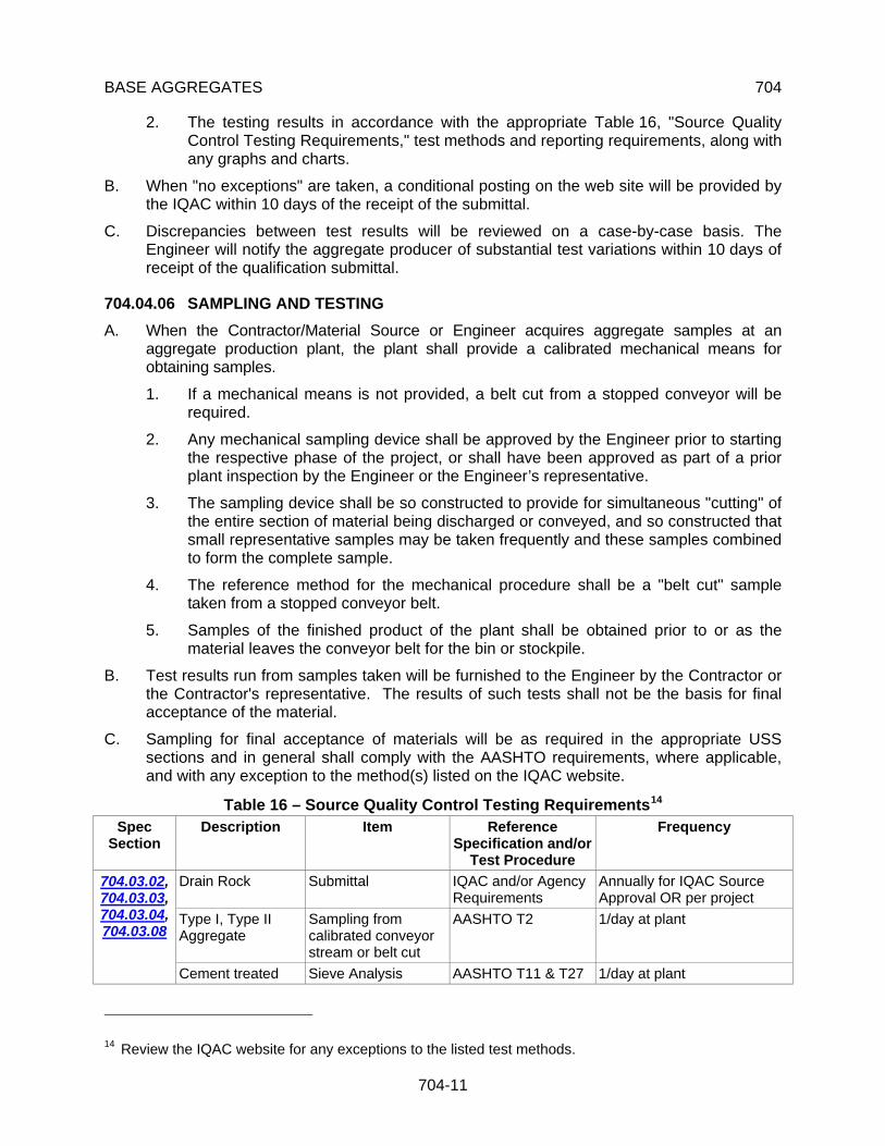
BASE AGGREGATES 704
704-11
2. The testing results in accordance with the appropriate Table 16, "Source Quality Control Testing Requirements," test methods and reporting requirements, along with any graphs and charts.
B. When "no exceptions" are taken, a conditional posting on the web site will be provided by the IQAC within 10 days of the receipt of the submittal.
C. Discrepancies between test results will be reviewed on a case-by-case basis. The Engineer will notify the aggregate producer of substantial test variations within 10 days of receipt of the qualification submittal.
704.04.06 SAMPLING AND TESTING
A. When the Contractor/Material Source or Engineer acquires aggregate samples at an aggregate production plant, the plant shall provide a calibrated mechanical means for obtaining samples.
1. If a mechanical means is not provided, a belt cut from a stopped conveyor will be required.
2. Any mechanical sampling device shall be approved by the Engineer prior to starting the respective phase of the project, or shall have been approved as part of a prior plant inspection by the Engineer or the Engineer’s representative.
3. The sampling device shall be so constructed to provide for simultaneous "cutting" of the entire section of material being discharged or conveyed, and so constructed that small representative samples may be taken frequently and these samples combined to form the complete sample.
4. The reference method for the mechanical procedure shall be a "belt cut" sample taken from a stopped conveyor belt.
5. Samples of the finished product of the plant shall be obtained prior to or as the material leaves the conveyor belt for the bin or stockpile.
B. Test results run from samples taken will be furnished to the Engineer by the Contractor or the Contractor's representative. The results of such tests shall not be the basis for final acceptance of the material.
C. Sampling for final acceptance of materials will be as required in the appropriate USS sections and in general shall comply with the AASHTO requirements, where applicable, and with any exception to the method(s) listed on the IQAC website.
Table 16 – Source Quality Control Testing Requirements14 Spec
Section Description Item Reference
Specification and/or Test Procedure
Frequency
Drain Rock Submittal IQAC and/or Agency Requirements
Annually for IQAC Source Approval OR per project
Type I, Type II Aggregate
Sampling from calibrated conveyor stream or belt cut
AASHTO T2 1/day at plant
704.03.02, 704.03.03, 704.03.04, 704.03.08
Cement treated Sieve Analysis AASHTO T11 & T27 1/day at plant
14 Review the IQAC website for any exceptions to the listed test methods.

704 BASE AGGREGATES
704-12
Table 16 – Source Quality Control Testing Requirements14 Spec
Section Description Item Reference
Specification and/or Test Procedure
Frequency
base Percentage of Wear (500 Rev.)
AASHTO T96 Annually for Source Approval OR per project
704.03.04, 704.03.05, 704.03.06
Drain rock, Type II, and Type III aggregate around water pipe
Total Available Water Soluble Sulfates15
AWWA 3500-NaD AWWA 4550 E
1/month at plant
Plasticity Index AASHTO T9016 1/day at plant
Liquid Limit AASHTO T89 1/day at plant
ASTM D2844 Annually for IQAC Source Qualification OR per project
704.03.03, 704.03.04
Type I and Type II Aggregate
Resistance (R Value)or Resilient Modulus AASHTO T307 Annually for IQAC Source
Qualification OR per project
Mix Design USS 704.03.07 Annually for IQAC Source Qualification OR per project
CLSM
Compressive Strength
USS 208.02.07 & AASHTO T22, T23
Annually for IQAC Source Qualification OR per project
704.03.07
CLSM-BAF Visual Inspection Report
USS 208.02.07 Split cylinders
Annually for IQAC Source Qualification OR per project
15 Required only for placement around waterline pipe. 16 Test specimens shall be prepared following the dry preparation procedure AASHTO T87.