2012 irc wood wall bracing - umn ccaps irc wall bracing 21 base shear february 2008 macon co....
TRANSCRIPT

2012 IRC Wall Bracing 12/11/2017
Copyright 2013 International Code Council 1
2012 IRC Wood Wall Bracing2012 IRC Wood Wall Bracing2012 International Residential Code® (IRC®)
DescriptionDescription This 6-hour seminar provides a comprehensive
explanation of the 2012 International Residential Code® (IRC®) bracing requirements. It guides the participant through an in-depth review and analysis of the bracing requirements for wood-frame residential structures. The seminar is designed to clarify the application of wall bracing provisions in the IRC wall bracing Sections R602.10 – R602.12.
2012 IRC Wall Bracing 2
GoalGoal The participant will successfully apply the
provisions of the 2012 IRC to problems involving bracing requirements for wood-framed residential structures.
2012 IRC Wall Bracing 3
ObjectivesObjectives Upon completion, participants will be
better able to:1. Identify the forces that act on a house.2. Describe the history of bracing and how it
works.3. Apply the wall bracing provisions of the IRC.4. Grasp the physical limits under which
bracing can be used.
2012 IRC Wall Bracing 4

2012 IRC Wall Bracing 12/11/2017
Copyright 2013 International Code Council 2
Objectives (continued)Objectives (continued)5. Select from the various bracing options
available.6. Determine how much bracing is required,
and how adjustment factors are applied.7. Recognize special considerations for
bracing.8. Apply attachment details, and pony and
cripple wall details.
2012 IRC Wall Bracing 5
Target AudienceTarget Audience Designers Plans examiners Inspectors Builders Contractors Architects & Engineers
2012 IRC Wall Bracing 6
ResourcesResourceswww.iccsafe.orgItem no. 7102S12
www.apawood.orgPublication F430
2012 IRC Wall Bracing 7
Bracing TopicsBracing Topics
2012 IRC Wall Bracing 8
Forces and History Limits Bracing Examples
Load Path
Lateral Forces
Stiffened Walls
Bracing History
Limits
Irregular Buildings
Wind Exposure
Locate BWL
Required Length
BWP Location
Panel Material & Ends
Sufficient Length
Connections
Foundation
Simplified Wall Bracing
Wind 90 mph, Exp B, SDC A
Wind 85 mph, Exp B, SDC D2
Wind 95 mph, Exp C, SDC B

2012 IRC Wall Bracing 12/11/2017
Copyright 2013 International Code Council 3
Bracing TopicsBracing Topics
2012 IRC Wall Bracing 9
Forces & History Limits Bracing Examples
Chapter 1 Chapter 4Chapter 2 Chapter 3
Bracing TopicsBracing Topics
2012 IRC Wall Bracing 10
Forces & History Limits Bracing Examples
Load Path
Lateral Forces
Stiffened Walls
Bracing History
1. Ridge Beam
2. Post
3. Header
4. Jack Studs
5. Sill Plate
6. Foundation
7. Ground2012 IRC Wall Bracing 11
Load PathLoad Path
Vertical (Gravity) Load PathLoad LoadLoad
2012 IRC Wall Bracing 12
Load PathLoad Path
Lateral (Sideways) Load PathLoad LoadLoad

2012 IRC Wall Bracing 12/11/2017
Copyright 2013 International Code Council 4
2012 IRC Wall Bracing 13
Load PathLoad Path
1. Load on wall
2. Transfer to roof
4. Transferto wall
5. Transfer to foundation
3. Connections
2012 IRC Wall Bracing 14
Load PathLoad Path
R301.1 Application The construction of buildings…shall result in a…complete load path…for the transfer of all loads…to the foundation.
Foundation3.7
Load
BracedWall
Panel
Foundations,IRC Chapter 4
Floors,IRC Chapter 5
Walls,IRC Chapter 6
Roof/Ceiling,IRC Chapter 8
Load PathLoad Path
2012 IRC Wall Bracing 15
Bracing TopicsBracing Topics
2012 IRC Wall Bracing 16
Forces and History Limits Bracing Examples
Load Path
Lateral Forces
Stiffened Walls
Bracing Provisions
2012 IRC Wall Bracing 12/11/2017
Copyright 2013 International Code Council 5
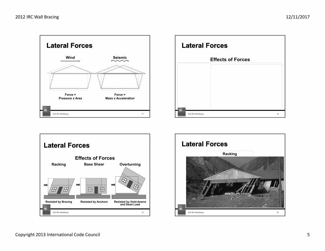
Lateral ForcesLateral Forces
2012 IRC Wall Bracing 17
Wind
Force =Pressure x Area
Force =Mass x Acceleration
Seismic
Resisted by hold-downs & Dead Load
Overturning
Resisted by Anchors
Base Shear
Resisted by Bracing
RackingEffects of Forces
Lateral ForcesLateral Forces
2012 IRC Wall Bracing 18
Resisted by Bracing
Racking
Resisted by Anchors
Base Shear
Resisted by Hold-downs and Dead Load
OverturningEffects of Forces
Lateral ForcesLateral Forces
2012 IRC Wall Bracing 19
Lateral ForcesLateral Forces
2012 IRC Wall Bracing 20
Racking

2012 IRC Wall Bracing 12/11/2017
Copyright 2013 International Code Council 6
Lateral ForcesLateral Forces
2012 IRC Wall Bracing 21
Base Shear
February 2008
Macon Co.
‘Super Tuesday’ Tornado
Lateral ForcesLateral Forces
2012 IRC Wall Bracing 22
Overturning
Anchors
hold-down
Lateral ForcesLateral Forces
2012 IRC Wall Bracing 23
Lateral ForcesLateral Forces
2012 IRC Wall Bracing 24
2003 Missouri Tornado

2012 IRC Wall Bracing 12/11/2017
Copyright 2013 International Code Council 7
Lateral ForcesLateral Forces
2012 IRC Wall Bracing 25
2003 Missouri TornadoLateral ForcesLateral Forces
2003 Missouri Tornado
2012 IRC Wall Bracing 26
Introduction: Lateral ForcesIntroduction: Lateral Forces
2012 IRC Wall Bracing 27
Wind Speed
Introduction: Lateral ForcesIntroduction: Lateral Forces
2012 IRC Wall Bracing 28
Wind Speed – USA

2012 IRC Wall Bracing 12/11/2017
Copyright 2013 International Code Council 8
Introduction: Lateral ForcesIntroduction: Lateral Forces
2012 IRC Wall Bracing 29
Earthquake
Introduction: Lateral ForcesIntroduction: Lateral Forces
2012 IRC Wall Bracing 30
SDC – United States
Bracing TopicsBracing Topics
2012 IRC Wall Bracing 31
Forces and History Limits Bracing Examples
Load Path
Lateral Forces
Stiffened Walls
Bracing History
Stiffened WallsStiffened Walls
2012 IRC Wall Bracing 32
Wall FramingHinge
Hinge

2012 IRC Wall Bracing 12/11/2017
Copyright 2013 International Code Council 9
Stiffened WallsStiffened Walls
2012 IRC Wall Bracing 33
Wall Framing
Panelresistanceimparted towall framing(Prevents hinging)
Interior Finish
Stiffened WallsStiffened Walls
2012 IRC Wall Bracing 34
Wall FramingWall FramingHinge
HingeBracedWall Panel(Prevents hinging)
(1) Areas requiring wind design in Table R301.2(4)B may not use the IRC for lateral provisions.
Stiffened WallsStiffened Walls
2012 IRC Wall Bracing 35
BWP (Prescriptive)
Limitations 3-Stories MaximumWind < 110 mph(1)
SDC A-D2Others (see IRC Chap. 3)
Typically withouthold-downs
Shear Walls (Engineered)
Applications Any building size/shapeWind – no limit SDC – no limit Calculations requiredTypically withhold-downs
VS.
Prescribedmaterial and nailing
Calculated load,material and nailing
Hold-downcapacity calculated
2012 IRC Wall Bracing 36
Stiffened WallsStiffened Walls
VS.BracedWall
Panel(BWP)
ShearWall

2012 IRC Wall Bracing 12/11/2017
Copyright 2013 International Code Council 10
Wall BracingWall Bracing R602.10 Wall Bracing "Where a building, or portion thereof, does not
comply with one or more of the bracing requirements in this section, those portions shall be designed and constructed in accordance with Section R301.1.ʺ
2012 IRC Wall Bracing 37
Bracing TopicsBracing Topics
2012 IRC Wall Bracing 38
Forces and History Limits Bracing Examples
Load Path
Lateral Forces
Stiffened Walls
Bracing History
History of BracingHistory of Bracing
Uniform Building Code – 1927 All exterior walls and partitions shall be thoroughly and effectively
angle braced.
Southern Building Code – 1946 Sheathing shall be applied on the exterior walls of buildings more than one story
in height, corners shall be braced by a let-in 1 x 4 or 1 x 6 continuous diagonal brace.
Uniform Building Code – 1952 All exterior walls and partitions shall be thoroughly and effectively angle braced
or sheathed with approved panels adequately nailed along all edges.
2012 IRC Wall Bracing 39
History of Wall BracingHistory of BracingHistory of Bracing
2012 IRC Wall Bracing 40

2012 IRC Wall Bracing 12/11/2017
Copyright 2013 International Code Council 11
History of BracingHistory of BracingUniform Building Code – 1970
All exterior walls and main cross stud partitions shall be effectively and thoroughly braced at each end, or as near thereto as possible, and at least every 25 feet of length by on of the following methods:
A. Nominal 1-inch by 4-inch…B. Wood boards of 5/8-inch…C. Plywood sheathing…D. Fiberboard sheathing…E. Gypsum sheathing…F. Particleboard sheathing…
The Southern Building Code of 1970 had similar requirements as did the National Building Code by 1984.
2012 IRC Wall Bracing 41
History of BracingHistory of Bracing
2012 IRC Wall Bracing 42
History of BracingHistory of BracingUniform Building Code - 1994
32-inch alternate braced wall panel added
2012 IRC Wall Bracing 43
International Residential Code – 2000 Bracing percentage requirement added Continuous wood structural panel bracing method added
International Residential Code – 2006 Alternate braced wall panel adjacent to door or window opening added Continuous sheathing 4:1 and 6:1 aspect ratio panels at garage door added
History of BracingHistory of Bracing
2012 IRC Wall Bracing 44

2012 IRC Wall Bracing 12/11/2017
Copyright 2013 International Code Council 12
History of BracingHistory of BracingInternational Residential Code – 2009
Methods renamed from number designation to abbreviation Wall bracing length determined by the greater length requirement from separate
wind and seismic bracing length tables Intermittent portal frame at garage added Continuous sheathing with structural fiberboard added Table of effective braced length for braced panels less than 48 in. long added Braced panel end distance limit of 12.5 ft. cumulative for SDC A-C with
intermittent bracing Additional bracing requirements for structures with masonry veneer moved to
wall bracing section Anchorage for masonry foundations with short wall lengths added Angled wall lines added Imaginary braced wall lines added
2012 IRC Wall Bracing 45
History of BracingHistory of BracingInternational Residential Code – 2012
Reorganization of wall bracing section Simplification of end distance and distance between braced wall panels Simplification of braced wall line length New method – Simplified Wall Bracing
2012 IRC Wall Bracing 46
Bracing TopicsBracing Topics
2012 IRC Wall Bracing 47
Forces & History Limits Bracing Examples
?Questions
Load Path
Lateral Forces
Stiffened Walls
Bracing History
Bracing TopicsBracing Topics
2012 IRC Wall Bracing 48
Forces & History Limits Bracing Examples
Limits
Irregular Buildings
Wind Exposure

2012 IRC Wall Bracing 12/11/2017
Copyright 2013 International Code Council 13
Limits – Story HeightLimits – Story Height
2012 IRC Wall Bracing 49R301.3
In-plane lateral forces
Requirements for story height exist to limit the wind and seismic provisions
In-plane forces (lateral forces along a wall line):• Story height limit – 11 ft. 7 in• Stud height – 10 ft.
Except:Stud height may be increased to 12 ft., therefore maximum story height may be 13 ft. 7 in
Limits – Story HeightLimits – Story Height
2012 IRC Wall Bracing 50
StudHeight
StoryHeight
StoryHeight
16" Max Floor Framing(Joist Depth)
10' = Max. Stud Height(1)
16" = Max. Floor Framing Height(2)
(1)R301.3 – Item 1, Exception permits the stud height to be 12' provided bracing length is increased by a factor of 1.2.
(2)R301.3 Permits floor framing depths greater than 16ʺ when maximum story height is 11'-7ʺ or less.
R301.3
Limits – Stud HeightLimits – Stud Height
2012 IRC Wall Bracing 51
Stud Size
(Inches)
BEARING WALLS NONBEARING WALLS
Laterally unsupported stud height
(feet)
Maximum spacing when
supporting roof-ceilingassembly or
habitable attic, only (inches)
Maximum spacing when
supporting one floor, plus a roof-ceilingassembly or
habitable attic (inches)
Maximum spacing when
supporting two floors, aroof-ceilingassembly or
habitable attic (inches)
Maximum spacing when
supporting one floor
height (inches)
Laterally unsupported stud height
(feet)
Maximum spacing (inches)
2 x 3 -- -- -- -- -- 10 16
2 x4 10 24 16 -- 24 14 24
3 x 4 10 24 24 16 24 14 24
2 x 5 10 24 24 -- 24 16 24
2 x 6 10 24 24 16 24 20 24
Size, Height and Spacing of Wood Studs - Table R602.3(5)
Limits – Story vs Stud HeightLimits – Story vs Stud Height
2012 IRC Wall Bracing 52
Balloon Framing Platform Framing
Stud Height
Story Height
Story Height
Stud Height
Stud Extends Two Stories
LateralSupport
R301.1.2
2012 IRC Wall Bracing 12/11/2017
Copyright 2013 International Code Council 14
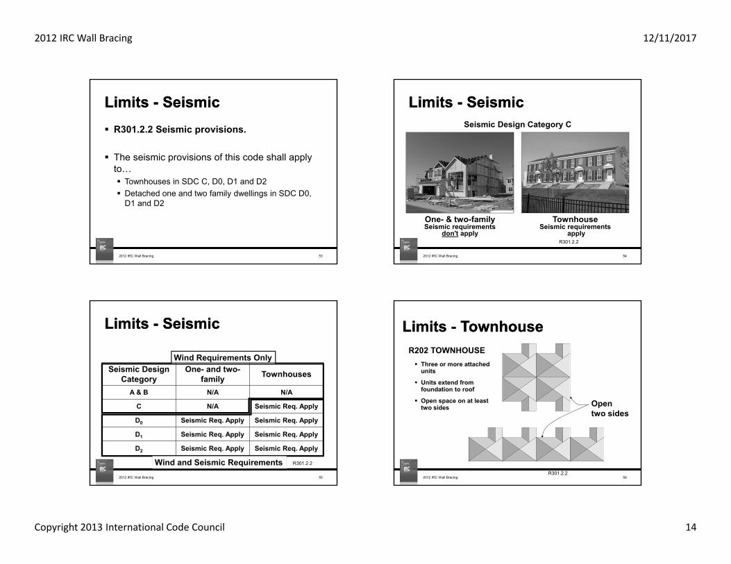
Limits - SeismicLimits - Seismic R301.2.2 Seismic provisions.
The seismic provisions of this code shall apply to… Townhouses in SDC C, D0, D1 and D2 Detached one and two family dwellings in SDC D0,
D1 and D2
2012 IRC Wall Bracing 53
Limits - SeismicLimits - Seismic
2012 IRC Wall Bracing 54
TownhouseSeismic requirements
apply
One- & two-familySeismic requirements
don't applyR301.2.2
Seismic Design Category C
Limits - SeismicLimits - Seismic
2012 IRC Wall Bracing 55
Wind Requirements Only
Wind and Seismic Requirements
Seismic Design Category
One- and two-family Townhouses
A & B N/A N/A
C N/A Seismic Req. Apply
D0 Seismic Req. Apply Seismic Req. Apply
D1 Seismic Req. Apply Seismic Req. Apply
D2 Seismic Req. Apply Seismic Req. Apply
R301.2.2
Limits - TownhouseLimits - TownhouseR202 TOWNHOUSE Three or more attached
units
Units extend from foundation to roof
Open space on at least two sides Open
two sides
R301.2.22012 IRC Wall Bracing 56

2012 IRC Wall Bracing 12/11/2017
Copyright 2013 International Code Council 15
Limits - TownhouseLimits - TownhouseR202 TOWNHOUSE Three or more attached
units
Units extend from foundation to roof
Open space on at least two sides
Not open two sides(therefore, not a townhouse)
R301.2.22012 IRC Wall Bracing 57
Limits - WeightLimits - Weight
2012 IRC Wall Bracing 58
R301.2.2.2.1 Weight of MaterialsAverage dead loads shall not exceed:
15 or 25 psf for roofs/ceiling assemblies 10 psf for floor assemblies 15 psf for exterior wall assemblies
Wind RequirementsWeight of materials
provisions do not apply
Seismic RequirementsWeight of materials
provisions apply
Limits - WeightLimits - Weight
2012 IRC Wall Bracing 59R301.2.3
Snow Load, R301.2.3Load Design Method
< 70 psf Prescriptive> 70 psf Engineered
Limits – Irregular BuildingsLimits – Irregular Buildings
2012 IRC Wall Bracing 60
R301.2.2.2.5 Irregular buildings
Wind Requirements
Irregular building provisions do not apply
Seismic Requirements
Irregular building provisionsapply
1 2 3 4 5 6 7Irregular building definitions

2012 IRC Wall Bracing 12/11/2017
Copyright 2013 International Code Council 16
LimitsLimits
2012 IRC Wall Bracing 61
GroundSnowLoad
WindSpeed(mph)
SeismicDesign
CategorySubject to Damage From
WinterDesignTemp
Ice BarrierUnderlayment
Required
FloodHazards
AirFreezing
Index
MeanAnnualTemp
≤70 <110 A-D2Weathering Frost Line
Depth Termite
CLIMATIC AND GEOGRAPIC DESIGN CRITERIA - TABLE R301.2(1)
Bracing TopicsBracing Topics
2012 IRC Wall Bracing 62
Forces & History Limits Bracing Examples
Limits
Irregular Buildings
Wind Exposure
Limits: Wind ExposureLimits: Wind ExposureR301.2.1.1 Wind Limitations and Wind Design Required
When wind speeds are 110 mph or greater OR When IRC Figure R301.2(4)B requires wind design
2012 IRC Wall Bracing 63
The following references may be used to design the walls to resist lateral forces:• WFCM• ICC 600• ASCE-7• AISI S230 (steel)• IBC R301.2.1.1
Limits: Wind ExposureLimits: Wind ExposureFigure R301.2(4)B shows where the IRC wall bracing requirements do not apply.
Another code or standard must be used to brace the walls against lateral loads.
2012 IRC Wall Bracing 64
Figure R301.2(4)B

2012 IRC Wall Bracing 12/11/2017
Copyright 2013 International Code Council 17
Limits: Wind ExposureLimits: Wind ExposureR301.2.1 Wind Design Criteria Component and cladding loads for wall coverings,
windows, etc. per Table R301.2(2) and adjusted per Table R301.2(3) shall be used…
2012 IRC Wall Bracing 65
Figure R301.2(7)
Limits: Wind ExposureLimits: Wind Exposure
2012 IRC Wall Bracing 66Cladding Failure
R301.2.1 Wind limitations
Limits: Wind ExposureLimits: Wind Exposure
2012 IRC Wall Bracing 67
Exposure A:Large city centers with at least 50 percent of the buildings having a height in excess of 70 feet for a distance of 0.5 mile upwind from the structure being designed.
70'Average
1/2 MileR301.2.1.4.1
Limits: Wind ExposureLimits: Wind Exposure
2012 IRC Wall Bracing 68
Exposure B:Urban and suburban areas, wooded areas or other terrain with many closely spaced obstructions having the size of single family dwellings or larger.
R301.2.1.4.2

2012 IRC Wall Bracing 12/11/2017
Copyright 2013 International Code Council 18
Limits: Wind ExposureLimits: Wind Exposure
2012 IRC Wall Bracing 69
Exposure C (1 of 2):Open with scattered obstructions or undulations generally less that 30 feet in height extending for 1,500 feet in any direction.
>30'
R301.2.1.4.3
Limits: Wind ExposureLimits: Wind Exposure
2012 IRC Wall Bracing 70
Exposure C (2 of 2):Within Exposure B terrain, but located directly adjacent to open areas of Exposure C for a distance of more than 600 ft..
More than600'
Exposure C terrain Exposure B terrain
R301.2.1.4.3
Limits: Wind ExposureLimits: Wind Exposure
2012 IRC Wall Bracing 71
Exposure D:Flat, unobstructed areas exposed to wind flowing over open water for at least 1 mile. Extends inland 1,500 feet.
1 Mile 1,500'
R301.2.1.4.4
Bracing TopicsBracing Topics
2012 IRC Wall Bracing 72
Forces & History Limits Bracing Examples
Limits
Irregular Buildings
Wind Exposure ?
Questions

2012 IRC Wall Bracing 12/11/2017
Copyright 2013 International Code Council 19
Bracing TopicsBracing Topics
2012 IRC Wall Bracing 73
Forces & History Limits Bracing Examples
Locate BWL
Required Length
BWP Location
Panel Material & Ends
Sufficient Length
Connections
Foundation
Simplified Wall Bracing
Forces & History Bracing ExamplesLimits
2012 IRC Wall Bracing 74
Bracing: BWL SpacingBracing: BWL Spacing
Start End
AB
C
How many BWL's?
Bracing: BWL SpacingBracing: BWL Spacing
R202, R602.10.1, R602.10.2
2012 IRC Wall Bracing 75
Bracing: BWL SpacingBracing: BWL Spacing
2012 IRC Wall Bracing 76
1
2
LengthA B
Wid
th
LOAD
RES
ISTA
NC
E
RES
ISTA
NC
E
R602.10.1
Loaded wall versus resisting walls

2012 IRC Wall Bracing 12/11/2017
Copyright 2013 International Code Council 20
2012 IRC Wall Bracing 77
Bracing: BWL SpacingBracing: BWL Spacing
1
2
LengthA B
Wid
th
LOAD
RESISTANCE
RESISTANCE
Loaded wall versus resisting walls
Bracing: BWL SpacingBracing: BWL Spacing
2012 IRC Wall Bracing 78
1
2
BWL SpacingA B
BW
L Sp
acin
g
WindBWL Spacing = 60' max.SeismicSDC C (only applies to townhouses)
BWL Spacing = 35' max.Permitted to be = 50' max. when bracing length increased.
Table R602.10.1.3
SeismicSDC D0, D1, & D2 (all dwellings)
BWL Spacing = 25' max.Permitted to be = 35' max. 1. To accommodate one
room not exceeding 900 ft2
2. For all BWLs when bracing length is increased and L/W < 3:1
Table R602.10.1.3
R602.10.12012 IRC Wall Bracing 79
Bracing: BWL SpacingBracing: BWL Spacing Bracing: BWL SpacingBracing: BWL Spacing
21 32BWLSpacing
BWLSpacing
Locating BWL here makes distance between BWL's less.
2
2012 IRC Wall Bracing 80

2012 IRC Wall Bracing 12/11/2017
Copyright 2013 International Code Council 21
Bracing: BWL SpacingBracing: BWL Spacing Wall Lines with BWP Offset Limitations Wall lines with BWP that are counted as part of a
BWL must be parallel to the BWL Offsets out-of-plane up to 4' are permitted for any wall
line There is an angle wall exception which will be
discussed later
2012 IRC Wall Bracing 81
R602.10.1.2 R602.10.1.2
1
2
A B
Bracing: BWL SpacingBracing: BWL Spacing
25'
20'
6'
2012 IRC Wall Bracing 82
Bracing: BWL SpacingBracing: BWL Spacing
2012 IRC Wall Bracing 83
4' BWL
R602.10.1.2
Bracing: BWL SpacingBracing: BWL Spacing
2012 IRC Wall Bracing 84
4'
4'
8'BWL
R602.10.1.2

2012 IRC Wall Bracing 12/11/2017
Copyright 2013 International Code Council 22
Bracing: BWL SpacingBracing: BWL Spacing
2012 IRC Wall Bracing 85
4'
4'
A
B
24'
16'
C
R602.10.1.2
Bracing: BWL SpacingBracing: BWL Spacing
2012 IRC Wall Bracing 86
Wind 20' Edge to Edge "X" End BWP Width
6'
A
B
24'
16'
10' Max.
4'C
R602.10.1.2
Bracing: BWL SpacingBracing: BWL Spacing
2012 IRC Wall Bracing 87
25'
18'
6'Max.
6' Max.
R602.10.1.2
?
Bracing: BWL SpacingBracing: BWL Spacing
2012 IRC Wall Bracing 88
24'
BWP BWP3'
R602.10.1.2

2012 IRC Wall Bracing 12/11/2017
Copyright 2013 International Code Council 23
2012 IRC Wall Bracing 89
Bracing: BWL SpacingBracing: BWL SpacingHow many BWL's?
Bracing: BWL SpacingBracing: BWL Spacing
2012 IRC Wall Bracing 90
24'
4'
R602.10.1.3 Angled Corners
Wall sheathing in a diagonal wall section may be counted for a wall line’s bracing length if the diagonal wall line is 8” or less in length.
R602.10.1.4
Bracing: BWL SpacingBracing: BWL Spacing
2012 IRC Wall Bracing 91
Angled Walls R602.10.1.4
Angle from BWL (degrees)
Projected BWL Length from Angled Wall Line
(ft.)Angled Wall Line
Length4 ft. 6 ft. 8 ft.
15 3.9 5.8 7.830 3.5 5.2 7.045 2.9 4.3 5.7 R602.10.1.4
Bracing TopicsBracing Topics
2012 IRC Wall Bracing 92
Forces & History Limits Bracing Examples
Locate BWL
Required Length
BWP Location
Panel Material & Ends
Sufficient Length
Connections
Foundation
Simplified Wall Bracing
Forces & History Bracing ExamplesLimits

2012 IRC Wall Bracing 12/11/2017
Copyright 2013 International Code Council 24
Wind Speed Seismic Risk
Both wind speed and seismic risk must be considered when defining required wall bracing. The required bracing length is the greater of the two bracing lengths.
Bracing: Required LengthBracing: Required Length
2012 IRC Wall Bracing 93
Bracing: Required LengthBracing: Required Length
Wind Requirements• Braced wall line spacing• Wall height• Eave to ridge height• Roof ties
Seismic Requirements• Wall length• Braced wall line spacing• Hold-downs• Material weight limits
When considering whether wind or seismic requirements control, a number of factors must be considered.
• Wall bracing length - either wind or seismic requirements may control. Use the longest required length.
• Hold-downs, Roof Ties, Limits – if wind or seismic requirements require additional connections or limits, they must be applied regardless of which requirement set controls.
2012 IRC Wall Bracing 94
Bracing: Required LengthBracing: Required Length
2012 IRC Wall Bracing 95
R602.10.3, Tables R602.10.3(1), R602.10.3(2), R602.10.3(3) & R602.10.3(4)
Bracing Length Tables
2012 – Two bracing length tables• Wind Table R602.10.3(1) • Seismic Table R602.10.3(3)
Required bracing length is the maximum of the two tables’ bracing length x all adjustment factors
Bracing: Required LengthBracing: Required Length
2012 IRC Wall Bracing 96
Bracing Required?
Wind Table R602.10.3(1)
All detached dwellings and townhouses
Seismic Table R602.10.3(3)
Detached dwellings in SDC
D0-D2
Townhouses in SDC C-D2
Decision Tree for Determining Required Bracing Length
R301.2.1, R301.2.2, R602.10.3

2012 IRC Wall Bracing 12/11/2017
Copyright 2013 International Code Council 25
Bracing: Required LengthBracing: Required Length
2012 IRC Wall Bracing 97
Table R602.10.3(1)
Bracing Requirements Based on Wind SpeedWind Bracing Table based on:
• Wind Exposure Category B• Mean roof height of 30 ft.• Eave to ridge height of 10 ft.• Wall height of 10 ft.• Two braced wall lines
Required bracing length is determined by:
• Wind speed• Story location• Wall line spacing• Bracing method
Bracing: Required LengthBracing: Required Length
Adjust required bracing length
using Table R602.10.3(2)
Wind Exposure Category
Adjustment
Roof Eave to Ridge Height Adjustment
Wall Height Adjustment
# of BWLs Adjustment
Hold-down, Interior finish, GB fastener Adjustments
Adjustments to the required bracing length for wind forces:
Only required when adjustment is greater than 1.0 Table R602.10.3(2)
2012 IRC Wall Bracing 98
Bracing: Required LengthBracing: Required Length
2012 IRC Wall Bracing 99
Table R602.10.3(2)
Bracing Requirements Based on Wind Speed –Adjustment Factors
Wind bracing adjustment factors are in Table R602.10.3(2)
1. Wind exposure category2. Eave-to-ridge height3. Wall height4. Number of braced wall lines5. 800-lb hold-down on top story6. Application of interior gypsum board finish7. Gypsum board fastening
Bracing: Required LengthBracing: Required Length
2012 IRC Wall Bracing 100
Adjustment Factor –Wind Exposure Category, Mean Roof Height
Number of Stories
Exposure/Height FactorExposure B Exposure C Exposure D
1 1.0 1.2 1.52 1.0 1.3 1.63 1.0 1.4 1.7
Table R602.10.3(2)

2012 IRC Wall Bracing 12/11/2017
Copyright 2013 International Code Council 26
2012 IRC Wall Bracing 101
Bracing: Required LengthBracing: Required LengthAdjustment Factor –
Roof Eave-to-Ridge Height
Support Condition
Roof Eave-to-Ridge Height< 5' 10' 15' 20'
Roof only 0.7 1.0 1.3 1.6Roof + floor 0.85 1.0 1.15 1.3
Roof + 2 floors 0.9 1.0 1.1 NPNP – Not Permitted
Roof sail area that contributes to total structure sail area
Eave-to-ridge height
Table R602.10.3(2)
Bracing: Required LengthBracing: Required LengthAdjustment Factor – Wall Height
Wall Height (ft.)
Adjustment Factor
8' 0.90
9' 0.95
10' 1.0
11' 1.05
12' 1.1
Table R602.10.3(2)
2012 IRC Wall Bracing 102
2012 IRC Wall Bracing 103
Bracing: Required LengthBracing: Required LengthAdjustment Factor – Number of Braced Wall Lines
Number of Braced Wall Lines
Adjustment Factor
2 1.0
3 1.30
4 1.45
> 5 1.60
x
xx
xxx
x – Braced wall line spacing– Braced wall line
Table R602.10.3(2)
2012 IRC Wall Bracing 104
Bracing: Required LengthBracing: Required LengthAdjustment Factor – Number of Braced Wall Lines
Footnote cNumber of Braced
Wall LinesAdjustment
Factor2 1.0
3 1.30
4 1.45
> 5 1.60
xx
xxx
x – Braced wall line spacing– Braced wall line
Table R602.10.3(2)
Table R602.10.3(2) Footnote c allows the adjustment factor to be 1.0 when the braced wall line spacing on exterior lines neglects the interior lines.
For example – when interior BWLs are only need for seismic bracing or when they are only needed to support BWLs in the story above.

2012 IRC Wall Bracing 12/11/2017
Copyright 2013 International Code Council 27
Bracing: Required LengthBracing: Required LengthAdjustment Factors – wind cont.
AdjustmentFactor
BracingMethod
Adjustment Factor
Additional 800-lb hold-down at each BWP for top story only
DWB, WSP, SFB, PBS, PCP, and HPS 0.80
Interior finish DWB, WSP, SFB, PBS, PCP, HPS, CS-WSP, CS-G, and CS-SFB 1.4
Gypsum board fastening –4” o.c. at all panel edges, blocked horizontal joints
GB 0.7
Table R602.10.3(2)
2012 IRC Wall Bracing 105
Bracing TopicsBracing TopicsForces & History Bracing Examples
Locate BWL
Required Length
BWP Location
Panel Material & Ends
Sufficient Length
Support
Connections
Simplified Wall Bracing
Limits
?Questions
2012 IRC Wall Bracing 106
Bracing TopicsBracing TopicsForces & History Limits Bracing Examples
Locate BWL
Required Length
BWP Location
Panel Material & Ends
Sufficient Length
Connections
Foundation
Simplified Wall Bracing
Forces & History Bracing ExamplesLimits
2012 IRC Wall Bracing 107
Bracing: BWP LocationBracing: BWP Location
R202, R602.10.1, R602.10.2
BWP, BWL & Spacing
2012 IRC Wall Bracing 108

2012 IRC Wall Bracing 12/11/2017
Copyright 2013 International Code Council 28
Bracing: BWP LocationBracing: BWP Location
6' 10'21' unbraced length
25' o.c.2'2'
4'BWP
4'BWP
BWP Spacing – 2009 and earlier
2012 IRC Wall Bracing 109
Bracing: BWP LocationBracing: BWP Location
6' 10'20' unbraced length
R602.10.2.2
BWP Spacing – 2012 Edition
2012 IRC Wall Bracing 110
Bracing: BWP LocationBracing: BWP Location
R602.10.2.2, R602.10.2.3
R602.10.2.2 Location of Braced Wall Panels,R602.10.2.3 Minimum Number of BWPs
BWL 1
10′ MAX
Placement Requirements BWP to begin no more than 10' feet from the end of a BWL. BWP located not more than 20' o.c. from edge to edge Two BWPs per BWL when BWL > 16 ft. ANDMinimum 1- 48″ BWP or 2- reduced length BWPs for BWL < 16 ft.
2012 IRC Wall Bracing 111 2012 IRC Wall Bracing 112
Bracing: BWP LocationBracing: BWP Location
8' to 12'
Distance from Corner
Corner(end of wall line)
Wind Panel begins up to 10 ft. from the corner
R602.10.2.2, R602.10.2.2.1
Braced Panel Starting Location

2012 IRC Wall Bracing 12/11/2017
Copyright 2013 International Code Council 29
Bracing: BWP LocationBracing: BWP Location
Wall Bracing
Parameter
Intermittent CS-WSP CS-SFB
Wind & SDC A-C
SDCD0-D2
Wind & SDC A-C
SDCD0-D2
Wind & SDC A-C
SDCD0-D2
Panel end distance
12.5'Combined 0' or 8' (a) 12.5' 8' 12.5' Not
Permitted
Corner return length Not required 24" Min. (b) 32" Min. (b)
(a) For WSP, 8' with 24" panel at corner or 1,800 lb hold down per R602.10.1.4.1, exception items 1 & 2.
(b) In lieu of a corner return, an 800 lb hold-down may be fastened to the side of the BWP closest to the corner per R602.10.5.3, exception item 2.
Overview – 2009 and earlier
2012 IRC Wall Bracing 113
Bracing: BWP LocationBracing: BWP Location
Wall Bracing
Parameter
Intermittent CS-WSP, CS-G, CS-PF CS-SFB
Wind & SDC A-C
SDCD0-D2
Wind & SDC A-C
SDCD0-D2
Wind & SDC A-C
SDCD0-D2
Panel end distance 10' 0' or 10' (a) 10' 10' 10' Not
Permitted
Corner return length Not required 24" Min. (b) 32" Min. (b)
(a) For WSP, 10' with 24" panel at corner or 1,800 lb hold down per R602.10.2.2.1, exception items 1 & 2.
(b) In lieu of a corner return, an 800 lb hold-down may be fastened to the side of the BWP closest to the corner per Figure R602.10.7, End Condition 2.
Overview – 2012 IRC
R602.10.2.2, Figure R602.10.7
2012 IRC Wall Bracing 114
Bracing: BWP LocationBracing: BWP Location
2012 IRC Wall Bracing 115R602.10.2.2
2012 IRC Wall Bracing 116
Bracing: BWP LocationBracing: BWP Location
12'-6" Max.
48"
Wind – 2009 IRC25' Centers"X" EndBWP length
25' Max.
R602.10.1.4, Figures R602.10.1.4(1) and R602.10.1.4(2)
48" 48"
Summary – 2009 Provisions

2012 IRC Wall Bracing 12/11/2017
Copyright 2013 International Code Council 30
Bracing: BWP LocationBracing: BWP Location
2012 IRC Wall Bracing 117
10' max
48"
Wind – 2012 IRC20' Spacing10' EndBWP length
20' max
R602.10.2.2
48" 48"
Summary – 2012 Provisions
Bracing: BWP LocationBracing: BWP Location
2012 IRC Wall Bracing 118
Does this meet code?No, 20' maximum exceeded.
Wind – 2012 IRC20' Spacing10' EndBWP Width
R602.10.2.2
28'
48" 48"
Wind – 2012 IRC20' Spacing10' EndBWP Length
Bracing: BWP LocationBracing: BWP Location
2012 IRC Wall Bracing 119
Does this meet code?Yes, 20' maximum not exceeded.
16'
36'
48" 48"48"
R602.10.2.2
Bracing: BWP LocationBracing: BWP Location
2012 IRC Wall Bracing 120
Does this meet code?No, BWP required to begin no more than 10 feet from the end of the wall.
Wind – 2012 IRC20' Spacing10' EndBWP Width
12'
36'
48" 48"
R602.10.2.2

2012 IRC Wall Bracing 12/11/2017
Copyright 2013 International Code Council 31
Bracing: BWP LocationBracing: BWP Location
3.7
Does this meet code?No, width requirement not met.
Wind & Seismic - 201220' Spacing10' EndBWP Width
R602.10.5
48" 48"
18'
2012 IRC
2012 IRC Wall Bracing 121
Bracing: BWP LocationBracing: BWP LocationDoes this meet code?
Yes, width requirements are met.
Wind – 2012 IRC20' Spacing10' EndBWP Width
3.7Note: If BWP is supporting a story above, nailing must be a maximum 4ʺ o.c.
18'
8'
R602.10.6.1
28"
ABW
28"
ABW
ABW
Equals 4'
2012 IRC Wall Bracing 122
Bracing: BWP LocationBracing: BWP LocationDoes this meet code?
Yes, width requirements are met.
Wind & Seismic - 201220' Spacing10' EndBWP Width
3.7
Extended HeaderExtended Header
8' Note: Increase BWP width to 24" if supporting a story above.
R602.10.6.2
18'
16"
PFH
16"
PFH
Equals 4'
PFH
2012 IRC Wall Bracing 123
Bracing TopicsBracing TopicsForces & History Bracing Examples
Locate BWL
Required Length
BWP Location
Panel Material & Ends
Sufficient Length
Support
Connections
Simplified Wall Bracing
Limits
?Questions
2012 IRC Wall Bracing 124

2012 IRC Wall Bracing 12/11/2017
Copyright 2013 International Code Council 32
Bracing TopicsBracing TopicsForces & History Bracing Examples
Locate BWL
Required Length
BWP Location
Panel Material & Ends
Sufficient Length
Connections
Foundation
Simplified Wall Bracing
Limits
2012 IRC Wall Bracing 125
Bracing TopicsBracing TopicsBracing
Locate BWL
Required Length
BWP Location
Panel Material & Ends
Sufficient Length
Connections
Foundation
Simplified Wall Bracing
Panel Material & Ends
Intermittent Bracing
Continuous Sheathing
Narrow Bracing
Mixed Methods
Interior Finish
Ends Conditions – Continuous Sheathing
Joints
2012 IRC Wall Bracing 126
Bracing: Panel Material -IntermittentBracing: Panel Material -Intermittent
2012 IRC Wall Bracing 127
Intermittent Bracing Methods:LIB - Let-in diagonal braceDWB - 3/4" Diagonal wood boardsWSP - 3/8" Wood structural panelBV-WSP – 7/16" Wood structural panel with stone or masonry veneerSFB - 1/2" Structural fiberboardGB - 1/2" Interior gypsum wallboard or gypsum sheathing particleboardPBS - 3/8" Particleboard sheathingPCP - Portland cement plaster on studsHPS - 7/16" Hardboard panel sidingABW - Alternate braced wallPFH - Portal frame with hold-downsPFG - Portal frame at garage door openings in SDC A-C
Table R602.10.4
Bracing: Panel Material -IntermittentBracing: Panel Material -Intermittent
2012 IRC Wall Bracing 128
Angled 45 to 60 degrees from horizontal
Extends continuously from bottom plate to top plate
1x4 lumber or approved metal strap
Application limited 8' to 10' wall height only 55" to
120"
8' to 10'
Table R602.10.4
Method LIB – Let-in Brace

2012 IRC Wall Bracing 12/11/2017
Copyright 2013 International Code Council 33
Bracing: Panel Material -IntermittentBracing: Panel Material -Intermittent
2012 IRC Wall Bracing 129
Table R602.10.4
Method LIB – Let-in Brace
Bracing: Panel Material -IntermittentBracing: Panel Material -Intermittent
Method LIB – Let-in Brace
Must extend continuously from
bottom plate to top plate
2012 IRC Wall Bracing 130
Bracing: Panel Material -IntermittentBracing: Panel Material -Intermittent
8' to 12'
Method DWB – Diagonal Wood Boards Wood boards 3/4" (1" nominal)
thick applied diagonally Studs spaced 24" max.
4' min.Table R602.10.4
2012 IRC Wall Bracing 131
Bracing: Panel Material -IntermittentBracing: Panel Material -Intermittent
2012 IRC Wall Bracing 132
Method DWB – Diagonal Wood Boards

2012 IRC Wall Bracing 12/11/2017
Copyright 2013 International Code Council 34
Bracing: Panel Material -IntermittentBracing: Panel Material -Intermittent
Method WSP – Wood Structural Panel 3/8" min. thickness Wood structural panel
defined in R604
8' to 12'
4' min.Table R602.3(3)
2012 IRC Wall Bracing 133 2012 IRC Wall Bracing 134
Bracing: Panel Material -IntermittentBracing: Panel Material -Intermittent
Method WSP – Wood Structural Panel
48"48" 48"
Bracing: Panel Material -IntermittentBracing: Panel Material -Intermittent
Method SFB – Structural Fiberboard Sheathing 1/2" or 25/32" thick Studs spaced 16" o.c. max. Must conform to ASTM C 208 Nailing 3" o.c. edge, 6" o.c. field
8' to 12'
4' min.Table R602.10.4
2012 IRC Wall Bracing 135
Bracing: Panel Material -IntermittentBracing: Panel Material -Intermittent
2012 IRC Wall Bracing 136
Method SFB – Structural Fiberboard Sheathing

2012 IRC Wall Bracing 12/11/2017
Copyright 2013 International Code Council 35
Bracing: Panel Material -IntermittentBracing: Panel Material -Intermittent
8' min.
Method GB – Gypsum Board 1/2" min. thick for studs
spaced 24" o.c. max. 4' minimum length Nailing at 7" o.c. Bracing length:
Single sided = 0.5 x actual length
Double sided = 1x actual length
No floating corners!
8' to 12'
Table R602.10.4
2012 IRC Wall Bracing 137
Bracing: Panel Material -IntermittentBracing: Panel Material -Intermittent
2012 IRC Wall Bracing 138
Method GB – Gypsum Board
Bracing: Panel Material -IntermittentBracing: Panel Material -Intermittent
Method PBS – Particleboard Sheathing 3/8" or 1/2" min. thickness Studs 16" o.c. max. 4' minimum length Nailing at 3" edge, 6" field Minimum 8d nails for 1/2"
thick sheathing8' to 12'
4' min.Table R602.10.4
2012 IRC Wall Bracing 139
Bracing: Panel Material -IntermittentBracing: Panel Material -IntermittentMethod PCP – Portland Cement Plaster
Studs 16" o.c. max. Installed in accordance with R703.6 Nailing 6" o.c.
8' to 12'
4' min.Table R602.10.4
2012 IRC Wall Bracing 140

2012 IRC Wall Bracing 12/11/2017
Copyright 2013 International Code Council 36
Bracing: Panel Material -IntermittentBracing: Panel Material -Intermittent
2012 IRC Wall Bracing 141
Method PCP – Portland Cement
Bracing: Panel Material -IntermittentBracing: Panel Material -Intermittent
Method HPS – Hardboard Panel Siding• 7/16" minimum thickness• Studs 16" on center• Nailing 4" o.c. edge and
8" o.c. field
8' to 12'
4' min.Table R602.10.4
2012 IRC Wall Bracing 142
Bracing: Panel Material -IntermittentBracing: Panel Material -Intermittent
2012 IRC Wall Bracing 143
Method HPS – Hardboard Panel Siding
Bracing: Panel Material -IntermittentBracing: Panel Material -Intermittent
Table R602.10.5 Minimum length for braced wall panels
48″ to 58″
BWP
BWP Height
BWPLengthMinimum Length of BWPs
Table R602.10.5
Method (See Table R602.10.4)
Minimum Lengtha
(inches) Contributing Length (inches)
Wall Height8 ft. 9 ft. 10 ft. 11 ft. 12 ft.
DWB, WSP, SFB, PBS,
PCP, HPS, BV-WSP
48 48 48 53 58 Actualb
GB 48 48 48 53 58
Double sided = Actual
Single sided = 0.5 × Actual
LIB 55 62 69 NP NP Actualb
2012 IRC Wall Bracing 144

2012 IRC Wall Bracing 12/11/2017
Copyright 2013 International Code Council 37
Bracing: Panel Material -IntermittentBracing: Panel Material -Intermittent
Table R602.10.5.2 Effective length of braced panels less than 48"
For Methods DWB, WSP, SFB, PBS, PCP, HPS
ActualLength
Effective Length of BWP
8' 9' 10'48" 48" 48" 48"
42" 36" 36" N/A
36" 27" N/A N/A
27" to 48"
BWP
BWP Height
BWPLengthPartial Credit for Narrow BWPs
R602.10.5.22012 IRC Wall Bracing 145
Bracing: Panel Material -IntermittentBracing: Panel Material -IntermittentMethod ABW - Alternate Braced Wall
Equivalent to 48" panel For use on bottom story only Minimum length varies with SDC and
height Nailing:
Single story – 6" o.c. min Bottom of two story – 4" o.c. min
Minimum hold-down capacity changes with SDC and height
R602.10.6.1, Table R602.10.4
2012 IRC Wall Bracing 146
Bracing: Panel Material -IntermittentBracing: Panel Material -Intermittent
Length
Height
Method ABW - Alternate Braced Wall
Table R602.10.5
Minimum ABW LengthWall Height (ft.)
8 9 10 11 12SDC A-C 28 32 34 38 42SDC D0-D2
32 32 34 NP NP
Table R602.10.5 Minimum length for braced wall panels (excerpt)
2012 IRC Wall Bracing 147
Bracing: Panel Material -IntermittentBracing: Panel Material -Intermittent
Method ABW - Alternate Braced Wall Hold-down:
A prefabricated metal anchoring device that attaches the framing of a wall system to the structure below.The hold-down prevents uplift of the studs and, thus overturning of the wall segment.
Hold-down
Foundation reinforcement required(Caused by moment from hold-downs)
2012 IRC Wall Bracing 148

2012 IRC Wall Bracing 12/11/2017
Copyright 2013 International Code Council 38
Bracing: Panel Material -IntermittentBracing: Panel Material -Intermittent
Min. 3/8" thick wood structural panel sheathing
#4 bars top and bottom for bracing
12" x 12" min. footing
Anchor bolts 1/2" (2)
Hold-down capacity per Table R602.10.6.1
Wind8' to 12'
SDC C, D0, D1and D2
8' to 10'
Figure R602.10.6.1
Method ABW - Alternate Braced Wall
2012 IRC Wall Bracing 149 2012 IRC Wall Bracing 150
Bracing: Panel Material -IntermittentBracing: Panel Material -Intermittent
Method PFH – Intermittent Portal Frame 16" min panel length for 1-story, 24" min for 2-story Header 6' min. to 18' max. Each vertical panel replaces a 48" braced wall panel
Extended header
16" or 24" min.
8' to 10'
R602.10.6.2, Table R602.10.5
PFH
PFH
PFH
Opening Opening
Bracing: Panel Material -IntermittentBracing: Panel Material -Intermittent
2012 IRC Wall Bracing 151
Min. 3/8" thick wood structural panel
(1) 5/8" anchor bolt
10' Max.
Extended header
3" o.c. nailing
4,200 lb strap type hold-down
1,000 lb strap capacity(opposite side from sheathing)
Method PFH – Intermittent Portal Frame
Figure R602.10.6.2
2012 IRC Wall Bracing 152
Method PFH with taller walls Wall height up to 12 ft. tall Portal height limited to 10 ft.
(top of header) Pony wall built above portal
header 4 ft. max pony wall height Pony walls require tension
straps (Table R60210.6.4) Number of jack studs
required for single portal post in Table R502.5(1)

2012 IRC Wall Bracing 12/11/2017
Copyright 2013 International Code Council 39
Bracing: Panel Material -IntermittentBracing: Panel Material -Intermittent
Min. #4,200 hold-down
Min. 1,000 lbstrap(opposite side)
Figure R602.10.6.2
Method PFH – Intermittent Portal Frame
Min. 1,000 lbhold-down
2012 IRC Wall Bracing 153
Bracing: Panel Material -IntermittentBracing: Panel Material -Intermittent
Figure R602.10.6.2
Method PFH – Intermittent Portal Frame
2012 IRC Wall Bracing 154
2012 IRC Wall Bracing 155
Bracing: Panel Material -IntermittentBracing: Panel Material -Intermittent
For use in SDC A-C only Bracing length = 1.5 x length of panel
Minimum 24" length Header 6' min. to 18' max.
R602.10.6.3, Table R602.10.5
Method PFG – Intermittent Portal Frame at Garage
Min. 1,000 lb strap(opposite side from sheathing)
No hold-downs required
Extended header
2012 IRC Wall Bracing 156
Bracing: Panel Material -IntermittentBracing: Panel Material -Intermittent
Method PFG – Intermittent Portal Frame at Garage
Min. 7/16" thick wood structural panel
(2) 1/2" anchor bolts
10' Max.
Extended header
3" o.c. nailing
No hold-downs required
1,000 lb strap capacity(opposite side)
Figure R602.10.6.3

2012 IRC Wall Bracing 12/11/2017
Copyright 2013 International Code Council 40
2012 IRC Wall Bracing 157 2012 IRC Wall Bracing 158
Method PFG with taller walls Wall height up to 12 ft. tall Portal height limited to 10 ft.
(top of header) Pony wall built above portal
header 4 ft. max pony wall height Pony walls require tension
straps (Table R60210.6.4) Number of jack studs
required for single portal post in Table R502.5(1)
Bracing: Panel Material -IntermittentBracing: Panel Material -Intermittent
Table R602.10.5 Minimum length for braced wall panels (excerpt)
Minimum Length of Narrow BWPs
Method (See Table R602.10.4)
Minimum Lengtha (inches) Contributing Length (inches)
Wall Height8 ft. 9 ft. 10 ft. 11 ft. 12 ft.
DWB, WSP, SFB, PBS, PCP, HPS, BV-WSP 48 48 48 53 58 Actualb
ABWSDC A, B and C 28 32 34 38 42
48SDC Do, D1 and D2 32 32 34 NP NP
PFHSupporting roof only 16 16 16 18c 20c 48Supporting one story
and roof 24 24 24 27c 29c 48
PFG SDC A, B and C 24 27 30 33d 36d 1.5 × Actualb
2012 IRC Wall Bracing 159
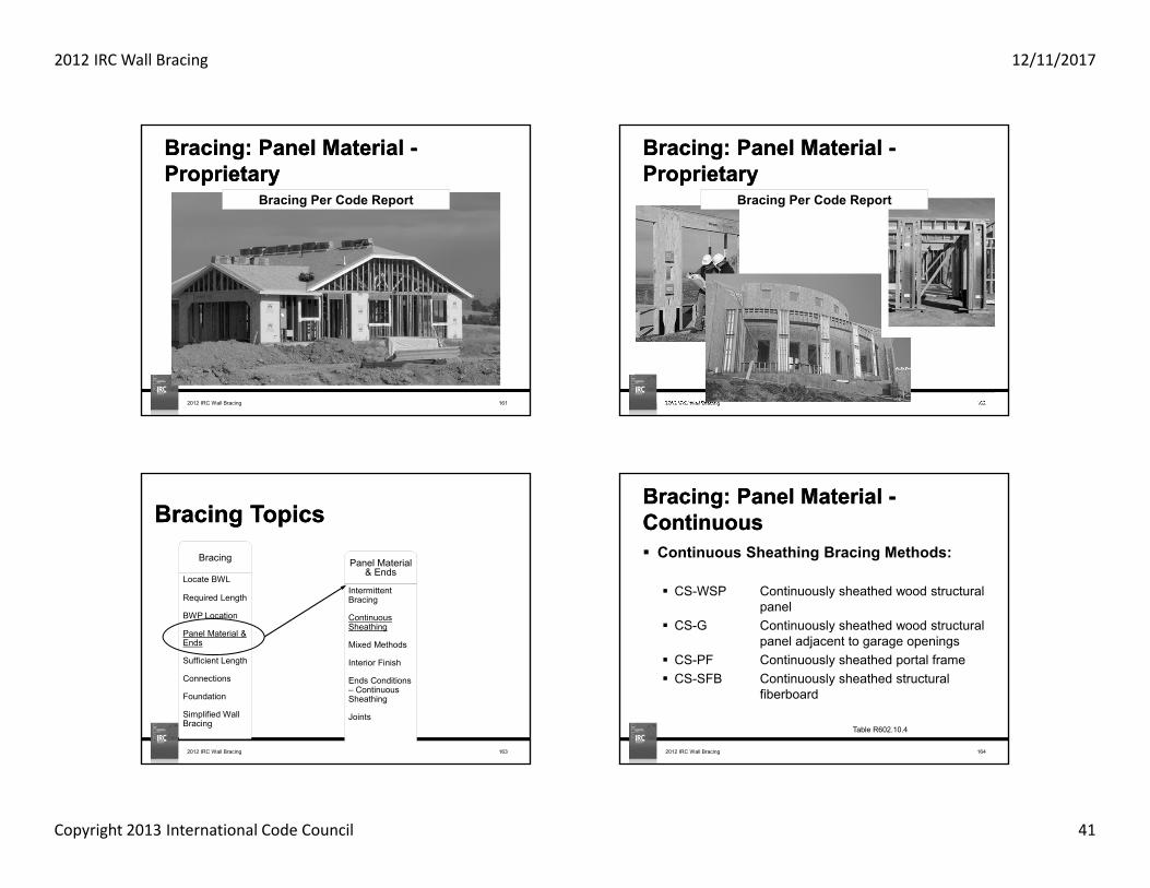
Bracing: Panel Material -ProprietaryBracing: Panel Material -ProprietaryOther bracing methods per code report Prefabricated units Laminated Kraft-paper board Fiberboard in various thicknesses
2012 IRC Wall Bracing 160R602.10.2
2012 IRC Wall Bracing 12/11/2017
Copyright 2013 International Code Council 41
Bracing: Panel Material -ProprietaryBracing: Panel Material -Proprietary
2012 IRC Wall Bracing 161
Bracing Per Code Report
Bracing: Panel Material -ProprietaryBracing: Panel Material -Proprietary
2012 IRC Wall Bracing 162
Bracing Per Code Report
Bracing TopicsBracing TopicsBracing
Locate BWL
Required Length
BWP Location
Panel Material & Ends
Sufficient Length
Connections
Foundation
Simplified Wall Bracing
Panel Material & Ends
Intermittent Bracing
Continuous Sheathing
Mixed Methods
Interior Finish
Ends Conditions – Continuous Sheathing
Joints
2012 IRC Wall Bracing 163
Bracing: Panel Material -ContinuousBracing: Panel Material -Continuous Continuous Sheathing Bracing Methods:
CS-WSP Continuously sheathed wood structuralpanel
CS-G Continuously sheathed wood structural panel adjacent to garage openings
CS-PF Continuously sheathed portal frame CS-SFB Continuously sheathed structural
fiberboard
2012 IRC Wall Bracing 164
Table R602.10.4

2012 IRC Wall Bracing 12/11/2017
Copyright 2013 International Code Council 42
Bracing: Panel Material -ContinuousBracing: Panel Material -ContinuousMain Concepts Allows for narrow
BWP's without hold-downs
BWL's must be fully sheathed with wood structural panel or structural fiberboard sheathing (continuously sheathed)
2012 IRC Wall Bracing 165
R602.10.4.2, Table R602.10.5
Bracing: Panel Material -ContinuousBracing: Panel Material -Continuous
R602.10.4.2 & R602.10.5
Sheathing Requirements:1. Sheath full height areas including gable ends2. Sheath above and below openings3. Adjacent openings determine minimum BWP length
Too Narrow
2012 IRC Wall Bracing 166
OpeningHeight
OpeningHeight
Bracing: Panel Material -ContinuousBracing: Panel Material -Continuous
Figure R602.10.52012 IRC Wall Bracing 167
Bracing: Panel Material -ContinuousBracing: Panel Material -Continuous
Aspect Ratio:The ratio of the height of a bracing unit to its length.
Length
Aspect Ratio = HeightLength
Aspect Ratio = 8'4'
= 2
Height
Table R602.10.52012 IRC Wall Bracing 168

2012 IRC Wall Bracing 12/11/2017
Copyright 2013 International Code Council 43
Bracing: Panel Material -ContinuousBracing: Panel Material -Continuous
BWP
20' Max.20' Max.
Infill Sheathing
R602.10.4 & Figure R602.10.52012 IRC Wall Bracing 169
Bracing: Panel Material -ContinuousBracing: Panel Material -Continuous
R602.10.4.2, Table R602.10.4
Method CS-WSP Continuous Sheathing with Wood Structural Panel Area above and below openings fully sheathed including gable ends Min 3/8" wood structural panel sheathing
Method CS-SFB Continuous Sheathing with Structural Fiberboard Area above and below openings fully sheathed including gable ends Min 1/2" structural fiberboard sheathing
2012 IRC Wall Bracing 170
Bracing: Panel Material -ContinuousBracing: Panel Material -Continuous
Wall Bracing Parameter
Continuously SheathedWood Structural PanelCS-WSP, CS-G, CS-PF
Continuously SheathedStructural Fiberboard
CS-SFB
Wind applicability < 110 mph ≤ 100 mph
Seismic applicability A - D2 A - C
Permitted wall heights 8' to 12' 8' to 12'
Corner return length(both sides of corner)
24" Min.(or hold downs at first BWP)
32" Min.(or hold downs at first BWP)
Panel end distance 10' 10'
Table R602.10.4, Figure R602.10.72012 IRC Wall Bracing 171
Bracing: Panel Material -ContinuousBracing: Panel Material -Continuous
Table R602.10.5
Method CS-WSPFull-height sheathed wall segments having a length equal or greater than Table R602.10.5 are counted toward the total bracing length.
Wall minimum length is based on wall height and height of the adjacent clear opening.
Too Narrow
2012 IRC Wall Bracing 172

2012 IRC Wall Bracing 12/11/2017
Copyright 2013 International Code Council 44
a. Garage opening adjacent to method CS-G panel shall have header. Max opening height includes header height.
b. Max header height 10 feet, pony wall may be used above header.
2012 IRC Wall Bracing 173
Bracing: Panel Material -ContinuousBracing: Panel Material -ContinuousMethod CS-WSP
Table R602.10.5
Method
Adjacent Clear
Opening Height (ft.)
Wall Height (ft.)
8 9 10 11 12
CS-WSP
64 24 27 30 33 3668 26 27 30 33 3672 27 27 30 33 3676 30 29 30 33 3680 32 30 30 33 3684 35 32 32 33 3688 38 35 33 33 3692 43 37 35 35 3696 48 41 38 36 36100 44 40 38 38104 49 43 40 39108 54 46 43 41112 50 45 43116 55 48 45120 60 52 48
Method
Adjacent Clear
Opening Height
(ft.)
Wall Height (ft.)
8 9 10 11 12
CS-WSP
124 56 51128 61 54132 66 58136 62140 66144 72
CS-G a 24 27 30 33 36CS-PF <120 16 18 20 22b 24b
Table R602.10.5 Minimum Length of Braced Wall Panels (in)
Bracing: Panel Material -ContinuousBracing: Panel Material -Continuous
36'
All panels less than 20′ apart edge to edge
< 20' < 20' < 20'
8'
R602.10.4.2 & Table R602.10.5
Too narrow to be counted
24" 108" 32" 24"24"24"
Method CS-WSP
2012 IRC Wall Bracing 174
Bracing: Panel Material -ContinuousBracing: Panel Material -Continuous
12' Max
H/4
Method CS-G Wood structural panel adjacent to garage opening Full-height sheathed wall segments to either side of garage openings Roof covering dead loads of 3 psf or less (seismic requirement only)
Applied to one wall line of garage only Panel length = bracing length 4:1 aspect ratio
R602.310.4, Table R602.10.5
GarageOpening
2012 IRC Wall Bracing 175
Bracing: Panel Material -ContinuousBracing: Panel Material -Continuous
4:1 Aspect Ratio (24" min.)
Garage only, supportingroof with 3 psf covering.
Standard Header
Method CS-G
2012 IRC Wall Bracing 176

2012 IRC Wall Bracing 12/11/2017
Copyright 2013 International Code Council 45
Bracing: Panel Material -ContinuousBracing: Panel Material -Continuous
Garage
Opening
H/6
10' max(12' max
with pony wall)
Method CS-PF Continuous portal frameWalls on either or both sides of openings in garage may have wall segment with a maximum 6:1 height-to-length ratio.
R602.10.6.4
Fully sheathed dwelling
GarageOpening
No hold-downs required OK on raised floor Top of header at 10' max
Top of wall at 12' max Panel length = bracing length
2012 IRC Wall Bracing 177
Bracing: Panel Material -ContinuousBracing: Panel Material -Continuous
Extended Header
6:1 Aspect Ratio (16" min.)
Garage only, story above permitted.
R602.10.6.4, Table R602.10.5
Method CS-PF
2012 IRC Wall Bracing 178
2012 IRC Wall Bracing 179
Bracing: Panel Material -ContinuousBracing: Panel Material -Continuous
Figure R602.10.6.4
Method CS-PF
Bracing: Panel Material -ContinuousBracing: Panel Material -ContinuousMethods PFH, PFG and CS-PF
MINIMUM WALLSTUD FRAMINGNOMINAL SIZE
AND GRADE
MAXIMUMPONY WALL
HEIGHT (feet)
MAXIMUMTOTAL WALL
HEIGHT(feet)
MAXIMUMOPENING
WIDTH(feet)
BASIC WIND SPEED (mph)
85 90 100 85 90 100
Exposure B Exposure C
Tension strap capacity required (lbf)
2 × 4No. 2 Grade
0 10 18 1000 1000 1000 1000 1000 1000
1 109 1000 1000 1000 1000 1000 1275
16 1000 1000 1750 1800 2325 350018 1000 1200 2100 2175 2725 DR
2 10
9 1000 1000 1025 1075 1550 2500
16 1525 2025 3125 3200 3900 DR18 1875 2400 3575 3700 DR DR
2 129 1000 1200 2075 2125 2750 4000
16 2600 3200 DR DR DR DR
18 3175 3850 DR DR DR DR
Table R602.10.6.4: Tension Strap Capacity Required for Resisting Wind Pressures Perpendicular to 6:1 Aspect Ratio Walls
2012 IRC Wall Bracing 180

2012 IRC Wall Bracing 12/11/2017
Copyright 2013 International Code Council 46
Bracing: Panel Material -ContinuousBracing: Panel Material -Continuous
MINIMUM WALLSTUD
FRAMINGNOMINAL SIZE
AND GRADE
MAXIMUMPONY WALL
HEIGHT (feet)
MAXIMUMTOTAL WALL
HEIGHT(feet)
MAXIMUMOPENING
WIDTH(feet)
BASIC WIND SPEED (mph)
85 90 100 85 90 100
Exposure B Exposure C
Tension strap capacity required (lbf)
2 × 4No. 2 Grade 4 12
9 1775 2350 3500 3550 DR DR16 4175 DR DR DR DR DR
2 × 6Stud Grade
2 129 1000 1000 1325 1375 1750 2550
16 1650 2050 2925 3000 3550 DR
18 2025 2450 3425 3500 4100 DR
4 129 1125 1500 2225 2275 2775 3800
16 2650 3150 DR DR DR DR18 3125 3675 DR DR DR DR
Table R602.10.6.4 cont.: Tension Strap Capacity Required for Resisting Wind Pressures Perpendicular to 6:1 Aspect Ratio Walls
Methods PFH, PFG and CS-PF cont.
2012 IRC Wall Bracing 181
Plan View
Garage DoorGarage Door
2012 IRC Wall Bracing 182
Bracing: Panel Material -ContinuousBracing: Panel Material -Continuous
R602.10.6.4
Method CS-PF
4
CS-G CS-PF
2012 IRC Wall Bracing 183
Bracing: Panel Material -ContinuousBracing: Panel Material -Continuous
Bracing: Panel Material -ContinuousBracing: Panel Material -Continuous
R602.10.5
Method CS-SFB Continuous Sheathing with Structural
Fiberboard
Wall minimum length based on wall height and height of adjacent clear opening
Maximum wall height = 12′ Length requirements for braced wall panels in Table R602.10.5 Same minimum bracing length requirements as CS-WSP Same aspect ratio (opening height limits) as CS-WSP
2012 IRC Wall Bracing 184

2012 IRC Wall Bracing 12/11/2017
Copyright 2013 International Code Council 47
Bracing: Panel Material -ContinuousBracing: Panel Material -Continuous
4:1 4:1 6:1 ~2:1
0% to 65%
H
0% to 65%
H
0% to 65%
H
18'
8'
R602.10.5.1
Too narrow to be counted
24"BWP
24"BWP
40"BWP
Method CS-SFB
2012 IRC Wall Bracing 185
18'
3:1 6:1 ~2.4:16:1
65%to
85% H
65%to
85% H
0%to
65%H8'
Bracing: Panel Material -ContinuousBracing: Panel Material -Continuous
R602.10.5.2
32"BWP
40"BWP
Method CS-SFB Too narrow to be counted
2012 IRC Wall Bracing 186
Bracing TopicsBracing TopicsBracing
Locate BWL
Required Length
BWP Location
Panel Material & Ends
Sufficient Length
Connections
Foundation
Simplified Wall Bracing
Panel Material & Ends
Intermittent Bracing
Continuous Sheathing
Mixed Methods
Interior Finish
Ends Conditions – Continuous Sheathing
Joints
2012 IRC Wall Bracing 187
Bracing Basics: Mixing Bracing MethodsBracing Basics: Mixing Bracing Methods
2012 IRC Wall Bracing 188
BWP method variation permitted from story to story with any type of sheathing
R602.10.4.1 Item 1
R602.10.4.1 Item 1

2012 IRC Wall Bracing 12/11/2017
Copyright 2013 International Code Council 48
BWP method variation permitted from BWL to BWL within a story for intermittent sheathing
For continuous and intermittent sheathing, variation may only occur in SDC A-C with winds < 100 mph
R602.10.4.1 Item 2
R602.10.4.1 Item 2
Bracing Basics: Mixing Bracing MethodsBracing Basics: Mixing Bracing Methods
2012 IRC Wall Bracing 189
BWP method variation within a BWL permitted ONLY in SDC A-B and for detached houses in SDC C with intermittent bracing
Greatest required bracing length for panel materials must be used.
Not applicable for use with continuous sheathing OR dwellings in SDC D0-D2
R602.10.4.1 Item 3
R602.10.4.1 Item 3
Bracing Basics: Mixing Bracing MethodsBracing Basics: Mixing Bracing Methods
2012 IRC Wall Bracing 190
Mixing of CS-WSP, CS-G and CS-FP along a BWL is permitted in any SDC
R602.10.4.1 Item 4
R602.10.4.1 Item 4
Bracing Basics: Mixing Bracing MethodsBracing Basics: Mixing Bracing Methods
2012 IRC Wall Bracing 191
BWP method variation in a BWL with continuous sheathing on exterior walls and intermittent on interior walls permitted ONLY in SDC A-B and for detached houses in SDC C Greatest required bracing length
for all panel materials in BWL must be used
Not applicable for dwellings in SDC D0-D2
R602.10.4.1 Item 5
R602.10.4.1 Item 5
Bracing Basics: Mixing Bracing MethodsBracing Basics: Mixing Bracing Methods
2012 IRC Wall Bracing 192

2012 IRC Wall Bracing 12/11/2017
Copyright 2013 International Code Council 49
Bracing TopicsBracing TopicsBracing
Locate BWL
Required Length
BWP Location
Panel Material & Ends
Sufficient Length
Connections
Foundation
Simplified Wall Bracing
Panel Material & Ends
Intermittent Bracing
Continuous Sheathing
Mixed Methods
Interior Finish
Ends Conditions – Continuous Sheathing
Joints
2012 IRC Wall Bracing 193
Interior Finish (Gypsum) Required½" thickness min
Exceptions:1. Wall panels braced with Methods GB, BV-WSP, ABW, PFH, PFG and CS-PF.2. When an approved interior finish material with an in-plane shear
resistance equivalent to gypsum board is installed.3. For all methods except LIB, omitting gypsum wall board is permitted when
the length of bracing in Tables R602.10.3(1) and R602.10.3(3) is multiplied by the factors in Tables R602.10.3(2) or R602.10.3(4).
BWP Material
R602.10.4.3 Braced Wall Panel Interior Finish Material
R602.10.4.3
Bracing Basics: Braced Panel ConstructionBracing Basics: Braced Panel Construction
2012 IRC Wall Bracing 194
Interior Finish (Gypsum) Required½" thickness min
Method LIB requires fasteners into interior finish at maximum 8" o.c.
Method LIB
R602.10.4.3 Braced Wall Panel Interior Finish Material
R602.10.4.3
Bracing Basics: Braced Panel ConstructionBracing Basics: Braced Panel Construction
2012 IRC Wall Bracing 195
Bracing TopicsBracing TopicsBracing
Locate BWL
Required Length
BWP Location
Panel Material & Ends
Sufficient Length
Connections
Foundation
Simplified Wall Bracing
Panel Material & Ends
Intermittent Bracing
Continuous Sheathing
Mixed Methods
Interior Finish
Ends Conditions – Continuous Sheathing
Joints
2012 IRC Wall Bracing 196
2012 IRC Wall Bracing 12/11/2017
Copyright 2013 International Code Council 50
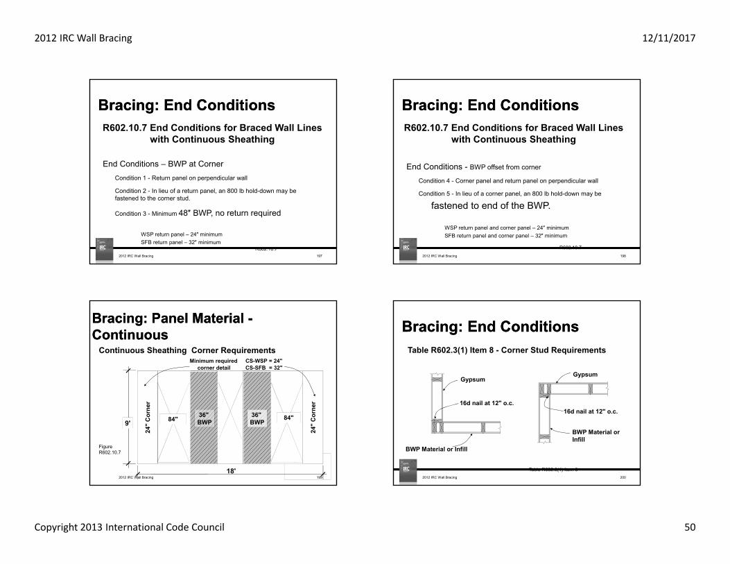
Bracing: End ConditionsBracing: End Conditions
End Conditions – BWP at CornerCondition 1 - Return panel on perpendicular wall
Condition 2 - In lieu of a return panel, an 800 lb hold-down may be fastened to the corner stud.
Condition 3 - Minimum 48″ BWP, no return required
WSP return panel – 24″ minimumSFB return panel – 32″ minimum
R602.10.7
R602.10.7 End Conditions for Braced Wall Lines with Continuous Sheathing
2012 IRC Wall Bracing 197
Bracing: End ConditionsBracing: End Conditions
End Conditions - BWP offset from corner
Condition 4 - Corner panel and return panel on perpendicular wall
Condition 5 - In lieu of a corner panel, an 800 lb hold-down may be
fastened to end of the BWP.
WSP return panel and corner panel – 24″ minimumSFB return panel and corner panel – 32″ minimum
R602.10.7
R602.10.7 End Conditions for Braced Wall Lines with Continuous Sheathing
2012 IRC Wall Bracing 198
2012 IRC Wall Bracing 199
Bracing: Panel Material -ContinuousBracing: Panel Material -Continuous
Minimum required CS-WSP = 24"corner detail CS-SFB = 32"
Figure R602.10.7
18'
9' 84" 84"32" BWP
32" BWP
24"
Cor
ner
24"
Cor
ner
36" BWP
36" BWP
Continuous Sheathing Corner Requirements
Bracing: End ConditionsBracing: End Conditions
Gypsum
BWP Material or Infill
16d nail at 12" o.c.
Gypsum
16d nail at 12" o.c.
Table R602.3(1) Item 8
Table R602.3(1) Item 8 - Corner Stud Requirements
BWP Material or Infill
2012 IRC Wall Bracing 200

2012 IRC Wall Bracing 12/11/2017
Copyright 2013 International Code Council 51
Bracing TopicsBracing TopicsBracing
Locate BWL
Required Length
BWP Location
Panel Material & Ends
Sufficient Length
Connections
Foundation
Simplified Wall Bracing
Panel Material & Ends
Intermittent Bracing
Continuous Sheathing
Mixed Methods
Interior Finish
Ends Conditions – Continuous Sheathing
Joints
2012 IRC Wall Bracing 201
Bracing: JointsBracing: Joints
2012 IRC Wall Bracing 202
All vertical panel joints shall occur
over studs
Wood Structural PanelMethod WSP
GypsumMethod GB
R602.10.10
48"48"48"
2012 IRC Wall Bracing 203
Bracing: JointsBracing: Joints
Horizontal Blocking
R602.10.10 Panel jointsBlocking required at horizontal edges of BWP's.
Bracing: JointsBracing: Joints
2012 IRC Wall Bracing 204
Blocking is required at vertical edges of BWP's, except:
Exception 1 –Vertical panel joints may occur over doubled studs when nailed at 10″ o.c. with 10d box nails
Braced Wall PanelMethod WSP R602.10.10
48"
R602.10.10 Exceptions

2012 IRC Wall Bracing 12/11/2017
Copyright 2013 International Code Council 52
Bracing: JointsBracing: Joints
2012 IRC Wall Bracing 205
Horizontal BlockingBlocking is required at horizontal edges of BWP's
Exceptions:2. Blocking at horizontal joints is not required in infill areas.3. Where the bracing length provided is 2x the minimum length required (Tables R602.10.3(1) and R602.10.3(3)) blocking at horizontal joints shall not be required in braced wall panels constructed using Methods WSP, SFB, GB, PBS or HPS.4. When Method GB panels are installed horizontally, blocking of horizontal joints is not required.
R602.10.10
R602.10.10 Exceptions
Bracing TopicsBracing TopicsForces & History Bracing Examples
Locate BWL
Required Length
BWP Location
Panel Material & Ends
Sufficient Length
Support
Connections
Simplified Wall Bracing
Limits
?Questions
2012 IRC Wall Bracing 206
Bracing TopicsBracing TopicsForces & History Bracing Examples
Locate BWL
Required Length
BWP Location
Panel Material & Ends
Sufficient Length
Connections
Foundation
Simplified Wall Bracing
Limits
2012 IRC Wall Bracing 207
Bracing: Sufficient LengthBracing: Sufficient Length
2012 IRC Wall Bracing 208
What is the minimum length of bracing allowed in a braced wall line?
(New) Section R602.10.2.3
BWL < 16 ft.: Minimum 2 BWPs any lengthOR 1 BWP 48″ long
BWL > 16 ft.: Minimum 2 BWPs

2012 IRC Wall Bracing 12/11/2017
Copyright 2013 International Code Council 53
Bracing: Sufficient LengthBracing: Sufficient Length
2012 IRC Wall Bracing 209
Determine whether there is sufficient space to place all the required bracing in a BWL
• Add length of qualified braced wall panel lengths• Check against required length• Locate space to place narrow panels if needed• Check end distances and spacing between panels
First, we will review panel lengths
Bracing: Sufficient LengthBracing: Sufficient Length
2012 IRC Wall Bracing 210
Minimum panel width – OK Distance between panels – OK End distance – OK
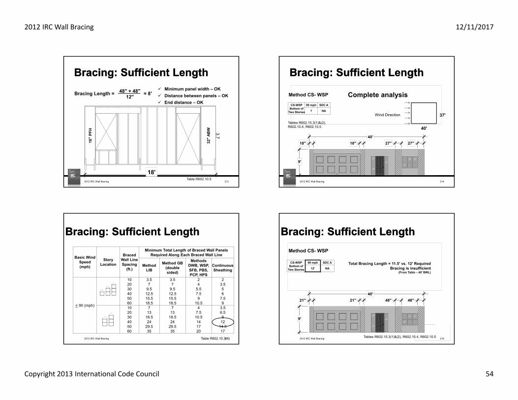
Bracing: Sufficient LengthBracing: Sufficient Length
2012 IRC Wall Bracing 211
Table R602.10.511'
3.748" 48"
Bracing Length = = 8′ 48" + 48"12"
Minimum panel width – OK Distance between panels – OK End distance – OK
Bracing: Sufficient LengthBracing: Sufficient Length
2012 IRC Wall Bracing 212
18'
3.748" 48"36"
2006 - 48" min length requirement 2009/2012 - 36" braced panel is allowed with a reduced effective length
Bracing Length = = 10.25′ 48" + 27" + 48" 12"
Tables R602.10.5, R602.10.5.2
Min panel width Distance
between panels End distance
2012 IRC Wall Bracing 12/11/2017
Copyright 2013 International Code Council 54
Bracing: Sufficient LengthBracing: Sufficient Length
2012 IRC Wall Bracing 213
18'
3.7
16"
PFH
32"
ABW
Bracing Length = = 8′ 48" + 48"12"
Table R602.10.5
Minimum panel width – OK Distance between panels – OK End distance – OK
Bracing: Sufficient LengthBracing: Sufficient Length
2012 IRC Wall Bracing 214
9'
18"40'
27" 27"18"
4'
2'Method CS- WSP
CS-WSPBottom of
Two Stories
90 mph SDC A
? NA
Tables R602.10.3(1)&(2), R602.10.4, R602.10.5 40'
37'Wind Direction
Complete analysis
Basic Wind Speed (mph)
Story Location
Braced Wall Line Spacing
(ft.)
Minimum Total Length of Braced Wall Panels Required Along Each Braced Wall Line
Method LIB
Method GB (double sided)
Methods DWB, WSP, SFB, PBS, PCP, HPS
Continuous Sheathing
< 90 (mph)
10 3.5 3.5 2 220 7 7 4 3.530 9.5 9.5 5.5 540 12.5 12.5 7.5 650 15.5 15.5 9 7.560 18.5 18.5 10.5 910 7 7 4 3.520 13 13 7.5 6.530 18.5 18.5 10.5 940 24 24 14 1250 29.5 29.5 17 14.560 35 35 20 17
2012 IRC Wall Bracing 215
Bracing: Sufficient LengthBracing: Sufficient Length
Table R602.10.3(1) 2012 IRC Wall Bracing 216
Bracing: Sufficient LengthBracing: Sufficient Length
9'
21"40'
48" 48"21"
4'
2'Method CS- WSP
CS-WSPBottom of
Two Stories
90 mph SDC A
12' NATotal Bracing Length = 11.5′ vs. 12′ Required
Bracing is insufficient(From Table – 40′ BWL)
Tables R602.10.3(1)&(2), R602.10.4, R602.10.5

2012 IRC Wall Bracing 12/11/2017
Copyright 2013 International Code Council 55
2012 IRC Wall Bracing 217
Bracing: Sufficient LengthBracing: Sufficient Length
9'
21"40'
48" 48"21"
4'
2'Method CS- WSP
CS-WSPBottom of
Two Stories
90 mph SDC A
11.4' NA
Can interpolate for BWL spacing or for wall height.
0.95 x 12′ = 11.4′
Total Bracing Length = 11.5′ vs. 11.4′ Required
Bracing is OK
Tables R602.10.3(1)&(2), R602.10.4, R602.10.5
Bracing: Sufficient LengthBracing: Sufficient Length
2012 IRC Wall Bracing 218
8'
16'2' 2'
CS-GOne Story
90 mph SDC C? NA
Method CS-WSP
Garage Opening
Tables R602.10.3(1)&(2), R602.10.4, R602.10.5
20'
22'Wind Direction
Basic Wind Speed (mph)
Story Location
Braced Wall Line Spacing
(ft.)
Minimum Total Length of Braced Wall Panels Required Along Each Braced Wall Line
Method LIB
Method GB (double sided)
Methods DWB, WSP, SFB, PBS, PCP, HPS
Continuous Sheathing
< 90 (mph)
10 3.5 3.5 2 220 7 7 4 3.530 9.5 9.5 5.5 540 12.5 12.5 7.5 650 15.5 15.5 9 7.560 18.5 18.5 10.5 910 7 7 4 3.520 13 13 7.5 6.530 18.5 18.5 10.5 940 24 24 14 1250 29.5 29.5 17 14.560 35 35 20 17
2012 IRC Wall Bracing 219
Bracing: Sufficient LengthBracing: Sufficient Length
Table R602.10.3(1)
Bracing: Sufficient LengthBracing: Sufficient Length
2012 IRC Wall Bracing 220
8'
16'2' 2'
CS-GOne
Story
105 mph SDC C
5' NA
Method CS-G
Garage Opening
Total Bracing Length = 4′ vs. 5′ Required
Bracing is NG
Tables R602.10.3(1)&(2), R602.10.4, R602.10.5

2012 IRC Wall Bracing 12/11/2017
Copyright 2013 International Code Council 56
Basic Wind Speed (mph)
Story Location
Braced Wall Line Spacing
(ft.)
Minimum Total Length of Braced Wall Panels Required Along Each Braced Wall Line
Method LIB
Method GB (double sided)
Methods DWB, WSP, SFB, PBS, PCP, HPS
Continuous Sheathing
< 90 (mph)
10 3.5 3.5 2 220 7 7 4 3.530 9.5 9.5 5.5 540 12.5 12.5 7.5 650 15.5 15.5 9 7.560 18.5 18.5 10.5 910 7 7 4 3.520 13 13 7.5 6.530 18.5 18.5 10.5 940 24 24 14 1250 29.5 29.5 17 14.560 35 35 20 17
2012 IRC Wall Bracing 221
Bracing: Sufficient LengthBracing: Sufficient Length
Table R602.10.3(1)
Bracing: Sufficient LengthBracing: Sufficient Length
2012 IRC Wall Bracing 222
8'
16'2' 2'
CS-GOne
Story
105 mph SDC C
3.8' NA
Method CS-G
Garage Opening
Interpolate bracing length:5′ – 3.5′ = 1.5′ 1.5′ /10 = 0.15′ 3.5′ + 2x0.15′ = 3.8′Total Bracing Length = 4′ vs. 3.8′ Required
Bracing is OK
Tables R602.10.3(1)&(2), R602.10.4, R602.10.5
Bracing: Sufficient LengthBracing: Sufficient Length
2012 IRC Wall Bracing 223
PBSBottom of
Two Stories
90 mph SDC A
? ?
10'
4' 4'24'
16'
Tables R602.10.3(1)&(2), R602.10.4, R602.10.5
24'
42'Wind DirectionBasic Wind
Speed (mph)
Story Location
Braced Wall Line Spacing
(ft.)
Minimum Total Length of Braced Wall Panels Required Along Each Braced Wall Line
Method LIB
Method GB (double sided)
Methods DWB, WSP, SFB, PBS, PCP, HPS
Continuous Sheathing
< 90 (mph)
10 3.5 3.5 2 220 7 7 4 3.530 9.5 9.5 5.5 540 12.5 12.5 7.5 650 15.5 15.5 9 7.560 18.5 18.5 10.5 910 7 7 4 3.520 13 13 7.5 6.530 18.5 18.5 10.5 940 24 24 14 1250 29.5 29.5 17 14.560 35 35 20 17
2012 IRC Wall Bracing 224
Bracing: Sufficient LengthBracing: Sufficient Length
Table R602.10.3(1)

2012 IRC Wall Bracing 12/11/2017
Copyright 2013 International Code Council 57
Bracing: Sufficient LengthBracing: Sufficient Length
2012 IRC Wall Bracing 225
PBSBottom of
Two Stories
90 mph SDC A
17′ NA
10'
4' 4'24'
16'
Total Bracing Length = 8′ vs. 17′ RequiredBracing is insufficient
Tables R602.10.3(1)&(2), R602.10.4, R602.10.5
Basic Wind Speed (mph)
Story Location
Braced Wall Line Spacing
(ft.)
Minimum Total Length of Braced Wall Panels Required Along Each Braced Wall Line
Method LIB
Method GB (double sided)
Methods DWB, WSP, SFB, PBS, PCP, HPS
Continuous Sheathing
< 90 (mph)
10 3.5 3.5 2 220 7 7 4 3.530 9.5 9.5 5.5 540 12.5 12.5 7.5 650 15.5 15.5 9 7.560 18.5 18.5 10.5 910 7 7 4 3.520 13 13 7.5 6.530 18.5 18.5 10.5 940 24 24 14 1250 29.5 29.5 17 14.560 35 35 20 17
2012 IRC Wall Bracing 226
Bracing: Sufficient LengthBracing: Sufficient Length
Table R602.10.3(1)
Bracing: Sufficient LengthBracing: Sufficient Length
2012 IRC Wall Bracing 227
PBSBottom of
Two Stories
90 mph SDC A
14.6′ NA
10'
4' 4'24'
16'
Interpolated required bracing length:17′ – 14′ = 3′ 3′/10 = 0.3′14′ + 2x0.3′ = 14.6′Total Bracing Length = 8′ vs. 14.6′ Required
Bracing is insufficient
Tables R602.10.3(1)&(2), R602.10.4, R602.10.5
Bracing: Sufficient LengthBracing: Sufficient Length
36'
48" 48"
10'
SFBBottom of
Two Stories
90 mph SDC B
? NA
Method SFB
Tables R602.10.3(1)&(2), R602.10.4, R602.10.5
36'
20'Wind Direction
2012 IRC Wall Bracing 228

2012 IRC Wall Bracing 12/11/2017
Copyright 2013 International Code Council 58
Basic Wind Speed (mph)
Story Location
Braced Wall Line Spacing
(ft.)
Minimum Total Length of Braced Wall Panels Required Along Each Braced Wall Line
Method LIB
Method GB (double sided)
Methods DWB, WSP, SFB, PBS, PCP, HPS
Continuous Sheathing
< 90 (mph)
10 3.5 3.5 2 220 7 7 4 3.530 9.5 9.5 5.5 540 12.5 12.5 7.5 650 15.5 15.5 9 7.560 18.5 18.5 10.5 910 7 7 4 3.520 13 13 7.5 6.530 18.5 18.5 10.5 940 24 24 14 1250 29.5 29.5 17 14.560 35 35 20 17
2012 IRC Wall Bracing 229
Bracing: Sufficient LengthBracing: Sufficient Length
Table R602.10.3(1)
Bracing: Sufficient LengthBracing: Sufficient Length
2012 IRC Wall Bracing 230
36'10'
Placement Requirement 4' + 4' = 8'
Wind Requirement7.5'
SFBBottom of
Two Stories
90 mph SDC B
7.5' NA
48" 48"
Wind Requirement 20' Centers 10' Ends BWP Width Bracing Length
Method SFB
Tables R602.10.3(1)&(2), R602.10.4, R602.10.5
7.5' < 8' 8 ft. required, 8 ft. available
Bracing: Sufficient LengthBracing: Sufficient Length
2012 IRC Wall Bracing 231
36'7' 8' 6' 8' 7'
8'
PCPBottom of
Two Stories
105 mph SDC B
? NA
Tables R602.10.3(1)&(2), R602.10.4, R602.10.5
36'
25'Wind Direction Basic Wind Speed (mph)
Story Location
Braced Wall Line Spacing
(ft.)
Minimum Total Length of Braced Wall Panels Required Along Each Braced Wall Line
Method LIB
Method GB (doublesided)
Methods DWB, WSP, SFB, PBS, PCP, HPS
Continuous Sheathing
< 110 (mph)
10 5.5 5.5 3 320 10 10 6 530 14.5 14.5 8.5 740 18.5 18.5 11 950 23 23 13 11.560 27.5 27.5 15.5 13.510 10.5 10.5 6 520 19 19 11 9.530 27.5 27.5 16 13.540 36 36 20.5 17.550 44 44 25.5 21.560 52.5 52.5 30 25.5
2012 IRC Wall Bracing 232
Bracing: Sufficient LengthBracing: Sufficient Length
Table R602.10.3(1)

2012 IRC Wall Bracing 12/11/2017
Copyright 2013 International Code Council 59
Bracing: Sufficient LengthBracing: Sufficient Length
2012 IRC Wall Bracing 233
36'7' 8' 6' 8' 7'
8'
PCPBottom of Two
Stories
105 mph SDC B
16' NATotal Bracing Length = 20′ vs. 16′ Required
Bracing is OK
Tables R602.10.3(1)&(2), R602.10.4, R602.10.5
Bracing Basics: PercentageBracing Basics: Percentage
36'
10'
WSPBottom of Two Story
90 mph SDC B
? NA
48"
WSP 48"
WSP
Method WSP
Tables R602.10.3(1)&(2), R602.10.4, R602.10.5
36'
28'Wind Direction
2012 IRC Wall Bracing 234
Basic Wind Speed (mph)
Story Location
Braced Wall Line Spacing
(ft.)
Minimum Total Length of Braced Wall Panels Required Along Each Braced Wall Line
Method LIB
Method GB (double sided)
Methods DWB, WSP, SFB, PBS, PCP, HPS
Continuous Sheathing
< 90 (mph)
10 3.5 3.5 2 220 7 7 4 3.530 9.5 9.5 5.5 540 12.5 12.5 7.5 650 15.5 15.5 9 7.560 18.5 18.5 10.5 910 7 7 4 3.520 13 13 7.5 6.530 18.5 18.5 10.5 940 24 24 14 1250 29.5 29.5 17 14.560 35 35 20 17
2012 IRC Wall Bracing 235
Bracing: Sufficient LengthBracing: Sufficient Length
Table R602.10.3(1)
Bracing Basics: PercentageBracing Basics: Percentage
2012 IRC Wall Bracing 236
36'
10'
Placement Requirement 4' + 4' = 8'
Wind Requirement10.5'
Wind 20' Centers 10' Ends BWP Width Bracing Length
WSPBottom of Two Story
90 mph SDC B
10.5' NA
48"
WSP 48"
WSP
Method WSP
Tables R602.10.3(1)&(2), R602.10.4, R602.10.5

2012 IRC Wall Bracing 12/11/2017
Copyright 2013 International Code Council 60
Bracing Basics: PercentageBracing Basics: Percentage
36'
10'
Placement Requirement 4' + 4' = 8'
Wind Requirement10.5'
Wind 20' Centers 10' Ends BWP Width Bracing Length
WSPBottom of Two Story
90 mph SDC B
10.5' NA
48"
WSP 48"
WSP
Method WSP
Tables R602.10.3(1)&(2), R602.10.4, R602.10.5
60"
WSP
4' + 5' + 4' = 13'
2012 IRC Wall Bracing 237
Bracing TopicsBracing TopicsForces & History Bracing Examples
Locate BWL
Required Length
BWP Location
Panel Material & Ends
Sufficient Length
Support
Connections
Simplified Wall Bracing
Limits
?Questions
2012 IRC Wall Bracing 238
Bracing TopicsBracing TopicsForces & History Bracing Examples
Locate BWL
Required Length
BWP Location
Panel Material & Ends
Sufficient Length
Connections
Foundation
Simplified Wall Bracing
Limits
2012 IRC Wall Bracing 239
Item Building Element Number, Type and Spacing of Fastener
13 Double top plates, face nail 10d (3″ × 0.128″) @ 24″ oc
14Double top plates, minimum 24-inch offset of end joints, face nail in lapped area
8-16d (31/2″ × 0.135″)
15 Sole plate to joist or blocking, face nail
16d (31/2″ × 0.135″) @ 16″ oc
16 Sole plate to joist or blocking at braced wall panels
3-16d (31/2″ × 0.135″) @ 16″ oc
17 Stud to sole plate, toe nail 3-8d (21/2″ × 0.113″) or 2-16d (31/2″ × 0.135″)
18 Top or sole plate to stud, end nail 2-16d (31/2″ × 0.135″)
19 Top plates, laps at corners and intersections, face nail 2-10d (3″ × 0.128″)
2012 IRC Wall Bracing 240
Bracing: ConnectionsBracing: ConnectionsBWP sole plates and top plates connections per Table R602.3(1) Items 13-19
Excerpt from Table R602.3(1) Items 13-19

2012 IRC Wall Bracing 12/11/2017
Copyright 2013 International Code Council 61
Bracing: ConnectionsBracing: Connections
2012 IRC Wall Bracing 241
When braced wall panels are perpendicular to joists above or below, blocking shall be provided in line with the BWPs…
R602.10.8 Item 1, Figure R602.10.8(1)
3.7BWP BWPBWP
2012 IRC Wall Bracing 242
Bracing: ConnectionsBracing: Connections
(3) 16d nails at 16" o.c. along BWP16d (3-1/2" x 0.135")
8d toenailed at 6" o.c. 8d (2-1/2" x 0.113")
BWP Perpendicular to Framing
Figure R602.10.8(1) & Table R602.3(1)
Continuous band or rim joist below BWP
Full height blocking above and below BWP
Bracing: ConnectionsBracing: Connections
2012 IRC Wall Bracing 243
Where joists are parallel to BWPs above or below… where a parallelframing member cannot be located… full-depth blocking at 16 inch spacing shall be provided…
BWP Blocking(not parallel)
R602.10.8 Item 2, Figure R602.10.8(2)
Bracing: ConnectionsBracing: Connections
2012 IRC Wall Bracing 244Figure R602.10.8(2) & Table R602.3(1)
2-16d nails each side
8d nails toe-nailed at 6"o.c.
Full height blocking @ 16" o.c. above and below BWP
(3) 16d nails at16" o.c. along
BWP
BWP Parallel to Framing
3-8d nails toe-nailed at blocking @ 16" o.c.
(3) 16d nails at blocking @ 16" o.c.

2012 IRC Wall Bracing 12/11/2017
Copyright 2013 International Code Council 62
SDC Wind Speed
Distance (bottom of roof sheathing
to top of plate)Blocking1
SDC A, B, C Wind < 100 mph
9.25" or less Not required, attach per R602.3(1)
9.25" to 15.25" Per R602.10.8.2.2 Item 1 and Figure R602.10.8.2(1)
SDC D0, D1, D2Wind > 100 mph 15.25" or less Per R602.10.8.2 Item 2 and
Figure R602.10.8.2(1)
All SDCsWind < 110 mph 15.25" to 48"
Per R602.10.8.2 Item 3 and Figure R602.10.8.2(2) or R602.10.8.2(3)
Bracing: ConnectionsBracing: Connections
2012 IRC Wall Bracing 245
(1) Rafter or truss plate connection per Table R602.3(1)
R602.10.8.2
BWP Connection Requirements to Roof Framing
Bracing: ConnectionsBracing: Connections
2012 IRC Wall Bracing 246Figure R602.10.8.2(1)
BWP Perpendicular to Rafters or Roof Trusses
For SDC A, B and C and wind speeds less than 100 mph, where
• 9.25″ < distance < 15.25″ to top of the rafters to perpendicular top plates
• The rafters connected to the top plates of braced wall panels with blocking
• In accordance with Figure R602.10.8.2(1) and attached using Table R602.3(1).
Bracing: ConnectionsBracing: Connections
2012 IRC Wall Bracing 247
BWP Perpendicular to Rafters or Roof Trusses
Figure R602.10.8.2(1)
For SDC D0, D1 and D2 or wind speeds of 100 mph or greater, where
• distance < 15.25″ to top of rafters or roof trusses to perpendicular top plates
• rafters or roof trusses shall be connected to the top plates of braced wall panels with blocking
• in accordance with Figure R602.10.8.2(1) and attached in accordance with Table R602.3(1)
2012 IRC Wall Bracing 248
Bracing: ConnectionsBracing: ConnectionsBWP Perpendicular to Rafters or Roof Trusses
For all Seismic Design Categories and wind speeds, where
• Distance > 15.25″ to top of rafters or roof trusses to perpendicular top plates
• Perpendicular rafters or roof trusses shall be connected to the top plates of braced wall panels in accordance with Figure R602.10.8.2(2) or Figure R602.10.8.2(3)
Roof Trusses per R802.10
Figure R602.10.8.2(2)

2012 IRC Wall Bracing 12/11/2017
Copyright 2013 International Code Council 63
Bracing: ConnectionsBracing: Connections
2012 IRC Wall Bracing 249Figure R602.10.8.2(3)
Roof Trusses per R802.10
Bracing
BWP Perpendicular to Rafters or Roof Trusses
Bracing TopicsBracing TopicsForces & History Bracing Examples
Locate BWL
Required Length
BWP Location
Panel Material & Ends
Sufficient Length
Connections
Foundation
Simplified Wall Bracing
Limits
?Questions
2012 IRC Wall Bracing 250
Bracing TopicsBracing TopicsForces & History Bracing Examples
Locate BWL
Required Length
BWP Location
Panel Material & Ends
Sufficient Length
Connections
Foundation
Simplified Wall Bracing
Limits
2012 IRC Wall Bracing 251
Bracing: FoundationBracing: Foundation
2012 IRC Wall Bracing 252
Soil frictionLateral bearing capacity
Weight of the structure and footingBearing capacity of soil
Weight of soil
SlidingResisted by soil friction and lateral bearing capacity of soil.
OverturningResisted by weight of structure and footing, weight of soil on footing, and bearing capacity of soil.
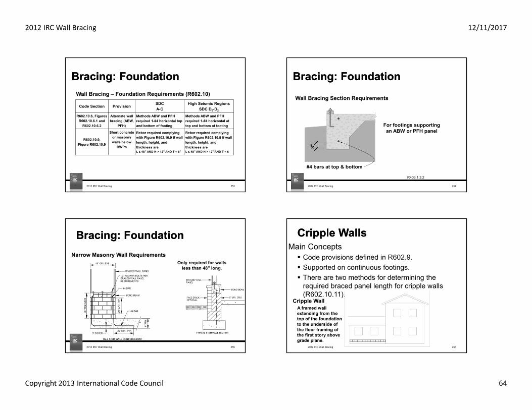
2012 IRC Wall Bracing 12/11/2017
Copyright 2013 International Code Council 64
Code Section Provision SDC A-C
High Seismic Regions SDC D0-D2
R602.10.6, Figures R602.10.6.1 and
R602.10.6.2
Alternate wall bracing (ABW,
PFH)
Methods ABW and PFH required 1-#4 horizontal top and bottom of footing
Methods ABW and PFH required 1-#4 horizontal at top and bottom of footing
R602.10.9, Figure R602.10.9
Short concrete or masonrywalls below
BWPs
Rebar required complying with Figure R602.10.9 if wall length, height, and thickness are L ≤ 48" AND H > 12" AND T < 6"
Rebar required complying with Figure R602.10.9 if wall length, height, and thickness are L ≤ 48" AND H > 12" AND T < 6
Wall Bracing – Foundation Requirements (R602.10)
Bracing: FoundationBracing: Foundation
2012 IRC Wall Bracing 253
Bracing: FoundationBracing: Foundation
3"
#4 bars at top & bottom
For footings supporting an ABW or PFH panel
R403.1.3.2
Wall Bracing Section Requirements
2012 IRC Wall Bracing 254
Bracing: FoundationBracing: Foundation
2012 IRC Wall Bracing 255
Narrow Masonry Wall RequirementsOnly required for walls
less than 48" long.
2012 IRC Wall Bracing 256
Main Concepts Code provisions defined in R602.9. Supported on continuous footings. There are two methods for determining the
required braced panel length for cripple walls (R602.10.11).
Cripple WallsCripple Walls
Cripple WallA framed wall extending from the top of the foundation to the underside of the floor framing of the first story above grade plane.

2012 IRC Wall Bracing 12/11/2017
Copyright 2013 International Code Council 65
Bracing Length from Tables R602.10.3(1) or (3)
for Roof only
1.15 x (Roof only Bracing Length)
Cripple WallsCripple Walls
2012 IRC Wall Bracing 257
Cripple Wall Supporting One Story
Bracing Length from Tables R602.10.3(1) or (3)
for Roof only
Roof + Floor Bracing Length
Redesignated as a Two-story
or
R602.10.11
Seismic Design Categories A-D1
14' BWP edge to edge 20' BWP edge to edge
Bracing Length from Tables R602.10.3(1) or (3)
for Roof only
1.15 x (Roof + 1 Floor BP Length)
Bracing Length from Tables R602.10.3(1) or (3)
for Roof + 1 Floor
14' BWP edge to edge
Cripple Wall Supporting Two Stories
Redesignated as a Three Story
20' BWP edge to edge
Bracing Length from Tables R602.10.3(1) or (3)
for Roof only
BP length for Roof + 2 Floors
Bracing Length from Tables R602.10.3(1) or (3)
for Roof + 1 Floor
or
Cripple WallsCripple Walls
2012 IRC Wall Bracing 258R602.10.11
Seismic Design Categories A-D1
2012 IRC Wall Bracing 259
Cripple WallsCripple Walls
Cripple Wall or Story Above Grade?See Chapter 2 Definitions: Story Above Grade Grade Plane
Stacked framing not permitted
Cripple WallsCripple Walls
2012 IRC Wall Bracing 260

2012 IRC Wall Bracing 12/11/2017
Copyright 2013 International Code Council 66
Bracing: FoundationBracing: FoundationFootings:
Anchor bolt placement Bolts embedded 7 inches Total length = 7” + plate(s) depth + threaded end
Footing depth Minimum 12 inches (R403.1.4) Frost depth controls in many areas
Footing width, W Table R403.1 lists minimum footing widths
2012 IRC Wall Bracing 261
Bracing: FoundationBracing: Foundation
2012 IRC Wall Bracing 262
6' Max.
7 bolt dia. min.to 12" max.
1/2" bolt with 7" min. embedment in concrete or masonry
End of Plate
R403.1.6
Bracing: FoundationBracing: Foundation
2012 IRC Wall Bracing 263
7"
1' 0"
6"
1' 0"
6" 7"
W W
T
P
3-1/2"
R403.1.1
Slab on Grade Raised Floor
Bracing TopicsBracing TopicsForces & History Bracing Examples
Locate BWL
Required Length
BWP Location
Panel Material & Ends
Sufficient Length
Connections
Foundation
Simplified Wall Bracing
Limits
?Questions
2012 IRC Wall Bracing 264

2012 IRC Wall Bracing 12/11/2017
Copyright 2013 International Code Council 67
Bracing TopicsBracing TopicsForces & History Bracing Examples
Locate BWL
Required Length
BWP Location
Panel Material & Ends
Sufficient Length
Connections
Foundation
Simplified Wall Bracing
Limits
2012 IRC Wall Bracing 265
Bracing: Simplified Wall BracingBracing: Simplified Wall BracingPrescriptive Limits
The structure must meet the following requirements: Seismic Design Category (SDC) A, B, or C (SDC A or B for townhouses) Basic Wind Speed of 90 mph or less with Wind Exposure Category A or B One or two story structure Wood structural panel (WSP) or structural fiberboard sheathing (SFB) is used to
brace exterior walls with ½ in gypsum board fastened to the interior side of walls 60 ft. maximum length and width of the building Max eave-to-ridge height of 15 ft. Wall max height of 10 ft. Max ratio between long and short side of building: 3 to 1 Max cantilever of 24 inches beyond foundation No cripple walls in two story buildings
2012 IRC Wall Bracing 266
2012 IRC Wall Bracing 267
Bracing: Simplified Wall BracingBracing: Simplified Wall Bracing
Prescriptive Limits
WSP
1 or 2 story
SFBBraced Wall Panel
Material
Building Length
Bracing: Simplified Wall BracingBracing: Simplified Wall Bracing
Advantages to the Simplified Method: No seismic requirements Bracing only occurs on the perimeter (exterior walls)
(No braced wall line length or spacing) No additional adjustment factors to check No interpolation
2012 IRC Wall Bracing 268

2012 IRC Wall Bracing 12/11/2017
Copyright 2013 International Code Council 68
Bracing: Simplified Wall BracingBracing: Simplified Wall Bracing
Procedure:
1. Draw a rectangle around the perimeter of the building and stagger the required number of bracing units along the four wall lines.
2012 IRC Wall Bracing 269
Bracing: Simplified Wall BracingBracing: Simplified Wall Bracing
Rectangle Circumscribing an Enclosed Building
2012 IRC Wall Bracing 270Figure R602.12.1
Bracing: Simplified Wall BracingBracing: Simplified Wall Bracing
Procedure cont.:
2. Identify the number of bracing units required on each side of the rectangle.
2012 IRC Wall Bracing 271
Bracing: Simplified Wall BracingBracing: Simplified Wall BracingMinimum Number of Bracing Units on Each Side of the Circumscribed Rectangle
2012 IRC Wall Bracing 272
Story Level
Eave-to Ridge Height(Feet)
Minimum Number of Bracing Units on Each Long Side a,b
Minimum Number of Bracing Units on Each Short Side a,b
Length of short side (ft.) c Length of long side (ft.) c
10 20 30 40 50 60 10 20 30 40 50 60
101 2 2 2 3 3 1 2 2 2 3 3
2 3 3 4 5 6 2 3 3 4 5 6
151 2 3 3 4 4 1 2 3 3 4 4
2 3 4 5 6 7 2 3 4 5 6 7
Table R602.12.4
a. Interpolation shall not be permitted.b. Cripple walls or wood-framed basement walls in a walk-out condition of a one-story structure
shall be designed as the first floor of a two-story house.c. Actual lengths of the sides of the circumscribed rectangle shall be rounded to the next highest
unit of 10 when using this table.

2012 IRC Wall Bracing 12/11/2017
Copyright 2013 International Code Council 69
Bracing: Simplified Wall BracingBracing: Simplified Wall Bracing
MaterialStud Spacing
& Fastener Criteria
Fastener Spacing Criteria
Bracing Unit Method
Minimum Bracing Unit Length (feet)
Wood Structural
PanelTable R602.3(3) 6'' edge
12'' fieldContinuous 3
Intermittent 4
Structural Fiberboard Sheathing
Max 16''spacing
Table R602.3(1)
3'' edge 6'' field
Continuous 3
Intermittent 4
Bracing Methods for Simplified Wall Bracing
a. Mixing of wood structural panel and structural fiberboard sheathing in one building is not permitted.b. Continuous and intermittent bracing units may be mixed from one story to another. c. Continuous and intermittent bracing unit methods may not be mixed within one story.
R602.12.2, R602.12.32012 IRC Wall Bracing 273
Bracing: Simplified Wall BracingBracing: Simplified Wall Bracing
Narrow Bracing Method
Equivalent Bracing Units
CS-G 0.5CS-PF 0.5PFH 1PFG 0.75
Narrow Bracing Methods for Simplified Wall Bracing
Each narrow bracing method is worth one or less than one 3 ft. or 4 ft. bracing unit.
R602.12.6
2012 IRC Wall Bracing 274
Bracing: Simplified Wall BracingBracing: Simplified Wall Bracing
2012 IRC Wall Bracing 275
Example SDC B Wind 90 mph, Wind Exposure B Method CS-WSP 1 Story Walls - 9 ft. Eave to ridge height - 12 ft.
Example Highlights: Strategic placement of bracing units
One Story
90 mph SDC B
NA
A B
49'-4"
2
1
59'-8"
1. Draw rectangle around the entire building
2. Check the length of the N-S and E-W sides the of rectangle
Less than 60 ft.?
OK
2012 IRC Wall Bracing 276

2012 IRC Wall Bracing 12/11/2017
Copyright 2013 International Code Council 70
Bracing: Simplified Wall BracingBracing: Simplified Wall BracingTable R602.12.4 Minimum Number of Bracing Units
2012 IRC Wall Bracing 277
A B
49'-4"
2
1
59'-8" 1. 4 bracing units required along each wall line
2. With CS-WSP, the minimum bracing unit length is 3 ft.
3. Panels must be within 12 ft. of the end of wall line and within 20 ft. of one another.
Sufficient space?
Yes, CS-PF units are only worth 0.5 units each so 5 B.U.s min will be needed on the south wall.
Furthermore, 3 CS-PF are needed to space units less than 20 ft. apart.
10'-2"18' 19'-6" 12'
CS-WSP
CS-WSP
CS-PF CS-
PFCS-PF
CS-WSP
CS-WSP
CS-WSP
CS-WSP
CS-WSP
CS-WSP
2012 IRC Wall Bracing 278
A B
4
1
59'-8"
Sufficient space?Yes, 4 CS-WSP bracing units fit along the east and west wall lines.
21'-8"
21'-2"
2
25'-2"
22'-2"
CS-WSP
CS-WSP
CS-WSP
CS-WSP
CS-WSP
CS-WSP
CS-WSP
CS-WSP
2012 IRC Wall Bracing 279
Bracing TopicsBracing TopicsForces & History Bracing Examples
Locate BWL
Required Length
BWP Location
Panel Material & Ends
Sufficient Length
Connections
Foundation
Simplified Wall Bracing
Limits
?Questions
2012 IRC Wall Bracing 280

2012 IRC Wall Bracing 12/11/2017
Copyright 2013 International Code Council 71
Bracing TopicsBracing TopicsForces & History ExamplesBracing
Wind 90 mph, Exp B, SDC A
Wind 90 mph, Exp B, SDC A
Wind 85 mph, Exp B, SDC D2
Wind 90 mph, Exp C, SDC B
Wind 105 mph, Exp C, SDC B
Limits
2012 IRC Wall Bracing 281 2012 IRC Wall Bracing 282
ExamplesExamples
Symbol Description
Diagonal let-in
Diagonal wood boards
Wood structural panel
Structural fiberboard
Gypsum wallboard
Particleboard
Portland cement
Hardboard
Symbol Description
Alternate BWP
Alt. BWP adj. opening
Continuous sheathing
Continuous 4:1
Continuous 6:1
Continuous sheathing
LIB
HBS
DWB
PBS
PCP
CS-G
ABW
PFH
CS-WSP
CS-PF
Symbol Key
CS-SFB
WSP
SFB
GB
Bracing TopicsBracing TopicsForces & History ExamplesBracing
Wind 90 mph, Exp B, SDC A
Wind 90 mph, Exp B, SDC A
Wind 85 mph, Exp B, SDC D2
Wind 90 mph, Exp C, SDC B
Wind 105 mph, Exp C, SDC B
Limits
2012 IRC Wall Bracing 283
Example: SDC A, Wind 90 mph, Exp BExample: SDC A, Wind 90 mph, Exp BExample Attributes: SDC A, Single-family dwelling Wind 90 mph, Wind Exposure B Method SFB Roof only (top of two stories) Wall height is 8 ft.
Example Highlights: Bracing percent based on wind. This structure is exempt from the seismic
requirements. BWP's on the second floor can be placed over an opening on the first floor. BWP's are permitted to occur up to 10 feet away from the ends of BWL's.
2012 IRC Wall Bracing 284
SFBTop
Story
90 mph SDC A

2012 IRC Wall Bracing 12/11/2017
Copyright 2013 International Code Council 72
24'-11"
36'-10"A B
1
2
SFBTop
Story
Wall Line
90mph
SDCA
1, 2 5.5 ft.N/A
A, B 7.5 ft.
Upper Story
2012 IRC Wall Bracing 285
Exposure Category B30 ft. Mean Roof Ht.10 ft. Eave to Ridge
Ht.10 ft. Wall Height
2 Braced Wall Lines
Minimum Total Length (feet) of Braced Wall Panels Required Along Each Braced Wall Line
Basic Wind Speed
StoryLocation
Braced Wall Line Spacing(feet)
MethodLIB
Method GB
(double sided)
Methods DWB, WSP, SFB, PCP,
HPS
CS‐WSP,CS‐G, CS‐PF
< 90 (mph)
10 3.5 3.5 2.0 2.020 7.0 7.0 4.0 3.530 9.5 9.5 5.5 5.040 12.5 12.5 7.5 6.050 15.5 15.5 9.0 7.560 18.5 18.5 10.5 9.010 7.0 7.0 4.0 3.520 13.0 13.0 7.5 6.530 18.5 18.5 10.5 9.040 24.0 24.0 14.0 12.050 29.5 29.5 17.0 14.560 35.0 35.0 20.0 17.0
EXPOSURE CATEGORY B, 30 FT MEAN ROOF HEIGHT, 10 FT EAVE TO RIDGE HEIGHT,
10 FT WALL HEIGHT,2 BRACED WALL LINES
MINIMUM TOTAL LENGTH (feet) OF BRACED WALL PANELS REQUIRED ALONG EACH BRACED WALL LINE
Basic Wind Speed (mph)
Story Location
Braced Wall Line Spacing
(feet)Method LIBf, h
Method GB (double sided)g
Methods DWB, WSP, SFB, PBS, PCP, HPSf,i
Continuous Sheathing
≤ 85 (mph)
10 3.5 3.5 2.0 1.5
20 6.0 6.0 3.5 3.0
30 8.5 8.5 5.0 4.5
40 11.5 11.5 6.5 5.5
50 14.0 14.0 8.0 7.0
60 16.5 16.5 9.5 8.0
10 6.5 6.5 3.5 3.0
20 11.5 11.5 6.5 5.5
30 16.5 16.5 9.5 8.0
40 21.5 21.5 12.5 10.5
50 26.5 26.5 15.0 13.0
60 31.5 31.5 18.0 15.5
10 NP 9.0 5.5 4.5
20 NP 17.0 10.0 8.5
30 NP 24.5 14.0 12.0
40 NP 32.0 18.0 15.5
50 NP 39.0 22.5 19.0
60 NP 46.5 26.5 22.5
≤ 90 (mph)
10 3.5 3.5 2.0 2.0
20 7.0 7.0 4.0 3.5
30 9.5 9.5 5.5 5.0
40 12.5 12.5 7.5 6.0
50 15.5 15.5 9.0 7.5
60 18.5 18.5 10.5 9.0
10 7.0 7.0 4.0 3.5
20 13.0 13.0 7.5 6.5
30 18.5 18.5 10.5 9.0
40 24.0 24.0 14.0 12.0
50 29.5 29.5 17.0 14.5
60 35.0 35.0 20.0 17.0
10 NP 10.5 6.0 5.0
20 NP 19.0 11.0 9.5
30 NP 27.5 15.5 13.5
40 NP 35.5 20.5 17.5
50 NP 44.0 25.0 21.5
60 NP 52.0 30.0 25.5
Minimum Required Length of BracingTable R602.10.3 (1)
2012 IRC Wall Bracing 286
Exposure Category B30 ft. Mean Roof Ht.10 ft. Eave to Ridge
Ht.10 ft. Wall Height
2 Braced Wall Lines
Minimum Total Length (feet) of Braced Wall Panels Required Along Each Braced Wall Line
Basic Wind Speed
StoryLocation
Braced Wall Line Spacing(feet)
MethodLIB
Method GB
(double sided)
Methods DWB, WSP, SFB, PCP,
HPS
CS‐WSP,CS‐G, CS‐PF
< 90 (mph)
10 3.5 3.5 2.0 2.020 7.0 7.0 4.0 3.530 9.5 9.5 5.5 5.040 12.5 12.5 7.5 6.050 15.5 15.5 9.0 7.560 18.5 18.5 10.5 9.010 7.0 7.0 4.0 3.520 13.0 13.0 7.5 6.530 18.5 18.5 10.5 9.040 24.0 24.0 14.0 12.050 29.5 29.5 17.0 14.560 35.0 35.0 20.0 17.0
EXPOSURE CATEGORY B, 30 FT MEAN ROOF HEIGHT, 10 FT EAVE TO RIDGE HEIGHT,
10 FT WALL HEIGHT,2 BRACED WALL LINES
MINIMUM TOTAL LENGTH (feet) OF BRACED WALL PANELS REQUIRED ALONG EACH BRACED WALL LINE
Basic Wind Speed (mph)
Story Location
Braced Wall Line Spacing
(feet)Method LIBf, h
Method GB (double sided)g
Methods DWB, WSP, SFB, PBS, PCP, HPSf,i
Continuous Sheathing
≤ 85 (mph)
10 3.5 3.5 2.0 1.5
20 6.0 6.0 3.5 3.0
30 8.5 8.5 5.0 4.5
40 11.5 11.5 6.5 5.5
50 14.0 14.0 8.0 7.0
60 16.5 16.5 9.5 8.0
10 6.5 6.5 3.5 3.0
20 11.5 11.5 6.5 5.5
30 16.5 16.5 9.5 8.0
40 21.5 21.5 12.5 10.5
50 26.5 26.5 15.0 13.0
60 31.5 31.5 18.0 15.5
10 NP 9.0 5.5 4.5
20 NP 17.0 10.0 8.5
30 NP 24.5 14.0 12.0
40 NP 32.0 18.0 15.5
50 NP 39.0 22.5 19.0
60 NP 46.5 26.5 22.5
≤ 90 (mph)
10 3.5 3.5 2.0 2.0
20 7.0 7.0 4.0 3.5
30 9.5 9.5 5.5 5.0
40 12.5 12.5 7.5 6.0
50 15.5 15.5 9.0 7.5
60 18.5 18.5 10.5 9.0
10 7.0 7.0 4.0 3.5
20 13.0 13.0 7.5 6.5
30 18.5 18.5 10.5 9.0
40 24.0 24.0 14.0 12.0
50 29.5 29.5 17.0 14.5
60 35.0 35.0 20.0 17.0
10 NP 10.5 6.0 5.0
20 NP 19.0 11.0 9.5
30 NP 27.5 15.5 13.5
40 NP 35.5 20.5 17.5
50 NP 44.0 25.0 21.5
60 NP 52.0 30.0 25.5
Minimum Required Length of BracingTable R602.10.3 (1)
2012 IRC Wall Bracing 287
A B
1
2
24'-11"
36'-10"
BWP over opening below
8 ft.9' 4' 4' 10'
4 4
8 ft.
9' 4' 4' 7'4 4
SFBTop
Story
Wall Line
90mph
SDCA
1, 2 5.5 ft.N/A
A, B 7.5 ft.
Upper Story
OK
OK
SFB
SFB SFB
SFB
2012 IRC Wall Bracing 288

2012 IRC Wall Bracing 12/11/2017
Copyright 2013 International Code Council 73
A B
1
2
24'-11"
36'-10"
8 ft.
4'
4'
4
4
8 ft.
4'
4'
10'
4
4
Upper Story
OKOK
SFB
SFB
SFB
SFB
SFBTop
Story
Wall Line
90mph
SDCA
1, 2 5.5 ft.N/A
A, B 7.5 ft.
2012 IRC Wall Bracing 289
A B
1
2
24'-11"
36'-10"
4'
4'
4'
4'
10'
9' 4' 4' 7'
9' 4' 4' 10'
4
4
4
4
4 4
4 4
SFBTop
Story
Wall Line
90mph
SDCA
1, 2 5.5 ft.N/A
A, B 7.5 ft.
Upper Story
SFB
SFB SFB
SFB
SFB
SFB
SFB
SFB
2012 IRC Wall Bracing 290
Example cont.: SDC A, Wind 90 mph, Exp BExample cont.: SDC A, Wind 90 mph, Exp BExample Attributes: SDC A, Single-family dwelling Wind 90 mph, Wind Exposure B Method SFB Roof plus 1 floor (bottom of two stories) Wall Height is 8 ft.
2012 IRC Wall Bracing 291
SFBBottom Story
90 mph SDC A
24'-11"
36'-10"A B
1
2
SFBBottom Story
Wall Line
90mph SDC A
1, 2 10.5 ft.N/A
A, B 14 ft.
Bottom Story
2012 IRC Wall Bracing 292

2012 IRC Wall Bracing 12/11/2017
Copyright 2013 International Code Council 74
36'-10"
24'-11"
A B
1
2
36'-10"
4' 4' 4' 8'
12 ft.SFB SFB SFB
10' 6' 4'
10 ft.SFB
SFBBottom Story
Wall Line
90mph SDC A
1, 2 10.5 ft.N/A
A, B 14 ft.
OK
NG
Bottom Story
SFB
SFB SFB
SFB
SFB
2012 IRC Wall Bracing 293
36'-10"
24'-11"
A B
1
2
36'-10"
4' 4' 4' 8'
12 ft.SFB SFB SFB
10' 6' 4'
10 ft.SFB SFB
SFBBottom Story
Wall Line 90 mph SDC A
1, 2 9 ft.N/A
A, B 13 ft.
OK
OK
Bottom Story
SFB
SFB SFB
SFB
SFB
10.5' x 0.9 = 9'14' x 0.9 = 13'
2012 IRC Wall Bracing 294
A B36'-10"
24'-11"
1
2
3'
12.2
5 ft.
SFB
SFB
4′-6ʺ
12 ft
.
SFB
SFB
SFBBottom Story
Wall Line 90 mph SDC A
1, 2 9 ft.N/A
A, B 13 ft.
NG NG
SFB 3′-6ʺ
4′-6ʺ
4′-6ʺ
5′-6ʺ
SFB
Bottom Story
The 3.5 ft. and 3 ft. segments qualify using Table R602.10.5.2
SFB
SFBSFB
SFB
SFB SFB
2012 IRC Wall Bracing 295
A B36'-10"
24'-11"
1
2
With the wall height adjustment, the required bracing length is 13 ft. x 0.9 = 11.7 ft.
3'
12.2
5 ft.
SFB
SFB
4′-6ʺ
12 ft
.
SFB
SFB
SFBBottom Story
Wall Line 90 mph SDC A
1, 2 9 ft.N/A
A, B 11.7 ft.
OK OK
SFB 3′-6ʺ
4′-6ʺ
4′-6ʺ
5′-6ʺ
SFB
Bottom Story
SFB
SFBSFB
SFB
SFB SFB
2012 IRC Wall Bracing 296

2012 IRC Wall Bracing 12/11/2017
Copyright 2013 International Code Council 75
A B36'-10"
24'-11"
1
2
3'
SFB
SFB
4′-6ʺSFB
SFB
SFBBottom Story
Wall Line 90 mph SDC A
1, 2 9 ft.N/A
A, B 11.5 ft.
SFB 3′-6ʺ
4′-6ʺ
4′-6ʺ
5′-6ʺ
SFB
10' 6' 4'4 4
4' 4'4 4
4' 8'4
Bottom Story
SFB
SFB SFB
SFB
SFB
SFB
SFBSFB
SFB
SFB SFB
2012 IRC Wall Bracing 297
Bracing TopicsBracing TopicsForces & History ExamplesBracing
Wind 90 mph, Exp B, SDC A
Wind 90 mph, Exp B, SDC A
Wind 85 mph, Exp B, SDC D2
Wind 90 mph, Exp C, SDC B
Wind 105 mph, Exp C, SDC B
Limits
2012 IRC Wall Bracing 298
Example: SDC A, Wind 90 mph, Exp BExample: SDC A, Wind 90 mph, Exp B
Example 3 SDC A Wind 90 mph Method WSP & GB 1 Story 8 ft. tall walls, 10 ft. eave to ridge height
Example Highlights: Strategic placement of BWL's. Different bracing methods can be used together. Application of PFH
WSPOne
Story
90 mph SDC A
GBOne
Story
90 mph SDC A
2012 IRC Wall Bracing 299
17'-2" 17' 15'-7"
A
2
B C D27'-11"
28'-10"
27'-8"
4'8'
64'-6"
4'34
1
3'-8"
77'-8"2012 IRC Wall Bracing 300

2012 IRC Wall Bracing 12/11/2017
Copyright 2013 International Code Council 76
17'-2" 17' 15'-7"
A
2
B C D27'-11"
28'-10"
27'-8"
4'8'
64'-6"
4'34
1
3'-8"
77'-8"2012 IRC Wall Bracing 301
Exposure Category B30 ft. Mean Roof Ht.10 ft. Eave to Ridge
Ht.10 ft. Wall Height
2 Braced Wall Lines
Minimum Total Length (feet) of Braced Wall Panels Required Along Each Braced Wall Line
Basic Wind Speed
StoryLocation
Braced Wall Line Spacing(feet)
MethodLIB
Method GB
(double sided)
Methods DWB, WSP, SFB, PCP,
HPS
CS‐WSP,CS‐G, CS‐PF
< 90 (mph)
10 3.5 3.5 2.0 2.020 7.0 7.0 4.0 3.530 9.5 9.5 5.5 5.040 12.5 12.5 7.5 6.050 15.5 15.5 9.0 7.560 18.5 18.5 10.5 9.010 7.0 7.0 4.0 3.520 13.0 13.0 7.5 6.530 18.5 18.5 10.5 9.040 24.0 24.0 14.0 12.050 29.5 29.5 17.0 14.560 35.0 35.0 20.0 17.0
EXPOSURE CATEGORY B, 30 FT MEAN ROOF HEIGHT, 10 FT EAVE TO RIDGE HEIGHT,
10 FT WALL HEIGHT,2 BRACED WALL LINES
MINIMUM TOTAL LENGTH (feet) OF BRACED WALL PANELS REQUIRED ALONG EACH BRACED WALL LINE
Basic Wind Speed (mph)
Story Location
Braced Wall Line Spacing
(feet)Method LIBf, h
Method GB (double sided)g
Methods DWB, WSP, SFB, PBS, PCP, HPSf,i
Continuous Sheathing
≤ 85 (mph)
10 3.5 3.5 2.0 1.5
20 6.0 6.0 3.5 3.0
30 8.5 8.5 5.0 4.5
40 11.5 11.5 6.5 5.5
50 14.0 14.0 8.0 7.0
60 16.5 16.5 9.5 8.0
10 6.5 6.5 3.5 3.0
20 11.5 11.5 6.5 5.5
30 16.5 16.5 9.5 8.0
40 21.5 21.5 12.5 10.5
50 26.5 26.5 15.0 13.0
60 31.5 31.5 18.0 15.5
10 NP 9.0 5.5 4.5
20 NP 17.0 10.0 8.5
30 NP 24.5 14.0 12.0
40 NP 32.0 18.0 15.5
50 NP 39.0 22.5 19.0
60 NP 46.5 26.5 22.5
≤ 90 (mph)
10 3.5 3.5 2.0 2.0
20 7.0 7.0 4.0 3.5
30 9.5 9.5 5.5 5.0
40 12.5 12.5 7.5 6.0
50 15.5 15.5 9.0 7.5
60 18.5 18.5 10.5 9.0
10 7.0 7.0 4.0 3.5
20 13.0 13.0 7.5 6.5
30 18.5 18.5 10.5 9.0
40 24.0 24.0 14.0 12.0
50 29.5 29.5 17.0 14.5
60 35.0 35.0 20.0 17.0
10 NP 10.5 6.0 5.0
20 NP 19.0 11.0 9.5
30 NP 27.5 15.5 13.5
40 NP 35.5 20.5 17.5
50 NP 44.0 25.0 21.5
60 NP 52.0 30.0 25.5
Minimum Required Length of BracingTable R602.10.3 (1)
2012 IRC Wall Bracing 302
Use Table R602.10.3(1) to determine required bracing lengthExterior braced wall lines Add adjustment factor
BWL A – assume 20 ft. spacingMethod WSP = 4 ft. 4 x 1.45 x 0.9 = 5.2 ft.
BWL D – assume 50 ft. spacingMethod WSP = 9 ft. 9 x 1.45 x 0.9 = 11.7 ft.
BWL 1, 3, 4 – assume 30 ft. spacingMethod WSP = 5.5 ft. 5.5 x 1.45 x 0.9 = 7.2 ft.
Interior braced wall linesBWL B – assume 20 ft. spacing
Method GB = 7 ft. 7 x 1.45 x 0.9 = 9.1 ft.BWL C – assume 50 ft. spacing
Method GB = 15.5 ft. 15.5 x 1.45 x 0.9 = 20.2 ft.BWL 2 – assume 30 ft. spacing
Method GB = 9.5 ft. 9.5 x 1.45 x 0.9 = 12.4 ft.
Adjustment Factors:• Wind Exposure B = 1.0 • 4 BWLs = 1.45• Walls - 8 feet tall = 0.9• Eave to ridge height - 10 feet tall = 1.0
Total = 1.31
OneStory
Wall Line
90mph
SDCB
WSPAD
1, 3, 4?
NA
GBBC2
?
2012 IRC Wall Bracing 303
16'-2" 16' 14'-7"
A
2
B C D28'-5"
28'-10"
27'-8"
73'-8"4'3
4
3'-8"
4'8'
60'-6"
1
23.7
ft.
14.8
ft.
41 ft
.
25.2
ft.
GB
GB
OneStory
Wall Line
90mph
SDCB
WSP AD
5.211.7
NAGB B
C9.1
20.2
WSP
WSP
WSP
WSPWSP
23'-8"
9'-8"
15'-6"23'-0"
18'-0"
2'-9"equivalent
14'-2"
OK OK OK OK
2012 IRC Wall Bracing 304

2012 IRC Wall Bracing 12/11/2017
Copyright 2013 International Code Council 77
17'-2" 17' 15'-7"
A
2
B C D27'-11"
28'-10"
27'-8"
77'-8"4'3
4
3'-8"
4'1
64'-6"
12 ft.
3 3
3 16 ft.8'
38 ft.
18 ft.
3
3
55
PFHPFH PFH
WSP
WSP
WSP
WSP
WSP
WSP
GB GB
WSP
OneStory
Wall Line
90mph
SDCB
WSP 1, 3, 4 7.2 ft.NA
GB 2 12.4 ft.
3WSP
6'
4'
20" typical
4'
4' 4'
4'
4'
4'
4'
4' OK
OK
OK
OK2012 IRC Wall Bracing 305
Bracing TopicsBracing TopicsForces & History ExamplesBracing
Wind 90 mph, Exp B, SDC A
Wind 90 mph, Exp B, SDC A
Wind 85 mph, Exp B, SDC D2
Wind 90 mph, Exp C, SDC B
Wind 105 mph, Exp C, SDC B
Limits
?Questions
2012 IRC Wall Bracing 306
307
International Code Council is a Registered Provider with The American Institute of Architects Continuing Education Systems. Credit earned on completion of this program will be reported to CES Records for AIA members. Certificates of Completion for non-AIA members are available on request.
This program is registered with the AIA/CES for continuing professional education. As such, it does not include content that may be deemed or construed to be an approval or endorsement by the AIA of any material of construction or any method or manner of handling, using, distributing, or dealing in any material or product. Questions related to specific materials, methods, and services will be addressed at the conclusion of this presentation.
2012 IRC Wall Bracing 308
Copyright Materials
This presentation is protected by US and International Copyright laws. Reproduction, distribution, display and use of the presentation without written permission of the speaker is
prohibited.
© International Code Council 2006
2012 IRC Wall Bracing

2012 IRC Wall Bracing 12/11/2017
Copyright 2013 International Code Council 78
Thank you for participating!Thank you for participating!
To schedule a seminar, contact:The Learning Center™
1‐888‐ICC‐SAFE (422‐7233) Ext. 33818or
E‐mail: [email protected]
2012 IBC Wall Bracing - Advance 309