2012 – 2013 georgia tech ramblin’ rocketeers flight ... gatech usli frr.pdf · g 2012 – 2013...
TRANSCRIPT

2012 – 2013 Georgia Tech Ramblin’ Rocketeers Flight Readiness Review

G 2012 – 2013 GEORGIA TECH RAMBLIN’ ROCKETEERS
FLIGHT READINESS REVIEW
Georgia Institute of Technology 2 of 187 Ramblin’ Rocketeers
PAGE INTENTIONALLY LEFT BLANK

G 2012 – 2013 GEORGIA TECH RAMBLIN’ ROCKETEERS
FLIGHT READINESS REVIEW
Georgia Institute of Technology 3 of 187 Ramblin’ Rocketeers
Table of Contents
Table of Contents ............................................................................................................................ 3 Table of Figures .............................................................................................................................. 8 Table of Tables ............................................................................................................................. 10 1. Introduction ........................................................................................................................... 12
School Information and NAR Section Contacts ............................................................ 12 1.1. Work Breakdown Structure ............................................................................................ 13 1.2. Launch Vehicle Summary .............................................................................................. 14 1.3.
1.3.1. Overview ................................................................................................................. 14 1.3.2. Changes since CDR ................................................................................................ 14
Payload Summary .......................................................................................................... 14 1.4.1.4.1. Overview ................................................................................................................. 14 1.4.2. Changes Since CDR ................................................................................................ 15 1.4.2.1. Payload Changes Since CDR .............................................................................. 15 1.4.2.2. Avionics Changes Since CDR............................................................................. 15
2. Project L.S.I.M. Overview ..................................................................................................... 16 Mission Statement .......................................................................................................... 16 2.1. Requirements Flow Down .............................................................................................. 16 2.2. Mission Objectives and Mission Success Criteria ......................................................... 17 2.3. System Requirements Verification Matrix (RVM) ........................................................ 17 2.1. Mission Profile ............................................................................................................... 30 2.1.
3. Launch Vehicle ...................................................................................................................... 32 Overview ........................................................................................................................ 32 3.1.
3.1.1. Mission Criteria ...................................................................................................... 32 System Design Overview ............................................................................................... 33 3.2. Recovery System ............................................................................................................ 42 3.3.
3.3.1. Altimeters ................................................................................................................ 45 3.3.2. Arming Switches ..................................................................................................... 46 3.3.3. Parachute Dimensions ............................................................................................. 47 3.3.4. Drift Profile Analysis .............................................................................................. 48 3.3.5. Kinetic Energy of Launch Vehicle ......................................................................... 50 3.3.6. Ejection Charges ..................................................................................................... 51 3.3.7. Testing..................................................................................................................... 52
Structure ......................................................................................................................... 53 3.4.3.4.1. Construction ............................................................................................................ 54 3.4.2. Payload Integration ................................................................................................. 55

G 2012 – 2013 GEORGIA TECH RAMBLIN’ ROCKETEERS
FLIGHT READINESS REVIEW
Georgia Institute of Technology 4 of 187 Ramblin’ Rocketeers
3.4.3. Avionics Integration ................................................................................................ 55 3.4.4. Section Integration .................................................................................................. 56
Launch Vehicle Performance Analysis .......................................................................... 56 3.5.3.5.1. Altitude Predictions and Motor Selection ............................................................... 56 3.5.2. Stability ................................................................................................................... 59 3.5.3. Testing..................................................................................................................... 60 3.5.4. ...................................................................................................................................... 61 3.5.5. ...................................................................................................................................... 61 3.5.6. ...................................................................................................................................... 61
Intimidator 5 Kit Mass Breakdown ............................................................................... 61 3.6. Interfaces and Integration ............................................................................................... 62 3.7.
3.7.1. Interface with the Ground ....................................................................................... 63 3.7.2. Interface with the Ground Launch System ............................................................. 63
Launch Vehicle Operations ............................................................................................ 63 3.8.3.8.1. Launch Checklist .................................................................................................... 63
4. Flight Experiment .................................................................................................................. 65 Introduction to the Experiment and Payload Concept Features & Definition ............... 65 4.1. Accomplishments Since CDR ........................................................................................ 66 4.2.
4.2.1. Important Changes .................................................................................................. 66 4.2.2. Test Launch Lessons Learned ................................................................................. 66 4.2.2.1. Summary of Science Team Payload .................................................................... 66 4.2.2.2. Report of Failures and Occurrences .................................................................... 67 4.2.2.3. Integration ........................................................................................................... 67 4.2.2.4. Sensor detachment ............................................................................................... 67 4.2.2.5. Openlog File Writing .......................................................................................... 67 4.2.2.6. Results and Future Mitigation ............................................................................. 67 4.2.2.7. Integration Results ............................................................................................... 67 4.2.2.8. Sensor data .......................................................................................................... 68 4.2.2.9. OpenLog Risk Mitigation .................................................................................... 68
Science Background ....................................................................................................... 69 4.3.4.3.1. Important Highlights ............................................................................................... 69
Experiment Requirements and Objectives ..................................................................... 69 4.4.4.4.1. Success Criteria ....................................................................................................... 69 4.4.2. Requirements .......................................................................................................... 70 4.4.3. Hypothesis and Premise .......................................................................................... 74 4.4.4. Experimental Method and Relevance of Data ........................................................ 75
Testing plan .................................................................................................................... 76 4.5.

G 2012 – 2013 GEORGIA TECH RAMBLIN’ ROCKETEERS
FLIGHT READINESS REVIEW
Georgia Institute of Technology 5 of 187 Ramblin’ Rocketeers
4.5.1. Overview ................................................................................................................. 76 4.5.2. MR Fluid Creation and Validation of Theory ......................................................... 79 4.5.3. MR Fluid Shear Stress Characterization: Two Plate Test ..................................... 80 4.5.4. Working Ground Model .......................................................................................... 82 4.5.5. Sensors .................................................................................................................... 82
Design review ................................................................................................................. 82 4.6.4.6.1. Viscosity Test Rig ................................................................................................... 82 4.6.2. Ground Test – MR fluid production and manipulation .......................................... 84 4.6.3. Hardware and build progress .................................................................................. 85 4.6.3.1. Sensing ................................................................................................................ 85 4.6.3.2. Solenoids ............................................................................................................. 89 4.6.3.3. Microcontroller .................................................................................................... 91
Payload Relevance and Science Merit ........................................................................... 91 4.7. RGEFP ........................................................................................................................... 93 4.8.
4.8.1. RGEFP-Specific Design Work ............................................................................... 93 4.8.1.1. Containment Box................................................................................................. 93 4.8.1.2. Computer ............................................................................................................. 95 4.8.1.3. Weights ................................................................................................................ 96 4.8.1.4. Equipment Layout for Take-off, in Flight, and Landing ..................................... 98
Flight Experiment Integration ...................................................................................... 100 4.9.5. Flight Avionics .................................................................................................................... 104
Avionics Overview ....................................................................................................... 104 5.1. Avionics Success Criteria ............................................................................................. 106 5.2. SIDES Design Approach .............................................................................................. 107 5.3.
5.3.1. SIDESboard .......................................................................................................... 108 5.3.2. SIDES Electrical Harness ..................................................................................... 109 5.3.3. Master IMU ........................................................................................................... 110 5.3.4. Science Experiment Computer ............................................................................. 110 5.3.5. Telemetry .............................................................................................................. 110
De-scope Options ......................................................................................................... 111 5.4. Power Budget ............................................................................................................... 111 5.5. EM Interference ............................................................................................................ 112 5.6. Transmission Frequencies and Protocols ..................................................................... 112 5.7. Software Maturity ........................................................................................................ 113 5.8. De-scope Option: Flight Computer Definition ............................................................ 113 5.9. Avionics Testing and Reliability Assurance ............................................................ 115 5.10. Ground Station .......................................................................................................... 116 5.11.
5.11.1. Purpose .................................................................................................................. 116 5.11.2. Function ................................................................................................................ 117

G 2012 – 2013 GEORGIA TECH RAMBLIN’ ROCKETEERS
FLIGHT READINESS REVIEW
Georgia Institute of Technology 6 of 187 Ramblin’ Rocketeers
5.11.3. Design Considerations .......................................................................................... 119 5.11.3.1. Choice of Antenna ............................................................................................. 119 5.11.3.2. Choice of Camera .............................................................................................. 120 5.11.3.3. Motor Sizing ...................................................................................................... 120 5.11.3.4. Software Maturity ............................................................................................. 122 5.11.3.5. Effects of Excess RF Radiation on the Recovery Avionics .............................. 127
Avionics Mechanical Integration.............................................................................. 128 5.12.6. General Safety ..................................................................................................................... 129
Vehicle Safety and Environment .................................................................................. 129 6.1.6.1.1. Overview ............................................................................................................... 129 6.1.2. Mission Assurance ................................................................................................ 130
Payload Safety .............................................................................................................. 132 6.2. Personnel and Environmental Hazards ........................................................................ 136 6.3.
7. Project Budget ..................................................................................................................... 141 Funding Overview ........................................................................................................ 141 7.1. Current Sponsors .......................................................................................................... 142 7.2. Actual Project Cost ....................................................................................................... 142 7.3.
7.3.1. FRR Budget Summary .......................................................................................... 142 7.3.2. System-Level Budget Summary ........................................................................... 143 7.3.3. Flight Hardware Expenditures .............................................................................. 144 7.3.3.1. Flight Hardware Expenditure Overview ........................................................... 144 7.3.3.2. Flight Hardware Cost Breakdown ..................................................................... 145
8. Project Schedule .................................................................................................................. 147 Schedule Overview ...................................................................................................... 147 8.1. Critical Path Chart: CDR to PLAR .............................................................................. 148 8.2. Schedule Risk ............................................................................................................... 150 8.3.
8.3.1. High Risk Items .................................................................................................... 150 8.3.2. Low-to-Moderate Risk Tasks ............................................................................... 151
9. Educational Engagement Plan and Status ........................................................................... 153 Overview ...................................................................................................................... 153 9.1. Atlanta Makers’ Faire ................................................................................................... 153 9.2. FIRST Lego League and Tech Challenge .................................................................... 153 9.3.
References ................................................................................................................................... 156 Appendix I: Gantt Chart.............................................................................................................. 157 Appendix II: Launch Checklist ................................................................................................... 159 Appendix III: Science Overview ................................................................................................ 164 Appendix IV: Ground Test Plan ................................................................................................. 177

G 2012 – 2013 GEORGIA TECH RAMBLIN’ ROCKETEERS
FLIGHT READINESS REVIEW
Georgia Institute of Technology 7 of 187 Ramblin’ Rocketeers
Appendix V: Science MFOs and Drawings ................................................................................ 179 Appendix VI: Altimeter Wiring Harness Schematic .................................................................. 187

G 2012 – 2013 GEORGIA TECH RAMBLIN’ ROCKETEERS
FLIGHT READINESS REVIEW
Georgia Institute of Technology 8 of 187 Ramblin’ Rocketeers
Table of Figures
Figure 1. 2012 – 2013 project work breakdown structure. .......................................................... 13 Figure 2. Flow down of requirements. .......................................................................................... 16 Figure 3. Project L.S.I.M. mission profile. ................................................................................... 31 Figure 4: Internal Layout of the Launch Vehicle .......................................................................... 43 Figure 5: Drogue Parachute Assembly ......................................................................................... 44 Figure 6: Main Parachute Assembly ............................................................................................. 45 Figure 7: Electronic Altimeter Schematic ..................................................................................... 46 Figure 8: Featherweight Screw Switches ...................................................................................... 47 Figure 9: Payload Integration Structure ........................................................................................ 55 Figure 10: Avionics Integration Structure .................................................................................... 56 Figure 11: L1390 Altitude and Thrust vs. Time ........................................................................... 58 Figure 12: Launch Vehicle Stability vs. Time .............................................................................. 59 Figure 13: 45% Scale Test Rocket and Flight .............................................................................. 60 Figure 14: Intimidator 5 Kit Landing Mass Breakdown ............................................................... 62 Figure 15: Correcting for Piezo drift ........................................................................................... 68 Figure 16: FFT of corrected data showing peak around 26 Hz ................................................... 68 Figure 17: LSIM testing logic, illustrating a simple relationship of information between the test sequences and emphasizing that they flow down from the pursuit of the LSIM hypothesis. ....... 78 Figure 18: Preliminary static testing of MR fluid mixtures in magnetic fields ........................... 80 Figure 19: Shear stress of a fluid using the two-plate test (Source: Wikipedia) ......................... 81 Figure 20: Piezo-electric sensor used for detecting anchor force oscillations ............................. 86 Figure 21: Piezo-electric sensor circuit. The sensor is modeled as a variable-voltage source at 300 Hz. While 300 Hz is a theoretical maximum for the reading speed of the microcontroller, data was logged at a rate between 88-96 Hz. ................................................................................ 87 Figure 22: Top and bottom view of sensor prototype circuit. Leads soldered to the piezo-electric sensors are attached to the blue terminals, while pins go to the microcontroller for data logging and analog reading. This prototype supports two sensors and is approximately 3 inches by 5 inches. Final boards may be much smaller. ................................................................................. 87 Figure 23: data showing sensor drift and a method of correction by distributing the data around the overall mean. ........................................................................................................................... 89 Figure 24: frequency spectrum for the entire dataset. .................................................................. 89 Figure 25: 4x4 solenoid driver. Two drivers can be linked together per microcontroller to control 32 solenoids directly. Approximately 3 inches by 2 inches. ............................................ 90 Figure 26: Arduino Mega microcontroller with major dimensions. ............................................ 91 Figure 27: Ideas for the containment box, illustrating some support elements and a possible electrical conduit. .......................................................................................................................... 94 Figure 28: bottom mounting bracket for the USLI sounding rocket. A larger version is intended to be used in the containment box. This piece attaches to the box - a second part attaches to the canister and snaps into the bracket. ............................................................................................... 95 Figure 29: Current weight budget with totals, and broken out by known subassemblies. .......... 97

G 2012 – 2013 GEORGIA TECH RAMBLIN’ ROCKETEERS
FLIGHT READINESS REVIEW
Georgia Institute of Technology 9 of 187 Ramblin’ Rocketeers
Figure 30: Summary of the weight budget to report subassembly totals. .................................... 98 Figure 31: Equipment layout for containment box, 6 canisters, laptop and crew for all stages of flight. ............................................................................................................................................. 99 Figure 32: Payload Assembly .................................................................................................... 100 Figure 33: Payload Base with 150N of loading .......................................................................... 101 Figure 34: Factor of Safety vs. Total Load from SolidWorks SimulationXpress and generated trend line equation....................................................................................................................... 103 Figure 35: SIDES system layout ................................................................................................ 108 Figure 36: SIDESboard bottom side view ................................................................................. 109 Figure 37: SIDESboard top side view ....................................................................................... 109 Figure 38: Xbee transceiver unit ................................................................................................ 110 Figure 39: Antenna performance as a function of range ............................................................ 113 Figure 40: Generalization of flight computer software .............................................................. 114 Figure 41: Diagram of a helical antenna .................................................................................... 119 Figure 42: Typical radiation pattern for a helical antenna ......................................................... 119 Figure 43: Canon Powershot SX260 ......................................................................................... 120 Figure 44: High-Level Software Process .................................................................................... 123 Figure 45: Updating Rocket State ............................................................................................... 124 Figure 46: Updating Servo Position ............................................................................................ 125 Figure 47: Updating Camera Zoom ............................................................................................ 126 Figure 48:Transmit Rocket Location .......................................................................................... 127 Figure 49. System expenditure summary at CDR. ..................................................................... 143 Figure 50. Sub-system Testing/Development Breakdown. ........................................................ 144 Figure 51. Sub-System Flight Hardware Breakdown. ................................................................ 145 Figure 52. Flight Systems flight hardware breakout. .................................................................. 146 Figure 6. Critical Path Chart from CDR to PLAR ...................................................................... 149 Figure 20. Participation at the Atlanta Makers' Faire. ................................................................ 153 Figure 21: Previous FIRST Lego League outreach event. .......................................................... 153 Figure 56: FLL Regional Event at Wheel High School .............................................................. 154 Figure 57: FLL Regional Straw Rocket Activity ........................................................................ 155 Figure 58: Plot of B field magnitude in MR fluid versus magnitude of vector 𝝁𝟎𝑯, for iron volume concentrations of 10, 20, and 30 percent ....................................................................... 165 Figure 59: Shear stress of ideal Bingham plastic (and MR fluid model) versus shear rate 𝒅𝒗𝒅𝒏, compared to ideal Newtonian liquid ........................................................................................... 167 Figure 60: Microgravity time as a function of launch angle from horizon ................................ 170 Figure 61: Slosh regimes and similarity parameters .................................................................. 172 Figure 62. Schematic and free-body diagram of slosh dynamic model ...................................... 173 Figure 63. Base Plate .................................................................................................................. 179 Figure 64. Second and Top Plate ................................................................................................ 180 Figure 65. Side view of main structure ....................................................................................... 182 Figure 66. Trimetric view of main structure ............................................................................... 182 Figure 67. Top view of structure with 90 Degree L Brackets .................................................... 183

G 2012 – 2013 GEORGIA TECH RAMBLIN’ ROCKETEERS
FLIGHT READINESS REVIEW
Georgia Institute of Technology 10 of 187 Ramblin’ Rocketeers
Figure 68. Side view of 90 Degree Brackets .............................................................................. 184 Figure 69. Test Structure with Base Plates ................................................................................. 185
Table of Tables
Table 1. Mission Objectives and Mission Success Criteria for the L.S.I.M. mission .................. 17 Table 2. Launch Vehicle RVM ..................................................................................................... 18 Table 3. Flight Systems RVM ...................................................................................................... 26 Table 4. Flight Avionics RVM ..................................................................................................... 29 Table 5: Mission Success Criteria................................................................................................. 33 Table 6: Launch Vehicle System Requirements ........................................................................... 34 Table 7: Launch Vehicles Properties ............................................................................................ 48 Table 8: Recovery System Properties ........................................................................................... 48 Table 9: Drift Estimates ................................................................................................................ 49 Table 10: Recovery Characteristics .............................................................................................. 49 Table 11: Kinetic Energy at Drogue Parachute Deployment ........................................................ 50 Table 12 : Kinetic Energy at Main Parachute Deployment .......................................................... 51 Table 13: Black Powder Properties............................................................................................... 52 Table 14: Black Powder Masses ................................................................................................... 52 Table 15: Success Criteria ............................................................................................................ 53 Table 16: Failure Modes ............................................................................................................... 53 Table 17: Altitude as a Function of Motor Selection (Constant Dry Mass) ................................. 57 Table 18: Overall Weight Breakdown .......................................................................................... 61 Table 19: Intimidator 5 Kit Landing Masses ................................................................................ 62 Table 20: Methods currently available for damping slosh. .......................................................... 65 Table 21: Elements of the theoretical modeling for the LSIM payload ...................................... 69 Table 22: LSIM success criteria from the Requirements Verification Matrix ............................ 70 Table 23: LSIM Requirements ..................................................................................................... 70 Table 24: Scientific method fulfillment for LSIM ....................................................................... 76 Table 25: Test sequences and descriptions, included options de-scoped since PDR .................. 77 Table 26: List of MR fluid ingredients ........................................................................................ 79 Table 27: Payload Assembly Dimensions ................................................................................. 100 Table 28: Data from SolidWorks SimulationXpress, highlighting the data from assumptions. 102 Table 29: Avionics requirements ............................................................................................... 105 Table 30: Avionics Success Criteria .......................................................................................... 107 Table 31. SIDES Power Budget.................................................................................................. 111 Table 32: Major Flight Computer Components ......................................................................... 115 Table 33: Ground station requirements ...................................................................................... 117 Table 34: Risk Identification and Mitigation Steps ................................................................... 130 Table 35: Risk Assessment Matrix with Risk Class ................................................................... 131 Table 36. Launch vehicle failure modes. ................................................................................... 131

G 2012 – 2013 GEORGIA TECH RAMBLIN’ ROCKETEERS
FLIGHT READINESS REVIEW
Georgia Institute of Technology 11 of 187 Ramblin’ Rocketeers
Table 37. Payload hazards and mitigation ................................................................................. 132 Table 38. Payload safety failure modes ..................................................................................... 135 Table 39: Environmental Hazards, Risks, and Mitigation ......................................................... 137 Table 40. Summary of sponsors for the Ramblin. Rocketeers ................................................... 141 Table 41. List of current sponsors of the Ramblin' Rocketeers. ................................................. 142 Table 42. FRR Project Budget Summary. .................................................................................. 143 Table 43. Design milestones set by the USLI Program Office. .................................................. 147 Table 44. Identification and Mitigations for High-Risk Tasks. .................................................. 150 Table 45. Low to Moderate Risk items and mitigiations. ........................................................... 152 Table 46: Microgravity times for fall heights ............................................................................ 171 Table 47: Similarity parameters for simplified flight profile of the launch vehicle .................. 172
G 2012 – 2013 GEORGIA TECH RAMBLIN’ ROCKETEERS
FLIGHT READINESS REVIEW
Georgia Institute of Technology 12 of 187 Ramblin’ Rocketeers
1. Introduction
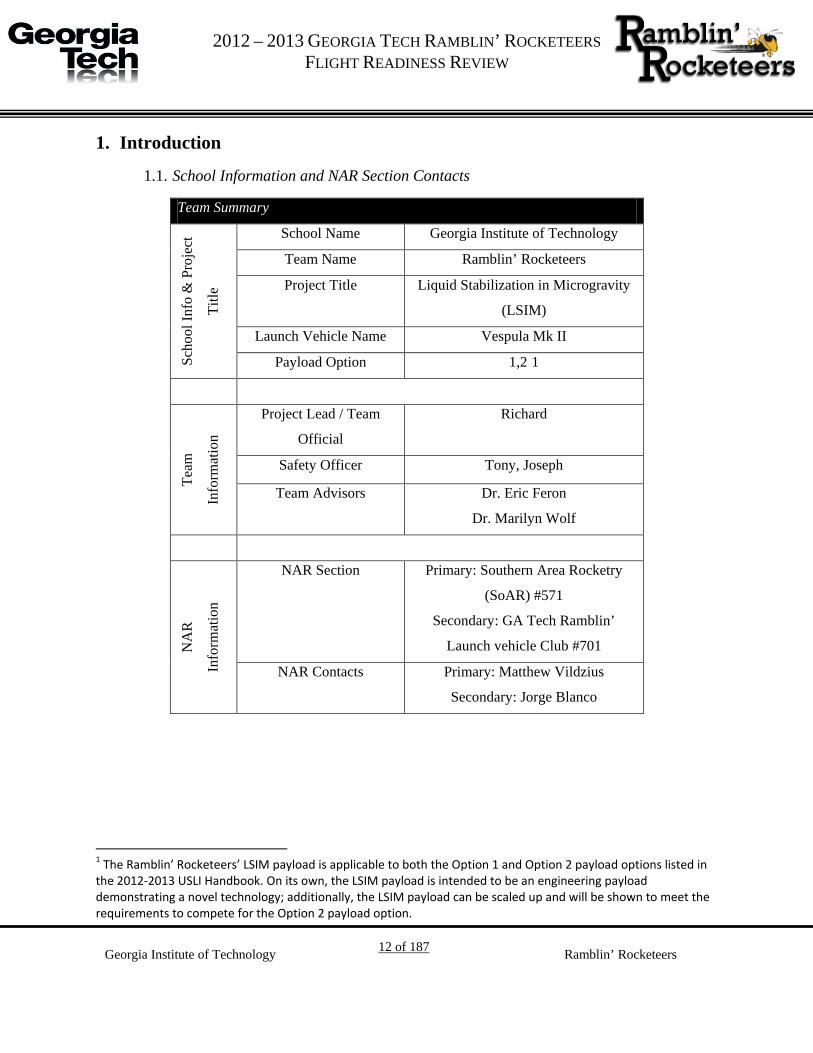
School Information and NAR Section Contacts 1.1.
Team Summary Sc
hool
Info
& P
roje
ct
Title
School Name Georgia Institute of Technology
Team Name Ramblin’ Rocketeers
Project Title Liquid Stabilization in Microgravity
(LSIM)
Launch Vehicle Name Vespula Mk II
Payload Option 1,2 0F1
Team
Info
rmat
ion
Project Lead / Team
Official
Richard
Safety Officer Tony, Joseph
Team Advisors Dr. Eric Feron
Dr. Marilyn Wolf
NA
R
Info
rmat
ion
NAR Section Primary: Southern Area Rocketry
(SoAR) #571
Secondary: GA Tech Ramblin’
Launch vehicle Club #701
NAR Contacts Primary: Matthew Vildzius
Secondary: Jorge Blanco
1 The Ramblin’ Rocketeers’ LSIM payload is applicable to both the Option 1 and Option 2 payload options listed in the 2012-2013 USLI Handbook. On its own, the LSIM payload is intended to be an engineering payload demonstrating a novel technology; additionally, the LSIM payload can be scaled up and will be shown to meet the requirements to compete for the Option 2 payload option.

G 2012 – 2013 GEORGIA TECH RAMBLIN’ ROCKETEERS
FLIGHT READINESS REVIEW
Georgia Institute of Technology 13 of 187 Ramblin’ Rocketeers
Work Breakdown Structure 1.2.
In order to effectively coordinate design efforts, the project is broken down along technical
discipline lines that emulate typical programs in the Aerospace industry. Each sub-team has a
general manager supported by several technical leads and subordinate members. Team
memberships were selected based on the individuals’ areas of expertise as well as personal
interest. Figure 1 shows the work breakdown structure.
Figure 1. 2012 – 2013 project work breakdown structure.

G 2012 – 2013 GEORGIA TECH RAMBLIN’ ROCKETEERS
FLIGHT READINESS REVIEW
Georgia Institute of Technology 14 of 187 Ramblin’ Rocketeers
Launch Vehicle Summary 1.3.
1.3.1. Overview
The Ramblin’ Rocketeers’ launch vehicle has a gross-lift off weight of approximately 45 pounds
and features a 75 mm L1350 solid motor. The launch vehicle is an Intimidator 5 kit with a
custom payload integration structure. The recovery system utilizes a 30” drogue parachute
slowing the launch vehicle down to 64.78 ft/s and a 120” main parachute to slow the launch
vehicle down to 15.12 ft/s.
1.3.2. Changes since CDR
The following changes have been made since the Preliminary Design Review:
• Due to several launch failures the custom Vespula Mk II vehicle design has been de-
scoped to the Intimidator 5 kit.
Payload Summary 1.4.
1.4.1. Overview
The Ramblin’ Rocketeers will design, build, test, and fly a system for damping liquid slosh
through the use of magnetorheological fluid. This fluid will be actuated with solenoids and
driven to a pre-defined state in the Liquid Stabilization in Microgravity (LSIM) experiment.
Further, Flight Systems will implement a network of SIDESboards for distributed sensor
networks, empowering LSIM, and collecting valuable engineering data. A substantial ground
station for observation and telemetry is planned to support the flight of the launch vehicle.
Additionally, the Ramblin’ Rocketeers will pursue the NASA payload options 1 and 2 in the
design, construction, testing, and flight of a primary science experiment and Reduced Gravity
Education Flight Program. This payload will test the feasibility and practicality of systems to
manipulate magnetorheological (MR) fluids in microgravity for the purpose of demonstrating
possible methods for reducing propellant slosh in low-gravity environments.
G 2012 – 2013 GEORGIA TECH RAMBLIN’ ROCKETEERS
FLIGHT READINESS REVIEW
Georgia Institute of Technology 15 of 187 Ramblin’ Rocketeers
1.4.2. Changes Since CDR
1.4.2.1. Payload Changes Since CDR
• All use of cameras for the science payload has been de-scoped.
1.4.2.2. Avionics Changes Since CDR
• Temperature and Strain Gauge nodes no longer necessary with switch from Vespulla MkII to Intimidator kit
• MasterIMU now uses a SIDESboard instead of a Maple, extra computing power not necessary because only two nodes use the SIDES network
• Master Clock node has been descoped, since there are only two nodes to synchronize • RS485 Hardware will use simplified control software reflecting the simplifications to the
SIDES network
Infrared will no longer be used as a primary means of measuring slosh in the experiment for the
launch vehicle. A camera independent of the avionics apparatus may be used – however the
primary sensor is seen to be a vibration sensor placed into the base bolt and integrated into a
SIDES node. The precise details of ground testing have been reviewed in depth and many
changes as to the specifics have been made as testing platforms have been developed. These
should result in high quality ground testing data. This data will be used to complete the final link
in an expanded theory describing MR fluid. While operating under several assumptions and
simplifications, this expanded theory should aid greatly in the development of control software
for the flight experiment.

G 2012 – 2013 GEORGIA TECH RAMBLIN’ ROCKETEERS
FLIGHT READINESS REVIEW
Georgia Institute of Technology 16 of 187 Ramblin’ Rocketeers
2. Project L.S.I.M. Overview
Mission Statement 2.1.
The mission of the Mile High Yellow Jackets is:
To maintain a sustainable team dedicated to the gaining of knowledge through the designing,
building, and launching of reusable launch vehicles with innovative payloads in accordance with
the NASA University Student Launch Initiative Guidelines.
Requirements Flow Down 2.2.
The requirements flow down is illustrated in Figure 2. As illustrated by the requirements flow
down, the Mission Success Criteria flow down from the Mission Objectives of Project A.P.E.S.
All system and sub-system level requirements flow down from the either of the Mission
Objectives, Mission Success Criteria, or the USLI Handbook.

G 2012 – 2013 GEORGIA TECH RAMBLIN’ ROCKETEERS
FLIGHT READINESS REVIEW
Georgia Institute of Technology 17 of 187 Ramblin’ Rocketeers
Mission Objectives and Mission Success Criteria 2.3.
Table 1. Mission Objectives and Mission Success Criteria for the L.S.I.M. mission
MO Mission Objective
MO-1 An altitude of 5,280 ft above the ground is achieved.
MO-2 Create an environment in which to test microgravity payloads.
MO-3 Reduction in the sloshing motion of a propellant simulatn in microgravity with a magnetic
fluid.
MO-4 Successful recovery of the launch vehicle resulting in no damage to the launch vehicle.
MSC Mission Success Criteria Source Verification
Method
MSC-1 Minimum Mission Succes: Achieve an altitude of
5,280 ft., with a tolerance of +320 ft./-640 ft. MO-1
Testing
MSC-2 Minimum Mission Succes: Achieve a microgravitiy
environment of ± 0.1 G MO-2
Testing
MSC-3 Minimum Mission Success:Sucessfully record video
of flight experiment during microgravity and start/stop
the experiment without mechanical and electrical
failures.
MO-3
Testing
MSC-4 Full Mission Succes: Successful matching of the
damping ratio for ringed baffles in the wave amplitudes
experienced during flight to within ±30%.
MO-3
Testing
MSC-5 Minimum Mission Success: The Launch Vehicle is
recovered with no damage to the structure of the launch
vehicle.
MO-4,USLI
Handbook 1.4
Testing
MSC-5.1 Full Mission Succes:The Launch Vehicle is recovered
with no damage to the skin of the launch vehicle.
MSC-7, MO-4 Testing
System Requirements Verification Matrix (RVM) 2.1.
Table 2, Table 3, and Table 4 list the requirements verification matrix for each subsystem.

G 2012 – 2013 GEORGIA TECH RAMBLIN’ ROCKETEERS
FLIGHT READINESS REVIEW
Georgia Institute of Technology 18 of 187 Ramblin’ Rocketeers
Table 2. Launch Vehicle RVM
Requirement
No. Requirement Source
Verification
Method
Design
Feature Status
LV-1
The Launch Vehicle
shall carry a
scientific or
engineering
payload.
USLI Handbook 1.1,
MO-2 Inspection
iMPS
standardized
payload
interface
In Progress
LV-1.1
The maximum
payload weight
including any
supporting avionics
shall not exceed 15
lbs.
LV-1 Inspection
Maximum
Parachute
Sizing
In Progress
LV-1.2
The Launch Vehicle
shall have a
maximum of four
(4) independent or
tethered sections
USLI Handbook 1.5 Inspection
Three (3)
sections:
nosecone,
payload, and
booster
In Progress
LV-2
The Launch Vehicle
shall carry the
payload to an
altitude of 5,280 ft.
above the ground.
USLI Handbook 1.1,
MO-1 Testing
Modified tube
fins for
straight flight,
motor sizing
In Progress

G 2012 – 2013 GEORGIA TECH RAMBLIN’ ROCKETEERS
FLIGHT READINESS REVIEW
Georgia Institute of Technology 19 of 187 Ramblin’ Rocketeers
Requirement
No. Requirement Source
Verification
Method
Design
Feature Status
LV-2.1
The Launch Vehicle
shall use a
commercially
available solid
motor using
ammonium
perchlorate
composite
propellant (APCP).
USLI Handbook
1.11 Inspection
Use of a
commercially
available
solid motor
In Progress
LV-2.2
The total impulse
provided by the
Launch Vehicle
shall not exceed
5,120 N-s.
USLI Handbook
1.12 Inspection
A motor with
a maximum
motor class of
"L" shall be
used
In Progress
LV-2.3
The Launch Vehicle
shall remain
subsonic throughout
the entire flight.
USLI Handbook 1.3 Analysis Motor Sizing In Progress
LV-2.4
The Launch Vehicle
shall carry one
commercially
available barometric
altimeter for
recording of the
official altitude
USLI Handbook 1.2 Inspection
Commercially
available
altimeter
In Progress

G 2012 – 2013 GEORGIA TECH RAMBLIN’ ROCKETEERS
FLIGHT READINESS REVIEW
Georgia Institute of Technology 20 of 187 Ramblin’ Rocketeers
Requirement
No. Requirement Source
Verification
Method
Design
Feature Status
LV-2.5
The amount of
ballast, in the
vehicle's final
configuration that
will be flown in
Huntsville, shall be
no more than 10%
of the unballasted
vehicle mass.
USLI Handbook
1.14 Inspection
Proper motor
selection for
gross lift-off
weight of the
launch
vehicle.
In Progress
LV-2.5
The Launch Vehicle
shall have
aerodynamic
stability margin of
1.5 to 3 cailbers
prior to leaving the
launch rail.
LV-2 Analysis
Modified
tube-fins for
aerodynamic
stabilization.
In Progress
LV-3
The Launch Vehicle
shall be safely
recovered and be
reusable.
MSC-7.1 Testing
Parachute
Sizing and
real time
Ground
Station
tracking
In Progress
LV-3.1
The Launch Vehicle
shall contain
redundant
altimeters.
USLI Handbook 2.5 Inspection
Ground
testing of
altimeter
ejection.
In Progress

G 2012 – 2013 GEORGIA TECH RAMBLIN’ ROCKETEERS
FLIGHT READINESS REVIEW
Georgia Institute of Technology 21 of 187 Ramblin’ Rocketeers
Requirement
No. Requirement Source
Verification
Method
Design
Feature Status
LV-3.2
The recovery
system shall be
designed to be
armed on the pad.
LV-3 Inspection Arming
Switches In Progress
LV-3.3
The recovery
system electronics
shall be completely
independent of the
payload electronics.
USLI Handbook 2.4 Inspection
The recovery
system
electronics
shall be
entirely
independent
of from all
other systems.
In Progress
LV-3.4
Each altimeter shall
be armed by a
dedicated arming
switch which is
accessible from the
exterior of the
vehicle airframe
when the vehicle is
in the launch
configuration on the
launch pad.
USLI Handbook 2.6 Inspection
Recovery
system design
shall
incorporate
one (1)
independent
arming switch
for each
altimeter
In Progress

G 2012 – 2013 GEORGIA TECH RAMBLIN’ ROCKETEERS
FLIGHT READINESS REVIEW
Georgia Institute of Technology 22 of 187 Ramblin’ Rocketeers
Requirement
No. Requirement Source
Verification
Method
Design
Feature Status
LV-3.5
Each altimeter shall
have a dedicated
power supply.
USLI Handbook 2.7 Inspection
Recovery
system design
shall
incorporate
independent
power
supplies for
each
altimeter.
In Progress
LV-3.6
Each arming switch
shall be capable of
being locked in the
"ON" position for
launch.
USLI Handbook 2.8 Testing
The arming
switches will
be designed to
use a key to
change the
state of the
switch.
In Progress
LV-3.7
Each arming switch
shall be a maximum
of six (6) feet above
the base of the
Launch Vehicle.
USLI Handbook 2.9 Inspection
Arming
switches shall
be located
near the
booster
section of the
launch
vehicle
In Progress
LV-3.8
The Launch Vehicle
shall utilize a dual
deployment
recovery system.
USLI Handbook 2.1 Inspection
Utilization of
a drogue and
main
parachute
In Progress

G 2012 – 2013 GEORGIA TECH RAMBLIN’ ROCKETEERS
FLIGHT READINESS REVIEW
Georgia Institute of Technology 23 of 187 Ramblin’ Rocketeers
Requirement
No. Requirement Source
Verification
Method
Design
Feature Status
LV-3.9
Removable shear
pins shall be used
for both the main
and drogue
parachute
compartments
USLI Handbook
2.10 Inspection
Plastic shear
pins will be
installed in
the recovery
compartments
.
In Progress
LV-3.10
All sections shall be
designed to recover
within 2,500 ft. of
the launch pad
assuming 15 MPH
winds.
USLI Handbook 2.3 Analysis
Parachute
sizing will
incorporate
descending
velocities and
drift
restrictions.
In Progress
LV-3.11
Each section of the
Launch Vehicle
shall have a
maximum landing
kinetic energy of 75
ft-lbf.
USLI Handbook 2.2 Analysis
Properly sized
main
parachute to
ensure
landing
kinetic
energies
below 75 ft.-
lbf
In Progress
G 2012 – 2013 GEORGIA TECH RAMBLIN’ ROCKETEERS
FLIGHT READINESS REVIEW
Georgia Institute of Technology 24 of 187 Ramblin’ Rocketeers
Requirement
No. Requirement Source
Verification
Method
Design
Feature Status
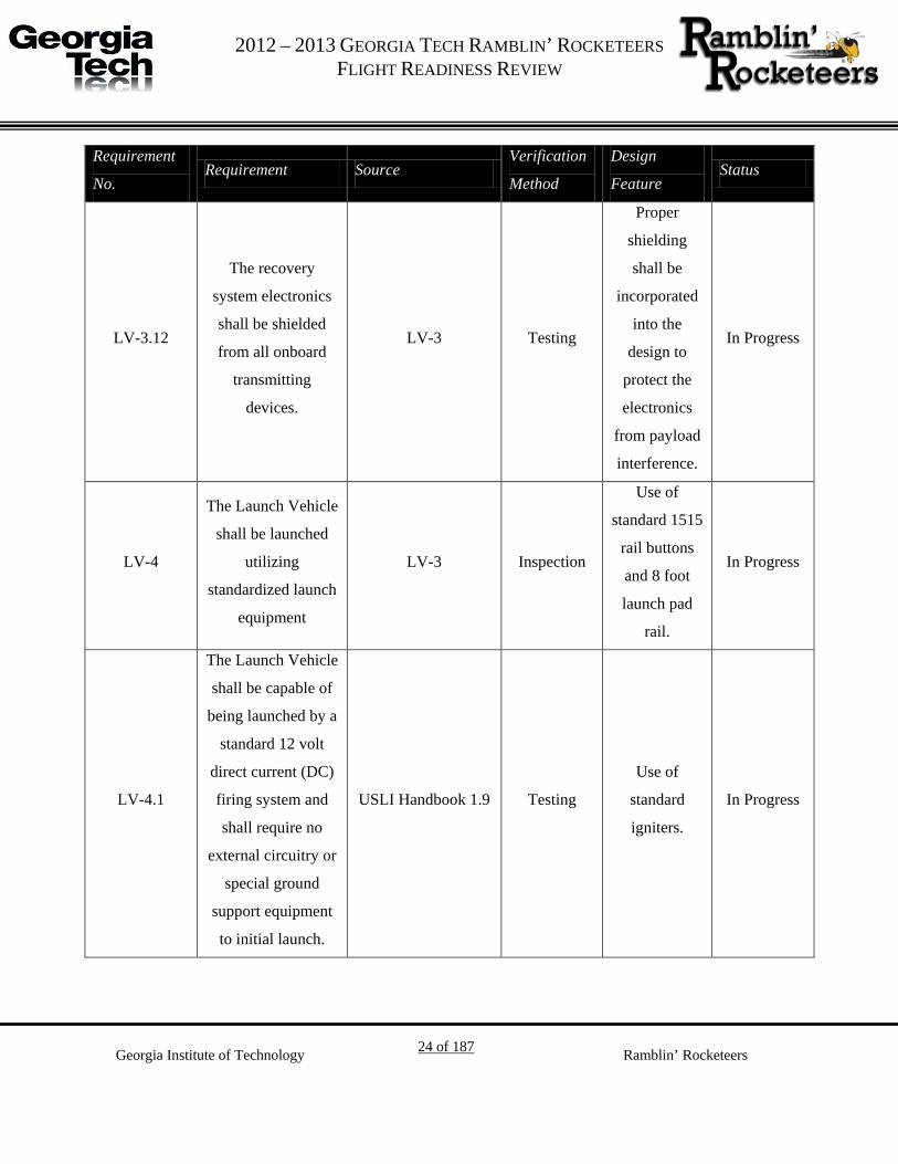
LV-3.12
The recovery
system electronics
shall be shielded
from all onboard
transmitting
devices.
LV-3 Testing
Proper
shielding
shall be
incorporated
into the
design to
protect the
electronics
from payload
interference.
In Progress
LV-4
The Launch Vehicle
shall be launched
utilizing
standardized launch
equipment
LV-3 Inspection
Use of
standard 1515
rail buttons
and 8 foot
launch pad
rail.
In Progress
LV-4.1
The Launch Vehicle
shall be capable of
being launched by a
standard 12 volt
direct current (DC)
firing system and
shall require no
external circuitry or
special ground
support equipment
to initial launch.
USLI Handbook 1.9 Testing
Use of
standard
igniters.
In Progress
G 2012 – 2013 GEORGIA TECH RAMBLIN’ ROCKETEERS
FLIGHT READINESS REVIEW
Georgia Institute of Technology 25 of 187 Ramblin’ Rocketeers
Requirement
No. Requirement Source
Verification
Method
Design
Feature Status
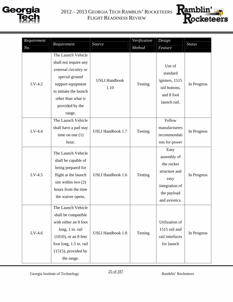
LV-4.2
The Launch Vehicle
shall not require any
external circuitry or
special ground
support equipment
to initiate the launch
other than what is
provided by the
range.
USLI Handbook
1.10 Testing
Use of
standard
igniters, 1515
rail buttons,
and 8 foot
launch rail.
In Progress
LV-4.4
The Launch Vehicle
shall have a pad stay
time on one (1)
hour.
USLI Handbook 1.7 Testing
Follow
manufacturers
recommendati
ons for power
In Progress
LV-4.5
The Launch Vehicle
shall be capable of
being prepared for
flight at the launch
site within two (2)
hours from the time
the waiver opens.
USLI Handbook 1.6 Testing
Easy
assembly of
the rocket
structure and
easy
integration of
the payload
and avionics.
In Progress
LV-4.6
The Launch Vehicle
shall be compatible
with either an 8 foot
long, 1 in. rail
(1010), or an 8 feet
foot long, 1.5 in. rail
(1515), provided by
the range.
USLI Handbook 1.8 Testing
Utilization of
1515 rail and
rail interfaces
for launch
In Progress

G 2012 – 2013 GEORGIA TECH RAMBLIN’ ROCKETEERS
FLIGHT READINESS REVIEW
Georgia Institute of Technology 26 of 187 Ramblin’ Rocketeers
Table 3. Flight Systems RVM
Requirement
Number
Requirement Definition Source Verification
Method
Design
Feature
Status Verification
Source
Document
FS-1 The flight systems team
shall design and build
the LSIM Payload MO-3 Inspection LSIM
payload In
Progress MO-3
FS-2 The LSIM payload shall
be designed to fly on a
SLP rocket
USLI Handbook
3.1.1 Inspection LSIM
payload In
Progress
USLI Handbook
3.1.1
FS-4 The Flight Systems
Team shall produce a
working system for
manipulating MR fluid
in LSIM.
MSC-3 Testing Solenoids
and Control Algorithms
In Progress MSC-3
FS-5 The Flight Systems
Team shall ensure that
all avionics are properly
shielded from the LSIM
payload.
MSC-3 Testing
Faraday cages and webbing tied to
ground on the harness
Not Started MSC-3
FS-6 The Flight Systems
Team shall design all
LSIM components and
avionics such that they
may be easily integrated
with the Modular
Payload System of the
payload bay in the
rocket.
MSC-3 Inspection Mounting system Complete MSC-3

G 2012 – 2013 GEORGIA TECH RAMBLIN’ ROCKETEERS
FLIGHT READINESS REVIEW
Georgia Institute of Technology 27 of 187 Ramblin’ Rocketeers
Requirement
Number
Requirement Definition Source Verification
Method
Design
Feature
Status Verification
Source
Document
FS-7 The Flight Systems
Team shall conform to
all weight, power, and
dimensional
requirements as per the
rocket design.
MSC-3 Analysis TBD In Progress MSC-3
FS-7.1 The Experiment and
Avionics, with
mechanical supports,
shall weight no more
than 15 lbf.
LV-1.1 Inspection TBD In Progress LV-1.1
FS-8 The flight computer
shall execute all tasks
necessary to the
operation of the LSIM
payload and avionics.
MSC-3 Inspection Maple SIDES node
In Progress MSC-3
FS-9 The LSIM payload shall
have a dedicated power
supply. MSC-3 Inspection SIDES node In
Progress MSC-3
FS-10 The Flight Systems
Team shall ensure
redundancy and
reliability of all internal
electrical hardware.
MSC-3 Inspection SIDES network
In Progress MSC-3

G 2012 – 2013 GEORGIA TECH RAMBLIN’ ROCKETEERS
FLIGHT READINESS REVIEW
Georgia Institute of Technology 28 of 187 Ramblin’ Rocketeers
Requirement
Number
Requirement Definition Source Verification
Method
Design
Feature
Status Verification
Source
Document
FS-11 The Flight Systems
Team shall provide for
payload operation with
up to 1 hour of wait on
the launch pad and 2
hours of wait during
preparation of the
Rocket.
USLI Handbook
1.6 Inspection TBD In
Progress
USLI Handbook
1.6
FS-12 The Flight Systems
Team shall provide for
electrical operations to
begin at the beginning
of the flight trajectory.
MSC-3 Inspection TBD In Progress MSC-3
FS-13 The Flight Systems
Team shall ensure that
the LSIM payload is
shut down safely during
the deployment phase of
the flight trajectory.
MSC-3 Inspection TBD In Progress MSC-3
FS-14 Data from the LSIM
payload shall be
collected, analyzed, and
reported by the team
using the scientific
method.
USLI Handbook
3.2 Inspection
Data logging in
SIDES network
In Progress
USLI Handbook
3.2
G 2012 – 2013 GEORGIA TECH RAMBLIN’ ROCKETEERS
FLIGHT READINESS REVIEW
Georgia Institute of Technology 29 of 187 Ramblin’ Rocketeers
Requirement
Number
Requirement Definition Source Verification
Method
Design
Feature
Status Verification
Source
Document
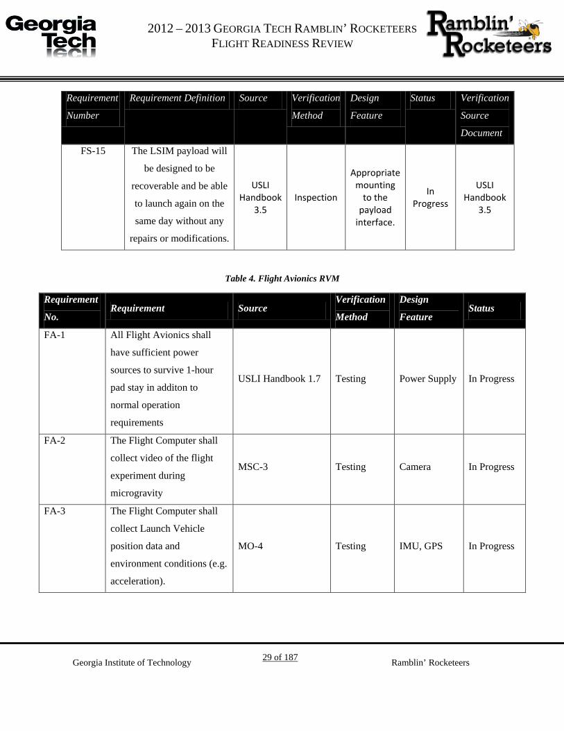
FS-15 The LSIM payload will
be designed to be
recoverable and be able
to launch again on the
same day without any
repairs or modifications.
USLI Handbook
3.5 Inspection
Appropriate mounting
to the payload
interface.
In Progress
USLI Handbook
3.5
Table 4. Flight Avionics RVM
Requirement
No. Requirement Source
Verification
Method
Design
Feature Status
FA-1 All Flight Avionics shall
have sufficient power
sources to survive 1-hour
pad stay in additon to
normal operation
requirements
USLI Handbook 1.7 Testing Power Supply In Progress
FA-2 The Flight Computer shall
collect video of the flight
experiment during
microgravity
MSC-3 Testing Camera In Progress
FA-3 The Flight Computer shall
collect Launch Vehicle
position data and
environment conditions (e.g.
acceleration).
MO-4 Testing IMU, GPS In Progress

G 2012 – 2013 GEORGIA TECH RAMBLIN’ ROCKETEERS
FLIGHT READINESS REVIEW
Georgia Institute of Technology 30 of 187 Ramblin’ Rocketeers
Requirement
No. Requirement Source
Verification
Method
Design
Feature Status
FA-4 The Flight Avionics shall
downlink telemetry
necessary to a Ground
Station for the recovery of
the Launch Vehicle
USLI Handbook
2.11 Teting
GPS, Ground
Station, Xbee In Progress
FA-5 The GPS coordinates of all
independent Launch Vehicle
sections shall be transmitted
to the Ground Station
USLI Handbook
2.11.1 Teting
GPS, Ground
Station, Xbee In Progress
FA-6 The Flight Avionics shall
operate on an independent
power supply from the
recovery system.
USLI Handbook
2.12 Inspection Power Supply In Progress
Mission Profile 2.1.
Figure 3 illustrates the mission profile for Project L.S.I.M. In order to achieve the desired
microgravity environment, the launch vehicle will continue through for one (1) second until
deployment of the drogue parachute. This post-apogee delay will yield approximate 4.5 seconds
of microgravity to perform the L.S.I.M.

G 2012 – 2013 GEORGIA TECH RAMBLIN’ ROCKETEERS FLIGHT READINESS REVIEW
Georgia Institute of Technology 31 of 187 Ramblin’ Rocketeers
Figure 3. Project L.S.I.M. mission profile.

G 2012 – 2013 GEORGIA TECH RAMBLIN’ ROCKETEERS
FLIGHT READINESS REVIEW
Georgia Institute of Technology 32 of 187 Ramblin’ Rocketeers
3. Launch Vehicle
Overview 3.1.
The purpose of the launch vehicle is to carry a scientific payload to one mile in altitude and
safely return the vehicle to the surface of the Earth. Embracing innovative and out-of-the-box
thinking, the Ramblin’ Rocketeers launch vehicle will have the ability to carry a wide range of
payloads, from scientific experiments to engineering flight demonstrations. A rib and stringer
payload mounting rig enables easy integration for payload. The launch vehicle has a five inch
outer diameter and is 9 feet, 10 inches in length. The launch vehicle is composed of three
sections; the nose cone, the payload section, and the booster section. The science payload will be
housed in the payload section of the rocket and the avionics will be housed in the booster section
above the motor.
The launch vehicle will utilize a dual-deployment recovery system that will minimize the drift of
the launch vehicle by mitigating the effects of unpredictable wind conditions with a drogue chute
descent. However, the overall purpose of the recovery system, to minimize damage to the launch
vehicle from impact with the ground, will be maintained by a main chute deployed closer to the
ground. The drogue parachute will be housed in the section connecting the booster and payload
sections, while the main parachute will be located between the payload section and nose cone.
Both parachutes are made of rip-stop nylon. To ensure successful chute deployment, redundant
systems will be used. Each chute will feature two independent black powder ejection charges
with corresponding redundant igniters and StratoLogger altimeters. The powder charges will be
ignited using low-current electronic matches with independent power supplies at the command of
the altimeters.
3.1.1. Mission Criteria
The criteria for mission success are shown in Table 3.

G 2012 – 2013 GEORGIA TECH RAMBLIN’ ROCKETEERS
FLIGHT READINESS REVIEW
Georgia Institute of Technology 33 of 187 Ramblin’ Rocketeers
Table 5: Mission Success Criteria
Requirement Design feature to satisfy that
requirement
Requirement
Verification Success Criteria
Provide a suitable
environment for the
payload.
The payload requires a steady, but
randomly vibrating platform to
test the L.S.I.M. system.
Unsteadiness in the motor's thrust
and launch vehicle aerodynamics
cause vibrations. In addition,
deployment of the drogue
parachute will be delayed one
second to maximize time in
microgravity.
By measuring the
acceleration with the
payload's
accelerometers.
The L.S.I.M.
system reduces a
recordable amount
of sloshing.
To fly as close to a
mile in altitude as
possible without
exceeding 5,600 ft.
A motor will be chosen to propel
the vehicle to a mile in altitude.
Through the use of
barometric
altimeters.
The altimeters
record an altitude
less than 5,600 ft.
The vehicle must be
reusable.
The structure will be robust
enough to handle any loading
encountered during the flight.
Through finite
element analyses
and structural
ground testing of
components.
The vehicle
survives the flight
with no damage.
System Design Overview 3.2.
lists the derived system-level requirements in order to meet the success criteria. The requirement
numbers reference the requirements in the 2012-2013 USLI Handbook.
G 2012 – 2013 GEORGIA TECH RAMBLIN’ ROCKETEERS
FLIGHT READINESS REVIEW
Georgia Institute of Technology 34 of 187 Ramblin’ Rocketeers
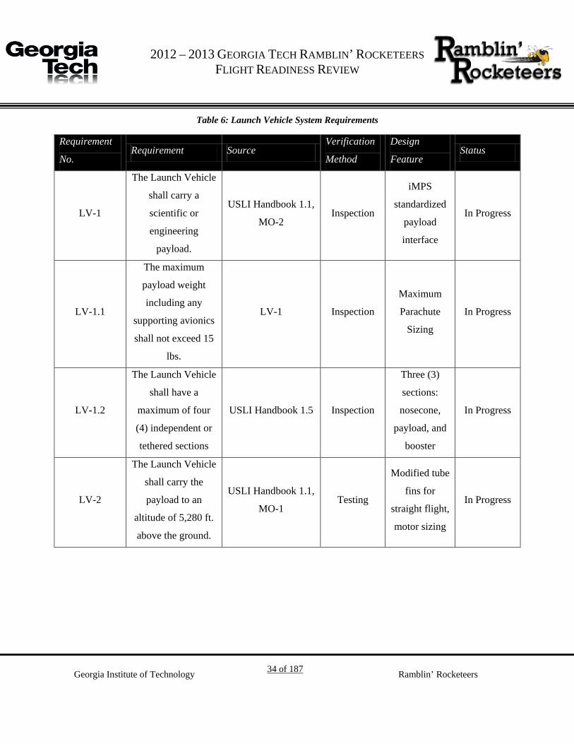
Table 6: Launch Vehicle System Requirements
Requirement
No. Requirement Source
Verification
Method
Design
Feature Status
LV-1
The Launch Vehicle
shall carry a
scientific or
engineering
payload.
USLI Handbook 1.1,
MO-2 Inspection
iMPS
standardized
payload
interface
In Progress
LV-1.1
The maximum
payload weight
including any
supporting avionics
shall not exceed 15
lbs.
LV-1 Inspection
Maximum
Parachute
Sizing
In Progress
LV-1.2
The Launch Vehicle
shall have a
maximum of four
(4) independent or
tethered sections
USLI Handbook 1.5 Inspection
Three (3)
sections:
nosecone,
payload, and
booster
In Progress
LV-2
The Launch Vehicle
shall carry the
payload to an
altitude of 5,280 ft.
above the ground.
USLI Handbook 1.1,
MO-1 Testing
Modified tube
fins for
straight flight,
motor sizing
In Progress

G 2012 – 2013 GEORGIA TECH RAMBLIN’ ROCKETEERS
FLIGHT READINESS REVIEW
Georgia Institute of Technology 35 of 187 Ramblin’ Rocketeers
Requirement
No. Requirement Source
Verification
Method
Design
Feature Status
LV-2.1
The Launch Vehicle
shall use a
commercially
available solid
motor using
ammonium
perchlorate
composite
propellant (APCP).
USLI Handbook
1.11 Inspection
Use of a
commercially
available
solid motor
In Progress
LV-2.2
The total impulse
provided by the
Launch Vehicle
shall not exceed
5,120 N-s.
USLI Handbook
1.12 Inspection
A motor with
a maximum
motor class of
"L" shall be
used
In Progress
LV-2.3
The Launch Vehicle
shall remain
subsonic throughout
the entire flight.
USLI Handbook 1.3 Analysis Motor Sizing In Progress
LV-2.4
The Launch Vehicle
shall carry one
commercially
available barometric
altimeter for
recording of the
official altitude
USLI Handbook 1.2 Inspection
Commercially
available
altimeter
In Progress

G 2012 – 2013 GEORGIA TECH RAMBLIN’ ROCKETEERS
FLIGHT READINESS REVIEW
Georgia Institute of Technology 36 of 187 Ramblin’ Rocketeers
Requirement
No. Requirement Source
Verification
Method
Design
Feature Status
LV-2.5
The amount of
ballast, in the
vehicle's final
configuration that
will be flown in
Huntsville, shall be
no more than 10%
of the unballasted
vehicle mass.
USLI Handbook
1.14 Inspection
Proper motor
selection for
gross lift-off
weight of the
launch
vehicle.
In Progress
LV-2.5
The Launch Vehicle
shall have
aerodynamic
stability margin of
1.5 to 3 cailbers
prior to leaving the
launch rail.
LV-2 Analysis
Modified
tube-fins for
aerodynamic
stabilization.
In Progress
LV-3
The Launch Vehicle
shall be safely
recovered and be
reusable.
MSC-7.1 Testing
Parachute
Sizing and
real time
Ground
Station
tracking
In Progress
LV-3.1
The Launch Vehicle
shall contain
redundant
altimeters.
USLI Handbook 2.5 Inspection
Ground
testing of
altimeter
ejection.
In Progress

G 2012 – 2013 GEORGIA TECH RAMBLIN’ ROCKETEERS
FLIGHT READINESS REVIEW
Georgia Institute of Technology 37 of 187 Ramblin’ Rocketeers
Requirement
No. Requirement Source
Verification
Method
Design
Feature Status
LV-3.2
The recovery
system shall be
designed to be
armed on the pad.
LV-3 Inspection Arming
Switches In Progress
LV-3.3
The recovery
system electronics
shall be completely
independent of the
payload electronics.
USLI Handbook 2.4 Inspection
The recovery
system
electronics
shall be
entirely
independent
of from all
other systems.
In Progress
LV-3.4
Each altimeter shall
be armed by a
dedicated arming
switch which is
accessible from the
exterior of the
vehicle airframe
when the vehicle is
in the launch
configuration on the
launch pad.
USLI Handbook 2.6 Inspection
Recovery
system design
shall
incorporate
one (1)
independent
arming switch
for each
altimeter
In Progress

G 2012 – 2013 GEORGIA TECH RAMBLIN’ ROCKETEERS
FLIGHT READINESS REVIEW
Georgia Institute of Technology 38 of 187 Ramblin’ Rocketeers
Requirement
No. Requirement Source
Verification
Method
Design
Feature Status
LV-3.5
Each altimeter shall
have a dedicated
power supply.
USLI Handbook 2.7 Inspection
Recovery
system design
shall
incorporate
independent
power
supplies for
each
altimeter.
In Progress
LV-3.6
Each arming switch
shall be capable of
being locked in the
"ON" position for
launch.
USLI Handbook 2.8 Testing
The arming
switches will
be designed to
use a key to
change the
state of the
switch.
In Progress
LV-3.7
Each arming switch
shall be a maximum
of six (6) feet above
the base of the
Launch Vehicle.
USLI Handbook 2.9 Inspection
Arming
switches shall
be located
near the
booster
section of the
launch
vehicle
In Progress

G 2012 – 2013 GEORGIA TECH RAMBLIN’ ROCKETEERS
FLIGHT READINESS REVIEW
Georgia Institute of Technology 39 of 187 Ramblin’ Rocketeers
Requirement
No. Requirement Source
Verification
Method
Design
Feature Status
LV-3.8
The Launch Vehicle
shall utilize a dual
deployment
recovery system.
USLI Handbook 2.1 Inspection
Utilization of
a drogue and
main
parachute
In Progress
LV-3.9
Removable shear
pins shall be used
for both the main
and drogue
parachute
compartments
USLI Handbook
2.10 Inspection
Plastic shear
pins will be
installed in
the recovery
compartments
.
In Progress
LV-3.10
All sections shall be
designed to recover
within 2,500 ft. of
the launch pad
assuming 15 MPH
winds.
USLI Handbook 2.3 Analysis
Parachute
sizing will
incorporate
descending
velocities and
drift
restrictions.
In Progress
LV-3.11
Each section of the
Launch Vehicle
shall have a
maximum landing
kinetic energy of 75
ft-lbf.
USLI Handbook 2.2 Analysis
Properly sized
main
parachute to
ensure
landing
kinetic
energies
below 75 ft.-
lbf
In Progress

G 2012 – 2013 GEORGIA TECH RAMBLIN’ ROCKETEERS
FLIGHT READINESS REVIEW
Georgia Institute of Technology 40 of 187 Ramblin’ Rocketeers
Requirement
No. Requirement Source
Verification
Method
Design
Feature Status
LV-3.12
The recovery
system electronics
shall be shielded
from all onboard
transmitting
devices.
LV-3 Testing
Proper
shielding
shall be
incorporated
into the
design to
protect the
electronics
from payload
interference.
In Progress
LV-4
The Launch Vehicle
shall be launched
utilizing
standardized launch
equipment
LV-3 Inspection
Use of
standard 1515
rail buttons
and 8 foot
launch pad
rail.
In Progress
LV-4.1
The Launch Vehicle
shall be capable of
being launched by a
standard 12 volt
direct current (DC)
firing system and
shall require no
external circuitry or
special ground
support equipment
to initial launch.
USLI Handbook 1.9 Testing
Use of
standard
igniters.
In Progress

G 2012 – 2013 GEORGIA TECH RAMBLIN’ ROCKETEERS
FLIGHT READINESS REVIEW
Georgia Institute of Technology 41 of 187 Ramblin’ Rocketeers
Requirement
No. Requirement Source
Verification
Method
Design
Feature Status
LV-4.2
The Launch Vehicle
shall not require any
external circuitry or
special ground
support equipment
to initiate the launch
other than what is
provided by the
range.
USLI Handbook
1.10 Testing
Use of
standard
igniters, 1515
rail buttons,
and 8 foot
launch rail.
In Progress
LV-4.4
The Launch Vehicle
shall have a pad stay
time on one (1)
hour.
USLI Handbook 1.7 Testing
Follow
manufacturers
recommendati
ons for power
In Progress
LV-4.5
The Launch Vehicle
shall be capable of
being prepared for
flight at the launch
site within two (2)
hours from the time
the waiver opens.
USLI Handbook 1.6 Testing
Easy
assembly of
the rocket
structure and
easy
integration of
the payload
and avionics.
In Progress

G 2012 – 2013 GEORGIA TECH RAMBLIN’ ROCKETEERS
FLIGHT READINESS REVIEW
Georgia Institute of Technology 42 of 187 Ramblin’ Rocketeers
Requirement
No. Requirement Source
Verification
Method
Design
Feature Status
LV-4.6
The Launch Vehicle
shall be compatible
with either an 8 foot
long, 1 in. rail
(1010), or an 8 feet
foot long, 1.5 in. rail
(1515), provided by
the range.
USLI Handbook 1.8 Testing
Utilization of
1515 rail and
rail interfaces
for launch
In Progress
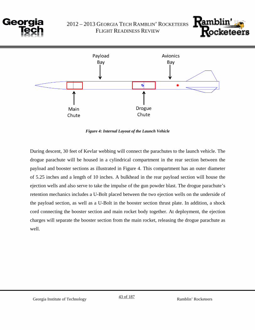
Recovery System 3.3.
The purpose of the recovery system is to minimize damage to the launch vehicle from impact
with the ground. The launch vehicle will use a dual-deployment recovery system to mitigate the
effects of unpredictable wind conditions on drift with a drogue chute descent. The drogue
parachute will be housed in the compartment connecting the booster and payload sections, and
the main parachute will be located between the payload section and nose cone, as illustrated
below in Figure 4. The launch vehicle will be armed on the launch pad using two arming
switches, one for each independent altimeter and ejection charge. For the purpose of simulation,
the launch vehicle has been modeled using the Open Rocket Software, with both parachutes
made of rip-stop nylon.
G 2012 – 2013 GEORGIA TECH RAMBLIN’ ROCKETEERS
FLIGHT READINESS REVIEW
Georgia Institute of Technology 43 of 187 Ramblin’ Rocketeers
Figure 4: Internal Layout of the Launch Vehicle
During descent, 30 feet of Kevlar webbing will connect the parachutes to the launch vehicle. The
drogue parachute will be housed in a cylindrical compartment in the rear section between the
payload and booster sections as illustrated in Figure 4. This compartment has an outer diameter
of 5.25 inches and a length of 10 inches. A bulkhead in the rear payload section will house the
ejection wells and also serve to take the impulse of the gun powder blast. The drogue parachute’s
retention mechanics includes a U-Bolt placed between the two ejection wells on the underside of
the payload section, as well as a U-Bolt in the booster section thrust plate. In addition, a shock
cord connecting the booster section and main rocket body together. At deployment, the ejection
charges will separate the booster section from the main rocket, releasing the drogue parachute as
well.

G 2012 – 2013 GEORGIA TECH RAMBLIN’ ROCKETEERS
FLIGHT READINESS REVIEW
Georgia Institute of Technology 44 of 187 Ramblin’ Rocketeers
Figure 5: Drogue Parachute Assembly
The main parachute will be placed in a section above the payload bay. The section has an outer
diameter of 5.25 inches and a length of 12 inches. The main parachute’s ejection wells will be
placed such that the impulse is imparted on the payload section and the nose cone is separated
from the main rocket – pulling the main parachute out. Shock cords will connect the main
parachute to the nose cone and the payload section of the launch vehicle, ensuring that the all
sections remain together during descent. The main parachute assembly is illustrated in Figure 6.

G 2012 – 2013 GEORGIA TECH RAMBLIN’ ROCKETEERS
FLIGHT READINESS REVIEW
Georgia Institute of Technology 45 of 187 Ramblin’ Rocketeers
Figure 6: Main Parachute Assembly
The parachute casings are made of G10 fiberglass, and the bulkhead under the main chute is
made of plywood. Two-inch stainless steel U-Bolts will be drilled into the bulkheads, and will be
used to attach the shock cords. 1/16” nylon rod will be used as the four shear pins to keep both
the main and drogue chute compartments together during flight until the parachutes are
deployed. PVC end-caps will be used to direct the ejection charges in order to protect the casing
from thermal shock, and a NOMEX shield will protect the parachutes. The charges will be
ignited using an e-match.
3.3.1. Altimeters
To ensure successful chute deployment, redundant systems will be used. Each chute will feature
two independent black powder ejection charges with corresponding redundant igniters and
StratoLogger altimeters. The altimeters will ignite the ejection charges through the use of low-
current electronic matches using independent power supplies. The components which compose
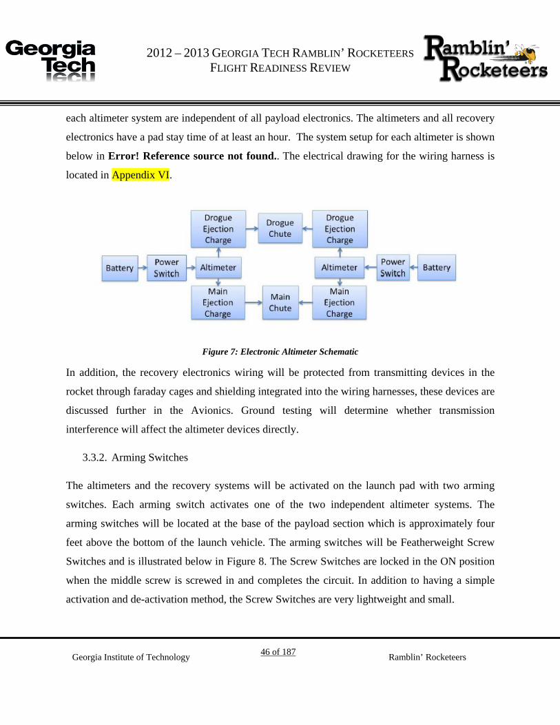
G 2012 – 2013 GEORGIA TECH RAMBLIN’ ROCKETEERS
FLIGHT READINESS REVIEW
Georgia Institute of Technology 46 of 187 Ramblin’ Rocketeers
each altimeter system are independent of all payload electronics. The altimeters and all recovery
electronics have a pad stay time of at least an hour. The system setup for each altimeter is shown
below in Error! Reference source not found.. The electrical drawing for the wiring harness is
located in Appendix VI.
Figure 7: Electronic Altimeter Schematic
In addition, the recovery electronics wiring will be protected from transmitting devices in the
rocket through faraday cages and shielding integrated into the wiring harnesses, these devices are
discussed further in the Avionics. Ground testing will determine whether transmission
interference will affect the altimeter devices directly.
3.3.2. Arming Switches
The altimeters and the recovery systems will be activated on the launch pad with two arming
switches. Each arming switch activates one of the two independent altimeter systems. The
arming switches will be located at the base of the payload section which is approximately four
feet above the bottom of the launch vehicle. The arming switches will be Featherweight Screw
Switches and is illustrated below in Figure 8. The Screw Switches are locked in the ON position
when the middle screw is screwed in and completes the circuit. In addition to having a simple
activation and de-activation method, the Screw Switches are very lightweight and small.

G 2012 – 2013 GEORGIA TECH RAMBLIN’ ROCKETEERS
FLIGHT READINESS REVIEW
Georgia Institute of Technology 47 of 187 Ramblin’ Rocketeers
Figure 8: Featherweight Screw Switches
3.3.3. Parachute Dimensions
The sizing of the main parachute is determined by the weight of the launch vehicle and the
kinetic energy constraint of the launch vehicle when it touches down. Based on the LV-3.10 and
LV-3.11 requirements, the launch vehicle should not experience more than 75.0 ft-lbf of kinetic
energy upon landing, this places an upper limit on the landing velocity to be approximately 15.12
ft/s. The main parachute is 12 feet and the drogue parachute is two feet.
Table 7 and Table 8 outline the dimensions and properties of the constraining launch vehicle
properties and the properties of the parachutes.

G 2012 – 2013 GEORGIA TECH RAMBLIN’ ROCKETEERS
FLIGHT READINESS REVIEW
Georgia Institute of Technology 48 of 187 Ramblin’ Rocketeers
Table 7: Launch Vehicles Properties
Launch Vehicle Properties
Weight of launch vehicle 45 lb
CD of Launch vehicle 0.75
Max Kinetic Energy 75.0 ft-lbf
Table 8: Recovery System Properties
Properties Main Parachute Drogue Parachute
Diameter (ft) 12 2
Surface Area (ft^2) 113.10 3.14
Estimated CD 1.40 1.20
Target Descent Rate (ft/s) 13.75 89.11
3.3.4. Drift Profile Analysis
Drift profile analysis is the method used to estimate and constrain the landing site for the launch
vehicle. Based on how long the launch vehicle will be in flight and the wind speed at launch, the
range can be estimated. Using the equations below, the drift of the launch vehicle under the main
and drogue parachutes can be determined. The results are shown below in Table 9
𝐷𝑟𝑖𝑓𝑡 = 𝑇𝑖𝑚𝑒𝑖𝑛 𝑓𝑙𝑖𝑔ℎ𝑡 ∗ 𝑉𝑤𝑖𝑛𝑑 (1)
𝑇𝑖𝑚𝑒𝑖𝑛 𝑓𝑙𝑖𝑔ℎ𝑡 =
𝐴𝑙𝑡𝑚𝑎𝑥
𝑑𝑒𝑠𝑐𝑒𝑛𝑡 𝑠𝑝𝑒𝑒𝑑 (2)
𝑑𝑒𝑠𝑐𝑒𝑛𝑡 𝑣𝑒𝑙𝑜𝑐𝑖𝑡𝑦 = �
2𝑚𝑔𝜌𝐴𝐶𝑑
(3)

G 2012 – 2013 GEORGIA TECH RAMBLIN’ ROCKETEERS
FLIGHT READINESS REVIEW
Georgia Institute of Technology 49 of 187 Ramblin’ Rocketeers
Table 9: Drift Estimates
Launch Vehicle Drift Estimates
Wind Speed (mph)
Drift (ft)
Drogue Parachute Main Parachute Total Drift 5 393.35 266.65 660.01
10 786.70 533.31 1320.01
15 1180.06 799.96 1980.02
20 2018.18 1216.11 3234.29
The descent velocity of the launch vehicle will be estimated using the terminal velocity. The
terminal velocity is the constant speed of a free-falling object when the drag due to air resistance
prevents further acceleration. The values are listed below in Table 10.
Table 10: Recovery Characteristics
Recovery Systems Properties Drogue Parachute Main Parachute
Diameter (ft) 2.00 Dimensions (ft) 12.00
Flight Time (s) 53.64 Flight Time (s) 36.36
Terminal
Velocity (ft/s) 89.11
Terminal
Velocity (ft/s) 13.75
Horizontal
Drift (ft) 1180.06
Horizontal
Drift (ft) 799.96
Total Drift (ft) 1980.02

G 2012 – 2013 GEORGIA TECH RAMBLIN’ ROCKETEERS
FLIGHT READINESS REVIEW
Georgia Institute of Technology 50 of 187 Ramblin’ Rocketeers
3.3.5. Kinetic Energy of Launch Vehicle
Kinetic energy calculations were performed using the equation below.
𝐾𝐸 =12𝑚𝑣2 (4)
Using the masses of the separate sections, the kinetic energies can be calculated using the
velocity of the system at different points in the mission. The Kinetic Energies of separate
sections after the drogue chute is deployed are given below in Table 11. After the drogue chute is
deployed, the launch vehicle has separated only between the booster section and the payload
section, so the payload and nosecone sections are treated as one part. The velocities listed are the
terminal velocities under the drogue parachute once the
Table 11: Kinetic Energy at Drogue Parachute Deployment
Launch Vehicle Section Weight (lb.) Velocity (ft/s) Kinetic Energy (ft-lbf)
Nose Cone 1.59 89.11 196.07
Payload 16.45 89.11 2028.51
Booster 19.61 89.11 2418.18
The Kinetic Energies of the separate sections after the deployment of the main chute and landing
are given below in Table 12. After the main chute is deployed all three sections have separated
and their separate masses were used in the calculations. All sections will have the same velocity
due to the shock cord tethers.

G 2012 – 2013 GEORGIA TECH RAMBLIN’ ROCKETEERS
FLIGHT READINESS REVIEW
Georgia Institute of Technology 51 of 187 Ramblin’ Rocketeers
Table 12 : Kinetic Energy at Main Parachute Deployment
Launch Vehicle Section Weight (lb.) Velocity (ft/s) Kinetic Energy (ft-lbf)
Nose Cone 1.59 13.75 4.67
Payload 16.45 13.75 48.30
Booster 19.61 13.75 57.58
3.3.6. Ejection Charges
To eject the parachutes, redundant black powder charges will be used. The containers housing
the chutes will also be pressurized in order to ensure chute deployment. Due to the different
requirements for the drogue and main chutes, two sets of calculations will be needed.
The amount of black powder used in the ejections charges can be calculated through Equation
(5) below. Once the amount of black powder is determined the values can then be tested before
flight. The equation relates weight of black powder to the ejection pressure, volume of the
container, black powder combustion gas constant, and the black powder combustion temperature.
The constants used are listed below in Table 13.
𝑙𝑏 𝑜𝑓 𝐵𝑙𝑎𝑐𝑘 𝑃𝑜𝑤𝑑𝑒𝑟 =
𝑃𝑟𝑒𝑠𝑠𝑢𝑟𝑒 ∗ 𝑉𝑜𝑙𝑢𝑚𝑒𝑅𝑇
(5)
Using the pressurization of 10 psig and 9 psig as a structural maximum for the main and drogue
chute compartments, the resulting black powder masses are calculated to be 5 grams and 2 grams
for the main and drogue chutes, respectively, as illustrated below in Table 14. The masses used
will depend on the final container dimensions, which were estimated at 5.25 inches in radius and
12 and 10 inches in length for the main and drogue, respectively. The force required for
separation with the given number of Nylon shear pins would be 446 lbf for the main chute and
393 lbf for the drogue chute.

G 2012 – 2013 GEORGIA TECH RAMBLIN’ ROCKETEERS
FLIGHT READINESS REVIEW
Georgia Institute of Technology 52 of 187 Ramblin’ Rocketeers
Table 13: Black Powder Properties
Constant Value
Combustion Gas
Constant 22.16 ft lbf/ lbm °R
Combustion
Temperature 3307 °R
Table 14: Black Powder Masses
Main Drogue
Total
Pressurization 10 psig 9 psig
Ejection force 446lbf 393lbf
Black Powder 5 grams 2 gram
3.3.7. Testing
In order to ensure the safety and viability of the calculations made in determining the black
powder masses, ground testing was completing before flying the launch vehicle recovery system.
The black powder testing was successfully conducted on the Vespula Mk II rocket. Since the
recovery sections of the Intimidator 5 kit and the Vespula Mk II are identical, the recovery
system of the Intimidator 5 kit is validated.
Due to the explosive nature of black powder charge testing, the tests for this launch vehicle were
coordinated with the campus security and the Georgia Tech Fire Marshal. For the black powder
test, the rocket was placed horizontally on the ground on a relatively smooth surface to minimize
unwanted static friction irrelevant to a flight environment. Table 15 lists the conditions for test
success and failure.

G 2012 – 2013 GEORGIA TECH RAMBLIN’ ROCKETEERS
FLIGHT READINESS REVIEW
Georgia Institute of Technology 53 of 187 Ramblin’ Rocketeers
Table 15: Success Criteria
Success Criteria
Ejection charge ignites
Shear pins break
Launch vehicle moves half the distance of shock cord
Table 16: Failure Modes
Failure Criteria
The fiberglass of the tube coupler shatters due to the charge.
The shear pins don’t shear, and the launch vehicle stays intact.
The NOMEX/cloth shield fails and the parachute is burned.
The E-matches fail to ignite the black powder.
Structure 3.4.
The purpose of the launch vehicle is to carry a microgravity research payload to a mile in altitude
and safely return to the surface of the Earth. Additionally, the launch vehicle will also be
designed to carry a wide range of possible experiments, so that the rocket can be reused in the
future. The overall design is to be as flexible as possible, encouraging reuse for future research
and multiple launches. The rocket has been constructed and is ready for a test launch scheduled
for Saturday, March 23rd. The objective of the test launch is to verify the recovery system with
delayed apogee ejection and to collect preliminary acceleration data from the RGEFP payload.
The launch vehicle is a Performance Rocketry 5 inch Intimidator kit. The construction was
carried out by the Rocket Team, under the Supervision of Richard Zappulla, an experienced and
certified Level 2 High-Powered Rocket flyer. The payload is designed around the constraints of
the vehicle payload section, which are five inches in diameter and 30 inches in length.

G 2012 – 2013 GEORGIA TECH RAMBLIN’ ROCKETEERS
FLIGHT READINESS REVIEW
Georgia Institute of Technology 54 of 187 Ramblin’ Rocketeers
3.4.1. Construction
The launch vehicle has a 98mm motor mount and adapters for both a 54mm and 75 mm motor
have been constructed to allow for a wide range of useable motors. The kit is made of all
fiberglass for strength and durability. The tubing is 1/16 in. thick, the centering rings and
bulkheads are 1/8 in. thick, the fins are 3/16 in. thick and factory beveled, and the nosecone is
constructed of fiberglass. The fins are attached with through-wall construction and securely
bonded to the motor mount and body tube with fiberglass-reinforced epoxy. The fins transmit
most of the force from the motor to the booster section, so the centering rings are not critical,
however they are bonded using the same techniques used for the fins. The fiberglass, at all
fiberglass-epoxy joints, was scuffed with 80 grit sandpaper to create a good bonding surface. US
Composites epoxy is reinforced with chopped (1/4 in.) or milled (1/16 in.) fiberglass filler and
fumed silica filler was used for all structural bonds on the rocket.
The recovery system attaches to the booster section with a length of 1/4 in. steel cable (wire
rope) rated for 6000 lb. breaking strength. Steel cable was used instead of a U-bolt because of
the small clearance between the 98mm motor mount and the 5 in. body tube. A loop of cable
extends through the centering ring, and a 1 foot section on either side is epoxied to the motor
mount. This method has been tested on other rockets and is at least as strong as the U-bolt bolted
to the centering ring. The long length of cable allows the force of the recovery system to be
distributed over a very large area of the motor mount tube compared to a relatively small area of
a centering ring. For a redundant recovery system attachment and a redundant motor retention, a
tapped forward closure will be used in addition to the cable attachment point. The rocket was not
built with a "ziperless" design because of the limitations that it would impose including motor
length and payload volume. A zipper is unlikely because the tubing is all fiberglass.
The attachment points to the payload bay use a more traditional U-bolt attachment. The U-bolts
are bolted through two doubled up 1/8 in. bulkheads for a total of 1/4 in. of fiberglass, and steel
fender washers are used on the back to further spread out the load from the recovery system.

G 2012 – 2013 GEORGIA TECH RAMBLIN’ ROCKETEERS
FLIGHT READINESS REVIEW
Georgia Institute of Technology 55 of 187 Ramblin’ Rocketeers
The bulkhead assembly will be bolted to the end structural plates of the MPS assembly. All U-
bolts are 1/4 in. steel rated for over 2000 lb. breaking strength. The shock cord is one inch nylon
webbing rated for 4000 lb. and will be attached to the other components of the recovery system
with 1/4 in. steel quick links rated for at least 2000 lb. A length of shock cord is epoxied directly
to the nose cone as opposed to sealing it with a bulkhead to allow the addition of weight for final
adjustment, and to allow the installation of electronics in future missions.
3.4.2. Payload Integration
The payload will be integrated using a rib and stringer design. The stringers will be three #8
threaded rods and the ribs will be made of plywood. The ribs will be secured using #8-32 nuts
and #8 washers on both the top and bottom of each rib. This flexible design allows for the ribs to
be moved based on the needs of the science payload. At the top and bottom of the payload
integration structure are two half inch plywood bulkheads. The bulkheads are attached to the
body of the rocket using four L-brackets on both the top and bottom of each bulkhead. There is a
total of 16 L-brackets on the payload section bulkheads. The payload integration structure is
pictured below in Figure 9 with L.S.I.M. specific integration already components mounted.
Figure 9: Payload Integration Structure
3.4.3. Avionics Integration
Due to the relatively short payload section of the Intimidator 5 kit the avionics will be mounted
in the booster section above the motor. Similarly to the payload integration structure, the
avionics integration structure is composed of a bulkhead and a rib separated by three #8 threaded

G 2012 – 2013 GEORGIA TECH RAMBLIN’ ROCKETEERS
FLIGHT READINESS REVIEW
Georgia Institute of Technology 56 of 187 Ramblin’ Rocketeers
rods. The bulkhead is secured by 8 L-brackets, four on the top and four on the bottom, and
features a steel U-bolt to secure the drogue parachute. The rib is secured using four L-brackets
on the bottom side. The avionics integration structure is pictured below in Figure 10.
Figure 10: Avionics Integration Structure
3.4.4. Section Integration
The three sections of the rocket, namely the nose cone, payload, and booster sections, will be
separated by two parachute bays made of G-10 fiberglass. These bays, one for the drogue
parachute and the other for the main parachute, will serve as structural elements as well as sealed
compartments for recovery purposes. At the end of each section is a sealing bulkhead with a U-
bolt to which adjacent sections of the launch vehicle are tethered, in addition to recovery devices.
Launch Vehicle Performance Analysis 3.5.
3.5.1. Altitude Predictions and Motor Selection
Mission performance predictions are based on a projected rocket mass of approximately 15.7 kg.
This estimate does not include the mass of the motor case and propellant. However, the mass of
the rocket motor case and propellant is factored into the flight performance simulations that have
been conducted. The motor selected for flight, which will result in the vehicle attaining the

G 2012 – 2013 GEORGIA TECH RAMBLIN’ ROCKETEERS
FLIGHT READINESS REVIEW
Georgia Institute of Technology 57 of 187 Ramblin’ Rocketeers
target altitude, is an Aerotech L1390. The Aerotech L1390 has a total impulse of 3949.0 Ns and
will keep the launch vehicle sub-sonic throughout flight.
Altitude simulations were performed in Open Rocket on a model representing the launch
vehicle's dimensions, mass, and Center of Gravity (CG) location. Table 17 below lists the
altitude output from various simulations. Additionally, Figure 11 is a plot of altitude and thrust
versus time for the selected flight motor.
Table 17: Altitude as a Function of Motor Selection (Constant Dry Mass)
Rocket Mass (without motor) Motor Altitude (ft)
15.7 kg L1390 (Aerotech) 5,272
15.7 kg L1720 (Cesaroni) 5,010
15.7 kg L1482 (Loki) 5,210
15.7 kg L1520 (Aerotech) 5,023
15.7 kg L1355 (Cesaroni) 5,190

G 2012 – 2013 GEORGIA TECH RAMBLIN’ ROCKETEERS
FLIGHT READINESS REVIEW
Georgia Institute of Technology 58 of 187 Ramblin’ Rocketeers
Figure 11: L1390 Altitude and Thrust vs. Time
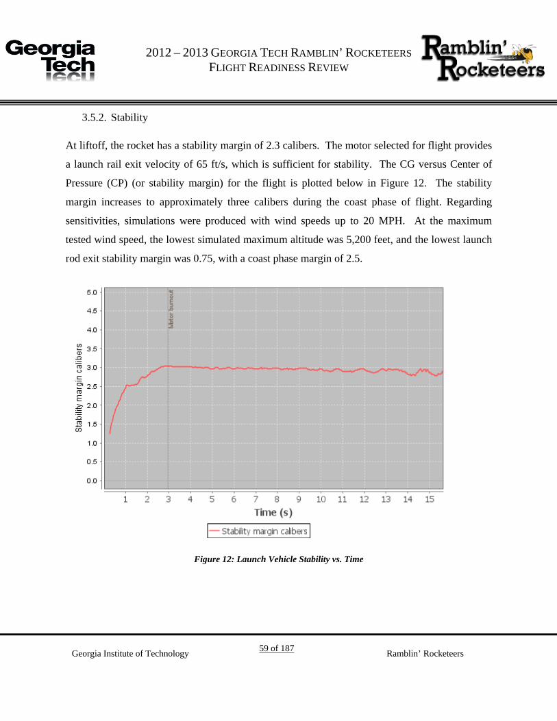
G 2012 – 2013 GEORGIA TECH RAMBLIN’ ROCKETEERS
FLIGHT READINESS REVIEW
Georgia Institute of Technology 59 of 187 Ramblin’ Rocketeers
3.5.2. Stability
At liftoff, the rocket has a stability margin of 2.3 calibers. The motor selected for flight provides
a launch rail exit velocity of 65 ft/s, which is sufficient for stability. The CG versus Center of
Pressure (CP) (or stability margin) for the flight is plotted below in Figure 12. The stability
margin increases to approximately three calibers during the coast phase of flight. Regarding
sensitivities, simulations were produced with wind speeds up to 20 MPH. At the maximum
tested wind speed, the lowest simulated maximum altitude was 5,200 feet, and the lowest launch
rod exit stability margin was 0.75, with a coast phase margin of 2.5.
Figure 12: Launch Vehicle Stability vs. Time

G 2012 – 2013 GEORGIA TECH RAMBLIN’ ROCKETEERS
FLIGHT READINESS REVIEW
Georgia Institute of Technology 60 of 187 Ramblin’ Rocketeers
3.5.3. Testing
The sub-scale launch tested the Vespula Mk II modified tube fin design. The successful sub-
scale test occurred on Saturday, October 13 and is illustrated below in Figure 13. The modified
tube fin design was de-scoped when the switch to the Intimidator Kit was made.
Figure 13: 45% Scale Test Rocket and Flight
At this time, the competition launch vehicle has not been flown due to previous in-flight failures
of the Vespula Mk II launch vehicle. The test flight of this vehicle will be completed before the
FRR telecom, and additional vehicle data will be presented during the presentation. The
presentation will include a drag assessment and the comparison and validity between flight
results and predicted results obtained via analysis tools.
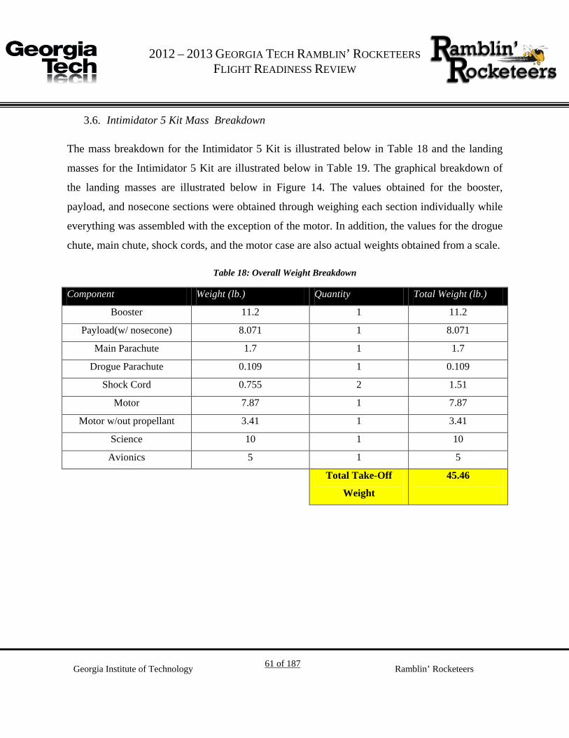
G 2012 – 2013 GEORGIA TECH RAMBLIN’ ROCKETEERS
FLIGHT READINESS REVIEW
Georgia Institute of Technology 61 of 187 Ramblin’ Rocketeers
Intimidator 5 Kit Mass Breakdown 3.6.
The mass breakdown for the Intimidator 5 Kit is illustrated below in Table 18 and the landing
masses for the Intimidator 5 Kit are illustrated below in Table 19. The graphical breakdown of
the landing masses are illustrated below in Figure 14. The values obtained for the booster,
payload, and nosecone sections were obtained through weighing each section individually while
everything was assembled with the exception of the motor. In addition, the values for the drogue
chute, main chute, shock cords, and the motor case are also actual weights obtained from a scale.
Table 18: Overall Weight Breakdown
Component Weight (lb.) Quantity Total Weight (lb.)
Booster 11.2 1 11.2
Payload(w/ nosecone) 8.071 1 8.071
Main Parachute 1.7 1 1.7
Drogue Parachute 0.109 1 0.109
Shock Cord 0.755 2 1.51
Motor 7.87 1 7.87
Motor w/out propellant 3.41 1 3.41
Science 10 1 10
Avionics 5 1 5
Total Take-Off
Weight
45.46

G 2012 – 2013 GEORGIA TECH RAMBLIN’ ROCKETEERS
FLIGHT READINESS REVIEW
Georgia Institute of Technology 62 of 187 Ramblin’ Rocketeers
Table 19: Intimidator 5 Kit Landing Masses
Section Landing Mass (lb.)
Nosecone 1.619
Payload 16.452
Booster 19.61
Total 37.68
Figure 14: Intimidator 5 Kit Landing Mass Breakdown
Interfaces and Integration 3.7.
The interfaces between the launch vehicle and the ground, and ground launch system, shall be
described such that the operation of interfacing the launch vehicle with these systems can be
correctly carried out to ensure optimal launch vehicle performance, with maximum safety to the
USLI team, and so that a sustainable architecture can be developed to show new members the
necessary action items of launch vehicle/ground/ground launch system integration.
1.619 lb.
16.452 lb.
19.61 lb.
Nosecone
Payload
Booster
G 2012 – 2013 GEORGIA TECH RAMBLIN’ ROCKETEERS
FLIGHT READINESS REVIEW
Georgia Institute of Technology 63 of 187 Ramblin’ Rocketeers
3.7.1. Interface with the Ground
The launch vehicle will have a GPS tracking system that will deliver real-time telemetry, as well
as the launch vehicle’s landing location, to the ground tracking station via an XBEE radio
transmitter. When the power system is locked to the ON position on the launch pad, the XBEE
will begin transmitting telemetry data.
3.7.2. Interface with the Ground Launch System
The launch vehicle will have attached large launch lugs, so that it can fit within a launch rail with
an aluminum 1515 T-slotted extrusion, of a minimum length of 8 feet. The launch vehicle will be
placed on a launch stand designated by the LCO after being inspected and certified flight-worthy
by the RSO. After proper assembly and insertion of the motor, inspection and certification, and
attachment to the launch stand, the electronics necessary for the payload and recovery system,
will be activated and locked into position. The altimeter will announce the readiness of the
electronics and payload system via a series of beeps. The launch vehicle will be launch using
standardized launch equipment including a standard 12 volt direct current firing system.
Launch Vehicle Operations 3.8.
It is the responsibility of Launch Operations to create comprehensive guides and checklists to
ensure proper operation of the launch vehicle and the safety of the USLI team. Proper operation
of the launch vehicle requires that certain protocols and procedures are observed by the Ramblin’
Rocketeers team during assembly and launch.
3.8.1. Launch Checklist
The Launch Checklist ensures that all tasks necessary for a successful launch are completed and
completed in the most efficient order. The Launch Checklist has both a performer and an
inspector to ensure all tasks are completed correctly. In addition, there is a Troubleshooting
Chart to address common problems when preparing and launching rockets. The Launch

G 2012 – 2013 GEORGIA TECH RAMBLIN’ ROCKETEERS
FLIGHT READINESS REVIEW
Georgia Institute of Technology 64 of 187 Ramblin’ Rocketeers
Checklist remains largely unchanged from the previous year in which the launch vehicle was
prepared for launch in one hour. Because of this the Ramblin’ Rocketeers are confident that the
time needed to prepare the launch vehicle for launch will remain well below the two hour
requirement, LV-4.5. The Launch Checklist can be found in Appendix II.

G 2012 – 2013 GEORGIA TECH RAMBLIN’ ROCKETEERS
FLIGHT READINESS REVIEW
Georgia Institute of Technology 65 of 187 Ramblin’ Rocketeers
4. Flight Experiment
Introduction to the Experiment and Payload Concept Features & Definition 4.1.
With the rise of entrepreneurial space flight, many new exotic spacecraft are being designed for
the purpose of finding a profit in space. Many of these spacecraft will be equipped with liquid
fuel propulsion and attitude control systems, or will seek to store large quantities of liquid
propellant. These liquids present difficulties in the design and operation of a spacecraft because
in low gravity, the fluids will be dominated by a combination of capillary/inertial/gravity
gradient forces and will respond to perturbations. The response of stored liquids to such
perturbations is termed slosh, and slosh is known to 1) alter the inertia matrix of a spacecraft and
2) to hamper the use of vents and propellant feed lines. Some methods of controlling slosh are
listed in Table 20.
Table 20: Methods currently available for damping slosh.
Damping Method Description
Tank geometry The choice of tank geometry (cylindrical, spherical, toroidal, etc) is known to
have an impact on slosh damping through viscous effects.
Ring baffles Annular disks along the circumference of a tank that impede slosh and may be
given various camber geometries.
Lids and mats Lids and mats float on a free surface of the liquid and impede slosh.
Floating cans Cans impede slosh by absorbing and dispersing the kinetic energy of the liquid.
Expulsion bag or
diaphragm
Bags and diaphragms reduce slosh by containing the propellant and forcing it
into propulsion feed lines.
Non-ring baffles Non-ring baffles are baffles that do not necessarily follow a tank circumference,
e.g. cruciform baffles.
Flexible baffles Flexible baffles are baffles made of flexible materials that deform under the
inertia of sloshing liquids.
While present methods of reducing slosh may be very effective in some flight regimes, there are
design issues inherent to some of these systems. For baffles – perhaps the most effective

G 2012 – 2013 GEORGIA TECH RAMBLIN’ ROCKETEERS
FLIGHT READINESS REVIEW
Georgia Institute of Technology 66 of 187 Ramblin’ Rocketeers
dampers for the additional inert mass – instabilities can occur during launch if propellant levels
are below the lowest baffle as in the case of the Saturn I. Similarly, such problems could occur
in low gravity situations where the baffles are rendered ineffectual from lack of contact with the
liquid. However, with the expense of mechanical complexity and inert mass, expulsion bags and
diaphragms can be used to avoid such instabilities. The Ramblin’ Rocketeers intend to provide
another alternative solution by demonstrating the use of magnetorheological (MR) fluid as a
moveable, deformable baffle and potentially a diaphragm equivalent.
Accomplishments Since CDR 4.2.
Since CDR, the team has pushed forward with hardware development. Despite delays due to
shipping and receiving of parts, as well as longer-than-predicted manufacturing times, ground
testing is about to begin and should be completed before April. A full science payload for the
rocket is on track to be completed on April 2, just before the RGEFP Technical Experiment Data
Package deadline of April 3.
Additionally, a science package was flown on the first test flight, giving important insight to
improve the science payload data acquisition. A second, upgraded package more similar to the
electronics that will be flown on the flight at Huntsville launched on March 9.
4.2.1. Important Changes
All use of cameras for the science payload has been de-scoped. Bench-testing of the solenoid
control system is prioritized over the two-plate testing, so that important progress is made
towards finalizing both the USLI and RGEFP payloads.
4.2.2. Test Launch Lessons Learned
4.2.2.1. Summary of Science Team Payload
The science team flew an Arduino Mega, OpenLog, and two piezo-electric vibration sensors to
obtain preliminary data on the launch vehicle environment. The power supply was a 6V AA

G 2012 – 2013 GEORGIA TECH RAMBLIN’ ROCKETEERS
FLIGHT READINESS REVIEW
Georgia Institute of Technology 67 of 187 Ramblin’ Rocketeers
battery array with DC connector. Payload tubes for the purpose of mass simulation were also
flown but were not within the scope of the science team interests of the full-scale test flight.
4.2.2.2. Report of Failures and Occurrences
4.2.2.3. Integration
The science electronics suffered a lack of integration consideration in design. A vertical
integration scheme was necessary for the Arduino Mega, however the protoboard shield and
power supply had cumbersome dimensions and securing these items increased the risk of failure.
A protoboard pieces was cut unnecessarily, endangering solder joints. Finally the Mega was
mounted vertically with duct tape and redundant zip-ties, securing it to the rocket structure.
4.2.2.4. Sensor detachment
A sensor was observed to have been detached from the terminals at some point during the
tumbling phase of the rocket trajectory. However, this sensor appears to have had its supporting
circuitry shorted to Arduino ground because of the manner of integration and a lack of electrical
tape on the Mega USB B header. The result was saturated readings of the secondary (radial)
piezo-electric sensor. This was a non-critical failure.
4.2.2.5. Openlog File Writing
A secondary file was begun at some point in the writing of data. There is no time-step matchup
between these files. Thus it is difficult to understand where in the timeline of the launch vehicle
trajectory that the open log reset. This is a potential failure risk for the SIDES nodes that could
disrupt the coherence of time data. The data are still available for analysis but are made difficult
to interpret.
4.2.2.6. Results and Future Mitigation
4.2.2.7. Integration Results

G 2012 – 2013 GEORGIA TECH RAMBLIN’ ROCKETEERS
FLIGHT READINESS REVIEW
Georgia Institute of Technology 68 of 187 Ramblin’ Rocketeers
One of the two zip-ties where broken during the spin of the launch vehicle. Fortunately a second
zip-tie provided redundancy. Integration systems resistant both to typical axial loads and
potential rotational loading should be considered for future launches.
4.2.2.8. Sensor data
Sensor data was recovered and is being analyzed. The data recovered are presented in Figure 15
and Figure 16.
Figure 15: Correcting for Piezo drift Figure 16: FFT of corrected data showing peak around 26 Hz
Sensor data might be improved by better mating of the sensors to the mounting brackets or
rocket structure. The data show strong peaks and piezo drift and should be useful in comparison
of future datasets.
4.2.2.9. OpenLog Risk Mitigation
To mitigate the risk of openlog errors – i.e. starting to write a new file with dissimilar time stamp
– or other issues that might arise unexpectedly in the SIDES network, as well as to better analyze
the data, an accelerometer will be flown on the science board so that the launch vehicle
accelerations can be precisely correlated with vibration data.

G 2012 – 2013 GEORGIA TECH RAMBLIN’ ROCKETEERS
FLIGHT READINESS REVIEW
Georgia Institute of Technology 69 of 187 Ramblin’ Rocketeers
Science Background 4.3.
A complete science background is included in Appendix III.
4.3.1. Important Highlights
In the science background, several important relationships are developed. These relationships
are given in Table 21.
Table 21: Elements of the theoretical modeling for the LSIM payload
LSIM element Relationship
Response of MR fluid
to a magnetic field
(motion as it
rigidifies)
Longitudinal Slosh
Model ∆�̈� = 𝑔 −
𝑏2𝑚�Δ�̇�� −
𝑘𝑚∆𝐿
Lateral Slosh Model �̈� = �−
𝑔𝑘(𝑘𝐿 + 𝑚𝑔)� 𝜃 − �
𝑏1𝑚� �̇�
Damping of MR
Fluid if it is a rigid
baffle
By experiment and in correspondence with reference material tabulated data and
plots
Damping of
Container
From reference material,
𝛿 = 4.98𝜈1/2𝑅−3/4𝑔−1/4
Experiment Requirements and Objectives 4.4.
4.4.1. Success Criteria
Minimum and maximum success criteria have been defined for the LSIM payload. Table 22 lists
these criteria.

G 2012 – 2013 GEORGIA TECH RAMBLIN’ ROCKETEERS
FLIGHT READINESS REVIEW
Georgia Institute of Technology 70 of 187 Ramblin’ Rocketeers
Table 22: LSIM success criteria from the Requirements Verification Matrix
LSIM Success Criteria
Minimum Successfully record video of flight experiment during microgravity and start/stop the
experiment without mechanical and electrical failures.
Maximum Successful matching of the damping ratio for ringed baffles in the wave amplitudes
experienced during flight to within ±30%.
4.4.2. Requirements
The requirements set for the LSIM experiment to satisfy both the goals of Ramblin’ Rocketeers
and the USLI requirements are listed in Table 23. Flight systems (experiment and avionics) are
now budgeted to be 15 lbf.
Table 23: LSIM Requirements
Requirement
Number
Requirement
Definition
Source Verification
Method
Design
Feature
Status Verification
Source
Document
FS-1 The flight systems
team shall design and
build the LSIM
Payload
MO-3 Inspection LSIM payload
In Progress MO-3
FS-2 The LSIM payload
shall be designed to
fly on a SLP rocket
USLI Handbook
3.1.1 Inspection LSIM
payload In
Progress
USLI Handbook
3.1.1
FS-4 The Flight Systems
Team shall produce a
working system for
manipulating MR
fluid in LSIM.
MSC-3 Testing Solenoids
and Control Algorithms
In Progress MSC-3

G 2012 – 2013 GEORGIA TECH RAMBLIN’ ROCKETEERS
FLIGHT READINESS REVIEW
Georgia Institute of Technology 71 of 187 Ramblin’ Rocketeers
Requirement
Number
Requirement
Definition
Source Verification
Method
Design
Feature
Status Verification
Source
Document
FS-5 The Flight Systems
Team shall ensure
that all avionics are
properly shielded
from the LSIM
payload.
MSC-3 Testing
Faraday cages and webbing tied to
ground on the harness
Not Started MSC-3
FS-6 The Flight Systems
Team shall design all
LSIM components
and avionics such
that they may be
easily integrated with
the Modular Payload
System of the
payload bay in the
rocket.
MSC-3 Inspection Mounting system Complete MSC-3
FS-7 The Flight Systems
Team shall conform
to all weight, power,
and dimensional
requirements as per
the rocket design.
MSC-3 Analysis TBD In Progress MSC-3

G 2012 – 2013 GEORGIA TECH RAMBLIN’ ROCKETEERS
FLIGHT READINESS REVIEW
Georgia Institute of Technology 72 of 187 Ramblin’ Rocketeers
Requirement
Number
Requirement
Definition
Source Verification
Method
Design
Feature
Status Verification
Source
Document
FS-7.1 The Experiment and
Avionics, with
mechanical supports,
shall weight no more
than 15 lbf.
LV-1.1 Inspection TBD In Progress LV-1.1
FS-8 The flight computer
shall execute all tasks
necessary to the
operation of the
LSIM payload and
avionics.
MSC-3 Inspection Maple SIDES node
In Progress MSC-3
FS-9 The LSIM payload
shall have a
dedicated power
supply.
MSC-3 Inspection SIDES node In Progress MSC-3
FS-10 The Flight Systems
Team shall ensure
redundancy and
reliability of all
internal electrical
hardware.
MSC-3 Inspection SIDES network
In Progress MSC-3

G 2012 – 2013 GEORGIA TECH RAMBLIN’ ROCKETEERS
FLIGHT READINESS REVIEW
Georgia Institute of Technology 73 of 187 Ramblin’ Rocketeers
Requirement
Number
Requirement
Definition
Source Verification
Method
Design
Feature
Status Verification
Source
Document
FS-11 The Flight Systems
Team shall provide
for payload operation
with up to 1 hour of
wait on the launch
pad and 2 hours of
wait during
preparation of the
Rocket.
USLI Handbook
1.6 Inspection TBD In
Progress
USLI Handbook
1.6
FS-12 The Flight Systems
Team shall provide
for electrical
operations to begin at
the beginning of the
flight trajectory.
MSC-3 Inspection TBD In Progress MSC-3
FS-13 The Flight Systems
Team shall ensure
that the LSIM
payload is shut down
safely during the
deployment phase of
the flight trajectory.
MSC-3 Inspection TBD In Progress MSC-3

G 2012 – 2013 GEORGIA TECH RAMBLIN’ ROCKETEERS
FLIGHT READINESS REVIEW
Georgia Institute of Technology 74 of 187 Ramblin’ Rocketeers
Requirement
Number
Requirement
Definition
Source Verification
Method
Design
Feature
Status Verification
Source
Document
FS-14 Data from the LSIM
payload shall be
collected, analyzed,
and reported by the
team using the
scientific method.
USLI Handbook
3.2 Inspection
Data logging in
SIDES network
In Progress
USLI Handbook
3.2
FS-15 The LSIM payload
will be designed to
be recoverable and be
able to launch again
on the same day
without any repairs
or modifications.
USLI Handbook
3.5 Inspection
Appropriate mounting
to the payload
interface.
In Progress
USLI Handbook
3.5
4.4.3. Hypothesis and Premise
The hypothesis posed in the LSIM experiment is that –
If a baffle can be manipulated during the flight of a spacecraft, then unstable slosh
can be actively damped.
The experiment will apply radial magnetic fields to the propellant tank to manipulate and rigidify
the MR fluid during the microgravity phase of the launch vehicle trajectory to perform Liquid
Stabilization in Microgravity – LSIM. The launch vehicle ascent will provide a high vibrational
intensity environment in which to test the anti-slosh system. Furthermore, the use of diaphragms
and propellant bags are eliminated with the assumption that:
Trading mechanical complexity for electrical complexity is preferable from a reliability
standpoint.

G 2012 – 2013 GEORGIA TECH RAMBLIN’ ROCKETEERS
FLIGHT READINESS REVIEW
Georgia Institute of Technology 75 of 187 Ramblin’ Rocketeers
Therefore, the Ramblin’ Rocketeers will implement a design to apply these concepts to both the
launch vehicle and RGEFP.
4.4.4. Experimental Method and Relevance of Data
The experimental method for LSIM requires a multi-step approach for ground testing, flight
testing, and RGEFP. The purpose of ground testing will be to characterize the shear stress
behavior of MR fluid of different composition and magnetic field configuration, the
manipulation of MR fluid, and preliminary data on slosh damping ability. Flight testing will
provide actual data on the capability of the MR fluid system to dampen slosh, especially in the
microgravity environment. RGEFP would seek to explore a “big-picture” system that actively
attempts to remove any stray MR fluid as propellant simulant is pumped out of the tank. In any
of the test cases, an optimal mixture of MR fluid will enable an application of active control to
maneuver MR fluid into position in flight. The testing cases are organized by the team testing
matrix for LSIM, which is designed to enable comparative analysis of the results and to verify
completion of the data set. Following the scientific method, the test matrix outlines control
experiments and baseline comparisons to develop a qualified understanding of MR fluid in the
context applicable to LSIM. A summary of scientific method fulfillment is given in Table 24.

G 2012 – 2013 GEORGIA TECH RAMBLIN’ ROCKETEERS
FLIGHT READINESS REVIEW
Georgia Institute of Technology 76 of 187 Ramblin’ Rocketeers
Table 24: Scientific method fulfillment for LSIM
Method step Fulfillment
Question What are options for electrically damping slosh?
Research Study of MR fluid and a review of “The Dynamic Behavior of Liquids
in Moving Containers”
Hypothesis If a baffle can be manipulated during the flight of a spacecraft, then
unstable slosh can be actively damped.
Test Ground testing plan and test matrix, flight test, RGEFP
Analysis Data examination, post-processing, and analysis
Communicate SLP documentation and VTC
Furthermore, in an improvement over previous experimental design, the team intends to fly a
control experiment as part of the flight test, permitting greater validating capability for the
effectiveness of the damping system.
Testing plan 4.5.
4.5.1. Overview
To accomplish the objectives of LSIM, several distinct testing sequences are necessary. Key to
the success of LSIM is ground testing, where MR fluid mixtures will be characterized and
manipulated with solenoids. Following on these tests are the USLI flight test and separately the
RGEFP project. However, at this juncture of the project some testing has been de-scoped,
namely shake-table testing of the “bench test” platform to demonstrate slosh reduction in 1-gee.
This test was de-scoped due to the complexity and time constraints of procuring an appropriate
shake-table.
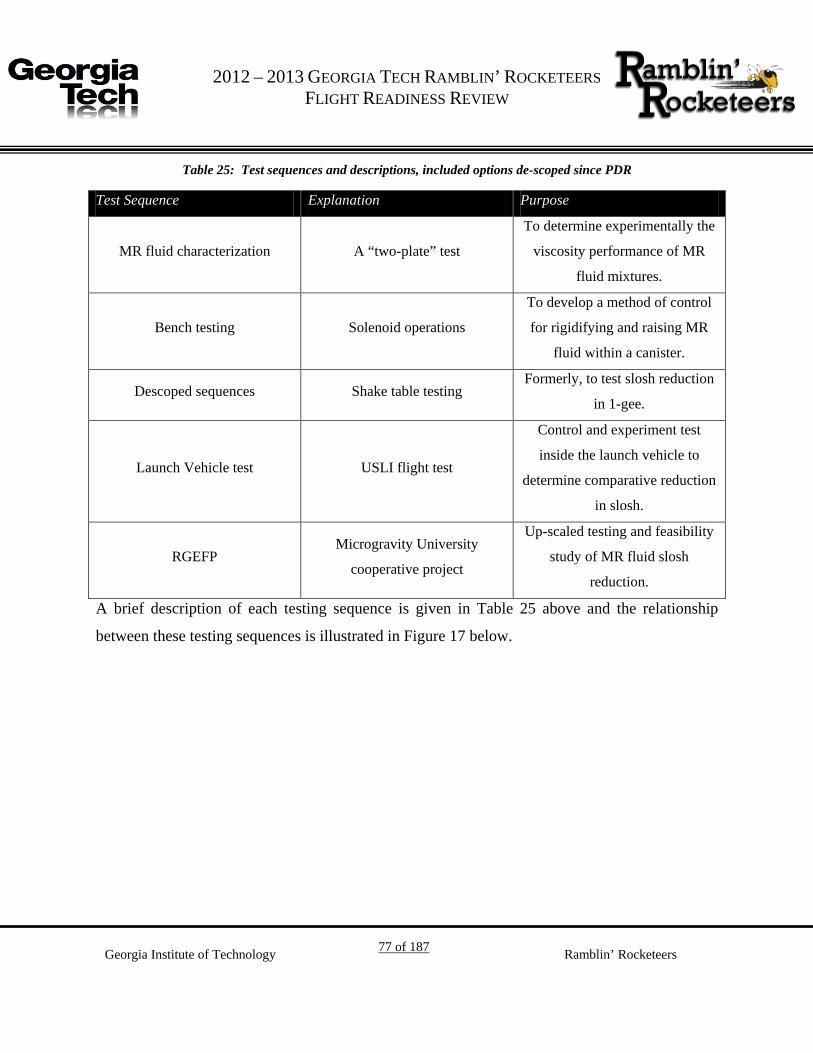
G 2012 – 2013 GEORGIA TECH RAMBLIN’ ROCKETEERS
FLIGHT READINESS REVIEW
Georgia Institute of Technology 77 of 187 Ramblin’ Rocketeers
Table 25: Test sequences and descriptions, included options de-scoped since PDR
Test Sequence Explanation Purpose
MR fluid characterization A “two-plate” test
To determine experimentally the
viscosity performance of MR
fluid mixtures.
Bench testing Solenoid operations
To develop a method of control
for rigidifying and raising MR
fluid within a canister.
Descoped sequences Shake table testing Formerly, to test slosh reduction
in 1-gee.
Launch Vehicle test USLI flight test
Control and experiment test
inside the launch vehicle to
determine comparative reduction
in slosh.
RGEFP Microgravity University
cooperative project
Up-scaled testing and feasibility
study of MR fluid slosh
reduction.
A brief description of each testing sequence is given in Table 25 above and the relationship
between these testing sequences is illustrated in Figure 17 below.

G 2012 – 2013 GEORGIA TECH RAMBLIN’ ROCKETEERS
FLIGHT READINESS REVIEW
Georgia Institute of Technology 78 of 187 Ramblin’ Rocketeers
Figure 17: LSIM testing logic, illustrating a simple relationship of information between the test sequences and emphasizing that they flow down from the pursuit of the LSIM hypothesis.
Ground testing will serve four general purposes: (1) the creation of MR fluid, (2) the verification
and validation of theory and control systems, (3) the characterization of MR fluid, and (4) the
development of a working model for flight testing. For the successful completion of ground
testing, the team will create an optimal mix of MR fluid. An optimal mix will depend on the
fluid's balance between rigidity and fluidity for manipulation under a magnetic field, such that
the MR fluid is easily moved to an appropriate location in the tank. Verifying the Ramblin'
Rocketeers' solution and theory of using MR fluid as a baffle to dampen unstable slosh will go
through two phases. During phase one, only MR fluid will be subjected to a magnetic field.
Phase two will include water along with MR fluid being subjected to a magnetic field. The
results from these phases will indicate whether the solution is feasible by observing the
controllability of MR fluid by a magnetic field as well as observing differences between MR
fluid and the propellant simulant. By characterizing the MR fluid, the team will understand the

G 2012 – 2013 GEORGIA TECH RAMBLIN’ ROCKETEERS
FLIGHT READINESS REVIEW
Georgia Institute of Technology 79 of 187 Ramblin’ Rocketeers
various properties of the MR fluid such as its exerted shear force and how it changes under a
magnetic field. The characterization process will include testing the force and viscosity of the
MR fluid and observing preliminary slosh damping. Finally, a working ground model will be
developed using the results from (1), (2), and (3) with constraints for flight experimentation.
4.5.2. MR Fluid Creation and Validation of Theory
MR fluid can be created from three ingredients: carrier oil, magnetic particles, and surfactant.
Table 26 provides example MR fluid ingredients in the design space.
Table 26: List of MR fluid ingredients
Carrier Oil Magnetic Particles Surfactant
Mineral Oil IRON100 Powder Citric Acid
Nanometer particulate ferrofluid IRON325 Powder Oleic Acid
FE100.29 Powder Soy Lecithin
Fe304 M1 Powder
For a preliminary ground test in search of better understanding the behavior of MR fluid –
thereby making more informed decisions on the design space – the team opted to use mineral oil,
IRON325 powder, and oleic acid. By trial and error testing, the team created a stable MR fluid
mixture using the aforementioned ingredients. The team created two mixtures of differing
viscosities. While some sources had presented the iron concentration as 60% by mass, the
preliminary tests found it necessary to increase this percentage. The first mixture resulted to be
too fluid with 17 grams of mineral oil, 1 gram of oleic acid, and 56 grams of IRON325 powder
(76% by mass). The second mixture resulted to be too viscous with 16 grams of mineral oil, 1
gram of oleic acid, and 56 grams of IRON325 powder (77% by mass). The ingredients were
measured using a scale accurate to a gram. Future measurements will use a more accurate scale.
From trial and error testing, the team created an MR fluid testing matrix that will test every

G 2012 – 2013 GEORGIA TECH RAMBLIN’ ROCKETEERS
FLIGHT READINESS REVIEW
Georgia Institute of Technology 80 of 187 Ramblin’ Rocketeers
possible combination between ingredients as well as small deviations from the trial and error
test. For example, the team will gradually decrease the iron percentage by mass while gradually
increasing the mineral oil percentage until the optimal mixture – a mixture that appears to be
rigid enough to act as a baffle and manipulative enough to move readily – has been attained.
Each mixture will be static tested by neodymium magnets and good mixtures may be tested with
solenoids as ground testing improves. Validation of theory and control of MR fluid will occur if
there is a change in the MR fluid's viscosity under a magnetic field.
Figure 18: Preliminary static testing of MR fluid mixtures in magnetic fields
From the results of preliminary testing, the composition of MR fluid is likely to be changed to
using carrier oil made of ferrofluid. Ferrofluid is a mixture nanometer-scale ferromagnetic
particles in oil with a surfactant. However, unlike MR fluid, ferrofluid does not have as high a
percentage of pure iron and does not rigidify in the same manner as MR fluid. As carrier oil, the
team hypothesizes that ferrofluid will increase the mobility and useability of the MR fluid
mixture; even with 60% and greater mass ratios of iron powder. Furthermore, smaller iron
particulates may also increase the mobility of the MR fluid. Greater mobility than the initial
mixtures is preferred such that the MR fluid may be moved to the final baffle location using
solenoids, and eventually for the mobility desired for RGEFP.
4.5.3. MR Fluid Shear Stress Characterization: Two Plate Test

G 2012 – 2013 GEORGIA TECH RAMBLIN’ ROCKETEERS
FLIGHT READINESS REVIEW
Georgia Institute of Technology 81 of 187 Ramblin’ Rocketeers
The team will determine the shear stress MR fluid exerts inside and outside magnetic fields to
better understand how to manipulate the MR fluid as desired. To determine the shear stress, the
team will perform a two-plate test with and without magnetic field acting upon the MR fluid.
This test was chosen because of its simplicity; other tests such as a barometer test were
considered for measuring the MR fluid's viscosity and force – they turned out too complicated to
realize.
The two-plate test consists of two plates: a bottom plate, which is fixed to the ground and a top
plate, which is free to move. A load sensor will be placed on the top plate to measure the reaction
force that is generated. The current plate choice is acrylic.
Figure 19: Shear stress of a fluid using the two-plate test (Source: Wikipedia)
A control test will be performed by only having two plates together with a load sensor on the top,
moving plate to calculate the frictional force by the plates themselves. For accurate and
consistent results, a mechanical pulling device will be used to pull the top plate. Once a control
has been measured, a quantity of MR fluid will be placed between the two plates and the same
procedure will repeat with and without the MR fluid under a magnetic field. These tests will
characterize the force that MR fluid will generate when it is under a magnetic field and when it is
free of a magnetic field. A complete ground testing plan description is included in the Ground
Test Plan appendix.

G 2012 – 2013 GEORGIA TECH RAMBLIN’ ROCKETEERS
FLIGHT READINESS REVIEW
Georgia Institute of Technology 82 of 187 Ramblin’ Rocketeers
4.5.4. Working Ground Model
The team will develop three methods of MR fluid control: an array of solenoids, a movable
solenoid, and a fixed solenoid. For the launch vehicle and RGEFP, solenoid arrays appear to be
the best current option.
4.5.5. Sensors
Piezo-electric vibration sensors will meaure the variation in the force applied to the mounting
brackets.
Design review 4.6.
4.6.1. Viscosity Test Rig
A two-plate test rig was designed to characterize the viscosity of MR fluid. The design of this
test rig underwent many revisions in order to meet measurement and budget requirements. The
objective of this rig is to measure the force of fluid acting on the plate and ultimately, the
viscosity value of the MR fluid. The reaction force and the viscosity constant are related by the
following equation:
𝐹𝑓𝑙𝑢𝚤𝑑�����������⃗𝐴
= −𝜂𝑉0𝐷
(1)
In Eq.(1), A is the surface area of the plates, V0 is the pulling velocity of the top plate, D is the
distance between the plates, and η is the viscosity coefficient. The surface area of the plate is
31.08 in2, and the distance between the plates is estimated to be about .25 in. A motor is used to
control the velocity, so V0 is also known. Ffluid is measured with a nichrome wire device. This
device measures force through changes in resistivity induced by small changes in cross-sectional
area resulting from tension in the wire. The measurement limits for this device are set by the
accuracy of electrical interface hardware and calibration testing.

G 2012 – 2013 GEORGIA TECH RAMBLIN’ ROCKETEERS
FLIGHT READINESS REVIEW
Georgia Institute of Technology 83 of 187 Ramblin’ Rocketeers
One of the design requirements is to simulate a non-frictional surface. The aim is to ensure that
the only force acting on the plate is the fluid’s shear force. This is accomplished by adding
railings between the plates and the base of the structure. Although the railings do not completely
remove friction, they minimize it enough so that friction is negligible. Part drawings for the test
rig are available in the Appendix. The drawings shows locations of the railings’ attachment
points and the tap needed as well. The railings require a #8 type screw, and a ¼ in tap is needed
for hard woods and acrylic sheets with this type of screws. The dimensions and locations of the
features on these parts are mainly driven by two parameters: solenoid strength and test time.
Because the magnetic strength of the solenoid decreases drastically as the distance increases, the
plates need to be close to the solenoid base. This requires short railings. The group also wants to
maximize the contact time between the plates and the MR fluid, so the plates are designed to be
long and skinny. Solenoids are aligned along the length of the plate to produce a uniform
magnetic field during testing.
Construction of the test rig depends on a number of assumptions and is subjected to revision for
alternative methods if necessary. First, super wood glue will be used to connect wood pieces. If
this is not sturdy enough, elbow brackets will be used to connect the corners of the wood pieces.
The motivation for using glue instead of brackets is saving money. Second, wood pieces and
acrylic sheets will also be glued together with epoxy. This method is the norm for connecting
wood to acrylic sheet, and it saves space and money. A #8 type screw will be used to tighten the
railings to the woods and acrylic sheets. The railings attachment holes are designed to provide a
bit of a leeway. Attachment holes on the structure pieces and test plates can be off by about .05
in. A motor will be used to pull the top plate. The motor will stand on a piece of wood that has
been designed with a height that will perfectly align the motor with the top plate. The tolerance
for the height offset is ±.04 in. String and hook will be used to round out the pulling mechanism.
This testing rig was delayed due to the design process and the winter break. Ordering and
construction are planned to begin coincident with CDR and testing could begin around the time
of CDR VTC in late January.

G 2012 – 2013 GEORGIA TECH RAMBLIN’ ROCKETEERS
FLIGHT READINESS REVIEW
Georgia Institute of Technology 84 of 187 Ramblin’ Rocketeers
4.6.2. Ground Test – MR fluid production and manipulation
In order to meet the system functional requirements, the MR fluid must have certain properties
and also adhere to certain standards. The fluid must be sufficiently rigid when magnetized to not
shear significantly or break due to fluid slosh; however, the fluid must also not be excessively
resistant to motion when moving and shearing against a wall, so that it may be moved into
position by the magnets. It is known that the size of iron particles makes the largest difference in
the rheometry of the fluid. For instance, one batch of low quality fluid that was created earlier
during preliminary testing, with larger iron particles than is typical of MR fluids, was found to be
extremely resistant to motion.
Therefore, to find a high-quality fluid with intermediate properties, it is wished to test iron
powders with particles of mean diameter between 0.1 µm and 10 µm. In addition, to ensure
purity, we shall attempt to purchase all powders from well-known sources. For example, one
option being explored is a purchase of carbonyl iron powder from BASF. For the carrier fluid,
mineral oil or hydraulic oil are both known to be fairly typical choices; the properties of the fluid
should not be significantly affected by which is chosen. The final choice of components and their
proportions will be made based on the results of the two-plate testing, as well as qualitative
experience from attempts to move the fluid by manually moving magnets.
The MR fluid will then be manipulated by solenoids in a ground testing platform that permits the
placement and use of solenoids to control the MR fluid.
The foundation of the bench test is built from Maker Beam parts. This allows for great
configurability and flexibility. Four 30 cm Maker Bars are the corner stands of the test rig; they
are placed vertically about 20 cm apart from each other. Four 20 cm Maker Bars are placed
horizontally in between the vertical 30 cm Maker Bars and are attached to give support. There
are three thin acrylic plates: one acts as the main base and the other two have holes cut for the
beaker to fit inside the plates. The base plate sits on 4 flat “L” Maker Beam brackets about 2 cm

G 2012 – 2013 GEORGIA TECH RAMBLIN’ ROCKETEERS
FLIGHT READINESS REVIEW
Georgia Institute of Technology 85 of 187 Ramblin’ Rocketeers
above from the base. The 4 “L” Maker Beam brackets are attached to the four 20 cm horizontal
Maker Bars. The beaker is placed in the middle of the base acrylic plate and the solenoids are
placed radially around the beaker on the base plate. Four 90 Degree brackets are used to hold the
second plate 2 cm above the first plate. The second plate has a hole cut in the middle to allow for
the beaker to pass through the middle. More solenoids can be placed around the second acrylic
plate. The same is done with the third acrylic plate as was done with the second acrylic plate, but
4 cm above the first, base acrylic plate.
This design using Maker Beam parts allows for future design modification and addition of parts.
Once more data has been collected, the team can attach a vibration motor underneath the first
base plate to simulate slosh. Solenoids can be added, moved, or removed from each of the three
acrylic plates during testing as test results shed more light on what is needed for more accurate
testing. The top two acrylic plates with holes in them can be moved up or down the 30 cm maker
beam bars to adjust the height at which the solenoids interact with the beaker.
4.6.3. Hardware and build progress
4.6.3.1. Sensing
The damping coefficient of the slosh-reduction system will be estimated by measuring the
anchor force decay1F
2 of the experiment. At this moment, the sensors will be measuring the
frequency and magnitude of these forces (i.e. vibrations). These sensors are considered as
Experimental hardware.
2 On the recommendation of p. 108, The Dynamic Behavior of Liquids in Moving Containers: with Applications to Space Vehicle Technology. Ed. H. Norman Abramson. NASA, 1966. (NASA SP-106)

G 2012 – 2013 GEORGIA TECH RAMBLIN’ ROCKETEERS
FLIGHT READINESS REVIEW
Georgia Institute of Technology 86 of 187 Ramblin’ Rocketeers
The sensors are piezo-electric elements which
produce voltage as a function of deformation,
especially deflections of the sensor tip. The
base of the sensor is affixed to both the
experiment canister and lower mounting
hardware. The mounting hardware is designed
to permit tip deflection in at least one direction.
This configuration was tested on the USLI
sounding rocket without any liquid within the
rocket experiment canister and the data is still
under review. At the time of writing, the
Figure 20: Piezo-electric sensor used for detecting anchor force oscillations 2F
3
method of sensing the reduction in slosh is open for revision pending further information. Figure
20 gives the sensor and the major dimensions – the thickness is on the order of 0.125 mm. 3F
4 To
operate the sensors, a simple op-amp circuit has been selected, modeled, and built to limit the
voltage and boost the current of the sensor so that a microcontroller, such as an arduino, may
read the sensor data on analog input pins. The circuit is given in Figure 21. A prototype built for
the USLI sounding rocket is given in Figure 22.
3 Image from Sparkfun, https://www.sparkfun.com/products/9196 4 Sensor datasheet: http://dlnmh9ip6v2uc.cloudfront.net/datasheets/Sensors/ForceFlex/LDT_Series.pdf

G 2012 – 2013 GEORGIA TECH RAMBLIN’ ROCKETEERS
FLIGHT READINESS REVIEW
Georgia Institute of Technology 87 of 187 Ramblin’ Rocketeers
Figure 21: Piezo-electric sensor circuit. The sensor is modeled as a variable-voltage source at 300 Hz. While 300 Hz is a theoretical maximum for the reading speed of the microcontroller, data was logged at a rate between
88-96 Hz. With six (6) canisters, six (6) of these circuits would be needed to measure the anchor force
oscillations for each canister. The power supply for the op-amp is sourced from the
microcontroller and does not need to interface directly from the aircraft.
Preliminary data illustrates voltage drift and
may help with analysis of tip deflection should
force magnitude be deemed important;
however, variation of the raw data is currently
under analysis for frequency spectra and to
understand the change in spectra over time. It
is current thought by the team that the change
in spectra over the course of the experiment
may illustrate the decay of the anchor force, as
the momentum of the water is changing as a
damped oscillation. The relative frequency of
the resting structure surrounding the
Figure 22: Top and bottom view of sensor prototype circuit. Leads soldered to the piezo-electric sensors are
attached to the blue terminals, while pins go to the microcontroller for data logging and analog reading.
This prototype supports two sensors and is approximately 3 inches by 5 inches. Final boards may
be much smaller.
G 2012 – 2013 GEORGIA TECH RAMBLIN’ ROCKETEERS
FLIGHT READINESS REVIEW
Georgia Institute of Technology 88 of 187 Ramblin’ Rocketeers
experiment in the sounding rocket is used as a baseline for that portion of the experiment; no
such baseline of data currently exists for the aircraft, but may be available as a test case. The
data collected from the test launch of the USLI sounding rocket on the prototype piezo-electric
sensor circuit is given in Figure 23 and Figure 24. The analysis of this data is not finalized and
the noise and peaks are not yet understood. An accelerometer will be added to the rocket
payload for increased clarity – it is not yet certain whether an accelerometer will be flown with
the aircraft payload or whether the team will wish to log the provided aircraft acceleration data.

G 2012 – 2013 GEORGIA TECH RAMBLIN’ ROCKETEERS
FLIGHT READINESS REVIEW
Georgia Institute of Technology 89 of 187 Ramblin’ Rocketeers
Figure 23: data showing sensor drift and a method of correction by distributing the data around the overall
mean.
Figure 24: frequency spectrum for the entire dataset.
4.6.3.2. Solenoids
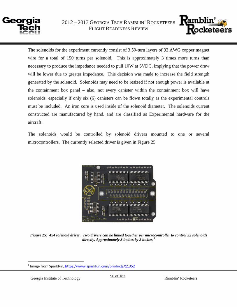
G 2012 – 2013 GEORGIA TECH RAMBLIN’ ROCKETEERS
FLIGHT READINESS REVIEW
Georgia Institute of Technology 90 of 187 Ramblin’ Rocketeers
The solenoids for the experiment currently consist of 3 50-turn layers of 32 AWG copper magnet
wire for a total of 150 turns per solenoid. This is approximately 3 times more turns than
necessary to produce the impedance needed to pull 10W at 5VDC, implying that the power draw
will be lower due to greater impedance. This decision was made to increase the field strength
generated by the solenoid. Solenoids may need to be resized if not enough power is available at
the containment box panel – also, not every canister within the containment box will have
solenoids, especially if only six (6) canisters can be flown totally as the experimental controls
must be included. An iron core is used inside of the solenoid diameter. The solenoids current
constructed are manufactured by hand, and are classified as Experimental hardware for the
aircraft.
The solenoids would be controlled by solenoid drivers mounted to one or several
microcontrollers. The currently selected driver is given in Figure 25.
Figure 25: 4x4 solenoid driver. Two drivers can be linked together per microcontroller to control 32 solenoids directly. Approximately 3 inches by 2 inches. 4F
5
5 Image from Sparkfun, https://www.sparkfun.com/products/11352

G 2012 – 2013 GEORGIA TECH RAMBLIN’ ROCKETEERS
FLIGHT READINESS REVIEW
Georgia Institute of Technology 91 of 187 Ramblin’ Rocketeers
4.6.3.3. Microcontroller
Currently proposed as the microcontroller for the experiment is the Arduino Mega. It is not
certain whether multiple microcontrollers will be necessary. If so a USB multiplexer may be
required but is not yet chosen. The microcontroller is illustrated in Figure 26.
Figure 26: Arduino Mega microcontroller with major dimensions.
Payload Relevance and Science Merit 4.7.
The top priority of the Flight Systems team during project development was to create a payload
concept leveraging team expertise while pursuing achievable and NASA-relevant experiments.
Previously, the 2009-2010 project investigated moving oxygen gas with an electromagnet –

G 2012 – 2013 GEORGIA TECH RAMBLIN’ ROCKETEERS
FLIGHT READINESS REVIEW
Georgia Institute of Technology 92 of 187 Ramblin’ Rocketeers
essentially a steady-state siphon for paramagnetic materials. The 2011-2012 USLI team
investigated active platform electromagnetic stabilization, developing control algorithms for
magnetic levitation during flight. After review by Flight Systems and the Georgia Tech
Ramblin’ Rocketeers, the team decided that the most relevant primary payload would be to
demonstrate the use of MR fluids in anti-slosh applications using technology development from
the 2009-2010 and 2011-2012 Georgia Tech USLI experiments. Combining technologies from
the previous projects, the new LSIM payload will demonstrate a possible method to combat
propellant sloshing. The benefits of such an anti-slosh system would be most applicable in deep-
space long-duration missions. In such missions, large quantities of fuel must be stored and/or
transported with cargo/personnel. A major issue in low-gravity environments for propellants is
sloshing, where fluid begins to float freely in space relative to the propellant tanks. Sloshing
may cause loss of pressurization in propellant feed systems, potentially creating dangerous
propulsion failures. The current solution is to create a moveable and deformable baffle from MR
fluid. Using electromagnets, the controlled fluid may then be used to dampen the propellant
oscillations. Systems might be needed to insure that the fluid is removed from the propellant,
and a magnetic siphon could be used if the mixing between fluid and propellant is minimal. This
is the basis for the RGEFP experiment discussed later in this document.
Generally however, the LSIM experiment is a science and engineering payload that involves
phenomena from several fields, primarily magnetism, rheology and viscous flow, as well as near-
inviscid fluid dynamics. Among the goals of LSIM is to develop a scientific model
encompassing all of the above fields in order to understand the interactions between the various
components of the system. This will be achieved by combining theory with experimentation and
testing. Data will be collected for variables such as MR fluid position, MR fluid shear stress, and
simulant position and acceleration as a function of time, rocket acceleration, and electromagnet
currents and positions. Collecting this experimental data will enable changes in the applied
control scheme to be made according to the observed data, as well as allowing for refinement of
the dynamic and scientific model of the MR fluid-propellant simulant system. A full explanation
G 2012 – 2013 GEORGIA TECH RAMBLIN’ ROCKETEERS
FLIGHT READINESS REVIEW
Georgia Institute of Technology 93 of 187 Ramblin’ Rocketeers
of the science of slosh and MR fluid relevant to LSIM is included in the Science Background
appendix.
For MR fluids, the primary focus of research in current years has been on the properties of the
MR fluids themselves, and on their interactions with solid objects or containers, rather than on
their interactions with other fluids. Therefore, the LSIM experiment should give insight into this
less-studied subject. In addition to the above modeling, there are other scientific benefits of this
experiment. The behavior of MR fluids in microgravity has been of significant interest, with the
InSPACE experiment on the International Space Station being a large-scale investigation on this
topic. However, engineering applications of the fluid specifically in microgravity do not seem to
have been investigated to the same extent. Microgravity is one of the places where MR fluid is
likely to be most effective, as settling of iron particles and thus degradation of integrity does not
occur in the near-absence of gravity. Therefore, the LSIM experiment allows for investigation of
actual applications of MR fluids in microgravity, as well as scientific modeling of the MR fluid-
simulant dynamics.
RGEFP 4.8.
The Ramblin’ Rocketeers were selected for RGEFP. Reporting on the progress of this portion of
LSIM will be to the JSC Microgravity University and TEDP documentation.
4.8.1. RGEFP-Specific Design Work
4.8.1.1. Containment Box
The containment box serves the role of supporting loads from aircraft accelerations, supporting
the experiment canisters, providing interfaces for electrical hardware, containing any leaks from
the canisters, and providing access to the canisters in the case that the initial canisters may be
exchanged for differently configured canisters during the flight.

G 2012 – 2013 GEORGIA TECH RAMBLIN’ ROCKETEERS
FLIGHT READINESS REVIEW
Georgia Institute of Technology 94 of 187 Ramblin’ Rocketeers
The redesigned containment box is 4’ long in the forward direction of the aircraft, 3’ along the
span, and 2’ tall. An illustration of the current containment box idea is given in Figure 27.
Figure 27: Ideas for the containment box, illustrating some support elements and a possible electrical conduit.
According to the aircraft ICD, the Georgia Tech containment box could be placed near any of the
panels, as all panels provide 115V AC and 28VDC.
To simplify the design of the box, the lower components to mate the canisters to the box will be
rescaled versions of hardware already designed for the USLI sounding rocket. These mounting
brackets will be resized for a 4”-maximum diameter tube and will provide a lower support for the
canisters. So that the canisters are not torqued by their own inertia, an upper support will be

G 2012 – 2013 GEORGIA TECH RAMBLIN’ ROCKETEERS
FLIGHT READINESS REVIEW
Georgia Institute of Technology 95 of 187 Ramblin’ Rocketeers
attached to the containment box lid that will drop over the top of each canister. Further supports
and trusses will be added as needed to support the manage inertia inside the box. The box,
internal supports, and brackets are classified as Experimental hardware.
The design of the mounting bracket for the USLI sounding rocket, and therefore a smaller
version of the bracket intended for use in the aircraft, is given in Figure 28.
Figure 28: bottom mounting bracket for the USLI sounding rocket. A larger version is intended to be used in the containment box. This piece attaches to the box - a second part attaches to the canister and snaps into the
bracket. 4.8.1.2. Computer
A laptop will be used for logging data and sending commands to the microcontroller(s) within
the containment box.

G 2012 – 2013 GEORGIA TECH RAMBLIN’ ROCKETEERS
FLIGHT READINESS REVIEW
Georgia Institute of Technology 96 of 187 Ramblin’ Rocketeers
4.8.1.3. Weights
Figure 29 and Figure 30 give a preliminary weight budget for known assemblies and
subassemblies. The average density of polycarbonate used in the weight computation is 1200
kg/m3. Currently, CBE for weight is 205.30 lb; this is felt to be conservative since the CBE for
weight without contingencies is 164.85 lb – a margin of 17.6%. Lighter weight solutions for the
containment box and mounting are being developed.

G 2012 – 2013 GEORGIA TECH RAMBLIN’ ROCKETEERS
FLIGHT READINESS REVIEW
Georgia Institute of Technology 97 of 187 Ramblin’ Rocketeers
Figure 29: Current weight budget with totals, and broken out by known subassemblies.

G 2012 – 2013 GEORGIA TECH RAMBLIN’ ROCKETEERS
FLIGHT READINESS REVIEW
Georgia Institute of Technology 98 of 187 Ramblin’ Rocketeers
Figure 30: Summary of the weight budget to report subassembly totals.
4.8.1.4. Equipment Layout for Take-off, in Flight, and Landing
Currently there is no apparatus designed to hold extra canisters to be swapped with the six (6)
canisters that begin the flight during take-off in the containment box. However, the general
configuration during take-off, flight, and landing for the containment box and internal canisters
is the same. This configuration is given in Figure 31.

G 2012 – 2013 GEORGIA TECH RAMBLIN’ ROCKETEERS
FLIGHT READINESS REVIEW
Georgia Institute of Technology 99 of 187 Ramblin’ Rocketeers
Figure 31: Equipment layout for containment box, 6 canisters, laptop and crew for all stages of flight. The precise placement of operators during parabolas is viewed as non-essential so long as the
cabling from containment box to laptop remains intact. Crew may need to change canisters
during hypergravity – precise configuration for this activity is not currently known.

G 2012 – 2013 GEORGIA TECH RAMBLIN’ ROCKETEERS
FLIGHT READINESS REVIEW
Georgia Institute of Technology 100 of 187 Ramblin’ Rocketeers
Flight Experiment Integration 4.9.
The payload includes all experimental components. A possible configuration for the payload is
shown in Figure 32. The assembly is made of four parts: the base bolt, the base, the payload
plug, and the payload. General dimensions for the payload are listed in Table 27. .
Figure 32: Payload Assembly
Table 27: Payload Assembly Dimensions Parameter Value
Base Diameter 4.97”
Total Height 10.58”
Payload Height 8.95”
Base Thickness 0.1”
The experiment is housed in a PVC plastic pipe that is connected to a base. The payload base is
designed to be the only load bearing component of the payload assembly.
Base Bolt
Payload Plug
Payload
Base

G 2012 – 2013 GEORGIA TECH RAMBLIN’ ROCKETEERS
FLIGHT READINESS REVIEW
Georgia Institute of Technology 101 of 187 Ramblin’ Rocketeers
Figure 33: Payload Base with 150N of loading
The base rests in the rib of the structure and holds all of the weight of the payload and any
sensors used. It is made of Delrin plastic and manufactured using injection molding. The payload
base can support roughly 60.85lbs of load before failure. It is designed to support an assumed
maximum load of 30.425lbs with a factor of safety of 2. This load comes from the assumption
that the payload weighs no more than 3lbs accelerated at 10 times the acceleration due to gravity.
Figure 33 shows the stress distribution through the base, using SolidWorks SimulationXpress
Wizard.

G 2012 – 2013 GEORGIA TECH RAMBLIN’ ROCKETEERS
FLIGHT READINESS REVIEW
Georgia Institute of Technology 102 of 187 Ramblin’ Rocketeers
Table 28: Data from SolidWorks SimulationXpress, highlighting the data from assumptions
Trial Total Load (lbf) Max Stress (psi) Factor of Safety
1 2.248 337.503 27.07
2 4.496 675.131 13.53
3 6.744 1012.653 9.02
4 8.992 1350.257 6.77
5 11.24 1687.804 5.41
6 13.488 2025.392 4.51
7 15.736 2362.954 3.87
8 17.984 2700.457 3.38
9 20.232 3038.089 3.01
10 22.48 3375.607 2.71
11 24.728 3713.220 2.46
12 26.976 4050.785 2.26
13 29.224 4388.348 2.08
14 31.472 4725.908 1.93
15 33.72 5063.411 1.80

G 2012 – 2013 GEORGIA TECH RAMBLIN’ ROCKETEERS
FLIGHT READINESS REVIEW
Georgia Institute of Technology 103 of 187 Ramblin’ Rocketeers
Table 28 shows data taken from SolidWorks SimulationXpress for the payload base. This data
was interpolated to find the maximum load of the payload base. Figure 34 shows the factor of
safety plotted versus the total load on the payload base. The graph and equation allow the
approximate maximum load to be determined mathematically before constructing the first
prototypes.
Figure 34: Factor of Safety vs. Total Load from SolidWorks SimulationXpress and generated trend line equation
y = 60.849x-1
0.00
5.00
10.00
15.00
20.00
25.00
30.00
0 5 10 15 20 25 30 35 40
Fact
or o
f Saf
ety
Total Load (lbs)
Factor of Safety vs. Total Load Payload Base (Delrin 2700)
Factor of Safety

G 2012 – 2013 GEORGIA TECH RAMBLIN’ ROCKETEERS
FLIGHT READINESS REVIEW
Georgia Institute of Technology 104 of 187 Ramblin’ Rocketeers
5. Flight Avionics
Feedback is essential to any meaningful design work. In recent years, the Ramblin’ Rocketeers
have implemented a number of unique launch vehicle designs, each with the intention of finding
solutions to particular problems. However, with only limited visual feedback available, it is
difficult, if not impossible to gauge the success of a design or to detect any unanticipated failure
modes. A system that could accurately describe the state of the rocket throughout its flight
would then be enormously valuable. To be effective, such a system would have to be capable of
not only recording data from multiple sources but also able to temporally connect the data. This
would provide the user insight into the interactions between different factors in addition to the
individual measurements. Due to the potential complexity of such a design, the system also
needs to be tolerant to the potential failure of any singular functional unit. This would ensure that
even if some information is lost, the system will still yield meaningful feedback from tests.
Finally, it would be helpful for such a system to be extensible. It is impossible now to envision
all of the potential use cases for such a system. Designing it to be easily adapted to the needs of
future projects would help ensure its success and longevity.
Avionics Overview 5.1.
The avionics are designed to accommodate the primary science payload LSIM, in addition to
supporting structural and aerodynamic analysis of both the advanced fin design and the ‘rib and
stringer’ fuselage design of the Vespulla MkII. To accomplish this goal, SIDES (Simultaneous
Independent Data Logging & Experiment System) was developed to maximize the data extracted
from each flight while reducing the risk of failure of a larger avionics system. SIDES
architecture allows for a flexible, complex, and fault tolerant distributed data collection system
for the Ramblin’ Rocketeers launch vehicle.

G 2012 – 2013 GEORGIA TECH RAMBLIN’ ROCKETEERS
FLIGHT READINESS REVIEW
Georgia Institute of Technology 105 of 187 Ramblin’ Rocketeers
Table 29: Avionics requirements
Requirement
Number
Requirement
Definition
Source Verification
Method
Design
Feature
Status Verification
Source
Document
1. The flight avionics
shall collect data
required for a
successful payload
experiment.
USLI Handbook
1.7 Testing Data logger Complete
2. Key elements of the
flight systems shall
operate on independent
power supplies.
MSC-3 Testing SIDES nodes Complete
3. Power supplies should
allow for successful
payload operation
during launch vehicle
flight with up to 1 hour
of pad stay and 2 hours
of standby time during
launch vehicle
preparation.
MO-4 Testing
Battery systems and
power management
Complete
4. The flight avionics
shall be capable of
being attached to the
launch vehicle
structure.
USLI Handbook
2.11 Testing Mechanical
Interfaces Complete

G 2012 – 2013 GEORGIA TECH RAMBLIN’ ROCKETEERS
FLIGHT READINESS REVIEW
Georgia Institute of Technology 106 of 187 Ramblin’ Rocketeers
Requirement
Number
Requirement
Definition
Source Verification
Method
Design
Feature
Status Verification
Source
Document
5. GPS coordinates of the
launch vehicle shall be
transmitted to a ground
station.
USLI Handbook
2.11.1 Testing GPS, Ground
Station, Xbee Complete
6. Each avionics node
shall be capable of data
logging with or
without a clock pulse.
USLI Handbook
2.12 Inspection
Flight Software and Data
Logger
Complete
7. Each avionics node
shall operate at some
equal or reduced
functionality during
RS485 communication
failure
USLI Handbook
2.12.1 Inspection
Flight Software
and Redundant
Node Hardware
Complete
Avionics Success Criteria 5.2.
The success of the Ramblin’ Rocketeers avionics team will be defined in two ways: minimum
success criteria that will be accomplished if the requirements are accomplished, and maximum
success criteria that will be met if everything goes according to plan. Maximum success will
include collecting diagnostic data for the launch vehicle, such that design feedback is available
for iterating the most effective launch vehicle design, while minimum success is limited to
successfully collecting and storing the LSIM payload data for recovery and analysis of the data.

G 2012 – 2013 GEORGIA TECH RAMBLIN’ ROCKETEERS
FLIGHT READINESS REVIEW
Georgia Institute of Technology 107 of 187 Ramblin’ Rocketeers
Table 30: Avionics Success Criteria
Requirement
Numbers
Requirement Definition Source Verification
Method
Design
Feature
Status Verification
Source
Document
1. The avionics system is
functional throughout
the flight and if failures
do occur the entire
system does not go
down.
Analysis,
Testing
Complete
2. The ground station
should be capable of
receiving
supplementary data
transmitted from the
launch vehicle.
Analysis,
Testing
Complete
3. The ground station
should detect the
location of the launch
vehicle throughout the
flight, and track the
location of the landing
for recovery purposes.
Analysis,
Testing
Complete
SIDES Design Approach 5.3.
SIDES utilizes a distributed network of microcontrollers to accomplish diverse tasks. Each node
in the distributed network is capable of operating independently of other nodes. To support this,
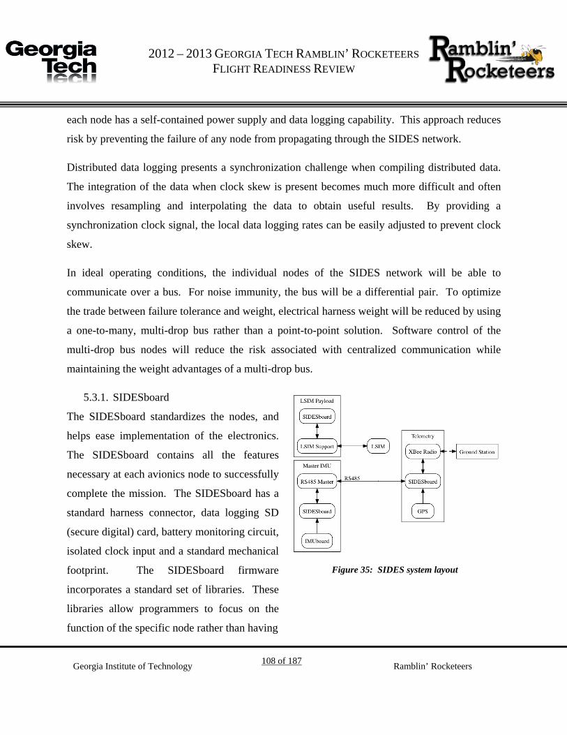
G 2012 – 2013 GEORGIA TECH RAMBLIN’ ROCKETEERS
FLIGHT READINESS REVIEW
Georgia Institute of Technology 108 of 187 Ramblin’ Rocketeers
each node has a self-contained power supply and data logging capability. This approach reduces
risk by preventing the failure of any node from propagating through the SIDES network.
Distributed data logging presents a synchronization challenge when compiling distributed data.
The integration of the data when clock skew is present becomes much more difficult and often
involves resampling and interpolating the data to obtain useful results. By providing a
synchronization clock signal, the local data logging rates can be easily adjusted to prevent clock
skew.
In ideal operating conditions, the individual nodes of the SIDES network will be able to
communicate over a bus. For noise immunity, the bus will be a differential pair. To optimize
the trade between failure tolerance and weight, electrical harness weight will be reduced by using
a one-to-many, multi-drop bus rather than a point-to-point solution. Software control of the
multi-drop bus nodes will reduce the risk associated with centralized communication while
maintaining the weight advantages of a multi-drop bus.
5.3.1. SIDESboard
The SIDESboard standardizes the nodes, and
helps ease implementation of the electronics.
The SIDESboard contains all the features
necessary at each avionics node to successfully
complete the mission. The SIDESboard has a
standard harness connector, data logging SD
(secure digital) card, battery monitoring circuit,
isolated clock input and a standard mechanical
footprint. The SIDESboard firmware
incorporates a standard set of libraries. These
libraries allow programmers to focus on the
function of the specific node rather than having
Figure 35: SIDES system layout

G 2012 – 2013 GEORGIA TECH RAMBLIN’ ROCKETEERS
FLIGHT READINESS REVIEW
Georgia Institute of Technology 109 of 187 Ramblin’ Rocketeers
to code the same functionality each time. The communication bus for the SIDESboard is
handled by an RS485 transceiver. The RS485 format is differential for noise rejection, bi-
directional to save weight in harness wiring, and multi-drop to reduce wiring complexity while
also saving weight. Risk of communication failure is considered to be acceptable for the
purposes of saving weight, because the consequences are low-impact by design. Figure 36 and
Figure 37 depict the SIDESboard PCB (Printed Circuit Board) design, supporting the features
listed above.
Figure 36: SIDESboard bottom side view
Figure 37: SIDESboard top side view
5.3.2. SIDES Electrical Harness

G 2012 – 2013 GEORGIA TECH RAMBLIN’ ROCKETEERS
FLIGHT READINESS REVIEW
Georgia Institute of Technology 110 of 187 Ramblin’ Rocketeers
The SIDES electrical harness within the Intimidator kit is extremely simple. Only the Telemetry
and MasterIMU can be wired together, and as such only require a handful of connections routed
between the two standard harness connectors.
5.3.3. Master IMU
The master IMU will house a triple axis accelerometer, gyroscope and magnetometer IMU, and
RS485 hardware. In particular, the Master IMU will facilitate sending data of interest to the
Telemetry node to be forwarded to the ground station.
5.3.4. Science Experiment Computer
The LSIM payload requires multiple vibration sensors, and will also actuate solenoids used to
control the MR fluid during the flight. Due to the switch from Vespulla MkII to the Intimidator
kit, integration changes have made connecting the Science Experiment Computer to the SIDES
network unreasonably difficult. Therefore, this unit will be equipped with an accelerometer to
ensure it can independently determine microgravity timing.
5.3.5. Telemetry
The Telemetry node fulfills the requirement 5 of transmitting the GPS data from the launch
vehicle to the ground station. The Telemetry node will make use of an Xbee GPS transceiver
and a SIDEDboard to log the GPS data while the Xbee is transmitting the data. An example of
the Xbee is depicted in Figure 38.
Figure 38: Xbee transceiver unit

G 2012 – 2013 GEORGIA TECH RAMBLIN’ ROCKETEERS
FLIGHT READINESS REVIEW
Georgia Institute of Technology 111 of 187 Ramblin’ Rocketeers
De-scope Options 5.4.
As part of the Ramblin’ Rocketeers’ Flight Systems package for the previous competition cycle,
a computer handling telemetry and GPS was built and flown. This computer has the capability
to run a solenoid driver and read the vibration sensors. Should the SIDES network need to be
de-scoped, this substitute hardware already exists and can be inserted into the system design with
minor modification. More info on this computer may be found in “De-scope Option: Flight
Computer Definition”.
Power Budget 5.5.
Table 31 details the power budget for SIDES.
Table 31. SIDES Power Budget.

G 2012 – 2013 GEORGIA TECH RAMBLIN’ ROCKETEERS
FLIGHT READINESS REVIEW
Georgia Institute of Technology 112 of 187 Ramblin’ Rocketeers
EM Interference 5.6.
Faraday cages and shielding webbing may be used to mitigate the risk of EM Interference from
both the telemetry devices and experiment solenoids. More analysis will be needed to determine
the amount of shielding require – for example, placement of electrical harness off-axis of the
experiment solenoids can negate much of the EMI risk inherent in a magnetics experiment. The
precise placement of harness has not been determined as of this point in the launch vehicle
development. Redundancy and robustness is key to the SIDES network and any node failures
should be survivable – further the ground station will provide an added redundancy through more
accurate communications should signal strength from the launch vehicle experience dramatic
fluctuations.
Transmission Frequencies and Protocols 5.7.
The telemetry system is designed to utilize two Xbee PRO 900-XSC modules for one-way
communication from the launch vehicle to the ground station. Using a simple, loss-tolerant
protocol with reliable delivery ensures the data is received if at all possible and that the
information is correct. The SIDES node controlling the Xbee module on-board the launch
vehicle will utilize a 900MHz monopole-monopole vertically polarized rubber duck antenna with
2 dBi gain and 100mW of power. This antenna’s performance is depicted graphically in Figure
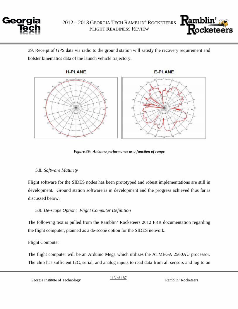
G 2012 – 2013 GEORGIA TECH RAMBLIN’ ROCKETEERS
FLIGHT READINESS REVIEW
Georgia Institute of Technology 113 of 187 Ramblin’ Rocketeers
39. Receipt of GPS data via radio to the ground station will satisfy the recovery requirement and
bolster kinematics data of the launch vehicle trajectory.
Figure 39: Antenna performance as a function of range
Software Maturity 5.8.
Flight software for the SIDES nodes has been prototyped and robust implementations are still in
development. Ground station software is in development and the progress achieved thus far is
discussed below.
De-scope Option: Flight Computer Definition 5.9.
The following text is pulled from the Ramblin’ Rocketeers 2012 FRR documentation regarding
the flight computer, planned as a de-scope option for the SIDES network.
Flight Computer
The flight computer will be an Arduino Mega which utilizes the ATMEGA 2560AU processor.
The chip has sufficient I2C, serial, and analog inputs to read data from all sensors and log to an

G 2012 – 2013 GEORGIA TECH RAMBLIN’ ROCKETEERS
FLIGHT READINESS REVIEW
Georgia Institute of Technology 114 of 187 Ramblin’ Rocketeers
SD card based on Sparkfun’s OpenLog break-out board. Additionally, the chip will run the
Fastrax UP501 GPS module and send the data to an Xbee PRO for transmission to the ground
station. An OpenLog board will provide logging capabilities. The board will be programmed in
the Arduino language, a subset of C++ with some additional libraries. Figure 40 provides a
generalization of proposed flight computer software. Table 32 lists the major components
utilized in this design.
Figure 40: Generalization of flight computer software

G 2012 – 2013 GEORGIA TECH RAMBLIN’ ROCKETEERS
FLIGHT READINESS REVIEW
Georgia Institute of Technology 115 of 187 Ramblin’ Rocketeers
Table 32: Major Flight Computer Components
Part Number Component Picture Description
1
The flight computer microprocessor, the
ATmega 2560
2
The GPS receiver, the Fastrax UP501
GPS module
3
The Xbee PRO 900-XSC module for
communication between launch vehicle
and ground station
4
The OpenLog board will provide logging
capability
Avionics Testing and Reliability Assurance 5.10.
Testing was performed on flight systems hardware in order to ensure in-flight success
while recording data and transmitting telemetry information. Test cases were written for each
major sensor to ensure proper hardware functionality. These test cases will be of significant

G 2012 – 2013 GEORGIA TECH RAMBLIN’ ROCKETEERS
FLIGHT READINESS REVIEW
Georgia Institute of Technology 116 of 187 Ramblin’ Rocketeers
value for debugging purposes. This will in turn lead to gains in the longevity of the system as
well as in efficiency of programming and future design. This process also led to the creation of a
document detailing the current utilization of input and output resources on each of the
SIDESBoards. Having this document will ensure that no pins will have overlapping utilization
and will facilitate future extensibility by making explicit remaining resources.
Ground Station 5.11.
Amateur rocketry is a test bed for novel aerospace designs; however, normal launches provide
little feedback beyond basic feasibility. This open loop makes it difficult to refine ideas and
identify meaningful or effective designs. While in many cases, acquiring such feedback could be
prohibitively expensive, many performance criteria for vehicles can be acquired through
relatively cheap means with some effort. Detailed visual observation of a launch vehicle can
provide meaningful insight into launch vehicle stability and other important design
considerations. Today even cheap digital cameras can provide levels of detail necessary to give
meaningful vehicle feedback.
Past missions flown by the Ramblin’ Rocketeers have encountered interesting performance
anomalies and have fallen victim to speculation due to limited data collection and some
provocative still camera images. By visually tracking the launch vehicle, unusual flight and
structural characteristics can be positively documented and close the design loop by providing
feedback for the next design iteration.
5.11.1. Purpose
The ground station is designed to ensure communication with and visual observation of the
launch vehicle. Communication quality will be ensured through the use of a high-gain directional
antenna. A digital video camera will be used to observe the launch vehicle throughout its flight.
The ground station will also feature a detachable GPS unit used to make recovery of the launch
vehicle easier.

G 2012 – 2013 GEORGIA TECH RAMBLIN’ ROCKETEERS
FLIGHT READINESS REVIEW
Georgia Institute of Technology 117 of 187 Ramblin’ Rocketeers
5.11.2. Function
Both the antenna and camera will be mounted on an alt-azimuthal mount. The mount will have
motors enabling automated rotation of the platform in both of its degrees of freedom. The motion
of the mount will be controlled by a microcontroller that will also be part of the ground station.
In addition to controlling the motors, the controller will also perform the wireless communication
that will receive signals from the launch vehicle via the antenna.
To effectively accomplish its objectives, the ground station must actively track the launch
vehicle throughout its flight. This will be accomplished in one of two ways. The first would use
telemetric data received from the launch vehicle to create a model of the vehicle’s motion. The
second would use a stereo camera system to create disparity maps of the launch vehicle’s motion
and translate these into a series of distance measurements. This could then be used to create a
similar model of motion. The camera zoom will also be adjusted throughout the flight to account
for the changing distance between the base station and the launch vehicle and attempt to
maintain a near constant level of detail.
Table 33: Ground station requirements
Requirement Design Feature
Satisfying
Requirement
Requirement Verification Success Criteria
Accurately receive
telemetric from launch
vehicle
High-gain
direction antenna
Analysis of received signals Sufficient information
for modeling motion
and retrieving launch
vehicle is received

G 2012 – 2013 GEORGIA TECH RAMBLIN’ ROCKETEERS
FLIGHT READINESS REVIEW
Georgia Institute of Technology 118 of 187 Ramblin’ Rocketeers
Requirement Design Feature
Satisfying
Requirement
Requirement Verification Success Criteria
Maintain constant visual
tracking of launch
vehicle
High optical
camera,
motorized mount
and control
algorithm
Review of captured video Launch vehicle remains
in FOV through apogee
Provide relative position
information of launch
vehicle for recovery
Detachable GPS
module
Successfully locate launch
vehicle
Successfully locate
launch vehicle

G 2012 – 2013 GEORGIA TECH RAMBLIN’ ROCKETEERS
FLIGHT READINESS REVIEW
Georgia Institute of Technology 119 of 187 Ramblin’ Rocketeers
5.11.3. Design Considerations
5.11.3.1. Choice of Antenna
Figure 41: Diagram of a helical antenna
Deciding on the proper type of antenna requires two opposing design characteristics: the
directionality and gain of the antenna. Choosing a higher gain antenna will allow for a greater
range of operation but would give a smaller beam width. This would increase dependence on the
tracking algorithm for ensuring signal quality. A helical antenna offers a good compromise
between these two considerations, with typical examples offering a half power beam width of
20-60° and boresight gains of 8-22 dB. This beam width would give some cushion for latency in
the tracking algorithm. The gain would also be sufficient to ensure good signal quality even
under non-line-of-sight propagation at considerable distance, such as might be the case after
landing.
Figure 42: Typical radiation pattern for a helical antenna

G 2012 – 2013 GEORGIA TECH RAMBLIN’ ROCKETEERS
FLIGHT READINESS REVIEW
Georgia Institute of Technology 120 of 187 Ramblin’ Rocketeers
5.11.3.2. Choice of Camera
The choice of video camera posed a similar design decision. Much like an antenna, a camera
provides a certain angular window of coverage. For a fixed number of pixels, increasing this
window will decrease the detail of the captured images. Unlike an antenna, however, these
parameters can be a dynamically changed through the use of zoom. A high optical zoom would
then allow for fairly high detail throughout the flight. Camera choice is further complicated by
the need to algorithmically adjust the zoom of the camera during flight. While this functionality
is built in to most digital cameras, it is seldom available to users programmatically. Models
supporting this functionality often do so at prohibitively high costs.
Figure 43: Canon Powershot SX260
The Canon Powershot SX260 seems to satisfy all of these requirements. The camera is capable
of recording video at 24FPS with an image size of 1920x1080 pixel. The camera also offers and
20x optical zoom. Assuming a 30° vertical field of view or a 60° horizontal field of view, these
parameters mean that at its furthest point, each pixel would correspond to 1.7inches of the launch
vehicle. This camera also offers access to a user-supported firmware known as the Canon Hack
Development Kit which provides direct access to camera operations not offered by factory
firmware. This will considerably simplify gaining direct electronic control of zoom.
5.11.3.3. Motor Sizing

G 2012 – 2013 GEORGIA TECH RAMBLIN’ ROCKETEERS
FLIGHT READINESS REVIEW
Georgia Institute of Technology 121 of 187 Ramblin’ Rocketeers
The ability of the platform to track the launch vehicle is inherently limited by the speed and
accuracy at which it can rotate. The rotational speed necessary will be dependent on the angular
velocity of the launch vehicle from the station’s reference frame. Assuming the launch vehicle’s
path is completely vertical from its Launchpad, the angular velocity of the launch vehicle is
given by:
𝑑𝜃𝑑𝑡
=𝑥𝑦′
𝑦2 + 𝑥2 (6)
Where x is the distance from the base station to the launch pad and y is the altitude of the launch
vehicle.
The maximum angular velocity of the launch vehicle will occur during the burn of the motor,
which will occur over the first two seconds of flight. At the end of this acceleration the launch
vehicle will be travelling at 177m/s.
This design will be used at events where participants will likely use at most class M motors. For
this size motor NAR requires a minimum personnel distance of 500 feet 5F
6, or approximately 150
meters. Assuming this distance for x and constant acceleration over the motor burn yields the
following equation:
𝑑𝜃𝑑𝑡
=88.5 ∗ 150𝑡
44.252𝑡4 + 15021𝑠
(7)
This function takes a value of approximately 0.62radians/s at t=1.4seconds. The motor must then
be capable of rotating the mount at a minimum of this speed. Once the moment of inertia for the
mounted camera and antenna has been decided, this value can be used to find the required torque
for the motor.
6 http://www.nar.org/NARhpsc.html

G 2012 – 2013 GEORGIA TECH RAMBLIN’ ROCKETEERS
FLIGHT READINESS REVIEW
Georgia Institute of Technology 122 of 187 Ramblin’ Rocketeers
5.11.3.4. Software Maturity
The software operation of the ground station can be broken into a number of logical
components. The process begins by configuring the unit, which consists of initializing contact
with the rocket and initializing the state variables for the rocket and ground station. Once this is
done, the station will then enter normal operation. This state consists of a loop which processes
incoming telemetry information, updating state information for the rocket, deciding whether to
update servo position, and deciding whether to update the zoom of the camera. During this
process, the station will also characterize the state using two Boolean variables, LAUNCHED
and LANDED. Once both of these variables become true, the loop will break, and the station
will transmit the resting coordinates of the rocket to the GPS Pendant. The figures below show
this process and the sub-processes involved in each of these steps.

G 2012 – 2013 GEORGIA TECH RAMBLIN’ ROCKETEERS
FLIGHT READINESS REVIEW
Georgia Institute of Technology 123 of 187 Ramblin’ Rocketeers
Figure 44: High-Level Software Process

G 2012 – 2013 GEORGIA TECH RAMBLIN’ ROCKETEERS
FLIGHT READINESS REVIEW
Georgia Institute of Technology 124 of 187 Ramblin’ Rocketeers
Figure 45: Updating Rocket State
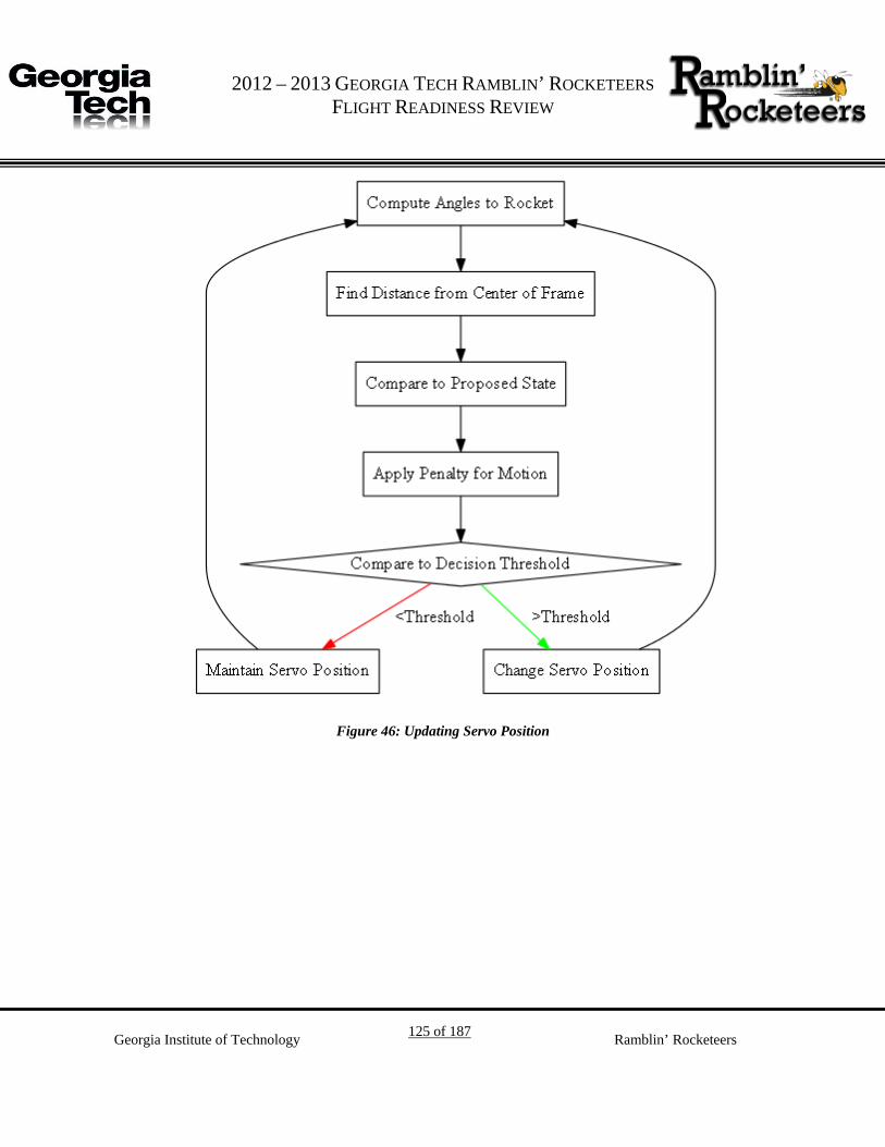
G 2012 – 2013 GEORGIA TECH RAMBLIN’ ROCKETEERS
FLIGHT READINESS REVIEW
Georgia Institute of Technology 125 of 187 Ramblin’ Rocketeers
Figure 46: Updating Servo Position

G 2012 – 2013 GEORGIA TECH RAMBLIN’ ROCKETEERS
FLIGHT READINESS REVIEW
Georgia Institute of Technology 126 of 187 Ramblin’ Rocketeers
Figure 47: Updating Camera Zoom

G 2012 – 2013 GEORGIA TECH RAMBLIN’ ROCKETEERS
FLIGHT READINESS REVIEW
Georgia Institute of Technology 127 of 187 Ramblin’ Rocketeers
Figure 48:Transmit Rocket Location
5.11.3.5. Effects of Excess RF Radiation on the Recovery Avionics
A simple testing procedure was implemented to ensure the safety of using the e-matches in
proximity to the transmitter. An Xbee transmitter operating at 100mW, with an omnidirectional
antenna was placed next to an e-match at several points of high transmission power along the
antenna and in the near field. The transmitter then sent a variety of packets varying in length
from a single byte to the entire ASCII alphabet. At no point during transmission did the e-match
ignite. This result was expected given the low output power of the transmitter.

G 2012 – 2013 GEORGIA TECH RAMBLIN’ ROCKETEERS
FLIGHT READINESS REVIEW
Georgia Institute of Technology 128 of 187 Ramblin’ Rocketeers
Avionics Mechanical Integration 5.12.
The avionics and other electronic systems will be fixed to the rocket through the use of a wooden
sled fixed vertically to wooden ribs on the interior of the booster section of the rocket. The
circuit boards will be bolted to the sled and their batteries will be zip-tied to the sled. The same
method is used to mount the supporting electronics for the scientific payload.

G 2012 – 2013 GEORGIA TECH RAMBLIN’ ROCKETEERS
FLIGHT READINESS REVIEW
Georgia Institute of Technology 129 of 187 Ramblin’ Rocketeers
6. General Safety
Vehicle Safety and Environment 6.1.
6.1.1. Overview
Ensuring the safety of our members during building, testing and implementation of the payload
experiment is an ideal condition. Procedures have been created and implemented in all of our
build environments to ensure safety requirements are met and exceeded. A key way the Ramblin'
Rocketeers ensure team safety is to always work in teams of at least two when using equipment
or during construction. This guarantees that should an incident occur with a device the other
member could provide immediate assistance or quickly get addition help if required. The
Invention Studio where the team does a majority of its work is equipped with safety glasses, fire
extinguishers, first aid kits, and expert personnel in the use of each of the machines in the area.
All the members of the payload and flight systems teams have been briefed on the proper
procedures and proper handling of machines in the labs.

G 2012 – 2013 GEORGIA TECH RAMBLIN’ ROCKETEERS
FLIGHT READINESS REVIEW
Georgia Institute of Technology 130 of 187 Ramblin’ Rocketeers
Table 34: Risk Identification and Mitigation Steps
Step Name Step Definition
Hazard Identification The first step is to correctly identify potential
hazards that could cause serious injury or death.
Hazard identification will be achieved through
team safety sessions and brainstorming.
Risk and Hazard Assessment Every hazard will undergo extensive analysis to
determine how serious the issue is and the best way
to approach the issue.
Risk Control and Elimination After the hazards are identified and assessed a
method is produced to avoid the issue.
Reviewing Assessments As new information becomes available the
assessments will be reviewed and revised as
necessary.
The steps outlined above in Table 34 are being used to develop a set of standard operating
procedures for launch vehicle construction, payload construction, ground testing, and on all
launch day safety checklists.
6.1.2. Mission Assurance
The top priority of the Ramblin' Rocketeers is the completion of a safe, successful mission with
minimal risk and in-flight anomalies. For this reason, a comprehensive review of all risks
associated with the flight of the launch vehicle must be undertaken to gain a fuller understanding
what can go wrong from the ground preparation stage to vehicle recovery. Risks associated with
the mission may be classified by the probability of occurrence and the severity of a failure.
Table 35 provides a risk assessment matrix with color coding for composite risk severity and risk
class identification for easy reference at a later time.
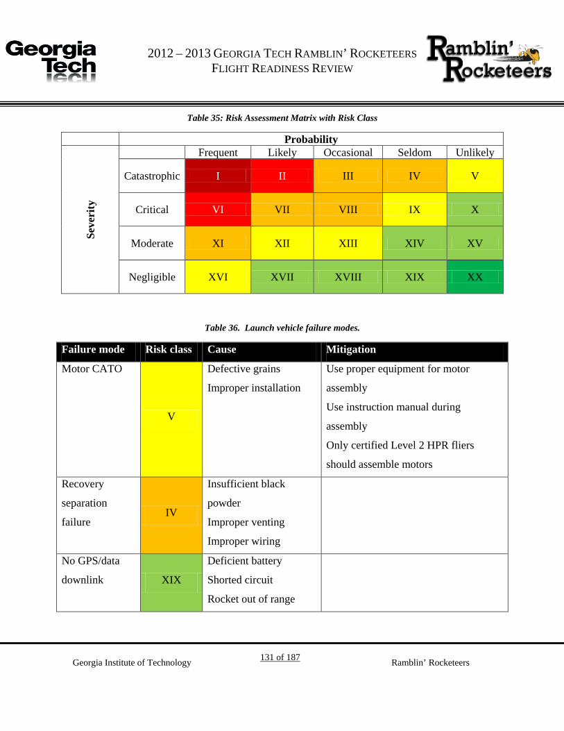
G 2012 – 2013 GEORGIA TECH RAMBLIN’ ROCKETEERS
FLIGHT READINESS REVIEW
Georgia Institute of Technology 131 of 187 Ramblin’ Rocketeers
Table 35: Risk Assessment Matrix with Risk Class
Probability
Seve
rity
Frequent Likely Occasional Seldom Unlikely
Catastrophic I II III IV V
Critical VI VII VIII IX X
Moderate XI XII XIII XIV XV
Negligible XVI XVII XVIII XIX XX
Table 36. Launch vehicle failure modes.
Failure mode Risk class Cause Mitigation
Motor CATO
V
Defective grains
Improper installation
Use proper equipment for motor
assembly
Use instruction manual during
assembly
Only certified Level 2 HPR fliers
should assemble motors
Recovery
separation
failure IV
Insufficient black
powder
Improper venting
Improper wiring
No GPS/data
downlink XIX
Deficient battery
Shorted circuit
Rocket out of range

G 2012 – 2013 GEORGIA TECH RAMBLIN’ ROCKETEERS
FLIGHT READINESS REVIEW
Georgia Institute of Technology 132 of 187 Ramblin’ Rocketeers
Payload Safety 6.2.
As already mentioned in General Safety, the same methodology to identify and assess risks for
vehicle safety will be used to identify hazards for the payload. The entire payload and flight
systems teams have been briefed on the possible hazards they may encounter while working with
the payload and how to go about avoiding them. Some of these hazards include inhaling small
iron powder, ingesting inedible substances, and touching harmful materials. Mitigation steps
have been identified for these potential threats. Other hazards that relate specifically to the
payload are listed in Table 37. Payload failure modes are outlined in `Table 38.
Table 37. Payload hazards and mitigation
Hazard Risk Assessment Control & Mitigation
Electrocution Serious Injury/death Do not touch wires that are hot and not
insulated. Wear rubber gloves when
the device is in operation. Handle
leads to the power supply with care.
Use low voltage settings whenever
possible.
Electromagnetic Fields Interfere with electronic
devices inside the body
Ground test equipment, keep people
with electronic components in them
away from the coil when the
electromagnetic coil is in use.
Epoxy/glue Toxic fumes, skin
irritation, eye irritation
Work in well ventilated areas to
prevent a buildup of fumes. Gloves
face masks, and safety glasses will be
worn at all times to prevent irritation.
Fire Burns, serious injury and
death
Keep a fire extinguisher in the lab. If
an object becomes too hot or starts to
burn, cut power and be prepared to use

G 2012 – 2013 GEORGIA TECH RAMBLIN’ ROCKETEERS
FLIGHT READINESS REVIEW
Georgia Institute of Technology 133 of 187 Ramblin’ Rocketeers
Hazard Risk Assessment Control & Mitigation
a fire extinguisher.
Soldering Iron Burns, solder splashing
into eyes
Wear safety glasses to prevent damage
to eyes. Do not handle the soldering
lead directly only touch handle. Do not
directly hold an object being soldered.
Drills Serious injury, cuts,
punctures, and scrapes
Only operate tools under supervision
of team mates. Only use tools in the
appropriate manner. Wear safety
glasses to prevent debris from entering
the eyes
Dremel Serious injury, cuts, and
scrapes
Only operate tools under supervision
of team mates. Only use tools in the
appropriate manner. Wear safety
glasses to prevent debris from entering
the eyes
Hand Saws Cuts, serious injury Only use saws under supervision of
team mates. Only use tools in the
appropriate manner. Wear safety
glasses to prevent debris from entering
the eyes. Do not cut in the direction of
yourself or others.
Exacto Knives Cuts, serious injury,
death
Only use knives under supervision of
team mates. Only use tools in the
appropriate manner. Do not cut in the
direction of yourself or others.
Hammers Bruises, broken bones, Be careful to avoid hitting your hand
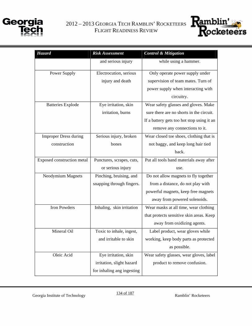
G 2012 – 2013 GEORGIA TECH RAMBLIN’ ROCKETEERS
FLIGHT READINESS REVIEW
Georgia Institute of Technology 134 of 187 Ramblin’ Rocketeers
Hazard Risk Assessment Control & Mitigation
and serious injury while using a hammer.
Power Supply Electrocution, serious
injury and death
Only operate power supply under
supervision of team mates. Turn of
power supply when interacting with
circuitry.
Batteries Explode Eye irritation, skin
irritation, burns
Wear safety glasses and gloves. Make
sure there are no shorts in the circuit.
If a battery gets too hot stop using it an
remove any connections to it.
Improper Dress during
construction
Serious injury, broken
bones
Wear closed toe shoes, clothing that is
not baggy, and keep long hair tied
back.
Exposed construction metal Punctures, scrapes, cuts,
or serious injury
Put all tools band materials away after
use.
Neodymium Magnets Pinching, bruising, and
snapping through fingers.
Do not allow magnets to fly together
from a distance, do not play with
powerful magnets, keep free magnets
away from powered solenoids.
Iron Powders Inhaling, skin irritation Wear masks at all time, wear clothing
that protects sensitive skin areas. Keep
away from oxidizing agents.
Mineral Oil Toxic to inhale, ingest,
and irritable to skin
Label product, wear gloves while
working, keep body parts as protected
as possible.
Oleic Acid Eye irritation, skin
irritation, slight hazard
for inhaling ang ingesting
Wear safety glasses, wear gloves, label
product to remove confusion.
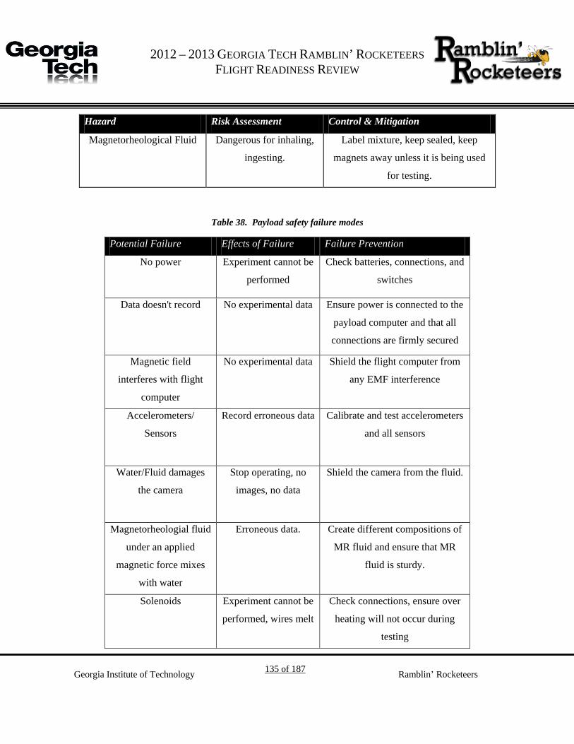
G 2012 – 2013 GEORGIA TECH RAMBLIN’ ROCKETEERS
FLIGHT READINESS REVIEW
Georgia Institute of Technology 135 of 187 Ramblin’ Rocketeers
Hazard Risk Assessment Control & Mitigation
Magnetorheological Fluid Dangerous for inhaling,
ingesting.
Label mixture, keep sealed, keep
magnets away unless it is being used
for testing.
Table 38. Payload safety failure modes
Potential Failure Effects of Failure Failure Prevention
No power Experiment cannot be
performed
Check batteries, connections, and
switches
Data doesn't record No experimental data Ensure power is connected to the
payload computer and that all
connections are firmly secured
Magnetic field
interferes with flight
computer
No experimental data Shield the flight computer from
any EMF interference
Accelerometers/
Sensors
Record erroneous data Calibrate and test accelerometers
and all sensors
Water/Fluid damages
the camera
Stop operating, no
images, no data
Shield the camera from the fluid.
Magnetorheologial fluid
under an applied
magnetic force mixes
with water
Erroneous data. Create different compositions of
MR fluid and ensure that MR
fluid is sturdy.
Solenoids Experiment cannot be
performed, wires melt
Check connections, ensure over
heating will not occur during
testing

G 2012 – 2013 GEORGIA TECH RAMBLIN’ ROCKETEERS
FLIGHT READINESS REVIEW
Georgia Institute of Technology 136 of 187 Ramblin’ Rocketeers
Potential Failure Effects of Failure Failure Prevention
Too much current goes
into the solenoids
The wires in the
solenoids get very hot
Make sure current is only pulsed
into the solenoids
Improper dress during
construction
Maiming, cuts,
scrapes, serious
injury.
Do not wear open toed shoes in
the build lab. Keep long hair tied
back. Do not wear baggy
clothing.
Avionics Chips or boards are
manufactured
incorrectly causing
equipment failures
and misfires
Test avionics operations, and
perform a flight test.
Personnel and Environmental Hazards 6.3.
As already mentioned in Section 6.1.1, the same methodology to identify and assess risks for
vehicle and payload safety will be used to identify hazards for constructing various flight and
testing components. A Material Safety Data Sheet (MSDS) is on hand for all materials used in
the construction of components, and team members have been briefed on best practices for
creating a safe workplace. Table 39 lists possible environmental safety concerns.

G 2012 – 2013 GEORGIA TECH RAMBLIN’ ROCKETEERS
FLIGHT READINESS REVIEW
Georgia Institute of Technology 137 of 187 Ramblin’ Rocketeers
Table 39: Environmental Hazards, Risks, and Mitigation
Hazard Risk Assessment Control & Mitigation
Electrocution Serious Injury/death Do not touch wires that are hot and
not insulated. Wear rubber gloves
when the device is in operation.
Handle leads to the power supply
with care. Use low voltage settings
whenever possible.
Electromagnetic Fields Interfere with
electronic devices
inside the body
Ground test equipment, keep
people with electronic components
in them away from the coil when
the electromagnetic coil is in use.
Epoxy/glue Toxic fumes, skin
irritation, eye irritation
Work in well ventilated areas to
prevent a buildup of fumes. Gloves
face masks, and safety glasses will
be worn at all times to prevent
irritation.
Fire Burns, serious injury
and death
Keep a fire extinguisher in the lab.
If an object becomes too hot or
starts to burn, cut power and be
prepared to use a fire extinguisher.

G 2012 – 2013 GEORGIA TECH RAMBLIN’ ROCKETEERS
FLIGHT READINESS REVIEW
Georgia Institute of Technology 138 of 187 Ramblin’ Rocketeers
Hazard Risk Assessment Control & Mitigation
Soldering Iron Burns, solder splashing
into eyes
Wear safety glasses to prevent
damage to eyes. Do not handle the
soldering lead directly only touch
handle. Do not directly hold an
object being soldered.
Drills Serious injury, cuts,
punctures, and scrapes
Only operate tools under
supervision of team mates. Only
use tools in the appropriate manner.
Wear safety glasses to prevent
debris from entering the eyes
Dremel Serious injury, cuts,
and scrapes
Only operate tools under
supervision of team mates. Only
use tools in the appropriate manner.
Wear safety glasses to prevent
debris from entering the eyes
Hand Saws Cuts, serious injury Only use saws under supervision of
team mates. Only use tools in the
appropriate manner. Wear safety
glasses to prevent debris from
entering the eyes. Do not cut in the
direction of yourself or others.
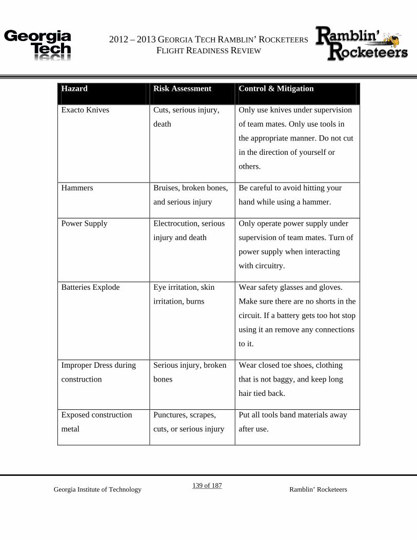
G 2012 – 2013 GEORGIA TECH RAMBLIN’ ROCKETEERS
FLIGHT READINESS REVIEW
Georgia Institute of Technology 139 of 187 Ramblin’ Rocketeers
Hazard Risk Assessment Control & Mitigation
Exacto Knives Cuts, serious injury,
death
Only use knives under supervision
of team mates. Only use tools in
the appropriate manner. Do not cut
in the direction of yourself or
others.
Hammers Bruises, broken bones,
and serious injury
Be careful to avoid hitting your
hand while using a hammer.
Power Supply Electrocution, serious
injury and death
Only operate power supply under
supervision of team mates. Turn of
power supply when interacting
with circuitry.
Batteries Explode Eye irritation, skin
irritation, burns
Wear safety glasses and gloves.
Make sure there are no shorts in the
circuit. If a battery gets too hot stop
using it an remove any connections
to it.
Improper Dress during
construction
Serious injury, broken
bones
Wear closed toe shoes, clothing
that is not baggy, and keep long
hair tied back.
Exposed construction
metal
Punctures, scrapes,
cuts, or serious injury
Put all tools band materials away
after use.
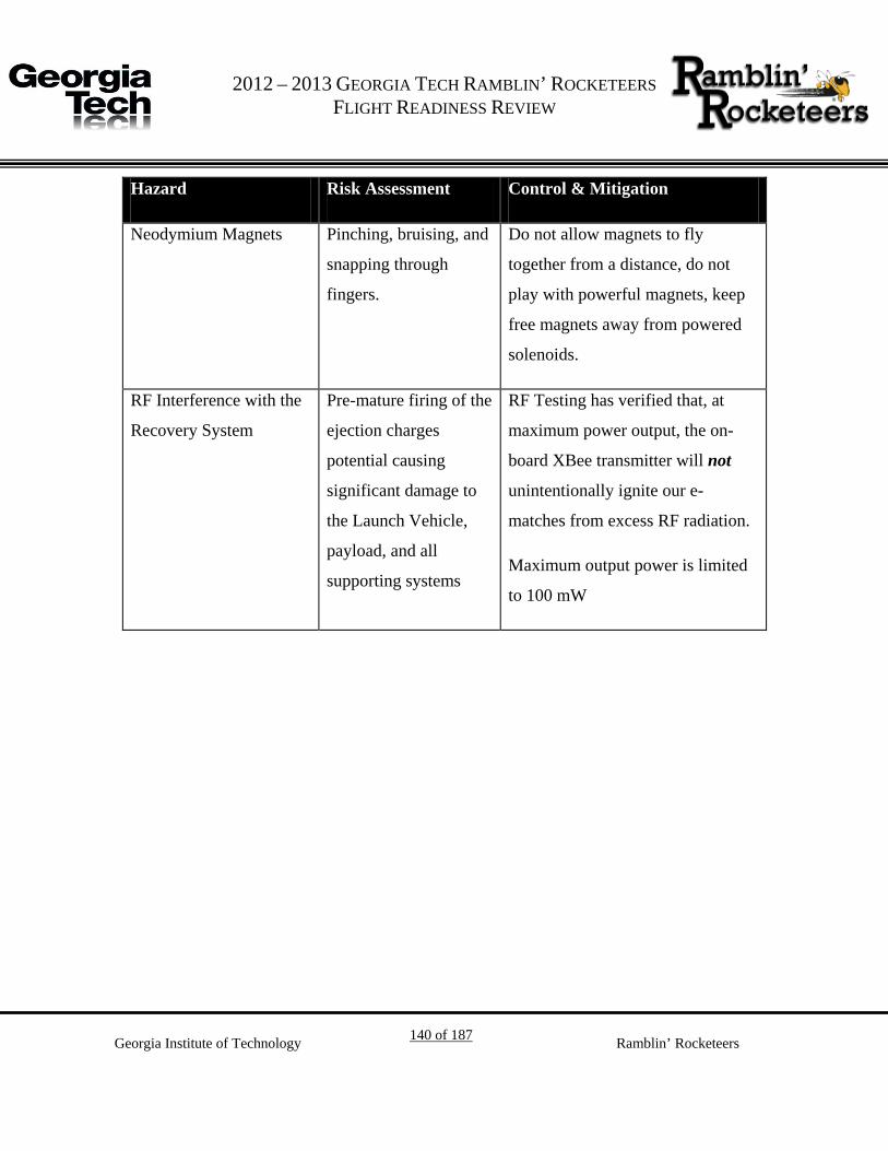
G 2012 – 2013 GEORGIA TECH RAMBLIN’ ROCKETEERS
FLIGHT READINESS REVIEW
Georgia Institute of Technology 140 of 187 Ramblin’ Rocketeers
Hazard Risk Assessment Control & Mitigation
Neodymium Magnets Pinching, bruising, and
snapping through
fingers.
Do not allow magnets to fly
together from a distance, do not
play with powerful magnets, keep
free magnets away from powered
solenoids.
RF Interference with the
Recovery System
Pre-mature firing of the
ejection charges
potential causing
significant damage to
the Launch Vehicle,
payload, and all
supporting systems
RF Testing has verified that, at
maximum power output, the on-
board XBee transmitter will not
unintentionally ignite our e-
matches from excess RF radiation.
Maximum output power is limited
to 100 mW

G 2012 – 2013 GEORGIA TECH RAMBLIN’ ROCKETEERS
FLIGHT READINESS REVIEW
Georgia Institute of Technology 141 of 187 Ramblin’ Rocketeers
7. Project Budget
Funding Overview 7.1.
In order to fund the 2012-2013 Competition year, the Ramblin’ Rocketeers have sought
sponsorships from academic and industry sources. The current sponsors of the Ramblin’
Rocketeers and their contributions can be found in Table 40. As of CDR, the Ramblin’
Rocketeers have received $5,700 in funding. Furthermore, the Team has also received a
dedicated room in which the Team can construct and store their rocket and non-explosive
components. All explosive components (i.e. black power) are properly stored in Fire Lockers in
either the Ben T. Zinn Combustion Laboratory or the Center for Space Systems Flight Hardware
Laboratory.
Table 40. Summary of sponsors for the Ramblin. Rocketeers
Sponsor Contribution Date
Unused Funds from 2011-2012 $1,000 Aug 2012
Georgia Space Grant Consortium $2,500 Sept 2012
Georgia Space Grant Consortium $500 Sept 2012
Georgia Space Grant Consortium $1,000 Dec 2012
Generation Orbit $300 Dec 2012
Georgia Tech
Student Government Association
$1,000 Feb 2013
Georgia Tech
School of Aerospace Engineering
$2,000 Mar 2013
ATK Travel Stipend $400 (est) Apr 2011
ATK Motor Stipend $200 (est) Apr 2011
Total $8,900
The team is currently pursuing the following sponsors: Virgin Galactic, Georgia Tech – College
of Engineering, Georgia Tech SGA, as well as private donations.

G 2012 – 2013 GEORGIA TECH RAMBLIN’ ROCKETEERS
FLIGHT READINESS REVIEW
Georgia Institute of Technology 142 of 187 Ramblin’ Rocketeers
Current Sponsors 7.2.
Table 41 lists the current sponsors of the Ramblin’ Rocketeers and their contributions.
Table 41. List of current sponsors of the Ramblin' Rocketeers.
Sponsor Contribution
Georgia Space
Grant Consortium
Financial contribution for general project expenses
Financial contribution for Outreach-specific expenses
Financial contribution for RGEFP-related activities.
Advanced Circuits Manufacturing of the SIDES boards throughout the design
process
Generation Orbit Financial contributions for general project expenses.
Huff Performance Discounts on motor and motor hardware
Georgia Tech
Invention Studio
Professional machines and tooling to fabricate the launch vehicle
and payload components
Actual Project Cost 7.3.
7.3.1. FRR Budget Summary
Table 42 illustrates the budget breakdown as of the CDR Milestone. The summary is broken
down into four (4) main categories: Launch Vehicle, Flight Systems, Operations, and Motors.
The Launch Vehicle and Flight Systems categories are further broken down into two (2) sub-
categories: Flight Hardware and Testing. Operational expenses are broken down into four (4)
sub-categories: Safety, Generic Supplies, Tooling, and Physical Capital. Lastly, while motors are
specific to the Launch Vehicle subsystem, they are critical component to the architecture and as
such are tracked separately from the Launch Vehicle subsystem.

G 2012 – 2013 GEORGIA TECH RAMBLIN’ ROCKETEERS
FLIGHT READINESS REVIEW
Georgia Institute of Technology 143 of 187 Ramblin’ Rocketeers
Table 42. FRR Project Budget Summary.
Category Amt Spent Amt Remaining
Launch Vehicle $ 1,707.78 $ 92.22
Motors $ 300.00 $ 700.00
Flight Systems $ 84.09 $ 915.91
Operations $ 202.25 $ 1,272.75
Testing/Dev $ 1,702.73 $ 47.27
7.3.2. System-Level Budget Summary
Figure 49 illustrates the system-level expenditure summary for Project LSIM at the FRR
milestone. Cost reduction techniques, such as proper resource utilization has resulted in lower
Flight Systems costs. It is important to note that both the Launch Vehicle and Flight Systems
include both Flight Hardware costs in addition to Test/Development costs. Additionally, Figure
50 illustrates the breakdown.
System Expenditure Breakdown
Launch Vehicle $ 661.75
Flight Systems $ 362.32
Operations $ 202.25
Motors $ 300.00
Testing/Development $ 1,702.73
Outreach $ 20.00
Total $ 3,249.10
Figure 49. System expenditure summary at CDR.

G 2012 – 2013 GEORGIA TECH RAMBLIN’ ROCKETEERS
FLIGHT READINESS REVIEW
Georgia Institute of Technology 144 of 187 Ramblin’ Rocketeers
Sub-system Testing/Development
Breakdown
Aerodynamics $ 346.42
Structures $ 639.61
Recovery $ 0.00
Avionics $ 142.32
Payload/Ground
Testing $ 514.38
Ground Station $ 0.00
Total $ 1,642.73 Figure 50. Sub-system Testing/Development Breakdown.
7.3.3. Flight Hardware Expenditures
7.3.3.1. Flight Hardware Expenditure Overview
Figure 51 summarizes the overall expenditures for all Flight Hardware purchased up to the CDR
milestone. In order to account for uncertainties in motor price, $300 has been allotted for the
purchase of the flight motor. As illustrated by Figure 51, only hardware for the Aerodynamics
and Mechanical Integration sub-systems has been purchased.

G 2012 – 2013 GEORGIA TECH RAMBLIN’ ROCKETEERS
FLIGHT READINESS REVIEW
Georgia Institute of Technology 145 of 187 Ramblin’ Rocketeers
Sub-system Flight Hardware
Breakdown
Aerodynamics $140.73
Structures $473.31
Recovery $102.29
Motors/Motor
Hardware $ 300.0
Mechanical
Integration $ 84.09
Electrical
Integration $ 0.00
Flight
Avionics $ 121.84
Flight Payload $ 156.39
Total $ 1,378.65
Figure 51. Sub-System Flight Hardware Breakdown.
7.3.3.2. Flight Hardware Cost Breakdown
Figure 52 lists the flight hardware breakout for Flight Systems. It is important to note that the
materials purchased for the Launch Vehicle flight hardware has not been used to fabricate any
parts, therefore no breakout is available at this time for the launch vehicle.

G 2012 – 2013 GEORGIA TECH RAMBLIN’ ROCKETEERS
FLIGHT READINESS REVIEW
Georgia Institute of Technology 146 of 187 Ramblin’ Rocketeers
Flight Experiment
Item Description Unit Price Qty Cost
L.S.I.M. Hardware $ 156.39 1 $ 156.39
Propellant Simulant
(Water) $ 0.01 2 $ 0.02
2” Diameter PVC
Pipe $ 9.24 2 $ 18.47
Balance Solenoids $ 0.83 36 $ 30.00
Camera Assembly $ 50.00 2 $ 100.00
Piezo Vibration
Sensor $ 2.95 2 $ 5.90
Base Plate $ 0.50 2 $ 1.00
Payload Bottom $ 0.50 1 $48.00
Total Flight Experiment Costs $ 156.39
Flight Avionics
Item Description Unit Price Qty Cost
SIDES Network $ 416.70 1 $ 416.70
SIDES Board $ 33.00 5 $ 165.00
Electrical Harness $ 45.00 1 $ 45.00
ClockDrive Board $ 15.00 1 $ 15.00
LSIM Board $ 25.00 1 $ 25.00
Telemetry Board $ 15.00 1 $ 15.00
MasterIMU $ 20.00 1 $ 20.00
Strain Gage Board $ 15.00 2 $ 30.00
SIDES Node Battery $ 8.95 6 $ 53.70
LSIM Battery $ 48.00 1 $ 48.00
Total Flight Avionics Cost $ 416.70
Figure 52. Flight Systems flight hardware breakout.

G 2012 – 2013 GEORGIA TECH RAMBLIN’ ROCKETEERS
FLIGHT READINESS REVIEW
Georgia Institute of Technology 147 of 187 Ramblin’ Rocketeers
8. Project Schedule
Schedule Overview 8.1.
The Mile High Yellow Jacket’s project is driven by the design milestone’s set forth by the USLI
Program Office. The design milestones are listed in Table 43. The project Gantt Chart for Project
L.S.I.M. – located in Appendix I – contains only high-level activities due to the unique launch
vehicle and payload designs. A more detailed Critical Path chart is located in Section 8.2.
Table 43. Design milestones set by the USLI Program Office.
Milestone Date
Proposal 26 SEP Team Selection 17 OCT
Web Presence Established 4 NOV PDR Documentation 28 NOV
PDR VTC 6 DEC CDR Documentation 23 JAN
CDR VTC 2 FEB FRR Documentation 26 MAR
FRR VTC 2-11 APR Rocket Week 18-21 APR
PLAR Documentation 7 MAY

G 2012 – 2013 GEORGIA TECH RAMBLIN’ ROCKETEERS
FLIGHT READINESS REVIEW
Georgia Institute of Technology 148 of 187 Ramblin’ Rocketeers
Critical Path Chart: CDR to PLAR 8.2.
The critical path chart illustrated by Figure 6 demonstrates the highly integrated nature of Project
L.S.I.M. The critical path chart identifies:
• High Risk Tasks • Low-Moderate Risk Tasks • Earned Value Management (EVM)
Goal Tasks
• Looping Tasks • Critical and Alternate Paths • Major Inputs to Tasks

2012 – 2013 Georgia Tech Ramblin’ Rocketeers Flight Readiness Review
Figure 53. Critical Path Chart from CDR to PLAR
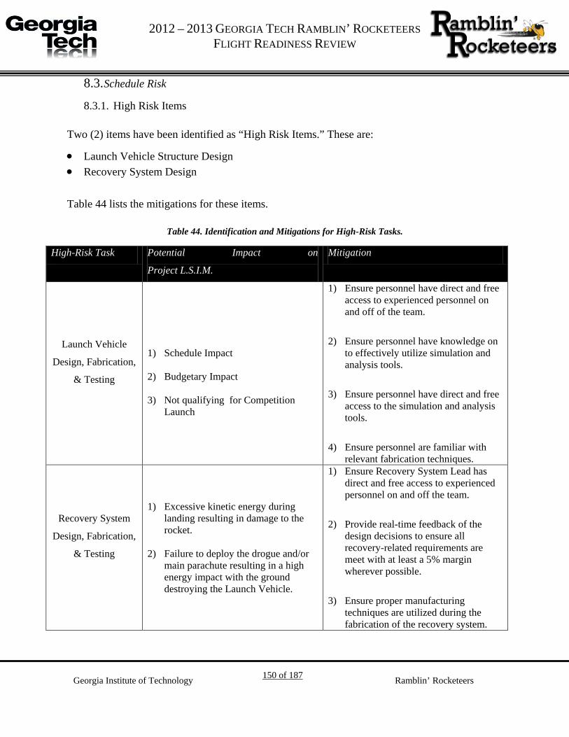
G 2012 – 2013 GEORGIA TECH RAMBLIN’ ROCKETEERS
FLIGHT READINESS REVIEW
Georgia Institute of Technology 150 of 187 Ramblin’ Rocketeers
Schedule Risk 8.3.
8.3.1. High Risk Items
Two (2) items have been identified as “High Risk Items.” These are:
• Launch Vehicle Structure Design • Recovery System Design
Table 44 lists the mitigations for these items.
Table 44. Identification and Mitigations for High-Risk Tasks.
High-Risk Task Potential Impact on
Project L.S.I.M.
Mitigation
Launch Vehicle
Design, Fabrication,
& Testing
1) Schedule Impact
2) Budgetary Impact
3) Not qualifying for Competition Launch
1) Ensure personnel have direct and free access to experienced personnel on and off of the team.
2) Ensure personnel have knowledge on to effectively utilize simulation and analysis tools.
3) Ensure personnel have direct and free access to the simulation and analysis tools.
4) Ensure personnel are familiar with relevant fabrication techniques.
Recovery System
Design, Fabrication,
& Testing
1) Excessive kinetic energy during landing resulting in damage to the rocket.
2) Failure to deploy the drogue and/or main parachute resulting in a high energy impact with the ground destroying the Launch Vehicle.
1) Ensure Recovery System Lead has direct and free access to experienced personnel on and off the team.
2) Provide real-time feedback of the design decisions to ensure all recovery-related requirements are meet with at least a 5% margin wherever possible.
3) Ensure proper manufacturing techniques are utilized during the fabrication of the recovery system.
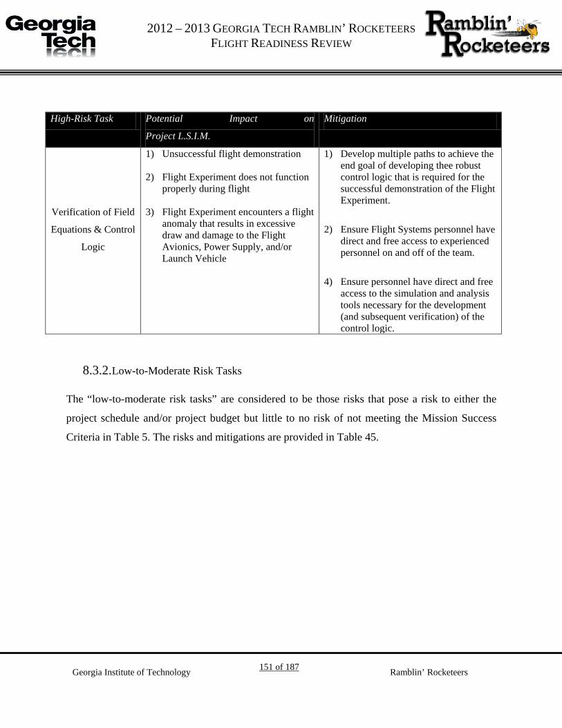
G 2012 – 2013 GEORGIA TECH RAMBLIN’ ROCKETEERS
FLIGHT READINESS REVIEW
Georgia Institute of Technology 151 of 187 Ramblin’ Rocketeers
High-Risk Task Potential Impact on
Project L.S.I.M.
Mitigation
Verification of Field
Equations & Control
Logic
1) Unsuccessful flight demonstration
2) Flight Experiment does not function properly during flight
3) Flight Experiment encounters a flight anomaly that results in excessive draw and damage to the Flight Avionics, Power Supply, and/or Launch Vehicle
1) Develop multiple paths to achieve the end goal of developing thee robust control logic that is required for the successful demonstration of the Flight Experiment.
2) Ensure Flight Systems personnel have direct and free access to experienced personnel on and off of the team.
4) Ensure personnel have direct and free access to the simulation and analysis tools necessary for the development (and subsequent verification) of the control logic.
8.3.2. Low-to-Moderate Risk Tasks
The “low-to-moderate risk tasks” are considered to be those risks that pose a risk to either the
project schedule and/or project budget but little to no risk of not meeting the Mission Success
Criteria in Table 5. The risks and mitigations are provided in Table 45.

G 2012 – 2013 GEORGIA TECH RAMBLIN’ ROCKETEERS
FLIGHT READINESS REVIEW
Georgia Institute of Technology 152 of 187 Ramblin’ Rocketeers
Table 45. Low to Moderate Risk items and mitigiations.
Risk Risk Level Potential Impact on
Project A.P.E.S.
Mitigation
Fabrication of
Launch Vehicle
Sections
Moderate 1) Schedule Impact 2) Budgetary Impact 3) Not qualifying for
Competition Launch
1) Ensure Manufacturing and Fabrication Orders (MFO’s) are sufficiently detailed for the task prior to starting any fabrication.
2) Ensure proper manufacturing techniques are observed during fabrication.
Full-Scale Launch
Vehicle Test Flight
Moderate 1) Schedule Impact 2) Budgetary Impact 3) Not qualifying for
Competition Launch
1) Ensure Launch Procedures are established practiced prior to any launch opportunity.
2) Have a sufficient number of launch opportunities that are in different geographical areas as to minimize the effects of weather on the number of launch opportunities.
Flight Computer
Fabrication Low
1) Budgetary Impact 2) Not able to collect in-
flight data
1) Ensure proper manufacturing techniques are observed during fabrication.
2) Ensure Manufacturing and Fabrication Orders (MFO’s) are sufficiently detailed for the task.
3) Descope custom board to COTS hardware
Ground Testing &
Control Logic
Development
Moderate 1) Schedule Impact 2) No Experimental Flight
Data is recorded prior to the Competition Launch.
1) Ensure personnel have direct and free access to experienced personnel on and off of the team.

G 2012 – 2013 GEORGIA TECH RAMBLIN’ ROCKETEERS
FLIGHT READINESS REVIEW
Georgia Institute of Technology 153 of 187 Ramblin’ Rocketeers
9. Educational Engagement Plan and Status
Overview 9.1.
The goal of Georgia Tech’s outreach program is
to promote interest in the Science, Technology,
Engineering, and Mathematics (STEM) fields.
The Ramblin’ Rocketeers intend to conduct
various outreach programs targeting middle
school students and educators. The Ramblin’
Rocketeers will also have an outreach request
form on their webpage for educators to request
presentations or hands-on activities for their classroom.
Atlanta Makers’ Faire 9.2.
Ramblin’ Rocketeers had a booth at the Atlanta Makers Fair,
a fair in which various craftsman from the community and
Georgia Tech assemble to show off their accomplishments.
The intent of this program is to give clubs, organizations, and
other hobbyists the opportunity to show others their unique
creations and skills. The event is open to the entire Atlanta
community and had a large attendance this year. The
Ramblin’ Rocketeers booth had a display of our various rockets, as well as a station for children
to make their own paper rockets. Our booth had 10-15 middle school aged children attend and
participate in the paper-rocket activity.
FIRST Lego League and Tech Challenge 9.3.
FIRST is a series of international robotics competitions for students from 3rd -12th grades.
FIRST Lego League is an engineering competition designed for middle school children in which
Figure 54. Participation at the Atlanta Makers' Faire.
Figure 55: Previous FIRST Lego League outreach event.

G 2012 – 2013 GEORGIA TECH RAMBLIN’ ROCKETEERS
FLIGHT READINESS REVIEW
Georgia Institute of Technology 154 of 187 Ramblin’ Rocketeers
they build and compete with an autonomous MINDSTORMS robot. Every year there is a new
competition centered on a theme exploring a real-world problem. FIRST Tech Challenge is a
robotics competition designed for students in middle and high school where the robots can be
18x18x18 inches at the start of each match.
This year the Ramblin’ Rocketeers have had an educational booth at a FIRST Lego League
Regional Competition at Wheeler High School which occurred on Saturday, December 8th.At the
booth students ranging from 3rd-8th grade were exposed to how lift is generated and participated
in building a paper rocket with a straw launcher that they could take with them. The event
reached 373 students, 295 of which were in the 4th-9th grade range, and 31 educators. Below in
Figure 56 and Figure 57 are pictures from this event.
Figure 56: FLL Regional Event at Wheel High School
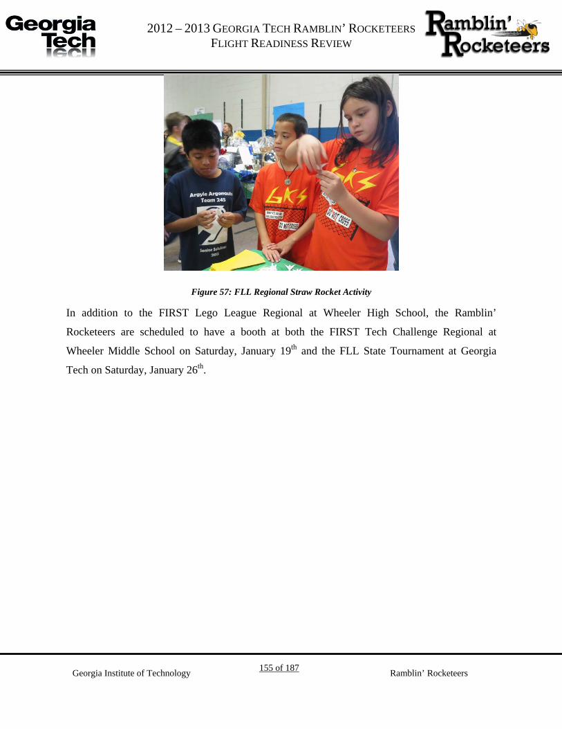
G 2012 – 2013 GEORGIA TECH RAMBLIN’ ROCKETEERS
FLIGHT READINESS REVIEW
Georgia Institute of Technology 155 of 187 Ramblin’ Rocketeers
Figure 57: FLL Regional Straw Rocket Activity
In addition to the FIRST Lego League Regional at Wheeler High School, the Ramblin’
Rocketeers are scheduled to have a booth at both the FIRST Tech Challenge Regional at
Wheeler Middle School on Saturday, January 19th and the FLL State Tournament at Georgia
Tech on Saturday, January 26th.

G 2012 – 2013 GEORGIA TECH RAMBLIN’ ROCKETEERS
FLIGHT READINESS REVIEW
Georgia Institute of Technology 156 of 187 Ramblin’ Rocketeers
References
Simon, T. M., Reitich, F., Jolly, M. R., Ito, K., & Banks, H. T. (1998). Estimation of the E ective
Permeability in Magnetorheological Fluids. CRSC Technical Report CRSC-TR98-35,
NC State Univ.
The Dynamic Behavior of Liquids in Moving Containers: with applications to space vehicle
technology. All articles. Ed. H. Norman Abramson. NASA, Washington, D.C., 1966.
"Apogee Paramagnetic Oxygen Gas Experimental Electromagnetic Separator: Preliminary Design Review." Comp. Georgia Tech University Student Launch Initiative. Atlanta: 2009. Print.
Cheng, David. Field and Wave Electromagnetics. 1st ed. Reading, MA: Addison-Wesley Publishing Company, 1985. Print.
Niskanen, Sampo. OpenRocket vehicle Technical Documentation. 18 July 2011. Web.
Apke, Ted. "Black Powder Usage." (2009). Print. <http://www.info-central.org/?article=303>.
PerfecFlite. StratoLogger SL100 Users Manual. Andover, NH: Print. <www.perfectflite.com>.
Roensch, S. (2010). "Finite Element Analysis: Introduction." 2011, from http://www.finiteelement.com/feawhite1.html.
“G-10 Fiberglass Epoxy Laminate Sheet.” MATWEB.com. http://www.matweb.com/ search/datasheet_print.aspx?matguid=8337b2d050d44da1b8a9a5e61b0d5f85
"Shape Effects on Drag." NASA Web. 19 Nov. 2011. <http://www.grc.nasa.gov/WWW/k- 12/airplane/shaped.html>.
Cavcar, Mustafa. "Compressibility Effects on Airfoil Aerodynamics." (2005). Print.

G 2012 – 2013 GEORGIA TECH RAMBLIN’ ROCKETEERS
FLIGHT READINESS REVIEW
Georgia Institute of Technology 157 of 187 Ramblin’ Rocketeers
Appendix I: Gantt Chart

ID Task Name Duration Start Finish Predecessors
1 Project L.S.I.M. 225 days Wed 8/1/12 Thu 6/6/13
2 RFP Released by NASA 30 days Wed 8/1/12 Tue 9/11/12
3 Proposal 22 days Wed 8/1/12 Fri 8/31/12
4 Team Formation 5 days Mon 8/20/12 Fri 8/24/12
5 Initial Rocket Design 20 days Wed 8/1/12 Tue 8/28/12
6 Flight Experiment Definition 20 days Wed 8/1/12 Tue 8/28/12
7 Internal Proposal Review 0 days Tue 8/28/12 Tue 8/28/12 6
8 Proposal Submitted 0 days Fri 8/31/12 Fri 8/31/12
9
10 Prelimary Design Review 71 days Fri 8/31/12 Thu 12/6/12
11 Launch Vehicle 31 days Fri 8/31/12 Sat 10/13/12
16 Flight Systems 31 days Fri 8/31/12 Fri 10/12/12
23 Project Level 71 days Fri 8/31/12 Thu 12/6/12
30 PDR Documentation Submitted 0 days Mon 10/29/12 Mon 10/29/12
31
32 Critical Design Review 68 days Sat 10/13/12 Mon 1/14/13
33 Launch Vehicle 57 days Mon 10/29/12 Mon 1/14/13
34 Recovery Detailed Design 51 days Mon 10/29/12 Mon 1/7/13 30
35 Structure Hardware Testing 19 days Mon 10/29/12 Thu 11/22/12 14,30
40 Full-Scale Launch Vehicle Fabrication 38 days Fri 11/23/12 Mon 1/14/13 39
44 Recovery Ground Testing 1 day Sat 1/12/13 Sat 1/12/13 41
45 Stability Analysis 51 days Mon 10/29/12 Mon 1/7/13 30
46 CFD of Launch Vehicle & Fin Can 20 days Mon 10/29/12 Fri 11/23/12 30
47 Development of stability model 40 days Mon 10/29/12 Fri 12/21/12 30
48 Verification of Scaled Test Launch 11 days Mon 12/24/12 Mon 1/7/13 46,47
49 Flight Systems 67 days Sat 10/13/12 Sat 1/12/13
50 Control System Preliminary Design 56 days Mon 10/29/12 Sat 1/12/13 30
51 Detailed Experiment Modeling 36 days Sat 10/13/12 Fri 11/30/12 20
52 Ground Testing 31 days Sat 10/13/12 Fri 11/23/12 20
53 Flight Systems Integration Plan 36 days Mon 10/29/12 Mon 12/17/12 30
54 Initial Ground Station Development 35 days Mon 10/29/12 Fri 12/14/12 30
55 Project Level 56 days Mon 10/29/12 Mon 1/14/13
56 Website Updates 56 days Mon 10/29/12 Sat 1/12/13 30
57 Outreach Events 56 days Mon 10/29/12 Sat 1/12/13 30
58 Completed 1st Draft of CDR 5 days Mon 12/17/12 Fri 12/21/12
59 Completed 2nd Draft of CDR 8 days Tue 1/1/13 Thu 1/10/13 58
60 Final editing of CDR Package 2 days Fri 1/11/13 Sat 1/12/13 59
61 CDR Documentation Submitted 0 days Mon 1/14/13 Mon 1/14/13
62
63 Flight Readiness Review 46 days Mon 1/14/13 Mon 3/18/13
64 Rocket 36 days Mon 1/14/13 Mon 3/4/13
65 Launch Vehicle Final Assembly 15 days Mon 1/14/13 Fri 2/1/13 61
66 Full-Scale Test Flight(s) 21 days Mon 2/4/13 Mon 3/4/13 65
67 Flight Systems 46 days Mon 1/14/13 Mon 3/18/13
68 Experiment Refinement 30 days Mon 1/14/13 Fri 2/22/13 61
69 Control System Refinement 46 days Mon 1/14/13 Mon 3/18/13 61
70 Integration of Flight Experiment & Avionics 15 days Mon 1/14/13 Fri 2/1/13 61
71 Project Level 46 days Mon 1/14/13 Mon 3/18/13
72 Website Updates 46 days Mon 1/14/13 Mon 3/18/13 61
73 Outreach Events 46 days Mon 1/14/13 Mon 3/18/13 61
74 FRR Documentation Submitted 0 days Mon 3/18/13 Mon 3/18/13
75
76 Rocket Week 34 days Thu 3/7/13 Mon 4/22/13
77 Fabrication of Flight Experiment 20 days Tue 3/19/13 Mon 4/15/13 68,69
78 Competition Launch Preparation 28 days Thu 3/7/13 Mon 4/15/13 66
79 Arrive in Huntsville 1 day Wed 4/17/13 Wed 4/17/13
80 Tour of MSFC 1 day Thu 4/18/13 Thu 4/18/13
81 Rocket Fair 1 day Fri 4/19/13 Fri 4/19/13
82 Competition Launch 2 days Sat 4/20/13 Mon 4/22/13
83
84 Post-Launch Assument Review Submitted 24 days Mon 5/6/13 Thu 6/6/13 82
Project L.S.I.M.
RFP Released by NASA
Proposal
8/28
8/31Proposal Submitted
Prelimary Design Review
10/29PDR Documentation Submitted
Critical Design Review
1/14CDR Documentation Submitted
Flight Readiness Review
3/18FRR Documentation Submitted
4/22Rocket Week
Post-Launch
29 5 12 19 26 2 9 16 23 30 7 14 21 28 4 11 18 25 2 9 16 23 30 6 13 20 27 3 10 17 24 3 10 17 24 31 7 14 21 28 5 12 19 26Aug '12 Sep '12 Oct '12 Nov '12 Dec '12 Jan '13 Feb '13 Mar '13 Apr '13 May '13 J
Task Split Progress Milestone Summary Project Summary External Tasks External Milestone Deadline
Page 1
Project: 2012 - 2013 USLI Gnatt ChartDate: Mon 3/18/13

G 2012 – 2013 GEORGIA TECH RAMBLIN’ ROCKETEERS
FLIGHT READINESS REVIEW
Georgia Institute of Technology 159 of 187 Ramblin’ Rocketeers
Appendix II: Launch Checklist
Pre-Launch
Performer Inspector
Packing The night before launch go through Launch Vehicle
Packing List and put all items in a designated spot.
The morning of launch go through Launch Vehicle Packing List and ensure all items are still there.
Load the vehicle(s)
Launch
Avionics On Prepare Payload Bay Ensure batteries and switches are wired to the altimeters
correctly.
Ensure batteries, power supply, switch, data recorder and pressure sensors are wired correctly.
Install fresh batteries into battery holders and secure with tape.
Test the altimeters.
Altimeter In Circuit Out of Circuit
Altimeter 1
Altimeter 2
Insert altimeter and payload into the payload bay. Connect appropriate wires. Verify payload powers on correctly and is working properly. If it is not, check all wires and connections.
Turn off payload power. Arm altimeters with output shorted to verify jumper settings. This is to check battery voltage and continuity.
Disarm altimeter, un-short outputs.

G 2012 – 2013 GEORGIA TECH RAMBLIN’ ROCKETEERS
FLIGHT READINESS REVIEW
Georgia Institute of Technology 160 of 187 Ramblin’ Rocketeers
Assemble Charges Test e-match resistance and make sure it is within spec. Remove protective cover from e-matches.
Measure amount of black powder determined in testing. Put e-matches on tape with sticky side up.
E-match Resistance
E-match 1
E-match 2
E-match 3
E-match 4
Pour black powder over e-matches. Seal tape. Re-test e-matches.
Check Altimeters Ensure altimeter is disarmed.
Connect charges to altimeter bay. Turn on altimeter and verify continuity. Disarm altimeters.
Altimeter 1 Altimeter 2
OFF ON
Pack Parachutes

G 2012 – 2013 GEORGIA TECH RAMBLIN’ ROCKETEERS
FLIGHT READINESS REVIEW
Georgia Institute of Technology 161 of 187 Ramblin’ Rocketeers
Connect drogue shock cord (long side) to booster section and altimeter bay (short side)
Fold excess shock cord so it does not tangle. Add Nomex cloth to ensure only the Kevlar shock chord is exposed to ejection charge.
Insert altimeter bay into drogue section and secure with shear pins.
Pack main chute. Attach main shock cord to payload bay (long side to nose
cone).
Fold excess shock cord so it does not tangle. Add Nomex cloth under main chute and shock cord ensuring that only the Kevlar part of the shock cord will be exposed to the ejection charge
Connect shock cord to nose cone, install nose cone and secure with shear pins.

G 2012 – 2013 GEORGIA TECH RAMBLIN’ ROCKETEERS
FLIGHT READINESS REVIEW
Georgia Institute of Technology 162 of 187 Ramblin’ Rocketeers
Post Launch
Recovery Recover launch vehicle, document landing.
Disarm altimeter(s) if there are unfired charges. Disassemble launch vehicle, clean motor case, other parts, inspect for damage.
Record altimeter data. Download payload data.
Assemble Motor Follow manufacturer's instructions.
Put on safety glasses and gloves. Do not get grease on propellant or delay. Do not install igniter until at pad. Install gasket on top of motor. Install motor in launch vehicle. Secure positive motor retention.
Final Prep Turn on payload via a switch and start stopwatches.
Install skin. Inspect launch vehicle. Check CG to make sure it is in safe range; add nose weight if necessary.
Bring launch vehicle to the range safety officer (RSO) table for inspection.
Bring launch vehicle to pad, install on pad, verify that it can move freely (use a standoff if necessary).
Arm altimeters via switches and wait for continuity check for both.
Install igniter Touch igniter clips together to make sure they will not fire igniter when connected.
Make sure clips are not shorted to each other or blast deflector. Return to front line.
Launch Stop the stopwatches and record time from arming payload and
launch.
Watch flight so launch vehicle does not get lost.

G 2012 – 2013 GEORGIA TECH RAMBLIN’ ROCKETEERS
FLIGHT READINESS REVIEW
Georgia Institute of Technology 163 of 187 Ramblin’ Rocketeers
Trouble Shooting
Test Problem Control & Mitigation
Power on payload Payload does not
power on
Check batteries have sufficient charge, check wires
are connected correctly
Check E-match
resistance
E-match resistance
does not match
required specifications
Replace e-match before use
Power on altimeters Altimeters do not
power on
Check batteries have sufficient charge, check wires
are connected correctly
Check for altimeter
continuity after
installing e-matches
No continuity Check wires are connected correctly
Launch Rocket Engine does not fire
Disconnect power, ensure igniter clips are not
touching, ensure power is reaching clips ,ensure
motor is assembled correctly

G 2012 – 2013 GEORGIA TECH RAMBLIN’ ROCKETEERS
FLIGHT READINESS REVIEW
Georgia Institute of Technology 164 of 187 Ramblin’ Rocketeers
Appendix III: Science Overview
Ferromagnetism and MR fluid response
Scientific Background and Mathematical Modeling
To the end of accomplishing the goals of the LSIM experiment, some theoretical research and
work must be accomplished in tandem with experimentation. A passive or active control system
is to be developed in order to move the simulated propellant to its desired location with the
magnetorheological (MR) fluid. To model the behavior of the simulant-MR fluid system,
equations are being researched, modified, and developed in order to calculate magnetic fields
and forces, to govern the properties of MR fluids, and to model system dynamics. In addition to
equations, qualitative research has been done in the literature concerning MR fluids to suggest
approaches that may be taken during experimental testing.
Magnetic fields
The forces on the MR fluid that will be transmitted to the simulant will depend largely on the
magnetic fields that are applied to the fluid. Control of currents in a solenoid will allow for
precise control of the fields. Last year, it was derived and also confirmed in the literature that the
exact magnetic H field from a current loop in spherical coordinates, with the loop centered at the
origin in the xy -plane and counterclockwise current, is as below (θ denotes azimuth angle):
𝐻𝑟 =
𝐶𝑅2 cos 𝜃𝛼2𝛽
𝐸(𝑘2)
𝐻𝜃 =𝐶
2𝛼2𝛽 sin𝜃[(𝑟2 + 𝑅2 cos 2𝜃)𝐸(𝑘2) − 𝛼2𝐾(𝑘2)]
where K and E are complete elliptic integrals of the first and second kinds, respectively, and
𝛼2 = 𝑅2 + 𝑟2 − 2𝑅𝑟 sin𝜃, 𝛽2 = 𝑅2 + 𝑟2 + 2𝑅𝑟 sin𝜃, 𝑘2 = 1 − 𝛼2 𝛽2⁄ , and 𝐶 = 𝐼 𝜋⁄ . I is the
loop current, R is its radius, and r is the distance from the origin to the point of measurement. A
solenoid simply consists of several such current loops, with the fields adding vectorally. While
the above expressions are extremely nonlinear and difficult to analyze or work with, they may be
simplified as needed, or modeled using a computer.

G 2012 – 2013 GEORGIA TECH RAMBLIN’ ROCKETEERS
FLIGHT READINESS REVIEW
Georgia Institute of Technology 165 of 187 Ramblin’ Rocketeers
Magnetic forces
After calculating the magnetic fields, in order to predict the motion of the MR fluid and simulant
in the container, the forces on the MR fluid due to the field must to be calculated. In any
material, the movement of atomic charges such as electrons causes the atoms to behave as
microscopic magnetic dipoles, experiencing forces in magnetic fields. The magnetization vector
M at a point in the material is defined as the volume “density” of magnetic dipole moment, i.e.
𝐌 = lim∆𝑣→0
∑𝐦𝑘
∆𝑣
Each 𝐦𝑘 is the magnetic moment of the kth atom in volume ∆𝑣, and the sum is over all atoms. M
depends on the magnetic field H at a point, and flux density B depends on the field, as follows:
𝐌 = χ𝑚𝐇
𝐁 = 𝜇0(𝐇 + 𝐌) = 𝜇0𝐇(1 + 𝜒𝑚) = 𝜇0𝜇𝑟𝐇 = 𝜇𝐇
where χ𝑚 is the material’s magnetic susceptibility, 𝜇𝑟 is its relative permeability, and 𝜇 is the
absolute permeability. It is assumed that χ𝑚, and hence 𝜇 and 𝜇𝑟, are approximately constant for
the MR fluid. This is a very valid assumption that greatly simplifies analysis, given that the fields
are not extremely large, as is evidenced in Figure 58 below taken from a paper by Simon et al.
Figure 58: Plot of B field magnitude in MR fluid versus magnitude of vector 𝝁𝟎𝑯, for iron volume concentrations of 10, 20, and 30 percent

G 2012 – 2013 GEORGIA TECH RAMBLIN’ ROCKETEERS
FLIGHT READINESS REVIEW
Georgia Institute of Technology 166 of 187 Ramblin’ Rocketeers
The force on a magnetic material can be determined by summing the forces on the dipoles in the
material due to the field that it is placed in. The force on a magnetic dipole m in field B is
𝐅 = 𝛁(𝐦 ∙ 𝐁)
Let V be the volume of a very small region of the MR fluid in which M is approximately
constant. Then, letting 𝐦 = 𝐌𝑉 = χ𝑚𝑉𝐇 = χ𝑚𝑉µ𝐁, the force on the region is
𝐅 = 𝛁�χ𝑚𝑉µ
𝐁 ∙ 𝐁� =2χ𝑚𝑉µ
𝐁 ∙ 𝛁(𝐁)
Using equations (1), (2), and (5) for the H and B fields of a current loop, it can be seen that the
force on each small region, and hence on the whole fluid, should be directly proportional to the
square of the current. In addition, 𝐁 ∙ 𝛁(𝐁) may be calculated using equations (1) and (2). These
equations will be further developed to better understand response of the MR fluid and simulant.
MR fluid rheological properties
In addition to translational movement, which is governed by the preceding equations, MR fluids
experience large increases in yield strength in the presence of magnetic fields. This is desirable
for the LSIM system, as otherwise the sloshing propellant simulant would simply shear through
the MR fluid barriers with little resistance. It is desired to characterize the rheological properties
of MR fluid to understand how much resistance to movement the simulant will experience.
More precisely, MR can be modeled fairly closely as a Bingham plastic, a common example of
which is toothpaste. A Bingham plastic does not start flowing until a certain point of yield shear
stress, after which it behaves similarly to a viscous liquid. The equation governing the shear
stress of an ideal Bingham plastic, and so to model the MR fluid for future analysis, is
𝜏 = 𝜏𝑦𝑖𝑒𝑙𝑑(𝐇) + 𝜂
𝑑𝑣𝑑𝑛
for τ > 𝜏𝑦𝑖𝑒𝑙𝑑(𝐇)
𝜏𝑦𝑖𝑒𝑙𝑑(𝐇) is the yield shear stress of the MR fluid, and is larger for stronger H fields. η is the
flow viscosity after shear, and 𝑑𝑣𝑑𝑛
is the velocity gradient in the direction normal to the plane of
shear. This relation is shown on the next page in Figure 59, compared to a Newtonian fluid.

G 2012 – 2013 GEORGIA TECH RAMBLIN’ ROCKETEERS
FLIGHT READINESS REVIEW
Georgia Institute of Technology 167 of 187 Ramblin’ Rocketeers
Figure 59: Shear stress of ideal Bingham plastic (and MR fluid model) versus shear rate 𝒅𝒗𝒅𝒏
, compared to ideal Newtonian liquid
Hence, if the simulant exerts such a force that MR fluid flow begins occurring, the shear stress
between layers of the MR fluid should increase, keeping the simulant comparatively restrained
until it settles again. If the need arises to decrease the yield shear stress for a given magnetic
field, such as to make the MR fluid flow more easily, replacing a percentage of microscale
ferroparticles with nanoscale particles can decrease the yield stress. Further research is still
required to find the relationship between the yield strength and magnetic field, which will allow
control of the yield stress acting against the simulant. However, the key observation is that there
is little to no MR fluid flow below some certain shear stress, for a given magnetic field H.
System Dynamics
While research on the physical properties and behavior of MR fluids is ongoing, basic system
dynamical modeling has already been started with variable parameters that will be determined
from theory and experimentation in the future. The fluid and MR fluid mixture is assumed to
operate roughly as a system with a spring, damper, and mass, where the driving force is the
solenoid. The fluid is considered the mass, whose motion is restrained by a spring and damper,
and driven by the MR fluid actuated by the solenoid. All system elements lie on the same x -
axis, with the solenoid axis coinciding. The dynamical equation of motion in this case is

G 2012 – 2013 GEORGIA TECH RAMBLIN’ ROCKETEERS
FLIGHT READINESS REVIEW
Georgia Institute of Technology 168 of 187 Ramblin’ Rocketeers
𝑚�̈� = 𝐹𝑠𝑜𝑙𝑒𝑛𝑜𝑖𝑑 − 𝑘𝑥 − 𝑏�̇�
Where m is the mass of the fluid, k and b are unknown damping placeholder constants, and x is
the position of the simulant relative to some point. After some manipulation, the dynamical
equation for the response of the fluid becomes:

G 2012 – 2013 GEORGIA TECH RAMBLIN’ ROCKETEERS
FLIGHT READINESS REVIEW
Georgia Institute of Technology 169 of 187 Ramblin’ Rocketeers
Understanding Slosh Damping
Fluid dynamics and hydrodynamic regimes of expected slosh
In considering the liquid slosh, the flight regime of the vehicle is extremely important. While the
experiment aims to approximate a spacecraft by manipulating MR fluid during microgravity to
dampen water slosh, the realities of atmospheric flight will limit the applicability of launch
vehicle test results. The extent of these flight regime limitations is revealed by three key
similarity parameters: the Weber (We) number, the Froude (Fr) number, and the Bond (Bo)
number. These three parameters measure the ratio of inertial to capillary forces, the effect of
gravitational body forces relative to inertial forces, and the relative magnitudes of gravitational
and capillary forces respectively. Finally, an understanding of the potential flow of sloshing
fluid is necessary to understand the motion of fluid inside a vehicle.
Flight regime
However, an estimate of the flight regime of the launch vehicle near apogee must first be known.
To better understand this flight regime and to confirm the microgravity requirements pulled from
previous team documents, a first-order analysis of the launch vehicle’s flight was computed.
Neglecting drag and assuming 2-D projectile motion with instantaneous acceleration from a
rocket motor, the flight profile of the launch vehicle was estimated and the characteristics of the
0.1-Gee requirement from the 2009 Georgia Tech team – 0.1-Gee being the definition of the
microgravity threshold for the purposes of the experiment – were examined. The results of this
simplified analysis are presented graphically in Figure 60.
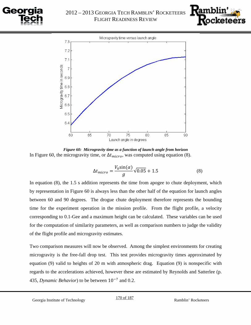
G 2012 – 2013 GEORGIA TECH RAMBLIN’ ROCKETEERS
FLIGHT READINESS REVIEW
Georgia Institute of Technology 170 of 187 Ramblin’ Rocketeers
Figure 60: Microgravity time as a function of launch angle from horizon
In Figure 60, the microgravity time, or ∆𝑡𝑚𝑖𝑐𝑟𝑜, was computed using equation (8).
∆𝑡𝑚𝑖𝑐𝑟𝑜 =
𝑉0sin (𝛼)𝑔
√0.05 + 1.5 (8)
In equation (8), the 1.5 s addition represents the time from apogee to chute deployment, which
by representation in Figure 60 is always less than the other half of the equation for launch angles
between 60 and 90 degrees. The drogue chute deployment therefore represents the bounding
time for the experiment operation in the mission profile. From the flight profile, a velocity
corresponding to 0.1-Gee and a maximum height can be calculated. These variables can be used
for the computation of similarity parameters, as well as comparison numbers to judge the validity
of the flight profile and microgravity estimates.
Two comparison measures will now be observed. Among the simplest environments for creating
microgravity is the free-fall drop test. This test provides microgravity times approximated by
equation (9) valid to heights of 20 m with atmospheric drag. Equation (9) is nonspecific with
regards to the accelerations achieved, however these are estimated by Reynolds and Satterlee (p.
435, Dynamic Behavior) to be between 10−7 and 0.2.

G 2012 – 2013 GEORGIA TECH RAMBLIN’ ROCKETEERS
FLIGHT READINESS REVIEW
Georgia Institute of Technology 171 of 187 Ramblin’ Rocketeers
∆𝑡𝑚𝑖𝑐𝑟𝑜 =1
2.2√ℎ (9)
The predicted times from equation (9) and from the flight profile are given in Figure 60.
Table 46: Microgravity times for fall heights
Height (m) Microgravity time (s)
3733.96 (free-fall) 27.78
1609 (free-fall, target altitude) 18.23
3733.96 (90° launch angle) ~7.13
Adjusting for the 1.5 second chute deployment, the 90° launch microgravity time appears to be
about one half the time given for free-fall from the same maximum height – given that the max
Gee loading specified in the reference is 0.2, or twice the Ramblin’ Rocketeers’ requirement, this
difference appears to be acceptable for a bounding and ideal case. Of course, accelerations due
to aerodynamic forces will requirement additional modeling and adjustment.
Similarity parameters
Table 47 presents the similarity parameters relevant to the LSIM experiment calculated for the
propellant simulant, water (30 °C). The Weber, Bond, and Froude numbers are considered here.
These numbers provide an indication of the hydrodynamic regime – these regimes
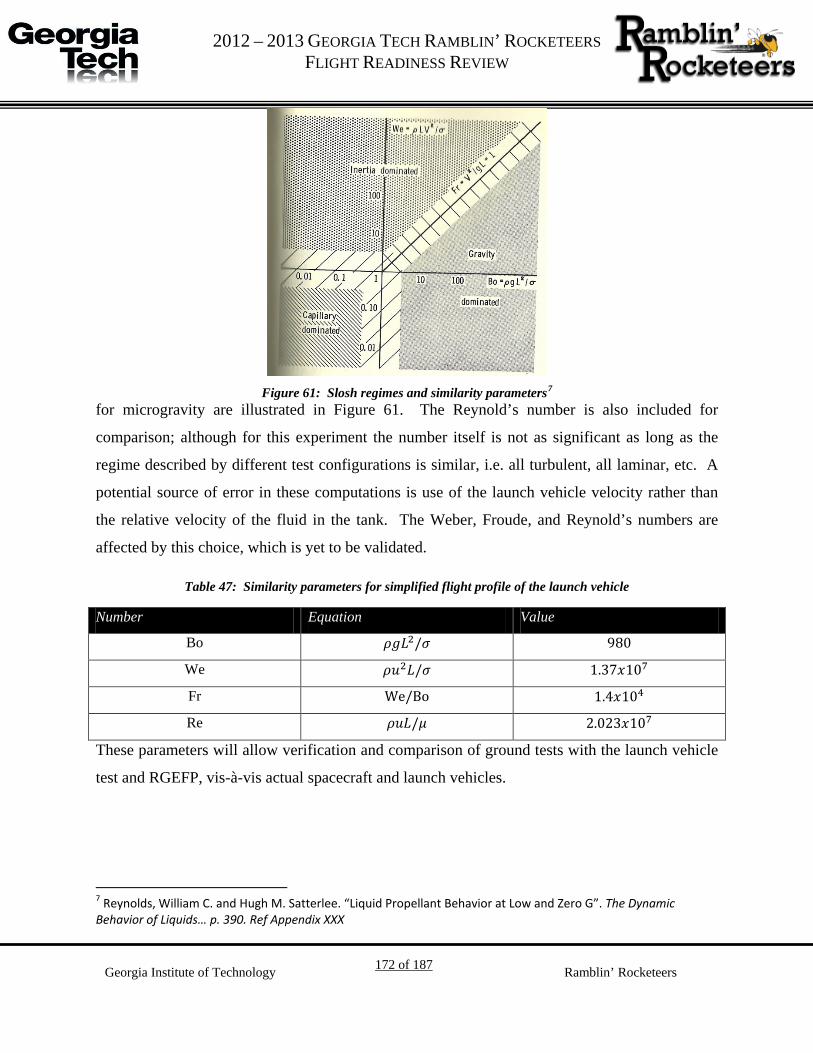
G 2012 – 2013 GEORGIA TECH RAMBLIN’ ROCKETEERS
FLIGHT READINESS REVIEW
Georgia Institute of Technology 172 of 187 Ramblin’ Rocketeers
Figure 61: Slosh regimes and similarity parameters 6F
7 for microgravity are illustrated in Figure 61. The Reynold’s number is also included for
comparison; although for this experiment the number itself is not as significant as long as the
regime described by different test configurations is similar, i.e. all turbulent, all laminar, etc. A
potential source of error in these computations is use of the launch vehicle velocity rather than
the relative velocity of the fluid in the tank. The Weber, Froude, and Reynold’s numbers are
affected by this choice, which is yet to be validated.
Table 47: Similarity parameters for simplified flight profile of the launch vehicle
Number Equation Value
Bo 𝜌𝑔𝐿2/𝜎 980
We 𝜌𝑢2𝐿/𝜎 1.37𝑥107
Fr We/Bo 1.4𝑥104
Re 𝜌𝑢𝐿/𝜇 2.023𝑥107
These parameters will allow verification and comparison of ground tests with the launch vehicle
test and RGEFP, vis-à-vis actual spacecraft and launch vehicles.
7 Reynolds, William C. and Hugh M. Satterlee. “Liquid Propellant Behavior at Low and Zero G”. The Dynamic Behavior of Liquids… p. 390. Ref Appendix XXX

G 2012 – 2013 GEORGIA TECH RAMBLIN’ ROCKETEERS
FLIGHT READINESS REVIEW
Georgia Institute of Technology 173 of 187 Ramblin’ Rocketeers
Modeling Slosh
In order to approximately predict the behavior of the propellant in the sloshing modes expected
at apogee of our launch vehicle, a mathematical model has been developed. The aim of this
model is solely to predict sloshing behavior in the absence of dampening; this is an intermediate
step to modeling the effects of the MR fluid dampening. Predicting the exact distribution and
dynamics of all sloshing fluid within the container, however, would require a large amount of
complexity, which would only be exacerbated by attempting to add the effects of the MR fluid
later on. Therefore, for analysis to be feasible, a much simpler model is proposed.
Figure 62. Schematic and free-body diagram of slosh dynamic model
The fluid is modeled schematically as shown above in Figure 62. It is assumed that the center of
mass of the fluid in the tank behaves roughly as an object of mass m attached to a pendulum-
spring of spring constant k, with additional dampening effects represented by viscous dampers of
constants b1 and b2. Also, let L be the original length of the pendulum-spring with no forces
applied, and ∆L the the amount the spring is stretched from length L (so that negative ∆L implies
compression). It is anticipated that the majority of sloshing will be longitudinal, so significant
vertical motion can be expected of the fluid. Therefore, in our model, the spring may experience
appreciable compression. However, a much smaller amount of lateral sloshing is predicted, so in
the model, the angle θ may be assumed to be small. Therefore, throughout this analysis, it will be
assumed that sin θ ≈ θ sufficiently closely for the corresponding substitution to be justified.

G 2012 – 2013 GEORGIA TECH RAMBLIN’ ROCKETEERS
FLIGHT READINESS REVIEW
Georgia Institute of Technology 174 of 187 Ramblin’ Rocketeers
The equations of motion can be written in the x and y directions, respectively, as follows:
−𝑘∆𝐿 sin𝜃 − 𝑏1�̇� ≈ 𝑘∆𝐿𝜃 − 𝑏1�̇� = 𝑚�̈� (1)
𝑘∆𝐿 cos𝜃 − 𝑏2�̇� − 𝑚𝑔 ≈ 𝑘∆𝐿 − 𝑏2�̇� − 𝑚𝑔 = 𝑚�̈� (2)
The equations to be developed will depend on state variables θ, �̇�, ∆L, and ∆�̇�. Let the origin of
the coordinate system be at the center of rotation of the pendulum. Then, it is known that
𝑥 = (𝐿 + ∆𝐿) sin𝜃 ≈ (𝐿 + ∆𝐿)𝜃 (3)
𝑦 = −(𝐿 + ∆𝐿) cos 𝜃 ≈ −(𝐿 + ∆𝐿) (4)
�̇� = �∆�̇��𝜃 + (𝐿 + ∆𝐿)�̇� (5)
�̇� = −∆�̇� (6)
�̈� = �∆�̈��𝜃 + 2�∆�̇���̇� + (𝐿 + ∆𝐿)�̈� (7)
�̈� = −∆�̈� (8)
where equations 5 through 8 are found by repeatedly differentiating equations 3 and 4. First of
all, substituting equations 6 and 8 into equation 2 and rearranging, it is readily found that
∆�̈� = 𝑔 −
𝑏2𝑚�Δ�̇�� −
𝑘𝑚∆𝐿 (9)
Note that this equation is independent of θ, and is the same as a one-dimensional spring-mass-
damper system.
The analysis and results from substituting equations 5 and 7 into equation 1 are significantly
more complicated. First of all, carrying out this substitution and rearranging,
�̈� = �
−𝑘∆𝐿 − 𝑏1�∆�̇��𝑚(𝐿 + ∆𝐿) −
�∆�̈��(𝐿 + ∆𝐿)� 𝜃 − �
𝑏1𝑚
+2�∆�̇��
(𝐿 + ∆𝐿)� �̇� (10)
Next, substituting equation 9 for ∆�̈� in equation 10, it is found that
�̈� = �
(𝑏2 − 𝑏1)�∆�̇��𝑚(𝐿 + ∆𝐿) −
𝑔(𝐿 + ∆𝐿)� 𝜃 − �
𝑏1𝑚
+2�∆�̇��
(𝐿 + ∆𝐿)� �̇� (11)
Therefore, as k, b1, b2, m, g, and L are constants, it is seen that �̈� is a function of the state
variables. Write �̈� = 𝑓�𝜃, �̇�,𝛥𝐿,𝛥�̇�� , where 𝑓:ℝ4 → ℝ is differentiable at any point

G 2012 – 2013 GEORGIA TECH RAMBLIN’ ROCKETEERS
FLIGHT READINESS REVIEW
Georgia Institute of Technology 175 of 187 Ramblin’ Rocketeers
�𝜃, �̇�,𝛥𝐿,𝛥�̇�� such that ∆L≠-L, due to continuity of the partial derivatives of f at those points.
The relation ∆L = -L only occurs for the spring being compressed into a flat piece, which
corresponds to all fluid molecules touching the top surface of the tank; both of these are
impossible scenarios. Therefore, it is possible to linearly approximate f close to any point of
interest, for easier analysis. Initially, the relation is linearized for points near the equilibrium
point of the system, which is (0, 0, mg/k, 0). In this case, defining 𝛿𝐿 = 𝛥𝐿 −𝑚𝑔/𝑘,
�̈� = 𝑓�𝜃, �̇�,𝛥𝐿,𝛥�̇��
≈ 𝑓 �0,0,𝑚𝑔𝑘
, 0� + ∇𝑓 �0,0,𝑚𝑔𝑘
, 0� ∙ �𝜃, �̇�, 𝛿𝐿,𝛥�̇�� (12)
�̈� = 0 +
𝜕𝑓𝜕𝜃�𝑒𝑞𝜃 +
𝜕𝑓𝜕�̇��𝑒𝑞�̇� +
𝜕𝑓𝜕𝛥𝐿
�𝑒𝑞𝛿𝐿 +
𝜕𝑓𝜕𝛥�̇�
�𝑒𝑞𝛥�̇� (13)
Finally, evaluating the partial derivatives, it is found that close to (0, 0, mg/k, 0),
�̈� = �−
𝑔𝑘(𝑘𝐿 + 𝑚𝑔)� 𝜃 − �
𝑏1𝑚� �̇� (14)
Therefore, relations for both ∆�̈� and �̈� have been found only in terms of the four state variables
𝜃, �̇�,𝛥𝐿, and 𝛥�̇� , assuming that the values of 𝜃, �̇�, 𝛿𝐿, and 𝛥�̇� are small. Using the above
equations, whether the linear approximations (9) and (14) or the more precise but complicated
form (11), further analysis by hand or by computer should yield information as to how the
system should approximately behave in the absence of the MR fluid baffles. Further
development should also approximate system dynamics in the presence of the baffles, allowing
rough predictions to be made as to how the MR fluid baffles may impact fluid slosh.
Unifying the LSIM theories
Finally, it is necessary to connect the response of MR fluid to a magnetic field with the damping
of slosh. According to Dynamic Behavior the damping of slosh for a ring baffle is dependent on
the baffle cross-section7F
8. For containers of constant geometry and liquid at constant rest height
in gravity dominated slosh, empirical relationships have been illustrated between the geometry of
8 Abramson, H. Norman and Sandor Silverman. “Damping of Liquid Motions and Lateral Sloshing”. The Dynamic Behavior of Liquids… p. 109. Ref Appendix XXX.

G 2012 – 2013 GEORGIA TECH RAMBLIN’ ROCKETEERS
FLIGHT READINESS REVIEW
Georgia Institute of Technology 176 of 187 Ramblin’ Rocketeers
a rigid baffle and the damping ratio vs. wave amplitude of slosh 8F
9. However, an effect not present
in the dynamic analysis above is the container geometry. In the case of LSIM where the liquid
height will be greater than the container radius, the damping coefficient in lateral slosh is given
by:
𝛿 = 4.98𝜈1/2𝑅−3/4𝑔−1/4 (1)
Where ν is the kinematic viscosity, R the container radius, g the acceleration of gravity. This
equation9F
10, along with curve fitting with the help of tables and plots given in Dynamic Behavior,
provides a means to experimentally determine the damping coefficients needed with given MR
fluid response to calculate the slosh dynamics.
9 P. 109 10 P. 110

G 2012 – 2013 GEORGIA TECH RAMBLIN’ ROCKETEERS
FLIGHT READINESS REVIEW
Georgia Institute of Technology 177 of 187 Ramblin’ Rocketeers
Appendix IV: Ground Test Plan
Goals
The LSIM ground test data will provide the basis for empirical modeling of magnetorheological
fluid as a damper for liquid sloshing. All actions will be incremented to allow for a detailed
model for extrapolation and interpolation of the data for future flight control systems.
Ground Test Goal Ground Test Goal Definition
1 Create MR Fluid
2 Calibrate Sensors
3 Determine force of MR Fluid
4 Develop model for solenoid control
5 1-G slosh dampening
Test Sequence 1 - Creating MR Fluid
MR fluid will be created using different compositions of iron powder, mineral oil, and surfactant.
The iron powder will make up about 74-76% of the mixture's mass. Mineral oil will make up 20-
22% of the total mass, and the surfactant will make up the remaining 1-4%. Water is then added
to test the time to mixture separation and solenoids. Each mixture will be preliminarily tested by
neodymium magnets. The mixture will qualify as a successful batch if MR fluid under the
influence of an applied magnetic field prevents the leakage of water.
Test Sequence 2 - Characterize the shear stress of MR fluid
In characterizing MR fluid, the team will utilize a two-plate test for measuring the MR fluid's
force and viscosity with and without a magnetic field acting upon the MR fluid. This test was
chosen because of its simplicity; other tests such as a barometer test were considered for
measuring the MR fluid's viscosity and force, but they turned out too complicated to realize.

G 2012 – 2013 GEORGIA TECH RAMBLIN’ ROCKETEERS
FLIGHT READINESS REVIEW
Georgia Institute of Technology 178 of 187 Ramblin’ Rocketeers
The two-plate test consists of two plates: a bottom plate, which is fixed to the ground and a top
plate, which is free to move. A load sensor will be placed on the top plate to measure the reaction
force that is generated. The plates used must not be strongly magnetic; thus, the two current
choices are wood or aluminum.
A control test will be performed by just having two plates together with a load sensor on the top,
moving plate to calculate the force by the plates themselves. For accurate and consistent results,
an automated pulling device will be used to pull the top plate. Once a control has been measured,
MR fluid will be placed between the two plates and the same procedure will repeat with and
without the MR fluid under a magnetic field. These tests will characterize the force that MR fluid
will generate when it is under a magnetic field and when it is free of a magnetic field
Test Sequence 4 - Developing solenoid control
Knowing the MR fluid shear stress properties will help determine the size and strength of the
solenoid used for flight testing. This will also enable the group to decide on what type of control
can be used on the solenoid. At the moment, an open loop control is considered.
If better coupling can be achieved between sensors and actuators, closed loop control may be
considered.
Test Sequence 5 – 1-G Slosh dampening
A vibration rig will be constructed such that several frequencies of vibration approximating those
experienced by the launch vehicle will be exerted on the ground test rig. Using similarity
parameters, the data gained from this experiment will allow predictions for dampening
performance of the controlled MR fluid during the microgravity period.

G 2012 – 2013 GEORGIA TECH RAMBLIN’ ROCKETEERS
FLIGHT READINESS REVIEW
Georgia Institute of Technology 179 of 187 Ramblin’ Rocketeers
Appendix V: Science MFOs and Drawings
Bench Stand
Take one 1/16’’ 12’’ x 12’’ acrylic plate and laser cut out a square that is 20cm x 20cm.
Figure 63. Base Plate

G 2012 – 2013 GEORGIA TECH RAMBLIN’ ROCKETEERS
FLIGHT READINESS REVIEW
Georgia Institute of Technology 180 of 187 Ramblin’ Rocketeers
Take the remaining two 12’’ x 12’’ plates and cut a rectangle that is 20cm x 22cm. Laser cut a
5.3cm diameter centered in the middle of the 20cm x 22cm acrylic plates as seen in Figure 2.
Figure 64. Second and Top Plate

G 2012 – 2013 GEORGIA TECH RAMBLIN’ ROCKETEERS
FLIGHT READINESS REVIEW
Georgia Institute of Technology 181 of 187 Ramblin’ Rocketeers
Take four 30cm Maker Bars and place them vertically 20 cm apart in the shape of a square.
Attach horizontally a 20cm Maker Bar 2 cm above each 30cm Maker Bar base and secure them
with 90 Degree Maker L Brackets as shown in Figure 3 and 4. This will be done on each side of
the square. Figure 3 shows a side view of two 30 cm Maker Bars attached together by a 20cm
Maker Bar horizontally.

G 2012 – 2013 GEORGIA TECH RAMBLIN’ ROCKETEERS
FLIGHT READINESS REVIEW
Georgia Institute of Technology 182 of 187 Ramblin’ Rocketeers
Figure 65. Side view of main structure
Figure 66. Trimetric view of main structure

G 2012 – 2013 GEORGIA TECH RAMBLIN’ ROCKETEERS
FLIGHT READINESS REVIEW
Georgia Institute of Technology 183 of 187 Ramblin’ Rocketeers
Attach four flat “L” Maker Beam brackets on the 20 cm horizontal bars as show in in Figure 5.
The short end of the “L” bracket will be placed 1cm from the end of the 20cm Maker Bar. This
will hold the 20cm x 20cm solid acrylic base plate in place.
Figure 67. Top view of structure with 90 Degree L Brackets

G 2012 – 2013 GEORGIA TECH RAMBLIN’ ROCKETEERS
FLIGHT READINESS REVIEW
Georgia Institute of Technology 184 of 187 Ramblin’ Rocketeers
On each vertical 30cm Maker Bar, attach the base of a 90 degree bracket 2 cm above the 20cm
horizontal Maker Bar (5cm from the bottom of the vertical 30cm Maker Bar) as shown in Figure
6. Do this for each vertical 30 cm Maker Bar facing inward into the square. These four 90 degree
brackets will hold the second acrylic plate.
Figure 68. Side view of 90 Degree Brackets

G 2012 – 2013 GEORGIA TECH RAMBLIN’ ROCKETEERS
FLIGHT READINESS REVIEW
Georgia Institute of Technology 185 of 187 Ramblin’ Rocketeers
Four cm above the top of each 90 degree bracket (9cm from the bottom of the vertical 30cm
Maker Bar), place the base of another 90 degree bracket as shown in Figure 6. These four 90
degree brackets will hold the third acrylic plate.
Place the 20cm x 20cm acrylic base plate that has no hole cut in it over the four, flat “L” Maker
Beam brackets. The place the other two 20cm x 22cm acrylic plates that have holes in them on
the 90 degree brackets creating three layers of acrylic plates as shown in Figure 7.
Figure 69. Test Structure with Base Plates
Place the 100 mL beaker through the acrylic plates and onto the base acrylic plate.

G 2012 – 2013 GEORGIA TECH RAMBLIN’ ROCKETEERS
FLIGHT READINESS REVIEW
Georgia Institute of Technology 186 of 187 Ramblin’ Rocketeers
Solenoids
Take each 20cm Soft Iron Core rod and cut them up into 6cm long rods. There will be 24 of
these rods after cutting.
Wrap a piece of paper or two around the Iron cores to provide insulation.
Take 100 feet of 32 gauge magnet wire and wind as many even turns possible around each core,
counting the turns. Make sure both ends of the magnet wire are free to be used (i.e. don’t start
winding the beginning of the magnet wire).
Place 8 magnets radially around the beaker on the first, base plate. Do the same for the other two
plates.

G 2012 – 2013 GEORGIA TECH RAMBLIN’ ROCKETEERS
FLIGHT READINESS REVIEW
Georgia Institute of Technology 187 of 187 Ramblin’ Rocketeers
Appendix VI: Altimeter Wiring Harness Schematic