2011 quest owner's manual
TRANSCRIPT


Black plate (2,1)
Model "E52-D" EDITED: 2010/ 10/ 22
Welcome to the growing family of new NISSANowners. This vehicle is delivered to you withconfidence. It was produced using the latesttechniques and strict quality control.
This manual was prepared to help you under-stand the operation and maintenance of yourvehicle so that you may enjoy many miles ofdriving pleasure. Please read through thismanual before operating your vehicle.
A separate Warranty Information Bookletexplains details about the warranties cov-ering your vehicle. The NISSAN Serviceand Maintenance Guide explains detailsabout maintaining and servicing your ve-hicle. Additionally, a separate CustomerCare/Lemon Law Booklet (U.S. only) willexplain how to resolve any concerns youmay have with your vehicle, as well asclarify your rights under your state’s lemonlaw.
Your NISSAN dealer knows your vehicle best.When you require any service or have anyquestions, we will be glad to assist you with theextensive resources available to us.
READ FIRST— THEN DRIVE SAFELY
Before driving your vehicle, read your Owner’sManual carefully. This will ensure familiarity withcontrols and maintenance requirements, assist-ing you in the safe operation of your vehicle.
WARNING
IMPORTANT SAFETY INFORMA-TION REMINDERS FOR SAFETY!
Follow these important driving rules tohelp ensure a safe and comfortable tripfor you and your passengers!
. NEVER drive under the influence ofalcohol or drugs.
. ALWAYS observe posted speed lim-its and never drive too fast forconditions.
. ALWAYS give your full attention todriving and avoid using vehiclefeatures or taking other actions thatcould distract you.
. ALWAYS use your seat belts andappropriate child restraint systems.Pre-teen children should be seatedin the rear seat.
. ALWAYS provide information aboutthe proper use of vehicle safetyfeatures to all occupants of thevehicle.
. ALWAYS review this Owner’s Man-ual for important safety information.
MODIFICATION OF YOUR VEHICLE
This vehicle should not be modified.Modification could affect its performance,safety or durability, and may even violategovernmental regulations. In addition,damage or performance problems result-ing from modification may not be coveredunder NISSAN warranties.
WHEN READING THE MANUAL
This manual includes information for alloptions available on this model. Therefore,you may find some information that doesnot apply to your vehicle.
All information, specifications and illustrations inthis manual are those in effect at the time ofprinting. NISSAN reserves the right to changespecifications or design at any time withoutnotice.
IMPORTANT INFORMATION ABOUTTHIS MANUAL
You will see various symbols in this manual. Theyare used in the following ways:
WARNING
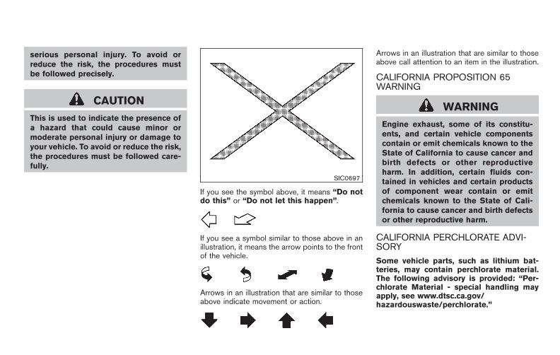
This is used to indicate the presence ofa hazard that could cause death or
Foreword
Black plate (3,1)
Model "E52-D" EDITED: 2010/ 10/ 22
serious personal injury. To avoid orreduce the risk, the procedures mustbe followed precisely.
CAUTION
This is used to indicate the presence ofa hazard that could cause minor ormoderate personal injury or damage toyour vehicle. To avoid or reduce the risk,the procedures must be followed care-fully.
SIC0697
If you see the symbol above, it means “Do notdo this” or “Do not let this happen”.
If you see a symbol similar to those above in anillustration, it means the arrow points to the frontof the vehicle.
Arrows in an illustration that are similar to thoseabove indicate movement or action.
Arrows in an illustration that are similar to thoseabove call attention to an item in the illustration.
CALIFORNIA PROPOSITION 65WARNING
WARNING
Engine exhaust, some of its constitu-ents, and certain vehicle componentscontain or emit chemicals known to theState of California to cause cancer andbirth defects or other reproductiveharm. In addition, certain fluids con-tained in vehicles and certain productsof component wear contain or emitchemicals known to the State of Cali-fornia to cause cancer and birth defectsor other reproductive harm.
CALIFORNIA PERCHLORATE ADVI-SORY
Some vehicle parts, such as lithium bat-teries, may contain perchlorate material.The following advisory is provided: “Per-chlorate Material - special handling mayapply, see www.dtsc.ca.gov/hazardouswaste/perchlorate.”

Black plate (4,1)
Model "E52-D" EDITED: 2010/ 10/ 22
Bluetooth® is a trademark ownedby Bluetooth SIG, Inc., U.S.A.and lisenced to Visteon Corpora-tion and Clarion Co., Ltd.
Gracenote® is a registered tra-demark of Gracenote, Inc. TheGracenote logo and logo type,and the “Powered by Gracenote”logo are trademarks of Grace-note.
XM Radio® requires a subscrip-tion, sold separately. It is notavailable in Alaska, Hawaii orGuam. For more information, visitwww.xmradio.com.
*C 2010 NISSAN MOTOR CO., LTD.
All rights reserved. No part of this Owner’sManual may be reproduced or stored in aretrieval system, or transmitted in any form, orby any means, electronic, mechanical, photo-copying, recording or otherwise, without theprior written permission of Nissan Motor Co.,Ltd.
Black plate (5,1)
Model "E52-D" EDITED: 2010/ 11/ 4
NISSAN CARES ...
Both NISSAN and your NISSAN dealer are dedicated to serving all your automotive needs. Your satisfaction with your vehicle and your NISSAN dealer areour primary concerns. Your NISSAN dealer is always available to assist you with all your automobile sales and service needs.
We appreciate your interest in NISSAN and thank you for buying a quality NISSAN vehicle.
However, if there is something that yourNISSAN dealer cannot assist you with or youwould like to provide NISSAN directly withcomments or questions, please contact theNISSAN Consumer Affairs Department usingour toll-free number:
For U.S. customers1-800-NISSAN-1(1-800-647-7261)
For Canadian customers1-800-387-0122
The Consumer Affairs Department will ask forthe following information:
— Your name, address, and telephone number
— Vehicle identification number (attached tothe top of the instrument panel on thedriver’s side)
— Date of purchase
— Current odometer reading
— Your NISSAN dealer’s name
— Your comments or questions
OR
You can write to NISSAN with the information at:For U.S. customersNissan North America, Inc.Consumer Affairs DepartmentP.O. Box 685003Franklin, TN 37068-5003
For Canadian customersNissan Canada Inc.5290 Orbitor DriveMississauga, Ontario L4W 4Z5
NISSAN CUSTOMER CAREPROGRAM

Black plate (1,1)
Table ofContents
Model "E52-D" Edited: 2010/ 10/ 22
Illustrated table of contents 0
Safety — Seats, seat belts and supplementalrestraint system 1
Instruments and controls 2
Pre-driving checks and adjustments 3
Monitor, heater, air conditioner, audio, phone andvoice recognition systems 4
Starting and driving 5
In case of emergency 6
Appearance and care 7
Maintenance and do-it-yourself 8
Technical and consumer information 9
Index 10

Black plate (1,1)
Seats, seat belts and Supplemental RestraintSystem (SRS) . . . . . . . . . . . . . . . . . . . . . . . . . . . . . . . . . . . . . . . . . . . . . . . . . . . 0-2Exterior front . . . . . . . . . . . . . . . . . . . . . . . . . . . . . . . . . . . . . . . . . . . . . . . . . . . . . 0-3Exterior rear . . . . . . . . . . . . . . . . . . . . . . . . . . . . . . . . . . . . . . . . . . . . . . . . . . . . . . 0-4Passenger compartment . . . . . . . . . . . . . . . . . . . . . . . . . . . . . . . . . . . . . . 0-5Cockpit. . . . . . . . . . . . . . . . . . . . . . . . . . . . . . . . . . . . . . . . . . . . . . . . . . . . . . . . . . . . 0-6
Instrument panel . . . . . . . . . . . . . . . . . . . . . . . . . . . . . . . . . . . . . . . . . . . . . . . . 0-7Meters and gauges. . . . . . . . . . . . . . . . . . . . . . . . . . . . . . . . . . . . . . . . . . . . . 0-8Engine compartment . . . . . . . . . . . . . . . . . . . . . . . . . . . . . . . . . . . . . . . . . . . 0-9
VQ35DE engine . . . . . . . . . . . . . . . . . . . . . . . . . . . . . . . . . . . . . . . . . . . . 0-9Warning and indicator lights . . . . . . . . . . . . . . . . . . . . . . . . . . . . . . . 0-10
0 Illustrated table of contents
Model "E52-D" EDITED: 2010/ 10/ 22

Black plate (4,1)
Model "E52-D" EDITED: 2010/ 10/ 25
SSI0820
1. Adjustable headrest (Page 1-11)
2. Child restraint anchor points (for top tether strapchild restraint) (P.1-31)
3. Seat belt for 3rd row center seat belt (P.1-19)
4. Seat belts (P.1-16)
5. Roof-mounted curtain side-impact supplementalair bags (P.1-46)
6. Head Restraints (P.1-8)— Front-seat Active Head Restraints (P.1-10)
7. Supplemental front-impact air bags (P.1-46)
8. LATCH (Lower Anchors and Tethers for CHildren)system (P.1-29)
9. 3rd row seats (P.1-7)— Child restraints (P.1-27)
10. Armrest (2nd row seat) (P.1-13)
11. 2nd row seats (P.1-6)— Child restraints (P.1-27)
12. Front seat-mounted side-impact supplemental airbags (P.1-46)
13. Seat belt pretensioner (P.1-58)
14. Front seats (P.1-3)— Occupant classification sensors (weight sen-sors) (P.1-52)
SEATS, SEAT BELTS ANDSUPPLEMENTAL RESTRAINTSYSTEM (SRS)
0-2 Illustrated table of contents

Black plate (5,1)
Model "E52-D" EDITED: 2010/ 10/ 25
SSI0821
1. Hood (P.3-24)
2. Windshield wiper and washer— Switch operation (P.2-28)— Blade replacement (P.8-17)— Window washer fluid (P.8-13)
3. Moonroof* (P.2-51)
4. Outside mirrors (P.3-34)
5. Power windows (P.2-48)
6. Side turn signal light— Switch operation (P.2-35)— Bulb replacement (P.8-26)
7. Roof rack (rail)* (P.2-47)
8. Recovery hook (P.6-15)
9. License plate installation (P.9-11)
10. Fog lights*— Switch operation (P.2-35)— Bulb replacement (P.8-26)
11. Headlight and turn signal lights— Switch operation (P.2-31)— Bulb replacement (P.8-25)
12. Tires— Wheel and tires (P.8-29, P.9-7)— Flat tire (6-2)— Tire Pressure Monitoring System (TPMS)(P.2-12, P.5-3)
13. Doors— Keys (P.3-2)— Door locks (P.3-4)— Intelligent Key system (P.3-12)— Security system (P.2-25)
14. Child safety rear door lock (P.3-8)
15. Sliding doors (P.3-6)
*: if so equipped
EXTERIOR FRONT
Illustrated table of contents 0-3

Black plate (6,1)
Model "E52-D" EDITED: 2010/ 10/ 25
SSI0822
1. Antenna (P.4-98)— Satellite radio antenna* (P.4-44)
2. Rear window wiper and washer— Switch operation (P.2-29)— Window washer fluid (P.8-13)
3. High-mounted stop light— Bulb replacement (P.8-26)
4. Rear window defroster (P.2-30)
5. Fuel-filler door— Operation (P.3-29)— Fuel recommendation (P.9-3)
6. Rear combination light— Bulb replacement (P.8-26)
7. Rear view camera* (P.4-22)
8. Lift gate (P.3-25)— Remote keyless entry system (P.3-20)— Intelligent Key system (P.3-12)
*: if so equipped
EXTERIOR REAR
0-4 Illustrated table of contents

Black plate (7,1)
Model "E52-D" EDITED: 2010/ 10/ 25
SSI0823
1. Rear personal light (P.2-53)
2. Coat hooks (P.2-48)
3. Heater/Air conditioner rear controller* (P.4-36)
4. Mobile Entertainment System (MES)* (P.4-98)
5. Door armrest— Power window switch (P.2-48)— Power door lock switch (P.3-5)
— Outside mirror remote control switch (P.3-34)
6. Automatic drive positioner switch* (P.3-36)
7. Moonroof switch* (P.2-51)
8. Front map lights (P.2-53)— Mood light (P.2-55)
9. Sunglasses holder (P.2-43) or communicationmirror (P.3-36)
10. Sun visors (P.3-32)
11. Inside rearview mirror (P.3-32)— HomeLink® universal transceiver* (P.2-56)— Compass* (P.2-7)
12. Cargo area— Cargo floor box (P.2-45)— Luggage hooks (P.2-46)— Cargo light (P.2-56)— Spare tire (P.6-3)— Power outlet (P.2-39)
13. Hooks (P.2-46)
14. Console box (P.2-44)— Power outlet* (P.2-39)— Auxiliary input jacks* (P.4-93)— iPod® connector* (P.4-84)— USB connector* (P.4-75)— Cup holders (P.2-41)
15. Rear moonroof switch* (P.2-51)
*: if so equipped
PASSENGER COMPARTMENT
Illustrated table of contents 0-5

Black plate (8,1)
Model "E52-D" EDITED: 2010/ 10/ 25
SSI0825
1. Vehicle Dynamic Control (VDC) OFF switch(P.5-31)
2. Blind Spot Warning (BSW) switch* (P.2-38)— Blind Spot Warning (BSW)* (P.5-17)
3. Sliding door switch* (driver’s side) (P.3-9)
4. Sliding door switch* (passenger’s side) (P.3-9)
5. Instrument brightness control switch (P.2-34)
6. Power lift gate switch* (P.3-25)
7. Headlight, fog light and turn signal switch— Headlight (P.2-31)— Turn signal (P.2-35)— Fog light* (P.2-35)
8. Trip computer switch (P.2-21)
9. TRIP/RESET switch for twin trip odometer (P.2-5)
10. Wiper and washer switch (P.2-28)
11. Fuse box cover (P.8-20)
12. Fuel-filler door opener handle (P.3-29)
13. Hood release handle (P.3-24)
14. Headlight aiming control* (P.2-33)
15. Power door main switch* (P.3-25, P.3-9)
16. Steering-wheel-mounted controls (left side)— Audio control steering switch (P.4-96)— Hands-Free Phone System switch* (P.4-110)
17. Horn (P.2-36)
18. Steering-wheel-mounted controls (right side)— Cruise control system (P.5-24)
*: if so equipped
COCKPIT
0-6 Illustrated table of contents

Black plate (9,1)
Model "E52-D" EDITED: 2010/ 10/ 25
SSI0824
1. Side ventilator (P.4-28)
2. Meters and gauges (P.2-4)
3. Push-button ignition switch (P.5-8)
4. Hazard warning flasher switch (P.2-35)
5. Selector lever (P.5-12)
6. Center display— Center color display* (P.4-2)
— Navigation system**
7. Center multi-function control panel* (P.4-2)— Navigation system**— Vehicle information and setting buttons*(P.4-7)
8. Rear window and outside mirror* defroster switch(P.2-30)
9. Center ventilator (P.4-28)
10. Heater/air conditioner control (P.4-29) or audiosystem (P.4-43)
11. Parking brake (P.5-16)
12. Tilting telescopic steering wheel lever or switch(P.3-31)
13. Front passenger air bag status light (P.1-53)
14. Heated seat switch* (P.2-36)
15. Cup holders (P.2-41)
16. Power outlet (P.2-39)
17. Instrument lower box (P.2-44) or CD/DVD slot(P.4-99)
18. Power outlet main switch* (P.2-39)
19. Audio system (P.4-43)
20. Glove box (P.2-44)
*: if so equipped
**: Refer to the separate Navigation System Owner’sManual (if so equipped).
INSTRUMENT PANEL
Illustrated table of contents 0-7

Black plate (10,1)
Model "E52-D" EDITED: 2010/ 10/ 25
SIC4630
1. Instrument brightness control switch (P.2-34)
2. Tachometer (P.2-6)
3. Speedometer (P.2-5)
4. Fuel gauge (P.2-7)
5. Warning/indicator lights (P.2-10)
6. Trip computer switch (P.2-21)
7. Dot matrix liquid crystal display (P.2-17)— Trip computer (P.2-35)
8. Engine coolant temperature gauge (P.2-6)
9. Odometer/twin trip odometer (P.2-5)/Continu-ously Variable Transmission (CVT) position indi-cator (P.2-15)
10. TRIP/RESET switch for twin trip odometer (P.2-5)
METERS AND GAUGES
0-8 Illustrated table of contents

Black plate (11,1)
Model "E52-D" EDITED: 2010/ 10/ 25
SDI2172
VQ35DE ENGINE1. Power steering fluid reservoir (P.8-11)
2. Drive belt location (P.8-15)
3. Engine oil filler cap (P.8-8)
4. Brake fluid reservoir (P.8-12)
5. Air cleaner (P.8-17)
6. Fuse/fusible link holder (P.8-20)
7. Window washer fluid reservoir (P.8-13)
8. Engine coolant reservoir (P.8-7)
9. Radiator filler cap (P.8-7)
10. Engine oil dipstick (P.8-8)
11. Battery (P.8-13)
ENGINE COMPARTMENT
Illustrated table of contents 0-9

Black plate (12,1)
Model "E52-D" EDITED: 2010/ 10/ 25
Warninglight
Name Page
Anti-lock Braking System(ABS) warning light
2-10
Blind Spot Warning (BSW)system warning light (orange)*
2-11
Brake warning light 2-11
Charge warning light 2-11
Engine oil pressure warninglight
2-12
Hydraulic pump electric powersteering warning light
2-12
Intelligent Key system warninglight
2-12
Low tire pressure warning light 2-12
Master warning light 2-14
Seat belt warning light 2-14
Warninglight
Name Page
Supplemental air bag warninglight
2-14
Vehicle Dynamic Control (VDC)warning light
2-14
Indicatorlight
Name Page
Continuously Variable Trans-mission (CVT) position indicatorlight
2-15
Cruise indicator light 2-15
Front passenger air bag statuslight
2-15
High beam indicator light 2-15
Low beam indicator light 2-15
Malfunction Indicator Light(MIL)
2-15
Overdrive off indicator light 2-16
Security indicator light 2-16
Indicatorlight
Name Page
Turn signal/hazard indicatorlights
2-16
Vehicle Dynamic Control (VDC)off indicator light
2-16
*: if so equipped
WARNING AND INDICATOR LIGHTS
0-10 Illustrated table of contents

Black plate (4,1)
1 Safety — Seats, seat belts and supple-mental restraint system
Model "E52-D" EDITED: 2010/ 10/ 22
Seats . . . . . . . . . . . . . . . . . . . . . . . . . . . . . . . . . . . . . . . . . . . . . . . . . . . . . . . . . . . . . . 1-2Front seats . . . . . . . . . . . . . . . . . . . . . . . . . . . . . . . . . . . . . . . . . . . . . . . . . . . 1-32nd row seats . . . . . . . . . . . . . . . . . . . . . . . . . . . . . . . . . . . . . . . . . . . . . . . 1-63rd row seats. . . . . . . . . . . . . . . . . . . . . . . . . . . . . . . . . . . . . . . . . . . . . . . . 1-7Head restraints . . . . . . . . . . . . . . . . . . . . . . . . . . . . . . . . . . . . . . . . . . . . . . 1-8Adjustable headrests. . . . . . . . . . . . . . . . . . . . . . . . . . . . . . . . . . . . . 1-11Armrests . . . . . . . . . . . . . . . . . . . . . . . . . . . . . . . . . . . . . . . . . . . . . . . . . . . . 1-13Flexible seating . . . . . . . . . . . . . . . . . . . . . . . . . . . . . . . . . . . . . . . . . . . . 1-14
Seat belts . . . . . . . . . . . . . . . . . . . . . . . . . . . . . . . . . . . . . . . . . . . . . . . . . . . . . . 1-16Precautions on seat belt usage . . . . . . . . . . . . . . . . . . . . . . . 1-16Pregnant women. . . . . . . . . . . . . . . . . . . . . . . . . . . . . . . . . . . . . . . . . . 1-19Injured persons. . . . . . . . . . . . . . . . . . . . . . . . . . . . . . . . . . . . . . . . . . . . 1-19Three-point type seat belt . . . . . . . . . . . . . . . . . . . . . . . . . . . . . . 1-19Seat belt extenders. . . . . . . . . . . . . . . . . . . . . . . . . . . . . . . . . . . . . . . 1-25Seat belt maintenance. . . . . . . . . . . . . . . . . . . . . . . . . . . . . . . . . . . 1-25
Child safety . . . . . . . . . . . . . . . . . . . . . . . . . . . . . . . . . . . . . . . . . . . . . . . . . . . . 1-26Infants . . . . . . . . . . . . . . . . . . . . . . . . . . . . . . . . . . . . . . . . . . . . . . . . . . . . . . . 1-26Small children . . . . . . . . . . . . . . . . . . . . . . . . . . . . . . . . . . . . . . . . . . . . . 1-26Larger children . . . . . . . . . . . . . . . . . . . . . . . . . . . . . . . . . . . . . . . . . . . . 1-27
Child restraints . . . . . . . . . . . . . . . . . . . . . . . . . . . . . . . . . . . . . . . . . . . . . . . . 1-27Precautions on child restraints. . . . . . . . . . . . . . . . . . . . . . . . . 1-28Lower Anchors and Tethers for CHildren System(LATCH) . . . . . . . . . . . . . . . . . . . . . . . . . . . . . . . . . . . . . . . . . . . . . . . . . . . . 1-29
Top tether strap child restraint. . . . . . . . . . . . . . . . . . . . . . . . . 1-31Rear-facing child restraint installation usingLATCH . . . . . . . . . . . . . . . . . . . . . . . . . . . . . . . . . . . . . . . . . . . . . . . . . . . . . . 1-32Rear-facing child restraint installation using theseat belts . . . . . . . . . . . . . . . . . . . . . . . . . . . . . . . . . . . . . . . . . . . . . . . . . . . 1-34Forward-facing child restraint installation usingLATCH . . . . . . . . . . . . . . . . . . . . . . . . . . . . . . . . . . . . . . . . . . . . . . . . . . . . . . 1-36Forward-facing child restraint installation usingthe seat belts . . . . . . . . . . . . . . . . . . . . . . . . . . . . . . . . . . . . . . . . . . . . . . 1-38Installing top tether strap (2nd row seats) . . . . . . . . . . 1-42Installing top tether strap (3rd row seat) . . . . . . . . . . . . 1-42Booster seats. . . . . . . . . . . . . . . . . . . . . . . . . . . . . . . . . . . . . . . . . . . . . . 1-43
Supplemental restraint system. . . . . . . . . . . . . . . . . . . . . . . . . . . . . 1-46Precautions on supplemental restraint system . . . . . 1-46NISSAN Advanced Air Bag System (frontseats). . . . . . . . . . . . . . . . . . . . . . . . . . . . . . . . . . . . . . . . . . . . . . . . . . . . . . . . 1-52Front seat-mounted side-impact supplementalair bag and roof-mounted curtain side-impactsupplemental air bag systems . . . . . . . . . . . . . . . . . . . . . . . . . 1-56Seat belts with pretensioners (front seats) . . . . . . . . . 1-58Supplemental air bag warning labels. . . . . . . . . . . . . . . . . 1-59Supplemental air bag warning light. . . . . . . . . . . . . . . . . . . 1-59Repair and replacement procedure. . . . . . . . . . . . . . . . . . . 1-60

Black plate (16,1)
Model "E52-D" EDITED: 2010/ 10/ 25
SSS0133
WARNING
. Do not ride in a moving vehiclewhen the seatback is reclined. Thiscan be dangerous. The shoulder beltwill not be against your body. In anaccident, you could be thrown into itand receive neck or other seriousinjuries. You could also slide underthe lap belt and receive seriousinternal injuries.
. For the most effective protectionwhen the vehicle is in motion, theseat should be upright. Always sit
well back in the seat with both feeton the floor and adjust the seat beltproperly. See “PRECAUTIONS ONSEAT BELT USAGE” later in thissection.
. After adjustment, gently rock in theseat to make sure it is securelylocked.
. Do not leave children unattendedinside the vehicle. They could un-knowingly activate switches or con-trols. Unattended children couldbecome involved in serious acci-dents.
. The seatback should not be reclinedany more than needed for comfort.Seat belts are most effective whenthe passenger sits well back andstraight up in the seat. If the seat-back is reclined, the risk of slidingunder the lap belt and being injuredis increased.
SEATS
1-2 Safety — Seats, seat belts and supplemental restraint system
Black plate (17,1)
Model "E52-D" EDITED: 2010/ 10/ 25
SSS0792
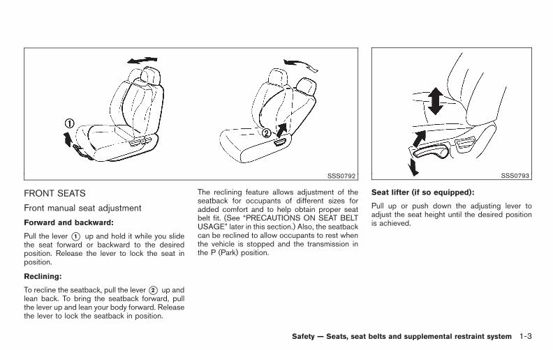
FRONT SEATS
Front manual seat adjustment
Forward and backward:
Pull the lever *1 up and hold it while you slidethe seat forward or backward to the desiredposition. Release the lever to lock the seat inposition.
Reclining:
To recline the seatback, pull the lever*2 up andlean back. To bring the seatback forward, pullthe lever up and lean your body forward. Releasethe lever to lock the seatback in position.
The reclining feature allows adjustment of theseatback for occupants of different sizes foradded comfort and to help obtain proper seatbelt fit. (See “PRECAUTIONS ON SEAT BELTUSAGE” later in this section.) Also, the seatbackcan be reclined to allow occupants to rest whenthe vehicle is stopped and the transmission inthe P (Park) position.
SSS0793
Seat lifter (if so equipped):
Pull up or push down the adjusting lever toadjust the seat height until the desired positionis achieved.
Safety — Seats, seat belts and supplemental restraint system 1-3

Black plate (18,1)
Model "E52-D" EDITED: 2010/ 10/ 25
Front power seat adjustment
Operating tips:
. The power seat motor has an auto-resetoverload protection circuit. If the motorstops during operation, wait 30 seconds,then reactivate the switch.
. Do not operate the power seat switch for along period of time when the engine is off.This will discharge the battery.
See “AUTOMATIC DRIVE POSITIONER” in the“3. Pre-driving checks and adjustments” sectionfor the seat position memory function (if soequipped).
CAUTION
When adjusting the seat positions, besure not to contact any moving parts toavoid possible injuries and/or da-mages.
SSS1051
Forward and backward:
Moving the switch *1 forward or backward willslide the seat forward or backward to thedesired position.
Reclining:
Move the recline switch *2 backward until thedesired angle is obtained. To bring the seatbackforward again, move the switch *2 forward.
The reclining feature allows adjustment of theseatback for occupants of different sizes foradded comfort and to help obtain proper seatbelt fit. (See “PRECAUTIONS ON SEAT BELTUSAGE” later in this section.) Also, the seatbackcan be reclined to allow occupants to rest when
the vehicle is stopped and the transmission is inthe P (Park) position.
1-4 Safety — Seats, seat belts and supplemental restraint system
Black plate (19,1)
Model "E52-D" EDITED: 2010/ 10/ 25
SSS1052
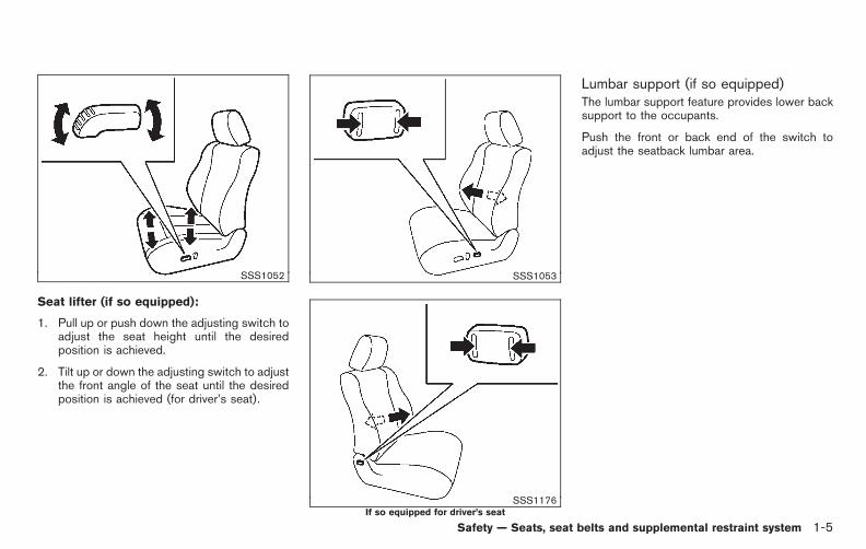
Seat lifter (if so equipped):
1. Pull up or push down the adjusting switch toadjust the seat height until the desiredposition is achieved.
2. Tilt up or down the adjusting switch to adjustthe front angle of the seat until the desiredposition is achieved (for driver’s seat).
SSS1053
SSS1176If so equipped for driver’s seat
Lumbar support (if so equipped)The lumbar support feature provides lower backsupport to the occupants.
Push the front or back end of the switch toadjust the seatback lumbar area.
Safety — Seats, seat belts and supplemental restraint system 1-5

Black plate (20,1)
Model "E52-D" EDITED: 2010/ 10/ 25
SSS1158
2ND ROW SEATS
Seat adjustment
WARNING
. The 2nd row seats are heavy. Becareful when folding and unfolding.
. To avoid injury to yourself andothers, keep hands and body clearwhen folding.
Forward and backward:
Pull the lever *1 up and hold it while you slidethe seat forward or backward to the desiredposition. Release the lever to lock the seat inposition.
Reclining:
To recline the seatback, pull the lever*2 up andlean back. To bring the seatback forward, pullthe lever up and lean your body forward. Releasethe lever to lock the seatback in position.
The reclining feature allows adjustment of theseatback for occupants of different sizes foradded comfort and to help obtain proper seatbelt fit. (See “PRECAUTIONS ON SEAT BELT
USAGE” later in this section.) Also, the seatbackcan be reclined to allow occupants to rest whenthe vehicle is stopped and the transmission inthe P (Park) position.
1-6 Safety — Seats, seat belts and supplemental restraint system
Black plate (21,1)
Model "E52-D" EDITED: 2010/ 10/ 25
SSS1159
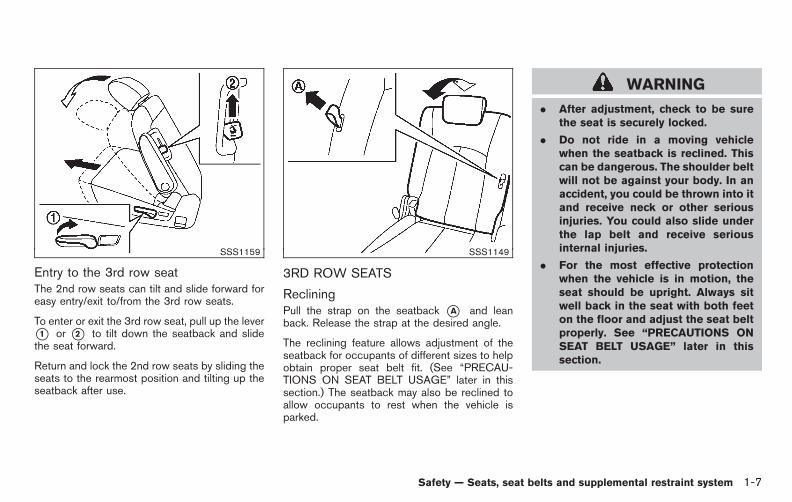
Entry to the 3rd row seatThe 2nd row seats can tilt and slide forward foreasy entry/exit to/from the 3rd row seats.
To enter or exit the 3rd row seat, pull up the lever*1 or *2 to tilt down the seatback and slidethe seat forward.
Return and lock the 2nd row seats by sliding theseats to the rearmost position and tilting up theseatback after use.
SSS1149
3RD ROW SEATS
RecliningPull the strap on the seatback *A and leanback. Release the strap at the desired angle.
The reclining feature allows adjustment of theseatback for occupants of different sizes to helpobtain proper seat belt fit. (See “PRECAU-TIONS ON SEAT BELT USAGE” later in thissection.) The seatback may also be reclined toallow occupants to rest when the vehicle isparked.
WARNING
. After adjustment, check to be surethe seat is securely locked.
. Do not ride in a moving vehiclewhen the seatback is reclined. Thiscan be dangerous. The shoulder beltwill not be against your body. In anaccident, you could be thrown into itand receive neck or other seriousinjuries. You could also slide underthe lap belt and receive seriousinternal injuries.
. For the most effective protectionwhen the vehicle is in motion, theseat should be upright. Always sitwell back in the seat with both feeton the floor and adjust the seat beltproperly. See “PRECAUTIONS ONSEAT BELT USAGE” later in thissection.
Safety — Seats, seat belts and supplemental restraint system 1-7

Black plate (22,1)
Model "E52-D" EDITED: 2010/ 10/ 25
HEAD RESTRAINTS
WARNING
Head restraints supplement the othervehicle safety systems. They may pro-vide additional protection against injuryin certain rear end collisions. Adjust thehead restraints properly, as specified inthis section. Check the adjustment aftersomeone else uses the seat. Do notattach anything to the head restraintstalks or remove the head restraint. Donot use the seat if the head restrainthas been removed. If the head restraintwas removed, reinstall and properlyadjust the head restraint before anoccupant uses the seating position.Failure to follow these instructionscan reduce the effectiveness of thehead restraints. This may increase therisk of serious injury or death in acollision.
SSS1160
The illustration shows the seating positionsequipped with head restraints. The head re-straints are adjustable.
Indicates the seating position is equippedwith a head restraint.
SSS0992
Components1. Head restraint
2. Adjustment notches
3. Lock knob
4. Stalks
1-8 Safety — Seats, seat belts and supplemental restraint system

Black plate (23,1)
Model "E52-D" EDITED: 2010/ 10/ 25
SSS0997
AdjustmentAdjust the head restraint so the center is levelwith the center of your ears.
SSS0993
To raise the head restraint, pull it up.
SSS0994
To lower, push and hold the lock knob and pushthe head restraint down.
Safety — Seats, seat belts and supplemental restraint system 1-9

Black plate (24,1)
Model "E52-D" EDITED: 2010/ 10/ 25
SSS0995
RemovalUse the following procedure to remove theadjustable head restraints.
1. Pull the head restraint up to the highestposition.
2. Push and hold the lock knob.
3. Remove the head restraint from the seat.
4. Store the head restraint properly in a secureplace so it is not loose in the vehicle.
5. Reinstall and properly adjust the headrestraint before an occupant uses theseating position.
SSS0996
Install1. Align the head restraint stalks with the holes
in the seat. Make sure that the head restraintis facing the correct direction. The stalk withthe adjustment notches *1 must be in-stalled in the hole with the lock knob *2 .
2. Push and hold the lock knob and push thehead restraint down.
3. Properly adjust the head restraint before anoccupant uses the seating position.
SSS0508
Front-seat Active Head RestraintThe Active Head Restraint moves forwardutilizing the force that the seatback receivesfrom the occupant in a rear-end collision. Themovement of the head restraint helps supportthe occupant’s head by reducing its backwardmovement and helping absorb some of theforces that may lead to whiplash-type injuries.
Active Head Restraints are effective for colli-sions at low to medium speeds in which it is saidthat whiplash injury occurs most.
Active Head Restraints operate only in certainrear-end collisions. After the collision, the headrestraints return to their original position.
1-10 Safety — Seats, seat belts and supplemental restraint system

Black plate (25,1)
Model "E52-D" EDITED: 2010/ 10/ 25
Adjust the Active Head Restraints properly asdescribed earlier in this section.
ADJUSTABLE HEADRESTS
WARNING
The adjustable headrests supplementthe other vehicle safety systems. Theymay provide additional protectionagainst injury in certain rear end colli-sions. Adjust the headrests properly, asspecified in this section. Check theadjustment after someone else usesthe seat. Do not attach anything to theadjustable headrest stalks or removethe adjustable headrests. Do not usethe seat if the adjustable headrestshave been removed. If the headrestwas removed, reinstall and properlyadjust the headrest before an occupantuses the seating position. Failure tofollow these instructions can reduce theeffectiveness of the adjustable head-rests. This may increase the risk ofserious injury or death in a collision.
SSS1161
The illustration shows the seating positionsequipped with adjustable headrests.
Indicates the seating position is equippedwith an adjustable or removable headrest.
SSS1128
Components1. Adjustable headrest
2. Adjustment notch
3. Lock knob
4. Stalks
Safety — Seats, seat belts and supplemental restraint system 1-11

Black plate (26,1)
Model "E52-D" EDITED: 2010/ 10/ 25
SSS1123
To raise the headrest, pull it up to the lockposition.
SSS1124
To lower, push and hold the lock knob and pushthe headrest down.
SSS1125
RemovalUse the following procedure to remove theheadrests.
1. Pull the headrest up to the highest position.
2. Push and hold the lock knob.
3. Remove the headrest from the seat.
4. Store the headrest properly in a secureplace so it is not loose in the vehicle.
5. Install and properly adjust the headrestbefore an occupant uses the seating posi-tion.
1-12 Safety — Seats, seat belts and supplemental restraint system
Black plate (27,1)
Model "E52-D" EDITED: 2010/ 10/ 25
SSS1126
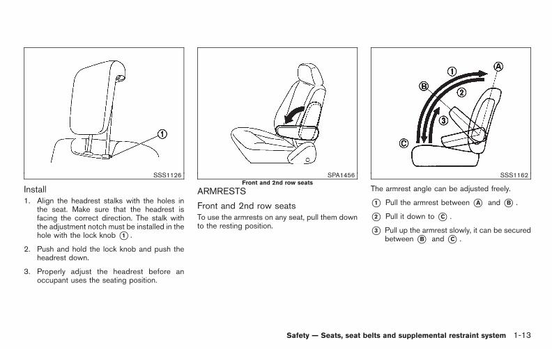
Install1. Align the headrest stalks with the holes in
the seat. Make sure that the headrest isfacing the correct direction. The stalk withthe adjustment notch must be installed in thehole with the lock knob *1 .
2. Push and hold the lock knob and push theheadrest down.
3. Properly adjust the headrest before anoccupant uses the seating position.
SPA1456Front and 2nd row seats
ARMRESTS
Front and 2nd row seatsTo use the armrests on any seat, pull them downto the resting position.
SSS1162
The armrest angle can be adjusted freely.
*1 Pull the armrest between *A and *B .
*2 Pull it down to *C .
*3 Pull up the armrest slowly, it can be securedbetween *B and *C .
Safety — Seats, seat belts and supplemental restraint system 1-13
Black plate (28,1)
Model "E52-D" EDITED: 2010/ 10/ 25
FLEXIBLE SEATING
WARNING
. Never allow anyone to ride in thecargo area or on the rear seatswhen they are in the fold-downposition. In a collision, people ridingin these areas without proper re-straints are more likely to be ser-iously injured or killed.
. Do not allow people to ride in anyarea of your vehicle that is notequipped with seats and seat belts.Be sure everyone in your vehicle isin a seat and using a seat beltproperly.
. Do not fold down the rear seatswhen occupants are in the rear seatarea or any cargo is on the rearseats.
. Head restraints and headrestsshould be adjusted properly as theymay provide significant protectionagainst injury in an accident. Alwaysreplace and adjust them properly ifthey have been removed for anyreason.
. If the head restraints are removedfor any reason, they should besecurely stored to prevent themfrom causing injury to passengersor damage to the vehicle in case ofsudden braking or an accident.
. When returning the seatbacks to theupright position, be certain they arecompletely secured in the latchedposition. If they are not completelysecured, passengers may be injuredin an accident or sudden stop.
. Properly secure all cargo to helpprevent it from sliding or shifting.Do not place cargo higher than theseatbacks. In a sudden stop orcollision, unsecured cargo couldcause personal injury.
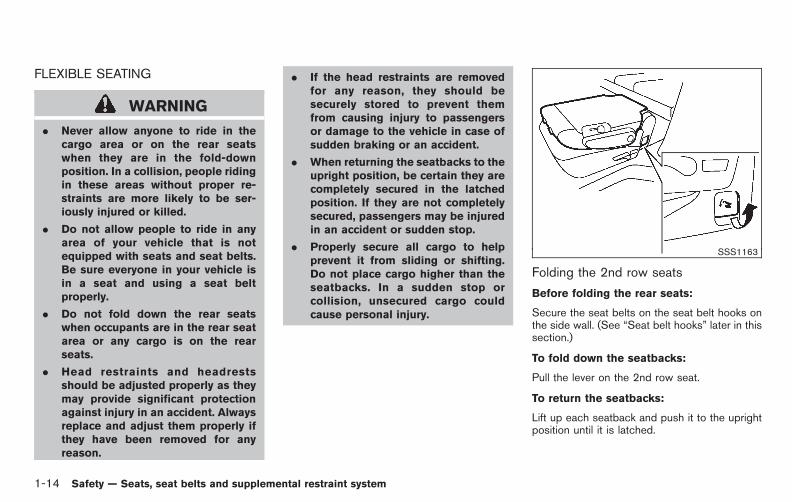
SSS1163
Folding the 2nd row seats
Before folding the rear seats:
Secure the seat belts on the seat belt hooks onthe side wall. (See “Seat belt hooks” later in thissection.)
To fold down the seatbacks:
Pull the lever on the 2nd row seat.
To return the seatbacks:
Lift up each seatback and push it to the uprightposition until it is latched.
1-14 Safety — Seats, seat belts and supplemental restraint system

Black plate (29,1)
Model "E52-D" EDITED: 2010/ 10/ 25
CAUTION
When folding the 2nd row seat formaximum cargo hauling, be sure thatcargo does not contact the centerconsole of the 2nd row seat to avoidpossible damage to the console.
SSS1149Third row seatback
SSS1150Back side of the third row seatback
Folding the 3rd row seats
Before folding the 3rd row seats:
. Secure the seat belts on the seat belt hookson the side wall. (See “Seat belt hooks” laterin this section.)
. Disconnect and stow the center seat beltand tongue into the retractor base. (See“3rd row center seat belt” later in thissection.)
. Always reconnect the center seat belt whenthe seat is returned to the upright position.
. Remove drink containers from the rear cupholder.
Manual folding:
Pull the strap on the seatback *A or on theback side of the seatback *B and fold theseatback.
Safety — Seats, seat belts and supplemental restraint system 1-15

Black plate (30,1)
Model "E52-D" EDITED: 2010/ 10/ 25
SSS1151
Power folding (if so equipped):
Push the front side of the switch*A located onthe right side or left side of the cargo area. Thecorresponding 3rd row seatback will be foldeddown automatically.
Push and hold the rear side of the switch *B .The 3rd row seatback will be returned auto-matically. A beep sounds and the rear seatbackwill rise up while holding the switch. A beepsounds when the seatback is fully returned inposition.
PRECAUTIONS ON SEAT BELTUSAGE
If you are wearing your seat belt properlyadjusted, and you are sitting upright and wellback in your seat with both feet on the floor, yourchances of being injured or killed in an accidentand/or the severity of injury may be greatlyreduced. NISSAN strongly encourages you andall of your passengers to buckle up every timeyou drive, even if your seating position includes asupplemental air bag.
Most U.S. states and Canadian provincesor territories specify that seat belts beworn at all times when a vehicle is beingdriven.
SEAT BELTS
1-16 Safety — Seats, seat belts and supplemental restraint system

Black plate (31,1)
Model "E52-D" EDITED: 2010/ 10/ 25
SSS0136A
SSS0134A
WARNING
. Every person who drives or rides inthis vehicle should use a seat belt atall times. Children should be prop-erly restrained in the rear seat and,if appropriate, in a child restraint.
. The seat belt should be properlyadjusted to a snug fit. Failure to doso may reduce the effectiveness ofthe entire restraint system and in-crease the chance or severity ofinjury in an accident. Serious injuryor death can occur if the seat belt isnot worn properly.
. Always route the shoulder belt overyour shoulder and across yourchest. Never put the belt behindyour back, under your arm or acrossyour neck. The belt should be awayfrom your face and neck, but notfalling off your shoulder.
. Position the lap belt as low andsnug as possible AROUND THEHIPS, NOT THE WAIST. A lap beltworn too high could increase therisk of internal injuries in an acci-dent.
Safety — Seats, seat belts and supplemental restraint system 1-17

Black plate (32,1)
Model "E52-D" EDITED: 2010/ 10/ 25
. Be sure the seat belt tongue issecurely fastened to the properbuckle.
. Do not wear the seat belt inside outor twisted. Doing so may reduce itseffectiveness.
. Do not allow more than one personto use the same seat belt.
. Never carry more people in thevehicle than there are seat belts.
. If the seat belt warning light glowscontinuously while the ignition isturned ON with all doors closed andall seat belts fastened, it may in-dicate a malfunction in the system.Have the system checked by aNISSAN dealer.
. No changes should be made to theseat belt system. For example, donot modify the seat belt, add mate-rial or install devices that maychange the seat belt routing ortension. Doing so may affect theoperation of the seat belt system.Modifying or tampering with theseat belt system may result inserious personal injury.
. Once a seat belt pretensioner has
activated, it cannot be reused andmust be replaced together with theretractor. See a NISSAN dealer.
. Removal and installation of thepretensioner seat belt system com-ponents should be done by aNISSAN dealer.
. All seat belt assemblies, includingretractors and attaching hardware,should be inspected after any colli-sion by a NISSAN dealer. NISSANrecommends that all seat belt as-semblies in use during a collision bereplaced unless the collision wasminor and the belts show no da-mage and continue to operate prop-erly.
Seat belt assemblies not in useduring a collision should also beinspected and replaced if eitherdamage or improper operation isnoted.
. All child restraints and attachinghardware should be inspected afterany collision. Always follow therestraint manufacturer’s inspectioninstructions and replacement re-commendations. The child restraints
should be replaced if they aredamaged.
1-18 Safety — Seats, seat belts and supplemental restraint system

Black plate (33,1)
Model "E52-D" EDITED: 2010/ 10/ 25
SSS0016
SSS0014
PREGNANT WOMEN
NISSAN recommends that pregnant women useseat belts. The seat belt should be worn snug,and always position the lap belt as low aspossible around the hips, not the waist, andplace the shoulder belt over your shoulder andacross your chest. Never run the lap/shoulderbelt over your abdominal area. Contact yourdoctor for specific recommendations.
INJURED PERSONS
NISSAN recommends that injured persons useseat belts, depending on the injury. Check withyour doctor for specific recommendations.
THREE-POINT TYPE SEAT BELT
WARNING
. Every person who drives or rides inthis vehicle should use a seat belt atall times.
. Do not ride in a moving vehiclewhen the seatback is reclined. Thiscan be dangerous. The shoulder beltwill not be against your body. In anaccident, you could be thrown into itand receive neck or other seriousinjuries. You could also slide underthe lap belt and receive serious
internal injuries.
. For the most effective protectionwhen the vehicle is in motion, theseat should be upright. Always sitwell back in the seat with both feeton the floor and adjust the seat beltproperly.
Safety — Seats, seat belts and supplemental restraint system 1-19

Black plate (34,1)
Model "E52-D" EDITED: 2010/ 10/ 25
SSS0292
Fastening the seat belts1. Adjust the seat. (See “SEATS” earlier in this
section.)
2. Slowly pull the seat belt out of the retractorand insert the tongue into the buckle untilyou hear and feel the latch engage.
. The retractor is designed to lockduring a sudden stop or on impact.A slow pulling motion permits thebelt to move, and allows you somefreedom of movement in the seat.
. If the seat belt cannot be pulledfrom its fully retracted position,firmly pull the belt and release it.
Then smoothly pull the belt out ofthe retractor.
SSS0290
3. Position the lap belt portion low and snugon the hips as shown.
4. Pull the shoulder belt portion toward theretractor to take up extra slack. Be sure theshoulder belt is routed over your shoulderand across your chest.
The three-point type seat belts have two modesof operation:
. Emergency Locking Retractor (ELR)
. Automatic Locking Retractor (ALR)
The Emergency Locking Retractor (ELR) modeallows the seat belt to extend and retract toallow the driver and passengers some freedom
1-20 Safety — Seats, seat belts and supplemental restraint system

Black plate (35,1)
Model "E52-D" EDITED: 2010/ 10/ 25
of movement in the seat. The ELR locks the seatbelt when the vehicle slows down rapidly orduring impacts.
The Automatic Locking Retractor (ALR) mode(child restraint mode) locks the seat belt forchild restraint installation.
When the ALR mode is activated the seat beltcannot be extended again until the seat belttongue is detached from the buckle and fullyretracted. The seat belt returns to the ELR modeafter the seat belt fully retracts. For additionalinformation, see “CHILD RESTRAINTS” later inthis section.
The ALR mode should be used only forchild restraint installation. During normalseat belt use by an occupant, the ALRmode should not be activated. If it isactivated, it may cause uncomfortable seatbelt tension.
WARNING
When fastening the seat belts, becertain that seatbacks are completelysecured in the latched position. If theyare not completely secured, passengersmay be injured in an accident or suddenstop.
SSS0326
Unfastening the seat beltsTo unfasten the seat belt, push the button on thebuckle. The seat belt automatically retracts.
Checking seat belt operationSeat belt retractors are designed to lock seatbelt movement by two separate methods:
. When the belt is pulled quickly from theretractor.
. When the vehicle slows down rapidly.
To increase your confidence in the seat belts,check the operation as follows:
. Grasp the shoulder belt and pull forwardquickly. The retractor should lock and
restrict further belt movement.
If the retractor does not lock during this check orif you have any question about seat beltoperation, see a NISSAN dealer.
Safety — Seats, seat belts and supplemental restraint system 1-21

Black plate (36,1)
Model "E52-D" EDITED: 2010/ 10/ 25
SSS0391
3rd row center seat beltThe 3rd row center seat belt has a connectortongue*1 and a seat belt tongue*2 . Both theconnector tongue and the seat belt tongue mustbe securely latched for proper seat belt opera-tion.
SSS0241
WARNING
. Always fasten the connector tongueand the seat belt in the order shown.
. Always make sure both the connec-tor tongue and the seat belt tongueare secured when using the seatbelt or installing a child restraint. Donot use the seat belt or childrestraint with only the seat belttongue attached. This could resultin serious personal injury in case ofan accident or a sudden stop.
SSS1164
1-22 Safety — Seats, seat belts and supplemental restraint system
Black plate (37,1)
Model "E52-D" EDITED: 2010/ 10/ 25
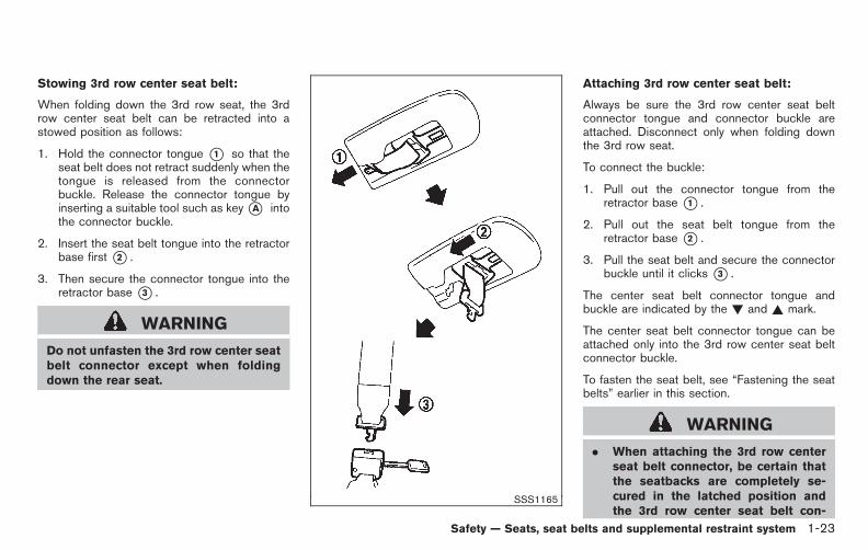
Stowing 3rd row center seat belt:
When folding down the 3rd row seat, the 3rdrow center seat belt can be retracted into astowed position as follows:
1. Hold the connector tongue *1 so that theseat belt does not retract suddenly when thetongue is released from the connectorbuckle. Release the connector tongue byinserting a suitable tool such as key*A intothe connector buckle.
2. Insert the seat belt tongue into the retractorbase first *2 .
3. Then secure the connector tongue into theretractor base *3 .
WARNING
Do not unfasten the 3rd row center seatbelt connector except when foldingdown the rear seat.
SSS1165
Attaching 3rd row center seat belt:
Always be sure the 3rd row center seat beltconnector tongue and connector buckle areattached. Disconnect only when folding downthe 3rd row seat.
To connect the buckle:
1. Pull out the connector tongue from theretractor base *1 .
2. Pull out the seat belt tongue from theretractor base *2 .
3. Pull the seat belt and secure the connectorbuckle until it clicks *3 .
The center seat belt connector tongue andbuckle are indicated by the ! and ~ mark.
The center seat belt connector tongue can beattached only into the 3rd row center seat beltconnector buckle.
To fasten the seat belt, see “Fastening the seatbelts” earlier in this section.
WARNING
. When attaching the 3rd row centerseat belt connector, be certain thatthe seatbacks are completely se-cured in the latched position andthe 3rd row center seat belt con-
Safety — Seats, seat belts and supplemental restraint system 1-23

Black plate (38,1)
Model "E52-D" EDITED: 2010/ 10/ 25
nector is completely secured.
. If the 3rd row center seat beltconnector and the seatbacks arenot secured in the correct position,serious personal injury may result inan accident or sudden stop.
SSS0351A
Shoulder belt height adjustment (if soequipped)The shoulder belt anchor height should beadjusted to the position best for you. (See“PRECAUTIONS ON SEAT BELT USAGE”earlier in this section.)
To adjust, pull the adjustment button *1 , andthen move the shoulder belt anchor to thedesired position *2 , so that the belt passesover the center of the shoulder. The belt shouldbe away from your face and neck, but not fallingoff of your shoulder. Release the adjustmentbutton to lock the shoulder belt anchor intoposition.
WARNING
. After adjustment, release the ad-justment button and try to move theshoulder belt anchor up and downto make sure it is securely fixed inposition.
. The shoulder belt anchor heightshould be adjusted to the positionbest for you. Failure to do so mayreduce the effectiveness of theentire restraint system and increasethe chance or severity of injury in anaccident.
1-24 Safety — Seats, seat belts and supplemental restraint system

Black plate (39,1)
Model "E52-D" EDITED: 2010/ 10/ 25
SSS1076
Seat belt hooksWhen the 2nd or 3rd row seat belts are not inuse and when folding down the 2nd or 3rd rowseats, hook the 2nd and 3rd outer seat belts onthe seat belt hooks.
SEAT BELT EXTENDERS
If, because of body size or driving position, it isnot possible to properly fit the lap-shoulder beltand fasten it, an extender that is compatible withthe installed seat belts is available that can bepurchased. The extender adds approximately 8in (200 mm) of length and may be used for eitherthe driver or front passenger seating position.See a NISSAN dealer for assistance withpurchasing an extender if an extender is
required.
WARNING
. Only NISSAN seat belt extenders,made by the same company whichmade the original equipment seatbelts, should be used with theNISSAN seat belts.
. Adults and children who can use thestandard seat belt should not use anextender. Such unnecessary usecould result in serious personalinjury in the event of an accident.
. Never use seat belt extenders toinstall child restraints. If the childrestraint is not secured properly, thechild could be seriously injured in acollision or a sudden stop.
SEAT BELT MAINTENANCE
. To clean the seat belt webbing, apply amild soap solution or any solution recom-mended for cleaning upholstery or carpets.Then, wipe with a cloth and allow the seatbelts to dry in the shade. Do not allow theseat belts to retract until they are completelydry.
. If dirt builds up in the shoulder belt
guide of the seat belt anchors, the seatbelts may retract slowly. Wipe the shoulderbelt guide with a clean, dry cloth.
. Periodically check to see that the seatbelt and the metal components such asbuckles, tongues, retractors, flexible wiresand anchors work properly. If loose parts,deterioration, cuts or other damage on thewebbing is found, the entire seat beltassembly should be replaced.
Safety — Seats, seat belts and supplemental restraint system 1-25
Black plate (40,1)
Model "E52-D" EDITED: 2010/ 10/ 25
Children need adults to help protect them.
They need to be properly restrained.
In addition to the general information in thismanual, child safety information is available frommany other sources, including doctors, teachers,government traffic safety offices, and communityorganizations. Every child is different, so be sureto learn the best way to transport your child.
There are three basic types of child restraintsystems:
. Rear-facing child restraint
. Forward-facing child restraint
. Booster seat
The proper restraint depends on the child’s size.Generally, infants up to about 1 year and lessthan 20 lbs (9 kg) should be placed in rear-facing child restraints. Forward-facing childrestraints are available for children who outgrowrear-facing child restraints and are at least 1year old. Booster seats are used to help positiona vehicle lap/shoulder belt on a child who can nolonger use a forward-facing child restraint.
WARNING
Infants and children need special pro-tection. The vehicle’s seat belts may notfit them properly. The shoulder belt may
come too close to the face or neck. Thelap belt may not fit over their small hipbones. In an accident, an improperlyfitting seat belt could cause serious orfatal injury. Always use appropriatechild restraints.
All U.S. states and Canadian provinces orterritories require the use of approved childrestraints for infants and small children. See“CHILD RESTRAINTS” later in this section.
A child restraint may be secured in the vehicleby using either the LATCH (Lower Anchor andTethers for CHildren) system or with the vehicleseat belt. See “CHILD RESTRAINTS” later inthis section for more information.
NISSAN recommends that all pre-teensand children be restrained in the rear seat.Studies show that children are safer whenproperly restrained in the rear seat than inthe front seat.
This is especially important because yourvehicle has a supplemental restraint sys-tem (Air bag system) for the front passen-ger. See “SUPPLEMENTAL RESTRAINTSYSTEM” later in this section.
INFANTS
Infants up to at least 1 year old should be placedin a rear-facing child restraint. NISSAN recom-mends that infants be placed in child restraintsthat comply with Federal Motor Vehicle SafetyStandards or Canadian Motor Vehicle SafetyStandards. You should choose a child restraintthat fits your vehicle and always follow themanufacturer’s instructions for installation anduse.
SMALL CHILDREN
Children that are over 1 year old and weigh atleast 20 lbs (9 kg) should remain in a rear-facingchild restraint as long as possible up to theheight or weight limit of the child restraint.Forward-facing child restraints are available forchildren who outgrow rear facing child restraintsand are at least 1 year old. Refer to themanufacturer’s instructions for minimum andmaximum weight and height recommendations.NISSAN recommends that small children beplaced in child restraints that comply withFederal Motor Vehicle Safety Standards orCanadian Motor Vehicle Safety Standards. Youshould choose a child restraint that fits yourvehicle and always follow the manufacturer’sinstructions for installation and use.
CHILD SAFETY
1-26 Safety — Seats, seat belts and supplemental restraint system

Black plate (41,1)
Model "E52-D" EDITED: 2010/ 10/ 25
LARGER CHILDREN
Children who are too large for child restraintsshould be seated and restrained by the seatbelts which are provided. The seat belt may notfit properly if the child is less than 4 ft 9 in (142.5cm) tall and weighs between 40 lbs (18 kg) and80 lbs (36 kg). A booster seat should be used toobtain proper seat belt fit.
NISSAN recommends that a child be placed in acommercially available booster seat if theshoulder belt fits close to the face or neck or ifthe lap portion of the seat belt goes across theabdomen. The booster seat should raise thechild so that the shoulder belt is properlypositioned across the top, middle portion ofthe shoulder and the lap belt is low on the hips.A booster seat can only be used in seatingpositions that have a three-point type seat belt.The booster seat should fit the vehicle seat andhave a label certifying that it complies withFederal Motor Vehicle Safety Standards orCanadian Motor Vehicle Safety Standards.Once the child has grown so the shoulder beltis no longer on or near the face and neck, usethe shoulder belt without the booster seat.
WARNING
Never let a child stand or kneel on anyseat and do not allow a child in thecargo area. The child could be seriouslyinjured or killed in a sudden stop orcollision.
SSS0099
SSS0100
CHILD RESTRAINTS
Safety — Seats, seat belts and supplemental restraint system 1-27

Black plate (42,1)
Model "E52-D" EDITED: 2010/ 10/ 25
PRECAUTIONS ON CHILDRESTRAINTS
WARNING
. Failure to follow the warnings andinstructions for proper use and in-stallation of child restraints couldresult in serious injury or death of achild or other passengers in asudden stop or collision:
— The child restraint must be usedand installed properly. Alwaysfollow all of the child restraintmanufacturer’s instructions forinstallation and use.
— Infants and children shouldnever be held on anyone’s lap.Even the strongest adult cannotresist the forces of a collision.
— Do not put a seat belt aroundboth a child and another pas-senger.
— NISSAN recommends that allchild restraints be installed inthe rear seat. Studies show thatchildren are safer when properlyrestrained in the rear seat thanin the front seat. If you must
install a forward-facing childrestraint in the front seat, see“FORWARD-FACING CHILD RE-STRAINT INSTALLATION USINGTHE SEAT BELTS” later in thissection.
— Even with the NISSAN AdvancedAir Bag System, never install arear-facing child restraint in thefront seat. An inflating air bagcould seriously injure or kill achild. A rear-facing child re-straint must only be used in therear seat.
— Be sure to purchase a childrestraint that will fit the childand vehicle. Some child re-straints may not fit properly inyour vehicle.
— Child restraint anchor points aredesigned to withstand loadsfrom child restraints that areproperly fitted.
— Never use the anchor points foradult seat belts or harnesses.
— A child restraint with a top tetherstrap should not be used in thefront passenger seat.
— Keep seatbacks as upright as
possible after fitting the childrestraint.
— Infants and children should al-ways be placed in an appropri-ate child restraint while in thevehicle.
. When the child restraint is not inuse, keep it secured with the LATCHsystem or a seat belt. In a suddenstop or collision, loose objects caninjure occupants or damage thevehicle.
CAUTION
A child restraint in a closed vehicle canbecome very hot. Check the seatingsurface and buckles before placing achild in the child restraint.
This vehicle is equipped with a universal childrestraint anchor system, referred to as theLATCH (Lower Anchors and Tethers for CHil-dren) system. Some child restraints include rigidor webbing-mounted attachments that can beconnected to these anchors.
For details, see “Lower Anchors and Tethers forCHildren System (LATCH)” later in this section.
1-28 Safety — Seats, seat belts and supplemental restraint system

Black plate (43,1)
Model "E52-D" EDITED: 2010/ 10/ 25
If you do not have a LATCH compatible childrestraint, the vehicle seat belts can be used.
Several manufacturers offer child restraints forinfants and small children of various sizes. Whenselecting any child restraint, keep the followingpoints in mind:
. Choose only a restraint with a label certifyingthat it complies with Federal Motor VehicleSafety Standard 213 or Canadian MotorVehicle Safety Standard 213.
. Check the child restraint in your vehicle tobe sure it is compatible with the vehicle’sseat and seat belt system.
. If the child restraint is compatible with yourvehicle, place your child in the child restraintand check the various adjustments to besure the child restraint is compatible withyour child. Choose a child restraint that isdesigned for your child’s height and weight.Always follow all recommended procedures.
All U.S. states and Canadian provinces orterritories require that infants and smallchildren be restrained in an approved childrestraint at all times while the vehicle isbeing operated. Canadian law requires thetop tether strap on forward-facing childrestraints be secured to the designatedanchor point on the vehicle.
SSS1166
Lower Anchors and Tethers for CHildrenSystem (LATCH)
Your vehicle is equipped with special anchorpoints that are used with the LATCH (LowerAnchors and Tethers for CHildren) systemcompatible child restraints. This system mayalso be referred to as the ISOFIX or ISOFIXcompatible system. With this system, you do nothave to use a vehicle seat belt to secure thechild restraint.
The LATCH anchor points are provided to installchild restraints in the following positions only:
. 2nd row seats
. 3rd row seat
LATCH lower anchor
WARNING
Failure to follow the warnings andinstructions for proper use and installa-tion of child restraints could result inserious injury or death of a child orother passengers in a sudden stop orcollision:
— Attach LATCH system compatiblechild restraints only at the locationsshown in the illustration.
— Do not secure a child restraint in thecenter rear seating position usingthe LATCH lower anchors. The childrestraint will not be secured prop-erly.
— Inspect the lower anchors by insert-ing your fingers into the loweranchor area. Feel to make surethere are no obstructions over theanchors such as seat belt webbingor seat cushion material. The childrestraint will not be secured prop-erly if the lower anchors are ob-structed.
Safety — Seats, seat belts and supplemental restraint system 1-29

Black plate (44,1)
Model "E52-D" EDITED: 2010/ 10/ 25
SSS0637LATCH lower anchor location
LATCH lower anchor locationThe LATCH anchors are located at the rear ofthe seat cushion near the seatback. A label isattached to the seatback to help you locate theLATCH anchors.
SSS11672nd row seats
SSS11773rd row seat
SSS0643LATCH webbing-mounted attachment
Installing child restraint LATCH loweranchor attachmentsLATCH compatible child restraints include tworigid or webbing-mounted attachments that canbe connected to anchors located at certainseating positions in your vehicle. With thissystem, you do not have to use a vehicle seatbelt to secure the child restraint. Check yourchild restraint for a label stating that it iscompatible with LATCH. This information mayalso be in the instructions provided by the childrestraint manufacturer.
1-30 Safety — Seats, seat belts and supplemental restraint system

Black plate (45,1)
Model "E52-D" EDITED: 2010/ 10/ 25
SSS0644LATCH rigid attachment
The child restraint top tether strap must be usedwhen installing the child restraint with theLATCH lower anchor attachments or seat belts.See “TOP TETHER STRAP CHILD RE-STRAINT” later in this section for installationinstructions.
When installing a child restraint, carefully readand follow the instructions in this manual andthose supplied with the child restraint.
SSS10882nd row seat
SSS11683rd row seat
TOP TETHER STRAP CHILD RE-STRAINT
If the manufacturer of your child restraintrequires the use of a top tether strap, it mustbe secured to an anchor point.
WARNING
. In the 3rd row seat, a child restraintwith a top tether strap can only beused in the center position. Do notplace in an outboard seating posi-tion and attempt to angle the tetherstrap to the center position.
. Child restraint anchor points aredesigned to withstand only thoseloads imposed by correctly fittedchild restraints. Under no circum-stances are they to be used for adultseat belts or harnesses.
. Do not allow cargo to contact thetop tether strap when it is attachedto the top tether anchor. Properlysecure the cargo so it does notcontact the top tether strap. Cargothat is not properly secured or cargothat contacts the top tether strapmay damage the top tether strapduring a collision. Your child could
Safety — Seats, seat belts and supplemental restraint system 1-31

Black plate (46,1)
Model "E52-D" EDITED: 2010/ 10/ 25
be seriously injured or killed in acollision if the child restraint toptether strap is damaged.
Top tether anchor point locationsAnchor points are located in the followinglocations:
. 2nd row seats on the back side of theseatback as shown.
. 3rd row seat on the back side of theseatback as shown.
If you have any questions when installing atop tether strap child restraint on the rearseat, consult a NISSAN dealer for details.
REAR-FACING CHILD RESTRAINT IN-STALLATION USING LATCH
Refer to all Warnings and Cautions in the “Childsafety” and “Child restraints” sections beforeinstalling a child restraint.
Follow these steps to install a rear-facing childrestraint in the 2nd row seats and 3rd row seatusing the LATCH system:
1. Position the child restraint on the seat.Always follow the child restraint manufac-turer’s instructions.
SSS0648Rear-facing web-mounted — step 2
2. Secure the child restraint anchor attach-ments to the LATCH lower anchors. Checkto make sure the LATCH attachment isproperly attached to the lower anchors.
SSS0649Rear-facing rigid-mounted — step 2
1-32 Safety — Seats, seat belts and supplemental restraint system
Black plate (47,1)
Model "E52-D" EDITED: 2010/ 10/ 25
SSS0639Rear-facing — step 3
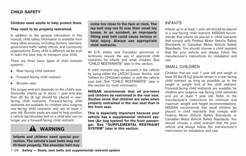
3. For child restraints that are equipped withwebbing-mounted attachments, remove anyadditional slack from the anchor attach-ments. Press downward and rearward firmlyin the center of the child restraint with yourhand to compress the vehicle seat cushionand seatback while tightening the webbingof the anchor attachments.
SSS0650Rear-facing — step 4
4. After attaching the child restraint, test itbefore you place the child in it. Push it fromside to side while holding the child restraintnear the LATCH attachment path. The childrestraint should not move more than 1 inch(25 mm), from side to side. Try to tug itforward and check to see if the LATCHattachment holds the restraint in place. If therestraint is not secure, tighten the LATCHattachment as necessary, or put the restraintin another seat and test it again. You mayneed to try a different child restraint or tryinstalling by using the vehicle seat belt (ifapplicable). Not all child restraints fit in alltypes of vehicles.
5. Check to make sure the child restraint is
properly secured prior to each use. If thechild restraint is loose, repeat steps 1through 4.
Safety — Seats, seat belts and supplemental restraint system 1-33

Black plate (48,1)
Model "E52-D" EDITED: 2010/ 10/ 25
SSS0100
REAR-FACING CHILD RESTRAINT IN-STALLATION USING THE SEAT BELTS
WARNING
. The three-point seat belt with Auto-matic Locking Retractor (ALR) mustbe used when installing a childrestraint. Failure to use the ALRmode will result in the child re-straint not being properly secured.The restraint could tip over or beloose and cause injury to a child in asudden stop or collision.
. When installing a child restraint
system in the 3rd row center posi-tion, both the center seat belt con-nector tongue and buckle tonguemust be secured. See “Attaching 3rdrow center seat belt” earlier in thissection.
SSS0100Rear-facing — step 1
Refer to all Warnings and Cautions in the“CHILD SAFETY” earlier in this section and“CHILD RESTRAINTS” earlier in this sectionbefore installing a child restraint.
Follow these steps to install a rear-facing childrestraint using the vehicle seat belts in the rearseats:
1. Child restraints for infants must beused in the rear-facing direction andtherefore must not be used in the frontseat. Position the child restraint on the seat.Always follow the restraint manufacturer’sinstructions.
1-34 Safety — Seats, seat belts and supplemental restraint system

Black plate (49,1)
Model "E52-D" EDITED: 2010/ 10/ 25
SSS0654Rear-facing — step 2
2. Route the seat belt tongue through the childrestraint and insert it into the buckle until youhear and feel the latch engage. Be sure tofollow the child restraint manufacturer’sinstructions for belt routing.
SSS0655Rear-facing — step 3
3. Pull the shoulder belt until the belt is fullyextended. At this time, the seat belt retractoris in the Automatic Locking Retractor (ALR)mode (child restraint mode). It reverts to theEmergency Locking Retractor (ELR) modewhen the seat belt is fully retracted.
SSS0656Rear-facing — step 4
4. Allow the seat belt to retract. Pull up on theshoulder belt to remove any slack in the belt.
Safety — Seats, seat belts and supplemental restraint system 1-35
Black plate (50,1)
Model "E52-D" EDITED: 2010/ 10/ 25
SSS0657Rear-facing — step 5
5. Remove any additional slack from the seatbelt; press downward and rearward firmly inthe center of the child restraint to compressthe vehicle seat cushion and seatback whilepulling up on the seat belt.
SSS0658Rear-facing — step 6
6. After attaching the child restraint, test itbefore you place the child in it. Push it fromside to side while holding the child restraintnear the seat belt path. The child restraintshould not move more than 1 inch (25 mm),from side to side. Try to tug it forward andcheck to see if the belt holds the restraint inplace. If the restraint is not secure, tightenthe seat belt as necessary, or put therestraint in another seat and test it again.You may need to try a different childrestraint. Not all child restraints fit in alltypes of vehicles.
7. Check to make sure that the child restraint isproperly secured prior to each use. If theseat belt is not locked, repeat steps 1
through 6.
After the child restraint is removed and the seatbelt fully retracted, the ALR mode (child restraintmode) is canceled.
FORWARD-FACING CHILD RE-STRAINT INSTALLATION USINGLATCH
Refer to all Warnings and Cautions in the “Childsafety” and “Child restraints” sections beforeinstalling a child restraint.
Follow these steps to install a forward-facingchild restraint using the LATCH system:
1. Position the child restraint on the seat.Always follow the child restraint manufac-turer’s instructions.
1-36 Safety — Seats, seat belts and supplemental restraint system

Black plate (51,1)
Model "E52-D" EDITED: 2010/ 10/ 25
SSS0645Forward-facing web-mounted — step 2
2. Secure the child restraint anchor attach-ments to the LATCH lower anchors. Checkto make sure the LATCH attachment isproperly attached to the lower anchors.
If the child restraint is equipped with a toptether strap, route the top tether strap andsecure the tether strap to the tether anchorpoint. See “Installing top tether strap” in thissection. Do not install child restraints thatrequire the use of a top tether strap inseating positions that do not have a toptether anchor.
SSS0646Forward-facing rigid-mounted — step 3
3. The back of the child restraint should besecured against the vehicle seatback.
If necessary, adjust or remove the headrestraint or headrest to obtain the correctchild restraint fit. If the head restraint orheadrest is removed, store it in a secureplace. Be sure to reinstall the headrestraint or headrest when the childrestraint is removed. See “HEAD RE-STRAINTS” earlier in this section and“ADJUSTABLE HEADRESTS” earlier in thissection for head restraint or headrestadjustment information.
If the seating position does not have anadjustable head restraint or headrest and it
is interfering with the proper child restraintfit, try another seating position or a differentchild restraint.
Safety — Seats, seat belts and supplemental restraint system 1-37
Black plate (52,1)
Model "E52-D" EDITED: 2010/ 10/ 25
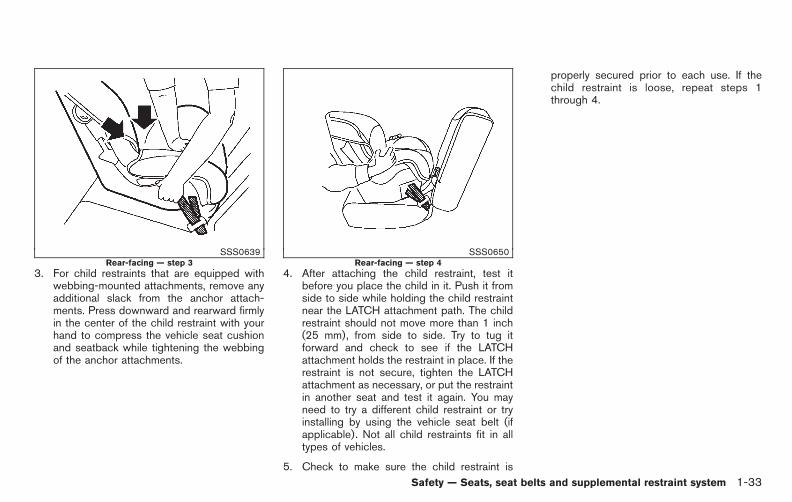
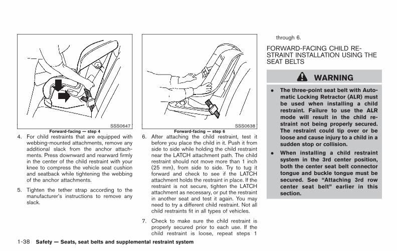
SSS0647Forward-facing — step 4
4. For child restraints that are equipped withwebbing-mounted attachments, remove anyadditional slack from the anchor attach-ments. Press downward and rearward firmlyin the center of the child restraint with yourknee to compress the vehicle seat cushionand seatback while tightening the webbingof the anchor attachments.
5. Tighten the tether strap according to themanufacturer’s instructions to remove anyslack.
SSS0638Forward-facing — step 6
6. After attaching the child restraint, test itbefore you place the child in it. Push it fromside to side while holding the child restraintnear the LATCH attachment path. The childrestraint should not move more than 1 inch(25 mm), from side to side. Try to tug itforward and check to see if the LATCHattachment holds the restraint in place. If therestraint is not secure, tighten the LATCHattachment as necessary, or put the restraintin another seat and test it again. You mayneed to try a different child restraint. Not allchild restraints fit in all types of vehicles.
7. Check to make sure the child restraint isproperly secured prior to each use. If thechild restraint is loose, repeat steps 1
through 6.
FORWARD-FACING CHILD RE-STRAINT INSTALLATION USING THESEAT BELTS
WARNING
. The three-point seat belt with Auto-matic Locking Retractor (ALR) mustbe used when installing a childrestraint. Failure to use the ALRmode will result in the child re-straint not being properly secured.The restraint could tip over or beloose and cause injury to a child in asudden stop or collision.
. When installing a child restraintsystem in the 3rd center position,both the center seat belt connectortongue and buckle tongue must besecured. See “Attaching 3rd rowcenter seat belt” earlier in thissection.
1-38 Safety — Seats, seat belts and supplemental restraint system
Black plate (53,1)
Model "E52-D" EDITED: 2010/ 10/ 25
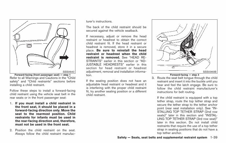
SSS0640Forward-facing (front passenger seat) — step 1
Refer to all Warnings and Cautions in the “Childsafety” and “Child restraints” sections beforeinstalling a child restraint.
Follow these steps to install a forward-facingchild restraint using the vehicle seat belt in therear seats or in the front passenger seat:
1. If you must install a child restraint inthe front seat, it should be placed in aforward-facing direction only. Move theseat to the rearmost position. Childrestraints for infants must be used inthe rear-facing direction and, therefore,must not be used in the front seat.
2. Position the child restraint on the seat.Always follow the child restraint manufac-
turer’s instructions.
The back of the child restraint should besecured against the vehicle seatback.
If necessary, adjust or remove the headrestraint or headrest to obtain the correctchild restraint fit. If the head restraint orheadrest is removed, store it in a secureplace. Be sure to reinstall the headrestraint or headrest when the childrestraint is removed. See “HEAD RE-STRAINTS” earlier in this section or “AD-JUSTABLE HEADRESTS” earlier in thissection for head restraint or headrestadjustment, removal and installation informa-tion.
If the seating position does not have anadjustable head restraint or headrest and itis interfering with the proper child restraintfit, try another seating position or a differentchild restraint.
SSS0360BForward-facing — step 3
3. Route the seat belt tongue through the childrestraint and insert it into the buckle until youhear and feel the latch engage. Be sure tofollow the child restraint manufacturer’sinstructions for belt routing.
If the child restraint is equipped with a toptether strap, route the top tether strap andsecure the tether strap to the tether anchorpoint (rear seat installation only). See “IN-STALLING TOP TETHER STRAP (2nd rowseats)” later in this section and “INSTAL-LING TOP TETHER STRAP (3rd row seat)”later in this section. Do not install childrestraints that require the use of a top tetherstrap in seating positions that do not have atop tether anchor.
Safety — Seats, seat belts and supplemental restraint system 1-39

Black plate (54,1)
Model "E52-D" EDITED: 2010/ 10/ 25
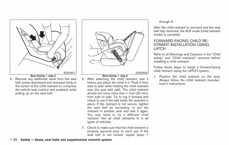
SSS0651Forward-facing — step 4
4. Pull the shoulder belt until the belt is fullyextended. At this time, the seat belt retractoris in the Automatic Locking Retractor (ALR)mode (child restraint mode). It reverts toEmergency Locking Retractor (ELR) modewhen the seat belt is fully retracted.
SSS0652Forward-facing — step 5
5. Allow the seat belt to retract. Pull up on theshoulder belt to remove any slack in the belt.
SSS0653Forward-facing — step 6
6. Remove any additional slack from the seatbelt; press downward and rearward firmly inthe center of the child restraint with yourknee to compress the vehicle seat cushionand seatback while pulling up on the seatbelt.
7. Tighten the tether strap according to themanufacturer’s instructions to remove anyslack.
1-40 Safety — Seats, seat belts and supplemental restraint system

Black plate (55,1)
Model "E52-D" EDITED: 2010/ 10/ 25
SSS0641Forward-facing — step 8
8. After attaching the child restraint, test itbefore you place the child in it. Push it fromside to side while holding the child restraintnear the seat belt path. The child restraintshould not move more than 1 inch (25 mm),from side to side. Try to tug it forward andcheck to see if the belt holds the restraint inplace. If the restraint is not secure, tightenthe seat belt as necessary, or put therestraint in another seat and test it again.You may need to try a different childrestraint. Not all child restraints fit in alltypes of vehicles.
9. Check to make sure the child restraint isproperly secured prior to each use. If theseat belt is not locked, repeat steps 2
through 8.
SSS0676Forward-facing — step 10
10. If the child restraint is installed in the frontpassenger seat, place the ignition switch inthe ON position. The front passenger air bagstatus light should illuminate. If thislight is not illuminated, see “Front passengerair bag and status light” in this section.Move the child restraint to anotherseating position. Have the systemchecked by a NISSAN dealer.
After the child restraint is removed and the seatbelt is fully retracted, the ALR mode (childrestraint mode) is canceled.
Safety — Seats, seat belts and supplemental restraint system 1-41

Black plate (56,1)
Model "E52-D" EDITED: 2010/ 10/ 25
SSS10882nd row seat
INSTALLING TOP TETHER STRAP (2ndrow seats)
First, secure the child restraint with the LATCHlower anchors or the seat belt, as applicable.
1. If necessary, raise or remove the headrestraint or headrest to position the toptether strap over the top of the seatback. Ifthe head restraint or headrest is removed,store it in a secure place. Be sure to reinstallthe head restraint or headrest when the childrestraint is removed. See “HEAD RE-STRAINTS” earlier in this section for headrestraint or headrest adjustment, removaland installation information.
2. Secure the tether strap to the tether anchorpoint on the back of each seatback behindthe child restraint.
3. Tighten the tether strap according to themanufacturer’s instructions to remove anyslack. Make sure the head restraint orheadrest does not contact the top tetherstrap.
If you have any questions when installing atop tether strap on the rear seat, consultyour NISSAN dealer for details.
SSS11683rd row seat
INSTALLING TOP TETHER STRAP (3rdrow seat)
WARNING
In the 3rd row seat, a child restraint witha top tether strap can only be used inthe center and right side position. Donot place in the left side seating posi-tion and attempt to angle the tetherstrap to the center or right side posi-tion.
The center and right side position of the 3rd rowseat is the seating position that can use a top
1-42 Safety — Seats, seat belts and supplemental restraint system

Black plate (57,1)
Model "E52-D" EDITED: 2010/ 10/ 25
tether strap.
First, secure the child restraint with the seat belt,as applicable.
1. Position the top tether strap over the top ofthe center and right side seating positionseatback.
2. Secure the tether strap to the tether anchorpoint on the floor behind the child restraint.
3. Refer to the appropriate child restraintinstallation procedure steps in this sectionbefore tightening the tether strap.
If you have any questions when installing atop tether strap child restraint on the rearseat, consult your NISSAN dealer for de-tails.
BOOSTER SEATS
Precautions on booster seats
WARNING
If a booster seat and seat belt are notused properly, the risk of a child beinginjured in a sudden stop or collisiongreatly increases:
— Make sure the shoulder portion ofthe belt is away from the child’s faceand neck and the lap portion of the
belt does not cross the stomach.
— Make sure the shoulder belt is notbehind the child or under the child’sarm.
— A booster seat must only be in-stalled in a seating position that hasa lap/shoulder belt.
LRS0455
Booster seats of various sizes are offered byseveral manufacturers. When selecting anybooster seat, keep the following points in mind:
. Choose only a booster seat with a labelcertifying that it complies with Federal MotorVehicle Safety Standard 213 or CanadianMotor Vehicle Safety Standard 213.
. Check the booster seat in your vehicle to besure it is compatible with the vehicle’s seatand seat belt system.
Safety — Seats, seat belts and supplemental restraint system 1-43

Black plate (58,1)
Model "E52-D" EDITED: 2010/ 10/ 25
LRS0453
. Make sure the child’s head will be properlysupported by the booster seat or vehicleseat. The seatback must be at or above thecenter of the child’s ears. For example, if alow back booster seat *1 is chosen, thevehicle seatback must be at or above thecenter of the child’s ears. If the seatback islower than the center of the child’s ears, ahigh back booster seat*2 should be used.
. If the booster seat is compatible with yourvehicle, place your child in the booster seatand check the various adjustments to besure the booster seat is compatible withyour child. Always follow all recommendedprocedures.
LRS0464
All U.S. states and Canadian provinces orterritories require that infants and smallchildren be restrained in an approved childrestraint at all times while the vehicle isbeing operated.
The instructions in this section apply to boosterseat installation in the rear seats or the frontpassenger seat.
Booster seat installation
CAUTION
Do not use the lap/shoulder belt Auto-matic Locking Retractor (ALR) modewhen using a booster seat with theseat belts.
Refer to all Warnings and Cautions in the “Childsafety”, “Child restraints” and “Booster seats”sections earlier in this section before installing achild restraint.
Follow these steps to install a booster seat in therear seat or in the front passenger seat:
1-44 Safety — Seats, seat belts and supplemental restraint system

Black plate (59,1)
Model "E52-D" EDITED: 2010/ 10/ 25
SSS0640
1. If you must install a booster seat in thefront seat, move the seat to the rear-most position.
2. Position the booster seat on the seat. Onlyplace it in a forward-facing direction. Alwaysfollow the booster seat manufacturer’sinstructions.
LRS0454Front passenger position
3. The booster seat should be positioned onthe vehicle seat so that it is stable.
If necessary, adjust or remove the headrestraint or headrest to obtain the correctbooster seat fit. If the head restraint orheadrest is removed, store it in a secureplace. Be sure to reinstall the headrestraint or headrest when the boosterseat is removed. See “HEAD RE-STRAINTS” earlier in this section or “AD-JUSTABLE HEADRESTS” earlier in thissection for head restraint or headrestadjustment, removal and installation informa-tion.
If the seating position does not have an
adjustable head restraint or headrest and itis interfering with the proper booster seat fit,try another seating position or a differentbooster seat.
4. Position the lap portion of the seat belt lowand snug on the child’s hips. Be sure tofollow the booster seat manufacturer’sinstructions for adjusting the seat beltrouting.
5. Pull the shoulder belt portion of the seat belttoward the retractor to take up extra slack.Be sure the shoulder belt is positionedacross the top, middle portion of the child’sshoulder. Be sure to follow the booster seatmanufacturer’s instructions for adjusting theseat belt routing.
6. Follow the warnings, cautions and instruc-tions for properly fastening a seat beltshown in “SEAT BELTS” earlier in thissection.
Safety — Seats, seat belts and supplemental restraint system 1-45
Black plate (60,1)
Model "E52-D" EDITED: 2010/ 10/ 25
SSS0676
7. If the booster seat is installed in the frontpassenger seat, push the ignition switch tothe ON position. The front passenger air bagstatus light may or may not illuminatedepending on the size of the child and thetype of booster seat used. See “Frontpassenger air bag and status light” later inthis section.
PRECAUTIONS ON SUPPLEMENTALRESTRAINT SYSTEM
This Supplemental Restraint System (SRS)section contains important information concern-ing the following systems.
. Driver and passenger supplemental front-impact air bag (NISSAN Advanced Air BagSystem)
. Front seat-mounted side-impact supple-mental air bag
. Roof-mounted curtain side-impact supple-mental air bag
. Seat belt with pretensioner
Supplemental front-impact air bag system:The NISSAN Advanced Air Bag System canhelp cushion the impact force to the head andchest of the driver and front passenger in certainfrontal collisions.
Front seat-mounted side-impact supple-mental air bag system: This system can helpcushion the impact force to the chest and pelvisarea of the driver and front passenger in certainside impact collisions. The supplemental side airbag is designed to inflate on the side where thevehicle is impacted.
Roof-mounted curtain side-impact: Thissystem can help cushion the impact force tothe head of occupants in front and rear (2nd and3rd) outboard seating positions in certain sideimpact. The curtain air bags are designed toinflate on the side where the vehicle is impacted.
These supplemental restraint systems are de-signed to supplement the crash protectionprovided by the driver and passenger seat beltsand are not a substitute for them. Seat beltsshould always be correctly worn and theoccupant seated a suitable distance away fromthe steering wheel, instrument panel and doorfinishers. (See “SEAT BELTS” earlier in thissection for instructions and precautions on seatbelt usage.)
The supplemental air bags operate onlywhen the ignition switch is in the ONposition.
After pushing the ignition switch to the ONposition, the supplemental air bag warninglight illuminates. The supplemental air bagwarning light will turn off after about 7seconds if the systems are operational.
SUPPLEMENTAL RESTRAINTSYSTEM
1-46 Safety — Seats, seat belts and supplemental restraint system

Black plate (61,1)
Model "E52-D" EDITED: 2010/ 10/ 25
SSS0131
SSS0132
WARNING
. The supplemental front air bagsordinarily will not inflate in theevent of a side impact, rear impact,rollover, or lower severity frontalcollision. Always wear your seatbelts to help reduce the risk orseverity of injury in various kindsof accidents.
. The front passenger air bag will notinflate if the passenger air bagstatus light is lit or if the frontpassenger seat is unoccupied. See“Front passenger air bag and statuslight” later in this section.
. The seat belts and the front air bagsare most effective when you aresitting well back and upright in theseat. The front air bags inflate withgreat force. Even with the NISSANAdvanced Air Bag System, if you areunrestrained, leaning forward, sit-ting sideways or out of position inany way, you are at greater risk ofinjury or death in a crash. You mayalso receive serious or fatal injuriesfrom the front air bag if you are upagainst it when it inflates. Always sit
Safety — Seats, seat belts and supplemental restraint system 1-47

Black plate (62,1)
Model "E52-D" EDITED: 2010/ 10/ 25
back against the seatback and asfar-away as practical from the steer-ing wheel or instrument panel. Al-ways use the seat belts.
. The driver and front passenger seatbelt buckles are equipped withsensors that detect if the seat beltsare fastened. The Advanced Air BagSystem monitors the severity of acollision and seat belt usage theninflates the air bags. Failure toproperly wear seat belts can in-crease the risk or severity of injuryin an accident.
. The front passenger seat isequipped with occupant classifica-tion sensors (weight sensors) thatturn the front passenger air bagOFF under some conditions. Thissensor is only used in this seat.Failure to be properly seated andwearing the seat belt can increasethe risk or severity of injury in anaccident. See “Front passenger airbag and status light” later in thissection.
. Keep hands on the outside of thesteering wheel. Placing them insidethe steering wheel rim could in-
crease the risk of injury if the frontair bag inflates.
SSS0007
SSS0006
1-48 Safety — Seats, seat belts and supplemental restraint system

Black plate (63,1)
Model "E52-D" EDITED: 2010/ 10/ 25
SSS0008
SSS0009
SSS0099
SSS0100
WARNING
. Never let children ride unrestrainedor extend their hands or face out ofthe window. Do not attempt to holdthem in your lap or arms. Someexamples of dangerous riding posi-tions are shown in the illustrations.
. Children may be severely injured orkilled when the front air bags, sideair bags or curtain air bags inflate ifthey are not properly restrained.Pre-teens and children should beproperly restrained in the rear seat,if possible.
. Even with the NISSAN Advanced AirBag System, never install a rear-facing child restraint in the frontseat. An inflating front air bag couldseriously injure or kill your child.See “CHILD RESTRAINTS” earlier inthis section for details.
Safety — Seats, seat belts and supplemental restraint system 1-49

Black plate (64,1)
Model "E52-D" EDITED: 2010/ 10/ 25
SSS0832
SSS0833
SSS0140
SSS0162
SSS0159
WARNING
Front seat-mounted side-impact sup-plemental air bags and roof-mountedcurtain side-impact supplemental airbags:
. The side-impact and certain supple-mental air bags ordinarily will notinflate in the event of a front impact,rear impact, rollover, or lower se-verity side collision. Always wearyour seat belts to help reduce therisk or severity of injury in variouskinds of accidents.
1-50 Safety — Seats, seat belts and supplemental restraint system

Black plate (65,1)
Model "E52-D" EDITED: 2010/ 10/ 25
. The seat belts, the side air bags andcurtain air bags are most effectivewhen you are sitting well back andupright in the seat. The side air bagsand curtain air bags inflate withgreat force. Do not allow anyone toplace their hand, leg or face near theside air bags on the side of theseatback of the front seat or nearthe side roof rails. Do not allowanyone sitting in the front seats orrear outboard seats to extend theirhand out of the window or leanagainst the door. Some examples ofdangerous riding positions areshown in the previous illustrations.
. When sitting in the rear seat, do nothold onto the seatback of the frontseat. If the side air bags inflates,you may be seriously injured. Beespecially careful with children, whoshould always be properly re-strained. Some examples of danger-ous riding positions are shown inthe illustrations.
. Do not use seat covers on the frontseatbacks. They may interfere withside air bags inflation.
SSS1169
1. Crash zone sensor
2. Supplemental front-impact air bag modules(NISSAN Advanced Air Bags)
3. Roof-mounted curtain side-impact supplementalair bag inflators
4. Front seat-mounted side-impact supplemental airbag modules
5. Roof-mounted curtain side-impact supplementalair bags
6. Diagnosis sensor unit
7. Seat belt pre-tensioners
8. Satellite sensors
9. Occupant classification system control unit
10. Occupant classification sensors (weight sensors)
Safety — Seats, seat belts and supplemental restraint system 1-51
Black plate (66,1)
Model "E52-D" EDITED: 2010/ 10/ 25
NISSAN ADVANCED AIR BAG SYS-TEM (front seats)
WARNING
To ensure proper operation of thepassenger’s advanced air bag system,please observe the following items.
. Do not allow a passenger in the rearseat to push or pull on the seatbackpocket.
. Do not place heavy loads heavierthan 9 lbs. (4 kg) on the seatback orin the seatback pocket. Do not hanganything from the head restraint.
. Do not store cargo behind the seatthat can press into the seatback.
. Do not position the front passengerseat so it contacts the rear seat. Ifthe front seat does contact the rearseat, the air bag system may deter-mine a sensor malfunction has oc-curred and the front passenger airbag status light may illuminate andthe supplemental air bag warninglight may flash.
. If a forward facing child restraint isinstalled in the front passenger
seat, do not position the frontpassenger seat so the child restraintcontacts the instrument panel. If thechild restraint does contact the in-strument panel, the system maydetermine the seat is occupied andthe passenger air bag may deploy ina collision. Also the front passengerair bag status light may not illumi-nate. See “CHILD RESTRAINTS”earlier in this section for informa-tion about installing and using childrestraints.
. Confirm the operating conditionwith the front passenger air bagstatus light.
. If you notice that the front passen-ger air bag status light is notoperating in accordance with theabove description, please take yourvehicle to your NISSAN dealer tocheck the passenger seat advancedair bag system.
. Until you have confirmed with yourdealer that your passenger seatadvanced air bag is working prop-erly, position the occupants in therear seating positions.
This vehicle is equipped with the NISSANAdvanced Air Bag System for the driver andfront passenger seats. This system is designedto meet certification requirements under U.S.regulations. It is also permitted in Canada.However, all of the information, cautionsand warnings in this manual still apply andmust be followed.
The driver supplemental front-impact air bag islocated in the center of the steering wheel. Thepassenger supplemental front-impact air bag ismounted in the instrument panel above the glovebox. The front air bags are designed to inflate inhigher severity frontal collisions, although theymay inflate if the forces in another type ofcollision are similar to those of a higher severityfrontal impact. They may not inflate in certainfrontal collisions. Vehicle damage (or lack of it) isnot always an indication of proper front air bagoperation.
The NISSAN Advanced Air Bag System hasdual stage air bag inflators. The system monitorsinformation from the Air bag Control Unit (ACU),seat belt buckle sensors and the occupantclassification sensors (weight sensors). Inflatoroperation is based on the severity of a collisionand seat belt usage for the driver. For the frontpassenger, the occupant classification sensorsare also monitored. Based on information fromthe sensors, only one front air bag may inflate ina crash, depending on the crash severity and
1-52 Safety — Seats, seat belts and supplemental restraint system

Black plate (67,1)
Model "E52-D" EDITED: 2010/ 10/ 25
whether the front occupants are belted orunbelted. Additionally, the front passenger airbag may be automatically turned OFF undersome conditions, depending on the informationprovided by the occupant classification sensors.If the front passenger air bag is OFF, thepassenger air bag status light will be illuminated(if the seat is unoccupied, the light will not beilluminated, but the air bag will be off). (See“Front passenger air bag and status light” laterin this section for further details.) One front airbag inflating does not indicate improper perfor-mance of the system.
If you have any questions about your air bagsystem, contact NISSAN or a NISSAN dealer. Ifyou are considering modification of your vehicledue to a disability, you may also contactNISSAN. Contact information is contained inthe front of this Owner’s Manual.
When a front air bag inflates, a fairly loud noisemay be heard, followed by release of smoke.This smoke is not harmful and does not indicatea fire. Care should be taken not to inhale it, as itmay cause irritation and choking. Those with ahistory of a breathing condition should get freshair promptly.
Front air bags, along with the use of seat belts,help to cushion the impact force on the headand chest of the front occupants. They can helpsave lives and reduce serious injuries. However,an inflating front air bag may cause facial
abrasions or other injuries. Front air bags donot provide restraint to the lower body.
Even with NISSAN advanced air bags, seatbelts should be correctly worn and the driverand passenger seated upright as far as practicalaway from the steering wheel or instrumentpanel. The front air bags inflate quickly in orderto help protect the front occupants. Because ofthis, the force of the front air bag inflating canincrease the risk of injury if the occupant is tooclose to, or is against, the air bag module duringinflation.
The front air bags deflate quickly after a collision.
The front air bags operate only when theignition switch is in the ON position.
After pushing the ignition switch to the ONposition, the supplemental air bag warninglight illuminates. The supplemental air bagwarning light will turn off after about 7seconds if the system is operational.
SSS0676Front passenger air bag status light
Front passenger air bag and status light
WARNING
The front passenger air bag is designedto automatically turn OFF under someconditions. Read this section carefullyto learn how it operates. Proper use ofthe seat, seat belt and child restraints isnecessary for most effective protection.Failure to follow all instructions in thismanual concerning the use of seats,seat belts and child restraints canincrease the risk or severity of injury inan accident.
Safety — Seats, seat belts and supplemental restraint system 1-53
Black plate (68,1)
Model "E52-D" EDITED: 2010/ 10/ 25
Status light:
The front passenger air bag status light islocated on the instrument panel. After theignition switch is placed in the ON position,the front passenger air bag status light illumi-nates for about 7 seconds and then turns off orilluminates depending on the front passengeroccupied status. The light operates as follows:
The light operates as follows:
. Unoccupied passenger seat: The lightis OFF and the front passenger air bag isOFF and will not inflate in a crash.
. Passenger seat occupied by a small adult,child or child restraint as outlined in thissection: The light illuminates to indi-cate that the front passenger air bag is OFFand will not inflate in a crash.
. Occupied passenger seat and the passen-ger meets the conditions outlined in thissection: The light is OFF to indicatethat the front passenger air bag is opera-tional.
Front passenger air bag:
The front passenger air bag is designed toautomatically turn OFF when the vehicle isoperated under some conditions as describedbelow as permitted by U.S. regulations. If thefront passenger air bag is OFF, it will not inflate
in a crash. The driver air bag and other air bagsin your vehicle are not part of this system.
The purpose of the regulation is to help reducethe risk of injury or death from an inflating air bagto certain front passenger seat occupants, suchas children, by requiring the air bag to beautomatically turned OFF.
The occupant classification sensors (weightsensors) are on the seat cushion frame underthe front passenger seat and are designed todetect an occupant and objects on the seat. Forexample, if a child is in the front passenger seat,the Advanced Air Bag System is designed toturn the passenger air bag OFF in accordancewith the regulations. Also, if a child restraint ofthe type specified in the regulations is on theseat, the occupant classification sensors candetect it and cause the air bag to turn OFF.
Front passenger seat adult occupants who areproperly seated and using the seat belt asoutlined in this manual should not cause thepassenger air bag to be automatically turnedOFF. For small adults it may be turned OFF,however, if the occupant does not sit in the seatproperly (for example, by not sitting upright, bysitting on an edge of the seat, or by otherwisebeing out of position), this could cause thesensor to turn the air bag OFF. Always be sureto be seated and wearing the seat belt properlyfor the most effective protection by the seat beltand supplemental air bag.
NISSAN recommends that pre-teens and chil-dren be properly restrained in a rear seat.NISSAN also recommends that appropriatechild restraints and booster seats be properlyinstalled in a rear seat. If this is not possible, theoccupant classification sensors are designed tooperate as described above to turn the frontpassenger air bag OFF for specified childrestraints. Failing to properly secure childrestrains and to use the ALR mode may allowthe restraint to tip or move in an accident orsudden stop. This can also result in thepassenger air bag inflating in a crash insteadof being OFF. (See “CHILD RESTRAINTS”earlier in this section for proper use andinstallation.)
If the front passenger seat is not occupied, thepassenger air bag is designed not to inflate in acrash. However, heavy objects placed on theseat could result in air bag inflation, because ofthe object being detected by the occupantclassification sensors. Other conditions couldalso result in air bag inflation, such as if a child isstanding on the seat, or if two children are on theseat, contrary to the instructions in this manual.Always be sure that you and all vehicleoccupants are seated and restrained properly.
Using the passenger air bag status light, you canmonitor when the front passenger air bag isautomatically turned OFF with the seat occu-pied. The light will not illuminate when the front
1-54 Safety — Seats, seat belts and supplemental restraint system

Black plate (69,1)
Model "E52-D" EDITED: 2010/ 10/ 25
passenger seat is unoccupied.
If an adult occupant is in the seat but thepassenger air bag status light is illuminated(indicating that the air bag is OFF), it could bethat the person is a small adult, or is not sittingon the seat properly.
If a child restraint must be used in the front seat,the passenger air bag status light may or maynot be illuminated, depending on the size of thechild and the type of child restraint being used. Ifthe passenger air bag status light is notilluminated (indicating that the air bag mightinflate in a crash), it could be that the childrestraint or seat belt is not being used properly.Make sure that the child restraint is installedproperly, the seat belt is used properly and theoccupant is positioned properly. If the passen-ger air bag status light is still not illuminated,reposition the occupant or child restraint in arear seat.
If the passenger air bag status light will notilluminate even though you believe that the childrestraint, the seat belts and the occupant areproperly positioned, the system may be sensingan unoccupied seat (in which case the air bag isOFF). Your NISSAN dealer can check that thesystem is OFF by using a special tool. However,until you have confirmed with your dealer thatyour air bag is working properly, reposition theoccupant or child restraint in a rear seat.
The NISSAN Advanced Air Bag System andpassenger air bag status light will take a fewseconds to register a change in the passengerseat status. However, if the seat becomesunoccupied, the air bag status light will remainoff.
If a malfunction occurs in the front passenger airbag system, the supplemental air bag warninglight , located in the meter and gauges areawill blink. Have the system checked by aNISSAN dealer.
Other supplemental front-impact air bagprecautions
WARNING
. Do not place any objects on thesteering wheel pad or on the instru-ment panel. Also, do not place anyobjects between any occupant andthe steering wheel or instrumentpanel. Such objects may becomedangerous projectiles and causeinjury if the front air bags inflate.
. Do not place objects with sharpedges on the seat. Also, do notplace heavy objects on the seat thatwill leave permanent impressions inthe seat. Such objects can damage
the seat or occupant classificationsensors (weight sensors). This canaffect the operation of the air bagsystem and result in serious perso-nal injury.
. Do not use water or acidic cleaners(hot steam cleaners) on the seat.This can damage the seat or occu-pant classification sensors. This canalso affect the operation of the airbag system and result in seriouspersonal injury.
. Immediately after inflation, severalfront air bag system componentswill be hot. Do not touch them; youmay severely burn yourself.
. No unauthorized changes should bemade to any components or wiringof the supplemental air bag system.This is to prevent accidental infla-tion of the supplemental air bag ordamage to the supplemental air bagsystem.
. Do not make unauthorized changesto your vehicle’s electrical system,suspension system or front endstructure. This could affect properoperation of the front air bag sys-
Safety — Seats, seat belts and supplemental restraint system 1-55
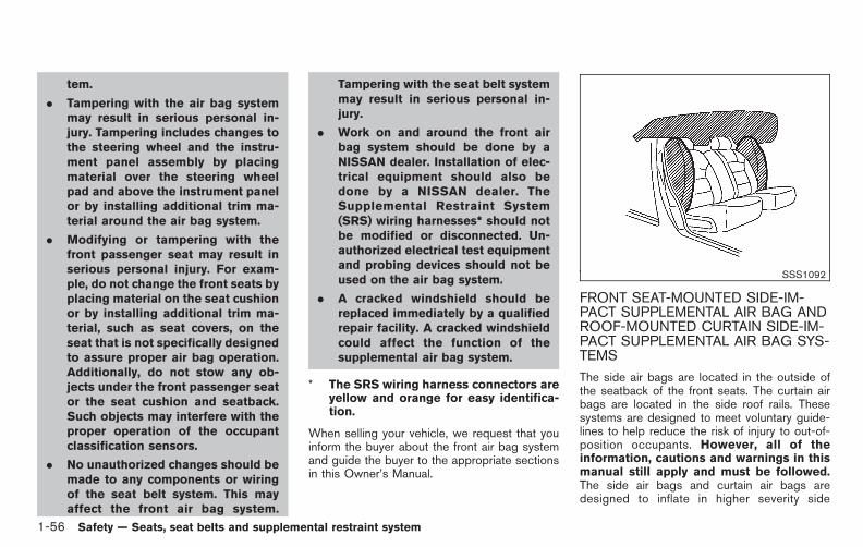
Black plate (70,1)
Model "E52-D" EDITED: 2010/ 10/ 25
tem.
. Tampering with the air bag systemmay result in serious personal in-jury. Tampering includes changes tothe steering wheel and the instru-ment panel assembly by placingmaterial over the steering wheelpad and above the instrument panelor by installing additional trim ma-terial around the air bag system.
. Modifying or tampering with thefront passenger seat may result inserious personal injury. For exam-ple, do not change the front seats byplacing material on the seat cushionor by installing additional trim ma-terial, such as seat covers, on theseat that is not specifically designedto assure proper air bag operation.Additionally, do not stow any ob-jects under the front passenger seator the seat cushion and seatback.Such objects may interfere with theproper operation of the occupantclassification sensors.
. No unauthorized changes should bemade to any components or wiringof the seat belt system. This mayaffect the front air bag system.
Tampering with the seat belt systemmay result in serious personal in-jury.
. Work on and around the front airbag system should be done by aNISSAN dealer. Installation of elec-trical equipment should also bedone by a NISSAN dealer. TheSupplemental Restraint System(SRS) wiring harnesses* should notbe modified or disconnected. Un-authorized electrical test equipmentand probing devices should not beused on the air bag system.
. A cracked windshield should bereplaced immediately by a qualifiedrepair facility. A cracked windshieldcould affect the function of thesupplemental air bag system.
* The SRS wiring harness connectors areyellow and orange for easy identifica-tion.
When selling your vehicle, we request that youinform the buyer about the front air bag systemand guide the buyer to the appropriate sectionsin this Owner’s Manual.
SSS1092
FRONT SEAT-MOUNTED SIDE-IM-PACT SUPPLEMENTAL AIR BAG ANDROOF-MOUNTED CURTAIN SIDE-IM-PACT SUPPLEMENTAL AIR BAG SYS-TEMS
The side air bags are located in the outside ofthe seatback of the front seats. The curtain airbags are located in the side roof rails. Thesesystems are designed to meet voluntary guide-lines to help reduce the risk of injury to out-of-position occupants. However, all of theinformation, cautions and warnings in thismanual still apply and must be followed.The side air bags and curtain air bags aredesigned to inflate in higher severity side
1-56 Safety — Seats, seat belts and supplemental restraint system

Black plate (71,1)
Model "E52-D" EDITED: 2010/ 10/ 25
collisions, although they may inflate if the forcesin another type of collision are similar to those ofa higher severity side impact. They are designedto inflate on the side where the vehicle isimpacted. They may not inflate in certain sidecollisions on the side where the vehicle isimpacted.
Vehicle damage (or lack of it) is not always anindication of proper side air bag and curtain airbag operation.
When side air bags and curtain air bags inflate, afairly loud noise may be heard, followed byrelease of smoke. This smoke is not harmful anddoes not indicate a fire. Care should be takennot to inhale it, as it may cause irritation andchoking. Those with a history of a breathingcondition should get fresh air promptly.
Side air bags, along with the use of seat belts,help to cushion the impact force on the chestand pelvis of the front occupants. Curtain airbags help to cushion the impact force to thehead of occupants in the front and rear (2nd and3rd) outboard seating positions. They can helpsave lives and reduce serious injuries. However,an inflating side air bags and curtain air bagsmay cause abrasions or other injuries. Side airbags and curtain air bags do not providerestraint to the lower body.
The seat belts should be correctly worn and thedriver and passenger seated upright as far as
practical away from the side air bag. Rear seatpassengers should be seated as far away aspractical from the door finishers and side roofrails. The side air bags and curtain air bagsinflate quickly in order to help protect theoccupants. Because of this, the force of theside air bags and curtain air bags inflating canincrease the risk of injury if the occupant is tooclose to, or is against, these air bag modulesduring inflation. The side air bags will deflatequickly after the collision is over.
The side air bags and curtain air bags operateonly when the ignition switch is in the ONposition.
After pushing the ignition switch to the ONposition, the supplemental air bag warninglight illuminates. The air bag warning lightwill turn off after about 7 seconds if thesystems are operational.
WARNING
. Do not place any objects near theseatback of the front seats. Also, donot place any objects (an umbrella,bag, etc.) between the front doorfinisher and the front seat. Suchobjects may become dangerousprojectiles and cause injury if sideair bag inflates.
. Right after inflation, several side airbags and curtain air bag systemcomponents will be hot. Do nottouch them; you may severely burnyourself.
. No unauthorized changes should bemade to any components or wiringof side air bag and curtain air bags.This is to prevent damage to oraccidental inflation of the side airbag and curtain air bag systems.
. Do not make unauthorized changesto your vehicle’s electrical system,suspension system or side panel.This could affect proper operationof the side air bag and curtain airbag systems.
. Tampering with the air bag systemmay result in serious personal in-jury. For example, do not change thefront seats by placing material nearthe seatback or by installing addi-tional trim material, such as seatcovers, around the side air bags.
. Work around and on the side air bagand curtain air bag systems shouldbe done by a NISSAN dealer. In-stallation of electrical equipment
Safety — Seats, seat belts and supplemental restraint system 1-57

Black plate (72,1)
Model "E52-D" EDITED: 2010/ 10/ 25
should also be done by a NISSANdealer. The Supplemental RestraintSystem (SRS) wiring harnesses*should not be modified or discon-nected. Unauthorized electrical testequipment and probing devicesshould not be used on the side-impact air bag system.
* The SRS wiring harness connectors areyellow and orange for easy identifica-tion.
When selling your vehicle, we request that youinform the buyer about the side air bag andcurtain air bag systems and guide the buyer tothe appropriate sections in this Owner’s Manual.
SEAT BELTS WITH PRETENSIONERS(front seats)
WARNING
. The pretensioners cannot be reusedafter activation. They must be re-placed together with the retractorand buckle as a unit.
. If the vehicle becomes involved in acollision but a pretensioner is notactivated, be sure to have the pre-tensioner system checked and, if
necessary, replaced by a NISSANdealer.
. No unauthorized changes should bemade to any components or wiringof the pretensioner system. This isto prevent damage to or accidentalactivation of the pretensioners.Tampering with the pretensionersystem may result in serious perso-nal injury.
. Work around and on the preten-sioner system should be done by aNISSAN dealer. Installation of elec-trical equipment should also bedone by a NISSAN dealer. Un-authorized electrical test equipmentand probing devices should not beused on the pretensioner system.
. If you need to dispose of a preten-sioner or scrap the vehicle, contact aNISSAN dealer. Correct preten-sioner disposal procedures are setforth in the appropriate NISSANService Manual. Incorrect disposalprocedures could cause personalinjury.
The pretensioner system may activate with thesupplemental air bag system in certain types of
collisions. Working with the seat belt retractor, ithelps tighten the seat belt when the vehiclebecomes involved in certain types of collisions,helping to restrain front seat occupants.
The pretensioner is encased with the seat beltretractor and buckle anchor. These seat beltsare used the same way as conventional seatbelts.
When a pretensioner activates, smoke is re-leased and a loud noise may be heard. Thesmoke is not harmful, and it does not indicate afire. Care should be taken not to inhale it as itmay cause irritation and choking. Those with ahistory of a breathing condition should get freshair promptly.
After pretensioner activation, load limiters allowthe seat belt to release webbing (if necessary) toreduce forces against the chest.
The supplemental air bag warning light isused to indicate malfunctions in the pretensionersystem. (See “SUPPLEMENTAL AIR BAGWARNING LIGHT” later in this section for moredetails.) If the supplemental air bag warning lightindicates there is a malfunction, have the systemchecked by a NISSAN dealer.
When selling your vehicle, we request that youinform the buyer about the pretensioner systemand guide the buyer to the appropriate sectionsin this Owner’s Manual.
1-58 Safety — Seats, seat belts and supplemental restraint system

Black plate (73,1)
Model "E52-D" EDITED: 2010/ 10/ 25
SSS1016
SUPPLEMENTAL AIR BAG WARNINGLABELS
Warning labels about the supplemental front-impact air bag system are placed in the vehicleas shown in the illustration.
SRS air bagThe warning labels *1 are located on thesurface of the sun visors.
SPA1097
SUPPLEMENTAL AIR BAG WARNINGLIGHT
The supplemental air bag warning light, display-ing in the instrument panel, monitors thecircuits of the supplemental front-impact air bag,front seat-mounted side-impact supplementalair bag, roof-mounted curtain side-impact sup-plemental air bag, and seat belt pretensionersystems. The monitored circuits include the airbag systems, pretensioners and all relatedwiring.
When the ignition switch is in the ON position,the supplemental air bag warning light illumi-nates for about 7 seconds and then turns off.This means the SRS air bag systems are
operational.
If any of the following conditions occur, the frontair bag, side air bag and curtain air bag and/orpretensioner systems need servicing:
. The supplemental air bag warning lightremains on approximately 7 seconds afterthe ignition switch is pushed to the ONposition.
. The supplemental air bag warning lightflashes intermittently.
. The supplemental air bag warning light doesnot come on at all.
Under these conditions, the front air bag, side airbags, and curtain air bags or pretensionersystems may not operate properly. They mustbe checked and repaired. Take your vehicle tothe nearest NISSAN dealer.
WARNING
If the supplemental air bag warninglight is on, it could mean that the frontair bag, side air bag and curtain air bagand/or pretensioner systems will notoperate in an accident. To help avoidinjury to yourself or others, have yourvehicle checked by a NISSAN dealer assoon as possible.
Safety — Seats, seat belts and supplemental restraint system 1-59

Black plate (74,1)
Model "E52-D" EDITED: 2010/ 10/ 25
REPAIR AND REPLACEMENT PRO-CEDURE
The front air bags, side air bags and curtain airbags and pretensioners are designed to activateon a one-time-only basis. As a reminder, unlessit is damaged, the supplemental air bag warninglight will remain illuminated after inflation hasoccurred. Repair and replacement of thesesystems should be done only by a NISSANdealer.
When maintenance work is required on thevehicle, the front air bags, side air bags andcurtain air bags, pretensioners and related partsshould be pointed out to the person conductingthe maintenance. The ignition switch shouldalways be in the LOCK position when workingunder the hood or inside the vehicle.
WARNING
. Once a front air bag, side air bag orcurtain air bag has inflated, the airbag module will not function againand must be replaced. Additionally,the activated pretensioner mustalso be replaced. The air bag mod-ule and pretensioner should bereplaced by a NISSAN dealer. Theair bag module and pretensionersystem cannot be repaired.
. The front air bag, side air bag,curtain air bag and the pretensionershould be inspected by a NISSANdealer if there is any damage to thefront end or side portion of thevehicle.
. If you need to dispose of a supple-mental air bag or pretensioner orscrap the vehicle, contact a NISSANdealer. Correct supplemental airbag and pretensioner system dis-posal procedures are set forth in theappropriate NISSAN Service Man-ual. Incorrect disposal procedurescould cause personal injury.
1-60 Safety — Seats, seat belts and supplemental restraint system

Black plate (75,1)
Model "E52-D" EDITED: 2010/ 10/ 25
MEMO
Safety — Seats, seat belts and supplemental restraint system 1-61
Black plate (7,1)
2 Instruments and controls
Model "E52-D" EDITED: 2010/ 10/ 22
Cockpit. . . . . . . . . . . . . . . . . . . . . . . . . . . . . . . . . . . . . . . . . . . . . . . . . . . . . . . . . . . . 2-2Instrument panel . . . . . . . . . . . . . . . . . . . . . . . . . . . . . . . . . . . . . . . . . . . . . . . . 2-3Meters and gauges. . . . . . . . . . . . . . . . . . . . . . . . . . . . . . . . . . . . . . . . . . . . . 2-4
Meter/ring illumination and needle sweep. . . . . . . . . . . . . 2-4Speedometer and odometer . . . . . . . . . . . . . . . . . . . . . . . . . . . . . 2-5Tachometer. . . . . . . . . . . . . . . . . . . . . . . . . . . . . . . . . . . . . . . . . . . . . . . . . . . 2-6Engine coolant temperature gauge . . . . . . . . . . . . . . . . . . . . . 2-6Fuel gauge . . . . . . . . . . . . . . . . . . . . . . . . . . . . . . . . . . . . . . . . . . . . . . . . . . . 2-7
Compass (if so equipped) . . . . . . . . . . . . . . . . . . . . . . . . . . . . . . . . . . . . 2-7Zone variation change procedure . . . . . . . . . . . . . . . . . . . . . . . 2-9
Warning/indicator lights and audible reminders . . . . . . . 2-10Checking bulbs . . . . . . . . . . . . . . . . . . . . . . . . . . . . . . . . . . . . . . . . . . . 2-10Warning lights . . . . . . . . . . . . . . . . . . . . . . . . . . . . . . . . . . . . . . . . . . . . . 2-10Indicator lights. . . . . . . . . . . . . . . . . . . . . . . . . . . . . . . . . . . . . . . . . . . . . 2-15Audible reminders . . . . . . . . . . . . . . . . . . . . . . . . . . . . . . . . . . . . . . . . 2-16
Dot matrix liquid crystal display. . . . . . . . . . . . . . . . . . . . . . . . . . . . 2-17Indicators for operation. . . . . . . . . . . . . . . . . . . . . . . . . . . . . . . . . . 2-18Indicators for maintenance. . . . . . . . . . . . . . . . . . . . . . . . . . . . . . 2-20Trip computer . . . . . . . . . . . . . . . . . . . . . . . . . . . . . . . . . . . . . . . . . . . . . . 2-21
Security systems. . . . . . . . . . . . . . . . . . . . . . . . . . . . . . . . . . . . . . . . . . . . . . 2-25Vehicle Security System. . . . . . . . . . . . . . . . . . . . . . . . . . . . . . . . . 2-25NISSAN Vehicle Immobilizer System . . . . . . . . . . . . . . . . . 2-27
Windshield wiper and washer switch . . . . . . . . . . . . . . . . . . . . 2-28Rear window wiper and washer switch. . . . . . . . . . . . . . . . . . 2-29Rear window and outside mirror defroster switch. . . . . 2-30
Headlight and turn signal switch . . . . . . . . . . . . . . . . . . . . . . . . . . 2-31Xenon headlights (if so equipped) . . . . . . . . . . . . . . . . . . . . 2-31Headlight switch . . . . . . . . . . . . . . . . . . . . . . . . . . . . . . . . . . . . . . . . . . 2-31Turn signal switch . . . . . . . . . . . . . . . . . . . . . . . . . . . . . . . . . . . . . . . . 2-35Fog light switch (if so equipped). . . . . . . . . . . . . . . . . . . . . . 2-35
Hazard warning flasher switch . . . . . . . . . . . . . . . . . . . . . . . . . . . . . 2-35Models with auto light system . . . . . . . . . . . . . . . . . . . . . . . . . 2-36
Horn . . . . . . . . . . . . . . . . . . . . . . . . . . . . . . . . . . . . . . . . . . . . . . . . . . . . . . . . . . . . . 2-36Heated seats (if so equipped) . . . . . . . . . . . . . . . . . . . . . . . . . . . . . 2-36Blind Spot Warning (BSW) switch (if soequipped). . . . . . . . . . . . . . . . . . . . . . . . . . . . . . . . . . . . . . . . . . . . . . . . . . . . . . . 2-38Vehicle Dynamic Control (VDC) OFF switch . . . . . . . . . . . 2-38Power outlet . . . . . . . . . . . . . . . . . . . . . . . . . . . . . . . . . . . . . . . . . . . . . . . . . . . 2-39Storage . . . . . . . . . . . . . . . . . . . . . . . . . . . . . . . . . . . . . . . . . . . . . . . . . . . . . . . . . 2-41
Cup holders. . . . . . . . . . . . . . . . . . . . . . . . . . . . . . . . . . . . . . . . . . . . . . . . 2-41Sunglasses holder (if so equipped) . . . . . . . . . . . . . . . . . . 2-43Glove box . . . . . . . . . . . . . . . . . . . . . . . . . . . . . . . . . . . . . . . . . . . . . . . . . . 2-44Instrument lower box (if so equipped) . . . . . . . . . . . . . . . 2-44Console box . . . . . . . . . . . . . . . . . . . . . . . . . . . . . . . . . . . . . . . . . . . . . . . 2-44Cargo floor box . . . . . . . . . . . . . . . . . . . . . . . . . . . . . . . . . . . . . . . . . . . 2-45Hooks . . . . . . . . . . . . . . . . . . . . . . . . . . . . . . . . . . . . . . . . . . . . . . . . . . . . . . . 2-46Roof rack (if so equipped). . . . . . . . . . . . . . . . . . . . . . . . . . . . . . 2-47Coat hooks. . . . . . . . . . . . . . . . . . . . . . . . . . . . . . . . . . . . . . . . . . . . . . . . . 2-48
Sunshade (if so equipped) . . . . . . . . . . . . . . . . . . . . . . . . . . . . . . . . . 2-48Windows . . . . . . . . . . . . . . . . . . . . . . . . . . . . . . . . . . . . . . . . . . . . . . . . . . . . . . . 2-48
Power windows . . . . . . . . . . . . . . . . . . . . . . . . . . . . . . . . . . . . . . . . . . . 2-48

Black plate (8,1)
Model "E52-D" EDITED: 2010/ 10/ 22
Moonroof (if so equipped) . . . . . . . . . . . . . . . . . . . . . . . . . . . . . . . . . . 2-51Automatic moonroof. . . . . . . . . . . . . . . . . . . . . . . . . . . . . . . . . . . . . . 2-51Front moonroof . . . . . . . . . . . . . . . . . . . . . . . . . . . . . . . . . . . . . . . . . . . . 2-51Rear moonroof . . . . . . . . . . . . . . . . . . . . . . . . . . . . . . . . . . . . . . . . . . . . 2-52If the front or rear moonroof does not operate. . . . . 2-53
Interior lights . . . . . . . . . . . . . . . . . . . . . . . . . . . . . . . . . . . . . . . . . . . . . . . . . . . 2-53Map lights . . . . . . . . . . . . . . . . . . . . . . . . . . . . . . . . . . . . . . . . . . . . . . . . . . 2-53Rear personal lights . . . . . . . . . . . . . . . . . . . . . . . . . . . . . . . . . . . . . . 2-54Interior light control switch . . . . . . . . . . . . . . . . . . . . . . . . . . . . . 2-54
Mood lights . . . . . . . . . . . . . . . . . . . . . . . . . . . . . . . . . . . . . . . . . . . . . . . . . . . . 2-55Vanity mirror lights . . . . . . . . . . . . . . . . . . . . . . . . . . . . . . . . . . . . . . . . . . . . 2-56
Cargo lights. . . . . . . . . . . . . . . . . . . . . . . . . . . . . . . . . . . . . . . . . . . . . . . . . . . . 2-56HomeLink® Universal Transceiver (if so equipped) . . . . 2-56
Programming HomeLink® . . . . . . . . . . . . . . . . . . . . . . . . . . . . . . . 2-57Programming HomeLink® for Canadiancustomers . . . . . . . . . . . . . . . . . . . . . . . . . . . . . . . . . . . . . . . . . . . . . . . . . . 2-58Operating the HomeLink® UniversalTransceiver . . . . . . . . . . . . . . . . . . . . . . . . . . . . . . . . . . . . . . . . . . . . . . . . . 2-59Programming trouble-diagnosis . . . . . . . . . . . . . . . . . . . . . . . 2-59Clearing the programmed information. . . . . . . . . . . . . . . . 2-59Reprogramming a single HomeLink® button . . . . . . . . 2-59If your vehicle is stolen . . . . . . . . . . . . . . . . . . . . . . . . . . . . . . . . . . 2-59

Black plate (78,1)
Model "E52-D" EDITED: 2010/ 10/ 25
SSI0825
1. Vehicle Dynamic Control (VDC) OFF switch
2. Blind Spot Warning (BSW) switch*— Blind Spot Warning (BSW)*
3. Sliding door switch* (driver’s side)
4. Sliding door switch* (passenger’s side)
5. Instrument brightness control switch
6. Power lift gate switch*
7. Headlight, fog light and turn signal switch— Headlight— Turn signal— Fog light*
8. Trip computer switch
9. TRIP/RESET switch for twin trip odometer
10. Wiper and washer switch
11. Fuse box cover
12. Fuel-filler door opener handle
13. Hood release handle
14. Headlight aiming control*
15. Power door main switch*
16. Steering-wheel-mounted controls (left side)— Audio control steering switch— Hands-Free Phone System switch*
17. Horn
18. Steering-wheel-mounted controls (right side)— Cruise control system
*: if so equipped
COCKPIT
2-2 Instruments and controls

Black plate (79,1)
Model "E52-D" EDITED: 2010/ 10/ 25
SSI0824
1. Side ventilator
2. Meters and gauges
3. Push-button ignition switch
4. Hazard warning flasher switch
5. Selector lever
6. Center display— Center color display*
— Navigation system**
7. Center multi-function control panel*— Navigation system**— Vehicle information and setting buttons*
8. Rear window and outside mirror* defroster switch
9. Center ventilator
10. Heater/air conditioner control or audio system
11. Parking brake
12. Tilting telescopic steering wheel lever or switch
13. Front passenger air bag status light
14. Heated seat switch*
15. Cup holders
16. Power outlet
17. Instrument lower box or CD/DVD slot
18. Power outlet main switch*
19. Audio system
20. Glove box
*: if so equipped
**: Refer to the separate Navigation System Owner’sManual (if so equipped).
INSTRUMENT PANEL
Instruments and controls 2-3

Black plate (80,1)
Model "E52-D" EDITED: 2010/ 10/ 25
SIC4630
1. Instrument brightness control switch
2. Tachometer
3. Speedometer
4. Fuel gauge
5. Warning/indicator lights
6. Trip computer switch
7. Dot matrix liquid crystal display— Trip computer
8. Engine coolant temperature gauge
9. Odometer/twin trip odometer/Continuously Vari-able Transmission (CVT) position indicator
10. TRIP/RESET switch for twin trip odometer
The needle indicators may move slightly
after the ignition switch is pushed to theOFF position. This is not a malfunction.
METER/RING ILLUMINATION ANDNEEDLE SWEEP
The ring illumination surrounding meters andgauges illuminates when the driver’s door isclosed after getting into the vehicle with theIntelligent Key carried in.
When the engine is started, the indicatorneedles will sweep in the speedometer andtachometer and the ring illumination will bebrightened gradually. This function can beturned off. (See “TRIP COMPUTER” later inthis section.)
METERS AND GAUGES
2-4 Instruments and controls
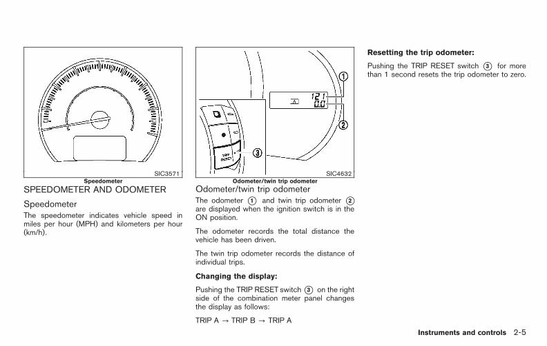
Black plate (81,1)
Model "E52-D" EDITED: 2010/ 10/ 25
SIC3571Speedometer
SPEEDOMETER AND ODOMETER
SpeedometerThe speedometer indicates vehicle speed inmiles per hour (MPH) and kilometers per hour(km/h).
SIC4632Odometer/twin trip odometer
Odometer/twin trip odometerThe odometer *1 and twin trip odometer *2are displayed when the ignition switch is in theON position.
The odometer records the total distance thevehicle has been driven.
The twin trip odometer records the distance ofindividual trips.
Changing the display:
Pushing the TRIP RESET switch*3 on the rightside of the combination meter panel changesthe display as follows:
TRIP A ? TRIP B ? TRIP A
Resetting the trip odometer:
Pushing the TRIP RESET switch *3 for morethan 1 second resets the trip odometer to zero.
Instruments and controls 2-5
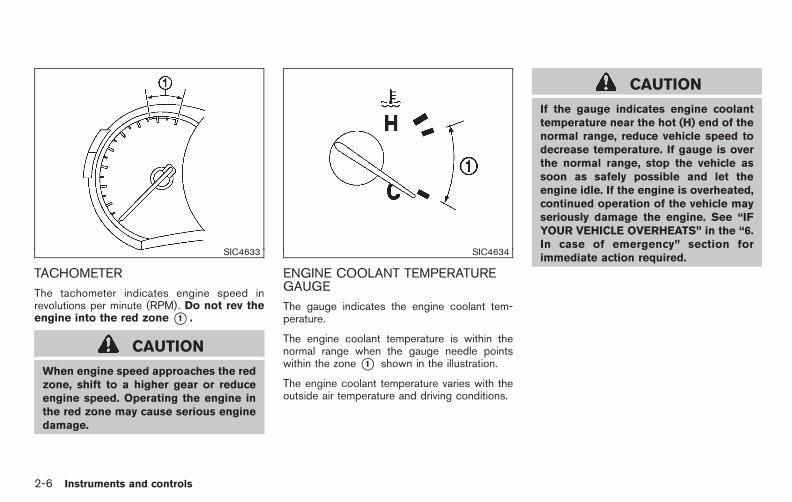
Black plate (82,1)
Model "E52-D" EDITED: 2010/ 10/ 25
SIC4633
TACHOMETER
The tachometer indicates engine speed inrevolutions per minute (RPM). Do not rev theengine into the red zone *1 .
CAUTION
When engine speed approaches the redzone, shift to a higher gear or reduceengine speed. Operating the engine inthe red zone may cause serious enginedamage.
SIC4634
ENGINE COOLANT TEMPERATUREGAUGE
The gauge indicates the engine coolant tem-perature.
The engine coolant temperature is within thenormal range when the gauge needle pointswithin the zone *1 shown in the illustration.
The engine coolant temperature varies with theoutside air temperature and driving conditions.
CAUTION
If the gauge indicates engine coolanttemperature near the hot (H) end of thenormal range, reduce vehicle speed todecrease temperature. If gauge is overthe normal range, stop the vehicle assoon as safely possible and let theengine idle. If the engine is overheated,continued operation of the vehicle mayseriously damage the engine. See “IFYOUR VEHICLE OVERHEATS” in the “6.In case of emergency” section forimmediate action required.
2-6 Instruments and controls

Black plate (83,1)
Model "E52-D" EDITED: 2010/ 10/ 25
SIC4714
FUEL GAUGE
The gauge indicates the approximate fuel levelin the tank.
The gauge may move slightly during braking,turning, acceleration, or going up or down hills.
The gauge needle returns to “0” (empty) afterthe ignition switch is pushed to the OFFposition.
Refill the fuel tank before the gaugeregisters “0” (empty).
The low fuel warning appears on the dotmatrix liquid crystal display when the fuel level inthe tank is getting low. Refuel as soon as it is
convenient, preferably before the gauge reaches“0”. There will be a small reserve of fuel in thetank when the fuel gauge needle reaches “0”.
The indicates that the fuel-filler door islocated on the driver’s side of the vehicle.
CAUTION
. If the vehicle runs out of fuel, themalfunction indicator light
(MIL) may come on. Refuel as soonas possible. After a few driving trips,the light should turn off. If thelight remains on after a few drivingtrips, have the vehicle inspected bya NISSAN dealer.
. For additional information, see“Malfunction Indicator Light (MIL)”later in this section.
SIC3181
When the ignition switch is pushed to the ONposition, the compass display *B will indicatethe direction of the vehicle’s heading.
COMPASS (if so equipped)
Instruments and controls 2-7
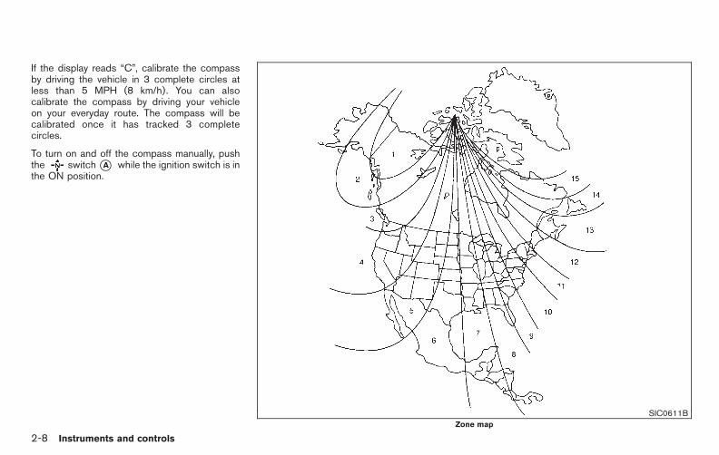
Black plate (84,1)
Model "E52-D" EDITED: 2010/ 10/ 25
If the display reads “C”, calibrate the compassby driving the vehicle in 3 complete circles atless than 5 MPH (8 km/h). You can alsocalibrate the compass by driving your vehicleon your everyday route. The compass will becalibrated once it has tracked 3 completecircles.
To turn on and off the compass manually, pushthe switch*A while the ignition switch is inthe ON position.
SIC0611BZone map
2-8 Instruments and controls

Black plate (85,1)
Model "E52-D" EDITED: 2010/ 10/ 25
ZONE VARIATION CHANGE PROCE-DURE
The difference between magnetic north andgeographical north is known as variance. Insome areas, this difference can sometimes begreat enough to cause false compass readings.Follow these instructions to set the variance foryour particular location if this happens:
1. Push the switch for more than 3seconds. The current zone number willappear in the display.
2. Find your current location and variancenumber on the zone map.
NOTE:Use zone number 5 for Hawaii.
3. Push the switch repeatedly until thenew zone number appears in the display,then release the switch. After you releasethe switch, the display will show a compassdirection within a few seconds.
. If the compass deviates from the correctindication soon after repeated adjust-ment, have the compass checked at aNISSAN dealer.
. The compass may not indicate thecorrect compass point in tunnels orwhile driving up or down a steep hill.
(The compass returns to the correct com-
pass point when the vehicle moves to anarea where the geomagnetism is stabilized.)
CAUTION
. Do not install a ski rack, antenna,etc., which are attached to thevehicle by means of a magnet. Theyaffect the operation of the compass.
. When cleaning the mirror, use apaper towel or similar materialdampened with glass cleaner. Donot spray glass cleaner directly onthe mirror as it may cause the liquidcleaner to enter the mirror housing.
Instruments and controls 2-9

Black plate (86,1)
Model "E52-D" EDITED: 2010/ 10/ 25
Anti-lock Braking System (ABS) warninglight
Intelligent Key system warning light Front passenger air bag status light
Low tire pressure warning light High beam indicator light
Brake warning light
Master warning light Low beam indicator light
Seat belt warning light and chime Malfunction Indicator Light (MIL)
Blind Spot Warning (BSW) system warninglight (orange)*
Supplemental air bag warning light Overdrive off indicator light
Charge warning lightVehicle Dynamic Control (VDC) warninglight
Security indicator light
Engine oil pressure warning lightContinuously Variable Transmission (CVT)position indicator light
Turn signal/hazard indicator lights
Hydraulic pump electric power steeringwarning light
Cruise indicator lightVehicle Dynamic Control (VDC) off indicatorlight
*: if so equipped
CHECKING BULBS
With all doors closed, apply the parking brakeand push the ignition switch to the ON positionwithout starting the engine. The following lightswill come on (if so equipped):
, or , , , ,
The following lights come on briefly and then gooff (if so equipped):
, or , , , , , ,
If any light does not come on, it may indicate aburned-out bulb or an open circuit in theelectrical system. Have the system checked bya NISSAN dealer.
Some indicators and warnings are also dis-played on the dot matrix crystal display on thespeedometer. (See “DOT MATRIX LIQUID
CRYSTAL DISPLAY” later in this section.)
WARNING LIGHTS
or Anti-lock Braking System(ABS) warning light
When the ignition switch is in the ON position,the Anti-lock Braking System (ABS) warninglight illuminates and then turns off. This indicates
WARNING/INDICATOR LIGHTS ANDAUDIBLE REMINDERS
2-10 Instruments and controls

Black plate (87,1)
Model "E52-D" EDITED: 2010/ 10/ 25
the ABS is operational.
If the ABS warning light illuminates while theengine is running, or while driving, it mayindicate the ABS is not functioning properly.Have the system checked by a NISSAN dealer.
If an ABS malfunction occurs, the anti-lockfunction is turned off. The brake system thenoperates normally, but without anti-lock assis-tance. (See “BRAKE SYSTEM” in the “5.Starting and driving” section.)
or Brake warning light
This light functions for both the parking brakeand the foot brake systems.
Parking brake indicator:
When the ignition switch is in the ON position,the light comes on when the parking brake isapplied.
Low brake fluid warning light:
When the ignition switch is in the ON position,the light warns of a low brake fluid level. If thelight comes on while the engine is running withthe parking brake not applied, stop the vehicleand perform the following:
1. Check the brake fluid level. Add brake fluidas necessary. (See “BRAKE FLUID” in the“8. Maintenance and do-it-yourself” sec-
tion.)
2. If the brake fluid level is correct, have thewarning system checked by a NISSANdealer.
Anti-lock Braking System (ABS) warningindicator:
When the parking brake is released and thebrake fluid level is sufficient, if both the brakewarning light and the Anti-lock Braking System(ABS) warning light illuminate, it may indicatethe ABS is not functioning properly. Have thebrake system checked, and if necessary re-paired, by a NISSAN dealer promptly. (See“Anti-lock Braking System (ABS) warning light”earlier in this section.)
WARNING
. Your brake system may not beworking properly if the warning lightis on. Driving could be dangerous. Ifyou judge it to be safe, drive care-fully to the nearest service stationfor repairs. Otherwise, have yourvehicle towed because driving itcould be dangerous.
. Pressing the brake pedal with theengine stopped and/or low brakefluid level may increase your stop-
ping distance and braking will re-quire greater pedal effort as well aspedal travel.
. If the brake fluid level is below theminimum or MIN mark on the brakefluid reservoir, do not drive until thebrake system has been checked at aNISSAN dealer.
Blind Spot Warning (BSW) sys-tem warning light (orange; if soequipped)
If the light comes on in orange and remains on, itmay indicate that the BSW system is notfunctioning properly. Although the vehicle is stilldriveable, have the system checked by aNISSAN dealer. See “BLIND SPOT WARNING(BSW) SYSTEM” in the “5. Starting and driving”section.
Charge warning lightIf the light comes on while the engine is running,it may indicate the charging system is notfunctioning properly. Turn the engine off andcheck the alternator belt. If the belt is loose,broken, missing or if the light remains on, see aNISSAN dealer immediately.
Instruments and controls 2-11
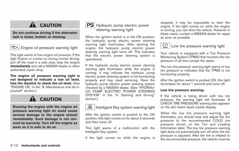
Black plate (88,1)
Model "E52-D" EDITED: 2010/ 10/ 25
CAUTION
Do not continue driving if the alternatorbelt is loose, broken or missing.
Engine oil pressure warning light
This light warns of low engine oil pressure. If thelight flickers or comes on during normal driving,pull off the road in a safe area, stop the engineimmediately and call a NISSAN dealer or otherauthorized repair shop.
The engine oil pressure warning light isnot designed to indicate a low oil level.Use the dipstick to check the oil level. (See“ENGINE OIL” in the “8. Maintenance and do-it-yourself” section.)
CAUTION
Running the engine with the engine oilpressure warning light on could causeserious damage to the engine almostimmediately. Such damage is not cov-ered by warranty. Turn off the engine assoon as it is safe to do so.
Hydraulic pump electric powersteering warning light
When the ignition switch is in the ON position,the hydraulic pump electric power steeringwarning light illuminates. After starting theengine, the hydraulic pump electric powersteering warning light turns off. This indicatesthat the electric power steering system isoperational.
If the hydraulic pump electric power steeringwarning light illuminates while the engine isrunning, it may indicate the hydraulic pumpelectric power steering system is not functioningproperly and may need servicing. Have thehydraulic pump electric power steering systemchecked by a NISSAN dealer. (See “HYDRAU-LIC PUMP ELECTRIC POWER STEERINGSYSTEM” in the “5. Starting and driving”section.)
Intelligent Key system warning light
After the ignition switch is pushed to the ONposition, this light comes on for about 2 secondsand then turns off.
This light warns of a malfunction with theIntelligent Key system.
If the light comes on while the engine is
stopped, it may be impossible to start theengine. If the light comes on while the engineis running, you can drive the vehicle. However inthese cases, contact a NISSAN dealer for repairas soon as possible.
Low tire pressure warning light
Your vehicle is equipped with a Tire PressureMonitoring System (TPMS) that monitors the tirepressure of all tires except the spare.
The low tire pressure warning light warns of lowtire pressure or indicates that the TPMS is notfunctioning properly.
After the ignition switch is pushed ON, this lightilluminates for about 1 second and turns off.
Low tire pressure warning:
If the vehicle is being driven with low tirepressure, the warning light will illuminate. ACHECK TIRE PRESSURE warning also appearson the dot matrix liquid crystal display.
When the low tire pressure warning lightilluminates, you should stop and adjust the tirepressure to the recommended COLD tirepressure shown on the Tire and LoadingInformation label. The low tire pressure warninglight does not automatically turn off when the tirepressure is adjusted. After the tire is inflated tothe recommended pressure, the vehicle must be
2-12 Instruments and controls

Black plate (89,1)
Model "E52-D" EDITED: 2010/ 10/ 25
driven at speeds above 16 MPH (25 km/h) toactivate the TPMS and turn off the low tirepressure warning light. Use a tire pressuregauge to check the tire pressure.
The CHECK TIRE PRESSURE warning is activeas long as the low tire pressure warning lightremains illuminated.
For additional information, see “TIRE PRES-SURE MONITORING SYSTEM (TPMS)” in the“5. Starting and driving” section and “TIREPRESSURE MONITORING SYSTEM (TPMS)”in the “6. In case of emergency” section.
TPMS malfunction:
If the TPMS is not functioning properly, the lowtire pressure warning light will flash for approxi-mately 1 minute when the ignition switch ispushed ON. The light will remain on after the 1minute. Have the system checked by a NISSANdealer. The CHECK TIRE PRESSURE warningdoes not appear if the low tire pressure warninglight illuminates to indicate a TPMS malfunction.
For additional information, see “TIRE PRES-SURE MONITORING SYSTEM (TPMS)” in the“5. Starting and driving” section. For theCHECK TIRE PRESSURE warning, see “DOTMATRIX LIQUID CRYSTAL DISPLAY” later inthis section.
WARNING
. If the light does not illuminate withthe ignition switch pushed ON, havethe vehicle checked by a NISSANdealer as soon as possible.
. If the light illuminates while driving,avoid sudden steering maneuvers orabrupt braking, reduce vehiclespeed, pull off the road to a safelocation and stop the vehicle assoon as possible. Driving with un-der-inflated tires may permanentlydamage the tires and increase thelikelihood of tire failure. Seriousvehicle damage could occur andmay lead to an accident and couldresult in serious personal injury.Check the tire pressure for all fourtires. Adjust the tire pressure to therecommended COLD tire pressureshown on the Tire and LoadingInformation label to turn the lowtire pressure warning light OFF. Ifthe light still illuminates while driv-ing after adjusting the tire pressure,a tire may be flat. If you have a flattire, replace it with a spare tire assoon as possible.
. When a spare tire is mounted or awheel is replaced, the TPMS will notfunction and the low tire pressurewarning light will flash for approxi-mately 1 minute. The light willremain on after 1 minute. Contactyour NISSAN dealer as soon aspossible for tire replacement and/or system resetting.
. Replacing tires with those not ori-ginally specified by NISSAN couldaffect the proper operation of theTPMS.
CAUTION
. The TPMS is not a substitute for theregular tire pressure check. Be sureto check the tire pressure regularly.
. If the vehicle is being driven atspeeds of less than 16 MPH (25km/h), the TPMS may not operatecorrectly.
. Be sure to correctly install thespecified size of tires to the fourwheels.
Instruments and controls 2-13

Black plate (90,1)
Model "E52-D" EDITED: 2010/ 10/ 25
Master warning lightWhen the ignition switch is in the ON position,the master warning light illuminates if any of thefollowing are displayed on the dot matrix liquidcrystal display:
. No key warning
. Low fuel warning
. Low washer fluid warning
. Parking brake release warning
. Door/lift gate open warning
. Loose fuel cap warning
. Check tire pressure warning
See “DOT MATRIX LIQUID CRYSTAL DIS-PLAY” later in this section.
Seat belt warning light and chime
The light and chime remind you to fasten seatbelts. The light illuminates whenever the ignitionswitch is pushed to the ON position, and willremain illuminated until the driver’s seat belt isfastened. At the same time, the chime will soundfor approximately 6 seconds unless the driver’sseat belt is securely fastened.
The seat belt warning light for the frontpassenger will illuminate if the seat belt is not
fastened when the front passenger’s seat isoccupied. For approximately 5 seconds after theignition switch is in the ON position, the systemdoes not activate the warning light for the frontpassenger.
See “SEAT BELTS” in the “1. Safety — Seats,seat belts and supplemental restraint system”section for precautions on seat belt usage.
Supplemental air bag warning light
After pushing the ignition switch to the ONposition, the supplemental air bag warning lightwill illuminate. The supplemental air bag warninglight will turn off after about 7 seconds if thesupplemental front air bag and supplementalside air bag, curtain side-impact air bag systemsand/or pretensioner seat belt are operational.
If any of the following conditions occur, the frontair bag, side air bag, curtain air bag andpretensioner systems needs servicing and yourvehicle must be taken to your nearest NISSANdealer.
. The supplemental air bag warning lightremains on after approximately 7 seconds.
. The supplemental air bag warning lightflashes intermittently.
. The supplemental air bag warning light doesnot come on at all.
Unless checked and repaired, the SupplementalRestraint Systems (air bag systems) and/or thepretensioners may not function properly.
For additional information, see “SUPPLEMEN-TAL RESTRAINT SYSTEM” in the “1. Safety —Seats, seat belts and supplemental restraintsystem” section.
WARNING
If the supplemental air bag warninglight is on, it could mean that the frontair bag, side air bag, curtain air bagand/or pretensioner systems will notoperate in an accident. To help avoidinjury to yourself or others, have yourvehicle checked by a NISSAN dealer assoon as possible.
Vehicle Dynamic Control (VDC)warning light
The light will blink when the VDC system or thetraction control system is operating, thus alertingthe driver that the vehicle is nearing its tractionlimits. The road surface may be slippery.
When the vehicle dynamic control warning lightilluminates when the vehicle dynamic controlsystem is turned on, this light alerts the driver to
2-14 Instruments and controls

Black plate (91,1)
Model "E52-D" EDITED: 2010/ 10/ 25
the fact that the vehicle dynamic controlsystem’s fail-safe mode is operating, for examplethe vehicle dynamic control system may not befunctioning properly. Have the system checkedby a NISSAN dealer. If a malfunction occurs inthe system, the vehicle dynamic control systemfunction will be canceled but the vehicle is stilldriveable. For additional information, see “VE-HICLE DYNAMIC CONTROL (VDC) SYSTEM”in the “5. Starting and driving” section of thismanual.
INDICATOR LIGHTS
Continuously Variable Transmis-sion (CVT) position indicator light
When the ignition switch is pushed to the ONposition, the indicator shows the automaticselector shift position. (See “CONTINUOUSLYVARIABLE TRANSMISSION (CVT)” in the “5.Starting and driving” section.)
Cruise indicator light
Cruise main switch indicator:
This light illuminates when the cruise controlmain switch is pushed. The light turns off whenthe main switch is pushed again. When thecruise main switch indicator light illuminates, thecruise control system is operational. (See
“CRUISE CONTROL” in the “5. Starting anddriving” section.)
Cruise malfunction:
If the cruise indicator light blinks while theengine is running, it may indicate the cruisecontrol system is not functioning properly. Havethe system checked by a NISSAN dealer. (See“CRUISE CONTROL” in the “5. Starting anddriving” section.)
Front passenger air bag statuslight
The front passenger air bag status light ( )will be lit and the passenger front air bag will beOFF depending on how the front passengerseat is being used.
For front passenger air bag status light opera-tion, see “NISSAN ADVANCED AIR BAGSYSTEM (front seats)” in the “1. Safety —Seats, seat belts and supplemental restraintsystem” section of this manual.
High beam indicator light
This light comes on when the headlight highbeam is on and goes out when the low beam isselected.
Low beam indicator light
The light comes on when the front park, sidemarker, tail and license plate lights are on.
Malfunction Indicator Light (MIL)
If the malfunction indicator light comes onsteady or blinks while the engine is running, itmay indicate a potential emission control.
The malfunction indicator light may also come onsteady if the fuel-filler cap is loose or missing, orif the vehicle runs out of fuel. Check to makesure the fuel-filler cap is installed and closedtightly, and that the vehicle has at least 3 USgallons (11.4 liters) of fuel in the fuel tank.
After a few driving trips, the light shouldturn off if no other potential emission controlsystem malfunction exists.
If this indicator light remains on for 20 secondsand then blinks for 10 seconds when the engineis not running, it indicates that the vehicle is notready for an emission control system inspection/maintenance test. (See “READINESS FORINSPECTION/MAINTENANCE (I/M) TEST” inthe “9. Technical and consumer information”section.)
Instruments and controls 2-15
Black plate (92,1)
Model "E52-D" EDITED: 2010/ 10/ 25
Operation:
The malfunction indicator light will come on inone of two ways:
. Malfunction indicator light on steady — Anemission control system has been detected.Check the fuel-filler cap if the LOOSE FUELCAP warning appears on the dot matrixliquid crystal display. If the fuel-filler cap isloose or missing, tighten or install the capand continue to drive the vehicle. Thelight should turn off after a few driving trips.If the light does not turn off after a fewdriving trips, have the vehicle inspected by aNISSAN dealer. You do not need to haveyour vehicle towed to the dealer.
. Malfunction indicator light blinking — Anengine misfire has been detected which maydamage the emission control system.
To reduce or avoid emission control systemdamage:
a) Do not drive at speeds above 45 MPH(72 km/h).
b) Avoid hard acceleration or deceleration.
c) Avoid steep uphill grades.
d) If possible, reduce the amount of cargobeing hauled or towed.
The malfunction indicator light may stop
blinking and remain on.
Have the vehicle inspected by a NISSANdealer. You do not need to have your vehicletowed to the dealer.
CAUTION
Continued vehicle operation withouthaving the emission control systemand repaired as necessary could leadto poor driveability, reduced fuel econ-omy, and possible damage to the emis-sion control system.
Overdrive off indicator light
The overdrive off indicator light illuminates whenthe overdrive off mode is selected.
For additional information, see ““CONTINU-OUSLY VARIABLE TRANSMISSION (CVT)” inthe “5. Starting and driving” section of thismanual.
Security indicator light
The light blinks when the ignition switch is in theACC, OFF or LOCK position. This functionindicates the security system equipped on thevehicle is operational.
If the security system is malfunctioning, this lightwill remain on while the ignition switch is in theON position. For additional information, see“SECURITY SYSTEMS” later in this section.
Turn signal/hazard indicator lights
The light flashes when the turn signal switchlever or hazard switch is turned on.
Vehicle Dynamic Control (VDC) offindicator light
The light comes on when the vehicle dynamiccontrol off switch is pushed to OFF. Thisindicates that the vehicle dynamic controlsystem and traction control system are notoperating.
AUDIBLE REMINDERS
Key reminder chimeA chime will sound if the driver side door isopened while the ignition switch is pushed tothe ACC position. Make sure the ignition switchis pushed to the OFF position, and take theIntelligent Key with you when leaving the vehicle.
Light reminder chimeA chime will sound when the driver side door isopened with the light switch in the or
position and the ignition switch in the ACC
2-16 Instruments and controls

Black plate (93,1)
Model "E52-D" EDITED: 2010/ 10/ 25
or OFF position.
Turn the light switch off when you leave thevehicle.
The chime will also sound for 2 seconds whenthe ignition switch is turned to the OFF positionwith the fog lights on while the headlight switchis in the AUTO position.
Parking brake reminder chimeThe chime will sound if the vehicle is driven atmore than 4 MPH (7 km/h) with the parkingbrake applied. Stop the vehicle and release theparking brake.
Brake pad wear warningThe disc brake pads have audible wear warn-ings. When a brake pad requires replacement, itwill make a high pitched scraping sound whenthe vehicle is in motion. This scraping sound willfirst occur only when the brake pedal isdepressed. After more wear of the brake pad,the sound will always be heard even if the brakepedal is not depressed. Have the brakeschecked as soon as possible if the warningsound is heard.
SIC4715
The dot matrix liquid crystal display *1 islocated in the speedometer, and it displays,the key operation information and other warn-ings and information.
For the detail about the Intelligent Key System,see “INTELLIGENT KEY SYSTEM” in the “3.Pre-driving checks and adjustments” section.
DOT MATRIX LIQUID CRYSTALDISPLAY
Instruments and controls 2-17

Black plate (94,1)
Model "E52-D" EDITED: 2010/ 10/ 25
SIC4716
INDICATORS FOR OPERATION
1. Engine start operation indicatorThis indicator appears when the selector lever isin the P (Park) position.
This indicator means that the engine will start by
pushing the ignition switch with the brake pedaldepressed.
You can start the engine directly in any position.
2. NO KEY warningThis warning appears in either of the followingconditions.
No key inside the vehicle:
The warning appears when the door is closed
2-18 Instruments and controls

Black plate (95,1)
Model "E52-D" EDITED: 2010/ 10/ 25
with the Intelligent Key left outside the vehicleand the ignition switch in the ACC or ONposition. Make sure that the Intelligent Key isinside the vehicle.
Unregistered key:
The warning appears when the ignition switch ispushed from the LOCK position and the keycannot be recognized by the system. You cannotstart the engine with an unregistered key. Usethe registered key.
See “INTELLIGENT KEY SYSTEM” in the “3.Pre-driving checks and adjustments” section formore details.
3. SHIFT “P” warningThis warning appears when the ignition switch ispushed to stop the engine with the selector leverin any position except the P (Park) position.
If this warning appears, move the selector leverto the P (Park) position or push the ignitionswitch to the ON position.
An inside warning chime will also sound. (See“INTELLIGENT KEY SYSTEM” in the “3. Pre-driving checks and adjustments” section.)
4. “PUSH” warningThis warning appears when the selector lever ismoved to the P (Park) position with the ignitionswitch in the ACC position after the SHIFT “P”
warning appears.
To push the ignition switch to the OFF position,perform the following procedure:
SHIFT “P” warning ? (Move the selectorlever to “P”) ? PUSH warning ? (Pushthe ignition switch? ignition switch positionis turned to ON) ? PUSH warning ?(Push the ignition switch ? ignition switchposition is turned to OFF)
5. Key battery discharge indicatorThis indicator appears when the key battery isrunning out of power.
If this indicator appears, replace the battery witha new one. (See “INTELLIGENT KEY BATTERYREPLACEMENT” in the “8. Maintenance anddo-it-yourself” section.)
6. Engine start operation for IntelligentKey system indicatorThis indicator appears when the Intelligent Keybattery is running out of power and when theIntelligent Key System and vehicle are notcommunicating normally.
If this indicator appears, touch the ignitionswitch with the Intelligent Key while depressingthe brake pedal. (See “INTELLIGENT KEYBATTERY DISCHARGE” in the “5. Startingand driving” section.)
7. Parking brake release warningThis warning appears when the vehicle speed isabove 4 MPH (7 km/h) and the parking brake isapplied. Stop the vehicle and release theparking brake.
8. Low fuel warningThis warning appears when the fuel level in thetank is getting low. Refuel as soon as it isconvenient, preferably before the fuel gaugereaches the empty (0) position.
There is a small reserve of fuel remainingin the tank when the fuel gauge reachesthe empty (0) position.
9. Low washer fluid warningThis warning appears when the washer tank fluidis at a low level. Add washer fluid as necessary.(See “WINDOW WASHER FLUID” in the “8.Maintenance and do-it-yourself” section.)
10. Door/lift gate open warning (ignitionswitch is in the ON position)This warning appears if any of the doors and/orthe lift gate are open or not closed securely. Thevehicle icon indicates which door is open on thedisplay.
11. Loose fuel cap warningThis warning appears when the fuel-filler cap isnot tightened correctly after the vehicle has
Instruments and controls 2-19

Black plate (96,1)
Model "E52-D" EDITED: 2010/ 10/ 25
been refueled. (See “FUEL-FILLER CAP” in the“3. Pre-driving checks and adjustments” sec-tion.)
12. Check tire pressure warningThis warning appears when the low tire pressurewarning light in the meter illuminates and low tirepressure is detected. If this warning appears,stop the vehicle and adjust the tire pressure tothe recommended COLD tire pressure shownon the Tire and Loading Information label. (See“Low tire pressure warning light” earlier in thissection and “TIRE PRESSURE MONITORINGSYSTEM (TPMS)” in the “5. Starting anddriving” section.)
13. “TIMER” indicatorThis indicator appears when the set “timer”indicator activates. You can set the time for up to6 hours. (See “TRIP COMPUTER” later in thissection.)
14. Low outside temperature warningThis warning appears if the outside temperatureis below 378F (38C). The warning can be set notto be displayed. (See “TRIP COMPUTER” laterin this section.)
SIC4237
INDICATORS FOR MAINTENANCE
1. Engine oil replacement indicatorThis indicator appears when the set time comesfor changing the engine oil. You can set or resetthe distance for changing the engine oil. (See“TRIP COMPUTER” later in this section.)
2. Oil filter replacement indicatorThis indicator appears when the set time comesfor replacing the oil filter. You can set or resetthe distance for replacing the oil filter. (See“TRIP COMPUTER” later in this section.)
3. Tire replacement indicatorThis indicator appears when the set time comesfor replacing tires. You can set or reset thedistance for replacing tires. (See “TRIP COM-PUTER” later in this section.)
4. “OTHER” indicatorThis indicator appears when the set time comesfor replacing items other than the engine oil, oilfilter and tires. You can set or reset the distancefor replacing the items. (See “TRIP COMPU-TER” later in this section.)
More maintenance reminders are also availableon the center display. (models with center multi-function control panel) (See “HOW TO USEINFO BUTTON” in the “4. Monitor, heater, airconditioner, audio, phone and voice recognitionsystems” section.)
2-20 Instruments and controls

Black plate (97,1)
Model "E52-D" EDITED: 2010/ 10/ 25
SIC3580
TRIP COMPUTER
Switches for the trip computer are located onthe right side of the combination meter panel. Tooperate the trip computer, push the side of theswitches as shown above.
*A switch
*B switch
When the ignition switch is pushed to the ONposition, modes of the trip computer can beselected by pushing the switch *A .
Each time the switch *A is pushed, thedisplay will change as follows:
Current and average fuel consumption ?Average fuel consumption and speed ?Elapsed time and trip odometer ? Distance toempty (dte) ? Outside air temperature (ICY) ?Setting ? Warning check
SIC4700
Current and average fuel consumption(MPG, l (liter)/100 km or km/l)The current and average fuel consumption modeshows the current and average fuel consump-tion.
Instruments and controls 2-21
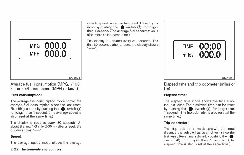
Black plate (98,1)
Model "E52-D" EDITED: 2010/ 10/ 25
SIC3674
Average fuel consumption (MPG, l/100km or km/l) and speed (MPH or km/h)
Fuel consumption:
The average fuel consumption mode shows theaverage fuel consumption since the last reset.Resetting is done by pushing the switch*Bfor longer than 1 second. (The average speed isalso reset at the same time.)
The display is updated every 30 seconds. Atabout the first 1/3 mile (500 m) after a reset, thedisplay shows “——”.
Speed:
The average speed mode shows the average
vehicle speed since the last reset. Resetting isdone by pushing the switch *B for longerthan 1 second. (The average fuel consumption isalso reset at the same time.)
The display is updated every 30 seconds. Thefirst 30 seconds after a reset, the display shows“——”.
SIC4701
Elapsed time and trip odometer (miles orkm)
Elapsed time:
The elapsed time mode shows the time sincethe last reset. The displayed time can be resetby pushing the switch *B for longer than1 second. (The trip odometer is also reset at thesame time.)
Trip odometer:
The trip odometer mode shows the totaldistance the vehicle has been driven since thelast reset. Resetting is done by pushing theswitch *B for longer than 1 second. (Theelapsed time is also reset at the same time.)
2-22 Instruments and controls

Black plate (99,1)
Model "E52-D" EDITED: 2010/ 10/ 25
SIC4702
Distance to empty (dte — miles or km)The distance to empty (dte) mode provides youwith an estimation of the distance that can bedriven before refueling. The dte is constantlybeing calculated, based on the amount of fuel inthe fuel tank and the actual fuel consumption.
The display is updated every 30 seconds.
The dte mode includes a low range warningfeature. If the fuel level is low, the warning isdisplayed on the screen.
When the fuel level drops even lower, the dtedisplay will change to “——”.
. If the amount of fuel added is small, thedisplay just before the ignition switch is
pushed to the OFF position may continue tobe displayed.
. When driving uphill or rounding curves, thefuel in the tank shifts, which may momenta-rily change the display.
SIC4703
Outside air temperature (ICY— 8F or 8C)The outside air temperature is displayed in 8F or8C in the range of −22 to 1408F (−30 to 608C).
The outside air temperature mode includes a lowtemperature warning feature. If the outside airtemperature is below 378F (38C), the warning isdisplayed on the screen.
The outside temperature sensor is located infront of the radiator. The sensor may be affectedby road or engine heat, wind directions andother driving conditions. The display may differfrom the actual outside temperature or thetemperature displayed on various signs or bill-boards.
Instruments and controls 2-23

Black plate (100,1)
Model "E52-D" EDITED: 2010/ 10/ 25
SIC3678
SettingSetting cannot be made while driving. Amessage “Setting can only be operatedwhen stopped” is also displayed on the dotmatrix crystal display.
The switch *A and switch *B areused in the setting mode to select and decide amenu.
SKIP:
Push the switch *A to move to thewarning check mode.
Push the switch*B to select other menus.
ALERT:
Alert menu can be set to notify the followingitems.
. TIMER
Select this submenu to specify when the“TIMER” indicator activates.
. ICY
Select this submenu to display the lowoutside temperature warning.
To return to the top page of the setting mode,select “BACK”.
MAINTENANCE:
The maintenance intervals of the following itemscan be set or reset for the reminders.
. OIL
Select this submenu to set or reset thedistance for changing the engine oil.
. FILTER
Select this submenu to set or reset thedistance for replacing the oil filter.
. TIRE
Select this submenu to set or reset thedistance for replacing tires.
. OTHER
Select this submenu and set or reset thedistance for replacing items other than theengine oil, oil filter and tires.
To return to the top page of the setting mode,select “BACK”.
OPTIONS:
The 3 option menus can be set to yourpreference.
. LANGUAGE
Select this submenu to choose English,French or Spanish for display.
. UNIT
Select this submenu to choose the unit fromMPG or l/100 km.
. EFFECTS
Select this menu to set the effects de-scribed below to on or off.
— The indicator needles sweep in themeters and the ring illumination will bebrightened gradually when the engine isstarted.
To return to the top page of the setting mode,select “BACK”.
2-24 Instruments and controls
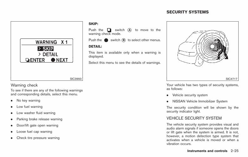
Black plate (101,1)
Model "E52-D" EDITED: 2010/ 10/ 25
SIC3993
Warning checkTo see if there are any of the following warningsand corresponding details, select this menu.
. No key warning
. Low fuel warning
. Low washer fluid warning
. Parking brake release warning
. Door/lift gate open warning
. Loose fuel cap warning
. Check tire pressure warning
SKIP:
Push the switch *A to move to thewarning check mode.
Push the switch*B to select other menus.
DETAIL:
This item is available only when a warning isdisplayed.
Select this menu to see the details of warnings.
SIC4717
Your vehicle has two types of security systems,as follows:
. Vehicle security system
. NISSAN Vehicle Immobilizer System
The security condition will be shown by thesecurity indicator light.
VEHICLE SECURITY SYSTEM
The vehicle security system provides visual andaudio alarm signals if someone opens the doorsor lift gate when the system is armed. It is not,however, a motion detection type system thatactivates when a vehicle is moved or when avibration occurs.
SECURITY SYSTEMS
Instruments and controls 2-25

Black plate (102,1)
Model "E52-D" EDITED: 2010/ 10/ 25
The system helps deter vehicle theft but cannotprevent it, nor can it prevent the theft of interioror exterior vehicle components in all situations.Always secure your vehicle even if parking for abrief period. Never leave your Intelligent Key(s)in the vehicle, and always lock it when un-attended. Be aware of your surroundings, andpark in secure, well-lit areas whenever possible.
Many devices offering additional protection,such as component locks, identification markers,and tracking systems, are available at autosupply stores and specialty shops. YourNISSAN dealer may also offer such equipment.Check with your insurance company to see ifyou may be eligible for discounts for varioustheft protection features.
SIC2045
How to arm the vehicle security system1. Close all windows.
The system can be armed even if thewindows are open.
2. Push the ignition switch to the OFF position.
3. Remove the Intelligent Key from the vehicle.
4. Close all doors and lift gate. Lock all doors.The doors can be locked with the IntelligentKey, door handle request switch, powerdoor lock switch or mechanical key.
5. Confirm that the security indicator lightcomes on. The security indicator light stayson for about 30 seconds. The vehicle
security system is now pre-armed. Afterabout 30 seconds the vehicle securitysystem automatically shifts into the armedphase. The security light begins to flashonce every approximately 3 seconds. If,during this 30-second pre-arm time period,the door is unlocked, or the ignition switch ispushed to ACC or ON, the system will notarm.
Even when the driver and/or passengersare in the vehicle, the system will activatewith all doors and lift gate locked with theignition switch in the LOCK position. Whenpushing the ignition switch to the ACC orON position, the system will be released.
Vehicle security system activationThe vehicle security system will give the follow-ing alarm:
. The headlights blink and the horn soundsintermittently.
. The alarm automatically turns off afterapproximately 1 minute. However, the alarmreactivates if the vehicle is tampered withagain.
The alarm is activated by:
. Unlocking the door or opening the lift gatewithout using the button on the IntelligentKey, the door handle request switch or the
2-26 Instruments and controls

Black plate (103,1)
Model "E52-D" EDITED: 2010/ 10/ 25
mechanical key. (Even if the door is openedby releasing the door inside lock knob, thealarm will activate.)
How to stop an activated alarmThe alarm will stop by unlocking a door bypushing the unlock button on the Intelligent Key,the door handle request switch or using themechanical key. The alarm will not stop if theignition switch is pushed to the ACC or ONposition.
If the system does not operate as de-scribed above, have it checked by aNISSAN dealer.
NISSAN VEHICLE IMMOBILIZER SYS-TEM
The NISSAN Vehicle Immobilizer System will notallow the engine to start without the use of theregistered Intelligent Key. Never leave thesekeys in the vehicle.
For USA:
This device complies with Part 15 of theFCC Rules. Operation is subject to thefollowing two conditions:
(1) This device may not cause harmfulinterference, and (2) this device mustaccept any interference received, includinginterference that may cause undesired
operation.
Note: Changes or modifications not ex-pressly approved by the party responsiblefor compliance could void the user’sauthority to operate the equipment.
For Canada:
This device complies with RSS-210 ofIndustry Canada. Operation is subject tothe following two conditions:
(1) this device may not cause interference,and (2) this device must accept any inter-ference, including interference that maycause undesired operation of the device. SIC2045
Security indicator lightThe security indicator light is located on themeter panel. It indicates the status of theNISSAN Vehicle Immobilizer System.
The light blinks after the ignition switch is in theLOCK, ACC or OFF position. This functionindicates the security systems equipped on thevehicle are operational.
If the NISSAN Vehicle Immobilizer System ismalfunctioning, this light will remain on while theignition switch is in the ON position.
If the light still remains on and/or theengine will not start, see a NISSAN dealerfor NISSAN Vehicle Immobilizer System
Instruments and controls 2-27

Black plate (104,1)
Model "E52-D" EDITED: 2010/ 10/ 25
service as soon as possible. Please bringall Intelligent Keys that you have whenvisiting a NISSAN dealer for service.
WARNING
In freezing temperatures the washersolution may freeze on the windshieldand obscure your vision which may leadto an accident. Warm windshield withthe defroster before you wash thewindshield.
CAUTION
. Do not operate the washer continu-ously for more than 30 seconds.
. Do not operate the washer if thereservoir tank is empty.
. Do not fill the window washerreservoir tank with washer fluidconcentrates at full strength. Somemethyl alcohol based washer fluidconcentrates may permanently stainthe grille if spilled while filling thewindow washer reservoir tank.
. Pre-mix washer fluid concentrateswith water to the manufacturer’srecommended levels before pouringthe fluid into the window washerreservoir tank. Do not use thewindow washer reservoir tank to
mix the washer fluid concentrateand water.
WINDSHIELD WIPER AND WASHERSWITCH
2-28 Instruments and controls

Black plate (105,1)
Model "E52-D" EDITED: 2010/ 10/ 25
SIC3664
The windshield wiper and washer operateswhen the ignition switch is in the ON position.
Push the lever down to operate the wiper at thefollowing speed:
*1 INT — intermittent operation can be ad-justed by turning the knob toward *A(Slower) or *B (Faster).When the speed sensing wiper intervalfunction (models with center multi-functioncontrol panel) is turned on, the intermittentoperation speed varies in accordance withthe vehicle speed. (For example, when thevehicle speed is high, the intermittentoperation speed will be faster.)Note that the function is set to disabled as
the factory default setting. To turn thisfunction on and off, see “HOW TO USESETTING BUTTON” in the “4. Monitor,heater, air conditioner, audio, phone andvoice recognition systems” section.
*2 LO — continuous low speed operation
*3 HI — continuous high speed operation
Push the lever up*4 (MIST) to have one sweepoperation of the wiper.
Pull the lever toward you *5 to operate thewasher. Then the wiper will also operate severaltimes.
WARNING
In freezing temperatures the washersolution may freeze on the rear windowglass and obscure your vision. Warmthe rear window with the defrosterbefore you wash the rear window.
CAUTION
. Do not operate the washer continu-ously for more than 30 seconds.
. Do not operate the washer if thereservoir tank is empty.
. Do not fill the window washerreservoir tank with washer fluidconcentrates at full strength. Somemethyl alcohol based washer fluidconcentrates may permanently stainthe grille if spilled while filling thewindow washer reservoir tank.
. Pre-mix washer fluid concentrateswith water to the manufacturer’srecommended levels before pouringthe fluid into the window washerreservoir tank. Do not use thewindow washer reservoir tank tomix the washer fluid concentrate
REAR WINDOW WIPER ANDWASHER SWITCH
Instruments and controls 2-29

Black plate (106,1)
Model "E52-D" EDITED: 2010/ 10/ 25
and water.
If the rear window wiper operation isinterrupted by snow or ice, the wiper maystop moving to protect its motor. If thisoccurs, turn the wiper switch to the OFFposition and remove the snow or ice that ison and around the wiper arms. In approxi-mately 1 minute, turn the switch on againto operate the wiper.
SIC3666
The rear window wiper and washer operatewhen the ignition switch is in the ON position.
Turn the switch clockwise from the OFF positionto operate the wiper.
*1 Intermittent (INT) — intermittent operation(not adjustable)
*2 Low (ON) — continuous low speed opera-tion
Push the switch forward *3 to operate thewasher. Then the wiper will also operate severaltimes.
SIC4718
To defog/defrost the rear window glass andoutside mirrors (if so equipped), start the engineand push the switch *1 on. The indicator light*2 will come on. Push the switch again to turnthe defroster off.
It will automatically turn off in approximately 15minutes.
CAUTION
When cleaning the inner side of the rearwindow, be careful not to scratch ordamage the rear window defroster.
REAR WINDOW AND OUTSIDEMIRROR DEFROSTER SWITCH
2-30 Instruments and controls

Black plate (107,1)
Model "E52-D" EDITED: 2010/ 10/ 25
XENON HEADLIGHTS (if so equipped)
WARNING
HIGH VOLTAGE
. When xenon headlights are on, theyproduce a high voltage. To preventan electric shock, never attempt tomodify or disassemble. Always haveyour xenon headlights replaced at aNISSAN dealer.
. Xenon headlights provide consider-ably more light than conventionalheadlights. If they are not correctlyaimed, they might temporarily blindan oncoming driver or the driverahead of you and cause a seriousaccident. If headlights are not aimedcorrectly, immediately take your ve-hicle to a NISSAN dealer and havethe headlights adjusted correctly.
When the xenon headlight is initially turned on,its brightness or color varies slightly. However,the color and brightness will soon stabilize.
. The life of xenon headlights will beshortened by frequent on-off opera-tion. It is generally desirable not to turn
off the headlights for short intervals(for example, when the vehicle stops ata traffic signal). Even when the daytimerunning lights are active (Canada only),the xenon headlights do not turn on.This way the life of the xenon head-lights is not reduced.
. If the xenon headlight bulb is close toburning out, the brightness will drasti-cally decrease, the light will startblinking, or the color of the light willbecome reddish. If one or more of theabove signs appear, contact a NISSANdealer.
SIC3668
HEADLIGHT SWITCH
Lighting
*1 Turn the switch to the position:
The front park, side marker, tail, licenseplate and instrument lights will come on.
*2 Turn the switch to the position:
Headlights will come on and all the otherlights remain on.
HEADLIGHT AND TURN SIGNALSWITCH
Instruments and controls 2-31

Black plate (108,1)
Model "E52-D" EDITED: 2010/ 10/ 25
SIC3669
Autolight system (if so equipped)The autolight system allows the headlights to beset so they turn on and off automatically.
To set the autolight system:
1. Make sure the headlight switch is in theAUTO position *1 .
2. Push the ignition switch to the ON position.
3. The autolight system automatically turns theheadlights on and off.
To turn the autolight system off, turn the switchto the OFF, or position.
The autolight system can turn on the headlightsautomatically when it is dark and turn off theheadlights when it is light.
The headlights will also be turned on automa-tically at twilight or in rainy weather (when thewindshield wiper is operated continuously) (if soequipped).
If the ignition switch is pushed to the OFFposition and one of the doors is opened and thiscondition is continued, the headlights remain onfor 5 minutes.
Automatic headlights off delay:
You can keep the headlights on for up to 180seconds after you push the ignition switch toOFF and open any door then close all the doors.
You can adjust the period of the automaticheadlights off delay from 0 seconds (OFF) to180 seconds. The factory default setting is 45seconds.
For automatic headlights off delay setting, see“Light Off Delay” in the “4. Monitor, heater, airconditioner, audio, phone and voice recognitionsystems” section.
SIC4722
Be sure not to put anything on top of thephoto sensor*A located on the top of theinstrument panel. The photo sensor con-trols the autolight; if it is covered, thephoto sensor reacts as if it is dark and theheadlights will illuminate.
2-32 Instruments and controls

Black plate (109,1)
Model "E52-D" EDITED: 2010/ 10/ 25
SIC3670
Headlight beam select
*1 To select the low beam, put the lever in theneutral position as shown.
*2 To select the high beam, push the leverforward while the switch is in theposition. Pull it back to select the low beam.
*3 Pulling the lever toward you will flash theheadlight high beam even when the head-light switch is in the OFF position.
Battery saver systemA chime will sound when the driver side door isopened with the light switch in the or
position and the ignition switch in the ACC,OFF or LOCK position.
When the headlight switch is in the orposition while the ignition switch is in the ONposition, the lights will automatically turn off 5minutes after the ignition switch has beenpushed to the OFF position.
When the headlight switch remains in theor position after the lights automaticallyturn off, the lights will turn on when the ignitionswitch is pushed to the ON position.
CAUTION
. When you turn on the headlightswitch again after the lights auto-matically turn off, the lights will notturn off automatically. Be sure toturn the light switch to the OFFposition when you leave the vehiclefor extended periods of time, other-wise the battery will be discharged.
. Never leave the light switch onwhen the engine is not running forextended periods of time even if theheadlights turn off automatically.
SIC2275
Headlight aiming control (if so equipped)Depending on the number of occupants in thevehicle and the load it is carrying, the headlightaxis may be higher than desired. If the vehicle istraveling on a hilly road, the headlights maydirectly hit the rearview mirror of the vehicleahead or the windshield of the oncomingvehicle. The light axis can be lowered with theoperation of the switch.
The larger the number designated on the switch,the lower the axis.
When traveling with no heavy load or on a flatroad, select position 0.
Instruments and controls 2-33

Black plate (110,1)
Model "E52-D" EDITED: 2010/ 10/ 25
WARNING
Xenon headlights (if so equipped) areextremely bright compared to conven-tional headlights. If the xenon head-lights hit the rearview mirror of thevehicle ahead or the windshield ofoncoming vehicle, the driver of thesevehicles may have difficulty drivingbecause of the brightness. Use theheadlight aiming control switch to low-er the light axis. See “XENON HEAD-LIGHTS” earlier in this section foradditional information.
Daytime running light system (Canadaonly)The daytime running lights automatically illumi-nate when the engine is started with the parkingbrake released. The daytime running lightsoperate with the headlight switch in the OFFposition or in the position. Turn theheadlight switch to the position for fullillumination when driving at night.
If the parking brake is applied before the engineis started, the daytime running lights do notilluminate. The daytime running lights illuminateonce the parking brake is released. The daytimerunning lights will remain on until the ignitionswitch is pushed to the OFF position.
WARNING
When the daytime running light systemis active, tail lights on your vehicle arenot on. It is necessary at dusk to turn onyour headlights. Failure to do so couldcause an accident injuring yourself andothers.
SIC3585
Instrument brightness controlThe instrument brightness control operateswhen the ignition switch is in the ON position.
Pushing the control switch*A once will changethe brightness to the night mode.
Pushing the control switch*B once will changethe brightness to the day mode.
To adjust the brightness of instrument panellights, push the control switches. Pushing theupper switch *A will brighten the lights. Whenthe brightness reaches the maximum level, abeep will sound. The lower switch *B dims thelights. Repeatedly pushing the lower switch willturn the lights off and a beep will sound.
2-34 Instruments and controls

Black plate (111,1)
Model "E52-D" EDITED: 2010/ 10/ 25
SIC3671
TURN SIGNAL SWITCH
*1 Turn signalMove the lever up or down to signal the turningdirection. When the turn is completed, the turnsignals cancel automatically.
*2 Lane change signalTo indicate a lane change, move the lever up ordown to the point where lights begin flashing.
SIC3672
FOG LIGHT SWITCH (if so equipped)
To turn the fog lights on, turn the headlightswitch to the position, then turn the switchto the position. To turn them off, turn theswitch to the OFF position.
The headlights must be on for the fog lights tooperate.
When the headlight switch is in the AUTOposition (if so equipped):
. Turning the fog light switch to theposition will turn on the headlights, fog lightsand the other lights while the ignition switchis in the ON position or the engine isrunning.
SIC2574
Push the switch on to warn other drivers whenyou must stop or park under emergency condi-tions. All turn signal lights will flash.
WARNING
. If stopping for an emergency, besure to move the vehicle well off theroad.
. Do not use the hazard warningflashers while moving on the high-way unless unusual circumstancesforce you to drive so slowly thatyour vehicle might become a hazardto other traffic.
HAZARD WARNING FLASHERSWITCH
Instruments and controls 2-35

Black plate (112,1)
Model "E52-D" EDITED: 2010/ 10/ 25
. Turn signals do not work when thehazard warning flasher lights areon.
The flasher can be actuated with the ignitionswitch in any position.
Some state laws may prohibit the use ofthe hazard warning flasher switch whiledriving.
MODELS WITH AUTO LIGHT SYSTEM
When an impact that could activate the supple-mental air bags is detected, the hazard warningflasher lights blink automatically. If the hazardwarning flasher switch is pushed, the hazardwarning flashers will turn off.
WARNING
Do not turn the hazard warning flasherswitch to off until you can make surethat it is safe to do so. Also, the hazardflasher warning may not blink automa-tically depending on the force of im-pact.
SIC3586
To sound the horn, push the pad area*A of thesteering wheel.
WARNING
Do not disassemble the horn. Doing socould affect proper operation of thesupplemental front air bag system.Tampering with the supplemental frontair bag system may result in seriouspersonal injury.
WARNING
Do not use or allow occupants to usethe seat heater if you or the occupantscannot monitor elevated seat tempera-tures or have an inability to feel pain inbody parts that contact the seat. Use ofthe seat heater by such people couldresult in serious injury.
CAUTION
. The battery could run down if theseat heater is operated while theengine is not running.
. Do not use the seat heater forextended periods or when no oneis using the seat.
. Do not put anything on the seatwhich insulates heat, such as ablanket, cushion, seat cover, etc.Otherwise, the seat may becomeoverheated.
. Do not place anything hard or heavyon the seat or pierce it with a pin orsimilar object. This may result indamage to the heater.
HORN HEATED SEATS (if so equipped)
2-36 Instruments and controls

Black plate (113,1)
Model "E52-D" EDITED: 2010/ 10/ 25
. Any liquid spilled on the heated seatshould be removed immediatelywith a dry cloth.
. When cleaning the seat, never usegasoline, thinner, or any similarmaterials.
. If any malfunctions are found or theheated seat does not operate, turnthe switch off and have the systemchecked by a NISSAN dealer.
SIC2770
The seats are warmed by built-in heaters. Theswitches located on the instrument panel can beoperated independently of each other.
1. Start the engine.
2. Select heat range.
*1 For high heat, push the HI (High) side ofthe switch.
*2 For low heat, push the LO (Low) side ofthe switch.
The indicator light in the switch *3 willilluminate when the heater is on.
3. To turn off the heater, return the switch tothe level position. Make sure the indicatorlight goes off.
The heater is controlled by a thermostat,automatically turning the heater on and off.The indicator light will remain on as long asthe switch is on.
When the vehicle’s interior is warmed, orbefore you leave the vehicle, be sure to turnoff the switch.
Instruments and controls 2-37

Black plate (114,1)
Model "E52-D" EDITED: 2010/ 10/ 25
SSD1179
The Blind Spot Warning (BSW) switch will turnon and off the Blind Spot Warning (BSW)system.
The BSW system will illuminate the Blind SpotWarning (BSW) indicator lights, in the outsidemirrors, when the radar sensors detect a vehiclein the detection zone. If the turn signal isactivated in the direction of the detected vehicle,a chime sounds twice and the BSW indicatorlight will flash. (See “BLIND SPOT WARNING(BSW) SYSTEM” in the “5. Starting and driving”section.)
The BSW switch is automatically turned onwhen the engine is started, and the BSW ONindicator *1 on the switch illuminates.
To cancel the warning systems, push the BSWswitch to turn off the system. The BSW ONindicator *1 will turn off.
NOTE:
If you continue to push the warningsystems switch from off to on for over 4seconds, a chime will sound. This willchange the default status of the BSWsystem to OFF so that this system willnot automatically turn on when the engineis started. If this procedure is repeated, thedefault status will return to ON.
SSD1149
The vehicle should be driven with the VehicleDynamic Control (VDC) system on for mostdriving conditions.
If the vehicle is stuck in mud or snow, the VDCsystem reduces the engine output to reducewheel spin. The engine speed will be reducedeven if the accelerator is depressed to the floor.If maximum engine power is needed to free astuck vehicle, turn the VDC system off.
To turn off the VDC system, push the VDC OFFswitch. The indicator will illuminate.
Push the VDC OFF switch again or restart theengine to turn on the system. (See “VEHICLEDYNAMIC CONTROL (VDC) SYSTEM” in the“5. Starting and driving” section.)
BLIND SPOT WARNING (BSW)SWITCH (if so equipped)
VEHICLE DYNAMIC CONTROL (VDC)OFF SWITCH
2-38 Instruments and controls

Black plate (115,1)
Model "E52-D" EDITED: 2010/ 10/ 25
CAUTION
. Use power outlet with the enginerunning to avoid discharging thevehicle battery.
. Avoid using power outlet when theair conditioner, headlights or rearwindow defroster is on.
. Before inserting or disconnecting aplug, be sure the electrical acces-sory being used is turned OFF.
. When not in use, be sure to closethe cap. Do not allow water tocontact the outlet.
SIC4723Instrument panel
SIC4724Cargo area
Type A
To use the power outlet, pull the cover asillustrated.
CAUTION
. The outlet and plug may be hotduring or immediately after use.
. Do not use with accessories thatexceed a 12 volt, 120W (10A) powerdraw. Do not use double adapters ormore than one electrical accessory.
. This power outlet is not designedfor use with a cigarette lighter unit.
. Push the plug in as far as it will go.If good contact is not made, the plugmay overheat or the internal tem-perature fuse may open.
POWER OUTLET
Instruments and controls 2-39

Black plate (116,1)
Model "E52-D" EDITED: 2010/ 10/ 25
SIC2648Main switch
Type B (if so equipped)
The power outlet (plug type) is located on thefront console. It can operate when the ignitionswitch in the ON position and the main switch(located on the instrument panel) is ON.
The specification of this power outlet is foruse of a 120 volt, 150W (1.25A) power draw.
To turn on or off the power supply to the outlet,push the ON *1 or OFF *2 side of the mainswitch. When the switch is turned to the ONposition, the indicator light *A will illuminate.
SIC4725Power outlet
Pull up the cover and plug in.
After using the power outlet, be sure to turn offthe main switch.
CAUTION
. Make sure that there is no fluid orother foreign substance in thepower outlet. Also, be sure not toconnect or disconnect the outletwith wet hands or insert any metalobjects into it. Doing so could resultin an electric shock or malfunction.
. Do not use with accessories that
exceed a 120 volt, 150W (1.25A)power draw or the power outletmay switch off automatically. If thisoccurs, turn the main switch on thepower outlet off and wait a shortperiod of time before turning it backon again. If an electrical appliancewith a wattage of less than 150W isused, the power outlet will beusable again.
. Use this power outlet with theengine running. (If the engine isstopped, this could result in a dis-charged battery.)
. When using the outlet for a longperiod of time such as when idlingetc., the battery may discharge de-pending on the vehicle conditions,even if the engine is running.
. Some electrical appliances withwattages below 150W, may notoperate normally. For example:
— Electrical appliances which con-sume a large amount of wattagewhen turned on (CRT TVs, elec-tric tools etc.)
— Electrical appliances which havea switching power frequency
2-40 Instruments and controls

Black plate (117,1)
Model "E52-D" EDITED: 2010/ 10/ 25
(clocks etc.)
— Electrical appliances that mea-sure precise data (measuringequipment etc.)
— Certain other electrical appli-ances (electric blankets etc.)
. Depending on the electrical appli-ance that is in use, some distortednoise may be audible when usingthe TV or radio.
. Be sure to turn the power switch ofthe electrical appliance used offbefore removing the plug from thepower outlet.
. Do not use an extension cord withmultiple outlets.
CUP HOLDERS
CAUTION
. Avoid abrupt starting and brakingwhen the cup holder is being usedto prevent spilling the drink. If theliquid is hot, it can scald you or yourpassenger.
. Use only soft cups in the cup holder.Hard objects can injure you in anaccident.
SIC4726Instrument panel
Front
Instrument panel:
To open the cup holder, push the instrumentpanel *1 .
STORAGE
Instruments and controls 2-41

Black plate (118,1)
Model "E52-D" EDITED: 2010/ 10/ 25
SIC4727Front side of the front center console
SIC4654Back side of the front center console
SIC4719
2nd row seat
SIC4419
3rd row seat
2-42 Instruments and controls

Black plate (119,1)
Model "E52-D" EDITED: 2010/ 10/ 25
SIC4720
Soft bottle holderSoft bottle holders are located on the frontdoors and sliding doors.
CAUTION
. Do not use bottle holder for anyother objects that could be thrownabout in the vehicle and possiblyinjure people during sudden brakingor an accident.
. Do not use bottle holder for openliquid containers.
SIC3589
SUNGLASSES HOLDER (if soequipped)
WARNING
Keep the sunglasses holder closedwhile driving to prevent an accident.
To open the sunglasses holder, push *1 .
CAUTION
. Do not use for anything other thanglasses.
. Do not leave glasses in the sun-
glasses holder while parking indirect sunlight. The heat may da-mage the glasses.
Instruments and controls 2-43

Black plate (120,1)
Model "E52-D" EDITED: 2010/ 10/ 25
SIC4647
GLOVE BOX
WARNING
Keep glove box lid closed while drivingto help prevent injury in an accident or asudden stop.
To open the glove box, pull the handle *1 .
To close, push the lid in until the lock latches.
To lock *2 /unlock *3 the glove box, use themechanical key. For the mechanical key usage,see “KEYS” in the “3. Pre-driving checks andadjustments” section.
SIC4729
INSTRUMENT LOWER BOX (if soequipped)
To open the box, pull the knob.
To close, push the lid in until the lock latches.
SIC4730Front
CONSOLE BOX
FrontTo open the box, pull the knob. To close, pushthe lid in until the lock latches.
2-44 Instruments and controls

Black plate (121,1)
Model "E52-D" EDITED: 2010/ 10/ 25
SIC47212nd row center console
2nd row center consolePull up on lever*A to open the console box lid.
To remove the 2nd row center console box:
1. Pull up on handle*B on rear of console andtilt the console up.
2. Move the console box toward the rear of thevehicle and lift out.
To reinstall the 2nd row center consolebox:
1. Tilt the console box forward and install thefront of the console box so that the hookengages the slot in the base.
2. Push down the rear of the console box tolock the console in place.
SIC4731
CARGO FLOOR BOX
To open the cargo floor box lid, pull the strap*A .
To hold lid open, secure the strap *B to thehook on the under side of cargo floor box lid.
WARNING
To prevent injury in an accident orsudden stop, do not drive with thecargo floor box lids open. Alwaysremove the strap *B from hook andclose the cargo floor box lids beforedriving.
Instruments and controls 2-45

Black plate (122,1)
Model "E52-D" EDITED: 2010/ 10/ 25
SIC4732Cargo area
SIC4733Seatbacks
HOOKS
Cargo areaThe 4 hooks are located on the right and leftside of the cargo area.
WARNING
. Always make sure that the cargo isproperly secured. Use the suitableropes and hooks.
. Unsecured cargo can become dan-gerous in an accident or suddenstop.
CAUTION
Do not apply a total load of more than 7lb (3 kg) to the hook.
SeatbacksThe hooks are located on the front and 3rd rowseatbacks.
To use the hook on the seatbacks, push thelower side of the hook and pull it out.
CAUTION
Do not apply a total load of more than 9
lb (4 kg) to the hook.
2-46 Instruments and controls

Black plate (123,1)
Model "E52-D" EDITED: 2010/ 10/ 25
SIC4737
ROOF RACK (if so equipped)
Always distribute the luggage evenly on the roofrack. Do not load more than 99 lb (45 kg) on theroof rails. Observe the maximum load limitshown on the crossbars or roof carriers whenyou attach them on the roof rails. Contact aNISSAN dealer for crossbar or other equipmentinformation. Be careful that your vehicle doesnot exceed the Gross Vehicle Weight Rating(GVWR) or its Gross Axle Weight Rating(GAWR front and rear). The GVWR and GAWRare located on the F.M.V.S.S. or C.V.M.S.S.certification label (located on the driver’s doorpillar). For more information regarding GVWRand GAWR, see “VEHICLE LOADING INFOR-MATION” in the “9. Technical and consumer
information” section.
WARNING
. Drive extra carefully when the vehi-cle is loaded at or near the cargocarrying capacity, especially if thesignificant portion of that load iscarried on the roof rack.
. Heavy loading of the roof rack hasthe potential to affect the vehiclestability and handling during sud-den or unusual handling maneuvers.
. Roof rack load should be evenlydistributed.
. Do not exceed maximum roof rackload weight capacity.
. Properly secure all cargo with ropesor straps to help prevent it fromsliding or shifting. In a sudden stopor collision, unsecured cargo couldcause personal injury.
CAUTION
Use care when placing or removingitems from the roof rack. If you cannotcomfortably lift the items onto the roof
rack from the ground, use a ladder orstool.
Instruments and controls 2-47
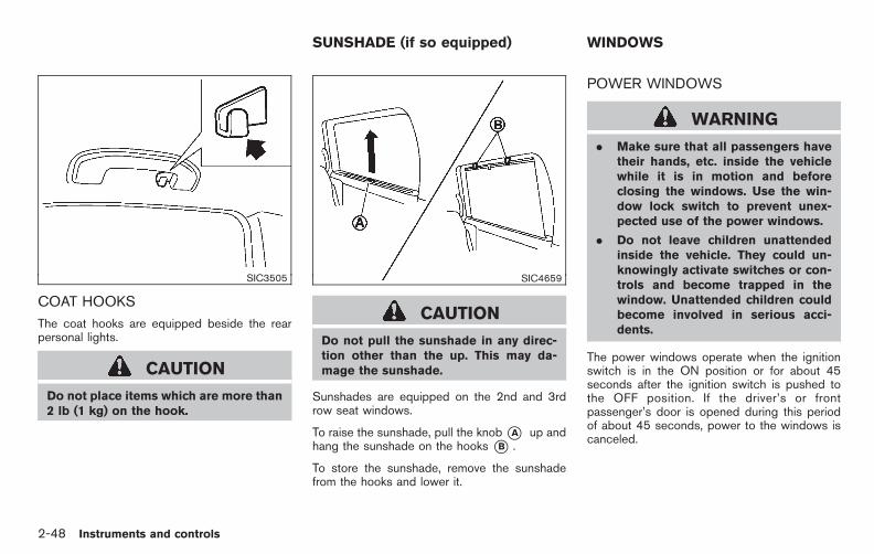
Black plate (124,1)
Model "E52-D" EDITED: 2010/ 10/ 25
SIC3505
COAT HOOKS
The coat hooks are equipped beside the rearpersonal lights.
CAUTION
Do not place items which are more than2 lb (1 kg) on the hook.
SIC4659
CAUTION
Do not pull the sunshade in any direc-tion other than the up. This may da-mage the sunshade.
Sunshades are equipped on the 2nd and 3rdrow seat windows.
To raise the sunshade, pull the knob*A up andhang the sunshade on the hooks *B .
To store the sunshade, remove the sunshadefrom the hooks and lower it.
POWER WINDOWS
WARNING
. Make sure that all passengers havetheir hands, etc. inside the vehiclewhile it is in motion and beforeclosing the windows. Use the win-dow lock switch to prevent unex-pected use of the power windows.
. Do not leave children unattendedinside the vehicle. They could un-knowingly activate switches or con-trols and become trapped in thewindow. Unattended children couldbecome involved in serious acci-dents.
The power windows operate when the ignitionswitch is in the ON position or for about 45seconds after the ignition switch is pushed tothe OFF position. If the driver’s or frontpassenger’s door is opened during this periodof about 45 seconds, power to the windows iscanceled.
SUNSHADE (if so equipped) WINDOWS
2-48 Instruments and controls

Black plate (125,1)
Model "E52-D" EDITED: 2010/ 10/ 25
SIC3283A
Main power window switch (driver’sside)1. Driver side window
2. Front passenger side window
3. Rear left passenger side window
4. Rear right passenger side window
5. Window lock button
To open or close the window, push down*A orpull up *B the switch and hold it. The mainswitch (driver side switches) will open or closeall the windows.
Locking passengers’ windowsWhen the lock button*C is pushed in, only thedriver side window can be opened or closed.Push it in again to cancel.
SIC3241
Passenger side power window switchThe passenger side switch will open or closeonly the corresponding window. To open orclose the window, push down or pull up theswitch and hold it.
Instruments and controls 2-49
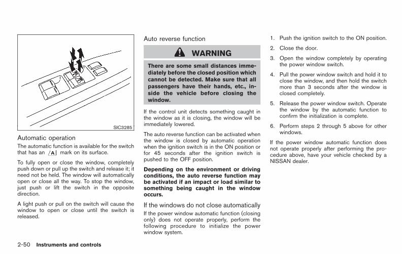
Black plate (126,1)
Model "E52-D" EDITED: 2010/ 10/ 25
SIC3285
Automatic operationThe automatic function is available for the switchthat has an mark on its surface.
To fully open or close the window, completelypush down or pull up the switch and release it; itneed not be held. The window will automaticallyopen or close all the way. To stop the window,just push or lift the switch in the oppositedirection.
A light push or pull on the switch will cause thewindow to open or close until the switch isreleased.
Auto reverse function
WARNING
There are some small distances imme-diately before the closed position whichcannot be detected. Make sure that allpassengers have their hands, etc., in-side the vehicle before closing thewindow.
If the control unit detects something caught inthe window as it is closing, the window will beimmediately lowered.
The auto reverse function can be activated whenthe window is closed by automatic operationwhen the ignition switch is in the ON position orfor 45 seconds after the ignition switch ispushed to the OFF position.
Depending on the environment or drivingconditions, the auto reverse function maybe activated if an impact or load similar tosomething being caught in the windowoccurs.
If the windows do not close automaticallyIf the power window automatic function (closingonly) does not operate properly, perform thefollowing procedure to initialize the powerwindow system.
1. Push the ignition switch to the ON position.
2. Close the door.
3. Open the window completely by operatingthe power window switch.
4. Pull the power window switch and hold it toclose the window, and then hold the switchmore than 3 seconds after the window isclosed completely.
5. Release the power window switch. Operatethe window by the automatic function toconfirm the initialization is complete.
6. Perform steps 2 through 5 above for otherwindows.
If the power window automatic function doesnot operate properly after performing the pro-cedure above, have your vehicle checked by aNISSAN dealer.
2-50 Instruments and controls
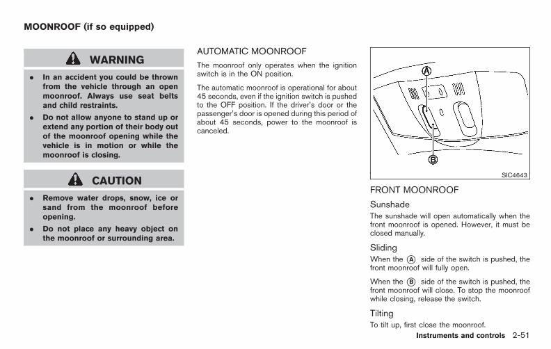
Black plate (127,1)
Model "E52-D" EDITED: 2010/ 10/ 25
WARNING
. In an accident you could be thrownfrom the vehicle through an openmoonroof. Always use seat beltsand child restraints.
. Do not allow anyone to stand up orextend any portion of their body outof the moonroof opening while thevehicle is in motion or while themoonroof is closing.
CAUTION
. Remove water drops, snow, ice orsand from the moonroof beforeopening.
. Do not place any heavy object onthe moonroof or surrounding area.
AUTOMATIC MOONROOF
The moonroof only operates when the ignitionswitch is in the ON position.
The automatic moonroof is operational for about45 seconds, even if the ignition switch is pushedto the OFF position. If the driver’s door or thepassenger’s door is opened during this period ofabout 45 seconds, power to the moonroof iscanceled.
SIC4643
FRONT MOONROOF
SunshadeThe sunshade will open automatically when thefront moonroof is opened. However, it must beclosed manually.
SlidingWhen the *A side of the switch is pushed, thefront moonroof will fully open.
When the *B side of the switch is pushed, thefront moonroof will close. To stop the moonroofwhile closing, release the switch.
TiltingTo tilt up, first close the moonroof.
MOONROOF (if so equipped)
Instruments and controls 2-51

Black plate (128,1)
Model "E52-D" EDITED: 2010/ 10/ 25
Push the *B side of the switch. The moonroofwill automatically tilt up all the way.
To tilt down, push the *A side of the switch.The roof will stop when the switch is released.
SIC4644
REAR MOONROOF
Rear moonroof operation switches are locatedon the front map light and rear ceiling.
SunshadeThe sunshade will open automatically when therear moonroof is opened. However, it must beclosed manually.
SlidingTo fully open or close the moonroof, push theswitch to the open *A or close *B positionand release. It does not need to be held. Theroof will automatically open or close all the way.To stop the roof, push the switch once morewhile it is opening or closing.
TiltingTo tilt up, first close the moonroof, then push theswitch to the tilt up position*B and release it; itdoes not need to be held. To tilt down themoonroof, push the switch to the tilt downposition *A .
LockingWhen the window lock button is pushed in, therear moonroof cannot be operated. When thewindow lock position is pushed off, the rearmoonroof can be operated. (See “POWERWINDOWS” earlier in this section.)
Auto-reverse function
WARNING
There are some small distances imme-diately before the closed position whichcannot be detected. Make sure that allpassengers have their hands, etc., in-side the vehicle before closing themoonroof.
If the control unit detects something caught inthe moonroof when it is closing, the moonroofwill be immediately opened.
The auto reverse function can be activated whenthe moonroof is closed by automatic operationwhen the ignition switch is in the ON position or
2-52 Instruments and controls

Black plate (129,1)
Model "E52-D" EDITED: 2010/ 10/ 25
for about 45 seconds after the ignition switch ispushed to the OFF position.
If the moonroof cannot be closed automaticallywhen the auto reverse function activates due toa malfunction, push and hold the moonroofswitch to the close position *B .
Depending on the environment or drivingconditions, the auto reverse function maybe activated if an impact or load similar tosomething being caught in the moonroofoccurs.
IF THE FRONT OR REAR MOONROOFDOES NOT OPERATE
If the front or rear moonroof does not operateproperly, perform the following procedure toinitialize the moonroof operation system. Initiali-zation can be performed for both the frontmoonroof and rear moonroof.
1. If the moonroof is open, close it fully bypushing and holding the moonroof switch tothe close position *B until the moonrooftilts up.
2. Release the moonroof switch, then push andhold the *B side again for more than 10seconds.
3. Release the moonroof switch, then continueto push on the*B side again. The moonroofwill operate in the close direction. (The
moonroof operates inch by inch.)
4. After the moonroof stops moving, releasethe moonroof switch and within 4 seconds,push side *B again. The moonroof willautomatically open once.
5. Within 0.5 seconds after the moonroofstops moving, release the moonroof switch.
6. Check that the moonroof now operatesnormally.
If the moonroof does not operate properly afterperforming the procedure above, have yourvehicle checked by a NISSAN dealer.
SIC4745
MAP LIGHTS
Push the button as illustrated to turn the light onor off.
INTERIOR LIGHTS
Instruments and controls 2-53
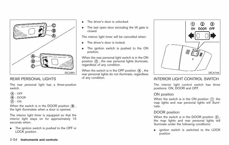
Black plate (130,1)
Model "E52-D" EDITED: 2010/ 10/ 25
SIC2881
REAR PERSONAL LIGHTS
The rear personal light has a three-positionswitch.
*A : OFF
*B : DOOR
*C : ON
When the switch is in the DOOR position *B ,the light illuminates when a door is opened.
The interior light timer is equipped so that theinterior light stays on for approximately 15seconds when:
. The ignition switch is pushed to the OFF orLOCK position.
. The driver’s door is unlocked.
. The last open door excluding the lift gate isclosed.
The interior light timer will be cancelled when:
. The driver’s door is locked.
. The ignition switch is pushed to the ONposition.
When the rear personal light switch is in the ONposition *C , the rear personal lights illuminate,regardless of any condition.
When the switch is in the OFF position*A , therear personal lights do not illuminate, regardlessof any condition.
SIC4746
INTERIOR LIGHT CONTROL SWITCH
The interior light control switch has threepositions: ON, DOOR and OFF.
ON positionWhen the switch is in the ON position *1 themap lights and rear personal lights will illumi-nate.
DOOR positionWhen the switch is in the DOOR position *2 ,the map lights and rear personal lights willilluminate under the following conditions:
. ignition switch is switched to the LOCKposition
2-54 Instruments and controls

Black plate (131,1)
Model "E52-D" EDITED: 2010/ 10/ 25
— remain on for about 15 seconds.
. doors are unlocked by pushing the UN-LOCK button on the Intelligent Key or doorhandle request switch with the ignitionswitch in the LOCK position
— remain on for about 15 seconds.
. any door is opened and then closed with theignition switch in the LOCK position
— remain on for about 15 seconds.
. any door is opened with the ignition switchin the ACC or ON position
— remain on while the door is opened.When the door is closed, the lights go off.
The lights will also turn off after 15minutes when the lights remain illumi-nated after the ignition switch has beenpushed to the OFF or LOCK position toprevent the battery from becoming dis-charged.
When the auto interior illumination is set to theOFF position (see “VEHICLE INFORMATIONAND SETTINGS (models with center multi-function control panel)” in the “4. Monitor,heater, air conditioner, audio, phone and voicerecognition systems” section), the lights willilluminate under the following condition:
. any door is opened with the ignition switch
in any position
— remain on while the door is opened.When the door is closed, the lights go off.
OFF positionWhen the switch is in the OFF position*3 , thelights will not illuminate, regardless of thecondition.
CAUTION
Do not use for extended periods of timewith the engine stopped. This couldresult in a discharged battery. SIC4747
Map lights
The mood lights *A located in the followingpositions will illuminate whenever the headlightswitch is in the or position.
. next to the map lights
. under the instrument panel
. under the driver’s power window switch
MOOD LIGHTS
Instruments and controls 2-55

Black plate (132,1)
Model "E52-D" EDITED: 2010/ 10/ 25
SIC4660
The light on the vanity mirror will turn on whenthe cover on the vanity mirror is opened.
When the cover is closed, the light will turn off.
The lights will turn off after 15 minuteswhen the lights remain illuminated toprevent the battery from becoming dis-charged.
SIC2925
When the switch is in the DOOR position *A ,the light illuminates while the lift gate is opened.When the lift gate is closed, the light will turn off.
When the switch is in the OFF position*B , thelight will turn off.
The lights will turn off after 15 minuteswhen the lights remain illuminated toprevent the battery from becoming dis-charged.
HomeLink® Universal Transceiver provides aconvenient way to consolidate the functions ofup to three individual hand-held transmitters intoone built-in device.
HomeLink® Universal Transceiver:
. Will operate most Radio Frequency (RF)devices such as garage doors, gates, homeand office lighting, entry door locks andsecurity systems.
. Is powered by your vehicle’s battery. Noseparate batteries are required. If thevehicle’s battery is discharged or is dis-connected, HomeLink® will retain all pro-gramming.
Once HomeLink® Universal Transceiver isprogrammed, retain the original transmit-ter for future programming procedures(Example: new vehicle purchases). Uponsale of the vehicle, the programmedHomeLink® Universal Transceiver buttonsshould be erased for security purposes.For additional information, see “PRO-GRAMMING HomeLink®” later in this sec-tion.
WARNING
. Do not use HomeLink® UniversalTransceiver with any garage dooropener that lacks safety stop and
VANITY MIRROR LIGHTS CARGO LIGHTS HomeLink® UNIVERSALTRANSCEIVER (if so equipped)
2-56 Instruments and controls
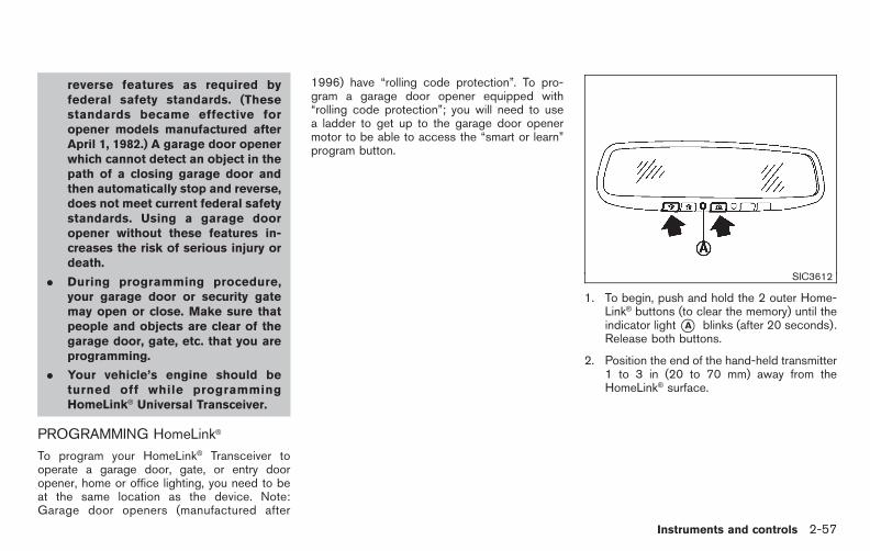
Black plate (133,1)
Model "E52-D" EDITED: 2010/ 10/ 25
reverse features as required byfederal safety standards. (Thesestandards became effective foropener models manufactured afterApril 1, 1982.) A garage door openerwhich cannot detect an object in thepath of a closing garage door andthen automatically stop and reverse,does not meet current federal safetystandards. Using a garage dooropener without these features in-creases the risk of serious injury ordeath.
. During programming procedure,your garage door or security gatemay open or close. Make sure thatpeople and objects are clear of thegarage door, gate, etc. that you areprogramming.
. Your vehicle’s engine should beturned off while programmingHomeLink® Universal Transceiver.
PROGRAMMING HomeLink®
To program your HomeLink® Transceiver tooperate a garage door, gate, or entry dooropener, home or office lighting, you need to beat the same location as the device. Note:Garage door openers (manufactured after
1996) have “rolling code protection”. To pro-gram a garage door opener equipped with“rolling code protection”; you will need to usea ladder to get up to the garage door openermotor to be able to access the “smart or learn”program button.
SIC3612
1. To begin, push and hold the 2 outer Home-Link® buttons (to clear the memory) until theindicator light*A blinks (after 20 seconds).Release both buttons.
2. Position the end of the hand-held transmitter1 to 3 in (20 to 70 mm) away from theHomeLink® surface.
Instruments and controls 2-57

Black plate (134,1)
Model "E52-D" EDITED: 2010/ 10/ 25
SIC3613
3. Using both hands, simultaneously push andhold both the HomeLink® button you want toprogram and the hand-held transmitterbutton.
DO NOT release the buttons until step 4 hasbeen completed.
4. Hold down both buttons until the indicatorlight on HomeLink® flashes, changing from a“slow blink” to a “rapid blink”. This couldtake up to 90 seconds. When the indicatorlight blinks rapidly, both buttons may bereleased. The rapidly flashing light indicatessuccessful programming. To activate thegarage door or other programmed device,push and hold the programmed HomeLink®
button - releasing when the device begins toactivate.
5. If the indicator light on HomeLink® blinksrapidly for two seconds and then turns solid,HomeLink® has picked up a “rolling code”garage door opener signal. You will need toproceed with the next steps to train Home-Link®, completing the programming mayrequire a ladder and another person forconvenience.
6. Push and release the program buttonlocated on the garage door opener’s motorto activate the “training mode”. This button isusually located near the antenna wire thathangs down from the motor. If the wireoriginates from under a light lens, you willneed to remove the lens to access thetraining button.
NOTE:Once you have pushed and releasedthe training button on the garage dooropener’s motor and the “training light”is lit, you have 30 seconds in which toperform step 7. For convenience, usethe help of a second person to assistwhen performing this step.
7. Quickly (within 30 seconds of pushing andreleasing the garage door opener trainingbutton) and firmly push and release theHomeLink® button you’ve just programmed.
Push and release the HomeLink® button upto three times to complete the training.
8. Your HomeLink® button should now beprogrammed. To program the remainingHomeLink® buttons for additional door orgate openers, follow steps 2 through 8 only.
NOTE:
Do not repeat step 1 unless you want to“clear” all previously programmed Home-Link® buttons.
If you have any questions or are having difficultyprogramming your HomeLink® buttons, pleaserefer to the HomeLink® web site at: www.homelink.com or call 1-800-355-3515.
PROGRAMMING HomeLink® FOR CA-NADIAN CUSTOMERS
Prior to 1992, D.O.C. regulations requiredhand-held transmitters to stop transmitting after2 seconds. To program your hand-held trans-mitter to HomeLink®, continue to push and holdthe HomeLink® button (note steps 2 through 4under “Programming HomeLink®”) while youpush and re-push (“cycle”) your hand-heldtransmitter every 2 seconds until the indicatorlight flashes rapidly (indicating successful pro-gramming).
2-58 Instruments and controls
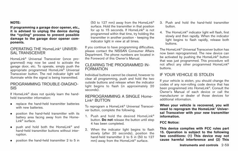
Black plate (135,1)
Model "E52-D" EDITED: 2010/ 10/ 25
NOTE:
If programming a garage door opener, etc.,it is advised to unplug the device duringthe “cycling” process to prevent possibledamage to the garage door opener com-ponents.
OPERATING THE HomeLink® UNIVER-SAL TRANSCEIVER
HomeLink® Universal Transceiver (once pro-grammed) may now be used to activate thegarage door, etc. To operate, simply push theappropriate programmed HomeLink® UniversalTransceiver button. The red indicator light willilluminate while the signal is being transmitted.
PROGRAMMING TROUBLE-DIAGNO-SIS
If HomeLink® does not quickly learn the hand-held transmitter information:
. replace the hand-held transmitter batterieswith new batteries.
. position the hand-held transmitter with itsbattery area facing away from the Home-Link® surface.
. push and hold both the HomeLink® andhand-held transmitter buttons without inter-ruption.
. position the hand-held transmitter 2 to 5 in
(50 to 127 mm) away from the HomeLink®
surface. Hold the transmitter in that positionfor up to 15 seconds. If HomeLink® is notprogrammed within that time, try holding thetransmitter in another position - keeping theindicator light in view at all times.
If you continue to have programming difficulties,please contact the NISSAN Consumer AffairsDepartment. The phone numbers are located inthe Foreword of this Owner’s Manual.
CLEARING THE PROGRAMMED IN-FORMATION
Individual buttons cannot be cleared, however toclear all programming, push and hold the twooutside buttons and release when the indicatorlight begins to flash (in approximately 20seconds).
REPROGRAMMING A SINGLE Home-Link® BUTTON
To reprogram a HomeLink® Universal Transcei-ver button, complete the following.
1. Push and hold the desired HomeLink®
button. Do not release the button until step4 has been completed.
2. When the indicator light begins to flashslowly (after 20 seconds), position thehand-held transmitter 2 to 5 in (50 to 127mm) away from the HomeLink® surface.
3. Push and hold the hand-held transmitterbutton.
4. The HomeLink® indicator light will flash, firstslowly and then rapidly. When the indicatorlight begins to flash rapidly, release bothbuttons.
The HomeLink® Universal Transceiver button hasnow been reprogrammed. The new device canbe activated by pushing the HomeLink® buttonthat was just programmed. This procedure willnot affect any other programmed HomeLink®
buttons.
IF YOUR VEHICLE IS STOLEN
If your vehicle is stolen, you should change thecodes of any non-rolling code device that hasbeen programmed into HomeLink®. Consult theOwner’s Manual of each device or call themanufacturer or dealer of those devices foradditional information.
When your vehicle is recovered, you willneed to reprogram the HomeLink® Univer-sal Transceiver with your new transmitterinformation.
FCC Notice:
This device complies with FCC rules part15. Operation is subject to the followingtwo conditions: (1) This device may notcause harmful interference and (2) This
Instruments and controls 2-59

Black plate (136,1)
Model "E52-D" EDITED: 2010/ 10/ 25
device must accept any interference thatmay be received, including interferencethat may cause undesired operation.
The transmitter has been tested andcomplies with FCC and DOC/MDC rules.Changes or modifications not expresslyapproved by the party responsible forcompliance could void the user’s authorityto operate the device.
DOC: ISTC 1763K1313
FCC I.D.: CB2V67690
2-60 Instruments and controls

Black plate (137,1)
Model "E52-D" EDITED: 2010/ 10/ 25
MEMO
Instruments and controls 2-61

Black plate (10,1)
3 Pre-driving checks and adjustments
Model "E52-D" EDITED: 2010/ 10/ 22
Keys . . . . . . . . . . . . . . . . . . . . . . . . . . . . . . . . . . . . . . . . . . . . . . . . . . . . . . . . . . . . . . . 3-2Intelligent Key system. . . . . . . . . . . . . . . . . . . . . . . . . . . . . . . . . . . . . . 3-2Mechanical key . . . . . . . . . . . . . . . . . . . . . . . . . . . . . . . . . . . . . . . . . . . . . . 3-3Valet hand-off. . . . . . . . . . . . . . . . . . . . . . . . . . . . . . . . . . . . . . . . . . . . . . . . 3-4
Doors. . . . . . . . . . . . . . . . . . . . . . . . . . . . . . . . . . . . . . . . . . . . . . . . . . . . . . . . . . . . . . 3-4Locking with mechanical key. . . . . . . . . . . . . . . . . . . . . . . . . . . . . 3-4Opening and closing windows with themechanical key (if so equipped). . . . . . . . . . . . . . . . . . . . . . . . . 3-5Locking with inside lock knob . . . . . . . . . . . . . . . . . . . . . . . . . . . 3-5Locking with power door lock switch . . . . . . . . . . . . . . . . . . 3-5Automatic door locks . . . . . . . . . . . . . . . . . . . . . . . . . . . . . . . . . . . . . . 3-6Sliding doors . . . . . . . . . . . . . . . . . . . . . . . . . . . . . . . . . . . . . . . . . . . . . . . . 3-6Sliding door auto closure function(if so equipped) . . . . . . . . . . . . . . . . . . . . . . . . . . . . . . . . . . . . . . . . . . . . . 3-8Child safety sliding door lock . . . . . . . . . . . . . . . . . . . . . . . . . . . . 3-8
Power sliding door (if so equipped) . . . . . . . . . . . . . . . . . . . . . . . . 3-9Precautions on power sliding door operation . . . . . . . . 3-9Switching sliding door operation . . . . . . . . . . . . . . . . . . . . . . 3-10Operating sliding door switch . . . . . . . . . . . . . . . . . . . . . . . . . 3-11Operating the power sliding door with theIntelligent Key (if so equipped) . . . . . . . . . . . . . . . . . . . . . . . . 3-11Operating sliding door by power assist . . . . . . . . . . . . . 3-11Sliding door auto reverse function . . . . . . . . . . . . . . . . . . . . 3-11
Intelligent Key system. . . . . . . . . . . . . . . . . . . . . . . . . . . . . . . . . . . . . . . . 3-12Intelligent Key operating range . . . . . . . . . . . . . . . . . . . . . . . . 3-14Door locks/unlocks precaution . . . . . . . . . . . . . . . . . . . . . . . . 3-14Intelligent Key operation. . . . . . . . . . . . . . . . . . . . . . . . . . . . . . . . . 3-15Battery saver system. . . . . . . . . . . . . . . . . . . . . . . . . . . . . . . . . . . . . 3-18Warning signals . . . . . . . . . . . . . . . . . . . . . . . . . . . . . . . . . . . . . . . . . . . 3-18Troubleshooting guide . . . . . . . . . . . . . . . . . . . . . . . . . . . . . . . . . . . 3-19
Remote keyless entry system . . . . . . . . . . . . . . . . . . . . . . . . . . . . . . 3-20How to use remote keyless entry system . . . . . . . . . . . 3-21
Hood . . . . . . . . . . . . . . . . . . . . . . . . . . . . . . . . . . . . . . . . . . . . . . . . . . . . . . . . . . . . 3-24Lift gate . . . . . . . . . . . . . . . . . . . . . . . . . . . . . . . . . . . . . . . . . . . . . . . . . . . . . . . . . 3-25
Operating manual lift gate . . . . . . . . . . . . . . . . . . . . . . . . . . . . . . 3-25Operating power lift gate (if so equipped) . . . . . . . . . . 3-25Auto closure . . . . . . . . . . . . . . . . . . . . . . . . . . . . . . . . . . . . . . . . . . . . . . . 3-28Lift gate release . . . . . . . . . . . . . . . . . . . . . . . . . . . . . . . . . . . . . . . . . . . 3-29
Fuel-filler door . . . . . . . . . . . . . . . . . . . . . . . . . . . . . . . . . . . . . . . . . . . . . . . . . 3-29Opening fuel-filler door. . . . . . . . . . . . . . . . . . . . . . . . . . . . . . . . . . 3-29Fuel-filler cap . . . . . . . . . . . . . . . . . . . . . . . . . . . . . . . . . . . . . . . . . . . . . . 3-29
Tilt/telescopic steering . . . . . . . . . . . . . . . . . . . . . . . . . . . . . . . . . . . . . . 3-31Tilt or telescopic operation . . . . . . . . . . . . . . . . . . . . . . . . . . . . . 3-31
Sun visors . . . . . . . . . . . . . . . . . . . . . . . . . . . . . . . . . . . . . . . . . . . . . . . . . . . . . . 3-32Mirrors. . . . . . . . . . . . . . . . . . . . . . . . . . . . . . . . . . . . . . . . . . . . . . . . . . . . . . . . . . . 3-32
Inside mirror. . . . . . . . . . . . . . . . . . . . . . . . . . . . . . . . . . . . . . . . . . . . . . . . 3-32

Black plate (11,1)
Model "E52-D" EDITED: 2010/ 10/ 22
Outside mirrors. . . . . . . . . . . . . . . . . . . . . . . . . . . . . . . . . . . . . . . . . . . . 3-34Vanity mirror. . . . . . . . . . . . . . . . . . . . . . . . . . . . . . . . . . . . . . . . . . . . . . . . 3-35Communication mirror (if so equipped) . . . . . . . . . . . . . . 3-36
Automatic drive positioner (if so equipped). . . . . . . . . . . . . 3-36Entry/exit function. . . . . . . . . . . . . . . . . . . . . . . . . . . . . . . . . . . . . . . . . 3-36Memory storage. . . . . . . . . . . . . . . . . . . . . . . . . . . . . . . . . . . . . . . . . . . 3-37System operation . . . . . . . . . . . . . . . . . . . . . . . . . . . . . . . . . . . . . . . . . 3-38

Black plate (140,1)
Model "E52-D" EDITED: 2010/ 10/ 25
A key number plate is supplied with your keys.Record the key number and keep it in a safeplace (such as your wallet), not in the vehicle. Ifyou lose your keys, see a NISSAN dealer forduplicates by using the key number. NISSANdoes not record any key numbers so it is veryimportant to keep track of your key number plate.
A key number is only necessary when you havelost all keys and do not have one to duplicatefrom. If you still have a key, this key can beduplicated by a NISSAN dealer.
SPA2406Type A
SPA2844Type B
SPA2845Type C
1. Master key (2)
2. Mechanical key (inside the key) (2)
3. Key number plate (1)
INTELLIGENT KEY SYSTEM
Your vehicle can only be driven with theIntelligent Keys which are registered to yourvehicle’s Intelligent Key system components andNISSAN Vehicle Immobilizer System compo-nents. As many as 4 Intelligent Keys can beregistered and used with one vehicle. The newkeys must be registered by a NISSAN dealerprior to use with the Intelligent Key system andNISSAN Vehicle Immobilizer System of yourvehicle. Since the registration process requireserasing all memory in the Intelligent Key compo-
KEYS
3-2 Pre-driving checks and adjustments

Black plate (141,1)
Model "E52-D" EDITED: 2010/ 10/ 25
nents when registering new keys, be sure to takeall Intelligent Keys that you have to the NISSANdealer.
CAUTION
. Be sure to carry the Intelligent Keywith you when driving. The Intelli-gent Key is a precision device with abuilt-in transmitter. To avoid dama-ging it, please note the following.
— The Intelligent Key is waterresistant; however, wetting maydamage the Intelligent Key. Ifthe Intelligent Key gets wet,immediately wipe until it is com-pletely dry.
— Do not bend, drop or strike itagainst another object.
— Do not place the Intelligent Keyfor an extended period in aplace where temperatures ex-ceed 1408F (608C).
— Do not change or modify theIntelligent Key.
— Do not use a magnet key holder.
— Do not place the Intelligent Keynear an electric appliance suchas a television set, personal
computer or cellular phone.
— Do not allow the Intelligent Keyto come into contact with wateror salt water, and do not wash itin a washing machine. Thiscould affect the system function.
. If an Intelligent Key is lost or stolen,NISSAN recommends erasing the IDcode of that Intelligent Key. This willprevent the Intelligent Key fromunauthorized use to unlock thevehicle. For information regardingthe erasing procedure, please con-tact a NISSAN dealer. SPA2033
MECHANICAL KEY
To remove the mechanical key, release the lockknob at the back of the key.
To install the mechanical key, firmly insert it intothe key until the lock knob returns to the lockposition.
Use the mechanical key to lock or unlock thedoors and glove box, if they are equipped with akey cylinder.
See “DOORS” later in this section and “STO-RAGE” in the “2. Instruments and controls”section.
Pre-driving checks and adjustments 3-3

Black plate (142,1)
Model "E52-D" EDITED: 2010/ 10/ 25
CAUTION
Always carry the mechanical key in-stalled in the key.
VALET HAND-OFF
When you have to leave a key with a valet, givethem the Intelligent Key itself after removing themechanical key to protect your belongings.
To prevent the glove box from being openedduring valet hand-off, follow the proceduresbelow.
1. Remove the mechanical key from the In-telligent Key.
2. Lock the glove box with the mechanical key.
3. Hand the Intelligent Key to the valet, keepingthe mechanical key in your pocket or bag.Insert the mechanical key into the IntelligentKey when you retrieve your vehicle.
For glove box lock, see “STORAGE” in the “2.Instruments and controls” section.
WARNING
. Always have the doors locked whiledriving. Along with the use of seatbelts, this provides greater safety inthe event of an accident by helpingto prevent persons from beingthrown from the vehicle. This alsohelps keep children and others fromunintentionally opening the doors,and will help keep out intruders.
. Before opening any door, alwayslook for and avoid oncoming traffic.
. Do not leave children unattendedinside the vehicle. They could un-knowingly activate switches or con-trols. Unattended children couldbecome involved in serious acci-dents.
SPA2527-B
LOCKING WITH MECHANICAL KEY
The power door lock system allows you to lockor unlock all doors simultaneously using themechanical key.
. Turning the driver’s door key cylinder to therear of the vehicle *1 will lock all doors.
. Turning the driver’s door key cylinder onceto the front of the vehicle*2 will unlock thedriver’s door. After returning the key to theneutral position *3 , turning it to the frontagain within 5 seconds will unlock all doors.
. You can switch the lock system to the modethat allows you to open all the doors whenthe key is turned once. (See “HOW TO USE
DOORS
3-4 Pre-driving checks and adjustments

Black plate (143,1)
Model "E52-D" EDITED: 2010/ 10/ 25
SETTING BUTTON” in the “4. Monitor,heater, air conditioner, audio, phone andvoice recognition systems” section.)
OPENING AND CLOSING WINDOWSWITH THE MECHANICAL KEY (if soequipped)
The driver’s door key operation also allows youto open and close the window that is equippedwith the automatic open/close function. (See“POWER WINDOWS” in the “2. Instrumentsand controls” section).
To open the windows, turn the driver’s door keycylinder to the front of the vehicle for longerthan 1 second. The door is unlocked and thewindow keeps opening while turning the key.
This function can also be performed by pushingand holding the door UNLOCK button of thekey. (See “REMOTE KEYLESS ENTRY SYS-TEM” later in this section.)
To close the windows, turn the driver’s door keycylinder to the rear of the vehicle for longerthan 1 second. The door is locked and thewindow keeps closing while turning the key.
SPA2847
LOCKING WITH INSIDE LOCK KNOB
To lock the door individually, move the insidelock knob to the lock position*1 then close thedoor.
To unlock, move the inside lock knob to theunlock position *2 .
When locking the door without IntelligentKey, be sure not to leave the IntelligentKey inside the vehicle.
SPA2300
LOCKINGWITH POWER DOOR LOCKSWITCH
Operating the power door lock switch will lockor unlock all the doors. The switches are locatedon the driver’s and front passenger’s doorarmrests.
To lock the doors, push the power door lockswitch to the lock position *1 with the driver’sor front passenger’s door open, then close thedoor.
When locking the door this way, be certainnot to leave the Intelligent Key inside thevehicle.
To unlock the doors, push the power door lock
Pre-driving checks and adjustments 3-5
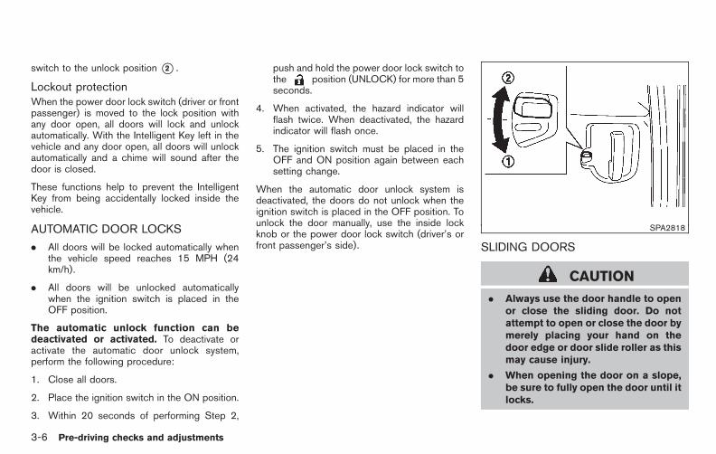
Black plate (144,1)
Model "E52-D" EDITED: 2010/ 10/ 25
switch to the unlock position *2 .
Lockout protectionWhen the power door lock switch (driver or frontpassenger) is moved to the lock position withany door open, all doors will lock and unlockautomatically. With the Intelligent Key left in thevehicle and any door open, all doors will unlockautomatically and a chime will sound after thedoor is closed.
These functions help to prevent the IntelligentKey from being accidentally locked inside thevehicle.
AUTOMATIC DOOR LOCKS
. All doors will be locked automatically whenthe vehicle speed reaches 15 MPH (24km/h).
. All doors will be unlocked automaticallywhen the ignition switch is placed in theOFF position.
The automatic unlock function can bedeactivated or activated. To deactivate oractivate the automatic door unlock system,perform the following procedure:
1. Close all doors.
2. Place the ignition switch in the ON position.
3. Within 20 seconds of performing Step 2,
push and hold the power door lock switch tothe position (UNLOCK) for more than 5seconds.
4. When activated, the hazard indicator willflash twice. When deactivated, the hazardindicator will flash once.
5. The ignition switch must be placed in theOFF and ON position again between eachsetting change.
When the automatic door unlock system isdeactivated, the doors do not unlock when theignition switch is placed in the OFF position. Tounlock the door manually, use the inside lockknob or the power door lock switch (driver’s orfront passenger’s side).
SPA2818
SLIDING DOORS
CAUTION
. Always use the door handle to openor close the sliding door. Do notattempt to open or close the door bymerely placing your hand on thedoor edge or door slide roller as thismay cause injury.
. When opening the door on a slope,be sure to fully open the door until itlocks.
3-6 Pre-driving checks and adjustments

Black plate (145,1)
Model "E52-D" EDITED: 2010/ 10/ 25
Locking with inside lock knobTo lock from the outside without an IntelligentKey, push the lock knob to the lock position*1 ,and then close the door. When the door isclosed, all doors will lock simultaneously. How-ever, when the ignition switch is in the “ACC” or“ON” position, doors cannot be locked.
To unlock, pull the inside lock knob to the unlockposition *2 .
SPA2387
Opening/Closing the sliding doorThe sliding door will be latched at the fullyopened/closed position.
To open/close the sliding door manually, pull thedoor handle or the inside door handle.
SPA2104
CAUTION
Do not put your hands or feet on theharness *A or the bracket *B . Thismay cause damage to the vehicle orpersonal injury.
Pre-driving checks and adjustments 3-7

Black plate (146,1)
Model "E52-D" EDITED: 2010/ 10/ 25
SPA2701
CAUTION
Before closing the sliding door, makesure that no objects are placed on thedoor step. Otherwise, the harness *Acould be damaged.
SLIDING DOOR AUTO CLOSUREFUNCTION (if so equipped)
The auto closure function will operate when thesliding door is not fully closed.
WARNING
When the auto closure function isoperating, keep hands and feet awayfrom the sliding door to prevent inju-ries.
SPA2819
CHILD SAFETY SLIDING DOOR LOCK
The child safety sliding door locks help preventsliding doors from being opened accidentally,especially when small children are in the vehicle.
When the levers are in the lock position*1 , thechild safety sliding door locks engage and thesliding doors can only be opened by the outsidedoor handles.
To disengage, move the levers to the unlockposition *2 .
3-8 Pre-driving checks and adjustments

Black plate (147,1)
Model "E52-D" EDITED: 2010/ 10/ 25
The power sliding door system will allow you toopen or close the sliding doors automaticallyusing the door handles, the sliding door switch,the Intelligent Key or sliding door one-touchswitch.
WARNING
There are some small distances imme-diately before the closed position whichcannot be detected. Make sure that allpassengers have their hands, etc., in-side the vehicle before closing the door.
CAUTION
. Operate the power sliding doorwhen the vehicle is completelystopped.
. Before operating the power slidingdoor, be sure to ensure safetyaround the door.
. Do not operate the power slidingdoor when the vehicle is inclinedconsiderably.
. Do not insert your hand into thesliding door rail. If you touch thecable at the rail, the door couldoperate automatically.
PRECAUTIONS ON POWER SLIDINGDOOR OPERATION
. Do not perform the power sliding dooroperation frequently when the engineis stopped. This could cause a dis-charged battery.
. Do not start the engine while thesliding door is in an power operation.The door may not operate properly.
. Make sure that the sliding doors are closedbefore starting the vehicle.
. Under the following cases, turn the powerdoor main switch off:
. When the sliding door is malfunctioning.
. When operating the sliding door manu-ally.
. When you need to keep the sliding dooropen for a period of time.
. When washing the vehicle or performingany maintenance work.
SPA2071
. Be careful not to damage the sensor *1 ofthe sliding door.
When reconnecting the battery cable with thesliding door open (in case of a dischargedbattery, etc.), be sure to fully close the slidingdoor manually once before performing thepower operation. Otherwise, the power openor close function may not operate properly.
POWER SLIDING DOOR (if soequipped)
Pre-driving checks and adjustments 3-9

Black plate (148,1)
Model "E52-D" EDITED: 2010/ 10/ 25
SPA2547Power door main switch
SWITCHING SLIDING DOOR OPERA-TION
Using the power door main switch located onthe instrument panel, you can switch the slidingdoor between power and manual operation. Toturn on the power operating mode, push theswitch to the ON position. To turn off the poweroperation, push the switch to the OFF position,and then the sliding door can be manuallyoperated.
When the power door main switch is pushed tothe “OFF” position, the power operation is notavailable by the sliding door switch on the pillar,sliding door one-touch switch and power assist.
The power sliding door system can be operatedwhen all of following conditions are satisfied.
. The vehicle is stopped.
. Battery voltage is normal.
. The sliding door is unlocked.
. The fuel-filler door is closed (for driver’s sideonly).
When the ignition switch is in the “ON” position,the system can be operated in the above andone of the following conditions.
. Selector lever is set in the “P” (Park)position.
. Brake pedal is depressed.
. Parking brake is applied.
If the conditions are interrupted when the powersliding door is being operated, the operationcould be stopped. In this case, meet theconditions above and the power sliding dooroperation will return to normal.
You can also switch the power lift gate betweenpower and manual operation using the powerdoor main switch. (See “LIFT GATE” later in thissection.)
SPA2846Instrument panel
*A Driver’s side sliding door switch
*B Passenger’s side sliding door switch
3-10 Pre-driving checks and adjustments

Black plate (149,1)
Model "E52-D" EDITED: 2010/ 10/ 25
SPA2857Door pillar
OPERATING SLIDING DOOR SWITCH
To operate the sliding doors with the slidingdoor switches, turn on the power door mainswitch.
. When the sliding door is fully closed, pushand hold the sliding door switch for about 1second. The sliding door will automaticallyopen to the fully opened position.
. When the sliding door is fully opened, pushand hold the sliding door switch for about 1second. The sliding door will automaticallyclose to the fully closed position.
. If the sliding door switch is pushed while thesliding door is being operated automatically,
the door will start moving in the reversedirection and stop at the fully opened orclosed position.
. When the child safety sliding door lock is inthe lock position, the sliding door switch onthe door pillar cannot be operated.
. The sliding doors can be opened by theinstrument panel switch *A or *B even ifthe sliding door is locked or the power doormain switch is in the OFF position.
OPERATING THE POWER SLIDINGDOOR WITH THE INTELLIGENT KEY (ifso equipped)
The sliding doors can also be opened andclosed by pushing the button on the IntelligentKey. (See “INTELLIGENT KEY SYSTEM” later inthis section.)
Sliding door one-touch unlock/openfunction (if so equipped)The sliding doors can be unlocked and openedwith a one-touch unlock/open operation. Whenclosed, the sliding door will not lock automati-cally. To lock the sliding doors, manually lock theinside knob before closing the sliding door orpush the LOCK button on the Intelligent Keyafter the door is closed. See “REMOTE KEY-LESS ENTRY SYSTEM” later in this section.
OPERATING SLIDING DOOR BYPOWER ASSIST
To operate, pull the inside or outside doorhandle until you hear the buzzer, the door willautomatically open or close.
If the door handle is operated while the slidingdoor is moving, the door will reverse directionsand stop at either the full open or closedposition.
SLIDING DOOR AUTO REVERSEFUNCTION
If an obstacle is detected while the powersliding door is being operated, the door willreverse directions and return to the full open orfull closed position.
If you touch the sensor of the sliding door whilethe sliding door is closing automatically, the doorwill start moving in the reverse direction andstop at the fully opened position.
Pre-driving checks and adjustments 3-11

Black plate (150,1)
Model "E52-D" EDITED: 2010/ 10/ 25
WARNING
. Radio waves could adversely affectelectric medical equipment. Thosewho use a pacemaker should con-tact the electric medical equipmentmanufacturer for the possible influ-ences before use.
. The Intelligent Key transmits radiowaves when the buttons arepushed. The FAA advises that radiowaves may affect aircraft navigationand communication systems. Do notoperate the Intelligent Key while onan airplane. Make sure the buttonsare not operated unintentionallywhen the unit is stored for a flight.
The Intelligent Key system can operate all thedoor locks (including the lift gate) using theremote controller function or pushing the re-quest switch on the vehicle without taking thekey out from a pocket or purse. The operatingenvironment and/or conditions may affect theIntelligent Key system operation.
Be sure to read the following before using theIntelligent Key system.
CAUTION
. Be sure to carry the Intelligent Keywith you when operating the vehi-cle.
. Never leave the Intelligent Key inthe vehicle when you leave thevehicle.
The Intelligent Key is always communicating withthe vehicle as it receives radio waves. TheIntelligent Key system transmits weak radiosignals. Environmental conditions may interferewith the operation of the Intelligent Key systemunder the following operating conditions.
. When operating near a location wherestrong radio signals are transmitted, suchas a TV tower, power station and broad-casting station.
. When in possession of wireless equipment,such as a cellular telephone, transceiver,and CB radio.
. When the Intelligent Key is in contact with orcovered by metallic materials.
. When any type of radio wave remote controlis used nearby.
. When the Intelligent Key is placed near anelectric appliance such as a personalcomputer.
. When the vehicle is parked near a parkingmeter.
In such cases, correct the operating conditionsbefore using the Intelligent Key function or usethe mechanical key.
Although the life of the battery varies dependingon the operating conditions, the battery’s life isapproximately 2 years. If the battery is dis-charged, replace it with a new one.
Since the Intelligent Key is continuously receiv-ing radio signals, if the key is left near equipmentwhich transmits strong radio signals such asfrom a TV and personal computer, the battery lifemay become shorter.
For information regarding replacement of abattery, see “INTELLIGENT KEY BATTERYREPLACEMENT” in the “8. Maintenance anddo-it-yourself” section.
As many as 4 Intelligent Keys can be registeredand used with one vehicle. For information aboutthe purchase and use of additional IntelligentKeys, contact a NISSAN dealer.
INTELLIGENT KEY SYSTEM
3-12 Pre-driving checks and adjustments

Black plate (151,1)
Model "E52-D" EDITED: 2010/ 10/ 25
CAUTION
. Do not allow the Intelligent Key,which contains electrical compo-nents, to come into contact withwater or salt water. This could affectthe system function.
. Do not drop the Intelligent Key.
. Do not strike the Intelligent Keysharply against another object.
. Do not change or modify the Intel-ligent Key.
. Wetting may damage the IntelligentKey. If the Intelligent Key gets wet,immediately wipe until it is comple-tely dry.
. If the outside temperature is below148F (−108C), the battery of theIntelligent Key may not functionproperly.
. Do not place the Intelligent Key foran extended period in an area wheretemperatures exceed 1408F (608C).
. Do not attach the Intelligent Keywith a key holder that contains amagnet.
. Do not place the Intelligent Key near
equipment that produces a mag-netic field, such as a TV, audioequipment, personal computer orcellular phone.
If an Intelligent Key is lost or stolen, NISSANrecommends erasing the ID code of thatIntelligent Key from the vehicle. This may preventthe unauthorized use of the Intelligent Key tooperate the vehicle. For information regardingthe erasing procedure, contact a NISSAN deal-er.
The Intelligent Key function can be disabled. Forinformation about disabling the Intelligent Keyfunction, contact a NISSAN dealer.
Pre-driving checks and adjustments 3-13

Black plate (152,1)
Model "E52-D" EDITED: 2010/ 10/ 25
SPA2074
INTELLIGENT KEY OPERATINGRANGE
The Intelligent Key functions can only be usedwhen the Intelligent Key is within the specifiedoperating range from the request switch *1 .
When the Intelligent Key battery is discharged orstrong radio signals are present near theoperating location, the Intelligent Key system’soperating range becomes narrower, and theIntelligent Key may not function properly.
The operating range is within 31.50 in (80 cm)from each request switch *1 .
If the Intelligent Key is too close to the doorglass, handle or rear bumper the request
switches may not function.
When the Intelligent Key is within the operatingrange, it is possible for anyone who does notcarry the Intelligent Key to push the requestswitch to lock/unlock the doors including the liftgate.
SPA2407
DOOR LOCKS/UNLOCKS PRECAU-TION
. Do not push the door handle request switchwith the Intelligent Key held in your hand asillustrated. The close distance to the doorhandle will cause the Intelligent Key systemto have difficulty recognizing that the In-telligent Key is outside the vehicle.
. After locking with the door handle requestswitch, verify the doors are securely lockedby testing them.
. To prevent the Intelligent Key from being leftinside the vehicle, make sure you carry thekey with you and then lock the doors.
3-14 Pre-driving checks and adjustments

Black plate (153,1)
Model "E52-D" EDITED: 2010/ 10/ 25
. Do not pull the door handle before pushingthe door handle request switch. The doorwill be unlocked but will not open. Releasethe door handle once and pull it again toopen the door.
. The Intelligent Key system (opening/closingdoors with the door handle request switch)can be set to remain inactive. (See “VEHI-CLE INFORMATION AND SETTINGS(models with center multi-function controlpanel)” in the “4. Monitor, heater, airconditioner, audio, phone and voice recog-nition systems” section.)
SPA2408
INTELLIGENT KEY OPERATION
You can lock or unlock the doors without takingthe key out from your pocket or bag.
SPA2848
SPA2545-C
Pre-driving checks and adjustments 3-15

Black plate (154,1)
Model "E52-D" EDITED: 2010/ 10/ 25
When you carry the Intelligent Key with you, youcan lock or unlock all doors by pushing the doorhandle request switch *A or the lift gaterequest switch *B within the range of opera-tion.
When you lock or unlock the doors or the liftgate, the hazard indicator will flash and the horn(or the outside chime) will sound as a confirma-tion. For details, see “Setting hazard indicatorand horn mode” later in this section.
Locking doors1. Move the selector lever to the P (Park)
position, push the ignition switch to the OFFposition and make sure you carry theIntelligent Key with you.*1
2. Close all the doors and the lift gate.*2
3. Push the door handle request switch*A orlift gate request switch *B while carryingthe Intelligent Key with you.*3
4. All the doors and the lift gate will lock.
5. The hazard indicator flashes twice and theoutside chime sounds twice.
*1: Doors will lock with the Intelligent Key whilethe ignition switch is in the ACC or ONposition.
*2: Doors will not lock with the Intelligent Keywhile any door (including the lift gate) is
open.
*3: Doors will not lock by pushing the doorhandle request switch with the IntelligentKey inside the vehicle.However, when an Intelligent Key is insidethe vehicle, doors can be locked withanother registered Intelligent Key.
CAUTION
. After locking the doors using therequest switch, make sure that thedoors have been securely locked byoperating the door handles.
. When locking the doors using therequest switch, make sure to havethe Intelligent Key in your posses-sion before operating the requestswitch to prevent the Intelligent Keyfrom being left in the vehicle.
. The request switch is operationalonly when the Intelligent Key hasbeen detected by the Intelligent Keysystem.
Lockout protection:
To prevent the Intelligent Key from beingaccidentally locked in the vehicle, lockoutprotection is equipped with the Intelligent Key
system.
When the driver’s side door is open, the doorsare locked, and then the Intelligent Key is putinside the vehicle and all the doors are closed;the lock will automatically unlock and the doorbuzzer sounds.
NOTE:
The doors may not lock when the Intelli-gent Key is in the same hand that isoperating the request switch to lock thedoor. Put the intelligent key in a purse,pocket or your other hand.
CAUTION
The lockout protection may not functionunder the following conditions:
. When the Intelligent Key is placedon top of the instrument panel.
. When the Intelligent Key is placedinside the glove box or a storagebin.
. When the Intelligent Key is placedinside the door pockets.
. When the Intelligent Key is placedinside or near metallic materials.
3-16 Pre-driving checks and adjustments
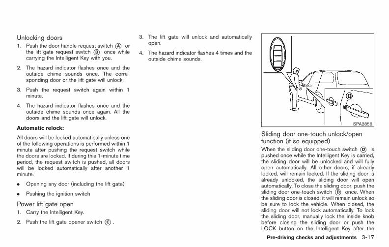
Black plate (155,1)
Model "E52-D" EDITED: 2010/ 10/ 25
Unlocking doors1. Push the door handle request switch*A or
the lift gate request switch *B once whilecarrying the Intelligent Key with you.
2. The hazard indicator flashes once and theoutside chime sounds once. The corre-sponding door or the lift gate will unlock.
3. Push the request switch again within 1minute.
4. The hazard indicator flashes once and theoutside chime sounds once again. All thedoors and the lift gate will unlock.
Automatic relock:
All doors will be locked automatically unless oneof the following operations is performed within 1minute after pushing the request switch whilethe doors are locked. If during this 1-minute timeperiod, the request switch is pushed, all doorswill be locked automatically after another 1minute.
. Opening any door (including the lift gate)
. Pushing the ignition switch
Power lift gate open1. Carry the Intelligent Key.
2. Push the lift gate opener switch *C .
3. The lift gate will unlock and automaticallyopen.
4. The hazard indicator flashes 4 times and theoutside chime sounds.
SPA2856
Sliding door one-touch unlock/openfunction (if so equipped)When the sliding door one-touch switch *D ispushed once while the Intelligent Key is carried,the sliding door will be unlocked and will fullyopen automatically. All other doors, if alreadylocked, will remain locked. If the sliding door isalready unlocked, the sliding door will openautomatically. To close the sliding door, push thesliding door one-touch switch *D once. Whenthe sliding door is closed, it will remain unlock sobe sure to lock the vehicle. When closed, thesliding door will not lock automatically. To lockthe sliding door, manually lock the inside knobbefore closing the sliding door or push theLOCK button on the Intelligent Key after the
Pre-driving checks and adjustments 3-17

Black plate (156,1)
Model "E52-D" EDITED: 2010/ 10/ 25
door is closed. (See “REMOTE KEYLESSENTRY SYSTEM” later in this section.)
Power lift gate open (if so equipped)1. Carry the Intelligent Key.
2. Push the power lift gate opener switch *C .
3. The lift gate will unlock and automaticallyopen.
4. The hazard indicator flashes 4 times and theoutside chime sounds.
To close the lift gate, push the power lift gatebutton on the key, or power lift gate switch onthe instrument panel or lower part of the lift gate.(See “LIFT GATE” in the “3. Pre-driving checksand adjustments” section.)
BATTERY SAVER SYSTEM
When all the following conditions are met for 60minutes, the battery saver system will cut off thepower supply to prevent battery discharge.
. The ignition switch is in the ACC position,and
. All doors are closed, and
. The selector lever is in the P (Park) position.
WARNING SIGNALS
To help prevent the vehicle from movingunexpectedly by erroneous operation of theIntelligent Key listed on the following chart orto help prevent the vehicle from being stolen,chime or beep sounds inside and outside thevehicle and a warning displays in the dot matrixliquid crystal display.
When a chime or beep sounds or the warningdisplays, be sure to check the vehicle andIntelligent Key.
See “TROUBLESHOOTING GUIDE” later inthis section and “DOT MATRIX LIQUID CRYS-TAL DISPLAY” in the “2. Instruments andcontrols” section.
3-18 Pre-driving checks and adjustments

Black plate (157,1)
Model "E52-D" EDITED: 2010/ 10/ 25
TROUBLESHOOTING GUIDE
Symptom Possible cause Action to take
When pushing the ignition switch tostop the engine
The SHIFT P warning appears on the display and theinside warning chime sounds continuously.
The selector lever is not in the P(Park) position.
Shift the selector lever to the P (Park)position.
When shifting the selector lever tothe P (Park) position.
The inside warning chime sounds continuously.The ignition switch is in the ACC orON position.
Push the ignition switch to the OFFposition.
When opening the driver’s door toget out of the vehicle
The inside warning chime sounds continuously.The ignition switch is in the ACCposition.
Push the ignition switch to the OFFposition.
When closing the door after gettingout of the vehicle
The NO KEY warning appears on the display, theoutside chime sounds 3 times and the insidewarning chime sounds for a few seconds.
The ignition switch is in the ACC orON position.
Push the ignition switch to the OFFposition.
The SHIFT P warning appears on the display and theoutside chime sounds continuously.
The ignition switch is in the ACC orOFF position and the selector leveris not in the P (Park) position.
Move the selector lever to the P (Park)position and push the ignition switch tothe OFF position.
When closing the door with theinside lock knob turned to LOCK
The outside chime sounds for a few seconds and allthe doors unlock.
The Intelligent Key is inside thevehicle or cargo area.
Carry the Intelligent Key with you.
When pushing the request switch orthe LOCK button on theIntelligent Key to lock the door
The outside chime sounds for a few seconds.
The Intelligent Key is inside thevehicle or cargo area.
Carry the Intelligent Key with you.
A door is not closed securely. Close the door securely.
When pushing the ignition switch tostart the engine
The Intelligent Key battery indicator appears on thedisplay.
The battery charge is low.
Replace the battery with a new one.(See “INTELLIGENT KEY BATTERYREPLACEMENT” in the “8. Mainte-nance and do-it-yourself” section.)
The NO KEY warning appears on the display and theinside warning chime sounds for a few seconds.
The Intelligent Key is not in thevehicle.
Carry the Intelligent Key with you.
When pushing the ignition switchThe Intelligent Key system warning light in the meterilluminates in yellow.
It warns of a malfunction with theIntelligent Key system.
Contact a NISSAN dealer.
Pre-driving checks and adjustments 3-19

Black plate (158,1)
Model "E52-D" EDITED: 2010/ 10/ 25
WARNING
The Intelligent Key transmits radiowaves when the buttons are pushed.The FAA advises that radio waves mayaffect aircraft navigation and commu-nication systems. Do not operate theIntelligent Key while on an airplane.Make sure the buttons are not operatedunintentionally when the unit is storedfor a flight.
It is possible to lock/unlock all doors and the liftgate, activate the panic alarm and operate thesliding doors/lift gate (if so equipped) bypushing the buttons on the Intelligent Key fromoutside the vehicle.
Before locking the doors, make sure theIntelligent Key is not left in the vehicle.
The LOCK/UNLOCK button on the IntelligentKey can operate at a distance of approximately33 ft (10 m) from the vehicle. (The effectivedistance depends upon the conditions aroundthe vehicle.) As many as 4 Intelligent Keys canbe used with one vehicle. For informationconcerning the purchase and use of additionalIntelligent Keys, contact a NISSAN dealer.
The lock and unlock buttons will not operatewhen:
. the distance between the Intelligent Key andthe vehicle is over 33 ft (10 m).
. the Intelligent Key battery is discharged.
After locking with the remote keyless entryfunction, pull the door handle to make sure thedoors are securely locked.
The LOCK/UNLOCK operating range variesdepending on the environment. To securelyoperate the lock and unlock buttons, approachthe vehicle to about 3 ft (1 m) from the door.
SPA2252-DType A
SPA2849Type B
REMOTE KEYLESS ENTRY SYSTEM
3-20 Pre-driving checks and adjustments
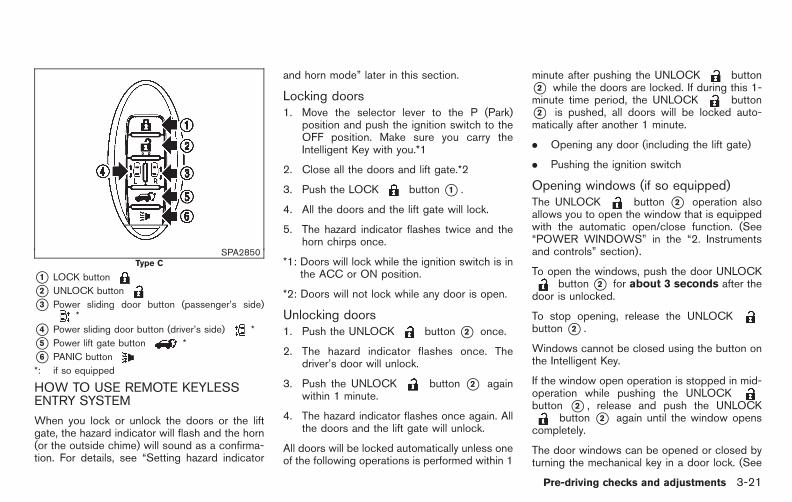
Black plate (159,1)
Model "E52-D" EDITED: 2010/ 10/ 25
SPA2850Type C
*1 LOCK button
*2 UNLOCK button
*3 Power sliding door button (passenger’s side)*
*4 Power sliding door button (driver’s side) *
*5 Power lift gate button *
*6 PANIC button
*: if so equipped
HOW TO USE REMOTE KEYLESSENTRY SYSTEM
When you lock or unlock the doors or the liftgate, the hazard indicator will flash and the horn(or the outside chime) will sound as a confirma-tion. For details, see “Setting hazard indicator
and horn mode” later in this section.
Locking doors1. Move the selector lever to the P (Park)
position and push the ignition switch to theOFF position. Make sure you carry theIntelligent Key with you.*1
2. Close all the doors and lift gate.*2
3. Push the LOCK button *1 .
4. All the doors and the lift gate will lock.
5. The hazard indicator flashes twice and thehorn chirps once.
*1: Doors will lock while the ignition switch is inthe ACC or ON position.
*2: Doors will not lock while any door is open.
Unlocking doors1. Push the UNLOCK button *2 once.
2. The hazard indicator flashes once. Thedriver’s door will unlock.
3. Push the UNLOCK button *2 againwithin 1 minute.
4. The hazard indicator flashes once again. Allthe doors and the lift gate will unlock.
All doors will be locked automatically unless oneof the following operations is performed within 1
minute after pushing the UNLOCK button*2 while the doors are locked. If during this 1-minute time period, the UNLOCK button*2 is pushed, all doors will be locked auto-matically after another 1 minute.
. Opening any door (including the lift gate)
. Pushing the ignition switch
Opening windows (if so equipped)The UNLOCK button *2 operation alsoallows you to open the window that is equippedwith the automatic open/close function. (See“POWER WINDOWS” in the “2. Instrumentsand controls” section).
To open the windows, push the door UNLOCKbutton *2 for about 3 seconds after the
door is unlocked.
To stop opening, release the UNLOCKbutton *2 .
Windows cannot be closed using the button onthe Intelligent Key.
If the window open operation is stopped in mid-operation while pushing the UNLOCKbutton *2 , release and push the UNLOCK
button *2 again until the window openscompletely.
The door windows can be opened or closed byturning the mechanical key in a door lock. (See
Pre-driving checks and adjustments 3-21

Black plate (160,1)
Model "E52-D" EDITED: 2010/ 10/ 25
“DOORS” earlier in this section.)
Opening/closing power sliding door (ifso equipped)To open/close the sliding door, push the powersliding door button *3 or *4 on the IntelligentKey for about 1 second. The power sliding doorwill automatically open/close.
If the power sliding door button *3 or *4 ispushed while the sliding door is being opened orclosed, the sliding door will reverse.
Opening/closing lift gate (if so equipped)To open/close the lift gate, push the power liftgate button*5 on the Intelligent Key formore than 1 second.
The lift gate will automatically open/close.
The hazard indicator flashes 4 times and theoutside chime sounds for approximately 3seconds.
If the power lift gate button *5 ispushed while the lift gate is being opened orclosed, the lift gate will reverse.
Using panic alarmIf you are near your vehicle and feel threatened,you can activate the alarm according to thefollowing procedure to call attention.
1. Push the PANIC button *6 for more
than 1 second.
2. The theft warning alarm will sound and theheadlights will flash for 25 seconds.
3. The panic alarm stops under either of thefollowing conditions.
. It has run for 25 seconds, or
. Any of the buttons is pushed. (Note: thePANIC button *6 should bepushed for more than 1 second.)
Setting hazard indicator and horn modeThis vehicle is set in hazard indicator and hornmode when you first receive the vehicle.
In hazard indicator and horn mode, when theLOCK button *1 is pushed, the hazardindicator flashes twice and the horn chirps once.When the UNLOCK button*2 is pushed,the hazard indicator flashes once.
If horns are not necessary, the system can beswitched to the hazard indicator mode.
In hazard indicator mode, when the LOCKbutton *1 is pushed, the hazard indicatorflashes twice. When the UNLOCK button*2 is pushed, neither the hazard indicator northe horn operates.
3-22 Pre-driving checks and adjustments

Black plate (161,1)
Model "E52-D" EDITED: 2010/ 10/ 25
Hazard indicator and horn mode:
DOOR LOCK DOOR UNLOCK
Intelligent Key system
(Using door handle or lift gate request switch)
HAZARD - twiceOUTSIDE CHIME - twice
HAZARD - onceOUTSIDE CHIME - once
Remote keyless entry system
(Using or button)HAZARD - twiceHORN - once
HAZARD - onceHORN - none
Hazard indicator mode:
DOOR LOCK DOOR UNLOCK
Intelligent Key system
(Using door handle or lift gate request switch)
HAZARD - twiceOUTSIDE CHIME - none
HAZARD - noneOUTSIDE CHIME - none
Remote keyless entry system
(Using or button)HAZARD - twiceHORN - none
HAZARD - noneHORN - none
Switching procedure:
Push the LOCK *1 and UNLOCK *2buttons simultaneously for more than 2 secondsto switch the mode from one to the other.
When pushing the buttons to set the hazardindicator mode, the hazard indicator flashes 3times.
When pushing the buttons to set the hazardindicator and horn mode, the hazard indicatorflashes once and the horn chirps once.
Pre-driving checks and adjustments 3-23

Black plate (162,1)
Model "E52-D" EDITED: 2010/ 10/ 25
SPA2858
When opening the hood:
1. Pull the hood lock release handle *1located below the instrument panel; thehood will then spring up slightly.
2. Locate the lever *2 in between the hoodand grille and push the lever sideways withyour fingertips.
3. Raise the hood *3 .
4. Remove the support rod *4 and insert itinto the slot *5 .
Hold the coated part*A when removing orresetting the support rod. Avoid directcontact with the metal parts, as they may
be hot immediately after the engine hasbeen stopped.
When closing the hood:
1. Reset the support rod to its original position.
2. Slowly move the hood down to latch thelock. Push the hood down to lock the hoodsecurely into place.
WARNING
. Make sure the hood is completelyclosed and latched before driving.Failure to do so could cause thehood to fly open and result in an
accident.
. If you see steam or smoke comingfrom the engine compartment, toavoid injury do not open the hood.
HOOD
3-24 Pre-driving checks and adjustments
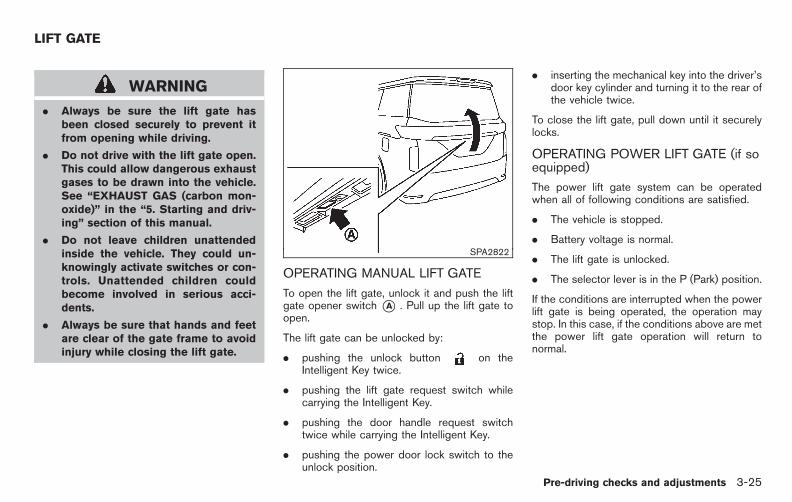
Black plate (163,1)
Model "E52-D" EDITED: 2010/ 10/ 25
WARNING
. Always be sure the lift gate hasbeen closed securely to prevent itfrom opening while driving.
. Do not drive with the lift gate open.This could allow dangerous exhaustgases to be drawn into the vehicle.See “EXHAUST GAS (carbon mon-oxide)” in the “5. Starting and driv-ing” section of this manual.
. Do not leave children unattendedinside the vehicle. They could un-knowingly activate switches or con-trols. Unattended children couldbecome involved in serious acci-dents.
. Always be sure that hands and feetare clear of the gate frame to avoidinjury while closing the lift gate.
SPA2822
OPERATING MANUAL LIFT GATE
To open the lift gate, unlock it and push the liftgate opener switch *A . Pull up the lift gate toopen.
The lift gate can be unlocked by:
. pushing the unlock button on theIntelligent Key twice.
. pushing the lift gate request switch whilecarrying the Intelligent Key.
. pushing the door handle request switchtwice while carrying the Intelligent Key.
. pushing the power door lock switch to theunlock position.
. inserting the mechanical key into the driver’sdoor key cylinder and turning it to the rear ofthe vehicle twice.
To close the lift gate, pull down until it securelylocks.
OPERATING POWER LIFT GATE (if soequipped)
The power lift gate system can be operatedwhen all of following conditions are satisfied.
. The vehicle is stopped.
. Battery voltage is normal.
. The lift gate is unlocked.
. The selector lever is in the P (Park) position.
If the conditions are interrupted when the powerlift gate is being operated, the operation maystop. In this case, if the conditions above are metthe power lift gate operation will return tonormal.
LIFT GATE
Pre-driving checks and adjustments 3-25
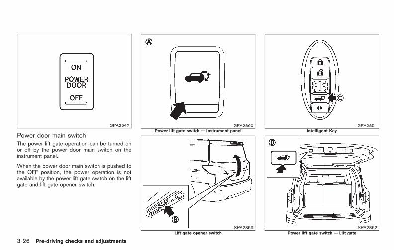
Black plate (164,1)
Model "E52-D" EDITED: 2010/ 10/ 25
SPA2547
Power door main switchThe power lift gate operation can be turned onor off by the power door main switch on theinstrument panel.
When the power door main switch is pushed tothe OFF position, the power operation is notavailable by the power lift gate switch on the liftgate and lift gate opener switch.
SPA2860Power lift gate switch — Instrument panel
SPA2859Lift gate opener switch
SPA2851Intelligent Key
SPA2852Power lift gate switch — Lift gate
3-26 Pre-driving checks and adjustments

Black plate (165,1)
Model "E52-D" EDITED: 2010/ 10/ 25
Power openWhen the lift gate is fully closed, the lift gate willfully open automatically by:
. pushing the power lift gate switch *A onthe instrument panel for more than 1 second
. pushing the lift gate opener switch *B
. pushing the power lift gate button *C onthe Intelligent Key for more than 1 second
The hazard flashes 4 times and the outsidechime sounds when the lift gate starts opening.
NOTE:
The lift gate can be opened by the powerlift gate switch *A or the lift gate button
*C even if the lift gate is locked orthe power door main switch is in the OFFposition. The lift gate will unlock and open.
Power closeWhen the lift gate is fully opened, the lift gatewill fully close automatically by:
. pushing the power lift gate switch *A onthe instrument panel for more than 1 second
. pushing the power lift gate switch *D onthe lower part of the lift gate
. pushing the lift gate button *C on theIntelligent Key for more than 1 second
The hazard flashes 4 times and the outsidechime sounds when the lift gate starts closing.
Reverse functionThe power lift gate will reverse immediately ifone of the following actions is performed duringpower open or power close.
. pushing the power lift gate switch *A onthe instrument panel
. pushing the lift gate switch*D on the lowerpart of the lift gate
. pushing the lift gate button *C onthe Intelligent Key.
The outside chime sounds when the lift gatestarts to reverse.
Auto reverse functionThe auto-reverse function enables the lift gate toautomatically reverse when something is caughtin the lift gate as it is opening or closing. Whenthe control unit detects an obstacle, the lift gatewill reverse and return to the full open or fullclose position.
If a second obstacle is detected, the lift gatemotion will stop and the drive motor willdisengage. The lift gate will enter the manualmode.
A pinch sensor is mounted on each side of thelift gate. If an object is detected by the pinch
sensor during power close, the lift gate willreverse and return to the full open positionimmediately.
NOTE:
If the pinch sensor is damaged or removed,the power close function will not operate.
WARNING
There is a small distance immediatelybefore the closed position that cannotbe detected. Make sure that all passen-gers keep their hands, etc., clear fromthe lift gate opening before closing thelift gate.
Manual modeIf power operation is not available, the lift gatecan be operated manually. Power operation maynot be available if multiple obstacles have beendetected in a single power cycle or if the batteryvoltage is low. When the power door mainswitch is in the OFF position, the lift gate can beopened manually by pushing the lift gate openerswitch. If the power lift gate opener switch ispushed during power open or close, the poweroperation will be canceled and the lift gate canbe operated manually.
Pre-driving checks and adjustments 3-27

Black plate (166,1)
Model "E52-D" EDITED: 2010/ 10/ 25
SPA2853
Safe ModeIf the gas stays of the lift gate*1 lose pressure,the power lift gate safe mode is activated. Whenthe safe mode is activated, the lift gateintermittently closes. Then the lift gate will bepulled to the closed and latched position by amotor.
The power lift gate cannot be opened using theswitches at any time in the safe mode.
Do not operate the lift gate again until it ischecked by a NISSAN dealer.
CAUTION
. If the power lift gate does not stayopen or if the lift gate unexpectedlycloses at any time, do not operatethe lift gate. There may be a pres-sure loss in one or both of the liftgate gas stays. Have the lift gateinspected by a NISSAN dealer.
. Do not activate the power lift gate ifone or both of the lift gate gas staysare removed. Damage to the liftgate or power lift gate mechanismsmay occur.
AUTO CLOSURE
If the lift gate is pulled down to a partly openposition, the lift gate will pull itself to the closedposition.
Do not apply excessive force when theauto closure is operating. Excessive forceapplied may cause the mechanism tomalfunction.
CAUTION
. The lift gate will automatically closefrom a partly open position. To avoid
pinching, keep hands and fingersaway from lift gate opening.
. Do not let children operate the liftgate.
3-28 Pre-driving checks and adjustments

Black plate (167,1)
Model "E52-D" EDITED: 2010/ 10/ 25
SPA2824
LIFT GATE RELEASE
If the lift gate cannot be opened due to adischarged battery, follow these steps.
1. Remove the cover *1 inside of the lift gatewith a suitable tool.
2. Move the lever*2 as illustrated to open thelift gate.
Have the vehicle checked by a NISSAN dealer.
SPA2861
OPENING FUEL-FILLER DOOR
To open the fuel-filler door, pull the fuel-fillerdoor opener handle *1 .
FUEL-FILLER CAP
WARNING
. Gasoline is extremely flammableand highly explosive under certainconditions. You could be burned orseriously injured if it is misused ormishandled. Always stop engineand do not smoke or allow openflames or sparks near the vehiclewhen refueling.
. Do not attempt to top off the fueltank after the fuel pump nozzleshuts off automatically. Continuedrefueling may cause fuel overflow,resulting in fuel spray and possiblya fire.
. Use only an original equipment typefuel-filler cap as a replacement. Ithas a built-in safety valve neededfor proper operation of the fuelsystem and emission control sys-tem. An incorrect cap can result in aserious malfunction and possibleinjury. It could also cause the mal-function indicator light to come on.
. Never pour fuel into the throttlebody to attempt to start your vehi-
FUEL-FILLER DOOR
Pre-driving checks and adjustments 3-29

Black plate (168,1)
Model "E52-D" EDITED: 2010/ 10/ 25
cle.
. Close the sliding door before open-ing the fuel-filler door.
. Do not fill a portable fuel containerin the vehicle or trailer. Static elec-tricity can cause an explosion offlammable liquid, vapor or gas inany vehicle or trailer. To reduce therisk of serious injury or death whenfilling portable fuel containers:
— Always place the container onthe ground when filling.
— Do not use electronic deviceswhen filling.
— Keep the pump nozzle in contactwith the container while you arefilling it.
— Use only approved portable fuelcontainers for flammable liquid.
CAUTION
. If fuel is spilled on the vehicle body,flush it away with water to avoidpaint damage.
. Insert the cap straight into the fuel-filler tube, then tighten until thefuel-filler cap clicks. Failure to tight-
en the fuel-filler cap properly maycause the malfunction indicatorlight (MIL) to illuminate. If thelight illuminates because the fuel-filler cap is loose or missing, tightenor install the cap and continue todrive the vehicle. The lightshould turn off after a few drivingtrips. If the light does not turnoff after a few driving trips, have thevehicle inspected by a NISSAN deal-er.
For additional information, see“Malfunction Indicator Light (MIL)”in the “2. Instruments and controls”section.
. The LOOSE FUEL CAP warning willappear if the fuel-filler cap is notproperly tightened. Failure to tight-en the fuel-filler cap properly afterthe LOOSE FUEL CAP warning ap-pears may cause the Malfunc-tion Indicator Light (MIL) toilluminate.
SPA2826
To remove the fuel-filler cap:
1. Turn the fuel-filler cap counterclockwise *1to remove.
2. Hang the tether of the cap on the hook *3while refueling.
To install the fuel-filler cap:
1. Insert the fuel-filler cap straight into the fuel-filler tube.
2. Turn the fuel-filler cap clockwise *2 until asingle click is heard.
3-30 Pre-driving checks and adjustments
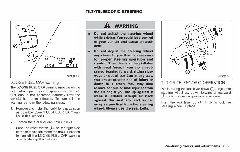
Black plate (169,1)
Model "E52-D" EDITED: 2010/ 10/ 25
SPA2833
LOOSE FUEL CAP warningThe LOOSE FUEL CAP warning appears on thedot matrix liquid crystal display when the fuel-filler cap is not tightened correctly after thevehicle has been refueled. To turn off thewarning, perform the following steps:
1. Remove and install the fuel-filler cap as soonas possible. (See “FUEL-FILLER CAP” ear-lier in this section.)
2. Tighten the fuel-filler cap until it clicks.
3. Push the reset switch *A on the right sideof the combination meter for about 1 secondto turn off the LOOSE FUEL CAP warningafter tightening the fuel cap.
WARNING
. Do not adjust the steering wheelwhile driving. You could lose controlof your vehicle and cause an acci-dent.
. Do not adjust the steering wheelany closer to you than is necessaryfor proper steering operation andcomfort. The driver’s air bag inflateswith great force. If you are unrest-rained, leaning forward, sitting side-ways or out of position in any way,you are at greater risk of injury ordeath in a crash. You may alsoreceive serious or fatal injuries fromthe air bag if you are up against itwhen it inflates. Always sit backagainst the seatback and as faraway as practical from the steeringwheel. Always use the seat belts.
SPA2854
TILT OR TELESCOPIC OPERATION
While pulling the lock lever down*1 , adjust thesteering wheel up, down, forward or rearward*2 until the desired position is achieved.
Push the lock lever up *3 firmly to lock thesteering wheel in place.
TILT/TELESCOPIC STEERING
Pre-driving checks and adjustments 3-31

Black plate (170,1)
Model "E52-D" EDITED: 2010/ 10/ 25
SIC3451
CAUTION
. Do not store the main sun visorbefore storing the extension sunvisor.
. Do not pull the extension sun visorforcedly downward.
1. To block out glare from the front, swingdown the main sun visor *1 .
2. To block glare from the side, remove themain sun visor from the center mount andswing it to the side *2 .
3. Draw out the extension sun visor *3 fromthe main sun visor to block from furtherglare.
SPA2447
INSIDE MIRROR
Adjust the height and the angle of the insidemirror to the desired position.
SUN VISORS MIRRORS
3-32 Pre-driving checks and adjustments
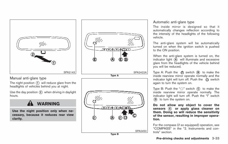
Black plate (171,1)
Model "E52-D" EDITED: 2010/ 10/ 25
SPA2143
Manual anti-glare typeThe night position*1 will reduce glare from theheadlights of vehicles behind you at night.
Use the day position*2 when driving in daylighthours.
WARNING
Use the night position only when ne-cessary, because it reduces rear viewclarity.
SPA2422AType A
SPA2450Type B
Automatic anti-glare typeThe inside mirror is designed so that itautomatically changes reflection according tothe intensity of the headlights of the followingvehicle.
The anti-glare system will be automaticallyturned on when the ignition switch is pushedto the ON position.
When the anti-glare system is turned on, theindicator light *A will illuminate and excessiveglare from the headlights of the vehicle behindyou will be reduced.
Type A: Push the switch *B to make theinside rearview mirror operate normally and theindicator light will turn off. Push the switchagain to turn the system on.
Type B: Push the “*” switch *C to make theinside rearview mirror operate normally. Theindicator light will turn off. Push the “I” switch*D to turn the system on.
Do not allow any object to cover thesensors *E or apply glass cleaner onthem. Doing so will reduce the sensitivityof the sensor, resulting in improper opera-tion.
For the compass (if so equipped) operation, see“COMPASS” in the “2. Instruments and con-trols” section.
Pre-driving checks and adjustments 3-33

Black plate (172,1)
Model "E52-D" EDITED: 2010/ 10/ 25
For the HomeLink® Universal Transceiver opera-tion, see “HomeLink® UNIVERSAL TRANSCEI-VER” in the “2. Instruments and controls”section.
SPA2319
OUTSIDE MIRRORS
WARNING
Objects viewed in the outside mirror onthe passenger side are closer than theyappear. Be careful when moving to theright. Using only this mirror could causean accident. Use the inside mirror orglance over your shoulder to properlyjudge distances to other objects.
Adjusting outside mirrorsThe outside mirror control switch is located onthe armrest.
The outside mirror will operate only when theignition switch is in the ACC or ON position.
Turn the switch right or left to select the right orleft side mirror*1 , then adjust using the controlswitch *2 .
Defrosting outside mirrors (if soequipped)The outside mirrors will be heated when the rearwindow defroster switch is operated.
Reverse tilt-down feature (if soequipped)When backing up the vehicle, the right and leftoutside mirrors will turn downward automaticallyto provide better rear visibility.
1. Push the ignition switch to the ON position.
2. Move the selector lever to the R (Reverse)position.
3. Choose the right or left outside mirror byoperating the outside mirror control switch.
4. The outside mirror surfaces move down-ward.
When one of the following conditions hasoccurred, the outside mirror surfaces will returnto their original positions.
. The selector lever is moved to any positionother than R (Reverse).
3-34 Pre-driving checks and adjustments

Black plate (173,1)
Model "E52-D" EDITED: 2010/ 10/ 25
. The outside mirror control switch is set tothe center position.
. The ignition switch is pushed to the OFFposition.
SPA1829
Foldable outside mirrorsFold the outside mirror by pushing it toward therear of the vehicle.
SIC4448
VANITY MIRROR
To use the front vanity mirror, pull down the sunvisor and pull up the cover.
Pre-driving checks and adjustments 3-35

Black plate (174,1)
Model "E52-D" EDITED: 2010/ 10/ 25
SPA2830
COMMUNICATION MIRROR (if soequipped)
The communication mirror can be used to viewthe second or third row seat inside the vehicle.
To use the communication mirror, push the lid.
To store the mirror, push it in until it latches.
The automatic drive positioner system has twofeatures:
. Entry/exit function
. Memory storage
ENTRY/EXIT FUNCTION
This system is designed so that the driver’s seatwill automatically move when the selector leveris in the P (Park) position. This allows the driverto get into and out of the driver’s seat moreeasily.
The driver’s seat will slide backward when thedriver’s door is opened with the ignition switchin the LOCK position.
The driver’s seat will return to the previouspositions when the ignition switch is pushed tothe ACC position.
The driver’s seat will not return to the previouspositions if the seat adjusting switch is operatedwhen the seat is at the exit position.
Cancel or activate entry/exit functionThe selector lever must be in the P (Park)position with the ignition switch in the OFFposition.
The entry/exit function can be activated orcanceled by pressing and holding the SETswitch for more than 10 seconds.
The indicator lights on the memory switches (1and 2) will blink once when the function iscanceled, and the indicator lights will blink twicewhen the function is activated. Note that theindicator lights may illuminate after 5 secondswhile holding the SET switch. This indicatesreadiness for linking the Intelligent Key to astored memory position. Keep the SET switchpressed for more than 10 seconds to turn on oroff the entry/exit function.
The entry/exit function can also be activated orcanceled if the “Slide Driver Seat Back on Exit”key is turned to ON or OFF in the “Comfortsettings”. (See “VEHICLE INFORMATION ANDSETTINGS (models with center multi-functioncontrol panel)” in the “4. Monitor, heater, airconditioner, audio, phone and voice recognitionsystems” section.)
Initialize entry/exit functionIf the battery cable is disconnected, or if the fuseopens, the entry/exit function will not workthough this function was set on before. In sucha case, after connecting the battery or replacingwith a new fuse, open and close the driver’sdoor more than two times after the ignitionswitch is placed in the LOCK position from theON position. The entry/exit function will beactivated.
AUTOMATIC DRIVE POSITIONER (ifso equipped)
3-36 Pre-driving checks and adjustments

Black plate (175,1)
Model "E52-D" EDITED: 2010/ 10/ 25
SPA2855
MEMORY STORAGE
Two positions for the driver’s seat and outsidemirrors can be stored in the automatic drivepositioner memory. Follow this procedure to usethe memory system.
1. Move the selector lever to the P (Park)position.
2. Push the ignition switch to the ON position.
3. Adjust the driver’s seat and outside mirrorsto the desired positions by manually operat-ing each adjusting switch. For additionalinformation, see “SEATS” in the “1. Safety —Seats, seat belts and supplemental restraintsystem” section and “OUTSIDE MIRRORS”
earlier in this section.
4. Push the SET switch and, within 5 seconds,push the memory switch (1 or 2).
The indicator light for the pushed memoryswitch will stay on for approximately 5seconds after pushing the switch.
If memory is stored in the same memoryswitch, the previous memory will be deleted.
Linking Intelligent Key to a stored mem-ory positionThe Intelligent Key can be linked to a storedmemory position with the following procedure.
1. Follow one of the steps for storing a memoryposition.
. While the indicator light for the memoryswitch being set is illuminated for 5 sec-onds, push the button on the IntelligentKey.
. Push the ignition switch to the OFF position,and then push the SET switch. Push the
button while pushing the memorybutton while the indicator light stays on forapproximately 5 seconds.
If the indicator light blinks, the Intelligent Key islinked to that memory setting.
Push the ignition switch to the OFF position, and
then push the button on the Intelligent Key.The driver’s seat and outside mirrors will move tothe memorized position.
Confirming memory storage. Push the ignition switch to the ON position
and push the SET switch. If the mainmemory has not been stored, the indicatorlight will come on for approximately 0.5second. When the memory has stored inposition, the indicator light will stay on forapproximately 5 seconds.
. If the battery cable is disconnected, or if thefuse opens, the memory will be canceled. Inthis case, reset the desired position usingthe previous procedure.
. If optional keys are added to your vehicle,the memory storage procedure to switch 1or 2 and linking Intelligent Key procedure toa stored memory position should be per-formed again for each Intelligent Key. Foradditional Intelligent Key information, see“KEYS” earlier in this section.
Selecting the memorized position1. Move the selector lever to the P (Park)
position.
2. Use one of the following methods to movethe driver’s seat and outside mirrors.
. Push the ignition switch to the ON
Pre-driving checks and adjustments 3-37

Black plate (176,1)
Model "E52-D" EDITED: 2010/ 10/ 25
position and push the memory switch (1or 2).
. Within 45 seconds of opening thedriver’s door, push the memory switch(1 or 2).
The driver’s seat and outside mirrors willmove to the memorized position with theindicator light flashing, and then the light willstay on for approximately 5 seconds.
SYSTEM OPERATION
The automatic drive positioner system will notwork or will stop operating under the followingconditions:
. When the vehicle speed is above 4 MPH (7km/h) (entry/exit function).
. When the vehicle is driven (memory sto-rage).
. When the adjusting switch for the driver’sseat is turned on while the automatic drivepositioner is operating.
. When the driver’s seat and outside mirrorshave already been moved to the memorizedposition.
. When no position is stored in the memoryswitch.
. When the engine is started while moving the
automatic drive positioner.
. When the selector lever is moved from the P(Park) position to any other position. (How-ever, it will not be canceled while the driver’sseat is returning to the previous positions(entry/exit function).)
. When the driver’s door remains open formore than 45 seconds and the ignitionswitch is not in the ON position.
3-38 Pre-driving checks and adjustments

Black plate (177,1)
Model "E52-D" EDITED: 2010/ 10/ 25
MEMO
Pre-driving checks and adjustments 3-39

Black plate (13,1)
4 Monitor, heater, air conditioner, audio,phone and voice recognition systems
Model "E52-D" EDITED: 2010/ 10/ 22
Safety note . . . . . . . . . . . . . . . . . . . . . . . . . . . . . . . . . . . . . . . . . . . . . . . . . . . . . . . 4-2Center multi-function control panel (if so equipped) . . . 4-2
How to use multi-function controller . . . . . . . . . . . . . . . . . . . 4-4How to use touch screen(models with navigation system) . . . . . . . . . . . . . . . . . . . . . . . . 4-4Menu options (models with navigation system) . . . . . . 4-6How to select menus on the screen . . . . . . . . . . . . . . . . . . . 4-7
Vehicle information and settings(models with center multi-function control panel) . . . . . . . 4-7
How to use STATUS button. . . . . . . . . . . . . . . . . . . . . . . . . . . . . . 4-7How to use brightness control and display ON/OFF button. . . . . . . . . . . . . . . . . . . . . . . . . . . . . . . . . . . . . . . . . . . . . . . . . . . 4-7How to use DISP button. . . . . . . . . . . . . . . . . . . . . . . . . . . . . . . . . . 4-8How to use ECON button(models without navigation system) . . . . . . . . . . . . . . . . . . . . 4-8How to use INFO button. . . . . . . . . . . . . . . . . . . . . . . . . . . . . . . . . . 4-8How to use SETTING button . . . . . . . . . . . . . . . . . . . . . . . . . . 4-12
RearView monitor (if so equipped) . . . . . . . . . . . . . . . . . . . . . . . 4-22How to read the displayed lines. . . . . . . . . . . . . . . . . . . . . . . 4-23How to park with predicted course lines. . . . . . . . . . . . 4-23Difference between predicted and actualdistances . . . . . . . . . . . . . . . . . . . . . . . . . . . . . . . . . . . . . . . . . . . . . . . . . . . 4-25How to adjust the screen . . . . . . . . . . . . . . . . . . . . . . . . . . . . . . . 4-27Operating tips . . . . . . . . . . . . . . . . . . . . . . . . . . . . . . . . . . . . . . . . . . . . . 4-27
Ventilators . . . . . . . . . . . . . . . . . . . . . . . . . . . . . . . . . . . . . . . . . . . . . . . . . . . . . . 4-28Center ventilators . . . . . . . . . . . . . . . . . . . . . . . . . . . . . . . . . . . . . . . . . 4-28Side ventilators. . . . . . . . . . . . . . . . . . . . . . . . . . . . . . . . . . . . . . . . . . . . 4-29
Rear ventilators. . . . . . . . . . . . . . . . . . . . . . . . . . . . . . . . . . . . . . . . . . . . 4-29Heater and air conditioner . . . . . . . . . . . . . . . . . . . . . . . . . . . . . . . . . . 4-29
Operating tips . . . . . . . . . . . . . . . . . . . . . . . . . . . . . . . . . . . . . . . . . . . . . 4-30Manual air conditioner . . . . . . . . . . . . . . . . . . . . . . . . . . . . . . . . . . . 4-31Automatic air conditioner . . . . . . . . . . . . . . . . . . . . . . . . . . . . . . . 4-36Servicing air conditioner . . . . . . . . . . . . . . . . . . . . . . . . . . . . . . . . 4-42In-cabin microfilter . . . . . . . . . . . . . . . . . . . . . . . . . . . . . . . . . . . . . . . . 4-43
Audio system . . . . . . . . . . . . . . . . . . . . . . . . . . . . . . . . . . . . . . . . . . . . . . . . . . 4-43Audio operation precautions . . . . . . . . . . . . . . . . . . . . . . . . . . . 4-43FM-AM radio with Compact Disc (CD)changer . . . . . . . . . . . . . . . . . . . . . . . . . . . . . . . . . . . . . . . . . . . . . . . . . . . . . 4-56FM-AM radio with Compact Disc (CD) player . . . . . 4-61FM-AM-SAT radio with Compact Disc (CD)player . . . . . . . . . . . . . . . . . . . . . . . . . . . . . . . . . . . . . . . . . . . . . . . . . . . . . . . . 4-67DVD (Digital Versatile Disc) player operation(if so equipped) . . . . . . . . . . . . . . . . . . . . . . . . . . . . . . . . . . . . . . . . . . . 4-71USB memory operation (if so equipped) . . . . . . . . . . . . 4-75Bluetooth® streaming audio(models with navigation system) . . . . . . . . . . . . . . . . . . . . . . 4-79iPod® player operation (if so equipped). . . . . . . . . . . . . . 4-84Music Box® (if so equipped) . . . . . . . . . . . . . . . . . . . . . . . . . . . 4-86Auxiliary input jacks (if so equipped) . . . . . . . . . . . . . . . . . 4-93CD/DVD/USB memory care and cleaning . . . . . . . . . . 4-95Steering-wheel-mounted controls for audio(if so equipped) . . . . . . . . . . . . . . . . . . . . . . . . . . . . . . . . . . . . . . . . . . . 4-96Antenna . . . . . . . . . . . . . . . . . . . . . . . . . . . . . . . . . . . . . . . . . . . . . . . . . . . . . 4-98
Black plate (14,1)
Model "E52-D" EDITED: 2010/ 10/ 22
NISSAN Mobile Entertainment System (MES)(if so equipped) . . . . . . . . . . . . . . . . . . . . . . . . . . . . . . . . . . . . . . . . . . . . . . . 4-98
Digital Versatile Disc (DVD) systemcomponents. . . . . . . . . . . . . . . . . . . . . . . . . . . . . . . . . . . . . . . . . . . . . . . . 4-99Before operating the DVD mobile entertainmentsystem. . . . . . . . . . . . . . . . . . . . . . . . . . . . . . . . . . . . . . . . . . . . . . . . . . . . . 4-104Playing a DVD. . . . . . . . . . . . . . . . . . . . . . . . . . . . . . . . . . . . . . . . . . . 4-105Care and maintenance . . . . . . . . . . . . . . . . . . . . . . . . . . . . . . . . 4-109
Car phone or CB radio. . . . . . . . . . . . . . . . . . . . . . . . . . . . . . . . . . . . 4-110Bluetooth® Hands-Free Phone System(models with navigation system) . . . . . . . . . . . . . . . . . . . . . . . . 4-110
Regulatory information . . . . . . . . . . . . . . . . . . . . . . . . . . . . . . . . . 4-111Voice commands. . . . . . . . . . . . . . . . . . . . . . . . . . . . . . . . . . . . . . . . 4-112Control buttons . . . . . . . . . . . . . . . . . . . . . . . . . . . . . . . . . . . . . . . . . 4-112Connecting procedure. . . . . . . . . . . . . . . . . . . . . . . . . . . . . . . . . 4-113Phone selection . . . . . . . . . . . . . . . . . . . . . . . . . . . . . . . . . . . . . . . . . 4-113Vehicle phonebook . . . . . . . . . . . . . . . . . . . . . . . . . . . . . . . . . . . . . 4-113Making a call. . . . . . . . . . . . . . . . . . . . . . . . . . . . . . . . . . . . . . . . . . . . . 4-116Receiving a call . . . . . . . . . . . . . . . . . . . . . . . . . . . . . . . . . . . . . . . . . 4-117During a call . . . . . . . . . . . . . . . . . . . . . . . . . . . . . . . . . . . . . . . . . . . . . 4-118Phone setting. . . . . . . . . . . . . . . . . . . . . . . . . . . . . . . . . . . . . . . . . . . . 4-118
Troubleshooting guide . . . . . . . . . . . . . . . . . . . . . . . . . . . . . . . . . 4-120Bluetooth® Hands-Free Phone System(models without navigation system) (if soequipped). . . . . . . . . . . . . . . . . . . . . . . . . . . . . . . . . . . . . . . . . . . . . . . . . . . . . 4-121
Regulatory information . . . . . . . . . . . . . . . . . . . . . . . . . . . . . . . . . 4-122Using the system . . . . . . . . . . . . . . . . . . . . . . . . . . . . . . . . . . . . . . . 4-122Control buttons . . . . . . . . . . . . . . . . . . . . . . . . . . . . . . . . . . . . . . . . . 4-125Getting started . . . . . . . . . . . . . . . . . . . . . . . . . . . . . . . . . . . . . . . . . . 4-125List of voice commands . . . . . . . . . . . . . . . . . . . . . . . . . . . . . . . 4-127Speaker Adaptation (SA) mode . . . . . . . . . . . . . . . . . . . . . 4-131Troubleshooting guide . . . . . . . . . . . . . . . . . . . . . . . . . . . . . . . . . 4-133
NISSAN Voice Recognition System(models with navigation system) . . . . . . . . . . . . . . . . . . . . . . . . 4-134
NISSAN voice recognition Standard Mode . . . . . . . 4-134Using the system . . . . . . . . . . . . . . . . . . . . . . . . . . . . . . . . . . . . . . . 4-136NISSAN voice recognition Alternate CommandMode . . . . . . . . . . . . . . . . . . . . . . . . . . . . . . . . . . . . . . . . . . . . . . . . . . . . . . 4-146Using the system . . . . . . . . . . . . . . . . . . . . . . . . . . . . . . . . . . . . . . . 4-152Troubleshooting guide . . . . . . . . . . . . . . . . . . . . . . . . . . . . . . . . . 4-157
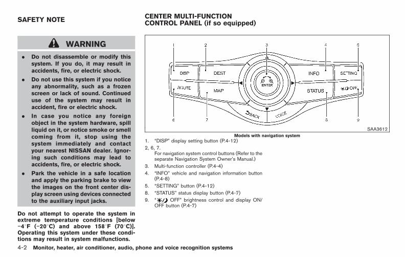
Black plate (180,1)
Model "E52-D" EDITED: 2010/ 10/ 25
WARNING
. Do not disassemble or modify thissystem. If you do, it may result inaccidents, fire, or electric shock.
. Do not use this system if you noticeany abnormality, such as a frozenscreen or lack of sound. Continueduse of the system may result inaccident, fire or electric shock.
. In case you notice any foreignobject in the system hardware, spillliquid on it, or notice smoke or smellcoming from it, stop using thesystem immediately and contactyour nearest NISSAN dealer. Ignor-ing such conditions may lead toaccidents, fire, or electric shock.
. Park the vehicle in a safe locationand apply the parking brake to viewthe images on the front center dis-play screen using devices connectedto the auxiliary input jacks.
Do not attempt to operate the system inextreme temperature conditions [below−48F (−208C) and above 1588F (708C)].Operating this system under these condi-tions may result in system malfunctions.
SAA3612
Models with navigation system1. “DISP” display setting button (P.4-12)
2, 6, 7.For navigation system control buttons (Refer to theseparate Navigation System Owner’s Manual.)
3. Multi-function controller (P.4-4)
4. “INFO” vehicle and navigation information button(P.4-8)
5. “SETTING” button (P.4-12)
8. “STATUS” status display button (P.4-7)
9. “ OFF” brightness control and display ON/OFF button (P.4-7)
SAFETY NOTE CENTER MULTI-FUNCTIONCONTROL PANEL (if so equipped)
4-2 Monitor, heater, air conditioner, audio, phone and voice recognition systems

Black plate (181,1)
Model "E52-D" EDITED: 2010/ 10/ 25
SAA3613Models without navigation system
1. “INFO” vehicle information button (P.4-8)
2. “STATUS” status display button (P.4-7)
3. “DISP” display setting button (P.4-12)
4. “ ” brightness UP button (P.4-7)
5. “ ECON” button (P.4-8)
6. “SETTING” button (P.4-12)
7. Multi-function controller (P.4-4)
8. “ OFF” brightness control and display ON/OFF button (P.4-7)
9. “ ” brightness DOWN button (P.4-7)
When you use this system, make sure theengine is running.
If you use the system with the engine notrunning (ignition ON or ACC) for a longtime, it will discharge the battery and theengine may not start.
SAA3025With navigation system
SAA3614Without navigation system
Monitor, heater, air conditioner, audio, phone and voice recognition systems 4-3

Black plate (182,1)
Model "E52-D" EDITED: 2010/ 10/ 25
HOW TO USE MULTI-FUNCTIONCONTROLLER
Choose an item on the display by rotating orpushing the center dial *1 upward/ downward,and push the ENTER button *2 for operation.
If you push the BACK button *3 before thesetup is completed, the setup will be canceledand/or the display will return to the previousscreen. This button can also be used to deletecharacters that have been input.
After the setup is completed, push the BACKbutton *3 and return to the previous screen.
For the VOICE button*4 functions, refer to theseparate Navigation System Owner’s Manual.
HOW TO USE TOUCH SCREEN(models with navigation system)
CAUTION
. The glass screen on the liquidcrystal display may break if it is hitwith a hard or sharp object. If theglass screen breaks, do not touch it.Doing so could result in an injury.
. To clean the display, use a soft, drycloth. If additional cleaning is ne-cessary, use a small amount ofneutral detergent with a soft cloth.
Never use a rough cloth, alcohol,benzine, thinner or any kind ofsolvent or paper towel with a che-mical cleaning agent. They willscratch or deteriorate the panel.
. Do not splash any liquid such aswater or car fragrance on the dis-play. Contact with liquid will causethe system to malfunction.
To ensure safe driving, some functions cannotbe operated while driving.
The on-screen functions that are not availablewhile driving will be “grayed out” or muted.
Park the vehicle in a safe location and thenoperate the navigation system.
WARNING
. ALWAYS give your full attention todriving.
. Avoid using vehicle features thatcould distract you. If distracted,you could lose control of yourvehicle and cause an accident.
SAA2473
Touch screen operationWith this system, the same operations as thosefor the multi-function controller are possibleusing the touch screen operation.
Selecting the item:
Touch an item to select it. To select the “Audio”settings, touch the “Audio” area *1 on thescreen.
Touch the “BACK” *2 button to return to theprevious screen.
4-4 Monitor, heater, air conditioner, audio, phone and voice recognition systems

Black plate (183,1)
Model "E52-D" EDITED: 2010/ 10/ 25
SAA2474
Adjusting an item:
Touch the + *1 or − *2 button to adjust thesettings.
Touch the *3 or *4 button to moveto the previous or next item.
Touch the *5 or *6 button to moveto the previous or next page.
SAA2475
Inputting characters:
Touch the letter or number *1 .
There are some options available when inputtingcharacters.
. Uppercase:
Shows uppercase characters.
. Lowercase:
Shows lowercase characters.
. Symbols:
Shows symbols such as the question mark(?).
. Space:
Inserts a space.
. Delete:
Deletes the last character that has beeninput with one touch. Push and hold thebutton to delete all of the characters.
. OK:
Completes character inputs.
Touch screen maintenanceIf you clean the display screen, use a dry, softcloth. If additional cleaning is necessary, use asmall amount of neutral detergent with a softcloth. Never spray the screen with water ordetergent. Dampen the cloth first, and then wipethe screen.
Monitor, heater, air conditioner, audio, phone and voice recognition systems 4-5

Black plate (184,1)
Model "E52-D" EDITED: 2010/ 10/ 25
SAA3673
MENU OPTIONS (models with naviga-tion system)
The start menu can be displayed using the menucontrol switch on the steering-wheel-mountedcontrols.
1. While the MAP or STATUS screen isdisplayed, push and hold the menu controlswitch until the “Menu Options” screenappears.
2. Highlight the preferred item by tilting themenu control switch up or down, and thenpush the menu control switch to select it.
SAA2476
Available items
Destination/Route:
These items are for the navigation system. Seethe separate Navigation System Owner’s Man-ual for details.
Info:
Displays the information screen. It is the samescreen that appears when you push the INFObutton.
Settings:
Displays the settings screen. It is the samescreen that appears when you push the SET-TING button.
SAA2477Models with navigation system
SAA3149Models without navigation system
4-6 Monitor, heater, air conditioner, audio, phone and voice recognition systems

Black plate (185,1)
Model "E52-D" EDITED: 2010/ 10/ 25
HOW TO SELECT MENUS ON THESCREEN
Vehicle functions are viewed on the displayscreen in menus. To select each key item,highlight the preferred item using the multi-function controller and push the ENTER button.
Whenever a menu selection is made or menuitem is highlighted, different areas on the screenprovide you with important information. See thefollowing for details.
1. Header:
Shows the path used to get to the currentscreen. (i.e. push SETTING button >choose “Comfort” menu item.)
2. Menu Selections:
Shows the options to choose within thatmenu screen.
3. UP/DOWN Movement indicator:
Shows that the multi-function controller maybe used to move UP/DOWN on the screenand select more options.
4. Menu Items Counter:
Shows the total number of items listedacross all pages for the current menu (i.e.3/7).
5. Footer/Information Line:
Provides more information (if available)about the menu selection currently high-lighted. (i.e. Adjust head lamp on time aftershut-off.)
HOW TO USE STATUS BUTTON
To display the status of the audio, fuel con-sumption and navigation system (if soequipped), push the STATUS button. Thefollowing information will appear when theSTATUS button is pushed repeatedly.
Audio and fuel economy ? Audio and Naviga-tion system (if so equipped)
HOW TO USE BRIGHTNESS CON-TROL AND DISPLAY ON/OFF BUTTON
Push the “ OFF” button to switch thedisplay brightness to the daytime mode or thenighttime mode, and to adjust the displaybrightness using the multi-function controllerwhile the indicator is displayed at the bottom ofthe screen.
. Models without navigation system
The display brightness can also be adjustedusing the brightness UP button (+) orbrightness DOWN button (−).
Push and hold the “ OFF” button for morethan 2 seconds to turn the display off. Push thebutton again to turn the display on.
VEHICLE INFORMATION ANDSETTINGS (models with centermulti-function control panel)
Monitor, heater, air conditioner, audio, phone and voice recognition systems 4-7

Black plate (186,1)
Model "E52-D" EDITED: 2010/ 10/ 25
HOW TO USE DISP BUTTON
Push the DISP button to show the displaysetting screen. (See “Display settings (modelswith navigation system)” later in this section or“Display settings (models without navigationsystem)” later in this section.)
HOW TO USE ECON BUTTON(models without navigation system)
Push the “ECON” button to show fuel economyinformation. (See “HOW TO USE INFO BUT-TON” later in this section.)
HOW TO USE INFO BUTTON
The display screen shows vehicle and navigationinformation for your convenience.
The information shown on the screen should bea guide to determine the condition of the vehicle.See the following for details.
SAA2478Models with navigation system
SAA1511Models without navigation system
Vehicle information display1. Push the INFO button on the control panel.
2. Select an item from the INFO menu.
3. After viewing or adjusting the information onthe following screens, push the BACKbutton to return to the INFO menu.
See the separate Navigation System Owner’sManual for the following items:
. Where am I?
. Traffic Info
. Weather Info
. Map Update
. Navigation Version
*When the ignition switch is in the ON position,the “Navigation Version” key is displayed afterselecting the “Others” key.
4-8 Monitor, heater, air conditioner, audio, phone and voice recognition systems

Black plate (187,1)
Model "E52-D" EDITED: 2010/ 10/ 25
SAA2479
SAA2480Models with navigation system
SAA2720
SAA2721Models without navigation system
Fuel Economy informationThe distance to empty, average fuel economyand current fuel economy will be displayed forreference.
To reset the average fuel economy (Avg FuelEcon or Average Fuel Economy), select the“Reset Fuel Eco” or “Reset” key.
If the “Fuel Eco History” or “View” key isselected, the average fuel consumption historywill be displayed in graph form along with theaverage for the previous Reset-to-Reset period.
The unit can be converted between “US” and“Metric”. (See “HOW TO USE SETTINGBUTTON” later in this section.)
The fuel economy information may differ from theinformation displayed on the dot matrix liquidcrystal display. This is due to the timingdifference in updating the information and doesnot indicate a malfunction.
For models without the navigation system, theinformation can also be displayed by pushingthe ECON button on the control panel.
Monitor, heater, air conditioner, audio, phone and voice recognition systems 4-9

Black plate (188,1)
Model "E52-D" EDITED: 2010/ 10/ 25
SAA2481Models with navigation system
SAA2830Models without navigation system
Maintenance informationThe maintenance intervals can be displayed forthe engine oil, oil filter, tire and other reminders.
To set a maintenance interval, select a preferreditem from the list.
You can also set to display a message to remindyou that the maintenance needs to be per-formed.
The following example shows how to set theengine oil maintenance information. Use thesame steps to set the other maintenanceinformation.
SAA2482Models with navigation system
SAA3141Models without navigation system
4-10 Monitor, heater, air conditioner, audio, phone and voice recognition systems

Black plate (189,1)
Model "E52-D" EDITED: 2010/ 10/ 25
1. Set the interval (mileage) of the maintenanceschedule. To determine the recommendedmaintenance interval, refer to your “NISSANService and Maintenance Guide”.
2. To display the reminder automatically whenthe desired distance is reached, select the“Reminder” key.
3. Reset the driving distance to the newmaintenance schedule.
4. To return to the previous screen, push theBACK button.
The unit can be converted between “US” and“Metric”. (See “HOW TO USE SETTINGBUTTON” later in this section.)
SAA3003Example
The Reminder will be automatically displayedwhen the specified distance has been drivenand every time the ignition switch is pushed tothe ACC or ON position. The reminder will notappear while driving.
Select the “OK” key to hide the reminder for therest of the current drive.
To stop the reminder from appearing, performone of the following actions:
. Select the “Reset Distance”.
. Deactivate the “Reminder”.
. Increase the “Interval” distance to be morethan the current distance being tracked.
SAA2483
Others information (models with naviga-tion system)The Others information display will appear whenpushing the INFO button and selecting the“Others” key.
GPS Position:
For the details of this item, see the separateNavigation System Owner’s Manual.
Voice Recognition:
For the details of this item, see “NISSAN VOICERECOGNITION SYSTEM (models with naviga-tion system)” later in this section.
Monitor, heater, air conditioner, audio, phone and voice recognition systems 4-11

Black plate (190,1)
Model "E52-D" EDITED: 2010/ 10/ 25
SAA2484Models with navigation system
SAA3562Models without navigation system
HOW TO USE SETTING BUTTON
The display as illustrated will appear when theSETTING button is pushed.
For navigation settings, refer to the separateNavigation System Owner’s Manual.
SAA2485Models with navigation system
SAA2740Models without navigation system
4-12 Monitor, heater, air conditioner, audio, phone and voice recognition systems

Black plate (191,1)
Model "E52-D" EDITED: 2010/ 10/ 25
Audio settingsThe display as illustrated will appear whenpushing the SETTING button and selecting the“Audio” key.
Bass/Treble/Balance/Fade:
To adjust the speaker tone quality and soundbalance, select the “Bass”, “Treble”, “Balance”or “Fade” key and adjust it with the multi-function controller.
These items can also be adjusted by pushingand turning the AUDIO knob.
Speed Sensitive Vol.:
The audio system’s volume is increased with thevehicle speed. Select the “Speed Sensitive Vol.”and adjust the effect level with the multi-functioncontroller. The Speed Sensitive Volume functionis turned off when the level is set to “OFF”.Increasing the value will cause the volume toincrease faster with vehicle speed.
DivX® Registration Code (models withnavigation system):
The registration code for a device that is used todownload DivX® files will be displayed on thescreen. If a disc is loaded or a USB memory isconnected to the audio system, this function willnot be activated.
Display Album Cover Art (models withnavigation system):
When this item is turned on, the album coverimage is displayed when playing iPod® or MP3music files through a CD, DVD or USB memory.When the image is not properly embedded inthe file or device, the image will not bedisplayed.
Phone settings (models with navigationsystem)For details of the “Phone” settings, see “BLUE-TOOTH® HANDS-FREE PHONE SYSTEM(models with navigation system)” later in thissection.
Bluetooth® settings (models with navi-gation system)For details of the “Bluetooth” settings, see“BLUETOOTH® HANDS-FREE PHONE SYS-TEM (models with navigation system)” later inthis section or “BLUETOOTH® STREAMINGAUDIO (models with navigation system)” later inthis section.
SAA2554Example
Volume and Beeps settings (models withnavigation system)The display as illustrated will appear whenpushing the SETTING button, selecting the“Volume & Beeps” key.
Audio Volume:
To increase or decrease the audio volume,select the “Audio Volume” and adjust it withthe multi-function controller. You can also adjustthe audio volume by turning the VOLUMEcontrol knob.
Monitor, heater, air conditioner, audio, phone and voice recognition systems 4-13

Black plate (192,1)
Model "E52-D" EDITED: 2010/ 10/ 25
Guidance Volume:
To adjust the guidance voice volume, select the“Guidance Volume” and adjust it with the multi-function controller.
You can also adjust the guidance voice volumeby turning the VOLUME control knob while voiceguidance is being announced.
Ringtone/Incoming Call/Outgoing Call:
For the details of these items, see “BLUE-TOOTH® HANDS-FREE PHONE SYSTEM(models with navigation system)” later in thissection.
Switch Beeps:
When this item is turned on, you will hear a beepsound when you use a button.
Guidance Voice:
When this item is turned on, you will hear voiceguidance in the navigation operation or in otheroperations.
NOTE:
When the voice guidance is being an-nounced during audio playback, turningthe volume knob does not adjust the musiclevel; it adjusts the guidance volume level.If voice guidance is not being heard,please check the Guidance Volume level.
SAA2605
Button beeps settings (models withoutnavigation system)The “Button Beeps” screen will appear whenpushing the SETTING button, selecting the“Button Beeps” key with the multi-functioncontroller and pushing the ENTER button.
Button Beeps:
When this item is turned to ON, you will hear abeep sound when you use a button.
SAA2917Models with navigation system
SAA2079Models without navigation system
4-14 Monitor, heater, air conditioner, audio, phone and voice recognition systems

Black plate (193,1)
Model "E52-D" EDITED: 2010/ 10/ 25
REAR DISPLAY settings (if so equipped)The “Rear Display” screen will appear whenpushing the SETTING button, selecting the“Rear Display” key.
Rear Display (models with navigation sys-tem)/Rear Display Open (models withoutnavigation system):
When this item is turned to ON, the rear displayopens. When the ignition switch is pushed tothe “ACC” or “ON” position, the rear display isflipped down automatically.
When the ignition switch is pushed to the “OFF”position, the rear display is closed automaticallyif ON is selected.
The rear display can also be opened or closedusing the remote controller. (See “NISSANMOBILE ENTERTAINMENT SYSTEM (MES)”later in this section.)
SAA2486
Display settings (models with navigationsystem)The display as illustrated will appear whenpushing the SETTING button and selecting the“Display” key.
Display Adjustment:
To adjust the display settings, select the “Dis-play Adjustment” key. The following settings areavailable.
. Display
To turn off the screen, push the ENTER buttonand turn the “Display” indicator off. The othermethod is to push and hold the “ OFF”
button for more than 2 seconds.
When any mode button is pushed with thescreen off, the screen turns on for furtheroperation. The screen will turn off automatically5 seconds after the operation is finished.
To turn on the screen, set this item to the ONposition, or push and hold the “ OFF”button.
. Brightness/Contrast/Background Color
To adjust the brightness and contrast of thescreen, select the “Brightness” or “Contrast”key.
Then, you can adjust the brightness to and thecontrast to using the multi-function controller.
For information on the “Background Color” key,refer to the separate Navigation System Own-er’s Manual.
Color Theme:
Choose the theme color of the menu screenfrom “Black”, “Blue” or “Red”.
Monitor, heater, air conditioner, audio, phone and voice recognition systems 4-15

Black plate (194,1)
Model "E52-D" EDITED: 2010/ 10/ 25
SAA2115
Display settings (models without navi-gation system)The “Display” screen will appear when pushingthe SETTING button on the control panel.
Display:
To turn off the screen, push the ENTER buttonand turn the “ON” indicator off.
When any mode button is pushed with thescreen off, the screen turns on for furtheroperation. The screen will turn off automatically5 seconds after the operation is finished.
To turn on the screen, set this item to the “ON”position or push the “ ” button.
Brightness/Contrast/Background Color:
To adjust the brightness, contrast and back-ground color of the screen, select the appro-priate “Brightness”, “Contrast” or “BackgroundColor” key and push the ENTER button.
You can then adjust the brightness and contrastusing the multi-function controller. Switch thebackground color to the daytime mode or thenighttime mode by pushing the ENTER button.
SAA2487Models with navigation system
SAA3675Models without navigation system
4-16 Monitor, heater, air conditioner, audio, phone and voice recognition systems

Black plate (195,1)
Model "E52-D" EDITED: 2010/ 10/ 25
Clock settingsThe display as illustrated will appear whenpushing the SETTING button and selecting the“Clock” key.
The clock settings display cannot be operatedwhile driving. Stop the vehicle in a safe placeand apply the parking brake before setting theclock.
On-screen Clock:
When this item is turned on, a clock is alwaysdisplayed in the upper right corner of the screen.
This clock will indicate the time almost exactlybecause it is always adjusted by the GPSsystem (models with navigation system).
Clock Format (24h):
When this item is turned on, the 24-hour clock isdisplayed. When this item is not turned on, the12-hour clock is displayed.
Offset (hour)/(min) (models with naviga-tion system)/Clock Adjust (models withoutnavigation system):
Adjust the time by increasing or decreasing perhour or per minute.
Daylight Saving Time:
Turn this item to ON for daylight saving timeapplication.
Time Zone:
Choose the time zone from the following
Models with navigation system
. Pacific
. Mountain
. Central
. Eastern
. Atlantic
. Newfoundland
. Hawaii
. Alaska
Models without navigation system
. Eniwetok, Kwajalein
. Midway Island, Samoa
. Hawaii
. Alaska
. Pacific
SAA2489
Others settings (models with navigationsystem)The Others settings display will appear whenpushing the SETTING button and selecting the“Others” key.
The following items are available:
. Comfort
. Language & Units
. Voice Recognition
. Image Viewer
. Camera
Monitor, heater, air conditioner, audio, phone and voice recognition systems 4-17

Black plate (196,1)
Model "E52-D" EDITED: 2010/ 10/ 25
SAA3151Models with navigation system
SAA3150Models without navigation system
Comfort settingsModels with navigation system
The display as illustrated will appear whenpushing the SETTING button, selecting the“Others” key and then selecting the “Comfort”key. This key does not appear on the display untilthe ignition switch is pushed to the ON position.
Models without navigation system
The display as illustrated will appear whenpushing the SETTING button and selecting the“Comfort” key. This key does not appear on thedisplay until the ignition switch is pushed to theON position.
Auto Interior Illumination:
When this item is turned on, the interior lightswill illuminate if any door is unlocked.
Light Sensitivity:
Adjust the sensitivity of the automatic headlightshigher (right) or lower (left).
Slide Driver Seat Back on Exit (if soequipped):
When this item is turned on, the driver’s seatmoves backward for easy exit if the ignitionswitch is in the OFF position and the driver’sdoor is opened. After getting into the vehicle andpushing the ignition switch to the ACC position,
the driver’s seat moves to the previous position.
Light Off Delay:
Choose the duration of the automatic headlightoff timer from 0, 30, 45, 60, 90, 120, 150 and180 second periods.
Selective Door Unlock:
When this item is turned on, only the driver’sdoor is unlocked first after the door unlockoperation. When the door handle request switchon the driver’s or front passenger’s side door ispushed to be unlocked, only the correspondingdoor is unlocked first. All the doors can beunlocked if the door unlock operation is per-formed again within 60 seconds.
When this item is turned off, all the doors will beunlocked after the door unlock operation isperformed once.
Intelligent Key Lock/Unlock:
When this item is turned on, door lock/unlockfunction by pushing the door handle requestswitch will be activated.
Return All Settings to Default:
Select this item and then select “YES” to returnall settings to the default.
4-18 Monitor, heater, air conditioner, audio, phone and voice recognition systems
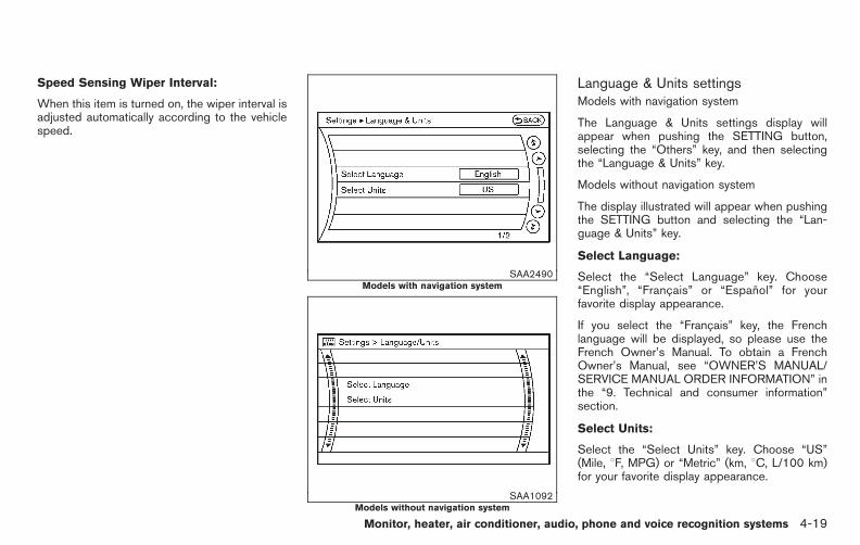
Black plate (197,1)
Model "E52-D" EDITED: 2010/ 10/ 25
Speed Sensing Wiper Interval:
When this item is turned on, the wiper interval isadjusted automatically according to the vehiclespeed.
SAA2490Models with navigation system
SAA1092Models without navigation system
Language & Units settingsModels with navigation system
The Language & Units settings display willappear when pushing the SETTING button,selecting the “Others” key, and then selectingthe “Language & Units” key.
Models without navigation system
The display illustrated will appear when pushingthe SETTING button and selecting the “Lan-guage & Units” key.
Select Language:
Select the “Select Language” key. Choose“English”, “Francais” or “Espanol” for yourfavorite display appearance.
If you select the “Francais” key, the Frenchlanguage will be displayed, so please use theFrench Owner’s Manual. To obtain a FrenchOwner’s Manual, see “OWNER’S MANUAL/SERVICE MANUAL ORDER INFORMATION” inthe “9. Technical and consumer information”section.
Select Units:
Select the “Select Units” key. Choose “US”(Mile, 8F, MPG) or “Metric” (km, 8C, L/100 km)for your favorite display appearance.
Monitor, heater, air conditioner, audio, phone and voice recognition systems 4-19

Black plate (198,1)
Model "E52-D" EDITED: 2010/ 10/ 25
Voice Recognition settings (models withnavigation system)For details about the “Voice Recognition”settings, see “NISSAN VOICE RECOGNITIONSYSTEM (models with navigation system)” laterin this section.
SAA2404Models with navigation system
SAA2606Models without navigation system
CAMERA settings (if so equipped)The “CAMERA” screen will appear when select-ing the “Camera” key.
For the details about the camera systemoperation, see “REARVIEW MONITOR” later inthis section.
Predictive Course Lines:
When this item is turned on, the predictedcourse lines will be displayed on the monitorwhen the selector/shift lever is in the “R”(Reverse) position.
4-20 Monitor, heater, air conditioner, audio, phone and voice recognition systems

Black plate (199,1)
Model "E52-D" EDITED: 2010/ 10/ 25
SAA2491
Image Viewer (models with navigationsystem)The image files in the USB memory will bedisplayed. To display the Image Viewer, push theSETTING button, select the “Other” key andthen select the “Image Viewer” key. The image ofthe selected file is displayed on the right side ofthe screen.
When a number of folders are included in theUSB memory, select a folder from the list todisplay the file list.
Images will not be shown on the display whilethe vehicle is in any drive position to reducedriver distraction. To view images, stop thevehicle in a safe location and apply the parking
brake.
SAA2492
Full Screen Display:
The full screen display will appear when select-ing the “Full Screen Display” key.
To operate the Image Viewer or to change thesettings, select the desired key using the multi-function controller.
. (Start)
Select the “ ” key to start playing theslideshow.
Monitor, heater, air conditioner, audio, phone and voice recognition systems 4-21

Black plate (200,1)
Model "E52-D" EDITED: 2010/ 10/ 25
. (Stop)
Select the “ ” key to stop the slideshow.
. (Next)
Select the “ ” key to display the next file.
. (Previous)
Select the “ ” key to display the previousfile.
Setting the Image Viewer:
The Image Viewer setting display will appearwhen selecting the “Settings” key on the fullscreen display. The following settings areavailable for the full screen display.
. Slideshow Speed
Select the “Slideshow Speed” key. From thefollowing display, select the changing timefrom 5, 10, 30, 60 seconds or “No AutoChange”.
. Slideshow Order
Select the “Slideshow Order” key. From thefollowing display, select “Random” or “OrderList”. For “Order List”, the image order is theorder of the files as stored on the USBmemory.
Operating tips:
. Only files that meet the following conditionswill be displayed.
— Image type: JPEG
— File Extensions: *.jpg, *jpeg
— Maximum Resolution: 2048 6 1536pixels
— Maximum Size: 2-MB
— Colors: 32768 (15-bit)
— Maximum File Name lengths: 253-Bytes
— Maximum Folders: 500
— Maximum Images per Folder: 1024
. If an electronic device (such as a digitalcamera) is directly connected to the vehicleusing a USB cable, no image will bedisplayed on the screen.
. If the file name is too long, some file namesmay not be entirely displayed.
. When the total number of characters in thefile name exceeds 100 or if 1 file name in adirectory exceeds 100 characters, all fileswill show a shortened 8-character version.The image will still be displayed whenselected.
When the selector lever is shifted into the R(Reverse) position, the monitor display showsthe view to the rear of the vehicle.
The system is designed as an aid to the driver indetecting large stationary objects to help avoiddamaging the vehicle. The system will not detectsmall objects below the bumper and may notdetect objects close to the bumper or on theground.
WARNING
. The rear view camera is a conve-nience but it is not a substitute forproper backing up. Always turn andcheck that it is safe to do so beforebacking up. Always back up slowly.
. Objects viewed in the RearViewMonitor differ from actual distancebecause a wide-angle lens is used.Objects in the RearView Monitorwill appear visually opposite thanwhen viewed in the rear view andoutside mirrors.
. Make sure that the lift gate issecurely closed when backing up.
. Underneath the bumper and thecorner areas of the bumper cannotbe viewed on the RearView Monitor
REARVIEW MONITOR (if soequipped)
4-22 Monitor, heater, air conditioner, audio, phone and voice recognition systems

Black plate (201,1)
Model "E52-D" EDITED: 2010/ 10/ 25
because of its monitoring rangelimitation.
. Do not put anything on the rear viewcamera. The rear view camera isinstalled above the license plate.
. When washing the vehicle withhigh-pressure water, be sure not tospray it around the camera. Other-wise, water may enter the cameraunit causing water condensation onthe lens, a malfunction, fire or anelectric shock.
. Do not strike the camera. It is aprecision instrument. Otherwise, itmay malfunction or cause damageresulting in a fire or an electricshock.
CAUTION
Do not scratch the camera lens whencleaning dirt or snow from the lens.
SAA1896
HOW TO READ THE DISPLAYEDLINES
Guiding lines which indicate the vehicle widthand distances to objects with reference to thevehicle body line *A are displayed on themonitor.
Distance guide lines:
Indicate distances from the vehicle body.
. Red line *1 : approx. 1.5 ft (0.5 m)
. Yellow line *2 : approx. 3 ft (1 m)
. Green line *3 : approx. 7 ft (2 m)
. Green line *4 : approx. 10 ft (3 m)
Vehicle width guide lines *5 :
Indicate the vehicle width when backing up.
Predicted course lines *6 :
Indicate the predicted course when backing up.The predicted course lines will be displayed onthe monitor when the selector lever is in the R(Reverse) position and the steering wheel isturned. The predicted course lines will movedepending on how much the steering wheel isturned and will not be displayed while thesteering wheel is in the neutral position.
HOW TO PARK WITH PREDICTEDCOURSE LINES
WARNING
. Always turn and check that it is safeto do so before backing up. Alwaysback up slowly.
. Use the displayed lines as a refer-ence. The lines are highly affectedby the number of occupants, fuellevel, vehicle position, road condi-tion and road grade.
. If the tires are replaced with differ-ent sized tires, the predicted courseline may be displayed incorrectly.
Monitor, heater, air conditioner, audio, phone and voice recognition systems 4-23

Black plate (202,1)
Model "E52-D" EDITED: 2010/ 10/ 25
. On a snow-covered or slippery road,there may be a difference betweenthe predicted course line and theactual course line.
. The displayed lines will appearslightly off to the right because therear view camera is not installed inthe rear center of the vehicle.
. The distance guide line and thevehicle width line should be usedas a reference only when the vehicleis on a level paved surface. Thedistance viewed on the monitor isfor reference only and may bedifferent than the actual distancebetween the vehicle and displayedobjects.
. When backing-up the vehicle up ahill objects viewed in the monitorare further than they appear. Whenbacking-up the vehicle down a hill,objects viewed in the monitor arecloser than they appear. Use theinside mirror or glance over yourshoulder to properly judge dis-tances to other objects.
The vehicle width and predicted courselines are wider than the actual width and
course.
SAA1897
1. Visually check that the parking space is safebefore parking your vehicle.
2. The rear view of the vehicle is displayed onthe screen *A when the selector lever ismoved to the R (Reverse) position.
4-24 Monitor, heater, air conditioner, audio, phone and voice recognition systems

Black plate (203,1)
Model "E52-D" EDITED: 2010/ 10/ 25
SAA1898
3. Slowly back up the vehicle adjusting thesteering wheel so that the predicted courselines *B enter the parking space *C .
4. Maneuver the steering wheel to make thevehicle width guide lines *D parallel to theparking space *C while referring to thepredicted course lines.
5. When the vehicle is parked in the spacecompletely, move the selector lever to the P(Park) position and apply the parking brake.
DIFFERENCE BETWEEN PREDICTEDAND ACTUAL DISTANCES
The distance guide line and the vehicle widthguide line should be used as a reference onlywhen the vehicle is on a level, paved surface.The distance viewed on the monitor is forreference only and may be different than theactual distance between the vehicle and dis-played objects.
SAA2019
Backing up on a steep uphillWhen backing up the vehicle up a hill, thedistance guide lines and the vehicle width guidelines are shown closer than the actual distance.For example, the display shows 3 ft (1 m) to theplace *A , but the actual 3 ft (1 m) distance onthe hill is the place*B . Note that any object on
Monitor, heater, air conditioner, audio, phone and voice recognition systems 4-25
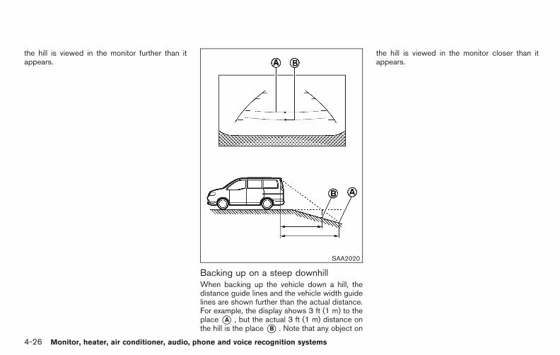
Black plate (204,1)
Model "E52-D" EDITED: 2010/ 10/ 25
the hill is viewed in the monitor further than itappears.
SAA2020
Backing up on a steep downhillWhen backing up the vehicle down a hill, thedistance guide lines and the vehicle width guidelines are shown further than the actual distance.For example, the display shows 3 ft (1 m) to theplace *A , but the actual 3 ft (1 m) distance onthe hill is the place*B . Note that any object on
the hill is viewed in the monitor closer than itappears.
4-26 Monitor, heater, air conditioner, audio, phone and voice recognition systems

Black plate (205,1)
Model "E52-D" EDITED: 2010/ 10/ 25
SAA2021
Backing up near a projecting objectThe predicted course lines*A do not touch theobject in the display. However, the vehicle mayhit the object if it projects over the actualbacking up course.
SAA2022
Backing up behind a projecting objectThe position *C is shown further than theposition *B in the display. However, theposition *C is actually at the same distanceas the position *A . The vehicle may hit theobject when backing up to the position *A ifthe object projects over the actual backing up
course.
HOW TO ADJUST THE SCREEN
To adjust the Display ON/OFF, Brightness, Tint,Color, Contrast and Black Level of the RearViewMonitor, push the SETTING button with theRearView Monitor on, select the item key andadjust the level using the multi-function con-troller.
Do not adjust the Brightness, Tint, Color,Contrast and Black Level of the RearViewMonitor while the vehicle is moving. Make surethe parking brake is firmly applied and theengine is not running.
The display of the predicted course lines can beset to ON or OFF. For details, see “CAMERAsettings” earlier in this section.
OPERATING TIPS
. When the selector lever is shifted to the R(Reverse) position, the monitor screen auto-matically changes to the RearView Monitormode. However, the radio can be heard.
. It may take some time until the RearViewMonitor or the normal screen is displayedafter the selector lever has been shifted to Rfrom another position or to another positionfrom R. Objects may be distorted momenta-rily until the RearView Monitor screen isdisplayed completely.
Monitor, heater, air conditioner, audio, phone and voice recognition systems 4-27

Black plate (206,1)
Model "E52-D" EDITED: 2010/ 10/ 25
. When the temperature is extremely high orlow, the screen may not clearly displayobjects. This is not a malfunction.
. When strong light directly enters the cam-era, objects may not be displayed clearly.This is not a malfunction.
. Vertical lines may be seen in objects on thescreen. This is due to strong reflected lightfrom the bumper. This is not a malfunction.
. The screen may flicker under fluorescentlight. This is not a malfunction.
. The colors of objects on the RearViewMonitor may differ somewhat from those ofthe actual object.
. Objects on the monitor may not be clear in adark place or at night. This is not amalfunction.
. If dirt, rain or snow attaches to the camera,the RearView Monitor may not clearly dis-play objects. Clean the camera.
. Do not use alcohol, benzine or thinner toclean the camera. This will cause discolora-tion. To clean the camera, wipe with a clothdampened with diluted mild cleaning agentand then wipe with a dry cloth.
. Do not damage the camera as the monitorscreen may be adversely affected.
. Do not use wax on the camera window.Wipe off any wax with a clean clothdampened with mild detergent diluted withwater.
SAA3511Center
CENTER VENTILATORS
Adjust the air flow direction of the ventilators bymoving the center knob (up/down, left/right)until the desired position is achieved.
VENTILATORS
4-28 Monitor, heater, air conditioner, audio, phone and voice recognition systems
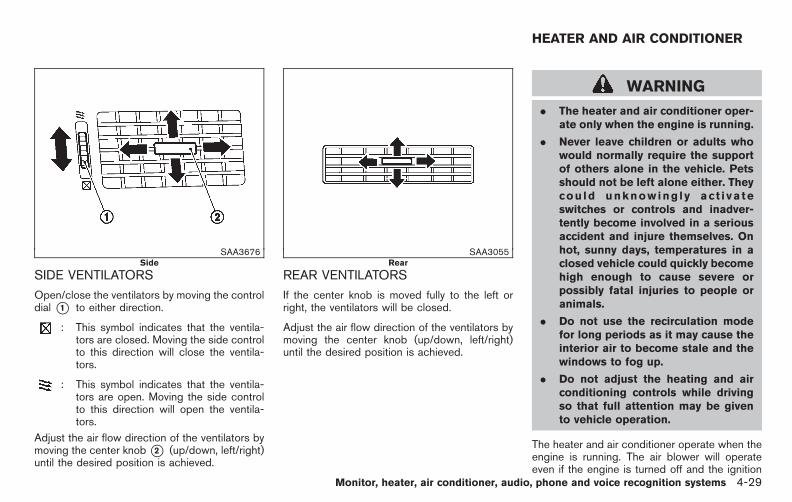
Black plate (207,1)
Model "E52-D" EDITED: 2010/ 10/ 25
SAA3676Side
SIDE VENTILATORS
Open/close the ventilators by moving the controldial *1 to either direction.
: This symbol indicates that the ventila-tors are closed. Moving the side controlto this direction will close the ventila-tors.
: This symbol indicates that the ventila-tors are open. Moving the side controlto this direction will open the ventila-tors.
Adjust the air flow direction of the ventilators bymoving the center knob*2 (up/down, left/right)until the desired position is achieved.
SAA3055Rear
REAR VENTILATORS
If the center knob is moved fully to the left orright, the ventilators will be closed.
Adjust the air flow direction of the ventilators bymoving the center knob (up/down, left/right)until the desired position is achieved.
WARNING
. The heater and air conditioner oper-ate only when the engine is running.
. Never leave children or adults whowould normally require the supportof others alone in the vehicle. Petsshould not be left alone either. Theycou ld unknowing l y ac t i va teswitches or controls and inadver-tently become involved in a seriousaccident and injure themselves. Onhot, sunny days, temperatures in aclosed vehicle could quickly becomehigh enough to cause severe orpossibly fatal injuries to people oranimals.
. Do not use the recirculation modefor long periods as it may cause theinterior air to become stale and thewindows to fog up.
. Do not adjust the heating and airconditioning controls while drivingso that full attention may be givento vehicle operation.
The heater and air conditioner operate when theengine is running. The air blower will operateeven if the engine is turned off and the ignition
HEATER AND AIR CONDITIONER
Monitor, heater, air conditioner, audio, phone and voice recognition systems 4-29

Black plate (208,1)
Model "E52-D" EDITED: 2010/ 10/ 25
switch is in the “ON” position.
SAA3594
SAA3514
OPERATING TIPS
When the engine coolant temperature andoutside air temperature are low, the air flowfrom the foot outlets may not operate. However,this is not a malfunction. After the coolanttemperature warms up, the air flow from thefoot outlets will operate normally.
The sensors *A and *B (for automatic airconditioner) located on the instrument panelhelp maintain a constant temperature. Do notput anything on or around the sensors.
4-30 Monitor, heater, air conditioner, audio, phone and voice recognition systems
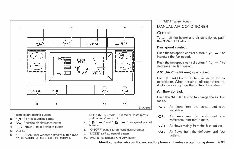
Black plate (209,1)
Model "E52-D" EDITED: 2010/ 10/ 25
SAA3596
1. Temperature control buttons
2. “ ” air recirculation button
3. “ ” outside air circulation button
4. “ FRONT” front defroster button
5. Display
6. “ REAR” rear window defroster button (See“REAR WINDOW AND OUTSIDE MIRROR
DEFROSTER SWITCH” in the “2. Instrumentsand controls” section.)
7. “ ” and “ ” fan speed controlbuttons
8. “ON·OFF” button for air conditioning system
9. “MODE” air flow control button
10. “A/C” air conditioner ON/OFF button
11. “REAR” control button
MANUAL AIR CONDITIONER
ControlsTo turn off the heater and air conditioner, pushthe “ON·OFF” button.
Fan speed control:
Push the fan speed control button “ ” toincrease the fan speed.
Push the fan speed control button “ ” todecrease the fan speed.
A/C (Air Conditioner) operation:
Push the A/C button to turn on or off the airconditioner. When the air conditioner is on, theA/C indicator light on the button illuminates.
Air flow control:
Push the “MODE” button to change the air flowmode.
: Air flows from the center and sideventilators.
: Air flows from the center and sideventilators, and foot outlets.
: Air flows mainly from the foot outlets.
: Air flows from the defroster and footoutlets.
Monitor, heater, air conditioner, audio, phone and voice recognition systems 4-31

Black plate (210,1)
Model "E52-D" EDITED: 2010/ 10/ 25
Temperature control:
Push the temperature control buttons (“ ”and “ ”) to set the desired temperature.
Air recirculation:
Push the air recirculation “ ” button torecirculate interior air inside the vehicle. Theindicator light on the air recirculation “ ”button will illuminate.
The air recirculation mode cannot be activatedwhen the air conditioner is in the front defrostingmode.
Outside air circulation:
Push the outside air circulation “ ” button todraw outside air into the passenger compart-ment. The indicator light on the outside aircirculation “ ” button will turn on.
Heater operation
Heating:
This mode is used to direct heated air to the footoutlets.
1. Push the outside air circulation “ ”button to switch to the outside air circulationmode. (The indicator light turns on.)
2. Push the air flow control button to change tothe mode.
3. Push the fan speed control buttons to setthe desired fan speed.
4. Push the temperature control buttons to setthe desired temperature between the middleand the hot position.
Ventilation:
This mode directs outside air to the side andcenter ventilators.
1. Push the outside air circulation “ ”button to switch to the outside air circulationmode. (The indicator light turns on.)
2. Push the air flow control button to change tothe mode.
3. Push the fan speed control buttons toset the desired position.
Bi-level heating:
This mode directs cool air from the side andcenter vents and warm air from the foot outlets.When the temperature is set to the maximum hotor cool position, the air between the ventilatorsand the foot outlets is the same temperature.
1. Push the outside air circulation “ ”button to switch to the outside air circulationmode. (The indicator light turns on.)
2. Push the air flow control button to change tothe mode.
3. Push the fan speed control buttons to setthe desired fan speed.
4. Push the temperature control buttons to setthe desired temperature.
Heating and defogging:
This mode heats the interior and defogs thewindows.
1. Push the air flow control button to change tothe mode.
2. Push the fan speed control buttons toset the desired fan speed.
3. Push the temperature control buttons to setthe desired temperature.
When the mode is selected, the airconditioner will automatically turn on. This willdehumidify the air and help to defog thewindows. The A/C indicator light will illuminatewhen the air conditioner automatically turns on.The air conditioner and A/C indicator light willremain on in all flow control modes until the A/Cbutton is pressed.
Air conditioner operationThe air conditioner system should be operatedfor approximately 10 minutes at least once amonth. This helps prevent damage to the airconditioner system due to the lack of lubrication.
4-32 Monitor, heater, air conditioner, audio, phone and voice recognition systems

Black plate (211,1)
Model "E52-D" EDITED: 2010/ 10/ 25
Cooling:
This mode is used to cool and dehumidify the air.
1. Push the outside air circulation “ ”button to switch to the outside air circulationmode. (The indicator light turns on.)
2. Push the air flow control button to change tothe mode.
3. Push the fan speed control buttons to setthe desired fan speed.
4. Push the A/C button on. (The A/C indicatorlight will illuminate.)
5. Push the temperature control buttons to setthe desired temperature between the middleand the cool position.
. For quick cooling when the outside tem-perature is high, push the air recirculation
button to switch to the air recirculationmode. (The indicator light turns on.) Be sureto turn off the air recirculation mode fornormal cooling.
. A visible mist may be seen coming from theventilators in hot, humid conditions as the airis cooled rapidly. This does not indicate amalfunction.
Dehumidified heating:
This mode is used to heat and dehumidify theair.
1. Push the outside air circulation “ ”button to switch to the outside air circulationmode. (The indicator light turns on.)
2. Push the air flow control button to change tothe position.
3. Push the fan speed control buttons to thedesired fan speed.
4. Push the A/C button on. (The A/C indicatorlight will illuminate.)
5. Push the temperature control buttons to setthe desired temperature between the middleand the hot position.
Dehumidified or defrosting/defogging:
This mode is used to defog the windows anddehumidify the air.
1. Push the front defroster button on.(The indicator light turns on.)
2. Push the fan speed control buttons to setthe desired fan speed.
3. Push the temperature control buttons to setthe desired temperature.
When the mode is selected, the air
conditioner will automatically turn on. This willdehumidify the air and help to defog thewindows. The A/C indicator light will illuminatewhen the air conditioner automatically turns on.The air conditioner and A/C indicator light willremain on in all flow control modes until the A/Cbutton is pushed.
To remove frost from the outside surface of thewindshield quickly, set the temperature to themaximum hot position and the fan speed tomaximum position.
Rear air conditioning system
Operating from front control buttons:
To control the rear air conditioning systemindependently with the front air conditionercontrol panel, push the “REAR” button. Whenthe rear air conditioning system control is on, theindicator light on the “REAR” button willilluminate and “REAR” will appear on the display.
In this state, the rear air conditioning system canbe adjusted with the front air conditioner controlpanel. However, if no operation is conducted forapproximately 10 seconds after the “REAR”button is pushed, the front air conditionercontrol panel will automatically switch to thefront air conditioning mode.
To cancel the rear air conditioning mode andswitch back to the front air conditioning mode,push “REAR” button one more time.
Monitor, heater, air conditioner, audio, phone and voice recognition systems 4-33
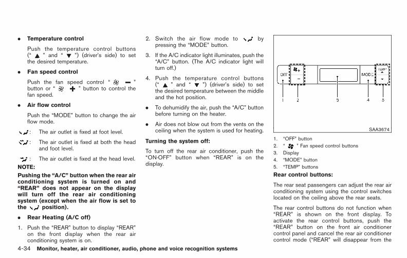
Black plate (212,1)
Model "E52-D" EDITED: 2010/ 10/ 25
. Temperature control
Push the temperature control buttons(“ ” and “ ”) (driver’s side) to setthe desired temperature.
. Fan speed control
Push the fan speed control “ ”button or “ ” button to control thefan speed.
. Air flow control
Push the “MODE” button to change the airflow mode.
: The air outlet is fixed at foot level.
: The air outlet is fixed at both the headand foot level.
: The air outlet is fixed at the head level.
NOTE:
Pushing the “A/C” button when the rear airconditioning system is turned on and“REAR” does not appear on the displaywill turn off the rear air conditioningsystem (except when the air flow is set tothe position).
. Rear Heating (A/C off)
1. Push the “REAR” button to display “REAR”on the front display when the rear airconditioning system is on.
2. Switch the air flow mode to bypressing the “MODE” button.
3. If the A/C indicator light illuminates, push the“A/C” button. (The A/C indicator light willturn off.)
4. Push the temperature control buttons(“ ” and “ ”) (driver’s side) to setthe desired temperature between the middleand the hot position.
. To dehumidify the air, push the “A/C” buttonbefore turning on the heater.
. Air does not blow out from the vents on theceiling when the system is used for heating.
Turning the system off:
To turn off the rear air conditioner, push the“ON·OFF” button when “REAR” is on thedisplay.
SAA3674
1. “OFF” button
2. “ ” Fan speed control buttons
3. Display
4. “MODE” button
5. “TEMP” buttons
Rear control buttons:
The rear seat passengers can adjust the rear airconditioning system using the control switcheslocated on the ceiling above the rear seats.
The rear control buttons do not function when“REAR” is shown on the front display. Toactivate the rear control buttons, push the“REAR” button on the front air conditionercontrol panel and cancel the rear air conditionercontrol mode (“REAR” will disappear from the
4-34 Monitor, heater, air conditioner, audio, phone and voice recognition systems
Black plate (213,1)
Model "E52-D" EDITED: 2010/ 10/ 25
front display).
“OFF” button: Turns off the rear air conditioningsystem.
“ ” Fan speed control buttons: Adjust rearfan speed
“MODE” button: Changes the rear air flow
“TEMP” buttons: Adjust the rear temperature
Monitor, heater, air conditioner, audio, phone and voice recognition systems 4-35

Black plate (214,1)
Model "E52-D" EDITED: 2010/ 10/ 25
SAA3595
1. Temperature control buttons (driver side)
2. “ ” air recirculation button
3. “ AUTO” auto-recirculation button (modelswith Advanced Climate Control System)/“ ” Outside air circulation button (modelswithout Advanced Climate Control System)
4. “ FRONT” front defroster button
5. Display
6. “ REAR” rear window defroster button (See“REAR WINDOW AND OUTSIDE MIRRORDEFROSTER SWITCH” in the “2. Instrumentsand controls” section.)
7. Temperature control buttons (passenger side)
8. “MODE” manual air flow control button
9. “ON·OFF” button for air conditioning system
10. “AUTO” button
11. “ ” fan speed control buttons
12. “A/C” air conditioner ON/OFF button
13. “REAR” control button
14. “DUAL” zone control ON/OFF button
AUTOMATIC AIR CONDITIONER
Automatic operation (AUTO)The AUTO mode may be used year-round as thesystem automatically controls constant tempera-ture, air flow distribution and fan speed after thedesired temperature is set manually.
To turn the heater and air conditioner on or off,push the “ON·OFF” button.
Cooling and dehumidified heating:
1. Push the “AUTO” button.(The AUTO indicator light will illuminate.)
2. If the A/C indicator light does not illuminate,push the “A/C” button.(The A/C indicator light will illuminate.)
3. Push the temperature control buttons(“ ” and “ ”) (driver’s side) to setthe desired temperature.
. The temperature can be set within therange of 60 to 908F (18 to 328C).
. When “DUAL” does not appear on the
4-36 Monitor, heater, air conditioner, audio, phone and voice recognition systems

Black plate (215,1)
Model "E52-D" EDITED: 2010/ 10/ 25
display:
— Pushing the “AUTO” button changesboth the driver’s and front passenger’sside temperature.
— Pushing the “DUAL” button allows theuser to independently change the frontpassenger’s side temperature with thepassenger side temperature controlbuttons (“ ” and “ ”). (“DUAL”will appear on the display.)
To cancel the separate temperaturesetting, push the “DUAL” button(“DUAL” will disappear from the display)and the driver’s side temperature settingwill be applied to both the driver’s andfront passenger’s sides.
4. Models with Advanced Climate ControlSystem (ACCS):
Push the “ AUTO” auto-recircula-tion button. The indicator light on the“ AUTO” auto-recirculation buttonwill illuminate. In this mode, the sensordetects odors and gas to automaticallyswitch between the air recirculationmode and the outside air circulationmode. (See “Advanced climate controlsystem” later in this section for details.)
Models without Advanced Climate ControlSystem (ACCS):
Push and hold the air recirculation“ ” button or outside air circulation“ ” button (the one with the indicatorlight on) for more than 2 seconds to setthe automatic control between the airrecirculation and outside air circulationmodes. (The “ ” and “ ” indicatorlights will blink twice.)
The following conditions need to be met for theautomatic air intake control mode to functionproperly.
. The air flow control is not in the frontdefogger mode (the indicator light on thefront defroster “ FRONT” button isturned off).
. The outside temperature is approximately328F (08C) or above.
A visible mist may be seen coming from theventilators in hot, humid conditions as the air iscooled rapidly. This does not indicate a mal-function.
Heating (A/C off):
1. Push the “AUTO” button.(The AUTO indicator light will illuminate.)
2. If the A/C indicator light illuminates, push the
“A/C” button.(The A/C indicator light will turn off.)
3. Push the temperature control buttons(“ ” and “ ”) (driver’s side) to setthe desired temperature.
When the DUAL mode is turned off (“DUAL”does not appear on the display):
— Pushing the “AUTO” button changesboth the driver’s and front passenger’sside temperature.
— Pushing the “DUAL” button allows theuser to independently change the frontpassenger’s side temperature with thepassenger side temperature controlbuttons (“ ” or “ ”). (“DUAL” willappear on the display.)
To cancel the separate temperaturesetting, push the “DUAL” button(“DUAL” will disappear from the display)and the driver’s side temperature settingwill be applied to both the driver’s andfront passenger’s sides.
4. Models with Advanced Climate ControlSystem (ACCS):
Push the “ AUTO” auto-recircula-tion button. The indicator light on the“ AUTO” auto-recirculation buttonwill illuminate. In this mode, the sensor
Monitor, heater, air conditioner, audio, phone and voice recognition systems 4-37

Black plate (216,1)
Model "E52-D" EDITED: 2010/ 10/ 25
detects odors and gas to automaticallyswitch between the air recirculationmode and the outside air circulationmode. (See “Advanced climate controlsystem” later in this section for details.)
Models without Advanced Climate ControlSystem (ACCS):
Push and hold the air recirculation“ ” button or outside air circulation“ ” button (the one with the indicatorlight on) for more than 2 seconds to setthe automatic control between the airrecirculation and outside air circulationmodes. (The “ ” or “ ” indicatorlight will blink twice.)
The following conditions need to be met forthe automatic air intake control mode tofunction properly.
. The air flow control is not in the frontdefogger mode (the indicator light onthe front defroster “ FRONT” buttonis turned off).
. The outside temperature is approxi-mately 328F (08C) or above.
NOTE:
. Do not set the temperature lower thanthe outside air temperature. Doing somay prevent the temperature frombeing controlled properly.
. To dehumidify the air, push the “A/C”button before turning on the heater.
Dehumidified defrosting/defogging:
1. Push the front defroster “ FRONT”button. (The indicator light will illuminate.)
2. Push the temperature control buttons(“ ” and “ ”) to set the desiredtemperature.
. To remove frost from the outside surfaceof the windshield quickly, set the tem-perature control and fan speed controlto their maximum position.
. After the windshield is cleared, push the“AUTO” button to set to the automaticmode.
. When the front defroster “ FRONT”button is pushed, the air conditioner willautomatically turn on sensing the out-side air temperature to defog the wind-shield. Do not select the air recirculationmode for the best defogging perfor-mance.
NOTE:
Do not set the temperature too low whenthe front defogger mode is on (the indi-cator on the front defroster “ FRONT”button is illuminated). Doing so may fogup the windshield.
Manual operationThe manual mode can be used to control theheater and air conditioner to your desiredsettings.
Fan speed control:
Push the fan speed control button “ ” toincrease the fan speed.
Push the fan speed control button “ ” todecrease the fan speed.
Push the “AUTO” button to change the fanspeed to the automatic mode.
Air flow control:
Push the “MODE” button to change the air flowmode.
: Air flows from the center and sideventilators.
: Air flows from the center and sideventilators, and foot outlets.
: Air flows mainly from the foot outlets.
4-38 Monitor, heater, air conditioner, audio, phone and voice recognition systems

Black plate (217,1)
Model "E52-D" EDITED: 2010/ 10/ 25
: Air flows from the defogger and footoutlets.
Temperature control:
Push the temperature control buttons (“ ”and “ ”) to set the desired temperature.
The temperature can be set within the range of60 to 908F (18 to 328C).
Air recirculation:
Push the air recirculation “ ” button torecirculate interior air inside the vehicle. Theindicator light on the air recirculation “ ”button will illuminate.
The air recirculation mode cannot be activatedwhen the air conditioner is in the front defrostingmode.
Outside air circulation:
. Models with Advanced Climate ControlSystem (ACCS):
Push the air recirculation “ ” buttontwice to draw outside air into the passengercompartment. The indicator light on the airrecirculation “ ” button will turn off.
. Models without Advanced Climate ControlSystem (ACCS):
Push the outside air circulation “ ”button to draw outside air into the passen-ger compartment. The indicator light on theoutside air circulation “ ” button will turnon.
Automatic air intake control:
. Models with Advanced Climate ControlSystem (ACCS):
Push the “ AUTO” auto-recirculation”button to switch to the automatic air intakecontrol mode. The indicator light on the“ AUTO” auto-recirculation button willilluminate. In this mode, the sensor detectsodors and gas to automatically switchbetween the air recirculation mode and theoutside air circulation mode. (See “Ad-vanced climate control system” later in thissection for details.)
. Models without Advanced Climate ControlSystem (ACCS):
To switch to the automatic control mode,push the intake air control button for about 2seconds. The indicator lights (both airrecirculation “ ” and outside air circula-tion “ ” buttons) will flash twice, andthen the intake air will be controlled auto-
matically.
The following conditions need to be met for theautomatic air intake control mode to functionproperly.
. The air flow control is not in the frontdefogger mode (the indicator light on thefront defroster “ FRONT” button isturned off).
. The outside temperature is approximately08C (328F) or above.
Monitor, heater, air conditioner, audio, phone and voice recognition systems 4-39

Black plate (218,1)
Model "E52-D" EDITED: 2010/ 10/ 25
SAA3670
Advanced climate control system (if soequipped)The advanced climate control system keeps theair inside of the vehicle clean, using the ioncontrol and the automatic air intake control withexhaust gas detecting sensor.
Push the “ AUTO” auto-recirculation button(the indicator light on the “ AUTO” auto-recirculation button will illuminate) to activate theion control and the automatic air intake control.
Ion control:
This unit generates highly concentrated Plas-macluster ions into the air blown from theventilators and reduces odor absorbed into the
interior trim.
When the air conditioner is turned on, thesystem generates Plasmacluster ions automati-cally.
“The high-density Plasmacluster ions generatedin the air conditioner’s air stream not onlysuppress airborne bacteria and reduce theadherence of odors to the interior trim, but alsohave a proven skin moisture preserving effect.”
The amount of Plasmacluster ions increasesaccording to the amount of air flow. When the airflow is high, “ ” *A is displayed on thescreen and when the air flow is low, theindication in the screen changes to “ ” *B .
Plasmacluster and Plasmacluster ions are regis-tered trademark of Sharp corporation.
Automatic air intake control with exhaustgas/outside odor detection sensor:
This vehicle is equipped with an exhaust gasdetection sensor. When the automatic air intakecontrol is activated, the sensor detects industryodors such as pulp or chemicals, and exhaustgas such as gasoline or diesel. When suchodors or gas are detected, “ ” *C willappear on the display and the system auto-matically changes from the outside air circulationmode to the recirculation mode.
The automatic air intake control can be activated
when the “ AUTO” auto-recirculation buttonis pushed (the indicator light on the “AUTO” auto-recirculation button will illuminate)under the following conditions.
. The air flow control is not in the frontdefogger mode (the indicator light on thefront defogger “ FRONT” button isturned off).
. The outside temperature is about 328F(08C) or above.
When the automatic air intake control is ON, forthe first 5 minutes, the recirculation mode isselected to prevent dust, dirt and pollen fromentering the vehicle and cleans the air inside ofthe vehicle with positive and negative ions thatare emitted from the ventilator.
After 5 minutes, the sensor detects exhaust gasand automatically alternates between the recir-culation mode and outside air circulation mode.
Turning the system offPush the “ON·OFF” button.
Rear air conditioning systemTo control the rear air conditioning systemindependently with the front air conditionercontrol panel, push the “REAR” button. Whenthe rear air conditioning system control is on, theindicator light on the “REAR” button willilluminate and “ ” will appear on the display.
4-40 Monitor, heater, air conditioner, audio, phone and voice recognition systems

Black plate (219,1)
Model "E52-D" EDITED: 2010/ 10/ 25
In this state, the rear air conditioning system canbe adjusted with the front air conditioner controlpanel. However, if no operation is conducted forapproximately 10 seconds after the “REAR”button is pushed, the front air conditionercontrol panel will automatically switch to thefront air conditioning mode.
To cancel the rear air conditioning mode andswitch back to the front air conditioning mode,push “REAR” button one more time.
Automatic operation:
1. Push the “REAR” button to display “ ”on the front display when the rear airconditioning system is on.
2. Push the “AUTO” button. (The AUTOindicator light will illuminate.)
3. Push the temperature control buttons(“ ” and “ ”) (driver’s side) to setthe desired temperature.
Manual operation:
To operate the rear air conditioning system usingthe front air conditioner control panel, push“REAR” button (the indicator light on the“REAR” button will illuminate and “ ” willappear on the display).
. Temperature control
Push the temperature control buttons
(“ ” and “ ”) (driver’s side) to setthe desired temperature.
. Fan speed control
Push the fan speed control “ ”button or “ ” button to manuallycontrol the fan speed.
. Air flow control
Push the “MODE” button to change the airflow mode.
: The air outlet is fixed at foot level.
: The air outlet is fixed at both the headand foot level.
: The air outlet is fixed at the head level.
NOTE:
Pushing the “A/C” button when the rear airconditioning system is turned on and“ ” does not appear on the display willturn off the rear air conditioning system(except when the air flow is set to theposition).
Rear Heating (A/C off):
1. Push the “REAR” button to display “ ”on the front display when the rear airconditioning system is on.
2. Switch the air flow mode to bypressing the “MODE” button.
3. Push the “AUTO” button. (The AUTOindicator light will illuminate.)
4. If the A/C indicator light illuminates, push the“A/C” button. (The A/C indicator light willturn off.)
5. Push the temperature control buttons(“ ” and “ ”) (driver’s side) to setthe desired temperature.
. Do not set the temperature lower than theoutside air temperature. Doing so may causethe temperature to not be controlled prop-erly.
. To dehumidify the air, push the “A/C” buttonbefore turning on the heater.
. Air does not blow out from the vents on theceiling when the system is used for heating.
Turning the system off:
To turn off the rear air conditioner, push the“ON·OFF” button when “ ” is on the display.
Monitor, heater, air conditioner, audio, phone and voice recognition systems 4-41

Black plate (220,1)
Model "E52-D" EDITED: 2010/ 10/ 25
SAA3517
1. “OFF” button
2. “ ” Fan speed control buttons
3. “AUTO” button
4. Display
5. “MODE” button
6. “TEMP” buttons
Rear control buttons:
The rear seat passengers can adjust the rearautomatic air conditioning system using thecontrol switches located on the ceiling abovethe rear seats (models with NISSAN mobileentertainment system) or on the upper left sideof the second row seat (models withoutNISSAN mobile entertainment system).
The rear control buttons do not function when“ ” is shown on the front display. To activatethe rear control buttons, push the “REAR”button on the front air conditioner control paneland cancel the rear air conditioner control mode(“ ” will disappear from the front display).
“OFF” button: Turns off the rear air conditioningsystem.
“ ” Fan speed control buttons: Adjust rearfan speed
“AUTO” button: Turns on/off the automaticoperation mode when rear air conditioningsystem is on
“MODE” button: Changes the rear air flow
“TEMP” buttons: Adjust the rear temperature
SERVICING AIR CONDITIONER
WARNING
The air conditioner contains refrigerantunder high pressure. To avoid personalinjury, any air conditioner serviceshould be done only by an experiencedtechnician with the proper equipment.
The air conditioner system in your vehicle ischarged with a refrigerant designed with theenvironment in mind.
This refrigerant will not harm the earth’sozone layer. However, it may contribute in asmall part to global warming.
Special charging equipment and lubricant arerequired when servicing your vehicle’s air con-ditioner. Using improper refrigerants or lubri-cants will cause severe damage to the airconditioner system. (See “AIR CONDITIONINGSYSTEM REFRIGERANT AND LUBRICANTRECOMMENDATIONS” in the “9. Technicaland consumer information” section.)
A NISSAN dealer will be able to service yourenvironmentally friendly air conditioner system.
4-42 Monitor, heater, air conditioner, audio, phone and voice recognition systems

Black plate (221,1)
Model "E52-D" EDITED: 2010/ 10/ 25
IN-CABIN MICROFILTER
Models without Advanced Climate ControlSystem (ACCS):
The climate control system is equipped with anin-cabin microfilter which collects dirt, pollen,dust, etc. To make sure the air conditioner heats,defogs, and ventilates efficiently, replace thefilter in accordance with the maintenanceschedule in the NISSAN Service and Mainte-nance Guide. To replace the filter, contact aNISSAN dealer.
The filter should be replaced if air flow isextremely decreased or when windows fogup easily when operating heater or airconditioning system.
Models with Advanced Climate Control System(ACCS):
The climate control system is equipped with anatural grape seed polyphenol filter whichcollects and neutralizes dirt, pollen, dust, etc.To make sure that the air conditioner heats,defogs and ventilates efficiently, replace the filterin accordance with the maintenance schedule inthe NISSAN Service and Maintenance Guide.To replace the filter, contact a NISSAN dealer.
The filter should be replaced if the air flowdecreases significantly or if windows fogup easily when operating the heater or airconditioner.
AUDIO OPERATION PRECAUTIONS
RadioPush the ignition switch to the ACC or ONposition and push the radio band select buttonto turn on the radio. If you listen to the radio withthe engine not running, the ignition switchshould be pushed to the ACC position.
Radio reception is affected by station signalstrength, distance from radio transmitter, build-ings, bridges, mountains and other externalinfluences. Intermittent changes in receptionquality normally are caused by these externalinfluences.
Using a cellular phone in or near thevehicle may influence radio receptionquality.
Radio reception:
Your NISSAN radio system is equipped withstate-of-the-art electronic circuits to enhanceradio reception. These circuits are designed toextend reception range, and to enhance thequality of that reception.
However there are some general characteristicsof both FM and AM radio signals that can affectradio reception quality in a moving vehicle, evenwhen the finest equipment is used. Thesecharacteristics are completely normal in a givenreception area, and do not indicate any mal-
function in your NISSAN radio system.
Reception conditions will constantly changebecause of vehicle movement. Buildings, terrain,signal distance and interference from othervehicles can work against ideal reception.Described below are some of the factors thatcan affect your radio reception.
Some cellular phones or other devices maycause interference or a buzzing noise to comefrom the audio system speakers. Storing thedevice in a different location may reduce oreliminate the noise.
AUDIO SYSTEM
Monitor, heater, air conditioner, audio, phone and voice recognition systems 4-43

Black plate (222,1)
Model "E52-D" EDITED: 2010/ 10/ 25
SAA0306
FM radio reception:
Range: FM range is normally limited to 25 to 30miles (40 to 48 km), with monaural (singlechannel) FM having slightly more range thanstereo FM. External influences may sometimesinterfere with FM station reception even if theFM station is within 25 miles (40 km). Thestrength of the FM signal is directly related to thedistance between the transmitter and receiver.FM signals follow a line-of-sight path, exhibitingmany of the same characteristics as light. Forexample they will reflect off objects.
Fade and drift: As your vehicle moves away froma station transmitter, the signals will tend to fadeand/or drift.
Static and flutter: During signal interference frombuildings, large hills or due to antenna position,usually in conjunction with increased distancefrom the station transmitter, static or flutter canbe heard. This can be reduced by lowering thetreble setting to reduce the treble response.
Multipath reception: Because of the reflectivecharacteristics of FM signals, direct and re-flected signals reach the receiver at the sametime. The signals may cancel each other,resulting in momentary flutter or loss of sound.
AM radio reception:
AM signals, because of their low frequency, canbend around objects and skip along the ground.In addition, the signals can be bounced off theionosphere and bent back to earth. Because ofthese characteristics. AM signals are alsosubject to interference as they travel fromtransmitter to receiver.
Fading: Occurs while the vehicle is passingthrough freeway underpasses or in areas withmany tall buildings. It can also occur for severalseconds during ionospheric turbulence even inareas where no obstacles exist.
Static: Caused by thunderstorms, electricalpower lines, electric signs and even traffic lights.
Satellite radio reception (if so equipped):
When the satellite radio is used for the first timeor the battery has been replaced, the satelliteradio may not work properly. This is not amalfunction. Wait more than 10 minutes with thesatellite radio ON and the vehicle outside of anymetal or large building for the satellite radio toreceive all of the necessary data.
The satellite radio mode requires an active XM®
Satellite Radio subscription. The satellite radio isnot available in Alaska, Hawaii and Guam.
The satellite radio performance may be affectedif cargo carried on the roof blocks the satelliteradio signal.
If possible, do not put cargo near the satelliteantenna.
A build up of ice on the satellite radio antennacan affect satellite radio performance. Removethe ice to restore satellite radio reception.
4-44 Monitor, heater, air conditioner, audio, phone and voice recognition systems

Black plate (223,1)
Model "E52-D" EDITED: 2010/ 10/ 25
SAA0480
Compact Disc (CD) player. Do not force a compact disc into the CD
insert slot. This could damage the CD and/or CD changer/player.
. Trying to load a CD with the CD door closedcould damage the CD and/or CD changer.
. During cold weather or rainy days, the playermay malfunction due to the humidity. If thisoccurs, remove the CD and dehumidify orventilate the player completely.
. The player may skip while driving on roughroads.
. The CD player sometimes cannot functionwhen the passenger compartment tempera-ture is extremely high. Decrease the tem-perature before use.
. Only use high quality 4.7 in (12 cm) rounddiscs that have the “COMPACT disc DIGI-TAL AUDIO” logo on the disc or packaging.
. Do not expose the CD to direct sunlight.
. CDs that are of poor quality, dirty, scratched,covered with fingerprints, or that have pinholes may not work properly.
. The following CDs may not work properly:
— Copy control compact discs (CCCD)
— Recordable compact discs (CD-R)
— Rewritable compact discs (CD-RW)
. Do not use the following CDs as they maycause the CD player to malfunction.
— 3.1 in (8 cm) discs
— CDs that are not round
— CDs with a paper label
— CDs that are warped, scratched, or haveabnormal edges
. This audio system can only play prerecordedCDs. It has no capabilities to record or burnCDs.
. If the CD cannot be played, one of thefollowing messages will be displayed.
CHECK DISC:
— Confirm that the CD is inserted correctly(the label side is facing up, etc.).
— Confirm that the CD is not bent or warpedand it is free of scratches.
PUSH EJECT:
This is an error due to the temperature insidethe player is too high. Remove the CD bypushing the EJECT button, and after a shorttime reinsert the CD. The CD can be playedwhen the temperature of the player returnsto normal.
UNPLAYABLE:
The file is unplayable in this audio system(only MP3 or WMA CD).
Monitor, heater, air conditioner, audio, phone and voice recognition systems 4-45
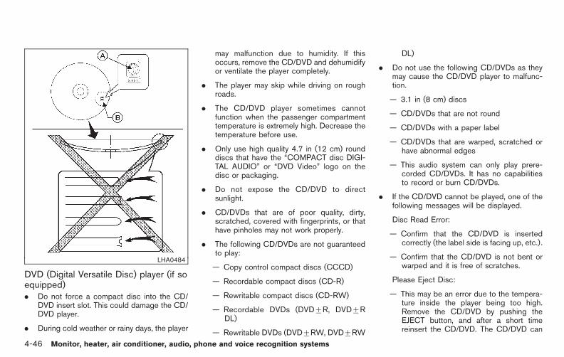
Black plate (224,1)
Model "E52-D" EDITED: 2010/ 10/ 25
LHA0484
DVD (Digital Versatile Disc) player (if soequipped). Do not force a compact disc into the CD/
DVD insert slot. This could damage the CD/DVD player.
. During cold weather or rainy days, the player
may malfunction due to humidity. If thisoccurs, remove the CD/DVD and dehumidifyor ventilate the player completely.
. The player may skip while driving on roughroads.
. The CD/DVD player sometimes cannotfunction when the passenger compartmenttemperature is extremely high. Decrease thetemperature before use.
. Only use high quality 4.7 in (12 cm) rounddiscs that have the “COMPACT disc DIGI-TAL AUDIO” or “DVD Video” logo on thedisc or packaging.
. Do not expose the CD/DVD to directsunlight.
. CD/DVDs that are of poor quality, dirty,scratched, covered with fingerprints, or thathave pinholes may not work properly.
. The following CD/DVDs are not guaranteedto play:
— Copy control compact discs (CCCD)
— Recordable compact discs (CD-R)
— Rewritable compact discs (CD-RW)
— Recordable DVDs (DVD+R, DVD+RDL)
— Rewritable DVDs (DVD+RW, DVD+RW
DL)
. Do not use the following CD/DVDs as theymay cause the CD/DVD player to malfunc-tion.
— 3.1 in (8 cm) discs
— CD/DVDs that are not round
— CD/DVDs with a paper label
— CD/DVDs that are warped, scratched orhave abnormal edges
— This audio system can only play prere-corded CD/DVDs. It has no capabilitiesto record or burn CD/DVDs.
. If the CD/DVD cannot be played, one of thefollowing messages will be displayed.
Disc Read Error:
— Confirm that the CD/DVD is insertedcorrectly (the label side is facing up, etc.).
— Confirm that the CD/DVD is not bent orwarped and it is free of scratches.
Please Eject Disc:
— This may be an error due to the tempera-ture inside the player being too high.Remove the CD/DVD by pushing theEJECT button, and after a short timereinsert the CD/DVD. The CD/DVD can
4-46 Monitor, heater, air conditioner, audio, phone and voice recognition systems

Black plate (225,1)
Model "E52-D" EDITED: 2010/ 10/ 25
be played when the temperature of theplayer returns to normal. If the errorpersists, consult your local dealership.
Unplayable File:
— The file may be copy protected.
— The file is not MP3, WMA, AAC, M4A orDivX® type.
Region Invalid:
— The DVD is not for region 1 or all regions.Use DVDs with a region code “1”, “ALL”or “1 included” for your DVD entertain-ment system. (The region code *A isdisplayed as a small symbol printed onthe top of the DVD *B .) This vehicle-installed DVD player cannot play DVDswith a region code other than “1” or“ALL”.
Copyright and trademark:
. The technology protected by the U.S. patentand other intellectual property rights ownedby Macrovision Corporation and other rightholders is adopted for this system.
. This copyright protected technology cannotbe used without a permit from MacrovisionCorporation. It is limited to be personal use,etc., as long as the permit from MacrovisionCorporation is not issued.
. Modifying or disassembling is prohibited.
. Dolby digital is manufactured under licensefrom Dolby Laboratories, Inc.
. Dolby and the double D mark “ ” aretrademarks of Dolby Laboratories, Inc.
. DTS and DTS 2.0 “ ” are registeredtrademarks of DTS, Inc.
. DTS and DTS Digital Surround “ ” areregistered trademarks of Digital TheaterSystems, Inc.
Parental level (parental control):
DVDs with the parental control setting can beplayed with this system. Please use your ownjudgement to set the parental control with thesystem.
Disc selection:
The following disc formats can be played withthe DVD drive.
. DVD-VIDEO
. VIDEO-CD
. CD-DA (Conventional Compact Disc)
. DTS-CD (models with navigation system)
USB (Universal Serial Bus) (if soequipped)This system supports various USB memorysticks, USB hard drives and iPod® players.There are some USB devices which may notbe supported with this system.
. Make sure that the USB device is connectedcorrectly into the USB connector.
. Do not force the memory stick or USB cableinto the USB connector. This could damagethe connector.
. During cold weather or rainy days, the playermay malfunction due to humidity. If thisoccurs, remove the USB device and dehu-midify or ventilate the USB player comple-tely.
. The USB player sometimes cannot functionwhen the passenger compartment tempera-ture is extremely high. Decrease the tem-perature before use.
. Do not leave USB memory in a place proneto static electricity or where the air condi-tioner blows directly. The data in the USBmemory may be damaged.
. The vehicle is not equipped with a USBmemory stick.
. A USB device cannot be formatted with this
Monitor, heater, air conditioner, audio, phone and voice recognition systems 4-47

Black plate (226,1)
Model "E52-D" EDITED: 2010/ 10/ 25
system. To format a USB device, use apersonal computer.
. Partitioned USB devices may not be playedcorrectly.
. Some characters used in other languages(Chinese, Japanese, etc.) are not displayedproperly on the vehicle center screen. UsingEnglish language characters with a USBdevice is recommended.
. Do not connect a USB device if a connectoror cable is wet. Allow the cable and/orconnectors to dry completely before con-necting the USB device. If the connector isexposed to fluids other than water, evapora-tive residue may cause a short between theconnector pins.
. Large video podcast files cause slowresponses in an iPod®. The vehicle centerdisplay may momentarily black out, but it willsoon recover.
. If an iPod® automatically selects large videopodcast files while in the shuffle mode, thevehicle center display may momentarilyblack out, but it will soon recover.
. Audiobooks may not play in the same orderas they appear on an iPod®.
. An iPod nano® (1st generation) may remainin fast forward or rewind mode if it is
connected during a seek operation. In thiscase, please manually reset the iPod®.
. An iPod nano® (2nd generation) will con-tinue to fast forward or rewind if it isdisconnected during a seek operation.
. An incorrect song title may appear when thePlay Mode is changed while using the iPodnano® (2nd generation)
iPod® is a trademark of Apple Inc., registered inthe U.S. and other countries.
Compressed Audio Files (MP3/WMA/AAC)
Explanation of terms:
. MP3 — MP3 is short for Moving PicturesExperts Group Audio Layer 3. MP3 is themost well known compressed digital audiofile format. This format allows for near “CDquality” sound, but at a fraction of the size ofnormal audio files. MP3 conversion of anaudio track can reduce the file size byapproximately a 10:1 ratio (Sampling: 44.1kHz, Bit rate: 128 kbps) with virtually noperceptible loss in quality. The compressionreduces certain parts of sound that seeminaudible to most people.
. WMA — Windows Media Audio (WMA) is acompressed audio format created by Micro-soft as an alternative to MP3. The WMA
codec offers greater file compression thanthe MP3 codec, enabling storage of moredigital audio tracks in the same amount ofspace when compared to MP3s at the samelevel of quality.
. AAC/M4A — Advanced Audio Coding(AAC) is a lossy audio compression format.Audio files that have been encoded withAAC are generally smaller in size and delivera higher quality of sound than MP3.
. Bit rate — Bit rate denotes the number ofbits per second used by a digital music file.The size and quality of a compressed digitalaudio file is determined by the bit rate usedwhen encoding the file.
. Sampling frequency — Sampling frequencyis the rate at which the samples of a signalare converted from analog to digital (A/Dconversion) per second.
. Multisession — Multisession is one of themethods for writing data to media. Writingdata once to the media is called a singlesession, and writing more than once iscalled a multisession.
. ID3/WMA Tag — The ID3/WMA tag is thepart of the encoded MP3 or WMA file thatcontains information about the digital musicfile such as song title, artist, album title,encoding bit rate, track time duration, etc.
4-48 Monitor, heater, air conditioner, audio, phone and voice recognition systems

Black plate (227,1)
Model "E52-D" EDITED: 2010/ 10/ 25
ID3 tag information is displayed on theAlbum/Artist/Track title line on the display.
* Windows® and Windows Media® are regis-tered trademarks or trademarks of MicrosoftCorporation in the United States of Americaand/or other countries.
SAA2494
Playback order:
. The folder names of folders not containingcompressed audio files are not shown in thedisplay.
. If there is a file in the top level of a disc/USB,“Root Folder” is displayed.
. The playback order is the order in which thefiles were written by the writing software, sothe files might not play in the desired order.
. Music playback order of compressed audiofiles is as illustrated in the next figure.
Monitor, heater, air conditioner, audio, phone and voice recognition systems 4-49
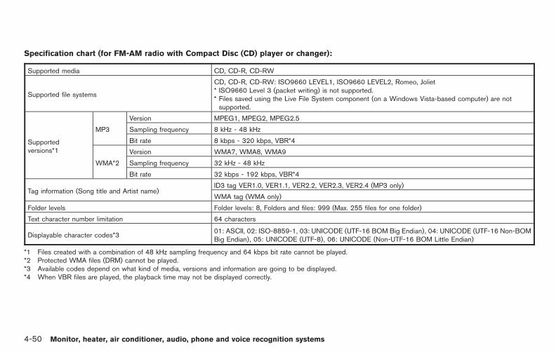
Black plate (228,1)
Model "E52-D" EDITED: 2010/ 10/ 25
Specification chart (for FM-AM radio with Compact Disc (CD) player or changer):
Supported media CD, CD-R, CD-RW
Supported file systems
CD, CD-R, CD-RW: ISO9660 LEVEL1, ISO9660 LEVEL2, Romeo, Joliet* ISO9660 Level 3 (packet writing) is not supported.* Files saved using the Live File System component (on a Windows Vista-based computer) are notsupported.
Supportedversions*1
MP3
Version MPEG1, MPEG2, MPEG2.5
Sampling frequency 8 kHz - 48 kHz
Bit rate 8 kbps - 320 kbps, VBR*4
WMA*2
Version WMA7, WMA8, WMA9
Sampling frequency 32 kHz - 48 kHz
Bit rate 32 kbps - 192 kbps, VBR*4
Tag information (Song title and Artist name)ID3 tag VER1.0, VER1.1, VER2.2, VER2.3, VER2.4 (MP3 only)
WMA tag (WMA only)
Folder levels Folder levels: 8, Folders and files: 999 (Max. 255 files for one folder)
Text character number limitation 64 characters
Displayable character codes*301: ASCII, 02: ISO-8859-1, 03: UNICODE (UTF-16 BOM Big Endian), 04: UNICODE (UTF-16 Non-BOMBig Endian), 05: UNICODE (UTF-8), 06: UNICODE (Non-UTF-16 BOM Little Endian)
*1 Files created with a combination of 48 kHz sampling frequency and 64 kbps bit rate cannot be played.*2 Protected WMA files (DRM) cannot be played.*3 Available codes depend on what kind of media, versions and information are going to be displayed.*4 When VBR files are played, the playback time may not be displayed correctly.
4-50 Monitor, heater, air conditioner, audio, phone and voice recognition systems

Black plate (229,1)
Model "E52-D" EDITED: 2010/ 10/ 25
Specification chart (for FM-AM-SAT radio with Compact Disc (CD) player):
Supported media CD, CD-R, CD-RW, DVD-ROM*5, DVD+R, DVD+RW, DVD+R DL, USB2.0
Supported file systems
CD, CD-R, CD-RW, DVD-ROM*5, DVD+R, DVD+RW, DVD+R DL: ISO9660 LEVEL1, ISO9660 LEVEL2,Romeo, Joliet* ISO9660 Level 3 (packet writing) is not supported.* Files saved using the Live File System component (on a Windows Vista-based computer) are not supported.
UDF Bridge (UDF1.02+ISO9660), UDF1.5, UDF2.0* VDF1.5/VDF2.0 (packet writing) is not supported.
USB memory: FAT16, FAT32
Supportedversions*1
MP3
Version MPEG1 Audio Layer 3
Sampling frequency 8 kHz - 48 kHz
Bit rate 8 kbps - 320 kbps, VBR*4
WMA*2
Version WMA7, WMA8, WMA9
Sampling frequency 32 kHz - 48 kHz
Bit rate 32 kbps - 192 kbps, VBR*4
AAC*5
Version MPEG-AAC
Sampling frequency 8 kHz - 96 kHz
Bit rate 16 kbps - 320 kbps, VBR*4
Tag information (Song title and Artist name)ID3 tag VER1.0, VER1.1, VER2.2, VER2.3, VER2.4 (MP3 only)
WMA tag (WMA only)
Folder levels
Models with navigation system:Folder levels: 8, Folders: 512 (including root folder), Files: 5,000Models without navigation system:Folder levels: 8, Folders and files: 999 (Max. 255 files for one folder)
Text character number limitationModels with navigation system: 100 characters
Models without navigation system: 64 characters
Monitor, heater, air conditioner, audio, phone and voice recognition systems 4-51

Black plate (230,1)
Model "E52-D" EDITED: 2010/ 10/ 25
Displayable character codes*301: ASCII, 02: ISO-8859-1, 03: UNICODE (UTF-16 BOM Big Endian), 04: UNICODE (UTF-16 Non-BOM BigEndian), 05: UNICODE (UTF-8), 06: UNICODE (Non-UTF-16 BOM Little Endian), 07: SHIFT-JIS
*1 Files created with a combination of 48 kHz sampling frequency and 64 kbps bit rate cannot be played.*2 Protected WMA files (DRM) cannot be played.*3 Available codes depend on what kind of media, versions and information are going to be displayed.*4 When VBR files are played, the playback time may not be displayed correctly.*5 Models with navigation system
4-52 Monitor, heater, air conditioner, audio, phone and voice recognition systems

Black plate (231,1)
Model "E52-D" EDITED: 2010/ 10/ 25
Troubleshooting guide:
Symptom Cause and Countermeasure
Cannot play
Check if the disc or USB device was inserted correctly.
Check if the disc is scratched or dirty.
Check if there is condensation inside the player, and if there is, wait until the condensation is gone (about 1 hour) before using theplayer.
If there is a temperature increase error, the player will play correctly after it returns to the normal temperature.
If there is a mixture of music CD files (CD-DA data) and compressed audio files on a CD, only the music CD files (CD-DA data) willbe played.
Files with extensions other than “.MP3 (.mp3)”, “.WMA (.wma)”, “.AAC (.aac)”, “.M4A (.m4a)”, or “.AA3 (.aa3)” cannot be played. Inaddition, the character codes and number of characters for folder names and file names should be in compliance with thespecifications.
Check if the disc or the file is generated in an irregular format. This may occur depending on the variation or the setting ofcompressed audio writing applications or other text editing applications.
Check if the finalization processes, such as session close and disc close, has been performed for the disc.
Check if the disc or USB device is copyright protected.
Poor sound quality Check if the disc is scratched or dirty.
It takes a relatively long time beforethe music starts playing.
If there are many folder or file levels on the disc or USB device, some time may be required before the music starts playing.
Music cuts off or skipsThe writing software and hardware combination might not match, or the writing speed, writing depth, writing width, etc., might notmatch the specifications. Try using the slowest writing speed.
Skipping with high bit rate files Skipping may occur with large quantities of data, such as for high bit rate data.
Move immediately to the next songwhen playing.
If an unsupported compressed audio file has been given a supported extension like .MP3, or when play is prohibited by copyrightprotection, the player will skip to the next song.
The songs do not play back in thedesired order.
The playback order is the order in which the files were written by the writing software, so the files might not play in the desired order.
Random/Shuffle may be active on the audio system or on a USB device.
Monitor, heater, air conditioner, audio, phone and voice recognition systems 4-53

Black plate (232,1)
Model "E52-D" EDITED: 2010/ 10/ 25
Compressed Video Files (models withnavigation system)
Explanation of terms:
. DivX® - DivX® refers to the DivX® codecowned by DivX, Inc. used for a lossycompression of video based on MPEG-4.
. AVI - AVI stands for Audio Video Interleave.It is a standard file format originated byMicrosoft Corporation. A “.divx” encoded filecan be saved into the “.avi” file format forplayback on this system if it meets therequirements stated in the table in thissection. However, not all the “.avi” files areplayable on this system since differentencodings can be used than the DivX®
codec.
. ASF - ASF stands for Advanced SystemsFormat. It is a file format owned by MicrosoftCorporation. Note: Only “.asf” files that meetthe requirements stated in the table in thissection can be played.
. Bit rate — Bit rate denotes the number ofbits per second used by a digital video file.The size and quality of a compressed digitalaudio file is determined by the bit rate usedwhen encoding the file.
Requirement for Supporting Video Play-back:
Media CD, CD-R, CD-RW, DVD, DVD+R, DVD+RW, DVD+RW DL, USB 2.0 Memory
File Systems CD,CD-R,CD-RW,DVD,DVD+R,DVD+RW,DVD+RW DL
ISO9660 LEVEL1, ISO9660 LEVEL2, Romeo, Joliet, UDF Bridge(UDF1.02+ISO9660), UDF1.5, UDF2.0
- ISO9660 Level 3 (packet writing) is not supported.
- Files saved using the Live File System component (on a WindowsVista-based computer) are not supported.
- VDF1.5/VDF2.0 (packet writing) is not supported.
USB Memory FAT16, FAT32
File Types .divx, .avi Video Codecs DivX3, DivX4, DivX5, DivX6
Audio Codecs MP3, MPEG2.5 Audio Layer3, AC3, LPCM
.asf Video Codec ISO-MPEG4
Audio Codec G.726
Bit Rates .divx, .avi Maximum Average 4Mbps
Maximum Peak 8Mbps
Resolution .divx, .avi Minimum 32 6 32
Maximum 720 6 480
.asf Minimum 32 6 32
Maximum 720 6 576
4-54 Monitor, heater, air conditioner, audio, phone and voice recognition systems
Black plate (233,1)
Model "E52-D" EDITED: 2010/ 10/ 25
Bluetooth® Audio player (models withnavigation system). Some Bluetooth® audio devices may not be
recognized by the in-vehicle audio system.
. It is necessary to set up the wirelessconnection between a compatible Blue-tooth® audio device and the in-vehicleBluetooth® module before using the Blue-tooth® audio player.
. Operating procedure of the Bluetooth®
audio player will vary depending on thedevice. Make sure you understand how tooperate an audio device before using it withthis system.
. The Bluetooth® audio player may be stoppedunder the following conditions:
— Receiving a hands-free call.
— Checking the connection to the hands-free phone.
. Do not place a Bluetooth® audio device in anarea surrounded by metal or far away fromthe in-vehicle Bluetooth® module to preventtone quality degradation and wireless con-nection disruption.
. While an audio device is connected througha Bluetooth® wireless connection, the bat-tery power of the device may discharge
quicker than usual.
. This system supports the Bluetooth® AudioDistribution Profile (A2DP, AVRCP).
. Bluetooth® is a trademark owned by Blue-tooth SIG, Inc. and licensed to Clarion Co.,Ltd.
Music Box® (if so equipped)
Recording:
. Note that data that is lost and not stored tothe hard drive/flash memory due to systemdamage, improper operation or malfunctionis not under warranty.
. Vehicle owners are not permitted to recordmusic without permission of the owner ofthe copyright except for personal use.
. Check if the music is appropriately recordedto the hard drive/flash memory after record-ing when the compact disc cannot bererecorded.
. Some music cannot be recorded dependingon the disc condition due to high-speedrecording being used.
. Jumping sounds may be recorded when acompact disc is recorded while driving onrough roads and excessive vibration occurs.
. A mark indicating jumping sounds is dis-played if jumping sounds are recorded.
. No sounds may be recorded if jumpingsounds occurs or the disc is in poorcondition.
. Tracks that include Serial Copy Manage-ment System (SCMS) are not recorded.
. If a compact disc is scratched or dirty, it maynot be recorded, jumping sounds may occuror it may take a long time to record.
Automatic title download:
. The title information that is automaticallydownloaded may differ from the actual title.
. When newly released compact discs arerecorded, their title information may not bedownloaded.
. The title information on the hard drive/flashmemory can be updated. (See “Playingrecorded songs” later in this section.)
Monitor, heater, air conditioner, audio, phone and voice recognition systems 4-55
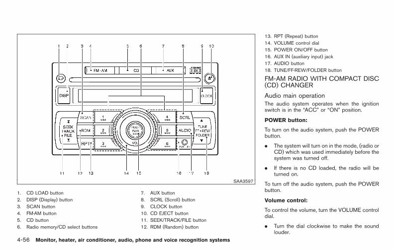
Black plate (234,1)
Model "E52-D" EDITED: 2010/ 10/ 25
SAA3597
1. CD LOAD button
2. DISP (Display) button
3. SCAN button
4. FM·AM button
5. CD button
6. Radio memory/CD select buttons
7. AUX button
8. SCRL (Scroll) button
9. CLOCK button
10. CD EJECT button
11. SEEK/TRACK/FILE button
12. RDM (Random) button
13. RPT (Repeat) button
14. VOLUME control dial
15. POWER ON/OFF button
16. AUX IN (auxiliary input) jack
17. AUDIO button
18. TUNE/FF·REW/FOLDER button
FM-AM RADIO WITH COMPACT DISC(CD) CHANGER
Audio main operationThe audio system operates when the ignitionswitch is in the “ACC” or “ON” position.
POWER button:
To turn on the audio system, push the POWERbutton.
. The system will turn on in the mode, (radio orCD) which was used immediately before thesystem was turned off.
. If there is no CD loaded, the radio will beturned on.
To turn off the audio system, push the POWERbutton.
Volume control:
To control the volume, turn the VOLUME controldial.
. Turn the dial clockwise to make the soundlouder.
4-56 Monitor, heater, air conditioner, audio, phone and voice recognition systems

Black plate (235,1)
Model "E52-D" EDITED: 2010/ 10/ 25
. Turn the dial counterclockwise to make thesound quieter.
AUDIO button:
To change the audio settings, push the AUDIObutton to select the mode while the CD or radiois on.
Push the AUDIO button until the desired modeappears on the display.
The display will change as follows.
BASS ? TREBLE ? FADE ? BALANCE ?BEEP
Push the SEEK/TRACK/FILE button or TUNE/FF·REW/FOLDER button to adjust the audiosettings.
BASS:(−) to decrease / (+) to increase
TREBLE:(−) to decrease / (+) to increase
FADE:(F) to front fade / (R) to rear fade
BALANCE:(R) to right balance / (L) to left balance
BEEP:When this item is turned on, a beep willsound each time a button is operated.
Once the audio settings are set to the desiredlevel, push the AUDIO button repeatedly untilthe radio or CD display appears.
If the audio settings mode is unchanged forapproximately 5 seconds, the audio settingsmode will automatically return to the normalmode.
Push the DISP button or SCRL button to returnto the normal mode.
button:
Clock display on/off:
Push the CLOCK button for less than 1.5seconds to turn the clock on or off.
Clock adjustment:
1. Push and hold the CLOCK button until theclock display starts to flash.
2. Push the SEEK/TRACK/FILE button toadjust the hours.
3. Push the TUNE/FF·REW/FOLDER button toadjust the minutes.
4. Push the CLOCK button again or push DISPbutton or SCRL button to exit the clock setmode.
If the clock set mode is unchanged forapproximately 10 seconds, the system will
automatically exit the clock set mode.
FM·AM radio operationThe audio system operates when the ignitionswitch is in the “ACC” or “ON” position.
FM·AM button:
When the FM·AM button is pushed while theaudio system is off, the audio system will turn onand the radio will turn on.
If another audio source is playing when theFM·AM button is pushed, the audio source willautomatically turn off and the radio will turn on.
To change the radio bands, push the FM·AMbutton to select the band.
AM ? FM1 ? FM2
TUNE button:
When adjusting the broadcasting station fre-quency manually, push the TUNE button or
until the desired frequency is achieved.
SEEK button:
When adjusting the broadcasting station fre-quency automatically, push the SEEK button
or for less than 1.5 seconds. Whenthe system detects a broadcasting station, it will
Monitor, heater, air conditioner, audio, phone and voice recognition systems 4-57

Black plate (236,1)
Model "E52-D" EDITED: 2010/ 10/ 25
stop at the station.
SCAN searching:
Push the SCAN tuning button to tune from lowto high frequencies and stop at each broad-casting station for 5 seconds. Pushing thebutton again during this 5-second period willstop SCAN tuning and the radio will remaintuned to that station.
If the SCAN tuning button is not pushed within 5seconds, SCAN tuning moves to the nextstation.
Radio memory button:
The audio system can store up to 12 FM stationfrequencies (for FM1 and FM2) and 6 AMstation frequencies.
To store the station frequency:
1. Tune to the desired broadcasting stationfrequency by using the TUNE button orSEEK button.
2. Push and hold a memory button (1 - 6) untila beep sounds.
3. The channel indicator will display indicatingthat the memory is stored properly.
4. Perform steps 1 - 3 for all other memorybuttons.
If the battery cable is disconnected, or if theaudio fuse blows, the radio memory will beerased. In such a case, reset the desiredstations.
CD changer operationThe audio system operates when the ignitionswitch is in the “ACC” or “ON” position.
CAUTION
. Do not force the compact disc intothe slot. This could damage theplayer.
. Do not use 8 cm (3.1 in) discs.
LOAD button:
To load a CD in the CD changer:
1. Push the button for less than 1.5seconds.
2. Select the loading slot by pushing the CDselect buttons to . If no slot isselected, the CD changer will automaticallyselect a slot which is available.
3. Insert a CD into the slot with the label sidefacing up. The CD will be guided automa-tically into the slot and will start playing.
To load 6 CDs in the CD changer in succession,push the button for more than 1.5 seconds.
If another audio source is already playing, it willautomatically turn off and the CD will startplaying.
After loading the CD, the number of tracks andthe play time will appear on the display.
CD button:
When the CD button is pushed while the audiosystem is off and CDs are loaded, the audiosystem will turn on and a CD will start playing.
If another audio source is playing when the CDbutton is pushed with CDs loaded, the audiosource will automatically turn off and a CD willstart playing.
button:
To display the CD text on the screen (textprogrammed CD only), push the DISP buttonwhile a CD is being played. The following CDtext will be displayed on the screen.
(CD)
4-58 Monitor, heater, air conditioner, audio, phone and voice recognition systems
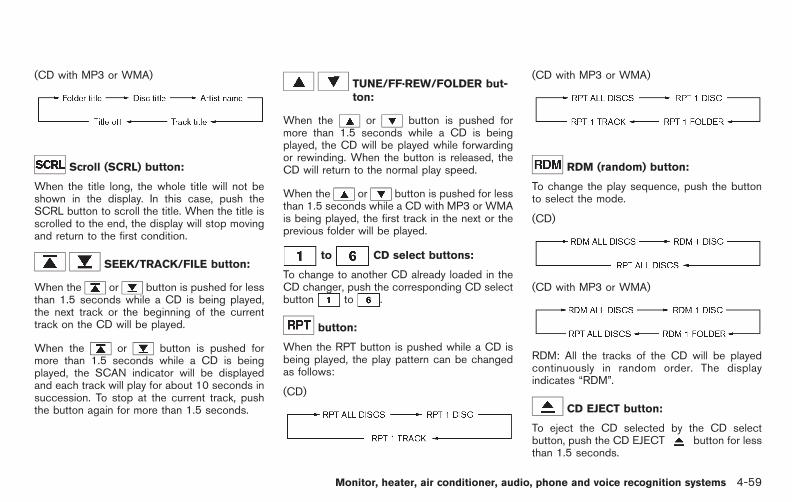
Black plate (237,1)
Model "E52-D" EDITED: 2010/ 10/ 25
(CD with MP3 or WMA)
Scroll (SCRL) button:
When the title long, the whole title will not beshown in the display. In this case, push theSCRL button to scroll the title. When the title isscrolled to the end, the display will stop movingand return to the first condition.
SEEK/TRACK/FILE button:
When the or button is pushed for lessthan 1.5 seconds while a CD is being played,the next track or the beginning of the currenttrack on the CD will be played.
When the or button is pushed formore than 1.5 seconds while a CD is beingplayed, the SCAN indicator will be displayedand each track will play for about 10 seconds insuccession. To stop at the current track, pushthe button again for more than 1.5 seconds.
TUNE/FF·REW/FOLDER but-ton:
When the or button is pushed formore than 1.5 seconds while a CD is beingplayed, the CD will be played while forwardingor rewinding. When the button is released, theCD will return to the normal play speed.
When the or button is pushed for lessthan 1.5 seconds while a CD with MP3 or WMAis being played, the first track in the next or theprevious folder will be played.
to CD select buttons:
To change to another CD already loaded in theCD changer, push the corresponding CD selectbutton to .
button:
When the RPT button is pushed while a CD isbeing played, the play pattern can be changedas follows:
(CD)
(CD with MP3 or WMA)
RDM (random) button:
To change the play sequence, push the buttonto select the mode.
(CD)
(CD with MP3 or WMA)
RDM: All the tracks of the CD will be playedcontinuously in random order. The displayindicates “RDM”.
CD EJECT button:
To eject the CD selected by the CD selectbutton, push the CD EJECT button for lessthan 1.5 seconds.
Monitor, heater, air conditioner, audio, phone and voice recognition systems 4-59

Black plate (238,1)
Model "E52-D" EDITED: 2010/ 10/ 25
To eject all the CDs, push the CD EJECTbutton for more than 1.5 seconds.
When this button is pushed while a CD is beingplayed, the CD will eject and the system will turnoff.
If the CD comes out and is not removed, itwill be pulled back into the slot to protectit.
AUX (Auxiliary) input
AUX IN jack:
The AUX IN jack is located on the audio unit.The AUX IN audio input jack accepts anystandard analog audio input such as from aportable cassette tape/CD player, MP3 player orlaptop computer.
AUX (Auxiliary) button:
Push the AUX button to play a compatibledevice when it is plugged into the AUX IN jack.
When the AUX button is pushed with no deviceplugged into the jack, the audio system does notchange to the AUX mode.
NISSAN strongly recommends using a stereomini plug cable when connecting your musicdevice to the audio system. Music may not playproperly when a monaural cable is used.
SAA2779
1. CD RDM (random) play button
2. Radio SCAN tuning button
3. Radio station preset select buttons
4. CD RPT (repeat) play button
5. Radio CAT (category)/REW (rewind) button forSEEK/TRACK
6. iPod® MENU button
7. CD EJECT button
8. Radio CAT (category)/FF (fast forward) button forSEEK/TRACK
9. ON·OFF button/VOL (volume) control knob
10. FM·AM band select button
11. CD button
12. AUX (auxiliary) button
4-60 Monitor, heater, air conditioner, audio, phone and voice recognition systems

Black plate (239,1)
Model "E52-D" EDITED: 2010/ 10/ 25
13. AUX IN jack
14. TUNE/SCROLL CONTROL dial
15. ENTER/SETTING button
FM-AM RADIO WITH COMPACT DISC(CD) PLAYER
Audio main operation
Head unit:
The auto loudness circuit enhances the low andhigh frequency ranges automatically in bothradio reception and CD playback.
ON·OFF/Volume control:
Push the ignition switch to the ACC or ONposition, and then push the ON·OFF buttonwhile the system is off to turn on the last audiosource (i.e. FM or CD), which was playingimmediately before the system was turned off.While the system is on, pushing the ON·OFFbutton turns the system off.
Turn the VOL control knob to adjust the volume.
SETTING button:
Push the button to change the selecting modeas follows.
Push the TUNE/SCROLL control dial to adjustBass and Treble to the desired level. Use theTUNE/SCROLL control dial also to adjust Fadeor Balance modes. Fade adjusts the sound levelbetween the front and rear speakers andBalance adjusts the sound between the rightand left speakers.
To change the Speed Sensitive Volume (SpdSen Vol) mode from off (0) to 5, and push theTUNE/SCROLL control dial until the desiredmode is displayed.
Turn the TUNE/SCROLL control dial to adjustthe brightness and contrast of the screen to thepreferred level.
Clock adjustment:
Push the ENTER SETTING button until “SettingClock” and “On-screen Clock” appear on thedisplay. Then turn the TUNE/SCROLL controldial to turn the clock on or off.
1. Push the ENTER SETTING button until“Setting Clock” and “Clock Adjust” appearon the display.
2. Turn the TUNE/SCROLL control dial toadjust the hour.
3. Push the ENTER SETTING button.
4. Turn the TUNE/SCROLL control dial toadjust the minute.
5. Push the ENTER SETTING button.
The display will return to the regular clockdisplay after 5 seconds.
Switching the display:
Pushing the AUX button will switch the displaysas follows:
iPod®/USB ? AUX ? iPod®/USB
FM-AM radio operation
radio (FM/AM) band select:
Pushing the radio band select button willchange the band as follows:
AM ? FM1 ? FM2 ? AM
When the radio band select button is pushedwhile the ignition switch is in the ACC or ONposition, the radio will come on at the channellast played.
The last channel played will also come on whenthe ON·OFF button is pushed to ON.
Monitor, heater, air conditioner, audio, phone and voice recognition systems 4-61

Black plate (240,1)
Model "E52-D" EDITED: 2010/ 10/ 25
If another audio source is playing when the radioband select button is turned on, the audiosource will automatically be turned off and thelast radio channel played will come on.
When the stereo broadcast signal is weak, theradio will automatically change from stereo tomonaural reception.
TUNE (Tuning):
Turn the radio TUNE/SCROLL control dial formanual tuning.
SEEK tuning:
Push the SEEK button or to tune fromlow to high or high to low frequencies and tostop at the next broadcasting station.
SCAN tuning:
Push the SCAN tuning button to tune from lowto high frequencies and stop at each broad-casting station for 5 seconds. Pushing thebutton again during this 5 seconds period willstop SCAN tuning and the radio will remaintuned to that station.
If the SCAN tuning button is not pushed within 5seconds, SCAN tuning moves to the nextstation.
*1 to *6 Station memory operations:
12 stations can be set for the FM band (6 eachfor FM1 and FM2) and 6 stations can be set forthe AM band.
1. Choose the radio band using the radio bandselect button.
2. Tune to the desired station using the SEEK/CAT, SCAN button or the radio TUNE/SCROLL control dial.
3. Push and hold the desired station presetbutton *1 to *6 until the radio mutes.
4. The station indicator will then come on andthe sound will resume. Memorizing is nowcomplete.
5. Other buttons can be set in the samemanner.
If the battery cable is disconnected, or if the fuseopens, the radio memory will be erased. In thatcase, reset the desired stations.
Compact Disc (CD) player operationPush the ignition switch to the ACC or ONposition and insert the Compact Disc (CD) intothe slot with the label side facing up. The CD willbe guided automatically into the slot and startplaying.
After loading the CD, the number of tracks on
the CD and the play time will appear on thedisplay.
If the radio is already operating, it will auto-matically turn off and the CD will play.
If the system has been turned off while the CDwas playing, pushing the ON·OFF button willstart the CD.
Do not use 3.1 in (8 cm) discs.
PLAY:
When the CD button is pushed with the systemoff and the CD loaded, the system will turn onand the CD will start to play.
When the CD button is pushed with the CDloaded and the radio playing, the radio willautomatically be turned off and the CD will startto play.
Next/Previous Track and FastForward/Rewind:
When the or button is pushed formore than 1.5 seconds while the CD is beingplayed, the CD will play while fast forwarding orrewinding. When the button is released, the CDwill return to normal play speed.
When the or button is pushed for lessthan 1.5 seconds while the CD is being played,
4-62 Monitor, heater, air conditioner, audio, phone and voice recognition systems

Black plate (241,1)
Model "E52-D" EDITED: 2010/ 10/ 25
the next track or the beginning of the currenttrack on the CD will be played.
REPEAT (RPT):
When the RPT button is pushed while the CD isplayed, the play pattern can be changed asfollows:
(CD)
Normal Û 1 Track Repeat
(CD with compressed audio files)
Normal? 1 Folder Repeat? 1 Track Repeat?Normal
RANDOM (RDM):
When the RDM button is pushed while a CD isbeing played, the play pattern can be changedas follows:
(CD)
Normal Û 1 Disc Random
(CD with compressed audio files)
Normal ? 1 Disc Random ? 1 Folder Random? Normal
CD EJECT:
When the CD EJECT button is pushed with theCD loaded, the CD will be ejected.
When this button is pushed while the CD isbeing played, the CD will be ejected.
If the CD comes out and is not removed, itwill be pulled back into the slot to protectit.
AUX (Auxiliary) input
AUX IN jack:
The AUX IN jack is located on the audio unit.The AUX IN audio input jack accepts anystandard analog audio input such as from aportable cassette tape/CD player, MP3 player orlaptop computer.
AUX (Auxiliary) button:
When the AUX button is pushed with no deviceplugged into the jack, the audio system does notchange to the AUX mode.
NISSAN strongly recommends using a stereomini plug cable when connecting your musicdevice to the audio system. Music may not playproperly when a monaural cable is used.
SAA3599
USB memory operation
Audio main operation:
The USB outlet connector is in the front centerconsole box. Connect a USB memory asillustrated. Then, switch to the USB memorymode automatically.
If the system has been turned off while the USBmemory was playing, pushing the ON·OFF/VOLcontrol knob will start the USB memory.
PLAY:
When the AUX button is pushed with the systemoff and the USB memory inserted, the systemwill turn on.
Monitor, heater, air conditioner, audio, phone and voice recognition systems 4-63

Black plate (242,1)
Model "E52-D" EDITED: 2010/ 10/ 25
If another audio source is playing and a USBmemory is inserted, push the AUX buttonrepeatedly until the center display changes tothe USB memory mode.
Next/Previous File and FastForward/Rewind:
When the or button is pushed formore than 1.5 seconds while a USB memory isbeing played, the USB memory will play whileforwarding or rewinding. When the button isreleased, the USB memory will return to normalplay speed.
When the or button is pushed for lessthan 1.5 seconds while the USB memory isbeing played, the next track or the beginning ofthe current track on the USB memory will beplayed.
Folder selection:
To change to another folder in the USB memory,turn the folder selector or choose a folderdisplayed on the screen using the multi-functioncontroller.
REPEAT (RPT):
When the RPT button is pushed while the USBmemory is played, the play pattern can bechange as follows.
To change the play mode, push the RPT buttonrepeatedly and the mode will change as follows.
Normal? 1 Folder Repeat? 1 Track Repeat?Normal
RANDOM (RDM):
When the RDM button is pushed while a USBmemory is being played, the play pattern can bechanged as follows.
To change the play mode, push the RDM buttonrepeatedly, and the mode will change as follows.
Normal ? All Random ? 1 Folder Random ?Normal
SAA3600
iPod® player operation
Connecting iPod®:
The USB outlet connector is in the front centerconsole box. Connect the iPod® cable to theUSB connector. The battery of the iPod® ischarged while the connection to the vehicle.
Depending on the version of the iPod®, thedisplay on the iPod® shows a NISSAN orAccessory Attached screen when the connec-tion is completed. When the iPod® is connectedto the vehicle, the iPod® music library can onlybe operated by the vehicle audio controls.
* iPod® and iPhone® are a trademark of AppleInc., registered in the U.S. and other countries.
4-64 Monitor, heater, air conditioner, audio, phone and voice recognition systems
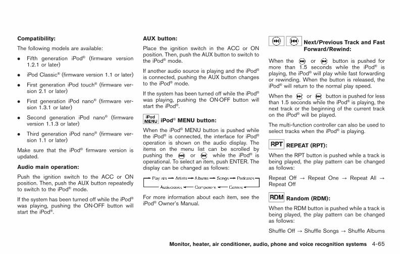
Black plate (243,1)
Model "E52-D" EDITED: 2010/ 10/ 25
Compatibility:
The following models are available:
. Fifth generation iPod® (firmware version1.2.1 or later)
. iPod Classic® (firmware version 1.1 or later)
. First generation iPod touch® (firmware ver-sion 2.1 or later)
. First generation iPod nano® (firmware ver-sion 1.3.1 or later)
. Second generation iPod nano® (firmwareversion 1.1.3 or later)
. Third generation iPod nano® (firmware ver-sion 1.1 or later)
Make sure that the iPod® firmware version isupdated.
Audio main operation:
Push the ignition switch to the ACC or ONposition. Then, push the AUX button repeatedlyto switch to the iPod® mode.
If the system has been turned off while the iPod®
was playing, pushing the ON·OFF button willstart the iPod®.
AUX button:
Place the ignition switch in the ACC or ONposition. Then, push the AUX button to switch tothe iPod® mode.
If another audio source is playing and the iPod®
is connected, pushing the AUX button changesto the iPod® mode.
If the system has been turned off while the iPod®
was playing, pushing the ON·OFF button willstart the iPod®.
iPod® MENU button:
When the iPod® MENU button is pushed whilethe iPod® is connected, the interface for iPod®
operation is shown on the audio display. Theitems on the menu list can be scrolled bypushing the or while the iPod® isoperational. To select an item, push ENTER. Thedisplay can be changed as follows:
For more information about each item, see theiPod® Owner’s Manual.
Next/Previous Track and FastForward/Rewind:
When the or button is pushed formore than 1.5 seconds while the iPod® isplaying, the iPod® will play while fast forwardingor rewinding. When the button is released, theiPod® will return to the normal play speed.
When the or button is pushed for lessthan 1.5 seconds while the iPod® is playing, thenext track or the beginning of the current trackon the iPod® will be played.
The multi-function controller can also be used toselect tracks when the iPod® is playing.
REPEAT (RPT):
When the RPT button is pushed while a track isbeing played, the play pattern can be changedas follows:
Repeat Off ? Repeat One ? Repeat All ?Repeat Off
Random (RDM):
When the RDM button is pushed while a track isbeing played, the play pattern can be changedas follows:
Shuffle Off ? Shuffle Songs ? Shuffle Albums
Monitor, heater, air conditioner, audio, phone and voice recognition systems 4-65
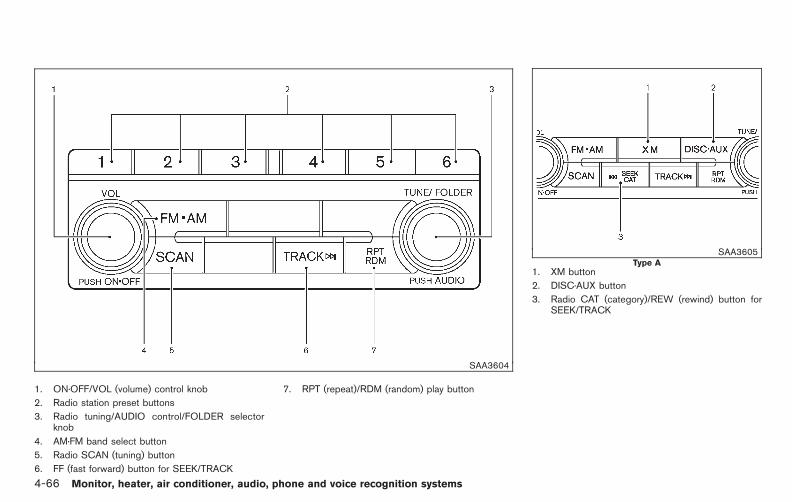
Black plate (244,1)
Model "E52-D" EDITED: 2010/ 10/ 25
SAA3604
1. ON·OFF/VOL (volume) control knob
2. Radio station preset buttons
3. Radio tuning/AUDIO control/FOLDER selectorknob
4. AM·FM band select button
5. Radio SCAN (tuning) button
6. FF (fast forward) button for SEEK/TRACK
7. RPT (repeat)/RDM (random) play button
SAA3605Type A
1. XM button
2. DISC·AUX button
3. Radio CAT (category)/REW (rewind) button forSEEK/TRACK
4-66 Monitor, heater, air conditioner, audio, phone and voice recognition systems

Black plate (245,1)
Model "E52-D" EDITED: 2010/ 10/ 25
SAA3606Type B
1. DISC button
2. AUX band select button
3. REW (rewind) button for SEEK/TRACK
FM-AM-SAT* RADIO WITH COMPACTDISC (CD) PLAYER
*: if so equipped
For all operation precautions, see “AUDIOOPERATION PRECAUTIONS” earlier in thissection.
The satellite radio mode (if so equipped)requires an active XM Satellite Radio subscrip-tion. The satellite radio is not available in Alaska,Hawaii and Guam.
It may take some time to receive the activationsignal after subscribing the XM Satellite Radio.After receiving the activation signal, an availablechannel list will be automatically updated in theradio. For XM, push the ignition switch fromLOCK to ACC to update the channel list.
Audio main operation
Head unit:
The auto loudness circuit enhances the low andhigh frequency ranges automatically in bothradio reception and CD playback.
ON·OFF/Volume control:
Push the ignition switch to the ACC or ONposition, and then push the ON·OFF buttonwhile the system is off to turn on the last audiosource (i.e. FM or CD), which was playingimmediately before the system was turned off.While the system is on, pushing the ON·OFFbutton turns the system off.
Turn the VOL control knob to adjust the volume.
Adjusting tone quality and speaker bal-ance:
To adjust Bass, Treble, Balance and Fade, pushthe Audio control knob. When the display showsthe setting you want to change (Bass, Treble,Balance and Fade), rotate the Audio controlknob to set the desired setting. For the othersetting methods, see “HOW TO USE SETTINGBUTTON” earlier in this section.
This vehicle has some sound effect functions asfollows:
. Speed Sensitive Vol.
For more details, see “VEHICLE INFORMATIONAND SETTINGS (models with center multi-function control panel)” earlier in this section.
Monitor, heater, air conditioner, audio, phone and voice recognition systems 4-67

Black plate (246,1)
Model "E52-D" EDITED: 2010/ 10/ 25
Switching the display:
. Models with satellite radio
Pushing the DISC·AUX button will switch thedisplays as follows:
iPod®/USB ? CD/DVD ? Music Box® ?Bluetooth® Audio (if so equipped) ? AUX ?iPod®/USB
. Models without satellite radio
Pushing the DISC button will switch the displayas follows:
CD/DVD ? Music Box® ? CD/DVD
Pushing the AUX button will switch the displayas follows:
USB/iPod® ? AUX
FM-AM-SAT (if so equipped) radio op-erationWhen the radio band select button is pushedwhile the ignition switch is in the ACC or ONposition, the radio will come on at the channellast played.
The last channel played will also come on whenthe ON·OFF button is pushed to ON.
If another audio source is playing when the radioband select button is turned on, the audiosource will automatically be turned off and the
last radio channel played will come on.
When the stereo broadcast signal is weak, theradio will automatically change from stereo tomonaural reception.
radio (FM/AM) band select:
Pushing the radio band select button willchange the band as follows:
AM ? FM1 ? FM2 ? AM
radio (SAT) band select (if soequipped):
Pushing the radio band select button willchange the band as follows:
XM1 ? XM2 ? XM3 ? XM1
The satellite radio is not available in Alaska,Hawaii and Guam.
TUNE (Tuning):
. For AM and FM radio
Turn the radio TUNE knob for manual tuning.
. For XM Satellite Radio (if so equipped)
Turn the radio TUNE knob to seek channelsfrom all of the categories when any categoryis not selected.
or / SEEK tuning/CATE-GORY (CAT):
. For AM and FM radio
Push the SEEK button or to tunefrom low to high or high to low frequenciesand to stop at the next broadcasting station.
. For XM Satellite Radio (if so equipped)
Push the SEEK button or to tuneto the first channel of the next or previouscategory.
During satellite radio reception (if so equipped),the following notices will be displayed undercertain conditions.
. NO SIGNAL (No signal is received while theSAT tuner is connected.)
. OFF AIR (Broadcasting signed off)
. CHECK ANTENNA (Antenna connectionerror)
. LOADING (When the initial setting isperformed)
. UPDATING (When the satellite radio sub-scription is not active)
4-68 Monitor, heater, air conditioner, audio, phone and voice recognition systems
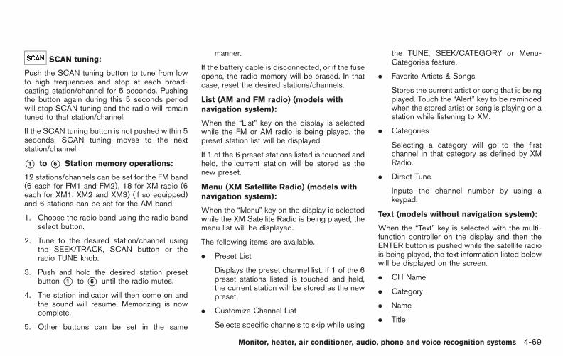
Black plate (247,1)
Model "E52-D" EDITED: 2010/ 10/ 25
SCAN tuning:
Push the SCAN tuning button to tune from lowto high frequencies and stop at each broad-casting station/channel for 5 seconds. Pushingthe button again during this 5 seconds periodwill stop SCAN tuning and the radio will remaintuned to that station/channel.
If the SCAN tuning button is not pushed within 5seconds, SCAN tuning moves to the nextstation/channel.
*1 to *6 Station memory operations:
12 stations/channels can be set for the FM band(6 each for FM1 and FM2), 18 for XM radio (6each for XM1, XM2 and XM3) (if so equipped)and 6 stations can be set for the AM band.
1. Choose the radio band using the radio bandselect button.
2. Tune to the desired station/channel usingthe SEEK/TRACK, SCAN button or theradio TUNE knob.
3. Push and hold the desired station presetbutton *1 to *6 until the radio mutes.
4. The station indicator will then come on andthe sound will resume. Memorizing is nowcomplete.
5. Other buttons can be set in the same
manner.
If the battery cable is disconnected, or if the fuseopens, the radio memory will be erased. In thatcase, reset the desired stations/channels.
List (AM and FM radio) (models withnavigation system):
When the “List” key on the display is selectedwhile the FM or AM radio is being played, thepreset station list will be displayed.
If 1 of the 6 preset stations listed is touched andheld, the current station will be stored as thenew preset.
Menu (XM Satellite Radio) (models withnavigation system):
When the “Menu” key on the display is selectedwhile the XM Satellite Radio is being played, themenu list will be displayed.
The following items are available.
. Preset List
Displays the preset channel list. If 1 of the 6preset stations listed is touched and held,the current station will be stored as the newpreset.
. Customize Channel List
Selects specific channels to skip while using
the TUNE, SEEK/CATEGORY or Menu-Categories feature.
. Favorite Artists & Songs
Stores the current artist or song that is beingplayed. Touch the “Alert” key to be remindedwhen the stored artist or song is playing on astation while listening to XM.
. Categories
Selecting a category will go to the firstchannel in that category as defined by XMRadio.
. Direct Tune
Inputs the channel number by using akeypad.
Text (models without navigation system):
When the “Text” key is selected with the multi-function controller on the display and then theENTER button is pushed while the satellite radiois being played, the text information listed belowwill be displayed on the screen.
. CH Name
. Category
. Name
. Title
Monitor, heater, air conditioner, audio, phone and voice recognition systems 4-69
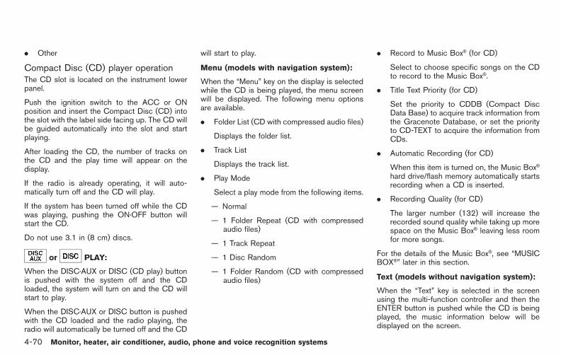
Black plate (248,1)
Model "E52-D" EDITED: 2010/ 10/ 25
. Other
Compact Disc (CD) player operationThe CD slot is located on the instrument lowerpanel.
Push the ignition switch to the ACC or ONposition and insert the Compact Disc (CD) intothe slot with the label side facing up. The CD willbe guided automatically into the slot and startplaying.
After loading the CD, the number of tracks onthe CD and the play time will appear on thedisplay.
If the radio is already operating, it will auto-matically turn off and the CD will play.
If the system has been turned off while the CDwas playing, pushing the ON·OFF button willstart the CD.
Do not use 3.1 in (8 cm) discs.
or PLAY:
When the DISC·AUX or DISC (CD play) buttonis pushed with the system off and the CDloaded, the system will turn on and the CD willstart to play.
When the DISC·AUX or DISC button is pushedwith the CD loaded and the radio playing, theradio will automatically be turned off and the CD
will start to play.
Menu (models with navigation system):
When the “Menu” key on the display is selectedwhile the CD is being played, the menu screenwill be displayed. The following menu optionsare available.
. Folder List (CD with compressed audio files)
Displays the folder list.
. Track List
Displays the track list.
. Play Mode
Select a play mode from the following items.
— Normal
— 1 Folder Repeat (CD with compressedaudio files)
— 1 Track Repeat
— 1 Disc Random
— 1 Folder Random (CD with compressedaudio files)
. Record to Music Box® (for CD)
Select to choose specific songs on the CDto record to the Music Box®.
. Title Text Priority (for CD)
Set the priority to CDDB (Compact DiscData Base) to acquire track information fromthe Gracenote Database, or set the priorityto CD-TEXT to acquire the information fromCDs.
. Automatic Recording (for CD)
When this item is turned on, the Music Box®
hard drive/flash memory automatically startsrecording when a CD is inserted.
. Recording Quality (for CD)
The larger number (132) will increase therecorded sound quality while taking up morespace on the Music Box® leaving less roomfor more songs.
For the details of the Music Box®, see “MUSICBOX®” later in this section.
Text (models without navigation system):
When the “Text” key is selected in the screenusing the multi-function controller and then theENTER button is pushed while the CD is beingplayed, the music information below will bedisplayed on the screen.
4-70 Monitor, heater, air conditioner, audio, phone and voice recognition systems

Black plate (249,1)
Model "E52-D" EDITED: 2010/ 10/ 25
CD:
. Disc title
. Track title
CD with compressed audio files:
. Folder title
. File title
. Song title
. Album title
. Artist
or / Next/Previous Trackand Fast Forward/Rewind:
When the or button is pushed formore than 1.5 seconds while the CD is beingplayed, the CD will play while fast forwarding orrewinding. When the button is released, the CDwill return to normal play speed.
When the or button is pushed for lessthan 1.5 seconds while the CD is being played,the next track or the beginning of the currenttrack on the CD will be played.
REPEAT (RPT), RANDOM (RDM):
When the RPT button is pushed while the CD isplayed, the play pattern can be changed asfollows:
(CD)
(CD with compressed audio files)
CD EJECT:
When the CD EJECT button is pushed with theCD loaded, the CD will be ejected.
When this button is pushed while the CD isbeing played, the CD will be ejected.
If the CD comes out and is not removed, itwill be pulled back into the slot to protectit.
DVD (Digital Versatile Disc) PLAYEROPERATION (if so equipped)
PrecautionsStart the engine when using the DVD entertain-ment system.
Movies will not be shown on the front displaywhile the vehicle is in any drive position toreduce driver distraction. Audio is availablewhen a movie is played. To view movies in thefront display, stop the vehicle in a safe location,move the selector lever to the P (Park) positionand apply the parking brake.
WARNING
. The driver must not attempt tooperate the DVD system or wearthe headphones while the vehicle isin motion so that full attention maybe given to vehicle operation.
. Do not attempt to modify the systemto display a movie on the frontscreen while the vehicle is beingdriven. Doing so may distract thedriver and may cause a collision andserious personal injury or death.
Monitor, heater, air conditioner, audio, phone and voice recognition systems 4-71

Black plate (250,1)
Model "E52-D" EDITED: 2010/ 10/ 25
CAUTION
. Only operate the DVD while thevehicle engine is running. Operatingthe DVD for extended periods oftime with the engine OFF can dis-charge the vehicle battery.
. Do not allow the system to get wet.Excessive moisture such as spilledliquids may cause the system tomalfunction.
. While playing VIDEO-CD media, thisDVD player does not guaranteecomplete functionality of all VI-DEO-CD formats.
Display settingsTo adjust the front display mode, push theSETTING button while the DVD is being played.
To adjust the display ON/OFF, brightness, tint,color and contrast, select the “Display Adjust-ment” key and then select each key.
Then you can adjust each item using the multi-function controller. After changes have beenmade push the BACK button to save the setting.
SAA2497Type A
SAA3091Type B
Playing a DVD
DISC·AUX/DVD button:
Park the vehicle in a safe location for thefront seat occupants to operate the DVDdrive while watching the images.
Push the DISC·AUX/DVD button on the instru-ment panel and turn the display to the DVDmode.
When a DVD is loaded, it will be replayedautomatically.
The operation screen will be turned on when theDISC·AUX button located on the instrumentpanel is pushed while a DVD is being played,and it will turn off automatically after a period oftime. To turn it on again, push the DISC·AUX/DVD button again.
DVD operation keys:
When the DVD is playing without the operationscreen being shown, you may use the touchscreen to select items from the displayed video.You may also use the multi-function controller toselect an item from the displayed video. Whenthe operation screen is being shown, use themultifunction controller or touch screen to selectan item from the displayed menus.
4-72 Monitor, heater, air conditioner, audio, phone and voice recognition systems

Black plate (251,1)
Model "E52-D" EDITED: 2010/ 10/ 25
PAUSE:
Select the “ ” key to pause the DVD. Toresume playing the DVD, use the “PLAY” key.
PLAY:
Select the “ ” key to start playing the DVD,for example, after pausing the DVD.
STOP:
Select the “ ” key to stop playing the DVD.
/ Next/Previous Chapter:
Select the “ ” or “ ” key to skip thechapter(s) of the disc forward/backward. Thechapters will advance/go back the number oftimes this key is selected.
/ Commercial Skip (Type A):
This function is only for DVD-VIDEO, DVD-VR.Select the “ ” or “ ” key to skip forwardor backwards by the set amount as defined inthe DVD Settings menu.
Top Menu (Type A)/Menu (Type B):
When the “Top Menu” key is selected in thescreen while a DVD is being played, the top
menu specific to each disc will be displayed. Fordetails, see the instructions on the disc.
SAA2498Type A (example)
SAA3087Type B (example)
Monitor, heater, air conditioner, audio, phone and voice recognition systems 4-73

Black plate (252,1)
Model "E52-D" EDITED: 2010/ 10/ 25
DVD settingsSelect the “Settings” key to adjust the followingsettings.
Key (DVD-VIDEO) (Type A):
Keys for the DVD menu operation are displayed.
: Move the cursor to select a DVD menu.
Enter: Enter the selected menu.
Move: Change the display location by movingthe operation key.
Back: Return to the previous screen.
Hide: Hide the operation key.
Title Menu (DVD-VIDEO):
Some menus specific to each disc will beshown. For details, see the instructions on thedisc.
Title Search (DVD-VIDEO, DVD-VR):
The scene with the specified title will bedisplayed each time the “+” side or “−” side isselected.
Group Search (VIDEO CD):
A scene in the specified group will be displayedeach time the “+” side or “−” side is selected.
10 Key Search (DVD-VIDEO, VIDEO-CD,CD-DA, DVD-VR):
Select the “10 Key Search” key to open thenumber entry screen. Input the number to besearched and select the “OK” key. The specifiedTitle/Chapter or Group/Track will be played.
Select No. (VIDEO-CD):
Select the “Select No.” key to open the numberentry screen. Input the number to be searchedand select the “OK” key. The specified scenewill be played.
Angle (DVD-VIDEO):
If the DVD contains different angles (such asmoving images), the current image angle can beswitched to another one. Select the “Angle” key.The angle will change each time the “+” side or“−” side is selected.
Angle Mark (DVD-VIDEO):
When this item is turned on, an angle mark willbe shown on the bottom of the screen if thescene can be seen from a different angle.
Menu Skip (DVD-VIDEO):
DVD menus are automatically configured andthe contents will be played directly when the“Menu Skip” key is turned on. Note that somediscs may not be played directly even if this itemis turned on.
CM Skip (DVD-VIDEO) (Type A):
Select the “CM Skip” key. Choose the settingtime from 15, 30 or 60 seconds by selecting the“+” side or “−” side.
DRC (DVD-VIDEO, DVD-VR):
DRC (Dynamic Range Compression) automati-cally adjusts the soundtrack volume level tomaintain a more even sound to the speakers.
DVD Language (DVD-VIDEO, VIDEO-CD):
Select the “DVD Language” key to open thenumber entry screen. Input the number corre-sponding to the preferred language and selectthe “OK” key. The DVD top menu language willbe changed to the one specified.
Display:
To adjust the image quality of the screen, selectthe preferred adjustment items.
Audio:
Select the preferred language for audio.
Subtitle (DVD-VIDEO, DVD-VR):
Select the preferred language for subtitles.
4-74 Monitor, heater, air conditioner, audio, phone and voice recognition systems

Black plate (253,1)
Model "E52-D" EDITED: 2010/ 10/ 25
Display Mode (DVD-VIDEO, VIDEO-CD,DVD-VR):
Select from the “Full”, “Wide”, “Normal” or“Cinema” modes.
Title List (DVD-VR):
Select the preferred title from the list.
Play Mode:
Select the preferred play mode.
PG/PL Mode (DVD-VR):
Select the “PG” or “PL” mode.SAA3599
USB MEMORY OPERATION (if soequipped)
Audio main operationOpen the console lid and connect a USBmemory as illustrated. Then, push the DISC·AUXor AUX button repeatedly to switch to the USBmemory mode.
If the system has been turned off while the USBmemory was playing, pushing the ON·OFF/VOLcontrol knob will start the USB memory.
SAA2500
File selection (models with navigationsystem)When there are both audio and movie files in theUSB memory, the mode select screen isdisplayed. Select the preferred content to play.
When there is only one type of file, the audio ormovie operation screen is displayed and startsto play.
If a video file restricts the number of playbacks, apop-up screen will appear to confirm it is ok toplay. Answer yes or no as requested by thedisplay.
Monitor, heater, air conditioner, audio, phone and voice recognition systems 4-75

Black plate (254,1)
Model "E52-D" EDITED: 2010/ 10/ 25
SAA2501Models with navigation system
SAA2611Models without navigation system
Audio file operation
or PLAY:
When the DISC·AUX or AUX button is pushedwith the system off and the USB memoryinserted, the system will turn on.
If another audio source is playing and a USBmemory is inserted, push the DISC·AUX or AUXbutton repeatedly until the center displaychanges to the USB memory mode.
or / Next/Previous Fileand Fast Forward/Rewind:
When the or button is pushed formore than 1.5 seconds while a USB memory isbeing played, the USB memory will play whileforwarding or rewinding. When the button isreleased, the USB memory will return to normalplay speed.
When the or button is pushed for lessthan 1.5 seconds while the USB memory isbeing played, the next track or the beginning ofthe current track on the USB memory will beplayed.
The multi-function controller can also be used toselect tracks when the USB memory is beingplayed.
Folder selection:
To change to another folder on the USBmemory, turn the FOLDER selector or choosea folder displayed on the screen using the multi-function controller.
REPEAT (RPT), RANDOM (RDM):
When the RPT/RDM button is pushed while theUSB memory is played, the play pattern can bechange as follows.
To change the play mode, push the RPT buttonrepeatedly and the mode will change as follows.
Normal? 1 Folder Repeat? 1 Track Repeat?All Random ? 1 Folder Random ? Normal
4-76 Monitor, heater, air conditioner, audio, phone and voice recognition systems

Black plate (255,1)
Model "E52-D" EDITED: 2010/ 10/ 25
SAA2502
Menu (models with navigation system):
There are some options available during play-back. Select one of the following options thatare displayed on the screen if necessary. Referto the following information for each item.
. Movie Playback
Switch to the movie playback mode. Thisitem is displayed only when a USB memorycontains movie files.
. Folder List/Track List
Displays the folder or track list. The “MoviePlayback” key is also displayed in this listscreen, and enables switching to the movie
playback mode.
. Play Mode
Select the preferred play mode.
Text (models without navigation system):
When the “Text” key is selected on the screenusing the multi-function controller and then theENTER button is pushed while a USB memory isbeing played, the music information listed belowwill be displayed on the screen.
. Folder title
. File title
. Song title
. Album Title
. Artist
SAA2503
Movie file operation (models with navi-gation system)Park the vehicle in a safe location for thefront seat occupants to operate the USBmemory while watching the images.
PLAY:
When the DISC·AUX button is pushed with thesystem off and the USB memory inserted, thesystem will turn on.
If another audio source is playing and a USBmemory is inserted, push the DISC·AUX buttonrepeatedly until the center display changes tothe USB memory mode.
Monitor, heater, air conditioner, audio, phone and voice recognition systems 4-77

Black plate (256,1)
Model "E52-D" EDITED: 2010/ 10/ 25
Operation keys:
To operate the USB memory, select the desiredkey displayed on the operation screen using themulti-function controller.
Pause
Select the “ ” key to pause the movie file. Toresume playing the movie file, select the “ ”key.
Play
Select the “ ” key to start playing a movie file,for example, after pausing a movie file.
STOP
Select the “ ” key to stop playing a movie file.
Skip (Next chapter)
Select the “ ” key to skip the chapter(s) ofthe file forward. The chapters will advance thenumber of times the ENTER button is pushed.
Skip (Previous chapter)
Select the “ ” key to skip the chapter(s) ofthe file backward. The chapters will go back the
number of times the “ ” key is selected.
List:
Select the “List” key on the movie file operationscreen to display the file list.
SAA2504Example
Settings:
Select the “Settings” key to adjust the followingsettings.
. Audio File Playback
Switch to the audio playback mode. Thisitem is displayed only when the USBmemory contains audio files.
. Play Mode
Select the “Normal” or “1 Track Repeat” playmode.
4-78 Monitor, heater, air conditioner, audio, phone and voice recognition systems

Black plate (257,1)
Model "E52-D" EDITED: 2010/ 10/ 25
. 10 Key Search
Select the “10 Key Search” key to open thenumber entry screen.
Input the number to be searched and selectthe “OK” key.
The specified folder/file will be played.
. Display
To adjust the image quality of the screen,select the preferred adjustment items.
. DRC
DRC (Dynamic Range Compression) auto-matically adjusts the soundtrack volumelevel to maintain a more even sound to thespeakers.
. Audio
Select the preferred language for audio.
. Subtitle
Select the preferred language for subtitle.
. Display Mode
Select the “Normal”, “Wide”, “Cinema” or“Full” mode.
BLUETOOTH® STREAMING AUDIO(models with navigation system)
Your NISSAN is equipped with Bluetooth®
Streaming Audio. If you have a compatibleBluetooth® device with streaming audio (A2DPprofile), you can set up the wireless connectionbetween your Bluetooth® device and the in-vehicle audio system. This connection allowsyou to listen to the audio from the Bluetooth®
device using your vehicle speakers. It also mayallow basic control of the device for playing andskipping audio files using the AVRCP Blue-tooth® profile. All Bluetooth® Devices do nothave the same level of controls for AVRCP.Please consult the manual for your Bluetooth®
Device for more details.
Once your Bluetooth® device is connected tothe in-vehicle audio system, it will automaticallyreconnect whenever the device is present in thevehicle and you select Bluetooth® Audio fromyour audio system. You do not need to manuallyreconnect for each usage.
Regulatory information
FCC Regulatory information:
— CAUTION: To maintain compliance withFCC’s RF exposure guidelines, use onlythe supplied antenna. Unauthorized antenna,modification, or attachments could damagethe transmitter and may violate FCC regula-tions.
— Operation is subject to the following twoconditions:
1) This device may not cause interferenceand
2) This device must accept any interfer-ence, including interference that maycause undesired operation of the device
IC Regulatory information:
— Operation is subject to the following twoconditions:
1) This device may not cause interference,and
2) This device must accept any interfer-ence, including interference that maycause undesired operation of the device.
— This Class B digital apparatus meets allrequirements of the Canadian Interference-Causing Equipment Regulations.
Monitor, heater, air conditioner, audio, phone and voice recognition systems 4-79

Black plate (258,1)
Model "E52-D" EDITED: 2010/ 10/ 25
Bluetooth trademark:
Bluetooth® is a trademark ownedby Bluetooth SIG, Inc. and li-censed to Clarion Co., Ltd.
SAA2505
Connecting procedure1. Push the SETTING button and select the
“Bluetooth” key.
SAA2506
2. Select the “Connect Bluetooth” key.
4-80 Monitor, heater, air conditioner, audio, phone and voice recognition systems

Black plate (259,1)
Model "E52-D" EDITED: 2010/ 10/ 25
SAA2507
3. A confirmation screen will be displayed.Select “No”.
Note: Selecting “Yes” will only connect thehands free phone portion of a Bluetooth®
device.
SAA3005
4. Choose a PIN code to use with thecompatible Bluetooth audio device usingthe number input screen. The PIN code willneed to be entered into the Bluetooth® audiodevice after step 5. Select the “OK” key.
SAA3006
5. The standby message screen will appear.Operate the compatible Bluetooth® audiodevice. For the connecting procedure of theaudio device, see the Bluetooth® audioinstructions.
When the connecting is completed, thescreen will return to the Bluetooth® setupdisplay.
Monitor, heater, air conditioner, audio, phone and voice recognition systems 4-81

Black plate (260,1)
Model "E52-D" EDITED: 2010/ 10/ 25
SAA2510
Audio main operationPush the ignition switch to the ACC or ONposition. Then, push the DISC·AUX buttonrepeatedly to switch to the Bluetooth® audiomode. If the system has been turned off whilethe Bluetooth® audio device was playing, push-ing the ON·OFF/VOL control knob will start theBluetooth® audio device.
The ability to pause, change tracks, fast forward,rewind, randomize and repeat music may bedifferent between devices. Some or all of thesefunctions may not be supported on each device.
DISC·AUX button:
When the DISC·AUX button is pushed with thesystem off and the Bluetooth® audio deviceconnected, the system will turn on. If anotheraudio source is playing and the Bluetooth® audiodevice is connected, push the DISC·AUX buttonrepeatedly until the display changes to theBluetooth® audio mode.
/ Next/Previous Track and FastForward/Rewind:
When the or button is pushed formore than 1.5 seconds while a Bluetooth® audiofile is being played, the Bluetooth® audio devicewill play while forwarding or rewinding. Whenthe button is released, the Bluetooth® audiodevice will return to normal play speed.
When the or button is pushed for lessthan 1.5 seconds while a Bluetooth® audio file isbeing played, the next track or the beginning ofthe current track on the Bluetooth® audio devicewill be played. The multi-function controller canalso be used to select tracks when the Blue-tooth® audio play mode screen is shown on thedisplay. (“Bluetooth audio” will be indicated onthe header of the screen.)
REPEAT (RPT), RANDOM (RDM):
To change the play mode, push the buttonrepeatedly and the mode changes as follows.
Normal ? Shuffle All Tracks ? Shuffle Group? Repeat 1 Track ? Repeat All Tracks ?Repeat Group ? Normal
Operation keys:
To operate a Bluetooth® audio device, select akey displayed on the operation screen using themulti-function controller.
Play
Select the “ ” key to start playing whenpausing. Select this key again to pause theaudio play.
Pause
Select the “ ” key to pause the Bluetooth®
audio device. Select this key again to resumeplaying.
Play Mode:
The play mode setting display will appear whenthe “Menu” key is selected.
Choose the preferred play mode from the
4-82 Monitor, heater, air conditioner, audio, phone and voice recognition systems
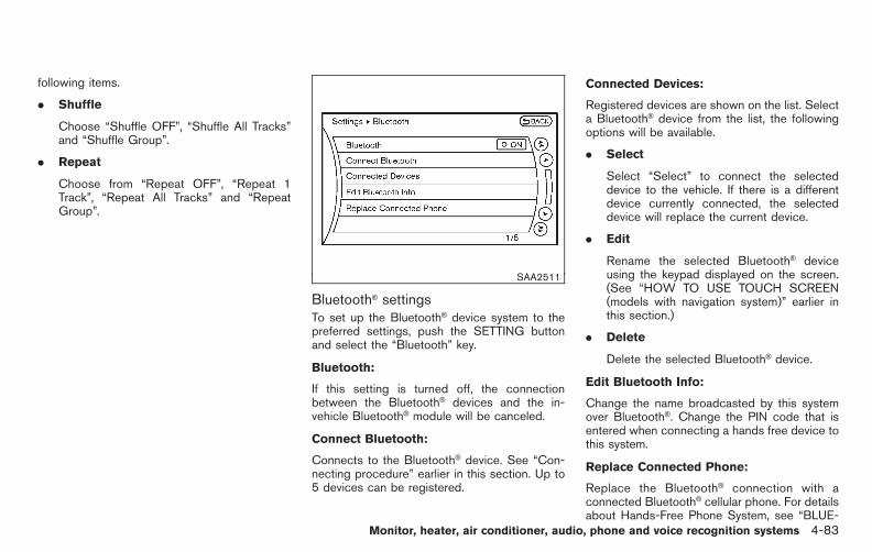
Black plate (261,1)
Model "E52-D" EDITED: 2010/ 10/ 25
following items.
. Shuffle
Choose “Shuffle OFF”, “Shuffle All Tracks”and “Shuffle Group”.
. Repeat
Choose from “Repeat OFF”, “Repeat 1Track”, “Repeat All Tracks” and “RepeatGroup”.
SAA2511
Bluetooth® settingsTo set up the Bluetooth® device system to thepreferred settings, push the SETTING buttonand select the “Bluetooth” key.
Bluetooth:
If this setting is turned off, the connectionbetween the Bluetooth® devices and the in-vehicle Bluetooth® module will be canceled.
Connect Bluetooth:
Connects to the Bluetooth® device. See “Con-necting procedure” earlier in this section. Up to5 devices can be registered.
Connected Devices:
Registered devices are shown on the list. Selecta Bluetooth® device from the list, the followingoptions will be available.
. Select
Select “Select” to connect the selecteddevice to the vehicle. If there is a differentdevice currently connected, the selecteddevice will replace the current device.
. Edit
Rename the selected Bluetooth® deviceusing the keypad displayed on the screen.(See “HOW TO USE TOUCH SCREEN(models with navigation system)” earlier inthis section.)
. Delete
Delete the selected Bluetooth® device.
Edit Bluetooth Info:
Change the name broadcasted by this systemover Bluetooth®. Change the PIN code that isentered when connecting a hands free device tothis system.
Replace Connected Phone:
Replace the Bluetooth® connection with aconnected Bluetooth® cellular phone. For detailsabout Hands-Free Phone System, see “BLUE-
Monitor, heater, air conditioner, audio, phone and voice recognition systems 4-83

Black plate (262,1)
Model "E52-D" EDITED: 2010/ 10/ 25
TOOTH® HANDS-FREE PHONE SYSTEM(models with navigation system)” later in thissection.
SAA3600
iPod® PLAYER OPERATION (if soequipped)
Connecting iPod®
Open the console lid and connect the iPod®
cable to the USB connector. If compatible, thebattery of the iPod® is charged while theconnection to the vehicle.
Depending on the version of the iPod®, thedisplay on the iPod® shows a NISSAN orAccessory Attached screen when the connec-tion is completed. When the iPod® is connectedto the vehicle, the iPod® music library can onlybe operated by the vehicle audio controls.
* iPod® is a trademark of Apple Inc., registered in
the U.S. and other countries.
CompatibilityThe following models are available:
Models with navigation system:
. Fifth generation iPod® (firmware version1.2.3 or later)
. iPod Classic® (firmware version 1.1.1 orlater)
. First generation iPod touch® (firmware ver-sion 2.0.0 or later)
. Second generation iPod touch® (firmwareversion 1.2.3 or later)
. First generation iPod nano® (firmware ver-sion 1.3.1 or later)
. Second generation iPod nano® (firmwareversion 1.1.3 or later)
. Third generation iPod nano® (firmware ver-sion 1.1 or later)
. Fourth generation iPod nano® (firmwareversion 1.0.2 or later)
Models without navigation system:
. Fifth generation iPod® (firmware version 1.3)
. First generation iPod Classic® (firmwareversion 1.1.2 PC)
4-84 Monitor, heater, air conditioner, audio, phone and voice recognition systems

Black plate (263,1)
Model "E52-D" EDITED: 2010/ 10/ 25
. Second generation iPod Classic® (firmwareversion 2.0 PC)
. First generation iPod touch® (firmware ver-sion 2.1)
. Second generation iPod touch® (firmwareversion 2.1.1)
. First generation iPod nano® (firmware ver-sion 1.3.1)
. Second generation iPod nano® (firmwareversion 1.1.3)
. Third generation iPod nano® (firmware ver-sion 1.1 PC)
. Third generation iPhone® (firmware version2.1)
Make sure that the iPod® version is updated.
Audio main operationPush the ignition switch to the ACC or ONposition. Then, push the DISC·AUX buttonrepeatedly to switch to the iPod® mode.
If the system has been turned off while the iPod®
was playing, pushing the ON·OFF button willstart the iPod®.
or play:
When the DISC·AUX or AUX button is pushedwith the system off and the iPod® connected, the
system will turn on. If another audio source isplaying and the iPod® is connected, push theDISC·AUX or AUX button repeatedly until thecenter display changes to the iPod® mode.
Interface:
The interface for iPod® operation shown on thevehicle center display is similar to the iPod®
interface. Use the multi-function controller andthe ENTER or BACK button to play the iPod®
with your favorite settings.
The following items can be chosen from themenu list screen. For further information abouteach item, see the iPod® Owner’s Manual.
. Now Playing
. Playlists
. Artists
. Albums
. Songs
. Podcasts
. Genres
. Composers
. Audiobooks
. Shuffle Songs
The following touch-panel buttons shown on thescreen are also available:
. : returns to the previous screen.
. : plays/pauses the music selected.
Next/Previous Track and FastForward/Rewind:
When the or button is pushed formore than 1.5 seconds while the iPod® isplaying, the iPod® will play while fast forwardingor rewinding. When the button is released, theiPod® will return to the normal play speed.
When the or button is pushed for lessthan 1.5 seconds while the iPod® is playing, thenext track or the beginning of the current trackon the iPod® will be played.
The multi-function controller can also be used toselect tracks when the iPod® is playing.
REPEAT (RPT), RANDOM (RDM):
When the RPT button is pushed while a track isbeing played, the play pattern can be changedas follows:
Monitor, heater, air conditioner, audio, phone and voice recognition systems 4-85
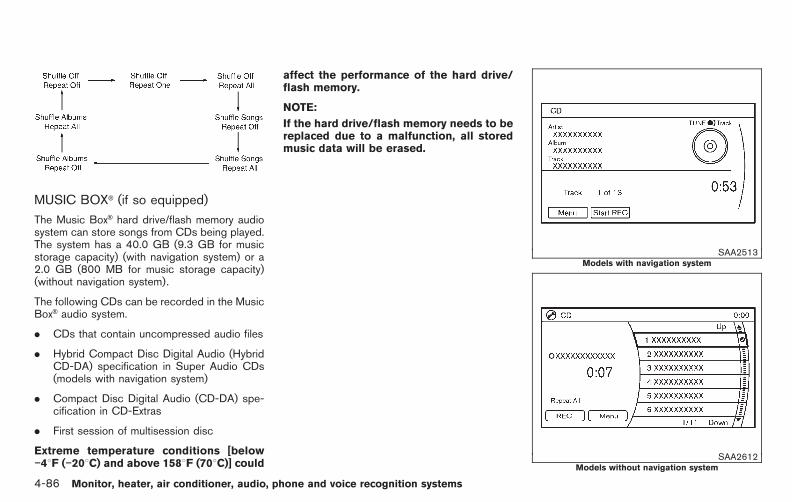
Black plate (264,1)
Model "E52-D" EDITED: 2010/ 10/ 25
MUSIC BOX® (if so equipped)
The Music Box® hard drive/flash memory audiosystem can store songs from CDs being played.The system has a 40.0 GB (9.3 GB for musicstorage capacity) (with navigation system) or a2.0 GB (800 MB for music storage capacity)(without navigation system).
The following CDs can be recorded in the MusicBox® audio system.
. CDs that contain uncompressed audio files
. Hybrid Compact Disc Digital Audio (HybridCD-DA) specification in Super Audio CDs(models with navigation system)
. Compact Disc Digital Audio (CD-DA) spe-cification in CD-Extras
. First session of multisession disc
Extreme temperature conditions [below−48F (−208C) and above 1588F (708C)] could
affect the performance of the hard drive/flash memory.
NOTE:
If the hard drive/flash memory needs to bereplaced due to a malfunction, all storedmusic data will be erased.
SAA2513Models with navigation system
SAA2612Models without navigation system
4-86 Monitor, heater, air conditioner, audio, phone and voice recognition systems

Black plate (265,1)
Model "E52-D" EDITED: 2010/ 10/ 25
Recording CDs1. Operate the audio system to play a CD. For
the details of playing CDs, see “FM-AM-SATRADIO WITH COMPACT DISC (CD)PLAYER” earlier in this section.
2. Select the “Start REC” (models with naviga-tion system)/“REC” (models without naviga-tion system) key.
NOTE:
. The system starts playing and record-ing the 1st track on the CD when the“Start REC” key is selected.
. The recording process can be stoppedat any time. All tracks that were playedbefore the CD was stopped are stored.
. Individual tracks can be deleted fromthe hard drive/flash memory after theCD is recorded.
SAA2514Models with navigation system
SAA2613Models without navigation system
If the title information of the track being recordedis stored either on the hard drive/flash memoryor the CD, the title is automatically displayed onthe screen. For title acquisition from the harddrive/flash memory, music recognition technol-ogy and related data are provided by Grace-note®.
If a track is not recorded successfully due to theCD skipping, the mark is displayed behindthe track number.
The Music Box® hard drive/flash memory cannotperform recording under the following condi-tions.
. There is not enough space on the harddrive/flash memory
. The number of albums reaches the maximumof 500.
. The number of tracks reaches the maximumof 3,000.
Automatic recording:
If the “Automatic Recording” function is turnedon, recording starts when a CD is inserted. (See“Music Box® settings” later in this section.)
Stopping recording:
To stop the recording, select the “Stop REC”key button by touching the screen or using themulti-function controller.
Monitor, heater, air conditioner, audio, phone and voice recognition systems 4-87
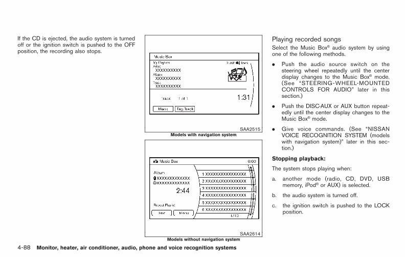
Black plate (266,1)
Model "E52-D" EDITED: 2010/ 10/ 25
If the CD is ejected, the audio system is turnedoff or the ignition switch is pushed to the OFFposition, the recording also stops.
SAA2515Models with navigation system
SAA2614Models without navigation system
Playing recorded songsSelect the Music Box® audio system by usingone of the following methods.
. Push the audio source switch on thesteering wheel repeatedly until the centerdisplay changes to the Music Box® mode.(See “STEERING-WHEEL-MOUNTEDCONTROLS FOR AUDIO” later in thissection.)
. Push the DISC·AUX or AUX button repeat-edly until the center display changes to theMusic Box® mode.
. Give voice commands. (See “NISSANVOICE RECOGNITION SYSTEM (modelswith navigation system)” later in this sec-tion.)
Stopping playback:
The system stops playing when:
a. another mode (radio, CD, DVD, USBmemory, iPod® or AUX) is selected.
b. the audio system is turned off.
c. the ignition switch is pushed to the LOCKposition.
4-88 Monitor, heater, air conditioner, audio, phone and voice recognition systems
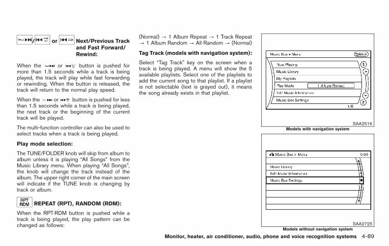
Black plate (267,1)
Model "E52-D" EDITED: 2010/ 10/ 25
/ or Next/Previous Trackand Fast Forward/Rewind:
When the or button is pushed formore than 1.5 seconds while a track is beingplayed, the track will play while fast forwardingor rewinding. When the button is released, thetrack will return to the normal play speed.
When the or button is pushed for lessthan 1.5 seconds while a track is being played,the next track or the beginning of the currenttrack will be played.
The multi-function controller can also be used toselect tracks when a track is being played.
Play mode selection:
The TUNE/FOLDER knob will skip from album toalbum unless it is playing “All Songs” from theMusic Library menu. When playing “All Songs”,the knob will change the track instead of thealbum. The upper right corner of the main screenwill indicate if the TUNE knob is changing bytrack or album.
REPEAT (RPT), RANDOM (RDM):
When the RPT·RDM button is pushed while atrack is being played, the play pattern can bechanged as follows:
(Normal) ? 1 Album Repeat ? 1 Track Repeat? 1 Album Random ? All Random ? (Normal)
Tag Track (models with navigation system):
Select “Tag Track” key on the screen when atrack is being played. A menu will show the 5available playlists. Select one of the playlists toadd the current song to that playlist. If a playlistis not selectable (text is grayed out), it meansthe song already exists in that playlist.
SAA2516Models with navigation system
SAA2725Models without navigation system
Monitor, heater, air conditioner, audio, phone and voice recognition systems 4-89

Black plate (268,1)
Model "E52-D" EDITED: 2010/ 10/ 25
There are some options available by selectingthe “Menu” key on the screen during playback.Select one of the following options that aredisplayed on the screen if necessary.
Now Playing (models with navigation sys-tem):
Displays a track list to choose a preferred trackfor playback.
Music Library:
There are some options available during play-back. Select one of the following options thatare displayed on the screen if necessary.
. Artists
Play tracks by an artist whose music iscurrently being played. The artists are sortedin alphabetical order.
. Albums
Play tracks in each album. The albums aresorted in alphabetical order.
. All Songs
Play tracks from all recorded tracks. Thetracks are sorted in alphabetical order.
. Genres
Play tracks by a selected genre.
My Playlists (models with navigation sys-tem):
Displays the Playlist and edits the Playlist ifnecessary.
Select the “Edit” key.
The following items are available
. Add Current Songs
Add a current track to the Playlist.
. Add Songs by Album
Displays a list of albums in alphabeticalorder. Selecting an album displays all of thetracks in the album. Select tracks from thelist to add to the Playlist.
. Add Songs by Artist
Displays a list of artists in alphabetical order.Selecting an artist displays all of the tracksby the artist. Select tracks from the list toadd to the Playlist.
. Edit Songs Order
Reorder the tracks in the Playlist by select-ing a track and specifying the order.
. Edit Name
Edit the name of the Playlist using thekeypad displayed on the screen. (See
“HOW TO USE MULTI-FUNCTION CON-TROLLER” earlier in this section.)
. Delete Songs
Delete tracks in the Playlist by selecting fromthe displayed song list.
Play Mode (models with navigation sys-tem):
Choose the preferred play mode from thefollowing items.
. Normal
. 1 Album Repeat
. 1 Track Repeat
. 1 Playlist Random
. 1 Artist Random
. 1 Album Random
. 1 All Track Random
. 1 All Random
4-90 Monitor, heater, air conditioner, audio, phone and voice recognition systems

Black plate (269,1)
Model "E52-D" EDITED: 2010/ 10/ 25
Edit Music Information:
Displays the following information about theMusic Box® hard drive/flash memory to edit ifnecessary.
. Edit Information of Current Song (mod-els with navigation system)
Edit the “Track”, “Artist” and “Genre” in-formation of the current track using thekeypad displayed on the screen. (See“HOW TO USE TOUCH SCREEN (modelswith navigation system)” earlier in thissection.)
Edit the “Mode” information by selectingfrom the list.
. Edit Information by Album (modelswith navigation system)
Edit the displayed information of a selectedalbum and the track information on thealbum.
. Update Gracenote from USB Device(models with navigation system)/Transfer Titles from USB (models with-out navigation system)
Update the in-vehicle Gracenote Databaseusing a USB memory. Search for the titlefrom information acquired from the Internet.Visit www.nissanusa.com/gracenote/ for de-
tails.
. Transfer Missing Titles to USB
Transfer the information for an album re-corded without titles to a USB memory. Visitwww.nissanusa.com/gracenote/ for details.
. Update Gracenote from HDD (modelswith navigation system)/Update Miss-ing Titles (models without navigationsystem)
Search for the title using the database onthe hard drive/flash memory.
SAA2517Models with navigation system
SAA2438Models without navigation system
Monitor, heater, air conditioner, audio, phone and voice recognition systems 4-91

Black plate (270,1)
Model "E52-D" EDITED: 2010/ 10/ 25
Music Box® settingsTo set the Music box® hard drive/flash memoryto your preferred settings, select the “Menu”key during playback, and the “Music BoxSettings” key with the multi-function controller,and then push the ENTER button.
Music Box Used/Free Space:
Information about “Saved Album”, “Saved Track”and “Remaining Time” is displayed.
Automatic Recording:
When this item is turned on, the Music Box®
hard drive/flash memory automatically startsrecording when a CD is inserted.
Delete Songs from Music Box:
Delete the current song, selected songs oralbums by choosing from the list, or all songs/albums in the Music Box®.
Recording Quality:
Set the recording quality to 105 kbps or 132kbps. The default is set to 105 kbps (modelswith navigation system).
Set the recording quality to 96 kbps, 128 kbpsor 192 kbps. The default is set to 128 kbps(models without navigation system).
CDDB Version (models with navigationsystem)/Gracenote Database Version(models without navigation system):
The version of the built-in Gracenote Databaseis displayed.
GracenoteNOTE:
. The information contained in theGracenote Database is not fully guar-anteed.
. The service of the Gracenote Databaseon the Internet may be stopped withoutprior notice for maintenance.
End-User License Agreement
USE OF THIS PRODUCT IMPLIES ACCEP-TANCE OF THE TERMS BELOW.
Gracenote® MusicID® Terms of Use
This application or device contains softwarefrom Gracenote, Inc. of Emeryville, California(“Gracenote”). The software from Gracenote(the “Gracenote Software”) enables this appli-cation to perform disc and/or file identificationand obtain music-related information, includingname, artist, track, and title information (“Grace-note Data”) from online servers or embeddeddatabases (collectively, “Gracenote Servers”)
and to perform other functions. You may useGracenote Data only by means of the intendedEnd-User functions of this application or device.You agree that you will use Gracenote Data, theGracenote Software, and Gracenote Servers foryour own personal non-commercial use only.You agree not to assign, copy, transfer ortransmit the Gracenote Software or any Grace-note Data to any third party. YOU AGREE NOTTO USE OR EXPLOIT GRACENOTE DATA,THE GRACENOTE SOFTWARE, OR GRACE-NOTE SERVERS, EXCEPT AS EXPRESSLYPERMITTED HEREIN.
You agree that your non-exclusive license to usethe Gracenote Data, the Gracenote Software,and Gracenote Servers will terminate if youviolate these restrictions. If your license termi-nates, you agree to cease any and all use of theGracenote Data, the Gracenote Software, andGracenote Servers. Gracenote reserves allrights in Gracenote Data, the Gracenote Soft-ware, and the Gracenote Servers, including allownership rights. Under no circumstances willGracenote become liable for any payment to youfor any information that you provide.
You agree that Gracenote, Inc. may enforce itsrights under this Agreement against you directlyin its own name.
The Gracenote service uses a unique identifierto track queries for statistical purposes. Thepurpose of a randomly assigned numeric identi-
4-92 Monitor, heater, air conditioner, audio, phone and voice recognition systems

Black plate (271,1)
Model "E52-D" EDITED: 2010/ 10/ 25
fier is to allow the Gracenote service to countqueries without knowing anything about whoyou are. For more information, see the web pagefor the Gracenote Privacy Policy for the Grace-note service.
The Gracenote Software and each item ofGracenote Data are licensed to you “AS IS.”Gracenote makes no representations or warran-ties, express or implied, regarding the accuracyof any Gracenote Data from in the GracenoteServers. Gracenote reserves the right to deletedata from the Gracenote Servers or to changedata categories for any cause that Gracenotedeems sufficient. No warranty is made that theGracenote Software or Gracenote Servers areerror-free or that functioning of GracenoteSoftware or Gracenote Servers will be unin-terrupted. Gracenote is not obligated to provideyou with new enhanced or additional data typesor categories that Gracenote may provide in thefuture and is free to discontinue its services atany time.
GRACENOTE DISCLAIMS ALL WARRANTIESEXPRESS OR IMPLIED, INCLUDING, BUTNOT LIMITED TO, IMPLIED WARRANTIES OFMERCHANTABILITY, FITNESS FOR A PARTI-CULAR PURPOSE, TITLE, AND NON-INFRIN-GEMENT. GRACENOTE DOES NOTWARRANT THE RESULTS THAT WILL BEOBTAINED BY YOUR USE OF THE GRACE-NOTE SOFTWARE OR ANY GRACENOTE
SERVER. IN NO CASE WILL GRACENOTEBE LIABLE FOR ANY CONSEQUENTIAL ORINCIDENTAL DAMAGES OR FOR ANY LOSTPROFITS OR LOST REVENUES.
Copyright:
Music recognition technology and related dataare provided by Gracenote®. Gracenote is theindustry standard in music recognition technol-ogy and related content delivery. For moreinformation, please visit www.gracenote.com.
CD and music-related data from Gracenote,Inc., copyright *C 2000-2009 Gracenote.Gracenote Software, copyright *C 2000-2009Gracenote. This product and service maypractice one or more of the following U.S.P a t e n t s : #5 , 987 , 525 ; #6 ,061 ,680 ;#6,154,773, #6,161,132, #6,230,192,#6,230,207, #6,240,459, #6,330,593, andother patents issued or pending. Some servicessupplied under license from Open Globe, Inc.for U.S. Patent: #6,304,523.
Gracenote and CDDB are registered trade-marks of Gracenote. The Gracenote logo andlogotype, and the “Powered by Gracenote” logoare trademarks of Gracenote.
SAA3601
AUXILIARY INPUT JACKS (if soequipped)
The auxiliary input jacks are located in the centerconsole. NTSC/PAL compatible devices suchas video games, camcorders and portable videoplayers can be connected to the auxiliary jacks.Compatible audio devices, such as some MP3players, can also be connected to the systemthrough the auxiliary jacks.
The auxiliary jacks are color coded for identifica-tion purposes.
. Yellow - video input
. White - left channel audio input
Monitor, heater, air conditioner, audio, phone and voice recognition systems 4-93
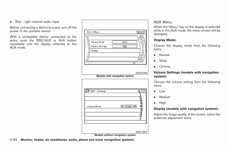
Black plate (272,1)
Model "E52-D" EDITED: 2010/ 10/ 25
. Red - right channel audio input
Before connecting a device to a jack, turn off thepower of the portable device.
With a compatible device connected to thejacks, push the DISC·AUX or AUX buttonrepeatedly until the display switches to theAUX mode.
SAA2496Models with navigation system
SAA1567Models without navigation system
AUX MenuWhen the “Menu” key on the display is selectedwhile in the AUX mode, the menu screen will bedisplayed.
Display Mode:
Choose the display mode from the followingitems.
. Normal
. Wide
. Cinema
Volume Settings (models with navigationsystem):
Choose the volume setting from the followingitems.
. Low
. Medium
. High
Display (models with navigation system):
Adjust the image quality of the screen, select thepreferred adjustment items.
4-94 Monitor, heater, air conditioner, audio, phone and voice recognition systems

Black plate (273,1)
Model "E52-D" EDITED: 2010/ 10/ 25
SAA0451
CD/DVD/USB MEMORY CARE ANDCLEANING
CD/DVD. Handle a CD/DVD by its edges. Never touch
the surface of the disc. Do not bend thedisc.
. Always place the discs in the storage casewhen they are not being used.
. To clean a disc, wipe the surface from thecenter to the outer edge using a clean, softcloth. Do not wipe the disc using a circularmotion.
Do not use a conventional record cleaner or
alcohol intended for industrial use.
. A new disc may be rough on the inner andouter edges. Remove the rough edges byrubbing the inner and outer edges with theside of a pen or pencil as illustrated.
USB memory. Never touch the terminal portion of the USB
memory.
. Do not place heavy objects on the USBmemory.
. Do not store the USB memory in highlyhumid locations.
. Do not expose the USB memory to directsunlight.
. Do not spill any liquids on the USB memory.
Refer to the USB memory Owner’s Manual forthe details.
SAA1854Models with navigation system
Monitor, heater, air conditioner, audio, phone and voice recognition systems 4-95
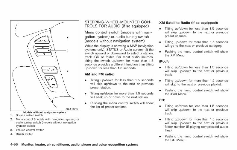
Black plate (274,1)
Model "E52-D" EDITED: 2010/ 10/ 25
SAA1855Models without navigation system
1. Source select switch
2. Menu control (models with navigation system) oraudio tuning switch (models without navigationsystem) switch
3. Volume control switch
4. BACK switch
STEERING-WHEEL-MOUNTED CON-TROLS FOR AUDIO (if so equipped)
Menu control switch (models with navi-gation system) or audio tuning switch(models without navigation system)While the display is showing a MAP (navigationsystems only), STATUS or Audio screen, tilt theswitch upward or downward to select a station,track, CD or folder. For most audio sources,tilting the switch up/down for more than 1.5seconds provides a different function than tiltingup/down for less than 1.5 seconds.
AM and FM radio:
. Tilting up/down for less than 1.5 secondswill skip up/down to the next or previouspreset station.
. Tilting up/down for more than 1.5 secondswill seek up or down to the next station.
. Pushing the menu control switch will showthe list of preset stations.
XM Satellite Radio (if so equipped):
. Tilting up/down for less than 1.5 secondswill skip up/down to the next or previouspreset channel.
. Tilting up/down for more than 1.5 secondswill go to the next or previous category.
. Pushing the menu control switch will showthe XM Menu.
iPod®:
. Tilting up/down for less than 1.5 secondswill skip up/down to the next or previoustrack.
. Tilting up/down for more than 1.5 secondswill skip to the next or previous playlist.
. Pushing the menu control switch will showthe iPod Menu.
CD:
. Tilting up/down for less than 1.5 secondswill skip up/down to the next or previoustrack.
. Tilting up/down for more than 1.5 secondswill skip up/down to the next or previousfolder number (if playing compressed audiofiles).
. Pushing the menu control switch will showthe CD Menu.
4-96 Monitor, heater, air conditioner, audio, phone and voice recognition systems

Black plate (275,1)
Model "E52-D" EDITED: 2010/ 10/ 25
DVD (if so equipped):
. Tilting up/down for less than 1.5 secondswill skip up/down to the next or previoustrack.
. Tilting up/down for more than 1.5 secondswill skip up/down to the next or previoustitle.
. Pushing the menu control switch will selectan item from the DVD display.
. When the transparent operation menu ap-pears, the switch will control the menu.
USB:
. Tilting up/down for less than 1.5 secondswill skip up/down to the next or previoustrack.
. Tilting up/down for more than 1.5 secondswill skip up/down to the next or previousfolder number
. Pushing the menu control switch will showthe USB Menu.
Music Box® (if so equipped):
. Tilting up/down for less than 1.5 secondswill skip up/down to the next or previoustrack.
. Tilting up/down for more than 1.5 secondswill skip up/down to the next or previous
album (folder) (if playing compressed audiofiles).
. Pushing the menu control switch will showthe Music Box® Menu.
Bluetooth® Audio (models with navigationsystem):
. Tilting up/down for less than 1.5 secondswill skip up/down to the next or previoustrack.
BACK switch (models with navi-gation system)
Push this switch to go back to the previousscreen or cancel the selection if it is notcompleted.
Volume control switchesPush the upper (+) or lower (−) side switch toincrease or decrease the volume.
Source select switchPush the audio source switch to change themode as follows.
. Models with navigation system
AM ? FM ? SAT ? CD/DVD ? MusicBox® ? USB/iPod® ? Bluetooth® Audio
. Models without navigation system
AM ? FM ? CD ? Music Box® ? USB/iPod® ? SAT
Monitor, heater, air conditioner, audio, phone and voice recognition systems 4-97

Black plate (276,1)
Model "E52-D" EDITED: 2010/ 10/ 25
ANTENNA
Window antennaThe antenna pattern is printed inside the rearside window.
CAUTION
. Do not place metalized film near therear side window glass or attach anymetal parts to it. This may causepoor reception or noise.
. When cleaning the inside of the rearwindow, be careful not to scratch ordamage the rear window antenna.Lightly wipe along the antenna witha dampened soft cloth.
SAA3602
Satellite antenna (if so equipped)There is a satellite antenna on the rear part of thevehicle roof.
This vehicle is equipped with the mobileentertainment system, which enables you toplay a Digital Versatile Disc (DVD) or USB,providing the images and sounds both in thefront and rear display screens.
WARNING
. The driver must not attempt tooperate or view the Mobile Enter-tainment System (MES) while thevehicle is in motion so that fullattention may be given to vehicleoperation.
. Do not attempt to modify the systemto display a movie on the frontscreen while the vehicle is beingdriven. Doing so may distract thedriver and may cause a collision andserious personal injury or death.
CAUTION
. The glass screen on the liquidcrystal display may break if hit witha hard or sharp object. If the glassbreaks, do not touch the liquidcrystalline material.
. Use a damp, soft cloth when clean-
NISSAN MOBILE ENTERTAINMENTSYSTEM (MES) (if so equipped)
4-98 Monitor, heater, air conditioner, audio, phone and voice recognition systems
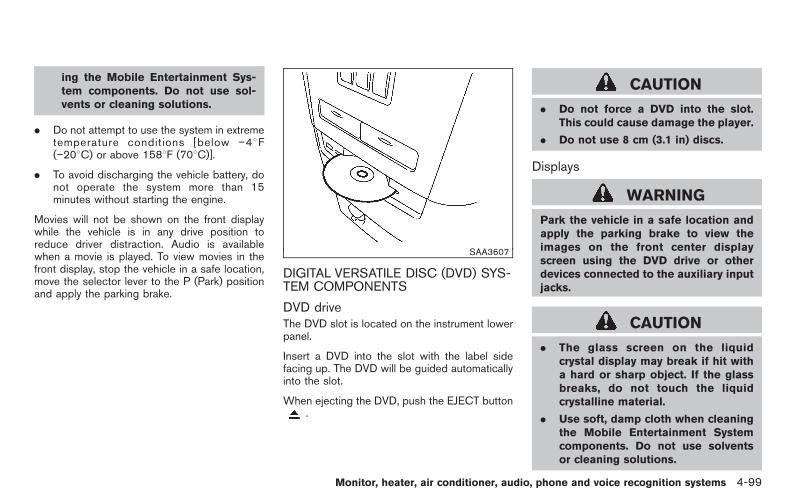
Black plate (277,1)
Model "E52-D" EDITED: 2010/ 10/ 25
ing the Mobile Entertainment Sys-tem components. Do not use sol-vents or cleaning solutions.
. Do not attempt to use the system in extremetemperature conditions [below −48F(−208C) or above 1588F (708C)].
. To avoid discharging the vehicle battery, donot operate the system more than 15minutes without starting the engine.
Movies will not be shown on the front displaywhile the vehicle is in any drive position toreduce driver distraction. Audio is availablewhen a movie is played. To view movies in thefront display, stop the vehicle in a safe location,move the selector lever to the P (Park) positionand apply the parking brake.
SAA3607
DIGITAL VERSATILE DISC (DVD) SYS-TEM COMPONENTS
DVD driveThe DVD slot is located on the instrument lowerpanel.
Insert a DVD into the slot with the label sidefacing up. The DVD will be guided automaticallyinto the slot.
When ejecting the DVD, push the EJECT button.
CAUTION
. Do not force a DVD into the slot.This could cause damage the player.
. Do not use 8 cm (3.1 in) discs.
Displays
WARNING
Park the vehicle in a safe location andapply the parking brake to view theimages on the front center displayscreen using the DVD drive or otherdevices connected to the auxiliary inputjacks.
CAUTION
. The glass screen on the liquidcrystal display may break if hit witha hard or sharp object. If the glassbreaks, do not touch the liquidcrystalline material.
. Use soft, damp cloth when cleaningthe Mobile Entertainment Systemcomponents. Do not use solventsor cleaning solutions.
Monitor, heater, air conditioner, audio, phone and voice recognition systems 4-99

Black plate (278,1)
Model "E52-D" EDITED: 2010/ 10/ 25
. Be sure to stow the rear displaywhen it is not used.
SAA3655Flip-down screen
Use the remote controller to operate themotorized flip-down rear display screen.
1. Push the REAR DISPLAY OPEN/CLOSEbutton on the remote controller to open orclose the display.
2. Adjust the display angle by pushing theDISPLAY TILT button or .
The screen can also be opened using the multi-function controller. (See “HOW TO USE SET-TING BUTTON” earlier in this section.)
Do not block the range of the wireless remotecontroller receiver and wireless headphonestransmitter *1 .
CAUTION
Do not touch the display when it isopening or closing.
Headphones
CAUTION
. Do not leave headphones on theseats. Sitting on headphones left ona seat could damage the head-phones and may result in personalinjury due to shards from the head-phones.
. After using the headphones, placethem in the included headphonebag and store them in a locationwhere they will not be an obstruc-tion.
Headphones are a wireless type and no cablesare necessary. You can use them in almost allthe ranges in the rear seat for listening to thesound from DVD, AUX or USB. (It is not possibleto use the headphones in the front seat.)
4-100 Monitor, heater, air conditioner, audio, phone and voice recognition systems

Black plate (279,1)
Model "E52-D" EDITED: 2010/ 10/ 25
SAA3608
Power ON/OFF:
Push the POWER button to turn the head-phones on or off.
SAA3609
Volume control:
Turn the volume control knob to adjust thevolume.
The headphones will automatically be turned offwithin approximately 5 minutes if there is noinfrared signal input during that period. Toprevent the battery from being discharged, keepthe power turned off when not in use.
If the sound from the headphones is not clear itmay be because:
. of an infrared communication device orcellular phone, turn down the headphonevolume or stop using the headphones, or
. the headphones maybe out of the range ofthe transmitter installed in the rear flip-downdisplay screen. This is not a malfunction, or
. the sound may be interrupted temporarilywhen there is an obstacle between theheadphones and the transmitter. Removethe obstacle, such as opaque materials,hands, hair, etc.
Monitor, heater, air conditioner, audio, phone and voice recognition systems 4-101
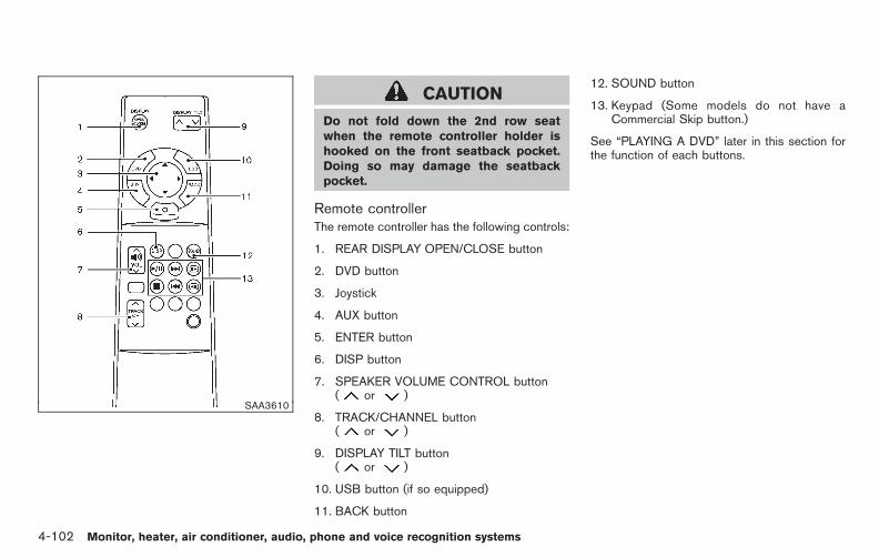
Black plate (280,1)
Model "E52-D" EDITED: 2010/ 10/ 25
SAA3610
CAUTION
Do not fold down the 2nd row seatwhen the remote controller holder ishooked on the front seatback pocket.Doing so may damage the seatbackpocket.
Remote controllerThe remote controller has the following controls:
1. REAR DISPLAY OPEN/CLOSE button
2. DVD button
3. Joystick
4. AUX button
5. ENTER button
6. DISP button
7. SPEAKER VOLUME CONTROL button( or )
8. TRACK/CHANNEL button( or )
9. DISPLAY TILT button( or )
10. USB button (if so equipped)
11. BACK button
12. SOUND button
13. Keypad (Some models do not have aCommercial Skip button.)
See “PLAYING A DVD” later in this section forthe function of each buttons.
4-102 Monitor, heater, air conditioner, audio, phone and voice recognition systems

Black plate (281,1)
Model "E52-D" EDITED: 2010/ 10/ 25
SAA0978Remote controller
SAA3611Headphones
Remote controller and headphones bat-tery replacementReplace the battery as follows:
1. Open the lid.
The lid is easy to open if a flat headscrewdriver etc., is used.
2. Replace both batteries with new ones.
. Size AA (remote control)
. Size AAA (headphones)
Make sure that the + and 7 ends onthe batteries match the markings in-side the compartment.
3. Close the lid securely.
If the battery is removed for any reasonother than replacement, close the lidsecurely.
. If you will not be using the remotecontrol for long periods of time, removethe batteries.
. Replacement of the batteries is neededwhen the remote control only functionsat extremely close distances to the MESor not at all.
. Be careful not to touch the batteryterminal.
. An improperly disposed battery canharm the environment. Always confirmlocal regulations for battery disposal.
. When changing batteries, do not letdust or oil get on the remote control andheadphones.
FCC Notice:
For USA:
This device complies with Part 15 of theFCC Rules. Operation is subject to thefollowing two conditions: (1) This devicemay not cause harmful interference, and(2) this device must accept any interfer-ence received, including interference thatmay cause undesired operation.
Note: Changes or modifications not ex-pressly approved by the party responsiblefor compliance could void the user’sauthority to operate the equipment.
For Canada:
This device complies with RSS-210 ofIndustry Canada. Operation is subject tothe following two conditions: (1) thisdevice may not cause interference, and(2) this device must accept any interfer-ence, including interference that maycause undesired operation of the device.
Monitor, heater, air conditioner, audio, phone and voice recognition systems 4-103
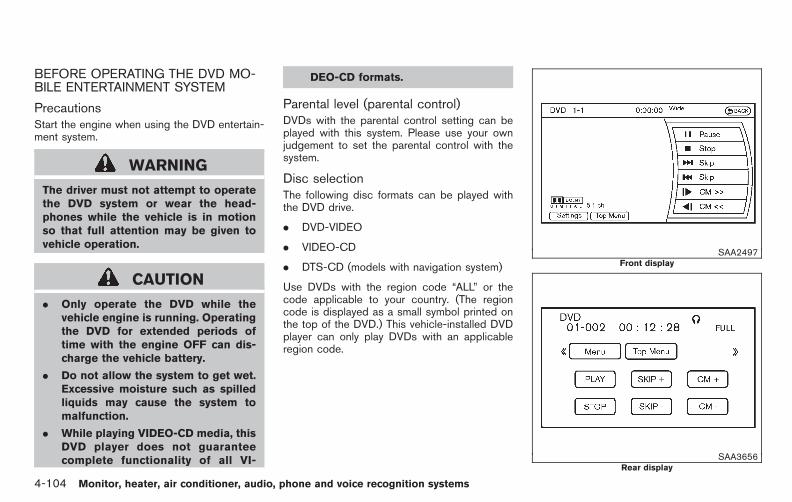
Black plate (282,1)
Model "E52-D" EDITED: 2010/ 10/ 25
BEFORE OPERATING THE DVD MO-BILE ENTERTAINMENT SYSTEM
PrecautionsStart the engine when using the DVD entertain-ment system.
WARNING
The driver must not attempt to operatethe DVD system or wear the head-phones while the vehicle is in motionso that full attention may be given tovehicle operation.
CAUTION
. Only operate the DVD while thevehicle engine is running. Operatingthe DVD for extended periods oftime with the engine OFF can dis-charge the vehicle battery.
. Do not allow the system to get wet.Excessive moisture such as spilledliquids may cause the system tomalfunction.
. While playing VIDEO-CD media, thisDVD player does not guaranteecomplete functionality of all VI-
DEO-CD formats.
Parental level (parental control)DVDs with the parental control setting can beplayed with this system. Please use your ownjudgement to set the parental control with thesystem.
Disc selectionThe following disc formats can be played withthe DVD drive.
. DVD-VIDEO
. VIDEO-CD
. DTS-CD (models with navigation system)
Use DVDs with the region code “ALL” or thecode applicable to your country. (The regioncode is displayed as a small symbol printed onthe top of the DVD.) This vehicle-installed DVDplayer can only play DVDs with an applicableregion code.
SAA2497Front display
SAA3656Rear display
4-104 Monitor, heater, air conditioner, audio, phone and voice recognition systems

Black plate (283,1)
Model "E52-D" EDITED: 2010/ 10/ 25
PLAYING A DVD
DISC·AUX or DISC buttonPark the vehicle in a safe location for thefront seat occupants to operate the DVDdrive while watching the images.
Insert a DVD into the CD/DVD slot with thelabeled side up. The DVD will be guidedautomatically into the slot. When ejecting theDVD, push the EJECT button.
Push the DISC·AUX or DISC button on theinstrument panel, turn the display to the DVDmode, and begin playing DVD automatically.
When a DVD is loaded, it will be replayedautomatically.
The front screen will be turned on when theDISC·AUX or DISC button is pushed while aDVD is being played, and it will turn offautomatically after a period of time. To turn iton again, push the DISC·AUX or DISC buttonagain.
Adjust Front/Rear display
Front display:
To adjust the front display, push the SETTINGbutton while the DVD is being played, select the“Others” key and then select the “Display” key.
To adjust the display ON/OFF, brightness, tint,
color and contrast, select the “Display Adjust-ment” key and then select the preferred key forsetting.
You can then adjust each item using the multi-function controller. After changes have beenmade press the BACK button to save thesetting.
Rear display:
To adjust the rear display, push the “DISP”(Display) button on the remote controller.
To adjust aspect, color system, 3D Y/C filter andpicture mode, select each key using the joystickon the remote controller and tilt the joystick toright or left.
Push the BACK button to apply the settings andreturn to the previous display.
DVD operation keysTo operate the DVD drive, select the desired keydisplayed on the operation screen using themulti-function controller.
PAUSE:
Select the “ ” key to pause the DVD. Toresume playing the DVD, use the “PLAY” key.
To pause the DVD, it is also possible to push the“ ” button on the keypad of the remotecontroller.
PLAY:
Select the “ ” key to start playing the DVD,for example, after pausing the DVD.
To start playing the DVD, it is also possible topush the “ ” button on the keypad of theremote controller.
STOP:
Select the “ ” key to stop playing the DVD.
To stop playing the DVD, it is also possible topush the “ ” button on the keypad of theremote controller.
SKIP (FORWARD):
Select the “ ” key to skip the chapter(s) ofthe disc forward. The chapters will advance thenumber of times the ENTER button is pushed.
To skip the chapter(s) forward, it is also possibleto push the “ ” button on the keypad of theremote controller.
Monitor, heater, air conditioner, audio, phone and voice recognition systems 4-105

Black plate (284,1)
Model "E52-D" EDITED: 2010/ 10/ 25
SKIP (REWIND):
Select the “ ” key to skip the chapter(s) ofthe disc backward. The chapters will go backthe number of times the ENTER button ispushed.
To skip the chapter(s) backward, it is alsopossible to push the “ ” button on thekeypad of the remote controller.
/ Commercial Skip (if soequipped):
This function is only for DVD-VIDEO and DVD-VR.
Select the “ ” or “ ” key to skip forwardor backwards by the set amount as defined inthe DVD settings menu.
To skip forward or backward, it is also possibleto push the “ ” or “ ” button on thekeypad of the remote controller.
SAA2498Front screen (models with navigation system)
SAA3656Rear screen (models with navigation system)
SAA3087Front screen (models without navigation system)
SAA3657Rear screen (models without navigation system)
4-106 Monitor, heater, air conditioner, audio, phone and voice recognition systems
Black plate (285,1)
Model "E52-D" EDITED: 2010/ 10/ 25
Setting keysSelect the “Settings” key with the multi-functioncontroller and push the ENTER button to adjustthe following settings.
The items indicated with “ * ” can also be setfrom the rear display. Push the “ DVD” button onthe remote controller while a DVD is beingplayed. Select the preferred item using thejoystick “ ” on the remote controller andpush the ENTER “ ” button.
Key (DVD-VIDEO) (models with navigationsystem):
Keys for the DVD menu operation are displayed.
: Move the cursor to select a DVD menu.
Enter: Enter the selected menu.
Move: Change the display location by movingthe operation key.
Back: Return to the previous screen.
Hide: Hide the operation key.
Title Menu (front)/Menu (rear) (DVD-VI-DEO):
Menus specific to each disc will be shown. Fordetails, see the instructions attached to the disc.
Title Search (DVD-VIDEO):
A scene that belongs to a specified title will bedisplayed each time the “+” side or “−” side isselected.
10 Key Search (DVD-VIDEO, VIDEO-CD,CD-DA):
Select the “10 Key Search” key and push theENTER button to open the number entry screen.
Input the number you want to search for andselect the “OK” key with the multi-functioncontroller. Then push the ENTER button. Thespecified Title/Chapter or Group/Track will beplayed.
Angle (DVD-VIDEO):
If the DVD contains different angles (such asmoving images), the current image angle can beswitched to another one.
Select the “Angle” key and push the ENTERbutton. When the “+” side or “−” side isselected, the angle will change.
Angle Mark (DVD-VIDEO):
When this item is turned on, an angle mark willbe shown on the bottom of the screen if thescene can be seen from a different angle.
Menu Skip (DVD-VIDEO):
DVD menus are automatically configured andthe contents will be played directly when the“Menu Skip” key is turned on. Note that somediscs may not be played directly even if this itemis turned on.
CM Skip (DVD-VIDEO) (models with navi-gation system):
The number of seconds for CM Skip can be setto 15, 30 or 60 seconds.
DRC (DVD-VIDEO):
DRC (Dynamic Range Compression) allowstuning of the dynamic range of sound recordedin the Dolby Digital format.
DVD Language (DVD-VIDEO, VIDEO-CD):
Select the “DVD Language” key and push theENTER button to open the number entry screen.
Input the number corresponding to the preferredlanguage and select the “OK” key with the multi-function controller. Then push the ENTERbutton. The DVD top menu language will bechanged to the one selected.
Display:
Adjust the image quality of the screen, select thepreferred adjustment items and push the ENTERbutton.
Monitor, heater, air conditioner, audio, phone and voice recognition systems 4-107

Black plate (286,1)
Model "E52-D" EDITED: 2010/ 10/ 25
Audio:
Choose the preferred language using the multi-function controller and push the ENTER button.
Subtitle (DVD-VIDEO):
Choose the preferred language using the multi-function controller and push the ENTER button.
To turn off the subtitles, push and hold theENTER button until a beep sounds.
Display Mode (DVD-VIDEO, VIDEO-CD):
Choose from the “Full”, “Wide”, “Normal” or“Cinema” mode using the multi-function con-troller and push the ENTER button again.
Play Mode:
Choose the preferred play mode using the multi-function controller and push the ENTER button.
Remote controller operationUse the remote controller to adjust the followingitems.
Rear display open/close:
To open or close the flip-down rear display, pushthe “ ” button.
Joystick:
Use the joystick “ ” to select the itemsdisplayed on the rear screen.
ENTER button:
Push the ENTER “ ” button to make theselected item complete on the rear screen.
BACK button:
Push to go back to the previous screen orcancel the selection.
Display tilt:
Adjust the display angle by pushing the DIS-PLAY TILT button “ ”.
DVD mode:
To select the DVD mode, push the DVD button.
USB mode:
To select the USB mode, push the USB button.
AUX mode:
To select the AUX (auxiliary input jacks), mode,push the AUX button.
Volume:
To control the speaker volume level, push theVOL button “ ”.
Display:
To adjust the rear display screen (aspect, colorsystem, 3D Y/C filter and picture mode etc.),push the DISP button.
Sound:
To change the language, push the SOUNDbutton. Each time the button is pushed, thelanguage will change to each language stored inthe DVD.
Track/Channel:
To skip to the previous or next DVD sceneselection, push the TRACK CH button“ ”.
Keypad:
: PLAY/PAUSE button
: STOP button
: FORWARD button
: REWIND button
: FORWARD button for commercial skip(for DVD-VIDEO and DVD-VR)
: REWIND button for commercial skip (forDVD-VIDEO and DVD-VR)
Rear display settingsTo adjust rear display setting, select thepreferred key and push the ENTER button.The following settings are available:
4-108 Monitor, heater, air conditioner, audio, phone and voice recognition systems

Black plate (287,1)
Model "E52-D" EDITED: 2010/ 10/ 25
Aspect:
Select the display size from “CINEMA”, “WIDE”,“FULL” or “NORMAL” using the joystick on theremote controller.
Picture Mode:
To adjust the display brightness automatically,select the “Brightness” key and then select from“DARKER”, “NORMAL” or “BRIGHTER”. Whenadjusting manually, select “OFF” and adjustusing the joystick on the remote controller andtilt the joystick to the right or left.
To adjust tint, color, contrast or black level,select a key using the joystick on the remotecontroller and tilt the joystick to the right or left.
Push the BACK button on the remote controllerto apply the settings and return to the previousdisplay.
To return the adjustment levels to the defaultvalue, select “Execute” next to “Initialization”using the joystick on the remote controller andpush the ENTER button. The “Execute” keyis deactivated when the picture mode settingsare already in the default value.
Color System:
To choose the color system, select from“NTSC”, “PAL”, “PAL-60”, “PAL-M”, “PAL-N” or“AUTO” using the joystick on the remote
controller and tilt the joystick to the right or left.
3D Y/C filter:
Set to ON/OFF using the joystick on the remotecontroller. When turned on, small charactersand an outline of the shapes will be displayedmore clearly than when turned off.
CARE AND MAINTENANCE
Use a lightly dampened, lint free cloth to cleanthe surfaces of your Mobile EntertainmentSystem (DVD player face, screen, remotecontroller, etc.).
CAUTION
. Do not use any solvents or cleaningsolutions when cleaning the videosystem.
. Do not use excessive force on themonitor screen.
. Avoid touching or scratching themonitor screen as it may becomedirty or damaged.
. Do not attempt to operate thesystem in extreme temperature con-ditions [below −48F (−208C) andabove 1588F (708C)].
. Do not attempt to operate thesystem in extreme humidity condi-tions (less than 10% or more than75%).
Monitor, heater, air conditioner, audio, phone and voice recognition systems 4-109
Black plate (288,1)
Model "E52-D" EDITED: 2010/ 10/ 25
When installing a car phone or a CB radio inyour NISSAN, be sure to observe the followingcautions, otherwise the new equipment mayadversely affect the electronic control modulesand electronic control system harness.
WARNING
. A cellular telephone should not beused while driving so full attentionmay be given to vehicle operation.Some jurisdictions prohibit the useof cellular telephones while driving.
. If you must make a call while yourvehicle is in motion, the hands-freecellular phone operational mode (ifso equipped) is highly recom-mended. Exercise extreme cautionat all times so full attention may begiven to vehicle operation.
. If a conversation in a moving vehiclerequires you to take notes, pull offthe road to a safe location and stopyour vehicle before doing so.
CAUTION
. Keep the antenna as far away aspossible from the electronic controlmodules.
. Keep the antenna wire more than 8in (20 cm) away from the electroniccontrol system harness. Do notroute the antenna wire next to anyharness.
. Adjust the antenna standing-waveratio as recommended by the man-ufacturer.
. Connect the ground wire from theCB radio chassis to the body.
. For details, consult a NISSAN deal-er.
WARNING
. Use a phone after stopping yourvehicle in a safe location. If youhave to use a phone while driving,exercise extreme caution at alltimes so full attention may be givento vehicle operation.
. If you find yourself unable to devotefull attention to vehicle operationwhile talking on the phone, pull offthe road to a safe location and stopyour vehicle before doing so.
CAUTION
To avoid draining the vehicle battery,use a phone after starting the engine.
Your NISSAN is equipped with Bluetooth®
Hands-Free Phone System. If you are an ownerof a compatible Bluetooth® enabled cellularphone, you can set up the wireless connectionbetween your cellular phone and the in-vehiclephone module. With Bluetooth® wireless tech-nology, you can make or receive a telephone callwith your cellular phone in your pocket.
Once a cellular phone is connected to the in-vehicle phone module, no phone connecting
CAR PHONE OR CB RADIOBLUETOOTH® HANDS-FREE PHONESYSTEM (models with navigationsystem)
4-110 Monitor, heater, air conditioner, audio, phone and voice recognition systems

Black plate (289,1)
Model "E52-D" EDITED: 2010/ 10/ 25
procedure is required anymore. Your phone isautomatically connected with the in-vehiclephone module when the ignition switch ispushed to the ON position with the registeredcellular phone turned on and carried in thevehicle.
You can register up to 5 different Bluetooth®
cellular phones in the in-vehicle phone module.However, you can talk on only one cellular phoneat a time.
The NISSAN Voice Recognition system sup-ports the phone commands, so dialing a phonenumber using your voice is possible. For moredetails, see “NISSAN VOICE RECOGNITIONSYSTEM (models with navigation system)” laterin this section; page 4-134.
Before using the Bluetooth® Hands-Free PhoneSystem, refer to the following notes.
. Set up the wireless connection between acompatible cellular phone and the in-vehiclephone module before using the Bluetooth®
Hands-Free Phone System.
. Some Bluetooth® enabled cellular phonesmay not be recognized by the in-vehiclephone module. Please visitwww.nissanusa.com/bluetooth for a recom-mended phone list.
. You will not be able to use a hands-freephone under the following conditions:
— Your vehicle is outside of the telephoneservice area.
— Your vehicle is in an area where it isdifficult to receive radio waves; such as ina tunnel, in an underground parkinggarage, behind a tall building or in amountainous area.
— Your cellular phone is locked in order notto be dialed.
. When the radio wave reception is not goodor ambient sound is too loud, it may bedifficult to hear the other person’s voiceduring a call.
. Immediately after the ignition switch ispushed to the ON position, it may beimpossible to receive a call for a shortperiod of time.
. Do not place the cellular phone in an areasurrounded by metal or far away from the in-vehicle phone module to prevent tone qualitydegradation and wireless connection dis-ruption.
. While a cellular phone is connected throughthe Bluetooth® wireless connection, thebattery power of the cellular phone maydischarge quicker than usual.
. If the Bluetooth® Hands-Free Phone Systemseems to be malfunctioning, please visit
www.nissanusa.com/bluetooth for trouble-shooting help.
. Some cellular phones or other devices maycause interference or a buzzing noise tocome from the audio system speakers.Storing the device in a different locationmay reduce or eliminate the noise.
. Refer to the cellular phone Owner’s Manualregarding the telephone pairing procedurespecific to your phone, battery charging,cellular phone antenna, etc.
. The antenna display on the monitor will notcoincide with the antenna display of somecellular phones.
. Keep the interior of the vehicle as quiet aspossible to hear the caller’s voice clearly aswell as to minimize its echoes.
. If reception between callers is unclear,adjusting the incoming or outgoing callvolume may improve the clarity.
REGULATORY INFORMATION
FCC Regulatory information— CAUTION: To maintain compliance with
FCC’s RF exposure guidelines, use onlythe supplied antenna. Unauthorized antenna,modification, or attachments could damagethe transmitter and may violate FCC regula-tions.
Monitor, heater, air conditioner, audio, phone and voice recognition systems 4-111

Black plate (290,1)
Model "E52-D" EDITED: 2010/ 10/ 25
— Operation is subject to the following twoconditions:
1) this device may not cause interference and
2) this device must accept any interference,including interference that may cause un-desired operation of the device
IC Regulatory information— Operation is subject to the following two
conditions: (1) this device may not causeinterference, and (2) this device must acceptany interference, including interference thatmay cause undesired operation of thedevice.
— This Class B digital apparatus meets allrequirements of the Canadian Interference-Causing Equipment Regulations.
Bluetooth trademark:
Bluetooth® is a trademark ownedby Bluetooth SIG, Inc., U.S.A.and licensed to Clarion Co., Ltd.
VOICE COMMANDS
You can use voice commands to operate variousBluetooth® Hands-Free Phone System featuresusing the NISSAN Voice Recognition system.
For more details, see “NISSAN VOICE RE-COGNITION SYSTEM (models with navigation
system)” later in this section; page 4-134.
SAA3603
CONTROL BUTTONS
1. TALK /PHONE SEND button
4-112 Monitor, heater, air conditioner, audio, phone and voice recognition systems

Black plate (291,1)
Model "E52-D" EDITED: 2010/ 10/ 25
SAA2519
CONNECTING PROCEDURE
1. Push the button, and select the“Connect Phone” key.
SAA2520
2. When a PIN code appears on the screen,operate the compatible Bluetooth® cellularphone to enter the PIN code.
The connecting procedure of the cellularphone varies according to each cellularphone. See the cellular phone Owner’sManual for the details. You can also visitwww.nissanusa.com/bluetooth or callNISSAN Consumer Affairs Department forinstructions on pairing NISSAN recom-mended cellular phones.
When the connection process is completed,the screen will return to the Phone menudisplay.
PHONE SELECTION
Up to 5 cellular phones can be registered to thesystem. To switch to connect another cellularphone, push button and select the “Con-nected Phones” key. The registered cellularphones are shown on the list. If you select acellular phone that is different from the onecurrently connected, the newly selected phonewill be connected to the system.
VEHICLE PHONEBOOK
This vehicle has two phonebooks available forhands-free use. Depending on the phone, thesystem may automatically download the entirecell phone’s phonebook into the “HandsetPhonebook”. For the details about downloadinga phonebook, see “PHONE SETTING” later inthis section. If a phonebook does not auto-matically download, the vehicle phonebook maybe set for up to 1,000 entries. This phonebookallows the recording of a name to speak whileusing voice recognition.
Monitor, heater, air conditioner, audio, phone and voice recognition systems 4-113

Black plate (292,1)
Model "E52-D" EDITED: 2010/ 10/ 25
SAA2521
1. Push the button and select the“Vehicle Phonebook” key.
2. Select the “Add New” key at the top of thescreen.
SAA2522
3. Choose the method for entering the phone-book entry. For this example, select “EnterNumber by Keypad”.
4. Enter the digits and select the “OK” key.(See “HOW TO USE TOUCH SCREEN(models with navigation system)” earlier inthis section.)
SAA2523
5. Select the “Voicetag” key to record a nameto speak when using the NISSAN VoiceRecognition system.
6. Select the “Store” key and prepare to speakthe name after the tone.
7. When the voicetag is successfully saved,select the “OK” key to save the phonebookentry.
8. After the phonebook entry is saved, it willshow a screen that is ready to call thenumber. Press the BACK button to return tothe Vehicle Phonebook.
There are different methods to input a phonenumber. Select one of the following options
4-114 Monitor, heater, air conditioner, audio, phone and voice recognition systems
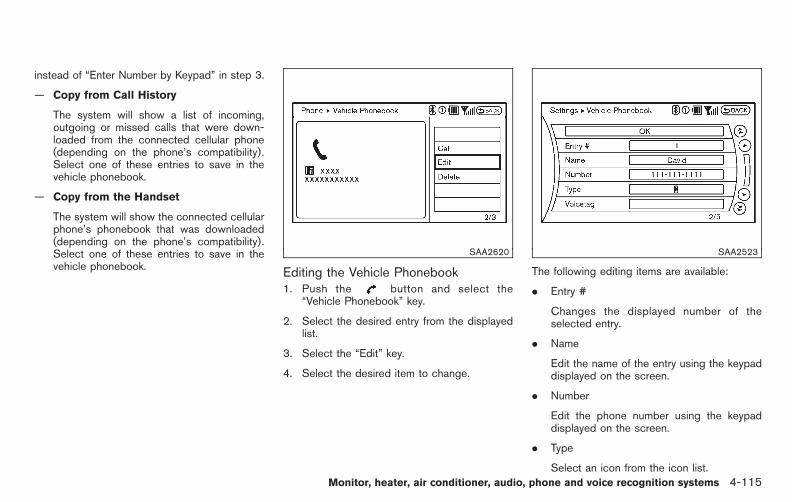
Black plate (293,1)
Model "E52-D" EDITED: 2010/ 10/ 25
instead of “Enter Number by Keypad” in step 3.
— Copy from Call History
The system will show a list of incoming,outgoing or missed calls that were down-loaded from the connected cellular phone(depending on the phone’s compatibility).Select one of these entries to save in thevehicle phonebook.
— Copy from the Handset
The system will show the connected cellularphone’s phonebook that was downloaded(depending on the phone’s compatibility).Select one of these entries to save in thevehicle phonebook.
SAA2620
Editing the Vehicle Phonebook1. Push the button and select the
“Vehicle Phonebook” key.
2. Select the desired entry from the displayedlist.
3. Select the “Edit” key.
4. Select the desired item to change.
SAA2523
The following editing items are available:
. Entry #
Changes the displayed number of theselected entry.
. Name
Edit the name of the entry using the keypaddisplayed on the screen.
. Number
Edit the phone number using the keypaddisplayed on the screen.
. Type
Select an icon from the icon list.Monitor, heater, air conditioner, audio, phone and voice recognition systems 4-115

Black plate (294,1)
Model "E52-D" EDITED: 2010/ 10/ 25
. Voicetag
Confirm and store the voicetag. Voicetagsallow easy dialing using the NISSAN VoiceRecognition system. (See “NISSAN VOICERECOGNITION SYSTEM (models with na-vigation system)” later in this section.)
To delete an entry, select the “Delete” key atstep 3.
SAA2524
MAKING A CALL
To make a call, follow this procedure.
1. Push the button on the steering wheel.The “PHONE” screen will appear on thedisplay.
2. Select the “Handset Phonebook” key on the“PHONE” menu.
3. Select the desired entry from the list.
4. Confirm the correct entry by selecting for thecorrect number from the list.
SAA2621
5. Select the “Call” key to start dialing thenumber.
There are different methods to make a call.Select one of the following options instead of“Handset Phonebook” in step 2 above.
. Vehicle Phonebook
Select an entry stored in the Vehicle’sPhonebook.
. Call History
Select an outgoing, incoming or missed calldownloaded from your cell phone (depend-ing on your phone’s compatibility).
4-116 Monitor, heater, air conditioner, audio, phone and voice recognition systems

Black plate (295,1)
Model "E52-D" EDITED: 2010/ 10/ 25
. Dial Number
Input the phone number manually using thekeypad displayed on the screen. (See“HOW TO USE TOUCH SCREEN (modelswith navigation system)” earlier in thissection.)
SAA2525
RECEIVING A CALL
When you hear a phone ring, the display willchange to the incoming call mode. To receive acall, perform one of the following procedureslisted below.
a) Select the “Answer” key.
b) Push the button on the steering wheel.
There are some options available when receivinga call. Select one of the following displayed onthe screen.
. Answer
Accept an incoming call to talk.
. Hold Call
Put an incoming call on hold.
. Reject Call
Reject an incoming call.
To finish the call, perform one of thefollowing procedures listed below.
a) Select the “Hang up” key.
b) Push the button on the steering wheel.
Monitor, heater, air conditioner, audio, phone and voice recognition systems 4-117
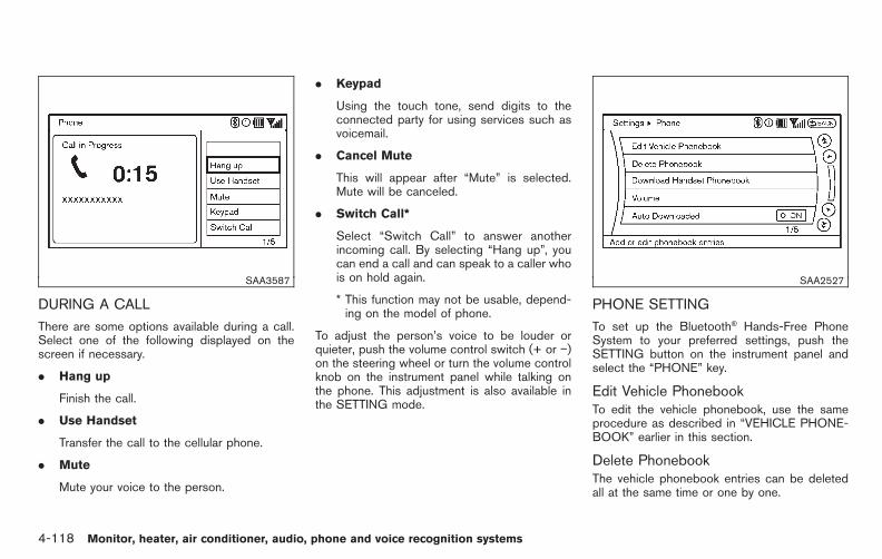
Black plate (296,1)
Model "E52-D" EDITED: 2010/ 10/ 25
SAA3587
DURING A CALL
There are some options available during a call.Select one of the following displayed on thescreen if necessary.
. Hang up
Finish the call.
. Use Handset
Transfer the call to the cellular phone.
. Mute
Mute your voice to the person.
. Keypad
Using the touch tone, send digits to theconnected party for using services such asvoicemail.
. Cancel Mute
This will appear after “Mute” is selected.Mute will be canceled.
. Switch Call*
Select “Switch Call” to answer anotherincoming call. By selecting “Hang up”, youcan end a call and can speak to a caller whois on hold again.
* This function may not be usable, depend-ing on the model of phone.
To adjust the person’s voice to be louder orquieter, push the volume control switch (+ or −)on the steering wheel or turn the volume controlknob on the instrument panel while talking onthe phone. This adjustment is also available inthe SETTING mode.
SAA2527
PHONE SETTING
To set up the Bluetooth® Hands-Free PhoneSystem to your preferred settings, push theSETTING button on the instrument panel andselect the “PHONE” key.
Edit Vehicle PhonebookTo edit the vehicle phonebook, use the sameprocedure as described in “VEHICLE PHONE-BOOK” earlier in this section.
Delete PhonebookThe vehicle phonebook entries can be deletedall at the same time or one by one.
4-118 Monitor, heater, air conditioner, audio, phone and voice recognition systems

Black plate (297,1)
Model "E52-D" EDITED: 2010/ 10/ 25
Download Handset PhonebookDownload the contacts registered in a Blue-tooth® cellular phone. Availability of this functiondepends on each cellular phone. The memorydownloading procedure from the cellular phonealso varies according to each cellular phone.See cellular phone Owner’s Manual for details.
VolumeThe following kinds of phone volume can be set.Pushing the button and selecting the“Volume” key can also operate the samesettings.
. Ringtone/Incoming Call/Outgoing Call
To increase or decrease the volume, selectthe “Ringtone”, “Incoming Call” or “Out-going Call” key and adjust it with the multi-function controller.
. Automatic Hold
When this function is activated, an incomingphone call is automatically held.
. Vehicle Ringtone
When this function is activated, a specificringtone that is different from the cellularphone will sound when receiving a call.
Auto DownloadWhen this item is activated, the phonebook of ahands-free phone is automatically downloadedat the same time that the hands-free phone isconnected.
Monitor, heater, air conditioner, audio, phone and voice recognition systems 4-119

Black plate (298,1)
Model "E52-D" EDITED: 2010/ 10/ 25
TROUBLESHOOTING GUIDE
The system should respond correctly to all voice commands without difficulty. If problems are encountered, try the following solutions.
Where the solutions are listed by number, try each solution in turn, starting with number 1, until the problem is resolved.
Symptom Solution
System fails to interpret the commandcorrectly.
1. Ensure that the command is valid. (See “NISSAN VOICE RECOGNITION SYSTEM (models with navigation system)” later inthis section; page 4-134.)
2. Ensure that the command is spoken after the tone.
3. Speak clearly without pausing between words and at a level appropriate to the ambient noise level in the vehicle.
4. Ensure that the ambient noise level is not excessive (for example, windows open or defroster on). NOTE: If it is too noisy touse the phone, it is likely that the voice commands will not be recognized.
5. If more than one command was said at a time, try saying the commands separately.
The system consistently selects thewrong voicetag.
1. Ensure that the voicetag requested matches what was originally stored. (See “VEHICLE PHONEBOOK” earlier in thissection.)
2. Replace one of the names being confused with a new name.
4-120 Monitor, heater, air conditioner, audio, phone and voice recognition systems

Black plate (299,1)
Model "E52-D" EDITED: 2010/ 10/ 25
WARNING
. Use a phone after stopping yourvehicle in a safe location. If youhave to use a phone while driving,exercise extreme caution at alltimes so full attention may be givento vehicle operation.
. If you find yourself unable to devotefull attention to vehicle operationwhile talking on the phone, pull offthe road to a safe location and stopyour vehicle before doing so.
CAUTION
To avoid draining the vehicle battery,use a phone after starting the engine.
SAA3677
1. PHONE SEND button
2. PHONE END button
Your NISSAN is equipped with the Bluetooth®
Hands-Free Phone System. If you have acompatible Bluetooth® enabled cellular phone,you can set up the wireless connection betweenyour cellular phone and the in-vehicle phonemodule. With Bluetooth® wireless technology,you can make or receive a hands-free telephonecall in your vehicle.
Once your cellular phone is connected to the in-vehicle phone module, no other phone connect-ing procedure is required. Your phone isautomatically connected with the in-vehiclephone module when the ignition switch ispushed to the ON position with the connected
cellular phone turned on and carried in thevehicle.
You can connect up to 5 different Bluetooth®
cellular phones in the in-vehicle phone module.However, you can talk on only one cellular phoneat a time.
Before using the Bluetooth® Hands-Free PhoneSystem, refer to the following notes.
. Set up the wireless connection between acompatible cellular phone and the in-vehiclephone module before using the Bluetooth®
Hands-Free Phone System.
. Some Bluetooth® enabled cellular phonesmay not be recognized by the in-vehiclephone module. Please visit www.nissanusa.com/bluetooth for a recommended phonelist and connecting.
. You will not be able to use a hands-freephone under the following conditions:
— Your vehicle is outside of the telephoneservice area.
— Your vehicle is in an area where it isdifficult to receive radio waves; such as ina tunnel, in an underground parkinggarage, near a tall building or in amountainous area.
— Your cellular phone is locked to prevent it
BLUETOOTH® HANDS-FREE PHONESYSTEM (models withoutnavigation system) (if so equipped)
Monitor, heater, air conditioner, audio, phone and voice recognition systems 4-121

Black plate (300,1)
Model "E52-D" EDITED: 2010/ 10/ 25
from being dialed.
. When the radio wave condition is not idealor ambient sound is too loud, it may bedifficult to hear the other person’s voiceduring a call.
. Immediately after the ignition switch ispushed to the ON position, it may beimpossible to receive a call for a shortperiod of time.
. Do not place the cellular phone in an areasurrounded by metal or far away from the in-vehicle phone module to prevent tone qualitydegradation and wireless connection dis-ruption.
. While a cellular phone is connected throughthe Bluetooth® wireless connection, thebattery power of the cellular phone maydischarge quicker than usual. The Blue-tooth® Hands-Free Phone System cannotcharge cellular phones.
. If the Bluetooth® Hands-Free Phone Systemseems to be malfunctioning, see “Trouble-shooting guide” later in this section. You canalso visit www.nissanusa.com/bluetooth fortroubleshooting help.
. Some cellular phones or other devices maycause interference or a buzzing noise tocome from the audio system speakers.Storing the device in a different location
may reduce or eliminate the noise.
. Refer to the cellular phone Owner’s Manualregarding battery charging, cellular phoneantenna, etc.
. This wireless hands free car kit is based onBluetooth® technology,
— Frequency: 2402 MHz - 2480 MHz
— Output Power: 4.14 dBm E.I.R.P
— Modulation: FHSS GFSK 8DPSK, p/4DQPSK
— Number of Channels: 79
— This wireless equipment can’t be used forany services related to safety becausethere is the possibility of radio interfer-ence.
REGULATORY INFORMATION
FCC Regulatory information— CAUTION: To maintain compliance with
FCC’s RF exposure guidelines, use onlythe supplied antenna. Unauthorized antenna,modification, or attachments could damagethe transmitter and may violate FCC regula-tions.
— Operation is subject to the following twoconditions:
1) this device may not cause interference and
2) this device must accept any interference,including interference that may cause un-desired operation of the device
IC Regulatory information— Operation is subject to the following two
conditions: (1) this device may not causeinterference, and (2) this device must acceptany interference, including interference thatmay cause undesired operation of thedevice.
— This Class B digital apparatus meets allrequirements of the Canadian Interference-Causing Equipment Regulations.
Bluetooth trademark:
Bluetooth® is a trademark ownedby Bluetooth SIG, Inc., U.S.A.and licensed to Visteon Corpora-tion.
USING THE SYSTEM
The NISSAN Voice Recognition system allowshands-free operation of the Bluetooth® Hands-Free Phone System.
If the vehicle is in motion, some commands maynot be available so full attention may be given tovehicle operation.
4-122 Monitor, heater, air conditioner, audio, phone and voice recognition systems

Black plate (301,1)
Model "E52-D" EDITED: 2010/ 10/ 25
InitializationWhen the ignition switch is pushed to the ONposition, NISSAN Voice Recognition is initia-lized, which may take up to one minute. If the
button is pushed before the initializationcompletes, the system will accept any com-mand.
Operating tipsTo get the best performance out of the NISSANVoice Recognition system, observe the follow-ing:
. Keep the interior of the vehicle as quiet aspossible. Close the windows to eliminatesurrounding noises (traffic noises, vibrationsounds, etc.), which may prevent the systemfrom recognizing voice commands correctly.
. Wait until the tone sounds before speaking acommand. Otherwise, the command will notbe received properly.
. Start speaking a command within 5 secondsafter the tone sounds.
. Speak in a natural voice without pausingbetween words.
Giving voice commandTo operate NISSAN Voice Recognition, pushand release the button located on thesteering wheel. After the tone sounds, speak a
command.
The command given is picked up by themicrophone, and voice feedback is given whenthe command is accepted.
. If you need to hear the available commandsfor the current menu again, say “Help” andthe system will repeat them.
. If a command is not recognized, the systemannounces, “Command not recognized.Please say again.” Repeat the command ina clear voice.
. If you want to go back to the previouscommand, you can say “Go back” or“Correction” anytime the system is waitingfor a response.
. You can cancel a command when thesystem is waiting for a response by saying,“Cancel” or “Quit.” The system announces“Cancel” and ends the VR session. You canalso push and hold the button for 5seconds on the steering wheel at any time tocancel the VR session. Whenever the VRsession is cancelled, a double beep isplayed to indicate you have exited thesystem.
. If you want to adjust the volume of the voicefeedback, push the volume control switch (+or −) on the steering wheel while beingprovided with feedback. You can also use
the radio volume control knob.
. In most cases you can interrupt the voicefeedback to speak the next command bypressing the button on the steeringwheel.
. To use the system faster, you may speak thesecond level commands with the main menucommand on the main menu. For example,press the button and after the tone say,“Call Redial.” Note: The combined com-mand of Call and (a Name) cannot be used.
Monitor, heater, air conditioner, audio, phone and voice recognition systems 4-123

Black plate (302,1)
Model "E52-D" EDITED: 2010/ 10/ 25
How to say numbersNISSAN Voice Recognition requires a certainway to speak numbers in voice commands.Refer to the rules and examples below.
. Either “zero” or “oh” can be used for “0”.
Example: 1-800-662-6200
— “One eight oh oh six six two six two ohoh”, or
— “One eight zero zero six six two six two ohoh”
. Words can be used for the first 4 digitsplaces only.
Example: 1-800-662-6200
— “One eight hundred six six two six two ohoh”,
— NOT “One eight hundred six six two sixtytwo hundred, and
— NOT “One eight oh oh six six two sixty twohundred.
. Numbers can be spoken in small groups.The system will prompt you to continuingentering digits, if desired.
Example: 1-800-662-6200
— “One eight zero zero”The system repeats the numbers and
prompts you to enter more.
— “six six two”The system repeats the numbers andprompts you to enter more.
— “six two zero zero”
. You can say “Star” for “*” and “Pound” for“#” at any time in any position of the phonenumber. (Available only when using the“Special Dialing” command.)
Example: 1-555-1212 *123
— “One five five five one two one two starone two three”
. Say “pound” for “#”. Say “star” for “*”(available when using the “Special Dialing”command and the “Send” command duringa call).
. Say “plus” for “+” (available only when usingthe “Special Dialing” command).
. Say “pause” for a 2 second pause (availableonly when storing a phone book number).
See “Making a call by entering a phonenumber” later in this section and “LIST OFVOICE COMMANDS” later in this sectionfor more information.
NOTE:
For best results, say phone numbers assingle digits.
The voice command “Help” is available at anytime. Please say the “Help” command to getinformation about how to use the system.
INFO
. If you are controlling the telephone systemby voice command for the first time or do notknow the appropriate voice command,speak “Help”. The system announces theavailable commands.
. When you speak numbers, you can speakboth “zero” or “oh” for “0”.
Manual command selectionCommands can be selected manually. While thecommands are displayed on the screen, select acommand by operating the Tune switch, andthen push the button. Once a command ismanually selected, the voice command functionis cancelled. To return to voice command mode,push the button to cancel the currentoperation, and then perform the first procedureof voice command.
4-124 Monitor, heater, air conditioner, audio, phone and voice recognition systems

Black plate (303,1)
Model "E52-D" EDITED: 2010/ 10/ 25
SAA1858
CONTROL BUTTONS
The control buttons for the Bluetooth® Hands-Free Phone System are located on the steeringwheel.
PHONE SEND
Push the button to initiate a VR session oranswer an incoming call.
You can also use the button to interruptsystem feedback and give a command at once.
PHONE END
While the voice recognition system is active,press the button to go back one step.Press and hold the button for 5 seconds toquit the voice recognition system at any time.
GETTING STARTED
The following procedures will help you getstarted using the Bluetooth® Hands-Free PhoneSystem with NISSAN Voice Recognition. Foradditional command options, refer to “LIST OFVOICE COMMANDS” later in this section.
Choosing a languageFor models with center multi-function controlpanel:
The available voice commands are only applic-able to the relevant language set in theLANGUAGE setting screen. (See “HOW TOUSE SETTING BUTTON” earlier in this section.)
For models without center multi-function controlpanel:
You can interact with the Bluetooth® Hands-FreePhone System using English, Spanish or French.
To change the language, perform the following.
1. Press and hold the button for morethan 5 seconds.
2. The system announces: “Press the PHONE
SEND ( ) button for the hands-freephone system to enter the speaker adapta-tion mode or press the PHONE END ( )button to select a different language.”
3. Push the button.
For information on speaker adaptation, see“SPEAKER ADAPTATION (SA) MODE”later in this section.
4. The system announces the current languageand gives you the option to change thelanguage to Spanish (in Spanish) or French(in French). Use the following chart to selectthe language.
NOTE:You must push the button or the
button within 5 seconds to changethe language.
Current lan-guage
Push(TALK/PHONESEND) to select
Push(MODE/
PHONE END)to select
English Spanish French
Spanish English French
French English Spanish
5. If you decide not to change the language, donot press either button. After 5 seconds, theVR session will end, and the language willnot be changed.
Monitor, heater, air conditioner, audio, phone and voice recognition systems 4-125

Black plate (304,1)
Model "E52-D" EDITED: 2010/ 10/ 25
Connecting procedureNOTE:
The connecting procedure must be per-formed when the vehicle is stationary. Ifthe vehicle starts moving during the pro-cedure, the procedure will be cancelled.
1. Push the button on the steering wheel.The system announces the available com-mands.
2. Say: “Connect Phone” *A . The systemacknowledges the command and an-nounces the next set of available commands.
3. Say: “Add phone”*B . The system acknowl-edges the command and asks you to initiatepairing from the phone handset *C .
The connecting procedure of the cellularphone varies according to each cellularphone. See the cellular phone Owner’sManual for details. You can also visit www.nissanusa.com/bluetooth for instructions onconnecting NISSAN recommended cellularphones.
When prompted for a Passkey code, enter“1234” from the handset. The Passkey code“1234” has been assigned by NISSAN andcannot be changed.
4. The system asks you to say a name for thephone *D .
If the name is too long or too short, thesystem tells you, then prompts you for aname again.
Also, if more than one phone is connectedand the name sounds too much like a namealready used, the system tells you, thenprompts you for a name again.
Making a call by entering a phonenumber
1. Push the button on steering wheel. Atone will sound.
2. Say: “Call” *A . The system acknowledgesthe command and announces the next set ofavailable commands.
3. Say: “Phone Number” *B . The systemacknowledges the command and an-
nounces the next set of available commands.Say: “Special Dialing” to dial more than 10digits or any special characters.
4. Say the number you wish to call starting withthe area code in single digit format. If thesystem has trouble recognizing the correctphone number, try entering the number inthe following groups: 3-digit area code, 3-digit prefix and the last 4-digits. For example,555-121-3354 can be said as “five five five”as the 1st group, then “one two one” as the2nd group, and “three three five four” as the3rd group. For dialing more than 10 digits orany special characters, say “Special Dial-ing”. See “How to say numbers” earlier inthis section, for more information.
5. When you have finished speaking the phonenumber, the system repeats it back andannounces the available commands.
6. Say: “Dial” *C . The system acknowledgesthe command and makes the call.
For additional command options, see “LIST OFVOICE COMMANDS” later in this section.
Receiving a callWhen you hear the ring tone, press thebutton on the steering wheel.
Once the call has ended, press the buttonon the steering wheel.
4-126 Monitor, heater, air conditioner, audio, phone and voice recognition systems
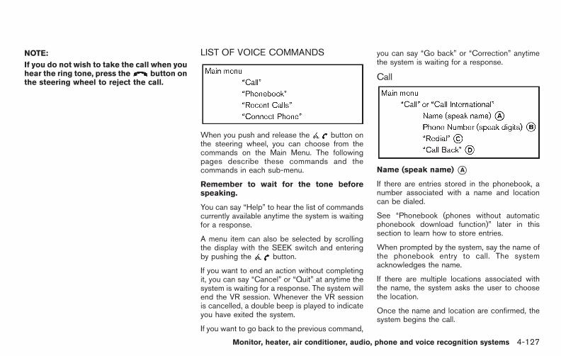
Black plate (305,1)
Model "E52-D" EDITED: 2010/ 10/ 25
NOTE:
If you do not wish to take the call when youhear the ring tone, press the button onthe steering wheel to reject the call.
LIST OF VOICE COMMANDS
When you push and release the button onthe steering wheel, you can choose from thecommands on the Main Menu. The followingpages describe these commands and thecommands in each sub-menu.
Remember to wait for the tone beforespeaking.
You can say “Help” to hear the list of commandscurrently available anytime the system is waitingfor a response.
A menu item can also be selected by scrollingthe display with the SEEK switch and enteringby pushing the button.
If you want to end an action without completingit, you can say “Cancel” or “Quit” at anytime thesystem is waiting for a response. The system willend the VR session. Whenever the VR sessionis cancelled, a double beep is played to indicateyou have exited the system.
If you want to go back to the previous command,
you can say “Go back” or “Correction” anytimethe system is waiting for a response.
Call
Name (speak name) *AIf there are entries stored in the phonebook, anumber associated with a name and locationcan be dialed.
See “Phonebook (phones without automaticphonebook download function)” later in thissection to learn how to store entries.
When prompted by the system, say the name ofthe phonebook entry to call. The systemacknowledges the name.
If there are multiple locations associated withthe name, the system asks the user to choosethe location.
Once the name and location are confirmed, thesystem begins the call.
Monitor, heater, air conditioner, audio, phone and voice recognition systems 4-127

Black plate (306,1)
Model "E52-D" EDITED: 2010/ 10/ 25
Phone Number (speak digits) *BWhen prompted by the system, say the numberto call. Refer to “Making a call by entering aphone number” earlier in this section for moredetails.
“Redial” *CUse the Redial command to call the last numberthat was dialed.
The system acknowledges the command, re-peats the number and begins dialing.
If a redial number does not exist, the systemannounces, “There is no number to redial” andends the VR session.
“Call back” *DUse the Call Back command to dial the numberof the last incoming call within the vehicle.
The system acknowledges the command, re-peats the number and begins dialing.
If a call back number does not exist, the systemannounces, “There is no number to call back”and ends the VR session.
Special Dialing
To dial more than 10 digits or any specialcharacters, please say “Special Dialing”. Whenthe system acknowledges the command, thesystem will prompt you to speak the number.
During a call
During a call there are several command optionsavailable. Push the button on the steeringwheel to mute the receiving voice and entercommands.
. “Help” — The system announces the avail-able commands.
. “Go back/Correction” — The system an-nounces “Go back,” ends the VR sessionand returns to the call.
. “Cancel/Quit” — The system announces“Cancel,” ends the VR session and returnsto the call.
. “Send/Enter/Call/Dial” — Use the Sendcommand to enter numbers, “*” or “#”during a call. For example, if you weredirected to dial an extension by an auto-mated system:
Say: “Send one two three four.”
The system acknowledges the commandand sends the tones associated with thenumbers. The system then ends the VRsession and returns to the call. Say “star” for“*”, say “pound” for “#”.
. “Transfer call” — Use the Transfer Callcommand to transfer the call from theBluetooth® Hands-Free Phone System to
the cellular phone when privacy is desired.
The system announces, “Transfer call. Calltransferred to privacy mode.” The systemthen ends the VR session.
To reconnect a call from the cellular phoneto the Bluetooth® Hands-Free Phone sys-tem, push the button.
. “Mute” — Use the Mute command to muteyour voice so the other party cannot hear it.Use the mute command again to unmuteyour voice.
NOTE:
If a call is ended or the cellular phonenetwork connection is lost while the Mutefeature is on, the Mute feature will be resetto “off” for the next call so the other partycan hear your voice.
4-128 Monitor, heater, air conditioner, audio, phone and voice recognition systems
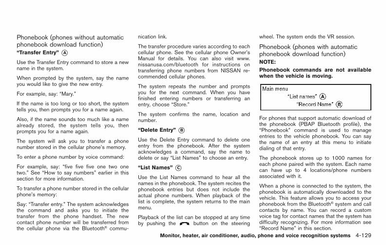
Black plate (307,1)
Model "E52-D" EDITED: 2010/ 10/ 25
Phonebook (phones without automaticphonebook download function)“Transfer Entry” *AUse the Transfer Entry command to store a newname in the system.
When prompted by the system, say the nameyou would like to give the new entry.
For example, say: “Mary.”
If the name is too long or too short, the systemtells you, then prompts you for a name again.
Also, if the name sounds too much like a namealready stored, the system tells you, thenprompts you for a name again.
The system will ask you to transfer a phonenumber stored in the cellular phone’s memory.
To enter a phone number by voice command:
For example, say: “five five five one two onetwo.” See “How to say numbers” earlier in thissection for more information.
To transfer a phone number stored in the cellularphone’s memory:
Say: “Transfer entry.” The system acknowledgesthe command and asks you to initiate thetransfer from the phone handset. The newcontact phone number will be transferred fromthe cellular phone via the Bluetooth® commu-
nication link.
The transfer procedure varies according to eachcellular phone. See the cellular phone Owner’sManual for details. You can also visit www.nissanusa.com/bluetooth for instructions ontransferring phone numbers from NISSAN re-commended cellular phones.
The system repeats the number and promptsyou for the next command. When you havefinished entering numbers or transferring anentry, choose “Store.”
The system confirms the name, location andnumber.
“Delete Entry” *BUse the Delete Entry command to delete oneentry from the phonebook. After the systemacknowledges a command, say the name todelete or say “List Names” to choose an entry.
“List Names” *CUse the List Names command to hear all thenames in the phonebook. The system recites thephonebook entries but does not include theactual phone numbers. When playback of thelist is complete, the system returns to the mainmenu.
Playback of the list can be stopped at any timeby pushing the button on the steering
wheel. The system ends the VR session.
Phonebook (phones with automaticphonebook download function)NOTE:
Phonebook commands are not availablewhen the vehicle is moving.
For phones that support automatic download ofthe phonebook (PBAP Bluetooth profile), the“Phonebook” command is used to manageentries to the vehicle phonebook. You can saythe name of an entry at this menu to initiatedialing of that entry.
The phonebook stores up to 1000 names foreach phone paired with the system. Each namecan have up to 4 locations/phone numbersassociated with it.
When a phone is connected to the system, thephonebook is automatically downloaded to thevehicle. This feature allows you to access yourphonebook from the Bluetooth® system and callcontacts by name. You can record a customvoice tag for contact names that the system hasdifficulty recognizing. For more information see“Record Name” in this section.
Monitor, heater, air conditioner, audio, phone and voice recognition systems 4-129

Black plate (308,1)
Model "E52-D" EDITED: 2010/ 10/ 25
NOTE:
Each phone has its own separate phone-book. You cannot access Phone A’s phone-book if you are currently connected withPhone B.
“List names” *AUse the List Names command to hear all thenames and locations in the phone book.
The system recites the phone book entries butdoes not include the actual phone numbers.When the playback of the list is complete, thesystem goes back to the main menu.
You can stop the playback of the list at any timeby pressing the button on the steeringwheel. The system ends the VR session. See the“Record Name” command in this section forinformation about recording custom voice tagsfor list entries that the system has difficultypronouncing.
“Record name” *BThe system allows you to record custom voicetags for contact names in the phonebook thatthe vehicle has difficulty recognizing. Thisfeature can also be used to record voice tagsto directly dial an entry with multiple numbers.Up to 40 voice tags can be recorded to thesystem.
Recent Calls
Use the Recent Calls command to accessoutgoing, incoming or missed calls.
“Outgoing” *AUse the Outgoing command to list the outgoingcalls made from the vehicle.
“Incoming” *BUse the Incoming command to list the incomingcalls made from the vehicle.
“Missed” *CUse the Missed command to list the missedcalls made to the vehicle that were notanswered.
Connect PhoneNOTE:
Add Phone command is not availablewhen the vehicle is moving.
Use the Connect Phone commands to managethe phones connecting to the vehicle or toenable the Bluetooth® function on the vehicle.
“Add Phone” *AUse the Add Phone command to add a phone tothe vehicle. See “Connecting procedure” earlierin this section for more information.
“Select Phone” *BUse the Select Phone command to select from alist of phones connected to the vehicle. Thesystem will list the names assigned to eachphone and then prompt you for the phone youwish to select. Only one phone can be active ata time.
“Delete Phone” *CUse the Delete Phone command to delete aphone that is connected to the vehicle. Thesystem will list the names assigned to eachphone and then prompt you for the phone you
4-130 Monitor, heater, air conditioner, audio, phone and voice recognition systems

Black plate (309,1)
Model "E52-D" EDITED: 2010/ 10/ 25
wish to delete. Deleting a phone from the vehiclewill also delete that phonebook for that phone.
. Replace Phone
Use the Replace Phone command tochange the priority level of the active phone.
The priority level determines which phone isactive when more than one paired Blue-tooth® phone is in the vehicle.
The system states the priority level of theactive phone and asks for a new priority level(1, 2, 3, 4, 5).
If the new priority level is already being usedfor another phone, the two phones will swappriority levels.
For example, if the current priority levels are:
Priority Level 1 = Phone APriority Level 2 = Phone BPriority Level 3 = Phone C
and you change the priority level of Phone C toLevel 1, then:
Priority Level 1 = Phone CPriority Level 2 = Phone BPriority Level 3 = Phone A
“Turn Bluetooth Off” *DUse the Bluetooth Off command to prevent awireless connection to your phone.
SPEAKER ADAPTATION (SA) MODE
Speaker Adaptation allows up to two out-ofdialect users to train the system to improverecognition accuracy. By repeating a number ofcommands, the users can create a voice modelof their own voice that is stored in the system.The system is capable of storing a differentspeaker adaptation model for each connectedphone.
Training procedure1. Position the vehicle in a reasonably quiet
outdoor location.
2. Sit in the driver’s seat with the enginerunning, the parking brake on, and thetransmission in Park.
3. Press and hold the button for morethan 5 seconds.
4. The system announces: “Press the PHONESEND ( ) button for the hands-freephone system to enter the speaker adapta-tion mode or press the PHONE END ( )button to select a different language.”
5. Press the button.
For information on selecting a differentlanguage, see “Choosing a language” earlierin this section.
6. If the connected phone is already in use, the
system will prompt you to overwrite. Followthe instructions provided by the system.
7. When preparation is complete and you areready to begin, press the button.
8. The SA mode will be explained. Follow theinstructions provided by the system.
9. When training is finished, the system will tellyou an adequate number of phrases havebeen recorded.
10. The system will announce that speakeradaptation has been completed and thesystem is ready.
The SA mode will stop if:
. The button is pressed for more than 5seconds in SA mode.
. The vehicle is driven during SA mode.
. The ignition switch is turned to the OFF orLOCK position.
Monitor, heater, air conditioner, audio, phone and voice recognition systems 4-131

Black plate (310,1)
Model "E52-D" EDITED: 2010/ 10/ 25
Training phrasesDuring the SA mode, the system instructs you tosay the following phrases.
(The system will prompt you for each phrase.)
. phonebook transfer entry
. dial 3 0 4 2 9
. delete call back number
. Incoming
. Transfer entry
. 8 pause 9 3 2 pause 7
. delete all entries
. call 7 2 4 0 9
. phonebook delete entry
. next entry
. dial star 2 1 7 0
. yes
. no
. select
. Missed
. dial 8 5 6 9 2
. Bluetooth on
. Outgoing
. call 3 1 9 0 2
. 9 7 pause pause 3 0 8
. cancel
. call back number
. call star 2 0 9 5
. delete phone
. dial 8 3 0 5 1
. Record Name
. 4 3 pause 2 9 pause 0
. delete redial number
. phonebook list names
. call 8 0 5 4 1
. correction
. connect phone
. dial 7 4 0 1 8
. previous entry
. delete
. dial 9 7 2 6 6
. call 7 6 3 0 1
. go back
. call 5 6 2 8 0
. dial 6 6 4 3 7
4-132 Monitor, heater, air conditioner, audio, phone and voice recognition systems

Black plate (311,1)
Model "E52-D" EDITED: 2010/ 10/ 25
TROUBLESHOOTING GUIDE
The system should respond correctly to all voice commands without difficulty. If problems are encountered, try the following solutions.
Where the solutions are listed by number, try each solution in turn, starting with number 1, until the problem is resolved.
Symptom Solution
System fails to interpret the command correctly.
1. Ensure that the command is valid. See “LIST OF VOICE COMMANDS” earlier in this section.
2. Ensure that the command is spoken after the tone.
3. Speak clearly without pausing between words and at a level appropriate to the ambient noise level in the vehicle.
4. Ensure that the ambient noise level is not excessive (for example, windows open or defroster on). NOTE: If it is toonoisy to use the phone, it is likely that the voice commands will not be recognized.
5. If more than one command was said at a time, try saying the commands separately.
6. If the system consistently fails to recognize commands, the voice training procedure should be carried out toimprove the recognition response for the speaker. See “SPEAKER ADAPTATION (SA) MODE” earlier in thissection.
The system consistently selects the wrong entry fromthe phonebook.
1. Ensure that the phonebook entry name requested matches what was originally stored. This can be confirmed byusing the “List Names” command. See “Phonebook (phones without automatic phonebook download function)”earlier in this section.
2. Replace one of the names being confused with a new name.
Monitor, heater, air conditioner, audio, phone and voice recognition systems 4-133
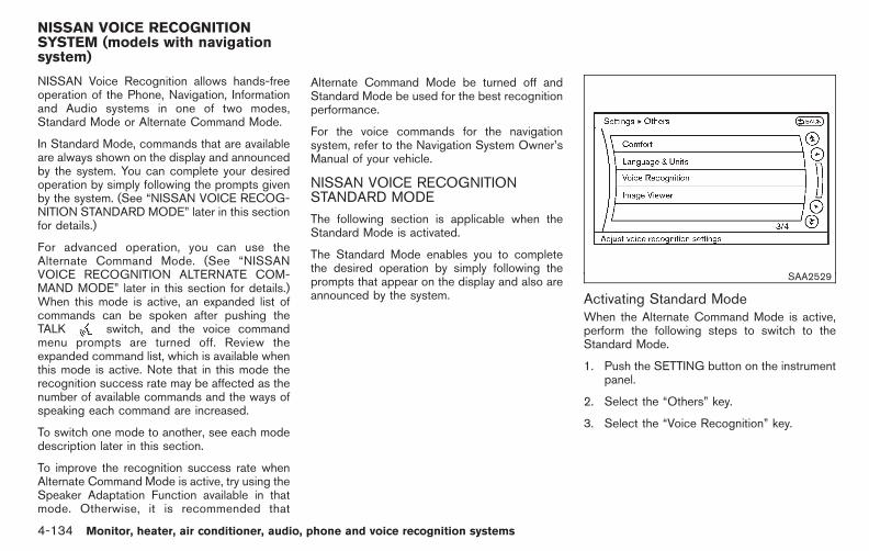
Black plate (312,1)
Model "E52-D" EDITED: 2010/ 10/ 25
NISSAN Voice Recognition allows hands-freeoperation of the Phone, Navigation, Informationand Audio systems in one of two modes,Standard Mode or Alternate Command Mode.
In Standard Mode, commands that are availableare always shown on the display and announcedby the system. You can complete your desiredoperation by simply following the prompts givenby the system. (See “NISSAN VOICE RECOG-NITION STANDARD MODE” later in this sectionfor details.)
For advanced operation, you can use theAlternate Command Mode. (See “NISSANVOICE RECOGNITION ALTERNATE COM-MAND MODE” later in this section for details.)When this mode is active, an expanded list ofcommands can be spoken after pushing theTALK switch, and the voice commandmenu prompts are turned off. Review theexpanded command list, which is available whenthis mode is active. Note that in this mode therecognition success rate may be affected as thenumber of available commands and the ways ofspeaking each command are increased.
To switch one mode to another, see each modedescription later in this section.
To improve the recognition success rate whenAlternate Command Mode is active, try using theSpeaker Adaptation Function available in thatmode. Otherwise, it is recommended that
Alternate Command Mode be turned off andStandard Mode be used for the best recognitionperformance.
For the voice commands for the navigationsystem, refer to the Navigation System Owner’sManual of your vehicle.
NISSAN VOICE RECOGNITIONSTANDARD MODE
The following section is applicable when theStandard Mode is activated.
The Standard Mode enables you to completethe desired operation by simply following theprompts that appear on the display and also areannounced by the system.
SAA2529
Activating Standard ModeWhen the Alternate Command Mode is active,perform the following steps to switch to theStandard Mode.
1. Push the SETTING button on the instrumentpanel.
2. Select the “Others” key.
3. Select the “Voice Recognition” key.
NISSAN VOICE RECOGNITIONSYSTEM (models with navigationsystem)
4-134 Monitor, heater, air conditioner, audio, phone and voice recognition systems

Black plate (313,1)
Model "E52-D" EDITED: 2010/ 10/ 25
SAA2530
4. Select the “Alternate Command Mode” key.
5. The indicator turns off and the StandardMode activates.
Displaying user guideIf you use the NISSAN Voice Recognitionsystem for the first time or you do not knowhow to operate it, you can display the UserGuide for confirmation.
You can confirm how to use voice commands byaccessing a simplified User Guide, whichcontains basic instructions and tutorials forseveral voice commands.
SAA2531
1. Push the INFO button on the instrumentpanel.
2. Select the “Others” key.
3. Select the “Voice Recognition” key.
4. Select the “User Guide” key.
5. Select a preferred item.
You can skip steps 1 and 3 above if you say“Help”.
Available items:
. Getting Started
Describes the basics of how to operate theNISSAN Voice Recognition system.
. Let’s Practice
Mode that allows practicing by following theinstructions of the system voice.
. Using the Address Book
Tutorial for entering a destination by usingthe Address Book.
. Finding a Street Address (if so equipped)
Tutorial for entering a destination by streetaddress.
. Placing Calls
Tutorial for making a phone call by voicecommand operation.
. Help on Speaking
Displays useful tips of speaking for correctcommand recognition by the system.
Note that the Command List feature is onlyavailable when Alternate Command Mode isactive.
Monitor, heater, air conditioner, audio, phone and voice recognition systems 4-135

Black plate (314,1)
Model "E52-D" EDITED: 2010/ 10/ 25
SAA2532
Getting StartedBefore using the NISSAN Voice Recognitionsystem for the first time, you can confirm how touse commands by viewing the Getting Startedsection of the User Guide.
1. Select the “Getting Started” key.
2. You can confirm the page by scrolling thescreen using the multi-function controller.
Tutorials on the operation of the NISSANVoice Recognition system
If you choose “Using the Address Book”,“Finding a Street Address” or “Placing Calls”,you can view tutorials on how to perform theseoperations using NISSAN Voice Recognition.
SAA2534
Let’s PracticeThis mode helps learn how to use the NISSANVoice Recognition system.
1. Select the “Let’s Practice” key.
2. After the message screen appears, push theTALK switch on the steering wheel.
3. Speak the displayed number after the tone.The evaluation screen will be displayed andthe result can be confirmed.
SAA2533
Useful tips for correct operationYou can display useful speaking tips to help thesystem recognize your voice commands cor-rectly.
Select “Help on Speaking” to start display.
USING THE SYSTEM
InitializationWhen the ignition switch is pushed to the ONposition, NISSAN Voice Recognition is initia-lized, which may take up to one minute. Whencompleted, the system is ready to accept voicecommands. If the TALK switch is pushedbefore the initialization completes, the displaywill show the message: “System not ready.” or a
4-136 Monitor, heater, air conditioner, audio, phone and voice recognition systems

Black plate (315,1)
Model "E52-D" EDITED: 2010/ 10/ 25
beep sounds.
Before startingTo get the best recognition performance fromNISSAN Voice Recognition, observe the follow-ing:
. The interior of the vehicle should be as quietas possible. Close the windows to eliminatethe surrounding noises (traffic noise andvibration sounds, etc.), which may preventthe system from correctly recognizing thevoice commands.
. Wait until the tone sounds before speaking acommand.
. Speak in a natural conversational voicewithout pausing between words.
. If the air conditioner is set to “Auto”, the fanspeed is automatically lowered so that yourcommands can be recognized more easily.
SAA1859
Giving voice commands1. Push the TALK switch located on the
steering wheel.
SAA2535
2. A list of commands appears on the screen,and the system announces, “Would you liketo access Phone, Navigation, Information,Audio or Help?”.
3. After the tone sounds and the icon on thescreen changes from to , speak acommand.
Selecting the “Practice” key will start thepractice mode. See “Let’s Practice” earlierin this section.
4. Continue to follow the voice menu promptsand speak after the tone sounds until yourdesired operation is completed.
Selecting the “Help” key can display the
Monitor, heater, air conditioner, audio, phone and voice recognition systems 4-137

Black plate (316,1)
Model "E52-D" EDITED: 2010/ 10/ 25
detailed information of the each command.
Operating tips:
. Say a command after the tone.
. Commands that are available are alwaysshown on the display and spoken throughvoice menu prompts. Commands other thanthose that are displayed are not accepted.Please follow the prompts given by thesystem.
. If the command is not recognized, thesystem announces, “Please say again”.Repeat the command in a clear voice.
. Push the BACK button once to return to theprevious screen.
. To exit the voice recognition system, pushand hold the TALK switch. Themessage, “Voice canceled” will be an-nounced.
. To skip the voice guidance function and givethe command immediately, press the TALK
switch to interrupt the system. Re-member to speak after the tone.
. If you want to adjust the volume of thesystem feedback, push the volume controlbuttons [+] or [−] on the steering switch oruse the audio system volume knob while thesystem is making an announcement.
How to speak numbers:
NISSAN Voice Recognition requires a certainway to speak numbers when giving voicecommands. Refer to the following examples.
General rule
Only single digits 0 (zero) to 9 can be used. (Forexample, if you would like to say 500, “five zerozero” can be used, but “five hundred” cannot.)
Examples
. 1-800-662-6200
— “One eight zero zero six six two six twozero zero”
Improving Recognition of Phone numbers
You can improve the recognition of phonenumbers by saying the phone number in threegroups of numbers. For example, when you try tocall 800-662-6200, say “eight zero zero” first,and the system will then ask you for the nextthree digits. Then, say “six six two”. Afterrecognition, the system will then ask for the lastfour digits. Say, “six two zero zero”. Using thismethod of phone digit entry can improverecognition performance.
When speaking a house number, speak thenumber “0” as “zero”. If the letter “o (Oh)” isincluded in the house number, it will not berecognized as the number “0 (zero)” even if you
speak “oh” instead of “zero”. Please speak“zero” for the number “0 (zero)”, “oh” forthe letter “o (oh)”.
4-138 Monitor, heater, air conditioner, audio, phone and voice recognition systems

Black plate (317,1)
Model "E52-D" EDITED: 2010/ 10/ 25
Command List
Category Command:
Command Action
Phone Operates the Phone function.
Navigation Operates the Navigation function.
Information Displays the vehicle Information function.
Audio Operates the Audio function.
Help Displays User Guide
. Phone Command:
Command Action
Dial Number Makes a call to a spoken phone number up to 10 digits.
Vehicle Phonebook Makes a call to a contact that is stored in the Vehicle Phonebook.
Handset Phonebook Makes a call to a contact that is stored in the mobile phone.
Call history Incoming Calls Makes a call to the incoming call number.
Outgoing Calls Makes a call to the dialed number.
Missed Calls Makes a call to the Missed calls number.
International Call Makes an international call by allowing more than 10 digits to be spoken.
Change Number Corrects the recognized phone number (available during phone number entry).
Monitor, heater, air conditioner, audio, phone and voice recognition systems 4-139

Black plate (318,1)
Model "E52-D" EDITED: 2010/ 10/ 25
. Navigation Command:
Command Action
Home Sets a route to your home that is stored in the Address Book.
Address Searches for a location by the street address specified, and sets a route to the location.
Places Sets a route to a facility near the current vehicle location.
Address Book Searches for stored information in the Address Book.
Previous Destinations Sets a route to a previous destination.
. Information Command:
Command Action
Fuel Economy Displays fuel economy information.
Maintenance Displays maintenance information.
Traffic Information Turns the traffic information system ON and OFF.
Where am I? Displays your current location.
. Audio Command:
Command Action
AM Turns to the AM band, selecting the station last played.
FM Turns to the FM band, selecting the station last played.
XM Turns to the XM Satellite band, selecting the channel last played.
Music Box Turns on the Music Box hard disk drive audio system.
CD Starts to play a CD.
4-140 Monitor, heater, air conditioner, audio, phone and voice recognition systems
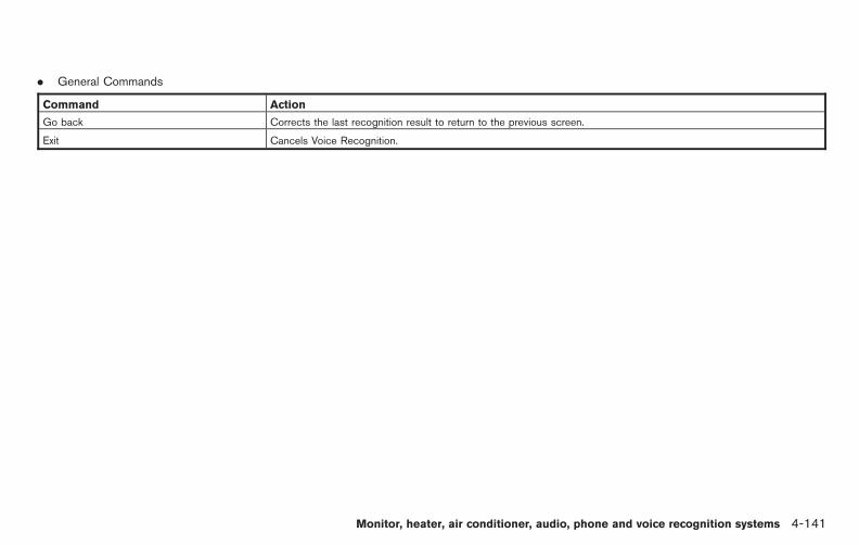
Black plate (319,1)
Model "E52-D" EDITED: 2010/ 10/ 25
. General Commands
Command Action
Go back Corrects the last recognition result to return to the previous screen.
Exit Cancels Voice Recognition.
Monitor, heater, air conditioner, audio, phone and voice recognition systems 4-141
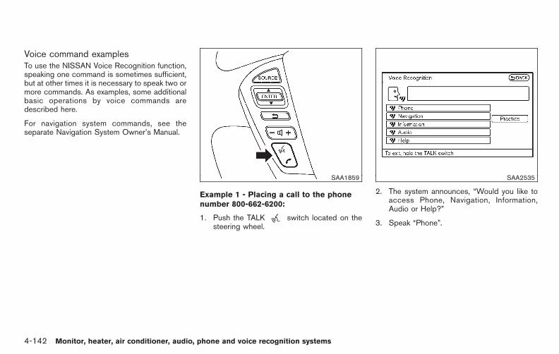
Black plate (320,1)
Model "E52-D" EDITED: 2010/ 10/ 25
Voice command examplesTo use the NISSAN Voice Recognition function,speaking one command is sometimes sufficient,but at other times it is necessary to speak two ormore commands. As examples, some additionalbasic operations by voice commands aredescribed here.
For navigation system commands, see theseparate Navigation System Owner’s Manual.
SAA1859
Example 1 - Placing a call to the phonenumber 800-662-6200:
1. Push the TALK switch located on thesteering wheel.
SAA2535
2. The system announces, “Would you like toaccess Phone, Navigation, Information,Audio or Help?”
3. Speak “Phone”.
4-142 Monitor, heater, air conditioner, audio, phone and voice recognition systems

Black plate (321,1)
Model "E52-D" EDITED: 2010/ 10/ 25
SAA2536
4. Speak “Dial Number”.
SAA2537
5. Speak “8 0 0”.
Selecting the “Manual Controls” keyswitches the screen to the keypad to inputthe phone number manually.
SAA2538
6. The system announces, “Please say the nextthree digits or dial, or say change number.”
7. Speak “6 6 2”.
Monitor, heater, air conditioner, audio, phone and voice recognition systems 4-143

Black plate (322,1)
Model "E52-D" EDITED: 2010/ 10/ 25
SAA2539
8. The system announces, “Please say the lastfour digits” or say change number.
9. Speak “6 2 0 0”.
SAA2540
10. The system announces, “Dial or ChangeNumber?”
11. Speak “Dial”.
12. The system makes a call to 800-662-6200.
Note:
. You can also speak “800-662-6200” (10continuous digits) or “662-6200” (7 con-tinuous digits), if the area code is notnecessary. However, the 3-3-4 digit group-ing is recommended for improved recogni-tion. (See “How to speak numbers” earlier inthis section.)
. You can only say a phone number using the3-3-4 grouping, 7 digits, and 10 digits usingthis command. Please use the “InternationalCall” command for all other formats.
. If you say “Change Number” during phonenumber entry, the system will automaticallyrequest that you repeat the number usingthe 3-3-4 format. In this case please say thearea code first and then follow the prompts.
. Do not add a “1” in front of the area codewhen speaking phone numbers.
. If the system does not recognize yourcommand, please try repeating the com-mand using a natural voice. Speaking tooslow or too loudly may further decreaserecognition performance.
4-144 Monitor, heater, air conditioner, audio, phone and voice recognition systems

Black plate (323,1)
Model "E52-D" EDITED: 2010/ 10/ 25
SAA1859
Example 2 - Placing an international call tothe phone number 011-81-111-222-3333:
1. Push the TALK switch located on thesteering wheel.
SAA2535
2. The system announces, “Would you like toaccess Phone, Navigation, Information orHelp?”
3. Speak “Phone”.
SAA2536
4. Speak “International Call”.
Monitor, heater, air conditioner, audio, phone and voice recognition systems 4-145
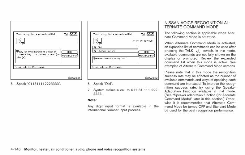
Black plate (324,1)
Model "E52-D" EDITED: 2010/ 10/ 25
SAA2541
5. Speak “011811112223333”.
SAA2542
6. Speak “Dial”.
7. System makes a call to 011-81-111-222-3333.
Note:
Any digit input format is available in theInternational Number input process.
NISSAN VOICE RECOGNITION AL-TERNATE COMMAND MODE
The following section is applicable when Alter-nate Command Mode is activated.
When Alternate Command Mode is activated,an expanded list of commands can be used afterpressing the TALK switch. In this mode,available commands are not fully shown on thedisplay or prompted. Review the expandedcommand list when this mode is active. Seeexamples of Alternate Command Mode screens.
Please note that in this mode the recognitionsuccess rate may be affected as the number ofavailable commands and ways of speaking eachcommand are increased. To improve the recog-nition success rate, try using the SpeakerAdaptation Function available in that mode.(See “Speaker adaptation function (for AlternateCommand Mode)” later in this section.) Other-wise it is recommended that Alternate Com-mand Mode be turned OFF and Standard Modebe used for the best recognition performance.
4-146 Monitor, heater, air conditioner, audio, phone and voice recognition systems

Black plate (325,1)
Model "E52-D" EDITED: 2010/ 10/ 25
SAA2529
Activating Alternate Command ModeWhen the Standard Mode is active, perform thefollowing steps to switch to the AlternateCommand Mode.
1. Push the SETTING button on the instrumentpanel.
2. Highlight the “Others” key.
3. Highlight the “Voice Recognition” key.
SAA2543
4. Highlight the “Alternate Command Mode”key.
5. The confirmation message is displayed onthe screen. Push the “OK” key to activatethe Alternate Command Mode.
Displaying command listIf you are controlling the system by voicecommands for the first time or do not know theappropriate voice command, perform the follow-ing procedure for displaying the voice commandlist (available only in Alternate Command Mode).
SAA2544
1. Push the INFO button on the instrumentpanel.
2. Select the “Others” key.
3. Select the “Voice Recognition” key.
4. Select the “Command List” key.
Monitor, heater, air conditioner, audio, phone and voice recognition systems 4-147

Black plate (326,1)
Model "E52-D" EDITED: 2010/ 10/ 25
SAA2545
5. Select a category from the list.
SAA2546
6. Select an item.
7. If necessary, scroll the screen using themulti-function controller to view the entirelist.
8. Press the BACK button to return to theprevious screen.
4-148 Monitor, heater, air conditioner, audio, phone and voice recognition systems

Black plate (327,1)
Model "E52-D" EDITED: 2010/ 10/ 25
Command List
Phone Commands:
Command Action
Dial Number Makes a call to a spoken phone number.
Vehicle Phonebook Makes a call to a contact that is stored in the Vehicle Phonebook.
Handset Phonebook Makes a call to a contact that is stored in the mobile phone.
Call History Incoming Calls Makes a call to the incoming call number.
Outgoing Calls Makes a call to the dialed number.
Missed Calls Makes a call to the Missed calls number.
International Call Makes an international call by allowing more than 10 digits to be spoken.
Call <named>Makes a call to a contact that is stored in either Vehicle Phonebook or Handset Phonebook. Please say “Call”followed by a stored name.
Navigation Commands:
Command Action
Home Sets a route to your home that is stored in the Address Book.
Address Searches for a location by the street address specified, and sets a route to the location.
Places Sets a route to a facility near the current vehicle location.
Address Book Searches for stored information in the Address Book.
Previous Destinations Sets a route to a previous destination.
Previous Start Point Sets a route to a previous starting point.
Delete Destination Deletes a destination.
Monitor, heater, air conditioner, audio, phone and voice recognition systems 4-149

Black plate (328,1)
Model "E52-D" EDITED: 2010/ 10/ 25
Information Commands:
Command Action
Fuel Economy Displays fuel economy information.
Maintenance Displays maintenance information.
Where am I? Displays your current location.
Traffic Information Turns the traffic information system ON and OFF.
Weather Information Displays weather information.
Weather Map Displays a weather map.
Audio Commands:
Command Action
Music Box Turns on the Music Box hard disk drive audio system.
CD Starts to play a CD.
FM Turns to the FM band, selecting the station last played.
AM Turns to the AM band, selecting the station last played.
XM Turns to the XM Satellite Radio band, selecting the channel last played.
USB Turns on the USB memory.
Bluetooth Audio Turns on the Bluetooth® audio player.
4-150 Monitor, heater, air conditioner, audio, phone and voice recognition systems

Black plate (329,1)
Model "E52-D" EDITED: 2010/ 10/ 25
Help Commands:
Command Action
Command List Navigation Commands Displays the navigation command list.
Phone Commands Displays the phone command list.
Audio Commands Displays the audio command list.
Information Commands Displays the information command list.
Help Commands Displays the help command list.
User Guide Displays the User Guide.
Speaker Adaptation The system can memorize the voices of up to three persons.
General Commands:
Command Action
Go back Corrects the last recognition result to return to the previous screen
Exit Cancels Voice Recognition
Monitor, heater, air conditioner, audio, phone and voice recognition systems 4-151

Black plate (330,1)
Model "E52-D" EDITED: 2010/ 10/ 25
SAA2547
Displaying user guideYou can confirm how to use voice commands byaccessing a simplified User Guide, whichcontains basic instructions and tutorials forseveral voice commands.
1. Push the INFO button on the instrumentpanel.
2. Select the “Others” key using the multi-function controller and push the ENTERbutton.
3. Highlight the “Voice Recognition” key usingthe multi-function controller and push theENTER button.
4. Highlight the “User Guide” key using the
multi-function controller and push the EN-TER button.
5. Highlight an item using the multi-functioncontroller and push the ENTER button.
Available items:
. Getting Started
Describe the basics of how to operate theNISSAN Voice Recognition system.
. Let’s Practice
Mode that allows practicing by following theinstructions of the system voice.
. Using the Address Book
Refer to Navigation System Owner’s Man-ual.
. Finding a Street Address (if so equipped)
Refer to Navigation System Owner’s Man-ual.
. Placing Calls
Tutorial for making a phone call by voicecommand operation.
. Help on Speaking
Displays useful tips for how to correctlyspeak commands in order for them to beproperly recognized by the system.
. Voice Recognition Settings
Describes the available voice recognitionsettings.
. Adapting the System to Your Voice
Tutorial adapting the system to your voice.
USING THE SYSTEM
InitializationWhen the ignition switch is pushed to the ONposition, NISSAN Voice Recognition is initia-lized, which may take up to one minute. Whencompleted, the system is ready to accept voicecommands. If the TALK switch is pushedbefore the initialization completes the display willshow the message: “System not ready.” or abeep sounds.
Before startingTo get the best performance from NISSANVoice Recognition, observe the following.
. Keep the interior of the vehicle as quiet aspossible. Close the windows to eliminate thesurrounding noises (traffic noises, vibrationsounds, etc.), which may prevent the systemfrom recognizing the voice commands cor-rectly.
. When the air conditioner is in the AUTOmode, the fan speed decreases automati-cally for easy recognition.
4-152 Monitor, heater, air conditioner, audio, phone and voice recognition systems
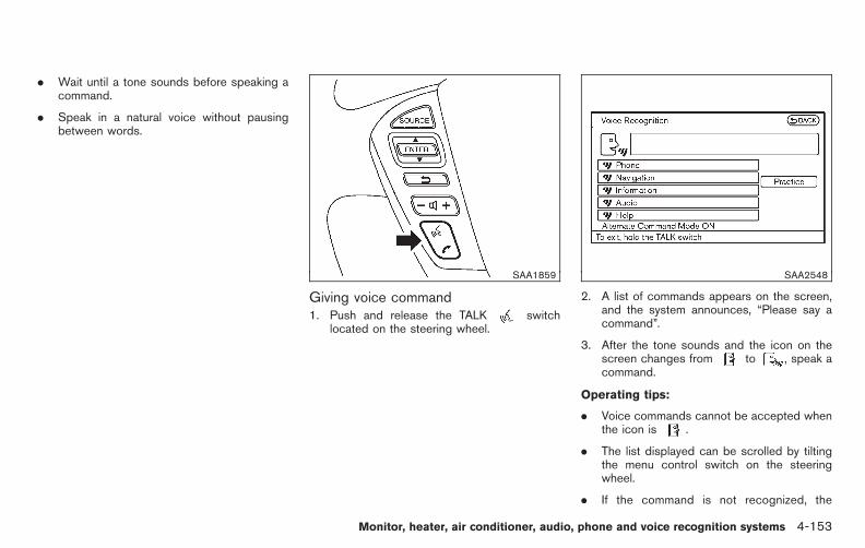
Black plate (331,1)
Model "E52-D" EDITED: 2010/ 10/ 25
. Wait until a tone sounds before speaking acommand.
. Speak in a natural voice without pausingbetween words.
SAA1859
Giving voice command1. Push and release the TALK switch
located on the steering wheel.
SAA2548
2. A list of commands appears on the screen,and the system announces, “Please say acommand”.
3. After the tone sounds and the icon on thescreen changes from to , speak acommand.
Operating tips:
. Voice commands cannot be accepted whenthe icon is .
. The list displayed can be scrolled by tiltingthe menu control switch on the steeringwheel.
. If the command is not recognized, the
Monitor, heater, air conditioner, audio, phone and voice recognition systems 4-153

Black plate (332,1)
Model "E52-D" EDITED: 2010/ 10/ 25
system announces, “Please say again”.Repeat the command in a clear voice.
. Push the BACK button once to return to theprevious screen.
. If you want to cancel the command, pushand hold the TALK switch for 1 second.The message “Voice canceled” will beannounced.
. To skip the voice guidance function and givethe command immediately, press the TALK
switch to interrupt the system. Re-member to speak after the tone.
. If you want to adjust the volume of thesystem feedback, push the volume controlswitch (+ or −) on the steering wheel or usethe audio system volume knob while thesystem is making an announcement.
How to speak numbers:
NISSAN Voice Recognition requires a certainway to speak numbers when giving voicecommands. Refer to the following examples.
General rule
Only single digits 0 (zero) to 9 can be used. (Forexample, if you would like to say 500, “five zerozero” can be used, but “five hundred” cannot.
Phone numbers
Speak phone numbers according to the follow-ing examples:
. 1-800-662-6200
— “Dial one eight zero zero six six two sixtwo zero zero.”
Note 1: For the best voice recognition phonedialing results, say phone numbers as singledigits.
Note 2: You cannot say 555-6000 as “five fivefive six thousands”.
Note 3: When speaking a house number, speakthe number “0” as “ zero”. If the letter “o ( Oh)” isincluded in the house number, it will not berecognized as the number “0 (zero)” even if youspeak “oh” instead of “ zero”. Please speak“zero” for the number “0 (zero)”, “oh” for theletter “o (oh)”.
SAA2549
Speaker adaptation function (for Alter-nate Command Mode)The voice recognition system has a function tolearn the user’s voice for better voice recognitionperformance. The system can memorize thevoices of up to three persons.
Having the system learn the user’s voice:
1. Push the SETTING button on the instrumentpanel and select the “Others” key.
2. Select the “Voice Recognition” key.
3. Select the “Speaker Adaptation” key.
4-154 Monitor, heater, air conditioner, audio, phone and voice recognition systems

Black plate (333,1)
Model "E52-D" EDITED: 2010/ 10/ 25
SAA2550
4. Select the user whose voice is memorizedby the system.
5. Select the “Start Speaker Adaptation Learn-ing” key.
SAA2551
6. Select a category to be learned by thesystem from the following list.
. Phone Commands
. Navigation Commands
. Information Commands
. Audio Commands
. Help Commands
The voice commands in the category aredisplayed.
7. Select a voice command and then push theENTER button.
The voice recognition system starts.
Monitor, heater, air conditioner, audio, phone and voice recognition systems 4-155

Black plate (334,1)
Model "E52-D" EDITED: 2010/ 10/ 25
SAA2552
8. The system requests that you repeat acommand after a tone.
9. After the tone sounds and the icon on thescreen changes from to , speakthe command that the system requested.
10. When the system has recognized the voicecommand, the voice of the user is learned.
Push the switch or BACK button to returnto the previous screen.
If the system has learned the command cor-rectly, the voice command status on the rightside of the command turns from “None” to“Stored”.
SAA2553
Speaker Adaptation function settings:
Edit User Name
Edit the user name using the keypad displayedon the screen.
Delete Voice Data
Resets the user’s voice that the voice recogni-tion system has learned.
Continuous Learning
When this item is turned on, you can have thesystem learn the voice commands in succes-sion, without selecting commands one by one.
Minimize voice feedback (for AlternateCommand Mode)To minimize the voice feedback from the system,perform the following steps.
1. Push the SETTING button on the instrumentpanel.
2. Select the “Others” key.
3. Select the “Voice Recognition” key.
4. Select the “Minimize Voice Feedback” key.
5. The setting is turned on and the voiceguidance will now be reduced when usingthe Voice Recognition system.
4-156 Monitor, heater, air conditioner, audio, phone and voice recognition systems

Black plate (335,1)
Model "E52-D" EDITED: 2010/ 10/ 25
TROUBLESHOOTING GUIDE
The system should respond correctly to all voice commands without difficulty. If problems are encountered, follow the solutions given in this guide for theappropriate error.
Where the solutions are listed by number, try each solution in turn, starting with number one, until the problem is resolved.
Symptom/error message Solution
Displays “COMMAND NOT RECOGNIZED” or thesystem fails to interpret the command correctly.
1. Ensure that the command format is valid, see “Command List” earlier in this section.
2. Speak clearly without pausing between words and at a level appropriate to the ambient noise level.
3. Ensure that the ambient noise level is not excessive, for example, windows open or defrost on.
NOTE:If it is too noisy to use the phone, it is likely that voice commands will not be recognized.
4. If optional words of the command have been omitted, then the command should be tried with these in place.
The system consistently selects the wrong voicetag inthe phonebook.
1. Ensure that the voicetag requested matches what was originally stored. (See “BLUETOOTH® HANDS-FREEPHONE SYSTEM (models with navigation system)” earlier in this section; page 4-110.)
2. Replace one of the voicetags being confused with a different voicetag.
Monitor, heater, air conditioner, audio, phone and voice recognition systems 4-157

Black plate (336,1)
Model "E52-D" EDITED: 2010/ 10/ 25
MEMO
4-158 Monitor, heater, air conditioner, audio, phone and voice recognition systems

Black plate (16,1)
5 Starting and driving
Model "E52-D" EDITED: 2010/ 10/ 22
Precautions when starting and driving . . . . . . . . . . . . . . . . . . . . . 5-2Exhaust gas (carbon monoxide) . . . . . . . . . . . . . . . . . . . . . . . . . 5-2Three-way catalyst. . . . . . . . . . . . . . . . . . . . . . . . . . . . . . . . . . . . . . . . . . 5-2Tire Pressure Monitoring System (TPMS). . . . . . . . . . . . . 5-3Avoiding collision and rollover . . . . . . . . . . . . . . . . . . . . . . . . . . . 5-6Off-road recovery . . . . . . . . . . . . . . . . . . . . . . . . . . . . . . . . . . . . . . . . . . . 5-6Rapid air pressure loss . . . . . . . . . . . . . . . . . . . . . . . . . . . . . . . . . . . . 5-7Drinking alcohol/drugs and driving. . . . . . . . . . . . . . . . . . . . . . 5-7
Push-button ignition switch . . . . . . . . . . . . . . . . . . . . . . . . . . . . . . . . . . 5-8Intelligent Key system. . . . . . . . . . . . . . . . . . . . . . . . . . . . . . . . . . . . . . 5-8Push-button ignition switch operation. . . . . . . . . . . . . . . . . . 5-9Push-button ignition switch positions . . . . . . . . . . . . . . . . 5-10Emergency engine shut off . . . . . . . . . . . . . . . . . . . . . . . . . . . . . 5-10Intelligent Key battery discharge . . . . . . . . . . . . . . . . . . . . . . 5-11
Before starting the engine . . . . . . . . . . . . . . . . . . . . . . . . . . . . . . . . . . 5-11Starting the engine . . . . . . . . . . . . . . . . . . . . . . . . . . . . . . . . . . . . . . . . . . . 5-12Driving the vehicle . . . . . . . . . . . . . . . . . . . . . . . . . . . . . . . . . . . . . . . . . . . . 5-12
Continuously Variable Transmission (CVT) . . . . . . . . . . 5-12Parking brake . . . . . . . . . . . . . . . . . . . . . . . . . . . . . . . . . . . . . . . . . . . . . . . . . . 5-16Blind Spot Warning (BSW) system (if soequipped). . . . . . . . . . . . . . . . . . . . . . . . . . . . . . . . . . . . . . . . . . . . . . . . . . . . . . . 5-17
BSW system operation. . . . . . . . . . . . . . . . . . . . . . . . . . . . . . . . . . 5-18BSW driving situations . . . . . . . . . . . . . . . . . . . . . . . . . . . . . . . . . . 5-20BSW malfunction . . . . . . . . . . . . . . . . . . . . . . . . . . . . . . . . . . . . . . . . . 5-23
System maintenance . . . . . . . . . . . . . . . . . . . . . . . . . . . . . . . . . . . . . 5-23Cruise control . . . . . . . . . . . . . . . . . . . . . . . . . . . . . . . . . . . . . . . . . . . . . . . . . 5-24
Precautions on cruise control . . . . . . . . . . . . . . . . . . . . . . . . . . 5-24Cruise control operations . . . . . . . . . . . . . . . . . . . . . . . . . . . . . . . 5-25
Break-in schedule . . . . . . . . . . . . . . . . . . . . . . . . . . . . . . . . . . . . . . . . . . . . 5-26Increasing fuel economy . . . . . . . . . . . . . . . . . . . . . . . . . . . . . . . . . . . . 5-26Parking/parking on hills. . . . . . . . . . . . . . . . . . . . . . . . . . . . . . . . . . . . . . 5-27Hydraulic pump electric power steering system . . . . . . . 5-28Brake system . . . . . . . . . . . . . . . . . . . . . . . . . . . . . . . . . . . . . . . . . . . . . . . . . . 5-29
Braking precautions . . . . . . . . . . . . . . . . . . . . . . . . . . . . . . . . . . . . . . 5-29Parking brake break-in. . . . . . . . . . . . . . . . . . . . . . . . . . . . . . . . . . . 5-29Anti-lock Braking System (ABS) . . . . . . . . . . . . . . . . . . . . . . 5-29
Vehicle Dynamic Control (VDC) system . . . . . . . . . . . . . . . . . 5-31Cold weather driving. . . . . . . . . . . . . . . . . . . . . . . . . . . . . . . . . . . . . . . . . 5-32
Freeing a frozen door lock. . . . . . . . . . . . . . . . . . . . . . . . . . . . . . 5-32Anti-freeze. . . . . . . . . . . . . . . . . . . . . . . . . . . . . . . . . . . . . . . . . . . . . . . . . . 5-32Battery . . . . . . . . . . . . . . . . . . . . . . . . . . . . . . . . . . . . . . . . . . . . . . . . . . . . . . 5-32Draining of coolant water . . . . . . . . . . . . . . . . . . . . . . . . . . . . . . . 5-32Tire equipment . . . . . . . . . . . . . . . . . . . . . . . . . . . . . . . . . . . . . . . . . . . . 5-33Special winter equipment . . . . . . . . . . . . . . . . . . . . . . . . . . . . . . . 5-33Driving on snow or ice . . . . . . . . . . . . . . . . . . . . . . . . . . . . . . . . . . 5-33Engine block heater (if so equipped). . . . . . . . . . . . . . . . . 5-33

Black plate (338,1)
Model "E52-D" EDITED: 2010/ 10/ 25
WARNING
. Do not leave children or adults whowould normally require the supportof others alone in your vehicle. Petsshould not be left alone either. Theycould accidentally injure themselvesor others through inadvertent op-eration of the vehicle. Also, on hot,sunny days, temperatures in aclosed vehicle could quickly becomehigh enough to cause severe orpossibly fatal injuries to people oranimals.
. Properly secure all cargo with ropesor straps to help prevent it fromsliding or shifting. Do not placecargo higher than the seatbacks. Ina sudden stop or collision, unse-cured cargo could cause personalinjury.
EXHAUST GAS (carbon monoxide)
WARNING
. Do not breathe exhaust gases; theycontain colorless and odorless car-bon monoxide. Carbon monoxide is
dangerous. It can cause uncon-sciousness or death.
. If you suspect that exhaust fumesare entering the vehicle, drive withall windows fully open, and have thevehicle inspected immediately.
. Do not run the engine in closedspaces such as a garage.
. Do not park the vehicle with theengine running for any extendedlength of time.
. Keep the lift gate closed whiledriving, otherwise exhaust gasescould be drawn into the passengercompartment. If you must drive withthe lift gate open, follow theseprecautions:
1. Open all the windows.
2. Set the air recirculation to offand the fan control to high tocirculate the air.
. If electrical wiring or other cableconnections must pass to a trailerthrough the seal on the lift gate orthe body, follow the manufacturer’srecommendation to prevent carbonmonoxide entry into the vehicle.
. If a special body, camper or otherequipment is added for recreationalor other usage, follow the manufac-turer’s recommendation to preventcarbon monoxide entry into thevehicle. (Some recreational vehicleappliances such as stoves, refrig-erators, heaters, etc. may also gen-erate carbon monoxide.)
. The exhaust system and bodyshould be inspected by a qualifiedmechanic whenever:
— The vehicle is raised for service.
— You suspect that exhaust fumesare entering into the passengercompartment.
— You notice a change in thesound of the exhaust system.
— You have had an accident invol-ving damage to the exhaustsystem, underbody, or rear ofthe vehicle.
THREE-WAY CATALYST
The three-way catalyst is an emission controldevice installed in the exhaust system. Exhaustgases in the three-way catalyst are burned athigh temperatures to help reduce pollutants.
PRECAUTIONS WHEN STARTINGAND DRIVING
5-2 Starting and driving
Black plate (339,1)
Model "E52-D" EDITED: 2010/ 10/ 25
WARNING
. The exhaust gas and the exhaustsystem are very hot. Keep people,animals or flammable materialsaway from the exhaust system com-ponents.
. Do not stop or park the vehicle overflammable materials such as drygrass, waste paper or rags. Theymay ignite and cause a fire.
CAUTION
. Do not use leaded gasoline. Depos-its from leaded gasoline will ser-iously reduce the three-waycatalyst’s ability to help reduce ex-haust pollutants.
. Keep your engine tuned up. Mal-functions in the ignition, fuel injec-tion, or electrical systems can causeoverrich fuel flow into the three-waycatalyst, causing it to overheat. Donot keep driving if the engine mis-fires, or if noticeable loss of perfor-mance or other unusual operatingconditions are detected. Have the
vehicle inspected promptly by aNISSAN dealer.
. Avoid driving with an extremely lowfuel level. Running out of fuel couldcause the engine to misfire, dama-ging the three-way catalyst.
. Do not race the engine while warm-ing it up.
. Do not push or tow your vehicle tostart the engine.
TIRE PRESSURE MONITORING SYS-TEM (TPMS)
Each tire, including the spare (if provided),should be checked monthly when cold andinflated to the inflation pressure recommendedby the vehicle manufacturer on the vehicleplacard or tire inflation pressure label. (If yourvehicle has tires of a different size than the sizeindicated on the vehicle placard or tire inflationpressure label, you should determine the propertire inflation pressure for those tires.)
As an added safety feature, your vehicle hasbeen equipped with a Tire Pressure MonitoringSystem (TPMS) that illuminates a low tirepressure telltale when one or more of your tiresis significantly under-inflated. Accordingly, whenthe low tire pressure telltale illuminates, youshould stop and check your tires as soon as
possible, and inflate them to the proper pres-sure. Driving on a significantly under-inflated tirecauses the tire to overheat and can lead to tirefailure. Under-inflation also reduces fuel effi-ciency and tire tread life, and may affect thevehicle’s handling and stopping ability.
Please note that the TPMS is not a substitute forproper tire maintenance, and it is the driver’sresponsibility to maintain correct tire pressure,even if under-inflation has not reached the levelto trigger illumination of the TPMS low tirepressure telltale.
Your vehicle has also been equipped with aTPMS malfunction indicator to indicate when thesystem is not operating properly. The TPMSmalfunction indicator is combined with the lowtire pressure telltale. When the system detects amalfunction, the telltale will flash for approxi-mately one minute and then remain continuouslyilluminated. This sequence will continue uponsubsequent vehicle start-ups as long as themalfunction exists. When the malfunction indi-cator is illuminated, the system may not be ableto detect or signal low tire pressure as intended.TPMS malfunctions may occur for a variety ofreasons, including the installation of replace-ment or alternate tires or wheels on the vehiclethat prevent the TPMS from functioning properly.Always check the TPMS malfunction telltaleafter replacing one or more tires or wheels onyour vehicle to ensure that the replacement or
Starting and driving 5-3

Black plate (340,1)
Model "E52-D" EDITED: 2010/ 10/ 25
alternate tires and wheels allow the TPMS tocontinue to function properly.
Additional information. The TPMS does not monitor the tire
pressure of the spare tire.
. The TPMS will activate only when thevehicle is driven at speeds above 16 MPH(25 km/h). Also, this system may not detecta sudden drop in tire pressure (for example aflat tire while driving).
. The low tire pressure warning light does notautomatically turn off when the tire pressureis adjusted. After the tire is inflated to therecommended pressure, the vehicle must bedriven at speeds above 16 MPH (25 km/h)to activate the TPMS and turn off the low tirepressure warning light. Use a tire pressuregauge to check the tire pressure.
. The CHECK TIRE PRESSURE warning alsoappears on the dot matrix liquid crystaldisplay when the low tire pressure warninglight is illuminated and low tire pressure isdetected. The CHECK TIRE PRESSUREwarning turns off when the low tire pressurewarning light turns off.
The CHECK TIRE PRESSURE warningdoes not appear if the low tire pressurewarning light illuminates to indicate a TPMSmalfunction.
. Tire pressure rises and falls depending onthe heat caused by the vehicle’s operationand the outside temperature. Low outsidetemperature can lower the temperature ofthe air inside the tire which can cause alower tire inflation pressure. This may causethe low tire pressure warning light toilluminate. If the warning light illuminates inlow ambient temperature, check the tirepressure for all four tires.
For additional information, see “Low tire pres-sure warning light” in the “2. Instruments andcontrols” section and “TIRE PRESSURE MON-ITORING SYSTEM (TPMS)” in the “6. In case ofemergency” section.
WARNING
. If the low tire pressure warning lightilluminates while driving, avoid sud-den steering maneuvers or abruptbraking, reduce vehicle speed, pulloff the road to a safe location andstop the vehicle as soon as possi-ble. Driving with under-inflated tiresmay permanently damage the tiresand increase the likelihood of tirefailure. Serious vehicle damagecould occur and may lead to anaccident and could result in serious
personal injury. Check the tire pres-sure for all four tires. Adjust the tirepressure to the recommended COLDtire pressure shown on the Tire andLoading Information label to turnthe low tire pressure warning lightOFF. If the light still illuminateswhile driving after adjusting the tirepressure, a tire may be flat. If youhave a flat tire, replace it with aspare tire as soon as possible. (See“FLAT TIRE” in the “6. In case ofemergency” section for changing aflat tire.)
. When a spare tire is mounted or awheel is replaced, the TPMS will notfunction and the low tire pressurewarning light will flash for approxi-mately 1 minute. The light willremain on after 1 minute. Contactyour NISSAN dealer as soon aspossible for tire replacement and/or system resetting.
. Replacing tires with those not ori-ginally specified by NISSAN couldaffect the proper operation of theTPMS.
. Do not inject any tire liquid oraerosol tire sealant into the tires,
5-4 Starting and driving
Black plate (341,1)
Model "E52-D" EDITED: 2010/ 10/ 25
as this may cause a malfunction ofthe tire pressure sensors.
CAUTION
. The TPMSmay not function properlywhen the wheels are equipped withtire chains or the wheels are buriedin snow.
. Do not place metalized film or anymetal parts (antenna, etc.) on thewindows. This may cause poor re-ception of the signals from the tirepressure sensors, and the TPMS willnot function properly.
Some devices and transmitters may temporarilyinterfere with the operation of the TPMS andcause the low tire pressure warning light toilluminate. Some examples are:
. Facilities or electric devices using similarradio frequencies are near the vehicle.
. If a transmitter set to similar frequencies isbeing used in or near the vehicle.
. If a computer (or similar equipment) or a DC/AC converter is being used in or near thevehicle.
FCC Notice:
For USA:
This device complies with Part 15 of theFCC Rules. Operation is subject to thefollowing two conditions: (1) This devicemay not cause harmful interference, and(2) this device must accept any interfer-ence received, including interference thatmay cause undesired operation.
Note: Changes or modifications not ex-pressly approved by the party responsiblefor compliance could void the user’sauthority to operate the equipment.
For Canada:
This device complies with RSS-210 ofIndustry Canada. Operation is subject tothe following two conditions: (1) thisdevice may not cause interference, and(2) this device must accept any interfer-ence, including interference that maycause undesired operation of the device.
TPMS with tire inflation indicatorWhen adding air to an under-inflated tire, theTPMS also provides visual and audible signalsoutside the vehicle to help you inflate the tires tothe recommended COLD tire pressure.
Vehicle set-up:
1. Park the vehicle in a safe and level place.
2. Apply the parking brake and place theselector lever in the P (Park) position.
3. Place the ignition switch in the ON position.Do not start the engine.
Operation:
1. Add air to the tire.
2. Within a few seconds, the hazard indicatorswill start flashing.
3. When the designated pressure is reached,the horn beeps once and the hazardindicators stop flashing.
4. Perform the above steps for each tire.
. If the tire is over-inflated to more thanapproximately 4 psi (30 kPa), the hornbeeps and the hazard indicators flash 3times. To correct the pressure, push thecore of the valve stem on the tire briefly torelease pressure. When the pressurereaches the designated pressure, the hornbeeps once.
. If the hazard indicator does not flash withinapproximately 15 seconds after starting toinflate the tire, it indicates that the TireInflation Indicator is not operating.
Starting and driving 5-5

Black plate (342,1)
Model "E52-D" EDITED: 2010/ 10/ 25
. The TPMS will not activate the tire inflationindicator under the following conditions:
— If there is interference from an externaldevice or transmitter
— The air pressure from the inflation deviceis not sufficient to inflate the tire
— There is a malfunction in the TPMSsystem
— There is a malfunction in the horn orhazard indicators
— The identification code of the tire pres-sure sensor is not registered to thesystem
— The battery of the tire pressure sensor islow
. If the tire inflation indicator does not operatedue to TPMS interference, move the vehicleabout 1 m (3 ft) backward or forward and tryagain.
If the tire inflation indicator is not working, use atire pressure gauge.
AVOIDING COLLISION AND ROLL-OVER
WARNING
Failure to operate this vehicle in a safeand prudent manner may result in lossof control or an accident.
Be alert and drive defensively at all times. Obeyall traffic regulations. Avoid excessive speed,high speed cornering, or sudden steeringmaneuvers, because these driving practicescould cause you to lose control of your vehicle.As with any vehicle, a loss of control couldresult in a collision with other vehicles orobjects, or cause the vehicle to rollover,particularly if the loss of control causes thevehicle to slide sideways. Be attentive at alltimes, and avoid driving when tired. Never drivewhen under the influence of alcohol or drugs(including prescription or over-the-counterdrugs which may cause drowsiness). Alwayswear your seat belt as outlined in the “SEATBELTS” in the “1. Safety — Seats, seat belts andsupplemental restraint system” section of thismanual, and also instruct your passengers to doso.
Seat belts help reduce the risk of injury incollisions and rollovers. In a rollover crash, anunbelted or improperly belted person is
significantly more likely to be injured orkilled than a person properly wearing aseat belt.
OFF-ROAD RECOVERY
If the right side or left side wheels leave the roadsurface, maintain control of the vehicle byfollowing the procedure below. Please note thatthis procedure is only a general guide. Thevehicle must be driven as appropriate based onthe conditions of the vehicle, road and traffic.
1. Remain calm and do not overreact.
2. Do not apply the brakes.
3. Maintain a firm grip on the steering wheelwith both hands and try to hold a straightcourse.
4. When appropriate, slowly release the accel-erator pedal to gradually slow the vehicle.
5. If there is nothing in the way, steer thevehicle to follow the road while the vehiclespeed is reduced. Do not attempt to drivethe vehicle back onto the road surface untilvehicle speed is reduced.
6. When it is safe to do so, gradually turn thesteering wheel until both tires return to theroad surface. When all tires are on the roadsurface, steer the vehicle to stay in theappropriate driving lane.
5-6 Starting and driving
Black plate (343,1)
Model "E52-D" EDITED: 2010/ 10/ 25
. If you decide that it is not safe to returnthe vehicle to the road surface based onvehicle, road or traffic conditions, gra-dually slow the vehicle to a stop in a safeplace off the road.
RAPID AIR PRESSURE LOSS
Rapid air pressure loss or a “blow-out” canoccur if the tire is punctured or is damaged dueto hitting a curb or pothole. Rapid air pressureloss can also be caused by driving on under-inflated tires.
Rapid air pressure loss can affect the handlingand stability of the vehicle, especially at highwayspeeds.
Help prevent rapid air pressure loss by main-taining the correct air pressure and visuallyinspect the tires for wear and damage. See“WHEELS AND TIRES” in the “8. Maintenanceand do-it-yourself” section of this manual.
If a tire rapidly loses air pressure or “blows-out”while driving maintain control of the vehicle byfollowing the procedure below. Please note thatthis procedure is only a general guide. Thevehicle must be driven as appropriate based onthe conditions of the vehicle, road and traffic.
WARNING
The following actions can increase thechance of losing control of the vehicle ifthere is a sudden loss of tire airpressure. Losing control of the vehiclemay cause a collision and result inpersonal injury.
. The vehicle generally moves or pullsin the direction of the flat tire.
. Do not rapidly apply the brakes.
. Do not rapidly release the accelera-tor pedal.
. Do not rapidly turn the steeringwheel.
1. Remain calm and do not overreact.
2. Maintain a firm grip on the steering wheelwith both hands and try to hold a straightcourse.
3. When appropriate, slowly release the accel-erator pedal to gradually slow the vehicle.
4. Gradually steer the vehicle to a safe locationoff the road and away from traffic if possible.
5. Lightly apply the brake pedal to graduallystop the vehicle.
6. Turn on the hazard warning flashers andeither contact a roadside emergency serviceto change the tire or see “CHANGING AFLAT TIRE” in the “6. In case of emergency”section of this Owner’s Manual.
DRINKING ALCOHOL/DRUGS ANDDRIVING
WARNING
Never drive under the influence ofalcohol or drugs. Alcohol in the blood-stream reduces coordination, delaysreaction time and impairs judgement.Driving after drinking alcohol increasesthe likelihood of being involved in anaccident injuring yourself and others.Additionally, if you are injured in anaccident, alcohol can increase the se-verity of the injury.
NISSAN is committed to safe driving. However,you must choose not to drive under the influenceof alcohol. Every year thousands of people areinjured or killed in alcohol-related accidents.Although the local laws vary on what isconsidered to be legally intoxicated, the fact isthat alcohol affects all people differently andmost people underestimate the effects ofalcohol.
Starting and driving 5-7

Black plate (344,1)
Model "E52-D" EDITED: 2010/ 10/ 25
Remember, drinking and driving don’t mix! Andthat is true for drugs, too (over-the-counter,prescription, and illegal drugs). Don’t drive ifyour ability to operate your vehicle is impaired byalcohol, drugs, or some other physical condition.
WARNING
Do not operate the push-button ignitionswitch while driving the vehicle exceptin an emergency. (The engine will stopwhen the ignition switch is pushed 3consecutive times or the ignition switchis pushed and held for more than 2seconds.) If the engine stops while thevehicle is being driven, this could leadto a crash and serious injury.
Before operating the push-button ignitionswitch, be sure to move the selector lever tothe P (Park) position.
INTELLIGENT KEY SYSTEM
The Intelligent Key system can operate theignition switch without taking the IntelligentKey out from your pocket or purse. Theoperating environment and/or conditions mayaffect the Intelligent Key system operation.
CAUTION
. Be sure to carry the Intelligent Keywith you when operating the vehi-cle.
. Never leave the Intelligent Key in-side the vehicle when you leave the
vehicle.
PUSH-BUTTON IGNITION SWITCH
5-8 Starting and driving

Black plate (345,1)
Model "E52-D" EDITED: 2010/ 10/ 25
SSD0436
Operating range for engine start functionThe Intelligent Key functions can only be usedfor starting the engine when the Intelligent Key iswithin the specified operating range *1 .
When the Intelligent Key battery is almostdischarged or strong radio waves are presentnear the operating location, the Intelligent Keysystem’s operating range becomes narrowerand may not function properly.
If the Intelligent Key is within the operatingrange, it is possible for anyone, even someonewho does not carry the Intelligent Key, to pushthe ignition switch to start the engine.
. The cargo area is not included in theoperating range, but the Intelligent Key mayfunction.
. If the Intelligent Key is placed on theinstrument panel, inside the glove box ordoor pocket, the Intelligent Key may notfunction.
. If the Intelligent Key is placed near the dooror window outside the vehicle, the IntelligentKey may function.
SSD1021
PUSH-BUTTON IGNITION SWITCHOPERATION
When the ignition switch is pushed withoutdepressing the brake pedal, the ignition switchposition will change as follows:
. Push center once to change to ACC.
. Push center two times to change to ON.
. Push center three times to change to OFF.(No position illuminates.)
. Push center four times to return to ACC.
. Open or close any door to return to LOCKduring the OFF position.
Starting and driving 5-9

Black plate (346,1)
Model "E52-D" EDITED: 2010/ 10/ 25
The ignition lock is designed so that the ignitionswitch position cannot be switched to LOCKuntil the selector lever is moved to the P (Park)position.
When the ignition switch cannot be pushedtoward the LOCK position, proceed as follows:
1. Move the selector lever into the P (Park)position.
2. Push the ignition switch to the OFF position.(The ignition switch position indicator willnot illuminate.)
3. Open the door. The ignition switch willchange to the LOCK position.
The selector lever can be moved from the P(Park) position if the ignition switch is inthe ON position and the brake pedal isdepressed.
If the battery of the vehicle is discharged,the push-button ignition switch cannot beturned from the LOCK position.
Some indicators and warnings for operation aredisplayed on the dot matrix liquid crystal displaybetween the speedometer and tachometer. (See“DOT MATRIX LIQUID CRYSTAL DISPLAY” inthe “2. Instruments and controls” section.)
PUSH-BUTTON IGNITION SWITCHPOSITIONS
LOCK (Normal parking position)The ignition switch can only be locked in thisposition.
The ignition switch will be unlocked when it ispushed to the ACC position while carrying theIntelligent Key.
ACC (Accessories)This position activates electrical accessoriessuch as the radio, when the engine is notrunning.
ON (Normal operating position)This position turns on the ignition system andelectrical accessories.
OFFThe engine can be turned off without locking thesteering wheel.
The ignition lock is designed so that the ignitionswitch cannot be switched to the LOCK positionuntil the selector lever is moved to the P (Park)position.
CAUTION
Do not leave the vehicle with the push-button ignition switch in ACC or ON
positions when the engine is not run-ning for an extended period. This candischarge the battery.
EMERGENCY ENGINE SHUT OFF
To shut off the engine in an emergency situationwhile driving perform the following procedure:
. Rapidly push the push-button ignition switch3 consecutive times, or
. Push and hold the push-button ignitionswitch for more than 2 seconds.
5-10 Starting and driving

Black plate (347,1)
Model "E52-D" EDITED: 2010/ 10/ 25
SSD0944
INTELLIGENT KEY BATTERY DIS-CHARGE
If the battery of the Intelligent Key is discharged,or environmental conditions interfere with theIntelligent Key operation, start the engineaccording to the following procedure:
1. Move the selector lever to the P (Park)position.
2. Firmly apply the foot brake.
3. Touch the ignition switch with the IntelligentKey as illustrated. (A chime will sound.)
4. Push the ignition switch while depressingthe brake pedal within 10 seconds after the
chime sounds. The engine will start.
After step 3 is performed, when the ignitionswitch is pushed without depressing the brakepedal, the ignition switch position will change toACC.
NOTE:
. When the ignition switch is pushed tothe ACC or ON position or the engine isstarted by the above procedures, theIntelligent Key battery discharge indi-cator appears on the dot matrix liquidcrystal display even if the IntelligentKey is inside the vehicle. This is not amalfunction. To turn off the IntelligentKey battery discharge indicator, touchthe ignition switch with the IntelligentKey again.
. If the Intelligent Key battery dischargeindicator appears, replace the batteryas soon as possible. (See “INTELLI-GENT KEY BATTERY REPLACEMENT”in the “8. Maintenance and do-it-your-self” section.)
. Make sure the area around the vehicle isclear.
. Check fluid levels such as engine oil, cool-ant, brake fluid and window washer fluid asfrequently as possible, or at least wheneveryou refuel.
. Check that all windows and lights are clean.
. Visually inspect tires for their appearanceand condition. Also check tires for properinflation.
. Lock all doors.
. Position seats and adjust head restraints/headrests.
. Adjust inside and outside mirrors.
. Fasten seat belts and ask all passengers todo likewise.
. Check the operation of warning lights whenthe ignition switch is pushed to the ONposition. (See “WARNING/INDICATORLIGHTS AND AUDIBLE REMINDERS” inthe “2. Instruments and controls” section.)
BEFORE STARTING THE ENGINE
Starting and driving 5-11

Black plate (348,1)
Model "E52-D" EDITED: 2010/ 10/ 25
1. Apply the parking brake.
2. Move the selector lever to the P (Park) or N(Neutral) position. (P is recommended.)
The starter is designed not to operate unlessthe selector lever is in either of the abovepositions.
3. Push the ignition switch to the ON position.Depress the brake pedal and push theignition switch to start the engine.
To start the engine immediately, push andrelease the ignition switch while depressingthe brake pedal with the ignition switch inany position.
. If the engine is very hard to start inextremely cold weather or when restart-ing, depress the accelerator pedal a little(approximately 1/3 to the floor) andwhile holding, crank the engine. Releasethe accelerator pedal when the enginestarts.
. If the engine is very hard to startbecause it is flooded, depress theaccelerator pedal all the way to the floorand hold it. Push the ignition switch tothe ON position to start cranking theengine. After 5 or 6 seconds, stopcranking by pushing the ignition switchto OFF. After cranking the engine,release the accelerator pedal. Crank
the engine with your foot off theaccelerator pedal by depressing thebrake pedal and pushing the push-button ignition switch to start the engine.If the engine starts, but fails to run,repeat the above procedure.
CAUTION
Do not operate the starter for morethan 15 seconds at a time. If the enginedoes not start, push the ignition switchto OFF and wait 10 seconds beforecranking again, otherwise the startercould be damaged.
4. Warm-up
Allow the engine to idle for at least 30seconds after starting. Do not race theengine while warming it up. Drive atmoderate speed for a short distance first,especially in cold weather. In cold weather,keep the engine running for a minimum of 2 -3 minutes before shutting it off. Starting andstopping the engine over a short period oftime may make the vehicle more difficult tostart.
5. To stop the engine, shift the selector lever tothe P (Park) position and push the ignitionswitch to the OFF position.
CONTINUOUSLY VARIABLE TRANS-MISSION (CVT)
The Continuously Variable Transmission (CVT)in your vehicle is electronically controlled toproduce maximum power and smooth operation.
The recommended operating procedures for thistransmission are shown on the following pages.Follow these procedures for maximum vehicleperformance and driving enjoyment.
Engine power may be automatically re-duced to protect the CVT if the enginespeed increases quickly when driving onslippery roads or while being tested onsome dynamometers.
Starting the vehicle1. After starting the engine, fully depress the
foot brake pedal before moving the selectorlever out of the P (Park) position.
This CVT is designed so that the footbrake pedal must be depressed beforeshifting from P (Park) to any drivingposition while the ignition switch is inthe ON position.
The selector lever cannot be moved outof the P (Park) position and into any ofthe other positions if the ignitionswitch is pushed to the LOCK, OFF orACC position.
STARTING THE ENGINE DRIVING THE VEHICLE
5-12 Starting and driving
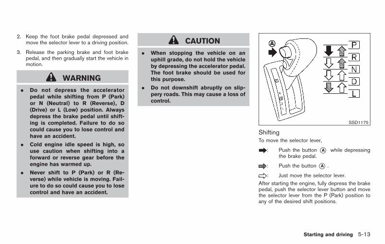
Black plate (349,1)
Model "E52-D" EDITED: 2010/ 10/ 25
2. Keep the foot brake pedal depressed andmove the selector lever to a driving position.
3. Release the parking brake and foot brakepedal, and then gradually start the vehicle inmotion.
WARNING
. Do not depress the acceleratorpedal while shifting from P (Park)or N (Neutral) to R (Reverse), D(Drive) or L (Low) position. Alwaysdepress the brake pedal until shift-ing is completed. Failure to do socould cause you to lose control andhave an accident.
. Cold engine idle speed is high, souse caution when shifting into aforward or reverse gear before theengine has warmed up.
. Never shift to P (Park) or R (Re-verse) while vehicle is moving. Fail-ure to do so could cause you to losecontrol and have an accident.
CAUTION
. When stopping the vehicle on anuphill grade, do not hold the vehicleby depressing the accelerator pedal.The foot brake should be used forthis purpose.
. Do not downshift abruptly on slip-pery roads. This may cause a loss ofcontrol.
SSD1175
ShiftingTo move the selector lever,
: Push the button *A while depressingthe brake pedal.
: Push the button *A .
: Just move the selector lever.
After starting the engine, fully depress the brakepedal, push the selector lever button and movethe selector lever from the P (Park) position toany of the desired shift positions.
Starting and driving 5-13

Black plate (350,1)
Model "E52-D" EDITED: 2010/ 10/ 25
WARNING
Apply the parking brake if the selectorlever is in any position while the engineis not running. Failure to do so couldcause the vehicle to move unexpectedlyor roll away and result in seriouspersonal injury or property damage.
CAUTION
Use the P (Park) or R (Reverse) positiononly when the vehicle is completelystopped.
P (Park):
Use this selector position when the vehicle isparked or when starting the engine. Make surethe vehicle is completely stopped. The brakepedal must be depressed and the selectorlever button pushed in to move the selec-tor lever from N (Neutral) or any driveposition to P (Park). Apply the parking brake.When parking on a hill, apply the parking brakefirst, then move the selector lever to the P (Park)position.
R (Reverse):
Use this position to back up. Make sure thevehicle is completely stopped before selectingthe R (Reverse) position. The brake pedalmust be depressed and the selector leverbutton pushed in to move the selectorlever from P (Park), N (Neutral) or anydriving position to R (Reverse).
N (Neutral):
Neither forward nor reverse gear is engaged.The engine can be started in this position. Youmay shift to N (Neutral) and restart a stalledengine while the vehicle is moving.
D (Drive):
Use this position for all normal forward driving.
L (Low):
Use this position for maximum engine braking onsteep downhill gradients/climbing steep slopesand whenever approaching sharp bends. Do notuse the L position in any other circumstances.
SSD1176
Overdrive (O/D) OFF switchWhen the O/D OFF switch is pushed with theselector lever in the D (Drive) position, theindicator light in the instrument panel illuminates.
Use the overdrive off mode when you needimproved engine braking.
To turn off the overdrive off mode, push the O/DOFF switch again. The indicator light willturn off.
Each time the engine is started, or when theselector lever is shifted to any position otherthan the D (Drive) position, the overdrive offmode will be automatically turned off.
5-14 Starting and driving

Black plate (351,1)
Model "E52-D" EDITED: 2010/ 10/ 25
Accelerator downshift— In D position —For passing or hill climbing, fully depress theaccelerator pedal to the floor. This shifts thetransmission down into a lower gear, dependingon the vehicle speed.
High fluid temperature protection modeThis transmission has a high fluid temperatureprotection mode. If the fluid temperature be-comes too high (for example, when climbingsteep grades in high temperature with heavyloads, such as when towing a trailer), enginepower and, under some conditions, vehiclespeed will be decreased automatically to reducethe chance of transmission damage. Vehiclespeed can be controlled with the acceleratorpedal, but the engine and vehicle speed may belimited.
Fail-safeIf the vehicle is driven under extremeconditions, such as excessive wheel spin-ning and subsequent hard braking, thefail-safe system may be activated. This willoccur even if all electrical circuits arefunctioning properly. In this case, placethe ignition switch in the OFF position andwait for 10 seconds. Then place the igni-tion switch back in the ON position. Thevehicle should return to its normal operat-ing condition. If it does not return to its
normal operating condition, have aNISSAN dealer check the transmissionand repair if necessary.
WARNING
When the high fluid temperature pro-tection mode or fail-safe operationoccurs, vehicle speed may be graduallyreduced. The reduced speed may belower than other traffic, which couldincrease the chance of a collision. Beespecially careful when driving. If ne-cessary, pull to the side of the road at asafe place and allow the transmissionto return to normal operation, or have itrepaired if necessary.
SSD1177
Shift lock releaseIf the battery charge is low or discharged, theselector lever may not be moved from the P(Park) position even with the brake pedaldepressed and the selector lever button pushed.
To move the selector lever, perform the followingprocedure:
1. Push the ignition switch to the OFF or LOCKposition.
2. Apply the parking brake.
3. Remove the shift lock release cover *Ausing a suitable tool.
4. Push down the shift lock release*B using a
Starting and driving 5-15
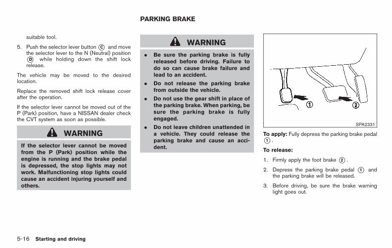
Black plate (352,1)
Model "E52-D" EDITED: 2010/ 10/ 25
suitable tool.
5. Push the selector lever button*C and movethe selector lever to the N (Neutral) position*D while holding down the shift lockrelease.
The vehicle may be moved to the desiredlocation.
Replace the removed shift lock release coverafter the operation.
If the selector lever cannot be moved out of theP (Park) position, have a NISSAN dealer checkthe CVT system as soon as possible.
WARNING
If the selector lever cannot be movedfrom the P (Park) position while theengine is running and the brake pedalis depressed, the stop lights may notwork. Malfunctioning stop lights couldcause an accident injuring yourself andothers.
WARNING
. Be sure the parking brake is fullyreleased before driving. Failure todo so can cause brake failure andlead to an accident.
. Do not release the parking brakefrom outside the vehicle.
. Do not use the gear shift in place ofthe parking brake. When parking, besure the parking brake is fullyengaged.
. Do not leave children unattended ina vehicle. They could release theparking brake and cause an acci-dent.
SPA2331
To apply: Fully depress the parking brake pedal*1 .
To release:
1. Firmly apply the foot brake *2 .
2. Depress the parking brake pedal *1 andthe parking brake will be released.
3. Before driving, be sure the brake warninglight goes out.
PARKING BRAKE
5-16 Starting and driving

Black plate (353,1)
Model "E52-D" EDITED: 2010/ 10/ 25
The Blind Spot Warning (BSW) system canhelp alert the driver of other vehicles in adjacentlanes when changing lanes.
SSD1178
The BSW system uses radar sensors *Ainstalled near the rear bumper to detect othervehicles beside your vehicle in an adjacent lane.
SSD1030Detection zone
The radar sensors can detect vehicles on eitherside of your vehicle within the detection zoneshown as illustrated. This detection zone startsfrom the outside mirror of your vehicle andextends approximately 10 ft (3.0 m) behind therear bumper, and approximately 10 ft (3.0 m)sideways.
The BSW system operates above approximately20 MPH (32 km/h). If the radar sensors detect avehicle in the detection zone, the BSW indicatorlight illuminates. If the driver then activates theturn signal, a chime will sound twice and theBSW indicator light will flash.
BLIND SPOT WARNING (BSW)SYSTEM (if so equipped)
Starting and driving 5-17
Black plate (354,1)
Model "E52-D" EDITED: 2010/ 10/ 25
WARNING
. The BSW system is not a replace-ment for proper driving procedureand is not designed to preventcontact with vehicles or objects.When changing lanes, always usethe side and rear mirrors and turnand look in the direction you willmove to ensure it is safe to changelanes. Never rely solely on the BSWsystem.
. The BSW system may not provide awarning for vehicles that passthrough the detection zone quickly.
SSD1184BSW indicator light
SSD1029BSW system warning light
SSD1179BSW switch
BSW SYSTEM OPERATION
If the radar sensors detect a vehicle in thedetection zone, the BSW indicator light in theoutside mirror will illuminate in the direction ofthe detected vehicle. If the turn signal is thenactivated, the BSW indicator light flashes and achime sounds twice. The indicator light con-tinues to flash until the detected vehicle leavesthe detection zone.
The BSW indicator lights illuminate for a fewseconds when the ignition switch is pushed tothe ON position.
The brightness of the BSW indicator lights isadjusted automatically depending on the bright-
5-18 Starting and driving

Black plate (355,1)
Model "E52-D" EDITED: 2010/ 10/ 25
ness of the ambient light.
A chime sounds if the radar sensors havealready detected vehicles when the driveractivates the turn signal. If a vehicle comes intothe detection zone after the driver activates theturn signal, then only the BSW indicator lightflashes and no chime sounds. (See “BSWDRIVING SITUATIONS” later in this section)
The BSW system is automatically turned onwhen the engine is started and the BSW ONindicator light*1 illuminates on the switch. Youcan turn the BSW system off by pushing theBSW switch on the instrumental panel.
NOTE:
If you continue to push the BSW switchfrom off to on for over 4 seconds, a chimewill sound. This will change the defaultstatus of the BSW system to OFF so thatthis system will not automatically turn onwhen the engine is started. If this proce-dure is repeated, the default status willreturn to ON.
WARNING
. Do not use the BSW system whentowing a trailer because the systemmay not function properly.
. Excessive noise (e.g. audio system
volume, open vehicle window) willinterfere with the chime sound, andit may not be heard.
. The radar sensors may not be able to detectand activate BSW when certain objects arepresent such as:
— Pedestrians, bicycles, animals
— Several types of vehicles such as motor-cycles
— Oncoming vehicles
— Vehicles remaining in the detection zonewhen you accelerate from a stop(See “BSW DRIVING SITUATIONS” laterin this section)
— A vehicle merging into an adjacent lane ata speed approximately the same as yourvehicle(See “BSW DRIVING SITUATIONS” laterin this section)
— A vehicle approaching rapidly from be-hind.(See “BSW DRIVING SITUATIONS” laterin this section)
— A vehicle which your vehicle overtakesrapidly.(See “BSW DRIVING SITUATIONS” laterin this section)
. Severe weather or road spray conditionsmay reduce the ability of the radar to detectother vehicles.
. The radar sensors detection zone is de-signed based on a standard lane width.When driving in a wider lane, the radarsensors may not detect vehicles in anadjacent lane. When driving in a narrowlane, the radar sensors may detect vehiclesdriving two lanes away.
. The radar sensors are designed to ignoremost stationary objects, however objectssuch as guardrails, walls, foliage and parkedvehicles may occasionally be detected. Thisis a normal operating condition.
Starting and driving 5-19

Black plate (356,1)
Model "E52-D" EDITED: 2010/ 10/ 25
SSD1026
BSW DRIVING SITUATIONS
Another vehicle approaching from be-hindThe BSW indicator light illuminates if a vehicleenters the detection zone from behind in anadjacent lane.
However, if the overtaking vehicle is travelingmuch faster than your vehicle, the indicator lightmay not illuminate before the detected vehicle isbeside your vehicle. Always use the side andrear mirrors and turn and look in the directionyour vehicle will move to ensure it is safe tochange lanes.
SSD1031
If the driver activates the turn signal, then theBSW indicator light flashes and a chime willsound twice.
NOTE:
If the driver activates the turn signal beforea vehicle enters the detection zone, theBSW indicator light will flash but no chimewill sound when the other vehicle isdetected.
SSD1032
NOTE:
If you accelerate from a stop with a vehiclein the detection zone, the other vehiclemay not be detected.
5-20 Starting and driving
Black plate (357,1)
Model "E52-D" EDITED: 2010/ 10/ 25
SSD1033
Overtaking other vehiclesThe BSW indicator light illuminates if youovertake a vehicle and that vehicle stays in thedetection zone for approximately 3 seconds.
The radar sensors may not detect slower movingvehicles if they are passed quickly.
SSD1034
If the driver activates the turn signal whileanother vehicle is in the detection zone, thenthe BSW indicator light flashes and a chime willsound twice.
Starting and driving 5-21

Black plate (358,1)
Model "E52-D" EDITED: 2010/ 10/ 25
SSD1036
NOTE:
When overtaking several vehicles in a row,the vehicles after the first vehicle may notbe detected if they are traveling closetogether.
SSD1037
Entering from the sideThe BSW indicator light illuminates if a vehicleenters the detection zone from either side.
NOTE:
The radar sensors may not detect a vehiclewhich is traveling at about the same speedas your vehicle when it enters the detec-tion zone.
5-22 Starting and driving

Black plate (359,1)
Model "E52-D" EDITED: 2010/ 10/ 25
SSD1038
If the driver activates the turn signal, then theBSW indicator light flashes and a chime willsound twice.
NOTE:
If the driver activates the turn signal beforea vehicle enters the detection zone, theBSW indicator light will flash but no chimewill sound when another vehicle is de-tected.
BSW temporarily not available. When radar blockage is detected, the BSW
system will be turned off automatically, abeep will sound and the BSW systemwarning light (orange) will blink. The BSWsystem is not available until the condition no
longer exists.
The radar sensors may be blocked by temporaryambient conditions such as splashing water,mist or fog. The blocked condition may also becaused by objects such as ice, frost or dirtobstructing the radar sensors.
Action to take:
When the above condition no longer exists, theBSW system will resume automatically.
If the warning light (orange) continues to blink,have the BSW system checked by a NISSANdealer.
BSW MALFUNCTION
When the BSW system malfunctions, they willbe turned off automatically, a beep will soundand the BSW system warning light (orange) willilluminate.
Action to take:
Stop the vehicle in a safe location, turn theengine off and restart the engine.
If the warning light (orange) continues toilluminate, have the BSW system checked by aNISSAN dealer.
SSD1178
SYSTEM MAINTENANCE
The two radar sensor units *A for the BSWsystem are located near the rear bumper. Alwayskeep the area near the radar sensors clean. Donot attach stickers (including transparent mate-rial), install accessories or apply additional paintnear the radar sensors. Do not strike or damagethe area around the radar sensors. Consult aNISSAN dealer if the area around the radarsensors is damaged due to a collision.
Radio frequency statementThis device complies with part 15 of the FCCRules and RSS-310 of Industry Canada.
Starting and driving 5-23

Black plate (360,1)
Model "E52-D" EDITED: 2010/ 10/ 25
Operation is subject to the following twoconditions:
1. This device may not cause harmful inter-ference.
2. This device must accept any interferencereceived, including interference that maycause undesired operation.
Frequency of operation: 24.05GHz —24.25GHz
Field Strength: Not greater than 2.5V/m peak(0.25V/m average) at a distance of 3 m
The manufacturer is not responsible for anyradio or TV interference caused by unauthorizedmodifications to this equipment. Such modifica-tions could void the user’s authority to operatethe equipment.
PRECAUTIONS ON CRUISE CON-TROL
. If the cruise control system malfunctions, itwill cancel automatically. The CRUISE in-dicator light on the meter panel will thenblink to warn the driver.
. If the engine coolant temperature becomesexcessively high, the cruise control systemwill cancel automatically.
. If the CRUISE indicator light blinks, turn thecruise control main switch off and have thesystem checked by a NISSAN dealer.
. The CRUISE indicator light may blink whenthe cruise control main switch is turned ONwhile pushing the RESUME/ACCELERATE,SET/COAST or CANCEL switch. To prop-erly set the cruise control system, performthe following procedures.
WARNING
Do not use the cruise control whendriving under the following conditions:
. when it is not possible to keep thevehicle at a set speed
. in heavy traffic or in traffic thatvaries in speed
. on winding or hilly roads
. on slippery roads (rain, snow, ice,etc.)
. in very windy areas
Doing so could cause a loss of vehiclecontrol and result in an accident.
CRUISE CONTROL
5-24 Starting and driving

Black plate (361,1)
Model "E52-D" EDITED: 2010/ 10/ 25
SSD0694
1. RESUME/ACCELERATE switch
2. SET/COAST switch
3. CANCEL switch
4. MAIN (ON·OFF) switch
CRUISE CONTROL OPERATIONS
The cruise control allows driving at a speedbetween 25 to 89 MPH (40 to 144 km/h)without keeping your foot on the acceleratorpedal.
To turn on the cruise control, push the MAINswitch on. The CRUISE indicator light willilluminate.
To set cruising speed, accelerate the vehicleto the desired speed, push the SET/COAST
switch and release it. Take your foot off theaccelerator pedal. Your vehicle will maintain theset speed.
. To pass another vehicle, depress theaccelerator pedal. When you release thepedal, the vehicle will return to the previouslyset speed.
. The vehicle may not maintain the set speedon winding or hilly roads. If this happens,drive without the cruise control.
To cancel the preset speed, use one of thefollowing methods:
a) Push the CANCEL switch.
b) Tap the brake pedal.
c) Turn the MAIN switch off. The CRUISE lightwill turn off.
. If you depress the brake pedal while pushingthe RESUME/ACCELERATE or SET/COAST switch and reset at the cruisingspeed, the cruise control will disengage.Turn the MAIN switch off once and then turnit on again.
. The cruise control will automatically cancel ifthe vehicle slows more than 8 MPH (13km/h) below the set speed.
. If you move the selector lever to the N(Neutral) position, the cruise control will be
canceled.
To reset at a faster cruising speed, use oneof the following methods:
. Depress the accelerator pedal. When thevehicle attains the desired speed, push andrelease the SET/COAST switch.
. Push and hold the RESUME/ACCELERATEswitch. When the vehicle attains the desiredspeed, release the switch.
. Push, then quickly release the RESUME/ACCELERATE switch. Each time you dothis, the set speed will increase by about 1MPH (1.6 km/h).
To reset at a slower cruising speed, use oneof the following methods:
. Lightly tap the brake pedal. When thevehicle attains the desired speed, push theSET/COAST switch and release it.
. Push and hold the SET/COAST switch.Release the switch when the vehicle slowsdown to the desired speed.
. Push, then quickly release the SET/COASTswitch. Each time you do this, the set speedwill decrease by about 1 MPH (1.6 km/h).
Starting and driving 5-25
Black plate (362,1)
Model "E52-D" EDITED: 2010/ 10/ 25
To resume the preset speed, push andrelease the RESUME/ACCELERATE switch.The vehicle will resume the last set cruisingspeed when the vehicle speed is over 25 MPH(40 km/h).
CAUTION
During the first 1,200 miles (2,000 km),follow these recommendations to ob-tain maximum engine performance andensure the future reliability and econo-my of your new vehicle. Failure tofollow these recommendations mayresult in shortened engine life andreduced engine performance.
. Avoid driving for long periods at constantspeed, either fast or slow. Do not run theengine over 4,000 rpm.
. Do not accelerate at full throttle in any gear.
. Avoid quick starts.
. Avoid hard braking as much as possible.
. Do not tow a trailer for the first 500 miles(800 km). Your engine, axle or other partscould be damaged.
. Accelerate slowly and smoothly. Maintaincruising speeds with a constant acceleratorposition.
. Drive at moderate speeds on the highway.Driving at high speed lowers fuel economy.
. Avoid unnecessary stopping and braking.Keep a safe distance behind other vehicles.
. Select a gear range suitable to road condi-tions.
. Avoid unnecessary engine idling.
. Keep your engine tuned up.
. Follow the recommended periodic mainte-nance schedule.
. Keep the tires inflated to the correctpressure. Low tire pressure increases tirewear and lowers fuel economy.
. Keep the wheels in correct alignment.Improper alignment increases tire wear andlowers fuel economy.
. Air conditioner operation lowers fuel econ-omy. Use the air conditioner only whennecessary.
. When cruising at highway speeds, it is moreeconomical to use the air conditioner andleave the windows closed to reduce drag.
BREAK-IN SCHEDULE INCREASING FUEL ECONOMY
5-26 Starting and driving

Black plate (363,1)
Model "E52-D" EDITED: 2010/ 10/ 25
. Use the recommended viscosity engine oil.(See “ENGINE OIL AND OIL FILTERRECOMMENDATION” in the “9. Technicaland consumer information” section.)
SSD0488
WARNING
. Do not stop or park the vehicle overflammable materials such as drygrass, waste paper or rags. Theymay ignite and cause a fire.
. Safe parking procedures requirethat both the parking brake be setand the transmission placed into P(Park). Failure to do so could causethe vehicle to move unexpectedly orroll away and result in an accident.Make sure the selector lever hasbeen pushed as far forward as it can
go and cannot be moved withoutdepressing the foot brake pedal.
. Never leave the engine runningwhile the vehicle is unattended.
. Do not leave children unattendedinside the vehicle. They could un-knowingly activate switches or con-trols. Unattended children couldbecome involved in serious acci-dents.
1. Firmly apply the parking brake.
2. Move the selector lever to the P (Park)position.
PARKING/PARKING ON HILLS
Starting and driving 5-27

Black plate (364,1)
Model "E52-D" EDITED: 2010/ 10/ 25
3. To help prevent the vehicle from rolling intotraffic when parked on an incline, it is a goodpractice to turn the wheels as illustrated.
. HEADED DOWNHILLWITH CURB:*1Turn the wheels into the curb and movethe vehicle forward until the curb sidewheel gently touches the curb.
. HEADED UPHILL WITH CURB: *2Turn the wheels away from the curb andmove the vehicle back until the curb sidewheel gently touches the curb.
. HEADED UPHILL OR DOWNHILL, NOCURB: *3Turn the wheels toward the side of theroad so the vehicle will move away fromthe center of the road if it moves.
4. Push the ignition switch to the LOCKposition.
WARNING
. If the engine is not running or isturned off while driving, the powerassist for the steering will not work.Steering will be harder to operate.
. When the hydraulic pump electricpower steering warning light illumi-nates with the engine running, thepower assist for the steering willcease operation. You will still havecontrol of the vehicle, but the steer-ing will be much harder to operate.
The hydraulic pump electric power steeringsystem is designed to provide power assistancewhile driving to operate the steering wheel withlight force.
When the steering wheel is operated repeatedlyor continuously while parking or driving at a verylow speed, the power assist for the steeringwheel will be reduced. This is to preventoverheating of the hydraulic pump electricpower steering system and protect it fromgetting damaged. While the power assist isreduced, steering wheel operation will becomeheavy. If the steering wheel operation is stillperformed, the power steering may stop and thehydraulic pump electric power steering warninglight will illuminate. Stop the engine and push
the ignition switch to the OFF position. Thetemperature of the hydraulic pump electricpower steering system will go down and thepower assist level will return to normal afterstarting the engine. The hydraulic pump electricpower steering warning light will go off. Avoidrepeating such steering wheel operations thatcould cause the hydraulic pump electric powersteering system to overheat.
You may hear a noise from the front of thevehicle when the steering wheel is operated.This is not a malfunction.
If the hydraulic pump electric power steeringwarning light illuminates while the engine isrunning, it may indicate the hydraulic pumpelectric power steering system is not functioningproperly and may need servicing. Have thehydraulic pump electric power steering systemchecked by a NISSAN dealer.
When the hydraulic pump electric power steer-ing warning light illuminates with the enginerunning, the power assist for the steering willcease operation but you will still have control ofthe vehicle. At this time, greater steering effortsare required to operate the steering wheel,especially in sharp turns and at low speeds.
HYDRAULIC PUMP ELECTRICPOWER STEERING SYSTEM
5-28 Starting and driving

Black plate (365,1)
Model "E52-D" EDITED: 2010/ 10/ 25
BRAKING PRECAUTIONS
The brake system has two separate hydrauliccircuits. If one circuit malfunctions, you will stillhave braking at two wheels.
Vacuum assisted brakesThe brake booster aids braking by using enginevacuum. If the engine stops, you can stop thevehicle by depressing the brake pedal. However,greater foot pressure on the brake pedal will berequired to stop the vehicle and the stoppingdistance will be longer.
Using the brakesAvoid resting your foot on the brake pedal whiledriving. This will cause overheating of thebrakes, wearing out the brake and pads fasterand reduce gas mileage.
To help reduce brake wear and to prevent thebrakes from overheating, reduce speed anddownshift to a lower gear before going down aslope or long grade. Overheated brakes mayreduce braking performance and could result inloss of vehicle control.
WARNING
. While driving on a slippery surface,be careful when braking, accelerat-ing or downshifting. Abrupt braking
or accelerating could cause thewheels to skid and result in anaccident.
. If the engine is not running or isturned off while driving, the powerassist for the brakes will not work.Braking will be harder.
Wet brakesWhen the vehicle is washed or driven throughwater, the brakes may get wet. As a result, yourbraking distance will be longer and the vehiclemay pull to one side during braking.
To dry brakes, drive the vehicle at a safe speedwhile lightly tapping the brake pedal to heat-upthe brakes. Do this until the brakes return tonormal. Avoid driving the vehicle at high speedsuntil the brakes function correctly.
PARKING BRAKE BREAK-IN
Break in the parking brake shoes whenever thestopping effect of the parking brake is weakenedor whenever the parking brake shoes and/ordrums/rotors are replaced, in order to assure thebest braking performance.
This procedure is described in the vehicleservice manual and can be performed by aNISSAN dealer.
ANTI-LOCK BRAKING SYSTEM (ABS)
WARNING
. The Anti-lock Braking System (ABS)is a sophisticated device, but itcannot prevent accidents resultingfrom careless or dangerous drivingtechniques. It can help maintainvehicle control during braking onslippery surfaces. Remember thatstopping distances on slippery sur-faces will be longer than on normalsurfaces even with ABS. Stoppingdistances may also be longer onrough, gravel or snow coveredroads, or if you are using tire chains.Always maintain a safe distancefrom the vehicle in front of you.Ultimately, the driver is responsiblefor safety.
. Tire type and condition may alsoaffect braking effectiveness.
— When replacing tires, install thespecified size of tires on all fourwheels.
— When installing a spare tire,make sure that it is the propersize and type as specified on the
BRAKE SYSTEM
Starting and driving 5-29

Black plate (366,1)
Model "E52-D" EDITED: 2010/ 10/ 25
Tire and Loading Informationlabel. See “TIRE AND LOADINGINFORMATION LABEL” in the “9.Technical and consumer infor-mation” section of this manual.
— For detailed information, see“WHEELS AND TIRES” in the“8. Maintenance and do-it-your-self” section of this manual.
The Anti-lock Braking System (ABS) controlsthe brakes so the wheels do not lock during hardbraking or when braking on slippery surfaces.The system detects the rotation speed at eachwheel and varies the brake fluid pressure toprevent each wheel from locking and sliding. Bypreventing each wheel from locking, the systemhelps the driver maintain steering control andhelps to minimize swerving and spinning onslippery surfaces.
Using the systemDepress the brake pedal and hold it down.Depress the brake pedal with firm steadypressure, but do not pump the brakes. TheABS will operate to prevent the wheels fromlocking up. Steer the vehicle to avoid obstacles.
WARNING
Do not pump the brake pedal. Doing somay result in increased stopping dis-tances.
Self-test featureThe ABS includes electronic sensors, electricpumps, hydraulic solenoids and a computer. Thecomputer has a built-in diagnostic feature thattests the system each time you start the engineand move the vehicle at a low speed in forwardor reverse. When the self-test occurs, you mayhear a “clunk” noise and/or feel a pulsation in thebrake pedal. This is normal and does notindicate a malfunction. If the computer sensesa malfunction, it switches the ABS off andilluminates the ABS warning light on theinstrument panel. The brake system then oper-ates normally, but without anti-lock assistance.
If the ABS warning light illuminates during theself-test or while driving, have the vehiclechecked by a NISSAN dealer.
Normal operationThe ABS operates at speeds above 3 to 6 MPH(5 to 10 km/h). The speed varies according toroad conditions.
When the ABS senses that one or more wheelsare close to locking up, the actuator rapidly
applies and releases hydraulic pressure. Thisaction is similar to pumping the brakes veryquickly. You may feel a pulsation in the brakepedal and hear a noise from under the hood orfeel a vibration from the actuator when it isoperating. This is normal and indicates that theABS is operating properly. However, the pulsa-tion may indicate that road conditions arehazardous and extra care is required whiledriving.
5-30 Starting and driving

Black plate (367,1)
Model "E52-D" EDITED: 2010/ 10/ 25
The Vehicle Dynamic Control (VDC) systemuses various sensors to monitor driver inputsand vehicle motion. Under certain driving con-ditions, the VDC system helps to perform thefollowing functions.
. Controls brake pressure to reduce wheelslip on one slipping drive wheel so power istransferred to a non slipping drive wheel onthe same axle.
. Controls brake pressure and engine outputto reduce drive wheel slip based on vehiclespeed (traction control function).
. Controls brake pressure at individual wheelsand engine output to help the driver maintaincontrol of the vehicle in the followingconditions:
— understeer (vehicle tends to not follow thesteered path despite increased steeringinput)
— oversteer (vehicle tends to spin due tocertain road or driving conditions).
The VDC system can help the driver to maintaincontrol of the vehicle, but it cannot prevent lossof vehicle control in all driving situations.
When the VDC system operates, the VDCwarning light in the instrument panelflashes so note the following:
. The road may be slippery or the system may
determine some action is required to helpkeep the vehicle on the steered path.
. You may feel a pulsation in the brake pedaland hear a noise or vibration from under thehood. This is normal and indicates that theVDC system is working properly.
. Adjust your speed and driving to the roadconditions.
See “Vehicle Dynamic Control (VDC) warninglight” in the “2. Instruments and controls”section.
If a malfunction occurs in the system, the VDCwarning light illuminates in the instrumentpanel. The VDC system automatically turns off.
The VDC OFF switch is used to turn off the VDCsystem. The VDC off indicator illuminatesto indicate the VDC system is off. When theVDC switch is used to turn off the system, theVDC system still operates to prevent one drivewheel from slipping by transferring power to anon slipping drive wheel. The VDC warning light
flashes if this occurs. All other VDCfunctions are off, and the VDC warning light
will not flash. The VDC system is auto-matically reset to on when the ignition switch isplaced in the off position then back to the onposition.
See “Vehicle Dynamic Control (VDC) warninglight” in the “2. Instruments and controls”
section and “Vehicle Dynamic Control (VDC)off indicator light” in the “2. Instruments andcontrols” section.
The computer has a built-in diagnostic featurethat tests the system each time you start theengine and move the vehicle forward or inreverse at a slow speed. When the self-testoccurs, you may hear a “clunk” noise and/or feela pulsation in the brake pedal. This is normal andis not an indication of a malfunction.
WARNING
. The VDC system is designed to helpthe driver maintain stability butdoes not prevent accidents due toabrupt steering operation at highspeeds or by careless or dangerousdriving techniques. Reduce vehiclespeed and be especially carefulwhen driving and cornering on slip-pery surfaces and always drive care-fully.
. Do not modify the vehicle’s suspen-sion. If suspension parts such asshock absorbers, struts, springs,stabilizer bars, bushings andwheels are not NISSAN recom-mended for your vehicle or areextremely deteriorated, the VDC
VEHICLE DYNAMIC CONTROL (VDC)SYSTEM
Starting and driving 5-31

Black plate (368,1)
Model "E52-D" EDITED: 2010/ 10/ 25
system may not operate properly.This could adversely affect vehiclehandling performance, and the VDCwarning light may illuminate.
. If brake related parts such as brakepads, rotors and calipers are notNISSAN recommended or are extre-mely deteriorated, the VDC systemmay not operate properly and theVDC warning light may illumi-nate.
. If engine control related parts arenot NISSAN recommended or areextremely deteriorated, the VDCwarning light may illuminate.
. When driving on extremely inclinedsurfaces such as higher bankedcorners, the VDC system may notoperate properly and the VDC warn-ing light may illuminate. Do notdrive on these types of roads.
. When driving on an unstable sur-face such as a turntable, ferry,elevator or ramp, the VDC warninglight may illuminate. This is nota malfunction. Restart the engineafter driving onto a stable surface.
. If wheels or tires other than the
NISSAN recommended ones areused, the VDC system may notoperate properly and the VDC warn-ing light may illuminate.
. The VDC system is not a substitutefor winter tires or tire chains on asnow covered road.
FREEING A FROZEN DOOR LOCK
To prevent a door lock from freezing, applydeicer through the key hole. If the lock becomesfrozen, heat the key before inserting it into thekey hole or use the remote keyless entry keyfob.
ANTI-FREEZE
In the winter when it is anticipated that theoutside temperature will drop below 328F (08C),check the anti-freeze to assure proper winterprotection. For additional information, see “EN-GINE COOLING SYSTEM” in the “8. Main-tenance and do-it-yourself” section.
BATTERY
If the battery is not fully charged duringextremely cold weather conditions, the batteryfluid may freeze and damage the battery. Tomaintain maximum efficiency, the battery shouldbe checked regularly. For additional information,see “BATTERY” in the “8. Maintenance and do-it-yourself” section.
DRAINING OF COOLANT WATER
If the vehicle is to be left outside without anti-freeze, drain the cooling system, including theengine block. Refill before operating the vehicle.For details, see “ENGINE COOLING SYSTEM”in the “8. Maintenance and do-it-yourself”section.
COLD WEATHER DRIVING
5-32 Starting and driving

Black plate (369,1)
Model "E52-D" EDITED: 2010/ 10/ 25
TIRE EQUIPMENT
SUMMER tires have a tread designed to providesuperior performance on dry pavement. How-ever, the performance of these tires will besubstantially reduced in snowy and icy condi-tions. If you operate your vehicle on snowy or icyroads, NISSAN recommends the use of MUD &SNOW or ALL SEASON tires on all four wheels.Consult a NISSAN dealer for the tire type, size,speed rating and availability information.
For additional traction on icy roads, studdedtires may be used. However, some U.S. statesand Canadian provinces prohibit their use.Check local, state and provincial laws beforeinstalling studded tires.
Skid and traction capabilities of studdedsnow tires, on wet or dry surfaces, may bepoorer than that of non-studded snowtires.
Tire chains may be used. For details, see “TIRECHAINS” in the “8. Maintenance and do-it-yourself” section of this manual.
SPECIAL WINTER EQUIPMENT
It is recommended that the following items becarried in the vehicle during winter:
. A scraper and stiff-bristled brush to removeice and snow from the windows and wiperblades.
. A sturdy, flat board to be placed under thejack to give it firm support.
. A shovel to dig the vehicle out of snow-drifts.
. Extra window washer fluid to refill thereservoir tank.
DRIVING ON SNOW OR ICE
WARNING
. Wet ice (328F, 08C and freezing rain),very cold snow or ice can be slickand very hard to drive on. Thevehicle will have much less tractionor “grip” under these conditions. Tryto avoid driving on wet ice until theroad is salted or sanded.
. Whatever the condition, drive withcaution. Accelerate and slow downwith care. If accelerating or down-shifting too fast, the drive wheels
will lose even more traction.
. Allow more stopping distance underthese conditions. Braking should bestarted sooner than on dry pave-ment.
. Allow greater following distanceson slippery roads.
. Watch for slippery spots (glare ice).These may appear on an otherwiseclear road in shaded areas. If apatch of ice is seen ahead, brakebefore reaching it. Try not to brakewhile on the ice, and avoid anysudden steering maneuvers.
. Do not use cruise control on slip-pery roads.
. Snow can trap dangerous exhaustgases under your vehicle. Keepsnow clear of the exhaust pipe andfrom around your vehicle.
ENGINE BLOCK HEATER (if soequipped)
Engine block heaters are used to assist withcold temperature starting.
The engine block heater should be used whenthe outside temperature is 208F (−78C) or lower.
Starting and driving 5-33

Black plate (370,1)
Model "E52-D" EDITED: 2010/ 10/ 25
To use the engine block heater1. Turn the engine off.
2. Open the hood and unwrap the engineblock heater cord.
3. Plug the engine block heater cord into agrounded 3-wire, 3-pronged extension cord.
4. Plug the extension cord into a Ground FaultInterrupt (GFI) protected, grounded 110-volt AC (VAC) outlet.
5. The engine block heater must be plugged infor at least 2 - 4 hours, depending onoutside temperatures, to properly warm theengine coolant. Use an appropriate timer toturn the engine block heater on.
6. Before starting the engine, unplug andproperly store the cord to keep it away frommoving parts.
WARNING
. Do not use your engine block heaterwith an ungrounded electrical sys-tem or a 2-pronged adapter. You canbe seriously injured by an electricalshock if you use an ungroundedconnection.
. Disconnect and properly store theengine block heater cord before
starting the engine. Damage to thecord could result in an electricalshock and can cause serious injury.
. Use a heavy-duty 3-wire, 3-prongedextension cord rated for at least10A. Plug the extension cord into aGround Fault Interrupt (GFI) pro-tected, grounded 110-VAC outlet.Failure to use the proper extensioncord or a grounded outlet can resultin a fire or electrical shock andcause serious personal injury.
5-34 Starting and driving

Black plate (371,1)
Model "E52-D" EDITED: 2010/ 10/ 25
MEMO
Starting and driving 5-35

Black plate (372,1)
Model "E52-D" EDITED: 2010/ 10/ 25
MEMO
5-36 Starting and driving

Black plate (19,1)
6 In case of emergency
Model "E52-D" EDITED: 2010/ 10/ 22
Emergency engine shut off . . . . . . . . . . . . . . . . . . . . . . . . . . . . . . . . . . . 6-2Flat tire . . . . . . . . . . . . . . . . . . . . . . . . . . . . . . . . . . . . . . . . . . . . . . . . . . . . . . . . . . . . 6-2
Tire Pressure Monitoring System (TPMS). . . . . . . . . . . . . 6-2Changing a flat tire . . . . . . . . . . . . . . . . . . . . . . . . . . . . . . . . . . . . . . . . . 6-3
Jump starting . . . . . . . . . . . . . . . . . . . . . . . . . . . . . . . . . . . . . . . . . . . . . . . . . . 6-10
Push starting. . . . . . . . . . . . . . . . . . . . . . . . . . . . . . . . . . . . . . . . . . . . . . . . . . . 6-11If your vehicle overheats. . . . . . . . . . . . . . . . . . . . . . . . . . . . . . . . . . . . . 6-12Towing your vehicle . . . . . . . . . . . . . . . . . . . . . . . . . . . . . . . . . . . . . . . . . . 6-13
Towing recommended by NISSAN . . . . . . . . . . . . . . . . . . . 6-14Vehicle recovery (freeing a stuck vehicle) . . . . . . . . . . . 6-15

Black plate (374,1)
Model "E52-D" EDITED: 2010/ 10/ 25
To shut off the engine in an emergency situationwhile driving perform the following procedure:
. Rapidly push the push-button ignition switch3 consecutive times, or
. Push and hold the push-button ignitionswitch for more than 2 seconds.
TIRE PRESSURE MONITORING SYS-TEM (TPMS)
This vehicle is equipped with the Tire PressureMonitoring System (TPMS). It monitors tirepressure of all tires except the spare. Whenthe low tire pressure warning light is lit and theCHECK TIRE PRESSURE warning appears onthe dot matrix liquid crystal display, one or moreof your tires is significantly under-inflated. If thevehicle is being driven with low tire pressure, theTPMS will activate and warn you of it by the lowtire pressure warning light. This system willactivate only when the vehicle is driven atspeeds above 16 MPH (25 km/h). For moredetails, see “WARNING/INDICATOR LIGHTSAND AUDIBLE REMINDERS” in the “2. Instru-ments and controls” section and “TIRE PRES-SURE MONITORING SYSTEM (TPMS)” in the“5. Starting and driving” section.
WARNING
. If the low tire pressure warning lightilluminates while driving, avoid sud-den steering maneuvers or abruptbraking, reduce vehicle speed, pulloff the road to a safe location andstop the vehicle as soon as possi-ble. Driving with under-inflated tiresmay permanently damage the tiresand increase the likelihood of tire
failure. Serious vehicle damagecould occur and may lead to anaccident and could result in seriouspersonal injury. Check the tire pres-sure for all four tires. Adjust the tirepressure to the recommended COLDtire pressure shown on the Tire andLoading Information label to turnthe low tire pressure warning lightOFF. If the light still illuminateswhile driving after adjusting the tirepressure, a tire may be flat. If youhave a flat tire, replace it with aspare tire as soon as possible.
. When a spare tire is mounted or awheel is replaced, the TPMS will notfunction and the low tire pressurewarning light will flash for approxi-mately 1 minute. The light willremain on after 1 minute. Contactyour NISSAN dealer as soon aspossible for tire replacement and/or system resetting.
. Replacing tires with those not ori-ginally specified by NISSAN couldaffect the proper operation of theTPMS.
. Do not inject any tire liquid oraerosol tire sealant into the tires,
EMERGENCY ENGINE SHUT OFF FLAT TIRE
6-2 In case of emergency

Black plate (375,1)
Model "E52-D" EDITED: 2010/ 10/ 25
as this may cause a malfunction ofthe tire pressure sensors.
CHANGING A FLAT TIRE
If you have a flat tire, follow the instructionsbelow.
Stopping the vehicle1. Safely move the vehicle off the road and
away from traffic.
2. Turn on the hazard warning flashers.
3. Park on a level surface and apply the parkingbrake. Move the selector lever to the P(Park) position.
4. Turn off the engine.
5. Raise the hood to warn other traffic, and tosignal professional road assistance person-nel that you need assistance.
6. Have all passengers get out of the vehicleand stand in a safe place, away from trafficand clear of the vehicle.
WARNING
. Make sure the parking brake issecurely applied and the transmis-sion is shifted into the P (Park)position.
. Never change tires when the vehicleis on a slope, ice or slippery areas.This is hazardous.
. Never change tires if oncomingtraffic is close to your vehicle. Waitfor professional road assistance.
MCE0001A
Blocking wheelsPlace suitable blocks *1 at both the front andback of the wheel diagonally opposite the flattire to prevent the vehicle from moving when it isjacked up.
WARNING
Be sure to block the wheel as thevehicle may move and result in personalinjury.
In case of emergency 6-3

Black plate (376,1)
Model "E52-D" EDITED: 2010/ 10/ 25
SCE0968
Getting the tools and jack1. Open the lift gate.
2. Open the cargo floor box. (See “CARGOFLOOR BOX” in the “2. Instruments andcontrols” section.)
3. Remove the cargo floor board (if so
equipped).
4. Remove tools *A and jack *B located asillustrated.
SCE0973
6-4 In case of emergency
Black plate (377,1)
Model "E52-D" EDITED: 2010/ 10/ 25
SCE0975
SCE0977
Getting the spare tireThe spare tire is located under the center of thevehicle.
1. Lift up the floor carpeting flap behind thefront center console, then remove insulationpiece to access the spare tire loweringmechanism *C .
2. Loosen the spare tire lowering mechanism*C with the wheel nut wrench.
3. Using the assembled socket tool *D , turnthe spare tire lowering mechanism *Ccounterclockwise as illustrated to lower thespare tire.
4. When the spare tire is completely lowered,carefully slide it from under the vehicle byusing the assembled tool *E .
5. Remove the suspending plate *F from thespare tire.
6. After removing the spare tire, raise the sparetire cable completely by turning the sparetire lowering mechanism clockwise using thetool *D .
7. Before moving or jacking up the vehicle,check under the vehicle to make sure thecable is stored properly.
WARNING
. Never jack up the vehicle beforeremoving the spare tire from underthe vehicle. This may lead to anaccident could result in seriouspersonal injury.
. Never get under the vehicle toremove the spare tire. This may leadto an accident and could result inserious personal injury. Always usethe assembled tool *E to slide thespare tire from under the vehicle.
. Do not move the vehicle with thespare tire cable lowered. The cablecould hit or become tangled with anobject on the road. Serious vehicledamage could occur and may leadto an accident and could result inserious personal injury.
In case of emergency 6-5
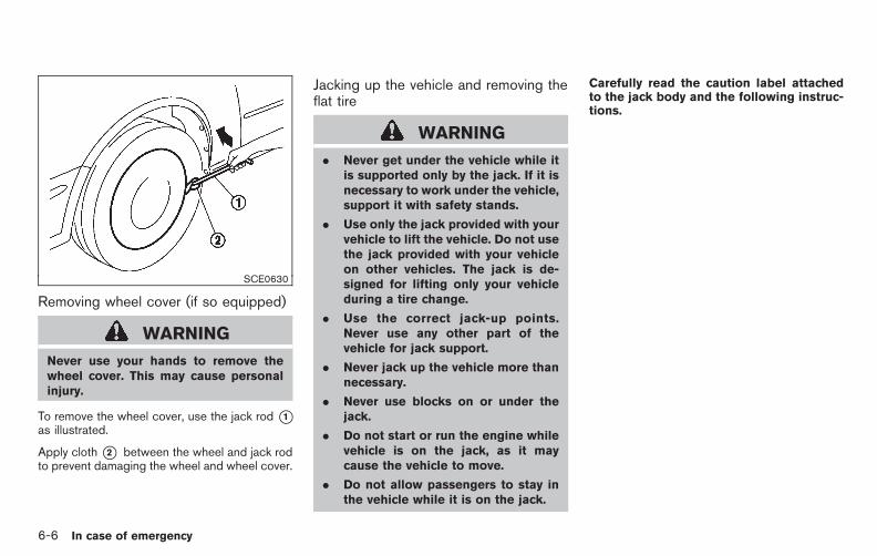
Black plate (378,1)
Model "E52-D" EDITED: 2010/ 10/ 25
SCE0630
Removing wheel cover (if so equipped)
WARNING
Never use your hands to remove thewheel cover. This may cause personalinjury.
To remove the wheel cover, use the jack rod*1as illustrated.
Apply cloth*2 between the wheel and jack rodto prevent damaging the wheel and wheel cover.
Jacking up the vehicle and removing theflat tire
WARNING
. Never get under the vehicle while itis supported only by the jack. If it isnecessary to work under the vehicle,support it with safety stands.
. Use only the jack provided with yourvehicle to lift the vehicle. Do not usethe jack provided with your vehicleon other vehicles. The jack is de-signed for lifting only your vehicleduring a tire change.
. Use the correct jack-up points.Never use any other part of thevehicle for jack support.
. Never jack up the vehicle more thannecessary.
. Never use blocks on or under thejack.
. Do not start or run the engine whilevehicle is on the jack, as it maycause the vehicle to move.
. Do not allow passengers to stay inthe vehicle while it is on the jack.
Carefully read the caution label attachedto the jack body and the following instruc-tions.
6-6 In case of emergency

Black plate (379,1)
Model "E52-D" EDITED: 2010/ 10/ 25
SCE0585Jack-up point
1. Place the jack directly under the jack-uppoint as illustrated so the top of the jackcontacts the vehicle at the jack-up point.Align the jack head between the twonotches in the front or the rear as shown.Also fit the groove of the jack head betweenthe notches as shown.
The jack should be used on level firmground.
SCE0504
2. Loosen each wheel nut one or two turns byturning counterclockwise with the wheel nutwrench. Do not remove the wheel nutsuntil the tire is off the ground.
3. To lift the vehicle, securely hold the jack leverand rod with both hands as shown above.Carefully raise the vehicle until the tire clearsthe ground. Remove the wheel nuts, andthen remove the tire.
In case of emergency 6-7

Black plate (380,1)
Model "E52-D" EDITED: 2010/ 10/ 25
SCE0039
Installing the spare tireThe spare tire is designed for emergencyuse. (See specific instructions under theheading “WHEELS AND TIRES” in the “8.Maintenance and do-it-yourself” section.)
1. Clean any mud or dirt from the surfacebetween the wheel and hub.
2. Carefully put the spare tire on and tightenthe wheel nuts finger tight. Check that all thewheel nuts contact the wheel surfacehorizontally.
3. With the wheel nut wrench, tighten wheelnuts alternately and evenly in the sequenceas illustrated (*1 ,*2 ,*3 ,*4 ,*5 ), more
than 2 times, until they are tight.
4. Lower the vehicle slowly until the tiretouches the ground. Then, with the wheelnut wrench, tighten the wheel nuts securelyin the sequence as illustrated. Lower thevehicle completely.
5. Securely store the flat tire, jack and tools inthe vehicle.
WARNING
. Incorrect wheel nuts or improperlytightened wheel nuts can cause thewheel to become loose or come off.This could cause an accident.
. Do not use oil or grease on thewheel studs or nuts. This couldcause the nuts to become loose.
. Retighten the wheel nuts when thevehicle has been driven for 600miles (1,000 km) (also in cases of aflat tire, etc.).
. As soon as possible, tighten thewheel nuts to the specified torquewith a torque wrench.
Wheel nut tightening torque:80 ft-lb (108 N·m)
The wheel nuts must be kept tightenedto specification at all times. It isrecommended that wheel nuts be tigh-tened to specifications at each lubrica-tion interval.
. Adjust tire pressure to the COLDpressure.
COLD pressure:
After the vehicle has been parked forthree hours or more or driven less than1 mile (1.6 km).
COLD tire pressures are shown on theTire and Loading Information labelaffixed to the driver side center pillar.
Stowing the spare tire and the toolsSecurely store the spare tire, jack and tools intheir original location.
WARNING
. Always make sure that the spare tireand jacking equipment are properlysecured after use. Such items canbecome dangerous projectiles in anaccident or sudden stop.
. The T-type spare tire and small sizespare tire are designed for emer-gency use. See specific instructions
6-8 In case of emergency

Black plate (381,1)
Model "E52-D" EDITED: 2010/ 10/ 25
under the heading “WHEELS ANDTIRES” in the “8. Maintenance anddo-it-yourself” section.
SCE0978
WARNING
. When storing the spare tire, makesure that the outer side of the sparetire *A is facing up and that thehanging plate *B is in the center ofthe wheel as illustrated. Failure tostore the spare tire properly couldresult in serious vehicle damageand may lead to an accident andcould result in serious personalinjury.
. Do not store any tire with the cableexcept the spare tire.
. Do not use an impact wrench whentightening or loosening the sparetire lowering mechanism.
. When raising the spare tire, tightenthe spare tire lowering mechanismuntil three clicks are heard.
. After storing the spare tire, checkunder the vehicle to make sure it isstored properly.
In case of emergency 6-9

Black plate (382,1)
Model "E52-D" EDITED: 2010/ 10/ 25
To start your engine with a booster battery, theinstructions and precautions below must befollowed.
WARNING
. If done incorrectly, jump startingcan lead to a battery explosion,resulting in severe injury or death.It could also damage your vehicle.
. Explosive hydrogen gas is alwayspresent in the vicinity of the battery.Keep all sparks and flames awayfrom the battery.
. Do not allow battery fluid to comeinto contact with eyes, skin, clothingor painted surfaces. Battery fluid isa corrosive sulfuric acid solutionwhich can cause severe burns. Ifthe fluid should come into contactwith anything, immediately flush thecontacted area with water.
. Keep the battery out of the reach ofchildren.
. The booster battery must be rated at12 volts. Use of an improperly ratedbattery can damage your vehicle.
. Whenever working on or near abattery, always wear suitable eye
protectors (for example, goggles orindustrial safety spectacles) andremove rings, metal bands, or anyother jewelry. Do not lean over thebattery when jump starting.
. Do not attempt to jump start afrozen battery. It could explodeand cause serious injury.
. Your vehicle has an automatic en-gine cooling fan. It could come on atany time. Keep hands and otherobjects away from it.
SCE0969
WARNING
Always follow the instructions below.Failure to do so could result in damageto the charging system and causepersonal injury.
1. If the booster battery is in another vehicle*B , position the two vehicles (*A and*B )to bring their batteries into close proximity toeach other.
Do not allow the two vehicles to touch.
2. Apply the parking brake. Move the selectorlever to the P (Park) position. Switch off all
JUMP STARTING
6-10 In case of emergency

Black plate (383,1)
Model "E52-D" EDITED: 2010/ 10/ 25
unnecessary electrical systems (lights, hea-ter, air conditioner, etc.).
3. Remove vent caps on the battery (if soequipped). Cover the battery with a firmlywrung out moist cloth to reduce explosionhazard.
4. Connect jumper cables in the sequence asillustrated (*1 ? *2 ? *3 ? *4 ).
If the battery is discharged, the ignitionswitch cannot be moved from the OFFposition. Connect the jumper cables tothe booster vehicle *B before pushingthe ignition switch.
CAUTION
. Always connect positive (+) to posi-tive (+) and negative (−) to bodyground (for example, as illustrated),not to the battery.
. Make sure the jumper cables do nottouch moving parts in the enginecompartment and that the cableclamps do not contact any othermetal.
5. Start the engine of the booster vehicle *Band let it run for a few minutes.
6. Keep the engine speed of the booster
vehicle *B at about 2,000 rpm, and startthe engine of the vehicle *A being jumpstarted.
CAUTION
Do not keep the starter motor engagedfor more than 10 seconds. If the enginedoes not start right away, place theignition switch in the OFF position andwait 10 seconds before trying again.
7. After starting your engine, carefully discon-nect the negative cable and then the positivecable (*4 ? *3 ? *2 ? *1 ).
8. Replace the vent caps (if so equipped). Besure to dispose of the cloth used to coverthe vent holes as it may be contaminatedwith corrosive acid.
Do not attempt to start the engine by pushing.
CAUTION
Continuously Variable Transmission(CVT) models cannot be push-startedor tow-started. Attempting to do so maycause transmission damage.
PUSH STARTING
In case of emergency 6-11

Black plate (384,1)
Model "E52-D" EDITED: 2010/ 10/ 25
CAUTION
. Do not continue to drive if yourvehicle overheats. Doing so couldcause engine damage or a vehiclefire.
. To avoid the danger of beingscalded, never remove the radiatorcap while the engine is still hot.When the radiator cap is removed,pressurized hot water will spurt out,possibly causing serious injury.
. Do not open the hood if steam iscoming out.
If your vehicle is overheating (indicated by anextremely high temperature gauge reading), or ifyou feel a lack of engine power, detect abnormalnoise, etc., take the following steps:
1. Move the vehicle safely off the road, applythe parking brake and move the selectorlever to the P (Park) position.
Do not stop the engine.
2. Turn off the air conditioner. Open all thewindows, move the heater or air conditionertemperature control to maximum hot and fancontrol to high speed.
3. Get out of the vehicle. Look and listen forsteam or coolant escaping from the radiatorbefore opening the hood. (If steam orcoolant is escaping, turn off the engine.)Do not open the hood further until no steamor coolant can be seen.
4. Open the engine hood.
WARNING
If steam or water is coming from theengine, stand clear to prevent gettingburned.
5. Visually check drive belts for damage orlooseness. Also check if the cooling fan isrunning. The radiator hoses and radiatorshould not leak water. If coolant is leaking,the water pump belt is missing or loose, orthe cooling fan does not run, stop theengine.
WARNING
Be careful not to allow your hands, hair,jewelry or clothing to come into contactwith, or get caught in, engine belts orthe engine cooling fan. The enginecooling fan can start at any time.
6. After the engine cools down, check thecoolant level in the reservoir tank with theengine running. Add coolant to the reservoirtank if necessary. Have your vehicle repairedat a NISSAN dealer.
IF YOUR VEHICLE OVERHEATS
6-12 In case of emergency

Black plate (385,1)
Model "E52-D" EDITED: 2010/ 10/ 25
When towing your vehicle, all State (Provincial inCanada) and local regulations for towing mustbe followed. Incorrect towing equipment coulddamage your vehicle. Towing instructions areavailable from a NISSAN dealer. Local serviceoperators are familiar with the applicable lawsand procedures for towing. To assure propertowing and to prevent accidental damage toyour vehicle, NISSAN recommends that youhave a service operator tow your vehicle. It isadvisable to have the service operator carefullyread the following precautions.
WARNING
. Never ride in a vehicle that is beingtowed.
. Never get under your vehicle after ithas been lifted by a tow truck.
CAUTION
. When towing, make sure that thetransmission, axles, steering systemand drivetrain are in working condi-tion. If any unit is damaged, dolliesmust be used.
. Always attach safety chains beforetowing.
For information about towing your vehicle behinda recreational vehicle (RV), see “FLAT TOW-ING” in the “9. Technical and consumerinformation” section of this manual.
TOWING YOUR VEHICLE
In case of emergency 6-13

Black plate (386,1)
Model "E52-D" EDITED: 2010/ 10/ 25
SCE0976
TOWING RECOMMENDED BYNISSAN
NISSAN recommends that your vehicle betowed with the driving (front) wheels off theground or place the vehicle on a flat bed truck asillustrated.
CAUTION
. Never tow Continuously VariableTransmission (CVT) models withthe front wheels on the ground orfour wheels on the ground (forwardor backward), as this may causeserious and expensive damage to
the drivetrain. If it is necessary totow the vehicle with the rear wheelsraised, always use towing dolliesunder the front wheels.
. When towing CVT models with thefront wheels on towing dollies:
. Push the ignition switch to theACC or ON position, and securethe steering wheel in a straight-ahead position with a rope orsimilar device.
. Move the selector lever to the N(Neutral) position.
. When towing a CVT model with the
rear wheels on the ground (if you donot use towing dollies): Alwaysrelease the parking brake.
6-14 In case of emergency
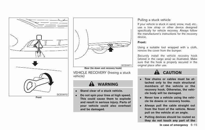
Black plate (387,1)
Model "E52-D" EDITED: 2010/ 10/ 25
SCE0970Front
SCE0971Rear (tie down and recovery hook)
VEHICLE RECOVERY (freeing a stuckvehicle)
WARNING
. Stand clear of a stuck vehicle.
. Do not spin your tires at high speed.This could cause them to explodeand result in serious injury. Parts ofyour vehicle could also overheatand be damaged.
Pulling a stuck vehicleIf your vehicle is stuck in sand, snow, mud, etc.,use a tow strap or other device designedspecifically for vehicle recovery. Always followthe manufacturer’s instructions for the recoverydevice.
Front:
Using a suitable tool wrapped with a cloth,remove the cover from the bumper.
Securely install the vehicle recovery hook(stored in the cargo area) as illustrated. Makesure that the hook is properly secured in theoriginal place after use.
CAUTION
. Tow chains or cables must be at-tached only to the main structuralmembers of the vehicle or therecovery hook. Otherwise, the vehi-cle body will be damaged.
. Never tow a vehicle using the vehi-cle tie downs or recovery hooks.
. Always pull the cable straight outfrom the front of the vehicle. Neverpull on the vehicle at an angle.
. Pulling devices should be routed sothey do not touch any part of the
In case of emergency 6-15

Black plate (388,1)
Model "E52-D" EDITED: 2010/ 10/ 25
suspension, steering, brake or cool-ing systems.
. Pulling devices such as ropes orcanvas straps are not recommendedfor use in vehicle towing or recov-ery.
Rocking a stuck vehicleIf your vehicle is stuck in sand, snow, mud, etc.,use the following procedure:
1. Turn off the Vehicle Dynamic Control (VDC)system.
2. Make sure the area in front and behind thevehicle is clear of obstructions.
3. Turn the steering wheel right and left to clearan area around the front tires.
4. Slowly rock the vehicle forward and back-ward.
. Shift back and forth between R (Re-verse) and D (Drive).
. Apply the accelerator as little as possi-ble to maintain the rocking motion.
. Release the accelerator pedal beforeshifting between R and D.
. Do not spin the tires above 35 MPH (55km/h).
5. If the vehicle cannot be freed after a fewtries, contact a professional towing serviceto remove the vehicle.
6-16 In case of emergency

Black plate (22,1)
7 Appearance and care
Model "E52-D" EDITED: 2010/ 10/ 22
Cleaning exterior . . . . . . . . . . . . . . . . . . . . . . . . . . . . . . . . . . . . . . . . . . . . . . . . 7-2Washing . . . . . . . . . . . . . . . . . . . . . . . . . . . . . . . . . . . . . . . . . . . . . . . . . . . . . . 7-2Waxing . . . . . . . . . . . . . . . . . . . . . . . . . . . . . . . . . . . . . . . . . . . . . . . . . . . . . . . . 7-2Removing spots . . . . . . . . . . . . . . . . . . . . . . . . . . . . . . . . . . . . . . . . . . . . . 7-3Underbody . . . . . . . . . . . . . . . . . . . . . . . . . . . . . . . . . . . . . . . . . . . . . . . . . . . 7-3Glass . . . . . . . . . . . . . . . . . . . . . . . . . . . . . . . . . . . . . . . . . . . . . . . . . . . . . . . . . . 7-3Wheels. . . . . . . . . . . . . . . . . . . . . . . . . . . . . . . . . . . . . . . . . . . . . . . . . . . . . . . . 7-3Chrome parts . . . . . . . . . . . . . . . . . . . . . . . . . . . . . . . . . . . . . . . . . . . . . . . . 7-3Tire dressing . . . . . . . . . . . . . . . . . . . . . . . . . . . . . . . . . . . . . . . . . . . . . . . . . 7-3
Cleaning interior . . . . . . . . . . . . . . . . . . . . . . . . . . . . . . . . . . . . . . . . . . . . . . . . 7-4Air fresheners. . . . . . . . . . . . . . . . . . . . . . . . . . . . . . . . . . . . . . . . . . . . . . . . 7-4Floor mats . . . . . . . . . . . . . . . . . . . . . . . . . . . . . . . . . . . . . . . . . . . . . . . . . . . . 7-5Seat belts . . . . . . . . . . . . . . . . . . . . . . . . . . . . . . . . . . . . . . . . . . . . . . . . . . . . 7-6
Corrosion protection . . . . . . . . . . . . . . . . . . . . . . . . . . . . . . . . . . . . . . . . . . . 7-6Most common factors contributing to vehiclecorrosion. . . . . . . . . . . . . . . . . . . . . . . . . . . . . . . . . . . . . . . . . . . . . . . . . . . . . . 7-6Environmental factors influence the rate ofcorrosion. . . . . . . . . . . . . . . . . . . . . . . . . . . . . . . . . . . . . . . . . . . . . . . . . . . . . . 7-6To protect your vehicle from corrosion. . . . . . . . . . . . . . . . . 7-6
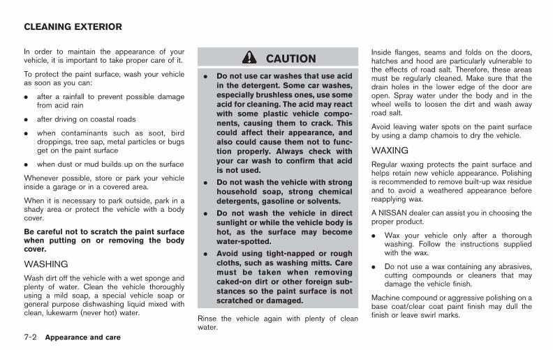
Black plate (392,1)
Model "E52-D" EDITED: 2010/ 10/ 25
In order to maintain the appearance of yourvehicle, it is important to take proper care of it.
To protect the paint surface, wash your vehicleas soon as you can:
. after a rainfall to prevent possible damagefrom acid rain
. after driving on coastal roads
. when contaminants such as soot, birddroppings, tree sap, metal particles or bugsget on the paint surface
. when dust or mud builds up on the surface
Whenever possible, store or park your vehicleinside a garage or in a covered area.
When it is necessary to park outside, park in ashady area or protect the vehicle with a bodycover.
Be careful not to scratch the paint surfacewhen putting on or removing the bodycover.
WASHING
Wash dirt off the vehicle with a wet sponge andplenty of water. Clean the vehicle thoroughlyusing a mild soap, a special vehicle soap orgeneral purpose dishwashing liquid mixed withclean, lukewarm (never hot) water.
CAUTION
. Do not use car washes that use acidin the detergent. Some car washes,especially brushless ones, use someacid for cleaning. The acid may reactwith some plastic vehicle compo-nents, causing them to crack. Thiscould affect their appearance, andalso could cause them not to func-tion properly. Always check withyour car wash to confirm that acidis not used.
. Do not wash the vehicle with stronghousehold soap, strong chemicaldetergents, gasoline or solvents.
. Do not wash the vehicle in directsunlight or while the vehicle body ishot, as the surface may becomewater-spotted.
. Avoid using tight-napped or roughcloths, such as washing mitts. Caremust be taken when removingcaked-on dirt or other foreign sub-stances so the paint surface is notscratched or damaged.
Rinse the vehicle again with plenty of cleanwater.
Inside flanges, seams and folds on the doors,hatches and hood are particularly vulnerable tothe effects of road salt. Therefore, these areasmust be regularly cleaned. Make sure that thedrain holes in the lower edge of the door areopen. Spray water under the body and in thewheel wells to loosen the dirt and wash awayroad salt.
Avoid leaving water spots on the paint surfaceby using a damp chamois to dry the vehicle.
WAXING
Regular waxing protects the paint surface andhelps retain new vehicle appearance. Polishingis recommended to remove built-up wax residueand to avoid a weathered appearance beforereapplying wax.
A NISSAN dealer can assist you in choosing theproper product.
. Wax your vehicle only after a thoroughwashing. Follow the instructions suppliedwith the wax.
. Do not use a wax containing any abrasives,cutting compounds or cleaners that maydamage the vehicle finish.
Machine compound or aggressive polishing on abase coat/clear coat paint finish may dull thefinish or leave swirl marks.
CLEANING EXTERIOR
7-2 Appearance and care

Black plate (393,1)
Model "E52-D" EDITED: 2010/ 10/ 25
REMOVING SPOTS
Remove tar and oil spots, industrial dust,insects, and tree sap as quickly as possiblefrom the paint surface to avoid lasting damageor staining. Special cleaning products areavailable at a NISSAN dealer or any automotiveaccessory stores.
UNDERBODY
In areas where road salt is used in winter, theunderbody must be cleaned regularly. This willprevent dirt and salt from building up andcausing the acceleration of corrosion on theunderbody and suspension. Before the winterperiod and again in the spring, the undersealmust be checked and, if necessary, re-treated.
GLASS
Use glass cleaner to remove smoke and dustfilm from the glass surfaces. It is normal for glassto become coated with a film after the vehicle isparked in the hot sun. Glass cleaner and a softcloth will easily remove this film.
CAUTION
When cleaning the inside of the win-dows, do not use sharp-edged tools,abrasive cleaners or chlorine-baseddisinfectant cleaners. They could da-
mage the electrical conductors, radioantenna elements or rear windowdefroster elements.
WHEELS
Wash the wheels when washing the vehicle tomaintain their appearance.
. Clean the inner side of the wheels when thewheel is changed or the underside of thevehicle is washed.
. Inspect wheel rims regularly for dents orcorrosion. Such damage may cause loss ofpressure or poor seal at the tire bead.
. NISSAN recommends that the road wheelsbe waxed to protect against road salt inareas where it is used during winter.
CAUTION
Do not use abrasive cleaners whenwashing the wheels.
Aluminum alloy wheelsWash regularly with a sponge dampened in amild soap solution, especially during wintermonths in areas where road salt is used. Saltcould discolor the wheels if not removed.
CAUTION
Follow the directions below to avoidstaining or discoloring the wheels:
. Do not use a cleaner that usesstrong acid or alkali contents toclean the wheels.
. Do not apply wheel cleaners to thewheels when they are hot. Thewheel temperature should be thesame as ambient temperature.
. Rinse the wheel to completely re-move the cleaner within 15 minutesafter the cleaner is applied.
CHROME PARTS
Clean chrome parts regularly with a non-abrasive chrome polish to maintain the finish.
TIRE DRESSING
NISSAN does not recommend the use of tiredressings. Tire manufacturers apply a coating tothe tires to help reduce discoloration of therubber. If a tire dressing is applied to the tires, itmay react with the coating and form a com-pound. This compound may come off the tirewhile driving and stain the vehicle paint.
If you choose to use a tire dressing, take the
Appearance and care 7-3

Black plate (394,1)
Model "E52-D" EDITED: 2010/ 10/ 25
following precautions:
. Use a water-based tire dressing. The coat-ing on the tire dissolves more easily with anoil-based tire dressing.
. Apply a light coat of tire dressing to helpprevent it from entering the tire tread/grooves (where it would be difficult toremove).
. Wipe off excess tire dressing using a drytowel. Make sure the tire dressing iscompletely removed from the tire tread/grooves.
. Allow the tire dressing to dry as recom-mended by tire dressing manufacturer.
Occasionally remove loose dust from the interiortrim, plastic parts and seats using a vacuumcleaner or soft bristled brush. Wipe the vinyl andleather surfaces with a clean, soft cloth dam-pened in mild soap solution, then wipe cleanwith a dry soft cloth.
Regular care and cleaning is required in order tomaintain the appearance of the leather.
Before using any fabric protector, read themanufacturer’s recommendations. Some fabricprotectors contain chemicals that may stain orbleach the seat material.
Use a cloth dampened only with water, to cleanthe meter and gauge lens.
WARNING
Do not use water or acidic cleaners (hotsteam cleaners) on the seat. This candamage the seat or occupant classifica-tion sensor. This can also affect theoperation of the air bag system andresult in serious personal injury.
CAUTION
. Never use benzine, thinner, or anysimilar material.
. Small dirt particles can be abrasive
and damaging to the leather sur-faces and should be removedpromptly. Do not use saddle soap,car waxes, polishes, oils, cleaningfluids, solvents, detergents or am-monia-based cleaners as they maydamage the leather’s natural finish.
. Never use fabric protectors unlessrecommended by the manufacturer.
. Do not use glass or plastic cleaneron meter or gauge lens covers. Itmay damage the lens cover.
AIR FRESHENERS
Most air fresheners use a solvent that couldaffect the vehicle interior. If you use an airfreshener, take the following precautions:
. Hanging-type air fresheners can causepermanent discoloration when they contactvehicle interior surfaces. Place the airfreshener in a location that allows it to hangfree and not contact an interior surface.
. Liquid-type air fresheners typically clip onthe ventilators. These products can causeimmediate damage and discoloration whenspilled on interior surfaces.
Carefully read and follow the manufacturer’sinstructions before using air fresheners.
CLEANING INTERIOR
7-4 Appearance and care

Black plate (395,1)
Model "E52-D" EDITED: 2010/ 10/ 25
FLOOR MATS
WARNING
To avoid potential pedal interferencethat may result in a collision or injury:
. NEVER place a floor mat on top ofanother floor mat in the driver frontposition.
. Use only genuine NISSAN floormats specifically designed for usein your vehicle model. See yourNISSAN dealer for more informa-tion.
. Properly position the mats in thefloorwell using the floor mat posi-tioning aid. See “Floor mat posi-tioning aid” later in this section.
The use of genuine NISSAN floor mats canextend the life of your vehicle carpet and make iteasier to clean the interior. Mats should bemaintained with regular cleaning and replaced ifthey become excessively worn.
SAI0038Front (example)
Floor mat positioning aidThis vehicle includes front floor mat brackets toact as floor mat positioning aid. NISSAN floormats have been specially designed for yourvehicle model. The front floor mats havegrommet holes in them. Position the mat byplacing the floor mat bracket hook through thefloor mat grommet hole while centering the matin the floorwell.
Periodically check to make certain that the matsare properly positioned.
SAI0058Bracket positions
The illustration shows the location of the floormat brackets.
Appearance and care 7-5

Black plate (396,1)
Model "E52-D" EDITED: 2010/ 10/ 25
SEAT BELTS
The seat belts can be cleaned by wiping themwith a sponge dampened in a mild soapsolution. Allow the belts to dry completely beforeusing them.
See “SEAT BELTS” in the “1. Safety — Seats,seat belts and supplemental restraint system”section.
WARNING
Do not allow wet seat belts to roll up inthe retractor. NEVER use bleach, dye, orchemical solvents to clean the seatbelts, since these materials may se-verely weaken the seat belt webbing.
MOST COMMON FACTORS CONTRI-BUTING TO VEHICLE CORROSION
. The accumulation of moisture-retaining dirtand debris in body panel sections, cavities,and other areas.
. Damage to paint and other protective coat-ings caused by gravel and stone chips orminor traffic accidents.
ENVIRONMENTAL FACTORS INFLU-ENCE THE RATE OF CORROSION
MoistureAccumulation of sand, dirt and water on thevehicle body underside can accelerate corro-sion. Wet floor coverings will not dry completelyinside the vehicle, and should be removed fordrying to avoid floor panel corrosion.
Relative humidityCorrosion will be accelerated in areas of highrelative humidity, especially those areas wherethe temperatures stay above freezing whereatmospheric pollution exists, or where road saltis used.
TemperatureA temperature increase will accelerate the rateof corrosion to those parts which are not wellventilated.
Air pollutionIndustrial pollution, the presence of salt in the airin coastal areas, or heavy road salt use willaccelerate the corrosion process. Road salt willalso accelerate the disintegration of paintsurfaces.
TO PROTECT YOUR VEHICLE FROMCORROSION
. Wash and wax your vehicle often to keep thevehicle clean.
. Always check for minor damage to the paintand repair it as soon as possible.
. Keep drain holes at the bottom of the doorsopen to avoid water accumulation.
. Check the underbody for accumulation ofsand, dirt or salt. If present, wash with wateras soon as possible.
CAUTION
. NEVER remove dirt, sand or otherdebris from the passenger compart-ment by washing it out with a hose.Remove dirt with a vacuum cleaner.
. Never allow water or other liquids tocome in contact with electroniccomponents inside the vehicle as
CORROSION PROTECTION
7-6 Appearance and care

Black plate (397,1)
Model "E52-D" EDITED: 2010/ 10/ 25
this may damage them.
Chemicals used for road surface deicing areextremely corrosive. They accelerate corrosionand deterioration of underbody componentssuch as the exhaust system, fuel and brakelines, brake cables, floor pan and fenders.
In winter, the underbody must be cleanedperiodically.
For additional protection against rust andcorrosion, which may be required in some areas,consult a NISSAN dealer.
Appearance and care 7-7

Black plate (398,1)
Model "E52-D" EDITED: 2010/ 10/ 25
MEMO
7-8 Appearance and care

Black plate (25,1)
8 Maintenance and do-it-yourself
Model "E52-D" EDITED: 2010/ 10/ 22
Maintenance requirement . . . . . . . . . . . . . . . . . . . . . . . . . . . . . . . . . . . . . 8-2Scheduled maintenance. . . . . . . . . . . . . . . . . . . . . . . . . . . . . . . . . . . 8-2General maintenance . . . . . . . . . . . . . . . . . . . . . . . . . . . . . . . . . . . . . . 8-2Where to go for service. . . . . . . . . . . . . . . . . . . . . . . . . . . . . . . . . . . 8-2
General maintenance . . . . . . . . . . . . . . . . . . . . . . . . . . . . . . . . . . . . . . . . . . 8-2Explanation of maintenance items. . . . . . . . . . . . . . . . . . . . . . . 8-2
Maintenance precautions . . . . . . . . . . . . . . . . . . . . . . . . . . . . . . . . . . . . . 8-5Engine compartment check locations . . . . . . . . . . . . . . . . . . . . . . 8-6
VQ35DE engine . . . . . . . . . . . . . . . . . . . . . . . . . . . . . . . . . . . . . . . . . . . . 8-6Engine cooling system. . . . . . . . . . . . . . . . . . . . . . . . . . . . . . . . . . . . . . . . . 8-7
Checking engine coolant level . . . . . . . . . . . . . . . . . . . . . . . . . . . 8-8Changing engine coolant . . . . . . . . . . . . . . . . . . . . . . . . . . . . . . . . . 8-8
Engine oil . . . . . . . . . . . . . . . . . . . . . . . . . . . . . . . . . . . . . . . . . . . . . . . . . . . . . . . . . 8-8Checking engine oil level . . . . . . . . . . . . . . . . . . . . . . . . . . . . . . . . . 8-8Changing engine oil and filter. . . . . . . . . . . . . . . . . . . . . . . . . . . . 8-9
Continuously Variable Transmission (CVT) fluid. . . . . . . . 8-11Power steering fluid . . . . . . . . . . . . . . . . . . . . . . . . . . . . . . . . . . . . . . . . . . 8-11Brake fluid . . . . . . . . . . . . . . . . . . . . . . . . . . . . . . . . . . . . . . . . . . . . . . . . . . . . . . 8-12Window washer fluid . . . . . . . . . . . . . . . . . . . . . . . . . . . . . . . . . . . . . . . . 8-13Battery . . . . . . . . . . . . . . . . . . . . . . . . . . . . . . . . . . . . . . . . . . . . . . . . . . . . . . . . . . 8-13
Jump starting . . . . . . . . . . . . . . . . . . . . . . . . . . . . . . . . . . . . . . . . . . . . . . 8-15Variable voltage control system. . . . . . . . . . . . . . . . . . . . . . . . . . . . 8-15Drive belt . . . . . . . . . . . . . . . . . . . . . . . . . . . . . . . . . . . . . . . . . . . . . . . . . . . . . . . 8-15
Spark plugs . . . . . . . . . . . . . . . . . . . . . . . . . . . . . . . . . . . . . . . . . . . . . . . . . . . . 8-16Replacing spark plugs . . . . . . . . . . . . . . . . . . . . . . . . . . . . . . . . . . . 8-16
Air cleaner. . . . . . . . . . . . . . . . . . . . . . . . . . . . . . . . . . . . . . . . . . . . . . . . . . . . . . 8-17Windshield wiper blades. . . . . . . . . . . . . . . . . . . . . . . . . . . . . . . . . . . . 8-17
Cleaning . . . . . . . . . . . . . . . . . . . . . . . . . . . . . . . . . . . . . . . . . . . . . . . . . . . . 8-17Replacing. . . . . . . . . . . . . . . . . . . . . . . . . . . . . . . . . . . . . . . . . . . . . . . . . . . 8-18
Rear window wiper blade. . . . . . . . . . . . . . . . . . . . . . . . . . . . . . . . . . . 8-19Brakes. . . . . . . . . . . . . . . . . . . . . . . . . . . . . . . . . . . . . . . . . . . . . . . . . . . . . . . . . . . 8-19
Self-adjusting brakes . . . . . . . . . . . . . . . . . . . . . . . . . . . . . . . . . . . . 8-19Brake pad wear warning . . . . . . . . . . . . . . . . . . . . . . . . . . . . . . . . 8-19
Fuses . . . . . . . . . . . . . . . . . . . . . . . . . . . . . . . . . . . . . . . . . . . . . . . . . . . . . . . . . . . . 8-20Engine compartment . . . . . . . . . . . . . . . . . . . . . . . . . . . . . . . . . . . . . 8-20Passenger compartment . . . . . . . . . . . . . . . . . . . . . . . . . . . . . . . . 8-21
Intelligent Key battery replacement . . . . . . . . . . . . . . . . . . . . . . . 8-22Lights. . . . . . . . . . . . . . . . . . . . . . . . . . . . . . . . . . . . . . . . . . . . . . . . . . . . . . . . . . . . 8-24
Headlights . . . . . . . . . . . . . . . . . . . . . . . . . . . . . . . . . . . . . . . . . . . . . . . . . . 8-25Exterior and interior lights. . . . . . . . . . . . . . . . . . . . . . . . . . . . . . . 8-26
Wheels and tires. . . . . . . . . . . . . . . . . . . . . . . . . . . . . . . . . . . . . . . . . . . . . . 8-29Tire pressure. . . . . . . . . . . . . . . . . . . . . . . . . . . . . . . . . . . . . . . . . . . . . . . 8-29Tire labeling . . . . . . . . . . . . . . . . . . . . . . . . . . . . . . . . . . . . . . . . . . . . . . . . 8-32Types of tires . . . . . . . . . . . . . . . . . . . . . . . . . . . . . . . . . . . . . . . . . . . . . . 8-34Tire chains. . . . . . . . . . . . . . . . . . . . . . . . . . . . . . . . . . . . . . . . . . . . . . . . . . 8-35Changing wheels and tires . . . . . . . . . . . . . . . . . . . . . . . . . . . . . 8-35

Black plate (400,1)
Model "E52-D" EDITED: 2010/ 10/ 25
Your new NISSAN has been designed to haveminimum maintenance requirements with longservice intervals to save you both time andmoney. However, some day-to-day and regularmaintenance is essential to maintain yourNISSAN’s fine mechanical condition, as wellas its emission and engine performance.
It is the owner’s responsibility to make sure thatthe scheduled maintenance, as well as generalmaintenance, is performed.
As the vehicle owner, you are the only one whocan ensure that your vehicle receives the propermaintenance. You are a vital link in the main-tenance chain.
SCHEDULED MAINTENANCE
For your convenience, both required and op-tional scheduled maintenance items are de-scribed and listed in your “NISSAN Service andMaintenance Guide”. You must refer to thatguide to ensure that necessary maintenance isperformed on your NISSAN at regular intervals.
GENERAL MAINTENANCE
General maintenance includes those itemswhich should be checked during normal day-to-day operation. They are essential for propervehicle operation. It is your responsibility toperform these procedures regularly as pre-scribed.
Performing general maintenance checks re-quires minimal mechanical skill and only a fewgeneral automotive tools.
These checks or inspections can be done byyourself, a qualified technician or, if you prefer, aNISSAN dealer.
WHERE TO GO FOR SERVICE
If maintenance service is required or your vehicleappears to malfunction, have the systemschecked and serviced by a NISSAN dealer.
NISSAN technicians are well-trained specialistsand are kept up-to-date with the latest serviceinformation through technical bulletins, servicetips, and in-dealership information systems.They are completely qualified to work onNISSAN vehicles before work begins.
You can be confident that a NISSAN dealer’sservice department performs the best job tomeet the maintenance requirements on yourvehicle — in a reliable and economical way.
During the normal day-to-day operation of thevehicle, general maintenance should be per-formed regularly as prescribed in this section. Ifyou detect any unusual sounds, vibrations orsmell, be sure to check for the cause or have aNISSAN dealer do it promptly. In addition, youshould notify a NISSAN dealer if you think thatrepairs are required.
When performing any checks or maintenancework, see “MAINTENANCE PRECAUTIONS”later in this section.
EXPLANATION OF MAINTENANCEITEMS
Additional information on the followingitems with “*” is found later in this section.
Outside the vehicleThe maintenance items listed here should beperformed from time to time, unless otherwisespecified.
Doors and engine hood: Check that all doorsand the engine hood operate properly. Alsoensure that all latches lock securely. Lubricatehinges, latches, latch pins, rollers and links ifnecessary. Make sure that the secondary latchkeeps the hood from opening when the primarylatch is released.
When driving in areas using road salt or othercorrosive materials, check lubrication frequently.
MAINTENANCE REQUIREMENT GENERAL MAINTENANCE
8-2 Maintenance and do-it-yourself

Black plate (401,1)
Model "E52-D" EDITED: 2010/ 10/ 25
Lights*: Clean the headlights on a regular basis.Make sure that the headlights, stop lights, taillights, turn signal lights, and other lights are alloperating properly and installed securely. Alsocheck headlight aim.
Road wheel nuts (lug nuts)*: When checkingthe tires, make sure no wheel nuts are missing,and check for any loose wheel nuts. Tighten ifnecessary.
Tire rotation*: Tires should be rotated every7,500 miles (12,000 km).
Tires*: Check the pressure with a gauge oftenand always prior to long distance trips. Ifnecessary, adjust the pressure in all tires,including the spare, to the pressure specified.Check carefully for damage, cuts or excessivewear.
Tire Pressure Monitoring System (TPMS)transmitter components: Replace the TPMStransmitter grommet seal, valve core and capwhen the tires are replaced due to wear or age.
Wheel alignment and balance: If the vehicleshould pull to either side while driving on astraight and level road, or if you detect uneven orabnormal tire wear, there may be a need forwheel alignment.
If the steering wheel or seat vibrates at normalhighway speeds, wheel balancing may beneeded.
For additional information regarding tires, referto “Important Tire Safety Information” (US) or“Tire Safety Information” (Canada) in the War-ranty Information Booklet.
Windshield: Clean the windshield on a regularbasis. Check the windshield at least every sixmonths for cracks or other damage. Have adamaged windshield repaired by a qualifiedrepair facility.
Windshield wiper blades*: Check for cracksor wear if they do not wipe properly.
Inside the vehicleThe maintenance items listed here should bechecked on a regular basis, such as whenperforming scheduled maintenance, cleaningthe vehicle, etc.
Accelerator pedal: Check the pedal forsmooth operation and make sure the pedaldoes not catch or require uneven effort. Keepthe floor mat away from the pedal.
Brake pedal: Check the pedal for smoothoperation. If the brake pedal suddenly goesdown further than normal, the pedal feelsspongy or the vehicle seems to take longer tostop, see a NISSAN dealer immediately. Keepthe floor mat away from the pedal.
Brakes: Check that the brakes do not pull thevehicle to one side when applied.
Continuously Variable Transmission (CVT)P (Park) position mechanism: On a fairlysteep hill, check that the vehicle is held securelywith the selector lever in the P (Park) positionwithout applying any brakes.
Parking brake: Check the parking brakeoperation regularly. The vehicle should besecurely held on a fairly steep hill with only theparking brake applied. If the parking brake needsadjustment, see a NISSAN dealer.
Seat belts: Check that all parts of the seat beltsystem (for example, buckles, anchors, adjustersand retractors) operate properly and smoothly,and are installed securely. Check the beltwebbing for cuts, fraying, wear or damage.
Seats: Check seat position controls such asseat adjusters, seatback recliner, etc. to ensurethey operate smoothly and that all latches locksecurely in every position. Check that the headrestraints/headrests move up and downsmoothly and that the locks (if so equipped)hold securely in all latched positions.
Steering wheel: Check for changes in thesteering conditions, such as excessive free play,hard steering or strange noises.
Warning lights and chimes: Make sure thatall warning lights and chimes are operatingproperly.
Maintenance and do-it-yourself 8-3

Black plate (402,1)
Model "E52-D" EDITED: 2010/ 10/ 25
Windshield defroster: Check that the aircomes out of the defroster outlets properly andin sufficient quantity when operating the heateror air conditioner.
Windshield wiper and washer*: Check thatthe wipers and washer operate properly and thatthe wipers do not streak.
Under the hood and vehicleThe maintenance items listed here should bechecked periodically (for example, each time youcheck the engine oil or refuel).
Battery*: Check the fluid level in each cell.It should be between the MAX and MIN lines.Vehicles operated in high temperatures or undersevere condition require frequent checks of thebattery fluid level.
Brake fluid level*: Make sure that the brakefluid level is between the MAX and MIN lines onthe reservoir.
Engine coolant level*: Check the coolant levelwhen the engine is cold.
Engine drive belts*: Make sure that the drivebelts are not frayed, worn, cracked or oily.
Engine oil level*: Check the level after parkingthe vehicle on a level surface and turning off theengine. Wait more than 10 minutes for the oil todrain back into the oil pan.
Exhaust system: Make sure there are no loosesupports, cracks or holes. If the sound of theexhaust seems unusual or there is a smell ofexhaust fumes, immediately have the exhaustsystem inspected by a NISSAN dealer. (See“PRECAUTIONS WHEN STARTING ANDDRIVING” in the “5. Starting and driving”section for exhaust gas (carbon monoxide).)
Fluid leaks: Check under the vehicle for fuel,oil, water or other fluid leaks after the vehicle hasbeen parked for a while. Water dripping from theair conditioner after use is normal. If you shouldnotice any leaks or if gasoline fumes are evident,check for the cause and have it correctedimmediately.
Power steering fluid level* and lines: Checkthe level when the fluid is cold, with the engineoff. Check the lines for proper attachment, leaks,cracks, etc.
Radiator and hoses: Check the front of theradiator and clean off any dirt, insects, leaves,etc., that may have accumulated. Make sure thehoses have no cracks, deformation, rot or looseconnections.
Underbody: The underbody is frequently ex-posed to corrosive substances such as thoseused on icy roads or to control dust. It is veryimportant to remove these substances, other-wise rust will form on the floor pan, frame, fuellines and around the exhaust system. At the end
of winter, the underbody should be thoroughlyflushed with plain water, being careful to cleanthose areas where mud and dirt may accumu-late. For additional information, see “CLEANINGEXTERIOR” in the “7. Appearance and care”section.
Windshield washer fluid*: Check that there isadequate fluid in the reservoir.
8-4 Maintenance and do-it-yourself
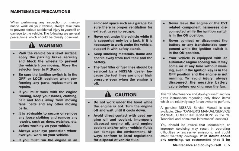
Black plate (403,1)
Model "E52-D" EDITED: 2010/ 10/ 25
When performing any inspection or mainte-nance work on your vehicle, always take careto prevent serious accidental injury to yourself ordamage to the vehicle. The following are generalprecautions which should be closely observed.
WARNING
. Park the vehicle on a level surface,apply the parking brake securelyand block the wheels to preventthe vehicle from moving. Move theselector lever to P (Park).
. Be sure the ignition switch is in theOFF or LOCK position when per-forming any parts replacement orrepairs.
. If you must work with the enginerunning, keep your hands, clothing,hair and tools away from movingfans, belts and any other movingparts.
. It is advisable to secure or removeany loose clothing and remove anyjewelry, such as rings, watches, etc.before working on your vehicle.
. Always wear eye protection when-ever you work on your vehicle.
. If you must run the engine in an
enclosed space such as a garage, besure there is proper ventilation forexhaust gases to escape.
. Never get under the vehicle while itis supported only by a jack. If it isnecessary to work under the vehicle,support it with safety stands.
. Keep smoking materials, flame andsparks away from fuel tank and thebattery.
. The fuel filter or fuel lines should beserviced by a NISSAN dealer be-cause the fuel lines are under highpressure even when the engine isoff.
CAUTION
. Do not work under the hood whilethe engine is hot. Turn the engineoff and wait until it cools down.
. Avoid direct contact with used en-gine oil and coolant. Improperlydisposed engine oil, and enginecoolant and/or other vehicle fluidscan damage the environment. Al-ways conform to local regulationsfor disposal of vehicle fluid.
. Never leave the engine or the CVTrelated component harnesses dis-connected while the ignition switchis in the ON position.
. Never connect or disconnect thebattery or any transistorized com-ponent while the ignition switch isin the ON position.
. Your vehicle is equipped with anautomatic engine cooling fan. It maycome on at any time without warn-ing, even if the ignition key is in theOFF position and the engine is notrunning. To avoid injury, alwaysdisconnect the negative batterycable before working near the fan.
This “8. Maintenance and do-it-yourself” sectiongives instructions regarding only those itemswhich are relatively easy for an owner to perform.
A genuine NISSAN Service Manual is alsoavailable. (See “OWNER’S MANUAL/SERVICEMANUAL ORDER INFORMATION” in the “9.Technical and consumer information” section.)
You should be aware that incomplete orimproper servicing may result in operatingdifficulties or excessive emissions, and couldaffect warranty coverage. If in doubt aboutany servicing, we recommend that it be
MAINTENANCE PRECAUTIONS
Maintenance and do-it-yourself 8-5
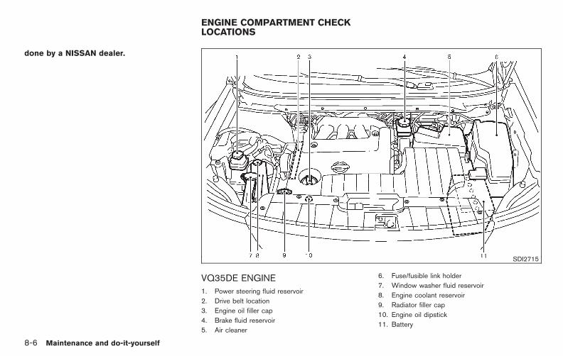
Black plate (404,1)
Model "E52-D" EDITED: 2010/ 10/ 25
done by a NISSAN dealer.
SDI2715
VQ35DE ENGINE1. Power steering fluid reservoir
2. Drive belt location
3. Engine oil filler cap
4. Brake fluid reservoir
5. Air cleaner
6. Fuse/fusible link holder
7. Window washer fluid reservoir
8. Engine coolant reservoir
9. Radiator filler cap
10. Engine oil dipstick
11. Battery
ENGINE COMPARTMENT CHECKLOCATIONS
8-6 Maintenance and do-it-yourself

Black plate (405,1)
Model "E52-D" EDITED: 2010/ 10/ 25
The engine cooling system is filled at the factorywith a pre-diluted mixture of 50% GenuineNISSAN Long Life Antifreeze/Coolant (blue) and50% water to provide year-round anti-freezeand coolant protection. The anti-freeze solutioncontains rust and corrosion inhibitors. Additionalengine cooling system additives are not neces-sary.
WARNING
. Never remove the radiator or cool-ant reservoir cap when the engine ishot. Wait until the engine andradiator cool down. Serious burnscould be caused by high pressurefluid escaping from the radiator.See precautions in “IF YOUR VEHI-CLE OVERHEATS” in the “6. In caseof emergency” section of this man-ual.
. The radiator is equipped with apressure type radiator cap. To pre-vent engine damage, use only agenuine NISSAN radiator cap.
CAUTION
. When adding or replacing coolant,be sure to use only Genuine
NISSAN Long Life Antifreeze/Cool-ant (blue) or equivalent. GenuineNISSAN Long Life Antifreeze/Cool-ant (blue) is pre-diluted to provideantifreeze protection to −348F(−378C). If additional freeze protec-tion is needed due to weather whereyou operate your vehicle, add Gen-uine NISSAN Long Life Antifreeze/Coolant (blue) concentrate follow-ing the directions on the container.If an equivalent coolant other thanGenuine NISSAN Long Life Anti-freeze/Coolant (blue) is used, fol-low the coolant manufacture’sinstructions to maintain minimumantifreeze protection to −348F(−378C). The use of other types ofcoolant solutions other than Genu-ine NISSAN Long Life Antifreeze/Coolant (blue) or equivalent maydamage the engine cooling system.
. The life expectancy of the factory-fillcoolant is 105,000 miles (168,000km) or 7 years. Mixing any othertype of coolant other than GenuineNISSAN Long Life Antifreeze/Cool-ant (blue) , including GenuineNISSAN Long Life Antifreeze/Cool-
ant (green), or the use of non-distilled water will reduce the lifeexpectancy of the factory-fill cool-ant. Refer to the NISSAN Serviceand Maintenance Guide for moredetails.
ENGINE COOLING SYSTEM
Maintenance and do-it-yourself 8-7

Black plate (406,1)
Model "E52-D" EDITED: 2010/ 10/ 25
SDI2691
CHECKING ENGINE COOLANT LEVEL
Check the coolant level in the reservoir whenthe engine is cold. If the coolant level is belowthe MIN level *2 , open the reservoir cap andadd coolant up to the MAX level *1 . If thereservoir is empty, check the coolant level in theradiator when the engine is cold. If there isinsufficient coolant in the radiator, fill the radiatorwith coolant up to the filler opening and also addit to the reservoir up to the MAX level *1 .
If the cooling system frequently requirescoolant, have it checked by a NISSANdealer.
CHANGING ENGINE COOLANT
Major cooling system repairs should be per-formed by a NISSAN dealer. The serviceprocedures can be found in the appropriateNISSAN Service Manual.
Improper servicing can result in reducedheater performance and engine overheat-ing.
WARNING
. To avoid the danger of beingscalded, never change the coolantwhen the engine is hot.
. Never remove the radiator cap whenthe engine is hot. Serious burnscould be caused by high pressurefluid escaping from the radiator.
. Avoid direct skin contact with usedcoolant. If skin contact is made,wash thoroughly with soap or handcleaner as soon as possible.
. Keep coolant out of reach of chil-dren and pets.
Engine coolant must be disposed of properly.Check your local regulations.
SDI2174
CHECKING ENGINE OIL LEVEL
1. Park the vehicle on a level surface and applythe parking brake.
2. Run the engine until it reaches operatingtemperature.
3. Turn off the engine. Wait more than 10minutes for the oil to drain back intothe oil pan.
4. Remove the dipstick and wipe it clean.Reinsert it all the way.
5. Remove the dipstick again and check the oillevel. It should be within the range*1 . If theoil level is below*2 , remove the oil filler cap
ENGINE OIL
8-8 Maintenance and do-it-yourself

Black plate (407,1)
Model "E52-D" EDITED: 2010/ 10/ 25
and pour recommended oil through theopening. Do not overfill *3 .
6. Recheck oil level with the dipstick.
It is normal to add some oil between oilmaintenance intervals or during the break-in period, depending on the severity ofoperating conditions.
CAUTION
Oil level should be checked regularly.Operating the engine with an insuffi-cient amount of oil can damage theengine, and such damage is not cov-ered by the warranty.
CHANGING ENGINE OIL AND FILTER
Change the engine oil and filter according to themaintenance log shown in the NISSAN Serviceand Maintenance Guide.
Vehicle set-up1. Park the vehicle on a level surface and apply
the parking brake.
2. Start the engine and let it idle until it reachesoperating temperature.
3. Turn the engine off and wait more than 10minutes.
4. Raise and support the vehicle using asuitable floor jack and safety jack stands.
. Place the safety jack stands under thevehicle jack-up points.
. A suitable adapter should be attached tothe jack stand saddle.
CAUTION
Make sure the correct lifting and sup-port points are used to avoid vehicledamage.
SDI2175
Maintenance and do-it-yourself 8-9
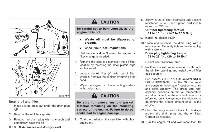
Black plate (408,1)
Model "E52-D" EDITED: 2010/ 10/ 25
SDI2717
Engine oil and filter1. Place a large drain pan under the drain plug
*A .
2. Remove the oil filler cap *B .
3. Remove the drain plug with a wrench andcompletely drain the oil.
CAUTION
Be careful not to burn yourself, as theengine oil is hot.
. Waste oil must be disposed ofproperly.
. Check your local regulations.
Perform steps 4 to 9 when the engine oilfilter change is needed.
4. Remove the plastic cover over the oil filterlocation by removing the small plastic clipsas illustrated.
5. Loosen the oil filter *C with an oil filterwrench. Remove the oil filter by turning it byhand.
6. Wipe the engine oil filter mounting surfacewith a clean rag.
CAUTION
Be sure to remove any old gasketmaterial remaining on the mountingsurface of the engine. Failure to do socould lead to engine damage.
7. Coat the gasket on the new filter with cleanengine oil.
8. Screw in the oil filter clockwise until a slightresistance is felt, then tighten additionallymore than 2/3 turn.Oil filter tightening torque:11 to 15 ft-lb (14.7 to 20.5 N·m)
9. Install the plastic cover.
10. Clean and re-install the drain plug with anew washer. Securely tighten the drain plugwith a wrench.Drain plug tightening torque:22 to 29 ft-lb (29 to 39 N·m)
Do not use excessive force.
11. Refill engine with recommended oil throughthe oil filler opening, and install the oil fillercap securely.
See “CAPACITIES AND RECOMMENDEDFUEL/LUBRICANTS” in the “9. Technicaland consumer information” section for drainand refill capacity. The drain and refillcapacity depends on the oil temperatureand drain time. Use these specifications forreference only. Always use the dipstick todetermine the proper amount of oil in theengine.
12. Start the engine and check for leakagearound the drain plug and the oil filter.Correct as required.
13. Turn the engine off and wait more than 10
8-10 Maintenance and do-it-yourself
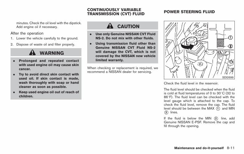
Black plate (409,1)
Model "E52-D" EDITED: 2010/ 10/ 25
minutes. Check the oil level with the dipstick.Add engine oil if necessary.
After the operation1. Lower the vehicle carefully to the ground.
2. Dispose of waste oil and filter properly.
WARNING
. Prolonged and repeated contactwith used engine oil may cause skincancer.
. Try to avoid direct skin contact withused oil. If skin contact is made,wash thoroughly with soap or handcleaner as soon as possible.
. Keep used engine oil out of reach ofchildren.
CAUTION
. Use only Genuine NISSAN CVT FluidNS-2. Do not mix with other fluids.
. Using transmission fluid other thanGenuine NISSAN CVT Fluid NS-2will damage the CVT, which is notcovered by the NISSAN new vehiclelimited warranty.
When checking or replacement is required, werecommend a NISSAN dealer for servicing.
SDI2699
Check the fluid level in the reservoir.
The fluid level should be checked when the fluidis cold at fluid temperatures of 0 to 308C (32 to868F). The fluid level can be checked with thelevel gauge which is attached to the cap. Tocheck the fluid level, remove the cap. The fluidlevel should be between the MAX *1 and MIN*2 lines.
If the fluid is below the MIN *2 line, addGenuine NISSAN E-PSF. Remove the cap andfill through the opening.
CONTINUOUSLY VARIABLETRANSMISSION (CVT) FLUID POWER STEERING FLUID
Maintenance and do-it-yourself 8-11
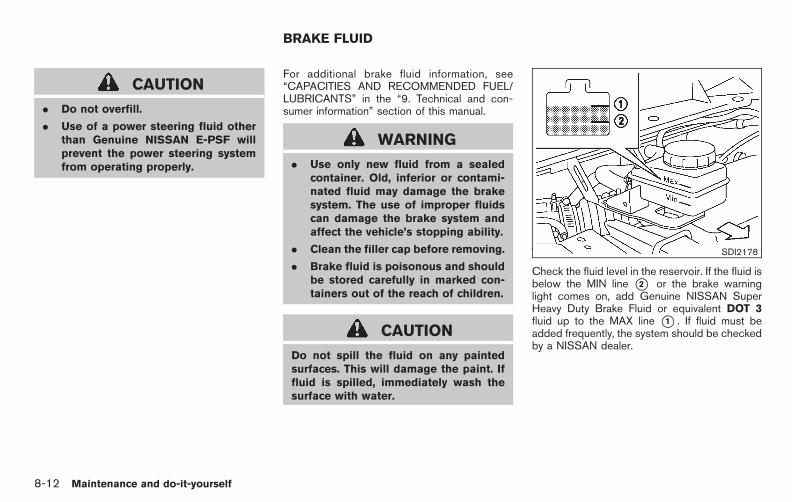
Black plate (410,1)
Model "E52-D" EDITED: 2010/ 10/ 25
CAUTION
. Do not overfill.
. Use of a power steering fluid otherthan Genuine NISSAN E-PSF willprevent the power steering systemfrom operating properly.
For additional brake fluid information, see“CAPACITIES AND RECOMMENDED FUEL/LUBRICANTS” in the “9. Technical and con-sumer information” section of this manual.
WARNING
. Use only new fluid from a sealedcontainer. Old, inferior or contami-nated fluid may damage the brakesystem. The use of improper fluidscan damage the brake system andaffect the vehicle’s stopping ability.
. Clean the filler cap before removing.
. Brake fluid is poisonous and shouldbe stored carefully in marked con-tainers out of the reach of children.
CAUTION
Do not spill the fluid on any paintedsurfaces. This will damage the paint. Iffluid is spilled, immediately wash thesurface with water.
SDI2178
Check the fluid level in the reservoir. If the fluid isbelow the MIN line *2 or the brake warninglight comes on, add Genuine NISSAN SuperHeavy Duty Brake Fluid or equivalent DOT 3fluid up to the MAX line *1 . If fluid must beadded frequently, the system should be checkedby a NISSAN dealer.
BRAKE FLUID
8-12 Maintenance and do-it-yourself
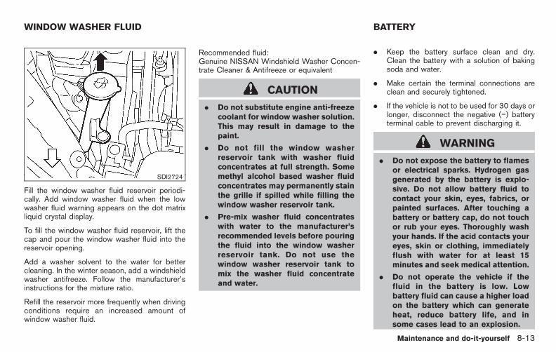
Black plate (411,1)
Model "E52-D" EDITED: 2010/ 10/ 25
SDI2724
Fill the window washer fluid reservoir periodi-cally. Add window washer fluid when the lowwasher fluid warning appears on the dot matrixliquid crystal display.
To fill the window washer fluid reservoir, lift thecap and pour the window washer fluid into thereservoir opening.
Add a washer solvent to the water for bettercleaning. In the winter season, add a windshieldwasher antifreeze. Follow the manufacturer’sinstructions for the mixture ratio.
Refill the reservoir more frequently when drivingconditions require an increased amount ofwindow washer fluid.
Recommended fluid:Genuine NISSAN Windshield Washer Concen-trate Cleaner & Antifreeze or equivalent
CAUTION
. Do not substitute engine anti-freezecoolant for window washer solution.This may result in damage to thepaint.
. Do not fill the window washerreservoir tank with washer fluidconcentrates at full strength. Somemethyl alcohol based washer fluidconcentrates may permanently stainthe grille if spilled while filling thewindow washer reservoir tank.
. Pre-mix washer fluid concentrateswith water to the manufacturer’srecommended levels before pouringthe fluid into the window washerreservoir tank. Do not use thewindow washer reservoir tank tomix the washer fluid concentrateand water.
. Keep the battery surface clean and dry.Clean the battery with a solution of bakingsoda and water.
. Make certain the terminal connections areclean and securely tightened.
. If the vehicle is not to be used for 30 days orlonger, disconnect the negative (−) batteryterminal cable to prevent discharging it.
WARNING
. Do not expose the battery to flamesor electrical sparks. Hydrogen gasgenerated by the battery is explo-sive. Do not allow battery fluid tocontact your skin, eyes, fabrics, orpainted surfaces. After touching abattery or battery cap, do not touchor rub your eyes. Thoroughly washyour hands. If the acid contacts youreyes, skin or clothing, immediatelyflush with water for at least 15minutes and seek medical attention.
. Do not operate the vehicle if thefluid in the battery is low. Lowbattery fluid can cause a higher loadon the battery which can generateheat, reduce battery life, and insome cases lead to an explosion.
WINDOW WASHER FLUID BATTERY
Maintenance and do-it-yourself 8-13

Black plate (412,1)
Model "E52-D" EDITED: 2010/ 10/ 25
. When working on or near a battery,always wear suitable eye protectionand remove all jewelry.
. Battery posts, terminals and relatedaccessories contain lead and leadcompounds. Wash hands afterhandling.
. Keep the battery out of the reach ofchildren.
DI0137MA
Check the fluid level in each cell. (Remove thebattery cover if it is necessary.) It should bebetween the UPPER LEVEL *1 and LOWERLEVEL *2 lines.
If it is necessary to add fluid, add only distilledwater to bring the level to the indicator in eachfiller opening. Do not overfill.
SDI1480C
1. Remove the cell plugs *A .
2. Add distilled water up to the UPPER LEVEL*1 line.
If the side of the battery is not clear, checkthe distilled water level by looking directlyabove the cell; the condition *1 indicatesOK and the conditions *2 needs more tobe added.
3. Tighten cell plugs *A .
Vehicles operated in high temperatures or undersevere conditions require frequent checks of thebattery fluid level.
8-14 Maintenance and do-it-yourself

Black plate (413,1)
Model "E52-D" EDITED: 2010/ 10/ 25
JUMP STARTING
If jump starting is necessary, see “JUMPSTARTING” in the “6. In case of emergency”section. If the engine does not start by jumpstarting, the battery may have to be replaced.Contact a NISSAN dealer.
CAUTION
. Do not ground accessories directlyto the battery terminal. Doing so willbypass the variable voltage controlsystem and the vehicle battery maynot charge completely.
. Use electrical accessories with theengine running to avoid dischargingthe vehicle battery.
The variable voltage control system measuresthe amount of electrical discharge from thebattery and controls voltage generated by thegenerator.
SDI2707
1. Alternator
2. Drive belt auto-tensioner
3. Crankshaft pulley
4. Air conditioner compressor
WARNING
Be sure the ignition switch is in the OFFor LOCK position before servicing drivebelt. The engine could rotate unexpect-edly.
1. Visually inspect the belt for signs of unusualwear, cuts, fraying or looseness. If the belt isin poor condition or loose, have it replacedor adjusted by a NISSAN dealer.
VARIABLE VOLTAGE CONTROLSYSTEM DRIVE BELT
Maintenance and do-it-yourself 8-15

Black plate (414,1)
Model "E52-D" EDITED: 2010/ 10/ 25
2. Have the belt condition checked regularly.WARNING
Be sure the engine and ignition switchare off and that the parking brake isengaged securely.
CAUTION
Be sure to use the correct socket toremove the spark plugs. An incorrectsocket can damage the spark plugs.
SDI2020
REPLACING SPARK PLUGS
If replacement is required, see a NISSAN dealerfor servicing.
Iridium-tipped spark plugsIt is not necessary to replace the platinum-tipped spark plugs as frequently as the conven-tional type spark plugs since they will last muchlonger. Follow the maintenance log shown in the“NISSAN Service and Maintenance Guide”. Donot reuse spark plugs by cleaning or regapping.
Always replace spark plugs with recom-mended or equivalent ones.
SPARK PLUGS
8-16 Maintenance and do-it-yourself

Black plate (415,1)
Model "E52-D" EDITED: 2010/ 10/ 25
SDI2180
Pull the tabs *1 and pull out the cover *2 .
The air cleaner filter should not be cleaned andreused. Replace it according to the maintenancelog shown in the “NISSAN Service and Main-tenance Guide”. When replacing the filter, wipethe inside of the air cleaner housing and thecover with a damp cloth.
WARNING
. Operating the engine with the aircleaner removed can cause you orothers to be burned. The air cleanernot only cleans the air, it stopsflame if the engine backfires. If it
isn’t there, and the engine backfires,you could be burned. Do not drivewith the air cleaner removed, and becareful when working on the enginewith the air cleaner removed.
. Never pour fuel into the throttlebody or attempt to start the enginewith the air cleaner removed. Doingso could result in serious injury.
CLEANING
If your windshield is not clear after using thewindshield washer or if a wiper blade chatterswhen running, wax or other material may be onthe blade or windshield.
Clean the outside of the windshield with awasher solution or a mild detergent. Yourwindshield is clean if beads do not form whenrinsing with clear water.
Clean each blade by wiping it with a clothsoaked in a washer solution or a mild detergent.Then rinse the blade with clear water. If yourwindshield is still not clear after cleaning theblades and using the wiper, replace the blades.
CAUTION
Worn windshield wiper blades candamage the windshield and impairdriver vision.
AIR CLEANER WINDSHIELD WIPER BLADES
Maintenance and do-it-yourself 8-17

Black plate (416,1)
Model "E52-D" EDITED: 2010/ 10/ 25
SDI2694
REPLACING
Replace the wiper blades if they are worn.
1. Pull the wiper arm.
2. Release the lock tab*1 and then move thewiper blade *2 as illustrated.
3. Remove the wiper blade.
4. Insert the new wiper blade onto the wiperarm until it clicks into place.
Contact a NISSAN dealer for wiper blade rubberreplacement.
CAUTION
. After wiper blade replacement, re-turn the wiper arm to its originalposition; otherwise it may be da-maged when the hood is opened.
. Make sure the wiper blades contactthe glass; otherwise the arm may bedamaged from wind pressure.
SDI2693
Be careful not to clog the washer nozzle *A .This may cause improper windshield washeroperation. If the nozzle is clogged, remove anyobjects with a needle or small pin *B . Becareful not to damage the nozzle.
8-18 Maintenance and do-it-yourself

Black plate (417,1)
Model "E52-D" EDITED: 2010/ 10/ 25
Contact a NISSAN dealer if checking orreplacement is required.
If the brakes do not operate properly, have thebrakes checked by a NISSAN dealer.
SELF-ADJUSTING BRAKES
Your vehicle is equipped with self-adjustingbrakes.
The disc-type brakes self-adjust every time thebrake pedal is applied.
WARNING
See a NISSAN dealer for a brakesystem check if the brake pedal heightdoes not return to normal.
BRAKE PAD WEAR WARNING
The disc brake pads have audible wear warn-ings. When a brake pad requires replacement, itwill make a high pitched scraping sound whenthe vehicle is in motion. This scraping sound willfirst occur only when the brake pedal isdepressed. After more wear of the brake pad,the sound will always be heard even if the brakepedal is not depressed. Have the brakeschecked as soon as possible if the wear warningsound is heard.
Under some driving or climate conditions,occasional brake squeak, squeal or other noisemay be heard. Occasional brake noise duringlight to moderate stops is normal and does not
affect the function or performance of the brakesystem.
Proper brake inspection intervals shouldbe followed. For additional information, see themaintenance log section of your “NISSANService and Maintenance Guide”.
REAR WINDOW WIPER BLADE BRAKES
Maintenance and do-it-yourself 8-19

Black plate (418,1)
Model "E52-D" EDITED: 2010/ 10/ 25
SDI2181
ENGINE COMPARTMENT
CAUTION
Never use a fuse of a higher or loweramperage rating than that specified onthe fuse box cover. This could damagethe electrical system or cause a fire.
If any electrical equipment does not operate,check for an open fuse.
1. Be sure the ignition switch and the headlightswitch are turned off.
2. Open the engine hood.
3. Remove the fuse/fusible link holder cover bypushing the tab *1 .
4. Remove the fuse with the fuse puller locatedin the passenger compartment fuse box.
SDI1754
5. If the fuse is open*A , replace it with a newfuse *B . Spare fuses are stored in thepassenger compartment fuse box.
6. If a new fuse also opens, have the electricalsystem checked and repaired by a NISSANdealer.
Fusible linksIf any electrical equipment does not operate andfuses are in good condition, check the fusiblelinks. If any of these fusible links are melted,replace only with genuine NISSAN parts.
FUSES
8-20 Maintenance and do-it-yourself
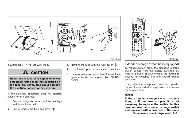
Black plate (419,1)
Model "E52-D" EDITED: 2010/ 10/ 25
SDI2718
PASSENGER COMPARTMENT
CAUTION
Never use a fuse of a higher or loweramperage rating than that specified onthe fuse box cover. This could damagethe electrical system or cause a fire.
If any electrical equipment does not operate,check for an open fuse.
1. Be sure the ignition switch and the headlightswitch are turned off.
2. Pull to remove the fuse box cover *1 .
3. Remove the fuse with the fuse puller *2 .
4. If the fuse is open, replace it with a new fuse.
5. If a new fuse also opens, have the electricalsystem checked and repaired by a NISSANdealer.
SDI2704
Extended storage switch (if so equipped)To reduce battery drain, the extended storageswitch comes from the factory switched off.Prior to delivery of your vehicle, the switch ispushed in (switched on) and should alwaysremain on.
If any electrical equipment does not operate,remove the extended storage switch and checkfor an open fuse.
NOTE:
If the extended storage switch malfunc-tions, or if the fuse is open, it is notnecessary to replace the switch. In thiscase, remove the extended storage switchand replace it with a new fuse of the same
Maintenance and do-it-yourself 8-21
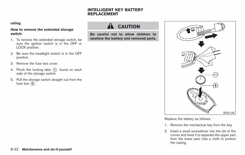
Black plate (420,1)
Model "E52-D" EDITED: 2010/ 10/ 25
rating.
How to remove the extended storageswitch:
1. To remove the extended storage switch, besure the ignition switch is in the OFF orLOCK position.
2. Be sure the headlight switch is in the OFFposition.
3. Remove the fuse box cover.
4. Pinch the locking tabs *1 found on eachside of the storage switch.
5. Pull the storage switch straight out from thefuse box *2 .
CAUTION
Be careful not to allow children toswallow the battery and removed parts.
SDI2135
Replace the battery as follows:
1. Remove the mechanical key from the key.
2. Insert a small screwdriver into the slit of thecorner and twist it to separate the upper partfrom the lower part. Use a cloth to protectthe casing.
INTELLIGENT KEY BATTERYREPLACEMENT
8-22 Maintenance and do-it-yourself

Black plate (421,1)
Model "E52-D" EDITED: 2010/ 10/ 25
3. Replace the battery with a new one.
Recommended battery:
CR2025 or equivalent
. Do not touch the internal circuit andelectric terminals as doing so couldcause a malfunction.
. Hold the battery by the edges. Holdingthe battery across the contact points willseriously deplete the storage capacity.
. Make sure that the + side faces thebottom case.
SDI1889
4. Align the tips of the upper and lower parts,and then push them together until it issecurely closed.
5. Operate the buttons to check its operation.
See a NISSAN dealer if you need any assistancefor replacement.
FCC Notice:
For USA:
This device complies with Part 15 of theFCC Rules. Operation is subject to thefollowing two conditions: (1) This devicemay not cause harmful interference, and(2) this device must accept any interfer-
ence received, including interference thatmay cause undesired operation.
Note: Changes or modifications not ex-pressly approved by the party responsiblefor compliance could void the user’sauthority to operate the equipment.
For Canada:
This device complies with RSS-210 ofIndustry Canada. Operation subject to thefollowing two conditions: (1) this devicemay not cause interference, and (2) thisdevice must accept any interference, in-cluding interference that may cause un-desired operation of the device.
Maintenance and do-it-yourself 8-23
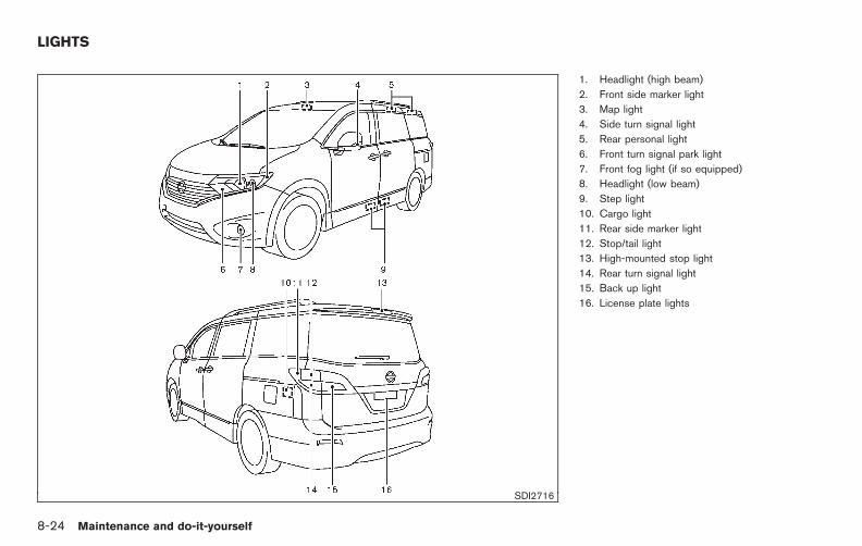
Black plate (422,1)
Model "E52-D" EDITED: 2010/ 10/ 25
SDI2716
1. Headlight (high beam)
2. Front side marker light
3. Map light
4. Side turn signal light
5. Rear personal light
6. Front turn signal park light
7. Front fog light (if so equipped)
8. Headlight (low beam)
9. Step light
10. Cargo light
11. Rear side marker light
12. Stop/tail light
13. High-mounted stop light
14. Rear turn signal light
15. Back up light
16. License plate lights
LIGHTS
8-24 Maintenance and do-it-yourself

Black plate (423,1)
Model "E52-D" EDITED: 2010/ 10/ 25
HEADLIGHTS
Fog may temporarily form inside the lens of theexterior lights in the rain or in a car wash. Atemperature difference between the inside andthe outside of the lens causes the fog. This isnot a malfunction. If large drops of water collectinside the lens, contact a NISSAN dealer.
ReplacingIf replacement is required, see a NISSAN dealer.
Xenon headlight model:
WARNING
HIGH VOLTAGE
When xenon headlights are on, theyproduce a high voltage. To prevent anelectric shock, never attempt to modifyor disassemble. Always have your xe-non headlights replaced at a NISSANdealer. For additional information, see“HEADLIGHT AND TURN SIGNALSWITCH” in the “2. Instruments andcontrols” section.
Halogen headlight model:
The headlight is a semi-sealed beam type whichuses a replaceable headlight (halogen) bulb.
CAUTION
. Do not leave the bulb out of theheadlight reflector for a long periodof time. Dust, moisture, smoke, etc.entering the headlight body mayaffect bulb performance.
. High pressure halogen gas is sealedinside the halogen bulb. The bulbmay break if the glass envelope isscratched or the bulb is dropped.
. Only touch the plastic base whenhandling the bulb. Never touch theglass envelope.
. Aiming is not necessary after repla-cing the bulb. When aiming adjust-ment is necessary, contact aNISSAN dealer.
Use the same number and wattage as originallyinstalled as shown in the chart.
SDI2719
Disconnect the battery negative cable beforereplacing bulbs.
Maintenance and do-it-yourself 8-25
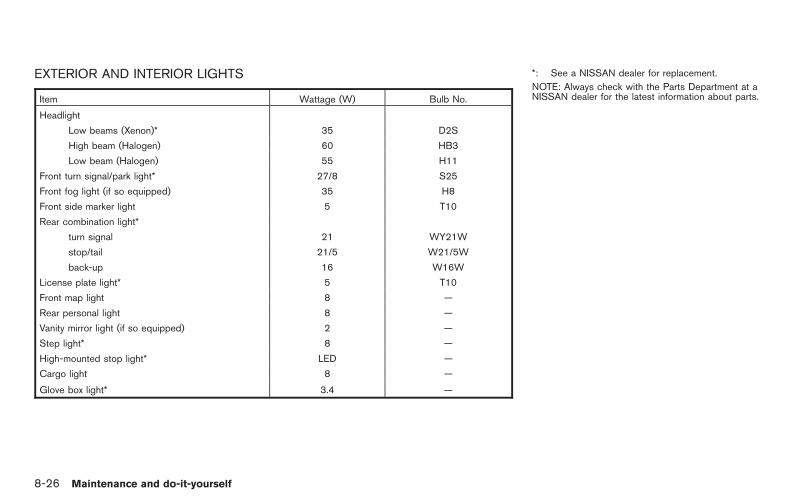
Black plate (424,1)
Model "E52-D" EDITED: 2010/ 10/ 25
EXTERIOR AND INTERIOR LIGHTS
Item Wattage (W) Bulb No.
Headlight
Low beams (Xenon)* 35 D2S
High beam (Halogen) 60 HB3
Low beam (Halogen) 55 H11
Front turn signal/park light* 27/8 S25
Front fog light (if so equipped) 35 H8
Front side marker light 5 T10
Rear combination light*
turn signal 21 WY21W
stop/tail 21/5 W21/5W
back-up 16 W16W
License plate light* 5 T10
Front map light 8 —
Rear personal light 8 —
Vanity mirror light (if so equipped) 2 —
Step light* 8 —
High-mounted stop light* LED —
Cargo light 8 —
Glove box light* 3.4 —
*: See a NISSAN dealer for replacement.
NOTE: Always check with the Parts Department at aNISSAN dealer for the latest information about parts.
8-26 Maintenance and do-it-yourself

Black plate (425,1)
Model "E52-D" EDITED: 2010/ 10/ 25
Replacement proceduresAll other lights are either type A, B, C, D, E or F.When replacing a bulb, first remove the lensand/or cover.
SDI1679
SDI2200Side marker light
1. Remove the rubber cover.
2. Remove the bulb as illustrated.
Maintenance and do-it-yourself 8-27

Black plate (426,1)
Model "E52-D" EDITED: 2010/ 10/ 25
SDI2184Front fog light (if so equipped)
SDI2030Front map light
SDI2031Rear personal light
SDI1500BCargo light
SDI2032Vanity mirror light
8-28 Maintenance and do-it-yourself
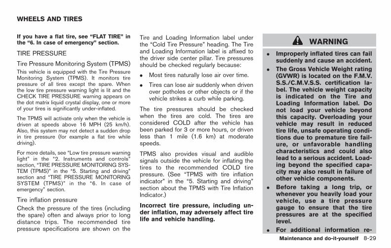
Black plate (427,1)
Model "E52-D" EDITED: 2010/ 10/ 25
If you have a flat tire, see “FLAT TIRE” inthe “6. In case of emergency” section.
TIRE PRESSURE
Tire Pressure Monitoring System (TPMS)This vehicle is equipped with the Tire PressureMonitoring System (TPMS). It monitors tirepressure of all tires except the spare. Whenthe low tire pressure warning light is lit and theCHECK TIRE PRESSURE warning appears onthe dot matrix liquid crystal display, one or moreof your tires is significantly under-inflated.
The TPMS will activate only when the vehicle isdriven at speeds above 16 MPH (25 km/h).Also, this system may not detect a sudden dropin tire pressure (for example a flat tire whiledriving).
For more details, see “Low tire pressure warninglight” in the “2. Instruments and controls”section, “TIRE PRESSURE MONITORING SYS-TEM (TPMS)” in the “5. Starting and driving”section and “TIRE PRESSURE MONITORINGSYSTEM (TPMS)” in the “6. In case ofemergency” section.
Tire inflation pressureCheck the pressure of the tires (includingthe spare) often and always prior to longdistance trips. The recommended tirepressure specifications are shown on the
Tire and Loading Information label underthe “Cold Tire Pressure” heading. The Tireand Loading Information label is affixed tothe driver side center pillar. Tire pressuresshould be checked regularly because:
. Most tires naturally lose air over time.
. Tires can lose air suddenly when drivenover potholes or other objects or if thevehicle strikes a curb while parking.
The tire pressures should be checkedwhen the tires are cold. The tires areconsidered COLD after the vehicle hasbeen parked for 3 or more hours, or drivenless than 1 mile (1.6 km) at moderatespeeds.
TPMS also provides visual and audiblesignals outside the vehicle for inflating thetires to the recommended COLD tirepressure. (See “TPMS with tire inflationindicator” in the “5. Starting and driving”section about the TPMS with Tire InflationIndicator.)
Incorrect tire pressure, including un-der inflation, may adversely affect tirelife and vehicle handling.
WARNING
. Improperly inflated tires can failsuddenly and cause an accident.
. The Gross Vehicle Weight rating(GVWR) is located on the F.M.V.S.S./C.M.V.S.S. certification la-bel. The vehicle weight capacityis indicated on the Tire andLoading Information label. Donot load your vehicle beyondthis capacity. Overloading yourvehicle may result in reducedtire life, unsafe operating condi-tions due to premature tire fail-ure, or unfavorable handlingcharacteristics and could alsolead to a serious accident. Load-ing beyond the specified capa-city may also result in failure ofother vehicle components.
. Before taking a long trip, orwhenever you heavily load yourvehicle, use a tire pressuregauge to ensure that the tirepressures are at the specifiedlevel.
. For additional information re-
WHEELS AND TIRES
Maintenance and do-it-yourself 8-29

Black plate (428,1)
Model "E52-D" EDITED: 2010/ 10/ 25
garding tires, refer to “ImportantTire Safety Information” (US) or“Tire Safety Information” (Cana-da) in the Warranty InformationBooklet.
SDI2197
Tire and Loading Information label
*1 Seating capacity: The maximum num-ber of occupants that can be seatedin the vehicle.
*2 Vehicle load limit: See “VEHICLELOADING INFORMATION” in the “9.Technical and consumer information”section.
8-30 Maintenance and do-it-yourself

Black plate (429,1)
Model "E52-D" EDITED: 2010/ 10/ 25
*3 Original size: The size of the tiresoriginally installed on the vehicle atthe factory.
*4 Cold tire pressure: Inflate the tires tothis pressure when the tires are cold.Tires are considered COLD after thevehicle has been parked for 3 ormore hours, or driven less than 1 mile(1.6 km) at moderate speeds. Therecommended cold tire inflation is setby the manufacturer to provide thebest balance of tire wear, vehiclehandling, driveability, tire noise, etc.,up to the vehicle’s GVWR.
*5 Tire size — see “TIRE LABELING”later in this section.
*6 Spare tire size or compact spare tiresize (if so equipped)
SDI1949
Checking the tire pressure1. Remove the valve stem cap from the
tire.
2. Press the pressure gauge squarely ontothe valve stem. Do not press too hard orforce the valve stem sideways, or air willescape. If the hissing sound of airescaping from the tire is heard whilechecking the pressure, reposition thegauge to eliminate this leakage.
3. Remove the gauge.
4. Read the tire pressure on the gaugestem and compare it to the specifica-
tion shown on the Tire and LoadingInformation label.
5. Add air to the tire as needed. If toomuch air is added, press the core of thevalve stem briefly with the tip of thegauge stem to release pressure. Re-check the pressure and add or releaseair as needed.
6. Install the valve stem cap.
7. Check the pressure of all other tires,including the spare.
Maintenance and do-it-yourself 8-31

Black plate (430,1)
Model "E52-D" EDITED: 2010/ 10/ 25
SIZECOLD TIREINFLATIONPRESSURE
FRONTORIGINAL
TIRE
P225/65R/16 99T
240 kPa,35 PSI
P235/55R/18 99T
240 kPa,35 PSI
REARORIGINAL
TIRE
P225/65R/16 99T
240 kPa,35 PSI
P235/55R/18 99T
240 kPa,35 PSI
SPARETIRE
T135/80D/16 101M
420 kPa,60 PSI
T135/90D/16 102M
420 kPa,60 PSI
SDI1575Example
TIRE LABELING
Federal law requires tire manufacturers toplace standardized information on the side-wall of all tires. This information identifiesand describes the fundamental character-istics of the tire and also provides the tireidentification number (TIN) for safety stan-dard certification. The TIN can be used toidentify the tire in case of a recall.
SDI1606Example
*1 Tire size (example: P215/60R1694H)
1. P: The “P” indicates the tire is designedfor passenger vehicles. (Not all tireshave this information.)
2. Three-digit number (215): This numbergives the width in millimeters of the tirefrom sidewall edge to sidewall edge.
3. Two-digit number (60): This number,known as the aspect ratio, gives thetire’s ratio of height to width.
4. R: The “R” stands for radial.
8-32 Maintenance and do-it-yourself

Black plate (431,1)
Model "E52-D" EDITED: 2010/ 10/ 25
5. Two-digit number (16): This number isthe wheel or rim diameter in inches.
6. Two- or three-digit number (94): Thisnumber is the tire’s load index. It is ameasurement of how much weight eachtire can support. You may not find thisinformation on all tires because it is notrequired by law.
7. H: Tire speed rating. You should notdrive the vehicle faster than the tirespeed rating.
SDI1607Example
*2 TIN (Tire Identification Number) for anew tire (example: DOT XX XX XXXXXXX)
1. DOT: Abbreviation for the “Departmentof Transportation”. The symbol can beplaced above, below or to the left orright of the Tire Identification Number.
2. Two-digit code: Manufacturer’s identifi-cation mark
3. Two-digit code: Tire size
4. Three-digit code: Tire type code (Op-tional)
5. Three-digit code: Date of Manufacture
6. Four numbers represent the week andyear the tire was built. For example, thenumbers 3103 means the 31st week of2003. If these numbers are missing,then look on the other sidewall of thetire.
*3 Tire ply composition and material
The number of layers or plies ofrubber-coated fabric in the tire.Tire manufacturers also must indicatethe materials in the tire, which includesteel, nylon, polyester, and others.
*4 Maximum permissible inflation pres-sureThis number is the greatest amountof air pressure that should be put inthe tire. Do not exceed the maximumpermissible inflation pressure.
*5 Maximum load rating
This number indicates the maximumload in kilograms and pounds thatcan be carried by the tire. Whenreplacing the tires on the vehicle,always use a tire that has the same
Maintenance and do-it-yourself 8-33

Black plate (432,1)
Model "E52-D" EDITED: 2010/ 10/ 25
load rating as the factory installedtire.
*6 Term of “tubeless” or “tube type”
Indicates whether the tire requires aninner tube (“tube type”) or not(“tubeless”).
*7 The word “radial”
The word “radial” is shown, if the tirehas radial structure.
*8 Manufacturer or brand name
Manufacturer or brand name isshown.
Other tire-related terminology:
In addition to the many terms that aredefined throughout this section, IntendedOutboard Sidewall is (1) the sidewall thatcontains a whitewall, bears white letteringor bears manufacturer, brand and/or modelname molding that is higher or deeper thanthe same molding on the other sidewall ofthe tire, or (2) the outward facing sidewallof an asymmetrical tire that has a particularside that must always face outward whenmounted on a vehicle.
TYPES OF TIRES
WARNING
. When changing or replacing tires,be sure all four tires are of the sametype (Example: Summer, All Seasonor Snow) and construction. ANISSAN dealer may be able to helpyou with information about tire type,size, speed rating and availability.
. Replacement tires may have a lowerspeed rating than the factoryequipped tires, and may not matchthe potential maximum vehiclespeed. Never exceed the maximumspeed rating of the tire.
. Replacing tires with those not ori-ginally specified by NISSAN couldaffect the proper operation of theTPMS.
. For additional information regard-ing tires, refer to “Important TireSafety Information” (US) or “TireSafety Information” (Canada) in theWarranty Information Booklet.
All season tiresNISSAN specifies all season tires on somemodels to provide good performance all year,including snowy and icy road conditions. AllSeason tires are identified by ALL SEASONand/or M&S (Mud and Snow) on the tiresidewall. Snow tires have better snow tractionthan All Season tires and may be more appro-priate in some areas.
Summer tiresNISSAN specifies summer tires on somemodels to provide superior performance on dryroads. Summer tire performance is substantiallyreduced in snow and ice. Summer tires do nothave the tire traction rating M&S on the tiresidewall.
If you plan to operate your vehicle in snowy oricy conditions, NISSAN recommends the use ofSNOW tires or ALL SEASON tires on all fourwheels.
Snow tiresIf snow tires are needed, it is necessary to selecttires equivalent in size and load rating to theoriginal equipment tires. If you do not, it canadversely affect the safety and handling of yourvehicle.
Generally, snow tires will have lower speedratings than factory equipped tires and may notmatch the potential maximum vehicle speed.
8-34 Maintenance and do-it-yourself

Black plate (433,1)
Model "E52-D" EDITED: 2010/ 10/ 25
Never exceed the maximum speed rating of thetire.
If you install snow tires, they must be the samesize, brand, construction and tread pattern on allfour wheels.
For additional traction on icy roads, studdedtires may be used. However, some U.S. statesand Canadian provinces prohibit their use.Check local, state and provincial laws beforeinstalling studded tires. Skid and traction cap-abilities of studded snow tires, on wet or drysurfaces, may be poorer than that of non-studded snow tires.
TIRE CHAINS
Use of tire chains may be prohibited accordingto location. Check the local laws before instal-ling tire chains. When installing tire chains, makesure they are the proper size for the tires on yourvehicle and are installed according to the chainmanufacturer’s suggestions. Use only SAEClass S chains. Class “S” chains are used onvehicles with restricted tire to vehicle clearance.Vehicles that can use Class “S” chains aredesigned to meet the SAE standard minimumclearances between the tire and the closestvehicle suspension or body component requiredto accommodate the use of a winter tractiondevice (tire chains or cables). The minimumclearances are determined using the factoryequipped tire size. Other types may damage
your vehicle. Use chain tensioners when re-commended by the tire chain manufacturer toensure a tight fit. Loose end links of the tirechain must be secured or removed to preventthe possibility of whipping action damage to thefenders or underbody. If possible, avoid fullyloading your vehicle when using tire chains. Inaddition, drive at a reduced speed. Otherwise,your vehicle may be damaged and/or vehiclehandling and performance may be adverselyaffected.
Tire chains must be installed only on thefront wheels and not on the rear wheels.
Never install tire chains on a TEMPORARY USEONLY spare tire.
Do not use tire chains on dry roads. Driving withtire chains in such conditions can cause damageto the various mechanisms of the vehicle due tosome overstress.
SDI1662
CHANGING WHEELS AND TIRES
Tire rotationNISSAN recommends rotating the tiresevery 7,500 miles (12,000 km). (See “FLATTIRE” in the “6. In case of emergency”section for tire replacing procedures.)
As soon as possible, tighten the wheelnuts to the specified torque with atorque wrench.
Maintenance and do-it-yourself 8-35

Black plate (434,1)
Model "E52-D" EDITED: 2010/ 10/ 25
Wheel nut tightening torque:
80 ft-lb (108 N·m)
The wheel nuts must be kept tigh-tened to the specification at all times.It is recommended that wheel nuts betightened to the specification at eachtire rotation interval.
WARNING
. After rotating the tires, checkand adjust the tire pressure.
. Retighten the wheel nuts whenthe vehicle has been driven for600 miles (1,000 km) (also incases of a flat tire, etc.).
. Do not include the spare tire orany other small size spare tire inthe tire rotation.
. For additional information re-garding tires, refer to “ImportantTire Safety Information” (US) or“Tire Safety Information” (Cana-da) in the Warranty InformationBooklet.
SDI1663
1. Wear indicator
2. Wear indicator location mark
Tire wear and damage
WARNING
. Tires should be periodically in-spected for wear, cracking, bul-ging or objects caught in thetread. If excessive wear, cracks,bulging or deep cuts are found,the tire(s) should be replaced.
. The original tires have built-intread wear indicators. When
wear indicators are visible, thetire(s) should be replaced.
. Tires degrade with age and use.Have tires, including the spare,over 6 years old checked by aqualified technician, becausesome tire damage may not beobvious. Replace the tires asnecessary to prevent tire failureand possible personal injury.
. Improper service of the sparetire may result in serious perso-nal injury. If it is necessary torepair the spare tire, contact aNISSAN dealer.
. For additional information re-garding tires, refer to “ImportantTire Safety Information” (US) or“Tire Safety Information” (Cana-da) in the Warranty InformationBooklet.
Replacing wheels and tiresWhen replacing a tire, use the same size, treaddesign, speed rating and load carrying capacityas originally equipped. (See “SPECIFICA-TIONS” in the “9. Technical and consumerinformation” section for recommended typesand sizes of tires and wheels.)
8-36 Maintenance and do-it-yourself

Black plate (435,1)
Model "E52-D" EDITED: 2010/ 10/ 25
WARNING
. The use of tires other than thoserecommended or the mixed use oftires of different brands, construc-tion (bias, bias-belted or radial), ortread patterns can adversely affectthe ride, braking, handling, groundclearance, body-to-tire clearance,tire chain clearance, speedometercalibration, headlight aim and bum-per height. Some of these effectsmay lead to accidents and couldresult in serious personal injury.
. If the wheels are changed for anyreason, always replace with wheelswhich have the same off-set dimen-sion. Wheels of a different off-setcould cause premature tire wear,degrade vehicle handling character-istics and/or interference with thebrake discs/drums. Such interfer-ence can lead to decreased brakingefficiency and/or early brake pad/shoe wear. See “WHEELS ANDTIRES” in the “9. Technical andconsumer information” section ofthis manual for wheel off-set dimen-sions.
. When a spare tire is mounted or awheel is replaced, the TPMS will notfunction and the low tire pressurewarning light will flash for approxi-mately 1 minute. The light willremain on after 1 minute. Contactyour NISSAN dealer as soon aspossible for tire replacement and/or system resetting.
. Replacing tires with those not ori-ginally specified by NISSAN couldaffect the proper operation of theTPMS.
. Do not install a damaged or de-formed wheel or tire even if it hasbeen repaired. Such wheels or tirescould have structural damage andcould fail without warning.
. The use of retread tire is not re-commended.
. For additional information regard-ing tires, refer to “Important TireSafety Information” (US) or “TireSafety Information” (Canada) in theWarranty Information Booklet.
Wheel balanceUnbalanced wheels may affect vehicle handlingand tire life. Even with regular use, wheels canget out of balance. Therefore, they should bebalanced as required.
Wheel balance service should be per-formed with the wheels off the vehicle.Spin balancing the wheels on the vehiclecould lead to mechanical damage.
For additional information regarding tires, referto “Important Tire Safety Information” (US) or“Tire Safety Information” (Canada) in the War-ranty Information Booklet.
Care of wheelsSee “CLEANING EXTERIOR” in the “7. Ap-pearance and care” section for details aboutcare of the wheels.
Spare tireWhen a spare tire is mounted (TEMPORARYUSE ONLY or conventional), the TPMS will notfunction.
Observe the following precautions if the TEM-PORARY USE ONLY spare tire must be used,otherwise your vehicle could be damaged orinvolved in an accident.
Maintenance and do-it-yourself 8-37

Black plate (436,1)
Model "E52-D" EDITED: 2010/ 10/ 25
WARNING
. The TEMPORARY USE ONLY sparetire should be used for emergencyuse. It should be replaced with thestandard tire at the first opportunityto avoid possible tire or differentialdamage.
. Drive carefully while the TEMPOR-ARY USE ONLY spare tire is in-stalled. Avoid sharp turns andabrupt braking while driving.
. Periodically check spare tire infla-tion pressure. Always keep thepressure of the TEMPORARY USEONLY spare tire at 60 psi (420 kPa,4.2 bar). Always keep the pressureof the full size spare tire (if soequipped) at the recommendedpressure for standard tires, as in-dicated on the Tire and LoadingInformation label.
. With the TEMPORARY USE ONLYspare tire installed do not drive yourvehicle at speeds faster than 50MPH (80 km/h).
. When driving on roads covered withsnow or ice, the TEMPORARY USE
ONLY spare tire should be used onthe rear wheels and original tireused on the front wheels (drivewheels). Use tire chains only onthe front (original) tires.
. Tire tread of the TEMPORARY USEONLY spare tire will wear at a fasterrate than the standard tire. Replacethe spare tire as soon as the treadwear indicators appear.
. Do not use the spare tire on othervehicles.
. Do not use more than one spare tireat the same time.
. Do not tow a trailer while theTEMPORARY USE ONLY spare tireis installed.
CAUTION
. Do not use tire chains on a TEM-PORARY USE ONLY spare tire. Tirechains will not fit properly and maycause damage to the vehicle.
. Because the TEMPORARY USEONLY spare tire is smaller than theoriginal tire, ground clearance isreduced. To avoid damage to the
vehicle, do not drive over obstacles.Also do not drive the vehiclethrough an automatic car washsince it may get caught.
8-38 Maintenance and do-it-yourself

Black plate (28,1)
9 Technical and consumer information
Model "E52-D" EDITED: 2010/ 10/ 22
Capacities and recommended fuel/lubricants . . . . . . . . . . . . 9-2Fuel recommendation . . . . . . . . . . . . . . . . . . . . . . . . . . . . . . . . . . . . . . 9-3Engine oil and oil filter recommendation. . . . . . . . . . . . . . . 9-5Air conditioning system refrigerant and lubricantrecommendations . . . . . . . . . . . . . . . . . . . . . . . . . . . . . . . . . . . . . . . . . . . 9-6
Specifications. . . . . . . . . . . . . . . . . . . . . . . . . . . . . . . . . . . . . . . . . . . . . . . . . . . . 9-7Engine. . . . . . . . . . . . . . . . . . . . . . . . . . . . . . . . . . . . . . . . . . . . . . . . . . . . . . . . . 9-7Wheels and tires. . . . . . . . . . . . . . . . . . . . . . . . . . . . . . . . . . . . . . . . . . . . 9-7Dimensions and weights . . . . . . . . . . . . . . . . . . . . . . . . . . . . . . . . . . 9-8
When traveling or registering your vehicle inanother country. . . . . . . . . . . . . . . . . . . . . . . . . . . . . . . . . . . . . . . . . . . . . . . . . . 9-8Vehicle identification . . . . . . . . . . . . . . . . . . . . . . . . . . . . . . . . . . . . . . . . . . . 9-8
Vehicle Identification Number (VIN) plate . . . . . . . . . . . . . 9-8Vehicle identification number (chassis number). . . . . . 9-9Engine serial number . . . . . . . . . . . . . . . . . . . . . . . . . . . . . . . . . . . . . . 9-9F.M.V.S.S./C.M.V.S.S. certification label . . . . . . . . . . . . . . . 9-9Emission control information label . . . . . . . . . . . . . . . . . . . . 9-10Tire and loading information label . . . . . . . . . . . . . . . . . . . . . 9-10Air conditioner specification label . . . . . . . . . . . . . . . . . . . . . 9-10
Installing front license plate . . . . . . . . . . . . . . . . . . . . . . . . . . . . . . . . 9-11Vehicle loading information . . . . . . . . . . . . . . . . . . . . . . . . . . . . . . . . . 9-12
Terms . . . . . . . . . . . . . . . . . . . . . . . . . . . . . . . . . . . . . . . . . . . . . . . . . . . . . . . . 9-12
Vehicle load capacity . . . . . . . . . . . . . . . . . . . . . . . . . . . . . . . . . . . . 9-12Securing the load. . . . . . . . . . . . . . . . . . . . . . . . . . . . . . . . . . . . . . . . . 9-14Loading tips. . . . . . . . . . . . . . . . . . . . . . . . . . . . . . . . . . . . . . . . . . . . . . . . 9-14Measurement of weights . . . . . . . . . . . . . . . . . . . . . . . . . . . . . . . . 9-15
Towing a trailer . . . . . . . . . . . . . . . . . . . . . . . . . . . . . . . . . . . . . . . . . . . . . . . . 9-15Maximum load limits. . . . . . . . . . . . . . . . . . . . . . . . . . . . . . . . . . . . . . 9-16Maximum Gross Vehicle Weight (GVW)/maximum Gross Axle Weight (GAW) . . . . . . . . . . . . . . . . 9-17Towing load/specification . . . . . . . . . . . . . . . . . . . . . . . . . . . . . . . 9-19Towing safety . . . . . . . . . . . . . . . . . . . . . . . . . . . . . . . . . . . . . . . . . . . . . . 9-20Flat towing . . . . . . . . . . . . . . . . . . . . . . . . . . . . . . . . . . . . . . . . . . . . . . . . . 9-23
Uniform tire quality grading . . . . . . . . . . . . . . . . . . . . . . . . . . . . . . . . . 9-24Treadwear . . . . . . . . . . . . . . . . . . . . . . . . . . . . . . . . . . . . . . . . . . . . . . . . . . 9-24Traction AA, A, B and C . . . . . . . . . . . . . . . . . . . . . . . . . . . . . . . . 9-24Temperature A, B and C . . . . . . . . . . . . . . . . . . . . . . . . . . . . . . . . 9-24
Emission control system warranty. . . . . . . . . . . . . . . . . . . . . . . . . 9-25Reporting safety defects (US only) . . . . . . . . . . . . . . . . . . . . . . . 9-25Readiness for Inspection/Maintenance (I/M) test. . . . . . 9-26Event Data Recorders (EDR) . . . . . . . . . . . . . . . . . . . . . . . . . . . . . . 9-27Owner’s Manual/Service Manual order information . . . 9-27
In the event of a collision . . . . . . . . . . . . . . . . . . . . . . . . . . . . . . . 9-28

Black plate (440,1)
Model "E52-D" EDITED: 2010/ 10/ 25
The following are approximate capacities. The actual refill capacities may be a little different. When refilling, follow the procedureinstructed in the “8. Maintenance and do-it-yourself” section to determine the proper refill capacity.
Capacity (Approximate) Recommended specifications
US measure Imp measure Liter
Fuel 20 gal 16-5/8 gal 75.6 See “FUEL RECOMMENDATION” later in this section.
Engine oil*1
Drain and refill
With oil filter change 4-7/8 qt 4 qt 4.6 . Engine oil with API Certification Mark*2, *3. Viscosity SAE 5W-30*2, *3Without oil filter change 4-1/2 qt 3-3/4 qt 4.3
Cooling system
With reservoir 12 qt 10 qt 11.3Pre-diluted Genuine NISSAN Long Life Antifreeze/Coolant (blue) or equivalent
Reservoir 3/4 qt 5/8 qt 0.75
Continuously Variable Transmission (CVT) fluid — — — Genuine NISSAN CVT Fluid NS-2*4
Power steering fluid (PSF) Refill to the proper oil level according to the instructions in the “8.Maintenance and do-it-yourself” section.
Genuine NISSAN E-PSF or equivalent*5
Brake fluid Genuine NISSAN Super Heavy Duty Brake Fluid*6 or equivalent DOT 3
Multi-purpose grease — — — NLGI No. 2 (Lithium soap base)
Air conditioning system refrigerant — — — HFC-134a (R-134a)*7
Air conditioning system lubricants — — — NISSAN A/C System Oil Type S or exact equivalent
Window washer fluid 1-1/4 gal 1 gal 4.5 Genuine NISSAN Windshield Washer Concentrate Cleaner & Antifreeze or equivalent
*1: For additional information, see “ENGINE OIL” in the “8. Maintenance and do-it-yourself” section for changing engine oil.*2: For additional information, see “ENGINE OIL AND OIL FILTER RECOMMENDATION” later in this section.*3: NISSAN recommends Genuine NISSAN Ester Engine Oil available at a NISSAN dealer.*4: Use only Genuine NISSAN CVT Fluid NS-2. Using transmission fluid other than Genuine NISSAN CVT Fluid NS-2 will damage the CVT, which is not covered by the NISSAN new vehicle
limited warranty.*5: Use of a power steering fluid other than Genuine NISSAN E-PSF will prevent the power steering system from operating properly.*6: Available in mainland U.S.A. through a NISSAN dealer.*7: For additional information, see “VEHICLE IDENTIFICATION” later in this section for air conditioner specification label.
CAPACITIES AND RECOMMENDEDFUEL/LUBRICANTS
9-2 Technical and consumer information

Black plate (441,1)
Model "E52-D" EDITED: 2010/ 10/ 25
FUEL RECOMMENDATION
Use unleaded regular gasoline with an octanerating of at least 87 AKI (Anti-Knock Index)number (Research octane number 91).
CAUTION
. Using a fuel other than that speci-fied could adversely affect the emis-sion control system, and may alsoaffect warranty coverage.
. Under no circumstances should aleaded gasoline be used, becausethis will damage the three-way cat-alyst.
. Do not use E-85 fuel in your vehicle.Your vehicle is not designed to runon E-85 fuel. Using E-85 fuel candamage the fuel system compo-nents and is not covered by theNISSAN new vehicle limited war-ranty.
Gasoline specificationsNISSAN recommends using gasoline that meetsthe World-Wide Fuel Charter (WWFC) speci-fications where it is available. Many of theautomobile manufacturers developed this spe-cification to improve emission control system
and vehicle performance. Ask your servicestation manager if the gasoline meets theWWFC specifications.
Reformulated gasolineSome fuel suppliers are now producing refor-mulated gasolines. These gasolines are speciallydesigned to reduce vehicle emissions. NISSANsupports efforts towards cleaner air and sug-gests that you use reformulated gasoline whenavailable.
Gasoline containing oxygenatesSome fuel suppliers sell gasoline containingoxygenates such as ethanol, MTBE and metha-nol with or without advertising their presence.NISSAN does not recommend the use of fuelsof which the oxygenate content and the fuelcompatibility for your NISSAN cannot be readilydetermined. If in doubt, ask your service stationmanager.
If you use oxygenate-blend gasoline, please takethe following precautions as the usage of suchfuels may cause vehicle performance problemsand/or fuel system damage.
. The fuel should be unleaded and havean octane rating no lower than thatrecommended for unleaded gasoline.
. If an oxygenate-blend, other thanmethanol blend is used, it shouldcontain no more than 10% oxygenate.
(MTBE may, however, be added up to15%.)
. If a methanol blend is used, it shouldcontain no more than 5% methanol(methyl alcohol, wood alcohol) . Itshould also contain a suitable amountof appropriate cosolvents and corro-sion inhibitors. If not properly formu-lated with appropriate cosolvents andcorrosion inhibitors, such methanolblends may cause fuel system damageand/or vehicle performance problems.At this time, sufficient data is notavailable to ensure that all methanolblends are suitable for use in NISSANvehicles.
If any driveability problems such as enginestalling and difficult hot-starting are experiencedafter using oxygenate-blend fuels, immediatelychange to a non-oxygenate fuel or a fuel with alow blend of MTBE.
Take care not to spill gasoline duringrefueling. Gasoline containing oxygenatescan cause paint damage.
E-85 fuelE-85 fuel is a mixture of approximately 85% fuelethanol and 15% unleaded gasoline. E-85 canonly be used in a Flexible Fuel Vehicle (FFV). Donot use E-85 fuel in your vehicle. U.S. govern-ment regulations require fuel ethanol dispensing
Technical and consumer information 9-3

Black plate (442,1)
Model "E52-D" EDITED: 2010/ 10/ 25
pumps to be identified by a small, square,orange and black label with the commonabbreviation or the appropriate percentage forthat region.
Aftermarket fuel additivesNISSAN does not recommend the use of anyaftermarket fuel additives (for example, fuelinjector cleaner, octane booster, intake valvedeposit removers, etc.) which are sold commer-cially. Many of these additives intended for gum,varnish or deposit removal may contain activesolvent or similar ingredients that can be harmfulto the fuel system and engine.
Octane rating tipsUsing unleaded gasoline with an octanerating lower than recommended can causepersistent, heavy “spark knock”. (Sparkknock is a metallic rapping noise.) Ifsevere, this can lead to engine damage. Ifyou detect a persistent heavy spark knockeven when using gasoline of the statedoctane rating, or if you hear steady sparkknock while holding a steady speed onlevel roads, have a NISSAN dealer correctthe condition. Failure to correct the condi-tion is misuse of the vehicle, for whichNISSAN is not responsible.
Incorrect ignition timing will result in sparkknock, after-run and/or overheating, which maycause excessive fuel consumption or engine
damage. If any of the above symptoms areencountered, have your vehicle checked at aNISSAN dealer.
However, now and then you may noticelight spark knock for a short time whileaccelerating or driving up hills. This is not acause for concern, because you get thegreatest fuel benefit when there is lightspark knock for a short time under heavyengine load.
CAUTION
. Your vehicle is not designed to runon E-85 fuel. Using E-85 fuel in avehicle not specifically designed forE-85 fuel can damage fuel systemcomponents and is not covered bythe NISSAN new vehicle limitedwarranty.
. E-85 is a mixture of approximately85% fuel ethanol and 15% unleadedgasoline.
. U.S. government regulations requireethanol dispensing pumps to beidentified by a small, square, orangeand black label with the commonabbreviation or the appropriate per-centage for that region.
9-4 Technical and consumer information

Black plate (443,1)
Model "E52-D" EDITED: 2010/ 10/ 25
STI0505
1. API certification mark
2. API service symbol
ENGINE OIL AND OIL FILTER RE-COMMENDATION
Selecting the correct oilIt is essential to choose the correct grade,quality, and viscosity engine oil to ensuresatisfactory engine life and performance, see“CAPACITIES AND RECOMMENDED FUEL/LUBRICANTS” earlier in this section. NISSANrecommends the use of an energy conserving oilin order to improve fuel economy.
Select only engine oils that meet the AmericanPetroleum Institute (API) certification or Interna-
tional Lubricant Standardization and ApprovalCommittee (ILSAC) certification and SAE vis-cosity standard. These oils have the APIcertification mark on the front of the container.Oils which do not have the specified qualitylabel should not be used as they could causeengine damage.
Oil additivesNISSAN does not recommend the use of oiladditives. The use of an oil additive is notnecessary when the proper oil type is used andmaintenance intervals are followed.
Oil which may contain foreign matter or hasbeen previously used should not be used.
Oil viscosityThe engine oil viscosity or thickness changeswith temperature. Because of this, it is importantto select the engine oil viscosity based on thetemperatures at which the vehicle will beoperated before the next oil change. Choosingan oil viscosity other than that recommendedcould cause serious engine damage.
Selecting the correct oil filterYour new NISSAN vehicle is equipped with ahigh-quality genuine NISSAN oil filter. Whenreplacing, use a genuine NISSAN oil filter or itsequivalent for the reason described in “Changeintervals”.
Change intervalsThe oil and oil filter change intervals for yourengine are based on the use of the specifiedquality oils and filters. Using an engine oil andfilter other than the specified quality, or exceed-ing recommended oil and filter change intervalscould reduce engine life. Damage to the enginecaused by improper maintenance or use ofincorrect oil and filter quality and/or viscosity isnot covered by the NISSAN new vehicle limitedwarranty.
Your engine was filled with a high quality engineoil when it was built. You do not have to changethe oil before the first recommended changeinterval. Oil and filter change intervals depend
Technical and consumer information 9-5

Black plate (444,1)
Model "E52-D" EDITED: 2010/ 10/ 25
upon how you use your vehicle.
Operation under the following conditions mayrequire more frequent oil and filter changes.
. repeated short distance driving at coldoutside temperatures
. driving in dusty conditions
. extensive idling
. towing a trailer
. stop and go commuting
Refer to the “NISSAN Service and MaintenanceGuide” for the maintenance schedule.
AIR CONDITIONING SYSTEM RE-FRIGERANT AND LUBRICANT RE-COMMENDATIONS
The air conditioning system in yourNISSAN vehicle must be charged with therefrigerant HFC-134a (R-134a) and the oil,NISSAN A/C system oil Type S or the exactequivalents.
CAUTION
The use of any other refrigerant or oilwill cause severe damage to the airconditioning system and will requirethe replacement of all air conditioner
system components.
The refrigerant HFC-134a (R-134a) in yourNISSAN vehicle will not harm the earth’s ozonelayer. Although this refrigerant does not affectthe earth’s atmosphere, certain governmentalregulations require the recovery and recycling ofany refrigerant during automotive air condition-ing system service. A NISSAN dealer has thetrained technicians and equipment needed torecover and recycle your air conditioning systemrefrigerant.
Contact a NISSAN dealer when servicing yourair conditioning system.
9-6 Technical and consumer information

Black plate (445,1)
Model "E52-D" EDITED: 2010/ 10/ 25
ENGINE
Model VQ35DE
Type Gasoline, 4-cycle
Cylinder arrangement 6-cylinder, V-slanted at 608
Bore 6 Stroke in (mm) 3.760 6 3.205 (95.5 6 81.4)
Displacement cu in (cm3) 213.45 (3,498)
Firing order 1-2-3-4-5-6
Idle speed rpmNo adjustment is necessary.
Ignition timing (B.T.D.C.) degree/rpm
Spark plug Standard FXE22HR-11
Spark plug gap (Normal) in (mm) 0.043 (1.1)
Camshaft operation Timing chain
This spark ignition system complies with the Canadian standard ICES-002.
WHEELS AND TIRES
Road wheel
Type Size Offset in (mm)
Steel 16 6 6-1/2JJ 1.97 (50)
Aluminum16 6 7J 1.97 (50)
18 6 7J 2.17 (55)
T-type 16 6 4T 1.18 (30)
Tire
Type SizePressure PSI(kPa) [Cold]
ConventionalP225/65R16 99T
35 (240)P235/55R18 99T
T-typeT135/80D16 101M
60 (420)T135/90D16 102M
SPECIFICATIONS
Technical and consumer information 9-7
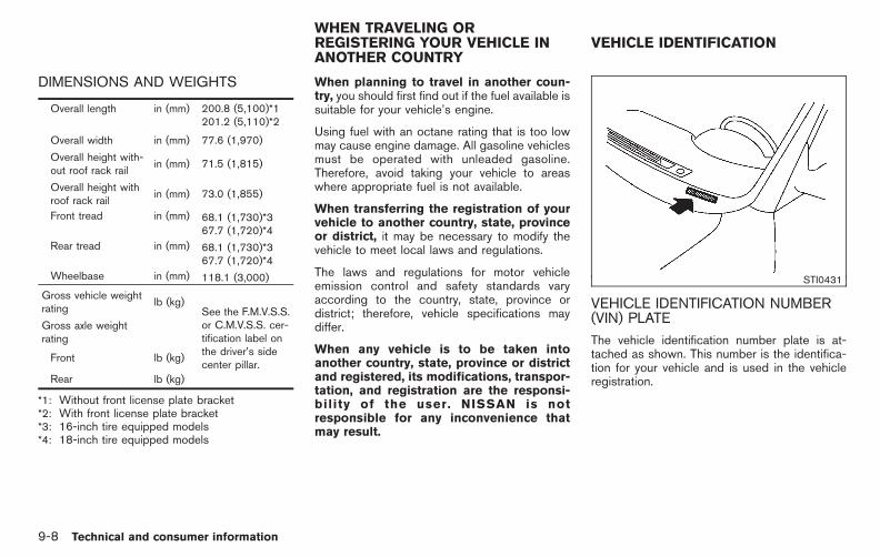
Black plate (446,1)
Model "E52-D" EDITED: 2010/ 10/ 25
DIMENSIONS AND WEIGHTS
Overall length in (mm) 200.8 (5,100)*1201.2 (5,110)*2
Overall width in (mm) 77.6 (1,970)
Overall height with-out roof rack rail
in (mm) 71.5 (1,815)
Overall height withroof rack rail
in (mm) 73.0 (1,855)
Front tread in (mm) 68.1 (1,730)*367.7 (1,720)*4
Rear tread in (mm) 68.1 (1,730)*367.7 (1,720)*4
Wheelbase in (mm) 118.1 (3,000)
Gross vehicle weightrating
lb (kg)See the F.M.V.S.S.or C.M.V.S.S. cer-tification label onthe driver’s sidecenter pillar.
Gross axle weightrating
Front lb (kg)
Rear lb (kg)
*1: Without front license plate bracket*2: With front license plate bracket*3: 16-inch tire equipped models*4: 18-inch tire equipped models
When planning to travel in another coun-try, you should first find out if the fuel available issuitable for your vehicle’s engine.
Using fuel with an octane rating that is too lowmay cause engine damage. All gasoline vehiclesmust be operated with unleaded gasoline.Therefore, avoid taking your vehicle to areaswhere appropriate fuel is not available.
When transferring the registration of yourvehicle to another country, state, provinceor district, it may be necessary to modify thevehicle to meet local laws and regulations.
The laws and regulations for motor vehicleemission control and safety standards varyaccording to the country, state, province ordistrict; therefore, vehicle specifications maydiffer.
When any vehicle is to be taken intoanother country, state, province or districtand registered, its modifications, transpor-tation, and registration are the responsi-bility of the user. NISSAN is notresponsible for any inconvenience thatmay result.
STI0431
VEHICLE IDENTIFICATION NUMBER(VIN) PLATE
The vehicle identification number plate is at-tached as shown. This number is the identifica-tion for your vehicle and is used in the vehicleregistration.
WHEN TRAVELING ORREGISTERING YOUR VEHICLE INANOTHER COUNTRY
VEHICLE IDENTIFICATION
9-8 Technical and consumer information

Black plate (447,1)
Model "E52-D" EDITED: 2010/ 10/ 25
STI0802
VEHICLE IDENTIFICATION NUMBER(chassis number)
The vehicle identification number is located asshown.
Remove the cover to access the number.
STI0562
ENGINE SERIAL NUMBER
The number is stamped on the engine as shown.
STI0448
F.M.V.S.S./C.M.V.S.S. CERTIFICATIONLABEL
The Federal/Canadian Motor Vehicle SafetyStandards (F.M.V.S.S./C.M.V.S.S.) certificationlabel is affixed as shown. This label containsvaluable vehicle information, such as: GrossVehicle Weight Ratings (GVWR), Gross AxleWeight Rating (GAWR), month and year ofmanufacture, Vehicle Identification Number(VIN), etc. Review it carefully.
Technical and consumer information 9-9

Black plate (448,1)
Model "E52-D" EDITED: 2010/ 10/ 25
STI0815
EMISSION CONTROL INFORMATIONLABEL
The emission control information label is at-tached as shown.
STI0494
TIRE AND LOADING INFORMATIONLABEL
The cold tire pressure is shown on the Tire andLoading Information label affixed to the pillar asillustrated.
STI0803
AIR CONDITIONER SPECIFICATIONLABEL
The air conditioner specification label is at-tached as shown.
9-10 Technical and consumer information

Black plate (449,1)
Model "E52-D" EDITED: 2010/ 10/ 25
STI0820
Use the following steps to mount the licenseplate.
Before mounting the license plate, confirm thatthe following parts are enclosed in the plasticbag.
. License plate bracket
. Screw 6 2 (for license plate bracket)
1. Park the vehicle on flat, level ground.
2. Line up the tab *A on the license platebracket under the top of the front bumper*B .
3. Install the license plate bracket with screws.
4. Install the license plate with screws (soldseparately).
Use a screw of 1/4 inch (6 mm) in diameterand approximately 5/8 inch (16 mm) inlength.
INSTALLING FRONT LICENSE PLATE
Technical and consumer information 9-11
Black plate (450,1)
Model "E52-D" EDITED: 2010/ 10/ 25
WARNING
. It is extremely dangerous to ridein a cargo area inside the vehi-cle. In a collision, people ridingin these areas are more likely tobe seriously injured or killed.
. Do not allow people to ride inany area of your vehicle that isnot equipped with seats andseat belts.
. Be sure everyone in your vehicleis in a seat and using a seat beltproperly.
TERMS
It is important to familiarize yourself with thefollowing terms before loading your vehicle:
. Curb Weight (actual weight of yourvehicle) - vehicle weight including:standard and optional equipment,fluids, emergency tools, and spare tireassembly. This weight does not in-clude passengers and cargo.
. GVW (Gross Vehicle Weight) - curbweight plus the combined weight ofpassengers and cargo.
. GVWR (Gross Vehicle Weight Rating)- maximum total combined weight of theunloaded vehicle, passengers, luggage,hitch, trailer tongue load and any otheroptional equipment. This information islocated on the F.M.V.S.S./C.M.V.S.S.label.
. GAWR (Gross Axle Weight Rating) -maximum weight (load) limit specifiedfor the front or rear axle. This informa-tion is located on the F.M.V.S.S./C.M.V.S.S. label.
. GCWR (Gross Combined Weight Rat-ing) - The maximum total weight ratingof the vehicle, passengers, cargo, andtrailer.
. Vehicle Capacity Weight, Load limit,Total load capacity - maximum totalweight limit specified of the load(passengers and cargo) for the vehicle.This is the maximum combined weightof occupants and cargo that can beloaded into the vehicle. If the vehicle isused to tow a trailer, the trailer tongueweight must be included as part of thecargo load. This information is locatedon the Tire and Loading Informationlabel.
. Cargo capacity - permissible weight ofcargo, the subtracted weight of occu-pants from the load limit.
VEHICLE LOAD CAPACITY
Do not exceed the load limit of your vehicleshown as “The combined weight of occu-pants and cargo” on the Tire and LoadingInformation label. Do not exceed thenumber of occupants shown as “SeatingCapacity” on the Tire and Loading Informa-tion label.
To get “the combined weight of occupantsand cargo”, add the weight of all occu-pants, then add the total luggage weight.Examples are shown in the followingillustration.
VEHICLE LOADING INFORMATION
9-12 Technical and consumer information

Black plate (451,1)
Model "E52-D" EDITED: 2010/ 10/ 25
STI0445
Steps for determining correct load limit1. Locate the statement “The combined
weight of occupants and cargo shouldnever exceed XXX kg or XXX lbs” onyour vehicle’s placard.
2. Determine the combined weight of thedriver and passengers that will be ridingin your vehicle.
3. Subtract the combined weight of thedriver and passengers from XXX kg orXXX lbs.
4. The resulting figure equals the availableamount of cargo and luggage loadcapacity. For example, if the XXXamount equals 1400 lbs. and there willbe five 150 lb. passengers in yourvehicle, the amount of available cargoand luggage load capacity is 650 lbs.(1400 − 750 (5 x 150) = 650 lbs) or(640 − 340 (5 x 70) = 300 kg.)
5. Determine the combined weight ofluggage and cargo being loaded onthe vehicle. That weight may not safelyexceed the available cargo and luggageload capacity calculated in Step 4.
6. If your vehicle will be towing a trailer,
Technical and consumer information 9-13

Black plate (452,1)
Model "E52-D" EDITED: 2010/ 10/ 25
load from your trailer will be transferredto your vehicle. Consult this manual todetermine how this reduces the avail-able cargo and luggage load capacityof your vehicle.
Before driving a loaded vehicle, confirmthat you do not exceed the Gross VehicleWeight Rating (GVWR) or the Gross AxleWeight Rating (GAWR) for your vehicle.(See “MEASUREMENT OF WEIGHTS”later in this section.)
Also check tires for proper inflation pres-sures. See the Tire and Loading Informationlabel.
SIC4732
SECURING THE LOAD
There are tie down hooks located in the cargoarea as shown. The tie down hooks can be usedto secure cargo with ropes or other types ofstraps.
Do not apply a total load of more than 7 lb.(3 kg) to a single hook when securingcargo.
WARNING
. Properly secure all cargo with ropesor straps to help prevent it fromsliding or shifting. Do not placecargo higher than the seatbacks. In
a sudden stop or collision, unse-cured cargo could cause personalinjury.
. The child restraint top tether strapmay be damaged by contact withitems in the cargo area. Secure anyitems in the cargo area. Your childcould be seriously injured or killedin a collision if the top tether strap isdamaged.
. Do not load your vehicle any heavierthan the GVWR or the maximumfront and rear GAWRs. If you do,parts of your vehicle can break, tiredamage could occur, or it canchange the way your vehicle han-dles. This could result in loss ofcontrol and cause personal injury.
LOADING TIPS
. The GVW must not exceed GVWR orGAWR as specified on the F.M.V.S.S./C.M.V.S.S. certification label.
. Do not load the front and rear axle tothe GAWR. Doing so will exceed theGVWR.
9-14 Technical and consumer information

Black plate (453,1)
Model "E52-D" EDITED: 2010/ 10/ 25
WARNING
. Properly secure all cargo withropes or straps to help prevent itfrom sliding or shifting. Do notplace cargo higher than theseatbacks. In a sudden stop orcollision, unsecured cargo couldcause personal injury.
. Do not load your vehicle anyheavier than the GVWR or themaximum front and rearGAWRs. If you do, parts of yourvehicle can break, tire damagecould occur, or it can change theway your vehicle handles. Thiscould result in loss of controland cause personal injury.
. Overloading not only can short-en the life of your vehicle andthe tire, but can cause unsafevehicle handling and longerbraking distances. This maycause a premature tire failure,which could result in a seriousaccident and personal injury.Failures caused by overloadingare not covered by the vehicle’s
warranty.
MEASUREMENT OF WEIGHTS
Secure loose items to prevent weight shiftsthat could affect the balance of yourvehicle. When the vehicle is loaded, driveto a scale and weigh the front and the rearwheels separately to determine axle loads.Individual axle loads should not exceedeither of the Gross Axle Weight Ratings(GAWR). The total of the axle loads shouldnot exceed the Gross Vehicle WeightRating (GVWR). These ratings are givenon the vehicle certification label. If weightratings are exceeded, move or removeitems to bring all weights below the ratings.
WARNING
Overloading or improper loading of atrailer and its cargo can adversely affectvehicle handling, braking and perfor-mance and may lead to accidents.
CAUTION
. Do not tow a trailer or haul a heavyload for the first 500 miles (800 km).Your engine, axle or other partscould be damaged.
. For the first 500 miles (800 km) thatyou tow a trailer, do not drive over50 MPH (80 km/h) and do not makestarts at full throttle. This helps theengine and other parts of yourvehicle wear in at the heavier loads.
Your new vehicle was designed to be usedprimarily to carry passengers and cargo. Re-member that towing a trailer places additionalloads on your vehicle’s engine, drivetrain, steer-ing, braking and other systems.
A NISSAN Towing Guide (U.S. only) is availableon the website at www.nissanusa.com. Thisguide includes information on trailer towingcapability and the special equipment required
TOWING A TRAILER
Technical and consumer information 9-15

Black plate (454,1)
Model "E52-D" EDITED: 2010/ 10/ 25
for proper towing.
MAXIMUM LOAD LIMITS
Maximum trailer loadsNever allow the total trailer load to exceed thevalue specified in the “Towing Load/Specifica-tion” chart. The total trailer load equals trailerweight plus its cargo weight.
. When towing a trailer load of 1,000 lbs(454 kg) or more, trailers with a brakesystem MUST be used.
The maximum GCWR (Gross Combined WeightRating) should not exceed the value specified inthe following “Towing Load/Specification” chart.
STI0541
The GCWR equals the combined weight of thetowing vehicle (including passengers and cargo)plus the total trailer load. Towing loads greaterthan these or using improper towing equipmentcould adversely affect vehicle handling, brakingand performance.
The ability of your vehicle to tow a trailer is notonly related to the maximum trailer loads, butalso the places you plan to tow. Tow weightsappropriate for level highway driving may have tobe reduced on very steep grades or for lowtraction situations (for example, on slippery boatramps).
Temperature conditions can also affect towing.For example, towing a heavy trailer in high
outside temperatures on graded roads canaffect engine performance and cause overheat-ing. The transmission high fluid temperatureprotection mode, which helps reduce thechance of transmission damage, could activateand automatically decrease engine power.Vehicle speed may decrease under high load.Plan your trip carefully to account for trailer andvehicle load, weather and road conditions.
WARNING
Overheating can result in reduced en-gine power and vehicle speed. Thereduced speed may be lower than othertraffic, which could increase the chanceof a collision. Be especially carefulwhen driving. If the vehicle cannotmaintain a safe driving speed, pull tothe side of the road in a safe area.Allow the engine to cool and return tonormal operation. See “IF YOUR VEHI-CLE OVERHEATS” in the “6. In case ofemergency” section of this manual.
9-16 Technical and consumer information

Black plate (455,1)
Model "E52-D" EDITED: 2010/ 10/ 25
CAUTION
Vehicle damage resulting from impro-per towing procedures are not coveredby NISSAN warranties.
STI0542
Tongue loadWhen using a weight carrying or a weightdistributing hitch, keep the tongue load between10 to 15% of the total trailer load within themaximum tongue load limits shown in thefollowing “Towing Load/Specification” chart. Ifthe tongue load becomes excessive, rearrangecargo to allow for proper tongue load.
TI1012M
MAXIMUM GROSS VEHICLE WEIGHT(GVW)/MAXIMUM GROSS AXLEWEIGHT (GAW)
The GVW of the towing vehicle must not exceedthe Gross Vehicle Weight Rating (GVWR)shown on the F.M.V.S.S./C.M.V.S.S. certificationlabel. The GVW equals the combined weight ofthe unloaded vehicle, passengers, luggage,hitch, trailer tongue load and any other optionalequipment. In addition, front or rear GAW mustnot exceed the Gross Axle Weight Rating(GAWR) shown on the F.M.V.S.S./C.M.V.S.S.certification label.
Towing capacities are calculated assuming abase vehicle with driver and any options
Technical and consumer information 9-17
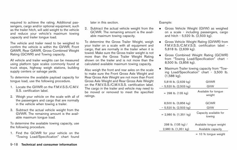
Black plate (456,1)
Model "E52-D" EDITED: 2010/ 10/ 25
required to achieve the rating. Additional pas-sengers, cargo and/or optional equipment, suchas the trailer hitch, will add weight to the vehicleand reduce your vehicle’s maximum towingcapacity and trailer tongue load.
The vehicle and trailer need to be weighed toconfirm the vehicle is within the GVWR, FrontGAWR, Rear GAWR, Gross Combined WeightRating (GCWR) and Towing capacity.
All vehicle and trailer weights can be measuredusing platform type scales commonly found attruck stops, highway weigh stations, buildingsupply centers or salvage yards.
To determine the available payload capacity fortongue load, use the following procedure.
1. Locate the GVWR on the F.M.V.S.S./C.M.V.S.S. certification label.
2. Weigh your vehicle on the scale with all ofthe passengers and cargo that are normallyin the vehicle when towing a trailer.
3. Subtract the actual vehicle weight from theGVWR. The remaining amount is the avail-able maximum tongue load.
To determine the available towing capacity, usethe following procedure.
1. Find the GCWR for your vehicle on the“Towing Load/Specification” chart found
later in this section.
2. Subtract the actual vehicle weight from theGCWR. The remaining amount is the avail-able maximum towing capacity.
To determine the Gross Trailer Weight, weighyour trailer on a scale with all equipment andcargo, that are normally in the trailer when it istowed. Make sure the Gross trailer weight is notmore than the Gross Trailer Weight Ratingshown on the trailer and is not more than thecalculated available maximum towing capacity.
Also weigh the front and rear axles on the scaleto make sure the Front Gross Axle Weight andRear Gross Axle Weight are not more than FrontGross Axle Weight and Rear Gross Axle Weighton the F.M.V.S.S./C.M.V.S.S. certification label.The cargo in the trailer and vehicle may need tobe moved or removed to meet the specifiedratings.
Example:
. Gross Vehicle Weight (GVW) as weighedon a scale - including passengers, cargoand hitch - 5,520 lb. (2,503 kg).
. Gross Vehicle Weight Rating (GVWR) fromF.M.V.S.S./C.M.V.S.S. certification label -5,818 lb. (2,639 kg).
. Gross Combined Weight Rating (GCWR)from “Towing Load/Specification” chart -8,500 lb. (3,856 kg).
. Maximum Trailer towing capacity from “Tow-ing Load/Specification” chart - 3,500 lb.(1,588 kg).
5,818 lb. (2,639 kg) GVWR
− 5,520 lb. (2,503 kg) GVW
= 298 lb. (135 kg)Available for tongue
weight
8,500 lb. (3,856 kg) GCWR
− 5,520 lb. (2,503 kg) GVW
= 2,980 lb. (1,351 kg)Capacity available for
towing
298 lb. (135 kg) / Available tongue weight
2,980 lb. (1,351 kg) Available capacity
= 10 % tongue weight
9-18 Technical and consumer information

Black plate (457,1)
Model "E52-D" EDITED: 2010/ 10/ 25
The available towing capacity may be less thanthe maximum towing capacity due to thepassenger and cargo load in the vehicle.
Remember to keep trailer tongue weight be-tween 10 to 15% of the trailer weight. If thetongue load becomes excessive, rearrange thecargo to obtain the proper tongue load. Do notexceed the 10 to 15% tongue weight specifica-tion even if the calculated available tongueweight is greater than 15%. If the calculatedtongue weight is less than 10%, reduce the totaltrailer weight to match the available tongueweight.
Always verify that available capacities are withinthe required ratings.
TOWING LOAD/SPECIFICATION
TOWING LOAD/SPECIFICATION CHART
Unit: lb (kg)
MODEL VQ35DE
WEIGHT CVT
MAXIMUM TRAILER WEIGHT*1 3,500 (1,588)
MAXIMUM TONGUE LOAD 350 (159)
GROSS COMBINED WEIGHT RATING 8,500 (3,856)
RECOMMENDED EQUIPMENT*2 Sway Control Device (SCD)
1: All towing above 1,000 lb (454 kg) requires the use of trailer brakes. NISSAN recommends the use of a tandemaxle trailer whenever towing above 3,000 lb (1,361 kg).
2: A sway control device is recommended for all towing above 2,000 lb (907 kg). Sway control devices are notoffered by NISSAN. See a professional trailer/hitch outlet for a properly designed sway control device for yourtrailer.
Technical and consumer information 9-19

Black plate (458,1)
Model "E52-D" EDITED: 2010/ 10/ 25
TOWING SAFETY
Trailer hitchChoose a proper hitch for your vehicle andtrailer. A genuine NISSAN trailer hitch isavailable from a NISSAN dealer. Make sure thetrailer hitch is securely attached to the vehicle tohelp avoid personal injury or property damagedue to sway caused by crosswinds, rough roadsurfaces or passing trucks.
WARNING
Trailer hitch components have specificweight ratings. Your vehicle may becapable of towing a trailer heavier thanthe weight rating of the hitch compo-nents. Never exceed the weight ratingof the hitch components. Doing so cancause serious personal injury or prop-erty damage.
Hitch ballChoose a hitch ball of the proper size andweight rating for your trailer:
. The required hitch ball size is stamped onmost trailer couplers. Most hitch balls alsohave the size printed on top of the ball.
. Choose the proper class hitch ball based onthe trailer weight.
. The diameter of the threaded shank of thehitch ball must be matched to the ball mounthole diameter. The hitch ball shank shouldbe no more than 1/16@ smaller than the holein the ball mount.
. The threaded shank of the hitch ball must belong enough to be properly secured to theball mount. There should be at least 2threads showing beyond the lock washerand nut.
Sway control deviceSudden maneuvers, wind gusts and buffetingcaused by other vehicles can affect trailerhandling. Sway control devices may be used tohelp control these affects. If you choose to useone, contact a reputable trailer hitch supplier tomake sure the sway control device will work withthe vehicle, hitch, trailer and the trailer’s brakesystem. Follow the instructions provided by themanufacturer for installing and using the swaycontrol device.
Class I hitchClass I trailer hitch equipment (receiver, ballmount and hitch ball) can be used to tow trailersof a maximum weight of 2,000 lb (907 kg).
Class II hitchClass II trailer hitch equipment (receiver, ballmount and hitch ball) can be used to tow trailersof a maximum weight of 3,500 lb (1,588 kg).
CAUTION
. Use hitches designed for your vehi-cle when towing. Check with yourNISSAN dealer for availability ofsuitable genuine NISSAN hitches.
. The hitch should not be attached toor affect the operation of the im-pact-absorbing bumper.
. Do not use axle-mounted hitches.
. Do not modify the vehicle exhaustsystem, brake system, etc. to installa trailer hitch.
. To reduce the possibility of addi-tional damage if your vehicle isstruck from the rear, where practi-cal, remove the hitch and/or recei-ver when not in use. After the hitchis removed, seal the bolt holes toprevent exhaust fumes, water ordust from entering the passengercompartment.
. Regularly check that all trailer hitchmounting bolts are securelymounted.
Tire pressures. When towing a trailer, inflate the vehicle
9-20 Technical and consumer information

Black plate (459,1)
Model "E52-D" EDITED: 2010/ 10/ 25
tires to the recommended cold tirepressure indicated on the Tire andLoading Information label.
. Trailer tire condition, size, load ratingand proper inflation pressure should bein accordance with the trailer and tiremanufacturers’ specifications.
Safety chainsAlways use a suitable chain between yourvehicle and the trailer. The safety chains shouldbe crossed and should be attached to the hitch,not to the vehicle bumper or axle. The safetychains can be attached to the bumper if thehitch ball is mounted to the bumper. Be sure toleave enough slack in the chains to permitturning corners.
Trailer lights
CAUTION
When splicing into the vehicle electricalsystem, a commercially availablepower-type module/converter must beused to provide power for all trailerlighting. This unit uses the vehiclebattery as a direct power source for alltrailer lights while using the vehicle taillight, stoplight and turn signal circuits
as a signal source. The module/con-verter must draw no more than 15milliamps from the stop and tail lampcircuits. Using a module/converter thatexceeds these power requirements maydamage the vehicle’s electrical system.See a reputable trailer dealer to obtainthe proper equipment and to have itinstalled.
Trailer lights should comply with federal and/orlocal regulations. For assistance in hooking uptrailer lights, contact a NISSAN dealer orreputable trailer dealer.
Trailer brakesIf your trailer is equipped with a braking system,make sure it conforms to federal and/or localregulations and that it is properly installed.
WARNING
Never connect a trailer brake systemdirectly to the vehicle brake system.
Pre-towing tips. Be certain your vehicle maintains a level
position when a loaded or unloaded trailer ishitched. Do not drive the vehicle if it has anabnormal nose-up or nose-down condition;check for improper tongue load, overload,
worn suspension or other possible causesof either condition.
. Always secure items in the trailer to preventload shift while driving.
. Keep the cargo load as low as possible inthe trailer to keep the trailer center of gravitylow.
. Load the trailer so approximately 60% of thetrailer load is in the front half and 40% is inthe back half. Also make sure the load isbalanced side to side.
. Check your hitch, trailer tire pressure,vehicle tire pressure, trailer light operation,and trailer wheel lug nuts every time youattach a trailer to the vehicle.
. Be certain your rearview mirrors conform toall federal, state or local regulations. If not,install any mirrors required for towing beforedriving the vehicle.
. Determine the overall height of the vehicleand trailer so the required clearance isknown.
Trailer towing tipsIn order to gain skill and an understanding of thevehicle’s behavior, you should practice turning,stopping and backing up in an area which is freefrom traffic. Steering stability, and brakingperformance will be somewhat different than
Technical and consumer information 9-21

Black plate (460,1)
Model "E52-D" EDITED: 2010/ 10/ 25
under normal driving conditions.
. Always secure items in the trailer to preventload shift while driving.
. Lock the trailer hitch coupler with a pin orlock to prevent the coupler from inadver-tently becoming unlatched.
. Avoid abrupt starts, acceleration or stops.
. Avoid sharp turns or lane changes.
. Always drive your vehicle at a moderatespeed. Some states or provinces havespecific speed limits for vehicles that aretowing trailers. Obey the local speed limits.
. When backing up, hold the bottom of thesteering wheel with one hand. Move yourhand in the direction in which you want thetrailer to go. Make small corrections andback up slowly. If possible, have someoneguide you when you are backing up.
Always block the wheels on both vehicle andtrailer when parking. Parking on a slope is notrecommended; however, if you must do so:
CAUTION
If you move the shift selector lever tothe P (Park) position before blockingthe wheels and applying the parkingbrake, transmission damage could oc-
cur.
1. Apply and hold the brake pedal.
2. Have someone place blocks on the downhillside of the vehicle and trailer wheels.
3. After the wheel blocks are in place, slowlyrelease the brake pedal until the blocksabsorb the vehicle load.
4. Apply the parking brake.
5. Shift the transmission into P (Park).
6. Turn off the engine.
To drive away:
1. Apply and hold the brake pedal.
2. Start the engine.
3. Shift the transmission into gear.
4. Release the parking brake.
5. Drive slowly until the vehicle and trailer areclear from the blocks.
6. Apply and hold the brake pedal.
7. Have someone retrieve and store the blocks.
. When going down a hill, shift into a lowergear and use the engine braking effect.When going up a long grade, downshift thetransmission to a lower gear and reduce
speed to reduce chances of engine over-loading and/or overheating.
. If the engine coolant rises to an extremelyhigh temperature when the air conditioningsystem is on, turn off the air conditioner.Coolant heat can be additionally vented byopening the windows, switching the fancontrol to high and setting the temperaturecontrol to the HOT position.
. Trailer towing requires more fuel than normalcircumstances.
. Avoid towing a trailer for the first 500 miles(800 km).
. Have your vehicle serviced more often thanat intervals specified in the recommendedmaintenance schedule in the NISSAN Ser-vice and Maintenance Guide.
. When making a turn, your trailer wheels willbe closer to the inside of the turn than yourvehicle wheels. To compensate for this,make a larger than normal turning radiusduring the turn.
. Crosswinds and rough roads will adverselyaffect vehicle/trailer handling, possibly caus-ing vehicle sway. When being passed bylarger vehicles, be prepared for possiblechanges in crosswinds that could affectvehicle handling. If swaying does occur,firmly grip the steering wheel, steer straight
9-22 Technical and consumer information

Black plate (461,1)
Model "E52-D" EDITED: 2010/ 10/ 25
ahead, and immediately (but gradually)reduce vehicle speed. This combination willhelp stabilize the vehicle. Never increasespeed.
Do the following if the trailer begins to sway:
1. Take your foot off the accelerator pedal toallow the vehicle to coast and steer asstraight ahead as the road conditions allow.This combination will help stabilize thevehicle.
— Do not correct trailer sway by steering orapplying the brakes.
2. When the trailer sway stops, gently applythe brakes and pull to the side of the road ina safe area.
3. Try to rearrange the trailer load so it isbalanced as described earlier in this section.
. Be careful when passing other vehicles.Passing while towing a trailer requiresconsiderably more distance than normalpassing. Remember the length of the trailermust also pass the other vehicle before youcan safely change lanes.
. Down shift the transmission to a lower gearfor engine braking when driving down steepor long hills. This will help slow the vehiclewithout applying the brakes.
. Avoid holding the brake pedal down toolong or too frequently. This could cause thebrakes to overheat, resulting in reducedbraking efficiency.
. Increase your following distance to allow forgreater stopping distances while towing atrailer. Anticipate stops and brake gradually.
. Do not use cruise control while towing atrailer.
. Some states or provinces have specificregulations and speed limits for vehiclesthat are towing trailers. Obey the localspeed limits.
. Check your hitch, trailer wiring harnessconnections, and trailer wheel lug nuts after50 miles (80 km) of travel and at everybreak.
. When stopped in traffic for long periods oftime in hot weather, put the vehicle in the P(Park) position.
. When launching a boat, don’t allow thewater level to go over the exhaust tail pipe orrear bumper.
. Make sure you disconnect the trailer lightsbefore backing the trailer into the water orthe trailer lights may burn out.
When towing a trailer, the transmission
fluid should be changed more frequently.For additional information, see the “8.Maintenance and do-it-yourself” sectionearlier in this manual.
FLAT TOWING
Towing your vehicle with all four wheels on theground is sometimes called flat towing. Thismethod is sometimes used when towing avehicle behind a recreational vehicle, such as amotor home.
CAUTION
. Failure to follow these guidelinescan result in severe transmissiondamage.
. Whenever flat towing your vehicle,always tow forward, never back-ward.
. DO NOT tow any continuously vari-able transmission vehicle with allfour wheels on the ground (flattowing). Doing so WILL DAMAGEinternal transmission parts due tolack of transmission lubrication.
. For emergency towing proceduresrefer to “TOWING RECOMMENDEDBY NISSAN” in the “6. In case of
Technical and consumer information 9-23

Black plate (462,1)
Model "E52-D" EDITED: 2010/ 10/ 25
emergency” section of this manual.
Continuously Variable Transmission(CVT)To tow a vehicle equipped with a ContinuouslyVariable Transmission (CVT), an appropriatevehicle dolly MUST be placed under the towedvehicle’s driving wheels. Always follow the dollymanufacturer’s recommendations when usingtheir product.
DOT (Department Of Transportation) QualityGrades: All passenger car tires must conform tofederal safety requirements in addition to thesegrades.
Quality grades can be found where applicableon the tire sidewall between tread shoulder andmaximum section width. For example:
Treadwear 200 Traction AA Temperature A
TREADWEAR
The treadwear grade is a comparative ratingbased on the wear rate of the tire when testedunder controlled conditions on a specifiedgovernment test course. For example, a tiregraded 150 would wear one and one-half(1 1/2) times as well on the government courseas a tire graded 100. The relative performanceof tires depends upon actual conditions of theiruse, however, and may depart significantly fromthe norm due to variations in driving habits,service practices and differences in road char-acteristics and climate.
TRACTION AA, A, B AND C
The traction grades, from highest to lowest, areAA, A, B and C. Those grades represent thetire’s ability to stop on wet pavement asmeasured under controlled conditions on spe-cified government test surfaces of asphalt andconcrete. A tire marked C may have poortraction performance.
WARNING
The traction grade assigned to this tireis based on straight-ahead brakingtraction tests, and does not includeacceleration, cornering, hydroplaning,or peak traction characteristics.
TEMPERATURE A, B AND C
The temperature grades A (the highest), B, andC, representing the tire’s resistance to thegeneration of heat and its ability to dissipateheat when tested under controlled conditions ona specified indoor laboratory test wheel. Sus-tained high temperature can cause the materialof the tire to degenerate and reduce tire life, andexcessive temperature can lead to sudden tirefailure. The grade C corresponds to a level ofperformance which all passenger car tires mustmeet under the Federal Motor Vehicle SafetyStandard No. 109. Grades B and A representhigher levels of performance on the laboratorytest wheel than the minimum required by law.
WARNING
The temperature grade for this tire isestablished for a tire that is properlyinflated and not overloaded. Excessivespeed, under-inflation, or excessive
UNIFORM TIRE QUALITY GRADING
9-24 Technical and consumer information

Black plate (463,1)
Model "E52-D" EDITED: 2010/ 10/ 25
loading, either separately or in combi-nation, can cause heat build-up andpossible tire failure.
Your NISSAN is covered by the followingemission warranties.
For USA:
. Emission Defects Warranty
. Emissions Performance Warranty
Details of these warranties may be found withother vehicle warranties in your Warranty In-formation Booklet which comes with yourNISSAN. If you did not receive a WarrantyInformation Booklet, or it has become lost, youmay obtain a replacement by writing to:
. Nissan North America, Inc.Consumer Affairs DepartmentP.O. Box 685003Franklin, TN 37068-5003
For Canada:
Emission Control System Warranty
Details of these warranties may be found withother vehicle warranties in your Warranty In-formation Booklet which comes with yourNISSAN. If you did not receive a WarrantyInformation Booklet, or it has become lost, youmay obtain a replacement by writing to:
. Nissan Canada Inc.5290 Orbitor DriveMississauga, Ontario,L4W 4Z5
For USA
If you believe that your vehicle has a defectwhich could cause a crash or could causeinjury or death, you should immediatelyinform the National Highway Traffic SafetyAdministration (NHTSA) in addition tonotifying NISSAN.
If NHTSA receives similar complaints, itmay open an investigation, and if it findsthat a safety defect exists in a group ofvehicles, it may order a recall and remedycampaign. However, NHTSA cannot be-come involved in individual problems be-tween you, your dealer, or NISSAN.
To contact NHTSA, you may call theVehicle Safety Hotline toll-free at 1-888-327-4236 (TTY: 1-800-424-9153); go tohttp://www.safercar.gov; or write to: Ad-ministrator, NHTSA, 400 Seventh Street,SW., Washington, D.C. 20590. You canalso obtain other information about motorvehicle safety from http://www.safercar.gov.
You may notify NISSAN by contacting ourConsumer Affairs Department, toll-free, at1-800-NISSAN-1 (1-800-647-7261).
EMISSION CONTROL SYSTEMWARRANTY
REPORTING SAFETY DEFECTS (USonly)
Technical and consumer information 9-25

Black plate (464,1)
Model "E52-D" EDITED: 2010/ 10/ 25
For Canada
If you believe that your vehicle has a defectwhich could cause a crash or could causeinjury or death, you should immediatelyinform Transport Canada in addition tonotifying NISSAN.
If Transport Canada receives complaints, itmay open an investigation, and if it findsthat a safety defect exists in a group ofvehicles, it may request that NISSANconduct a recall campaign. However,Transport Canada cannot become involvedin individual problems between you, yourdealer, or NISSAN.
You may contact Transport Canada’s De-fect Investigations and Recalls Division tollfree at 1-800-333-0510. You may alsoreport safety defects online at:https://wwwapps.tc.gc.ca/Saf-Sec-Sur/7/PCDB-BDPP/Index.aspx.
Additional information concerning motorvehicle safety may be obtained from Trans-port Canada’s Road Safety InformationCentre at 1-800-333-0371 or online atwww.tc.gc.ca/roadsafety (English speak-ers) or www.tc.gc.ca/securiteroutiere(French speakers).
To notify NISSAN of any safety concernsplease contact our Consumer InformationCentre toll free at 1-800-387-0122
Due to legal requirements in some states/areasor provinces, your vehicle may be required to bein what is called the “ready condition” for anInspection/Maintenance (I/M) test of the emis-sion control system.
The vehicle is set to the “ready condition” whenit is driven through certain driving patterns.Usually, the “ready condition” can be obtainedby ordinary usage of the vehicle.
If a powertrain system component is repaired orthe battery is disconnected, the vehicle may bereset to a “not ready condition”. Before takingthe I/M test, check the vehicle’s inspection/maintenance test readiness condition. Place theignition switch in the ON position withoutstarting the engine. If the Malfunction IndicatorLight (MIL) comes on steady for 20 seconds andthen blinks for 10 seconds, the I/M testcondition is “not ready”. If the MIL does notblink after 20 seconds, the I/M test condition is“ready”.
Contact a NISSAN dealer to set “ready condi-tion” or to prepare the vehicle for testing.
READINESS FOR INSPECTION/MAINTENANCE (I/M) TEST
9-26 Technical and consumer information
Black plate (465,1)
Model "E52-D" EDITED: 2010/ 10/ 25
This vehicle is equipped with an Event DataRecorder (EDR). The main purpose of an EDR isto record, in certain crash or near crash-likesituations, such as an air bag deployment orhitting a road obstacle, data that will assist inunderstanding how a vehicle’s systems per-formed. The EDR is designed to record datarelated to vehicle dynamics and safety systemsfor a short period of time, typically 30 secondsor less. The EDR in this vehicle is designed torecord such data as:
. How various systems in your vehicle wereoperating;
. Whether or not the driver and passengersafety belts were buckled/fastened;
. How far (if at all) the driver was depressingthe accelerator and/or brake pedal; and,
. How fast the vehicle was traveling.
. Sounds are not recorded.
These data can help provide a better under-standing of the circumstances in which crashesand injuries occur.
NOTE: EDR data are recorded by your vehicleonly if a nontrivial crash situation occurs; no dataare recorded by the EDR under normal drivingconditions and no personal data (e.g. name,gender, age and crash location) are recorded.However, other parties, such as law enforce-
ment, could combine the EDR data with the typeof personally identifying data routinely acquiredduring a crash investigation.
To read data recorded by an EDR, specialequipment is required and access to the vehicleor the EDR is needed. In addition to the vehiclemanufacturer and NISSAN dealer, other parties,such as law enforcement, that have the specialequipment, can read the information if they haveaccess to the vehicle or the EDR. EDR data willonly be accessed with the consent of the vehicleowner or lessee or as otherwise required orpermitted by law.
Genuine NISSAN Service Manuals for thismodel year and prior can be purchased. Agenuine NISSAN Service Manual is the bestsource of service and repair information for yourvehicle. This manual is the same one used by thefactory trained technicians working at a NISSANdealer. Genuine NISSAN Owner’s Manuals canalso be purchased.
In the USA:
For current pricing and availability of genuineNISSAN Service Manuals, contact:
1-800-450-9491www.nissan-techinfo.com
For current pricing and availability of genuineNISSAN Owner’s Manuals, contact:
1-800-247-5321
In Canada:
To purchase a copy of a genuine NISSANService Manual or Owner’s Manual for thismodel year and prior, contact a NISSAN dealer.For the phone number and location of a NISSANdealer in your area call the NISSAN InformationCenter at 1-800-387-0122 and a bilingualNISSAN representative will assist you.
EVENT DATA RECORDERS (EDR) OWNER’S MANUAL/SERVICEMANUAL ORDER INFORMATION
Technical and consumer information 9-27
Black plate (466,1)
Model "E52-D" EDITED: 2010/ 10/ 25
IN THE EVENT OF A COLLISION
Unfortunately, accidents do occur. In thisunlikely event, there is some important informa-tion you should know.
Many insurance companies routinely authorizethe use of non-genuine collision parts in order tocut costs, among other reasons.
Insist on the use of Genuine NISSANCollision Parts!If you want your vehicle to be restored usingparts made to NISSAN’s original exactingspecifications — if you want to help it to lastand hold its resale value, the solution is simple.Tell your insurance agent and your repairshop to only use Genuine NISSAN Colli-sion Parts. NISSAN does not warrant non-NISSAN parts, nor does NISSAN’s warrantyapply to damage caused by a non-genuine part.
Using Genuine NISSAN Parts can help protectyour personal safety, preserve your warrantyprotection and maintain the resale value of yourvehicle. And if your vehicle was leased, usingGenuine NISSAN Parts may prevent or limitunnecessary excess wear and tear expenses atthe end of your lease.
NISSAN designs its hoods with crumple zonesto minimize the risk that the hood will penetratethe windshield of your vehicle in an accident.Non-genuine (imitation) parts may not provide
such built-in safeguards. Also, non-genuineparts often show premature wear, rust andcorrosion.
Why should you take a chance?In over 40 states, the law says you must beadvised if non-genuine parts are used to repairyour vehicle. And some states have enactedlaws that restrict insurance companies fromauthorizing the use of non-genuine collisionparts during the new vehicle warranty. Theselaws help protect you, so you can take action toprotect yourself.
It’s your right!If you should need further information visit us at:
www.nissanusa.com (for U.S. customers) orwww.nissan.ca (for Canadian customers)
9-28 Technical and consumer information

Black plate (1,1)
10 Index
A
A/C (Air Conditioner) operation . . . . . . . . . . . . . . . . . . 4-31ABS (Anti-lock Braking System). . . . . . . . . . . . . . . . . . 5-29Advanced air bag system . . . . . . . . . . . . . . . . . . . . . . . . . 1-52Aiming control, Headlights . . . . . . . . . . . . . . . . . . . . . . . . 2-33Air bag system
Advanced air bag system . . . . . . . . . . . . . . . . . . . . . 1-52Front passenger air bag and status light . . . . 1-53Front-seat mounted side-impactsupplemental air bag system. . . . . . . . . . . . . . . . . . 1-56Roof-mounted curtain side-impactsupplemental air bag system. . . . . . . . . . . . . . . . . . 1-56
Air bag warning labels. . . . . . . . . . . . . . . . . . . . . . . . . . . . . 1-59Air bag warning light . . . . . . . . . . . . . . . . . . . . . . . 1-59, 2-14Air cleaner housing filter . . . . . . . . . . . . . . . . . . . . . . . . . . 8-17Air conditioner
Air conditioner operation . . . . . . . . . . . . . . . . . . . . . . 4-29Air conditioner service. . . . . . . . . . . . . . . . . . . . . . . . . 4-42Air conditioner specification label . . . . . . . . . . . . 9-10Air conditioning system refrigerant andlubricant recommendations . . . . . . . . . . . . . . 4-42, 9-6In-cabin microfilter . . . . . . . . . . . . . . . . . . . . . . . . . . . . . 4-43
Alarm, How to stop alarm(see vehicle security system) . . . . . . . . . . . . . . . . . . . . . 2-27Alcohol, drugs and driving . . . . . . . . . . . . . . . . . . . . . . . . . . 5-7Antenna. . . . . . . . . . . . . . . . . . . . . . . . . . . . . . . . . . . . . . . . . . . . . 4-98Anti-lock Braking System (ABS). . . . . . . . . . . . . . . . . . 5-29Anti-lock braking system (ABS) warning light . . . 2-10Appearance care
Exterior appearance care. . . . . . . . . . . . . . . . . . . . . . . . 7-2Interior appearance care . . . . . . . . . . . . . . . . . . . . . . . . 7-4
Armrests . . . . . . . . . . . . . . . . . . . . . . . . . . . . . . . . . . . . . . . . . . . . 1-13
Audible reminders . . . . . . . . . . . . . . . . . . . . . . . . . . . . . . . . . 2-16Audio operation precautions . . . . . . . . . . . . . . . . . . . . . . 4-43Audio system. . . . . . . . . . . . . . . . . . . . . . . . . . . . . . . . . . . . . . . 4-43
Steering wheel audio controls . . . . . . . . . . . . . . . . 4-96Auto closure. . . . . . . . . . . . . . . . . . . . . . . . . . . . . . . . . . . . . . . . 3-28Autolight system . . . . . . . . . . . . . . . . . . . . . . . . . . . . . . . . . . . 2-32Automatic
Air conditioner. . . . . . . . . . . . . . . . . . . . . . . . . . . . . . . . . . 4-36Door locks. . . . . . . . . . . . . . . . . . . . . . . . . . . . . . . . . . . . . . . . 3-6Drive positioner . . . . . . . . . . . . . . . . . . . . . . . . . . . . . . . . 3-36Moonroof . . . . . . . . . . . . . . . . . . . . . . . . . . . . . . . . . . . . . . . 2-51Seat positioner . . . . . . . . . . . . . . . . . . . . . . . . . . . . . . . . . 3-36
AUX (Auxiliary) button . . . . . . . . . . . . . . . . . . . . . . 4-60, 4-63AUX (Auxiliary) input . . . . . . . . . . . . . . . . . . . . . . . . 4-60, 4-63Avoiding collision and rollover . . . . . . . . . . . . . . . . . . . . . . 5-6
B
Back door (See lift gate) . . . . . . . . . . . . . . . . . . . . . . . . . . 3-25Battery . . . . . . . . . . . . . . . . . . . . . . . . . . . . . . . . . . . . . . . . . . . . . . 8-13
Battery saver system . . . . . . . . . . . . . . . . . . . . . . . . . . 2-33Intelligent Key . . . . . . . . . . . . . . . . . . . . . . . . . . . . . . . . . . 8-22Variable voltage control system. . . . . . . . . . . . . . . 8-15
Before starting the engine . . . . . . . . . . . . . . . . . . . . . . . . 5-11Blind Spot Warning (BSW) system . . . . . . . . . . . . . . 5-17Blind Spot Warning (BSW) system warninglight . . . . . . . . . . . . . . . . . . . . . . . . . . . . . . . . . . . . . . . . . . . . . . . . . 2-11Bluetooth® hands-free phone system(models with navigation system). . . . . . . . . . . . . . . . . 4-110Bluetooth® hands-free phone system(models without navigation system) . . . . . . . . . . . . . 4-121Bluetooth® streaming audio . . . . . . . . . . . . . . . . . . . . . . . 4-79Booster seats . . . . . . . . . . . . . . . . . . . . . . . . . . . . . . . . . . . . . . 1-43
BrakeAnti-lock Braking System (ABS). . . . . . . . . . . . . . 5-29Brake fluid . . . . . . . . . . . . . . . . . . . . . . . . . . . . . . . . . . . . . . 8-12Brake system. . . . . . . . . . . . . . . . . . . . . . . . . . . . . . . . . . . 5-29Parking brake operation . . . . . . . . . . . . . . . . . . . . . . . 5-16Warning light . . . . . . . . . . . . . . . . . . . . . . . . . . . . . . . . . . . 2-11
Break-in schedule. . . . . . . . . . . . . . . . . . . . . . . . . . . . . . . . . . 5-26Brightness control
Display ON/OFF button . . . . . . . . . . . . . . . . . . . . . . . . . 4-7Instrument panel . . . . . . . . . . . . . . . . . . . . . . . . . . . . . . . 2-34
Bulb check/instrument panel. . . . . . . . . . . . . . . . . . . . . . 2-10Bulb replacement . . . . . . . . . . . . . . . . . . . . . . . . . . . . . . . . . . 8-24
C
Cabin air filter . . . . . . . . . . . . . . . . . . . . . . . . . . . . . . . . . . . . . . 4-43Capacities and recommended fuel/lubricants . . . . . 9-2Car phone or CB radio. . . . . . . . . . . . . . . . . . . . . . . . . . . 4-110Cargo floor box . . . . . . . . . . . . . . . . . . . . . . . . . . . . . . . . . . . . 2-45Cargo lights . . . . . . . . . . . . . . . . . . . . . . . . . . . . . . . . . . . . . . . . 2-56Catalytic converter, Three way catalyst . . . . . . . . . . . . 5-2CD/CF/USB memory care and cleaning. . . . . . . . . 4-95Center multi-function control panel. . . . . . . . . . . . . . . . . 4-2Child restraints . . . . . . . . . . . . . . . . . . . . . . . . . . . . . . . . . . . . . 1-27
Booster seats . . . . . . . . . . . . . . . . . . . . . . . . . . . . . . . . . . 1-43LATCH system . . . . . . . . . . . . . . . . . . . . . . . . . . . . . . . . . 1-29Precautions on child restraints. . . . . . . . . . . . . . . . 1-28Top tether strap . . . . . . . . . . . . . . . . . . . . . . . . . . . . . . . . 1-31
Child safety. . . . . . . . . . . . . . . . . . . . . . . . . . . . . . . . . . . . . . . . . 1-26Chimes
Audible reminders . . . . . . . . . . . . . . . . . . . . . . . . . . . . . 2-16Seat belt warning light and chime. . . . . . . . . . . . 2-14
Circuit breaker, Fusible link . . . . . . . . . . . . . . . . . . . . . . . 8-20
Model "E52-D" EDITED: 2010/ 10/ 22

Black plate (2,1)
10-2
Cleaning exterior and interior . . . . . . . . . . . . . . . . . 7-2, 7-4Coat hooks . . . . . . . . . . . . . . . . . . . . . . . . . . . . . . . . . . . . . . . . . 2-48Cockpit . . . . . . . . . . . . . . . . . . . . . . . . . . . . . . . . . . . . . . . . . . . . . . . 2-2Cold weather driving . . . . . . . . . . . . . . . . . . . . . . . . . . . . . . 5-32Communication mirror . . . . . . . . . . . . . . . . . . . . . . . . . . . . . 3-36Compact Disc (CD) player(See audio system) . . . . . . . . . . . . . . . . . . . . . . . . . 4-62, 4-70Compass . . . . . . . . . . . . . . . . . . . . . . . . . . . . . . . . . . . . . . . . . . . . . 2-7Console box. . . . . . . . . . . . . . . . . . . . . . . . . . . . . . . . . . . . . . . . 2-44Continuously Variable Transmission (CVT)fluid . . . . . . . . . . . . . . . . . . . . . . . . . . . . . . . . . . . . . . . . . . . . . . . . . 8-11Controls, Control panel button . . . . . . . . . . . . . . . . . . . . . 4-2Coolant
Capacities and recommendedfuel/lubricants . . . . . . . . . . . . . . . . . . . . . . . . . . . . . . . . . . . . 9-2Changing engine coolant. . . . . . . . . . . . . . . . . . . . . . . . 8-8Checking engine coolant level . . . . . . . . . . . . . . . . . . 8-8
Corrosion protection. . . . . . . . . . . . . . . . . . . . . . . . . . . . . . . . . 7-6Cruise control . . . . . . . . . . . . . . . . . . . . . . . . . . . . . . . . . . . . . . 5-24Cup holders . . . . . . . . . . . . . . . . . . . . . . . . . . . . . . . . . . . . . . . . 2-41CVT, Driving with CVT(Continuously Variable Transmission). . . . . . . . . . . . . 5-12
D
Daytime running light system . . . . . . . . . . . . . . . . . . . . . 2-34Defroster switch, Rear window and outsidemirror defroster switch . . . . . . . . . . . . . . . . . . . . . . . . . . . . 2-30Dimensions and weights . . . . . . . . . . . . . . . . . . . . . . . . . . . . 9-8DISP button . . . . . . . . . . . . . . . . . . . . . . . . . . . . . . . . . . . . . . . . . . 4-8Dot matrix liquid crystal display . . . . . . . . . . . . . . . . . . . 2-17Drive belt . . . . . . . . . . . . . . . . . . . . . . . . . . . . . . . . . . . . . . . . . . . 8-15Drive positioner . . . . . . . . . . . . . . . . . . . . . . . . . . . . . . . . . . . . 3-36Driving
Cold weather driving . . . . . . . . . . . . . . . . . . . . . . . . . . 5-32
Driving with CVT(Continuously Variable Transmission). . . . . . . . . 5-12Precautions when starting and driving . . . . . . . . . 5-2
DVD player, NISSAN mobile entertainment. . . . . . 4-98
E
ECON button . . . . . . . . . . . . . . . . . . . . . . . . . . . . . . . . . . . . . . . . 4-8Economy, Fuel . . . . . . . . . . . . . . . . . . . . . . . . . . . . . . . . . . . . . 5-26Elapsed time . . . . . . . . . . . . . . . . . . . . . . . . . . . . . . . . . . . . . . . 2-22Emission control information label . . . . . . . . . . . . . . . . 9-10Emission control system warranty . . . . . . . . . . . . . . . . 9-25Engine
Before starting the engine . . . . . . . . . . . . . . . . . . . . 5-11Break-in schedule. . . . . . . . . . . . . . . . . . . . . . . . . . . . . . 5-26Capacities and recommendedfuel/lubricants . . . . . . . . . . . . . . . . . . . . . . . . . . . . . . . . . . . . 9-2Changing engine coolant. . . . . . . . . . . . . . . . . . . . . . . . 8-8Changing engine oil and filter. . . . . . . . . . . . . . . . . . . 8-9Checking engine coolant level . . . . . . . . . . . . . . . . . . 8-8Checking engine oil level. . . . . . . . . . . . . . . . . . . . . . . . 8-8Coolant temperature gauge . . . . . . . . . . . . . . . . . . . . . 2-6Emergency engine shut off. . . . . . . . . . . . . . . . . . . . 5-10Engine block heater . . . . . . . . . . . . . . . . . . . . . . . . . . . 5-33Engine compartment check locations . . . . . . . . . . 8-6Engine cooling system . . . . . . . . . . . . . . . . . . . . . . . . . . 8-7Engine oil . . . . . . . . . . . . . . . . . . . . . . . . . . . . . . . . . . . . . . . . . 8-8Engine oil and oil filter recommendation . . . . . . . 9-5Engine oil replacement indicator. . . . . . . . . . . . . . 2-20Engine oil viscosity . . . . . . . . . . . . . . . . . . . . . . . . . . . . . . 9-5Engine serial number . . . . . . . . . . . . . . . . . . . . . . . . . . . . 9-9Engine specifications . . . . . . . . . . . . . . . . . . . . . . . . . . . . 9-7Engine start operation indicator . . . . . . . . . . . . . . 2-18If your vehicle overheats. . . . . . . . . . . . . . . . . . . . . . . 6-12Starting the engine . . . . . . . . . . . . . . . . . . . . . . . . . . . . 5-12
Entry/exit function, Automatic drive positioner . . . 3-36Event Data Recorders (EDR) . . . . . . . . . . . . . . . . . . . . . 9-27Exhaust gas (carbon monoxide) . . . . . . . . . . . . . . . . . . . . 5-2
F
F.M.V.S.S./C.M.V.S.S. certification label. . . . . . . . . . . . 9-9Filter
Air cleaner housing filter . . . . . . . . . . . . . . . . . . . . . . 8-17Changing engine oil and filter. . . . . . . . . . . . . . . . . . . 8-9
Flashers (See hazard warning flasher switch) . . . 2-35Flat tire. . . . . . . . . . . . . . . . . . . . . . . . . . . . . . . . . . . . . . . . . . . . . . . . 6-2Flat towing. . . . . . . . . . . . . . . . . . . . . . . . . . . . . . . . . . . . . . . . . . 9-23Flexible seating. . . . . . . . . . . . . . . . . . . . . . . . . . . . . . . . . . . . . 1-14Floor mat cleaning . . . . . . . . . . . . . . . . . . . . . . . . . . . . . . . . . . . 7-5Fluid
Brake fluid . . . . . . . . . . . . . . . . . . . . . . . . . . . . . . . . . . . . . . 8-12Capacities and recommendedfuel/lubricants . . . . . . . . . . . . . . . . . . . . . . . . . . . . . . . . . . . . 9-2Continuously Variable Transmission (CVT)fluid . . . . . . . . . . . . . . . . . . . . . . . . . . . . . . . . . . . . . . . . . . . . . 8-11Engine coolant . . . . . . . . . . . . . . . . . . . . . . . . . . . . . . . . . . . 8-7Engine oil . . . . . . . . . . . . . . . . . . . . . . . . . . . . . . . . . . . . . . . . . 8-8Power steering fluid . . . . . . . . . . . . . . . . . . . . . . . . . . . 8-11Window washer fluid . . . . . . . . . . . . . . . . . . . . . . . . . . 8-13
FM-AM radio with Compact Disc (CD)changer . . . . . . . . . . . . . . . . . . . . . . . . . . . . . . . . . . . . . . . . . . . . . 4-56FM-AM radio with Compact Disc (CD)player . . . . . . . . . . . . . . . . . . . . . . . . . . . . . . . . . . . . . . . . . . . . . . . 4-61FM-AM-SAT radio with Compact Disc (CD)player . . . . . . . . . . . . . . . . . . . . . . . . . . . . . . . . . . . . . . . . . . . . . . . 4-67Fog light switch . . . . . . . . . . . . . . . . . . . . . . . . . . . . . . . . . . . . 2-35Front manual seat adjustment. . . . . . . . . . . . . . . . . . . . . . . 1-3Front passenger air bag and status light . . . . . . . . 1-53Front power seat adjustment . . . . . . . . . . . . . . . . . . . . . . . 1-4
Model "E52-D" EDITED: 2010/ 10/ 22

Black plate (3,1)
Front seat, Front seat adjustment . . . . . . . . . . . . . . . . . . 1-3Front-seat active head restraint. . . . . . . . . . . . . . . . . . . 1-10Fuel
Capacities and recommendedfuel/lubricants . . . . . . . . . . . . . . . . . . . . . . . . . . . . . . . . . . . . 9-2Fuel economy . . . . . . . . . . . . . . . . . . . . . . . . . . . . . . . . . . 5-26Fuel economy information (display). . . . . . . . . . . . . 4-9Fuel octane rating. . . . . . . . . . . . . . . . . . . . . . . . . . . . . . . . 9-3Fuel recommendation. . . . . . . . . . . . . . . . . . . . . . . . . . . . 9-3Fuel-filler cap. . . . . . . . . . . . . . . . . . . . . . . . . . . . . . . . . . . 3-29Fuel-filler door. . . . . . . . . . . . . . . . . . . . . . . . . . . . . . . . . . 3-29Gauge . . . . . . . . . . . . . . . . . . . . . . . . . . . . . . . . . . . . . . . . . . . . 2-7LOOSE FUEL CAP warning . . . . . . . . . . . . . . . . . . 3-31
Fuses . . . . . . . . . . . . . . . . . . . . . . . . . . . . . . . . . . . . . . . . . . . . . . . 8-20Fusible links . . . . . . . . . . . . . . . . . . . . . . . . . . . . . . . . . . . . . . . . 8-20
G
Garage door opener, HomeLink® UniversalTransceiver . . . . . . . . . . . . . . . . . . . . . . . . . . . . . . . . . . . . . . . . . 2-56Gas cap . . . . . . . . . . . . . . . . . . . . . . . . . . . . . . . . . . . . . . . . . . . . 3-29Gauge . . . . . . . . . . . . . . . . . . . . . . . . . . . . . . . . . . . . . . . . . . . . . . . . 2-4
Engine coolant temperature gauge . . . . . . . . . . . . . 2-6Fuel gauge . . . . . . . . . . . . . . . . . . . . . . . . . . . . . . . . . . . . . . . 2-7Odometer. . . . . . . . . . . . . . . . . . . . . . . . . . . . . . . . . . . . . . . . . 2-5Speedometer . . . . . . . . . . . . . . . . . . . . . . . . . . . . . . . . . . . . . 2-5Tachometer . . . . . . . . . . . . . . . . . . . . . . . . . . . . . . . . . . . . . . . 2-6Trip computer . . . . . . . . . . . . . . . . . . . . . . . . . . . . . . . . . . 2-21
General maintenance . . . . . . . . . . . . . . . . . . . . . . . . . . . . . . . . 8-2Glove box. . . . . . . . . . . . . . . . . . . . . . . . . . . . . . . . . . . . . . . . . . . 2-44
H
Hands-free phone system, Bluetooth®
(models with navigation system). . . . . . . . . . . . . . . . . 4-110
Hands-free phone system, Bluetooth®
(models without navigation system) . . . . . . . . . . . . . 4-121Hazard warning flasher switch . . . . . . . . . . . . . . . . . . . . 2-35Head restraints. . . . . . . . . . . . . . . . . . . . . . . . . . . . . . . . . . . . . . . 1-8Headlights
Aiming control. . . . . . . . . . . . . . . . . . . . . . . . . . . . . . . . . . 2-33Bulb replacement . . . . . . . . . . . . . . . . . . . . . . . . . . . . . . 8-25Headlight switch . . . . . . . . . . . . . . . . . . . . . . . . . . . . . . . 2-31Xenon headlights . . . . . . . . . . . . . . . . . . . . . . . . . . . . . . 2-31
Heated seats . . . . . . . . . . . . . . . . . . . . . . . . . . . . . . . . . . . . . . . 2-36Heater
Engine block heater . . . . . . . . . . . . . . . . . . . . . . . . . . . 5-33Heater and air conditioner operation . . . . . . . . . 4-29
HomeLink® Universal Transceiver . . . . . . . . . . . . . . . . . 2-56Hood release. . . . . . . . . . . . . . . . . . . . . . . . . . . . . . . . . . . . . . . 3-24Hook, Coat hooks . . . . . . . . . . . . . . . . . . . . . . . . . . . . . . . . . 2-48Horn . . . . . . . . . . . . . . . . . . . . . . . . . . . . . . . . . . . . . . . . . . . . . . . . 2-36Hydraulic pump electric power steeringsystem . . . . . . . . . . . . . . . . . . . . . . . . . . . . . . . . . . . . . . . . . . . . . . 5-28
I
Ignition switch (Push-button) . . . . . . . . . . . . . . . . . . . . . . . 5-8Immobilizer system. . . . . . . . . . . . . . . . . . . . . . . . . . . . . . . . . 2-27In-cabin microfilter . . . . . . . . . . . . . . . . . . . . . . . . . . . . . . . . . 4-43Indicator
Dot matrix display . . . . . . . . . . . . . . . . . . . . . . . . . . . . . . 2-17Lights . . . . . . . . . . . . . . . . . . . . . . . . . . . . . . . . . . . . . . . . . . . 2-15
INFO button . . . . . . . . . . . . . . . . . . . . . . . . . . . . . . . . . . . . . . . . . . 4-8Inside mirror . . . . . . . . . . . . . . . . . . . . . . . . . . . . . . . . . . . . . . . . 3-32Inspection/maintenance (I/M) test . . . . . . . . . . . . . . . . 9-26Instrument brightness control . . . . . . . . . . . . . . . . . . . . . 2-34Instrument panel . . . . . . . . . . . . . . . . . . . . . . . . . . . . . . 2-3, 2-41Intelligent Key system . . . . . . . . . . . . . . . . . . . . . . . . 3-2, 3-12
Battery replacement . . . . . . . . . . . . . . . . . . . . . . . . . . . 8-22
Intelligent Key system warning light . . . . . . . . . . 2-12Key operating range . . . . . . . . . . . . . . . . . . . . . . . . . . . 3-14Key operation . . . . . . . . . . . . . . . . . . . . . . . . . . . . . . . . . . 3-15Warning signals . . . . . . . . . . . . . . . . . . . . . . . . . . . . . . . . 3-18
Interior light control switch . . . . . . . . . . . . . . . . . . . . . . . . 2-54Interior light replacement . . . . . . . . . . . . . . . . . . . . . . . . . . 8-26Interior lights . . . . . . . . . . . . . . . . . . . . . . . . . . . . . . . . . . . . . . . 2-53iPod® player operation. . . . . . . . . . . . . . . . . . . . . . 4-64, 4-84ISOFIX child restraint. . . . . . . . . . . . . . . . . . . . . . . . . . . . . . 1-29
J
Jump starting . . . . . . . . . . . . . . . . . . . . . . . . . . . . . . . . . . . . . . . 6-10
K
Keyless entry(See remote keyless entry system) . . . . . . . . . . . . . . . 3-20Keys. . . . . . . . . . . . . . . . . . . . . . . . . . . . . . . . . . . . . . . . . . . . . . . . . . . 3-2
For Intelligent Key system . . . . . . . . . . . . . . . . 3-2, 3-12
L
LabelsAir bag warning labels. . . . . . . . . . . . . . . . . . . . . . . . . 1-59Air conditioner specification label . . . . . . . . . . . . 9-10Emission control information label . . . . . . . . . . . . 9-10Engine serial number . . . . . . . . . . . . . . . . . . . . . . . . . . . . 9-9F.M.V.S.S./C.M.V.S.S. certification label. . . . . . . . 9-9Tire and Loading information label . . . . 8-30, 9-10Vehicle identification number (VIN) . . . . . . . . . . . . . 9-8
LATCH system . . . . . . . . . . . . . . . . . . . . . . . . . . . . . . . . . . . . . 1-29License plate, Installing front license plate. . . . . . . 9-11Lift gate . . . . . . . . . . . . . . . . . . . . . . . . . . . . . . . . . . . . . . . . . . . . . 3-25Light
Air bag warning light . . . . . . . . . . . . . . . . . . . . . . . . . . 1-59
10-3
Model "E52-D" EDITED: 2010/ 10/ 22

Black plate (4,1)
10-4
Bulb replacement . . . . . . . . . . . . . . . . . . . . . . . . . . . . . . 8-24Cargo lights . . . . . . . . . . . . . . . . . . . . . . . . . . . . . . . . . . . . 2-56Fog light switch . . . . . . . . . . . . . . . . . . . . . . . . . . . . . . . . 2-35Headlight switch . . . . . . . . . . . . . . . . . . . . . . . . . . . . . . . 2-31Headlights bulb replacement . . . . . . . . . . . . . . . . . 8-25Indicator lights . . . . . . . . . . . . . . . . . . . . . . . . . . . . . . . . . 2-15Interior light control switch . . . . . . . . . . . . . . . . . . . . 2-54Interior lights . . . . . . . . . . . . . . . . . . . . . . . . . . . . . . . . . . . 2-53Map lights . . . . . . . . . . . . . . . . . . . . . . . . . . . . . . . . . . . . . . 2-53Mood lights. . . . . . . . . . . . . . . . . . . . . . . . . . . . . . . . . . . . . 2-55Replacement . . . . . . . . . . . . . . . . . . . . . . . . . . . . . . . . . . . 8-24Vanity mirror lights . . . . . . . . . . . . . . . . . . . . . . . . . . . . . 2-56Warning/indicator lights and audiblereminders . . . . . . . . . . . . . . . . . . . . . . . . . . . . . . . . . . . . . . . 2-10Xenon headlights . . . . . . . . . . . . . . . . . . . . . . . . . . . . . . 2-31
Lights, Exterior and interior light replacement . . . 8-26Loading information(See vehicle loading information) . . . . . . . . . . . . . . . . . 9-12Lock
Automatic door locks . . . . . . . . . . . . . . . . . . . . . . . . . . . . 3-6Door locks. . . . . . . . . . . . . . . . . . . . . . . . . . . . . . . . . . . . . . . . 3-4Lift gate lock . . . . . . . . . . . . . . . . . . . . . . . . . . . . . . . . . . . 3-25Power door lock . . . . . . . . . . . . . . . . . . . . . . . . . . . . . . . . . 3-4
Locking with mechanical key. . . . . . . . . . . . . . . . . . . . . . . . 3-4Loose fuel cap warning . . . . . . . . . . . . . . . . . . . . 2-19, 3-29Low outside temperature warning . . . . . . . . . . . . . . . . 2-20Low tire pressure warning light . . . . . . . . . . . . . . . . . . . 2-12Low tire pressure warning system (See tirepressure monitoring system (TPMS)) . . . . . . . . . . . . . . 5-3
M
MaintenanceBattery . . . . . . . . . . . . . . . . . . . . . . . . . . . . . . . . . . . . . . . . . . 8-13General maintenance . . . . . . . . . . . . . . . . . . . . . . . . . . . . 8-2
Indicators for maintenance . . . . . . . . . . . . . . . . . . . . 2-20Inside the vehicle . . . . . . . . . . . . . . . . . . . . . . . . . . . . . . . . 8-3Maintenance precautions. . . . . . . . . . . . . . . . . . . . . . . . 8-5Maintenance requirements . . . . . . . . . . . . . . . . . . . . . . 8-2Outside the vehicle . . . . . . . . . . . . . . . . . . . . . . . . . . . . . . 8-2Seat belt maintenance. . . . . . . . . . . . . . . . . . . . . . . . . 1-25
Malfunction indicator light (MIL) . . . . . . . . . . . . . . . . . . 2-15Manual air conditioner . . . . . . . . . . . . . . . . . . . . . . . . . . . . . 4-31Manual front seat adjustment . . . . . . . . . . . . . . . . . . . . . . . 1-3Map lights . . . . . . . . . . . . . . . . . . . . . . . . . . . . . . . . . . . . . . . . . . 2-53Master warning light . . . . . . . . . . . . . . . . . . . . . . . . . . . . . . . 2-14Mechanical key (Intelligent Key system). . . . . . . . . . . . 3-3Memory storage, Automatic drive positioner. . . . . 3-37Meter
Trip computer . . . . . . . . . . . . . . . . . . . . . . . . . . . . . . . . . . 2-21Meters and gauges . . . . . . . . . . . . . . . . . . . . . . . . . . . . . . . . . . 2-4
Instrument brightness control . . . . . . . . . . . . . . . . . 2-34Mirror
Inside mirror . . . . . . . . . . . . . . . . . . . . . . . . . . . . . . . . . . . . 3-32Outside mirrors . . . . . . . . . . . . . . . . . . . . . . . . . . . . . . . . 3-34Vanity mirror . . . . . . . . . . . . . . . . . . . . . . . . . . . . . . . . . . . . 3-35
Monitor, Rearview monitor . . . . . . . . . . . . . . . . . . . . . . . . 4-22Mood lights. . . . . . . . . . . . . . . . . . . . . . . . . . . . . . . . . . . . . . . . . 2-55Moonroof . . . . . . . . . . . . . . . . . . . . . . . . . . . . . . . . . . . . . . . . . . . 2-51Multi-function controller . . . . . . . . . . . . . . . . . . . . . . . . . . . . . 4-4
N
New vehicle break-in . . . . . . . . . . . . . . . . . . . . . . . . . . . . . . 5-26NISSAN Mobile entertainment system (MES) . . . 4-98NISSAN Vehicle Immobilizer System . . . . . . . . . . . . . 2-27NISSAN voice recognition system. . . . . . . . . . . . . . . 4-134
O
Odometer. . . . . . . . . . . . . . . . . . . . . . . . . . . . . . . . . . . . . . . . . . . . . 2-5Off-road recovery . . . . . . . . . . . . . . . . . . . . . . . . . . . . . . . . . . . . 5-6Oil
Capacities and recommendedfuel/lubricants . . . . . . . . . . . . . . . . . . . . . . . . . . . . . . . . . . . . 9-2Changing engine oil and filter. . . . . . . . . . . . . . . . . . . 8-9Checking engine oil level. . . . . . . . . . . . . . . . . . . . . . . . 8-8Engine oil . . . . . . . . . . . . . . . . . . . . . . . . . . . . . . . . . . . . . . . . . 8-8Engine oil viscosity . . . . . . . . . . . . . . . . . . . . . . . . . . . . . . 9-5Oil filter replacement indicator . . . . . . . . . . . . . . . . 2-20
Operation, Indicators for operation . . . . . . . . . . . . . . . 2-18Outside air temperature display . . . . . . . . . . . . . . . . . . 2-23Outside mirrors . . . . . . . . . . . . . . . . . . . . . . . . . . . . . . . . . . . . 3-34Overdrive OFF switch . . . . . . . . . . . . . . . . . . . . . . . . . . . . . 5-14Overheat, If your vehicle overheats . . . . . . . . . . . . . . . 6-12Owner’s Manual/Service Manual orderinformation. . . . . . . . . . . . . . . . . . . . . . . . . . . . . . . . . . . . . . . . . . 9-27
P
Panic alarm . . . . . . . . . . . . . . . . . . . . . . . . . . . . . . . . . . . . . . . . . 3-22Parking
Brake break-in. . . . . . . . . . . . . . . . . . . . . . . . . . . . . . . . . . 5-29Parking brake operation . . . . . . . . . . . . . . . . . . . . . . . 5-16Parking on hills . . . . . . . . . . . . . . . . . . . . . . . . . . . . . . . . . 5-27
PhoneBluetooth® hands-free phone system(models with navigation system). . . . . . . . . . . . . 4-110Bluetooth® hands-free phone system(models without navigation system) . . . . . . . . . 4-121Car phone or CB radio. . . . . . . . . . . . . . . . . . . . . . . 4-110
PowerFront seat adjustment . . . . . . . . . . . . . . . . . . . . . . . . . . . 1-4
Model "E52-D" EDITED: 2010/ 10/ 22

Black plate (5,1)
Power door lock . . . . . . . . . . . . . . . . . . . . . . . . . . . . . . . . . 3-4Power outlet. . . . . . . . . . . . . . . . . . . . . . . . . . . . . . . . . . . . 2-39Power sliding door. . . . . . . . . . . . . . . . . . . . . . . . . . . . . . . 3-9Power steering fluid . . . . . . . . . . . . . . . . . . . . . . . . . . . 8-11Power windows . . . . . . . . . . . . . . . . . . . . . . . . . . . . . . . . 2-48
PrecautionsAudio operation . . . . . . . . . . . . . . . . . . . . . . . . . . . . . . . . 4-43Braking precautions . . . . . . . . . . . . . . . . . . . . . . . . . . . 5-29Child restraints . . . . . . . . . . . . . . . . . . . . . . . . . . . . . . . . . 1-28Cruise control . . . . . . . . . . . . . . . . . . . . . . . . . . . . . . . . . . 5-24Maintenance. . . . . . . . . . . . . . . . . . . . . . . . . . . . . . . . . . . . . . 8-5Seat belt usage . . . . . . . . . . . . . . . . . . . . . . . . . . . . . . . . 1-16Supplemental restraint system . . . . . . . . . . . . . . . . 1-46When starting and driving. . . . . . . . . . . . . . . . . . . . . . . 5-2
Push starting . . . . . . . . . . . . . . . . . . . . . . . . . . . . . . . . . . . . . . . 6-11Push-button ignition switch . . . . . . . . . . . . . . . . . . . 5-8, 5-9
R
Radio . . . . . . . . . . . . . . . . . . . . . . . . . . . . . . . . . . . . . . . . . . . . . . . 4-43Car phone or CB radio. . . . . . . . . . . . . . . . . . . . . . . 4-110FM-AM radio with Compact Disc (CD)changer . . . . . . . . . . . . . . . . . . . . . . . . . . . . . . . . . . . . . . . . . 4-56FM-AM radio with Compact Disc (CD)player . . . . . . . . . . . . . . . . . . . . . . . . . . . . . . . . . . . . . . . . . . . 4-61FM-AM-SAT radio with Compact Disc(CD) player . . . . . . . . . . . . . . . . . . . . . . . . . . . . . . . . . . . . . 4-67
Rapid air pressure loss . . . . . . . . . . . . . . . . . . . . . . . . . . . . . . 5-7Readiness for inspection/maintenance (I/M)test . . . . . . . . . . . . . . . . . . . . . . . . . . . . . . . . . . . . . . . . . . . . . . . . . . 9-26Rear personal lights . . . . . . . . . . . . . . . . . . . . . . . . . . . . . . . 2-54Rear window and outside mirror defrosterswitch. . . . . . . . . . . . . . . . . . . . . . . . . . . . . . . . . . . . . . . . . . . . . . . 2-30Rear window wiper and washer switch . . . . . . . . . . 2-29Rearview monitor . . . . . . . . . . . . . . . . . . . . . . . . . . . . . . . . . . 4-22
Recorders, Event data . . . . . . . . . . . . . . . . . . . . . . . . . . . . . 9-27Registering your vehicle in another country. . . . . . . . 9-8Remote controller (DVD) . . . . . . . . . . . . . . . . . . . . . . . . . 4-108Remote keyless entry system . . . . . . . . . . . . . . . . . . . . . 3-20Reporting safety defects (US only). . . . . . . . . . . . . . . 9-25Rollover . . . . . . . . . . . . . . . . . . . . . . . . . . . . . . . . . . . . . . . . . . . . . . . 5-6Roof, Roof rack . . . . . . . . . . . . . . . . . . . . . . . . . . . . . . . . . . . . 2-47
S
2nd row seat . . . . . . . . . . . . . . . . . . . . . . . . . . . . . . . . . . . . . . . 2-42Safety
Child seat belts . . . . . . . . . . . . . . . . . . . . . . . . . . . . . . . . 1-26Reporting safety defects (US only). . . . . . . . . . . 9-25Towing safety . . . . . . . . . . . . . . . . . . . . . . . . . . . . . . . . . . 9-20
Satellite radio operation . . . . . . . . . . . . . . . . . . . . . . . . . . . 4-68Seat adjustment
Front manual seat adjustment. . . . . . . . . . . . . . . . . . . 1-3Front power seat adjustment . . . . . . . . . . . . . . . . . . . 1-4Front seats . . . . . . . . . . . . . . . . . . . . . . . . . . . . . . . . . . . . . . . 1-3
Seat belt(s)Child safety. . . . . . . . . . . . . . . . . . . . . . . . . . . . . . . . . . . . . 1-26Infants. . . . . . . . . . . . . . . . . . . . . . . . . . . . . . . . . . . . . . . . . . . 1-26Injured persons. . . . . . . . . . . . . . . . . . . . . . . . . . . . . . . . . 1-19Larger children . . . . . . . . . . . . . . . . . . . . . . . . . . . . . . . . . 1-27Precautions on seat belt usage. . . . . . . . . . . . . . . 1-16Pregnant women . . . . . . . . . . . . . . . . . . . . . . . . . . . . . . . 1-19Seat belt cleaning . . . . . . . . . . . . . . . . . . . . . . . . . . . . . . . 7-6Seat belt extenders . . . . . . . . . . . . . . . . . . . . . . . . . . . . 1-25Seat belt hooks . . . . . . . . . . . . . . . . . . . . . . . . . . . . . . . . 1-25Seat belt maintenance. . . . . . . . . . . . . . . . . . . . . . . . . 1-25Seat belt warning light and chime. . . . . . . . . . . . 2-14Seat belts . . . . . . . . . . . . . . . . . . . . . . . . . . . . . . . . . . . . . . 1-16Seat belts with pretensioners . . . . . . . . . . . . . . . . . 1-58Shoulder belt height adjustment . . . . . . . . . . . . . . 1-24
Small children . . . . . . . . . . . . . . . . . . . . . . . . . . . . . . . . . . 1-26Three-point type . . . . . . . . . . . . . . . . . . . . . . . . . . . . . . . 1-19
Seat(s)Driver-side memory . . . . . . . . . . . . . . . . . . . . . . . . . . . . 3-36Heated seats . . . . . . . . . . . . . . . . . . . . . . . . . . . . . . . . . . . 2-36Seats. . . . . . . . . . . . . . . . . . . . . . . . . . . . . . . . . . . . . . . . . . . . . . 1-2
Security system, Vehicle security system . . . . . . . . 2-25Security system (NISSAN Vehicle ImmobilizerSystem), Engine start. . . . . . . . . . . . . . . . . . . . . . . . . . . . . . 2-27Selector lever
Shift lock release . . . . . . . . . . . . . . . . . . . . . . . . . . . . . . 5-15Servicing air conditioner. . . . . . . . . . . . . . . . . . . . . . . . . . . 4-42SETTING button . . . . . . . . . . . . . . . . . . . . . . . . . . . . . . . . . . . 4-12Shift lock release, Transmission . . . . . . . . . . . . . . . . . . 5-15Shifting, CVT(Continuously Variable Transmission). . . . . . . . . . . . . 5-12Shoulder belt height adjustment . . . . . . . . . . . . . . . . . . 1-24Sliding doors . . . . . . . . . . . . . . . . . . . . . . . . . . . . . . . . . . . . . . . . . 3-6SOURCE select switch . . . . . . . . . . . . . . . . . . . . . . . . . . . 4-97Spare tire . . . . . . . . . . . . . . . . . . . . . . . . . . . . . . . . . . . . . . 8-37, 9-7Spark plugs . . . . . . . . . . . . . . . . . . . . . . . . . . . . . . . . . . . . . . . . 8-16Speedometer . . . . . . . . . . . . . . . . . . . . . . . . . . . . . . . . . . . . . . . . . 2-5Starting
Before starting the engine . . . . . . . . . . . . . . . . . . . . 5-11Jump starting . . . . . . . . . . . . . . . . . . . . . . . . . . . . . . . . . . . 6-10Precautions when starting and driving . . . . . . . . . 5-2Push starting . . . . . . . . . . . . . . . . . . . . . . . . . . . . . . . . . . . 6-11Starting the engine . . . . . . . . . . . . . . . . . . . . . . . . . . . . 5-12
STATUS button . . . . . . . . . . . . . . . . . . . . . . . . . . . . . . . . . . . . . . 4-7Status light, Front passenger air bag . . . . . . . . . . . . 1-53Steering
Power steering fluid . . . . . . . . . . . . . . . . . . . . . . . . . . . 8-11Steering-wheel-mounted controls foraudio . . . . . . . . . . . . . . . . . . . . . . . . . . . . . . . . . . . . . . . . . . . . 4-96Tilt/telescopic steering . . . . . . . . . . . . . . . . . . . . . . . . 3-31
10-5
Model "E52-D" EDITED: 2010/ 10/ 22

Black plate (6,1)
10-6
Storage . . . . . . . . . . . . . . . . . . . . . . . . . . . . . . . . . . . . . . . . . . . . . 2-41Sun visors . . . . . . . . . . . . . . . . . . . . . . . . . . . . . . . . . . . . . . . . . . 3-32Sunglasses holder . . . . . . . . . . . . . . . . . . . . . . . . . . . . . . . . . 2-43Supplemental air bag warning labels. . . . . . . . . . . . . 1-59Supplemental air bag warning light . . . . . . . 1-59, 2-14Supplemental restraint system . . . . . . . . . . . . . . . . . . . . 1-46
Precautions on supplemental restraintsystem . . . . . . . . . . . . . . . . . . . . . . . . . . . . . . . . . . . . . . . . . . 1-46
SwitchAutolight switch . . . . . . . . . . . . . . . . . . . . . . . . . . . . . . . . 2-32Fog light switch . . . . . . . . . . . . . . . . . . . . . . . . . . . . . . . . 2-35Hazard warning flasher switch . . . . . . . . . . . . . . . . 2-35Headlight aiming control . . . . . . . . . . . . . . . . . . . . . . 2-33Headlight switch . . . . . . . . . . . . . . . . . . . . . . . . . . . . . . . 2-31Overdrive OFF switch . . . . . . . . . . . . . . . . . . . . . . . . . 5-14Power door lock switch . . . . . . . . . . . . . . . . . . . . . . . . . 3-5Rear window and outside mirror defrosterswitch. . . . . . . . . . . . . . . . . . . . . . . . . . . . . . . . . . . . . . . . . . . 2-30Turn signal switch. . . . . . . . . . . . . . . . . . . . . . . . . . . . . . 2-35Vehicle dynamic control (VDC) off switch . . . 2-38
T
3rd row seat . . . . . . . . . . . . . . . . . . . . . . . . . . . . . . . . . . . . . . . 2-42Tachometer . . . . . . . . . . . . . . . . . . . . . . . . . . . . . . . . . . . . . . . . . . . 2-6Temperature display . . . . . . . . . . . . . . . . . . . . . . . . . . . . . . . 2-23Temperature gauge, Engine coolanttemperature gauge. . . . . . . . . . . . . . . . . . . . . . . . . . . . . . . . . . . 2-6Theft (NISSAN Vehicle Immobilizer System),Engine start . . . . . . . . . . . . . . . . . . . . . . . . . . . . . . . . . . . . . . . . 2-27Three-way catalyst . . . . . . . . . . . . . . . . . . . . . . . . . . . . . . . . . . . 5-2Tilt/telescopic steering . . . . . . . . . . . . . . . . . . . . . . . . . . . . 3-31Tire
Pressure, Low tire pressure warning light . . . 2-12Tire replacement indicator. . . . . . . . . . . . . . . . . . . . . 2-20
TiresFlat tire. . . . . . . . . . . . . . . . . . . . . . . . . . . . . . . . . . . . . . . . . . . . 6-2Low tire pressure warning system. . . . . . . . . . . . . . 5-3Tire and Loading information label . . . . 8-30, 9-10Tire chains. . . . . . . . . . . . . . . . . . . . . . . . . . . . . . . . . . . . . . 8-35Tire dressing . . . . . . . . . . . . . . . . . . . . . . . . . . . . . . . . . . . . . 7-3Tire pressure . . . . . . . . . . . . . . . . . . . . . . . . . . . . . . . . . . . 8-29Tire pressure monitoring system(TPMS) . . . . . . . . . . . . . . . . . . . . . . . . . . . . . . . . . . . . . 5-3, 6-2Tire rotation . . . . . . . . . . . . . . . . . . . . . . . . . . . . . . . . . . . . 8-35Types of tires . . . . . . . . . . . . . . . . . . . . . . . . . . . . . . . . . . . 8-34Uniform tire quality grading . . . . . . . . . . . . . . . . . . . 9-24Wheel/tire size . . . . . . . . . . . . . . . . . . . . . . . . . . . . . . . . . . . 9-7Wheels and tires. . . . . . . . . . . . . . . . . . . . . . . . . . . . . . . 8-29
Top tether strap child restraints . . . . . . . . . . . . . . . . . . 1-31Touch screen system . . . . . . . . . . . . . . . . . . . . . . . . . . . . . . . . 4-4Towing
Flat towing. . . . . . . . . . . . . . . . . . . . . . . . . . . . . . . . . . . . . . 9-23Tow truck towing. . . . . . . . . . . . . . . . . . . . . . . . . . . . . . . 6-13Towing a trailer. . . . . . . . . . . . . . . . . . . . . . . . . . . . . . . . . 9-15Towing safety . . . . . . . . . . . . . . . . . . . . . . . . . . . . . . . . . . 9-20
TPMS, Tire pressure monitoring system . . . . . . . . . . . 5-3TPMS with Tire Inflation Indicator . . . . . . . . . . . . . . 5-5
TPMS, Tire pressure warning system . . . . . . . . . . . . . . 6-2Trailer towing . . . . . . . . . . . . . . . . . . . . . . . . . . . . . . . . . . . . . . . 9-15Transceiver, HomeLink® UniversalTransceiver . . . . . . . . . . . . . . . . . . . . . . . . . . . . . . . . . . . . . . . . . 2-56Transmission
Continuously Variable Transmission (CVT)fluid . . . . . . . . . . . . . . . . . . . . . . . . . . . . . . . . . . . . . . . . . . . . . 8-11Driving with CVT(Continuously Variable Transmission). . . . . . . . . 5-12Transmission selector lever lock release . . . . . 5-15
Transmitter (See remote keyless entrysystem) . . . . . . . . . . . . . . . . . . . . . . . . . . . . . . . . . . . . . . . . . . . . . 3-20
Traveling or registering your vehicle in anothercountry. . . . . . . . . . . . . . . . . . . . . . . . . . . . . . . . . . . . . . . . . . . . . . . . 9-8Trip computer . . . . . . . . . . . . . . . . . . . . . . . . . . . . . . . . . . . . . . 2-21Trip odometer . . . . . . . . . . . . . . . . . . . . . . . . . . . . . . . . . . . . . . 2-22Turn signal switch. . . . . . . . . . . . . . . . . . . . . . . . . . . . . . . . . . 2-35
U
Underbody cleaning . . . . . . . . . . . . . . . . . . . . . . . . . . . . . . . . . 7-3Uniform tire quality grading . . . . . . . . . . . . . . . . . . . . . . . 9-24USB memory operation . . . . . . . . . . . . . . . . . . . . 4-63, 4-75
V
Vanity mirror . . . . . . . . . . . . . . . . . . . . . . . . . . . . . . . . . . . . . . . . 3-35Vanity mirror lights . . . . . . . . . . . . . . . . . . . . . . . . . . . . . . . . . 2-56Variable voltage control system. . . . . . . . . . . . . . . . . . . 8-15Vehicle
Dimensions and weights . . . . . . . . . . . . . . . . . . . . . . . . 9-8Identification number (VIN) . . . . . . . . . . . . . . . . . . . . . . 9-8Loading information. . . . . . . . . . . . . . . . . . . . . . . . . . . . 9-12Recovery (freeing a stuck vehicle). . . . . . . . . . . . 6-15Security system . . . . . . . . . . . . . . . . . . . . . . . . . . . . . . . . 2-25Vehicle dynamic control (VDC) off switch . . . 2-38Vehicle dynamic control (VDC) system . . . . . . 5-31Vehicle dynamic control (VDC) warninglight . . . . . . . . . . . . . . . . . . . . . . . . . . . . . . . . . . . . . . . . . . . . . 2-14
Ventilators . . . . . . . . . . . . . . . . . . . . . . . . . . . . . . . . . . . . . . . . . . 4-28Voice command(Bluetooth® Hands-Free Phone System). . . . . . . . 4-127Voice command(NISSAN voice recognition system) . . . . 4-139, 4-149
Model "E52-D" EDITED: 2010/ 10/ 22

Black plate (7,1)
W
WarningDot matrix display . . . . . . . . . . . . . . . . . . . . . . . . . . . . . . 2-17Hazard warning flasher switch . . . . . . . . . . . . . . . . 2-35Lights . . . . . . . . . . . . . . . . . . . . . . . . . . . . . . . . . . . . . . . . . . . 2-10Tire pressure monitoring system(TPMS) . . . . . . . . . . . . . . . . . . . . . . . . . . . . . . . . . . . . . 5-3, 6-2Warning/indicator lights and audiblereminders . . . . . . . . . . . . . . . . . . . . . . . . . . . . . . . . . . . . . . . 2-10
Warning labels, Air bag warning labels . . . . . . . . . . 1-59Warning light
Air bag warning light . . . . . . . . . . . . . . . . . . . 1-59, 2-14Anti-lock braking system (ABS) warninglight . . . . . . . . . . . . . . . . . . . . . . . . . . . . . . . . . . . . . . . . . . . . . 2-10Brake warning light . . . . . . . . . . . . . . . . . . . . . . . . . . . . 2-11Intelligent Key system warning light . . . . . . . . . . 2-12Low tire pressure warning light . . . . . . . . . . . . . . . 2-12Seat belt warning light and chime. . . . . . . . . . . . 2-14
Warranty, Emission control system warranty. . . . . 9-25Washer switch
Rear window wiper and washer switch . . . . . . 2-29Windshield wiper and washer switch . . . . . . . . 2-28
Washing . . . . . . . . . . . . . . . . . . . . . . . . . . . . . . . . . . . . . . . . . . . . . . 7-2Waxing. . . . . . . . . . . . . . . . . . . . . . . . . . . . . . . . . . . . . . . . . . . . . . . . 7-2Weights (See dimensions and weights) . . . . . . . . . . . 9-8Wheel/tire size . . . . . . . . . . . . . . . . . . . . . . . . . . . . . . . . . . . . . . . 9-7Wheels and tires. . . . . . . . . . . . . . . . . . . . . . . . . . . . . . . . . . . 8-29
Care of wheels. . . . . . . . . . . . . . . . . . . . . . . . . . . . . . . . . . . 7-3Cleaning aluminum alloy wheels . . . . . . . . . . . . . . . . 7-3
Window washer fluid . . . . . . . . . . . . . . . . . . . . . . . . . . . . . . 8-13Window(s)
Cleaning . . . . . . . . . . . . . . . . . . . . . . . . . . . . . . . . . . . . . . . . . . 7-3Power windows . . . . . . . . . . . . . . . . . . . . . . . . . . . . . . . . 2-48
Windshield wiper and washer switch . . . . . . . . . . . . 2-28
WiperRear window wiper and washer switch . . . . . . 2-29Rear window wiper blade . . . . . . . . . . . . . . . . . . . . . 8-19Windshield wiper and washer switch . . . . . . . . 2-28Wiper blades. . . . . . . . . . . . . . . . . . . . . . . . . . . . . . . . . . . 8-17
X
Xenon headlights . . . . . . . . . . . . . . . . . . . . . . . . . . . . . . . . . . 2-31
10-7
Model "E52-D" EDITED: 2010/ 10/ 22

Black plate (2,1)
Model "E52-D" EDITED: 2010/ 10/ 22
FUEL RECOMMENDATION:
Use unleaded regular gasoline with an octanerating of at least 87 AKI (Anti-Knock Index)number (Research octane number 91).
CAUTION
. Using a fuel other than that speci-fied could adversely affect the emis-sion control systems, and may alsoaffect warranty coverage.
. Under no circumstances should aleaded gasoline be used, since thiswill damage the three way catalyst.
. Do not use E-85 fuel in your vehicle.Your vehicle is not designed to runon E-85 fuel. Using E-85 fuel candamage the fuel system compo-nents and is not covered by theNISSAN new vehicle limited war-ranty.
For additional information, see “CAPACITIESAND RECOMMENDED FUEL/LUBRICANTS”in the “9. Technical and consumer information”section.
ENGINE OIL RECOMMENDATION:
. Engine oil with API Certification Mark
. Viscosity SAE 5W-30
See “CAPACITIES AND RECOMMENDEDFUEL/LUBRICANTS” in the “9. Technical andconsumer information” section for engine oil andoil filter recommendation.
COLD TIRE PRESSURES:
The label is typically located on the driver sidecenter pillar or on the driver’s door. Foradditional information, see “WHEELS ANDTIRES” in the “8. Maintenance and do-it-yourself” section.
NEW VEHICLE BREAK-IN PROCE-DURES RECOMMENDATION:
During the first 1,200 miles (2,000 km) ofvehicle use, follow the recommendations out-lined in the “BREAK-IN SCHEDULE” in the “5.Starting and driving” section of this Owner’sManual. Follow these recommendations for thefuture reliability and economy of your newvehicle.
GAS STATION INFORMATION
