2010 crossbow service information - lehman trikes€¦ · 5 understanding safety labels &...
TRANSCRIPT

SERVICE INFORMATION 2010

2
Reader’s Comments
Lehman Trikes continuously strives to improve the quality and use-fulness of its publications. To do this effectively, we need your feed-back—your critical evaluation of this manual. Please comment on this manual’s completeness, accuracy, organiza-tion, usability and readability. __________________________________________________________ __________________________________________________________ __________________________________________________________ __________________________________________________________
Did you find errors in this manual? __________________________________________________________ __________________________________________________________ __________________________________________________________ __________________________________________________________
How can this manual be improved? __________________________________________________________ __________________________________________________________ __________________________________________________________ __________________________________________________________
Name ______________________________________________________ Occupation __________________________________________________ Dealership __________________________Department __________________ Street _________________________________________________________________ City ________________________ State _______________________Zip __________
2010 CrossBow Service Supplement Print and mail or fax to: Lehman Trikes USA, Inc. - Product Support Dept. 125 Industrial Drive Spearfish, SD 57783 Fax- 605-642-1182 Email to [email protected]
THIS IS YOUR MANUAL - HELP US MAKE IT BETTER

3
This service supplement is designed for use by authorized Lehman Trikes dealer technicians. Online copies of this supplement may be printed for internal use in your shop. This supplement is for use in a properly equipped shop and should remain available for reference in the shop area. All references to left hand (LH) and right hand (RH) side of the trike are from the operator’s perspective when seated in a normal riding position. Some procedures outlined in this supplement require sound knowledge of mechanical theory, tool use, and shop procedures in order to perform work safely and correctly. Illustrations may show a trike body or other component removed for clarity. These illustrations are for photographic purposes only and may or may not indicate removing such components. If you are unsure about how to perform any procedure, call Lehman Trikes before you start work. Read the text and become familiar with the service procedures before starting any work. Some proce-dures require the use of special tools. Use only the proper tools as specified. If you have any doubt as to your ability to perform any of the procedures outlined in this service supplement or within the posted flat rate times, contact Lehman Trikes before you start work at 1-888-394-3357.
© 2009. All rights reserved. Lehman Trikes® provides this publication as is without warranty of any kind, either expressed or implied. While every precaution has been taken in the preparation of this manual, Lehman Trikes®
assumes no responsibility for errors or omissions. Neither is any liability assumed for damages resulting from the use of the information contained herein. Lehman Trikes®
reserves the right to revise and improve its products as it sees fit. This publication describes the state of this product at the time of its publication, and may not reflect the product in the future. Lehman Trikes® is a registered trademark. All other brands and product names are trademarks or registered trademarks of their respective holders. Printed in the United States of America.
FOREWARD
Jump to Flat Rate Times Jump to Parts and Pricing Jump to Service Procedures

4
SAFETY INFORMATION .................................................................... 5 AXLE BEARING ................................................................................. 6 BELT .............................................................................................. 7-10 SWINGARM..................................................................................11-15 DIFFERENTIAL ........................................................................... 16-20 SHOCK (AUXILIARY) ....................................................................... 21 MUFFLER ......................................................................................... 22
EXTENSION PIPE ................................................................... 23 BODY
SECTION, LEFT ...................................................................... 24 SECTION, RIGHT .................................................................... 26
TRUNK DOOR.................................................................... TRUNK LATCH...................................................................
PASSENGER FOOTPADS................................................................ 28 BRAKES
PADS ....................................................................................... 29 CALIPER ................................................................................. 30 PARK BRAKE.......................................................................... 31 BLEEDING............................................................................... 33
WHEELS (REAR).............................................................................. 34 TORQUE SPECS.............................................................................. 35
TABLE OF CONTENTS
Jump to Flat Rate Times Jump to Parts and Pricing

5
UNDERSTANDING SAFETY LABELS & INSTRUCTIONS
READ AND BECOME FAMILIAR WITH ALL WARNING, CAUTION SYMBOLS AND STATEMENTS
LISTED BELOW AND IN THE TEXT OF THIS MANUAL BEFORE YOU BEGIN WORK.
DANGER, WARNINGS & CAUTION SYMBOLS
This is the safety alert symbol. When you see this symbol on your machine or in this manual, be alert to the potential for personal injury. Your safety is involved!
SAFETY ALERT WARNING indicates a potential hazard that may result in severe injury or death to the operator, by-stander or person (s) inspecting or servicing the vehicle.
WARNING
Indicates a potential hazard that may result in minor per-sonal injury or damage to the vehicle.
CAUTION
CAUTION indicates special precautions that must be taken to avoid vehicle damage or property damage.
CAUTION
NOTE provides key information by clarifying instructions.
NOTE:
IMPORTANT provides key reminders during disassembly, assembly and inspection of components.
IMPORTANT:
SAFETY INFORMATION
Jump to Flat Rate Times Jump to Parts and Pricing

6
REMOVAL
1. Remove rear wheels (See R&R Rear Wheels). 2. Remove LH/RH rear calipers and rotors (See
R&R Brakes). 3. See Fig. 1. Line up holes in axle flange with
retaining nuts and remove all (4) retaining nuts. NOTE: Axle can be tapped from back side
of flange for removal.
4. See Fig. 2. Remove and discard locking collar using a grinder or chisel.
5. Place a bearing splitter tool under bearing, place axle in a press and press bearing off. REPLACEMENT
1. Install new bearing using a press and bearing splitter.
2. Install new collar (provided with new bearing). 3. Reinstall caliper mounting plate and axle into
axle tube. 4. Reinstall axle flange nuts. Torque to 44 ft. lbs. 5. Reinstall calipers. Torque to 30 ft. lbs. 6. Reinstall rear wheels. Torque to 85 ft. lbs.
Fig. 1
Fig. 2
Remove and discard locking collar
R & R AXLE BEARING
Jump to Flat Rate Times Jump to Parts and Pricing
TOOLS REQUIRED:
12-20 TON PRESS
TORQUE WRENCH
9/16” DEEP SOCKET
3/8” RATCHET

7
REMOVAL
1. Remove operator seat. 2. Remove RH muffler and extension pipe (See
R&R Mufflers/R&R Extension Pipes). 3. Remove rear wheels (See R&R Rear Wheels). 4. Remove RH body section (See R&R Body
Section, Right). 5. See Fig. 1. Remove front and rear head pipe
nuts. 6. See Fig. 2. Remove crossover support bolt. 7. See Fig. 3. Remove RH operator footboard
bolts (Lay board down and forward). 8. Remove RH side cover.
Fig. 1
Fig. 2
R & R BELT
TOOLS REQUIRED:
3/8” RATCHET 1/2” WRENCH
4MM ALLEN SOCKET (2) 9/16” WRENCH
5MM ALLEN SOCKET 11MM WRENCH
8MM ALLEN SOCKET 13MM WRENCH
1/2” SOCKET 14MM WRENCH
9/16” SOCKET SIDE CUTTERS
13MM SOCKET NEEDLE-NOSE PLIERS
15MM SOCKET TORQUE WRENCH
17MM SOCKET
7/16” WRENCH
*Vision Service Manual referenced
in this section.
Fig. 3
Jump to Flat Rate Times Jump to Parts and Pricing

8
9. Disconnect gear case switch connector under
operator seat (reverse models only). 10. See Fig. 4. Remove (3) chrome belt cover
bolts. 11. Unscrew actuator rod (reverse models only)
from backside of chrome belt cover (See Vi-
sion Service Manual). 12. See Fig. 5. Remove (2) RH brake line cable
ties. 13. Remove park brake cable from RH caliper (see
R&R Park Brake). 14. Remove caliper mounting bolts, remove rotor,
lay caliper on lift (See R&R Caliper). 15. Back off LH/RH differential adjuster screws. 16. Loosen LH differential to adapter plate bolts. 17. Place jack stand under RH axle tube. 18. Remove (3) differential to adapter plate bolts
(See R&R Differential). 19. Remove differential housing bolts (See R&R
Differential). 20. Install two bolts into threaded housing holes
and separate differential housing (See R&R
Differential). 21. See Fig. 6. Work belt off front pulley, slide belt
between exhaust pipe and footpad mount. 22. Remove RH differential housing while working
belt around swingarm 23. Remove carrier/pulley assembly from housing 24. Remove belt and replace.
Fig. 4
Fig. 5
R & R BELT CONTINUED
Fig. 6
Shown with LH housing removed for clarity
Jump to Flat Rate Times Jump to Parts and Pricing

9
REPLACEMENT
1. Place new belt inside differential housing. 2. See Fig. 1. Reinstall carrier/pulley assembly
into housing. 3. See Fig. 2. Lift differential housing into place,
set on jack stand, make sure to route belt around swingarm.
4. Route belt between footpad mount and ex-haust pipe.
5. Start carrier into LH axle and install differential housing bolts. Torque to 35 ft. lbs.
6. Start RH adapter plate bolts. 7. Install caliper and rotor. Torque caliper mount-
ing bolts to 24 ft. lbs. 8. Install cable ties to brake lines. 9. Install park brake cable to caliper. 10. See Fig. 3. Adjust belt deflection using a tape
measure and belt tensioning tool. Deflection should be 3/4” at 10 lbs. (See R&R Differen-
tial). 11. Tighten differential adapter plate bolts. Torque
bolts to 55 ft. lbs.
Fig. 1
Fig. 2
R & R BELT CONTINUED
Fig. 3
Shown with LH housing removed for clarity
Jump to Flat Rate Times Jump to Parts and Pricing

10
12. See Fig. 4. Tighten jam nuts on differential
adjuster bolt. Recheck belt tension. 13. See Fig. 5. Tighten differential brace bolts.
Torque bolts to 35 ft. lbs. 14. Reinstall chrome belt cover. 15. Reinstall actuator rod on back side of chrome
belt cover (reverse models only). 16. Route gear case switch connector wire to LH
side of bike under operator seat and install connector in original location (reverse models only).
17. Reinstall side cover. 18. Reinstall head pipes and crossover mount bolt. 19. Reinstall muffler and extension pipe (See R&R
Muffler/Extension Pipe). 20. Reinstall RH operator footboard. 21. Reinstall RH body section ) (See R&R Body
Sections, LH/RH). 22. Reins tall rear wheels (See R&R Rear
Wheels).
Fig. 4
Fig. 5
R & R BELT CONTINUED
Jump to Flat Rate Times Jump to Parts and Pricing

11
REMOVAL
1. Remove rear wheels (See R&R Rear Wheels). 2. Remove mufflers and extension pipes (See
R&R Extension Pipes). 3. Remove LH body section (See R&R Body,
Left). 4. Rem ove differential (see R&R Differential). 5. See Fig. 1. Remove LH/RH adapter plates. 6. See Fig. 2. Remove oil filter to prevent dam-
age when swingarm is lowered. 7. See Fig. 3. Support rear of swingarm with
floor jack. 8. See Fig. 3. Remove lower auxiliary shock
mount bolt.
Fig. 1
R & R SWINGARM
Fig. 2
Fig. 3
TOOLS REQUIRED:
3/8” RATCHET
14MM WRENCH
17MM WRENCH
17MM SOCKET
7/16” SOCKET
1 1//6” SOCKET
(2) 9/16” WRENCH
15/16” WRENCH
TORQUE WRENCH
Jump to Flat Rate Times Jump to Parts and Pricing

12
REMOVAL CONTINUED
9. Remove remaining cable ties attaching brake lines to swingarm.
10. See Fig. 4. Remove brake tee mounting bolt; remove brake tee assembly from swingarm
11. Be sure caliper assemblies and brake lines are clear of swingarm.
12. See Fig. 5. Remove lower OEM shock mount-ing bolts.
13. See Fig. 6. Remove swingarm pivot shaft from LH side. CAUTION: Swingarm is heavy and awk-
ward. Get an assistant to steady swingarm. 14. Carefully lower swingarm onto jack and lower
downward and rearward.
Fig. 4
R & R SWINGARM CONTINUED
Fig. 5
Fig. 6
Jump to Flat Rate Times Jump to Parts and Pricing

13
REPLACEMENT
1. See Fig. 1. Install bronze bushing from origi-nal swingarm into LH side of new swingarm.
2. See Fig. 1. Install steel bushing from original swingarm into RH side of new swingarm. CAUTION: Swingarm is heavy and awk-
ward. Get an assistant to steady swingarm. 3. See Fig. 2. Using floor jack, place swingarm
on jack and position under frame with belt around inside of swingarm.
4. See Fig. 3. Place swingarm over swingarm mounts.
5. Apply thin coating of anti-seize to pivot shaft
Fig. 1
R & R SWINGARM CONTINUED
Fig. 2
Fig. 3
LH RH
Jump to Flat Rate Times Jump to Parts and Pricing

14
REPLACEMENT CONTINUED
6. See Fig. 4. Insert swingarm pivot shaft from LH side through lower swingarm mounts and swingarm.
7. Apply Loctite 243 to pivot shaft nut. 8. See Fig. 5. Install pivot shaft through swin-
garm and transmission housing. Install nut and washer on RH side. Torque swingarm nut to 65 ft. lbs.
9. Move swingarm up and down to check for bind-ing, making sure it moves freely.
Fig. 4
R & R SWINGARM CONTINUED
Fig. 5
Jump to Flat Rate Times Jump to Parts and Pricing

15
REPLACEMENT CONTINUED
10. See Fig. 6. Re-install OEM lower shock mount to swingarm with original hardware.
11. Torque OEM shock bolts to 54 ft. lbs. 12. Route brake lines and cables along swingarm
in original configuration. 13. Reinstall brake tee to swingarm with original
hardware. 14. See Fig.’s 7 & 8. Secure brake lines and ca-
bles to swingarm with cable ties. 15. See Fig. 9. Reinstall auxiliary shock to lower
shock mount bracket using original hardware. 16. Torque secondary shock mount bolts to 35 ft.
lbs. 17. Install LH/RH adapter plates to swingarm using
original (8) bolts. 18. Snug bolts and leave loose for adjustment. 19. Reinstall oil filter. 20. Proceed with differential replacement (See
R&R Differential).
Fig. 6
R & R SWINGARM CONTINUED
Fig. 8
Fig. 7
Fig. 9
Fig. 8
Jump to Flat Rate Times Jump to Parts and Pricing

16
REMOVAL
1. Remove rear wheels (See R&R Rear Wheels). 2. Remove mufflers and extension pipes (See
R&R Extension Pipes). 3. See Fig.’s 1 & 2. Remove cable ties attaching
brake cables to differential. 4. See Fig. 3. Remove caliper mounting bolts. 5. See Fig. 4. Remove caliper assemblies and
carefully set them on lift away from differential (toward swingarm).
6. Rem ove rotors.
Fig. 1
R & R DIFFERENTIAL
Fig. 3
Fig. 2
Fig. 4
TOOLS REQUIRED:
3/8” RATCHET
14MM WRENCH
17MM WRENCH
17MM SOCKET
1 1//6” SOCKET
(2) 9/16” WRENCH
TORQUE WRENCH
SIDE CUTTERS
Jump to Flat Rate Times Jump to Parts and Pricing
Exploded View-Differential

17
REMOVAL CONTINUED
7. See Fig. 5. Back off LH/RH differential ad-juster bolts.
8. See Fig. 6. Loosen (3) differential brace bolts. 9. See Fig. 7. Loosen (3) RH adapter plate to
differential bolts. 10. Place jack stand under LH axle tube; slide dif-
ferential forward. 11. Loosen and remove (3) LH adapter plate to
differential bolts.
Fig. 5
R & R DIFFERENTIAL CONTINUED
Fig. 7
Fig. 6
Jump to Flat Rate Times Jump to Parts and Pricing

18
REMOVAL CONTINUED
12. See Fig. 8. Remove (8) differential housing bolts (2 bolts hold differential bracket in place).
13. See Fig. 9. Insert (2) differential housing bolts into threaded holes and separate differential halves.
14. Remove LH side of differential. 15. See Fig. 10. Remove carrier from housing. 16. Place jack stand under RH axle tube. 17. Remove (3) RH adapter plate to differential
bolts. 18. Work long park brake cable (RH) away from
RH differential housing and remove RH differ-ential housing.
Fig. 8
R & R DIFFERENTIAL CONTINUED
Fig. 10
Fig. 9
Jump to Flat Rate Times Jump to Parts and Pricing

19
REPLACEMENT
1. See Fig. 1. Using floor jack, install RH side of differential to adapter plate using (3) original bolts. Leave bolts loose for adjustment.
2. See Fig. 2. Making sure that grease fitting is facing LH side, insert pulley and carrier assem-bly into RH side of differential housing.
3. Starting at top of pulley, walk belt around and behind pulley.
4. Continue to seat pulley and carrier assembly into housing, using a rubber mallet if neces-sary.
5. Install LH side of differential into carrier and attach to adapter plate using (3) original bolts. Leave bolts loose for adjustment.
6. See Fig. 3. Hand-start (2) housing bolts to connect LH/RH differential halves together.
7. Install remaining (6) housing bolts and tighten in a criss-cross pattern.
8. Install front differential brace to swingarm using original hardware. Leave bolts loose.
9. Install rear differential brace to differential housing using original hardware.
10. Torque differential housing bolts to 35 ft. lbs. 11. If adapter plates were removed from swingarm,
perform steps 12-14. If not, proceed to step 15.
12. Using square, center differential from side to side.
13. Measurement should be approximately 7 3/8” from inside of adapter plate to bottom edge of frame as shown. Obtain as close to 7 3/8” as possible on both sides.
14. Torque adapter plate to swingarm plate bolts to 55 ft. lbs.
Fig. 2
Fig. 1
R & R DIFFERENTIAL CONTINUED
Fig. 3
Jump to Flat Rate Times Jump to Parts and Pricing

20
REPLACEMENT CONTINUED
15. See Fig. 4. Use adjuster bolts for differential alignment, tracking and belt tension. Differen-tial should be equally spaced back from adapter plates on both sides.
16. See Fig. 5. Measure belt deflection using a tape measure and belt tensioning tool. Deflec-tion should be 3/4” at 10 lbs.
17. Tighten jam nuts on adjuster bolts when adjust-ment is complete.
18. Tighten all differential brace hardware. 19. Torque adapter plate to differential bolts to 55
ft. lbs. 20. Torque differential brace bolts to 35 ft. lbs. 21. Re-route park brake cables to original locations
(See R&R Park Brake). 22. Reinstall calipers and rotors (See R&R Cali-
pers). 23. Re- install rear wheels (See R&R Rear
Wheels).
Fig. 5
Fig. 4
R & R DIFFERENTIAL CONTINUED
Jump to Flat Rate Times Jump to Parts and Pricing

21
REMOVAL
1. Remove rear wheels (See R&R Rear Wheels). 2. See Fig. 1. Remove cable tie securing LH
park brake cable from upper shock mount bushing.
3. See Fig. 2. Remove upper shock mount bolt. 4. See Fig. 3. Remove lower shock mount bolt. 5. Remove shock and save shock bushings.
REPLACEMENT
NOTE: See Fig. 3. Floor jack may be used
to raise differential to line up shock mount-
ing bolts.
1. See Fig. 3. Place lower end of new auxiliary shock in lower shock mount with lower shock bushing and attach with original hardware.
2. Place upper end of new auxiliary shock with upper shock bushing in upper shock mount and attach with original hardware.
3. Secure LH park brake cable to upper shock bushing with new cable tie.
4. Torque shock mounting bolts 35 ft. lbs. 5. Secure LH park brake cable to upper shock
mount with cable tie. 6. Re- install rear wheels (See R&R Rear
Wheels).
Fig. 2
Fig. 1
R & R AUXILIARY SHOCK
Fig. 3
TOOLS REQUIRED:
15MM SOCKET
17MM WRENCH
TORQUE WRENCH
Jump to Flat Rate Times Jump to Parts and Pricing

22
REMOVAL
1. Remove rear wheels (See R&R Rear Wheels). 2. See Fig. 1. Loosen LH/RH muffler and exten-
sion pipe clamps. 3. See Fig. 2. Open trunk, remove trunk liner
(carpet), locate and remove rear exhaust mounting bolts.
4. See Fig. 3. Work rear mufflers loose while sliding rearward, separating mufflers from ex-tension pipes. REPLACEMENT
1. Slide new mufflers onto extension pipes with muffler and extension pipe clamps in place. Align rear mounting bracket with mounting holes in trunk.
2. Install rear mounting bolts in trunk. 3. Tighten muffler and extension pipe clamps to
front extension pipes. 4. Reinstall trunk liner. 5. Reins tall rear wheels (See R&R Rear
Wheels).
Fig. 2
Fig. 1
R & R MUFFLERS
Fig. 3
TOOLS REQUIRED:
15MM DEEP SOCKET
4MM ALLEN SOCKET
3/8” RATCHET
Jump to Flat Rate Times Jump to Parts and Pricing

23
REMOVAL
1. Remove LH/RH mufflers (See R&R Mufflers). 2. See Fig. 1. Loosen LH/RH extension pipe
clamps at OEM head pipes. 3. See Fig. 2. Work extension pipes loose while
sliding rearward. REPLACEMENT
NOTE: See Fig. 3. If replacing LH exten-
sion pipe, remove heat shield from old pipe
and install shield to new extension pipe. 1. Slide new extension pipes onto OEM head
pipes with OEM clamps in place. Leave clamps loose until mufflers are installed.
2. Slide mufflers onto extension pipes with muffler and extension pipe clamps in place. Align rear mounting bracket with mounting holes in trunk.
3. Install rear mounting bolts in trunk. 4. Tighten muffler and extension pipe clamps. 5. Reinstall trunk liner. 6. Reins tall rear wheels (See R&R Rear
Wheels).
Fig. 2
Fig. 1
R & R EXTENSION PIPES
Fig. 3
TOOLS REQUIRED:
15MM DEEP SOCKET
4MM ALLEN SOCKET
3/8” RATCHET
Jump to Flat Rate Times Jump to Parts and Pricing

24
REMOVAL
1. Remove LH rear wheel (See R&R rear
wheels). 2. Remove LH passenger footpad (See R&R
passenger footpads). 3. See Fig. 1. Remove LH front body mount
bolts. 4. Open LH trunk door, remove carpet and re-
move LH rear body mount bolts. 5. See Fig. 2. From underside of body, remove
LH trunk latch assembly mounting bolts. Set latch assembly on upper trunk panel. CAUTION: Get an assistant to help remove
body section. Before removing center body
mount bolt, be prepared to secure body
section as it will move.
5. See Fig. 3. Remove LH center body mount. 6. Carefully lift left body section upward and away
from trike.
Fig. 1
Fig. 2
Fig. 3
R & I BODY SECTION, LEFT
TOOLS REQUIRED:
3/8” RATCHET
1/2” SOCKET
7/16” DEEP SOCKET
1/2” WRENCH
4MM ALLEN SOCKET
5MM ALLEN SOCKET
10MM SOCKET
Jump to Flat Rate Times Jump to Parts and Pricing

25
REPLACEMENT
1. See Fig. 1. Place body mount pads on rear body mount as shown.
2. With an assistant’s help, carefully set body section on body mounts. Install and hand-tighten center body mount to body with original hardware.
3. See Fig. 2. Install and hand-tighten rear body mount to body with original hardware.
4. See Fig. 3. Adjust body to obtain 1/8” gap be-tween body and rear tail light and between body and grab handle.
5. Tighten center and rear body mount bolts. 6. Install and tighten front body mount and body
with original hardware. 7. Reinstall LH truck latch assembly using original
hardware. 8. Install LH passenger footpad original hardware. 9. Install LH rear wheel (See R&R Rear Wheels).
Fig. 1
Fig. 2
Fig. 3
R & R BODY SECTION, LEFT CONTINUED
Jump to Flat Rate Times Jump to Parts and Pricing

26
REMOVAL
1. Remove RH rear wheel (See R&R Rear
Wheels). 2. Remove RH passenger footpad (See R&R
Passenger Footpads). 3. Remove RH front body mounts. 4. See Fig. 1. From underside of body, remove
RH trunk latch assembly mounting bolts. Set latch assembly on upper trunk panel.
5. Open RH trunk door, remove carpet and re-move RH rear body mount bolts.
6. Lift up park brake handle so it can slide rear-ward through access hole.
7. See Fig. 2. Remove Velcro park brake boot strap on inside of body. Remove park brake bracket nuts. Slide park brake handle and as-sembly rearward and away from RH body sec-tion. CAUTION: Get an assistant to help remove
body section. Before removing center body
mount bolt, be prepared to secure body
section as it will move.
7. See Fig. 3. Remove center body mount. 8. Carefully lift left body section upward and away
from trike.
Fig. 1
Fig. 2
Fig. 3
R & I BODY SECTION, RIGHT
TOOLS REQUIRED:
3/8” RATCHET
1/2” SOCKET
7/16” DEEP SOCKET
1/2” WRENCH
4MM ALLEN SOCKET
5MM ALLEN SOCKET
10MM SOCKET
13MM SOCKET
Jump to Flat Rate Times Jump to Parts and Pricing

27
REPLACEMENT
1. See Fig. 1. Place body mount pads on rear body mount as shown.
2. With an assistant’s help, carefully set body section on body mounts. Install and hand-tighten center body mount to body with original hardware.
3. See Fig. 2. Install and hand-tighten rear body mount to body with original hardware.
4. See Fig. 3. Adjust body to obtain 1/8” gap be-tween body and rear tail light and between body and grab handle.
5. Tighten center and rear body mount bolts. 6. Install and tighten front body mount and body
with original hardware. 7. Reinstall RH truck latch assembly using origi-
nal hardware. 8. Reinstall park brake assembly and boot 9. Install RH passenger footpad using original
hardware. 10. Install RH rear wheel (See R&R Rear
Wheels).
Fig. 1
Fig. 2
Fig. 3
R & I BODY SECTION, RIGHT CONTINUED
Jump to Flat Rate Times Jump to Parts and Pricing

28
REMOVAL
1. See Fig. 1. Remove LH/RH passenger foot-pad nuts.
2. See Fig. 2. Lift upward on footpad and remove pad from body. REPLACEMENT
1. Install new footpad by carefully placing footpad studs through mounting holes of body.
2. Reinstall footpad nuts with original hardware. NOTE: Do not over-tighten nuts.
Fig. 1
Fig. 2
R & R PASSENGER FOOTPADS
TOOLS REQUIRED:
7/16” RATCHETING WRENCH
3/8” RATCHET
Jump to Flat Rate Times Jump to Parts and Pricing

29
REMOVAL
1. Remove rear wheels (See R&R Rear Wheels). 2. See Fig. 1. Remove master cylinder reservoir
cover. CAUTION: Prepare to drain brake fluid out
of reservoir when you move caliper pistons.
Pressure build-up may displace brake fluid
causing it to leak and damage body paint or
other parts. 6. See Fig. 2. Remove LH/RH caliper bolts and
remove rear calipers. 7. Remove brake pads from caliper. 8. Using a disc brake piston tool (Napa part #
SER3163 or equivalent), thread piston clock-wise back into brake housing. NOTE: Conduct a thorough inspection of
the rotor for warping or irregularities in ro-
tor surface anytime you replace the pads. Minimum rotor thickness is .320. REPLACEMENT
1. See Fig. 3. Make sure notches in piston are perpendicular to housing opening before rein-stallation.
2. See Fig. 4. Install new brake pads. 3. Reinstall caliper and torque bolts to 24 ft.-lbs. 4. Pump brake pedal to seat pads to rotor. 5. Check level in reservoir and fill with DOT 4
brake fluid if necessary. 6. Operate park brake several times to work pis-
ton in to proper position. Adjust park brake if necessary.
7. Reins tall rear wheels (See R&R Rear
Wheels).
Fig. 2
Remove caliper bolts
Fig. 3
Notches perpendicular to opening
Fig. 4
Align tab in pad with piston notches
Fig. 1
BRAKE PADS
Master cylinder
TOOLS REQUIRED:
12MM DEEP SOCKET
14MM DEEP SOCKET
TORQUE WRENCH
Jump to Flat Rate Times Jump to Parts and Pricing

30
REMOVAL
1. Remove rear wheels (See R&R Rear Wheels). 2. See Fig. 1. Disconnect park brake cables from
calipers (See R&R park brake cables). NOTE: Place a container under calipers to
drain fluid before proceeding.
3. See Fig. 1. Remove banjo bolts and braided brake lines from LH/RH calipers.
4. See Fig. 2. Remove LH/RH park brake cable brackets from calipers.
5. See Fig. 3. Remove caliper mounting bracket bolts; remove LH/RH calipers and mounting shims (save shims and be sure to install shims in the same location). REPLACEMENT
1. Install park brake cable brackets to new cali-pers (See R&R park brake cables).
2. Slide new calipers over rotors with caliper shims between caliper mounting brackets and calipers.
3. Secure calipers with original mounting hard-ware. Torque to 24 ft. lbs.
4. Reinstall park brake cables to park brake cable brackets.
5. Reinstall braided brake lines, banjo bolts and washers to calipers. Torque banjo bolts to 16
ft. lbs. 6. Bleed brakes (See Brake Bleeding). 7. Install rear wheels (See R&R Rear Wheels).
Fig. 2
Fig. 1
R & R CALIPER
Fig. 3
TOOLS REQUIRED:
14MM SOCKET
TORQUE WRENCH
NEEDLE-NOSE PLIERS
12MM SOCKET
3/8” RATCHET
10MM WRENCH
Jump to Flat Rate Times Jump to Parts and Pricing

31
REMOVAL
1. Remove rear wheels (See R&R Rear Wheels). 2. Lift park brake handle upward (engaged) so it
can slide rearward through access hole. 3. See Fig. 1. Remove Velcro park brake boot
strap on inside of body. Remove park brake bracket nuts.
4. See Fig. 2. Remove cable clamp located on RH rear frame.
5. Cut zip ties attaching cables to differential housing and upper shock mount.
6. See Fig. 3. Remove cotter key from clevis pin on LH/RH caliper assembly.
7. Remove cable from caliper park brake bracket with needle nose pliers.
8. Slide park brake handle and assembly rear-ward and away from RH body section.
Fig. 1
PARK BRAKE ASSEMBLY
Fig. 3
Fig. 2
TOOLS REQUIRED:
13MM SOCKET
3/8” RATCHET
NEEDLE-NOSE PLIERS
SIDE CUTTERS
Jump to Flat Rate Times Jump to Parts and Pricing
32
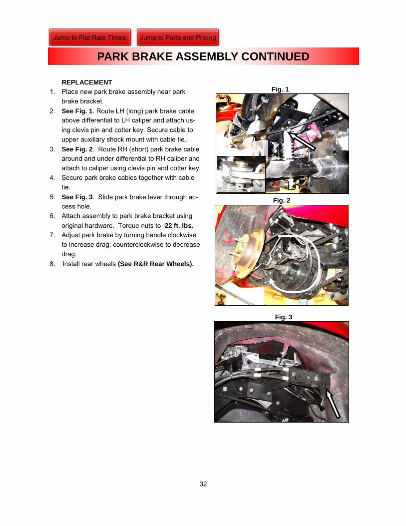
REPLACEMENT
1. Place new park brake assembly near park brake bracket.
2. See Fig. 1. Route LH (long) park brake cable above differential to LH caliper and attach us-ing clevis pin and cotter key. Secure cable to upper auxiliary shock mount with cable tie.
3. See Fig. 2. Route RH (short) park brake cable around and under differential to RH caliper and attach to caliper using clevis pin and cotter key.
4. Secure park brake cables together with cable tie.
5. See Fig. 3. Slide park brake lever through ac-cess hole.
6. Attach assembly to park brake bracket using original hardware. Torque nuts to 22 ft. lbs.
7. Adjust park brake by turning handle clockwise to increase drag; counterclockwise to decrease drag.
8. Install rear wheels (See R&R Rear Wheels).
Fig. 1
PARK BRAKE ASSEMBLY CONTINUED
Fig. 3
Fig. 2
Jump to Flat Rate Times Jump to Parts and Pricing

33
NOTE: Before bleeding brakes, make sure
there is no clearance between pads and ro-
tor.
1. Fill brake fluid reservoir with DOT 4 brake fluid. 2. Massage reservoir hose to remove any air that
may be present. 3. See Fig. 1. Attach brake bleeder fitting to RH
bleeder screw. 4. See Fig. 2. Suck out all air from brake line with
brake bleeder until fluid begins to come through by turning on the brake bleeder and slightly opening bleeder screw.
5. Tighten bleeder screw and remove brake bleeder fitting. NOTE: Keep adequate fluid level in reservoir
to prevent more air from entering lines.
6. Repeat steps 1-5 on the remaining bleeder screw using the proper sequence.
Fig. 2
Fig. 1
LH RH
BRAKE BLEEDING PROCEDURE
TOOLS REQUIRED:
BRAKE BLEEDER SYSTEM
10MM WRENCH
Jump to Flat Rate Times Jump to Parts and Pricing

34
REMOVAL
NOTE: Canadian models have a 3/8” wheel
spacer between axle flange and wheel. 1. Place trike on lift. 2. See Fig. 1. Place center stand as shown. 3. See Fig. 2. Remove rear wheel center caps
(center cap design may vary based on wheel options).
4. Loosen lug nuts with 13/16” (or 3/4” depending on wheel) shallow socket.
5. See Fig. 3. Lift trike using a jack under differ-ential carrier housing and two safety jack stands under left and right rear axles.
6. Remove lug nuts. 7. Remove LH/RH rear wheels by sliding them
out and away from body. REPLACEMENT
1. Install LH/RH rear wheels to wheel studs (Canadian models-install wheel spacer before installing wheels).
2. Install lug nuts to wheel studs. 3. Torque lug nuts to 85 ft. lbs. 4. Reinstall center caps. 5. Remove center stand. 6. Remove floor jack and jack stands. 7. Lower lift and remove trike.
Fig. 2
Fig. 1
R & R REAR WHEELS
Fig. 3
TOOLS REQUIRED:
3/8” RATCHET
13/16” DEEP SOCKET
Jump to Flat Rate Times Jump to Parts and Pricing

35
ADAPTER PLATE TO DIFFERENTIAL BOLTS...............................................................55 FT. LBS.
ADAPTER PLATE TO SWINGARM BOLTS ....................................................................55 FT. LBS.
AUXILIARY SHOCK BOLTS ............................................................................................35 FT. LBS.
AXLE FLANGE NUTS.......................................................................................................44 FT. LBS.
BANJO BOLTS .................................................................................................................16 FT. LBS.
CALIPER MOUNTING BOLTS .........................................................................................24 FT. LBS.
DIFFERENTIAL HOUSING BOLTS..................................................................................35 FT. LBS.
OEM SHOCK BOLTS........................................................................................................54 FT. LBS.
REAR WHEEL LUG NUTS................................................................................................85 FT. LBS.
SWINGARM PIVOT SHAFT..............................................................................................65 FT. LBS.
TORQUE SPECS
Jump to Flat Rate Times Jump to Parts and Pricing

PART NUMBER DESCRIPTION QTY. UNIT DLR. COST MSRPHARDWARE BAG
CB1090 SCR HX .25-20 X 1.25 ZN 1 EA. $0.10 $0.13CB1233 SCR HX .38-16 X 1.00 GR. 8 15 EA. $0.25 $0.33CB1242 SCR HX .38-16 X 1.25 GR 8 3 EA. $1.25 $1.63CB1263 SCR HX FT .38-16 X 2.50 GR. 5 ZN 2 EA. $0.60 $0.78CB1624 SCR BN SK M8-1.25 X 40 ZN 2 EA. $0.42 $0.55CN1900 NUT NL M4-0.7 CL6 ZN 4 EA. $0.21 $0.27CN1904 NUT HX M6 ZN 8 EA. $0.15 $0.20CB1904 SCR FB SK M6-1.00 X 16 CL 10.9 ZN 2 EA. $0.15 $0.20CB1907 SCR FH M6-1.00 X 16 CL 10.9 ZN 14 EA. $0.30 $0.39CB1908 SCR FH M6-1.00 X 20 CL 8.8 ZN 12 EA. $0.85 $1.11CB1915 SCR SW SK M6-1.00 X 40 ZN 2 EA. $1.15 $1.50CB1928 SCR FH M10-1.5 X 25 CL8.8 ZN 1 EA. $1.25 $1.63CB1929 SCR BN SK M8-1.25 X 30 CL 8.8 ZN 2 EA. $0.30 $0.39CB1944 SCR FH M10-1.25 X 25 CL 10.9 ZN 4 EA. $0.40 $0.52CB1971 SCR SF M10-1.5 X 30 CL10.9 ZN 4 EA. $2.36 $3.07CB1972 SCR SF M8-1.25 X 25 CL 8.8 ZN 36 EA. $0.35 $0.46CB1973 SCR SF M12-1.75 X 40 CL10.9 ZN 14 EA. $1.77 $2.30CB1974 SCR FG M10-1.5 X 90 CL 10.9 ZN 4 EA. $1.40 $1.82CB1975 SCR SK M8-1.25 X 40 CL 12.9 ZN 2 EA. $0.35 $0.46CB1976 SCR SK M8-1.25 X 60 CL 12.9 ZN 2 EA. $0.49 $0.64CB1977 SCR SF M8-1.25 X 16 CL10.9 ZN 4 EA. $1.09 $1.42CN1908 NUT NL M8-1.25 CL 8.8 ZN 4 EA. $0.25 $0.33CN3015 NUT .38-16 GR 8 ZN 1 EA. $0.15 $0.20CN3017 NUT JM .38-16 GR. 5 ZN 2 EA. $0.10 $0.13CN3042 NUT NL .25-20 GR 8 7 EA. $0.16 $0.21CN3048 NUT NL .31-18 GR. 8 2 EA. $0.50 $0.65CN3049 NUT HEX NL M10-1.50 CL 10.9 ZN 4 EA. $0.50 $0.65CN3052 NUT NL .38-16 GR. 8 ZN 2 EA. $0.23 $0.30CN3302 NUT U TYPE, #8, STEEL 4 EA. $0.70 $0.91CS4098 SCR PN PH ST #8 BP 4 EA. $0.25 $0.33CT1015 TIE NYLON, BLACK, 7.31 3 EA. $0.10 $0.13CT1020 TIE NYLON BLACK 11.1" 1 EA. $0.10 $0.13CT1026 TIE HIGH TEMP 8 EA. $1.00 $1.30CW2005 WSH FL .25 GR. 8 ZN 8 EA. $0.05 $0.07CW2010 WSH FL .31 GR. 8 2 EA. $0.11 $0.14CW2015 WSH FL .38 GR. 8 4 EA. $0.20 $0.26CW2022 WSH FL .44 GR. 8 ZN 2 EA. $0.10 $0.13CW2040 WSH LK .25 ZN 1 EA. $0.05 $0.07CW2050 WSH LK .38 GR. 8 ZN 1 EA. $0.05 $0.07CW2068 WSH EL .38 ZN 1 EA. $0.13 $0.17CW2097 WSH .31 X 1.50 X .25 RB 2 EA. $0.60 $0.78CW2109 WSH FN .34 X 1.50 X .06 ZN 8 EA. $0.20 $0.26CW2168 WSH LK M8 ZN 2 EA. $0.10 $0.13CW2535 WEATHER SEAL EPDM MED DENSITY BULB 9.5 FT. $2.90 $3.77GC0112 CLAMP DOUBLE TUBE .687" TUBE DIA. 2 EA. $0.62 $0.81
GT1800 TRIM EDGE BLACK RUBBER 1.67 FT. $1.15 $1.50LB0000 LABEL ARB UNIVERSAL 1 EA. $1.85 $2.41LB0007 FUEL CAPACITY LABEL 3.5" X 2" 1 EA. $0.25 $0.33PUB0001 MANUAL SAFETY 1 EA. $2.04 $2.65PUB0028 WARRANTY INFORMATION SHEET 1 EA. $0.15 $0.20
2010 CROSSBOW PARTS AND PRICE LIST (PRICES ARE SUBJECT TO CHANGE)
BODY
(most hardware available at your local parts store)
Jump to Flat Rate Times Jump to Service

PART NUMBER DESCRIPTION QTY. UNIT DLR. COST MSRPPUB0031 MANUAL RIDER CROSSBOW 2010 1 EA. $9.00 $11.70S001062 DOCUMENT POUCH 1 EA. $6.75 $8.78S001067 SPACER 1/2 OD X .400 ID - .375 LONG 1 EA. $12.25 $15.93S001128 BRACKET, HITCH MOUNT 1 EA. $91.00 $118.30S001132 SUPPORT BODY FRONT. PAD MTG. 2 EA. $12.00 $15.60S001376 BRACKET TRUNK RELEASE LH 1 EA. $25.20 $32.76S001377 BRACKET TRUNK RELEASE RH 1 EA. $25.20 $32.76S001387 BRACKET SIDE COVER LH 1 EA. $7.00 $9.10S001389 BRACKET SIDE COVER RH 1 EA. $7.00 $9.10S001396 BADGE CROSSBOW 1 EA. $8.20 $10.66S001409 ROD HINGE PIVOT 2 EA. $17.00 $22.10S001411 PLATE, HINGE PIVOT RETAINER 2 EA. $18.50 $24.05S001418 FOOTPAD LEFT 1 EA. $30.00 $39.00S001419 FOOTPAD RIGHT 1 EA. $30.00 $39.00S001436 BODY SIDE RH 1 EA. $1,500.00 $1,950.00S001437 BODY SIDE LH 1 EA. $1,700.00 $2,210.00S001438 DOOR RH 1 EA. $400.00 $520.00S001439 DOOR LH 1 EA. $400.00 $520.00S001511 VALANCE CENTER BODY CROSSBOW 1 EA. $108.00 $140.40S001512 BEZEL LATCH LH CROSSBOW 1 EA. $13.00 $16.90S001513 BEZEL LATCH RH CROSSBOW 1 EA. $13.00 $16.90S001421 REFLECTOR REAR 2 EA. $5.20 $6.76S001426 LABEL LEHMAN COMPLIANCE 1 EA. $1.60 $2.08S001427 GROMMET .38ID X .81OD X .50 GROOVE 2 EA. $1.50 $1.95S001430 RIVET PUSH 2 EA. $0.25 $0.33S001434 HOSE VACUUM 0.25" 2 IN. $0.10 $0.13S001442 SUPPORT, UPPER BODY 2 EA. $12.50 $16.25S001480 CLIP T-STUD 6 EA. $0.30 $0.39S001485 LABEL VECI/NECI OE VICTORY 1 EA. $1.25 $1.63S001486 LABEL PATENT NOTICE OE VICTORY 1 EA. $0.50 $0.65S001487 LABEL EVAP HOSE ROUTING OE VICTORY 1 EA. $2.50 $3.25S001488 LABEL AIR SUSPENSION ADJ. OE VICTORY 1 EA. $1.00 $1.30S001496 ARM HINGE LH 2 EA. $27.00 $35.10S001497 ARM HINGE RH 2 EA. $33.00 $42.90S001503 LABEL CLUTCH COVER 1 EA. $1.20 $1.56S001504 CABLE DOOR RELEASE 2 EA. $27.00 $35.10S001507 SEAT CHECK VALVE 1 EA. $26.00 $33.80S001508 BALL 9/64TH" STAINLESS STEEL 1 EA. $0.20 $0.26S001510 CLIP HAIRPIN 3/16-1/4"SHAFT DIA. .042 2 EA. $0.10 $0.13S001517 SPACER FRONT BODY MOUNT SUPPORT 2 EA. $20.58 $26.75S001529 BUMPER RUBBER 3/4" PYRAMID 4 EA. $0.45 $0.59S001532 BADGE LEHMAN 25 YR. ANNIVERSARY 2 EA. $3.92 $5.10S001534 BRACKET REAR BODY MOUNT RIGHT CB 1 EA. $1.80 $2.34
BODY

PART NUMBER DESCRIPTION QTY. UNIT DLR. COST MSRPCB6001 BOLT BANJO SINGLE METRIC M10 X 1.0 3 EA. $6.75 $8.78CB6003 BOLT BANJO DOUBLE .388-24 1 EA. $5.75 $7.48CC3108 PIN CLEVIS (6MM X 18MM) 2 EA. $0.25 $0.33CC4018 PIN COTTER 1/16 X 1/2 2 EA. $0.10 $0.13GC6002 WASHER COPPER BANJO SEALING M10 11 EA. $0.53 $0.69S001133 BRACKET PARK BRAKE CABLE RH 1 EA. $15.75 $20.48S001173 BRACKET PARK BRAKE CABLE LH 1 EA. $22.25 $28.93S001174 BRACKET CALIPER 2 EA. $36.00 $46.80S001221 ROTOR DISC BRAKE 2 EA. $130.00 $169.00S001222 PUSH-ROD BREMBO MASTER CYL. 10.4776 1 EA. $20.00 $26.00S001224 CYLINDER MASTER 1 EA. $55.00 $71.50S001227 PADS BRAKE ORGANIC 1 EA. $18.50 $24.05S001278 ASSEMBLY MOUNT BRAKE TEE 1 EA. $14.00 $18.20S001311 ADAPTOR BANJO 90° 3/8 MALE -03AN 1 EA. $8.63 $11.22S001312 LINE, BRAKE, 12" SOFT, FEM-FEM -03AN 1 EA. $15.00 $19.50S001350 SHIM, BRAKE, CALIPER 2 EA. $22.50 $29.25S001352 ADAPTER BANJO TWIN 1 EA. $18.00 $23.40S001353 LINE BRAKE STAINLESS BRAIDED 32" 1 EA. $27.00 $35.10S001357 BRACKET PARK BRAKE 1 EA. $51.80 $67.34S001379 ASSEMBLY PARK BRAKE 1 EA. $135.80 $176.54S001413 BRACKET ADAPTOR CYLINDER MASTER 1 EA. $8.50 $11.05S001414 ADAPTOR BARBED UNION 1/4 X 3/8 1 EA. $2.75 $3.58S001416 ADAPTOR MALE TO FEMALE 1 EA. $4.25 $5.53S001428 ADAPTOR BANJO 45° 3/8 MALE -03AN 2 EA. $9.00 $11.70S001435 SHIM CALIPER BRAKE 2 EA. $20.02 $26.03S001429 LINE BRAKE STAINLESS BRAIDED 26" 1 EA. $25.00 $32.50S001432 BOOT PARK BRAKE 1 EA. $20.00 $26.00S001474 CALIPER BRAKE RH 1 PC. $210.00 $273.00S001475 CALIPER BRAKE LH 1 PC. $210.00 $273.00S001502 BLT BANJO M10-1.25 1 EA. $14.25 $18.53S001509 BLT BANJO M10-1.25 VICTORY OEM 1 EA. $14.25 $18.53
PART NUMBER DESCRIPTION UNIT QTY. DLR. COST MSRPGB1024 BEARING SWINGARM OE VICTORY 6004 2 EA. $30.00 $39.00GB1032 BEARING SWINGARM OE VICTORY 3514413 1 EA. $18.86 $24.52MA2012 AXLE LONG 23-SPLINE 1 EA. $160.00 $208.00MA2013 AXLE SHORT 23-SPLINE 1 EA. $150.00 $195.00S001146 ASSEMBLY DIFFERENTIAL 1 EA. $1,000.00 $1,300.00
CB1168 SCR BN SK .31-24 X 1.25 6 EA. $0.49 $0.64CB1696 BOLT-T 3/8 N.F. 8 EA. $1.85 $2.41CF5112 FITTING BRASS 3/16 INV X 1/8 NPT 2 EA. $2.00 $2.60CN3101 NUT PL .38-24 GR 8 ZN 8 EA. $0.15 $0.20CW2015 WSH FL .38 GR. 8 4 EA. $0.20 $0.26CW2049 WSH LK .38 GR 8 20 EA. $0.15 $0.20LB1118 BRACKET-BIG TWIN DEBRIS 1 EA. $10.50 $13.65LS1018 SHIELD DEBRIS-BIG TWIN DIFF 1 EA. $29.72 $38.64LS1196 SPACER 5/8OD X .319ID-5/16 LONG 6 EA. $0.60 $0.78S001329 BRACKET DIFFERENTIAL MTG 2 EA. $62.40 $81.12
S001200 SPACER SWINGARM ADAPTER RH 1 EA. $182.00 $236.60S001201 SPACER SWINGARM ADAPTER LH 1 EA. $182.00 $236.60S001228 SHIM AXLE RETAINER 2 EA. $34.00 $44.20S001238 BRACE REAR DIFFERENTIAL 1 EA. $32.50 $42.25S001239 BRACE FRONT DIFFERENTIAL 1 EA. $26.00 $33.80S001333 RING RETAINING OE VICTORY 1 EA. $2.60 $3.38S001335 PIVOT SWINGARM OE VICTORY 1 EA. $43.00 $55.90S001338 SEAL SWINGARM OE VICTORY 2 EA. $5.60 $7.28S001366 ASSEMBLY CARRIER/PULLEY 1 EA. $585.00 $760.50
BRAKES
DRIVE

PART NUMBER DESCRIPTION UNIT QTY. DLR. COST MSRPCC2012 CLAMP HOSE 29/64-17/32" OETIKER 2 EA. $0.80 $1.04S001166 PIPE EXHAUST LH 1 EA. $65.00 $84.50S001167 PIPE EXHAUST RH 1 EA. $135.00 $175.50S001402 SHIELD HEAT EXHAUST LH 1 EA. $43.00 $55.90S001412 CLAMP EXHAUST OE VICTORY 1 EA. $12.50 $16.25S001498 BRACKET EXHAUST SUPPORT 1 EA. $15.00 $19.50S001499 CLAMP U BOLT 3/8-16 1 EA. $3.50 $4.55
PART NUMBER DESCRIPTION UNIT QTY. DLR. COST MSRPS001197 FRAME MAIN 1 EA. $240.50 $312.65
PART NUMBER DESCRIPTION UNIT QTY. DLR. COST MSRPS001154 STOP BUMP 1 EA. $6.75 $8.78S001159 CLEVIS SHOCK MOUNT 1 EA. $8.25 $10.73S001203 BRACKET UPPER SHOCK MTG. 1 EA. $43.00 $55.90S001233 SHOCK AUXILIARY 1 EA. $200.00 $260.00S001236 BUSHING SHOCK MOUNT 4 EA. $9.90 $12.87S001385 BEARING SPHERICAL OE VICTORY 2 EA. $25.00 $32.50
PART NUMBER DESCRIPTION UNIT QTY. DLR. COST MSRPWK0035 KIT WHEEL SILVER 205-60/R 1 SET $480.00 $624.00
CN3135 NUT LUG OPEN BULGE 1/2-20 8 EA. $0.65 $0.85GT1972 TIRE 205-60/R15 DUNLOP 2 EA. $99.00 $128.70HW0053 WHEEL SILVER 09 STANDARD 2 EA. $90.00 $117.00
S001505 SPACER WHEEL 3/8" (CN MODELS ONLY) 2 EA. $12.00 $15.60S001506 PLATE BALLAST 10 LB. (CN MODELS ONLY) 1 EA. $15.00 $19.50
CB1610 SCR HX M12-1.75 X 50 CL10.9 ZN 4 EA. $2.00 $2.60CN1916 NUT NL M12-1.75 CL10.9 ZN 4 EA. $1.20 $1.56
WHEEL
EXHAUST
FRAME
SUSPENSION

QTY. TIME
1 0.201 0.501 0.302 0.401 0.20
1 1.401 1.50
1 0.302 0.601 0.75
1 0.602 1.20
1 1.252 2.501 2.751 2.25
1 3.75
1 2.00
1 0.302 0.501 0.75
1 0.752 1.50
Auxiliary Shock R&R
CROSSBOW FLAT RATE TIMES
Trunk Door Seal R&RTrunk Door R&RPassenger Footpad R&R
BODYFLAT RATE PROCEDURE
DRIVE
Brake Pads R&R
Trunk Door Latch Assembly R&R
BRAKE
Body R&R LHBody R&R RH
Drive Belt R&R (Reverse Models)
Swingarm R&R
Differential R&R
Exhaust, Muffler Assembly R&R
Axle R&R
Drive Belt R&R (Non Reverse Models)
Park Brake Assembly R&R
Brake Caliper R&R
Axle Bearing R&R
Jump to Parts and Pricing Jump to Service Procedures

ADAPTER-DIFF-MOUNTING-s001199 ARM-HINGE-LH-s001496
ARM-HINGE-RH-s001497 ASSEMBLY-PARK BRAKE-s001379
ASSEMLBLY-DIFFERENTIAL-s001146 AXLE-LONG-ma2012
AXLE-SHORT-ma2013 BRACE-FRONT-DIFFERENTIAL-s001239

BRACE-REAR-DIFF-s001238 BRACKET- PARK BRAKE-s001357
BRACKET-ADAPTER-MASTER CYLINDER-s001413 BRACKET-BODY-EXHAUST-s001145
BRACKET-CALIPER-s001174 BRACKET-EXHAUST-SUPPORT-s001498
BRACKET-HITCH MOUNT-s001128 BRACKET-MOUNTING, SHOCK-s001203

BRACKET-PARK BRAKE CABLE-LH-s001173 BRACKET-PARK BRAKE CABLE-RH-s001133
BRACKET-SIDE COVER-LH-s001387 BRACKET-SIDE COVER-RH-s001389
BRACKET-TRUCK RELEASE-LH-s001376 BRACKET-TRUNK RELEASE-RH-s001377
CARRIER-PULLEY-s001366 CLEVIS-SHOCK MOUNT-s001159

COLLAR-RELEASE CABLE-TRUNK-s001441 FRAME-MAIN-s001197
MOUNT-BRAKE TEE-s001278 PIPE-EXHAUST-LH-s001166
PIPE-EXHAUST-RH-s001167 PLATE-HINGE PIVOT-s001411
PLATE-STRIKER MOUNTING BASE-s001457 PLATE-TAPPED TRUNK RELEASE-s001345

SHIELD-HEAT-EXHAUST-LH-s001402 SHIM-AXLE RETAINER-s001228
SHIM-BRAKE CALIPER-s001350 SPACER-SWINGARM ADAPTER-RH-s001200
SPACER-SWINGARM ADAPTER, LH-s001201 STOP-BUMP-s001154
SUPPORT-UPPER BODY-s001442 SWINGARM-s001198