2008 p upplement - lehman trikes · 2008 pit boss clip out and mail or fax to: lehman trikes usa,...
TRANSCRIPT

22000088 PPaarrttss SSuupppplleemmeenntt SSuupppplleemmeenntt ttoo VViiccttoorryy®® KKiinnggppiinn™™ PPaarrttss MMaannuuaall
S001016
NOTE:
Throughout this manual, a vendor reference of “various” refers to your local parts supply store or warehouse. Be sure to follow all DOT and grade
specifications listed in this manual when buying parts.
PB0208V2GR © 2008. All rights reserved. Lehman Trikes® provides this publication as is without warranty of any kind, either expressed or implied. While every precaution has been taken in the preparation of this manual, Lehman Trikes® assumes no responsibility for errors or omissions. Neither is any liability assumed for damages resulting from the use of the information contained herein. Lehman Trikes® reserves the right to revise and improve its products as it sees fit. This publication describes the state of this product at the time of its publication, and may not reflect the product in the future. Lehman Trikes® is a registered trademark. All other brands and product names are trademarks or registered trademarks of their respective holders. Printed in the United States of America.

Reader’s Comments
Lehman Trikes continuously strives to improve the quality and usefulness of its publications. To do this effectively we need user feedback—your critical evaluation of this manual. Please comment on this manual’s completeness, accuracy, organization, usability and readability.
___________________________________________________________ ___________________________________________________________ ___________________________________________________________ ___________________________________________________________
Did you find errors in this manual? ___________________________________________________________ ___________________________________________________________ ___________________________________________________________ ___________________________________________________________ How can this manual be improved? ___________________________________________________________ ___________________________________________________________ ___________________________________________________________ ___________________________________________________________
Name ______________________________________________________ Occupation _________________________________________________ Dealership_______________________ Department________________ Street______________________________________________________ City __________________ State __________________ Zip __________
2008 PIT BOSS Clip out and mail or fax to: Lehman Trikes USA, Inc. Technical Communications 125 Industrial Drive Spearfish, SD 57783 Fax- 605-642-1182

PIT BOSS POWERED BY VICTORY®
PARTS DESCRIPTION INDEX
A
ACTUATOR, TRUNK RELEASE ..................... 21 ASSEMBLY, AXLE, LEFT................................ 19 ASSEMBLY, AXLE, RIGHT ............................. 19 ASSEMBLY, CARRIER ................................... 19 ASSEMBLY, DIFFERENTIAL .......................... 19 ASSEMBLY, PULLEY, REAR.......................... 19 ASSEMBLY, TRUNK LATCH........................... 21 ASSEMBLY., PARK BRAKE............................ 15
B
BADGE, VICTORY .......................................... 23 BAR, STABILIZER ........................................... 11 BEARING, AXLE.............................................. 19 BEARING, SWINGARM..................................... 9 BELT, DRIVE................................................... 19 BODY............................................................... 21 BOLT, BANJO.................................................. 13 BRACE, BODY MOUNT, LH............................ 13 BRACE, BODY MOUNT, RH ........................... 13 BRACE, FRAME, BOTTOM............................. 11 BRACE, FRAME, LH ....................................... 11 BRACE, FRAME, RH....................................... 11 BRACE, SHOCK, LH ......................................... 9 BRACE, SHOCK, RH......................................... 9 BRACKET, AUTO CANCEL MODULE ............ 23 BRACKET, CABLE PULLING.......................... 15 BRACKET, DRIVER SEAT, BACKREST......... 23 BRACKET, FRONT BODY MOUNT, LH.......... 13 BRACKET, FRONT BODY MOUNT, RH ......... 13 BRACKET, LATCH, MOUNT ........................... 21 BRACKET, LATCH/ACTUATOR MOUNT........ 21 BRACKET, LICENSE PLATE .......................... 23 BRACKET, LOWER SHOCK MOUNT ............... 9 BRACKET, PARK BRAKE ............................... 15 BRACKET, PIN, STRIKER............................... 21 BRACKET, REAR, LH, EXHAUST MOUNT..... 17 BRACKET, REAR, RH, EXHAUST MOUNT.... 17 BRACKET, STABILIZER BAR ......................... 11 BRACKET, TAILLIGHT MOUNT...................... 23 BRACKET, UPPER AUX. SHOCK..................... 9 BUSHING, POLY-URETHANE .......................... 9 BUSHING, SHOCK............................................ 9
C
CABLE, PARK BRAKE, LONG ........................ 15 CABLE, PARK BRAKE, SHORT...................... 15 CABLE, TRUNK, SAFETY RELEASE ............. 21 CALIPER, BRAKE ........................................... 13 CLAMP, EXHAUST.......................................... 17 CONNECTOR, VALVE, RESIDUAL ................ 13 COVER, RESERVOIR ..................................... 13
CYLINDER, MASTER...................................... 13
D
DOOR, TRUNK................................................ 21
F
FITTING, BRASS, DIFF. .................................. 19 FOOTPAD, LH ................................................. 21 FOOTPAD, RH................................................. 21 FRAME, LICENSE PLATE............................... 23
G
GASKET, BODY, FRONT ................................ 21 GASKET, BODY, REAR ...................................21 GASKET, HANDLE, GRAB.............................. 21 GASKET, RESERVOIR COVER...................... 13
H
HANDLE, GRAB, LH/RH.................................. 21 HANDLE, PARK BRAKE.................................. 15 HARNESS, TRUNK ACTUATOR..................... 23 HARNESS, WIRING ........................................ 23 HINGE, TRUNK ............................................... 21 HOSE, BRAKE................................................. 13
K
KIT, BRAKE LINE, BRAIDED........................... 13 KIT, DISC BRAKE (INCLUDES PARK BRAKE
ASSM.)........................................................ 13 KIT, WHEEL..................................................... 23
L
LAMP, TAIL...................................................... 23 LATCH, STRIKER PIN..................................... 21 LATCH, TRUNK............................................... 21 LINER, TRUNK ................................................ 23
M
MANUAL, OWNER’S ....................................... 23
4

PIT BOSS POWERED BY VICTORY®
5
N
NIPPLE, GREASE ZERK, DIFF....................... 19
P
PADS, CALIPER.............................................. 13 PIN, SHOCK ...................................................... 9 PIPE, EXHAUST, FRONT, LH ......................... 17 PIPE, EXHAUST, REAR, LH ........................... 17 PIPE, EXHAUST, REAR, RH........................... 17 PLATE, MOUNT, DIFFERENTIAL ................... 19
R
RAIL, FRAME, LH............................................ 11 RAIL, FRAME, RH ........................................... 11 REFLECTOR, RED, ASSEMBLY .................... 23 RESERVOIR, MASTER CYLINDER................ 13 ROD, END, LH................................................. 11 ROD, END, RH ................................................ 11 ROTOR, DISC, BRAKE ................................... 13
S
SEAL, NEEDLE BEARING ................................ 9
SHIELD, DEBRIS, DIFFERENTIAL ................. 19 SHOCK, REAR ................................................. 9 SPACER, DISC BRAKE................................... 13 SPACER, FRAME, REAR................................ 11 SPACER, LICENSE PLATE MOUNT............... 23 SPACER, STAB. BAR...................................... 11 STUD, AXLE .................................................... 23 SWINGARM...................................................... 9
T
TIE, CABLE...................................................... 23 TIRE, REAR..................................................... 23
V
VALVE, RESIDUAL, PRESSURE.................... 13
W
WHEEL, CHROME PLATED ........................... 23 WRENCH, HEX, REMOVAL ............................ 23 WRENCH, SPANNER, SHOCK........................ 9

PIT BOSS POWERED BY VICTORY®
PART NUMBER INDEX
1
1910620........................................................... 13
3
3211102........................................................... 19 3610096............................................................. 9
C
CB1697............................................................ 13 CC2017............................................................ 17 CF5112 ............................................................ 19 CH1008............................................................ 13 CN1100............................................................ 19 CR1810............................................................ 11 CR1811............................................................ 11 CS1001............................................................ 23 CT1015 ............................................................ 23 CT1026 ............................................................ 23
G
GB0320.............................................................. 9 GB1001............................................................ 19 GB1024.............................................................. 9 GB1032.............................................................. 9 GB1099M......................................................... 15 GB1139............................................................ 13 GB1146............................................................ 13 GB1154............................................................ 13 GB1180............................................................ 15 GB1181............................................................ 15 GB1326............................................................ 23 GB6211............................................................ 13 GB6213............................................................ 13 GC1015 ........................................................... 17
H
HW0050........................................................... 23
L
LB1294 ............................................................ 15 LB1298 .............................................................. 9 LB6419 ............................................................ 11 LB6600 ............................................................ 11 LB6601 ............................................................ 11 LB6602 ............................................................ 11
LB6605............................................................. 13 LB6606............................................................. 13 LB6609.............................................................. 9 LB6610.............................................................. 9 LB6611.............................................................. 9 LB6616............................................................. 15 LB6627............................................................. 11 LC6201 ............................................................ 13 LCK5100 .......................................................... 13 LCK5100-1....................................................... 13 LCK5100-2....................................................... 13 LCK5100-3....................................................... 13 LCK5100-4....................................................... 13 LCK5100-5....................................................... 13 LCK5100-6....................................................... 15 LD1103 ............................................................ 19 LD6600 ............................................................ 19 LF6602............................................................. 11 LG6601 ............................................................ 21 LG6602 ............................................................ 21 LP2010..............................................................19 LP6400............................................................. 19 LP6601............................................................. 17 LP6602............................................................. 17 LP6603............................................................. 17 LP6605.............................................................. 9 LS0600.............................................................. 9 LS0601.............................................................. 9 LS1018............................................................. 19 LS6408............................................................. 11 LS6600.............................................................. 9 LS6601............................................................. 11 LT6601............................................................. 23
M
MA2012............................................................ 19 MA2013............................................................ 19
S
S001000............................................................ 9 S001001........................................................... 17 S001002........................................................... 17 S001003........................................................... 11 S001004........................................................... 23 S001007........................................................... 23 S001013........................................................... 23 S001015........................................................... 23 S001021........................................................... 13 S001022........................................................... 13 S001023........................................................... 21 S001025........................................................... 23 S001026........................................................... 21 S001027........................................................... 21 S001028........................................................... 23 S001029........................................................... 21 S001030........................................................... 21
6

PIT BOSS POWERED BY VICTORY®
7
S001033 .......................................................... 23 S001034 .......................................................... 23 S001035 .......................................................... 21 S001037 .......................................................... 23 S001038 .......................................................... 21 S001039 .......................................................... 23 S001040 .......................................................... 23 S001043 .......................................................... 21 S001044 .......................................................... 21 S001053 .......................................................... 21
S001054........................................................... 21 S001055........................................................... 21 S001056........................................................... 21 S001058........................................................... 21
W
WK0029 ........................................................... 23

PIT BOSS POWERED BY VICTORY®
8
# 2
# 3
# 5
# 8
# 7
# 6
# 1
# 4
PIT BOSS POWERED BY VICTORY®
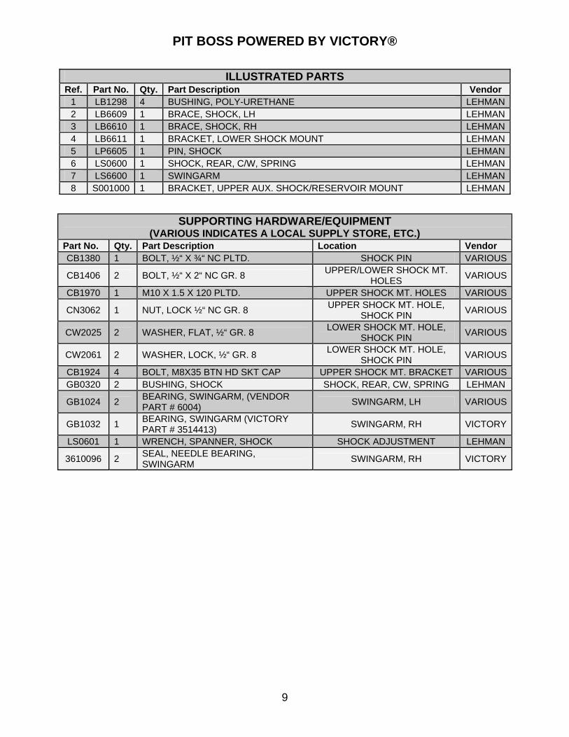
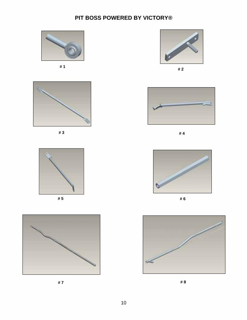
ILLUSTRATED PARTS Ref. Part No. Qty. Part Description Vendor
1 LB1298 4 BUSHING, POLY-URETHANE LEHMAN2 LB6609 1 BRACE, SHOCK, LH LEHMAN3 LB6610 1 BRACE, SHOCK, RH LEHMAN4 LB6611 1 BRACKET, LOWER SHOCK MOUNT LEHMAN5 LP6605 1 PIN, SHOCK LEHMAN6 LS0600 1 SHOCK, REAR, C/W, SPRING LEHMAN7 LS6600 1 SWINGARM LEHMAN8 S001000 1 BRACKET, UPPER AUX. SHOCK/RESERVOIR MOUNT LEHMAN
SUPPORTING HARDWARE/EQUIPMENT (VARIOUS INDICATES A LOCAL SUPPLY STORE, ETC.)
Part No. Qty. Part Description Location Vendor CB1380 1 BOLT, ½“ X ¾“ NC PLTD. SHOCK PIN VARIOUS
CB1406 2 BOLT, ½“ X 2“ NC GR. 8 UPPER/LOWER SHOCK MT.
HOLES VARIOUS
CB1970 1 M10 X 1.5 X 120 PLTD. UPPER SHOCK MT. HOLES VARIOUS
CN3062 1 NUT, LOCK ½“ NC GR. 8 UPPER SHOCK MT. HOLE,
SHOCK PIN VARIOUS
CW2025 2 WASHER, FLAT, ½“ GR. 8 LOWER SHOCK MT. HOLE,
SHOCK PIN VARIOUS
CW2061 2 WASHER, LOCK, ½“ GR. 8 LOWER SHOCK MT. HOLE,
SHOCK PIN VARIOUS
CB1924 4 BOLT, M8X35 BTN HD SKT CAP UPPER SHOCK MT. BRACKET VARIOUSGB0320 2 BUSHING, SHOCK SHOCK, REAR, CW, SPRING LEHMAN
GB1024 2 BEARING, SWINGARM, (VENDOR PART # 6004)
SWINGARM, LH VARIOUS
GB1032 1 BEARING, SWINGARM (VICTORY PART # 3514413)
SWINGARM, RH VICTORY
LS0601 1 WRENCH, SPANNER, SHOCK SHOCK ADJUSTMENT LEHMAN
3610096 2 SEAL, NEEDLE BEARING, SWINGARM
SWINGARM, RH VICTORY
9
PIT BOSS POWERED BY VICTORY®
10
# 1 # 2
# 5
# 3 # 4
# 6
# 7 # 8

PIT BOSS POWERED BY VICTORY®
ILLUSTRATED PARTS Ref. Part No. Qty. Part Description Vendor 1 CR1810 1 ROD, END, RH, ½” -20 , MALE LEHMAN1 CR1811 1 ROD, END, LH, ½” -20, MALE LEHMAN2 LB6419 1 BRACKET, STABILIZER BAR LEHMAN3 LB6600 1 BRACE, FRAME, BOTTOM LEHMAN4 LB6601 1 BRACE, FRAME, LH LEHMAN5 LB6602 1 BRACE, FRAME, RH LEHMAN6 LB6627 1 BAR, STABILIZER LEHMAN7 S001003 1 RAIL, FRAME, LH LEHMAN8 LF6602 1 RAIL, FRAME, RH LEHMAN
SUPPORTING HARDWARE/EQUIPMENT (VARIOUS INDICATES A LOCAL SUPPLY STORE, ETC.)
Part No. Qty. Part Description Location Vendor
CB1234 2 BOLT, 3/8” X 1” NC GR. 8 FRAME RAIL-SHOCK MT. BRACKET
VARIOUS
CB1242 2 BOLT, 3/8” X 1 ¼” NC GR. 8 STABILIZER BAR-DIFF. HOUSING
VARIOUS
CB1268 3 BOLT, 3/8” X 2 ½” NC GR. 8 FRAME RAIL-MUFFLER MT. BRACKET
VARIOUS
CB1299 1 BOLT, 3/8” X 6 NC GR. 8 HEX HD. FRAME RAIL-MUFFLER MT. BRACKET
VARIOUS
CB1406 1 BOLT, ½” X 2 NC GR. 8 STAB. BAR-SWINGARM VARIOUS CN3026 2 NUT, ½” NF PLTD., GR. 8 STAB. BAR-SWINGARM VARIOUS
CN3062 3 NUT, ½” NC GR. 8 NYLOCK STAB. BAR-STAB. BAR BRACKET
VARIOUS
CW2025 1 WASHER, FLAT, ½” GR. 8 STAB. BAR-STAB. BAR BRACKET
VARIOUS
CW2049 1 WASHER, LOCK, 3/8” GR. 8 STAB. BAR-DIFF. HOUSING VARIOUS LS6408 1 SPACER, STAB. BAR STAB. BAR BRACKET LEHMAN LS6601 1 SPACER, FRAME, REAR FRAME RAIL LEHMAN
11

PIT BOSS POWERED BY VICTORY®
# 1 # 2
# 3 # 4
12

PIT BOSS POWERED BY VICTORY®
ILLUSTRATED PARTS Ref. Part No. Qty. Part Description Vendor
1 S001021 1 BRACKET, FRONT BODY MOUNT, LH LEHMAN
2 S001022 1 BRACKET, FRONT BODY MOUNT, RH LEHMAN
3 LB6605 1 BRACE, BODY MOUNT, LH LEHMAN
4 LB6606 1 BRACE, BODY MOUNT, RH LEHMAN
SUPPORTING HARDWARE/EQUIPMENT (VARIOUS INDICATES A LOCAL SUPPLY STORE, ETC.)
Part No. Qty. Part Description Location Vendor
CB1162 2 BOLT, 5/16” X 1” Z FL SER. BODY MOUNT
BRACKETS VARIOUS
CB1950 2 BOLT, M10 X 1.5 X 60 PLTD. FLG HX SHOCK MT. BRACE VARIOUS CB1936 2 BOLT, M10 X 1 X 60 SHCS Z 12.9 BODY BRACES VARIOUS GB1139 1 KIT, BRAKE LINE, BRAIDED ASSM., BRAKES LEHMAN 1910620 1 CYLINDER, MASTER ASSM., BRAKES VICTORY GB6211 1 RESERVOIR, MASTER CYLINDER ASSM., BRAKES LEHMAN GB6213 1 GASKET, RESERVOIR COVER ASSM., BRAKES LEHMAN LC6201 1 COVER, RESERVOIR ASSM., BRAKES LEHMAN
LCK5100 1 KIT, DISC BRAKE (INCLUDES PARK BRAKE ASSM.)
ASSM., BRAKES LEHMAN
LCK5100-1
2 CALIPER, BRAKE, 1.38” ASSM., BRAKES LEHMAN
LCK5100-2
2 ROTOR, DISC, BRAKE, .188” X 11.59” ASSM., BRAKES LEHMAN
LCK5100-3
1 PADS, CALIPER, DISC BRAKE (SET) ASSM., BRAKES LEHMAN
LCK5100-4
2 SPACER, DISC BRAKE, .630” ASSM., BRAKES LEHMAN
LCK5100-5
2 SPACER, DISC BRAKE, 1.03” ASSM., BRAKES LEHMAN
CB1095 1 BOLT, .25-20NC X 1.5 LG HHCS ASSM., RES. VALVE VARIOUS CC2013 3 CLAMP, HOSE, BRAKE, ¾” X 1 ¾” ASSM., BRAKES VARIOUS CW2005 2 WASHER, FLAT, ¼” GR. 8 ASSM., BRAKES VARIOUS CB1697 1 BOLT, BANJO ASSM., BRAKES VARIOUS CH1008 1 HOSE, BRAKE, 5/16”, D.O.T. COMP. (13.5”) ASSM., BRAKES VARIOUS CN3042 3 NUT, LOCK, ¼” NC GR. 8 ASSM., BRAKES VARIOUS CS4065 2 SCREW, MACH., 10-32 X ½” PHLPS HD. ASSM., BRAKES VARIOUS CB1903 2 BOLT, 10-32 X 3/4 SHCS Z ASSM., BRAKES VARIOUS GB1146 1 VALVE, RESIDUAL, PRESSURE ASSM., RES. VALVE LEHMAN GB1154 1 CONNECTOR, VALVE, RESIDUAL ASSM., RES. VALVE LEHMAN GC6002 2 WASHER, COPPER, BANJO SEALING ASSM., BRAKES VARIOUS S001099 1 FITTING, -3AN FEM TO M10-1.25 FEM ASSM., RES. VALVE LEHMAN S001103 1 SPACER, ALU., 1/2"OD X 1/4 ID-1/4" LON ASSM., RES. VALVE VARIOUS
13

PIT BOSS POWERED BY VICTORY®
# 1 # 2
# 3 # 4
# 5
14

PIT BOSS POWERED BY VICTORY®
15
ILLUSTRATED PARTS Ref. Part No. Qty. Part Description Vendor 1 GB1099M 1 HANDLE, PARK BRAKE LEHMAN 2 GB1180 1 CABLE, PARK BRAKE, SHORT (42.5”) LEHMAN 3 GB1181 1 CABLE, PARK BRAKE, LONG (64”) LEHMAN 4 LB1294 1 BRACKET, CABLE PULLING LEHMAN 5 LB6616 1 BRACKET, PARK BRAKE LEHMAN
SUPPORTING HARDWARE/EQUIPMENT (VARIOUS INDICATES A LOCAL SUPPLY STORE, ETC.)
Part No. Qty. Part Description Location Vendor CB1156 2 BOLT, 5/16” X ¾” NC BTN. HD SS ASSM., PARK
BRAKE VARIOUS
CC2023 1 BRAKE LINE SPLICE (VENDOR PART # 90-554)
ASSM., PARK BRAKE
VARIOUS
CC3106 1 PIN CLEVIS, 5/16” X 19/32” 50/BX ASSM., PARK BRAKE
LEHMAN
CC4017 1 PIN, COTTER, 3/32” X ½” ASSM., PARK BRAKE
LEHMAN
CN3009 4 NUT, 5/16” NF GR. 8 ASSM., PARK BRAKE
VARIOUS
CW2010 2 WASHER, FLAT, 5/16” ASSM., PARK BRAKE
VARIOUS
CW2049 2 WASHER, LOCK, 5/16” GR. 8 ASSM., PARK BRAKE
VARIOUS
LCK5100-6
1 ASSM., PARK BRAKE, LH/RH ASSM., PARK BRAKE
LEHMAN

PIT BOSS POWERED BY VICTORY®
# 1 # 2
# 3 # 4
# 5
16

PIT BOSS POWERED BY VICTORY®
ILLUSTRATED PARTS Ref. Part No. Qty. Part Description Vendor 1 LP6601 1 PIPE, EXHAUST, FRONT, LH LEHMAN 2 LP6602 1 PIPE, EXHAUST, REAR, LH LEHMAN 3 LP6603 1 PIPE, EXHAUST, REAR, RH LEHMAN 4 S001001 1 BRACKET, REAR, RH, EXHAUST MOUNT LEHMAN 5 S001002 1 BRACKET, REAR, LH, EXHAUST MOUNT LEHMAN
SUPPORTING HARDWARE/EQUIPMENT
(VARIOUS INDICATES A LOCAL SUPPLY STORE, ETC.) Part No. Qty. Part Description Location Vendor CC2017 1 CLAMP, EXHAUST, SIZE 32 EXHAUST ASSM. VARIOUS GC1015 3 CLAMP, EXHAUST, 47-51MM EXHAUST ASSM. VARIOUS
17

PIT BOSS POWERED BY VICTORY®
# 1 # 2
# 3 # 4
# 5 # 6
# 7
18
PIT BOSS POWERED BY VICTORY®
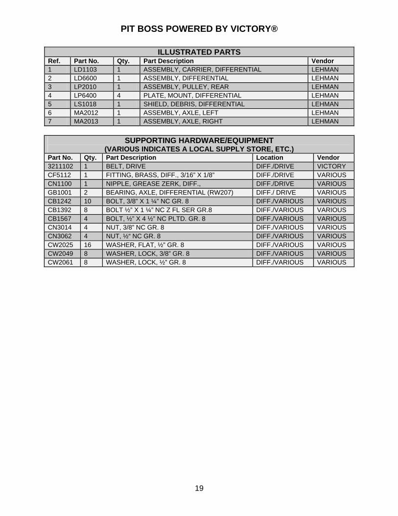
ILLUSTRATED PARTS Ref. Part No. Qty. Part Description Vendor 1 LD1103 1 ASSEMBLY, CARRIER, DIFFERENTIAL LEHMAN 2 LD6600 1 ASSEMBLY, DIFFERENTIAL LEHMAN 3 LP2010 1 ASSEMBLY, PULLEY, REAR LEHMAN 4 LP6400 4 PLATE, MOUNT, DIFFERENTIAL LEHMAN 5 LS1018 1 SHIELD, DEBRIS, DIFFERENTIAL LEHMAN 6 MA2012 1 ASSEMBLY, AXLE, LEFT LEHMAN 7 MA2013 1 ASSEMBLY, AXLE, RIGHT LEHMAN
SUPPORTING HARDWARE/EQUIPMENT
(VARIOUS INDICATES A LOCAL SUPPLY STORE, ETC.) Part No. Qty. Part Description Location Vendor 3211102 1 BELT, DRIVE DIFF./DRIVE VICTORY CF5112 1 FITTING, BRASS, DIFF., 3/16” X 1/8” DIFF./DRIVE VARIOUS CN1100 1 NIPPLE, GREASE ZERK, DIFF., DIFF./DRIVE VARIOUS GB1001 2 BEARING, AXLE, DIFFERENTIAL (RW207) DIFF./ DRIVE VARIOUS CB1242 10 BOLT, 3/8” X 1 ¼” NC GR. 8 DIFF./VARIOUS VARIOUS CB1392 8 BOLT ½” X 1 ¼” NC Z FL SER GR.8 DIFF./VARIOUS VARIOUS CB1567 4 BOLT, ½” X 4 ½” NC PLTD. GR. 8 DIFF./VARIOUS VARIOUS CN3014 4 NUT, 3/8” NC GR. 8 DIFF./VARIOUS VARIOUS CN3062 4 NUT, ½“ NC GR. 8 DIFF./VARIOUS VARIOUS CW2025 16 WASHER, FLAT, ½” GR. 8 DIFF./VARIOUS VARIOUS CW2049 8 WASHER, LOCK, 3/8” GR. 8 DIFF./VARIOUS VARIOUS CW2061 8 WASHER, LOCK, ½” GR. 8 DIFF./VARIOUS VARIOUS
19

PIT BOSS POWERED BY VICTORY®
# 1
# 3
# 2
# 4
# 6 # 5
20

PIT BOSS POWERED BY VICTORY®
ILLUSTRATED PARTS Ref. Part No. Qty. Part Description Vendor 1 S001026 1 BODY, COMPLETE LEHMAN 2 S001027 1 DOOR, TRUNK LEHMAN 3 S001035 2 HANDLE, GRAB, LH/RH LEHMAN 4 S001038 1 HINGE, TRUNK LEHMAN 5 S001044 1 BRACKET, PIN, STRIKER LEHMAN 6 S001053 1 ASSEMBLY, TRUNK LATCH LEHMAN
SUPPORTING HARDWARE/EQUIPMENT (VARIOUS INDICATES A LOCAL SUPPLY STORE, ETC.)
Part No. Qty. Part Description Location Vendor CB1084 8 BOLT, ¼” X ¾” BUTTON SOC CAP SS ASSM., BODY VARIOUSCB1153 1 BOLT, 5/16” X ½” NC PLTD. (HINGE STOP BOLT) ASSM., BODY VARIOUSCB1159 2 BOLT 5/16” X 1” NC BUTTON HD SS ASSM., BODY VARIOUSCB1161 2 BOLT, 5/16” X 1” NC GR. 8 ASSM., BODY VARIOUSCB1162 4 BOLT 5/16”-18 X 1 Z FL HX SERR GRAB
HANDLES VARIOUS
CC1901 1 CLAMP, CABLE, TRUNK (FASTENAL PART # C0L1Z0921)
ASSM., TRUNK VARIOUS
CN3042 4 NUT, LOCK ¼” GR. 8 ASSM., TRUNK VARIOUSCN3048 2 NUT, LOCK 5/16” NC GR.8 ASSM., BODY VARIOUSCS4066 1 SCREW MACH. 10-32” X ½” RD. HD ASSM., BODY VARIOUSCW2005 8 WASHER, FLAT, ¼” GR. 8 ASSM., TRUNK VARIOUSCW2010 4 WASHER, FLAT 5/16” GR. 8 ASSM., BODY VARIOUSCW2041 8 WASHER, LOCK ¼” SS ASSM., BODY VARIOUSCW2109 6 WASHER, FENDER, 5/16” X 1 1/2” ASSM., BODY VARIOUSLG6601 2 GASKET, BODY, REAR ASSM., BODY LEHMAN LG6602 2 GASKET, BODY, FRONT ASSM., BODY LEHMAN S001023 1 BRACKET, LATCH/ACTUATOR MOUNT ASSM., TRUNK LEHMAN S001029 1 LATCH, TRUNK ASSM., TRUNK LEHMAN S001030 1 LATCH, STRIKER PIN ASSM., TRUNK LEHMAN S001043 1 ACTUATOR, TRUNK RELEASE ASSM., TRUNK LEHMAN S001054 1 BRACKET, LATCH, MOUNT ASSM., BODY LEHMAN S001055 1 FOOTPAD, LH ASSM., BODY LEHMAN S001056 1 FOOTPAD, RH ASSM., BODY LEHMAN S001058 4 GASKET, HANDLE, GRAB ASSM., BODY LEHMAN S001061 1 CABLE, TRUNK, SAFETY RELEASE ASSM., TRUNK LEHMAN
21

PIT BOSS POWERED BY VICTORY®
#4
# 2 # 1
#3
#5
22

PIT BOSS POWERED BY VICTORY®
23
ILLUSTRATED PARTS Ref. Part No. Qty. Part Description Vendor 1 LT6601 1 WRENCH, HEX, REMOVAL TOOL LEHMAN 2 S001004 1 BRACKET, DRIVER SEAT, BACKREST LEHMAN 3 S001040 1 FRAME, LICENSE PLATE (VENDOR PART # 8201-52) BIG BIKE PARTS 4 S001025 2 LAMP, TAIL LEHMAN 5 S001037 1 BRACKET, TAILLIGHT MOUNT LEHMAN
SUPPORTING HARDWARE/EQUIPMENT (VARIOUS INDICATES A LOCAL SUPPLY STORE, ETC.)
Part No. Qty. Part Description Location Vendor CB1080 6 BOLT, ¼” X ¾” NC PLTD. GR. 8 ASSM., BODY VARIOUS CN3132 8 NUT, LUG, ½” OPEN, ACORN (558-016) ASSM., WHEEL VARIOUS CS1001 8 STUD, AXLE, ½” X 1 7/8” ASSM., WHEEL VARIOUS CT1015 2 TIE, CABLE (BLACK, NYLON-7.31”) ASSM.,
VARIOUS VARIOUS
CT1026 5 TIE, CABLE, COLORED (MIN.,-100 LBS./250°) ASSM., VARIOUS
VARIOUS
CW2005 4 WASHER, FLAT ¼” GR. 8 ASSM., BODY VARIOUS CW2040 4 WASHER, LOCK ¼” PLTD. ASSM., BODY VARIOUS CW2536 6 SEAL, BULB, MED. DENSITY ASSM., BODY LEHMAN FG1002 4 GASKET, MAGNUM, 3 HOLE ASSM., BODY LEHMAN GB1326 1 BADGE, VICTORY, PITBOSS ASSM., BODY LEHMAN GG0010 8” GASKET, TAILLIGHT (MCMASTER CARR PN
6322K12) ASSM., TAILLIGHT
VARIOUS
HW0050 2 WHEEL, CHROME PLATED 15X7 82 SERIES ASSM., WHEEL LEHMAN S001007 1 HARNESS, TAILLIGHT ASSM., BODY LEHMAN S001013 1 HARNESS, TRUNK ACTUATOR ASSM., BODY LEHMAN S001015 1 MANUAL, OWNER’S ASSM., BODY LEHMAN S001028 1 LINER, TRUNK ASSM., BODY LEHMAN S001033 1 BRACKET, AUTO CANCEL MODULE ASSM.,
VARIOUS LEHMAN
S001034 1 SPACER, LICENSE PLATE MOUNT ASSM., BODY LEHMAN S001039 1 BRACKET, LICENSE PLATE (VENDOR PART
# 49-0044) ASSM., BODY BIG BIKE
PARTS S001045 1 REFLECTOR, RED, ASSEMBLY ASSM., BODY LEHMAN CS4027 4 SCREW, 8/32” PHILLIPS, MACH. ASSM., BODY VARIOUS GT1970 2 TIRE, REAR, P205/70R-15 ASSM., WHEEL VARIOUS WK0029 1 KIT, WHEEL, 5-SPOKE CHROME, (SET) ASSM., WHEEL LEHMAN

20082008 Service SupplementService Supplement
Supplement to Victory® Supplement to Victory® Kingpin™ Service ManualKingpin™ Service Manual
S001016

Reader’s Comments
Lehman Trikes continuously strives to improve the quality and use-fulness of its publications. To do this effectively we need user feed-back—your critical evaluation of this manual. Please comment on this manual’s completeness, accuracy, organiza-tion, usability and readability. ___________________________________________________________ ___________________________________________________________ ___________________________________________________________ ___________________________________________________________ Did you find errors in this manual? ___________________________________________________________ ___________________________________________________________ ___________________________________________________________ ___________________________________________________________ How can this manual be improved? ___________________________________________________________ ___________________________________________________________ ___________________________________________________________ ___________________________________________________________
Name _______________________________________________________ Occupation___________________________________________________ Dealership __________________________ Department __________________ Street_________________________________________________________________ City _______________________ State ______________________ Zip __________
2008 Pit Boss Clip out and mail or fax to: Lehman Trikes USA, Inc. Technical Communications 125 Industrial Drive Spearfish, SD 57783 Fax- 605-642-1182

FOREWARD
This manual is designed primarily for use by authorized Lehman Pit Boss dealer technicians in a prop-erly equipped shop and should remain available for reference in the shop area. All references to left and right side of the trike are from the operator’s perspective when seated in a normal riding position. Some procedures outlined in this manual require sound knowledge of mechanical theory, tool use, and shop procedures in order to perform the work safely and correctly. Read the text and become familiar with the service procedures before starting any work. Some procedures require the use of special tools. Use only the proper tools as specified. If you have any doubt as to your ability to perform any of the pro-cedures outlined in this service manual, contact an authorized Lehman Pit Boss dealer for service.
PB0208V2GR © 2008. All rights reserved. Lehman Trikes® provides this publication as is without warranty of any kind, either expressed or implied. While every precaution has been taken in the preparation of this manual, Lehman Trikes® assumes no responsibility for errors or omissions. Neither is any liability assumed for damages resulting from the use of the information contained herein. Lehman Trikes® reserves the right to revise and improve its products as it sees fit. This publication describes the state of this product at the time of its publication, and may not reflect the product in the future. Lehman Trikes® is a registered trademark. All other brands and product names are trademarks or registered trademarks of their respective holders. Printed in the United States of America.

Safety Information................................................................................................................. 29
Battery .................................................................................................................................... 30
Brake Hose............................................................................................................................. 31
Brake Line.............................................................................................................................. 32
Residual Valve ....................................................................................................................... 33
Body ....................................................................................................................................... 34
Differential.............................................................................................................................. 36
Disc Brakes............................................................................................................................ 39
Drive Belt ............................................................................................................................... 40
Drive Belt Tensioning/Tracking ........................................................................................... 44
LED License Plate Light ....................................................................................................... 46
Mufflers/Exhaust ................................................................................................................... 47
Park Brake.............................................................................................................................. 49
Rear Tires............................................................................................................................... 52
Shock...................................................................................................................................... 53
Swingarm ............................................................................................................................... 54
Taillight................................................................................................................................... 56
Trunk Latch Adjustment....................................................................................................... 57
Trunk Release Solenoid/In-Line Fuse ................................................................................. 58
Torque Specifications........................................................................................................... 59
Wiring Diagrams.................................................................................................................... 60
Table of Contents

UNDERSTANDING SAFETY LABELS & INSTRUCTIONS
READ AND BECOME FAMILIAR WITH ALL WARNING, CAUTION SYMBOLS AND STATEMENTS
LISTED BELOW AND IN THE TEXT OF THIS MANUAL BEFORE YOU BEGIN WORK.
DANGER, WARNINGS & CAUTION SYMBOLS
This is the safety alert symbol. When you see this symbol on your machine or in this manual, be alert to the potential for personal injury. Your safety is involved!
SAFETY ALERT WARNING indicates a potential hazard that may result in severe injury or death to the operator, by-stander or person (s) inspecting or servicing the vehicle.
WARNING
Indicates a potential hazard that may result in minor per-sonal injury or damage to the vehicle.
CAUTION
CAUTION indicates special precautions that must be taken to avoid vehicle damage or property damage.
CAUTION
NOTE provides key information by clarifying instructions.
NOTE:
IMPORTANT provides key reminders during disassembly, assembly and inspection of components.
IMPORTANT:
Safety Information

Removal 1. Remove left and right side covers from trike,
using side cover removal tool (Fig. 1).
2. Disconnect trunk-release solenoid switch from
within left side cover (Fig. 2).
3. Remove (2) 6mm Allen head bolts from opera-
tor seat and remove operator seat (Fig. 3).
4. Remove (2) 10mm battery cover nuts and re-
move battery cover (Fig. 4).
5. Remove (1) 10mm upper, rear battery box bolt.
6. Disconnect negative (-) battery cable (cable
end is exposed) using tool supplied on battery
cover.
Caution: Disconnecting positive cable first can
produce an electric shock that could result in
damage or injury.
7. Disconnect positive (+) cable (cable is covered
with a red boot).
8. Carefully slide battery out between park brake
bracket and motorcycle frame.
Installation
1. Before installing new battery, make sure it is
fully charged and clean.
2. Slide battery into position in battery tray with
positive (+) terminal to rear of trike.
3. Connect positive (+) battery cable, tighten se-
curely and install red boot.
4. Connect negative (-) cable and tighten se-
curely. Be sure cables have acceptable side
cover clearance.
Caution: Connecting negative cable first can
produce an electric shock that can result in in-
jury or damage. Connecting battery cables to
the wrong terminals can severely damage the
electrical system.
5. Reinstall battery cover.
6. Reinstall upper, rear battery box bolt.
7. Reinstall operator seat.
8. Reinstall trunk-release solenoid switch.
9. Reinstall left and right side covers.
Battery Replacement
Battery cover bolts
Fig. 3
Fig. 2
Fig. 1
Release switch
Fig. 4
Side-cover removal
Seat removal
Disconnect
Operator seat bolt
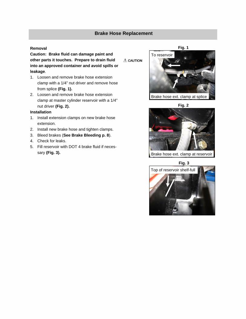
Removal
Caution: Brake fluid can damage paint and
other parts it touches. Prepare to drain fluid
into an approved container and avoid spills or
leakage.
1. Loosen and remove brake hose extension
clamp with a 1/4” nut driver and remove hose
from splice (Fig. 1).
2. Loosen and remove brake hose extension
clamp at master cylinder reservoir with a 1/4”
nut driver (Fig. 2).
Installation
1. Install extension clamps on new brake hose
extension.
2. Install new brake hose and tighten clamps.
3. Bleed brakes (See Brake Bleeding p. 8).
4. Check for leaks.
5. Fill reservoir with DOT 4 brake fluid if neces-
sary (Fig. 3).
Brake Hose Replacement
Fig. 2
Fig. 1
Fig. 3
Brake hose ext. clamp at splice
To reservoir
Top of reservoir shelf-full
Brake hose ext. clamp at reservoir
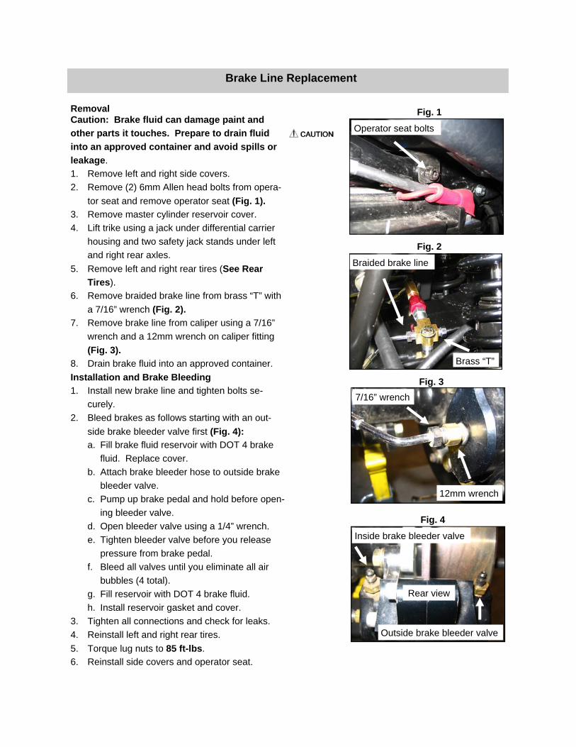
Removal Caution: Brake fluid can damage paint and
other parts it touches. Prepare to drain fluid
into an approved container and avoid spills or
leakage.
1. Remove left and right side covers.
2. Remove (2) 6mm Allen head bolts from opera-
tor seat and remove operator seat (Fig. 1).
3. Remove master cylinder reservoir cover.
4. Lift trike using a jack under differential carrier
housing and two safety jack stands under left
and right rear axles.
5. Remove left and right rear tires (See Rear
Tires).
6. Remove braided brake line from brass “T” with
a 7/16” wrench (Fig. 2).
7. Remove brake line from caliper using a 7/16”
wrench and a 12mm wrench on caliper fitting
(Fig. 3).
8. Drain brake fluid into an approved container.
Installation and Brake Bleeding
1. Install new brake line and tighten bolts se-
curely.
2. Bleed brakes as follows starting with an out-
side brake bleeder valve first (Fig. 4):
a. Fill brake fluid reservoir with DOT 4 brake
fluid. Replace cover.
b. Attach brake bleeder hose to outside brake
bleeder valve.
c. Pump up brake pedal and hold before open-
ing bleeder valve.
d. Open bleeder valve using a 1/4” wrench.
e. Tighten bleeder valve before you release
pressure from brake pedal.
f. Bleed all valves until you eliminate all air
bubbles (4 total).
g. Fill reservoir with DOT 4 brake fluid.
h. Install reservoir gasket and cover.
3. Tighten all connections and check for leaks.
4. Reinstall left and right rear tires.
5. Torque lug nuts to 85 ft-lbs.
6. Reinstall side covers and operator seat.
Brake Line Replacement
Fig. 2
Fig. 1
Fig. 3
Fig. 4
12mm wrench
7/16” wrench
Outside brake bleeder valve
Inside brake bleeder valve
Rear view
Operator seat bolts
Brass “T”
Braided brake line

Removal Caution: Brake fluid can damage paint and
other parts it touches. Prepare to drain fluid
into an approved container and avoid spills or
leakage.
1. Remove left and right side covers.
2. Remove (2) 6mm Allen head bolts from opera-
tor seat and remove operator seat (Fig. 1).
3. Remove master cylinder reservoir cover.
4. Lift trike using a jack under differential carrier
housing and two safety jack stands under left
and right rear axles.
5. Remove left and right rear tires (See Rear
Tires).
6. Remove banjo bolt and brake line from residual
valve adaptor with a 12mm wrench (Fig. 2).
7. Drain brake fluid into an approved container.
8. Remove residual valve adaptor with a 5/8”
wrench.
9. Remove residual valve with a 5/8” wrench (Fig.
3).
Installation and Brake Bleeding
1. Install new residual valve and tighten securely.
2. Reinstall residual valve adaptor, brake line and
banjo bolt and tighten securely.
3. Tighten all connections and check for leaks.
4. Bleed brakes (see Brake Bleeding on previ-
ous page).
4. Reinstall left and right rear tires.
5. Torque lug nuts to 85 ft-lbs.
6. Reinstall side covers and operator seat.
Residual Valve Replacement
Fig. 2
Fig. 1
Fig. 3
Operator seat bolts
Banjo bolt
Residual valve adaptor
Residual valve
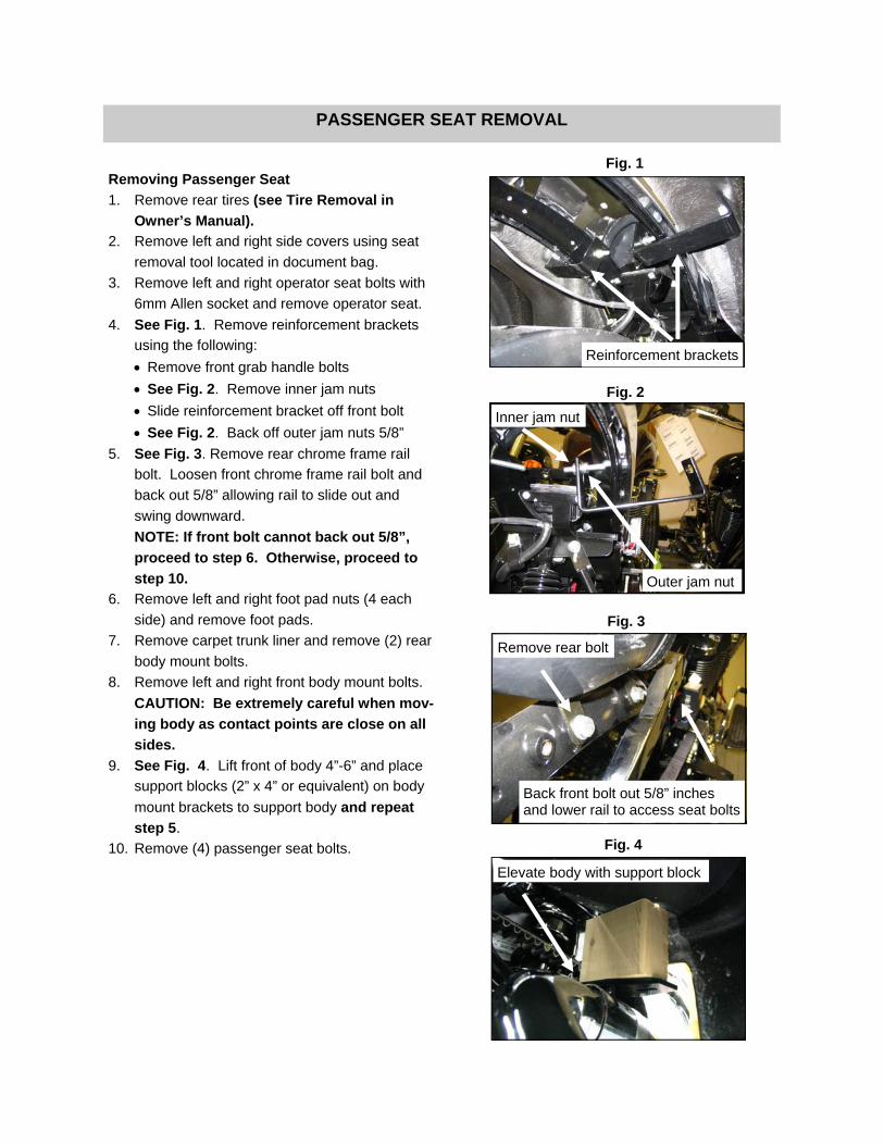
Removing Passenger Seat
1. Remove rear tires (see Tire Removal in
Owner’s Manual).
2. Remove left and right side covers using seat
removal tool located in document bag.
3. Remove left and right operator seat bolts with
6mm Allen socket and remove operator seat.
4. See Fig. 1. Remove reinforcement brackets
using the following:
• Remove front grab handle bolts
• See Fig. 2. Remove inner jam nuts
• Slide reinforcement bracket off front bolt
• See Fig. 2. Back off outer jam nuts 5/8”
5. See Fig. 3. Remove rear chrome frame rail
bolt. Loosen front chrome frame rail bolt and
back out 5/8” allowing rail to slide out and
swing downward.
NOTE: If front bolt cannot back out 5/8”,
proceed to step 6. Otherwise, proceed to
step 10.
6. Remove left and right foot pad nuts (4 each
side) and remove foot pads.
7. Remove carpet trunk liner and remove (2) rear
body mount bolts.
8. Remove left and right front body mount bolts.
CAUTION: Be extremely careful when mov-
ing body as contact points are close on all
sides.
9. See Fig. 4. Lift front of body 4”-6” and place
support blocks (2” x 4” or equivalent) on body
mount brackets to support body and repeat
step 5.
10. Remove (4) passenger seat bolts.
PASSENGER SEAT REMOVAL
Fig. 2
Inner jam nut
Outer jam nut
Fig. 1
Reinforcement brackets
Remove rear bolt
Back front bolt out 5/8” inches and lower rail to access seat bolts
Fig. 3
Fig. 4
Elevate body with support block

Installing Passenger Seat
1. Reinstall passenger seat with original hard-
ware.
2. See Fig. 5. Reinstall chrome frame rail and
tighten bolts.
CAUTION: Be extremely careful when moving
body as contact points are close on all sides (if
applicable).
NOTE: Before lowering body, examine rubber
body shims and ensure they are in proper posi-
tion and still in tact. Replace if necessary.
3. See Fig. 6. Remove support blocks and lower
body onto body mount brackets (if applicable).
NOTE: When reinstalling left and right front
body mount bolts, check left-to-right and front-
to-back body alignment before tightening bolts
(fit to side covers-if applicable).
4. Reinstall rear body mount bolts in trunk (if ap-
plicable).
5. Reinstall carpet trunk liner (if applicable).
6. Reinstall front body mount bolts (if applicable).
7. See Fig. 7. Reinstall reinforcement bracket
using the following:
• Slide reinforcement bracket onto front bolt
• Install front grab handle bolt
• See Fig. 8. Reinstall outer jam nuts and
hand-tighten to bracket
• See Fig. 8. Reinstall inner jam nuts and
tighten both to bracket
8. Reinstall passenger foot pads.
9. Re-install operator seat.
10. Reinstall both side covers.
11. Reinstall rear tires and torque lug nuts to 85 ft.-
lbs.
PASSENGER SEAT INSTALLATION
Fig. 8
Inner jam nut
Outer jam nut
Fig. 7
Reinforcement brackets
Reinstall rear bolt
Chrome frame rail
Fig. 5
Fig. 6
Remove support block
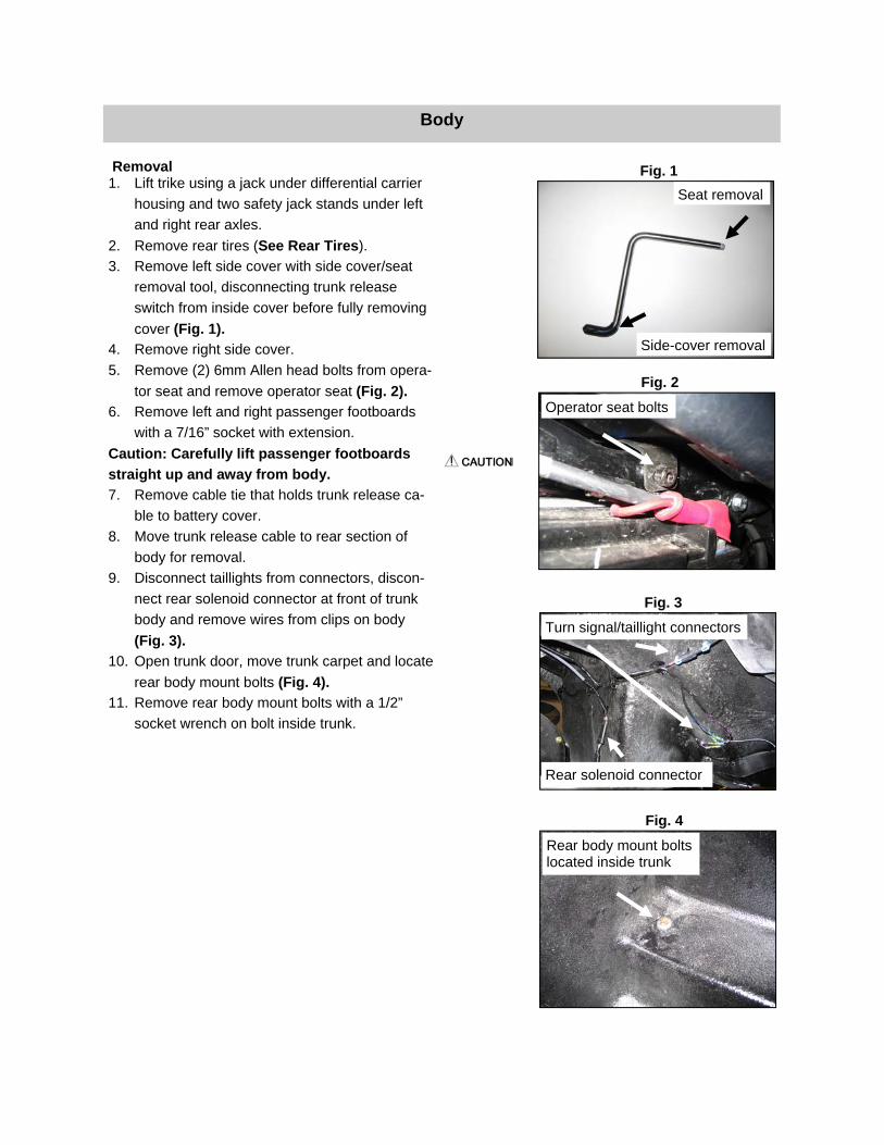
Removal 1. Lift trike using a jack under differential carrier
housing and two safety jack stands under left
and right rear axles.
2. Remove rear tires (See Rear Tires).
3. Remove left side cover with side cover/seat
removal tool, disconnecting trunk release
switch from inside cover before fully removing
cover (Fig. 1).
4. Remove right side cover.
5. Remove (2) 6mm Allen head bolts from opera-
tor seat and remove operator seat (Fig. 2).
6. Remove left and right passenger footboards
with a 7/16” socket with extension.
Caution: Carefully lift passenger footboards
straight up and away from body.
7. Remove cable tie that holds trunk release ca-
ble to battery cover.
8. Move trunk release cable to rear section of
body for removal.
9. Disconnect taillights from connectors, discon-
nect rear solenoid connector at front of trunk
body and remove wires from clips on body
(Fig. 3).
10. Open trunk door, move trunk carpet and locate
rear body mount bolts (Fig. 4).
11. Remove rear body mount bolts with a 1/2”
socket wrench on bolt inside trunk.
Body
Fig. 2
Fig. 1
Operator seat bolts
Side-cover removal
Seat removal
Fig. 4
Fig. 3
Rear body mount bolts located inside trunk
Rear solenoid connector
Turn signal/taillight connectors

12. Remove left and right front body mount bolts
with a 3/16” Allen head socket wrench on bolt
and a 1/2” wrench on the nut (Fig. 7).
13. Remove left and right grab handle bracket
bolts and brackets with a 13 mm wrench (Fig.
8).
Caution: Use an assistant when removing body
from trike. Be sure you and your assistant do
not damage body paint. The body comes close
to clutch actuator on left side and sprocket
cover on right side.
14. With an assistant’s help, slide body up and
away from trike.
Body Installation
1. After placing body on trike, center the body left-
to-right and front-to-back.
2. Install body mount bolts and tighten. Torque
bolts to proper specification (See Torque
Specifications).
3. Reinstall left and right grab handle brackets.
4. Reinstall new cable tie at trunk release cable.
5. Re-connect taillights and rear solenoid.
6. Reinstall operator seat.
7. Reinstall left and right side covers.
8. Install rear tires.
9. Torque lug nuts to 85 ft.-lbs.
Body (Continued)
Fig. 7
Front body mount bolts
Fig. 8
Grab handle bracket bolts
Fig. 9
Fig. 10
Chrome frame rail covers
Passenger seat bolts

The Pit Boss differential has one short axle (right side) and one long axle (left side). The appropriate tire will need to be removed depending on which axle or axle bearing is being replaced. Removal 1. Lift trike using a jack under differential carrier
housing and two safety jack stands under left
and right rear axles.
2. Remove appropriate rear tire (See Rear Tires).
3. Remove brake caliper and place in a secure
location (not hanging by brake line).
4. Remove brake rotor.
5. Remove axle flange retaining nuts (Fig. 1).
6. Remove axle from axle tube (Fig. 2).
7. Remove and discard locking collar (a grinder or
chisel is recommended) (Fig. 3).
8. Remove and save axle shim for reinstallation
(Fig. 3).
9. Place a bearing splitter tool under bearing,
place axle in a press and press bearing off.
Installation
1. Install new bearing using a press.
2. Reinstall axle shim between new bearing and
axle collar.
3. Install new locking collar (provided with the
new bearing).
Note: Make sure axle shim aligns with bearing
surface before tightening collar (Fig. 4).
4. Reinstall axle into axle tube.
5. Reinstall axle flange nuts. Torque to 44 ft.-
lbs.
6. Reinstall brake rotor.
7. Reinstall brake caliper.
8. Reinstall rear tire (See Rear Tires).
9. Torque lug nuts to 85 ft.-lbs.
Differential/Axle Bearing Replacement
Fig. 2
Fig. 1
Fig. 3
Axle flange retaining nuts
Remove and discard locking collar
Remove and save axle shim
Axle Axle tube
Fig. 4
Align shim with bearing surface

Removal 1. Lift trike using a jack under differential carrier
housing and two safety jack stands under left
and right rear axles.
2. Remove rear tires (See Rear Tires).
3. Remove body (See Body).
4. Remove left brake caliper and place in a se-
cure location (not hanging from brake line).
5. Remove left-side axle (See Differential-Axle
Bearing Replacement).
6. Remove park brake assembly by removing
park brake bracket bolts (Fig. 1).
7. Remove park brake cables from backing plates
(See Park Brake Cable Replacement).
8. Loosen jam nuts on adaptor plates with a 9/16”
wrench and turn adjuster bolts inward to re-
move tension on plates (Fig. 2).
9. Remove left-side adaptor plates from differen-
tial bolts with a 3/4” socket wrench and a 3/4”
wrench.
Note: Replace shim washers in the same loca-
tion you remove them from (Fig. 3).
10. Remove lower shock mount bolt.
11. Remove stabilizer bar from stabilizer bar
bracket (Fig. 4).
Differential/Carrier/Carrier Bearing Replacement
Fig. 2
Fig. 1
Fig. 3
Fig. 4
Park brake bracket bolts
Jam nut
Remove tension by turning bolt clockwise
Shim washer location
Remove stabilizer bar

12. At this point, relocate jack directly under differ-
ential plug hole for extra support.
13. Remove (2) inside, right adaptor plate bolts
and remove the inside, right adaptor plate from
differential (Fig. 5).
Note: Leaving outside adaptor plate connected
allows the differential to remain attached to the
swingarm.
14. Remove (4-inside and out) adaptor plate bolts
and plates from left side of differential (Fig. 6).
15. Remove (8) differential housing bolts with a
9/16” socket wrench.
16. Lift differential slightly with jack to split differen-
tial halves.
Note: If necessary, insert a 3/8” bolt into
tapped hole (Fig. 7) of differential to split differ-
ential halves.
17. Remove left side of differential.
18. Work belt off pulley and remove the carrier si-
multaneously.
Note: If carrier hangs up on left side of differ-
ential, remove left side axle and drive carrier
out.
19. After carrier assembly is removed, install a
splitter plate underneath the carrier bearing
and place carrier in a press.
Note: If splitter plate is too small to remove the
bearing with sprocket attached, you can re-
move sprocket, but this will require checking
the run-out with a dial indicator.
20. Press carrier bearing off carrier shaft.
Installation
1. Press new bearing onto carrier shaft bottoming
out bearing on shoulder of shaft.
2. Begin reinstallation procedure in reverse order.
3. Torque bolts to proper specifications (See
Torque Specifications).
Differential/Carrier/Carrier Bearing Replacement (Continued)
Fig. 6
Fig. 5
Fig. 7
Remove inside, right adaptor plate bolts/inside adap-tor plate
Remove both adaptor plates and all bolts
Insert 3/8” bolt to split differential halves if necessary
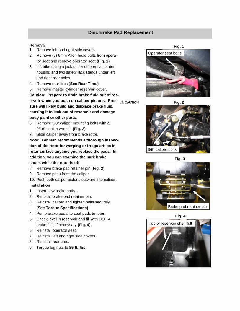
Removal 1. Remove left and right side covers.
2. Remove (2) 6mm Allen head bolts from opera-
tor seat and remove operator seat (Fig. 1).
3. Lift trike using a jack under differential carrier
housing and two safety jack stands under left
and right rear axles.
4. Remove rear tires (See Rear Tires).
5. Remove master cylinder reservoir cover.
Caution: Prepare to drain brake fluid out of res-
ervoir when you push on caliper pistons. Pres-
sure will likely build and displace brake fluid,
causing it to leak out of reservoir and damage
body paint or other parts.
6. Remove 3/8” caliper mounting bolts with a
9/16” socket wrench (Fig. 2).
7. Slide caliper away from brake rotor.
Note: Lehman recommends a thorough inspec-
tion of the rotor for warping or irregularities in
rotor surface anytime you replace the pads. In
addition, you can examine the park brake
shoes while the rotor is off.
8. Remove brake pad retainer pin (Fig. 3).
9. Remove pads from the caliper.
10. Push both caliper pistons outward into caliper.
Installation
1. Insert new brake pads.
2. Reinstall brake pad retainer pin.
3. Reinstall caliper and tighten bolts securely
(See Torque Specifications).
4. Pump brake pedal to seat pads to rotor.
5. Check level in reservoir and fill with DOT 4
brake fluid if necessary (Fig. 4).
6. Reinstall operator seat.
7. Reinstall left and right side covers.
8. Reinstall rear tires.
9. Torque lug nuts to 85 ft.-lbs.
Disc Brake Pad Replacement
Fig. 2
Fig. 1
Fig. 3
Fig. 4
3/8” caliper bolts
Top of reservoir shelf-full
Operator seat bolts
Brake pad retainer pin

Removal 1. Lift trike using a jack under differential carrier
housing and two safety jack stands under left
and right rear axles.
2. Remove rear tires (See Rear Tires).
3. Remove body (See Body).
4. Remove left brake caliper and place in a se-
cure location (not hanging from the brake line).
5. Remove left-side axle (See Differential/Axle
Bearing Replacement).
6. Remove park brake assembly by removing
park brake bracket bolts (Fig. 1).
7. Remove park brake cables from backing plates
(See Park Brake Adjustment/Cable Replace-
ment).
8. Loosen jam nuts on adaptor plates with a 9/16”
wrench and turn adjuster bolt inward to remove
tension on plate (Fig. 2).
9. Remove left-side adaptor plates from differen-
tial bolts with a 3/4” socket wrench and a 3/4”
wrench.
Note: Replace shim washers in same location
you remove them from (Fig. 3).
10. Remove lower shock mount bolt.
11. Remove stabilizer bar nuts and bolts; remove
stabilizer bar (Fig. 4).
Drive Belt Replacement
Fig. 2
Fig. 1
Fig. 3
Fig. 4
Park brake bracket bolts
Jam nut
Remove tension by turning bolt clockwise
Shim washer location
Remove stabilizer bar Remove stabilizer bar

12. At this point, relocate jack directly under differ-
ential plug hole for extra support.
13. Remove upper shock bolt; remove shock.
14. Remove (2) inside, right adaptor plate bolts
and remove inside, right adaptor plate from
differential (Fig. 5).
Note: Leaving outside adaptor plate connected
allows differential to remain attached to swin-
garm.
15. Remove (4-inside and out) adaptor plate bolts
and plates from left side of differential (Fig. 6).
16. Remove (8) differential housing bolts, including
the debris shield, stabilizer bar bracket and
shock bracket, with a 9/16” socket wrench.
17. Lift differential slightly with jack to split differen-
tial halves.
Note: If necessary, insert a 3/8” bolt into
tapped hole (Fig. 7) of differential to split differ-
ential halves.
18. Remove left side of differential.
19. Work belt off pulley and remove carrier simulta-
neously.
20. Remove exhaust up to, and including rear
header pipe using a 1/2” wrench on header
pipe and a 15mm socket wrench on exhaust
clamps (Fig. 8).
Drive Belt Replacement (Continued)
Fig. 6
Fig. 5
Fig. 7
Fig. 8
Remove inside, right adaptor plate bolts/inside adap-tor plate
Remove both adaptor plates and all bolts
Insert 3/8” bolt to split differ-ential halves if necessary
Remove exhaust

21. Remove right-side frame brace with a 9/16”
socket wrench (Fig. 9).
22. Remove sprocket cover with a 4mm Allen head
socket wrench.
23. Remove right-side front body mount with an
8mm Allen head socket wrench, and a 1/2”
socket wrench and extension (Fig. 10).
Installation
1. Slide new belt into differential housing.
2. Lift differential housing using jack to align swin-
garm adaptor plates with differential.
3. Install differential to right side of swingarm by
drawing bushings together while hand starting
nuts to bolts. Tighten nuts using a ¾” shallow
socket wrench and ¾” wrench.
4. Insert pulley and carrier into differential hous-
ing with grease fitting facing left side (Fig. 11).
5. Walk belt around pulley.
6. Reinstall an adaptor plate to outside (left) of
differential by hand starting bolts. Tighten bolts
using a ¾” swivel socket wrench and a ¾”
wrench.
7. Pull differential halves together by hand start-
ing bolts in a cross pattern. Tighten bolts using
a 9/16” deep socket wrench and a 9/16”
wrench.
8. Reinstall an adaptor plate to the inside (right)
of the differential by hand starting bolts.
Tighten bolts using a ¾” swivel socket wrench
and a 3/4” wrench.
9. Install differential to left side of swingarm by
drawing bushings together while hand-starting
nuts to bolts. Tighten nuts using a ¾” shallow
socket wrench and a ¾” wrench.
10. Reinstall stabilizer bar bracket to topmost bolts
on differential housing by hand-starting bolts.
Tighten bolts using a 9/16” deep socket wrench
(Fig. 12).
Drive Belt Replacement (Continued)
Fig. 10
Fig. 9
Fig. 11
Fig. 12
Right-side frame brace
Right-side front body mount
Left-side carrier housing Grease fitting
Remove stabilizer bar

11. Install top bolt of debris shield to front bolt-hole
on the differential by hand starting bolt.
Tighten bolt using a 9/16” deep socket wrench
(Fig. 9).
12. Reinstall lower shock mount bracket to bottom
three bolts on differential housing and bottom
of debris shield by hand starting bolts. Tighten
bolts using a 9/16” deep socket wrench (Fig.
10).
13. Reinstall shock.
14. Reinstall stabilizer bar.
15. Torque (8) differential housing bolts to 35 ft.
lbs using 9/16” deep socket wrench and torque
wrench (Fig. 11). 16. Torque (4) adaptor plate-to-swingarm bolts to
75 ft. lbs. using a ¾” torque adaptor, torque
wrench and ¾” wrench.
17. Torque (8) adaptor plate-to-differential bolts to
75 ft. lbs using a ¾” shallow socket wrench
and torque wrench (Fig. 12).
18. Reinstall park brake cables (See Park Brake
Adjustment/Cable Replacement).
19. Reinstall park brake assembly.
20. Reinstall left-side axle (See Differential/Axle
Bearing Replacement).
21. Reinstall left brake caliper.
22. Adjust belt tension and tracking (See Belt Ten-
sioning/Tracking).
23. Reinstall body (See Body).
24. Reinstall rear tires (See Rear Tires).
25. Torque lug nuts to 85 ft.-lbs.
26. Torque bolts to proper specifications (See
Torque Specifications).
Drive Belt Replacement (Continued)
Fig. 10
Fig. 9
Fig. 11
Fig. 12
Top bolt of debris shield
Lower shock mount bracket
Debris shield bottom bolt
Differential housing bolts
Adaptor plate-to-differential bolts

1. Lift trike using a jack under differential carrier
housing and two safety jack stands under left
and right rear axles.
2. Remove rear tires (See Rear Tires).
3. Loosen adaptor plate-to-swingarm bolts.
4. Loosen jam nuts on stabilizer bar (Fig. 1).
5. Place transmission in neutral.
6. Measure and mark 4 locations on belt by rotat-
ing wheel 90° in forward direction between
measurements. The tightest spot will be used
for adjustment and tensioning.
7. Move 4 adjuster bolts exactly the same dis-
tance for any adjustment (Fig. 2). Push differ-
ential assembly back until belt has 5/16”- 3/8”
slack with 10lbs. pressure at midpoint of bot-
tom run of belt (Fig. 3).
8. Rotate pulley forward for at least three revolu-
tions of rear pulley by pulling backwards on
bottom run of belt. Pull belt straight back to
get an accurate reading.
9. Check belt to ensure it is not contacting flanges
on rear pulley.
10. Correct belt tension by moving adjusters in or
out from side to side to achieve proper track-
ing.
Note: Stabilizer bar requires adjustment when
adjuster bolts are moved. Clockwise rotation of
stabilizer bar pushes top of differential down
and forward. Counter-clockwise rotation of sta-
bilizer bar pulls top of differential up and rear-
ward.
11. Torque adaptor plate-to-swingarm bolts to 75
ft.-lbs. with torque wrench and 3/4” torque
adaptor.
12. Tighten jam nuts on stabilizer bar (Fig. 1).
13. Once proper tracking is obtained, recheck belt
tension. The correct deflection is 5/16”-3/8”
with 10 lbs. pressure applied.
14. Any adjustment requires checking belt tracking
again.
Drive Belt Tensioning/Tracking
Fig. 1
Fig. 2
Midpoint of bottom run of belt
Fig. 3
Adjuster bolts
Jam nut

15. Ensure belt clearance of carrier housing on top
and bottom of housing (Fig.’s 4 & 5).
16. Reinstall rear tires.
17. Torque lug nuts to 85 ft.-lbs.
Drive Belt Tensioning/Tracking (Continued)
Fig. 4
Clearance at top of carrier housing
Fig. 5
Clearance at bottom of carrier housing

Removal 1. Disconnect license plate light from wiring har-
ness: wires will have to be cut and connectors
removed (Fig. 1).
2. Pull license plate wires through license plate
frame hole as shown (Fig. 2).
3. Remove (4) license plate frame screws with
Phillips screw driver (Fig. 2).
4. Remove license plate frame and discard.
Installation
1. Install new license plate frame.
2. Tighten frame plate screws with Phillips screw-
driver.
3. Route license plate wires through hole (Fig. 2)
and trim excess wire to appropriate length.
4. Using new connectors, splice license plate
wires to wire harness according to the follow-
ing: white wire to blue wire on harness; black
wire to black wire on harness.
LED License Plate Light Replacement
Fig. 1
Fig. 2
Frame screws
Disconnect light wires from harness
Pull wires through here

Muffler Removal 1. Lehman recommends removing appropriate
tire for ease of access in changing a muffler.
2. Lift trike using a jack under differential carrier
housing and two safety jack stands under left
and right rear axles.
3. Remove appropriate tire (See Rear Tires) to
change muffler.
4. Remove rear muffler mounting bolts with
13mm wrench (Fig’s. 1 & 2).
5. Loosen muffler-to-exhaust pipe clamp with a
15mm socket wrench (Fig. 3).
6. Slide muffler out and away from exhaust pipe
(If necessary, apply lubricant to joint to aid in
removing muffler from exhaust pipe).
Muffler Installation
1. Apply high-temperature silicone to new muffler
where it inserts over pipe.
2. Install new muffler into exhaust pipe.
3. Reinstall rear muffler mounting bolts and
tighten all clamps.
4. Reinstall tire.
5. Torque lug nuts to 85 ft.-lbs.
Mufflers/Exhaust Replacement
Fig. 2
Fig. 1
Muffler-to-exhaust clamp
Fig. 3
Left side muffler clamp bolt
Right side muffler clamp bolts

Exhaust Pipe Removal 1. For replacement of pipes LP6601, LP6602 and
LP6603 (Fig. 4), repeat Muffler Removal
steps 1-5 and proceed as follows.
2. Loosen appropriate clamps with a 10mm
socket wrench and extension (Fig. 5, 6 & 7).
3. Remove appropriate pipe.
Exhaust Pipe Installation
1. Apply high-temperature silicone to pipe at the
insertion points.
2. Install new pipe.
3. Tighten all clamps securely.
4. Reinstall tire.
5. Torque lug nuts to 85 ft.-lbs.
Mufflers/Exhaust Replacement (Continued)
Fig. 5
Fig. 4
Fig. 6
Fig. 7
LP6601
LP6602 LP6603
Exhaust clamp
Exhaust clamp
Exhaust clamp

Cable Removal 1. Lift trike using a jack under differential carrier
housing and two safety jack stands under left
and right rear axles.
2. Remove left rear tire (See Rear Tires).
3. Remove park brake assembly by removing
park brake bracket bolts (Fig. 1).
4. Remove left frame brace.
5. Slide park brake assembly rearward into wheel
opening.
6. Loosen cable adjuster nuts with a 1/2” open-
end wrench (Fig. 2).
7. Loosen cable retainer nuts with two 7/8”
wrenches (Fig. 3).
8. Remove cables from park brake bracket.
9. Remove cable ties that hold cables to rear axle
assembly.
10. Remove cir-clip from backing plate bracket.
11. Pull cable and remove loop from brake lever
(Fig. 3).
Cable Installation
1. Place loop of new cable over brake lever.
2. Install a cable retainer nut on cable and place
through park brake bracket. Install other cable
retainer nut.
3. Install end of cable through cable pulling
bracket with one nut on either side of bracket.
4. Repeat steps 1-3 for both cables.
5. Install new cable ties and left frame brace.
6. Reinstall park brake assembly.
7. Reinstall left rear tire.
Park Brake Adjustment
1. Adjust cable retainer nuts as shown in Fig. 1
with roughly 2 threads exposed on front end
creating a slight and consistent drag on both
sides.
2. Adjust drag on park brake shoes for a slight
drag while still allowing the rotor to turn.
3. Adjust park brake handle to engage in 3rd po-
sition ensuring the handle does not contact left
side cover when engaged.
4. Reinstall tire. Torque lug nuts to 85 ft.-lbs.
Park Brake Cable Replacement/Adjustment
Fig. 2
Fig. 1
Cable adjuster nuts
Cable retainer nuts
Brake lever Cable loop
Cable pulling bracket
Park brake bracket bolts
Fig. 3

Removal 1. Lift trike using a jack under differential carrier
housing and two safety jack stands under left
and right rear axles.
2. Remove left rear tire (See Rear Tires).
3. Remove park brake assembly by removing
park brake bracket bolts (Fig. 1).
4. Remove left frame brace.
5. Disconnect park brake cables from park brake
bracket (See Park Brake Cable Replacement/
Adjustment).
6. Remove snap ring from pin in park brake han-
dle (Fig. 2).
7. Remove pin from handle and park brake
bracket; remove handle.
Installation
1. Attach new park brake handle to park brake
bracket by sliding pin through bracket into han-
dle and insert pawl on handle into catch on
bracket.
2. Reinstall snap ring to pin using snap ring pliers.
3. Install cable-pulling bracket (if being replaced)
to park brake handle, install clevis pin and cot-
ter pin, and bend cotter pin around clevis pin
(Fig. 3).
4. Reinstall park brake cables (See Park Brake
Cable Replacement/Adjustment).
5. Reinstall left frame brace.
6. Reinstall park brake assembly.
7. Reinstall left rear tire.
Park Brake Handle Replacement
Fig. 2
Fig. 1
Cotter key Pin
Snap ring
Park brake bracket bolts
Fig. 3

Installation (Continued)
8. Install (1) 5/16” nut to cable before installing
cable into cable-pulling bracket. Install another
5/16” nut to end of cable (Fig. 3).
Note: Leave adjustment nuts with the most ad-
justment possible.
9. Repeat steps 5 and 6 for the long park brake
cable, inserting cable to right side of park brake
bracket.
10. Install park brake bracket behind front body
mount by hand starting bolts. Tighten bolts us-
ing a 1/2” socket wrench.
11. Wrap each cable around the left side of the
differential.
12. Attach the loop on the cables to the brake lever
on the rotors and slide plated portion of cables
into brake bracket (Fig. 4).
13. Tighten 5/16” nuts around the cable pulling
bracket using (2) 1/2” wrenches.
14. Tighten larger nuts around park brake bracket
using a 7/8” wrench and a 90° offset 7/8”
wrench.
15. Reinstall body (See Body).
16. Reinstall rear tires (See Rear Tires).
17. Torque lug nuts to 85 ft.-lbs.
Park Brake Handle Replacement (Continued)
Fig. 4
Fig. 3
Brake lever Cable loop
Brake bracket
5/16” nuts

Removal 1. Remove (2) center cap bolts with center cap
removal tool (located in document bag in trunk)
(Fig. 4).
Caution: Only (2) of what appear to be (5) bolts
holding the center cap are real. Attempting to
loosen any other than the (2) real bolts will de-
stroy the center cap (Fig. 4).
2. Loosen lug nuts with a thin-wall 13/16” socket
wrench and extension.
3. Lift trike using a jack under differential carrier
housing (Fig. 1) and two safety jack stands
under left and right rear axles (Fig. 2).
4. Remove lug nuts.
5. Remove left and right rear tires by sliding them
out and away from body.
Caution: When changing or removing tires for
any reason, do not allow tire to “free” stand.
The wheel will suffer damage if tire is dropped
on the wheel side (Fig. 3).
6. Always face tire with wheel facing outward to
avoid wheel damage.
Installation
1. Install left and right rear tires by sliding them in
and toward the body.
2. Install and tighten lug nuts with a thin-wall
13/16” wrench and extension.
3. Lower trike from jack and jack stands; remove
jack and jack stands.
4. Torque lug nuts to 85 ft.-lbs.
5. Reinstall center caps.
Rear Tires
Fig. 3
Fig. 2
Fig. 1
Fig. 4
Spokes will suffer damage if wheel is dropped
Bolts used to secure center cap
Fig. 3
Fig. 4
Place jack under diff. housing
Place jack under rear axle

Removal 1. Lift trike using a jack under differential carrier
housing and two safety jack stands under left
and right rear axles.
2. Remove left rear tire (See Rear Tires).
3. Remove lower shock bolt with a ¾” socket
wrench and extension (Fig. 1).
4. Place jack under differential housing and jack
up differential to keep mounting holes aligned
during shock replacement (Fig. 2).
Note: Lehman recommends the use of a ratchet
strap for load suspension during shock re-
placement.
5. Remove upper shock bolt with a ¾” socket
wrench and a ¾” wrench.
6. Remove shock.
Installation
1. Install shock bushings into holes of new shock.
2. Install shock to top shock mount by hand start-
ing nut to bolt. Tighten the nut using a ¾” shal-
low socket wrench with 2” extension and a ¾”
wrench.
3. Install shock to lower shock mount by hand-
starting bolt. Tighten bolt using a ¾” shallow
socket wrench. Torque bolts to proper specifi-
cations (See Torque Specifications).
4. Remove ratchet strap.
5. Adjust shock with a spanner wrench as shown
(Fig. 3). A clockwise adjustment will increase
preload while a counterclockwise adjustment
will decrease preload.
6. Torque bolts to proper specifications (See
Torque Specifications).
7. Reinstall left rear tire.
8. Torque lug nuts to 85 ft.-lbs.
Shock Replacement
Fig. 2
Fig. 1
Fig. 3
Lower shock mount bolt
Shock adjustment
Place jack under differential housing

Removal 1. Lift trike using a jack under differential carrier
housing and two safety jack stands under left
and right rear axles.
2. Remove rear tires (See Rear Tires).
3. Remove body (See Body).
4. Remove exhaust up to, and including, rear
header pipe with a 15mm socket wrench (Fig.
1).
5. Remove sprocket cover with a 4mm Allen head
socket wrench.
6. Remove right-side front body mount with an
8mm Allen head socket wrench, a 1/2” socket
wrench and extension (Fig. 2).
7. Work belt off front sprocket.
8. Remove both brake calipers (See Disc Brake
Pad Replacement).
9. Remove both brake rotors (necessary to re-
move adaptor plate bolts).
10. Remove the Pit Boss shock (See Shock Ad-
justment/Replacement).
11. Remove stabilizer bolts and nuts; remove sta-
bilizer bar.
12. Remove park brake assembly by removing
park brake bracket bolts (Fig. 3).
13. Remove brass “T” from brake line. Remove all
cable-ties from swingarm.
14. Remove left-side frame brace with a 9/16”
socket wrench.
15. Remove left-side front body mount with an
8mm Allen head socket wrench and a 1/2”
socket wrench and extension.
16. Slide differential slowly backward to get clear-
ance for swingarm removal.
17. Loosen and remove the swingarm nut from left
side of trike.
18. Remove swingarm pin (Fig. 4).
19. Remove swingarm shaft.
20. Remove swingarm.
21. Remove snap ring from left side of old swin-
garm.
Swingarm Replacement
Fig. 2
Fig. 1
Fig. 3
Fig. 4
Swingarm pin
Right-side front body mount
Remove exhaust
Park brake bracket bolts

22. Remove shouldered bushing from left side of
old swingarm.
23. Remove steel spacer from right side of old
swingarm bearing.
Installation
1. Press (2) bearings (GB1024) into left side of
new swingarm (Fig. 5) and install snap ring to
outside bearing (Fig. 6).
2. Press (1) needle bearing (GB1032) into right
side of swingarm (Fig. 7) and install a new
needle bearing seal (Victory part # 3610096)
on each side of bearing (Fig. 8).
3. Install shouldered bushing from old swingarm
into left side of new swingarm bearing.
4. Install steel spacer into bearing on right side of
new swingarm.
5. Place new swingarm over lower swingarm
mounts.
6. Insert swingarm pivot shaft from left side
through lower swingarm mounts and swingarm.
7. Apply Loctite 242 to pivot shaft nut and insert
pivot shaft on right side of swingarm.
8. Torque right side pivot shaft nut to 65 ft. lbs.
using a 15/16” socket and torque wrench while
holding left side with a 1 1/16” socket wrench
and adaptor.
9. Move swingarm up and down to check for bind-
ing.
10. Reinstall removed parts in reverse order.
11. Reinstall new cable-ties.
12. Torque bolts to proper specifications (See
Torque Specifications).
Swingarm Replacement (Continued)
Fig. 6
Fig. 5
Fig. 7
Fig. 8
GB1024 Bearing
Snap ring
GB1032 Needle bearing
3610096 Needle bearing seal

Removal 1. Lehman recommends you remove the appro-
priate tire for ease of access to taillight assem-
blies (See Rear Tires).
2. Disconnect taillight wiring (Fig. 1).
3. Remove bolts from taillight bracket located un-
der body (Fig. 1).
4. Lift bottom of taillight assembly out of body and
slide out of slotted groove (Fig. 2).
Installation
1. Install 8” of 1/4” gasket as shown around base
of taillight and secure with adhesive (Fig. 3).
2. Slide new taillight assembly (top first at slotted
groove) into body.
3. Tighten bolts securely.
4. Connect taillight wiring.
5. Test taillight.
6. Reinstall tire.
7. Torque lug nuts to 85 ft.-lbs.
Taillight Replacement
Fig. 3
Fig. 1
Fig. 2
Slide taillight out from the bottom
Taillight bolts
Taillight wiring
Taillight gasket

1. Trunk door adjustment begins by ensuring
proper distance (14”) between bottom of hinge
bracket and trunk floor (Fig. 1).
2. Hinge bracket can be adjusted as shown to
achieve proper measurement (Fig. 1).
3. Additional hinge adjustments can be made as
shown in Fig. 2. Striker pin bracket adjust-
ments can be made as shown in Fig. 3.
4. Close door gently and apply light pressure to
determine if striker pin engages 1st position
inside latch. (Fig. 4).
5. If latch 1st position cannot be obtained, latch
may need to be adjusted slightly. Use slotted
hole adjustments to adjust latch accordingly.
6. Repeat step 4.
7. After striker pin engages latch 1st position, ap-
ply pressure to door to engage 2nd latch posi-
tion If striker pin engages latch 2nd position,
move to step 10.
8. If 2nd position cannot be obtained, latch may
need to be adjusted slightly. Striker pin may
be adjusted as well. Loosen striker pin bracket
bolts with a 7/16” wrench and adjust accord-
ingly. Tighten bolts.
9. Repeat step 5.
10. When door closes with two clicks consistently,
check door seal by placing a piece of paper in
door seal on all sides of door, close door and
try to remove paper. The door seals properly
when paper slides out with a fair amount of
tension.
Trunk Door Latch Adjustment
Fig. 1
Fig. 2
Fig. 3
Fig. 4
14” from floor to bottom of bracket
Slotted hole adjustment-vertical
Slotted hole adjustment-vertical
Striker pin bracket Striker pin
Slotted hole adjustment-horizontal
Trunk latch

Trunk Release Solenoid-Removal 1. Remove (2) latch bolts with a 5/32” Allen head
socket (Fig. 1). 2. Remove (2) rear latch cover bolts with a 7/16”
wrench and remove latch cover (Fig. 2). 3. Remove (2) solenoid bolts with a #25 Torx
socket (Fig. 3). 4. Remove solenoid. Trunk Release Solenoid-Installation 1. Install new solenoid, replace and tighten sole-
noid bolts. 2. Reinstall parts in reverse order. Trunk Release Fuse Replacement 1. Remove (2) 6mm Allen head bolts from opera-
tor seat and remove operator seat. 2. Locate trunk release fuse under operator seat
(Fig. 4). 3. Replace fuse. 4. Reinstall operator seat.
Trunk Release Solenoid Replacement/In-Line Fuse Replacement
Fig. 1
Fig. 2
Fig. 3
Fig. 4
Trunk release fuse
Solenoid bolts
Latch bolts
Rear latch cover bolts

Axle flange nuts .........................................................................................................44 ft.-lbs.
Adaptor plate-to-differential bolts ............................................................................75 ft.-lbs.
Adaptor plate-to-swingarm bolts..............................................................................75 ft.-lbs.
Banjo bolt (Brass “T”)-disc brakes ..........................................................................16 ft.-lbs.
Caliper-to-bracket bolts.............................................................................................30 ft.-lbs.
Caliper-bracket to backing plate bolts.....................................................................17 ft.-lbs.
Differential housing bolts..........................................................................................35 ft.-lbs.
Frame brace bolts ......................................................................................................44 ft.-lbs.
Frame rail bolts ..........................................................................................................35 ft.-lbs.
Front body mounts/brace bolts ................................................................................24 ft.-lbs.
Lower shock mount bracket bolts............................................................................35 ft.-lbs.
Master cylinder reservoir bracket ............................................................................12 ft.-lbs.
Muffler mount brackets .............................................................................................35 ft.-lbs.
Pulley-to-carrier-bolts................................................................................................44 ft.-lbs.
Rear tire lug nuts........................................................................................................85 ft.-lbs.
Right-side pivot shaft (swingarm) ............................................................................65 ft.-lbs.
Shock bolts.................................................................................................................35 ft.-lbs.
Shock pin ....................................................................................................................44 ft.-lbs.
Stabilizer bar upper/lower .........................................................................................35 ft.-lbs.
Upper shock mount bracket bolts............................................................................19 ft.-lbs.
Upper/lower minor pivot mount bolts ......................................................................35 ft.-lbs.
Torque Specifications

Trunk Release Wiring Diagram

Body Wiring Diagram