2010-2012 6.7l cummins egr delete kit 6.7 dodge egr delete...tab) on the back side of the throttle...
TRANSCRIPT

2010-2012 6.7L CUMMINS EGR DELETE KIT

1
DISCLAIMER
1) By installing this product onto your vehicle, you assume all risk and liability associated with its use.
2) It is your responsibility to make sure your vehicle complies with all federal, state, and local emissions laws. Federal and many state and local laws prohibit the removal, modi�cation or rendering inoperative of any part of the design a�ecting emissions or safety on motor vehicles used on a public street or highway. Violation may result in a �ne of up to $32,500 per vehicle (or possibly higher depending on changes in the law). All civil penalties and �nes for removing your vehicle’s emissions equipment are the sole responsibility of the end user.
3) Due to its high performance nature, this product may void vehicle manufacturer’s warranty.
4) Sinister Mfg Company, Inc. is not responsible for misuse of its products. By installing this product, you release Sinister Mfg Company, Inc. of any and all liability associated with its use.
5) Depending on where you live, restrictions may apply. Check all applicable laws before installing or using!
6) The purchaser and end user releases, indemni�es, discharges and holds harmless Sinister Mfg Company, Inc. from any and all claims, damages, causes of action, injuries, or expenses resulting from or relating to the use or installation of this product that is in violation of the terms and conditions on this page, the product disclaimer, and/or the product installation instructions. Sinister Mfg Company, Inc. will not be liable for any direct, indirect, consequential, exemplary, punitive, statutory, or incidental damages or �nes caused by the use or installation of this product.
!
! WARNING REGARDING EMISSIONS LAWS
Not legal for sale or use on pollution-controlled motor vehicles anywhere in the United States. Legal ONLY for o�-road competition racing vehicles and cannot be used on vehicles that are operated on public streets, roads, or highways.

6.7L Cummins EGR Delete
PACKING LIST:
QTY.111212412112
Description Coolant HoseCoolant Hose ConnectorM10 Flange Nut5/16 Bolts, Nuts, and Flat Washers1/4-20 Bolt, Nut, and Lock WasherM10 Hex Head BoltsM8 x 1.25 x 20 Allen Head BoltsIntake Block O� PlateExhaust Block O� Plates Stand O� BoltSupport BracketHose Clamps
Note: Prior to installation, please compare the parts that you have received with the bill of materials provided on this page to assure that you have all the parts necessary for the installation.
2
Part#ABCDEFGHIJKL
A
B
C
Read all instructions prior to install.
D
E F
G
H I
J
K
L

3
!CAUTION!!! Never work on a hot vehicle. Serious injury in the form of burns can result if the vehicle has been in use. Allow vehicle to cool prior to installation. Always wear eye protection when working on or under any vehicle.
Note: With a used vehicle, we suggest using a penetrating spray lubricant to be applied liberally to all exhaust fasteners. When doing so allow a signi�cant amount of time for the chemical to lubricate the threads before attempting to disassemble.
Step 1: Disconnect batteries.
Step 2: Drain engine coolant.
Step 3: Remove the plastic engine cover that is held in place by four 8mm bolts. Note: The dipstick must be removed in order to remove the plastic engine cover. (Image 1)
Step 4: Using an 11mm socket loosen the two V-band clamps. Remove the 10mm bolt in the center of the tube and disconnect the sensor plug. The EGR crossover tube can now be removed. (Image 2)
Step 5: Remove the electrical connector on the EGR valve. (Circled in image 3)
Note: Some electrical connectors may have a locking tab. In order to remove these connectors the the tab must be slid into the “unlock” position.
Step 6: Remove the EGR valve that is held in place by four 10mm bolts.
Image 2.5 x 1.6376
Image 1
Image 2
Image 3
EGR Valve

Step 7: Remove any existing gasket material from the mounting surface on the intake elbow. (Image 4)
Note: It is important to keep gasket debris from getting in the open intake ports. We recommend putting a clean rag in each port to keep any excess gasket material out of the intake.
Step 8: Unplug the electrical connector (equipped with locking tab) on the back side of the throttle valve. The throttle valve is located on the driver side, just under the intake elbow. It is important to leave this unplugged in order to keep the throttle valve from permanently closing. (Image 4 & 5)
Note: An alternative to leaving the throttle valve unplugged is to install the Sinister Diesel Throttle Valve delete, which will also increase �ow through the intake. Step 9: Install the Sinister blue intake block o� with the supplied bolts. Ensure that both O-rings are fully seated. (Image 6)
Step 10: Remove the heat shield from the EGR bypass. The heat shield is held in place by three 10mm nuts and two 8mm bolts. (Image 7)
4
Image 4
Throttle Valve
Intake Elbow
Locking Tab
Image 5
Image 6
Image 7
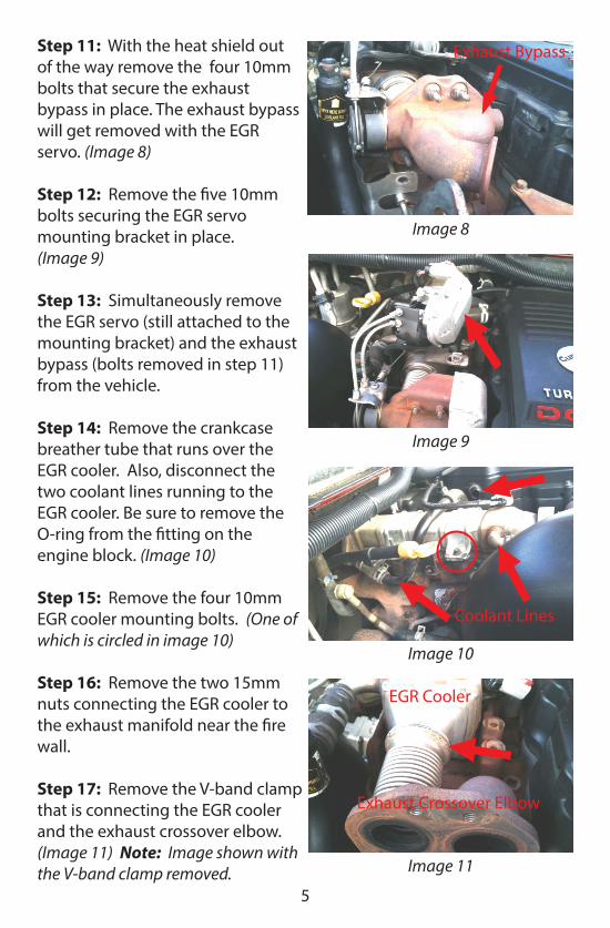
Step 11: With the heat shield out of the way remove the four 10mm bolts that secure the exhaust bypass in place. The exhaust bypass will get removed with the EGR servo. (Image 8)
Step 12: Remove the �ve 10mm bolts securing the EGR servo mounting bracket in place.(Image 9)
Step 13: Simultaneously remove the EGR servo (still attached to the mounting bracket) and the exhaust bypass (bolts removed in step 11) from the vehicle.
Step 14: Remove the crankcase breather tube that runs over the EGR cooler. Also, disconnect the two coolant lines running to the EGR cooler. Be sure to remove the O-ring from the �tting on the engine block. (Image 10)
Step 15: Remove the four 10mm EGR cooler mounting bolts. (One of which is circled in image 10)
Step 16: Remove the two 15mm nuts connecting the EGR cooler to the exhaust manifold near the �re wall.
Step 17: Remove the V-band clamp that is connecting the EGR cooler and the exhaust crossover elbow. (Image 11) Note: Image shown with the V-band clamp removed.
5
Image 8
Exhaust Bypass
Image 9
Image 10
EGR Cooler
Exhaust Crossover Elbow
Image 11
Coolant Lines

Step 18: Remove exhaust crossover elbow that is held in place by two 15mm nuts. Install the small exhaust block o� plate. (Image 12)
Note: The block o� that is not pre-drilled will be installed in place of the exhaust crossover elbow.
Step 19: Remove the EGR cooler, this can be done by pulling the cooler up and out towards the front of the vehicle.
Step 20: Remove EGR cooler mounting bracket by unbolting the two 14mm bolts that bolt directly to the engine. (Image 13)
Note: The bolt heads are not visible in the image, however the arrows give a general idea of where the bolts are through the mounting bracket.
Step 21: Install the other exhaust block o� plate, reusing the factory hardware. The block o� with the pre-drilled port will be installed on the back side of the exhaust manifold. (Image 14)
Step 22: Re-install the crankcase breather tube.
Image 12
Image 13
Image 14
6

Step 23: Using the new supplied coolant hose and hose adapter, connect the two coolant ports that previously went to the EGR cooler.Secure the hose with the supplied hose clamps. (Image 15 and 16)
Step 25: Replace the manifold bolt with the supplied stand o� bolt. The bolt will be the third one in from the back of the motor. The nut on the stand o� bolt should be used as a jam nut to secure it in place. (Image 17)
Step 26: Mount the supplied support bracket as seen in image. The back bolt will screw into the stand o� bolt. Use the 1/4-20 bolt, nut, and washer to secure the transmission dipstick to the bracket.(Image 18)
Note: The bracket will hold the coolant hose connector in place.
Step 27: Re�ll the coolant to factory speci�cations.
Step 28: The installation of the Sinister EGR delete kit is complete and ready for testing. Start the engine and run until coolant circulates. Top o� coolant system as necessary and make a close inspection for any leaks.
Step 29: Re-install plastic engine cover.
Image 16
Image 17
7
Image 15
Image 18

8
Bracket Diagram
Coolant Hose Adapter Slot
Transmission Dipstick Mount
Stand O� Bolt Mount
Factory Coolant Tube Mount
Exhaust Pressure Tube Mount
Crank Case Breather Tube Mount
9
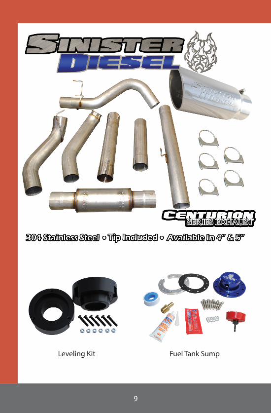
Leveling Kit Fuel Tank Sump

10
Coolant Filtration Kit Fuel Rail Race Valve
Steering Stabilizer
Upgraded EGR Cooler Throttle Valve Delete
DODGE
CUMMINS PRODUCTS

2025 Opportunity Dr. Suite #7Roseville CA, 95678
877-692-4110 - SinisterDiesel.com