2009 leader video catalog
TRANSCRIPT

LEADER ELECTRONICS CORP.

COMPANY PROFILE
LEADER Since LEADER ELECTRONICS CORP. was established in 1954, has focused its attention on international markets. LEADER established local corporations in U.S.A. in 1969 and Hong Kong in 1980. Many other positive measures have also been taken before other companies.In July 1995, LEADER's own service center was set up in Shanghai for better service/maintenance in China.In 2003, Regional Offices were established in Beijing and Dongguan to support LEADER products, which are becoming increasing popular in view of the growing Japanese presence in China.In 2005, The Technical Service Center was established in Beijing.LEADER ELECTRONICS is keeping abreast of the times with the establishment of LEADER ELECTRONICS EUROPEAN OFFICE in The Netherlands in 2006.LEADER ELECTRONICS now has a global network linking its agents in 62 countries/areas.
Audit and Registration of ISO9001 and ISO14001, the internal standard for Quality and Environmental Management SystemsThe electronic measuring instrument, the mother tool of electronics, consistently requires the highest technology and quality.The history of LEADER ELECTRONICS CORP. is indeed the history of the pursuit of higher technology and quality. In December 1994, we received an audit and successfully registered ISO9001, the international standard for quality management systems, and furthermore, as our basic policy of product development considering the environment, we received an audit and successfully registered ISO14001 in April 2007, that is the international standard for an environmental management system. It gives us great satisfaction to offer products manufactured with outstanding technologies and quality, and moreover, to contribute to society through activities that take into consideration the environment.
Company name LEADER ELECTRONICS CORP.
Headquarters 2-6-33 Tsunashima-Higashi,Kohoku-ku, Yokohama 223-8505, JapanPhone: 81-45-541-2123 Fax: 81-45-541-2823 Headquaters annex 2-6-21 Tsunashima-HigashiKohoku-ku, Yokohama 223-0052, Japan Factory 1 6-11-28 Tsunashima-HigashiKohoku-ku, Yokohama 223-0052, Japan Factory 2 5-10-35 Tsunashima-Higashi,Kohoku-ku, Yokohama 223-0052, Japan
Headquarters
Headquaters annex
Factory 1
Factory 2
2

3
Fuji Television Wangan Studio in Tokyo
ABC Studio in New York

4
Selection GuideWaveform Monitor
※1 LV 7720 (SD only) ※2 Eye Pattern (option) ※3 Option 73A
Signal Generator/SDI System Margin Checker

5
Video Test Instruments
Dean Krueger, DP & DITLV 5750 in use on the set.

6
MULTI SDIMONITOR
LV 5380
The LV 5380 is a multi-SDI monitor equipped with a precisionvideo signal waveform and vectorscope display via a high-fidelity TFT LCD that produces high-quality picture displays. Italso offers an embedded audio signal display featuringLissajous and level-meter configurations.*1 Additional featuresinclude simultaneous display of two SDI signals, screen cap-ture to USB memory, and on-picture gamut error monitoring.All these features are integrated into a thin, light instrumentthat allows it to be used in any video production or monitoringapplication.
FEATURES•High-Quality TFT LCD
Employs an XGA TFT LCD (1,024x768) that produces high-quality picture displays.
• Extensive Video Signal DisplaysThe waveform monitor display has gain adjustment, sweep,and cursor measurement features along with RGB andpseudo-composite information. The LV 5380 also providesvectorscope and embedded audio Lissajous and Level-meter displays.
• Multi-Functional Picture DisplayThe picture display has various adjustment features such ascolor temperature selection, brightness, contrast, gain, andbias. Other features include monochrome, chroma up, on-image gamut error, and safety marker displays.
• Multi-Screen Display and 2-Channel Simultaneous Display1)You can switch to multi-screen which simultaneously
shows video signal waveforms and pictures.2)You can switch to multi-screen which simultaneously
shows video signal waveforms, picture, vectorscope, andaudio levels.
3)You can display two SDI signals simultaneously.*1• Dual link input *1• Status Display
The LV 5380 can display SDI signal's data dump and errorlogs as well as the phase difference between the externalsync signal and SDI signal.
• Display Mode Switch KeysFor quick operation, the LV 5380 provides dedicated keysfor switching between different display modes such asvideo waveform, vectorscope, and picture displays. In addi-tion, all keys can be back-lit.
• Stereo Headphone OutputDelivers SDI signal's embedded audio signals in stereothrough the headphone output jacks.
• External Sync Signal InputAccepts tri-level sync signals or NTSC/PAL black burst signals.
• PresetsStores up to 30 front panel presets.
• Last MemoryEquipped with a feature that stores panel settings to memory.
• 75-mm VESA MountingProvides 75-mm VESA mounting holes on the rear panel thatallows the LV 5380 to be mounted on an arm or stand.Tripod mounting facilities also provided.
• External Remote Connector (Factory Option)An external remote connector can be installed as a factoryoption. In addition, one of the connectors can be modifiedso that a tally indicator can be displayed on the screen.
Battery Mount (Factory Option)*2A battery adapter can be installed on the rear panel as afactory option.• OP73 : BATTERY MOUNT IDX (V-Mount)• OP74 : BATTERY MOUNT ANTON (AntonBauer)
OP70: Cinelite II (Cinelite+Cinezone) (Option)Leader's CINELITE and CINEZONE features are added as asingle option in this instrument. For details on CINELITE &CINEZONE, please see page #49.
*1 To be supported in the future
*2 If you install the battery mount, you cannot use the 75-mm VESA mounting holes.
Compact Multi-SDI Monitor
8.4 Inches
The design is subject to change.
4U size
Ⅱoption

7
LV 5380 SPECIFICATIONS
Video Formats andCorresponding Standards
Audio DisplayCompliant StandardQuantizationSynchronizationChannel Selection
Input/Output ConnectorsSDI Input
Input ConnectorsInput ImpedanceInput Return LossMaximum Input Voltage
SDI OutputOutput Connector
Output ImpedanceOutput VoltageMaximum Return Loss
External Reference Input*1
Input SignalInput ConnectorsInput Impedance
Headphone OutputOutput Signal
Sampling FrequencyOutput ConnectorImpedance
LCDLCD TypeBacklight BrightnessAuto Shutoff
Screen CaptureCapture
Data Output
Data Input
PresetsDisplay Mode PresetsNumber of Presets
Waveform DisplayWaveform Operation
Display ModeOverlay DisplayParade Display
Blanking PeriodRGB ConversionPseudo-Composite Display
Channel Assignments
Line SelectVertical Axis
GainVariable GainAmplitude AccuracyFrequency Characteristics HDTV
Y SignalCB, CR SignalsLow-Pass Attenuation
Frequency Characteristics SDTVY SignalCB, CR SignalsLow-Pass Attenuation
Horizontal AxisLine DisplayField Display
Cursor MeasurementTypes
Amplitude MeasurementTime MeasurementFrequency Display
ScaleTypeColorThumbnail Display
Vectorscope DisplayGainVariable GainAmplitude AccuracyScale
TypeIQ AxisColor
Pseudo-Composite Display
Thumbnail Display
5 Bar DisplayBar DisplayChannel AssignmentsScaleError Level
SMPTE 299M (HD-SDI), SMPTE 272M (SD-SDI)20 bitsMust be synchronized to all video clocksTwo groups (eight channels in the same SDI channel) selec-table
Two BNC connectors75 Ω≥ 15 dB 5 MHz to the serial clock frequency±2 V (DC + ACpeak)
One BNC connectorReclocks and transmits the selected SDI input signal75 Ω800 mVp-p ± 10 %≥ 15 dB 5 MHz to the serial clock frequency
Tri-level sync or NTSC/PAL black burstOne pair of BNC connectors15 kΩ passive loop-through
Extracts and transmits the embedded audio signal (whensynchronized to the video signal)Supports 48 kHzOne stereo miniature jack16 Ω
8.4-inch color XGA TFT. Effective area 1,024 x 768 dots32 adjustable levelsTime to turn off the LCD can be set.
Captures the screen to an image fileOnly one screen image can be stored in the internal memory.Screen captures can be saved as bitmap files to USBmemory or to a PC over the Ethernet.Data saved to USB memory can be loaded and displayed onthe LV 5380.
Only stores settings specific to each display mode30 total.Display Mode Presets:Five presets for each display mode.
Overlays component signalsDisplays component signals side by sideH and V blanking periods can be maskedConverts Y, CB, CR signals into RGB and displays the resultDigitally converts component signals into composite signalsand displays the resultThe G, B, R order or R, G, B order selectable for RGB con-version displayDisplays the selected line
x1 or x5 selectablex0.2 to x2.0≤ ±0.5 %
≤ ±0.5 % for 1 to 30 MHz≤ ±0.5 % for 0.5 to 15 MHz≥ 20 dB (at 20 MHz)
≤ ±0.5 % for 1 to 5.75 MHz≤ ±0.5 % for 0.5 to 2.75 MHz≥ 20 dB (at 3.8 MHz)
x1, x10, x20, ACTIVE, or BLANK selectablex1, x20, or x40 selectable
Two horizontal cursors (REF and DELTA)Two vertical cursors (REF and DELTA)Measures in % or VMeasures in usec or msecDisplays the frequency by assuming the interval between thecursors to be one period
% scale or V scale selectableSelectable from seven colorsCan display thumbnails of picture displays and audio levelmeters
x1, x5, or IQ-MAG selectablex0.2 to x2.0≤ ±0.5 %
75 % or 100 % selectableShow or hide selectableSelectable from seven colorsDigitally converts component signals into composite signalsand displays the resultCan display thumbnails of picture displays and audio levelmeters
Displays the peak levels of Y, R, G, B, and compositeRGB or GBR selectablemV or % selectableBased on gamut error level and composite gamut errorlevel settings, user settable.
Picture DisplayColor TemperatureQuality AdjustmentDisplay SizeColor
Frame Rate
Aspect Marker DisplayAspect Marker FormatSafety Marker SizeLine SelectGamut Error DisplayThumbnail Display
Embedded Audio DisplayLissajous Display
Display ChannelsDisplay Mode
Level Meter DisplayDisplay ChannelsMeter
ChannelsGroup Selection
Audio Information DetectionSampling Frequency
Status DisplayEvent LogData Dump DisplayData Output
Phase Difference DisplayDisplay
Display RangeVertical
Horizontal
Error CountError Count
Count PeriodVideo Errors
CRC ErrorEDH Error
Gamut ErrorGamut Error
Detection Range Upper LimitLower Limit
Composite Gamut Error
Detection Range Upper LimitLower Limit
Audio ErrorsCRC ErrorBCH Errors
Time DisplayCurrent Time DisplayElapsed TimeTime Code
Other Display FeaturesID DisplayTally Indicator
Front PanelKey LEDsLast Memory
Environmental ConditionsOperating TemperatureOperating Humidity RangeOperating EnvironmentOvervoltage CategoryPollution Degree
Power Requirements
Dimensions
Weight
Accessory
Option Sold Separately
6500K or 9300K selectableBrightness, contrast, gain, bias, apertureFit, full frame, real, and 4:3 full screenR, G, or B can be turned off separately. Variable chromagain and monochrome available.Displays by converting the frame rate using the internalsync signal4:3, 13:9, 14:9, or 16:9 selectableLine, shadow (three types), blackARIB TR-B4, SMPTE RP-218, or user-defined selectableDisplays a mark on the selected lineDisplays gamut error locations over the pictureDisplays thumbnails of audio level meters
2ch (single) or 8ch (multi) selectableX-Y or L-R selectable
2ch or 8ch display selectable60 dB peak level, 90 dB peak level, or average selectable.(Peak level meters include setable peak hold indication.)
Select any two groups within the same SDI channel fromgroups 1, 2, 3, and 4Detects the presence of each audio channel48 kHz (must be synchronized with the video signal)
Stores up to 1,000 eventsDumps data by serial data sequence or by channelCan be saved in text format to USB memory or to a PC
Displays numerically and graphically the phase differencebetween an SDI signal and the external sync signal
±1 field (for interlace)±1/2 frame (for progressive)±1 line
Counts up to 999,999 video, audio, and gamut errorsseparatelyCounts all errors that occur in one field as one error
Detects transmission errors of HD-SDI signalsDetects transmission errors of SD-SDI signals
Detects gamut errors90.0 to 109.4 %-7.2 to +6.1 % (0.1 % steps)Monitors level errors when component signals are convertedto composite signals90.0 to 135.0 %-40 to -20 % (0.1 % steps)
Detects CRC errors in channel status bitsDetects transmission errors of HD-SDI audio packets
Time display based on the internal clockTime elapsed since the error count was clearedLTC or VITC selectable (complies with SMPTE RP-188)
ID can be assigned to each input channel.One of the remote connectors can be modified so that tallyindication can be shown on the screen (to be supported inthe future).
All keys illuminate dimly. (The selected key illuminates brightly.)Backs up panel settings to memory
0 to 40 ºC≤ 85 % RH (without condensation)IndoorsI2
10 to 18 VDC, 30 W max.
215 (W) x176 (H) x 85 (D) mm (excluding projections)8 1/2(W) x 6 15/16(H) x 3 3/8(D) in. (excluding projections)
2.0 kg, 4.5 lbs
Instruction manual.................................................................1Ferrite Core ...........................................................................1
AC adapter LP 1960Rack mount LR 2751 IBlank Panel LC 2129
Format Quantization Scanning Frame (Field) Frequency Corresponding StandardY, CB, CR 4:2:2 10bit 1080i 60/59.94/50 SMPTE 274M
1080p 30/29.97/25/24/23.98 SMPTE 292M
1080PsF 30/29.97/25/24/23.98 SMPTE RP211SMPTE 292M
720p60/59.94/50/ SMPTE 296M30/29.97/25/24/23.98 SMPTE 292M
525i 59.94 SMPTE 259M625i 50
• The video signal waveform display and vectorscope display may be delayed by up to 1frame with respect to the picture display.
• V sweep cannot be displayed when the video signal waveform displays for two simultaneousinputs are shown.
• Phase difference accurary between external reference and internal signal is ±1 clock cycle.
Cinelite Cinezone
*1
Cinelite II (Option)

8
LV 5380 DISPLAY
Picture Display
Versatile Picture DisplayPicture adjustment options include color
temperature (6500K/9300K), brightness,
contrast, gain, bias, and aperture. You can
switch the R, G, and B signals on and off.
Picture adjustment menu Picture and waveform time axis correspondence
Multi-Screen Display Waveforms Y RGB Display Audio Display
Phase Difference Display Data Dump Status Aperture
Composite Display 5 Bar/Picture/Gamut Gamut Error Display
Video Waveform Color Selection Various Markers Line Selection
White display Green display
Marker display menu
ON
Changes the color of gamut error areas in the picture display.
OFF

9
LV 5380 REAR PANEL
External Dimensions
Rack Mounting
215 mm.
8.46455 in.
85 mm.
3.34645 in.
75 mm.
2.95275 in.
47.5 mm.
1.870075 in.
20mm.
17mm.
48 mm.
0.7874 in. 1.88976 in.0.66929 in.
176 m
m.
6.9
2912 in
.
155.2
mm
.
6.1
10224 in
.
75 m
m.
2.9
5275 in
.
34.2
mm
.
1.3
46454 in
.
10.4
mm
.
0.4
09448 in
.
10.4
mm
.
0.4
09448 in
.
FIT Display Size (with audio levels) REAL Display Size
(pixel to pixel correlation)
MONOCHROME Display
AC Adapter LP 1960 (sold separately)
LV 5380 dualmount example
LR 2751 I Rack Mount (sold separately; tiltable)
LC 2129 Blank Panel (sold separately)

10
MULTI SDIMONITOR
LV 5330
The LV 5330 is a compact and lightweight multi-SDI test moni-tor specifically designed for oncamera and portable applica-tions. Picture, waveform, vector, audio and status screens canbe displayed individually or in multi-screen representations.The instrument is also equipped with on-picture measurementfunctions, Cinelite and Cinezone, and helps facilitate measure-ments that are easily understood by both technical and opera-tions personnel. High-accuracy measurement and monitoringfacilities also include settable error level monitoring andalarms as well as extensive data analysis. A screen capturefunction facilitates communication between production andpost production personnel and aids in project documentation.
FEATURES• Two Serial Digital Inputs
Two SDI input connectors (channels A and B) support HD-SDIand SD-SDI signals. The selected SDI input is passed through anSDI output connector to facilitate switched monitor output opera-tion.
• DisplayA built-in 6.5-inch XGA TFT LCD (1,024x768) provides brilliantand clear representations of waveforms, vectors, pictures, audiolevel meters, status, etc. The multi-screen feature allows thesedisplays to be shown simultaneously in tiled windows.
• Picture displayBrightness, contrast, and saturation is adjustable and aspectratio, safe action and safe title markers can be displayed. Theedge enhancement feature provides visual assistance with focus.
• Cinelite II (Cinelite and Cinezone)The Cinelite on-picture measurement feature displays the lumi-nance of any three user definable points and provides luminancemeasurements in %, RGB levels (or %) as well as in f-stops. TheCinezone feature uses false-colors to represent luminance valueson the display enabling quick confirmation of the luminance dis-tribution levels on the display.
• Waveform MonitoringParade, overlay, Y CB CR, RGB, and pseudo-composite displaysare available.
• VectorscopeVectorscope display is available and accommodates both 75 %and 100 % saturation levels; pseudo-composite vectorscope dis-play is also available.
• 5 Bar DisplayThe 5 Bar display enables simultaneous monitoring of compo-nent and composite gamut.
• Line SelectorSelects any line of the video signal to be displayed and provideswaveform, vector and 5-bar representations of the selected line.A line marker on the picture facilitates visual selection of theappropriate line.
• Audio Level MeterUp to 8 channels of embedded audio signals can be displayedusing audio bar level meters.*The SD-SDI audio quantization precision is up to 20 bits.
• ViewfinderThe camera's composite video output (in NTSC or PAL) can beshown on the picture display. The edge enhancement featureassists you in focusing the camera.
• Screen CaptureThe displayed screen can be captured and saved to internal mem-ory or USB memory.
• Extensive Analysis Features• Various types of error detection• SDI signal event log• Digital data dump
• Flexible Control• Instrument can be remote controlled from a PC over an
Ethernet network.• Internal memory holds up to 30 presets allowing quick access
to your favorite instrument setups. Personalize your LV 5330 byloading your own custom presets via USB thumb-drive.
• External SynchronizationAccepts tri-level sync or NTSC/PAL black burst signals.
• Stereo Headphone OutputExtracts embedded audio signals and sends 2 user selectableaudio channels to the headphone jack.
• Panel LED IlluminationYou can illuminate all of the panel keys; a useful feature whenworking in a dark environment.
• Power SupplyXLR DC input connector is provided; accepts 12Vdc- 18Vdc. AV-mount battery adapter is also available as a factory option.
• Tripod MountingA Screw(1/4.in) hole attaching a camera tripod is provided on thebottom panel of the LV 5330.
• Battery Mount (Factory Option)A battery adapter can be installed on the rear panel as a factoryoption.• BATTERY MOUNT IDX (V-MOUNT)*1• BATTERY MOUNT ANTON (AntonBauer)*1 To be supported in the future
Compact, Slim & Lightweight Multi-SDI Test Monitor
6.5 Inches
1.3 kg
The design is subjectto change.
Ⅱ
215 mm
63 mm
128 mm

11
LV 5330 SPECIFICATIONS
Video Formats andCorresponding Standards
Other StandardsAncillary Data StandardEmbedded Audio Standard
Format SettingFormat SettingSampling Frequency
External Synchronization
Input/Output ConnectorsSDI Input
Input ConnectorExternal Reference Input
Input SignalInput Connector
SDI OutputOutput Connector
Output VoltageHeadphone Output
Output SignalSampling Frequency
Output ConnectorUSB Memory
Function
Remote ControlFunctionConnector
EthernetFunction
Type:Viewfinder Input
FunctionInput SignalInput Connector
Picture DisplayHDTV DisplaySDTV DisplayDisplayFrame Rate
Marker Display
Adjustment:
Cinelite Displayf-STOP:
Measurement pointsReference
%DISPLAY
Measurement pointsMeasurement areasGAMMA
0.45USER 1-3USER A-E
On Picture Level Indicator
Cinezone DisplayScreen
UPPER
LOWER
Display FormDisplay Size
1 Screen Display
2 Screen Display
SMPTE 291MSMPTE 299M (HD-SDI), SMPTE 272M (SD-SDI)
Auto or manual setting from the supported formats74.25 MHz (HDTV), 74.25/1.001 MHz (HDTV),13.5 MHz (SDTV)Auto setting from supported formats
Two BNC connectors (switching between A and B)
Tri-level sync or NTSC/PAL black burstOne pair of BNC connectors (15 kΩ passive loop-through)*Phase difference accurary between external referenceand internal signal is ±1 clock cycle.
One BNC connector (reclocks and transmits theselected SDI input signal)800 mVp-p±10 % outputs (75 Ω)
Extracts and outputs the embedded audio signal.Supports 48 kHz (must be synchronized to the videosignal)One stereo miniature jack, 32 Ω (16 to 600 Ω)
Stores screen captures, error logs, preset data, anddata dumps, Also used for Firmware update.
Recalls presets, transmits errors, controls the tally indicatorD-sub 15-pin female
Enables remote control from an external computerand data transmission10BASE-T/100BASE-TX auto switching, one RJ-45 jack
Monitors composite video signals, picture only.NTSC/PAL VBS signalOne BNC connector
Displays by sampling pixelsDisplays by interpolating pixelsColor or black and white selectableDisplays by converting the frame rate using the inter-nal sync signalCenter marker, aspect marker, safe title marker, safeaction markerBrightness, contrast, chroma, aperture
Measures relative brightness in f-stopsThree points specified using the cursorUses an object with an 18 % reflectance as referenceDisplays luminance percentage (LEVEL%), RGB per-centage (RGB%), and RGB numeric valuesThree points specified using the cursor1x1, 3x3, 9x9
Reference gammaUser-defined gammaGamma downloaded from USB memorySwitches the screen to black and white and displaysthe set luminance level in green
Maps colors based on luminance levels. Linear orstep selectable.Can be set from -6.3 % to 109.4 %. Displays whitewhen the level is above the set level.Can be set from -7.3 % to 108.4 %. Displays Blackwhen the level is below the set level.
6.5-inch color XGA. Effective area 1024 x 768 dotsPicture display, Cinelite display, Cinezone display,waveform display, vectorscope display, status dis-play, viewfinder displayPicture and waveform displays, waveform and vec-torscope displays, waveform and picture displays,waveform and audio level displays, audio numericand bar displays
4 Screen Display
Waveform DisplayWaveform Operation
Display ModesTiming Display
EAV-SAV periodG, B, R Conversion
Pseudo-Composite Display
Channel Assignments
Vertical AxisGainVariable Gain
Amplitude AccuracyFrequency Characteristics HDTV
Y SignalCB, CR signals
Frequency Characteristics SDTVY SignalCB, CR signals
Horizontal AxisLine MagnificationField Magnification
Cursor MeasurementHorizontal CursorsVertical CursorsAmplitude MeasurementTime MeasurementFrequency Display
Marker Display75 % Marker
Vectorscope DisplayScaleGainVariable Gain
Amplitude AccuracyIQ AxisPseudo-Composite Display
5 Bar DisplayBar Display
Embedded Audio DisplayDisplay ChannelsMeterGroup SelectionChannel Mapping
ViewfinderDisplay SizeAdjustment
StatusData Dump DisplayEvent logData output
Screen Capture
Presets
Other Display FeaturesLCD
Backlight brightnessScreen DisplayPanel LED Illumination
Environmental ConditionsOperating TemperatureOperating Humidity RangeOperating EnvironmentOvervoltage CategoryPollution Degree
Power Requirements
Dimensions and Weight
Accessory
Option Sold Separately
Audio level display or status display selectable inaddition to waveform display, vectorscope display,and picture display
Overlay and paradeDisplays by calculating Y-CB and Y-CR
Uses bowtie signals (authorized by Tektronix, Inc.)Show or hide selectableConverts Y, CB, CR signals into G, B, R and displaysthe resultDigitally converts component signals into compositesignals and displays the resultThe G, B, R order or R, G, B order selectable for G, B,R conversion display
x1, x5, or variable selectablex0.2 to x2.0 at the x1 setting, x1.0 to x10.0 at the x5setting≤ ±0.5 %
≤ ±0.5 % 1 to 30 MHz≤ ±0.5 % 0.5 to 15 MHz
≤ ±0.5 % 1 to 5.75 MHz≤ ±0.5 % 0.5 to 2.75 MHz
x1 or x10 selectablex1, x20, or x40 selectable
2 (REF and DELTA)2 (REF and DELTA)Measures in % or VMeasures in usec or msecDisplays the frequency by assuming the intervalbetween the cursors to be one period
Indicates the value corresponding to the peak chromi-nance signal of the 75 % color bar.
75 % or 100 % selectablex1, x5, IQ-MAG, or variable selectablex0.2 to x2.0 at the x1 setting, x1.0 to x10.0 at the x5setting≤ ±0.5 %Show or hide selectableDigitally converts component signals into compositesignals and displays the result
Displays the peak levels of Y, R, G, B, and composite
8-channel simultaneous display60 dB peak level or 90 dB peak levelSelect any two groups from groups 1, 2, 3, and 4Mapping to L, R, SL(S), SR, C, LFE, RL, RR
Full-screen displayBrightness, contrast, chroma, aperture
Dumps data by serial data sequence or by channelStores up to 1,000 eventsTo USB memory or over an Ethernet network
Captures the displayed screen
30
6.5-inch color LCDHigh or low selectableFormat, color system, date, timeIlluminates all keys
0 to 40 ºC≤ 85 %RH (no condensation)Indoors, or outdoors with no rainI2
12 VDC (10 to 18 V), 18 Wmax.
215 (W) x128 (H) x 63 (D) mm (excluding projections), 1.3 kg8 1/2 (W) x 5 3/64 (H) x 2 31/64(D) in. 2.9 lbs
Instruction manual ......................................................1
AC adapter LP 1960
123456789
1011121314151617181920212223
1080i/601080i/59.941080i/501080p/301080p/29.971080p/251080p/241080p/23.981080PsF/301080PsF/29.971080PsF/251080PsF/241080PsF/23.98720p/60720p/59.94720p/50720p/30720p/29.97720p/25720p/24720p/23.98525i/59.94625i/50
Format
SMPTE 274M, 292M
SMPTE RP211, 292M
SMPTE 296M, 292M
SMPTE 259M
Corresponding Standard
Cinelite Cinezone
Cinelite II

MULTIMONITOR
LV 5800
Your Desired combination of units allows a flexiblewaveform monitor
The LV 5800 is a new type of multi monitor that allows youfreely configure various input and output units according toyour application.You can construct a versatile system by combining dedicatedinput and output units.In particular, simultaneous display and error monitoring ofmultiple SDI inputs are possible, and four-waveform paradedisplay on the waveform monitor is also supported.
FEATURES•Four Input Slots
Up to four input units can be inserted. Each input unitoperates independently.
•Two Output SlotsUp to two output units can be inserted. Each output unitoperates independently.
•Display FunctionEmploys a color TFT LCD monitor with XGA resolution(1,024 x 768).The display function of each unit can be displayed on a fullscreen or 4 screen multi display.The 4 screen display allows arbitrary combination of signalsof different input units to be displayed.
Unit List
•USB ConnectorScreen captures, records of data, and presets can bestored by connecting a USB memory to the USB connectoron the front panel.
•Ethernet Connector Remote control through TELNET or FTP, error monitoring,and file transfer are possible by connecting a PC to theEthernet connector on the rear panel.
•Remote ConnectorThe remote connector on the rear panel allows recalling ofpresets, detection of errors, and switching of inputs.
•Low Noise Cooling SystemEquipped with a low noise fan. Fan speed controlled usinga temperature sensor. If the fan stops due to a malfunction,an alarm can be displayed on the screen through the revo-lution sensor.
•Headphone SocketSound can be monitored when the LV 58SER40A is installed.
LV 5800 REAR PANEL
Please use exclusive cabi-net for Model LV 5800 (pho-tograph shows LR 2427B)The Panel design is subjectto change. The cabinet issold separately.
LV 58SER20/LV 58SER40A/LV 58SER02/LV 58SER01A x 2 for installation example
PATENTED: Equivalent cable length measurement
12
Ⅱoption
•LV 58SER01A SDI INPUT
•LV 58SER02 EYE PATTERN UNIT
•LV 58SER03 COMPOSITE VIDEO UNIT
•LV 58SER04 MPEG DECODER
•LV 58SER20 DVI-I OUTPUT UNIT
•LV 58SER40A DIGITAL AUDIO
AFD Ready

13
LV 5800 SPECIFICATIONS
SlotNumber of Slots for InputNumber of Slots for Output
LCD DisplayLCD Screen TypeDisplay FormatFrame Frequency
Backlight BrightnessAuto Shutoff
Display Screen
Screen CaptureCapture
MediaFormat
Data Output
PresetsNumber of PresetsMediaRecall Method
Copy
External Reference InputInput SignalInput ConnectorInput ImpedanceInput Return LossMaximum Input Voltage
42
6.3-inch TFT color XGA Effective area 1024 x 768 dots 59.94 MHz(The input signal and the display clock signalhave not been synchronized.) Selects HIGH or LOWSets the time for the backlight to shutoff automat-ically.1-screen display, 2-screen display, 4-screen display
Image capture by the still picture of the displayscreenRecords 1 screen in the internal memory.Internal memory (RAM) or a USB memoryTIF, DPXSave displayed test screens or full-frame cap-tures in various formats, including BMP, DPX,and TIFF. Save data to a PC via a USB memoryor Ethernet network.
60Internal memory (RAM) or a USB memoryThrough the front panel, remote connector, andEthernet network (Switches 8 points and 60 pointsfor recalling through the remote connector.)Copies presets collectively to the USB memoryor from the USB memory to the LV 5800.
Tri-level sync signal or NTSC/PAL black burst BNC connector 1 system 2 connectors15 kΩ Passive Loop-through≥30 dB±5 V (DC + peak AC)
External Control ConnectorUSB Connector
SpecificationsFunction
Ethernet ConnectorCorresponding StandardInput/Output ConnectorFunction
TypeRemote Connector
FunctionControl SignalControl Connector
Headphone OutputPHONES connectorFunction
Environmental ConditionsOperating TemperatureOperating HumidityOperating EnvironmentOperating AltitudeOvervoltage CategoryPollution DegreePower Requirements
Dimensions and Weight
Accessories
USB2.0Only a large capacity memory device is supported.
IEEE802.3RJ-45Remote control from an external computer andmonitoring of errors, etc.10BASE-T/100BASE-TX
Recalling of presets, monitoring of errorsLV-TTL level (LOW active)25-pin D-sub (female)
Miniature jack (stereo)Like LV 58SER40A (DIGITAL AUDIO), it is effec-tive when the unit that has audio decoding func-tion is inserted.
0 to 40 °C≤ 85 % RH(without condensation)Indoor useUp to 2,000 mII290 to 250 VAC50 Hz/60 Hz, 150 Wmax.215(W) x 133(H) x 449(D) mm 5 kg8 1/2(W) x 5 1/4(H) x 17 11/16(D) in 11 lbsPower cord .......................................................1Cover/Inlet stopper...........................................1Screws for rack mounting(inch specification) ...........................................2Instruction manual ............................................125-pin D-sub connector ...................................125-pin D-sub connector cover .........................1
EX, LV 58SER01A 2 sets are installed EX, LV 58SER01A 2, LV58SER021 sets are installed
EX, LV 58SER01A 2 sets are installed EX, LV 58SER01A/LV 58SER02 1 setseach are installed
EX, LV 58SER01A 2 set are installed(4Y PARADE)
EX, LV 58SER01A 1 set is installed EX, LV 58SER01A 2 set are installed
EX, LV 58SER01A 2 set are installed
EX, LV 58SER01A 1 set is installed EX, LV 58SER01A 1 set is installed
EX, LV 58SER01A 1 set is installed EX, LV 58SER01A 1 set is installed EX, LV 58SER02 1, LV 58SER 01A1 set is installed
EX, LV 58SER02 1, LV 58SER 01A1 set is installed
EX, LV 58SER03 1 set is installed
OptionEX, LV 58SER04 1 set is installed EX, LV 58SER40A 1 set is installed EX, LV 58SER40A 1 set is installed
Multi
Wave form Vector
4 input Picture
Status Phase
V-ANC 5 Bar EyePattern/Jitter COMPOSITE
CinezoneMPEG Audio
Option
Cinelite

14
LV 5800 Platform Options
This unit is an SDI input unit thatinstalled in a LV 5800 input slot. Theunit allows waveform display, pic-ture display, and error detection ofthe SDI signal on the LV 5800.Combination with other optionalunits allows various displays suchas the eye pattern display of theSDI signal (LV 58SER02) and theLissajous and level displays of theembedded audio (LV 58SER40A).The SDI signal that is inputted tothe ACH or the BCH can be out-putted respectively from theACH/BCH Reclockout output con-nector by interlocking with the inputkey of the front panel.
Video Formats andCorresponding Standards
Single Link System VideoSignal Corresponding Formatsand Corresponding Standards
Dual Link System Video Signal Corresponding Formats and Corresponding Standards
Ancillary data standardEmbedded audio standardFormat Setting
Input/Output ConnectorSDI Input
Input Connector
Input ImpedanceInput Return LossMaximum Input Voltage
External Sync Signal InputInput SignalInput Connector
SDI OutputOutput Connector
Output ImpedanceOutput VoltageOutput Return Loss
Waveform Display FunctionWaveform Operation
Display ModeOverlay displayParade displayGain Adjustment
Blanking PeriodYCBCR→GBR conversionPseudo-Composite Display
Timing Display
Channel Assignment
Line SelectImage Quality Adjustment
Vertical axisSensitivity
GainVariable GainAmplitude AccuracyFrequency Response HDTV
Y SignalCB, CR SignalLow-pass Attenuation
Frequency Response SDTVY SignalCB, CR SignalLow-pass Attenuation
Horizontal AxisLine Display
Display Format
SMPTE 291MHD-SDI: SMPTE 299M SD-SDI: SMPTE 272MAutomatic setting
BNC connector 2 connectorsFor single link A ch / B ch 2 systemsFor dual link link A / link B 1 system75 Ω15 dB or more 5 MHz to serial clock frequency±2 V (DC + peak AC )
Tri-level sync or NTSC/PAL black burstBNC connector 1 system 2 connectors
BNC connector 2 connectorsReclocks serially and outputs the input signal.For single link A ch / B ch 2 systemsFor dual link link A / link B 1 system75 Ω800 mVp-p ±10 %15 dB or more 5 MHz to serial clock frequency
Displays component signals overlaidDisplays component signals side by sidex1 / x5 / variableShow / hide selectableConverts YCBCR signals into GBR and displays the result.Digitally converts component signals into compos-ite signals and displays the result.Displays by calculating Y-CB and Y-CR
Uses bowtie signals (authorised by Tektronix, inc.)Selects GBR order or RGB order for the GBR con-version displayDisplays the selected lineBrightness adjustment
V scale 0 V to 0.7 V, -0.3 V to 0.7 V% scale 0 % to 100 %, -50 % to 100 %x1, x5, and variablex0.2 to x10±0.5 %
±0.5 % 1 MHz to 30 MHz±0.5 % 0.5 MHz to 15 MHz20 dB or more at 20 MHz
±0.5 % 1 MHz to 5.75 MHz±0.5 % 0.5 MHz to 2.75 MHz20 dB or more at 3.8 MHz
Overlay: 1H, 2HParade: 1H, 2H, 3HTiming: Y-CB,Y-CR
4Y Parade*1: 4H
FEATURES•Two-Channel Serial Digital I/O
An SDI input unit contains two channels of SDI input connec-tors. The two connectors can also function as a dual link inputof a single channel. SDI output that is reclocked using a serialsignal is provided for each input. In addition, the SDI signalthat is inputted to the ACH or the BCH can be outputtedrespectively from the ACH/BCH Reclockout output connectorby interlocking with the input key of the front panel.
•Video Signal Display FunctionIn addition to displaying the video waveforms, vectors, and pic-tures of the SDI signal on a full screen, 2- and 4-screen multidisplay can be shown. The multi display allows arbitrary combi-nation of a single or multiple input signals to be displayed.(Multi display in which link A and link B are separated duringdual link operation is not allowed.)
•Error Detection FunctionDetects various errors related to the SDI, embedded audio,and ancillary data including CRC errors and EDH errors.
•Ancillary Data AnalysisSupports various types of ancillary data for analysis display.In particular.
•5 BAR DISPLAYPeak levels of video signals can be displayed in place of thevectors.
•SDI-EXT REF Phase Difference Display FunctionThe SDI-EXT REF phase difference display function showsthe phase difference between the SDI signal and the externalsync signal (EXT REF).
•Simultaneous Monitoring of Component and CompositeGamut Using the 5 Bar Displays
•Japanese Caption Display Function (to be supported inthe future)
•Embedded Audio Demultiplex FunctionThe unit is equipped with a function for demultiplexing theembedded audio signal.Level meter and Lissajous displays can be achieved whenused in combination with the digital audio unit (LV 58SER40A).The signal can also be output as AES/EBU.
•Dual link input
OPTION•FS 3033 Cinelite II(Cinelite and Cinezone)
Format
Y,CB,CR
4:2:2
Quantization
10bit
Scanning
1080i1080p
1080PsF
720p
525625
StandardSupported
SMPTE 274MSMPTE 292M
SMPTE RP211SMPTE 292M
SMPTE 296MSMPTE 292M
SMPTE 259M
Frame(Field)Frequency60/59.94/5030/29.97/25/24/23.9830/29.97/25/24/23.9860/59.94/50/30/29.97/25/24/23.9859.9450
Scanning
1080p
1080PsF
1080i1080p
1080PsF
1080i1080p1080p
1080PsF
1080i
Quantization
10 bit
12 bit
10 bit
12 bit
Format
GBR 4:4:4
Y,CB,CR 4:2:2
Frame(Field)Frequency30/29.97/25/24/23.9830/29.97/25/24/23.9860/59.94/5030/29.97/25/24/23.9830/29.97/25/24/23.9860/59.94/5060/59.94/5030/29.97/25/24/23.9830/29.97/25/24/23.9860/59.94/50
StandardSupported
SMPTE 372M(1920x1080)
LV 58SER01A SDI INPUT SPECIFICATIONS
Ⅱoption
Cinelite Cinezone
LV 58SER01A SDI INPUT Plug-In Unit for LV 5800

15
Magnification
Field DisplayDisplay Format
Time Base AccuracyCursor Measurement
Configuration
Amplitude MeasurementTime MeasurementFrequency Display
Vectorscope DisplayScaleGainVariable gainAmplitude AccuracyIQ AxisPseudo-Composite Display
Image Quality AdjustmentPhase Difference Display
Display
Display Range
Sync SignalPhase Difference Measurementof Dual Link(future support)
Picture DisplayHDTV DisplaySDTV DisplayMarker Display
Gamut Error DisplayLine SelectImage Quality Adjustment
Status DisplayStatus Display of SDI Signal
Signal DetectionFormatEquivalent CableLength Measurement
Embedded Audio ChannelError Detection of SDI signals
CRC ErrorEDH ErrorTRS ErrorLine Number Error
Illegal Code Error
Embedded Prohibition Error
Cable Length Meter ErrorError Detection of Embedded Audio
BCH Error
DBN ErrorParity Error
Error Detection of Ancillary DataChecksum ErrorParity Error
Image EvaluationGamut Error
Composite Gamut Error
Level Error
Freeze DetectionBlack Detection
Event LogNumber of Logs
5 Bar DisplayBar Display
Analysis FunctionData Dump Display
Display Format
Line SelectSample SelectJump FunctionData Output
Audio Control PacketsDisplay ContentGroup Selection
EDH DisplayStandard SupportedDisplay Content
Format ID DisplayStandard SupportedDisplay Content
Closed Caption Data DisplayStandard SupportedDisplay Content
Inter-Stationary ControlData (NET-Q) Display
Standard SupportedDisplay ContentLog Function
V-ANC User Data DisplayStandard Supported
Arbitrary ANC Packet DisplayMethod of Specifying ANC
Time Code DisplayCorresponding Time CodeDisplay Method
Embedded Audio ProcessingClock Generation System
Closed Caption Processing(future support)
SMPTE System
Cable Length MeasurementDetection method
Supported Cables
Display Range
AccuracyResolution
Frame Capture FunctionMediaInternal Memory Capacity
Data Output
Recalling Capture Data
Power Consumption
WeightAccessory
Selects x1, x10, x20, ACTIVE, or BLANK*1 As for 4Y parade mode, two LV 58SER01A (SDI
INPUT unit) should be inserted, and four inputsneed to synchronize in the same format eachother together.
Overlay: 1V, 2V (2V display not allowed for progressive)Parade: 1V, 2V, 3VMagnification: x1, x20, x40±0.5 %
Horizontal cursors: 2 cursors (REF and DELTA)Vertical cursors: 2 cursors (REF and DELTA)Measured in [%] and [V]Displayed in [usec] or [msec]Displays the frequency in which the time betweencursors is considered a cycle.
Selects 75 % or 100 % (Using a color bar)Selects x1, x5, IQ-MAG or variablex0.2 to x10±0.5 %Selects show or hideDigitally converts component signals into compos-ite signals and displays the result. (the color matrixfor HDTV signal is converted into SDTV)Brightness adjustment
Displays the phase difference between the SDI signaland external sync signal numerically and graphicallyHolds and displays eight phase difference values beingmeasuredV direction ±1/2 FrameH direction ±1 Line*The phase difference display in the H directionmay fluctuate in the range of ±1 clock when thesignal is switched.HD tri-level sync or black burst signal
Displays phase difference between Link A and Bwith the number of the parallel reclock. (including±1 clock error)
Displayed by sampling the pixels (8 bit RGB)Displayed by interpolating pixels (8 bit RGB)Center marker4:3 or 16:9 marker displaySafe action marker displaySafe title marker displayOn picture indication of gamut errorsDisplays the selected line as a markerGBR gain adjustment, Contrast adjustment,Brightness adjustment
Detects the presence or absence of SDI signals.Auto format Detection
Converts the SDI signal attenuation into a coaxialcable length and displays the result.Displays the embedded audio channel number.
Detects transmission error of HD-SDI signals.Detects transmission error of SD-SDI signals.Detects errors in the TRS position and protection bit.Line number errors in the HD-SDI signals arebeing detected.Detects data in the range of 000h to 003h and3FCh to 3FFh outside the TRS or ADF header.Detects the presence or absence of embeddedaudio at the embedded prohibition line.Detects the signal attenuation and displays the result.
Detects transmission errors of embedded audiopackets in the HD-SDI signal.Detects sequential errors in audio packets.Detects parity errors in audio packets embeddedin HD-SDI dignals
Detects transmission errors in the ancillary data.Detects parity errors in the ancillary data header.
Detects Gamut Errors by specifying duration and size.Upper limit: 90.8 % to 109.4 % (0.1 % steps)Lower limit: -7.2 % to +6.1 % (0.1 % steps)Monitors the level error when the component sig-nal is converted into composite signalUpper limit: 90.0 % to 135.0 % (0.1 % steps)Lower limit: -40.0 % to 20.0 % (0.1 % steps)Detects Y CB CR level errorsY upper limit: -51 mV to 766 mV (1-mV resolution)Y lower limit: -51 mV to 766 mV (1-mV resolution)CB CR upper limit: -400 mV to 399 mV (1-mV resolution)CB CR lower limit: -400 mV to 399 mV (1-mV resolution)Detects video freezeDetects blackouts of the video signal
Error items, time stamps, etc.
Displays the Y GBR component Gamut and com-posite Gamut
Displayed by serial data sequence or channelseparation.Displays the selected lineDisplays the selected sampleMove to EAV or SAV by one-key operationSave data in text format to a PC via or Ethernet orUSB memory.
Analyzes and displays the audio control packetsOne group is selected from four groups.
SMPTE RP-165Analyzes and displays the EDH packets.Displays the received CRC errors.
SMPTE 352M ARIB STD-B39Analyzes and displays the Format ID.
ARIB STD-B37,EIA/CEA-608,EIA-708Analyzes and displays the closed caption data.
ARIB STD-B39Analyzes and displays the Inter-Stationary Control Data.Logs Q signals
ARIB TR-B23
Selects DID or SDID
Selects LTC or VITC SMPTE RP-188Switches the display of internal clock, and the timecode.
SD-SDI: Generated from the video clockHD-SDI: Generated from the video clockDual link (future support): Generated from thevideo clock
The closed caption data that is multiplexed in theSDI signal can be overlaid on the picture display.CEA/EIA-608-B embedded in the CDP packets asdefined in CEA/EIA-708-B.CEA/EIA-608-BVBI(CEA/EIA-608-B Line21)
Converts the SDI signal attenuation into a coaxialcable length and displays the result.HD-SDI: Selects L-7CHD, LS-5CFB, or 1694ASD-SDI: Selects LS-5C2V, 8281, or 1505AHD-SDI: From under 5 m to 130 m or more(For L-7CHD: From under 10 m to 200 m or more)*Less than 10 m to greater than or equal to 200 m for L-7CHD SD-SD: From under 50 m to 300 m or more±20 m5 m (For L-7CHD: 10 m)
Internal memory (RAM) or USB memoryVideo data 1 Frame 2 SystemsFor Dual Link mode: 1 Frame 1 systemSave capture data to a PC via Ethernet network or aUSB memory.Recalls and displays the Picture/ Waveform/ Vectorof 1 frame capture data.The capture data saved in the USB memory canbe read back.(Reading back operation is possible only if an SDI inputof the same format as the captured data is available)Supplied from LV 580070 Wmax. (If one unit is installed to the LV 5800)18 Wmax. (additional power consumption for eachadditional unit installed to the LV 5800)0.28 kg, 0.6 lbsInstruction manual ................................................1
Precautions Concerning Dual Link OperationAliasing occurs in the V sweep display of 1080p/60, 59.94, and 50, becausethe unit processes the sampling data. The picture display is processed using8 bits even if the quantization is set to 12 bits.In addition, waveform display in external synchronization mode is not allowedif 1080p/60 (59.94) or 1080p/50 signal is applied.

16
LV 5800 Platform OptionsLV 58SER02 EYE PATTERN UNIT Plug-In Unit for LV 5800
LV 58SER03 COMPOSITE VIDEO INPUT UNIT Plug-In Unit for LV 5800
This unit displays eye patterns. Itis installed in a LV 5800 input slot.By combining with the LV 5800input unit, eye pattern waveformsof SDI signals can be monitored.Automatic measurement of para-meters such as amplitude, risetime, and fall time is also possible.
FEATURES•HD-SDI, SD-SDI Format Support•6 Systems of Eye Pattern Displays and
Jitter MeasurementDisplays the SDI signal eye pattern or measures the jitter ofone system among up to 6 systems by combining 3 SDIinput units and selecting A or B among the three modules.(Two Eye units cannot be installed simultaneously.)
•Eye Pattern DisplayDisplays the eye pattern of the timing jitter or alignment jitterby switching the filter.
•Jitter MeasurementThe jitter measurement by the phase detection methodallows accurate jitter measurement even if the eye is barelyopen. In addition, timing jitter and alignment jitter can bemeasured.
•Automatic MeasurementThe eye pattern display allows automatic measurement ofthe eye pattern amplitude, rise time, and fall time. The jitterdisplay allows automatic measurement of the timing jitter andalignment jitter values.
•Jitter Display Using Video SweepAllows V sweep and H sweep displays.
•Simultaneous Display on the Multi DisplayThe multi display allows the eye pattern waveform and jitterwaveform to be displayed simultaneously. In addition, theeye pattern display screen automatically measures the eyepattern amplitude, rise time, and fall time, while the jitter dis-play screen automatically measures the timing jitter andalignment jitter.
•Alarm MonitoringThe alarm monitor mode allows the eye pattern amplitude,rise time, and fall time to be monitored with respect to thethreshold level specified in advance. It also monitors the tim-ing jitter and alignment jitter using the phase detectionmethod. An alarm is displayed when the threshold level isexceeded. The alarm can also be logged.
Supported FormatsData Rate
HD-SDISD-SDI
Eye PatternMethodAmplitude AccuracyTime AxisTime Axis AccuracyJitter Filter
Jitter DetectionMethodTime AxisTime Axis AccuracyJitter Filter
Power Consumption
WeightAccessories
LV 58SER02 EYE PATTERN UNIT SPECIFICATIONS
SMPTE292M 1.485 Gbps, or 1.485/1.001 GbpsSMPTE259M 270 Mbps
Equivalent time sampling method800 mV ±5 % for 800 mV input2 / 4 / 16 Eye pattern Display±3 %10 Hz HPF100 Hz HPF 1 kHz HPF 100 kHz HPF
Phase detection methodH rate or V rate±3 %10 Hz HPF100 Hz HPF 1 kHz HPF 100 kHz HPF (* Doesn't support JITTER measurement of a DVB-ASI standard Eye pattern only.)Supplied from LV 580020 Wmax.0.4 kg, 0.9 lbsCoaxial cable .........................................................1Instruction manual..................................................1
The LV 58SER03 provides theLV 5800 with two composite(NTSC/ PAL) inputs. The LV5800's newest functions related towaveforms such as the waveformmonitor, vectorscope, and simplepicture monitor can be used onanalog video signals of NTSC andPAL formats.For a description of the specifica-tions other than those of thisnewly added option, see thespecifications of the standardmodel.This unit in combination with theLV 58SER01A is suitable for moni-toring in a mixed environmentcontaining SDI and compositesignals.
FEATURES• Input/Output
There are two input connectors: INPUT A and INPUT B.The selected channel is output from the PIX OUT connectoron the rear panel.
•DisplayWaveform display, vectorscope display, picture display, andEXT REF phase display function are available.In addition, the luminance component can be displayedusing a low-pass filter.
•SCH Measurement FunctionYou can perform SCH measurements which are essentialwhen editing the composite signal.
•EXT REF Phase Display FunctionCompares the input signal to the V.H sync signal of theexternal reference signal and displays the phase differencenumerically and graphically.This function makes synchronization phase management easy.
•MiscellaneousCursors can be used to measure the amplitude and time,with high accuracy.

17
LV 58SER04 MPEG DECODER Plug-In Unit for LV 5800
Measured SignalSupported StandardsInput
Composite VideoInput ConnectorInput ImpedanceInput Return LossMaximum Input Voltage
OutputComposite Video
Output SignalOutput ConnectorOutput ImpedanceOutput AmplitudeFrequency Characteristics
DisplayWAVE DisplayVECTOR DisplayPICTURE Display
Waveform Display SectionVertical Axis
Sensitivity
GainVariable GainAmplitude AccuracyFrequency Characteristics
Composite Signal
Step Response (for 1 V full scale, flat, 2T pulse, and 2T bar)
OvershootPreshootRingingPulse/Bar RatioVertical Tilt
FilterDC Restorer
LV 58SER03 COMPOSITE VIDEO INPUT UNIT SPECIFICATIONSComposite video signal (NTSC/PAL)SMPTE 170M and ITU-R BT.470
Select A or BBNC connector75 Ω≥ 30 dB (up to 6 MHz)±5 V (DC + Peak AC)
ActiveBNC connector 1 system 1 connector75 Ω1 Vp-p ± 5 %± 5 % 25 Hz to 5 MHz+5 % to -10 % 5 MHz to 5.6 MHz
Waveform displayVectorscope displayPicture display
V Scale (PAL) -0.3 V to 0.7 VIRE Scale (NTSC) -40 IRE to 100 IRESelect x1 or x5≤ 0.2 to ≥ 2±1 %
±2 % 25 Hz to 5 MHz+3 % to -7 % 5 MHz to 5.6 MHz
±2 %±1 %±2 %±1 %±1 %Luminance filterClamp to the back porch (fixed)
Horizontal AxisOperation ModeDisplay Format
Line DisplayLine MagnificationField DisplayField Magnification
Time Base AccuracyVectorscope Display Section
SensitivityGainVariable GainPhase AccuracyAmplitude AccuracyPhase Adjustment RangeSetup (NTSC)NTSC Display (PAL)IQ AxisSCH
Status Display SectionDisplay
Display RangeV directionH direction
Synchronization SignalGeneral Specifications
Environmental ConditionsPower Consumption
WeightAccessoriesPicture DisplayLine Selector Cursor Measurement
Amplitude MeasurementScreen Capture
Overlay Displays only a single waveform
1H or 2HSelect x1, x10 or x201V or 2VSelect x1, x20 or x40±1 %
Select 75 % or 100 % Using a color barSelect x1, x5, or IQ-MAG0.2 to 2±2 ˚±3 %360˚Select 0 % or 7.5 %Select NTSC or PAL displaySelect show or hideDisplays the SCH value numerically
Displays the phase difference between the com-posite signal and external sync signal numericallyand graphically.Holds and displays eight phase difference valuesbeing measured.
±1/2 frame±1/2 LineNTSC/PAL black burst signals
Conforms to the LV 5800Supplied from the LV 5800 9 Wmax.0.25 kg, 0.5 lbsInstruction manual .................................................1(Conforms to the LV 5800)(Conforms to the LV 5800)(Conforms to the LV 5800)Measure in terms of [IRE] or [V](Conforms to the LV 5800)
The LV 58SER04 is an input unitthat receives MPEG-2 TS (DVB-ASI) signals and displaysvideo/audio information on theLEADER LV 5800 (Multi Monitor).Because it contains an MPEG-2video decoder and audiodecoder, it can display the signalusing the video signal waveformdisplay, vectorscope display, pic-ture display, and audio display.The LV 58SER04A can also beused to monitor errors defined byETSI ETR-290, to display PAT andPMT data, and to display the TSbit rate and the bit rate for eachPID. These features are ideal forcontinuous monitoring of MPEG-2TS signals in broadcasting sta-tions and similar facilities.In addition, the LV 58SER04 cando the following when combinedwith other units.
*1 Cannot descramble broadcast scrambling. May not be able to decode allMPEG-2 data formats.
*2 Dolby is a trademark of Dolby Laboratories.*3 When decoding Dolby Digital(AC-3), Dolby E option is necessary for the LV
58SER40A(DIGITAL AUDIO)separately.*4 There are some limitations on the error detection feature.*5 Jitter cannot be displayed even if the LV 58SER02 is used.• Eye pattern display of DVB-ASI signals (when combined
with the LV 58SER02).• Lissajous and level displays of audio signals (when com-
bined with the LV 58SER40A).
FEATURES•DVB-ASI Input Connector
The unit comes with one DVB-ASI input connector.•Video Decoding
Decodes compressed video data on the MPEG-2 TS(MPEG-2 Video 4:2:2, 4:2:0) and displays a video signalwaveform, vectorscope, or picture.*1
•Audio DecodingCombine with the LV 58SER40A (DIGITAL AUDIO) to decodeaudio data on the MPEG-2 TS and show Lissajous, soundimage, and level meter displays as well as outputs digitalaudio signals.The decodable audio data types are MPEG-2 AAC, Dolby*2
Digital (AC-3)*3, and LPCM (SMPTE 302M)
•PID SearchVideo and audio search for PID automatically.
•Error DetectionMonitors and displays ETSI ETR 290 priority 1 and 2 errors.*4
•Status DisplayDisplays packet bit rates and measures PCR jitter.Displays PAT, PMT, and a selected packet dump.
•Eye Pattern DisplayCombine with the LV 58SER02 (EYE PATTERN unit) to dis-play DVB-ASI eye patterns.*5
StandardsSupported StandardsProfile and Level
DVB-ASI I/OInput Connector
Input ConnectorNumber of Input ConnectorsMaximum Input Voltage
Input SignalSerial ClockTransmission ModeMaximum Bit RateSupported Packet SizesPacket Size Detection
LV 58SER04 MPEG DECODER SPECIFICATIONS
ISO/IEC 13818-1MP@HL, MP@ML, 422@ML, 422P@HL
BNC-R1 connector, 75 Ω±2 V (DC + peak AC)
270 MHzPacket/Burst66 Mbps188, 204, and 208 bytesAudio Detects supported packet sizes

18
LV 5800 Platform OptionsDecoding Function
Video Formats:
Audio Signals
Video Signal Waveform Display FunctionWaveform Operation
Display Mode
Y, CB, CR to G, B, R Conversion
Pseudo-Composite Display
Channel Assignment
Line SelectImage Quality Adjustment
Vertical AxisSensitivity
V Scale% ScaleGainVariable GainAmplitude Accuracy
HDTV Frequency CharacteristicsY SignalCB,CR signalLow-pass Attenuation
SDTV Frequency CharacteristicsY SignalCB,CR signalLow-pass Attenuation
Horizontal AxisLine Display
Display Mode
MagnificationField Display
Display Mode
MagnificationTime Accuracy
Cursor MeasurementComposition
Horizontal CursorsVertical Cursors
Amplitude MeasurementTime MeasurementFrequency Measurement
1920x1080i / 59.94, 60, 50 (4:2:0,4:2:2)1440x1080i / 59.99, 60, 50 (4:2:0,4:2:2)1280x720p / 59.94, 60, 50 (4:2:0,4:2:2)720x480i / 59.94 (4:2:0,4:2:2)720x576i / 50 (4:2:0,4:2:2)MPEG-2 AAC, Dolby Digital(AC-3), MPERG-1LAYER-2 LPCM(SMPTE 302M)(LV 58SER40A (DIGITAL AUDIO) is necessary sep-arately. In addition, when decoding Dolby Digital(AC-3), Dolby E option is necessary)*This unit decodes only one set of video data and audio data.Even if you use the LV 5800 multi display, the unitcannot decode different video and audio streamssimultaneously.If you assign the display showing the data that thisunit is decoding to multiple displays and youchange the PID of the data being decoded, thePIDs on all displays change simultaneously.
Overlay display (displays component signals overlaid)Parade display (displays component signals side by side)Converts Y, CB, CR signals into G, B, R and displaysthe resultDisplays component signals artificially as compos-ite signalsG, B, R or R, G, B order (when displaying G, B, Rconverted signals)Displays the selected lineAdjusts the brightness
0 to 0.7 V, -0.3 to 0.7 V0 to 100 %, -50 to 100 %x1, x5, variablex0.2 to x2±0.5 %
±0.5 % (1 to 30 MHz)±0.5 % (0.5 to 15 MHz)20 dB or more (at 20 MHz)
±0.5 % (1 to 5.75 MHz)±0.5 % (0.5 to 2.75 MHz)20 dB or more (at 3.8 MHz)
Overlay: 1H, 2H *1
Parade: 1H, 2H, 3Hx1, x10, x20, ACTIVE, BLANK
Overlay: 1V, 2V *1
Parade: 1V, 2V, 3Vx1, x20, x40±0.5 %
2 cursors (REF and DELTA)2 cursors (REF and DELTA)Percentage and voltage displaysDisplays time in secondsDisplays the frequency by considering the timebetween cursors to be a cycle*1 The 2V display is not allowed if the input signal
is progressive.
Vectorscope DisplayScaleGainVariable GainAmplitude AccuracyIQ AxisPseudo-Composite Display
Image Quality AdjustmentPicture Display
HDTV DisplaySDTV DisplayMarker Display
Line SelectDisplay SizeImage Quality Adjustment
Section and PCR InformationPAT
PAT Detection
Cycle Measurement *2
PAT data displayPMT
PMT DetectionCycle Measurement *2
PMT data displayNIT
NIT Detection
Cycle Measurement *2
CATCAT DetectionCycle Measurement *2
PCRPCR detection
Cycle Measurement *2
PCR jitter
Dump DisplayFunction
NotationBit Rate Display
Function
Bar Display
Displayed SectionsDisplayed Packets
General SpecificationsEnvironmental ConditionsPower Supply
WeightAccessory
75 %, 100 % (for the color bars)x1, x5, IQ-MAG, variablex0.2 to x2±0.5 %Show or hideDisplays component signals by converting to com-posite signals that have burst added artificially.(The color matrix for HDTV signals is converted to SDTV.)Adjusts the brightnessDisplayed by sampling pixelsDisplayed by interpolating pixelsCenter marker display4:3 or 16:9 marker displaySafe action marker displaySafe title marker displayMarks the selected lineOptimized display, actual size displayGBR level adjustment, contrast adjustment, bright-ness adjustment
Automatically recognizes packets whose PID is0000h as PATMeasures the PAT cycle in 1-ms intervalsPAT dump display
Select the PID of the PMT to be decodedMeasures the PMT cycle in 1-ms intervalsPMT dump display
Automatically detects packets with the NIT PIDspecified by the PAT.Measures the NIT cycle in 1-ms intervals
Recognizes packets whose PID is 0001h as CATMeasures the CAT cycle in 1-ms intervals
Automatically detects packets with the PCR PIDspecified by the selected PMTMeasures the PCR cycle in 1-ms intervalsMeasures the PCR accuracy based on the internalreference clock
*2: If a section is divided into multiple TS packets,the cycle is measured for each section.
Dump display of the PAT, PMT, and the dump dis-play of the selected packetDisplays binary and hexadecimal values and contents
Displays the bit rate and cycle of the main sectionsand packetsDisplays the occupied bandwidth with respect tothe TS bit rate using barsNIT, CAT, PAT, and PMTVideo, audio, PCR, and null
Conforms to the LV 5800Supplied from the LV 580070 W max. (if one unit is installed to the LV 5800)20 W max. (additional power consumption for eachadditional unit installed to the LV 5800)0.4 kg, 0.9 lbsInstruction manual..................................................1
LV 58SER20 DVI-I OUTPUT UNIT Plug-In Unit for LV 5800
This unit is a DVI-I OUTPUT unitthat outputs the contents dis-played on the front LCD panelfrom the DVI-I connector to anexternal monitor. The unit isinstalled in a LV 5800 output slot.
FEATURES•DVI-I Connector
The connector allows the screen displayed on the LV 5800 tobe shown on an external monitor.The DVI output provides both digital and analog outputallowing the signal to be used on a wide variety of XGA-com-patible monitors.
DVI-I ConnectorSignal Format
Display FormatDDC FunctionHOT PLUG Detection FunctionOutput Connector
Power Consumption
WeightAccessory
LV 58SER20 DVI-I OUTPUT UNIT SPECIFICATIONS
Single Link T.M.D.SAnalog RGBXGA (Effective area 1024x768 dots)Not supportedNot supportedDVI-I 1 systemSupplied from LV 58005 Wmax.0.2 kg, 0.4 lbsInstruction manual..................................................1

19
LV 58SER40A DIGITAL AUDIO Plug-In Unit for LV 5800
The LV 58SER40(A) (DIGITALAUDIO) operates as an AES/EBUI/O unit when installed in a LV5800 input slot or as an AES/EBUoutput unit when installed in a LV5800 output slot. It allows the LV5800 to display Lissajous, soundimage, level meter, and signalstatus displays*1 for data in 8AES/EBU channel pairs (16 chan-nels)*2 and 2 analog audio chan-nels.*3 If the LV 58SER01A (SDIINPUT) is installed in the LV 5800,this unit can process AES/EBUsignals that are embedded in SDIsignals. If the LV 58SER04 (MPEGDECODER) is installed, this unitcan process MPEG-1 Layer 2 sig-nals, MPEG-2 AAC signals, AC3and LPCM signals that areembedded in DVB-ASI signals.
FEATURES•8 AES/EBU I/O Pairs (16 Channels)
This unit operates as an AES/EBU I/O unit when installed in aLV 5800 input slot or as an AES/EBU output unit wheninstalled in a LV 5800 output slot.
•Headphone OutputWhen you install this unit into an LV 5800 input slot, you canlisten to the selected channel audio using a headphone.
•Various Display FeaturesThis unit enables the LV 5800 to display the following itemson the AES/EBU input signals.•Single Lissajous display between any two channels•Multi Lissajous display that simultaneously shows 4 or 8 sin-
gle Lissajous displays of different channel pair combina-tions.
•Sound image display•Meter displayThe unit also enables the LV 5800 to display the followingAES/EBU signal status bits.• Channel status bit• User bit• Validity bit• Parity bit
* You cannot assign the audio measurement display to multiple areas.•Analog Audio Input
The LV 58SER40A can measure analog audio signals on 2channels.
•Dolby Decoding Capability (Optional)
* Dolby E, Dolby Digital is a trademark of Dolby Laboratories.
Input and Output SignalsSupported FormatsSampling Frequency
Rear BNC ConnectorsMaximum Input VoltageOutput VoltageI/O Connectors
Input/Output ImpedanceInput and Output Switching
Analog Audio InputMaximum Input VoltageInput Connector
Input Impedance
Waveform Displays Lissajous Display
Sound Image DisplayChannel MappingSurround Formats
Correlation Meter
Meter DisplayDuring Multi Lissajous Display
During Single Lissajous Display
Response Mode Selection*1
LV 58SER40ALV 58SER40
Peak Hold Mode Selection*1
LV 58SER40ALV 58SER40
Peak Hold TimeDisplay dynamic range*2
Reference Level SettingWarning Level SettingOver Level Setup
Status DisplayChannel Status Bit DisplayUser Data Bit DisplayDolby E Metadata DisplayDolby Digital Metadata DisplayError Detection
Level Over Detection
Detection SettingClip Detection
Detection SettingMute Detection
Detection SettingParity Error Detection
Validity Error Detection
CRC Error Detection
Code Violation Detection
Headphone OutputOutput ConnectorOutput Power
General SpecificationsEnvironmental ConditionsPower ConsumptionWeightAccessories
LV 58SER40A DIGITAl AUDIO SPECIFICATIONS
IEC60958, Dolby E* (option), Dolby Digital* (option)48 kHz
± 5V (DC + ACpeak)1.0 Vp-p ± 10 % (into 75 Ω)BNC connectors (eight channels in four-channelpairs)75 ΩWhether to use the connectors as audio signalinput connectors or as output connectors for audiosignals that are embedded in SDI or DVB-ASI sig-nals is selectable on the LV 5800.
+18 dBm (6.2 Vrms)D-Sub 25-pin connector on the LV 5800 (DC-cou-pled balanced input)At least 5 kΩ* The LV 58SER40 does not support analog audio input.
Single Lissajous display between any two channelsMulti Lissajous display that simultaneously shows 4or 8 single Lissajous displays of different channelpair combinations.
L, R, C, LFE, Ls(S), Rs, LL, RR3-1, 3-2, 3-2-2Displays the correlation between 2 channels in therange of -1 to 1
Displays the levels of 8 channels or 16 channels ona bar graphDisplays the levels of 2 selected channels on a bargraph
TRUE PEAK, PPM type I, PPM type II, VUTRUE PEAK, PPM, VU(when the meter response mode is VU)TRUE PEAK, PPM type I, PPM type IITRUE PEAK, PPM0.5 to 5.0 s (in 0.5-s steps), HOLD-60 dBFS, -90 dBFS-40.0 to 0.0 dBFS-40.0 to 0.0 dBFS-40.0 to 0.0 dBFS*1 The LV 58SER40 PPM (Peak Program Meter) and
the LV 58SER40A PPM type I are equivalent.*2 Fixed at -60 dBFS when measuring an analog
audio signal.
Dump display, text displayDump displayText displayText displayCounts the number of errors for each channelCounts the number of times the input signal levelexceeds the specified level-40.0 to 0.0 dBFSDetects an error when the number of maximum sig-nal values that are received consecutively exceedsthe specified number of samples and counts thenumber of times this error occurs1 to 100 samplesDetects an error when the length of a receivedmute signal exceeds the specified duration, andcounts the number of times this error occurs1 to 5000 msCounts the number of times the input signal paritybit differs from the parity bit value that the LV58SER40(A) calculatesCounts the number of times the input signal validitybit is 1Counts the number of times the input signal CRCvalue differs from the CRC value that the LV58SER40(A) calculatesCounts the number of times the input signal bi-phase modulation status is in error
3.5 mm stereo mini jack121.5 mWrms max. (into 8 Ω)
The same as the LV 58009 Wmax. supplied from the LV 58000.27 kg, 0.6 lbsInstruction manual .................................................1Analog audio cable(LV 58SER40A only) ..............................................1
*1 All AES/EBU signals must be synchronized. This unit only supports 48 kHzsampling frequency.
*2 The standard LV 58SER40(A) provides 4 AES/EBU channel pairs (8 chan-nels). Installing the optional I/O expansion unit expands the I/O connectors to8 AES/EBU channel pairs (16 channels).
*3 The LV 58SER40 does not support the measurement of analog audio signals.

20
MULTI SDIRASTERIZER
LV 7700 (HD/SD-SDI)LV 7720 (SD-SDI)
Compact, Low-Cost Multi SDI RasterizerThe LV 7700 is capable of displaying the monitor waveform,image, and other data of HD-SDI and SD-SDI signals on anexternal display (SD-SDI signals only on the LV 7720).Display items include waveform monitor, vectorscope, audiomonitor, simple picture display, as well as multi display onwhich these items can be arranged on a single screen. Its 1Uhalf rack size reduces space consumption in broadcastinginstallations, etc. In addition, complete digital processing ofSDI signals enables highly accurate measurements. It is alsosuitable as a monitoring device that monitors signals anddetect errors via the network through the support of SNMP.
•5 BAR DISPLAYEasy to read monitoring function that depicts both compo-nent RGB and composite Gumut Errors.
•Preset FunctionUp to 30 sets of panel control settings can be stored.Stored data can be recalled easily from the panel, Ethernetconnector, or remote connector.
•SNMP SupportIn addition to controlling the LV 7700 from the panel, remotecontrol is possible through Ethernet connection.
•Web ServerThe Web server function is used to remotely control the LV7700/7720 and show the display using Internet Explorer onWindows via an Ethernet network.
•External SynchronizationAccepts tri-level sync signals or black burst signals (NTSCand PAL).
•All Panel LED LightingAll panel LEDs can be turned on which makes it convenientfor operations in extremely dark places.
•Power SupplyDC operation is possible by connecting a 12 V external DCpower supply with a current capacity of at least 3 A to theDC input connector.AC power operation (100 to 240 VAC) is also possiblethrough the supplied AC adapter.
•LV 7720 is upgradable to LV 7700 at our factory•Closed Captioning monitoring is available•Dedicated Rack Mount Adapter (Sold Separately)
By using the dedicated rack mount adapter that is sold sep-arately, the LV 7700 can be rack mounted.•2 units of LV 7700 fit in LR 2477•One unit of LV 7700 fit in LR 2480 (Not for 2 units)
FEATURES•Two Serial Digital Inputs
The SDI input connectors on the LV 7700 can receive HD-SDI and SD-SDI signals. You can select auto or manual set-ting for the input signal format.
•SDI OutputEquipped with an active output that reclocks the input signal.
•DisplayEquipped with a DVI-I connector of XGA resolution (1,024 x 768).Waveform, vectorscope, picture, audio, and status can beshown on an external LCD, etc. Multi display that displaysthese items on a single screen is also possible.• Waveform Display Function• Vectorscope Function• Picture Display Function• Line Selector Function• Embedded Audio Signal Display Function• Screen Capture Function
•Extensive Analysis Functions• Various Error Detection Functions• Event Log Function of SDI Signals• Digital Data Dump Function• Analysis Display Function
•SDI-EXT REF Phase Difference Display FunctionThe SDI-EXT REF phase difference display function showsthe phase difference between the SDI signal and the exter-nal sync signal (EXT REF).
External DisplayLR 2480 Rackmount Adapter

21
LV 7700 / LV 7720 SPECIFICATIONSVideo Formats and Corresponding Standards
Video Signal Standards
Other StandardsAncillary Data StandardEmbedded Audio StandardFormat Setting
Format Setting
Sampling Frequency
External SynchronizationInput/Output Connector
SDI InputInput Connector
External Synchronization InputInput SignalInput Connector
SDI OutputOutput Connector
Compact Flash Memory CardFunction
Remote ConnectorFunctionControl Connector
Ethernet ConnectorFunction
TypeDVI-I Connector
Signal FormatDisplay FormatOutput Connector
Display FormatDisplay FormatDisplay
1 Screen Display
2 Screen Display
4 Screen Display
Waveform DisplayWaveform Operation
Display Mode
EAV-SAV PeriodG, B, R Conversion
Pseudo-Composite Display
Channel Assignment
Line SelectVertical Axis
GainGain Variable
Horizontal AxisLine Display
Field Display
SMPTE 291MSMPTE 299M (LV 7700 only)/ SD-SDI SMPTE 272M
Auto setting or manual setting for the supportedformats74.25 MHz (HDTV LV 7700 only), 74.25/1.001MHz (HDTV LV 7700 only), 13.5 MHz (SDTV)Auto setting for the supported formats
BNC connector 2 systems (A/B switching type)
Tri-level sync signal or NTSC/PAL black burst signalBNC connector 1 system 2 connectors
BNC connector 1 connector
Saves screen captures, error logs, preset data,and data dumps. Also used for firmware updates.
Recalls presets and outputs errorsD-sub 25 pin 1 connector (female) TTL level(low active)
Remote control from an external computer anddata output10BASE-T or 100BASE-TX auto switching
Single Link T.M.D.S, Analog R, G, BXGADVI-I 1 system
XGA Effective area 1024 x 768 dots
Waveform display, vectorscope display, picturedisplay, audio display, or status displayWaveform display and vectorscope displayWaveform display and picture displayWaveform display and audio level displaySelect audio display or status display in additionto waveform display, vectorscope display, andpicture display(5 Bar can be shown instead ofVectorscope.)
Overlay display: Displays component signals overlaidParade display: Displays component signals side by sideTiming Display: Displays by calculating Y-CB and Y-CR
Uses bowtie signals (authorized by Tektronix, Inc.)Select show or hideConverts Y, CB, CR signals into G, B, R and dis-plays the resultDigitally converts component signals into com-posite signals and displays the resultSelect G, B, R order or R, G, B order during G,B, R conversion displayDisplays the selected line
Select × 1, × 5, or variable× 0.2 to × 10.0
Display Format Overlay: 1H, 2HParade: 1H, 2H, 3HTiming: 2H
Magnification: Select × 1 or × 10Display Format Overlay: 1 V, 2 V
(2V display not allowed for progressive)
Time Base AccuracyCursor Measurement
Configuration
Vectorscope DisplayGainGain VariableAmplitude AccuracyIQ Axis
Simple Picture DisplayHDTV DisplaySDTV DisplayFrame Rate
Embedded Audio DisplayQuantizationLissajous Display
Display ChannelDisplay Mode
Sound Image DisplayDisplay Channel
Level Meter DisplayDisplay ChannelMeter
Status DisplaySDI Signal Status Display
Signal DetectionCRC Error
EDH ErrorBCH Error
Checksum ErrorParity ErrorGamut Error
Detection Range
Composite Gamut Error
Detection Range
Audio Information Detection
Equivalent Cable LengthMeasurement
Error Count
Data Dump DisplayDisplay Format
Event LogNumber of Logs
Audio StatusVoice Control Packets
EDH Display(only for SD-SDI input)
EDHScreen Capture
CaptureMedia
PresetsNumber of Presets
Environmental ConditionsOperating TemperatureOperating HumidityOperating EnvironmentOperating AltitudePollution Degree
Power RequirementsDimensions and Weight
Accessories
Parade: 1 V, 2 V, 3 VMagnification: Select × 1, × 20 or × 40
≤ ± 0.5 %
Horizontal Cursors: 2 cursors (REF and DELTA)Vertical Cursors: 2 cursors (REF and DELTA)
Select × 1, × 5, IQ-MAG, or variable× 0.2 to × 10.0≤ ± 0.5 %Select show/hide
Displayed by sampling the pixels (LV 7700 only)Displayed by interpolating pixelsConverts the frame rate using the internal syn-chronization signal and displays the result
HDTV 24 bits (LV 7700 only)/SDTV 20 bits
Select 2-ch or 8-ch displaySelect X-Y or L-R
Select 3-1 ch, 3-2 ch, or 3-2-2 ch.
Simultaneous 8 ch displaySelect 60 dB peak level, 90 dB peak level, oraverage response meter
Detects the presence or absence of SDI signalsDetects transmission errors of HD-SDI signals(LV 7700 only)Detects transmission errors of SD-SDI signalsDetects transmission errors of embedded audiosignals in the HD-SDI signal (LV 7700 only)Detects transmission errors of ancillary dataDetects parity errors in the ancillary data headerDetects gamut errorsUpper limit: 90.0 % to 109.4 %, Lower limit -7.2 %to + 6.0 %0.1 % stepsMonitors the level error when the component sig-nal is converted into composite signalUpper limit: 90.0 % to 135.0 %, Lower limit -40 % to -20 %0.1 % stepsDetects the presence or absence of audio oneach channel
Displays the signal attenuation of the SDI signalby converting to cable lengthSupported Cables HD-SDI Select LS-5CFB,1694A, or L-7CHD (LV 7700 only)SD-SDI Select L-5C2V, 8281, or 1505AUp to 100,000 errorsCounts only the specified errors (1 count even ifmultiple errors occur within 1 second)
Displayed separately by serial data sequence orchannel
Up to 1,000 events
Analyzes and displays the voice control packetsof the SDI signal
Displays the status of the EDH packets
Captures the display screenInternal memory (RAM) or compact flash card
30
0 to 40 ˚C≤ 85 % RH (without condensation)Indoor useUp to 2,000 m212 VDC (10 to 18 V), 35 W max.215(W) × 44(H) × 400(D) mm, 2.3 kg8 1/2(W) x 1 3/4(H) x 15 4/5(D) in, 5 lbsAC adapter 1Instruction manual 1
1234567891011121314151617181920212223
1080i/601080i/59.941080i/501080p/301080p/29.971080p/251080p/241080p/23.981080PsF/301080PsF/29.971080PsF/251080PsF/241080PsF/23.98720p/60720p/59.94720p/50 720p/30720p/29.97720p/25720p/24720p/23.98525i/59.94625i/50
Format Name
SMPTE 274M, 292M (LV 7700 only)
SMPTE RP211, 292M (LV 7700 only)
SMPTE 296M, 292M (LV 7700 only)
SMPTE 259M
Standard Supported

22
MULTI SDIMONITOR
LV 5750
High performance packed into this compact modelThe LV 5750 is a waveform monitor for HD-SDI and SD-SDIsignals with a color TFT LCD monitor. It is a compact,portable model that contains a waveform monitor, vec-torscope, audio level display, picture display, and status dis-play.Complete digital processing of SDI signals enables highlyaccurate measurements. In addition, extensive error detec-tion functions and analysis functions are provided whichenables the LV 5750 to be used as a SDI signal monitor.
FEATURES•Receives either HD-SDI or SD-SDI signals•Employs a color TFT LCD monitor with XGA resolution•Multi screen display, waveform display, vectorscope dis-
play, picture display, and embedded audio display•Error detection for SDI signal monitoring•Delivers embedded audio in SDI signals through stereo
headphone output•Provides screw holes for attaching a camera tripod•Battery operation and DC power operation•Ancillary Data Display•SDI-EXT REF Phase Difference Display Function•5 BAR DISPLAY
LV 5750 REAR PANEL
OPTIONS
Shows V-Mount Modelavailable AntonBauer Model
•Option Board
•FS 3032 Cinelite
*If you install this unit, you will not be able to use the compact memorycard unit that comes standard.
CineLite
LV 5750-01Ethernet Unit
LV 5750-02Remote Control Unit
option

23
LV 5750 SPECIFICATIONSVideo Formats andCorresponding Standards
Video Signal Standards
Other Standards•Ancillary data standard•Embedded audio standard
Format SettingSDI SignalSampling Frequency
External SynchronizationInput/Output Connector
SDI InputInput Connector
External Synchronization InputInput SignalInput Connector
SDI OutputOutput Connector
Headphone OutputOutput Signal
IF SlotInstallable Units
Compact Flash Memory Card UnitFunction
Remote Control Unit (Sold Separately)FunctionControl connector
Ethernet Unit (Sold Separately)FunctionType
Display FormatDisplay FormatDisplay
1 Screen Display
2 Screen Display
4 Screen Display
Waveform DisplayWaveform Operation
Display Mode
Timing Display
EAV-SAV PeriodG, B, R Conversion
Pseudo-Composite Display
Channel Assignment
Line SelectVertical Axis
SMPTE 291MHD-SDI SMPTE 299MSD-SDI SMPTE 272M
Auto setting or manual setting from the supported formats74.25 MHz(HDTV),74.25/1.001 MHz(HDTV)13.5 MHz(SDTV)4:2:2 YCBCR, signalAuto setting from supported formats
BNC connector 2 systems (A/B switching type)
Tri-level sync signal or NTSC/PAL black burstBNC connector 1 system 2 connectors
BNC connector 1 connector
Separates and outputs the embedded audio sig-nal in the SDI signal
One of the following can be installed: compactflash memory card unit(Standard), remote controlunit (sold separately), and Ethernet unit (soldseparately)
Saves screen captures, error logs, preset data,and data dumps. Also used for firmware updates.
Recalls presets and outputs alarmsD-sub 25 pin 1 connector (female)*If you install this unit, you will not be able to usethe compact memory card unit that comes stan-dard or the Ethernet unit that is sold separately.
Remote control from an external computer10BASE-T/100BASE-TX Auto switching, one connector*If you install this unit, you will not be able to use thecompact memory card unit that comes standard orthe remote control unit that is sold separately.
XGA Effective area 1024 X 768 dots
Waveform display, vectorscope display, picturedisplay, audio display, or status displayWaveform and vectorscope display, waveformdisplay and picture display, or waveform displayand audio level displaySelect audio display or status display in additionto waveform display, vectorscope display, andpicture display
Overlay display:Displays component signalsoverlaid Parade display:Displays component sig-nals side by sideDisplays by calculating Y-CB and Y-CR
Uses bowtie signals (authorized by Tektronix, Inc.)Select show or hideConverts Y, CB, CR signals into G, B, R and dis-plays the resultDigitally converts component signals into com-posite signals and displays the resultSelect G, B, R order or R, G, B order during G,B, R conversion displayDisplays the selected line
GainAmplitude Accuracy
Horizontal AxisLine Display
Field Display
Time Base AccuracyCursor Measurement
Configuration
Vectorscope DisplayGainAmplitude AccuracyIQ Axis
Simple Picture DisplayHDTV DisplaySDTV DisplayDisplay Frame Rate
Embedded Audio DisplayAudio Signal
Level MeterDisplay ChannelMeterReference LevelScale
Status DisplaySDI Signal Status Display
Signal DetectionCRC ErrorEDH ErrorBCH Error
Checksum ErrorGamut ErrorDetection Range
Composite Gamut Error
Detection Range
Audio Information Detection
Error CountV-ANC MonitorData Dump Display
Display Format
Event LogNumber of Logs
Audio StatusVoice Control Packets
EDH DisplayEDH
Screen CaptureCaptureMedia
PresetsNumber of Presets
Environmental conditionsOperating EnvironmentOperating AltitudeOvervoltage categoryPollution Degree
Power RequirementsDimensions and Weight
Accessory
Select x1, x5, or variable (up to x10)< ±0.5 %
Display format Overlay: 1H, 2HParade: 1H, 2H, 3HTiming: 2H
Magnification Select x1 or x10Display format Overlay: 1V, 2V
(2V display not allowed for progressive)Parade: 1V, 2V, 3V
Magnification Select x1, x20 or x40< ±0.5 %
Horizontal cursors: 2 cursors (REF and DELTA)Vertical cursors: 2 cursors (REF and DELTA)
Select x1, x5, IQ-MAG, or variable< ±0.5 %Select show/hide
Displayed by sampling the pixelsDisplayed by interpolating pixelsConverts the frame rate using the internal syn-chronization signal and displays the result
Select two arbitrary groups from embeddedaudio signals in the SDI signal
Simultaneous 8 ch display60 dB peak level or 90 dB peak levelSelect -20 dB, -18 dB, or -12 dBSelect absolute dB display or reference level 0dB display
Detects the presence or absence of SDI signalsTransmission error of HD-SDI signalsTransmission error of SD-SDI signalsTransmission error of embedded audio signals inthe HD-SDI signalTransmission error of ancillary dataDetects gamut errorsUpper limit: 90.0 % to 109.4 %Lower limit: -7.2 % to +6.0 %
0.1 % steps
Monitors the level error when the component sig-nal is converted into composite signalUpper limit: 90.0 % to 135.0 %Lower limit: -40 % to -20 %
0.1 % stepsDetects the presence or absence of audio oneach channelUp to 100,000 errorsNET-Q, CLOSED CAPTION
Counts only the specified errorsDisplayed separately by serial data sequence orchannel
Up to 1,000 events
Analyzes and displays the voice control packetsof the SDI signal
Displays the status of the EDH packets
Captures the display screenInternal memory (RAM) or compact flash card
30
Indoor/outdoor use (no rain water)Up to 2000 mI212 VDC (10 to 18 V), 30 W max.215(W)x133(H)x103(D) mm (excluding protrusions)221(W)x143(H)x168(D) mm (including protrusions)2.5 kg8 1/2(W) x 5 1/4(H) x 4 1/16(D) in.8 45/64(W) x 5 41/64(H) x 6 5/8(D) in.5.5 lbsInstruction manual..............................................1
Format Name Standard Supported1 1080i/602 1080i/59.943 1080i/504 1080p/305 1080p/29.97 SMPTE 274M、292M6 1080p/257 1080p/248 1080p/23.989 1080PsF/3010 1080PsF/29.9711 1080PsF/25 SMPTE RP211、292M12 1080PsF/2413 1080PsF/23.9814 720p/6015 720p/59.9416 720p/50 SMPTE 296M、292M17 720p/2418 720p/23.9819 525i/59.9420 625i/50 SMPTE 259M
OPTIONAL ACCESSORYLR 2750-IRackmount adapter

24
MULTI SDIMONITOR
LV 5700A
HD-SDI/SD-SDI Color LCD Waveform MonitorThe LV 5700A is a waveform monitor for HD-SDI and SD-SDIsignals. Employs color TFT LCD screen.The functions of waveform monitors, vectorscopes, audio lissajous,and simple picture monitors are achieved with a single unit.Complete digital processing of SDI signals enables highlyaccurate measurements. In addition, extensive error detectionfunctions and analysis functions are provided which allow theLV 5700A to be used as SDI signal monitor.
FEATURES•Two serial digital input systems
The SDI input connector on the LV 5700A supports freerates. Thus, either HD-SDI or SD-SDI signals can be appliedto the same connector. You can select auto or manual set-ting for the input signal format.
•DisplayEmploys an LCD monitor with XGA resolution.Various displays such as waveform display, vector display,picture display, and status display can be placed side byside on the XGA monitor. You can monitor these displayssimultaneously.Depending on the combination, bowtie, embedded audio,and data dump can also be displayed.Furthermore, each display can be magnified.
•OperationThe LV 5700A can be controlled through the panel andremotely controlled through a computer via the Ethernet net-work. In addition, presets can be recalled using the remoteconnectors on the rear panel.
•Extensive Analysis FunctionsThe LV 5700A can also be used as an analyzer to detectmultiple types of transmission errors, detect gamut errors,display data dumps, ancillary data display, analyze the con-tents of voice control packets, measure the equivalent cablelength, and so on.
•OutputEquipped with two active output connectors that reclock theinput signal.One connector is an HD-SDI/SD-SDI switching type serialoutput; the other is a dedicated SD-SDI output. Other output connectors are the analog picture monitor out-put and the AES/EBU output that separates the embeddedaudio in the SDI signal.An analog XGA output connector is also provided allowingthe screen to be displayed on an external monitor.
•External SynchronizationAllows tri-level sync signals or B. B signals of NTSC andPAL to be input.
•SDI-EXT REF Phase Difference Display FunctionThe SDI-EXT REF phase difference display function showsthe phase difference between the SDI signal and the exter-nal sync signal (EXT REF).
•5 BAR DISPLAYPeak levels of video signals can be displayed in place of thevectors.
OPTION•FS 3030 Cinelite
PATENTED: Equivalent cable length measurement
The cabinet is soldseparately.
LV 5700A REAR PANEL
option

25
LV 5700A SPECIFICATIONSVideo Formats andCorresponding Standards
Video Signal Standards
Other StandardsAncillary data standardEmbedded audio standard
Format SettingVideo SystemSampling Frequency
Input/Output ConnectorSDI Input
Input ConnectorExternal Reference Input
Input SignalInput Connector
XGA OutputOutput SignalOutput Connector
SDI OutputOutput Connector
Analog OutputOutput SignalOutput Connector
AES/EBU OutputOutput Signal
Output ConnectorRemote Connector
FunctionControl SignalControl Connector
Ethernet ConnectorFunction
Input/Output ConnectorDisplay Format
Waveform DisplayWaveform Operation
EAV-SAV PeriodGBR ConversionPseudo-Composite Display
Channel Assignment
Vertical AxisFilter
Horizontal AxisOperation Mode
OverlayParadeTiming
SMPTE 291MHD-SDI SMPTE 299MSD-SDI SMPTE 272M
Select manual setting or automatic settingHD: Auto switching between 74.25 MHz and
74.25/1.001 MHzSD: 13.5 MHz
BNC connector 2 systems A and B, 75 Ω
Tri-level sync signal or NTSC/PAL black burstBNC connector passive loop-through 1 system 2 connectors
XGA signalD-sub 15 pin female
BNC connector 2 connectorsOne connector is a dedicated SD-SDI outputconnectorReclocks and outputs the selected SDI input signal, 75Ω
Y, PB, PR or GBRBNC connector 1 system 3 connectors
CH1/2, CH3/4, CH5/6, CH7/8Separated from embedded audio and outputSelect 2 groups (8 ch) from 4 groups (16 ch)BNC connector 4 connectors
Recalling of presetsTTL level (LOW active)D-sub 25 pin female 1 connector
Remote control from an external computer and monitoring of errors, etc.10BASE-T/100BASE-TX 1 connector(RJ-45)XGA Effective area 1024 x 768 dots1-screen display
Waveform display, vectorscope display, pic-ture display, audio display, and status display
2-screen displayWaveform display and vectorscope displayWaveform display and picture displayWaveform display and audio waveform display
4-screen displaySelect audio waveform display, audio levelmeter display, or status display in addition towaveform display, vectorscope display, andpicture display.
Select show/hideSelect Y, CB, CR or GBR conversion displayDigitally converts component signals into com-posite signals and displays the result (the colormatrix for HDTV signal is converted into SDTV)Select GBR order or RGB order for GBR conver-sion Display
Flat, low-pass
Displays multiple waveforms overlaidDisplays waveforms side by sideTime difference between channelsUses bowtie* signals
Display FormatLine display
Line MagnificationField Display
Field MagnificationScale
Scale DisplayVoltage Scale% Scale
Vectorscope DisplaySensitivityGainEAV-SAV PeriodI, Q Axes
Simple Picture DisplayHD DisplaySD Display
Embedded Audio DisplayLissajous Display
Display ChannelDisplay Method
Sound Image DisplayDisplay Channel
Peak Level Meter DisplayDisplay ChannelDisplay Method
ChannelCh Mapping
Status DisplaySDI Signal Status Display
Signal DetectionCRC ErrorEDH ErrorBCH Error
Checksum ErrorGamut ErrorComposite Gamut Error
Audio Information DetectionError Count
V-ANC MonitorData Dump Display
Display Format
Event LogNumber of Logs
Audio StatusVoice Control Packets
EDH DisplayEDH
Line SelectorOperation Mode
PresetsNumber of PresetsPresets ItemsRecall Method
Cursor MeasurementConfiguration
Amplitude MeasurementTime MeasurementFrequency Measurement
Screen CaptureCapture
MediaData Output
Environmental ConditionsOperating TemperatureOperating HumidityOperating EnvironmentOperating AltitudePollution Degree
Power Requirements
Dimentions and Weight
Accessories
*Authorized by Tektronix, Inc.
Overlay: 1H, 2HParade: 1H, 2H, 3HTiming: 2HSelect x1, X10, ACTIVE, or BLANKOverlay: 1V, 2VParade: 1V, 2V, 3VSelect x1 or x20
0 V to 0.7 V, -0.3 V to 0.7 V0 % to 100 %, -50 % to 100 %
Select 75 % or 100 % Using a color barSelect x1, x5, or IQ-MAGSelect show/hideSelect show/hide
Reduced displayMagnified display
Select from 2 ch or 8 ch displaySelect X-Y or L-R
Select from 3-1 ch, 3-2 ch, and 3-2-2 ch displays
Simultaneous 8 ch displayPeak meter
Can be mapped arbitrary from 1 ch to 8 ch
Detects the presence or absence of SDI signalsTransmission error of HD-SDI signalsTransmission error of SD-SDI signalsTransmission error of embedded audio signals inthe HD-SDI signalTransmission error of ancillary dataDetects gamut errorsMonitors the level error when the component sig-nal is converted into composite signalDetects the presence or absence of audio on each channelUp to 100,000 errorsNET-Q, CLOSED CAPTION
Counts only the specified errorsDisplayed separately by serial data sequence orchannel
Up to 1,000 events
Analyzes and displays the voice control packetsof the SDI signal
Displays the status of the EDH packets
Interlocked type between waveform display, vec-tor display, and picture display
100 setsAll setup itemsThrough the front panel, remote connector, andEthernet Switch 8 points or 100 points are avail-able for recall through the remote connector
Horizontal cursor: 2 lines (REF, ∆)Vertical cursor: 2 lines (REF, ∆)Measured in [%] and [V]Displayed in [ms] and [ms]Displays the frequency in which the timebetween cursors is considered a cycle.
Captures the display screenRecords 1 screen in the internal memoryInternal memory (RAM) or compact flash cardSave data in BMP format to a PC via a compactflash memory card or Ethernet network.
0 to +40 ˚C≤ 85 % RH (without condensation)Indoor useUp to 2,000 m290 to 250 VAC, 50 Hz/60 Hz, 120 Wmax. 9 to 17 VDC(Option)215 (W) x 133 (H) x 449 (D) mm 4.9 kg8 1/2(W) x 5 1/4(H) x 17 11/16(D) in. 10.8 lbsPower cord.........................................................1Cover/Inlet stopper ............................................1Screws for rack mounting (inch specification)......225-pin D-sub connector .....................................125-pin D-sub connector cover ...........................1Instruction manual..............................................1
1 2 3 4 5 6 7 8 910111213141516171819202122232425
Format Name1080i/601080i/59.941080i/501080p/301080p/29.971080p/251080p/241080p/23.981080PsF/301080PsF/29.971080PsF/251080PsF/241080PsF/23.981035i/601035i/59.94720p/60720p/59.94720p/50720p/30720p/29.97720p/25720p/24720p/23.98525i/59.94625i/50
Standard Supported
SMPTE 274M,292M
SMPTE RP211,292M
SMPTE 240M,292M
SMPTE 296M,292M
SMPTE 259M

26
LV 5700A Multi-SDI Monitor Available Options
Standards SupportedNTSCPAL
InputComposite VideoInput ImpedanceInput Return Loss
OutputComposite Video
Output SignalOutput ConnectorOutput ImpedanceOutput AmplitudeFrequencyCharacteristics
DisplayWAVEFORMVECTORPICTURE
NTSC-M, SMPTE 170MPAL-B, G, H, I, ITU-R BT.470
Select A or B75 Ω≥30 dB (up to 6 MHz)
ActiveBNC connector, 1 system 1 connector75 Ω≤1 Vp-p ±5 %25 Hz to 5 MHz within ±5 %5 MHz to 5.6 MHz within +5 % to -10 %
Waveform displayVectorscope displayPicture display
OP73A NTSC/PAL COMPOSITE ANALOG SPECIFICATIONS
Ideal for broadcast and field acquisition professionals,the option 73A adds expansion capabilities to accom-modate analog NTSC/PAL composite inputs. Twocomposite inputs(auto-sensing) are provided and theselected input is fed to a monitoring output. Monitoringfunctions include waveform, vector and picture dis-plays. SCH measurement is also provided for bothNTSC and PAL and full line selection capabilities allowmonitoring on a line-by-line basis.
Waveform Display SectionVertical Axis
Sensitivity
GainVariable GainAmplitude Accuracy
Frequency CharacteristicsComposite Signal
Step Response (for 1V full scale, flat, 2T pulse, and 2T bar)
FilterDC Restorer
Horizontal AxisOperation Mode
Display FormatLine DisplayLine MagnificationField DisplayField Magnification
Time Base AccuracyVectorscope Display Section
SensitivitySetupGainVariable GainPhase AccuracyAmplitude Accuracy
Phase Adjustment RangeIQ Axis
SCH Measurement SectionAccuracy Color Frame Area
* 2 screens mode, 4 screens mode, audio display, and status display are not available.
V Scale 1 Vp-p (-0.3 V to 0.7 V)IRE Scale 1 Vp-p (-40 IRE to 100 IRE)x1, x5 Selectablex 0.1 or less to x5 or more≤1 %
25 Hz to 5 MHz within 2 %5 MHz to 5.6 MHz within +3 % to -5 %
Overshoot(±2 %), Preshoot(±1 %), Ringing(±2 %),Pulse/Bar Ratio(±1 %), Vertical Tilt(±1 %)Luminance filterClamp to the back porch (fixed)
OverlayDisplays only one single waveform
Overlay 1H or 2HSelect x1 or x10Overlay 1V or 2VSelect x1 or x20±1 %
Select 75 % or 100 % (ref color bar pattern)Select 0 % or 7.5 %Select x1, x5 or IQ-MAGx0.1 or less to x10 or more±2 ˚±3 %360 ˚Select show or hide
±5 ˚ (room temperature 25 ˚C)±60 ˚
NTSC/PAL Composite Analog Input Module (OP73A) Plug-In Unit for LV 5700A
Format SupportedAES/EBU Digital Audio Input
Input ChannelsInput ConnectorInput Impedance
Headphone Audio OutputOutput ChannelsOutput ConnectorOutput Format
Built-In LoudspeakerOutput Format
OP75 AES/EBU DIGITAL AUDIO SPECIFICATIONSThe LV 5700A Multi-SDI monitor is provided with audiomonitoring, measurement and data analysis capabili-ties for embedded AES/EBU monitoring (audio is dis-embedded and output via 4 BNC connectors; 8 chan-nels, as standard). Facilities using separate (non-embedded) AES/EBU audio will need to use the OP75External AES/EBU Inputs option in order to monitorexternal AES/EBU. All of the embedded audio mea-surement, monitoring and analysis abilities of the LV5700A are also available for monitoring externalAES/EBU using the OP75.Option 75 adds monitoring and display for 8-channelsof AES/EBU digital audio inputs. Surround soundimage, lissajous, bar graphs and digital levels are dis-played. A speaker is also included to allow monitoringof the selected channel.
AES/EBU format 48 kHz
4 BNC, 8 channels (CH 1/2, 3/4, 5/6, 7/8)BNC Connector75 Ω
1 terminalMiniature jack (stereo type)Stereo. Selects the channel from the menu to setup L, R channel
Mono. Outputs selected L channel sound tospeaker output.
AES/EBU Digital Audio Module (8 Channels) (OP75) Plug-In Unit for LV 5700A
This option model adds eye pattern display function ofHD and SD-SDI signals to the standard LV 5700Amodel.Measurements of various parameters such as theamplitude, rise time, fall time, timing jitter, and aligh-ment jitter od SDI signals are possible from the dis-played eye patterns.
For a description of the specifications other than thoseof the newly added eye pattern function, see thespecifications of the standard model.
Standard SupportedData Rate
Eye Pattern DisplayDisplay
OP70 HD/SD EYE PATTERN SPECIFICATIONSHD SMPTE292M, SD SMPTE259MHD 1.485 Gbps or 1.485/1.001 GbpsSD 270 Mbps
Displays the SDI input waveform before equalizing
Note: Option 70: Phase detection method is used for jitter measurement and functionsare eye pattern, jitter display and histogram
HD/SD Eye Pattern Module (OP70) Plug-In Unit for LV 5700A
MethodAmplitude AccuracyTime Axis
Time Axis AccuracyJitter Filter
Jitter DisplayDisplayMethodAmplitude Accuracy
Jitter Filter
Jitter OutputOutput Connector
EXT REF Input for Eye PatternsStandardData Rate
Input ConnectorInput Format
Equivalent time sampling methodWithin 800 mV ±5 % for 800 mV input2 waveform display 100 ps/div4 waveform display 200 ps/div16 waveform display 800 ps/divWithin ±3 %10 Hz HPF, 100 Hz HPF, 1 kHz HPF10 kHz HPF, 100 kHz HPF
Displays the jitter component of the SDI inputPhase detection methodWithin ±10 % when applying 10 KHz 1 UI jitter(using 100 Hz filter)10 Hz HPF, 100 Hz HPF, 1 kHz HPF10 kHz HPF, 100 kHz HPF
75 Ω BNC connector, 1 output
HD SMPTE292M, SD SMPTE259MHD 1.485 Gbps or 1.485/1.001 GbpsSD 270 Mbps75 Ω BNC connector, 1 inputHD SMPTE292M, SD SMPTE259M

27
SDI SYSTEMMARGINCHECKER
LT 9610
Checks the Transmission Margin of the Coaxial CableLaid in a HD-SDI/SD-SDI (525) System
The LT 9610 is a handy tool for checking the transmissionmargin of the coaxial cable laid in a HD-SDI/SD-SDI system.The HD-SDI/SD-SDI signal source and the HD-SDI/SD-SDIequivalent cable length display are built in. It converts thelevel of transmission attenuation of the coaxial cable undermeasurement to a cable length of a given cable type and dis-plays the result.
FEATURES•Supports HD-SDI (1080i/59.94 1.485 Gbps) and SD-SDI
(525i/59.94 270 Mbps).•By converting the amount of transmission attenuation of
the coaxial cable to a cable length of a given cable type,the following points are featured.• The amount of transmission attenuation is intuitive as com-
pared to displays such as the power value.• If the characteristics of the cable are degraded due to the
cable wearing out, the length is indicated longer than thephysical length. This enables the amount of degradationand transmission performance to be determined.
• In a system in where different types of cables are used, theperformance of the system (system margin) can easily bedetermined, because the cable length is displayed interms of a given cable type.
•Built-in Signal Generator• Because the HD-SDI/SD-SDI signal generator is built in,
there is no need to prepare a separate signal source. Inaddition, highly accurate measurement is possible,because the signal generator and the equivalent cablelength meter can be calibrated as a single instrument.
• The test pattern of the signal generator can be set to color baror check field pattern. This enables the LV 7700 to be usedas a simple standalone HD-SDI/SD-SDI signal generator.
• Up to 20 ID characters can be multiplexed in the test pat-tern of the signal generator.
• 8 channels (4 channels × 2 groups) of embedded audiocan be embedded.
•GO/NOGO Judgemant•Built-in Error Monitor Function•Battery Operation
CommonFormat
Automatic Power Down
Signal GeneratorTest Patterns
Embedded AudioChannelsResolutionFrequencyLevel
ID Characters
Cable Length Display Equivalent Cables
Measurement Lange
Measurement AccuracyResolution
Error Monitoring FunctionMonitoring items
Power Requirements
Dimensions and Weight
Accessories
HDTV:1080i/59.94SDTV:525i/59.94Power is turned off about five minutes after finalkey operation. This function can be disabled
HDTV:Multi-format color bar/check fieldSDTV:100/0/75/0 Full field color bar/check field
8ch (4ch X 2 groups)20 bits/24 bits switchable1 kHz-20/-18 dB switchableMultiplex up to 20 alphanumeric characters(for HDTV and SDTV)
HDTV:L-7CHD, LS-5CFBSDTV:L-5C2VHDTV:L-7CHD to 200 m, LS-5CFB to 130 mSDTV:L-5C2V to 300 m±20 mL-7CHD:10 m, LS-5CFB and L-5C2V:5 m
• Transmission errorsFormat error, TRS error, CRC error(HDTV only),EDH error(SDTV only), Checksum error, linenumber error(HDTV only)
• Equivalent cable length error/equivalent cablelength warningWhen cable lengths larger than two thresholdvalues are displayed, the system marginchecker determines that it indicateswarning/error.
4 AAA nickel hybride batteries, AC adapter240 (H)×94 (W)×40 (D) mm (projections excluded)Approx. 600 g (including the 4 AAA nickelhydride batteries)9 1/6 (H)×3 3/10 (W)×1 1/5 (D) in. 1.3 lbs
AC adapter .......................................................1Instruction manual ............................................1
LT 9610 SPECIFICATIONS
An operator checks cable performance
color bar check field
Up to 20 ID characters can be multiplexed in thetest pattern of the signal generator.
Built-in Signal Generator

LV 5152
LV 5152 REAR PANEL
Displays Analog Component Signals of Multi-Format DTVMonitoring with Conversion Matrix (Y, PB, PR, to GBR)
MULTIFORMATWAVEFORMMONITOR
28
The cabinet is soldseparately.
The LV 5152 Multi-format Waveform Monitor is designed todisplay analog component signals of multi-format DTV. Thisinstrument features two analog component signal input sys-tems. In addition to the waveform monitor function, vector,timing, and audio signal display functions are provided.Moreover, the full line selector function and control settingmenu are provided.
FEATURES•Comply DTV for USA and Europe
Accepts eight analog video formats for DTV-USA and threeanalog video formats for DTV-Europe.
•Two analog signal input systems (Y, PB, PR or GBR) areprovided.
•Picture monitor output is provided.•Vectorscope function (SMPTE 274M, 296M)
Displays color difference signal of component signals invector format.The analog GBR signal is converted into color differencesignal with a matrix and displayed in vector format.
•Conversion matrix, Y, PB, PR into GBR (SMPTE 274M,296M)Simplifies signal level monitoring.
•Measurements using cursorEnsures level measurement with 0.5% accuracy.
•Preset memory functionStores/recalls up to 10 panel settings to reduce setup timeby presetting frequently used measurement conditions.
•Basic Operation ModeWFM(Waveform monitor mode)Displays up to three channel waveforms.VEC(Vectorscope mode)Vector display of PB and PR channel input signals.PIC(Picture monitor mode)Monochrome display of Y/G channel input signals.AUDIO(Audio mode)Lissajous display of analog stereo audio signal.

29
LV 5152 SPECIFICATIONS
Measurement Signaland Standards
Input SystemSignal Input
Input ChannelInput Connector Retaurn LossImpedanceMaximum Input Voltage
EXT REF InputInput ChannelInput ConnectorReturn LossImpedanceMaximum Input Voltage
Sync Amplitude
Picture Monitor OutputFrequency ResponseOutput ImpedanceOutput ConnectorAmplitude
Vertical AxisDeflection System
Deflection Sensitivity
Variable RangeGBR Matrix
Deflection Sensitivity
Frequency ResponseFLAT
LOWPASSAttenuation
DIF'D STEPAttenuation
Step Response
DC RestorerFrequency Response
Slow ModeFast Mode
ClampPointVariable RangeBlanking Level Shift
Horizontal AxisOperation Mode
Display MethodLine:Line MagnifiedField:Field Magnified
Time Base AccuracyLinearity
Vectorscope ModeFrequency RangeAmplitude Accuracy
CH1(Y/G),CH2(PB/B),CH3(PR/R),2-systemBNC≥ 30 dB, 50 kHz to 30 MHz (both power on/off)75 Ω passive loop-through±2 V (DC + peak AC)
EXT REF, 1-systemBNC≥ 30 dB, 50 kHz to 30 MHz (both power on/off)75 Ω passive loop-through±12 V (DC + peak AC)
0.3 Vp-p ±6 dB
25 Hz to 30 MHz, within ± 5 %75 ΩBNC, 1 system1 V ± 5 %
Within ± 1 %, GAIN x 1Within ± 3 %, GAIN x 5At least 0.5 to 1.2 times (both GAIN x 1 / x 5)
Within ± 1 %, GAIN x 1Within ± 3 %, GAIN x 5x 1 GAINWithin ± 1 %, 25 Hz to 30 MHz (50 kHz ref., GBRMatrix OFF mode)
≥ 20 dB, at 20 MHz (50 kHz ref.)
≥ 20 dB, at 30 kHz (1.6 MHz ref.)≥ 20 dB, at 7 MHz (1.6 MHz ref.)For 2T pulse, 2T barWithin ± 1 %, pulse/bar ratioWithin ± 1 %, overshootWithin ± 1 %, preshootWithin ± 1 %, ringingWithin ± 1 %, sag (vertical tilt)
≤20 %, attenuation at 60 Hz input≥80 %, attenuation at 60 Hz input
Back porch0.5 to 2 µs, relative to sync pulse raising edge≤1 % (10 to 90 % of APL Variation)
Overlay: Displays waveforms overlaidParade: Displays waveforms side by sideTiming: For bowtie signal* measurement* Authorized by Tektronix, Inc.
1H, 2H, 3H1H MAG, 2H MAG, 3H MAG1V, 2V, 3V1V MAG, 2V MAG, 3V MAGWithin ±3 % (0.1 µs/ div)Within ±3 %
≥ 1 MHz± 2 % (Y, PB, PR Input) ± 2 % (G, B, R Input)
Variable Range
GraticuleSync Blanking
Picture Monitor Mode
Audio ModeCalibration AccuracyFull ScaleBandwidthX-Y Phase Accuracy
Calibration Signal
Line SelectorOperation ModeOperation Field
Display
Line WindowFunction
Window RangeOperation ModeOperation Field
Preset FunctionPreset/ RecallControls
Remote ControlControl SignalControl Input
Cursor MeasurementConfiguration
Amplitude MeasurementMeasurement RangeAccuracyResolution
Amplitude Ratio Measurement
Time MeasurementMeasurement RangeAccuracyResolution
Time Ratio Measurement
Frequency Measurement
CRTEffective Display AreaGraticule
Environmental ConditionsOperating TemperatureOperating HumidityOperating EnvironmentOperating AltitudeOvervoltage CategoryPollution Degree
Power Requirements
Dimensions and Weight
Accessories
Optional Accessories
At least 0.5 to 1.2 times (both GAIN x1 / x5)(for vertical and horizontal axes)Electronic graticuleBlanks sync dot
Displays picture using the Y or G signal.The picture is horizontally reduced in sizebecause the CRT aspect ratio is not 16:9.
±0.5 dB of full sale0, 2, 4 dBm (menu selectable)Within –3 dB at 20 kHz Within 1 ˚ at 20 kHz
1 V ±0.5 %
WFM, VEC, PICFLD1, FLD2, ALL (at Interlace)Only ALL at 1080/50i (1250Line).The selected line is intensified
Displays brighter by overlaying multiple linesresulting in higher effective refresh rate.1 to 15 linesWFM, VEC, PICFLD1, FLD2, ALL (at Interlace)
Up to 10 front panel controlsAll front panel controls (except INTEN,READOUT INTEN, ROTATION, FOCUS, ILLUM, POWER)
TTL (low active)D-sub, 25-pin (REMOTE), rear panel
Two horizontal cursors (REF, ∆)Two vertical cursors (REF, ∆)Voltage (V or %) between the REF and ∆ cursors0 to 2000 mV, 0 to 280.0 %±0.5 %1 mV or 0.1 %Amplitude between the REF and ∆ cursors rela-tive to 100 % REF is displayed in R%.Measures time between the REF and ∆ cursorsAt least ±6 div from graticule center±3 %1/ 80 divWhen [ R% ] is selected with the menu, timebetween the REF and ∆ cursors relative to 100 %REF is displayed in R%.Frequency of one cycle between the REF and ∆cursors
80 x 100 mmInternal (waveform)External (vector)Electronically-generated (vector, audio)
0 to 40 ˚C≤ 90 % RH (without condensation)Indoor useup to 2000 mII2
90 to 250 VAC, 48 to 440 Hz, 60 W max.
215 (W) x 132 (H) x 429 (D) mm, 5.5 kg8 1/2(W) x 5 1/4(H) x 16 3/4(D) in., 12.1 lbs
Illumination lamp...............................................525-pin D-sub connector....................................125-pin D-sub connector cover..........................1Screw, rack mounting (inch size) .....................2Cover, inlet stopper ..........................................1Power cord .......................................................1Instruction manual ............................................1
LR 2427B (Cabinet, with handle)LR 2404A (Cabinet, without handle)LR 2700A-I (Rack-Mount Adapter, inch size)
No Format FullLine/Flame Frequency Complied Spec.1 1080/60i 1125/29.97(30) SMTPE 274M2 1080/50i 1125/25 SMTPE 274M3 1080/24P 1125/23.98(24) SMTPE 274M4 1080/24sF 1125/23.98(24) SMTPE 274M5 720/60P 750/59.94(60) SMPTE 296M6 720/50P 750/25 SMPTE 296M7 480/60P 525/59.94(60) SMPTE 293M8 480/60i 525/59.97(30) SMPTE 253M9 1080/50i 1250/25 SMTPE 295M
10 576/50P 625/50 ITU-R BT.135811 576/50i 625/25 ITU-R BT.601-4

WAVEFORMMONITOR
30
5222
The Model 5222 is a precision Waveform Monitor designed tomonitor video signals. The 5222 with its bright CRT adds suchextra features to conventional waveform monitors as a lineselector, picture monitor mode, X-Y display mode for stereoaudio signals, and menu screen for setting functions. These instruments have eight video inputs and one externalreference input channel. Up to four waveforms, component orcomposite signals, and the external reference can be dis-played side-by-side to reduce system size. These instrumentscan also be remotely controlled when combined with the 5212Vectorscope.
Precise Video Signal Level Measurements with CursorProvides Full Component Monitoring Capability
PAT. PEND. The cabinet is soldseparately.
•Eight video inputs and one external reference input channelThese instruments have eight video inputs and one externalreference input channel. Up to four waveforms, includingthe external reference, can, be displayed simultaneously. The parade (side-by-side) or ALT (overlaid) display is selec-table. The component signal can be displayed in the bowtie con-figuration. (Bowtie signal: U.S. PATENT 4,829,366 is usedwith permission of Tektronix, Inc.)
•Menu functionFor user-friendly front panel control, a menu controller isprovided for various functions.
•Dual filterBoth FLAT and LUM (low-pass filter) filtered characteristicscan be displayed simultaneously.
•Preset functionThe front panel settings, including vertical and horizontalpositioning, can be stored in memory, and recalled from thefront panel or via the remote control connector on the rearpanel. You can reduce setup time by presetting frequentlyused measuring conditions.
•Clamp position settingThe clamp point can be set at any position, with the positionbeing highlighted on the waveform.
•RGB/YRGB display function•Y/C input connectors•Bright CRT, accelerating potential of 16.5 kV•Universal AC power supply, 90 to 250 V
FEATURES•Precise measurements with cursor
The cursor permits signal level measurements with 0.5%accuracy.
•Full line selectorSince one or two lines of a video signal can be displayed,you can conveniently observe VITS, VIR, or teletext signals.The function also helps to test video camera characteristics.
•Picture display functionThese instruments can display video signals as a TV pictureeven without a picture monitor. In the line selector mode, the selected line is highlighted foridentification on the picture.
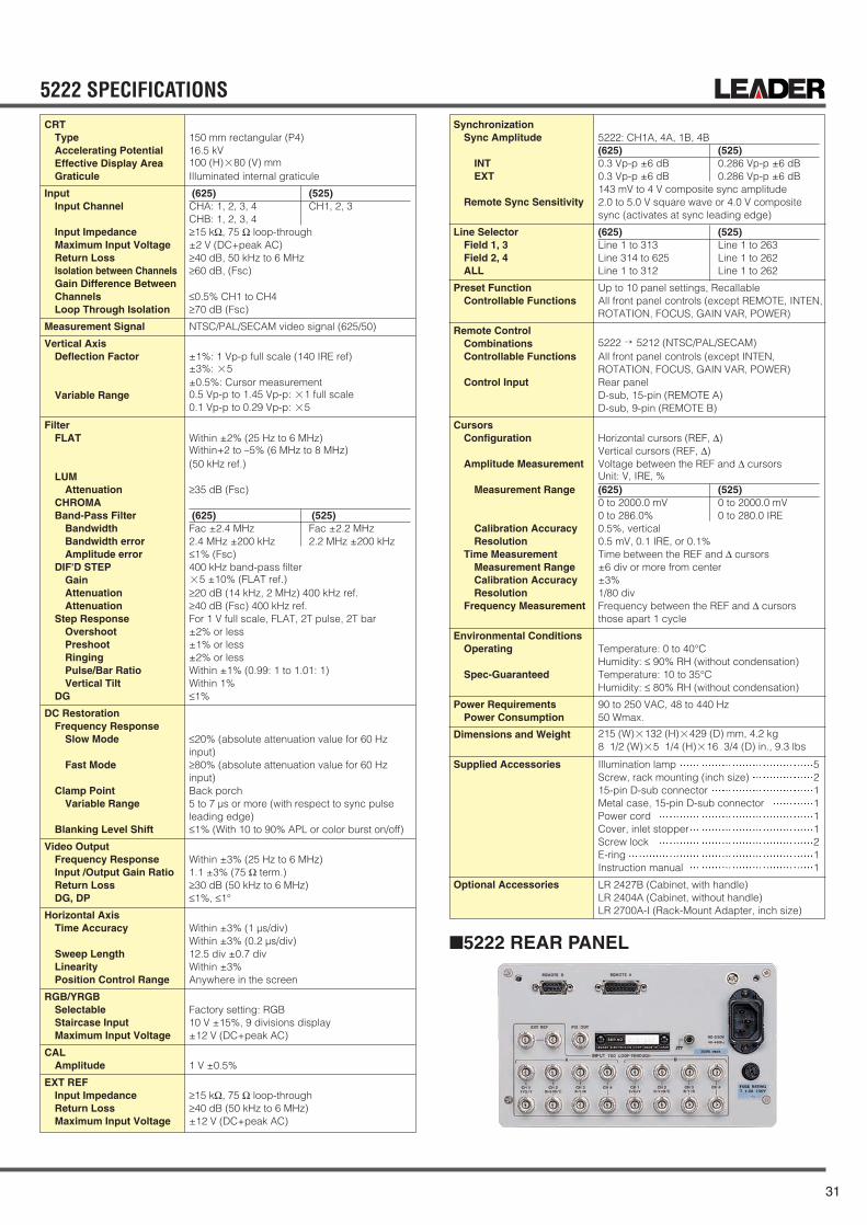
31
5222 SPECIFICATIONSCRT
TypeAccelerating PotentialEffective Display AreaGraticule
InputInput Channel
Input ImpedanceMaximum Input VoltageReturn LossIsolation between ChannelsGain Difference BetweenChannelsLoop Through Isolation
Measurement Signal
Vertical AxisDeflection Factor
Variable Range
FilterFLAT
LUMAttenuation
CHROMABand-Pass Filter
BandwidthBandwidth errorAmplitude error
DIF'D STEPGainAttenuationAttenuation
Step ResponseOvershootPreshootRingingPulse/Bar RatioVertical Tilt
DG
DC RestorationFrequency Response
Slow Mode
Fast Mode
Clamp PointVariable Range
Blanking Level Shift
Video OutputFrequency ResponseInput /Output Gain RatioReturn LossDG, DP
Horizontal AxisTime Accuracy
Sweep LengthLinearityPosition Control Range
RGB/YRGBSelectableStaircase InputMaximum Input Voltage
CALAmplitude
EXT REFInput ImpedanceReturn LossMaximum Input Voltage
150 mm rectangular (P4)16.5 kV100 (H)×80 (V) mmIlluminated internal graticule
(625) (525)CHA: 1, 2, 3, 4 CH1, 2, 3CHB: 1, 2, 3, 4≥15 kΩ, 75 Ω loop-through±2 V (DC+peak AC)≥40 dB, 50 kHz to 6 MHz≥60 dB, (Fsc)
≤0.5% CH1 to CH4≥70 dB (Fsc)
NTSC/PAL/SECAM video signal (625/50)
±1%: 1 Vp-p full scale (140 IRE ref)±3%: ×5±0.5%: Cursor measurement0.5 Vp-p to 1.45 Vp-p: ×1 full scale0.1 Vp-p to 0.29 Vp-p: ×5
Within ±2% (25 Hz to 6 MHz)Within+2 to −5% (6 MHz to 8 MHz)(50 kHz ref.)
≥35 dB (Fsc)
(625) (525)Fac ±2.4 MHz Fac ±2.2 MHz2.4 MHz ±200 kHz 2.2 MHz ±200 kHz≤1% (Fsc)400 kHz band-pass filter×5 ±10% (FLAT ref.)≥20 dB (14 kHz, 2 MHz) 400 kHz ref.≥40 dB (Fsc) 400 kHz ref.For 1 V full scale, FLAT, 2T pulse, 2T bar±2% or less±1% or less±2% or lessWithin ±1% (0.99: 1 to 1.01: 1)Within 1%≤1%
≤20% (absolute attenuation value for 60 Hzinput)≥80% (absolute attenuation value for 60 Hzinput)Back porch5 to 7 µs or more (with respect to sync pulse leading edge)≤1% (With 10 to 90% APL or color burst on/off)
Within ±3% (25 Hz to 6 MHz)1.1 ±3% (75 Ω term.)≥30 dB (50 kHz to 6 MHz)≤1%, ≤1°
Within ±3% (1 µs/div)Within ±3% (0.2 µs/div)12.5 div ±0.7 divWithin ±3%Anywhere in the screen
Factory setting: RGB10 V ±15%, 9 divisions display±12 V (DC+peak AC)
1 V ±0.5%
≥15 kΩ, 75 Ω loop-through≥40 dB (50 kHz to 6 MHz)±12 V (DC+peak AC)
SynchronizationSync Amplitude
INTEXT
Remote Sync Sensitivity
Line SelectorField 1, 3Field 2, 4ALL
Preset FunctionControllable Functions
Remote ControlCombinationsControllable Functions
Control Input
CursorsConfiguration
Amplitude Measurement
Measurement Range
Calibration AccuracyResolution
Time MeasurementMeasurement RangeCalibration AccuracyResolution
Frequency Measurement
Environmental ConditionsOperating
Spec-Guaranteed
Power RequirementsPower Consumption
Dimensions and Weight
Supplied Accessories
Optional Accessories
5222: CH1A, 4A, 1B, 4B(625) (525)0.3 Vp-p ±6 dB 0.286 Vp-p ±6 dB0.3 Vp-p ±6 dB 0.286 Vp-p ±6 dB143 mV to 4 V composite sync amplitude2.0 to 5.0 V square wave or 4.0 V compositesync (activates at sync leading edge)
(625) (525)Line 1 to 313 Line 1 to 263Line 314 to 625 Line 1 to 262Line 1 to 312 Line 1 to 262
Up to 10 panel settings, RecallableAll front panel controls (except REMOTE, INTEN, ROTATION, FOCUS, GAIN VAR, POWER)
5222 → 5212 (NTSC/PAL/SECAM)All front panel controls (except INTEN, ROTATION, FOCUS, GAIN VAR, POWER)Rear panelD-sub, 15-pin (REMOTE A)D-sub, 9-pin (REMOTE B)
Horizontal cursors (REF, ∆)Vertical cursors (REF, ∆)Voltage between the REF and ∆ cursorsUnit: V, IRE, %(625) (525)0 to 2000.0 mV 0 to 2000.0 mV0 to 286.0% 0 to 280.0 IRE0.5%, vertical0.5 mV, 0.1 IRE, or 0.1%Time between the REF and ∆ cursors±6 div or more from center±3%1/80 divFrequency between the REF and ∆ cursorsthose apart 1 cycle
Temperature: 0 to 40°CHumidity: ≤ 90% RH (without condensation)Temperature: 10 to 35°CHumidity: ≤ 80% RH (without condensation)
90 to 250 VAC, 48 to 440 Hz50 Wmax.
215 (W)×132 (H)×429 (D) mm, 4.2 kg8 1/2 (W)×5 1/4 (H)×16 3/4 (D) in., 9.3 lbs
Illumination lamp 5Screw, rack mounting (inch size) 215-pin D-sub connector 1Metal case, 15-pin D-sub connector 1Power cord 1Cover, inlet stopper 1Screw lock 2E-ring 1Instruction manual 1
LR 2427B (Cabinet, with handle)LR 2404A (Cabinet, without handle)LR 2700A-I (Rack-Mount Adapter, inch size)
5222 REAR PANEL

WAVEFORMMONITOR
32
5861V(PAL) 5860V(NTSC)
The 5861V and 5860V Waveform Monitors are oscilloscopesthat are capable of quick monitoring amplitude, time and fre-quency response, etc. of composite TV signals, which arehard for ordinary oscilloscopes to measure. The waveform monitor is equipped with various modes andtrigger functions that are optimum to video signal monitoring.Such various modes as 2H, 1H, 1 µs/div, 2V, 1V, and 2V MAGcan be selected by the horizontal axis sweep. As FLAT, LUM(5861V), IRE (5860V), CHROMA, DIF GAIN and DIF'D STEPcan be switched, it is possible to observe various characteris-tics of video signals. Furthermore, the line selector function is provided for observ-ing VITS and VIR signals which are inserted during the verticalblanking period. In addition, the blanking output connector forblanking other periods that lines selected by the line selector,video output connector and other functions necessary forvideo signal monitoring are provided.
FEATURES•Depending on synchronization system and subcarrier fre-
quency, the 5860V is compatible with the M system, and5861V is compatible with the B, C, D, G, H, I, and K sys-tems.
•Differentiated-step methods are used to display the differen-tial of staircase signals to make measuring the linearity oftransmission system luminance components easier.
•Built-in line selector function for monitoring VITS and VIRsignals, a blanking output and a video output.
•Horizontal sweep mode selection from 2H, 1H, 1 µs/div, 2V,1V, and 2V MAG. The frequency response of the vertical axisis switchable among FLAT, LUM (5861V), IRE (5860V),CHROMA, DIF GAIN, and DIF'D STEP.
•K factor scale provided for checking of frequency charac-teristics.
5860V FRONT PANEL5861V REAR PANEL
Measurements of Composite Video Signal Amplitude,Timing, and Frequency Response
5860V
5861V
(5861V only)
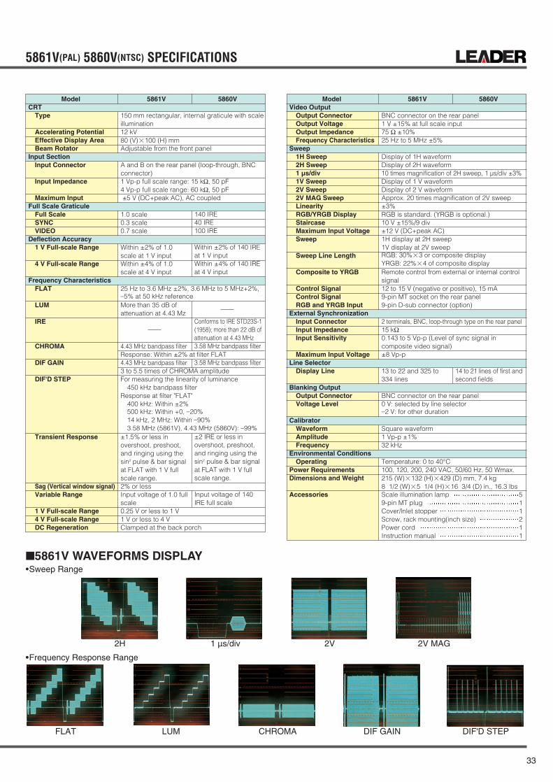
33
5861V(PAL) 5860V(NTSC) SPECIFICATIONS
5861V WAVEFORMS DISPLAY
ModelCRT
Type
Accelerating PotentialEffective Display AreaBeam Rotator
Input SectionInput Connector
Input Impedance
Maximum Input Full Scale Graticule
Full ScaleSYNCVIDEO
Deflection Accuracy1 V Full-scale Range
4 V Full-scale Range
Frequency CharacteristicsFLAT
LUM
IRE
CHROMA
DIF GAIN
DIF'D STEP
Transient Response
Sag (Vertical window signal)Variable Range
1 V Full-scale Range4 V Full-scale RangeDC Regeneration
5861V 5860V
150 mm rectangular, internal graticule with scaleillumination12 kV80 (V)×100 (H) mmAdjustable from the front panel
A and B on the rear panel (loop-through, BNCconnector)1 Vp-p full scale range: 15 kΩ, 50 pF4 Vp-p full scale range: 60 kΩ, 50 pF±5 V (DC+peak AC), AC coupled
1.0 scale0.3 scale0.7 scale
Within ±2% of 1.0 scale at 1 V inputWithin ±4% of 1.0 scale at 4 V input
25 Hz to 3.6 MHz ±2%, 3.6 MHz to 5 MHz+2%, −5% at 50 kHz referenceMore than 35 dB of attenuation at 4.43 Mz
4.43 MHz bandpass filterResponse: Within ±2% at filter FLAT4.43 MHz bandpass filter3 to 5.5 times of CHROMA amplitudeFor measuring the linearity of luminance
450 kHz bandpass filterResponse at filter "FLAT"
400 kHz: Within ±2%500 kHz: Within +0, −20%14 kHz, 2 MHz: Within −90%3.58 MHz (5861V), 4.43 MHz (5860V): −99%
±1.5% or less inovershoot, preshoot, and ringing using the sin2 pulse & bar signal at FLAT with 1 V fullscale range.2% or lessInput voltage of 1.0 full scale0.25 V or less to 1 V1 V or less to 4 VClamped at the back porch
ModelVideo Output
Output ConnectorOutput VoltageOutput ImpedanceFrequency Characteristics
Sweep 1H Sweep2H Sweep1 µs/div1V Sweep2V Sweep2V MAG SweepLinearity RGB/YRGB DisplayStaircase Maximum Input VoltageSweep
Sweep Line Length
Composite to YRGB
Control SignalControl SignalRGB and YRGB Input
External SynchronizationInput ConnectorInput ImpedanceInput Sensitivity
Maximum Input VoltageLine Selector
Display Line
Blanking OutputOutput ConnectorVoltage Level
CalibratorWaveformAmplitudeFrequency
Environmental ConditionsOperating
Power RequirementsDimensions and Weight
Accessories
5861V 5860V
BNC connector on the rear panel1 V ±15% at full scale input75 Ω ±10%25 Hz to 5 MHz ±5%
Display of 1H waveformDisplay of 2H waveform10 times magnification of 2H sweep, 1 µs/div ±3%Display of 1 V waveformDisplay of 2 V waveformApprox. 20 times magnification of 2V sweep±3%RGB is standard. (YRGB is optional.)10 V ±15%/9 div±12 V (DC+peak AC)1H display at 2H sweep1V display at 2V sweepRGB: 30%×3 or composite displayYRGB: 22%×4 of composite displayRemote control from external or internal controlsignal12 to 15 V (negative or positive), 15 mA9-pin MT socket on the rear panel9-pin D-sub connector (option)
2 terminals, BNC, loop-through type on the rear panel15 kΩ0.143 to 5 Vp-p (Level of sync signal in composite video signal)±8 Vp-p
13 to 22 and 325 to 14 to 21 lines of first and334 lines second fields
BNC connector on the rear panel0 V: selected by line selector−2 V: for other duration
Square waveform1 Vp-p ±1%32 kHz
Temperature: 0 to 40°C100, 120, 200, 240 VAC, 50/60 Hz, 50 Wmax.215 (W)×132 (H)×429 (D) mm, 7.4 kg8 1/2 (W)×5 1/4 (H)×16 3/4 (D) in., 16.3 lbsScale illumination lamp 59-pin MT plug 1Cover/lnlet stopper 1Screw, rack mounting(inch size) 2Power cord 1Instruction manual 1
140 IRE40 IRE100 IRE
Within ±2% of 140 IRE at 1 V inputWithin ±4% of 140 IRE at 4 V input
Conforms to IRE STD23S-1 (1958); more than 22 dB of attenuation at 4.43 MHz3.58 MHz bandpass filter
3.58 MHz bandpass filter
±2 IRE or less in overshoot, preshoot, and ringing using the sin2 pulse & bar signal at FLAT with 1 V full scale range.
Input voltage of 140 IRE full scale
•Sweep Range
•Frequency Response Range
2H
FLAT LUM CHROMA DIF GAIN DIF'D STEP
1 µs/div 2V 2V MAG

VECTORSCOPE
34
5212
The Model 5212 is precision Vectorscope designed to moni-tor video signals. The 5212 with its bright CRT features a vec-tor display, DG/DP function to measure differential gain anddifferential phase with a line display, X-Y display mode forstereo audio signals, and menu screen for setting functions. These instruments have three video inputs and one externalreference input channel. Up to four waveforms, including theexternal reference, can be displayed. The newly developeddigital phase control ensures a phase measurement accuracyof within 1%. These instruments can also be remotely con-trolled when combined with the 5222 Waveform Monitor.
Precise DG/DP Measurements with CRT Readout Three Video Inputs, One External Reference Input X-Y Display Capability, Auto Phase & Mag Burst
PAT. PEND. The cabinet is soldseparately.
•X-Y display functionThe level and phase of stereo audio signals can be mea-sured.
•Menu functionFor user-friendly front panel control, a menu controller isprovided for various functions.
•Preset functionThe front panel settings, including vertical and horizontalpositioning, can be stored in memory, and recalled from thefront panel or via the remote control connector on the rearpanel. Yon can reduce setup time by presetting frequentlyused measuring conditions.
•Automatic NTSC/PAL system discriminator (5212 only)The 5212 automatically selects the NTSC or PAL color sys-tem.
•Y/C inputThe C signal vector can be displayed by respectively apply-ing the Y signal and C-signal to the CH1 and CH2 input con-nectors.
•Remote controlThese instruments can also be remotely controlled whencombined with the 5222 Waveform Monitor. The line select-ed by the waveform monitor is displayed automatically.
•Bright CRT, accelerating potential of 16.5 kV•Universal AC power supply, 90 to 250 V
FEATURES•Three videoinputsandoneexternalreferenceinput channel
Up to four waveforms, including the external reference, canbe displayed simultaneously.
•Digital phase controlThe newly developed digital phase control ensures a phasemeasurement accuracy of within 1% and display resolutionof within 0.1° with alphanumeric readout.
•DG/DP measuring functionThese instruments enable accurate measurement of differ-ential gain (DG) and differential phase (DP) with alphanu-meric readout.

35
5212 SPECIFICATIONS
CRTTypeAccelerating PotentialEffective Display AreaGraticule
InputInput ChannelInput ImpedanceMaximum Input VoltageReturn LossIsolation Between ChannelsGain Difference Between ChannelsPhase Difference Between ChannelsLoop-Through Isolation
SynchronizationSync Amplitude
CH1, 2, 3Video Signal
EXTVideo Signal
SubcarrierSignal Selection
Vector ModeBandwidth
Upper -3 dB PointLower -3 dB PointCenter Frequency (Fsc)
Display
Phase Accuracy
Amplitude Accuracy
Digital Phase ControlPhase Accuracy
Subcarrier RegenerationPull-In RangePull-In TimePhase Control RangePhase ShiftPhase ShiftBurst Jitter
Position Variable RangeVertical PositionHorizontal Position
DG/DP ModeMeasurement Accuracy
DGDP
Position Control RangeVertical PositionHorizontal Position
Auto SetupDG Setup AccuracyDP Setup Accuracy
X-Y ModeInput
Input ImpedanceCalibration AccuracyInput Amplitude
Maximum Input VoltageFrequency ResponseX-Y Phase DifferenceInput ConnectorV Position Control RangeH Position Control Range
150 mm rectangular (P4)16.5 kV100 (H)×80 (V) mmIlluminated internal graticule
CH1, CH2, CH3, EXT≥15 kΩ, 75 Ω loop-through±12 V (DC+peak AC)≥40 dB (50 kHz to 6 MHz)≥70 dB (Fsc)≤±0.5%≤±0.5% (Fsc)≥70 dB (Fsc)
PAL NTSC
Burst, sync amplitude Burst, sync amplitude0.3 Vp-p ±6 dB 0.286 Vp-p ±6 dB
Burst, sync amplitude Burst, sync amplitude0.3 Vp-p ±6 dB 0.286 Vp-p ±6 dB2 Vp-p ±6 dBVideo or subcarrier, selectable
PAL NTSCFsc+500 kHz ±100 kHz Fsc+500 kHz ±100 kHzFsc−500 kHz ±100 kHz Fsc−500 kHz ±100 kHz4.43361875 MHz 3.579545 MHzColor bars 75%, 100%MAG mode settingOFF: Within ±1°BURST: Within ±2°×5 MAG: Within ±2°OFF: Within ±3%BURST: Within ±3%×5 MAG: Within ±5%
Within ±0.5°
Within ±150 HzWithin 1 sec360°Within ±2° (Fsc ±50 Hz)Within ±2° (Burst amplitude ±6 dB)≤±0.5°
At least ±8 mm from centerAt least ±8 mm from center
Within ±0.5%Within ±0.5°
±40 mm ±4 mm from centerAt least ±8 mm from centerAt CAL positionWithin ±2%Within ±2°
DC-coupled differential inputs(Balanced input)≥20 kΩWithin ±3%0 dBm to 12 dBm (600 Ω)(0.775 V to 3.1 Vrms)±12 V (DC+peak AC)DC to 20 kHz, ≤3 dB≤1° (20 kHz)15-Pin D-sub connector (rear panel)At least ±8 mm from centerAt least ±8 mm from center
GAINGAIN Variable RangePhase Shift by GAIN
Auto PhaseAccuracy
REF SETVECT ModeDG ModeDP Mode
Preset FunctionControllable Functions
Remote ControlCombinationsLine Selection
Recall FunctionControllable FunctionsControl SignalInput Connector
CRT ReadoutColor SystemPhase
Display ResolutionNTSC SetupREF ChannelDG
Display ResolutionDP
Display ResolutionX-Y DisplayRecall ModeY/C Display
Environmental ConditionsOperating
Spec-Guaranteed
Power RequirementsPower Consumption
Dimensions and Weight
Supplied Accessories
Optional Accessories
+3 dB to −14 dB or moreWithin ±1° (+3 dB to −6 dB)
Burst phase is set to-(B-Y) axis.Within ±2°
PHASE display is set to 0.0°DG display is set to 0.00%DP display is set to 0.00°
Up to 10 panel settingsAll front panel controls (except INTEN, FOCUS.ROTATION, ILLUM, GAIN, VAR, POWER), andMenu (SYSTEM, DISPLAY)
5222 → 5212 (NTSC/PAL)Full line selection capabilityWindow display capabilityAvailableINPUT, REF, Y/C, RECALLTTL, low activeD-sub, 9-pin (rear panel)
NTSC/PAL (SYNC ABSENT)0.0° to 359.9°0.1°SETUP 7.5%/SETUP 0%CH1, CH2, CH3, EXT+10.00% to −10.00% (DG mode)0.01%+10.00° to −10.00° (DP mode)0.01°X-Y scale is displayed (X-Y mode).Address to be recalledY/C is displayed (Y/C mode).
Temperature: 0 to 40°CHumidity: ≤ 90% RH (without condensation)Temperature: 10 to 35°CHumidity: ≤ 80% RH (without condensation)
90 to 250 VAC, 48 to 440 Hz55 Wmax.
215 (W)×132 (H)×429 (D) mm, 4 kg8 1/2 (W)×5 1/4 (H)×16 3/4 (D) in., 8.8 lbs
Illumination lamp 5Screw, rack mounting (inch size) 215-pin D-sub connector 1Metal case, 15-pin D-sub connector 19-pin to 9-pin D-sub connector cable 1Power cord 1Cover, inlet stopper 1Screw lock 6E-ring 3Instruction manual 1
LR 2427B (Cabinet, with handle)LR 2404A (Cabinet, without handle)LR 2700A-I (Rack-Mount Adapter, inch size)
5212 REAR PANEL

VECTORSCOPE
36
5850V(NTSC)
The 5850V Vectorscope is designed to simultaneously mea-sure the amplitude and phase of chrominance componentscontained in a composite video signal.To measure phase (i.e., direction with respect to burst signal)and amplitude (i.e., length from center) in vector format, thechrominance components containing color information of thevideo signal are first demodulated, then displayed on the CRT.VITS and VTR can also be displayed in vector format byapplying blanking signal output from the waveform monitor toZ INPUT of the vectorscope.
FEATUREFS•The 150 mm rectangular CRT with internal graticule (with the
scale illumination), it is possible to measure without parallaxreading error.
•DP and DG measurements enable using the modulatedstaircase.
•Use with a waveform monitor to observe the vector VITS andVIR signals.
•The optional rackmount adapter enables a pattern genera-tor, color monitor, and vectorscope to be integrated in a sys-tem.
5850V REAR PANEL
Vector Display for Composite Video Signal

37
5850V(NTSC) SPECIFICATIONS
THE ANGLES FOR EACH HUE 5850V
CRTType
Accelerating PotentialEffective Display AreaBeam RotatorGraticule
Composite Video Signal InputInput
Input ImpedanceMax. Input VoltageCalibrated Value
Blanking InputSensitivityPolarity
ChrominanceBandwidth
Phase AccuracyAmplitude AccuracyDifferential PhaseDifferential Gain
150 mm rectangular, internal graticule with scale illumination12 kV80 (V)×100 (H) mmAdjustable from the front panelInternal scale Allowable frame: ±20%/ ±10°ofstandard color bar, circle, angle, R-Y axis, B-Yaxis, I axis, Q axis, DG and DP, ±2.5 IRE/±2.5°of standard color bar, and ±20 %/ ±10° of burstsignal
A, B and EXT REF on the rear panel (loop-through, BNC connector)A, B: 2 MΩ, EXT REF: 10 kΩ±5 V (DC+peak AC)Color Saturation: 75%, 100%, full scaleAmplitude: 1 Vp-p, 1.24 Vp-pVariable Range: 0.5 to 5 times of the calibrated value
EXT REFSubcarrier: 2 Vp-p ±6 dBBlack Burst: 0.45 Vp-p ±6 dB (5851V)/0.43 Vp-p ±6 dB (5850V)
DC ±1 VBrightens With positive voltage
Center: Fsc=3.579545 MHzHigh Freq.=Fsc +500 kHzLow Freq.=Fsc -500 kHz±2°±3%±1°±1%
Measurement ItemVector Measurement
Horizontal SynchronizationInput
Sync PolaritySync Level Range
Subcarrier Signal SynchronizationSynchronization by Burst Signal (of composite video signal)
Sync Level RangeSynchronization by External Subcarrier Signal (which is applied to the EXT REF input)
Subcarrier Signal SyncLevel Range
Synchronization by Black Burst Signal (which is applied to the EXT REF input)
Black Burst Sync Level Range
Note: The external subcarrier signal is switched to and from the black burst signal internally. (set in black burst mode at shipment)Subcarrier FrequencySync Capture RangePhase Adjustment RangeCalibration
Test Circle
Power Requirements
Dimensions and Weight
Accessories
Phase and amplitude of chrominance componentin 75% or 100% saturation color bar signal
Synchronization by the horizontal sync signal ofcomposite video signal from input A or B.Negative0.286 Vp-p ±6 dB
0.286 Vp-p ±6 dB
2 Vp-p ±6 dB
0.43 Vp-p ±6 dB
3.579545 MHz±50 Hz (0°C to 40°C)360°, continuously variable
Set the chrominance signal applied from theinput connector in asynchronous mode.100, 120, 200, 240 VAC, selectable by internalwiring 50/60 Hz, 40 Wmax.215 (W)×132 (H)×429 (D) mm, 7.3 kg8 1/2 (W)×5 1/4 (H)×16 3/4 (D) in, 16.1 lbsIllumination lamp 5Cover/Inlet stopper 1Screw, rack mounting (inch size) 2Power cord 1Instruction manual 1
123° 103.4° 60.8°
33°
347.1°
303°283.4°240.8°
213°
167.1°
-(B-Y)BURST
-(R-Y)
R-Y
B-Y

38
MULTI FORMATVIDEOGENERATORMAINFRAME
LT 443D
The LT 443D Signal Generator can be flexibly used for the mul-tiformat digital broadcast systems. Various plug-in units enablethe output of SDI signals (i.e., HDTV, SDTV), sync signals, andanalog signals. By using these signals and genlock functions,users can customize this signal generator as desired.
FEATURES•Plug-in units provide various functions
Since up to four plug-in units can be installed in the main-frame (consisting of a power supply, main signal generator,and controller), users can customize this signal generator asdesired.*1 The plug-in unit is installed at the factory; user cannnot
replace the unit.•Applicable to multiformat HDTV
For the SDI signals, 14 HDTV format unit and 525 line/625line SDTV unit are provided. The NTSC/PAL analog videosignal unit is also available.Since each unit can output the signal simultaneously, a mul-tiformat system can be constructed to satisfy user's require-ments.
•Various sync outputTwo units can simultaneously output HD signals with 74.25MHz clock and 74.25/1.001 MHz clock.
•Easy-to-use sync signalsFor today's modern age of digital TV systems, BB signal (forNTSC/PAL) and HDTV tri-level sync signals can be generat-ed from the Analog BB Unit.
•Ethernet providedSince the ethernet capability is provided as standard. Thisfeature can remotely control various functions and monitorthe genlock status.
•User-friendly operabilityLeader's traditional design and operability concepts arealso reflected in this instrument. User-friendly operationincludes significantly reduced power-on initialization time isadvantageous to a high-performance instrument.
•Reading logo mark data
OPTIONLT 443D-70 (NATURAL Picture Memory: Option 70)
This option adds the NATURAL picture pattern outputcapability to the LT 443D mainframe.A compact flash memory card is used as an additionalmemory to store the NATURAL picture pattern.
Various plug-in units expand the capability of the Multiformat Signal Generator.
CompartmentNumber of compartmentsID Function
LCD PanelNumber of Characters
Internal ClockInternal Reference Frequency
Memory Card SlotApplicable CardFunction
External InterfaceEthernetUSB (Universal Serial Bus)
General SpecificationsEnvironmental Conditions
Operating Temperature RangeOperating Humidity RangeSpec-Guaranteed Temperature RangeSpec-Guaranteed Humidity RangeOperating EnvironmentOperating AltitudeOvervoltage CategoryPollution Degree
Power RequirementsPower ConsumptionDimensions and Weight
Accessories
4Automatically identifies the unit installed.*2 Refer to specifications of each unit.
20 characters x 2 lines can be displayed(W/backlight)
27 MHz
Compact flash memory card (CFA TYPE-1) *3Storing/reading preset dataReading logo mark data Reading NATURAL PICTURE data *4*3 No compact flash memory card is sup-plied as standard accessory.Memory cards produced by following manu-facturers should be procured (as of August2002):SanDisk*4 The NATURAL picture function is onlyusable when the LT 443D-70 Option isinstalled in the mainframe.
10Base-T/100 Base-T (Automatic selection)Applicable to USB 1.1This function will be supported.
0 to 40 ˚C≤ 90% RH (without condensation)10 to 35 ˚C≤ 85% RH (without condensation)Indoor useUp to 2000 mII290 to 250 VAC, 50/60 HzApprox. 150 W max. (Approx. 75 W max. *5)426 (W) x 44 (H) x 560 (D) mm, Approx. 7 kg *5*5 When four plug-in units (i.e., LT 443D-HD, LT443D-SD, LT 443D-BL, LT 443D-GL) are installed.16 3/4 (W) x 1 3/4 (H) x 22 (D) in., 15.4 lbsPower cord....................................................1Cover/Inlet stopper .......................................1Rack Support (right and Left) .......................1Screw (for rack support) ...............................4Rubber Feet ..................................................5Logo Mark Software CD-R............................1Instruction manual ........................................1
LT 443D SPECIFICATIONS

LT 443D-GLA GENLOCK UNIT
39
This unit provides genlock capability to lock the LT 443D mainframe withthe external reference signal, and three independent black signal genera-tors.The NTSC/PAL black burst signals, principal 20 types of HDTV analog tri-level sync signal formats, and 525p/625p analog sync signals can be usedas an external reference signal.The following black burst signal formats can be selected.For NTSC/PAL system, black burst signal with field reference pulse is pro-vided. For NTSC system, black burst with 10-field sequence identificationconforming to the SMPTE 318M standards is provided. The instrument continues operation since the flywheel mode is providedeven if the external reference signal is accidentally removed in genlockmode. By logging the genlock status, the time can be obtained when theexternal reference signal is removed. The log information can be stored on
the CF CARD.The genlock timing can be adjusted for the entire color frame range whenthe NTSC/PAL black burst signal is applied; entire frame range when theHDTV analog tri-level sync signal is applied.Three black burst signal output systems with selectable formats are avail-able as follows:For NTSC/PAL system, standard black burst signal and black burst signalwith field reference pulse are provided. For NTSC system, 10-field blackburst signal with ID conforming to the SMPTE 318M standards, 525p/625panalog sync signal, and HDTV analog tri-level sync signal are provided.The format and output signal timing of each output can be respectively set.The black signal timing can be adjusted for the entire color frame rangewhen the NTSC/PAL black burst signal is applied; entire frame range whenthe HDTV analog tri-level sync signal is applied.
The LT 443D-HD HD-SDI Unit adds the 14 format HD-SDI signal output capability to the LT 443D mainframe.Various functions (e.g., ID character, simple motionpictures, embedded audio, NATURAL picture pattern*)are provided.*The NATURAL picture function is only usable whenthe LT 443D-70 Option is installed in the mainframe.
Output• HD-SDI Video Output
Specifications• Specifications
SDI Characteristics• Bit Rate• Output Amplitude• Overshoot• Rise and Fall Time• Return Loss
Function• Applicable Format
• Test Patterns
1 system, 2 outputs (75 Ω, BNC)
Conforms to SMPTE 240M(Except for Return Loss)/274M/296M standards
1.485 Gbps, 1.485/1.001 Gbps800 mVp-p ±10%≤ 10 %≤ 270 ps (20 % to 80 %)≥ 15 dB (5 MHz to 742.5 MHz)≥ 10 dB (742.5 MHz to 1.485 GHz)
1035i/60, 1035i/59.94,1080i/60, 1080i/59.94, 1080i/50,1080p/30, 1080p/29.97, 1080p/25,1080p/24, 1080p/23.98,1080PsF/24, 1080PsF/23.98,720p/60, 720p/59.94The following formats will be supported:720p/29.97, 720p/24, 720p/23.98, 720p/50,720p/30, 720p/25COLOR BAR 100 %, COLOR BAR 75 %, MULTIFOR-MAT COLOR BAR (ARIB STD-B28) FLAT FIELD 100 %,
• Variable TimingVariable RangeVariable In V
H• Simple Motion Picture Mode (Scroll)
DirectionSpeed (Range, Resolution)
Field Frame InterlaceV InterlaceH Common
• ID Character
• Embedded AudioNumber of Channels Embedded
Sampling FrequencyResolutionPreemphasisFrame NumberFrequency
Level
FLAT FIELD 50 %, FLAT FIELD 0 %, LINE SWEEP 100%, MULTI BURST 100 %, BOWTIE 100 %, RAMP, SHAL-LOW RAMP, 10 STEP, PULSE & BAR, CHECK FIELD,RED RASTER 100 %, CROSS & DOT, MONOSCOPE
Entire frame rangeLine stepsClock steps (74.25 MHz or 74.25/1.001 MHz)
8 directions (vertical, horizontal, diagonal)
Variable in field steps0 to 256 lines in 2 line steps0 to 256 dots in 4 dot stepsID characters can be displayed at the arbitrary posi-tion on the screen.
8 channels (4 channels x 2 groups)Each group can be set ON/OFF48 kHz (sync to video signal)20 bits, 24 bits, selectableOFF, 50/15 µs, CCITT, selectable (CS bit is only selected.)None50, 100, 150, 200, 250, 300, 400, 500, 600, 750,800, 1.0 k, 1.2 k, 1.5 k, 1.6 k, 2.0 k, 2.4 k, 3.0 k, 3.2 k, 4.0 k, 4.8 k, 5.0 k, 6.0 k, 8.0 k, 9.6 k, 10 k, 12 k, 15 k, 16 k, 20 kHz, silence-60 to 0 dBFS (settable in 1 dB steps)*Frequency, level, and audio click can be set toeach channel.*When the CHECK FIELD pattern is selected, noaudio signal is embedded.
Sync Level (into 75 Ω)• HDTV
• 525p• 625p• NTSC• PAL
Rise and fall times• HDTV• 525p• 625p• NTSC• PAL
Horizontal Sync Width• 1125-Line Format
• 750-Line Format
• 525p• 625p• NTSC/PAL
Vertical Sync WidthOutput ConnectorNumber of OutputsTiming Variable Range
• H-PHASE• V-PHASE• F-PHASE
N14/SMPTE RP-154/SMPTE 170M/SMPTE 318MstandardsPAL black burst signal conforming to ITU-R BT. 470-6 standards
Positive polarity: 300 mV ±6 mVNegative polarity: -300 mV ±6 mV-300 mV ±6 mV-300 mV ±6 mV40 IRE ±1 IRE-300 mV ±6 mV
54 ns ±20 ns70 ns ±10 ns100 ns ±10 ns140 ns ±10 ns200 ns ±10 ns
Positive polarity: 593 ns ±40 nsNegative polarity: 593 ns ±40 nsPositive polarity: 539 ns ±40 nsNegative polarity: 539 ns ±40 ns2.35 µs ±0.05 µs2.35 µs ±0.1 µs4.7 µs ±0.1 µs5H (HDTV) / 6H (525p) / 5H (625p) / 3H (NTSC) / 2.5H (PAL)BNC1 each
Up to ±1 line-1 dotUp to ±1 frame-1 lineUp to ±5 frames (depends on the input signal format.)
Genlock FunctionLoop-Through Input
Input ConfigurationReturn LossReference Input Signal
Reference Input Signal Level• HDTV
• 525p/625p• NTSC• PAL
Operation Modes
Genlock Timing Variable Range• H-PHASE (FINE)• H-PHASE (COARSE)• V-PHASE• F-PHASE
Analog Sync Signal OutputBLACK 1/BLACK 2/BLACK 3 OutputFormat
BNC connector, 75 Ω loop-through≥ 30 dB (0.3 MHz to 30 MHz)HDTV tri-level sync signal conforming to SMPTE240M/274M/296M standards525p/625p analog sync signal conforming to SMPTE293M/ITU-R BT 1358 standardsNTSC black burst signal conforming to EBUN14/SMPTE RP-154/SMPTE 170M/SMPTE 318M standardsPAL black burst signal conforming to ITU-R BT. 470-6 standards
Positive polarity: 300 mVNegative polarity: -300 mV-300 mV-286 mV-300 mVAUTO and MANUAL modes are provided for select-ing INT or EXT mode.
Fine adjustment between the H-PHASE (COARSE) steps.±1/2 line with respect to the input signal±1 frame with respect to the input signalUp to ±5 frames with respect to the input signal.(Variable range depends on the input signal format.)
HDTV tri-level sync signal conforming to SMPTE240M/274M/296M standards525p/625p analog sync signal conforming to SMPTE293M/ITU-R BT 1358 standardsNTSC black burst signal conforming to EBU
Plug-In Unit For LT 443D
LT 443D-HD HD-SDI UNIT/LT 443D-HDB (HD-SDI Out x 2, HD-SDI Black Out x 2) UNIT Plug-In Unit For LT 443D

40
Output• SD-SDI Video Output
Specifications• Specifications
SDI Characteristics• Bit Rate• Output Amplitude• Overshoot• Rise and Fall Time• Return Loss
Function• Applicable Format• Test Patterns
1 system, 2 outputs (75 Ω, BNC)
Conforms to ITU-R BT. 601, SMPTE 125M standardsConforms to ITU-R BT. 656, SMPTE 259M standards
270 Mbps800 mVp-p ±10 %≤ 10 %0.4 to 1.5 ns (20 % to 80 %)≥ 15 dB (5 MHz to 270 MHz)
525i/59.94-270 MHz, 625i/50-270 MHzCOLOR BAR 100%, COLOR BAR 75%, EBU COLORBAR, BBC COLOR BAR, SMPTE COLOR BAR, RAMP& COLOR, FLAT FIELD 100%, FLAT FIELD 50%,FLAT FIELD 0%, FIELD ID, CROSSHATCH, LINESWEEP 100%, LINE SWEEP 60%, MULTIBURST 100%, MULTI-BURST 60%, OVER SIZE RAMP, DIGITAL LIMITRAMP, SHALLOW RAMP, 10 STEP, CHECK FIELD,MONOSCOPE, BOWTIE 100%, PULSE & BAR, REDRASTER, MULTIPULSE
• Variable TimingVariable RangeVariable In V
H• Simple Motion Picture Mode (Scroll)
DirectionSpeed (Range, Resolution)
Field FrameVH
• ID CharactersNumber of CharactersSize
• Embedded AudioNumber of Channels Embedded
Sampling FrequencyResolutionPreemphasisFrame NumberFrequency
Level
Entire frame rangeLine stepsClock steps (27 MHz)
8 directions (vertical, horizontal, diagonal)
Variable in field steps0 to 256 lines in 2 line steps0 to 256 dots in 4 dot steps
Up to 2032 x 32 dots, 64 x 64 dots, selectable
8 channels (4 channels x 2 groups)Each group can be set ON/OFF respectively.48 kHz (sync to video signal)20 bits, 24 bits, selectableOFF, 50/15 µs, CCITT, selectable(CS bit is onlyselected.)ON/OFF, selectable50, 100, 150, 200, 250, 300, 400, 500, 600, 750, 800,1.0 k, 1.2 k, 1.5 k, 1.6 k, 2.0 k, 2.4 k, 3.0 k, 3.2 k, 4.0 k, 4.8 k, 5.0 k, 6.0 k, 8.0 k, 9.6 k, 10 k, 12 k, 15 k,16 k, 20 kHz, silence-60 to 0 dBFS (settable in 1 dB steps)*Frequency, level, and audio click can be set to eachchannel.*When the CHECK FIELD pattern is selected, noaudio signal is embedded.
Function• Sampling Frequency• Frequency
• Level
48 kHz (Sync to video signal)50, 100, 150, 200, 250, 300, 400, 500, 600, 750, 800,1.0 k, 1.2 k, 1.5 k, 1.6 k, 2.0 k, 2.4 k, 3.0 k, 3.2 k, 4.0 k, 4.8 k, 5.0 k, 6.0 k, 8.0 k, 9.6 k, 10 k, 12 k, 15 k,16 k, 20 kHz, silence-40 to 4 dBm (settable in 1 dBm steps)
Output• Number of Outputs• Output Impedance• Output Amplitude• Output Amplitude Accuracy• Output Amplitude Flatness• Output Connector
2600 Ω, balanced0.775 Vrms (into 600 Ω at 0 dBm)±0.5 dB (at 1 kHz)±0.5 dB (1 kHz ref.)XLR-3P x 2
The LT 443D-SD SD-SDI Unit adds the 525/625 line formatSD-SDI signal (4:2:2 component signal) output capability tothe LT 443D mainframe. Various functions (e.g., ID charac-ter, simple motion pictures, embedded audio, NATURALpicture pattern*) are provided.*1: The NATURAL picture function is only usable when theLT 443D-70 Option is installed in the mainframe.
Installing the LT 443D-AA Analog Audio Unit in the LT 443Dmainframe can output analog audio signal (two systems).Output characteristics (e.g., output level, frequency) can beindependently set for each output system.The sound sampling frequency is synchronized with thevideo signal of plug-in unit installed in the mainframe.
Analog Sync Signal OutputBLACK 1, 2/BLACK 3, 4/BLACK 5, 6Format
Sync Level (into 75 Ω)• HDTV
• 525p• 625p• NTSC• PAL
Rise and fall times• HDTV• 525p
HDTV tri-level sync signal conforming to SMPTE240M/274M/296M standards525p/625p analog sync signal conforming to SMPTE293M/ITU-R BT 1358 standardsNTSC black burst signal conforming to SMPTE RP-154/SMPTE 170M/SMPTE 318M standardsPAL black burst signal conforming to ITU-R BT. 470-6 standards
Positive polarity: 300 mV ±6 mVNegative polarity: -300 mV ±6 mV-300 mV ±6 mV-300 mV ±6 mV40 IRE ±1 IRE-300 mV ±6 mV
54 ns ±20 ns70 ns ±10 ns
• 625p• NTSC• PAL
Horizontal Sync Width• 1125-Line
• 750-Line
• 525p• 625p• NTSC/PAL
Vertical Sync WidthOutput ConnectorNumber of OutputsTiming Variable Range
• H-PHASE• V-PHASE• F-PHASE
100 ns ±10 ns140 ns ±10 ns200 ns ±10 ns
Positive polarity: 593 ns ±40 nsNegative polarity: 593 ns ±40 nsPositive polarity: 539 ns ±40 nsNegative polarity: 539 ns ±40 ns2.35 µs ±0.05 µs2.35 µs ±0.05 µs4.7 µs ±0.1 µs5H (HDTV) / 6 H (525p) / 5H (625p) / 3H (NTSC) / 2.5H (PAL)BNC (BLACK 1, 2/BLACK 3, 4/BLACK 5, 6)2 each
Up to ±1 line-1 dotUp to ±1 frame-1 lineUp to ±5 frames (depends on the input signal format.)
The LT 443D-BL Analog Black Signal Unit adds the 20 HDTV formatanalog tri-level sync signal, 525p/625p analog sync signals, andNTSC/PAL black burst signals output capability to the LT 443D main-frame.Three independent output systems (six outputs, two outputs per sys-tem) are provided to output multiformat black sync signal.The format and output signal timing can be respectively set each output.
The ten-field black signal with ID conforming to the SMPTE 318Mstandards is also available.The entire range of timing can be set for the 525p/625p analog syncsignals and NTSC/PAL black burst signals in 54 MHz clock steps.The entire range of timing can also be set for the HDTV analog tri-level sync signal in 74.25 MHz or 74.25/1.001 MHz clock steps.
LT 443D-BL ANALOG BLACK UNIT
LT 443D-SD SD-SDI UNIT/LT 443D-SDB (SD-SDI Out x 2, SD-SDI Black Out x 2) UNIT
LT 443D-AA ANALOG AUDIO UNIT
Plug-In Unit For LT 443D
Plug-In Unit For LT 443D
Plug-In Unit For LT 443D

41
Output• AES/EBU Digital Audio Output
Number of Outputs Output AmplitudeOutput Connector
• Silence Signal (DARS grade 2) OutputNumber of OutputsOutput AmplitudeOutput Connector
• 48 kHz Word ClockNumber of OutputsOutput AmplitudeOutput Connector
Signal Specifications• Specifications
4 (2-channel output)1 Vp-p ±0.1 V (into 75 Ω)BNC
1 (2-channel output)1 Vp-p ±0.1 V (into 75 Ω)BNC
11 Vp-p ±0.1 V (into 75 Ω), 5 V CMOS, selectableBNC
ANSI S4.40 (AES3-1992), AES 11-1997SMPTE 276M, AES-3id-2001
Function• Sampling Frequency• Resolution• Preemphasis• Frequency
• Level• Audio Click• Output ON/OFF• Timing
Variable Range
48 kHz (sync to video signal)20 bits, 24 bits, selectableOFF, 50/15 µs, CCITT, selectable (CS bit can only beselected.)50, 100, 150, 200, 250, 300, 400, 500, 600, 750, 800,1.0 k, 1.2 k, 1.5 k, 1.6 k, 2.0 k, 2.4 k, 3.0 k, 3.2 k, 4.0 k, 4.8 k, 5.0 k, 6.0 k, 8.0 k, 9.6 k, 10 k, 12 k, 15 k,16 k, 20 kHz, silence-60 to 0 dBFS (settable in 1 dB steps)1, 2, 3, 4 sec, noneSelectable
±1 AES/EBU frameSettable in 512 fs (24.576 MHz) steps*The timing can be varied with respect to the VideoUnit installed in the LT 443D mainframe.The settings are common to the digital audio, silenceand word clock signals.*Frequency, level, and audio click can be set to eachchannel.Other items (except timing) can be respectively set tothe 2-channel output.
Installing the LT 443D-DA Digital Audio Unit in the LT 443Dmainframe can output AES/EBU digital audio signals (foursystems), silence signals (one system), and 48 kHz wordclock signals.The AES/EBU signal characteristics (e.g., output level, fre-quency) can be independently set for each output system.The sampling frequency is synchronized with the video sig-nal of plug-in unit installed in the mainframe.
Test Signal Output• Format
• Pattern
• NATURAL Picture *5
• APLMODE
Time Interval• ID Charactor
Number of CharactersSizeDisplay PositionBlinking
NTSC, NTSC+REFERENCE *2, NTSC+ID *3, NTSC+REF-ERENCE+ID *2 *3, NTSC+SETUP, NTSC+SETUP+REF *2,NTSC+SETUP+ID *3, NTSC+SETUP+REF+ID *2 *3, PAL*4, PAL+REFERENCE *4 *2
*2 REFERENCE and REF denote Field Reference. *3 ID denotes 10 field ID. *4 The 25-Hz offset subcarrier is used for the PAL system.COLOR BAR 100%, COLOR BAR 75%, EBU COLOR BAR,BBC COLOR BAR, SMPTE COLOR BAR, FLAT FIELD100%, FLAT FIELD 50%, FLAT FIELD 0%, CROSSHATCH1, CROSSHATCH 2, LINE SWEEP 100%, LINE SWEEP60%, MULTIBURST 100%, MULTIBURST 60%, SHAL-LOW RAMP, 10 STEP, MOD 10 STEP, RAMP, MOD RAMP,MONOSCOPE, RED RASTER, WINDOW, PULSE & BARUp to five screens of 24-bit full color BMP file can besimultaneously switched.
APL OFF, APL HIGH, APL LOW, APL(BOUNCE), BOUNCEAPL (BOUNCE) is switched at a preset time intervalfor APL HIGH and APL LOW.BOUNCE is switched at a preset time interval forFLAT FIELD 100 % and FLAT FIELD 0 %.1 to 20 seconds (settable in one second steps)
Up to 2032 x 32 dots, 64 x64 dots, selectableArbitrary position on the screen.OFF, 1 to 10 seconds (settable in one second steps)
• Simple Motion Picture FunctionDirectionSpeed
• Timing VariableH-PHASEV-PHASEF-PHASE
• Number of OutputsBlack Signal Output
• format
• Output Signal• Format• Timing Variable
H-PHASEV-PHASEF-PHASE
• Number of Outputs• Signal Level
Horizontal Drive Pluse Output• Format• Signal Level• Signal Polarity• Timing Variable
H-PHASE• Number of Outputs
Vertical Drive Pluse Output• Format• Signal Level• Signal Polarity• Timing Variable
V-PHASE• Number of Outputs
8 directions (up, down, left, right, and combinations)H: 0 to 256 dots in 4 dot stepsV: 0 to 256 lines in 2 line steps(Pattern can be scrolled in field time steps.)*5 The Option LT 443D-70 should be installed in themainframe to enable this function.The timing of OUTPUT 1 and 2 can be varied simultaneously.Up to ±1 line-1 dotUp to ±1 frame-1 lineNTSC:Up to ±5 framesPAL: UP to ±2 frames2
Depends on the test signal format. (Supports the fieldReference and 10 field ID)Analog black burstThe timing of OUTPUT 1 and 2 can be varied simultaneously.
Up to ±1 line-1 dotUp to ±1 frame-1 lineNTSC:Up to ±5 framesPAL: UP to ±2 frames2 Systems (one each)1 Vp-p (into 75 Ω)
Depends on the test signal format.2 Vp-p (into 75 Ω)Negative
Up to ±1 line-1 dot1
Depends on the test signal format.2 Vp-p (into 75 Ω)Negative
Up to ±1 frame-1 line1
The LT 443D-CS Analog Composite Unit adds theNTSC/PAL analog composite signal output capability tothe LT 443D mainframe. Various functions (e.g., IDcharacter, simple motion pictures, embedded audio,NATURAL picture pattern *1) are provided.*1: The NATURAL picture function is only usable whenthe Option LT 443D-70 is installed in the mainframe.
LT 443D-DA DIGITAL AUDIO UNIT
LT 443D-CS ANALOG COMPOSITE UNIT
Plug-In Unit For LT 443D
Plug-In Unit For LT 443D

42
MULTI FORMATVIDEOGENERATOR
Applicable to both HD-SDI and SD-SDI systems, 1U half-rack size
The compact, 1U half-rack sized, LT 4400 Multiformat VideoGenerator is applicable to both HD-SDI and SD-SDI systems.The various output capabilities are provided: color bar, SDIcheck field test pattern, ID characters, logomark in QVGAsize, safety-area marker, superimposing embedded audio,genlock mode to synchronize external reference signal, andthree independent analog black signal systems.
•Genlock modeThis instrument can be locked by a NTSC/PAL black burstor HDTV tri-level sync signals for variable timing. TheNTSC/PAL black burst signals with field reference pulsesignal, and NTSC/PAL black burst signal with 10-field IDare also applicable.
•Stay-in sync functionThis function ensures the stable operation in genlock modeeven when the external reference signal is accidentallyintermitent.
•Analog black signal outputThree independent analog black signal output systems areprovided. The black burst signal with the same format asthe SDI output, or HDTV tri-level sync signal with the sameformat of clock frequency can be selected for variable tim-ing. The NTSC/PAL black burst signals with field referencepulse signal, and NTSC black burst signal with 10-field IDare also applicable.
•Pattern scroll (Simple motion picture mode)The simple motion picture mode is provided to scroll thepattern.
•Word clock outputThe 48 kHz word clock output is provided to synchronizethe audio signal.
•Applicable to SNMPThe network system can easily be constructed since thisinstrument supports SNMP. (Not available currently)
FEATURES•Applicable to both HD-SDI and SD-SDI systems
Applicable to both HDTV (18 types of HDTV formats) andSDTV (525i/59.94, 625i/50) systems. The HDTV or SDTVcan be selected.
•Superimposing ID charactersThe ID characters can be superimposed at the arbitraryposition on the screen. The character blinks to indicate thefreeze status.
•Superimposing logomarkA logomark up to 320 (pixel) x 240 (line) in QVGA size canbe superimposed at an arbitrary position on the screen.The logomark is converted from the bit map to four-grademonochrome data.
•Safety-area markerThe 90 % and 80 % safety-area markers can be superim-posed on the screen.The 4:3 aspect-ratio marker can also be superimposed inHDTV format.
•Superimposing embedded audioThe 16 channels of embedded audio signals (4 channels x4 groups) can be superimposed. The frequency and levelcan be respectively set for each channel.
LT 4400
OPTION
•OP70:FULL SIZE LOGO OptionApplicable to the LOGO MARK of a full screenThe Logo Mark of full screen size (up to 1920 x 1080 pixels)can be displayed.

43
LT 4400 SPECIFICATIONSSDI Output
Number of OutputsConform To
HDTVSDTV
Applicable FormatHDTV
SDTVTiming Variable
Variable RangeResolution
Test PatternsHDTV
SDTV
Safety Area MarkerHDTV
SDTV
ID CharactersNumber of CharactersSize
HDTVSDTV
Display PositionFreeze Confirmation Display
Logo MarkLogo Mark DataMaximum SizeDisplay PositionDisplay LevelDisplay MethodFile Format
Before ConversionAfter Conversion
Conversion Color Matrix
Conversion MethodTransferring the Logo Mark Data
Pattern Scroll (Simple Motion Picture Mode)Direction
Speed (Range, Resolution)Field and FrameInterlaceOthers
V InterlaceOthers
H CommonEmbedded Audio
Number of Channels Embedded
Sampling FrequencyResolutionPreemphasisFrame NumberFrequencyLevel
Audio Click
Genlock FunctionReference Input Signal
Input ConfigurationInput Signal
NTSC black burst signalPAL black burst signalHDTV tri-level sync signal
Sync Level NTSC black burst signalPAL black burst signalHDTV tri-level sync signal
Maximum Input LevelOperating Input Level RangeExternal Lock RangeJitter
Burst Lock ModeSync Lock Mode
Operation ModesINTERNAL
1 system, 2 outputs (75 Ω, BNC) HD-SDI/SD-SDI, selectable
SMPTE 274M, SMPTE 296M, SMPTE 292M (except return loss)ITU-R BT 601, SMPTE 125MITU-R BT 656, SMPTE 259M
1080i/60, 1080i/59.94, 1080i/50, 1080p/30,1080p/29.97, 1080p/25, 1080p/24, 1080p/23.98,1080PsF/24, 1080PsF/23.98, 720p/60, 720p/59.94,720p/50, 720p/30, 720p/29.97, 720p/25, 720p/24,720p/23.98525i/59.94-270 MHz, 625i/50-270 MHz
Entire frame rangeV: Settable in line stepsH: Settable in clock steps(74.25 MHz, 74.25/1.001 MHz, 27 MHz)
COLOR BAR 100 %, COLOR BAR 75 %, MULTIFOR-MAT COLOR BAR (ARIB STD-B28:75 % White, 100% White, and + I signal, selectable), CHECK FIELDCOLOR BAR 100 % (applicable to both 525i/59.94,625i/50), COLOR BAR 75 %, SMPTE COLOR BAR(applicable to 525i/59.94), EBU COLOR BAR/BBCCOLOR BAR (applicable to 625i/50), CHECKFIELD (applicable to both 525i/59.94, 625i/50)
Action safety area (90 %), Title safety area (80 %)4:3 aspect ratioSelectable ON/OFF individuallyAction safety area (90 %), Title safety area (80 %)Selectable ON/OFF individually
Up to 20 characters
32x32/64x64/128x128 dots selectable32x32/64x64 dots selectableDisplays at an arbitrary position on the screen.Blinking OFF, 1 to 10 seconds
4-level monochrome data between 0 and 3320(dot) x 240(line) (QVGA size)Displays at an arbitrary position on the screenSet arbitrary levels for levels 0 to 3 Simultaneous display with the ID character
24-bit full-color bitmap data (.bmp) formatLT 4400/LT 443D dedicated (.lg) formatY = 0.212*R + 0.701*G + 0.087*BConverts 256-level monochrome data(Y) to four levels(level 0 to 3) using arbitrary threshold values.Converted using the logo mark conversion application.Saves the data to a commercially sold CompactFlash card and inserts it to the LT 4400.*The data loaded from CF card to the LT 4400 can-not be held when the power is turned OFF.
8 directions (vertical, horizontal, diagonal)
Variable in field stepsVariable in frame steps0 to 256 lines in 2 line steps 0 to 256 lines in 1 line steps 0 to 256 dots in 4 line steps
16 Channels (4ch x 4group).Each group can be set ON/OFF48 kHz (sync to video signal)20 bits, 24 bits, selectableOFF, 50/15 ms, CCITT, selectable (CS bit can only be selected)ON, OFF, selectable400 Hz /800 Hz /1 kHz, selectable (sets to each channel)Can be selected including silence (sets to each channel)-60 to 0 dBFS (settable in 1 dBFS steps)1 sec/2 sec/3 sec/4 sec/OFF (sets to each channel)* When the CHECK FIELD pattern is selected, no
audio signal is embedded.* In the SDTV format, resolution becomes 20 bits
when the 16ch is output.
BNC (75 Ω, loop through)
EBU N14/SMPTE RP154/SMPTE 170M/SMPTE 318MITU-R BT.470-6 SMPTE 274M, SMPTE 296M
-286 mV-300 mV±300 mV± 4.5 V (DC + peak AC)± 6 dB± 10 ppm
≤ 0.5 °≤ 1 ns
Internal reference signal is used for operation. (INT mode)
AUTO (GO INTERNAL)The EXT is automatically selected when the external reference signal is appliedto the GENLOCK input. The INT mode is automatically selected when the exter-nal reference signal is removed.
MANUAL (GO INT)The EXT mode is automatically selected when the external reference signal withthe same format specified to the GENLOCK input is applied after power isturned on. The INT mode is automatically selected when no external referencesignal is applied to the GENLOCK input or signal format does not match thespecified format.
AUTO (STAYinSYNC)The EXT mode is automatically selected when the external reference signal isapplied to the GENLOCK input after power is turned on.If the external reference signal is accidentally removed during operation, theinstrument continues operation under the conditions immediately before the sig-nal is removed since STAYinSYNC mode is provided.After the external reference signal is recovered, the system is automaticallylocked.
MANUAL (STAYinSYNC)The EXT mode is automatically selected when the external reference signal withthe same format specified to the GENLOCK input is applied after power is turnedon. If the external reference signal is accidentally removed during operation, theinstrument continues operation under the conditions immediately before the signalis removed since STAYinSYNC mode is provided.The STAYinSYNC mode will be held until the reset operation is performed via thefront panel even after the external reference signal is recovered.
Genlock Timing Variable Range
NTSC black burst signalPAL black burst signalHDTV tri-level sync signal
ResolutionHVF
Reference Point(at the time of theblack burst input)
NTSC
PAL
Analog Sync Signal OutputFormat
NTSC black burst signalHDTV tri-level sync
Output SignalNumber of Outputs
Setting Output FormatOutput Connector
Output ImpedanceOutput Connector
Output TimingSettingVariable Range
NTSC black burst signalPAL black burst signalHDTV tri-level sync
Setting ResolutionNTSC black burst signalHDTV tri-level sync
Word Clock OutputFrequencyOutput ImpedanceOutput AmplitudeOutput ConnectorNumber of OutputsTiming Variable
Variable RangeSetting Resolution
Memory Card SlotFunctionEthernet Connector
TypeFunction
LCD PanelNumber of Characters
Environmental ConditionsOperating Temperature RangeOperating Humidity RangeSpec-Guaranteed TemperatureSpec-Guaranteed HumidityOperating EnvironmentOperating AltitudeOvervoltage CategoryPollution Degree
Power RequirementsDimensions and Weight
Accessories
± 5 frames± 2 frames1 frame (entire frame range)
0.0741 µs steps (13.5 MHz clock steps)1 line steps1 frame steps
The phase coincident point of line 4 of the NTSCand line 1 of the HDTVThe phase coincident point of line 1 of the PAL andline 1 of the HDTV
EBU N14, SMPTE RP154, SMPTE 170M, SMPTE 318MSMPTE 274M, SMPTE 296M
6 Outputs (three output systems which equip withtwo connectors each)Settable
75 ΩBNC
Three systems can be set individually.
± 5 frames± 2 frames1 frame (entire frame range)
0.0185 µs steps (54 MHz in clock steps)0.0135 µs steps (74.25/1.001 MHz in clock steps,or 74.25 MHz in clock steps)
48 kHz75 Ω unbalanced ("1 Vp-p" output)1 Vp-p ± 0.1 V (into 75 Ω), or 5 V CMOS, selectableBNC1
± 1 AES/EBU frame512 fs (24.576 MHz) steps
Storing/reading preset data Reading logo data
10BASE-T/100BASE-TX, auto switchingTransferring operation status (e.g., genlock status)Remote control (e.g., pattern switching)SNMP supported (to be supported in the future)
20 characters x 2 lines can be displayed (w/backlight)
0 to 40 °C≤ 85 % RH (without condensation)10 to 30 °C≤ 85 % RH (without condensation)Indoor useUp to 2000 mI2DC12 V (10 to 18 V) 20 W213(W) x 44(H) x 400(D) mm (excluding projections), 1.8 kg8 3/8(W) x 1 3/4(H) x 15 4/5(D) in., 4 lbsAC adapter .............................................................1Instruction manual ..................................................1

44
SPECIFICATIONS
AUTOCHANGEOVER
LT 444/LT 4440
The LT 444/LT 4440 is a changeover unit that automaticallyswitches the signal from the primary signal to the backupsignal when problems are detected in the primary signal.If a switch occurs from the primary signal to the backupsignal, the LT 444 / LT 4440 indicates the channel thatcaused the problem on the LED front panel.
The LT 444/LT 4440 is a changeover unit that switches to the backup system when failures occur.
FEATURES• Input/Output
Provides 11 channels (a single channel consists of PRIMA-RY input, BACKUP input, and OUTPUT output) on a singleLT 444.
• Delay for Starting the MonitorThe delay for starting the error monitor at power up can beset to FAST or SLOW depending on the rise time of the sys-tem signal source being connected.
• Determination Criteria of the Signal LevelThe internal preset switch allows level detection switchingamong SD-SDI, AES/EBU digital audio, NTSC or PAL analog black burst, HD analog tri-level sync, HD-SDI(onlysupported on channels 1 to 6), and other signals.
• Error DisplayWhen a signal level error is detected, the LT 444 illuminatesthe error LED on the front panel as well as the LED panelthat indicates the channel causing the problem. This featureallows quick investigation of the problem.
• Dimension
InputsPRIMARY inputs
BACKUP input
OutputsOUTPUT outputs
Input/Output Characteristics (CH1 to CH11)
Return Loss
Input Signal Type
Signal Type
Determination Criteria of the Signal Level
Detection Level
Error DisplayTotal Error LED
Error Channel LED
Panel Key LockTime to Key Lock
External Control (REMOTE) Connector
Application Connector Type
Dimensions and Weight
Accessories
1 input each for 11 channels(75 Ω BNC connector)1 input each for 11 channels(75 Ω BNC connector)
1 output each for 11 channels(75 Ω BNC connector)
30 dB 0 to 10 MHz15 dB 10 MHz to 750 MHz10 dB 750 MHz to 1.5 GHz
Set the type of input signal applied to the LT 444using the internal dip switch.HD-SDI (CH1 to CH6 only)SD-SDI (270 Mb/s)SD-SDI (143 Mb/s)AES/EBU digital audioTri-level sync signalNTSC black burstPAL black burst
Detects an error when the amplitude of the inputsignal drops by 2 to 5 dB from the defined leveland makes the switch.The detection level can be set to LOW or HIGH foreach signal type.
Notifies errors by illuminating the error LED on thepanel.Detects the channel causing the error and showsthe channel by illuminating the corresponding LED.
The key lock is automatically enabled when keyoperation is not detected for 60 s.
For external remote control.9-pin Dsub connector
426 (W) x 44 (H) x 560 (D) mm(LT 444)426 (W) x 44 (H) x 400 (D) mm(LT 4440)(excluding protrusions), 4 kg16 3/4 (W) x 1 3/4 (H) x 22 (D) in.(LT 444)16 3/4 (W) x 1 3/4 (H) x 15 4/5 (D) in.(LT 4440)(excluding protrusions), 8.8 lbs
Rack supports .......................................................2Rack support attachment screws..........................4Power cord ............................................................1Instruction manual .................................................1
•LT 444 is a Long Cabinet
(LT 4440)

45
The LT 4440 can be configured in the system with the LT4400
LT 4440 is a Short Cabinet
REAR PANEL
The LT 444 can be configured in the system with the LT443D
LT 444 is a long Cabinet
The photo is LT 444
400 mm15 4/5 in.
560 mm22 in.
Dimension

46
410BB SPECIFICATIONS
NTSCSYNCGENERATOR
410BB
The 410BB is an NTSC Sync Generator that provides syncgenerator signals for other video equipment.
410BB REAR PANEL
Provides six black burst outputs
FEATURES•Provides six black outputs•Provides composite sync and subcarrier outputs•Provides SMPTE color bars output•Digital waveform generation provides highly accurate
and stable signals.•Supplies two 1 kHz outputs of audio tone•The low-profile rackmount size easily fits into system
configuration
Black Burst(1) System and other System
Number of Scanning LinesField FrequencyLine FrequencySubcarrier FrequencyOutput ImpedanceNumber of Outputs
(2) Sync Signal and Color BurstSync Signal
AmplitudeBlanking LevelRise/Fall TimesHorizontal Sync Pluse WidthVertical Sync Pluse WidthEqualizing Pluse WidthVertical Serration Pluse WidthVirtical Blanking Period
Color BurstAmplitudeNumber of CyclesRise/Fall TimesSCH Phase
NTSC-M, conforms to SMPTE 170M standards525, interlaced59.94 Hz15.73426 kHz3.579545 MHz ±10 Hz75 Ω6
286 ±14.3 mV0 ±20 mV140 ±20 ns4.7 µs±100 ns3H2.3 µs±100 ns4.7 µs±100 ns20H +1.5 µs
286 ±14.3 mVp-p9300+200 ns, or 300-100 ns±10 °
Composite SyncAmplitudeOutput ImpedancePolarityTimingRise/Fall TimesNumber of Outputs
Subcarrier AmplitudeOutput ImpedanceFrequencyPhaseNumber of Outputs
SMPTE Color BarSpecificationsFull AmplitudeNumber of Outputs
Analog Audio ToneFrequencyOutput WaveformOutput Amplitude
Output ImpedanceOutput ConnectorNumber of Outputs
OthersPower Requirements
Size and Weight
Environmental ConditionsSpec-Guaranteed Accuracy
Operating
Storage
Accessories
4±0.2 V into 75 Ω75 ΩNegative±100 ns, compared with black burst140±20 ns1
2±0.2 Vp-p into 75 Ω75 Ω3.579545 MHz ±10 Hz±10 °, compared with black burst1
Conforms to SMPTE ECR1-1978 standards.1 Vp-p ±20 mVp-p into 75 Ω2
1 kHz±100 HzSine Wave0±0.5 dBm, or 4±0.5 dBm, selectable by inter-nal switching600 Ω, balancedXLR type (3-pin), cannon2
100, 120, 220, 240 VAC, 50/60 Hz, 20 Wmax.selectable by internal wiring426 (W)×44 (H)×400 (D) mm, 6 kg16 3/4(W)×1 3/4(H)×15 4/5(D) in., 13.3 lbs
Temperature:0 to 35 °CHumidity:≤ 85 % RH(without condensation)Temperature:0 to 40 °CHumidity:≤ 85 % RH(without condensation)Temperature:-10 to 50 °C
Rack support 1 setPower cord 1Instruction manual 1
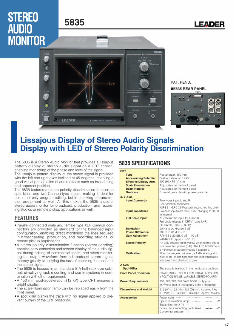
47
STEREOAUDIOMONITOR
5835
5835 REAR PANEL
Lissajous Display of Stereo Audio SignalsDisplay with LED of Stereo Polarity Discrimination
The 5835 is a Stereo Audio Monitor that provides a lissajouspattern display of stereo audio signal on a CRT screen,enabling monitoring of the phase and level of the signal.The lissajous pattern display of the stereo signal is providedwith the left and right axes inclined at 45 degrees, enabling agood visual presentation of audio effects such as broadeningand apparent position.The 5835 features a stereo polarity discrimination function, aspot killer, and two Cannon-type inputs, making it ideal foruse in not only program editing, but in checking of transmis-sion equipment as well. All this makes the 5835 a usefulstereo audio monitor for broadcast, production, and record-ing studios or remote pickup applications as well.
FEATURES•Parallel-connected male and female type XLR Cannon con-
nectors are provided as standard for the balanced inputconfiguration, enabling direct monitoring the lines requiredin broadcasting, production, and recording studios, orremote pickup applications.
•A stereo polarity discrimination function (patent pending)enables easy extraction and screen display of the audio sig-nal during editing of commercial tapes, and when monitor-ing the output waveform from a broadcast stereo signal,thereby greatly simplifying the task of checking the phase ofthe stereo signal.
•The 5835 is housed in an standard EIA half-rack size cabi-net, simplifying rack mounting and use in systems in com-bination with other equipment.
•A 150 mm post-acceleration (12 kV) type CRT ensures abright display.
•The scale-illumination lamp can be replaced easily from thefront panel.
•A spot killer blanks the trace with no signal applied to pre-vent burn-in of the CRT phosphor.
PAT. PEND.
5835 SPECIFICATIONSCRT
TypeAccelerating PotentialEffective Display AreaScale IlluminationBeam RotatorGraticule
X, Y-AxisInput Connector
Input Impedance
Full Scale Input
BandwidthPhase DifferenceGain Adjustment
Stereo Polarity
Calibration
Z AxisSpot-Killer
Front Panel Operation
Power Requirements
Dimensions and Weight
Accessories
Rectangular, 150 mmPost acceleration 12 kV100 (H)×75 (V) mmAdjustable on the front panelAdjustable on the front panelExternal graticule with phase graticule
Two types input.L and RRear cannon connectorXLR-3-31, XLR-3-32 (First earth, second hot, third cold)Balanced input.more than 20 kΩ, changing to 600 Ωin internalAt 775 mVrms input for L and RFull scale display in CRT (Y axis: L=R)(At CAL'D, RANGE 0 dB)20 Hz to 20 kHz ±0.5 dB20 Hz to 20 kHz ±1°RANGE (–20 dB, 0 dB, +10 dB)VARIABLE (approx, ±10 dB)An LED display lights yellow when stereo signalis in reversed phase (L-R). The LED hold time isa minimum of approximately 5 seconds.When the range is calibrated, a 1 kHz sine signal isinput to the left and right channels enabling rotationadjustment and checking of gain.
The trace is blanked in the no-signal condition.
POWER, INTEN, FOCUS, ILLUM, ROTAT, X-POSITION,Y-POSITION, RANGE, VARIABLE, STEREO POLARITY
100, 120, 220, 240, VAC, 50/60 Hz Approx. 35 Wmax. (set at the factory before shipping)
215 (W)×132 (H)×429 (D) mm, Approx. 7 kg8 1/2 (W)×5 1/4 (H)×16 3/4 (D) in., Approx. 15.4 lbs
Power cord 1Spare illumination lamp 2Scale filter (for X-Y) 1Screw, rack mounting (inch size) 2Cover/Inlet stopper 1

48
New Measurement MethodOverview of the 5 Bar Display
Overview of the SDI-EXT REF Phase Difference Display
5 Bar Display Enables the Simultaneous Observationof Digital Broadcasts and Composite Levels
SDI-EXT REF Phase Difference Display
SDI-EXT REF Phase Difference Display
Bar Display Details
In the 5 bar display, video signal peak levels can be displayedinstead of vectors. Five different bars are used to simultaneouslydisplay five different levels: luminance (Y), green (G), blue (B),red (R), and composite (COMP).The 5 bar display functions as amode of the vector display. It is view-able as an alternate display underthe vectorscope menu.The G, B, R, and COMP bars areconverted from the SDI Y, CB, andCR signals using matrix calculation.
100
0
100
0
100
0
100
0
-33-40
120133135
G B R CMP
IRE
Contents of the 5 Bar Display
OverviewThe SDI-EXT REF phase difference display shows thephase differences between an SDI signal and an externalsync signal (EXT REF).
FeaturesGraphic and Numeric Displays of SDI and External Sync Signal(EXT REF) Phase DifferencesTraditionally, the most common SDI phase adjustment methodwas to determine the phase difference by switching between aninternal and external sync signal and observing the waveform
A feature that shows the phase differences between SDI and external sync (EXT REF) signals.
You can readily determine the phase difference between an SDI and external sync (EXT REF) signal through graphic andnumeric phase difference representations. You can also determine the phase differences between different SDI signals by set-ting the difference for one signal to zero.
You can record up to eight phase differences. You can quickly determine the phase differences between multiple inputs.
shift. However, you can view phase differences and adjust phas-es more easily by using the SDI-EXT REF phase difference dis-play.
Relative SDI Signal Phase Differences Are DisplayableBy setting a particular SDI-EXT REF phase difference tozero, you can display relative SDI signal phase differences.
Store Up to Eight Different Phase DifferencesYou can store up to eight different phase differences. Thisallows you to store up to eight different switcher SDI signalphases.
Numeric DisplayThe current phase differencesbetween the applied SDI andEXT REF signals are indicatednumerically under CURRENTPHASE.
Phase Difference LogYou can store up to eight sets ofmeasured values. This is useful incases such as when you use adevice such as a switcher tochange inputs and match phases.
Graphic CenterThe V marker turns from whiteto green when it is in the center.The H marker turns from whiteto green when it is within ±3clocks of the center.
Y,G,B,R
100
0
Contents of the Component Bar Display
CMP
IRE
0
100
120133135
-33
-40
Contents of the Composite Bar Display
Y level bar
Positive peak
100 % color bar negativepeak limit with 0 % setup.
Maximum negativemodulation level
Luminance positivepeak limit
Luminance negativepeak limit
The blanking interval data does not appearin the bar levels.
Indicates the rangebetween the positive andnegative peak levels of Y+ C (luminance + chromi-nance) in the SDI signalafter it has been convert-ed to a composite signal.
100 % color barnegative peak limitwith 0 % setup.
Reference level with0.7 V set to 100 %
Reference level with0 V set to 0 %Negative peak
Indicates the range between the negative and positive peak levels
SDI Y signallevel
Composite gamut bar
The combined luminance andchrominance signal level of the SDIsignal after it has been converted toa composite signal.
GBR component gamut bars
The converted GBRlevels of the SDIsignal

49

50
OPTIONAL ACCESSORIESUseful for incorporating video equipment system
LR 2404ACabinet
LR 2427BCabinet
LI 2306 (A set of 5 pcs.)Illumination lamp
LI-2308 (LED)Illumination lamp
without handle with handle
LI 2307 (A set of 2 pcs.)Illumination lamp
LC 2126Metal Cabinet
LH 2139Viewing Hood
LR 2751-IRackmount adapter
126.5 mm.4.980305 in.
409 mm.16.10233 in. 209.5 mm.
8.248015 in.
126.5 mm.4.980305 in.
409 mm.16.10233 in.
209.5 mm.8.248015 in.
A must for outdoor use
LC 2127Tripod Mounting Plate
LP 1960AC Adapter
For LV 5750For LV 5380 For LV 5750
For LV 5750
LC 2128Front cover
For LV 5380, LV 5330,LT 4400, LV 5750,LV 7700, LV 7720

51
OPTIONAL ACCESSORIESDedicated Rack Mount Adapter (Sold Separately)
LR 2750-IRackmount adapter
LR 2700A-IRackmount adapter
EIA standard, inch size
LC 2125ABlank Panel
For LV 5750
190482 mm.18.97634 in. 7.4803 in.
132 mm.5.19684 in.
mm.
LC 2125ABlank Panel
LR 2701RackmountStorage box
432 mm.
130 mm.5.11811 in.
410 mm.16.1417 in.
482 mm.18.97634 in.
17.00784 in.
5.19684 in.
2.251964 in.
mm.
132 mm. 57.2
Replacing with a lamp for 5222, 5850V, 5860V, etc.
Replacing with a lamp for 5835
One unit of LV 7700 or LT 4400 fit in LR 2480 (Not for 2 units)
2 units of LV 7700/LT 4400 fit in LR 2477
LR 2701 is designed to be appropriated for the storage box LR 2700I/AI, Rackmount Adaptor
LV 5800, LV 5700A, LV 5152, 5212, 5222
LV 5800, LV 5152, 5212, 5222, LV 5700A,LV 5750, 5835, 5850V, 5860V, 5861V
Replacing with a lamp for 5850V, 5860V
LI 2306
LI 2307
LR 2480
LR 2477
LR 2701
LR 2404A
LR 2427B
LR 2700A-I
LI 2308
Illumination lamp
Illumination lamp
Rackmount adapter
Rackmount adapter
Rackmount Strage Box
LV 5380 onlyLR 2751 I Rackmount adapter
LV 5750 onlyLR 2750-I Rackmount adapter
Applicalle ModelModel Product Name
Cabinet (without handle)
Cabinet (with handle)
Rackmount adapter
Illumination lamp (LED)
*White CRT is standard.*Description and specifications in this catalog are subject to change without previous notice.* Caution:Use a cabinet with the specified model number. If you use a cabinet that has not been specified, ventilation will not take place properly, and damage to the instrument,
smoke emission, or fire may result.
LV 5700A, LV 5750LC 2128 Front cover
LR 2700A-I, LR 2750-ILR 2125A Blank Panel
LR 2477Rackmount adapter
LR 2480Rackmount adapter

LEADER ELECTRONICS CORP.
2-6-33 Tsunashima-Higashi, Kohoku-ku, Yokohama 223-8505, Japan
LEADER INSTRUMENTS CORP.(U.S.A)LEADER INSTRUMENTS (H.K.)LTD.LEADER ELECTRONICS CORP.BEIJING OFFICELEADER INSTRUMENTS (H.K.)LTD.DONGGUAN OFFICE LEADER ELECTRONICS CORP.SHANGHAI OFFICELEADER ELECTRONICS EUROPEAN OFFICE
http://www.leader.co.jp
PHONE:81-45-541-2123PHONE:1-714-527-9300PHONE:852-2721-2503PHONE:86-10-8511-8606/8607PHONE:86-769-83829381,83829391PHONE:86-21-62756905,62759629PHONE:31-40-2565008
FAX:81-45-541-2823FAX:1-714-527-7490FAX:852-2723-7573FAX:86-10-8511-8608FAX:86-769-83819289FAX:86-21-62751486FAX:31-40-2565009
AGENT
SPECIFICATION CHANGES:LEADER ELECTRONICS CORP. reserves the right to discontinue the sale of instruments and/or change the specifications ofinstruments at any time without responsibility for the incorporation of new features in the instruments already sold.
ORDERING INSTRUCTIONS:When inquiries or orders re made, please specify operating voltage and AC frequency of the instrument the VOLTAGE of thepower supply etc. of the instruments to be used. The instruments can be furnished for AC line voltages of 100, 120, 220, or 240 volts and desighed to operate at the voltages which are with in ±8 % of the rated line voltage.
ENVIRONMENTAL CONDITIONS:Our products can be used under the following conditions unless stated otherwise.<Operating range>1.Temperature: 0 to 40 °C2.Humidity: 85 % RH (without condensation)
POWER REQUIREMENTS:“ VA ” in the “ Power Consumption ” indicates the apparent power.
TSSep.12,2008 08097K Printed in Japan12
About Green-Leaf Mark
Models marked with "Green Leaf" meet the Restriction of the Use of Certain Hazardous Substances in Electrical and Electronic Equipment (Directive 2002/95/EC RoHS).
EU WEEE Directive
The EU WEEE Directive applies to this product and its accessories. When disposing of this product or its accessories, follow the regulations in your country or region.(WEEE Directive: Waste Electrical and Electronic Equipment)