2000 system disturbances - nerc disturbance reports dl...objectives of this report ... have a plan...
TRANSCRIPT
2000 System
Disturbances
Review of Selected Electric System Disturbances in
North America
North American Electric Reliability Council Princeton Forrestal Village 116-390 Village Boulevard
Princeton, New Jersey 08540-5731
September 2001

System Disturbances 2000
NERC 2
FOREWORD
The Disturbance Analysis Working Group of the North American Electric Reliability Council (NERC) Operating Committee prepared this review of selected 2000 bulk electric system disturbances, unusual occurrences, demand and voltage reductions, and public appeals. NERC has published its findings on bulk electric system disturbances, unusual occurrences, demand and voltage reductions, and public appeals since 1979. The objectives of this report include: • Sharing the experiences and lessons that North American utilities have learned. • Suggesting ways that utilities can apply the NERC Operating Policies to their
operations and the NERC Planning Standards to their planning. • Determining if these Policies and Standards adequately address the normal and
emergency conditions that can occur on the bulk electric systems. The Working Group appreciates the assistance received from the utilities whose disturbances are analyzed in this review. Please address questions on the details of the analyses in this report to NERC at 609-452-8060.

System Disturbances 2000
NERC 3
CONTENTS Introduction...........................................................................................................................................4 Commentary ..........................................................................................................................................5 Disturbances by Analysis Category.....................................................................................................7 Operating Policies...................................................................................................................................7 Planning Standards..................................................................................................................................8 Disturbances ..........................................................................................................................................9 1. Southern California Edison Company Laguna Bell 220 kV Bus Outage February 26, 2000 .....9 2. Public Service Company of New Mexico Brush Fire and Transmission Outages March 18, 2000...............................................................................................................................13 3. Dominion Virginia Power Ox Substation Fire April 1, 2000....................................................28 4. Georgia Power Company Plant Bowen Lightning Outages September 1, 2000 .......................32 5. New Brunswick Power Corporation Salt Contamination/Freezing Rain Related Loss of Transmission December 20, 2000 .............................................................................................35 Appendices Appendix A. Reporting Requirements for Major Electric Utility System Emergencies .....................43 Appendix B. Analysis Categories........................................................................................................50 Appendix C. Interruptions, Unusual Occurrences, Demand and Voltage Reductions, and Public Appeals.........................................................................................................52 Disturbance Analysis Working Group Members.............................................................................54

System Disturbances 2000
NERC 4
INTRODUCTION NERC and the U.S. Department of Energy (DOE) have established requirements for reporting major electric utility system emergencies (Appendix A). These emergencies include electric service interruptions, unusual occurrences, demand and voltage reductions, public appeals, fuel supply problems, and acts of sabotage that can affect the reliability of the bulk electric systems. NERC’s annual review of system disturbance reports begins in November when the Disturbance Analysis Working Group meets to review and discuss each disturbance reported to NERC and DOE so far that year. The Working Group selects reports which it believes to be of value to the industry and then contacts the Regional Council or utility(ies) involved and requests a detailed report of each incident. The Working Group summarizes the report for this review and analyzes it using the NERC Operating Policies and Planning Policies as the analysis categories. (A list of these categories is found in Appendix B.) The Commentary section includes the conclusions and recommendations that were formulated from the analyses in this report plus the general expertise of the Working Group members.
In 2000, utilities in the United States and Canada reported 58 incidents of system interruptions, unusual occurrences, demand and voltage reductions, or public appeals. These incidents are listed chronologically in Appendix C and categorized as:
• Thirty-five system interruptions • Seventeen unusual occurrences (no customer interruption) • Two voltage reductions • Two public appeals • Two public appeals and system interruptions This document contains analyses of five incidents. The analysis of one of the incidents, the fire at Dominion Virginia Power’s Ox Substation on April 1, 2000 represents a “good news” story, and describes how the utility expeditiously recovered from the loss of a key transmission facility. The other four incidents represent a variety of events with lessons to be learned from all of them. Unless otherwise noted, recommendations included in each analysis are from the Region, pool, or utility and not from the Disturbance Analysis Working Group. On pages 7 and 8 are tables of Disturbances by Analysis Category that offer quick reviews of the operating and planning categories applicable to each incident.

System Disturbances 2000
NERC 5
COMMENTARY Causes of Disturbances Almost half (28 out of 58) of the disturbances reported to DOE and NERC during 2000 were related to severe weather. Personnel related actions were the cause of 12 incidents, a statistic that the Working Group is concerned about. The third major cause (ten incidents) of disturbances was equipment failure, in one form or another. The Working Group selected disturbances related to each of these categories for analysis in this report. References: • Southern California Edison Company
Laguna Bell 220 kV Bus Outage February 26, 2000
• Public Service Company of New Mexico Brush Fire and Transmission Outages March 18, 2000
• Georgia Power Company Plant Bowen Lightning Outages September 1, 2000
• New Brunswick Power Corporation Salt Contamination/Freezing Rain Related Loss of Transmission December 20, 2000
Communications The need for timely, adequate, and effective communications among Security Coordinators, control centers, Regional Councils, power pools, and other entities having responsibility for system operations during disturbances continues to arise during the analysis of disturbances. This year’s review is no different. Failure to fully implement communication protocols, lack of alternative communications facilities, and inadequate operator training in communication procedures were all evident. Effective communication requires that all participants have access to and the same understanding of the information being exchanged.
References: • Southern California Edison Company
Laguna Bell 220 kV Bus Outage February 26, 2000
• Public Service Company of New Mexico Brush Fire and Transmission Outages March 18, 2000
Planning System planners and operators need to work together during the design of new facilities and the modification of existing facilities. Even more important, they must continually review system disturbances to see if changes are needed to permit operators to more effectively handle disturbances. Unfortunately, it usually takes a system disturbance to highlight weaknesses in the operation of the electric system. When restoring the system following a disturbance, bulk electric system operators should use this opportunity to improve their system when possible. References: • Southern California Edison Company
Laguna Bell 220 kV Bus Outage February 26, 2000
• Public Service Company of New Mexico Brush Fire and Transmission Outages March 18, 2000
• Dominion Virginia Power Ox Substation Fire April 1, 2000
• Georgia Power Company Plant Bowen Lightning Outages September 1, 2000
Training Bulk electric system operating entities should have a plan for initial and continuing training of those responsible for operating and maintaining electricity systems. That plan should address required knowledge and competencies and how they can be used in real-time operations. The cause of 12 of the disturbances reported in 2000

System Disturbances 2000
NERC 6
was operator or maintenance error. Although no immediate conclusion can be drawn from the limited data available, the Working Group is concerned that this number of events might be indicative of a larger problem as utilities reorganize and are deregulated. The Working Group recommends an increased emphasis on operator and maintenance personnel training by all entities responsible for operating the bulk electric systems with increased oversight of this activity by the NERC Operating and Planning Committees. References: • Southern California Edison Company
Laguna Bell 220 kV Bus Outage February 26, 2000
• Public Service Company of New Mexico Brush Fire and Transmission Outages March 18, 2000
Planning and Operating Studies As capacity margins shrink and the transmission grid becomes more heavily utilized, the importance of up-to-date and accurate planning and operating studies becomes paramount. Systems are being run “closer to the limit” than ever before, and the risk of a disturbance precipitating a cascading outage is great. The Working Group urges all bulk electric system operators to review their planning and operating study data inputs and methodologies to ensure that operators have the most up-to-date and accurate information possible. Operators of the bulk electric systems also should review their system protection schemes to ensure that they are designed properly and take into account as many contingencies as possible. Reference: • Public Service Company of New Mexico
Brush Fire and Transmission Outages March 18, 2000

System Disturbances 2000
NERC 7
DISTURBANCES BY ANALYSIS CATEGORY Operating Policies
Incident Number Operating Policies
1 2 3 4 5
Policy I. Generation Control and Performance
E. − Control Performance X
Policy 2. Transmission
A. − Transmission Operations X
Policy 4. System Coordination
A. − Monitoring System Conditions X
Policy 5. Emergency Operations
A. − Coordination with Other Systems X
E. − System Restoration X
Policy 6. Operations Planning
B. − Emergency Operations X X
C. − Automatic Load Shedding X X
Policy 7. Telecommunications
A. − Facilities X X
B. − System Operator Telecommunication Procedures X X
Policy 8. Operating Personnel and Training
B. − Training X X
1. Southern California Edison Company Laguna Bell 220 kV Bus Outage February 26, 2000 2. Public Service Company of New Mexico Brush Fire and Transmission Outages March 18, 2000 3. Dominion Virginia Power Ox Substation Fire April 1, 2000 4. Georgia Power Company Plant Bowen Lightning Outages September 1, 2000 5. New Brunswick Power Corporation Salt Contamination/Freezing Rain Related Loss of Transmission
December 20, 2000

System Disturbances 2000
NERC 8
Planning Standards
Incident Number Standards for Planning Reliable Bulk Electric Systems
1 2 3 4 5
I. System Adequacy and Security
A. − Transmission Systems X
III. System Protection and Control
A. − Transmission Protection Systems X X
C. − Generation Control and Protection X X
IV. System Restoration
A. − Blackstart Capability X
1. Southern California Edison Company Laguna Bell 220 kV Bus Outage February 26, 2000 2. Public Service Company of New Mexico Brush Fire and Transmission Outages March 18, 2000 3. Dominion Virginia Power Ox Substation Fire April 1, 2000 4. Georgia Power Company Plant Bowen Lightning Outages September 1, 2000 5. New Brunswick Power Corporation Salt Contamination/Freezing Rain Related Loss of Transmission
December 20, 2000
System Disturbances 2000
NERC 9
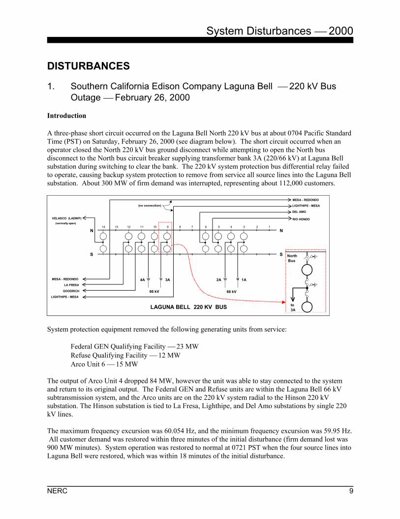
DISTURBANCES 1. Southern California Edison Company Laguna Bell 220 kV Bus
Outage February 26, 2000 Introduction A three-phase short circuit occurred on the Laguna Bell North 220 kV bus at about 0704 Pacific Standard Time (PST) on Saturday, February 26, 2000 (see diagram below). The short circuit occurred when an operator closed the North 220 kV bus ground disconnect while attempting to open the North bus disconnect to the North bus circuit breaker supplying transformer bank 3A (220/66 kV) at Laguna Bell substation during switching to clear the bank. The 220 kV system protection bus differential relay failed to operate, causing backup system protection to remove from service all source lines into the Laguna Bell substation. About 300 MW of firm demand was interrupted, representing about 112,000 customers.
System protection equipment removed the following generating units from service: Federal GEN Qualifying Facility 23 MW Refuse Qualifying Facility 12 MW Arco Unit 6 15 MW The output of Arco Unit 4 dropped 84 MW, however the unit was able to stay connected to the system and return to its original output. The Federal GEN and Refuse units are within the Laguna Bell 66 kV subtransmission system, and the Arco units are on the 220 kV system radial to the Hinson 220 kV substation. The Hinson substation is tied to La Fresa, Lighthipe, and Del Amo substations by single 220 kV lines. The maximum frequency excursion was 60.054 Hz, and the minimum frequency excursion was 59.95 Hz. All customer demand was restored within three minutes of the initial disturbance (firm demand lost was 900 MW minutes). System operation was restored to normal at 0721 PST when the four source lines into Laguna Bell were restored, which was within 18 minutes of the initial disturbance.
(normally open)13 12 11 10 9 8 7 6 5 4 3 2 114
RIO HONDO
DEL AMO
LIGHTHIPE - MESA
1A2A3A4A
LIGHTHIPE - MESA
MESA - REDONDO
MESA - REDONDO
N
S
GOODRICH
LA FRESA
VELASCO (LADWP)
N
S
LAGUNA BELL 220 KV BUS
66 kV66 kV
to 3A
North Bus
(no connection)
(normally open)13 12 11 10 9 8 7 6 5 4 3 2 114
RIO HONDO
DEL AMO
LIGHTHIPE - MESA
1A2A3A4A
LIGHTHIPE - MESA
MESA - REDONDO
MESA - REDONDO
N
S
GOODRICH
LA FRESA
VELASCO (LADWP)
N
S
LAGUNA BELL 220 KV BUS
66 kV66 kV
to 3A
North Bus
(no connection)

System Disturbances 2000
NERC 10
During the incident, voltage excursions did not exceed 20% of the pre-disturbance bus voltage magnitude and frequency excursions did not dip below 59.6 Hz, thereby meeting the Western Systems Coordinating Council (WSCC) Reliability Criteria for Transmission System Planning. Conclusions and Recommendations A WSCC report on the incident identified seven conclusions and six recommendations. 1. Conclusion:
The Cal-ISO Grid and the SCE system were operating within established WSCC Minimum Operating Reliability Criteria (MORC) prior to the disturbance.
2. Conclusion:
NERC Policy 5, Section A (Coordination with Other Systems During an Operating Emergency) was not a factor in the disturbance.
3. Conclusion:
NERC Policy 6, Section B (Planning for Emergency Operations) was not a factor in the disturbance. 4. Conclusion:
Within a few cycles of the initial fault, the test jacks of the system protection bus differential relay at Laguna Bell flashed over on all three phases, preventing the bus differential relay from operating. Contributing factors are the close spacing of the jacks and metal particles, which were observed near the test jacks.
Recommendation 4A: Perform tests to determine the voltage withstand capability of several different test jacks and determine the type of jacks to install on new projects.
Status 4A: Tests have been performed on several types of test jacks and one has been selected with a voltage withstand capability in excess of 10 kV and with plastic barriers between the phases. Subsequently, the test jacks at Laguna Bell were replaced.
Recommendation 4B: Determine whether replacement of all existing PVD bus differential relay scheme test jacks (company-wide) is required.
Status 4B: All test jacks on all high impedance bus differential relay schemes will be replaced. The work is on-going throughout the system with priority given to 500 and 220 kV stations.
Recommendation 4C: Provide the results of the relay failure analysis and any recommendations to the WSCC Relay Work Group.

System Disturbances 2000
NERC 11
Status 4C: This analysis and subsequent recommendations were discussed at the October 2000 Work Group meeting.
5. Conclusion:
Laguna Bell Substation is divided between two jurisdictional switching centers. Energy management system (EMS) overview screens did not reflect the remote status of all transmission lines connected at Laguna Bell Substation, and, as a result, the overall station status was not sufficiently clear. Consequently, instructions were given by the Grid Control Center (GCC), which resulted in the Del Amo-Laguna Bell line being closed at Del Amo (three-phase fault still applied to the Laguna Bell North Bus).
Recommendation: Enhance applicable energy management system overviews to allow dispatchers to better ascertain the status of remote terminals at all bulk power stations having multiple jurisdictions. In addition, further enhance station single-line displays where the data are available to depict whether or not transmission lines are energized.
Status: The enhancement to the status of remote terminals is complete. SCE dispatchers can immediately detect the overall system status of remote terminals at bulk power stations regardless of jurisdiction with the addition of a dynamic dispatch map board. The new map board displays the SCE and adjacent bulk power (500/230 kV) systems, including all switch rack equipment status, station voltages, and loading. The enhancements to station single-line displays were investigated for potential implementation and determined to not be feasible.
6. Conclusion: The Laguna Bell North 220 kV Bus ground disconnects were closed when an operator, following approved switching procedures, operated the wrong disconnect.
Recommendation: Determine by investigation whether training practices and existing switching procedures are in place, which under normal circumstances would prevent the switching error that occurred.
Status: Training practices and switching procedures were reviewed and determined to be adequate.
7. Conclusion:
The Del Amo-Laguna Bell 220 kV line was closed by a system operator when the GCC dispatcher gave instructions to follow emergency switching procedures. After this order was given, the line was closed without verifying it was energized, which resulted in the re-energizing of Laguna Bell with the bus grounds still applied.
Recommendation: Have all operators review procedures that provide the guidelines for the closing of lines following relay operations.
Status: All operators have received the guidelines for closing of lines following relay operation.

System Disturbances 2000
NERC 12
Refer to: NERC Operating Policy 7 – Telecommunications A. Facilities B. System Operator Telecommunication Procedures NERC Operating Policy 8 – Operator Personnel Training B. Training NERC Planning Standard III – System Protection and Control A. Transmission Protection Systems For more information on the incident, please contact the Western Systems Coordinating Council staff.

System Disturbances 2000
NERC 13
2. Public Service Company of New Mexico Brush Fire and Transmission Outages March 18, 2000 Summary Smoke contamination and fire damage from a brush fire near and beneath a Public Service Company of New Mexico (PNM) transmission corridor, about four miles south of the Four Corners Generating Station, caused outages on several 345 kV and 230 kV lines on March 18, 2000. The system stability problems created by these outages eventually resulted in a major service interruption. At about 1558 MST, system protection removed a 345 kV line from service. Attempts to restore the line to service were unsuccessful. A PNM employee was dispatched to the area and observed a large brush fire generating large amounts of smoke. Local firefighters were attempting to extinguish the fire. At 1609, system protection removed the second and third 345 kV lines from service. Several transmission structures were observed to be on fire and the decision was made not to re-energize the lines until the fires were out and the firefighters were safe. At 1613, system protection removed a 230 kV line from service. This left central and northern New Mexico with only a single 345 kV source from El Paso Electric Company (EPE). At about 1643, system protection removed from service EPE’s 180 MW Newman Generating Unit No. 4. PNM and EPE began shedding load to restore stability to their systems, followed by Texas-New Mexico Power Company (TNP) at 1649. System protection subsequently removed several more transmission lines from service at 1718, which interrupted electric service to about 660,000 central and northern New Mexico customers. Restoration efforts began immediately, and by 2020 service was restored to essentially all customers. Discussion Prior to the disturbance, PNM’s San Juan−Ojo 345 kV line had been taken out of service to replace a static ground wire with a fiber optic static wire. During the line outage, the system was operating within Western Systems Coordinating Council (WSCC) minimum operating reliability criteria. Crews were working on the circuit at the time of the fire. Sometime during the early afternoon on March 18, a fire of unknown origin began outside the rights-of-way containing the lines shown in Figures 1 and 2. The fire was not immediately reported to PNM. At about 1558 MST, the San Juan to BA Switching Station 345 kV line experienced a fault and system protection removed the line from service. The cause was not immediately known. PNM’s initial restoration attempt at 1559:20 was successful, but about 28 seconds later the line faulted again and system protection removed it from service a second time. At about 1607, the PNM system operator, still unaware of the fire, contacted a PNM lineman who was in the Farmington area and dispatched him to a location about ten miles from the San Juan Plant. This location was based upon fault recorder data and the system operator’s knowledge of the previous night’s outage involving the San Juan−BA 345 kV line. Direct contact between the PNM System Operations and the PNM lineman in the field was not re-established until about 1809. From that point on, the energizing of the two lines was closely coordinated. It was not until 1711 when the PNM system operator first received word of a fire outside of the Four Corners Power Plant area under the 345 kV lines from Arizona Public Service Company (APS).

System Disturbances 2000
NERC 14
Figure 1

System Disturbances 2000
NERC 15
Figure 2

System Disturbances 2000
NERC 16
At 1609, system protection removed the Four Corners−West Mesa 345 kV line from service due to the same fire. Although these two transmission lines do not share a common corridor, they are within 1,400 feet of each other at their closest point. The structures on the 345 kV and 230 kV lines at that point consist of two and three pole wood structures. Also at 1609, system protection removed the BA Switching Station−Blackwater 345 kV line from service due to problems at the Blackwater dc converter station. At 1613, system protection removed the Four Corners−Pillar 230 kV line from service due to the fire. This left central and northern New Mexico with a single 345 kV source, the West Mesa−Arroyo 345 kV line from EPE, and lower voltage ties in western New Mexico and northern New Mexico (See Figure 3).
Figure 3

System Disturbances 2000
NERC 17
Between 1558 and 1643, the PNM system operator was evaluating the outages and stabilizing the system. Several attempts were made to restore the northern ties with APS during this time frame. At 1643, the PNM system operator opened the Bisti−Ambrosia 230 kV line at the Ambrosia end to reduce overloading of the Farmington System and on the Gallegos 230/115kV 100 MVA transformer. Immediately upon the opening of this line, the Valencia Las Vegas Combustion Turbine unit, which was just being put into service and producing 2 MW, was shut down by system protection. System protection removed from service a 230 kV line and a 115 kV line in the area, as well as the EPE Newman Generating Unit No. 4 in Southern New Mexico. Upon the removal from service of Newman No. 4, the EPE under-voltage demand reduction system began operating. At 1643:48.59, the PNM under-frequency (UF) protection system began to operate when the frequency dropped from 60.00 Hz to 59.5 Hz. Five of the six substations equipped with UF protection systems operated as planned. PNM tested the UF equipment at all six stations and found it to be in calibration. At about 1643:25, under-voltage protection systems in EPE removed from service about 240 MW of demand. EPE system operators manually removed an additional 160 MW between 1659 and 1702 in an attempt to raise the low voltages occurring in the EPE system. At 1649, TNP interrupted 60 MW of interruptible demand in the southern New Mexico system. At about 1643, system protection removed from service the Plains Electric Generation and Transmission Cooperative (PEGT) PEGS Unit (214 MW) due to over frequency. At 1718, system protection removed from service the EPE Arroyo−West Mesa 345 kV line and the PEGT West Mesa Substation−Elephant Butte 115 kV line. This action isolated the northern, central, and western New Mexico system and resulted in a total loss of service to that area. Prior to system protection removal of the Arroyo−West Mesa line, PNM had already manually removed about 252 MW of demand. Estimated demand lost during the disturbance: PNM 815 MW PEGT 200 MW EPE 400 MW Los Alamos County 47 MW EPE restored its service by about 1728. At 1736, the Four Corners−Ambrosia and Ambrosia−PEGT 230 kV lines were restored to supply start-up power to the PEGT generating unit. At 1743, the EPE Arroyo−West Mesa 345 kV line was re-energized, and about 200 MW of PNM demand was restored. Manual restoration of the remaining demand was then initiated. At 1814, the Ambrosia−West Mesa 230 kV line was returned to service, restoring the 230 kV lines from Four Corners−West Mesa. By 1830, PNM restored about 50% of the demand lost during the disturbance. At 1835, the San Juan−BA 345 kV line was returned to service after confirming that the structure fire on this line was extinguished, and the line was safe to test. By 1845, PNM restored about 65% of lost demand, and by 1906 about 98%. The Los Alamos County tie was restored at 1849 and demand restoration began at that time. At 1925, field crews verified that the structure fire on the Four Corners−West Mesa 345 kV line was out and the line was restored to service. Restoration on the PEGT system began at 1848 and demand was restored by about 1938. By 2020, PNM restored most of its demand with the exception of a few isolated pockets on the distribution system.

System Disturbances 2000
NERC 18
The San Juan−Ojo 345 kV line and the BA Switching Station−Blackwater 345 kV line were restored to service by midday on March 19. Delayed restoration of these lines did not affect the PNM restoration of customer service. The 500 acre grass and brush fire in the multi line rights-of-way in northwest New Mexico (Figures 1 and 2) was an unexpected event, and the resulting line outages were not preventable. However, several actions, or lack of actions, which followed the initial loss of five transmission lines, appear to have aggravated the system conditions and contributed to the outages. Had the manual demand reduction by the PNM system operator been deeper and quicker, the overloading condition in the Farmington area could have been reduced to acceptable levels, and the loadings on the EPE West Mesa−Arroyo 345 kV tie line and the Arroyo Phase-Shifting Transformer would have been reduced. Deeper and quicker manual demand reduction by the PNM system operator also would have reduced the excessive closing angles on the Four Corners−West Mesa and Four Corners−Pillar 230 kV line to acceptable closing limits and potentially avoided the eventual blackout. Conclusions and Recommendations A Western Systems Coordinating Council report on the incident identified 20 conclusions and recommendations. 1. Conclusion:
PNM system was operating within WSCC Minimum Operating Reliability Criteria (MORC) prior to the event.
2. Conclusion:
PNM violated NERC Policy 5, Section A on Coordination with Other Systems, and this was a contributing factor in the disturbance. PNM did not adequately convey the nature of its developing problems to the Rocky Mountain Desert Southwest Security Coordinator (RDSC) and some neighboring systems. PNM, however, was in constant communication with EPE.
Recommendation: PNM shall review the requirements in NERC Policy 5, Section A, establish procedures, and provide training to ensure proper communications are established and maintained during outage conditions.
Status: PNM reviewed NERC Policy 5, Section A, established procedures, and provided the requisite communications training.
3. Conclusion:
PNM violated NERC Policy 6, Section B (Planning for Emergency Operations) and this violation was a contributing factor in the disturbance. Communications between the PNM system operator and the PNM distribution dispatcher was inadequate and incomplete causing a delay in PNM reducing demand.
Recommendation: PNM shall review the requirements in NERC Policy 6, Section B, provide training, and ensure that adequate written procedures are in place to comply with NERC requirements. PNM shall determine if its current process of having distribution dispatchers reduce demand in these types of situations is appropriate, and it shall determine if fully automated demand reduction is necessary.

System Disturbances 2000
NERC 19
Status: Power operations and distribution operations met on May 26, 2000 to discuss load shedding capabilities at the distribution level. An agreement was reached to enhance load-shedding capabilities at the distribution level to allow larger blocks of demand to be shed manually. Procedures were written to assure proper coordination between system operators and distribution dispatchers and training was completed.
4. Conclusion: PNM distribution dispatcher did not immediately reduce demand when directed to do so by the system operator.
Recommendation: PNM shall provide necessary training to distribution operators as to their authority to immediately take actions as requested by PNM system operators.
Status:
Training to review the March 18, 2000 incident with distribution dispatchers occurred on May 23, 2000. Training included discussions to improve communications, including when support cannot be provided.
5. Conclusion:
PNM system operator’s order to the distribution dispatcher was not clear as to the immediate need. Recommendation: PNM shall provide training to their system operators and distribution operators that emergency orders shall be clear and concise when immediate actions are required.
Status:
Training to review the March 18, 2000 incident with distribution dispatchers occurred on May 23, 2000. Training included discussions to improve communications, including when support cannot be provided.
6. Conclusion: The lack of data from PNM to the WSCC Extra High Voltage (EHV) data pool was a problem for the Rocky Mountain Desert Southwest Security Coordinator (RDSC). The inability of the RDSC to see the severity of the problems within the PNM system prevented the RDSC from determining the scope of the event and attempting to provide assistance to PNM. It also was determined that TEP and EPE have not fully implemented the Inter Control Center Communication Protocol (ICCP) Data Link and are not providing data to the EHV Data Pool.
Recommendation 6.1: PNM shall complete its ICCP link to the EHV Data Pool and provide required data to the RDSC. Status 6.1: PNM completed an ICCP link to the WSCC EHV Data Pool on March 29, 2000. The Rocky Mountain Desert Southwest Security Coordinator began receiving PNM security data on April 28, 2000.
System Disturbances 2000
NERC 20
Recommendation 6.2: The RDSC also shall resolve any data collection issues currently preventing it from receiving data from PNM. Status 6.2.: All data collection issues between PNM and RDSC were resolved. Recommendation 6.3: EPE shall complete its ICCP data link to the EHV Data Pool and provide required data to the RDSC. Status 6.3: EPE completed an ICCP data exchange system at its System Operations Control Center on October 11, 2000. All required real-time operating data now are transmitted to the RDSC. Recommendation 6.4: TEP shall complete its ICCP Data link to the EHV Data Pool and provide required data to the RDSC. Status 6.4: TEP reported it completed its ICCP link to the WSCC EHV Data Pool and the RDSC as of April 21, 2000.
7. Conclusion: Communications from the RDSC to the PNM Control Center were hampered due to local phone lines and cell systems being overloaded, preventing adequate voice communications between the two groups. Also, the lack of ring downs and a regional hot line prevented an alternative means of communicating with PNM.
Recommendation 7.1: The Southwest Utilities shall work with the RDSC and WSCC to establish a hot line for emergency communications. Reference NERC Policy 7, Figure 9, Appendix 7A.
Status 7.1:
In June 2000, PNM completed a direct ring-down line to the RDSC via microwave. As of August 14, 2001, the EPE−Salt River Project ring-down circuit was in service. The EPE−APS ring-down circuit is working at the EPE end only, and EPE is waiting for APS to complete its work. The EPE−RDSC ring-down circuit is working at the EPE end only, and EPE is waiting for the Western Area Power Administration (WAPA) to complete its work. An APS−RDSC hot line was completed at Loveland on July 9, 2001. The Southwest utilities are working with the RDSC to complete installation of a direct ring-down line to RDSC by the end of September 2001.
Recommendation 7.2.:
The RDSC shall review usage of alternate communications systems such as the satellite phones. Satellite phone procedures shall be reviewed and modified, if required.
Status 7.2: A communications review was completed listing all available facilities, including satellite phones, to each control area. This list is now available for use by the Security Coordinator. It was also decided that a new hotline, which included both the Rocky Mountain and Desert Southwest regions, was the optimum answer. WAPA procured a new hotline switch for use by RDSC and all the members of the

System Disturbances 2000
NERC 21
two subregions. The system was delivered and installed by the first week of July at the control center in Loveland. WAPA is connecting the RDSC members to the switch.
8. Conclusion: Overloading of the EPE Arroyo 345 kV Phase Shifting Transformer (PST) created a serious condition and placed the equipment at risk of damage. Recommendation: EPE and PNM shall develop emergency procedures to address overloading conditions and time limits that such overloads will be permitted before opening the 345 kV tie.
Status: EPE and PNM have developed and distributed to system operators emergency procedures dated March 16, 2001, which address this issue.
9. Conclusion:
The EPE PST was removed from service by protection equipment during this event following a sustained period of severe overload, and the loss of station service power. On two occasions, EPE system operators attempted to bypass the Arroyo PST but were unsuccessful. At 1717:39, the EPE system operator issued a bypass command, and three seconds later the Arroyo−West Mesa 345 kV line opened at the Arroyo end. Recommendation 9.1: EPE shall determine why the PST station service distribution feeder was designed to open on under voltage when no other station service source was available. EPE also should determine what caused the PST protection equipment to function and whether the action was correct. In addition, EPE needs to determine what alarms it received on the Arroyo PST, and are they correct?
Status 9.1a:
EPE removed the Arroyo-21 feeder that serves as station service to the PST from both the under voltage protection scheme and the EPE automatic demand reduction scheme.
Status 9.1b: EPE personnel reported that the PST protection equipment operation was correct. EPE reported that the Programmable Logic Controller (PLC) logic for the Arroyo PST is such that when the operator executes the insert/bypass mode command, the PLC checks to see if the PST is in neutral tap position (it will not bypass if not in neutral tap). If the tap is in neutral, a close command is sent to the bypass breaker. This breaker must acknowledge this command before a trip is sent to the line breakers. The acknowledgement is for receipt of command and not to determine if the bypass breaker actually closed. The EPE dispatcher issued the command for the bypass breaker to close; the breaker received the command and acknowledged the command but did not close. Once the PST logic received the acknowledgement from the bypass breaker, it issued the command to open the line side breakers. Status 9.1c: EPE reviewed the alarms received from the PST and determined that they were correct. EPE reported that the system operator will receive a 60-minute overload alarm on the PST whenever the flow is greater than or equal to 400 MVA, and will receive a 30-minute overload alarm whenever flows are greater than or equal to 462 MVA. In the mass of alarms received was an alarm stating that station service to the PST was lost.

System Disturbances 2000
NERC 22
Recommendation 9.2: EPE personnel should review the existing Arroyo PST control logic and determine if the PST bypass logic should be modified to include a permissive that the bypass breaker is closed before issuing the trip of the line side breakers. Status 9.2: EPE personnel reviewed the existing Arroyo PST Control Logic and concluded that the logic was implemented for the protection of the PST. Therefore, EPE does not contemplate changing the logic to include a permissive that the bypass breaker be closed before issuing the trip of the line breakers. EPE reported the PST PLC uses 125 vdc for control only. Recommendation 9.3: EPE should determine if the bypass breaker has dc backup power. If so, EPE should determine why the breaker did not close. Status 9.3: EPE reported that the bypass breaker control circuits are 125 vdc. The reason the breaker did not operate on March 18, 2000 was that there was a “General Lockout SF6/Spring Charge” alarm on the breaker, which kept it from operating. EPE relay personnel were not able to recreate the situation when testing the breaker after the event.
10. Conclusion: The PNM restoration plans were not adequate for the conditions. The current PNM restoration plan only addresses a more regional black out scenario (provides startup to local generation) and does not address conditions experienced during this event. Recommendation: PNM shall review its current restoration plan and make necessary modifications to ensure coverage for events similar to those described in this report.
Status 10: PNM reviewed and modified its restoration procedure and completed a technical review and verification of its powerflow program. PNM completed its restoration plan May 30, 2001.
11. Conclusion:
PNM did not have under-voltage demand reduction in place prior to the disturbance that would have disconnected demand due to the under-voltage conditions during the event.
Recommendation: PNM shall complete installation of its under-voltage demand reduction program and also be fully compliant with WSCC under-voltage demand reduction program.
Status:
PNM started installing the under-voltage demand reduction remedial action scheme on February 7, 2000. The system was placed in service on May 26, 2000.
12. Conclusion:
The PEGT Supervisory Control and Data Acquisition system was unable to retrieve disturbance data due to printer jamming and ribbon failure, which caused the system to over-write alarm data.

System Disturbances 2000
NERC 23
Recommendation: PEGT shall determine the cause of this type of failure and make necessary upgrades or install appropriate software/hardware modifications.
Status: Tri-State G&T technicians identified the cause of the printer paper jamming and resolved the issue. These printers have since been replaced with a new printing system.
13. Conclusion:
Four Corners Unit 5 was removed from service by protection equipment about 35 seconds after protection equipment removed the Four Corners−Pillar 230 kV line from service. Controls for the bag house for Unit 5 receive their electric service from the 230 kV switchyard and are not served from an uninterruptible power supply (UPS). Due to the close proximity of Four Corners to the fault on the 230 kV line, the resulting voltage dip was large enough that the electric service to the control failed. When the controls failed, the two exhaust fans on the bag house system also stopped operating, resulting in the furnace pressure increasing to the point that protection equipment removed the bag house from service.
Recommendation: APS shall review its philosophy of not installing UPS for the critical bag house control systems at Four Corners and take appropriate action to ensure that the occurrence of this type of failure is minimized.
Status: On March 23, 2001, APS reported that the UPS system installation at Four Corners was complete.
14. Conclusion: It was reported that the Western Area Power Lower Colorado (WALC) Dispatchers were aware of the problems in the northern New Mexico system but not the extent of the problem until about 1709 MST. Because there was no notification of transmission outages in the PNM system, no attempt was made to curtail schedules by WALC, TEP, LAC, PEGT, or PNM dispatchers across the open boundary from San Juan and Four Corners 230 and 345 kV interconnections until 1709. This notification was the first message from PNM informing WALC of the full extent of its system problems. WALC reported that PNM received 100 MW of assistance from the Southwest Reserve Sharing Group at 1612 and schedules were increased by 100 MW at 1625 by PNM marketers. PNM marketers also were requested to increase the schedule by an additional 50 MW at 1646.
Recommendation 14.1:
PNM system operators should be trained and instructed to follow WSCC Minimum Operating Reliability Criteria, Section 5.A.4 and Section 5.A.7 Emergency Operations, regarding the notification of loss of transmission elements to all participants scheduling across these transmission elements and providing this information via the WSCCNet Messaging System as quickly as possible. PNM should train and instruct the system operators to ensure that all schedules are promptly zeroed across open transmission paths. Status 14.1: PNM completed a review of the requirements in WSCC’s Minimum Operating Reliability Criteria, Section 5.A.4 and Section 5.A.7 Emergency Operations. PNM provided training to its system operators to ensure the notification of loss of transmission elements to all participants scheduling

System Disturbances 2000
NERC 24
across transmission elements and provides this information via the WSCCNet Messaging System as quickly as possible. PNM also trained and instructed the system operators to ensure that all schedules are promptly zeroed across open transmission paths. Recommendation 14.2: Emphasis must be placed upon communication between the PNM system operators and the PNM marketing arm during system emergencies resulting in open transmission paths. PNM should review emergency procedures with its marketing group and establish combined emergency drills for marketing and operating groups. Status 14.2: PNM reviewed its existing emergency communications procedure and developed an emergency communications training procedure for use with its marketing arm; this training was completed. PNM operations plans to conduct its first combined emergency drill with the PNM marketing arm later this year.
15. Conclusion:
It appears that the WSCC Security Coordinators do not have adequate communication facilities for voice (primary and backup) to properly perform their function and provide assistance during emergency conditions.
Recommendations 15.1: The WSCC Security Coordination Subcommittee shall survey all Security Coordinators regarding deficiencies in primary telecommunications channels, back up telecommunication channels, and training of Security Coordinators in communication processes.
Status 15.1: A telecommunications drill was conducted on September 7, 2000, similar to the Y2k drills in 1999. The Security Coordinators at each Center contacted all operating authorities in their jurisdiction through primary, secondary, and in some cases additional methods of communication. A record was kept of each contact. Security Coordinators were trained in these communication processes. This same type of telecommunications drill will be conducted annually, as requested, by the WSCC Operations Committee.
Recommendation 15.2: The WSCC Security Coordinators shall develop procedures to use all of these communications media during emergencies.
Status 15.2: Procedures were developed from the telecommunications drill for use in everyday situations and during emergencies. These procedures consist of tables and matrices indicating every method of communicating with operating authorities under a Security Coordinator’s jurisdiction, plus descriptions of Hot Line communications and procedures between Security Coordination Centers and others.
16. Conclusion:
The efforts of EPE and PNM should be recognized as they apply to the restoration and the efforts by EPE to maintain the interconnection with PNM and the attempts made by EPE to assist PNM.

System Disturbances 2000
NERC 25
17. Conclusion: At about 1704, there appeared to be an unexpected demand increase in the PNM/PEGT system that
resulted in about a 60 MW increase in south to north flow on the EPE West Mesa−Arroyo 345 kV line.
Recommendation:
PEGT, TEP, and PNM need to determine what caused the demand increase at 1704. Status: The unexpected load increase at 1704 was caused by the breaker closing at the PEGT West Mesa substation on the West Mesa to Blue Water 115 kV line after the West Mesa bus voltage recovered. This action is a normal operation of the West Mesa Reclosing Relay.
18. Conclusion: PNM system operator could not determine that demand was not being reduced as requested.
Recommendation:
PNM shall determine how real-time demand data can be displayed so the system operator knows what the demand is actually doing and when demand is being reduced.
Status 18: PNM completed its project to display a real-time demand value that does not rely on remote generation values in the load calculation. This procedure allows for a real-time demand value that is accurate when PNM’s load is islanded from its remote generation sources.
19. Conclusion: Vegetation growth around the poles and in the right-of-way may have contributed to the severity of
the fire and contributed to structure damage. Recommendation:
PNM shall determine if its current vegetation management practices are adequate or whether more aggressive clearing should be practiced. Wetlands and environmental issues must also be addressed. PNM should be particularly sensitive to fire hazards where transmission lines occupy adjacent corridors and could be affected by a single event. Status: PNM reported that prior to June 1997, the Vegetation Management Department relied solely on information provided by transmission line department inspectors. In June 1997, the Vegetation Management began scheduling its own inspections in addition to those done by the line department. During the summer of 1997, the Vegetation Management Department patrolled the entire transmission system by air. In addition to the work completed, ground inspectors identified other areas of concern and, as a result, Vegetation Management scheduled a series of system-wide aerial (helicopter) inspections to re-evaluate the transmission system vegetation control needs. These inspections were scheduled to coincide with the tree leaf-out period, but due to the March 18, 2000 fire and subsequent disturbance, inspectors flew over the entire length of the Four Corners−San Juan, San Juan−BA, and Four Corners transmission area lines on April 4, 2000. PNM line crews perform routine ground patrols in addition to the Vegetation Management Departments regularly scheduled aerial patrols of the transmission system. PNM has a minimum clearance standard for contract tree trimming crews. The standard is designed to avoid contact between lines and trees. The PNM

System Disturbances 2000
NERC 26
contractors must take these factors into consideration when determining what clearance is required for a specific tree to be trimmed. PNM has a Brush Clearance Standard and also chemically treats the ground area to prevent re-sprouting in certain areas although this was not done in the vicinity of the wooden poles that support the three PNM lines affected by the fire discussed in this report. The PNM Assistant Forester provides direct supervision for these operations. At present, Vegetation Management plans to continue inspecting and clearing the transmission corridors on the PNM system as it has since 1997. It also noted that it is investigating the practices of other utility companies and exploring other options that look promising.
20. Conclusion:
PNM system operators attempted to initiate an Automatic Demand Reduction Program based within their Energy Management System (EMS). Two attempts by the system operator were unsuccessful and it was thought that it might have failed due to a large volume of system alarms currently being processed by the EMS. PNM reported that the manufacturer of the system had performed factory acceptance tests of the program under loaded EMS conditions and reported a successful test. Recommendation: PNM personnel should determine the cause for failure of the EMS Automatic Demand Reduction Program and make appropriate fixes.
Status:
The PNM EMS vendor has developed a correction for demand reduction, which address two issues in the same variance:
• simultaneous breaker orders versus sequential which addresses removing numerous demands
quickly • network communications priorities for heavy traffic times
PNM’s in-house testing of the EMS vendor’s Load Shed Program correction was successfully resolved and is now operating on the production system. PNM plans to take one additional step and observe the Load Shed fixes on its Operator Training Simulator as soon as it can.
Refer to: NERC Operating Policy 4 – System Coordination A. Monitoring System Conditions NERC Operating Policy 5 – Emergency Operations A. Coordination with Other Systems E. System Restoration NERC Operating Policy 6 – Operations Planning B. Emergency Operations C. Automatic Load Shedding NERC Operating Policy 7 – Telecommunications A. Facilities B. System Operator Telecommunications Procedures NERC Operating Policy 8 – Operator Personnel and Training B. Training NERC Planning Standard III – System Protection and Control A. Transmission Protection Systems C. Generation Control and Protection

System Disturbances 2000
NERC 27
NERC Planning Standard IV – System Restoration A. System Blackstart Capability
For more information on the incident, please contact the Western Systems Coordinating Council staff.

System Disturbances 2000
NERC 28
3. Dominion Virginia Power Ox Substation Fire April 1, 2000 Summary A 500/230 kV transformer failed internally and caught fire at the Ox Substation, a major Dominion Virginia Power transmission switchyard, on April 1, 2000. The fire spread to the control building, and the entire substation had to be de-energized, interrupting electric service to about 37,000 customers. The report about this incident is not one of the lessons to be learned from what went wrong, but rather a report of what was done right in terms of rapidly restoring system integrity. Discussion The Ox Substation is a primary source of electricity for the northern Virginia area and contains more than 2,500 MVA of 500/230 kV transformation and several 230 kV transmission lines. At 1646 EST, on April 1, 2000, a 500/230 kV transformer failed internally and caught fire (Figure 1). Normally, the incident would not have caused any short-term capacity problems. Three other transformers were in use at the switching station and normally could pick up the demand, which at that time of the year was light. However, as fire department and station personnel fought to contain the fire, they noticed smoke coming from the control building. Mutual coupling, via an abandoned telephone cable, started a fire in the overhead cable trays in the control building. Eventually, the fire engulfed much of the control cables in the overhead trays (Figure 2), and it became necessary to de-energize the entire substation from remote locations. Figure 1

System Disturbances 2000
NERC 29
Figure 2
As a result of the fire, a critical transmission substation now was totally out of service. Fortunately, demand was light and after manually isolating equipment, service was restored to all affected customers within an hour. However, restoring the Ox Substation to service quickly was critical and required significant planning and effort by Dominion Virginia Power personnel. The possibility of early warm weather or the failure of a second transformer at the substation made it necessary to set an objective of restoring the substation to service within 30 days. The following are the major activities accomplished: • System load studies were run for a variety of conditions to determine the best immediate, short-term,
and permanent solution to the transformer failure. • A new 230 kV corridor was established in 24 hours between Possum Point Power Station and the
northern Virginia demand area. This project was accomplished by tying two lines together outside the Ox Substation.
• Similarly, a second 230 kV corridor and a 500 kV tie were established in 72 hours. • Design, material procurement, and construction of a 500 kV and 230 kV spare bus were completed in
30 days. This work established a means for quickly connecting the unaffected phase of the failed transformer bank into the two remaining banks, should another transformer failure occur.
• Damaged control cables were cut away and removed, and all relay and control equipment in the building was thoroughly cleaned.
• More than 2,500 damaged control cables were spliced with new control cables.

System Disturbances 2000
NERC 30
• All control circuits were tested and checked for operational accuracy and all bus sections, line terminals, and transformers were systematically energized. The first portion of the replaced equipment was returned to service in two weeks, on April 14; the remaining portion of the equipment was completed two weeks later, on April 27, 2000.
• A replacement transformer bank was purchased, and a plan developed to establish a 500−230 kV tie at the Possum Point Power station instead of re-establishing the transformer bank at Ox Substation.
An adjacent phase of the failed transformer also was damaged by the fire further hampering restoration efforts. This damage eliminated the possibility of moving into place a replacement unit, because two replacements were not available. It was, therefore, necessary to build 500 kV and 230 kV spare buses to allow for a contingency connection of the remaining phase to the others banks. The massive quantity of control cable that was damaged and melted together presented a mind-boggling challenge to sort out, analyze, and establish a systematic restoration. The Ox Substation is at a critical intersection in the northern Virginia network. Completely isolating this intersection has a dramatic impact on the capability and integrity of the transmission system. Some of the physical changes that needed to occur at the substation included building the spare buses, removing line terminals and tying them together, thereby, bypassing the substation, and building a line parallel to the low voltage side of one of the transformers to increase the ampacity. The severity of the problem required an innovative approach. Immediate, short-term, and long-range plans were conceived. A decision was made to immediately establish additional transmission support for the northern Virginia area. This decision involved running load studies, checking protection requirements, and tying lines together outside the substation. Two 230 kV ties and one 500 kV tie were established within 72 hours. The short-range plan involved getting the substation back in service within 30 days (Figure 3). This plan would be without the failed transformer bank, and the new arrangement needed to be compatible with the long-range plan. The spare bus was built, the 2,500 damaged control cables were cut away and spliced, two 230 kV line terminals were permanently removed, the 500 kV lines were re-established, and the failed transformer bank was permanently disconnected. Not only was the plan innovative, but field procedures had to be developed that ensured accurate work, thorough checkout, and minimum risk to the integrity of the transmission system and customer reliability. The long-range plan had to be developed immediately to ensure compatibility with the short-range plan. It consists of establishing a replacement 500−230 kV source at Possum Point Power Station, south of the Ox Substation, and constructing a new control building at the substation with new protective equipment. The new 500−230 kV source will improve the overall reliability of the transmission system. The replacement protective equipment is necessary because of the unknown long-term effects of the soot and smoke contamination on existing control building equipment that was not damaged by the fire. The scope of the restoration effort offered the opportunity to provide improvements to company facilities and the transmission grid. Instead of simply putting things back as they were originally, time was taken to analyze the situation and develop the best plan for the future. By developing a sound plan and working around the clock, a group of dedicated employees restored the integrity of a complex transmission network

System Disturbances 2000
NERC 31
in less than 30 days, rivaling the accomplishments of a project that would normally take 12 months. The restoration process proceeded without incident and the peak demand requirements of the northern Virginia area were satisfied during summer 2000. The completion of the long-range plan will further improve system flexibility and economy. Figure 3
For more information on the incident, contact Dominion Virginia Power Bulk Power Engineering.
System Disturbances 2000
NERC 32
4. Georgia Power Company Plant Bowen Lightning Outages September 1, 2000
Summary Units 2, 3, and 4 at Georgia Power’s Plant Bowen were removed from service by protection equipment during a lightning storm on September 1, 2000. All three units were removed from service within one second of each other. The actions seemed to be caused by one to three large lightning strikes on or near the Unit 3 and 4 end of the plant. Unit 1 was not affected. Discussion Initial information on the incident Information concerning actions taken by the several equipment protection schemes is presented to operators on various alarm display panels and information recorders. The “first hit” information displayed on the plant boiler control system (DCS) displays was “Thrust Bearing Wear Detection Trip.” All three units had the same “first hit.” The turbine control system (TCS) provides the “first hit” information to the DCS. The fault recorder for the substation adjacent to the plant showed a secondary trip (ST) labeled “Sec Taux AL” as its first trip indication on all three units. The voltage level of the 4 kV station service (SS) supplies triggered plant fault recorders. The DCS sequence of events (SOE) printer on Unit 2 displayed “No Load Fuel Trip” as its first indication. Other findings The 4 kV station service supplies were lost on all units that were removed from service. Units 2 and 3 transferred to starting station service (SSS) supplies within about 63 cycles. Unit 4 failed to transfer to SSS supplies. It took the Operations Department about nine to ten minutes to restore Unit 4 SSS supplies. The Unit 2 DCS was able to transfer to Unit 1 DCS 208 V electric service. The printer for the Unit 4 DCS and the TCS Units 3 and 4 human machine interface (HMI) both lost electric service for nine to ten minutes. The Unit 2 TCS HMI alarm list was never printed. The alarm list was lost when the turbine was reset. An alarm file normally gets saved on each TCS HMI after a trip. The Unit 2 TCS HMI alarm files contained no information. The TCS HMI printer for Units 3 and 4 logged event data after it was rebooted about nine to ten minutes after the outages. The data was not in correct sequence and was not time-stamped correctly. Some Unit 2 TCS analog history was available. These data were sampled at one second intervals. The Unit 2 DCS SOE alarm printer had some data available. Both the plant and the substation fault recorders operated during the outages.

System Disturbances 2000
NERC 33
Unit 1 was not affected during the lightning event. The thrust wear trip system on the Unit 1 turbine is different from the system used on Units 2, 3, and 4 in that it is not activated by the TCS system. It is likely that Unit 1 was further away from the lightning strike than the other three units, which may be another reason why it was not affected. Data Finding Summary Fault recorder data indicated that protection equipment removed the three turbines from service before their high-side circuit breakers opened. The TCS “first hit” indication was “thrust bearing wear detection trip” on all three units. Turbine experts from the turbine-generator and the TCS manufacturer were consulted. They believe that all three units experienced a thrust wear trip. The turbine generation manufacturer believes the intercept valves (IVs) closing before the control valves (CVs) caused the thrust wear trip. Two methods of closing the IVs were discussed: IV fast closing and power load unbalance (PLU). IV fast closing uses the speed of the turbine to determine when to close the IVs. Power load unbalance compares megawatt (MW) output with reheat pressure to determine when to close the IVs and CVs. Turbine control system sensing cables use European grounding methods, which employ a ground at the sensor end and a capacitor at the control end. TCS controls utilize alternating current (ac) and direct current (dc) electricity and transducers used by the TCS for megawatt output information use only ac electricity. Analysis Two possible root causes were discussed: improper cable grounding, which could cause incorrect speed indications, and loss of electric service to the transducers, which could cause loss of megawatt output readings. Either condition could cause the IVs to close. Discussion and Analysis Summary Lightning struck near Plant Bowen Units 3 and 4 on September 1, 2000. Units 2, 3, and 4 were immediately removed from service by system protection equipment. Outage data records indicated that the turbines were shut down before the unit high-side circuit breakers were opened. The TCS control system indicated that a turbine thrust wear trip initiated the turbine shut down. The turbine-generator manufacturer believes that the thrust trip happened because the IVs closed before the CVs. The TCS experts believe each unit experienced a PLU. The turbine-generator manufacturer believes each unit experienced an IV fast closing operation. Both methods of operation were discussed. A PLU operation would suggest the loss of electric service to the megawatt transducers. An IV fast closing operation would suggest noise spikes induced in the sensing cables for turbine speed. Noise spikes would indicate grounding problems. Corrective Actions • Loss of electric service to the transducers were corrected by adding jumpers from the potential
transformer (PT) connections to input electric service connections on the transducers. This change eliminates the need for external ac power.
• TCS control cable shields were grounded using turbine generator manufacturer recommended grounding methods.

System Disturbances 2000
NERC 34
• Uninterruptable power supplies (UPS) were added to the DCS and TCS HMI systems. • The plant grounding and lightning elimination systems were inspected and tested. • Diagnostics software were installed in the TCS HMI to make troubleshooting easier. • First hit indicators were installed on the plant DCS. Valve position indicators were installed on the
plant DCS or TCS HMI stations. • The clocks were synchronized between switchyard, plant DCS, and TCS. • Several additional items were identified and corrected as part of an extensive review by Georgia
Power Company and the various equipment manufacturers. Refer to: NERC Operating Policy 1 – Generation Control and Performance E. Control Performance NERC Planning Standard III – System Protection and Control C. Generation Control and Protection For more information on the incident, please contact Georgia Power Company, Manager Protection and Control.

System Disturbances 2000
NERC 35
5. New Brunswick Power Corporation Salt Contamination/Freezing Rain Related Loss of Transmission December 20, 2000
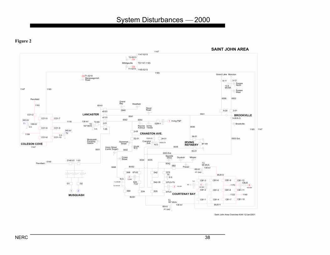
Summary New Brunswick Power Corporation (NBP) experienced a series of numerous 345 kV, 138 kV, and 69 kV transmission system outages on December 20, 2000 as a result of salt contamination on insulators combined with precipitation in the form of snow and freezing rain. The contamination occurred following two days of strong southwesterly onshore winds (70 mph) off the Bay of Fundy, which deposited salt spray from high waves over a wide area in the south of the province. Light snow, which began falling early on December 20 in the coastal area around the city of Saint John, combined with the salt spray contamination, caused a total of one 345 kV, 17 138 kV, and 20 69 kV transmission system outages in a two-hour period. This resulted in the loss of 314 MW of customer demand, including all industrial customers, the entire 69 kV system in the city, and three generating units. As the light snow turned to rain, the salt spray contamination on the insulators began to wash off, and the insulators regained their voltage withstand capability. This permitted load restoration to the city of Saint John, which was essentially completed by 0730 AST. As service was being restored in Saint John, freezing rain on contaminated insulators began to cause additional transmission system outages further east in the Salisbury area, eventually affecting four 345 kV and two 138 kV transmission lines. The first effect of this new series of outages was an interruption of supply to the two 138 kV submarine cables supplying the province of Prince Edward Island. These outages caused under frequency demand reduction on the “islanded” Prince Edward Island system. A series of 345 kV outages then resulted in system protection removing from service the three 345 kV lines supplying the Salisbury/Moncton area. The removal of these lines activated automatic under-voltage demand reduction of 143 MW of demand in the city of Moncton to stabilize area voltages. Service in this area was restored to normal by 0830 hours with the assistance of imports from Nova Scotia Power, Inc. However, re-energization attempts on two of the 345 kV lines were unsuccessful until about 1600 hours by which time rain had succeeded in cleaning the insulation. Figure 1 is a map of the Saint John Area 345 kV and 138 kV transmission system. Detailed Description of the Disturbance 1. Saint John Area Outages The outages in the Saint John area were almost all located at or very close to the Courtenay Bay Plant, with a few others on transmission apparatus close to the coastline. The first outages occurred on 69 kV Courtenay Bay L42, at the end of the line where the Mispec substation oil-supertanker unloading facilities are located (six outages between 0231 and 0253 hours). Following the last outage, this line was opened manually and left out-of-service. The first major outage was at 0249 hours when a three-phase fault struck the 138 kV Coleson Cove to Courtenay Bay L1165 line about eight miles from Coleson Cove, where the line runs parallel to the coast with no intervening cover. This outage disrupted Saint John area industrial customers, including 116 MW at the Irving Paper and Irving Refinery operations. The line was restored by the operator two minutes later and did not experience any other outages. The insulation at the Courtenay Bay Plant then began to break down, starting with a phase-to-phase short circuit on a 69 kV line to the No. 1 Irving Refinery substation (0305 hours). In the next half-hour, this line experienced another four outages. Following the first line outage, a series of bus short circuits then began at the Courtenay Bay Plant, starting at 0312 hours with simultaneous short circuits on the 138 kV

System Disturbances 2000
NERC 36
Figure 1
1 2 3
CO1-9
CO1-7
CO1-5CO1-6
CO1-8
CO1-10
CO3-13
CO3-14CO3-10
CO3-9
CO3-6
CO3-5
CO3-7 CO3-11
CO3-8
345 kV BUS 37
345 kV BUS 38 138 kV BUS 2
138 kV BUS 1
T1450 MVA
T2318 MVA
3009
PointLepreau
3002
Keswick
350MW
350MW
350MW
1193
Pennfield
CO1-2
1104
Marysville/Oak Bay
ManawagonishRoad
1165
1147
Millidgeville
4
CB1-3
CB1-2 CB1-5
CB1-6 CB1-9
CB1-8
CB1-7CB1-1
69 kV
T2167 MVA
138 kV
69 kV
PTGND.
138 kVT3
66 MVA 1170
IR1-1
IR1-4
IR1-3
T1Irving RefinerySub #2
T2
IR1-2
1122
IrvingPaperInc.PT
GND.
Salisbury
Lakewood
LochLomond
Fairvale
Hampton
Potacan
GondolaPoint
T4225 MVA
NO1-03
1199
T1340 MVA
345 Kv
S.S.
NO3-01 NO3-04NO3-02
3013Salisbury
3004
3004
SAINT JOHN AREA 345 kV & 138 kV TRANSMISSION
COURTENAYBAY
NORTON
COLESON COVE
SS100 MW
S.S.
S.S.
SB2
GrandviewAve.
SJAREA1 kah 12/Jan/01
1680MW
StationService
P3-6P3-5
K3-5K3-4
KESWICK
CB1-4
Lancaster
1116
IV1-4
IV1-1
T1Irving RefinerySub #3
T2
IV1-2
IV1-3 1212X
1149
3003
6
1149CB1-12
CB1-11
CB1-10
P3-9P3-4
TU1 TU4 TU6
180 MW
69 kV
T2167 MVA
T2-69
NO1-04NO1-01
NO1-02
1212
CBU6
1149
Bus 12
Bus 11
SST1
(Underconstruction)
1122-03
S5295-1122 T1
T2
TF
TE
TH
TB
TC
TD
TF
TE
TH
TE, TF, TH50/84 MVA
TB, TC, TD25/41 MVA

System Disturbances 2000
NERC 37
Bus 12 and the off-line 138 kV Unit 1 Bus. The operation of the system protection scheme resulted in the loss of one of the three 138/69 kV transformers that supply the city of Saint John 69 kV system and the loss of backup station service to the Courtenay Bay Plant. Two minutes later, a short circuit occurred at a 138 kV transformer about one mile away at the new No. 3 Irving Refinery substation. Eleven seconds after that, a 69 kV short circuit at the Courtenay Bay Plant resulted in system protection interrupting service to the two main substations in the downtown core of Saint John. Two minutes later, a three phase 69 kV short circuit at the Courtenay Bay Plant resulted in loss of the main plant station service feed. The preceding series of outages and interruptions to station service caused Courtenay Bay Unit 4 to rapidly reduce output from its full-load 98 MW. This contributed to a ruptured cooling water pipe two minutes later and the unit was removed from service. Fourteen seconds after this occurred, at 0318 hours, the 69 kV equipment associated with Courtenay Bay Unit 2 experienced a short circuit and system protection removed this unit from service. This action removed the final source of station service at the Courtenay Bay Plant except for the small emergency diesel. Another major blow to the 69 kV supply for the city occurred at 0323 hours when 138 kV Coleson Cove to Lancaster L1116 was removed from service by system protection due to a permanent short circuit. A contaminated insulator had failed on the initial flashover, and dropped the top phase conductor onto the middle steel crossarm. Loss of this line resulted in system protection taking out of service the second (connected in series with the line) of the three 138/69 kV transformers serving the city, which greatly weakened supply to the 69 kV system from the west side of the city. At 0346 hours, a short circuit on 69 kV Cranston Avenue to Lancaster L2 cut off supply from the Courtenay Bay Plant to most of the 69 kV system and resulted in system protection removing from service the last remaining supply from the west, 69 kV Musquash to Lancaster L1. At about the same time, the 138 kV Coleson Cove to Pennfield L1193 line experienced the first of its two short circuits within three miles of Coleson Cove. Also, at about this same time, a series of outages developed on the east side of the city at the No. 3 Irving Refinery terminal due to contamination flashover of 138 kV breaker bushing insulators. At 0344 hours and again at 0348 hours, short circuits on breaker IV1-3 caused both of its associated lines L1170 and L1212X to open and reclose. At 0350 hours, the already open breaker IV1-4 had a bushing short circuit that caused L1170 breaker IV1-3 to open without reclosing. At 0357 hours, another short circuit occurred on a breaker IV1-3 bushing (while it was open) causing the 138 kV Norton to No. 2 Irving Refinery L1212 line to be removed from service by system protection, interrupting all supply to the 138 kV Nos. 2 and 3 Irving Refinery terminals. One second after this, Irving Paper had a short circuit in its 138 kV switchyard, three conductor spans from the Courtenay Bay Plant, tripping L1122 and blacking out the paper mill. Also, at this time, Coleson Cove Unit 1 experienced an external flashover of its phase “A” 345 kV lightning arrestor (located closest to the coast), taking the unit out of service while at 177 MW output. The final outages at the Courtenay Bay Plant came shortly afterward when the remaining 138/69 kV transformer serving the city was taken out of service by system protection due to a short circuit on its 69 kV Bus at 0411 hours. The action eliminated the last 69 kV service to the city and open-ended the last three 138 kV lines into the Courtenay Bay Plant L1147, L1149, and L1165 (at this time, only one breaker of 24 was still closed at the plant). The Coleson Cove to Courtenay Bay L1147 line then experienced three short circuits (between 0413 and 0418 hours) in its 138 kV bus at the Courtenay Bay Plant, causing it to trip at Coleson Cove. A detailed map of the Saint John Area transmission system is shown as Figure 2.
System Disturbances 2000
NERC 38
Figure 2
SAINT JOHN AREA
1 2
ManawagonishRoad
CS T1-5219
MusquashPumpingStation
0140
MUSQUASH
LANCASTER
GrandBay Westfield
DeverRoad
RaynesAvenue
100540002
5264-1
2-05
1116 T2-69
1-05
2-01
41-01
40-01
T2167 MVA
52-01
52-06
CrownStreet
Union Street(Lantic Sugar)
4
2
3
CB1-7
CB1-8
CB1-9
1170
1122
S.S.
SB2
T5ST5
STU3-T5
STU3S35
S42-35
S42STU2
S34-TU2
S34S84
S68
0068
34-01Cranston
Sub.
CRANSTON AVE.
IRVINGREFINERY BT-69
35-01
36-01
BaysideDrive Drydock Mispec
0042
0003 Ext.
Brookville
3-018-20
00030008
0041
SussexWest
SussexNorth10.8
MVAR
3-128-11
MonctonGrand Lake
Irving P&P
0040
0041
11471165
BROOKVILLE
COURTENAY BAY
1104CO1-8 CO1-10
345 kV
138 kV
CO1-6 CO1-9345 kV
CO1-7CO1-5
CO1-2
1193
Pennfield
1165
1147
CB1-1
CB1-2
CB1-3
BUS12
CB1-6
CB1-5
BUS11
T366 MVA
T2167 MVA
7.2 MVAR
10.8 MVAR
BUS1
BUS2
1-010140-01
00011147
0036
COLESON COVE
Pennfield
1165
00350034
S5262-34
S5262-52
TU1
100 MW100 MW
12 MW
138 kV69 kV
69 kV138 kV
138 kV
69 kV
Millidgeville
CS
TS1147-1165
T2-5213
T1-5213CS
1147
G2G1
IrvingTissue
N.O.N.O.
N.O.3-26
0003 Ext.
N.O.
0035
S.S.
PT GND
PT GND
S.S.
S.S.
1147-5213
1165-5213
T1
T2
Praxair
Saint John Area Overview KAH 12/Jan/2001
CB1-4
CB1-12
CB1-11
CB1-10
6
1149
CBU6
180 MW
SS
SomersetStreet
0052

System Disturbances 2000
NERC 39
2. Salisbury Area Faults Further away from the coast the temperature was just below freezing, resulting in the precipitation (which started at 0400 hours in this area) falling as freezing rain. The Memramcook to Murray Corner L1143 line, one of the two 138 kV lines which supply the submarine cables to Prince Edward Island, began experiencing a series of openings and reclosings at 0605 hours. Over a period of 25 minutes it suffered eight short circuits to ground, close to Memramcook, at varying distances and involving each of the phases; the line remained open at the Murray Corner end after the fifth short circuit. During the course of the short circuits on L1143, more serious outages began to occur on the 345 kV system, starting with a successful single-pole opening and reclosing of the Norton−Salisbury L3013 line at 0617 hours. This was followed at 0629 hours by a single-pole opening and reclosing into a short circuit followed by an immediate three-pole opening of the Coleson Cove to Norton L3004 line. The short circuits on both L3013 and L3004 were very close to Norton and attempts to restore L3004 resulted in openings after a few seconds on both occasions (0631 and 0725 hours). One minute after L3004 initially opened, the Salisbury 340 MVA 345/138 kV tie transformer (T3) was removed from service by operation of its reactor protection system, three seconds after the operator initiated a remote opening of one of its 37.5 Mvar tertiary winding reactors. This action placed supply to the Moncton area in a more vulnerable position because the Salisbury 345 kV ring bus was left with the two transformer high-side breakers open. L1143 then experienced four more short circuits (0632 hours), one of which triggered an improper system protection operation at Memramcook that resulted in a trip of the parallel L1142 line and the Memramcook 138/69 kV tie transformer. The opening of L1142 while L1143 was also open resulted in loss of supply to Prince Edward Island and the “islanding” of its system. Total Prince Edward Island system demand at the time was 92 MW, of which 52 MW was being imported. Under-frequency demand reduction was activated on the island and frequency was stabilized at 58.6 Hz. This stabilization enabled the PEI Charlottetown steam units to increase output, prevent a complete system blackout, and allowed the Borden combustion turbines to be started. At 0723 hours, while the operators were dealing with the problems in the Saint John and Memramcook areas, the 345 kV Bathurst to Salisbury L3019/3017 short circuited near Salisbury and was taken out of service by system protection. Due to the open 345 kV breakers on Salisbury transformer 3, the loss of L3019/3017 also cut off the 345 kV tie to Nova Scotia via L3006. With L3004 already out, the opening of these two lines caused area voltages to drop to about 86% of normal, triggering operation of the Southeast Area under voltage demand reduction protection. This protection scheme immediately connected two 10 Mvar tertiary capacitor banks at Moncton. When this action did not have any significant effect, the protection scheme removed 143 MW of demand from Moncton 138 kV lines L1156 and L1157 about one second after the loss of the 345 kV lines. This action was sufficient to stabilize the voltage/load situation for the remaining single 230 kV and three 138 kV lines that were supplying the entire southern New Brunswick service area from Saint John to the Nova Scotia border. Nine minutes later, remote control breaker operations at Salisbury allowed the 345 kV tie to Nova Scotia to be re-established. Re-energization attempts on L3017/3019 were unsuccessful when both short circuited and opened (0737 and 1335 hours) a few seconds after energization. Following re-energization of the submarine cables to Prince Edward Island, its system re-synchronized at 0841 hours. All service in Saint John, Moncton, and Memramcook was restored by 0842 hours, but restrictions on the large industrial customers were maintained until L3004 and L3019/3017 were restored to service at 1604 and 1659 hours respectively. A detailed map of the Southeastern New Brunswick Area transmission system is shown as Figure 3.

System Disturbances 2000
NERC 40
BaigBlvd.
To Bathurst (3019)
7002
70037001
70047005
T1392 MVA
8002
8003
224MVA
813
812
811
814
67N-815
8001
1N-613
T2392 MVA
6513
74N-636
6536
ChurchStreet
SPRINGHILL
ONSLOW
30N-635
LOAD
MACCAN
MURRAYCORNER
PEICable 1
PEICable 2
MC1-2
MC1-1
6514
6535
1160
1142 MC1-3
0118ME-2
1143MC1-4
Hardy Rd.
ME1-9
ME1-13
ME1-T1
T150 MVA
ME-1
1159
MEMRAMCOOK
1190
0119T5
0003
0006
0019
0029
0024
0010
TSB2-B3
T1-69
T3-69T3-138
T1-138
T1112.5 MVA
T3112.5 MVA
TSB11-B12
Bus 11
1124-01
1108-01 1108
1190SA1-11
SA1-9
SA1-10
SA1-12
T3340 MVA
SA3-1SA3-43017
3006SA3-2
SA3-3SA3-6
1215
SALISBURY
3013
NO3-04NO3-02NO3-01
NORTON
3004CO3-7
CO3-11
CO3-9
T1340 MVA
NO1-01
NO1-03IR1-1
IR1-2T4 PHASESHIFTER225 MVA
12121199
SA1-8
SA1-6
SA1-5
SA1-7SA2145
T1350 MVA
2145
1151 1148K2-7
K2-6
KESWICK
COLESONCOVE
GRANDLAKE
1101-01 1101
Bus 12
1101-02
1151-01
1156-01
1157-01
30MVAR
T2-138
1148-01
1156
1157
1118
NE1-7
NE1-8
NEWCASTLE
SOUTHEASTERNNEW BRUNSWICK
AREA
Gunningsville
NovaScotiaSystem
NovaScotiaSystem
345kV
230 kV
138 kV
69 kV
138 kV
69 kV
69 kV
345 kV
345 kV
138 kV
IRVINGREFINERY
2145
1124 1215
ME1-12
ME1-8
Ryan Rd. CaledoniaPark
CanadaLiquid Air
DieppeInd.
Church St.
ShediacWest
Cocagne WestBuctouche
Rexton Richibucto St. Louis
T2
T1
T2
T1
BT-69
10-10
24-01
29-01
19-01
6-08
3-20
T5-6542
R1
R2
2 x 37.5 MVAR
S.S.
S.S.
S.S.
MONCTON
Mir. P&P(Nelson)
CS
T2450 MVA
7018
CS
T2Riverview
T1
Cyclomet
30N-614
74N-600
74N-613
36MVAR
74N-619
Southeastern NB Area KAH 12/Jan/2001
CedarStreet
NO1-02
1199
NO1-04
1149
1157
Figure 3

System Disturbances 2000
NERC 41
Conclusions and Recommendations The insulator contamination monitoring stations in the Saint John area recorded their highest level ever of contamination the day before the short circuits occurred. However, the high winds throughout the day prevented any live washing of switchyard apparatus. New Brunswick Power’s policy is to take anti-contamination measures for all new switchyard equipment at the Courtenay Bay Plant, where six new 138 kV breakers were added in recent years. However, not all of the older equipment at the plant had room temperature vulcanization (RTV) anti-contamination treatment applied. Analysis of the short circuits that occurred indicates that all of those occurring at the Courtenay Bay Plant were on untreated apparatus. Similarly, the recently constructed customer-owned No. 3 Irving Refinery terminal was not made contamination proof, resulting in five incidents of 138 kV breaker bushing flashovers during the storm. A program is being developed during 2001 to have both these locations further enhanced against contamination related to short circuits. RTV coating of critical apparatus in the Coleson Cove and Point Lepreau switchyards was completed several years ago and has been very successful. The flashover of the RTV-coated lightning arrestor on Coleson Cove Unit 1 was the first known case where the salt contamination levels were higher than the withstand ability of the coated insulation. The total number of short circuits caused by contamination during this disturbance was far in excess of anything ever before experienced by New Brunswick Power Corporation (NBP). The transmission problems experienced in the Salisbury area are believed to have been caused by the type of synthetic insulators used on the affected lines. For a few years, beginning around 1990, NBP switched from using porcelain insulators to insulators made of a synthetic material. Lines 3004 and 3013, running from Coleson Cove to Salisbury, were originally constructed using porcelain insulators. In 1990, the line was cut into two sections by the addition of short synthetic insulated taps into the new Norton terminal. Similarly, L3017/3019 was built in 1992 using synthetic insulators. Field reports of crews searching for the short circuits on December 20 indicate that the freezing rain was bridging across the insulator skirts of the synthetic insulators. This bridging appeared to be due to the small diameter and uniform shape of these particular insulators (unlike the porcelain insulators, which have a much larger diameter and greater spacing between each skirt). Operating records on L3004 and L3013 indicate that the short circuits on both lines were taking place in the area of the short taps into Norton. It is believed that the wide-spread salt contamination combined with the freezing rain bridging of insulator skirts caused the breakdown of the voltage withstand capability. Another example is L1143, which was built with synthetic insulators and runs in parallel with the older porcelain insulated L1142 on the same right of way. L1143 had 12 short circuits while L1142 had none. It is to be noted that, prior to this disturbance, the operating history of the involved 345 kV lines had been excellent. The value of automatic demand reduction systems was demonstrated on two separate occasions. When the small Prince Edward Island system (170 MW peak) became islanded because of the loss of its two underwater supply cables, its under frequency demand reduction system enabled its generating resources to survive the loss of the 52 MW imported from NBP. Similarly, the automatic under-voltage demand reduction system in the Moncton area was able to arrest the voltage decline following the loss of the three 345 kV ties into the area. This automatic system likely prevented the system protection scheme from opening the area’s few remaining ties to the NBP system, due to overload. Protective relay performance was excellent considering the number of short circuits. No reason was found for operation of the 12.47 kV tertiary reactor protection on the Salisbury T3 transformer. The improper 138 kV protection operation at Memramcook was due to mutual coupling between the parallel lines in this area, resulting in instantaneous neutral over current operation on a non-short circuited line. Setting adjustments have since been made.
System Disturbances 2000
NERC 42
Refer to: NERC Operating Policy 2 – Transmission A. Transmission Operations NERC Operating Policy 6 – Operations Planning B. Emergency Operations C. Automatic Load Shedding NERC Planning Standard I – System Adequacy and Security A. Transmission Systems For more information on this incident, please contact the Northeast Power Coordinating Council.

System Disturbances 2000
NERC 43
APPENDICES Appendix A. Reporting Requirements for Major Electric Utility System Emergencies NERC Operating Policy 5F and Appendix 5F detail the requirements and procedures for reporting disturbances or unusual occurrences that jeopardize the operation of the interconnected systems, and result, or could result, in system equipment damage or customer interruptions. Operating Policy 5F and Appendix 5F are included below for reference and guidance.
Operating Policy 5F Disturbance Reporting
Introduction Disturbances or unusual occurrences that jeopardize the operation of the interconnected systems, and result, or could result, in system equipment damage, or customer interruptions, must be studied in sufficient depth to increase industry knowledge of electrical interconnection mechanics to minimize the likelihood of similar events in the future. It is important that the facts surrounding a disturbance shall be made available to Security Coordinators, system and control area operators, system managers, Regional Councils, NERC, and regulatory agencies entitled to the information. Requirements 1. Regional Council reporting procedures. Each Regional Council shall establish and maintain a
Regional reporting procedure to facilitate preparation of preliminary and final disturbance reports.
2. Analyzing disturbances. Bulk system disturbances shall be promptly analyzed by the affected systems.
3. Disturbance reports. Based on the NERC and DOE disturbance reporting requirements, those systems responsible for investigating the incident shall provide a preliminary written report to their Regional Council and NERC.
3.1. Preliminary written reports. Either a copy of the report submitted to DOE, or, if no DOE report is required, a copy of the NERC Preliminary Disturbance Report form shall be submitted by the affected system(s) within 24 hours of the disturbance or unusual occurrence. Certain events (e.g., near misses) may not be identified until some time after they occur. Events such as these should be reported within 24 hours of being recognized.
3.2. Preliminary reporting during adverse conditions. Under certain adverse conditions, e.g., severe weather, it may not be possible to assess the damage caused by a disturbance and issue a written Preliminary Disturbance Report within 24 hours. In such cases, the affected entity(ies) shall notify its Regional Council(s) and NERC promptly and verbally provide as much information as is available at that time. The affected utility(s) shall then provide timely, periodic verbal updates until adequate information is available to issue a written Preliminary Disturbance Report.

System Disturbances 2000
NERC 44
3.3. Final written reports. If in the judgment of the Regional Council, after consultation with the electric system(s) in which a disturbance occurred, a final report is required, the affected electric system(s) shall prepare this report within 60 days. As a minimum, the final report shall have a discussion of the events and its cause, the conclusions reached, and recommendations to prevent recurrence of this type of event. The report shall be subject to Regional Council approval.
4. Notifying NERC. The NERC Disturbance Reporting Requirements, shown in Appendix 5F, are the minimum requirements for reporting disturbances, unusual occurrences, and voltage excursions to NERC.
5. Notifying DOE. The U.S. Department of Energy’s most recent Power System Emergency Reporting Procedures, shown in Appendix 5F, are the minimum requirements for U.S. utilities and other entities subject to Section 311 of the Federal Power Act required to report disturbances to DOE. Copies of these reports shall be submitted to NERC at the same time they are submitted to DOE.
6. Assistance from NERC OC and the Disturbance Analysis Working Group (DAWG). When a bulk system disturbance occurs, the Regional Council’s OC and DAWG representatives shall make themselves available to the system or systems immediately affected to provide any needed assistance in the investigation and to assist in the preparation of a Final Report.
7. Final report recommendations. The Regional Council shall track and review the status of all final report recommendations at least twice each year to ensure they are being acted upon in a timely manner. If any recommendation has not been acted on within two years, or if Regional Council tracking and review indicates at any time that any recommendation is not being acted on with sufficient diligence, the Regional Council shall notify the NERC EC and OC of the status of the recommendation(s) and the steps the Regional Council has taken to accelerate implementation.

System Disturbances 2000
NERC 45
NERC Disturbance Reporting Requirements Policy 5F, Appendix 5F — Reporting Requirements for Major Electric System Emergencies
These disturbance reporting requirements apply to all entities using the electric transmission systems in North America and provide a common basis for all NERC disturbance reporting. The utility or other electricity supply entity on whose system a disturbance that must be reported occurs shall notify NERC and its Regional Council of the disturbance using the NERC Preliminary Disturbance Report form. If a disturbance is to be reported to DOE also, the responding entity may use the DOE reporting form when reporting to NERC. The report is to be made as specified in Policy 5F for any of the following events. 1. The loss of a bulk power transmission component that significantly affects the integrity of the
interconnection system operation. 2. The occurrence of an interconnected system separation or system islanding or both. 3. Loss of generation by a utility or generation supply entity — 2,000 MW or more in the Eastern
Interconnection or Western Interconnection and 1,000 MW or more in the ERCOT Interconnection or Quebec Interconnection. Reports can be sent to NERC via e-mail ([email protected]) or by facsimile (609-452-9550) using the NERC Preliminary Disturbance Report form.
4. Equipment failures/system operational actions, which result in the loss of firm system demands
for more than 15 minutes, as described below:
4.1. Entities with a previous year recorded peak demand of more than 3,000 MW are required to report all such losses of firm demands totaling more than 300 MW.
4.2. All other entities are required to report all such losses of firm demands totaling more than
200 MW or 50% of the total customers being supplied immediately prior to the incident, whichever is less.
5. Firm load shedding of 100 MW or more to maintain the continuity of the bulk electric system. 6. Any system operation or operator action resulting in: 6.1. sustained voltage excursions equal to or greater than ±10%, or 6.2. major damage to power system components, or 6.3. an event other than those covered above that a system operator in another electric
transmission system might encounter and should be aware of, or 6.4. failure, degradation, or a “near miss” of system protection, special protection schemes, remedial action schemes, or other operating systems that do not require system operator intervention.
System Disturbances 2000
NERC 46
7. An operating security limit violation as required in Policy 2A — Transmission Operations, Standard 2.2.
8. An actual or suspected act of physical or electronic (cyber) sabotage or terrorism directed at the
bulk electric system or its components with intent to deny service or disrupt or degrade the reliability of the bulk electric system.

System Disturbances 2000
NE
1. 2. 3. 4. 5. 6.
7. 8. 9.
10
11
Check here if this is an operating security limit
NERC Princeton Forrestal Village 116-390 Village Boulevard
RC 47
NERC Preliminary Disturbance Report
Organization filing report:
Name of person filing report:
Telephone number: ( ) -
Date and time of disturbance: / / Date (mm/dd/yy) / /Time/Zone
Did disturbance originate in your system?
Describe disturbance including: cause, equipment damage, critical services interrupted, system separation, key scheduled and actual flows prior to disturbance and in the case of a disturbance involving a special protection or remedial action scheme, what action is being taken to prevent recurrence:
List generation tripped: MW total
Frequency: a. just prior to disturbance Hz b. immediately after disturbance Hz max. Hz Min.
List transmission lines tripped (specify voltage level of each line):
FIRM INTERRUPTIBLE . Demand tripped MW MW
Number of customers affected Customers Customers Demand lost in MW-Minutes MW-Min. MW-Min.
. Restoration time Initial Final Transmission _______ ______ Generation _______ ______ Demand _______ ______
violation report Princeton, NJ 08540-5731 E-mail: [email protected]
Fax: 609-452-9550 Tel: 609-452-8060

System Disturbances 2000
NERC 48
U.S. Department of Energy Disturbance Reporting Requirements Introduction Every electric utility or other entity subject to the provisions of Section 311 of the Federal Power Act, engaged in the generation, transmission, or distribution of electric energy for delivery and/or sale to the public shall expeditiously report to the U.S. Department of Energy’s (DOE) Emergency Operation Center (EOC) any of the events described below. Such report or part of such report may be made jointly by two or more entities or by a Regional Electric Reliability Council or power pool. 1. Loss of Firm System Loads 1.1. Any load shedding actions resulting in the reduction of over 100 megawatts (MW) of
firm customer load for reasons of maintaining the continuity of the bulk electric power supply system.
1.2. Equipment failures and system operational actions associated with the loss of firm system
loads for a period in excess of 15 minutes, as described below: 1.2.1. Reports from entities with a previous year recorded peak load of over 3,000 MW
are required for all such losses of firm loads which total over 300 MW. 1.2.2. Reports from all other entities are required for all such losses of firm loads which
total over 200 MW or 50% of the system load being supplied immediately prior to the incident, whichever is less.
1.3. Other events or occurrences which result in a continuous interruption for three hours or
longer to over 50,000 customers, or more than 50% of the total customers being served immediately prior to the interruption, whichever is less.
When to Report: The DOE EOC (202-586-8100) shall be notified as soon as practicable without undue interference with service restoration and, in any event, within three hours after the beginning of the interruption. 2. Voltage Reductions and Public Appeals
2.1. A report is required for any anticipated or actual system voltage reduction of three percent or greater for purposes of maintaining the continuity of the bulk electric power supply system.
2.2. A report is required for any issuance of a public appeal to reduce the use of electricity for
purposes of maintaining the continuity of the bulk electric power system. When to Report: The DOE EOC (202-586-8100) shall be notified as soon as practicable, but no later than 24 hours after initiation of the actions described in paragraph 2, above.

System Disturbances 2000
NERC 49
3. Vulnerabilities That Could Impact Bulk Electric Power System Adequacy or Reliability
3.1. Reports are required for any actual or suspected act(s) of physical sabotage (not vandalism) or terrorism directed at the bulk electric power supply system in an attempt to:
3.1.1. Disrupt or degrade the adequacy or service reliability of the bulk electric power
system such that load reduction action(s) or special operating procedures may be needed.
3.1.2. Disrupt, degrade, or deny bulk electric power service on an extended basis to a
specific: (1) facility (industrial, military, governmental, private), (2) service (transportation, communications, national security), or (3) locality (town, city, county). This requirement is intended to include any major event involving the supply of bulk power.
3.2. Reports are required for any other abnormal emergency system operating conditions or
other events which, in the opinion of the reporting entity, could constitute a hazard to maintaining the continuity of the bulk electric power supply system. DOE has a special interest in actual or projected deterioration in bulk power supply adequacy and reliability due to any causes. Events which may result in such deterioration include, but are not necessarily limited to: natural disasters; failure of a large generator or transformer; extended outage of a major transmission line or cable; Federal or state actions with impacts on the bulk electric power system.
When to Report: The DOE EOC (202-586-8100) shall be promptly notified as soon as practicable after the detection of any actual or suspected acts(s) or event(s) directed at increasing the vulnerability of the bulk electric power system. A 24-hour maximum reporting period is specified in the regulations; however, expeditious reporting, especially of sabotage or suspected sabotage activities, is requested. 4. Fuel Supply Emergencies 4.1. Reports are required for any anticipated or existing fuel supply emergency situation,
which would threaten the continuity of the bulk electric power supply system, such as:
4.1.1. Fuel stocks or hydroelectric project water storage levels are at 50% or less of normal for that time of the year, and a continued downward trend is projected.
4.1.2. Unscheduled emergency generation is dispatched causing an abnormal use of a
particular fuel type, such that the future supply or stocks of that fuel could reach a level, which threatens the reliability or adequacy of bulk electric power supply.
When to Report: The DOE EOC (202-586-8100) shall be notified as soon as practicable, or no later than three days after the determination is made.

System Disturbances 2000
NERC 50
Appendix B. Analysis Categories The categories used to analyze the disturbances and unusual occurrences are the titles and subtitles of the NERC Operating Policies, plus the NERC Planning Standards. Operating Policies Policy I. Generation Control and Performance A. Operating Reserve B. Automatic Generation Control C. Frequency Response and Bias D. Time Control E. Control Performance F. Inadvertent Interchange G. Control Surveys H. Control and Monitoring Equipment Policy 2. Transmission A. Transmission Operations B. Voltage and Reactive Control Policy 3. Interchange A. Interchange Transactions B. Interchange Schedules C. Schedule Specifications D. Interconnected Operations Services E. Transfer Capability Policy 4. System Coordination A. Monitoring System Conditions B. Operational Security Information C. Maintenance Coordination D. System Protection Coordination Policy 5. Emergency Operations A. Coordination with Other Systems B. Insufficient Generating Capacity C. Transmission Overload D. Separation from the Interconnection E. System Restoration F. Disturbance Reporting G. Sabotage Reporting
Policy 6. Operations Planning A. Normal Operations B. Emergency Operations C. Automatic Load Shedding D. System Restoration E. Control Center Backup Policy 7. Telecommunications A. Facilities B. System Operator Telecommunication
Procedures C. Loss of Telecommunications Policy 8. Operator Personnel and Training A. Responsibility and Authority B. Training C. Certification Policy 9. Security Coordinator Procedures A. Next Day Operations Planning Process B. Current Day Operations – Generation C. Current Day Operations – Transmission

System Disturbances 2000
NERC 51
Planning Standards I. System Adequacy and Security A. Transmission Systems B. Reliability Assessment C. Facility Connection Requirements D. Voltage Support and Reactive Power E. Transfer Capability F. Disturbance Monitoring II. System Modeling Data Requirements A. System Data B. Generation Equipment C. Facility Ratings D. Actual and Forecast Demands E. Demand Characteristics (Dynamic) III. System Protection and Control A. Transmission Protection Systems B. Transmission Control Devices C. Generation Control and Protection D. Underfrequency Load Shedding E. Undervoltage Load Shedding F. Special Protection Systems IV. System Restoration A. System Blackstart Capability B. Automatic Restoration of Load

System Disturbances 2000
NERC 52
Appendix C. Interruptions, Unusual Occurrences, Demand and Voltage Reductions, and Public Appeals
(Analyses of the items in boldface are included in this report.)
Firm Load
Date
Region
Utilities
Type*
MW
Customers
Cause
01/23/00 SERC Duke Power Company INT N/A 133,000 Weather – ice storm 01/24/00 SERC Carolina Power & Light Company INT 960 173,000 Weather – ice storm 01/24/00 SERC South Carolina Electric & Gas Company INT N/A 62,000 Weather – ice storm 01/29/00 SERC Duke Power Company INT N/A 81,000 Weather – ice storm 02/02/00 NPCC Independent Electricity Market Operator UO N/A N/A Operator error 02/02/00 MAPP Otter Tail Power Company INT 100 20,000 Operator error 02/26/00 WSCC Southern California Edison Company INT 300 112,000 Operator error 03/17/00 WSCC Nevada Power Company INT 40 N/A Operator error
03/18/00 WSCC El Paso Electric Co., Public Service Company of New Mexico INT 1,525 662,800 Fire damage – brush fire
under transmission line 03/21/00 NPCC Transenergie UO N/A N/A False block order signal 04/01/00 FRCC City of Lake Worth Utilities INT 46 24,000 Equipment failure 04/01/00 SERC Dominion Virginia Power Company INT 143 37,000 Equipment failure 04/20/00 MAPP Manitoba Hydro UO N/A N/A Equipment failure
05/02/00 ERCOT Reliant Energy – Houston Lighting & Power Company INT N/A 238,000 Weather – thunderstorms
05/08/00 MAAC Conectiv VR N/A N/A Hot weather and high customer demand
05/09/00 NPCC Consolidated Edison Company of New York, New York Independent System Operator PA N/A N/A Hot weather and operating
reserve shortage 05/18/00 MAIN ComEd INT N/A 50,000 Weather – thunderstorms 05/20/00 SERC Duke Power Company INT 200 50,000 Weather – thunderstorms
05/25/00 SPP Entergy PA N/A N/A Hot weather and capacity shortage
05/25/00 SERC Duke Power Company INT 500 147,000 Weather – thunderstorms 06/09/00 NPCC Transenergie INT 50 1 Operator error 06/09/00 MAPP Manitoba Hydro UO N/A N/A Maintenance error
06/14/00 WSCC California Independent System Operator INT 130 32,000 Inadequate generation resources
06/14/00 ECAR American Electric Power Company INT 294 N/A Relay malfunction
06/14/00 WSCC Tucson Electric Power Company INT 138 40,911 Forest fire under transmission lines
06/19/00 NPCC Independent Electricity Market Operator UO N/A N/A Operator error
06/28/00 SERC Dominion Virginia Power Company INT 175 30,500 Weather – thunderstorms
06/29/00 NPCC Transenergie UO N/A N/A Equipment trip
07/03/00 ASCC Alaska Electric Light & Power Company INT 35 14,273 Transmission line fault
07/05/00 WSCC British Columbia Hydro and Power Authority INT 325 N/A Protection system operation
07/10/00 NPCC Transenergie UO N/A N/A Weather – thunderstorms
07/13/00 NPCC Independent Electricity Market Operator UO N/A N/A Equipment failure and weather – thunderstorms
07/17/00 NPCC Transenergie UO N/A N/A Weather – thunderstorms
07/20/00 SERC Alabama Power Company INT N/A 160,000 Weather – thunderstorms
08/04/00 WSCC Power Pool of Alberta INT 190 N/A Weather – thunderstorms
08/06/00 MAIN ComEd INT N/A 239,567 Weather – thunderstorms

System Disturbances 2000
NERC 53
Firm Load
Date Region Utilities Type* MW Customers Cause 08/09/00 ECAR Cinergy INT N/A 92,000 Weather – thunderstorms
08/10/00 SERC Alabama Power Company INT N/A 75,000 Weather – thunderstorms
08/18/00 SERC Duke Power Company INT 4−500 130,000 Weather – thunderstorms
08/22/00 NPCC Independent Electricity Market Operator INT 130 1 Weather – thunderstorms
08/27/00 NPCC Independent Electricity Market Operator UO N/A N/A Operating procedure error
08/28/00 ECAR Southern Indiana Gas & Electric Company INT/PA 10−15 124,000 Insufficient generating reserves
08/31/00 NPCC Independent Electricity Market Operator VR N/A N/A Loss of generation
09/01/00 SERC Georgia Power Company UO N/A N/A Weather – thunderstorms 09/17/00 FRCC Florida Power & Light Company INT N/A 120,000 Weather – Hurricane Gordon
09/19/00 NPCC Transenergie UO N/A N/A Maintenance error
09/28/00 NPCC Transenergie UO N/A N/A Maintenance error
09/30/00 NPCC Independent Electricity Market Operator UO N/A N/A Operator procedure error
10/02/00 NPCC Independent Electricity Market Operator UO N/A N/A Operator procedure error
10/08/00 MAIN ComEd INT N/A 11,000 Equipment failure
10/29/00 MAPP Manitoba Hydro UO N/A N/A Equipment failure
10/31/00 MAPP Nebraska Public Power District UO N/A N/A Weather – thunderstorms
11/02/00 WSCC Southern California Edison Company INT 160 N/A Equipment failure
12/07/00 WSCC California Independent System Operator INT/PA 1,775 N/A Inadequate generation resources
12/13/00 SPP Southwest Power Pool INT 1,200−1,400 235,000 Weather – ice storm
12/16/00 SERC Alabama Power Company INT N/A 50,000 Weather – tornado
12/20/00 NPCC New Brunswick Power Corporation INT 530 N/A Weather – ice storm 12/25/00 SPP Southwest Power Pool INT 460 94,285 Weather – ice storm
*INT = Customer Interruptions, UO = Unusual Occurrences, DR = Demand Reduction, VR = Voltage Reduction, PA = Public Appeal
N/A = Not Available
System Disturbances 2000
NERC 54
DISTURBANCE ANALYSIS WORKING GROUP MEMBERS
Glenn W. Brown (Chairman) Director, T&D Technical Services
NEW BRUNSWICK POWER CORPORATION
David A. Powell Engineer FIRST ENERGY CORPORATION Dennis B. Hogan Senior Engineer TXU ELECTRIC Steven R. Wallace Manager of System Operations SEMINOLE ELECTRIC COOPERATIVE, INC. Larry Larson Supervisor, Operational Analysis, System Operations OTTER TAIL POWER COMPANY Philip B. Winston Supervisor, Protection and Control GEORGIA POWER COMPANY
Bruce Rew Manager, Engineering SOUTHWEST POWER POOL Donald L. Gold Process Manager, Dittmer Consulting BONNEVILLE POWER ADMINISTRATION Robert K. Harbour Vice President Engineering & Operations SOYLAND POWER COOPERATIVE, INC. Paul T. Rychert Manager Interconnection Arrangements CONECTIV Eugene F. Gorzelnik Director-Communications NORTH AMERICAN ELECTRIC RELIABILITY COUNCIL