2000 - pioneer athletics · the model 2000 handles all athletic field needs with ease. ......
TRANSCRIPT

BRITE STRIPER®
INSTRUCTION MANUAL & PARTS LISTING
2000

2 0 0 0Versatility
The MODEL 2000 handles allathletic field needs with ease.So simple to operate that any-one can do a professional job.
5-YEAR WARRANTYAGAINST “RUST OUT”
Ample 12 gallon paint tanktackles large striping needs ina snap. Pioneer’s 5-year war-ranty (against rust) is on thestainless steel paint tank.
BUILT STURDY FORYEARS OF SERVICE
Honda 4 H.P. engine powers aPiston-Type Compressor.Heavy-gauge welded steelframe rolls smoothly on threelarge, fully pneumatic wheels.The MODEL 2000 has a cable-operated control valve topaint crisp lines and featuresthe Hydraulic Direct Drive Sys-tem.
SIMPLE DESIGN- LOW MAINTENANCE
The MODEL 2000’s simple de-sign means low maintenance.The air-release valve and dualsafety relief system assurestrouble-free operation. Rearoutlet valve makes cleanup asnap.
BRITE STRIPER®
Call 800.877.1500
FULLY ADJUSTABLE SPRAY BOXChange line width easily from 2” to 8”.
12’ HAND HOSE WITH WANDA twelve-foot hand hose (and spray gun) with wandand quick disconnect fitting is standard on our BRITESTRIPER® 2000. Get professional results on yardline
stencils, endzones and out-of-bounds.
SPECIAL TUNE-UP KIT FOR BRITESTRIPER® 2000
Our exclusive tune-up kit, as an accessory, for thismodel includes:
2 Nozzle Tips
2 Nozzle Screens
2 Nozzle Caps
1 Tank Gasket
1 Safety Relief Valve
1 Drive Belt
1 Spark Plug
1 Air Filter
• 3-YEAR LIMITED WARRANTY •
Replacement parts for all of Pioneer’s machines are fully stocked and available for immediate de-livery. We also carry replacement parts for many other airless line stripers.
Call your local representative or Pioneer for more information.
PN08018

PN08018
THE BRITE STRIPER® 2000
ASSEMBLY INSTRUCTIONSTools Necessary for Assembly . . . . . . . . . . . . . . . . . . . . . . . . . . . . . . 1
Removing from Shipping Carton . . . . . . . . . . . . . . . . . . . . . . . . . . . 1
Handle Assembly . . . . . . . . . . . . . . . . . . . . . . . . . . . . . . . . . . . . . . . . 1
Speed Control Cable . . . . . . . . . . . . . . . . . . . . . . . . . . . . . . . . . . . . . 2
Adjustable Spray Box . . . . . . . . . . . . . . . . . . . . . . . . . . . . . . . . . . . . 3
OPERATION & CAREBefore Starting. . . . . . . . . . . . . . . . . . . . . . . . . . . . . . . . . . . . . . . . . . 4
Care and Operation of Compressor. . . . . . . . . . . . . . . . . . . . . . . . . . 4
Care and Operation of Paint Tank Unit . . . . . . . . . . . . . . . . . . . . . . 5
Paint Tank Label . . . . . . . . . . . . . . . . . . . . . . . . . . . . . . . . . . . . . . . . 5
Operation of Machine . . . . . . . . . . . . . . . . . . . . . . . . . . . . . . . . . . . . 6
Striping Tips. . . . . . . . . . . . . . . . . . . . . . . . . . . . . . . . . . . . . . . . . . . . 9
Clean-Up of the Paint Tank Unit . . . . . . . . . . . . . . . . . . . . . . . . . . 10
Clean-Up Tips. . . . . . . . . . . . . . . . . . . . . . . . . . . . . . . . . . . . . . . . . . 11
How to Store . . . . . . . . . . . . . . . . . . . . . . . . . . . . . . . . . . . . . . . . . . . 11
Normal Wear . . . . . . . . . . . . . . . . . . . . . . . . . . . . . . . . . . . . . . . . . . 11
Customer Service . . . . . . . . . . . . . . . . . . . . . . . . . . . . . . . . . . . . . . . 14
Shipping the Product . . . . . . . . . . . . . . . . . . . . . . . . . . . . . . . . . . . . 14
IDENTIFYING PROBLEMS & PARTSParts List & Parts Explosion Drawings . . . . . . . . . . . . . . . . . . . . 7-8
Trouble Shooting the #2000 . . . . . . . . . . . . . . . . . . . . . . . . . . . . 12-13
Limited Warranty . . . . . . . . . . . . . . . . . . . . . . . . . . . . . . . . . . . . . . 15
TABLE OF CONTENTS

1REV 2/08
If you have any questions concerning the assembly or operation, please call our CUSTOMER SERVICE
DEPARTMENT at 800.877.1500.
TOOLS NEEDED FOR ASSEMBLY1 - 5/8" Open End Wrench1 - 7/16" Socket1 - 7/16" Open End Wrench1 - Crescent Wrench (Vise Grips may be substituted)
Allen Wrenches (supplied in hardware kit)
ASSEMBLY INSTRUCTIONS FOR BRITE STRIPER® MODEL #2000After Removing Box from Shipping Carton:
STEP 1.Remove Brite Striper 2000 – two people necessary to lift
STEP 2.Remove handle bar.Remove box conaining:
12 Ft. Hand Hose AssemblyHand Hose Wand Drain LineShut-Off Valve Assembly
STEP 3.Handle AssemblyParts required:
a. Handleb. Handle adjustment bolts
Step 1: Slide handle into frameStep 2: Insert handle adjustment boltsStep 3: Attach paint control lever to handle
NOTE: TEST CONTROL TRIGGER TO MAKE SURE CABLE IS ADJUSTED PROPERLY.CABLE SHOULD HAVE SMALL AMOUNT OF SLACK.

2 MODEL 2000
STEP 4.SPEED CONTROL CABLE
PARTS REQUIRED:Throttle Control Cable is already attached and pre-set
at Speed Control Lever.
2 - 3/4" x 1/4" - 7/16" Hex Head Bolts
2 - 7/16" Hex Head Self Locking Nuts
TOOLS REQUIRED:7/16" Socket
7/16" Open End Wrench
Step 1: Line up holes in speed cable bracket with the holes onfront side of engine base.
Step 2: Insert 7/16" hex head bolts through holes and attach7/16" hex head self-locking nuts then tighten.
Step 3: Remove cotter pin from clevis pin and set aside.
Step 4: Remove clevis pin and set aside.
Step 5: Line up holes on clevis with linkage on speedcontrol valve.
Step 6: Insert clevis pin through aligned holes.
Step 7: Insert cotter pin into bottom of clevis pin and bend openthe tails of cotter pin to secure.

3REV 2/08
STEP 5.Adjustable Spray BoxParts required:
a. Snap ringb. Adjustable spray box
Step 1: Slide adjustable spray box bar on the front axleStep 2: Attach carriage bolt, washer, lock washer and wingnutStep 3: Attach snap ring on end of axle to prevent spray box bar
from sliding offStep 4: Attach free end of paint line hose to shut-off valve and
Tighten with 5/8” wrench
(DO NOT OVER TIGHTEN). MAKE SURE NOZZLE TIP IS ALIGNED HORIZONTALLY WITH GROUND.
Use supplied Allen Wrenches to adjust side plates for proper width. Adjust bar height by loosening wing nut and setting desired height, retighten wing nut. Side plates may need to be adjusted up or down depending on height of Spray Box Bar. Use supplied Allen Wrenches. Do not over tighten side plates. SIDE PLATES SHOULD BE ABLE TO MOVE UP AND DOWN BY HAND.

4 MODEL 2000
BEFORE STARTINGThe 2000 STRIPER is shipped with engine oil. Be sure to check the en-closed Operating and Maintenance instructions for proper oil. Follow fill-ing directions.
1.Carefully read and follow instructions for starting and maintaining the engine (in a separate booklet furnished with your machine).
2.Check all hose connections and fittings making sure they are tight.
3.Be sure paint tank pump assembly is sealed tightly. Refer to care and operation of tank unit section.
4.Check to make certain that paint tank is secured tightly.
5.Any fittings, if replaced, should have teflon tape applied before tightening. Do not force fittings on paint tank bushings. Alwayshold nut on paint tank bushing when tightening fittings.DO NOT TIGHTEN FITTINGS WITH PRESSURE IN TANK.
CARE AND OPERATION OF COMPRESSORThe piston-type compressor requires minimal maintenance. Pre-lubricated ball bearings for delivery of oil free air. APPLYING OIL TO ANY PART CAN RESULT IN REDUCED PERFORMANCE AND MAY VOID WARRANTY.
The compressor is designed to release pressure at approximately 40 to 45 PSI. If it is not releasing, contact us immediately. You may have a defective or damaged relief valve. If striper is left idling the releasevalve on tank will release pressure.
The air filter (part# 1632) should be replaced whenever it becomes dirtyand/or clogged.
Operate compressor at lowest engine speed practical.

5REV 2/08
CARE AND OPERATION OF PAINT TANK UNITDIRECTIONS FOR OPERATING:1. Remove pump assembly by raising locking lever to vertical position, and turning counter-clockwise until ends of locking lever reach slots in locking ring; lift out.
2. Mix paint (in pail - not in tank) and strain through cloth or fine sieve. Paint Strainer Fil-ters packaged 25 per case are available. Use item #PS 25 when ordering.
3. Fill tank 3/4 full, leaving remaining space for compressed air.
4. Replace pump assembly in tank, holding locking lever up in vertical position, turn clock-wise about halfway, and push locking lever down to seal. Do not force. NEVER USE TOOL TOTIGHTEN PUMP ASSEMBLY.
5. Optional method of pressurizing paint tank: You can build pressure by using the handleof the pump assembly. Pump plunger up and down until sufficient pressure builds up andspray becomes fine; re-engage pump handle by pushing down against spring and turningback into retaining slots.
WARNING1. Release pressure with pressure release valve when not in use. NEVER use any tool to re-move pump if there is pressure in the tank. Failure to follow this instruction may result inpersonal injury or damage.
2. Never stand with head or body over top of tank when operating or removing pump. Fail-ure to follow this instruction may result in personal injury.
3. Periodically test hose for strength and make sure all fittings are secure. Replace wornhose with recommended replacement parts (refer to parts list).
4. We recommend the use of goggles when spraying. Failure to follow this instruction mayresult in personal injury.
WARNING: IMPROPER USE OR FAILURE TO FOLLOW INSTRUCTIONS CAN RESULTIN EXPLOSIVE FAILURE WITH MAJOR INJURIES. FOR SAFE USE OF THIS PROD-UCT—YOU MUST READ AND FOLLOW ALL INSTRUCTIONS BEFORE USE.
CAUTION: Do not leave a pressurized sprayer in the hot sun. Heat can cause pres-sure build-up. Do not store or leave solution in tank after use. Always wear goggles,gloves, long sleeve shirt, long pants and full foot protection when spraying. Never useany tool to remove pump if there is pressure in sprayer. Never stand with face orbody over top of tank when pumping or loosening pump to prevent ejected pump as-sembly and/or solution from striking and injuring you. Never pressurize sprayer byany means other than the original pump. Do not attempt to modify or repair this prod-uct except with original manufacturer’s parts. NEVER SPRAY FLAMMABLE MATERI-ALS OR PRESSURE AND GAS PRODUCING CHEMICALS SUCH AS SODIUMHYDROXIDE. ALWAYS READ CHEMICAL LABEL BEFORE FILLING SPRAYER ASSOME CHEMICALS MAY BE HAZARDOUS WHEN USED WITH THIS SPRAYER. PRE-USE CHECK: Remove pump (see filling, pressurizing and spraying instructions), in-spect interior and exterior of tank for signs of deterioration (i.e. rust, bubbling,and/orpitting) of body and bottom. Any sign of deterioration indicates possible tank weak-ening and could result in explosive bursting under pressure. If any of these signs arefound, discard tank immediately and replace. Do not attempt to patch leaks, etc., asthis could result in serious injury. Follow filling, pressurizing and spraying instruc-tions EXCEPT: Use water only. Pump plunger only 8-10 strokes and inspect for leaks.Open discharge to make sure it is not clogged. If unit passes this test, release pres-sure (see pressure releasing instructions), empty tank, and proceed with filling, pres-surizing and spraying instructions. FILLING, PRESSURIZING AND SPRAYINGINSTRUCTIONS: To engage handle in lock position: Push handle down to completelycompress spring and rotate handle 1/4 turn, then allow handle to raise into the lockposition. To remove pump from: FUNNEL TOP STYLE: Engage handle in locked po-sition and turn pump counterclockwise until pump can be removed from tank. 3-PRONG CLAMP OPEN HEAD STYLE: Turn handle counterclockwise until 3-prongclamp is loose. Then rotate clamp counterclockwise to stop and lift pump out. LOCK-ING LEVER OPEN HEAD STYLE: Engage handle in locking hooks then lift lockinglever to its most upright position. Turn pump counterclockwise until prongs are lo-cated under slots in funnel and lift pump out. THREAD CAP STYLE: Engage handlein lock position and turn pump counterclockwise until pump can be removed fromtank. Prepare spray solution following directions on chemical container label. Strain
solution and fill tank to indicated usable capacity, leaving remaining space for com-pressed air. To close after filling: NOTE: Check pump barrel to be sure no dirt orgrass is stuck to barrel. FUNNEL TOP STYLE: By placing pump into tank openingand rotating clockwise until tightly locked and sealed in tank opening. 3-PRONGCLAMP STYLE OPEN HEAD: Place pump prongs down into slots in funnel. Turnclamp clockwise to furthest position under bottom slot, then turn handle clockwiseuntil tightly locked and sealed in place. LOCKING LEVER OPEN HEAD STYLE: Liftlocking lever into upright position. Place pump prongs into slots in funnel. Turn pumpclockwise until it stops, then push locking lever down to funnel to lock and seal inplace. THREAD CAP STYLE: Place pump into tank opening then rotate clockwiseuntil tightly locked and sealed in tank opening. To pressurize sprayer disengagehandle from locked position, push down, turning 1/4 turn to release handle and thenpump plunger up and down until it works hard. Refer to filling, pressurizing andspraying instructions: To engage handle in lock position.
WARNING: THIS SPRAYER IS NOW UNDER PRESSURE AND DANGEROUS.
Always wear goggles, gloves, long sleeve shirt, long pants and sturdy foot protec-tion when spraying. Re-pump unit as required to maintain spray force.
PRESSURE RELEASE INSTRUCTIONS: WARNING: To avoid possibility of ejectedpump assembly and/or spray material from striking and injuring you: Place unit onits side with top directed away from you with outlet on top, open discharge and allowremaining spray solution and pressure to be completely exhausted. Turn sprayer up-right, then remove pump (follow filling, pressurizing and spraying instructions), whilemaintaining position of top of sprayer away from you.
SPRAYER CARE, STORAGE AND MAINTENANCE: Clean tank and discharge thor-oughly. Remove pump and empty sprayer. Sprayer tank should be hung upside down,with pump removed, in a warm dry location. Pump should be periodically oiled bydropping 10-12 drops of light oil down pump rod through opening in cover. At leasttwice a year and always before storage, remove pump barrel from cover assembly,apply a small amount of vaseline or other similar lubricant to barrel threads and as-semble (if applicable).SK-637-5 R0500
PAINT TANK LABEL

6 MODEL 2000
OPERATION OF MACHINE1. Check to make certain that brass bleed-off valve (located on
cross fitting) is in closed position so air will not escape.
2. Make certain that your V-belt is tight.
WARNING: NEVER OPERATE UNIT WITHOUT BELT GUARD IN PLACE. FAILURE TO FOLLOW THESE INSTRUCTIONS MAY RESULT IN PERSONAL INJURY OR DAMAGE.
3. Test run the machine with water to see how it operates. You maywish to practice using paint in an off-area before starting your job.
4. Start your engine. Allow compressor to build up pressure in your paint tank from 40 to 45 PSI at which point air will automaticallyrelease through the safety relief valve on the compressor unit.This should only take a few minutes. Check again for loose fittings or air leaks.
Note: The compressor unit is designed to deliver pressure between 40 to 45 PSI. A low pressure gauge is installed so that you may be sure machine is at proper operating pressure. A safety relief valve on the paint tank is pre-set to relieve pressure at 50 PSI ± 2 lbs.
5. It is best to operate at the lowest pressure and slowest engine speed that is practical. This will greatly reduce wear and prevent overspraying.
6. When done or when changing paint, always turn off machine.
7. Bleed off pressure by opening the brass bleed-off valve located at the top of paint tank.
WARNING: ALWAYS BLEED OFF PRESSURE IN PAINT TANK BEFORE OPENING PUMP ASSEMBLY! ! ! FAILURE TO FOLLOW THESE INSTRUCTIONS MAY RESULT IN PERSONAL INJURY OR DAMAGE.
8. When transporting machine, do not tip on side when filled with paint.

7REV 2/08
PARTS LISTBRITE STRIPER® MODEL 2000KEY# PART # DESCRIPTION 1 1503 Hand Grip2 1505 Paint Control Lever3 1636 Paint Control Cable4 2071 17” Airline Hose5 0311 Low Pressure Gauge6 0104 Brass Tee with Nipple Fitting7 1532 Check Valve8 2021 Rear Wheel- - 1218 Wheel Bearing9 1630 Compressor- - 1618 Compressor Pulley10 0096 Brass Nipple11 1629 Safety Relief Valve (comp.)12 1638 50” Paint Line Hose13 2004 Front Axle14 1635 Shut-Off Valve Assy.15 1541 Single Spray Nozzle Assy.- - 1523 Two Head Sprayer Assy.16 1524 Side Plate- - 1544 Side Plate Clamp Set17 1546 Spray Box Support Arm18 2030 Height Adjustment Bracket19 2020 Front Wheel- - 2055 Hub Front Wheel20 2005 Filler Breather Cap21 Honda4 Engine (4 H.P. Honda)- - 1606 * Drive Belt- - 1519 Engine Pulley- - 2002 Engine to Pump Coupling- - 2028 * Air Filter (Honda)- - 2018 * Spark Plug (Honda)22 0080 Bushing Fitting23 1500 12 Gallon Paint Tank24 0103 * Safety Relief Valve25 0090 Cross Fitting26 0125 Bleed-Off Valve27 5088 Female Quick Disconnect28 0116 Nozzle Body29 0115 * Nozzle Screen30 0112 * Nozzle Tip31 0114 * Nozzle Cap- - 0135 Nozzle Assy. Kit (4 ea.
#0112 & #0115, 2 ea. #0114)
KEY# PART # DESCRIPTION 32 1102 Pump Assy.- - 0076 Rubber End Pump Assy.- - 0119 * Tank Gasket33 2065 Speed Control Cable34 2024 Clevis for Control Cable35 2063 Speed Control Lever Assy.- - 2026 Frame- - 1621 Handle- - 2037 Rear Axle
Hydraulic Components:2073 Inline Oil Strainer2087 12” Hose - Tank to Pump2012 Connector Tank to Pump2001 Hydraulic Pump2084 Elbow on Pump2082 16” Hose Pump to Speed
Valve & Valve to Tank2003 Speed Control Valve2086 Elbow Top & Bottom of
Speed Valve2083 27” Hose Speed Valve
to Drive Motor2017 Drive Motor2032 Elbow for Oil Tank &
Speed Valve
Accessories:1523 Two Head Sprayer Assy.1212 12’ Hand Hose with Wand0094 Wand Only1213 12’ Hand Hose Only1515 20’ Hand Hose with Wand0026 25’ Retractable Spray Gun1533 Drain Hose2040 Floating Spray Box
*Indicate parts included for Tuneup Kit part # 2095

1
3
4
5
912
1314
15
1617
18
19
2123
22
24
25
2632
2
28
29
30
31
Obscured by Rear Wheel
22
27 6 128 MODEL 2000
6 7
5
610
11
PARTS LISTBRITE STRIPER® MODEL 2000
8
20
33
3435

9REV 2/08
STRIPING TIPSWhen striping always have the machine in motion before opening thespray valve, thus eliminating a heavy “blob” of paint at the beginning.
If striping on an asphalt or concrete surface you may have a build-up ofpaint on the edges of your line. This can be corrected by adjusting the tipso the fan spray is angled at 45 degrees to each side plate. Adjust so spraybarely touches plates and your build-up will be eliminated or reduced.Call for other spray tips.
When releasing pressure on the paint tank, hold a rag over the brassbleed-off valve, as paint may have splashed up to the bleed-off valve andwill be blown out.
Simplest method for running test lines is to apply lines on paper or an off-area. For a sharp cut-off at end of a line, place paper or cardboard at end,so the line is square.
Periodically clean or replace the screen and tip located inside the spraybox assembly.
Run your engine at the slowest speed possible. This will greatly decreasewear and tear on your entire machine.

10 MODEL 2000
CLEAN-UP OF THE TANK UNIT1. Discharge remaining paint through drain hose (supplied with
unit) into clean container. Cap container tightly for next use.
2. Shut off gas engine.
3. Release pressure in the paint tank with brass bleed-off valve.WARNING: NEVER USE ANY TOOL TO REMOVE PUMP IF THERE IS PRESSURE IN THE TANK. FAILURE TO FOLLOW THESE INSTRUCTIONS MAY RESULT IN PERSONAL INJURY OR DAMAGE.
4. Remove Pump Assembly. Hose the inside of the tank to remove any excess paint. Fill tank 3/4 full with water and Pioneer P.H.D. Solution. Scrub inside of paint tank with soft nylon bristle brush, available through Pioneer, Item # TBrush.
5. Replace pump assembly and lock in place.
6. Start gas engine and pressurize tank to proper operating pressure, or use hand pump.
7. Discharge water and P.H.D. Solution through adjustable spray box alternating to hand hose (if hand hose was used) until tank is empty.
8. Shut off engine — release pressure in paint tank.SEE STEP 3 ABOVE.
9. Remove pump assembly and fill paint tank 1/4 full of clean water. Replace pump assembly and lock in place.
10. Start gas engine and pressurize tank to proper pressure.
11. Discharge water through adjustable spray box and hand hose (if used) until tank is empty. REPEAT ABOVE STEP UNTIL WATER COMES OUT CLEAR.
11REV 2/08
CLEAN UP TIPSAll parts of your PIONEER Brite Striper® 2000 should be cleaned immediatelyafter each use. We recommend Pioneer P.H.D. Cleaner. A clean, lint-free ragshould be used to wipe dry the inside of the tank.
A final step should then be to remove the nozzle caps and clean the nozzle tipsand screens. This can easily be done by placing all three parts into a small can ofsoapy water and allowing them to soak for a few minutes. An old toothbrush canbe used for stubborn spots. Rinse Nozzle Assembly parts with clean water andallow to air dry. Do not store with pump locked in tank, leave loose.
CAUTION: DO NOT USE WIRE OR ANY OTHER OBJECT TO CLEAN NOZZLE TIP ASTHIS MAY CAUSE TIP ORIFICE TO BECOME ENLARGED WHICH WILL RESULT INPOOR PERFORMANCE WHEN STRIPING.
HOW TO STORECleaning your machine thoroughly cannot be overemphasized. A littleextra effort at the end of each job will save you time and money when it is time to stripe again. As stated previously, run a tankful of waterthrough the machine. Be sure to clean out screen inside the Nozzle As-sembly.
IMPORTANT: BE SURE TO CLEAN PUMP UNIT IN TANK. IMMERSE IN CLEANING SO-LUTION AND PUMP SEVERAL TIMES. FAILURE TO DO THIS MAY RESULT IN LEAKSOR MALFUNCTION IN THE UNIT.
When storing your striper for an extended period, do the following:
1. Flush machine out thoroughly.2. Remove hoses and drain.3. Run engine until gas tank is empty.4. Wipe the sides and bottom of the inside of the tank
with a clean dry rag.5. Lubricate spray valve (shut-off valve).6. Apply vaseline or similar substance to pump gasket.7. Do not store with pump assembly tight.
NORMAL WEARWarranty will not cover repair where normal use has exhausted the life of the part. Line stripers, like all mechanical devices, need periodicparts replacement and service to perform well. It should be rememberedthat the service life of any equipment is dependent on the care itreceives and the conditions under which it has to operate.

12 MODEL 2000
TROUBLE SHOOTINGBrite Striper® Model #2000
STRIPER DOES NOT STRIPE FULL LINE1. Was paint strained?2. Check paint level.3. Check nozzle screen for clogs. Clean as needed.4. Check nozzle tip for proper alignment — horizontal.5. Check operating pressure — is air releasing through safety release
valve on compressor?6. Check airline hose fittings — tighten as needed.7. Check pulleys and belt. Adjust as necessary.8. Check shut-off valve for clogs — clean. Adjust control cable. 9. Check paint line hose for clogs — clean.
HAND HOSE ASSEMBLY DOES NOT SPRAY PROPERLY
1. Check nozzle, screen and tip for clogs — clean as needed. 2. Check operating pressure.
PAINT LEAKS
PAINT TANK LEAKS PAINTCheck that fittings are tight.
PUMP ASSEMBLY LEAKS PAINT THROUGH CENTERCheck to be sure rubber end on bottom of pump assembly is not being held open by dry paint.
PAINT LINE HOSE LEAKS PAINTCheck paint line hose fitting — tighten.
NOZZLE ASSEMBLY LEAKSTighten nozzle assembly.
SHUT-OFF VALVE LEAKS PAINTCheck that shut-off valve is tightened. Check control cable adjustment.

13REV 2/08
AIR LEAKS
PUMP ASSEMBLY LEAKS AIR1. Shut off machine.2. Bleed pressure from paint tank.3. Remove pump assembly and check tank gasket for damage
– replace if needed. Re-seat in pump assembly. Do not overtighten.4. Check that brass tube is threaded tightly against top of
pump assembly. Also, check plastic cup at bottom of shaft for excessive wear. Repair with pump assembly and shut-off repair kit.
AIR LINE HOSE LEAKS AIR1. Check air line hose for breaks/cuts. Replace as needed.2. Tighten air line hose fittings.
STRIPER WILL NOT ROLL EASILY1. Wheels should spin freely – lubricate bearings.2. Paint line hose and 12’ hand hose should clear wheels.
STRIPER USES TOO MUCH PAINT1. Opening in nozzle tip enlarged.
Replace with new nozzle tip.2. Tank building too much pressure.

CALL OUR CUSTOMER SERVICE REPSFROM 8:00a.m. - 5:00p.m. (EST) 1-800-877-1500
with any questions you may have concerning the care, assembly, operation, or maintenance of this product. Before you call be sure
that unsatisfactory operation is not due to inadequate care or cleaning, abuse, or neglect. This may save you time and money. See our warranty for specific coverage.
IF YOU SHIP THE PRODUCTPRIOR AUTHORIZATION MUST BE RECEIVED BEFORE RETURN
Carefully pack unit and send it prepaid and adequately insured. Attach a postage-affixed letter, detailing the complaint, to the outsideof the carton. BE SURE TO SHOW RETURN AUTHORIZATION CODE NUMBER ON OUTSIDE OF ENVELOPE.
FOR ANY REPAIRS INCLUDING WARRANTY REPAIRS:
Call 1-800-877-1500 for repair cost estimates, and full service information, INCLUDING RETURN AUTHORIZATION CODE NUMBER, BEFORE SENDING YOUR UNIT.
SEND YOUR UNIT, FREIGHT PREPAID TO:PIONEER MANUFACTURING COMPANY
4529 Industrial ParkwayCleveland, Ohio 44135
14 MODEL 2000

LIMITED WARRANTY
For a period of three years from date of purchase, PIONEER MANUFACTURINGCOMPANY will replace for the original PURCHASERS, any part or parts* of theline Striper (a five (5) year limited warranty against rust-out on stainless steeltanks), found upon examination by a PIONEER FACTORY-trained representative,to be defective in material or workmanship or both; this is the exclusive remedy.This warranty is pro-rated as to cover 100% of the cost of materials, parts andlabor for the first twelve months of ownership, 60% the second twelve months, and40% for the third twelve month period. The customer is responsible for all remain-ing costs. The customer may elect to return the entire unit to the factory at his ex-pense for repair. Or he may, at his expense, return the defective part for factoryinspection AND replacement. In no case will PIONEER MANUFACTURING au-thorize outside repair on any unit nor will PIONEER MANUFACTURING reimburseany customer for unauthorized work. Prior to returning any part or machine, theCUSTOMER must obtain a RETURN MATERIAL AUTHORIZATION CODE. Calltoll free 1-800-877-1500. This warranty gives the customer specific legal rights aswell as other rights which may vary by state. There are no WARRANTIES whichextend beyond the face hereof and the warranties set forth above are in lieu of allother warranties, EXPRESS or implied, including any and all implied warranties ofmerchantability or fitness for a particular purpose, and any other obligation or lia-bility on the part of PIONEER.
PIONEER SHALL IN NO EVENT BE RESPONSIBLE OR LIABLE TO THEOWNER OR ANY THIRD PARTY FOR INDIRECT, SPECIAL OR CONSEQUEN-TIAL DAMAGES WHETHER ARISING FROM DEFICIENCIES IN THE DESIGN,MANUFACTURE, LABELING OR OPERATION OF THE BRITE STRIPER ORFROM ANY OTHER CAUSE WHATSOEVER AND WHETHER BASED ON TORT,CONTRACT, WARRANTY, STRICT LIABILITY OR OTHERWISE. IN ANY EVENT,PIONEER MANUFACTURING COMPANY INC.’S RESPONSIBILITY IS LIMITEDTO THE COST OF THE PRODUCT ITSELF.
No representative employee, agent of Pioneer, or any other person has any au-thority to assume for Pioneer any additional or other liability or responsibility, otherthan as described above, in connection with the BRITE STRIPER. Either direct orindirect acceptance of this limited warranty constitutes approval of, and agreementwith, all of its terms and conditions by the owner. This limited warranty becomeseffective only when all invoices for the Brite Striper have been paid in full.
* The engine and compressor are covered exclusively by the manufacturer’s war-ranty.
15REV 2/08

to order BRITE STRIPER® Accessories
a l s o a v a i l a b l e f r o m
Call 800.877.1500
• Exclusive formula includes propri-etary brightener for the brightest,whitest lines.• The brightener are enhanced byvideo receptors so lines seem to glowon T.V.• Thicker richer formula is higher indensity and solids.• Enhanced formula performs up to50% longer.• Due to more Halogen® 2000 andOptiwite™ optical brightener, linesare up to 500% brighter under UVlight and 35% brighter un sunlight.
MAX™ STENCILSThe Ultimate Field Marking Paint
• Specially designed to clean PioneerAthletic Field Marking Machines.• Biodegradable• Contains no flammable solvents• Economical - highly concentrated,P.H.D. cleans more at less cost• Fast Acting - Leaves no soap scumor residue. Keeps your athletic fieldmarker cleaner and brighter longer.
P.H.D.Specially Design Cleaning Concentrate• Exclusive formula provides the
brightest, whitest lines in the industry• Premium field marking paint forspecial events, playoffs and high pro-file teams• Higher concentration of premiumpigment and optical brightener thanany other natural turf paint• Ideal choice for major champi-onships and other nationally televisedevents
GameDay®
The Ultimate Field Marking Paint
• Helmet Stencil Kit allows you to cus-tomize your field with your schoolshelmet design.• Available Stencil Kits: Yardline Sten-cil Kit, Hash Mark Kit, Letter StencilKit.• Custom Stencils made with our newstencil technology means fewerpieces. Customizing your field hasnever been as easy or affordable.
Pioneer’s Athletic Field Stencilsare made of rugged, easy to use
clean plastic for years of use. Theyare lightweight enough for one
person to handle and pre-markedfor easy assembly
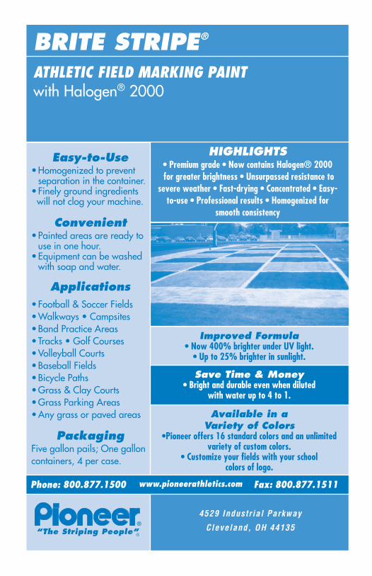
Easy-to-Use•Homogenized to prevent
separation in the container.• Finely ground ingredientswill not clog your machine.
Convenient•Painted areas are ready to
use in one hour.•Equipment can be washed
with soap and water.
Applications•Football & Soccer Fields •Walkways • Campsites •Band Practice Areas • Tracks • Golf Courses•Volleyball Courts •Baseball Fields •Bicycle Paths•Grass & Clay Courts•Grass Parking Areas •Any grass or paved areas
PackagingFive gallon pails; One galloncontainers, 4 per case.
“The Striping People”
ATHLETIC FIELD MARKING PAINTwith Halogen® 2000
BRITE STRIPE®
®
HIGHLIGHTS• Premium grade • Now contains Halogen® 2000 for greater brightness • Unsurpassed resistance to
severe weather • Fast-drying • Concentrated • Easy-to-use • Professional results • Homogenized for
smooth consistency
Save Time & Money• Bright and durable even when diluted
with water up to 4 to 1.
Improved Formula• Now 400% brighter under UV light.
• Up to 25% brighter in sunlight.
Available in a Variety of Colors
•Pioneer offers 16 standard colors and an unlimitedvariety of custom colors.
• Customize your fields with your schoolcolors of logo.
Phone: 800.877.1500 Fax: 800.877.1511www.pioneerathletics.com
4529 Industr ial Parkway
Cleveland, OH 44135