2-speed, hand-crank rheometer
TRANSCRIPT
2-Speed, Hand-Crank Rheometer
Part No. 132-00
Instruction ManualUpdated 1/23/2020
Ver. 4
OFI Testing Equipment, Inc.11302 Steeplecrest Dr. · Houston, Texas · 77065 · U.S.A.Tele: 832.320.7300 · Fax: 713.880.9886 · www.ofite.com
©Copyright OFITE 2013

OFITE, 11302 Steeplecrest Dr., Houston, TX 77065 USA / Tel: 832-320-7300 / Fax: 713-880-9886 / www.ofite.com 1
Intro..................................................................................................2Description ......................................................................................2Components ...................................................................................3Operation.........................................................................................5Calculations ....................................................................................7Calibration .......................................................................................8Maintenance ....................................................................................9
Removing the Bob Shaft ...........................................................10
Replacing the Bob Shaft Bearings ............................................ 11
Replacing the Main Bearings ....................................................12
Re-Assembly .............................................................................14
Warranty and Return Policy ........................................................15
Table of Contents

OFITE, 11302 Steeplecrest Dr., Houston, TX 77065 USA / Tel: 832-320-7300 / Fax: 713-880-9886 / www.ofite.com 2
The OFITE Rheometer is a direct-indicating, manually operated, rotational viscometer. The instrument is powered by a hand crank, which drives the spindle through a precision gear train. The shift cam selects between fixed speeds of 300 and 600 RPM. A Knob on the hub of the shift cam determines gel strength.
During operation, fluid is contained in the annular space between two con-centric cylinders. The outer cylinder, or rotor, is driven by the hand crank. The inner cylinder, or bob, is restrained by a torsion spring. A dial attached to the torsion spring indicates bob displacement due to friction. The instrument constants have been adjusted so that plastic viscosity and yield point can be calculated using the 300 and 600 RPM readings.
Intro
Description

OFITE, 11302 Steeplecrest Dr., Houston, TX 77065 USA / Tel: 832-320-7300 / Fax: 713-880-9886 / www.ofite.com 3
Components #130-41 Beaker, 400 mL, Polypropylene, Nalgene#132-01 Frame#132-02-1 Plastic Cover#132-04 Jewel#132-05 Base#132-09 Inside Leg with Groove#132-10 Inside Leg without Groove#132-11 Leg Spring; Qty: 2#132-12 Left Leg Outside#132-13 Leg Lock Ring#132-14 Leg Lock Nut#132-15 Right Leg Outside#132-16 Leg Cap#132-17 Leg Cap Screw; Qty: 2#132-18 Key#132-19 Stop Spring#132-20 Governor Body#132-21 Brass Washer; Qty: 8#132-22 Drive Spindle#132-23 Weight; Qty: 4#132-24 Pressure Plate#132-26 Thrust Collar#132-28 Control Rod#132-29 Control Spring; Qty: 6#132-30 Gear Block#132-31 Drive Shaft#132-32 Drive Shaft Nut#132-33 Drive Shaft Spacer Set#132-34 Drive Shaft Pinion#132-35 Idler Pinion#132-36 Idler Gear#132-37 Crank Shaft#132-38 Crank Shaft Gear#132-39 Idler Shaft#132-40 Shift Housing#132-41 Shift Pin; Qty: 2#132-42 Speed Nut#132-43 Shift Cam#132-44 Gel Knob#132-45 Crank#132-50 Rotor, Drive#132-51 Bevel Gear (Pair)#132-52 Spindle Bushing#132-56 Rotor, R1, 303 Stainless Steel#132-57 Shield#132-58 Bob, B1, 303 Stainless Steel#132-59 Bearing Retainer#132-60 Dial#132-61 Torsion Body

OFITE, 11302 Steeplecrest Dr., Houston, TX 77065 USA / Tel: 832-320-7300 / Fax: 713-880-9886 / www.ofite.com 4
#132-62 Stop#132-64 Lock Collet and Bushing#132-66 Torsion Shaft#132-67 Torsion Spring Assembly#132-68 Shielded Bearing; Qty: 2#132-69 Bearing, ⅜" × ⅞" (30730); Qty: 2#132-70 Bearing, ¼" × ⅝"; Qty: 2 #132-71 Bearing, 20 mm × 42 mm; Qty: 2#132-73 Internal Locking Ring; 1 ⅞"#132-74-1 Lock Ring#132-75 Internal Locking Ring; ½"#132-76 External Locking Ring; 25/32"#132-77 Bushing; ⅛" × ¼" × ¼"#132-78 Bushing; ¼" × ⅜" × ¼"#135-02 External Retainer Ring#135-23 Upper Cap Screw; Qty: 2#170-44 Rubber Foot; ½"; Qty: 4
Optional:
#132-06 Transport Case with Foam Insert#132-58-1 B2 Bob#132-58-2 B3 Bob#132-58-4 B5 Bob#132-58H Hastelloy (B1) Bob
#132-00-SP Spare Parts Kit: #132-59 Bearing Retainer; Qty: 4 #132-64 Lock Collet and Bushing #132-68 Bearing, Shielded #132-69 Bearing, ⅜" × ⅞", Qty: 2 #132-70 Bearing, ¼" × ⅝"; Qty: 4 #132-71 Bearing, 20 mm × 42 mm, Qty: 2 #132-75 Internal Locking Ring; ½"; Qty: 4 #132-80 Calibration Fluid, 100 cP, 16 oz #132-81 Calibration Fluid, 50 cP, 16 oz

OFITE, 11302 Steeplecrest Dr., Houston, TX 77065 USA / Tel: 832-320-7300 / Fax: 713-880-9886 / www.ofite.com 5
Operation The Rheometer has three settings:
300 RPM: Turn the shift cam all the way clockwise and turn the crank fast enough to cause slipping.
600 RPM: Set the shift cam between the 300 RPM and Stir settings and turn the crank fast enough to cause slipping.
Stir: Turn the shift cam all the way counter-clockwise and turn the crank vigorously.
1. Place a recently agitated sample of fluid in a suitable container.
Be sure to leave enough empty volume in the cup for the displacement of the bob and rotor (approximately 100 mL). It is very important that you take the measurements as soon as possible after you retrieve the sample. Record the location the sample was obtained on the Mud Report.
2. Immerse the rotor exactly to the scribed line and then tighten the leg lock nut to hold it in position.
Crank
Gel Knob
Shift Cam
Drive Rotor
R1 Rotor
Leg Lock Nut

OFITE, 11302 Steeplecrest Dr., Houston, TX 77065 USA / Tel: 832-320-7300 / Fax: 713-880-9886 / www.ofite.com 6
3. Set the shift cam to the “Stir” position (all the way counter-clockwise) and turn the crank for about 15 seconds. While stirring, place a thermometer in the sample and record the temperature.
4. Set the shift cam to the 600 RPM setting (middle) and continue cranking until the dial reading becomes steady. The time for this is dependent upon the mud characteristics. Record the dial reading.
5. Switch the shift cam to 300 RPM (all the way clockwise) and turn the crank until the dial reading becomes steady. Record the dial reading.
To measure gel strength:
1. Stir the sample by setting the shift cam all the way counter-clockwise and turn the crank at high speed for about 10 seconds.
2. Allow the fluid to stand undisturbed for 10 seconds. Slowly and steadily turn the gel knob clockwise and note the maximum dial reading before the gel breaks. Record this reading as “Initial Gel Strength (10-Second Gel)” in lbs/100 ft2.
3. Stir the fluid again at high speed for 10 seconds and then allow the fluid to stand undisturbed for 10 minutes. Slowly and steadily turn the gel knob clockwise and note the maximum dial reading before the gel breaks. Re-cord this reading as “10-Minute Gel” in lbs/100 ft2.

OFITE, 11302 Steeplecrest Dr., Houston, TX 77065 USA / Tel: 832-320-7300 / Fax: 713-880-9886 / www.ofite.com 7
Calculations Plastic Viscosity (PV), cP = 600 RPM reading - 300 RPM reading
Yield Point (YP), lb./100 ft2 = 300 RPM reading - Plastic Viscosity (PV)
Apparent Viscosity (AV), cP = 600 RPM reading / 2
Gel Strength, 10 second, lb/100 ft2 = the maximum dial deflection after 10 sec.
Gel Strength, 10 minute, lb/100 ft2 = the maximum dial deflection after 10 min.
ŋ=K F
ŋ= Viscosity (cP)
K= Machine constant for the bob and rotor combination
F= Spring factor
Ɵ= Dial readings
RPM= Rotational speed
Machine constants:
R1B1= 300
R1B2= 2672
R1B3= 7620
R1B4= 15200
R1B5= 349
ƟRPM

OFITE, 11302 Steeplecrest Dr., Houston, TX 77065 USA / Tel: 832-320-7300 / Fax: 713-880-9886 / www.ofite.com 8
Calibration According to API Recommended Practice 10B-2, viscometers being used for testing well cement should be calibrated quarterly. API Recommended Prac-tice 13B-1 and 13B-2 specify viscometers being used for drilling fluids should be checked monthly.
For accurate readings, the Rheometer must operate at 300 ± 6 RPM and 600 ± 12 RPM. New or repaired units will deviate at one half of these values. To test the speed of the Rheometer you will use the stroboscopic effect of a fluorescent light to observe the holes in the top of the rotor during opera-tion. When the Rheometer is turning at exactly 300 or 600 RPM, the holes will appear to stand still. If the actual speed is faster, the holes will appear to rotate clockwise. If the actual speed is slower, the holes will appear to rotate counter-clockwise.
1. Place a fluorescent or neon light operating on a 60-cycle current as close as possible to the Rheometer.
2. Lower the rotor into a sample of 100 cP calibration fluid (#132-80) to the scribed line and tighten the leg lock nut.
3. Crank the Rheometer at 300 RPM and time the number of seconds required for 12 holes to appear to rotate past. This time should be at least 10 seconds.
4. Repeat the procedure at 600 RPM. The time should be at least 5 seconds for 12 holes to pass by.
5. If it takes less than 10 seconds at 300 RPM or 5 seconds at 600 RPM for 12 holes to rotate past, the speed regulation of the instrument is in error. Return the unit to OFITE for servicing by a trained and qualified techni-cian.

OFITE, 11302 Steeplecrest Dr., Houston, TX 77065 USA / Tel: 832-320-7300 / Fax: 713-880-9886 / www.ofite.com 9
Maintenance 1. The bob and rotor should be washed with soap and water and dried after each operation. To remove the R1 rotor, hold the drive rotor and unscrew the R1 rotor. Then, unscrew the bob and slide it downward off the shaft.
2. Always set the instrument upright when cleaning to keep water out of the bearings.
3. When re-assembling the bob, the tapered end points up.
4. To avoid unnecessary damage, always remove the bob before transport-ing the Rheometer by vehicle.
OFITE, 11302 Steeplecrest Dr., Houston, TX 77065 USA / Tel: 832-320-7300 / Fax: 713-880-9886 / www.ofite.com 10
MaintenanceRemoving the Bob Shaft
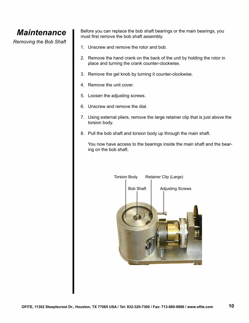
Before you can replace the bob shaft bearings or the main bearings, you must first remove the bob shaft assembly.
1. Unscrew and remove the rotor and bob.
2. Remove the hand crank on the back of the unit by holding the rotor in place and turning the crank counter-clockwise.
3. Remove the gel knob by turning it counter-clockwise.
4. Remove the unit cover.
5. Loosen the adjusting screws.
6. Unscrew and remove the dial.
7. Using external pliers, remove the large retainer clip that is just above the torsion body.
8. Pull the bob shaft and torsion body up through the main shaft.
You now have access to the bearings inside the main shaft and the bear-ing on the bob shaft.
Torsion Body
Bob Shaft
Retainer Clip (Large)
Adjusting Screws

OFITE, 11302 Steeplecrest Dr., Houston, TX 77065 USA / Tel: 832-320-7300 / Fax: 713-880-9886 / www.ofite.com 11
MaintenanceReplacing the Bob
Shaft Bearings
1. Remove the pin from the top of the bob shaft.
2. Remove the small retainer clip from the torsion body.
3. Using the Allen wrench, loosen the set screw on the torsion body.
4. You can now remove the torsion body. The upper bearing is inside the tor-sion body.
5. Loosen the set screw on the bearing retainer and remove it and the lower bearing.
6. Slide a new bearing onto the lower end of the shaft beneath the spring.
7. Slide the bearing retainer beneath the lower bearing and secure it in place by tightening the set screw.
8. Slide a new bearing onto the upper end of the shaft above the spring.
9. Slide the torsion body over the upper bearing and secure it in place by tightening the set screw. The upper bearing should be inside the torsion body.
10. Place the pin back into the upper end of the shaft.
Retainer Clip (Small)
Torsion Body Bob Shaft Pin
Upper Bearing (Not Visible)Torsion BodySet Screw
Torsion Spring
Lock Collet
Lower BearingBearing Retainer
Bob Shaft

OFITE, 11302 Steeplecrest Dr., Houston, TX 77065 USA / Tel: 832-320-7300 / Fax: 713-880-9886 / www.ofite.com 12
MaintenanceReplacing the Main
Bearings
1. Remove the retainer clip on the upper main bearing. Once the retainer clip is removed, the rotor will no longer be secured.
2. Remove the rotor by pulling it downward.
3. Remove the upper bearing from the main shaft.
The bearings are designed to fit tightly into the assembly. It may be nec-essary to use force to remove them. Turn the entire rheometer unit upside down and place a pipe, tube, or other slender object through the hole and against the bearing and tap it with a mallet or hammer.
4. Place a new bearing into the upper hole in the main shaft. Make sure the open end of the bearing is facing down.
Upper Main Bearing
Main Shaft Adjusting Screws
Retainer Clip

OFITE, 11302 Steeplecrest Dr., Houston, TX 77065 USA / Tel: 832-320-7300 / Fax: 713-880-9886 / www.ofite.com 13
5. Loosen the set screw on the bevel gear and remove the spindle bushing, gear, and lower bearing.
6. Slide a new bearing onto the rotor. Make sure the open end of the bearing is facing up. Slide the bevel gear and the spindle bushing back onto the rotor. Tighten the set screw on the bevel gear to secure it in place.
7. Slide the rotor assembly back up into the main shaft and secure it in place with the retainer clip.
Bob Shaft
Bob Shaft
Lower Bearing
Rotor
OFITE, 11302 Steeplecrest Dr., Houston, TX 77065 USA / Tel: 832-320-7300 / Fax: 713-880-9886 / www.ofite.com 14
MaintenanceRe-Assembly
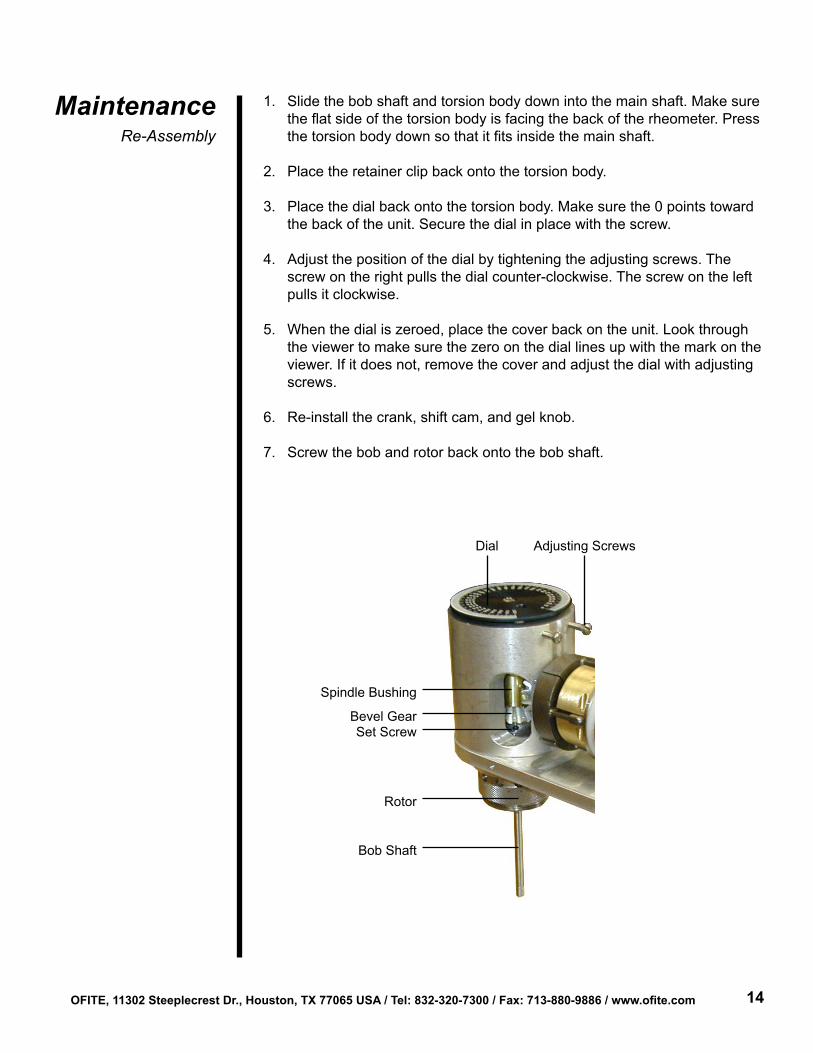
1. Slide the bob shaft and torsion body down into the main shaft. Make sure the flat side of the torsion body is facing the back of the rheometer. Press the torsion body down so that it fits inside the main shaft.
2. Place the retainer clip back onto the torsion body.
3. Place the dial back onto the torsion body. Make sure the 0 points toward the back of the unit. Secure the dial in place with the screw.
4. Adjust the position of the dial by tightening the adjusting screws. The screw on the right pulls the dial counter-clockwise. The screw on the left pulls it clockwise.
5. When the dial is zeroed, place the cover back on the unit. Look through the viewer to make sure the zero on the dial lines up with the mark on the viewer. If it does not, remove the cover and adjust the dial with adjusting screws.
6. Re-install the crank, shift cam, and gel knob.
7. Screw the bob and rotor back onto the bob shaft.
Dial Adjusting Screws
Spindle Bushing
Bevel GearSet Screw
Rotor
Bob Shaft
OFITE, 11302 Steeplecrest Dr., Houston, TX 77065 USA / Tel: 832-320-7300 / Fax: 713-880-9886 / www.ofite.com 15
Warranty and Return Policy
Warranty:OFI Testing Equipment, Inc. (OFITE) warrants that the products shall be free from liens and defects in title, and shall conform in all respects to the terms of the sales order and the specifications applicable to the products. All products shall be furnished subject to OFITE’s standard manufacturing variations and practices. Unless the warranty period is otherwise extended in writing, the following warranty shall apply: if, at any time prior to twelve (12) months from the date of invoice, the products, or any part thereof, do not conform to these warranties or to the specifications applicable thereto, and OFITE is so notified in writing upon discovery, OFITE shall promptly repair or replace the defective products. Notwithstanding the foregoing, OFITE’s warranty obligations shall not extend to any use by the buyer of the products in conditions more severe than OFITE’s recommendations, nor to any defects which were visually observable by the buyer but which are not promptly brought to OFITE’s attention.
In the event that the buyer has purchased installation and commissioning services on applicable products, the above warranty shall extend for an additional period of twelve (12) months from the date of the original warranty expiration for such products.
In the event that OFITE is requested to provide customized research and development for the buyer, OFITE shall use its best efforts but makes no guarantees to the buyer that any products will be provided.
OFITE makes no other warranties or guarantees to the buyer, either express or implied, and the warranties provided in this clause shall be exclusive of any other warranties including ANY IMPLIED OR STATUTORY WARRANTIES OF FITNESS FOR PURPOSE, MERCHANTABILITY, AND OTHER STATUTORY REMEDIES WHICH ARE WAIVED.
This limited warranty does not cover any losses or damages that occur as a result of:
• Improper installation or maintenance of the products
• Misuse
• Neglect
• Adjustment by non-authorized sources
• Improper environment
• Excessive or inadequate heating or air conditioning or electrical power failures, surges, or other irregularities
• Equipment, products, or material not manufactured by OFITE
• Firmware or hardware that have been modified or altered by a third party
• Consumable parts (bearings, accessories, etc.)
Returns and Repairs:Items being returned must be carefully packaged to prevent damage in shipment and insured against possible damage or loss. OFITE will not be responsible for equipment damaged due to insufficient packaging.
Any non-defective items returned to OFITE within ninety (90) days of invoice are subject to a 15% restocking fee. Items returned must be received by OFITE in original condition for it to be accepted. Reagents and special order items will not be accepted for return or refund.
OFITE employs experienced personnel to service and repair equipment manufactured by us, as well as other companies. To help expedite the repair process, please include a repair form with all equipment sent to OFITE for repair. Be sure to include your name, company name, phone number, email address, detailed description of work to be done, purchase order number, and a shipping address for returning the equipment. All repairs performed as “repair as needed” are subject to the ninety (90) day limited warranty. All “Certified Repairs” are subject to the twelve (12) month limited warranty.
Returns and potential warranty repairs require a Return Material Authorization (RMA) number. An RMA form is available from your sales or service representative.
Please ship all equipment (with the RMA number for returns or warranty repairs) to the following address:
OFI Testing Equipment, Inc. Attn: Repair Department 11302 Steeplecrest Dr. Houston, TX 77065 USA
OFITE also offers competitive service contracts for repairing and/or maintaining your lab equipment, including equipment from other manufacturers. For more information about our technical support and repair services, please contact [email protected].