2 application of ann for induction motor fault classification using
TRANSCRIPT

Mrs. Anjali.U.Jawadekar, Dr.G.M.Dhole, SRParaskar, S.S .Jadhao and M.A.Beg 7
International Journal of Emerging Trends in Electrical and Electronics (IJETEE) Vol. 1, Issue. 1, March-2013.
Application of ANN for Induction Motor Fault Classification Using Hilbert Transform
Mrs. Anjali.U.Jawadekar, Dr.G.M.Dhole, SRParaskar, S.S .Jadhao and M.A.Beg
Abstract: This paper addresses the development of new signal processing approach based on Hilbert transform to extract the fault features in number of induction motor conditions. The motor conditions considered are normal condition and motors with bearing defects like inner race, outer race, stator interturn faults and rotor bar crack. Present approach is based on extraction of envelopes of the stator currents by Hilbert Transform. Representative features like maximum and minimum value, mean, standard deviation and norm are obtained from current envelopes. These features are then used as input to Artificial Neural Network. Experimental results obtained show that diagnostic system using MLP neural network along with Hilbert Transform is capable of classifying multiple faults in induction motor with high accuracy recognition rate
Keywords: : Hilbert Transform, Induction motor, current envelope, artificial neural network, Multilayer perceptron.
I. INTRODUCTION
Induction motors are widely used in industry due to their reliability, low cost and robustness and hence treated as workhouses of industry. But the possibility of faults is unavoidable .Fault identification and diagnosis schemes are intended to provide advanced warnings of incipient faults so that appropriate maintenance actions can be taken at an early stage. [1][2].This helps to reduce the maintenance cost and prevent unscheduled maintenance of these machines. Failures surveys [3] reported that forty percent of motor failures are caused by bearing related failures, thirty eight percent by stator interturn, ten percent by rotor related failures and twelve percent by mixed failures which affect other parts of the machine. Condition monitoring of the induction motor received considerable attention in recent year’s .Many condition monitoring methods has been proposed for different types of induction motor fault detection and localization. Martelo [4] and Schoen et al [5] study bearing failures based on FFT analysis. Using same tool Benbouzid et al [6] and Cameron [7] analyze other types of failures such as rotor slot effect, saturation and static and dynamic eccentricities.
Mrs. Anjali.U.Jawadekar, Dr.G.M.Dhole, SRParaskar, S.S .Jadhao and M.A.Beg are working in 1-5 Department of Electrical Engineering, S.S.G.M.College of Engineering Shegaon. (M.S.),444203,India, [email protected]
Stator interturn fault estimation using particle swarm optimization method is discussed in [8] and by current Concordia pattern based fuzzy decision system is given in [9]. An induction motor fault diagnosis using stator current envelopes for broken rotor bars and inter turn short circuit in stator winding have been proposed in [10].Time frequency domain techniques have been also used for fault diagnosis of induction motors which includes STFT,FFT ,bispectrum, high resolution spectral analysis and wavelet analysis.[11]-[14]. Another technique used for induction motor fault detection uses AI techniques such as expert systems ,fuzzy inference system ,neural network , SVM, genetic algorithm and adoptive neural fuzzy inference system[15]-[17].
Present work proposes a method that is capable to detect multiple faults in induction motor such as bearing faults like inner race and outer race defects, stator interturn short circuit and rotor bar crack by analyzing stator currents. The approach is based on extraction of the envelope of the signal to be analyzed using Hilbert Transform. Fault features are extracted from current envelopes which are further used as input to ANN which acts as a fault classifier and classifies multiple faults in induction motor with 100 percent accuracy.
II. HILBERT TRANSFORM:
Hilbert transform is a signal analysis method that is frequently used in different scientific fields. Mathematically Hilbert transform of a real signal ( )x t is defined as time domain convolution of ( )x t with 1/t and is defined for all t by equation 1.
1 1 ( )( ) ( ( )) ( ) xy t H x t x t dt t
(1)
Following are the properties of Hilbert Transform
A real signal ( )x t and its Hilbert Transform ( )y t are mutually orthogonal
Mathematically ( ) ( ) 0x t y t dt
(2)

Mrs. Anjali.U.Jawadekar, Dr.G.M.Dhole, SRParaskar, S.S .Jadhao and M.A.Beg 8
International Journal of Emerging Trends in Electrical and Electronics (IJETEE) Vol. 1, Issue. 1, March-2013.
If ( )y t is Hilbert Transform of ( )x t then Hilbert
Transform of ( )y t is ( )x t (3)
2 Phase shift is another basic property of Hilbert
transform. Phase of positive frequency components is shifted
by 2 and phase of negative frequency components is
shifted by 2
( )2 For 0
( )2 For 0 (4)
A real function ( )x t and its Hilbert Transform ( )y t are such that they together create an analytic signal ( )z t .
( ) ( ) ( )z t x t jy t (5)
Signal ( )z t has the property that all negative frequencies of ( )x t has been filtered.
Envelope E(t) of a signal is defined as
( ) ( ) ( ) ( )E t z t x t jy t (6)
And instantaneous phase is defined as
( )( ) arctan( )( )
y ttx t
(7)
III. ARTIFICIAL NEURAL NETWORK
The application of artificial neural network to various decision making, forecasting and classification problems has gained a lot of attention recently. ANN s are able to learn the relationship among past, present and future variables. An ANN is an information processing paradigm, inspired by biological nervous systems. The basic processing element of neural network is called artificial neuron or simply neuron. The key element of it is the novel structure of the information processing system. It is composed of large number of highly interconnected processing elements working in union to solve specific problem.
Artificial neural system functions as distributed computing networks .Their most basic characteristics is their architecture. Only some networks provide instantaneous responses, other networks need time to respond and are
characterized by their time domain behaviour, which often referred to as dynamics. Neural networks also differ from each other in their learning modes. There are varieties of learning rules that establish when and how the connecting weights changes. Networks exhibit different speeds and efficiency of learning. An ANN is configured for a specific application, such as pattern recognition or data classification, through a learning process. Learning in biological system involves adjustments to the synaptic connections that exist between the neurons.
Neural networks are typically organized in layers. Layers are made up of number of interconnected nodes which contain an ‘Activation Function’. Patterns are presented to the network via a system of ‘Weighted Connections’. The hidden layer then links to an output layer where the answer is output as shown in Figure 1
Figure 1.Architecture of Artificial Neural Network
Common type of artificial neural network consists of three layers of units; a layer of ‘input’ unit is connected to a layer of ‘hidden’ unit, which is then connected to a layer of ‘output’ units. The activity of input unit represents the raw information that is fed into the network. The activity of each hidden unit is determined by the activities of the input units and the weights on the connection between the input and hidden units. The behavior of the output unit depends on the activity of hidden units and the weights between the hidden and output units. Feed forward ANN allow signal to travel from input to output only. There is no feedback i.e. the output of any layer does not affect the same layer. Feed forward ANN tends to be straight forward networks that associate inputs with outputs.
Prediction with NNs involves two steps: training and learning. Training of FFNNs is normally performed in a supervised manner. The success of training is greatly affected by proper selection of inputs. In the learning process, a neural network constructs an input–output mapping, adjusting the weights and biases at each iteration based on the minimization or optimization of some error measure between the output produced and the desired output. This process is repeated until an acceptable criterion for convergence is reached. The most common learning algorithm is the back propagation (BP) algorithm, in which the input is passed layer through layer until the final output is calculated, and it
Mrs. Anjali.U.Jawadekar, Dr.G.M.Dhole, SRParaskar, S.S .Jadhao and M.A.Beg 9
International Journal of Emerging Trends in Electrical and Electronics (IJETEE) Vol. 1, Issue. 1, March-2013.
is compared to the real output to find the error. The error is then propagated back to the input adjusting the weights and biases in each layer. The standard BP learning algorithm is a steepest descent algorithm that minimizes the sum of square errors. In order to accelerate the learning process, two parameters of the BP algorithm can be adjusted: the learning rate and the momentum. The learning rate is the proportion of error gradient by which the weights should be adjusted. Larger values can give a faster convergence to the minimum. The momentum determines the proportion of the change of past weights that should be used in the calculation of the new weights.
IV. Experimental Setup:
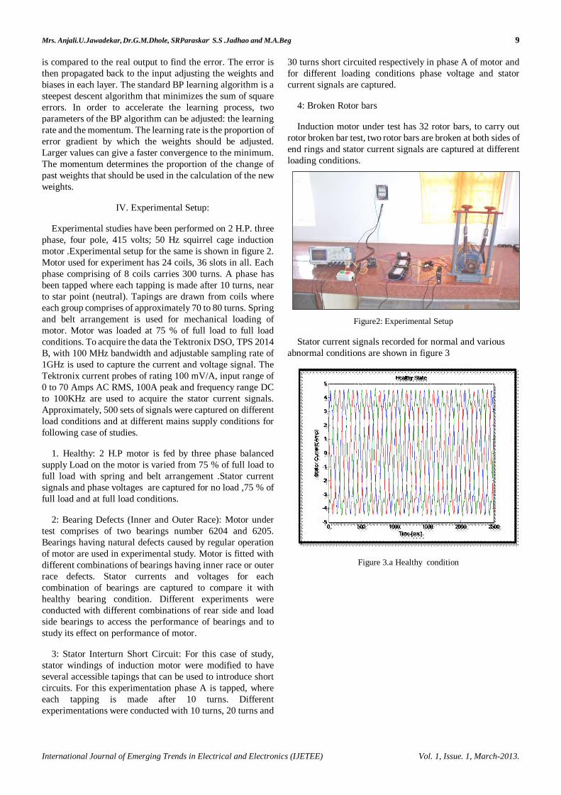
Experimental studies have been performed on 2 H.P. three phase, four pole, 415 volts; 50 Hz squirrel cage induction motor .Experimental setup for the same is shown in figure 2. Motor used for experiment has 24 coils, 36 slots in all. Each phase comprising of 8 coils carries 300 turns. A phase has been tapped where each tapping is made after 10 turns, near to star point (neutral). Tapings are drawn from coils where each group comprises of approximately 70 to 80 turns. Spring and belt arrangement is used for mechanical loading of motor. Motor was loaded at 75 % of full load to full load conditions. To acquire the data the Tektronix DSO, TPS 2014 B, with 100 MHz bandwidth and adjustable sampling rate of 1GHz is used to capture the current and voltage signal. The Tektronix current probes of rating 100 mV/A, input range of 0 to 70 Amps AC RMS, 100A peak and frequency range DC to 100KHz are used to acquire the stator current signals. Approximately, 500 sets of signals were captured on different load conditions and at different mains supply conditions for following case of studies.
1. Healthy: 2 H.P motor is fed by three phase balanced supply Load on the motor is varied from 75 % of full load to full load with spring and belt arrangement .Stator current signals and phase voltages are captured for no load ,75 % of full load and at full load conditions.
2: Bearing Defects (Inner and Outer Race): Motor under test comprises of two bearings number 6204 and 6205. Bearings having natural defects caused by regular operation of motor are used in experimental study. Motor is fitted with different combinations of bearings having inner race or outer race defects. Stator currents and voltages for each combination of bearings are captured to compare it with healthy bearing condition. Different experiments were conducted with different combinations of rear side and load side bearings to access the performance of bearings and to study its effect on performance of motor.
3: Stator Interturn Short Circuit: For this case of study, stator windings of induction motor were modified to have several accessible tapings that can be used to introduce short circuits. For this experimentation phase A is tapped, where each tapping is made after 10 turns. Different experimentations were conducted with 10 turns, 20 turns and
30 turns short circuited respectively in phase A of motor and for different loading conditions phase voltage and stator current signals are captured.
4: Broken Rotor bars
Induction motor under test has 32 rotor bars, to carry out rotor broken bar test, two rotor bars are broken at both sides of end rings and stator current signals are captured at different loading conditions.
Figure2: Experimental Setup
Stator current signals recorded for normal and various abnormal conditions are shown in figure 3
Figure 3.a Healthy condition
Mrs. Anjali.U.Jawadekar, Dr.G.M.Dhole, SRParaskar, S.S .Jadhao and M.A.Beg 10
International Journal of Emerging Trends in Electrical and Electronics (IJETEE) Vol. 1, Issue. 1, March-2013.
Figure 3.b Defective Bearing
Figure 3 c Interturn short circuit
Figure 3 d. Rotor bar crack
V .FEATURE EXTRACTION
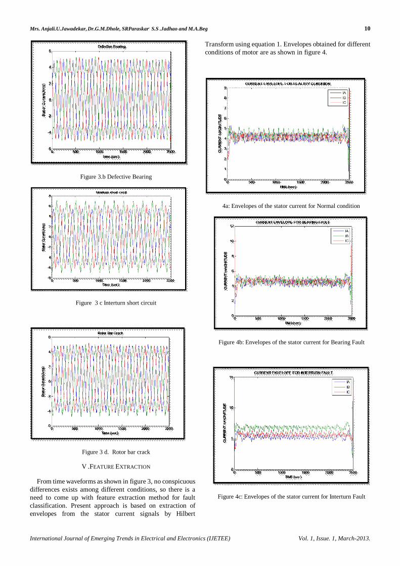
From time waveforms as shown in figure 3, no conspicuous differences exists among different conditions, so there is a need to come up with feature extraction method for fault classification. Present approach is based on extraction of envelopes from the stator current signals by Hilbert
Transform using equation 1. Envelopes obtained for different conditions of motor are as shown in figure 4.
4a: Envelopes of the stator current for Normal condition
Figure 4b: Envelopes of the stator current for Bearing Fault
Figure 4c: Envelopes of the stator current for Interturn Fault

Mrs. Anjali.U.Jawadekar, Dr.G.M.Dhole, SRParaskar, S.S .Jadhao and M.A.Beg 11
International Journal of Emerging Trends in Electrical and Electronics (IJETEE) Vol. 1, Issue. 1, March-2013.
Figure 4d: Envelopes of the stator current for Rotor bar crack
The main problem facing the use of ANN are the selection of best inputs and how to choose the ANN parameters making the structure compact and creating highly accurate networks. For the proposed system to create training pattern statistical parameters like maximum, minimum, standard deviation, mean and norm are obtained from the current envelopes extracted from stator currents for different fault conditions.
VI. Results and Discussion:
Application of ANN to various decision making, forecasting and classification problem has gained lot of attention. An ANN with its excellent pattern recognition capabilities can be effectively employed for fault classification of three phase induction motor. In present study three layer fully connected feedforward artificial neural network is used and trained with supervised learning algorithm back propagation. FFANN consists of one input layer, one hidden layer and one output layer. Input layer consists of fifteen neurons, the inputs to these neurons are the statistical parameters computed from envelopes of stator currents. Output layer consists of four neurons representing healthy, bearing fault, interturn fault and rotor bar crack condition respectively.
Selected parameters for FFANN are as follows
Number of epochs=1000, Training data=60% , Testing data= 40%,
Number of hidden layers=01, Transfer function = TanhAxon, Learning Rule= Momentum
Step size =0.1, Momentum=0.7
With these assumptions variation of percentage accuracy of classification for induction motor under healthy and different fault conditions with respect to number of processing elements in hidden layer is obtained. Figure 5 shows the graph for the same.
Figure 5 Variation of Average Classification Accuracy
VII .Conclusion
This work proposes Hilbert Transform based approach for fault classification of induction motor validating its effectiveness through different cases of study that considered the motor under diverse fault conditions like bearing fault, stator interturn fault and rotor bar crack. Line current signals recorded under healthy and different fault conditions are passed through signal processing procedures involving Hilbert transform. This methodology based on envelope concept derives rich information about the fault from stator current signals. Statistical parameters computed from fault features are further used as training and testing data for FFANN.
Envelope analysis with Hilbert Transform approach and FFANN with momentum learning rule and TanhAxon transfer function and with four processing elements in hidden layer produced best results for classifying multiple faults in induction motor.
REFERENCES
[1] F Boldea & A.Nasar Induction machine handbook CRC press 2002
[2] P Tavner, L.Ram,J Penman & H Sedding ,”Condition Monitoring of Rotating electrical machines” The Institution of Engineering & technology 2008
[3] W.T.Thomson & M Fenger “ Current Signature Analysis to detect Induction motor faults” IEEE industry Applications Magazine vol 7, No 4, pp 26-34 July/August 2001
[4] Martelo A ,” Fault detection of ball bearings in electrical motors by means of vibrations ,noise, and stator current spectral analysis Msc Thesis ,Dept of Mechanical Engineering University of Los Andes,Bogota Colombia 2000.

Mrs. Anjali.U.Jawadekar, Dr.G.M.Dhole, SRParaskar, S.S .Jadhao and M.A.Beg 12
International Journal of Emerging Trends in Electrical and Electronics (IJETEE) Vol. 1, Issue. 1, March-2013.
[5] Schoem R, Habetler T, Kamran F, Bartheld R ,”Motor bearing damage detection using stator current monitoring “ IEEE Transaction Industrial Application pp 1274-1279 ,1995
[6] benbouzid M,Beguenane R, Viera M ,”Induction motor asymmetrical fault detection using advanced signal processing techniques “IEEE Transaction Energy Conversion 14(2) pp146-152, 1999
[7]Cameron JR, Thomson WT ,Dow A “Vibration and current monitoring for detecting air gap eccentricity in large induction machine IEEE Proceedings 133B(3) pp155-163,1986
[8] J.Penman , H.G.Seding , B.A.Lioyd & W.T.Fink,”Detection and location of interturn short circuits in stator winding of operating motor , IEEE Transaction Energy Conversion vol 9 , No4 December 1994, pp652-658
[9] J.Sottile & J.L Kohler ,”An online method to detect incipient failures of turn insulation in random wound motors IEEE transactions energy Conversion vol 8, No4, December 1993, pp 762-768.
[10] Aderiano M,da Silva ,Richard J Povinelli & Nabeel , A.O. Demerdash, “Induction Machines broken bar and stator short circuit fault diagnosis based on three phase stator current envelopes. “ IEEE transaction Ind Electron vol 55, No 3, pp1310-1318 March 2008
[11] H.Douglas,P Pillay& A.K.Ziarani,” A New algorithm for transient motor current signature analysis using wavelets , IEEE Transactions Industrial Application vol 40, pp1361-1368 September/ October 2004.
[12] M.E.H.Benbouzid ,Michella Vieira & Celine Theys ,”Induction motor fault detection and localization using stator current advanced signal processing techniques” IEEE Transaction Power Electrons vol 14, pp14-22 January1999.
[13]T.W.S. Chow & S Hai ,”Induction machine fault diagnostic analysis with wavelet technique ,IEEE Transaction Industrial Electron vol 51, No 3, pp558-565 January 2004
[14] W.Thomson & M .Fenger,”Current signature analysis to detect induction motor faults “ IEEE Industrial Application magazine vol 7, No 4, pp26-34 July/August 2001
[15] Jover Rodrgez ,P Arkkio.A ,” detection of stator winding fault in induction machine using fuzzy logic “ Applied soft computing vol 8,No 2 pp1112-1120,2008
[16] F.Felippetti, G .Franceschini & C Tassoni ,”A survey of AI techniques approach for induction machine online diagnostic in proceeding PEMC 96 vol 2, pp314-318 1996
[17] M.Awadallah & M.Marcos ,”Application of AI tools in fault diagnosis of electrical machines and drives – An overview “IEEE transaction Energy Conversion vol 18, No 2 pp245-251 , June 2003.
Mrs.ANJALI U. JAWADEKAR received her B.E. and M.E. from the S.G.B.University of Amravati, India in 1994 and 2001 respectively in Electrical Power system Engineering and pursuing her Ph.D. from the S.G.B. University of
Amravati in Induction Motorr protection. She is IEEE, IACSIT and ISTE member. In 2000, she joined S.S.G.M.College of Engg. Shegaon, where she is a faculty in Electrical Engg. Department. Her present research interest includes Digital protection of Induction motor & Signal Processing technique.
S.R.PARASKAR received his B.E. and M.E. from the S.G.B.University of Amravati, India in 1992 and 2001 respectively in Electrical Power system Engineering and pursuing his Ph.D. from the S.G.B. University of Amravati
in Transformer protection. He is IEEE, IACSIT and ISTE member. In 1995, he joined S.S.G.M.College of Engg. Shegaon, where he Assistant Professor in Electrical Engg. Department. His present research interest includes Digital protection of Transformer, FACTS and Power Quality.
S.S.JADHAO received his B.E. and M.E. from the S.G.B.Amravati University of Amravati, India in 2009 and 2012 respectively in Electrical Power system Engineering and pursuing his Ph.D. from the S.G.B.University of
Amravati, in Power Quality Enhancement. In 2011, he joined S.S.G.M.College of Engg. Shegaon, where he is a faculty in Electrical Engg. Department. His present research interest includes power quality monitoring and signal processing technique
MIRZA ANSAR BEG received his B.E. and M.E. from the S.G.B.Amravati University of Amravati, India in 1992 and 1998 respectively in Electrical Power system Engineering and Ph.D. from
the S.G.B.University of Amravati, in Power Quality. He is IACSIT and ISTE member. In 1990, he joined S.S.G.M.College of Engg. Shegaon, where he is a faculty in Electrical Engg. Department. His present research interest includes power quality monitoring and signal processing technique applications in power systems applications in power syste