1a.1 aggressive tetrahedral mesh improvementimr.sandia.gov/papers/imr16/klinger.pdf · aggressive...
TRANSCRIPT

1A.1
Aggressive Tetrahedral Mesh Improvement
Bryan Matthew Klingner and Jonathan Richard Shewchuk
University of California at Berkeley
Summary. We present a tetrahedral mesh improvement schedule that usually cre-ates meshes whose worst tetrahedra have a level of quality substantially better thanthose produced by any previous method for tetrahedral mesh generation or “meshclean-up.” Our goal is to aggressively optimize the worst tetrahedra, with speed asecondary consideration. Mesh optimization methods often get stuck in bad local op-tima (poor-quality meshes) because their repertoire of mesh transformations is weak.We employ a broader palette of operations than any previous mesh improvementsoftware. Alongside the best traditional topological and smoothing operations, weintroduce a topological transformation that inserts a new vertex (sometimes deletingothers at the same time). We describe a schedule for applying and composing theseoperations that rarely gets stuck in a bad optimum. We demonstrate that all threetechniques—smoothing, vertex insertion, and traditional transformations—are sub-stantially more effective than any two alone. Our implementation usually improvesmeshes so that all dihedral angles are between 31◦ and 149◦, or (with a differentobjective function) between 23◦ and 136◦.
1 Introduction
Industrial applications of finite element and finite volume methods using un-structured tetrahedral meshes typically begin with a geometric model, fromwhich a mesh is created using advancing front, Delaunay, or octree meth-ods. Often, the next step is to use heuristic mesh improvement methods (alsoknown as mesh clean-up) that take an existing mesh and try to improve thequality of its elements (tetrahedra). The “quality” of an element is usuallyexpressed as a number that estimates its good or bad effects on interpolationerror, discretization error, and stiffness matrix conditioning. The quality of amesh is largely dictated by its worst elements. Mesh improvement softwarecan turn a good mesh into an even better one, but existing tools are incon-sistent in their ability to rescue meshes handicapped by bad elements. In thispaper, we demonstrate that tetrahedral mesh improvement methods can pushthe worst elements in a mesh to levels of quality not attained by any previoustechnique, and can do so consistently.
There are two popular mesh improvement methods. Smoothing is the actof moving one or more mesh vertices to improve the quality of the elements
4 Bryan Matthew Klingner and Jonathan Richard Shewchuk
a
b
a a a
b b
a a
b b
edge removal
multi−face removal
R
I J
T
b
2−3 flip
3−2 flip
4−4 flip
2−2 flip
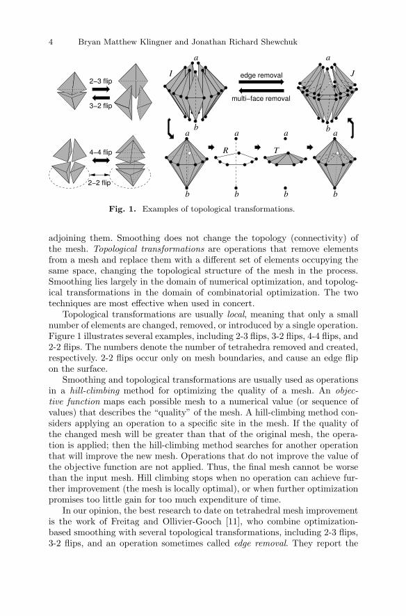
Fig. 1. Examples of topological transformations.
adjoining them. Smoothing does not change the topology (connectivity) ofthe mesh. Topological transformations are operations that remove elementsfrom a mesh and replace them with a different set of elements occupying thesame space, changing the topological structure of the mesh in the process.Smoothing lies largely in the domain of numerical optimization, and topolog-ical transformations in the domain of combinatorial optimization. The twotechniques are most effective when used in concert.
Topological transformations are usually local, meaning that only a smallnumber of elements are changed, removed, or introduced by a single operation.Figure 1 illustrates several examples, including 2-3 flips, 3-2 flips, 4-4 flips, and2-2 flips. The numbers denote the number of tetrahedra removed and created,respectively. 2-2 flips occur only on mesh boundaries, and cause an edge flipon the surface.
Smoothing and topological transformations are usually used as operationsin a hill-climbing method for optimizing the quality of a mesh. An objec-tive function maps each possible mesh to a numerical value (or sequence ofvalues) that describes the “quality” of the mesh. A hill-climbing method con-siders applying an operation to a specific site in the mesh. If the quality ofthe changed mesh will be greater than that of the original mesh, the opera-tion is applied; then the hill-climbing method searches for another operationthat will improve the new mesh. Operations that do not improve the value ofthe objective function are not applied. Thus, the final mesh cannot be worsethan the input mesh. Hill climbing stops when no operation can achieve fur-ther improvement (the mesh is locally optimal), or when further optimizationpromises too little gain for too much expenditure of time.
In our opinion, the best research to date on tetrahedral mesh improvementis the work of Freitag and Ollivier-Gooch [11], who combine optimization-based smoothing with several topological transformations, including 2-3 flips,3-2 flips, and an operation sometimes called edge removal. They report the

1A.1 Aggressive Tetrahedral Mesh Improvement 5
performance on a variety of meshes of several schedules for applying these op-erations, show that their best schedule eliminates most poorly shaped tetrahe-dra, and offer empirical recommendations about what makes some schedulesbetter than others.
Although we have long felt that the paper by Freitag and Ollivier-Goochis a model of excellent meshing research, we also suspected that yet betterresults were possible through a more aggressive set of operations. Delaunaymesh generation algorithms achieve good results by inserting new vertices [12],often boosting the smallest dihedral angle to 19◦ or more [22]. But no “meshclean-up” paper we know of uses transformations that add new vertices tothe mesh—a strange omission. No doubt this oversight stems partly from thedesire not to increase the size (number of elements) of a mesh.
We show here that vertex-creating transformations make it possible toachieve levels of mesh quality that, to the best of our knowledge, are unprece-dented. Given meshes whose vertices are somewhat regularly spaced (as everycompetent tetrahedral mesh generator produces), our implementation usuallyimproves them so that no dihedral angle is smaller than 31◦ or larger than149◦. It sometimes achieves extreme angles better than 40◦ or (with a differ-ent objective function) 120◦. No previous software we know of for tetrahedralmesh generation or mesh improvement achieves angles of even 22◦ or 155◦
with much consistency.As a combinatorial optimization problem, mesh improvement is not well
behaved. The search space is the set of all possible meshes of a fixed geometricdomain. A transformation (including smoothing) is an operation that trans-forms one mesh of the domain to another. These operations give the searchspace structure, by dictating what meshes are immediately reachable fromanother mesh. The objective function, which maps the search space to qualityscores, has many local optima (meshes whose scores cannot be improved byany single transformation at hand), and it is unlikely that any mesh improve-ment algorithm will ever find the global optimum—the best possible mesh ofthe domain—or even come close.
However, our goal is merely to find a local optimum whose tetrahedra areall excellent. Intuitively, a powerful enough repertoire of operations ought to“smooth out” the objective function, thereby ensuring that few poor localoptima exist. The question is, what is a powerful enough repertoire?
In this paper, we take the operations explored by Freitag and Ollivier-Gooch and enrich them considerably, adding the following.• A topological transformation that inserts a new vertex (usually into a bad
tetrahedron). This operation is not unlike Delaunay vertex insertion, butit is designed to optimize the worst new tetrahedron instead of enforcingthe Delaunay property. Sometimes it deletes vertices as well.
• Smoothing of vertices constrained to lie on the boundary of the mesh.• Edge removal for edges on the boundary of the mesh.• The multi-face removal operation of de Cougny and Shephard [7].

6 Bryan Matthew Klingner and Jonathan Richard Shewchuk
• Compound operations that combine several other operations in the hopeof getting over a valley in the objective function and finding a better peak.If unsuccessful, these operations are rolled back.These additions are motivated by two observations: to repair a tetrahe-
dralization it is often necessary to repair the boundary triangulation; andinserting a new vertex often breaks resistance that cannot be broken by topo-logical operations that do not change the set of vertices in a mesh. We haveimplemented and tested schedules that use these operations, and we investi-gate the consequences of turning different operations on or off.
The main goal of this paper is to answer the question, “How high canwe drive the quality of a tetrahedral mesh, assuming that speed is not thehighest priority?” Questions like “How quickly can we consistently fix a meshso all its dihedral angles are between, say, 20◦ and 160◦?” are important too.But we think it is hard to do justice to both questions in one short paper,and studying the former question first will make it easier to answer the latterquestion in future work.
2 Mesh Quality
The success of the finite element method depends on the shapes of the tetra-hedra. Large dihedral angles (near 180◦) cause large interpolation errors androb the numerical simulation of its accuracy [14, 17, 24], and small dihedralangles render the stiffness matrices associated with the finite element methodfatally ill-conditioned [2, 24]. Although anisotropic tetrahedra with extremeangles are desirable and necessary in some contexts, such as aerodynamics, werestrict our attention here to isotropic simulations, which are the norm in me-chanics, heat transfer, and electromagnetics. Often, a single bad tetrahedroncan spoil a simulation. For example, a large dihedral angle can engender a hugespurious strain in the discretized solution of a mechanical system. Therefore,our top priority is to produce a mesh in which the worst tetrahedra are asgood as possible.
Most mesh improvement programs encapsulate the quality of a tetrahedront as a single numerical quality measure q(t). Many such quality measuresare available [9, 24]. All the mesh operations we use are flexible enough toaccommodate almost every measure in the literature. We assume each measureis “normalized” so that a larger value of q(t) indicates a better tetrahedron,and q(t) is positive if t has the correct topological orientation, zero if t isdegenerate, and negative if t is “inverted” (meaning that there is a wrinkle inthe fabric of the mesh). We assume no input mesh has inverted tetrahedra;all our operations will keep it that way.
We tried four quality measures in our implementation.• The minimum sine of a tetrahedron’s six dihedral angles, or the minimum
sine measure for short. This measure penalizes both small and large di-hedral angles, and Freitag and Ollivier-Gooch [11] find it to be the most

1A.1 Aggressive Tetrahedral Mesh Improvement 7
effective measure they considered. It also has the advantage that dihedralangles are intuitive.
• The biased minimum sine measure, which is like the minimum sine mea-sure, but if a dihedral angle is obtuse, we multiply its sine by 0.7 (beforechoosing the minimum). This allows us to attack large angles much moreaggressively without much sacrifice in improving the small angles.
• The volume-length measure, suggested by Parthasarathy, Graichen, andHathaway [19] and denoted V/�3rms, is the signed volume of a tetrahedrondivided by the cube of its root-mean-squared edge length. We multiply itby 6
√2 so that the highest quality is one, the measure of an equilateral
tetrahedron.• The radius ratio, suggested by Cavendish, Field, and Frey [5], is the ra-
dius of a tetrahedron’s inscribed sphere divided by the radius of its cir-cumscribing sphere. We multiply it by 3 so that the highest quality isone, the measure of an equilateral tetrahedron. We experimented withthis measure because of its popularity, but we found that it is inferior tothe volume-length measure in mesh optimization, even when the goal isto optimize the radius ratio. So we will revisit it only once—in Section 5where we demonstrate this fact.
The first two measures do not penalize some tetrahedra that are consideredbad by the last two measures. For example, an extremely skinny, needle-shaped tetrahedron can have excellent dihedral angles, whereas its skinninessis recognized by the volume-length measure and the radius ratio. There isevidence that a skinny tetrahedron with good dihedral angles is harmless,hurting neither discretization error nor conditioning [24]; its worst crime is towaste vertices, because its accuracy is inversely proportional to the length ofits longest edge, not its shortest. Moreover, such a tetrahedron is indispensableat the tip of a needle-shaped domain. Readers not convinced by this argumentwill find the volume-length measure invaluable.
We need to extend quality measures from individual tetrahedra to wholemeshes. The worst tetrahedra in a mesh have far more influence than the av-erage tetrahedra, so the objective function we optimize is the quality vector: avector listing the quality of each tetrahedron, ordered from worst to best. Twomeshes’ quality vectors are compared lexicographically (akin to alphabeticalorder) so that, for instance, an improvement in the second-worst tetrahedronimproves the overall objective function even if the worst tetrahedron is notchanged. A nice property of the quality vector is that if an operation replacesa small subset of tetrahedra in a mesh with new ones, we only need to com-pare the quality vectors of the submeshes constituting the changed tetrahedra(before and after the operation). If the submesh improves, the quality vectorof the whole mesh improves. Our software never needs to compute the qualityvector of an entire mesh.

8 Bryan Matthew Klingner and Jonathan Richard Shewchuk
3 The Fundamental Tools: Mesh Operations
Here we describe the mesh transformation operations that form the core ofour mesh improvement program. Simultaneously, we survey the previous workin mesh improvement.
3.1 Smoothing
The most famous smoothing technique is Laplacian smoothing, in which avertex is moved to the centroid of the vertices to which it is connected [13].Typically, Laplacian smoothing is applied to each mesh vertex in sequence, andseveral passes of smoothing are done, where each “pass” moves every vertexonce. Laplacian smoothing is popular and somewhat effective for triangularmeshes, but for tetrahedral meshes it is much less reliable, and often producespoor tetrahedra.
Better smoothing algorithms are based on numerical optimization [20, 4].Early algorithms define a smooth objective function that summarizes the qual-ity of a group of elements (e.g. the sum of squares of the qualities of all thetetrahedra adjoining a vertex), and use a numerical optimization algorithmsuch as steepest descent or Newton’s method to move a vertex to the optimallocation. Freitag, Jones, and Plassman [10] propose a more sophisticated non-smooth optimization algorithm, which makes it possible to optimize the worsttetrahedron in a group—for instance, to maximize the minimum angle amongthe tetrahedra that share a specified vertex. A nonsmooth optimization algo-rithm is needed because the objective function—the minimum quality amongseveral tetrahedra—is not a smooth function of the vertex coordinates; thegradient of this function is discontinuous wherever the identity of the worsttetrahedron in the group changes. Freitag and Ollivier-Gooch [11] had greatsuccess with this algorithm, and we use it essentially unchanged (though wehave our own implementation).
Whereas Freitag and Ollivier-Gooch only smooth vertices in the interiorof a mesh, we also implemented constrained smoothing of boundary vertices.If the boundary triangles adjoining a vertex appear (within some tolerance)to lie on a common plane, our smoother assumes that the vertex can besmoothed within that plane. Similarly, we identify vertices that can be movedalong an edge of the domain without changing its shape. However, we did notimplement constrained smoothing for curved domain boundaries, so some ofour meshes do not benefit from boundary smoothing.
We always use what Freitag and Ollivier-Gooch call smart smoothing: ifa smoothing operation does not improve the minimum quality among thetetrahedra changed by the operation, then the operation is not done. Thus,the quality vector of the mesh never gets worse.

1A.1 Aggressive Tetrahedral Mesh Improvement 9
3.2 Edge Removal
Edge removal, proposed by Briere de l’Isle and George [3], is a topologicaltransformation that removes a single edge from the mesh, along with all thetetrahedra that include it. (The name is slightly misleading, because edge re-moval can create new edges while removing the old one. Freitag and Ollivier-Gooch refer to edge removal as “edge swapping,” but we prefer the earliername.) It includes the 3-2 and 4-4 flips, but also includes other transforma-tions that remove edges shared by any number of tetrahedra. In general, edgeremoval replaces m tetrahedra with 2m − 4; Figure 1 (right) illustrates re-placing seven tetrahedra with ten. De Cougny and Shephard [7] and Freitagand Ollivier-Gooch [11] have shown dramatic evidence for its effectiveness,especially in combination with other mesh improvement operations.
Let ab be an edge in the interior of the mesh with vertices a and b. Let Ibe the set of tetrahedra that include ab. Each tetrahedron in I has an edgeopposite ab. Let R be the set of these edges. (R is known as the link of ab.) Rforms a (non-planar) polygon in three-dimensional space, as illustrated. Anedge removal transformation constructs a triangulation T of R, and creates aset of new tetrahedra J =
⋃t∈T {conv({a} ∪ t), conv({b} ∪ t)}, as illustrated,
which replace the tetrahedra in I.The chief algorithmic problem is to find the triangulation T of R that
maximizes the quality of the worst tetrahedron in J . We solve this problemwith a dynamic programming algorithm of Klincsek [16], which was inventedlong before anyone studied edge removal. (Klincsek’s algorithm solves a gen-eral class of problems in optimal triangulation. Neither Briere de l’Isle andGeorge nor Freitag and Ollivier-Gooch appear to have been aware of it.) Thealgorithm runs in O(m3) time, but m is never large enough for its speed tobe an impairment.
3.3 Multi-Face Removal
Multi-face removal is the inverse of edge removal, and includes the 2-3 and4-4 flips. An m-face removal replaces 2m tetrahedra with m + 2. It has beenneglected in the literature; so far as we know, it has appeared only in anunpublished manuscript of de Cougny and Shephard [7], who present evidencethat multi-face removal is effective for mesh improvement.
Multi-face removal, like edge removal, revolves around two chosen verticesa and b. Given a mesh, say that a triangular face f is sandwiched between aand b if the two tetrahedra that include f are conv({a}∪f) and conv({b}∪f).For example, in Figure 1, the faces of T are sandwiched between a and b inthe mesh J . An m-face removal operation singles out m of those sandwichedfaces, and replaces the tetrahedra that adjoin them, as illustrated. (An m-faceremoval actually removes 3m − 2 faces, but only m of them are sandwichedbetween a and b.)
Our software uses multi-face removal by singling out a particular inter-nal face f it would like to remove. Let a and b be the apex vertices of the

10 Bryan Matthew Klingner and Jonathan Richard Shewchuk
pGr
l
2
11 1
1
1
13
121
2
88
7
8
6
6
32
1
8
935
2
4
8
2
28
8
9
88
7
8
6
6
99
27
9
762
6
32 9 2
7
9
6
8
7
3
2p
G
Fig. 2. Vertex insertion as graph cut optimization. In this example, the smallestcut has weight 6. The weights of the cut edges are the qualities of the new elements.
two tetrahedra adjoining f . The optimal multi-face removal operation doesnot necessarily remove all the faces sandwiched between a and b. We use thealgorithm of Shewchuk [23] to find the optimal multi-face removal operationfor f (and to determine whether any multi-face removal operation can re-move f without creating inverted tetrahedra), in time linear in the number ofsandwiched faces.
3.4 Vertex Insertion
Our main innovation in this paper is to show that mesh improvement is farmore effective with the inclusion of transformations that introduce new ver-tices. We use an algorithm similar to Delaunay vertex insertion: we choose alocation p to insert a new vertex and a set I of tetrahedra to delete, such thatp lies in, and can “see” all of, the star-shaped polyhedral cavity C =
⋃t∈I t.
We fill the cavity with a set of new tetrahedra J = {conv({p}∪f) : f is a faceof C}. Choosing the position of p is a black art; see Section 4.2 for how wechoose it. To choose I, we solve this combinatorial problem: given a point p,which tetrahedra should we delete to maximize the quality of the worst newtetrahedron?
Our algorithm views the mesh as a graph M with one node for each tetra-hedron, as depicted in Figure 2. For simplicity, we identify nodes of the graphwith the tetrahedra they represent. M contains a directed edge (v, w) if thetetrahedron v shares a triangular face with the tetrahedron w, and v occludesw from p’s point of view. The edge (v, w) reflects the geometric constraint thatw can only be included in the set I (i.e., in the cavity C) if v is included—that is, the cavity must be star-shaped from p’s perspective. (If p is coplanarwith the triangular face that v and w share, we direct the edge arbitrarily.)Although M can have cycles, they are rare, so we adopt some nomenclaturefrom trees: if (v, w) ∈ M then w is a child of v and v is a parent of w. Anytetrahedron that contains p is a root of M . Usually there is just one roottetrahedron, but sometimes we insert a new vertex on a boundary edge ofthe domain, in which case all the tetrahedra sharing that edge are roots. If avertex is inserted at p, all the roots must be deleted.

1A.1 Aggressive Tetrahedral Mesh Improvement 11
Our algorithm for finding an optimal cavity computes a cut in M thatinduces a cavity in the mesh. It begins by constructing the subgraph G of Mwhose nodes are the roots of M and all the tetrahedra that are reachable inM from the roots by a directed path of length six or less. We select G thisway because we do not want to search the entire graph M for a cut, and wefind that in practice, tetrahedra further away from the root rarely participatein the optimal cavity. We find that G typically has 5–100 tetrahedra. For eachtriangular face that belongs to only one tetrahedron in G, we add a “ghostnode” to G to act as a neighboring tetrahedron. Then, every leaf of G is aghost node, as Figure 2 shows.
The tetrahedra in G, except the leaves, are candidates for deletion. Foreach edge (v, w) ∈ G, let f be the triangular face shared by the tetrahedrav and w. Our algorithm labels (v, w) with the quality of the tetrahedronconv(p∪f)—the tetrahedron that will be created if v is deleted but w survives.
The problem is to partition G into two subgraphs, Gr and Gl, such thatGr contains the root tetrahedra and Gl contains the leaves, as illustrated inFigure 2. The deleted tetrahedra I will be the nodes of Gr, and the survivingtetrahedra will be the nodes of Gl. Because the cavity C =
⋃t∈I t must be star-
shaped from p’s perspective (to prevent the creation of inverted tetrahedra),no tetrahedron in Gl may be a parent of any tetrahedron in Gr. Our goal isto find the partition that satisfies this constraint and maximizes the smallestedge cut (because that edge determines the worst new tetrahedron).
The algorithm in Figure 3 computes this optimal cut. (We omit the proof.)The algorithm iterates through the edges of G, from worst quality to best,and greedily ensures that each edge will not be cut, if that assurance doesnot contradict previous assurances. Upon termination, the tetrahedra labeled“cavity” become the set I of tetrahedra to be deleted, and the set J of tetra-hedra to be created are determined by the triangular faces of the cavity C,which are recorded by the ninth line of pseudocode. In practice, I typicallycomprises 5–15 tetrahedra. After an initial O(|G| log |G|)-time sorting step,the rest of the algorithm runs in O(|G|) time.
Sometimes, a vertex insertion operation deletes one or more of the othervertices, as in Figure 2. When a tetrahedron with three parents is deleted,the vertex it shares with all three parents is deleted too. Thus, our vertexinsertion operation sometimes reduces the number of vertices in the mesh.
3.5 Composite Operations
Mesh improvement methods often get stuck in local optima that are far fromthe global optimum. Joe [15] suggests that this problem can be ameliorated bycomposing multiple basic operations to form new operations. These compositeoperations sometimes get a hill-climbing optimizer across what was formerlya valley in the objective function, thereby leading the way to a better localoptimum.
We have found that vertex insertion, as described in Section 3.4, rarely im-proves the quality vector of the mesh immediately, but it is frequently effective

12 Bryan Matthew Klingner and Jonathan Richard Shewchuk
Sort edges of G from smallest to largest quality.H ⇐ a graph with the same vertices as G but
no edges (yet). (H need not be stored as aseparate graph; let each edge of G have a bitthat indicates whether it is in H too.)
All vertices of G are initially unlabeled.Label every root of G “cavity.”Label every leaf of G “anti-cavity.”for each directed edge (v, w) of G (in sorted order)
if v is labeled “cavity”if w is labeled “anti-cavity”
Record (v, w), which determines a newtetrahedron in J.
else if w is unlabeledCavity(w)
else if v is unlabeledif w is labeled “anti-cavity”
AntiCavity(v)else { w is unlabeled }
Add (v, w) to H.
Cavity(w)Label w “cavity.”for each unlabeled parent p of w in G
Cavity(p)for each unlabeled child c of w in H
Cavity(c)
AntiCavity(v)Label v “anti-cavity.”for each unlabeled child c of v in G
AntiCavity(c)for each unlabeled parent p of v in H
AntiCavity(p)
Fig. 3. Algorithm for computing the cavity that optimizes the new tetrahedrawhen a new vertex is inserted. Upon completion, the tetrahedra to be deleted arelabeled “cavity.”
if traditional smoothing and transformations follow. To create an operationthat composes vertex insertion with subsequent operations, we implemented arollback mechanism that allows us to attempt a sequence of transformations,then reverse all the changes if the final mesh is not better than the initial one.
The AttemptInsert pseudocode in Figure 4 shows how we follow ver-tex insertion with smoothing and topological transformations, then decidewhether to roll back the insertion. Immediately after inserting the new ver-tex (as described in Section 3.4), we smooth it (by optimization), then werun passes of topological transformations and smoothing on the tetrahedraadjoining it in an attempt to improve them. (See the pseudocode for details.)Finally, we compare the quality vector of all the new and changed (smoothed)tetrahedra with the quality vector of the deleted tetrahedra (the set I). If themesh has not improved, we roll it back to the instant before we inserted thenew vertex.
Even though the algorithm in Figure 3 is technically optimal, we havelearned by experiment that composite vertex insertion is more effective if webias the algorithm to prefer larger cavities than it would normally choose.To encode this bias, our implementation multiplies edge weights by 1.0, 1.4,1.8, or 2.1 if they are a distance of zero, one, two, or greater than two fromthe nearest root, respectively. These weights sometimes cause worse-than-optimal tetrahedra to be created, but these are often improved by subsequentoperations. In the end, the vertex insertion operation is only accepted (notrolled back) if the unbiased quality vector improves.

1A.1 Aggressive Tetrahedral Mesh Improvement 13
4 Scheduling the Operations
4.1 Examples from Previous Work
Joe’s algorithm [15] checks each face of the mesh to see if any of his transforma-tions (including composite transformations) will improve the local tetrahedra.It performs passes over the entire mesh (checking each face), and terminateswhen a pass makes no changes. His experiments show that he can eliminatemost, but not all, tetrahedra with radius ratios below 0.3. (In our experiments,we eliminated all tetrahedra with radius ratios below 0.51 by optimizing theobjective V/�3rms.)
Freitag and Ollivier-Gooch’s schedule [11] begins with a pass of 2-3 flipsthat enforce the Delaunay in-sphere criterion (testing each interior face of themesh once), then a pass of 2-3 flips that optimize the minimum sine measure,then a pass of edge removal operations that optimize the minimum sine, thentwo passes of optimization-based smoothing. Next, a procedure that targetsonly the worst tetrahedra in the mesh attempts to remove them with 2-3flips and edge removal operations. Two more passes of smoothing completethe schedule. For many of their meshes, they obtain dihedral angles boundedbetween about 12◦ and 160◦, but these results are not consistent across alltheir test meshes. Dihedral angles less than 1◦ occasionally survive, and inmore examples dihedral angles under 10◦ survive.
Edelsbrunner and Guoy [8] demonstrate that that a theoretically moti-vated technique called sliver exudation [6], which uses sequences of 2-3 and3-2 flips to remove poor tetrahedra from meshes, usually removes most of thebad tetrahedra from a mesh, but rarely all. Again, dihedral angles less than1◦ sometimes survive, and in most of their examples a few dihedral angles lessthan 5◦ remain.
Alliez, Cohen-Steiner, Yvinec, and Desbrun [1] propose a variational mesh-ing algorithm that alternates between optimization-based smoothing (usinga smooth objective function) and computing a new Delaunay triangulationfrom scratch. This algorithm generates meshes that have only a small numberof tetrahedra under 10◦ or over 160◦, but it does not eliminate all mediocretetrahedra, especially on the boundary. (See the StGallen and StayPuftinput meshes in Section 5.) Note that variational meshing is a standalone meshgeneration algorithm, and cannot be used as a mesh improvement algorithm,because the mesh it generates does not conform to a specified triangulatedboundary.
4.2 Our Mesh Improvement Schedule
Pseudocode for our mesh improvement implementation appears in Figure 4.Like all such schedules, ours is heuristic and evolved through trial and error.
We find that prescribing a fixed number of improvement passes, as Freitagand Ollivier-Gooch do, is too inflexible, and we get better results by adaptingour schedule to the mesh at hand. We begin with a pass of optimization-based

14 Bryan Matthew Klingner and Jonathan Richard Shewchuk
MeshAggression(M) { M is a mesh }Smooth each vertex of M .TopologicalPass(M)failed ⇐ 0while failed < 3
Q ⇐ list of quality indicators for M .Smooth each vertex of M .if M is sufficiently better than Q
failed ⇐ 0else
TopologicalPass(M)if M is sufficiently better than Q
failed ⇐ 0else
if failed = 1 { desperation pass }L ⇐ list of tets with a dihedral
< 40◦ or > 140◦.else L ⇐ list of the worst 3.5% of
tets in M .InsertionPass(M, L)if M is sufficiently better than Q
failed ⇐ 0else failed ⇐ failed +1
InsertionPass(M, L) { L is a list of tets }for each tetrahedron t ∈ L that still exists
for each face f of t on the meshboundary (if any)
p ⇐ point at barycenter of fif AttemptInsert(M, p)
Restart outer loop on next tet.p ⇐ point at barycenter of tif AttemptInsert(M, p)
Restart outer loop on next tet.for each edge e of t on the mesh
boundary (if any)p ⇐ point at midpoint of eif AttemptInsert(M, p)
Restart outer loop on next tet.
TopologicalPass(L) { L is a list of tets }for each tetrahedron t ∈ L that still exists
for each edge e of t (if t still exists)Attempt to remove edge e.
for each face f of t (if t still exists)Attempt to remove face f (multi-face
or 2-3 or 2-2 flip).return the surviving tetrahedra of L and
all the new tetrahedracreated by this call.
AttemptInsert(M, p) { New vertex at p }I ⇐ deleted tetrahedra, computed as
discussed in Section 3.4q ⇐ quality of the worst tetrahedron in IReplace I with the new tetrahedra J (see
Section 3.4 and Figure 3).attempts ⇐ 8repeat
Smooth p.{ In next line, the cavity may expand }J ⇐ TopologicalPass(J)attempts ⇐ attempts −1
while attempts > 0 and some topologicalchange occurred
K ⇐ J∪ the tetrahedra in M that sharea vertex with J
repeatq′ ⇐ quality of the worst tet in JSmooth each vertex of J.q′′ ⇐ quality of the worst tet in Kattempts ⇐ attempts −1
while attempts > 0 and q′′ > q′
if q′′ > qreturn true.
Roll back all changes since the beginningof this procedure call.
return false.
Fig. 4. Our mesh improvement schedule.
smoothing (smoothing each vertex once) and a pass of topological transfor-mations (leaving out vertex insertion), because these are always fruitful. Ourtopological pass visits each tetrahedron once, and searches for a transfor-mation that will eliminate it and improve the quality vector of the changedtetrahedra (and therefore of the entire mesh). If no edge removal operationsucceeds in removing a particular tetrahedron, we try multi-face removal oneach face of that tetrahedron that lies in the mesh interior. However, in Sec-tion 5 we test the effect of disabling multi-face removal but still allowing facesto be removed by 2-3 flips (which are easier to implement). If an interior facehas an edge on the mesh boundary, we also test the possibility that a 2-2 flipon that edge might improve the mesh.
Our implementation then performs passes over the mesh until three sub-sequent passes fail to make sufficient progress. We gauge progress using asmall list of quality indicators: the quality of the worst tetrahedron in theentire mesh, and seven thresholded means. A mean with threshold d is com-puted by calculating the quality of each tetrahedron in the mesh, reducingto d any quality greater than d, then taking the average. The purpose of

1A.1 Aggressive Tetrahedral Mesh Improvement 15
a thresholded mean is to measure progress in the lowest-quality tetrahedrawhile ignoring changes in the high-quality tetrahedra. For the minimum sinemeasure, we compute thresholded means with thresholds sin 1◦, sin 5◦, sin 10◦,sin 15◦, sin 25◦, sin 35◦, and sin 45◦. (Each tetrahedron is scored according toits worst dihedral angle; we do not compute thresholded means of all dihedralangles.) A mesh is deemed to be sufficiently improved (to justify more passes)if at least one of the thresholded means increases by at least 0.0001, or if thequality of the worst tetrahedron increases at all.
Each pass begins with smoothing. If smoothing does not make adequateprogress, a topological pass follows. If progress is still insufficient, we resortto vertex insertion, which is less desirable than the other operations bothbecause it often increases the size of the mesh and because our compoundvertex insertion operation is slow. Vertex insertion is usually aimed at theworst 3.5% of tetrahedra in the mesh, but our implementation never givesup without trying at least one “desperation pass” that attempts to insert avertex in every tetrahedron that has an angle less than 40◦ or greater than140◦.
Most mesh generation algorithms create their worst tetrahedra on theboundary of the mesh, and boundary tetrahedra are the hardest to repair.Thus, when our vertex insertion pass targets a tetrahedron on the boundaryof the mesh, it always tries to insert a vertex at the barycenter of the bound-ary face(s) first. For tetrahedra where that fails, and tetrahedra not on theboundary, we try the tetrahedron barycenter next. We also try the midpointsof tetrahedron edges that lie on the boundary, but we try them last, because(for reasons we don’t understand) we obtain better meshes that way.
5 Results and Discussion
We tested our schedule on a dozen meshes.• Cube1K and Cube10K are high-quality meshes of a cube generated by
NETGEN [21].• TFire is a high-quality mesh of a tangentially-fired boiler, created by
Carl Ollivier-Gooch’s GRUMMP software.• Tire, Rand1 and Rand2 come courtesy of Freitag and Ollivier-Gooch,
who used them to evaluate their mesh improvement algorithms. Tire is atire incinerator. Rand1 and Rand2 are lazy triangulations, generated byinserting randomly located vertices into a cube, one by one. Each vertexwas inserted by splitting one or more tetrahedra into multiple tetrahedra.(Unlike in Delaunay insertion, no flips took place.) The random mesheshave horrible quality.
• Dragon and Cow are medium-quality meshes with curved boundaries,generated by isosurface stuffing [18]. The curvature prevents us fromsmoothing the original boundary vertices.

16 Bryan Matthew Klingner and Jonathan Richard Shewchuk
• StGallen and StayPuft are medium- to low-quality meshes withcurved boundaries, generated by two different implementations of vari-ational tetrahedral meshing [1], courtesy of Pierre Alliez and AdamBargteil, respectively.
• House and P are Delaunay meshes generated by Pyramid [22] configuredso the vertices are nicely spaced, but no effort is made to eliminate slivertetrahedra.Tables 1 and 2 show these meshes before and after improvement with
the MeshAggression schedule in Figure 4. We tested the minimum sinemeasure (upper right corner of each box), the biased minimum sine measure(lower right), and the volume-length measure V/�3rms (lower left) as objectives.(We omit meshes optimized for the radius ratio objective, which was notcompetitive with the volume-length measure, even as measured by the radiusratios of the tetrahedra.)
Our main observation is that the dihedral angles improved to between31◦ and 149◦ for the minimum sine objective, between 25◦ and 142◦ for thebiased minimum sine objective, and between 23◦ and 136◦ for the volume-length measure. Even the pathological meshes Rand1 and Rand2 end withexcellent quality. These numbers put our implementation far ahead of anyother tetrahedral mesh algorithm we have seen reported. Freitag and Ollivier-Gooch reported angle bounds as good as 13.67◦ and 156.14◦ for Tire, versusour 28.13◦ and 125.45◦; as good as 15.01◦ and 159.96◦ for Rand1, versus our36.95◦ and 119.89◦; and as good as 10.58◦ and 164.09◦ for Rand2, versus our34.05◦ and 126.61◦.
Of course, to obtain such high quality takes time. Meshes that begin withhigh quality take a modest amount of time to improve. Rand1 and Rand2take disproportionately longer—both because our implementation tries tohold back vertex insertions until they prove to be necessary, and becausethe composite vertex insertion operation is slow, often accounting for about90% of the running time. Of that 90%, about one third is spent in the basicvertex insertion operation, one third in smoothing the cavity, and one thirdin topological transformations in the cavity. It seems impossible to predictwhich quality measure will run faster on a given mesh, and the differences inrunning times are erratic.
No mesh increased in size by more than 41%, and some meshes shrank(because the vertex insertion operation can also delete vertices).
Table 3 shows the effects of turning features on or off. The top half ofthe page explores the question of which features are most important to haveif the programmer’s time is limited. We try all combinations of three opera-tions: optimization-based vertex smoothing in the interior of the mesh (butnot on mesh boundaries); vertex insertion in the interior of the mesh (but noton boundaries); and edge removal (but no other topological transformations).Smoothing proves to be the most indispensable; substantial progress is almostimpossible without it. Vertex insertion is the second-most powerful operation.We were surprised to see that it alone can substantially improve some meshes,even though most vertex insertion operations fail when neither smoothing nor

1A.1 Aggressive Tetrahedral Mesh Improvement 17
Table 1. Twelve meshes before and after improvement (continued in Table 2). Ineach box, the upper left mesh is the input, the upper right mesh is optimized for theminimum sine measure, the lower right mesh is optimized for the biased minimumsine measure, and the lower left mesh is optimized for V/�3rms. Running times aregiven for a Mac Pro with a 2.66 GHz Intel Xeon processor. Red tetrahedra havedihedral angles under 5◦ or over 175◦, orange have angles under 15◦ or over 165◦,yellow have angles under 30◦ or over 150◦, green have angles under 40◦ or over140◦, and better tetrahedra do not appear. Histograms show the distributions ofdihedral angles, and the minimum and maximum angles, in each mesh. Histogramsare normalized so the tallest bar always has the same height; absolute numbers oftetrahedra cannot be compared between histograms.
Cube1k 14 sec Cube10K 119 sec TFire 40 sec
1,185 tets 1,223 tets 11,661 tets 11,313 tets 1,105 tets 1,300 tets
16020 40 60 80 100 120 140
127.631.8
16020 40 60 80 100 120 140
130.442.2
16020 40 60 80 100 120 140
142.025.2
16020 40 60 80 100 120 140
135.541.0
20 40 60 80 100 120 140 160
144.519.4
16020 40 60 80 100 120 140
137.838.8
20 40 60 80 100 120 140 160
35.9 119.3
20 40 60 80 100 120 140 160
39.0 113.5
20 40 60 80 100 120 140 160
35.0 117.7
20 40 60 80 100 120 140 160
39.6 113.5
16020 40 60 80 100 120 140
124.230.9
20 40 60 80 100 120 140 160
37.6 117.9
1,173 tets 1,212 tets 11,528 tets 11,700 tets 1,374 tets 1,551 tets
5 sec 7 sec 57 sec 121 sec 103 sec 84 secTire 447 sec Rand1 177 sec Rand2 3,378 sec
11,099 tets 12,495 tets 5,105 tets 3,677 tets 25,705 tets 18,050 tets
20 40 60 80 100 120 140 160
0.6 178.9
16020 40 60 80 100 120 140
143.336.0
20 40 60 80 100 120 140 160
0.3 179.0
16020 40 60 80 100 120 140
141.738.8
20 40 60 80 100 120 140 160
0.1 179.9
16020 40 60 80 100 120 140
142.936.7
16020 40 60 80 100 120 140
125.528.1
16020 40 60 80 100 120 140
130.431.8
16020 40 60 80 100 120 140
120.931.5
20 40 60 80 100 120 140 160
36.9 119.9
16020 40 60 80 100 120 140
122.532.1
16020 40 60 80 100 120 140
126.734.0
12,369 tets 13,845 tets 4,540 tets 3,681 tets 22,584 tets 14,735 tets
748 sec 940 sec 274 sec 457 sec 1,430 sec 4,658 sec

18 Bryan Matthew Klingner and Jonathan Richard Shewchuk
Table 2. Continuation of Table 1. Red histogram bars should have their heightsmultiplied by 20 to account for the fact that in the semi-regular meshes Dragonand Cow, angles of 45◦, 60◦, and 90◦ occur with high frequency.
Dragon 155 sec Cow 950 sec StGallen 509 sec
32,960 tets 36,034 tets 42,054 tets 46,380 tets 50,392 tets 50,262 tets
80 100 120 140 160604020
156.815.5
16020 40 60 80 100 120 140
141.531.0
80 100 120 140 160604020
158.014.5
16020 40 60 80 100 120 140
148.331.9
20 40 60 80 100 120 140 160
161.811.4
16020 40 60 80 100 120 140
140.032.0
16020 40 60 80 100 120 140
127.224.3
16020 40 60 80 100 120 140
126.331.0
16020 40 60 80 100 120 140
128.523.7
16020 40 60 80 100 120 140
142.025.6
16020 40 60 80 100 120 140
129.033.3
16020 40 60 80 100 120 140
121.231.9
39,148 tets 36,364 tets 50,718 tets 47,648 tets 49,941 tets 50,317 tets
1,349 sec 169 sec 5,823 sec 2,398 sec 197 sec 576 secP 23 sec House 26 sec StayPuft 5,376 sec
927 tets 1,261 tets 1,390 tets 1,705 tets 102,393 tets 116,867 tets
40 60 80 100 120 140 16020
1.3 178.0
16020 40 60 80 100 120 140
137.538.2
20 40 60 80 100 120 140 160
177.31.8
16020 40 60 80 100 120 140
134.038.5
20 40 60 80 100 120 140 160
177.31.1
16020 40 60 80 100 120 140
146.434.1
16020 40 60 80 100 120 140
121.932.9
20 40 60 80 100 120 140 160
38.4 116.9
16020 40 60 80 100 120 140
122.231.2
20 40 60 80 100 120 140 160
37.4 118.5
16020 40 60 80 100 120 140
135.123.4
16020 40 60 80 100 120 140
128.133.3
1,113 tets 1,249 tets 1,730 tets 1,883 tets 130,736 tets 125,221 tets
34 sec 24 sec 80 sec 60 sec 14,214 sec 8,944 sec
other topological transformations are available to create a compound opera-tion (as described in Section 3.5). Edge removal ranks last. Any combinationof two of these operations gives a substantial advantage over one, and havingall three gives another substantial advantage.
Implementing all the features discussed in this paper (“maximum ag-gression”) gives another substantial advantage, but these additional features

1A.1 Aggressive Tetrahedral Mesh Improvement 19
Table 3. Histograms showing the dihedral angle distribution, and minimum andmaximum dihedral angles, for several meshes optimized with selected features turnedon (upper half of page) or off (lower half). The objective was to maximize thebiased minimum sine measure. Multiply the heights of the red histogram bars by20. “Maximum aggression” has all features turned on.
Tire Rand2 Cow P All 12 meshes
Initial state
20 40 60 80 100 120 140 160
0.6 178.9
20 40 60 80 100 120 140 160
0.1 179.9
80 100 120 140 160604020
158.014.5
40 60 80 100 120 140 16020
1.3 178.0
20 40 60 80 100 120 140 160
0.1 179.9
Smoothing(interior)only
140 16012020 40 60 80 100
174.34.3
40 60 80 100 120 140 16020
2.8 174.5
140 16020 40 60 80 100 120
157.216.1
20 40 60 80 100 120 140 160
6.9 168.1
40 60 80 100 120 140 16020
2.8 174.6
Edgeremovalonly
60 80 100 120 140 1604020
172.43.0
20 40 60 80 100 120 140 160
0.1 179.9
16014020 40 60 80 100 120
149.517.3
16014020 40 60 80 100 120
148.415.4
20 40 60 80 100 120 140 160
0.1 179.9
Vertexinsertion(interior)only
20 40 60 80 100 120 140 160
178.90.6
20 40 60 80 100 120 140 160
0.9 178.1
80 100 120 140 160604020
158.014.5
120 140 1601008020 40 60
157.014.7
20 40 60 80 100 120 140 160
0.6 178.9
Smoothing+ edgeremoval
120 140 1601008020 40 60
150.89.5
16014020 40 60 80 100 120
165.98.7
16020 40 60 80 100 120 140
145.822.6
20 40 60 80 100 120 140 160
144.119.1
16014020 40 60 80 100 120
165.98.7
Smoothing+ vertexinsertion
16020 40 60 80 100 120 140
139.722.9
16014020 40 60 80 100 120
153.518.3
16020 40 60 80 100 120 140
141.925.7
16020 40 60 80 100 120 140
134.123.6
16014020 40 60 80 100 120
153.518.3
Edgeremoval +vertexinsertion
120 140 1601008020 40 60
172.14.6
60 80 100 120 140 1604020
174.13.0
140 16020 40 60 80 100 120
147.517.3
20 40 60 80 100 120 140 160
21.8 144.9
40 60 80 100 120 140 16020
3.0 174.1
All three
40 60 80 100 120 140 16020
23.3 142.5
20 40 60 80 100 120 140 160
148.421.6
16020 40 60 80 100 120 140
141.925.6
16020 40 60 80 100 120 140
132.524.0
20 40 60 80 100 120 140 160
148.421.6
Maximumaggression
16020 40 60 80 100 120 140
130.431.8
16020 40 60 80 100 120 140
126.734.0
16020 40 60 80 100 120 140
142.025.6
20 40 60 80 100 120 140 160
38.4 116.9
16020 40 60 80 100 120 140
142.025.6
TFire Maximum aggression No smoothing No boundary smooth No edge removal No 2-2 flips
20 40 60 80 100 120 140 160
37.6 117.9
16020 40 60 80 100 120 140
138.026.3
16020 40 60 80 100 120 140
123.033.5
16020 40 60 80 100 120 140
123.734.6
20 40 60 80 100 120 140 160
36.1 120.7
16020 40 60 80 100 120 140
147.121.3
20 40 60 80 100 120 140 160
37.0 120.5
16020 40 60 80 100 120 140
129.231.8
20 40 60 80 100 120 140 160
36.5 121.7
20 40 60 80 100 120 140 160
36.5 121.7
No vertex insert No boundary insert No boundary change No multi-face rem. No face removal
Rand2 Maximum aggression No smoothing No boundary smooth No edge removal No 2-2 flips
16020 40 60 80 100 120 140
126.734.0
80 100 120 140 160604020
158.015.7
40 60 80 100 120 140 16020
24.1 144.6
16020 40 60 80 100 120 140
132.830.8
16020 40 60 80 100 120 140
132.630.5
20 40 60 80 100 120 140 160
160.313.3
16020 40 60 80 100 120 140
129.533.2
140 16020 40 60 80 100 120
151.420.8
16020 40 60 80 100 120 140
137.728.4
16020 40 60 80 100 120 140
125.834.5
No vertex insert No boundary insert No boundary change No multi-face rem. No face removal
All 12 Maximum aggression No smoothing No boundary smooth No edge removal No 2-2 flips
16020 40 60 80 100 120 140
142.025.6
80 100 120 140 160604020
158.015.7
40 60 80 100 120 140 16020
24.1 144.6
16020 40 60 80 100 120 140
138.028.7
16020 40 60 80 100 120 140
134.130.0
40 60 80 100 120 140 16020
13.3 160.3
16020 40 60 80 100 120 140
142.324.4
140 16020 40 60 80 100 120
151.920.8
16020 40 60 80 100 120 140
142.025.6
16020 40 60 80 100 120 140
142.125.6
No vertex insert No boundary insert No boundary change No multi-face rem. No face removal

20 Bryan Matthew Klingner and Jonathan Richard Shewchuk
Table 4. A stretched input mesh and four output meshes optimized with differ-ent quality measures as objective functions. The histograms tabulate, from top tobottom, dihedral angles, radius ratios (times 3), and 6
√2V/�3rms.
Stretch5 minimum sine biased min sine radius ratio V/�3rms
1,339 tets 1,802 tets 1,816 tets 1,059 tets 1,291 tets104 seconds 113 seconds 45 seconds 77 seconds
20 40 60 80 100 120 140 160
177.41.0
16020 40 60 80 100 120 140
140.737.8
16020 40 60 80 100 120 140
135.332.2
40 60 80 100 120 140 16020
16.3 137.8
16020 40 60 80 100 120 140
121.233.1
0.1 0.2 0.3 0.4 0.5 0.6 0.7 0.8 0.9
0.01
0.2 0.3 0.4 0.5 0.6 0.7 0.8 0.90.1
0.16
0.4 0.5 0.6 0.7 0.8 0.90.30.1 0.2
0.13
0.1 0.2 0.3 0.4 0.5 0.6 0.7 0.8 0.9
0.45
0.30.1 0.2 0.4 0.5 0.6 0.7 0.8 0.9
0.59
0.2 0.3 0.4 0.5 0.6 0.7 0.8 0.90.1
0.02
0.90.80.1 0.2 0.3 0.4 0.5 0.6 0.7
0.13
0.7 0.8 0.90.1 0.2 0.3 0.4 0.5 0.6
0.06
0.5 0.6 0.7 0.8 0.90.40.1 0.2 0.3
0.31
0.30.1 0.2 0.4 0.5 0.6 0.7 0.8 0.9
0.65
(multi-face removal, boundary smoothing, boundary insertion) are individu-ally responsible for only small increments. The bottom half of Table 3 showsthe effects of turning just a single feature off. Some of the switches listed thereare inclusive of other switches. “No smoothing” turns off all smoothing—inthe interior and on the boundary. Likewise, “no vertex insert” turns off all in-sertion. “No face removal” turns off multi-face removal and 2-3 flips, whereas“no multi-face removal” turns off only the former.
Smoothing and vertex insertion are clearly the most disastrous operationsto lose. The effort to extend smoothing and vertex insertion so that they canoperate on the boundary of the mesh was also well rewarded. Besides vertexinsertion, no single topological operation is crucial if the others are present.
The papers by Freitag and Ollivier-Gooch and by de Cougny and Shep-hard both concluded that edge removal is rarely successful for an edge thatadjoins more than seven tetrahedra; but our experience contradicts this. Wesee many successful removals of edges adjoining eight tetrahedra, and eventhe occasional removal of eleven tetrahedra. (Klincsek’s algorithm makes thiseasy to implement.) However, we observe that edge removal is most likely tobe successful for edges that adjoin four tetrahedra, and multi-face removalsthat remove two faces predominate, so the most common beneficial topologicalchange is a 4-4 flip.
Table 4 illustrates the effect of optimizing our four quality measures on amesh called Stretch5, which is Cube1K scaled along one axis by a factorof five. This mesh highlights the weakness of the minimum sine measure andits biased counterpart as objective functions—namely, they sometimes permitskinny tetrahedra to survive. The other two quality measures are better forimproving the distribution of vertices and producing “rounder” tetrahedra.The minimum sine objective is best for optimizing the smallest dihedral angle,but the volume-length measure is the best all-around objective of the four. It

1A.1 Aggressive Tetrahedral Mesh Improvement 21
even optimizes the radius ratio better than the radius ratio does! (We suspectthat the radius ratio behaves poorly as an objective function because of theinstability of the circumscribing radius as a function of vertex position.) Inour twelve-mesh test suite, the volume-length objective always improved theworst radius ratio to at least 0.51, whereas the radius ratio objective leftbehind many worse tetrahedra, the worst having a radius ratio of 0.30.
6 Conclusions
We see two important avenues for future work. First, our mesh improvementimplementation assumes that the spacing of the vertices in the input meshis already correct. A better code would take as input a spacing function thatdictates how large the tetrahedra should be in different regions of the mesh,and insert or delete vertices accordingly. Second, algorithms and schedulesthat achieve results similar to ours in much less time would be welcome. Ourcomposite vertex insertion operation accounts for most of the running time,so a more sophisticated vertex insertion algorithm might improve the speeddramatically.
Because we can produce meshes that usually have far better quality thanthose produced by any previous algorithm for mesh improvement or meshgeneration, even when given pathological inputs, we suggest that algorithmstraditionally considered “mesh improvement” might become standalone meshgenerators. If the barrier of speed can be overcome, the need to write sep-arate programs for mesh generation and mesh improvement might somedaydisappear.
Acknowledgments. We thank Pierre Alliez, Adam Bargteil, MosheMahler, and Carl Ollivier-Gooch for meshes and geometric models. Pixie ren-dered our meshes. This work was supported by the National Science Foun-dation under Awards CCF-0430065 and CCF-0635381, and by an Alfred P.Sloan Research Fellowship.
References
1. Pierre Alliez, David Cohen-Steiner, Mariette Yvinec, and Mathieu Desbrun.Variational Tetrahedral Meshing. ACM Transactions on Graphics 24:617–625,2005. Special issue on Proceedings of SIGGRAPH 2005.
2. Randolph E. Bank and L. Ridgway Scott. On the Conditioning of Finite ElementEquations with Highly Refined Meshes. SIAM Journal on Numerical Analysis26(6):1383–1394, December 1989.
3. E. Briere de l’Isle and Paul-Louis George. Optimization of Tetrahedral Meshes.Modeling, Mesh Generation, and Adaptive Numerical Methods for Partial Dif-ferential Equations, IMA Volumes in Mathematics and its Applications, vol-ume 75, pages 97–128. 1995.
22 Bryan Matthew Klingner and Jonathan Richard Shewchuk
4. Scott A. Canann, Michael Stephenson, and Ted Blacker. Optismoothing: AnOptimization-Driven Approach to Mesh Smoothing. Finite Elements in Analysisand Design 13:185–190, 1993.
5. James C. Cavendish, David A. Field, and William H. Frey. An Approach toAutomatic Three-Dimensional Finite Element Mesh Generation. InternationalJournal for Numerical Methods in Engineering 21(2):329–347, February 1985.
6. Siu-Wing Cheng, Tamal Krishna Dey, Herbert Edelsbrunner, Michael A. Facello,and Shang-Hua Teng. Sliver Exudation. Journal of the ACM 47(5):883–904,September 2000.
7. Hugues L. de Cougny and Mark S. Shephard. Refinement, Derefinement, andOptimization of Tetrahedral Geometric Triangulations in Three Dimensions.Unpublished manuscript, 1995.
8. Herbert Edelsbrunner and Damrong Guoy. An Experimental Study of Sliver Ex-udation. Tenth International Meshing Roundtable (Newport Beach, California),pages 307–316, October 2001.
9. David A. Field. Qualitative Measures for Initial Meshes. International Journalfor Numerical Methods in Engineering 47:887–906, 2000.
10. Lori A. Freitag, Mark Jones, and Paul Plassman. An Efficient Parallel Algorithmfor Mesh Smoothing. Fourth International Meshing Roundtable (Albuquerque,New Mexico), pages 47–58, October 1995.
11. Lori A. Freitag and Carl Ollivier-Gooch. Tetrahedral Mesh Improvement Us-ing Swapping and Smoothing. International Journal for Numerical Methods inEngineering 40(21):3979–4002, November 1997.
12. William H. Frey. Selective Refinement: A New Strategy for Automatic NodePlacement in Graded Triangular Meshes. International Journal for NumericalMethods in Engineering 24(11):2183–2200, November 1987.
13. L. R. Hermann. Laplacian-Isoparametric Grid Generation Scheme. Journal ofthe Engineering Mechanics Division of the American Society of Civil Engineers102:749–756, October 1976.
14. P. Jamet. Estimations d’Erreur pour des Elements Finis Droits PresqueDegeneres. RAIRO Analyse Numerique 10:43–61, 1976.
15. Barry Joe. Construction of Three-Dimensional Improved-Quality Triangula-tions Using Local Transformations. SIAM Journal on Scientific Computing16(6):1292–1307, November 1995.
16. G. T. Klincsek. Minimal Triangulations of Polygonal Domains. Annals ofDiscrete Mathematics 9:121–123, 1980.
17. Michal Krızek. On the Maximum Angle Condition for Linear Tetrahedral Ele-ments. SIAM Journal on Numerical Analysis 29(2):513–520, April 1992.
18. Francois Labelle and Jonathan Richard Shewchuk. Isosurface Stuffing: FastTetrahedral Meshes with Good Dihedral Angles. ACM Transactions on Graphics26(3), August 2007. Special issue on Proceedings of SIGGRAPH 2007.
19. V. N. Parthasarathy, C. M. Graichen, and A. F. Hathaway. A Comparisonof Tetrahedron Quality Measures. Finite Elements in Analysis and Design15(3):255–261, January 1994.
20. V. N. Parthasarathy and Srinivas Kodiyalam. A Constrained Optimization Ap-proach to Finite Element Mesh Smoothing. Finite Elements in Analysis andDesign 9:309–320, 1991.
21. Joachim Schoberl. NETGEN: An Advancing Front 2D/3D-Mesh GeneratorBased on Abstract Rules. Computing and Visualization in Science 1(1):41–52,July 2007.

1A.1 Aggressive Tetrahedral Mesh Improvement 23
22. Jonathan Richard Shewchuk. Tetrahedral Mesh Generation by Delaunay Re-finement. Proceedings of the Fourteenth Annual Symposium on ComputationalGeometry (Minneapolis, Minnesota), pages 86–95, June 1998.
23. . Two Discrete Optimization Algorithms for the Topologi-cal Improvement of Tetrahedral Meshes. Unpublished manuscript athttp://www.cs.cmu.edu/∼jrs/jrspapers.html, 2002.
24. . What Is a Good Linear Element? Interpolation, Conditioning, andQuality Measures. Eleventh International Meshing Roundtable (Ithaca, NewYork), pages 115–126, September 2002.
