1992-8645 modification of strapdown inertial navigation ... · strapdown inertial navigation system...
TRANSCRIPT

Journal of Theoretical and Applied Information Technology 20
th February 2015. Vol.72 No.2
© 2005 - 2015 JATIT & LLS. All rights reserved.
ISSN: 1992-8645 www.jatit.org E-ISSN: 1817-3195
273
MODIFICATION OF STRAPDOWN INERTIAL NAVIGATION
SYSTEM ALGORITHM FOR ROCKET FLIGHT TEST
1,5ROMI WIRYADINATA,
2OYAS WAHYUNGGORO,
3WAHYU WIDADA,
4SUNARNO,
5M.
IMAN SANTOSO 1Doctoral Student, Department of Electrical Engineering, Gadjah Mada University
Jl. Grafika No. 2, Sleman, Yogyakarta, Indonesia, 55281.
2Assoc. Professor, Department of Electrical Engineering, Gadjah Mada University Jl. Grafika No. 2, Sleman, Yogyakarta, Indonesia, 55281.
3Research Professor, Center of Rocket Technology, Indonesian National Institute of Aeronautics and Space, Jl. Raya Lapan-Rumpin, Tarogong, Bogor, Indonesia.
4Professor, Department of Physic Engineering, Gadjah Mada University Jl. Grafika No. 2, Sleman, Yogyakarta, Indonesia, 55281.
5Lecturer, Department of Electrical Engineering, University of Sultan Ageng Tirtayasa, Jl. Jend. Sudirman, km 03, Kota Cilegon, Banten, Indonesia, 42435.
E-mail: [email protected], [email protected], [email protected], [email protected], [email protected]
ABSTRACT
Specification, type, and IMU utilization on the INS algorithm influences rocket performance. Improvement could be done by hardware errors minimization that optimize algorithm and matrix transformation on the processor. Pitch angle (θ) on the Euler transform matrix have singularity on 90 degree. This paper modifies INS algorithm to solve that singularity. A novel control of rocket flight test with a modified algorithm which combines INS Euler and Quaternion method has been conducted. The modifications of INS algorithm proves that the proposed method can be used for flight test rocket that has a high-speed and rapid data alteration.
Keywords: INS Algorithm, Strapdown IMU, Euler, Guided Rocket 1. INTRODUCTION
The movement of objects (north, east, upward direction) will always look for a reference to the Earth, objects, navigation, geography, and inertia [1]. Previous researches have been done with the object and too many different of research focus. Walchko in 2002 studied that the accuracy of the GPS (Global Positioning System) errors reach 10-15 meters per second or equal to 95% in the second [2].
Real-Time navigation, guidance, and control of a UAV (Uninhibited Aerial Vehicle) using low-cost sensor, which is written by Kim etc. all on 2006 implemented INS/GPS for GNC (Guidance, Navigation and Control) system on UAV [3].
Tan and Park (2002) design INS (Inertial Navigation System) to computer linear and angular motions of rigid body uses only accelerometer [4].
Kumar 2004 write that integration of INS and GPS using kalman filter with a focus research on creating a simulator, where the output GPS processed on FPGA (Field Programmable Gate array) and integration IMU (Inertial Measurement Unit) and GPS output processed on DSP (Digital Signal Processing) [5]. Schumacher (2006) write about the Integration of a GPS aided Strapdown INS for land vehicle. The estimation accuracy and error state in of INS be formed and analyzed by EKF (Extended Kalman Filter) [6].

Journal of Theoretical and Applied Information Technology 20
th February 2015. Vol.72 No.2
© 2005 - 2015 JATIT & LLS. All rights reserved.
ISSN: 1992-8645 www.jatit.org E-ISSN: 1817-3195
274
Simulation launch vehicle rocket AtlasIIAS also use the INS and the integration of GPS, such as in the paper written by Istanbulluoglu in 2002 [7].
Hjortsmarker (2005) write the experimental system for validating GPS/INS algorithms integration, which aims to calibrate INS and GPS using the jet coaster so easily be described into three-dimensional space [8].
This paper try to explain how the algorithm is used in rocket INS moving unusual than other flying objects. INS modified algorithm adapted to cruising speed rocket that reaches 530m/s. The strapdown of INS algorithm differed from the common algorithms (in robotic or aeromodeling).
Limitation in this research is solve the singularity by modifying INS algorithm without using prediction method. With the result that this research eventful to use this algorithm for solve the singularity problem. Furthemore, this research trying to simplify the equation, so it has shorter a mathematical process.
The normalized Euler method used in the INS algorithm is modified hence the result is the same as the Quaternion method. The similar result is obtained but distinct to the general technique used. The modified INS algorithm proved that changes in the inertial and body reference produce the same pattern with different values even by the slight difference. Inertial Measurement Unit (IMU) is employed to manage such parameters. Thus, buffering in the INS algorithm is no longer required.
2. STRAPDOWN INS
Navigation is a very ancient skill or art which has become a complex science. It is essentially about travel and finding the way from one place to another and there are variety of means by which this may be achieved [9][10]. Modern systems was removed most of the mechanical complexity of platform systems by having the sensors attached rigidly (strapped down) to the body of the host vehicle [9].
Alignment is the process to determine Strapdown Inertial Navigation System (SINS) with respect to the reference axis system using the orientation of the strapdown axes. The basic concept of aligning an INS is quit simple and straight forward. However, there are many complications that make alignment both time-consuming and complex. Accurate alignment is crucial if precision navigation is to be achieved
over long periods of time without any form of aiding [11][12]. The following (Fig. 1) illustrates how the strapdown INS placed on an aircraft vehicle, complete with the direction of rotation (roll, pitch, and yaw) and translational (X, Y, and Z) in the body frame.
Figure 1. Orientation of Body Frame [5]
Generally the INS algorithm converts the data
output from the sensor into the navigation data within the framework of inertia or navigation. Gyroscope-rotation generate data/attitude and accelerometer produces data such as acceleration, velocity, and position. The following (Fig. 2) shows a general overview of processing the sensor output to the rate-gyroscope navigation data (speed and position).
Figure 2. Functional Components of an Inertial
Navigation System [9]
The process to change the sensor output data becomes more complete navigation data contained in (Fig. 3). The sensor output has to be filtered first hence the data to be processed is not affected by noise. Next step is correcting bias resulting accelerometer sensor and gyroscope drift.

Journal of Theoretical and Applied Information Technology 20
th February 2015. Vol.72 No.2
© 2005 - 2015 JATIT & LLS. All rights reserved.
ISSN: 1992-8645 www.jatit.org E-ISSN: 1817-3195
275
Figure 3. Strapdown INS Algorithm [2]
Some transformations or coordinate reference systems (reference frame) and rotations are exist. It can be classified as Earth Centred Earth Fix (ECEF), Earth Centred Inertial (ECI), Local Geodetic Vertical (LGV), Wander Azimuth Frame (WAF), and body frame [2][13]. This research uses ECEF reference system which is depicted on the block diagram in (Fig. 4).
Figure 4. INS Priciple in the Earth-Fix Tangent Frame
[3]
3. MODIFICATION OF INS ALGORITHM
IMU and INS variation will greatly affect the performance of the type of rocket, so that errors can be reduced to a minimum [13]. This study conduct a modification of the initialization Quaternion equations by adding a initial-parameter earlier. However, the Euler transformation matrix is still employed. Moreover, buffer system inserted to avoid the influence of the singularity at the angle of 90o tangent. (Fig. 5) shows a block diagram of a standard INS used.
Figure 5. General INS Algorithm [14]
The modification process begins with a calculation of the initialization parameters to obtain data Quaternion rotation. Quaternion parameters (e0, e1, e2, and e3) in Eq. (1 to 4) are combined to the Euler transformation matrix for early initialization parameter determination [5].
��� � � �
����� � ��� � �� (1) ��� � �
����� � �� � ��� (2) ��� � �
����� � ��� � �� (3) ��� � �
���� � ��� � ��� (4)
The only way to obtain the value of the angle in the body reference was to integrate Eq (1 to 4) numerically which is done by Eq. (5). ���� �������� �������� �������� ����� (5)
The value of pitch, roll, and yaw can be calculated in Eq. (6 to 8) from the angular velocity yielded by Eq. (5). ∆ � ������2����� � �� �� (6) ∆� � ����2�2����� � �� ��, �1 � 2��������)) (7) ∆� � ����2�2����� � �� ��, �1 � 2��������) (8)
Nevertheless, the resulting value can still be influenced by the singularity when it reaches 90o angle. Thus, initialization parameter value should be recalculated as contained in Eq. (9 and 10). ��� � ��� � ��� � ��� � 1 (9) �� � 1 and �� � �� � �� � 0 (10)
Value of the angular velocity (Δφ, Δθ, Δψ) is converted into the form of radians. Roll pitch and yaw values in Eq. (11 to 13) is used for objects that have a change in angular velocity is very high as in a rocket. Extreme rocket motion can be resolved without using Quaternion but singularities can also be solved by the algorithm modifications. Up to this point the process for determining the value of the angle from the gyroscope sensor output can already be observed. ��� � ∆��� � �� �� (11) �� � ∆ �� � � �� (12) ��� �∆��� � �� �� (13)
The next process Eq. (14 to 16) combine the value of the resulting angles (φ, θ, ψ) with the output from an accelerometer sensor to correct for the effect of changes in the value of the acceleration of gravity on the navigation frame. ������ � �� � ���� (14) ������ � �� � ���� ���� (15) ������ � �� � ���� ���� (16)
Journal of Theoretical and Applied Information Technology 20
th February 2015. Vol.72 No.2
© 2005 - 2015 JATIT & LLS. All rights reserved.
ISSN: 1992-8645 www.jatit.org E-ISSN: 1817-3195
276
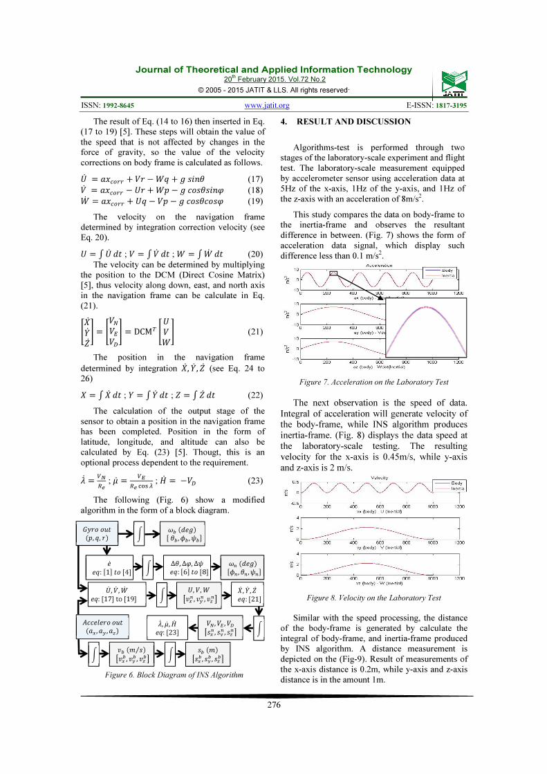
The result of Eq. (14 to 16) then inserted in Eq. (17 to 19) [5]. These steps will obtain the value of the speed that is not affected by changes in the force of gravity, so the value of the velocity corrections on body frame is calculated as follows. � � ������ � ! �"� � ���� (17) !� � ������ � �"� � ���� ���� (18) "� � ������ � � � !� � ���� ���� (19)
The velocity on the navigation frame determined by integration correction velocity (see Eq. 20). � # � $� ; ! � #!� $� ; " � #"� $� (20)
The velocity can be determined by multiplying the position to the DCM (Direct Cosine Matrix) [5], thus velocity along down, east, and north axis in the navigation frame can be calculate in Eq. (21).
%&�'�(� ) � %!�!�!�) � DCM� % !") (21)
The position in the navigation frame
determined by integration &� , '� , (� (see Eq. 24 to 26) & � #&� $� ; ' � #'� $� ; ( � # (� $� (22)
The calculation of the output stage of the sensor to obtain a position in the navigation frame has been completed. Position in the form of latitude, longitude, and altitude can also be calculated by Eq. (23) [5]. Thougt, this is an optional process dependent to the requirement. -� � ��
� ; .� � �
� ���� ; /� � �!� (23)
The following (Fig. 6) show a modified algorithm in the form of a block diagram.
Figure 6. Block Diagram of INS Algorithm
4. RESULT AND DISCUSSION
Algorithms-test is performed through two stages of the laboratory-scale experiment and flight test. The laboratory-scale measurement equipped by accelerometer sensor using acceleration data at 5Hz of the x-axis, 1Hz of the y-axis, and 1Hz of the z-axis with an acceleration of 8m/s2.
This study compares the data on body-frame to the inertia-frame and observes the resultant difference in between. (Fig. 7) shows the form of acceleration data signal, which display such difference less than 0.1 m/s2.
Figure 7. Acceleration on the Laboratory Test
The next observation is the speed of data.
Integral of acceleration will generate velocity of the body-frame, while INS algorithm produces
inertia-frame. (Fig. 8) displays the data speed at
the laboratory-scale testing. The resulting
velocity for the x-axis is 0.45m/s, while y-axis
and z-axis is 2 m/s.
Figure 8. Velocity on the Laboratory Test
Similar with the speed processing, the distance
of the body-frame is generated by calculate the integral of body-frame, and inertia-frame produced by INS algorithm. A distance measurement is depicted on the (Fig-9). Result of measurements of the x-axis distance is 0.2m, while y-axis and z-axis distance is in the amount 1m.
�� , �� , �� eq: [23]
�� , �� , ��
���� , ��� , ���
�� �� ��, �, �� ��� , �� , ���
�������
�� ��:�1�� �4� !" ∆�, ∆$, ∆�
��: �6�� �8� ��� , �� , ��� �������
'� , �� ,(� eq: [17] to [19]
', �,(
�)�� , )�� , )��
*++�,�� �� �-� , -� , -��
)��. �⁄ � �)�� , )�� , )��
���.� ���� , ��� , ���
0� , 1� , 2� ��: �21�
!"
!"
!"
!" !"

Journal of Theoretical and Applied Information Technology 20
th February 2015. Vol.72 No.2
© 2005 - 2015 JATIT & LLS. All rights reserved.
ISSN: 1992-8645 www.jatit.org E-ISSN: 1817-3195
277
Figure 9. Distance on the Laboratory Test
The observations of attitude are conducted as shown in the (Fig. 10). This research uses such data to determine the characteristics and patterns of rate-gyroscope. The frequency of p, q, and r in the amount of 5Hz, 2Hz, and 1 Hz sequentially generates angular velocity. The value of angular velocity is about 7deg / sec.
Figure 10. Angular Velocity on the Laboratory Test
The resulting value of the angle between the
body-frame and the inertia-frame for roll, pitch,
and yaw (Fig. 11) also coincide and has a slight difference of less than 0.1deg.
Figure 11. Angle on Laboratory Test
A flight test is conducted offline (from the
data logger) after the laboratory-scale
measurement. In the first of three hundredth data,
the x-axis acceleration reaches 500m/s2 that
occur when the rocket motor is still burning so
acceleration jump very quickly. A speedup is
found on the first of one hundredth data from 50m/s
2 to 100m/s
2 caused by an extremely high
vibration on y-axis and z-axis, see reference [15].
(Fig. 12) exposes the acceleration data of flight test that compared to the body-frame (blue) and
the inertia-frame (green).
Figure 12. Acceleration on the Flight Test
During the flight test, the calculation is done
by integrating the body-frame and inertia-frame data as a result of the INS algorithm. In the first
of 500th data, body-frame (blue) and the inertia-
frame (green) still coincide with the speeds below 1m/s (Fig. 13). The speed at the end of the
flight test has a difference velocity in the range of 10m/s to 60m/s. Such phenomena happen
because of the influence of noise (drift and
temperature changes) and affected by the sensor output value from a very long time measurement
[4][5][6][8][13].
Figure 13. Velocity on Flight Test

Journal of Theoretical and Applied Information Technology 20
th February 2015. Vol.72 No.2
© 2005 - 2015 JATIT & LLS. All rights reserved.
ISSN: 1992-8645 www.jatit.org E-ISSN: 1817-3195
278
Position/distance obtained from the flight test for the x-axis is still coinciding up to the 750th data (Fig. 14), while the y-axis up to the 1200th data, and the z-axis up to-200th data. The resulting difference of the distance to the end of the flight test ranges from 1.5m to 27m.
Figure 14. Distance on Flight Test
Considering the attitude data, the patterns between the body-frame and the inertia-frame are very different (Fig. 15). Such diversity is caused by the influence of the data alteration on the axis of the roll, hence the difference of the both frame becomes 480deg, while the difference on the pitch axis is about 200deg, and the difference on the yaw in the amount of 110deg. Both frames are still coinciding and have the same pattern until the data of 115th.
Figure 15. Attitude on Flight Test
INS-algorithm is very powerful for very short time measurements. Thus, it needs to be combined with GPS as a correction value for the speed and distance measurements made for a very long time. Correction methods are also needed to revise the corresponding values to the reference data of the GPS.
5. CONCLUSION A novel control of rocket flight test with a modified algorithm which combines INS Euler and Quaternion method has been conducted. The modifications of INS algorithm proves that the proposed method can be used for flight test rocket that has a high-speed and rapid data alteration. In the slow data changes (below 10Hz), body-frame and inertia-frame still have the same pattern and characteristics until the end of the measurement. However, in the accelerated data alteration (above 10Hz), the same pattern occurs only at 115th - 1200th first data. Difference data at the end of the flight test is 10m - 60m for speed and 10m - 40m for a distance, while for the altitude is in the amount of 110deg - 480deg. The future work is to make this system to be fully stand alone in microcontroller which does not sent the navigation data to ground station and combine this algorithm with prediction algorithm.
REFRENCES:
[1] W.S. Flenniken, “Modeling Inertial Measurement Units and Analyzing The Effect of Their Errors in Navigation Application”, Master Thesis, Auburn University, 2005.
[2] K. J. Walchko, “Low Cost Inertial Navigation: Learning to Integrate Noise and Find Your Way”, Master Thesis, University of Florida, USA, 2002, pp: 13.
[3] J. H. Kim, S. Wishart, and S. Sukkarieh, “Real-Time Navigation, Guidance, and Control of UAV using Low-cost Sensors”, The Australian National University, Australia, 2006.
[4] C. W. Tan and S. Park, “Design and Error Analysis of Accelerometer-Based Inertial Navigation System”, Research Reports,
University of California, USA, 2002. [5] V. Kumar N., “Integration of Inertial
Navigation System and Global Positioning System Using Kalman Filtering”, Master
Thesis, Indian Institute of Technology, India, 2004, pp: 8-12.
[6] A. Schumacher, “Integration of GPS Aided Strapdown Inertial Navigation System for Land Vehicle”, Master Thesis, Royal Institute
of Technology, Sweden, 2006. [7] M. Istanbulluoglu, “Performance Tradeoff
Study of A GPS-Aided INS for A Rocket Trajectory”, Master Thesis, Air Force Institute
of Ohio, USA, 2002.

Journal of Theoretical and Applied Information Technology 20
th February 2015. Vol.72 No.2
© 2005 - 2015 JATIT & LLS. All rights reserved.
ISSN: 1992-8645 www.jatit.org E-ISSN: 1817-3195
279
[8] N. Hjortsmarker, “Experimental System for
Validating GPS/INS Integration Algotihms”, Master Thesis, Lulea University of
Technology, Sweden, 2005. [9] Titterton, D. H. and J. L. Weston, “Strapdown
Inertial Navigation Technology Second Edition”, Vol 207, Astronautics and
Aeronautics, MIT Lab., pp: 10. [10] Anderson, E.W. “The Principles of
Navigation”, Holis and Carter, 1966 [11] Titterton, D. H. and J. L. Weston, “Strapdown
Inertial Navigation Technology”, IEE Radar,
Sonar, Navigation and Avionics Series 5, 1997, pp: 259-292.
[12] Ali, J. and F. Jiancheng, “ Alignment of Strapdown Inertial Navigation System: A Literature Survey Spanned Over The Last 14 Years”, pp: 1-12.
[13] R. Wiryadinata, W. Widada, “Modification of Quaternion Equation on INS Algorithm for Rocket Application”, Tekgan Journal, Vol. 8,
No. 2, Indonesia, pp: 98-107. [14] Foxlin, E, M Harrington, Y. Altshuler,
“Miniature 6-DOF Inertial System for Tracking HMDs” SPIE vol 3362, Helmet and
Head-Mounted Displays III, AeroSense 98,
Orlando, FL, April 13-14, 1998, pp: 1-12. [15] Yu, G.Z., N.X Ji, G.M Feng, “Quaternion-
Based Kalman Filter for Micro-machined Strapdown Attitude Heading Reference System”, Chinese Journal of Aeronautics Vol
15. No 3. August 2002, pp. 1-5.