1979: expected life of pressure equipment
TRANSCRIPT

Expected Life ofPressure Equipment
This paper discusses the factors which affect the judgement of thesafety of used and existing piping, pressure vessels, and structures.
LA. ZeisPullman-Kellogg, Houston, Tex.
G.P. EschenbrennerAssociated Pullman-Kellogg Ltd., Alberta, Canada
EXPECTED LIFE OF PRESSURE EQJJIPMENT
In addition to a continuing concern forsafety, there are several occasions When theoperator of pressure equipment must decide ifthat equipment is still suitable for contin-ual operation. Usually a periodic review ismade at each shutdown or turnaround. Afterincidents such as over temperature or over-pressure, process upsets, or other unusualconditions the operator should ask himselfabout the condition of his equipment.
It's not only the out-of*-the ordinarywhich will lessen the useful life of equipment.Operation over long time periods even at thenormal design conditions may cause changes inmaterial integrity which should be considered.Just as humans and autoraobilies change overthe years, some pressure equipment will agewith time. Corrosion, oxidation, fatigue,creep and other time dependent deteriorationscan be anticipated.
One purpose of this presentation is todescribe some of the sources of data and thepublications which can be used to help inevaluating the condition of equipment.
There are many aids in making the decis-ion on the safety of equipment. Remember,doing nothing is a decision based upon a judgrment that everything is satisfactory. Some ofthe aids in deciding are state and local laws,insurance companies, and safety codes an<3standards.0149-3701-80-3909 $01.00 © 1980American Institute of Chemical Engineers
State and Local Laws-
For boilers and in a few cases for unfir-ed pressure vessels and piping, state lawsrequire periodic inspection and judgments asto the continued suitability of operation ofequipment. These inspection requirements arerninimums and the conscientious operator willaugment these with his own program of review.
Insurance Companies -
These companies have an interest in thesafety of your equipment and offer advice tohelp minimize risks.
Safety Godes and Standards •?•
ASME Boiler and Pressure Vessel CodesSections I and VIII1 and Piping Code B31.32
cover rules for new construction of pressureequipment with an indefinite design life.They do not include rules on judging thesafety of used equipment. However ASME Sec-tion XI, "Rules for Inservice Inspection ofNuclear Power Plant Components," offers apractical guideline, framework, and checklistfor the logic process an operator should con-sider in judging the condition of pressureequipment. The detailed procedures and cri-teria are tailored for nuclear caused deterio-ration and not the kind of wear normally ex-pected in process plants.
The National Board of Boiler Vessel In- 3specters publishes a National Inspection Code
86

which contains rules for "Inservice Inspectionof Pressure Vessels by Authorized Owner-UserInspection Agencies." This covers periodicinspection for wall thickness based on measur-ed corrosion rates. The Inspection Gode alsoincludes reconntendations for organizing anOwner-user Inspection Agency. The NationalBoard organization provides guidance for suchOwner-User Agencies,
The British Standard BS5500 "UnfiredFusion Welded Pressure Vessels" and ASME GodeCase 1592-10 "Class 1 Components in ElevatedTemperature Service" provide a method of de-signing for a finite operating life based onthe relationship between stress, temperatureand time. For example, according to ASME CodeCase 1592-10, at 1100°F (593 C) a vessel madefron carbon steel could be designed for a de-sign life of 10 hours with a stress of 13,200psi, (90.9 MPa) or forr 200,000 hours at astress of 5,700 psi (39.3 MPa). The BritishStandard BS5500 is unique in that it is nowpreparing guidelines for judging "Fitness forService" after the original specified designlife has passed. A document is being preparedwhich will provide guidance in the assessmentof the residual life of equipment which hasoperated at conditions where time dependentproperties control design life.
API "Guide for the Inspection of RefineryEquipment"5 are twenty individually boundchapters covering conponents of process plants;for example, Chapter VI "Unfired PressureVessels," Chapter VII "Heat Exchangers, Con-densors and Cooler Boxes" and Chapter XI "Pipe,Valves, Fittings." This information offers anexcellent guide for continued safe operation.It covers the theory, the practical methodsof examination, how to interpret the resultsof examination, and most importantly, goodrecord-keeping.
API KP 530 "Recommended Practice forCalculation of Heater Tube Thickness in Petro-leum Refineries"° permits determination of theremaining life in furnace tubes based on thetime the tubes were operated at various temp-eratures and whether wall thickness has beenlost by corrosion.
API RP 510 "Maintenance, Inspection, Rat-ing, and Repair of Pressure Vessels" reccm-mends procedures, forms, and method of ratingof pressure vessels. It also contains amethod for evaluating the effect of scatteredcorrosion pits on vessel integrity. A similarapproach is used in ASME Section XI "Rules forInservice Inspection of Nuclear Plant Com-
ponents."
The guides and recommendations describedabove are meant to be just that - guides forestablishing what the condition is and theyoffer general recommendations. The finalanswer to the question "Is it safe?" must inthe end be made by the operator. That deci-sion should be based on knowledge and exper-ience - knowledge of the condition of theequipment, its history and its expected be-havior, and experience - your own and theexperience of others.
Most process equipment will last forever.Pressure equipment which is in non-corrosive,non-fatiguing service below the creep rangewill operate forever, barring accidents. Thedesign factors are such that the primaryworking stresses are well below the yieldpoint of the materials used.
Which equipment has a limited life? Thesimplest example of shortened life is wherewall thickness is removed by corrosion orerosion. As the wall thickness decreases,the load stays the same and the stress in-creases. When the wall thickness decreasesto the point where the pressure container isoverstressed, it will fail.
The other major predictable failure isthat caused by creep or rupture at elevatedtemperatures. First, you should determinewhich equipment is in the creep range.
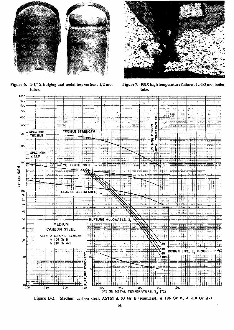
Figure 3-B from API RP 530, May 1978*shows the design curve for carbon steel (A53&A106 GrB) furnace tubes. In the ElasticRange the Allowable stress is 2/3 the yieldstrength at temperature. In the plasticrange the Rupture Allowable stress is 100% ofthe minimum stress causing rupture in either20,000 hours, 40,000 hours, 60,000 hours or100,000 hours. The creep stress basis isusually based on the stress to cause a creepof 0.01% per 1000 hours and is less than therupture strength for 100,000 hours and istherefore not considered for Carbon Steelfurnace tubes. The term "in the creep range"can be understood by referring to Figure 3B.At temperatures below 775°F (413 C) the de-sign basis is the elastic allowable stress.
* Figure 3B, "Medium Carbon Steel, " of APIRP 530, Recommended Practice for Calculationof Heater Tube Thickness in PetroleumRefineries, Second Edition, May 1978, reprint-ed by courtesy of the American PetroleumInstitute."
87
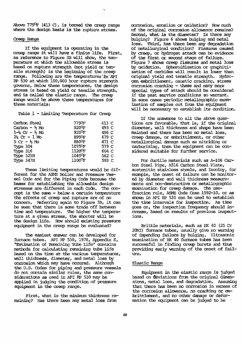
Above 775°P (413 C), is termed the creep rangewhere the design basis is the rupture stress.
Creep Range
If the equipment is operating in thecreep range it will have a finite life. First,as reference to Figure 3B will show, the tem-perature at which the allowable stress isbased on rupture strength (not yield or ten-sile strength) is the beginning of the creeprange. Following are the temperatures :in~ APIKP 530 at which 100,000 hour rupture strengthgoverns, Below these temperatures, the designstress is based on yield or tensile strength,and is called the elastic range. The creeprange would be above these temperatures forthese materials:
Table 1 - Limiting Temperature for Creep
Carbon SteelCarbon - h Mo1-% Cr - h Mo2% Cr - 1 Mo5 Cr - h MoType 304Type 316Type 321HType 347H
7750F9209F925°F8950F8809P10759F1120°F1045°F1100°F
413493496 C479 C471 C579 C604 C562 C593 C
These limiting temperatures would be dif-ferent for the ASME Boiler and Pressure Ves-sel Code and for the Piping Code because thebases for establishing the allowable designstresses are different in each Code. The con-cept is the same - below a certain temperaturethe effects of creep and rupture are of noconcern. Referring again to Figure 3B, it canbe seen that there is seme trade off betweentime and temperature. The higher the tempera-ture at a given stress, the shorter will bethe design life. How should existing pressureequipment in the creep range be evaluated?
The easiest answer can be developed forfurnace tubes. API RP 530, 1978, appendix E,"Estimation of Remaining Tube Life" containsmethods for calculating remaining tube lifebased on the time at the various temperatures,wall thickness, diameter, and metal loss bycorrosion which may have occured. Althoughthe U.S. Codes for piping and pressure vesselsdo not contain similar rules, the same con-siderations as used in API RP 530 may beapplied in judging the condition of pressureequipment in the creep range.
First, what is the minimum thickness re-maining? Has there been any metal loss from
corrosion, erosiion or oxidation? How muchof the original corrosion allowance remains?Second, what is the diameter? Is there anybulging? Figure 6 shows bulging and metalloss. Third, has there been any degradationof metallurgical condition? Fissures causedby creep, or hydrogen attack can be evidenceof the first or second stage of failure.Figure 7 shows creep fissures and metal lossby oxidation. Spheroidization or graphiti-zation of carbides will result in lower thanoriginal yield and tensile strength. Hydro-gen embrittlement, caustic cracking, stresscorrosion cracking - these and many morespecial types of attack should be consideredif the past service conditions so warrant.In some cases periodic metallographic exam-ination of samples cut from the equipmentwill be necessary to establish its condition.
If the answeres to all the above ques-tions are favorable, that is, if the originaldiameter, wall thickness and shape have beenmainted and there has been no metal loss,creep damage, or embrittlement, or othermetallurgical damage such as nitriding orcarburizing, then the equipment can be con-sidered suitable for further service.
For ductile materials such as A-106 Car-bon Steel Pipe, A516 Carbon Steel Plate,austenitic stainless steels, and Incoloy, forexample, the onset of failure can be monitor-ed by diameter and wall thickness measure-ments and non-destructive or metallographicexamination for creep damage. The use-fraction rule, ASME Code Case 1592-10, or asshown in API RP 530 can be used to establishthe time intervals for inspection. As timegoes on, the inspection frequency should in-crease, based on results of previous inspect-ions.
Brittle materials, such as HK 40 (25 Cr20NI) furnace tubes, usually give no warningof impending failure by bulging, ultrasonicexamination of HK 40 furnace tubes has beensuccessful in finding creep bursts and thusproviding early warning of the onset of fail-ure.
Elastic Range
Equipment in the elastic range is judgedbased on déviations from the original dimen-sions, metal loss, and degradation. Assumingthat there has been no corrosion in excess ofthe corrosion allowance, no cracking or em-brittlement, and no other damage or defor-mation the equipment can be judged to be
88

suitable for continued long service,
Other Damage
The design conditions - pressure andtemperature assure that the équipaient willerate under conditions which will produce anindefinite life. Accidents causing mechanicaldamage - dents gouges, or cracks, over pres*-suring which may cause yielding, or overtemprerature which may cause yielding or metallur*-gical damage - all these events would call fora careful examination of the equipment and areassessment of its fitness for service.
Fatigue damage is detected by non*des<rtractive examination (magnetic particle orliquid penetrant). Once fatigue cracks appearthe equipment should be repaired or replacedand the design changed to lower the stress,lower the number of cycles or lower the ampli-rtude of the cyclic load.
Fire damage can include metallurgical damr-age, over-stressing at higher temperature, urn-usual corrosion *- either metal loss or inter-rgranular attack, or melting. Each affecteditem should be examined and reassessed bycomparison to its original condition. Fire oroverheating can degrade the low temperatureimpact properties of carbon and low alloysteels. In many cases the only way to determine if there has been no damage is to cut outsamples and perform impact tests.
The Decision
The simpliest decision is for the pipe,vessel or exchanger in the elastic range (lowand moderate temperature service) which is ina non-corrosive, non«-fatiguing service. Itwill last forever.
Corrosive services will be limited by thecorrosion rate which is generally predictable.If there is no embrittlement or intergranularattack, the life is a function of time. Whenthe corrosion allowance is used up, the equip*-ment should be replaced.
Service of ductile materials in the creeprange could be continued until the diameterand thickness change to the point where thepressure shell is overstressed, or until creepbursts begin to connect into cracks. At thattime, failure is imminent.
There are many vessels which have beenoperating in the creep range for long times.For example, carbon steel catalytic cracker
reactors have operated in the 700° - 975°F(371-524 C) temperature range for 36 years(more than 300,000 hours) and longer". Al-though this is not forever, it does indicatethat the creep stress basis need not be aceiling on useful life. The stress basis forcarbon steel in the creep range in the ASMECode VIII is the lower of:
100% of the average stress for a creeprate of 0.01%/1000 hour, or 67% of theaverage stress for rupture at the endof 100,000 hours or 80% of the minimumstress for rupture at the end of100,000 hours.
Referring again to Figure 3B, the fact-ors on rupture give a logarithmic relation-ship between stress and rupture life. Thatis, 80% of the stress for rupture will yieldmuch more expected life than the arithmeticproportion of 100% to 80%.
Long time at elevated service tempera-ture will cause spheroidization and graphiti-zation of carbides in carbon steel and carbon-molybdenum steel, and a lowering of yieldstrength and tensile strength. Although thestrength has been lowered, the yield strengthis well above the design stress and the ves-sels continue to operate safely. As long asthe diameter and wall thickness remain as de-signed and there is no cracking or localyielding, the vessel can operate safely. Astime goes on, inspections should be more fre*-quent since there will be a time when creepbursts, yielding and visible bulging will be-gin.
The most straightforward basis for jud-ging the suitability of used pressure equip-ment, either your own existing equipment orpurchased used equipment, is to check conform-ity with the governing Codes. First, thelocal boiler, pressure vessel or piping lawsand regulations must be satisfied. Part ofthat conformity to local laws will includeverification that the equipment conforms to aCode. Normally, the Code to be used is theyear of the Code to which the equipment wasbuilt. If you can verify that the design,materials, fabrication, and inspection meeta later edition of a Code, that later editioncould be used, providing the local law allowsit.
Summary
The judgment as to safety of equipmentshould be based on knowledge and experience.
89

Knowledge of the condition of the equipment isbased on:
1. Original design data and drawings.2. Besults of measurements of thickness
and dimensions.3. Results of non-destructive examinat-
ions.4. Documented history of service.5. Expected behavior of the equipment.
Your own experience and that of othersvri.ll affect the decision. How has similarequipment behaved? What is the likelihood offailure?
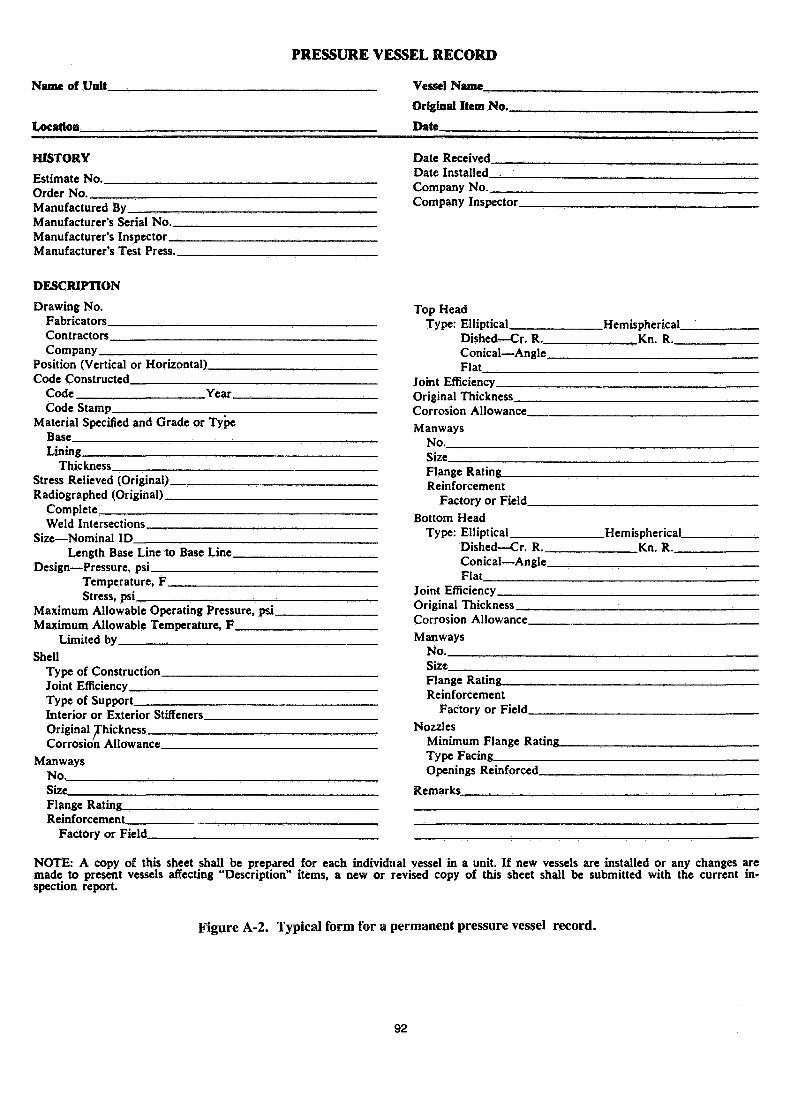
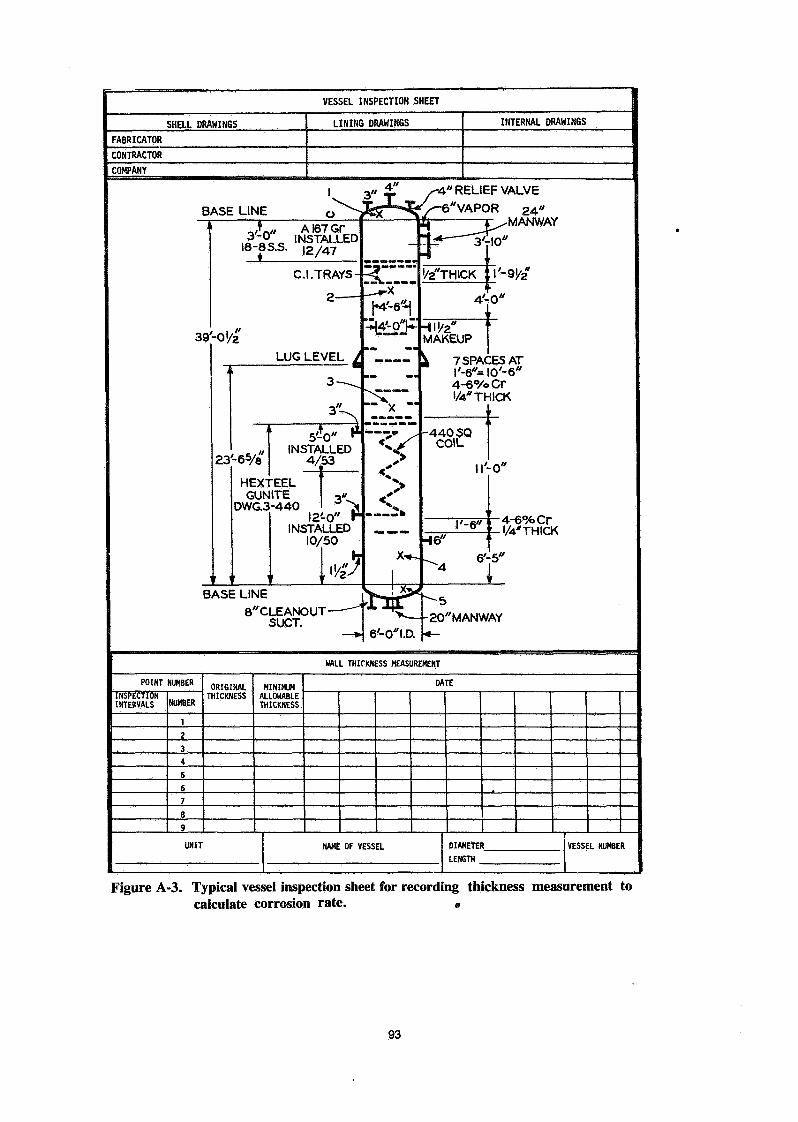
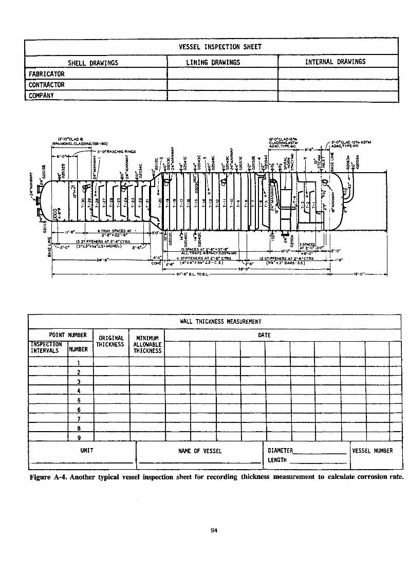
The best guide for records, inspectionguides and documentation is in the API "Guidefor Inspection of Refinery Equipment." Fig-ures A-l, A-2, A-3, A-4 and A-5 from ChapterVT* of those guides are typical of the detailprovided. Such documentation is vital today.Although after some equipment failures theremay be litigation or other legal problemswhich inhibit a free interchange of informa-tion, it is the open discussion of such in-cidents which will help the operators of suchequipment in maintaining the long time safetyof their opérations.
* Figure A-l, A-2, A-3, A-4 and A-5 of theGuide for Inspection of Befinery Equipment,Chapter VT, Pressure Vessels (Towers, Drums,and Reactors) Third Edition, 1976, reprintedby courtesy of the .American Petroleum Insti-tute."
LITERATURE CITED
1. ASME Boiler and Pressure Vessel Code,Section I and Section VIII, 1977.Published by the American Society ofMechanical Engineers.
2. ASME B31.3 Refinery Piping Code 1976,Published by the American Society ofMechanical Engineers, N.Y., N.Y.
3. National Board Inspection Code, 1977,Published by The National Board ofBoiler and Pressure Vessel Inspectors,Columbus, Ohio.
4. BS 5500 Unfired Fusion Welded PressureVessels, Published by British StandardsInstitution, London.
5. API Guide for Inspection of RefineryEquipment, 1976, Published by AmericanPetroleum Institute.
6. API RP 530, 1978, Recotroended Practicefor Calculation of Heater Tube Thicknessin Petroleum Refineries, Published bythe Snerican Petroleum Institute.
7. API RP 510, Maintenance, Inspection,Rating and Repair of Pressure Vessels,Published by the American PetroleumInstitute.
8. NPRA Maintenance Panel, 1978, Oil andGas Journal March 19, 1979, P. 104,Vol. 77 No. 12.
ESCHENBRENNER, G.P.
90

Owner or User No Owner
Jurisdiction orNational Board No Owner
Date
Date
Manufacturer
Manufacturer's Serial No
Design Pressure
Temperature
Original Hydrostatic Test Pressure
Original Thickness: A B
Corrosion Allowance: A B
C
C
D
D
Date ofInspection
Thickness atCritical Points
A B C D
Maximum MetalTemperature atCritical Points
A B C D
Minimum AllowableMetal Thickness at
Critical PointsA B C D
'
Date of NextInspection
Signatureof
Inspector
Description of Location
Description of Location
Description of Location
Description of Location
Description of Location
Date
Date
Date
Date
Date
NOTE: Manufacturer's drawing can be used to show the location of A, B, C, D.
Figure A-l. Typical form for an inspection record of pressure vessels in service.
91
Name of Unit.
PRESSURE VESSEL RECORD
Vessel Name__
Location
Original Item No._
Date
HISTORY
Estimate No..Order No.Manufactured ByManufacturer's Serial No—Manufacturer's InspectorManufacturer's Test Press..
Date Received,Date Installed.Company No._Company Inspector.
DESCRIPTION
Drawing No.FabricatorsContractors.Company
Position (Vertical or Horizontal)Code Constructed
Code Year.Code Stamp.
Material Specified and Grade or TypeBaseLining.
Thickness.Stress Relieved (Original).Radiographed (Original) _
CompleteWeld Intersections.
Size—Nominal IDLength Base Line to Base Line.
Design—Pressure, psiTemperature, F_Stress, psi
Maximum Allowable Operating Pressure, psi.Maximum Allowable Temperature, F
Limited byShell
Type of ConstructionJoint EfficiencyType of SupportInterior or Exterior Stiffeners.Original Thickness.Corrosion Allowance.
ManwaysNo.Size_Flange Rating_Reinforcement.
Factory or Field.
Top HeadType: Elliptical.
Dished—Cr. R._Conical—Angle.Flat
.Hemispherical.Kn. R.
Joint EfficiencyOriginal ThicknessCorrosion Allowance.Manways
No.SizeFlange Rating.Reinforcement
Factory or Field.Bottom Head
Type: EllipticalDished—Cr. R._Conical—Angle.Flat
.Hemispherical.Kn. R._
Joint EfficiencyOriginal ThicknessCorrosion Allowance.Manways
No.SizeFlange Rating.Reinforcement
Factory or FieldNozzles
Minimum Flange Rating.Type FacingOpenings Reinforced.
Remarks
NOTE: A copy of this sheet shall be prepared for each individual vessel in a unit. If new vessels are installed or any changes aremade to present vessels affecting "Description" items, a new or revised copy of this sheet shall be submitted with the current in-spection report.
Figure A-2. Typical form for a permanent pressure vessel record.
92
VESSEL INSPECTION SHEET
SHELL DRAWINGS LINING DRAWINGS INTERNAL DRAWINGS
FABRICATOR
CONTRACTOR
COMPANY
"RELIEF VALVE
"VAPOR 24"MANWAY1
39
_,*-„ A 167 Gr3-0" INSTALLED
I8-8S.S. 12/47
C.I. TRAYS -
2
-ofe'LUG LEVEL 1
i
23
3/S5'V «"
, . . INSTALLED'-6S/8 4/53
HEXTEEL fGUNITE V'
DWG.3-440 1 J>I2'-0" H
INSTALLED10/50
.. Its*
-
!
]*— 3p'/2*THICK |l-
4'-1
MAKEUP
k 7SPACi /_»//_.
4-6°/o1/4" Tl-
-440 SQCOIL
ll<
i
l'-6"^e"
i
k0"
:ESo'-er
1ICH
i
0"
(• 1
5"
4-6% Cr
8"CLEANOUT-SUCT.
6'-0*I.D.•20"MANWAY
MALL THICKNESS MEASUREMENT
POINT NUMBERINSPECTION „ „ „INTERVALS NUMBER
ORIGINALTHICKNESS
MINIMUMALLOWABLETHICKNESS
DATE
UNIT NAME OF VESSEL OIAMETER_
LENGTHVESSEL NUMBER
Figure Â-3. Typical vessel inspection sheet for recording thickness measurement tocalculate corrosion rate. »
93
VESSEL INSPECTION SHEET
SHELL DRAWINGSFABRICATORCONTRACTORCOMPANY
LINING DRAWINGS INTERNAL DRAWINGS
I3'-IO"O_AD «L15*. MONEL CLADDING (38-l«O)
Ky-0*a.AD 151*CLADDING ASTMA24O,TyP£4IO
,-/
e'-6"— • -U
3-0'CLAO 15*. ASTM
WALL THICKNESS MEASUREMENT
POINT NUMBERINSPECTIONINTERVALS NUMBER
12
34
56789
ORIGINALTHICKNESS
MINIMUMALLOWABLETHICKNESS
UNIT
DATE
NAME OF VESSEL DIAMETERLENGTH
VESSEL NUMBER
Figure A-4. Another typical vessel inspection sheet for recording thickness measurement to calculate corrosion rate.
94
Name of Unit
PRESSURE VESSEL RECORD
Location
Inspection and Test No._ Date.
NAME OF VESSEL
COMPANY VESSEL AND SKETCH NO.
OPERATING DATAHours Under Pressure to Date
SERVICE DATA
Average Maximum Operating Tempera-ture, F
TopBottom
No. TraysNo. BafflesNo. Coils
INSPECTION AND TEST DATAInspectorNominal IDMinimum Thickness
ShellLocation - — . ...Top HeadBottom Head
Joint Efficiency — ShellHeads
Head Factor TopBottom
Last InspectionInside WeldsOutside Welds
Test Pressure
Time Pressure Held (l) + (2)Maximum Allowable Operating Pressure,
psiMaximum Allowable Operating Tempera-
ture, FLimited by
Working Stress, psi — Operating Tempera-ture
Approved Operating Pressure, psi
Safety Valve Setting psi
PROTECTIVE LINING DATADrawing NoDate InstalledMaterial and Type :Section LinedDate Repaired
Extent of RepairsDate Previous Lining Removed
Cause of Removal .'.
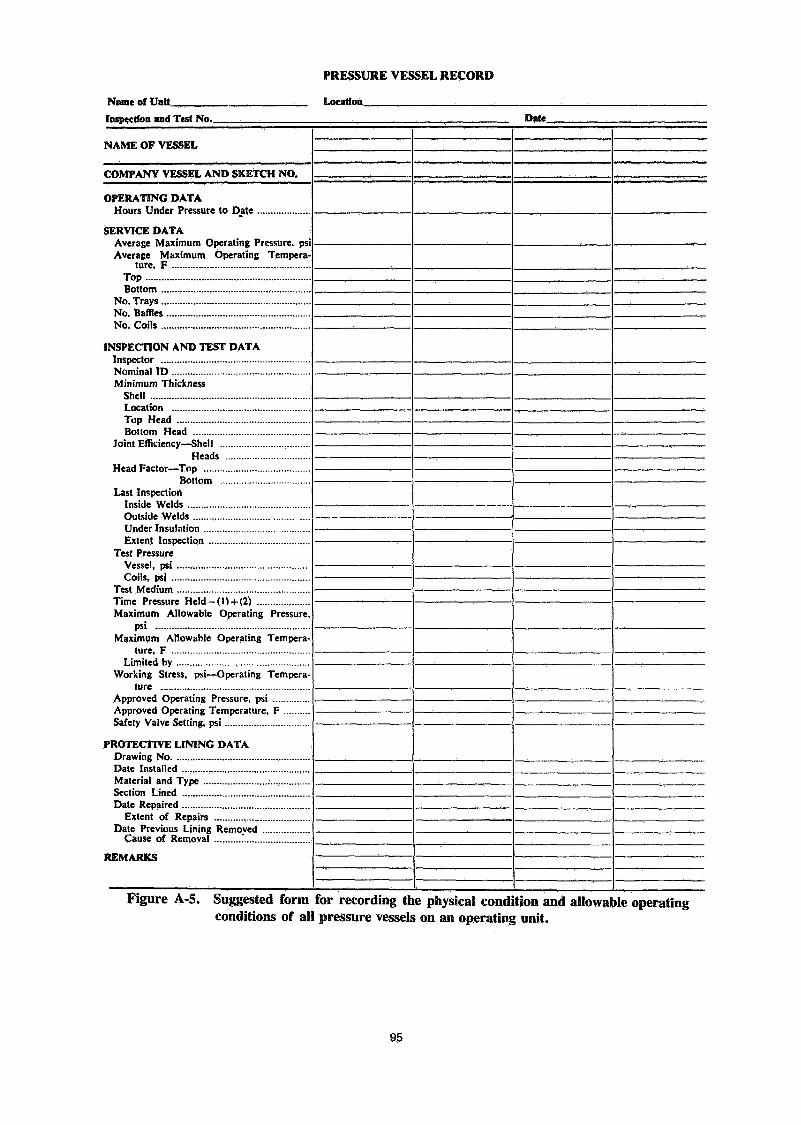
Figure A-5. Suggested form for recording the physical condition and allowable operatingconditions of all pressure vessels on an operating unit.
95
?"S .is *'?-Jk-. *•»*'•' •"
Figure 6. 1-1/4X bulging and metal loss carbon, 1/2 mo. Figure?. S OCX high temperature failure of c-1/2 mo. boilertubes. tube.
1000
TENSILE STRENGTHSPEC MINTENSILE
SPEC MINYIELD
Y ELD STRENGTH
ELASTIC ALLOWABLE, S
RUPTURE ALLOWABLE, Sf 3
MEDIUMCARBON STEEL
ASTM A 53 Gr B (Seamless) -A 106 Gr BA 210 Gr A-1
DESIGN LIFE, Lrf (HOURS x
10200 250 300 600
DESIGN METAL TEMPERATURE, Trf (°C)
Figure B-3. Medium carbon steel, ASTM A 53 Gr B (seamless), A 106 Gr B, A 210 Gr A-1.
96

DISCUSSION
JOHN LiVINSTONE, ICI: As one of many operators, I have ahorrible feeling that all the information that keeps piling upon meabout vessels and piping and about decisions to run or not run theplant is on the wrong side. There doesn't seem to be enoughevidence about destructive testing of these pieces of equipment.
It's growing more and more difficult with these plants to take therisk of operating with cracks, because there just doesn't seem tobe enough known about destructive tests, and just how much of arisk is involved in operating when some cracks start to appear.Have you, or could you give us any enlightenment on some of thework that's going on in that sort of side of the scale?
L. ZIES, Pullman Kellogg: The Erskine paper discusses thattopic, which is - "Can you safely operate a piece of equipmentwith cracks in it?"
This has been answered with a fracture mechanic's approach.It has been used, for example, on the Alaska pipe line, when theybecame aware of some cracks in the pipe line which had beenmissed on the original radiograph. The affected portion of thepipe line was under a river, or something similar where it wasalmost impossible to get at the weld and repair them.
It was possible, through the use of fracture mechanics todecide whether or not the crack would cause a failure. This is acalculation tying together the length of the crack, the brittleness ofthe material, and the stress in relation to the yield strength. It hasbeen used in many other instances, most of them called to ourattention by vendors of equipment, who have cracks in equipmentwhich they would like to sell.
We're suspicious of that particularly because our clients wantto buy new equipment, and we would think it should be crack-free.Secondly, although much work has been done on fracturemechanics, and even though it's used in the nuclear energy codeto evaluate cracks which cannot be repaired, we feel that in thepressure vessel codes we use and in our own practice we alwaysavoid operating pressure equipment with cracks in it.
As an operator and an owner, you have to make up your ownmind about that. The most conservative approach would be tosay, "If it has a crack in it, we want to have it repaired." But theremay be a time when that is not practical and you would want tolook at the science of fracture mechanics. As the operator youhave to make the decision, and you must remember that there'salways an outside chance that the metallurgist could be wrong.
LIVINGSTONE: I'm sure that Ralph Erskine would never admitthat. I'll hold some of what I want to say until he has spoken,
because I do know he's in this field and very much a sparringpartner at home. I'm not going to spar with him here, but I thinksome of the very helpful advice we get from Ralph and people likeyourself does need to be backed up a little bit with experimentaldata because I think as plants grow older - say 12,13,14 years ofage - then problems of cracks do start, and the operator is facedwith the decision of just what to do.
JON BLANKEN, UKF: We operate two used cars, one for 12 years, one for eight years. And we've come to
a point where we would like to / could justify replacing thecatalyst. We have been asking ourselves whether after 8 or 12years we shouldn't inspect our converter internals. Is there anyexperience indicating what part of the internals of a converter weshould replace, and therefore have the material available to beable to install new catalysts and operate it another ten yearswithout inspecting the internals. We worry about nitriding of thestainless steel.
ZIES: That's not really related to safety as we were talking earlier,but there has been some experience which Bob Phillips and Iwere talking about today. Yes, you do get nitriding, but it seems tobe self limiting. It's only for a few thousandths of an inch deep andit doesn't significantly affect the pressure thickness. Theinspection of welds in internals should be by liquid penetrant andmagnet tests; and if you find any cracks they should be repaired.
The only things that would need to be replaced would be thinsections. We have seen cases where some strands of the wiremesh were made of the wrong wire ; instead of Inconel, they wouldbe austenitic stainless steel. That will nitride all the way through,ome of the thinner components may also nitride all the way
through, and those should also be replaced. But the basket itself,barring stress-corrosion cracking, should be in no trouble,because it is very much over-designed for the stress it is under,and the nitride surface will not affect its load carrying ability.BLANKEN: We have also considered the bellows. We wouldconsider that a part which should be replaced or at least haveavailable spares.
ZIES: Bellows do have a finite life. The bellows manufacturer willtell you that. They are good for only so many cycles. It's difficult tosay what stresses and what cycles are going through inside thatconverter all the time. I believe the operators who have beenthrough this might be able to give you more enlightenment than Icould.
97