1973-87 gm p/u, 1973-91 blazer, suburban, 1 ton 4wd 4”-6” kits · 2018-01-11 · 92114500...
TRANSCRIPT
92114500
1973-87 GM P/U, 1973-91 Blazer, Suburban, 1 Ton 4WD 4”-6” Kits
Thank you for choosing Rough Country for all of your suspension needs. Rough Country recommends a certified technician installs this system. In addition to these instructions, professional knowledge of disassemble/reassembly procedures as well as post installation checks must be known. Attempts to install this system without this knowledge and expertise may jeopardize the integrity and/or operating safety of the vehicle.
Please read all the instructions before beginning the installation. Check the kit hardware against the Kit Contents list on next page. Be sure you have all the needed parts and understand where they go. Also please review the tools needed list to be certain that you have the tools necessary to complete the installation.
PRODUCT USE INFORMATION
As a general rule, the taller a vehicle is the easier it will roll. We strongly recommend, because of roll-over possibility, that seat belts and shoulder harnesses should be worn at all times. Avoid situations where a side roll-over may occur. Braking performance and capabilities are decreased when significantly larger/heavier tires and wheels are used. Take this into consideration while driving. Also, speedometer recalibration is necessary when larger tires are installed.
Do no add, alter, or fabricate any factory or after-market parts which increase vehicle height over the intended height of the Rough Country product purchased. Mixing component brands, lifts, with this suspension lifts voids all warranties. Rough Country makes no claims regarding lifting devices and excludes any and all implied claims. We will not be re-sponsible for any product that is altered.
NOTICE TO DEALER AND VEHICLE OWNER
Any vehicle equipped with any Rough country product must have the “Warning to Driver” decal installed on the sun visor or dash. The decal is to act as a constant reminder for whoever is operating the vehicle of its unique handling character-istics. INSTALLING DEALER—It is your responsibility to install the warning decal and to forward these installation in-structions on too the vehicle owner for review and to be kept in the vehicle for its service life.
We hope installing your Rough Country lift kit is a positive experience. Please note that variations in construc-tion and assembly in the vehicle manufacturing process will virtually ensure that some parts may seem difficult to install. Additionally, the current trend in manufacturing of vehicles results in a frame that is highly flexible and may shift slightly on disassembly prior to installation. The use of pry bars and tapered punches for align-ment is considered normal and usually does not indicate a faulty product. However, if you are uncertain about some aspect of the installation process, please feel free to call our tech support department at 800-222-7023. We do not recommend that you modify the Rough Country parts in any way as this will void any warranty ex-pressed or implied.

KIT CONTENTS
FRONT LEAF SPRINGS W/ BUSHINGS
FRONT LEAF SPRINGS W/ BUSHINGS
STEERING ARM
(4) SHOCKS
REAR BLOCKS
REAR LEAF SPRINGS
STEERING ARM
(4) SHOCKS
REAR UBOLTS
REAR UBOLTS
FRONT UBOLTS
FRONT UBOLTS
BRAKE LINE BRKTS
BRAKE LINE BRKTS
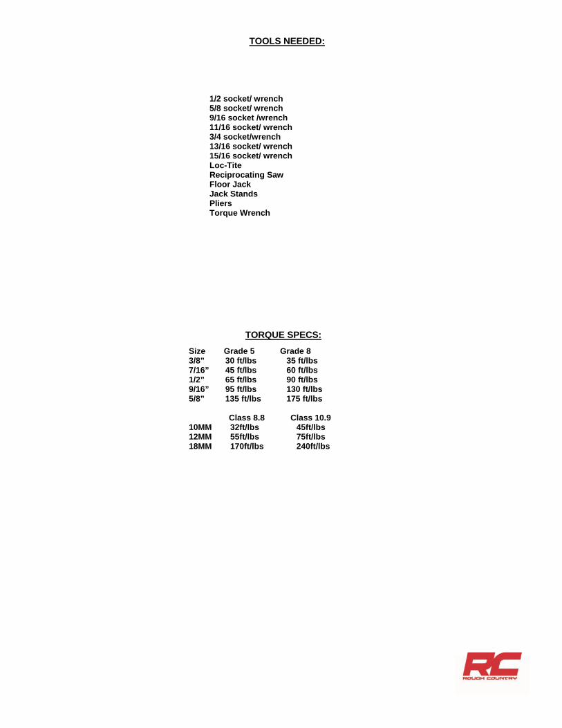
TORQUE SPECS: Size Grade 5 Grade 8 3/8” 30 ft/lbs 35 ft/lbs 7/16” 45 ft/lbs 60 ft/lbs 1/2” 65 ft/lbs 90 ft/lbs 9/16” 95 ft/lbs 130 ft/lbs 5/8” 135 ft/lbs 175 ft/lbs Class 8.8 Class 10.9 10MM 32ft/lbs 45ft/lbs 12MM 55ft/lbs 75ft/lbs 18MM 170ft/lbs 240ft/lbs
1/2 socket/ wrench 5/8 socket/ wrench 9/16 socket /wrench 11/16 socket/ wrench 3/4 socket/wrench 13/16 socket/ wrench 15/16 socket/ wrench Loc-Tite Reciprocating Saw Floor Jack Jack Stands Pliers Torque Wrench
TOOLS NEEDED:

INSTALLATION INSTRUCTIONS 1. Chock the rear wheels. 2. Jack up the front of the vehicle. 3. Place jack stands on the frame behind the lower control arms. 4. Lower the vehicle onto the jack stands and remove the tires and wheels. 5. Place the floor jack under the front axle. 6. Using a 3/4” socket and wrench remove the lower shock bolt. Retain factory hardware. See Photo 1. 7. Using 3/4” wrench, remove upper shock bolt. Retain factory hardware. See Photo 2.
8. Remove the 3 nuts securing the steering arm to the knuckle using a 7/8” socket. See Photo 3. 9. Remove cotter pin. Then, using a 15/16” wrench loosen the nut securing the steering arm to the drag link, it may be
necessary to hit the steering arm with a hammer to break the taper loose. Save hardware for reuse. See Photo 4. You may need to replace the cotter pin.
10. Support the front axle with a floor jack. 11. Using a 7/8” socket, remove the front spring bolts and retain for reuse. See Photo 5. 12. Using a 13/16” socket, remove the rear spring bolts and retain for reuse. See photo 6.
Photo 1 Photo 2
Remove front spring bolt.
Photo 5
Remove rear spring bolt.
Photo 6
Remove lower shock bolt. Remove upper shock bolt.
Photo 3 Photo 4
Remove steering arm. Remove steering arm.

13. Lower the axle. Note: use caution when lowering the axle not to over extend the brake lines. 14. Using a 15/16” socket, remove the ubolts and stock spring. See Photo 7. 1 ton models will have ubolts and studs. 15. After the spring is free from the axle, remove the spring. 16. Install supplied bushings and sleeves in both ends of leaf spring. 17. Using factory hardware install the front spring bolt and tighten using a 7/8” socket. See Photo 8.
18. Install factory bolt in the rear spring eye and tighten using a 13/16” socket. See Photo 9. 19. Install supplied ubolts, washers ,and nuts. Tighten using a 15/16” socket. See Photo 10.
Remove ubolts.
Photo 7 Photo 8
Install front spring bolt.
Photo 9 Photo 10
Install rear spring bolt. Install ubolts.

Photo 11 Photo 12
Tighten upper shock bolt. Tighten lower shock bolt.
20. Clean mounting surface thoroughly and install the new Rough Country steering arm using the new nuts supplied in the kit. Torque nuts to 90ft/lbs.
21. Inspect the drag link assembly. If the drag link is worn or the ball joint grease boot is torn, replace the assembly. Install the drag link onto the steering arm but do not tighten. It may need to be adjusted to allow the wheels to travel from stop to stop without binding the steering mechanism.
22. Install new Rough Country N2.0 front shocks. 4” lift kits will use 658695. 6” lift kits use 658692. Upper mount will
use spacer bushing and sleeve. 1/2” sleeve will need to be pressed into the lower bushing. Shock body goes down. 23. Using factory hardware, tighten the upper shock bolt using a 3/4” wrench. See Photo 11. 24. Using factory hardware, tighten the lower shock bolt using a 3/4” wrench and socket. See Photo 12.
Steering Arm Install

REAR INSTALLATION INSTRUCTIONS 1. Chock the front tires. 2. Position a floor jack under the rear differential and jack up the vehicle. 3. Place jack stands under the frame rails just forward of the front leaf spring hangers and lower the frame on the jack
stands. 4. Reposition the floor jack under the center of the differential and apply slight pressure for support, but do not raise the
frame off the jack stands. 5. Remove the rear shock with a 15/16” wrench on the upper and 13/16” and 7/8” wrenches on the lower mount. Re-
tain lower hardware for reuse. See Photos 1 & 2.
6. Using a 15/16” socket, remove the factory ubolts and lower axle. See Photo 3. Note: use caution when lowering the axle not to over extend the brake lines.
7. Kit with rear blocks, place supplied lift block between the leaf spring and axle pad. Thicker end of the block goes to the rear of the truck. See Photo 3. If your kit has new rear leaf springs, skip to next step.
8. Using a 13/16” socket, remove the front spring bolt and retain for reuse. See Photo 4.
9. Using a 13/16” and 7/8” socket and wrench, remove the rear spring bolt and retain for reuse. See Photo 5. 10. Install supplied rear springs using stock hardware. Tighten using 13/16” and 7/8” sockets/wrenches. See Photo 6.
Photo 1 Photo 2
Remove factory shock. Remove factory shock.
Photo 3 Photo 4
Remove ubolts. Remove front spring bolt.
Photo 5 Photo 6
Remove rear spring bolt. Install new leaf spring.

11. Using a cutoff wheel, cut the factory e-brake cable mount and bend. See Photo 7. 12. Remove e-brake cable and bend mount back to original position. See Photo 8. Apply paint to cut surfaces to
prevent rust.
13. Attach 1/4” coupler and hose to differential breather hose. See Photo 9. 14. Attach rear brake line relocation bracket to the differential. Using supplied 5/16” x 1” bolt washer and nut, attach the
factory brake line bracket to the relocation bracket. Tighten using 1/2” wrench and socket. See Photo 10.
15. Install supplied shock pin kit into frame. See Photo 11. 16. Install rear shock (658694) on pin and tighten using 15/16” wrench. See Photo 12. Body of the shock goes
down. 17. Insert sleeve into lower shock eye. Attach using factory hardware and tighten using 12/16” and 7/8” wrenches. 18. Install wheels and tires and lower the vehicle to the ground.
Photo 7 Photo 8
Photo 9 Photo 10
Cut E-brake bracket. Remove E-brake cable from bracket.
Install vent tube extension. Install brake line relocation bracket.
Photo 11
Install rear shock mounting pin.
Photo 12
Install rear shock.

POST INSTALLATION INSTRUCTIONS
1. Check all fasteners for proper torque. Check to ensure for adequate clearance between all rotating, mobile, fixed, and heated members. Verify clearance between exhaust and brake lines, fuel lines, fuel tank, floor boards and wiring harness. Check steering gear for clearance. Test and inspect brake system.
2. On some vehicles the front lower skirting will need to be trimmed if using certain wheel /tire combinations and with heavy offset wheels. Trim only as needed.
3. Activate four wheel drive system and check front hubs for engagement. 4. Have a qualified alignment center align the vehicle immediately. Realign to factory specifications. Have headlights
adjusted to proper settings. 6. Perform head light check and adjustment to proper settings. 7. Check and retighten wheels at 50 miles and again at 500 miles. 8. Recheck lifted height and adjust torsion bar as necessary. 9. All kit components must be retightened at 500 miles and then every three thousand miles after installation. Periodi-
cally check all hardware for tightness. 10. Install “Warning to Driver” decal on sun visor.
Front
Total Toe -0.10° +0.10° +0.30°
Front Camber -0.90° -0.10° +0.70°
Caster +1.80° +2.80° +3.80°
King-Pin ——— ——— ———
Incl. Angle ——— ——— ———
Rear
Total Toe ° ° °
Rear Camber ° ° °
Thrust Angle -.025° +0.00° +0.25°
Alignment Specs

Thank you for choosing Rough Country for all of your suspension needs. By purchasing any item sold by Rough Country, LLC, the buyer expressly warrants that he/she is in compliance with all applicable , State, and Local laws and regulations regarding the purchase, ownership, and use of the item. It shall be the buyers responsibility to comply with all Federal, State and Local laws governing the sales of any items listed, illustrated or sold. The buyer expressly agrees to indemnify and hold harmless Rough Country, LLC for all claims resulting directly or indirectly from the purchase, owner-ship, or use of the items.
FRONT CONSTANT VELOCITY U-JOINT STOPS MODIFICATION INSTRUCTIONS
The stops on the front cv u-joint and the stops on the front drive shaft must be modified to obtain maximum suspension travel on all 4” and 6” lift systems (see diagram below). These stops are designed to prevent the drive shaft from contacting the road surface in the event of a u-joint failure at the front-end housing. 1. Remove the front drive shaft assembly from the vehicle. Use a grinder or other suitable tool and remove the amount of material needed to gain ample u-joint clearance at the drive shaft stop. (Remove as little material as possible). About 1/8” of material. 2. With the grinding completed, reinstall the drive shaft and check the stop clearance by turning the drive shaft.
TRANSFER CASE LOWERING INSTRUCTIONS
For ½ & ¾T 1980 and later model years on 4” and 6” lifts, the transfer case is lowered by using stock mounting hardware on the transfer case cross-member. 1. Place floor jack under transfer case cross-member, raise jack until it applies pressure to the cross-member. Remove stock mounting hardware. 2. Lower floor jack until there is enough space between the cross-member and the frame to install stock spacer and mounting hardware per the picture. Tighten all hardware.
The sleeves may be either on top of the frame rail or on the bottom from the factory as shown here.
Place sleeves here, between the frame and cross-member.