186-273-09 katalog-register seiten - kjtech.czné jednotky_bse.pdf · 4/3 typ type type...
TRANSCRIPT
4/0
Allgemeine Merkmale
Blockschiebereinheit
Blockschiebereinheit, breite Ausführung
Blockschiebereinheit mit Positionsschaltern
Zylinderschiebereinheit
Zylinderschiebereinheit mit Positionsschaltern
Blockzylinder-Schiebereinheit
General parameters
Block push unit
Block push unit, wide version
Block push unit with position switches
Cylinder push unit
Cylinder push unit with position switches
Block style push unit
Caractéristiques générales
Unité de guidage
Unité de guidage version large
Unité de guidage et détecteurs de position
Unité de guidage
Unité de guidage avec détecteurs de position
Vérin-bloc avec guidage
Zubehör Accessories Accessoires 16
SeitePagePage
+
4/2
BSE 4/8
BSE XL 4/14
BSEP 4/22
ZSE 4/26
ZESP 4/27
BZS 4/32

4/1
4
SchiebereinheitPush unitPousseur

4/2
BSE und ZSE sind eine Weiterentwicklungunserer bewährten Blockzylinder bzw. Hydraulikzylinder. Die AHP Merkle-Hydraulik -zylinder in den Schiebereinheiten wurdenmit zusätzlichen Führungs säulen ausge -rüstet. Das bedeutet gezielten Krafteinsatz.Die großen Führungslängen im Zylinder derSchiebereinheiten nehmen darüber hinausextreme Querkräfte auf. Die kompakte Bau-weise und der hohe Qualitätsstandard machen die Schiebereinheit zu einem belieb-ten Normelement für den Sondermaschinen-und Werkzeugbau. Damit helfen sie Platzund Geld sparen. Gehäuse, Hydraulik -zylinder, Kolbenstangen und Führungs -elemente sind eine Komponente. Dadurchwird eine zusätzliche Zylinderbefestigungüberflüssig. Ein weiteres Plus: Kolbenstan-gen und Führungssäulen sind gehärtet, geschliffen und hartverchromt. Spezielle Abstreifer schützen Führung und Zylindervor Schmutz. Die Schiebereinheiten könnenmit Positionsschalter und Schaltfahnen geliefert werden. Hubunabhängige Teilewerden in Serie gefertigt. Damit ist ihre Aus-tauschbarkeit optimal gewährleistet. AHPMerkle bietet verschiedene Kolbendurch-messer und Hübe nach Wunsch. Zylinder füreine Umgebungstemperatur von 180 GradCelsius sind ebenfalls lieferbar. Der großeVorteil dieser Baugruppen sind die kurzenLieferzeiten. Standardhübe liegen auf Lager,andere Hübe fertigen wir schnellstens.So garantieren wir unseren Kunden imWerkzeug-, Formen- und Maschinenbaugrößtmögliche Flexibilität, Sicherheit undAnwendungs vielfalt.
The push unit types BSE and ZSE have beende veloped on the basis of our well-provenblock or hydraulic cylinders. The AHP Merklehydraulic cylinders in the push units wereequipped with additional guiding rods. Thatmeans targeted power trans mission. In addition, the considerable guiding lengthsin the cylinder of the push unit absorb ex-treme transverse forces. lts compact designand high quality standard make the pushunit a popular standard element in specialmachine tool and tool manufacture whichhelps to save space and money. Housing, hy-draulic cylinders, piston rods and guidingelements form one component. An additio-nal fixing of the cylinder becomes super-fluous. Another advantage: the piston rodsand guiding rods are hardened, ground and hardchrome plated. Special wipers protectthe guiding unit and the cylinder againstdirt. The push units are available with position switches and switch actuators.Stroke-independent parts are manufacturedin series which guarantees an optimal partexchange. AHP Merkle offers a variety of customized piston diameters and strokes. Cylinders appropriate for an ambient temperature of 180 °C are also available.Another advantage: short delivery terms.Standard strokes are in stock, other strokeswill be produced as soon as possible. That’show we guarantee the maximum flexibility,security and diversity of application to ourcustomers in the tool-making, mold andmachine construction industry.
Allgemeine MerkmaleGeneral parametersCaractéristiques générales
Les unités de translation AHP des types BSEet ZSE constituent un développement à partir des vérins-bloc et hydrauliques AHPqui ont fait leurs preuves. Les vérins hydrau-liques AHP Merkle dans les unités de trans -lation sont équipés de tiges de guidagesupplémentaires. Cela signifie une trans -mission de force parfaitement dirigée. Lesgrandes longueurs de guidage dans les cylindres des unités de translation AHP permettent d’absorber des forces transver-sales extrêmement élevées. La constructioncompacte et le standard de qualité élevéfont de ces unités de translation un élémentstandard apprécié pour la construction demachines spéciales et d’outillages. Elles permettent de gagner de la place et d’économiser de l’argent. Le corps, le cylindre hydraulique, la tige de piston et leséléments de guidage en sont les composants. Une fixation de cylindre supplémentaire serait superflue. Un avantage supplémentaire : les tiges de vérinet les tiges de guidage sont trempées, rectifiées et chromées dur. Des jointsracleurs spéciaux protègent les guidages etles vérins des saletés. Les unités de transla-tion AHP peuvent être équipées de contac-teurs de position et drapeaux de détection.Les pièces indépendantes de la course sontfabriquées en série. Leur interchangeabilitéest optimale. AHP Merkle propose différents diamètres de piston et différentescourses suivant la demande. Les cylindressont livrables sur demande aussi pour unetempérature de 180 °C. Un avantage supplé-mentaire: des délais de livraison courts.Courses standard en stock, courses horsstandard dans les plus brefs délais. Nous garantissons ainsi à nos clients dans les domaines des constructeurs de machines,d’outillages et de moules un programme répondant aux exigences les plus élevées etoffrant la sécurité maximum.

4/3
Typ Type Type
BlockschiebereinheitBlock push unitUnité de guidage
Der Typ BSE ist technisch mit unserem bewährten Blockzylinderverwandt und daher für Hübe bis 100 mm besonders geeignet.The BSE type was developed from our well-proven block cylinder,making it suitable for strokes of up to 100 mm.Les vérins des unités type BSE sont de conception similaire auxvérins-bloc BZ longuement éprouvés. Ainsi ces unités conviennentparfaitement aux applications atteignant 100 mm de course.
BSE
Blockschiebereinheit mit PositionsschalternBlock push unit with position switchesUnité de guidage et détecteurs de position
BSEP ist eine Variante der BSE mit Schaltern, die über die Frontplatte oder Schaltfahnen geschaltet werden.BSEP is a version of the BSE with switches that areoperated via the front plate or switch actuators.L'unité BSEP est une unité BSE avec détecteurs deposition, actionnés soit par la plaque avant, soitpar des drapeaux.
BSEP
Zylinderschiebereinheit mit PositionsschalternCylinder push unit with position switchesUnité de guidage avec détecteurs de position
ZSEP ist eine Variante der ZSE mit Schaltern, die über die Frontplatte oder Schaltfahnen geschaltet werden.ZSEP is a version of the ZSE with switches that are operated viathe front plate or switch actuators.L'unité ZSEP est une unité ZSE avec détecteurs de position, actionnés soit par la plaque avant, soit par des drapeaux.
ZSEP
ZylinderschiebereinheitCylinder push unitUnité de guidage
Der Typ ZSE entspringt der HZ-Technologie. Die hubabhängigen Teile werdenauftragsbezogen für Sie angefertigt. Die ZSE ist vom Charakter her eher robust.The ZSE type has its origins in the HZ technology. The stroke-dependent parts are customized for you. Its characteristics render it quite robust.Les vérins des unités ZSE disposent de la technologie HZ, et sont donc fabriquésspécialement pour chaque commande. Ce principe nous permet d'avoir desunités particulièrement robuste.
ZSE
Blockschiebereinheit, breite AusführungBlock push unit, wide versionUnité de guidage version large
Breite Ausführung der Blockschiebereinheit BSEWide version of the block push unit, BSEUnité de guidage BSE version large
BSEXL
Blockzylinder-SchiebereinheitBlock style push unitVérin-bloc avec guidage
Der Typ BZS ist technisch die Weiterentwicklung unseres bewährten Blockzylinders und daher für Hübe bis 100 mm geeignet.The BZS Block style push unit was developed from our Block cylinders and is available with strokes up to 100mm. Les vérins-bloc avec guidage type BZS sont une evolution desvérins bloc BZ longuement éprouvés. Ainsi ces unités conviennentparfaitement aux applications atteignant 100 mm de course.
BZS
Querkräfte Transverse forces Forces latéralesDie Frontplatte ist bis zur Maximalkraft an jedem beliebigen Punkt voll belastbar. Die große Führungslänge und die gewählte Passung ergeben auch bei großen Querkräften einegute Führung.The push unit is designed to stand high side forces. The front plate can be loaded with maximum power on each spot, even in case of considerable transverse forces.La plaque supporte des forces maximales sur l’ensemble de sa surface. Les grandes longueur de guidage et l’adaptation choisie garantissent un bon guidage même sous des forcestransversales très élevées.

4/4
BSE 250ZSE 250
.50 32 02. 2 . 201 . 50 . / .
2 402
Ko
lben
ØPi
sto
n Ø
Ø P
isto
n
Stan
gen
Ø (
d)
Ro
d Ø
(d
)Ø
Tig
e (d
)
Füh
run
gss
äule
nG
uid
ing
ro
ds
Tig
es d
e g
uid
age
50 201
Bestellbezeichnung (Beispiel) Order specification (example) Référence de commande (exemple)
32
Au
sfü
hru
ng
Mo
de
Mod
e
FunktionsartOperation modeMode de fonctionnement
StandardhübeStandard strokesCourses standard
OptionOptionsOptions
50 75 100
SchiebereinheitPush unit Pousseur
● Maximaler Betriebsdruck 250 bar● Umfassende Standardreihe● Auf Wunsch geführte Frontplatte zur Aufnahme
von Werkzeugen● Kurze Lieferzeiten● Großes Lagerprogramm● Kolbenstangen gehärtet und geschliffen● Standardhübe 50 mm, 75 mm, 100 mm● 2, 3 oder 4 Führungssäulen● Verschiedene Befestigungsarten● Einsatz vorwiegend als Entgrat- oder Schneid-
werkzeug● Von AHP Merkle zum Standard entwickelt
● Maximum operating pressure 250 bar● Comprehensive standard range● Guided front plate for accepting tools on request● Short delivery times● Large stock range● Piston rods ground and hardened● Standard strokes 50 mm, 75 mm, 100 mm● 2, 3 or 4 guiding rods● Multiple mounting options available● Use primarily as deburring or cutting tool● Developed into the standard by AHP Merkle
● Pression maximale 250 bar● Série standard étendue● Sur demande, plaque avant guidée pour la prise
en charge d'outils● Délais de livraison rapides● Programme de stock important● Tiges de piston trempées et rectifiées● Courses standard 50 mm, 75 mm, 100 mm● 2, 3 ou 4 colonnes-guides● Différents types de fixations● Utilisation essentiellement en tant qu'outil
d'ébavurage ou de coupe● Une référence développée par AHP Merkle
4/5
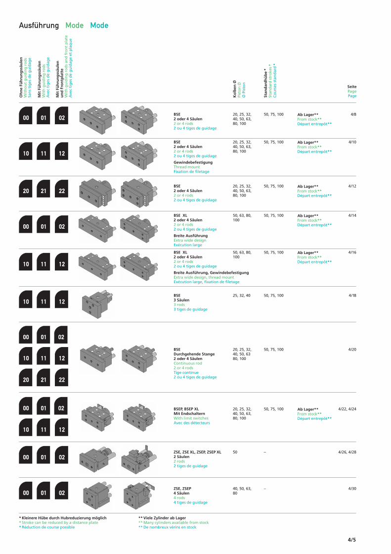
Ausführung Mode Mode
4/8BSE 2 oder 4 Säulen2 or 4 rods2 ou 4 tiges de guidage
BSE 2 oder 4 Säulen2 or 4 rods2 ou 4 tiges de guidage
GewindebefestigungThread mountFixation de filetage
BSE 2 oder 4 Säulen2 or 4 rods2 ou 4 tiges de guidage
BSE XL2 oder 4 Säulen2 or 4 rods2 ou 4 tiges de guidage
Breite AusführungExtra wide designExécution large
BSE XL2 oder 4 Säulen2 or 4 rods2 ou 4 tiges de guidage
Breite Ausführung, GewindebefestigungExtra wide design, thread mountExécution large, fixation de filetage
BSEDurchgehende Stange2 oder 4 SäulenContinuous rod2 or 4 rodsTige continue2 ou 4 tiges de guidage
BSEP, BSEP XLMit EndschalternWith limit switchesAvec des détecteurs
ZSE, ZSE XL, ZSEP, ZSEP XL2 Säulen2 rods2 tiges de guidage
ZSE, ZSEP4 Säulen4 rods4 tiges de guidage
00
10
20
00
10
00
00
01
11
21
01
11
01
01
02
12
22
02
12
BSE 3 Säulen3 rods3 tiges de guidage
10 11 12
00 01 02
10 11 12
20 21 22
02
02
00 01 02
10 11 12
* Kleinere Hübe durch Hubreduzierung möglich * Stroke can be reduced by a distance plate * Réduction de course possible
** Viele Zylinder ab Lager** Many cylinders available from stock** De nombreux vérins en stock
20, 25, 32,40, 50, 63,80, 100
20, 25, 32,40, 50, 63,80, 100
20, 25, 32,40, 50, 63,80, 100
50, 63, 80,100
50, 63, 80,100
25, 32, 40
20, 25, 32,40, 50, 6380, 100
20, 25, 32,40, 50, 63,80, 100
50
40, 50, 63,80
50, 75, 100
50, 75, 100
50, 75, 100
50, 75, 100
50, 75, 100
50, 75, 100
50, 75, 100
50, 75, 100
–
–
Ab Lager**From stock**Départ entrepôt**
Ab Lager**From stock**Départ entrepôt**
Ab Lager**From stock**Départ entrepôt**
Ab Lager**From stock**Départ entrepôt**
Ab Lager**From stock**Départ entrepôt**
Ab Lager**From stock**Départ entrepôt**
Ko
lben
ØPi
sto
n Ø
Ø P
isto
n
Oh
ne
Füh
run
gss
äule
nW
ith
ou
t g
uid
ing
ro
ds
San
s ti
ges
de
gu
idag
e
Mit
Fü
hru
ng
ssäu
len
Wit
h g
uid
ing
ro
ds
Ave
c ti
ges
de
gu
idag
e
Mit
Fü
hru
ng
ssäu
len
u
nd
Fro
ntp
latt
eW
ith
gu
idin
g r
od
s an
d f
ron
t p
late
Ave
c ti
ges
de
gu
idag
e et
pla
qu
e
Stan
dar
dh
üb
e*
Stan
dar
d s
tro
kes*
Co
urs
es s
tan
dar
d*
SeitePagePage
4/10
4/12
4/14
4/16
4/18
4/20
4/22, 4/24
4/26, 4/28
4/30
4/6
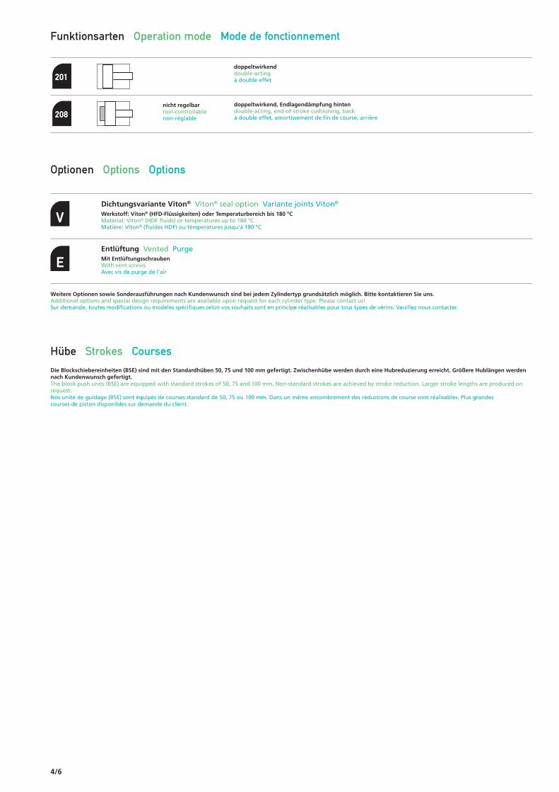
Funktionsarten Operation mode Mode de fonctionnement
doppeltwirkenddouble-actingà double effet
doppeltwirkend, Endlagendämpfung hintendouble-acting, end-of-stroke cushioning, backà double effet, amortissement de fin de course, arrière
nicht regelbarnon-controllablenon-réglable
201
208
Optionen Options Options
Dichtungsvariante Viton® Viton® seal option Variante joints Viton®
Werkstoff: Viton® (HFD-Flüssigkeiten) oder Temperaturbereich bis 180 °CMaterial: Viton® (HDF fluids) or temperatures up to 180 °CMatière: Viton® (fluides HDF) ou témperatures jusqu'à 180 °C
V
Entlüftung Vented PurgeMit EntlüftungsschraubenWith vent screwsAvec vis de purge de l'air
E
Weitere Optionen sowie Sonderausführungen nach Kundenwunsch sind bei jedem Zylindertyp grundsätzlich möglich. Bitte kontaktieren Sie uns.Additional options and special design requirements are available upon request for each cylinder type. Please contact us!Sur demande, toutes modifications ou modèles spécifiques selon vos souhaits sont en principe réalisables pour tous types de vérins. Veuillez nous contacter.
Hübe Strokes CoursesDie Blockschiebereinheiten (BSE) sind mit den Standardhüben 50, 75 und 100 mm gefertigt. Zwischenhübe werden durch eine Hubreduzierung erreicht. Größere Hublängen werdennach Kundenwunsch gefertigt.The block push units (BSE) are equipped with standard strokes of 50, 75 and 100 mm. Non-standard strokes are achieved by stroke reduction. Larger stroke lengths are produced on request.Nos unité de guidage (BSE) sont équipés de courses standard de 50, 75 ou 100 mm. Dans un même encombrement des réductions de course sont réalisables. Plus grandes courses de piston disponibles sur demande du client.

4/7
Auch mit folgenden Schaltern lieferbar:* Also available with the following switches:* Livrable aussi avec:*
Allgemeine Daten General data Donnée d'identification générales
Hersteller Manufacturer Constructeur Telemecanique, XCK-M 110
Betriebsdaten Operating data Caractéristiques des fonctionnement
~AC-15; A300 (Ue = 240V, le = 3A)= DC-13; Q300 (Ue = 250V, le = 0,27A)Gemäß IEC 947-5-1 Anhang AAccording to IEC 536, appendix AD'après C.E.I. 536, annexe A
Berührungsschutz Contact safety device Protection contre les contacts accidentelsKlasse I gem. IEC 536, NF C 20-030 Class I according to IEC 536, NF C 20-030 Classe I d après C.E.I. 536; NF C 20-030
Schutzart Degree of protection Indice de protectionIP 66 gem. IEC 529; IP 665 gem. NF C 20-010 IP 66 according to IEC 529; IP 665 according to NF C 20-010 IP 66 d après C.E.I. 529; IP 665 d après NF C 20-010
Umgebungstemperatur Ambient temperature Température ambianteBetrieb: –25 ... +70 °C Operation: –25 ... +70 °C Exploitation: –25 ... +70 °C
Elektrische Lebensdauer Electrical service life Durée de service électronique Gemäß IEC 947-5-1 Anhang C According to IEC 947-5-1-appendix C D aprés C.E.I. 947-5-1 annexe CGebrauchskategorien AC-15 und DC-13Conditions of severity AC-15 and DC-13 Catégories d utilisation CA-15 et CC-13Maximale Schalthäufigkeit: 3600 Schaltspiele/hMaximum operating frequency: 3600 operating cycles/h Régime de charge maximum: 3600 commutations/h
Schalterdaten Switch data Caractéristiques des détecteurs
Balluff Typ BNS 519-FK 60-101Kolben-Ø abPiston Ø from Ø 32Ø de piston à partir de
Balluff Typ BNS 519-099 K-11Kolben-Ø bisPiston Ø up to Ø 25Ø de piston jusqu á
Euchner Typ N1AK . 502
Mio
. Sch
alts
piel
eM
illio
ns o
f ope
ratin
g cy
cles
Mill
ions
de
com
mut
atio
ns
Strom (A) current (A) intensité (A)
* Abweichendes Bohrbild!* Different position of holes!* Perçages différents!

4/8
2 Führungssäulen2 guiding rods2 tiges de guidage
a1 d1
d2H
L4H1
L3
L1+Hub L1+stroke L1+course
L2+Hub L2+stroke L2+course
Senkung für DIN 912Counterbore for DIN 912Lamage pour DIN 912
Senkung für DIN 912Counterbore for DIN 912Lamage pour DIN 912
bb1
R R
L5 L6
h
h1
h2
L7
G2
G3
d3
a2 a
G4
L8
da5a4
20
25
32
40
50
63
80
100
BSE 250 .50 32 . 02 . 2 . 201 ./
Bestellbezeichnung (Beispiel)Order specification (example)Référence de commande (exemple)
Ko
lben
ØPi
sto
n Ø
Ø P
isto
n
Stan
gen
Ø (
d)
Ro
d Ø
(d
)Ø
Tig
e (d
)
FunktionsartOperation modeMode defonctionnement
AusführungModeMode
Standardhübe1
Standard strokes1
Courses standard1
201
201
201
201
201
201
201
201
12
16
20
25
32
40
50
60
BSE 250 – 00 / 01 / 02
208
208
208
208
208
208
208
208
Nenndruck, statisch Nominal pressure, static Pression nominale, statique250 bar (3600 PSI)
Technische Änderungen vorbehaltenSubject to change without noticeSous réserve de modifications
Maße in mmDimensions in mmDimensions en mm
50
50
50
50
50
50
50
50
75
75
75
75
75
75
75
75
100
100
100
100
100
100
100
100
115
130
150
170
200
225
260
280
50
58
64
74
84
98
124
124
158
a a1
85
95
110
125
150
175
200
220
a2
28
35
40
43
45
54
54
90
a3
115
190
210
230
260
285
320
340
a4
60
65
65
80
90
120
134
153
a5
60
65
75
80
95
100
100
119
b
30
30
30
30
35
38
38
42
b1
14
16
20
25
30
30
40
40
d1
6,8
8,5
11
11
14
14
17,5
17,5
d2
Ø57,5
Ø63,5
Ø73,5
Ø83,5
Ø97,5
Ø123,5
®123,5
®156
d3
00
00
00
00
00
00
00
00
01
01
01
01
01
01
01
01
2
2
2
2
2
2
2
2
4
4
4
4
4
4
4
4
02
02
02
02
02
02
02
02
Füh
run
gss
äule
nG
uid
ing
ro
ds
Tig
es d
e g
uid
age Option
OptionsOptions
V
E
Berechnungsgrundlage siehe ahp informiertCalculation based on "Information from AHP"Base de calcul, voir « AHP vous informe »

4/9
4 Führungssäulen4 guiding rods
4 tiges de guidage
L1+Hub L1+stroke L1+course
a1 a3
d1
d2H
L4 H1L3
L2+Hub L2+stroke L2+course
Senkung für DIN 912Counterbore for DIN 912Lamage pour DIN 912
Senkung für DIN 912Counterbore for DIN 912Lamage pour DIN 912
bb1
R R
L5 L6
h
h1
h2L7
G3
G2
d3 a2 a
G4
L8
da5a4
BSE 250 – 00 / 01 / 02Nenndruck, statisch Nominal pressure, static Pression nominale, statique250 bar (3600 PSI)
1 Kleinere Hübe durch Hubreduzierung möglich1 Shorter strokes are possible through stroke reduction1 Dans un même encombrement, des réductions de course sont réalisables
M8
M10
M10
M12
M12
M16
M16
M20
G2
10
10
12
12
12
17
17
20
h
28
32
35
40
40
46
46
55
h1
48
55
60
68
65
75
75
90
h2
8,5
8,5
11
11
11
11
13
13
H1
8
8
10
10
10
10
12
12
HH7
37
37
40
40
45
52
52
56
L3
7
7
10
10
10
14
14
14
L4
24
26
32
33
40
39
46
54
L5
22
23
25
26
30
33
40
43
L6
10
10
10
10
12
12
12
12
L7
–
9
11
12
15
15
20
20
L8
G1/4"
G1/4"
G3/8"
G3/8"
G3/8"
G1/2"
G1/2"
G1/2"
R
201
101
107
120
125
145
157
157
181
63
70
79
89
97
112
131
133
81
89
91
101
109
127
145
149
L2L1
M8
M10
M10
M12
M12
M16
M20
M20
G3
M6
M5
M6
M6
M6
M6
M6
M6
G4
208

4/10
Gewindebefestigung, 2 FührungssäulenThread mount, 2 guiding rodsFixation de filetage, 2 tiges de guidage
Bestellbezeichnung (Beispiel)Order specification (example)Référence de commande (exemple)
BSE 250 – 10 / 11 / 12 Nenndruck, statisch Nominal pressure, static Pression nominale, statique250 bar (3600 PSI)
Technische Änderungen vorbehaltenSubject to change without noticeSous réserve de modifications
Maße in mmDimensions in mmDimensions en mm
115
130
150
170
200
225
260
280
58
64
74
84
98
124
124
158
a a1
85
95
110
125
150
175
200
220
a2
28
35
40
43
45
54
54
90
a3
115
190
210
230
260
285
320
340
a4
60
65
65
80
90
120
134
153
a5
60
65
75
80
95
100
100
119
b
30
30
30
30
35
38
38
42
b1
14
16
20
25
30
30
40
40
d1
Ø57,5
Ø63,5
Ø73,5
Ø83,5
Ø97,5
Ø123,5
®123,5
®156
d3
L1+Hub L1+stroke L1+course
a1 d1
HG1
L4 H1L3
L2+Hub L2+stroke L2+course
Senkung für DIN 912Counterbore for DIN 912Lamage pour DIN 912
bb1
R R
L5 L6
h
h1
h2L7
G3
G2
d3
a2 a
G4 L8
da5a4
20
25
32
40
50
63
80
100
BSE 250 .50 32 . 12 . 2 . 201 ./
Ko
lben
ØPi
sto
n Ø
Ø P
isto
n
Stan
gen
Ø (
d)
Ro
d Ø
(d
)Ø
Tig
e (d
)
FunktionsartOperation modeMode defonctionnement
Standardhübe1
Standard strokes1
Courses standard1
201
201
201
201
201
201
201
201
12
16
20
25
32
40
50
60
208
208
208
208
208
208
208
208
50
50
50
50
50
50
50
50
75
75
75
75
75
75
75
75
100
100
100
100
100
100
100
100
50
10
10
10
10
10
10
10
10
11
11
11
11
11
11
11
11
2
2
2
2
2
2
2
2
4
4
4
4
4
4
4
4
12
12
12
12
12
12
12
12
Füh
run
gss
äule
nG
uid
ing
ro
ds
Tig
es d
e g
uid
age Option
OptionsOptions
AusführungModeMode
V
E
Berechnungsgrundlage siehe ahp informiertCalculation based on "Information from AHP"Base de calcul, voir « AHP vous informe »

4/11
Gewindebefestigung, 4 FührungssäulenThread mount, 4 guiding rods
Fixation de filetage, 4 tiges de guidage
BSE 250 – 10 / 11 / 12Nenndruck, statisch Nominal pressure, static Pression nominale, statique250 bar (3600 PSI)
1 Kleinere Hübe durch Hubreduzierung möglich1 Shorter strokes are possible through stroke reduction1 Dans un même encombrement, des réductions de course sont réalisables
M8
M10
M10
M12
M12
M16
M16
M20
G2
10
10
12
12
12
17
17
20
h
28
32
35
40
40
46
46
55
h1
48
55
60
68
65
75
75
90
h2
8,5
8,5
11
11
11
11
13
13
H1
8
8
10
10
10
10
12
12
HH7
37
37
40
40
45
52
52
56
L3
7
7
10
10
10
14
14
14
L4
24
26
32
33
40
39
46
54
L5
22
23
25
26
30
33
40
43
L6
10
10
10
10
12
12
12
12
L7
–
9
11
12
15
15
20
20
L8
G1/4"
G1/4"
G3/8"
G3/8"
G3/8"
G1/2"
G1/2"
G1/2"
R
201 208
101
107
120
125
145
157
157
181
63
70
79
89
97
112
131
133
81
89
91
101
109
127
145
149
L2L1
M8
M10
M10
M12
M12
M16
M20
M20
G3
M6
M5
M6
M6
M6
M6
M6
M6
G4
M8x16
M10x20
M12x25
M12x25
M16x30
M16x30
M20x35
M20x35
G1
L1+Hub L1+stroke L1+course
a1 a3
d1
H G1
L4 H1
L3
L2+Hub L2+stroke L2+course
Senkung für DIN 912Counterbore for DIN 912Lamage pour DIN 912
bb1
R R
L5 L6
h
h1
h2L7
G3
G2
d3
a2 a
G4 L8
da5a4

4/12
BSE 250 .50 32 . 22 . 2 . 201 ./ 50
20
25
32
40
50
63
80
100
Ko
lben
ØPi
sto
n Ø
Ø P
isto
n
Stan
gen
Ø (
d)
Ro
d Ø
(d
)Ø
Tig
e (d
)
FunktionsartOperation modeMode defonctionnement
Standardhübe1
Standard strokes1
Courses standard1
201
201
201
201
201
201
201
201
12
16
20
25
32
40
50
60
208
208
208
208
208
208
208
208
50
50
50
50
50
50
50
50
75
75
75
75
75
75
75
75
100
100
100
100
100
100
100
100
20
20
20
20
20
20
20
20
21
21
21
21
21
21
21
21
2
2
2
2
2
2
2
2
4
4
4
4
4
4
4
4
22
22
22
22
22
22
22
22
Füh
run
gss
äule
nG
uid
ing
ro
ds
Tig
es d
e g
uid
age Option
OptionsOptions
2 Führungssäulen2 guiding rods2 tiges de guidage
Bestellbezeichnung (Beispiel)Order specification (example)Référence de commande (exemple)
BSE 250 – 20 / 21 / 22 Nenndruck, statisch Nominal pressure, static Pression nominale, statique250 bar (3600 PSI)
Technische Änderungen vorbehaltenSubject to change without noticeSous réserve de modifications
Maße in mmDimensions in mmDimensions en mm
138
160
185
205
245
270
315
335
58
64
74
84
98
124
124
158
a a1
85
95
110
125
150
175
200
220
a2
28
35
40
43
45
54
54
90
a3
113
126
148
168
196
221
255
275
a4
127
145
168
188
222
247
288
308
a5
60
65
75
80
95
100
100
119
b
30
30
30
30
35
38
38
42
b1
25
25
30
30
30
30
35
40
b2
14
16
20
25
30
30
40
40
d1
6,8
8,5
11
11
14
13
17,5
17,5
d2
L2+Hub L2+stroke L2+course
L1+Hub L1+stroke L1+course
bb1
b2
R R
L5 L6
L7
L4
L3
G3
G2 d1
d3
a2 a4
G4 L8
da4
Senkung für DIN 912Counterbore for DIN 912Lamage pour DIN 912
a1
h2
h1
h
a5 a
d2H
G1 auf KundenwunschG1 only on customer requestG2 seulement en option
AusführungModeMode
V
E
Berechnungsgrundlage siehe ahp informiertCalculation based on "Information from AHP"Base de calcul, voir « AHP vous informe »

4/13
4 Führungssäulen4 guiding rods
4 tiges de guidage
BSE 250 – 20 / 21 / 22Nenndruck, statisch Nominal pressure, static Pression nominale, statique250 bar (3600 PSI)
1 Kleinere Hübe durch Hubreduzierung möglich1 Shorter strokes are possible through stroke reduction1 Dans un même encombrement, des réductions de course sont réalisables
M8
M10
M10
M12
M12
M16
M16
M20
G2
29
32
37
42
49
62
62
79
h
40
45
50
60
68
50
45
55
h1
–
–
–
–
–
100
98
125
h2
8
8
10
10
10
10
12
12
HH7
37
37
40
40
45
52
52
56
L3
7
7
10
10
10
14
14
14
L4
24
26
32
33
40
39
46
54
L5
22
23
25
26
30
33
40
43
L6
10
10
10
10
12
12
12
12
L7
–
9
11
12
15
15
20
20
L8
G1/4"
G1/4"
G3/8"
G3/8"
G3/8"
G1/2"
G1/2"
G1/2"
R
Ø57,5
Ø63,5
Ø73,5
Ø83,5
Ø97,5
Ø123,5
®123,5
®156
d3
201
101
107
120
125
145
157
157
181
63
70
79
89
97
112
131
133
81
89
91
101
109
127
145
149
L2L1
M8
M10
M10
M12
M12
M16
M20
M20
G3
M6
M5
M6
M6
M6
M6
M6
M6
G4
208
L2+Hub L2+stroke L2+course
L1+Hub L1+stroke L1+course
bb1
b2
R R
L5 L6
L7
L4
L3
G3
G2 d1
d3
a2 a4
G4 L8
da4
Senkung für DIN 912Counterbore for DIN 912Lamage pour DIN 912
a1
h2
h1
h
a3
a5 a
d2H

4/14
Nenndruck, statisch Nominal pressure, static Pression nominale, statique250 bar (3600 PSI)
a1 d1
H
L4 H1
L3
L1+Hub L1+stroke L1+course
L2+Hub L2+stroke L2+course
Senkung für DIN 912Counterbore for DIN 912Lamage pour DIN 912
Senkung für DIN 912Counterbore for DIN 912Lamage pour DIN 912
bb1
R R
L5 L6
h d2
h1
h2
L7
G3
G2
d3 a2 a
G4 L8
da5a4
2 Führungssäulen2 guiding rods2 tiges de guidage
Bestellbezeichnung (Beispiel)Order specification (example)Référence de commande (exemple)
Technische Änderungen vorbehaltenSubject to change without noticeSous réserve de modifications
Maße in mmDimensions in mmDimensions en mm
300
300
330
360
98
124
124
158
a a1
250
250
275
300
45
54
54
90
360
360
390
420
200
200
210
230
95
100
100
119
35
38
38
42
30
30
40
40
14
14
17,5
17,5
a2 a3 a4 a5 b b1 d1 d2
Ø97,5
Ø123,5
®123,5
®156
d3
Breite Ausführung Extra wide design Exécution large
BSE 250 XL – 00 / 01 / 02
BSE 250 50 32. 02 . 2 . 201 ./. .50 XL
50
63
80
100
Ko
lben
ØPi
sto
n Ø
Ø P
isto
n
Stan
gen
Ø (
d)
Ro
d Ø
(d
)Ø
Tig
e (d
)
FunktionsartOperation modeMode defonctionnement
Standardhübe1
Standard strokes1
Courses standard1
201
201
201
201
32
40
50
60
208
208
208
208
50
50
50
50
75
75
75
75
100
100
100
100
00
00
00
00
01
01
01
01
2
2
2
2
4
4
4
4
02
02
02
02
Füh
run
gss
äule
nG
uid
ing
ro
ds
Tig
es d
e g
uid
age Option
OptionsOptions
V
E
AusführungModeMode
Berechnungsgrundlage siehe ahp informiertCalculation based on "Information from AHP"Base de calcul, voir « AHP vous informe »

4/15
Nenndruck, statisch Nominal pressure, static Pression nominale, statique250 bar (3600 PSI)
a1 a3
d1
H
L4H1
L3
L1+Hub L1+stroke L1+course
L2+Hub L2+stroke L2+course
Senkung für DIN 912Counterbore for DIN 912Lamage pour DIN 912
Senkung für DIN 912Counterbore for DIN 912Lamage pour DIN 912
bb1
R R
L5 L6
h d2
h1
h2
L7
G3
G2
d3 a2 a
G4
L8
da5a4
4 Führungssäulen4 guiding rods
4 tiges de guidage
1 Kleinere Hübe durch Hubreduzierung möglich1 Shorter strokes are possible through stroke reduction1 Dans un même encombrement, des réductions de course sont réalisables
M12
M16
M16
M20
M12
M16
M20
M20
M6
M6
M6
M6
12
17
17
20
40
46
46
55
65
75
75
90
10
10
12
12
G2 h h1 h2 HH7
11
11
13
13
145
157
157
181
97
112
131
133
109
127
145
149
45
52
52
56
10
14
14
14
40
39
46
54
30
33
40
43
12
12
12
12
15
15
20
20
H1 L3 L4 L5 L6 L7 L8
G3/8"
G1/2"
G1/2"
G1/2"
R
201
L2L1G3 G4
208
Breite Ausführung Extra wide design Exécution large
BSE 250 XL – 00 / 01 / 02

4/16
BSE 250 50 32. 12 . 2 . 201 ./ .50 XL
Bestellbezeichnung (Beispiel)Order specification (example)Référence de commande (exemple)
Technische Änderungen vorbehaltenSubject to change without noticeSous réserve de modifications
Maße in mmDimensions in mmDimensions en mm
300
300
330
360
98
124
124
158
a a1
250
250
275
300
45
54
54
90
360
360
390
420
200
200
210
230
95
100
100
119
35
38
38
42
30
30
40
40
a2 a3 a4 a5 b b1 d1
Ø97,5
Ø123,5
®123,5
®156
d3
a1 d1
HG1
L4 H1
L3
L1+Hub L1+stroke L1+course
L2+Hub L2+stroke L2+course
Senkung für DIN 912Counterbore for DIN 912Lamage pour DIN 912
Senkung für DIN 912Counterbore for DIN 912Lamage pour DIN 912
bb1
R R
L5 L6
h
h1
h2
L7
G3
G2
d3 a2 a
G4 L8
da5a4
Gewindebefestigung, 2 FührungssäulenThread mount, 2 guiding rodsFixation de filetage, 2 tiges de guidage
Nenndruck, statisch Nominal pressure, static Pression nominale, statique250 bar (3600 PSI)
Breite Ausführung Extra wide design Exécution large
BSE 250 XL – 10 / 11 / 12
50
63
80
100
Ko
lben
ØPi
sto
n Ø
Ø P
isto
n
Stan
gen
Ø (
d)
Ro
d Ø
(d
)Ø
Tig
e (d
)
FunktionsartOperation modeMode defonctionnement
Standardhübe1
Standard strokes1
Courses standard1
201
201
201
201
32
40
50
60
208
208
208
208
50
50
50
50
75
75
75
75
100
100
100
100
10
10
10
10
11
11
11
11
2
2
2
2
4
4
4
4
12
12
12
12
Füh
run
gss
äule
nG
uid
ing
ro
ds
Tig
es d
e g
uid
age Option
OptionsOptions
V
E
AusführungModeMode
Berechnungsgrundlage siehe ahp informiertCalculation based on "Information from AHP"Base de calcul, voir « AHP vous informe »
.

4/17
1 Kleinere Hübe durch Hubreduzierung möglich1 Shorter strokes are possible through stroke reduction1 Dans un même encombrement, des réductions de course sont réalisables
M12
M16
M16
M20
M12
M16
M20
M20
M6
M6
M6
M6
12
17
17
20
40
46
46
55
65
75
75
90
10
10
12
12
G2 h h1 h2 HH7
11
11
13
13
145
157
157
181
97
112
131
133
109
127
145
149
45
52
52
56
10
14
14
14
40
39
46
54
30
33
40
43
12
12
12
12
15
15
20
20
H1 L3 L4 L5 L6 L7 L8
G3/8"
G1/2"
G1/2"
G1/2"
R
M16x30
M16x30
M20x35
M20x35
G1
201
L2L1G3 G4
208
a1 a3
d1
HG1
L4 H1L3
L1+Hub L1+stroke L1+course
L2+Hub L2+stroke L2+course
Senkung für DIN 912Counterbore for DIN 912Lamage pour DIN 912
bb1
R R
L5 L6
h
h1
h2
L7
G3
G2
d3
a2 a
G4 L8
da5a4
Gewindebefestigung, 4 FührungssäulenThread mount, 4 guiding rods
Fixation de filetage, 4 tiges de guidage
Nenndruck, statisch Nominal pressure, static Pression nominale, statique250 bar (3600 PSI)
Breite Ausführung Extra wide design Exécution large
BSE 250 XL – 10 / 11 / 12
4/18
Nenndruck, statisch Nominal pressure, static Pression nominale, statique250 bar (3600 PSI)BSE 250 – 10 / 11 / 12
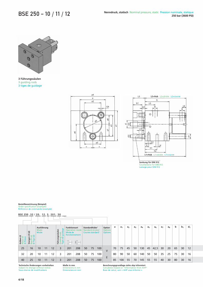
3 Führungssäulen3 guiding rods3 tiges de guidage
Technische Änderungen vorbehaltenSubject to change without noticeSous réserve de modifications
Maße in mmDimensions in mmDimensions en mm
70
80
85
75
90
100
a a1
45
50
55
50
60
70
130
140
145
45
50
55
42,5
50
55
30
30
30
12
16
16
a2 a3 a4 a5 a6
30
35
40
a7
20
25
30
a8 b1
65
75
80
b d1
b1
b
L3
L4
L7
G1
h Hh1
h2
L5L6R
R
G3
G2
d
d1
a4
a
a2
G4
a5
= =
a6
a7
a3 a1
a8
d3
L1+Hub L1+stroke L1+course
L2+Hub L2+stroke L2+course
Senkung für DIN 912Counterbore for DIN 912Lamage pour DIN 912
BSE 250 .32 20 . 12 . 3 . 201 ./ 50
25
32
40
Ko
lben
ØPi
sto
n Ø
Ø P
isto
n
Stan
gen
Ø (
d)
Ro
d Ø
(d
)Ø
Tig
e (d
)
FunktionsartOperation modeMode defonctionnement
Standardhübe1
Standard strokes1
Courses standard1
201
201
201
16
20
25
208
208
208
50
50
50
75
75
75
100
100
100
10
10
10
11
11
11
3
3
3
12
12
12
Füh
run
gss
äule
nG
uid
ing
ro
ds
Tig
es d
e g
uid
age Option
OptionsOptions
V
E
Bestellbezeichnung (Beispiel)Order specification (example)Référence de commande (exemple)
AusführungModeMode
Berechnungsgrundlage siehe ahp informiertCalculation based on "Information from AHP"Base de calcul, voir « AHP vous informe »

4/19
Nenndruck, statisch Nominal pressure, static Pression nominale, statique250 bar (3600 PSI) BSE 250 – 10 / 11 / 12
1 Kleinere Hübe durch Hubreduzierung möglich1 Shorter strokes are possible through stroke reduction1 Dans un même encombrement, des réductions de course sont réalisables
45
52
62
d3
M8x16
M10x20
M10x20
M8
M10
M10
G2
M10
M10
M12
G3
M6
M6
M6
G4G1
10
10
12
h
32
35
40
h1
55
60
68
107
120
125
69
80
86
87
103
112,5
h2
10
10
10
HH7
G1/4"
G3/8"
G3/8"
R
201
L2L1
37
40
40
L3
7
10
10
L4
26
32
33
L5
10
12,5
13
L6
10
10
10
L7
208

4/20
20
25
32
40
50
63
80
100
BSE 250 .50 32 . 02 . 2 . 201 ./
Bestellbezeichnung (Beispiel)Order specification (example)Référence de commande (exemple)
Ko
lben
ØPi
sto
n Ø
Ø P
isto
n
Stan
gen
Ø (
d)
Ro
d Ø
(d
)Ø
Tig
e (d
)
FunktionsartOperation modeMode defonctionnement
Standardhübe1
Standard strokes1
Courses standard1
201
201
201
201
201
201
201
201
12
16
20
25
32
40
50
60
Technische Änderungen vorbehaltenSubject to change without noticeSous réserve de modifications
Maße in mmDimensions in mmDimensions en mm
50
50
50
50
50
50
50
50
75
75
75
75
75
75
75
75
100
100
100
100
100
100
100
100
115
130
150
170
200
225
260
280
50
58
64
74
84
98
124
124
158
a a1
85
95
110
125
150
175
200
220
a2
115
190
210
230
260
285
320
340
a4
60
65
75
80
95
100
100
119
b
30
30
30
30
35
38
38
42
b1
10
12
16
20
25
32
40
50
d4
Ø57,5
Ø63,5
Ø73,5
Ø83,5
Ø97,5
Ø123,5
®123,5
®156
d3
M6x12
M8x12
M10x15
M12x15
M16x25
M20x30
M27x40
M30x40
G5
101
107
120
125
145
157
157
181
L1
63
70
79
89
97
112
131
133
L2
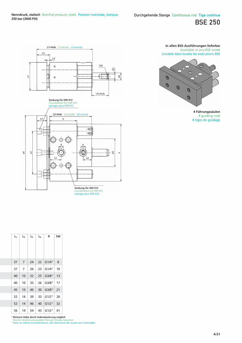
In allen BSE-Ausführungen lieferbarAvailable in any BSE modeLivrable dans toutes les exécutions BSE
a1
G5
d4
L4
L3
SW
L4+Hub
L1+Hub L1+stroke L1+course
L2+Hub L2+stroke L2+course
Senkung für DIN 912Counterbore for DIN 912Lamage pour DIN 912
Senkung für DIN 912Counterbore for DIN 912Lamage pour DIN 912
bb1
R R
L5 L6
d3 aa2a4
201
Nenndruck, statisch Nominal pressure, static Pression nominale, statique250 bar (3600 PSI)
Durchgehende Stange Continuous rod Tige continue
BSE 250
OptionOptionsOptions
V
E
2
2
2
2
2
2
2
2
4
4
4
4
4
4
4
4
Füh
run
gss
äule
nG
uid
ing
ro
ds
Tig
es d
e g
uid
ageAusführung
ModeMode
Nac
h K
un
den
wu
nsc
hTo
cu
sto
mer
sp
ecif
icat
ion
sÀ
la d
eman
de d
u cl
ient
2 Führungssäulen2 guiding rods2 tiges de guidage
Fehlende Maße entnehmen Sie bitte der entsprechenden AusführungFor missing dimensions please refer to corresponding modePour toutes dimensions ne figurant pas ici, voir le mode correspondant
Berechnungsgrundlage siehe ahp informiertCalculation based on "Information from AHP"Base de calcul, voir « AHP vous informe »
4/21
1 Kleinere Hübe durch Hubreduzierung möglich1 Shorter strokes are possible through stroke reduction1 Dans un même encombrement, des réductions de course sont réalisables
37
37
40
40
45
52
52
56
L3
7
7
10
10
10
14
14
14
L4
24
26
32
33
40
39
46
54
L5
22
23
25
26
30
33
40
43
L6
G1/4"
G1/4"
G3/8"
G3/8"
G3/8"
G1/2"
G1/2"
G1/2"
R
8
10
13
17
21
26
32
41
SW
a1
G5
d4
L4
L3
SW
L4+Hub
L1+Hub L1+stroke L1+course
L2+Hub L2+stroke L2+course
Senkung für DIN 912Counterbore for DIN 912Lamage pour DIN 912
Senkung für DIN 912Counterbore for DIN 912Lamage pour DIN 912
bb1
R R
L5 L6
d3 aa2a4
Nenndruck, statisch Nominal pressure, static Pression nominale, statique250 bar (3600 PSI)
Durchgehende Stange Continuous rod Tige continue
BSE 250
In allen BSE-Ausführungen lieferbarAvailable in any BSE mode
Livrable dans toutes les exécutions BSE
4 Führungssäulen4 guiding rods
4 tiges de guidage

4/22
BSEP 250 .50 32 . 02 . 2 . 201 ./
Technische Änderungen vorbehaltenSubject to change without noticeSous réserve de modifications
Maße in mmDimensions in mmDimensions en mm
50
2, 4 Führungssäulen2, 4 guiding rods2, 4 tiges de guidage
Auch XL-VersionAlso XLAussi XL
BSEP 250 – 00 / 01 / 02
20
25
32
40
50
63
80
100
Bestellbezeichnung (Beispiel)Order specification (example)Référence de commande (exemple)
Ko
lben
ØPi
sto
n Ø
Ø P
isto
n
Stan
gen
Ø (
d)
Ro
d Ø
(d
)Ø
Tig
e (d
)
12
16
20
25
32
40
50
60
115
130
150
170
200
225
260
280
58
64
74
84
98
124
124
158
a a1
85
95
110
125
150
175
200
220
a2
*
190
210
230
260
285
320
340
a4
60
65
75
80
95
100
100
119
b
30
30
30
30
35
38
38
42
b1
8
8
6
8
10
10
10
10
b3
M6
M5
M6
M6
M6
M6
M6
M6
G4
a1
L4
L3
b3L1+Hub L1+stroke L1+course
bb1
R R
L5 L6
d3 a
G4
L8
a2a4
00
00
00
00
00
00
00
00
01
01
01
01
01
01
01
01
2
2
2
2
2
2
2
2
4
4
4
4
4
4
4
4
02
02
02
02
02
02
02
02
Füh
run
gss
äule
nG
uid
ing
ro
ds
Tig
es d
e g
uid
ageAusführung
ModeMode
OptionOptionsOptions
V
E
FunktionsartOperation modeMode defonctionnement
Standardhübe1
Standard strokes1
Courses standard1
201
201
201
201
201
201
201
201
208
208
208
208
208
208
208
208
50
50
50
50
50
50
50
50
75
75
75
75
75
75
75
75
100
100
100
100
100
100
100
100
Fehlende Maße entnehmen Sie bitte der entsprechenden AusführungFor missing dimensions please refer to corresponding modePour toutes dimensions ne figurant pas ici, voir le mode correspondant
Ø57,5
Ø63,5
Ø73,5
Ø83,5
Ø97,5
Ø123,5
®123,5
®156
d3
Berechnungsgrundlage siehe ahp informiertCalculation based on "Information from AHP"Base de calcul, voir « AHP vous informe »

4/23
Nenndruck, statisch Nominal pressure, static Pression nominale, statique250 bar (3600 PSI)
1 Kleinere Hübe durch Hubreduzierung möglich1 Shorter strokes are possible through stroke reduction1 Dans un même encombrement, des réductions de course sont réalisables
* a4 = a, Schaltfahne auf Frontplatte befestigt* a4 = a, Switch actuator mounted on front plate* a4 = a, Drapeau de détection fixé sur la plaque avant.
37
37
40
40
45
52
52
56
L3
7
7
10
10
10
14
14
14
L4
24
26
32
33
40
39
46
54
L5
22
23
25
26
30
33
20
20
L6
G1/4"
G1/4"
G3/8"
G3/8"
G3/8"
G1/2"
G1/2"
G1/2"
R
101
107
120
125
145
157
157
181
L1
–
9
11
12
15
15
20
20
L8
Bitte Maßblatt anfordern Please ask for dimension sheet Demander la fiche technique
Bitte Maßblatt anfordern Please ask for dimension sheet Demander la fiche technique

4/24
BSEP 250 50 32. 12 . 2 . 201 ./. 50
Technische Änderungen vorbehaltenSubject to change without noticeSous réserve de modifications
Maße in mmDimensions in mmDimensions en mm
2, 3, 4 Führungssäulen2, 3, 4 guiding rods2, 3, 4 tiges de guidage
Auch XL-VersionAlso XLAussi XL
BSEP 250 – 10 / 11 / 12
20
25
32
40
50
63
80
100
Bestellbezeichnung (Beispiel)Order specification (example)Référence de commande (exemple)
Ko
lben
ØPi
sto
n Ø
Ø P
isto
n
Stan
gen
Ø (
d)
Ro
d Ø
(d
)Ø
Tig
e (d
)
12
16
20
25
32
40
50
60
115
130
150
170
200
225
260
280
58
64
74
84
98
124
124
158
a a1
85
95
110
125
150
175
200
220
a2
*
190
210
230
260
285
320
340
a4
60
65
75
80
95
100
100
119
b
30
30
30
30
35
38
38
42
b1
8
8
6
8
10
10
10
10
b3
Fehlende Maße entnehmen Sie bitte der entsprechenden AusführungFor missing dimensions please refer to corresponding modePour toutes dimensions ne figurant pas ici, voir le mode correspondant
M6
M5
M6
M6
M6
M6
M6
M6
–
M6
M6
M6
–
–
–
–
G4
2, 4
Säu
len
2, 4
ro
ds
2, 4
tig
es
3 Sä
ule
n3
rod
s3
tig
es
a1
L4
L3
b3L1+Hub L1+stroke L1+course
bb1
R R
L5 L6
d3 a
G4
L8
a2a4
10
10
10
10
10
10
10
10
11
11
11
11
11
11
11
11
2
2
2
2
2
2
2
2
–
3
3
3
–
–
–
–
4
4
4
4
4
4
4
4
12
12
12
12
12
12
12
12
Füh
run
gss
äule
nG
uid
ing
ro
ds
Tig
es d
e g
uid
ageAusführung
ModeMode
OptionOptionsOptions
FunktionsartOperation modeMode defonctionnement
Standardhübe1
Standard strokes1
Courses standard1
201
201
201
201
201
201
201
201
208
208
208
208
208
208
208
208
50
50
50
50
50
50
50
50
75
75
75
75
75
75
75
75
100
100
100
100
100
100
100
100
V
E
Ø57,5
Ø63,5
Ø73,5
Ø83,5
Ø97,5
Ø123,5
®123,5
®156
d3
Berechnungsgrundlage siehe ahp informiertCalculation based on "Information from AHP"Base de calcul, voir « AHP vous informe »
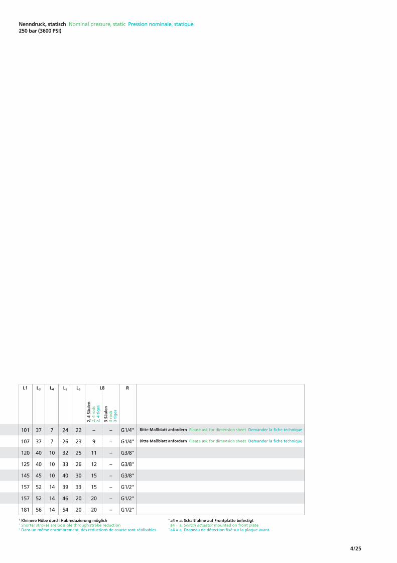
4/25
Nenndruck, statisch Nominal pressure, static Pression nominale, statique250 bar (3600 PSI)
1 Kleinere Hübe durch Hubreduzierung möglich1 Shorter strokes are possible through stroke reduction1 Dans un même encombrement, des réductions de course sont réalisables
* a4 = a, Schaltfahne auf Frontplatte befestigt* a4 = a, Switch actuator mounted on front plate* a4 = a, Drapeau de détection fixé sur la plaque avant.
37
37
40
40
45
52
52
56
L3
7
7
10
10
10
14
14
14
L4
24
26
32
33
40
39
46
54
L5
22
23
25
26
30
33
20
20
L6
G1/4"
G1/4"
G3/8"
G3/8"
G3/8"
G1/2"
G1/2"
G1/2"
R
101
107
120
125
145
157
157
181
L1
–
9
11
12
15
15
20
20
–
–
–
–
–
–
–
–
L8
2, 4
Säu
len
2, 4
ro
ds
2, 4
tig
es
3 Sä
ule
n3
rod
s3
tig
es
Bitte Maßblatt anfordern Please ask for dimension sheet Demander la fiche technique
Bitte Maßblatt anfordern Please ask for dimension sheet Demander la fiche technique

4/26
.50 32. 02 . 2 . 201 ./ 50
ZSE 250 – 00 / 01 / 02
2 Führungssäulen2 guiding rods2 tiges de guidage
Bestellbezeichnung (Beispiel)Order specification (example)Référence de commande (exemple)
Hub Stroke Course
Technische Änderungen vorbehaltenSubject to change without noticeSous réserve de modifications
Maße in mmDimensions in mmDimensions en mm
180 100
a a1
115
a2
160
a5
38
a7
78
a8
120
b
35
b1
10
b3
40
d1
72
d3
M12
G1
Nenndruck, statisch Nominal pressure, static Pression nominale, statique250 bar (3600 PSI)
a1
G4
L8
d3
1
a7
a8
h
h1
h2
L4
b1
L1+Hub L1+stroke L1+course
L2+Hub L2+stroke L2+course
Senkung für DIN 912Counterbore for DIN 912Lamage pour DIN 912
R
L5
L3b
H G1L7
G2
Rd
1
a2da a5
50
Ko
lben
ØPi
sto
n Ø
Ø P
isto
n
Stan
gen
Ø (
d)
Ro
d Ø
(d
)Ø
Tig
e (d
)
FunktionsartOperation modeMode defonctionnement
20132 20800 01 202
Füh
run
gss
äule
nG
uid
ing
ro
ds
Tig
es d
e g
uid
age Option
OptionsOptions
AusführungModeMode
ZSE 250ZSEP 250
V, EKundenwunschCustomer requestSouhait du client
Berechnungsgrundlage siehe ahp informiertCalculation based on "Information from AHP"Base de calcul, voir « AHP vous informe »

4/27
Nenndruck, statisch Nominal pressure, static Pression nominale, statique250 bar (3600 PSI)
1 Kleinere Hübe durch Hubreduzierung möglich1 Shorter strokes are possible through stroke reduction1 Dans un même encombrement, des réductions de course sont réalisables
M12
G2
11
h
55
h1
88
h2
8
HH7
ZSEP 250 – 00 / 01 / 02a1
b3
L8
1a7
L4b1
L1+Hub L1+stroke L1+course
L2+Hub L2+stroke L2+course
R
L5
L3 b
Rd
1
a2da
Senkung für DIN 912Counterbore for DIN 912Lamage pour DIN 912
Mit Endschalter, 2 FührungssäulenWith limit switch, 2 guiding rodsAvec capteur, 2 tiges de guidage
M6
G4
179 121
L2201
L1
Hu
b <
80
Stro
ke <
80
Cour
se<
80
123 150,5
Hu
b ≥
80
Stro
ke ≥
80
Cour
se≥
80
15 50
201208 208
Mindesthub1
Minimum stroke1
Course minimum1
50
L3
15
L4
53
L5
10
L7
15
L8
G1/2"
R
4/28
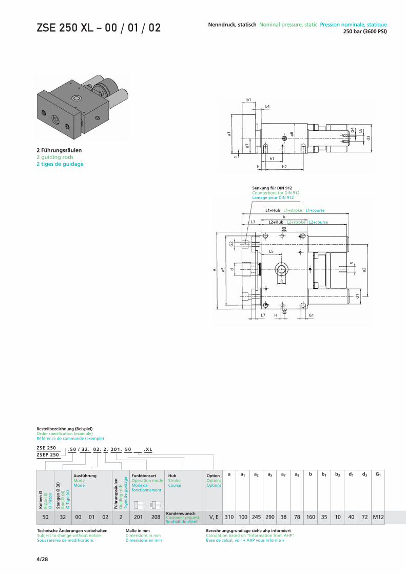
.50 32. 02 . 2 . 201 ./ 50 .XL
ZSE 250 XL – 00 / 01 / 02
2 Führungssäulen2 guiding rods2 tiges de guidage
Bestellbezeichnung (Beispiel)Order specification (example)Référence de commande (exemple)
Technische Änderungen vorbehaltenSubject to change without noticeSous réserve de modifications
Maße in mmDimensions in mmDimensions en mm
310 100
a a1
245
a2
290
a5
38
a7
78
a8
160
b
35
b1
10
b3
40
d1
72
d3
M12
G1
Nenndruck, statisch Nominal pressure, static Pression nominale, statique250 bar (3600 PSI)
a1
G4
L8
d3
1
a7
a8
h
h1
h2
L4
b1
L1+Hub L1+stroke L1+course
L2+Hub L2+stroke L2+course
Senkung für DIN 912Counterbore for DIN 912Lamage pour DIN 912
R
L5
L3b
H G1L7
G2
Rd
1
a2da a5
50
Ko
lben
ØPi
sto
n Ø
Ø P
isto
n
Stan
gen
Ø (
d)
Ro
d Ø
(d
)Ø
Tig
e (d
)
FunktionsartOperation modeMode defonctionnement
20132 20800 01 202
Füh
run
gss
äule
nG
uid
ing
ro
ds
Tig
es d
e g
uid
age Option
OptionsOptions
AusführungModeMode
ZSE 250ZSEP 250
V, E
Hub Stroke Course
Berechnungsgrundlage siehe ahp informiertCalculation based on "Information from AHP"Base de calcul, voir « AHP vous informe »
KundenwunschCustomer requestSouhait du client

4/29
Nenndruck, statisch Nominal pressure, static Pression nominale, statique250 bar (3600 PSI)
1 Kleinere Hübe durch Hubreduzierung möglich1 Shorter strokes are possible through stroke reduction1 Dans un même encombrement, des réductions de course sont réalisables
M12
G2
11
h
80
h1
138
h2
8
HH7
ZSEP 250 XL – 00 / 01 / 02a1
b3
L8
1a7
L4b1
L1+Hub L1+stroke L1+course
L2+Hub L2+stroke L2+course
R
L5
L3 b
Rd
1
a2da
Senkung für DIN 912Counterbore for DIN 912Lamage pour DIN 912
Mit Endschalter, 2 FührungssäulenWith limit switch, 2 guiding rodsAvec capteur, 2 tiges de guidage
M6
G4
219 121
L2201
L1
Hu
b <
80
Stro
ke <
80
Cour
se<
80
123 150,5
Hu
b ≥
80
Stro
ke ≥
80
Cour
se≥
80
208
50
L3
15
L4
53
L5
10
L7
15
L8
15 50
201 208
Mindesthub1
Minimum stroke1
Course minimum1
G1/2"
R

4/30
5
4
11
11
b3
ZSE 250 – 00 / 01 / 02
4 Führungssäulen4 guiding rods4 tiges de guidage
Bestellbezeichnung (Beispiel)Order specification (example)Référence de commande (exemple)
Technische Änderungen vorbehaltenSubject to change without noticeSous réserve de modifications
Maße in mmDimensions in mmDimensions en mm
125
190
330
330
100
180
300
300
a a1
50
80
170
170
a2
68
115
170
170
a3
103
170
285
285
a5
49
90
160
160
a6
48
89
155
155
a7
25
50
40
40
a9
80
146
250
250
a10
98
160
180
180
b
30
40
48
48
b1
Nenndruck, statisch Nominal pressure, static Pression nominale, statique250 bar (3600 PSI)
a1
G4
d1
d3 a3
a7
L6 R*
R
a6
a9
R**b1
L1+Hub L1+stroke L1+course
L2+Hub L2+stroke L2+course
R**
L5
L4
L7
h h2 h1
h h1 h2
d2H
L3 b
G2
a2 a10
da a5
.50 32 . 02 . 2 . 201 ./ 50
40
50
63
80
Ko
lben
ØPi
sto
n Ø
Ø P
isto
n
Stan
gen
Ø (
d)
Ro
d Ø
(d
)Ø
Tig
e (d
)
FunktionsartOperation modeMode defonctionnement
201
201
201
201
20
32
32
50
208
208
208
208
00
00
00
00
01
01
01
01
4
4
4
4
02
02
02
02
Füh
run
gss
äule
nG
uid
ing
ro
ds
Tig
es d
e g
uid
age Option
OptionsOptions
V
E
AusführungModeMode
ZSE 250ZSEP 250
Hub Stroke Course
Ku
nd
enw
un
sch
Cu
sto
mer
req
ues
tSo
uh
ait
du
clie
nt
Berechnungsgrundlage siehe ahp informiertCalculation based on "Information from AHP"Base de calcul, voir « AHP vous informe »

4/31
Nenndruck, statisch Nominal pressure, static Pression nominale, statique250 bar (3600 PSI)
1 Kleinere Hübe durch Hubreduzierung möglich1 Shorter strokes are possible through stroke reduction1 Dans un même encombrement, des réductions de course sont réalisables
16
40
40
40
d1
58
72
90
115
d3
M10
M12
M12
M12
G2
M5
M6
M6
M6
G4
15
36
20
20
h
35
44
110
110
h1
35
44
30
30
h2
10
10
16
16
HH7
ZSEP 250 – 00 / 01 / 02
Mit Endschalter, 4 FührungssäulenWith limit switch, 4 guiding rodsAvec capteur, 4 tiges de guidage
11
13
21
21
d2
145
224
264
264
L1
40
55
65
65
L3
10
15
17
17
L4
45
52
–
–
L5
–
–
63
73,5
L6
10
10
10
10
L7
G3/8"
G1/2"
G1/2"
G1/2"
R
25
50
50
50
Mindesthub1
Minimum stroke1
Course minimum1
104
116
137
161
130,5
143,5
166
191
201
L2
208
a1
d1
d3 a3
a7
b1
b3L1+Hub L1+stroke L1+course
L2+Hub L2+stroke L2+course
R**
L5
L4
L3 b
a2 a5da
*Anschluss bei Kolben Ø 63, Ø 80 / ** Ø 40, Ø 50*Connection port for piston Ø 63, Ø 80 / ** Ø 40, Ø 50*Raccordement pour Ø de piston 63 et 80 / ** Ø 40, Ø 50

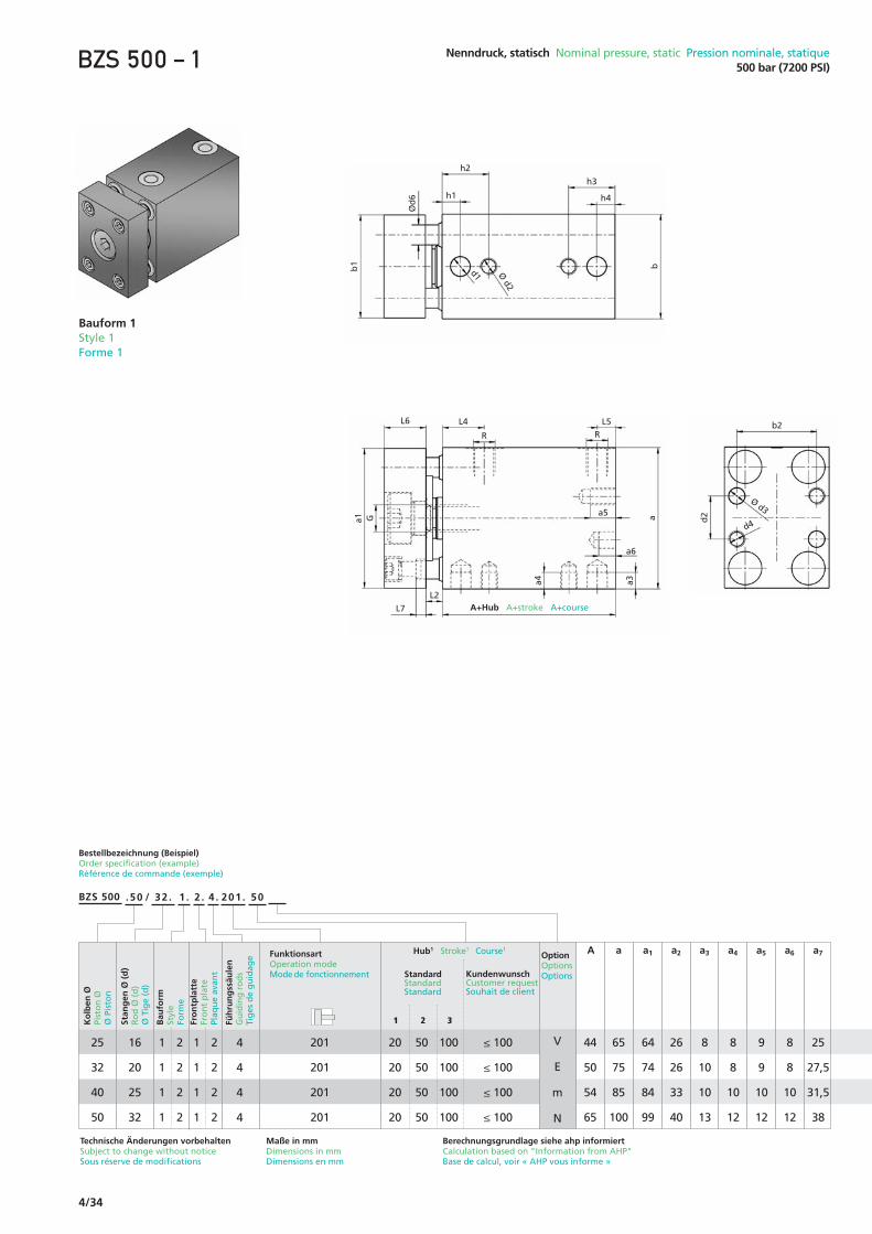
4/32
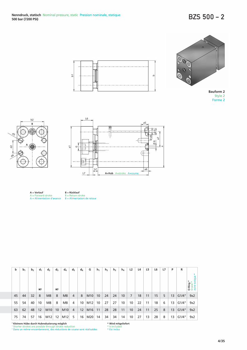
BZS 500 .50 32 1. 2 . 4 . 201 . 50 / .
2 41
Ko
lben
ØPi
sto
n Ø
Ø P
isto
n
Stan
gen
Ø (
d)
Ro
d Ø
(d
)Ø
Tig
e (d
)
Fro
ntp
latt
eFr
on
t p
late
Plaq
ue
avan
t
50 201
Bestellbezeichnung (Beispiel) Order specification (example) Référence de commande (exemple)
32
Bau
fom
Styl
eFo
rme
Füh
run
gss
äule
nG
uid
ing
ro
ds
Tig
es d
e g
uid
age Funktionsart
Operation modeMode de fonctionnement
HubStrokeCourse
OptionOptionsOptions
50
Blockzylinder-SchiebereinheitBlock style push unitVérin-bloc avec guidage
● Maximaler Betriebsdruck 500 bar ● Kompakter Zylinder ● Kolbenstangen gehärtet und geschliffen● Kolbendurchmesser von Ø 25 mm bis Ø 50 mm ● 4 Führungssäulen● Verschiedene Befestigungsarten
● Maximum operating pressure 500 bar● Compact cylinder ● Piston rods ground and hardened● Piston diameters from Ø 25 to 50 mm● 4 guiding rods● Multiple mounting options available
● Pression maximale 500 bar● Vérin compact● Tiges de piston trempées et rectifiées● Diamètres de piston de 25 à 50 mm● 4 colonnes-guides● Différents types de fixations

4/33
Bauform Style Forme
doppeltwirkenddouble-actingà double effet
Befestigungsgewinde hinten und seitlich – Zollgewindeanschluss Attachment threads side and back end – inch thread port connetion Taraudages arrière et lateral – taraudages d'alimentation
Befestigungsgewinde und Passungen hinten – O-Ring-Anschluss hinten Attachment threads back end – o-seal port connection back end Taraudages arrière – alimentation arrière par joint torique
1
2
Frontplatte Front plate Plaque avant
Mit FrontplatteWith front plate Avec plaque avant additionnelle
Ohne FrontplatteWithout front plateSans plaque avant1
2
Funktionsarten Operation modes Modes de fonctionnement
Optionen Options Options
Dichtungsvariante Viton® Viton® seal option Variante joints Viton®
Werkstoff: Viton® (HFD-Flüssigkeiten) oder Temperaturbereich bis 180 °CMaterial: Viton® (HDF fluids) or temperatures up to 180 °C Matière: Viton® (fluides HDF) ou témperatures jusqu'à 180 °C
V
Weitere Optionen sowie Sonderausführungen nach Kundenwunsch sind bei jedem Zylindertyp grundsätzlich möglich. Bitte kontaktieren Sie uns.Additional options and special design requirements are available upon request for each cylinder type. Please contact us!Sur demande, toutes modifications ou modèles spécifiques selon vos souhaits sont en principe réalisables pour tous types de vérins. Veuillez nous contacter.
201
Anschluss Connection Raccordement Befestigungsart Mounting mode Mode de fixation
4/34
Bestellbezeichnung (Beispiel)Order specification (example)Référence de commande (exemple)
Technische Änderungen vorbehaltenSubject to change without noticeSous réserve de modifications
Maße in mmDimensions in mmDimensions en mm
44
50
54
65
64
74
84
99
65
75
85
100
A a1a
26
26
33
40
a2
8
10
10
13
a3
8
8
10
12
a4
9
9
10
12
a5
8
8
10
12
a6
25
27,5
31,5
38
a7
.50 32 . 1 . 2 . 4 . 201 ./ 50
25
32
40
50
Ko
lben
ØPi
sto
n Ø
Ø P
isto
n
Stan
gen
Ø (
d)
Ro
d Ø
(d
)Ø
Tig
e (d
)
FunktionsartOperation modeMode de fonctionnement
Hub1 Stroke1 Course1
StandardStandardStandard
KundenwunschCustomer requestSouhait de client
201
201
201
201
16
20
25
32
20
20
20
20
50
50
50
50
100
100
100
100
≤ 100
≤ 100
≤ 100
≤ 100
1
1
1
1
2
2
2
2
4
4
4
4
Füh
run
gss
äule
nG
uid
ing
ro
ds
Tig
es d
e g
uid
age Option
OptionsOptions
V
E
m
N
Bau
form
Styl
eFo
rme
Fro
ntp
latt
eFr
on
t p
late
Plaq
ue
avan
t
BZS 500
1
1
1
1
1
2
2
2
2
32
L6 L4
a5
a6
L2
a1 aG
L5RR
L7
a3a4
Ø d3
A+Hub A+stroke A+course
b2
d2
d4
BZS 500 – 1 Nenndruck, statisch Nominal pressure, static Pression nominale, statique500 bar (7200 PSI)
h2
h3
b1
Ød
6
bd1
h1 h4
Ø d2
Berechnungsgrundlage siehe ahp informiertCalculation based on "Information from AHP"Base de calcul, voir « AHP vous informe »
Bauform 1Style 1Forme 1
4/35
O-R
ing
*O
-sea
l *Jo
int
tori
qu
e *
1 Kleinere Hübe durch Hubreduzierung möglich1 Shorter strokes are possible through stroke reduction1 Dans un même encombrement, des réductions de course sont réalisables
M8
M8
M10
M12
d2
8
8
10
12
d3
4
4
4
5
d5
8
10
12
16
d6
M10
M12
M16
M20
G
10
10
11
14
h1
24
27
28
34
h2
24
27
28
34
h3
10
10
11
14
h4
M8
M8
M10
M12
d4
7
10
10
10
L2 L4 L5
15
18
25
28
L6
5
6
8
8
L7
13
13
13
13
P
G1/4"
G1/4"
G1/4"
G1/4"
R
18
22
24
27
11
11
11
13
45
55
63
75
b
44
54
62
74
b1
32
40
48
57
b2
8
10
12
16
d1
Nenndruck, statisch Nominal pressure, static Pression nominale, statique500 bar (7200 PSI)
H7 H7
9x2
9x2
9x2
9x2
Ø P
Ø d
5Ø
6
d3
A+Hub A+stroke A+course
d4
BZS 500 – 2
L6
a5
a6
b2
a1b
1 b
aG
A
B
L7
L2
a7
d2
* Wird mitgeliefert* Is included* Est inclus
A = VorlaufA = Forward strokeA = Alimentation d'avance
B = RücklaufB = Return strokeB = Alimentation de retour
Bauform 2Style 2
Forme 2