1734-um006-a-en-p.pdf, encoder/counter modules, user … · the examples shown in this publication....
TRANSCRIPT

Encoder/Counter ModulesCat. No. 1734-IJ and -IK
User Manual
Important User Information Because of the variety of uses for the products described in this publication, those responsible for the application and use of this control equipment must satisfy themselves that all necessary steps have been taken to assure that each application and use meets all performance and safety requirements, including any applicable laws, regulations, codes and standards.
The illustrations, charts, sample programs and layout examples shown in this guide are intended solely for purposes of example. Since there are many variables and requirements associated with any particular installation, Allen-Bradley does not assume responsibility or liability (to include intellectual property liability) for actual use based upon the examples shown in this publication.
Allen-Bradley publication SGI-1.1, Safety Guidelines for the Application, Installation and Maintenance of Solid-State Control (available from your local Allen-Bradley office), describes some important differences between solid-state equipment and electromechanical devices that should be taken into consideration when applying products such as those described in this publication.
Reproduction of the contents of this copyrighted publication, in whole or part, without written permission of Rockwell Automation, is prohibited.
Throughout this manual we use notes to make you aware of safety considerations:
Attention statements help you to:
• identify a hazard
• avoid a hazard
• recognize the consequences
Allen-Bradley is a trademark of Rockwell Automation
ATTENTION
!Identifies information about practices or circumstances that can lead to personal injury or death, property damage or economic loss
IMPORTANT Identifies information that is critical for successful application and understanding of the product.
Preface
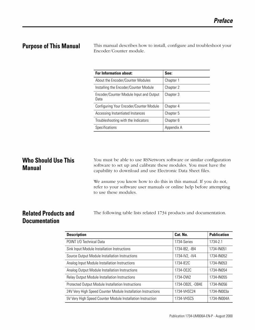
Purpose of This Manual This manual describes how to install, configure and troubleshoot your Encoder/Counter module.
Who Should Use This Manual
You must be able to use RSNetworx software or similar configuration software to set up and calibrate these modules. You must have the capability to download and use Electronic Data Sheet files.
We assume you know how to do this in this manual. If you do not, refer to your software user manuals or online help before attempting to use these modules.
Related Products and Documentation
The following table lists related 1734 products and documentation.
For Information about: See:
About the Encoder/Counter Modules Chapter 1
Installing the Encoder/Counter Module Chapter 2
Encoder/Counter Module Input and Output Data
Chapter 3
Configuring Your Encoder/Counter Module Chapter 4
Accessing Instantiated Instances Chapter 5
Troubleshooting with the Indicators Chapter 6
Specifications Appendix A
Description Cat. No. Publication
POINT I/O Technical Data 1734-Series 1734-2.1
Sink Input Module Installation Instructions 1734-IB2, -IB4 1734-IN051
Source Output Module Installation Instructions 1734-IV2, -IV4 1734-IN052
Analog Input Module Installation Instructions 1734-IE2C 1734-IN053
Analog Output Module Installation Instructions 1734-OE2C 1734-IN054
Relay Output Module Installation Instructions 1734-OW2 1734-IN055
Protected Output Module Installation Instructions 1734-OB2E, -OB4E 1734-IN056
24V Very High Speed Counter Module Installation Instructions 1734-VHSC24 1734-IN003a
5V Very High Speed Counter Module Installation Instruction 1734-VHSC5 1734-IN004A
1 Publication 1734-UM006A-EN-P - August 2000
Preface 2
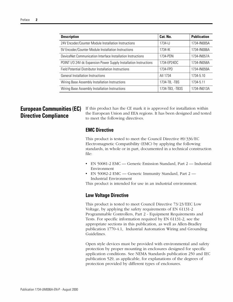
European Communities (EC) Directive Compliance
If this product has the CE mark it is approved for installation within the European Union and EEA regions. It has been designed and tested to meet the following directives.
EMC Directive
This product is tested to meet the Council Directive 89/336/EC Electromagnetic Compatibility (EMC) by applying the following standards, in whole or in part, documented in a technical construction file:
• EN 50081-2 EMC — Generic Emission Standard, Part 2 — Industrial Environment
• EN 50082-2 EMC — Generic Immunity Standard, Part 2 — Industrial Environment
This product is intended for use in an industrial environment.
Low Voltage Directive
This product is tested to meet Council Directive 73/23/EEC Low Voltage, by applying the safety requirements of EN 61131-2 Programmable Controllers, Part 2 - Equipment Requirements and Tests. For specific information required by EN 61131-2, see the appropriate sections in this publication, as well as Allen-Bradley publication 1770-4.1, Industrial Automation Wiring and Grounding Guidelines.
Open style devices must be provided with environmental and safety protection by proper mounting in enclosures designed for specific application conditions. See NEMA Standards publication 250 and IEC publication 529, as applicable, for explanations of the degrees of protection provided by different types of enclosures.
24V Encoder/Counter Module Installation Instructions 1734-IJ 1734-IN005A
5V Encoder/Counter Module Installation Instructions 1734-IK 1734-IN006A
DeviceNet Communication Interface Installation Instructions 1734-PDN 1734-IN057A
POINT I/O 24V dc Expansion Power Supply Installation Instructions 1734-EP24DC 1734-IN058A
Field Potential Distributor Installation Instructions 1734-FPD 1734-IN059A
General Installation Instructions All 1734 1734-5.10
Wiring Base Assembly Installation Instructions 1734-TB, -TBS 1734-5.11
Wiring Base Assembly Installation Instructions 1734-TB3, -TB3S 1734-IN013A
Description Cat. No. Publication
Publication 1734-UM006A-EN-P - August 2000

Preface 3
Definitions The following define the intended operation of the Encoder/Counter module.
Lead Breakage
Typically requires a shunt resistor (across the load) to detect 3 levels of current/input states -
• Open (Wire Off, Device = ?),
• Off (Wire OK, Device Off),
• On (Wire OK, Device On).
This method does not check the input against a time base, only that the device wiring (current loop) is intact.
Missing Pulse
Typically uses an input pulse to reset a watchdog timer (fixed or programmable HW). This method does detect “Lead Breakage”, since a broken wire will time-out the watchdog.
Zero Frequency
Typically uses an input pulse to calculate an input frequency and verify it is above an error threshold. This method does detect “Lead Breakage,” since a broken wire will generate a 0Hz frequency.
“Missing Pulse” or “Zero Frequency” will also detect a customer device stuck “high’ or “low”, since the counter is monitoring for a change in the input state. Currently, the Counter/Encoder Modes do not have Zero Frequency Detection - the “A” & “B” inputs are time independent, only looking for input edge changes to increment/decrement the count value.
The Period/Rate and Continuous Rate modes do have Zero Frequency Detection, since the “Z” input is monitored for Zero Frequency in Firmware (A and B inputs not used, and not monitored).
The Rate Measurement mode inherently has Zero Frequency Detection, since no “A” pulses in any sample period are = 0Hz (B and Z inputs not used, and not monitored).
Publication 1734-UM006A-EN-P - August 2000

Preface 4
Operational Mode Zero Frequency Detection
Input Monitored
Counter No None
Encoder No None
Period/Rate Yes Z Only
Rate Measurement Y A Only
Publication 1734-UM006A-EN-P - August 2000

Table of Contents
Important User Information . . . . . . . . . . . . . . . . . . . . . . . . . . 2Preface Purpose of This Manual. . . . . . . . . . . . . . . . . . . . . . . . . . . P-1
Who Should Use This Manual . . . . . . . . . . . . . . . . . . . . . . P-1Related Products and Documentation. . . . . . . . . . . . . . . . . P-1European Communities (EC) Directive Compliance . . . . . . P-2
EMC Directive . . . . . . . . . . . . . . . . . . . . . . . . . . . . . . . P-2Low Voltage Directive . . . . . . . . . . . . . . . . . . . . . . . . . P-2
Definitions . . . . . . . . . . . . . . . . . . . . . . . . . . . . . . . . . . . . P-3
About the Encoder/Counter Modules
General . . . . . . . . . . . . . . . . . . . . . . . . . . . . . . . . . . . . . . 1-1Introducing the Encoder/Counter Modules . . . . . . . . . . . . . 1-1
Module Overview . . . . . . . . . . . . . . . . . . . . . . . . . . . . 1-1Functional Overview . . . . . . . . . . . . . . . . . . . . . . . . . . 1-1
Operating Modes . . . . . . . . . . . . . . . . . . . . . . . . . . . . . . . 1-2Counter Mode . . . . . . . . . . . . . . . . . . . . . . . . . . . . . . . 1-2Encoder Modes . . . . . . . . . . . . . . . . . . . . . . . . . . . . . . 1-3Period / Rate Mode . . . . . . . . . . . . . . . . . . . . . . . . . . . 1-5Operation of Scalar . . . . . . . . . . . . . . . . . . . . . . . . . . . 1-6Rate Measurement Mode . . . . . . . . . . . . . . . . . . . . . . . 1-7New Data Indicator . . . . . . . . . . . . . . . . . . . . . . . . . . . 1-8Default Configuration. . . . . . . . . . . . . . . . . . . . . . . . . . 1-8
Operating Mode Features . . . . . . . . . . . . . . . . . . . . . . . . . 1-9Operating Mode Features . . . . . . . . . . . . . . . . . . . . . . . 1-9
Chapter Summary . . . . . . . . . . . . . . . . . . . . . . . . . . . . . . . 1-11
Installing the Encoder/Counter Module
General . . . . . . . . . . . . . . . . . . . . . . . . . . . . . . . . . . . . . . 2-1Installing the Mounting Base/ Wiring Base Assembly . . . . . 2-1Installing an I/O Module . . . . . . . . . . . . . . . . . . . . . . . . . . 2-2Installing the Removable Terminal Block . . . . . . . . . . . . . . 2-4Removing a Mounting Base . . . . . . . . . . . . . . . . . . . . . . . . 2-4Wiring the Encoder/Counter Modules . . . . . . . . . . . . . . . . 2-5Communicating with the 1734-IJ/IK Encoder/Counter Modules . . . . . . . . . . . . . . . . . . . . . . . . . . . . . . . . . . . . . . 2-6
Default Data Map for the 1734-IJ/IK Counter Module . . 2-6Configuring Your Encoder/Counter Module . . . . . . . . . . . . 2-7
Counter Configuration . . . . . . . . . . . . . . . . . . . . . . . . . 2-7Filter Selection . . . . . . . . . . . . . . . . . . . . . . . . . . . . . . . 2-8Scalar Selection . . . . . . . . . . . . . . . . . . . . . . . . . . . . . . 2-8
Chapter Summary . . . . . . . . . . . . . . . . . . . . . . . . . . . . . . . 2-8
i Publication 1734-UM006A-EN-P - August 2000

ii
Encoder/Counter Module Input and Output Data
In This Chapter . . . . . . . . . . . . . . . . . . . . . . . . . . . . . . . . . 3-1Data Table . . . . . . . . . . . . . . . . . . . . . . . . . . . . . . . . . . . . 3-1Detailed Description of Data Table Information . . . . . . . . . 3-2
Stored/Accumulated Channel Data (Input Word 2) . . . . 3-2Module/Channel Status and Programming Error Codes (Input Words 3 and 4) . . . . . . . . . . . . . . . . . . . . . . . . . 3-2
Configuration Data . . . . . . . . . . . . . . . . . . . . . . . . . . . . . . 3-4Counter Configuration (Configuration Word 1) . . . . . . . 3-5Filter Selection (Configuration Word 2 . . . . . . . . . . . . . 3-5Decimal Position (Configuration Word 3) . . . . . . . . . . . 3-6Word 4 is reserved. . . . . . . . . . . . . . . . . . . . . . . . . . . . 3-6Time Base and Gate Interval (Configuration Words 5 and 6) . . . . . . . . . . . . . . . . . . . . . . . . . . . . . . . . . . . 3-6Scalar (Configuration Word 7) . . . . . . . . . . . . . . . . . . . 3-7Scalar Selection . . . . . . . . . . . . . . . . . . . . . . . . . . . . . . 3-7Rollover (Configuration Word 8). . . . . . . . . . . . . . . . . . 3-7Preset (Configuration Word 9) . . . . . . . . . . . . . . . . . . . 3-7Safe State Values (Configuration Word 10) . . . . . . . . . . 3-8
Communicating Real Time/Nonreal Time Information. . . . . 3-8
Configuring Your Encoder/Counter Module
Configuration Overview . . . . . . . . . . . . . . . . . . . . . . . . . . 4-1Adding the Adapter to Your Network . . . . . . . . . . . . . . 4-1Adding I/O Modules to Your Network . . . . . . . . . . . . . 4-2
Setting the Counter’s Parameters . . . . . . . . . . . . . . . . . . . . 4-4Checking I/O Status and Viewing/Editing the EDS File . . . . 4-6
Accessing Instantiated Instances In This Chapter . . . . . . . . . . . . . . . . . . . . . . . . . . . . . . . . . 5-1Using Instantiated Instances. . . . . . . . . . . . . . . . . . . . . . . . 5-1Assemblies . . . . . . . . . . . . . . . . . . . . . . . . . . . . . . . . . . . . 5-3
Troubleshooting with the Indicators
Using the Indicators for Troubleshooting . . . . . . . . . . . . . . 6-1
Specifications Specifications for the Encoder/Counter, Cat. No. 1734-IJ . . . A-1Specifications for the Encoder/Counter, Cat. No. 1734-IK . . A-2Input Derating Curve for the 1734-IKEncoder/Counter Module . . . . . . . . . . . . . . . . . . . . . . . . . A-3
Publication 1734-UM006A-EN-P - August 2000

Chapter 1
About the Encoder/Counter Modules
General In this chapter, you will learn about the types of encoder/counters, their features and capabilities.
Introducing the Encoder/Counter Modules
Module Overview
The counter modules install into the Point I/O terminal base (1734-TB or -TBS) and interface with the Point I/O DeviceNet Pass-through (1734-PDN) or the Point I/O DeviceNet Adapter (1734-ADN). The Counter Module serves as a "signal conditioner" and "function block" (i.e. a counter) between the customer process signals on the terminal base and the PointBus containing the command information. The three main functional blocks are the customer digital I/O interface, the counter "ASIC" and the microprocessor.
Functional Overview
The Encoder/Counter Module accepts feedback from:
– encoders (either single ended or differential)
– pulse generators
– mechanical limit switches
– frequencies up to 1 MHz
A filter is available with four settings:
• 50Hz
• 500Hz
• 5kHz
• 50kHz)
The filter can be turned off to achieve the fastest counting rate.
The input voltage range is 5Vdc (1734-IJ) or 15-24Vdc (1734-IK). The module returns the count or frequency in the form of a 24 bit binary number (0 - 16,777,215) expressed in a 32 bit long word. Each counter has a user selectable preset and rollover value associated with it.
1 Publication 1734-UM006A-EN-P - August 2000
1-2 About the Encoder/Counter Modules
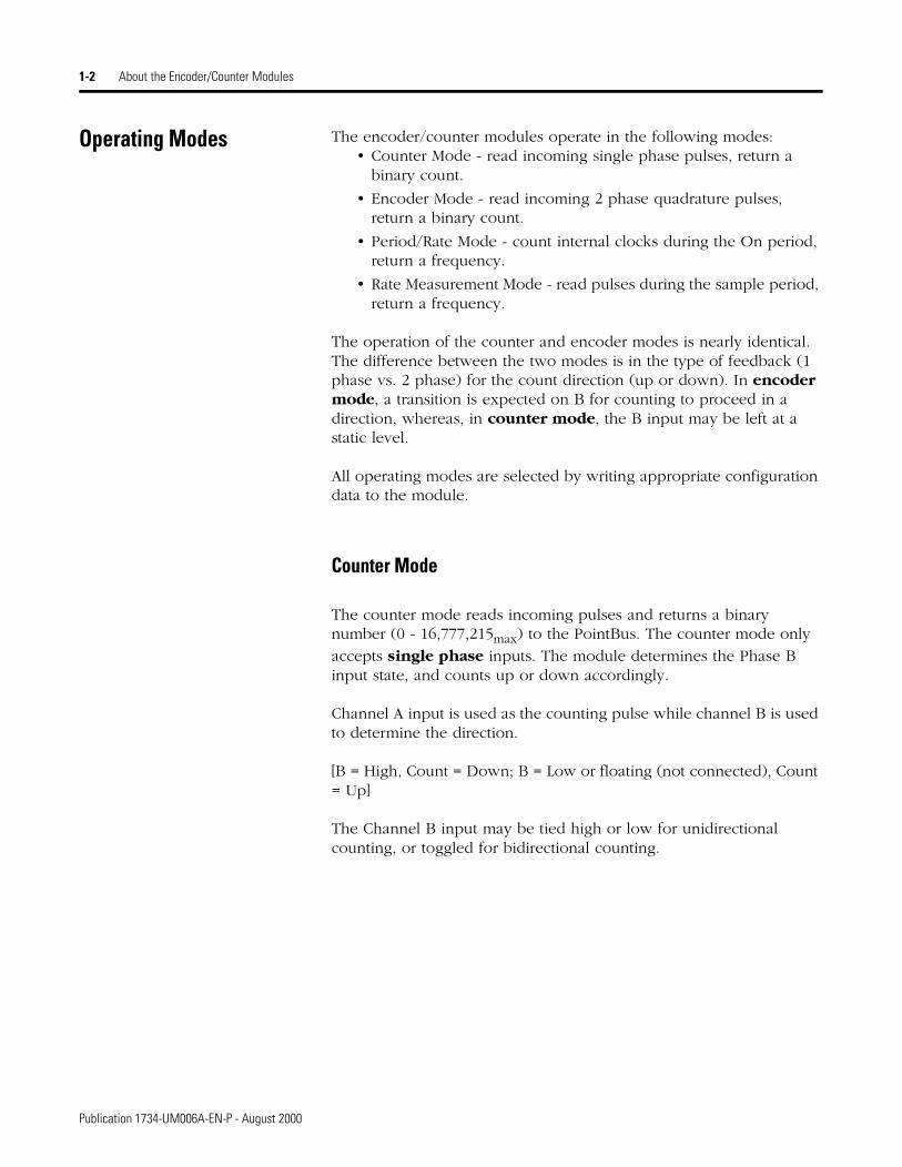
Operating Modes The encoder/counter modules operate in the following modes:• Counter Mode - read incoming single phase pulses, return a
binary count.
• Encoder Mode - read incoming 2 phase quadrature pulses, return a binary count.
• Period/Rate Mode - count internal clocks during the On period, return a frequency.
• Rate Measurement Mode - read pulses during the sample period, return a frequency.
The operation of the counter and encoder modes is nearly identical. The difference between the two modes is in the type of feedback (1 phase vs. 2 phase) for the count direction (up or down). In encoder mode, a transition is expected on B for counting to proceed in a direction, whereas, in counter mode, the B input may be left at a static level.
All operating modes are selected by writing appropriate configuration data to the module.
Counter Mode
The counter mode reads incoming pulses and returns a binary number (0 - 16,777,215max) to the PointBus. The counter mode only
accepts single phase inputs. The module determines the Phase B input state, and counts up or down accordingly.
Channel A input is used as the counting pulse while channel B is used to determine the direction.
[B = High, Count = Down; B = Low or floating (not connected), Count = Up]
The Channel B input may be tied high or low for unidirectional counting, or toggled for bidirectional counting.
Publication 1734-UM006A-EN-P - August 2000

About the Encoder/Counter Modules 1-3
EXAMPLE
Example of Counter Mode
Encoder Modes
The encoder mode reads incoming pulses and returns a binary number (0 - 16,777,215max) to the PointBus. The encoder mode only
accepts 2 phase quadrature inputs. The module senses the relationship between the 2 phases, and counts up or down accordingly.
There are two basic encoder types, absolute and incremental. A single output incremental encoder is called a tachometer encoder. A dual channel incremental encoder with one channel leading the other by 90° is called a quadrature encoder.
A system using a quadrature encoder may include an optional zero pulse, or index, serving as a reference mark for system reset. The principal disadvantage of a system using incremental encoders is that a power interruption causes the loss of position reference, so a system must be reinitialized or returned to a known zero position.
Absolute encoders typically have higher speed requirements (200 KHz typical) for motion control applications. An absolute encoder has a unique code associated with each position, so the exact position is always known, even if the system power is turned off.
A Input
B Direction
Z (Store Count)
Single Phase Pulse Generator1734-VHSC
Input A
Input B
1 2 3
A Input
B Input
Count
(Gate / Reset )
2 1 0
Count Up Count Down
Input Z
0
OutputsUpdatedContinuously
Publication 1734-UM006A-EN-P - August 2000

1-4 About the Encoder/Counter Modules
EXAMPLE
Example of Multiplying Encoder Mode X1
X1 Multiplying Encoder Mode
Quadrature input signals are used to count on the leading (up direction) OR trailing (down direction) edge of A for a bidirectional count, and channel B is used to determine the direction.
[ B = leads A, Count = Down; B = follows A, Count = Up ]
X2 Multiplying Encoder Mode
Quadrature input signals are used to count on leading AND trailing edges of A for a bidirectional count, and channel B is used to determine the direction.
[ B = leads A, Count = Down; B = follows A, Count = Up ]
X4 Multiplying Encoder Mode
Quadrature input signals are used to count on leading AND trailing edges of A AND B for a bidirectional count, and channel B is used to determine the direction.
[ B = leads A, Count = Down; B = follows A, Count = Up ]
A
B
Quadrature Encoder1734-VHSC
Input A
Input B
1 2 3
1 3 52 4 6
1 3 52 4 6 7 1098 1211
A Input
B Input
X1 Count
X2 Count
X4 Count
2 1 0
5 3 14 2 0
11 9 710 8 6 5 234 01
Forward Rotation Reverse Rotation
Input Z
OutputsUpdatedContinuously
Z (Store Count)
(Gate / Reset )
Publication 1734-UM006A-EN-P - August 2000
About the Encoder/Counter Modules 1-5
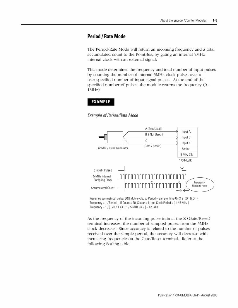
Period / Rate Mode
The Period/Rate Mode will return an incoming frequency and a total accumulated count to the PointBus, by gating an internal 5MHz internal clock with an external signal.
This mode determines the frequency and total number of input pulses by counting the number of internal 5MHz clock pulses over a user-specified number of input signal pulses. At the end of the specified number of pulses, the module returns the frequency (0 - 1MHz).
EXAMPLE
Example of Period/Rate Mode
As the frequency of the incoming pulse train at the Z (Gate/Reset) terminal increases, the number of sampled pulses from the 5MHz clock decreases. Since accuracy is related to the number of pulses received over the sample period, the accuracy will decrease with increasing frequencies at the Gate/Reset terminal. Refer to the following Scaling table.
A ( Not Used )
B ( Not Used )
Encoder / Pulse Generator
1734-IJ/IK
Input A
Input B
Z Input ( Pulse )
5 MHz Internal
(Gate / Reset )Input Z
Z
Accumulated Count
1
Scalar
5 MHz Clk
Sampling Clock
Assumes symmetrical pulse, 50% duty cycle, so Period = Sample Time On X 2 {On & Off}
10 20
Frequency = 1 / Period If Count = 20, Scalar = 1, and Clock Period = ( 1 / 5 MHz )Frequency = 1 / [ ( 20 / 1 ) X ( 1 / 5 MHz ) X 2 ] = 125 kHz
Frequency Updated Here
Publication 1734-UM006A-EN-P - August 2000

1-6 About the Encoder/Counter Modules
Relationship Between Sampled Pulses and Input Frequency
Scaling the input frequency through the use of a scalar can lessen the decrease in accuracy. A scalar value of 1 will only return an accurate input frequency if incoming input pulses have a 50% duty cycle.
Operation of Scalar
In the Period/Rate mode, the scalar lets the incoming pulse train at the Z Gate/Reset pin be divided by a user defined number. There is one scalar value for each counter. Acceptable values for the scalar are 1, 2, 4, 8, 16, 32, 64, and 128. The default value for each scalar is 1. Note that a “0” scalar is equivalent to a “1”.
The product of the Sample Period times the scalar should be less than 6.71 seconds in order to avoid a zero frequency detect indication.
(5 MHz sample time = 200ns; 16,777,216 counts x 200ns x 2 half cycles of Z = 6.71 seconds)
Input Frequency at Z Gate/Reset Terminal
Sample Pulses for 1/2 Cycle of Z Gate/Reset Pulse
2.5Hz 1M
5Hz 500k
10Hz 250k
20Hz 125k
50Hz 50k
100Hz 25k
200Hz 12.5k
500Hz 5k
1kHz 2.5k
2 Hz 1.25k
5kHz 500
10kHz 250
20kHz 125
50kHz 50
100kHz 25
Publication 1734-UM006A-EN-P - August 2000

About the Encoder/Counter Modules 1-7
Rate Measurement Mode
The Rate Measurement mode determines the frequency and total number of input pulses over a user-specified sample period. At the end of the interval, the module returns a value representing the sampled number of pulses and a value indicating the incoming frequency. When the count and frequency are updated, any associated outputs are checked against their associated presets. Frequency is calculated by dividing the accumulated count by the user selected time period, and is returned in the read data. Allowable time periods are 10ms to 3s in 10ms increments, with a default value of 1s. Note that a “0” time period is equivalent to the 1s default.
EXAMPLE
Example of Rate Measurement Mode
A Input
B ( Not Used )
Encoder/Pulse Generator
1734-IJ/IK
Input A
Input B
A Input ( Pulse )
Internal Sampling Gate
(Gate / Reset )Input Z
Z ( Not Used )
User Selectable Sample Period,
If Sample Period is 50ms, and Count = 3, then Frequency = 3 /50ms = 60Hz
Accumulated Count1
Time Base
2 3
Frequency Calculated, Updated Here
10ms to 2s in 10ms increments.
Publication 1734-UM006A-EN-P - August 2000
1-8 About the Encoder/Counter Modules
New Data Indicator
A two bit counter, C1 & C0, is updated every time an "event" occurs, indicating that new data is available in the Stored/Accumulated Count words. Events are defined as:
Any active gate transition in any of the Store Count (Counter or Encoder) modes;
The end of the gate sample period in either the Period/Rate modes;
The end of the programmed sample period in the Rate Measurement mode.
To use these bits reliably, acquisition of data from the Counter Module must occur faster than the events, which cause C1/C0 to increment. When C1/C0 is updated, a Change Of State (COS) message can be sent.
Default Configuration
The module’s default configuration on startup will be:
• Counter Mode
• 50Hz filter on A, B and Z
• No time base
• Rollover = 0x00FFFFFF
• Preset = 0
• No scalar
• Counter Control Safe State = 0
To modify the default settings to those required for your application, refer to chapter 3.
Publication 1734-UM006A-EN-P - August 2000
About the Encoder/Counter Modules 1-9
Operating Mode Features The following table summarizes which features are active in each mode:
Operating Mode Features
The Z Gate/Reset Terminall will operate in one of four modes when the Store Count feature is in use. The four figures below detail the operation in each mode.
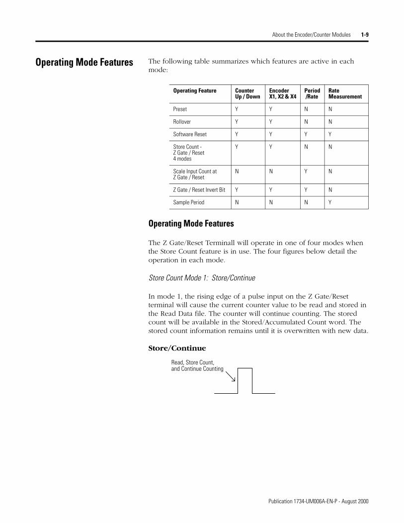
Store Count Mode 1: Store/Continue
In mode 1, the rising edge of a pulse input on the Z Gate/Reset terminal will cause the current counter value to be read and stored in the Read Data file. The counter will continue counting. The stored count will be available in the Stored/Accumulated Count word. The stored count information remains until it is overwritten with new data.
Store/Continue
Operating Feature CounterUp / Down
EncoderX1, X2 & X4
Period /Rate
Rate Measurement
Preset Y Y N N
Rollover Y Y N N
Software Reset Y Y Y Y
Store Count - Z Gate / Reset4 modes
Y Y N N
Scale Input Count at Z Gate / Reset
N N Y N
Z Gate / Reset Invert Bit Y Y Y N
Sample Period N N N Y
Read, Store Count,and Continue Counting
Publication 1734-UM006A-EN-P - August 2000

1-10 About the Encoder/Counter Modules
Store Count Mode 2: Store/Wait/Resume
In mode 2, the rising edge of a pulse input on the Z Gate/Reset terminal will read and store the current counter value in the Stored/Accumulated Count word and inhibit counting while the Z Gate/Reset terminal is high. Counting resumes on the falling edge of the pulse at the Z Gate/Reset terminal. The stored count information will remain until it is overwritten with new data.
Store/Wait/Resume
Store Count Mode 3: Store-Reset/Wait/Start
In mode 3, the rising edge of a pulse input on the Z Gate/Reset terminal will stop counting, read and store the current counter value in the Stored/Accumulated Count word, and reset the counter to zero. The counter does not count while the input pulse on the Z Gate/Reset terminal is high. Counting resumes from zero on the falling edge of the pulse at the Gate/Reset terminal. The stored count information will remain until it is overwritten with new data.
Store-Reset/Wait/Start
Store Count Resume Counting
Stop Counting
and Reset to zero from zero
Counter has stopped Counting
Start CountingStop Count, Store,
Publication 1734-UM006A-EN-P - August 2000
About the Encoder/Counter Modules 1-11
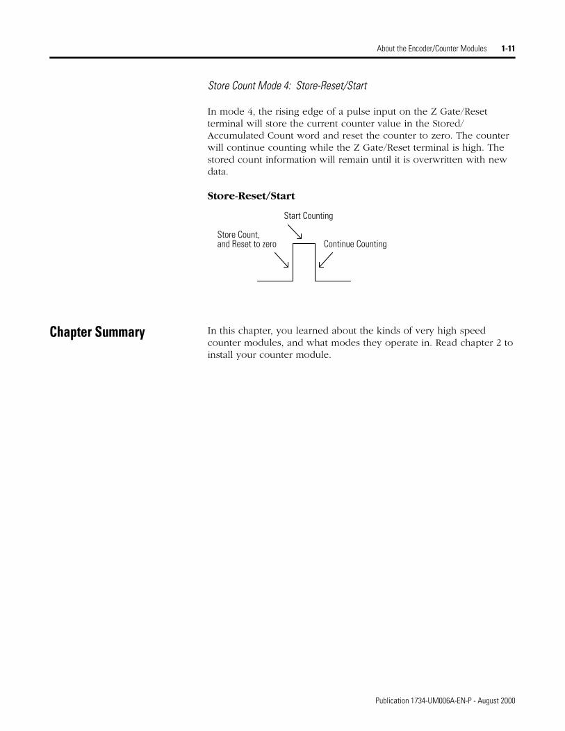
Store Count Mode 4: Store-Reset/Start
In mode 4, the rising edge of a pulse input on the Z Gate/Reset terminal will store the current counter value in the Stored/Accumulated Count word and reset the counter to zero. The counter will continue counting while the Z Gate/Reset terminal is high. The stored count information will remain until it is overwritten with new data.
Store-Reset/Start
Chapter Summary In this chapter, you learned about the kinds of very high speed counter modules, and what modes they operate in. Read chapter 2 to install your counter module.
and Reset to zero
Start Counting
Continue CountingStore Count,
Publication 1734-UM006A-EN-P - August 2000

1-12 About the Encoder/Counter Modules
Publication 1734-UM006A-EN-P - August 2000
Chapter 2
Installing the Encoder/Counter Module
General In this chapter, you will learn about the Encoder/Counter modules and their installation.
Installing the Mounting Base/ Wiring Base Assembly
The wiring base assembly (1734-TB or -TBS) consists of a mounting base (cat. no. 1734-MB) and a removable terminal block (cat. no. 1734-RTB or -RTBS). You can install the assembly, or just the mounting base. To install the mounting base/wiring base assembly on the DIN rail, proceed as follows.
1. Position the mounting base/wiring base assembly vertically above the installed units (adapter, power supply or existing module).
2. Slide the mounting base down allowing the interlocking side pieces to engage the adjacent module or adapter.
For more information about: See page:
Installing the Mounting Base/ Wiring Base Assembly 2-1
Installing an I/O Module 2-3
Installing the Removable Terminal Block 2-4
Removing a Mounting Base 2-4
Wiring the Encoder/Counter Modules 2-5
Communicating with the 1734-IJ/IK Encoder/Counter Modules 2-6
Configuring Your Encoder/Counter Module 2-7
1 Publication 1734-UM006A-EN-P - August 2000

2-2 Installing the Encoder/Counter Module
3. Press firmly to seat the mounting base on the DIN rail. The mounting base will snap into place.
4. To remove the mounting base from the DIN rail, remove any installed module (and any module immediately to the right), and use a small bladed screwdriver to rotate the DIN rail locking screw to a vertical position. This releases the locking mechanism. Then lift straight up to remove the mounting base.
5. Repeat this procedure for the next mounting base assembly.
24VDC
Source
Output
Module
Status
Network
Status
1734OB4E
NODE:
0
1
2
3
Mounting Base
Mechanical Keying (orange)
Module Wiring Diagram
1
Module Locking Mechanism
Insertable I/O Module
RTB Removing Handle
Removable Terminal Block (RTB)
DIN Rail Locking Screw (orange)
Slide-in Writable Label
Interlocking Side Pieces
Publication 1734-UM006A-EN-P - August 2000
Installing the Encoder/Counter Module 2-3
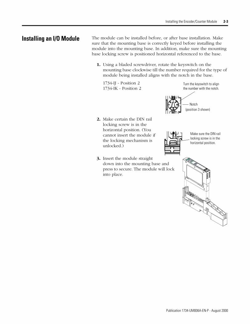
Installing an I/O Module The module can be installed before, or after base installation. Make sure that the mounting base is correctly keyed before installing the module into the mounting base. In addition, make sure the mounting base locking screw is positioned horizontal referenced to the base.
1. Using a bladed screwdriver, rotate the keyswitch on the mounting base clockwise till the number required for the type of module being installed aligns with the notch in the base.
1734-IJ - Position 21734-IK - Position 2
2. Make certain the DIN rail locking screw is in the horizontal position. (You cannot insert the module if the locking mechanism is unlocked.)
3. Insert the module straight down into the mounting base and press to secure. The module will lock into place.
Turn the keyswitch to alignthe number with the notch.
Notch(position 3 shown)
Make sure the DIN rail locking screw is in the horizontal position.
24VDC
Source
Output
Module
Status
Network
Status
1734OB4E
NODE:
0
1
2
3
Publication 1734-UM006A-EN-P - August 2000

2-4 Installing the Encoder/Counter Module
Installing the Removable Terminal Block
A removable terminal block is supplied with your mounting base assembly. To remove, pull up on the RTB handle. This allows the base to be removed and replaced as necessary without removing any of the wiring. To reinsert the removable terminal block, proceed as follows.
1. Insert the RTB end opposite the handle into the base unit. This end has a curved section that engages with the mounting base.
2. Rotate the terminal block into the mounting base until it locks itself in place.
3. If an I/O module is installed, snap the RTB handle into place on the module.
Removing a Mounting Base To remove a mounting base, you must remove any installed module, and remove the removable terminal block (if wired).
1. Unlatch the RTB handle on the I/O module.
2. Pull on the RTB handle to remove the removable terminal block.
3. Press in on the module lock on the top of the module and pull up on the I/O module to remove from the base.
4. Remove the module to the right of the base you are removing. (The interlocking portion of the base sits under the adjacent module.)
5. Use a small bladed screwdriver to rotate the orange DIN rail locking screw on the mounting base to a vertical position. This releases the locking mechanism.
6. Then lift the mounting base straight up to remove.
Hook the RTB end into the mounting base end, and rotate until it locks into place.
Publication 1734-UM006A-EN-P - August 2000
Installing the Encoder/Counter Module 2-5
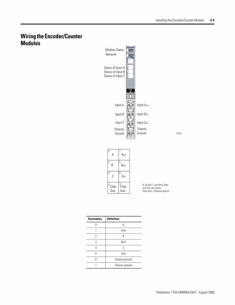
Wiring the Encoder/Counter Modules
Ternination Definition
0 A
1 Aret
2 B
3 Bret
4 Z
5 Zret
6 Chassis ground
7 Chassis ground
42016
Status of Input Z
Input Aret
Input Bret
Input Zret
Chassis Ground
Input A
Input B
Input Z
ChassisGround
Module StatusNetwork
Status of Input AStatus of Input B
0 1
2 3
4 5
6 7
A
B
Z
ChasGnd
Aret
Bret
Zret
ChasGnd
A, B and Z , and Aret, Bret, and Zret are inputsChas Gnd = Chassis ground
Publication 1734-UM006A-EN-P - August 2000
2-6 Installing the Encoder/Counter Module
Communicating with the 1734-IJ/IK Encoder/Counter Modules
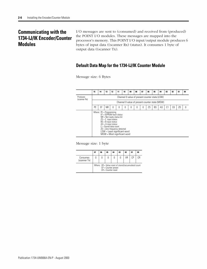
I/O messages are sent to (consumed) and received from (produced) the POINT I/O modules. These messages are mapped into the processor’s memory. This POINT I/O input/output module produces 6 bytes of input data ((scanner Rx) (status). It consumes 1 byte of output data ((scanner Tx).
Default Data Map for the 1734-IJ/IK Counter Module
Message size: 6 Bytes
Message size: 1 byte
15 14 13 12 11 10 09 08 07 06 05 04 03 02 01 00
Produces (scanner Rx)
Channel 0 value of present counter state (LSW)
Channel 0 value of present counter state (MSW)
PE EF NR 0 0 0 0 0 0 ZS BS AS C1 C0 ZD 0
Where: PE = ProgrammingEF = EEPROM fault statusNR = Not ready status bitZS = Z input statusBS = B input statusAS = A input statusC = Stored data countZD = Zero frequency detectedLSW = Least significant wordMSW = Most significant word
07 06 05 04 03 02 01 00
Consumes (scanner Tx)
0 0 0 0 0 VR CP CR
Where: VR = Value reset of stored/accumulated countCP = Counter presetCR = Counter reset
Publication 1734-UM006A-EN-P - August 2000
Installing the Encoder/Counter Module 2-7
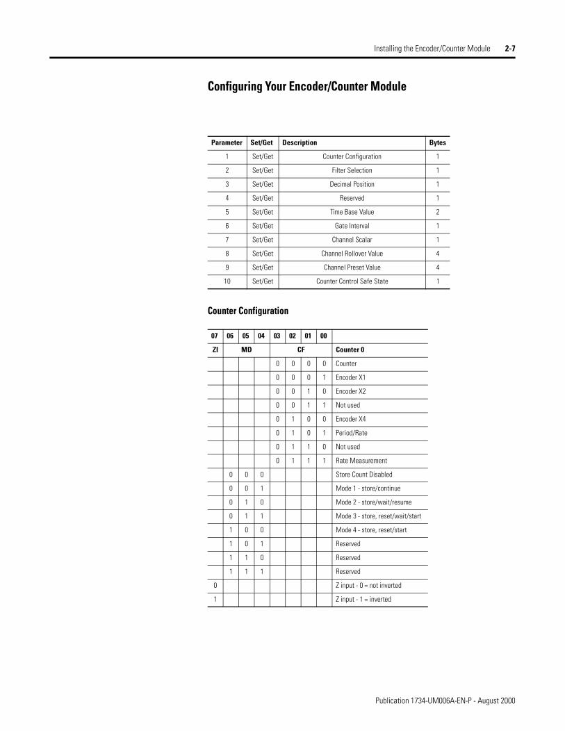
Configuring Your Encoder/Counter Module
Counter Configuration
Parameter Set/Get Description Bytes
1 Set/Get Counter Configuration 1
2 Set/Get Filter Selection 1
3 Set/Get Decimal Position 1
4 Set/Get Reserved 1
5 Set/Get Time Base Value 2
6 Set/Get Gate Interval 1
7 Set/Get Channel Scalar 1
8 Set/Get Channel Rollover Value 4
9 Set/Get Channel Preset Value 4
10 Set/Get Counter Control Safe State 1
07 06 05 04 03 02 01 00
ZI MD CF Counter 0
0 0 0 0 Counter
0 0 0 1 Encoder X1
0 0 1 0 Encoder X2
0 0 1 1 Not used
0 1 0 0 Encoder X4
0 1 0 1 Period/Rate
0 1 1 0 Not used
0 1 1 1 Rate Measurement
0 0 0 Store Count Disabled
0 0 1 Mode 1 - store/continue
0 1 0 Mode 2 - store/wait/resume
0 1 1 Mode 3 - store, reset/wait/start
1 0 0 Mode 4 - store, reset/start
1 0 1 Reserved
1 1 0 Reserved
1 1 1 Reserved
0 Z input - 0 = not inverted
1 Z input - 1 = inverted
Publication 1734-UM006A-EN-P - August 2000

2-8 Installing the Encoder/Counter Module
Filter Selection
Scalar Selection
Chapter Summary In this chapter, you learned how to install your module and mounting base assembly. You also learned how to wire your module.
07 06 05 04 03 02 01 00
0 ZF BF AF FS
0 0 0 0 No Filter
0 0 0 1 50kHz (10µs + 0µs/-1.6µs)
0 0 1 0 5kHz (100µs + 0µs/-13.2µs)
0 1 0 0 500Hz (1.0ms + 0µs/-125µs)
1 0 0 0 50Hz (10ms + 0ms/-1.25ms)
0 A input not filtered
1 A input filtered
0 B input not filtered
1 B input filtered
0 Z input not filtered
1 Z input filtered
07 06 05 04 03 02 01 00
Scalar1
0 0 0 0 0 0 0 1 Z - Fmin = 0.149Hz
0 0 0 0 0 0 1 0 Z/2 - Fmin = 0.298Hz
0 0 0 0 0 1 0 0 Z/4 - Fmin = 0.596Hz
0 0 0 0 1 0 0 0 Z/8 - Fmin = 1.192Hz
0 0 0 1 0 0 0 0 Z/16 - Fmin = 2.384Hz
0 0 1 0 0 0 0 0 Z/32 - Fmin = 4.768Hz
0 1 0 0 0 0 0 0 Z/64 - Fmin = 9.537Hz
1 0 0 0 0 0 0 0 Z/128 - Fmin = 19.073Hz
1 Where Fmin indicates the frequency at which the zero frequency detect is asserted due to counter overflow.
Publication 1734-UM006A-EN-P - August 2000

Chapter 3
Encoder/Counter Module Input and Output Data
In This Chapter In this chapter, you will learn about the input/output data table of your 1734-IJ and -IK.
Data Table The following table shows the complete format of the input/output data..
For more information about: See page:
Data Table 3-1
Detailed Description of Data Table Information 3-2
Configuration Data 3-4
Communicating Real Time/Nonreal Time Information 3-8
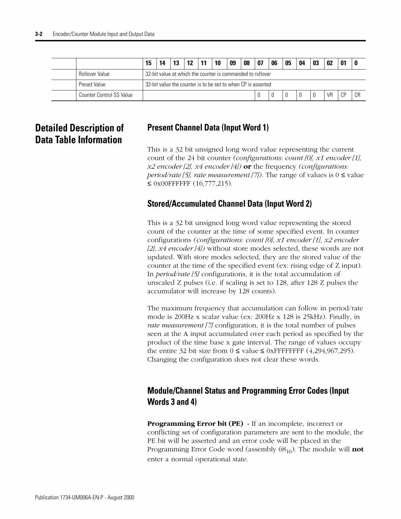
15 14 13 12 11 10 09 08 07 06 05 04 03 02 01 0
Input Information
Present Channel Data 32-bit Value of the present counter state
Stored Channel Data 32-bit value of the stored/accumulated count
Status PE EF NR 0 0 0 0 0 0 ZS BS AS C1 C0 ZD 0
Programming Error Code PE 0 0 0 0 E10 E9 E8 E7 E6 E5 E4 E3 E2 E1 E0
Output Information
Counter Control 0 0 0 0 0 VR CP CR
Configuration Information
Counter Configuration ZI MD MD MD CF CF CF CF
Filter Selection 0 ZF BF AF FS FS FS FS
Decimal Position 8-bit value used to modify the present channel data display
Reserved
Time Base 16-bit value used to set the time base
Gate Interval 8-bit value used to set the gate interval
Scalar 8-bit value used to divide the Z input by 2n
1 Publication 1734-UM006A-EN-P - August 2000
3-2 Encoder/Counter Module Input and Output Data
Detailed Description of Data Table Information
Present Channel Data (Input Word 1)
This is a 32 bit unsigned long word value representing the current count of the 24 bit counter (configurations: count [0], x1 encoder [1], x2 encoder [2], x4 encoder [4]) or the frequency (configurations: period/rate [5], rate measurement [7]). The range of values is 0 ≤ value ≤ 0x00FFFFFF (16,777,215).
Stored/Accumulated Channel Data (Input Word 2)
This is a 32 bit unsigned long word value representing the stored count of the counter at the time of some specified event. In counter configurations (configurations: count [0], x1 encoder [1], x2 encoder [2], x4 encoder [4]) without store modes selected, these words are not updated. With store modes selected, they are the stored value of the counter at the time of the specified event (ex: rising edge of Z input). In period/rate [5] configurations, it is the total accumulation of unscaled Z pulses (i.e. if scaling is set to 128, after 128 Z pulses the accumulator will increase by 128 counts).
The maximum frequency that accumulation can follow in period/rate mode is 200Hz x scalar value (ex: 200Hz x 128 is 25kHz). Finally, in rate measurement [7] configuration, it is the total number of pulses seen at the A input accumulated over each period as specified by the product of the time base x gate interval. The range of values occupy the entire 32 bit size from 0 ≤ value ≤ 0xFFFFFFFF (4,294,967,295). Changing the configuration does not clear these words.
Module/Channel Status and Programming Error Codes (Input Words 3 and 4)
Programming Error bit (PE) - If an incomplete, incorrect or conflicting set of configuration parameters are sent to the module, the PE bit will be asserted and an error code will be placed in the Programming Error Code word (assembly 6816). The module will not
enter a normal operational state.
Rollover Value 32-bit value at which the counter is commanded to rollover
Preset Value 32-bit value the counter is to be set to when CP is asserted
Counter Control SS Value 0 0 0 0 0 VR CP CR
15 14 13 12 11 10 09 08 07 06 05 04 03 02 01 0
Publication 1734-UM006A-EN-P - August 2000
Encoder/Counter Module Input and Output Data 3-3
Bit definitions for the error code are:
E10: Reserved
E9: The decimal point position is outside of acceptable range.
E8: Reserved
E7: Reserved
E6: A configuration was selected that requires the scalar and none was programmed OR Multiple scalars were selected.
E5: The preset is out of range ( > 0x00FFFFFF).
E4: A rollover of zero was programmed OR Rollover is out of range ( > 0x01000000).
E3: A configuration requiring time base was selected and no gate interval was set OR Gate interval is out of range ( > 200) OR Product of time base and gate interval is greater than 3 seconds.
E2: A time base was entered that is not a multiple of 10 OR Time base is out of range ( > 3000, i.e. 3 seconds).
E1: ZF/BF/AF were selected and no filter was programmed OR Multiple filters were selected.
E0: A reserved configuration/mode was programmed.
EEPROM Fault status bit (EF) - If a fault is detected with the EEPROM during power up tests, this bit is asserted to 1. It indicates that the content of the EEPROM has been corrupted, most likely caused by loss of power during an executing write.
Not Ready status bit (NR) - Whenever power is applied to the module, the hardware must be initialized. During this time, the NR bit will be asserted and the green module status indicator will flash.
Z input Status (ZS) - This bit indicates the present status of the Z input (1 indicates Z is ON, 0 indicates Z is OFF). This bit is unaffected by Z Invert, ZI, in the Counter Configuration word.
B input Status (BS) - This bit indicates the present status of the B input (1 indicates B is ON, 0 indicates B is OFF).
A input Status (AS) - This bit indicates the present status of the A input (1 indicates A is ON, 0 indicates A is OFF).
C[1,0] Stored data count - This count cycles through [ 0 0 ], [ 0 1 ], [ 1 0 ], [ 1 1 ], [ 0 0 ]… Each time the stored/accumulated count words are updated, C[1,0] is incremented. This feature assumes the host’s sample rate (including network delay and program scan) is as fast or faster than the frequency of the event which updates C[1,0].
Publication 1734-UM006A-EN-P - August 2000

3-4 Encoder/Counter Module Input and Output Data
Zero frequency Detected (ZD) - This bit is operational when frequency configurations are programmed (configurations: period/rate [5], rate measurement [7]).
In period/rate [5] configuration, counts are acquired during the ON state of the Z input. At very low frequencies the counter saturates, indicating a zero frequency detect. The time it takes to determine a zero frequency in these two configurations can be as long as 6.7 seconds ( 16,777,216 counts x 1/5MHz x 2 half cycles of Z ).
In rate measurement [7] configuration pulses on the A input are counted over a sample interval specified by the time base. The time it takes to determine a zero frequency in this configuration will be determined by the sample interval (ex: time base = 0.300 second ∴300 milliseconds to determine ZF).
Configuration Data The following represents the configuration data used by the 1734-VHSC24 module.
Parameter Configuration Information Size (bytes)
1 Set/Get Counter Configuration 1
2 Set/Get Filter Selection 1
3 Set/Get Decimal Position 1
4 Set/Get Reserved 1
5 Set/Get Time Base 2
6 Set/Get Gate Interval 1
7 Set/Get Scalar 1
8 Set/Get Rollover Value 4
9 Set/Get Preset Value 4
10 Set/Get Counter Control SS Value 1
Publication 1734-UM006A-EN-P - August 2000
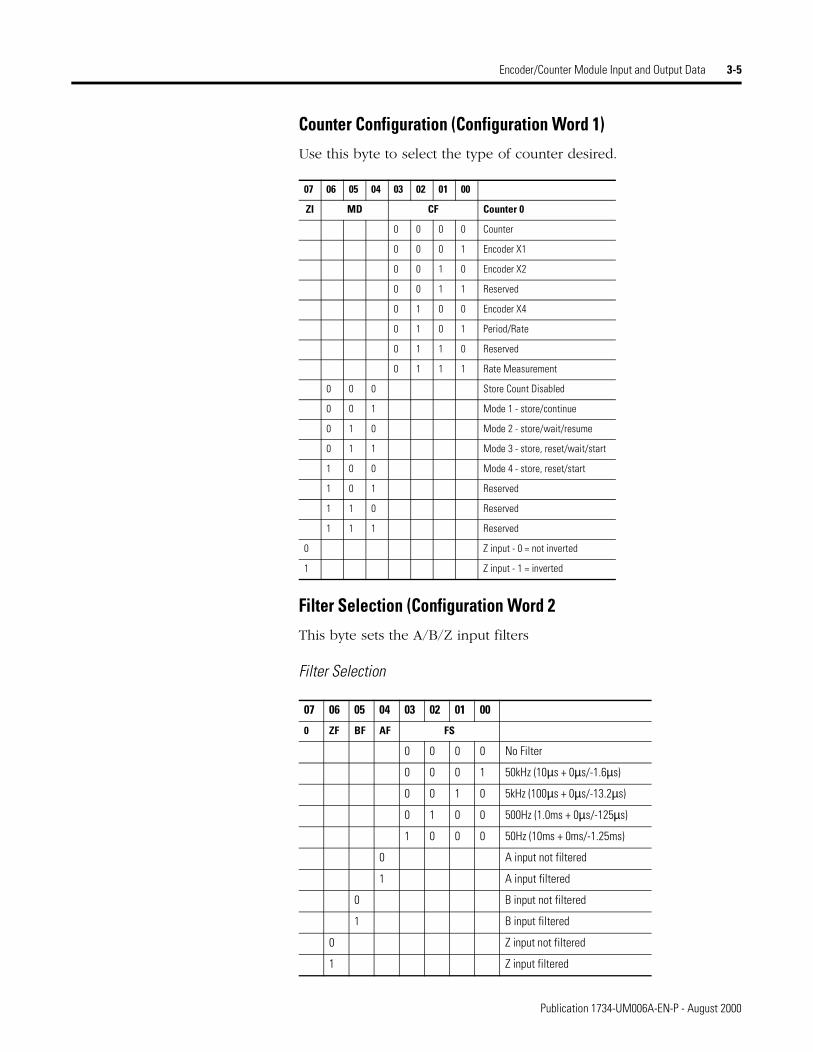
Encoder/Counter Module Input and Output Data 3-5
Counter Configuration (Configuration Word 1)Use this byte to select the type of counter desired.
Filter Selection (Configuration Word 2This byte sets the A/B/Z input filters
Filter Selection
07 06 05 04 03 02 01 00
ZI MD CF Counter 0
0 0 0 0 Counter
0 0 0 1 Encoder X1
0 0 1 0 Encoder X2
0 0 1 1 Reserved
0 1 0 0 Encoder X4
0 1 0 1 Period/Rate
0 1 1 0 Reserved
0 1 1 1 Rate Measurement
0 0 0 Store Count Disabled
0 0 1 Mode 1 - store/continue
0 1 0 Mode 2 - store/wait/resume
0 1 1 Mode 3 - store, reset/wait/start
1 0 0 Mode 4 - store, reset/start
1 0 1 Reserved
1 1 0 Reserved
1 1 1 Reserved
0 Z input - 0 = not inverted
1 Z input - 1 = inverted
07 06 05 04 03 02 01 00
0 ZF BF AF FS
0 0 0 0 No Filter
0 0 0 1 50kHz (10µs + 0µs/-1.6µs)
0 0 1 0 5kHz (100µs + 0µs/-13.2µs)
0 1 0 0 500Hz (1.0ms + 0µs/-125µs)
1 0 0 0 50Hz (10ms + 0ms/-1.25ms)
0 A input not filtered
1 A input filtered
0 B input not filtered
1 B input filtered
0 Z input not filtered
1 Z input filtered
Publication 1734-UM006A-EN-P - August 2000
3-6 Encoder/Counter Module Input and Output Data
Decimal Position (Configuration Word 3)
This byte changes the significant digits of the frequency or counter display.
In the frequency modes (period/rate [5], rate measurement [7]) for example, a -2 will move the decimal point left 2 places, dividing the frequency value by 100, a +1 moves it right, multiplying by 10. The firmware checks for placement to be in the range -4 ≤ value ≤ +2. A value outside the range will move the decimal point to the zero position and assert the programming error (PE) bit. Moving the decimal point to the left (i.e. negative), allows high frequencies, commonly present in rate measurement mode, to fit within a single 16 bit word. Moving the decimal point to the right (i.e. positive), allows low frequencies, commonly present in period and continuous rate modes, to have resolution displayed to 0.1Hz and 0.01Hz. Frequencies should be kept below 3.2kHz for 0.1Hz resolution and below 320Hz for 0.01Hz. Scalars of Z/128, Z/64, Z/32 and Z/16 should not be used when positioning is applied. 0 is the default setting.
In the counter modes (counter [0], x1 encoder [1], x2 encoder [2], x4 encoder [4]), it attenuates the counter display, for example, 20 divides count+1 by 20. The value may be in the range 0 < value ≤ 255. The result of requesting a number other than 1 performs the function: (COUNT + 1)/ATTENUATION. This is useful for scaling a large counter value to a smaller 16 bit value or a percentage. 1 is the default setting and zero reverts to 1 to prevent a divide by zero.
Word 4 is reserved.
Time Base and Gate Interval (Configuration Words 5 and 6)
The gate interval byte sets the counter’s gate intervall using the time base setting (16-bit word 5) as its time unit. (i.e. its resolution is determined by the time base). The actual gate interval is the product of the time base and the gate interval (ex: 50ms gate interval may be produced with a time base of 10 and a gate interval of 5 or a time base of 50 and a gate interval of 1). The maximum value of the product of time base x gate interval is 3 seconds. The gate interval must be entered when rate measurement [7] configurations are used. The maximum value is 200.
Publication 1734-UM006A-EN-P - August 2000
Encoder/Counter Module Input and Output Data 3-7
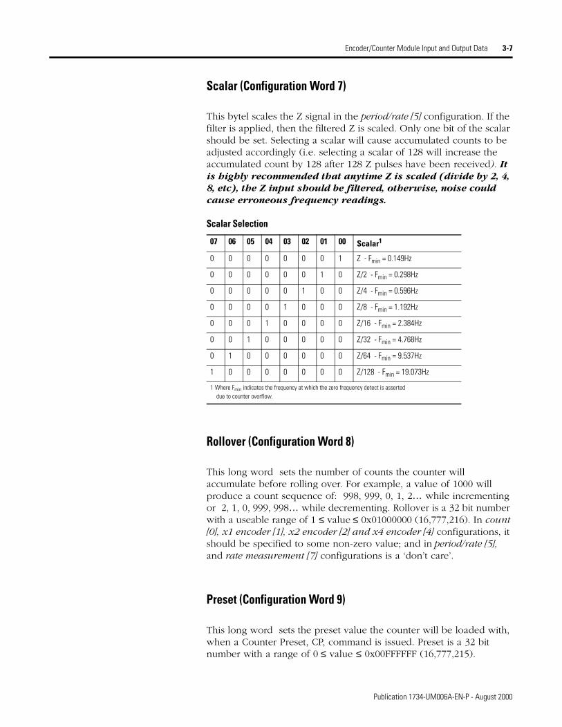
Scalar (Configuration Word 7)
This bytel scales the Z signal in the period/rate [5] configuration. If the filter is applied, then the filtered Z is scaled. Only one bit of the scalar should be set. Selecting a scalar will cause accumulated counts to be adjusted accordingly (i.e. selecting a scalar of 128 will increase the accumulated count by 128 after 128 Z pulses have been received). It is highly recommended that anytime Z is scaled (divide by 2, 4, 8, etc), the Z input should be filtered, otherwise, noise could cause erroneous frequency readings.
Scalar Selection
Rollover (Configuration Word 8)
This long word sets the number of counts the counter will accumulate before rolling over. For example, a value of 1000 will produce a count sequence of: 998, 999, 0, 1, 2… while incrementing or 2, 1, 0, 999, 998… while decrementing. Rollover is a 32 bit number with a useable range of 1 ≤ value ≤ 0x01000000 (16,777,216). In count [0], x1 encoder [1], x2 encoder [2] and x4 encoder [4] configurations, it should be specified to some non-zero value; and in period/rate [5], and rate measurement [7] configurations is a ‘don’t care’.
Preset (Configuration Word 9)
This long word sets the preset value the counter will be loaded with, when a Counter Preset, CP, command is issued. Preset is a 32 bit number with a range of 0 ≤ value ≤ 0x00FFFFFF (16,777,215).
07 06 05 04 03 02 01 00 Scalar1
0 0 0 0 0 0 0 1 Z - Fmin = 0.149Hz
0 0 0 0 0 0 1 0 Z/2 - Fmin = 0.298Hz
0 0 0 0 0 1 0 0 Z/4 - Fmin = 0.596Hz
0 0 0 0 1 0 0 0 Z/8 - Fmin = 1.192Hz
0 0 0 1 0 0 0 0 Z/16 - Fmin = 2.384Hz
0 0 1 0 0 0 0 0 Z/32 - Fmin = 4.768Hz
0 1 0 0 0 0 0 0 Z/64 - Fmin = 9.537Hz
1 0 0 0 0 0 0 0 Z/128 - Fmin = 19.073Hz
1 Where Fmin indicates the frequency at which the zero frequency detect is asserted due to counter overflow.
Publication 1734-UM006A-EN-P - August 2000
3-8 Encoder/Counter Module Input and Output Data
Safe State Values (Configuration Word 10)
When either the host transitions to PROGRAM mode or a communication fault (i.e. broken network cable) occurs, the module copies the safe state word (counter control value) into its real-time working buffer. The definitions are identical to those described under Real-time Output Data.
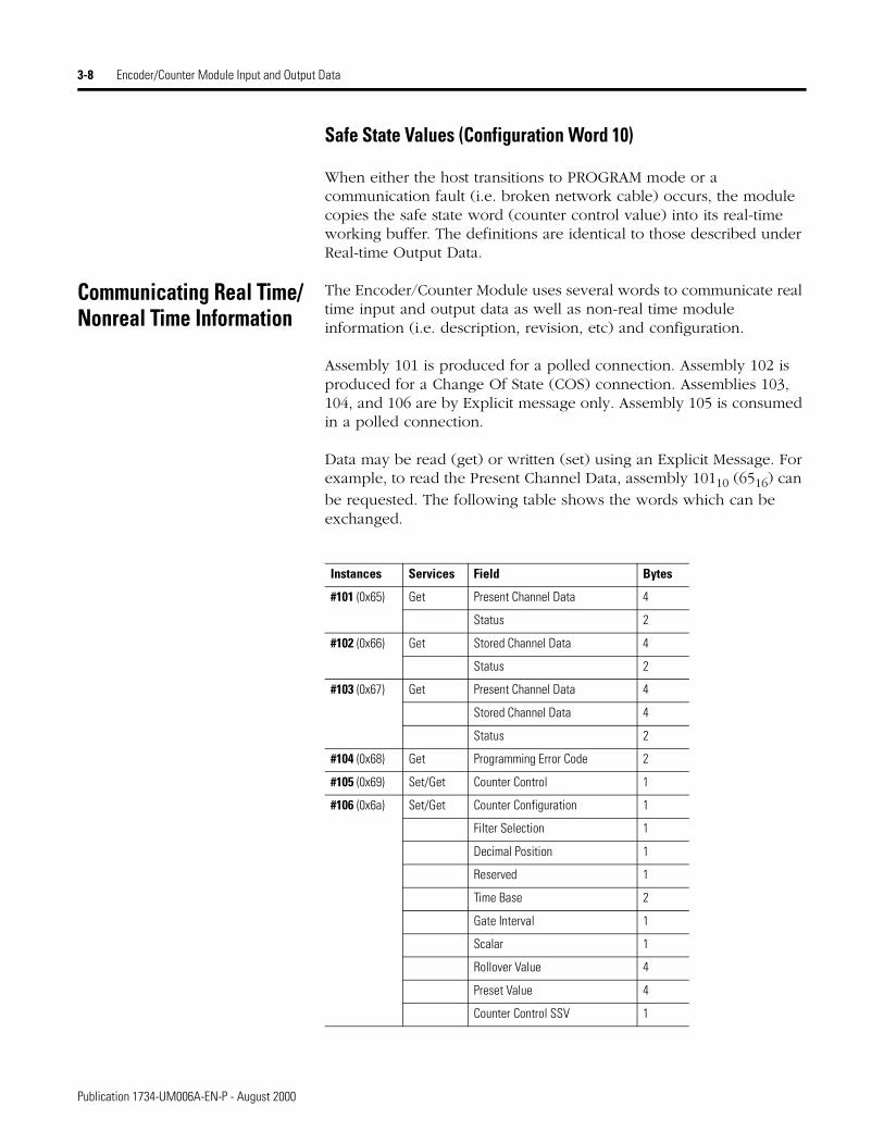
Communicating Real Time/Nonreal Time Information
The Encoder/Counter Module uses several words to communicate real time input and output data as well as non-real time module information (i.e. description, revision, etc) and configuration.
Assembly 101 is produced for a polled connection. Assembly 102 is produced for a Change Of State (COS) connection. Assemblies 103, 104, and 106 are by Explicit message only. Assembly 105 is consumed in a polled connection.
Data may be read (get) or written (set) using an Explicit Message. For example, to read the Present Channel Data, assembly 10110 (6516) can
be requested. The following table shows the words which can be exchanged.
Instances Services Field Bytes
#101 (0x65) Get Present Channel Data 4
Status 2
#102 (0x66) Get Stored Channel Data 4
Status 2
#103 (0x67) Get Present Channel Data 4
Stored Channel Data 4
Status 2
#104 (0x68) Get Programming Error Code 2
#105 (0x69) Set/Get Counter Control 1
#106 (0x6a) Set/Get Counter Configuration 1
Filter Selection 1
Decimal Position 1
Reserved 1
Time Base 2
Gate Interval 1
Scalar 1
Rollover Value 4
Preset Value 4
Counter Control SSV 1
Publication 1734-UM006A-EN-P - August 2000
Chapter 4
Configuring Your Encoder/Counter Module
This chapter describes how to configure your Encoder/Counter modules with RSNetworx.
Configuration Overview You must use the RSNetworx for DeviceNet software to configure your module. You can configure the module while it is:
• online
or
• offline
This chapter shows configuration in the online mode. Configuration screens appear similar in both modes. The primary difference is that if you make changes offline, you must go online before the configuration changes take effect.
Adding the Adapter to Your Network
Follow these steps:
1. Start the RSNetworx for DeviceNet software.
For more information about: See page:
Configuration Overview 4-1
Adding the Adapter to Your Network 4-1
Adding I/O Modules to Your Network 4-2
Setting the Counter’s Parameters 4-4
Checking I/O Status and Viewing/Editing the EDS File
4-6
1 Publication 1734-UM006A-EN-P - August 2000
4-2 Configuring Your Encoder/Counter Module
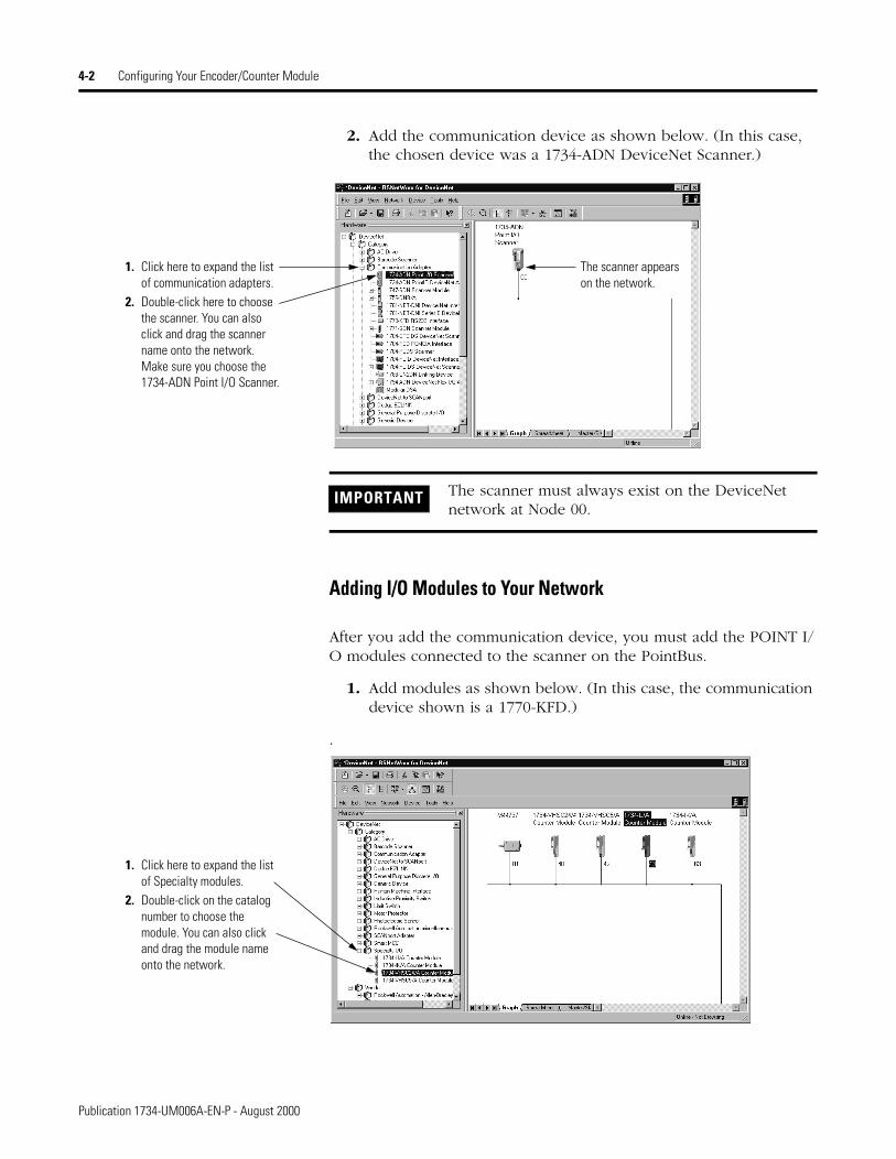
2. Add the communication device as shown below. (In this case, the chosen device was a 1734-ADN DeviceNet Scanner.)
Adding I/O Modules to Your Network
After you add the communication device, you must add the POINT I/O modules connected to the scanner on the PointBus.
1. Add modules as shown below. (In this case, the communication device shown is a 1770-KFD.)
.
1. Click here to expand the list of communication adapters.
2. Double-click here to choose the scanner. You can also click and drag the scanner name onto the network.Make sure you choose the 1734-ADN Point I/O Scanner.
The scanner appears on the network.
IMPORTANT The scanner must always exist on the DeviceNet network at Node 00.
1. Click here to expand the list of Specialty modules.
2. Double-click on the catalog number to choose the module. You can also click and drag the module name onto the network.
Publication 1734-UM006A-EN-P - August 2000

Configuring Your Encoder/Counter Module 4-3
The out-of-the-box node setting for 1734 modules is 63. You can change the setting by using the node commissioning tool. The node commissioning tool is available either online or offline.
IMPORTANT If you commission a node online, you must power down your system before the change takes place.
1. Go to the pulldown Tools. Select Node Commissioning.
2. Click on Browse. 3. Select the module to change.4. The node commissioning
screen returns. It displays the node number and data rate.
5. Change the node number and Apply. The screen will then identify the new setting.
6. Click on Close to continue.
4
2
3
1
5
6
Publication 1734-UM006A-EN-P - August 2000
4-4 Configuring Your Encoder/Counter Module
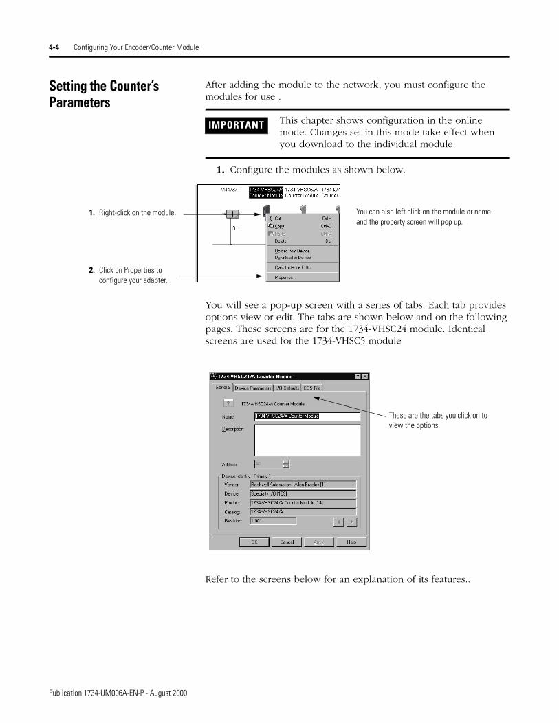
Setting the Counter’s Parameters
After adding the module to the network, you must configure the modules for use .
1. Configure the modules as shown below.
You will see a pop-up screen with a series of tabs. Each tab provides options view or edit. The tabs are shown below and on the following pages. These screens are for the 1734-VHSC24 module. Identical screens are used for the 1734-VHSC5 module
Refer to the screens below for an explanation of its features..
IMPORTANT This chapter shows configuration in the online mode. Changes set in this mode take effect when you download to the individual module.
1. Right-click on the module.
2. Click on Properties to configure your adapter.
You can also left click on the module or name and the property screen will pop up.
These are the tabs you click on to view the options.
Publication 1734-UM006A-EN-P - August 2000
Configuring Your Encoder/Counter Module 4-5
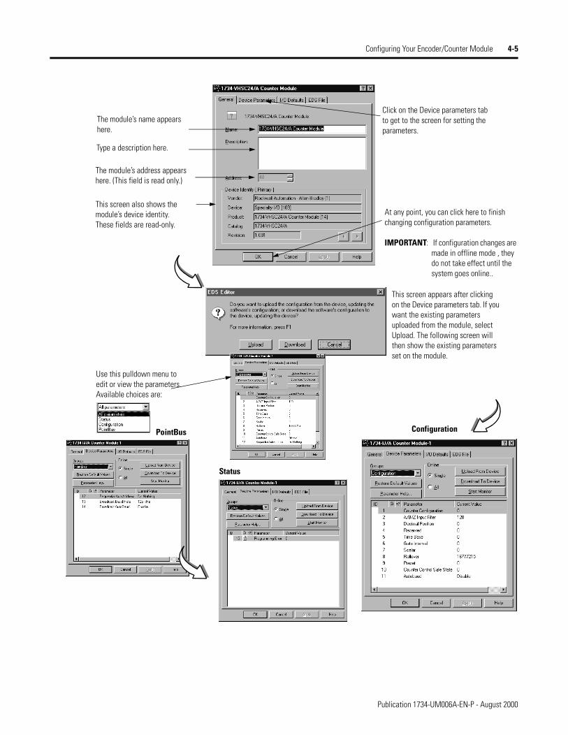
The module’s name appears here.
Type a description here.
The module’s address appears here. (This field is read only.)
This screen also shows the module’s device identity. These fields are read-only.
At any point, you can click here to finish changing configuration parameters.
IMPORTANT: If configuration changes are made in offline mode , they do not take effect until the system goes online..
Click on the Device parameters tab to get to the screen for setting the parameters.
This screen appears after clicking on the Device parameters tab. If you want the existing parameters uploaded from the module, select Upload. The following screen will then show the existing parameters set on the module.
Use this pulldown menu to edit or view the parameters. Available choices are:
PointBus
Status
Configuration
Publication 1734-UM006A-EN-P - August 2000
4-6 Configuring Your Encoder/Counter Module
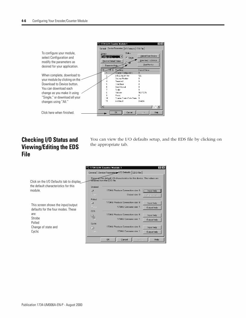
Checking I/O Status and Viewing/Editing the EDS File
You can view the I/O defaults setup, and the EDS file by clicking on the appropriate tab.
To configure your module, select Configuration and modify the parameters as desired for your application.
When complete, download to your module by clicking on the Download to Device button. You can download each change as you make it using “Single,” or download all your changes using “All.”
Click here when finished.
Click on the I/O Defaults tab to display the default characteristics for this module.
This screen shows the input/output defaults for the four modes. These are:StrobePolledChange of state andCyclic
Publication 1734-UM006A-EN-P - August 2000

Configuring Your Encoder/Counter Module 4-7
Click on View File to view the actual EDS file (shown at the left).
Click on the EDS File tab to display the statistics of the EDS file used to configure this
You can view the actual EDS file or edit the file.
Publication 1734-UM006A-EN-P - August 2000

4-8 Configuring Your Encoder/Counter Module
Publication 1734-UM006A-EN-P - August 2000
Chapter 5
Accessing Instantiated Instances
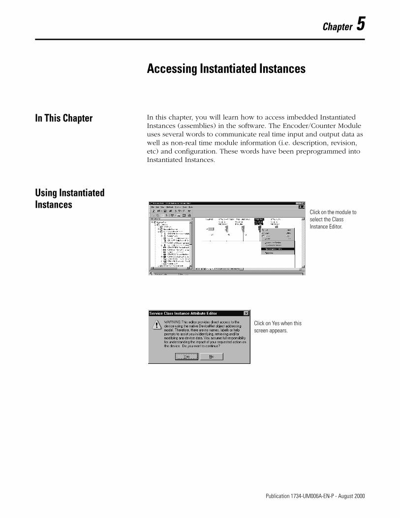
In This Chapter In this chapter, you will learn how to access imbedded Instantiated Instances (assemblies) in the software. The Encoder/Counter Module uses several words to communicate real time input and output data as well as non-real time module information (i.e. description, revision, etc) and configuration. These words have been preprogrammed into Instantiated Instances.
Using Instantiated Instances
Click on the module to select the Class Instance Editor.
Click on Yes when this screen appears.
1 Publication 1734-UM006A-EN-P - August 2000
5-2 Accessing Instantiated Instances
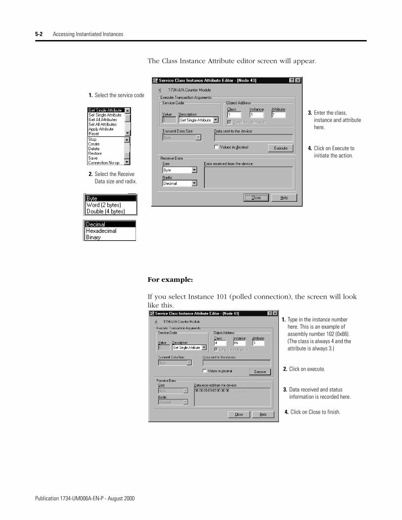
The Class Instance Attribute editor screen will appear.
For example:
If you select Instance 101 (polled connection), the screen will look like this.
1. Select the service code
3. Enter the class, instance and attribute here.
4. Click on Execute to initiate the action.
2. Select the Receive Data size and radix.
1. Type in the instance number here. This is an example of assembly number 102 (0x66). (The class is always 4 and the attribute is always 3.)
2. Click on execute.
3. Data received and status information is recorded here.
4. Click on Close to finish.
Publication 1734-UM006A-EN-P - August 2000
Accessing Instantiated Instances 5-3
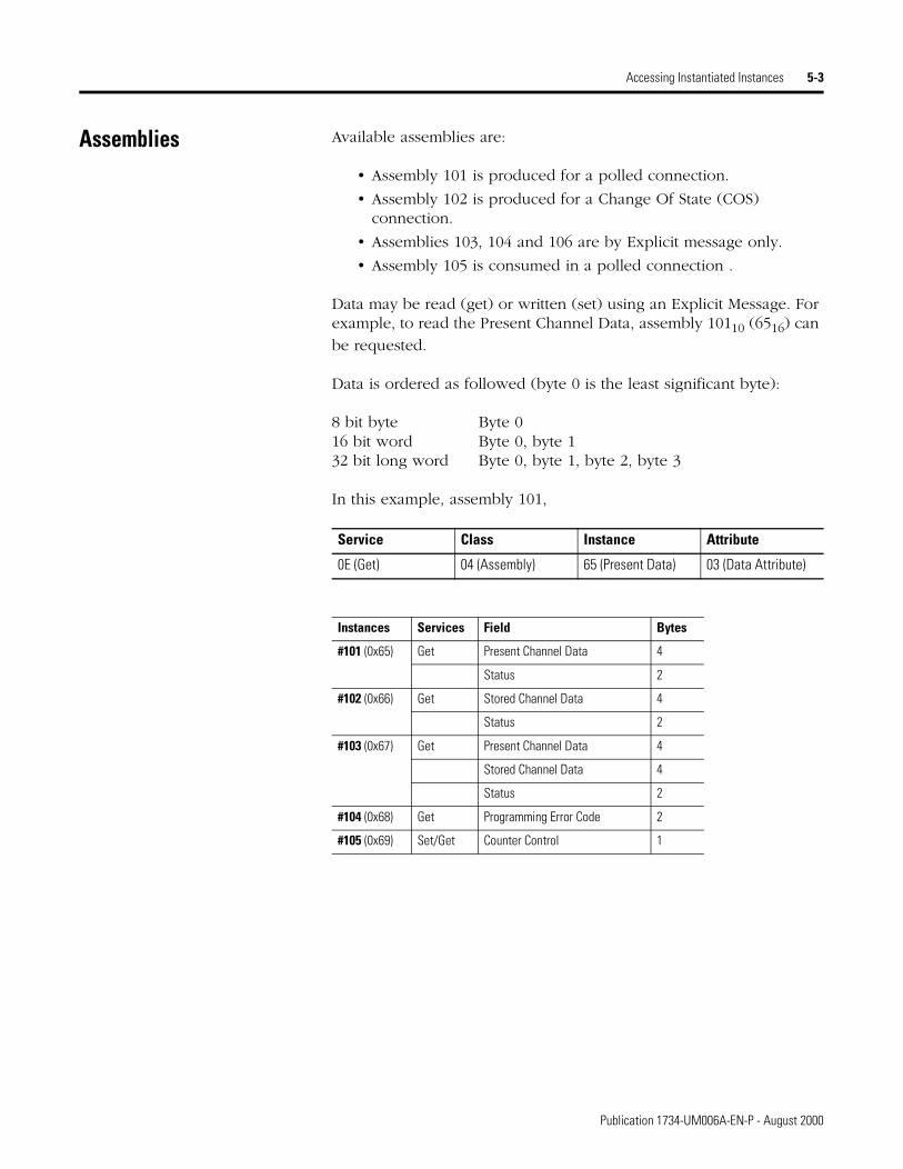
Assemblies Available assemblies are:
• Assembly 101 is produced for a polled connection.
• Assembly 102 is produced for a Change Of State (COS) connection.
• Assemblies 103, 104 and 106 are by Explicit message only.
• Assembly 105 is consumed in a polled connection .
Data may be read (get) or written (set) using an Explicit Message. For example, to read the Present Channel Data, assembly 10110 (6516) can
be requested.
Data is ordered as followed (byte 0 is the least significant byte):
8 bit byte Byte 016 bit word Byte 0, byte 132 bit long word Byte 0, byte 1, byte 2, byte 3
In this example, assembly 101,
Service Class Instance Attribute
0E (Get) 04 (Assembly) 65 (Present Data) 03 (Data Attribute)
Instances Services Field Bytes
#101 (0x65) Get Present Channel Data 4
Status 2
#102 (0x66) Get Stored Channel Data 4
Status 2
#103 (0x67) Get Present Channel Data 4
Stored Channel Data 4
Status 2
#104 (0x68) Get Programming Error Code 2
#105 (0x69) Set/Get Counter Control 1
Publication 1734-UM006A-EN-P - August 2000
5-4
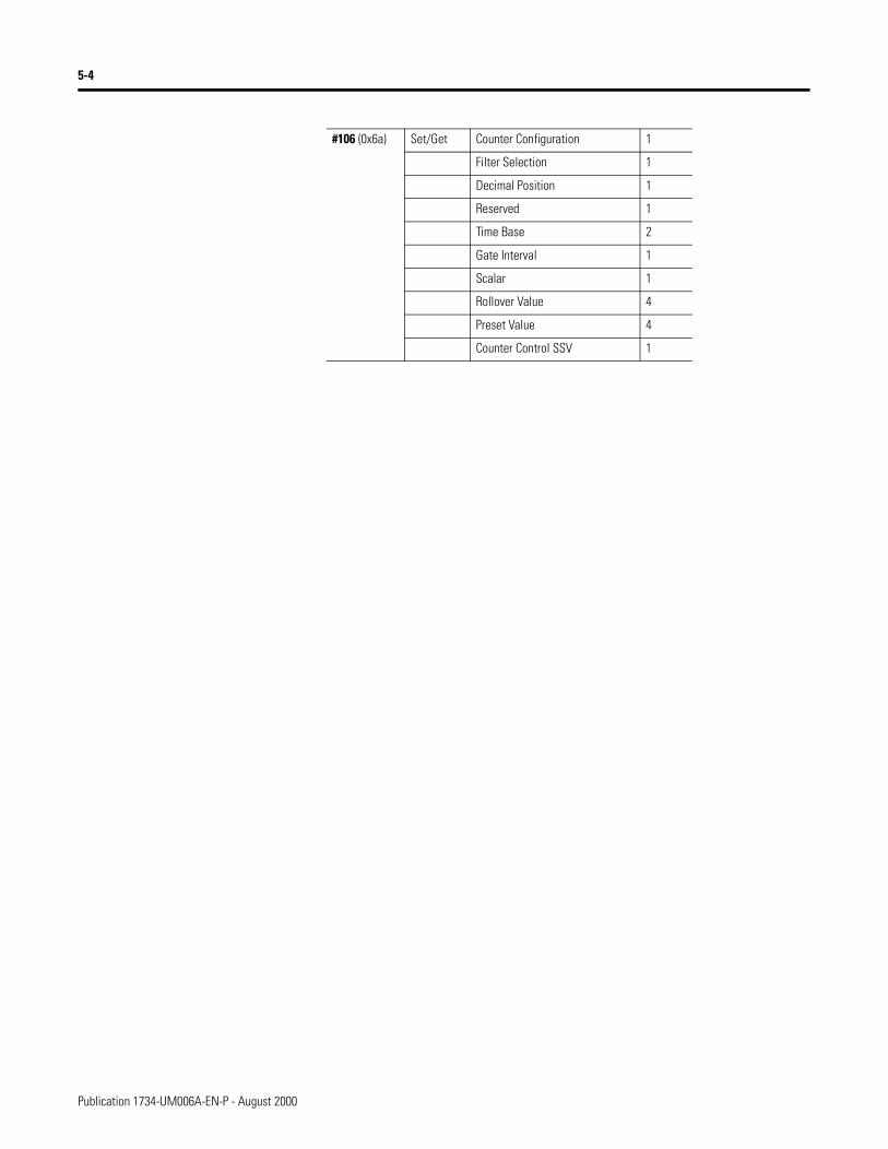
#106 (0x6a) Set/Get Counter Configuration 1
Filter Selection 1
Decimal Position 1
Reserved 1
Time Base 2
Gate Interval 1
Scalar 1
Rollover Value 4
Preset Value 4
Counter Control SSV 1
Publication 1734-UM006A-EN-P - August 2000
Chapter 6
Troubleshooting with the Indicators
Using the Indicators for Troubleshooting
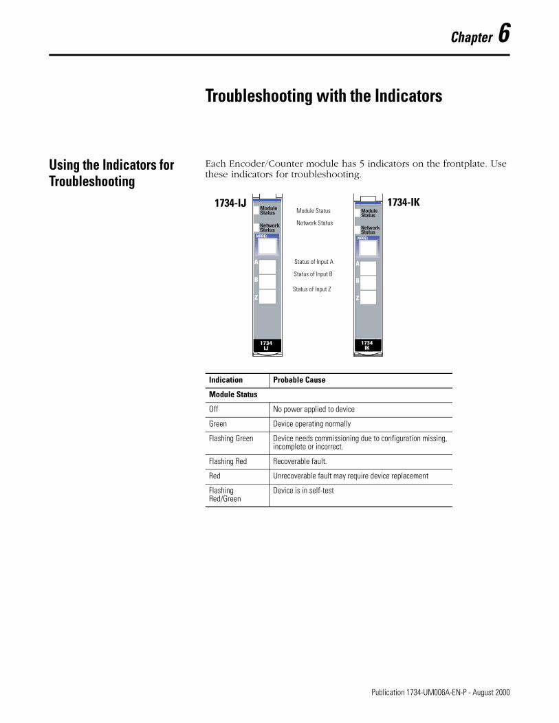
Each Encoder/Counter module has 5 indicators on the frontplate. Use these indicators for troubleshooting.
Indication Probable Cause
Module Status
Off No power applied to device
Green Device operating normally
Flashing Green Device needs commissioning due to configuration missing, incomplete or incorrect.
Flashing Red Recoverable fault.
Red Unrecoverable fault may require device replacement
Flashing Red/Green
Device is in self-test
Module Status
Network Status
Status of Input A
Status of Input B
Status of Input Z
1734-IJ 1734-IK
1 Publication 1734-UM006A-EN-P - August 2000
6-2 Troubleshooting with the Indicators
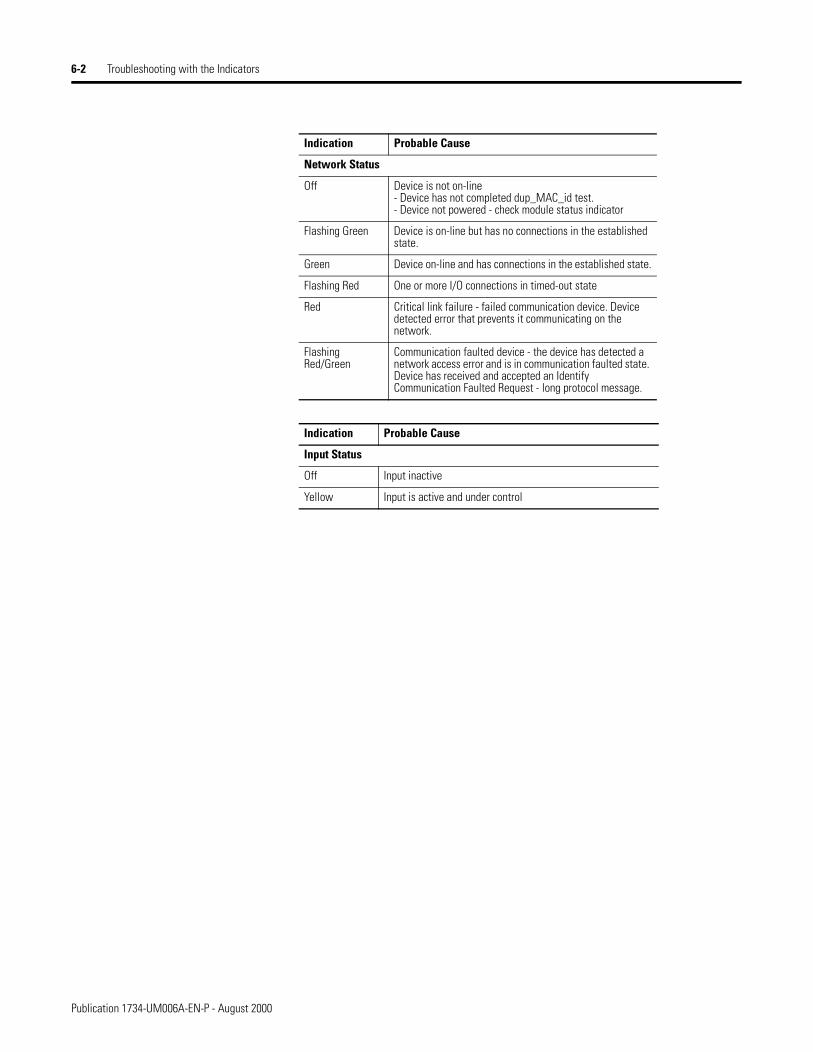
Indication Probable Cause
Network Status
Off Device is not on-line- Device has not completed dup_MAC_id test.- Device not powered - check module status indicator
Flashing Green Device is on-line but has no connections in the established state.
Green Device on-line and has connections in the established state.
Flashing Red One or more I/O connections in timed-out state
Red Critical link failure - failed communication device. Device detected error that prevents it communicating on the network.
Flashing Red/Green
Communication faulted device - the device has detected a network access error and is in communication faulted state. Device has received and accepted an Identify Communication Faulted Request - long protocol message.
Indication Probable Cause
Input Status
Off Input inactive
Yellow Input is active and under control
Publication 1734-UM006A-EN-P - August 2000
Appendix A
Specifications
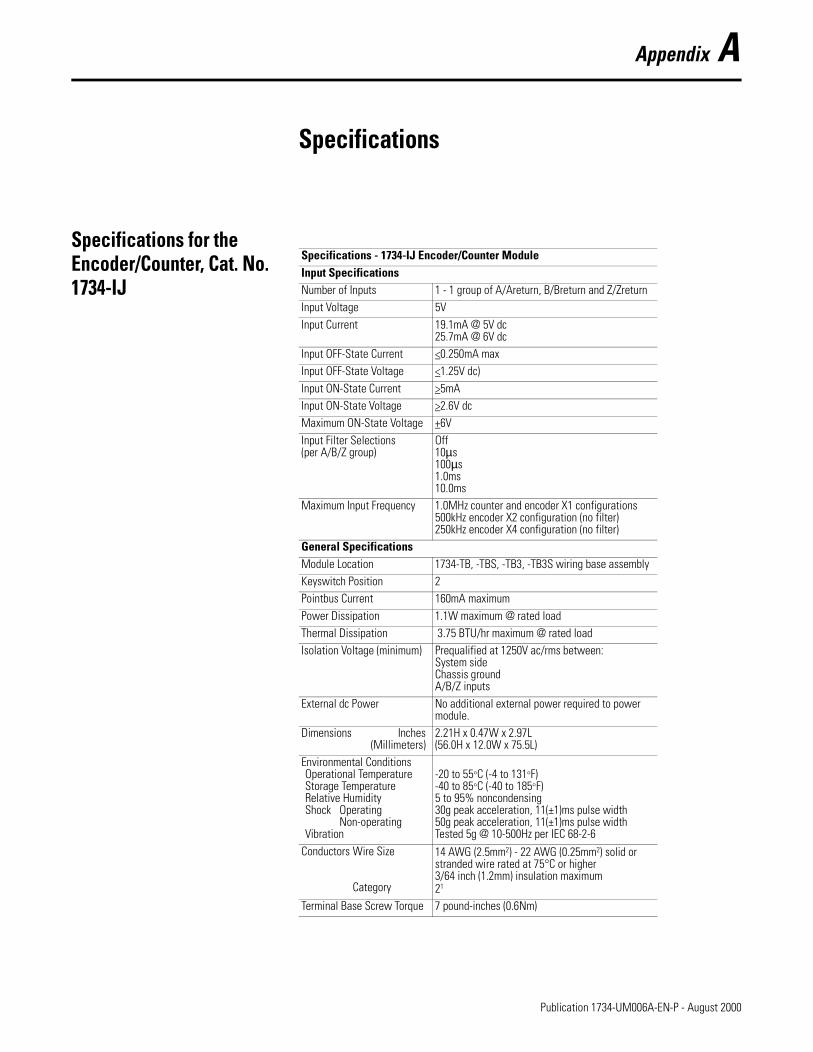
Specifications for the Encoder/Counter, Cat. No. 1734-IJ
Specifications - 1734-IJ Encoder/Counter ModuleInput SpecificationsNumber of Inputs 1 - 1 group of A/Areturn, B/Breturn and Z/ZreturnInput Voltage 5VInput Current 19.1mA @ 5V dc
25.7mA @ 6V dcInput OFF-State Current <0.250mA maxInput OFF-State Voltage <1.25V dc)Input ON-State Current >5mAInput ON-State Voltage >2.6V dcMaximum ON-State Voltage +6VInput Filter Selections (per A/B/Z group)
Off10µs100µs1.0ms10.0ms
Maximum Input Frequency 1.0MHz counter and encoder X1 configurations500kHz encoder X2 configuration (no filter)250kHz encoder X4 configuration (no filter)
General SpecificationsModule Location 1734-TB, -TBS, -TB3, -TB3S wiring base assemblyKeyswitch Position 2Pointbus Current 160mA maximumPower Dissipation 1.1W maximum @ rated loadThermal Dissipation 3.75 BTU/hr maximum @ rated loadIsolation Voltage (minimum) Prequalified at 1250V ac/rms between:
System sideChassis groundA/B/Z inputs
External dc Power No additional external power required to power module.
Dimensions Inches(Millimeters)
2.21H x 0.47W x 2.97L(56.0H x 12.0W x 75.5L)
Environmental ConditionsOperational TemperatureStorage TemperatureRelative HumidityShock Operating
Non-operatingVibration
-20 to 55°C (-4 to 131°F)-40 to 85°C (-40 to 185°F)5 to 95% noncondensing30g peak acceleration, 11(±1)ms pulse width50g peak acceleration, 11(±1)ms pulse widthTested 5g @ 10-500Hz per IEC 68-2-6
Conductors Wire Size
Category
14 AWG (2.5mm2) - 22 AWG (0.25mm2) solid or stranded wire rated at 75°C or higher3/64 inch (1.2mm) insulation maximum21
Terminal Base Screw Torque 7 pound-inches (0.6Nm)
1 Publication 1734-UM006A-EN-P - August 2000
A-2 Specifications
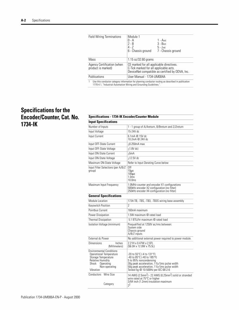
Specifications for the Encoder/Counter, Cat. No. 1734-IK
Field Wiring Terminations Module 10 - A 1 - Aret2 - B 3 - Bret4 - Z 5 - Zret6 - Chassis ground 7 - Chassis ground
Mass 1.15 oz/32.60 gramsAgency Certification (when product is marked)
CE marked for all applicable directives.C-Tick marked for all applicable acts.DeviceNet compatible as certified by ODVA, Inc.
Publications User Manual - 1734-UM004A1 Use this conductor category information for planning conductor routing as described in publication
1770-4.1, “Industrial Automation Wiring and Grounding Guidelines.”.
Specifications - 1734-IK Encoder/Counter ModuleInput SpecificationsNumber of Inputs 1 - 1 group of A/Areturn, B/Breturn and Z/Zreturn
Input Voltage 15-24V dc
Input Current 6.1mA @ 15V dc10.2mA @ 24V dc
Input OFF-State Current <0.250mA max
Input OFF-State Voltage <1.8V dc)
Input ON-State Current >5mA
Input ON-State Voltage >12.5V dc
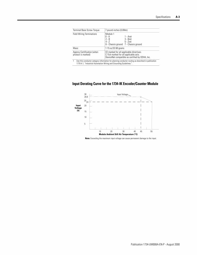
Maximum ON-State Voltage Refer to Input Derating Curve below
Input Filter Selections (per A/B/Z group)
Off10µs100µs1.0ms10.0ms
Maximum Input Frequency 1.0MHz counter and encoder X1 configurations500kHz encoder X2 configuration (no filter)250kHz encoder X4 configuration (no filter)
General SpecificationsModule Location 1734-TB, -TBS, -TB3, -TB3S wiring base assembly
Keyswitch Position 2
Pointbus Current 160mA maximum
Power Dissipation 1.5W maximum @ rated load
Thermal Dissipation 5.1 BTU/hr maximum @ rated load
Isolation Voltage (minimum) Prequalified at 1250V ac/rms between:System sideChassis groundA/B/Z inputs
External dc Power No additional external power required to power module.
Dimensions Inches(Millimeters)
2.21H x 0.47W x 2.97L(56.0H x 12.0W x 75.5L)
Environmental ConditionsOperational TemperatureStorage TemperatureRelative HumidityShock Operating
Non-operatingVibration
-20 to 55°C (-4 to 131°F)-40 to 85°C (-40 to 185°F)5 to 95% noncondensing30g peak acceleration, 11(±1)ms pulse width50g peak acceleration, 11(±1)ms pulse widthTested 5g @ 10-500Hz per IEC 68-2-6
Conductors Wire Size
Category
14 AWG (2.5mm2) - 22 AWG (0.25mm2) solid or stranded wire rated at 75°C or higher3/64 inch (1.2mm) insulation maximum22
Publication 1734-UM006A-EN-P - August 2000
Specifications A-3
Input Derating Curve for the 1734-IK Encoder/Counter Module
Terminal Base Screw Torque 7 pound-inches (0.6Nm)
Field Wiring Terminations Module 10 - A 1 - Aret2 - B 3 - Bret4 - Z 5 - Zret6 - Chassis ground 7 - Chassis ground
Mass 1.15 oz/32.60 grams
Agency Certification (when product is marked)
CE marked for all applicable directives.C-Tick marked for all applicable acts.DeviceNet compatible as certified by ODVA, Inc.
1 Use this conductor category information for planning conductor routing as described in publication 1770-4.1, “Industrial Automation Wiring and Grounding Guidelines.”.
5
10
15
20
24
28.830
10 20 30 40 45 55Module Ambient Still Air Temperature (°C)
InputVoltage
(V)
Input Voltage
Note: Exceeding the maximum input voltage can cause permanent damage to the input.
25
Publication 1734-UM006A-EN-P - August 2000

A-4 Specifications
Publication 1734-UM006A-EN-P - August 2000

Index
Aadding modules to the network 4-2adding the communication device 4-2assembly selection 3-8
Bbase assembly, mounting 2-1
CCE directives P-2checking I/O status 4-6class instance attribute editor 5-2class instance editor 5-1configuration 4-1configuration, default 1-8counter mode 1-2counter mode operation 1-2
Ddata table - complete format 3-1decimal position - frequency or counter display 3-6default configuration 1-8directives, European Union P-2
Eencoder mode 1-2encoder mode operation 1-3
Fformat - data table 3-1
Ggate interval 3-6gate interval setting 3-6
Iinput word - present channel data 3-2installation, module 2-2installation, removable terminal block 2-4
Kkeyswitch position 2-3
Mmodule installation 2-2module/channel error bits 3-2mounting base, removal 2-4mounting, base assembly 2-1
Nnew data indicator 1-8
Ooperation - counter mode 1-2operation - encoder mode 1-3operation - rate measurement mode 1-7operation - scalar 1-6
Pperiod rate mode - operation 1-5period/rate mode 1-2present channel data 3-2preset configuration 3-7
Rrate measurement mode 1-2rate measurement mode operation 1-7rollover configuration 3-7RTB, installation and removal 2-4
Ssafe state configuration 3-8scalar 3-7scalar operation 1-6setting counter parameters 4-4setting rollover counts 3-7setting safe state values 3-8setting the counter gate interval 3-6setting the preset value 3-7stored/accumulated channel data 3-2
Vviewing EDS files 4-6
ZZ gate/reset terminal modes of operation 1-9Z gate/reset terminal operation 1-9
Publication 1734-UM006A-EN-P - August 2000

2 Index
Publication 1734-UM006A-EN-P - August 2000
Allen-BradleyPublication Problem ReportIf you find a problem with our documentation, please complete and return this form.
Pub. Title/Type Encoder/Counter Module User Manual
Cat. No. 1734-IJ, 1734-IK Pub. No. 1734-UM006A-EN-P Pub. Date August 2000 Part No. 957395-28
Check Problem(s) Type: Describe Problem(s) Internal Use Only
Technical Accuracy text illustration
Completeness procedure/step illustration definition info in manual
What information is missing? example guideline feature (accessibility)
explanation other info not in manual
Clarity
What is unclear?
Sequence
What is not in the right order?
Other Comments
Use back for more comments.
Your Name Location/Phone
Return to: Marketing Communications, Allen-Bradley., 1 Allen-Bradley Drive, Mayfield Hts., OH 44124-6118Phone:(440) 646-3176FAX:(440) 646-4320
Publication ICCG-5.21- August 1995 PN 955107-82

Other Comments
PLEASE FOLD HERE
NO POSTAGE NECESSARY IF MAILED
IN THE UNITED STATES
BUSINESS REPLY MAILFIRST-CLASS MAIL PERMIT NO. 18235 CLEVELAND OH
POSTAGE WILL BE PAID BY THE ADDRESSEE
1 ALLEN-BRADLEY DRMAYFIELD HEIGHTS OH 44124-9705
PLEASE FASTEN HERE (DO NOT STAPLE)
PLEA
SE R
EMOV
E


Publication 1734-UM006A-EN-P - August 2000 6 PN 957395-28© 2000 Rockwell International Corporation. Printed in the U.S.A.
Back Cover