1723204 w hi - basco
TRANSCRIPT

OPERATOR’SMANUAL
16HP Hydro TractorsMfg. No. Description1694009 Broadmoor, 16HP1694010 Broadmoor, 16HP1694011 Conquest, 16HP Hydro1694018 1606, 16HP Hydro1694019 1616, 16HP Hydro1694020 1716H, 16HP Hydro1694027 2606, 16HP Hydro1694028 2616, 16HP Hydro1694029 2716H, 16HP Hydro1694170 Conquest, 16HP Hydro (CE)1694179 Broadmoor, 16HP Hydro (CE)1694207 1616, 16HP Hydro (CE)1694209 2616, 16HP Hydro (CE)1694277 Broadmoor, 16HP Hydro1694279 1626, 16HP Hydro1694281 2626, 16HP Hydro1694301 Broadmoor, 16HP Hydro (CE)1694368 YT1644, 16HP Hydro1694429 Broadmoor, 16HP Hydro1694430 Broadmoor, 16HP Hydro (CE)1694431 2616, 16HP Hydro1694465 1616, 16HP Hydro1694487 LT1644, 16HP Hydro
18HP Hydro TractorsMfg. No. Description1694013 Conquest, 18HP Hydro1694022 1718H, 18HP Hydro1694031 2718H, 18HP Hydro1694369 YT1850, 18HP Hydro1694467 1618, 18HP Hydro1694468 Broadmoor, 18HP Hydro1694469 2618, 18HP Hydro1694470 Conquest, 18HP Hydro (CE)1694475 YT1844, 18HP Hydro1694518 YT1844, 18HP Hydro (CE)
20HP Hydro TractorsMfg. No. Description1694014 Conquest, 20HP Hydro1694015 Prestige, 20HP Hydro1694016 Prestige, 20HP Hydro PS1694023 1720H, 20HP Hydro1694024 1820H, 20HP Hydro1694025 1820H, 20HP Hydro PS1694032 2720H, 20HP Hydro1694033 2820H, 20HP Hydro1694034 2820H, 20HP Hydro PS1694172 Prestige, 20HP Hydro (CE)1694476 YT2050, 20HP Hydro1694582 Prestige, 20HP Hydro (CE)
23HP Hydro TractorsMfg. No. Description1694017 Prestige, 23HP Hydro PS1694026 1823H, 23HP Hydro PS1694035 2823H, 23HP Hydro PS1694370 GT2354, 23HP Hydro PS
38” Mower DecksMfg. No. Description1694036 38” Mower Deck1694042 38” Mower Deck1694453 38” Mower Deck (CE)
40” Mower DecksMfg. No. Description1694041 40” Mower Deck1694047 40” Mower Deck1694177 40” Mower Deck (CE)1694210 40” Mower Deck (CE)1694339 40” Mower Deck1694340 40” Mower Deck1694341 40” Mower Deck (CE)
44” Mower DecksMfg. No. Description1694037 44” Mower Deck1694038 44” Mower Deck1694043 44” Mower Deck1694044 44” Mower Deck1694173 44” Mower Deck (CE)1694178 44” Mower Deck (CE)1694371 44” Mower Deck1694488 44” Mower Deck1694519 44” Mower Deck (CE)
50” Mower DecksMfg. No. Description1694039 50” Mower Deck1694045 50” Mower Deck1694174 50” Mower Deck (CE)1694372 50” Mower Deck
54” Mower DecksMfg. No. Description1694040 54” Mower Deck1694046 54” Mower Deck1694373 54” Mower Deck1694366 54” Mower Deck1694367 54” Mower Deck1694491 54” Mower Deck
Prestige / 1800 / 2800 / GT
Conquest / 1700 / 2700 / YT
Broadmoor / 1600 / 2600 / LT
Series
1723204Revision W
05/2009
Not for
Reprod
uctio
n

2
Troubleshooting, Adjustment & Service .........33Troubleshooting the Tractor ..................................33Troubleshooting the Mower ..................................34Battery Charging ...................................................35Seat Adjustment....................................................35Manual Lift Assist Adjustment ...............................35Steering Wheel Adjustment ..................................36Steering Gear Adjustment.....................................36Brake Adjustment..................................................36PTO Clutch Adjustment ........................................37Mower Adjustments ..............................................38
Gauge Wheels ..............................................38Leveling the Mower.......................................38
Mower Belt Replacement ......................................4044” & 50” PTO Belt Replacement .................4054” PTO Belt Replacement ...........................40Arbor Drive Belt Replacement, 44” 50” 54” ...4140” Mower PTO Belt Replacement ...............4240” Mower Arbor Drive Belt Replacement ....4338” Mower Drive Belt Replacement ..............44
Specifications ....................................................45Parts & Accessories..........................................47
NOTE: In this manual, “left” and “right” are referred to asseen from the operating position.
Safety Rules & Information.................................3Identification Numbers........................................6Safety Decals .......................................................7Safety Icons .........................................................8Features & Controls ............................................9
Control Functions....................................................9Parking Brake Function.........................................11Automatic Controlled Traction...............................11Dashboard Display Functions ...............................12
Operating the Tractor ........................................13Safety Interlock System ........................................13General Operating Safety .....................................13Adding Fuel ...........................................................13Starting the Engine ...............................................13Stopping the Tractor & Engine..............................14Driving the Tractor ................................................14Mowing..................................................................14Pushing the Tractor by Hand ................................14Using a Mulching Mower.......................................15Adjusting Mower Cutting Height - 40” Decks ........16Adjusting Mower Cutting Height - 38” 44” 50” 54”.16Mower Deck Removal & Installation .....................17Attaching a Trailer .................................................20Storage .................................................................20Lift Variations When Using Attachments...............21
Regular Maintenance ........................................22Maintenance Schedule .........................................22Check / Clean Oil Cooler ......................................23Safety Interlock System Check .............................23Blade Brake Check ...............................................23PTO Clutch Adjustment Check .............................23Engine Maintenance .............................................23Checking Tire Pressures.......................................24Battery Maintenance .............................................24Lubrication ............................................................25Lubricate Rear Axes .............................................26Servicing the Mower Blades .................................27Check Mower Blade Timing ..................................28Transmission Identification ...................................29Transmission Maintenance ...................................29
Table of Contents
Not for
Reprod
uctio
n

3
GENERAL OPERATION1. Read, understand, and follow all instructions in the
manual and on the unit before starting.2. Do not put hands or feet near rotating parts or under
the machine. Keep clear of the discharge opening atall times.
3. Only allow responsible adults, who are familiar withthe instructions, to operate the unit (local regulationscan restrict operator age).
4. Clear the area of objects such as rocks, toys, wire,etc., which could be picked up and thrown by theblade(s).
5. Be sure the area is clear of other people before mow-ing. Stop the unit if anyone enters the area.
6. Never carry passengers.7. Do not mow in reverse unless absolutely necessary.
Always look down and behind before and while travel-ling in reverse.
8. Never direct discharge material toward anyone.Avoid discharging material against a wall or obstruc-tion. Material may ricochet back toward the operator.Stop the blade(s) when crossing gravel surfaces.
9. Do not operate the machine without the entire grasscatcher, discharge guard (deflector), or other safetydevices in place.
10. Slow down before turning.11. Never leave a running unit unattended. Always disen-
gage the PTO, set parking brake, stop engine, andremove keys before dismounting.
12. Disengage blades (PTO) when not mowing. Shut offengine and wait for all parts to come to a completestop before cleaning the machine, removing the grasscatcher, or unclogging the discharge guard.
13. Operate the machine only in daylight or good artificiallight.
14. Do not operate the unit while under the influence ofalcohol or drugs.
15 Watch for traffic when operating near or crossingroadways.
16. Use extra care when loading or unloading the unitinto a trailer or truck.
17. Always wear eye protection when operating this unit.18. Data indicates that operators, age 60 years and
above, are involved in a large percentage of ridingmower-related injuries. These operators should eval-uate their ability to operate the riding mower safelyenough to protect themselves and others from injury.
19. Follow the manufacturer’s recommendations forwheel weights or counterweights.
20. Keep in mind the operator is responsible for accidentsoccurring to other people or property.
21. All drivers should seek and obtain professional andpractical instruction.
22. Always wear substantial footwear and trousers.Never operate when barefoot or wearing sandals.
23. Before using, always visually check that the bladesand blade hardware are present, intact, and secure.Replace worn or damaged parts.
24. Disengage attachments before: refueling, removingan attachment, making adjustments (unless theadjustment can be made from the operator’s posi-tion).
25. When the machine is parked, stored, or left unattend-ed, lower the cutting means unless a positivemechanical lock is used.
26. Before leaving the operator’s position for any reason,engage the parking brake, disengage the PTO, stopthe engine, and remove the key.
27. To reduce fire hazard, keep the unit free of grass,leaves, & excess oil. Do not stop or park over dryleaves, grass, or combustible materials.
28. It is a violation of California Public Resource CodeSection 4442 to use or operate the engine on or nearany forest-covered, brush-covered, or grass-coveredland unless the exhaust system is equipped with aspark arrester meeting any applicable local or statelaws. Other states or federal areas may have similarlaws.
Read these safety rules and follow them closely. Failure to obey these rules could result in loss of control of unit, severe personal injury or death to you, or bystanders, or damage to property or equipment.This mowing deck is capable of amputating hands and feet and throwing objects.The triangle in text signifies important cautions or warnings which must be followed.
Safety Rules & Information
TRANSPORTING AND STORAGE1. When transporting the unit on an open trailer, make
sure it is facing forward, in the direction of travel. Ifthe unit is facing backwards, wind lift could damagethe unit.
2. Always observe safe refueling and fuel handling prac-tices when refueling the tractor after transportation orstorage.
3. Never store the unit (with fuel) in an enclosed poorlyventilated structure. Fuel vapors can travel to anignition source (such as a furnace, water heater, etc.)and cause an explosion. Fuel vapor is also toxic tohumans and animals.
4. Always follow the engine manual instructions forstorage preparations before storing the unit for bothshort and long term periods.
5. Always follow the engine manual instructions forproper start-up procedures when returning the unit toservice.
6. Never store the unit or fuel container inside wherethere is an open flame or pilot light, such as in awater heater. Allow unit to cool before storing.
TP 600-2459-06-UV-SMA
Not for
Reprod
uctio
n

4
CHILDRENTragic accidents can occur if the operator is not alert to thepresence of children. Children are often attracted to theunit and the mowing activity. Never assume that childrenwill remain where you last saw them.1. Keep children out of the mowing area and under the
watchful care of another responsible adult.2. Be alert and turn unit off if children enter the area.3. Before and during reverse operation, look behind and
down for small children.4. Never carry children, even with the blade(s) off. They
may fall off and be seriously injured or interfere withsafe unit operation. Children who have been givenrides in the past may suddenly appear in the mowingarea for another ride and be run over or backed overby the machine.
5. Never allow children to operate the unit.6. Use extra care when approaching blind corners,
shrubs, trees, or other objects that may obscurevision.
EMISSIONS1. Engine exhaust from this product contains chemicals
known, in certain quantities, to cause cancer, birthdefects, or other reproductive harm.
2. Look for the relevant Emissions Durability Period andAir Index information on the engine emissions label.
IGNITION SYSTEM1. This spark ignition system complies with Canadian
ICES-002.
Safety Rules and Information
SLOPE OPERATIONSlopes are a major factor related to loss-of-control and tip-over accidents, which can result in severe injury or death.Operation on all slopes requires extra caution. If you can-not back up the slope or if you feel uneasy on it, do notoperate on it.Control of a ride-on machine sliding on a slope will not beregained by the application of the brake. The main rea-sons for loss of control are: insufficient tire grip on theground, speed too fast, inadequate braking, the type ofmachine is unsuitable for its task, lack of awareness of theground conditions, incorrect hitching and load distribution.1. Mow up and down slopes, not across.2. Watch for holes, ruts, or bumps. Uneven terrain could
overturn the unit. Tall grass can hide obstacles.3. Choose a slow speed so that you will not have to
stop or change speeds while on the slope. 4. Do not mow on wet grass. Tires may loose traction.5. Always keep unit in gear especially when traveling
down slopes. Do not shift to neutral and coast down-hill.
6. Avoid starting, stopping, or turning on a slope. If tireslose traction, disengage the blade(s) and proceedslowly straight down the slope.
7. Keep all movement on slopes slow and gradual. Donot make sudden changes in speed or direction,which could cause the machine to rollover.
8. Use extra care while operating machines with grasscatchers or other attachments; they can affect thestability of the unit.
9. Do not try to stabilize the machine by putting yourfoot on the ground.
10. Do not mow near drop-offs, ditches, or embank-ments. The mower could suddenly turn over if awheel is over the edge of a cliff or ditch, or if an edgecaves in.
11. Do not use grass catchers on steep slopes.12. Do not mow slopes you cannot back up.13. See your authorized dealer/retailer for recommenda-
tions of wheel weights or counterweights to improvestability.
14. Remove obstacles such as rocks, tree limbs, etc.15. Use slow speed. Tires may lose traction on slopes
even through the brakes are functioning properly. 16. Do not turn on slopes unless necessary, and then,
turn slowly and gradually downhill, if possible.
TOWED EQUIPMENT1. Tow only with a machine that has a hitch designed
for towing. Do not attach towed equipment except atthe hitch point.
2. Follow the manufacturer’s recommendations forweight limit for towed equipment and towing onslopes.
3. Never allow children or others in or on towed equip-ment.
4. On slopes, the weight of the towed equipment maycause loss of traction and loss of control.
5. Travel slowly and allow extra distance to stop.6. Do not shift to neutral and coast down hill.
WARNINGNever operate on slopes greater than 17.6 percent(10°) which is a rise of 3-1/2 feet (106 cm) vertically in20 feet (607 cm) horizontally. When operating on slopes use additional wheelweights or counterweights. See your dealer/retailerto determine which weights are available andappropriate for your unit. Select slow ground speed before driving onto slope.In addition to front weights, use extra caution whenoperating on slopes with rear-mounted grasscatchers.Mow UP and DOWN the slope, never across theface, use caution when changing directions and DONOT START OR STOP ON SLOPE.
Not for
Reprod
uctio
n

5
Safety Rules & Information
SERVICE AND MAINTENANCESafe Handling of Gasoline1. Extinguish all cigarettes, cigars, pipes, and other
sources of ignition.2. Use only approved gasoline containers.3. Never remove the gas cap or add fuel with the engine
running. Allow the engine to cool before refueling.4. Never fuel the machine indoors.5. Never store the machine or fuel container where
there is an open flame, spark, or pilot light such asnear a water heater or other appliance.
6. Never fill containers inside a vehicle or on a truck bedwith a plastic bed liner. Always place containers onthe ground away from your vehicle before filling.
7. Remove gas-powered equipment from the truck ortrailer and refuel it on the ground. If this is not possi-ble, then refuel such equipment on a trailer with aportable container, rather than from a gasoline dis-penser nozzle.
8. Keep nozzle in contact with the rim of the fuel tank orcontainer opening at all times until fueling is com-plete. Do not use a nozzle lock-open device.
9. If fuel is spilled on clothing, change clothing immedi-ately.
10. Never over-fill the fuel tank. Replace gas cap andtighten securely.
11. Use extra care in handling gasoline and other fuels.They are flammable and vapors are explosive.
12. If fuel is spilled, do not attempt to start the engine butmove the machine away from the area of spillage andavoid creating any source of ignition until fuel vaporshave dissipated.
13. Replace all fuel tank caps and fuel container capssecurely.
Service & Maintenance1. Maintain or replace safety and instruction labels as
necessary.2. Never run the unit in an enclosed area where carbon
monoxide fumes may collect.3. Keep nuts and bolts, especially blade attachment
bolts, tight and keep equipment in good condition.4. Never tamper with safety devices. Check their proper
operation regularly and make necessary repairs ifthey are not functioning properly.
5. Keep unit free of grass, leaves, or other debris build-up. Clean up oil or fuel spillage.
6. Stop and inspect the equipment if you strike anobject. Repair, if necessary, before restarting.
7. Never make adjustments or repairs with the enginerunning unless specified otherwise in the engine man-ufacturer’s manual.
8. Do not remove the fuel filter when the engine is hotas spilled gasoline may ignite. Do not spread fuel lineclamps further than necessary. Ensure clamps griphoses firmly over the filter after installation.
9. Do not use gasoline containing METHANOL, gasoholcontaining more than 10% ETHANOL, gasoline addi-tives, or white gas because engine/fuel system dam-age could result.
10. If the fuel tank must be drained, it should be drainedoutdoors.
11. Replace faulty silencers/mufflers.
12. Grass catcher components are subject to wear, dam-age, and deterioration, which could expose movingparts or allow objects to be thrown. Frequently checkcomponents and replace with manufacturer’s recom-mended parts, when necessary.
13. Mower blades are sharp and can cut. Wrap theblade(s) or wear gloves, and use extra caution whenservicing them.
14. Check brake operation frequently. Adjust and serviceas required.
15. Use only factory authorized replacement parts whenmaking repairs.
16. Always comply with factory specifications on all set-tings and adjustments.
17. Only authorized service locations should be utilizedfor major service and repair requirements.
18. Never attempt to make major repairs on this unitunless you have been properly trained. Improper ser-vice procedures can result in hazardous operation,equipment damage and voiding of manufacturer’swarranty.
19. On multiple blade mowers, take care as rotating oneblade can cause other blades to rotate.
20. Do not change engine governor settings or over-speed the engine. Operating the engine at excessivespeed can increase the hazard of personal injury.
21. Disengage drive attachments, stop the engine,remove the key, and disconnect the spark plugwire(s) before: clearing attachment blockages andchutes, performing service work, striking an object, orif the unit vibrates abnormally. After striking anobject, inspect the machine for damage and makerepairs before restarting and operating the equip-ment.
22. Never place hands near the moving parts, such as ahydro pump cooling fan, when the tractor is running.(Hydro pump cooling fans are typically located on topof the transaxle).
23. Units with hydraulic pumps, hoses, or motors: WARN-ING: Hydraulic fluid escaping under pressure mayhave sufficient force to penetrate skin and cause seri-ous injury. If foreign fluid is injected into the skin itmust be surgically removed within a few hours by adoctor familiar with this form of injury or gangrenemay result. Keep body and hands away from pinholes or nozzles that eject hydraulic fluid under highpressure. Use paper or cardboard, and not hands, tosearch for leaks. Make sure all hydraulic fluid con-nections are tight and all hydraulic hoses and linesare in good condition before applying pressure to thesystem. If leaks occur, have the unit serviced imme-diately by your authorized dealer.
24. WARNING: Stored energy device. Improper releaseof springs can result in serious personal injury.Springs should be removed by an authorized techni-cian.
25. Models equipped with an engine radiator: WARNING:Stored energy device. To prevent serious bodilyinjury from hot coolant or steam blow-out, neverattempt to remove the radiator cap while the engine isrunning. Stop the engine and wait until it is cool.Even then, use extreme care when removing the cap.
Not for
Reprod
uctio
n

6
Identification Numbers
Tractor ID Tag Mower ID Tag
ENGINE REFERENCE DATA
Model Description Name/Number
Unit MFG Number
PRODUCT REFERENCE DATA
Unit SERIAL Number
Dealer Name Date Purchased
Engine Make
Engine Type/Spec
Engine Model
Engine Code/Serial Number
Mower Deck MFG Number Mower Deck SERIAL Number
Identification Numbers
When contacting your authorized dealer for replace-ment parts, service, or information you MUST havethese numbers.
Record your model name/number, manufacturer’s identi-fication numbers, and engine serial numbers in thespace provided for easy access. These numbers can befound in the locations shown.
NOTE: For location of engine identification numbers,refer to the engine owner’s manual.
Part No. xxxxxxx
xxxxxxxxxxxxxxxSerial No. xxxxxxxxxx
20xxkW: x.xx
xxxx max
xxxxxxxxxxxxxxxxxxxxxxxxxxxxxxxxxxxxxxxxxxxxxxxxxxxxxxxxxxxxxxxxxxxxxxxxxxxxxxxxxxxxxxxxxxxx
xxx dBkg: xxx
SAMPLE
SAMPLE
North American /CE Models
CE Models(Only)
CE IDENTIFICATION TAG MARKINGSA. Manufacturer’s Identification NumberB. Manufacturer’s Serial NumberC. Power Rating in KilowattsD. Maximum Engine Speed in Rotations per MinuteE. Manufacturer’s Name and AddressF. Year of ManufactureG. CE Compliance LogoH. Mass of Unit in KilogramsI. Guaranteed Sound Power in Decibels
Identification Numbers
Part No. xxxxxxx
xxxxxxxxxxxxxxxSerial No. xxxxxxxxxx
20xxkW: x.xx
xxxx max
xxxxxxxxxxxxxxxxxxxxxxxxxxxxxxxxxxxxxxxxxxxxxxxxxxxxxxxxxxxxxxxxxxxxxxxxxxxxxxxxxxxxxxxxxxxx
xxx dBkg: xxx
A
B
C
D
E
F G
H
I
Not for
Reprod
uctio
n
7
Safety Decals
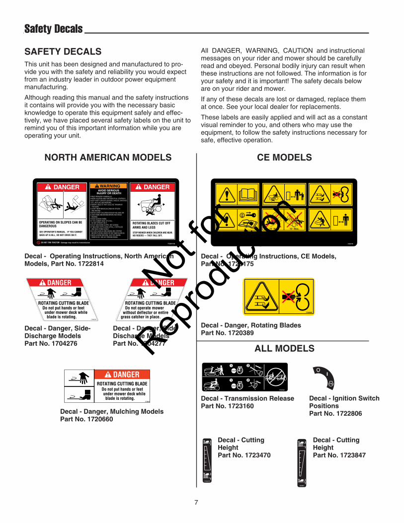
SAFETY DECALSThis unit has been designed and manufactured to pro-vide you with the safety and reliability you would expectfrom an industry leader in outdoor power equipmentmanufacturing.
Although reading this manual and the safety instructionsit contains will provide you with the necessary basicknowledge to operate this equipment safely and effec-tively, we have placed several safety labels on the unit toremind you of this important information while you areoperating your unit.
All DANGER, WARNING, CAUTION and instructionalmessages on your rider and mower should be carefullyread and obeyed. Personal bodily injury can result whenthese instructions are not followed. The information is foryour safety and it is important! The safety decals beloware on your rider and mower.
If any of these decals are lost or damaged, replace themat once. See your local dealer for replacements.
These labels are easily applied and will act as a constantvisual reminder to you, and others who may use theequipment, to follow the safety instructions necessary forsafe, effective operation.
Decal - Danger, Side-Discharge ModelsPart No. 1704276
ROTATING CUTTING BLADE Do not put hands or feet under mower deck while blade is rotating.
DANGER
1720660
Decal - Danger, Mulching ModelsPart No. 1720660
Decal - Danger, SideDischarge ModelsPart No. 1704277
Decal - Transmission ReleasePart No. 1723160
Decal - Ignition SwitchPositionsPart No. 1722806
Decal - Operating Instructions, North AmericanModels, Part No. 1722814
DANGER
OPERATING ON SLOPES CAN BE DANGEROUS
SEE OPERATOR'S MANUAL. IF YOU CANNOT BACK-UP A HILL, DO NOT DRIVE ON IT.
ROTATING BLADES CUT OFF ARMS AND LEGSSTOP MOWER WHEN CHILDREN ARE NEAR. NO RIDERS — THEY FALL OFF.
DANGERAVOID SERIOUS
INJURY OR DEATH• READ OPERATOR'S MANUAL(S).• KNOW LOCATION AND FUNCTION OF ALL CONTROLS.• KEEP SAFETY DEVICES (GUARDS, SHIELDS, SWITCHES, ETC.) IN PLACE AND WORKING.• REMOVE OBJECTS THAT COULD BE THROWN BY THE BLADE.• DO NOT MOW WHEN CHILDREN OR OTHERS ARE AROUND.• NEVER CARRY CHILDREN EVEN WITH BLADES OFF.• LOOK DOWN AND BEHIND BEFORE AND WHILE BACKING.• AVOID SUDDEN TURNS.• IF YOU CANNOT BACK UP A HILL, DO NOT OPERATE ON IT.• GO UP AND DOWN SLOPES, NOT ACROSS.• IF MACHINE STOPS GOING UPHILL, STOP BLADE AND BACK DOWN SLOWLY.• BE SURE BLADE(S) AND ENGINE ARE STOPPED BEFORE PLACING HANDS OR FEET NEAR BLADE(S).• WHEN LEAVING MACHINE, SHUT OFF ENGINE, REMOVE KEY, AND SET PARKING BRAKE.
WARNING
1722814-00DO NOT TOW TRACTOR! Damage may result to transmission
Decal - Operating Instructions, CE Models, Part No. 1723175
1723175
NORTH AMERICAN MODELS
ALL MODELS
CE MODELS
Decal - Danger, Rotating Blades Part No. 1720389
Decal - CuttingHeightPart No. 1723470
1723470
Decal - CuttingHeightPart No. 1723847
1723847
Not for
Reprod
uctio
n

8
CE Safety Icons
Warning: Read Operator’sManual.
Read and understand theOperator’s Manual before usingthis machine.
Danger: Thrown Objects.
This machine is capable of throwingobjects and debris. Keepbystanders away.
Warning: Remove Key BeforeServicing.
Remove the key and consult techni-cal literature before performingrepairs or maintenance.
Danger: Machine Rollover.
Do not use this machine on slopesgreater than 10°.
Danger: Dismemberment.
This machine can amputate limbs.Keep bystanders and children awaywhen engine is running.
Danger: Dismemberment.
This mower deck can amputatelimbs. Keep hands and feet awayfrom blades.
SAFETY ICONS
Not for
Reprod
uctio
n

9
Features & Controls
Throttle/Choke Control (Single Lever Models)
The throttle/choke lever controls engine speed andchoke. Move the throttle forward to increase enginespeed and back to decrease engine speed. Alwaysoperate at FULL throttle. Move the control fully forward(past the detent) to close the choke. Close the choke forcold starting. Open the choke once the engine starts. Awarm engine may not require choking.
Throttle Control(Twin Lever Models)
The throttle controls engine speed. Move the throttle for-ward to increase engine speed and back to decreaseengine speed. Always operate at FULL throttle.
Choke (Twin Lever Models)
Close the choke for cold starting. Open the choke oncethe engine starts. A warm engine may not require chok-ing. Move the lever forward to close the choke.
CONTROL FUNCTIONSThe information below briefly describes the function of individual controls. Starting, stopping, driving, and mowingrequire the combined use of several controls applied in specific sequences. To learn what combination and sequenceof controls to use for various tasks see the OPERATION section.
Figure 1. Controls
HydraulicLiftModels
SelectManual Lift Models
SelectManual Lift Models
38”, 44”, 50”,& 54” Models
40” Models
Not for
Reprod
uctio
n
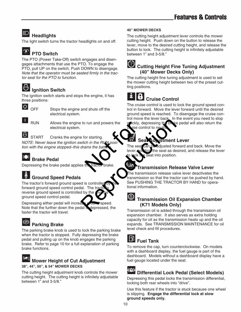
HeadlightsThe light switch turns the tractor headlights on and off.
PTO SwitchThe PTO (Power Take-Off) switch engages and disen-gages attachments that use the PTO. To engage thePTO, pull UP on the switch. Push DOWN to disengage.Note that the operator must be seated firmly in the trac-tor seat for the PTO to function.
Ignition Switch The ignition switch starts and stops the engine, it hasthree positions:
OFF Stops the engine and shuts off the electrical system.
RUN Allows the engine to run and powers the electrical system.
START Cranks the engine for starting.NOTE: Never leave the ignition switch in the RUN posi-tion with the engine stopped–this drains the battery.
Brake Pedal Depressing the brake pedal applies the tractor brake.
Ground Speed Pedals The tractor’s forward ground speed is controlled by theforward ground speed control pedal. The tractor’sreverse ground speed is controlled by the reverseground speed control pedal.
Depressing either pedal will increase ground speed.Note that the further down the pedal is depressed, thefaster the tractor will travel.
Parking Brake The parking brake knob is used to lock the parking brakewhen the tractor is stopped. Fully depressing the brakepedal and pulling up on the knob engages the parkingbrake. Refer to page 10 for a full explanation of parkingbrake functions.
Mower Height of Cut Adjustment38”, 44”, 50”, & 54” MOWER DECKS
The cutting height adjustment knob controls the mowercutting height. The cutting height is infinitely adjustablebetween 1” and 3-5/8.”
10
Features & Controls
40” MOWER DECKS
The cutting height adjustment lever controls the mowercutting height. Push down on the button to release thelever, move to the desired cutting height, and release thebutton to lock. The cutting height is infinitely adjustablebetween 1” and 3-5/8.”
Cutting Height Fine Tuning Adjustment(40” Mower Decks Only)
The cutting height fine tuning adjustment is used to setthe mower cutting height between two of the preset cut-ting positions.
Cruise ControlThe cruise control is used to lock the ground speed con-trol in forward. Move the lever forward until the desiredground speed is reached. To disengage the cruise con-trol move the lever back. In the event you need to stopquickly, depressing the brake pedal will also return thecruise control to neutral.
Seat Adjustment LeverThe seat can be adjusted forward and back. Move thelever, position the seat as desired, and release the leverto lock the seat into position.
Transmission Release Valve Lever The transmission release valve lever deactivates thetransmission so that the tractor can be pushed by hand.See PUSHING THE TRACTOR BY HAND for opera-tional information.
Transmission Oil Expansion Chamber (K71 Models Only)
Transmission oil is added through the transmission oilexpansion chamber. It also serves as extra holdingcapacity for oil as the transmission heats up and the oilexpands. See TRANSMISSION MAINTENANCE for oillevel check and fill procedures.
Fuel TankTo remove the cap, turn counterclockwise. On modelswith a dashboard display, the fuel gauge is part of thedashboard. Models without a dashboard display have afuel gauge located under the seat.
Differential Lock Pedal (Select Models)Depressing this pedal locks the transmission differential,locking both rear wheels into “drive”.
Use this feature if the tractor is stuck because one wheelis slipping. Engage the differential lock at slowground speeds only.
Not for
Reprod
uctio
n
11
Features & Controls
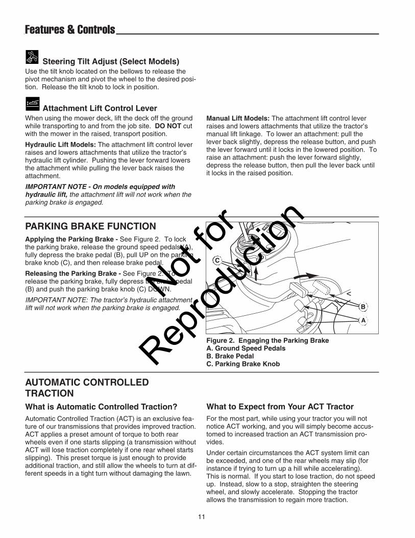
Figure 2. Engaging the Parking BrakeA. Ground Speed PedalsB. Brake PedalC. Parking Brake Knob
PARKING BRAKE FUNCTIONApplying the Parking Brake - See Figure 2. To lockthe parking brake, release the ground speed pedals (A),fully depress the brake pedal (B), pull UP on the parkingbrake knob (C), and then release brake pedal.
Releasing the Parking Brake - See Figure 2. Torelease the parking brake, fully depress the brake pedal(B) and push the parking brake knob (C) DOWN.
IMPORTANT NOTE: The tractor’s hydraulic attachmentlift will not work when the parking brake is engaged.
AUTOMATIC CONTROLLEDTRACTION What is Automatic Controlled Traction?Automatic Controlled Traction (ACT) is an exclusive fea-ture of our transmissions that provides improved traction.ACT applies a preset amount of torque to both rearwheels even if one starts slipping (a transmission withoutACT will lose traction completely if one rear wheel startsslipping). This preset torque is just enough to provideadditional traction, and still allow the wheels to turn at dif-ferent speeds in a tight turn without damaging the lawn.
A
B
C
What to Expect from Your ACT TractorFor the most part, while using your tractor you will notnotice ACT working, and you will simply become accus-tomed to increased traction an ACT transmission pro-vides.
Under certain circumstances the ACT system limit canbe exceeded, and one of the rear wheels may slip (forinstance if trying to turn up a hill while accelerating).This is normal. If you start to lose traction, do not speedup. Instead, slow to a stop, straighten the steeringwheel, and slowly accelerate. Stopping the tractorallows the transmission to regain more traction.
Steering Tilt Adjust (Select Models)Use the tilt knob located on the bellows to release thepivot mechanism and pivot the wheel to the desired posi-tion. Release the tilt knob to lock in position.
Attachment Lift Control LeverWhen using the mower deck, lift the deck off the groundwhile transporting to and from the job site. DO NOT cutwith the mower in the raised, transport position.
Hydraulic Lift Models: The attachment lift control leverraises and lowers attachments that utilize the tractor’shydraulic lift cylinder. Pushing the lever forward lowersthe attachment while pulling the lever back raises theattachment.
IMPORTANT NOTE - On models equipped withhydraulic lift, the attachment lift will not work when theparking brake is engaged.
Manual Lift Models: The attachment lift control leverraises and lowers attachments that utilize the tractor’smanual lift linkage. To lower an attachment: pull thelever back slightly, depress the release button, and pushthe lever forward until it locks in the lowered position. Toraise an attachment: push the lever forward slightly,depress the release button, then pull the lever back untilit locks in the raised position.
Not for
Reprod
uctio
n
12
Features & Controls
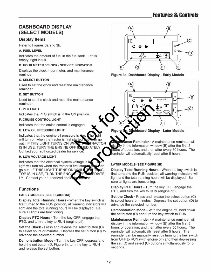
DASHBOARD DISPLAY(SELECT MODELS)Display ItemsRefer to Figures 3a and 3b.
A. FUEL LEVEL
Indicates the amount of fuel in the fuel tank. Left isempty; right is full.
B. HOUR METER / CLOCK / SERVICE INDICATOR
Displays the clock, hour meter, and maintenancereminder.
C. SELECT BUTTON
Used to set the clock and reset the maintenancereminder.
D. SET BUTTON
Used to set the clock and reset the maintenancereminder.
E. PTO LIGHT
Indicates the PTO switch is in the ON position.
F. CRUISE CONTROL LIGHT
Indicates that the cruise control is engaged.
G. LOW OIL PRESSURE LIGHT
Indicates that the engine oil pressure is low. The lightwill turn on when the tractor is first started and then goout. IF THIS LIGHT TURNS ON WHILE THE TRACTORIS IN USE, TURN THE ENGINE OFF IMMEDIATELY.Contact your authorized dealer for service.
H. LOW VOLTAGE LIGHT
Indicates that the electrical system voltage is low. Thelight will turn on when the tractor is first started and thengo out. IF THIS LIGHT TURNS ON WHILE THE TRAC-TOR IS IN USE, TURN THE ENGINE OFF IMMEDIATE-LY. Contact your authorized dealer for service.
FunctionsEARLY MODELS (SEE FIGURE 3A)
Display Total Running Hours - When the key switch isfirst turned to the RUN position, all warning indicators willlight and the total running hours will be displayed. Besure all lights are functioning.
Display PTO Hours - Turn the key OFF, engage thePTO, and turn the key to RUN (engine off).
Set the Clock - Press and release the select button (C)to select hours or minutes. Depress the set button (D) toadvance the selected number.
Demonstration Mode - Turn the key OFF, depress andhold the set button (D, Figure 3), turn the key to RUNand release the set button.
Figure 3a. Dashboard Display - Early Models
A B
C
D
H G F E
Figure 3b. Dashboard Display - Later Models
Cruise PTO
A B
C
D
H G F E
Maintenance Reminder - A maintenance reminder willdisplay in the information window (B) after the first 5hours of operation, and then after every 50 hours. Thereminder will automatically reset after 5 hours.
LATER MODELS (SEE FIGURE 3B)
Display Total Running Hours - When the key switch isfirst turned to the RUN position, all warning indicators willlight and the total running hours will be displayed. Besure all lights are functioning.
Display PTO Hours - Turn the key OFF, engage thePTO, and turn the key to RUN (engine off).
Set the Clock - Press and release the select button (C)to select hours or minutes. Depress the set button (D) toadvance the selected number.
Demonstration Mode - With the engine off, hold downthe set button (D) and turn the key switch to RUN.
Maintenance Reminder - A maintenance reminder willdisplay in the information window (B) after the first 5hours of operation, and then after every 50 hours. Thereminder will automatically reset after 5 hours. Thereminder can be manually reset by turning the key switchfrom OFF to RUN (with engine off) and then depressingthe set (D) and select (C) buttons simultaneously for 5seconds.
Not for
Reprod
uctio
n

13
Operating the TractorGENERAL OPERATING SAFETYBe sure to read all information in the Safety andOperation sections before attempting to operate this unit.Become familiar with all of the controls and how to stopthe unit.
ADDING FUELTo add fuel:1. Remove the fuel cap (A, Figure 4). 2. Fill the tank. Do not overfill. Leave room in the tank
for fuel expansion. Refer to your engine manual forspecific fuel recommendations.
3. Install and hand tighten the fuel cap.
STARTING THE ENGINE1. While sitting in the operator’s seat, fully depress the
brake pedal or set the parking brake. 2. Make sure that your feet are not depressing the
ground speed control pedals and that the cruise con-trol lever is in neutral.
3. Disengage the PTO clutch.4. Set the throttle to FULL.5. Close the choke. NOTE: A warm engine may not require choking.6. Insert the ignition key and turn it to START.7. After the engine starts, move the engine throttle con-
trol to SLOW. Warm up the engine by running it for atleast a minute.
8. Set throttle to FULL.NOTE: In the event of an emergency the engine can bestopped by simply turning the ignition switch to STOP.Use this method only in emergency situations. For nor-mal engine shut down follow the procedure given inSTOPPING THE TRACTOR.
WARNINGGasoline is highly flammable and must behandled with care. Never fill the tank when theengine is still hot from recent operation. Do notallow open flame, smoking or matches in thearea. Avoid over-filling and wipe up any spills.
Do not use gasoline containing METHANOL,gasohol containing more than 10% ETHANOL, gasoline additives, or whitegas because engine/fuel system damagecould result.
SAFETY INTERLOCKSYSTEM TESTS
This unit is equipped with safety interlock switches andother safety devices. These safety systems are pre-sent for your safety: do not attempt to bypass safetyswitches, and never tamper with safety devices. Checktheir operation regularly.
Operational SAFETY ChecksYour unit is equipped with a seat switch safety system.Check the seat switch operation every fall and springwith the following tests.
Test 1 — Engine should NOT crank if:
• PTO switch is ON, OR
• Brake pedal is NOT fully depressed (parking brakeOFF), OR
• The cruise control lever is NOT in NEUTRAL.
Test 2 — Engine SHOULD crank if:
• PTO switch is OFF, AND
• Brake pedal is fully depressed (parking brake ON),AND
• The cruise control lever is in NEUTRAL.
Test 3 — Engine should SHUT OFF if:
• Operator rises off seat with PTO engaged, OR
• Operator rises off seat with brake pedal NOT fullydepressed (parking brake OFF).
Test 4 — Blade Brake Check
Mower blades and mower drive belt should come to acomplete stop within five seconds after electric PTOswitch is turned OFF (or operator rises off seat). Ifmower drive belt does not stop within five seconds,readjust the PTO clutch as described in the ADJUST-MENTS section or see your dealer.
NOTE: Once the engine has stopped, the PTO switchmust be turned off after the operator returns to the seatin order to start the engine.
WARNINGIf the unit does not pass a safety test, do notoperate it. See your authorized dealer. Under nocircumstance should you attempt to defeat thepurpose of the safety interlock system.
Not for
Reprod
uctio
n

14
STOPPING THE TRACTOR & ENGINE1. Return the ground speed control(s) to neutral.
2. Disengage the PTO and wait for all moving parts tostop.
3. Place the throttle control in the position specified inthe engine owner’s manual provided in the operator'spacket shipped with your tractor. Follow any recom-mended stopping procedures.
4. Turn the ignition switch to OFF. Remove the key.
DRIVING THE TRACTOR1. Sit in the seat and adjust the seat so that you can
comfortably reach all the controls and see the dash-board display.
2. Engage the parking brake. 3. Make sure the PTO switch is disengaged.4. Start the engine (see STARTING THE ENGINE).5. Disengage the parking brake and release the brake
pedal.6. Depress the forward ground speed control pedal to
travel forward. Release the pedal to stop. Note thatthe further down the pedal is depressed the faster thetractor will travel.
7. Stop the tractor by releasing the ground speed con-trol pedals, setting the parking brake, and stoppingthe engine (see STOPPING THE TRACTOR ANDENGINE).
Operating the Tractor
DO NOT TOW TRACTORTowing the unit will cause transmissiondamage. • Do not use another vehicle topush or pull this unit. • Do not actuate thetransmission release valve lever while theengine is running.
Figure 4. Transmission Release Lever & Fuel TankA. Fuel Tank Cap.B. Transmission Release Lever
B
A
MOWING1. Set the mower cutting height to the desired level and
set the gauge wheels to the appropriate position (ifequipped).
2. Engage the parking brake. Make sure the PTOswitch is disengaged.
3. Start the engine (see STARTING THE ENGINE).4. Fully lower the mower using the attachment lift lever.5. Set the throttle to FULL.6. Engage the PTO (Mower Deck).7. Begin mowing. See Section LC for tips on mowing
patterns, lawn care, and troubleshooting information.8. When finished, shut off the PTO and raise the mower
using the attachment lift control lever.9. Stop the engine (see STOPPING THE TRACTOR
AND ENGINE).
PUSHING THE TRACTOR BY HAND1. Disengage the PTO and turn the engine off.2. Pull the transmission release (B, Figure 4) back
approximately 2-1/2” (6 cm) to lock into releasedposition.
3. The tractor can now be pushed by hand.
Not for
Reprod
uctio
n

15
Operating the Tractor
USING A MULCHING MOWER (40” MOWER ONLY)
Benefits of Proper MulchingMulching consists of a mower deck which cuts andrecuts clippings into tiny particles and then blows themdown into the lawn. These tiny particles decomposerapidly into by-products that your lawn can use. Underproper conditions your mulching mower virtually elimi-nate noticeable clippings on the lawn surface.
Limitations of Mulching DecksMulching mowers cannot function properly if the grass iswet, or if the grass is simply too high. Even more thannormal mowing, mulching requires that the grass be dryand that no more than 1/3 of the height is cut.
Do not use the mower as a mulching mower during thefirst two or three cuttings in the spring. The long grassblades, quick growth, and often wetter conditions aremore suitable for broadcasting (side-discharging).
Correct Ground Speed & Engine SpeedUse full engine throttle to maximize mower blade tipspeed matched with a slow ground speed so that clip-pings will be finely cut. Ground speed while mulchingshould be half the speed used when broadcasting (side-discharging) under similar conditions. Since mulchingrequires more horse power than broadcasting, using aproper ground speed is vitally important for goodmulching operation.
Correct Cutting HeightCutting off too much at one time shocks the plant’sgrowth system and weakens the grass. A good rule ofthumb is the 1/3 rule: to cut no more than one third of thegrass height, and never more than 1 inch (2,5cm) at atime.
The best mulching action typically results from cuttingonly the top 1/2” to 3/4” (1,25 - 2cm) of the grass blade.This provides short clippings which decompose properly(much more quickly than longer clippings). The idealcutting height will vary with climate, time of year, andquality of your lawn. We recommend that you experi-ment with both the cutting height and ground speed toachieve the best cut. Start with a high cutting height anduse progressively lower heights until you find a cuttingheight that is matched to your mowing conditions andpreferences. For best results, overlapping is recom-mended.
Using the Side Discharge DeflectorWhen to use the side discharge deflector: If you’vebeen on vacation or missed a mowing and the grass hasgotten very long, do not try to mulch at your normal cut-ting height. To handle these situations your mulchingmower is equipped with a side discharge deflector.Installing the side discharge deflector allows you tobroadcast clippings. Broadcasting, or side-discharging,disperses fine clippings evenly over the entire lawn.Always operate the engine at full throttle. Use an appro-priate ground speed for the thickness and height of grassyou are cutting. If you hear the engine slowing down,you are mowing too fast, use a slower ground speed.Mow when the grass is 3”-5” (7,6-12,7cm) long. Do notcut off more than 1” (2,5cm) in a single pass.
To install the side discharge chute:
1. Lift up the mulching cover (B, Figure 5).
2. Install the side discharge deflector (A) under themulching cover. The side discharge deflector hooksonto the mulching cover hinge rod, and is held inplace by the mulching cover.
3. Release the mulching cover.
Figure 5. Installing the Side Discharge DeflectorA. Side Discharge DeflectorB. Mulching Cover
WARNINGNever operate the mower deck without either thedischarge chute or mulching deflector in place.
A
B
Not for
Reprod
uctio
n
16
Operating the Tractor
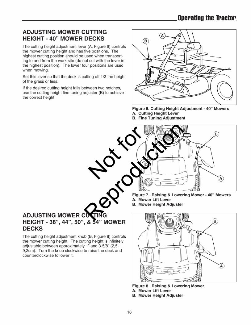
Figure 7. Raising & Lowering Mower - 40” MowersA. Mower Lift LeverB. Mower Height Adjuster
A
B
Figure 6. Cutting Height Adjustment - 40” MowersA. Cutting Height LeverB. Fine Tuning Adjustment
ADJUSTING MOWER CUTTINGHEIGHT - 40” MOWER DECKSThe cutting height adjustment lever (A, Figure 6) controlsthe mower cutting height and has five positions. Thehighest cutting position should be used when transport-ing to and from the work site (do not cut with the lever inthe highest position). The lower four positions are usedwhen mowing.
Set this lever so that the deck is cutting off 1/3 the heightof the grass or less.
If the desired cutting height falls between two notches,use the cutting height fine tuning adjuster (B) to achievethe correct height.
AB
ADJUSTING MOWER CUTTINGHEIGHT - 38”, 44”, 50”, & 54” MOWERDECKSThe cutting height adjustment knob (B, Figure 8) controlsthe mower cutting height. The cutting height is infinitelyadjustable between approximately 1” and 3-5/8” (2,5-9,2cm). Turn the knob clockwise to raise the deck andcounterclockwise to lower it.
Figure 8. Raising & Lowering Mower A. Mower Lift LeverB. Mower Height Adjuster
A
B
Not for
Reprod
uctio
n

MOWER DECK REMOVAL &INSTALLATION Lift Link Models
17
Operating the Tractor
Removing the Mower Deck1. Park tractor on a hard, level surface such as a con-
crete floor. Turn off PTO switch and engine, removethe key and apply parking brake.
2. Place mower in the lowest cutting position using themower height adjuster.
3. Place the attachment lift in the lowest position.
4. Disconnect the mower lift arm (A, Figure 9) from thetractor lift arm (B). Re-install washer (C) and safetyclip (D).
5. Remove belt from PTO pulley (B, Figure 10).
6. Turn wheels straight ahead. Pull back on spring-loaded lever (B, Figure 11) and lift mower hitch off ofthe tractor brackets.
7. Turn wheels fully left, and slide mower deck out rightside of tractor.
WARNINGEngage parking brake, disengage PTO, stopengine and remove key before attempting toinstall or remove the mower.
Figure 9. Lift Arms (Viewed from underneath right side of tractor)A. Mower Lift Arm C. Flat WasherB. Tractor Lift Arm D. Safety Clip
Figure 10. Removing & Installing BeltA. Idler ArmB. PTO Pulley
B
A
C
D
B A
CAUTIONThe muffler and surrounding areas may be hot.
Not for
Reprod
uctio
n

18
Operating the Tractor
Figure 11. Mower HitchA. Tractor Hitch BracketsB. Spring-Loaded Lever
A
B
Installing the Mower Deck1. Park tractor, shut off PTO and engine, remove the
key and apply parking brake. Turn the wheels fully tothe left.
2. Place mower height adjuster (B, Figures 7 & 8) in thelowest cutting position. Place the mower lift lever inthe lowest position, also. Slide mower deck underright side of tractor so that mower hitch is alignedwith the front tractor hitch.
3. See Figure 11. Turn wheels straight. Pull back onthe spring-loaded lever (B) while lifting up on themower hitch. Install mower hitch onto tractor hitchbrackets (A). When properly installed, the spring-loaded lever should seat fully underneath the brack-ets.
4. See Figure 9. Connect the mower lift arm (A) to thetractor lift arm (B) using the flat washer (C) and safetyclip (D).
5. See Figure 10. Move idler arm (A) to relieve belt ten-sion. Install belt onto the PTO pulley (B).
Not for
Reprod
uctio
n

19
Removing the Mower Deck1. Park the tractor, fully lower the attachment lift, turn off
the PTO, turn off the engine, remove the key, andengage the parking brake. If equipped, pivot thegauge wheels into sliding position (see Figure 13).
2. Place mower in the lowest cutting position using themower height control.
3. Use the idler arm (D, Figure 14) to release tension onthe PTO belt, and remove belt from the PTO pulley.
4. Pull down on the lift hooks (A, Figure 14) and unhookthe lift chains (B).
5. Turn the wheels straight ahead. Pull back on spring-loaded lever (B, Figure 15) and lift mower hitch off ofthe tractor brackets (A).
6. Turn wheels fully left, and slide mower deck out fromunder the right side of the tractor.
Operating the Tractor
WARNINGEngage parking brake, disengage PTO, stopengine and remove key before attempting toinstall or remove the mower.
Muffler and surrounding areas may be hot.
Figure 12. Raising & Lowering MowerA. Attachment Lift - ManualB. Attachment Lift - HydraulicC. Cutting Height Control
A
A
B
C
D
B C
Figure 13. Gauge Wheels - 54” Models Only
Figure 14. Mower LiftA. Lift Hook C. PTO BeltB. Lift Chain D. Idler Arm
MOWER DECK REMOVAL &INSTALLATION Chain Lift Models
Not for
Reprod
uctio
n

20
Operating the Tractor
A
B
Figure 15. Mower HitchA. Tractor Hitch BracketsB. Spring-Loaded Lever
Installing the Mower DeckNOTE: Perform mower installation on a hard, level sur-face such as a concrete floor.1. Park the tractor, fully lower the attachment lift, turn off
the PTO switch, turn off the engine, remove the key,and engage the parking brake. Turn the wheels fullyto the left.
2. Place mower in the lowest cutting position using themower height adjuster. Slide the mower deck underthe right side of tractor so that the mower hitch isaligned with front tractor hitch (A, Figure 15).
3. See Figure 15. Turn wheels straight. Pull back onthe spring-loaded lever (B) while lifting up on themower hitch. Install the mower hitch onto tractor hitchbrackets (A). When properly installed, the spring-loaded lever should seat fully underneath the brack-ets (A).
4. See Figure 14. Connect the mower lift chains (B) tothe the tractor lift hooks (A).
NOTE 50” & 54” Mowers: The four-link lift chain is boltedto the mower deck using the third link. This is correct formost mowing applications. If mowing ditches or othersurfaces that require the mower to travel below its nor-mal range, use the fourth link.5. See Figure 14. From left side of tractor, use the idler
arm (D) to relieve belt tension. Install belt (C) onto thePTO pulley.
6. If equipped, raise the attachment lift and rotate thefront gauge wheels (Figure 13) into cutting position.
ATTACHING A TRAILERThe maximum horizontal drawbar force allowed is 444Newton. The maximum vertical drawbar force is 222Newton. This equates to a 396 lbs (180 kg) trailer on a10 degree hill. Secure the trailer with an appropriatelysized clevis pin (A, Figure 16) and clip (B).
STORAGE
Before you store your unit for the off-season, read theMaintenance and Storage instructions in the SafetyRules section, then perform the following steps:
• Disengage the PTO, set the parking brake, & removethe key.
WARNINGNever store the unit (with fuel) in an enclosed,poorly ventilated structure. Fuel vapors cantravel to an ignition source (such as a furnace,water heater, etc.) and cause an explosion.
Fuel vapor is also toxic to humans and animals.
• Perform engine maintenance and storage measureslisted in the engine owner’s manual. This includesdraining the fuel system, or adding stabilizer to thefuel (do not store a fueled unit in an enclosed struc-ture - see warning).
• Battery life will be increased if it is removed, put in acool, dry place and fully charged about once a month.If the battery is left in the unit, disconnect the nega-tive cable.
Before starting the unit after it has been stored:
• Check all fluid levels. Check all maintenance items.
• Perform all recommended checks and proceduresfound in the engine owner’s manual.
• Allow the engine to warm up for several minutesbefore use.
(180kg)
396 Lbs.
10˚3'4"(1m)
20' (6m)
Figure 16. Trailer Weight RecommendationsA. Clevis PinB. Clip
A
B
Not for
Reprod
uctio
n

21
Operating the Tractor
A
F C D
G
Figure 18. Lift Link - Manual Lift ModelsA. PinB. Rear Hole of Lift Bar (Snowthrower Applications)C. SpacerD. Hair Pin ClipE. Upper Hole (Snowthrower Applications)F. Slot of Lift Link (Mower Applications)G. Lower Hole (Mower Applications)
A
B C D
E
Snowthrower& DozerApplications
MowerApplications
Figure 17. Lift Lock Plate - Hydraulic Lift ModelsA. Lift CylinderB. Flat Head Pin (Original)C. Flat Head Pin (New)D. Lock PlateE. Hair Pin ClipsF. Lift Shaft Assy.G. Washers
A
BC
D
F
E
A
BF
G E
LIFT VARIATIONS WHEN USINGATTACHMENTSWhen a front-mounted attachment such as a snowthrow-er or dozer blade is used with the tractor, the lift mecha-nism must be locked to provide downward force. Whenthe mower is reinstalled the downward pressure lockmust be released so that the mower can float.
Hydraulic Lift ModelsFully lower the hydraulic lift. The lift assembly is springloaded so it will need to be held in the down position toperform of the following procedures.
When using a snowthrower or dozer, the downwardpressure lock plate (D, Figure 17) and an additional pin(C) is installed. These parts are included with the attach-ment. Note that the washers (G) are not used with thelock plate.
When mowing, the downward pressure lock plate (D) isremoved and replaced with two washers (G). The addi-tional pin (C) is also removed.
Manual Lift ModelsNOTE: These instructions apply to Conquest / 1700 /2700 / YT Series tractors or Broadmoor / 1600 / 2600Series tractors equipped with a lift lever kit.
The lift link is installed differently depending on whatattachment is being used. Refer to Figure 18 for linkinstallation information.
Snowthrower& DozerApplications
MowerApplications
Not for
Reprod
uctio
n
22
RegularMaintenance
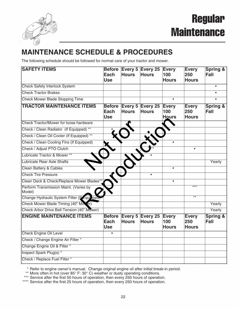
MAINTENANCE SCHEDULE & PROCEDURESThe following schedule should be followed for normal care of your tractor and mower.
* Refer to engine owner’s manual. Change original engine oil after initial break-in period. ** More often in hot (over 85° F: 30° C) weather or dusty operating conditions.
*** Service after the first 50 hours of operation, then every 250 hours of operation.**** Service after the first 25 hours of operation, then every 250 hours of operation.
SAFETY ITEMS BeforeEachUse
Every 5Hours
Every 25Hours
Every100Hours
Every250Hours
Spring &Fall
Check Safety Interlock System •
Check Tractor Brakes •
Check Mower Blade Stopping Time • •
TRACTOR MAINTENANCE ITEMS BeforeEachUse
Every 5Hours
Every 25Hours
Every100Hours
Every250Hours
Spring &Fall
Check Tractor/Mower for loose hardware •
Check / Clean Radiator (If Equipped) ** • •
Check / Clean Oil Cooler (If Equipped) ** •
Check / Clean Cooling Fins (If Equipped) •
Check / Adjust PTO Clutch **** •
Lubricate Tractor & Mower ** •
Lubricate Rear Axle Shafts Yearly
Clean Battery & Cables •
Check Tire Pressure •
Clean Deck & Check/Replace Mower Blades** •
Perform Transmission Maint. (Varies byModel)
***
Change Hydraulic System Filter (If Equipped) **
Check Mower Blade Timing (40” Mower) Yearly
Check Arbor Drive Belt Tension (40” Mower) Yearly
ENGINE MAINTENANCE ITEMS BeforeEachUse
Every 5Hours
Every 25Hours
Every100Hours
Every250Hours
Spring &Fall
Check Engine Oil Level •
Check / Change Engine Air Filter *
Change Engine Oil & Filter *
Inspect Spark Plug(s) *
Check / Replace Fuel Filter *
Not for
Reprod
uctio
n

23
Regular Maintenance
CHECK / CLEAN OIL COOLER(SELECT MODELS)Service Interval: Every 25 Hours, or As NecessaryThe engine oil cooler is located on the side of the engine(A, Figure 19) and should be cleaned with compressedair at regular intervals or if dirty.
SAFETY INTERLOCK SYSTEMCHECKService Interval: Every Fall & SpringCheck the function of the safety interlock system usingthe test procedure found on page 12 of this manual. Ifthe tractor fails any of the tests, see your dealer.
BLADE BRAKE CHECKService Interval: Every 100 Hours or Fall & SpringMower blades and mower drive belt should come to acomplete stop within five seconds after electric PTOswitch is turned off. 1. With tractor in neutral, PTO disengaged and operator
in seat, start the engine.2. Look over the left-hand footrest at the mower drive
belt. Engage the PTO and wait several seconds.Disengage the PTO and check the amount of time ittakes for the mower drive belt to stop.
3. If mower drive belt does not stop within five seconds,re-adjust the clutch or see your dealer.
PTO CLUTCH ADJUSTMENT CHECKService Interval: After 25 Hrs, Then Every 250 HrsCheck the PTO clutch adjustment after the initial 25 hourbreak-in period and then after every 250 hours of opera-tion–or if the clutch starts slipping or will not engage.Check and adjust the clutch using the procedure outlinedin the Adjustments section of this manual.
ENGINE MAINTENANCERefer to the engine owner’s manual for all engine main-tenance procedures and recommendations.
G
Figure 19. Clean Oil CoolerA. Oil Cooler
A
Not for
Reprod
uctio
n
24
Regular Maintenance
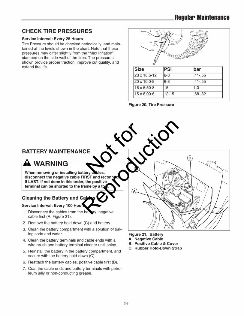
BATTERY MAINTENANCE
Cleaning the Battery and Cables
Service Interval: Every 100 Hours
1. Disconnect the cables from the battery, negativecable first (A, Figure 21).
2. Remove the battery hold-down (C) and battery.
3. Clean the battery compartment with a solution of bak-ing soda and water.
4. Clean the battery terminals and cable ends with awire brush and battery terminal cleaner until shiny.
5. Reinstall the battery in the battery compartment, andsecure with the battery hold-down (C).
6. Reattach the battery cables, positive cable first (B).
7. Coat the cable ends and battery terminals with petro-leum jelly or non-conducting grease.
WARNINGWhen removing or installing battery cables,disconnect the negative cable FIRST and reconnectit LAST. If not done in this order, the positiveterminal can be shorted to the frame by a tool.
Figure 21. BatteryA. Negative CableB. Positive Cable & CoverC. Rubber Hold-Down Strap
A
C
B
Figure 20. Tire Pressure
CHECK TIRE PRESSURESService Interval: Every 25 HoursTire Pressure should be checked periodically, and main-tained at the levels shown in the chart. Note that thesepressures may differ slightly from the “Max Inflation”stamped on the side-wall of the tires. The pressuresshown provide proper traction, improve cut quality, andextend tire life. Size PSI bar
23 x 10.5-12 6-8 ,41-,55
20 x 10.0-8 6-8 ,41-,55
16 x 6.50-8 15 1,0
15 x 6.00-6 12-15 ,68-,82
Not for
Reprod
uctio
n

25
Regular Maintenance
LUBRICATIONService Interval: Every 25 Hours
Lubricate the unit at the locations shown in Figures 22-26 as well as the lubrication points listed. Generally, allmoving metal parts should be oiled where contact ismade with other parts. Keep oil and grease off belts andpulleys. Wipe surfaces clean before and after lubrica-tion.Grease:
• steering linkage• foot pedal• mower linkage• transmission idler assembly pivot• rear axle shafts (remove wheel hubs)• front axle where it contacts the frame
Use grease fittings when present. Automotive lithiumgrease is recommended.
Oil:• control linkage • seat adjustment assembly• brake linkage • mower deck height adjustment linkage• manual lift lever
Figure 22. Lubricating the Tractor
Figure 24. Mower Lubrication Points
Figure 26. Arbor Lubrication Point
Figure 23. Lubricate Steering Linkage
Figure 25. Mower Lubrication Points
Not for
Reprod
uctio
n
26
Regular Maintenance
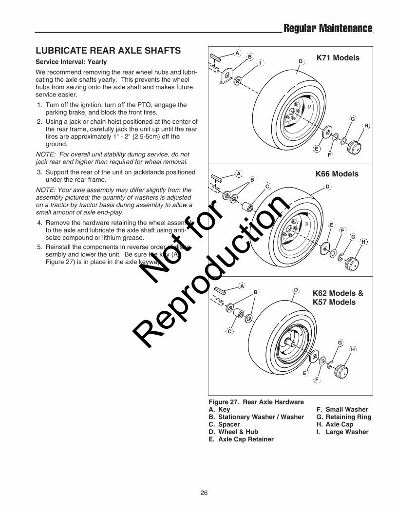
LUBRICATE REAR AXLE SHAFTSService Interval: Yearly
We recommend removing the rear wheel hubs and lubri-cating the axle shafts yearly. This prevents the wheelhubs from seizing onto the axle shaft and makes futureservice easier.
1. Turn off the ignition, turn off the PTO, engage theparking brake, and block the front tires.
2. Using a jack or chain hoist positioned at the center ofthe rear frame, carefully jack the unit up until the reartires are approximately 1" - 2" (2.5-5cm) off theground.
NOTE: For overall unit stability during service, do notjack rear end higher than required for wheel removal.
3. Support the rear of the unit on jackstands positionedunder the rear frame.
NOTE: Your axle assembly may differ slightly from theassembly pictured: the quantity of washers is adjustedon a tractor by tractor basis during assembly to allow asmall amount of axle end-play.
4. Remove the hardware retaining the wheel assemblyto the axle and lubricate the axle shaft using anti-seize compound or lithium grease.
5. Reinstall the components in reverse order of disas-sembly and lower the unit. Be sure the key (A,Figure 27) is in place in the axle keyway.
BI D
EF
GH
A
AB
C D
EF
GH
K71 Models
K66 Models
Figure 27. Rear Axle HardwareA. Key F. Small WasherB. Stationary Washer / Washer G. Retaining RingC. Spacer H. Axle CapD. Wheel & Hub I. Large WasherE. Axle Cap Retainer
AB
C
D
EF
GH
K62 Models &K57 Models
Not for
Reprod
uctio
n
27
Regular Maintenance
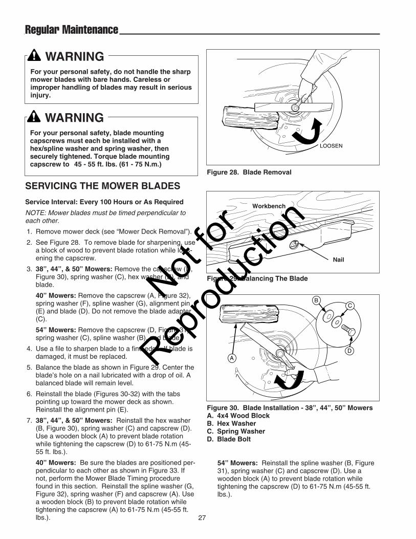
SERVICING THE MOWER BLADES
Service Interval: Every 100 Hours or As Required
NOTE: Mower blades must be timed perpendicular toeach other.
1. Remove mower deck (see “Mower Deck Removal”).
2. See Figure 28. To remove blade for sharpening, usea block of wood to prevent blade rotation while loos-ening the capscrew.
3. 38”, 44”, & 50” Mowers: Remove the capscrew (D,Figure 30), spring washer (C), hex washer (B), andblade.
40” Mowers: Remove the capscrew (A, Figure 32),spring washer (F), spline washer (G), alignment pin(E) and blade (D). Do not remove the blade adapter(C).
54” Mowers: Remove the capscrew (D, Figure 31),spring washer (C), spline washer (B), and blade.
4. Use a file to sharpen blade to a fine edge. If blade isdamaged, it must be replaced.
5. Balance the blade as shown in Figure 29. Center theblade’s hole on a nail lubricated with a drop of oil. Abalanced blade will remain level.
6. Reinstall the blade (Figures 30-32) with the tabspointing up toward the mower deck as shown.Reinstall the alignment pin (E).
7. 38”, 44”, & 50” Mowers: Reinstall the hex washer(B, Figure 30), spring washer (C) and capscrew (D).Use a wooden block (A) to prevent blade rotationwhile tightening the capscrew (D) to 61-75 N.m (45-55 ft. lbs.).
40” Mowers: Be sure the blades are positioned per-pendicular to each other as shown in Figure 33. Ifnot, perform the Mower Blade Timing procedurefound in this section. Reinstall the spline washer (G,Figure 32), spring washer (F) and capscrew (A). Usea wooden block (B) to prevent blade rotation whiletightening the capscrew (A) to 61-75 N.m (45-55 ft.lbs.).
WARNINGFor your personal safety, do not handle the sharpmower blades with bare hands. Careless orimproper handling of blades may result in seriousinjury.
WARNINGFor your personal safety, blade mountingcapscrews must each be installed with ahex/spline washer and spring washer, thensecurely tightened. Torque blade mountingcapscrew to 45 - 55 ft. lbs. (61 - 75 N.m.)
Figure 29. Balancing The Blade
Workbench
Nail
LOOSEN
Figure 28. Blade Removal
AD
CB
Figure 30. Blade Installation - 38”, 44”, 50” MowersA. 4x4 Wood BlockB. Hex WasherC. Spring WasherD. Blade Bolt
54” Mowers: Reinstall the spline washer (B, Figure31), spring washer (C) and capscrew (D). Use awooden block (A) to prevent blade rotation whiletightening the capscrew (D) to 61-75 N.m (45-55 ft.lbs.).
Not for
Reprod
uctio
n

28
Regular Maintenance
CHECK MOWER BLADE TIMING - 40” MOWERSService Interval: Yearly
1. Turn the PTO OFF, engage the parking brake, turnthe engine off, and remove the key. Remove themower deck (see “Mower deck removal”).
2. Turn the mower deck over and check the position ofthe blades. The blades must be positioned perpen-dicular to each other as shown in Figure 31. If not,proceed to step 3.
3. Use a block of wood (B, Figure 28) to prevent bladerotation while loosening the capscrew.
4. Remove the capscrew (A, Figure 32), spring washer(F), and spline washer (G).
5. Remove the alignment pin (E, Figure 32). Rotate theblade (D) manually until the blades are perpendicularto each other as shown in Figure 33. It may be nec-essary to remove and rotate the blade adapter (C) toalign the blade hole and adapter hole.
6. Reinstall the alignment pin (E), spline washer (G),spring washer (F) and capscrew (A). Use a woodenblock (B) to prevent blade rotation while tighteningthe capscrew (A) to 61-75 N.m (45-55 ft. lbs.).
Figure 33. Check Blade Timing
A
B C D E
G
F
A
Figure 32. Blade Installation - 40” MowersA. Blade Mounting CapscrewB. 4x4 Wood BlockC. Blade AdapterD. BladeE. Alignment PinF. Spring WasherG. Spline Washer
AD
CB
Figure 31. Blade Installation - 54” MowersA. 4x4 Wood BlockB. Spline WasherC. Spring WasherD. Blade Bolt
Not for
Reprod
uctio
n

29
Regular Maintenance
Figure 34. Transmission ID Tag LocationA. ID TagB. K62 Expansion Chamber
TUFF TORQ K611001010101010010101
TRANSMISSION MAINTENANCE
K57 MaintenanceThe K57 is a sealed unit and does not require regularmaintenance.
K62 MaintenanceThe K62 is a sealed unit and does not require regularmaintenance. The transmission oil level can be checkedat the expansion chamber located on top of the transmis-sion (see Figure 34). Shine a light at the back of theexpansion chamber to see the oil level. There should beapproximately 7/16” (1 cm) of oil in the chamber. If thereis no oil in the chamber, see your dealer.
TRANSMISSION INFORMATION
Transmission Oil Capacity: Apx. 2.6 qt (2,5L).
Transmission Oil Type: SAE 10W-30 with a minimumAPI rating of SG/CD.
K66 MaintenanceThe K66 is a sealed unit and does not require regularmaintenance. The transmission oil level can be checkedat the access hole located behind the left rear wheel (seeFigure 35). Shine a light at the back of the expansionchamber to see the oil level. There should be approxi-mately 7/16” (1 cm) of oil in the chamber. If there is nooil in the chamber, see your dealer.
TRANSMISSION INFORMATION
Transmission Oil Capacity: Apx. 2.6 qt (2.5L).
Transmission Oil Type: SAE 10W-30 with a minimumAPI rating of SG/CD.
Do not allow dirt, water, or other debris toenter the expansion chamber ortransmission. Even a small amount of dirtcan damage the transmission
TRANSMISSION IDENTIFICATIONSeveral service procedures within this book are identifiedby, and vary by, transmission type. To determine whattransmission is in your tractor, check the identificationtag attached to the axle of the transmission (Figure 34),or check your tractor’s parts book.
Figure 35. Transmission Oil Reservoir - K66A. K66 Reservoir Access Hole
A
A
B
Not for
Reprod
uctio
n

30
Regular Maintenance
K71 MaintenanceThe following maintenance procedures must be per-formed on the K71 transmission after the first 50 hours ofoperation and then after every 250 hours.
TRANSMISSION INFORMATION
Transmission Oil Capacity: Apx. 4-1/2 qt (4.25L)
Transmission Oil Type: SAE 10W-30 with a minimumAPI rating of SG/CD.
Internal Oil Filter Part Number: 1719832
Hydraulic System Oil Filter Part Number: 1719168
CHECK TRANSMISSION OIL LEVEL
Service Interval: Every 5 HoursNOTE: Lift cylinder should be extended.1. Slide the seat assembly back to access the plastic
plug in the top of the seat deck (see Figure 36).Remove the plug.
2. Clean the area around the expansion chamber.Open the lid and check that there is oil present in thebottom of the expansion chamber. If there is no oilpresent, add 10W-30 SG engine oil until the oil levelis 7/16” (1 cm) above the bottom. DO NOT OVER-FILL. Empty space is required in the expansionchamber for heat expansion.
CHANGE TRANSMISSION OIL, INTERNAL FILTER, &HYDRAULIC SYSTEM FILTER
Service Interval: After 50 Hrs, Then Every 250 HrsNOTE: The oil should also be changed whenever it hasbecome discolored from overheating or contamination.
NOTE: Support the frame with jackstands and removethe left rear wheel for easier access to the differential fillplug (Figure 37).1. Place a drain pan under the transmission and remove
the two 14mm drain plugs (A, Figure 38).2. Remove the differential fill cap (B, Figure 39).3. Remove the filter access cap (B, Figure 38).4. Remove and replace the hydraulic system filter (A,
Figure 39). Thread the new filter onto the filter baseand tighten 1/2 to 3/4 turns past finger tight.
Figure 39. Hydraulic System Oil FilterA. Hydraulic System FilterB. Differential Fill Cap
A
B
Figure 36. Seat Deck Access PlugA. Expansion Chamber Access Plug
Figure 37. Differential Fill Plug AccessA. Differential Fill Plug
Figure 38. Transmission Drain PlugsA. 14mm Drain PlugsB. Filter Access Cap
A B
A
A
Not for
Reprod
uctio
n

31
Regular Maintenance
Figure 40. Internal Transmission Filter ServiceA. Filter Access Cap B. Internal Filter
5. Remove and replace the internal transmission filter(B, Figure 40).
6. Reinstall the filter access cap (A, Figure 40) and thetwo 14mm drain plugs (A, Figure 41).
7. Using a long funnel, add 2 quarts of oil to the differ-ential fill (See Figure 37). The differential fill capshould have been removed earlier).
8. Reinstall the differential fill cap (A, Figure 37).9. Remove the expansion chamber access plug (A,
Figure 42) and expansion chamber cover. Add 2quarts (1.9L) of oil to the expansion chamber a fewounces at a time.
10. Reinstall the expansion chamber cover and accessplug (Figure 42).
11. Test run the tractor for 10 minutes. Drive forwardand backward; raise and lower the attachment liftseveral times.
12. Recheck the transmission oil level. There should be7/16” (1 cm) of oil visible in expansion chamber. DONOT OVERFILL. Empty space is required for heatexpansion.
AB
Figure 41. Transmission Drain PlugsA. 14mm Drain PlugsB. Filter Access Cap
A B
Figure 42. Seat Deck Access PlugA. Expansion Chamber Access Plug
A
Not for
Reprod
uctio
n

32
Regular Maintenance
MAINTENANCE RECORDS
Not for
Reprod
uctio
n
33
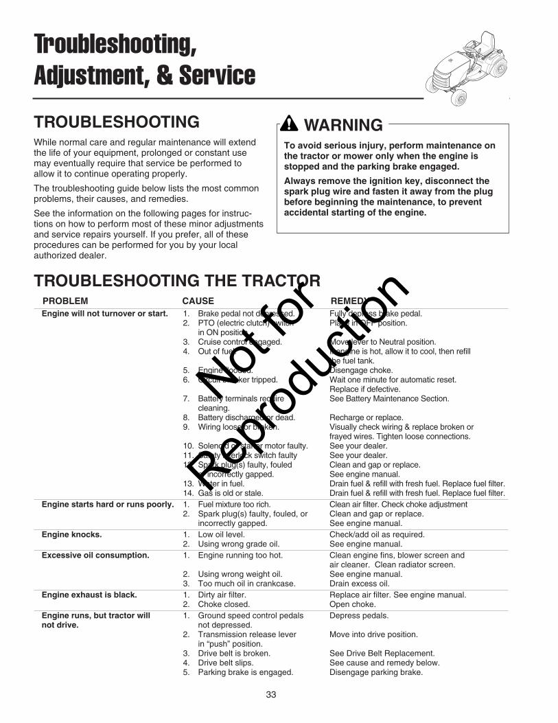
Troubleshooting,Adjustment, & Service
TROUBLESHOOTINGWhile normal care and regular maintenance will extendthe life of your equipment, prolonged or constant usemay eventually require that service be performed toallow it to continue operating properly.
The troubleshooting guide below lists the most commonproblems, their causes, and remedies.
See the information on the following pages for instruc-tions on how to perform most of these minor adjustmentsand service repairs yourself. If you prefer, all of theseprocedures can be performed for you by your localauthorized dealer.
TROUBLESHOOTING THE TRACTORPROBLEM CAUSE REMEDYEngine will not turnover or start. 1. Brake pedal not depressed. Fully depress brake pedal.
2. PTO (electric clutch) switch Place in OFF position.in ON position.
3. Cruise control engaged. Move lever to Neutral position.4. Out of fuel. If engine is hot, allow it to cool, then refill
the fuel tank.5. Engine flooded. Disengage choke.6. Circuit breaker tripped. Wait one minute for automatic reset.
Replace if defective.7. Battery terminals require See Battery Maintenance Section.
cleaning. 8. Battery discharged or dead. Recharge or replace.9. Wiring loose or broken. Visually check wiring & replace broken or
frayed wires. Tighten loose connections.10. Solenoid or starter motor faulty. See your dealer.11. Safety interlock switch faulty See your dealer.12. Spark plug(s) faulty, fouled Clean and gap or replace.
or incorrectly gapped. See engine manual.13. Water in fuel. Drain fuel & refill with fresh fuel. Replace fuel filter.14. Gas is old or stale. Drain fuel & refill with fresh fuel. Replace fuel filter.
Engine starts hard or runs poorly. 1. Fuel mixture too rich. Clean air filter. Check choke adjustment 2. Spark plug(s) faulty, fouled, or Clean and gap or replace.
incorrectly gapped. See engine manual.Engine knocks. 1. Low oil level. Check/add oil as required.
2. Using wrong grade oil. See engine manual.Excessive oil consumption. 1. Engine running too hot. Clean engine fins, blower screen and
air cleaner. Clean radiator screen.2. Using wrong weight oil. See engine manual.3. Too much oil in crankcase. Drain excess oil.
Engine exhaust is black. 1. Dirty air filter. Replace air filter. See engine manual.2. Choke closed. Open choke.
Engine runs, but tractor will 1. Ground speed control pedals Depress pedals.not drive. not depressed.
2. Transmission release lever Move into drive position.in “push” position.
3. Drive belt is broken. See Drive Belt Replacement.4. Drive belt slips. See cause and remedy below.5. Parking brake is engaged. Disengage parking brake.
WARNINGTo avoid serious injury, perform maintenance onthe tractor or mower only when the engine isstopped and the parking brake engaged.
Always remove the ignition key, disconnect thespark plug wire and fasten it away from the plugbefore beginning the maintenance, to preventaccidental starting of the engine.
Not for
Reprod
uctio
n

34
Troubleshooting, Adjustment, & Service
Tractor Troubleshooting Cont.Tractor drive belt slips. 1. Clutch/brake is out of adjustment. See Adjustments Section.
2. Pulleys or belt greasy or oily. Clean as required.3. Belt stretched or worn. Replace with new belt.4. Idler pulley pivot bracket Remove idler pulley bracket, clean and lubricate.
“frozen” in declutched position. Brake will not hold. 1. Brake is incorrectly adjusted. See Brake Adjustment.
2. Internal brake worn. See your dealer. Tractor steers hard or 1. Steering linkage is loose. Check and tighten any loose connections.handles poorly. See Steering Gear Adjustment.
2. Improper tire inflation. Check and correct.3. Front wheel spindle Grease spindles. See Lubricating the
bearings dry. Tractor.
TROUBLESHOOTING THE MOWERPROBLEM CAUSE REMEDYMower will not raise. 1. Lift linkage not properly attached Attach or repair.
or damaged.2. Dirt in hydraulic lines. Change hydraulic system filter.3. Brake pedal depressed. Release brake pedal to power transmission.
Mower cut is uneven. 1. Mower not leveled properly. See Mower Adjustment.2. Tractor tires not inflated See Maintenance Section.
equally or properly.Mower cut is rough looking. 1. Engine speed too slow. Set to full throttle.
2. Ground speed too fast. Slow down.3. Blades are dull. Sharpen or replace blades.
See Mower Blade Service.4. Mower drive belt slipping Clean or replace belt as necessary.
because it is oily or worn. 5. Check PTO (Electric Clutch) See Adjustments Section.
Adjustment.6. Blades not properly fastened See Servicing the Mower Blades.
to arbors.Engine stalls easily with 1. Engine speed too slow. Set to full throttle.mower engaged. 2. Ground speed too fast. Slow down.
3. Carburetor improperly adjusted. See Engine Manual.4. Cutting height set too low. Cut tall grass at maximum cutting
height during first pass.5. Discharge chute jamming Cut grass with discharge pointing toward
with cut grass. previously cut area.6. Engine not up to operating Run engine for several minutes to warm-up.
temperature.7. Starting mower in tall grass. Start the mower in a cleared area.
Excessive mower vibration. 1. Blade mounting screws Tighten to 45-55 ft.lbs. (61-75 N.m.).are loose.
2. Mower blades, arbors, Check and replace as necessary.or pulleys are bent.
3. Mower blades are out Remove, sharpen, and balance blades.of balance. See Servicing the Mower Blades.
4. Belt installed incorrectly. Reinstall Correctly.Excessive belt wear or breakage. 1. Bent or rough pulleys. Repair or replace.
2. Using incorrect belt. Replace with correct belt.Mower drive belt slips 1. Idler pulley spring broken or not Repair or replace as needed.or fails to drive. properly attached.
2. Belt stops out of adjustment. Check belt stops.3. Mower drive belt broken. Replace drive belt.4. PTO clutch out of adjustment. Adjust PTO clutch.
Mower blades collide (40” Mower). 1. Blade shear pin broken. Replace shear pin.
Not for
Reprod
uctio
n

35
Troubleshooting, Adjustment, & Service
Figure 43. Seat AdjustmentA. Seat Adjustment LeverB. Carriage Bolt, Spacer, Washer, & NutC. Seat Spring
A
Figure 44. Manual Lift Assist AdjustmentA. Adjustment Bolt
BATTERY CHARGING
A dead battery or one too weak to start the engine maybe the result of a defect in the charging system or otherelectrical component. If there is any doubt about thecause of the problem, see your dealer. If you need toreplace the battery, follow the steps under Cleaning theBattery & Cables in the Regular Maintenance Section.
To charge the battery, follow the instructions provided bythe battery charger manufacturer as well as all warningsincluded in the safety rules sections of this book. Chargethe battery until fully charged (until the specific gravity ofthe electrolyte is 1.250 or higher and the electrolyte tem-perature is at least 60° F). Do not charge at a rate high-er than 10 amps.
SEAT ADJUSTMENTPitch AdjustmentThe pitch of the seat can be adjusted to one of threepositions. To adjust, remove the carriage bolts, spacers,washers, and nuts (B, Figure 43) from the hinge andreinstall them in the desired holes.
Seat Slide AdjustmentThe seat can also be adjusted forward and back. Movethe lever (A, Figure 43), position the seat as desired, andrelease the lever to lock the seat into position.
Seat Spring AdjustmentThe seat springs (C, Figure 43) can be adjusted to pro-vide a softer or firmer ride. Tilt the seat forward and slidethe spring assembly (C) forward for a softer ride, andback for a firmer ride.
MANUAL LIFT ASSIST ADJUSTMENTModels with large, left-side lift lever.
The manual lift assist spring tension can be adjusted tocompensate for the additional load of various attach-ments.
1. Locate the adjustment bolt (A, Figure 44) at the lowerleft corner of the engine compartment bulkhead.
2. Turn the bolt (A) clockwise to increase assist. Turnthe bolt (A) counterclockwise to reduce lift assist.
AC
B
WARNINGKeep open flames and sparks away from thebattery; the gasses coming from it are highlyexplosive. Ventilate the battery well duringcharging.
Not for
Reprod
uctio
n

36
Troubleshooting, Adjustment, & Service
STEERING WHEEL ADJUSTMENTNOTE: The steering wheel on Snapper models is notadjustable.
1. Use a suitable punch to remove the roll pin at thebase of the steering wheel (B, Figure 45).
2. Pull down on the rubber boot to expose the two holesin the steering shaft (A).
3. Align the hole in the steering wheel with the appropri-ate steering shaft hole and install the roll pin.
NOTE: Steering wheel is factory installed with the roll pinin the bottom hole.
STEERING GEAR ADJUSTMENTIf there is excessive slack in the steering system, thesteering gear backlash can be removed.
1. See Figure 46. Locate the steering gear assembly onthe underside of the tractor. Loosen the two nuts andadjust the bracket so the gear teeth are closelymeshed.
2. Tighten nuts (A, Figure 46) to 36-44 ft. lbs. (49-59Nm) after adjustment.
BRAKE ADJUSTMENT1. Disengage the PTO, stop the engine, block the
wheels, remove the ignition key, and engage theparking brake.
2. Remove the mower deck (see Mower DeckRemoval).
3. Locate the brake spring (A, Figure 47) and adjust-ment nut (B).
4. With the parking brake engaged, measure the com-pressed spring length. The spring should be 2-1/2”(6,4 cm) when compressed.
If the spring is not within this range, turn the adjust-ment nut (B, Figure 47) to compress or release thespring.
If this adjustment does not correct a braking problem,see your dealer.
Figure 46. Steering Gear AdjustmentA. Nuts
Figure 47. Brake Spring AdjustmentA. Brake SpringB. Adjustment Nut
A
B
Figure 45. Steering Wheel ComponentsA. Steering ShaftB. Roll PinC. Steering Wheel
B
A
C
Thicker SpokeFaces Seat
A
Not for
Reprod
uctio
n

37
Troubleshooting, Adjustment, & Service
PTO CLUTCH ADJUSTMENT
Check the PTO clutch adjustment after the initial 25 hourbreak-in period and then after every 250 hours of opera-tion. Also perform the following procedure if the clutch isslipping or will not engage, or if a new clutch has beeninstalled.
1. Remove key from ignition switch and disconnectspark plug wires to prevent the possibility of acciden-tal starting while the PTO is being adjusted.
2. See Figure 48. Note the position of the 3 adjustmentwindows (A) in the side of the brake plate and thenylock adjustment nuts (B).
3. Insert a .012”-.015” (2,5-4mm) feeler gauge (C)through each window, positioning the gauge betweenthe rotor face and the armature face as shown inFigure 49.
4. Alternately tighten the adjustment nuts (B, Figure 48)until the rotor face and armature face just contactsthe gauge.
5. Check the windows for an equal amount of tensionwhen the gauge is inserted and removed, and makeany necessary adjustments by tightening or loosen-ing the adjustment nuts.
NOTE: The actual air gap between the rotor and arma-ture may vary even after performing the adjustment pro-cedure. This is due to dimensional variations on compo-nent parts, and is an acceptable condition.
6. Check the mower blade stopping time. The mowerblades and mower drive belt should come to a com-plete stop within five seconds after the electric PTOswitch is turned off.
7. Perform the BLADE BRAKE CHECK found in theMAINTENANCE Section. Mower blades and mowerdrive belt should come to a complete stop within fiveseconds after electric PTO switch is turned off.
Figure 48. PTO Clutch AdjustmentA. Adjustment Window (Qty. 3, one shown) B. Adjustment Nut
AB
B
B
AB
C
Figure 49. Adjust PTO ClutchA. WindowB. Adjustment NutC. Feeler Gauge
WARNINGTo avoid serious injury, perform adjustments onlywith engine stopped, key removed and tractor onlevel ground.
Not for
Reprod
uctio
n
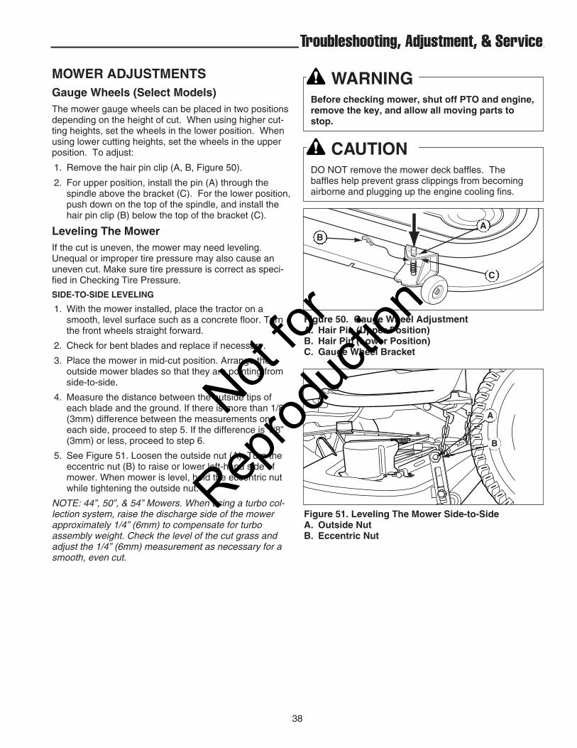
38
Troubleshooting, Adjustment, & Service
MOWER ADJUSTMENTSGauge Wheels (Select Models)The mower gauge wheels can be placed in two positionsdepending on the height of cut. When using higher cut-ting heights, set the wheels in the lower position. Whenusing lower cutting heights, set the wheels in the upperposition. To adjust:
1. Remove the hair pin clip (A, B, Figure 50).
2. For upper position, install the pin (A) through thespindle above the bracket (C). For the lower position,push down on the top of the spindle, and install thehair pin clip (B) below the top of the bracket (C).
Leveling The MowerIf the cut is uneven, the mower may need leveling.Unequal or improper tire pressure may also cause anuneven cut. Make sure tire pressure is correct as speci-fied in Checking Tire Pressure.
SIDE-TO-SIDE LEVELING
1. With the mower installed, place the tractor on asmooth, level surface such as a concrete floor. Turnthe front wheels straight forward.
2. Check for bent blades and replace if necessary.
3. Place the mower in mid-cut position. Arrange the outside mower blades so that they are pointing fromside-to-side.
4. Measure the distance between the outside tips ofeach blade and the ground. If there is more than 1/8”(3mm) difference between the measurements oneach side, proceed to step 5. If the difference is 1/8”(3mm) or less, proceed to step 6.
5. See Figure 51. Loosen the outside nut (A). Turn theeccentric nut (B) to raise or lower left-hand side ofmower. When mower is level, hold the eccentric nutwhile tightening the outside nut.
NOTE: 44”, 50”, & 54” Mowers. When using a turbo col-lection system, raise the discharge side of the mowerapproximately 1/4” (6mm) to compensate for turboassembly weight. Check the level of the cut grass andadjust the 1/4” (6mm) measurement as necessary for asmooth, even cut.
Figure 51. Leveling The Mower Side-to-SideA. Outside NutB. Eccentric Nut
WARNINGBefore checking mower, shut off PTO and engine,remove the key, and allow all moving parts tostop.
CAUTIONDO NOT remove the mower deck baffles. Thebaffles help prevent grass clippings from becomingairborne and plugging up the engine cooling fins.
Figure 50. Gauge Wheel AdjustmentA. Hair Pin (Upper Position)B. Hair Pin (Lower Position)C. Gauge Wheel Bracket
AB
C
A
B
Not for
Reprod
uctio
n

39
Troubleshooting, Adjustment, & Service
FRONT-TO-BACK LEVELING
NOTE: 54” mowers have two adjustment rods thatshould be adjusted simultaneously.
6. Arrange the blades so they face front-to-back.7. Measure the distance from the ground to the front tip
of the center blade, and from the ground to rear tipsof left-hand and right-hand blades. Front tip of the center blade should be 1/4" (6mm)higher than rear tips of left-hand and right-handblades. If not, proceed with steps 8 - 9.
8. To raise front of mower deck, loosen front nut (B) andturn rear nut (A, Figure 52) against bracket. To lowerfront of mower deck, loosen rear nut (A) and thebracket will move backwards to lengthen rod.
10. Re-check the blade measurement then tighten thefront nut (B) against the bracket to secure.
Figure 52. Front to Back LevelingA. Rear Nut B. Front Nut
A B
Not for
Reprod
uctio
n
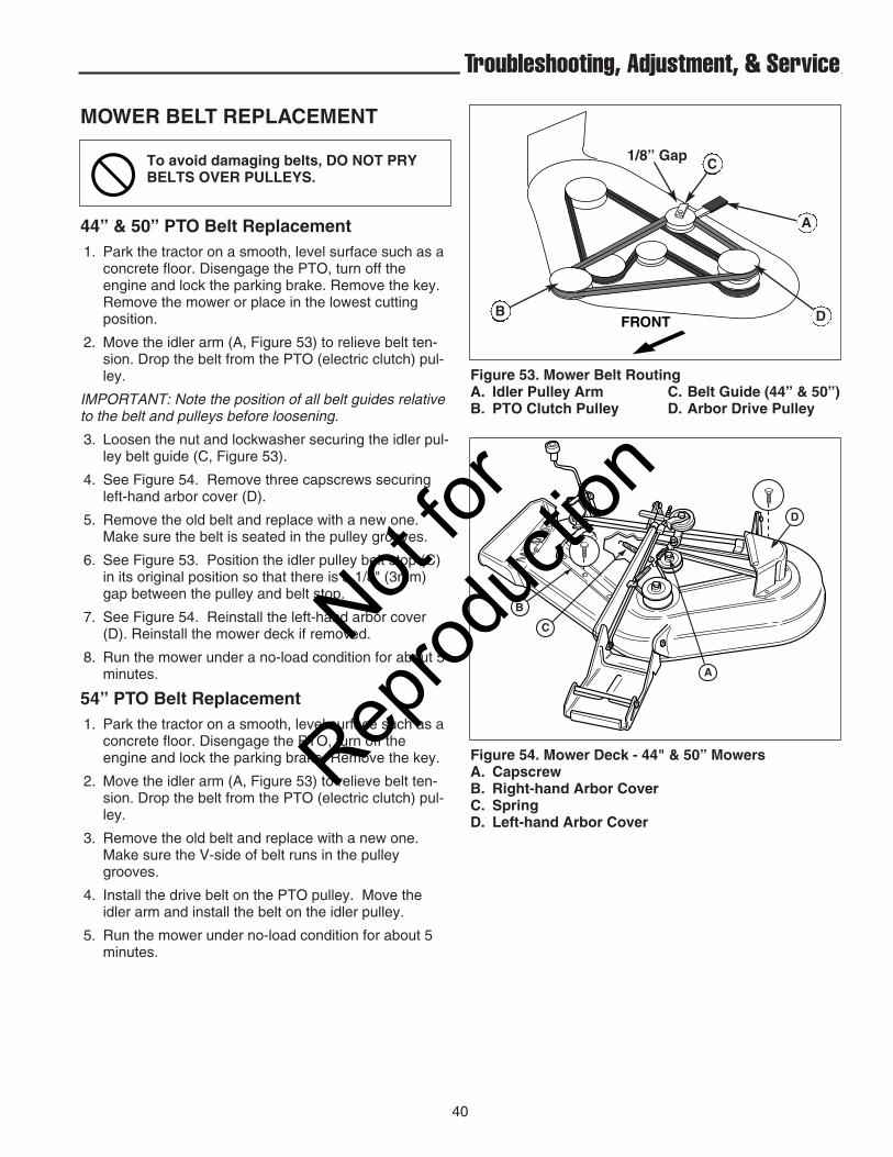
40
Troubleshooting, Adjustment, & Service
Figure 53. Mower Belt Routing A. Idler Pulley Arm C. Belt Guide (44” & 50”)B. PTO Clutch Pulley D. Arbor Drive Pulley
MOWER BELT REPLACEMENT
44” & 50” PTO Belt Replacement1. Park the tractor on a smooth, level surface such as a
concrete floor. Disengage the PTO, turn off theengine and lock the parking brake. Remove the key.Remove the mower or place in the lowest cuttingposition.
2. Move the idler arm (A, Figure 53) to relieve belt ten-sion. Drop the belt from the PTO (electric clutch) pul-ley.
IMPORTANT: Note the position of all belt guides relativeto the belt and pulleys before loosening.
3. Loosen the nut and lockwasher securing the idler pul-ley belt guide (C, Figure 53).
4. See Figure 54. Remove three capscrews securingleft-hand arbor cover (D).
5. Remove the old belt and replace with a new one.Make sure the belt is seated in the pulley grooves.
6. See Figure 53. Position the idler pulley belt stop (C)in its original position so that there is a 1/8" (3mm)gap between the pulley and belt stop.
7. See Figure 54. Reinstall the left-hand arbor cover(D). Reinstall the mower deck if removed.
8. Run the mower under a no-load condition for about 5minutes.
54” PTO Belt Replacement1. Park the tractor on a smooth, level surface such as a
concrete floor. Disengage the PTO, turn off theengine and lock the parking brake. Remove the key.
2. Move the idler arm (A, Figure 53) to relieve belt ten-sion. Drop the belt from the PTO (electric clutch) pul-ley.
3. Remove the old belt and replace with a new one.Make sure the V-side of belt runs in the pulleygrooves.
4. Install the drive belt on the PTO pulley. Move theidler arm and install the belt on the idler pulley.
5. Run the mower under no-load condition for about 5minutes.
D
B
C
A
Figure 54. Mower Deck - 44" & 50” MowersA. CapscrewB. Right-hand Arbor CoverC. SpringD. Left-hand Arbor Cover
To avoid damaging belts, DO NOT PRYBELTS OVER PULLEYS.
1/8” Gap
FRONT
A
DB
C
Not for
Reprod
uctio
n
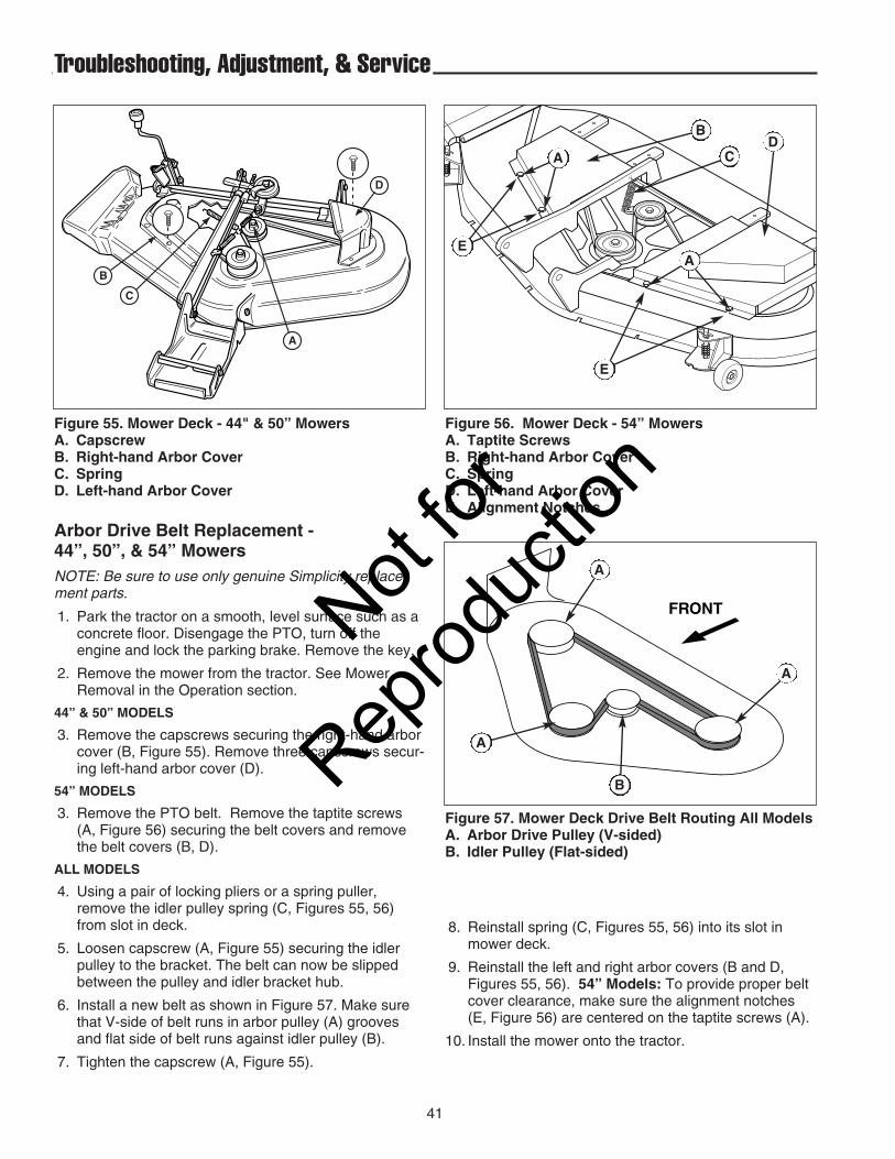
41
Troubleshooting, Adjustment, & Service
Arbor Drive Belt Replacement - 44”, 50”, & 54” MowersNOTE: Be sure to use only genuine Simplicity replace-ment parts.
1. Park the tractor on a smooth, level surface such as aconcrete floor. Disengage the PTO, turn off theengine and lock the parking brake. Remove the key.
2. Remove the mower from the tractor. See MowerRemoval in the Operation section.
44” & 50” MODELS
3. Remove the capscrews securing the right-hand arborcover (B, Figure 55). Remove three capscrews secur-ing left-hand arbor cover (D).
54” MODELS
3. Remove the PTO belt. Remove the taptite screws(A, Figure 56) securing the belt covers and removethe belt covers (B, D).
ALL MODELS
4. Using a pair of locking pliers or a spring puller,remove the idler pulley spring (C, Figures 55, 56)from slot in deck.
5. Loosen capscrew (A, Figure 55) securing the idlerpulley to the bracket. The belt can now be slippedbetween the pulley and idler bracket hub.
6. Install a new belt as shown in Figure 57. Make surethat V-side of belt runs in arbor pulley (A) groovesand flat side of belt runs against idler pulley (B).
7. Tighten the capscrew (A, Figure 55).
FRONT
Figure 57. Mower Deck Drive Belt Routing All ModelsA. Arbor Drive Pulley (V-sided)B. Idler Pulley (Flat-sided)
A
A
A
B
Figure 56. Mower Deck - 54” MowersA. Taptite ScrewsB. Right-hand Arbor CoverC. SpringD. Left-hand Arbor CoverE. Alignment Notches
D
B
C
A
Figure 55. Mower Deck - 44" & 50” MowersA. CapscrewB. Right-hand Arbor CoverC. SpringD. Left-hand Arbor Cover
E
E
B
AD
C
8. Reinstall spring (C, Figures 55, 56) into its slot inmower deck.
9. Reinstall the left and right arbor covers (B and D,Figures 55, 56). 54” Models: To provide proper beltcover clearance, make sure the alignment notches(E, Figure 56) are centered on the taptite screws (A).
10. Install the mower onto the tractor.
A
Not for
Reprod
uctio
n

42
Troubleshooting, Adjustment, & Service
40” Mower PTO Belt Replacement1. With the mower deck installed, park the tractor on a
smooth, level surface such as a concrete floor.Disengage the PTO, engage the parking brake, shutthe engine off, and remove the key.
2. Remove the mower deck (see “Mower deckremoval”). Remove the belt covers.
3. Note the position of the idler pulley belt guides (E &F, Figure 58) when installed. Loosen the idler pulleycapscrews and remove the belt from the idler pulleys(D & G).
4. Install the new belt (B) as shown. When the mowerdeck is installed on the tractor, the belt wraps aroundthe PTO clutch pulley (A), backside idler pulley (D),mower deck drive pulley (C), and v-idler pulley (G) .
5. Return the idler pulley belt guides (E & F) to theiroriginal positions and tighten the idler pulley cap-screws.
A
DEF
G
C
B
Figure 58. PTO Belt ReplacementA. Engine PTO Clutch PulleyB. PTO BeltC. Mower Deck Drive PulleyD. Backside Idler PulleyE. Belt GuideF. Belt GuideG. V-Idler PulleyNot
for
Reprod
uctio
n

43
Troubleshooting, Adjustment, & Service
40” Mower Arbor Drive Belt Replacement1. With the mower deck installed, park the tractor on a
smooth, level surface such as a concrete floor.Disengage the PTO, engage the parking brake, shutthe engine off, and remove the key.
2. Remove the mower deck (see “Mower DeckRemoval”). Remove the belt covers.
3. Loosen the idler assembly capscrew (A, Figure 59).
4. Using a ratchet (A, Figure 60), insert the end of theextension into the square hole (D, Figure 59) andmove the idler assembly (B, Figure 59) to relieve ten-sion on the belt (C).
5. Remove the belt (C).
6. Install a new belt (C) on the pulleys as shown.Releasing the idler assembly (A) allows the spring toautomatically tension the cogged belt.
7. Tighten the idler assembly capscrew (A). Reinstallthe belt covers.
8. Check that the blades are positioned perpendicular toeach other (see Figure 61). If not, perform the mowerblade timing procedure found in the RegularMaintenance section.
Figure 59. Mulching Deck (Belt Covers Removed)A. Idler Assembly CapscrewB. Spring-Loaded Idler AssemblyC. BeltD. Square Hole
A
B
D
C
Figure 60. Release Cogged Belt TensionA. 3/8” Ratchet and Extension
A
Figure 61. Mower Blade Timing
Not for
Reprod
uctio
n

44
Troubleshooting, Adjustment, & Service
38” Mower Drive Belt ReplacementNOTE: Be sure to use only genuine Simplicity replace-ment parts. Check the back of this manual or the decalunder the hood for common replacement part numbers.
NOTE: It is not necessary to remove the mower to installa new belt. However, for easier access mower can beremoved. See Mower Removal in the Operation section.
Refer to Figure 62.
1. Park the tractor on a smooth, level surface such as aconcrete floor. Disengage the PTO, turn off theengine and lock the parking brake. Remove the key.
2. If mower is not removed, lower the mower lift andplace the mower in the lowest cutting position.
3. Push the idler arm (A) away from you to relieve belttension. Drop the belt from the PTO (electric clutch)pulley.
IMPORTANT: Note the position of all belt guides relativeto the belt and pulleys before loosening.
4. Loosen the two belt stop brackets (C) and idler pulleybelt guide (D).
5. Remove the old belt and replace with a new belt.Make sure V-side of belt runs in arbor pulley groovesand the flat backside runs against the idler pulley.
6. Position the belt stop brackets (C) in their originalpositions. There must be 1/8” clearance between thebelt stop and the pulleys.
7. Position the idler pulley belt guide (D) in its originalposition up against arm (A) so that there is a 1/8" gapbetween the pulley and belt guide.
8. Install mower on tractor if it was removed. SeeOperation section.
9. Run the mower under no-load condition for about 5minutes.
Figure 62. Mower Belt Routing - 38" Mower DeckA. Idler Pulley Arm C. Belt Stop BracketB. PTO Pulley D. Idler Pulley Belt Guide
Left Side of Mower
1/8” Gap
1/8” Gap
1/8” Gap
Not for
Reprod
uctio
n
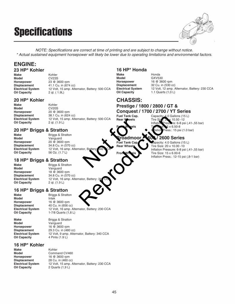
45
Specifications
ENGINE:23 HP* KohlerMake KohlerModel CV23SHorsepower 23 @ 3600 rpmDisplacement 41.1 Cu. in (674 cc)Electrical System 12 Volt, 15 amp. Alternator, Battery: 500 CCAOil Capacity 2 qt. ( 1.9L)
20 HP* KohlerMake KohlerModel CV20SHorsepower 20 @ 3600 rpmDisplacement 38.1 Cu. in (624 cc)Electrical System 12 Volt, 15 amp. Alternator, Battery: 500 CCAOil Capacity 2 qt. (1.9 L)
20 HP* Briggs & StrattonMake Briggs & StrattonModel VanguardHorsepower 20 @ 3600 rpmDisplacement 34.8 Cu. in (570 cc)Electrical System 12 Volt, 16 amp. Alternator, Battery: 340 CCAOil Capacity 56 Oz. (1.7 L)
18 HP* Briggs & StrattonMake Briggs & StrattonModel VanguardHorsepower 18 @ 3600 rpmDisplacement 34.8 Cu. in (570 cc)Electrical System 12 Volt, 16 amp. Alternator, Battery: 340 CCAOil Capacity 2 qt. (1.9 L)
16 HP* Briggs & StrattonMake Briggs & StrattonModel IntekHorsepower 16 @ 3600 rpmDisplacement 40 Cu. in (656 cc)Electrical System 12 Volt, 16 amp. Alternator, Battery: 230 CCAOil Capacity 1-7/8 Quarts (1,8 L)
Make Briggs & StrattonModel VanguardHorsepower 16 @ 3600 rpmDisplacement 29.3 Cu. in (480 cc)Electrical System 12 Volt, 9 amp. Alternator, Battery: 340 CCAOil Capacity 4 Pints (1.9 L)
16 HP* KohlerMake KohlerModel Command CV460Horsepower 16 @ 3600 rpmDisplacement 28 Cu. in (460 cc)Electrical System 12 Volt, 15 amp. Alternator, Battery: 230 CCAOil Capacity 2 Quarts (1,9 L)
16 HP* HondaMake HondaModel GXV530Horsepower 16 @ 3600 rpmDisplacement 32 Cu. in (530 cc)Electrical System 12 Volt, 12 amp. Alternator, Battery: 230 CCAOil Capacity 1.1 Quarts (1,0 L)
CHASSIS:Prestige / 1800 / 2800 / GT &Conquest / 1700 / 2700 / YT SeriesFuel Tank Cap. Capacity: 4.0 Gallons (15 L)Rear Wheels Tire Size: 23 x 10.50 -12
Inflation Pressure: 6-8 psi (,41-,55 bar)Front Wheels Tire Size: 16 x 6.50-8
Inflation Press.: 15 psi (1.0 bar)
Broadmoor / 1600 / 2600 SeriesFuel Tank Cap. Capacity: 4.0 Gallons (15 L)Rear Wheels Tire Size: 20 x 10.00 -10
Inflation Pressure: 6-8 psi (,41-,55 bar)Front Wheels Tire Size: 15 x 6.00-6
Inflation Press.: 12-15 psi (,8-1 bar)
NOTE: Specifications are correct at time of printing and are subject to change without notice.* Actual sustained equipment horsepower will likely be lower due to operating limitations and environmental factors.
Not for
Reprod
uctio
n

46
Specifications
TRANSMISSIONS:K71Type Hydrostatic Tuff Torq K71Hydraulic Fluid 10w 30 Premium Engine OilCapacity 4.8 qt (4,6 L)Speeds Forward: 0-7.2 MPH (0-11.6 km/h)@ 3400 rpm Reverse: 0-4.5 MPH (0-7.2 km/h)Continuous Torque 410 ft. lbs. (554 N.m.)OutputDrawbar Rating 440 lbs. (200 Kg)Maximum Weight 728 lbs. (330 Kg)on Axle
K66Type Hydrostatic Tuff Torq K66Hydraulic Fluid 10w 30 Premium Engine Oil Capacity 2.6 qt (2,5 L)Speeds Forward: 0-5.8 MPH (9.3 km/h)@ 3400 rpm Reverse: 0-3.5 MPH (5.6 km/h)Continuous Torque 310 ft. lbs. (419 N.m.)OutputDrawbar Rating 440 lbs. (200 Kg)Maximum Weight 697 lbs. (316 Kg)on Axle
K62Type Hydrostatic Tuff Torq K62Hydraulic Fluid 10w 30 Premium Engine OilCapacity 2.6 qt (2,5 L)Speeds Forward: 5.5 MPH (8,9 km/h)@ 3400 rpm Reverse: 3.5 MPH (5,6 km/h)Continuous Torque 217 ft. lbs. (294 Nm)OutputDrawbar Rating 440 lbs. (200 Kg)Maximum Weight 697 lbs. (316 Kg)on Axle
K57Type Hydrostatic Tuff Torq K57Hydraulic Fluid 10w 30 Premium Engine OilCapacity 2.1 qt (2,0 L)Speeds Forward: 5.5 MPH (8,9 km/h)@ 3400 rpm Reverse: 3.5 MPH (5,6 km/h)Continuous Torque 159 ft. lbs. (216 Nm)OutputDrawbar Rating 440 lbs. (200 Kg)Maximum Weight 674 lbs. (306 Kg)on Axle
DIMENSIONS:Prestige / 1800 / 2800 / GT SeriesOverall Length 75” (190,5 cm)Overall Width 39” (99 cm)Height At Top of Seat: 50” (127 cm)Weight Tractor 666 lbs. (302 kg)4 50” Mower Deck 125 lbs. (57 kg)54” Mower Deck 192 lbs. (87 kg)
Conquest / 1700 / 2700 / YT SeriesOverall Length 75” (190,5 cm)Overall Width 39” (99 cm)Height At Top of Seat: 50” (127 cm)Weight Tractor 586 lbs. (266 kg)44” Mower Deck 112 lbs. (51 kg)50” Mower Deck 125 lbs. (57 kg)
Broadmoor / 1600 / 2600 SeriesOverall Length 74” (187 cm)Overall Width 42” (107 cm)Height At Top of Seat: 43” (109 cm)WeightBroadmoor / 1600 / 2600 Series Tractor
477 lbs. (217 kg)40” Mower Deck 121 lbs. (55 kg)
Not for
Reprod
uctio
n

47
Parts & Accessories
REPLACEMENT PARTSReplacement parts are available from your authorizeddealer. Always use genuine Simplicity Service Parts.
TECHNICAL MANUALSAdditional copies of this manual are available, as well asfully illustrated parts lists. These manuals show all of theproduct’s components in exploded views (3D illustrationswhich show the relationship of parts and how they gotogether) as well as part numbers and quantities used.Important assembly notes and and torque values arealso included.
For applicable manuals currently available for yourmodel, contact our Customer Publications Department at262-284-8519. Have the information listed in the boxbelow available when phoning in your request.Technical manuals can be downloaded from www.simplicitymfg.com
Snowthrower CabSnowthrower Attachments42" Dozer/Snow BladeRear Wheel WeightsTire ChainsTwin Bag Grass CatcherDump CartHour Meter Kit
Gas CansRear Weight CarrierFront Weight CarrierTriple Bag CollectorTurbo CollectorTiller
Engine OilTouch-Up PaintGrease Gun Kit 8 oz. Grease Tube
Tire SealantDegrimer/DegreaserGas Stabilizer
OPTIONAL ACCESSORIES
MAINTENANCE ITEMSMany convenient and helpful service and maintenanceitems are available from you authorized dealer. Some ofthese items include:
Model:
Mfg. No.:
Your Name:
Address:
City, State, Zip:
Visa/Mastercard No.:
Card Expiration Date:
Not for
Reprod
uctio
n

Briggs & Stratton Power Products Group, L.L.C. Copyright © 2009 Briggs & Stratton CorporationMilwaukee, WI USA. All Rights Reserved
www.BRIGGSandSTRATTON.comwww.simplicitymfg.com
Not for
Reprod
uctio
n