ac generator - basco
TRANSCRIPT

GeneratorCustomer Helpline1-800-222-3136
120/240 VoltElectric Start10000 Watt
AC GENERATOR
Sears, Roebuck and Co., Hoffman Estates, IL 60179
Operators Manual
Model No. 580.327203
CAUTION:Before using this product, read thismanual and follow all its Safety Rulesand Operating Instructions.
Part No. B4659 Draft 1 (10/1/1999) Printed in the U.S.A.
Visit our Craftsman website: www.sears.com/craftsman
HOURS: Mon. - Fri. 8 a.m. to 5 p.m. (CT)
• Safety• Assembly• Operation• Maintenance• Parts• Español

2
TABLE OF CONTENTSWarranty . . . . . . . . . . . . . . . . . . . . . . . . . . . . . . . . . 2Safety Rules . . . . . . . . . . . . . . . . . . . . . . . . . . . . . . 3Assembly. . . . . . . . . . . . . . . . . . . . . . . . . . . . . . . . . 4Operation . . . . . . . . . . . . . . . . . . . . . . . . . . . . . . 5-12Product Specifications . . . . . . . . . . . . . . . . . . . . . . 13Maintenance. . . . . . . . . . . . . . . . . . . . . . . . . . . 13-16Storage . . . . . . . . . . . . . . . . . . . . . . . . . . . . . . . . . 17
Troubleshooting. . . . . . . . . . . . . . . . . . . . . . . . . . . 18Wiring Diagram/Schematic . . . . . . . . . . . . . . . . 20-21Replacement Parts . . . . . . . . . . . . . . . . . . . . . . 22-33Emissions Warranty . . . . . . . . . . . . . . . . . . . . . 34-34Español . . . . . . . . . . . . . . . . . . . . . . . . . . . . . . 36-55How to Order Parts . . . . . . . . . . . . . . . . . . Back Page
LIMITED WARRANTY FOR DELUXE PORTABLE GENERATORSSEARS warrants to the original purchaser that the alternator and engine for its portable generator will be freefrom defects in materials or workmanship for the items and period set forth below from the date of originalpurchase. This warranty is not transferable and applies only to portable generators driven by the Searswarranted engine.
CONSUMER* COMMERCIAL*Alternator 2 years (2nd year parts only) 1 year
Engine 2 years (2nd year parts only) 1 year
* NOTE: For the purpose of this warranty “Consumer Use” means personal residential household andemergency use by original purchaser, not to be used as a primary source of power. “Commercial Use” means allother uses, including rental, construction, commercial, and income producing purposes. Once a generator hasexperienced commercial use, it shall thereafter be considered a commercial use generator for the purpose ofthis warranty.
During said warranty period, SEARS will, at its option, repair or replace any part which, upon examination bySEARS, is found to be defective under normal use and service**. Starting batteries are not warranted bySEARS. All transportation costs under warranty, including return to the factory if necessary, are to be borne bythe purchaser and prepaid by him. This warranty does not cover normal maintenance and service and does notapply to a generator set, alternator or engine, or parts which have been subjected to improper or unauthorizedinstallation or alteration, misuse, negligence, accident, overloading, overspeeding, improper maintenance, repairor storage so as, in SEARS’s judgment, to adversely affect its performance and reliability.
** NORMAL WEAR: As with all mechanical devices, engines need periodic parts service and replacement toperform well. This warranty will not cover repair when normal use has exhausted the life of a part or engine.
THERE IS NO OTHER EXPRESS WARRANTY. SEARS HEREBY DISCLAIMS ANY AND ALLIMPLIED WARRANTIES, INCLUDING BUT NOT LIMITED TO THOSE OF MERCHANTABILITY ANDFITNESS FOR A PARTICULAR PURPOSE TO THE EXTENT PERMITTED BY LAW. THE DURATIONOF ANY IMPLIED WARRANTIES WHICH CANNOT BE DISCLAIMED IS LIMITED TO THE TIMEPERIOD AS SPECIFIED IN THE EXPRESS WARRANTY. LIABILITY FOR CONSEQUENTIAL,INCIDENTAL, OR SPECIAL DAMAGES UNDER ANY AND ALL WARRANTIES IS EXCLUDED.
Some states do not allow limitations on how long an implied warranty lasts, or the exclusion or limitation ofincidental or consequential damages, so the above limitations or exclusions may not apply to you. This warrantygives you specific legal rights and you may also have other rights, which vary from state to state.
For service, see your nearest SEARS authorized warranty service facility. Warranty service can be performedonly by a SEARS authorized service facility. This warranty will not apply to service at any other facility. At thetime of requesting warranty service, evidence of original purchase date must be presented.
Sears, Roebuck and Co., D/817WA, Hoffman Estates, IL 60179
WARRANTY
3
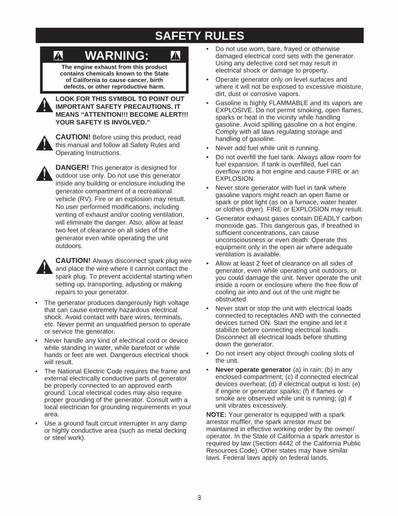
LOOK FOR THIS SYMBOL TO POINT OUTIMPORTANT SAFETY PRECAUTIONS. ITMEANS “ATTENTION!!! BECOME ALERT!!!YOUR SAFETY IS INVOLVED.”
CAUTION! Before using this product, readthis manual and follow all Safety Rules andOperating Instructions.
DANGER! This generator is designed foroutdoor use only. Do not use this generatorinside any building or enclosure including thegenerator compartment of a recreationalvehicle (RV). Fire or an explosion may result.No user performed modifications, includingventing of exhaust and/or cooling ventilation,will eliminate the danger. Also, allow at leasttwo feet of clearance on all sides of thegenerator even while operating the unitoutdoors.
CAUTION! Always disconnect spark plug wireand place the wire where it cannot contact thespark plug. To prevent accidental starting whensetting up, transporting, adjusting or makingrepairs to your generator.
• The generator produces dangerously high voltagethat can cause extremely hazardous electricalshock. Avoid contact with bare wires, terminals,etc. Never permit an unqualified person to operateor service the generator.
• Never handle any kind of electrical cord or devicewhile standing in water, while barefoot or whilehands or feet are wet. Dangerous electrical shockwill result.
• The National Electric Code requires the frame andexternal electrically conductive parts of generatorbe properly connected to an approved earthground. Local electrical codes may also requireproper grounding of the generator. Consult with alocal electrician for grounding requirements in yourarea.
• Use a ground fault circuit interrupter in any dampor highly conductive area (such as metal deckingor steel work).
• Do not use worn, bare, frayed or otherwisedamaged electrical cord sets with the generator.Using any defective cord set may result inelectrical shock or damage to property.
• Operate generator only on level surfaces andwhere it will not be exposed to excessive moisture,dirt, dust or corrosive vapors.
• Gasoline is highly FLAMMABLE and its vapors areEXPLOSIVE. Do not permit smoking, open flames,sparks or heat in the vicinity while handlinggasoline. Avoid spilling gasoline on a hot engine.Comply with all laws regulating storage andhandling of gasoline.
• Never add fuel while unit is running.• Do not overfill the fuel tank. Always allow room for
fuel expansion. If tank is overfilled, fuel canoverflow onto a hot engine and cause FIRE or anEXPLOSION.
• Never store generator with fuel in tank wheregasoline vapors might reach an open flame orspark or pilot light (as on a furnace, water heateror clothes dryer). FIRE or EXPLOSION may result.
• Generator exhaust gases contain DEADLY carbonmonoxide gas. This dangerous gas, if breathed insufficient concentrations, can causeunconsciousness or even death. Operate thisequipment only in the open air where adequateventilation is available.
• Allow at least 2 feet of clearance on all sides ofgenerator, even while operating unit outdoors, oryou could damage the unit. Never operate the unitinside a room or enclosure where the free flow ofcooling air into and out of the unit might beobstructed.
• Never start or stop the unit with electrical loadsconnected to receptacles AND with the connecteddevices turned ON. Start the engine and let itstabilize before connecting electrical loads.Disconnect all electrical loads before shuttingdown the generator.
• Do not insert any object through cooling slots ofthe unit.
• Never operate generator (a) in rain; (b) in anyenclosed compartment; (c) if connected electricaldevices overheat; (d) if electrical output is lost; (e)if engine or generator sparks; (f) if flames orsmoke are observed while unit is running; (g) ifunit vibrates excessively.
NOTE: Your generator is equipped with a sparkarrestor muffler, the spark arrestor must bemaintained in effective working order by the owner/operator. In the State of California a spark arrestor isrequired by law (Section 4442 of the California PublicResources Code). Other states may have similarlaws. Federal laws apply on federal lands.
SAFETY RULES
The engine exhaust from this product contains chemicals known to the State
of California to cause cancer, birth defects, or other reproductive harm.
WARNING:

Your generator requires some assembly and is readyfor use after it has been properly serviced with therecommended oil and fuel.
If you have any problems with the assembly ofyour generator, please call the generator helplineat 1-800-222-3136.
Important: Any attempt to run the engine before it hasbeen serviced with the recommended oil will result inan engine failure.
TO REMOVE THE GENERATORFROM CARTON• Set the palleted carton on a rigid flat surface.• Carefully cut bands around the shipping carton.• Lift carton off the generator.• Remove all packing material, carton fillers, etc.• Remove the generator from the shipping pallet.
CARTON CONTENTSCheck all contents. If any parts are missing ordamaged, call the generator helpline at1-800-222-3136. Contents include:
• 10,000 Watt generator• Battery charge cables• 3 Locking plugs• Owner’s manual• Engine oil• Battery hold down components
INSTALLING TRAY AND BATTERYNOTE: The generator can be started manually. If youchoose not to use the electric start feature of thisgenerator, you do not need to install the battery.
Purchase and install a 12 Volt DC battery (SearsDieHard 28-27135). The battery should be servicedwith electrolyte fluid and fully charged prior toinstallation.
Install the battery as follows:• Locate the battery fasteners and wires shipped
loose in the carton. Included are 7" bolts, lockwashers, flat washers, battery hold down bracket,and hex nuts. In addition you should have one M8x 1.25 inch bolt to attach the black battery cable tothe engine.
• Set battery onto tray as shown.• Secure battery with the 7" bolts, lock washers, flat
washers, hold down bracket, and hex nuts asshown.
• Connect the red battery cable to the engine starterswitch.
• Connect the red battery cable from the electricstarter switch to positive (+) post on the battery.
• Connect the black battery cable to the engine usingthe M8 x 1.25 inch bolt.
CAUTION! Be sure the black cable isconnected to the engine mount and not theframe. You could damage the ground wire.
• Connect the other end of the black battery cable tothe negative (–) battery post.
• Double check all connections to insure they are inthe correct locations.
ASSEMBLY
4
Connectblack batterycable hereusing M8 x1.25 bolt.
Connect thered batterycable to thisconnection onthe electricstarter switch.

5
KNOW YOUR GENERATORRead the owner’s manual and safety rules before operating your generator.Compare the illustrations with your generator to familiarize yourself with the locations of various controls andadjustments. Save this manual for future reference
12 Volt DC, 10 Amp Receptacle —This receptacleallows you to recharge a 12 Volt DC storage batterywith provided battery charge cable.120 Volt AC, 20 Amp Locking Receptacle —Supplies electrical power for the operation of 120 VoltAC, 20 Amp, single phase, 60 Hz electrical lighting,appliance, tool and motor loads.120 Volt AC, 20 Amp, GFCI, Duplex Receptacles —Each socket supplies electrical power for the operationof 120 Volt AC, 20 Amp, single phase, 60 Hz electricallighting, appliance, tool and motor loads. Circuits areprotected with a ground fault interrupt device.120 Volt AC, 30 Amp Locking Receptacle —Supplies electrical power for the operation of 120 VoltAC, 30 Amp, single phase, 60 Hz electrical lighting,appliance, tool and motor loads.120/240 Volt AC, 30 Amp Locking Receptacle —Supplies electrical power for the operation of120 and/or 240 Volt AC, 30 Amp, single phase, 60 Hzelectrical lighting, appliance, tool and motor loads.120/240 Volt AC, 50 Amp — Supplies electricalpower for the operation of 120/240 Volt AC, 50 Amp,single phase, 60 Hz, welder or motor loads.
Air Cleaner — Filters intake air as it is drawn into theengine.Choke Lever — Used when starting a cold engine.Circuit Breakers (AC) — Each receptacle is providedwith a circuit breaker to protect the generator againstelectrical overload. Breakers are "push to reset" type.Electric Start Button — Pressed to start the engine.Fuel Shut Off Valve — Used to stop the supply ofgasoline to the carburetor.Fuel Tank — Tank holds 10 U.S. gallons of unleadedgasoline.Grounding Lug — Used to connect unit to earthground.Hour Meter — Measures engine running time.Idle Control Switch — The idle control runs theengine at normal (high) speeds when there is a loadpresent and runs the engine at idle (low) speeds whena load is not present.Run/Stop Switch — Must be in “Run” position to startengine. Set to “Stop” to stop a running engine.Spark Arrestor Muffler — Muffler lowers enginenoise and is equipped with a spark arrestor screen.
Fuel Tank
Air Cleaner(on top of engine)
Fuel Shut-offValve
Choke Lever
Grounding Lug
Electric StartButton
Run/Stop Switch
12 Volt DC, 10 AmpReceptacle
Circuit Breakers (AC)
Hour Meter
Idle Control Switch
120/240 Volt AC,50 Amp Receptacle
120/240 Volt AC, 30 AmpLocking Receptacle120 Volt AC, 20 Amp
Locking Receptacle 120 Volt AC, 30 AmpLocking Receptacle
120 Volt AC, 20 AmpGFCI Duplex Receptacle
Spark ArrestorMuffler
OPERATION

CORD SETS AND CONNECTORPLUGS120 Volt, 20 Amp, GFCI, DuplexReceptacleThis is a 120 Volt ground fault circuit interrupter
(GFCI) outlet, consisting of a pair of receptaclesprotected against overload by a 20 Amp push-to-resetcircuit breaker. Use each receptacle to power 120 VoltAC, single phase, 60 Hz electrical loads requiring upto a combined 2400 watts (2.4 kW) or 20 Amps ofcurrent.
Use only high quality, well-insulated, 3-wire groundedcord sets rated 125 Volts at 20 Amps (or greater).Keep extension cords as short as possible, preferablyless than 15 feet long, to prevent voltage drop andpossible overheating of wires.
Ground Fault ProtectionThe generator is equipped with a Ground Fault CircuitInterrupter (GFCI). This device meets all requirementsof applicable federal, state and local codes.
The GFCI protects against electrical shock that maybe caused if your body becomes a path whichelectricity travels to reach ground. This could happen ifyou touch a “Live” appliance, or cord or are touchingplumbing or other materials that go to ground.
When protected by a GFCI, a person will still feel ashock, but the GFCI should cut it off quickly enoughso that a person in normal health should not suffer anyserious electrical injury.
DANGER: The GFCI will not protect youagainst the following situations: (1) Line-to-lineshocks; (2) Current overloads or line-to-lineshort circuits. The fuse or circuit breaker at thedistribution panel must provide such protection.
Testing the GFCI OutletTest your GFCI outlet every month. Follow theseinstructions:
1. Push the black “TEST” button. The red “RESET”button should pop out, which should disconnectpower from the outlet. Use a test lamp and testeach outlet.
DANGER: If the “RESET” button does not popout or the test lamp remains lit when the“RESET” button is popped out, do not use anyoutlets on the circuit. Call a qualified electrician.
2. If the GFCI tests good, restore power by pressingthe “RESET” button firmly until it is fully in placeand locks in that position. If the GFCI outlet doesnot reset properly, do not use the outlet — call aqualified electrician.
3. If the GFCI trips by itself at any time, reset and testthe outlet. If the reset button does pop out whenthe test button is pressed, do not use the outlet.Call a qualified electrician.
120 Volt AC, 20 Amp ReceptacleUse a NEMA L5-20 plug with this receptacle. Connecta 3-wire cord set rated for 125 Volt loads at 20 Amps(or greater) to the plug.
Use this receptacle to operate 120 Volt AC, 60 Hz,single phase loads requiring up to 2400 watts (2.4 kW)of power at 20 Amps. The outlet is protected by a20 Amp push-to-reset circuit breaker.
6
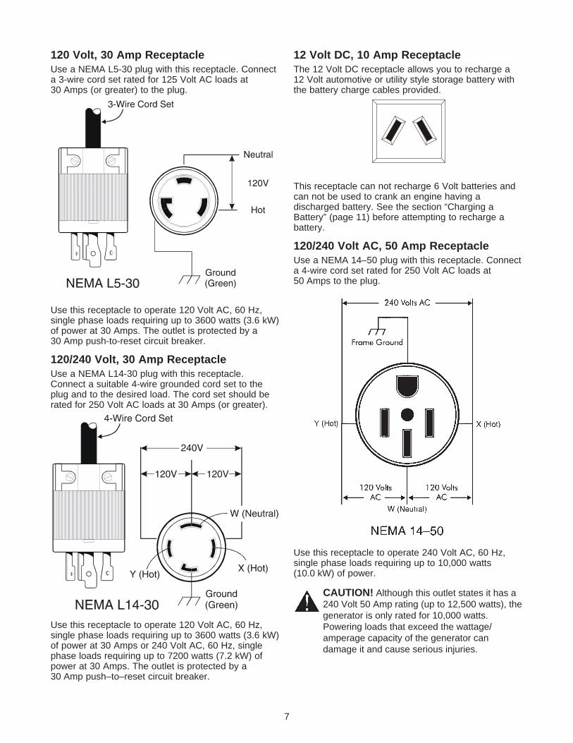
120 Volt, 30 Amp ReceptacleUse a NEMA L5-30 plug with this receptacle. Connecta 3-wire cord set rated for 125 Volt AC loads at30 Amps (or greater) to the plug.
Use this receptacle to operate 120 Volt AC, 60 Hz,single phase loads requiring up to 3600 watts (3.6 kW)of power at 30 Amps. The outlet is protected by a30 Amp push-to-reset circuit breaker.
120/240 Volt, 30 Amp ReceptacleUse a NEMA L14-30 plug with this receptacle.Connect a suitable 4-wire grounded cord set to theplug and to the desired load. The cord set should berated for 250 Volt AC loads at 30 Amps (or greater).
Use this receptacle to operate 120 Volt AC, 60 Hz,single phase loads requiring up to 3600 watts (3.6 kW)of power at 30 Amps or 240 Volt AC, 60 Hz, singlephase loads requiring up to 7200 watts (7.2 kW) ofpower at 30 Amps. The outlet is protected by a30 Amp push–to–reset circuit breaker.
12 Volt DC, 10 Amp ReceptacleThe 12 Volt DC receptacle allows you to recharge a12 Volt automotive or utility style storage battery withthe battery charge cables provided.
This receptacle can not recharge 6 Volt batteries andcan not be used to crank an engine having adischarged battery. See the section “Charging aBattery” (page 11) before attempting to recharge abattery.
120/240 Volt AC, 50 Amp ReceptacleUse a NEMA 14–50 plug with this receptacle. Connecta 4-wire cord set rated for 250 Volt AC loads at50 Amps to the plug.
Use this receptacle to operate 240 Volt AC, 60 Hz,single phase loads requiring up to 10,000 watts(10.0 kW) of power.
CAUTION! Although this outlet states it has a240 Volt 50 Amp rating (up to 12,500 watts), thegenerator is only rated for 10,000 watts.Powering loads that exceed the wattage/amperage capacity of the generator candamage it and cause serious injuries.
7

HOW TO USE YOUR GENERATORIf you have any problems operating your generator,please call the generator helpline at 1-800-222-3136.
Grounding The GeneratorThe National Electrical Code requires that theframe and external electrically conductive parts ofthis generator be properly connected to anapproved earth ground. Local electrical codes mayalso require proper grounding of the unit. For thatpurpose, a grounding lug is provided on the base ofthe cradle.
Generally, connecting a No. 12 AWG (American WireGauge) stranded copper wire to the grounding lug andto an earth-driven copper or brass grounding rod(electrode) provides adequate protection againstelectrical shock. However, local codes may varywidely. Consult with a local electrician forgrounding requirements in your area.Proper grounding of generator will help preventelectrical shock in the event of a ground faultcondition in the generator or in connected electricaldevices. Proper grounding also helps dissipate staticelectricity, which often builds up in ungroundeddevices.
Connecting Electrical Loads• Let engine stabilize and warm up for a few minutes
after starting.• Plug in and turn on the desired 120 Volt AC or
240 Volt AC, single phase, 60 Hz electrical loads.• DO NOT connect 240 Volt loads to 120 Volt
receptacles.• DO NOT connect 3-phase loads to the generator.• DO NOT connect 50 Hz loads to the generator.• Add up the rated watts (or amps) of all loads to be
connected at one time. This total should not begreater than (a) the rated wattage/amperagecapacity of the generator or (b) circuit breakerrating of the receptacle supplying the power. See“Don’t Overload the Generator” on page 12.
BEFORE STARTING THEGENERATORTo operate the generator you will need to first addengine oil and gasoline:
Add Engine OilNOTE: When adding oil to the engine crankcase inthe future, use only high quality detergent oil ratedwith API service classification SF or SG. Use nospecial additives.
Select the oil’s viscosity grade according to yourexpected operating temperature:
• Above 40°F, use SAE 10W–30 or SAE 30.• Below 40°F, use synthetic 5W–20 or 5W–30Although multi-viscosity oils (5W30, 10W30, etc.)improve starting in cold weather, these multi-viscosityoils will result in increased oil consumption when usedabove 32°F. Check your engine oil level morefrequently to avoid possible damage from running lowon oil.
• Place generator on a level surface.• Clean area around oil fill and remove oil fill cap and
dipstick.• Wipe dipstick clean.• Slowly fill engine with oil through the oil fill opening
until it reaches the full mark on the dipstick. Stopfilling occasionally to check oil level. DO NOTOVERFILL.
• Install dipstick. Install oil fill cap and hand tightensecurely.
• Check engine oil level before starting unit eachtime thereafter.
Add Gasoline
DANGER! NEVER fill fuel tank indoors.NEVER fill fuel tank when engine is running orhot. DO NOT light a cigarette or smoke whenfilling the fuel tank.
DANGER! Do not overfill the fuel tank. Alwaysleave room for expansion.
• Use regular UNLEADED gasoline in thegenerator. DO NOT use premium gasoline. DONOT mix oil with gasoline. DO NOT overfill the gastank.
• Clean area around fuel fill cap; remove cap.
8
10W–30, SAE 30
Synthetic 5W–20, 5W–30
Grounding Lug

• Fill fuel tank with clean, fresh, unleaded gasoline.Be careful not to overfill. Allow about 1/2” tankspace for fuel expansion.
• Install fuel cap and wipe up any spilled gasoline.IMPORTANT: It is important to prevent gum depositsfrom forming in essential fuel system parts such as thecarburetor, fuel filter, fuel hose or tank during storage.Also, experience indicates that alcohol-blended fuels(called gasohol, ethanol or methanol) can attractmoisture, which leads to separation and formation ofacids during storage. Acidic gas can damage the fuelsystem of an engine while in storage. To avoid engineproblems, the fuel system should be emptied beforestorage of 30 days or longer. See “Storage” onpage 17. Never use engine or carburetor cleanerproducts in the fuel tank or permanent damage mayoccur.
TO START THE ENGINE
WARNING! Never start or stop engine withelectrical devices plugged into the panelreceptacles and turned on.
• Unplug all electrical loads from generatorreceptacles before starting the engine.
• Make sure the unit is in a level position.• Open the fuel shut–off valve.
• Locate the idle control on/off switch on the controlpanel and set it to the “Off” position.
• Place the Run/Stop Switch in the “Run” position.
• Pull engine choke out to close choke. DO NOTFORCE. If the engine is warm, you may not needas much choking.
DANGER! Never run engine indoors or inenclosed poorly ventilated areas. Engineexhaust contains carbon monoxide, an odorlessand deadly gas.
DANGER! Temperature of muffler and nearbyareas may exceed 150°F (65°C). Avoid theseareas on the generator.
Electric Starting• Press the Run/Stop switch to the “RUN” position,
Press the electric start button, located on thegenerator cradle opposite the control panel, untilengine cranks.
• Use short starting cycles (15 sec. per min.) toprolong starter life. Extended cranking can damagestarter motor.
WARNING! If starting the engine with theelectric starter, always operate the engine withthe battery connected. This ensures that thebattery will be recharged.
• When the engine starts, OPEN the choke graduallyas engine warms up up by pushing in on the chokehandle.
• Set the idle control on/off switch to the “On”position.
9
OFFposition
RUNposition

10
Manual Starting• Grasp starter grip handle and pull slowly until you
feel some resistance. Then pull cord out with rapidfull arm stroke. Let rope return slowly. Do not letrope “snap back” against starter. Repeat, ifnecessary, with choke opened slightly.
• When engine starts, OPEN the choke gradually asthe engine warms up by pushing in on the chokehandle.
• Set the idle control on/off switch to the “On”position.
IMPORTANT: Do not overload the generator. Also, donot overload individual panel receptacles. Theseoutlets are protected against overload with push-to-reset-type circuit breakers. If amperage rating of anycircuit breaker is exceeded, that breaker opens andelectrical output to that receptacle is lost. Read “Don’tOverload the Generator” on page 12 carefully.
STOPPING THE ENGINE• Unplug (or turn OFF) all electrical loads connected
to generator panel receptacles. Never start or stopengine with devices plugged in and turned on.
• Turn “Off” the idle control switch.• Let engine run at no-load for 30 seconds to
stabilize the internal temperatures of engine andgenerator.
• Move run/stop switch to “Stop” position.• Close the fuel valve.
AUTOMATIC IDLE CONTROLOPERATIONThis switch is designed to greatly improve fueleconomy. When this switch is turned “On”, the enginewill only run at its normal high governed engine speedwhen an electrical load is connected. When anelectrical load is removed, the engine will run at areduced speed. With the switch “Off,” the engine runsat the normal high engine speed all the time. Alwayshave the switch off when starting and stopping theengine.
LOW OIL PRESSURE SHUTDOWNSYSTEMThe engine is equipped with a low oil pressure sensorthat shuts down the engine automatically when the oilpressure drops below 6 psi. If the engine shuts downby itself and the fuel tank has enough gasoline, checkengine oil level.
Initial Start–upA delay built in the low oil shutdown system allows oilpressure to build during starting. The delay allows theengine to run for about 10 seconds before sensing oilpressure.
Sensing Low PressureIf the system senses low oil pressure during operation,the engine shuts down.
RestartingIf you try to restart the engine within 10 seconds after itshuts down, the engine may NOT start. The systemneeds 5 to 10 seconds to reset.
If you do restart the engine after such a shutdown andhave not corrected the low oil pressure, the engineruns for about 10 seconds as described above andthen stops.
11
CHARGING A BATTERY
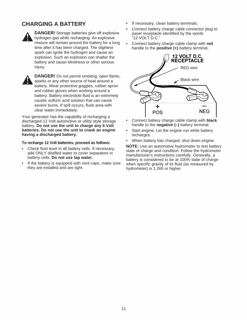
DANGER! Storage batteries give off explosivehydrogen gas while recharging. An explosivemixture will remain around the battery for a longtime after it has been charged. The slightestspark can ignite the hydrogen and cause anexplosion. Such an explosion can shatter thebattery and cause blindness or other seriousinjury.
DANGER! Do not permit smoking, open flame,sparks or any other source of heat around abattery. Wear protective goggles, rubber apronand rubber gloves when working around abattery. Battery electrolyte fluid is an extremelycaustic sulfuric acid solution that can causesevere burns. If spill occurs, flush area withclear water immediately.
Your generator has the capability of recharging adischarged 12 Volt automotive or utility style storagebattery. Do not use the unit to charge any 6 Voltbatteries. Do not use the unit to crank an enginehaving a discharged battery.
To recharge 12 Volt batteries, proceed as follows:• Check fluid level in all battery cells. If necessary,
add ONLY distilled water to cover separators inbattery cells. Do not use tap water.
• If the battery is equipped with vent caps, make surethey are installed and are tight.
• If necessary, clean battery terminals.• Connect battery charge cable connector plug to
panel receptacle identified by the words“12-VOLT D.C.”
• Connect battery charge cable clamp with redhandle to the positive (+) battery terminal.
• Connect battery charge cable clamp with blackhandle to the negative (–) battery terminal.
• Start engine. Let the engine run while batteryrecharges.
• When battery has charged, shut down engine.NOTE: Use an automotive hydrometer to test batterystate of charge and condition. Follow the hydrometermanufacturer’s instructions carefully. Generally, abattery is considered to be at 100% state of chargewhen specific gravity of its fluid (as measured byhydrometer) is 1.260 or higher.
RED wire
Black wire
12
DON’T OVERLOAD THEGENERATOROverloading a generator in excess of its rated wattagecapacity can result in damage to the generator and toconnected electrical devices. Observe the following toprevent overloading the unit:
• Add up the total wattage of all electrical devices tobe connected at one time. This total should NOT begreater than the generator’s wattage capacity.
• The rated wattage of lights can be taken from lightbulbs. The rated wattage of tools, appliances andmotors can usually be found on a data plate ordecal affixed to the device.
• If the appliance, tool or motor does not givewattage, multiply volts times ampere rating todetermine watts (volts x amps = watts).
• Some electric motors, such as induction types,require about three times more watts of power forstarting than for running. This surge of power lastsonly a few seconds when starting such motors.Make sure you allow for this high starting wattagewhen selecting electrical devices to connect to yourgenerator:1. Figure the watts needed to start the largest
motor.2. Add to that figure the running watts of all other
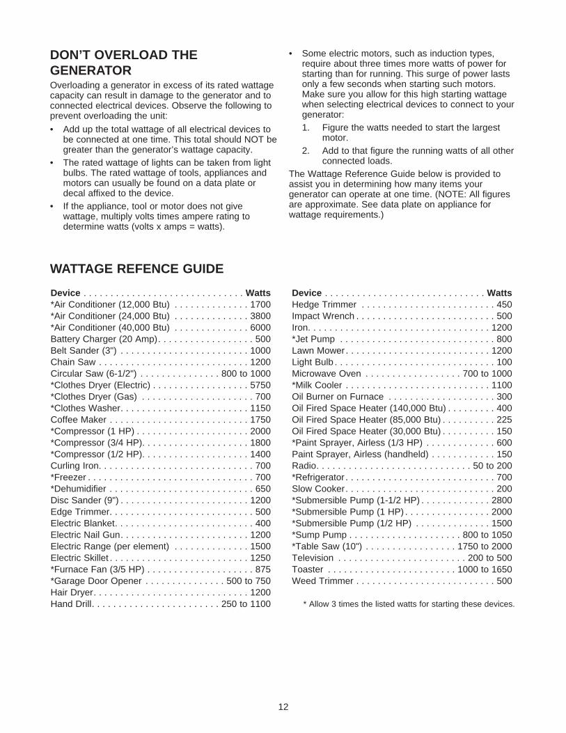
connected loads.The Wattage Reference Guide below is provided toassist you in determining how many items yourgenerator can operate at one time. (NOTE: All figuresare approximate. See data plate on appliance forwattage requirements.)
Device . . . . . . . . . . . . . . . . . . . . . . . . . . . . . . Watts*Air Conditioner (12,000 Btu) . . . . . . . . . . . . . . 1700*Air Conditioner (24,000 Btu) . . . . . . . . . . . . . . 3800*Air Conditioner (40,000 Btu) . . . . . . . . . . . . . . 6000Battery Charger (20 Amp). . . . . . . . . . . . . . . . . . 500Belt Sander (3") . . . . . . . . . . . . . . . . . . . . . . . . 1000Chain Saw . . . . . . . . . . . . . . . . . . . . . . . . . . . . 1200Circular Saw (6-1/2") . . . . . . . . . . . . . . . 800 to 1000*Clothes Dryer (Electric) . . . . . . . . . . . . . . . . . . 5750*Clothes Dryer (Gas) . . . . . . . . . . . . . . . . . . . . . 700*Clothes Washer. . . . . . . . . . . . . . . . . . . . . . . . 1150Coffee Maker . . . . . . . . . . . . . . . . . . . . . . . . . . 1750*Compressor (1 HP) . . . . . . . . . . . . . . . . . . . . . 2000*Compressor (3/4 HP). . . . . . . . . . . . . . . . . . . . 1800*Compressor (1/2 HP). . . . . . . . . . . . . . . . . . . . 1400Curling Iron. . . . . . . . . . . . . . . . . . . . . . . . . . . . . 700*Freezer . . . . . . . . . . . . . . . . . . . . . . . . . . . . . . . 700*Dehumidifier . . . . . . . . . . . . . . . . . . . . . . . . . . . 650Disc Sander (9") . . . . . . . . . . . . . . . . . . . . . . . . 1200Edge Trimmer. . . . . . . . . . . . . . . . . . . . . . . . . . . 500Electric Blanket. . . . . . . . . . . . . . . . . . . . . . . . . . 400Electric Nail Gun. . . . . . . . . . . . . . . . . . . . . . . . 1200Electric Range (per element) . . . . . . . . . . . . . . 1500Electric Skillet . . . . . . . . . . . . . . . . . . . . . . . . . . 1250*Furnace Fan (3/5 HP) . . . . . . . . . . . . . . . . . . . . 875*Garage Door Opener . . . . . . . . . . . . . . . 500 to 750Hair Dryer. . . . . . . . . . . . . . . . . . . . . . . . . . . . . 1200Hand Drill. . . . . . . . . . . . . . . . . . . . . . . . 250 to 1100
Device . . . . . . . . . . . . . . . . . . . . . . . . . . . . . . WattsHedge Trimmer . . . . . . . . . . . . . . . . . . . . . . . . . 450Impact Wrench . . . . . . . . . . . . . . . . . . . . . . . . . . 500Iron. . . . . . . . . . . . . . . . . . . . . . . . . . . . . . . . . . 1200*Jet Pump . . . . . . . . . . . . . . . . . . . . . . . . . . . . . 800Lawn Mower . . . . . . . . . . . . . . . . . . . . . . . . . . . 1200Light Bulb . . . . . . . . . . . . . . . . . . . . . . . . . . . . . . 100Microwave Oven . . . . . . . . . . . . . . . . . . 700 to 1000*Milk Cooler . . . . . . . . . . . . . . . . . . . . . . . . . . . 1100Oil Burner on Furnace . . . . . . . . . . . . . . . . . . . . 300Oil Fired Space Heater (140,000 Btu) . . . . . . . . . 400Oil Fired Space Heater (85,000 Btu) . . . . . . . . . . 225Oil Fired Space Heater (30,000 Btu) . . . . . . . . . . 150*Paint Sprayer, Airless (1/3 HP) . . . . . . . . . . . . . 600Paint Sprayer, Airless (handheld) . . . . . . . . . . . . 150Radio. . . . . . . . . . . . . . . . . . . . . . . . . . . . . 50 to 200*Refrigerator . . . . . . . . . . . . . . . . . . . . . . . . . . . . 700Slow Cooker. . . . . . . . . . . . . . . . . . . . . . . . . . . . 200*Submersible Pump (1-1/2 HP) . . . . . . . . . . . . . 2800*Submersible Pump (1 HP) . . . . . . . . . . . . . . . . 2000*Submersible Pump (1/2 HP) . . . . . . . . . . . . . . 1500*Sump Pump . . . . . . . . . . . . . . . . . . . . . 800 to 1050*Table Saw (10") . . . . . . . . . . . . . . . . . 1750 to 2000Television . . . . . . . . . . . . . . . . . . . . . . . . 200 to 500Toaster . . . . . . . . . . . . . . . . . . . . . . . . 1000 to 1650Weed Trimmer . . . . . . . . . . . . . . . . . . . . . . . . . . 500
* Allow 3 times the listed watts for starting these devices.
WATTAGE REFENCE GUIDE

PRODUCT SPECIFICATIONSGenerator SpecificationsRated Maximum Power ................10,000 Watts (10.0kW)Surge Power .................................12,500 Watts (12.5kW)Rated AC Voltage .........................120/240 Volts ACRated Maximum AC Load Current
at 240 Volts................................41.7 Amperesat 120 Volts................................83.3 Amperes
Rated Frequency ..........................60 Hz at 3600 rpmPhase Single PhaseRated DC Voltage.........................12 VoltsRated Maximum DC Load Current
at 12 Volts..................................10.0 Amperes
Engine SpecificationsRated Horsepower ........................19 at 3600 rpmDisplacement ................................570 ccSpark Plug
Type: .................................Champion RC12YC or Equivalent
Set Gap To:.......................0.030inch (0.76mm)Set Torque To: ..................200 in-lbs (22.5 N-m)
Gasoline Capacity.........................10 U.S. gallonsOil Type:
Summer.............................SAE 30 or 10W-30Winter................................Synthetic 5W-20 or
5W-30
GENERAL RECOMMENDATIONSThe generator warranty does not cover items thathave been subjected to operator abuse or negligence.To receive full value from the warranty, the operatormust maintain the generator as instructed in thismanual.
Some adjustments will need to be made periodically toproperly maintain the generator. All adjustments in theService and Adjustments section of this manual shouldbe made at least once each season. Follow therequirements in the “Maintenance Schedule” chartabove.
NOTE: Once a year you should clean or replace thespark plug and replace the air filter. A new spark plugand clean air filter assure proper fuel-air mixture andhelp your engine run better and last longer.
GENERATOR MAINTENANCEGenerator maintenance consists of keeping the unitclean and dry. Operate and store the unit in a cleandry environment where it will not be exposed toexcessive dust, dirt, moisture or any corrosive vapors.Cooling air slots in the generator must not becomeclogged with snow, leaves, or any other foreignmaterial.
Check the cleanliness of the generator frequently andclean when dust, dirt, oil, moisture or other foreignsubstances are visible on its exterior surface.
CAUTION! Never insert any object or toolthrough the air cooling slots, even if the engineis not running.
13
MAINTENANCE
‡ Change oil after first 8 hours of operation then after every 50 hours or every season.* Change oil and oil filter every 25 hours when operating under heavy load or in high temperatures.** Clean more often under dirty or dusty conditions. Replace cleaner parts if very dirty.*** Retorque head bolts only after the first 50 hours.
MAINTENANCE SCHEDULEFollow the hourly or calendar intervals, whichever occurs first.
More frequent service is required when operating in adverse conditions noted below.
Maintenance Operation Every 8 Hours or Daily
25 Hours or Every Season
50 Hours or Every Season
100 Hours or Every Season
Check Oil Level X Service Air Pre-Cleaner X** Changer Oil And Oil Filter‡ X* Clean Spark Arrestor Screen X Adjust Valve Clearance X Retorque Head Bolts X*** Service Air Cleaner X** Replace Spark Plugs X

14
NOTE: DO NOT use a garden hose to cleangenerator. Water can enter the engine fuel system andcause problems. In addition, if water enters thegenerator through cooling air slots, some water will beretained in voids and cracks of the rotor and statorwinding insulation. Water and dirt buildup on thegenerator internal windings will eventually decreasethe insulation resistance of these windings.
To Clean the Generator:• Use a damp cloth to wipe exterior surfaces clean.• A soft, bristle brush may be used to loosen caked
on dirt, oil, etc.• A vacuum cleaner may be used to pick up loose
dirt and debris.• Low pressure air (not to exceed 25 psi) may be
used to blow away dirt. Inspect cooling air slotsand openings on the generator. These openingsmust be kept clean and unobstructed.
ENGINE MAINTENANCE
DANGER! When working on the generator,always disconnect negative cable from battery.Also disconnect spark plug wires from sparkplugs and keep wires away from spark plugs.
Checking Oil LevelSee the “BEFORE STARTING THE GENERATOR”section on page 8 for information on checking the oillevel. The oil level should be checked before eachuse, or at least every eight hours of operation. Keepthe oil level properly maintained.
Changing the Oil and Oil FilterChange the oil and filter after the first eight hours ofoperation. Change the oil every 50 hoursthereafter. If you are using this engine under dirty ordusty conditions, or in extremely hot weather, changethe oil more often.
Use the following instructions to change the oil whilethe engine is still warm:1. Clean the area around the oil drain plug, remove
the plug and drain the oil completely into a suitablecontainer.
2. When the oil is drained, install and tighten the oildrain plug.
3. Place a suitable container beneath the oil filter andturn the filter counterclockwise to remove the filter.
4. Lightly coat the gasket of a new filter with freshengine oil. Turn the new filter clockwise until thegasket contacts the filter adapter, then tighten anadditional 3/4 turn.
5. Remove the oil fill cap and insert a clean funnelinto the cap opening. Slowly fill the crankcase withthe recommended oil until the oil level is at theFULL mark.
6. When the crankcase is filled to the proper level,install and tighten the oil fill cap.
Replacing the Spark PlugsUse the recommended spark plugs set to the correctair gap [0.76 mm (0.030 in.)]. Replace the plugsevery 100 hours of operation or once each year,whichever comes first. This will help your engine tostart easier and run better.
1. Stop the engine and pull the spark plug wires off ofthe spark plugs.
2. Clean around the spark plugs and remove themfrom the cylinder head.
3. Set the spark plugs’ gap to 0.76 mm (0.030 in.).Install the correctly gapped spark plugs into thecylinder heads.
Service Air CleanerYour equipment’s air cleaner is one of the mostimportant areas to maintain. This engine will not runproperly and may get damaged if it is run with a dirtyair cleaner system.
Clean the foam pre-cleaner every 25 hours ofoperation, or sooner under dusty or dirty conditions.Clean or replace the paper air filter every 50 hours ofoperation or once a year, whichever comes first.Clean or replace the filter more often if the engine isoperated under dusty or dirty conditions.
CAUTION: Never run this equipment withoutthe complete air cleaner system installed on theengine. This could result in premature wear tothe engine.
Use the following instructions to clean or replace theair cleaner components:1. Remove the cover by loosening both hold-down
straps.2. Slide the foam pre-cleaner off the cartridge.

15
3. Wash the pre-cleaner in liquid detergent and water.4. Squeeze the pre-cleaner dry with a clean cloth. DO
NOT TWIST.5. Prelube the pre-cleaner with clean motor oil.6. Squeeze the pre-cleaner in a clean cloth to remove
excess oil. DO NOT TWIST.7. Remove the knob and plate. Tap the cartridge
gently on a solid surface to loosen and removetrapped particles.
NOTE: If the filter is too dirty, it must be replaced.
8. Reinstall the pre-cleaner over the cartridge.9. Reinstall the air cleaner assembly.10.Reinstall the plate, knob and cover.NOTE: If you need to order a new air filter, please call1-800-366-7278.
Clean Spark Arrestor ScreenThe engine exhaust muffler has a spark arrestorscreen. Inspect and clean the screen every 50hours of operation or once each year, whichevercomes first.NOTE: If you use your generator on any forest-covered, brush-covered or grass-covered unimprovedland, it must have a spark arrestor. The spark arrestormust be maintained in good condition by the owner/operator. The proceeding is required by the law in thestate of California. Other states may have similar laws.Federal laws apply on federal lands.
WARNING: Let the muffler cool before workingon it. Contact with a hot muffler or engine cancause severe burns.
To clean and inspect the spark arrestor:• Remove four screws that attach the spark arrestor
screen.
• Inspect screen and replace if torn, perforated orotherwise damaged. DO NOT USE a defectivescreen. If screen is not damaged, clean it withcommercial solvent.
• Reattach the screen with four screws.
Engine Governed Speed
CAUTION! The engine speed was properlyadjusted at the factory and should require noadditional adjustment. Do not attempt to changeengine speed. If you believe the engine isrunning too fast or too slow, take your engine toan authorized service center for repair andadjustment. CHANGING THE ENGINEGOVERNED SPEED WILL VOID THE ENGINEWARRANTY.
Your engine runs at a constant speed. This constantoperating speed is maintained by a mechanical fixedspeed governor. DO NOT try to adjust the governedspeed setting for the following reasons:
• Operating the engine at high engine speeds isdangerous and increases the risk of personal injuryor damage to the equipment.
• Operating the engine at low engine speeds withheavy loads may shorten the engine’s life.
Incorrect speed settings also affects electricaloperation of your generator as follows:
• Operating at high speeds results in an over-frequency and over-voltage condition.
• Operating at low speeds causes an under-frequency and under-voltage condition.
IMPORTANT: Incorrect frequency and/or voltage maydamage some connected electrical loads.
If you suspect engine speed is incorrect, take thegenerator to an authorized service facility forrepair and adjustment.

16
Carburetor AdjustmentsYour engine carburetor is preset at the factory. Thecarburetor should not be tampered with because thiswill void the emission control system warranty. If youexperience problems or your engine is used at analtitude in excess of 5,000 feet, contact the nearestauthorized dealer regarding high altitude settingchanges.
Check/Adjust Valve to Rocker ArmClearanceEvery 50 hours of operation, remove the rockercover and check the valve to rocker arm clearance.Important: If you feel uncomfortable about doing thisprocedure or you don’t have the proper tools, pleasetake your generator in to the nearest service center tohave the valve clearance adjusted. This is a veryimportant step to insure the longest life for yourengine.
When adjusting the clearance, the engine should be atroom temperature, and each piston should be at topdead center (TDC) of its compression stroke (bothvalves are closed). The correct clearance is0.10-0.15 mm (0.004-0.006 in.). Check and adjust thevalve to rocker arm clearance as follows:
1. Remove the two nuts and seals from the valvecovers.
2. Remove the valve covers and gaskets.3. With the spark plugs removed, rotate the crankshaft
until the piston in the cylinder you are checking is atTDC of its compression stroke (both valves areclosed).
4. Place a caliper end through the spark plug hole andcontinue turning the crankshaft until the piston hasmoved 1/4 inch past TDC.
5. Check the valve clearance with a feeler gagebetween the valve stem and rocker arm.
6. Adjust the valve so clearance is 0.1-0.15 mm(0.004-0.006 in.) for both intake and exhaustvalves.
7. Tighten each lock nut while holding the adjustingscrew. Torque the lock nut to 7 N-m (60 in.-lbs).
8. Reinstall the valve cover gaskets, valve covers,seals and nuts. Torque the nuts to 3 N-m(25 in.-lbs).
Retorque the Head Bolts
After the first 50 hours of operation, retorque the headbolts.NOTE: Only perform this adjustment after the first50 hours of operation. The head bolts will need nofurther adjustment.
Important: If you feel uncomfortable about doing thisprocedure or you don’t have the proper tools, pleasetake your generator in to the nearest service center tohave the valve clearance adjusted. This is a veryimportant step to insure the longest life for yourengine.
1. Remove the valve covers as described previously.2. Torque the head bolts in the sequence shown
below to 19 N-m (165 in.-lbs).
3. Reinstall the valve cover gaskets and valve coversas described previously.

17
STORAGEGENERALThe generator should be started at least once everyseven days and allowed to run at least 30 minutes. Ifthis cannot be done and you must store the unit formore than 30 days, use the following information as aguide to prepare it for storage.
DANGER! NEVER store engine with fuel intank indoors or in enclosed, poorly ventilatedareas where fumes may reach an open flame,spark or pilot light as on a furnace, waterheater, clothes dryer or other gas appliance.
LONG TERM STORAGEIt is important to prevent gum deposits from forming inessential fuel system parts such as the carburetor, fuelhose or tank during storage. Also, experienceindicates that alcohol-blended fuels (called gasohol,ethanol or methanol) can attract moisture, which leadsto separation and formation of acids during storage.Acidic gas can damage the fuel system of an enginewhile in storage.
To avoid engine problems, the fuel system should beemptied before storage of 30 days or longer, asfollows:
• Remove all gasoline from the fuel tank.
DANGER! Drain fuel into approved containeroutdoors, away from open flame. Be sureengine is cool. Do not smoke.
• Start and run engine until engine stops from lack offuel.
• Disconnect negative battery cable from battery.• While engine is still warm, drain oil from crankcase.
Refill with recommended grade.• Remove spark plug and pour about 1/2 ounce
(15 ml) of engine oil into the cylinder. Cover sparkplug hole with rag. Pull recoil starter slowly todistribute oil.
CAUTION! Avoid spray from spark plug holewhen cranking engine.
• Install and tighten spark plug. Do not connect sparkplug wire.
• Clean the generator outer surfaces. Check thatcooling air slots and openings on generator areopen and unobstructed.
• Store the unit in a clean, dry place.
OTHER STORAGE TIPS:• Do not store gasoline from one season to another.• Replace your gasoline can if your can starts to rust.
Rust and/or dirt in your gasoline will causeproblems.
• If possible, store your unit indoors and cover it togive protection from dust and dirt. BE SURE TOEMPTY THE FUEL TANK.
• Cover your unit with a suitable protective cover thatdoes not retain moisture.
DANGER! NEVER cover your generator whileengine and exhaust area are warm.

18
TROUBLESHOOTING
Problem Cause Solution
Engine is running, but no AC output is available.
1. Circuit breaker is open. 2. Poor connection or defective
cord set. 3. Connected device is bad.
4. Fault in generator.
1. Reset circuit breaker. 2. Check and repair.
3. Connect another device that is in
good condition. 4. Contact Sears service facility.
Engine runs good but bogs down when loads are connected.
1. Short circuit in a connected load.
2. Generator is overloaded.
3. Engine speed is too slow. 4. Shorted generator circuit.
1. Disconnect shorted electrical load.
2. Read “Don’t Overload the Generator” on page 12.
3. Contact Sears service facility. 4. Contact Sears service facility.
Engine will not start; or starts and runs rough.
1. Run/Stop switch set to “Stop”. 2. Dirty air cleaner. 3. Out of gasoline. 4. Battery is dead. 5. Stale gasoline.
6. Spark plug wire not connected
to spark plug. 7. Bad spark plug. 8. Water in gasoline.
9. Over choking.
10. Low oil level. 11. Excessively rich fuel mixture. 12. Intake valve stuck open or
closed. 13. Engine has lost compression.
1. Set switch to “Run”. 2. Clean or replace air cleaner. 3. Fill fuel tank. 4. Recharge or replace battery. 5. Drain gas tank and fill with fresh
fuel. 6. Connect wire to spark plug.
7. Replace spark plug. 8. Drain gas tank; fill with fresh
fuel. 9. Put choke lever to “no choke”
position. 10. Fill crankcase to proper level. 11. Contact Sears Service facility. 12. Contact Sears Service facility.
13. Contact Sears Service facility.
Engine shuts down during operation.
1. Out of gasoline. 2. Low oil level. 3. Fault in engine.
1. Fill fuel tank. 2. Fill crankcase to proper level. 3. Contact Sears service facility.
Engine lacks power.
1. Load is too high.
2. Dirty air filter. 3. Engine needs to be serviced.
1. Read “Don’t Overload the Generator” on page 12.
2. Replace air filter. 3. Contact Sears Service facility.
Engine “hunts” or falters.
1. Choke is opened too soon.
2. Carburetor is running too rich or too lean.
1. Move choke to halfway position till engine runs smoothly.
2. Contact Sears Service facility.
No Battery Charge DC Output.
1. Battery posts are corroded. 2. Battery fluid level is low. 3. Battery cable is bad. 4. Battery is defective.
5. Receptacle is bad.
1. Clean battery posts. 2. Add distilled water to battery. 3. Replace cable. 4. Check battery condition; replace
if defective. 5. Contact Sears Service facility.

19
NOTES
20
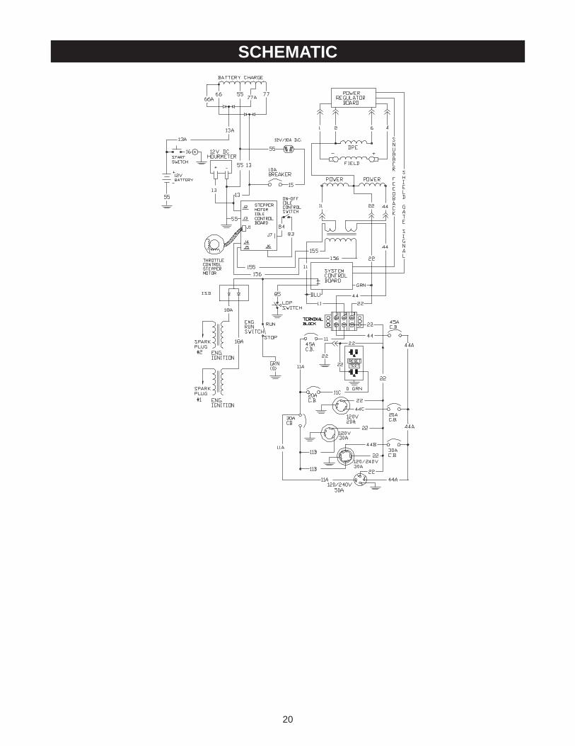
SCHEMATIC

21
WIRING DIAGRAM

22
CRAFTSMAN 10000 Watt AC Generator 580.327203Main Unit — Exploded View
900

CRAFTSMAN 10000 Watt AC Generator 580.327203Main Unit — Parts List
23
Item Part # Qty Description1 B4653 1 ASSEMBLY, Control Panel2 22237 16 LOCK WASHER, 3/8"3 22241 8 NUT, 3/8-16 Hex4 86292 7 SELF DRILLER, 10-16 x 3/4"5 B2758 1 DECAL, Control Panel6 62265 2 GROMMET, Rubber7 22097 9 LOCK WASHER, 1/4"8 22127 6 NUT, 1/4"-20 Hex9 18453621 1 WIRE ASSEMBLY, Ground
10 B84650 1 TRAY, Battery11 22473 2 FLAT WASHER, 1/4"12 45000 2 HHMS, 1/4-20" NC x 7"13 B44951 1 BRACKET, Hold-Down14 22261 1 SHAKEPROOF, 3/8" Internal15 23762 1 WASHER, #10 Shakeproof16 18553621 1 ASSEMBLY, Ground Wire17 38353 8 MOUNTS, Vibration18 23152 8 HHCS, 3/8-16 x 3/4"19 B90916 1 HEAT SHIELD, Stator20 56892 3 CRIMPTITE, 10-24 x 3/8"21 NSP 1 DECAL, Data Plate22 B2757 1 DECAL, Side Panel23 73054 1 DECAL, Fuel Shut Off24 BB4137 1 CRADLE25 B93074 1 SHIELD, Heat26 78299 1 BUSHING, Tank27 80270 1 VALVE, Plastic Tank28 B1696 1 TANK, Fuel29 B4325 1 CAP, Fuel Gauge30 78831B 4 HHCS, M6-1.0 x 60mm31 83465 4 GROMMET, Tank Mounting32 22287 2 HHCS, 1/4"-20 x 3/4"33 78289 1 BRACKET, Starter Switch34 77282 1 SWITCH, Starter35 18253621 1 WIRE ASSEMBLY, Starter36 18353621 1 WIRE ASSEMBLY, Battery37 96867 1 ASSEMBLY, Stepper Motor38 22129 2 LOCK WASHER, 5/16 -M839 39253 2 HHCS, M8-1.25 x 2040 79661P 1 DECAL, Engine
Item Part # Qty Description41 92982 1 DECAL, Danger42 93826 1 DECAL, Start Instruction44 77816 1 DECAL, Caution Hot Muffler45 46852 2 TAPTITE, #10-32 x 1/4"46 93841 1 SHIELD, Oil Sensor Heat47 90914 1 ADAPTER, Oil Filter48 70185 1 FILTER, Oil49 40945 3 SHCS, M6-1.0 x 2050 60108 1 SWITCH, Low Oil Pressure51 B77304 2 SUPPORT, Engine52 75246 4 TAPTITE, 3/8-16 x 1-1/4"53 68548 1 GASKET, Oil Filter Adapter54 33141 1 HHCS, #10-32 x 3/4" 55 95921 1 LINKAGE, Bell Crank to
Throttle56 49226 1 LOCK WASHER, M557 95348 1 BELL, Crank58 95920 1 LINKAGE, Stepper Motor to
Bell Crank59 96717 1 SPRING, Step Motor Control60 95349 1 PLATE, Idle Control Adjust61 75477 2 PPHMS, M5-0.8 x 2062 96716 3 WASHER, Nylon63 96378 1 SPACER, Step Motor Link64 51713 1 FLAT WASHER, M565 B4901 1 DECAL, 1-800-4-MyHome66 20566 1 DECAL, 1-800
900 NSP 1 Engine, 19HP, Briggs &Stratton, 350445-1162-E1
Parts Not IllustratedB4659 1 Owners manual65787 1 Battery charge cableAB3061 2 Oil, 28oz. SAE 3037806 1 120 Volt, 30 Amp locking plug43438 1 240 Volt, 30 Amp locking plug93568 1 120 Volt, 20 Amp locking plug
Optional Accessories Not Illustrated09-32688 Cord Wrap Kit

24
CRAFTSMAN 10000 Watt AC Generator 580.327203Power Head Assembly — Exploded View and Parts List
Item Part # Qty Description2 B55277 1 GUARD, Center3 B71791 1 PLATE, Cover4 46852 8 SCREW, No. 10-32 x 1/4"5 22129 11 WASHER, 5/16" Lock6 86307 2 CAPSCREW, 5/16"-24 x 3/4"
Hex Head7 B55275 3 GUARD, Fan8 BB2700 1 CASTING, Adapter9 24114 4 NUT, 5/16-24" Hex
10 22237 4 WASHER, 3/8" Lock11 23152 4 CAPSCREW, 3/8"-16 x 3/4"
Hex Head12 92381 1 ASSEMBLY, Rotor 10-KW13 65791 1 BEARING
Item Part # Qty Description14 50190 1 WASHER, 5/16" Flat15 53365 1 CAPSCREW, 5/16"-24 x
10.75" Hex Head16 B94983 1 ASSEMBLY, Stator 10-KW17 B49410A 1 CARRIER, Rear Bearing18 77324 4 CAPSCREW, 5/16"-24 x 12.25
Hex Head19 B77303 1 SUPPORT, Alternator20 66849A 2 SCREW, M5-0.8 x 20 Taptite21 96423 1 SCREEN, Finger Guard22 92769 1 ASSEMBLY, Power Regulator
900 NSP 1 Engine, 19HP, Briggs &Stratton, 350445-1162-E1
900

25
CRAFTSMAN 10000 Watt AC Generator 580.327203Control Panel — Exploded View and Parts List
Item Part # Qty Description1 95941 1 PANEL, Control2 23897 5 FLAT WASHER, #10 - M53 91526 4 PPHMS, M5 - .08 x 12mm4 49226 5 LOCK WASHER, M55 82538 1 SWITCH, On - Off6 90418 1 OUTLET, 12V DC Snap7 78653 1 SWITCH, Run - Stop8 77604 1 HOURMETER9 51714 2 NUT, M3 - 0.5 Hex
10 23365 12 WASHER, #8 Shakeproof11 80409 1 OUTLET, 120V, 20 Amp
Duplex GFCI12 38150 12 FLAT WASHER, #813 22264 16 LOCK WASHER, #814 51715 12 NUT, M4 - 0.7 Hex15 75207 2 CIRCUIT BREAKER, 20 Amp16 75207-A 2 CIRCUIT BREAKER, 30 Amp17 74190 1 OUTLET, 120V/20A locking18 68868 1 OUTLET, 120V, 30 Amp
locking19 B4455 2 CIRCUIT BREAKER, 45 Amp20 B4262 1 OUTLET, 120/250V, 50 Amp
Item Part # Qty Description21 43437 1 OUTLET, 120/240V, 30 Amp
locking22 80077 4 PPHMS, M4 x 20mm23 92953 1 BLOCK, 50 Amp, 3 - Terminal24 96067 1 ASSEMBLY, Engine Harness25 84135 1 GROMMET, Rubber26 87962 1 CIRCUIT BREAKER27 43181 4 PHMS, M3 - .05 x 10mm28 43182 2 LOCK WASHER, M329 84028 1 TRANSFORMER, Idle Control30 93986 4 PPHMS, M3 - 0.5 x 20mm31 94117 1 ASSY., Idle Control32 93929 4 STAND OFF, 1/2" Hex33 79224 1 PPHMS, M5 - 0.8 x 30mm34 65795 2 RECTIFIER, Battery Charge35 B95906 1 BOX, Control Panel36 51716 1 NUT M5 - 0.8 Hex37 90576 1 GROMMET, Rubber38 96476 1 BOARD, System Control39 64526 8 PHTS, #6-32 x 3/8"40 64525 4 STAND-OFF, 3/4" Hex

26
Engine – 19HP Briggs & Stratton, 350445-1162-E1Exploded View and Parts List

27
Engine – 19HP Briggs & Stratton, 350445-1162-E1Exploded View and Parts List

28
Engine – 19HP Briggs & Stratton, 350445-1162-E1Exploded View and Parts List

29
Engine – 19HP Briggs & Stratton, 350445-1162-E1Exploded View and Parts List

30
Engine – 19HP Briggs & Stratton, 350445-1162-E1Exploded View and Parts List

31
Engine – 19HP Briggs & Stratton, 350445-1162-E1Exploded View and Parts List

32
Item Part # Description1 100-92134 Cylinder Assembly2 100-85110 Bushing3 67805* Seal, Oil5 101-92134 Head, Cylinder #1
5A 102-92134 Head, Cylinder #27 103-92134*+ Gasket, Cylinder Head8 104-85110 Breather Assembly9 72315* Gasket, Breather (incl. #722)
10 105-85110 Screw, Shoulder11 70596 Tube, Breather12 69336* Gasket, Crankcase13 69325 Screw, Hex15 67888 Plug, Oil Drain16 104-92134 Crankshaft
106-85110 Timing Gear Key107-85110 Thrust Washer
17 108-85110 Bearing, Ball18 70540 Cover, Crankcase20 67924* Seal, Oil22 109-85110 Screw, Hex23 106-92134 Flywheel24 112-85110 Key, Flywheel25 107-92134 Piston Assembly (std)
108-92134 Piston Assembly (.010 o/s)109-92134 Piston Assembly (.020 o/s)110-92134 Piston Assembly (.030 o/s)
26 111-92134 Ring Set (std)112-92134 Ring Set (.010 o/s)113-92134 Ring Set (.020 o/s)114-92134 Ring Set (.030 o/s)
27 69327 Lock Pin, Piston28 115-92134 Pin, Piston29 119-85110 Rod, Connecting (std)
120-85110 Rod, Connecting (.020 o/s)32 72346 Screw, Hex33 69316 Valve, Exhaust34 69317 Valve, Intake35 121-85110 Spring, Valve37 102-85109 Guard, Flywheel39 123-85110 Deflector, Oil40 69320 Retainer, Valve42 70513 Keeper, Valve45 124-85110 Tappet, Valve46 70530 Gear, Cam50 125-85110 Manifold, Intake
50A 103-85109 Manifold, Exhaust (man. start)50B 69370 Manifold, Exhaust (elec. start)51 127-85110* Gasket, Intake52 67895*+ Gasket53 128-85110 Screw, Hex54 67158 HHCS/LW M8-1.25 x 65 mm55 129-85110 Housing, Rewind Starter56 130-85110 Pulley, Rewind Starter57 131-85110 Spring, Rewind Starter58 132-85110 Rope, Starter59 133-85110 Insert, Starter Grip60 134-85110 Grip, Starter Rope
Item Part # Description84 135-85110 Plug, Pipe87 68554 Seal, Governor Shaft91 118-92134 Body Assembly, Upper94 119-92134@ Valve, Idle Adjustment95 138-85110 Screw, Slotted98 139-85110 Screw, Idle Speed
102 140-85110@ Gasket, Carburetor Body103 79264 Float, Carburetor104 141-85110@ Pin, Float Hinge105 142-85110@ Valve, Needle108 120-92134 Valve, Choke110 121-92134@ Washer116 70506* Seal, O-Ring
116A 68573* Seal, O-Ring116B 70541* Seal, O-Ring117 122-92134@ Jet, Main119 145-85110 Screw, Slotted121 123-92134 Carburetor Kit122 124-92134 Spacer125 125-92134 Carburetor127 147-85110@ Plug, Welch130 126-92134 Valve,Throttle131 127-92134 Shaft, Throttle141 128-92134 Shaft, Choke147 129-92134 Jet, Slow Speed161 86443 Base, Air Cleaner166 70131 Stud, Hex Drive
166A 151-85110 Stud, Hex Drive167 75253*+ Washer171 67885+ Nut, Lock M6187 AA-47662 Line, Fuel188 39253 HHCS M8-1.25 x 20 mm189 22129 Washer, Lock 5/16-M8192 75254 Screw, Valve Adjust201 74946 Link206 152-85110 Nut207 153-85110 Spring, Control Rod208 154-85110 Rod Control209 77348 Spring, Governor
209A 79282 Spring, Governor Idler216 157-85110 Link
216A 158-85110 Rod, Choke222 130-92134 Bracket, Control227 72320 Lever, Governor232 70125 Spring, Link239 60108 Switch, Oil Pressure240 160-85110 Filter, Fuel243 70531 Screen, Oil Pump265 131-92134 Clamp, Casing271 161-85110 Lever, Control277 67884 Washer, Flat M6
277A 132-92134 Washer280 163-85110 Bracket, Rod284 39253 HHCS M8-1.25 x 20 mm300 164-85110 Muffler, Exhaust304 133-92134 Housing, Blower305 66886 HHCS/LW M6-1.0 x 12 mm
Engine – 19HP Briggs & Stratton, 350445-1162-E1Exploded View and Parts List

33
Item Part # Description307 67898 HHCS/LW M8-1.25 x 16 mm
307A 105-85109 Screw, Hex308 168-85110 Cover, Air Guide (cyl #1)
308A 169-85110 Cover, Air Guide (cyl #2)309 170-85110 Motor, Starter310 75256 Screw, Hex332 171-85110 Nut, Flywheel333 67891 Armature, Magneto334 72356 HHCS/LW M4 x 7 mm337 72347 Plug, Spark346 134-92134 Screw, Hex351 20169 Screw,Phillips Hex
351A 173-85110 Screw, Hex353 174-85110 Washer, Lock
353A 175-85110 Washer, Lock354A 176-85110 Nut, Hex356 193-85110 Wire, Stop
356A 137-92134 Wire, Stop357 138-92134 Key, Drive Pulley358 139-92134 Gasket, Set363 177-85110 Flywheel Puller383 178-85110 Wrench, Spark Plug423 66484 Screw, Phillips Hex445 86444 Filter, Air455 140-92134 Cup, Flywheel456 180-85110 Retainer459 181-85110 Dog, Starter461 182-85110 Screw, Retainer467 86445 Knob478 212-85110 Cover, Carburetor503 183-85110 Strap, Starter510 75260 Drive, Starter513 75261 Clutch, Drive515 184-85110 Spring, Dog520 185-85110 Terminal523 70158 Dipstick524 67181 Seal, Oil525 70151 Tube, Oil Fill526 187-85110 Screw, Phillips Hex529 143-92134 Extension, Breather535 188-85110 Filter, Air537 189-85110* Gasket, Air Cleaner539 190-85110 Clip Rod544 75269 Armature, Starter552 72361 Bushing, Crank
552A 72362 Bushing, Crank562 191-85110 Bolt, Carriage572 70199 Baffle, Breather573 192-85110 Plate, Back592 72321 Nut, Hex M6-1.0601 70162 Clamp, Hose608 106-85109 Starter, Rewind613 69397 HHCS/LW M8-1.25 x 20 mm614 194-85110 Pin, Cotter615 195-85110 Ring, Retaining616 72367 Crank, Governor634 72365 Washer, Gov. Shaft
634A 216-85110@ Collar, Throttle
Item Part # Description634B 197-85110@ Collar, Choke634C 145-92134@ Seal,Shaft635 70562 Boot, Spark Plug642 86447 Cover, Air Cleaner643 86448 Retainer, Air Filter657 67820 Screw, Phillips688 198-85110 Cap, Spring718 68555 Dowel, Crankcase722 sold w/#9 ONLYO-Ring726 200-85110 Gear, Ring727 201-85110 Cover, Starter Drive
729A 202-85110 Grommet729B 203-85110 Clip, Wire741 204-85110 Gear, Timing783 75264 Gear, Starter801 75265 Cap, Drive802 205-85110 Cap, End803 206-85110 Housing, Starter819 68572 HHCS M6-1.0 x 30 mm823 70542 HHCS/LW M6 x 16 mm842 207-85110 Seal, O-Ring851 75272 Terminal, Cable862 86449 Strap, Air Cleaner Mounting863 107-85109 Bracket, Muffler (man. start)
863A 209-85110 Bracket, Muffler (elec. start)866 210-85110 Cover, Air Guide868 70122 Seal, Valve Guide871 67813 Bushing, Guide876 211-85110 Kit, Gear883 67897*+ Gasket, Exhaust884 213-85110 Clamp896 214-85110 Pin, Roll915 67195 Liner, Port955 147-92134 Plug978 68548 Gasket, Oil Filter982 68527 HHCS/LW M6-1.0 x 20 mm985 215-85110 Insulator994 217-85110 Arrestor, Spark
1004 218-85110 Duct, Air1005 148-92134 Fan, Flywheel1006 149-92134 Retainer, Fan1014 150-92134 Shield, Carburetor1022 220-85110*+ Gasket, rocker Cover1023 69328 Cover, Rocker1024 70539 Pump, Oil1025 70536 Spool, Governor1026 70577 Rod, Push (steel, intake)1026 80009 Rod, Push (aluminum,
exhaust)1027 222-85110 Filter, Oil1029 224-85110 Arm, Rocker1033 101-93571 Kit, Valve Overhaul1054 227-85110 Tie, Cable1091 229-85110@ Cap, Limiter1100 230-85110 Pivot, Rocker, Arm
* Included in Gasket Set (139-92134)+ Included in Valve Overhaul Kit (101-93571)@ Included in Carburetor Kit (123-92134)
Engine – 19HP Briggs & Stratton, 350445-1162-E1Exploded View and Parts List

34
EMISSION CONTROL SYSTEM WARRANTYCALIFORNIA AND FEDERAL EMISSION CONTROLWARRANTY STATEMENT
Your Warranty Rights and Obligations
The California Air Resources Board (CARB), United StatesEnvironmental Protection Agency (EPA), and Sears Roebuck andCo. USA (Sears) are pleased to explain the emissions controlsystem warranty on your 1997 and later “utility and lawn andgarden equipment engine” (referred to as ‘engine’). New enginesmust be designed, built, and equipped to meet both the State ofCalifornia and Federal stringent anti-smog standards. Sears mustwarrant the emission control system on your engine for the periodsof time listed below provided there has been no abuse, neglect, orimproper maintenance of your engine.
The emissions control system may include parts such as thecarburetor, ignition and exhaust systems. When a warrantablecondition occurs, Sears will repair your engine at no cost to you.Expenses covered under warranty include diagnosis, replacementparts and labor.
Manufacturer’s Warranty Coverage
The 1997 and later engines are warranted for two years. If anyemission related component or system on your engine (as listedbelow) is found to be defective, repairs or replacement will beperformed by an authorized Sears service center.
Owner’s Warranty Responsibilities
As the engine owner, you are responsible for the completion of allrequired maintenance as listed in your factory supplied owner'smanual. For warranty purposes Sears recommends that you retainall receipts covering maintenance on your engine. However, Searscannot deny warranty solely because of the lack of receipts or foryour failure to ensure the completion of all scheduled maintenance.
As the engine owner, you should be aware that Sears may denyany and/or all warranty coverage or responsibility if your engine ora part/component of it has failed due to abuse, neglect, impropermaintenance, unapproved modifications, or the use of counterfeitand/or ‘grey-market’ parts not made, supplied or approved by theoriginal equipment manufacturer.
You are responsible for presenting your engine to a Searsauthorized service center as soon as a problem occurs. Warrantyrepairs should be completed in a reasonable amount of time, not toexceed 30 days.
If you have any questions regarding your warranty rights andresponsibilities, you should contact your nearest authorized servicecenter or call Sears at 1-800-473-7247.
Warranty Commencement Date
The warranty period begins on the date the engine is delivered tothe original, end-use purchaser.
Length of Coverage
Sears warrants to the initial owner and each subsequent purchaserthat the engine is free from defects in materials and workmanshipwhich cause the failure of a warranted part for a period of twoyears.
What is Covered
Repair or Replacement of Parts
Repair or replacement of any warranted part will be performed atno charge to the owner at an approved Sears service center. If youhave any questions regarding your warranty rights andresponsibilities, you should contact your nearest authorized servicecenter or call Sears at 1-800-473-7247.
Warranty Period
Any warranted part which is not scheduled for replacement asrequired maintenance shall be warranted for 2 years. Anywarranted part which is scheduled only for regular inspection and/orhas instructions to the effect of “repair or replace as necessary”shall also be warranted for 2 years. Any warranted part which isscheduled for replacement as required maintenance shall bewarranted either for the period of time up to its first scheduledreplacement, or for 2 years, whichever comes sooner.
Diagnosis
When the engine is inspected by an authorized Sears servicecenter, the owner shall not be held responsible for diagnostic costsif the repair is deemed warrantable.
Consequential Damages
Sears may be liable for damages to other engine componentscaused by the failure of a warranted part if the failed part was stillunder warranty.
What is not covered
Owner Responsibilities
Any failures caused by abuse, neglect, or improper maintenancewill not be covered.
Add–On or Modified Parts
The use of add-on, unauthorized or modified parts constitutessufficient reason for denial of submitted warranty repairs. Sears willnot be held liable for repairs of this type.
How to FIle a Claim
If you have any questions regarding your warranty rights andresponsibilities, you should contact your nearest authorized servicecenter or call Sears at 1-800-473-7247.
Where to get Warranty Service
Warranty services or repairs shall be provided at all Searsauthorized service centers.
Maintenance, Replacement and Repair of Emission RelatedParts
Any Sears approved replacement part used in the performance ofany warranty maintenance or repair on emission related parts willbe provided without charge to the owner if the part is underwarranty.
Emission Control Warranty Parts List
1. Fuel Metering System:
a. Carburetor assembly
b. Fuel filter
2. Air Induction System:
a. Intake manifold
b. Air cleaner
3. Catalytic Muffler Assembly (if so equipped), including:
a. Muffler gasket
b. Exhaust manifold
4. Ignition System
a. Spark plug
b. Ignition module
5. Crankcase Breather Tube

35
NOTES

36
TABLA DE CONTENIDOSGarantía . . . . . . . . . . . . . . . . . . . . . . . . . . . . . . . . . . . . . 36Reglas de Seguridad . . . . . . . . . . . . . . . . . . . . . . . . . . . 37Montaje . . . . . . . . . . . . . . . . . . . . . . . . . . . . . . . . . . . . . 38Funcionamiento . . . . . . . . . . . . . . . . . . . . . . . . . . . . . 39-46Especificaciones del Producto. . . . . . . . . . . . . . . . . . . . . 47
Mantenimiento . . . . . . . . . . . . . . . . . . . . . . . . . . . . . . 47-50Almacenamiento . . . . . . . . . . . . . . . . . . . . . . . . . . . . . . . 51Reparacion de Averías . . . . . . . . . . . . . . . . . . . . . . . . . . 52Garantía de Emisiones. . . . . . . . . . . . . . . . . . . . . . . . 53-54Como ordenar partes . . . . . . . . . . . . . . . . . . Ultima Página
GARANTIA LIMITADA PARA GENERADORES PORTATILES DE LUJOSEARS le garantiza al comprador original que el alternador y el motor de su generador portátil estará libre de defectos enmateriales y mano de obra en los componentes y por el período de tiempo establecido a continuación a partir de la fecha decompra original. Esta garantía no es transferible y únicamente se aplica a generadores portátiles accionados por el motorgarantizado Sears Serie GN.
CLIENTE* COMERCIAL*Alternador 2 años (2do año únicamente las partes) 1 año
Motor 2 años (2do año únicamente las partes) 1 año
* NOTA: Para propósitos de esta garantía el término “Uso del Cliente” representa el uso doméstico residencial y deemergencia por parte del comprador original, sin incluir aplicaciones donde la unidad sea usada como fuente de potenciaprincipal. El término “Uso Comercial” representa todos los otros usos, incluyendo alquiler, construcción, comercial y parapropósitos lucrativos. Una vez el generador haya tenido uso comercial, éste será considerado como un generador para usocomercial para los fines de esta garantía.
Durante dicho período de garantía, SEARS reparará o reemplazará, a su discreción, cualquier parte que haya sidoencontrada defectuosa, en examen previo realizado por SEARS, bajo uso y servicio normal**. Las baterías de arranque noestán garantizadas por SEARS. Todos los costos de transporte bajo garantía, incluyendo el envío a la fábrica, de sernecesario, serán responsabilidad del comprador y deberán ser pagados por anticipado. Esta garantía no cubre elmantenimiento y servicio normal y no se aplica a juegos de generadores, alternador, motor o partes que hayan sido sujetosa instalaciones o modificaciones incorrectas o no autorizadas, mal uso, negligencia, accidente, sobrecarga, exceso develocidad, mantenimiento, reparación o almacenamiento incorrecto que, a juicio de SEARS, afecte negativamente sufuncionamiento y confiabilidad.
** DESGASTE NORMAL: Como con todos los dispositivos mecánicos, los motores necesitan el servicio y reemplazoperiódico de las partes para funcionar en buenas condiciones. Esta garantía no cubre reparaciones cuando el uso normalhaya sobrepasado la vida útil de una parte o motor.
NO EXISTEN OTRAS GARANTIAS EXPRESAS. SEARS POR MEDIO DE LA PRESENTE DESCONOCE TODAS LASGARANTIAS IMPLICITAS, INCLUYENDO, SIN LIMITARSE, A AQUELLAS DE COMERCIALIZACION Y ADAPTACIONPARA UN PROPOSITO PARTICULAR AL EXTREMO PERMITIDO POR LA LEY. LA DURACION DE CUALQUIERGARANTIA IMPLICITA QUE NO PUEDA SER DESCONOCIDA, ESTA LIMITADA AL PERIODO DE TIEMPOESPECIFICADO EN LA GARANTIA EXPRESA. LA RESPONSABILIDAD LEGAL ES EXCLUIDA POR DAÑOSCONSECUENCIALES, INCIDENTALES O ESPECIALES BAJO CUALQUIERA DE LAS GARANTIAS.
Algunos estados no permiten limitaciones en la duración de las garantías implícitas, o la exclusión o limitación de dañosincidentales o consecuenciales, por tanto las limitaciones o exclusiones anteriormente mencionadas podrían no aplicarse austed. Esta garantía le otorga derechos legales específicos; usted podría tener otros derechos, los cuales cambian deestado a estado.
Para servicio, visite su centro de servicio de garantía autorizado SEARS más cercano. El servicio de garantía puede serllevado a cabo únicamente por un centro de servicio autorizado SEARS. Esta garantía no se podrá aplicar para servicio enotros centros de servicio. Evidencia de la fecha de compra original deberá ser presentada en el momento de solicitar elservicio de garantía.
Sears, Roebuck and Co., D/817WA, Hoffman Estates, IL 60179
GARANTIA

37
BUSQUE ESTE SIMBOLO PARA SEÑALARPRECAUCIONES DE SEGURIDADIMPORTANTES. ESTE SIGNIFICA “¡ATENCION!!!¡ESTE ALERTA!!! SU SEGURIDAD ESTA ENPELIGRO.”
¡PELIGRO! Este generador está diseñado parauso en exteriores únicamente. No use estegenerador en el interior de ninguna edificación orecinto cerrado, incluyendo el compartimiento paragenerador de un vehículo recreacional (VR).Podrían ocurrir incendios o explosiones. Lasmodificaciones realizadas por el usuario, incluyendoventilación del escape y/o ventilación deenfriamiento, no eliminarán el peligro. También,permita que exista al menos dos pies de distanciaalrededor del generador, incluso cuando estéoperando la unidad en exteriores.
¡PRECAUCION! Siempre desconecte el alambrede la bujía y colóquelo donde no pueda entrar encontacto con la bujía, para evitar el arranqueaccidental durante la instalación, transporte, ajusteo reparación de su generador.
• El generador produce un voltaje muy alto, el cual puedeocasionar descargas eléctricas extremamentepeligrosas. Evite el contacto con terminales, alambrespelados o sin recubrimiento, etc. Nunca permita quepersonas no calificadas operen o proporcionen servicioal generador.
• Nunca manipule dispositivos o cordones eléctricoscuando se encuentre parado en agua, descalzo o conlos pies o las manos mojadas. Podrían ocurrirdescargas eléctricas peligrosas.
• El Código Eléctrico Nacional exige que el bastidor y laspartes externas conductoras de electricidad delgenerador estén conectadas adecuadamente a unaconexión a tierra física. Los códigos eléctricos localestambién pueden exigir la conexión a tierra adecuada delgenerador. Consulte con un electricista local para losrequisitos de conexión a tierra en su área.
• Use un interruptor de circuito de falla a tierra en áreashúmedas o de alta conductividad (como en pisosmetálicos o estructuras de acero).
• No utilice en el generador juegos de cordones eléctricosque estén desgastados, pelados, raídos o dañados decualquier manera. El uso de juegos de cordoneseléctricos defectuosos puede ocasionar descargaseléctricas o daños al equipo y/o a la propiedad.
• Opere el generador únicamente en superficiesniveladas y donde no se vaya a exponer a humedadexcesiva, suciedad, polvo o vapores corrosivos.
• La gasolina es altamente INFLAMABLE y sus vaporesson EXPLOSIVOS. No permita que fumen, que existanllamas abiertas, chispas o calor a su alrededor cuandomanipule gasolina. Evite regar gasolina sobre un motorcaliente. Cumpla con todas las regulaciones querequieran almacenamiento y manejo de gasolina.
• Nunca agregue combustible cuando la unidad esté enfuncionamiento.
• No llene el tanque de combustible excesivamente.Siempre permita que exista espacio para la expansióndel combustible. Si el tanque está demasiado lleno, elcombustible podría rebosarse y caer sobre el motorcaliente y ocasionar un INCENDIO o una EXPLOSION.
• Nunca almacene el generador con combustible en eltanque, donde los vapores de la gasolina puedan entraren contacto con llamas abiertas, chispas o luces depiloto (como en hornos, calentadores de agua osecadoras de ropa). Podrían ocurrir INCENDIOS oEXPLOSIONES.
• Los gases del escape del generador contienen gas demonóxido de carbono MORTAL. Este gas peligroso, sise inhala en concentraciones suficientes, puedeocasionar pérdida de la consciencia o incluso la muerte.Unicamente opere este equipo al aire libre donde existaventilación adecuada.
• Deje por lo menos 2 pies de distancia alrededor delgenerador, incluso cuando la unidad esté funcionandoen exteriores, de otra forma podría dañar la unidad.Nunca opere la unidad en el interior de habitaciones orecintos encerrados donde el flujo de aire que entra osale de la unidad pueda ser obstruido.
• Nunca arranque o detenga el motor-generador cuandotenga cargas eléctricas conectadas a los tomacorrientesy los dispositivos conectados estén ENCENDIDOS.Arranque el motor y permita que se estabilice antes deconectar las cargas eléctricas. Desconecte todas lascargas eléctricas antes de apagar el generador.
• No introduzca objetos a través de las ranuras deenfriamiento del motor-generador.
• Nunca opere el generador: en la lluvia; encompartimientos encerrados; si se recalientan losdispositivos eléctricos conectados; si se pierde la salidaeléctrica; si se presentan chispas en el motor ogenerador; si se observan llamas o humo cuando launidad está funcionando; si la unidad vibraexcesivamente.
NOTA: Su generador está equipado con un silenciadorapagachispas. El apagachispas deberá ser mantenido enbuenas condiciones de trabajo por parte delpropietario/operador. La ley en el Estado de Californiaexige el uso del apagachispas (Sección 4442 del Código deRecursos Públicos de California). Otros estados puedentener leyes similares. Las leyes federales se aplican entierras federales.
REGLAS DE SEGURIDAD
El escape del motor de este producto contieneelementos químicos, los cuales son reconocidos en elEstado de California por producir cáncer, defectos de
nacimiento u otros daños de tipo reproductivo.
ADVERTENCIA:

38
Su generador requiere de cierto ensamble y estará listo paraser usado después de haberle dado un servicio adecuadocon el aceite y el combustible recomendados.
Si tiene problemas con el montaje de su generador, porfavor llame a la Línea de Ayuda del Generador al1-800-222-3136.
IMPORTANTE: Cualquier intento de poner en marcha almotor antes de darle el servicio con el aceite recomendadoresultará en falla del motor.
PARA RETIRAR EL GENERADORDE LA CAJA• Coloque la caja entarimada sobre una superficie plana y
sólida.
• Corte con cuidado las bandas a que están alrededor dela caja de envío.
• Levante la caja del generador.
• Retire todo el material de protección, material de relleno,etc.
• Retire el generador de la tarima de envío.
CONTENIDO DE LA CAJARevise todo el contenido. Si alguna parte falta o estádañada, llame a la Línea de Ayuda del Generador al1-800-222-3136.
• Generador de 10.000 Vatios
• Cables de Carga de la Batería
• 3 Tapones de Aseguramiento
• Manual del Propietario
• Aceite para motor
• Componentes del soporte de la batería
INSTALACION DEL SOPORTE YBATERIANOTA: Se le puede dar marcha al generador manualmente.Si decide no utilizar la característica del arranque eléctricode este generador, usted no tendrá que instalar la batería.
Deberá comprar e instalar una batería de 12 Voltios DCSears DieHard 28-27135). Deberá darle servicio a la bateríausando el líquido electrólito indicado y deberá estarcompletamente cargada antes de la instalación.
INSTALE LA BATERÍA DE LASIGUIENTE MANERA:• Encuentre los sujetadores de la batería y los alambres
enviados sueltos en la caja. Encontrará: pernos de 7”,arandelas de seguridad, arandelas, soporte para bateríay tuercas hexagonales. Además deberá tener un pernoM8 x 1.25 pulgadas para conectar el cable negro de labatería al motor.
• Coloque la batería sobre el soporte.
• Conecte el cable rojo de la batería al interruptor delarrancador del motor.
• Conecte el cable rojo de la batería del interruptor delarrancador eléctrico al terminal positivo (+) de la batería.
• Conecte el cable negro de la batería al motor utilizandoel perno M8 x 1.25 pulgadas.
¡PRECAUCION! Asegúrese de que el cable negroesté conectado a la montura del motor y no alarmazón. Podría dañar el alambre de conexión atierra.
• Conecte el otro extremo del cable negro de la batería alterminal negativo (-) de la batería.
• Vuelva a revisar todas las conexiones para asegurarsede que están en los sitios correctos.
MONTAJE
Conecte elcable negro dela batería aquíutilizando elperno M8 x1.25
Conecte el cablerojo de la bateríaa esta conexiónen el interruptordel arrancadoreléctrico.

39
CONOZCA SU GENERADORLea este manual del propietario y las reglas de seguridad antes de operar su generador. Compare las ilustracionescon su generador para familiarizarse con la ubicación de los diferentes controles y ajustes.
Cortacircuitos (AC) - Cada tomacorriente posee un cortacircuitopara proteger el generador contra sobrecargas eléctricas. Loscortacircuitos son del tipo “oprimir para reposicionar”.
Cronómetro - Mide el tiempo del funcionamiento del motor.
Depurador de Aire - Filtra el aire de entrada a medida que penetraen el motor.
Interruptor de Control de Marcha en Vacío - El control de marchaen vacío hace funcionar el motor a velocidades normales (altas)cuando existe una carga y hace funcionar el motor a velocidades demarcha en vacío (bajas) cuando no existen cargas. Estacaracterística mejora el ahorro de combustible, prolonga la vida delmotor y disminuye el ruido del motor.
Interruptor de Marcha/Parado - Deberá estar en la posición “Run”(Marcha) para darle arranque al motor. Colóquelo en la posición“Stop” (Parado) para detener un motor en funcionamiento.
Palanca del Cebador - Usada cuando se está dando arranque a unmotor frío.
Silenciador Apagachispas - El silenciador disminuye el ruido delmotor y está equipado con una pantalla apagachispas.
Tanque de Combustible - El tanque tiene una capacidad de 10galones americanos de gasolina sin contenido de plomo.
Tomacorriente de 12 Voltios DC, 10 Amperios - Estetomacorriente le permite recargar una batería de almacenamientode 12 Voltios DC con el cable de carga para batería suministrado.
Tomacorriente de 120/240 Voltios AC, 50 Amperios - Suministraalimentación eléctrica para el funcionamiento de cargas de motor osoldadores de 120/240 Voltios, monofásica de 60 Hertzios a50 Amperios.
Tomacorriente de Seguridad de 120 Voltios AC, 20 Amperios -Suministra alimentación eléctrica para el funcionamiento de cargasdel motor y herramientas, aparatos especiales e iluminacióneléctrica de 120 Voltios AC, 20 Amperios, monofásica de 60 Hz.
Tomacorriente de Seguridad de 120 Voltios AC, 30 Amperios -Suministra alimentación eléctrica para el funcionamiento de cargasdel motor y herramientas, aparatos especiales e iluminacióneléctrica de 120 Voltios AC, 30 Amperios, monofásica de 60 Hz.
Tomacorriente de Seguridad de 120/240 Voltios AC,30 Amperios - Suministra alimentación eléctrica para elfuncionamiento de cargas del motor y herramientas, aparatosespeciales e iluminación eléctrica de 120 y/o 240 Voltios AC,30 Amperios, monofásica de 60 Hz.
Tomacorrientes Dobles de 120 Voltios AC, 30 Amperios conDispositivo ICFT (GFCI) - Cada uno suministra alimentacióneléctrica para el funcionamiento de cargas del motor yherramientas, aparatos especiales e iluminación eléctrica de120 Voltios AC, 20 Amperios, monofásica de 60 Hz. Los circuitosestán protegidos con un dispositivo de interrupción de falla a tierra.
Válvula de Corte de Combustible - Usada para detener elsuministro de gasolina al carburador.
FUNCIONAMIENTO
Aleta de Conexíón a Tierra
Interruptor delarranque eléctrico
Tanque de Combustible
Depurador de Aire(en la parte superiordel motor)
Válvula de Cortede Combustible
Palanca delCebadorInterruptor de
Marcha/Parado
Tomacorriente de12 Voltios DC, 10 Amperios
Cortacircuitos (AC)
Cronómetro
Interruptor de Controlde Marcha en Vacío
Tomacorriente de120/240 Voltios AC,50 Amperios
Tomacorriente de Seguridad de120/240 Voltios AC, 30 AmperiosTomacorriente de
Seguridad de 120 VoltiosAC, 20 Amperios
Tomacorriente deSeguridad de 120 VoltiosAC, 30 Amperios
Tomacorrientes Doble conDispositivo ICFT (GFCI) de120 Voltios AC, 20 Amperios
SilenciadorApagachispas

JUEGOS DE CORDONES YENCHUFES DEL CONECTORTomacorriente Doble de 120 Voltios AC,20 Amperios con ICFT (GFCI)Esta es una toma de 120 Voltios con interruptor de circuitopor falla a tierra (ICFT = GFCI), la cual consiste de un parde tomacorrientes protegidos contra sobrecargas a travésde un cortacircuito con dispositivo de reposición de20 Amperios.
Use los tomacorrientes para activar cargas eléctricas de120 Voltios AC, monofásicas de 60 Hz que requieran hasta2400 vatios combinados (2.4 kW) o 20 Amperios decorriente. Unicamente use juegos de cordones de 3 cablescon conexión a tierra de alta calidad, con buen aislamiento ycon capacidad de 125 Voltios a 20 Amperios (o de mayorcapacidad).
Mantenga los cordones de extensión lo más corto posible,preferiblemente menos de 15 pies de largo para evitar lacaída de Voltaje y el posible recalentamiento de losalambres.
Proteccion De Falla A TierraEl generador está equipado con un Interruptor de Circuito deFalla a Tierra (ICFT = GFCI). Este dispositivo satisfacetodos los requisitos de los códigos federales, estatales ylocales aplicables.
El ICFT protege contra descargas eléctricas que puedan serocasionadas si su cuerpo se convierte en parte del recorridoen donde viaja la electricidad para alcanzar tierra. Estopodría suceder si usted toca un aparato o cordón “vivo” o sitoca tuberías u otros materiales que tengan conexión atierra.
Cuando los dispositivos están protegidos por un ICFT, lapersona sentirá la descarga, pero el ICFT cortará dichadescarga lo suficientemente rápido como para que unapersona en condiciones de salud normales no presentelesiones severas por la electricidad.
¡PELIGRO! El ICFT no lo protegerá contra lassiguientes situaciones: (1) Descargas de línea alínea; (2) sobrecargas de corriente o cortocircuitos delínea a línea. El fusible o el cortacircuito del panel dedistribución deberá proporcionar dicha protección.
Prueba de la Toma con ICFTPruebe su toma con ICFT cada mes. Siga estasinstrucciones:
1. Oprima el botón “TEST” (“PROBAR”) negro. El botón de“RESET” (“REAJUSTAR”) rojo deberá saltarse, lo cualdesconectará la alimentación de la toma. Utilice unalámpara de prueba en cada toma.
¡PELIGRO! Si el botón “RESET” no salta, o si lalámpara de prueba permanece encendida cuando elbotón “RESET” salta, no utilice ninguna toma delcircuito. Llame a un electricista calificado.
2. Si las pruebas del ICFT son buenas, vuelva a activar laalimentación oprimiendo el botón RESET firmementehasta que esté en su posición y permanezca asegurado.Si el ICFT no se reposiciona adecuadamente, no utilicela toma, llame a un electricista calificado.
3. Si el ICFT se dispara por sí solo en cualquier momento,reposicionelo y pruebe la toma. No utilice la toma si elbotón de reajuste no se sale cuando oprima el boton deprueba. Llame a un electricista calificado.
Tomacorriente de 120 Voltios AC,20 AmperiosUse un enchufe tipo NEMA L5-20 con este tomacorriente.Conecte un juego de cordones de 3 alambres de 125 VoltiosAC a 20 Amperios (o de mayor capacidad) al enchufe.
Utilice este tomacorriente para operar cargas de 120 VoltiosAC, 60 Hz, monofásicas que requieran hasta 2400 vatios(2.4 kW) de potencia a 20 Amperios. La toma está protegidapor un cortacircuito con dispositivo de reposición de20 Amperios.
40
REAJUSTAR
PROBAR

41
Tomacorriente de 120 Voltios AC,30 AmperiosUse un enchufe tipo NEMA L5-30 con este tomacorriente.Conecte un juego de cordones de 3 alambres concapacidad de 125 Voltios AC a 30 Amperios (o mayor) alenchufe.
Utilice este tomacorriente para operar cargas de 120 VoltiosAC, 60 Hz, monofásicas que requieran hasta 3600 vatios(3.6 kW) de potencia a 30 Amperios. La toma está protegidapor un cortacircuito con dispositivo de reposición de30 Amperios.
Tomacorriente de 120/240 Voltios,30 AmperiosUse un enchufe tipo NEMA L14-30 con este tomacorriente.Conecte un juego de cordones de 4 alambres con conexión atierra al enchufe y a la carga que desea. El cordón deberá teneruna capacidad de 250 Voltios AC a 30 Amperios (o mayor).
Utilice este tomacorriente para operar cargas de 120 VoltiosAC, 60 Hz, monofásicas que requieran hasta 3600 vatios(3.6 kW) de potencia a 30 Amperios o cargas de 240 VoltiosAC, 60 Hz, monofásicas que requieran hasta 7200 vatios(7.2 kW) de potencia a 30 Amperios. La toma está protegidapor un cortacircuito con dispositivo de reposición de30 Amperios.
Tomacorriente de 12 Voltios DC,10 AmperiosEste tomacorriente le permite recargar una batería dealmacenamiento tipo servicio o automotriz de 12 Voltiosutilizando los cables suministrados para carga de batería.
Este tomacorriente no puede recargar baterías de 6 Voltiosy no se puede usar para darle arranque a motores quetengan la batería descargada. Vea la sección“Procedimiento de Carga de la Batería” (página 45) antes deintentar recargar la batería.
Tomacorriente de 120/240 Voltios AC,50 AmperiosUtilice un enchufe NEMA 14-50 con este tomacorriente.Conecte un juego de cordones de 4 alambres concapacidad de 250 Voltios AC a 50 Amperios al enchufe.
Utilice este tomacorriente para operar cargas eléctricas de240 Voltios AC, 60 Hz, monofásicas que requieran hasta10,000 vatios (10.0 kW) de potencia.
¡PRECAUCION! A pesar de que esta toma tieneuna capacidad de 240 Voltios AC a 50 Amperios(hasta 12,500 vatios), el generador tan solo tiene unacapacidad de 10,000 vatios. Las cargas de potenciaque excedan la capacidad de vatiaje/amperaje delgenerador pueden dañarlo o causar lesionesseveras.
Conexión aTierra delArmazón
240 Voltios AC
(Vivo)
120 Voltios
W (Neutro)
120 Voltios
(Vivo)

42
COMO USAR SU GENERADORSi tiene problemas operando su generador, por favor llamea la línea de ayuda para generadores al 1-800-222-3136.
Conexión a Tierra del GeneradorEl Código Eléctrico Nacional exige que el bastidor y laspartes externas conductoras de electricidad de estegenerador se encuentren conectadas adecuadamente auna tierra física aprobada. Los códigos eléctricos localestambién podrían exigir la conexión a tierra de la unidad.Para tal propósito, se ha suministrado una aleta de conexióna tierra en la base del armazón.
Por lo general, la conexión de un alambre de cobre trenzadoNo. 12 AWG (American Wire Gauge) a la aleta de conexióna tierra y a una barra de conexión a tierra de cobre o bronce(electrodo) proporciona una protección adecuada contra lasdescargas eléctricas. Sin embargo, los códigos localespueden variar substancialmente. Consulte con unelectricista local para conocer los requisitos deconexión a tierra de su área.
La conexión a tierra adecuada del generador ayudará aevitar las descargas eléctricas en el caso de que exista unacondición de falla a tierra en el generador o en losdispositivos eléctricos conectados. La conexión a tierraadecuada también ayuda a disipar la electricidad estática, lacual se acumula frecuentemente en dispositivos noconectados a tierra.
Conexión de Cargas Eléctricas• Deje que el motor se estabilice y se caliente por unos
minutos después del arranque.
• Enchufe y encienda las cargas eléctricas de 120 o240 Voltios, monofásicas de 60 Hertzios.
• NO conecte cargas de 240 Voltios a tomacorrientes de120 Voltios.
• NO conecte cargas trifásicas al generador.
• NO conecte cargas de 50 Hz al generador.
• Sume los vatios asignados (o amperios) de todas lascargas que se van a conectar al mismo tiempo. Estetotal no debe ser mayor que (a) la capacidad delvatiaje/amperaje nominal del generador o (b) lacapacidad del cortacircuito del tomacorriente quesuministre la alimentación. Vea “No Sobrecargue elGenerador” en la página 46.
ANTES DE DARLE ARRANQUE ALGENERADORPara operar el motor, deberá colocar gasolina y aceite demotor en el generador:
Añada Aceite al MotorNOTA: Cuando añada aceite a la caja del cigüeñal delmotor en el futuro, únicamente use aceite detergente de altacalidad con la clasificación de servicio SF o SG de API. Nouse aditivos especiales.
Seleccione el grado de viscosidad del aceite de acuerdo conla temperatura de funcionamiento que espera tener:
• Por encima de 40F, use SAE 10W-30 o SAE 30.
• Por debajo de 40F, use sintético 5W-20 o 5W-30.
A pesar de que los aceites de múltiple viscosidad (5W30,10W30, etc.) mejoran el arranque en clima frío, estospueden producir un aumento en el consumo de aceitecuando son usados por encima de 32F. Revise el nivel deaceite de su motor más frecuentemente para evitar elposible daño del motor debido al funcionamiento del mismocon un bajo nivel de aceite.
• Coloque el generador sobre una superficie nivelada.
• Limpie el área alrededor del llenado de aceite y retire latapa y la varilla de medición.
• Limpie la varilla de medición.
• Llene el motor usando la abertura de llenado del aceitehasta que llegue a la marca de lleno (“full”) de la varillade medición. Deténgase y revise periódicamente el niveldel aceite. NO LLENE EXCESIVAMENTE.
• Instale la varilla de medición. Instale la tapa y aprietelacon la mano firmemente.
• En adelante, revise el nivel de aceite del motor antes decada arranque.
Agregue Gasolina
¡PELIGRO! NUNCA llene el tanque del combustibleen recintos cerrados. NUNCA llene el tanque delcombustible cuando el motor esté en funcionamientoo caliente. NO encienda cigarrillos o fume cuandoesté llenando el tanque del combustible.
¡PELIGRO! No llene excesivamente el tanque decombustible. Deje suficiente espacio para laexpansión del combustible.
• Use gasolina regular SIN CONTENIDO DE PLOMO enel generador. No use gasolina premium. NO mezcleaceite con gasolina. NO llene en exceso el tanque degasolina.
Temperaturas de Uso Esperadas
10W–30, SAE 30
Sintético 5W–20, 5W–30
Aleta de Conexión a Tierra

43
• Limpie el área alrededor del llenado de gasolina; retire latapa.
• Llene el tanque con gasolina sin contenido de plomolimpia y nueva. Sea cuidadoso de no llenar en exceso.Deje suficiente espacio para que la expansión delcombustible.
• Instale la tapa del combustible y limpie cualquierderrame de gasolina.
IMPORTANTE: Es importante evitar la formación dedepósitos de goma en las partes esenciales del sistema decombustible como en el carburador, filtro del combustible,manguera del combustible o tanque, durante sualmacenamiento. Además, la experiencia nos dice que loscombustibles con mezclas de alcohol (llamados gasohol,etanol o metanol) pueden atraer la humedad, la cualproduce la separación y formación de ácidos durante elalmacenamiento. La gasolina ácida puede dañar el sistemade combustible de un motor durante su almacenamiento.Para evitar problemas en el motor, deberá vaciar el sistemade combustible antes de períodos de almacenamiento de30 días o más. Vea “Almacenamiento” en la página 51.Nunca use productos para limpiar motores o carburadoresen el tanque del combustible; si lo hace ocurrirán dañospermanentes.
PARA DARLE ARRANQUE ALMOTOR
¡ADVERTENCIA! Nunca arranque o detenga elmotor teniendo dispositivos eléctricos conectados yencendido en los tomacorrientes del panel.
• Desconecte todas las cargas eléctricas de lostomacorrientes del generador antes de darle arranque almotor.
• Asegúrese de que la unidad está nivelada.
• Abra la válvula de corte de combustible.
• Localice interruptor de encendido/apagado del control demarcha en vacío en el panel de control y colóquelo en laposición “Off” (Apagado).
• Coloque el interruptor de Marcha/Parado en la posición“Run” (Marcha).
• Saque el cebador del motor para cerrarlo. NO LOFUERCE. Si el motor está caliente, es posible que nonecesite cebar mucho el motor.
¡PELIGRO! Nunga haga funcionar el motor enrecintos encerrados o en áreas cerradas con pocaventilación. El escape del motor contiene monóxidode carbono, gas inoloro y mortal.
¡PELIGRO! La temperatura del silenciador y susáreas vecinas podría exceder los 150°F (65°C)>Evite estas áreas.
Arranque Eléctrico• Coloque el interruptor de Marcha/ Parado en “RUN”.
Oprima el interruptor del arranque eléctrico, ubicado enla base del generador al lado opuesto del panel decontrol, hasta que el motor comience a girar.
• Use ciclos de arranque cortos (15 seg. por minuto) paraprolongar la vida del arrancador. El exceso de arranquespuede dañar el motor del arrancador.
¡ADVERTENCIA! Si da arranque al motor con elarrancador eléctrico, opere el motor con la bateríaconectada. Esto asegura que la batería va a serrecargada.
Tanque deCombustible
Gírela en este sentido ala posición “OFF”(“Cerrada”)
Válvula delCombustible enposición “Open”(“Abierta”)
MARCHA EN VACIO
IGNICION
MARCHPARADO

44
• Cuando el motor arranque, ABRA el cebadorgradualmente a medida que el motor se calientaempujando la manija del cebador.
• Coloque el interruptor de encendido/apagado del controlde marcha en vacío en la posición “On”.
Arranque Manual• Agarre el mango del arrancador y halelo lentamente
hasta que sienta cierta resistencia. Después, hale lacuerda con un movimiento rápido del brazo. Permita quela soga se devuelva lentamente. No deje que la soga se“devuelva rápidamente” y golpee el arrancador. Repitaeste procedimiento, si es necesario, con el cebadorligeramente abierto.
• Cuando el motor arranque, ABRA el cebadorgradualmente a medida que el motor se calientaempujando la manija del cebador.
• Coloque el interruptor de encendido/apagado del controlde marcha en vacío en la posición “On”.
IMPORTANTE: No sobrecargue el generador. Tampocosobrecargue lot tomacorrientes individuales del panel. Estastomas están protegidas contra sobrecarga por loscortacircuitos tipo oprimir para reajustar. Si excede lacapacidad de cualquier cortacircuito, ese cortacircuito seabrirá y se perderá la salida eléctrica para esetomacorrientes. Lea minuciosamente “No Sobrecargue elGenerador” en la página 46.
PARADO DEL MOTOR• Desconecte (o APAGUE) las cargas eléctricas
conectadas a los tomacorrientes del panel delgenerador. Nunca le de arranque o detenga el motorteniendo dispositivos conectados y encendidos.
• Mueva el interruptor de control de marcha en vacío a laposición “Off”.
• Deje que el motor funcione sin cargas por 30 segundospara estabilizar las temperaturas internas del motor y elgenerador.
• Mueva el interruptor de marcha/parado a la posición“Stop” (Parado).
• Cierre la válvula del combustible.
CONTROL AUTOMÁTICO DEMARCHA EN VACÍOEste interruptor ha sido diseñado para mejorar el consumode combustible. Cuando este interruptor esté en “On”(Activado), el motor funcionará únicamente en su altavelocidad de mando normal una vez la carga eléctrica seaconectada. Cuando la carga eléctrica es retirada, el motorfuncionará a una velocidad reducida. Si el interruptor estáen “Off” (Desactivado), el motor funcionará en alta velocidadnormal. Siempre tenga el interruptor en apagado cuandoarranque y detenga el motor.
SISTEMA DE APAGADO POR BAJAPRESION DE ACEITEEl motor está equipado con un sensor de baja presión deaceite que apaga el motor automáticamente cuando lapresión del aceite cae por debajo de 6 psi. Si el motor seapaga por sí solo y el tanque de combustible tiene suficientegasolina, revise el nivel de aceite del motor.
Puesta en Marcha InicialUna demora previamente incorporada en el sistema deapagado por baja presión aceite permite que la presión delaceite se acumule durante el arranque. La demora permiteque el motor funcione por aproximadamente 10 segundosantes de detectar la presión del aceite.
Detección de Baja PresiónEl motor se apagará si el sistema detecta baja presión deaceite durante el funcionamiento.
Arranques SucesivosSi usted trata de volver a darle arranque al motor a los10 segundos de haberse apagado, es posible que el motorNO arranque. El sistema necesita de 5 a 10 segundos parareajustarse.
Si usted vuelve a darle arranque al motor después de dichoapagado y no ha corregido el problema de baja presión deaceite, el motor funcionará por aproximadamente10 segundos, como fue descrito anteriormente, y despuésse detendrá.

45
PROCEDIMIENTO DE CARGA DEBATERIAS
¡PELIGRO! Las baterías de acumuladoresproducen gas de hidrógeno explosivo cuando sonrecargadas. Una mezcla explosiva va a permaneceralrededor de la batería por un período de tiempoprolongado después de haber sido cargada. Lachispa más pequeña podría encender el hidrógeno ycausar una explosión. La explosión puede destruir labatería y causar ceguera y otras lesiones serias.
¡PELIGRO! No permita que se fume, llamasabiertas, chispas o cualquier otra fuente de caloralrededor de la batería. Use anteojos de protección,delantal de caucho y guantes de caucho cuandotrabaje alrededor de la batería. El líquido electrólitode la batería es una solución de ácido sulfúricoextremadamente cáustica, la cual puede causarquemaduras severas. Si ocurren derrames, limpieinmediatamente el área con agua limpia.
Su generador tiene la capacidad de recargar bateríasdescargadas de acumuladores tipo servicio o automotriz de12 Voltios. No utilice la unidad para cargar baterías de6 Voltios. No use la unidad para mover motores quetengan la batería descargada.
Para recargar baterías de 12 Voltios, lleve a cabo lossiguientes procedimientos:
• Revise el nivel del líquido en todas las celdas de labatería. Si es necesario, añada UNICAMENTE aguadestilada hasta cubrir los separadores de las celdas dela batería. No use agua de grifo.
• Si la batería está equipada con tapas de desfogue,asegúrese de que estén instaladas y apretadas.
• Limpie los terminales de la batería si es necesario.
• Conecte el enchufe conector del cable de carga de labatería al tomacorrientes del panel identificado con laspalabras “12-VOLT D.C.” (“12-VOLTIOS D.C.”).
• Conecte el sujetador del cable de carga de la bateríaque tiene la manija roja al terminal positivo (+) de labatería.
• Conecte el sujetador del cable de carga de la bateríaque tiene la manija negra al terminal negativo (-) de labatería.
• Dele arranque el motor. Deje que el motor funcionemientras la batería se recarga.
• Apague el motor cuando la batería se haya cargado.
NOTA: Use un hidrómetro para automóviles para probar elestado de carga y condición de la batería. Sigacuidadosamente las instrucciones del fabricante delhidrómetro. Por lo general, se considera que una bateríaestá en un estado de carga del 100% cuando la gravedadespecífica de su líquido (medido por el hidrómetro) es de1.260 o más.
TOMACORRIENTEDE 12 VOLTIOS DC
BATERIA DE 12 VOLTIOS

46
NO SOBRECARGUE ELGENERADORSobrecargar el generador más allá de su capacidad devatiaje puede ocasionar daños al mismo y a los dispositivoseléctricos conectados. Siga las siguientes instrucciones paraevitar sobrecargar la unidad:
• Sume el vatiaje total de todos los dispositivos eléctricosque van a ser conectados al mismo tiempo. Este totalNO debe ser mayor que la capacidad de vatiaje delgenerador.
• El vatiaje nominal de las luces puede ser tomado de losbombillos. El vatiaje nominal de herramientas, aparatosespeciales y motores se puede encontrar, por lo general,en la calcomanía o placa de datos del dispositivo.
• Si el aparato especial, herramienta o motor no suministrael vatiaje, multiplique los voltios por la clasificación deamperaje para determinar los vatios (voltios x amperios= vatios).
• Algunos motores eléctricos, como los de inducción,requieren aproximadamente 3 veces más vatios depoder para su arranque que para su funcionamiento.Esta onda irruptiva de poder dura tan solo unossegundos durante el arranque de dichos motores.Asegúrese de tener en cuenta este alto vatiaje dearranque cuando seleccione los dispositivos eléctricosque va a conectar a su generador:
1. Calcule la cantidad de vatios necesarios para dararranque al motor más grande.
2. Sumele a ese número los vatios de funcionamientode todas las otras cargas conectadas.
La Guía de Vatiaje a continuación ha sido suministrada paraayudarle a determinar cuando elementos puede operar sugenerador al mismo tiempo. (NOTA: todas las cifras sonaproximadas. Vea la placa de datos del aparato para losrequisitos de vatiaje).
Dispositivo . . . . . . . . . . . . . . . . . . . . . . . . . . . . Vatios*Aire Acondicionado (12.000 BTU) . . . . . . . . . . . . . . . 1700*Aire Acondicionado (24.000 BTU) . . . . . . . . . . . . . . . 3800*Aire Acondicionado (40.000 BTU) . . . . . . . . . . . . . . . 6000Cargador de Baterías (20 Amperios). . . . . . . . . . . . . . . 500Lijadora Automática de Correa (3”) . . . . . . . . . . . . . . . 1000Sierra de Cadena . . . . . . . . . . . . . . . . . . . . . . . . . . . 1200Sierra Circular (6-1/2”) . . . . . . . . . . . . . . . . . . . 800 a 1000*Secadora de Ropa (Eléctrica) . . . . . . . . . . . . . . . . . . 5750*Secadora de Ropa (Gas) . . . . . . . . . . . . . . . . . . . . . . 700*Lavadora de Ropa. . . . . . . . . . . . . . . . . . . . . . . . . . . 1150Cafetera . . . . . . . . . . . . . . . . . . . . . . . . . . . . . . . . . . . 1750*Compresor (1 HP) . . . . . . . . . . . . . . . . . . . . . . . . . . . 2000*Compresor (3/4 HP) . . . . . . . . . . . . . . . . . . . . . . . . . 1800*Compresor (1/2 HP) . . . . . . . . . . . . . . . . . . . . . . . . . 1400Pinza para cabello . . . . . . . . . . . . . . . . . . . . . . . . . . . . 700*Congelador . . . . . . . . . . . . . . . . . . . . . . . . . . . . . . . . . 700*Deshumidifacor . . . . . . . . . . . . . . . . . . . . . . . . . . . . . . 650Lijadora de Disco (9”) . . . . . . . . . . . . . . . . . . . . . . . . . 1200Recordadora de Bordes . . . . . . . . . . . . . . . . . . . . . . . . 500Cobija Eléctrica . . . . . . . . . . . . . . . . . . . . . . . . . . . . . . 400Pistola Eléctrica de Puntillas . . . . . . . . . . . . . . . . . . . . 1200Cocina Eléctrica (por hornilla) . . . . . . . . . . . . . . . . . . . 1500Sartén Eléctrico . . . . . . . . . . . . . . . . . . . . . . . . . . . . . 1250*Ventilador de Horno (3/5 HP) . . . . . . . . . . . . . . . . . . . 875*Control Abrepuertas . . . . . . . . . . . . . . . . . . . . . 500 a 700Secador de Pelo. . . . . . . . . . . . . . . . . . . . . . . . . . . . . 1200Taladro de Mano . . . . . . . . . . . . . . . . . . . . . . . 250 a 1100Recordadora de Bordes . . . . . . . . . . . . . . . . . . . . . . . . 450 Llave de Choque . . . . . . . . . . . . . . . . . . . . . . . . . . . . . 500
Dispositivo . . . . . . . . . . . . . . . . . . . . . . . . . . . . VatiosMáquina de Planchar . . . . . . . . . . . . . . . . . . . . . . . . . 1200*Bomba de Chorro . . . . . . . . . . . . . . . . . . . . . . . . . . . . 800Segadora de Césped . . . . . . . . . . . . . . . . . . . . . . . . . 1200Bombillo . . . . . . . . . . . . . . . . . . . . . . . . . . . . . . . . . . . . 100Horno Micro-ondas . . . . . . . . . . . . . . . . . . . . . . 700 a 1000*Enfriador de Leche . . . . . . . . . . . . . . . . . . . . . . . . . . 1100Quemador de Aceite de Horno . . . . . . . . . . . . . . . . . . . 300Calentador Alimentado a Petróleo (140.000 Btu). . . . . . . . . . . . . . . . . . . . . . . . 400Calentador Alimentado a Petróleo (85.000 Btu) . . . . . . . . . . . . . . . . . . . . . . . . 225Calentador Alimentado a Petróleo (30.000 Btu) . . . . . . . . . . . . . . . . . . . . . . . . 150*Rociador de Pintura, Sin Aire (1/3 HP) . . . . . . . . . . . . 600Rociador de Pintura, Sin Aire (de mano). . . . . . . . . . . . 150Radio . . . . . . . . . . . . . . . . . . . . . . . . . . . . . . . . . . 50 a 200*Refrigerador . . . . . . . . . . . . . . . . . . . . . . . . . . . . . . . . 700Olla de Cocción Lenta . . . . . . . . . . . . . . . . . . . . . . . . . 200*Bomba Sumergible (1-1/2 HP). . . . . . . . . . . . . . . . . . 2800*Bomba Sumergible (1 HP). . . . . . . . . . . . . . . . . . . . . 2000*Bomba Sumergible (1/2 HP) . . . . . . . . . . . . . . . . . . . 1500*Bomba de Pozo. . . . . . . . . . . . . . . . . . . . . . . . 800 a 1050*Sierra de Caballete (10”) . . . . . . . . . . . . . . . . 1750 a 2000Televisión . . . . . . . . . . . . . . . . . . . . . . . . . . . . . . 200 a 500Tostadora . . . . . . . . . . . . . . . . . . . . . . . . . . . . 1000 a 1650Corta Maleza . . . . . . . . . . . . . . . . . . . . . . . . . . . . . . . . 500
* Permita 3 veces los vatios listados para el arranque deestos dispositivos.
GUIA DE REFERENCIA DE VATIAJE

47
ESPECIFICACIONES DELPRODUCTOEspecificaciones del GeneradorPotencia Máxima . . . . . . . . . . . . . .10,000 vatios (10.0 kW)Potencia de Sobretensión . . . . . . .12,500 vatios (12.5 kW)Voltaje AC Nominal . . . . . . . . . . . .120/240 VoltiosCorriente de Carga Máxima
a 240 Voltios . . . . . . . . . . . . . . .41.7 Amperiosa 120 Voltios . . . . . . . . . . . . . . .83.3 Amperios
Frecuencia Nominal . . . . . . . . . . . .60Hz a 3600 rpmFase . . . . . . . . . . . . . . . . . . . . . . .MonofásicaVoltaje DC Nominal . . . . . . . . . . . .12 VoltiosCorriente de Carga Máxima a 12 Voltios . . . . . . . . . . .10.0 Amperios
Especificaciones del MotorCaballos de Fuerza . . . . . . . . . . . .19 a 3600 rpmDesplazamiento . . . . . . . . . . . . . . .570 ccBujíaTipo: . . . . . . . . . . . . . . . . . . . . . . .Champion RC12YC o
equivalenteCalibrar Separación a: . . . . . . . . . .0.030 pulgadas
(0.76mm)Torsión: . . . . . . . . . . . . . . . . . . . . .200 pul-lbs (22.5 N-m)Capacidad del Tanque de Gasolina . . . . . . . . . . . . . . . . . .10 galones americanosTipo de Aceite
Verano . . . . . . . . . . . . . . . . . . .SAE 30 o10W-30Invierno . . . . . . . . . . . . . . . . . .Sintético 5W-20 o
5W-30
RECOMENDACIONES GENERALESLa garantía del generador no cubre los elementos quehayan sido sujetos al abuso o negligencia del operador.Para recibir el valor completo de la garantía, el operadordeberá mantener el generador de la forma descrita en estemanual.
Se deberán llevar a cabo algunos ajustes periódicamentepara mantener correctamente su generador.
Todos los ajustes de la sección Servicio y Ajustes de estemanual deberán ser hechos por lo menos una vez en cadaestación. Cumpla con los requisitos de la tabla “Programade Mantenimiento” descrita anteriormente.
NOTA: Una vez al año deberá limpiar o reemplazar la bujíay reemplazar el filtro de aire. Una bujía nueva y un filtro deaire limpio garantizan una mezcla de combustible-aireadecuada y ayuda a que su motor funcione mejor y tengauna vida útil más prolongada.
MANTENIMIENTO DELGENERADOREl mantenimiento del generador consiste en mantener launidad limpia y seca. Opere y almacene la unidad en unambiente limpio y seco donde no vaya a estar expuesta aexcesos de polvo, suciedad, humedad o a vaporescorrosivos. Las ranuras para aire de enfriamiento delgenerador deben permanecer despejadas, sin acumulaciónde nieve, hojas u objetos extraños.
MANTENIMIENTOPROGRAMA DE MANTENIMIENTOSiga los intervalos horarios o de calendario, lo que ocurra primero. Se requiere de servicio con mayor frecuencia cuandoopere la unidad en las condiciones adversas descritas a continuación.
Operación de Mantenimiento
Cada 8 horas o diariamente
25 horas o cada estación
50 horas o cada estación
100 horas o cada estación
Revise el nivel del aceite. X Suministre servicio al predepurador de aire.
X**
Cambie el aceite y el filtro del aceite. ++
X*
Limpie la pantalla del apagachispas.
X
Ajuste la separación de las válvulas.
X
Vuelva a apretar los pernos de cabeza.
X***
Suministre servicio al depurador de aire.
X**
Reemplace la bujías. X ++ Cambie el aceite después de las primeras 8 horas de operación y después cada 50 horas o cada estación. * Cambie el aceite y el filtro del aceite cada 25 horas cuando opere la unidad bajo cargas fuertes o en altas temperaturas. ** Limpie más a menudo bajo condiciones demasiado sucias o polvorientas. Reemplace las partes del
depurador si están muy sucias. *** Vuelva a apretar los pernos de cabeza después de las primeras 50 horas de operación.
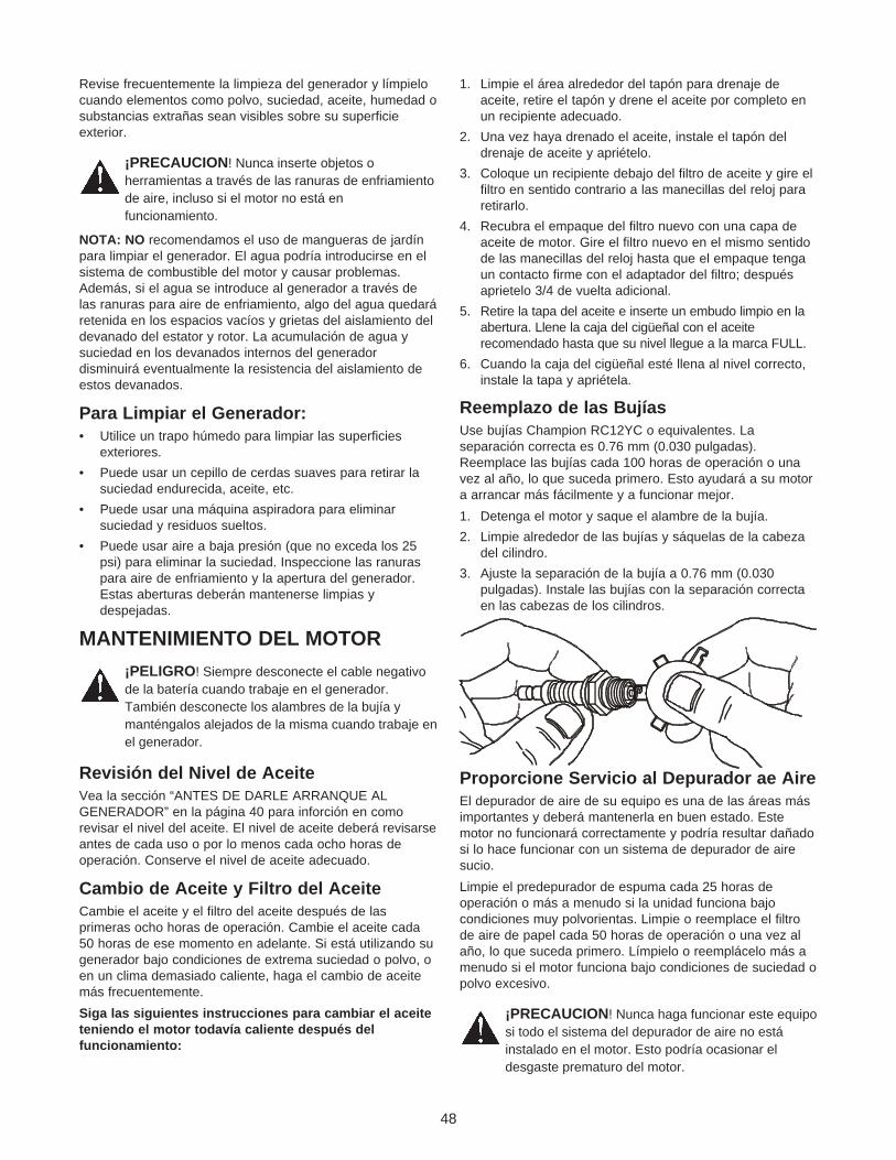
48
Revise frecuentemente la limpieza del generador y límpielocuando elementos como polvo, suciedad, aceite, humedad osubstancias extrañas sean visibles sobre su superficieexterior.
¡PRECAUCION! Nunca inserte objetos oherramientas a través de las ranuras de enfriamientode aire, incluso si el motor no está enfuncionamiento.
NOTA: NO recomendamos el uso de mangueras de jardínpara limpiar el generador. El agua podría introducirse en elsistema de combustible del motor y causar problemas.Además, si el agua se introduce al generador a través delas ranuras para aire de enfriamiento, algo del agua quedaráretenida en los espacios vacíos y grietas del aislamiento deldevanado del estator y rotor. La acumulación de agua ysuciedad en los devanados internos del generadordisminuirá eventualmente la resistencia del aislamiento deestos devanados.
Para Limpiar el Generador:• Utilice un trapo húmedo para limpiar las superficies
exteriores.
• Puede usar un cepillo de cerdas suaves para retirar lasuciedad endurecida, aceite, etc.
• Puede usar una máquina aspiradora para eliminarsuciedad y residuos sueltos.
• Puede usar aire a baja presión (que no exceda los 25psi) para eliminar la suciedad. Inspeccione las ranuraspara aire de enfriamiento y la apertura del generador.Estas aberturas deberán mantenerse limpias ydespejadas.
MANTENIMIENTO DEL MOTOR
¡PELIGRO! Siempre desconecte el cable negativode la batería cuando trabaje en el generador.También desconecte los alambres de la bujía ymanténgalos alejados de la misma cuando trabaje enel generador.
Revisión del Nivel de Aceite Vea la sección “ANTES DE DARLE ARRANQUE ALGENERADOR” en la página 40 para inforción en comorevisar el nivel del aceite. El nivel de aceite deberá revisarseantes de cada uso o por lo menos cada ocho horas deoperación. Conserve el nivel de aceite adecuado.
Cambio de Aceite y Filtro del AceiteCambie el aceite y el filtro del aceite después de lasprimeras ocho horas de operación. Cambie el aceite cada50 horas de ese momento en adelante. Si está utilizando sugenerador bajo condiciones de extrema suciedad o polvo, oen un clima demasiado caliente, haga el cambio de aceitemás frecuentemente.
Siga las siguientes instrucciones para cambiar el aceiteteniendo el motor todavía caliente después delfuncionamiento:
1. Limpie el área alrededor del tapón para drenaje deaceite, retire el tapón y drene el aceite por completo enun recipiente adecuado.
2. Una vez haya drenado el aceite, instale el tapón deldrenaje de aceite y apriételo.
3. Coloque un recipiente debajo del filtro de aceite y gire elfiltro en sentido contrario a las manecillas del reloj pararetirarlo.
4. Recubra el empaque del filtro nuevo con una capa deaceite de motor. Gire el filtro nuevo en el mismo sentidode las manecillas del reloj hasta que el empaque tengaun contacto firme con el adaptador del filtro; despuésaprietelo 3/4 de vuelta adicional.
5. Retire la tapa del aceite e inserte un embudo limpio en laabertura. Llene la caja del cigüeñal con el aceiterecomendado hasta que su nivel llegue a la marca FULL.
6. Cuando la caja del cigüeñal esté llena al nivel correcto,instale la tapa y apriétela.
Reemplazo de las Bujías Use bujías Champion RC12YC o equivalentes. Laseparación correcta es 0.76 mm (0.030 pulgadas).Reemplace las bujías cada 100 horas de operación o unavez al año, lo que suceda primero. Esto ayudará a su motora arrancar más fácilmente y a funcionar mejor.
1. Detenga el motor y saque el alambre de la bujía.
2. Limpie alrededor de las bujías y sáquelas de la cabezadel cilindro.
3. Ajuste la separación de la bujía a 0.76 mm (0.030pulgadas). Instale las bujías con la separación correctaen las cabezas de los cilindros.
Proporcione Servicio al Depurador ae AireEl depurador de aire de su equipo es una de las áreas másimportantes y deberá mantenerla en buen estado. Estemotor no funcionará correctamente y podría resultar dañadosi lo hace funcionar con un sistema de depurador de airesucio.
Limpie el predepurador de espuma cada 25 horas deoperación o más a menudo si la unidad funciona bajocondiciones muy polvorientas. Limpie o reemplace el filtrode aire de papel cada 50 horas de operación o una vez alaño, lo que suceda primero. Límpielo o reemplácelo más amenudo si el motor funciona bajo condiciones de suciedad opolvo excesivo.
¡PRECAUCION! Nunca haga funcionar este equiposi todo el sistema del depurador de aire no estáinstalado en el motor. Esto podría ocasionar eldesgaste prematuro del motor.

49
Siga las siguientes instrucciones para limpiar oreemplazar los componentes del depurador de aire:
1. Retire la cubierta soltando ambos cerrojos de sujeción.
2. Saque el predepurador de espuma del cartucho.
3. Lave el predepurador en agua y detergente líquido.
4. Exprima el predepurador hasta que esté seco en untrapo limpio. (NO LO RETUERZA).
5. Lubrique el predepurador con aceite de motor limpio.
6. Exprima el predepurador en un trapo limpio para retirarel exceso de aceite. NO LO RETUERZA.
7. Retire la perilla y la placa para poder golpearsuavemente el cartucho contra una superficie sólida yasí retirar y soltar las partículas atrapadas.
NOTA: Si el filtro está muy sucio deberá reemplazarlo.
8. Vuelva a instalar el predepurador sobre el cartucho.
9. Vuelva a instalar el conjunto del depurador de aire.
10. Vuelva a instalar la placa, la perilla y la cubierta.
NOTA: Si necesita ordenar un filtro de aire nuevo, llame porfavor al 1-800-366-7278.
Limpie la Pantalla del ApagachispasEl silenciador de escape del motor posee una pantallaapagachispas. Inspeccione y limpie la pantalla cada 100horas de operación o una vez al año, lo que sucedaprimero.
NOTA: El generador deberá tener un apagachispas si lo usaen terrenos no tratados cubiertos de monte, maleza o pasto.El apagachispas deberá ser mantenido en buenascondiciones por parte del propietario/operador. Lo anteriores exiguido por la ley en el estado de California. Otrosestados pueden tener leyes similares. Las leyes federalesse aplican en tierras federales.
Deje enfriar el silenciador antes de manipularlo. El contactocon un silenciador o motor caliente puede causarquemaduras severas.
Para limpiar e inspeccionar el apagachispas:
• Retire los cuatro tornillos que están sujetando la pantalladel apagachispas.
• Inspeccione la pantalla y reemplácela si está rota,perforada o en general dañada. NO use pantallasdefectuosas. Si la pantalla no está dañada, límpiela conun disolvente comercial.
• Vuelva a instalar la pantalla usando los cuatro tornillos.
Velocidad de Mando del Motor
¡PRECAUCION! La velocidad del motor fueajustada adecuadamente en la fábrica y no requierede ajustes adicionales. No intente cambiar lavelocidad del motor. Si cree que el motor estáfuncionando muy rápido o muy lento, lleve su motora un centro de servicio autorizado para reparación yajuste. CAMBIAR LA VELOCIDAD DE MANDO DELMOTOR CANCELA LA GARANTIA.
Su motor funciona a una velocidad constante. Estavelocidad constante de operación es mantenida por unregulador mecánico de velocidad fija tipo contrapeso. NOintente ajustar la calibración de la velocidad de mando porlas siguientes razones:
• Hacer funcionar el motor a velocidades altas espeligroso y aumenta el riesgo de lesiones personales odaño del equipo.
• Hacer funcionar el motor a velocidades bajas con cargaspesadas puede acortar la vida del motor.
Las calibraciones incorrectas de velocidad tambiénafectan el funcionamiento eléctrico de su generador dela siguiente manera:
• Hacer funcionar el motor a altas velocidades crea unacondición de sobrefrecuencia y sobrevoltaje.
• Hacer funcionar el motor a bajas velocidades crea unacondición de baja frecuencia y bajo voltaje.
IMPORTANTE: La frecuencia y/o el voltaje incorrecto puededañar algunas de las cargas electricas conectadas.
Si sospecha que la velocidad del motor es incorrecta,lleve el generador a un centro de servicio autorizadopara su reparación y ajuste.
CAJA
PREDEPURADOR
DE ESPUMA
CARTUCHO
PERILLA
SUJETADORES
RETENEDOR
DEL CARTUCHO

50
Ajuste del CarburadorEl carburador de su motor fue ajustado previamente en lafábrica. No deberá manipular el carburador ya que estocancelará la garantía del sistema de control de emisiones.Si tiene problemas o su motor es usado en altitudesmayores de 5,000 pies, póngase en contacto con eldistribuidor autorizado más cercano para los cambios decalibración correspondientes para altitudes elevadas.
Revisión/Ajuste de la Separacion de lasVálvulas al Brazo OsclianteCada 50 horas de operación, retire la cubierta del brazooscilante y revise la separación de las válvulas al brazooscilante.
IMPORTANTE: Si no se siente seguro de llevar a cabo esteprocedimiento o no tiene las herramientas indicadas, por favorlleve su generador al centro de servicio más cercano parasolicitar el ajuste de la separación de las válvulas. Este es unpaso muy importante para asegurar la vida útil másprolongada de su motor.
Cuando ajuste la separación, el motor deberá estaatemperatura ambiente y cada pistón deberá estar en el puntofijo superior (PFS) de su recorrido de compresión (ambasválvulas están cerradas). La separación correcta es 0.1-0.15mm (0.004-0.006 pul.). Revise y ajuste la separación de lasválvulas al brazo oscilante de la siguiente manera:
1. Retire las dos tuercas y sellos de las cubiertas de lasválvulas.
2. Retire los empaques y cubiertas de las válvulas.
3. Después de retirar las bujías, gire el cigüeñal hasta queel pistón del cilindro que está revisando se encuentre enel PFS de su recorrido de compresión (ambas válvulasestán cerradas).
4. Pase el extremo de un calibrador a través del orificio dela bujía y continue girando el cigüeñal hasta que el sehaya movido 1/4 de pulgada más allá del PFS.
5. Revise la separación de las válvulas con un calibradorcolocándolo entre el vástago de la válvula y el brazooscilante.
6. Ajuste la válvula de manera que la separación sea de0.1-0.15 mm (0.004-0.006 pul.) para la válvula de toma yla de escape.
7. Apriete cada tuerca de fijación mientras sostiene eltornillo de ajuste. Apriete la tuerca de fijación a 7 N-m(60 pul.-lbs.).
8. Vuelva a instalar los empaques de las cubiertas de lasválvulas, cubiertas de las válvulas, sellos y tuercas.Apriete las tuercas a 3 N-m (25 pul.-lbs.).
Vuelva a Apretar los Pernos de CabezaVuelva a apretar los pernos de cabeza después de lasprimeras 50 horas de operación.
NOTA: Unicamente lleve a cabo este ajuste después de lasprimeras 50 horas de operación. Los pernos de cabeza nonecesitarán ajuste adicional.
IMPORTANTE: Si no se siente seguro de llevar a cabo esteprocedimiento o no tiene las herramientas adecuadas, porfavor lleve su generador al centro de servicio más cercanopara hacer apretar los pernos de cabeza. Este es un pasomuy importante para asegurar la vida útil más prolongadade su motor.
1. Retire las cubiertas de las válvulas como fue descritoanteriormente en esta página.
2. Apriete los pernos de cabeza en la secuencia mostradaen la Figura 9 a 19 N-m (165 pul.-lbs.).
3. Vuelva a instalar los empaques de las cubiertas de lasválvulas y las cubiertas de las válvulas como fue descritoanteriormente en esta página.
CALIBRADOR
LLAVE HEXAGONALDE 5 MM
TORNILLO DEAJUSTE
LLAVE DE13 MM
TUERCA DEFIJACION
PERNOS DECABEZA DELCILINDRO
ARANDELAS DE SELLADO
51
GENERALIDADESEl generador deberá ser encendido al menos una vez cadasiete días y deberá dejarlo funcionar al menos durante 30minutos. Si no puede hacer esto y debe almacenar launidad por más de 30 días, siga las siguientes instruccionescomo guía para preparar su unidad para almacenamiento.
¡ADVERTENCIA! NUNCA almacene el motor concombustible en el tanque en recintos cerrados o enáreas encerradas con poca ventilación donde losvapores puedan alcanzar llamas abiertas, chispa oluz de piloto como en un horno, calentador de agua,secadora de ropa u otro aparato de gas.
ALMACENAMIENTO PARAPERIODOS PROLONGADOSEs importante evitar que se formen depósitos de goma enlas partes esenciales del sistema de combustible, como elcarburador, manguera o tanque de combustible, durante elalmacenamiento. También, la experiencia indica que loscombustibles con mezclas de alcohol (llamados gasohol,etanol o metanol) pueden atraer humedad, la cual lleva a laseparación y formación de ácidos durante elalmacenamiento. La gasolina ácida puede dañar el sistemade combustible de un motor durante su almacenamiento.
Para evitar problemas con el motor, el sistema decombustible deberá desocuparse antes de unalmacenamiento de 30 días o más de la siguiente manera:
• Retire toda la gasolina del tanque de combustible.
¡PELIGRO! Drene el combustible dentro de unrecipiente adecuado, lejos de llamas abiertas y enlugares al aire libre. Asegúrese de que el motor estéfrío. No fume.
• Dele arranque al motor y déjelo funcionar hasta que sedetenga por la falta de combustible.
• Con el motor todavía caliente, drene el aceite de la cajadel cigüeñal. Vuelva a llenarlo con el grado de aceiterecomendado.
• Retire la bujía y rocíe aproximadamente ½ onza (15 ml)de aceite para motor dentro del cilindro. Cubra el orificiode la bujía con un trapo. Hale el arrancador porretroceso lentamente para distribuir el aceite.
¡PRECAUCION! Evite el rociado del orificio de labujía cuando esté girando el motor.
• Instale y apriete la bujía. No conecte el alambre de labujía.
• Limpie las superficie externa del generador. Revise quelas ranuras de aire de enfriamiento y aberturas delgenerador estén abiertas y despejadas.
• Almacene la unidad en un lugar seco y limpio.
OTRAS SUGERENCIAS PARA ELALMACENAMIENTO:• No almacene gasolina de una estación a otra.
• Reemplace la caneca de gasolina si comienza aoxidarse. El óxido y/o la suciedad en la gasolina lecausará problemas.
• Si es posible, almacene su unidad en un recintoencerrado y cúbrala para protegerla del polvo y lasuciedad. ASEGURESE DE VACIAR EL TANQUE DELCOMBUSTIBLE.
• Cubra su unidad con una cubierta de protecciónadecuada que no retenga humedad.
¡PELIGRO! NUNCA cubra su Generador cuando elmotor y el área del escape estén calientes.
ALMACENAMIENTO
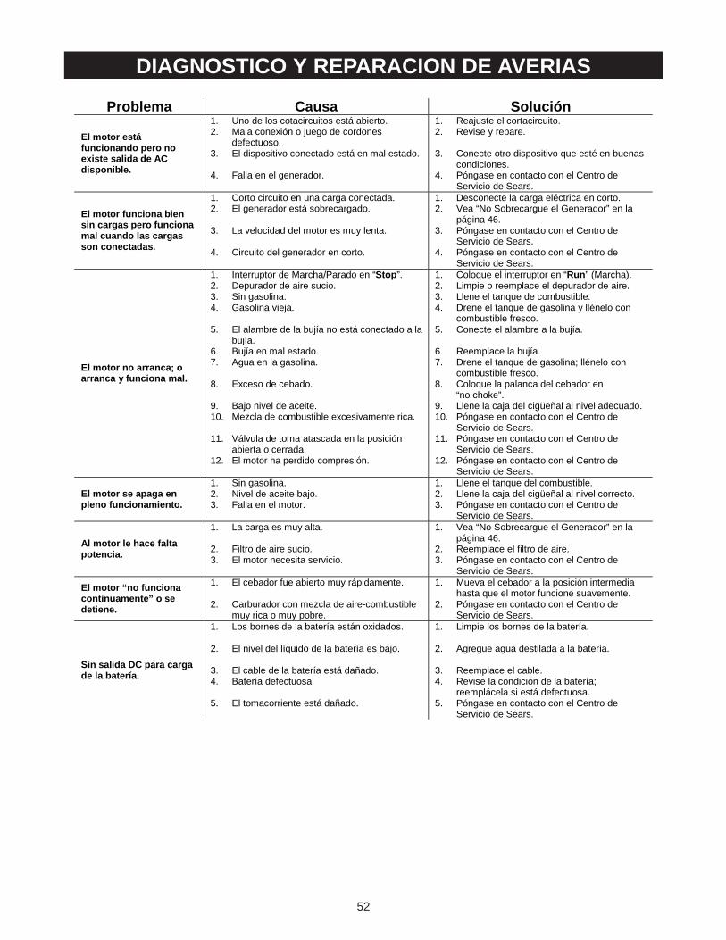
52
DIAGNOSTICO Y REPARACION DE AVERIAS
Problema Causa Solución
El motor está funcionando pero no existe salida de AC disponible.
1. Uno de los cotacircuitos está abierto. 2. Mala conexión o juego de cordones
defectuoso. 3. El dispositivo conectado está en mal estado.
4. Falla en el generador.
1. Reajuste el cortacircuito. 2. Revise y repare.
3. Conecte otro dispositivo que esté en buenas
condiciones. 4. Póngase en contacto con el Centro de
Servicio de Sears.
El motor funciona bien sin cargas pero funciona mal cuando las cargas son conectadas.
1. Corto circuito en una carga conectada. 2. El generador está sobrecargado.
3. La velocidad del motor es muy lenta.
4. Circuito del generador en corto.
1. Desconecte la carga eléctrica en corto. 2. Vea “No Sobrecargue el Generador” en la
página 46. 3. Póngase en contacto con el Centro de
Servicio de Sears. 4. Póngase en contacto con el Centro de
Servicio de Sears.
El motor no arranca; o arranca y funciona mal.
1. Interruptor de Marcha/Parado en “Stop”. 2. Depurador de aire sucio. 3. Sin gasolina. 4. Gasolina vieja.
5. El alambre de la bujía no está conectado a la
bujía. 6. Bujía en mal estado. 7. Agua en la gasolina.
8. Exceso de cebado.
9. Bajo nivel de aceite. 10. Mezcla de combustible excesivamente rica.
11. Válvula de toma atascada en la posición
abierta o cerrada. 12. El motor ha perdido compresión.
1. Coloque el interruptor en “Run” (Marcha). 2. Limpie o reemplace el depurador de aire. 3. Llene el tanque de combustible. 4. Drene el tanque de gasolina y llénelo con
combustible fresco. 5. Conecte el alambre a la bujía.
6. Reemplace la bujía. 7. Drene el tanque de gasolina; llénelo con
combustible fresco. 8. Coloque la palanca del cebador en
“no choke”. 9. Llene la caja del cigüeñal al nivel adecuado. 10. Póngase en contacto con el Centro de
Servicio de Sears. 11. Póngase en contacto con el Centro de
Servicio de Sears. 12. Póngase en contacto con el Centro de
Servicio de Sears.
El motor se apaga en pleno funcionamiento.
1. Sin gasolina. 2. Nivel de aceite bajo. 3. Falla en el motor.
1. Llene el tanque del combustible. 2. Llene la caja del cigüeñal al nivel correcto. 3. Póngase en contacto con el Centro de
Servicio de Sears.
Al motor le hace falta potencia.
1. La carga es muy alta.
2. Filtro de aire sucio. 3. El motor necesita servicio.
1. Vea “No Sobrecargue el Generador” en la página 46.
2. Reemplace el filtro de aire. 3. Póngase en contacto con el Centro de
Servicio de Sears.
El motor “no funciona continuamente” o se detiene.
1. El cebador fue abierto muy rápidamente.
2. Carburador con mezcla de aire-combustible muy rica o muy pobre.
1. Mueva el cebador a la posición intermedia hasta que el motor funcione suavemente.
2. Póngase en contacto con el Centro de Servicio de Sears.
Sin salida DC para carga de la batería.
1. Los bornes de la batería están oxidados.
2. El nivel del líquido de la batería es bajo.
3. El cable de la batería está dañado. 4. Batería defectuosa.
5. El tomacorriente está dañado.
1. Limpie los bornes de la batería.
2. Agregue agua destilada a la batería.
3. Reemplace el cable. 4. Revise la condición de la batería;
reemplácela si está defectuosa. 5. Póngase en contacto con el Centro de
Servicio de Sears.

53
GARANTÍA DEL SISTEMA DE CONTROL DE EMISIONES
INFORME DE LA GARANTIA DECONTROL DE EMISIONES DELGOBIERNO FEDERAL YCALIFORNIASus Obligaciones y Derechos de GarantíaLa Junta Directiva de Recursos Ambientales de California(CARB), la Agencia de Protección del Medio Ambiente delos Estados Unidos (EPA) y Sears Roebuck y Co. USA(Sears), tienen el gusto de explicar la Garantía del Sistemade Control de Emisiones del motor de su equipo de jardín yprados de 1997 y años posteriores. Los motores nuevospara equipos de servicio y equipo de jardín y prados (motor)deberán ser diseñados, fabricados y equipados para cumplircon los estrictos estándares anti-polución de California y delGobierno Federal. Sears deberá garantizar el sistema decontrol de emisiones de su motorpor los períodos de tiempoenlistados a continuación, con tal de que no haya habidoabuso, negligencia o mantenimiento inadecuado de sumotor.
El sistema de control de emisiones incluye partes como elcarburador, sistemas de escape y encendido. Donde existauna condición que se pueda garantizar, Sears reparará elmotor de su equipo de jardín y prados sin ningún costoalguno para usted. Los gastos cubiertos bajo la garantíaincluyen diagnóstico, partes y mano de obra.
Cubrimiento de la Garantía del FabricanteLos motores 1997 y posteriores están garantizados por dosaños. Si algun componente o sistema de su motorrelacionado con las emisiones (lista a continuación) esdefectuoso, será reemplazado o reparado por un centro deservicio Sears autorizado.
Responsabilidades de Garantía delPropietario Como propietario del motor, usted es responsable de larealización del mantenimiento requerido enlistado en elManual del Propietario suministrado por la fábrica. Parapropósito de la garantía, Sears le recomienda conservar
todos los recibos que cubran el mantenimiento de su motor.Sin embargo, Sears no puede negar la garantía tan solodebido a la falta de los recibos o por que no se hayaasegurado de realizar todo el mantenimiento programado.
Como propietario del motor, usted debe saber que Searspuede negar su cubrimiento de garantía o responsabilidad sisu motor, o una parte/componente del mismo, ha falladodebido a abuso, negligencia, mantenimiento inadecuado,modificaciones no aprobadas, o por el uso de partesfalsificadas y/o obtenidas en el ‘mercado negro’que nohayan sido fabricadas, suministradas o aprobadas por elfabricante original del equipo.
Usted es el responsable de llevar su motor a un centro deservicio autorizado Sears tan pronto como aparezca elproblema. Las reparaciones de garantía deberán terminarseen un período de tiempo razonable, que no exceda los 30días.
Si tiene preguntas acerca de sus responsabilidades yderechos de garantía, deberá ponerse en contacto con sucentro de servicio autorizado más cercano o llamar a Searsal 1-800-473-7247.
Fecha de Inicio de la GarantíaEl período de la garantía comienza en la fecha de entregadel motor al comprador original y usuario final.
Duración del CubrimientoSears garantiza al propietario inicial y a cada compradorsubsecuente, que el motor está libre de defectos enmateriales y mano de obra que puedan causar falla de laparte garantizada por un período de dos años.
Qué está Cubierto
Reparación o Reemplazo de Partes
La reparación o el reemplazo de cualquier parte garantizadase realizará sin ningún costo para el propietario en un centrode servicio aprobado Sears. Si tiene preguntas acerca desus responsabilidades y derechos de garantía, deberáponerse en contacto con su centro de servicio autorizadomás cercano o llamar a Sears al 1-800-473-7247.

54
Período de GarantíaCualquier parte garantizada que no haya sido programadapara reemplazo como mantenimiento requerido serágarantizada por 2 años. Cualquier parte garantizada queesté programada tan solo para inspección regular y/o tengainstrucciones de “repare o reemplace cuando sea necesario”también estará garantizada por dos años. Cualquier partegarantizada que esté programada para reemplazo según elmantenimiento requerido será garantizada por el período detiempo hasta su primer reemplazo programado o por 2 años;lo que suceda primero.
DiagnósticoNo se le cobrará al propietario los costos del trabajo dediagnóstico si la reparación se considera en garantíacuando el motor sea inspeccionado por un centro deservicio Sears autorizado.
Daños ConsecuencialesSears puede ser responsable por daños a otroscomponentes del motor causados por la falla de una partegarantizada si la parte que falló se encontraba aún bajogarantía.
Qué no está Cubierto
Responsabilidades del Propietario
No serán cubiertas las fallas causadas por abuso,negligencia o mantenimiento inadecuado.
Partes Agregadas o Modificadas
El uso de partes agregadas, no autorizadas o modificadases motivo suficiente para negar reparaciones presentadasbajo garantía. Sears no será responsable de cubrirreparaciones de este tipo.
Cómo Presentar un ReclamoSi tiene preguntas acerca de sus responsabilidades yderechos de garantía, deberá ponerse en contacto con sucentro de servicio autorizado más cercano o llamar a Searsal 1-800-473-7247.
Dónde se Obtiene el Servicio de GarantíaLas reparaciones o servicios de garantía seránproporcionados en todos los centros de servicio autorizadosSears.
Mantenimiento, Reemplazo y Reparaciónde Partes Relacionadas con EmisionesCualquier repuesto aprobado por Sears usado en larealización de cualquier mantenimiento o reparación degarantía en las partes relacionadas con las emisiones, serásuministrado sin costo alguno al propietario si la parte estábajo garantía.
Lista de Partes de la Garantía del Controlde Emisiones1. Sistema de Medición del Combustible:
a. Conjunto del Carburador
b. Filtro del combustible
2. Sistema de Inducción de Aire:
a. Múltiple de admisión
b. Depurador de Aire
3. Conjunto del Silenciador Catalítico (si está equipado),incluyendo:
a. Empaque del silenciador
b. Múltiple de escape
4. Sistema de Encendido
a. Bujía
b. Módulo de encendido
5. Tubo del Respiradero de la Caja del Cigüeñal
GARANTÍA DEL SISTEMA DE CONTROL DE EMISIONES

55
NOTAS
