17. electronics - ijece -driving system for disabled -karandeep kaur
TRANSCRIPT

8/12/2019 17. Electronics - Ijece -Driving System for Disabled -Karandeep Kaur
http://slidepdf.com/reader/full/17-electronics-ijece-driving-system-for-disabled-karandeep-kaur 1/8
www.iaset.us [email protected]
DRIVING SYSTEM FOR DISABLED
KARANDEEP KAUR
Department of Electronics and Communication Engineering, Chitkara College of Engineering and Technology,
Rajpura, Punjab, India
ABSTRACT
The need to help the persons with disabilities has led to the development of assistive technology. In this paper, a
technology is presented with the use of which a person with disability can control his or her surroundings effectively.
They can move their wheelchair; operate electronic appliances, computer as well as phones. Persons who have different
degrees of disabilities can operate their surroundings in different manners. The people who are having a minimal amountof upper limb movement only and no lower limb movement can control the system using a magnet on their tongue.
Whereas those people who cannot move their lower limb but have access over their upper body can control their vehicle
using their hands. The tongue can be used in the project because there is a degree of freedom with the tongue and
moreover it is connected to the brain by the hypoglossal nerve, which generally escapes severe damage even in high level
spinal cord injuries. Non-invasive access to the tongue is readily available. The paper additionally presents the practical
use of encoder–decoder module and the LMX Bluetooth module for transferring data as a wireless transmission.
The results show that the system is efficient and highly practical.
KEYWORDS: Assistive Technology, LMX Bluetooth Module, Magnetic Tracer Tongue, Wireless Transmission
INTRODUCTION
The Driving Systems for Disabled (DSD) proves to be a boon for the disabled persons because it provides a
practical use of the electromagnetic theories and wireless technologies in the Bio-Medical science. DSD serves its
different users by using various key components. In general, system consists of the 4 key components: a small magnetic
tracer fixed on the tongue with tissue adhesives or piercing, a headset with an array of 3-axial magnetic hall effect sensors
to detect the changes in the magnetic field generated by the tracer, a wireless link established between a control unit on the
headset and a receiver on a driving vehicle or smart phone to transfer the magnetic sensor data, and a sensing and driving
algorithm to carry out the processes, a switch to control the wireless transmission through an encoder-decoder module or a
Bluetooth module. The paper presents a driving system for those persons who are disabled because of accidents, strokes,
some sort of injury or trauma and can have a driving system by using their tongue. It is an efficient system using wireless
transmission of data. The paper also presents the technology for those people who are having some sort of hand movement
but movement of legs in their case is very difficult. The Section 2 includes the solution proposed to the above problems.
SOLUTION PROPOSED
The paper presents the solution to a majority of problems faced by those persons who are suffered from strokes,
trauma or accident and have minimal amount of upper and lower body movements. In the solution the driving system is
designed in such a way that the use of rare-earth super magnet provides a degree of higher efficiency. The magnetic
sensors used are Ratiometric Linear Bipolar “hall effect sensors A1321EUA-T”. Further the paper also presents the
International Journal of Electronics and
Communication Engineering (IJECE)
ISSN(P): 2278-9901; ISSN(E): 2278-991X
Vol. 3, Issue 4, July 2014, 137-146
© IASET
8/12/2019 17. Electronics - Ijece -Driving System for Disabled -Karandeep Kaur
http://slidepdf.com/reader/full/17-electronics-ijece-driving-system-for-disabled-karandeep-kaur 2/8
138 Karandeep Kaur
Impact Factor (JCC): 3.2029 Index Copernicus Value (ICV): 3.0
technology for those persons who are suffering from lymphedema, joint dysfunction or paralysis of legs . The Bluetooth
technology combined with android technology can be an aid for those who can control the vehicle through hand
movements. The paper presents use of LMX9839 Bluetooth IC combined with the Bluetooth of the android mobile to
drive out vehicle and the Bluetooth IC can be used to control various devices as well.
SYSTEM OVERALL ARCHITECTURE AND DESIGN
Overall proposed solution consists of both the hardware as well as the software part.
Hardware System Design
The proposed system hardware includes the following blocks:
• Headset Module,
• Encoder Circuit,
• Microcontroller MSP430G2553,
• Decoder Circuit,
• Driving Circuit,
• LMX9838 Bluetooth.
Headset Module
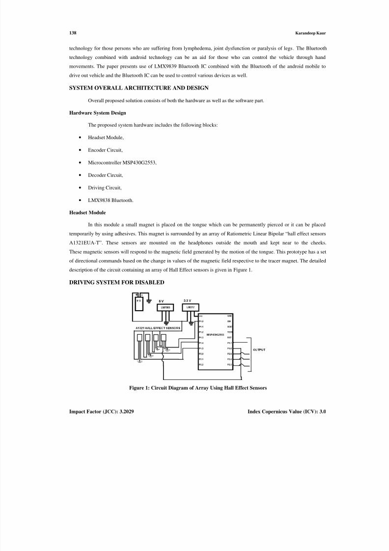
In this module a small magnet is placed on the tongue which can be permanently pierced or it can be placed
temporarily by using adhesives. This magnet is surrounded by an array of Ratiometric Linear Bipolar “hall effect sensors
A1321EUA-T”. These sensors are mounted on the headphones outside the mouth and kept near to the cheeks.
These magnetic sensors will respond to the magnetic field generated by the motion of the tongue. This prototype has a set
of directional commands based on the change in values of the magnetic field respective to the tracer magnet. The detailed
description of the circuit containing an array of Hall Effect sensors is given in Figure 1.
DRIVING SYSTEM FOR DISABLED
Figure 1: Circuit Diagram of Array Using Hall Effect Sensors
8/12/2019 17. Electronics - Ijece -Driving System for Disabled -Karandeep Kaur
http://slidepdf.com/reader/full/17-electronics-ijece-driving-system-for-disabled-karandeep-kaur 3/8
Driving System for Disabled
www.iaset.us
The circuit shows an
A1321EUA-T. These sensors measure
regulators. The data from these linear
digital converter that is present in MSPthe ADC10SC bit. ADC10 oscillator i
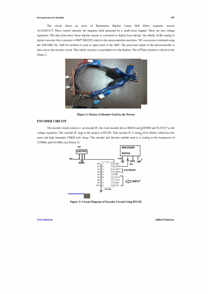
then sent to the encoder circuit. This w
Figure 2.
Fig
ENCODER CIRCUIT
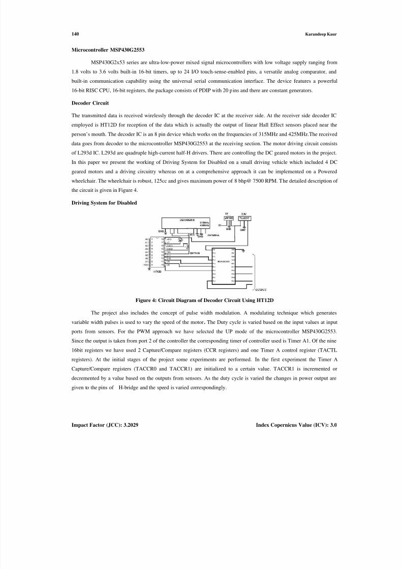
The encoder circuit consists o
voltage regulators. The encoder IC use
noise and high immunity CMOS tech
315MHz and 434 MHz [see Figure 3].
Figure 3:
array of Ratiometric Bipolar Linear Hall
the magnetic field generated by a small tracer ma
bipolar sensors is converted to digital form throug
30G2553 which is the microcontroller used here. Ths used as input clock to the ADC. The processed ou
hole circuitry is assembled over the headset. The co
ure 2: Picture of Headset Used by the Person
an encoder IC, the 4 pin encoder device R403A and
d in the project is HT12E. This encoder IC is desig
ology. The encoder and decoder module used is o
Circuit Diagram of Encoder Circuit Using HT12E
139
Effect magnetic sensors
gnet. There are also voltage
the inbuilt 10-Bit analog to
conversion is initiated usingtput of the microcontroller is
plete headset is shown in the
LM7805 and TLV2217 as the
ed by Holtex which has low
erating at the frequencies of
8/12/2019 17. Electronics - Ijece -Driving System for Disabled -Karandeep Kaur
http://slidepdf.com/reader/full/17-electronics-ijece-driving-system-for-disabled-karandeep-kaur 4/8
140 Karandeep Kaur
Impact Factor (JCC): 3.2029 Index Copernicus Value (ICV): 3.0
Microcontroller MSP430G2553
MSP430G2x53 series are ultra-low-power mixed signal microcontrollers with low voltage supply ranging from
1.8 volts to 3.6 volts built-in 16-bit timers, up to 24 I/O touch-sense-enabled pins, a versatile analog comparator, and
built-in communication capability using the universal serial communication interface. The device features a powerful
16-bit RISC CPU, 16-bit registers, the package consists of PDIP with 20 pins and there are constant generators.
Decoder Circuit
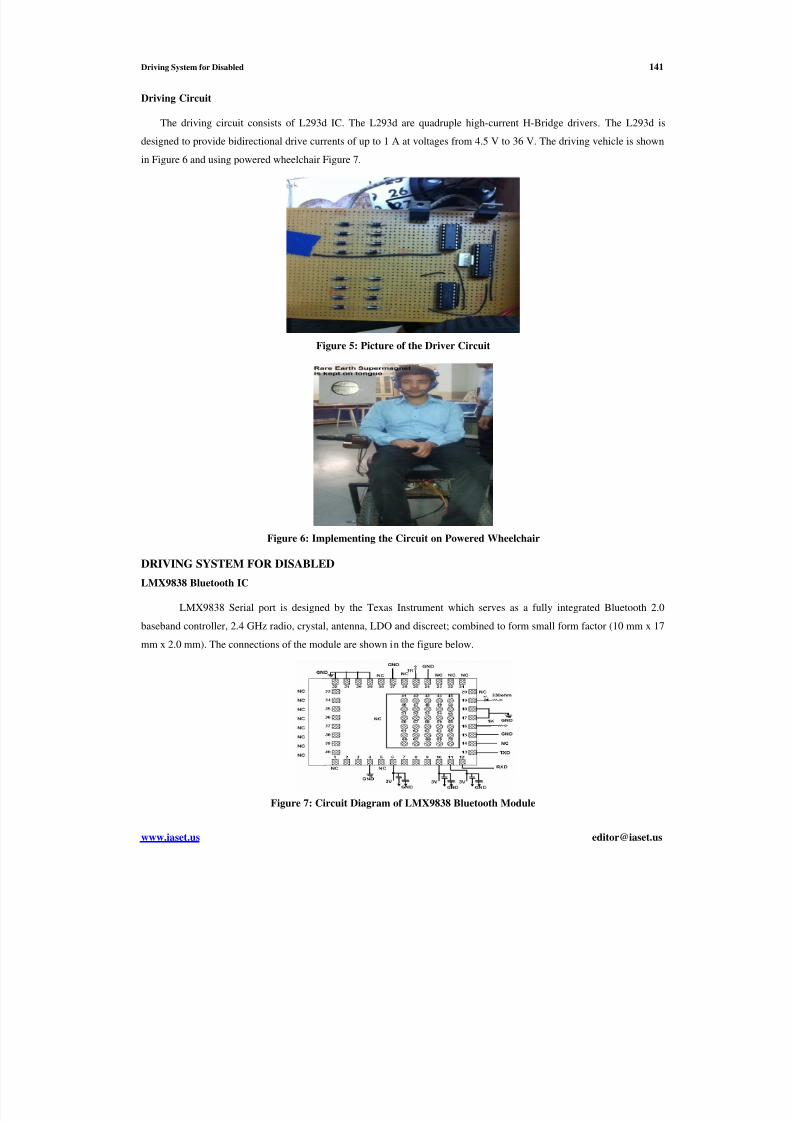
The transmitted data is received wirelessly through the decoder IC at the receiver side. At the receiver side decoder IC
employed is HT12D for reception of the data which is actually the output of linear Hall Effect sensors placed near the
person’s mouth. The decoder IC is an 8 pin device which works on the frequencies of 315MHz and 425MHz.The received
data goes from decoder to the microcontroller MSP430G2553 at the receiving section. The motor driving circuit consists
of L293d IC. L293d are quadruple high-current half-H drivers. There are controlling the DC geared motors in the project.
In this paper we present the working of Driving System for Disabled on a small driving vehicle which included 4 DC
geared motors and a driving circuitry whereas on at a comprehensive approach it can be implemented on a Powered
wheelchair. The wheelchair is robust, 125cc and gives maximum power of 8 bhp@ 7500 RPM. The detailed description of
the circuit is given in Figure 4.
Driving System for Disabled
Figure 4: Circuit Diagram of Decoder Circuit Using HT12D
The project also includes the concept of pulse width modulation. A modulating technique which generates
variable width pulses is used to vary the speed of the motor. The Duty cycle is varied based on the input values at input
ports from sensors. For the PWM approach we have selected the UP mode of the microcontroller MSP430G2553.
Since the output is taken from port 2 of the controller the corresponding timer of controller used is Timer A1. Of the nine
16bit registers we have used 2 Capture/Compare registers (CCR registers) and one Timer A control register (TACTL
registers). At the initial stages of the project some experiments are performed. In the first experiment the Timer A
Capture/Compare registers (TACCR0 and TACCR1) are initialized to a certain value. TACCR1 is incremented or
decremented by a value based on the outputs from sensors. As the duty cycle is varied the changes in power output are
given to the pins of H-bridge and the speed is varied correspondingly.
8/12/2019 17. Electronics - Ijece -Driving System for Disabled -Karandeep Kaur
http://slidepdf.com/reader/full/17-electronics-ijece-driving-system-for-disabled-karandeep-kaur 5/8
Driving System for Disabled 141
www.iaset.us [email protected]
Driving Circuit
The driving circuit consists of L293d IC. The L293d are quadruple high-current H-Bridge drivers. The L293d is
designed to provide bidirectional drive currents of up to 1 A at voltages from 4.5 V to 36 V. The driving vehicle is shown
in Figure 6 and using powered wheelchair Figure 7.
Figure 5: Picture of the Driver Circuit
Figure 6: Implementing the Circuit on Powered Wheelchair
DRIVING SYSTEM FOR DISABLED
LMX9838 Bluetooth IC
LMX9838 Serial port is designed by the Texas Instrument which serves as a fully integrated Bluetooth 2.0
baseband controller, 2.4 GHz radio, crystal, antenna, LDO and discreet; combined to form small form factor (10 mm x 17
mm x 2.0 mm). The connections of the module are shown in the figure below.
Figure 7: Circuit Diagram of LMX9838 Bluetooth Module
8/12/2019 17. Electronics - Ijece -Driving System for Disabled -Karandeep Kaur
http://slidepdf.com/reader/full/17-electronics-ijece-driving-system-for-disabled-karandeep-kaur 6/8
142 Karandeep Kaur
Impact Factor (JCC): 3.2029 Index Copernicus Value (ICV): 3.0
Firmware Design
The system firmware includes programming in embedded c and the software used is Code Composer 5. AIDE
integrated development environment (IDE) is for Android. AIDE supports building Apps with Java/Xml, Android SDK,
Eclipse project. The Bluetooth device is recognised as serial port device when the link between Bluetooth of the phone
and the module is established. The pulse width modulation technique is also included since it controls the speed of the
vehicle. In the app the two sliders control the two motors and the speed as well. The code is written for a period value of
3472 and 31 step resolution. The first five bits describe the throttle duty cycle. The next bit provides the choice of motor
and further bit gives the direction of the motors. In this prototype both timers Timer A0 and Timer A1 serves the purpose.
The timers control duty cycles which is given by (1).
Software Implementation
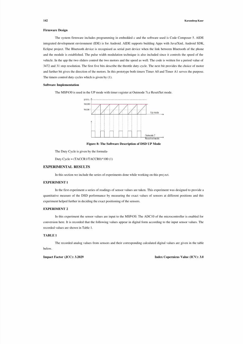
The MSP430 is used in the UP mode with timer register at Outmode 7i.e Reset/Set mode.
Figure 8: The Software Description of DSD UP Mode
The Duty Cycle is given by the formula-
Duty Cycle = (TACCR1/TACCR0)*100 (1)
EXPERIMENTAL RESULTS
In this section we include the series of experiments done while working on this project.
EXPERIMENT 1
In the first experiment a series of readings of sensor values are taken. This experiment was designed to provide a
quantitative measure of the DSD performance by measuring the exact values of sensors at different positions and this
experiment helped further in deciding the exact positioning of the sensors.
EXPERIMENT 2
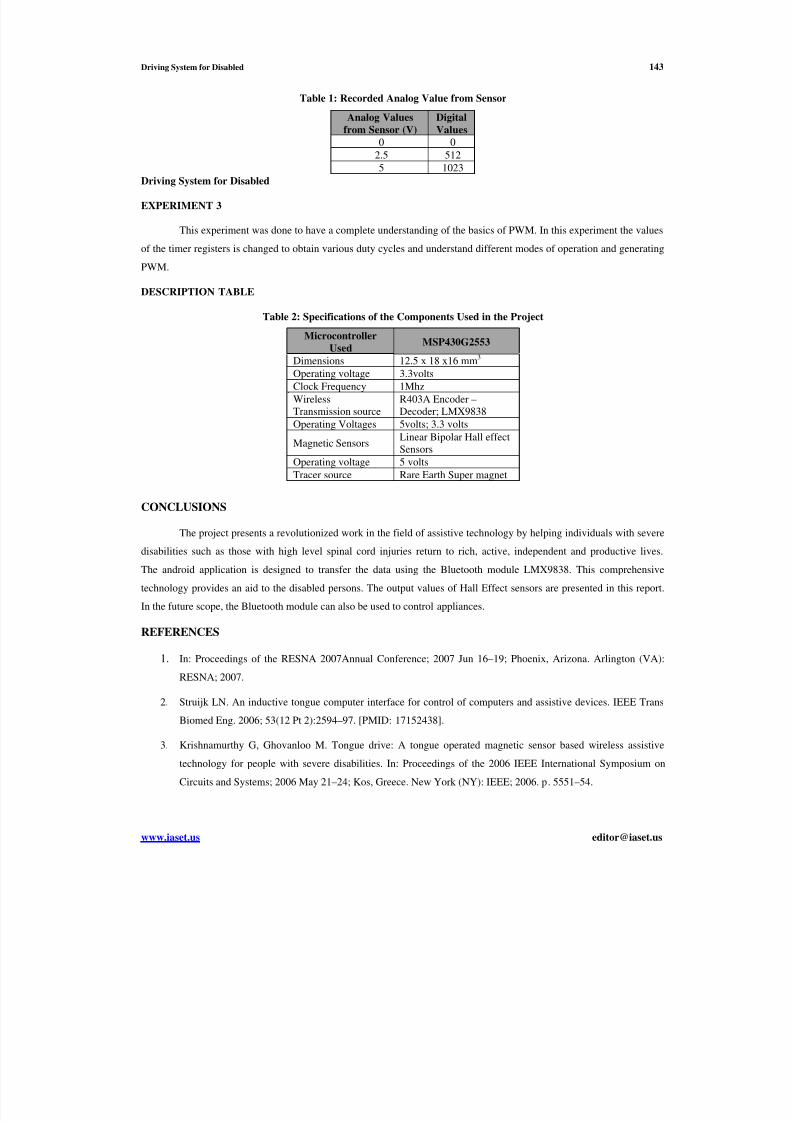
In this experiment the sensor values are input to the MSP430. The ADC10 of the microcontroller is enabled for
conversion here. It is recorded that the following values appear in digital form according to the input sensor values. The
recorded values are shown in Table 1.
TABLE 1
The recorded analog values from sensors and their corresponding calculated digital values are given in the table
below.
8/12/2019 17. Electronics - Ijece -Driving System for Disabled -Karandeep Kaur
http://slidepdf.com/reader/full/17-electronics-ijece-driving-system-for-disabled-karandeep-kaur 7/8
Driving System for Disabled 143
www.iaset.us [email protected]
Table 1: Recorded Analog Value from Sensor
Analog Values
from Sensor (V)
Digital
Values
0 0
2.5 5125 1023
Driving System for Disabled
EXPERIMENT 3
This experiment was done to have a complete understanding of the basics of PWM. In this experiment the values
of the timer registers is changed to obtain various duty cycles and understand different modes of operation and generating
PWM.
DESCRIPTION TABLE
Table 2: Specifications of the Components Used in the Project
Microcontroller
UsedMSP430G2553
Dimensions 12.5 x 18 x16 mm3
Operating voltage 3.3volts
Clock Frequency 1Mhz
Wireless
Transmission source
R403A Encoder –
Decoder; LMX9838
Operating Voltages 5volts; 3.3 volts
Magnetic SensorsLinear Bipolar Hall effect
Sensors
Operating voltage 5 volts
Tracer source Rare Earth Super magnet
CONCLUSIONS
The project presents a revolutionized work in the field of assistive technology by helping individuals with severe
disabilities such as those with high level spinal cord injuries return to rich, active, independent and productive lives.
The android application is designed to transfer the data using the Bluetooth module LMX9838. This comprehensive
technology provides an aid to the disabled persons. The output values of Hall Effect sensors are presented in this report.
In the future scope, the Bluetooth module can also be used to control appliances.
REFERENCES
1. In: Proceedings of the RESNA 2007Annual Conference; 2007 Jun 16–19; Phoenix, Arizona. Arlington (VA):
RESNA; 2007.
2. Struijk LN. An inductive tongue computer interface for control of computers and assistive devices. IEEE Trans
Biomed Eng. 2006; 53(12 Pt 2):2594–97. [PMID: 17152438].
3. Krishnamurthy G, Ghovanloo M. Tongue drive: A tongue operated magnetic sensor based wireless assistive
technology for people with severe disabilities. In: Proceedings of the 2006 IEEE International Symposium on
Circuits and Systems; 2006 May 21–24; Kos, Greece. New York (NY): IEEE; 2006. p. 5551–54.

8/12/2019 17. Electronics - Ijece -Driving System for Disabled -Karandeep Kaur
http://slidepdf.com/reader/full/17-electronics-ijece-driving-system-for-disabled-karandeep-kaur 8/8
144 Karandeep Kaur
Impact Factor (JCC): 3.2029 Index Copernicus Value (ICV): 3.0
4. National Spinal Cord Injury Statistical Center [Internet]. Birmingham (AL): University of Alabama at
Birmingham Department of Physical Medicine and Rehabilitation; c2008. Facts and figures at a glance, January
2008;[about6 screens]. Available from: http://www.spinalcord.uab.edu/ show.asp?
durki=116979&site=1021&return=19775.
5. Huo X, Wang J, Ghovanloo M. Use of tongue movements as a substitute for arm and hand functions in people
with severe disabilities.
6. J. Kim, X. Huo, and M. Ghovanloo, "Wireless control of smartphones with tongue motion using tongue drive
assistive technology," Proc. IEEE 32nd Eng. in Med. and Biol. Conf., pp. 5250-5253, Sep. 2010.