153-082006 hpm 4-6 - ideal vac will return the unit to its normal ... thermocouple tubes observing...
TRANSCRIPT
MODEL HPM 4/6 VACUUM GAUGE
INSTRUCTION MANUAL
TELEDYNE HASTINGS INSTRUMENTS

Page 2 of 12
Manual Print History
The print history shown below lists the printing dates of all revisions and addenda created for this manual. The revision level letter increases alphabetically as the manual undergoes subsequent updates. Addenda, which are released between revisions, contain important change information that the user should incorporate immediately into the manual. Addenda are numbered sequentially. When a new revision is created, all addenda associated with the previous revision of the manual are incorporated into the new revision of the manual. Each new revision includes a revised copy of this print history page.
Revision A (Document Number 153-012000)............................... ................................... January 2000 Revision B (Document Number 153-082005).....................................................................August 2005 Revision C (Document Number 153-082006).....................................................................August 2006
Visit www.teledyne-hi.com for WEEE disposal guidance.
Contact with harsh solvents and chemicals to any plastic parts of the HPM 4/6 Vacuum Gauge can damage the unit and may void the warranty.
Instrument repair should only be performed by Teledyne Hastings service technicians.
Disconnecting gauge tube by pulling on the cable may result in damage to the octal socket and/or cable.
Electromagnetic interferences (EMI) in the frequency range 80MHtz to 1000MHz at intensity levels of 3V/m may cause the HPM-4/6 unit to display up to a 21% deviation from the correct reading.
Removing the source of the EMI or increasing the distance between the source and the HPM-4/6 will return the unit to its normal operating condition.
Teledyne Hastings Instruments reserves the right to change or modify the design of its equipment, at any time, without any obligation to provide notification of change or intent to change.
Hastings Instruments reserves the right to change or modify the design of its equipment without any obligation to provide notification of change or intent to change.

Page 3 of 12
Table of Contents
1.0 QUICK START INSTRUCTIONS. . . . . . . . . . . . . . . . . . . . . . . . . . . . . . . . . . . . . . . . . . . . . . . . . . . . . . . . . . . . . . . . . . . . . . . . . . . . . . . . . . . 4
2.0 SPECIFICATIONS . . . . . . . . . . . . . . . . . . . . . . . . . . . . . . . . . . . . . . . . . . . . . . . . . . . . . . . . . . . . . . . . . . . . . . . . . . . . . . . . . . . . . . . . . . . . . . . . . . . . . 5
3.0 INSTALLATION.. . . . . . . . . . . . . . . . . . . . . . . . . . . . . . . . . . . . . . . . . . . . . . . . . . . . . . . . . . . . . . . . . . . . . . . . . . . . . . . . . . . . . . . . . . . . . . . . . . . . . . 6 3.1. RECEIVING INSPECTION.....................................................................................................................6 3.2. VACUUM SENSOR (DV-4 OR DV-6 SERIES) ..........................................................................................6 3.3. BATTERY INSTALLATION...................................................................................................................6
4.0 GENERAL INFORMATION.. . . . . . . . . . . . . . . . . . . . . . . . . . . . . . . . . . . . . . . . . . . . . . . . . . . . . . . . . . . . . . . . . . . . . . . . . . . . . . . . . . . . . . . . . 7 4.1. SENSOR ELECTRICAL CONNECTOR.....................................................................................................7 4.2. PRESSURE MEASUREMENTS................................................................................................................7
5.0 CALIBRATION.. . . . . . . . . . . . . . . . . . . . . . . . . . . . . . . . . . . . . . . . . . . . . . . . . . . . . . . . . . . . . . . . . . . . . . . . . . . . . . . . . . . . . . . . . . . . . . . . . . . . . . . . 9 5.1. CALIBRATION IN A VACUUM SYSTEM ..................................................................................................9 5.2. CALIBRATION WITH A REFERENCE TUBE.............................................................................................9
6.0 MAINTENANCE.. . . . . . . . . . . . . . . . . . . . . . . . . . . . . . . . . . . . . . . . . . . . . . . . . . . . . . . . . . . . . . . . . . . . . . . . . . . . . . . . . . . . . . . . . . . . . . . . . . . . 11 6.1. AUTHORIZED MAINTENANCE........................................................................................................... 11
7.0 WARRANTY .. . . . . . . . . . . . . . . . . . . . . . . . . . . . . . . . . . . . . . . . . . . . . . . . . . . . . . . . . . . . . . . . . . . . . . . . . . . . . . . . . . . . . . . . . . . . . . . . . . . . . . . . . 12 7.1. WARRANTY REPAIR POLICY ............................................................................................................. 12 7.2. NON-WARRANTY REPAIR POLICY..................................................................................................... 12
Page 4 of 12
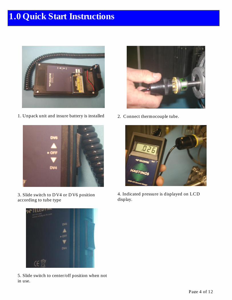
1. Unpack unit and insure battery is installed
2. Connect thermocouple tube.
3. Slide switch to DV4 or DV6 position according to tube type
4. Indicated pressure is displayed on LCD display.
5. Slide switch to center/off position when not in use.
1.0 Quick Start Instructions

Page 5 of 12
Operating Range DV-4 - 0.01 - 20 Torr (.01 to 20 mbar) DV-6 - 0.001 – 1 Torr (.001 to 1.3 mbar)
Operating temperature -20 to 50°C
Digital Display 3 ½ Digit
Input Voltage 9 Volt Battery
Input Output 11mA @ 9 VDC (Battery)
HPM 4/6 Dimensions In (mm) 5.91” (150 mm) x 3.15” (80mm) x 1.18” (30mm)
Weight with Case-Lbs (kg) 1.8 lbs (0.8 kg)
CE Compliance EN61326:1997, A1:1998 A2:2001, A3:2003
Electromagnetic interferences (EMI) in the frequency range 80MHtz to 1000MHz at intensity levels of 3V/m may cause the HPM-4/6 unit to display up to a 21% deviation from the correct reading.
Removing the source of the EMI or increasing the distance between the source and the HPM-4/6 will return the unit to its normal operating condition.
2.0 Specifications

Page 6 of 12
3.1. Receiving Inspection
Unpack unit and inspect all items for obvious signs of damage. Immediately advise Teledyne Hastings and the carrier of any suspected damage.
In the unlikely event that items need to be returned, first obtain an RMA (Return Material Authorization) number from our Customer Service Department at 1-800-950-2468.
3.2. Vacuum Sensor (DV-4 or DV-6 series)
Figure 3-1 shows a typical Hastings thermocouple vacuum tube. A standard 1/8” npt male stem is shown for illustration purposes only. If other type fittings are required, refer to Hastings product bulletin, PB-100A, for availability of other fittings. Product bulletins and other technical information can be found at www.teledyne-hi.com. The thermocouple tube may be installed in any orientation however, the ideal installation is with the tube vertical and stem down. Install thermocouple tubes observing standard shop practices.
Fig 3.1
3.3. Battery Installation
The battery cover is located on the bottom rear of the HPM 4/6 Instrument. When the battery requires replacing, it can be accessed by pressing in on the battery cover release latch (the small slot on the top edge of the cover) with a small object such as a key or small screwdriver and then rotating cover open. Plug 9-volt battery into battery connector terminals. Place battery and cable into the battery compartment. Reinstall battery cover by inserting the bottom edge of the cover first and then closing the cover until it snaps into the locked position.
Note: A low battery will be indicated by “LOBAT” appearing in lower left corner of LCD display.
3.0 Installation
Page 7 of 12
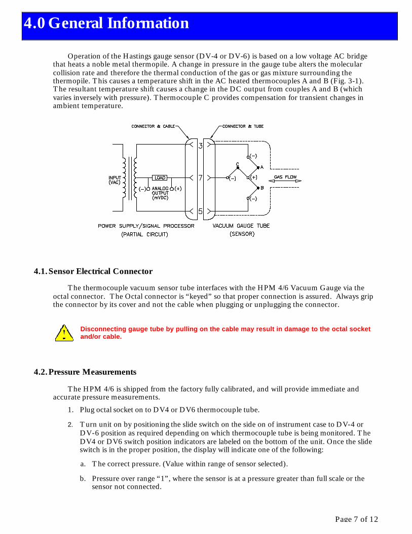
Operation of the Hastings gauge sensor (DV-4 or DV-6) is based on a low voltage AC bridge that heats a noble metal thermopile. A change in pressure in the gauge tube alters the molecular collision rate and therefore the thermal conduction of the gas or gas mixture surrounding the thermopile. This causes a temperature shift in the AC heated thermocouples A and B (Fig. 3-1). The resultant temperature shift causes a change in the DC output from couples A and B (which varies inversely with pressure). Thermocouple C provides compensation for transient changes in ambient temperature.
4.1. Sensor Electrical Connector
The thermocouple vacuum sensor tube interfaces with the HPM 4/6 Vacuum Gauge via the octal connector. The Octal connector is “keyed” so that proper connection is assured. Always grip the connector by its cover and not the cable when plugging or unplugging the connector.
Disconnecting gauge tube by pulling on the cable may result in damage to the octal socket and/or cable.
4.2. Pressure Measurements
The HPM 4/6 is shipped from the factory fully calibrated, and will provide immediate and accurate pressure measurements.
1. Plug octal socket on to DV4 or DV6 thermocouple tube.
2. Turn unit on by positioning the slide switch on the side on of instrument case to DV-4 or DV-6 position as required depending on which thermocouple tube is being monitored. The DV4 or DV6 switch position indicators are labeled on the bottom of the unit. Once the slide switch is in the proper position, the display will indicate one of the following:
a. The correct pressure. (Value within range of sensor selected).
b. Pressure over range “1”, where the sensor is at a pressure greater than full scale or the sensor not connected.
4.0 General Information
Page 8 of 12
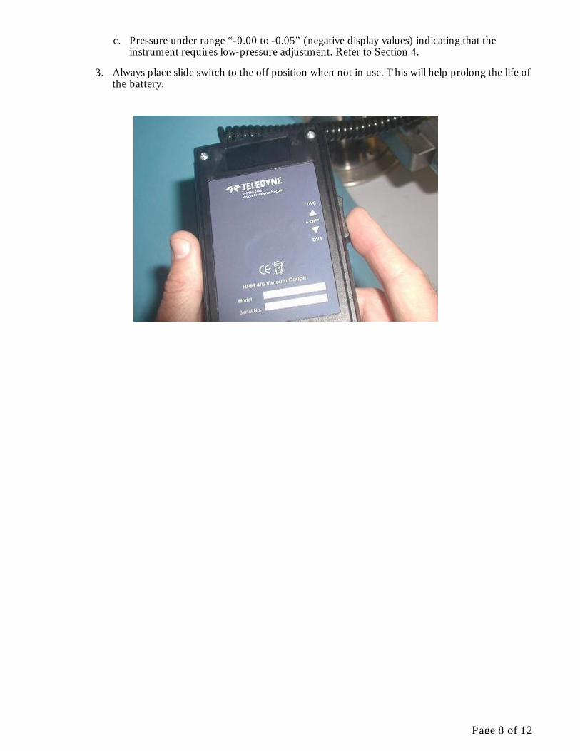
c. Pressure under range “-0.00 to -0.05” (negative display values) indicating that the instrument requires low-pressure adjustment. Refer to Section 4.
3. Always place slide switch to the off position when not in use. This will help prolong the life of the battery.

Page 9 of 12
5.1. Calibration in a Vacuum System
1 Install a DV-4 or DV-6 sensor in your vacuum system and evacuate vacuum chamber to a pressure less than 1.00E-04 Torr.
NOTE: Refer to Fig 3 for locations of calibration pots. Adjust only the pot that corresponds to the particular type of sensor tube installed (DV4 or DV6).
2 DV-4 or DV6 zero adjustment pot:
a. Remove battery compartment cover.
b. Adjust DV-4 or DV6 (as required for particular type of tube installed) calibration pot, until display reads 0.00.
3 The HPM4/6 is now calibrated. Slide switch to OFF position and disconnect gauge cable from sensor.
4 Re-Install battery compartment cover.
5.2. Calibration with a Reference Tube
NOTE: Refer to Fig 3 for locations of calibration pots. Adjust only the pot that corresponds to the particular type of sensor tube installed (DV4 or DV6).
5.0 Calibration

Page 10 of 12
1 DV-4 low pressure adjustments:
a. Connect instrument gauge cable to a DB-16D Reference Tube and position slide switch to DV-4.
b. Remove battery compartment cover, and then adjust DV-4 calibration pot until display reads pressure value listed on reference tube label.
c. Set slide switch to OFF position and disconnect gauge cable from sensor.
d. Reinstall battery compartment cover.
2 DV-6 low pressure adjustment:
a. Connect instrument gauge cable to a DB-20 Reference Tube and position slide switch to DV-6.
b. Remove battery compartment cover, and then adjust DV-6 calibration pot until display reads pressure value listed on reference tube label.
c. Slide switch to OFF position and disconnect gauge cable from sensor.
d. Reinstall battery compartment cover.
Page 11 of 12
6.1. Authorized Maintenance
The HPM 4/6 Power Supply/Display does not require maintenance other than routine battery replacement and calibration.
Note: A low battery will be indicated by “LOBAT” appearing in lower left corner of LCD display.
In the unlikely event that the HPM4/6 fails or is damaged, only qualified Teledyne Hastings personnel should attempt repair. If the HPM4/6 should require service, the unit may be returned by first obtaining an RMA (Return Material Authorization) number from our Customer Service Department at 1-800-950-2468.
Refer to Section 7 last page.
Instrument repair should only be performed by Teledyne Hastings service technicians.
Contact with harsh solvents and chemicals to any plastic parts of the HPM 4/6 Vacuum Gauge can damage the unit and may void the warranty.
6.0 Maintenance
Page 12 of 12
7.1. Warranty Repair Policy
Hastings Instruments warrants this product for a period of one year from the date of shipment to be free from defects in material and workmanship. This warranty does not apply to defects or failures resulting from unauthorized modification, misuse or mishandling of the product. This warranty does not apply to batteries or other expendable parts, nor to damage caused by leaking batteries or any similar occurrence. This warranty does not apply to any instrument which has had a tamper seal removed or broken.
This warranty is in lieu of all other warranties, expressed or implied, including any implied warranty as to fitness for a particular use. Hastings Instruments shall not be liable for any indirect or consequential damages.
Hastings Instruments, will, at its option, repair, replace or refund the selling price of the product if Hastings Instruments determines, in good faith, that it is defective in materials or workmanship during the warranty period. Defective instruments should be returned to Hastings Instruments, shipment prepaid, together with a written statement of the problem and a Return Material Authorization (RMA) number. Please consult the factory for your RMA number before returning any product for repair. Collect freight will not be accepted.
7.2. Non-Warranty Repair Policy
Any product returned for a non-warranty repair must be accompanied by a purchase order, RMA form and a written description of the problem with the instrument. If the repair cost is higher, you will be contacted for authorization before we proceed with any repairs. If you then choose not to have the product repaired, a minimum will be charged to cover the processing and inspection. Please consult the factory for your RMA number before returning any product repair.
TELEDYNE HASTINGS INSTRUMENTS
804 NEWCOMBE AVENUE
HAMPTON, VIRGINIA 23669 U.S.A.
ATTENTION: REPAIR DEPARTMENT
TELEPHONE (757) 723-6531 1-800-950-2468
FAX (757) 723-3925
E MAIL mailto:[email protected]
INTERNET ADDRESS http://www.hastings-inst.com
Repair Forms may be obtained from the “Information Request” section of the Hastings Instruments
7.0 Warranty