14.00 m. mooring tug boat - חברת החשמל לישראל b - specification... · -1-technical...
TRANSCRIPT
-1-
TECHNICAL SPECIFICATION
Boat 3-2013
15-16 M Steel Hull Mooring Tug Boat
Version 1.52
Prepared & Edited
For
Israel Electric Corporation Ltd. By
Mar Tech Marine Systems Ltd
Eng. Isaac Avtalion Mr. Dror Maor
May 2013
בדק : רמי מנשה
אישר : שרגא ויצמן
-2-
Contents
1. INTRODUCTION .......................................................................................................................................... 5
2. GENERAL DESCRIPTION ....................................................................................................................... 5
2.1 Main Dimensions and Weights ................................................................................................................... 7 2.2 Performance ................................................................................................................................................ 7 2.3 Noise and Vibration ..................................................................................................................................... 7 2.4 Vibrations .................................................................................................................................................... 7 2.5 Stability ........................................................................................................................................................ 7 2.6 Ambient Conditions ..................................................................................................................................... 8 2.7 Tank Capacity ............................................................................................................................................. 8
3. REGULATIONS ........................................................................................................................................ 8
4. CLASSIFICATION .................................................................................................................................... 9
5. APPROVAL .............................................................................................................................................. 9
6. DOCUMENTS ......................................................................................................................................... 10
7. WARRANTY .......................................................................................................................................... 11
8. DELIVERY .............................................................................................................................................. 11
9. WORKMANSHIP AND QUALITY OF MATERIALS .............................................................................. 11
10. HULL CONSTRUCTION ........................................................................................................................ 12 10.1 General description ................................................................................................................................. 12 10.2 Main Scantlings ....................................................................................................................................... 12 10.3 Tank configuration ................................................................................................................................... 12 10.4 Fuel Oil tanks .......................................................................................................................................... 12 10.5 Fresh water tank ..................................................................................................................................... 12 10.6 Dirty oil collecting tank ............................................................................................................................. 13 10.7 Sludge ..................................................................................................................................................... 13 10.8 Chain locker ............................................................................................................................................ 13 10.9 Deck ........................................................................................................................................................ 13 10.10 Anchors (2) ............................................................................................................................................ 13 10.11 Bulwark.................................................................................................................................................. 13 10.12 Mooring ports ........................................................................................................................................ 14 10.13 Engine foundation ................................................................................................................................. 14 10.14 Hatches ................................................................................................................................................. 14 10.15 Manholes ............................................................................................................................................... 14 10.16 Stairs Ladders and Climbing steps ....................................................................................................... 14 10.17 Handrails ............................................................................................................................................... 14 10.18 Air gratings ............................................................................................................................................ 15 10.19 Air duct covers ...................................................................................................................................... 15 10.20 Inspection .............................................................................................................................................. 15
-3-
11. SUPERSTRUCTURE ............................................................................................................................. 15 11.1 General description ................................................................................................................................. 15 11.2 Windows and Doors ................................................................................................................................ 16 11.3 Clear view screens .................................................................................................................................. 16 11.4 Rope guards ............................................................................................................................................ 16
12. RUBBER FENDERS .............................................................................................................................. 16 12.1 Bow ......................................................................................................................................................... 16 12.2 Side hull ................................................................................................................................................... 17 12.3 Stern of the boat ...................................................................................................................................... 17
13. STEEL OUTFITTING ............................................................................................................................. 17 13.1 Bollards ................................................................................................................................................... 17 13.2 Tow Bar ……………………………………………………………………………………………………..……18 13.3 Towing bit aft deck .................................................................................................................................. 17 13.4 Mast......................................................................................................................................................... 17 13.5 Navigation light boxes ............................................................................................................................. 17 13.6 boat particulars ........................................................................................................................................ 17 13.7 Draught marks and Margin Lines ............................................................................................................ 17 13.8 Welding Draught marks .......................................................................................................................... 18 13.9 Equipment and system Name plates ...................................................................................................... 18
14. PROPULSION PLANT ........................................................................................................................... 18 14.1 Main engines and gearboxes .................................................................................................................. 18 14.2 Bow Thruster ........................................................................................................................................... 19 14.3 Marine diesel generator – see paragraph 18.8 ...................................................................................... 19 14.4 Shafts, stern tubes and struts ................................................................................................................. 19 14.5 Propeller .................................................................................................................................................. 19 14.6 Steerable Nozzles ................................................................................................................................... 19 14.7 Control and Monitoring ............................................................................................................................ 20 14.8 Alarms ..................................................................................................................................................... 20 14.9 Emergency stop ...................................................................................................................................... 21
15. STEERING SYSTEM .............................................................................................................................. 21 15.1 General.................................................................................................................................................... 21 15.2 Rudder stock and sealing ........................................................................................................................ 21 15.3 Tillers and tie bar ..................................................................................................................................... 21 15.4 Steering gear ........................................................................................................................................... 21 15.6 Emergency steering ................................................................................................................................ 22 15.7 Rudder position indicator......................................................................................................................... 22
16. DECK EQUIPMENT ............................................................................................................................... 23 16.1 Anchoring equipment .............................................................................................................................. 23 16.2 Set mooring lines .................................................................................................................................... 23 1 towing line 8" X 100 m .................................................................................................................................. 23 16.3 Towing and lifting equipment .................................................................................................................. 23 16.3.1 Towing hook and line ........................................................................................................................... 23 16.3.2 Capstan ................................................................................................................................................ 23 16.3.3 Hydraulic marine crane ........................................................................................................................ 23 16.4 Pad eyes ................................................................................................................................................. 23 16.6 Lashing pad eyes .................................................................................................................................... 24
17. AUXILIARY SYSTEMS .......................................................................................................................... 24 17.1 General.................................................................................................................................................... 24 17.1.1 Pumps .................................................................................................................................................. 24 17.2 ................................................................................................................................................ Bilge system ........................................................................................................................................................................ 24 17.2.1 General description .............................................................................................................................. 24 17.2.2 Bilge pumps ......................................................................................................................................... 25 17.2.3 Alarms sensor ..................................................................................................................................... 25 17.3 Firefighting and deck wash ..................................................................................................................... 25 17.4 Fuel oil system ........................................................................................................................................ 26 17.5 Cooling water system .............................................................................................................................. 26 17.6 Fresh water system ................................................................................................................................. 27
-4-
17.7 Exhaust system ....................................................................................................................................... 27 17.8 Lubrication system .................................................................................................................................. 27 17.9 Hydraulic System .................................................................................................................................... 28 17.10 Sea water system .................................................................................................................................. 28
18. ELECTRIC INSTALLATION ................................................................................................................... 28 18.1 General Description ................................................................................................................................ 28 18.2 Batteries .................................................................................................................................................. 29 18.3 Battery charging ...................................................................................................................................... 29 18.4.Shore Power connection ……………………………………………………………………………………..…31 18.4.1 Power Tools connection ....................................................................................................................... 29 18.5 Cables and wires ..................................................................................................................................... 30 18.6 Switchboards / Distribution panels .......................................................................................................... 30 18.7 Lighting .................................................................................................................................................... 31 18.8 A.C. system ............................................................................................................................................. 31 18.9 Low pressure air compressor .................................................................................................................. 32
19. PAINT ..................................................................................................................................................... 32 19.1 General.................................................................................................................................................... 32 19.2 Table of painting specification ................................................................................................................. 32
20. CATHODIC PROTECTION .................................................................................................................... 33
21. VENTILATION ........................................................................................................................................ 34
22. AIR CONDITIONING .............................................................................................................................. 34
23. LIFE SAVING EQUIPMENT ................................................................................................................... 34
24. NAUTICAL NAVIGATION AND COMMUNICATION EQUIPMENT ...................................................... 34
25. JOINERY AND INSULATION ................................................................................................................ 36 25.1 General.................................................................................................................................................... 36 25.2 Wheel house ........................................................................................................................................... 37 25.3 Arrangement in wheelhouse ................................................................................................................... 37 25.4 Engine room, aft peak and stores ........................................................................................................... 38
26. ACOUSTIC INSULATION ...................................................................................................................... 38
27. SPARE PARTS, TOOLS AND INVENTORY ......................................................................................... 38
28. TESTS AND TRIALS .............................................................................................................................. 39 28.1 General.................................................................................................................................................... 39 28.2 Delivery tests to include: ......................................................................................................................... 39 28.3 "As Made" set of drawing ........................................................................................................................ 40 28.4 Heavy duty Docking ................................................................................................................................ 40
NOMENCLATURE (Abbreviations) .................................................................................................................... 41
APPENDIX A – General Instructions ............................................................................................................... 42
APPENDIX B ...................................................................................................................................................... 44 B1 Main engine rating and particulars ...................................................................................................... 44 B2 Steerable Nozzle System Arrangement .............................................................................................. 44 B3 Kaplan propeller for Nozzle application............................................................................................... 44 B4 Water tight doors, one handle operated, LRS approved .................................................................... 44 B5 Clear View Screen particulars ............................................................................................................. 44 B6 Hydraulic steering system ................................................................................................................... 44 B7 Thermal insulation material (sample delivered to IEC) ....................................................................... 44 B8 Acoustic insulation material (sample delivered to IEC) ....................................................................... 44
APPENDIX C: - Wheelhouse artist impression ………………………………………………………………………47
-5-
1. INTRODUCTION
This technical specification intends to cover in sufficient details the requirements for
the construction and supply of a coastal Twin Screw, Steel Hull Mooring Tug Boat
for the ISRAELI ELECTRIC Corporation Ltd. (hereinafter "IEC" or the "Owner").
Participants are to offer a proven design of a similar tug boat and a full and
complete specification to IEC.
All details of this specification should be regarded as basic and obligating
guidelines for the full and complete technical specification of a proven design tug
boat – offered by the participants.
This specification will form an integral part of the building / purchasing contract
signed by the owner and builder.
IEC holds the right to supervise by its representatives (or others nominated by the
owner) at all times the building/ outfitting/ preparation of the tug boat to be supplied.
2. GENERAL DESCRIPTION
A. The tug boat is intended for service as a coastal mooring tug for Oil
tankers and as a work boat /platform for diving operation, supporting marine
pollution operations at IEC's power stations basin and offshore berths (eastern
coast of the Mediterranean).
B. The tug boat should be a Twin Screw design with fixed pitch Kaplan type
propellers and a Steerable Nozzles arrangement - for achieving high thrust
and better maneuverability.
C. The main service tasks are:
C.1 To deliver mooring ropes at C.B.M. (Conventional Buoy Mooring)
berths Offshore.
C.2 Platform for small diving operations (up to six divers).
C.3 Pilot and crew transfer – shore to ship.
C.4 Towing the anti-pollution/working barge
C.5 Towing oil booms
-6-
D. Stern (Aft) Free Board to deck - about 60-70 cm for easy handling of buoys
up to 50 Kg. by crew. Pick up manually from the water by the crew.
E. Wheel house to accommodate 7 persons. Sitting arrangement for
additional 5 persons to be provided outside the wheel house, on deck. Total
number of people on board = 12. Sitting arrangements to be provided for all
people onboard (to IMOT requirements).
F. Safety crew – 2 persons.
G. Forward flush deck for Safe and easy embracement (embarking) of crew to
ship & mooring buoys
H. Only gas oil fuel (diesel) to be used on board.
I. Duration of stay at open sea - 12 hours.
-7-
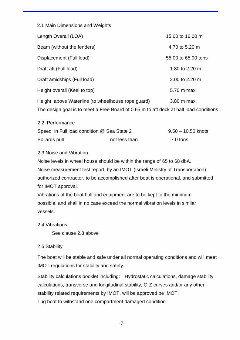
2.1 Main Dimensions and Weights
Length Overall (LOA) 15.00 to 16.00 m
Beam (without the fenders) 4.70 to 5.20 m
Displacement (Full load) 55.00 to 65.00 tons
Draft aft (Full load) 1.80 to 2.20 m
Draft amidships (Full load) 2.00 to 2.20 m
Height overall (Keel to top) 5.70 m max.
Height above Waterline (to wheelhouse rope guard) 3.80 m max.
The design goal is to meet a Free Board of 0.65 m to aft deck at half load conditions.
2.2 Performance
Speed in Full load condition @ Sea State 2 9.50 – 10.50 knots
Bollards pull not less than 7.0 tons
2.3 Noise and Vibration
Noise levels in wheel house should be within the range of 65 to 68 dbA.
Noise measurement test report, by an IMOT (Israeli Ministry of Transportation)
authorized contractor, to be accomplished after boat is operational, and submitted
for IMOT approval.
Vibrations of the boat hull and equipment are to be kept to the minimum
possible, and shall in no case exceed the normal vibration levels in similar
vessels.
2.4 Vibrations
See clause 2.3 above
2.5 Stability
The boat will be stable and safe under all normal operating conditions and will meet
IMOT regulations for stability and safety.
Stability calculations booklet including: Hydrostatic calculations, damage stability
calculations, transverse and longitudinal stability, G-Z curves and/or any other
stability related requirements by IMOT, will be approved be IMOT.
Tug boat to withstand one compartment damaged condition.
-8-
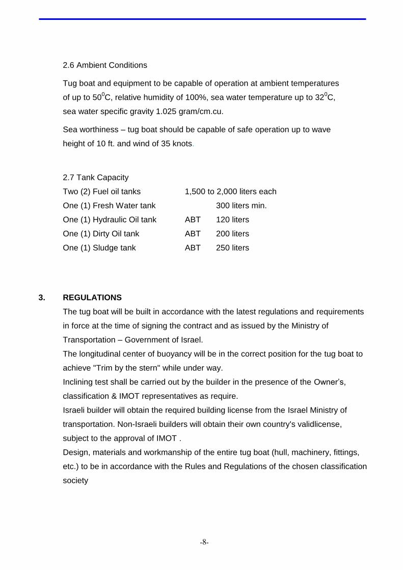
2.6 Ambient Conditions
Tug boat and equipment to be capable of operation at ambient temperatures
of up to 500C, relative humidity of 100%, sea water temperature up to 32
0C,
sea water specific gravity 1.025 gram/cm.cu.
Sea worthiness – tug boat should be capable of safe operation up to wave
height of 10 ft. and wind of 35 knots.
2.7 Tank Capacity
Two (2) Fuel oil tanks 1,500 to 2,000 liters each
One (1) Fresh Water tank 300 liters min.
One (1) Hydraulic Oil tank ABT 120 liters
One (1) Dirty Oil tank ABT 200 liters
One (1) Sludge tank ABT 250 liters
3. REGULATIONS
The tug boat will be built in accordance with the latest regulations and requirements
in force at the time of signing the contract and as issued by the Ministry of
Transportation – Government of Israel.
The longitudinal center of buoyancy will be in the correct position for the tug boat to
achieve "Trim by the stern" while under way.
Inclining test shall be carried out by the builder in the presence of the Owner’s,
classification & IMOT representatives as require.
Israeli builder will obtain the required building license from the Israel Ministry of
transportation. Non-Israeli builders will obtain their own country's validlicense,
subject to the approval of IMOT .
Design, materials and workmanship of the entire tug boat (hull, machinery, fittings,
etc.) to be in accordance with the Rules and Regulations of the chosen classification
society
-9-
4. CLASSIFICATION
The tug boat will be built in accordance with the classification detailed below, and will
fully comply with the classification society 's rules and regulations, The tug boat
should also comply with the IMOT (Israeli Ministry of Transportation) regulations.
The tug boat shall be certificated by class:
+100A1 Tug Specified Coastal Waters or Route Service LMC (without cross).
Certification by LLOYD’S Register of Shipping or any other reputable, equivalent
certification (such as BV, ABS, GL, DNV).
Service along a coast or between two or more ports, and for a distance out to sea
generally not exceeding 7 nautical miles. The geographical limits of which will be
noted in the IMOT navigation license.
The classification society will be chosen by IEC, and a supervision contract will be
signed between IEC and the classification society .
5. APPROVAL
The Owner or its representatives shall approve all main tug boat drawings, in order
to confirm conformity to the specification and contract.
All main purchased equipment, including machinery, shall be subject to IEC's
approval prior to purchase.
Any substitution or change to equivalent equipment – must receive IEC's
confirmation and approval.
Relevant data and drawings shall be delivered for approval and confirmation to the
Chief Naval Architect, Engineering Dept. Shipping and Port Authority, Israeli Ministry
Of Transportation (IMOT),
15 Pal Yam Street. 31339 Haifa, Israel.
-11-
6. DOCUMENTS
Following documents are required to be delivered to IEC with Tug delivery:
A) builder's certificate
b) Class: +100A1 Tug Specified Coastal Waters or Route Service LMC (without
cross) or equivalent.
c) Navigation license by IMOT.
d) Sea trials test reports
e) Stability booklet and General Arrangement drawing (approved by IMOT)
f) Safety plan drawing (Laminated).
g) Electrical, electronic and hydraulic system drawings
h) Cooling Water system drawing
I) Detailed Weight book
j) Inventory list and all shipyard orders & subvendor details
k) "As made" drawings, diagrams, manufactures equipment manuals, operation and
maintenance manuals, list of agents for the equipment,
spare parts manuals (according to the contract requirement) and a copy of all
shipyard orders applicable to this project.
All documents and drawings to be provided in four (4) duplicates. (Hard copies) and
two (2) magnetic media copies (C.D.) or flash. /ssd
Training: The builder will train the IEC crew and provide instruction on all
equipment, electrical boards and circuits, piping systems, and instruments.
A list of Drawings shall be submitted for approval before delivery:
-11-
7. WARRANTY
1. Steel work, hull, deck, wheelhouse 24 (twenty four) month builder warranty at the
owner premises. IEC will have the right to extend the warranty period up to 5 years.
Warranty period shall commence upon acceptance of the tug boat by IEC.
.
2. Dry docking : a 24 month warranty for dry-docking and repairs in Owner's country
will be provided by the builder at his cost ( if the builder is Israeli ,the docking can
take place at his yard).
3. Machinery: (main engines, generator, pumps, propulsion line, shafts, Propellers,
struts, bearings, nozzles, crane, winch, etc. - 24 months .
4. Electric system and electric switchboards – 24 months .
5. Electronic equipment- 24 months .
The builder will have the capability to repair and maintain the tug boat at its
regular location in Israel , and will supply all the necessary spare parts and/or
tooling required during the warranty period.
See also contract for Terms and Conditions.
8. DELIVERY
The tug boat will be delivered not later than 12 months after signing the order contract, to
the owners in Israel to "Eshkol" power station in Ashdod.
The tug boat will be complete and ready for operation on delivery.
The builder will be responsible for all the permits and tests required by the Israel M.O.T.
9. WORKMANSHIP AND QUALITY OF MATERIALS
The workmanship of the hull and fittings throughout shall be of good marine practice. Care
shall be taken to ensure fair lines, smooth surfaces and neat welding. All materials and
equipment installed or delivered with the vessel shall be new and of good marine quality.
Hull steel plates to be approved by the classification society and IEC's representative.
-12-
10. HULL CONSTRUCTION
10.1 General description
A double chine sea going hull with a round stern and a full displacement bow.
Hull material to be of steel plates, frame and girders, certified by the classification
society .
Water tight bulkheads, to divide the hull into water tight compartments to allow for
“one compartment” damaged stability condition.
All scantlings and structural dimensions are IEC's recommendation and should
comply with the class and IMOT rules/ regulations
10.2 Main Scantlings
Side shell no less than 8 mm.
Bottom plates no less than 8 mm.
Deck plating no less than 6 mm.
Bulkhead plates no less than 6 mm.
Stern plates no less than 10mm.
Bow plates no less then 10 mm
Keel bar 300 x 15 mm.
Frame spacing 450 mm.
10.3 Tank configuration
All tanks to be provided with bolted manhole covers, to ensure easy access and
inspection.
Drain plugs (docking plugs), filling, discharge, vent and sounding pipes to be
provided for all tanks and installed to class regulations.
Gauge glass, calibrated by liters, to be provided to all fuel tanks.
Remote Shut down valve operating from deck to be provided.
10.4 Fuel Oil tanks
Two main fuel oil tanks to be provided.
The F.O. tanks form an integral part of the hull structure.
Total fuel oil tanks capacity to be in excess of 3,000 liters.
10.5 Fresh water tank
Tank to be provided with a hydrophore system for supplying FW to taps on deck,
-13-
engine room and wind screen.
Total net capacity of tank to be 300 liters min.
10.6 Dirty oil collecting tank
One steel double bottom tank to be an integral part of the hull, close or within the
engine room compartment.
Total tank capacity ABT 200 liters.
10.7 Sludge
One structural double bottom tank to be an integral part of the hull.
Total tank capacity ABT 250 liters.
10.8 Chain locker
The chain locker to be capable of housing the full length of the chain (chain length
70 m) or rope according to Ministry of Transportation Guidelines.
Access to the chain locker should be provided through the forepeak, to enable
maintenance.
10.9 Deck
The deck surface will be free from obstacles and coated with anti-slip American
Safety standard 440 G
Deck structure aft, to be constructed to carry loads of 2.00 tons per square meter
and a total of 4 tons of different cargo.
Opening or openings for main engines servicing to be provided on deck.
Openings to be covered by watertight flash plates bolted by stainless steel bolts.
Eye bolts to be fitted on engine room ceiling for main engines/gearbox maintenance
service.
Forward deck to be fitted with breakwater in front of wheelhouse.
Working ports on deck to be reinforced and protected for chain handling.
10.10 Anchors (2)
One aluminum anchor to be fitted on front wall of the wheel house or on deck.
And one to be spare.
10.11 Bulwark
A bulwark of 0.60 m height, (from deck) with opening ports to be provided along the
aft deck. However, on the bow deck – both sides, a flat deck with no bulwark to ease
embracement.
-14-
Water freeing ports to enable water discharge from deck in 5 seconds.
Top of the bulwark to be protected and reinforced by a bulwark pipe/whole- bar
A pipe of 76x6 mm to be fitted on the stern bulwark (to protect towing cable).
Stern bulwark with opening for chain handling. Deck corner will be fitted with half
round reinforcement.
10.12 Mooring ports
Mooring ports to be fitted in the bulwark on both sides of the aft deck.
10.13 Engine foundation
The engine foundation to be sufficiently rigid to minimize hull vibrations exerted by
the engines. The manufacturer will use b.a.t (best available technology) for tug
boats. Main engines and reduction reverse gearboxes to be secured to the top plate
of the seating.
10.14 Hatches
All hatch covers to be watertight by means of gaskets.
All hinges to be adjustable and provided with grease nipples.
10.15 Manholes
All tanks, to be accessible for inspection, service and cleaning via manholes.
Manholes to be closed by watertight plate covers, secured by bolts.
10.16 Stairs Ladders and Climbing steps
All interior stairs to be made of stainless steel (St.St.) 316L.
Wheelhouse roof climbing ladder to be a detachable type of St.St. 316L.
Diver's Detachable ladder for seawater to boat deck climbing, made of marine
Aluminum material (5086,5083 or equivalent).
All ladders to have non-slip steps.
If required, tanks to be provided with climbing steps and handgrips.
10.17 Handrails
All handrails to be made of St.St. 316L material.
Handrails to be welded along sides and front of wheelhouse.
Storm handrails to be provided in additional locations to owner’s specific demand.
Handrails on the bow for safe embarkment and disembarkement of vessel.
Handrails to be provided inside wheelhouse ceiling and at control console.
-15-
10.18 Air gratings
Galvanized air gratings to be fitted in the inlet/outlet of engine room ventilation ducts.
10.19 Air duct covers
For firefighting purposes, steel covers or flaps are to be fitted to the air gratings for
engine room ventilation (on deck).
Covers to be closed manually.
10.20 Inspection
Welds to be checked occasionally as required by IEC and classification society 's
requirements.
Only approved and certified welders to carry out work on the tug boat’s hull.
X-Ray tests of welds, to be carried out at least at 10% sampling by IEC
representative or surveyor.
11. SUPERSTRUCTURE
11.1 General description
The superstructure includes the following functions:
- Floating wheelhouse on shock absorber to be made of steel to accommodate 7
persons for 12 hours at open sea conditions. The design of the wheelhouse will
make Extra care for crew and skipper ergonomics comfort and boat handling
- Seven (7) seats. See the attached drawings/artist impression at appendix C.
- One (1) skipper seat in front – designed to functional and comfort use.
- Lockers for crew.
- Lockers for safety equipment.
- Access to engine room, can be adjacent to rear wheelhouse wall.
- Additional bench for 5 persons outside of wheelhouse.
- Air conditioning arrangement and air condition unit 1.5 H.P.
- A breakwater barrier to be constructed on deck in front of wheelhouse to
reduce water
- flow under the raised wheelhouse.
- All the equipment exposed to the sea environment and located outside the
Cabin shall be IP67 protected.
-16-
11.2 Windows and Doors
Windows to allow full 3600 view field for the skipper.
Top quality toughened glass of not less than 6 mm thickness to be provided for all
windows.
Glass to be fitted in aluminum bolted frames (Aluminum Frames to be isolated from
the steel wheelhouse, to prevent galvanic contact).
Windows arrangement on wheelhouse walls to be as follows:
Front wall - 3 windows as follows:
- One center fixed window with a clear view screen.
- One off center fixed window equipped with clear view screen starboard side.
- One off center fixed window open flops, and hinges.
Side walls -2- 3 windows on each side as follows:
- One internal open window, in the middle.
- One or Two fixed windows, one forward one aft.
Rear wall - One center water tight door with window.
- Two hinged windows, one on each side of door.
11.3 Clear view screens
Two clear view screens, of top marine quality, to be installed on the two front
windows of the wheelhouse, center and portside.
All metal parts to be made of marine aluminum. Units to be water and air tight,
making it suitable for air-conditioned bridge. Motor to be 24VDC, 40W min. Rotating
glass diameter to be 12” – 15”. Each unit to be controlled separately.
11.4 Rope guards
Rope guards to be fitted on wheelhouse roof.
12. RUBBER FENDERS
All fenders to be secured to the hull by steel studs, through steel U shape profile.
Attention should be taken to ensure continuity with other sections with fenders.
Fenders arrangement to be the following: Sides of the bow to be protected by
additional D shape fenders – from deck to water line.
12.1 Bow
Heavy duty ‘D’ shape blocks of 250x250 mm to be provided, and install vertically
A round pusher fender to be installed above the D shape blocks.
-17-
12.2 Side hull
Heavy-duty D-shape rubber fenders to be mounted on sides of hull.
Dimensions about 150 x 150 mm
12.3 Stern of the boat
Heavy-duty D-shape rubber fenders to be fitted around the stern. To be install one by
one vertically (One next the other). Dimensions about 250 x 250X300 mm.
13. STEEL OUTFITTING
13.1 Bollards
Steel welded double Bollards are to be fitted on both sides at fore and aft ends of deck.
Welded single Bollards are to be fitted amidships on both sides.
All Bollards to be made of 6” diameter pipe – SCH.80.
13.2 Tow bar
The main tow bar, to be fitted athwart, to consist of a double cross bollard, (H shape) made
of two heavy pipes interconnected by horizontal heavy pipe.
13.3 Towing bit aft deck
Towing bit on the aft deck is part of a separate section and welded to the deck construction.
13.4 Mast
Stainless steel mast for navigation lights and antennas, to be fitted on the aft of the
wheelhouse roof. Head light and anchor light on mast will operated while mast is folded to
low position
The mast to be of a foldable type with locking arrangement.
13.5 Navigation light boxes
Side boxes to be welded on wheelhouse top deck for navigation lights.
13.6 Tug boat particulars
Welded characters for the tug boat name on the bow and for the port of registry on the
stern to be applied.
A Company name or logo on wheelhouse sides to be fixed if required.
13.7 Draught marks and Margin Lines
Draught marks to be provided at both sides of the bow and stern. Additional margin lines in
aft and forward to be provided as required.
-18-
13.8 Welded Draught marks
Draught marks to be marked by welding on port and starboard sides of the hull.
13.9 Equipment and system Name plates
Brass nameplates to be provided in all inside compartments, equipment, pipes, valves
,weather deck, and all systems
Plastic nameplates may be provided inside the wheelhouse.
All inscriptions to be in Hebrew and English language.
14. PROPULSION PLANT
The propulsion plant of the vessel is based on two independent propulsion lines
each consisting of a main engine, reverse reduction gearbox with flexible coupling,
shaft line, and Kaplan propeller in Steerable Nozzles
14.1 Main engines and gearboxes
Main engines
Make: CATERPILLAR marine diesel engines
Model: C-7 A-RATING - DM7590-01,
S.B engine: C-7 ; 186 bkW @ 8100 rpm LH service
P.S engine: C-7 ; 186 bkW @ 8111 rpm RH service
Gearboxes
Twin disc MGX 5075SC Reverse reduction gearboxes 2.88:1
Gearbox reduction ratio to be checked and confirmed by propulsion line supplier and
shipyard.
Gearboxes to be directly mounted on main engines via a flexible coupling.
Each engine and gearbox to be rigidly mounted to engine room beds.
Engines to be electrically started (24V DC).
Cooling system to be of the closed circulating water cooling type – to allow for
shallow water operation (Keel cooling system).
Hydraulic steering pump, as required to supply proper volume and head to the
hydraulic steering system, to be installed on one engine PTO (Power Take Off)–
directly coupled.
A second Hydraulic pump with a manual engaging clutch, as required to supply
proper volume and head to the hydraulic power system, to be installed on the
second engine PTO.
Main engine control and monitoring board to be installed in the wheelhouse console
-19-
while a secondary monitoring board to be installed in engine room (for each engine).
Control panels on each engine should face inward.
14.2 Bow Thruster
Hydraulic / Electric heavy duty "Bow Thruster" of ABT 20 –25 hp to be
installed below the boat bow water line .The electric current will be 24V DC .
in case of hydraulic unit, hydraulic power pack with electric pump of 24V DC
and reservoir will be installed in the forward/store compartment near the
thruster.
14.3 Marine diesel generator – see paragraph 18.8
14.4 Shafts, stern tubes and struts
Each shaft to pass through a stern tube and be supported by water lubricated rubber
bearings and/or grease lubricated bearings as required by class rules and per the
specific design.
The propeller shaft to be of stainless steel material – type 1.4057 or equivalent.
Stern tube arrangement will include stuffing box, arrangement or equivalent as per
the specific approved design.
Stern tube pipe will consist of a pipe with fore and aft bossing, properly
fastened/welded to the hull structure by streamlined struts and frames – as required.
Complete propulsion line to be supplied by propeller manufacturer and fitted for in its
production plant.
14.5 Propeller
Propeller to be counter rotating and designed to the required boat performance by
propeller manufacturer as Eliche Radice-Italy (ER), France Helices-France (FRH) or
equivalent.
Propeller type Kaplan
No. of Blades 4
Material NiBrAl
Rope Cutter to be fitted in front of propeller.
14.6 Steerable Nozzles
Nozzle to perform as directional/steering nozzles – taking also the rudder function.
Nozzle material to be steel with stainless-steel ring around propeller path for
reducing pitting and cavitation efficiency losses.
Nozzle directional operation to be performed by means of hydraulic power controlled
-21-
by the helm in the wheelhouse.
Fixed directional plates to be fixed on nozzle aft side for better directional stability
and maneuvering.
Nozzles to be produced supplied and fitted to propeller by propeller manufacturer.
14.7 Control and Monitoring
All functions of control and monitoring to be available from the main console in the
wheelhouse.
Engine rpm and gearbox ahead/neutral/astern position to be remotely controlled
from wheelhouse, with one lever for each propulsion line.
Engine monitoring and control functions and indications to be included in the main
operating panel installed in the wheelhouse.
A secondary engine control panel to be installed in the engine room.
A fully redundant backup system is included to ensure Propulsion system operation
in the event of a failure to the Primary control system.
Main engine/gearbox control and monitoring panel at wheel house to include:
Engine rpm
Cooling water temperature
Engine Lubricating oil pressure
Gearbox lubricating oil pressure
Gearbox lubricating oil temperature
Start/stop buttons (or switches)
Emergency engine shut down switch
♦ Combined Engine rpm and gearbox position control lever throttle by
KOBELT-mighty mariner or TWIN DISC EC-300
14.8 Alarms
Alarms to be visual and audible at the same time.
Acknowledgement of audible alarm to be separated from visual alarm.
The alarms in engine room to be individually displayed.
A group alarm for each engine line to be provided in the wheelhouse console.
Alarm indication on panel to be as follows:
Flashing light for incoming alarm
Steady light for acknowledged alarm
No signal for disappearance of alarm condition after acknowledgement.
Following alarms to be provided for each propulsion line:
-21-
Engine - High cooling water temperature
Engine - Low lubricating oil pressure
Engine over speed
Gearbox – Low lubricating oil pressure
Gearbox – High lubricating oil temperature
Indication of water tight doors below deck in wheelhouse.
14.9 Emergency stop
Manual emergency stops, to be provided in wheelhouse for Main Engines shut down
and Engine Room Blowers.
15. STEERING SYSTEM
15.1 General
The steering system should provide high performance and maneuverability.
Steering performance to be provided by a Steerable Nozzle system.
The Steerable Nozzles perform as rudders but with higher efficiency.
15.2 Rudder stock and sealing
The Steerable Nozzles to be attached by means of adequate rudder stocks through
the hull, enabling about 250 rotation of each nozzle to port and starboard.
Rudder stocks to penetrate the hull into the aft compartment (steering room), through
adequate stuffing boxes providing water tight seals and bearings.
Rudder stocks to be supported by adequate bearing arrangement above and below
the directional nozzle.
Installation to allow for easy dismantling and assembly for maintenance purposes.
15.3 Tillers and tie bar
A tiller to be fitted to each rudder stock inside the steering compartment.
Both rudder stocks to be interconnected in the steering compartment by means of an
adjustable tie-bar, connected between the two tillers. This enables parallel
(simultaneous) movement of both steerable nozzles.
15.4 Steering gear
Steering gear to be an electro-hydraulic system, of top marine quality, “Kobelt” make
or similar, including the following main equipment and functions:
Stainless steel steering wheel 700 - 800 mm diameter –mounted on the main
console in the wheelhouse.
-22-
Non follow-up steering control by electrical jog lever steering- from wheelhouse
Non follow up power steering from wheelhouse by the steering wheel.
Local steering capabilities in steering compartment (emergency).
Emergency manual steering tiller on deck connected to the S.B rudder stoke via
Opening in the deck see paragraph 15.6
Steering gear system to comprise of the following items:
Hydraulic Actuator – attached to one tiller, steering compartment
Pressure relief and bypass valve - line mounted
Sailing valve – main console mounted, wheelhouse
One electric joystick – main console mounted, wheelhouse (with guards).
Hydraulic power pack – installed in steering compartment.
Flexible and rigid hydraulic St.St. (stainless steel) piping – as per class
requirements.
15.5 Hydraulic piping
Seamless steel precision pipes to be installed between the hydraulic equipment and
pumps.
High pressure hydraulic hoses to be applied where necessary.
15.6 Emergency steering
Local steering capabilities in steering compartment (emergency), required.
In addition, emergency manual steering tiller on deck, connected to the SB rudder
stoke via opening in the deck.
A mechanical emergency steering device, attached directly to the rudder stocks, to
be supplied.
Arrangement for bypass of the hydraulic steering cylinder to be provided.
15.7 Rudder position indicator
A top quality rudder position indicator (Kobelt make or similar) to be mounted on the
main console board in the wheelhouse.
Feedback unit to be of top quality high performance unit (Kobelt make or similar), to
ensure trouble free operation.
Mechanical rudder position (angle) indicator to be install on S.B rudder stoke
steering room
-23-
16. DECK EQUIPMENT
16.1 Anchoring equipment
Anchoring equipment and installation to be in accordance with the classification
society regulations –Coastal Service Rules.
The anchors to be marine F.O.B. type.
St.St Chain/ rope to run via the anchor into the chain locker below the fore deck.
Main anchor to be located on Deck and other in Forward Store
16.2 Set mooring lines
To be provided by builder: 4 ropes 4" X 10 m
1 rope 4" X 200 m
1 anchor rope X 200 m
1 towing line 8" X 100 m
16.3 Towing and lifting equipment
16.3.1 Towing hook and line
A 6 ton S.W.L disc type tow hook. Mampaey make or similar, certificated by
the classification society - With quick release as require by IMOT
16.3.2 Capstan
Hydraulic Capstan of 2 ton pull (SWL) to be install on port side and foreword
of the Towing bitts.
The capstan and crane can be operated paralleling.
16.3.3 Hydraulic marine crane
Hydraulic marine grade folded (knuckle boom) crane with 0.6 ton SWL @
ABT 6 Meter boom ,ABT 4.2 ton/meter Palfinger PK 4501M or equivalent to
be installed on deck starboard side .
16.4 Pad eyes
Pad eyes to be installed in front of the towing hook to allow pulley arrangement up to
5 tons SWL each.
16.5 Lifting Pad eyes
Four (4) lifting pad eyes to be provided in adequate locations to lift boat out of water.
Pad eyes to be designed for 30-35 tons S.W.L. each.
A swivel hoist ring like "Actek – safety swivel hoist ring # 46367" or equivalent is
-24-
preferable.
16.6 Lashing pad eyes
Lashing pad eyes or arrangements, on aft deck near the bulwark, to keep flat deck
advantage – 6 pcs. At both sides.
S.W.L of. – 3 tons each.
16.7 Floors
In the engine room, steering gear room and store room floor plates to be provided
over the complete area. Made of 5-6 mm raised pattern (anti slip) aluminum plates.
Where necessary the floor plates will be dismountable. Dismountable panels are
clearly marked by brass nameplate
17. AUXILIARY SYSTEMS
17.1 General
17.1.1 Pumps
Pumps to be “SIHI” make or equivalent top quality makes.
Pressure gauges to be installed in all pumps. Piping systems design, layout, on board installation and test procedures, to
comply with builder’s standards and with relevant rules of the classification
society .
All outlets/inlets through the hull to be connected by means of bolted flanges.
Sea water system pipes to be of galvanized steel material.
Seamless steel precision pipes and steel valves to be used for the hydraulic
system.
Sanitary Salt Water and Fresh Water system piping to be - Seamless steel
pipes for large bore and Cu pipes for small bore.
Seawater pipelines to be bolted by St.St. bolts.
17.2 Bilge system
17.2.1 General description
A central bilge system to be installed providing bilge suction for all boat’s
compartments.
The system to enable also seawater inlet/suction to a fire hydrant on the deck.
A bilge manifold, enabling suction control through bronze globe valves, to be
installed in the engine room. The manifold will enable suction from each
-25-
compartment separately or jointly and in addition suction of seawater through
the hull for firefighting/deck wash purposes.
Each compartment to be provided with a suction point and a strainer in its
lower most point, as per classification rule requirements. Strainers to be easily
accessible.
Each bilge suction and each separate pump suction, to have a non-return
valve installed.
The manifold to be connected to the main bilge pumps through non-return
bronze globe valves.
The bilge system to discharge overboard, via bronze overboard valve, and to
the deck wash hydrant.
17.2.2 Bilge pumps
Three bilge pumps of the self-priming type to be installed.
One of the pumps is driven by the main engines.
One electric pump 24v DC driven with automatic operating device.
One electric pump 380V AC driven
Pumps to be top quality make. Capacity as per class requirements.
17.2.3 Alarms sensor
Automatic level sensor to be installed in each compartment near the bilge
suctions.
When activated a visual alarm to be operated in the wheelhouse, showing the
activating compartment. A separate group audible alarm to be activated in the
wheelhouse. Resetting of the audible alarm shall not deactivate the visual.
In addition, a rotating yellow red flashlight to be installed on the wheelhouse
roof and connected parallel to the visual alarms. This light is to drag attention
when boat is in harbor and not manned.
An outside horn/siren to be activated when the rotating flashlight is working.
17.3 Firefighting and deck wash
The bilge system to be designed for providing sea water to a fire fighting/deck wash
hydrant.
Sea water suction to be through a seawater inlet valve flanged or moon pulls to the
bottom of the hull, and directed through the bilge pumps and manifold to the deck
hydrant.
One (1) deck hydrant with a 2” Storz hose quick coupling to be provided.
-26-
One (1) fire hose of 10 m length, equipped with a nozzle and 2” Storz coupling, to be
stored on the aft deck in a red box.
One (1) hydrant with a 2” Storz coupling to be provided in the engine room.
One (1) fire hose of 10 m length, equipped with a nozzle and 2” Storz coupling, to be
stored in the engine room.
Portable fire extinguishers to be installed as follows:
Portable extinguishers of 2 Kg. each - Two (2) in wheelhouse
- Two (2) in steering compartment
- One (1) in each watertight
compartment.
Portable extinguishers of 6 Kg. each - Two (2) in engine room
A central CO2 fire fighting extinguishing system, approved marine type, to be
installed in the engine room and steering room if batteries are installed there. System
to be manual.
17.4 Fuel oil system
Two fuel oil storage tanks to be provided.
Total capacity of tanks to exceed 5000 liters.
Manually operated quick closing valves to be installed on the fuel oil supply lines of
all tanks. Operation to be manual, by St.St. cables from main deck.
Fuel oil to be supplied to the main engines as per the builder’s specific design.
Duplex oil filters to be installed in the fuel oil supply lines to the main engines.
All tanks to be provided with filling, sounding and air venting pipes to class rules and
regulations. Air vent pipes to be equipped with de-aeration caps with closing device
and flame arrestors.
All filling pipes to be provided with bronze caps secured by chains.
All sounding pipes to be routed to the bottom of their respective tanks.
Drainage for each fuel oil tank to be provided by means of a globe valve and a
closing cap.
17.5 Cooling water system
Closed circulating cooling water system to be provided for the main engines and
generator.
The system to be adequate for tropical working conditions, i.e. sea water
temperature up to 320C.
An outside bottom keel cooler for each engine, to be installed on the bottom of the
-27-
hull.
Each engine is provided with a closed cooling system which circulates fresh cooling
water via the keel coolers and an expansion tank.
Each cooling water pump is driven by its respective engine.
The cooling water pipes to be connected to the engines via flexible couplings.
De aeration plugs to be mounted at suitable points in the cooling water system.
The fresh water cooling pump is a part of the engine spec.
The expansion tanks to have a gauge glass and low lever alarm, as per engine
maker spec.
17.6 Fresh water system
A St.St 316L, fresh water tank of 300 liter capacity. A hydrophore water pump to be
provided and installed in the engine room – or store room.
Pump to provide water to a tap and a sink install on the aft deck and a sink with a tap
in the engine room and for wind screen spray system.
Electric marine "tank less" fresh water heater to be installed in engine room, hot
water to be supplied to deck as "aft deck shower" for divers.
Piping to be seamless galvanized steel or copper for small bore pipes.
Valves to be of bronze or brass. Hose for window washing to be provided.
17.7 Exhaust system
Two main engines exhaust pipes to be designed to MOT regulation for oil tanker
mooring boat, and to prevent harmful gas infiltration to the working deck and cabin
area.
Stainless steel expansion bellows to be fitted between the engine exhaust manifold
and the exhaust piping.
Exhaust silencers of adequate capacity to be installed.
Care shall be taken to prevent entry of water into the engines
The exhaust pipes to be made of seamless steel pipes.
Heat resistant insulation material to be applied over the hot parts of the exhaust
piping to prevent incidental skin burns.
17.8 Lubrication system
A hand operated pump of adequate capacity, to be fitted to each engine oil pan for
discharge of dirty oil. Discharge to be connected to the dirty oil tank in the engine
room.
A lubricating oil tank with capacity sufficient to change the total lubricating oil
-28-
of one engine, to be fitted in the engine room. Tank to have filling cap and breather,
adequately placed for refilling. Tank to be provided with glass gauge and a tap for
manual oil acquisition.
Hand operated greasing devices – as required for the rudder stock and bearings, to
be stored in the steering room (after peak).
17.9 Hydraulic System
One hydraulic pump to be installed. One on P.S. main engine PTO. As a secondary
steering pump connected via valve to the steering system
Hydraulic steering pump – To be directly coupled to the P.S. engine’s PTO and
provide adequate power to the steering system.
A hydraulic tank, of adequate capacity, to be installed. Care to be taken that
hydraulic system operates at normal temperatures.
Hydraulic tank to be provided with filling cap, breather, drain, glass gauge and filters
and valves.
The engine mounted hydraulic pumps to be connected via seamless precision steel
pipes to the hydraulic equipment. When equipment is not operational, pumps to
circulate oil through the hydraulic oil tank.
One hydraulic electric pump – 380 V AC/3ph/50Hz or equivalent, to power deck
equipment/capstan and marine crane.
17.10 Sea water system
A. See Bilge system
B. Sewage and sanitary arrangements
Sewage and sanitary tanks to be provided with all necessary arrangements as
required for operating these tanks at a later stage. Inlets and outlets to be closed by
blind flanges.
18. ELECTRIC INSTALLATION
18.1 General Description
The electrical installation and equipment will be built tested and delivered in
accordance with the class rules and regulations.
All electric and electronic equipment is to be suitable for continuous duty marine
service.
The electricity network throughout the boat is 24 V DC, two wires, insulated.
-29-
Two battery sets of 24 V DC each, to provide the full electric capacity for the boat’s
command and control equipment, communication, navigation and lights and all other
nautical equipment on board. Provision for backup interconnection between the two
sets of batteries to be provided.
18.2 Batteries
Three sets of 24 V DC batteries of suitable capacity, installed in well ventilated
boxes, to be provided.
Each engine to be started by a separate set of batteries while electric power to
consumers throughout the boat to be provided by both sets (evenly distributed).
Provisions for backup interconnection between the battery sets to be provided.
18.3 Battery charging
Each main engine to be supplied with 24 V DC, according to Caterpillar specification,
for battery charging. Alternators to charge the battery sets through separate
regulators.
Switching system capable of charging each battery set from each alternator to be
provided.
Indicators of battery charging current and voltage, and charging switch over control,
to be provided on main console in wheelhouse.
A static charger with full automatic switching between battery sets to be installed
(supplied by generator or shore power).
18.4 Shore power connection
Shore power to be provided via suitable watertight power socket with interlocking
switch, installed on the aft wheelhouse.
Shore power to charge batteries through a static charger, when engines are not
operating. When engines are started, switching to engine charging to be automatic
or manual by a selector switch.
A shore power connection cable with two matching plugs to be supplied.
Static battery charger to be able to charge automatically all battery sets.
18.4.1 Power tools connection
Suitable watertight power socket with interlocking switch connected through the
main switchboard to enable supply for power tools on deck.
-31-
18.5 Cables and wires
Cables used throughout the boat to be of approved marine type and flame retarding
to class regulations.
Cables to be loaded according to class requirements, considering also ambient
temperatures.
Cable cross sections to be according to class and equipment manufacturers’
requirements.
Control cables to have spare conductors according to shipyard practice.
All cables to be neatly arranged and strapped to perforated galvanized cable trays.
Where exposed to mechanical damage, cables to be suitably protected.
All cables to be labeled by copper labels with engraved numbers.
18.6 Switchboards / Distribution panels
Switchboards/distribution panels to be of dead front type with closed back and shall
meet classification society requirements.
The equipment installed within the panels to be easily accessible for operation and
maintenance, without danger to personnel.
Doors on switch panels to be hinged and equipped with door stopper and lockable
latch and handle.
Switchboards and panels to be coated with corrosion resistant paint after
manufacturing.
Cable entrance to be from the bottom through suitable cable glands.
The switchboard and distribution panels, including the switching equipment, to be
constructed to withstand without damage, the dynamic conditions during short circuit
that may occur at the point of connection.
The make and break capacities of the circuit breakers, to be in excess of the
prospective short circuit current at the point of connection.
All circuits to be protected as required, by suitable molded case circuit breakers,
protection switches or miniature circuit breakers, provided with thermal overload
protection and instantaneous magnetic short circuit protection on all poles, and
disconnect the poles in case of fault on any one of them.
Short circuit indicator to be provided for 24 volts DC. and 380 volts AC.
All control circuit, signal lamps and instruments to be protected by semi automatic
fuses.
Electrical instruments to have accuracy class 1.5 and to be rated as follows:
Voltmeters 0 – 120% of nominal voltage
-31-
Ammeters 0 – 130% of rated current
KW meters 0 – 120% of rated power
Signal lamp lenses, unless otherwise specified, to have the following colors:
White - Electric source on
Green - Running equipment
Red - Stopped/out
Red - Alarm condition
Main electrical distribution panel, including battery switching contactors (knives) and
main switches, to be installed in engine room.
Secondary distribution panel to be installed in main console in wheelhouse.
18.7 Lighting
All lighting to be 24 V DC.
Lighting fixtures to be of marine approved type. With preference to LED
In wheelhouse and engine room, fixtures to be of watertight neon LED type and
suitably protected against mechanical damage. On open deck marine type
floodlights and working lights.
Two (2) X 24 V DC sockets to be provided in wheel house and two (2) on deck
All compartments to be properly lighted and in addition the following lights to be
installed:
Aft Deck - Two 40W bull-eyes, two 500W halogen floodlights.
Fore deck - Two 40W bull-eyes.
All lamps outdoors (search light and navigation lights, work lights,) must be gas tight.
Electrical outlet for 24v to be attached to wheelhouse wall on deck.
Inside wheelhouse each light to be installed with individual on/off switch.
18.8 AC. system
One (1) diesel generator set to feed the following equipment:
380v ac/ 50Hz – at least 10 KWH to fit calculated load balance.
(A) Air-conditioning sys.
(B) Battery charger.
(C) Electric tools.
(D) Electric powered air compressor
Max. Pressure: 7 atm.
Capacity: 20 C.F.M.
-32-
(E) Hydraulic system
All electric plans and drawings to be approved by marine electrical engineer
authorized by I. M.O.T and approved by IEC.
One (1) Shore power connection cable with two matching plugs to feed the AC.
System while alongside docking platform.
One (1) AC. switchboard\distribution panel. Equipped with all accessories as to
class regulations.
18.9 Low pressure air compressor
For pneumatic power supply, build-in engine room, to meet the following details
02 C.F.M rate, 7 Atm. Max. Pressure
One outlet connection in engine room
One outlet connection at AFT deck
One outlet connection at front deck.
19. PAINT
19.1 General
All steel plates and profiles to be completely cleaned by sand blasting to Swedish standard SA
2½. All foreign materials like dust, grease etc. to be removed before painting.
All painting works to be carried out with good workmanship according to the maker
instructions and specifications. All paints to be of TAMARIN supply or equivalent. Except
the anti slip coating on deck. All primed surfaces to be thoroughly checked for bare spots
before applying additional coats. The following painting schedule to be performed in
general, unless otherwise specified:
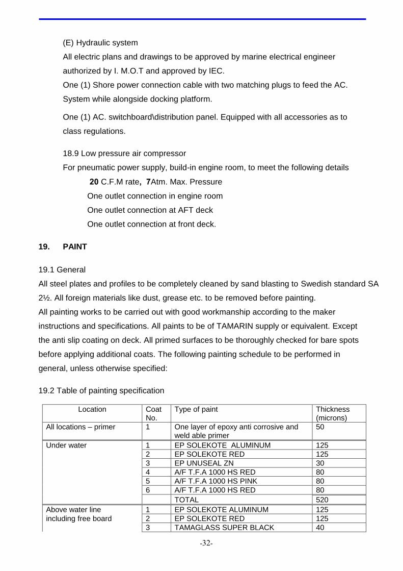
19.2 Table of painting specification
Location Coat No.
Type of paint Thickness (microns)
All locations – primer 1 One layer of epoxy anti corrosive and weld able primer
50
Under water 1 EP SOLEKOTE ALUMINUM 125
2 EP SOLEKOTE RED 125
3 EP UNUSEAL ZN 30
4 A/F T.F.A 1000 HS RED 80
5 A/F T.F.A 1000 HS PINK 80
6 A/F T.F.A 1000 HS RED 80
TOTAL 520
Above water line 1 EP SOLEKOTE ALUMINUM 125
including free board 2 EP SOLEKOTE RED 125
3 TAMAGLASS SUPER BLACK 40
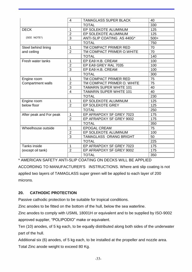
-33-
4 TAMAGLASS SUPER BLACK 40
TOTAL 330
DECK 1 EP SOLEKOTE ALUMINUM 125
2 EP SOLEKOTE ALUMINUM 125 (SEE NOTE*) 3 ANTI-SLIP COATING AS 440G* 500+
TOTAL 750
Steel behind lining 1 TM COMPACT PRIMER RED 70
and ceiling 2 TM COMPACT PRIMER O.WHITE 70
TOTAL 140
Fresh water tanks 1 EP EA9 H.B. CREAM 100
2 EP EA9 GREY RAL 7035 100
3 EP EA9 H.B. CREAM 100
TOTAL 300
Engine room 1 TM COMPACT PRIMER RED 75
Compartment walls 2 TM COMPACT PRIMER O. WHITE 75
3 TAMARIN SUPER WHITE 101 40
4 TAMARIN SUPER WHITE 101 40
TOTAL 230
Engine room 1 EP SOLEKOTE ALUMINUM 125
below floor 2 EP SOLEKOTE GREY 125
TOTAL 250
After peak and For peak 1 EP AFRAPOXY SF GREY 7023 175
2 EP AFRAPOXY SF GREY 9002 175
TOTAL 350
Wheelhouse outside 1 EPOGAL CREAM 75
2 EP SOLEKOTE ALUMINUM 100
3 TAMAGLASS ORANG BRIGHT 50
TOTAL 225
Tanks inside 1 EP AFRAPOXY SF GREY 7023 175
(except oil tank) 2 EP AFRAPOXY SF GREY 9002 175
TOTAL 350
* AMERICAN SAFETY ANTI-SLIP COATING ON DECKS WILL BE APPLIED
ACCORDING TO MANUFACTURER'S INSTRUCTIONS. Where anti slip coating is not
applied two layers of TAMAGLASS super green will be applied to each layer of 200
microns.
20. CATHODIC PROTECTION
Passive cathodic protection to be suitable for tropical conditions.
Zinc anodes to be fitted on the bottom of the hull, below the sea waterline.
Zinc anodes to comply with USMIL 18001H or equivalent and to be supplied by ISO-9002
approved supplier, “POLIPODIO” make or equivalent.
Ten (10) anodes, of 5 kg each, to be equally distributed along both sides of the underwater
part of the hull.
Additional six (6) anodes, of 5 kg each, to be installed at the propeller and nozzle area.
Total Zinc anode weight to exceed 80 Kg.
-34-
21. VENTILATION
Sufficient ventilation for engine room, storage space & wheelhouse complying with class
and IMOT regulations to be provided
22. AIR CONDITIONING
Installation of one (1) split aggregate with fan coil unit, for the wheelhouse to be provided..
Final specifications to be concluded at contract signature.
Electrical power supply is 380 v ac / 3 phase / 50 Hz.
Capacity of Air-conditioning system - 1.5 hp, min.
23. LIFE SAVING EQUIPMENT
The safety appliances to be in accordance with the SOLAS standards number and
capacities of life saving and classification society rules and/or national authorities (IMOT).
The following equipment to be supplied:
- Life buoys X 3 with self operating light and 30 meters line.
- Two (2) Rigid "life rafts" for 6 persons each to be supplied by builder.
- life jackets for 12 persons to be supplied by builder. (" IMO 1" approved type )
- Extended first aid equipment ("No 2" first aid rucksack)
- Pyrotechnic equipment (6 Parashoot rocket. 12 hand flares 2 smoke signals).
As per I. M.O.T requirements.
24. NAUTICAL NAVIGATION AND COMMUNICATION EQUIPMENT
All "navionics" navigation suit (electronics navigation aids, VHF, GPS, PLOTTER, RADAR,
ECHO SOUNDER, AIS, Compass Multi-function touch screen etc.') to be from the same
maker to ease maintenance and operation. Maker must have representative in Israel with
lab and proved capability to provide service.
The builder shall obtain the approval of the Israeli ministry of Communication for wireless
systems.
24.1 Navigation lights
Navigation lights (24 V DC), to have power supply from the main panel in the
wheelhouse.
The following lights to be installed:
All lights to be LED (Light Emitting Diodes) technology, ( LOPOLIGHT or equivalent)
- Two side lights red and green on port and starboard sides of wheelhouse top.
- One stern light, white
-35-
- Two masthead lights on the mast, white
- One white all round light, to be combined for diving operations
- One yellow stern light.
- One red all round light to be installed between the white lights to provide under
water operation signal.
24.2 Searchlight
One 500 W, 24 V DC searchlights, 10’ diameter, efficient to 200 meters, remote
controlled from inside the wheelhouse, to be installed on wheelhouse roof.
24.3 Signal accessories
Two (2) daylight anchor balls and one (1) daylight towing diamond, to be provided.
24.4 Radar
– 24 miles range radar. Raymarine - multi-function or equivalent with LCD/LED color
display. Antenna to be fitted in close Radom.
24.5 Horn
An electric operated, 24 V DC horn, with noise level to exceed 120 dB, to be fitted on
wheelhouse roof and operated from wheelhouse.
24.6 Ship’s Bell
A ship’s bell, 150 mm diameter and of bronze material, to be fitted on the front of the
wheelhouse structure.
24.7 VHF radio telephone
A VHF radio telephone, (same make of radar), with all international channels
(Europe), complying with IMOT requirements, to be installed in wheelhouse (DSC).
Antenna to be mounted on wheelhouse roof or mast.
External speaker to be install on aft side of wheel house facing the aft deck, the
speaker will have his own ON/OFF switch and volume control knob
24.8 Echo sounder
One echo sounder same make of radar, with display of 6” minimum and detection
range of 0 – 80 meters, to be fitted in wheelhouse.
-36-
24.9 GPS system
Plotter GPS and radar system to be provided in wheelhouse. Ray marine e 230 or
equivalent.
24.10 Magnetic compass
A Magnetic compass with internal illumination, dimmer/switch on desk and with
deviation correction system (calibrated to decrease deviation to 50 maximum), to be
installed in wheelhouse.
24.11 Radio+mp3
Radio/+ mp3 of good quality, car type, with two speakers, to be installed in
wheelhouse.
Antenna to be fitted on wheelhouse roof or mast.
24.12 Megaphone/ amplifier
Electric operated megaphone to be installed on wheelhouse.
Megaphone system to be interconnected with communication system.
24.13 E.P.I.R.B.
ONE UNIT 406MHZ/ 1.6 GHZ to be supplied by builder
24.14 Auto pilot
Auto pilot system to be installed in wheelhouse console, easy operating from skipper
position.
25. JOINERY AND INSULATION
25.1 General
All joinery work shall be in accordance with normal yard standards.
For lining non-steel partition bulkheads, ceilings and furniture, hard plastic coated
marine plywood panels shall be used.
Painting colors ……………………………………. TBD
Partitions to be fastened with screws and finished with omega wall joints and
aluminum profiles or mahogany laths.
Thickness of partition bulkheads and lining ……To Classification society rules.
Thickness of ceiling ………………………………. To Classification society rules.
All doors to have a central operated mechanism (one handle operation), and to be
insulated, thermally and acoustically.
External and Water tight bulkhead doors – to be water proof.
Door locks, door handles, clamps, door hooks are to be made of marine type
-37-
chrome-plated Brass or equivalent.
Table tops are to be made of hard plastic covered waterproof plywood.
Benches provided with a 15 cm polyester mattress.
Stainless steel 316L handrails to be fitted where necessary.
25.2 Wheel house
The wheelhouse ceiling and walls and floor are to be insulated with adequate
thermal/acoustic insulation materials, to comply with IMOT requirements.
The instrument panel must have engraved text in Hebrew and symbols.
All instruments and instrument panels to be arranged in an ergonomic way to have
good visibility angles and ease of operation by the skipper.
25.3 Arrangement in wheelhouse
25.3.1 Cabinet
Wooden cabinet, for navigation equipment storage, to be provided in
wheelhouse.
Wooden cabinets of adequate size, for storage of First aid equipment and
Pyrotechnic equipment (separately) to be provided in wheelhouse.
Cabinet for binoculars
25.3.2 Helmsman seat
An ergonomic, shock absorbing, marine type seat, on a sliding base, to allow
Space for the helmsman to stand up during maneuvering.
25.3.3 Seating accommodation
Seating accommodation for 7 persons to be provided in wheelhouse.
Seats to be of good quality to allow for long stay at sea (12 hours).
5 seats to be fitted on deck, outside the wheelhouse (bench type).
25.3.4 Bridge time clock
Bridge brass quartz clock, with 6” diameter clear face view, to be installed in
wheelhouse.
25.3.4 Binoculars
One pair of prismatic binoculars marine type (7X50) to be provided in a
binocular box.
25.3.6 Barometer/temperature
(one) 6” diameter clear faces view to be installed in wheel house.
-38-
25.3.7 Fans
two (2) 12v dc universal fans (soft plastic impeller with guard) or equivalent to
be installed on the sides of the forward wheel house wall.
25.4 Engine room, aft peak and stores
25.4.1. Floor Plates
Checkered aluminum floor plates to be fitted in the engine room and
steering gear compartment (aft peak) and stores. The plates will be
mounted on angle section frames in such a way that all equipment can
be reached for operation and maintenance. Plates to be fixed with
stainless steel 316 screws. Flat rubber strips to be fitted between floor
plates and mounting frames to prevent excessive rattle noise.
26. ACOUSTIC INSULATION
Special care to be taken to minimize acoustic noise levels in wheelhouse.
Wheelhouse to be properly insulated by adequate acoustic materials as above, to
achieve noise levels as required by IMOT – 70 dbA max.
Noise levels throughout the boat, in living and working areas, not to exceed the IMOT
requirements.
27. SPARE PARTS, TOOLS AND INVENTORY
27.1. Spare parts list to be provided for:
27.1.1 On board spares
27.1.2 Depot spare parts.
27.2. Spare parts will be provided for all equipment according to the
classification society 's recommendations.
27.3 List of spare parts including quantities , recommended by equipment
subvendors of the builder, will be handed to Owner as follows:
- Spare parts for main engines and gearboxes, for 2,000 and 4,000 operation
hours.
- Spare parts for electrical equipment.
- Spare parts for deck and auxiliary equipment.
27.4 Two spare Propellers, one Left Hand (LH) and one Right Hand (RH) to
be provided with the boat as part of the basic scope of supply.
27.5 One set of propulsion shaft bearings to be supplied as part of the basic
scope of supply.
-39-
27.6 Tools
27.6.1 A metal toolbox with drawers, containing all general and specific tools
for on-board maintenance, to be provided and installed in engine room with
locking device.
27.6.2 Snap-on U.S Apprentice set 2, or its equivalent
both to be supplied as part of the basic scope of supply
27.7 Inventory
Complete Inventory List to be supplied.
27.7.1 All equipment "Order Forms" by builder to be supplied upon delivery
of tug boat.
28. TESTS AND TRIALS
28.1 General
The boat will be tested by the builders yard, in the presence of the IEC
representatives and IMOT representative with the approval of the classification
society , as follows:
(a) Water tightness test of hull, hatches and doors.
(b) Pressure tests on all tanks, piping and valves.
(c) Initial sea trials to be performed by the builders yard at its original location (only if
yard is not in Israel), including: speed, maneuverability, bollard pull, inclining test,
functioning of all auxiliary systems at sea.
(d) Delivery tests will be performed at the port of vessel’s delivery in Israel, at the
operation ambient conditions (air and seawater temperatures), In the presence of the
IEC representatives and IMOT representative (or at an Israeli shipyard).
28.2 Delivery tests to include:
(a) All mechanical systems and safety devices.
(b) Test of all electric equipment and installation.
(c) Inclining test.
(d) Sea trials for:
Speed measured by DGPS.
Bollard pull.
Crash stop.
Stability at sea, Free running and towing conditions.
Endurance test: Propulsion system under full load during 5 hours (100%)
-41-
Steering system and maneuverability at min and full speed, at 80% of full power.
Noise level measurements and report to IMOT.
Note:
Sea trials to be carried out at the normal environment conditions for the operation
area, i.e. at sea state – one.
28.3 As Made" set of drawing
"As Made" set of drawing (4 sets) to be provided ON delivery of boat to owner.
28.4 Heavy duty Docking
Heavy duty Docking and Transportation cradle to be provided by builder – and
delivered to Ashdod to insure safe dry docking of the boat at the owner’s yard.
-41-
NOMENCLATURE (Abbreviations)
BHD - Bulkhead
BHP - Break Horsepower
IEC - The Israel Electric Corporation Ltd.
FO - Fuel Oil
FW - Fresh Water
IMOT - Israel Ministry of Transportation
In, “ - Inch
Lit. - Liters
LRS - Lloyd’s Register of Shipping
M, m - Meters
RPM - Revolutions per Minute
SHP - Shaft Horsepower
St.St. - Stainless Steel
SW - Salt Water
TBD - To Be Determined
VDC - Volt Direct Current
W - Watt
-42-
APPENDIX A – General Instructions
A1 Before and during the construction, all drawing and documentation, calculations
and schemes will be submitted in duplicate for approval.
A2 All drawings have to be fully detailed with:
A21 General arrangement of parts and systems.
A22 Detail drawings with dimension and tolerances of all parts and equipment on
board.
A3 Specification of all parts.
A4 At delivery of the vessel, 4 (four) paper prints of each drawing of the fully revised
set (as made) will be handed over to IEC.
A5 at least following drawings have to be submitted for approval at delivery of the
vessel:
A51 General arrangement.
A52 Arrangement drawings of: tanks location.
A53 Mast, rigging and railing.
A6 Hatches, doors. Windows and manholes.
A7 Mooring and anchoring equipment.
A8 Safety plan and lifesaving equipment.
A9 Propulsion lines and all mechanical equipment installation.
A10 Rudder and steering gear.
A11 Docking plan with position and number of blocks, docking plugs, cathodic
protection, bilge keel cooling.
A12 Navigation equipment, installation and cabling.
A13 Shipping cradles and hoisting eyes.
A14 Engine room arrangement
A15 Propeller shaft line with details and alignment prescription.
A16 Rudder and steering gear construction with details.
A17 Construction drawings of midship section, hull construction, wheelhouse and
-43-
accommodation construction, mast, bollards, bilge keel with cooling channels,
exhaust gas line, ventilation ducts, and sea chest.
A18 Diagrams for: bilge and ballast line, air fill and sounding line, fresh waterlines,
waste waterline, fuel oil lines, Lub oil lines, fire fighting and deck wash lines, cooling
waterlines, air conditioning system, ventilation system, hydraulic system. For
each diagram a list will be added specifying, pipes, flanges, bolts, packing,
expansion pipes, indicators, sensors, valves and all other fittings. The full
specification will give name, description, manufacturer, supplier, type, and
certification.
A19 Electrical drawings containing at least:
different switch panels and distribution boxes for 24 v dc and 380v ac system.
Electrical schemes of all equipment, installations. One line diagram. Battery
chargers. All drawing will be complete with name, description, manufacturer,
supplier, type, and certification.
A20 Unified oil and grease list of all main and auxiliary apparatus and installation placed
on board.
A22 Instruction books, shop manuals and parts drawings kits corresponding to the
drawings, troubleshooting schemes, safety instructions, servicing and maintenance
instruction, repair and commissioning instruction.
A23 All supplied equipment and the manuals will indicate:
position number referring to a detailed and readable drawing. Name or description
of the part. Unique part number. Full specification of equipment.
.

-44-
APPENDIX B
The builder will supply the IEC with the follow list of documents.
B1 Main engine rating and particulars
B2 Steerable Nozzle System Arrangement
B3 Kaplan propeller for Nozzle application
B4 Water tight doors, one handle operated, LRS approved
B5 Clear View Screen particulars
B6 Hydraulic steering system
B7 Thermal insulation material (sample delivered to IEC)
B8 Acoustic insulation material (sample delivered to IEC)
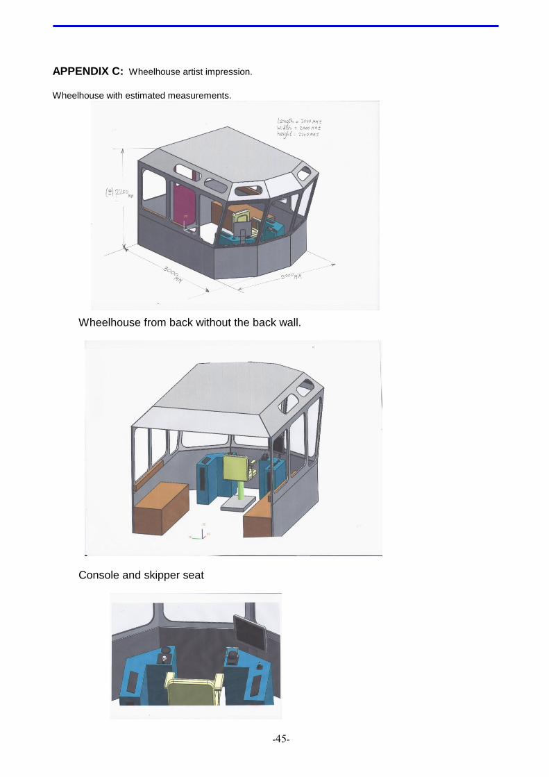
-45-
APPENDIX C: Wheelhouse artist impression.
Wheelhouse with estimated measurements.
Wheelhouse from back without the back wall.
Console and skipper seat