14-01-06(1).pdf
TRANSCRIPT

IOSR Journal of Mechanical and Civil Engineering (IOSR-JMCE)
e-ISSN: 2278-1684,p-ISSN: 2320-334X,
PP 01-06
www.iosrjournals.org
International Conference on Emerging Trends in Engineering & Management 1 |Page
(ICETEM-2016)
Punching Shear Strength Development of Bubble deck Slab Using
GFRP Stirrups
Reshma Mathew1, Binu.P
2
1(Department of civil engineering, SNGCE kadayirippu, India)
2(Department of civil engineering, SNGCE kadayiruppu, India)
Abstract: Jorgen Breuning invented the air space and steel within a voided bi axial concrete slab in the
1990.The world-wide first application is manifested in Netherlands. The Bubble deck slab floor system can be
used for story , roof and ground floor slabs. A Bubble deck slab floor is a type of flat slab; therefore it does not
require beams and column heads. The Bubble Deck is a two-way hollow deck in which plastic balls eliminating
concrete that has no carrying effect. Currently, this innovative technology has only been applied to a few
hundred of multi-story and residential floor slabs. This paper mainly concentrates the punching shear behavior
of bubble deck slab. Compared to solid slab punching shear capacity of bubble deck slab is small. In this study
GFRP strips with various orientation is used as a strengthening system for bubble deck slab .Finite element
analysis was carried out using ANSYS software
Keywords - Bubble deck slab, GFRP, Finite element analysis, ANSYS.
I. Introduction
The Bubble deck slab is mainly consisting three materials Steel, Plastic spheres and concrete. Steel
reinforcement is a grade of Fe 415 strength or higher. Plastic spheres are made from recycled high-density
polyethylene or HDPE. Concrete is made of standard Portland cement with a maximum aggregate size of 20
mm. Fig.1 shows reinforcement mesh on top of hollow plastic ball. No plasticizers are necessary for the
concrete mixture. A standard beam stress block is shown in Fig.2. The only elements working are the concrete
cover on the compression side and the steel provided on the tension side.
Shear strength of any concrete slab is mainly dependent on the effective mass of concrete. Due to the
introduction of plastic bubbles, the shear resistance of a Bubble Deck slab is very low compared to a solid slab.
From the studies the punching shear strength of the bubble deck slab is limited to be 60-80% of a solid slab with
the same thickness. For all flat slab systems, the floor to column junction is a region of high shear. The design
for Bubble Deck section is similar to that of typical flat slabs. The designer must first determine whether the
applied shear is greater or less than the shear capacity of the Bubble Deck. If it is less, no further checks are
needed; if it is greater, the designer omit the spheres around the column and then check the shear in the newly
solid section. If the shear resistance of the solid portion of concrete is below the applied, shear reinforcement
must be required. Material weight reduction, construction and time saving, cost saving, eco-friendly and high
thermal resistance are the main advantages of bubble deck slab.
Fig.1.Reinforcement mesh over HDPE balls

IOSR Journal of Mechanical and Civil Engineering (IOSR-JMCE)
e-ISSN: 2278-1684,p-ISSN: 2320-334X,
PP 01-06
www.iosrjournals.org
International Conference on Emerging Trends in Engineering & Management 2 |Page
(ICETEM-2016)
Fig.2. Standard stress block diagram
II. Materials Bubble deck mainly composed of three main materials
Concrete: M25 grade of concrete is used. Modulus of elasticity of concrete used is 25000 MPa. Poisson’s ratio
is 0.2 .element type used for modeling of concrete is solid 65.
Steel: element type used for steel is link 180. Modulus of elasticity 2X10⁵ ,Poison’s ratio 0.3 ,yield stresses 415
HDPE BALLS: 180 mm diameter balls. Modulus of elasticity 1030 MPa, Poison’s ratio 0.4, and shell 181
element type was used
GFRP STRIPS: Length of GFRP is 2100 mm, width 200mm and thickness is 2 mm. number of layers used is 3
Modulus of elasticity is 20.23 GPa, Poisons ratio 0.223.
III. Finite Element Analysis
Analysis was done using ANSYS software. Load carrying capacity of slab and deflection of slab were
studied. Total length of slab was 5 x5 thickness of slab is 230 mm. in order to check the punching shear capacity
of slab only column strip is needed to consider. Column strip dimension is 2.5 m x2.5 m. Slab dimension is
shown in Fig. 3. 16 mm diameter bars with 100 mm c/c is used at support. 10 mm diameter bars with 100 mm
c/c use at mid span. Column dimension is 300 x 300 mm .only one fourth of slab is modeled in order to save
time. Slab is fixed at 4 sides. The Newton-Raphson method is used to compute the nonlinear response. The
application of the loads up to failure is done incrementally as required by the Newton-Raphson procedure.
Fig.3. Slab dimension
In order to check the punching shear capacity of flat slab mainly two set up are available they are test set up 1
and test set up 2
Test setup 1: slab is supported along boundary and load is applied through column.
Test setup 2: column is fixed and load applied from slab as area load.

IOSR Journal of Mechanical and Civil Engineering (IOSR-JMCE)
e-ISSN: 2278-1684,p-ISSN: 2320-334X,
PP 01-06
www.iosrjournals.org
International Conference on Emerging Trends in Engineering & Management 3 |Page
(ICETEM-2016)
Fig.4. Test set up 1 and 2
Fig.5.Meshed model of solid slab with test setup 1
Fig.6.Meshed model of solid slab with test setup 2
IV. Results Compared to solid slab bubble deck slab punching shear capacity of bubble deck slab is less. Bubble
deck can achieve only 70 % load carrying capacity. But due to the strengthening of bubble deck slab with GFRP
strips improve load carrying capacity up to 20 %.
Table 1: Comparison of test set up 1& 2 TEST SETUP 1 TEST SETUP 2
LOAD CARRYING
CAPACITY (kN 352.924 352.475
But due to the complexity of providing mesh contact between slab and column separate analysis is carried out
by removing column below slab and model is named as model 1(a) load carrying capacity of slab obtained is
351.256. So for the modeling of bubble deck slab model 1(a) is chosen.
IOSR Journal of Mechanical and Civil Engineering (IOSR-JMCE)
e-ISSN: 2278-1684,p-ISSN: 2320-334X,
PP 01-06
www.iosrjournals.org
International Conference on Emerging Trends in Engineering & Management 4 |Page
(ICETEM-2016)
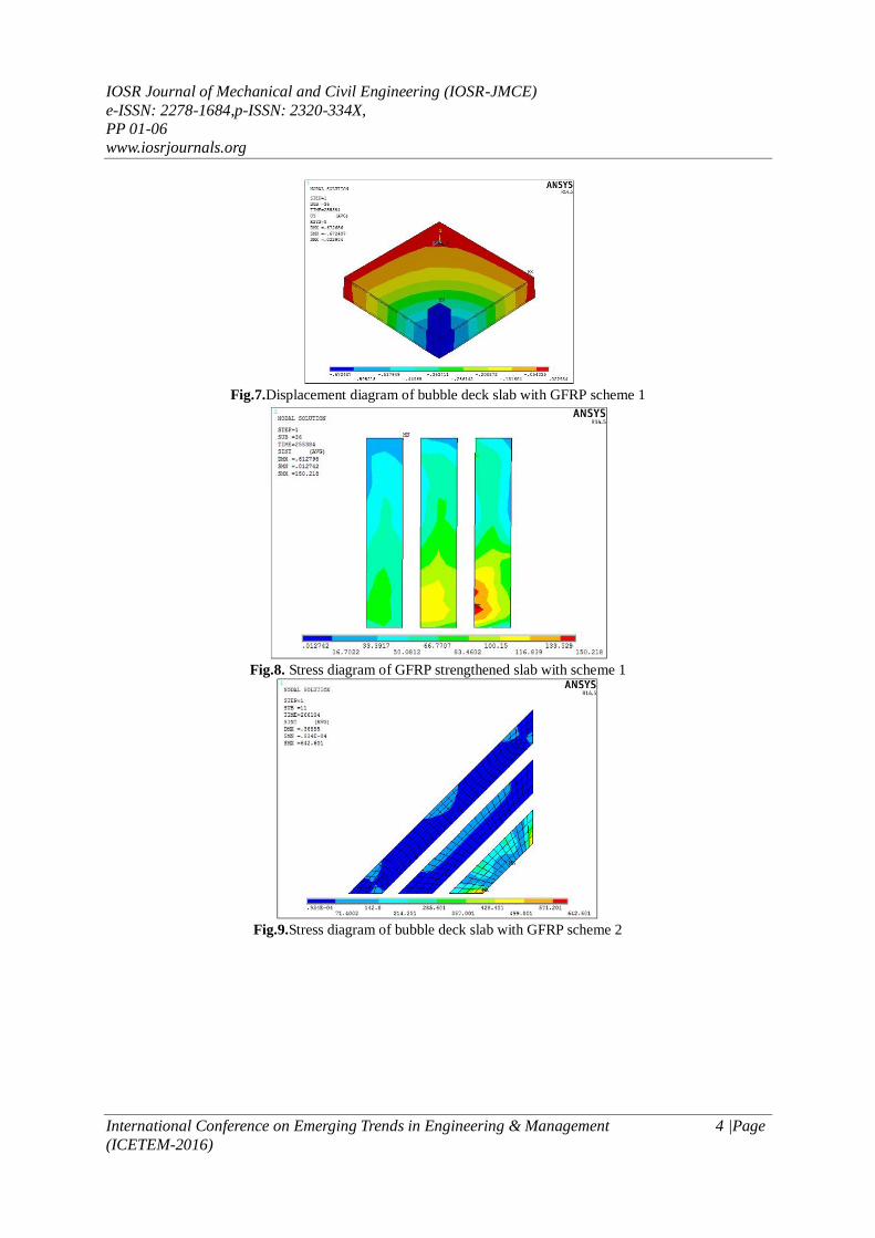
Fig.7.Displacement diagram of bubble deck slab with GFRP scheme 1
Fig.8. Stress diagram of GFRP strengthened slab with scheme 1
Fig.9.Stress diagram of bubble deck slab with GFRP scheme 2
IOSR Journal of Mechanical and Civil Engineering (IOSR-JMCE)
e-ISSN: 2278-1684,p-ISSN: 2320-334X,
PP 01-06
www.iosrjournals.org
International Conference on Emerging Trends in Engineering & Management 5 |Page
(ICETEM-2016)
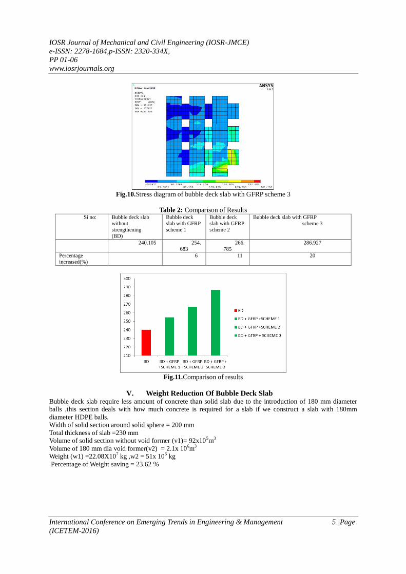
Fig.10.Stress diagram of bubble deck slab with GFRP scheme 3
Table 2: Comparison of Results Si no: Bubble deck slab
without
strengthening
(BD)
Bubble deck
slab with GFRP
scheme 1
Bubble deck
slab with GFRP
scheme 2
Bubble deck slab with GFRP
scheme 3
240.105 254.
683
266.
785
286.927
Percentage
increased(%)
6 11 20
Fig.11.Comparison of results
V. Weight Reduction Of Bubble Deck Slab Bubble deck slab require less amount of concrete than solid slab due to the introduction of 180 mm diameter
balls .this section deals with how much concrete is required for a slab if we construct a slab with 180mm
diameter HDPE balls.
Width of solid section around solid sphere = 200 mm
Total thickness of slab =230 mm
Volume of solid section without void former (v1)= 92x105m
3
Volume of 180 mm dia void former(v2) = 2.1x 10⁶m
3
Weight (w1) =22.08X10⁷ kg ,w2 = 51x 10
6 kg
Percentage of Weight saving = 23.62 %

IOSR Journal of Mechanical and Civil Engineering (IOSR-JMCE)
e-ISSN: 2278-1684,p-ISSN: 2320-334X,
PP 01-06
www.iosrjournals.org
International Conference on Emerging Trends in Engineering & Management 6 |Page
(ICETEM-2016)
Fig.12. Cross Section Bubble Deck Slab. Fig13. Plan View of Bubble Deck Slab
VI. Conclusion Punching shear capacity of bubble deck slab is a major problem because of its reduced weight. GFRP
strengthening system is used in this study. Strengthened slabs have higher punching capacity compared with
control bubble deck slab. Increase in load carrying capacity up to 20 % due to strengthening of bubble deck slab
with GFRP. Strengthened bubble deck has low deflection compared to un strengthened bubble deck slab. 8 % of
global carbon dioxide are due to cement production. One ton of cement causes emission of about 800 kg of
carbon dioxide. One m3 of concrete causes carbon dioxide emission close to 300 kg. Introducing HDPE balls of
180 mm diameter in to a flat slab of thickness 230 mm we can save the weight up to 23.62 % around one ball.
Bubble deck slab have reduced concrete usage in which 1 kg of HDPE balls replace more than 100 kg of
concrete.
Acknowledgements
The author thank Mrs. BINU.P associate professor, staffs in Sree Narayana Gurukulam College, my parents and
my friends for their valuable time spending with me for the completion of this project.
References [1]. S.Y. Caob, “Behaviour of GFRP-strengthened RC cantilever slabs” journal of Construction and Building Materials vol 15, pp 339-
349,2001
[2]. Martina Schnellenbach-Held “Punching behaviour of biaxial hollow slab” Journal of cement and concrete composites vol 24 , pp
551 -556, 2002
[3]. S.J. Kim Strengthening of one-way spanning RC slabs with cutouts using FRP composites, Journal of construction and building
materials ,SCIENCE DIRECTvol 23 ,2009 , pp 1578 -1590
[4]. Ahmed Sabry “Experimental and analytical study on on punching strength of two-way slabs strengthened externally with CFRP
sheets” ”, International Journal of Research in Engineering and Technology, vol 03 , pp113-120,2014
[5]. Chung “An analytical study on the impact of hollow shapes in bi-axial hollow slabs” ISBN vol 97,pp 182-192 2011
[6]. Amer “ Finite element analysis of reinforced concrete slabs with spherical voids” Diyala Journal of Engineering Sciences Vol. 06,
No. 04, pp. 11- 37,2012
[7]. Shaimaa Tariq Sakin “punching shear of voided slab” Civil and Environmental Research ,ISSN vol .24, ,pp 22-32,2013
[8]. SaifeeBhagat “Parametric study of R.C.C voided and solid slab” IOSR Journal of Mechanical and Civil Engineering ,Volume 11,
Issue 2 , pp 11-21 ,2010
[9]. C C Marais, J M Robberts and B W J van Rensburg “sherical void formers in solid slab”Journal of the south african institution of
civil engineering vol 52, pp2-11,2010
[10]. Maria anna polak “ study of punching shear of concrete” slab,American concrete institute
[11]. www.bubbledeck.com