13/15dve control series - dartcontrols.com · mi ma +ar - ac1 +fiel-ts to remote speedpot speedpot...
TRANSCRIPT

P.O. Box 105000 W. 106th StreetZionsville, Indiana 46077
Phone (317) 873-5211Fax (317) 873-1105
www.dartcontrols.com
Instruction ManualVariable Speed Control
LT35 (13/15DVETRI-0805)
CONTROLS
13/1
5DVE
CON
TROL
SER
IES
A-5-3013B

MODEL 13DVE Rev.A / 15DVE Rev.A HOOK-UP
IMPROPER INSTALLATION OR OPERATION OF THIS CONTROL MAY RESULT IN INJURY TO PERSONNEL OR ELECTRONIC FAILURE. THE
CONTROL MUST BE INSTALLED AND GROUNDED IN ACCORDANCE WITH LOCAL, STATE, AND NATIONAL SAFETY CODES. AT NO TIME
SHOULD THE CIRCUIT CONTINUITY BE CHECKED BY SHORTING TERMINALS WITH A SCREWDRIVER OR OTHER METAL DEVICE.
WARNING
PLEASE READ COMPLETELY BEFORE MAKING ANY ADJUSTMENTS
HOOK-UP & TERMINAL IDENTIFICATION1) Before attempting to wire the control, make sure all power is turned off.
2) The 15DVE Series controller comes with built-in fusing (250VAC 6.3A, Littlefuse PN 216 06.3 or equivalent) wired in line with AC1.
ALL SINGLE PHASE AC SYSTEMS SHOULD HAVE HOT AC CONNECTED TO AC1(L) PIN. FOR 240 VAC SUPPLIES WITH TWO HOT LINES, AN EXTERNAL FUSE WILL NEED TO BE ADDED IN SERIES WITH THE AC2(N) PIN.
CAUTION SHOULD BE USED IN SELECTING THE SIZE OF HOOK-UP WIRING. LIMIT THE VOLTAGE DROP THROUGH THE WIRING TO 5% OF
THE LINE VOLTAGE AT FULL LOAD.
3) +ARM: Connect to plus (+) Armature wire on motor. 0-90 VDC for 120 VAC input, and 0-180 VDC for 240 VAC input.
4) -ARM: Connect to minus (-) Armature wire on motor.
5) -FIELD: Connect to minus (-) Field wire of Shunt Wound Motor.
6) AC1 and AC2: 120 VAC - Connect incoming hot AC (black wire) to AC1 and neutral (white wire) to AC2
240 VAC - Connect both hot sides, one to AC1 and one to AC2.
7) +FIELD: Do not use for permanent magnet motor. This supplies +Field voltage for a Shunt Wound Motor. For motors
with dual voltage field (ie; 50/100V or 100/200V), make sure the highest value is connected.
1) Preset trimpots in the counter-clockwise (CCW) position.
2) Apply power and set the power on/off switch to the on position.
3) Rotate the Speedpot fully CW and adjust MAX trimpot in the CW direction until the maximum desired speed is obtained.
4) Rotate the Speedpot fully counter-clockwise (CCW) and adjust the MIN trimpot in the CW direction until deadband or the minimum desired speed is obtained.
5) The IR COMP trimpot is used as a regulation adjustment. If better motor regulation is needed between minimum and maximum loads, then adjust IR COMP trimpot as follows. Rotate the Speedpot CW to the 50% position and rotate the IR COMP trimpot CW as needed to increase regulation.
6) Recheck and readjust trimpots if necessary. Trimpot interaction with each other will be minimal.
ADJUSTMENTS
1
- AC2
SPEEDPOT LO(orange wire)
IR MI MA
+AR - AC1 +FIEL
-TS
TO REMOTESPEEDPOT
SPEEDPOT HI(white wire)
SPEEDPOT WIPER(red wire)
CAUTION: DO NOT ATTEMPT TO PERFORM A HI-POT TEST ACROSS AC LINES WITH CONTROL IN CIRCUIT.
THIS WILL RESULT IN IMMEDIATE OR LONG TERM DAMAGE TO THE CONTROL.
SPEEDPOT HI(white wire)
SPEEDPOT WIPER(red wire)
SPEEDPOT LO(orange wire)
MIN
MAXIR
+FAC1
AC2-F
-ARM
+ARM
�����
���� ����
�����
�������� �
����
���
����
��������
��
�����
���
���
�����
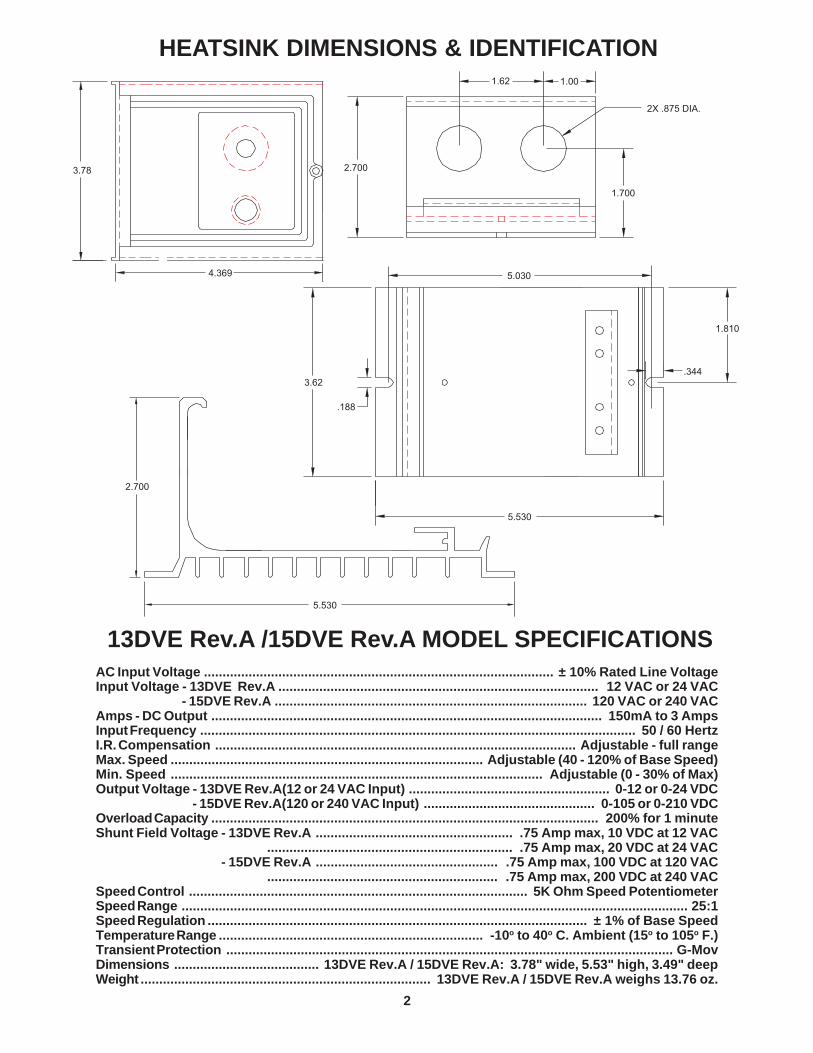
AC Input Voltage .............................................................................................. ± 10% Rated Line VoltageInput Voltage - 13DVE Rev.A ...................................................................................... 12 VAC or 24 VACInput Voltage - 15DVE Rev.A .................................................................................... 120 VAC or 240 VACAmps - DC Output ......................................................................................................... 150mA to 3 AmpsInput Frequency ..................................................................................................................... 50 / 60 HertzI.R. Compensation ................................................................................................. Adjustable - full rangeMax. Speed .................................................................................... Adjustable (40 - 120% of Base Sp eed)Min. Speed .................................................................................................... Adj ustable (0 - 30% of Max)Output Voltage - 13DVE Rev.A(12 or 24 VAC Input) ...................................................... 0-12 or 0-24 VDCOutput Voltage - 15DVE Rev.A(120 or 240 VAC Input) .............................................. 0-105 or 0-210 VDCOverload Capacity ........................................................................................................ 200% for 1 minuteShunt Field Voltage - 13DVE Rev.A ..................................................... .75 Amp max, 10 VDC at 12 VACShunt Field Voltage - 15DV .................................................................. .75 Amp max, 20 VDC at 24 VACShunt Field Voltage - 15DVE Rev.A ................................................. .75 Amp max, 100 VDC at 120 VACShunt Field Voltage - 15DV .............................................................. .75 Amp max, 200 VDC at 240 VACSpeed Control ........................................................................................... 5K Ohm Speed Potentiom eterSpeed Range ........................................................................................................................................ 25:1Speed Regulation ...................................................................................................... ± 1% of Base SpeedTemperature Range ....................................................................... -10o to 40 o C. Ambient (15 o to 105o F.)Transient Protection ........................................................................................................................ G-MovDimensions ....................................... 13DVE Rev.A / 15DVE Rev.A: 3.78" wide, 5.53" high, 3.49" deepWeight .............................................................................. 13DVE Rev.A / 15DVE Rev.A weighs 13.76 oz.
13DVE Rev.A /15DVE Rev.A MODEL SPECIFICATIONS
HEATSINK DIMENSIONS & IDENTIFICATION
2
��
������
���������
��
������ ��
��������
��
�������
�����������
�
�
� � �
�
�-
�••
�••
•-•���
����
INSTALACIÓN DEL MODELO 13DVE, Rev. A / 15DVE, Rev. A
LA INSTALACIÓN U OPERACIÓN INCORRECTA DE ESTE CONTROL PUEDE RESULTAR EN LESIONES DEL PERSONAL O EN LA FALLA DEL CIRCUITO ELECTRÓNICO. EL CONTROL SE DEBE INSTALAR Y CONECTAR A TIERRA DE ACUERDO CON LOS CÓDIGOS DE SEGURIDAD LOCAL, ESTATAL Y NACIONAL. EN NINGÚN MOMENTO SE DEBERÁ VERIFICAR LA CONTINUIDAD DEL CIRCUITO PONIENDO LOS TERMINALES EN CORTOCIRCUITO CON UN DESTORNILLADOR O CON OTRO DISPOSITIVO METÁLICO.
ADVERTENCIA
POR FAVOR LEA LAS INSTRUCCIONES COMPLETAMENTE ANTES DE HACER CUALQUIER AJUSTE
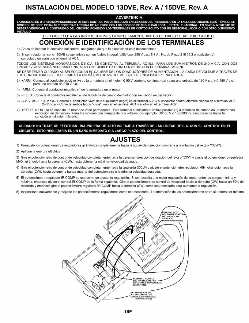
CONEXIÓN E IDENTIFICACIÓN DE LOS TERMINALES1) Antes de intentar la conexión del control, asegúrese de que la electricidad esté desconectada.
2) El controlador en serie 15DVE se suministra con un fusible integral (Littlefuse, 250 V c.a., 6,3 A., No. de Pieza 216 06.3 o equivalente), conectado en serie con el terminal AC1.
TODOS LOS SISTEMAS MONOFÁSICOS DE C.A. SE CONECTAN AL TERMINAL AC1(L). PARA LOS SUMINISTROS DE 240 V C.A. CON DOS LÍNEAS "VIVAS", SERÁ NECESARIO INSTALAR UN FUSIBLE EXTERNO EN SERIE CON EL TERMINAL AC2(N).
SE DEBE TENER CUIDADO AL SELECCIONAR EL CALIBRE DE LOS CONDUCTORES DE ALIMENTACIÓN. LA CAÍDA DE VOLTAJE A TRAVÉS DE LOS CONDUCTORES SE DEBE LIMITAR A UN MÁXIMO DE 5% DEL VOLTAJE DE LÍNEA BAJO PLENA CARGA.
3) +ARM: Conecte al conductor positivo (+) de la armadura en el motor. 0-90 V corriente continua (c.c.) para una entrada de 120 V c.a. y 0-180 V c.c. para una entrada de 240 V c.a.
4) -ARM: Conecte al conductor negativo (-) de la armadura en el motor.
5) -FIELD: Conecte al conductor negativo (-) de la bobina de campo del motor con excitación en derivación.
6) AC1 y AC2: 120 V c.a. - Conecte el conductor "vivo" de c.a. (alambre negro) en el terminal AC1 y el conductor neutro (alambre blanco) en el terminal AC2. 240 V c.a. - Conecte ambos lados "vivos", uno en el terminal AC1 y el otro en el terminal AC2.
7) +FIELD: No lo use en caso de un motor de imán permanente. Este terminal suministra el voltaje positivo (+) a la bobina de campo de un motor con excitación en derivación. Para los motores con campos de dos voltajes (por ejemplo, 50/100 V ó 100/200 V), asegúrese de hacer la conexión en el valor más alto.
1) Preajuste los potenciómetros reguladores girándolos completamente hacia la izquierda (dirección contraria a la rotación del reloj o "CCW").
2) Aplique la energía eléctrica.
3) Gire el potenciómetro de control de velocidad completamente hacia la derecha (dirección de rotación del reloj o "CW") y ajuste el potenciómetro regulador MAX, girándolo hacia la derecha (CW), hasta obtener la máxima velocidad deseada.
4) Gire el potenciómetro de control de velocidad completamente hacia la izquierda (CCW) y ajuste el potenciómetro regulador MIN, girándolo hacia la derecha (CW), hasta obtener la banda muerta del potenciómetro o la mínima velocidad deseada.
5) El potenciómetro regulador IR COMP se usa como un ajuste de regulación. Si se necesita una mejor regulación del motor entre las cargas mínima y máxima, entonces ajuste el control IR COMP de la forma siguiente. Gire el potenciómetro de control de velocidad hacia la derecha (CW) hasta un 50% del recorrido y entonces gire el potenciómetro regulador IR COMP hacia la derecha (CW) como sea necesario para aumentar la regulación.
6) Inspeccione nuevamente y reajuste los potenciómetros reguladores como sea necesario. La interacción de los potenciómetros entre sí deberá ser mínima.
AJUSTES
CUIDADO:NO TRATE DE EFECTUAR UNA PRUEBA DE ALTO VOLTAJE A TRAVÉS DE LAS LÍNEAS DE C.A. CON EL CONTROL EN EL
CIRCUITO. ESTO RESULTARÍA EN UN DAÑO INMEDIATO O A LARGO PLAZO DEL CONTROL.
1SP
MIN
MAXIR
+FAC1
AC2-F
-ARM
+ARM EXTREMO ALTODEL POTENCIÓMETRODE CONTROL DE VELOCIDAD(alambre anaranjado)
ELEMENTO MOVIBLEDEL POTENCIÓMETRODE CONTROL DE VELOCIDAD(alambre rojo)
EXTREMO BAJO DELPOTENCIÓMETRO DECONTROL DE VELOCIDAD
(alambre blanko)

�����
���� ����
�����
�������� �
����
���
����
��������
��
�����
���
���
�����
ESPECIFICACIONES DEL MODELO 13DVE Rev.A / 15DVE Rev.A
DIMENSIONES E IDENTIFICACIÓN DEL DISIPADOR TÉRMICO
2SP
Voltaje CA de Entr ada .......................................................................... Voltaje Nominal de Línea ± 10%Voltaje de Entrada - 13DVE Rev.A ............................................................................... 12VCA ó 24 VCA
- 15DVE Rev.A .......................................................................... 120 VCA ó 240 VCASalida de CC en Amps .................................................................................................150mA a 3 Amps.Frecuencia de Entrada .......................................................................................................... .... 50 / 60 HzCompensación de R.I. .................................................................................. Ajustable - gama completaVelocidad Máx. ...................................................................... Ajustabl e (40 - 120% de Velocidad Base)Velocidad Mín. .................................................................................... Ajustable (0 - 30% de la Máxi ma)Voltaje de Salida - 13DVE Rev.A (12 ó 24 VCA Entrada) ......................................... 0 - 12 ó 0 - 24 VCCVoltaje de Salida - 15DVE Rev.A (120 ó 240 VCA Entrada) ................................ 0 - 105 ó 0 - 210 VCCCapacidad de Sobrecarga ........................................................................................ 200% por 1 minut oVoltaje de Campo de Puente - 13DVE Rev.A..................................... .75 Amp máx., 10 VCC a 12 VCAVoltaje de Campo de Puente - 15DV ................................................... 75 Amp máx., 20 VCC a 24 VCAVoltaje de Campo de Puente - 15DVE Rev. A................................. .75 Amp m áx., 100 VCC a 120 VCAVoltaje de Campo de Puente - 15DV .............................................. .75 Amp máx., 200 VCC a 240 VCAControl de Velocidad ............................................................. Potenciómetro de Velocidad de 5 kOhmGama de Velocidades ........................................................................................................................ 25:1Regulación de Vel ocidad ................................................................................. ± 1% de Velocidad BaseGama de Temperaturas .................................................................. -10o a 45o C. Ambiente (15 o a 105o F.)Protección C. Trans itori as .............................................................................................................. G-MovDimensiones .............................. 13DVE Rev.A / 15DVE Rev.A: ancho 3.78", alto 5.53", profund. 3.49"Peso .................................................................................... 13DVE Rev.A / 15 DVE Rev.A pesa 13.76 oz.
2X .875 DIÁM

CONNEXION MODÈLE 13DVE Rév.A/15DVE Rév.A
UNE INSTALLATION OU UN FONCTIONNEMENT INCORRECT DE CETTE COMMANDE PEUT PRODUIRE DES BLESSURES OU UNE DÉFAILLANCE ÉLECTRONIQUE. IL FAUT INSTALLER LA COMMANDE ET LA METTRE À LA TERRE CONFORMÉMENT AUX CODES DE SÉCURITÉ LOCAUX, D'ÉTAT (OU DE PROVINCE) ET NATIONAUX. À AUCUN MOMENT, LA CONTINUITÉ DU CIRCUIT NE DOIT ÊTRE VÉRIFIÉE EN COURT-CIRCUITANT LES BORNES AVEC UN TOURNEVIS OU UN AUTRE DISPOSITIF EN MÉTAL.
AVERTISSEMENT
VEUILLEZ LIRE COMPLÈTEMENT CE QUI SUIT AVANT DE FAIRE DES RÉGLAGES
CONNEXIONS ET IDENTIFICATION DES BORNES1) Avant d'essayer de câbler la commande, s'assurer que toute l'alimentation a été mise à l'arrêt.
2) Le contrôleur de Série 15DVE se présente avec une protection par fusible incorporée (6,3 A-150 V CA, Littlefuse N pièce 216 06.3 ou l'équivalent) câblée en ligne avec AC1.
TOUS LES SYSTÈMES CA MONOPHASÉS SONT RACCORDÉS À LA BROCHE AC1(L). POUR LES ALIMENTATIONS 240 V CA AYANT DEUX LIGNES SOUS TENSION, UN FUSIBLE EXTERNE DOIT ÊTRE AJOUTÉ EN SÉRIE AVEC LA BROCHE AC2(N).
IL FAUT FAIRE ATTENTION QUAND ON CHOISIT LA TAILLE DU CÂBLAGE DE CONNEXION. LIMITER LA CHUTE DE TENSION À TRAVERS LE CÂBLAGE À 5% DE LA TENSION SECTEUR À PLEINE CHARGE.
3) +ARM : Connecter cette borne au conducteur positif (+) de l'induit sur le moteur. 0-90 V CC pour entrée 120 V CA et 0-180 V CC pour entrée 240 V CA.
4) -ARM: Connecter cette borne au conducteur négatif (-) de l'induit sur le moteur.
5) -FIELD: Connecter cette borne au conducteur négatif (-) de l'excitation du moteur à enroulement shunt.
6) AC1 et AC2: 20 V CA – Connecter le conducteur CA sous tension d'arrivée (conducteur noir) à AC1 et le neutre (conducteur blanc) à AC2. 240 V CA – Connecter les deux côtés sous tension, l'un à AC1 et l'autre à AC2.
7) +FIELD: À ne pas utiliser pour un moteur à aimant permanent. Cette borne fournit la tension d'excitation positive (+) pour unmoteur à enroulement shunt. Pour les moteurs ayant une excitation à tension double (c'est-à-dire 50/100 V ou 100/200 V), s'assurer que la valeur la plus élevée est connectée. with dual voltage field (ie; 50/100V or 100/200V), make sure the highest value is connected.
1) Régler d'avance les potentiomètres multitours dans la position correspondant au sens antihoraire.
2) Appliquer l'alimentation.
3) Faire tourner le Speedpot (potentiomètre vitesse) complètement dans le sens horaire et ajuster le potentiomètre MAX en allant dans le sens horaire jusqu'à ce que la vitesse maximale désirée soit obtenue.
4) Faire tourner le Speedpot (potentiomètre vitesse) complètement dans le sens antihoraire et ajuster le potentiomètre MIN en allant dans le sens horaire jusqu'à ce que la zone d'insensibilité ou la vitesse minimale désirée soit obtenue.
5) Le potentiomètre IR COMP est utilisé comme réglage de régulation. Si une meilleure régulation de moteur est nécessaire entre les charges minimales et maximales, alors régler le potentomètre IR COMP de la manière suivante. Faire tourner le Speedpot dans le sens horaire jusqu'à la position à 50% et faire tourner le potentiomètre IR COMP dans le sens horaire comme nécessaire pour augmenter la régulation.
6) Revérifier et régler de nouveau les potentiomètres multitours si nécessaire. L'interaction des potentiomètres entre eux sera minimale.
RÉGLAGES
1FR
MISE EN GARDE : NE PAS ESSAYER D'EFFECTUER UN TEST HI-POT (MESURE À L'AIDE D'UN POTENTIOMÈTRE) À TRAVERS LES LIGNES CA LORSQUE LA COMMANDE EST EN CIRCUIT. CELA CAUSERAIT DES DOMMAGES IMMÉDIATS OU À LONG TERME À LA COMMANDE.
MIN
MAXIR
+FAC1
AC2-F
-ARM
+ARM
BAS DE SPEEDPOT(conducteur orange)
CURSEUR DE SPEEDPOT(conducteur rouge)
HAUT DE SPEEDPOT(conducteur blanc)

�����
���� ����
�����
�������� �
����
���
����
��������
��
�����
���
���
�����
Tension d’entrée CA ........................................................................... Tension secteur nominale ±10%Tension d’entrée – 13DVE Rév.A ............................................................................ 12 V CA ou 24 V CA
- 15DVE Rév.A ........................................................................ 120 V CA ou 240 V CAIntensité – So rtie CC ...................................................................................................... de 150 mA à 3 AFréquence d’entrée ............................................................................................................... 50 / 60 HertzCompensation lecture indicateur ............................................................ Réglable – sur toute l’échelleVitesse max. ................................................................... Réglable (40 – 120% de la vitesse de base)Vitesse min. ............................................................................................. Réglable (0 – 30% du m ax.)Tension de sortie - 13DVE Rév.A (entrée 12 ou 24 V CA) ........................................ 0-12 ou 0-24 V CC
- 15DVE Rév.A (entrée 120 ou 240 V CA) ................................ 0-105 ou 0-210 V CCCapacité de surchar ge ....................................................................................... 200% pendant 1 minu teTension excitation shunt - 13DVE Rév.A ............................................. 10 V CC, 0,75 A max à 12 V CA
20 V CC, 0,75 A max à 24 V CA - 15DVE Rév.A .......... ................................ 100 V CC, 0,75 A max à 120 V CA
.......................................................... 200 V CC, 0,75 A max à 240 V CARéglage de vitesse ..........................................................................Potentiomètre de vitesse 5K OhmsGamme de vitesses .............................................................................................................. .............. 25:1Régulation de vitesse ........................................................................................ ±1% de vitesse de baseGamme de températures ...................................................... Ambiantes de -10o à 45o C (de 15o à 115oF)Protection contre les transitoires .................................................................................................... G-MovDimensions ................... 13DVE Rév.A / 15DVE Rév.A : largeur 3,78”, hauteur 5,53”, profondeur 3,49”Poids ................................................................................... 13DVE Rév.A / 15DVE Rév.A pèse 13,76 oz .
CARACTÉRISTIQUES DES MODÈLES 13DVE Rév.A/15DVE Rév.A
DIMENSIONS & IDENTIFICATION DU DISSIPATEUR THERMIQUE
2FR
2X DIA. 0,875

In the event that a Product manufactured by Dart Controls Incorporated (DCI) is in need ofrepair service, it should be shipped, freight paid, to: Dart Controls, Inc., 5000 W. 106th Street,Zionsville, IN. 46077, ATTN: Repair Department.
Those orders received from anyone without and existing account with DCI will need to specifyif they will be paying COD or Credit Card (Master Card or Visa). This information is requiredbefore work can begin. If you have an account with Dart your order will be processed accordingto the terms listed on your account.
Completed repairs are returned with a Repair Report that states the problem with the controland the possible cause. Repair orders are returned via UPS Ground unless other arrangementsare made. If you have further questions regarding repair procedures, contact your Dart Controls,Inc. at 317-733-2133 Ext.460.
REPAIR PROCEDURE
Dart Controls, Inc.
Manufacturer of high qual-ity DC and AC motor speedcontrols and accessoriessince 1963.
P.O. Box 105000 W. 106th StreetZionsville, Indiana 46077Phone: (317) 733-2133Fax: (317) 873-1105
Indiana) production and head-quarters facility - with over2,000,000 variable speed unitsin the field.
In addition to the standard off-the-shelf products, you can se-lect from a wide variety of op-tions to customize controls foryour specific application. Forfurther information and appli-cation assistance, contact yourlocal Dart sales representa-tive, stocking distributor, orDart Controls, Inc.
Dart Controls, Inc. is a de-signer, manufacturer, andmarketer of analog and dig-ital electronic variable speeddrives, controls, and acces-sories for AC, DC, and DCbrushless motor applica-tions.
Shown above is just a sam-pling of the expanded line ofDart controls that feature thelatest in electronic technologyand engineering. Products aremanufactured in the U.S.A. atour Zionsville (Indianapolis,
YOUR MOTION SYSTEMS SOLUTION PROVIDER
700/COMMUTROL SERIESDC BRUSHLESS 5 & 20 Amp for
12,24,& 36VDC Inputs
250G SERIESAC INPUT - VARIABLE DC OUTPUT
1/50 HP through 2.0 HP
65 SERIESDC INPUT - VARIABLE DC OUTPUTCURRENT RATINGS OF 20, 40, AND
60 AMPS
DM SERIESFIELD PROGRAMMABLEDIGITAL TACHOMETER
MDP SERIESPROGRAMMABLECLOSED LOOP DCSPEED CONTROL
125D SERIESAC INPUT - VARIABLE DC OUTPUT
1/50 HP through 1.0 HP
www.dartcontrols.comISO9001:2000 REGISTERED