130807 manu.l jad x en - webmaster - escapenet · titan gr.2 flanges standard 1.0038 carbon steel...
TRANSCRIPT

- 0 -
INSTRUCTION MANUAL
Heat Exchanger

- 1 -
Content: ...................................................................................................................................... version 04.13
1. APPLICATION .................................................................................................................................. - 2 -
2. OPERATING PRINCIPLE ................................................................................................................. - 2 -
3. CONSTRUCTION FEATURES AND DIMENSIONS ........................................................................ - 2 -
4. MATERIAL ........................................................................................................................................ - 3 -
5. NAME PLATE ................................................................................................................................... - 3 -
6. DIMENSIONS : .................................................................................................................................. - 4 -
7. BASIC TECHNICAL PARAMETERS: .............................................................................................. - 5 -
8. THICKNESS OF USED COMPONENTS: ............................................................................................ 6
9. STORAGE, PACKING AND TRANSPORTATION .......................................................................... - 7 -
10. OPERATING PARAMETERS AND SAFETY INSTRUCTIONS ..................................................... - 7 -
11. WORKING EQUIPMENT .................................................................................................................. - 8 -
12. INSTALLATION ................................................................................................................................ - 8 -
13. INSULATION ..................................................................................................................................... - 9 -
14. OPERATING PRECAUTIONS ........................................................................................................ - 10 -
15. START UP ....................................................................................................................................... - 11 -
16. CHEMICAL COMPOSITION MONITORING .................................................................................. - 11 -
17. CONSTRUCT MATERIAL CHARACTERISTICS ........................................................................... - 12 -
18. CHEMICAL REGIMES .................................................................................................................... - 12 -
19. CLEANING ...................................................................................................................................... - 13 -
20. CERTIFICATION ............................................................................................................................. - 14 -
21. WARRANTY .................................................................................................................................... - 14 -
22. SALES AND SERVICE ................................................................................................................... - 15 -
23. Notes ............................................................................................................................................... - 15 -
ATTACHEMENT: -WARRANTY CERTIFICATE -CLAIM FORM -DECLARATION OF CONFORMITY WITH PRESSURE EQUIPMENT DIRECTIVE 97/23/EC

- 2 -
1. APPLICATIONThe JAD-X(-XK) Heat exchangers are often utilized in the following applications:
- District heating installations- Hot water systems- Refrigeration (condensers, evaporators)- Various process systems (heat recovery, aftercooling, etc.)
If working fluid is classified at group 1., as “Dangerous fluids” according to art. 2.of PED 97/23 EC, it is necessary to use proper heat exchanger, which was made with category corresponds to using of pressure equipment (working conditions, state of intended fluids and risk of intended fluids)!
2. OPERATING PRINCIPLEA heat exchanger is a device in which heat is transferred from one flowing fluid to another.
Shell and Tube heat exchangers are the most common type of heat exchangers for liquid/liquid service although many applications also involve steam and certain gases. Secespol heat exchangers are counterflow units, which from a thermodynamic point of view, extract more heat from a given fluid stream than the other common types of heat exchangers.
Normally, the heating medium flows through the tubes, although for specific properties or conditions (e.g. high viscosity, high pressure drops), the heating medium can flow through the shell side. Thermal energy is transferred through the tube walls. The total heat load is dependent on the flow parameters of the fluid.
3. CONSTRUCTION FEATURES AND DIMENSIONS The heat exchangers are designed and fabricated as a single unit with non-removable
parts.
The cylindrical shell encloses a tube bundle which consists of circular layers of helically, corrugated or smooth tubes. Each layer flows in the opposite direction to the layers surrounding it in a criss-cross manner. The tube bundle is equipped with two tubesheets, which are welded into the connections of tubeside. Both ends of the cylindrical shell are enclosed within hemispherical heads.
There are two variations to each model of JAD-type heat exchangers, JAD-X and JAD-XK. JAD-X heat exchangers consist of tube bundles made of smooth tubes, whereas JAD-XK heat exchangers consist of tube bundles with corrugated tubes.
This Manual is appointed to installation, maintenance and using of Heat Exchanger into systems with working mediums classified according to art.2., PED 97/23 EC : Non-dangerous fluids – group 2
This product is appointed to working fluids of group 2. (see PED 97/23 EC) and it is not possible to use it for fluids : – exploding
– oxidize– extreme flammable– highly flammable– flammable– highly toxic– toxic
The heat exchangers JAD and their derived models are not possible to use for processes based on principle of boiling of liquids.

- 3 -
Each heat exchanger has a total of four (4) symmetrically located connections, two on each hemispherical head. One pair of opposing connections is connected to the tube side while the other pair is connected to the shell side.
Marking: JAD (X)
(X) type of heat exchanger K using of helically corrugated tube, skip if smooth tube inside
6.50. size of heat exchanger 08. diameter of tubes at (mm), skip if 8 mm71. length of shell (cm) of shorten models; skip if standard modelsFF code of working conditions KN Stainless steel flanges (if not, it is carbon steel) 5T Connection for circulation on shell (if not marked, it is without 5th connection)
STA Material of Heat exchnager AISI 321, PRO – material of Heat exchanger AISI 316L
4. MATERIALSecespol heat exchangers are typically manufactured according to the following table,
although different materials may be used to suit specific customer requirements
Standard WNR AISI (ASTM) Heat transfer area Standard 1.4404 316L
1.4541 321
On demand 1.4571 316Ti
Titan Gr.2 Flanges Standard 1.0038 Carbon steel
1.4404 316L 1.4541 321
On demand 1.4571 316Ti
Titan Gr.2
5. NAME PLATEThe name plate is placed on the shell and includes the following data:
manufacturer logo type of heat exchanger code of heat exchanger serial number production year heat transfer area weight maximum working pressure and temperature internal volumes (tube side, shell side) value of test pressure working mediums category according to PED 97/23/EC mark of conformity
K 6.50. 08. 71. FF KN 5T STA
Name plate is not allowed to take off.

- 4 -
6. DIMENSIONS :( also 5th connect. model)
Note : - The flanges according to EN 1092-1 200 - 5th conn. – select by chosen types
Basic dimensions :
Type HE A
[mm]
B
[mm]
C
[mm]
D
[mm]
E
[mm]
F
[mm]
K
[mm] H *
[inch] Dimension of flanges
flanges Ext.thread
JAD X (K) 2.11.08.68 835 160 251 80 942 - - - DN40, PN40 1 ½”
JAD X (K) 2.11 1513 160 251 80 1620 144 581 G1” DN40, PN40 1 ½”
JAD X (K) 3.18.08.75 917 172 272 101,6 1037 - - - DN50, PN40 2”
JAD X (K) 3.18 1510 172 272 101,6 1630 151 585 G1” DN50, PN40 2”
JAD X (K) 5.38.08.71 908 204 320 139,7 1047 - - - ” DN65, PN40 2 ½”
JAD X (K) 5.38 1510 204 320 139,7 1649 170 537 G1 ½ ” DN65, PN40 2 ½”
JAD X (K) 6.50.08.72 907 206 323 159 1068 - - - DN80, PN40 3”
JAD X (K) 6.50 1492 206 323 159 1653 180 538 G2” DN80, PN40 3”
JAD X (K) 6.50.10 1492 206 323 159 1653 180 538 G2” DN80, PN40 3”
JAD X (K) 9.88.08.65 886/903 263 (1) 416 219 1050 - - - DN100, PN40 4”
JAD X (K) 9.88.08.85 1086/1103 263 (1) 416 219 1250 - - - DN100, PN40 4”
JAD X (K) 9.88 1481/1498 263 (1) 416 219 1676 229 494 G2” DN100, PN40 4”
JAD X (K) 9.88.10 1481/1498 263 (1) 416 219 1676 229 494 G2” DN100, PN40 4”
JAD X (K) 9.88.12 1481/1498 263 (1) 416 219 1676 229 494 G2” DN100, PN40 4”
JAD X (K) 12.114.08.50** 781 340 501 273 935 - - - DN125, PN40 4”
JAD X (K) 12.114.08.60** 881 340 501 273 1053 - - - DN125, PN40 4”
JAD X (K) 12.114.08.75** 1031 340 501 273 1203 - - - DN125, PN40 4”
JAD X (K) 12.114** 1681 340 501 273 1900 256 565 G2” DN125, PN40 4”
JAD X (K) 12.114.10** 1681 340 501 273 1900 256 565 G2” DN125, PN40 4”
JAD X (K) 12.114.12** 1681 340 501 273 1900 256 565 G2” DN125, PN40 4”
JAD X (K) 12.114 1678 340 491,6 273 1897 256 565 G2” DN125, PN40 -
S0 X (K) 911 204 300 273 1026 - - - DN40, PN40 1 ½”
S1 X (K) 993 206 302 139,7 1108 - - - DN40, PN40 1 ½”
Note : * internal thread,** DN 100 (custom made), (1) model FF 253 mm

- 5 -
7. BASIC TECHNICAL PARAMETERS:(standard and 5th connect. model)
Type
Hea
ttran
sfer
ar
ea
Wei
ght
Volume Category of PED/ 97/23/EC
Fluids Group 2 - Non-dangerous shell Tube bundle
m2 kg dm3 dm3 FF MF BF
JAD X (K) 2.11.08.68 0,6 21,5 1,2 1,2 SEP SEP SEP
JAD X (K) 2.11 1,2 16 2,6 2,3 SEP I. I.
JAD X (K) 3.18.08.75 1,2 23 2,5 2,6 SEP I. I.
JAD X (K) 3.18 2,0 30 5,0 4,0 I. I. I.
JAD X (K) 5.38.08.71 2,3 34 6,8 4,0 I. I. I.
JAD X (K) 5.38 4,0 57 11,2 6,6 I. I. II.
JAD X (K) 6.50.08.72 3,1 38 9,9 4,6 I. I. I.
JAD X (K) 6.50 5,3 57 13,6 11,2 II. II. II.
JAD X (K) 6.50.10 5,1 54 10,6 14,2 II. II. II.
JAD X (K) 9.88.08.65 5,0 56 20,8 6,6 II. II. II.
JAD X (K) 9.88.08.85 6,2 64 25,0 8,2 II. II. II.
JAD X (K) 9.88 10,8 90 29,0 16,0 II. II. II.
JAD X (K) 9.88.10 8,3 81 32,0 13,0 II. II. II.
JAD X (K) 9.88.12 6,1 79 30,0 16,0 II. II. II.
JAD X (K) 12.114.08.50 6,3 74 29,0 8,0 II. II. II.
JAD X (K) 12.114.08.60 6,5 77 34,0 8,0 II. II. II.
JAD X (K) 12.114.08.75 8,8 90 38,5 10,0 II. II. II.
JAD X (K) 12.114 18,4 165 54,2 20,1 II. II. II.
JAD X (K) 12.114.10 14,9 153 55,0 19,3 II. II. II.
JAD X (K) 12.114.12 10,5 143 55,8 18,5 II. II. II.
S0 X (K) 2,3 24 6,2 3,3 I. I. I.
S1 X (K) 3,1 29 9,8 4,5 I. I. I.
- Parameters at brackets relate to Heat Exchangers with corrugated tubes inside. - Category of pressure equipment according to PED/97/23/EC. - SEP : sound engineering practice
Note :

6
8. THICKNESS OF USED COMPONENTS:
Type of HE Working codes
FF MF BFemin c eminS cS eminB cB emin c eminS cS eminB cB emin c eminS cS eminB cB
JAD X (K) 2.11 1,2 0,47 1,25 0,74 1,6 1,17 1,52 0,75 1,24 0,54 2,69 1,81 1,52 0,76 1,6 0,86 2,69 1,45
JAD X (K) 3.18.08.75 1,2 0,26 1,35 0,58 1,6 1,06 1,52 0,54 1,6 0,66 2,69 1,56 1,52 0,54 1,6 0,66 3,47 1,93
JAD X (K) 3.18 1,2 0,26 1,35 0,58 1,6 1,06 1,52 0,54 1,6 0,66 2,69 1,56 1,52 0,54 1,6 0,66 3,47 1,93
JAD X (K) 5.38.08.71 1,8 0,49 1,8 0,37 3,8 3,11 1,91 0,56 1,6 0,53 2,79 1,34 1,91 0,56 1,6 0,53 3,87 1,99
JAD X (K) 5.38 1,8 0,49 1,8 0,37 3,8 3,11 1,91 0,56 1,6 0,53 2,79 1,34 1,91 0,56 1,6 0,53 3,87 1,99
JAD X (K) 6.50.08.72 1,8 0,3 1,8 0,4 2,4 1,59 1,91 0,37 1,6 0,36 2,49 0,77 1,91 0,37 1,6 0,38 2,49 0,18
JAD X (K) 6.50 1,8 0,3 1,8 0,4 2,4 1,59 1,91 0,37 1,6 0,36 2,49 0,77 1,91 0,37 1,6 0,38 2,49 0,18
JAD X (K) 6.50.10 1,8 0,3 1,8 0,4 2,4 1,59 1,91 0,37 1,6 0,36 2,49 0,77 1,91 0,37 1,6 0,38 2,49 0,18
JAD X (K) 9.88.08.65 2,78 0,41 2,75 0,61 2,5 1,66 2,87 0,43 2,54 0,37 2,87 0,64 2,87 0,43 2,54 0,37 3,86 0,93
JAD X (K) 9.88.08.85 2,78 0,41 2,75 0,61 2,5 1,66 2,87 0,43 2,54 0,37 2,87 0,64 2,87 0,43 2,54 0,37 3,86 0,93
JAD X (K) 9.88 2,78 0,41 2,75 0,61 2,5 1,66 2,87 0,43 2,54 0,37 2,87 0,64 2,87 0,43 2,54 0,37 3,86 0,93
JAD X (K) 9.88.10 2,78 0,41 2,75 0,61 2,5 1,66 2,87 0,43 2,54 0,37 2,87 0,64 2,87 0,43 2,54 0,37 3,86 0,93
JAD X (K) 9.88.12 2,78 0,41 2,75 0,61 2,5 1,66 2,87 0,43 2,54 0,37 2,87 0,64 2,87 0,43 2,54 0,37 3,86 0,93
JAD X (K) 12.114.08.50 3,2 1,92 3,65 0,98 3,2 1,92 3,47 0,42 3,54 0,83 3,86 1,15 3,47 0,42 3,54 0,83 3,86 0,93
JAD X (K) 12.114.08.60 3,2 1,92 3,65 0,98 3,2 1,92 3,47 0,42 3,54 0,83 3,86 1,15 3,47 0,42 3,54 0,83 3,86 0,93
JAD X (K) 12.114.08.75 3,2 1,92 3,65 0,98 3,2 1,92 3,47 0,42 3,54 0,83 3,86 1,15 3,47 0,42 3,54 0,83 3,86 0,93
JAD X (K) 12.114** 3,2 1,92 3,65 0,98 3,2 1,92 3,47 0,42 3,54 0,83 3,86 1,15 3,47 0,42 3,54 0,83 3,86 0,93
JAD X (K) 12.114.10 3,2 1,92 3,65 0,98 3,2 1,92 3,47 0,42 3,54 0,83 3,86 1,15 3,47 0,42 3,54 0,83 3,86 0,93
JAD X (K) 12.114.12 3,2 1,92 3,65 0,98 3,2 1,92 3,47 0,42 3,54 0,83 3,86 1,15 3,47 0,42 3,54 0,83 3,86 0,93
JAD X (K) 12.114 3,2 1,92 3,65 0,98 3,2 1,92 3,47 0,42 3,54 0,83 3,86 1,15 3,47 0,42 3,54 0,83 3,86 0,93
Legend : emin : min.alowable wall thickness of shell c : material allowance for corrosion or erosion of shell eminS : min.alowable wall thickness of head cS : material allowance for corrosion or erosion of head eminB : min.alowable wall thickness of nozzle cB : material allowance for corrosion or erosion of nozzle according toEN 13445-3)

- 7 -
9. STORAGE, PACKING AND TRANSPORTATION
The Heat Exchangers are packed in a wooden crate. They should be stored in a clean place away from corrosive environments or weather elements ( e.g. rain)..
Be aware of rest water in Heat exchanger. If there remain any water inside ( by rain or during transport ), the freeze will surely demage the heat exchanger. The same applies when apparatus is set away.
During transportation, ensure that they are not exposed to mechanical damages.
Please notice the posibility to return the label on below mentioned address of company SECESPOL-CZ s.r.o.
10. OPERATING PARAMETERS AND SAFETY INSTRUCTIONS Heat exchanger has to be ensured on tube-line according to PED 97/23 EC with independent safety valves.
Maximum working parameters of the JAD X (XK) heat exchangers are as follows: Work. section Tubes Shell Code of max. working conditions
Max. work. pressure
[bar]]
Max. work. temperature
[°C]
Test pressure
[bar]
Max. work. pressure
[bar]]
Max. work. temperature
[°C]
Test pressure
[bar] MF 25 250 54 16 203 32 FF 16 203 32 16 203 32 BF 35 203 70 16 203 32
NOTICE: In order to select the proper heat exchangers, a customer should specify the following information :
• type of medium• required heat load• required inlet/outlet temperature of heating medium• required inlet/outlet temperature of heated medium
Selection is made through a computer software program developed by Secespol and distributed to our customers.

- 8 -
11. WORKING EQUIPMENT Heat exchanger has to be equipped
and secure (see PED 97/23 EC) with safety accessories (safety valve) above crossing of the highest allowable pressure and the highest allowable temperature. Heating system has to be equipped with expansion tank. There have to be thermometer, manometer, sensor of pressure and temperature in safety point. There could be used sensor of lack of water, or air-outlet valve. Heat exchanger has to be equipped with insulation of external surface according to Section 13. Insulation.
If there are flaps or ball valves in system, which can allow quick closing of tube, it is necessary to secure off water-hammer. Also it is necessary to secure the pressure and temperature working changes could not increase by jumps but contrary proportionally ! On the tube-line, in front of heat exchanger, is necessary to place separator
12. INSTALLATIONOnly qualified personnel shall install a heat exchanger. Heat exchanger should be installed,
operated and maintained in accordInstall the heat exchanger in a manner where it will not be exposed to mechanical stresses or moments. (example: in cases of pipe expansions, use expansion compensators to relieve the stress from the connections of the heat exchanger).
The Heat Exchanger is assigned to installation in vertical position or lean out at angle 50° max from vertical position. It should be mounted by means of stainless steel brackets and support of lower bottom. Other positions should first be consulted with Secespol salesperson. Angle between both nozzles of Heat Exchanger is different with model. There is 100° with JAD-X (-XK) 2.11- 9.88 and 110° with JAD-X(-XK) 12.114.
In the same way it is possible to install heat exchanger at horizontal position. This position is not allowed at steam-water applications or other condensing.
The joining of flanges have to be made with screws and nuts class 5.6 (ISO 898-1) and flat gasket ring (EN 13 555) with thickness 3mm for temperature min. 300 °C and pressure PN 40.
There have to be free space for easy mounting beside heat exchanger. The distance of 1,5 m is recommended for mounting and maintenance.
WARNING! With JAD-X(-XK) and S-X(-XK), there is no angle of connecting nozzles of 90°.
- 9 -
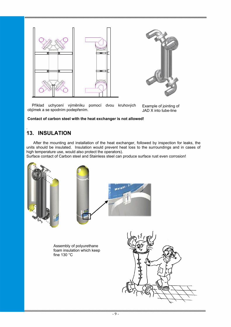
Příklad uchycení výměníku pomocí dvou kruhových objímek a se spodním podepřením.
Contact of carbon steel with the heat exchanger is not allowed!
. 13. INSULATION After the mounting and installation of the heat exchanger, followed by inspection for leaks, the units should be insulated. Insulation would prevent heat loss to the surroundings and in cases of high temperature use, would also protect the operators). Surface contact of Carbon steel and Stainless steel can produce surface rust even corrosion!
Example of jointing of JAD X into tube-line
Assembly of polyurethane foam insulation which keep fine 130 °C

- 10 -
14. OPERATING PRECAUTIONS
In order to achieve maximum performance from the heat exchanger, the following must be strictly followed:
• Heat exchangers should be used according to the specification given by Secespol.• The „INSTRUCTION FOR OPERATING PERSONEL“ (by local law) will be done by user-operator
before initial Start-up of HE, on base of Project (description-instruction of project-engineer). Therewill be described steps of personel if the emergency situation occures.
• Pressures and temperatures should not exceed limits set forth in Section 10: OperatingParameters and Safety Instruction.
• Initial start up should be done according to Section 15: Start Up.• Heat exchangers should be free of any debris existing in the fluid.• Prevent heat exchanger against sudden temperature changes (temperature shocks). Increase of
temperature should not exceeds 10°C/min.• Necessary to avoid input of hot medium into working space, without heat removal by cold medium• Prevent any of the fluids from dropping below their solidification point (freezing point),• Do not put aside inflammble things or materials close to dangerous distance to heat exchanger• In central heating applications the manufacturer recommend to use water treatment. In other way
the lime deposits will form on the tube walls, if the hot water exceeds 60 °C,• With Water treatment is not allow the contain of chlorines and its solutions in order to avoid
corrosion. See Section 16: Cleaning• Heat Exchanger is necessary to shot down before works which can cause change of environment,
i.d. useing of glue, colors and so,• Foresee and set level of working pressure on cold side in order to avoid boiling of cold medium
also during control process,• The system should be designed to prevent the heat exchanger from encountering pressure
shocks.• Prevent rapid (peak) pressure increases in the heat exchangers. (pressure shock, water
hammer), which can occur with quick closing of valves or break-down of pumps• It is necessary to include all foreseen risks, especially to put your care to :
- dangerous outputs of safety valves- surface temperature considering environment- risk of external fire
• Keep maximal concentraions of chemical compounds within allowed limits
Steam applications have to be secured : • Vapor of heating medium have to be used
inside of tube-bundle only. It can not be puttedinto shell.
• There has to be used separated condensate-line to lead condensate from steam tube-line (infront of steam input). Steam must not be wet !
• There has to be used continuous ( proportional) control system of heatload of steam heatexchanger. It is unsuitable to use control byway “YES / NO” !
• At range of allowable pressure, there isnecessary to set safety valve for cold mediumto avoid boiling of cold medium inside workingspace also during control process.

- 11 -
15. START UP
To prepare the heat exchanger for operation, it should initially be • mounted properly• filled with working fluids• deaerated• all connections checked for leaks
During startup, first open the valves, then start the pump of the cold medium followed by opening the cycle of the heating medium. The valves should be opened gradually in order to achieve a steady increase in flow and pressure. During start up of steam system, it is useful to preheat heat exchanger slowly to working temperature for a minimally 5 – 10 min. and than use steam with full working parameters.
16. CHEMICAL COMPOSITION MONITORINGIt is recommended to check operating conditions of heat exchanger, aspecially chemical composition of process fluids and its compatibility with heat exchanger construct materials.
Heat exchanger is aproved for specific fluids in their pure chemical state. Any chemical treatments of the aproved fluids can only be done with responsibillity of owner/operator.
Heat exchanger must not be operated under such conditions (with such chemical composition), which causes corrosive attacks of stainless steel used as construct materials. Any failure or demage of heat exchanger which is caused by wrong treatment / chemical composition of aproved process fluids is not reason to admit a claim.
For proper operation of heat exchangers, operator must continuously check / control chemical composition of process fluids so that maximal concentration of certain compounds are not exceeded. There is limitation of the compounds which causes stainless steel demage. Compliance with the limits is effective ONLY if heat tranfer area is not fouled!
Maximal concentrations of listed compounds (mg/l).
1) It is prohibited to allow local vaporization on heat tranfer surface2) Valid for all halogenides
Values of another parameters for treated heating water, such as pH, electrical conductivity, hardness and alkalinity prescribes local norms for quality of steam and heating water used for unfired pressure vessels.
Before start up of Heat Exchanger it is necessary to check all safety valves and safety equipments, which have to be used according to PED 97/23 EC, national standards, norms or other directives.
The pressure increase/decrease should not exceed 3 bar/min (43,5 psi/min). The temperature increase/decrease should not exceed 10 °C/min
Temperature 20°C 40°C 60°C 80°C 100°C and more1) Chlorides (Cl-)2) STA 200 55 20 10 5
PRO 400 120 50 20 10 Sulphates (SO4
2-) 350 250 160 100 60 For treated heating water:
Oxygen (O2) 0,1 0,05 0,03 0,02 0,01 Chlorine (Cl2) 0,5 0,3 0,2 0,1 0 Carbon dioxyde (free CO2) 5 5 3 3 2

- 12 -
17. CONSTRUCT MATERIAL CHARACTERISTICSConstruct materials for JAD X(K) heat exchangers:
STA: WNR 1.4541 - AISI 321 - %CrNiMo 18-10 PRO: WNR 1.4404 - AISI 316L - %CrNiMo 17-12-2,5
Material STA: Cr-Ni austenitic stainless steel, Ti stabilized. Material PRO: Cr-Ni-Mo austenitic stainless steel with lowered carbon concentration. Molybdenium rises chemical resistance.
Although stainless steel is used as a construct material, there are environments which causes specific corrosion such as pitting and stress corrosion cracking.
Specific stainless steel corrosion caused by forbidden chemicals or wrong treatment of aproved process fluids:
• Pitting corrosionCorrosion causes local disruption of stainless steel pasive layer, which ends in perforation
through heat transfer tubes. Corrosion rate depends mainly on temperature and concentration of chloride ions.
• Crevice corrosionCorrosion causes local disruption of stainless steel pasive layer, which ends in perforationthrough heat transfer tubes. Corrosion rate depends mainly on temperature and concentration ofchloride ions. This type of corrosion occure very often while heat transfer area is fouled. Pittingand crevice corrosion is most likely to find together.
• Stress corrosion crackingThis type of corrosion occure in corrosive environment (most likely chloride ions) with
simultaneous aplication of mechanical or temperature stress. Risk factors are big temperature difference and fouling of heat transfer tubes (for example steam heating of drinking water).
18. CHEMICAL REGIMES
The most widespread mistakes in heat exchanger operation is wrong water treatment, which creates corrosive environment for stainless steel materials. Water treatment has to be done with care so that concentraion of forbidden compounds are not exceeded.
• Water clarification - coagulation and flocculationVery often used coagulants on chloride basis (FeCl3, FeCl3.6H2O) can rise concentration of
chloride ions in treated water. Their activity may also be raised by sulphates, which is undesirableeffect of water treatment as well. Sulpate concentration can be affected by coagulants withsulphate basis (Al2(SO4)3.18H2O). The safest choice is to use alternative coagulants as NaAlO2.
• Deoxygenation of treated water
The increased oxygen content has significant impact to corrosion rate and the incubation periodbefore corrosion beggins to perforate material. There is a risk while deoxygenation is poor(increased level of oxygen) as well as deoxygenation in chemicals excess, where it is probably toincrease level of suphates (deoxygenation by sulphites oxygenation).
• Drinking water treatmentChlorine treatment (Cl2)
Chlorine addition rises concentration of chloride ions and therefore specific corrrosion (pitting etc.) can occure with temperature dependance. The same risk is with using all halides.
Deposits in the heat exchanger and fouled heat transfer surface significantly increase probability that specific types of corrosion occur in heat exchanger!

- 13 -
Treatment against Legionella (ClO2) ClO2 addition rises concentration of chlorides, chlorites, chlorates and free Cl2 in water. High
risk of specific corrosion in temperature dependance.
Manufacturer cannot guarantee service life of heat exchangers in such cases, where it is probably to expect specific stainless steel corrosion due to the corrosion environmet or fouling of heat exchanger.
19. CLEANING Work of heat exchangers is necessary to check continuously and to clean with partial
scaling. It can be recognised with increasing pressure drop of heated water, worse subcooling of heating medium and related necessity of flow or decreasing of heatload.
It has to be made periodical checking with the reason of formation of hard scaling inside heat exchanger. It has to made according to regulations described below : • With heat exchanger working in system with Water treatment – min. every 18th month
(according with quality and quantity of added water) • With heat exchanger working in system of natural water – min. every 12th month.
The heat exchanger could be taken out of system and cleaned only, if following appointments are fulfilled :
1) All of pumps are switched off and secured to unforeseen start up.2) The equipment is not under pressure.3) The temperature of heat exchanger drop under 40°C but not less than 10°C.
The heat exchangers are cleansed by flushing the units with fluids which do not react with stainless steel.
Dirt deposited in the heat exchanger will result in an increase of pressure drop, lower temperature difference in the heated medium or a higher exit temperature on the heating medium side. Flushing can be done without removal of the heat exchanger from the system, although extra connections and bypasses would be required.
The cleaning solutions (detergents) are easily accessible at businesses carrying chemical cleaning agents for heat exchangers or tubing and piping applications. As a guideline to purchasing the cleaning solutions, check for the following product data:
- compatibility with stainless steel, - accepted for use in food processing industries (if applicable), - remove scale, slag, tarnishes, and hard water deposits, - easily rinsed out of the system, - has no objectionable or corrosive fumes
Note :
Following fluids are abandoned for cleaning or using inside heat exchangers : - hydrochloric acid and its solutions - free chlorine with concentration higher than 0,5 ppm; (Cl2 < 0,5 ppm) - solutions contains ions of Cl- , with concentration higher than following :
Cl- < 50 ppm heating of water up to 50 to 60°C Cl- < 20 ppm heating of water up to 70 to 80°C
- all fluids which can deposits alcaline residues or phosphorus,

- 14 -
- There is necessary to rinse out heat exchanger by neutralizing fluids after using alkaline detergents (for example : 1-2% solution NaOH or NaHCO3) with inhibitors of corrosion and than rinse out by fresh water.
- Cleaning period depends on type of deposits and on level of fouling and on flow velocity.
20. CERTIFICATIONSecespol company is ISO 9001-2008 certified and Secespol´s heat exchangers fulfil
requirements of PED 97/23 EC with modul H. Copies of the listed above certificates are available upon request. The manufacturer issues declaration of conformity to each unit.
21. WARRANTY Secespol guarantees its products are free of defective materials and faulty
workmanship. The Heat Exchanger has been subject to hydrostatic test at our factory according to PED 97/23 EC and special requirements, thoroughly inspected for leakage during the above test. Commencing with date of shipment, Secespol’s warranty runs for 24 months. Should the product fail to perform according to the specifications set forth by Secespol during the warranty period, Secespol will repair or replace without charge the products that it finds defective.
Secespol will not be responsible for any products that operate outside of the conditions and parameters given to Secespol at the time of purchase, or any product which have been installed incorrectly.
The cleaning during warranty period can be made with confirmation of SECESPOL only.

- 15 -
WARRANTY CERTIFICATE Approval of quality and completeness of the product
Type of heat exchanger :
Serial number of heat exchanger :
Date of the selling : stamp and signatureof supplier:
Confirmation of starting up of the device : Filled out by the installation company.
Datum of installation of the device : stamp and signatureof the installation company:
Guarantee conditions : Generally, guarantee condition are ruled by Civil legal code. Seller is responsible for quality, completeness, functionality and state of sold product.
Guarantee period of the product lasts for 24 months from the date of selling. The seller accepts guarantee for quality of the selling products at negotiated guarantee
period, which starts from the date of selling of the heat exchanger. Guarantee time is specified in guarantee list. In the case of claiming the reclamation in the specified guarantee period, this complaint will be accepted and repair of the product will be carried out free of charge only when: • Completely filled guarantee list will be presented with stated date of selling , confirmation of seller
about the selling , installation company, which carried out mounting connection of heat exchanger.
• Product was not mechanically damaged dur transport, incorrect storage, affected by weather,chemicals or other influences, no other modifications or unauthorised manipulation were done.
• Product was installed professionally and operated according to valid operational and safetyinstruction.
• Product was utilised for the purpose given by montage-operational directives of the manufacturer.• Product was secured against overloading.• MANUAL FOR OPERATION, MAINTENANCE AND MONTAGE is integral part of guarantee list.
Execution of guarantee repair will be stated in this guarantee list. Guarantee time is prolonged of time, since the buyer claimed the demand for guarantee repair at service organisation, until time when he was obliged to take over the product after the repair was finished. If no defect coming under the guarantee will be found during reparation, all costs associated with the work of service technician will be paid by the owner of the device. Guarantee does not relate to damages arisen during transport. Guarantee list must be filled out correctly during the selling. All readings must be filled immediately during selling in unerasable way. Unentire or unauthorised changes (rewritten) of guarantee list is unlawful.
Record of service and executed guarantee repairs : Date Description of reclaimed defect, stamp of organisation