125/1-900xp mopps and mmel - · web viewthis version of the maintenance/operational/placarding...
TRANSCRIPT
Hawker 125 (Series 1 through 900XP)(All Models on A3EU TCDS except BAe-125-1000A/B and Hawker 1000)
Maintenance and Operational Proceduresfor the Federal Aviation Administration Master Minimum Equipment List
This version of the Maintenance/Operational/Placarding Procedures (MOPP) manual is being provided in Microsoft ® Office Word (.doc) format which allows the owner/operator to modify the MOPP for their personal operational contingencies. This document is provided as a courtesy for owner/operators and Beechcraft Corporation assumes no responsibility for the owner/operator modified document.
Reference the official Beechcraft PDF A7 March 2014 Revision to view highlights for MML revisions not revised for this A7 Revision.
The Table of Contents provided with this document reflects the information as currently listed in this document. Any change to this document will render the current Table of Contents obsolete. To generate a new Table of Contents, click anywhere within the Table of Contents until highlighted, then hit function key F9. Please refer to the Microsoft ® website for any other help you may require while working in Word.
TABLE OF CONTENTS
21 - Air Conditioning 1
10-1 1Engine Main Air Valves 110-2 1Engine Main Air Valve Position Indicators 110-3 2Refrigeration Unit System/ Air Cycle Machine 210-4 2Footwarmer and Windscreen Demister valve 210-5 2*** 2Cockpit Ventilation Hawker (Excluding aircraft equipped with Collins Pro Line 21 Avionics) 210-6 2Cabin Flood Valve 210-7 3Ram Air Shut-Off Valve 310-8 4*** 4Rear Baggage Pannier Heating System 410-9 4Refrigeration Unit Bypass Valve (RBV) 410-10 4Overhead Air Flow Distribution Vents (Punkah Louvers) 410-11 4Cabin Floor Valves 410-12 5Cabin Flood Valve Indicator (Series 750, 800A, 800XP, 850XP and 900XP) 510-13 5Cabin Floor Valve Indicator 510-14 6Flow Control Valve (Series 1 Through 800, except 750) 610-15 6High Pressure (HP) Air Valve (With TFE-731 Engines Only) 610-16 7Pressure Regulating Shutoff valve (PRSOV) (Series 800XP, 850XP, 900XP, C-29A, and 750) 720-1 7Cabin Recirculating Fan 720-2 7Flight Deck Heat Valve/ Auxiliary Heating Valve 720-3 7Flight Deck Recirculating Fan (s) 720-4 7Mixing Valves (TFE 731 Engine Only) 721-1 8Nose Compartment Ventilation System 830-1 8Cabin Altitude Warning Light/ Annunciator 830-2 8Cabin Altitude Aural Warning 830-3 9
TABLE OF CONTENTS Page 1Mar.2014
Automatic Cabin Pressure Controller / DCPS AUTO Mode 930-4 9Fan Operated Venturi (excludes Digital Cabin Pressurization System) 930-5 10Outflow / Safety Valves 1030-6 10Cabin Pressure Instruments (Triple Indicator or Separate Indicators) 1030-7 12Absolute Pressure Regulators (excludes Digital Cabin Pressurization System) 1230-8 12Air Jet Pump 1230-9 12Flow Control Valve 1250-1 12Auxiliary Cooling Pack 1260-1 12Temperature Control System 1260-2 12Cabin Temperature Indicator 1260-3 12Cabin Duct Temperature Indicator 1260-4 13Turbine Unit Bypass valve (Series 1 through 800) / Low Limit Temp Control Valve (Series 750, 800XP, 850XP & 900XP) 1360-5 13Cabin / VIP Temperature Control Switch 1360-6 13Cabin Flood Control Valve / Flood Flow Valve 1360-7 13Refrigeration Unit Bypass Valve (RBV) (Series1 through 800) /Cabin Temperature Control Valve (Series 750, 800XP, 850XP & 900XP) 13
22 – Auto Flight 1
10-1 1Autopilot System(s) 110-2 1Autopilot Control Yoke Disengage Switches 110-3 1Autopilot Disconnect Annunciator Lights (Except Collins Pro Line21 Equipped Aircraft) 110-4 1Yaw Damper / Autopilot Disconnect Switch on Autopilot Controller Panel 110-5 2Touch Control Steering (TCS) (Honeywell Equipped Aircraft Only) 210-6 2Go Around (GA) Switches 210-7 2Control Yoke Pitch / Roll Switches (Collins APS-85 Equipped Aircraft Only) 210-8 2A/P Flap Annunciator(s) (Honeywell Equipped Aircraft Only) 220-1 2Yaw Damper System 220-2 3Aileron Out-of Trim Annunciators (Honeywell-Equipped Series 800 and 800XP Aircraft Only) 320-3 3
TABLE OF CONTENTS Page 2Mar.2014
Elevator Out-of Trim Annunciators (Honeywell-Equipped Series 800 and 800XP Aircraft Only) 320-4 3Autopilot Trim Annunciators (Collins APS-85 Equipped Aircraft Only) 320-5 3Autopilot Aileron Trim Indicator (Series 1 through 700 Only) 320-6 4Autopilot Elevator Trim Indicator (Series 1 through 700 Only) 420-7 4Guidance Controller (Honeywell SPZ-8000 and Collins APS-85 and Collins Pro Line 21 Equipped Aircraft) 420-8 4Mach Trim System 420-9 4Mode Select Panel 4
23 – Communications 1
05-1 1RMU’S/RTU’s 110-1 1Communications System (VHF, UHF) 110-2 1Audio Control panel 110-3 1Standby Nav / Com Controller (Clearance Delivery Unit) 1HF Communication System 220-1 2SELCAL 220-2 2ACARS System 220-3 3AFIS (VHF / SAT) 330-1 3Passenger Address System 330-2 3Cabin Chimes 330-3 3Prerecorded passenger Announcement System 330-4 3Flight Deck Speakers 330-5 3Emergency Locator Transmitter (ELT) 340-1 3Crewmember Interphone System 350-1 4Headsets (Except Microphone)450-2 4Handheld Microphones 450-3 4Boom Microphones (Including Headset Microphones) 450-4 4Glareshield Microphone Key Button(s) 450-5 4Flight Deck Pilot-to -Pilot Interphone System 4
TABLE OF CONTENTS Page 3Mar.2014
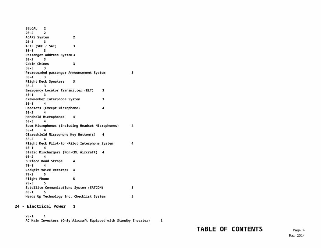
60-1 4Static Dischargers (Non-CDL Aircraft) 460-2 4Surface Bond Straps 470-1 4Cockpit Voice Recorder 470-2 5Flight Phone 570-3 5Satellite Communications System (SATCOM) 580-1 5Heads Up Technology Inc. Checklist System 5
24 - Electrical Power 1
20-1 1AC Main Inverters (Only Aircraft Equipped with Standby Inverter) 120-2 1Standby Inverter (Except Pro Line 21) 1(Pro Line 21 Only) 120-3 1Inverter Fail Lights/ Annunciators 120-4 1Standby Inverter “ON” Light / Annunciator 120-5 1AC Voltmeter 120-6 1AC Frequency Meter (Series 600 and 700 only) 121-1 1AC Alternator(s) 121-2 2AC Alternator Fail Warning Light / Annunciator(s) 221-3 2115 VAC / 60 Hertz (Hz) System 231-1 2Battery Temperature (With NiCad Battery Only) 232-1 3Battery NO CHARGE Light (Series 1 through 700 only) 332-2 3Battery Heater Muffs 334-1 3Engine Driven Generators 334-2 3APU Generator 337-1 3DC Voltmeter 337-2 3DC Generator Fail Lights / Annunciators 337-3 3DC Bus Tie Light Annunciator 337-4 4Battery Contactor Annunciators 4(Series 1 through 700) 4
TABLE OF CONTENTS Page 4Mar.2014
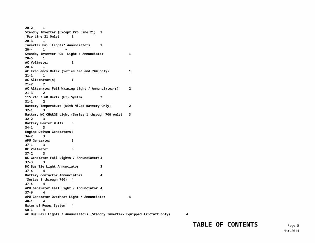
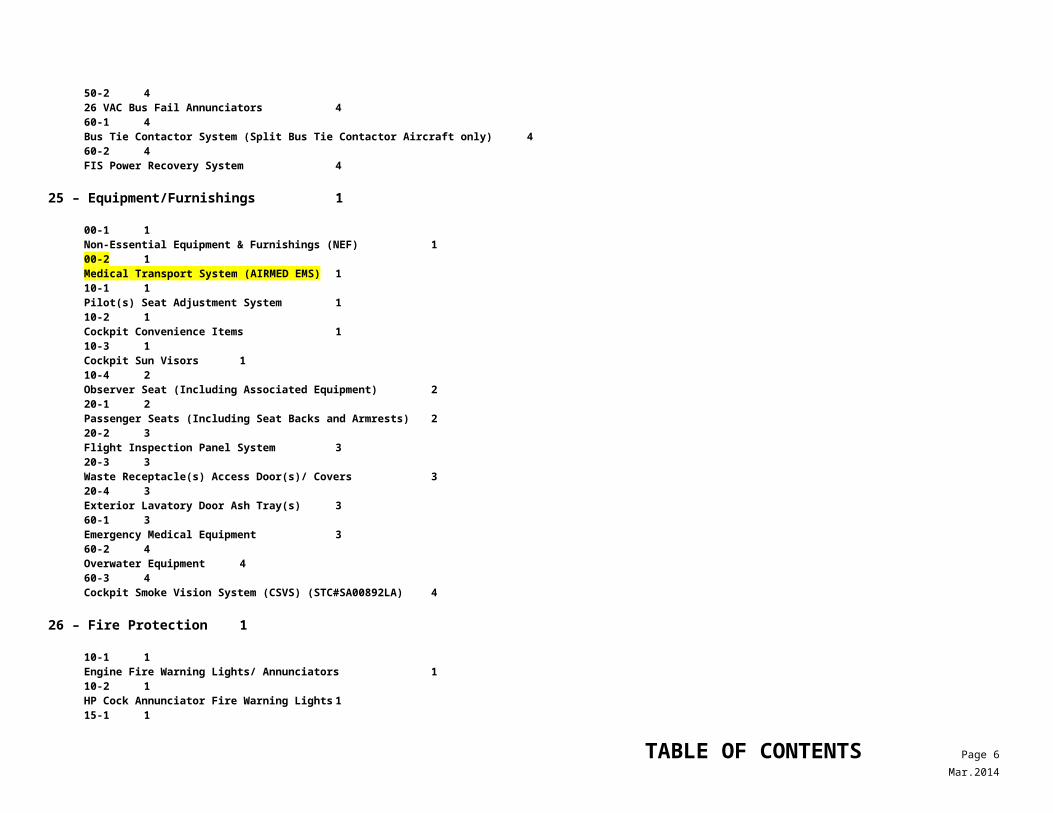
37-5 4APU Generator Fail Light / Annunciator 437-6 4APU Generator Overheat Light / Annunciator 440-1 4External Power System 450-1 4AC Bus Fail Lights / Annunciators (Standby Inverter- Equipped Aircraft only) 450-2 426 VAC Bus Fail Annunciators 460-1 4Bus Tie Contactor System (Split Bus Tie Contactor Aircraft only) 460-2 4FIS Power Recovery System 4
25 – Equipment/Furnishings 1
00-1 1Non-Essential Equipment & Furnishings (NEF) 100-2 1Medical Transport System (AIRMED EMS) 110-1 1Pilot(s) Seat Adjustment System 110-2 1Cockpit Convenience Items 110-3 1Cockpit Sun Visors 110-4 2Observer Seat (Including Associated Equipment) 220-1 2Passenger Seats (Including Seat Backs and Armrests) 220-2 3Flight Inspection Panel System 320-3 3Waste Receptacle(s) Access Door(s)/ Covers 320-4 3Exterior Lavatory Door Ash Tray(s) 360-1 3Emergency Medical Equipment 360-2 4Overwater Equipment 460-3 4Cockpit Smoke Vision System (CSVS) (STC#SA00892LA) 4
26 – Fire Protection 1
10-1 1Engine Fire Warning Lights/ Annunciators 110-2 1HP Cock Annunciator Fire Warning Lights 115-1 1APU Fire Detection System 1
TABLE OF CONTENTS Page 5Mar.2014
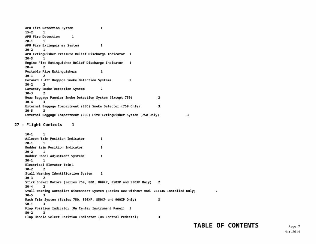
15-2 1APU Fire Detection 120-1 1APU Fire Extinguisher System 120-2 1APU Extinguisher Pressure Relief Discharge Indicator 120-3 1Engine Fire Extinguisher Relief Discharge Indicator 120-4 2Portable Fire Extinguishers 230-1 2Forward / Aft Baggage Smoke Detection Systems 230-2 2Lavatory Smoke Detection System 230-3 2Rear Baggage Pannier Smoke Detection System (Except 750) 230-4 3External Baggage Compartment (EBC) Smoke Detector (750 Only) 330-5 3External Baggage Compartment (EBC) Fire Extinguisher System (750 Only) 3
27 – Flight Controls 1
10-1 1Aileron Trim Position Indicator120-1 1Rudder trim Position Indicator 120-2 1Rudder Pedal Adjustment Systems 130-1 1Electrical Elevator Trim 130-2 2Stall Warning Identification System 230-3 2Stick Shaker Motors (Series 750, 800, 800XP, 850XP and 900XP Only) 230-4 2Stall Warning Autopilot Disconnect System (Series 800 without Mod. 253146 Installed Only) 230-5 3Mach Trim System (Series 750, 800XP, 850XP and 900XP Only) 350-1 3Flap Position Indicator (On Center Instrument Panel) 350-2 3Flap Handle Select Position Indicator (On Control Pedestal) 350-3 4Flap Position Switches 460-1 4Air Brake Position Indicator(s) 460-2 4Control Column Lock System 460-3 5Rudder Gust Lock Flapper Door 5
TABLE OF CONTENTS Page 6Mar.2014
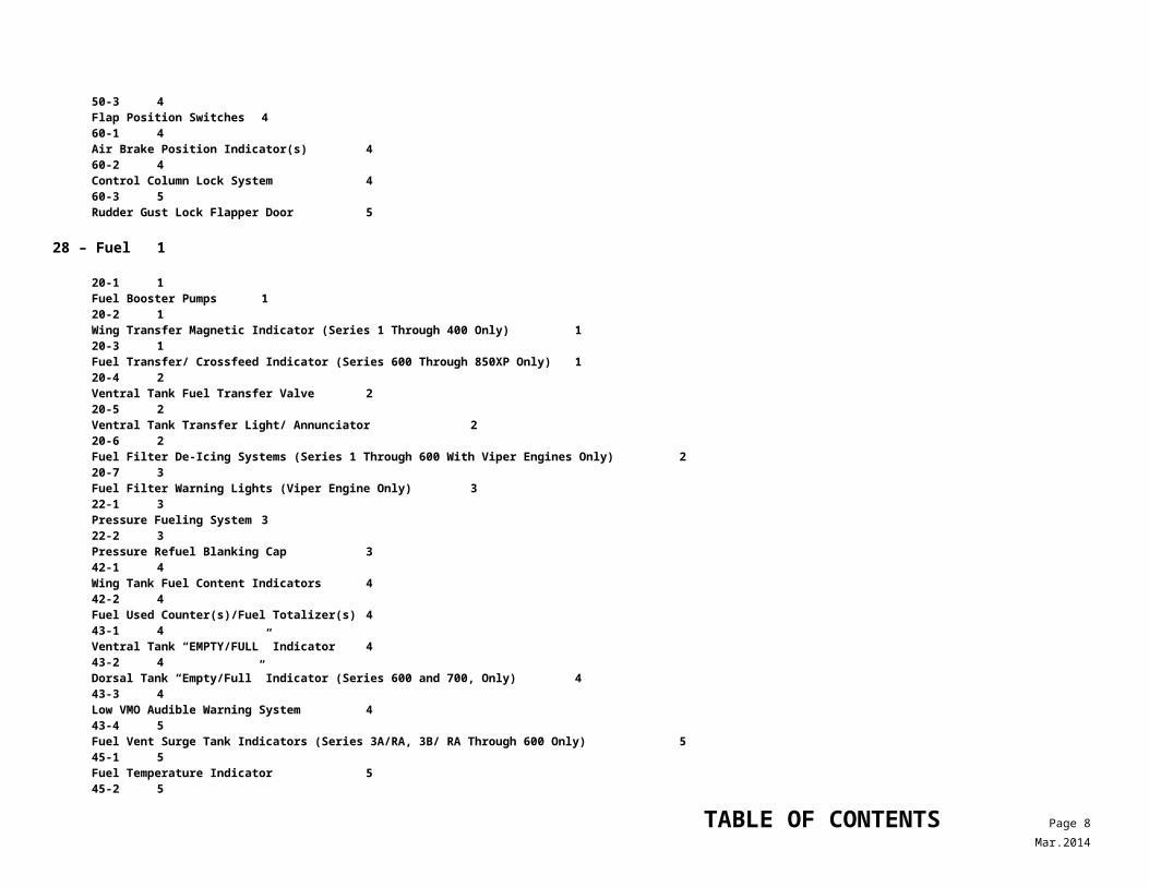
28 – Fuel 1
20-1 1Fuel Booster Pumps 120-2 1Wing Transfer Magnetic Indicator (Series 1 Through 400 Only) 120-3 1Fuel Transfer/ Crossfeed Indicator (Series 600 Through 850XP Only) 120-4 2Ventral Tank Fuel Transfer Valve 220-5 2Ventral Tank Transfer Light/ Annunciator 220-6 2Fuel Filter De-Icing Systems (Series 1 Through 600 With Viper Engines Only) 220-7 3Fuel Filter Warning Lights (Viper Engine Only) 322-1 3Pressure Fueling System 322-2 3Pressure Refuel Blanking Cap 342-1 4Wing Tank Fuel Content Indicators 442-2 4Fuel Used Counter(s)/Fuel Totalizer(s) 443-1 4Ventral Tank “EMPTY/FULL” Indicator 443-2 4Dorsal Tank “Empty/Full” Indicator (Series 600 and 700, Only) 443-3 4Low VMO Audible Warning System 443-4 5Fuel Vent Surge Tank Indicators (Series 3A/RA, 3B/ RA Through 600 Only) 545-1 5Fuel Temperature Indicator 545-2 5Fuel Management Computer System (Garrett GEMS System) 5
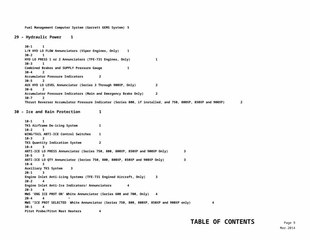
29 – Hydraulic Power 1
30-1 1L/R HYD LO FLOW Annunciators (Viper Engines, Only) 130-2 1HYD LO PRESS 1 or 2 Annunciators (TFE-731 Engines, Only) 130-3 1Combined Brakes and SUPPLY Pressure Gauge 130-4 2Accumulator Pressure Indicators 230-5 2AUX HYD LO LEVEL Annunciator (Series 3 Through 900XP, Only) 230-6 2Accumulator Pressure Indicators (Main and Emergency Brake Only) 230-7 2
TABLE OF CONTENTS Page 7Mar.2014
Thrust Reverser Accumulator Pressure Indicator (Series 800, if installed, and 750, 800XP, 850XP and 900XP) 2
30 – Ice and Rain Protection 1
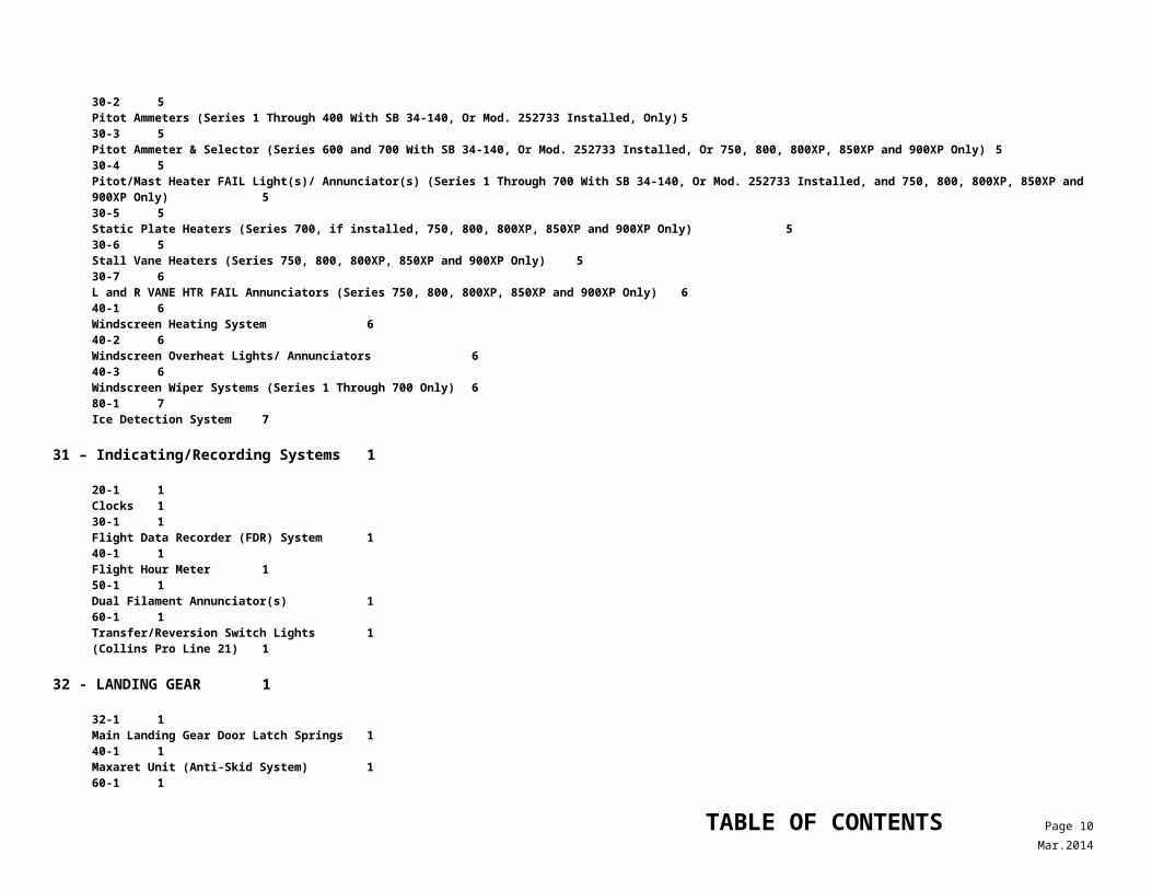
10-1 1TKS Airframe De-icing System 110-2 1WING/TAIL ANTI-ICE Control Switches 110-3 2TKS Quantity Indication System 210-4 3ANTI-ICE LO PRESS Annunciator (Series 750, 800, 800XP, 850XP and 900XP Only) 310-5 3ANTI-ICE LO QTY Annunciator (Series 750, 800, 800XP, 850XP and 900XP Only) 310-6 3Auxiliary TKS System 320-1 3Engine Inlet Anti-icing Systems (TFE-731 Engined Aircraft, Only) 320-2 4Engine Inlet Anti-Ice Indicators/ Annunciators 420-3 4MWS ‘ENG ICE PROT ON’ White Annunciator (Series 600 and 700, Only) 420-4 4MWS “ICE PROT SELECTED” White Annunciator (Series 750, 800, 800XP, 850XP and 900XP only) 430-1 4Pitot Probe/Pitot Mast Heaters 430-2 5Pitot Ammeters (Series 1 Through 400 With SB 34-140, Or Mod. 252733 Installed, Only) 530-3 5Pitot Ammeter & Selector (Series 600 and 700 With SB 34-140, Or Mod. 252733 Installed, Or 750, 800, 800XP, 850XP and 900XP Only) 530-4 5Pitot/Mast Heater FAIL Light(s)/ Annunciator(s) (Series 1 Through 700 With SB 34-140, Or Mod. 252733 Installed, and 750, 800, 800XP, 850XP and 900XP Only) 530-5 5Static Plate Heaters (Series 700, if installed, 750, 800, 800XP, 850XP and 900XP Only) 530-6 5Stall Vane Heaters (Series 750, 800, 800XP, 850XP and 900XP Only) 530-7 6L and R VANE HTR FAIL Annunciators (Series 750, 800, 800XP, 850XP and 900XP Only) 640-1 6Windscreen Heating System 640-2 6Windscreen Overheat Lights/ Annunciators 640-3 6Windscreen Wiper Systems (Series 1 Through 700 Only) 680-1 7Ice Detection System 7
31 – Indicating/Recording Systems 1
20-1 1Clocks 130-1 1
TABLE OF CONTENTS Page 8Mar.2014
Flight Data Recorder (FDR) System 140-1 1Flight Hour Meter 150-1 1Dual Filament Annunciator(s) 160-1 1Transfer/Reversion Switch Lights 1(Collins Pro Line 21) 1
32 - LANDING GEAR 1
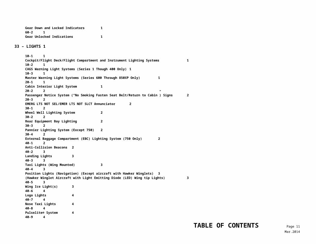
32-1 1Main Landing Gear Door Latch Springs 140-1 1Maxaret Unit (Anti-Skid System) 160-1 1Gear Down and Locked Indicators 160-2 1Gear Unlocked Indications 1
33 – LIGHTS 1
10-1 1Cockpit/Flight Deck/Flight Compartment and Instrument Lighting Systems 110-2 1CAGS Warning Light Systems (Series 1 Though 400 Only) 110-3 1Master Warning Light Systems (Series 600 Through 850XP Only) 120-1 1Cabin Interior Light System 120-2 2Passenger Notice System (“No Smoking Fasten Seat Belt/Return to Cabin”) Signs 220-3 2EMERG LTS NOT SEL/EMER LTS NOT SLCT Annunciator 230-1 2Wheel Well Lighting System 230-2 2Rear Equipment Bay Lighting 230-3 2Pannier Lighting System (Except 750) 230-4 2External Baggage Compartment (EBC) Lighting System (750 Only) 240-1 2Anti-Collision Beacons 240-2 3Landing Lights 340-3 3Taxi Lights (Wing Mounted) 340-4 3Position Lights (Navigation) (Except aircraft with Hawker Winglets) 3(Hawker Winglet Aircraft with Light Emitting Diode (LED) Wing tip Lights) 340-5 3
TABLE OF CONTENTS Page 9Mar.2014
Wing Ice Light(s) 340-6 4Logo Lights 440-7 4Nose Taxi Lights 440-8 4Pulselite® System 440-9 4Wing Tip Taxi Lighting System440-10 4Weight on Wheels Switch (Automatic Dim Function On Landing) 450-1 4Cabin Emergency Lighting System 450-2 5Floor Proximity Lighting System 5
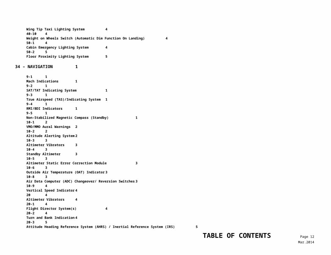
34 – NAVIGATION 1
9-1 1Mach Indications 19-2 1SAT/TAT Indicating System 19-3 1True Airspeed (TAS)/Indicating System 19-4 1RMI/BDI Indicators 19-5 1Non-Stabilized Magnetic Compass (Standby) 110-1 2VMO/MMO Aural Warnings 210-2 2Altitude Alerting System 210-3 3Altimeter Vibrators 310-4 3Standby Altimeter 310-5 3Altimeter Static Error Correction Module 310-6 3Outside Air Temperature (OAT) Indicator 310-8 3Air Data Computer (ADC) Changeover/ Reversion Switches 310-9 4Vertical Speed Indicator 420 4Altimeter Vibrators 420-1 4Flight Director System(s) 420-2 4Turn and Bank Indication 420-3 5Attitude Heading Reference System (AHRS) / Inertial Reference System (IRS) 520-4 5
TABLE OF CONTENTS Page 10Mar.2014
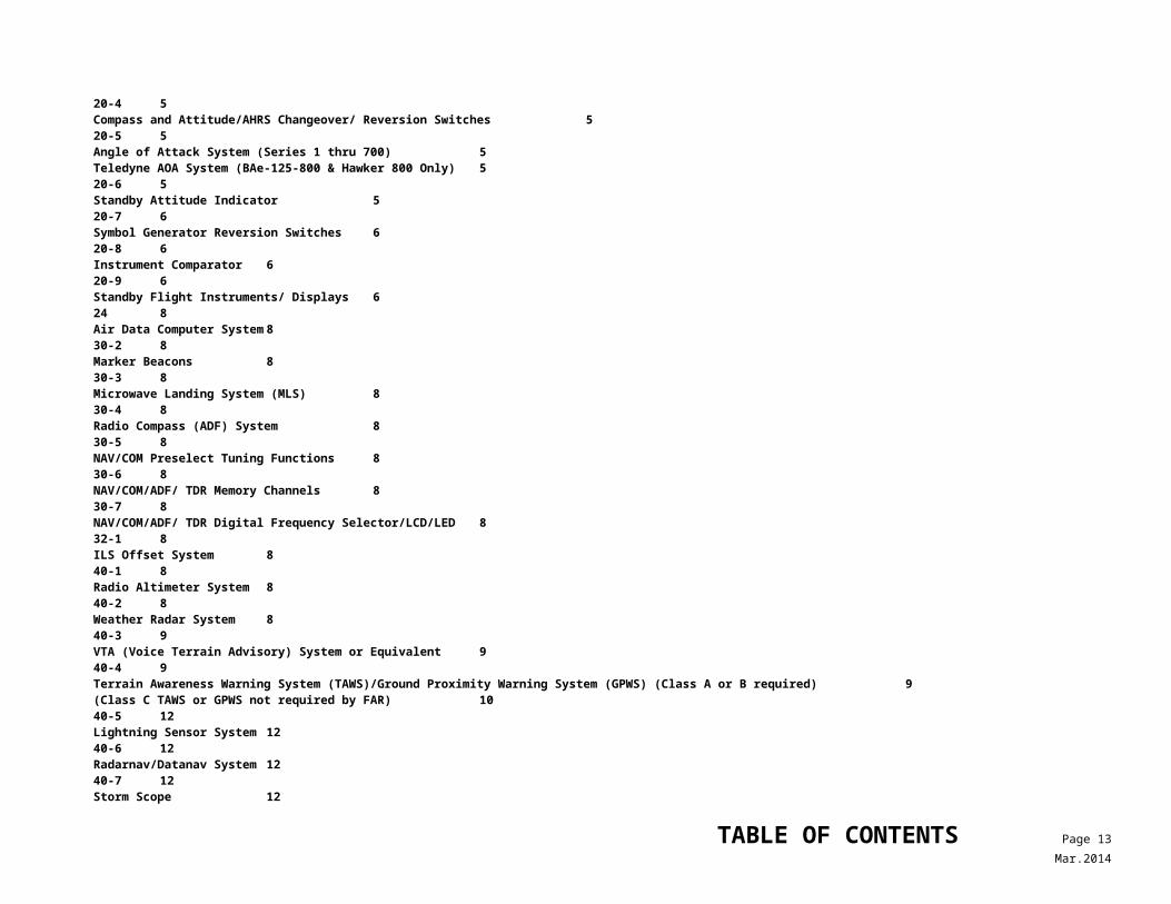
Compass and Attitude/AHRS Changeover/ Reversion Switches 520-5 5Angle of Attack System (Series 1 thru 700) 5Teledyne AOA System (BAe-125-800 & Hawker 800 Only) 520-6 5Standby Attitude Indicator 520-7 6Symbol Generator Reversion Switches 620-8 6Instrument Comparator 620-9 6Standby Flight Instruments/ Displays 624 8Air Data Computer System 830-2 8Marker Beacons 830-3 8Microwave Landing System (MLS) 830-4 8Radio Compass (ADF) System 830-5 8NAV/COM Preselect Tuning Functions 830-6 8NAV/COM/ADF/ TDR Memory Channels 830-7 8NAV/COM/ADF/ TDR Digital Frequency Selector/LCD/LED 832-1 8ILS Offset System 840-1 8Radio Altimeter System 840-2 8Weather Radar System 840-3 9VTA (Voice Terrain Advisory) System or Equivalent 940-4 9Terrain Awareness Warning System (TAWS)/Ground Proximity Warning System (GPWS) (Class A or B required) 9(Class C TAWS or GPWS not required by FAR) 1040-5 12Lightning Sensor System 1240-6 12Radarnav/Datanav System 1240-7 12Storm Scope 1242-1 12TACAN Number 2 Tuning System 1243-1 12ATC Transponder Attenuation System 1250-1 12LNAV or RNAV Systems 1250-2 12Flight Management Systems (FMS) 1250-3 12Distance Measuring Equipment (DME) Systems 12
TABLE OF CONTENTS Page 11Mar.2014
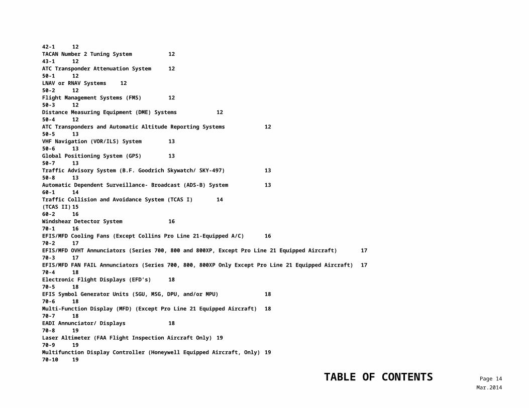
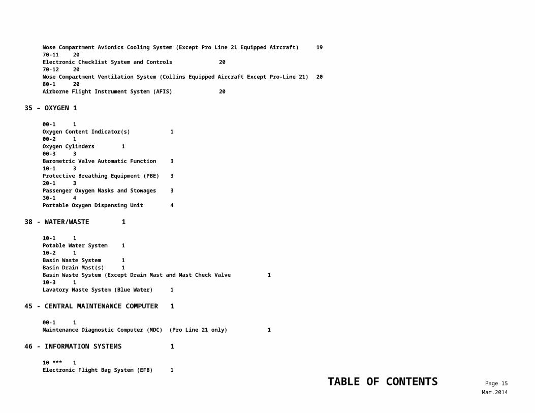
50-4 12ATC Transponders and Automatic Altitude Reporting Systems 1250-5 13VHF Navigation (VOR/ILS) System 1350-6 13Global Positioning System (GPS) 1350-7 13Traffic Advisory System (B.F. Goodrich Skywatch/ SKY-497) 1350-8 13Automatic Dependent Surveillance- Broadcast (ADS-B) System 1360-1 14Traffic Collision and Avoidance System (TCAS I) 14(TCAS II) 1560-2 16Windshear Detector System 1670-1 16EFIS/MFD Cooling Fans (Except Collins Pro Line 21-Equipped A/C) 1670-2 17EFIS/MFD OVHT Annunciators (Series 700, 800 and 800XP, Except Pro Line 21 Equipped Aircraft) 1770-3 17EFIS/MFD FAN FAIL Annunciators (Series 700, 800, 800XP Only Except Pro Line 21 Equipped Aircraft) 1770-4 18Electronic Flight Displays (EFD’s) 1870-5 18EFIS Symbol Generator Units (SGU, MSG, DPU, and/or MPU) 1870-6 18Multi-Function Display (MFD) (Except Pro Line 21 Equipped Aircraft) 1870-7 18EADI Annunciator/ Displays 1870-8 19Laser Altimeter (FAA Flight Inspection Aircraft Only) 1970-9 19Multifunction Display Controller (Honeywell Equipped Aircraft, Only) 1970-10 19Nose Compartment Avionics Cooling System (Except Pro Line 21 Equipped Aircraft) 1970-11 20Electronic Checklist System and Controls 2070-12 20Nose Compartment Ventilation System (Collins Equipped Aircraft Except Pro-Line 21) 2080-1 20Airborne Flight Instrument System (AFIS) 20
35 – OXYGEN 1
00-1 1Oxygen Content Indicator(s) 100-2 1Oxygen Cylinders 100-3 3Barometric Valve Automatic Function 310-1 3Protective Breathing Equipment (PBE) 320-1 3
TABLE OF CONTENTS Page 12Mar.2014
Passenger Oxygen Masks and Stowages 330-1 4Portable Oxygen Dispensing Unit 4
38 - WATER/WASTE 1
10-1 1Potable Water System 110-2 1Basin Waste System 1Basin Drain Mast(s) 1Basin Waste System (Except Drain Mast and Mast Check Valve 110-3 1Lavatory Waste System (Blue Water) 1
45 - CENTRAL MAINTENANCE COMPUTER 1
00-1 1Maintenance Diagnostic Computer (MDC) (Pro Line 21 only) 1
46 - INFORMATION SYSTEMS 1
10 *** 1Electronic Flight Bag System (EFB) 120 1Integrated Flight Information System (Pro Line 21 IFIS-5000) 1
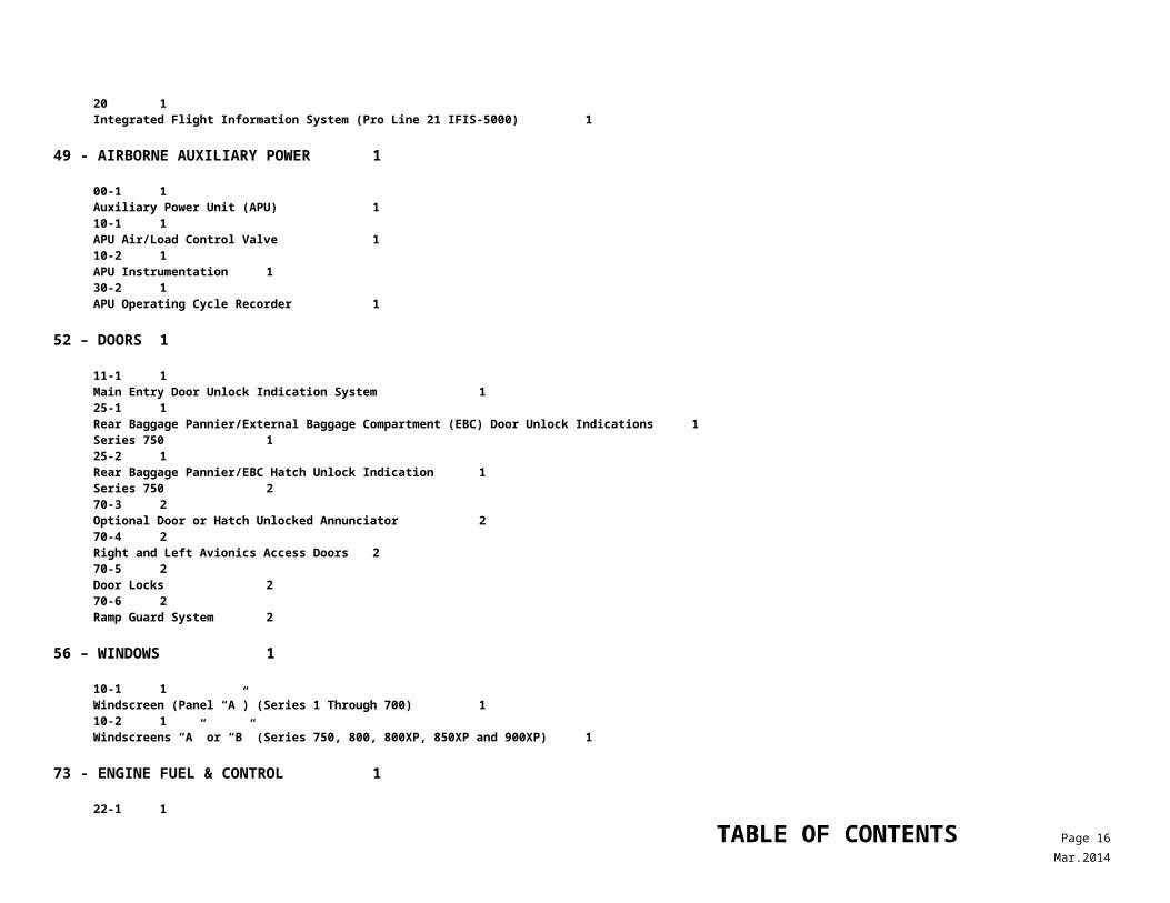
49 - AIRBORNE AUXILIARY POWER 1
00-1 1Auxiliary Power Unit (APU) 110-1 1APU Air/Load Control Valve 110-2 1APU Instrumentation 130-2 1APU Operating Cycle Recorder 1
52 – DOORS 1
11-1 1Main Entry Door Unlock Indication System 125-1 1Rear Baggage Pannier/External Baggage Compartment (EBC) Door Unlock Indications 1Series 750 125-2 1Rear Baggage Pannier/EBC Hatch Unlock Indication 1Series 750 270-3 2
TABLE OF CONTENTS Page 13Mar.2014
Optional Door or Hatch Unlocked Annunciator 270-4 2Right and Left Avionics Access Doors 270-5 2Door Locks270-6 2Ramp Guard System 2
56 – WINDOWS 1
10-1 1Windscreen (Panel “A”) (Series 1 Through 700) 110-2 1Windscreens “A” or “B” (Series 750, 800, 800XP, 850XP and 900XP) 1
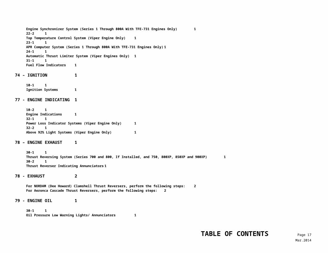
73 - ENGINE FUEL & CONTROL 1
22-1 1Engine Synchronizer System (Series 1 Through 800A With TFE-731 Engines Only) 122-2 1Top Temperature Control System (Viper Engine Only) 123-1 1APR Computer System (Series 1 Through 800A With TFE-731 Engines Only) 124-1 1Automatic Thrust Limiter System (Viper Engines Only) 131-1 1Fuel Flow Indicators 1
74 – IGNITION 1
10-1 1Ignition Systems 1
77 - ENGINE INDICATING 1
10-2 1Engine Indications 132-1 1Power Loss Indicator Systems (Viper Engine Only) 132-2 1Above 92% Light Systems (Viper Engine Only) 1
78 – ENGINE EXHAUST 1
30-1 1Thrust Reversing System (Series 700 and 800, If Installed, and 750, 800XP, 850XP and 900XP) 130-2 1Thrust Reverser Indicating Annunciators 1
TABLE OF CONTENTS Page 14Mar.2014
78 - EXHAUST 2
For NORDAM (Dee Howard) Clamshell Thrust Reversers, perform the following steps: 2For Aeronca Cascade Thrust Reversers, perform the following steps: 2
79 - ENGINE OIL 1
30-1 1Oil Pressure Low Warning Lights/ Annunciators 1
80 – STARTING 1
00-1 1Starter Power Available Annunciator (TFE-731 Engines Only) 100-2 1Starter Select Light (Viper Engines Only) 100-3 1Starter Operating Annunciators (TFE-731 Engines Only) 1
TABLE OF CONTENTS Page 15Mar.2014
HAWKER 125 (SERIES 1 THROUGH 900XP) M&O FOR MINIMUM EQUIPMENT LIST
Maintenance and Operational Proceduresfor Federal Aviation Administration Master Minimum Equipment List - Revision No: 8d – 12/12/13
1. SYSTEM, Sequence Numbers & Item
Repair Category2. Number Installed
3. Number Required for Dispatch MAINTENANCEPROCEDURES
OPERATIONALPROCEDURES21 - Air Conditioning 4. Remarks and Exceptions
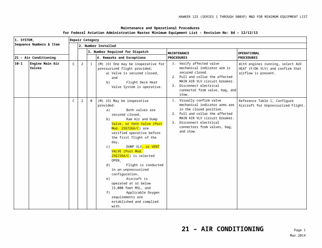
10-1 Engine Main Air Valves C 2 1 (M) (O) One may be inoperative for pressurized flight provided;
a) Valve is secured closed, and b) Flight Deck Heat Valve System is
operative.
1. Verify affected valve mechanical indicator arm is secured closed.
2. Pull and collar the affected MAIN AIR VLV circuit breaker.
3. Disconnect electrical connector from valve, bag, and stow.
With engines running, select AUX HEAT (F/DK VLV) and confirm that airflow is present.
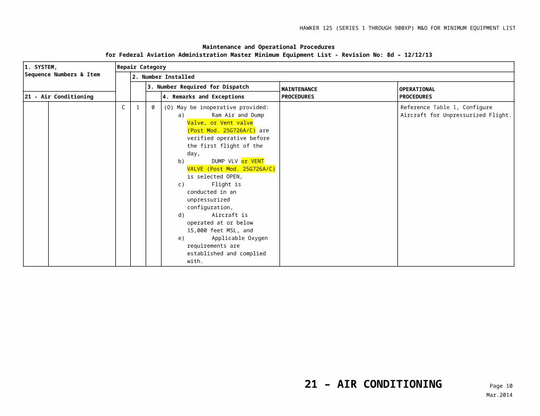
C 2 0 (M) (O) May be inoperative provided:
a) Both valves are secured closed, b) Ram Air and Dump Valve, or Vent
Valve (Post Mod. 25G726A/C) are verified operative before the first flight of the day,
c) DUMP VLV, or VENT VALVE (Post Mod. 25G726A/C) is selected OPEN,
d) Flight is conducted in an unpressurized configuration,
e) Aircraft is operated at or below 15,000 feet MSL, and
f) Applicable Oxygen requirements are established and complied with.
1. Visually confirm valve mechanical indicator arms are in the closed position.
2. Pull and collar the affected MAIN AIR VLV circuit breaker.
3. Disconnect electrical connectors from valves, bag, and stow.
Reference Table 1, ConfigureAircraft for Unpressurized Flight.
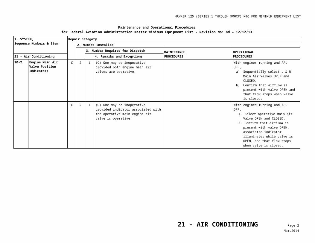
10-2 Engine Main Air Valve Position Indicators
C 2 1 (O) One may be inoperative provided both engine main air valves are operative.
With engines running and APU OFF,a) Sequentially select L & R Main Air
Valves OPEN and CLOSED.b) Confirm that airflow is present with
valve OPEN and that flow stops when valve is closed.
C 2 1 (O) One may be inoperative provided indicator associated with the operative main engine air valve is operative.
With engines running and APU OFF,1. Select operative Main Air
Valve OPEN and CLOSED.2. Confirm that airflow is present with
valve OPEN, associated indicator illuminates while valve is OPEN, and that flow stops when valve is closed.
21 – AIR CONDITIONING Page 1Mar.2014
HAWKER 125 (SERIES 1 THROUGH 900XP) M&O FOR MINIMUM EQUIPMENT LIST
Maintenance and Operational Proceduresfor Federal Aviation Administration Master Minimum Equipment List - Revision No: 8d – 12/12/13
1. SYSTEM, Sequence Numbers & Item
Repair Category2. Number Installed
3. Number Required for Dispatch MAINTENANCEPROCEDURES
OPERATIONALPROCEDURES21 - Air Conditioning 4. Remarks and Exceptions
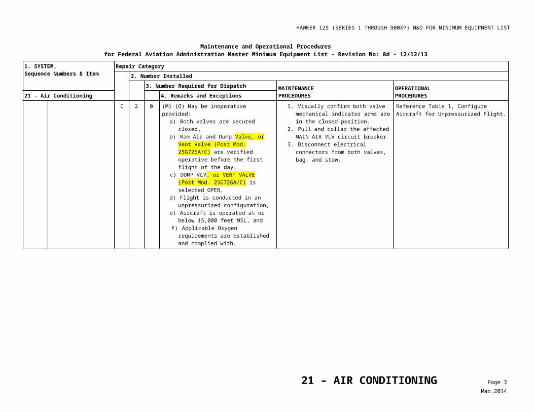
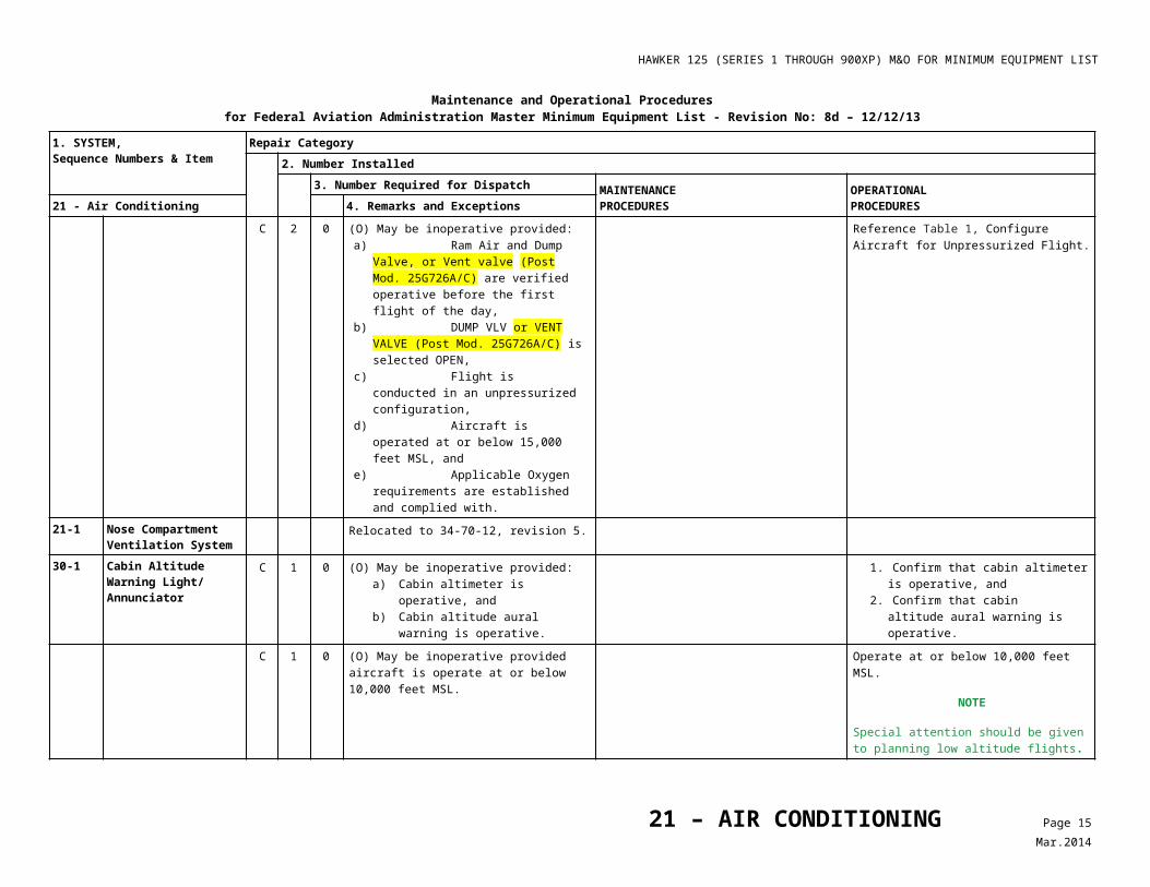
C 2 0 (M) (O) May be inoperative provided:
a) Both valves are secured closed,b) Ram Air and Dump Valve, or Vent
Valve (Post Mod. 25G726A/C) are verified operative before the first flight of the day,
c) DUMP VLV, or VENT VALVE (Post Mod. 25G726A/C) is selected OPEN,
d) Flight is conducted in an unpressurized configuration,
e) Aircraft is operated at or below 15,000 feet MSL, and
f) Applicable Oxygen requirements are established and complied with.
1. Visually confirm both valve mechanical indicator arms are in the closed position.
2. Pull and collar the affectedMAIN AIR VLV circuit breaker
3. Disconnect electrical connectors from both valves, bag, and stow.
Reference Table 1, ConfigureAircraft for Unpressurized Flight.
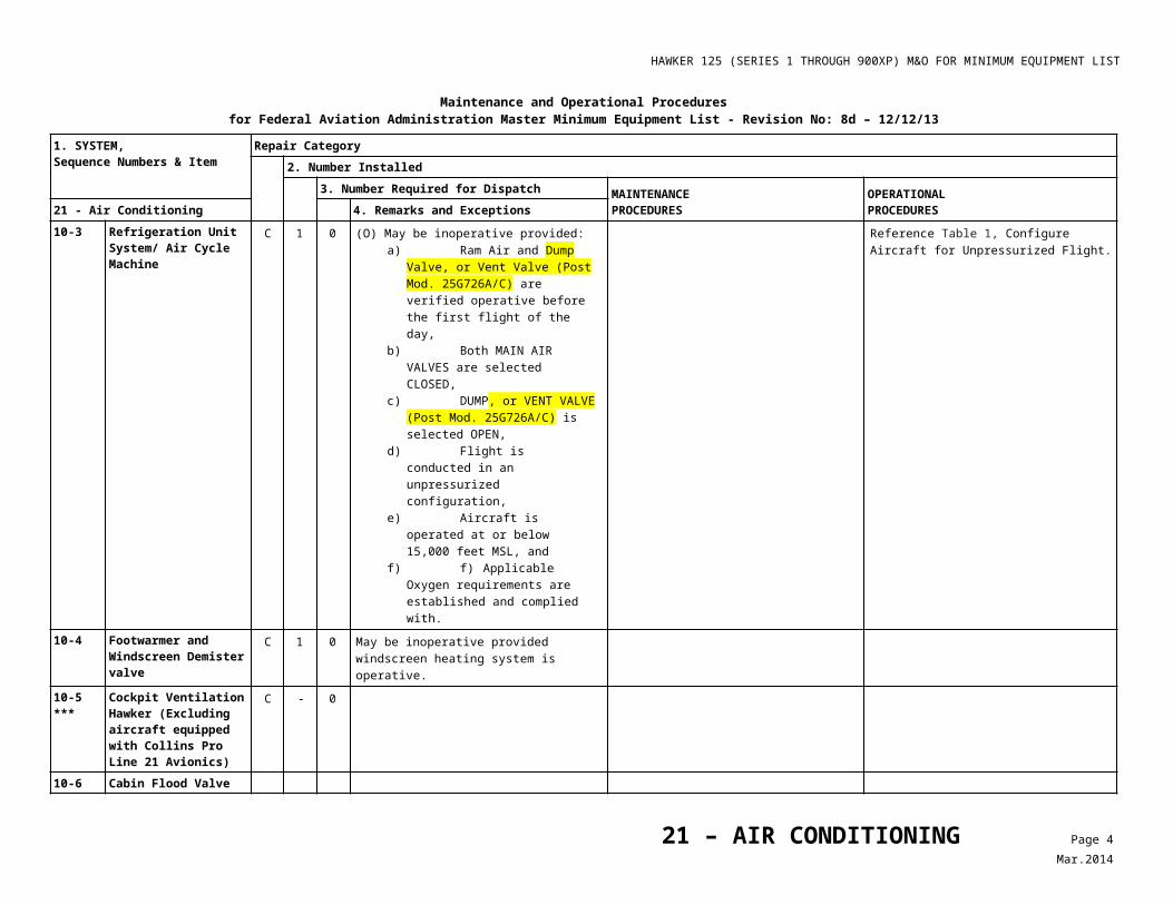
10-3 Refrigeration Unit System/ Air Cycle Machine
C 1 0 (O) May be inoperative provided: a) Ram Air and Dump Valve, or Vent
Valve (Post Mod. 25G726A/C) are verified operative before the first flight of the day,
b) Both MAIN AIR VALVES are selected CLOSED,
c) DUMP, or VENT VALVE (Post Mod. 25G726A/C) is selected OPEN,
d) Flight is conducted in an unpressurized configuration,
e) Aircraft is operated at or below 15,000 feet MSL, and
f) f) Applicable Oxygen requirements are established and complied with.
Reference Table 1, ConfigureAircraft for Unpressurized Flight.
10-4 Footwarmer and Windscreen Demister valve
C 1 0 May be inoperative provided windscreen heating system is operative.
10-5***
Cockpit Ventilation Hawker (Excluding aircraft equipped with Collins Pro Line 21 Avionics)
C - 0
10-6 Cabin Flood Valve
21 – AIR CONDITIONING Page 2Mar.2014
HAWKER 125 (SERIES 1 THROUGH 900XP) M&O FOR MINIMUM EQUIPMENT LIST
Maintenance and Operational Proceduresfor Federal Aviation Administration Master Minimum Equipment List - Revision No: 8d – 12/12/13
1. SYSTEM, Sequence Numbers & Item
Repair Category2. Number Installed
3. Number Required for Dispatch MAINTENANCEPROCEDURES
OPERATIONALPROCEDURES21 - Air Conditioning 4. Remarks and Exceptions
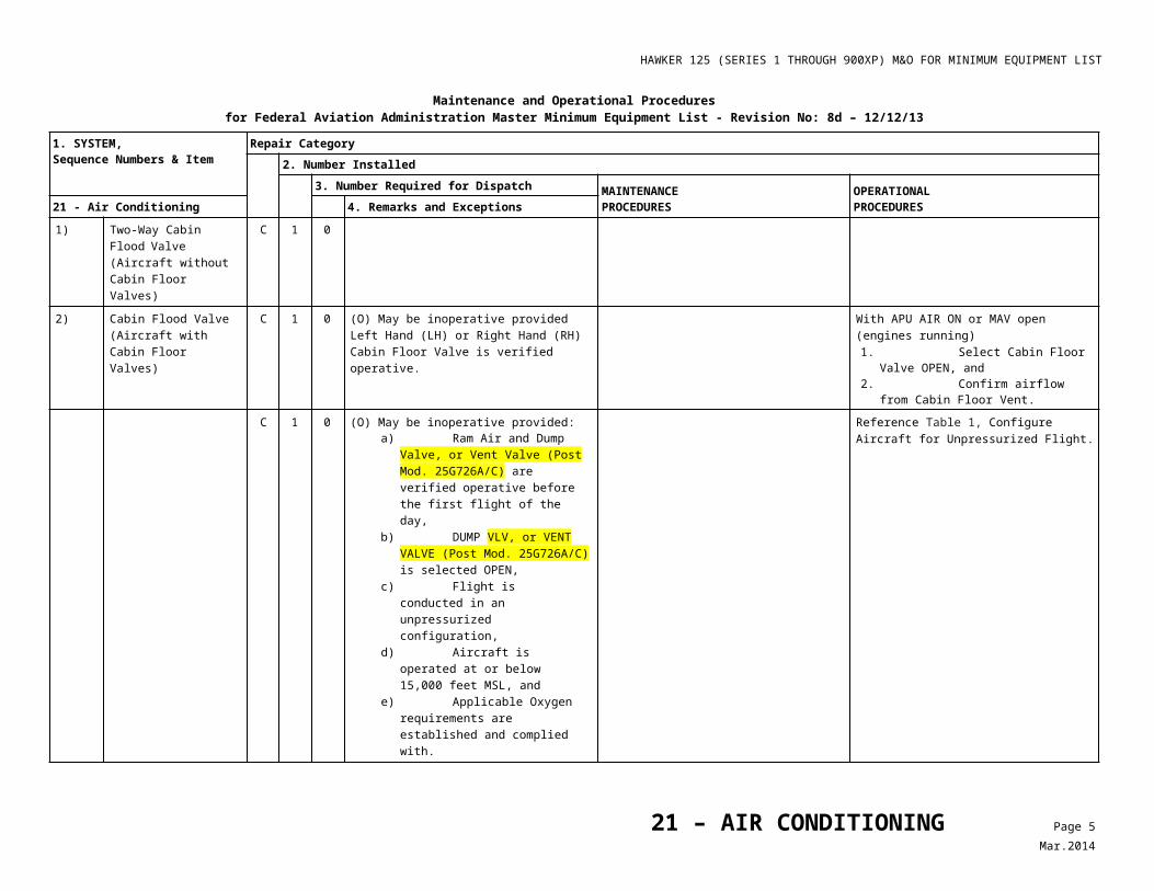
1) Two-Way Cabin Flood Valve (Aircraft without Cabin Floor Valves)
C 1 0
2) Cabin Flood Valve (Aircraft with Cabin Floor Valves)
C 1 0 (O) May be inoperative provided Left Hand (LH) or Right Hand (RH) Cabin Floor Valve is verified operative.
With APU AIR ON or MAV open(engines running) 1. Select Cabin Floor Valve OPEN, and 2. Confirm airflow from Cabin Floor Vent.
C 1 0 (O) May be inoperative provided: a) Ram Air and Dump Valve, or Vent
Valve (Post Mod. 25G726A/C) are verified operative before the first flight of the day,
b) DUMP VLV, or VENT VALVE (Post Mod. 25G726A/C) is selected OPEN,
c) Flight is conducted in an unpressurized configuration,
d) Aircraft is operated at or below 15,000 feet MSL, and
e) Applicable Oxygen requirements are established and complied with.
Reference Table 1, ConfigureAircraft for Unpressurized Flight.
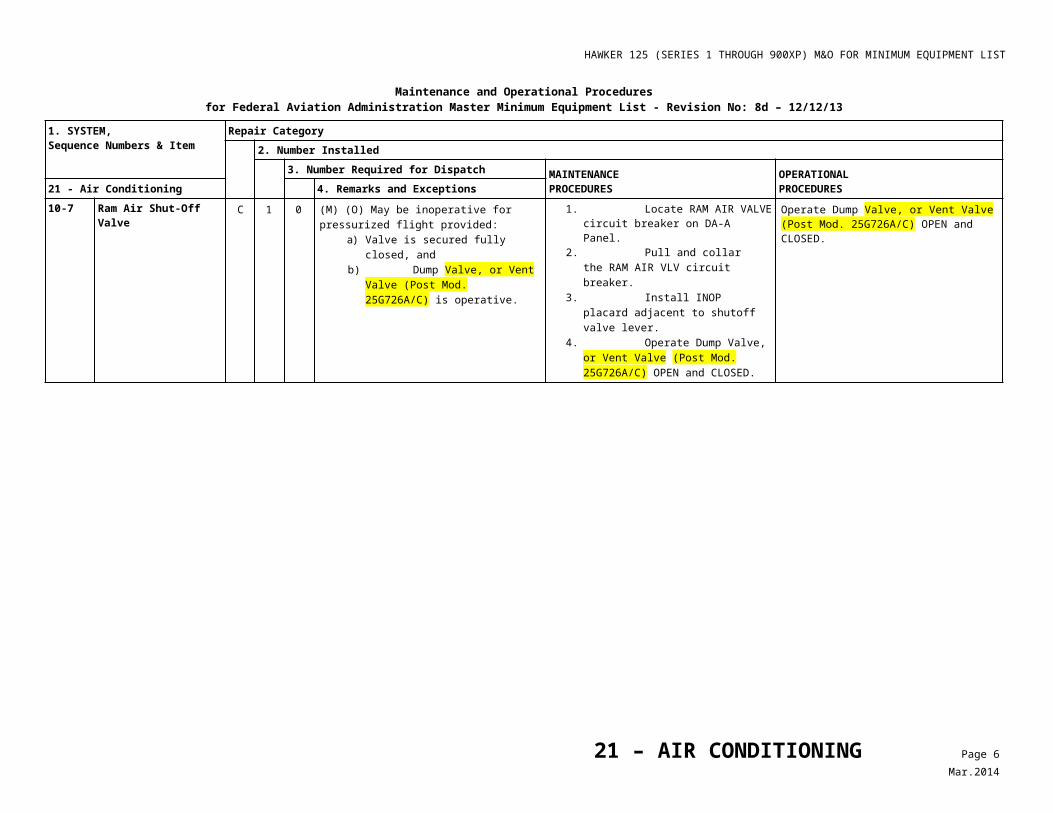
10-7 Ram Air Shut-Off Valve C 1 0 (M) (O) May be inoperative for pressurized flight provided:
a) Valve is secured fully closed, and b) Dump Valve, or Vent Valve (Post
Mod. 25G726A/C) is operative.
1. Locate RAM AIR VALVE circuit breaker on DA-A Panel.
2. Pull and collar the RAM AIR VLV circuit breaker.
3. Install INOP placard adjacent to shutoff valve lever.
4. Operate Dump Valve, or Vent Valve (Post Mod. 25G726A/C) OPEN and CLOSED.
Operate Dump Valve, or Vent Valve (Post Mod. 25G726A/C) OPEN and CLOSED.
21 – AIR CONDITIONING Page 3Mar.2014
HAWKER 125 (SERIES 1 THROUGH 900XP) M&O FOR MINIMUM EQUIPMENT LIST
Maintenance and Operational Proceduresfor Federal Aviation Administration Master Minimum Equipment List - Revision No: 8d – 12/12/13
1. SYSTEM, Sequence Numbers & Item
Repair Category2. Number Installed
3. Number Required for Dispatch MAINTENANCEPROCEDURES
OPERATIONALPROCEDURES21 - Air Conditioning 4. Remarks and Exceptions
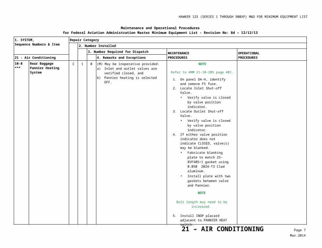
10-8***
Rear Baggage Pannier Heating System
C 1 0 (M) May be inoperative provided:a) Inlet and outlet valves are verified
closed, andb) Pannier heating is selected OFF.
NOTE
Refer to AMM 21-10-205 page 401.
1. On panel DA-H, identify and remove F5 fuse.
2. Locate Inlet Shut-off Valve.• Verify valve is closed by valve
position indicator.3. Locate Outlet Shut-off Valve.
• Verify valve is closed by valve position indicator.
4. If either valve position indicator does not indicate CLOSED, valve(s) may be blanked.• Fabricate blanking plate to
match 25-8VF405-1 gasket using 0.050” 2024-T3 Clad aluminum.
• Install plate with two gaskets between valve and Pannier.
NOTE
Bolt length may need to be increased.
5. Install INOP placard adjacent to PANNIER HEAT switch.
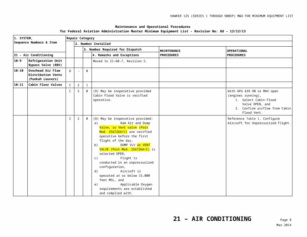
10-9 Refrigeration Unit Bypass Valve (RBV)
Moved to 21-60-7, Revision 5.
10-10 Overhead Air Flow Distribution Vents (Punkah Louvers)
D - 0
10-11 Cabin Floor Valves C 2 1
C 2 0 (O) May be inoperative provided Cabin Flood Valve is verified operative.
With APU AIR ON or MAV open(engines running),
1. Select Cabin Flood Valve OPEN, and
2. Confirm airflow from Cabin Flood Vent.
21 – AIR CONDITIONING Page 4Mar.2014
HAWKER 125 (SERIES 1 THROUGH 900XP) M&O FOR MINIMUM EQUIPMENT LIST
Maintenance and Operational Proceduresfor Federal Aviation Administration Master Minimum Equipment List - Revision No: 8d – 12/12/13
1. SYSTEM, Sequence Numbers & Item
Repair Category2. Number Installed
3. Number Required for Dispatch MAINTENANCEPROCEDURES
OPERATIONALPROCEDURES21 - Air Conditioning 4. Remarks and Exceptions
C 2 0 (O) May be inoperative provided: a) Ram Air and Dump Valve, or Vent valve
(Post Mod. 25G726A/C) are verified operative before the first flight of the day,
b) DUMP VLV or VENT VALVE (Post Mod. 25G726A/C) is selected OPEN,
c) Flight is conducted in an unpressurized configuration,
d) Aircraft is operated at or below 15,000 feet MSL, and
e) Applicable Oxygen requirements are established and complied with.
Reference Table 1, ConfigureAircraft for Unpressurized Flight.
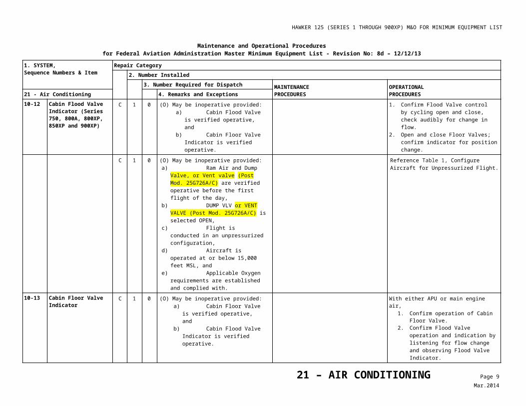
10-12 Cabin Flood Valve Indicator (Series 750, 800A, 800XP, 850XP and 900XP)
C 1 0 (O) May be inoperative provided: a) Cabin Flood Valve is verified
operative, and b) Cabin Floor Valve Indicator is
verified operative.
1. Confirm Flood Valve control by cycling open and close, check audibly for change in flow.
2. Open and close Floor Valves; confirm indicator for position change.
C 1 0 (O) May be inoperative provided: a) Ram Air and Dump Valve, or Vent valve
(Post Mod. 25G726A/C) are verified operative before the first flight of the day,
b) DUMP VLV or VENT VALVE (Post Mod. 25G726A/C) is selected OPEN,
c) Flight is conducted in an unpressurized configuration,
d) Aircraft is operated at or below 15,000 feet MSL, and
e) Applicable Oxygen requirements are established and complied with.
Reference Table 1, ConfigureAircraft for Unpressurized Flight.
10-13 Cabin Floor Valve Indicator
C 1 0 (O) May be inoperative provided: a) Cabin Floor Valve is verified
operative, and b) Cabin Flood Valve Indicator is
verified operative.
With either APU or main engine air,1. Confirm operation of Cabin Floor
Valve.2. Confirm Flood Valve operation and
indication by listening for flow change and observing Flood Valve Indicator.
21 – AIR CONDITIONING Page 5Mar.2014
HAWKER 125 (SERIES 1 THROUGH 900XP) M&O FOR MINIMUM EQUIPMENT LIST
Maintenance and Operational Proceduresfor Federal Aviation Administration Master Minimum Equipment List - Revision No: 8d – 12/12/13
1. SYSTEM, Sequence Numbers & Item
Repair Category2. Number Installed
3. Number Required for Dispatch MAINTENANCEPROCEDURES
OPERATIONALPROCEDURES21 - Air Conditioning 4. Remarks and Exceptions
C 1 0 (O) May be inoperative provided: a) Ram Air and Dump Valve, or Vent
valve (Post Mod. 25G726A/C) are verified operative before the first flight of the day,
b) DUMP VLV or VENT VALVE (Post Mod. 25G726A/C) is selected OPEN,
c) Flight is conducted in an unpressurized configuration,
d) Aircraft is operated at or below 15,000 feet MSL, and
e) Applicable Oxygen requirements are established and complied with.
Reference Table 1, ConfigureAircraft for Unpressurized Flight.
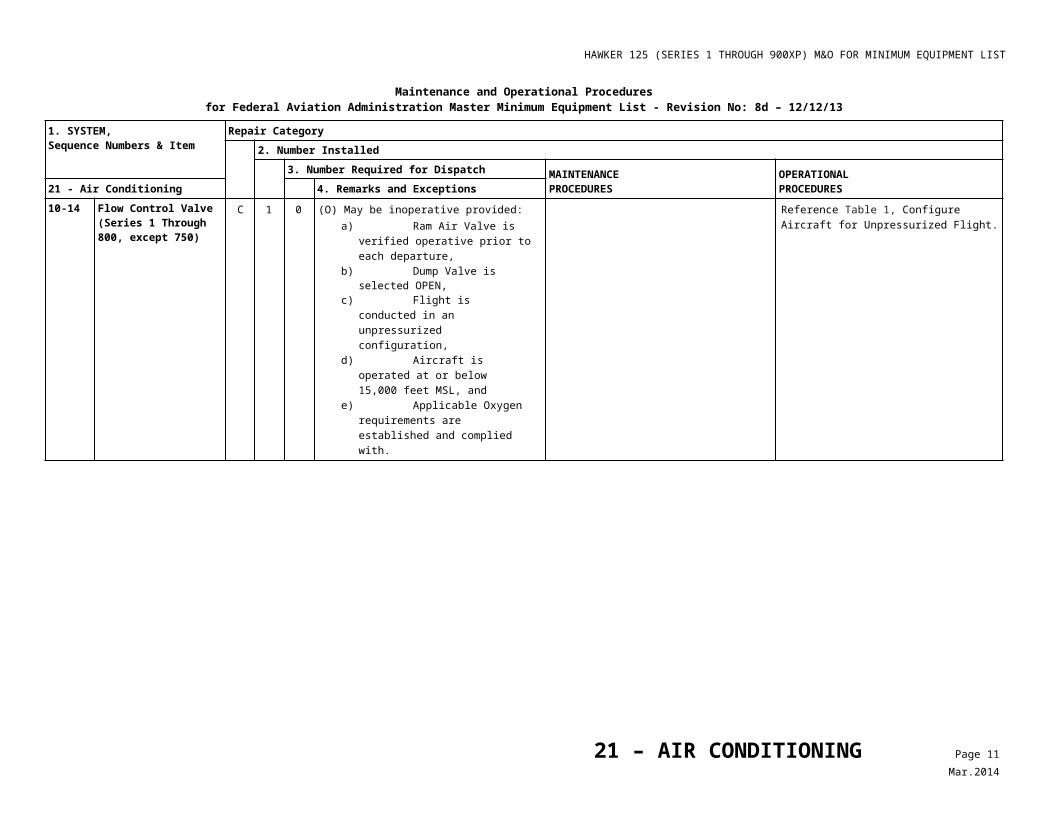
10-14 Flow Control Valve (Series 1 Through 800, except 750)
C 1 0 (O) May be inoperative provided: a) Ram Air Valve is verified operative
prior to each departure, b) Dump Valve is selected OPEN, c) Flight is conducted in an
unpressurized configuration, d) Aircraft is operated at or below
15,000 feet MSL, and e) Applicable Oxygen requirements are
established and complied with.
Reference Table 1, ConfigureAircraft for Unpressurized Flight.
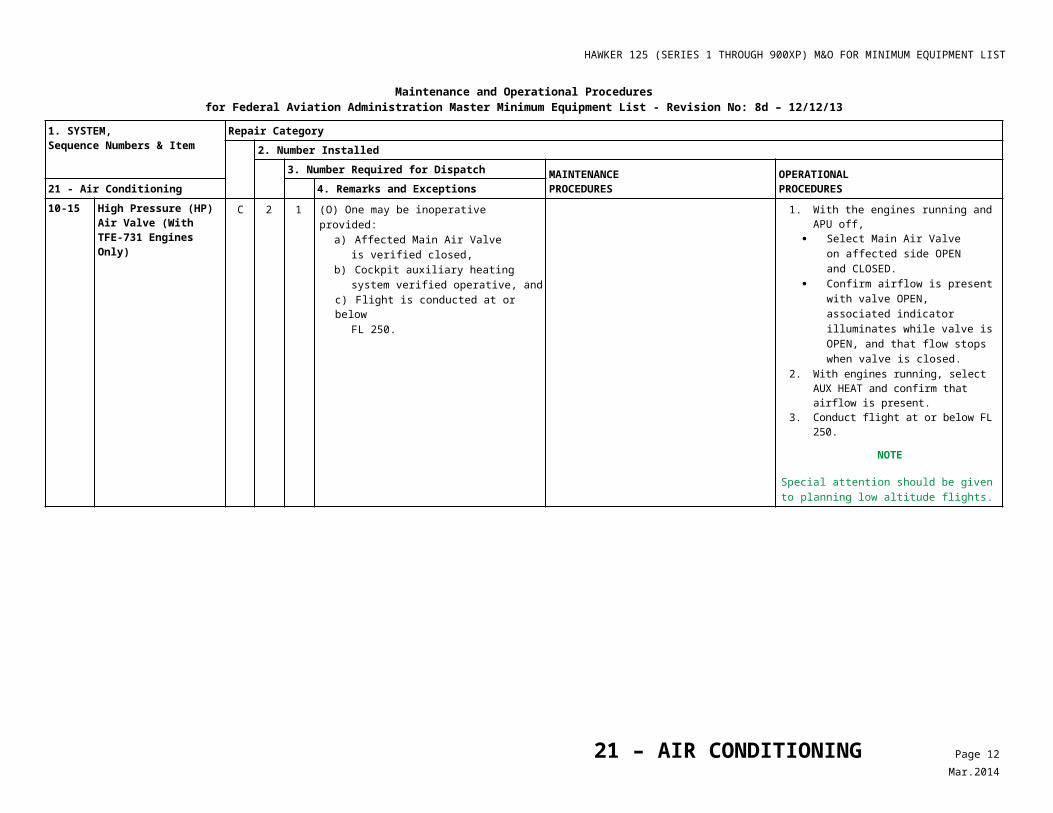
10-15 High Pressure (HP) Air Valve (With TFE-731 Engines Only)
C 2 1 (O) One may be inoperative provided:
a) Affected Main Air Valve is verified closed,
b) Cockpit auxiliary heating system verified operative, and
c) Flight is conducted at or belowFL 250.
1. With the engines running and APU off, Select Main Air Valve on
affected side OPEN and CLOSED.
Confirm airflow is present with valve OPEN, associated indicator illuminates while valve is OPEN, and that flow stops when valve is closed.
2. With engines running, select AUX HEAT and confirm that airflow is present.
3. Conduct flight at or below FL 250.
NOTE
Special attention should be given to planning low altitude flights.
21 – AIR CONDITIONING Page 6Mar.2014
HAWKER 125 (SERIES 1 THROUGH 900XP) M&O FOR MINIMUM EQUIPMENT LIST
Maintenance and Operational Proceduresfor Federal Aviation Administration Master Minimum Equipment List - Revision No: 8d – 12/12/13
1. SYSTEM, Sequence Numbers & Item
Repair Category2. Number Installed
3. Number Required for Dispatch MAINTENANCEPROCEDURES
OPERATIONALPROCEDURES21 - Air Conditioning 4. Remarks and Exceptions
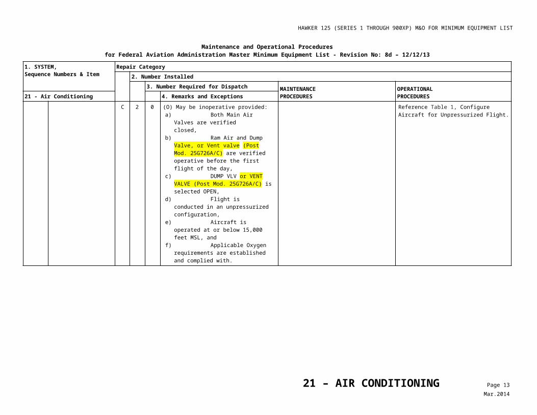
C 2 0 (O) May be inoperative provided: a) Both Main Air Valves are verified
closed, b) Ram Air and Dump Valve, or Vent valve
(Post Mod. 25G726A/C) are verified operative before the first flight of the day,
c) DUMP VLV or VENT VALVE (Post Mod. 25G726A/C) is selected OPEN,
d) Flight is conducted in an unpressurized configuration,
e) Aircraft is operated at or below 15,000 feet MSL, and
f) Applicable Oxygen requirements are established and complied with.
Reference Table 1, ConfigureAircraft for Unpressurized Flight.
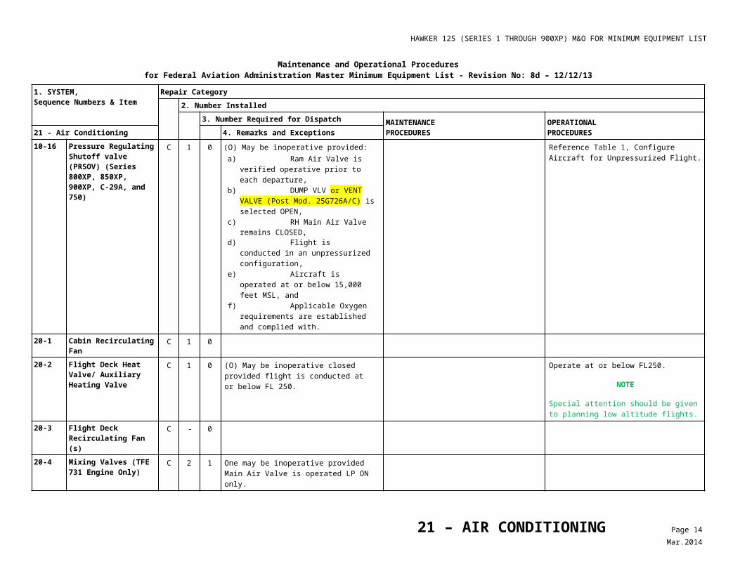
10-16 Pressure Regulating Shutoff valve (PRSOV) (Series 800XP, 850XP, 900XP, C-29A, and 750)
C 1 0 (O) May be inoperative provided: a) Ram Air Valve is verified operative prior to
each departure, b) DUMP VLV or VENT VALVE (Post Mod.
25G726A/C) is selected OPEN, c) RH Main Air Valve remains CLOSED, d) Flight is conducted in an unpressurized
configuration, e) Aircraft is operated at or below 15,000
feet MSL, and f) Applicable Oxygen requirements are
established and complied with.
Reference Table 1, ConfigureAircraft for Unpressurized Flight.
20-1 Cabin Recirculating Fan C 1 020-2 Flight Deck Heat Valve/
Auxiliary Heating ValveC 1 0 (O) May be inoperative closed provided
flight is conducted at or below FL 250.Operate at or below FL250.
NOTE
Special attention should be given to planning low altitude flights.
20-3 Flight Deck Recirculating Fan (s)
C - 0
20-4 Mixing Valves (TFE 731 Engine Only)
C 2 1 One may be inoperative provided Main Air Valve is operated LP ON only.
21 – AIR CONDITIONING Page 7Mar.2014
HAWKER 125 (SERIES 1 THROUGH 900XP) M&O FOR MINIMUM EQUIPMENT LIST
Maintenance and Operational Proceduresfor Federal Aviation Administration Master Minimum Equipment List - Revision No: 8d – 12/12/13
1. SYSTEM, Sequence Numbers & Item
Repair Category2. Number Installed
3. Number Required for Dispatch MAINTENANCEPROCEDURES
OPERATIONALPROCEDURES21 - Air Conditioning 4. Remarks and Exceptions
C 2 0 (O) May be inoperative provided: a) Ram Air and Dump Valve, or Vent valve
(Post Mod. 25G726A/C) are verified operative before the first flight of the day,
b) DUMP VLV or VENT VALVE (Post Mod. 25G726A/C) is selected OPEN,
c) Flight is conducted in an unpressurized configuration,
d) Aircraft is operated at or below 15,000 feet MSL, and
e) Applicable Oxygen requirements are established and complied with.
Reference Table 1, ConfigureAircraft for Unpressurized Flight.
21-1 Nose Compartment Ventilation System
Relocated to 34-70-12, revision 5.
30-1 Cabin Altitude Warning Light/ Annunciator
C 1 0 (O) May be inoperative provided:a) Cabin altimeter is operative, andb) Cabin altitude aural warning is
operative.
1. Confirm that cabin altimeter is operative, and
2. Confirm that cabin altitude aural warning is operative.
C 1 0 (O) May be inoperative provided aircraft is operate at or below 10,000 feet MSL.
Operate at or below 10,000 feetMSL.
NOTE
Special attention should be given to planning low altitude flights.
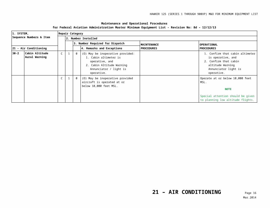
30-2 Cabin Altitude Aural Warning
C 1 0 (O) May be inoperative provided:1. Cabin altimeter is operative, and2. Cabin Altitude Warning
Annunciator / light is operative.
1. Confirm that cabin altimeter is operative, and
2. Confirm that cabin altitude Warning Annunciator light is operative.
C 1 0 (O) May be inoperative provided aircraft is operated at or below 10,000 feet MSL.
Operate at or below 10,000 feetMSL.
NOTE
Special attention should be given to planning low altitude flights.
21 – AIR CONDITIONING Page 8Mar.2014
HAWKER 125 (SERIES 1 THROUGH 900XP) M&O FOR MINIMUM EQUIPMENT LIST
Maintenance and Operational Proceduresfor Federal Aviation Administration Master Minimum Equipment List - Revision No: 8d – 12/12/13
1. SYSTEM, Sequence Numbers & Item
Repair Category2. Number Installed
3. Number Required for Dispatch MAINTENANCEPROCEDURES
OPERATIONALPROCEDURES21 - Air Conditioning 4. Remarks and Exceptions
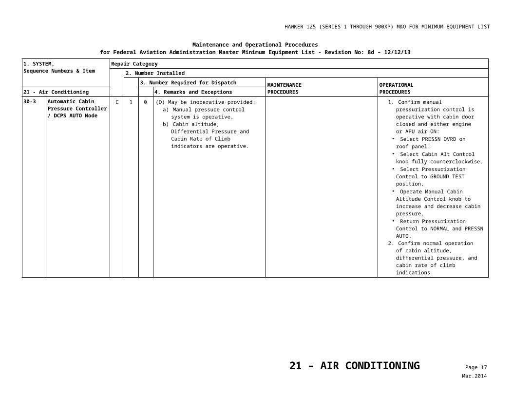
30-3 Automatic Cabin Pressure Controller / DCPS AUTO Mode
C 1 0 (O) May be inoperative provided:a) Manual pressure control system
is operative,b) Cabin altitude, Differential Pressure
and Cabin Rate of Climb indicators are operative.
1. Confirm manual pressurization control is operative with cabin door closed and either engine or APU air ON:
• Select PRESSN OVRD on roof panel.
• Select Cabin Alt Control knob fully counterclockwise.
• Select Pressurization Control to GROUND TEST position.
• Operate Manual Cabin Altitude Control knob to increase and decrease cabin pressure.
• Return Pressurization Control to NORMAL and PRESSN AUTO.
2. Confirm normal operation of cabin altitude, differential pressure, and cabin rate of climb indications.
C 1 0 (O) May be inoperative provided: a) Ram Air and Dump Valve, or Vent
valve (Post Mod. 25G726A/C) are verified operative before the first flight of the day,
b) DUMP VLV or VENT VALVE (Post Mod. 25G726A/C) is selected OPEN,
c) Flight is conducted in an unpressurized configuration,
d) Aircraft is operated at or below 15,000 feet MSL, and
e) Applicable Oxygen requirements are established and complied with.
Reference Table 1, ConfigureAircraft for Unpressurized Flight.
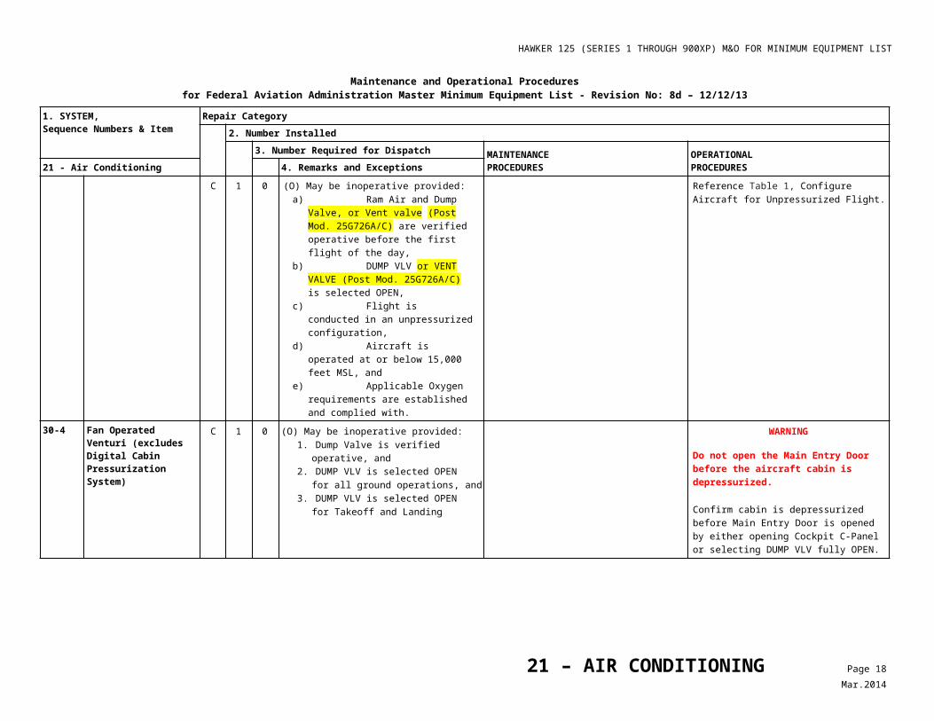
30-4 Fan Operated Venturi (excludes Digital Cabin Pressurization System)
C 1 0 (O) May be inoperative provided:1. Dump Valve is verified
operative, and2. DUMP VLV is selected OPEN
for all ground operations, and3. DUMP VLV is selected OPEN
for Takeoff and Landing
WARNING
Do not open the Main Entry Door before the aircraft cabin is depressurized.
Confirm cabin is depressurized before Main Entry Door is opened by either opening Cockpit C-Panel or selecting DUMP VLV fully OPEN.
21 – AIR CONDITIONING Page 9Mar.2014
HAWKER 125 (SERIES 1 THROUGH 900XP) M&O FOR MINIMUM EQUIPMENT LIST
Maintenance and Operational Proceduresfor Federal Aviation Administration Master Minimum Equipment List - Revision No: 8d – 12/12/13
1. SYSTEM, Sequence Numbers & Item
Repair Category2. Number Installed
3. Number Required for Dispatch MAINTENANCEPROCEDURES
OPERATIONALPROCEDURES21 - Air Conditioning 4. Remarks and Exceptions
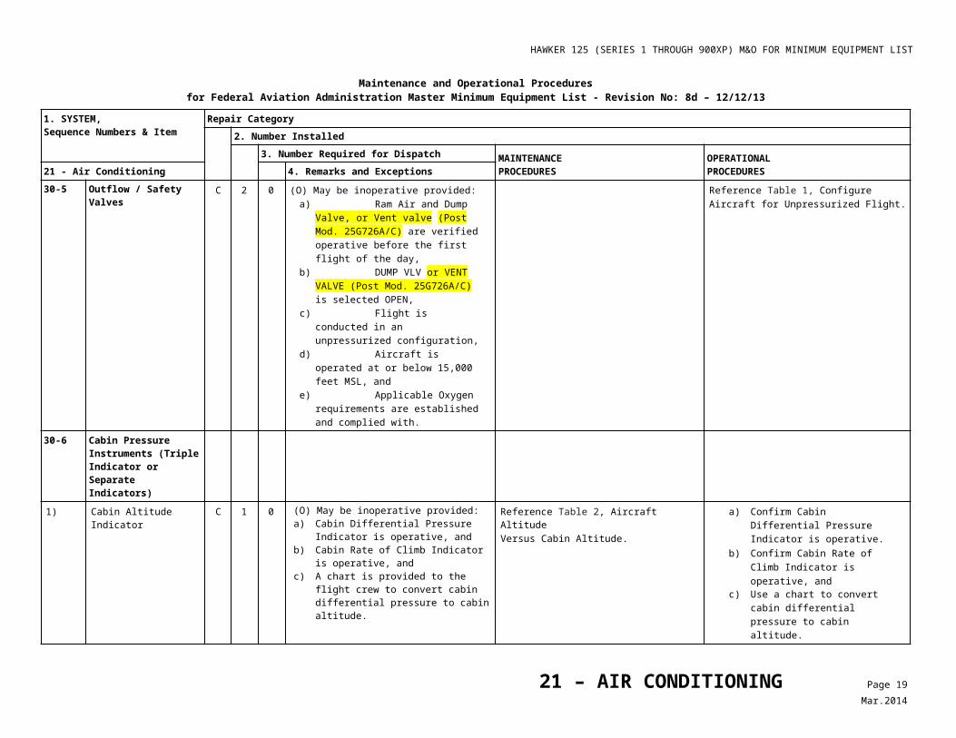
30-5 Outflow / Safety Valves C 2 0 (O) May be inoperative provided: a) Ram Air and Dump Valve, or Vent
valve (Post Mod. 25G726A/C) are verified operative before the first flight of the day,
b) DUMP VLV or VENT VALVE (Post Mod. 25G726A/C) is selected OPEN,
c) Flight is conducted in an unpressurized configuration,
d) Aircraft is operated at or below 15,000 feet MSL, and
e) Applicable Oxygen requirements are established and complied with.
Reference Table 1, ConfigureAircraft for Unpressurized Flight.
30-6 Cabin Pressure Instruments (Triple Indicator or Separate Indicators)
1) Cabin Altitude Indicator C 1 0 (O) May be inoperative provided:a) Cabin Differential Pressure Indicator is
operative, andb) Cabin Rate of Climb Indicator is
operative, andc) A chart is provided to the flight crew to
convert cabin differential pressure to cabin altitude.
Reference Table 2, Aircraft AltitudeVersus Cabin Altitude.
a) Confirm Cabin Differential Pressure Indicator is operative.
b) Confirm Cabin Rate of Climb Indicator is operative, and
c) Use a chart to convert cabin differential pressure to cabin altitude.
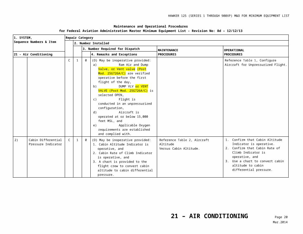
C 1 0 (O) May be inoperative provided: a) Ram Air and Dump Valve, or Vent valve
(Post Mod. 25G726A/C) are verified operative before the first flight of the day,
b) DUMP VLV or VENT VALVE (Post Mod. 25G726A/C) is selected OPEN,
c) Flight is conducted in an unpressurized configuration,
d) Aircraft is operated at or below 15,000 feet MSL, and
e) Applicable Oxygen requirements are established and complied with.
Reference Table 1, ConfigureAircraft for Unpressurized Flight.
21 – AIR CONDITIONING Page 10Mar.2014
HAWKER 125 (SERIES 1 THROUGH 900XP) M&O FOR MINIMUM EQUIPMENT LIST
Maintenance and Operational Proceduresfor Federal Aviation Administration Master Minimum Equipment List - Revision No: 8d – 12/12/13
1. SYSTEM, Sequence Numbers & Item
Repair Category2. Number Installed
3. Number Required for Dispatch MAINTENANCEPROCEDURES
OPERATIONALPROCEDURES21 - Air Conditioning 4. Remarks and Exceptions
2) Cabin Differential Pressure Indicator
C 1 0 (O) May be inoperative provided:1. Cabin Altitude Indicator is operative,
and2. Cabin Rate of Climb Indicator is operative,
and3. A chart is provided to the flight crew to
convert cabin altitude to cabin differential pressure.
Reference Table 2, Aircraft AltitudeVersus Cabin Altitude.
1. Confirm that Cabin Altitude Indicator is operative.
2. Confirm that Cabin Rate of Climb Indicator is operative, and
3. Use a chart to convert cabin altitude to cabin differential pressure.
C 1 0 (O) May be inoperative provided: a) Ram Air and Dump Valve, or Vent
valve (Post Mod. 25G726A/C) are verified operative before the first flight of the day,
b) DUMP VLV or VENT VALVE (Post Mod. 25G726A/C) is selected OPEN,
c) Flight is conducted in an unpressurized configuration,
d) Aircraft is operated at or below 15,000 feet MSL, and
e) Applicable Oxygen requirements are established and complied with.
Reference Table 1, ConfigureAircraft for Unpressurized Flight.
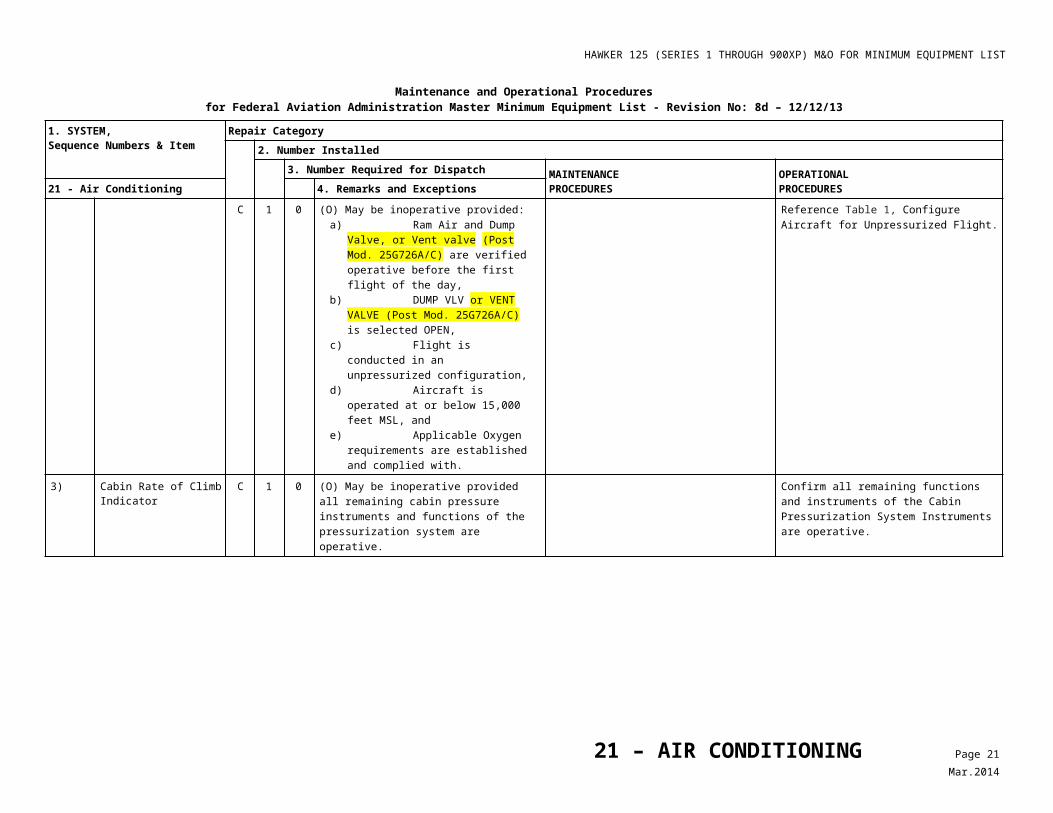
3) Cabin Rate of Climb Indicator
C 1 0 (O) May be inoperative provided all remaining cabin pressure instruments and functions of the pressurization system are operative.
Confirm all remaining functions and instruments of the Cabin Pressurization System Instruments are operative.
C 1 0 (O) May be inoperative provided:a) Ram Air and Dump Valve, or Vent
valve (Post Mod. 25G726A/C) are verified operative before the first flight of the day,
b) DUMP VLV or VENT VALVE (Post Mod. 25G726A/C) is selected OPEN,
c) Flight is conducted in an unpressurized configuration,
d) Aircraft is operated at or below 15,000 feet MSL, and
e) Applicable Oxygen requirements are established and complied with.
Reference Table 1, ConfigureAircraft for Unpressurized Flight.
21 – AIR CONDITIONING Page 11Mar.2014
HAWKER 125 (SERIES 1 THROUGH 900XP) M&O FOR MINIMUM EQUIPMENT LIST
Maintenance and Operational Proceduresfor Federal Aviation Administration Master Minimum Equipment List - Revision No: 8d – 12/12/13
1. SYSTEM, Sequence Numbers & Item
Repair Category2. Number Installed
3. Number Required for Dispatch MAINTENANCEPROCEDURES
OPERATIONALPROCEDURES21 - Air Conditioning 4. Remarks and Exceptions
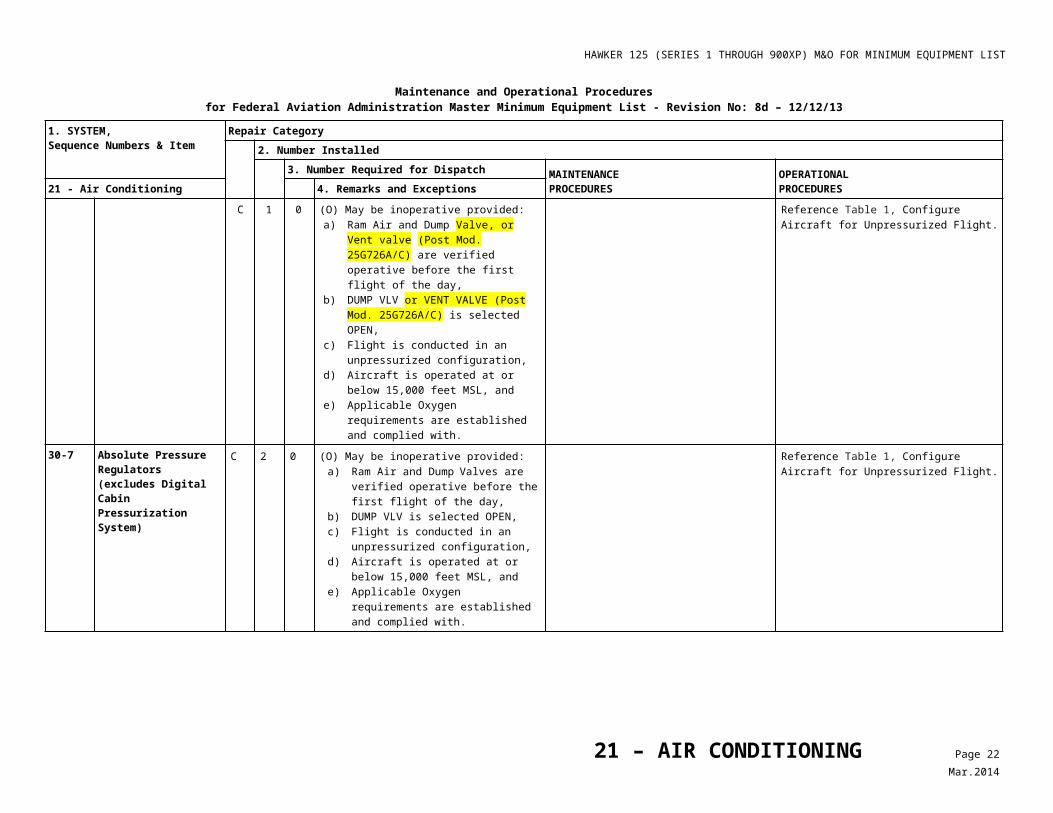
30-7 Absolute Pressure Regulators (excludes Digital Cabin Pressurization System)
C 2 0 (O) May be inoperative provided:a) Ram Air and Dump Valves are verified
operative before the first flight of the day,
b) DUMP VLV is selected OPEN, c) Flight is conducted in an
unpressurized configuration, d) Aircraft is operated at or below
15,000 feet MSL, and e) Applicable Oxygen requirements are
established and complied with.
Reference Table 1, ConfigureAircraft for Unpressurized Flight.
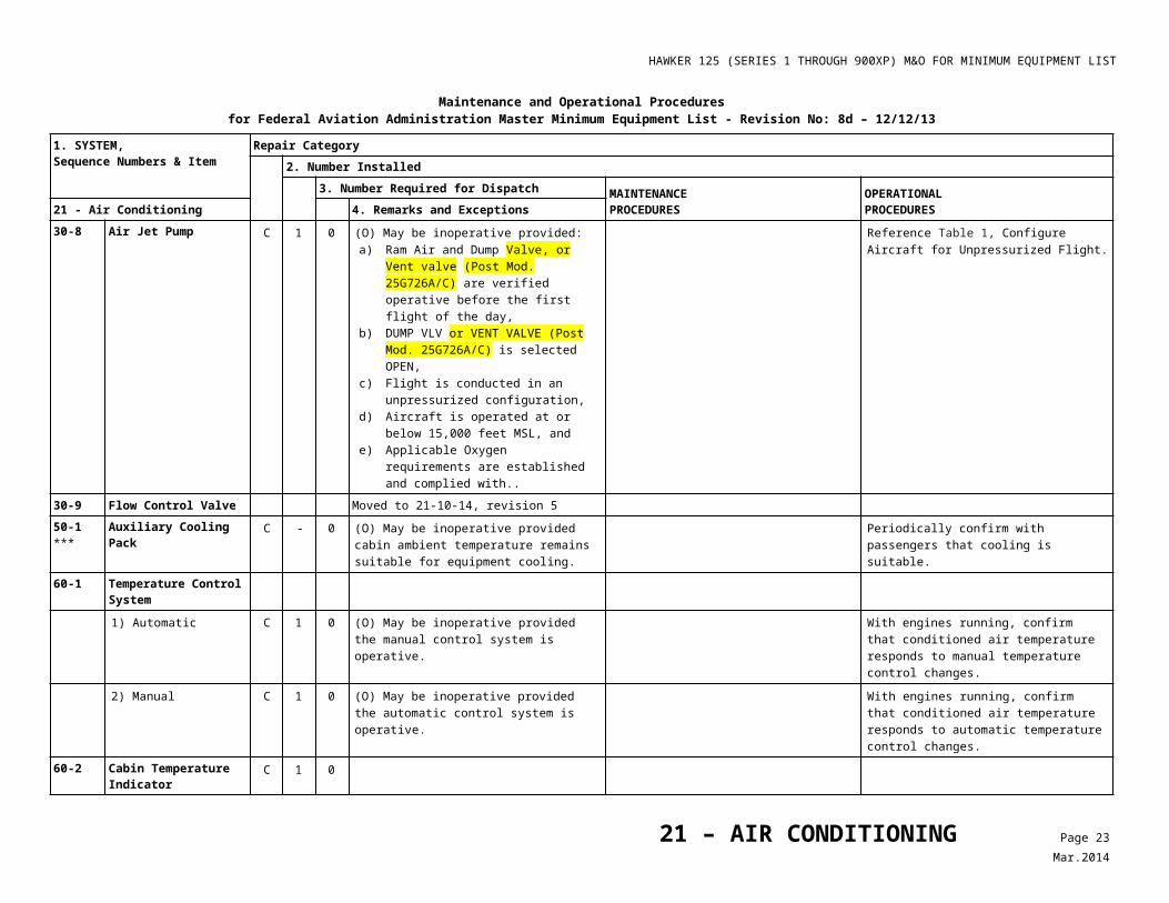
30-8 Air Jet Pump C 1 0 (O) May be inoperative provided:a) Ram Air and Dump Valve, or Vent
valve (Post Mod. 25G726A/C) are verified operative before the first flight of the day,
b) DUMP VLV or VENT VALVE (Post Mod. 25G726A/C) is selected OPEN,
c) Flight is conducted in an unpressurized configuration,
d) Aircraft is operated at or below 15,000 feet MSL, and
e) Applicable Oxygen requirements are established and complied with..
Reference Table 1, ConfigureAircraft for Unpressurized Flight.
30-9 Flow Control Valve Moved to 21-10-14, revision 5
50-1***
Auxiliary Cooling Pack C - 0 (O) May be inoperative provided cabin ambient temperature remains suitable for equipment cooling.
Periodically confirm with passengers that cooling is suitable.
60-1 Temperature Control System1) Automatic C 1 0 (O) May be inoperative provided the
manual control system is operative.With engines running, confirm that conditioned air temperature responds to manual temperature control changes.
2) Manual C 1 0 (O) May be inoperative provided the automatic control system is operative.
With engines running, confirm that conditioned air temperature responds to automatic temperature control changes.
60-2 Cabin Temperature Indicator
C 1 0
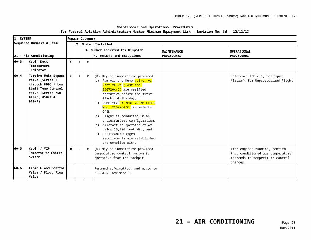
60-3 Cabin Duct Temperature Indicator
C 1 0
21 – AIR CONDITIONING Page 12Mar.2014
HAWKER 125 (SERIES 1 THROUGH 900XP) M&O FOR MINIMUM EQUIPMENT LIST
Maintenance and Operational Proceduresfor Federal Aviation Administration Master Minimum Equipment List - Revision No: 8d – 12/12/13
1. SYSTEM, Sequence Numbers & Item
Repair Category2. Number Installed
3. Number Required for Dispatch MAINTENANCEPROCEDURES
OPERATIONALPROCEDURES21 - Air Conditioning 4. Remarks and Exceptions
60-4 Turbine Unit Bypass valve (Series 1 through 800) / Low Limit Temp Control Valve (Series 750, 800XP, 850XP & 900XP)
C 1 0 (O) May be inoperative provided:a) Ram Air and Dump Valve, or Vent
valve (Post Mod. 25G726A/C) are verified operative before the first flight of the day,
b) DUMP VLV or VENT VALVE (Post Mod. 25G726A/C) is selected OPEN,
c) Flight is conducted in an unpressurized configuration,
d) Aircraft is operated at or below 15,000 feet MSL, and
e) Applicable Oxygen requirements are established and complied with.
Reference Table 1, ConfigureAircraft for Unpressurized Flight.
60-5 Cabin / VIP Temperature Control Switch
D - 0 (O) May be inoperative provided temperature control system is operative from the cockpit.
With engines running, confirm that conditioned air temperature responds to temperature control changes.
60-6 Cabin Flood Control Valve / Flood Flow Valve
Renamed reformatted, and moved to 21-10-6, revision 5
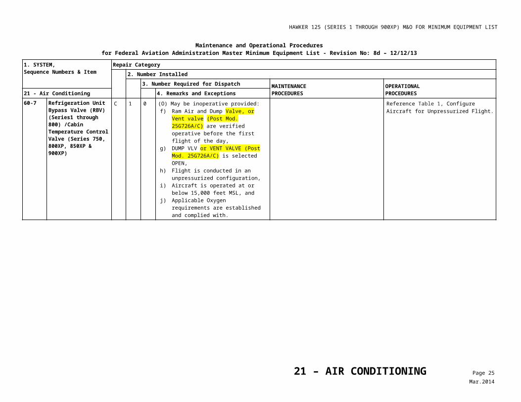
60-7 Refrigeration Unit Bypass Valve (RBV) (Series1 through 800) /Cabin Temperature Control Valve (Series 750, 800XP, 850XP & 900XP)
C 1 0 (O) May be inoperative provided:f) Ram Air and Dump Valve, or Vent
valve (Post Mod. 25G726A/C) are verified operative before the first flight of the day,
g) DUMP VLV or VENT VALVE (Post Mod. 25G726A/C) is selected OPEN,
h) Flight is conducted in an unpressurized configuration,
i) Aircraft is operated at or below 15,000 feet MSL, and
j) Applicable Oxygen requirements are established and complied with.
Reference Table 1, ConfigureAircraft for Unpressurized Flight.
21 – AIR CONDITIONING Page 13Mar.2014
HAWKER 125 (SERIES 1 THROUGH 900XP) M&O FOR MINIMUM EQUIPMENT LIST
Table 1
Configure Aircraft for Unpressurized Flight
21 - Air Conditioning
Chapter 21 Para. Item OPERATIONAL PROCEDURES
10-1, Stated in each listed paragraph
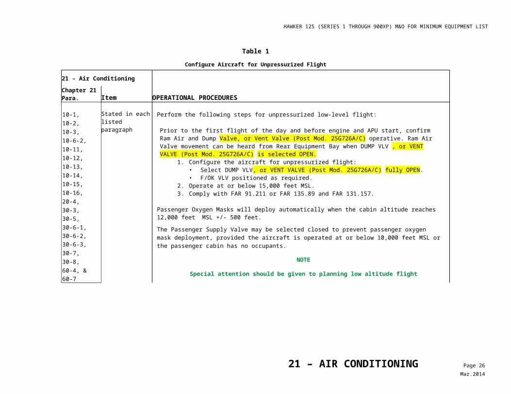
Perform the following steps for unpressurized low-level flight:
Prior to the first flight of the day and before engine and APU start, confirm Ram Air and Dump Valve, or Vent Valve (Post Mod. 25G726A/C) operative. Ram Air Valve movement can be heard from Rear Equipment Bay when DUMP VLV , or VENT VALVE (Post Mod. 25G726A/C) is selected OPEN.
1. Configure the aircraft for unpressurized flight:• Select DUMP VLV, or VENT VALVE (Post Mod. 25G726A/C) fully OPEN.• F/DK VLV positioned as required.
2. Operate at or below 15,000 feet MSL.3. Comply with FAR 91.211 or FAR 135.89 and FAR 131.157.
Passenger Oxygen Masks will deploy automatically when the cabin altitude reaches 12,000 feet MSL +/- 500 feet.
The Passenger Supply Valve may be selected closed to prevent passenger oxygen mask deployment, provided the aircraft is operated at or below 10,000 feet MSL or the passenger cabin has no occupants.
NOTE
Special attention should be given to planning low altitude flight
10-2,10-3,10-6-2,10-11,10-12,10-13,10-14,10-15,10-16,20-4,30-3,30-5,30-6-1,30-6-2,30-6-3,30-7,30-8,60-4, &60-7
21 – AIR CONDITIONING Page 14Mar.2014
HAWKER 125 (SERIES 1 THROUGH 900XP) M&O FOR MINIMUM EQUIPMENT LIST
Table 2Aircraft Altitude Versus Cabin Altitude
Cabin Altitude (feet)
AircraftAltitude (feet)
2 Pounds per square inch dial (psid) 4 psid 6 psid 8 psid 8.6 psid
41,000 28,875 20,575 14,120 8,785 7,345
40,000 28,250 20,120 13,750 8,470 7,045
35,000 24,980 17,605 11,700 6,725 5,375
30,000 21,410 14,785 9,350 4,705 3,430
25,000 17,625 11,710 6,735 2,525 1,230
20,000 13,650 8,390 3,870
15,000 9,525 4,860 765
21 – AIR CONDITIONING Page 15Mar.2014
HAWKER 125 (SERIES 1 THROUGH 900XP) M&O FOR MINIMUM EQUIPMENT LIST
Maintenance and Operational Proceduresfor Federal Aviation Administration Master Minimum Equipment List - Revision No: 8a - 08/01/2008
1. SYSTEM, Sequence Numbers & Item
Repair Category2. Number Installed
3. Number Required for Dispatch MAINTENANCEPROCEDURES
OPERATIONALPROCEDURES22 – Auto Flight
10-1 Autopilot System(s) C - 1 (O) May be inoperative provided operations do not require dual autopilot use.
Plan flight to ensure that:a) Operations do not require dual autopilot
use.B - 0 May be inoperative provided enroute operations
and / or approach minimums do not require autopilot use.
Note
Any operative autopilot mode may be used.
Note
RVSM is not authorized.
Plan flight to ensure that:a) Enroute operations do not require use of
autopilot.b) Approach minimums do not require use of
autopilot.
Note
Any operative autopilot mode may be used.
Note
RVSM is not authorized.10-2 Autopilot Control Yoke
Disengage SwitchesC 2 1 (O) One may be inoperative provided:
a) Autopilot is not used below 1,500 feet AGL, and
b) Approach minimums do not require the use of the autopilot.
Disengage autopilot at or above initial approach altitude.
B 2 0 May be inoperative provided:a) Autopilot is not used, andb) Enroute operations and / or approach
minimums do not require autopilot use.
Note
RVSM is not authorized.
10-3 Autopilot Disconnect Annunciator Lights (Except Collins Pro Line21 Equipped Aircraft)
C - 0 May be inoperative provided: a) Autopilot is not used below 1500 feet AGL,
and b) All remaining A/P disengagement alerts are
operative.B - 0 May be inoperative provided:
a) Autopilot is not used, and b) Enroute operations and/or approach
minimums do not require autopilot use.10-4 Yaw Damper / Autopilot
Disconnect Switch on Autopilot Controller Panel
C 1 0 May be inoperative provided both Autopilot Control Yoke Disengage Switches are operative.
22 – AUTO FLIGHT Page 1Sep.2008
HAWKER 125 (SERIES 1 THROUGH 900XP) M&O FOR MINIMUM EQUIPMENT LIST
Maintenance and Operational Proceduresfor Federal Aviation Administration Master Minimum Equipment List - Revision No: 8a - 08/01/2008
1. SYSTEM, Sequence Numbers & Item
Repair Category2. Number Installed
3. Number Required for Dispatch MAINTENANCEPROCEDURES
OPERATIONALPROCEDURES22 – Auto Flight
10-5 ***
Touch Control Steering (TCS) (Honeywell Equipped Aircraft Only)
C 2 0 (O) May be inoperative provided: a) Before each departure, TCS is verified to
be OFF, and b) TCS is not used.
1. Prior to takeoff perform the following:• Engage Autopilot.• Press (ON) TCS button on either pilot
control wheel and confirm servo clutches are disengaged (no resistance to hand/foot input).
• Release switch (OFF), confirm servo clutches remain disengaged.
• Disengage autopilot. 2. Do not use TCS.
B 2 0 May be inoperative provided:a) Autopilot is considered inoperative and not
used, andb) Enroute operations and / or approach
minimums do not require autopilot use.
Note
RVSM is not authorized.10-6 Go Around (GA) Switches C 2 1 One may be inoperative provided approach
minimums do not require its use.C 2 0 (O) May be inoperative provided:
a) Autopilot is not used for approach below 500 feet AGL, and
b) Alternate procedures are established and used.
1. Disengage autopilot at or above 500 feet AGL.
2. Prior to each departure, review missed approach procedures.
3. Select 12° pitch when a go-around is required.
10-7 Control Yoke Pitch / Roll Switches (Collins APS-85 Equipped Aircraft Only)
C 2 1 (O) One may be inoperative provided Autopilot Controller is operative.
Prior to each flight, confirm normal operation of the autopilot controller.
10-8 A/P Flap Annunciator(s) (Honeywell Equipped Aircraft Only)
C - 1
C - 0 May be inoperative provided autopilot and flight director are not used with flaps extended.
20-1 Yaw Damper System B 1 0 (O) May be inoperative provided: a) Yaw Damper is not used,b) Autopilot is not used, andc) Rudder Pedals have normal freedom of
movement.
Note
RVSM is not authorized.
1. Do not use Yaw Damper or Autopilot.2. Confirm Rudder Pedal movement is free.
22 – AUTO FLIGHT Page 2Sep.2008
HAWKER 125 (SERIES 1 THROUGH 900XP) M&O FOR MINIMUM EQUIPMENT LIST
Maintenance and Operational Proceduresfor Federal Aviation Administration Master Minimum Equipment List - Revision No: 8a - 08/01/2008
1. SYSTEM, Sequence Numbers & Item
Repair Category2. Number Installed
3. Number Required for Dispatch MAINTENANCEPROCEDURES
OPERATIONALPROCEDURES22 – Auto Flight
20-2 Aileron Out-of Trim Annunciators (Honeywell-Equipped Series 800 and 800XP Aircraft Only)
C 2 1
B 2 0 May be inoperative provided: a) Autopilot is not used, and b) Enroute operations and/or approach
minimums do not require autopilot use.
Note
RVSM is not authorized.20-3 Elevator Out-of Trim
Annunciators (Honeywell-Equipped Series 800 and 800XP Aircraft Only)
C 2 1
B 2 0 May be inoperative provided: a) Autopilot is not used, and b) Enroute operations and/or approach
minimums do not require autopilot use.
Note
RVSM is not authorized.20-4 Autopilot Trim
Annunciators (Collins APS-85 Equipped Aircraft Only)
B 2 0 May be inoperative provided: a) Autopilot is not used, and b) Enroute operations and/or approach
minimums do not require autopilot use.
Note
RVSM is not authorized.20-5 Autopilot Aileron Trim
Indicator (Series 1 through 700 Only)
B 1 0 May be inoperative provided: a) Autopilot is not used, and a) Enroute operations and/or approach
minimums do not require autopilot use.
Note
RVSM is not authorized.
22 – AUTO FLIGHT Page 3Sep.2008
HAWKER 125 (SERIES 1 THROUGH 900XP) M&O FOR MINIMUM EQUIPMENT LIST
Maintenance and Operational Proceduresfor Federal Aviation Administration Master Minimum Equipment List - Revision No: 8a - 08/01/2008
1. SYSTEM, Sequence Numbers & Item
Repair Category2. Number Installed
3. Number Required for Dispatch MAINTENANCEPROCEDURES
OPERATIONALPROCEDURES22 – Auto Flight
20-6 Autopilot Elevator Trim Indicator (Series 1 through 700 Only)
B 1 0 May be inoperative provided: a) Autopilot is not used, and b) Enroute operations and/or approach
minimums do not require autopilot use.
Note
RVSM is not authorized.20-7 Guidance Controller
(Honeywell SPZ-8000 and Collins APS-85 and Collins Pro Line 21 Equipped Aircraft)
B 1 0 (O) May be inoperative provided: a) Autopilot is considered inoperative, b) Enroute operations and/or approach
minimums do not require autopilot/guidance controller use, and
c) For 750, 800XP, 850XP and 900XP aircraft, 0.73 IMN is not exceeded unless Mach Trim is operative.
Note
Autopilot and yaw damper will not be available.
Note
RVSM is not authorized.
1. Plan flight to ensure that:• Enroute operations do not require
use of autopilot.• Approach minimums do not require
use of autopilot. 2. For 750, 800XP, 850XP and 900XP
aircraft, 0.73 IMN limitation is not exceeded unless Mach Trim is operative.
Note
Autopilot and yaw damper will not be available.
20-8 Mach Trim System This item moved to ATA 27-30-5, Revision 5
20-9 Mode Select Panel B - 0 May be inoperative provided: a) Autopilot is not in use, and b) Enroute operations and/or approach
minimums do not require autopilot use.
Note
RVSM is not authorized.
22 – AUTO FLIGHT Page 4Sep.2008
HAWKER 125 (SERIES 1 THROUGH 900XP) M&O FOR MINIMUM EQUIPMENT LIST
Maintenance and Operational Proceduresfor Federal Aviation Administration Master Minimum Equipment List - Revision No: 8c - 10/17/2012
1. SYSTEM, Sequence Numbers & Item
Repair Category2. Number Installed
3. Number Required for Dispatch MAINTENANCEPROCEDURES
OPERATIONALPROCEDURES23 – Communications 4. Remarks and Exceptions
05-1 RMU’S/RTU’s C 2 1 (O) One may be inoperative provided:a) Inoperative Unit is not powered by an
Emergency Bus, or equivalent and is not required to accomplish Emergency Procedures,
b) Remaining RMU/RTU is operative, andc) Alternate procedures are established and
used.
1. Confirm that inoperative RMU is not powered by PE Bus.
2. Confirm operative RMU/RTU functionality.3. Crew will establish and coordinate using
alternative procedures.
10-1 Communications System (VHF, UHF)
D - - Any in excess of those required by FAR may be inoperative provided they are not powered by the XE or PE Bus and are not required for emergency procedures.
1) VHF Comm Control Panels (Except RMU/RTU or Pro Line 21 Equipped Aircraft)
a) Frequency Transfer Light C - 0b) Frequency Transfer Switch C - 0c) Frequency Selector Knob C - 2d) Frequency Indication C - 22) HF Communication System Moved to 10-4, Revision 710-2 Audio Control panel C - 2 (O) Any in excess of those required at pilot and
copilot’s seat positions may be inoperative provided alternate procedures are established and used.
1. Place INOP placard on or adjacent to affected panel(s).
2. Coordinate with affected user(s) for procedures to be used.
10-3 Standby Nav / Com Controller (Clearance Delivery Unit)
Deleted, Revision 6.
23 – COMMUNICATIONS Page 1Dec.2012
HAWKER 125 (SERIES 1 THROUGH 900XP) M&O FOR MINIMUM EQUIPMENT LIST
Maintenance and Operational Proceduresfor Federal Aviation Administration Master Minimum Equipment List - Revision No: 8c - 10/17/2012
1. SYSTEM, Sequence Numbers & Item
Repair Category2. Number Installed
3. Number Required for Dispatch MAINTENANCEPROCEDURES
OPERATIONALPROCEDURES23 – Communications 4. Remarks and Exceptions
10-4***
HF Communication System
C - 1 (O) May be inoperative while conducting operations that require two LRCS provided:a) SATCOM Voice Data Link system is
operative,b) Alternate procedures are
established and used,c) SATCOM coverage is available over
the intended route of flight, andd) If SATCOM Voice is to be used over the
intended route of flight, SATCOM Voice short codes (INMARSAT) or direct dial commercial numbers (IRIDIUM) must be available. If not available, prior coordination with the appropriate ATS (FIR) facility is required.
NOTE
SATCOM is to be used only as a backup to normal communications unless otherwise authorized by the appropriate ATS facilities.
1. Confirm that remaining HF COMM system is operative.
2. Confirm that SATCOM Data link is operative.
3. Prior to flight, confirm that SATCOM Data link service is available for intended route of flight.
D - - Any in excess of those by FAR may be inoperative.
20-1 ***
SELCAL C - 0 (O) May be inoperative provided alternate procedures are established and used.
D - 0 (O) May be inoperative provided procedures do not require its use.
1) Channels C - 0 (O) May be inoperative provided alternate procedures are established and used.
D - 0 (O) May be inoperative provided procedures do not require its use.
20-2***
ACARS System C - 0 (O) May be inoperative provided alternate procedures are established and used.
Voice or other communication will be used between the aircraft and the ground.
D - 0 (O) May be inoperative provided procedures do not require its use.
20-3 ***
AFIS (VHF / SAT) C - 0 (O) May be inoperative provided alternate procedures are established and used.
1. Place INOP placard on AFIS panel. 2. Prior to flight, determine alternate
communication to be used.
23 – COMMUNICATIONS Page 2Dec.2012
HAWKER 125 (SERIES 1 THROUGH 900XP) M&O FOR MINIMUM EQUIPMENT LIST
Maintenance and Operational Proceduresfor Federal Aviation Administration Master Minimum Equipment List - Revision No: 8c - 10/17/2012
1. SYSTEM, Sequence Numbers & Item
Repair Category2. Number Installed
3. Number Required for Dispatch MAINTENANCEPROCEDURES
OPERATIONALPROCEDURES23 – Communications 4. Remarks and Exceptions
D - 0 (O) May be inoperative provided procedures do not require its use.
30-1 Passenger Address System
1) Passenger Configuration C 1 0 (O) May be inoperative provided: a) PA System is not required by FAR, and b) Alternate normal and emergency
procedures, and/ or operating restrictions are established and used.
1. Verbally brief passengers and cabin crew in the event that normal or emergency procedures dictate such action.
2. Confirm that Flight Deck/ Cabin interphone system is operative (if installed).
2) Cargo Configuration D - 0 (O) May be inoperative provided procedures do not require its use.
30-2 Cabin Chimes C - 0 (O) May be inoperative provided PA system is operative.
Confirm that PA system is operative.
C - 0 (O) May be inoperative provided alternate procedures are established and used.
Verbally brief passengers and cabin crew whenever cabin chimes would be used.
30-3 ***
Prerecorded passenger Announcement System
C 1 0 (O) May be inoperative provided alternate procedures are established and used.
Verbally brief passengers and cabin crew.
D 1 0 May be inoperative provided procedures do not require its use.
30-4 Flight Deck Speakers C - 0 May be inoperative provided: a) Procedures do not require their use, and b) Headsets are installed and operative.
30-5 ***
Emergency Locator Transmitter (ELT)
1) Survival Type ELT’s D - - Any in excess of those required by FAR may be inoperative or missing.
2) Fixed ELT’s A 0 May be inoperative or missing provided repairs are made within 90 days.
D - - Any in excess of those required by FAR may be inoperative or missing.
40-1 Crewmember Interphone System
23 – COMMUNICATIONS Page 3Dec.2012
HAWKER 125 (SERIES 1 THROUGH 900XP) M&O FOR MINIMUM EQUIPMENT LIST
Maintenance and Operational Proceduresfor Federal Aviation Administration Master Minimum Equipment List - Revision No: 8c - 10/17/2012
1. SYSTEM, Sequence Numbers & Item
Repair Category2. Number Installed
3. Number Required for Dispatch MAINTENANCEPROCEDURES
OPERATIONALPROCEDURES23 – Communications 4. Remarks and Exceptions
1) Flight Deck Cabin, Cabin to Flight Deck Function(s)
C - 0 (O) May be inoperative provided alternate procedures are established and used.
Use verbal communication between flight deck and cabin.
D - 0 (O) May be inoperative provided procedures do not require its use.
2) Flight Deck to Ground Function
C 1 0 (O) May be inoperative provided alternate procedures are established and used.
Brief crew members and ground personnel on hand signals to be used.
D 1 0 May be inoperative provided procedures do not require its use.
50-1 Headsets (Except Microphone)
C - 1 One may be inoperative at either pilot’s station provided speaker system is operative.
1) Active Noise Canceling/Reduction Function
D - 0 May be inoperative provided normal audio function of the headset is operative.
50-2 Handheld Microphones C 2 1 One may be inoperative at either pilot’s station provided associated headset with boom microphone is operative.
50-3 Boom Microphones (Including Headset Microphones)
A - 0 May be inoperative provided:1. Associated Hand Microphone is
installed and operative, and2. Repairs are made within three flight
days.D - 0 Any in excess of those required by FAR may be
inoperative.50-4 ***
Glareshield Microphone Key Button(s)
D 2 0 (O) May be inoperative provided Handheld Microphone on affected side is operative.
Utilize Handheld Microphones or Yoke Microphone switches
50-5 ***
Flight Deck Pilot-to -Pilot Interphone System
C 1 0 (O) May be inoperative provided:. a) Alternate pilot-to-pilot communication
procedures are established and used, and
b) Repairs are made within three flight days.
Use hand signals and/or direct voice communication.
60-1 Static Dischargers (Non-CDL Aircraft)
C - - One Static discharger may be damaged or missing.
60-2 Surface Bond Straps Deleted Revision 8c, use CDL70-1 Cockpit Voice Recorder
(Aircraft with FDR) A - 0 May be inoperative provided:a) FDR is operative, andb) Repairs are made within three flight days.
(Aircraft without FDR) A - 0 May be inoperative provided repairs are made within three flight days.
23 – COMMUNICATIONS Page 4Dec.2012
HAWKER 125 (SERIES 1 THROUGH 900XP) M&O FOR MINIMUM EQUIPMENT LIST
Maintenance and Operational Proceduresfor Federal Aviation Administration Master Minimum Equipment List - Revision No: 8c - 10/17/2012
1. SYSTEM, Sequence Numbers & Item
Repair Category2. Number Installed
3. Number Required for Dispatch MAINTENANCEPROCEDURES
OPERATIONALPROCEDURES23 – Communications 4. Remarks and Exceptions
(Aircraft operated by other than Air Carrier or Commercial Operator Certificate Holder)
A - 0 May be inoperative provided repairs are made in accordance with applicable FAR’s.
1) Independent Power Source C 1 070-2 ***
Flight Phone
1) Cockpit D - 02) Cabin D - 070-3 ***
Satellite Communications System (SATCOM)
D - 0
80-1 ***
Heads Up Technology Inc. Checklist System
D - 0 (O) May be inoperative provided alternate procedures are established and used.
Note
Any activation switch which functions normally may be used.
Use paper or other checklist.
23 – COMMUNICATIONS Page 5Dec.2012
HAWKER 125 (SERIES 1 THROUGH 900XP) M&O FOR MINIMUM EQUIPMENT LIST
Maintenance and Operational Proceduresfor Federal Aviation Administration Master Minimum Equipment List - Revision No: 8a - 08/01/2008
1. SYSTEM, Sequence Numbers & Item
Repair Category2. Number Installed
3. Number Required for Dispatch MAINTENANCEPROCEDURES
OPERATIONALPROCEDURES24 - Electrical Power 4. Remarks and Exceptions
20-1 AC Main Inverters (Only Aircraft Equipped with Standby Inverter)
C 2 1 (O) One may be inoperative provided: a) Standby inverter is verified operative
before each departure, b) For aircraft with two (2) AOA Vanes and
SSU systems, both Engine Driven AC alternators are operative, and
c) Flight is not conducted in known or forecast icing conditions.
1. Perform inverter check prior to each departure.
2. For aircraft with two (2) AOA Vanes and SSU systems, verify both Engine Driven AC alternators are operative.
3. Planeach flight to avoid known or forecast icing conditions along entire route including alternate destination.
20-2 Standby Inverter (Except Pro Line 21)
B 1 0 May be inoperative for Day Minimum Speed Control (VMC) provided both main inverters are operative.
(Pro Line 21 Only) B 1 0 May be inoperative provided both main inverters are operative.
20-3 Inverter Fail Lights/ Annunciators
C 2 0 (O) May be inoperative provided: a) Auto-changeover system is operative, and b) Both main inverters are operative, and c) AC voltmeter is installed and operative.
1. Confirm both inverters are operative. 2. Confirm AC powered equipment operates
with either inverter selected OFF. 3. Confirm AC voltmeter indicates correct
voltage. 20-4 Standby Inverter “ON”
Light / AnnunciatorC 1 0 (O) May be inoperative provided standby
inverter is verified operative before each departure.
Prior to each departure: a) Select STBY INV to ARM. b) Select INV 1 and INV 2 to STOP. c) Confirm normal Standby Inverter voltage
on XE buss. 20-5 AC Voltmeter C 1 0 (O) May be inoperative provided:
a) All inverters are operative, and b) All AC system Annunciators are operative.
a) Prior to each departure, confirm INV and buss FAIL annunciators illuminate with all inverters OFF.
b) Confirm annunciators extinguish with inverters ON.
20-6 AC Frequency Meter (Series 600 and 700 only)
C - 0 May be inoperative provided electrical busbar fail lights are operative.
21-1 AC Alternator(s)
24 – ELECTRICAL POWER Page 1Sep.2008
HAWKER 125 (SERIES 1 THROUGH 900XP) M&O FOR MINIMUM EQUIPMENT LIST
Maintenance and Operational Proceduresfor Federal Aviation Administration Master Minimum Equipment List - Revision No: 8a - 08/01/2008
1. SYSTEM, Sequence Numbers & Item
Repair Category2. Number Installed
3. Number Required for Dispatch MAINTENANCEPROCEDURES
OPERATIONALPROCEDURES24 - Electrical Power 4. Remarks and Exceptions
1) Aircraft with One AC Alternator
C 1 0 (O) May be inoperative provided: a) AFM Limitations are observed, b) Windshield fluid de-icing system is
installed and operative, and c) Aircraft is not operated in known or
forecast icing conditions.
a) Observe AFM airspeed (birdstrike) limitations.
b) Confirm windscreen fluid de-icing system is operative.
c) Plan each flight to avoid known or forecast icing conditions along entire route including alternate destination.
2) Aircraft with Two AC Alternators
C 2 1 (O) One may be inoperative provided:a) For aircraft with 2 AOA Vane and
SSU systems, both Main AC inverters are operative, and
a) Aircraft is not operated in known or forecast icing conditions.
a) For aircraft with two (2) AOA Vane and SSU systems, both Main AC Inverters are operative.
b) Plan each flight to avoid known or forecast icing conditions along entire route including alternate destination.
21-2 AC Alternator Fail Warning Light / Annunciator(s)
1) Aircraft with One AC Alternator
C 1 0 (O) May be inoperative provided both windshield heating systems are operative.
1. With RH engine running select W/SCREEN HEAT ON.
2. Verify by feel that windscreen heating is operative.
2) Aircraft with Two AC Alternators
C 2 0 (O) May be inoperative provided: a) Both AC alternators are operative, and b) Auto-changeover system is operative.
1. Confirm both AC alternators are operative.
2. With engines running, select screen heats and alternator ON, and verify screen heat is operative.
3. Switch one alternator OFF and verify the “B” screens are no longer heated and the associated VANE HTR FAIL does not illuminate.
21-3 ***
115 VAC / 60 Hertz (Hz) System
D 1 0 (M) May be inoperative provided: a) Procedures do not require its use, and b) System is deactivated.
b) Refer to applicable Hawker Aircraft Wiring Parts Catalog (Chapter 24).
c) Remove fuse from affected inverter DC input.
d) Place ‘INOP’ placard adjacent to affected inverter switch on CG Panel.
31-1 Battery Temperature (With NiCad Battery Only)
24 – ELECTRICAL POWER Page 2Sep.2008
HAWKER 125 (SERIES 1 THROUGH 900XP) M&O FOR MINIMUM EQUIPMENT LIST
Maintenance and Operational Proceduresfor Federal Aviation Administration Master Minimum Equipment List - Revision No: 8a - 08/01/2008
1. SYSTEM, Sequence Numbers & Item
Repair Category2. Number Installed
3. Number Required for Dispatch MAINTENANCEPROCEDURES
OPERATIONALPROCEDURES24 - Electrical Power 4. Remarks and Exceptions
1)Indicator
C - 0 (M) May be inoperative provided Battery Hot Caution annunciators are operative.
a) Disconnect Batt Temp connector from both batteries.
b) Jumper across Pins A & B. c) Verify BATT HOT lights illuminate.
2) BATT HOT Caution Annunciators
C - 0 (O) May be inoperative provided: a) Battery Temperature Indicator is operative,
and b) Battery temperatures are monitored in
flight.
Note
Not required for lead acid battery systems.
1. Prior to flight, confirm No. 1 and No. 2 Battery Temperatures are normal.
2. Regularly monitor No. 1 and No. 2 Battery Temperatures during flight.
32-1 Battery NO CHARGE Light (Series 1 through 700 only)
C 1 0 (O) May be inoperative provided battery is verified to be charging normally.
With engines running, confirm battery charging by checking ammeter on CG panel.
32-2 ***
Battery Heater Muffs C 2 0 (O) May be inoperative provided: a) Battery Temperature Indicator is operative,
and b) Battery temperature is monitored to ensure
temperature remains above 10 °C at all times.
1. Prior to flight, confirm No. 1 and No. 2 Battery Temperatures are normal.
2. Regularly monitor No. 1 and No. 2 Battery Temperatures during flight.
3. Battery temperatures must remain above -10°C.
34-1 Engine Driven Generators Deleted, Revision 3.34-2 APU Generator C 1 037-1 DC Voltmeter Deleted, Revision 537-2 DC Generator Fail Lights /
AnnunciatorsC 2 0 (O) May be inoperative provided:
a) Both ammeters are operative, and b) DC voltmeter is operative.
With engines running and both generators ON, confirm: 1. Both ammeters indicating current, and 2. Both DC voltmeters indicating proper
voltage.37-3 DC Bus Tie Light
AnnunciatorC 1 0 (O) May be inoperative provided:
a) Bus Tie system is operative, b) Both ammeters are operative, and c) Generator fail lights / annunciators are
operative.
1. Prior to each departure:• Select GEN 1 to TRIP.• Confirm current on GEN 2.• Confirm Power (PS)1 and PS2
voltage with Buss Tie CLOSED.• Open Buss Tie and verify voltage on
PS2 only and GEN 1 FAIL annunciator.
• Reset GEN 1 and Buss Tie.2. Repeat above for GEN 2 TRIP by
substituting GEN 1 for GEN 2 and vice-versa, in above steps.
24 – ELECTRICAL POWER Page 3Sep.2008
HAWKER 125 (SERIES 1 THROUGH 900XP) M&O FOR MINIMUM EQUIPMENT LIST
Maintenance and Operational Proceduresfor Federal Aviation Administration Master Minimum Equipment List - Revision No: 8a - 08/01/2008
1. SYSTEM, Sequence Numbers & Item
Repair Category2. Number Installed
3. Number Required for Dispatch MAINTENANCEPROCEDURES
OPERATIONALPROCEDURES24 - Electrical Power 4. Remarks and Exceptions
37-4 Battery Contactor Annunciators(Series 1 through 700)
C 2 1 (O) One may be inoperative provided before each departure:
a) Emergency contactor is verified operative, and
b) Battery (Batt) contactor is verified operative.
1. Confirm Batt 1 and Batt 2 voltage on overhead voltmeter.
2. Select Battery switch to ON and confirm PE voltage on overhead voltmeter.
3. Start APU or either engine.4. Confirm increase of Batt 1 and Batt 2
voltage on overhead voltmeter when generator is brought on line and Buss Tie switch is selected to CLOSE.
5. Confirm charging current to Batt 1 and Batt 2 on overhead ammeter.
37-5 APU Generator Fail Light / Annunciator
C 1 0
37-6 APU Generator Overheat Light / Annunciator
C 1 0 May be inoperative provided APU generator is not used.
40-1 External Power System D 1 050-1 AC Bus Fail Lights /
Annunciators (Standby Inverter- Equipped Aircraft only)
C 3 2 (O) One may be inoperative provided: a) Standby inverter (STBY INV) is verified
operative before each departure, b) Inverter associated with the inoperative
light / Annunciator is verified operative before each departure, and
c) Voltmeter is operative.
Before each departure:1. Turn off both main inverters and note
that STBY INV ON light illuminates.2. Confirm standby inverter output voltage
on XE bus.3. Confirm inverter output voltage for
associated bus fail annunciator on XS1 or XS2.
50-2 ***
26 VAC Bus Fail Annunciators
1) INST 1 FAIL C 1 02) INST 2 FAIL C 1 060-1 Bus Tie Contactor
System (Split Bus Tie Contactor Aircraft only)
C 1 0 (O) May be inoperative provided: a) Both engine driven DC generators are
operative, b) Bus Tie contactor is verified to be open
before each departure, and c) PS1 AND PS2 voltage is verified normal
before each departure.
Prior to each departure:1. Individually check #1 & #2 Generator
voltage.2. Turn #2 Generator ON, turn #1
Generator OFF and confirm PS1 Buss voltage is zero.
3. With both generators ON, confirm Generator (GEN) 1 FAIL and GEN 2 FAIL annunciators are both out.
4. Confirm PS1 and PS2 voltage normal.60-2 ***
FIS Power Recovery System
C 1 0 May be inoperative provided procedures do not require its use.
24 – ELECTRICAL POWER Page 4Sep.2008
HAWKER 125 (SERIES 1 THROUGH 900XP) M&O FOR MINIMUM EQUIPMENT LIST
Maintenance and Operational Proceduresfor Federal Aviation Administration Master Minimum Equipment List - Revision No: 8d – 12/12/2013
1. SYSTEM, Sequence Numbers & Item
Repair Category2. Number Installed
3. Number Required for Dispatch MAINTENANCEPROCEDURES
OPERATIONALPROCEDURES25 – Equipment/Furnishings 4. Remarks and Exceptions
00-1 ***
Non-Essential Equipment & Furnishings (NEF)
- 0 May be inoperative, damaged, or missing provided that the item(s) is deferred in accordance with the operator’s NEF program. The NEF program, procedures, and processes are outlined in the operator’s (insert name) Manual. (M) & (O) procedures, if required, must be available to the flight crew and included in the operator’s appropriate document.
Note
Exterior Lavatory Door Ash Trays are not considered convenience items.
00-2 Medical Transport System (AIRMED EMS)
C 1 0 (M) May be inoperative provided:a) Medical Stretcher or Pediatric
Incubator is not occupied, and b) All Medical Equipment
Systems are deactivated.
1) EMS AC InverterSystem
C 1 0 (M) May be inoperative provided system is deactivated.
2) EMS Suction AirSystem
C 1 0 (M) May be inoperative provided vacuum pump is deactivated.
3) EMS Pressure AirSystem
C 2 0 (M) May be inoperative provided affected air compressor is deactivated.
4) EMS OxygenSystem
C 1 0 (M) May be inoperative provided system is deactivated.
10-1 Pilot(s) Seat Adjustment System
C 2 0 (M) May be inoperative provided: a) Position of the seat(s) permits normal pilot
visibility and full flight control movement, and
b) Seat(s) is/are secured with mechanical stops.
1. Thoroughly inspect seat locking mechanisms for engagement and security. Alternative means may be used to ensure locking.
2. Ensure that seat position is satisfactory for pilot vision and control.
1) Crew Shoulder Harness Deleted, Revision 2.10-2 Cockpit Convenience
Items Deleted, Revision 8a. Use NEF Program.
10-3 Cockpit Sun Visors D - 0
25 – EQUIPMENT/FURNISHINGS Page 1Dec.2012
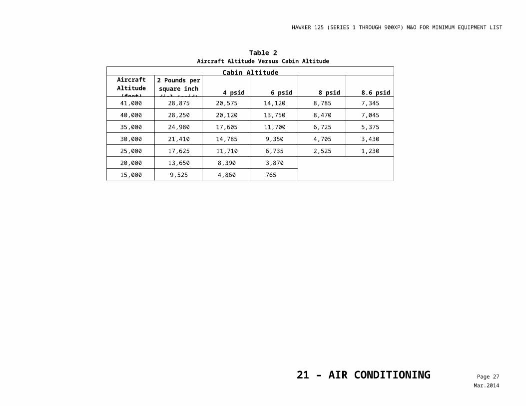
HAWKER 125 (SERIES 1 THROUGH 900XP) M&O FOR MINIMUM EQUIPMENT LIST
Maintenance and Operational Proceduresfor Federal Aviation Administration Master Minimum Equipment List - Revision No: 8d – 12/12/2013
1. SYSTEM, Sequence Numbers & Item
Repair Category2. Number Installed
3. Number Required for Dispatch MAINTENANCEPROCEDURES
OPERATIONALPROCEDURES25 – Equipment/Furnishings 4. Remarks and Exceptions
10-4 Observer Seat (Including Associated Equipment)
A - - May be inoperative provided: a) A passenger seat in the passenger cabin
is available to an FAA inspector for the performance of official duties, and
b) Repairs are made within two flight days.A - - May be inoperative provided;
a) Required minimum safety equipment (safety belt and oxygen) is available,
b) Seat is acceptable to the FAA inspector for performance of official duties, and
c) Repairs are made within two flight days.
Note
These provisos are intended to provide for occupancy of the above seat by an FAA Inspector when the minimum safety equipment (oxygen and safety belt) is functional and the inspector determines the conditions to be acceptable.
Note
The Pilot-in-Command will determine if the minimum safety equipment is functional for other person(s) authorized to occupy an observer seat.
20-1 Passenger Seats (Including Seat Backs and Armrests)
C - - May be inoperative provided:a) Seat does not block an Emergency Exit.b) Seat does not restrict any passenger from
access to the main aircraft aisle, andc) Affected seat(s) are blocked and
placarded, ’DO NOT OCCUPY’.
Note
A seat with an inoperative seatbelt is considered inoperative.
Note
Affected seat(s) may include the seat(s) behind and / or adjacent seat.
25 – EQUIPMENT/FURNISHINGS Page 2Dec.2012
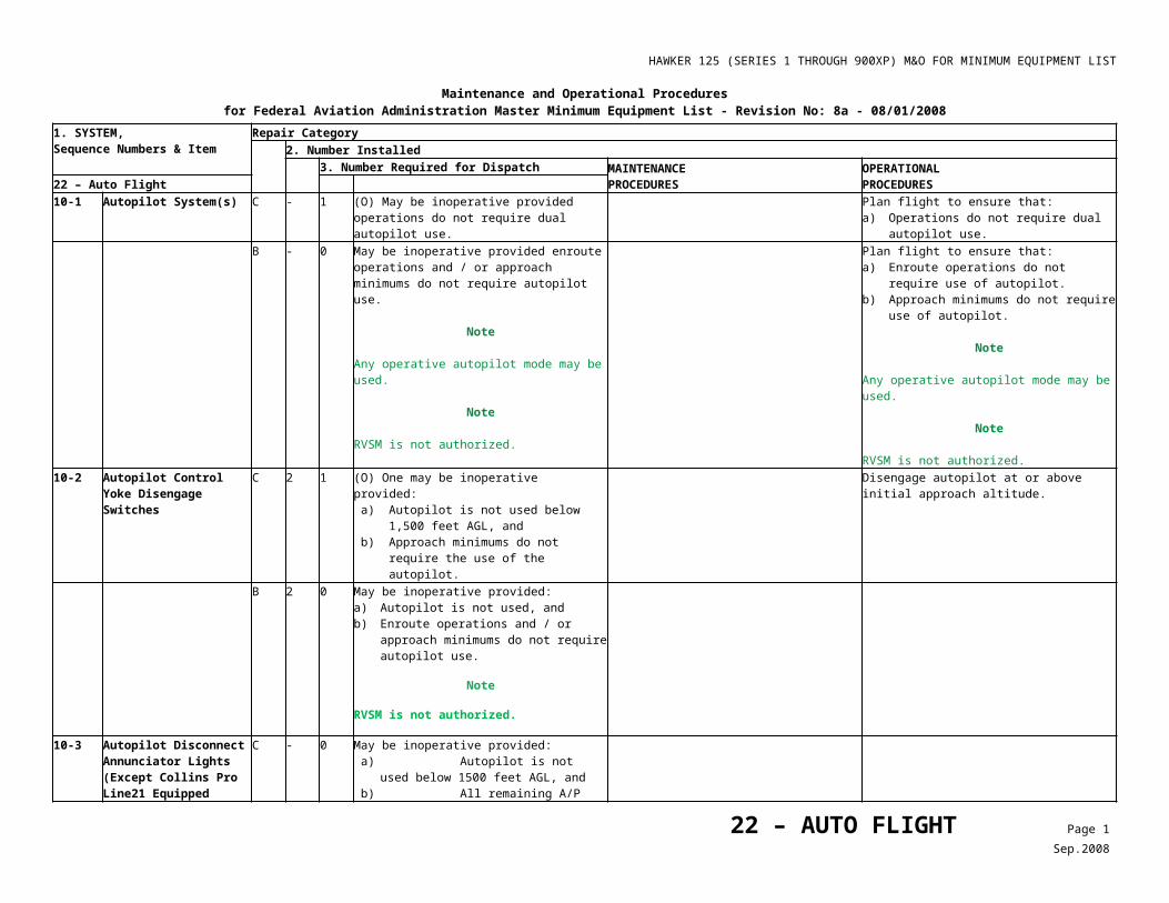
HAWKER 125 (SERIES 1 THROUGH 900XP) M&O FOR MINIMUM EQUIPMENT LIST
Maintenance and Operational Proceduresfor Federal Aviation Administration Master Minimum Equipment List - Revision No: 8d – 12/12/2013
1. SYSTEM, Sequence Numbers & Item
Repair Category2. Number Installed
3. Number Required for Dispatch MAINTENANCEPROCEDURES
OPERATIONALPROCEDURES25 – Equipment/Furnishings 4. Remarks and Exceptions
1) Recline Mechanism(s) D - - (M) May be inoperative and seat occupied provided seat is secured in the full up-right position.
1. Confirm that seat is locked in full up-right position.
2. Tape recline lever in the locked position. 2. Placard recline lever, “INOP - DO NOT
USE”. C - - (O) May be inoperative and seat occupied
provided seatback is immovable in the full upright position.
Confirm that seat is locked in full up-right position and does not move.
2) Underseat Baggage Stowage
C - - (O) May be inoperative provided: a) Baggage is not stowed under seat with
inoperative stowage, b) Associated seat is placarded “DO NOT
STOW BAGGAGE UNDER THIS SEAT”, and
c) Procedures are established to alert Cabin Crew of inoperative stowage.
1. Placard associated seat “DO NOT STOW BAGGAGE UNDER THIS SEAT.
2. Confirm there is no baggage under associated seat(s).
3. Brief passengers and Cabin Crew not to place baggage under associated seat(s).
3) Armrest C - - (O) May be inoperative provided: a) Armrest does not block an Emergency
Exit, b) Armrest does not restrict any passenger
from access to the main aircraft aisle, and
c) For an armrest with a recline mechanism, seat is immovable in the full upright position.
1. Confirm armrest does not block any emergency exit.
2. Confirm armrest does not restrict access to aisle.
3. If armrest has a seat back recline lever, confirm seat back is in full up-right position and does not move.
20-2 ***
Flight Inspection Panel System
D 1 0 May be inoperative provided procedures do not require its use.
20-3 Waste Receptacle(s) Access Door(s)/ Covers
D - - May be inoperative provided: a) Container is empty and access is secured
to prevent waste introduction into compartment, and
b) Sufficient waste receptacles are available to accommodate all waste that may be generated on a flight.
20-4 Exterior Lavatory Door Ash Tray(s)
A 1 0 May be missing provided it is replaced within 3 calendar days.
60-1 Emergency Medical Equipment
25 – EQUIPMENT/FURNISHINGS Page 3Dec.2012
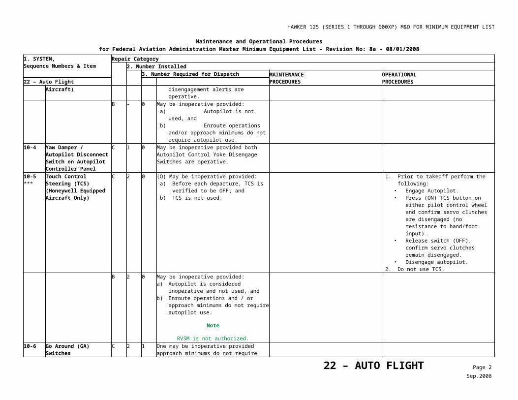
HAWKER 125 (SERIES 1 THROUGH 900XP) M&O FOR MINIMUM EQUIPMENT LIST
Maintenance and Operational Proceduresfor Federal Aviation Administration Master Minimum Equipment List - Revision No: 8d – 12/12/2013
1. SYSTEM, Sequence Numbers & Item
Repair Category2. Number Installed
3. Number Required for Dispatch MAINTENANCEPROCEDURES
OPERATIONALPROCEDURES25 – Equipment/Furnishings 4. Remarks and Exceptions
1) Automatic External Defibrillator (AED) and/or associated equipment
D - - Any in excess of those required by FAR may be incomplete, missing, or inoperative.
2) Emergency Medical Kit (EMK) and/or associated equipment
D - - Any in excess of those required by FAR may be incomplete, missing, or inoperative.
3) First Aid Kit (FAK) and/or associated equipment
D - - Any in excess of those required by FAR may be inoperative.
60-2 Overwater Equipment D - - Any in excess of those require by FAR may be inoperative.
60-3 ***
Cockpit Smoke Vision System (CSVS) (STC#SA00892LA)
D - 0 May be inoperative or missing.
25 – EQUIPMENT/FURNISHINGS Page 4Dec.2012
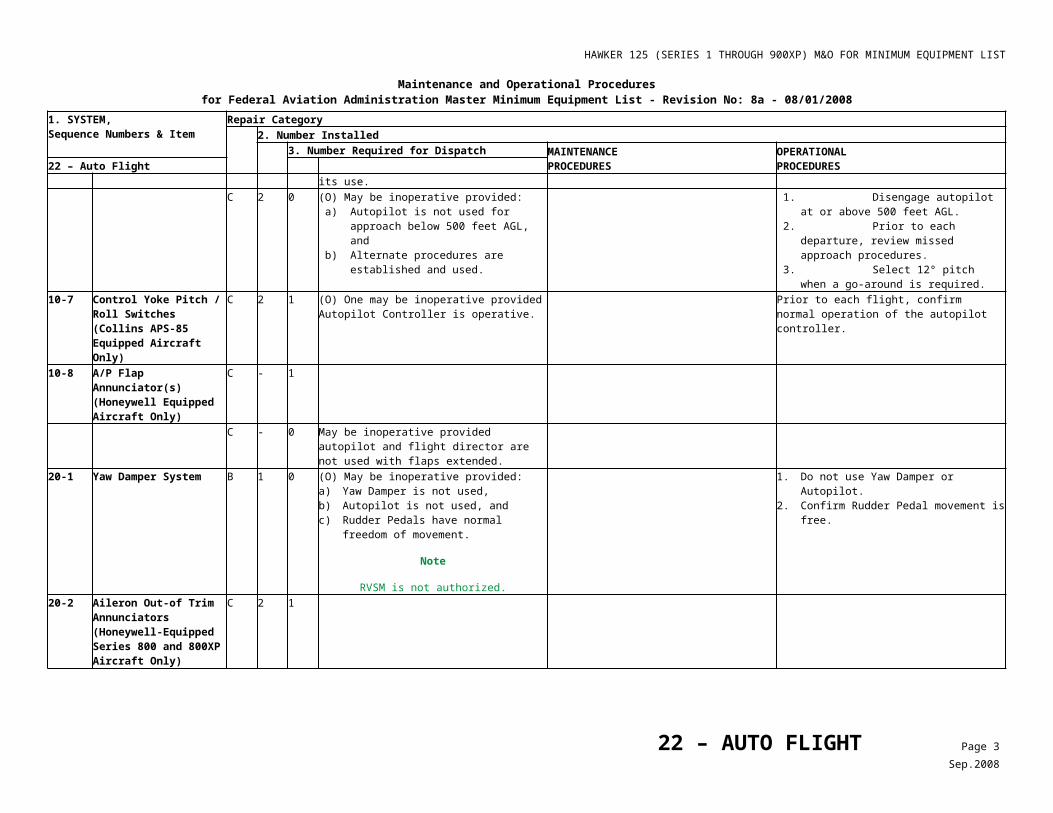
HAWKER 125 (SERIES 1 THROUGH 900XP) M&O FOR MINIMUM EQUIPMENT LIST
Maintenance and Operational Proceduresfor Federal Aviation Administration Master Minimum Equipment List - Revision No: 8 - 02/18/2008
1. SYSTEM, Sequence Numbers & Item
Repair Category2. Number Installed
3. Number Required for Dispatch MAINTENANCEPROCEDURES
OPERATIONALPROCEDURES26 – Fire Protection 4. Remarks and Exceptions
10-1 Engine Fire Warning Lights/ Annunciators
1) Series 1 through 700 only C 2 0 May be inoperative provided HP Cock Fire Warning lights are operative.
2) Series 800, 800XP, 850XP, 900XP and 750
C - 0 May be inoperative provided HP Cock Fire Warning lights are operative.
10-2 HP Cock Annunciator Fire Warning Lights
C 2 0 May be inoperative provided Engine Fire Warning System is operative.
15-1 APU Fire Detection System
C 1 0 May be inoperative provided APU is not used.
1) Warning Bell C 1 0 May be inoperative for ground operations provided: a) APU Fire warning Annunciator is
operative, and b) System is continuously monitored by a
qualified person from the cockpit control panel.
2) Warning Annunciator C 1 0 May be inoperative for ground operations provided: a) APU Fire warning bell is operative, and b) System is continuously monitored by a
qualified person from the cockpit control panel.
15-2 APU Fire Detection C 1 0 (M) May be inoperative provided: a) Failure is verified to be in the light circuit,
and b) System operation is verified once each
flight day.
Prior to the first flight of the day, push and hold FIRE TEST switch (APU), then verify the bell sounds.
C 1 0 May be inoperative provided APU is not used.20-1 APU Fire Extinguisher
SystemC 1 0 May be inoperative provided APU is not used.
20-2 APU Extinguisher Pressure Relief Discharge Indicator
C 1 0 (M) May be damaged or missing provided Indicator readings or other acceptable means are used to verify adequate charge.
Verify that fire extinguisher pressure is within limits.
C 1 0 May be damaged or missing provided APU is not used.
20-3 Engine Fire Extinguisher Relief Discharge Indicator
C 2 0 (M) May be inoperative provided an acceptable procedure is used to verify bottle charge is adequate before each departure.
1. Prior to each flight, verify that fire extinguisher pressures are within limits, or
2. Perform weight check on both fire bottles.
26 – FIRE PROTECTION Page 1Sep.2008
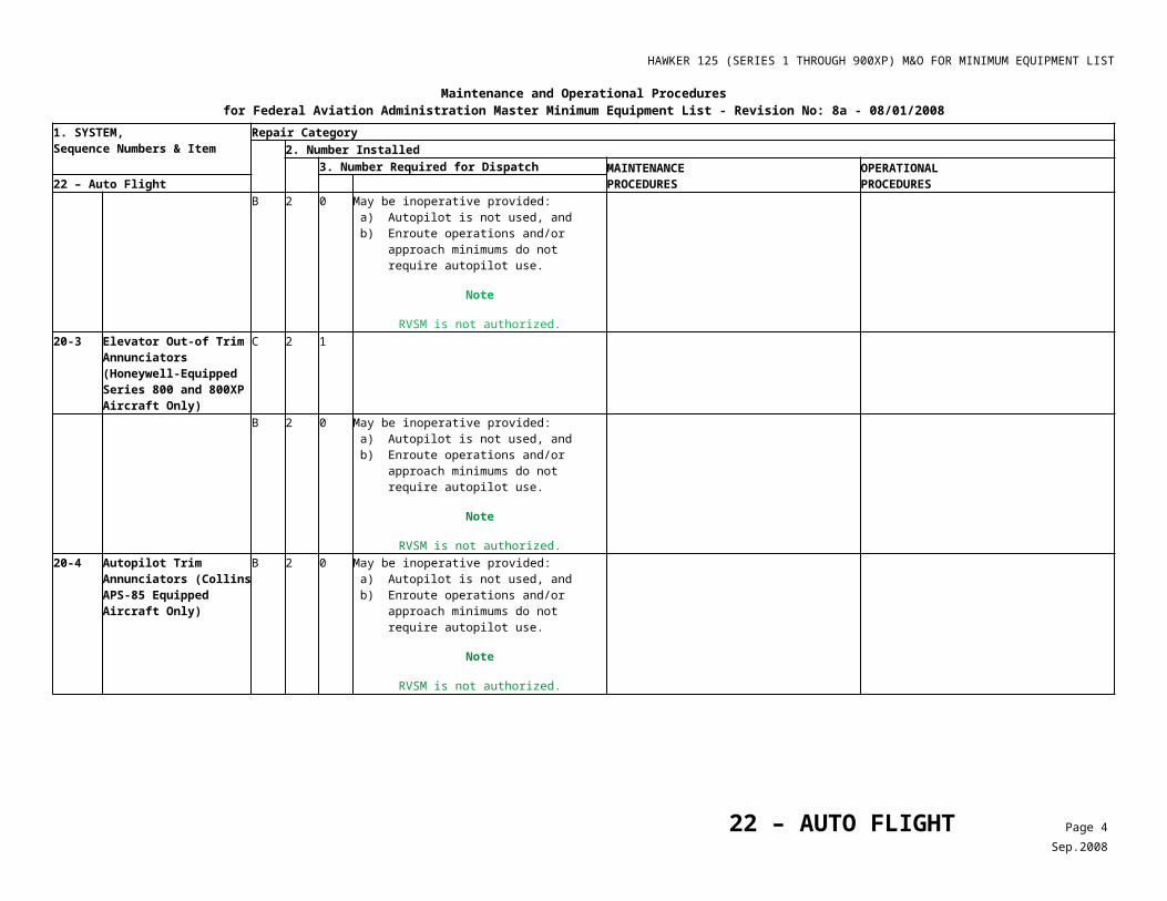
HAWKER 125 (SERIES 1 THROUGH 900XP) M&O FOR MINIMUM EQUIPMENT LIST
Maintenance and Operational Proceduresfor Federal Aviation Administration Master Minimum Equipment List - Revision No: 8 - 02/18/2008
1. SYSTEM, Sequence Numbers & Item
Repair Category2. Number Installed
3. Number Required for Dispatch MAINTENANCEPROCEDURES
OPERATIONALPROCEDURES26 – Fire Protection 4. Remarks and Exceptions
20-4 Portable Fire Extinguishers
D - - (M) Any in excess of those required by FAR may be unserviceable or missing provided: a) Inoperative fire extinguisher is tagged
inoperative, removed from location, and placed out of sight so it can not be mistaken for a functional unit, and
b) Required distribution is maintained.
1. Tag affected fire extinguishers ‘INOPERATIVE’ and stow out of sight.
2. Verify that required fire extinguishers are operational and properly located.
30-1 Forward / Aft Baggage Smoke Detection Systems
C - 0 (O) May be inoperative provided procedures are established and used to ensure the associated compartment remains empty, or is confirmed to contain only cargo handling equipment, ballast, which may be loaded in Unit Loading Devices (ULD’s), and / or Fly Away Kits.
Note
Operator Minimum Equipment Lists (MEL’s) must define which items are approved for inclusion in Fly Away kits, and which materials can be used as ballast.
1. Install DO NOT USE placard prominently inside baggage compartment.
2. Check that affected baggage compartment is either not used or contains only cargo handling equipment, ballast, which may be loaded in ULD’s, and/or Fly Away Kits.
30-2 ***
Lavatory Smoke Detection System
C - May be inoperative provided: a) Lavatory waste receptacle is empty, b) Lavatory door is locked closed and
placarded ‘INOPERATIVE-DO NOT ENTER’, and
c) Lavatory is used only by crew members.
Note
These provisos are not intended to prohibit Lavatory use or inspections by crew members.
Note
A lavatory Smoke Detector System is not required for all cargo operations.
30-3 ***
Rear Baggage Pannier Smoke Detection System (Except 750)
C 1 0 (O) May be inoperative provided: 1. Compartment remains empty, and 2. Pannier Heating Selector remains OFF.
1. Install ‘DO NOT USE’ placard prominently inside baggage compartment.
2. Prior to each departure, verify that compartment is empty.
3. Select and leave Pannier Heat OFF.
26 – FIRE PROTECTION Page 2Sep.2008
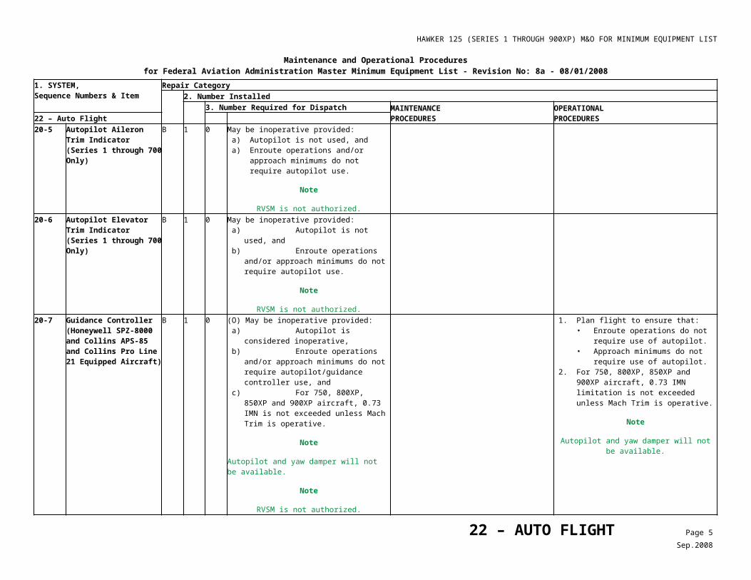
HAWKER 125 (SERIES 1 THROUGH 900XP) M&O FOR MINIMUM EQUIPMENT LIST
Maintenance and Operational Proceduresfor Federal Aviation Administration Master Minimum Equipment List - Revision No: 8 - 02/18/2008
1. SYSTEM, Sequence Numbers & Item
Repair Category2. Number Installed
3. Number Required for Dispatch MAINTENANCEPROCEDURES
OPERATIONALPROCEDURES26 – Fire Protection 4. Remarks and Exceptions
30-4 External Baggage Compartment (EBC) Smoke Detector (750 Only)
C 2 1 One Smoke Detector system may be inoperative provided the remaining Smoke Detector System is operative prior to each departure.
Verify remaining Smoke Detector System is operative prior to each departure.
C 2 0 (O) May be inoperative provided: 1. Compartment remains empty, and 2. EBC Air Valve is OFF.
1. Prior to each departure, verify that compartment is empty, and
2. Verify EBC Air Valve is OFF. 30-5 External Baggage
Compartment (EBC) Fire Extinguisher System (750 Only)
C 1 0 (O) May be inoperative provided: 1. Compartment remains empty, and 2. EBC Air Valve is OFF.
1. Prior to each departure, verify that compartment is empty, and
2. Verify EBC Air Valve is OFF.
26 – FIRE PROTECTION Page 3Sep.2008
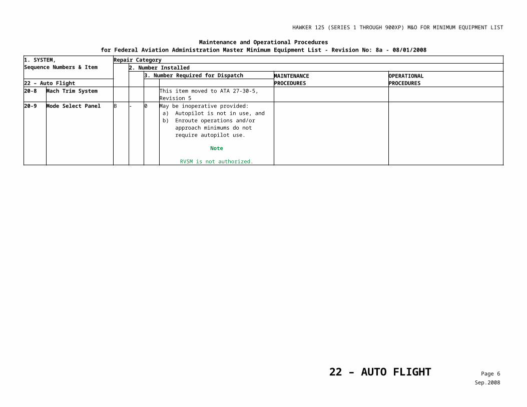
HAWKER 125 (SERIES 1 THROUGH 900XP) M&O FOR MINIMUM EQUIPMENT LIST
Maintenance and Operational Proceduresfor Federal Aviation Administration Master Minimum Equipment List - No: 8c – 10/17/2012
1. SYSTEM, Sequence Numbers & Item
Repair Category
2. Number Installed3. Number Required for Dispatch MAINTENANCE
PROCEDURESOPERATIONALPROCEDURES27 – Flight Controls 4. Remarks and Exceptions
10-1 Aileron Trim Position Indicator
B 1 0 (O) May be inoperative provided, before each departure: a) Aileron trim system is visually verified
operative, and b) Aileron trim is visually verified to be
neutral.
1. Operate aileron trim while observing LH aileron trim tab for appropriate movement prior to each departure.
2. With controls in neutral position, confirm the aileron trim tab is centered.
20-1 Rudder trim Position Indicator
B 1 0 (O) May be inoperative provided, before each departure: a) Rudder trim system is visually verified
operative, and b) Rudder trim is visually verified to be
neutral.
1. Operate rudder trim while observing rudder trim tab for appropriate movement prior to each departure.
2. With controls in neutral position, the rudder trim tab is centered.
Note
Check requires coordinated effort of both crew to perform.
20-2 Rudder Pedal Adjustment Systems
C 2 0 (M) May be inoperative provided affected adjustment system(s) can be secured in a position which suits affected pilot’s requirements.
1. Remove the crew seat and flight compartment carpets from affected side.
Caution
Make sure correct securing screws are identified and kept with correlating floor panels.
2. Remove flight compartment floor panels as necessary.
3. Disconnect the rudder pedal assembly adjustment cable at the lever.
4. Pull up on cable to disengage locking pin and move rudder pedals to desired position.
5. Check that the pin is fully engaged in locked position and that spring force will maintain lock.
6. Disconnect adjustment cable from rudder pedal adjustment assembly.
7. Install flight compartment floor panels using correct screw length.
8. Install flight compartment carpets and the crew seat.
30-1 Electrical Elevator Trim B 1 0 (M) (O) May be inoperative provided: a) Associated circuit breakers are pulled and
collared, b) Mechanical Elevator Trim System is
1. Locate ELEC PITCH TRIM Circuit Breaker. 2. Pull and Collar ELEC PITCH TRIM circuit
breaker.
1. Operate mechanical elevator trim throughout full range before departure, and
2. Verify that trim is set in normal position prior to takeoff, and
27 – FLIGHT CONTROLS Page 1Dec.2012
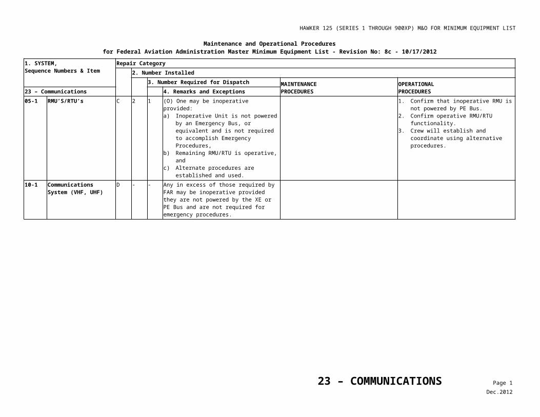
HAWKER 125 (SERIES 1 THROUGH 900XP) M&O FOR MINIMUM EQUIPMENT LIST
Maintenance and Operational Proceduresfor Federal Aviation Administration Master Minimum Equipment List - No: 8c – 10/17/2012
1. SYSTEM, Sequence Numbers & Item
Repair Category
2. Number Installed3. Number Required for Dispatch MAINTENANCE
PROCEDURESOPERATIONALPROCEDURES27 – Flight Controls 4. Remarks and Exceptions
verified operative, c) Autopilot is considered inoperative, and d) For 750, 800XP, 850XP, and 900XP
aircraft, the mach trim system is considered inoperative and appropriate AFM speed limitations observed.
Note
RVSM is not authorized.
3. Plan for flight without autopilot, and 4. Do not exceed AFM speed limitation of
Mach 0.73 (750, 800XP, 850XP and 900XP Only)
5. Plan flight to avoid RVSM operation.
30-2 Stall Warning Identification System
1) (Series 1 through 700 Only) B 2 1 (M) (O) May be inoperative provided, before each departure: a) Remaining stall detector pneumatic system
is verified operative, and b) Remaining stall test channel is verified
operative.
Prior to each departure, verify operational stall detector per Table 1.
Prior to each departure, confirm that stall test is operative for the operational system.
2) (Series 800, 800XP with 3 Channels Only)
B 3 2 (M) (O) One stall warning and / or identification channel may be inoperative provided: a) Inoperative channel is inhibited by pulling
and collaring the associated STALL IDENT circuit breaker (SSU and STALL IDENT amber annunciators illuminated if IDENT 1 or 2 is inhibited),
b) Before each departure, normal operation of the remaining channels is verified by independently pressing the cockpit TEST buttons,
c) Before each departure, normal operation of the stick pusher is verified (stall valves A and B OPEN with red annunciators illuminated) by pressing the two operative TEST buttons simultaneously, and
d) Lights erroneously ON due to system failure are deactivated.
1. Pull and collar associated STALL IDENT circuit breaker.
2. Remove light bulb from any annunciator which is erroneously illuminated.
1. Prior to each departure, confirm both remaining stall channels operate normally by independently pressing associated TEST buttons, and
2. Confirm normal operation of pusher by pressing both operational TEST buttons.
30-3 Stick Shaker Motors (Series 750, 800, 800XP, 850XP and 900XP Only)
C 2 1 One may be inoperative provided:a) Both stall warning channels are operative, andb) Remaining stick shaker system is verified operative.
30-4 Stall Warning Autopilot Disconnect System
C 1 0 (O) May be inoperative provided Stick Shaker Autopilot Disconnect functions of both Stall
1. Prior to each departure, perform the following checks:
27 – FLIGHT CONTROLS Page 2Dec.2012
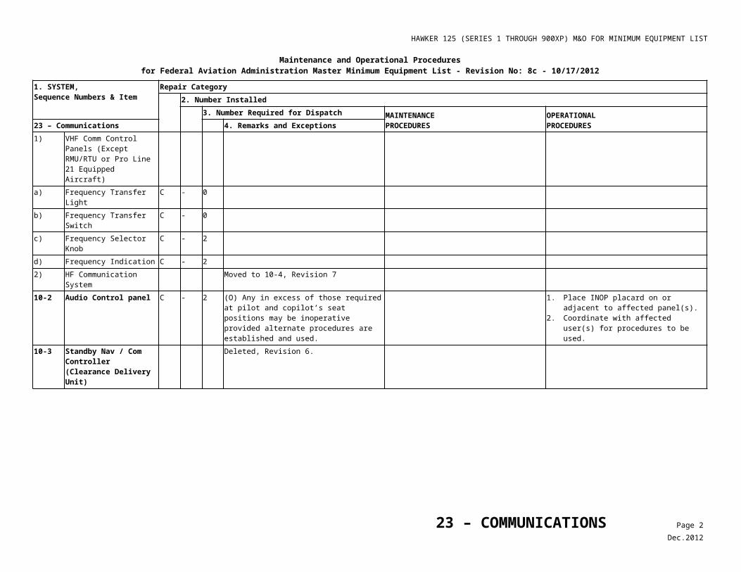
HAWKER 125 (SERIES 1 THROUGH 900XP) M&O FOR MINIMUM EQUIPMENT LIST
Maintenance and Operational Proceduresfor Federal Aviation Administration Master Minimum Equipment List - No: 8c – 10/17/2012
1. SYSTEM, Sequence Numbers & Item
Repair Category
2. Number Installed3. Number Required for Dispatch MAINTENANCE
PROCEDURESOPERATIONALPROCEDURES27 – Flight Controls 4. Remarks and Exceptions
(Series 800 without Mod. 253146 Installed Only)
Warning Channels 1 and 2 are verified operative before each departure.
2. Engage Autopilot and hold light force on control yoke.
3. Push and hold No. 1 STALL buttona) Confirm that stick shaker motors are
operative and autopilot disengages.b) Confirm IDENT 1 (both sides) and
STALL IDENT annunciators illuminate after 4 or 5 seconds.
4. Release No. 1 STALL button. 5. Engage autopilot and hold light force on
control yoke. 6. Push and hold No. 2 STALL button.
c) Confirm that stick shaker motors operate and autopilot disengages.
d) Confirm IDENT 2 (both sides) and STALL IDENT annunciators illuminate after 4 or 5 seconds.
7. Release No. 2 STALL button.30-5 Mach Trim System
(Series 750, 800XP, 850XP and 900XP Only)
C 1 0 (O) May be inoperative provided: a) Mechanical Elevator Trim System is
verified operative before each departure, and
b) AFM Speed Limitation of 0.73 Indicated Mach Number (IMN) is not exceeded unless Auto Pilot verified operative and is used.
1. Operate mechanical elevator trim throughout full range before departure, and
2. Confirm that trim is set in normal position prior to takeoff, and
3. Do not exceed AFM speed limitations with autopilot disengaged.
50-1 Flap Position Indicator (On Center Instrument Panel)
C 1 0 (O) May be inoperative provided: a) Flap position is visually verified to be at 0°
before each departure, b) AFM procedures for flap 0° take-off and
landing are observed, and c) Flaps remain in the retracted position for
the entire flight.
1. Visually confirm that flaps are at 0° prior to each departure by checking the position of the rig marks on the wing and flap assembly.
2. 0° flap performance will be used for takeoff and landing.
3. Flaps will not be used in flight. 4. AFM FLAPLESS LANDING procedures
will be followed.50-2 Flap Handle Select
Position Indicator (On Control Pedestal)
C 1 0 (O) May be inoperative, and flap used, provided: a) Flap position Indicator (On Center
Instrument Panel) is operative, and b) Before each departure, flap position
indication is visually verified for each flap selection.
Confirm that actual flap position indication is correct for each flap position prior to each departure.
27 – FLIGHT CONTROLS Page 3Dec.2012
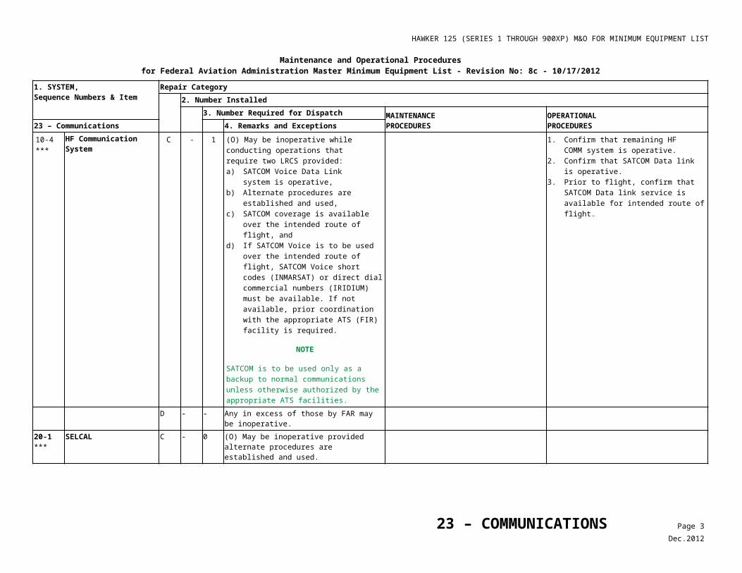
HAWKER 125 (SERIES 1 THROUGH 900XP) M&O FOR MINIMUM EQUIPMENT LIST
Maintenance and Operational Proceduresfor Federal Aviation Administration Master Minimum Equipment List - No: 8c – 10/17/2012
1. SYSTEM, Sequence Numbers & Item
Repair Category
2. Number Installed3. Number Required for Dispatch MAINTENANCE
PROCEDURESOPERATIONALPROCEDURES27 – Flight Controls 4. Remarks and Exceptions
C 1 0 (O) May be inoperative provided: a) Flap position is visually verified to be 0°
before each departure, b) AFM procedures for flap 0° take-off and
landing are observed, and c) Flaps remain in the retracted position for
the entire flight.
1. Visually confirm that flaps are at 0° prior to each departure by visual use of marks on flaps.
2. 0° flap performance will be used for takeoff and landing.
3. Flaps will not be used in flight. 4. AFM FLAPLESS LANDING procedures
will be followed.50-3 Flap Position Switches A 4 0 (M) (O) May be inoperative provided:
a) LH and RH Flap Bias Switches are bypassed to position flaps in 0° position,
b) Flaps are verified to be in the 0° position and are not used.
c) AFM procedures for flap 0° take-off and landing are observed, and
d) Repairs are made within one flight day.
Perform the LH and RH Flap Bias Switches - Bypass Procedure, Refer to Table 3.
1. Confirm LH and RH Flap Bias Switches are bypassed to position flaps in 0° position.
2. Visually confirm that flaps are at 0° prior to each departure by visual use of marks on flaps.
3. 0° flap performance will be used for takeoff and landing.
4. Flaps will not be used in flight. 5. AFM FLAPLESS LANDING procedures
will be followed.60-1 Air Brake Position
Indicator(s)C - 0 (O) May be inoperative provided, before each
departure: a) Airbrakes are visually verified operative, b) Takeoff Warning System is verified
operative with Air Brake deployment, and c) Airbrakes are visually verified retracted.
1. Extend and retract airbrakes and visually confirm normal operation.
2. Confirm Takeoff Warning system is operative by advancing the throttles to 40% to 60% and pull back on the airbrake handle to slightly deploy the airbrake. The warning horn should sound.
3. Airbrakes are visually confirmed retracted prior to departure by observation through cabin windows. Trailing edge of Air Brakes should fair smoothly with wing.
60-2 Control Column Lock System
C 1 0 (O) May be inoperative provided: a) Procedures are established and used to
prevent damage from gusts while aircraft is on the ground, and
b) Throttle Lever Baulks are verified disengaged prior to each departure.
1. A suitable alternate means is provided to secure controls to prevent ground gust induced damage to control system when aircraft is parked.
Note
Assure that any alternate means employed are prominent in display, so they will not be inadvertently left in place when the aircraft is dispatched. Such means shall be effectively secured to prevent slippage under gust load conditions.
27 – FLIGHT CONTROLS Page 4Dec.2012
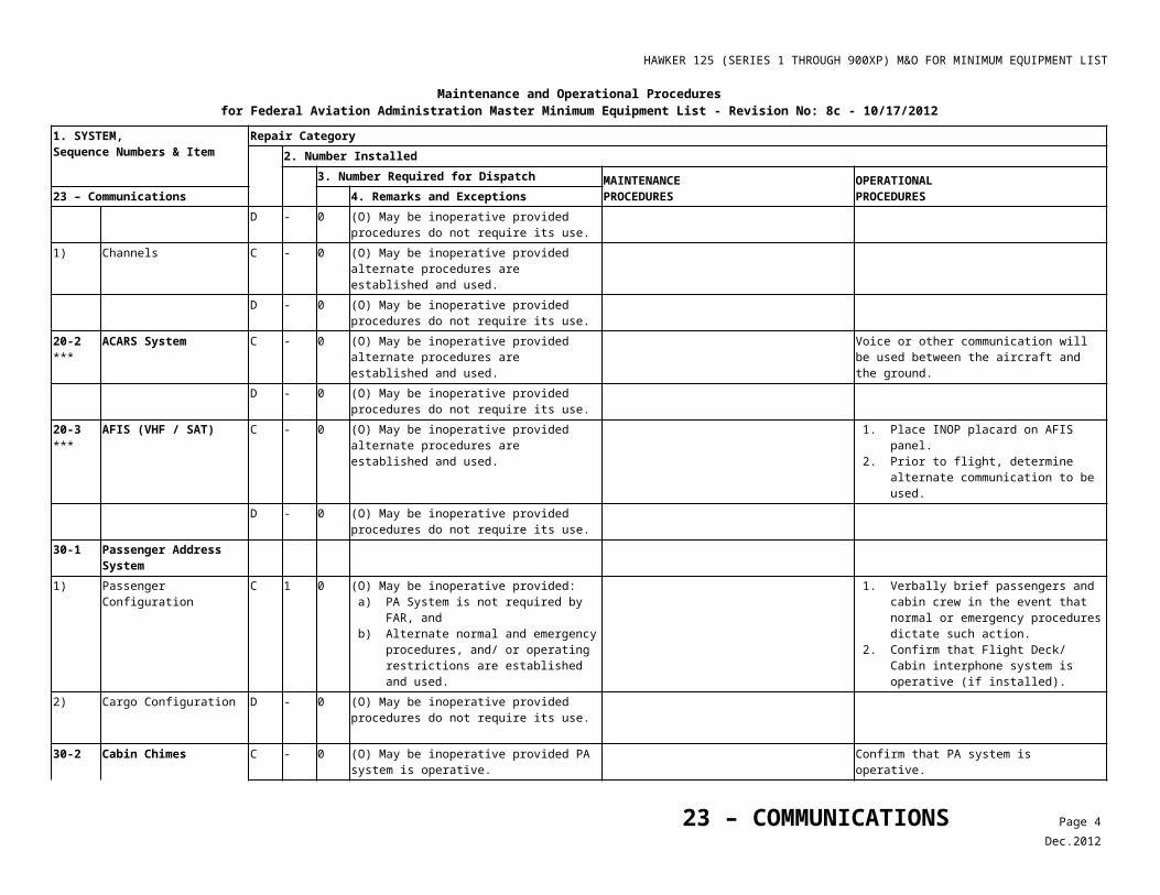
HAWKER 125 (SERIES 1 THROUGH 900XP) M&O FOR MINIMUM EQUIPMENT LIST
Maintenance and Operational Proceduresfor Federal Aviation Administration Master Minimum Equipment List - No: 8c – 10/17/2012
1. SYSTEM, Sequence Numbers & Item
Repair Category
2. Number Installed3. Number Required for Dispatch MAINTENANCE
PROCEDURESOPERATIONALPROCEDURES27 – Flight Controls 4. Remarks and Exceptions
2. Advance each throttle lever through full range of movement noting travel limits.
3. Confirm throttle lever baulks are disengaged by advancing both throttle levers simultaneously through full range of movement without travel restriction.
60-3 Rudder Gust Lock Flapper Door
Deleted Revision 8c, use CDL.
27 – FLIGHT CONTROLS Page 5Dec.2012
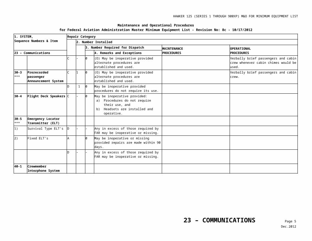
HAWKER 125 (SERIES 1 THROUGH 900XP) M&O FOR MINIMUM EQUIPMENT LIST
Table 1Stall Detection Maintenance and Operational Procedure
27- FLIGHT CONTROLS
30-2
Stall Warning Identification System MAINTENANCE/ OPERATIONAL
PROCEDURES1) (Series 1 through
700, Only) 1. Connect the pressure outlet of one pitot/static test set to the right pitot head, and the pressure outlet of the other test set to the operative wing
stall detector vent.
2. Confirm that No.6 static vent orifices on each static vent plate are clear of obstruction.
3. Energize PE busbar.
4. At the pitot head connection, apply sequentially the pressure (P) values given in Table 2, and in each case slowly increase pressure (V) to the stall detector vent until the stick shaker motor operates. Note V pressure at each point.
5. Verify that V pressures meet requirements of Table 2, and then release pressures.
NOTE
Table 2 provides a V/P ratio of 0.71 ± 0.02 on increasing pressure, when checked using Millimeter(s) (mm) water.
NOTE
When A.S.I. gauges (calibrated in knots) are used as alternative to mm water gauge, the readings will not provide the same ratio as mm water to knots as conversion is not linear. Reference Check Pressures Table 2.
6. Remove test set connection from pitot head and apply increasing pressure to stall detector vent until stick shaker motor operates. Maintain this vent pressure, reconnect test set to pitot head and apply increasing pressure (P) until warning system cuts out. Verify that, at cutout, the pressure (P) was between 76.5 and 86.0 mm water (70 ± 2 knots). Release pressures.
7. Disconnect and remove test sets.
8. De-energize busbar.
Table 2Check Pressures
MIllimeters (mm) WaterKnots
Pitot (P) Vent (V) Pitot (P) Vent (V)
1st Check Point 100 67-73 78 64.5-66.5
2nd Check Point 150 103.5-109.5 95 79-81
3rd Check Point 200 138-146 110 91-94
27 – FLIGHT CONTROLS Page 6Dec.2012
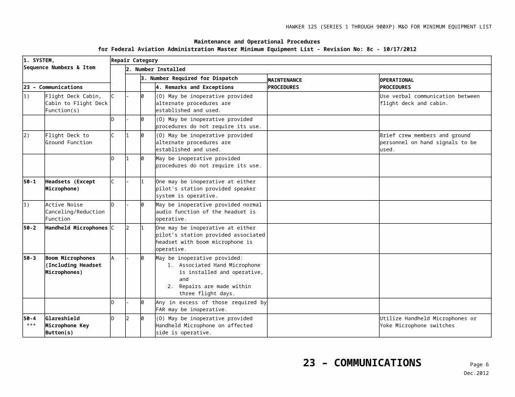
HAWKER 125 (SERIES 1 THROUGH 900XP) M&O FOR MINIMUM EQUIPMENT LIST
Table 3LH and RH Flap Bias Switches – Bypass Procedure
27- FLIGHT CONTROLS
50-3Flap Position Switches MAINTENANCE
PROCEDURES
Perform the following procedure to bypass the LH and RH Flap Bias Switches:
1. Ensure power is removed from aircraft.
2. To bypass LH Wing Flap microswitches:
• Remove 2nd (from the rear) overwing access panel on LH side, using quick release fasteners.
• Locate terminal block JBA, remove nut from JBA8, and remove the wire marked A8JB:W1:55:W1:JD3L. Stow wire to safely isolate the 15/45 Flap LH microswitch.
• Remove nut from JBA7, and remove the wire marked A7JB:W1:55:W1:P1N from JBA7 and place on JBA8. This isolates the 0 Flap LH microswitch and provides 28V to the SSU 1.
• Replace nuts on JBA7 and JBA8 terminal blocks and replace overwing access panel.
3. To bypass RH Wing Flap microswitches:
• Remove 2nd (from the rear) overwing access panel on LH side, using quick release fasteners.
• Locate terminal block KB, remove nut from KB8, and remove the wire marked 8KB:W2:55:W2:KD4L. Stow wire to safely isolate the 15/45 Flap RH microswitch.
• • Remove nut from KB7, and remove the wire marked 7KB:W2:55:W2:P2N from KB7 and place on KB8. This isolates the 0 Flap RH microswitch and provides 28V to the SSU 2.
• • Replace nuts on KB7 and KB8. terminal blocks and replace overwing access panel.
4. Power up the aircraft and check that the SSU Fault light and the STALL IDENT light are not illuminated.
27 – FLIGHT CONTROLS Page 7Dec.2012
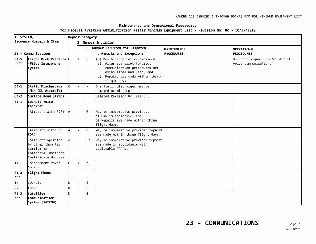
HAWKER 125 (SERIES 1 THROUGH 900XP) M&O FOR MINIMUM EQUIPMENT LIST
Maintenance and Operational Proceduresfor Federal Aviation Administration Master Minimum Equipment List - No: 8b - 05/21/2009
1. SYSTEM, Sequence Numbers & Item
Repair Category2. Number Installed
3. Number Required for Dispatch MAINTENANCEPROCEDURES
OPERATIONALPROCEDURES28 – Fuel 4. Remarks and Exceptions
20-1 Fuel Booster Pumps A 2 1 (M) (O) One may be inoperative provided: a) Inoperative pump is deactivated. b) Crossfeed and Wing Transfer Valves are
operative.c) Aircraft is operated in accordance with
AFM Supplement. d) Low Pressure (LP) Fuel Warning System
is operative.e) Both Wing Fuel Content Indicators are
operative.f) Repairs are made within three flight cycles.
1. Refer to Table 1 and do the Fuel Booster Pump Deactivation procedure.
2. Make sure the Crossfeed and Wing Transfer Valves are operative by checking fuel gauge for movement.
3. Make sure the LP Fuel Warning System is operative.
4. Make sure both Fuel Content Indicators are operative.
1. Observe limitations and procedures in AFM Supplement “Flight With One Pump Inoperative”.
20-2 Wing Transfer Magnetic Indicator (Series 1 Through 400 Only)
C 1 0 (O) May be inoperative provided:a) Both Fuel Booster Pumps are operative,b) Wing Fuel Content Indicators are
operative, andc) Before each departure, TRANSFER and
CROSSFEED Valves are verified operative.
Prior to each departure, 1. Move X FEED/TRANSFER lever to the
transfer position.2. Sequentially, operate LH and RH fuel
booster pumps. Fuel will transfer to the wing with the operating fuel boost pump, indicated by an increase in the respective fuel contents indicator.
20-3 Fuel Transfer/ Crossfeed Indicator (Series 600 Through 850XP Only)
C 1 0 (O) May be inoperative provided: a) Both Fuel Booster Pumps are operative, b) Wing Fuel Content Indicators are
operative, and c) Before each departure, TRANSFER and
CROSSFEED Valves are verified operative.
Prior to each departure, 1. Move X FEED/TRANSFER lever to the
crossfeed and transfer positions.2. Sequentially, operate LH and RH fuel
boost pump. Fuel will transfer to the wing with the operating fuel boost pump, indicated by an increase in the fuel contents indicator.
3. With lever in X FEED position and one boost pump operation, make sure both fuel low pressure annunciators extinguish.
28 – FUEL Page 1Jul.2009
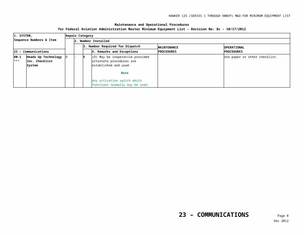
HAWKER 125 (SERIES 1 THROUGH 900XP) M&O FOR MINIMUM EQUIPMENT LIST
Maintenance and Operational Proceduresfor Federal Aviation Administration Master Minimum Equipment List - No: 8b - 05/21/2009
1. SYSTEM, Sequence Numbers & Item
Repair Category2. Number Installed
3. Number Required for Dispatch MAINTENANCEPROCEDURES
OPERATIONALPROCEDURES28 – Fuel 4. Remarks and Exceptions
20-4 Ventral Tank Fuel Transfer Valve
C 1 0 (M) (O) May be inoperative provided: a) Tank remains empty, b) Valve is secured closed, and c) Dorsal tank remains empty for Series 600
and 700.
1. Defuel Dorsal (Series 600 and 700) and Ventral Tanks; Refer to Aircraft Maintenance Manual (AMM) 12-28 for cautions.• Select AUX FUEL TRANSFER cock
OPEN.• Unlock and remove filler cap(s) from
tank(s) being defuelled.• Unscrew blanking adapter from fuel
drain valve and install the fuel drain adaptor assembly to tank(s).
• Off-load fuel from each tank.• Remove the fuel drain adaptor
assembly and install blanking adapter to fuel drain valve.
Note: Series 700 may be defueled by Single Point.
2. Set valve selector in CLOSED position. 3. Check valve FWD RH face of ventral tank)
to make sure it is in the CLOSED position. 4. Install ‘INOP placard adjacent to selector
handle.
1. Plan flight without ventral or dorsal fuel. 2. Monitor refuel operations to make sure fuel
is not placed in ventral or dorsal tanks.
20-5 Ventral Tank Transfer Light/ Annunciator
C 1 0 (M) May be inoperative provided: a) Associated valve is verified operative, and b) Valve position is verified after each
refueling.
1. Access ventral tank transfer valve (FWD RH face of tank).
2. Observe valve for proper position when selector is moved from CLOSED to OPEN.
C 1 0 (O) May be inoperative provided: a) Tank remains empty, and b) Dorsal tank remains empty for Series 600
and 700.
Monitor refueling to make sure Ventral and Dorsal tanks are not refueled for Series 600 and 700.
20-6 Fuel Filter De-Icing Systems (Series 1 Through 600 With Viper Engines Only)
28 – FUEL Page 2Jul.2009
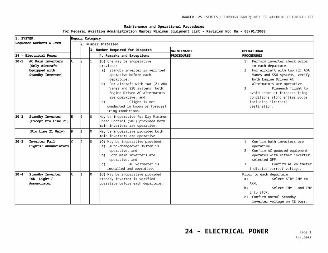
HAWKER 125 (SERIES 1 THROUGH 900XP) M&O FOR MINIMUM EQUIPMENT LIST
Maintenance and Operational Proceduresfor Federal Aviation Administration Master Minimum Equipment List - No: 8b - 05/21/2009
1. SYSTEM, Sequence Numbers & Item
Repair Category2. Number Installed
3. Number Required for Dispatch MAINTENANCEPROCEDURES
OPERATIONALPROCEDURES28 – Fuel 4. Remarks and Exceptions
1) Automatic System C 1 0 May be inoperative provided fuel temperature indicator, fuel low-pressure warning, fuel filter ice warning, and manual system are operative.
2) Manual System C 1 0 May be inoperative provided:a) Fuel temperature indicator is operative,
andb) Automatic fuel pump filter ice warning
Press-to-Test function is operative.3) Manual and Automatic
SystemsC 2 0 (O) May be inoperative provided;
a) Fuel temperature indicator is operative, and
b) Fuel temperature remains at or above 5° C.
1. Make sure the fuel temperature indication is normal.
2. Monitor fuel temperature during flight and maintain 5°C or above.
20-7 Fuel Filter Warning Lights (Viper Engine Only)
C 2 1 (O) One may be inoperative provided automatic fuel filter de-icing system is operative and is used during flight.
1. Select AUTO filter deice ON. 2. Press affected warning light and make
sure the filter deice pump runs. 3. Leave filter deice in AUTO.
22-1 Pressure Fueling System1) (Series 400 through 700) (If
Installed)C 1 0 (M) (O) May be inoperative provided:
a) Failure of the fueling system is verified not be due to fuel pipe leakage,
b) Both refueling vent valves, master refuel valve, and refueling valves are closed, and
c) Overwing refueling procedure is established and used.
1. Inspect external lower fuselage for evidence of fuel leakage.
2. Defuel Dorsal and Ventral fuel tanks. 3. Make sure both refueling vent valves,
master refuel valve, and dorsal and ventral refueling valves are closed (Refer to Pressure Refueling System Inactivation Procedure, Table 2.)
1. Follow Overwing Fueling refueling procedures.
2. Plan flight for Dorsal and Ventral fuel tanks empty.
2) (Series 750, 800, 800XP, 850XP and 900XP)
C 1 0 (M) (O) May be inoperative provided:a) Failure of the fueling system is verified not
be due to fuel pipe leakage.b) Master refueling valve and all tank
refueling valves are closed, andc) Overwing refueling procedure is
established and used.
1. Inspect external lower fuselage for evidence of fuel leakage.
2. Make sure the master refuel valve and ventral refueling valves are closed (Refer to Table 2 steps 2 and 4 for details).
1. Follow Overwing Fueling refueling procedures.
2. Plan flight for Ventral fuel tank empty.
22-2 Pressure Refuel Blanking Cap
C 1 0 (O) May be inoperative provided master refuel valve is verified closed.
Prior to each flight, make sure the MASTER REFUEL selector is CLOSED.
28 – FUEL Page 3Jul.2009
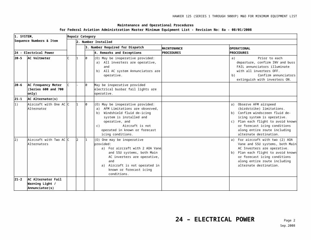
HAWKER 125 (SERIES 1 THROUGH 900XP) M&O FOR MINIMUM EQUIPMENT LIST
Maintenance and Operational Proceduresfor Federal Aviation Administration Master Minimum Equipment List - No: 8b - 05/21/2009
1. SYSTEM, Sequence Numbers & Item
Repair Category2. Number Installed
3. Number Required for Dispatch MAINTENANCEPROCEDURES
OPERATIONALPROCEDURES28 – Fuel 4. Remarks and Exceptions
42-1 Wing Tank Fuel Content Indicators
B 2 1 (O) One may be inoperative provided:a) Before departure, fuel quantity in associated tank is verified by an alternate means,b) All remaining fuel system components are operative,c) FUEL FLOW/FUEL USED COUNTER/ FUEL TOTALIZER indicators are operative,d) Aircraft remains within one (1) hour flying time from a suitable airport, ande) Alternate procedures for monitoring enroute fuel consumption are established and used.
1. Make sure the fuel in the associated wing tank is full by checking wing filler cap, or
2. Airplane is fueled with a known quantity from an empty condition.
3. All remaining fuel system components are operative.
4. Aircraft must remain within one (1) hour flying time of a suitable airport at all times.
5. Fuel Used Counter/Fuel Totalizer indicators are used to determine remaining fuel.
42-2 Fuel Used Counter(s)/Fuel Totalizer(s)
C - 0 (O) May be inoperative provided:a) Wing Tank Content Indicators are
operative, andb) Alternate procedures for monitoring
enroute fuel consumption are established and used.
1. Make sure the wing fuel contents indicators are operative.
2. Regularly compute fuel remaining or check FMS for fuel remaining, or
3. Compute fuel remaining utilizing Aircrew Manual Performance charts.
43-1 Ventral Tank “EMPTY/FULL” Indicator
C 1 0 (M) (O) May be inoperative provided:a) Ventral Tank is verified to be empty before
each departure, and b) Procedures are established and used to
make sure fuel is not transferred into Ventral Tank during flight.
1. Defuel Ventral Tank IAW AMM Chapter 12.
2. Check that Ventral Tank EMPTY/FULL indicator is extinguished.
3. If Ventral Tank EMPTY/FULL indicator is not extinguished, disconnect Ventral Tank Float Switch, bag and stow connector.
Refuel operations are monitored to make sure fuel is not placed in the ventral tank.
43-2 Dorsal Tank “Empty/Full” Indicator (Series 600 and 700, Only)
C 1 0 (M) (O) May be inoperative provided:a) Dorsal Tank is verified empty before each
departure, and b) Procedures are established and used to
make sure fuel is not transferred into Dorsal Tank during flight.
Make sure that dorsal tank is drained IAW AMM procedures.
Refuel operations are monitored to make sure fuel is not placed in the dorsal tank.
43-3 Low VMO Audible Warning System
28 – FUEL Page 4Jul.2009
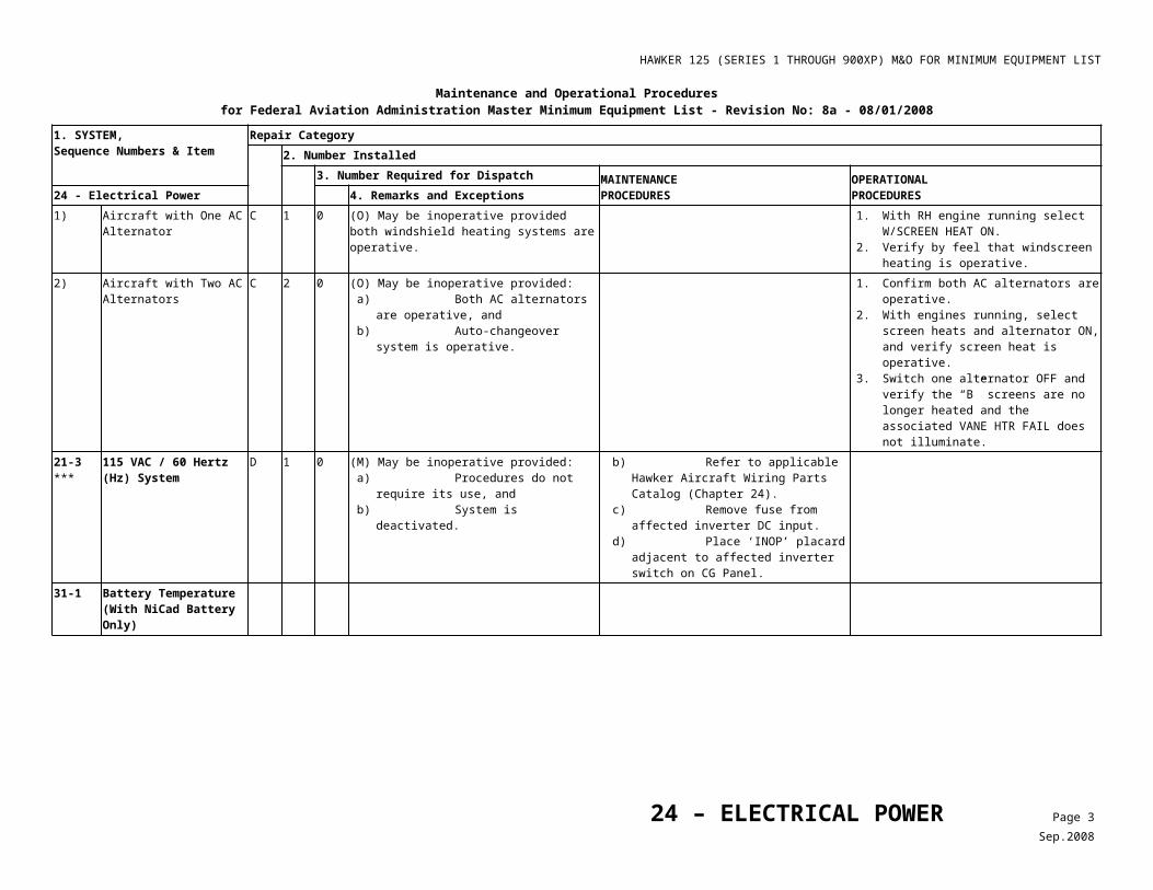
HAWKER 125 (SERIES 1 THROUGH 900XP) M&O FOR MINIMUM EQUIPMENT LIST
Maintenance and Operational Proceduresfor Federal Aviation Administration Master Minimum Equipment List - No: 8b - 05/21/2009
1. SYSTEM, Sequence Numbers & Item
Repair Category2. Number Installed
3. Number Required for Dispatch MAINTENANCEPROCEDURES
OPERATIONALPROCEDURES28 – Fuel 4. Remarks and Exceptions
1) Series 3A/RA, 3B/ RA Through 400, 800, 800XP, 850XP and 900XP Only
C 1 0 (M) (O) May be inoperative provided: a) Ventral tank is verified empty before each
departure, and b) Procedures are established and used to
make sure fuel is not transferred into Ventral Tank during flight.
Make sure that ventral tank is drained IAW AMM procedures.
1. If aircraft has not been refueled since previous flight, make sure ventral fuel was transferred from the tank on previous flight.
2. If aircraft has been refueled since previous flight, make sure the ventral tank is empty by checking sump drains. Ventral tank must be Single Point defueled and drained if fuel is present at sump.
2) Series 600 and 700, Only C 1 0 (M) (O) May be inoperative provided: 1. Ventral and Dorsal Tanks are verified
empty before each departure, and 2. Procedures are established and used
to make sure fuel is not transferred into Ventral Tank or Dorsal Tank during flight.
Make sure that dorsal and ventral tanks are drained IAW AMM procedures.
a) If aircraft has not been refueled since previous flight, make sure dorsal and ventral fuel was transferred from tanks on previous flight.
b) If aircraft has been refueled since previous flight, make sure the dorsal tank is empty which requires the ventral tank to be empty also. Both the ventral and dorsal tank must be defueled and drained if fuel is present at sump.
43-4 Fuel Vent Surge Tank Indicators (Series 3A/RA, 3B/ RA Through 600 Only)
C 2 0 (M) (O) May be inoperative provided: 1. Both fuel content indicators are
operative, and 2. Vent valves are operative.
a) Drain any fuel from Vent Surge Tanks.
b) Quantity drained must be less than one (1) gallon.
Make sure both wing fuel indications are normal.
45-1 Fuel Temperature Indicator
1) Viper Engine Only C 1 0 (O) May be inoperative provided: 1. Fuel filter ice warning system is
operative, 2. Fuel filter de-icing system is
operative, 3. OAT indicator is operative, and 4. Fuel temperature AFM Limitations are
applied.
a) Prior to each flight with fuel pumps OFF, select AUTO fuel filter deicing.
b) Press FILTER TEST and ENG 1/ENG 2 LO PRESS and FUEL annunciators shall extinguish.
c) Make sure the OAT indicator is operative.
d) Do not operate where OAT is below minimum AFM fuel temperature limit.
2) TFE-731 Engines Only C 1 0 (O) May be inoperative provided: 1. OAT indicator is operative, and 2. Fuel temperature AFM Limitations are
applied.
a) Make sure the OAT indicator is operative.
b) Do not operate where OAT is below minimum AFM fuel temperature limit.
45-2 ***
Fuel Management Computer System (Garrett GEMS System)
C - 0
28 – FUEL Page 5Jul.2009
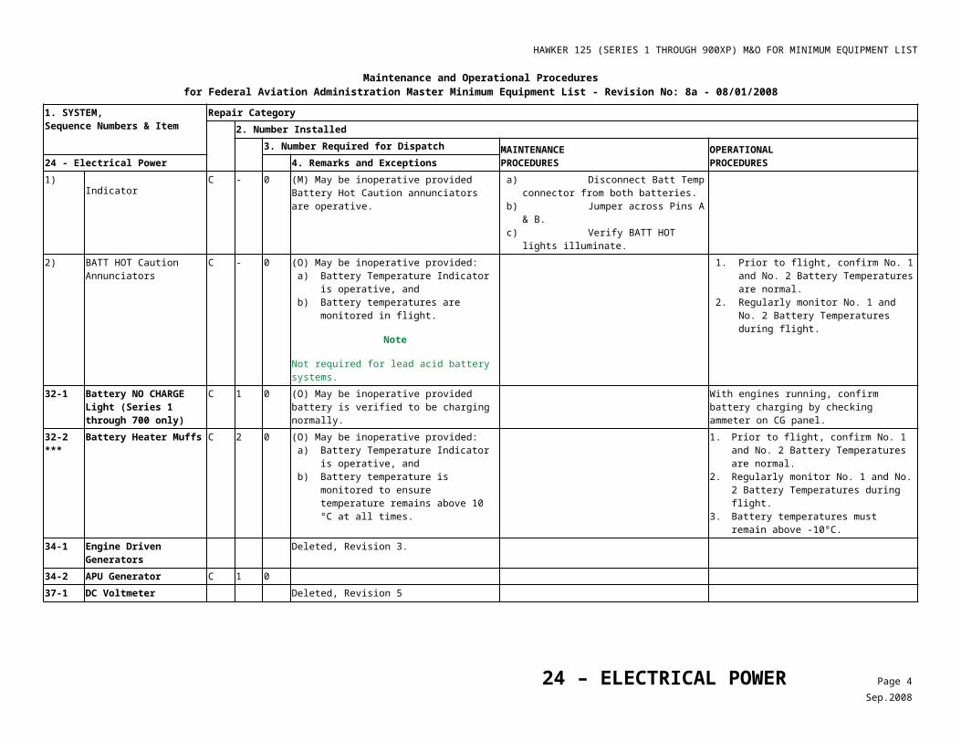
HAWKER 125 (SERIES 1 THROUGH 900XP) M&O FOR MINIMUM EQUIPMENT LIST
Table 1Fuel Booster Pump Deactivation
Left Hand Pump Deactivation:
On overhead panel ‘CG’’, locate switch in the Engine section labeled ‘L PUMP’ and select center position OFF.
On Main Distribution Panel DA/D, open and safety tag the following breakers:
B28 Fuel Pump CTL LH Grid Reference C8
B27 Fuel Pump LH Grid Reference C7
B26 STBY Fuel Pump LH Grid Reference C6
Right Hand Pump Deactivation:
On overhead panel ‘CG’’, locate switch in the Engine section labeled ‘R PUMP’ and select center position OFF.
On Main Distribution Panel DA/D, open and safety tag the following breakers:
B38 Fuel Pump CTL RH Grid Reference D8
B37 Fuel Pump RH Grid Reference D7
B36 STBY Fuel Pump RH Grid Reference D6
28 – FUEL Page 6Jul.2009
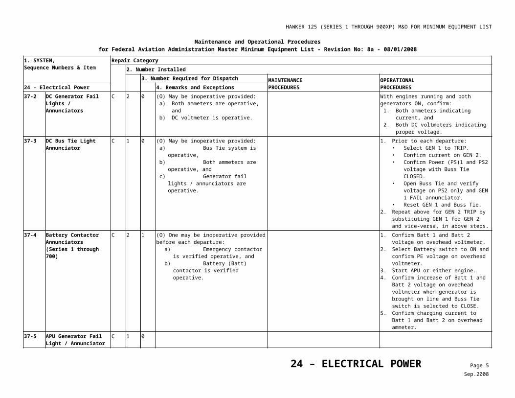
HAWKER 125 (SERIES 1 THROUGH 900XP) M&O FOR MINIMUM EQUIPMENT LIST
Table 2Pressure Refueling System Inactivation
28 - FUEL
MAINTENANCE PROCEDURES
22-1 Pressure Fueling System
1) Series 400 though 700, Only (If Installed)
1. Make sure the Refuel Vent Valve is closed.
a) Make sure the MASTER switch on the refuel control panel is selected OFF and the wing VENT valve indicators show SHUT. If indication is not present,
b) On panel DA/D, open circuit breakers REFUEL MASTER VALVE and REFUEL VENTS.
c) Remove the wing access panel, outboard of rib 13
d) Make sure the indicator on the actuator is horizontal.
e) Disconnect and stow the electrical connector from the valve.
2) Series 750, 800, 800XP, 850XP and 900XP Only
2. Make sure the Master Refuel Valve is closed.
a) Make sure the MASTER switch on the refuel control panel is selected OFF and Refuel Valve indicators show SHUT. If indication is not present,
b) Make sure the landing gear ground lock pins are installed.
c) Close the crossfeed and both low pressure valves (cocks).
d) Close the auxiliary fuel transfer lever.
e) Make sure the MASTER, DORSAL and VENTRAL REFUEL switches are selected OFF.
f) Isolate the electrical circuits of (4); refer to REFUEL SYSTEM CIRCUIT POWER SUPPLY DETAILS, Table 3.
g) Open left main gear door.
h) Remove the rear inboard sidewall panel in left main landing gear wheel well.
i) Make sure the indicator on the actuator is aligned with the marks.
j) Disconnect and stow the electrical connector from the valve.
3) Series 1-700 Only 3. Make sure the Dorsal Tank Refuel Valve is closed (For Series 1-700 Only).
a) Defuel dorsal tank (Chapter 12, SERVICING - FUEL).
b) Close No. 1 engine low pressure valve (cock).
c) Make sure all switches on the refuel control panel are OFF and the MASTER VALVE is indicated SHUT and that the Dorsal Refuel Valve indicator shows SHUT. If indication is not present,
d) On panel DA/D, open circuit breakers REFUEL DORSAL & VENTRAL, and REFUEL MASTER VALVE.
e) Gain access to the rear equipment bay; the valve is on the left side of the bay, just forward of the engine beam.
f) Make sure that the position indicator shows closed.
g) Disconnect and stow the electrical plug from the valve.
28 – FUEL Page 7Jul.2009
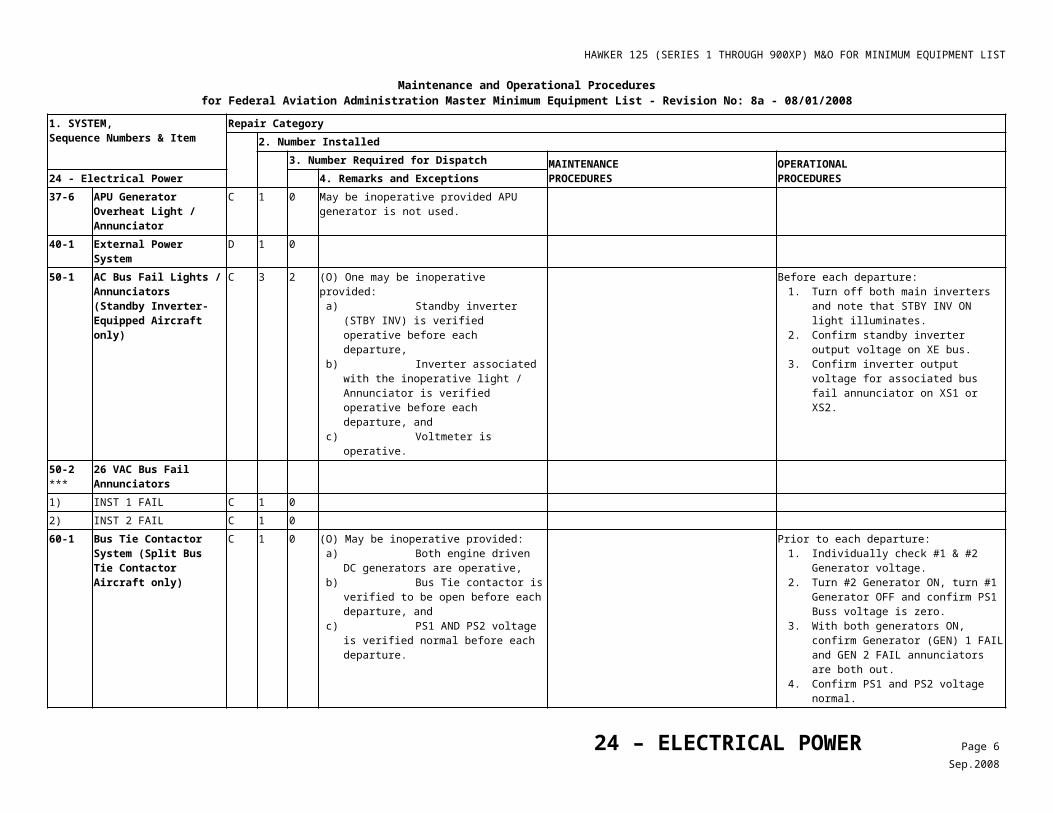
HAWKER 125 (SERIES 1 THROUGH 900XP) M&O FOR MINIMUM EQUIPMENT LIST
28 - FUEL
MAINTENANCE PROCEDURES
22-1 Pressure Fueling System
4. Make sure the Ventral Tank Transfer Valve is closed.
a) Make sure the MASTER switch on the refuel control panel is selected OFF and that the Ventral Valve indicator shows SHUT. If indication is not present,
b) Close the auxiliary fuel transfer valve.
c) Defuel the ventral tank (Chapter 12, SERVICING - FUEL).
d) Make sure all switches on the refuel panel DB are OFF and indicated as SHUT.
e) Close No.2 engine low-pressure fuel valve (cock).
f) On panel DA/D open circuit breakers REFUEL DORSAL AND VENTRAL and REFUEL MASTER VALVE.
g) Make sure the landing gear locking pins are installed (Chapter 10, PARKING AND MOORING).
h) Release hydraulic system pressure (Chapter 29, HYDRAULIC - MAIN SYSTEM).
i) Lower left main landing gear door and install door jack clamp (Chapter 32, LANDING GEAR - MAIN GEAR FAIRINGS AND DOORS).
j) Remove inboard access panel in rear wall of left main wheel bay to gain access to refuel valve on ventral tank forward wall.
k) Operate the manual override lever on the valve to the closed position.
l) Disconnect and stow the electrical connector from the valve.
Reference the REFUEL SYSTEM CIRCUIT POWER SUPPLY DETAILS, Table 3.
Table 3Refuel System Circuit Power Supply Details
Equipment Supply Panel DA C.B.
Master Refuel Valve Ident
PE (a) Sub Panel D REFUEL VENT
PE (a) Sub Panel D REFUEL MASTER VALVE
PE (a) Sub Panel E REFUEL CONTROL
PE (a) Sub Panel E WING O’FLOW (Overflow)
Wing Refuel Valve L & R PE (a) Sub Panel D REFUEL WING
Dorsal and Ventral Refuel Valve PE (a) Sub Panel D REFUEL DORSAL & VENTRAL
28 – FUEL Page 8Jul.2009
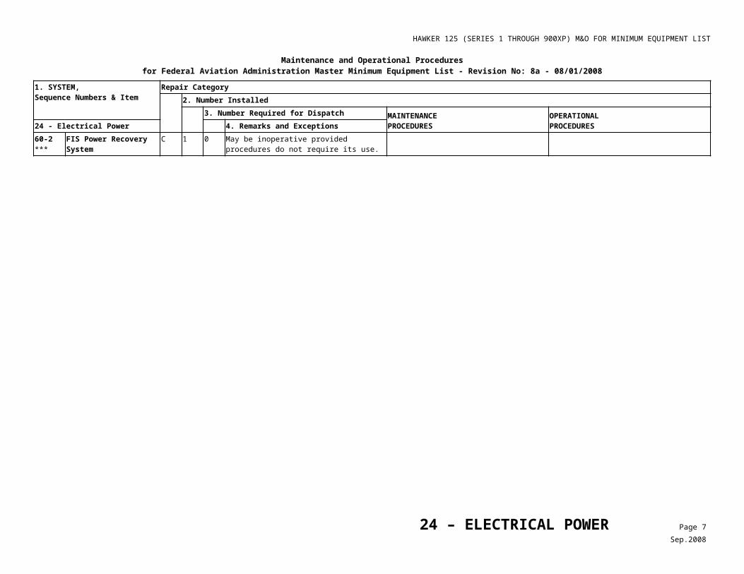
HAWKER 125 (SERIES 1 THROUGH 900XP) M&O FOR MINIMUM EQUIPMENT LIST
Maintenance and Operational Proceduresfor Federal Aviation Administration Master Minimum Equipment List - No: 8a - 08/01/2008
1. SYSTEM, Sequence Numbers & Item
Repair Category2. Number Installed
3. Number Required for Dispatch MAINTENANCEPROCEDURES
OPERATIONALPROCEDURES29 – Hydraulic Power 4. Remarks and Exceptions
30-1 L/R HYD LO FLOW Annunciators (Viper Engines, Only)
C 2 1 (O) One may be inoperative provided: a) Associated hydraulic pump is operative, b) Main hydraulic supply pressure
indicator is operative, c) EMRG HYD LO PRESS annunciator is
operative, d) Associated engine is started first to
verify pressure buildup before each departure.
1. Confirm HYD LO PRESS indicator is operative.
2. Prior to each departure, start the engine on the affected side first and confirm a pressure increase on the main hydraulic pressure indicator.
3. If HYD LP lamp illuminates in flight, follow EMERGENCY BRAKE SUPPLY FAILURE drill.
30-2 HYD LO PRESS 1 or 2 Annunciators (TFE-731 Engines, Only)
C 2 1 (O) One may be inoperative provided:a) Associated hydraulic pump is operative, b) Main hydraulic supply pressure
indicator is operative. c) EMRG BRK LO PRESS annunciator is
operative, and d) Associated engine is started first to
verify pressure buildup before each departure.
1. Prior to each departure, • Prior to engine start,
select Emergency Brake and operate brake pedals until EMER BRK LO PRESS annunciator illuminates.
CautionAirplane must be chocked during engine start.
• Start the associated engine first and observe pressure build up on the main hydraulic pressure indicator.
• Observe EMER BRK LO PRESS annunciator OFF at 2250 to 2450 psi.
2. Series 1 thru 700: If brake EMERG BRK LO PRESS warning light illuminates in flight, follow EMERGENCY BRAKE SUPPLY FAILURE drill.
30-3 Combined Brakes and SUPPLY Pressure Gauge
29 – HYDRAULIC POWER Page 1Sep.2008
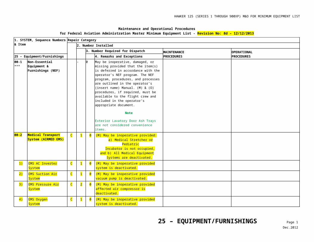
HAWKER 125 (SERIES 1 THROUGH 900XP) M&O FOR MINIMUM EQUIPMENT LIST
Maintenance and Operational Proceduresfor Federal Aviation Administration Master Minimum Equipment List - No: 8a - 08/01/2008
1. SYSTEM, Sequence Numbers & Item
Repair Category2. Number Installed
3. Number Required for Dispatch MAINTENANCEPROCEDURES
OPERATIONALPROCEDURES29 – Hydraulic Power 4. Remarks and Exceptions
1) BRAKE Pressure Indicators
C 2 1 (O) One may be inoperative provided before each departure:a) Main hydraulic SUPPLY indication is
within normal limits,b) Emergency Brake Pressure
Indicators/Annunciators are verified operative, and
c) Normal braking is confirmed independently for left and right brakes.
1. Prior to each departure:• Confirm Supply
Pressure indication is normal.• Prior to taxi, select
EMRGY wheel brake and confirm both 1 and 2 WHEEL BRAKE EMRGY annunciators illuminate.
2. Confirm normal braking independently for left and right brakes.
30-4 Accumulator Pressure Indicators
Deleted, Rev. 3.
30-5 AUX HYD LO LEVEL Annunciator (Series 3 Through 900XP, Only)
C 1 0 (O) May be inoperative provided fluid quantity is visually verified to be adequate before each departure.
1. Gain access to Nose Landing Gear (NLG) wheel well.
2. Visually confirm Auxiliary AUX HYD Reservoir has adequate quantity prior to each departure.
30-6 Accumulator Pressure Indicators (Main and Emergency Brake Only)
C 2 1 (O) One may be inoperative provided: a) Combined BRAKES and SUPPLY
Pressure Gauge is operative, and b) Associated accumulator pre-charge is
verified adequate before the first flight of each day.
1. Perform the following prior to the first flight of each day:• With engines not operating,
check hydraulic pressure indicator pressure to be ~2,300 PSI.
• Operate brakes five (5) times and confirm negligible change in hydraulic pressure.
2. Select WHEEL BRAKE lever to EMERGY and operate brakes 5 times. Confirm EMERG BRAKE annunciators illuminate.
30-7 Thrust Reverser Accumulator Pressure Indicator (Series 800, if installed, and 750, 800XP, 850XP and 900XP)
C 1 0 (O) May be inoperative provided before each departure:a) Thrust Reversers are verified operative,
andb) Main Hydraulic Accumulator pressure is
verified normal.
Note
Thrust Reversers may be inoperative with loss of main hydraulic system pressure.
1. Prior to each departure, confirm Thrust Reversers are operative, and
2. Confirm Main Hydraulic Accumulator pressure is normal.
Note
Thrust Reversers may be inoperative with loss of main hydraulic system pressure.
29 – HYDRAULIC POWER Page 2Sep.2008
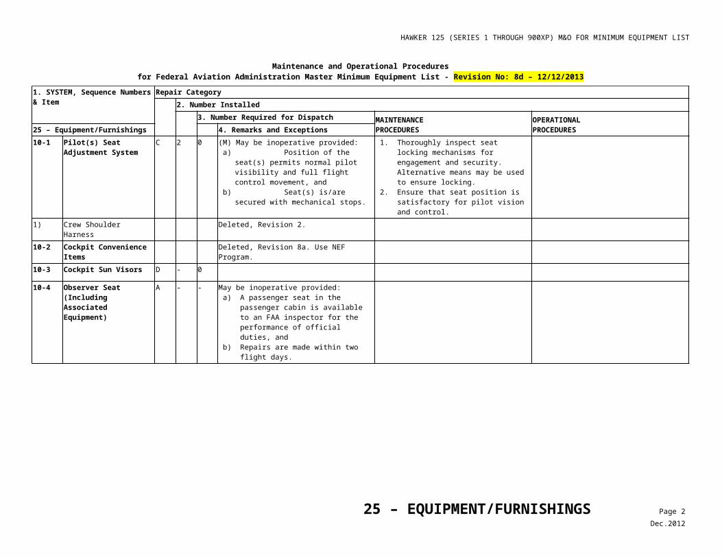
HAWKER 125 (SERIES 1 THROUGH 900XP) M&O FOR MINIMUM EQUIPMENT LIST
Maintenance and Operational Proceduresfor Federal Aviation Administration Master Minimum Equipment List - No: 8a - 08/01/2008
1. SYSTEM, Sequence Numbers & Item
Repair Category2. Number Installed
3. Number Required for Dispatch MAINTENANCEPROCEDURES
OPERATIONALPROCEDURES30 – Ice and Rain Protection 4. Remarks and Exceptions
10-1 TKS Airframe De-icing System
C 1 0 May be inoperative provided the airplane is not operated in known or forecast icing conditions.
Plan flight to avoid known or forecast icing conditions along intended and alternate flight path.
10-2 WING/TAIL ANTI-ICE Control Switches
30 – ICE AND RAIN PROTECTION Page 1Sep.2008
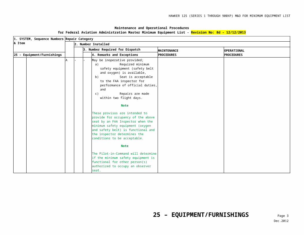
HAWKER 125 (SERIES 1 THROUGH 900XP) M&O FOR MINIMUM EQUIPMENT LIST
Maintenance and Operational Proceduresfor Federal Aviation Administration Master Minimum Equipment List - No: 8a - 08/01/2008
1. SYSTEM, Sequence Numbers & Item
Repair Category2. Number Installed
3. Number Required for Dispatch MAINTENANCEPROCEDURES
OPERATIONALPROCEDURES30 – Ice and Rain Protection 4. Remarks and Exceptions
1) WING/TAIL TIME Switcha) (Series 1 Through 400,
Only)C 1 0 (O) May be inoperative provided:
a) WING/TAIL ON/OFF Switch is verified operative,
b) WING/TAIL ON/OFF Switch is verified OFF when not in use (no audible sound from Anti-Icing Pump), and
c) Alternate procedures for accomplishing timing are established and used.
1. WING/TAIL ON/OFF switch is confirmed operative.
2. Confirm the switch is OFF when not in use by listening for operation of the pump.
3. Use clock or other means to time the use of TKS.
C 1 0 (O) May be inoperative provided:a) WING/TAIL ANTI-ICE System is verified
OFF (no audible sound from Anti-Icing Pump), and
b) Airplane is not operated in visible moisture or known or forecast icing conditions.
1. WING/TAIL ANTI-ICE System is confirmed OFF (no audible sound from Anti-Icing Pump).
2. Plan each flight to avoid known or forecast icing conditions along entire route including alternate destination.
b) Time Function (Series 600 Through 900XP and 750 Only)
C 1 0 (O) May be inoperative provided:a) System is verified OFF when not is use,b) Priming can be accomplished, andc) An alternate timing method is established
and used.
1. Confirm the system is off when not in use by listening for operation of the pump.
2. Confirm that system can be primed. 3. Check ANTICE LO PRESS annunciator
OFF 15 seconds after selecting airframe anti ice ON.
4. Use clock or other means to time the use of TKS.
C 1 0 May be inoperative provided airplane is not operated in known or forecast icing conditions.
Plan each flight to avoid known or forecast icing conditions along entire route including alternate destination.
2) WING/TAIL ON/OFF Switch (Series 1 Through 400 Only)
C 1 0 (O) May be inoperative provided:a) WING/TAIL ANTI-ICE System is verified
OFF when not in use (no audible sound from Anti-Icing Pump), and
b) WING/TAIL TIME Switch is verified to operate normally, and is used for Anti-Icing.
1. WING/TAIL ANTI-ICE System is confirmed OFF (no audible sound from Anti-Icing Pump).
2. Confirm normal operation of the WING/TAIL TIME Switch by selecting ON and confirming TKS flow.
3. Use WING/TAIL TIME Switch for selecting TKS ON for anti-icing.
C 1 0 (O) May be inoperative provided:a) WING/TAIL ANTI-ICE System is verified
OFF (no audible sound from Anti-Icing Pump), and
b) Airplane is not operated in visible moisture or known or forecast icing conditions.
1. WING/TAIL ANTI-ICE System is confirmed OFF (no audible sound from Anti-Icing Pump).
2. Plan each flight to avoid known or forecast icing conditions along entire route including alternate destination.
10-3 TKS Quantity Indication System
C 1 0 (O) May be inoperative provided fluid quantity is verified adequate for each flight.
Prior to each departure, confirm TKS quantity adequate for intended and alternate flight path.
30 – ICE AND RAIN PROTECTION Page 2Sep.2008
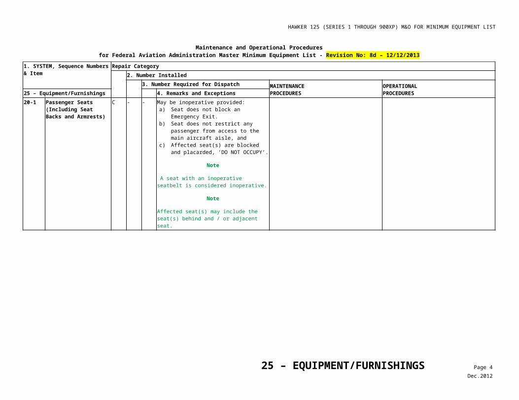
HAWKER 125 (SERIES 1 THROUGH 900XP) M&O FOR MINIMUM EQUIPMENT LIST
Maintenance and Operational Proceduresfor Federal Aviation Administration Master Minimum Equipment List - No: 8a - 08/01/2008
1. SYSTEM, Sequence Numbers & Item
Repair Category2. Number Installed
3. Number Required for Dispatch MAINTENANCEPROCEDURES
OPERATIONALPROCEDURES30 – Ice and Rain Protection 4. Remarks and Exceptions
C 1 0 May be inoperative provided airplane is not operated in known or forecast icing conditions.
Plan each flight to avoid known or forecast icing conditions along entire route including alternate destination.
10-4 ANTI-ICE LO PRESS Annunciator (Series 750, 800, 800XP, 850XP and 900XP Only)
C 1 0 (O) May be inoperative provided:a) Fluid delivery system is operative, andb) Quantity indication system is operative.
1. Confirm that TKS system is operative, and 2. Confirm that TKS quantity indication is
operative.
C 1 0 May be inoperative provided airplane is not operated in known or forecast icing conditions.
Plan each flight to avoid known or forecast icing conditions along entire route including alternate destination.
10-5 ANTI-ICE LO QTY Annunciator (Series 750, 800, 800XP, 850XP and 900XP Only)
C 1 0 (O) May be inoperative provided fluid quantity is verified adequate for each flight.
Prior to each departure, confirm fluid quantity adequate for intended and alternate flight path.
C 1 0 May be inoperative provided airplane is not operated in known or forecast icing conditions.
Plan each flight to avoid known or forecast icing conditions along entire route including alternate destination.
10-6 ***
Auxiliary TKS System D 1 0 (O) May be inoperative provided alternate procedures are established and used.
Plan flight for normal TKS fluid quantity only.
20-1 Engine Inlet Anti-icing Systems (TFE-731 Engined Aircraft, Only)
C 2 1 (O) One may be inoperative ON provided:a) Associated Engine Inlet Anti-Ice (ENG
A/ICE) Annunciator is operative when ENG ANTICE for that engine is selected,
b) Takeoff and Landing field temperatures do not exceed +10 ° C, and
c) Aircraft Flight Manual (AFM) Engine Anti-Ice ON Performance and Limitations are observed.
1. Select ENG A/ICE ON for affected engine and confirm normal annunciation.
2. Plan flight such that takeoff and landing temperature does not exceed 10° C for intended flight including alternates.
3. Use Anti-Ice ON takeoff and landing performance data.
4. Monitor engine ITT during flight.
30 – ICE AND RAIN PROTECTION Page 3Sep.2008
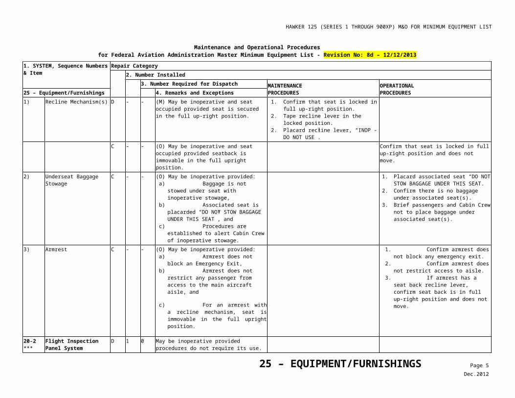
HAWKER 125 (SERIES 1 THROUGH 900XP) M&O FOR MINIMUM EQUIPMENT LIST
Maintenance and Operational Proceduresfor Federal Aviation Administration Master Minimum Equipment List - No: 8a - 08/01/2008
1. SYSTEM, Sequence Numbers & Item
Repair Category2. Number Installed
3. Number Required for Dispatch MAINTENANCEPROCEDURES
OPERATIONALPROCEDURES30 – Ice and Rain Protection 4. Remarks and Exceptions
C 2 1 (O) One may be inoperative provided: a) Airplane is not operated in visible moisture
or in known or forecast icing conditions, b) Takeoff and Landing field temperature do
not exceed +10 ° C, and c) AFM Engine Anti-Ice ON Performance and
Limitations are observed.
1. Plan flight to avoid visible moisture and known or forecast icing conditions for icing conditions for the intended flight including alternates.
2. Plan flight such that takeoff and landing temperature does not exceed 10° C for intended flight including alternates.
3. Use Anti-Ice ON takeoff and landing performance data.
4. Monitor engine Interstage Turbine Temperature (ITT) during flight.
C 2 1 (M) (O) One may be inoperative provided: a) Associated anti-ice valve is verified closed,
and b) Airplane is not operated in visible moisture
or in known or forecast icing conditions.
Warning
Do not reach inside engine lip with engine running.
With engine running, verify that inlet lip is not heated.
Plan flight to avoid visible moisture and known or forecast icing conditions for icing conditions for the intended flight including alternates.
20-2 Engine Inlet Anti-Ice Indicators/ Annunciators
C 2 1 (O) One may be inoperative provided: a) All power indicating instruments for
associated engine are operative, and b) Associated valve operates normally.
1. Confirm that all engine indicators operate normally.
2. Confirm that ITT EGT increases when anti-ice is selected ON.
20-3 MWS ‘ENG ICE PROT ON’ White Annunciator (Series 600 and 700, Only)
C 1 0 (O) May be inoperative provided: a) “ENG A/ICE” white annunciators on
overhead panel are verified operative, and b) Alternate procedures for determining
operation of Engine Anti-Ice are established and used.
1. With engines running, Select ENG ICE PROT ON and confirm ITT rise while selected and white annunciator lights in the overhead CG panel are on.
2. Select ENG ICE PROT OFF.
20-4 MWS “ICE PROT SELECTED” White Annunciator (Series 750, 800, 800XP, 850XP and 900XP only)
C 1 0 (O) May be inoperative provided “ENG A/ICE” amber annunciators are verified operative.
1. With the engine off and the ENG ANTICE ON confirm (amber) ENG A/ICE annunciator illuminates dim. After 2 seconds it should illuminate bright.
2. With the engine running and the ENG ANTICE ON confirm (amber) ENG A/ICE annunciator illuminates dim and then extinguishes as the air pressure rises.
30-1 Pitot Probe/Pitot Mast Heaters
B 2 1 (O) One may be inoperative provided: a) Flight is conducted in day VMC flight
conditions only, and b) Airplane is not operated in visible moisture,
or in known or forecast icing conditions.
1. Conduct flight in day VMC only, and 2. Avoid flight in visible moisture, and 3. Plan flight to avoid known or forecast icing
conditions along entire route including alternates.
30 – ICE AND RAIN PROTECTION Page 4Sep.2008
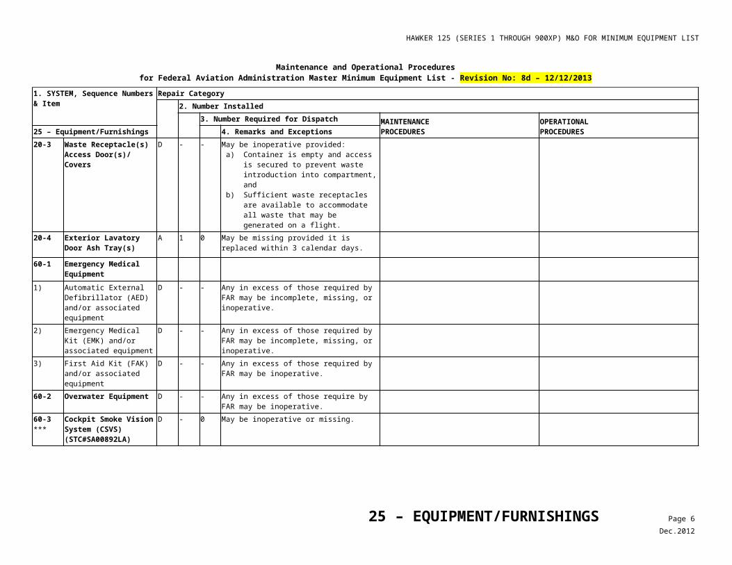
HAWKER 125 (SERIES 1 THROUGH 900XP) M&O FOR MINIMUM EQUIPMENT LIST
Maintenance and Operational Proceduresfor Federal Aviation Administration Master Minimum Equipment List - No: 8a - 08/01/2008
1. SYSTEM, Sequence Numbers & Item
Repair Category2. Number Installed
3. Number Required for Dispatch MAINTENANCEPROCEDURES
OPERATIONALPROCEDURES30 – Ice and Rain Protection 4. Remarks and Exceptions
Note
RVSM is not authorized.30-2 Pitot Ammeters (Series 1
Through 400 With SB 34-140, Or Mod. 252733 Installed, Only)
C 2 0 (O) May be inoperative provided: a) Pitot/Mast Heater Fail annunciators are
verified operative before each departure, and
b) Alternate procedures are established and used.
1. Briefly select PITOT HEAT ON and confirm pitot probe has heated for affected probe(s) prior to each departure.
2. Select L & R Pitot Heat OFF and confirm that PITOT HTR FAIL annunciator(s) is (are) operating.
3. Confirm that Pitot Heaters are on prior to each departure.
30-3 Pitot Ammeter & Selector (Series 600 and 700 With SB 34-140, Or Mod. 252733 Installed, Or 750, 800, 800XP, 850XP and 900XP Only)
C - 0 (O) May be inoperative provided Pitot/Mast Heater Fail Lights are confirmed to operate normally before each departure.
1. Select L & R Pitot Heat OFF and confirm that Pitot/Mast Heater Fail annunciator(s) is (are) operative.
2. Confirm Pitot Heaters are on prior to each departure.
30-4 Pitot/Mast Heater FAIL Light(s)/ Annunciator(s) (Series 1 Through 700 With SB 34-140, Or Mod. 252733 Installed, and 750, 800, 800XP, 850XP and 900XP Only)
B - 0 (O) May be inoperative provided: a) Associated Pitot Heating System is verified
operative before each departure, b) Associated Pitot Heat Ammeter is
operative, and c) Alternate procedures for monitoring Pitot
Heater function in icing conditions are established and used.
1. Select Pitot heat ON and check ammeter for normal current for both left and right Pitot Probes prior to each departure.
2. Monitor Pitot Heater Ammeter frequently when in icing conditions.
30-5 Static Plate Heaters (Series 700, if installed, 750, 800, 800XP, 850XP and 900XP Only)
B 2 1 (O) One may be inoperative provided: a) Enroute operations do not require
operation of both static plate heaters, b) Flight is conducted in day VMC flight
conditions only, and c) Airplane is not operated in visible moisture,
or in known or forecast icing conditions.
Note
RVSM is not authorized
1. Conduct flight in day VMC only, and 2. Avoid flight in visible moisture, and 3. Plan flight to avoid known or forecast icing
conditions along entire route including alternates.
4. Plan flight to avoid rush operations.
30-6 Stall Vane Heaters (Series 750, 800, 800XP, 850XP and 900XP Only)
B 2 1 (O) One may be inoperative provided: a) VANE HTR FAIL Annunciator for operative
Stall Vane Heater is operative, b) Flight is conducted in day VMC flight
conditions only, and c) Airplane is not operated in visible or
1. Confirm VANE HTR FAIL Annunciator for operative Stall Vane Heater is operative.
2. Conduct flight in day VMC only, and 3. Avoid flight in visible moisture, and 4. Plan flight to avoid known or forecast icing
conditions along entire route including
30 – ICE AND RAIN PROTECTION Page 5Sep.2008
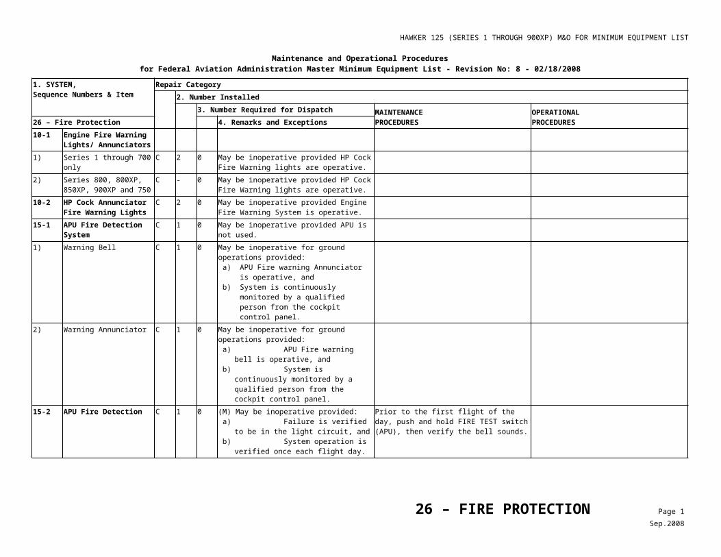
HAWKER 125 (SERIES 1 THROUGH 900XP) M&O FOR MINIMUM EQUIPMENT LIST
Maintenance and Operational Proceduresfor Federal Aviation Administration Master Minimum Equipment List - No: 8a - 08/01/2008
1. SYSTEM, Sequence Numbers & Item
Repair Category2. Number Installed
3. Number Required for Dispatch MAINTENANCEPROCEDURES
OPERATIONALPROCEDURES30 – Ice and Rain Protection 4. Remarks and Exceptions
forecast icing conditions. alternates.30-7 L and R VANE HTR FAIL
Annunciators (Series 750, 800, 800XP, 850XP and 900XP Only)
B 2 1 (O) One may be inoperative provided: a) Both Stall Vane Heaters are verified
operative before each departure, b) Flight is conducted in day VMC conditions,
only, and c) Airplane is not operated in visible moisture,
or in known or forecast icing conditions.
1. Prior to each departure, using caution to avoid burns, confirm that both vane heaters are operative, and
2. Plan flight to be performed in day VMC conditions only, and
3. Avoid flight in visible moisture and known or forecast icing conditions.
40-1 Windscreen Heating System
1) Series 1 Through 700 Series Only
C 2 0 (O) May be inoperative provided: a) Airplane is operated in accordance with
AFM Limitations, and b) Windscreen fluid de-icing system is
installed and operative.
1. Refer to Bird Strike Speed in AFM Limitations for temperature and speed limitations.
2. Confirm normal operation of the windscreen de-icing system.
C 2 0 (O) May be inoperative provided: a) Airplane is operated in accordance with
AFM Limitations, and b) Airplane is not operated in known or
forecast icing conditions.
1. Refer to Bird Strike Speed in AFM Limitations for temperature and speed limitations.
2. Plan flight to avoid known or forecast icing conditions along entire route including alternates.
2) Series 750, 800, 800XP, 850XP and 900XP Only
C 4 3 Heating to one side screen “B” only may be inoperative.
C 4 2 (O) Both “B” screens may be inoperative provided airplane is not operated in known or forecast icing conditions.
Plan flight to avoid known or forecast icing conditions along entire route including alternates.
C 4 0 (O) May be inoperative provided: a) Airplane is operated in accordance with
AFM Limitations, and b) Airplane is not operated in known or
forecast icing conditions.
1. Refer to Bird Strike Speed in AFM Limitations for temperature and speed limitations.
2. Plan flight to avoid known or forecast icing conditions along entire route including alternates.
40-2 Windscreen Overheat Lights/ Annunciators
C - 0 May be inoperative provided: a) Affected windscreen heat system in not
used, b) Airplane is not operated in known or
forecast icing conditions, and c) AFM take-off temperature and airspeed
limitations are observed.40-3 Windscreen Wiper
Systems (Series 1 C 2 0 May be inoperative provided airplane is not
operated in precipitation within 5 nautical miles
30 – ICE AND RAIN PROTECTION Page 6Sep.2008
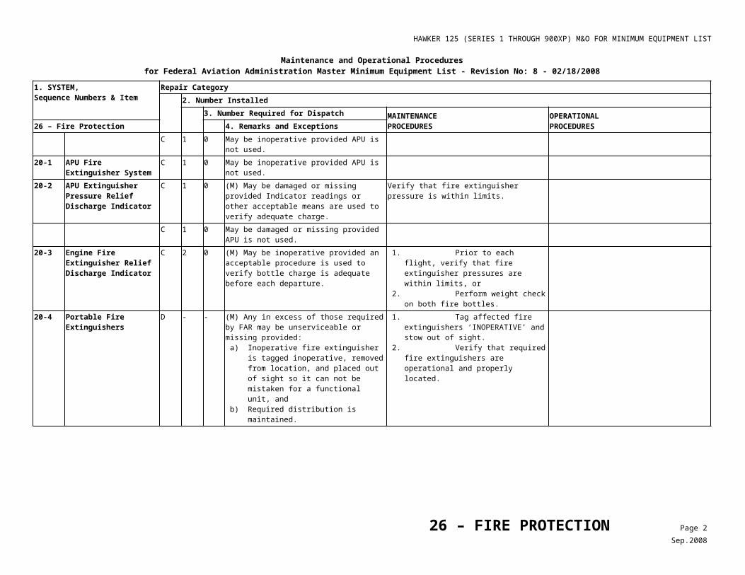
HAWKER 125 (SERIES 1 THROUGH 900XP) M&O FOR MINIMUM EQUIPMENT LIST
Maintenance and Operational Proceduresfor Federal Aviation Administration Master Minimum Equipment List - No: 8a - 08/01/2008
1. SYSTEM, Sequence Numbers & Item
Repair Category2. Number Installed
3. Number Required for Dispatch MAINTENANCEPROCEDURES
OPERATIONALPROCEDURES30 – Ice and Rain Protection 4. Remarks and Exceptions
Through 700 Only) of the airport of takeoff or intended landing.1) Park and Slow Speed
FunctionC - 0 May be inoperative without an operational
restriction provided blade(s) can be positioned in a location that will not obstruct forward vision.
80-1 Ice Detection System C 1 0 (O) May be inoperative provided: a) Airplane is not operated at night, and b) Alternate procedures are established and
used for detection of icing and activation of airplane anti-icing equipment.
1. Conduct flight in day only, and 2. Avoid flight in visible moisture, and 3. Activate anti-icing systems when near or in
visible moisture below 40° F OAT.
30 – ICE AND RAIN PROTECTION Page 7Sep.2008
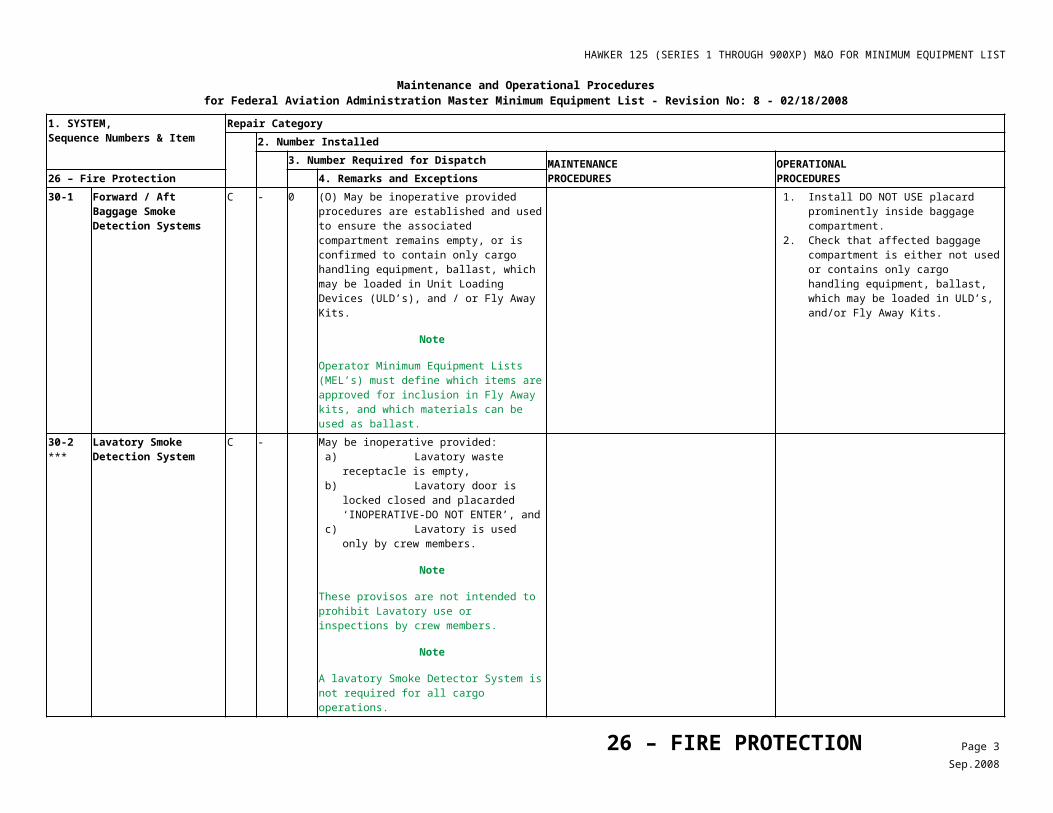
HAWKER 125 (SERIES 1 THROUGH 900XP) M&O FOR MINIMUM EQUIPMENT LIST
Maintenance and Operational Proceduresfor Federal Aviation Administration Master Minimum Equipment List - No: 7 - 09/07/2007
1. SYSTEM, Sequence Numbers & Item
Repair Category2. Number Installed
3. Number Required for Dispatch MAINTENANCEPROCEDURES
OPERATIONALPROCEDURES31 – Indicating/Recording Systems 4. Remarks and Exceptions
20-1 Clocks C - 1 As required by FAR.30-1 Flight Data Recorder
(FDR) SystemD - - Any in excess of those required by FAR may be
inoperative.A - 0 May be inoperative provided:
a) Cockpit Voice Recorder (CVR), is operative,
b) Airplane is not dispatched from a designated airport as listed in the operator’s MEL unless:• The FDR failure occurs after
pushback but before takeoff, or• FDR repair was attempted but was
not successful. c) In those cases where repair is attempted
but not successful, the aircraft may be dispatched on a flight or series of flight until the next designated airport where repair must be accomplished before dispatch, and
d) Repairs are made within three flight days.1) FDR Recording Parameters
Required by FARA - - May be inoperative provided:
a) Cockpit Voice Recorder operates normally, and
b) Repairs are made within 20 calendar days. 2) FDR Recording Parameters
Not required by FARA - - May be inoperative provided repairs are made
prior to the completion of the next heavy maintenance visit.
(Aircraft operated by other than Air Carrier or Commercial Operator certificate holder)
A - 0 May be inoperative provided repairs are made in accordance with applicable FAR’s.
40-1 ***
Flight Hour Meter C 1 0 (O) May be inoperative provided alternate procedures are established and used.
Record total flight time and flight cycles per flight in aircraft records.
50-1 Dual Filament Annunciator(s)
1) Filament C - - One filament in each annunciator may be inoperative.
60-1 Transfer/Reversion Switch Lights (Collins Pro Line 21)
31 – INDICATING/RECORDING SYSTEMS Page 1Nov.2007
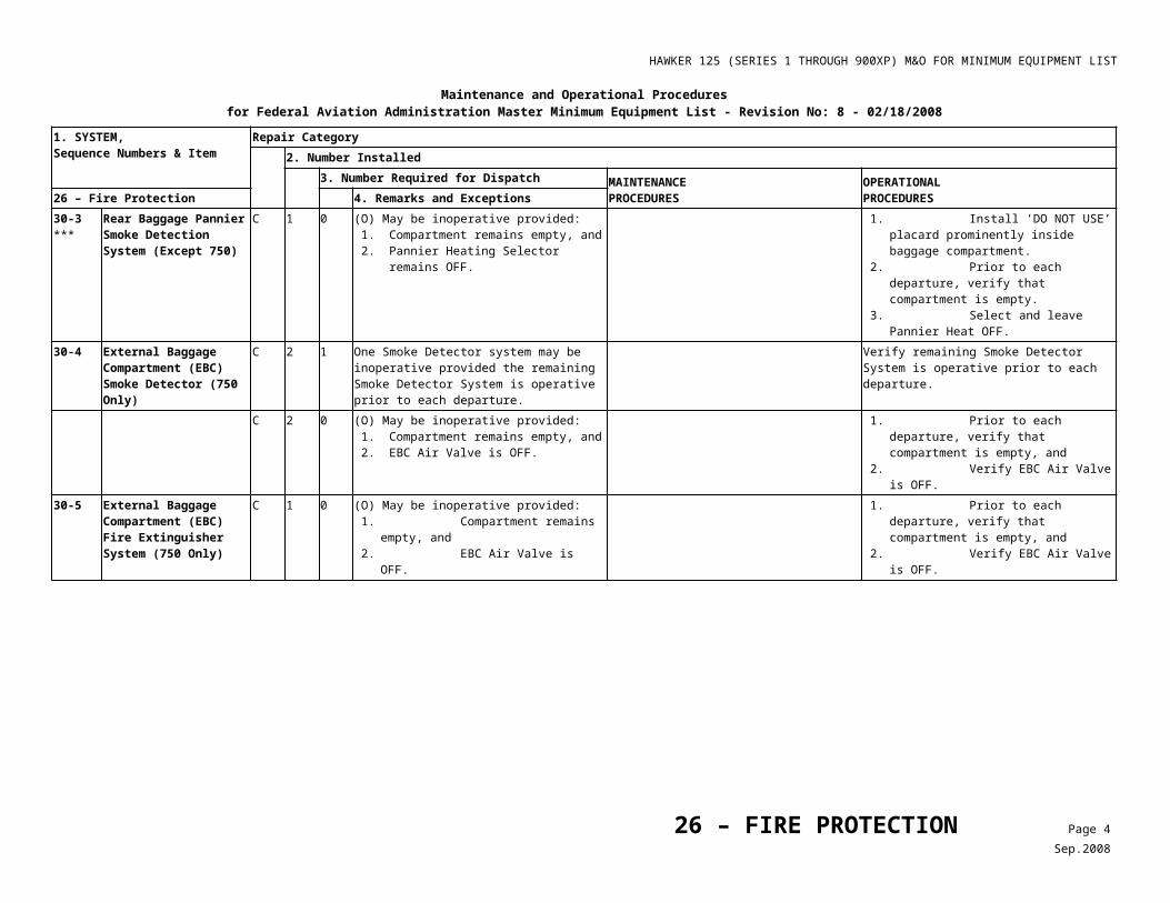
HAWKER 125 (SERIES 1 THROUGH 900XP) M&O FOR MINIMUM EQUIPMENT LIST
Maintenance and Operational Proceduresfor Federal Aviation Administration Master Minimum Equipment List - No: 7 - 09/07/2007
1. SYSTEM, Sequence Numbers & Item
Repair Category2. Number Installed
3. Number Required for Dispatch MAINTENANCEPROCEDURES
OPERATIONALPROCEDURES31 – Indicating/Recording Systems 4. Remarks and Exceptions
1) CDU REV Transfer Switch Lights
C 4 0 Switch backlight and switch annunciation lights, left and right, may be inoperative provided switch operates normally.
2) PFD REV Transfer Switch Lights
C 4 0 Switch backlight and switch annunciation lights, left and right, may be inoperative provided switch operates normally.
3) Multifunction Display Reversion (MFD REV) Transfer Switch Lights
C 4 0 Switch backlight and switch annunciation lights, left and right, may be inoperative provided switch operates normally.
4) Right (R) Primary Flight Display (PFD) Engine (ENG) SELECT Switch Lights
C 2 0 Switch backlight and switch annunciation lights may be inoperative provided switch operates normally.
31 – INDICATING/RECORDING SYSTEMS Page 2Nov.2007
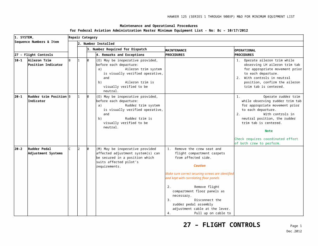
HAWKER 125 (SERIES 1 THROUGH 900XP) M&O FOR MINIMUM EQUIPMENT LIST
Maintenance and Operational Proceduresfor Federal Aviation Administration Master Minimum Equipment List - No: 7 - 09/07/2007
1. SYSTEM, Sequence Numbers & Item
Repair Category2. Number Installed
3. Number Required for Dispatch MAINTENANCEPROCEDURES
OPERATIONALPROCEDURES32 - LANDING GEAR 4. Remarks and Exceptions
32-1 Main Landing Gear Door Latch Springs
D 2 0
40-1 Maxaret Unit (Anti-Skid System)
Deleted, Rev. 3.
60-1 Gear Down and Locked Indicators
1) Primary Indicators B 3 2 (O) One indicator may be inoperative provided all standby indicators operate normally.
Confirm all standby indicators are normal.
2) Standby Indicators B 3 2 (O) One indicator may be inoperative provided all primary indicators operate normally.
Confirm all primary indicators are normal.
60-2 Gear Unlocked Indications
Deleted, Revision 6. Relief already provided for in item 31-50-1.
32 – LANDING GEAR Page 1Nov.2007
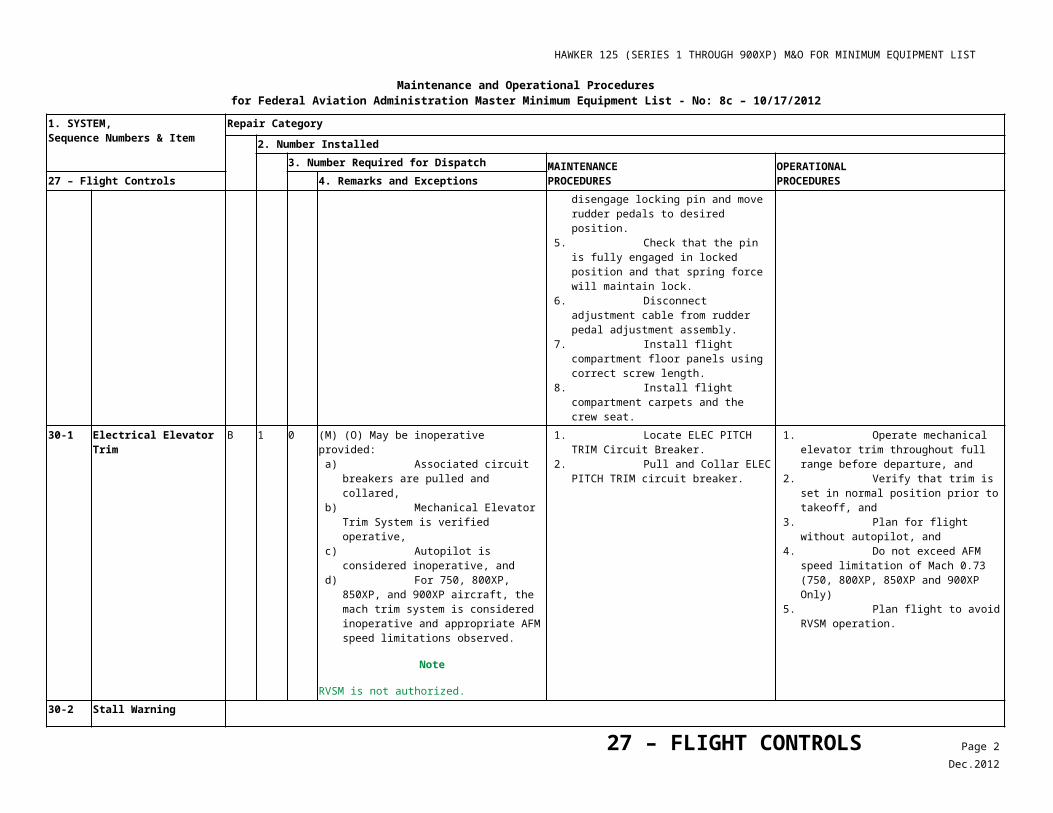
HAWKER 125 (SERIES 1 THROUGH 900XP) M&O FOR MINIMUM EQUIPMENT LIST
Maintenance and Operational Proceduresfor Federal Aviation Administration Master Minimum Equipment List - No: 8a - 08/01/2008
1. SYSTEM, Sequence Numbers & Item
Repair Category2. Number Installed
3. Number Required for Dispatch MAINTENANCEPROCEDURES
OPERATIONALPROCEDURES33 – LIGHTS 4. Remarks and Exceptions
10-1 Cockpit/Flight Deck/Flight Compartment and Instrument Lighting Systems
C - - Individual lights may be inoperative provided remaining lights are: a) Sufficient to clearly illuminate all required
instruments, controls, and devices for which they are intended,
b) Positioned so that direct rays are shielded from flight crew members’ eyes, and
c) Lighting configuration and intensity is acceptable to the flightier.
10-2 CAGS Warning Light Systems (Series 1 Though 400 Only)
C 2 1 One flasher may be inoperative provided all remaining system-warning lights are operative.
Note
Not required for inoperative systems.
10-3 Master Warning Light Systems (Series 600 Through 850XP Only)
C 2 1 One flasher may be inoperative provided all remaining system-warning lights are operative.
Note
Not required for inoperative systems.
20-1 Cabin Interior Light System
C - - (O) Individual lights may be inoperative provided: a) Cabin Emergency Lighting is operative. b) Sufficient Lighting is available for crew to
perform required duties, and c) Sufficient Lighting is available for
passenger carrying operations at night.
Note
Not required for cargo operations.
Note
Cabin emergency lighting does not include floor proximity lights.
1. Select Cabin Emergency lighting and confirm it is operative.
2. Confirm Sufficient Lighting for crew to perform required duties, and
3. Confirm Sufficient Lighting for passenger carrying operations at night.
Note
Turn off all electrical power after Emergency Lighting check to reset the Emergency Lighting System.
33 –LIGHTS Page 1Sep.2008
HAWKER 125 (SERIES 1 THROUGH 900XP) M&O FOR MINIMUM EQUIPMENT LIST
Maintenance and Operational Proceduresfor Federal Aviation Administration Master Minimum Equipment List - No: 8a - 08/01/2008
1. SYSTEM, Sequence Numbers & Item
Repair Category2. Number Installed
3. Number Required for Dispatch MAINTENANCEPROCEDURES
OPERATIONALPROCEDURES33 – LIGHTS 4. Remarks and Exceptions
20-2 Passenger Notice System (“No Smoking Fasten Seat Belt/Return to Cabin”) Signs
C - 0 (O) May be inoperative and associated passenger seat(s) occupied provided: a) PA System is operative, and b) PA System is used to notify passengers
when seat belts should be fastened and smoking is prohibited.
1. Confirm PA system is operative, and 2. Use PA system to notify passengers when:
²To fasten seat belts and² Smoking is prohibited.
C - 0 (O) May be inoperative provided alternate procedures are established and used to notify passengers when seat belts should be fastened, and smoking is prohibited.
Prior to flight, brief passengers how they will be informed: 1. When to fasten seat belts, and 2. When smoking is prohibited.
20-3 EMERG LTS NOT SEL/EMER LTS NOT SLCT Annunciator
C 1 0 (O) May be inoperative provided, before each departure: a) Passenger cabin emergency lighting
system is verified operative, and b) Flight crew ensures the INTERIOR
LIGHTS EMERG switch is ARMED.
1. Select Cabin Emergency lighting and confirm it is operative.
Note
Turn off all electrical power after Emergency Lighting check to reset the Emergency Lighting System.
2. Confirm EMERG LIGHTS switch is ARMED prior to each departure.
30-1 ***
Wheel Well Lighting System
C - 0
30-2 ***
Rear Equipment Bay Lighting
C - 0
30-3 ***
Pannier Lighting System (Except 750)
D 1 0
30-4 External Baggage Compartment (EBC) Lighting System (750 Only)
D 1 0
40-1 Anti-Collision Beacons
33 –LIGHTS Page 2Sep.2008
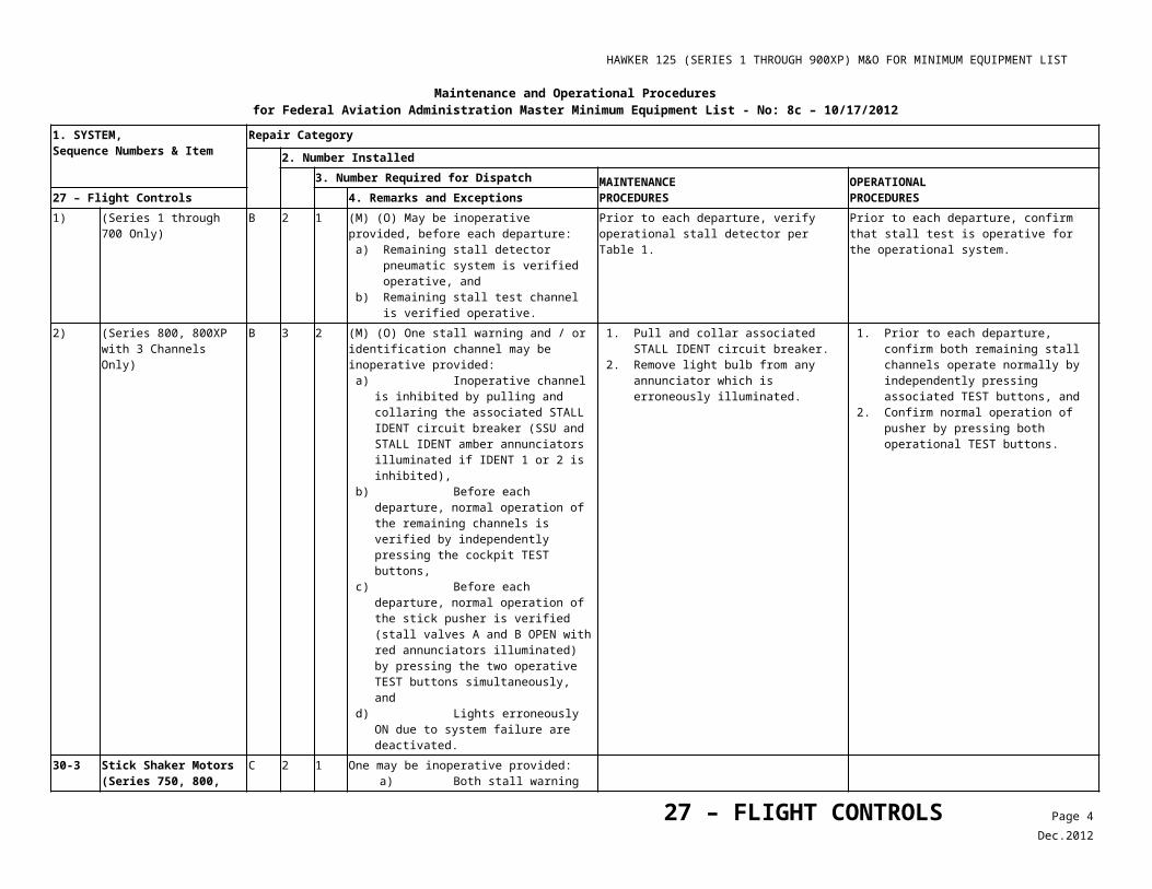
HAWKER 125 (SERIES 1 THROUGH 900XP) M&O FOR MINIMUM EQUIPMENT LIST
Maintenance and Operational Proceduresfor Federal Aviation Administration Master Minimum Equipment List - No: 8a - 08/01/2008
1. SYSTEM, Sequence Numbers & Item
Repair Category2. Number Installed
3. Number Required for Dispatch MAINTENANCEPROCEDURES
OPERATIONALPROCEDURES33 – LIGHTS 4. Remarks and Exceptions
1) Fuselage/Vertical Fin C 2 0 May be inoperative provided Wing/ Tail white strobe lights are operative and used.
C 2 0 May be inoperative for day operations.2) Wing/Tail White Strobe
LightsC - 0 May be inoperative provided Fuselage/Vertical
Fin Anti-Collision Beacons are operative.C - 0 May be inoperative for day operations.
40-2 Landing Lights C 2 1 One may be inoperative provided adjacent taxi light is operative.
C 2 0 May be inoperative for day operations.40-3 Taxi Lights (Wing
Mounted)C 2 0 (O) May be inoperative provided both landing
lights are operative.Confirm that both landing lights are operative.
C 2 0 May be inoperative for day operations. Limit operations to daylight hours.C 2 0 (O) May be inoperative provided nose taxi lights
are operative.Confirm that both nose taxi lights are operative.
40-4 Position Lights (Navigation) (Except aircraft with Hawker Winglets)
C - 3 May be inoperative provided the following minimum Position Lights are operative: a) One stationary red wing tip light, b) One stationary green wing tip light, and c) One stationary white taillight.
(Hawker Winglet Aircraft with Light Emitting Diode (LED) Wing tip Lights)
C - 5 One stationary white taillight may be inoperative.
Note
All LED’s in both position lights in each winglet must be operative for night operations.
(All Models) C - 0 May be inoperative for day operations.1) Stationary White Tail
Light(s) (all models)C - 0 May be inoperative provided an operative white
strobe light is located in close proximity to the inoperative white position light.
40-5 Wing Ice Light(s) C - 1
33 –LIGHTS Page 3Sep.2008
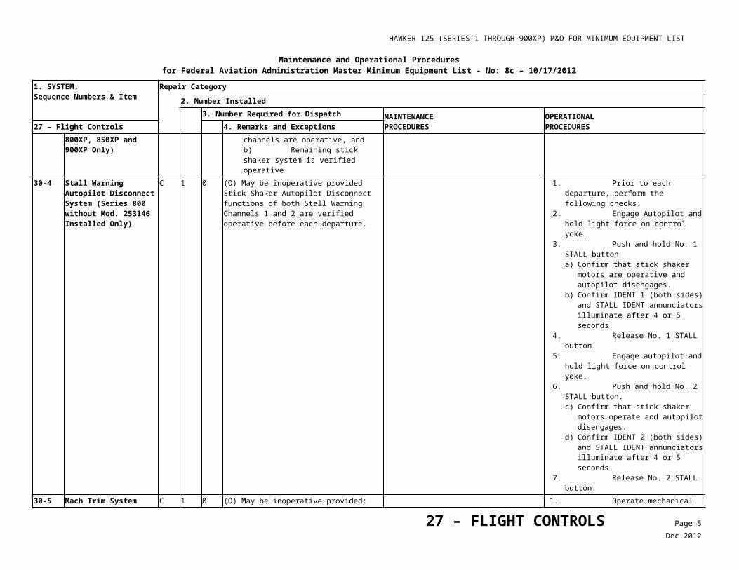
HAWKER 125 (SERIES 1 THROUGH 900XP) M&O FOR MINIMUM EQUIPMENT LIST
Maintenance and Operational Proceduresfor Federal Aviation Administration Master Minimum Equipment List - No: 8a - 08/01/2008
1. SYSTEM, Sequence Numbers & Item
Repair Category2. Number Installed
3. Number Required for Dispatch MAINTENANCEPROCEDURES
OPERATIONALPROCEDURES33 – LIGHTS 4. Remarks and Exceptions
C - 0 May be inoperative for day operations.C - 0 May be inoperative provided:
a) Ice Detector System is installed and operative, and
b) Ground deicing procedures do not require their use.
40-6 ***
Logo Lights D - 0
40-7 ***
Nose Taxi Lights C - 0
40-8 ***
Pulselite® System D 1 0 (M) May be inoperative provided system is deactivated.
1. Open the nose cone. 2. Locate the Pulselite® Control Unit.
Disconnect the Control Unit connectors. 3. Cap and stow the connectors. 4. Pull and collar the Pulselite circuit breaker. 5. Install an ‘INOP’ placard adjacent to the
Beacon (BCN)/Pulse position on Beacon/Pulselite® switch in overhead control panel ’CG’.
40-9 ***
Wing Tip Taxi Lighting System
D 1 0
40-10 ***
Weight on Wheels Switch (Automatic Dim Function On Landing)
D 1 0
50-1 Cabin Emergency Lighting System
C 1 0 May be inoperative for all cargo operations and operation without passengers.
INCANDESCENT LIGHT SYSTEM
1) Entryway Floor Lighting (Aft Base Crew Cabinet)
C 1 0 May be inoperative provided both adjacent cabin aisle lights are operative.
2) Exterior Emergency Lights (Over/Under RH wing)
C 2 0 May be inoperative for Day operation.
LED LIGHT SYSTEM
33 –LIGHTS Page 4Sep.2008
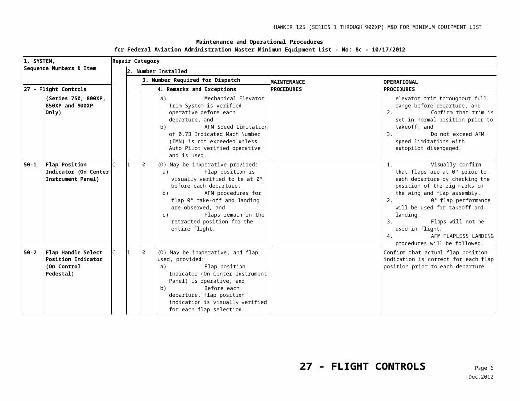
HAWKER 125 (SERIES 1 THROUGH 900XP) M&O FOR MINIMUM EQUIPMENT LIST
Maintenance and Operational Proceduresfor Federal Aviation Administration Master Minimum Equipment List - No: 8a - 08/01/2008
1. SYSTEM, Sequence Numbers & Item
Repair Category2. Number Installed
3. Number Required for Dispatch MAINTENANCEPROCEDURES
OPERATIONALPROCEDURES33 – LIGHTS 4. Remarks and Exceptions
1) LH FWD Reading/ Table Lights
C 3 1 Any two may be inoperative.
2) RH FWD Reading/ Table Lights
C 3 2 Any one may be inoperative.
3) LH Aft Reading/ Table Lights
C - 1 Any may be inoperative provided one remains operative.
4) RH Aft Reading/ Table Lights
C 2 1 Any one may be inoperative.
50-2 ***
Floor Proximity Lighting System
C - - May be inoperative provided light is not part of Emergency Lighting System.
33 –LIGHTS Page 5Sep.2008
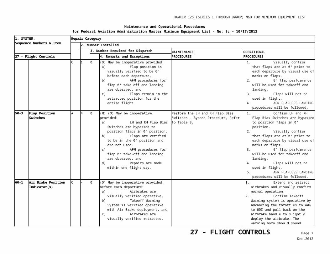
HAWKER 125 (SERIES 1 THROUGH 900XP) M&O FOR MINIMUM EQUIPMENT LIST
Maintenance and Operational Proceduresfor Federal Aviation Administration Master Minimum Equipment List - No: 8c – 10/17/2012
1. SYSTEM, Sequence Numbers & Item
Repair Category2. Number Installed
3. Number Required for Dispatch MAINTENANCEPROCEDURES
OPERATIONALPROCEDURES34 – NAVIGATION 4. Remarks and Exceptions
9-1 Mach Indications1) Non-EFIS Equipped Aircraft C 2 1 One Mach indicator may be inoperative
provided VMO/MMO aural warning is operative.C 2 0 (O) May be inoperative provided:
a) Flight remains at or below FL 295, and b) A placard which sets forth this limitation is
affixed to the instrument panel.
1. Do not exceed FL 295. 2. Affix a placard with this limitation on the
instrument panel.
2) EFIS Equipped Aircraft C 2 1 One may be inoperative provided: a) EFIS Airspeed Tape displays are installed
at each pilot station and are operative, b) One Mach/Airspeed warning system is
operative, and c) VMO/MMO aural warning system is
operative.C 2 0 (O) May be inoperative provided:
a) Flight remains at or below FL 295, and b) A placard which sets forth this limitation is
affixed to the instrument panel.
1. Place a placard MAX FL 295 on the instrument panel.
2. Plan flights at or below FL 295.
9-2 ***
SAT/TAT Indicating System
C - 0 (O) May be inoperative provided: a) Outside air temperature (OAT) indicator is
operative, and b) Flight Management System (FMS) (if
installed) is operative.
Table Confirm OAT indicator is operative, and
Table Confirm FMS (if installed) is operative.
9-3 ***
True Airspeed (TAS)/Indicating System
C - 0
9-4 ***
RMI/BDI Indicators C - 1 One indicating system may be inoperative provided one independent compass-heading indicator is available at each pilot’s station.
9-5 Non-Stabilized Magnetic Compass (Standby)
B 1 0 May be inoperative provided any combination of three gyro or INS (IRU) stabilized compass systems are operative.
34 – NAVIGATION Page 1Dec.2012
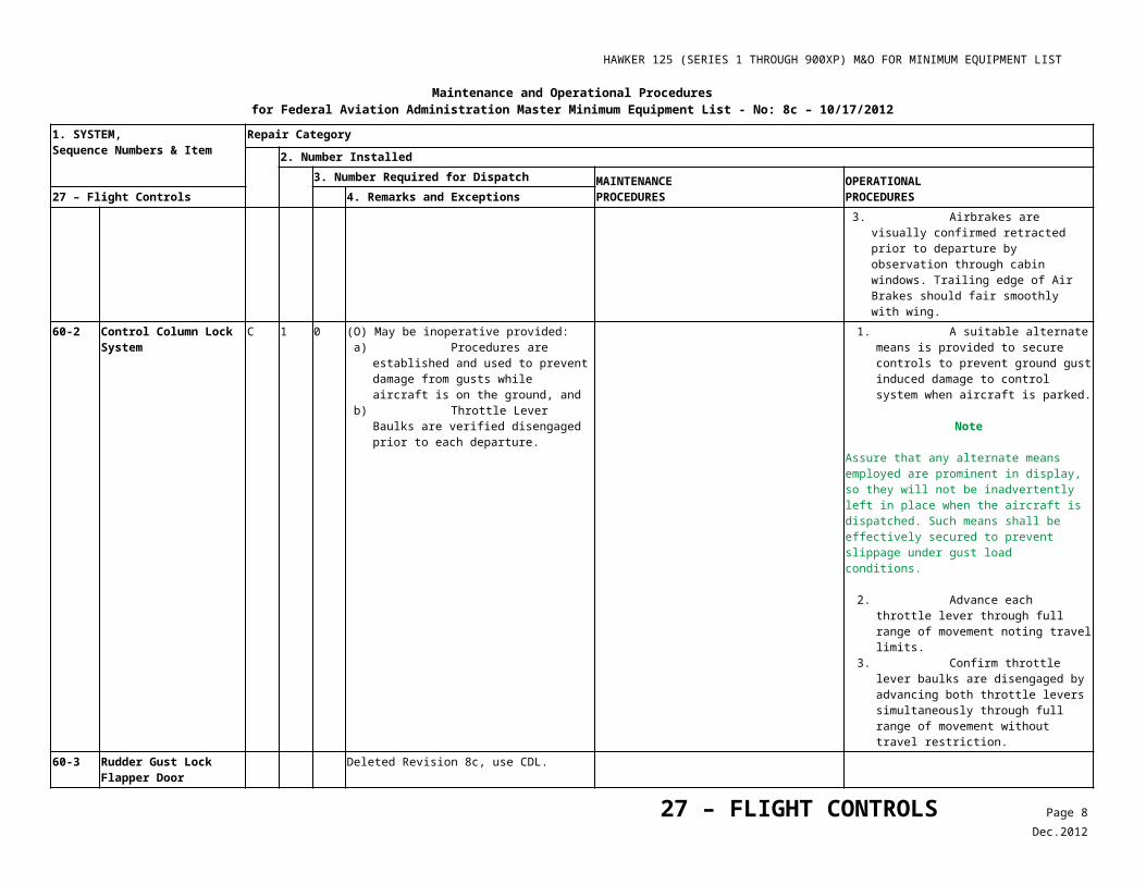
HAWKER 125 (SERIES 1 THROUGH 900XP) M&O FOR MINIMUM EQUIPMENT LIST
Maintenance and Operational Proceduresfor Federal Aviation Administration Master Minimum Equipment List - No: 8c – 10/17/2012
1. SYSTEM, Sequence Numbers & Item
Repair Category2. Number Installed
3. Number Required for Dispatch MAINTENANCEPROCEDURES
OPERATIONALPROCEDURES34 – NAVIGATION 4. Remarks and Exceptions
B 1 0 (O) May be inoperative provided: a) Any combination of two gyro OR INS (IRU)
stabilized compass systems are operative, and
b) Airplane is operated with dual independent navigation capability and under positive radar control by ATC, on the enroute portion of the flight.
1. Confirm any combination of three gyro or INS (IRU) stabilized compass systems are operative, OR
2. Confirm any combination of two gyro or INS (IRU) stabilized compass systems are operative, and
3. Airplane is operated with dual independent navigation systems, and
4. Airplane is operated under positive enroute ATC RADAR control.
B 1 0 (O) May be inoperative for flights that are entirely within areas of magnetic unreliability provided at least two stabilized directional gyro systems are operative and used in conjunction with approved free gyro navigation techniques.
Flights that are entirely within areas of magnetic unreliability may be flown provided at least two stabilized directional gyro systems are operative and used in conjunction with approved free gyro navigation techniques.
10-1 VMO/MMO Aural Warnings
B 2 1
B 2 0 (O) May be inoperative provided: a) Both Mach/Airspeed indicators at both pilot
positions are operative, b) If installed, Ventral Tank is either empty or
EMPTY/FULL indicator is operative, and c) VMO/MMO Aircraft Flight Manual (AFM)
limitations are observed.
1. For air data computer driven indicators, confirm that both left and right Mach/Airspeed indicators are not flagged, and
2. For aircraft equipped with Ventral Fuel Tank, tank must either not be filled or EMPTY/ FULL indicator must be verified operative.
3. Observe AFM VMO/MMO limitations.10-2 Altitude Alerting System A - 0 (O) May be inoperative provided:
a) Autopilot with altitude capture and altitude hold is operative,
b) Enroute operations do not require its use, and
c) Repairs are made within three flight days.
Note
RVSM is not authorized.
1. Autopilot with altitude capture and altitude hold is operative.
2. Flight planning must avoid use of RVSM airspace.
1) Aural Alert C - 0 May be inoperative provided:Visual alert is operative, andAutopilot with altitude capture and hold is operative.
34 – NAVIGATION Page 2Dec.2012
HAWKER 125 (SERIES 1 THROUGH 900XP) M&O FOR MINIMUM EQUIPMENT LIST
Maintenance and Operational Proceduresfor Federal Aviation Administration Master Minimum Equipment List - No: 8c – 10/17/2012
1. SYSTEM, Sequence Numbers & Item
Repair Category2. Number Installed
3. Number Required for Dispatch MAINTENANCEPROCEDURES
OPERATIONALPROCEDURES34 – NAVIGATION 4. Remarks and Exceptions
2) Visual Alert C - 0 May be inoperative provided:Aural alert is operative, andAutopilot with altitude capture and hold is operative.
10-3 Altimeter Vibrators1) Servo Pneumatic C 2 1 One may be inoperative provided associated air
data computer is operative.2) Pneumatic C 2 1 One may be inoperative provided VMC exists at
departure and arrival airports.3) One Pneumatic and One
Servo PneumaticC 2 1 Servo Pneumatic may be inoperative provided:
a) Associated air data computer is operative, and
b) VMC exists at departure and arrival airports.
4) Standby Altimeter Vibrator (With Electric Altimeters Installed)
C 1 0 May be inoperative provided VMC exist at both departure and arrival airports.
10-4 Standby Altimeter Incorporated into Item 34-20-9. Revision 6.10-5 Altimeter Static Error
Correction Module Deleted, Revision 7
10-6 Outside Air Temperature (OAT) Indicator
C - 0 (O) May be inoperative provided alternate temperature indicating system (True Air Temperature (TAT) or Static Air Temperature (SAT)) is operative and used.
Use the TAT/SAT indicator or the Air Data page in the FMS for Temperature indications.
10-8 Air Data Computer (ADC) Changeover/ Reversion Switches
C 2 0 (O) May be inoperative provided:a) Associated instruments are operative from
independent sources, andb) Inoperative switches are not moved during
flight.
1. Associated instruments are operative from independent sources, and
2. Inoperative switches are placarded Inoperative (‘INOP’) and not moved during flight.
3. Confirm the both ADC’s are providing information to their respective sides (not cross transferred) and in the event of an ADC failure, the pilot with the operating instruments will become the flying pilot. No attempt to cross-transfer data should be made.
34 – NAVIGATION Page 3Dec.2012
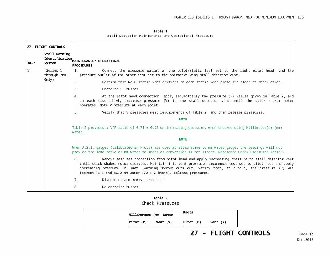
HAWKER 125 (SERIES 1 THROUGH 900XP) M&O FOR MINIMUM EQUIPMENT LIST
Maintenance and Operational Proceduresfor Federal Aviation Administration Master Minimum Equipment List - No: 8c – 10/17/2012
1. SYSTEM, Sequence Numbers & Item
Repair Category2. Number Installed
3. Number Required for Dispatch MAINTENANCEPROCEDURES
OPERATIONALPROCEDURES34 – NAVIGATION 4. Remarks and Exceptions
1) ADC Reversion Switch Lights (Honeywell)
C 6 0 (O) Switch backlight and annunciation, left and right, may be inoperative provided associated annunciation on the PFD is operative.
Confirm PFD annunciation each time affected switch is moved.
2) ADC REV Transfer Switch Lights (Pro Line 21)
C 4 0 (O) Switch backlight and annunciation, left and right, may be inoperative provided associated annunciation on the PFD is operative.
Confirm PFD annunciation each time affected switch is moved.
10-9 Vertical Speed Indicator B 2 1 One may be inoperative for day VMC flight only.20 Altimeter Vibrators Incorporated into item 10-3, Rev 3.20-1 Flight Director System(s)1) Aircraft Equipped With
Honeywell AvionicsC 2 1 One may be inoperative provided approach
minimums do not require its use.B 2 0 May be inoperative provided:
a) Auto Pilot is considered inoperative, and b) Approach minimums do not require their
use.
Note
RVSM is not authorized. 2) Aircraft Equipped With
Collins AvionicsB 2 0 May be inoperative provided:
a) Auto Pilot is considered inoperative, andb) Approach minimums do not require their
use.
Note
With Collins Pro Line-equipped aircraft, the A/P cannot be engaged unless both Flight Director Systems are operative.
Note
RVSM is not authorized. 20-2 Turn and Bank Indication
34 – NAVIGATION Page 4Dec.2012
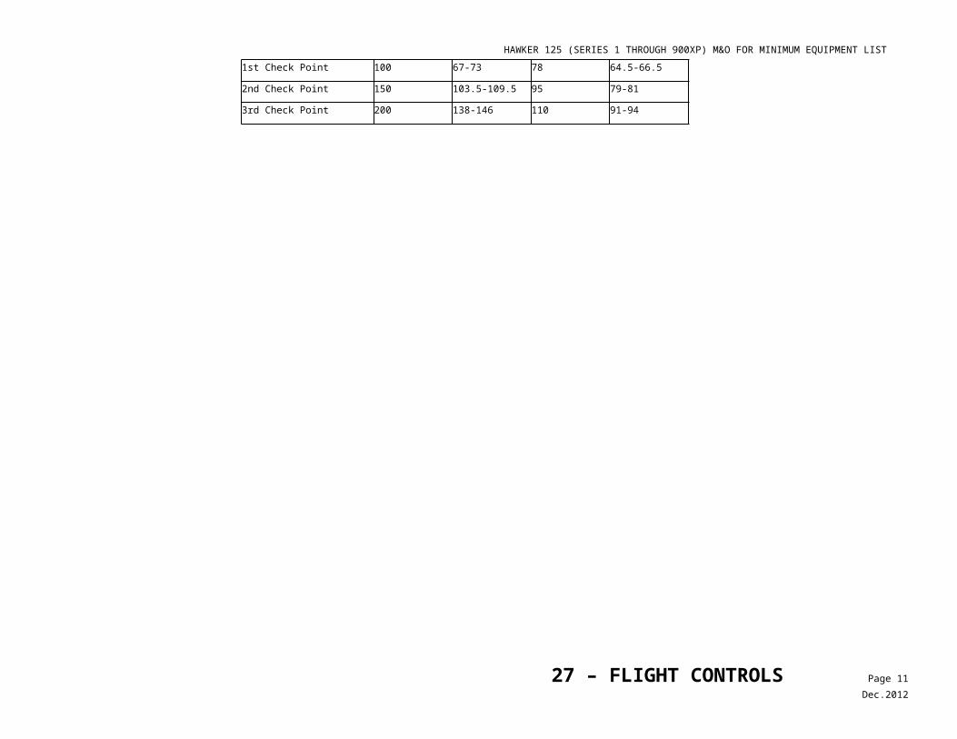
HAWKER 125 (SERIES 1 THROUGH 900XP) M&O FOR MINIMUM EQUIPMENT LIST
Maintenance and Operational Proceduresfor Federal Aviation Administration Master Minimum Equipment List - No: 8c – 10/17/2012
1. SYSTEM, Sequence Numbers & Item
Repair Category2. Number Installed
3. Number Required for Dispatch MAINTENANCEPROCEDURES
OPERATIONALPROCEDURES34 – NAVIGATION 4. Remarks and Exceptions
1) Rate of Turn Indication C - 1 Turn function of one instrument may be inoperative provided flight is conducted in VMC conditions only.
C - 0 May be inoperative provided standby attitude indicator is operative.
20-3 Attitude Heading Reference System (AHRS) / Inertial Reference System (IRS)
1) Primary AHRS/IRS B 2 1 (O) One may be inoperative provided:a) Standby attitude reference system is
selected and verified operative,b) AFM limitations are observed, andc) Autopilot (A/P) is not used.
1. Select and confirm operation of Standby Attitude Reference System.
2. Autopilot is not used.
2) Standby AHRS/ IRS C 1 0 (O) May be inoperative provided both primary AHRS/IRS systems are verified operative.
Select and confirm Primary Attitude Reference System.
20-4 Compass and Attitude/AHRS Changeover/ Reversion Switches
C 2 0 (O) May be inoperative provided:a) Associated instruments are operative from
independent sources, andb) Inoperative switches are not moved during
flight.
1. Confirm associated instruments are operative from independent sources, and
2. Inoperative switches are placarded ‘INOP’ and not moved during flight.
3. Confirm the switch is not in the cross transfer position, and in the event of an AHRS failure the pilot with the operative instruments will be the flying pilot. No attempt should be made to cross transfer data.
1) AHRS Reversion Switch Lights (Honeywell)
C 6 0 (O) Switch backlight and annunciation, left and right, may be inoperative provided associated annunciation on the PFD is operative.
Confirm PFD annunciation each time affected switch is moved.
2) AHS REV Transfer Switch Lights(Pro Line 21)
C 4 0 (O) Switch backlight and annunciation, left and right, may be inoperative provided associated annunciation on the PFD is operative.
Confirm PFD annunciation each time affected switch is moved.
20-5 ***
Angle of Attack System (Series 1 thru 700)
C - 0
*** Teledyne AOA System (BAe-125-800 & Hawker 800 Only)
C 1 0
20-6 Standby Attitude Indicator
Incorporated into Item 34-20-9, Revision 6.
34 – NAVIGATION Page 5Dec.2012
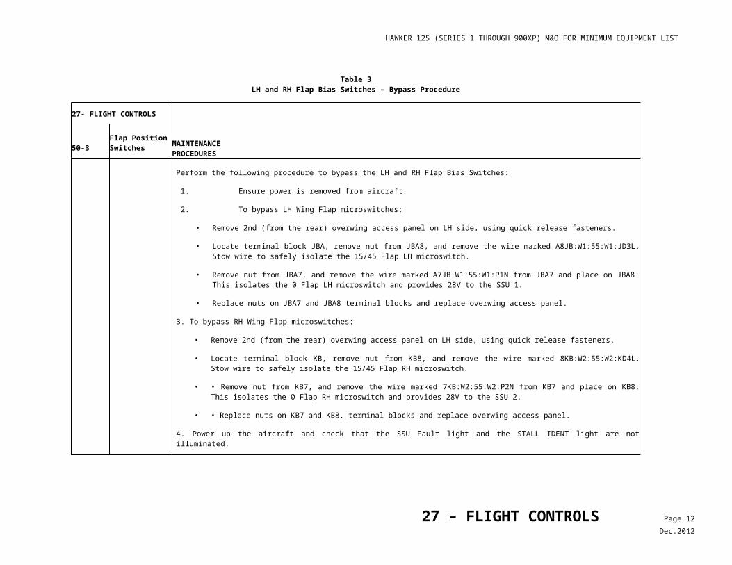
HAWKER 125 (SERIES 1 THROUGH 900XP) M&O FOR MINIMUM EQUIPMENT LIST
Maintenance and Operational Proceduresfor Federal Aviation Administration Master Minimum Equipment List - No: 8c – 10/17/2012
1. SYSTEM, Sequence Numbers & Item
Repair Category2. Number Installed
3. Number Required for Dispatch MAINTENANCEPROCEDURES
OPERATIONALPROCEDURES34 – NAVIGATION 4. Remarks and Exceptions
20-7 Symbol Generator Reversion Switches
C 2 0 (O) May be inoperative provided:a) Associated instruments operate normally
from independent sources, andb) Inoperative switches are not moved during
flight.
1. Confirm associated instruments are operative from independent sources, and
2. Inoperative switches are placarded ‘INOP’ and not moved during flight.
3. Confirm the switch is not in a cross transfer position and in the event of a symbol generator failure on either side, the Reversion Switches are not used to transfer data. However the symbol generator from the MFD may be switched over to the inoperative pilot station. The MFD will be inoperative if this is accomplished.
1) SG Reversion Switch Lights (Honeywell)
C 6 0 (O) Switch backlight and annunciation, left and right, may be inoperative provided associated annunciation on the PFD is operative.
Confirm PFD annunciation each time affected switch is moved.
20-8 Instrument Comparator C - 0 (O) May be inoperative provided: a) Approach minimums do not require its use,
and b) Flight crew monitors instrument indications
for accuracy.
Plan flight to avoid requirement for Comparator.
20-9 Standby Flight Instruments/ Displays
34 – NAVIGATION Page 6Dec.2012
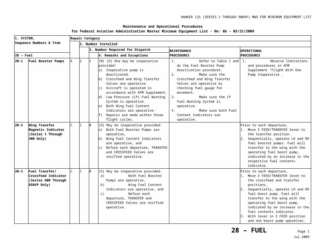
HAWKER 125 (SERIES 1 THROUGH 900XP) M&O FOR MINIMUM EQUIPMENT LIST
Maintenance and Operational Proceduresfor Federal Aviation Administration Master Minimum Equipment List - No: 8c – 10/17/2012
1. SYSTEM, Sequence Numbers & Item
Repair Category2. Number Installed
3. Number Required for Dispatch MAINTENANCEPROCEDURES
OPERATIONALPROCEDURES34 – NAVIGATION 4. Remarks and Exceptions
1) Standby Attitude Indicator(s) (Electro-Mechanical Gyro Horizons)
C - 0 May be inoperative provided not required by FAR.
B - 0 May be inoperative provided:a) Operations are conducted in day VMC,
only, andb) Operations are not conducted into known
or forecast Visual Flight Rules (VFR)-on-Top conditions.
a) Glideslope/Localizer Indicator(s)
C - 0
2) Standby Altimeter(s) (Stand-Alone Unit)
B - 0 May be inoperative provided airplane is operated in day VMC, only.
3) Secondary Flight Display - (3-In-1 Color Graphic Standby Attitude, Altitude, and Airspeed Indicator) OR (4-In-1 Color Graphic Standby Attitude, Altitude, Heading and Airspeed Indicator) (Meggitt)
a) Standby Attitude Display C 1 0 May be inoperative provided not required by FAR.
B 1 0 May be inoperative provided:a) Operations are conducted in day VMC,
only, andb) Operations are not conducted into known
or forecast VFR-On-Top conditions.b) Standby Altimeter Display C 1 0 May be inoperative provided airplane is
operated in day VMC only.c) Baroset Knob C 1 0 May be inoperative provided airplane is
operated in day VMC only.d) Standby Heading Display(s) C - 0 May be inoperative provided:
a) Two independent Heading Reference Systems are operative, and
b) Magnetic compass is operative.e) Standby Mach Number
IndicatorC 1 0
f) Instrument Landing System (ILS) Button
C 1 0
34 – NAVIGATION Page 7Dec.2012
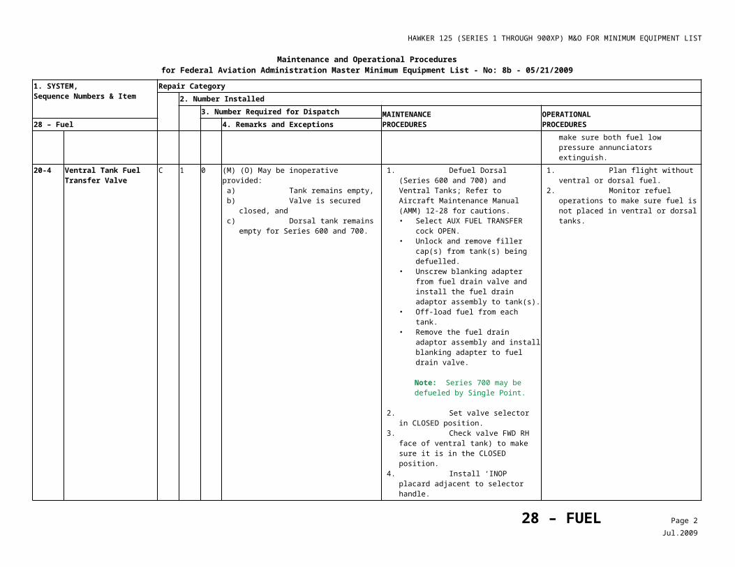
HAWKER 125 (SERIES 1 THROUGH 900XP) M&O FOR MINIMUM EQUIPMENT LIST
Maintenance and Operational Proceduresfor Federal Aviation Administration Master Minimum Equipment List - No: 8c – 10/17/2012
1. SYSTEM, Sequence Numbers & Item
Repair Category2. Number Installed
3. Number Required for Dispatch MAINTENANCEPROCEDURES
OPERATIONALPROCEDURES34 – NAVIGATION 4. Remarks and Exceptions
g) HP/IN Button C 1 0h) Light Sensor C 1 024 Air Data Computer
SystemDeleted, Revision 2.
30-2 Marker Beacons C - 0 May be inoperative provided approach minimums do not required their use.
30-3 ***
Microwave Landing System (MLS)
C - 0 As required by FAR.
Note
Equipment is not operationally approved for steep approaches in the United States of America.
30-4 Radio Compass (ADF) System
C - - As required by FAR.
30-5 NAV/COM Preselect Tuning Functions
C - 0 May be inoperative provided direct tuning mode is installed and operative for each associated unit.
30-6 NAV/COM/ADF/ TDR Memory Channels
C - 0 May be inoperative provided manual tuning is operative.
30-7 NAV/COM/ADF/ TDR Digital Frequency Selector/LCD/LED
C - 1 One pilot side only may be inoperative provided:a) Manual remote tune or dual FMS/CDU
tune capability is operative, andb) All Digital Frequency Selector/ LCD/LED
display units on opposite pilot side are operative.
32-1 ***
ILS Offset System C 1 0 May be inoperative provided procedures do not require its use.
40-1 Radio Altimeter System A - 0 (M) (O) May be inoperative provided:a) Affected TAWS/GWPS functions are
considered inoperative,b) TCAS II RA Mode is considered
inoperative, c) Approach minimums or operating
procedures do not require its use, d) Alternate procedures are established and
used, ande) Repairs are made within two flight days.
1. Confirm there is no Radio Altimeter display.
2. If Radio Altimeter is displayed, pull and collar the RAD ALT circuit breaker.
Copilot will call out altitudes during approach including minimum altitudes.
40-2 Weather Radar System C - - As required by FAR.
34 – NAVIGATION Page 8Dec.2012
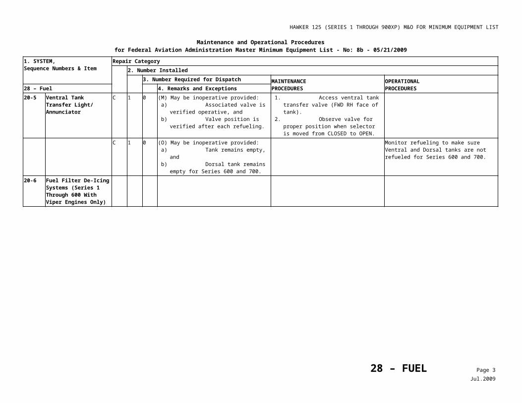
HAWKER 125 (SERIES 1 THROUGH 900XP) M&O FOR MINIMUM EQUIPMENT LIST
Maintenance and Operational Proceduresfor Federal Aviation Administration Master Minimum Equipment List - No: 8c – 10/17/2012
1. SYSTEM, Sequence Numbers & Item
Repair Category2. Number Installed
3. Number Required for Dispatch MAINTENANCEPROCEDURES
OPERATIONALPROCEDURES34 – NAVIGATION 4. Remarks and Exceptions
1)***
Windshear Detection and Avoidance System (Predictive)
C - 0 (O) May be inoperative provided alternate procedures are established and used.
Note
Operators alternate procedures should include reviewing windshear avoidance and windshear recovery procedures.
1. Check departure, enroute, arrival, and alternate weather conditions for potential windshear conditions.
2. Review windshear recovery procedures.
40-3 ***
VTA (Voice Terrain Advisory) System or Equivalent
C - 0 (M) May be inoperative provided system is deactivated.
1. Pull and collar affected circuit breaker(s). 2. Place INOP placard adjacent to system
control.40-41)
Terrain Awareness Warning System (TAWS)/Ground Proximity Warning System (GPWS) (Class A or B required)
A - 0 (O) May be inoperative provided:a) Alternate procedures are established and
used, andb) Repairs are made within two flight days.
1. Exercise extreme caution and vigilance with regard to vertical descent rate, radar altimeter readouts, recognizing signs of windshear, and
2. In the event of a windshear encounter, promptly act to counter the effects of the windshear as described in the appropriate aircraft manuals.
34 – NAVIGATION Page 9Dec.2012
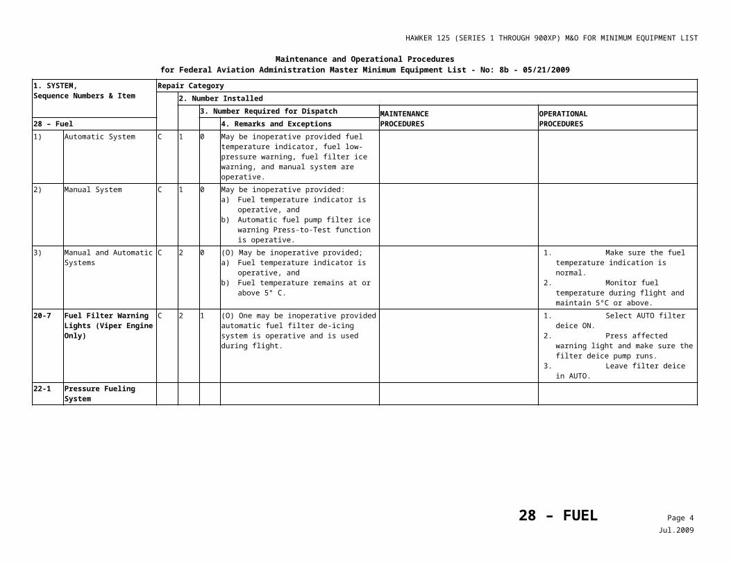
HAWKER 125 (SERIES 1 THROUGH 900XP) M&O FOR MINIMUM EQUIPMENT LIST
Maintenance and Operational Proceduresfor Federal Aviation Administration Master Minimum Equipment List - No: 8c – 10/17/2012
1. SYSTEM, Sequence Numbers & Item
Repair Category2. Number Installed
3. Number Required for Dispatch MAINTENANCEPROCEDURES
OPERATIONALPROCEDURES34 – NAVIGATION 4. Remarks and Exceptions
(Class C TAWS or GPWS not required by FAR)
C - 0 (O) May be inoperative provided alternate procedures are established and used.
NOTE
Any mode that is operative may be used.
1. Exercise caution and vigilance with regard to vertical descent rate, radar altimeter readouts, recognizing signs of windshear, and
2. In the event of a windshear encounter, promptly act to counter the effects of the windshear as described in the appropriate aircraft manuals.
a) Modes 1-4(Class A TAWS required)
A 4 0 (O) May be inoperative provided:a) Alternate procedures are established and
used, andb) Repairs are made within two flight days.
Exercise extreme caution and vigilance with regard to vertical descent rate and radar altimeter readouts.
Modes 1 & 3(Class B TAWS required by FAR)
A 2 0 (O) May be inoperative provided:a) Alternate procedures are established and
used, andb) Repairs are made within two flight days.
Exercise extreme caution and vigilance with regard to vertical descent rate and radar altimeter readouts.
b) Test Mode A 1 0 (O) May be inoperative provided:a) GPWS is considered inoperative, andb) Repairs are made within two flight days.
1. Exercise extreme caution and vigilance with regard to vertical descent rate, radar altimeter readouts, recognizing signs of windshear, and
2. In the event of a windshear encounter, promptly act to counter the effects of the windshear as described in the appropriate aircraft manuals.
3. TAWS alerts are not to be considered reliable.
c) Glideslope Deviation (Mode 5) (Class A TAWS required by FAR)
C - 1
B - 0*** Modes 2, 4 & 5 (Class B
TAWS required by FAR)C 3 0
d) Advisory Callouts B - 0 (O) May be inoperative provided alternate procedures are established and used.
1. Exercise extreme caution and vigilance with regard to vertical descent rate, radar altimeter readouts, recognizing signs of windshear, and
2. In the event of a windshear encounter, promptly act to counter the effects of the windshear as described in the appropriate aircraft manuals.
34 – NAVIGATION Page 10Dec.2012
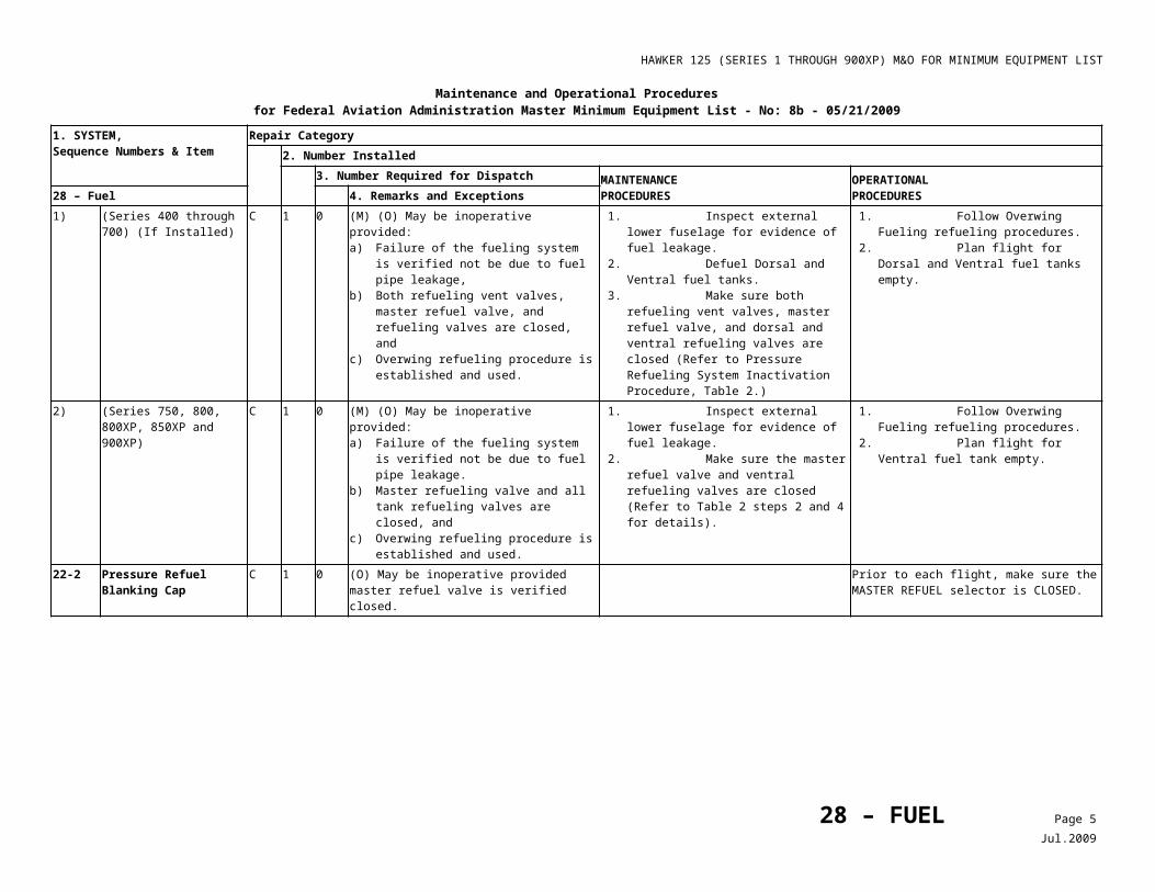
HAWKER 125 (SERIES 1 THROUGH 900XP) M&O FOR MINIMUM EQUIPMENT LIST
Maintenance and Operational Proceduresfor Federal Aviation Administration Master Minimum Equipment List - No: 8c – 10/17/2012
1. SYSTEM, Sequence Numbers & Item
Repair Category2. Number Installed
3. Number Required for Dispatch MAINTENANCEPROCEDURES
OPERATIONALPROCEDURES34 – NAVIGATION 4. Remarks and Exceptions
C - 0 (O) May be inoperative provided:a) Advisory callout not required by FAR, andb) Alternate procedures are established and
used.
1. Exercise extreme caution and vigilance with regard to vertical descent rate, radar altimeter readouts, recognizing signs of windshear, and
2. In the event of a windshear encounter, promptly act to counter the effects of the windshear as described in the appropriate aircraft manuals.
e)***
Windshear Mode (Reactive)(Class A TAWS required by FAR)
B 1 0 (O) May be inoperative provided alternate procedures are established and used.
NOTE
Operator’s alternate procedure should include reviewing windshear avoidance and windshear recovery procedures.
1. Exercise extreme caution and vigilance with regard to vertical descent rate recognizing signs of windshear, and
2. In the event of a windshear encounter, promptly act to counter the effects of the windshear as described in the appropriate aircraft manuals.
(Class A TAWS required by FAR)
C - 0 (O) May be inoperative provided: a) Alternate procedures are established and
used, and b) Windshear Detection and Avoidance
System (Predictive) operates normally.
1. Exercise extreme caution and vigilance with regard to vertical descent rate, radar altimeter readouts, recognizing signs of windshear, and
2. In the event of a windshear encounter, promptly act to counter the effects of the windshear as described in the appropriate aircraft manuals.
(Class B TAWS required by FAR)
C 1 0 (O) May be inoperative provided alternate procedures are established and used.
1. Exercise extreme caution and vigilance with regard to vertical descent rate, radar altimeter readouts, recognizing signs of windshear, and
2. In the event of a windshear encounter, promptly act to counter the effects of the windshear as described in the appropriate aircraft manuals.
2) Terrain System Forward Looking Terrain Avoidance (FLTA) and Premature Descent Alert (PDA) Functions
B - 0 (O) May be inoperative provided alternate procedures are established and used.
Exercise extreme caution and vigilance with regard to vertical descent rate and radar altimeter readouts.
3) Terrain Displays(Class A TAWS required)
C - 1
B - 0*** (Class B TAWS required) C - 0
34 – NAVIGATION Page 11Dec.2012
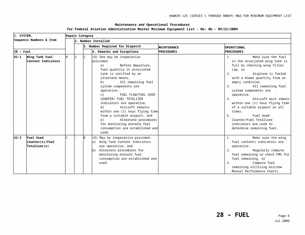
HAWKER 125 (SERIES 1 THROUGH 900XP) M&O FOR MINIMUM EQUIPMENT LIST
Maintenance and Operational Proceduresfor Federal Aviation Administration Master Minimum Equipment List - No: 8c – 10/17/2012
1. SYSTEM, Sequence Numbers & Item
Repair Category2. Number Installed
3. Number Required for Dispatch MAINTENANCEPROCEDURES
OPERATIONALPROCEDURES34 – NAVIGATION 4. Remarks and Exceptions
4)***
Runway Awareness & Advisory System (RAAS)
C 1 0
40-5 ***
Lightning Sensor System C - 0
40-6 ***
Radarnav/Datanav System
C - 0
40-7 ***
Storm Scope D - 0
42-1 ***
TACAN Number 2 Tuning System
C 1 0 May be inoperative provided procedures do not require its use.
43-1 ***
ATC Transponder Attenuation System
C 1 0 May be inoperative provided procedures do not require its use.
50-1 LNAV or RNAV Systems C - - As required by FAR.50-2 ***
Flight Management Systems (FMS)
C - 0 (O) May be inoperative provided operations do not require FMS.
Confirm that flight may be conducted without FMS (See Item 28-42-2).
1) NAV Data Base C - - (O) May be out of currency provided:a) Current Aeronautical Charts are used to
verify Navigation Fixes before dispatch,b) Procedures are established and used to
verify status and suitability of Navigation Facilities used to define route of flight, and
c) Approach Navigation Radios are manually tuned and identified.
1. Current Aeronautical Charts are used to confirm Navigation Fixes prior to dispatch, and
2. The status and suitability of Navigation Facilities used to define route of flight are checked prior to each flight, and
3. Approach Navigation radios are manually tuned and identified.
50-3 Distance Measuring Equipment (DME) Systems
D - - Any in excess of those required by FAR may be inoperative.
50-4 ATC Transponders and Automatic Altitude Reporting Systems
B - 0 May be inoperative provided:a) Enroute operations do not require their
use, andb) Prior to flight, approval is obtained from
ATC facilities having jurisdiction over the planned route of flight.
Note
RVSM is not authorized.
34 – NAVIGATION Page 12Dec.2012
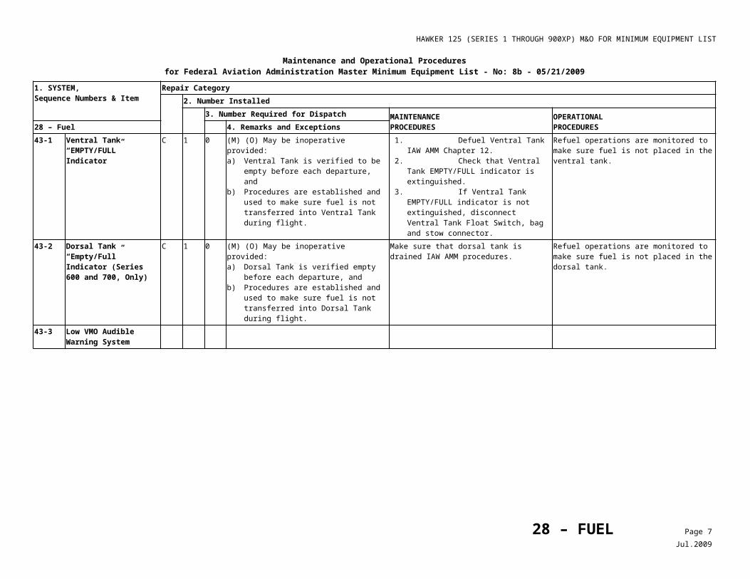
HAWKER 125 (SERIES 1 THROUGH 900XP) M&O FOR MINIMUM EQUIPMENT LIST
Maintenance and Operational Proceduresfor Federal Aviation Administration Master Minimum Equipment List - No: 8c – 10/17/2012
1. SYSTEM, Sequence Numbers & Item
Repair Category2. Number Installed
3. Number Required for Dispatch MAINTENANCEPROCEDURES
OPERATIONALPROCEDURES34 – NAVIGATION 4. Remarks and Exceptions
D - 1 Any in excess of those required by FAR may be inoperative.
1) Elementary and Enhanced Downlink Aircraft Reportable Parameters not Required by FAR
A - 0 May be inoperative provided:a) Enroute operations do not require its use,
and b) Repairs are made prior to completion of
the next heavy maintenance visit. 2) ATC Transponder
Identification (Ident) Buttons
C - 2 May be inoperative provided one is operative at each pilot position.
50-5 VHF Navigation (VOR/ILS) System
C - - As required by FAR.
50-6 ***
Global Positioning System (GPS)
C - 0 As required by FAR.
50-7 ***
Traffic Advisory System (B.F. Goodrich Skywatch/ SKY-497)
D 1 0
50-8 Automatic Dependent Surveillance- Broadcast (ADS-B) System
D - 0 May be inoperative provided it is not required by 14 CFR.
Note
If ADS-B is installed in lieu of or as a replacement for 14 CFR required equipment, the repair category in the operator’s Minimum Equipment List (MEL) will be the same as that of the 14 CFR required equipment.
34 – NAVIGATION Page 13Dec.2012
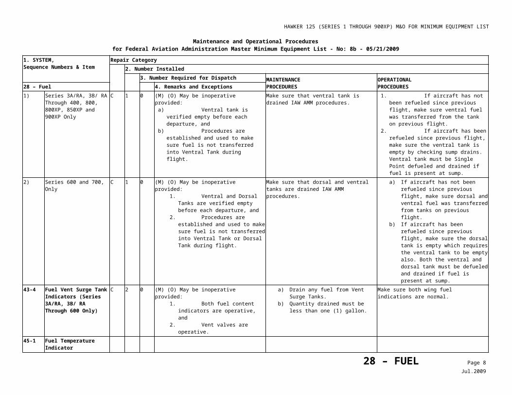
HAWKER 125 (SERIES 1 THROUGH 900XP) M&O FOR MINIMUM EQUIPMENT LIST
Maintenance and Operational Proceduresfor Federal Aviation Administration Master Minimum Equipment List - No: 8c – 10/17/2012
1. SYSTEM, Sequence Numbers & Item
Repair Category2. Number Installed
3. Number Required for Dispatch MAINTENANCEPROCEDURES
OPERATIONALPROCEDURES34 – NAVIGATION 4. Remarks and Exceptions
1) Link and Display Processor Unit (LDPU)
D - 0Note
Cockpit Display Traffic Information (CDTI) display of data from other aircraft systems may be used.
2) Cockpit Display and Traffic Information (CDTI)
D - 0Note
ADS-B data transmissions may continue. 3) CDTI Control Panel D - 0 May be inoperative provided:
a) Flight Identification (ID) can be set, andb) Screen Display is acceptable to the flight
crew.4) Data Link Transmitters D - 05) Data Link Receivers D - 060-1 Traffic Collision and
Avoidance System (TCAS I)
B - 0 (M) May be inoperative provided:a) System is deactivated and secured, andb) Enroute or approach procedures do not
require its use.
1. Pull TCAS circuit breaker and tie-wrap. 2. Install “TCAS INOP” placards on both
RMU’s for Honeywell equipped aircraft and near the FMS-CDU for Collins equipped aircraft.
1. Confirm the associated (M) procedure has been completed to deactivate and secure the system.
2. Plan flight so enroute and approach procedures do not require use of TCAS.
3. Use ATC on (modes S and A) or ATC ALT (modes A, C, S).
34 – NAVIGATION Page 14Dec.2012
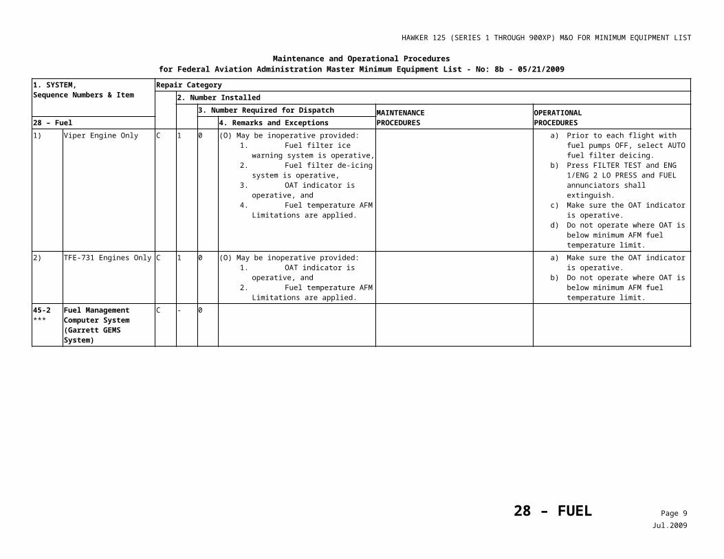
HAWKER 125 (SERIES 1 THROUGH 900XP) M&O FOR MINIMUM EQUIPMENT LIST
Maintenance and Operational Proceduresfor Federal Aviation Administration Master Minimum Equipment List - No: 8c – 10/17/2012
1. SYSTEM, Sequence Numbers & Item
Repair Category2. Number Installed
3. Number Required for Dispatch MAINTENANCEPROCEDURES
OPERATIONALPROCEDURES34 – NAVIGATION 4. Remarks and Exceptions
C - 0 (M) May be inoperative provided:a) System not required by FAR,b) System is deactivated and secured, andc) Enroute or approach procedures do not
require its use.
1. Pull TCAS circuit breaker and tie-wrap. 2. Install “TCAS INOP” placards on both
RMU’s for Honeywell equipped aircraft and near the FMS-CDU for Collins equipped aircraft.
1. Confirm the associated (M) procedure has been completed to deactivate and secure the system.
2. Plan flight so enroute and approach procedures do not require use of TCAS.
3. Use ATC on (modes S and A) or ATC ALT (modes A, C, S).
Note
TCAS is not required on any aircraft with a seating configuration of less than 10 seats, excluding any pilot seat, per FAR 135.180, and it is not required by FAR 91.
(TCAS II) B - 0 (M) (O) May be inoperative provided:a) System is deactivated and secured, andb) Enroute or approach procedures do not
require its use.
1. Pull TCAS circuit breaker and tie-wrap. 2. Install “TCAS INOP” placards on both
RMU’s for Honeywell equipped aircraft and near the FMS-CDU for Collins equipped aircraft.
1. Confirm the associated (M) procedure has been completed to deactivate and secure the system.
2. Plan flight so enroute and approach procedures do not require use of TCAS.
3. Use ATC on (modes S and A) or ATC-ALT (modes A, C, S).
C - 0 (M) May be inoperative provided:a) System not required by FAR,b) System is deactivated and secured, andc) Enroute or approach procedures do not
require its use.
1. Pull TCAS circuit breaker and tie-wrap. 2. Install “TCAS INOP” placards on both
RMU’s for Honeywell equipped aircraft and near the FMS-CDU for Collins equipped aircraft.
1. Confirm the associated (M) procedure has been completed to deactivate and secure the system.
2. Plan flight so enroute and approach procedures do not require use of TCAS.
3. Use ATC on (modes S and A) or ATC ALT (modes A, C, S).
Note
TCAS is not required on any aircraft with a seating configuration of less than 10 seats, excluding any pilot seat, per FAR 135.180, and it is not required by FAR 91.
1) Combined Traffic Alert (TA) and Resolution Advisory (RA) Dual Display System(s)
C 2 1 May be inoperative on the non-flying pilot side provided:a) TA and RA visual display is operative on
the flying pilot’s side, andb) TA and RA audio function is operative on
the flying pilot’s side.
34 – NAVIGATION Page 15Dec.2012
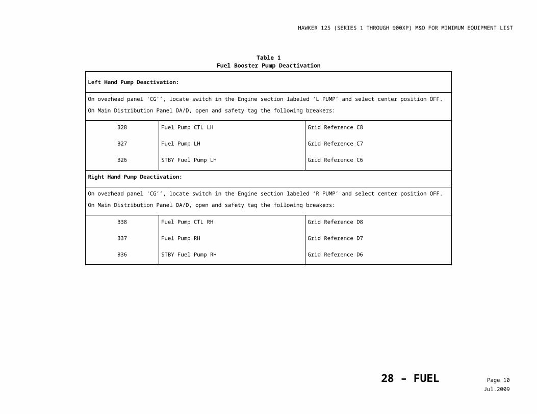
HAWKER 125 (SERIES 1 THROUGH 900XP) M&O FOR MINIMUM EQUIPMENT LIST
Maintenance and Operational Proceduresfor Federal Aviation Administration Master Minimum Equipment List - No: 8c – 10/17/2012
1. SYSTEM, Sequence Numbers & Item
Repair Category2. Number Installed
3. Number Required for Dispatch MAINTENANCEPROCEDURES
OPERATIONALPROCEDURES34 – NAVIGATION 4. Remarks and Exceptions
2) Resolution Advisory (RA) Display Systems
C 2 1 May be inoperative on non-flying pilot’s side.
C - 0 (O) May be inoperative provided:a) Traffic Alert (TA) visual display and audio
functions are operative,b) TA only mode is selected by the crew, andc) Enroute and/or approach procedures do
not required their use.
1. Confirm visual and audio functions. 2. Place INOP Placard adjacent to affected
RA position. 3. Select only TA mode. 4. Plan flight such that RA mode is not
required.3) Traffic Alert (TA) Display
System(s)C - 0 (O) May be inoperative provided:
a) RA visual display and audio functions are operative, and
b) Enroute and/or approach procedures do not require its use.
1. Confirm visual and audio functions. 2. Place INOP Placard adjacent to affected
TA position. 3. Select only RA mode. 4. Plan flight such that TA mode is not
required.4) Audio Functions B 1 0 May be inoperative provided enroute or
approach operations do not require use of TCAS.
5) Airspace Selection Function C - 060-2 ***
Windshear Detector System
Deleted Revision 7; conflicts with other Windshear Detection Relief.
70-1 EFIS/MFD Cooling Fans (Except Collins Pro Line 21-Equipped A/C)
34 – NAVIGATION Page 16Dec.2012
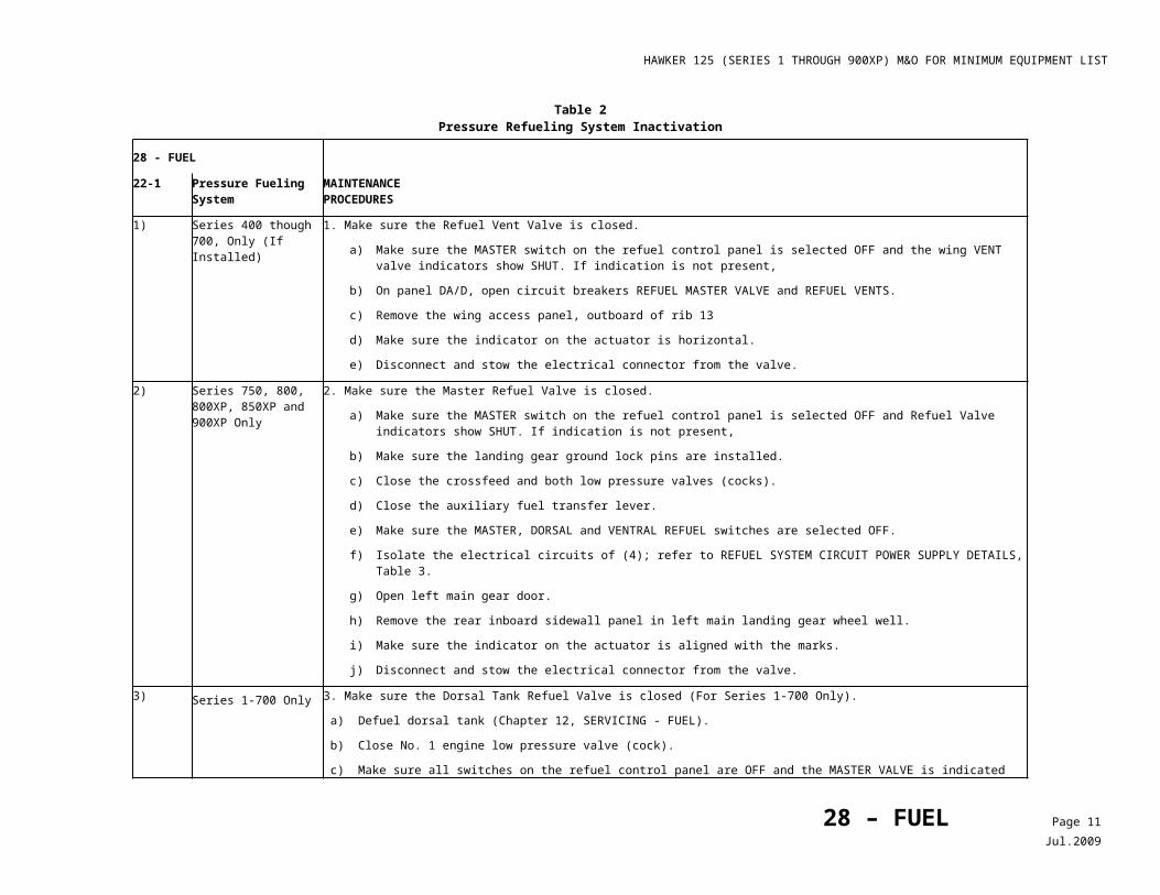
HAWKER 125 (SERIES 1 THROUGH 900XP) M&O FOR MINIMUM EQUIPMENT LIST
Maintenance and Operational Proceduresfor Federal Aviation Administration Master Minimum Equipment List - No: 8c – 10/17/2012
1. SYSTEM, Sequence Numbers & Item
Repair Category2. Number Installed
3. Number Required for Dispatch MAINTENANCEPROCEDURES
OPERATIONALPROCEDURES34 – NAVIGATION 4. Remarks and Exceptions
1) Aircraft with 5 Fans Installed
A 5 4 (O) One may be inoperative provided:a) Standby attitude indicator is operative,b) Bearing Distance indicator (BDI) and
standby compass are operative,c) Cabin temperature can be maintained
below 35° C, andd) Repairs are made within three flight days.
1. Confirm standby attitude indicator is operative, and
2. Confirm BDI and standby compass is operative.
3. Maintain cabin temperature below 35° C. 4. Make repairs within three flight days.
2) Aircraft with 3 Fans Installed
A 3 2 (O) One may be inoperative provided:a) Standby attitude indicator is operative,b) Distance Bearing Indicator (BDI) and
standby compass are operative.c) Cabin temperature can be maintained
below 35° C, andd) Repairs are made within three flight days.
1. Confirm standby attitude indicator is operative, and
2. Confirm BDI and standby compass is operative.
3. Maintain cabin temperature below 35° C. 4. Make repairs within three flight days.
70-2 EFIS/MFD OVHT Annunciators (Series 700, 800 and 800XP, Except Pro Line 21 Equipped Aircraft)
C - 0 (M) May be inoperative provided:a) All EFIS/MFD cooling fans are verified
operative before each departure, andb) Associated EFIS/MFD FAN FAIL
annunciators are operative.
1. Reach up behind the instrument panel and verify the EFIS instrument blower/s and/or the MFD blower is forcing air out its respective piccolo tube. Verify all of the following fans are operating:• DPU fan 2 ea• MPU fan 1 ea• EFIS fan 2 ea• MFD fan 1 ea.
2. Verify that associated EFIS/ MFD FAN FAIL Annunciators are operative.
C - - (O) One may be inoperative provided:a) Nose Cooling Fan and Fan Door are
verified operative,b) Associated EFIS/MFD FAN FAIL
Annunciators are operative, andc) Ground use of EFIS is limited to not more
than 30 minutes.
1. Confirm Nose Avionics Fan Door is OPEN and airflow is present with power ON, and
2. Confirm EFIS/MFD Fan Fail annunciators’ operation.
3. Limit use of EFIS/MFD ground use to 30 minutes before takeoff and after landing.
70-3 EFIS/MFD FAN FAIL Annunciators (Series 700, 800, 800XP Only Except Pro Line 21 Equipped Aircraft)
C - - (O) One may be inoperative provided:a) Nose Cooling Fan and Fan Door are
verified operative before each departure,b) Associated EFIS/MFD OVHT Annunciators
are operative, andc) Ground use of EFIS is limited to not more
than 30 minutes.
1. Confirm Nose Avionics Fan Door is OPEN and airflow is present, and
2. Confirm EFIS/MFD Overheat annunciators’ operation, and
3. Limit use of EFIS/MFD ground use to 30 minutes before takeoff and after landing.
34 – NAVIGATION Page 17Dec.2012
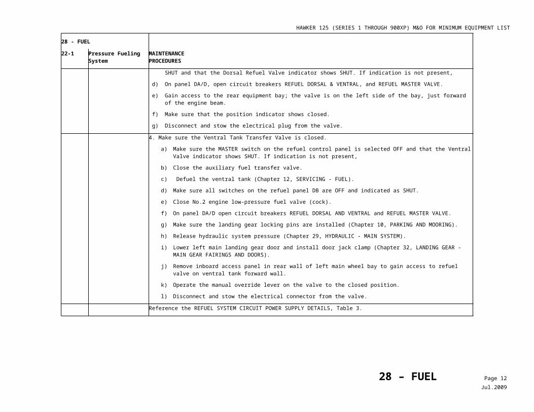
HAWKER 125 (SERIES 1 THROUGH 900XP) M&O FOR MINIMUM EQUIPMENT LIST
Maintenance and Operational Proceduresfor Federal Aviation Administration Master Minimum Equipment List - No: 8c – 10/17/2012
1. SYSTEM, Sequence Numbers & Item
Repair Category2. Number Installed
3. Number Required for Dispatch MAINTENANCEPROCEDURES
OPERATIONALPROCEDURES34 – NAVIGATION 4. Remarks and Exceptions
C - 0 (M) May be inoperative provided:a) All EFIS/MFD cooling fans are verified
operative before each departure,b) Associated EFIS/MFD OVHT Annunciators
are operative, andc) Ground use of EFIS is limited to not more
than 30 minutes.
1. Reach up behind the instrument panel and verify EFIS instrument blower/s and/ or the MFD blower is forcing air out its respective piccolo tube. Assure all of the following fans are operative:• DPU fan 2 ea• MPU fan 1 ea• EFIS fan 2 ea• MFD fan 1 ea.
2. Verify associated EFIS/MFD OVHT Annunciators are operative.
70-4 Electronic Flight Displays (EFD’s)
1) Non-Collins Pro Line 21 Equipped Aircraft, Only
B 4 3 (O) One unit may be inoperative provided: a) Inoperative display is positioned in the
Right Side EHSI location, b) RMI/BDI’s) is/are operative, and c) Standby Instrument(s) are operative.
Confirm an EADI is available on the RH side. Two EFD’s will display on the LH side. The captain will determine if this is a safe configuration for the flight.
2) Collins Pro Line 21 Equipped Aircraft
B 4 3 Right side MFD position may be inoperative.
Note
With IFIS-5000 AFD installed, the EFB is affected (Refer to Chapter 46).
70-5 EFIS Symbol Generator Units (SGU, MSG, DPU, and/or MPU)
B 3 2 (O) One may be inoperative provided:a) The No. 1 (left side) SGU/ DPU remains
operative, and b) Each pilot’s EFIS is driven be an operative
independent symbol generator unit (SGU, MSG, DPU, or MPU).
Confirm each pilots’ EFIS is driven by an independent SGU, MSG, DPU, or MPU which is operative. Refer to the applicable Avionics Operating Manual for guidance.
70-6 Multi-Function Display (MFD) (Except Pro Line 21 Equipped Aircraft)
C 1 0 (O) May be inoperative provided: a) Procedures do not require its use, and b) When radar is required, at least one radar
display is operative.
1. Plan flight ensuring procedures do not require its use, and
2. When radar is required, at least one radar display is operative.
3. Confirm both pilots’ Symbol Generators are operative.
4. Printed checklist will be used since the electronic checklist will be inoperative.
70-7 ***
EADI Annunciator/ Displays
34 – NAVIGATION Page 18Dec.2012
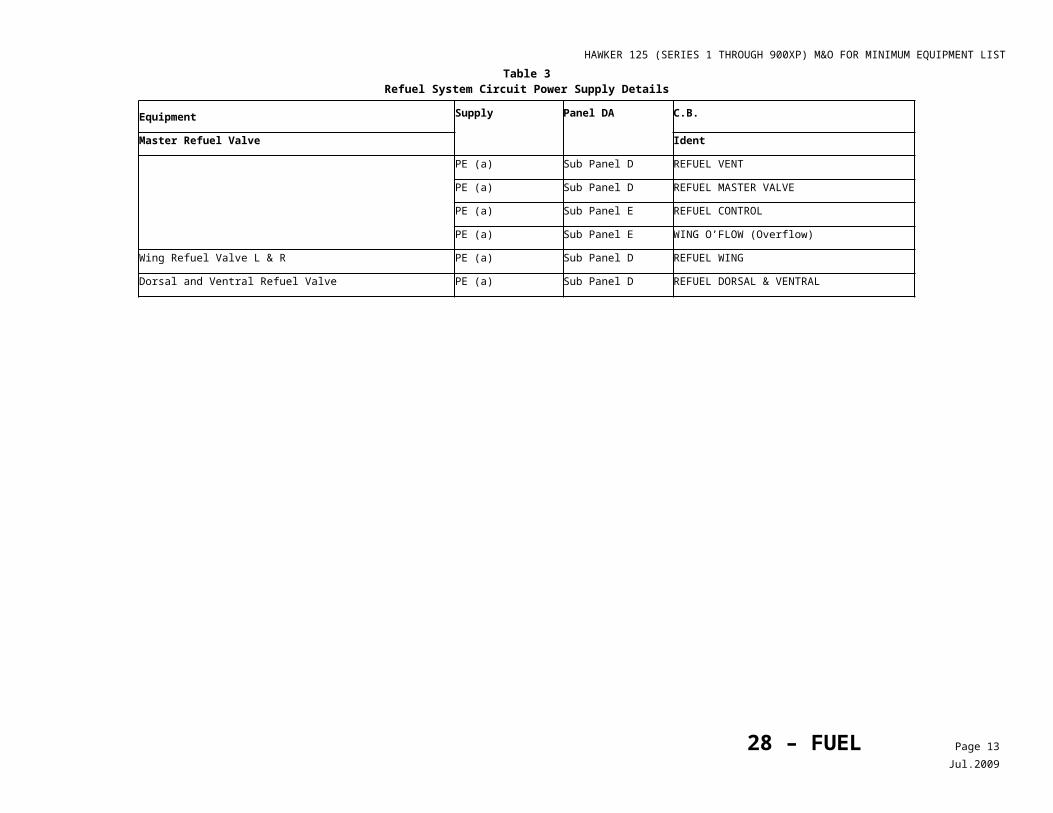
HAWKER 125 (SERIES 1 THROUGH 900XP) M&O FOR MINIMUM EQUIPMENT LIST
Maintenance and Operational Proceduresfor Federal Aviation Administration Master Minimum Equipment List - No: 8c – 10/17/2012
1. SYSTEM, Sequence Numbers & Item
Repair Category2. Number Installed
3. Number Required for Dispatch MAINTENANCEPROCEDURES
OPERATIONALPROCEDURES34 – NAVIGATION 4. Remarks and Exceptions
1) FAST/SLOW Indications C 2 070-8 Laser Altimeter (FAA
Flight Inspection Aircraft Only)
Deleted Revision 4.
70-9 Multifunction Display Controller (Honeywell Equipped Aircraft, Only)
C 1 0 (O) May be inoperative provided:a) Procedures do not require its use,b) When Radar is required, at least one
Radar Display is verified operative before each departure, and
c) Before each departure, both Symbol Generators (SG) and their reversionary switching are verified operative, and
d) Alternate Normal and Emergency Procedures are established and used.
1. Plan flight ensuring that the procedures do not require its use, and
2. Ensure that one RADAR display is operative, and
3. Ensure that both SG’s and reversionary switching are operative. • Confirm both SG’s are operative,
observing operation with independent control using each respective Display Controller.
• Confirm reversionary switching works normally by selecting Pilot’s SG pushbutton and observing amber boxed SG2 in both EADIs.
• Deselect SG pushbutton and confirm the SG2 annunciation is removed.
• Select Copilot’s SG pushbutton and confirm an amber boxed SG1 in both EADIs.
4. Deselect SG pushbutton and confirm SG1 annunciation is removed.
70-10 Nose Compartment Avionics Cooling System (Except Pro Line 21 Equipped Aircraft)
34 – NAVIGATION Page 19Dec.2012
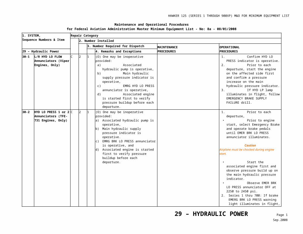
HAWKER 125 (SERIES 1 THROUGH 900XP) M&O FOR MINIMUM EQUIPMENT LIST
Maintenance and Operational Proceduresfor Federal Aviation Administration Master Minimum Equipment List - No: 8c – 10/17/2012
1. SYSTEM, Sequence Numbers & Item
Repair Category2. Number Installed
3. Number Required for Dispatch MAINTENANCEPROCEDURES
OPERATIONALPROCEDURES34 – NAVIGATION 4. Remarks and Exceptions
1) Avionics Cooling Fan C 1 0 (O) May be inoperative provided: a) Avionics Cooling Fan Door remains
closed, and b) Ground operation of the EFIS and MFD is
limited to not more than 30 minutes.
1. Confirm door is closed for aircraft with external fan door.
2. Follow AFM abnormal procedures. See abnormal checklist for NOSE FAN.
3. Limit ground operation of the EFIS and MFD to 30 minutes.
2) Avionics Cooling Fan Door C 1 0 (O) May be inoperative provided:a) Avionics Cooling Fan Door remains
closed, andb) Ground operation of the EFIS and MFD is
limited to not more than 30 minutes.
1. Confirm door is closed for aircraft with external fan door.
2. Follow AFM abnormal procedures. See abnormal checklist for NOSE FAN.
3. Limit ground operation of the EFIS and MFD to 30 minutes.
70-11 Electronic Checklist System and Controls
C - 0 (O) May be inoperative provided alternate checklists and procedures are used.
Use paper or approved alternate checklist.
70-12 Nose Compartment Ventilation System (Collins Equipped Aircraft Except Pro-Line 21)
1) Avionics Cooling Fan Low Speed Warning Detector
C 1 0 (M) May be inoperative OFF provided Avionics Nose Cooling Fan is verified operative.
Check for airflow from Avionics Nose Cooling Fan.
2) Avionics Cooling Fan Nose FAIL Annunciator
C 1 0 (M) May be inoperative OFF provided Avionics Nose Cooling Fan is verified operative.
Check for airflow from Avionics Nose Cooling Fan.
80-1 ***
Airborne Flight Instrument System (AFIS)
D - 0 (O) May be inoperative provided alternate procedures are established and used.
Utilize any other type of communication available such as Flight Phone, HF/VHF phone patch, etc.
34 – NAVIGATION Page 20Dec.2012
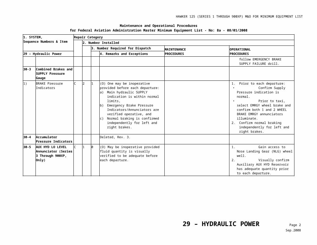
HAWKER 125 (SERIES 1 THROUGH 900XP) M&O FOR MINIMUM EQUIPMENT LIST
Maintenance and Operational Proceduresfor Federal Aviation Administration Master Minimum Equipment List - No: 8a - 08/01/2008
1. SYSTEM, Sequence Numbers & Item
Repair Category2. Number Installed
3. Number Required for Dispatch MAINTENANCEPROCEDURES
OPERATIONALPROCEDURES35 – OXYGEN 4. Remarks and Exceptions
00-1 Oxygen Content Indicator(s)
1) Servicing Gauge D - 0 (M) May be inoperative provided: a) Cockpit gauge is verified operative, and b) Contents are verified full after servicing the
oxygen system.
1. Make sure the cockpit gauge is operative. 2. Make sure the contents are full after
oxygen system servicing.
2) Cockpit Gauge C 1 0 (M) (O) May be inoperative provided: a) Flight remains at or below 10,000 feet
Mean Sea Level (MSL), b) Fault is verified to be in the indicator only
and have no leaks, c) An acceptable procedure is used to
confirm oxygen supply is above minimum required to complete the AFM smoke evacuation procedures, and
d) Passengers are appropriately briefed.
Make sure the fault is in the indicator only and no leaks exist.
1. Plan flight for operation at or below 10,000 feet MSL,
2. Provide appropriate passenger briefing. 3. Make sure by viewing the ACT/POM
Oxygen Servicing Gauge that adequate oxygen is available for performing Emergency Smoke Evacuation procedures.
00-2 Oxygen Cylinders
35 – OXYGEN Page 1Jul.2009
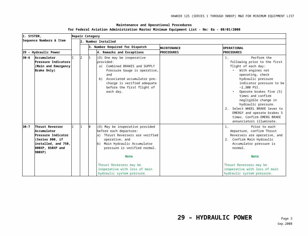
HAWKER 125 (SERIES 1 THROUGH 900XP) M&O FOR MINIMUM EQUIPMENT LIST
Maintenance and Operational Proceduresfor Federal Aviation Administration Master Minimum Equipment List - No: 8a - 08/01/2008
1. SYSTEM, Sequence Numbers & Item
Repair Category2. Number Installed
3. Number Required for Dispatch MAINTENANCEPROCEDURES
OPERATIONALPROCEDURES35 – OXYGEN 4. Remarks and Exceptions
1) (Remaining Oxygen Cylinders have less than 1,400 Liters but more than 750 Liters of combined volume available for use.
A - - (M) (O) Any bottles in excess of 750 Liters useable oxygen may be inoperative provided: a) Aircraft remains at or below 10,000 feet
MSL, b) Passenger oxygen supply valve is verified
closed, c) Passengers are appropriately briefed, d) Oxygen supply to flight crew is verified
adequate to meet operations being conducted,
e) Cockpit oxygen quantity indicator is verified operative, and
f) Repairs are made within three flight days.
Note
Aircraft cannot take off with less than 750 Liters of oxygen available for crew use.
1. Make sure the inoperative bottle(s) shutoff valve is closed.
2. Post a placard in the cockpit noting the number and nominal sizes (in liters) of remaining operative bottles.
1. Plan flight to operate below 10,000 feet MSL, and
2. Make sure the cockpit oxygen quantity indicator is operative.
3. Make sure the oxygen supply to flight crew is adequate to meet operations being conducted including planning for “Smoke in the Cockpit” procedure. Oxygen duration may be factored using the duration data provided in Table 1.
4. Plan flight in accordance with applicable operational FAR. Oxygen duration may be factored using the duration data provided in Table 1.
5. Brief passengers that flight will be conducted at low altitude.
Note
Aircraft cannot take off with less than 750 Liters of oxygen available for crew use.
2) (Remaining Oxygen Cylinders have more than 1400 Liters of combined volume available for use.)
C - 1 (M) (O) Any bottles in excess of 1,400 Liters may be inoperative provided oxygen supply to the flight crew and passengers is verified adequate to meet operations being conducted.
1. Make sure the inoperative bottle(s) shutoff valve is closed.
2. Post a placard in the cockpit noting the number and nominal sizes (in liters) of remaining operative bottles.
If one (1) bottle is operative, make sure that the remaining oxygen quantity is adequate to meet operations being conducted.
35 – OXYGEN Page 2Jul.2009
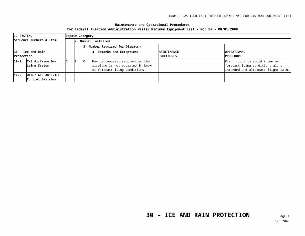
HAWKER 125 (SERIES 1 THROUGH 900XP) M&O FOR MINIMUM EQUIPMENT LIST
Maintenance and Operational Proceduresfor Federal Aviation Administration Master Minimum Equipment List - No: 8a - 08/01/2008
1. SYSTEM, Sequence Numbers & Item
Repair Category2. Number Installed
3. Number Required for Dispatch MAINTENANCEPROCEDURES
OPERATIONALPROCEDURES35 – OXYGEN 4. Remarks and Exceptions
00-3 Barometric Valve Automatic Function
C 1 0 (M) May be inoperative provided: a) Manual deployment system is operative, b) Flight remains at or below FL 300, and c) Passenger supply valve is operative.
1. Make sure the oxygen cylinders are fully charged and cylinder stop valves are open.
2. Open the passenger oxygen supply valve. 3. Select OVERRIDE on the oxygen control
panel, on pilot’s side panel. 4. Make sure all drop out mask boxes have
opened and all masks are hanging from lanyard cord.
Note
Oxygen pressure remaining inside the cabin oxygen lines must be decreased before repacking mask.
5. Reset the cabin oxygen manual override knob.
6. Decrease remaining oxygen pressure at each deployed mask box by pulling the lanyard cord which removes the lanyard pin from the valve.
7. Let the inlet oxygen pressure exhaust, and install the lanyard pin into the valve.
8. Carefully restow all deployed masks. 9. Place placard MAX FL 300 on instrument
panel.
Do not exceed Flight Level (FL) 300.
10-1 Protective Breathing Equipment (PBE)
D - - Any in excess of those required by FAR may be inoperative.
20-1 Passenger Oxygen Masks and Stowages
C - 0 (O) May be inoperative provided associated seats are blocked and placarded to prevent occupancy.
1. Block and placard any seat with an inoperative mask to prevent occupancy, and
2. Brief passengers not to occupy affected seats.
35 – OXYGEN Page 3Jul.2009
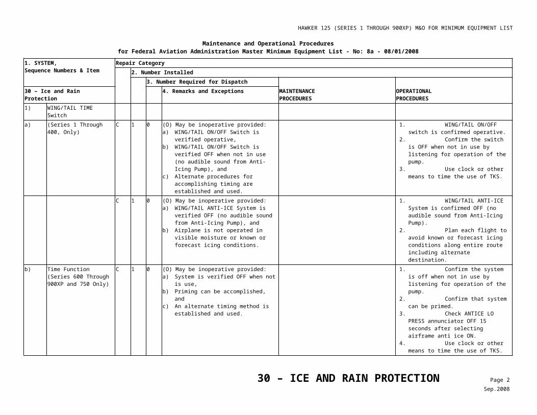
HAWKER 125 (SERIES 1 THROUGH 900XP) M&O FOR MINIMUM EQUIPMENT LIST
Maintenance and Operational Proceduresfor Federal Aviation Administration Master Minimum Equipment List - No: 8a - 08/01/2008
1. SYSTEM, Sequence Numbers & Item
Repair Category2. Number Installed
3. Number Required for Dispatch MAINTENANCEPROCEDURES
OPERATIONALPROCEDURES35 – OXYGEN 4. Remarks and Exceptions
C - 0 (O) May be inoperative provided: a) Flight is not conducted where the minimum
enroute altitude is above 14,000 feet MSL, b) Pressurization system is operative, c) Flight remains at or below FL 250, d) Portable oxygen is provided to each
passenger above 15,000 feet MSL, and e) Passengers are appropriately briefed.
1. Make sure all components of the pressurization system operate normally.
2. Place placard MAX FL 250 on instrument panel.
3. Flight is not to be conducted where the MEA is above 14,000 feet MSL,
4. Flight to be conducted at or below FL 250. 5. Provide portable oxygen to each
passenger above 15,000 feet MSL, 6. Brief passengers.
30-1 Portable Oxygen Dispensing Unit
C - - (M) Any in excess of those required by FAR may be unserviceable or missing provided: a) Required distribution of serviceable bottles
is maintained throughout the aircraft, and b) Bottles not properly serviced are replaced,
serviced or removed at the next available maintenance facility.
1. Bottles not properly serviced are to be replaced, serviced or removed at the next available maintenance facility.
2. Bottle is to be secured in its original housing and placarded as inoperative and empty.
Table 1Useable Oxygen at Reduced Supply Pressure
Note
Oxygen duration may be factored for the number of bottles installed to number of bottles available and for the percentage of full indication using the following values:
Gauge Indication
(PSIG)
Useable Capacity (Liters - Normal Temperature and Pressure Dry (NTPD))
Bottle Configuration (Liters - Nominal)
1 X 750 2 X 750 3 X 750 4 X 750 2 X 750 + 1096 1400
Full (1800) 675 1350 2025 2700 2336 1260
3/4 (1350) 487 975 1462 1950 1687 910
1/2 (900) 300 600 900 1200 1038 560
1/4 (450) 112 225 337 450 389 210
35 – OXYGEN Page 4Jul.2009
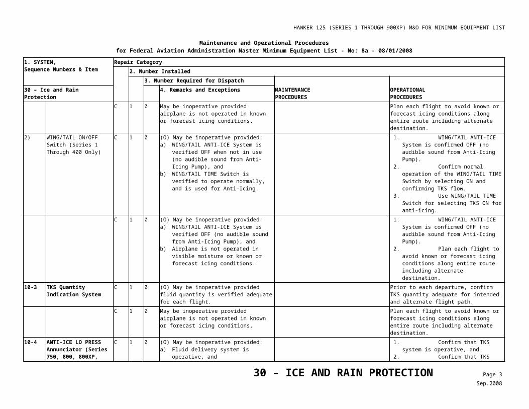
HAWKER 125 (SERIES 1 THROUGH 900XP) M&O FOR MINIMUM EQUIPMENT LIST
Maintenance and Operational Proceduresfor Federal Aviation Administration Master Minimum Equipment List - No: 8d- 12/12/2013
1. SYSTEM, Sequence Numbers & Item
Repair Category2. Number Installed
3. Number Required for Dispatch MAINTENANCEPROCEDURES
OPERATIONALPROCEDURES38 - WATER/WASTE 4. Remarks and Exceptions
10-1 Potable Water System C - - (M) Individual components may be inoperative provided: a) Associated components are deactivated or
isolated, and b) Associated system components are
verified not to have leaks.
Note
Any portion of the system which is operative may be used.
1. Pull and collar appropriate circuit breaker(s).
2. Check associated components to assure that there are no signs of leakage.
3. Install ‘INOP’ placard.
Note
Reference applicable AMM, AMM Addenda, or AMM Supplement for procedures and associated Circuit Breakers.
D - - (O) May be inoperative provided: a) System is drained, and b) Procedures are established to ensure that
the system is not serviced.
1. Remove water supply tank and drain existing water.
2. Ensure that system is not serviced.
10-2 Basin Waste System1) Basin Drain Mast(s) C - 0 (O) May be inoperative provided:
a) Associated components are drained and not used,
b) Ram Air and Dump Valve, or Vent Valve (Post Mod. 25G726A/C) are verified operative before the first flight of the day,
c) DUMP VLV, or VENT VALVE (Post Mod. 25G726A/C) is selected OPEN,
d) Flight is conducted in an unpressurized configuration, and
e) Aircraft is operated at or below 15,000 feet MSL.
f) Applicable Oxygen Requirements are established and complied with.
1. Drain associated components, as needed and install ‘INOP’ placard,
2. Reference Table 1, Configure Aircraft for Unpressurized Flight.
2) Basin Waste System (Except Drain Mast and Mast Check Valve
C - 0 (O) May be inoperative provided: a) Associated components and water supply
are drained, and b) Procedures are established to ensure the
system is not serviced or used.
1. Drain associated components and water supply, and
2. Establish procedures to ensure system is not serviced or used.
10-3 Lavatory Waste System (Blue Water)
38 – WATERWASTE Page 1Mar.2014
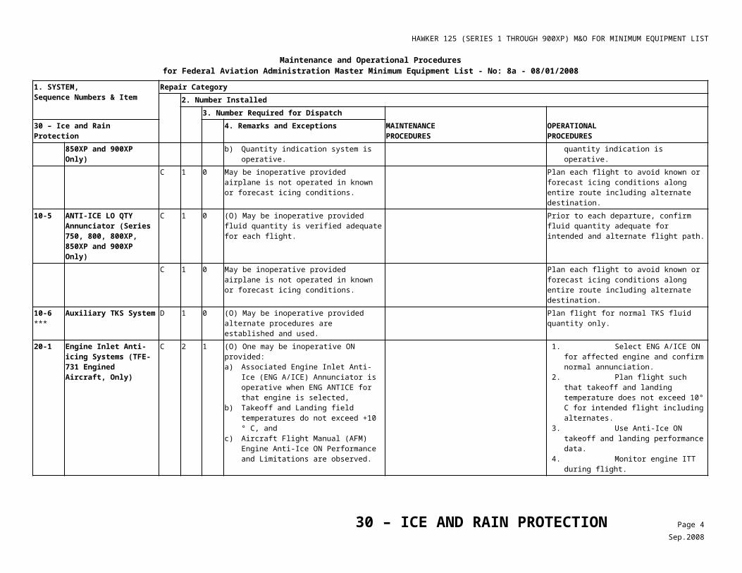
HAWKER 125 (SERIES 1 THROUGH 900XP) M&O FOR MINIMUM EQUIPMENT LIST
Maintenance and Operational Proceduresfor Federal Aviation Administration Master Minimum Equipment List - No: 8d- 12/12/2013
1. SYSTEM, Sequence Numbers & Item
Repair Category2. Number Installed
3. Number Required for Dispatch MAINTENANCEPROCEDURES
OPERATIONALPROCEDURES38 - WATER/WASTE 4. Remarks and Exceptions
1) Lavatory Plug Assembly (Lavatory Doughnut)
C - 0 (O) May be inoperative, or missing, provided: a) Associated Lavatory Waste Tank is
drained, b) Pilot in Command determines that flight
duration is acceptable with toilet unusable, c) Associated toilet is secured closed and
placarded, ‘INOP DO NOT USE’, d) Ram Air and Dump Valve, or Vent Valve
(Post Mod. 25G726A/C) are verified operative before the first flight of the day,
e) DUMP VLV, or VENT VALVE (Post Mod. 25G726A/C) is selected OPEN,
f) Flight is conducted in an unpressurized configuration, and
g) Aircraft is operated at or below 15,000 feet MSL.
h) Applicable Oxygen Requirements are established and complied with.
1. Ensure that Lavatory (LAV) Waste water is drained,
2. Determine if flight duration is acceptable with toilet unusable,
3. Secure lavatory door(s) and placard ‘INOPERATIVE, DO NOT USE’, and
4. Reference Table 1, Configure Aircraft for Unpressurized Flight.
2) Lavatory Wastes System (except Plug Assembly)
C 1 0 (O) May be inoperative provided: a) Associated components and water supply
are drained, and b) Procedures are established to ensure the
system is not serviced or used.
1. Ensure associated components and water supply are drained, and
2. Establish procedures to ensure the system is not used.
38 – WATERWASTE Page 2Mar.2014
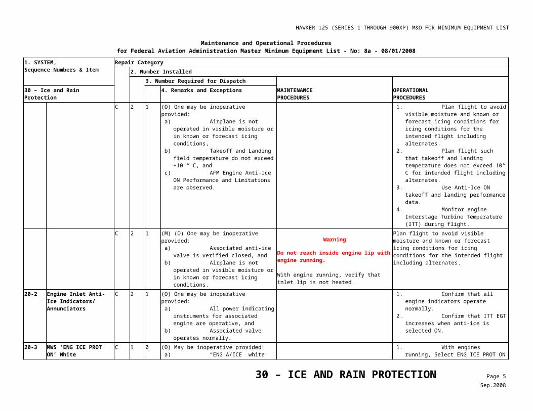
HAWKER 125 (SERIES 1 THROUGH 900XP) M&O FOR MINIMUM EQUIPMENT LIST
Table 1 Configure Aircraft for Unpressurized Flight
38 - Water/WasteOPERATIONAL PROCEDURES
Chapter 38 Para.
Item
10-2-1, & 10-3-1
Stated in each listed paragraph
Perform the following steps for unpressurized low-level flight:
1. Prior to the first flight of the day and before engine and APU start, confirm Ram Air and Dump Valve, or Vent Valve (Post Mod. 25G726A/C) are operative. Ram Air Valve movement can be heard from Rear Equipment Bay when DUMP VALVE OPEN is selected.
2. Configure the aircraft for unpressurized flight:
• Select DUMP VLV, or VENT VALVE (Post Mod. 25G726A/C) fully OPEN.
• F/DK VLV positioned as required.
3. Operate at or below 15,000 feet MSL.
4. Comply with FAR 91.211 or FAR 135.89 and FAR 131.157.
Passenger Oxygen Masks will deploy automatically when the cabin altitude reaches 12,000 feet MSL +/- 500 feet.
The Passenger Supply Valve may be selected closed to prevent passenger oxygen mask deployment, provided the aircraft is operated at or below 10,000 feet MSL or the passenger cabin has no occupants.
NOTE
Special attention should be given to planning low altitude flights.
38 – WATERWASTE Page 3Mar.2014
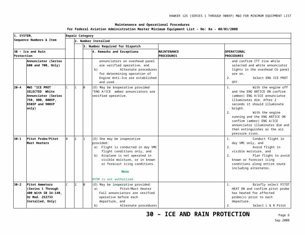
HAWKER 125 (SERIES 1 THROUGH 900XP) M&O FOR MINIMUM EQUIPMENT LIST
Maintenance and Operational Proceduresfor Federal Aviation Administration Master Minimum Equipment List - No: 7 - 09/07/2007
1. SYSTEM, Sequence Numbers & Item
Repair Category2. Number Installed
3. Number Required for DispatchMAINTENANCEPROCEDURES
OPERATIONALPROCEDURES
45 - CENTRAL MAINTENANCE COMPUTER 4. Remarks and Exceptions00-1 Maintenance Diagnostic
Computer (MDC)
(Pro Line 21 only)
D 1 0
45 – CENTRAL MAINTENANCE COMPUTER Page 1Nov.2007
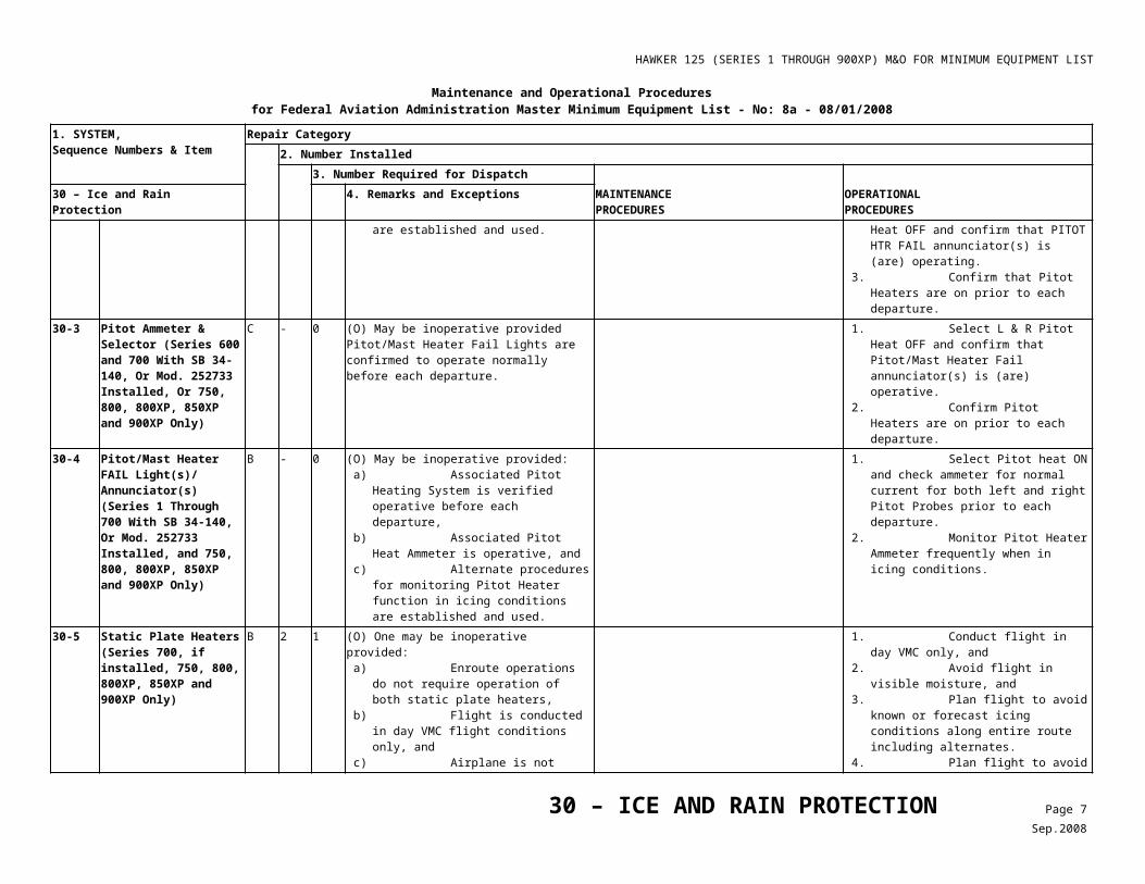
HAWKER 125 (SERIES 1 THROUGH 900XP) M&O FOR MINIMUM EQUIPMENT LIST
Hawker 125 (Series 1 through 900XP) Maintenance and Operational Proceduresfor Federal Aviation Administration Master Minimum Equipment List - No: 8 - 02/18/2008
1. SYSTEM, Sequence Numbers & Item
Repair Category2. Number Installed
3. Number Required for Dispatch MAINTENANCEPROCEDURES
OPERATIONALPROCEDURES46 - INFORMATION SYSTEMS 4. Remarks and Exceptions
10 *** Electronic Flight Bag System (EFB)
C - 0 (O) May be inoperative provided alternate procedures are established and used to ensure all information associated with the flight is available in current and appropriate form.
Note
If alternate source is electronic, dual redundancy is required for operation.
Any function, program or document which operates normally may be used.
Operations are to be conducted in accordance with FAA approved EFB Policy and Procedures Manual.
1) *** Power Connection (Class 1 & 2)
C - 0 (O) May be inoperative provided alternate procedures are established and used.
Operations are to be conducted in accordance with FAA approved EFB Policy and Procedures Manual.
2) *** Mounting Device (Class 2) C - 0 (M) (O) May be inoperative provided: The associated EFB and hardware is secured by an alternate means or removed from the aircraft, andAlternate procedures are established and used.
Remove or secure EFB mounting device to assure the device does not interfere with Normal or Emergency crew duties.
Operations are to be conducted in accordance with FAA approved EFB Policy and Procedures Manual.
3) *** Data Connectivity (Class 2) C - 0 (O) May be inoperative provided alternate procedures are established and used.
Operations are to be conducted in accordance with FAA approved EFB Policy and Procedures Manual.
4) *** EFB Printer C - 0 (O) May be inoperative provided all affected pertinent flight information is printed and available prior to departure.
Operations are to be conducted in accordance with FAA approved EFB Policy and Procedures Manual.
20 Integrated Flight Information System (Pro Line 21 IFIS-5000)
1) File Server Unit (FSU)(FSU INOP) Message)
C 1 0
*** C 2 0 (O) One or both may be inoperative provided alternate procedures are established and used to ensure all information associated with the flight is available at the pilot station in current and appropriate form.
Note
If alternate source is electronic, dual redundancy is required for operation.
Traditional paper data will be carried and used for intended flight, orOperations are to be conducted in accordance with FAA approved EFB Policy and Procedures Manual.
46 – INFORMATION SYSTEMS Page 1Feb.2008
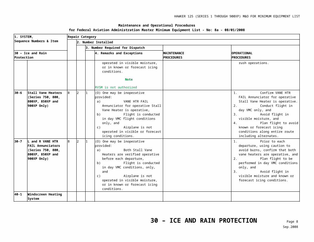
HAWKER 125 (SERIES 1 THROUGH 900XP) M&O FOR MINIMUM EQUIPMENT LIST
Hawker 125 (Series 1 through 900XP) Maintenance and Operational Proceduresfor Federal Aviation Administration Master Minimum Equipment List - No: 8 - 02/18/2008
1. SYSTEM, Sequence Numbers & Item
Repair Category2. Number Installed
3. Number Required for Dispatch MAINTENANCEPROCEDURES
OPERATIONALPROCEDURES46 - INFORMATION SYSTEMS 4. Remarks and Exceptions
2) Cursor Control Panel (CCP) C 2 0 (O) One or both may be inoperative provided alternate procedures are established and used to ensure all information associated with the flight is available at the pilot station in current and appropriate form.
Traditional paper data will be carried and used for intended flight, orOperations are to be conducted in accordance with FAA approved EFB Policy and Procedures Manual.
3) *** Communications Management Unit (CMU)
C 1 0 (O) May be inoperative provided alternate procedures are established and used for Aircraft Communication Addressing and Reporting System (ACARS) and Universal Weather Radar (WX) inoperative.
Weather data for the intended flight path including alternates shall be obtained prior to departure.
4) *** Third VHF Comm Radio C 1 0 (O) May be inoperative provided alternate procedures are established and used for ACARS and Universal WX inoperative.
Weather data for the intended flight path including alternates shall be obtained prior to departure.
5) *** XM Satellite Weather System
C 1 0
46 – INFORMATION SYSTEMS Page 2Feb.2008
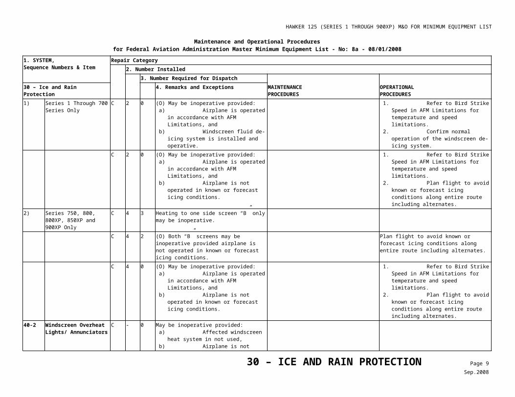
HAWKER 125 (SERIES 1 THROUGH 900XP) M&O FOR MINIMUM EQUIPMENT LIST
Maintenance and Operational Proceduresfor Federal Aviation Administration Master Minimum Equipment List - No: 7 - 09/07/2007
1. SYSTEM, Sequence Numbers & Item
Repair Category2. Number Installed
3. Number Required for DispatchMAINTENANCEPROCEDURES
OPERATIONALPROCEDURES
49 - AIRBORNE AUXILIARY POWER
4. Remarks and Exceptions
00-1 Auxiliary Power Unit (APU)
C 1 0 May be inoperative provided APU is not used.
10-1 APU Air/Load Control Valve
C 1 0 (M) (O) May be inoperative provided: a) Air valve is secured closed, and b) APU air switch remains OFF.
Note
If APU and APU Generator operate normally, APU may be used to provide electric power.
1. Locate APU air valve in Rear Equipment Bay. Check valve mechanical indicator CLOSED.
2. Disconnect electrical connections, bag and stow.
3. In cockpit locate APU Air Valve Switch and insure that it is OFF.
4. Place Inoperative ‘INOP’ Placard at APU air valve switch.
1. Do not use APU bleed air. 2. If APU and APU generator are operational,
they may be used.
C 1 0 May be inoperative provided APU is not used.10-2 APU Instrumentation1) Revolutions Per Minute
(RPM)/ Exhaust Gas Temperature (EGT) Indicators (T62T-40C8D/ T62T-40C8D1 and 36-150/92/100/ APU Only)
C 2 0 May be inoperative provided APU is not used.
2) Ampere (Amp) Meter/Load Meter
C 1 0 May be inoperative provided APU is not used.
30-2 ***
APU Operating Cycle Recorder
C 1 0 (O) May be inoperative provided an alternate procedure for recording APU operating cycles is established and used.
Record APU cycles used in APU logbook.
49 – AIRBORNE AUXILIARY POWER Page 1Nov.2007
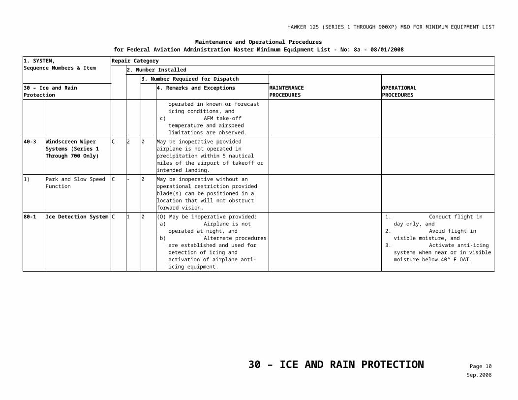
HAWKER 125 (SERIES 1 THROUGH 900XP) M&O FOR MINIMUM EQUIPMENT LIST
Maintenance and Operational Procedures for Federal Aviation Administration Master Minimum Equipment List - No: 8c 10/17/2012
1. SYSTEM, Sequence Numbers & Item
Repair Category2. Number Installed
3. Number Required for Dispatch MAINTENANCEPROCEDURES
OPERATIONALPROCEDURES52 – DOORS 4. Remarks and Exceptions
11-1 Main Entry Door Unlock Indication System
C 1 0 (O) May be inoperative provided door is both visually and manually verified to be fully closed and locked before each departure.
Prior to each departure, close and lock door and visually confirm the handle is in the locked position and that each (6) lock is seated.
25-1 Rear Baggage Pannier/External Baggage Compartment (EBC) Door Unlock Indications
C - 0 (O) May be inoperative OFF provided door(s) is/are visually and manually verified fully closed and locked before each departure.
1. Prior to each departure,• Open Left Hand (LH) Pannier Door,• Operate latching handle checking for
extension and retraction of all three (3) latching pins, and
• Close and latch door. 2. Repeat above bulleted steps for Right
Hand (RH) Pannier Door (if installed).C - 0 (M) (O) May be inoperative ON provided:
a) System is deactivated, and b) Door(s) is visually and manually verified
fully closed and locked before each departure.
1. Gain access to Connectors ‘UL’ and UK’ through Access Panel F162 behind Baggage Pannier.
2. Remove wires ‘K’ and ‘V’ from both connectors, cap, and stow.
3. Check that indication is OFF.
1. Prior to each departure, perform the following: • Open LH Pannier Door, • Operate latching handle checking for
extension and retraction of all three (3) latching pins, and
• Close and latch door, and 2. Repeat above bulleted steps for RH
Pannier Door (if installed).Series 750 C - 0 (M) (O) May be inoperative ON provided:
a) System is deactivated, and b) Door is visually and manually verified fully
closed and locked before each departure.
1. Gain access to Connector ‘UZ’ through Access Panel F162 behind Baggage Pannier.
2. Remove wires ‘K’ and ‘V’ from connector, cap, and stow.
3. Check that indication is OFF.
1. Prior to each departure, perform the following:
• Open LH Pannier Door,• Operate all latches checking for
extension and retraction of latching pins, and
• Close and latch door.25-2 Rear Baggage
Pannier/EBC Hatch Unlock Indication
C 1 0 (O) May be inoperative OFF provided associated hatch is both visually and manually verified fully closed and locked before each departure.
Prior to each departure, 1. Open the lower hatch door and visually
confirm the upper hatch is installed and locked.
2. Close and latch the lower hatch door.
52 – DOORS Page 1Dec.2012
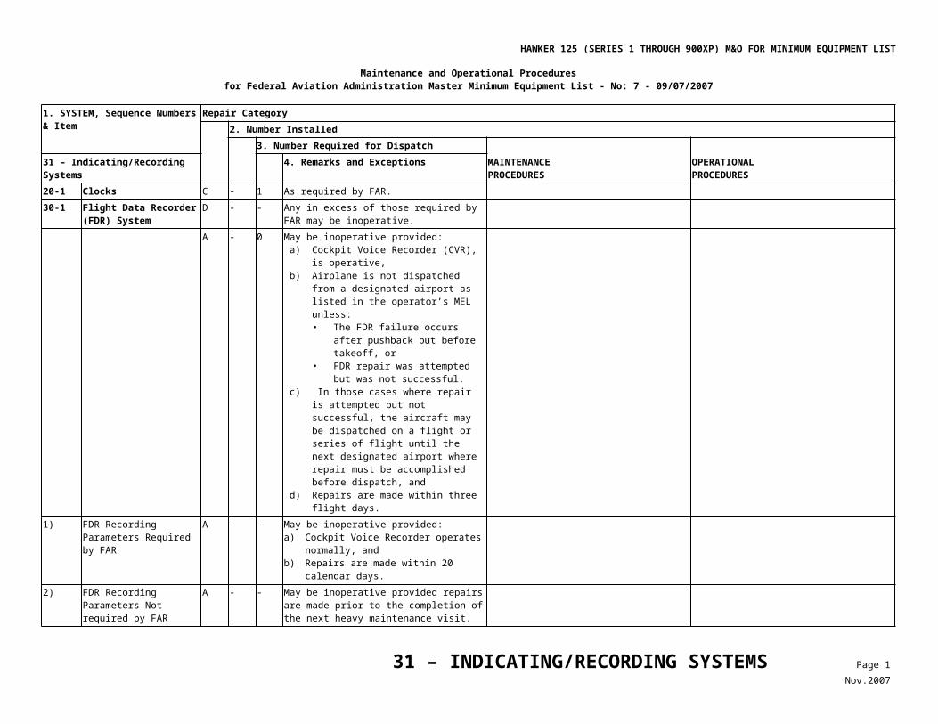
HAWKER 125 (SERIES 1 THROUGH 900XP) M&O FOR MINIMUM EQUIPMENT LIST
Maintenance and Operational Procedures for Federal Aviation Administration Master Minimum Equipment List - No: 8c 10/17/2012
1. SYSTEM, Sequence Numbers & Item
Repair Category2. Number Installed
3. Number Required for Dispatch MAINTENANCEPROCEDURES
OPERATIONALPROCEDURES52 – DOORS 4. Remarks and Exceptions
C 1 0 (M) (O) May be inoperative ON provided: a) System is deactivated, and b) Hatch is both visually and manually
verified full closed and locked before each departure.
1. Gain access to Connector ‘UL’ through Access Panel F162 behind Baggage Pannier.
2. Remove wires ‘H’ and ‘T’ from connector, cap, and stow.
3. Check that indication is OFF.
Prior to each departure, 1. Open the lower hatch door and visually
confirm the upper hatch is installed and locked.
2. Close and latch the lower hatch door.
Series 750 (M) (O) May be inoperative ON provided: a) System is deactivated, and b) Hatch is visually and manually verified fully
closed and locked before each departure.
1. Gain access to Connector ‘UZ’ through Access Panel F162 behind Baggage Pannier.
2. Remove wires ‘H’ and ‘T’ from connector, cap, and stow.
3. Check that indication is OFF.
Prior to each departure, 1. Open the lower hatch door and visually
confirm the upper hatch is installed and locked.
2. Close and latch the lower hatch door.
70-3 ***
Optional Door or Hatch Unlocked Annunciator
C 1 0 (O) May be inoperative provided annunciator is not visibly illuminated and associated door(s) or hatch(es) are visually and manually verified fully closed and locked before each departure.
Note
Optional doors/hatches approved for relief under the above include the following: Remote Refuel Panel Door; Single Point Refuel Door; Ventral Tank Gravity Refuel Door; Rear Equipment Bay Door; and Lavatory Service Panel Door.
Prior to each departure, confirm both visually and manually that affected door(s) are closed and latched.
70-4 Right and Left Avionics Access Doors
Deleted Revision 5.
70-5 ***
Door Locks D - 0 (O) May be inoperative provided checks are made to ensure the lock does not interfere with normal operation of the latch.
Confirm the inoperative lock does not prevent the affected door or hatch from being properly closed and latched.
70-6 ***
Ramp Guard System D - 0
52 – DOORS Page 2Dec.2012
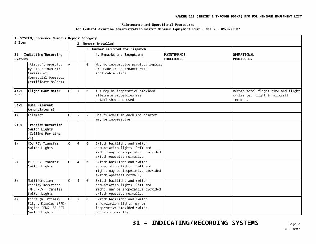
HAWKER 125 (SERIES 1 THROUGH 900XP) M&O FOR MINIMUM EQUIPMENT LIST
Maintenance and Operational Proceduresfor Federal Aviation Administration Master Minimum Equipment List - No: 8 - 02/18/2008
1. SYSTEM, Sequence Numbers & Item
Repair Category2. Number Installed
3. Number Required for Dispatch MAINTENANCEPROCEDURES
OPERATIONALPROCEDURES56 – WINDOWS 4. Remarks and Exceptions
10-1 Windscreen (Panel “A”) (Series 1 Through 700)
C - - (M) (O) May be delaminated provided:a) Visibility through the affected
windscreen(s) is acceptable to the crew,b) Airplane is not operated in known or
forecast icing conditions,c) Associated SCREEN HEAT Control (CTL)
circuit breaker is pulled and collared, andd) AFM limitations are observed.
1. Locate affected SCREEN HEAT CTL circuit breaker.
2. Pull and collar circuit breaker. 3. Place INOP placard adjacent to affected
switch.
1. Confirm that delamination does not affect visibility.
2. Plan flight to avoid flight in known or forecast icing conditions.
3. Review AFM low altitude airspeed limitations for windscreen heat inoperative.
10-2 Windscreens “A” or “B” (Series 750, 800, 800XP, 850XP and 900XP)
C - - (M) (O) One “A” or “B” windscreen may be delaminated provided:a) Visibility through the affected windscreen
is acceptable to the crew, and vision is not impaired on the remaining windscreens,
b) Airplane is not operated in known or forecast icing conditions,
c) Associated SCREEN HEAT CTL circuit breaker is pulled and collared, and
d) AFM limitations are observed.
1. Locate affected SCREEN HEAT CTL circuit breaker.
2. Pull and collar circuit breaker. 3. Place INOP placard adjacent to affected
switch.
1. Confirm that delamination does not affect visibility.
2. Plan flight to avoid flight in known or forecast icing conditions.
3. Review AFM low altitude airspeed limitations for windscreen heat inoperative.
56 – WINDOWS Page 1Feb.2008
HAWKER 125 (SERIES 1 THROUGH 900XP) M&O FOR MINIMUM EQUIPMENT LIST
Maintenance and Operational Proceduresfor Federal Aviation Administration Master Minimum Equipment List - No: 7 - 09/07/2007
1. SYSTEM, Sequence Numbers & Item
Repair Category2. Number Installed
3. Number Required for Dispatch MAINTENANCEPROCEDURES
OPERATIONALPROCEDURES73 - ENGINE FUEL & CONTROL 4. Remarks and Exceptions
22-1 Engine Synchronizer System (Series 1 Through 800A With TFE-731 Engines Only)
C 1 0 (O) May be inoperative provided: a) System is selected “OFF”, b) Automatic Performance Reserve (APR)
system is not armed, and c) AFM limitations are observed.
1. Prior to flight, review Aircraft AFM procedures with APR inoperative.
2. Observe limitations with APR inoperative. 3. Select engine synchronization (synch)
OFF and do not use. 4. Install ‘INOP’ placard adjacent to engine
synch switch.22-2 Top Temperature Control
System (Viper Engine Only)
C 2 1 (M) (O) One may be inoperative provided: a) Associated switch remains OFF, b) Associated circuit breakers are pulled and
collared, and c) Associated JPT indicator is operative.
Pull and collar affected TOP Temperature (TEMP) CONTROL circuit breaker.
1. Select associated system OFF. 2. Confirm normal operation of associated
JPT indication.
3. Engine Electronic Fuel Computer System (Series 1 Through 800 With TFE-731 Engines Only)
Deleted, Revision 2.
23-1 ***
APR Computer System (Series 1 Through 800A With TFE-731 Engines Only)
C 1 0 (O) May be inoperative provided: a) AFM performance limitations are
observed, b) APR system is selected OFF, and c) Procedures for monitoring engine
limitations are established and used.
1. Prior to flight, review AFM procedures with APR inoperative.
2. Observe limitations with APR inoperative. 3. Select APR OFF and do not use. 4. Install Inoperative (‘INOP’) placard
adjacent to APR switch.24-1 Automatic Thrust Limiter
System (Viper Engines Only)
C 2 0 (O) May be inoperative provided Revolutions Per Minute (RPM) and JPT can be controlled manually.
Confirm that takeoff power can be set manually.
31-1 Fuel Flow Indicators C 2 1 (O) One may be inoperative provided: a) Associated RPM and JPT/ITT indicators
are operative, b) All fuel quantity indicators are operative,
and c) A fuel monitoring procedure is established
and used.
1. Confirm associated RPM and ITT indicators operate normally,
2. Confirm all fuel quantity indicators are operative, and
3. During flight, monitor engine gauges to ensure that both engines are operating normally,
4. Fuel consumption will be monitored to ensure that abnormal fuel imbalances do not occur.
5. Fuel flow may be available on the Fuel Management page in the FMS.
73 – ENGINE FUEL & CONTROL Page 1Nov.2007
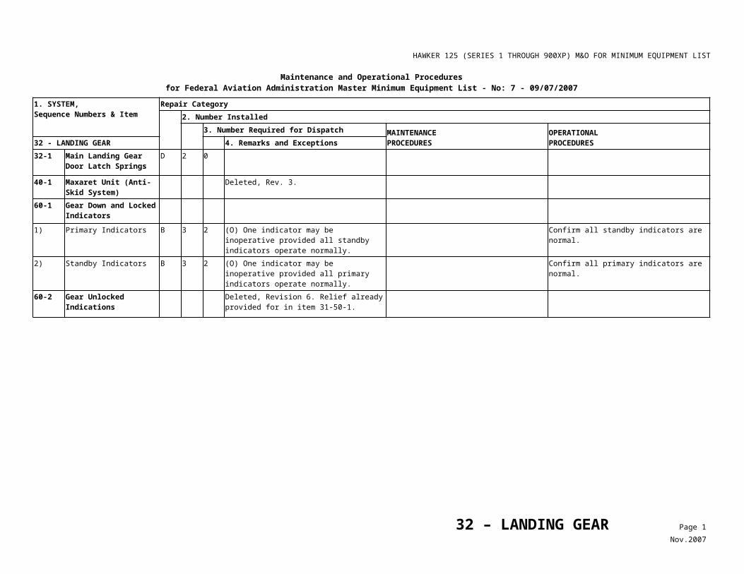
HAWKER 125 (SERIES 1 THROUGH 900XP) M&O FOR MINIMUM EQUIPMENT LIST
Maintenance and Operational Proceduresfor Federal Aviation Administration Master Minimum Equipment List - No: 7 - 09/07/2007
1. SYSTEM, Sequence Numbers & Item
Repair Category2. Number Installed
3. Number Required for Dispatch MAINTENANCEPROCEDURES
OPERATIONALPROCEDURES74 – IGNITION 4. Remarks and Exceptions
10-1 Ignition Systems B 4 3 (O) One igniter on one engine may be inoperative provided: a) Aircraft is not operated in visible moisture
or from contaminated runways, and b) Aircraft is not operated in known or
forecast icing conditions.
1. Prior to each flight, confirm that only one igniter is inoperative on only one engine.• With battery power only on, select
Ignition “ON”, and• Then listen to each engine for two
distinct “snaps”. If only one distinct “snap” is noticed only one igniter is working on that engine.
2. Ensure that the aircraft is not operated in visible moisture or from wet or contaminated runways, and
3. Aircraft is not operated in known or forecast icing conditions.
4. Plan flights to avoid any of the above mentioned conditions.
74 – IGNITION Page 1Nov.2007
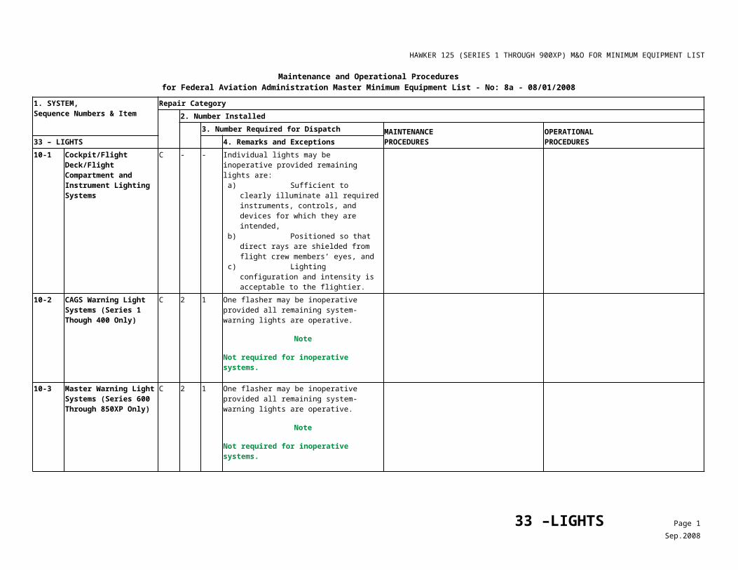
HAWKER 125 (SERIES 1 THROUGH 900XP) M&O FOR MINIMUM EQUIPMENT LIST
Maintenance and Operational Proceduresfor Federal Aviation Administration Master Minimum Equipment List - No: 7 - 09/07/2007
1. SYSTEM, Sequence Numbers & Item
Repair Category2. Number Installed
3. Number Required for Dispatch MAINTENANCEPROCEDURES
OPERATIONALPROCEDURES77 - ENGINE INDICATING 4. Remarks and Exceptions
10-2 Engine Indications1) N1 Indicator Digital
Readouts
a) Digital Readout(s) (Except Pro Line 21-Equipped Aircraft)
C - 0
2) N2/RPM IndicatorsC 2 1 (O) One may be inoperative provided N1 and
Fuel Flow Indicators for the associated engine are operative.
Prior to each departure, confirm that the N1 and Fuel Flow Indicators for the associated engine are operative.
a) Digital Readout(s)C - 0
3) Interstage Turbine Temperature (ITT) / Exhaust Gas Temperature (EGT) Indicators
a) Digital Readout(s) (Except Pro Line 21-Equipped Aircraft)
C - 0
32-1 Power Loss Indicator Systems (Viper Engine Only)
C 2 0 (O) May be inoperative provided all remaining engine indicating systems are operative.
Prior to each departure, confirm all remaining engine indicating systems are operative.
32-2 Above 92% Light Systems (Viper Engine Only)
C 2 0 (O) May be inoperative provided alternate procedures are established and used.
Closely monitor engine RPM, especially when setting takeoff and climb power.
32-3 Climb Power Annunciators (TFE-731 Engines Except Pro Line 21 Equipped Aircraft)
C 2 0 (O) May be inoperative provided alternate procedures are established and used.
1. Ensure climb power does not exceed AFM Limitations.
2. Non-Flying Pilot will monitor and adjust climb power as needed.
3. 3. Captain will brief procedure to be used before each departure.
77 – ENGINE INDICATING Page 1Nov.2007
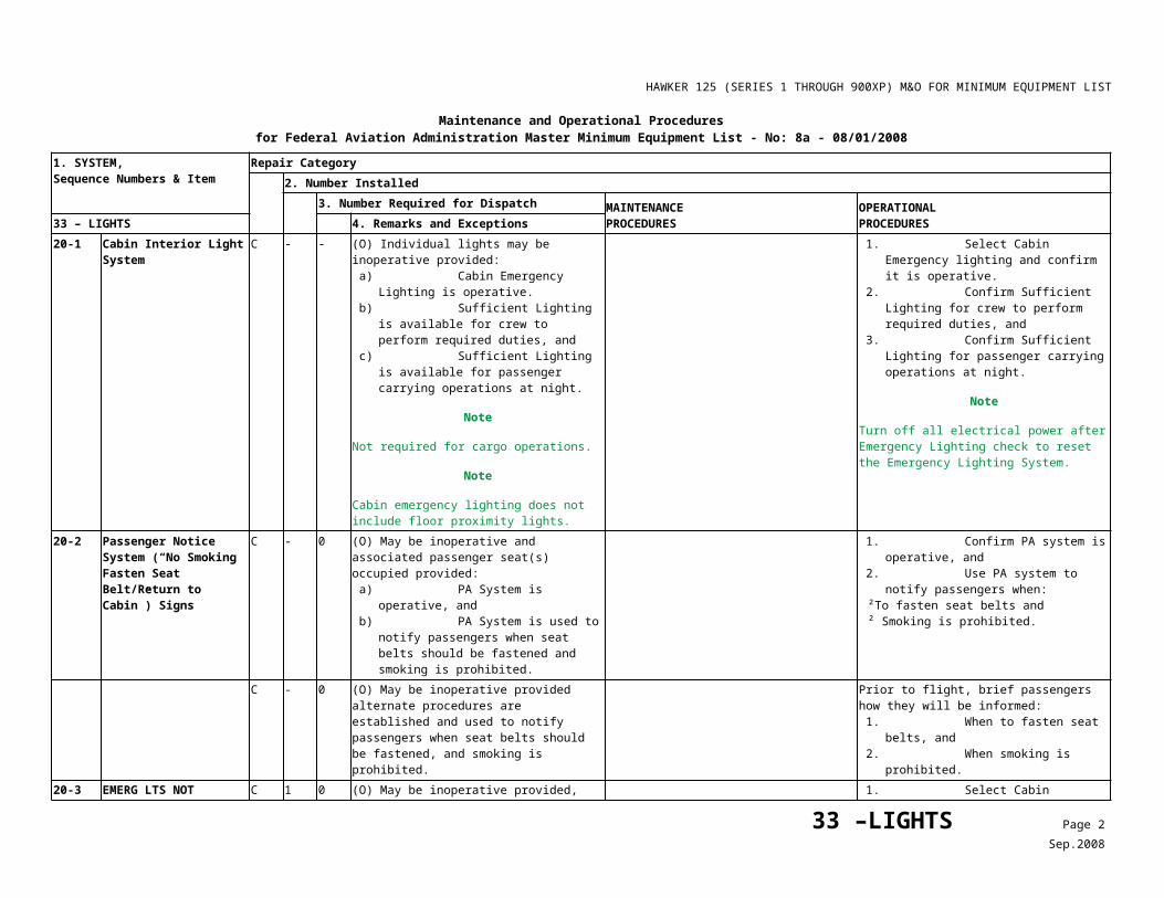
HAWKER 125 (SERIES 1 THROUGH 900XP) M&O FOR MINIMUM EQUIPMENT LIST
Hawker 125 (Series 1 through 900XP) Maintenance and Operational Proceduresfor Federal Aviation Administration Master Minimum Equipment List - No: 8 - 02/18/2008
1. SYSTEMSequence Numbers & Item
Repair Category2. Number Installed
3. Number Required for Dispatch MAINTENANCEPROCEDURES
OPERATIONALPROCEDURES78 – ENGINE EXHAUST 4. Remarks and Exceptions
30-1 Thrust Reversing System (Series 700 and 800, If Installed, and 750, 800XP, 850XP and 900XP)
C 2 0 (M) (O) May be inoperative provided: a) No damage to the thrust reverser
system exists which would adversely affect operation of the airplane, and
b) A procedure is established and used to ensure that the associated thrust reverser(s) is disabled and pinned in the stowed (forward thrust) position.
Refer to Table 1 for maintenance procedure. 1. Confirm that the associated (M) procedure for disabling thrust reverser(s) in the stowed position is accomplished, and
2. Confirm that no apparent damage to the thrust reverser system exists which would adversely affect operation of the airplane, and
3. Plan flight to ensure that safe landings can be made at the airports to be used with the thrust reverser(s) inoperative (INOP).
Note
Care should be exercised when advancing single reverse thrust to avoid controllability effects.
30-2 Thrust Reverser Indicating Annunciators
C 4 0 (M) (O) May be inoperative provided procedures are established and used to ensure associated thrust reverser(s) is disabled and pinned in the stowed (forward thrust) position.
Refer to Table 1 for maintenance procedure. 1. Confirm that the associated (M) procedure for disabling thrust reverser(s) in the stowed position is accomplished, and
2. Plan flight to ensure that safe landings can be made at the airports to be used with the thrust reverser(s) inoperative.
Note
Close attention should be paid to the appropriate brake cooling times as set forth in the Normal Procedures section of the Flight Manual.
78 – EXHAUST Page 1Nov.2007
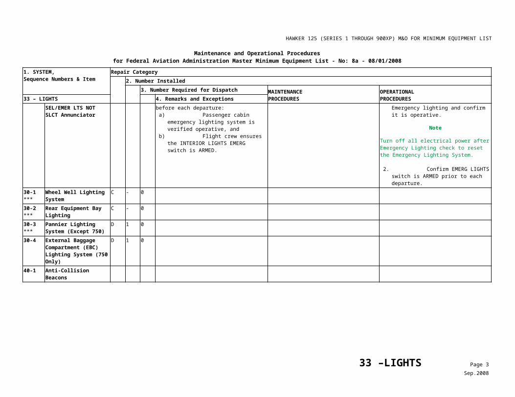
HAWKER 125 (SERIES 1 THROUGH 900XP) M&O FOR MINIMUM EQUIPMENT LIST
Table 1Thrust Reverser Maintenance Procedure
78 - EXHAUST
MAINTENANCEPROCEDURES 30-2
Thrust Reverser Indicating Annunciators
1)
2)
Series 700 and 800, (If Installed)
Series 750, 800XP, 850XP and 900XP
For NORDAM (Dee Howard) Clamshell Thrust Reversers, perform the following steps: a) Verify that the airplane bus bars are de-energized and that no external electrical power is connected. b) Open and collar the Thrust Reverser (TR) circuit breakers (Refer to Table 2). c) Remove the outboard fairing from each TR. d) Verify that the TR’s are stowed and latched. e) On the outboard of each engine install the two latch lock pins through the latch box cover and the latch box.
NOTE
It may be necessary to remove the lockwire from the bolts in the latch box.
f) Attach the two latch lock pins with screws. g) Lockwire the bolts in the latch box and route the wire over the lock pins. h) Inspect visible operating mechanism for evidence of damage. i) Install the outboard fairing to each TR. j) Put a warning placard over the annunciators in the flight compartment reading, ‘THRUST REVERSER INOP’.
For Aeronca Cascade Thrust Reversers, perform the following steps: a) Remove the inboard and outboard pneumatic latch access panels.
NOTE
Before the inboard access panel can be removed, the detachable panels on the engine mounting pylon, adjacent to the pneumatic latch panel, must first be removed.
b) At each pneumatic latch-mounted switch assembly, verify that the switch operating plunger is fully up. Insert a stop pin and push the stop pin fully home.
NOTE
The stop pin is retained by its handling loop abutting the access panel when the panel is closed.
a) At sub-panel DA-E open and collar circuit breaker C1 (LH system) and/or D1 (RH system).b) If both systems are to be inhibited, open and collar circuit breakers C4 and D4 (3A) and E1 (5A).c) Inspect visible mechanism for indications of damage.d) Check that blocker doors are correctly stowed and free of damage.e) Put a warning placard over the annunciators in the flight compartment reading, ‘THRUST REVERSER INOP’.
78 – EXHAUST Page 2Nov.2007
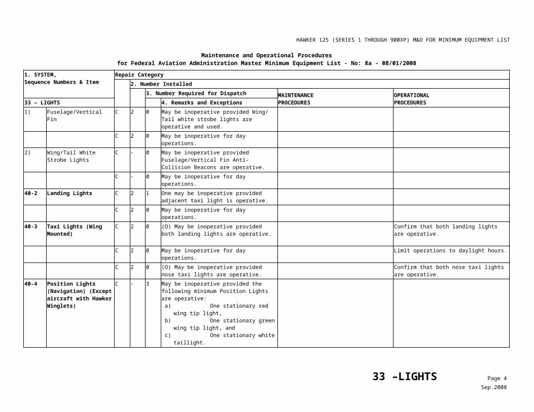
HAWKER 125 (SERIES 1 THROUGH 900XP) M&O FOR MINIMUM EQUIPMENT LIST
Table 2Thrust Reverser Circuit Breakers
No. 1 Thrust Reverser Ident Panel DA-D No. 2 Thrust Reverser Ident Panel DA-DLH DEPLOY RH DEPLOY
LH ANNUN RH ANNUN
LH STOW RH STOW
78 – EXHAUST Page 3Nov.2007
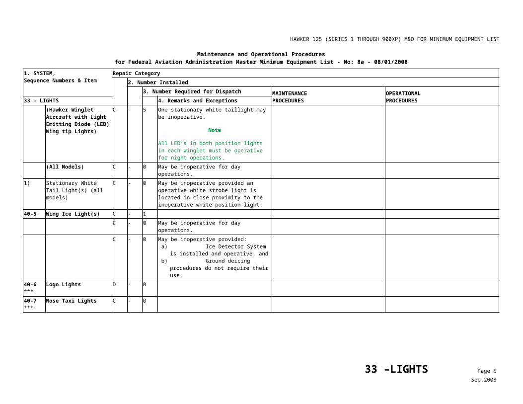
HAWKER 125 (SERIES 1 THROUGH 900XP) M&O FOR MINIMUM EQUIPMENT LIST
Maintenance and Operational Proceduresfor Federal Aviation Administration Master Minimum Equipment List - No: 7 - 09/07/2007
1. SYSTEM, Sequence Numbers & Item
Repair Category2. Number Installed
3. Number Required for Dispatch MAINTENANCEPROCEDURES
OPERATIONALPROCEDURES79 - ENGINE OIL 4. Remarks and Exceptions
30-1 Oil Pressure Low Warning Lights/ Annunciators
C 2 0 (O) May be inoperative provided: a) Associated Oil Pressure and Oil
Temperature Indicators are operative, b) Associated Oil Tank is serviced to
recommended capacity before each departure, and
c) There is no evidence of above normal oil consumption or leakage.
1) Confirm associated Oil Pressure and Oil Temperature indicators are operative,
2) Associated oil tank is serviced to recommended capacity before each departure, and
3) There is no evidence of above normal oil consumption or leakage.
4) Monitor the oil pressure gauge during flight to ensure engine limitations are not exceeded.
79 – OIL Page 1Nov.2007
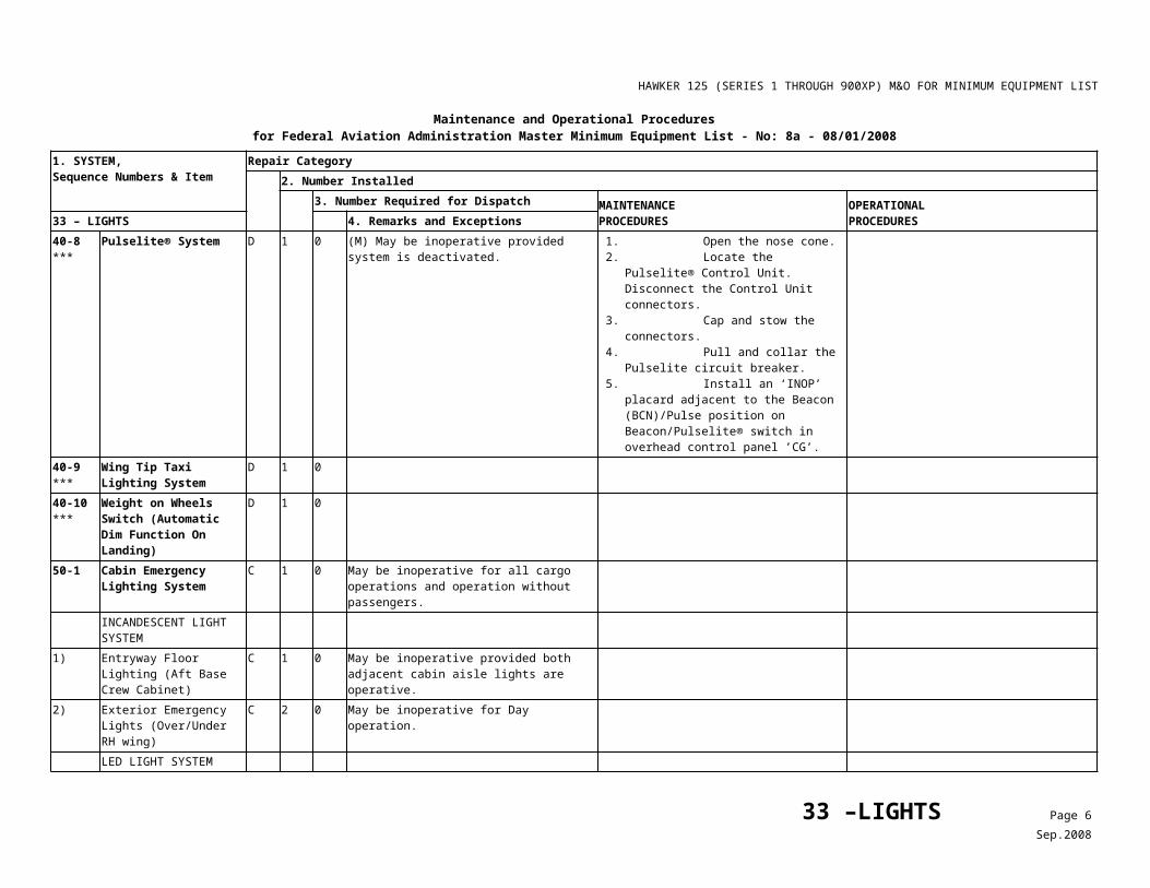
HAWKER 125 (SERIES 1 THROUGH 900XP) M&O FOR MINIMUM EQUIPMENT LIST
Maintenance and Operational Proceduresfor Federal Aviation Administration Master Minimum Equipment List - No: 7 - 09/07/2007
1. SYSTEM, Sequence Numbers & Item
Repair Category2. Number Installed
3. Number Required for Dispatch MAINTENANCEPROCEDURES
OPERATIONALPROCEDURES80 – STARTING 4. Remarks and Exceptions
00-1 Starter Power Available Annunciator (TFE-731 Engines Only)
C 1 0
00-2 Starter Select Light (Viper Engines Only)
C 1 0
00-3 Starter Operating Annunciators (TFE-731 Engines Only)
C 2 0 (O) May be inoperative provided:a) Procedures are established and used to
assure that start power and EXT PWR switches are disengaged when engine reaches self-sustaining speed, and
b) Procedures are established and used to assure that associated generator(s) is (are) on line after each start.
1) Start power and EXT PWR switches are disengaged when engine reaches self-sustaining speed, and
2) Generator is verified to be on line. (Reference After Start checklist.)
80 – STARTING Page 1Nov.2007