1210 manual - fsip · 200 kisco avenue mt. kisco, new york 10509 usa tel.914.666.2971...
TRANSCRIPT
MANUAL
1210 Manual, p/n 37278Rev. A: January 2004
© 2004 CURTIS INSTRUMENTS, INC.
DESIGN OF CURTIS PMC 1200 SERIESCONTROLLERS PROTECTED BY U.S.PATENT NO. 4626750.
MO
DE
L
1 2 1 0MultiMode™
MOTOR CONTROLLER
CURTIS INSTRUMENTS, INC.
200 Kisco AvenueMt. Kisco, New York 10509 USATel. 914.666.2971Fax 914.666.2188
www.curtisinstruments.com
1210
Curtis 1210 Manual ii
12345678901231234567890123123456789012312345678901231234567890123123456789012312345678901231234567890123123456789012312345678901231234567890123123456789012312345678901231234567890123123456789012312345678901231234567890123123456789012312345678901231234567890123123456789012312345678901231234567890123123456789012312345678901231234567890123123456789012312345678901231234567890123123456789012312345678901231234567890123123456789012312345678901231234567890123123456789012312345678901231234567890123123456789012312345678901231234567890123123456789012312345678901231234567890123123456789012312345678901231234567890123123456789012312345678901231234567890123123456789012312345678901231234567890123123456789012312345678901231234567890123123456789012312345678901231234567890123123456789012312345678901231234567890123123456789012312345678901231234567890123123456789012312345678901231234567890123123456789012312345678901231234567890123123456789012312345678901231234567890123123456789012312345678901231234567890123123456789012312345678901231234567890123123456789012312345678901231234567890123123456789012312345678901231234567890123123456789012312345678901231234567890123123456789012312345678901231234567890123123456789012312345678901231234567890123123456789012312345678901231234567890123123456789012312345678901231234567890123123456789012312345678901231234567890123123456789012312345678901231234567890123123456789012312345678901231234567890123123456789012312345678901231234567890123123456789012312345678901231234567890123123456789012312345678901231234567890123123456789012312345678901231234567890123123456789012312345678901231234567890123123456789012312345678901231234567890123123456789012312345678901231234567890123123456789012312345678901231234567890123123456789012312345678901231234567890123123456789012312345678901231234567890123123456789012312345678901231234567890123123456789012312345678901231234567890123123456789012312345678901231234567890123123456789012312345678901231234567890123123456789012312345678901231234567890123123456789012312345678901231234567890123123456789012312345678901231234567890123123456789012312345678901231234567890123
CONTENTS
1. OVERVIEW.............................................................................. 1
2. INSTALLATION AND WIRING ............................................ 4Mounting the Controller .................................................... 4Connections: High Current ............................................... 5Connections: Low Current ................................................ 5Wiring: Applications without Seat Lift .............................. 6Wiring: Applications with Seat Lift ................................... 8Throttle Wiring ................................................................ 10
5kΩ, 3-wire potentiometer throttle........................... 105V throttle ................................................................ 10Curtis ET-XXX electronic throttle ............................ 11Speed limit pot ......................................................... 12
Switches and Other Hardware .......................................... 12Keyswitch ................................................................. 12Push switch ............................................................... 12Brake release switch .................................................. 13Inhibit ...................................................................... 13Status LED ............................................................... 13Battery discharge indicator ........................................ 14Horn ......................................................................... 14Circuitry protection devices ...................................... 14Seat lift switch .......................................................... 14
3. PROGRAMMABLE PARAMETERS ..................................... 15Motor Parameters ............................................................. 17
Main Current Limit .................................................. 17Motor Resistance ...................................................... 17
Acceleration Parameters .................................................... 17Maximum-Speed Forward Acceleration Rate ............ 17Minimum-Speed Forward Acceleration Rate ............ 17Maximum-Speed Reverse Acceleration Rate.............. 18Minimum-Speed Reverse Acceleration Rate .............. 18Gear Soften ............................................................... 18Soft Start ................................................................... 18
Braking Parameters ........................................................... 19Maximum-Speed Forward Deceleration Rate ............ 19Minimum-Speed Forward Deceleration Rate ............ 19Emergency Stop Deceleration Rate ........................... 19Maximum-Speed Reverse Deceleration Rate ............. 19Minimum-Speed Reverse Deceleration Rate ............. 20
CONTENTS
Curtis 1210 Manual iii
CONTENTS
12345678901234123456789012341234567890123412345678901234123456789012341234567890123412345678901234123456789012341234567890123412345678901234123456789012341234567890123412345678901234123456789012341234567890123412345678901234123456789012341234567890123412345678901234123456789012341234567890123412345678901234123456789012341234567890123412345678901234123456789012341234567890123412345678901234123456789012341234567890123412345678901234123456789012341234567890123412345678901234123456789012341234567890123412345678901234123456789012341234567890123412345678901234123456789012341234567890123412345678901234123456789012341234567890123412345678901234123456789012341234567890123412345678901234123456789012341234567890123412345678901234123456789012341234567890123412345678901234123456789012341234567890123412345678901234123456789012341234567890123412345678901234123456789012341234567890123412345678901234123456789012341234567890123412345678901234123456789012341234567890123412345678901234123456789012341234567890123412345678901234123456789012341234567890123412345678901234123456789012341234567890123412345678901234123456789012341234567890123412345678901234123456789012341234567890123412345678901234123456789012341234567890123412345678901234123456789012341234567890123412345678901234123456789012341234567890123412345678901234123456789012341234567890123412345678901234123456789012341234567890123412345678901234123456789012341234567890123412345678901234123456789012341234567890123412345678901234123456789012341234567890123412345678901234123456789012341234567890123412345678901234123456789012341234567890123412345678901234123456789012341234567890123412345678901234123456789012341234567890123412345678901234123456789012341234567890123412345678901234123456789012341234567890123412345678901234123456789012341234567890123412345678901234123456789012341234567890123412345678901234123456789012341234567890123412345678901234123456789012341234567890123412345678901234123456789012341234567890123412345678901234123456789012341234567890123412345678901234123456789012341234567890123412345678901234123456789012341234567890123412345678901234123456789012341234567890123412345678901234123456789012341234567890123412345678901234123456789012341234567890123412345678901234123456789012341234567890123412345678901234
Key-Off Deceleration Rate........................................ 20Brake Delay .............................................................. 20
Speed Parameters .............................................................. 20Maximum Speed, M1/M2 ........................................ 20Minimum Speed, M1/M2 ........................................ 21Maximum Reverse Speed, M1/M2 ........................... 21Minimum Reverse Speed .......................................... 21Creep Speed .............................................................. 21Push Speed ............................................................... 21IR Compensation ..................................................... 22Speed Scaler .............................................................. 22
Throttle Parameters .......................................................... 22Throttle Input Signal Type ....................................... 22Throttle Autocalibration ........................................... 23Throttle Deadband ................................................... 23Throttle Gain ........................................................... 25Ramp Shape (Static Throttle Map) ........................... 26
Fault Parameters ............................................................... 27High Pedal Disable (HPD) ....................................... 27Brake Faults .............................................................. 28Seat Lift Brake Faults ................................................ 28Fault Beep ................................................................. 28
Other Parameters ............................................................. 28Seat Lift .................................................................... 28Virtual Seat Lift ........................................................ 29Beeper Solid .............................................................. 29BDI Full Voltage ....................................................... 29BDI Empty Voltage .................................................. 29BDI Reset Voltage .................................................... 29Sleep Delay ............................................................... 30Tremor Compensation .............................................. 30
4. INITIAL SETUP .................................................................... 31Beginning the Setup Procedures ....................................... 31Throttle ............................................................................ 31Basic Vehicle Checkout .................................................... 33Determining Motor Resistance ......................................... 33
5. VEHICLE PERFORMANCE ADJUSTMENT ..................... 34Setting the Maximum Speeds ........................................... 34Setting the Acceleration and Deceleration Rates ............... 34Adjusting Load Compensation ......................................... 37Fine-Tuning the Vehicle’s Response Smoothness ............... 38
Curtis 1210 Manual iv
6. PROGRAMMER MENUS ..................................................... 401210 Program Menu ........................................................ 401210 Test Menu ............................................................... 421210 Diagnostics and Diagnostic History ........................ 42
7. DIAGNOSTICS AND TROUBLESHOOTING ................... 43Programmer Diagnostics .................................................. 43LED Diagnostics .............................................................. 43Troubleshooting Chart ..................................................... 45
8. MAINTENANCE ................................................................... 46
APPENDIX A Vehicle Design Considerations RegardingElectromagnetic Compatibility (EMC)and Electrostatic Discharge (ESD) .................... A-1
APPENDIX B 1311 Programmer Operation ............................ B-1
APPENDIX C Index to Programmable Parameters ................... C-1
APPENDIX D Specifications .................................................... D-1
12345678901231234567890123123456789012312345678901231234567890123123456789012312345678901231234567890123123456789012312345678901231234567890123123456789012312345678901231234567890123123456789012312345678901231234567890123123456789012312345678901231234567890123123456789012312345678901231234567890123123456789012312345678901231234567890123123456789012312345678901231234567890123123456789012312345678901231234567890123123456789012312345678901231234567890123123456789012312345678901231234567890123123456789012312345678901231234567890123123456789012312345678901231234567890123123456789012312345678901231234567890123123456789012312345678901231234567890123123456789012312345678901231234567890123123456789012312345678901231234567890123123456789012312345678901231234567890123123456789012312345678901231234567890123123456789012312345678901231234567890123123456789012312345678901231234567890123123456789012312345678901231234567890123123456789012312345678901231234567890123123456789012312345678901231234567890123123456789012312345678901231234567890123
CONTENTS
Curtis 1210 Manual v
FIGURES
FIG. 1: Curtis 1210 electronic motor controller .................................. 1
FIG. 2: Mounting dimensions, Curtis 1210 controller ........................ 4
FIG. 3a: Standard wiring configuration, without seat lift ...................... 6
FIG. 3b: Low-power wiring configuration, without seat lift ................... 7
FIG. 4a: Standard wiring configuration, with seat lift ............................ 8
FIG. 4b: Low-power wiring configuration, with seat lift ........................ 9
FIG. 5: Wiring for 5KΩ, 3-wire potentiometer ................................. 10
FIG. 6: Wiring for 5V throttle ........................................................... 11
FIG. 7: Wiring for Curtis ET-XXX electronic throttle ....................... 11
FIG. 8: Wiring to inhibit operation during battery charging ............. 13
FIG. 9: Effect of adjusting the neutral deadband parameter ............... 24
FIG. 10: Effect of adjusting the throttle gain parameter ...................... 25
FIG. 11: Ramp shape (throttle map) for controllerwith maximum speed set at 100% ........................................ 26
FIG. 12: Ramp shape (throttle map) for controllerwith maximum speed set at 60% .......................................... 27
FIG. B-1: Curtis 1311 handheld programmer ..................................... B-1
TABLES
TABLE 1: Programmable throttle input signal types ......................... 22
TABLE 2: Status LED fault codes ..................................................... 45
TABLE 3: Troubleshooting chart ...................................................... 46
TABLE C-1: Parameter index .............................................................C-1
TABLE D-1: Specifications, 1210 controller ...................................... D-1
FIGURES / TABLES
Curtis 1210 Manual 1
1 — OVERVIEW
OVERVIEW
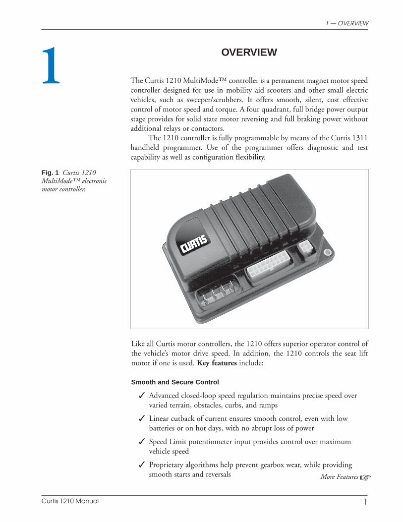
The Curtis 1210 MultiMode™ controller is a permanent magnet motor speedcontroller designed for use in mobility aid scooters and other small electricvehicles, such as sweeper/scrubbers. It offers smooth, silent, cost effectivecontrol of motor speed and torque. A four quadrant, full bridge power outputstage provides for solid state motor reversing and full braking power withoutadditional relays or contactors.
The 1210 controller is fully programmable by means of the Curtis 1311handheld programmer. Use of the programmer offers diagnostic and testcapability as well as configuration flexibility.
1
Fig. 1 Curtis 1210MultiMode™ electronicmotor controller.
Like all Curtis motor controllers, the 1210 offers superior operator control ofthe vehicle’s motor drive speed. In addition, the 1210 controls the seat liftmotor if one is used. Key features include:
Smooth and Secure Control
Advanced closed-loop speed regulation maintains precise speed overvaried terrain, obstacles, curbs, and ramps
Linear cutback of current ensures smooth control, even with lowbatteries or on hot days, with no abrupt loss of power
Speed Limit potentiometer input provides control over maximumvehicle speed
Proprietary algorithms help prevent gearbox wear, while providingsmooth starts and reversals More Features
Curtis 1210 Manual 2
1 — OVERVIEW
The vehicle is brought to a complete stop before the electromagneticbrakes are applied, to prevent harsh jarring
Inhibit line prevents driving while battery charging
Key-Off Decel function ensures smooth braking to a stop when thekey is turned off while driving
Anti Rollback/Roll-forward function improves vehicle control on hillsand ramps
Internal main contactor provides secure power-off and reverse batterypolarity protection
Easy Installation and Setup
Over 40 parameters can be easily adjusted with the 1311 handheldprogrammer or the 1314 PC programmer
Interfaces to several throttle types, including wigwag (center-off)throttles
Simplified troubleshooting and diagnostics
Standard 18-pin Molex and Fast-on terminals provide proven robustconnection
Additional Features
Push Switch input releases the brake and allows the motor to freewheel
Push-Too-Fast software restricts vehicle top speed, even with the keyoff
Built-in functions simplify the wiring needed to add a seat lift
MultiMode™ provides for two distinct and programmable controlmodes (typically used for indoor/outdoor operation)
Power Saver function deactivates the main contactor after a periodof non-use, to reduce battery drain
Battery Discharge Indicator output option provides an accurate signalof the battery charge
Regulatory Compliance
FDA documentation filed
TÜV approved
Unique power design produces low RF emissions to meet stringentmedical limits
High RF immunity prevents speed variation and shutdowns in noisyRF environments
Curtis 1210 Manual 3
Controller’s power circuits and microprocessor software arecontinuously monitored for proper operation
System start-up checks will disable drive if a defective throttle, brake,or associated wiring is detected
Reverse Beeper function alerts bystanders
Optional power and signal wiring boots provide improved sealing foroperation in harsh environments (IP54 with boots, IP40 without).
Familiarity with your Curtis controller will help you install and operate itproperly. We encourage you to read this manual carefully. If you have questions,please contact the Curtis office nearest you.
1 — OVERVIEW
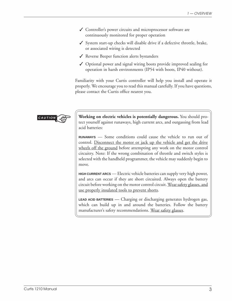
Working on electric vehicles is potentially dangerous. You should pro-tect yourself against runaways, high current arcs, and outgassing from leadacid batteries:
RUNAWAYS — Some conditions could cause the vehicle to run out ofcontrol. Disconnect the motor or jack up the vehicle and get the drivewheels off the ground before attempting any work on the motor controlcircuitry. Note: If the wrong combination of throttle and switch styles isselected with the handheld programmer, the vehicle may suddenly begin tomove.
HIGH CURRENT ARCS — Electric vehicle batteries can supply very high power,and arcs can occur if they are short circuited. Always open the batterycircuit before working on the motor control circuit. Wear safety glasses, anduse properly insulated tools to prevent shorts.
LEAD ACID BATTERIES — Charging or discharging generates hydrogen gas,which can build up in and around the batteries. Follow the batterymanufacturer’s safety recommendations. Wear safety glasses.
C A U T I O N
Curtis 1210 Manual 4
INSTALLATION AND WIRING
MOUNTING THE CONTROLLER
The 1210 controller can be oriented in any position, but the location shouldbe carefully chosen to keep the controller clean and dry. If a clean, drymounting location cannot be found, a cover must be used to shield thecontroller from water and contaminants.
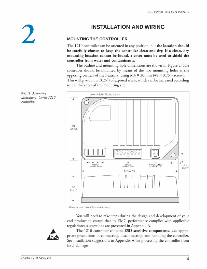
The outline and mounting hole dimensions are shown in Figure 2. Thecontroller should be mounted by means of the two mounting holes at theopposing corners of the heatsink, using M4 × 20 mm (#8 × 0.75") screws.This will give 6 mm (0.25") of exposed screw, which can be increased accordingto the thickness of the mounting site.
22 — INSTALLATION & WIRING
Fig. 2 Mountingdimensions, Curtis 1210controller.
Dimensions in millimeters and (inches)
You will need to take steps during the design and development of yourend product to ensure that its EMC performance complies with applicableregulations; suggestions are presented in Appendix A.
The 1210 controller contains ESD-sensitive components. Use appro-priate precautions in connecting, disconnecting, and handling the controller.See installation suggestions in Appendix A for protecting the controller fromESD damage.
B+ B- M2 M1LOGIC
CONNECTORPROGRAMMERCONNECTOR
POWERCONNECTIONS
J1 J2
4.8 (0.19) dia., 2 plcs
147 (5.79)
6.8(0.27)
43(1.71)
94(3.70)
Curtis 1210 Manual 5
2 — INSTALLATION & WIRING
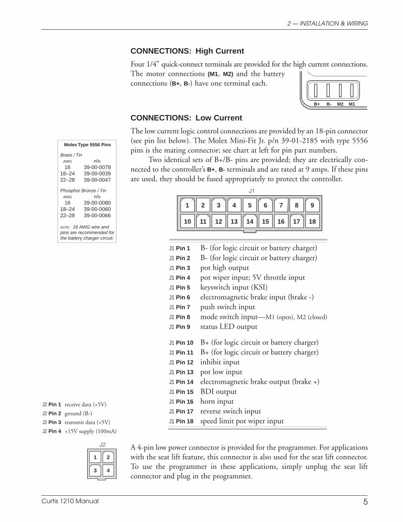
J1 Pin 1 B- (for logic circuit or battery charger)J1 Pin 2 B- (for logic circuit or battery charger)J1 Pin 3 pot high outputJ1 Pin 4 pot wiper input; 5V throttle inputJ1 Pin 5 keyswitch input (KSI)J1 Pin 6 electromagnetic brake input (brake -)J1 Pin 7 push switch inputJ1 Pin 8 mode switch input—M1 (open), M2 (closed)
J1 Pin 9 status LED output
J1 Pin 10 B+ (for logic circuit or battery charger)J1 Pin 11 B+ (for logic circuit or battery charger)J1 Pin 12 inhibit inputJ1 Pin 13 pot low inputJ1 Pin 14 electromagnetic brake output (brake +)J1 Pin 15 BDI outputJ1 Pin 16 horn inputJ1 Pin 17 reverse switch inputJ1 Pin 18 speed limit pot wiper input
1 2 3 4 5 6 7 8 9
10 11 12 13 14 15 16 17 18
CONNECTIONS: High Current
Four 1/4" quick-connect terminals are provided for the high current connections.The motor connections (M1, M2) and the batteryconnections (B+, B-) have one terminal each.
CONNECTIONS: Low Current
The low current logic control connections are provided by an 18-pin connector(see pin list below). The Molex Mini-Fit Jr. p/n 39-01-2185 with type 5556pins is the mating connector; see chart at left for pin part numbers.
Two identical sets of B+/B- pins are provided; they are electrically con-nected to the controller’s B+, B- terminals and are rated at 9 amps. If these pinsare used, they should be fused appropriately to protect the controller.
A 4-pin low power connector is provided for the programmer. For applicationswith the seat lift feature, this connector is also used for the seat lift connector.To use the programmer in these applications, simply unplug the seat liftconnector and plug in the programmer.
1 2
3 4
Molex Type 5556 Pins
Brass / TinAWG P/N16 39-00-0078
18–24 39-00-003922–28 39-00-0047
Phosphor Bronze / TinAWG P/N16 39-00-0080
18–24 39-00-006022–28 39-00-0066
NOTE: 16 AWG wire andpins are recommended forthe battery charger circuit.
J1
J2
J2 Pin 1 receive data (+5V)
J2 Pin 2 ground (B-)
J2 Pin 3 transmit data (+5V)
J2 Pin 4 +15V supply (100mA)
B+ B- M2 M1
Curtis 1210 Manual 6
2 — INSTALLATION & WIRING
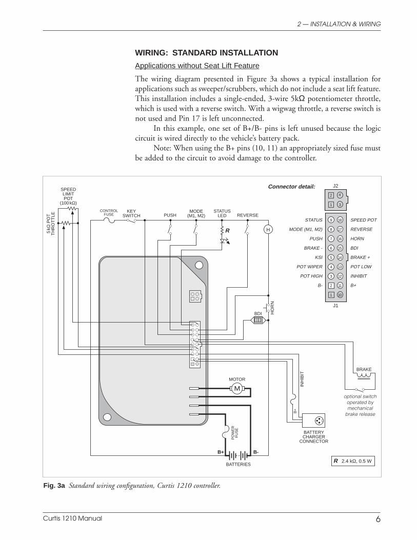
Fig. 3a Standard wiring configuration, Curtis 1210 controller.
WIRING: STANDARD INSTALLATION
Applications without Seat Lift Feature
The wiring diagram presented in Figure 3a shows a typical installation forapplications such as sweeper/scrubbers, which do not include a seat lift feature.This installation includes a single-ended, 3-wire 5kΩ potentiometer throttle,which is used with a reverse switch. With a wigwag throttle, a reverse switch isnot used and Pin 17 is left unconnected.
In this example, one set of B+/B- pins is left unused because the logiccircuit is wired directly to the vehicle’s battery pack.
Note: When using the B+ pins (10, 11) an appropriately sized fuse mustbe added to the circuit to avoid damage to the controller.
J2
1
2
3
4
R 2.4 kΩ, 0.5 W
J1
B+ B-
R H
M INH
IBIT
BRAKE
MODE(M1, M2)
HO
RN
SPEEDLIMITPOT
(100 kΩ)
PUSH
5kΩ
PO
TT
HR
OT
TLE REVERSE
optional switchoperated bymechanical
brake release
CONTROLFUSE
KEYSWITCH
MOTOR
PO
WE
RF
US
E
BDI
BATTERIES
BATTERYCHARGER
CONNECTOR
STATUSLED
SPEED POT
REVERSE
HORN
BDI
BRAKE +
POT LOW
INHIBIT
B+
B+
STATUS
MODE (M1, M2)
PUSH
BRAKE -
KSI
POT WIPER
POT HIGH
B-
B-
16
13
14
10
17
18
11
12
15
7
4
5
1
8
9
2
3
6
Connector detail:
+15V
Tx DATA
GROUND
Rx DATA
B+
Curtis 1210 Manual 7
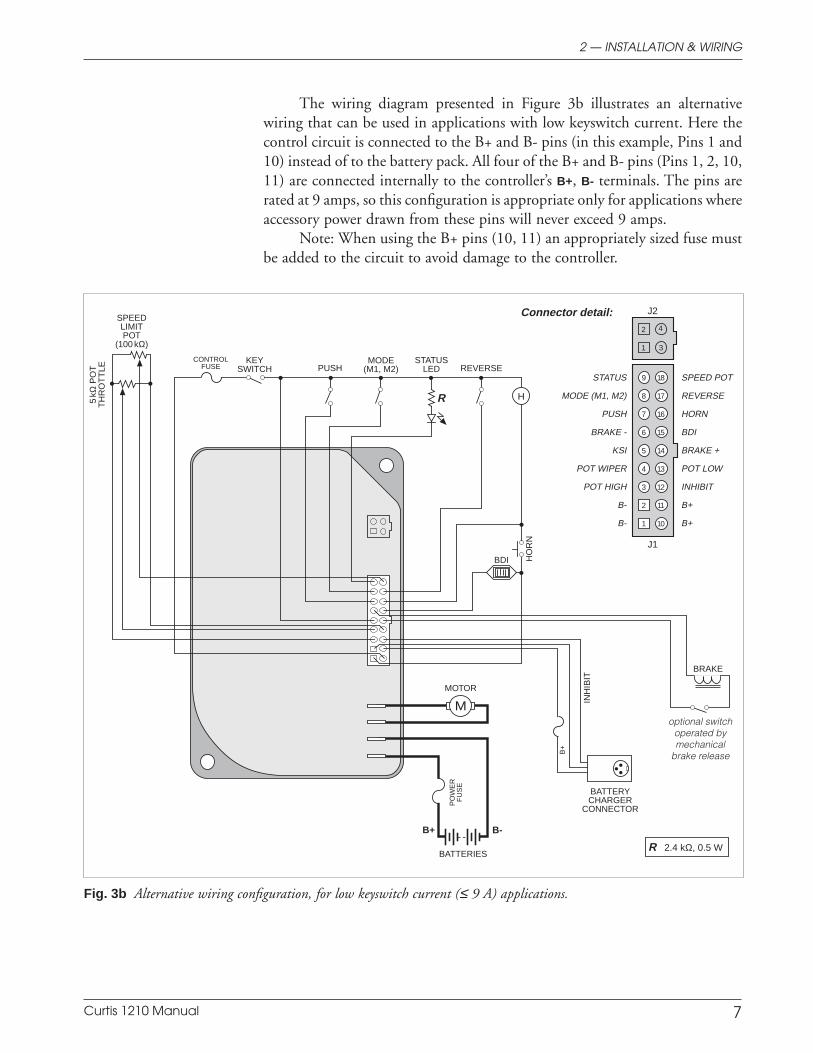
The wiring diagram presented in Figure 3b illustrates an alternativewiring that can be used in applications with low keyswitch current. Here thecontrol circuit is connected to the B+ and B- pins (in this example, Pins 1 and10) instead of to the battery pack. All four of the B+ and B- pins (Pins 1, 2, 10,11) are connected internally to the controller’s B+, B- terminals. The pins arerated at 9 amps, so this configuration is appropriate only for applications whereaccessory power drawn from these pins will never exceed 9 amps.
Note: When using the B+ pins (10, 11) an appropriately sized fuse mustbe added to the circuit to avoid damage to the controller.
2 — INSTALLATION & WIRING
Fig. 3b Alternative wiring configuration, for low keyswitch current (≤ 9 A) applications.
J2
1
2
3
4
R 2.4 kΩ, 0.5 W
J1
B+ B-
R H
M INH
IBIT
BRAKE
MODE(M1, M2)
HO
RN
SPEEDLIMITPOT
(100 kΩ)
PUSH
5kΩ
PO
TT
HR
OT
TLE REVERSE
optional switchoperated bymechanical
brake release
CONTROLFUSE
KEYSWITCH
MOTOR
PO
WE
RF
US
E
BDI
BATTERIES
BATTERYCHARGER
CONNECTOR
STATUSLED
SPEED POT
REVERSE
HORN
BDI
BRAKE +
POT LOW
INHIBIT
B+
B+
STATUS
MODE (M1, M2)
PUSH
BRAKE -
KSI
POT WIPER
POT HIGH
B-
B-
16
13
14
10
17
18
11
12
15
7
4
5
1
8
9
2
3
6
Connector detail:
+15V
Tx DATA
GROUND
Rx DATA
B+
Curtis 1210 Manual 8
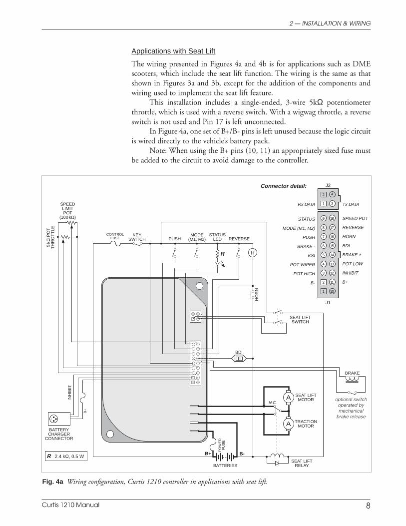
Fig. 4a Wiring configuration, Curtis 1210 controller in applications with seat lift.
2 — INSTALLATION & WIRING
Applications with Seat Lift
The wiring presented in Figures 4a and 4b is for applications such as DMEscooters, which include the seat lift function. The wiring is the same as thatshown in Figures 3a and 3b, except for the addition of the components andwiring used to implement the seat lift feature.
This installation includes a single-ended, 3-wire 5kΩ potentiometerthrottle, which is used with a reverse switch. With a wigwag throttle, a reverseswitch is not used and Pin 17 is left unconnected.
In Figure 4a, one set of B+/B- pins is left unused because the logic circuitis wired directly to the vehicle’s battery pack.
Note: When using the B+ pins (10, 11) an appropriately sized fuse mustbe added to the circuit to avoid damage to the controller.
1
2
3
4
R 2.4 kΩ, 0.5 W
J1
J2
B+ B-
A
R H
A
INH
IBIT
BRAKE
MODE(M1, M2)
HO
RN
SPEEDLIMITPOT
(100 kΩ)
PUSH
5kΩ
PO
TT
HR
OT
TLE
REVERSE
optional switchoperated bymechanical
brake release
CONTROLFUSE
KEYSWITCH
SEAT LIFTMOTOR
PO
WE
RF
US
E
BDI
BATTERIES
BATTERYCHARGER
CONNECTOR
STATUSLED
Connector detail:
SPEED POT
REVERSE
HORN
BDI
BRAKE +
POT LOW
INHIBIT
B+
B+
STATUS
MODE (M1, M2)
PUSH
BRAKE -
KSI
POT WIPER
POT HIGH
B-
B-
TRACTIONMOTOR
N.C.
SEAT LIFTRELAY
SEAT LIFTSWITCH
+15V
Tx DATA
GROUND
Rx DATA
7
4
5
1
8
9
2
3
6
16
13
14
10
17
18
11
12
15
B+
Curtis 1210 Manual 9
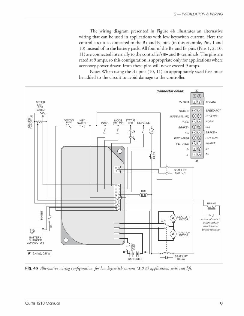
Fig. 4b Alternative wiring configuration, for low keyswitch current (≤ 9 A) applications with seat lift.
2 — INSTALLATION & WIRING
The wiring diagram presented in Figure 4b illustrates an alternativewiring that can be used in applications with low keyswitch current. Here thecontrol circuit is connected to the B+ and B- pins (in this example, Pins 1 and10) instead of to the battery pack. All four of the B+ and B- pins (Pins 1, 2, 10,11) are connected internally to the controller’s B+ and B- terminals. The pins arerated at 9 amps, so this configuration is appropriate only for applications whereaccessory power drawn from these pins will never exceed 9 amps.
Note: When using the B+ pins (10, 11) an appropriately sized fuse mustbe added to the circuit to avoid damage to the controller.
1
2
3
4
R 2.4 kΩ, 0.5 W
J1
J2
B+ B-
A
R H
A
INH
IBIT
BRAKE
MODE(M1, M2)
HO
RN
SPEEDLIMITPOT
(100 kΩ)
PUSH
5kΩ
PO
TT
HR
OT
TLE
REVERSE
optional switchoperated bymechanical
brake release
CONTROLFUSE
KEYSWITCH
SEAT LIFTMOTOR
PO
WE
RF
US
E
BDI
BATTERIES
BATTERYCHARGER
CONNECTOR
STATUSLED
Connector detail:
SPEED POT
REVERSE
HORN
BDI
BRAKE +
POT LOW
INHIBIT
B+
B+
STATUS
MODE (M1, M2)
PUSH
BRAKE -
KSI
POT WIPER
POT HIGH
B-
B-
TRACTIONMOTOR
N.C.
SEAT LIFTRELAY
SEAT LIFTSWITCH
+15V
Tx DATA
GROUND
Rx DATA
7
4
5
1
8
9
2
3
6
16
13
14
10
17
18
11
12
15
B+
Curtis 1210 Manual 10
2 — INSTALLATION & WIRING: Throttle
THROTTLE WIRING
A 3-wire potentiometer throttle or a voltage throttle can be used. The 1210controller can accept a single-ended, inverse single-ended, wigwag, or inversewigwag input signal from the throttle, depending on how the Throttle Typeparameter is programmed; see page 22.
Wiring for the 3-wire pot, voltage throttle, and Curtis ET-XXX electronicthrottle is described in the following text. If the throttle you are planning to useis not covered, contact the Curtis office nearest you.
5kΩ, 3-Wire Potentiometer
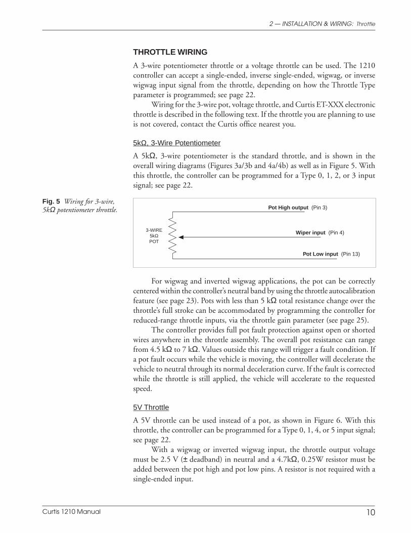
A 5kΩ, 3-wire potentiometer is the standard throttle, and is shown in theoverall wiring diagrams (Figures 3a/3b and 4a/4b) as well as in Figure 5. Withthis throttle, the controller can be programmed for a Type 0, 1, 2, or 3 inputsignal; see page 22.
Fig. 5 Wiring for 3-wire,5kΩ potentiometer throttle.
For wigwag and inverted wigwag applications, the pot can be correctlycentered within the controller’s neutral band by using the throttle autocalibrationfeature (see page 23). Pots with less than 5 kΩ total resistance change over thethrottle’s full stroke can be accommodated by programming the controller forreduced-range throttle inputs, via the throttle gain parameter (see page 25).
The controller provides full pot fault protection against open or shortedwires anywhere in the throttle assembly. The overall pot resistance can rangefrom 4.5 kΩ to 7 kΩ. Values outside this range will trigger a fault condition. Ifa pot fault occurs while the vehicle is moving, the controller will decelerate thevehicle to neutral through its normal deceleration curve. If the fault is correctedwhile the throttle is still applied, the vehicle will accelerate to the requestedspeed.
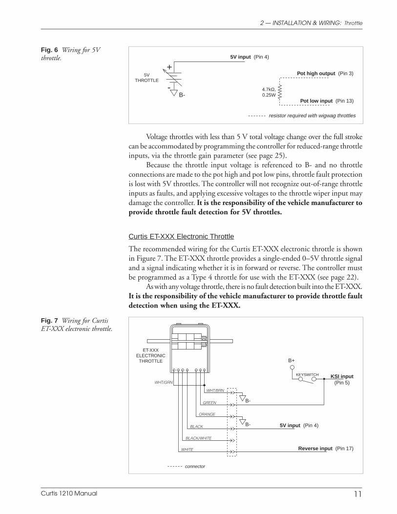
5V Throttle
A 5V throttle can be used instead of a pot, as shown in Figure 6. With thisthrottle, the controller can be programmed for a Type 0, 1, 4, or 5 input signal;see page 22.
With a wigwag or inverted wigwag input, the throttle output voltagemust be 2.5 V (± deadband) in neutral and a 4.7kΩ, 0.25W resistor must beadded between the pot high and pot low pins. A resistor is not required with asingle-ended input.
3-WIRE5kΩPOT
Wiper input (Pin 4)
Pot Low input (Pin 13)
Pot High output (Pin 3)
Curtis 1210 Manual 11
2 — INSTALLATION & WIRING: Throttle
Voltage throttles with less than 5 V total voltage change over the full strokecan be accommodated by programming the controller for reduced-range throttleinputs, via the throttle gain parameter (see page 25).
Because the throttle input voltage is referenced to B- and no throttleconnections are made to the pot high and pot low pins, throttle fault protectionis lost with 5V throttles. The controller will not recognize out-of-range throttleinputs as faults, and applying excessive voltages to the throttle wiper input maydamage the controller. It is the responsibility of the vehicle manufacturer toprovide throttle fault detection for 5V throttles.
Curtis ET-XXX Electronic Throttle
The recommended wiring for the Curtis ET-XXX electronic throttle is shownin Figure 7. The ET-XXX throttle provides a single-ended 0–5V throttle signaland a signal indicating whether it is in forward or reverse. The controller mustbe programmed as a Type 4 throttle for use with the ET-XXX (see page 22).
As with any voltage throttle, there is no fault detection built into the ET-XXX.It is the responsibility of the vehicle manufacturer to provide throttle faultdetection when using the ET-XXX.
Fig. 6 Wiring for 5Vthrottle.
5VTHROTTLE
5V input (Pin 4)
Pot high output (Pin 3)
Pot low input (Pin 13)
4.7kΩ,0.25W
resistor required with wigwag throttles
+
-B-
Fig. 7 Wiring for CurtisET-XXX electronic throttle.
GREEN
ORANGE
BLACK
BLACK/WHITE
WHITE
WHT/BRN
B+
KEYSWITCH
connector
WHT/GRN
ET-XXXELECTRONIC
THROTTLE
B-
B-
Reverse input (Pin 17)
KSI input(Pin 5)
5V input (Pin 4)
Curtis 1210 Manual 12
Speed Limit Pot
A speed limit pot allows the operator to adjust the speed of the vehicle at fullthrottle. The speed limit pot should be sized so that it does not affect throttleinput resistance and thus the throttle response; a 100kΩ pot is recommended.Wiring is shown in the basic wiring diagrams (Figures 3a/3b and 4a/4b).
The speed limit pot is at its maximum speed setting when its wiper isshorted to the throttle pot’s pot high connection (Pin 3). When the speed limitpot is in its maximum speed position, the vehicle’s speed at full throttlecorresponds to the programmed maximum speed setting.
The speed limit pot is at its minimum speed setting when its wiper isshorted to the throttle pot’s pot low connection (Pin 13). When the speed limitpot is in its minimum speed position, the vehicle’s speed at full throttlecorresponds to the programmed minimum speed setting. For information onthe programmable speed parameters, see Section 3.
The speed limit pot varies the vehicle’s speed linearly over the rangebetween the minimum and maximum speed settings in each mode.
The speed limit pot also limits the vehicle’s reverse speed. Reverse speedis linearly proportional to the speed limit pot setting and is adjustable from theprogrammed maximum reverse speed (maximum reverse speed with speed limitpot in its maximum speed position) to the programmed minimum reversespeed (maximum reverse speed with speed limit pot in its minimum speedposition).
If a speed limit pot is not used, the speed limit input (Pin 18) shouldbe jumpered to the pot high output (Pin 3). In this configuration, the vehiclespeed at full throttle is defined by the programmed maximum speed. If no jumperis used, the vehicle speed at full throttle will be limited to the programmedminimum speed, and the controller will register a speed limit pot fault.
SWITCHES AND OTHER HARDWARE
Keyswitch
The vehicle should have an OEM-supplied master on/off switch to turn thesystem off when not in use. The keyswitch provides logic power for thecontroller and for the other control input switches. It must be sized to carry the150 mA quiescent logic current plus the current necessary to drive the prechargefunction (1.5 A for 0.5 seconds) and the status LED, horn, and any otheraccessories powered from the keyswitch circuit.
Push Switch
A push switch can be used to electrically release the electromagnetic brake, sothat the vehicle can be pushed. Activating the push input inhibits the controller’sdrive functions until the push switch is turned off.
The push switch must go from off to on while the vehicle is stopped; if thepush switch is turned on while the vehicle is moving, the electromagnetic brake
2 — INSTALLATION & WIRING: Switches, etc.
Curtis 1210 Manual 13
will not release when the vehicle stops. Also, the controller must be connectedto the batteries and the keyswitch must be turned on in order for the pushfeature to be used.
Brake Release Switch (Brake Coil Disable Switch)
If a brake release lever is used to release the electromagnetic brake mechanically,a brake coil disable switch is recommended. This switch opens the electromag-netic brake coil circuit when the mechanical brake release lever releases thebrake from the motor shaft. The open brake coil circuit will register as a fault,inhibiting controller operation if an operator attempts to drive the vehicle withthe brake mechanically released. This safety feature ensures that the vehiclecannot be driven when the brake cannot be engaged.
Inhibit
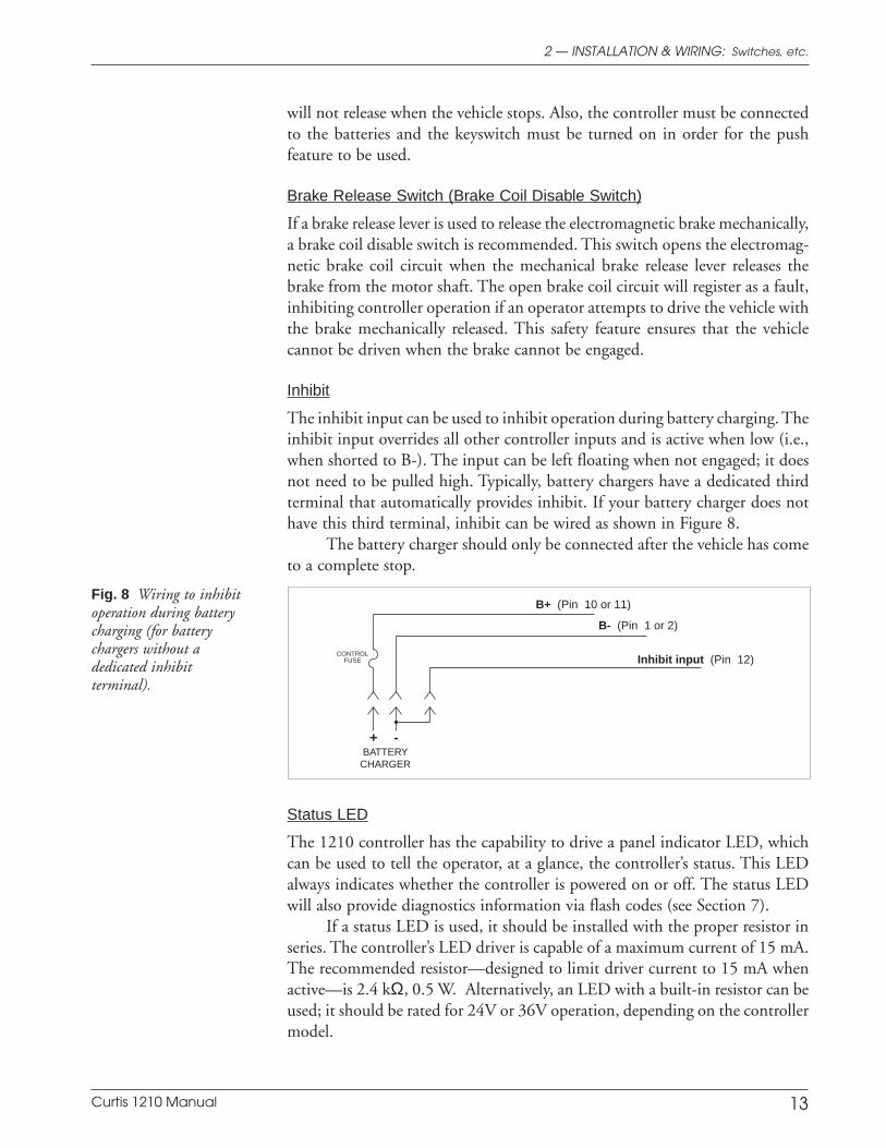
The inhibit input can be used to inhibit operation during battery charging. Theinhibit input overrides all other controller inputs and is active when low (i.e.,when shorted to B-). The input can be left floating when not engaged; it doesnot need to be pulled high. Typically, battery chargers have a dedicated thirdterminal that automatically provides inhibit. If your battery charger does nothave this third terminal, inhibit can be wired as shown in Figure 8.
The battery charger should only be connected after the vehicle has cometo a complete stop.
Fig. 8 Wiring to inhibitoperation during batterycharging (for batterychargers without adedicated inhibitterminal).
BATTERYCHARGER
+ -
CONTROLFUSE
B+ (Pin 10 or 11)
B- (Pin 1 or 2)
Inhibit input (Pin 12)
Status LED
The 1210 controller has the capability to drive a panel indicator LED, whichcan be used to tell the operator, at a glance, the controller’s status. This LEDalways indicates whether the controller is powered on or off. The status LEDwill also provide diagnostics information via flash codes (see Section 7).
If a status LED is used, it should be installed with the proper resistor inseries. The controller’s LED driver is capable of a maximum current of 15 mA.The recommended resistor—designed to limit driver current to 15 mA whenactive—is 2.4 kΩ, 0.5 W. Alternatively, an LED with a built-in resistor can beused; it should be rated for 24V or 36V operation, depending on the controllermodel.
2 — INSTALLATION & WIRING: Switches, etc.
Curtis 1210 Manual 14
2 — INSTALLATION & WIRING: Switches, etc.
Battery Discharge Indicator (BDI)
The 1210 controller can drive a 0–5V panel meter to show the battery pack’sstate of charge as a percentage of the amp-hour capacity of the batteries. TheBDI resets to full charge when the battery voltage rises above the programmedthreshold value (see page 31). The batteries must be put through a full chargecycle with the controller installed before the BDI will begin operation.
The controller must be powered on for the BDI to monitor battery charging.One way to do this is by turning on the keyswitch. Alternatively, the controllercan be factory-configured with the BDI output “stuffed” to automaticallypower up the controller during charging. With this option, you don’t run the riskof forgetting to turn on the keyswitch and thus not getting accurate informa-tion from the BDI. Note: In order for the stuffed BDI output to power up thecontroller, the charger must be connected to the inhibit input; see page 13.
Horn
The controller’s horn driver—Pin 16—is designed to drive a low current dchorn at 1 Hz. The horn sounds a warning when the reverse direction is selected(a series of beep tones) and when the throttle autocalibration feature is beingused (a constant tone). The horn driver sinks a maximum current of 15 mA.Using a horn with a higher current requirement will damage and disable thedriver.
Circuitry Protection Devices
To protect the control wiring from accidental shorts, a low current fuse(appropriately sized for the maximum control circuit current draw) should beconnected in series with the B+ logic supply. A fuse is also recommended for usein the high power connection from the battery to the controller’s B+ terminal.This fuse will protect the power system from external shorts and should be sizedappropriately for the maximum rated current of the controller.
Seat Lift Switch
A seat lift switch can be used to short Pins 1 and 3 of the 4-pin connector (J2),thus activating the throttle-controlled seat lift function. The mating connectorfor J2 is a 4-pin Molex Mini-Fit Jr., p/n 39-01-2045.
Seat lift should not be turned on while the vehicle is moving.

Curtis 1210 Manual 15
3 — PROGRAMMABLE PARAMETERS
PROGRAMMABLE PARAMETERS
The 1210 controller has a number of parameters that can be programmed bymeans of the handheld programmer. These programmable parameters allow thevehicle’s performance characteristics to be customized to best fit the needs ofindividual vehicle operators. For information on programmer operation, seeAppendix B.
The MultiMode™ feature of the 1210 controller allows operation in twodistinct modes: “Mode 1” and “Mode 2.” These modes can be programmed toprovide two different sets of operating characteristics, which can be useful foroperation in different conditions. For example, Mode 1 could be programmedsuch that the vehicle moves slowly for precise, indoor maneuvering and Mode 2programmed for higher speed, long distance travel outdoors. Three parameterscan be configured independently in the two modes:
M1 maximum speedM2 maximum speed
M1 minimum speedM2 minimum speed
M1 maximum reverse speedM2 maximum reverse speed.
The controller is in Mode 2 when the mode switch is in the On position (inputconnected to B+). Leaving the mode input floating or actively switching it Off(pulling it to B-) puts the controller in Mode 1.
3
Curtis 1210 Manual 16
3 — PROGRAMMABLE PARAMETERS
Motor Parameters ............................... p. 17
Main Current LimitMotor Resistance
Acceleration Parameters ................... p. 17
Max-Speed Forward Accel RateMin-Speed Forward Accel RateMax-Speed Reverse Accel RateMin-Speed Reverse Accel RateGear SoftenSoft Start
Braking Parameters ........................... p. 19
Max-Speed Forward Decel RateMin-Speed Forward Decel RateEmergency Stop Decel RateMax-Speed Reverse Decel RateMin-Speed Reverse Decel RateKey-Off Decel RateBrake Delay
Speed Parameters ................................ p. 20
Max Speed, M1/M2Min Speed, M1/M2Max Reverse Speed, M1/M2Min Reverse SpeedCreep SpeedPush SpeedIR CompensationSpeed Scaler
Throttle Parameters ........................... p. 22
Throttle Input Signal TypeThrottle AutocalibrationThrottle DeadbandThrottle GainRamp Shape (Static Throttle Map)
Fault Parameters ................................. p. 27
High Pedal Disable (HPD)Brake FaultsSeat Lift Brake FaultsFault Beep
Other Parameters ............................... p. 28
Seat LiftVirtual Seat LiftBeeper SolidBDI Full VoltageBDI Empty VoltageBDI Reset VoltageSleep DelayTremor Compensation
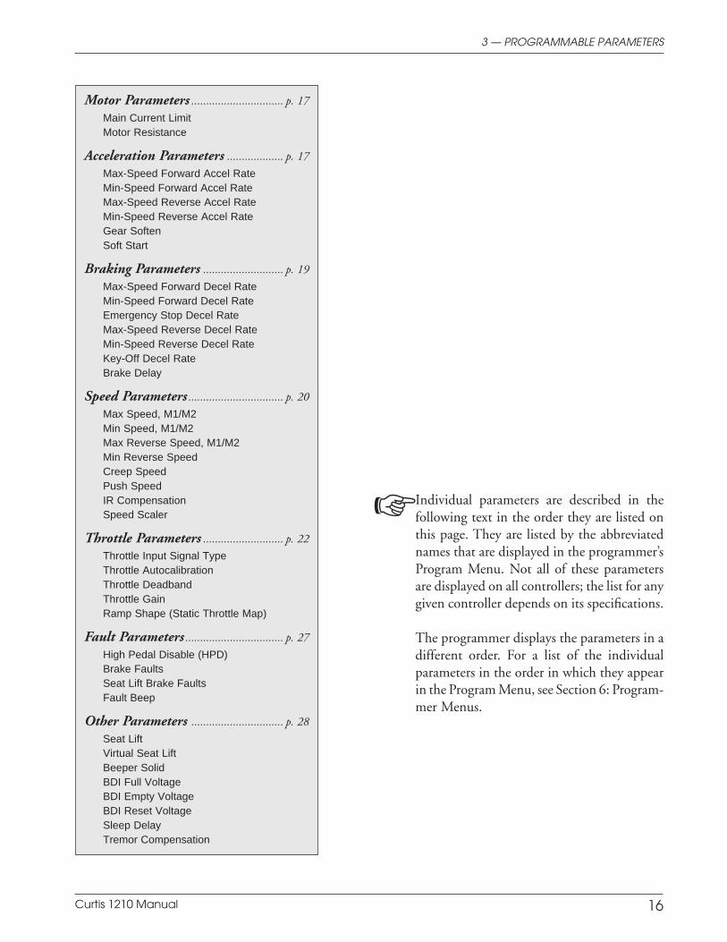
Individual parameters are described in thefollowing text in the order they are listed onthis page. They are listed by the abbreviatednames that are displayed in the programmer’sProgram Menu. Not all of these parametersare displayed on all controllers; the list for anygiven controller depends on its specifications.
The programmer displays the parameters in adifferent order. For a list of the individualparameters in the order in which they appearin the Program Menu, see Section 6: Program-mer Menus.
Curtis 1210 Manual 17
3 — PROGRAMMABLE PARAMETERS: Motor and Acceleration Parameters
Motor Parameters
MAIN C/L
The main current limit parameter allows adjustment of the maximum currentthe controller will supply to the motor during both drive and regenerativebraking operation. This parameter can be limited to protect the motor fromexcessive (potentially damaging) currents or to reduce the maximum torqueapplied to the drive system by the motor. It is adjustable from 30 amps to 100%of the controller’s full rated current. (The full rated current depends on thecontroller model; see 15-second ratings in Table D-1.)
MOTOR R
The motor resistance parameter is crucial to proper vehicle operation. Thecontrol system performance depends on this value being set correctly. The motorresistance parameter is adjustable between 0 and 985 milliohms. It must be setto the actual cold motor resistance. For instructions, see initial setup procedure 4,on page 33.
ACCEL MAX SPD
The maximum-speed forward acceleration rate defines the time it takes thecontroller to accelerate from zero to 100% output during forward travel at fullthrottle with the speed limit pot in its maximum speed position. Larger valuesrepresent a longer acceleration time and gentler starts, while smaller valuesrepresent faster acceleration. The maximum-speed forward acceleration rate isadjustable from 0.2 to 4.0 seconds. Acceleration rates under 0.5 second provideabrupt acceleration and should only be used under special circumstances.
The maximum-speed and minimum-speed forward acceleration rates arescaled linearly to provide appropriate response throughout the speed limit pot’srange.
ACCEL MIN SPD
The minimum-speed forward acceleration rate defines the time it takes thecontroller to accelerate from zero to 100% output during forward travel at fullthrottle with the speed limit pot in its minimum speed position. Larger valuesrepresent a longer acceleration time and gentler starts, while smaller valuesrepresent faster acceleration. The minimum-speed forward acceleration rate isadjustable from 0.2 to 8.0 seconds. Acceleration rates under 0.5 second provideabrupt acceleration and should only be used under special circumstances.
Acceleration Parameters
Curtis 1210 Manual 18
3 — PROGRAMMABLE PARAMETERS: Acceleration Parameters
REV ACCEL MAX
The maximum-speed reverse acceleration rate defines the time it takes thecontroller to accelerate from zero to 100% output while traveling in reverse atfull throttle with the speed limit pot in its maximum speed position. Largervalues represent a longer acceleration time and gentler starts, while smallervalues represent faster acceleration. The maximum-speed reverse accelerationrate is adjustable from 0.2 to 8.0 seconds. Acceleration rates under 0.5 secondprovide abrupt acceleration and should only be used under special circum-stances.
The maximum-speed and minimum-speed reverse acceleration rates arescaled linearly to provide appropriate response throughout the speed limit pot’srange.
REV ACCEL MIN
The minimum-speed reverse acceleration rate defines the time it takes thecontroller to accelerate from zero to 100% output while traveling in reverse atfull throttle with the speed limit pot in its minimum speed position. Largervalues represent a longer acceleration time and gentler starts, while smallervalues represent faster acceleration. The minimum-speed reverse accelerationrate is adjustable from 0.2 to 8.0 seconds. Acceleration rates under 0.5 secondprovide abrupt acceleration and should only be used under special circum-stances.
GEAR SOFTEN
The gear soften feature allows smooth pickup of gear slack in the transmissionwhen torque is reversed; it affects all accelerations except those from zero speed.The effect of this feature is most noticeable when reapplying the throttle fromneutral after decelerating from high speed but before coming to a stop. (See softstart parameter, below, for softening torque endpoints for accelerations from acomplete stop.)
The gear soften parameter is adjustable from 0% to 100%, with 100%providing a great deal of softening and 0% eliminating the feature. The trade-off in increasing the gear soften value is that acceleration response may beslowed somewhat, especially at higher values.
SOFT START
The soft start feature allows softened torque endpoints for forward/reverseaccelerations from a complete stop. When accelerating from a stop, some usersprefer the softened gear slack transitions this parameter can provide, whileothers prefer the vehicle to respond instantly.
The soft start parameter is adjustable from 0% to 100%, with 100%providing a great deal of softening and 0% eliminating the feature. The trade-
Curtis 1210 Manual 19
3 — PROGRAMMABLE PARAMETERS: Braking Parameters
off in increasing the soft start value is that acceleration response may be slowedsomewhat, especially at higher values.
DECEL MAX SPD
The maximum-speed forward deceleration rate determines the time it takesthe controller to decelerate from its present output to zero when the throttle isreleased to neutral during forward travel with the speed limit pot in itsmaximum speed position. Larger values represent a longer deceleration timeand gentler stops. Smaller values will reduce the stopping distance required.The maximum-speed deceleration rate should be set at a value that will ensurethe vehicle stops within a safe distance when traveling at full speed. Themaximum-speed deceleration rate is adjustable from 0.2 to 4.0 seconds. Decel-eration rates under 0.5 second provide abrupt stops and should only be usedunder special circumstances.
DECEL MIN SPD
The minimum-speed forward deceleration rate defines the time it takes thecontroller to decelerate from its present output to zero when the throttle isreleased to neutral during forward travel with the speed limit pot in itsminimum speed position. Larger values represent a longer deceleration timeand gentler stops. Smaller values will reduce the stopping distance required.The minimum-speed deceleration rate is adjustable from 0.2 to 8.0 seconds.Deceleration rates under 0.5 second provide abrupt stops and should only beused under special circumstances.
E STOP
The emergency stop deceleration rate defines the time it takes the vehicle tostop when a reverse throttle command >80% is given while the vehicle ismoving forward. This gives the operator a way to stop more quickly whenunexpected conditions arise.
When the E Stop feature is invoked the E Stop deceleration rate becomesthe new forward deceleration rate. Therefore it makes sense to set it to a valuelower (faster stop) than the fastest forward deceleration rate (DECEL MAX SPEED).The E Stop deceleration rate is adjustable from 0.2 to 4.0 seconds.
REV DECEL MAX
The maximum-speed reverse deceleration rate defines the time it takes thecontroller to decelerate from its present output to zero when the throttle isreleased to neutral during reverse travel with the speed limit pot in its maximumspeed position. Larger values represent a longer deceleration time and gentler
Braking Parameters
Curtis 1210 Manual 20
3 — PROGRAMMABLE PARAMETERS: Speed Parameters
stops. Smaller values will reduce the stopping distance required. The maxi-mum-speed reverse deceleration rate should be set at a value that will ensure thevehicle stops within a safe distance when traveling in reverse at full speed. Themaximum-speed deceleration rate is adjustable from 0.2 to 4.0 seconds. Decel-eration rates under 0.5 second provide abrupt stops and should only be usedunder special circumstances.
REV DECEL MIN
The minimum-speed reverse deceleration rate defines the time it takes thecontroller to decelerate from its present output to zero when the throttle isreleased to neutral during reverse travel with the speed limit pot in its minimumspeed position. Larger values represent a longer deceleration time and gentlerstops. Smaller values will reduce the stopping distance required. The minimum-speed reverse deceleration rate is adjustable from 0.2 to 8.0 seconds. Decelera-tion rates under 0.5 second provide abrupt stops and should only be used underspecial circumstances.
KEY OFF DECEL
The key-off deceleration rate defines the time it takes the vehicle to stop afterthe keyswitch has been turned off while the vehicle is in motion. The key-offdeceleration rate is independent of the normal programmed deceleration rate,the selected mode, and the speed and direction of travel when KSI is switchedoff. It is adjustable from 0.2 to 4.0 seconds.
BRAKE DELAY
The brake delay parameter specifies when the controller engages the electro-magnetic brake after the vehicle’s speed command has reached zero. This timedelay is adjustable from 0.0 to 1.0 seconds. It should be set low enough tominimize rolling downhill when stopping on ramps, yet long enough to allowfor a smooth stop on flat surfaces.
The brake delay does not apply in situations where an incline causes thevehicle to change direction after the throttle command has been zeroed. In thiscase, the controller will detect the “rollback” and engage the electromagneticbrake immediately.
M1/M2 MAX SPD
The maximum speed parameter defines the maximum allowed speed at fullforward throttle with the speed limit pot in its maximum speed position. Forexample, if Mode 1 Maximum Speed is set at 60% and the speed limit pot is inits maximum speed position, the controller will adjust its output to achieve
Speed Parameters
Curtis 1210 Manual 21
60% speed at full throttle in Mode 1. Note: If a speed limit pot is not used inyour application, see page 12.
M1/M2 MIN SPD
The minimum speed parameter defines the maximum allowed speed at fullforward throttle with the speed limit pot in its minimum speed position. Forexample, if Mode 1 Minimum Speed is set at 20% and the speed limit pot is inits minimum speed position, the controller will adjust its output to achieve20% speed at full throttle in Mode 1. The minimum speed cannot be set higherthan the programmed maximum speed. Note: If a speed limit pot is not usedin your application, see page 12.
M1/M2 REV MAX SPD
The maximum reverse speed parameter defines the maximum allowed speedin reverse at full throttle with the speed limit pot in its maximum speedposition. For example, if Mode 1 Maximum Reverse Speed is set at 40% and thespeed limit pot is in its maximum speed position, the controller will adjust itsoutput to achieve 40% reverse speed at full throttle in Mode 1. Note: If a speedlimit pot is not used in your application, see page 12.
REV MIN SPD
The minimum reverse speed parameter defines the maximum allowed speedin reverse at full throttle with the speed limit pot in its minimum speedposition. Reverse speed is not affected by which mode (Mode 1, Mode 2) isselected. Note: If a speed limit pot is not used in your application, see page 12.
CREEP SPD
Creep speed helps to prevent vehicle rollback on inclines when the brake isreleased with very little throttle applied. It is activated when the throttle requestexceeds the throttle’s deadband threshold. The throttle response is rescaled sothat the controller’s output is adjustable over the full throttle range, but startingat the programmed creep speed value. Creep speed is programmable from 0%to 10.0% of the maximum available speed.
PUSH SPD
When the push switch is switched to the On position, the push feature releasesthe electromagnetic brake and allows the vehicle to be manually pushed. Themaximum speed at which the vehicle can be pushed is defined by the pushspeed parameter. It is programmable from 25% to 50% of the maximumavailable speed. This parameter also sets the “push-too-fast” speed, which is themaximum speed at which the vehicle can be pushed when it is unpowered andthe brake is mechanically released. Note: the vehicle must be manually pushed
3 — PROGRAMMABLE PARAMETERS: Speed Parameters
Curtis 1210 Manual 22
fast enough so that the motor voltage reaches approximately 15 V in order forthe push feature to be activated.
IR COMP COEFF
IR compensation is a method by which the controller maintains a constantvehicle speed despite changes in motor loading. The IR compensation param-eter adjusts how aggressively the controller tries to maintain constant speedunder changing load conditions. The parameter is scaled 0–100%, and definesthe percentage of compensation applied.
SPD SCALER
The speed scaler parameter sets the maximum voltage that can be applied tothe motor. It can be used to eliminate variations in maximum speed that wouldotherwise result when driving with a fully charged battery vs. a partially dis-charged battery. If the speed scaler is set at 23 volts, for example, the maximumvehicle speed will be the same whether the actual battery voltage is 28 volts or23 volts or any value in between.
The speed scaler parameter is programmable between 20.0 V and 28.0 V.
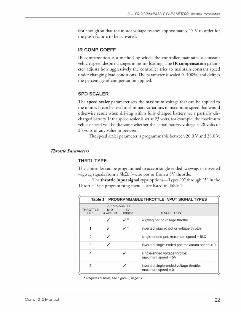
THRTL TYPE
The controller can be programmed to accept single-ended, wigwag, or invertedwigwag signals from a 5kΩ, 3-wire pot or from a 5V throttle.
The throttle input signal type options—Types “0” through “5” in theThrottle Type programming menu—are listed in Table 1.
Table 1 PROGRAMMABLE THROTTLE INPUT SIGNAL TYPES
APPLICABILITYTHROTTLE 5kΩ 5V
TYPE 3-wire Pot Throttle DESCRIPTION
0 * wigwag pot or voltage throttle
1 * inverted wigwag pot or voltage throttle
2 single-ended pot; maximum speed = 5kΩ
3 inverted single-ended pot; maximum speed = 0
4 single-ended voltage throttle;maximum speed = 5V
5 inverted single-ended voltage throttle;maximum speed = 0
* Requires resistor; see Figure 6, page 11.
3 — PROGRAMMABLE PARAMETERS: Throttle Parameters
Throttle Parameters
Curtis 1210 Manual 23
THRTL AUTOCAL
The throttle autocalibration parameter provides a means of easily and reliablycentering wigwag throttle pots. To use this method, a horn must be connectedto the horn driver. The controller inhibits driving while in autocalibrationmode, enabling the throttle potentiometer to be adjusted safely.
Throttle centering is accomplished as follows:
1. Jack the vehicle drive wheels off the ground or disconnect the motorleads.
2. Completely assemble the throttle mechanism but do not tightenthe clamping mechanism that secures the potentiometer shaft tothe throttle lever.
3. Plug the programmer into the controller, and turn on the key-switch.
4. Select the program mode and scroll down to the throttle auto-calibration parameter.
5. Set the throttle autocalibration to On. At this point, the horn willprobably sound, indicating that the throttle pot is out of adjust-ment. If the horn does not sound, the pot is already centered andfurther adjustment is not necessary.
6. With the throttle lever at the neutral position, adjust the potenti-ometer in one direction until the horn turns off. Note this position.Adjust the pot in the other direction until the horn turns off. Notethis position. Set the pot halfway between the two noted positions.The pot is now adjusted to the proper value for neutral.
7. Tighten the clamping mechanism that secures the throttle lever tothe potentiometer shaft. Depress and release the throttle to verifythe mechanical return to neutral; the horn should turn off with thesame amount of motion in both directions.
8. Set the throttle autocalibration parameter to Off, or cycle thekeyswitch to reset it to Off. (If you are performing the reset bycycling the keyswitch, note that KSI must remain off for at least4 seconds.) The vehicle will not drive if the throttle autocalibrationparameter is left On.
THRTL DEADBAND
The throttle deadband parameter defines the throttle pot wiper voltage rangethat the controller interprets as neutral. Increasing the throttle deadband settingincreases the neutral range. This parameter is especially useful with throttleassemblies that do not reliably return to a well-defined neutral point, because itallows the deadband to be defined wide enough to ensure that the controllergoes into neutral when the throttle mechanism is released.
3 — PROGRAMMABLE PARAMETERS: Throttle Parameters
Curtis 1210 Manual 24
3 — PROGRAMMABLE PARAMETERS: Throttle Parameters
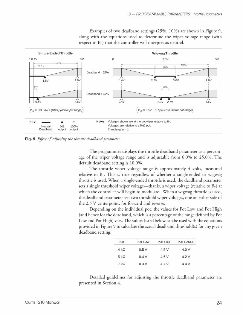
Fig. 9 Effect of adjusting the throttle deadband parameter.
Single-Ended Throttle Wigwag Throttle
0 5V
0.8V
Deadband = 25%
1.5V
0 5V
2.3V 2.7V
2.0V 3.0V
2.5V
KEY:
Neutral 0% 100%Deadband output output
Notes: Voltages shown are at the pot wiper relative to B-.Voltages are relative to a 5kΩ pot.Throttle gain = 1.
0.4V
0.4V 4.6V
4.6V4.6V
4.6V
VDB = Pot Low + (DB%) (active pot range) VDB = 2.5V ± (0.5) (DB%) (active pot range)
0.4V
25%100%
10%
100%
Deadband = 10%
25%
10%
Examples of two deadband settings (25%, 10%) are shown in Figure 9,along with the equations used to determine the wiper voltage range (withrespect to B-) that the controller will interpret as neutral.
The programmer displays the throttle deadband parameter as a percent-age of the wiper voltage range and is adjustable from 6.0% to 25.0%. Thedefault deadband setting is 10.0%.
The throttle wiper voltage range is approximately 4 volts, measuredrelative to B-. This is true regardless of whether a single-ended or wigwagthrottle is used. When a single-ended throttle is used, the deadband parametersets a single threshold wiper voltage—that is, a wiper voltage (relative to B-) atwhich the controller will begin to modulate. When a wigwag throttle is used,the deadband parameter sets two threshold wiper voltages, one on either side ofthe 2.5 V centerpoint, for forward and reverse.
Depending on the individual pot, the values for Pot Low and Pot High(and hence for the deadband, which is a percentage of the range defined by PotLow and Pot High) vary. The values listed below can be used with the equationsprovided in Figure 9 to calculate the actual deadband threshold(s) for any givendeadband setting:
POT POT LOW POT HIGH POT RANGE
4 kΩ 0.5 V 4.5 V 4.0 V
5 kΩ 0.4 V 4.6 V 4.2 V
7 kΩ 0.3 V 4.7 V 4.4 V
Detailed guidelines for adjusting the throttle deadband parameter arepresented in Section 4.
Curtis 1210 Manual 25
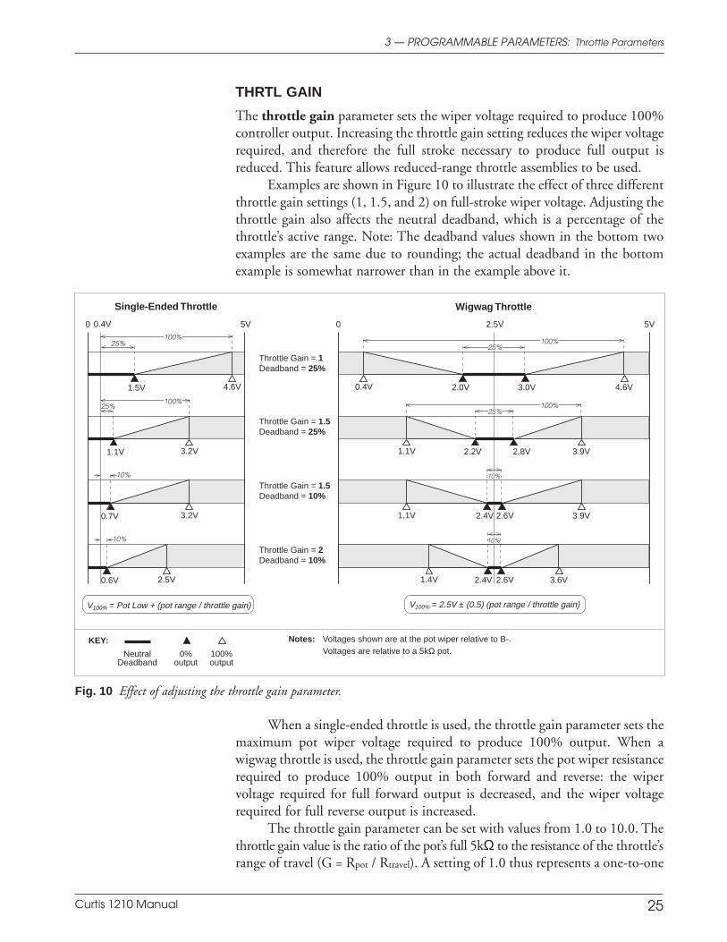
THRTL GAIN
The throttle gain parameter sets the wiper voltage required to produce 100%controller output. Increasing the throttle gain setting reduces the wiper voltagerequired, and therefore the full stroke necessary to produce full output isreduced. This feature allows reduced-range throttle assemblies to be used.
Examples are shown in Figure 10 to illustrate the effect of three differentthrottle gain settings (1, 1.5, and 2) on full-stroke wiper voltage. Adjusting thethrottle gain also affects the neutral deadband, which is a percentage of thethrottle’s active range. Note: The deadband values shown in the bottom twoexamples are the same due to rounding; the actual deadband in the bottomexample is somewhat narrower than in the example above it.
3 — PROGRAMMABLE PARAMETERS: Throttle Parameters
Fig. 10 Effect of adjusting the throttle gain parameter.
Single-Ended Throttle Wigwag Throttle
0 5V
Throttle Gain = 1Deadband = 25%
1.5V
0 5V
2.0V 3.0V
2.5V
KEY:
Neutral 0% 100%Deadband output output
Notes: Voltages shown are at the pot wiper relative to B-.Voltages are relative to a 5kΩ pot.
0.4V 4.6V4.6V
V100% = Pot Low + (pot range / throttle gain) V100% = 2.5V ± (0.5) (pot range / throttle gain)
0.4V
25%100%100%
Throttle Gain = 1.5Deadband = 25%
Throttle Gain = 1.5Deadband = 10%
Throttle Gain = 2Deadband = 10%
1.1V 3.2V
100%
2.2V 2.8V1.1V 3.9V
25%100%
2.4V 2.6V1.1V 3.9V
10%
0.7V 3.2V
0.6V 2.5V 2.4V 2.6V1.4V 3.6V
10%
25%
25%
10%
10%
When a single-ended throttle is used, the throttle gain parameter sets themaximum pot wiper voltage required to produce 100% output. When awigwag throttle is used, the throttle gain parameter sets the pot wiper resistancerequired to produce 100% output in both forward and reverse: the wipervoltage required for full forward output is decreased, and the wiper voltagerequired for full reverse output is increased.
The throttle gain parameter can be set with values from 1.0 to 10.0. Thethrottle gain value is the ratio of the pot’s full 5kΩ to the resistance of the throttle’srange of travel (G = Rpot / Rtravel). A setting of 1.0 thus represents a one-to-one
Curtis 1210 Manual 26
ratio—in other words, no throttle gain adjustment. A setting of 10.0 wouldallow use of a pot with a range of only 1/10th of 5kΩ, i.e., 500 ohms. For mostapplications, throttle gain settings between 1.0 and 2.0 will work best.
Note: The throttle characteristics are defined in terms of wiper voltagerather than throttle pot resistance because of the range of pot values that can beused and the variation between pots of the same value.
Detailed guidelines for adjusting the throttle gain parameter are pre-sented in Section 4.
RAMP SHAPE
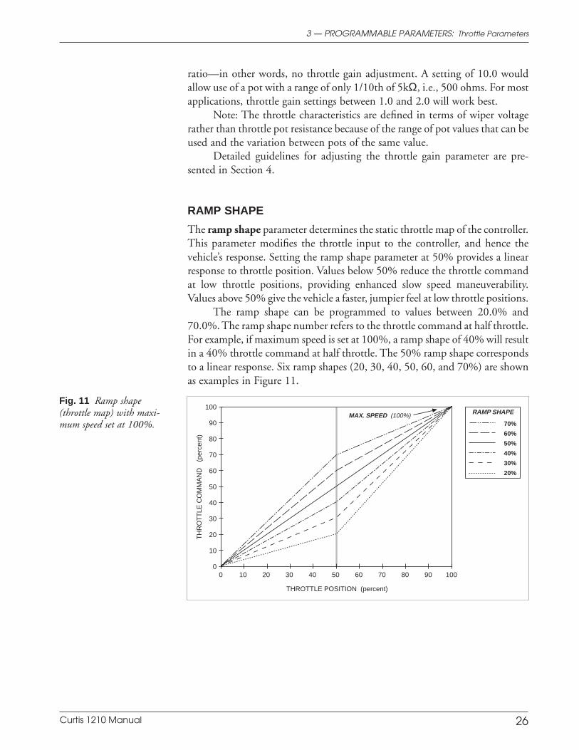
The ramp shape parameter determines the static throttle map of the controller.This parameter modifies the throttle input to the controller, and hence thevehicle’s response. Setting the ramp shape parameter at 50% provides a linearresponse to throttle position. Values below 50% reduce the throttle commandat low throttle positions, providing enhanced slow speed maneuverability.Values above 50% give the vehicle a faster, jumpier feel at low throttle positions.
The ramp shape can be programmed to values between 20.0% and70.0%. The ramp shape number refers to the throttle command at half throttle.For example, if maximum speed is set at 100%, a ramp shape of 40% will resultin a 40% throttle command at half throttle. The 50% ramp shape correspondsto a linear response. Six ramp shapes (20, 30, 40, 50, 60, and 70%) are shownas examples in Figure 11.
3 — PROGRAMMABLE PARAMETERS: Throttle Parameters
Fig. 11 Ramp shape(throttle map) with maxi-mum speed set at 100%.
MAX. SPEED (100%)
THROTTLE POSITION (percent)
TH
RO
TT
LE C
OM
MA
ND
(pe
rcen
t)
70%
60%
50%
40%
30%
20%
RAMP SHAPE100
90
80
70
60
50
40
30
20
10
0100908070605040302010 0
Curtis 1210 Manual 27
3 — PROGRAMMABLE PARAMETERS: Fault Parameters
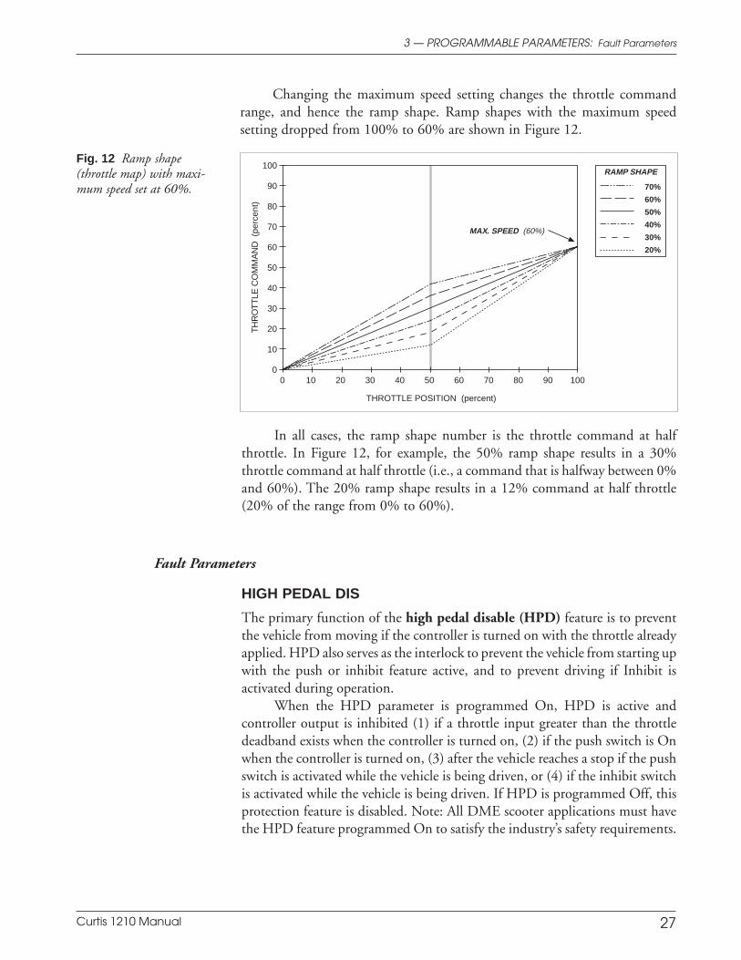
Changing the maximum speed setting changes the throttle commandrange, and hence the ramp shape. Ramp shapes with the maximum speedsetting dropped from 100% to 60% are shown in Figure 12.
Fig. 12 Ramp shape(throttle map) with maxi-mum speed set at 60%.
MAX. SPEED (60%)
THROTTLE POSITION (percent)
TH
RO
TT
LE C
OM
MA
ND
(pe
rcen
t)
70%
60%
50%
40%
30%
20%
RAMP SHAPE100
90
80
70
60
50
40
30
20
10
0100908070605040302010 0
In all cases, the ramp shape number is the throttle command at halfthrottle. In Figure 12, for example, the 50% ramp shape results in a 30%throttle command at half throttle (i.e., a command that is halfway between 0%and 60%). The 20% ramp shape results in a 12% command at half throttle(20% of the range from 0% to 60%).
HIGH PEDAL DIS
The primary function of the high pedal disable (HPD) feature is to preventthe vehicle from moving if the controller is turned on with the throttle alreadyapplied. HPD also serves as the interlock to prevent the vehicle from starting upwith the push or inhibit feature active, and to prevent driving if Inhibit isactivated during operation.
When the HPD parameter is programmed On, HPD is active andcontroller output is inhibited (1) if a throttle input greater than the throttledeadband exists when the controller is turned on, (2) if the push switch is Onwhen the controller is turned on, (3) after the vehicle reaches a stop if the pushswitch is activated while the vehicle is being driven, or (4) if the inhibit switchis activated while the vehicle is being driven. If HPD is programmed Off, thisprotection feature is disabled. Note: All DME scooter applications must havethe HPD feature programmed On to satisfy the industry’s safety requirements.
Fault Parameters
Curtis 1210 Manual 28
3 — PROGRAMMABLE PARAMETERS: Other Parameters
BRAKE FLTS
The brake faults parameter enables (“On”) or disables (“Off”) all the electro-magnetic brake driver and wiring fault detection. All DME scooter applicationsmust have this parameter programmed On to satisfy the industry’s safetyrequirements.
In non-DME applications such as sweeper/scrubbers, where there is noelectromagnetic brake, the brake faults parameter can be programmed Off, thuseliminating the need for the 200Ω, 5W bias resistor on the controller’s brakedriver output that would otherwise be necessary.
SL BRAKE FLTS
The seat lift brake faults parameter enables (“On”) or disables (“Off”) thebrake coil open and shorted brake driver fault detection in seat lift mode.
The seat lift brake faults parameter is only active when the standard brakefaults parameter is also programmed On. If the standard brake faults parameteris programmed Off, there will be no fault detection in seat lift mode even if theseat lift brake faults parameter is programmed On.
FAULT BEEP
The fault beep parameter enables the horn during controller faults, in order tomake the fault codes audible. It beeps only the fault codes; it does not precedethe fault code with a level-of-seriousness code (as does the status LED, with itsslow/fast flash preceding the fault code). If this audible alarm is not wanted, thefault beep parameter should be programmed Off.
SEAT LIFT
DME scooter systems typically use the 1210 controller to drive the seat liftmotor as well as the traction motor. The power path is determined by a relaythat routes motor drive power from the controller to either the traction motoror the seat lift motor depending on whether the seat lift switch is open or closed;see Figures 4a/4b. When the seat lift feature is active, the controller disables theelectromagnetic brake driver (i.e., sets the brake), and operates in Mode 1,regardless of mode switch position.
The seat lift switch connector plugs into J2 (the 4-pin connector). Thecontroller transitions from traction mode to seat lift mode when the seat liftswitch is closed.
To use the programmer, you must remove the seat lift switch connectorfrom J2 in order to plug in the programmer; both connectors use J2. When youhave finished using the programmer, the seat lift switch connector can beplugged back into J2.
Other Parameters
Curtis 1210 Manual 29
The seat lift parameter enables (“On”) or disables (“Off”) seat lift mode.Programming the seat lift parameter On enables the controller to recognize seatlift switch inputs at J2. If the seat lift parameter is programmed Off, the controllerwill not respond to the seat lift switch, even when it is plugged into J2.
VSL
The handheld programmer and the seat lift switch input share the same 4-pinconnector (J2) on the controller—see Figures 4a/4b. The virtual seat liftparameter allows the controller to be put into seat lift mode when the program-mer—rather than the seat lift switch input—is plugged in. Setting this param-eter On transitions the controller from traction mode to seat lift mode, and setsthe brake (i.e., disables the electromagnetic brake driver). This can be conve-nient when the programmer is being used during vehicle checkout. VSLautomatically resets to Off when the keyswitch is cycled.
For controllers without the VSL parameter, seat lift operation can betested only when the programmer is not plugged in.
BEEPER SOLID
The beeper solid parameter, when programmed On, provides a continuous24V+ signal to the horn driver (Pin 16) when throttle is requested in reverse;this signal can be used to drive a logic function—such as a watering solenoid fora sweeper/scrubber.
When a horn is connected to Pin 16, the Beeper Solid parameter istypically programmed Off. With Beeper Solid programmed Off, the hornsounds a series of beep tones when throttle is requested in reverse.
BDI FULL VLTS
The BDI full voltage parameter sets the battery voltage considered to be a100% state-of-charge. It should be set to the voltage level of the fully-chargedbattery pack.
BDI EMPTY VLTS
The BDI empty voltage parameter sets the battery voltage considered to be a0% state-of-charge; when the battery pack remains under this voltage consis-tently, the BDI will read 0% state of charge. It is typically set to about 85% ofBDI full voltage.
BDI RESET
The BDI reset voltage parameter sets the no-load threshold at which thecontroller’s battery-state-of-charge calculator will reset to 100%. When thisvoltage is present for 2 minutes the battery discharge indicator (BDI) is reset to
3 — PROGRAMMABLE PARAMETERS: Other Parameters
Curtis 1210 Manual 30
3 — PROGRAMMABLE PARAMETERS: Other Parameters
100%. Because this is the charging voltage, it is set 2 to 3 volts higher than theactual battery voltage (e.g., 27 V for a 24V system).
SLEEP DLY
The controller powers down completely if the throttle request remains atneutral beyond the time specified by the sleep delay parameter; to resumeoperation, the keyswitch must be cycled. The sleep delay can be set from 0 to60 minutes. Setting this parameter to zero disables the sleep delay.
TREMOR COMP
The tremor compensation parameter allows adjustment to limit the controller’sresponse to sharp throttle movements, such as movements resulting from handtremors. The tremor compensation parameter can be set to values of 1 through 5,with 1 providing no compensation, and 5 providing the most. Although largervalues provide steadier response, they also result in more sluggish response tothrottle requests. There is thus a trade-off between crispness of response (lowtremor compensation settings) and steady speed in the presence of tremors(high tremor compensation settings).
The effect of tremor compensation is most noticeable when the throttleis moved quickly from full to very low requests. Note: this function is bypassedif the throttle moves into the neutral deadband.
Although designed primarily to help end users with hand tremor prob-lems, this parameter can be used more generally to smooth out overall vehicleresponsiveness for steadier driving.
Curtis 1210 Manual 31
4 — INITIAL SETUP
4 INITIAL SETUP
Before operating the vehicle, carefully complete the following initial setupprocedures. If you find a problem during the checkout, refer to the diagnosticsand troubleshooting section (Section 7) for further information.
Before starting the setup procedures, jack the vehicle drive wheels upoff the ground so that they spin freely. Doublecheck all wiring to ensure thatit is consistent with the wiring guidelines presented in Section 2. Make sure allconnections are tight.
1 Begin the setup procedures
1-a. Put the throttle in neutral, and make sure the forward/reverseswitches are open.
1-b. Turn on the controller and plug in the 1311 programmer. Theprogrammer should power up with an initial display, and the status LED shouldlight steadily. If neither happens, check for continuity in the keyswitch circuitand controller ground.
2 Throttle
Put the programmer into Program mode, and set the Throttle Type parameterto match the throttle you are using (Type 0–5); see page 22.
It is important to ensure that the controller output is operating over itsfull range. The following tuning procedures will establish the throttle deadbandand throttle gain parameter values that correspond to the absolute full range ofyour particular throttle mechanism.* It is advisable to include some bufferaround the absolute full range of the throttle mechanism to allow for throttleresistance variations over time and temperature as well as variations in thetolerance of potentiometer values between individual throttle mechanisms.
Tuning the Throttle Deadband2-a. Select the Test Menu. The Throttle % field should be visible in the
display. You will need to reference the value displayed here..2-b. Slowly apply the throttle until you hear the electromagnetic brake
disengage. Use care with this step as it is important to identify the thresholdthrottle position at which the brake is disengaged.
2-c. Without moving the throttle, read the value shown in the Throttle% field. This value should be zero. If the Throttle % value is zero, proceed toStep 2-d. If it is greater than zero, the throttle deadband parameter must beincreased. Select the Program Menu, scroll down to display the THRTL DEADBAND
field, and enter a larger THRTL DEADBAND value. Select the Test Menu and repeat
* If you are using a wigwag throttle, you should center it before proceeding withthe throttle tuning procedures. Instructions for wigwag throttle centering (usingthe Throttle Autocalibration parameter) are presented on page 23.

Curtis 1210 Manual 32
4 — INITIAL SETUP
the procedure from Step 2-b until the Throttle % is zero at the electromagneticbrake disengagement point.
2-d. While observing the Throttle % value displayed in the programmer’sTest Menu, continue to increase the throttle past the electromagnetic brakedisengagement point. Note where the Throttle % value begins to increase,indicating that the controller has begun to supply drive power to the motor. Ifthe throttle had to be moved further than desired before the Throttle % valuebegan to increase, the throttle deadband parameter must be decreased. In theProgram Menu, scroll down to the THRTL DEADBAND field, and enter a smallerTHRTL DEADBAND value. Select the Test Menu and repeat the procedure from Step2-b. When the amount of travel between the point at which the brake isdisengaged and the Throttle % value begins to increase is acceptable, thethrottle deadband is properly tuned.
2-e. If a bidirectional (wigwag) throttle assembly is being used, theprocedure should be repeated for the reverse direction. The THRTL DEADBAND valueshould be selected such that the throttle operates correctly in both forward andreverse.
Tuning the Throttle Gain2-f. Apply full throttle and observe the Throttle % value. This value
should be 100%. If it is less than 100%, the throttle gain must be increased toattain full controller output at the maximum throttle position. Select theProgram Menu, scroll down to the THROTTLE GAIN field, and enter a largerTHROTTLE GAIN value. Select the Test Menu and repeat this step until the Throttle% value is 100%.
2-g. Now that the full throttle position results in a 100% value forThrottle %, slowly reduce throttle until the Throttle % value drops below100% and note the throttle position. This represents the extra range of motionallowed by the throttle mechanism. If this range is large, you may wish todecrease it by decreasing the throttle gain. This will provide a larger activethrottle range and more vehicle control. Select the Program Menu, scroll downto the THROTTLE GAIN field, and enter a smaller THROTTLE GAIN value. Select the TestMenu and repeat this step until an appropriate amount of extra range isattained.
2-h. If a wigwag throttle is being used, repeat the procedure for thereverse direction. The THROTTLE GAIN value should be selected such that thethrottle operates correctly in both forward and reverse.
Confirming proper throttle operationSelect a direction and operate the throttle. The motor should begin to
turn in the selected direction. If it does not, verify the wiring to the throttle andmotor. The motor should run proportionally faster with increasing throttle. Ifnot, refer to Section 7.
Curtis 1210 Manual 33
3 Basic vehicle checkout
Put the programmer in Test mode, and scroll down the menu to observe thestatus of the switches: mode, reverse, and push. Plug in the battery charger toverify the Inhibit input status. Cycle each input in turn, observing the program-mer. The programmer should display the correct status for each input.
Similarly, check the throttle and speed limit pot inputs. The programmershould display the correct value for each input.
Verify that all options, such as high pedal disable (HPD) and seat lift, areas desired. To verify operation of the seat lift function, put the programmer intoProgram mode and set the VSL parameter On; if VSL is not an option, you willneed to unplug the programmer and plug in the seat lift connector in order toverify seat lift operation.
4 Determining motor resistance
If the cold resistance of the traction motor in your application is known, youcan enter this value, in milliohms, for the motor resistance (MOTOR R) parameter,and proceed to Step 3. However, we strongly recommend that instead of usingthe theoretical value provided by the motor manufacturer you use the actualvalue as determined in the following procedure. It is very important that themotor resistance parameter be set accurately. The correct value for MOTOR R isdetermined as follows.
4-a. Position the vehicle up against a wall, high curb, or some otherimmovable object.
4-b. Plug the programmer into the controller and turn on the key-switch.
4-c. In the programmer’s Program Menu, set the MAIN C/L parameter to“30” (30 amps).
4-d. In the Test Menu, scroll down to display the Motor R field.4-e. With the speed limit pot set at maximum, apply the throttle full
forward, driving the vehicle against the immovable object.4-f. Observe the Motor R value displayed in the Test Menu.4-g. Select the Program Menu, where MOTOR R will appear near the top
of the display. Program the MOTOR R parameter to the Motor R value that wasdisplayed in the Test Menu.
4-h. Before moving on to Section 5, Vehicle Performance Adjustment,be sure to set the MAIN C/L back to its default setting.
4 — INITIAL SETUP
Curtis 1210 Manual 34
5 — VEHICLE PERFORMANCE ADJUSTMENT
5 VEHICLE PERFORMANCE ADJUSTMENT
The 1210 controller is a very powerful vehicle control system. Its wide varietyof adjustable parameters allow many aspects of vehicle performance to beoptimized. Once a vehicle/motor/controller combination has been tuned, theparameter values can be made standard for that system or vehicle model. Anychanges in the motor, the vehicle drive system, or the controller will require thatthe system be tuned again to provide optimum performance.
The tuning procedures should be conducted in the sequence given,because successive steps build upon the ones before. It is important that theeffect of these programmable parameters be understood in order to take fulladvantage of the 1210 controller’s powerful features. Please refer to the descrip-tions of the applicable parameters in Section 3 if there is any question aboutwhat any of them do.
Instructions are provided for the following four tuning steps.
5 Setting the maximum speeds
6 Setting the acceleration and deceleration rates
7 Adjusting load compensation
8 Fine-tuning the vehicle’s response smoothness.
5 Setting the maximum speeds
The four maximum speeds with the speed limit pot in its maximum speedposition are set by the speed parameters containing the words MAX SPD:
M1 MAX SPDM2 MAX SPDM1 REV MAX SPD
M2 REV MAX SPD
The three maximum speeds with the speed limit pot in its minimum speedposition are set by the speed parameters containing the words MIN SPD:
M1 MIN SPDM2 MIN SPDREV MIN SPD
Each of the maximum speeds is programmed as a percentage of the maximumpossible speed. Set each of the seven maximum speed parameters to give thedesired performance.
6 Setting the acceleration and deceleration rates
The acceleration and deceleration functions have been designed to providesmooth throttle response when maneuvering at low speeds and snappy throttleresponse when traveling at high speeds. This is accomplished by definingacceleration/deceleration rates at each end of the speed limit pot’s range. The
Curtis 1210 Manual 35
rates are scaled linearly between these two endpoints. Four pairs of parametersdefine the endpoints of the acceleration/deceleration curves:
Forward acceleration: ACCEL MIN SPD and ACCEL MAX SPD
Forward deceleration: DECEL MIN SPD and DECEL MAX SPD
Reverse acceleration: REV ACCEL MIN and REV ACCEL MAX
Reverse deceleration: REV DECEL MIN and REV DECEL MAX.
The programmed acceleration and deceleration rates are independent ofmode. However, it makes sense to adjust the low speed rates under the slowestspeed conditions (Mode 1) and the high speed rates under the fastest speedconditions (Mode 2). Tuning the rates under the most extreme (slowest, fastest)conditions will most likely result in good performance throughout the entiredriving range.
Forward acceleration and deceleration rates
6-a. First, set the ACCEL MIN SPD. Select Mode 1 and set the speed limit pot to itsminimum speed position. For low speed testing, we suggest that you drivein a confined area such as an office, where low speed maneuverability iscrucial. Depending on how you liked the forward acceleration you experi-enced, increase or decrease the ACCEL MIN SPD value from its default setting.Smaller values provide faster response. Continue testing and adjusting thisvalue until you are satisfied with the vehicle’s low speed forward accelerationbehavior.
6-b. Now adjust DECEL MIN SPD, the low speed forward deceleration characteristic.Driving at full throttle with the speed limit pot still in its minimum speedposition, release the throttle to neutral. Depending on how you liked thedeceleration you experienced, increase or decrease the DECEL MIN SPD valuefrom its default setting. Smaller values provide faster response. Continuetesting and adjusting this value until you are satisfied with the vehicle’s lowspeed forward deceleration behavior.
6-c. Next, set the ACCEL MAX SPD. Select Mode 2 and set the speed limit pot to itsmaximum speed position. Apply full throttle. Depending on how you likedthe forward acceleration you experienced, increase or decrease the ACCEL MAX
SPD value from its default setting. Smaller values provide faster response.Continue testing and adjusting this value until you are satisfied with thevehicle’s high speed forward acceleration.
6-d. Driving at full throttle with the speed limit pot still in its maximum speedposition, release the throttle to neutral. Depending on how you liked thedeceleration you experienced, increase or decrease the DECEL MAX SPD valuefrom its default setting. Smaller values provide faster response. Continuetesting and adjusting this value until you are satisfied with the vehicle’s highspeed forward deceleration behavior.
Reverse acceleration and deceleration rates
6-e. First, set the REV ACCEL MIN. Select Mode 1 and set the speed limit pot to itsminimum speed position. For low speed testing, we suggest that you drive
5 — VEHICLE PERFORMANCE ADJUSTMENT
Curtis 1210 Manual 36
in a confined area such as an office, where low speed maneuverability iscrucial. Depending on how you liked the acceleration you experiencedwhile driving in reverse, increase or decrease the REV ACCEL MIN value from itsdefault setting. Smaller values provide faster response. Continue testing andadjusting this value until you are satisfied with the vehicle’s low speed reverseacceleration behavior.
6-f. Now adjust REV DECEL MIN, the low speed reverse deceleration characteristic.Leaving the speed limit pot in its minimum speed position, drive in reverseat full throttle and then release the throttle to neutral. Depending on howyou liked the deceleration you experienced, increase or decrease the REVDECEL MIN value from its default setting. Smaller values provide fasterresponse. Continue testing and adjusting this value until you are satisfiedwith the vehicle’s low speed reverse deceleration behavior.
6-g. Next, set the REV ACCEL MAX. Select Mode 2 and set the speed limit pot to itsmaximum speed position. Driving in reverse, apply full throttle. Dependingon how you liked the reverse acceleration you experienced, increase ordecrease the REV ACCEL MAX value from its default setting. Smaller valuesprovide faster response. Continue testing and adjusting this value until youare satisfied with the vehicle’s high speed reverse acceleration.
6-h. Leaving the speed limit pot in its maximum speed position, drive in reverseat full throttle and then release the throttle to neutral. Depending on howyou liked the deceleration you experienced, increase or decrease the REVDECEL MAX value from its default setting. Smaller values provide fasterresponse. Continue testing and adjusting this value until you are satisfiedwith the vehicle’s high speed reverse deceleration behavior.
Fine tuning the acceleration and deceleration rates
6-i. Drive around in both Mode 1 and Mode 2, while varying the position of thethrottle and the speed limit pot. In most cases, setting the acceleration anddeceleration rates as described in Steps 6-a through 6-h will provide goodperformance throughout. However, you may want to make further adjust-ments to them.
6-j. In rare cases, it may be desirable to adjust the RAMP SHAPE parameter. Thisparameter can be used, for example, to extend the throttle’s gentle accelera-tion range to further enhance maneuverability in confined areas. See page26 for a detailed description of the ramp shape options.
Emergency stop deceleration rate
The E STOP function is invoked when the vehicle is moving forward and thethrottle makes a fast transition through neutral to a >80% reverse throttlerequest. This provides a way to stop more quickly when unexpected conditionsarise. When the E STOP function engages, its programmed value becomes thenew forward deceleration rate, replacing the regular forward deceleration rate.
6-k. Drive fast and suddenly release the throttle. You will experience the decel-eration behavior determined by the forward deceleration rate.
5 — VEHICLE PERFORMANCE ADJUSTMENT
Curtis 1210 Manual 37
6-l. Return to fast speed operation, and this time throw the throttle into >80%reverse. Now you are experiencing the deceleration behavior determined bythe E STOP rate.
6-m. Adjust the E STOP value to produce the desirable “feel” for emergency stops:typically as fast as possible without making the vehicle unstable.
6-n. Note that the E STOP rate should always be faster than (or equal to) thefastest forward deceleration rate, DECEL MAX SPD.
7 Adjusting load compensation
The IR COMP COEFF parameter is used to set the percentage of the maximummotor resistance that will be applied, i.e., (IR COMP COEFF) × (MOTOR R), tocompensate for increased load caused by uneven terrain.
The trade-off in setting this parameter is that as ability to overcome loaddisturbances increases, operating smoothness decreases. A high IR COMP COEFF
value will allow the vehicle to continue creeping at a low speed, even though ithas just contacted a bump in the threshold of a doorway. But if IR COMP COEFF
is set too high, it may make the vehicle “jumpy” during normal driving. Smallthrottle movements in this case may no longer provide gentle linear accelera-tion, but instead initiate accelerations with a sharp jerk. Therefore, the tuninggoal is a balance between adequate load disturbance response and normalacceleration/deceleration response.
The normal range for IR COMP COEFF is approximately 50–80%. Largernumbers provide stiffer, stronger response. If the value needs to be much largeror smaller than this range to achieve acceptable performance, the MOTOR R hasprobably not been set up correctly and should be checked. Note: Largelydifferent settings for IR COMP COEFF will affect the maximum speeds that were setin Step 5. Therefore, if you make large changes to IR COMP COEFF, you shouldrepeat Step 5.
Assuming that MOTOR R is set correctly (within 10–20%), some generalrules of thumb apply:
7-a. If the vehicle rolls the other direction near the end of a stop on flat ground,IR COMP COEFF is set too high.
7-b. If the vehicle seems to decelerate to a stop in a nonlinear fashion,IR COMP COEFF could be set too high.
7-c. If the vehicle is extremely “jumpy” (i.e., responds abruptly to small throttlechanges, IR COMP COEFF could be set too high.
7-d. If the vehicle is still moving on a modest ramp when the brake gets set,IR COMP COEFF is set too low.
7-e. If the vehicle speed varies dramatically when cresting a hill, IR COMP COEFF ismost likely set too low.
5 — VEHICLE PERFORMANCE ADJUSTMENT
Curtis 1210 Manual 38
8 Fine-tuning the vehicle’s response smoothness
Three additional functions—gear soften, soft start, and tremor compensa-tion—are available for softening and smoothing vehicle response. In most cases,these functions can be used to maintain a high degree of responsiveness, whilestill providing smooth vehicle operation.
Gear soften and soft start
These two parameters can be set from 0–100%, with 100% providing agreat deal of softening and 0% eliminating the function. They have by farthe most noticeable effect on older, worn transaxles.
8-a. Make sure the GEAR SOFTEN and SOFT START parameters are set to 0%.
8-b. While driving at both high and low speeds, release the throttle to neutraland then reapply it before coming to a complete stop. Notice how thetransaxle gears bump as you reapply the throttle.
8-c. Change the GEAR SOFTEN parameter from 0% to 100% and repeat the sameexercise. Notice how the slop transition is softened, at the expense of a smallbit of nonlinearity in the acceleration rate.
8-d. Adjust the GEAR SOFTEN parameter until you find a setting you like, notingthat you probably won’t notice much of a difference if you’re using a brandnew, tight transaxle. Some users prefer a softened feel, while others preferthis parameter set to zero because they want complete linearity in response.In setting this parameter, you also may want to take into consideration thatsoftened slack take-up is easier on the transaxle gears and may extend thetransaxle operating life.
8-e. The soft start function is the same as gear soften, except that it applies toaccelerations from zero speed. Note that you’ll feel a transaxle bump only ifthe gears are meshed in the opposite direction when torque is applied, soyou may need to nudge the vehicle backwards against the brake whenexperimenting with this parameter. We recommend relatively small valuesfor the SOFT START parameter (typically < 40%) to avoid excessive delay froma stop. Having separate parameters for the soft start and gear soften func-tions allows you to set the SOFT START parameter lower than the GEAR SOFTENparameter. Setting the two parameters the same in effect collapses them intoa single parameter.
Tremor compensation
The TREMOR COMP parameter controls vehicle response to sharp throttlemovements, such as those resulting inadvertently from hand tremors. Thisparameter can be set from 1–5, with larger values providing steadierresponse. The tremor compensation function somewhat overlaps the gearsoftening functions. However, the tremor compensation function is activeall the time, while the two gear softening functions are active only during agear slack transition, i.e., a torque direction reversal.
5 — VEHICLE PERFORMANCE ADJUSTMENT

Curtis 1210 Manual 39
Generally, we recommend that you do all your tuning with theTREMOR COMP parameter set to 4 and then either leave it at 4 or adjust it downto 3 or up to 5 as the final piece of tuning. Tremor compensation is mostnoticeable when the throttle is moved quickly from full to small (but non-neutral) values. The function is bypassed in the neutral state to ensureresponsive linear deceleration when the driver commands a stop.
5 — VEHICLE PERFORMANCE ADJUSTMENT
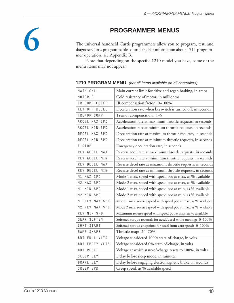
Curtis 1210 Manual 40
6 — PROGRAMMER MENUS: Program Menu
6 PROGRAMMER MENUS
The universal handheld Curtis programmers allow you to program, test, anddiagnose Curtis programmable controllers. For information about 1311 program-mer operation, see Appendix B.
Note that depending on the specific 1210 model you have, some of themenu items may not appear.
1210 PROGRAM MENU (not all items available on all controllers)
MAIN C/L Main current limit for drive and regen braking, in amps
MOTOR R Cold resistance of motor, in milliohms
IR COMP COEFF IR compensation factor: 0–100%
KEY OFF DECEL Deceleration rate when keyswitch is turned off, in seconds
TREMOR COMP Tremor compensation: 1–5
ACCEL MAX SPD Acceleration rate at maximum throttle requests, in seconds
ACCEL MIN SPD Acceleration rate at minimum throttle requests, in seconds
DECEL MAX SPD Deceleration rate at maximum throttle requests, in seconds
DECEL MIN SPD Deceleration rate at minimum throttle requests, in seconds
E STOP Emergency deceleration rate, in seconds
REV ACCEL MAX Reverse accel rate at maximum throttle requests, in seconds
REV ACCEL MIN Reverse accel rate at minimum throttle requests, in seconds
REV DECEL MAX Reverse decel rate at maximum throttle requests, in seconds
REV DECEL MIN Reverse decel rate at minimum throttle requests, in seconds
M1 MAX SPD Mode 1 max. speed with speed pot at max, as % available
M2 MAX SPD Mode 2 max. speed with speed pot at max, as % available
M1 MIN SPD Mode 1 max. speed with speed pot at min, as % available
M2 MIN SPD Mode 2 max. speed with speed pot at min, as % available
M1 REV MAX SPD Mode 1 max. reverse speed with speed pot at max, as % available
M2 REV MAX SPD Mode 2 max. reverse speed with speed pot at max, as % available
REV MIN SPD Maximum reverse speed with speed pot at min, as % available
GEAR SOFTEN Softened torque reversals for accel/decel while moving: 0–100%
SOFT START Softened torque endpoints for accel from zero speed: 0–100%
RAMP SHAPE Throttle map: 20–70%
BDI FULL VLTS Voltage considered 100% state-of-charge, in volts
BDI EMPTY VLTS Voltage considered 0% state-of-charge, in volts
BDI RESET Voltage at which state-of-charge resets to 100%, in volts
SLEEP DLY Delay before sleep mode, in minutes
BRAKE DLY Delay before engaging electromagnetic brake, in seconds
CREEP SPD Creep speed, as % available speed
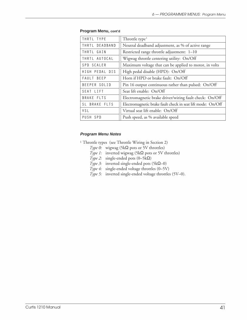
Curtis 1210 Manual 41
6 — PROGRAMMER MENUS: Program Menu
THRTL TYPE Throttle type1
THRTL DEADBAND Neutral deadband adjustment, as % of active range
THRTL GAIN Restricted range throttle adjustment: 1–10
THRTL AUTOCAL Wigwag throttle centering utility: On/Off
SPD SCALER Maximum voltage that can be applied to motor, in volts
HIGH PEDAL DIS High pedal disable (HPD): On/Off
FAULT BEEP Horn if HPD or brake fault: On/Off
BEEPER SOLID Pin 16 output continuous rather than pulsed: On/Off
SEAT LIFT Seat lift enable: On/Off
BRAKE FLTS Electromagnetic brake driver/wiring fault check: On/Off
SL BRAKE FLTS Electromagnetic brake fault check in seat lift mode: On/Off
VSL Virtual seat lift enable: On/Off
PUSH SPD Push speed, as % available speed
Program Menu Notes
1 Throttle types (see Throttle Wiring in Section 2)Type 0: wigwag (5kΩ pots or 5V throttles)Type 1: inverted wigwag (5kΩ pots or 5V throttles)Type 2: single-ended pots (0–5kΩ)Type 3: inverted single-ended pots (5kΩ–0)Type 4: single-ended voltage throttles (0–5V)Type 5: inverted single-ended voltage throttles (5V–0).
Program Menu, cont’d
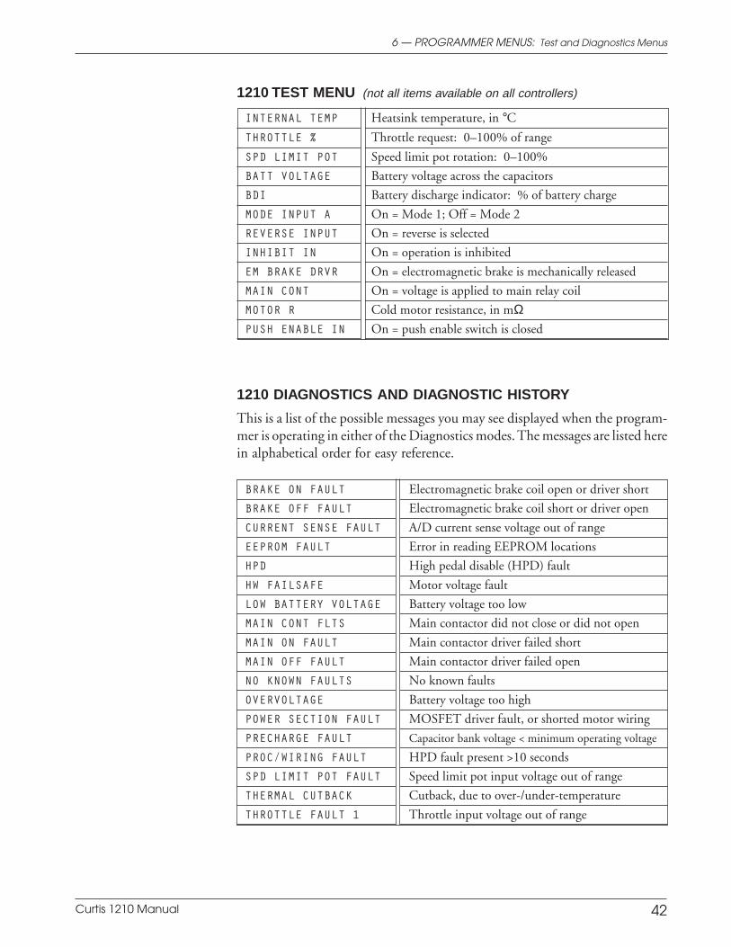
Curtis 1210 Manual 42
1210 TEST MENU (not all items available on all controllers)
INTERNAL TEMP Heatsink temperature, in °CTHROTTLE % Throttle request: 0–100% of range
SPD LIMIT POT Speed limit pot rotation: 0–100%
BATT VOLTAGE Battery voltage across the capacitors
BDI Battery discharge indicator: % of battery charge
MODE INPUT A On = Mode 1; Off = Mode 2
REVERSE INPUT On = reverse is selected
INHIBIT IN On = operation is inhibited
EM BRAKE DRVR On = electromagnetic brake is mechanically released
MAIN CONT On = voltage is applied to main relay coil
MOTOR R Cold motor resistance, in mΩPUSH ENABLE IN On = push enable switch is closed
1210 DIAGNOSTICS AND DIAGNOSTIC HISTORY
This is a list of the possible messages you may see displayed when the program-mer is operating in either of the Diagnostics modes. The messages are listed herein alphabetical order for easy reference.
BRAKE ON FAULT Electromagnetic brake coil open or driver short
BRAKE OFF FAULT Electromagnetic brake coil short or driver open
CURRENT SENSE FAULT A/D current sense voltage out of range
EEPROM FAULT Error in reading EEPROM locations
HPD High pedal disable (HPD) fault
HW FAILSAFE Motor voltage fault
LOW BATTERY VOLTAGE Battery voltage too low
MAIN CONT FLTS Main contactor did not close or did not open
MAIN ON FAULT Main contactor driver failed short
MAIN OFF FAULT Main contactor driver failed open
NO KNOWN FAULTS No known faults
OVERVOLTAGE Battery voltage too high
POWER SECTION FAULT MOSFET driver fault, or shorted motor wiring
PRECHARGE FAULT Capacitor bank voltage < minimum operating voltage
PROC/WIRING FAULT HPD fault present >10 seconds
SPD LIMIT POT FAULT Speed limit pot input voltage out of range
THERMAL CUTBACK Cutback, due to over-/under-temperature
THROTTLE FAULT 1 Throttle input voltage out of range
6 — PROGRAMMER MENUS: Test and Diagnostics Menus
Curtis 1210 Manual 43
7 — DIAGNOSTICS & TROUBLESHOOTING
7 DIAGNOSTICS AND TROUBLESHOOTING
The 1210 controller provides diagnostics information to assist technicians introubleshooting drive system problems. The diagnostics information can beobtained in two ways: reading the appropriate display on the handheld pro-grammer or observing the fault codes issued by the status LED.
PROGRAMMER DIAGNOSTICS
The handheld programmer presents complete diagnostic information in plainlanguage. Faults are displayed in the Diagnostics Menu, and the status of thecontroller inputs/outputs is displayed in the Test Menu.
Additionally, the Diagnostics History Menu provides a list of the faultsthat have occurred since the history file was last cleared. Checking (andclearing) the history file is recommended each time the vehicle is brought in formaintenance.
Refer to the troubleshooting chart (Table 3) for suggestions about pos-sible causes of the various faults.
For information on 1311 programmer operation, see Appendix B.
LED DIAGNOSTICS
During normal operation, with no faults present, the status LED is steadily on.If the controller detects a fault, the status LED provides two types of informa-tion. First, it displays a slow flash (2 Hz) or a fast flash (4 Hz) to indicate theseverity of the fault. Slow-flash faults are self-clearing; as soon as the fault iscorrected, the vehicle will operate normally. Fast-flash faults (“ ” in Table 2) areconsidered to be more serious in nature and require that the keyswitch be cycledto resume operation after the fault is corrected.
After the severity indication has been active for 10 seconds, the statusLED flashes a 2-digit fault identification code continuously until the fault iscorrected. For example, code “1,4”—low battery voltage—appears as:
¤ ¤ ¤ ¤ ¤ ¤ ¤ ¤ ¤ ¤ ¤ ¤ ¤ ¤ ¤( 1 , 4 ) ( 1 , 4 ) ( 1 , 4 )
The codes are listed in Table 2. Refer to the troubleshooting chart (Table 3) forsuggestions about possible causes of the various faults.
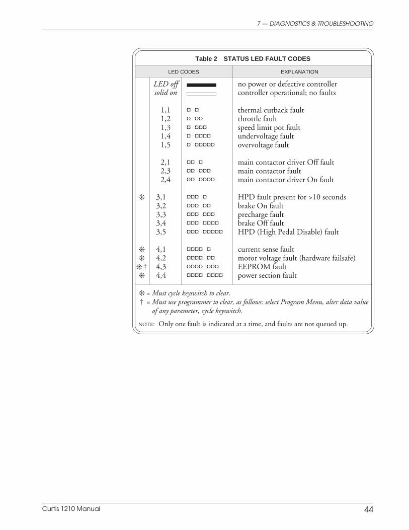
Curtis 1210 Manual 44
Table 2 STATUS LED FAULT CODES
LED CODES EXPLANATION
LED off no power or defective controllersolid on controller operational; no faults
1,1 ¤ ¤ thermal cutback fault1,2 ¤ ¤¤ throttle fault1,3 ¤ ¤¤¤ speed limit pot fault1,4 ¤ ¤¤¤¤ undervoltage fault1,5 ¤ ¤¤¤¤¤ overvoltage fault
2,1 ¤¤ ¤ main contactor driver Off fault2,3 ¤¤ ¤¤¤ main contactor fault2,4 ¤¤ ¤¤¤¤ main contactor driver On fault
3,1 ¤¤¤ ¤ HPD fault present for >10 seconds3,2 ¤¤¤ ¤¤ brake On fault3,3 ¤¤¤ ¤¤¤ precharge fault3,4 ¤¤¤ ¤¤¤¤ brake Off fault3,5 ¤¤¤ ¤¤¤¤¤ HPD (High Pedal Disable) fault
4,1 ¤¤¤¤ ¤ current sense fault 4,2 ¤¤¤¤ ¤¤ motor voltage fault (hardware failsafe)
† 4,3 ¤¤¤¤ ¤¤¤ EEPROM fault 4,4 ¤¤¤¤ ¤¤¤¤ power section fault
= Must cycle keyswitch to clear.† = Must use programmer to clear, as follows: select Program Menu, alter data value
of any parameter, cycle keyswitch.
NOTE: Only one fault is indicated at a time, and faults are not queued up.
7 — DIAGNOSTICS & TROUBLESHOOTING
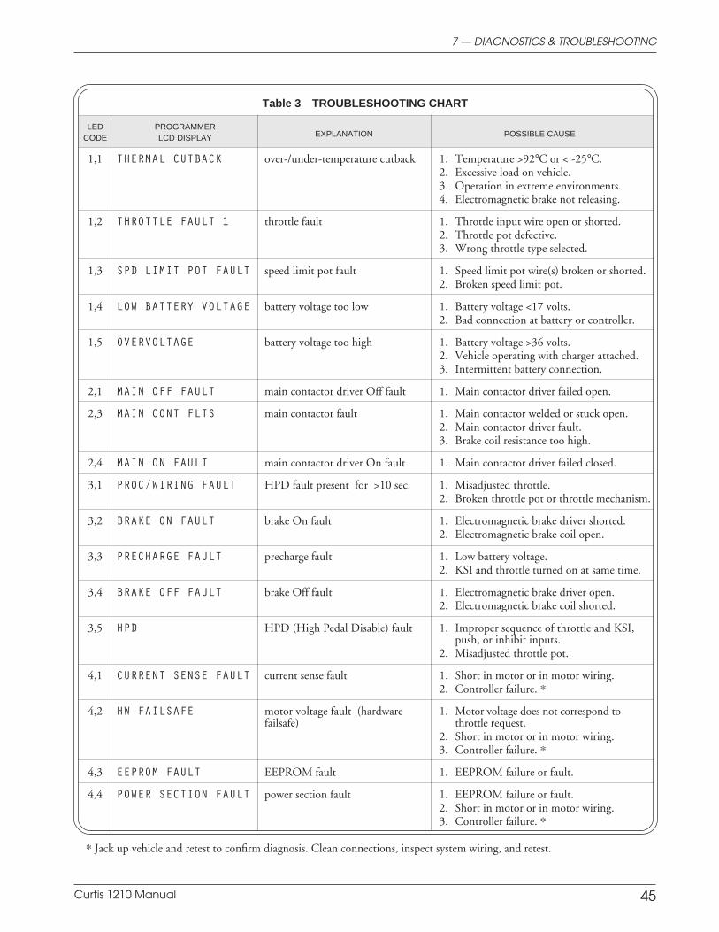
Curtis 1210 Manual 45
7 — DIAGNOSTICS & TROUBLESHOOTING
Table 3 TROUBLESHOOTING CHART
LED PROGRAMMERCODE LCD DISPLAY EXPLANATION POSSIBLE CAUSE
1,1 THERMAL CUTBACK over-/under-temperature cutback 1. Temperature >92°C or < -25°C.2. Excessive load on vehicle.3. Operation in extreme environments.4. Electromagnetic brake not releasing.
1,2 THROTTLE FAULT 1 throttle fault 1. Throttle input wire open or shorted.2. Throttle pot defective.3. Wrong throttle type selected.
1,3 SPD LIMIT POT FAULT speed limit pot fault 1. Speed limit pot wire(s) broken or shorted.2. Broken speed limit pot.
1,4 LOW BATTERY VOLTAGE battery voltage too low 1. Battery voltage <17 volts.2. Bad connection at battery or controller.
1,5 OVERVOLTAGE battery voltage too high 1. Battery voltage >36 volts.2. Vehicle operating with charger attached.3. Intermittent battery connection.
2,1 MAIN OFF FAULT main contactor driver Off fault 1. Main contactor driver failed open.
2,3 MAIN CONT FLTS main contactor fault 1. Main contactor welded or stuck open.2. Main contactor driver fault.3. Brake coil resistance too high.
2,4 MAIN ON FAULT main contactor driver On fault 1. Main contactor driver failed closed.
3,1 PROC/WIRING FAULT HPD fault present for >10 sec. 1. Misadjusted throttle.2. Broken throttle pot or throttle mechanism.
3,2 BRAKE ON FAULT brake On fault 1. Electromagnetic brake driver shorted.2. Electromagnetic brake coil open.
3,3 PRECHARGE FAULT precharge fault 1. Low battery voltage.2. KSI and throttle turned on at same time.
3,4 BRAKE OFF FAULT brake Off fault 1. Electromagnetic brake driver open.2. Electromagnetic brake coil shorted.
3,5 HPD HPD (High Pedal Disable) fault 1. Improper sequence of throttle and KSI,push, or inhibit inputs.
2. Misadjusted throttle pot.
4,1 CURRENT SENSE FAULT current sense fault 1. Short in motor or in motor wiring.2. Controller failure. *
4,2 HW FAILSAFE motor voltage fault (hardware 1. Motor voltage does not correspond tofailsafe) throttle request.
2. Short in motor or in motor wiring.3. Controller failure. *
4,3 EEPROM FAULT EEPROM fault 1. EEPROM failure or fault.
4,4 POWER SECTION FAULT power section fault 1. EEPROM failure or fault.2. Short in motor or in motor wiring.3. Controller failure. *
* Jack up vehicle and retest to confirm diagnosis. Clean connections, inspect system wiring, and retest.

Curtis 1210 Manual 46
8 — MAINTENANCE
MAINTENANCE
There are no user serviceable parts in the Curtis 1210 controller. No attemptshould be made to open, repair, or otherwise modify the controller. Doingso may damage the controller and will void the warranty. However, it isrecommended that the controller’s diagnostics history file be checked andcleared periodically, as part of routine vehicle maintenance.
DIAGNOSTIC HISTORY
The handheld programmer can be used to access the controller’s diagnostichistory file. The programmer will read out all the faults that the controller hasexperienced since the last time the history file was cleared. The faults may beintermittent faults, faults caused by loose wires, or faults caused by operatorerrors. Faults such as HPD or overtemperature may be caused by operatorhabits or by overloading.
After a problem has been diagnosed and corrected, clearing the history fileis advisable. This allows the controller to accumulate a new file of faults. Bychecking the new history file at a later date, you can readily determine whetherthe problem was indeed completely fixed.
The Fault History file and Clear Fault History are in the programmer’sFaults Menu; see Appendix B.
8
Curtis 1210 Manual A-1
APPENDIX A: EMC & ESD DESIGN CONSIDERATIONS
APPENDIX A
VEHICLE DESIGN CONSIDERATIONS
REGARDING ELECTROMAGNETIC COMPATIBILITY (EMC)
AND ELECTROSTATIC DISCHARGE (ESD)
ELECTROMAGNETIC COMPATIBILITY (EMC)
Electromagnetic compatibility (EMC) encompasses two areas: emissions andimmunity. Emissions are radio frequency (RF) energy generated by a product.This energy has the potential to interfere with communications systems such asradio, television, cellular phones, dispatching, aircraft, etc. Immunity is theability of a product to operate normally in the presence of RF energy.
EMC is ultimately a system design issue. Part of the EMC performanceis designed into or inherent in each component; another part is designed intoor inherent in end product characteristics such as shielding, wiring, and layout;and, finally, a portion is a function of the interactions between all these parts.The design techniques presented below can enhance EMC performance inproducts that use Curtis motor controllers.
Decreasing Emissions
Motor brush arcing can be a significant source of RF emissions. These emissionsmay be reduced by installing bypass capacitors across the motor wires and/orbetween each motor wire and the motor frame. If the latter approach is used,the voltage rating and leakage characteristics of the capacitors must be adequateto meet any safety regulations regarding electrical connections between abattery operated circuit and the chassis. The bypass capacitor should be in-stalled as close to the motor as possible, or even inside it, to provide the bestperformance. Alternatively a ferrite bead can be installed on the wires, as closeas possible to the motor. In some instances, capacitors and ferrite beads mayboth be appropriate. Another option is to choose a motor with a brush materialthat will result in less arcing to the commutator. Brushes that have been run infor approximately 100 hours will typically generate lower emissions than newbrushes because there is less arcing after they are properly seated.
The motor drive output from Curtis controllers can also make a contri-bution to RF emissions. This output is a pulse width modulated square wavewith rather fast rise and fall times that are rich in harmonics. The impact ofthese switching waveforms can be minimized by making the wires from thecontroller to the motor as short as possible. Ferrite beads installed on the drivewires can further reduce these emissions. For applications requiring very lowemissions, the solution may involve enclosing the controller, interconnectwires, and motor together in one shielded box. The motor drive harmonics cancouple to battery supply leads and throttle circuit wires, so ferrite beads mayalso be required on these other wires in some applications.
Curtis 1210 Manual A-2
APPENDIX A: EMC & ESD DESIGN CONSIDERATIONS
Increasing Immunity
Immunity to radiated electric fields can be achieved either by reducing theoverall circuit sensitivity or by keeping the undesired signals away from thiscircuitry. The controller circuitry itself cannot be made less sensitive, since itmust accurately detect and process low level signals from the throttle potenti-ometer. Thus immunity is generally achieved by preventing the external RFenergy from coupling into sensitive circuitry. This RF energy can get into thecontroller circuitry via conducted paths and via radiated paths.
Conducted paths are created by the wires connected to the controller.These wires act as antennas and the amount of RF energy coupled into thesewires is generally proportional to their length. The RF voltages and currentsinduced in each wire are applied to the controller pin to which the wire isconnected. Curtis motor controllers include bypass capacitors on the printedcircuit board’s throttle wires to reduce the impact of this RF energy on theinternal circuitry. In some applications, ferrite beads may also be required onthe various wires to achieve desired performance levels.
Radiated paths are created when the controller circuitry is immersed in anexternal field. This coupling can be reduced by enclosing the controller in ametal box. Some Curtis motor controllers are enclosed by a heat sink that alsoprovides shielding around the controller circuitry, while others are unshielded.In some applications, the vehicle designer will need to mount the controllerwithin a shielded box on the end product. The box may be constructed of justabout any metal, although steel and aluminum are most commonly used.
Most coated plastics do not provide good shielding because the coatingsare not true metals, but rather a mixture of small metal particles in a non-conductive binder. These relatively isolated particles may appear to be goodbased on a dc resistance measurement but do not provide adequate electronmobility to yield good shielding effectiveness. Electroless plating of plastic willyield a true metal and can thus be effective as an RF shield, but it is usually moreexpensive than the coatings.
A contiguous metal enclosure without any holes or seams, known as aFaraday cage, provides the best shielding for the given material and frequency.When a hole or holes are added, RF currents flowing on the outside surface ofthe shield must take a longer path to get around the hole than if the surface wascontiguous. As more “bending” is required of these currents, more energy iscoupled to the inside surface, and thus the shielding effectiveness is reduced.The reduction in shielding is a function of the longest linear dimension of ahole rather than the area. This concept is often applied where ventilation isnecessary, in which case many small holes are preferable to a few larger ones.
Applying this same concept to seams or joints between adjacent pieces orsegments of a shielded enclosure, it is important to minimize the open lengthof these seams. Seam length is the distance between points where good ohmiccontact is made. This contact can be provided by solder, welds, or pressurecontact. If pressure contact is used, attention must be paid to the corrosioncharacteristics of the shield material and any corrosion-resistant processes
Curtis 1210 Manual A-3
APPENDIX A: EMC & ESD DESIGN CONSIDERATIONS
applied to the base material. If the ohmic contact itself is not continuous, theshielding effectiveness can be maximized by making the joints between adjacentpieces overlapping rather than abutted.
The shielding effectiveness of an enclosure is further reduced when a wirepasses through a hole in the enclosure. RF energy on the wire from an externalfield is re-radiated into the interior of the enclosure. This coupling mechanismcan be reduced by filtering the wire at the point where it passes through theboundary of the shield. Given the safety considerations involved with connect-ing electrical components to the chassis or frame in battery powered vehicles,such filtering will usually consist of a series inductor (or ferrite bead) rather thana shunt capacitor. If a capacitor is used, it must have a voltage rating and leakagecharacteristics that will allow the end product to meet applicable safety regula-tions.
The B+ (and B-, if applicable) wires that supply power to the throttlecontrol panel—such as for the keyswitch—should be bundled with the remain-ing throttle wires so that all these wires are routed together. If the wires to thecontrol panel are routed separately, a larger loop area is formed. Larger loopareas produce more efficient antennas which will result in decreased immunityperformance.
ELECTROSTATIC DISCHARGE (ESD)
Curtis motor controllers contain ESD-sensitive components, and it is thereforenecessary to protect them from ESD damage. Electrostatic discharge (ESD)immunity is achieved either by providing sufficient distance between conduc-tors and the outside world so that a discharge will not occur, or by providing anintentional path for the discharge current such that the circuit is isolated fromthe electric and magnetic fields produced by the discharge. In general theguidelines presented above for increasing the radiated immunity will alsoprovide increased ESD immunity.
It is usually easier to prevent the discharge from occurring than to divertthe current path. A fundamental technique for ESD prevention is to provideadequately thick insulation between all metal conductors and the outsideenvironment so that the voltage gradient does not exceed the threshold requiredfor a discharge to occur. However, in some scooter applications isolation maynot be appropriate; in these cases, connection to chassis ground may berequired. If the current diversion approach is used, all exposed metal compo-nents must be grounded. The shielded enclosure, if properly grounded, can beused to divert the discharge current; it should be noted that the location of holesand seams can have a significant impact on the ESD suppression. If theenclosure is not grounded, the path of the discharge current becomes morecomplex and less predictable, especially if holes and seams are involved. Someexperimentation may be required to optimize the selection and placement ofholes, wires, and grounding paths. Careful attention must be paid to the controlpanel design so that it can tolerate a static discharge.
APPENDIX A: EMC & ESD DESIGN CONSIDERATIONS
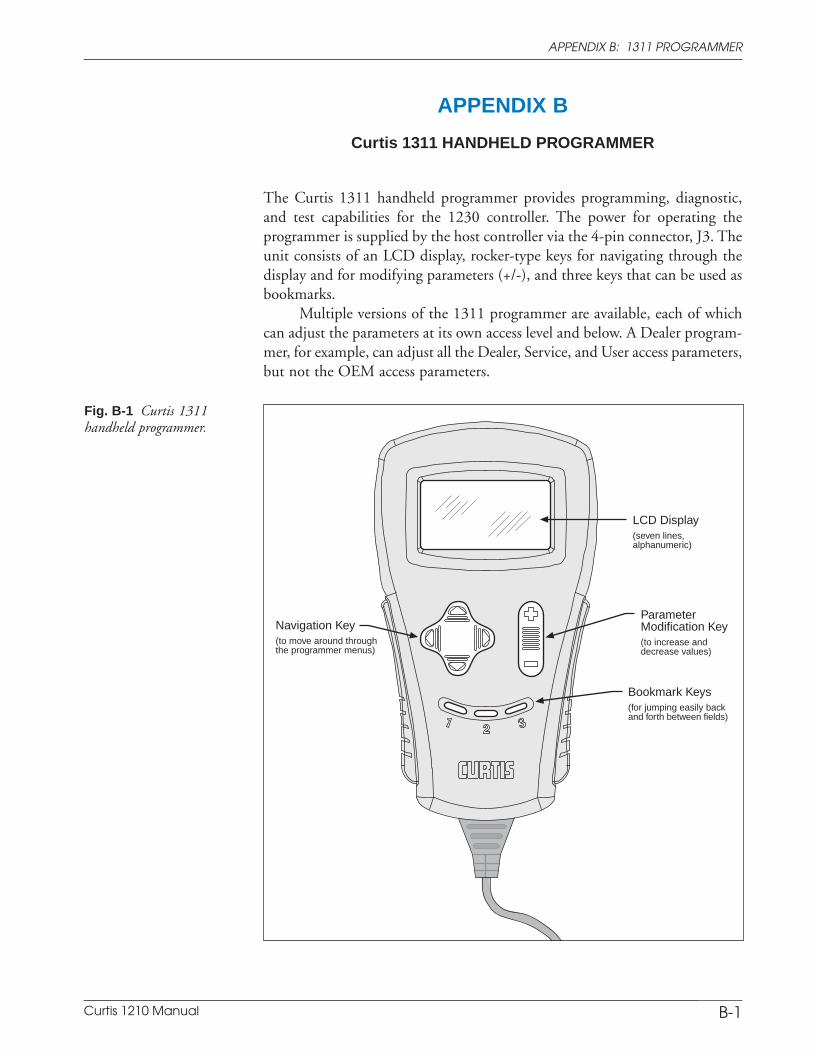
Curtis 1210 Manual A-4
APPENDIX A: EMC & ESD DESIGN CONSIDERATIONS
B-1
ParameterModification Key(to increase anddecrease values)
LCD Display(seven lines,alphanumeric)
Bookmark Keys(for jumping easily backand forth between fields)
Navigation Key(to move around throughthe programmer menus)
Fig. B-1 Curtis 1311handheld programmer.
APPENDIX B
Curtis 1311 HANDHELD PROGRAMMER
The Curtis 1311 handheld programmer provides programming, diagnostic,and test capabilities for the 1230 controller. The power for operating theprogrammer is supplied by the host controller via the 4-pin connector, J3. Theunit consists of an LCD display, rocker-type keys for navigating through thedisplay and for modifying parameters (+/-), and three keys that can be used asbookmarks.
Multiple versions of the 1311 programmer are available, each of whichcan adjust the parameters at its own access level and below. A Dealer program-mer, for example, can adjust all the Dealer, Service, and User access parameters,but not the OEM access parameters.
APPENDIX B: 1311 PROGRAMMER

Curtis 1210 Manual A-5
APPENDIX A: EMC & ESD DESIGN CONSIDERATIONS
B-2
PROGRAMMER OPERATION
The 1311 programmer is easy to use, with self-explanatory functions. Afterplugging in the programmer, wait a few seconds for it to boot up and gatherinformation from the controller.
For experimenting with settings, the programmer can be left plugged inwhile the vehicle is driven.
The bookmark keys can make parameter adjustment more convenient. Forexample, in setting the throttle deadband parameter, you might set a bookmark atthis parameter in the Throttle submenu [Program > Throttle > Throttle Deadband]and another at the throttle readout [Monitor > Inputs > Throttle Input]; this wayyou can easily toggle between the readout and the parameter.
To set a bookmark, press one of the three bookmark keys for more than 2seconds. To jump to a bookmarked location, press the appropriate bookmark keyquickly (for less than 2 seconds).
PROGRAMMER MENUS
There are six main menus, which in turn lead to nested submenus:
Program — provides access to the individual programmable parameters (seeSection 3).
Monitor — presents real-time values during vehicle operation (see Section 4).
Faults — presents diagnostic information, and also a means to clear the faulthistory file (see Section 7).
Functions — provides access to the controller-cloning commands (see page 44)and to the “reset” command.
Information — displays data about the host controller: model and serial num-bers, date of manufacture, hardware and software revisions, and itemization ofother devices that may be associated with the controller’s operation.
Programmer Setup — displays data about the programmer: model and serialnumbers, date of manufacture, and a list of the programmable parameters thatcan be accessed with this particular programmer.
APPENDIX B: 1311 PROGRAMMER
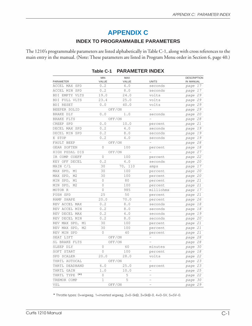
Curtis 1210 Manual A-6
APPENDIX A: EMC & ESD DESIGN CONSIDERATIONS
APPENDIX CINDEX TO PROGRAMMABLE PARAMETERS
The 1210’s programmable parameters are listed alphabetically in Table C-1, along with cross references to themain entry in the manual. (Note: These parameters are listed in Program Menu order in Section 6, page 40.)
Table C-1 PARAMETER INDEXMIN MAX DESCRIPTION
PARAMETER VALUE VALUE UNITS IN MANUAL
ACCEL MAX SPD 0.2 4.0 seconds page 17ACCEL MIN SPD 0.2 8.0 seconds page 17BDI EMPTY VLTS 19.0 24.0 volts page 29BDI FULL VLTS 23.4 25.0 volts page 29BDI RESET 0.0 40.0 volts page 29BEEPER SOLID OFF/ON — page 29BRAKE DLY 0.0 1.0 seconds page 20BRAKE FLTS OFF/ON — page 28CREEP SPD 0.0 10.0 percent page 21DECEL MAX SPD 0.2 4.0 seconds page 19DECEL MIN SPD 0.2 8.0 seconds page 19E STOP 0.2 4.0 seconds page 19FAULT BEEP OFF/ON — page 28GEAR SOFTEN 0 100 percent page 18HIGH PEDAL DIS OFF/ON — page 27IR COMP COEFF 0 100 percent page 22KEY OFF DECEL 0.2 4.0 seconds page 20MAIN C/L 30 70, 110 amps page 17MAX SPD, M1 30 100 percent page 20MAX SPD, M2 30 100 percent page 20MIN SPD, M1 0 80 percent page 21MIN SPD, M2 0 100 percent page 21MOTOR R 0 985 milliohms page 17PUSH SPD 25 50 percent page 21RAMP SHAPE 20.0 70.0 percent page 26REV ACCEL MAX 0.2 8.0 seconds page 18REV ACCEL MIN 0.2 8.0 seconds page 18REV DECEL MAX 0.2 4.0 seconds page 19REV DECEL MIN 0.2 8.0 seconds page 20REV MAX SPD, M1 30 100 percent page 21REV MAX SPD, M2 30 100 percent page 21REV MIN SPD 0 40 percent page 21SEAT LIFT OFF/ON — page 28SL BRAKE FLTS OFF/ON — page 28SLEEP DLY 0 60 minutes page 30SOFT START 0 100 percent page 18SPD SCALER 20.0 28.0 volts page 22THRTL AUTOCAL OFF/ON — page 23THRTL DEADBAND 6.0 25.0 percent page 23THRTL GAIN 1.0 10.0 — page 25THRTL TYPE (*) 0 5 — page 22TREMOR COMP 1 5 — page 30VSL OFF/ON — page 29
* Throttle types: 0=wigwag, 1=inverted wigwag, 2=0–5kΩ, 3=5kΩ–0, 4=0–5V, 5=5V–0.
APPENDIX C: PARAMETER INDEX
C-1
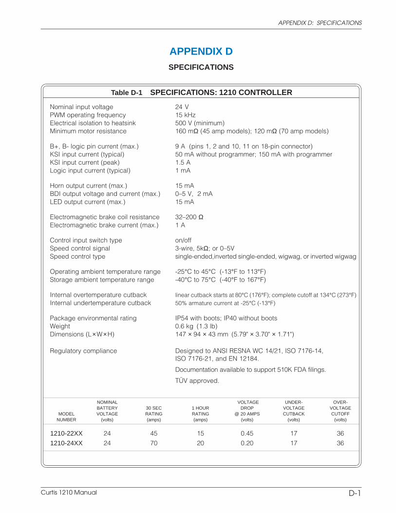
Curtis 1210 Manual A-7
APPENDIX A: EMC & ESD DESIGN CONSIDERATIONS
APPENDIX DSPECIFICATIONS
APPENDIX D: SPECIFICATIONS
D-1
NOMINAL VOLTAGE UNDER- OVER-BATTERY 30 SEC 1 HOUR DROP VOLTAGE VOLTAGE
MODEL VOLTAGE RATING RATING @ 20 AMPS CUTBACK CUTOFFNUMBER (volts) (amps) (amps) (volts) (volts) (volts)
1210-22XX 24 45 15 0.45 17 36
1210-24XX 24 70 20 0.20 17 36
Table D-1 SPECIFICATIONS: 1210 CONTROLLER
Nominal input voltage 24 VPWM operating frequency 15 kHzElectrical isolation to heatsink 500 V (minimum)Minimum motor resistance 160 mΩ (45 amp models); 120 mΩ (70 amp models)
B+, B- logic pin current (max.) 9 A (pins 1, 2 and 10, 11 on 18-pin connector)KSI input current (typical) 50 mA without programmer; 150 mA with programmerKSI input current (peak) 1.5 ALogic input current (typical) 1 mA
Horn output current (max.) 15 mABDI output voltage and current (max.) 0–5 V, 2 mALED output current (max.) 15 mA
Electromagnetic brake coil resistance 32–200 ΩElectromagnetic brake current (max.) 1 A
Control input switch type on/offSpeed control signal 3-wire, 5kΩ; or 0–5VSpeed control type single-ended,inverted single-ended, wigwag, or inverted wigwag
Operating ambient temperature range -25°C to 45°C (-13°F to 113°F)Storage ambient temperature range -40°C to 75°C (-40°F to 167°F)
Internal overtemperature cutback linear cutback starts at 80°C (176°F); complete cutoff at 134°C (273°F)Internal undertemperature cutback 50% armature current at -25°C (-13°F)
Package environmental rating IP54 with boots; IP40 without bootsWeight 0.6 kg (1.3 lb)Dimensions (L×W×H) 147 × 94 × 43 mm (5.79" × 3.70" × 1.71")
Regulatory compliance Designed to ANSI RESNA WC 14/21, ISO 7176-14,ISO 7176-21, and EN 12184.
Documentation available to support 510K FDA filings.
TÜV approved.