12- paper on lock design rigo v3 - uliege.be paper on lock... · o ben c. gerwick, inc. (usa) -...
TRANSCRIPT

40th IWASA , January 2010, Aachen, Germany ____________________________________________________________________________
1
INNOVATIONS IN NAVIGATION LOCK DESIGN
By
Philippe RIGO
Chairman of PIANC InCom WG29
ANAST- University of Liege, Belgium; [email protected]

40th IWASA , January 2010, Aachen, Germany ____________________________________________________________________________
2
Table of contents
ABSTRACT .................................................................................................................... 3
ACKNOWLEDGEMENTS:.......................................................................................... 3
1. INTRODUCTION .................................................................................................. 3
1.1 Report 2009’s DVD .......................................................................................... 4
2. PROJECT REVIEWS............................................................................................ 6
3. LIVE CYCLE COST AND LOCK DESIGN OBJECTIVES .......................... 11
3.1 General Project Objectives ............................................................................ 11
3.2 Economic and Financial Objectives............................................................... 11
3.3 Environmental Objectives .............................................................................. 12
3.4 Priorities......................................................................................................... 12
3.5 Main Design Objectives ................................................................................. 12
3.6 Life Cycle Management (LCM) ...................................................................... 13
3.7 Safety .............................................................................................................. 13
4 INNOVATIONS IN TRADITIONAL FILLING AND EMPTYING SYSTEMS ............................................................................................................ 14
4.1 Partial Distributed System ............................................................................. 15
4.2 Double Ditches Energy Dissipation System ................................................... 16
4.3 Energy Dissipation For Side Port System ...................................................... 17
5 MOORING FORCES AND SHIP BEHAVIOUR IN NAVIGATION LOCKS............................................................................................................................... 17
6. CONSTRUCTION METHODS .......................................................................... 18
7 NEW İNNOVATİVE GATE CONCEPTS ........................................................ 19
8. LOCK STRUCTURES and FOUNDATIONS .................................................. 24
9. COMPUTATIONAL FLUID DYNAMICS (CFD) IN LOCK DESIGN......... 24
10. NUMERICAL SIMULATIONS AND EXPERIMENTAL MODELS: HOW TO CHOOSE? ..................................................................................................... 26
11. CONCLUSIONS................................................................................................... 27
References ..................................................................................................................... 29

40th IWASA , January 2010, Aachen, Germany ____________________________________________________________________________
3
ABSTRACT
This paper introduces the Report 106 on “Innovations in Navigation Lock Design”
published by PIANC in August 2009. Main objectives and issues are highlighted in this
paper. This report was achieved by the INCOM Working Group 29 of PIANC from
2006 to 2009.
ACKNOWLEDGEMENTS:
The author thanks MM. BÖDEFELD Jörg, BOS Jan CLARKSON John, DALY
Fabrice, FERNANDEZ Jose Luis, HIJDRA Arjan, HIVER Jean-Michel, HOLM Olli,
HUNTER Peter, MILLER Dale, PECHTOLD Erwin, PICHON Nicolas, POLIGOT-
PITSCH Stephanie, SARGHIUTA Radu, TARPEY Michael, THORENZ Carsten,
WONG Juan, WU Peng, as co-authors of the PIANC 106 Report (2009).
The present paper will be published at MMX-PIANC’2010, May 2010, Liverpool, UK.
1. INTRODUCTION
Locks are key structures for the development of the navigation in canals and in natural
rivers where weirs regulate water levels to enable navigation. They may also be
strategic infrastructure for port development. In lower elevation regions, such as New
Orleans and the Netherlands, locks are structures in dikes and also have an important
task in flood defence.
In 1986, PIANC produced a comprehensive report of 445 pages on Locks. For about
twenty years this report has been considered as a world reference guideline, but it
needed updating to include new design techniques and concepts. PIANC decided in
2006 to launch a new Working Group (WG) to update the report, and the present report
is the result.
The core of this report has three major parts. The first part presents an exhaustive list of
design goals associated with locks. This section is particularly important for decision

40th IWASA , January 2010, Aachen, Germany ____________________________________________________________________________
4
makers who have to launch a new project. The second part reviews the design principles
that must be considered by designers. This section is methodology oriented. The third
part is technically oriented. All main technical aspects (hydraulics, structures,
foundations, including computational aspects, etc.) are reviewed, focussing on changes
and innovations occurring since 1986. Perspectives and trends for the future are also
listed. When appropriate, recommendations are listed.
Other major changes since 1986 concern maintenance and operational aspects, and more
specifically how to consider these criteria as goals for the conceptual and design stages
of a lock. Renovation and rehabilitation of existing locks are also an increasingly
important topic for the future.
The PIANC n°106 report also includes on a DVD more than 56 reviews of existing
locks (or lock projects under development) which describe the projects and their
innovative aspects. Some purely innovative and untested concepts are also mentioned as
references although with no guarantee of validity.
1.1 Report 2009’s DVD
To assist continuity and to avoid duplication of existing PIANC material the former
1986 PIANC Report on Locks is included on the DVD attached to the 2009 report
(Directory A3). In addition, the former Table of Contents is given in Annex I of the new
report. These documents should be used as support to this report and as a baseline of
standard practice.
Due to publishing constraints the number of pages of the InCom-WG29’s hardcopy
report was limited. Therefore additional information has been saved on a companion
DVD (attached to this PIANC hardcopy report). Care should always be taken to use the
current versions of standards and other publications that might supersede the versions
on the DVD.

40th IWASA , January 2010, Aachen, Germany ____________________________________________________________________________
5
This DVD includes the following directories:
- A1: The Project Reviews of 56 lock projects.
- A2: PIANC'2009 Lock Report, n°106
- A3: PIANC'1986 Lock Report – in French and English
- A4: PIANC Dictionary on Locks & Waterways
- A5: LIST of LOCKS (Worldwide list)
- Additional information to various sections of this report (Directories B) such as:
o B4.6.1: Salt Water Intrusion
o B4.6.5: 3D Video Modelling of Construction Process
o B5.2: Hydraulic (Manoeuvring, Fendering, ...)
o B5.5: Gates and Valves
o B5.7: Lock Equipment
o B5.8.5: Lubricants and Bio Oils
- Various technical guidelines (Directories C) :
o C1- Estoril'2006 - PIANC Congress Papers
o C2- Beijing'2008 - AGA-2008 Papers.
o C3- Navigation Lock - Ecluse de Navigation (by N.M Dehousse, 1985) in
French
o C4- Corps of Engineering, USA - Reports on Innovation
o C5- Chinese Codes
o C6- French Guidelines - Lubaqua (CETMEF)
o C7- Fish Passage In Lock
o C8- Corrosion Protection
o C9- Planning of Lock Maintenance (example)
o C10- European Code For Inland Waterways (CEVNI)
o C11- Ship Impact
o C12- Seismic Impact of Lock Gates
o C13- ISPS Code 2003 - IMO (Safety and Security of Ship and Port)
o C14- Panama Third Lock Lane

40th IWASA , January 2010, Aachen, Germany ____________________________________________________________________________
6
o C15- Seine Nord Europe Canal (France)
o C16- Three Gorges Locks, China
o C17- Specifications for Lock Design (Lanaye Lock, Belgium)
- Sponsor Company’s References (Directory D):
o Bureau GREISCH (BE)
o IMDC (BE)
o TECHNUM (BE)
o Planning and Design Institute for Water Transportation (PDI, China)
o Guanxi Xijiang Navigation Construction Co. Ltd. (China)
o Compagnie Nationale du Rhône (CNR, France)
o Grontmij / BGS Ingenieurgesellschaft mbH (D)
o Delta Marine Consultants (NL)
o Rijkswaterstaat (NL)
o ISPH (Romania)
o IDOM (Spain)
o Ben C. Gerwick, Inc. (USA)
- InCom WG29 meeting pictures, (Directory E)
2. PROJECT REVIEWS
An important feature of Report 106 is the availability of many detailed project reviews
in which the practical use of innovations are presented (Figure 1 to Figure 7).
Figure 1: Example of Project reviews – Sevilla (Spain)
40th IWASA , January 2010, Aachen, Germany ____________________________________________________________________________
7
Representative samples of each lock type are summarized in Chapter 2 of the report.
Case studies (56 in total) of each of these locks are included on the attached WG 106-
CD-Rom (Directory A1).
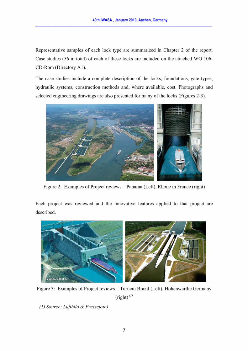
The case studies include a complete description of the locks, foundations, gate types,
hydraulic systems, construction methods and, where available, cost. Photographs and
selected engineering drawings are also presented for many of the locks (Figures 2-3).
Figure 2: Examples of Project reviews – Panama (Left), Rhone in France (right)
Each project was reviewed and the innovative features applied to that project are
described.
Figure 3: Examples of Project reviews – Turucui Brazil (Left), Hohenwarthe Germany
(right) (1)
(1) Source: Luftbild & Pressefoto)

40th IWASA , January 2010, Aachen, Germany ____________________________________________________________________________
8
These innovative features were ranked into five general classifications. Those
innovations and their classifications are shown in Table 2.1 in the report (see Table 1).
Table 1. Layout of Table 2.1 in the report
The selected project reviews do not exhaustively cover all aspects, but are
representative for the innovations currently in use or currently in the phase of research
or design.
Members of WG 106 selected projects for which they or their associates have
experience in the lock design or construction (Fig 4). Many of the projects fall under
multiple categories in their areas of innovation.
Figure 4: Project reviews – Naviduct-NL (Left), Float in Segment - Braddock-
USA(right)

40th IWASA , January 2010, Aachen, Germany ____________________________________________________________________________
9
In order to show what these areas are in a systematic way, five major categories and
appropriate subcategories were created as follows:
- Hydraulics
- Operation and Maintenance (Figure 5)
- Environmental
- Design / Construction
- Miscellaneous
Figure 5: Examples of Project reviews – Mooring System (Left), Folded plate miter
gate and capsulated hydraulic actuator (right)
Each project summary enhances few innovative concepts. These innovations were
categorized to indicate the status of the innovations. The following definitions were
used.
- A PROVEN INNOVATION is one which has been researched, designed and
constructed. It is been in service for a number of years and has possibly been
constructed at multiple locations.
- An UNPROVEN CONCEPT is one that has been recently constructed and as
such the viability of the concept has not been validated by time and sufficient
use for potential shortcomings or needed modifications to become apparent.

40th IWASA , January 2010, Aachen, Germany ____________________________________________________________________________
10
- A NEW CONCEPT is a concept that has been validated by a client and is in
design. Construction is currently scheduled or will be as funding becomes
available.
- An ADVANCED CONCEPT is one that is currently in research. A prototype
may have been built to establish proof of the concept but it has not yet been
accepted for construction or for regular operations.
Figure 6: Project reviews: Falkirk Wheel - UK (Left), Floating Pontoon and lock in the
rock – Finland (right)
Because each review may represent multiple innovations the project reviews have not
been categorized by innovation. They are organized alphabetically by country.
Short summaries of each project review are included in Section 2.3 of the report.
Detailed reviews and contact information for each project are included on the WG 106-
CD-Rom.
Figure 7: The Three Gorges Project (China)

40th IWASA , January 2010, Aachen, Germany ____________________________________________________________________________
11
3. LIVE CYCLE COST AND LOCK DESIGN OBJECTIVES
The comprehensive 1986 PIANC report on Locks (PIANC, 1986) provides a mass of
detailed data and recommendations for the planning and design of locks. But it also
focuses on new areas of design objectives that have become more important since 1986,
like the live cycle cost of navigation locks.
3.1 General Project Objectives
The objectives and priorities of planning and design a lock vary depending on the
viewpoint of the assessor, but they can usually be grouped into financial, economic and
environmental categories. Safety is a theme running through all these categories. They
all require detailed evaluation to allow logical decisions when selecting optimum
solutions or deciding whether to proceed with a proposed project.
3.2 Economic and Financial Objectives
There can be more than one reason for constructing a new lock or waterway. It might
be to reduce maintenance costs, or to allow larger ships to reduce overall transport costs
and to increase capacity of a canal. Alternatively a waterway project may be justified
because it brings increased economic activity in the form of tourism and leisure, both on
the waterway and in the surrounding waterfront land areas.
Financial objectives depend on the type of developer. While a public sector developer
might not need to raise revenue directly from users, a private sector project such as a
marina may require revenues from users to fund the project directly.

40th IWASA , January 2010, Aachen, Germany ____________________________________________________________________________
12
3.3 Environmental Objectives
This issue has become of overriding importance since the 1986 PIANC report, and often
governs the decision whether a project should go ahead. Local and regional
environmental impacts of all aspects of construction and operation now have to be
evaluated, to assess whether the project complies with statutory requirements.
3.4 Priorities
The design approach can have four different priorities:
• Design for lowest initial (construction)cost
• Design for minimum maintenance.
• Lowest whole life cost, which is a logical combination of the two previous
approaches
• Best performance (fastest operation, least down-time).
The selection of priorities depends on the objectives of the owner/developer of a project.
3.5 Main Design Objectives
The following are the main design objectives for lock design, and many of these were
relatively low priority at the time of the previous report (PIANC, 1986, numbered as in
that report)
3.2 Reliability and proven technology
3.3 Reliable lock operations
3.4 Life Cycle Management
3.5 Lock navigation cycle
3.6 Water motions inducing ship displacement and mooring forces

40th IWASA , January 2010, Aachen, Germany ____________________________________________________________________________
13
3.7 Water resource problems:
• Water shortage
• Saltwater intrusion
3.8 Minimizing energy use
3.9 Environmental impacts
3.10 Minimizing impacts of construction
3.11 Security and Safety
Of course the first point “Proven Technology” does not match with the use of
innovation, and a major reason for adopting innovative concepts and materials is to
achieve improved performance, reliable design or reduced costs.
3.6 Life Cycle Management (LCM)
LCM is a management approach to infrastructure construction to achieve optimum
quality and minimum Whole Life Cost (WLC). For locks, a reduced WLC should
imply optimum levels of reliability (which must be determined specifically for each
project), and more efficient maintenance. This does not mean less inspection and
survey or less maintenance.
3.7 Safety
Safety has become another increasingly important aspect of design for locks. As well as
highlighting many areas of design that can lead to increased safety (e.g. mooring,
lighting, signs, channel design and gate protection), the report (PIANC, 2009) also
provides a classification of different types of water edge structure and gives guidelines
for suitable safety treatment for each type.

40th IWASA , January 2010, Aachen, Germany ____________________________________________________________________________
14
4 INNOVATIONS IN TRADITIONAL FILLING AND EMPTYING SYSTEMS
Hydraulic systems for filling and emptying locks can be divided into two main types.
One is the filling and emptying “through the heads”; and the other is the “through
longitudinal culverts” system. Within these filling and emptying systems, the “In
Chamber Longitudinal Culvert System” (ILCS) and “Pressure Chamber under the Floor
System” are new types developed after 1986.
In recent years some locks in Germany have been equipped with a filling system which
uses a pressure chamber beneath the floor. This type of filling system has proven to be
very efficient especially in combination with water saving basins.
In general the ILCS system could be used for intermediate lift locks. Under specific
conditions, such as in rock, a large saving in lock wall construction costs could be
realized if the lock filling and emptying culverts were located inside the lock chamber
rather than within the lock walls. The WG29 report reviews these systems, previous
implementations, guidelines for the selection of a system, utilization in combination
with other methods such as water saving basins, and optimization of the systems.
The objectives to choose a proper filling and emptying system are to get a proper
filling/emptying time (not as short as possible) and to get a lower cost with the proper
filling time. In general the simpler the filling and emptying system is, the lower the lock
cost as shown in Table 2.
Energy dissipation is a major problem in filling and emptying systems. For a specific
filling and emptying system, you can raise the hydraulic efficiency of the system (or
shorten the filling time) by optimizing the energy dissipation measures.
Following are some examples to improve the efficiency of filling and emptying systems
(studied in China).

40th IWASA , January 2010, Aachen, Germany ____________________________________________________________________________
15
Complexity Hydraulic systems Lock cost
1. Simple systems
- Through the head system
- Wall culvert side port system
- In Chamber longitudinal culvert system
(ILCS)
Low
2. More complex
systems
- Wall culvert bottom lateral system
- Longitudinal culverts under the lock
floor
- Wall culvert bottom longitudinal system
- Longitudinal culverts under the lock
floor
Higher
3. Very complex
systems
- Dynamically balanced lock filling system
- Pressure chamber under the floor Highest
Table 2: Complexity categories of hydraulic systems
4.1 Partial Distributed System
Through the head system is a very simple and low cost system. But it can be only used
for locks with very low lift height. Based on the principle that distributed (longitudinal
culvert) filling and emptying system could improve the operation efficiency of locks, a
partial distributed system could be used to raise the efficiency and reduce the cost. The
short culverts of the system were extended into chamber walls with bottom lateral
branch culverts (Figure 8).

40th IWASA , January 2010, Aachen, Germany ____________________________________________________________________________
16
Figure 8: Partial distributed filling system
4.2 Double Ditches Energy Dissipation System
To avoid dangerous currents at the outlets of filling and emptying system, measures
should be taken for energy dissipation. Double ditches are effective system for energy
dissipation. Figure 9 shows the double ditches used in bottom lateral system and
Figure 10 used in In-chamber Longitudinal Culvert System (ILCS). Compared with one
ditch system the filling time was shortened.
Figure 9 Double ditches used in bottom lateral system
Figure10 Double ditches used in ILCS system
Lock chamber
Upstream

40th IWASA , January 2010, Aachen, Germany ____________________________________________________________________________
17
4.3 Energy Dissipation For Side Port System
For side port system enough submergence is required to prevent direct action of the port
jets against the bottom of the vessel. But in many cases a little more submergence will
lead to much cost.
Tests have shown that if port deflectors were arranged in chamber (Figure 11) the jet
into the chamber was spread by the deflectors evenly and the hydraulic condition was
improved. So the minimum submergence could be reduced.
Figure 11 Side Port System with Port Deflectors
5 MOORING FORCES AND SHIP BEHAVIOUR IN NAVIGATION LOCKS
The hydraulic design of a lock filling/emptying system aims at (among other issues)
minimization of the filling/emptying time, constrained by the so-called hawser force
criterion (De Mulder 2009). The latter criterion is meant to guarantee a certain degree
of safety and comfort to a moored vessel during lockage.
The hawser force criterion attempts to quantify the necessary limitation of ‘turbulence’
(in the wide sense) generated by the lock filling/emptying, in order to limit the

40th IWASA , January 2010, Aachen, Germany ____________________________________________________________________________
18
displacement of the vessel and the associated forces in the vessel-positioning system
(e.g. mooring lines). Notice that the water flow, the lock (chamber and filling/emptying
system), the vessel and its positioning system mutually interact, (see Figure 12).
The appreciation of safety and comfort during a lockage contains both objective (e.g.
forces on the vessel, forces in the mooring lines, slope of the water surface, slope of the
vessel, displacement of the vessel) and subjective elements (e.g. feeling of the captain,
pilot, lockmaster).
The hawser force criterion sets an upper bound (i.e. a threshold) to an objective element
(i.e. definition of the criterion). To assess whether a given filling/emptying system
meets the defined criterion, a verification tool should be available. In order to assess
that the adopted definition and its associated verification tool lead to both safe and
comfortable as well as economic lockage’s, validation efforts should be carried out.
Figure 12. Constituting elements of a hawser force criterion
6. CONSTRUCTION METHODS
The in-the-wet method has recently been applied to the construction of locks and weirs
(Figure 4 – right). This innovative method demonstrates several advantages over the
conventional construction method, because the prefabrication can be performed in a
well-controlled environment, the quality of the construction can be better ensured with
this method than with cast-in-place concrete construction. This technique can also
provide greater flexibility to the construction process to adapt to varying needs of the
site and the community, such as accommodation of off-season work and easy access of
40th IWASA , January 2010, Aachen, Germany ____________________________________________________________________________
19
personnel and materials. As a result it can substantially reduce the construction time,
helps to reduce adverse environmental impacts and construction risks. In general, this
method reduces impact to existing navigation, and can provide considerable cost
savings. The WG29 report presents these methods, their respective advantages and
disadvantages in comparison with conventional methods, and case studies (Yao and
Clarkson 2009).
In-the-wet construction techniques were first used in the offshore oil industry before
evolving into the immersed tunnel and bridge building industry and are a recent
development in the construction of locks and dams. This innovative method
prefabricates precast concrete or steel modules on land and places them in rivers as the
in-situ form into which underwater concrete and mass concrete are then placed directly.
The tremie and mass concrete is designed to work in composite structural action with
the prefabricated modules. Therefore, a lock or a dam may be constructed without use
of a cofferdam.
Selection of a proper erection method for transporting and placing prefabricated
modules is an important design decision. The erection method can be generally
categorized into the float-in method and the lift-in method. Each method has its special
implications on project cost, construction schedules, river traffic, and level of
construction risks. In general, a thorough evaluation of the erection method is preferably
made in the early design phase, because it affects the structural concept and layout.
7 NEW İNNOVATİVE GATE CONCEPTS
This section introduces some new innovative concepts related to gates identified by the
INCOM WG29.
a) Reverse Mitre Gate.
Recently innovative gate operating systems were designed to combine the link between
the gate and the operating cylinder plus a retaining strut to resist the effects of a reverse

40th IWASA , January 2010, Aachen, Germany ____________________________________________________________________________
20
head imposed by flood conditions. Such system is, in principle, suitable for limited
water heads and rehabilitation works.
Nevertheless the progress performed in hydraulic cylinder reverse water heads of 2 and
3 m can be reached (for instance in the IJmuiden locks in the Netherlands). In these
cases the cylinders work in compression (reversed head) or in tensile (standard head) –
See Fig. 13.
Figure 13 : Reverse Mitre Gates (IJmuiden-NL)
b) Folded plate gates
It is now possible to use complex geometric folded plate for lock gate structures
(Figure 5). Therefore the advantages are:
- Some redundancy in the bearing capacity
- Simplified maintenance and inspection
- Well designed to avoid fatigue damage
- Favourable corrosion protection characteristics
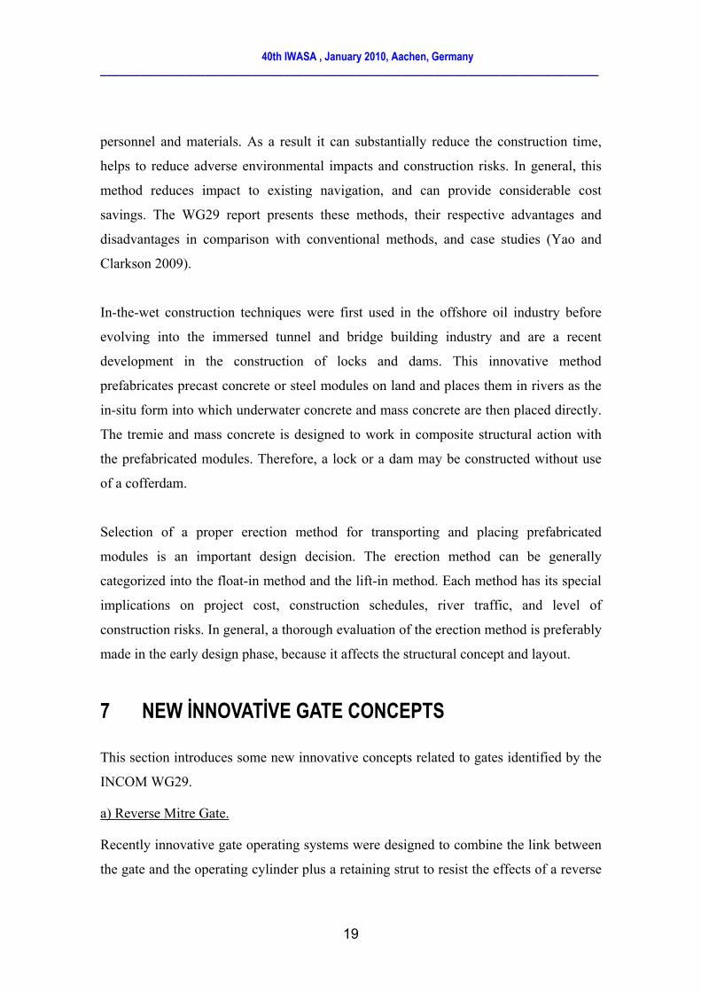
c) Suspended Mitre gates
There is an innovative solution to the problem of gate hinge wear, so-called ‘suspension
gate’, for mitre or single-leaf gate system (Figure 14). The gate leaves are suspended to
a rope, chain or other torque-flexible member – anchored in the leaf rotation axis and
hooked to a small tower or console. Both the top and the bottom hinge carry only
40th IWASA , January 2010, Aachen, Germany ____________________________________________________________________________
21
horizontal reactions in this way, which significantly decreases the wear and helps
solving some fatigue related problems (Daniel et al 2004).
Figure 14 - Suspended Mitre Gate (left); Mitre gates supported only at their top hinges
(Right)
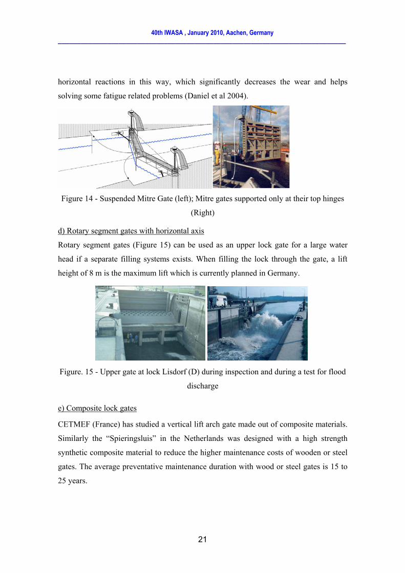
d) Rotary segment gates with horizontal axis
Rotary segment gates (Figure 15) can be used as an upper lock gate for a large water
head if a separate filling systems exists. When filling the lock through the gate, a lift
height of 8 m is the maximum lift which is currently planned in Germany.
Figure. 15 - Upper gate at lock Lisdorf (D) during inspection and during a test for flood
discharge
e) Composite lock gates
CETMEF (France) has studied a vertical lift arch gate made out of composite materials.
Similarly the “Spieringsluis” in the Netherlands was designed with a high strength
synthetic composite material to reduce the higher maintenance costs of wooden or steel
gates. The average preventative maintenance duration with wood or steel gates is 15 to
25 years.

40th IWASA , January 2010, Aachen, Germany ____________________________________________________________________________
22
Main advantages of composite arch gates are:
- No corrosion;
- Good resistance to aging in damp environment;
- Finishing paint useless, thereby seriously reducing maintenance costs;
- Lightness, easing transportation and fitting of the gate;
- Lightness reducing the purchasing and maintenance costs of the machinery;
- Gate positioning on the river side of the lock heads, easing maintenance and
reducing the risk of collision of the gate and/or machinery.
f) Rolling gates with integrated filling/emptying system
In Germany, an innovative gate system (Figure 16) combines the advantages of a lifting
gate, where the gate body also forms the closure for filling and emptying the lock
chamber, with those of a sliding gate.
Figure. 16 - Kaiser lifting and sliding lock gate
g) Gate tightness, linings and seals
In the Netherlands, Germany, Panama, etc. UHMPE (ultra-high molecular weight
polyethylene) is nowadays considered a reliable technology and a very durable material
to be used for sliding gate and lock filling and emptying valves.
It is a durable material a) long-service and b) environmentally favourable. It is
chemically very stable and its mechanical properties are little sensitive to time, weather
etc.
40th IWASA , January 2010, Aachen, Germany ____________________________________________________________________________
23
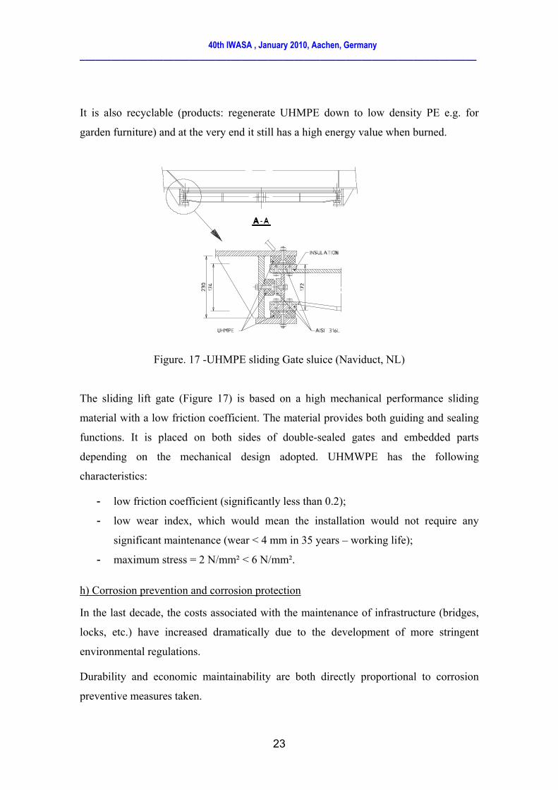
It is also recyclable (products: regenerate UHMPE down to low density PE e.g. for
garden furniture) and at the very end it still has a high energy value when burned.
Figure. 17 -UHMPE sliding Gate sluice (Naviduct, NL)
The sliding lift gate (Figure 17) is based on a high mechanical performance sliding
material with a low friction coefficient. The material provides both guiding and sealing
functions. It is placed on both sides of double-sealed gates and embedded parts
depending on the mechanical design adopted. UHMWPE has the following
characteristics:
- low friction coefficient (significantly less than 0.2);
- low wear index, which would mean the installation would not require any
significant maintenance (wear < 4 mm in 35 years – working life);
- maximum stress = 2 N/mm² < 6 N/mm².
h) Corrosion prevention and corrosion protection
In the last decade, the costs associated with the maintenance of infrastructure (bridges,
locks, etc.) have increased dramatically due to the development of more stringent
environmental regulations.
Durability and economic maintainability are both directly proportional to corrosion
preventive measures taken.

40th IWASA , January 2010, Aachen, Germany ____________________________________________________________________________
24
Corrosion prevention of metal, which should be built into the design, must not be
confused with corrosion protection, which is regarded as a secondary item to be applied
to the structures at the building stage.
The PIANC Report 106 (2009) includes recommendations about corrosion and makes a
clear distinction between Corrosion Prevention and Corrosion Protection.
8. LOCK STRUCTURES and FOUNDATIONS
In third part (Section 5) of the report, all main technical aspects including new structural
concepts, technical aspects and foundations issues are reviewed, focussing on changes
and innovations occurring since 1986.
9. COMPUTATIONAL FLUID DYNAMICS (CFD) IN LOCK DESIGN
A main change since 1986 concerns the arrival of the CFD (Thorenz 2009). The recent
developments in computational methods and the tremendous rise in available computing
power have shifted the regions of applicability of numerical models in the last years
(Figure 18). Still it must be stated that the filling and emptying of a lock is a complex
process, which is not easily replicated in computational models.
The development of computers and numerical models has shifted the range of
applicability largely in the last years. Many aspects of fluid flow in locks can be
described with computer models. But it must be stated that the most accurate and
complete way to predict the behavior of a lock is still a physical model. On the other
hand, numerical models can be very helpful for many aspects of lock design. If a new
design is based on an older design for which data is available, it can be sufficient to use
numerical models to extrapolate this know-how to the new design. In conjunction with
physical models, they can be helpful to eliminate unnecessary variants or to model
aspects of the fluid flow which are difficult to see or measure in physical models.

40th IWASA , January 2010, Aachen, Germany ____________________________________________________________________________
25
Nowadays, Computational Fluid Dynamics (CFD) software is available “from the
shelf”. Additionally, computing resources have increased substantially, so that many
people start to do CFD simulations. If the person who is doing the simulations is not
very well trained and/or of good will to produce quality results, there is a significant
danger that only nice pictures will be rendered. For external parties, only looking at the
resulting pictures, it is impossible to judge the quality of the results. Especially
commercial packages have a tendency to produce results under any circumstances, even
if for example the grid resolution is not sufficient for the problem. This is triggered by
the tendency that only models of higher dimensionality are “accepted”, so that three
dimensional models are being used, even if the available computing resources are not
sufficient for quality results. As a result “Colored fluid dynamics” pictures are
produced, which have nothing in common with real CFD.
Figure 18: Detail of computed flow field in the lower approach area of a lock, computed
with LES and RANS turbulence models (Thorenz 2009)

40th IWASA , January 2010, Aachen, Germany ____________________________________________________________________________
26
10. NUMERICAL SIMULATIONS AND EXPERIMENTAL MODELS: HOW TO CHOOSE?
Since Leonardo da Vinci the experiment has attained a leading and continuously
growing role in fluid mechanics research.
It is a prime merit of some scientists at the beginning of 20th century that they developed
experimental methods for the solution of hydraulic engineering problems and they
succeeded in convincing the profession of the usefulness and validity of this approach.
Hydraulic physical modelling developed rapidly into engineering tool of a general
recognition for the solution of hydraulic engineering problems.
NUMERICAL MODELLING
During the second part of the 20th century, there is fundamental research concerning the
development of some mathematical tools to describe the flow evolution. In parallel, the
progress in numerical and algorithmic increases considerably.
Then more numerical models have been applied in some areas of technical
hydromechanics with great success. The greater flexibility of numerical models is often
compensated by the more convincing intuitive power of the physical model. The market
shares of the numerical models have increased in the last century against the physical
models.
COMPARISON BETWEEN APPROACHES, LIMITATIONS
Scale model studies have proven a cost-effective means of investigating performance of
a proposed structure, provided requirements for hydraulic similitude are met.
Idealistically, this requires matching the ratio f appropriate pairs of forces in both scaled
model and prototype that play significant roles in the physical being examined.
The effort in constructing a hydraulic physical model is comparable to the effort of
working out a solution scheme for the numerical model. Both methods must make use
of certain simplifications and approximations and have to be adapted to the real

40th IWASA , January 2010, Aachen, Germany ____________________________________________________________________________
27
situation in nature – in the one case by adapting the empirical coefficients, in the other
case by changing the model roughness.
In numerical models, the decisive limitation is the fact that the majority of flows
processes are complex and no closed system of equations can be formulated (incomplete
set of equations, turbulence hypothesis,…). Another practical limitation is given by the
resolution of the model, which is determined by the choice of the grid size for the
solution scheme.
For the credibility of a model, it is important to know on the one hand, which
experiences are already available with similar types of models, and on the other hand to
know the extend of possible feedback between nature and model.
Thus, the results of both physical and numerical models should be carefully examined.
For physical models, the model set-up is not very error-prone, but the measuring and
interpretation process can be lead to errors. In numerical models, most errors are
introduced in the conception and set-up phase of the model.
11. CONCLUSIONS
PIANC decided in 2006 to launch a new Working Group to update the 1986 report on
locks. The new report (n°106) focuses on new design techniques and concepts that were
not reported in the former report. It covers all the aspects of the design of a lock.
Innovations and changes since 1986 are the main target of the present report.
So if you are convinced, enjoy reading PIANC Report 106.

40th IWASA , January 2010, Aachen, Germany ____________________________________________________________________________
28
LIST OF FIGURES
Figure 1: Example of Project reviews – Sevilla (Spain) 6
Figure 2: Examples of Project reviews – Panama (Left), Rhone in France (right) 7
Figure 3: Examples of Project reviews – Turucui Brazil (Left), Hohenwarthe Germany (right) (1) 7
Figure 4: Project reviews – Naviduct-NL (Left), Float in Segment - Braddock-USA(right) 8
Figure 5: Examples of Project reviews – Mooring System (Left), Folded plate miter gate and capsulated
hydraulic actuator (right) 9
Figure 6: Project reviews: Falkirk Wheel - UK (Left), Floating Pontoon and lock in the rock – Finland
(right) 10
Figure 7: The Three Gorges Project (China) 10
Figure 8: Partial distributed filling system 16
Figure 9: Double ditches used in bottom lateral system 16
Figure10: Double ditches used in ILCS system 16
Figure 11: Side Port System with Port Deflectors 17
Figure 12: Constituting elements of a hawser force criterion 18
Figure 13: Reverse Mitre Gates (IJmuiden-NL) 20
Figure 14: Suspended Mitre Gate (left); Mitre gates supported only at their top hinges (Right) 21
Figure. 15:Upper gate at lock Lisdorf (D) during inspection and during a test for flood discharge 21
Figure. 16:Kaiser lifting and sliding lock gate 22
Figure. 17:UHMPE sliding Gate sluice (Naviduct, NL) 23
Figure 18: Detail of computed flow field in the lower approach area of a lock, computed with LES and
RANS turbulence models (Thorenz 2009) 25
LIST OF TABLES
Table 1 : Layout of Table 2.1 in the report
Table 2 : Complexity categories of hydraulic system

40th IWASA , January 2010, Aachen, Germany ____________________________________________________________________________
29
References
PIANC (1986) Final Report of the International Commission for the Study of Locks,
PIANC, Brussels.
PIANC (2009), Report No.106, Innovations in Navigation Lock Design, PIANC,
Brussels
Daniel R., Vrijburcht A. (2004), Design of Lock Gate, PIANC Bulletin n°117
De Mulder T. (2009), Mooring forces and ship behaviour in navigation locks, Paper 7 of
PIANC Workshop, 15-16 Oct 2009, Brussels.
Hiver J-M (2009), Numerical Simulations And Experimental Models: How To Choose?
, Paper 11 of PIANC Workshop, 15-16 Oct 2009, Brussels.
Hunter P. (2009), Navigation Locks: Developments In Design Objectives and Methods,
Paper 3 of PIANC Workshop, 15-16 Oct 2009, Brussels.
Pechtold E. (2009), Project Reviews, Paper 3 of PIANC Workshop, 15-16 Oct 2009,
Brussels.
Rigo P. ; Gernay T. (2009), Lock Gates – Part A: Innovative Concepts – Part B: Ship
Impact, Paper 9 of PIANC Workshop, 15-16 Oct 2009, Brussels.
Thorenz C. (2009), Computational Fluid Dynamics in lock design - State of the art
Paper 10 of PIANC Workshop, 15-16 Oct 2009, Brussels.
Webb J, Wu Peng (2009), Innovations in Lock Filling and Emptying Systems, Paper 5
of PIANC Workshop, 15-16 Oct 2009, Brussels.
Yao S.X.; Clarkson J. (2009), In the Wet Construction, Paper 8 of PIANC Workshop,
15-16 Oct 2009, Brussels.

40th IWASA , January 2010, Aachen, Germany ____________________________________________________________________________
30
The PIANC WG29 members are:
- Rigo Ph. - Chairman (BE),
- Bödefeld J. (D),
- Bos J. (NL),
- Clarkson J. (USA),
- Daly F. (Fr),
- Fernandez J-L. (Spain),
- Hijdra A. (NL),
- Hiver J-M. (BE),
- Holm O. (Fin),
- Hunter P. (UK),
- Miller D. (USA),
- Pechtold E. (NL), YP
- Pichon N. (Fr), YP
- Poligot-Pitsch S. (Fr), YP
- Sarghiuta R. (Ro),
- Tarpey M. (USA),
- Thorenz C. (D),
- Wong J. (Panama),
- Wu Peng (China)
Support Groups and Associated
members:
Belgium:
- R. Thomas,
- O. Bribosia,
- T. De Mulder,
- I. Hermans,
- M. Sas,
- M. Vantorre;
Brazil:
- L. E. Garcia;
China:
- R. Zhang;
France:
- O. Cazaillet,
- J-N. Maillet,
- P-E. Pareau,
- J. Pinto;
Netherlands:
- R. Delhez,
- G.T.M. Smits,
- B. Spaargaren,
- J. Van Rijen,
- W.F. Molenaar;
Panama:
- J. De La Guardia,
- C. George,
- L. De Rodriguez;
UK:
- M. Cullen;
USA:
- R. B. Bittner,
- L. Dalton,
- J. E. Hite Jr. ,
- J. Maynard,
- W. R. Miles,
- L. Pierce,
- S. Yao
- B. Willis,