115615 smartscoop – the smartphone microscopenbg-web01.opitec.com/img/115/615/115615be.pdf ·...
TRANSCRIPT

1E115615#1
115615
S m a r t s c o o p – t h e S m a r t p h o n e m i c r o s c o p e
Contents list .
Qty Size (mm Designation Part no
Plywood 1 179x179x4 Base 1
Pine strip 4 200x20x10 Frame 2
Gaboon plywood 1 130x40x5 Construction, reflector 3
Pine cube 1 25x25x25 Construction, reflector 4
Acrylic glass 1 170x170x2 Cover for lens 5
Acrylic glass 1 250x50x2 Auflageplatte 6
Plastic lens 1 9x6 Lens 7
Polystyrene mirror 1 140x33x1 Mirror 8
Compression spring 1 38x7x0,5 Spring 9
Light Emitting 1 ø5 Lighting 10
Battery clip 1 Power source 11
Micro sliding switch 1 19x6 Switch 12
Resistor 33 ohm 1 Resistor 13
Threaded rod 3 150xM4 Construction 14
Cylinder head bolt 1 50x4 Fastening, Reflector 15
Nut 9 M4 Screw connection 16
Butterfly nut 3 M4 Distance adjustment 17
Cap nut 3 M4 Screw connection 18
Washer 10 9/4,3 Screw connection 19
Hook-up wire 1 500 Cabling 20
Please Note The OPITEC range of projects is not intended as play
toys for young children. They are teaching aids for young people learning the skills of Craft, Design and Technology. These projects should only be underta-ken and operated with the guidance of a fully quali-fied adult. The finished projects are not suitable to
give to children under 3 years old. Some parts can be swallowed. Danger of suffocation!
Required Tools: Scroll saw or jigsaw Drills: ø4, ø5, ø6, ø8,5, ø10mm (oil) Sandpaper Hot glue gun, tape Mitre saw, round file Wire stripper Wood glue Soldering iron & solder Engineer’s file, Hacksaw, Diagonal cutter

2 E115615#2
3819
130
150
74
170
200
20
25
130
40
Ø 4
20
725
12,525
Ø 6
25
12,525
4
25
25
4
1515
11
5
Ø 5
12,5
Ø 4
12,5
Ø 10
25
4
202090
3020
180
6
12
Ø 4
14
Ø 5
3819
130
150
74
170
200
20
25
130
40
Ø 4
20
725
12,525
Ø 6
25
12,525
4
25
25
4
1515
11
5
Ø 5
12,5
Ø 4
12,5
Ø 10
25
4
3819
130
150
74
170
200
20
25
130
40
Ø 4
20
725
12,525
Ø 6
25
12,525
4
25
25
4
1515
11
5
Ø 5
12,5
Ø 4
12,5
Ø 10
25
4
2a
2a
2b
Instructions1. Shorten each of the pine strips (2) to 170mm length with the
jigsaw or scroll saw as shown. Keep the remaining pieces for further work stages!
2. Mark the drill holes (ø 4mm/ ø 5mm) and the recess for the switch (12x6mm) on the base (1). Drill the holes with the ø 4mm and ø 5mm drills. Cut out the recess from the base with a jigsaw. Glue the four strips (2a) to the base (1) as shown. Let the glue dry thoroughly
2a
1
5. Transfer the side panels for the reflector construction from the template (page 7) onto the plywood (3). Cut both pieces out with a jigsaw or scroll saw. Tidy up the saw cuts with sandpaper. Fixate both parts above each other with tape as shown, and drill a ø4mm hole through both parts. Shorten one of the remaining pine strips (2b - step 1) to 25mm length with a jigsaw or scroll saw, and tidy up the saw cut. Measure, sketch and drill a ø 5mm hole.
3
3. Stick or glue the micro sliding switch (12) in its designated opening as shown. Be careful not to get any glue on to the contacts and the switch when gluing. 12
3a 3b
4. Use the hot glue gun to glue the battery clip (11) centrally on to the underside of the base (1) as shown. Feed the black cable of the battery clip through the drill hole in the base to the upper side. Connect the red cable of the battery clip with one end of the resistor (13).
Detailed View
Connect the second end of the resistor with the outer connection of the switch (12). Cut an approx. 80-100mm piece of hook up wire (20) and remove the insulation from both ends. Connect one end of the hook up wire with the central switch port. Feed the other end through the drill hole in the base to the upper side.
2b
2a
2a
1

3E115615#1
3819
130
150
74
170
200
20
25
130
40
Ø 4
20
725
12,525
Ø 6
25
12,525
4
25
25
4
1515
11
5Ø 5
12,5
Ø 4
12,5
Ø 10
25
4
3b
3a
17
15
19
89179
179
2533
25140
Ø 5
13
1818
38
A)B)
2b
3819
130
150
74
170
200
20
25
130
40
Ø 4
20
725
12,525
Ø 6
25
12,525
4
25
25
4
1515
11
5
Ø 5
12,5
Ø 4
12,5
Ø 10
25
4
Instructions6. Work on the wooden cube (4) as follows:
Drill a 15mm blind hole with a ø6mm drill to the measurements shown in Top View. Turn the wooden cube over and drill a 15mm blind hole in the centre with a ø10mm drill. Then drill ø 4mm hole on one side (see Side View)
Top ViewBottom View Side View
ansicht
8. A) Glue both side parts (3a+3b) to part 2b as shown. Note: The drill hole in part 2b has to point towards the back. B) Attach the wooden cube (4) with the cylinder head bolt (15), a washer (19) and a butterfly nut (17) between the two side parts (3a+3b)!
8
7 . Use jeweller’s cutters or tin cutters to cut a 25x25mm piece of polystyrene mirror (8). You can also use a craft knife or a jigsaw. When doing this score along the lines from both sides and carefully break off the cut-out piece. Measure and mark the correct position of the drill holes and drill, using ø5mm drill.
4
9. Shorten the threaded rods (14) to 130mm length with a hacksaw. Deburr the saw cuts.
4 E115615#2
25
Ø 4 Ø 8,5
Ø 4
170
170
170
50
15 15
1525
1515
5
6
Ø 4 Ø 8,5
Ø 4
170
170
170
50
15 15
1525
1515
Instructions
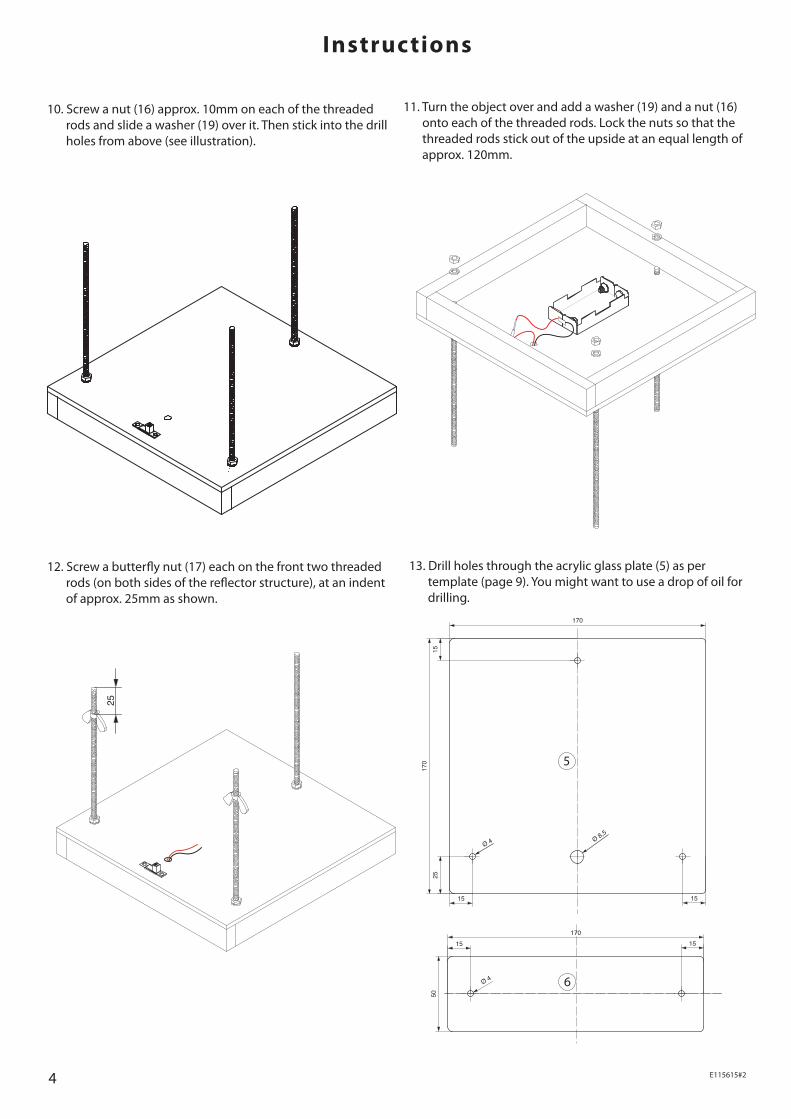
10. Screw a nut (16) approx. 10mm on each of the threaded rods and slide a washer (19) over it. Then stick into the drill holes from above (see illustration).
11. Turn the object over and add a washer (19) and a nut (16) onto each of the threaded rods. Lock the nuts so that the threaded rods stick out of the upside at an equal length of approx. 120mm.
12. Screw a butterfly nut (17) each on the front two threaded rods (on both sides of the reflector structure), at an indent of approx. 25mm as shown.
13. Drill holes through the acrylic glass plate (5) as per template (page 9). You might want to use a drop of oil for drilling.

5E115615#1
3819
130
150
74
170
200
20
25
130
40
Ø 4
20
725
12,525
Ø 6
25
12,525
4
25
25
4
1515
11
5
Ø 5
12,5
Ø 4
12,5
Ø 10
25
4
9
6
16 5
Instructions14. Carefully enlarge the drilled hole for the plastic lens
with a round file until the plastic lens fits exactly into the hole. Glue the plastic lens (7) as shown into the correct drill hole (approx. ø 8,8mm) in the acrylic glass plate (5). Make sure that it doesn’t protru-de upwards. Let the glue dry properly. Note: Pay attention to the installation direction! Notches face upwards
15. Place the acrylic glass plate (6) on the two butterfly nuts (17) as shown in the illustration. Cut the com-pression spring (9) in half with a diagonal cutter. Add a washer (19) to each of the front threaded rods. Stick one half of the cut compression spring (9) on each of the threaded rods as shown in the illustration.
16. Screw a nut (16) approx. 10mm onto each threaded rod.
17. Place the acrylic disk (5) on top of the nuts (16). Align the nuts (16) so that the acrylic glass plate is level.

6 E115615#2
18
10
Instructions18. To fix screw on a cap nut (18) each and lock.
20. Connect the LED’s cathode cable (short leg, flat side) to the black cable of the battery clip. Then connect the cable from the LED’s (10) anode with the free switch cable. Add batteries to the battery clip and switch on the switch. Does the LED light up? If yes, continue building. If it doesn’t light up, double-check the cables. Then glue the reflector construction with switched-on light on to the base so that the LED stands vertically under the lens.
cathode -
anode +
wiring diagram:
LED
battery
switch
resistor 33ohm
8
19. Thread two approx. 100mm long pieces of hook-up wire (20) through the two drill holes (see illustration) to the top, and connect to the two LED connectors (10). Insulate one of the LED connectors with tape. Then stick the LED (10) from above in the ø6mm drill hole in the cube (4). Glue the polystyrene mirror piece (8) on to the wooden cube (4) with hot glue or double-sided tape as shown.

7E115615#1
3819
130
150
74
170
200
20
25
130
40
Ø 4
20
725
12,525
Ø 6
25
12,525
4
25
25
4
1515
11
5
Ø 5
12,5
Ø 4
12,5
Ø 10
25
4Ø 4 Ø 8,5
Ø 4
17017
0
170
50
15 15
1525
1515
6
Instructions
Template Construction of reflector scale 1:1
Template small acrylic glass plate scale 1:1
21. Place the chosen object between the two acrylic glass pla-tes under the lens. Put a smartphone camera on to the lens and take a picture. This will produce fascinating photos. Note: The picture can be sharpened by turning the butterfly nut.

8 E115615#2
9E115615#1
202090
3020
180
6
12
Ø 4
14
Ø 5
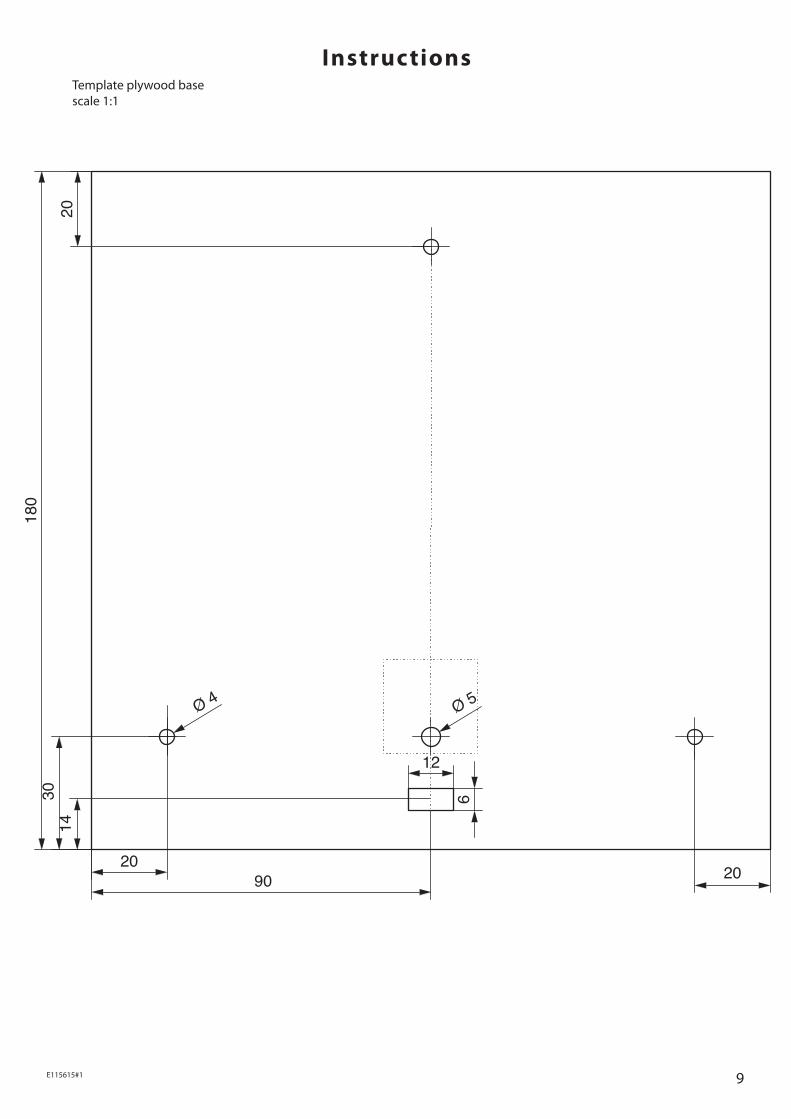
InstructionsTemplate plywood base scale 1:1

10 E115615#2
11E115615#1
Ø 4 Ø 8,5
Ø 4
170
170
170
50
15 15
1525
1515
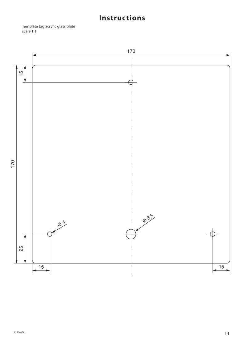
InstructionsTemplate big acrylic glass plate scale 1:1