1062 ieee transactions on power electronics,...
TRANSCRIPT
1062 IEEE TRANSACTIONS ON POWER ELECTRONICS, VOL. 22, NO. 3, MAY 2007
Fault Diagnostic System for a MultilevelInverter Using a Neural Network
Surin Khomfoi, Student Member, IEEE, and Leon M. Tolbert, Senior Member, IEEE
Abstract—In this paper, a fault diagnostic system in a multi-level-inverter using a neural network is developed. It is difficult todiagnose a multilevel-inverter drive (MLID) system using a math-ematical model because MLID systems consist of many switchingdevices and their system complexity has a nonlinear factor. There-fore, a neural network classification is applied to the fault diag-nosis of a MLID system. Five multilayer perceptron (MLP) net-works are used to identify the type and location of occurring faultsfrom inverter output voltage measurement. The neural networkdesign process is clearly described. The classification performanceof the proposed network between normal and abnormal conditionis about 90%, and the classification performance among fault fea-tures is about 85%. Thus, by utilizing the proposed neural net-work fault diagnostic system, a better understanding about faultbehaviors, diagnostics, and detections of a multilevel inverter drivesystem can be accomplished. The results of this analysis are iden-tified in percentage tabular form of faults and switch locations.
Index Terms—Diagnostic system, fault diagnosis, multilevel in-verter drive (MLID), neural network.
I. INTRODUCTION
I N recent years, industry has begun to demand higher powerratings, and multilevel inverter drive (MLID) systems have
become a solution for high power applications. A multilevel in-verter not only achieves high power ratings, but also enablesthe use of renewable energy sources. Two topologies of multi-level inverters for electric drive application have been discussedin [1]. The cascade MLID is a general fit for large automotiveall-electric drives because of the high VA rating possible andbecause it uses several level dc voltage sources which would beavailable from batteries or fuel cells [1].
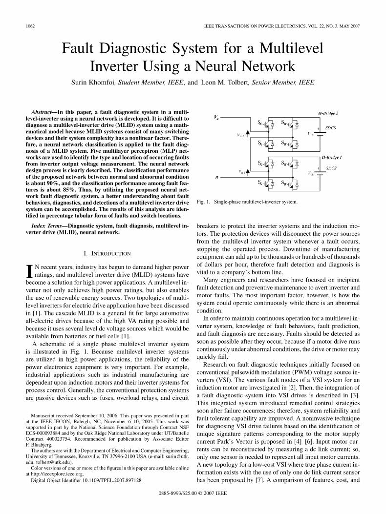
A schematic of a single phase multilevel inverter systemis illustrated in Fig. 1. Because multilevel inverter systemsare utilized in high power applications, the reliability of thepower electronics equipment is very important. For example,industrial applications such as industrial manufacturing aredependent upon induction motors and their inverter systems forprocess control. Generally, the conventional protection systemsare passive devices such as fuses, overload relays, and circuit
Manuscript received September 10, 2006. This paper was presented in partat the IEEE IECON, Raleigh, NC, November 6–10, 2005. This work wassupported in part by the National Science Foundation through Contract NSFECS-000093884 and by the Oak Ridge National Laboratory under UT/BattelleContract 400023754. Recommended for publication by Associate EditorF. Blaabjerg.
The authors are with the Department of Electrical and Computer Engineering,University of Tennessee, Knoxville, TN 37996-2100 USA (e-mail: [email protected]; [email protected]).
Color versions of one or more of the figures in this paper are available onlineat http://ieeexplore.ieee.org.
Digital Object Identifier 10.1109/TPEL.2007.897128
Fig. 1. Single-phase multilevel-inverter system.
breakers to protect the inverter systems and the induction mo-tors. The protection devices will disconnect the power sourcesfrom the multilevel inverter system whenever a fault occurs,stopping the operated process. Downtime of manufacturingequipment can add up to be thousands or hundreds of thousandsof dollars per hour, therefore fault detection and diagnosis isvital to a company’s bottom line.
Many engineers and researchers have focused on incipientfault detection and preventive maintenance to avert inverter andmotor faults. The most important factor, however, is how thesystem could operate continuously while there is an abnormalcondition.
In order to maintain continuous operation for a multilevel in-verter system, knowledge of fault behaviors, fault prediction,and fault diagnosis are necessary. Faults should be detected assoon as possible after they occur, because if a motor drive runscontinuously under abnormal conditions, the drive or motor mayquickly fail.
Research on fault diagnostic techniques initially focused onconventional pulsewidth modulation (PWM) voltage source in-verters (VSI). The various fault modes of a VSI system for aninduction motor are investigated in [2]. Then, the integration ofa fault diagnostic system into VSI drives is described in [3].This integrated system introduced remedial control strategiessoon after failure occurrences; therefore, system reliability andfault tolerant capability are improved. A noninvasive techniquefor diagnosing VSI drive failures based on the identification ofunique signature patterns corresponding to the motor supplycurrent Park’s Vector is proposed in [4]–[6]. Input motor cur-rents can be reconstructed by measuring a dc link current; so,only one sensor is needed to represent all input motor currents.A new topology for a low-cost VSI where true phase current in-formation exists with the use of only one dc link current sensorhas been proposed by [7]. A comparison of features, cost, and
0885-8993/$25.00 © 2007 IEEE
KHOMFOI AND TOLBERT: FAULT DIAGNOSTIC SYSTEM 1063
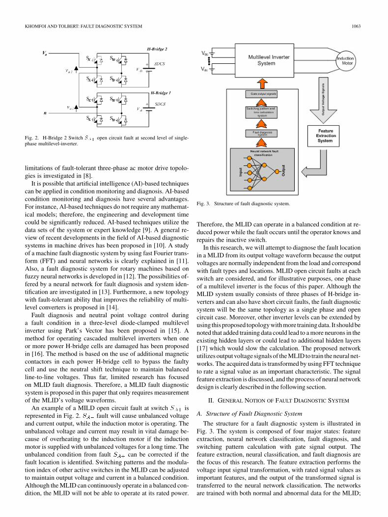
Fig. 2. H-Bridge 2 Switch S open circuit fault at second level of single-phase multilevel-inverter.
limitations of fault-tolerant three-phase ac motor drive topolo-gies is investigated in [8].
It is possible that artificial intelligence (AI)-based techniquescan be applied in condition monitoring and diagnosis. AI-basedcondition monitoring and diagnosis have several advantages.For instance, AI-based techniques do not require any mathemat-ical models; therefore, the engineering and development timecould be significantly reduced. AI-based techniques utilize thedata sets of the system or expert knowledge [9]. A general re-view of recent developments in the field of AI-based diagnosticsystems in machine drives has been proposed in [10]. A studyof a machine fault diagnostic system by using fast Fourier trans-form (FFT) and neural networks is clearly explained in [11].Also, a fault diagnostic system for rotary machines based onfuzzy neural networks is developed in [12]. The possibilities of-fered by a neural network for fault diagnosis and system iden-tification are investigated in [13]. Furthermore, a new topologywith fault-tolerant ability that improves the reliability of multi-level converters is proposed in [14].
Fault diagnosis and neutral point voltage control duringa fault condition in a three-level diode-clamped multilevelinverter using Park’s Vector has been proposed in [15]. Amethod for operating cascaded multilevel inverters when oneor more power H-bridge cells are damaged has been proposedin [16]. The method is based on the use of additional magneticcontactors in each power H-bridge cell to bypass the faultycell and use the neutral shift technique to maintain balancedline-to-line voltages. Thus far, limited research has focusedon MLID fault diagnosis. Therefore, a MLID fault diagnosticsystem is proposed in this paper that only requires measurementof the MLID’s voltage waveforms.
An example of a MILD open circuit fault at switch isrepresented in Fig. 2. fault will cause unbalanced voltageand current output, while the induction motor is operating. Theunbalanced voltage and current may result in vital damage be-cause of overheating to the induction motor if the inductionmotor is supplied with unbalanced voltages for a long time. Theunbalanced condition from fault can be corrected if thefault location is identified. Switching patterns and the modula-tion index of other active switches in the MLID can be adjustedto maintain output voltage and current in a balanced condition.Although the MLID can continuously operate in a balanced con-dition, the MLID will not be able to operate at its rated power.
Fig. 3. Structure of fault diagnostic system.
Therefore, the MLID can operate in a balanced condition at re-duced power while the fault occurs until the operator knows andrepairs the inactive switch.
In this research, we will attempt to diagnose the fault locationin a MLID from its output voltage waveform because the outputvoltages are normally independent from the load and correspondwith fault types and locations. MLID open circuit faults at eachswitch are considered, and for illustrative purposes, one phaseof a multilevel inverter is the focus of this paper. Although theMLID system usually consists of three phases of H-bridge in-verters and can also have short circuit faults, the fault diagnosticsystem will be the same topology as a single phase and opencircuit case. Moreover, other inverter levels can be extended byusing this proposed topology with more training data. It should benoted that added training data could lead to a more neurons in theexisting hidden layers or could lead to additional hidden layers[17] which would slow the calculation. The proposed networkutilizes output voltage signals of the MLID to train the neural net-works. The acquired data is transformed by using FFT techniqueto rate a signal value as an important characteristic. The signalfeature extraction is discussed, and the process of neural networkdesign is clearly described in the following section.
II. GENERAL NOTION OF FAULT DIAGNOSTIC SYSTEM
A. Structure of Fault Diagnostic System
The structure for a fault diagnostic system is illustrated inFig. 3. The system is composed of four major states: featureextraction, neural network classification, fault diagnosis, andswitching pattern calculation with gate signal output. Thefeature extraction, neural classification, and fault diagnosis arethe focus of this research. The feature extraction performs thevoltage input signal transformation, with rated signal values asimportant features, and the output of the transformed signal istransferred to the neural network classification. The networksare trained with both normal and abnormal data for the MLID;
1064 IEEE TRANSACTIONS ON POWER ELECTRONICS, VOL. 22, NO. 3, MAY 2007
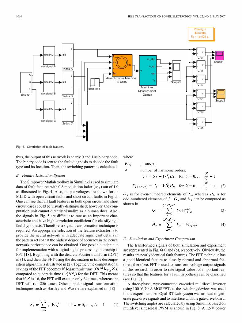
Fig. 4. Simulation of fault features.
thus, the output of this network is nearly 0 and 1 as binary code.The binary code is sent to the fault diagnosis to decode the faulttype and its location. Then, the switching pattern is calculated.
B. Feature Extraction System
The Simpower Matlab toolbox in Simulink is used to simulatedata of fault features with 0.8 modulation index ( ) out of 1.0as illustrated in Fig. 4. Also, output voltages are shown for anMLID with open circuit faults and short circuit faults in Fig. 5.One can see that all fault features in both open circuit and shortcircuit cases could be visually distinguished; however, the com-putation unit cannot directly visualize as a human does. Also,the signals in Fig. 5 are difficult to rate as an important char-acteristic and have high correlation coefficient for classifying afault hypothesis. Therefore, a signal transformation technique isrequired. An appropriate selection of the feature extractor is toprovide the neural network with adequate significant details inthe pattern set so that the highest degree of accuracy in the neuralnetwork performance can be obtained. One possible techniquefor implementation with a digital signal processing microchip isFFT [18]. Beginning with the discrete Fourier transform (DFT)in (1), and then the FFT using the decimation in time decompo-sition algorithm is illustrated in (2). Together, the computationalsavings of the FFT becomes logarithmic time ( )compared to quadratic time ( ) for the DFT. This meansthat if is 16, the FFT will execute only 64 times, whereas theDFT will run 256 times. Other popular signal transformationtechniques such as Hartley and Wavelet are explained in [18]
(1)
where
;number of harmonic orders;
for
for (2)
is for even-numbered elements of , whereas is forodd-numbered elements of . and can be computed asshown in
(3)
(4)
C. Simulation and Experiment Comparison
The transformed signals of both simulation and experimentare represented in Fig. 6(a) and (b), respectively. Obviously, theresults are nearly identical fault features. The FFT technique hasa good identical feature to classify normal and abnormal fea-tures; therefore, FFT is used to transform voltage output signalsin this research in order to rate signal value for important fea-tures so that the features for a fault hypothesis can be classified(see Fig. 7).
A three-phase, wye-connected cascaded multilevel inverterusing 100-V, 70-A MOSFETs as the switching devices was usedin the experiment. An Opal-RT Lab system was utilized to gen-erate gate drive signals and to interface with the gate drive board.The switching angles are calculated by using Simulink based onmultilevel sinusoidal PWM as shown in Fig. 8. A 12-V power
KHOMFOI AND TOLBERT: FAULT DIAGNOSTIC SYSTEM 1065
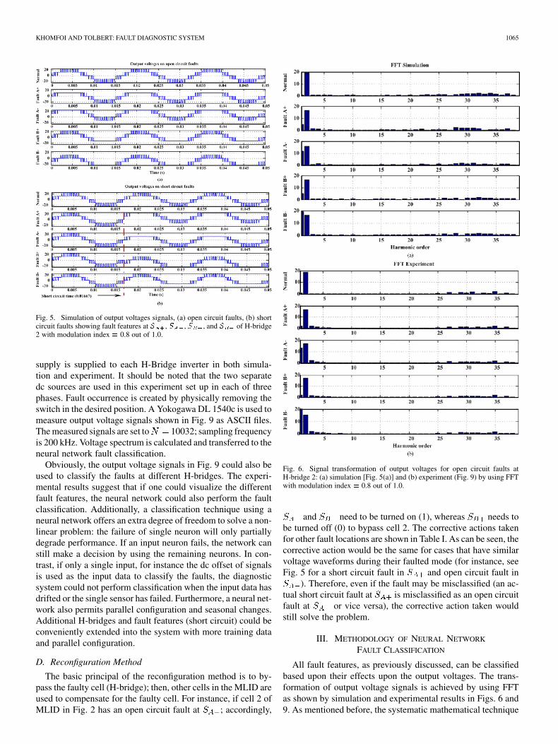
Fig. 5. Simulation of output voltages signals, (a) open circuit faults, (b) shortcircuit faults showing fault features at S , S , S , and S of H-bridge2 with modulation index = 0.8 out of 1.0.
supply is supplied to each H-Bridge inverter in both simula-tion and experiment. It should be noted that the two separatedc sources are used in this experiment set up in each of threephases. Fault occurrence is created by physically removing theswitch in the desired position. A Yokogawa DL 1540c is used tomeasure output voltage signals shown in Fig. 9 as ASCII files.The measured signals are set to 10032; sampling frequencyis 200 kHz. Voltage spectrum is calculated and transferred to theneural network fault classification.
Obviously, the output voltage signals in Fig. 9 could also beused to classify the faults at different H-bridges. The experi-mental results suggest that if one could visualize the differentfault features, the neural network could also perform the faultclassification. Additionally, a classification technique using aneural network offers an extra degree of freedom to solve a non-linear problem: the failure of single neuron will only partiallydegrade performance. If an input neuron fails, the network canstill make a decision by using the remaining neurons. In con-trast, if only a single input, for instance the dc offset of signalsis used as the input data to classify the faults, the diagnosticsystem could not perform classification when the input data hasdrifted or the single sensor has failed. Furthermore, a neural net-work also permits parallel configuration and seasonal changes.Additional H-bridges and fault features (short circuit) could beconveniently extended into the system with more training dataand parallel configuration.
D. Reconfiguration Method
The basic principal of the reconfiguration method is to by-pass the faulty cell (H-bridge); then, other cells in the MLID areused to compensate for the faulty cell. For instance, if cell 2 ofMLID in Fig. 2 has an open circuit fault at ; accordingly,
Fig. 6. Signal transformation of output voltages for open circuit faults atH-bridge 2: (a) simulation [Fig. 5(a)] and (b) experiment (Fig. 9) by using FFTwith modulation index = 0.8 out of 1.0.
and need to be turned on (1), whereas needs tobe turned off (0) to bypass cell 2. The corrective actions takenfor other fault locations are shown in Table I. As can be seen, thecorrective action would be the same for cases that have similarvoltage waveforms during their faulted mode (for instance, seeFig. 5 for a short circuit fault in and open circuit fault in
). Therefore, even if the fault may be misclassified (an ac-tual short circuit fault at is misclassified as an open circuitfault at or vice versa), the corrective action taken wouldstill solve the problem.
III. METHODOLOGY OF NEURAL NETWORK
FAULT CLASSIFICATION
All fault features, as previously discussed, can be classifiedbased upon their effects upon the output voltages. The trans-formation of output voltage signals is achieved by using FFTas shown by simulation and experimental results in Figs. 6 and9. As mentioned before, the systematic mathematical technique
1066 IEEE TRANSACTIONS ON POWER ELECTRONICS, VOL. 22, NO. 3, MAY 2007
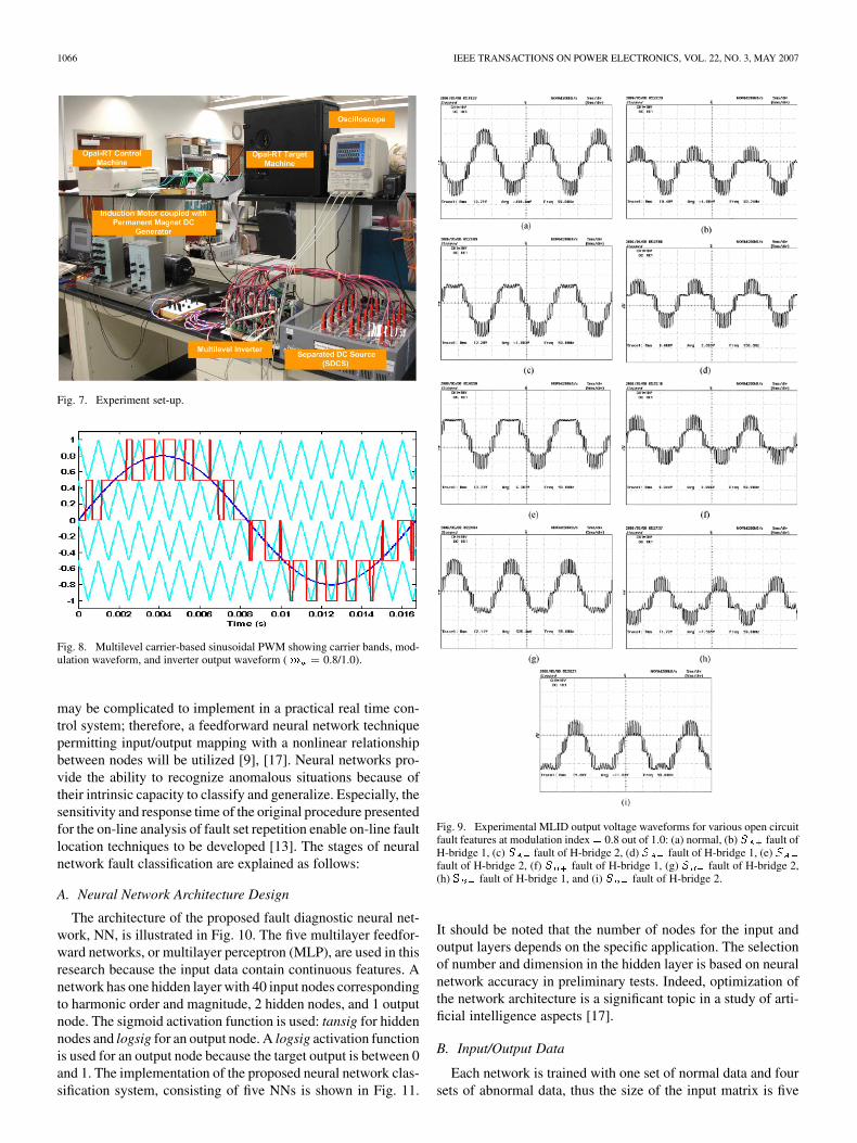
Fig. 7. Experiment set-up.
Fig. 8. Multilevel carrier-based sinusoidal PWM showing carrier bands, mod-ulation waveform, and inverter output waveform ( m = 0.8/1.0).
may be complicated to implement in a practical real time con-trol system; therefore, a feedforward neural network techniquepermitting input/output mapping with a nonlinear relationshipbetween nodes will be utilized [9], [17]. Neural networks pro-vide the ability to recognize anomalous situations because oftheir intrinsic capacity to classify and generalize. Especially, thesensitivity and response time of the original procedure presentedfor the on-line analysis of fault set repetition enable on-line faultlocation techniques to be developed [13]. The stages of neuralnetwork fault classification are explained as follows:
A. Neural Network Architecture Design
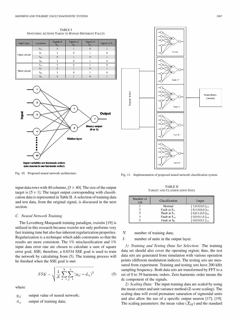
The architecture of the proposed fault diagnostic neural net-work, NN, is illustrated in Fig. 10. The five multilayer feedfor-ward networks, or multilayer perceptron (MLP), are used in thisresearch because the input data contain continuous features. Anetwork has one hidden layer with 40 input nodes correspondingto harmonic order and magnitude, 2 hidden nodes, and 1 outputnode. The sigmoid activation function is used: tansig for hiddennodes and logsig for an output node. A logsig activation functionis used for an output node because the target output is between 0and 1. The implementation of the proposed neural network clas-sification system, consisting of five NNs is shown in Fig. 11.
Fig. 9. Experimental MLID output voltage waveforms for various open circuitfault features at modulation index= 0.8 out of 1.0: (a) normal, (b) S fault ofH-bridge 1, (c) S fault of H-bridge 2, (d) S fault of H-bridge 1, (e) Sfault of H-bridge 2, (f) S fault of H-bridge 1, (g) S fault of H-bridge 2,(h) S fault of H-bridge 1, and (i) S fault of H-bridge 2.
It should be noted that the number of nodes for the input andoutput layers depends on the specific application. The selectionof number and dimension in the hidden layer is based on neuralnetwork accuracy in preliminary tests. Indeed, optimization ofthe network architecture is a significant topic in a study of arti-ficial intelligence aspects [17].
B. Input/Output Data
Each network is trained with one set of normal data and foursets of abnormal data, thus the size of the input matrix is five
KHOMFOI AND TOLBERT: FAULT DIAGNOSTIC SYSTEM 1067
TABLE ISWITCHING ACTIONS TAKEN TO BYPASS DIFFERENT FAULTS
Fig. 10. Proposed neural network architecture.
input data rows with 40 columns, [5 40]. The size of the outputtarget is [5 1]. The target output corresponding with classifi-cation data is represented in Table II. A selection of training dataand test data, from the original signal, is discussed in the nextsection.
C. Neural Network Training
The Levenberg Marquardt training paradigm, trainlm [19] isutilized in this research because trainlm not only performs veryfast training time but also has inherent regularization properties.Regularization is a technique which adds constraints so that theresults are more consistent. The 1% misclassification and 1%input data error rate are chosen to calculate a sum of squareerror goal, SSE; therefore, a 0.0334 SSE goal is used to trainthe network by calculating from (5). The training process willbe finished when the SSE goal is met
(5)
where
output value of neural network;
output of training data;
Fig. 11. Implementation of proposed neural network classification system.
TABLE IITARGET AND CLASSIFICATION DATA
number of training data;
number of units in the output layer.
1) Training and Testing Data Set Selection: The trainingdata set should also cover the operating region; thus, the testdata sets are generated from simulation with various operationpoints (different modulation indices). The testing sets are mea-sured from experiment. Training and testing sets have 200 kHzsampling frequency. Both data sets are transformed by FFT to aset of 0 to 39 harmonic orders. Zero harmonic order means thedc component of the signals.
2) Scaling Data: The input training data are scaled by usingthe mean center and unit variance method (Z-score scaling). Thescaling data will avoid premature saturation of sigmoidal unitsand also allow the use of a specific output neuron [17], [19].The scaling parameters: the mean value ( ) and the standard
1068 IEEE TRANSACTIONS ON POWER ELECTRONICS, VOL. 22, NO. 3, MAY 2007
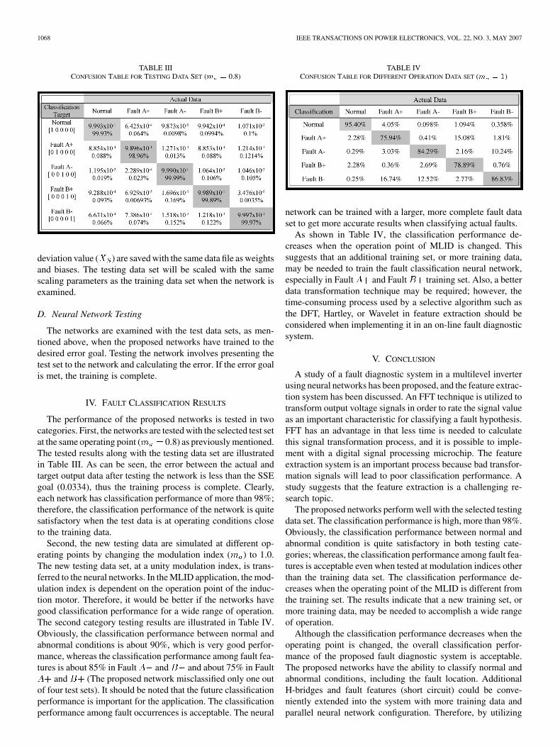
TABLE IIICONFUSION TABLE FOR TESTING DATA SET (m = 0.8)
deviation value ( ) are saved with the same data file as weightsand biases. The testing data set will be scaled with the samescaling parameters as the training data set when the network isexamined.
D. Neural Network Testing
The networks are examined with the test data sets, as men-tioned above, when the proposed networks have trained to thedesired error goal. Testing the network involves presenting thetest set to the network and calculating the error. If the error goalis met, the training is complete.
IV. FAULT CLASSIFICATION RESULTS
The performance of the proposed networks is tested in twocategories. First, the networks are tested with the selected test setat the same operating point ( 0.8) as previously mentioned.The tested results along with the testing data set are illustratedin Table III. As can be seen, the error between the actual andtarget output data after testing the network is less than the SSEgoal (0.0334), thus the training process is complete. Clearly,each network has classification performance of more than 98%;therefore, the classification performance of the network is quitesatisfactory when the test data is at operating conditions closeto the training data.
Second, the new testing data are simulated at different op-erating points by changing the modulation index ( ) to 1.0.The new testing data set, at a unity modulation index, is trans-ferred to the neural networks. In the MLID application, the mod-ulation index is dependent on the operation point of the induc-tion motor. Therefore, it would be better if the networks havegood classification performance for a wide range of operation.The second category testing results are illustrated in Table IV.Obviously, the classification performance between normal andabnormal conditions is about 90%, which is very good perfor-mance, whereas the classification performance among fault fea-tures is about 85% in Fault and and about 75% in Fault
and (The proposed network misclassified only one outof four test sets). It should be noted that the future classificationperformance is important for the application. The classificationperformance among fault occurrences is acceptable. The neural
TABLE IVCONFUSION TABLE FOR DIFFERENT OPERATION DATA SET (m = 1)
network can be trained with a larger, more complete fault dataset to get more accurate results when classifying actual faults.
As shown in Table IV, the classification performance de-creases when the operation point of MLID is changed. Thissuggests that an additional training set, or more training data,may be needed to train the fault classification neural network,especially in Fault and Fault training set. Also, a betterdata transformation technique may be required; however, thetime-consuming process used by a selective algorithm such asthe DFT, Hartley, or Wavelet in feature extraction should beconsidered when implementing it in an on-line fault diagnosticsystem.
V. CONCLUSION
A study of a fault diagnostic system in a multilevel inverterusing neural networks has been proposed, and the feature extrac-tion system has been discussed. An FFT technique is utilized totransform output voltage signals in order to rate the signal valueas an important characteristic for classifying a fault hypothesis.FFT has an advantage in that less time is needed to calculatethis signal transformation process, and it is possible to imple-ment with a digital signal processing microchip. The featureextraction system is an important process because bad transfor-mation signals will lead to poor classification performance. Astudy suggests that the feature extraction is a challenging re-search topic.
The proposed networks perform well with the selected testingdata set. The classification performance is high, more than 98%.Obviously, the classification performance between normal andabnormal condition is quite satisfactory in both testing cate-gories; whereas, the classification performance among fault fea-tures is acceptable even when tested at modulation indices otherthan the training data set. The classification performance de-creases when the operating point of the MLID is different fromthe training set. The results indicate that a new training set, ormore training data, may be needed to accomplish a wide rangeof operation.
Although the classification performance decreases when theoperating point is changed, the overall classification perfor-mance of the proposed fault diagnostic system is acceptable.The proposed networks have the ability to classify normal andabnormal conditions, including the fault location. AdditionalH-bridges and fault features (short circuit) could be conve-niently extended into the system with more training data andparallel neural network configuration. Therefore, by utilizing

KHOMFOI AND TOLBERT: FAULT DIAGNOSTIC SYSTEM 1069
the proposed neural network fault diagnostic system in thisresearch, a better understanding of fault behaviors, diagnostics,and detections for multilevel inverter drive systems can beachieved.
REFERENCES
[1] L. M. Tolbert, F. Z. Peng, and T. G. Habetler, “Multilevel convertersfor large electric drives,” IEEE Trans. Ind. Appl., vol. 35, no. 1, pp.36–44, Jan./Feb. 1999.
[2] D. Kastha and B. K. Bose, “Investigation of fault modes of voltage-fedinverter system for induction motor drive,” IEEE Trans. Ind. Appl., vol.30, no. 4, pp. 1028–1038, Jul. 1994.
[3] D. Kastha and B. K. Bose, “On-line search based pulsating torquecompensation of a fault mode single-phase variable frequency induc-tion motor drive,” IEEE Trans. Ind. Appl., vol. 31, no. 4, pp. 802–811,Jul./Aug. 1995.
[4] A. M. S. Mendes, A. J. M. Cardoso, and E. S. Saraiva, “Voltage sourceinverter fault diagnosis in variable speed ac drives by Park’s vector ap-proach,” in Proc. IEE 7th Int. Conf. Power Electron. Var. Speed Drives,1998, pp. 538–543.
[5] K. Rothenhagen and F. W. Fuchs, “Performance of diagnosis methodsfor IGBT open circuit faults in three phase voltage source inverters forac variable speed drives,” in Proc. Eur. Conf. Power Electron. Appl.,Dresden, Germany, 2005, pp. P.1–P.10.
[6] D. Diallo, M. H. Benbouzid, D. Hamad, and X. Pierre, “Fault detectionand diagnosis in an induction machine drive: A pattern recognition ap-proach based on concordia stator mean current vector,” IEEE Trans.Energy Conv., vol. 20, no. 3, pp. 512–519, Sep. 2005.
[7] F. Blaabjerg and J. K. Pedersen, “A new low-cost, fully fault-protectedPWM-VSI inverter with true phase-current information,” IEEE Trans.Power Electron., vol. 12, no. 1, pp. 187–197, Jan. 1997.
[8] B. A. Welchko, T. A. Lipo, T. M. Jahns, and S. E. Schulz, “Faulttolerant three-phase ac motor drive topologies: A comparison of fea-tures, cost, limitations,” IEEE Trans. Power Electron., vol. 19, no. 4,pp. 1108–1116, Jul. 2004.
[9] P. Vas, Artificial-Intelligence-Based Electrical Machines andDrives. New York: Oxford University Press, 1999.
[10] F. Filippetti, G. Franceschini, C. Tassoni, and P. Vas, “Recent develop-ments of induction motor drives fault diagnosis using AI techniques,”IEEE Trans. Power Electron., vol. 19, no. 4, pp. 1108–1116, Jul. 2004.
[11] S. Hayashi, T. Asakura, and S. Zhang, “Study of machine fault diag-nosis using neural networks,” in Proc. Neural Networks (IJCNN’02),2002, vol. 1, pp. 956–961.
[12] S. Zhang, T. Asakura, X. Xu, and B. Xu, “Fault diagnosis system forrotary machines based on fuzzy neural networks,” in Proc. IEEE/ASMEAdv. Intell. Mechatron. (AIM), 2003, pp. 199–204.
[13] A. Bernieri, M. D’Apuzzo, L. Sansone, and M. Savastano, “A neuralnetwork approach for identification and fault diagnosis on dynamic sys-tems,” IEEE Trans. Instrum. Meas., vol. 43, no. 6, pp. 867–873, Dec.1994.
[14] A. Chen, L. Hu, L. Chen, Y. Deng, and X. He, “A multilevel convertertopology with fault-tolerant ability,” IEEE Trans. Power Electron., vol.20, no. 2, pp. 405–415, Mar. 2005.
[15] H. I. Son, T. J. Kim, D. W. Kang, and D. S. Hyun, “Fault diagnosis andneutral point voltage control when the 3-level inverter faults occur,” inProc. IEEE Power Electron. Spec. Conf., 2004, pp. 4558–4563.
[16] J. Rodriguez, P. W. Hammond, J. Pontt, R. Musalem, P. Lezana, and M.J. Escobar, “Operation of a medium-voltage drive under faulty condi-tions,” IEEE Trans. Ind. Electron., vol. 52, no. 4, pp. 1080–1085, Aug.2005.
[17] L. H. Tsoukalas and R. E. Uhrig, Fuzzy and Neural Approaches in En-gineering. New York: Wiley, 1997.
[18] J. A. Momoh, W. E. Oliver, Jr, and J. L. Dolc, “Comparison of featureextractors on DC power system faults for improving ANN fault diag-nosis accuracy,” in Proc. IEEE Intell. Syst. 21st Century, 1995, vol. 4,pp. 3615–3623.
[19] H. Demuth and M. Beale, Neural Network Toolbox User’s Guide, 3ed. Natick, MA: The MathWorks, Inc., 1998.
Surin Khomfoi (S’03) received the B.Eng. andM.Eng. degree in electrical engineering from KingMongkut’s Institute of Technology Ladkrabang(KMITL), Bangkok, Thailand, in 1996 and 2000,respectively, and the Ph.D. degree in electricaland computer engineering from The University ofTennessee, Knoxville, in 2007.
From 1996 to 1997, he worked in the EngineeringDivision, Telephone Organization of Thailand(TOT); then, he joined the Department of ElectricalEngineering, King Mongkut’s Institute of Tech-
nology Ladkrabang, Bangkok, in December 1997 as a Lecturer. His researchinterests include multilevel power converters, ac drives, diagnostic system, faultdiagnosis, and more specially, artificial intelligent-based techniques applied topower electronics and drive applications.
Dr. Khomfoi received an academic scholarship from the Telephone Organ-ization of Thailand and an academic scholarship from the Energy Policy andPlanning Office (EPPO), Thailand. He is member of Eta Kappa Nu.
Leon M. Tolbert (S’89–M’91–SM’98) received theB.E.E., M.S., and Ph.D. degrees in electrical engi-neering from the Georgia Institute of Technology,Atlanta, in 1989, 1991, and 1999, respectively.
He joined the Engineering Division, LockheedMartin Energy Systems, in 1991 and worked onseveral electrical distribution projects at the threeU.S. Department of Energy plants in Oak Ridge,TN. In 1997, he became a Research Engineer in thePower Electronics and Electric Machinery ResearchCenter, Oak Ridge National Laboratory. In 1999,
he was appointed an Assistant Professor in the Department of Electricaland Computer Engineering, University of Tennessee, Knoxville, where he ispresently an Associate Professor. He is an adjunct participant at the Oak RidgeNational Laboratory and conducts joint research at the National TransportationResearch Center (NTRC). He does research in the areas of electric powerconversion for distributed energy sources, motor drives, multilevel converters,hybrid electric vehicles, and application of SiC power electronics.
Dr. Tolbert received the National Science Foundation CAREER Award andthe 2001 IEEE Industry Applications Society Outstanding Young MemberAward. He was an Associate Editor for the IEEE POWER ELECTRONICS LETTERS
from 2003 to 2006. He has been the Chairman of the Education ActivitiesCommittee, IEEE Power Electronics Society, since 2003. He is a RegisteredProfessional Engineer in the state of Tennessee.