1 the transport layer: tcp and udp jean-yves le boudec fall 2009
TRANSCRIPT

1
The Transport Layer: TCP and UDPJean-Yves Le Boudec
Fall 2009
ÉCOLE POLYTECHNIQUE FÉDÉRALE DE LAUSANNE

2
Contents
1. Where should packet losses be repaired ?
2. Mechanisms for error recovery
3. Flow Control
4. The Transport Layer
5. TCP basics
6. TCP, advanced

3
1. Error Recovery
In section 1, we first discuss where packet losses should be dealt with.
In sections 2 and following we will discuss how this is implemented in the Internet in detail

4
The Philosophy of Errors in a Layered ModelThe physical layer is not completely error-free – there is always some bit error rate (BER).
Information theory tells us that for every channel there is a capacity C such thatAt any rate R < C, arbitrarily small BER can be achievedAt rates R ¸ C, any BER such that H2(BER) > 1 – C/R is achievable, with H2(p) = entropy= – p log2(p) – (1 – p ) log2(1 – p)
The TCP/IP architecture decidedEvery layer ¸ 2 offers an error free service to the upper layer:
SDUs are either delivered without error or discarded
Example: MAC layerQ1. How does an Ethernet adapter know whether a received Ethernet frames has some bit errors ? What does it do with the frame ?
WiFi detects errors with CRC and does retransmissions if neededQ2. Why does not Ethernet do the same ?solution

5
The Layered Model Transforms Errors into Packet Losses
Packet losses occur due to error detection by MAC buffer overflow in bridges and routersOther exceptional errors may occur tooQ. give some examples
solution
A R1 R2 BP1
P1P1
P2P2
P2P3
P4P4
P4P3 is missing
P3P3
A R1 R2 BP1
P1P1
P2P2
P2P3
P3P3
P3
P3 is missing
P4P4P3
P4
Therefore, packet losses must be repaired. This can be done using either of the following strategies:
end to end : host A sends 10 packets to host B. B verifies if all packets are received and asks for A to send again the missing ones. or hop by hop: every router would do this job.
Which one is better ? We will discuss this in the next slides.

6
There are arguments in favour of the end-to-end strategy. The keyword here is complexity:
The TCP/IP architecture tries to keep intermediate systems as simple as possible. Hop by hop error recovery makes the job of routers too complicated.
Needs to remember some information about every packet flow -> too much processing per packetNeeds to store packets in case they have to be retransmitted -> too much memory required
IP packets may follow parallel paths, this is incompatible with hop-by-hop recovery. R2 sees only 3 out of 7 packets but should not ask R1 for retransmisison
The Case for End-to-end Error Recovery
R2 BA
R3
R4R1
14 23567

7
* The Case for Hop-By-Hop Error Recovery
There are also arguments in favour of hop-by-hop strategy. To understand them, we will use the following result.
Capacity of erasure channel: consider a channel with bit rate R that either delivers correct packets or loses them. Assume the loss process is stationary, such that the packet loss rate is p2[0,1]. The capacity is R£(1-p) packets/sec.
This means in practice that, for example, over a link at 10Mb/s that has a packet loss rate of 10% we can transmit 9 Mb/s of useful data.
The packet loss rate (PLR) can be derived from the bit error rate (BER) as follows, if bit errors are independent events, as a function of the packet length in bits L:
PLR = 1 – (1 – BER)L

8
* The Capacity of the End-to-End Path
We can now compute the capacity of an end-to-end path with both error recovery strategies.
Assumptions: same packet loss rate p on k links; same nominal rate R. Losses are independent.Q. compute the capacity with end-to-end and with hop by hop error recovery.
A
R1 R1 R1 R1 R1 R1
B
Loss probability p
k links
solution

9
* End-to-end Error Recovery is Inefficient when Packet Error Rate is high
The table shows the capacity of an end-to-end path as a function of the packet loss rate p
Conclusion: end-to-end error recovery is not acceptable when packet loss rate is high
Q. How can one reconcile the conflicting arguments for and against hop-by-hop error recovery ?
k Packet loss rate
C1 (end-to-end)
C2 (hop-by-hop)
10 0.05 0.6 £ R 0.95 £ R
10 0.0001 0.9990 £ R 0.9999 £ R
solution

10
Conclusion: Where is Error Recovery located in the TCP/IP architecture ?
The TCP/IP architecture assumes that1. The MAC layer provides error—free packets to the network layer2. The packet loss rate at the MAC layer (between two routers, or between a
router and a host) must be made very small. It is the job of the MAC layer to achieve this.
3. Error recovery must also be implemented end-to-end.
Thus, packet losses are repairedAt the MAC layer on lossy channels (wireless)In the end systems (transport layer or application layer).

11
2. Mechanisms for Error Recovery
In this section we discuss the methods for repairing packet losses that are used in the Internet.
We have seen one such method already:Q. which one ?
Stop and Go is an example of packet retransmission protocol. Packet retransmission is the general method used in the Internet for repairing packet losses. It is also called Automatic Repeat Request (ARQ).
TCP is an ARQ protocol
solution

12
ARQ Protocols
Why invented ?Repair packet losses
What does an ARQ protocol do ?1. Recover lost packets2. Deliver packets at destination in order, i.e. in the same order as submitted by source
How does an ARQ protocol work ? Similar to Stop and Go but:
It may differ in many details such asHow packet loss is detectedThe format and semantics of acknowledgementsWhich action is taken when one loss is detected
Practically all protocols use the concept of sliding window, which we review now.

13
Why Sliding Window ?
Why invented ?Overcome limitations of Stop and GoQ. what is the limitation of Stop and Go ?solution
What does it do ?1. Allow mutiple transmissions
But this has a problem: the required buffer at destination may be very large
2. This problem is solved by the sliding window. The sliding window protocol puts a limit on the number of packets that may have to be stored at receive buffer.
P0
A1
P1
P2
A2
Pn
P0 again
Pn+1
P1
P1 P2
P1 P2 ... Pn
P1 P2 ... Pn+1
ReceiveBuffer

14
How Sliding Window Works.
Usable Window
P = 1
A = 0
P = 0
A =2
P = 2
P = 3
P = 4
A =1
P = 5
P = 6
P = 7
P = 8
P = 9
A =3
P = 10
A =4
A =5
A =6
A =7
0 1 2 3 4 5 6 7 8 9 10 11 12
0 1 2 3 4 5 6 7 8 9 10 11 12
0 1 2 3 4 5 6 7 8 9 10 11 12
0 1 2 3 4 5 6 7 8 9 10 11 12
0 1 2 3 4 5 6 7 8 9 10 11 12
0 1 2 3 4 5 6 7 8 9 10 11 12
0 1 2 3 4 5 6 7 8 9 10 11 12
0 1 2 3 4 5 6 7 8 9 10 11 12
0 1 2 3 4 5 6 7 8 9 10 11 12
0 1 2 3 4 5 6 7 8 9 10 11 12
0 1 2 3 4 5 6 7 8 9 10 11 12
0 1 2 3 4 5 6 7 8 9 10 11 12
0 1 2 3 4 5 6 7 8 9 10 11 12
0 1 2 3 4 5 6 7 8 9 10 11 12
Legend
Maximum
Send Window
= Offered Window
( = 4 here)

15
On the example, packets are numbered 0, 1, 2, ..The sliding window principle works as follows:- a window size W is defined. In this example it is fixed. In general, it may vary based on
messages sent by the receiver. The sliding window principle requires that, at any time: number of unacknowledged packets at the receiver <= W
- the maximum send window, also called offered window is the set of packet numbers for packets that either have been sent but are not (yet) acknowledged or have not been sent but may be sent.
- the usable window is the set of packet numbers for packets that may be sent for the first time. The usable window is always contained in the maximum send window.
- the lower bound of the maximum send window is the smallest packet number that has been sent and not acknowledged
- the maximum window slides (moves to the right) if the acknowledgement for the packet with the lowest number in the window is received
A sliding window protocol is a protocol that uses the sliding window principle. With a sliding window protocol, W is the maximum number of packets that the receiver needs to buffer in the re-sequencing (= receive) buffer.
If there are no losses, a sliding window protocol can have a throughput of 100% of link rate (overhead is not accounted for) if the window size satisfies: W b / L, where b is the bandwidth delay product, and L the packet size. Counted in bytes, this means that the minimum window size for 100% utilization is the bandwidth-delay product.

16
An Example of ARQ Protocol with Selective Repeat
A=1
P=0P0; 3
Upper BoundMaximum Send
Window
RetransmissionBuffer
P=1
P=2
P=3 A=2
A=3Timeout
Timeout
P=0
P=2A=0
A=2P=4
P=5
P=6
P0; P13
P0; P23
P0; P2; P33
P0; P23
P25
P2; P45
P2; P4; P55
P4; P5; P67
ResequencingBuffer
Lowest Expected
Packet Number
P1 0
P1; P2 0
P1; P2; P3 0
P0;P1;P2;P3 0
deliver P0 ... P3
4
4
P4 4deliver P4
5A=4P5 5
deliver P5
6
0

17
The previous slide shows an example of ARQ protocol, which uses the following details:
1. packets are numbered by source, staring from 0. 2. window size = 4 packets; 3. Acknowledgements are positive and indicate exactly which packet is being
acknowledged4. Loss detection is by timeout at sender when no acknowledgement has
arrived5. When a loss is detected, only the packet that is detected as lost is re-
transmitted (this is called Selective Repeat).
Q. Is it possible with this protocol that a packet is retransmitted whereas it was correctly received? solution

18
*An Example of ARQ Protocol with Go Back N
Lowestunacknowledgedpacket number
V(A)
RetransmissionBuffer
P=0
Next ExpectedPacket Number
V(R))
0
Next Sequence Number forSendingV(S)
P0; 10
P0; P120
A=0
deliver P0 1
P=1
P0; P1; P230P=2
P0; P1; P2; P340P=3 deliver P12
deliver P23deliver P34
A=1
P=0P0; P1; P2; P310
discard4
A=2
A=3P0; P1; P2; P320
P=1
P0; P1; P2; P330P=2
P0; P1; P2; P340P=3 discard4
discard4discard4
P0; P1; P2; P300
P2; P342 P=2

19
The previous slide shows an example of ARQ protocol, which uses the following details:1. window size = 4 packets; 2. Acknowledgements are positive and are cumulative, i.e. indicate the highest packet
number upt to which all packets were correctly received3. Loss detection is by timeout at sender4. When a loss is detected, the source starts retransmitting packets from the last
acknowldeged packet (this is called Go Back n).
Q. Is it possible with this protocol that a packet is retransmitted whereas it was correctly received? Solution
Go Back n is less efficient than selective repeat, since we may unneccesarily retransmit a packet that was correctly transmitted. Its advantage is its extreme simplicity:
(less memory at destination) It is possible for the destination to reject all packets other than the expected one. If so, the required buffer at destination is just one packet(less processing) The actions taken by source and destination are simpler
Go Back n is thus suited for very simple implementations, for example on sensors.

20
*An Example of ARQ Protocol with Go Back N and Negative Acks
RetransmissionBuffer
P=0
V(R)
0
V(S)
P0; 10
P0; P120 deliver P01
P=1
P0; P1; P230P=2
P0; P1; P2; P340P=3
NACK, A=0
P1; P2; P341
discard1
deliver P12 deliver P23
A=1
A=0
P=4
P1; P2; P3; P451
P1; P2; P3; P411 P=1
P1; P2; P3; P421 P=2
NACK, A=0 discard1
discard1
V(A)

21
The previous slide shows an example of ARQ protocol, which uses the following details:
1. window size = 4 packets;
2. Acknowledgements are positive or negative and are cumulative. A positive ack indicates that packet n was received as well as all packets before it. A negative ack indicates that all packets up to n were received but a packet after it was lost
3. Loss detection is either by timeout at sender or by reception of negative ack.
4. When a loss is detected, the source starts retransmitting packets from the last acknowldeged packet (Go Back n).
Q. What is the benefit of this protocol compared to the previous ?solution

22
Where are ARQ Protocols Used ?
Hop-by-hopMAC layer
Modems: Selective RepeatWiFi: Stop and Go
End-to-endTransport Layer:
TCP: variant of selective repeat with some features of go back n
Application layerDNS: Stop and Go

23
Are There Alternatives to ARQ ?
Coding is an alternative to ARQ.
Forward Error Correction (FEC):Principle:
Make a data block out of n packetsAdd redundancy (ex Reed Solomon codes) to block and generate k+n packetsIf n out of k+n packets are received, the block can be reconstructed
Q. What are the pros and cons ?solutionIs used for data distribution over satellite linksOther FEC methods are used for voice or video (exploit the fact that some distortion may be allowed – for example: interpolate a lost packet by two adjacent packets)

24
FEC may be combined with ARQ
Example with multicast, using digital fountain codesSource has a file to transmit; it sends n packetsA destination that misses one packet sends a request for retransmission; source uses a fountain code and sends packet n+1If this or another destination still does not has enough, sources codes and sends packets n+2, n+3, … as necessaryAll packets are differentAny n packets received by any destination allows to reconstruct the entire fileUsed for data distribution over the Internet.

25
3. Flow Control
Why invented ?Differences in machine performance: A may send data to B much faster than B can use. Or B may be shared by many processes and cannot consume data received at the rate that A sends.Data may be lost at B due to lack of buffer space – waste of resources !
What does it do ?Flow control prevents prevent buffer overflow at receiver
How does it work ?Backpressure, orCredits
Flow Control Congestion controlcongestion control is about preventing too many losses inside the network

26
Backpressure Flow Control
Destination sends STOP (= PAUSE) or GO messages
Source stops sending for x msec after receiving a STOP message
Simple to implement
Q. When does it work well ?
solution
Where implemented ?
X-ON / X-OFF protocols inside a computerBetween Bridges in a LAN
IssuesLoops in feedback must be avoided (otherwise deadlock)
P=0
P0
P=1
P=2
P=3STOP
P1
P2
P3
STOP
GO
P=5
P=6
P=7
P=4

27
Can we use Sliding Window for Flow Control ?
One could use a sliding window for flow control, as followsAssume a source sends packets to a destination using an ARQ protocol with sliding window. The window size is 4 packets and the destination has buffer space for 4 packets. Assume the destination delays sending acks until it has enough free buffer space. For example, destination has just received (but not acked) 4 packets. Destination will send an ack for the 4 packets only when destination application has consumed them.
Q. Does this solve the flow control problem ? solution

28
Credit Flow Control
0 1 2 3 4 5 6 7 8 9 10 11 12
0 1 2 3 4 5 6 7 8 9 10 11 12
P = 1
A = -1, credit = 2
P = 0
P = 2
P = 3
P = 4
A = 0, credit = 2
P = 5
P = 6
0 1 2 3 4 5 6 7 8 9 10 11 12
0 1 2 3 4 5 6 7 8 9 10 11 12
0 1 2 3 4 5 6 7 8 9 10 11 12
A = 2, credit = 4
0 1 2 3 4 5 6 7 8 9 10 11 12
A = 0, credit = 4
0 1 2 3 4 5 6 7 8 9 10 11 12
0 1 2 3 4 5 6 7 8 9 10 11 12
0 1 2 3 4 5 6 7 8 9 10 11 12
0 1 2 3 4 5 6 7 8 9 10 11 12
0 1 2 3 4 5 6 7 8 9 10 11 12
0 1 2 3 4 5 6 7 8 9 10 11 12
A = 4, credit = 2
0 1 2 3 4 5 6 7 8 9 10 11 120 1 2 3 4 5 6 7 8 9 10 11 12 A = 6, credit = 0
0 1 2 3 4 5 6 7 8 9 10 11 12A = 6, credit = 4
0 1 2 3 4 5 6 7 8 9 10 11 12
0 1 2 3 4 5 6 7 8 9 10 11 12
P = 7

29
The credit scheme solves the issue with using the sliding window alone for flow control. Credits are used by TCP, under the name of “window advertisement”. With a credit scheme, the receiver informs the sender about how much data it is willing to receive (and have buffer for). Credits may be the basis for a stand-alone protocol or, as shown here, be a part of an ARQ protocol. Credit schemes allow a receiver to share buffer between several connections, and also to send acknowledgements before packets are consumed by the receiving upper layer (packets received in sequence may be ready to be delivered, but the application program may take some time to actually read them). The picture shows the maximum send window (called “offered window” in TCP) (red border) and the usable window (pink box). On the picture, like with TCP, credits (= window advertisements) are sent together with acknowledgements. The acknowledegements on the picture are cumulative. Credits are used to move the right edge of the maximum send window. (Remember that acknowledgements are used to move the left edge of the maximum send window). By acknowledging all packets up to number n and sending a credit of k, the receiver commits to have enough buffer to receive all packets from n+1 to n+k. In principle, the receiver(who sends acks and credits) should make sure that n+k is non-decreasing, namely, that the right edge of the maximum send window does not move to the left (because packets may have been sent already by the time the sdr receives the credit). A receiver is blocked from sending if it receives credit = 0, or more generally, if the received credit is equal to the number of unacknowledged packets. By the rule above, the received credits should never be less than the number of unacknowledged packets. With TCP, a sender may always send one byte of data even if there is no credit (window probe, triggered by persistTimer) and test the receiver’s advertized window, in order to avoid deadlocks (lost credits).

30
Credits are Modified as Receive Buffer Space Varies
A = 4, credit = 2
P = 1
A = -1, credit = 2
P = 0
P = 2
P = 3
P = 4
A = 0, credit = 2
P = 5
P = 6
A = 2, credit = 4
A = 0, credit = 4
A = 6, credit = 0A = 6, credit = 4
P = 7
3 4 5 6
5 6
7 8 9 10
1 2 3 4
1 2 3 4
1 2 3 4
1 2 3 4
3 4 5 6
3 4 5 6
3 4 5 6
7 8 9 10
0 1
0 1
1 2
-2 -1 -3
-2 -1 -3
-2 -1 0 -3
-2 -1 0 -3
-2 -1 0 1-3
-2 -1 0 1-3 2
-2 -1 0 1-3 2
-2 -1 0 1-3 2 3
-2 -1 0 1-3 2 3 4
-2 -1 0 1-3 2 3 4 5
-2 -1 0 1-3 2 3 4 5 6
-2 -1 0 1-3 2 3 4 5 6
free buffer, or unacked data
data acked but not yet read

31
The figure shows the relation between buffer occupancy and the credits sent to the source. This is an ideal representation. TCP implementations may differ a little.
The picture shows how credits are triggered by the status of the receive buffer. The flows are the same as on the previous picture.
The receiver has a buffer space of 4 data packets (assumed here to be of constant size for simplicity). Data packets may be stored in the buffer either because they are received out of sequence (not shown here), or because the receiving application, or upper layer, has not yet read them.
The receiver sends window updates (=credits) in every acknowledgement. The credit is equal to the available buffer space.
Loss conditions are not shown on the picture. If losses occur, there may be packets stored in the receive buffer that cannot be read by the application (received out of sequence). In all cases, the credit sent to the source is equal to the buffer size, minus the number of packets that have been received in sequence. This is because the sender is expected to move its window based only on the smallest ack number received.

32
4. The Transport Layer
Reminder:network + link + phy carry packets end-to-endtransport layer makes network services available to programsis in end systems only, not in routers
In TCP/IP there are two transport layersUDP (User Datagram Protocol): offers only a programming interface, no real functionTCP (Transmission Control Protocol): implements error recovery + flow control

33
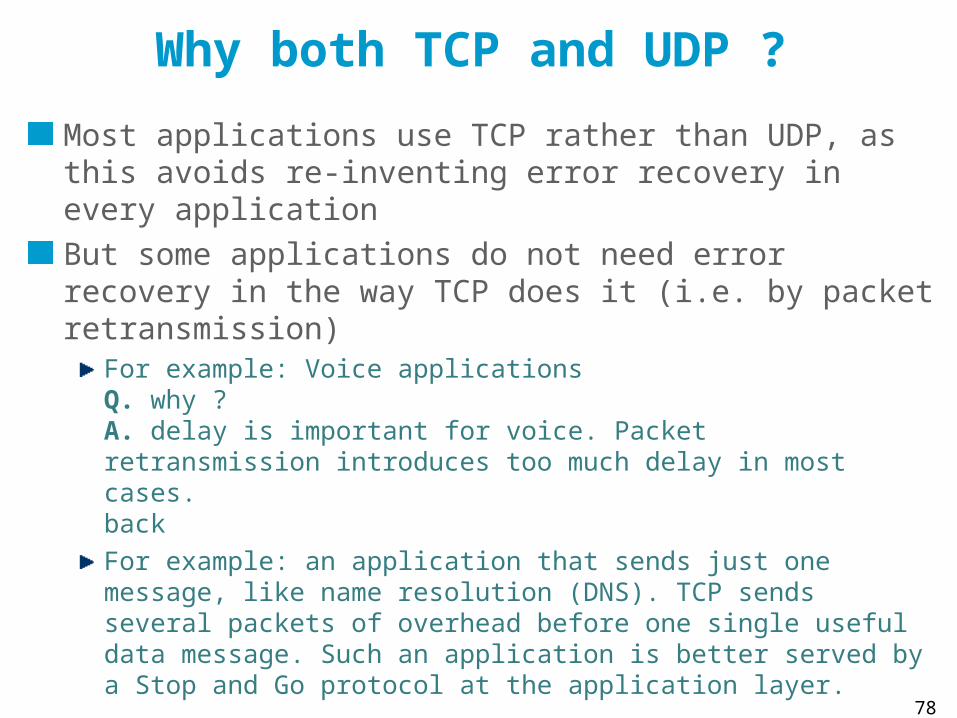
Why both TCP and UDP ?
Most applications use TCP rather than UDP, as this avoids re-inventing error recovery in every application
But some applications do not need error recovery in the way TCP does it (i.e. by packet retransmission)
For example: Voice applicationsQ. why ?solutionFor example: an application that sends just one message, like name resolution (DNS). TCP sends several packets of overhead before one single useful data message. Such an application is better served by a Stop and Go protocol at the application layer.For example: multicast (TCP does not support multicast IP addresses)

34
UDP Uses Port Numbers
Host IP addr=B
Host IP addr=B
Host IP addr=A
Host IP addr=A
IP SA=A DA=B prot=UDPsource port=1267destination port=53…data…
processsa
processra
UDP
processqa
processpa
TCP
IP
1267
processsb
processrb
UDP
processqb
processpb
TCP
IP
53
IP network
UDP Source Port UDP Dest Port UDP Message Length UDP Checksum
data
IP header
UDP datagramIP datagram

35
The picture shows two processes (= application programs) pa, and pb, are communicating. Each of them is associated locally with a port, as shown in the figure.
In addition, every machine (in reality: every communication adapter) has an IP address.
The example shows a packet sent by the name resolver process at host A, to the name server process at host B. The UDP header contains the source and destination ports. The destination port number is used to contact the name server process at B; the source port is not used directly; it will be used in the response from B to A.
The UDP header also contains a checksum the protect the UDP data plus the IP addresses and packet length. Checksum computation is not performed by all systems. Ports are 16 bits unsigned integers. They are defined statically or dynamically. Typically, a server uses a port number defined statically.
Standard services use well-known ports; for example, all DNS servers use port 53 (look at /etc/services). Ports that are allocated dynamically are called ephemeral. They are usually above 1024. If you write your own client server application on a multiprogramming machine, you need to define your own server port number and code it into your application.

36
The UDP service
UDP service interfaceone message, up to 8Kdestination address, destination port, source address, source port
UDP service is message orienteddelivers exactly the message or nothingseveral messages may be delivered in disorderMessage may be lost, application must implement loss recovery.
If a UDP message is larger than MTU, then fragmentation occurs at the IP layer

37
UDP is used via a Socket Library The socket library provides a programming interface to TCP and UDPThe figure shows toy client and server UDP programs. The client sends one string of chars to the server, which simply receives (and displays) it.
socket() creates a socket and returns a number (=file descriptor) if successfulbind() associates the local port number with the socketsendto() gives the destination IP address, port number and the message to sendrecvFrom() blocks until one message is received for this port number. It returns the source IP address and port number and the message.
client
socket();
bind();
sendto();
close();
server
socket();
bind();
rcvfrom();
% ./udpClient <destAddr> bonjour les amis%
% ./udpServ &%

38
How the Operating System views UDP
id=3 id=4
buffer buffer
port=32456 port=32654
program
UDP
IPaddress=128.178.151.84
socketsocket

39
5. TCP basics
Why invented ?Repair packet lossesSave application from doing it.
What does TCP do ?TCP guarantees that all data is delivered in sequence and without loss, unless the connection is broken; TCP should work for all applications that transfer data, either in small or large quantitiesTCP does not work with multicast IP addresses, UDP does. TCP also does flow controlTCP also does congestion control (not seen in this module)
How does TCP work ?first, a connection (=synchronization of sequence numbers) is opened between two processesthen TCP implements ARQ (for error recovery) and credits (for flow control)in the end, the connection is closed

40
The TCP Service
TCP offers a stream service A stream of bytes is accepted for transmission and delivered at destinationTCP uses port numbers like UDP eg. TCP port 80 is used for web server. TCP requires that a connection is opened before data can be transferred. A TCP connection is identified by: srce IP addr, srce port, dest IP addr, dest port

41
TCP views data as a stream of bytes
TCP-PDUs are called TCP segmentsbytes accumulated in buffer until sending TCP decides to create a segmentMSS = maximum “segment“ size (maximum data part size)
“B sends MSS = 236” means that segments, without header, sent to B should not exceed 236 bytes
536 bytes by default (576 bytes IP packet)Sequence numbers based on byte counts, not packet countsTCP builds segments independent of how application data is broken
unlike UDPTCP segments never fragmented at source
possibly at intermediate points with IPv4where are fragments re-assembled ?
TCP dataTCP hdr
IP data = TCP segmentIP hdr
prot=TCP

42
TCP is an ARQ protocol
Basic operation:sliding windowloss detection by timeout at senderretransmission is a hybrid of go back and selective repeatCumulative acks
Supplementary elementsfast retransmitselective acknowledgements
Flow control is by credit
Congestion controladapt to network conditions

43
TCP Basic Operation8001:8501(500) ack 101 win 6000
101:201(100) ack 8501 win 140008501:9001(500) ack 201 win 14247
9001:9501(500) ack 201 win 14247
9501:10001(500) ack 201 win 14247
(0) ack 8501 win 13000
8501:9001(500) ack 251 win 14247201:251(50) ack 8501 win 12000
251:401(150) ack 10001 win 12000
10001:10501(500) ack 401 win 14247
Timeout !
1
2
3
4
56
7
8
910
deliverbytes
...:8500
deliverbytes
8501:10000
deliverbytes
10001:10500
A B
Reset timersfor packets
4, 5, 6

44
The picture shows a sample exchange of messages. Every packet carries the sequence number for the bytes in the packet; in the reverse direction, packets contain the acknowledgements for the bytes already received in sequence. The connection is bidirectional, with acknowledgements and sequence numbers for each direction. Acknowledgements are not sent in separate packets (“piggybacking”), but are in the TCP header. Every segment thus contains a sequence number (for itself), plus an ack number (for the reverse direction). The following notation is used:
firstByte”:”lastByte+1 “(“segmentDataLength”) ack” ackNumber+1 “win” offeredWindowSise. Note the +1 with ack and lastByte numbers.
At line 8, a retransmission timer expires, causing the retransmission of data starting with byte number 8501 (Go Back n principle).Note however that after segment 9 is received, transmission continues with byte number 10001. This is because the receiver stores segments received out of order. The window field (win) gives to the sender the size of the window. Only byte numbers that are in the window may be sent. This makes sure the destination is not flooded with data it cannot handle.Note that numbers on the figure are rounded for simplicity. Real examples use non-round numbers between 0 and 232 -1. The initial sequence number is not 0, but is chosen at random using a 4 µsec clock. The figure shows the implementation of TCP known as “TCP SACK”, which is the basis for current implementations. An earlier implementation (“TCP Tahoe”) did not reset the pending timers after a timeout; thus, this was implementing a true Go Back n protocol; the drawback was that packets were retransmitted unnecessarily, because packet losses are usually simple.
45
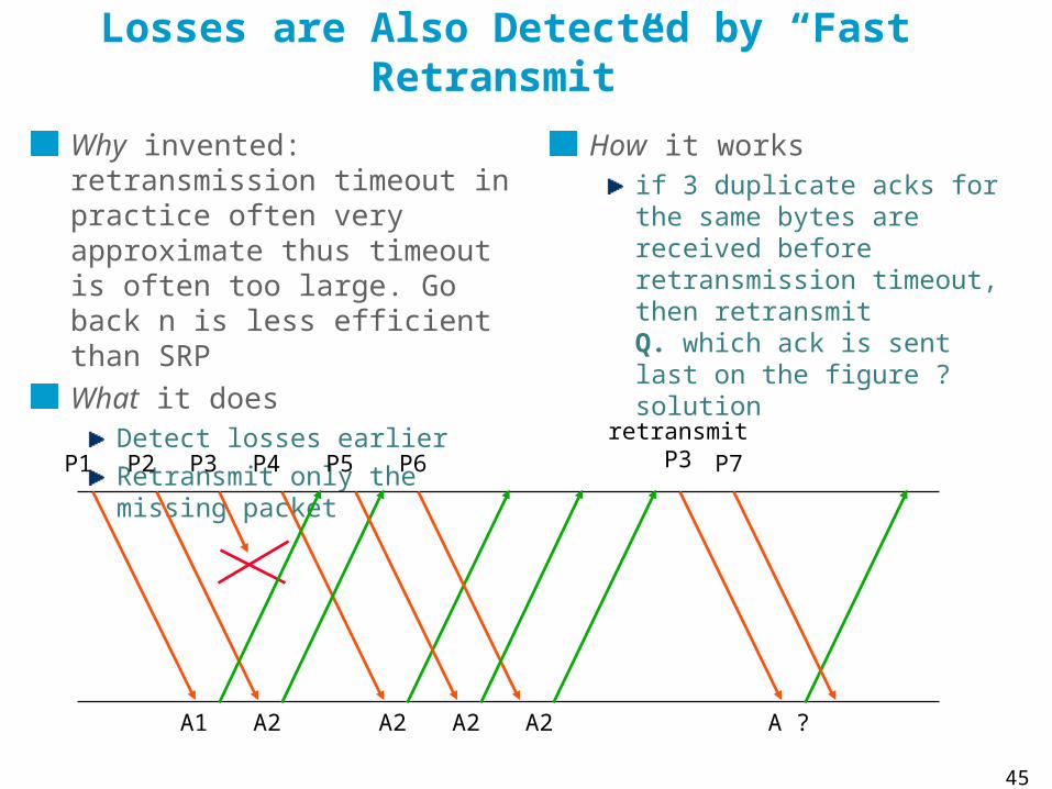
Losses are Also Detected by “Fast Retransmit”
Why invented: retransmission timeout in practice often very approximate thus timeout is often too large. Go back n is less efficient than SRP
What it doesDetect losses earlierRetransmit only the missing packet
How it worksif 3 duplicate acks for the same bytes are received before retransmission timeout, then retransmitQ. which ack is sent last on the figure ?solution
P1 P2 P3 P4
A1 A2 A2
P5 P6
A2 A2
retransmitP3
A ?
P7

46
Selective Acknowledgements
Why invented ?Fast retransmit works well if there is one isolated loss, not if there are a few isolated losses
What does it do ? Acknowledge exactly which bytes are received and allow their selective retransmission
How does it do it ?up to 3 SACK blocks are in TCP option, on the return path; a SACK block is a positive ack for an interval of bytes; first block is most recently receivedSent by destination when : new data is received that does not increase ack fieldsource to detect a loss by gap in received acknowledgementIf gap detected, missing bytes are retransmitted

47
TCP uses Connections
TCP requires that a connection (= synchronization) is opened before transmitting data
Used to agree on sequence numbers
The next slide shows the states of a TCP connection:
Before data transfer takes place, the TCP connection is opened using SYN packets. The effect is to synchronize the counters on both sides.The initial sequence number is a random number.The connection can be closed in a number of ways. The picture shows a graceful release where both sides of the connection are closed in turn.Remember that TCP connections involve only two hosts; routers in between are not involved.

48
TCP Connection Phases
SYN, seq=xsyn_sent
SYN seq=y, ack=x+1
ack=y+1establishedestablished
snc_rcvd
listen
FIN, seq=u
ack=v+1
ack=u+1
FIN seq=vfin_wait_2
time_wait
close_wait
last_ack
closed
application active open passive open
application close:
active closefin_wait_1
Connection
Setup
Data Transfer
Connection
Release

49
paddingoptions (if any)
srce port dest port
sequence number
ack number
hlen windowcode bitsrsvd
urgent pointerchecksum
segment data (if any)
TCPheader(20 Bytes + options)
IP header (20 B + options)
<= MSS bytes
code bit meaning urg urgent ptr is validack ack field is validpsh this seg requests a pushrst reset the connectionsyn connection setupfin sender has reached end of byte stream

50
*TCP Segment FormatThe next slide shows the TCP segment format. the push bit can be used by the upper layer using TCP; it forces TCP on the sending
side to create a segment immediately. If it is not set, TCP may pack together several SDUs (=data passed to TCP by the upper layer) into one PDU (= segment). On the receiving side, the push bit forces TCP to deliver the data immediately. If it is not set, TCP may pack together several PDUs into one SDU. This is because of the stream orientation of TCP. TCP accepts and delivers contiguous sets of bytes, without any structure visible to TCP. The push bit used by Telnet after every end of line.
the urgent bit indicates that there is urgent data, pointed to by the urgent pointer (the urgent data need not be in the segment). The receiving TCP must inform the application that there is urgent data. Otherwise, the segments do not receive any special treatment. This is used by Telnet to send interrupt type commands.
RST is used to indicate a RESET command. Its reception causes the connection to be aborted.
SYN and FIN are used to indicate connection setup and close. They each consume one sequence number.
The sequence number is that of the first byte in the data. The ack number is the next expected sequence number.
Options contain for example the Maximum Segment Size (MSS) normally in SYN segments (negotiation of the maximum size for the connection results in the smallest value to be selected).
The checksum is mandatory.

51
TCP is used via a Socket LibraryThe figure shows toy client and servers. The client sends a string of chars to the server which reads and displays it.
socket() creates a socket and returns a number (=file descriptor) if successfulbind() associates the local port number with the socketconnect() associates the remote IP address and port number with the socket and sends a SYN packetsend() sends a block of data to the remote destinationlisten() can be omitted at first reading; accept blocks until a SYN packet is received for this local port number. It creates a new socket (in pink) and returns the file descriptor to be used to interact with this new socketreceive() blocks until one block of data is ready to be consumed on this port number. You must tell in the argument of receive how many bytes at most you want to read. It returns the number of bytes that is effectively retruned and and the block of data.
% ./tcpClient <destAddr> bonjour les amis%
% ./tcpServ &%
clientsocket();
serversocket();
bind();
connect();
send();
close();
bind();
listen();
accept();
receive();
close();

52
How the Operating System views TCP Sockets
program
TCP
IP
id=3 id=4
incomingconnection
queue
buffer
port=32456
address=128.178.151.84
id=5
buffer
socketsocket socket
53
Test Your Understanding
Consider the UDP and TCP servicesQ1. what does service mean here ?Q2. does UDP transfer the blocks of data delivered by the calling process as
they were submitted ? Analyze: delineation, order, missing blocks. Q3. does TCP transfer the messages delivered by the calling process as they
were submitted ? Analyze: delineation, order, missing blocks.
One more questionQ4. Is Stop and Go a sliding window protocol ?
solution

54
6. TCP, advanced
TCP implements a large number of additional mechanisms. Why ?1. The devils’ in the detail
Doing ARQ and flow control the right way poses a number of small problems that need to be solved. We give some examples in the next slides.
This will give you a feeling for the complexity of the real TCP code.Note that there are many other details in TCP, not shown in this lecture.
2. Congestion control is done in TCPCongestion control is a network layer function (avoid congestion in the network) that the IETF decided to implement in TCP – we discuss why in the module on congestion control cc.pdf. We do not consider congestion control in this module.
55
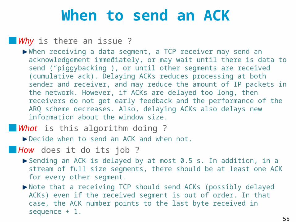
When to send an ACK
Why is there an issue ?When receiving a data segment, a TCP receiver may send an acknowledgement immediately, or may wait until there is data to send (“piggybacking”), or until other segments are received (cumulative ack). Delaying ACKs reduces processing at both sender and receiver, and may reduce the amount of IP packets in the network. However, if ACKs are delayed too long, then receivers do not get early feedback and the performance of the ARQ scheme decreases. Also, delaying ACKs also delays new information about the window size.
What is this algorithm doing ?Decide when to send an ACK and when not.
How does it do its job ?Sending an ACK is delayed by at most 0.5 s. In addition, in a stream of full size segments, there should be at least one ACK for every other segment. Note that a receiving TCP should send ACKs (possibly delayed ACKs) even if the received segment is out of order. In that case, the ACK number points to the last byte received in sequence + 1.
56
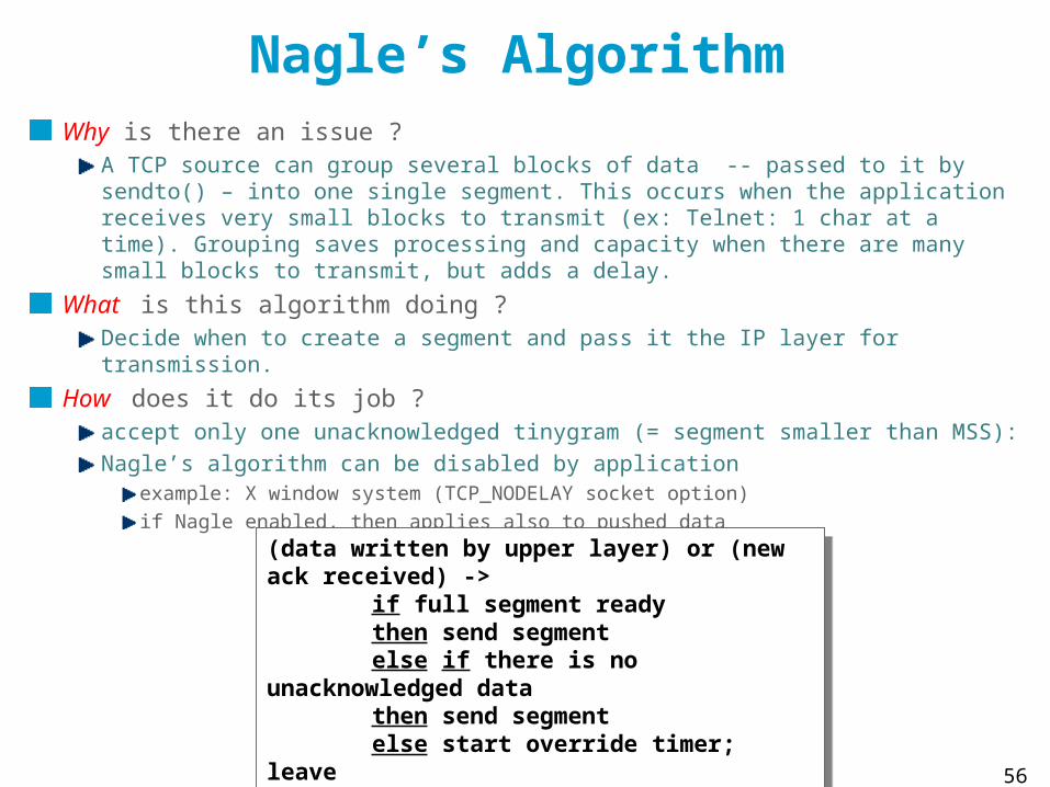
Nagle’s AlgorithmWhy is there an issue ?
A TCP source can group several blocks of data -- passed to it by sendto() – into one single segment. This occurs when the application receives very small blocks to transmit (ex: Telnet: 1 char at a time). Grouping saves processing and capacity when there are many small blocks to transmit, but adds a delay.
What is this algorithm doing ?Decide when to create a segment and pass it the IP layer for transmission.
How does it do its job ?accept only one unacknowledged tinygram (= segment smaller than MSS):Nagle’s algorithm can be disabled by application
example: X window system (TCP_NODELAY socket option)if Nagle enabled, then applies also to pushed data
(data written by upper layer) or (new ack received) ->
if full segment ready then send segmentelse if there is no unacknowledged data then send segmentelse start override timer; leave
override timer expires -> create segment and send
(data written by upper layer) or (new ack received) ->
if full segment ready then send segmentelse if there is no unacknowledged data then send segmentelse start override timer; leave
override timer expires -> create segment and send

57
Example: Nagle’algorithm
8000:8001(1) ack 101 win 60001
A B
a ->
b ->
c ->
d ->
e ->
f ->
101:102(1) ack 8001 win 1400028001:8003(2) ack 102 win 6000
3
102:102(0) ack 8003 win 1399848003:8005(2) ack 102 win 6000
102:102(0) ack 8003 win 1400056
102:102(0) ack 8005 win 1399878005:8006(1) ack 102 win 6000
8

58
Silly Window Syndrome Avoidance: Why ?Silly Window Syndrome occurs when
Receiver is slow or busysender has large amount of data to sendbut small window forces sender to send many small packets -> waste of resources
ack 0 win 2000 <----- 0:1000 -----> bufferSize= 2000B, freebuf= 1000B 1000:2000 -----> freebuf= 0B ack 2000, win 0 <----- application reads 1 Byte: freeBuf = 1 ack 2000, win 1 <----- 2000:2001 -----> freeBuf = 0
application reads 1 Byte: freeBuf = 1 ack 2001, win 1 <----- 2001:2002 -----> freeBuf = 0
application reads 1 Byte: freeBuf = 1 ack 2002, win 1 <----- 2002:2003 -----> freeBuf = 0

59
Silly Window Syndrome Avoidance
What does SWS avoidance do ?Prevent receiver from sending small incremental window updates
How does SWS avoidance work ?receiver moves the window by increments that are as large as one MSS or 1/2 receiveBuffer:
keep nextByteExpected + offeredWindow fixed until:reserve · min (MSS, 1/2 receiveBuffer)
keep nextByteExpected + offeredWindow fixed until:reserve · min (MSS, 1/2 receiveBuffer)
highestByteRead nextByteExpected ---|-----------|---------------------|------------|---- <-- offeredWindow --> <- reserve -> <-------------- receiveBuffer ---------------->
60
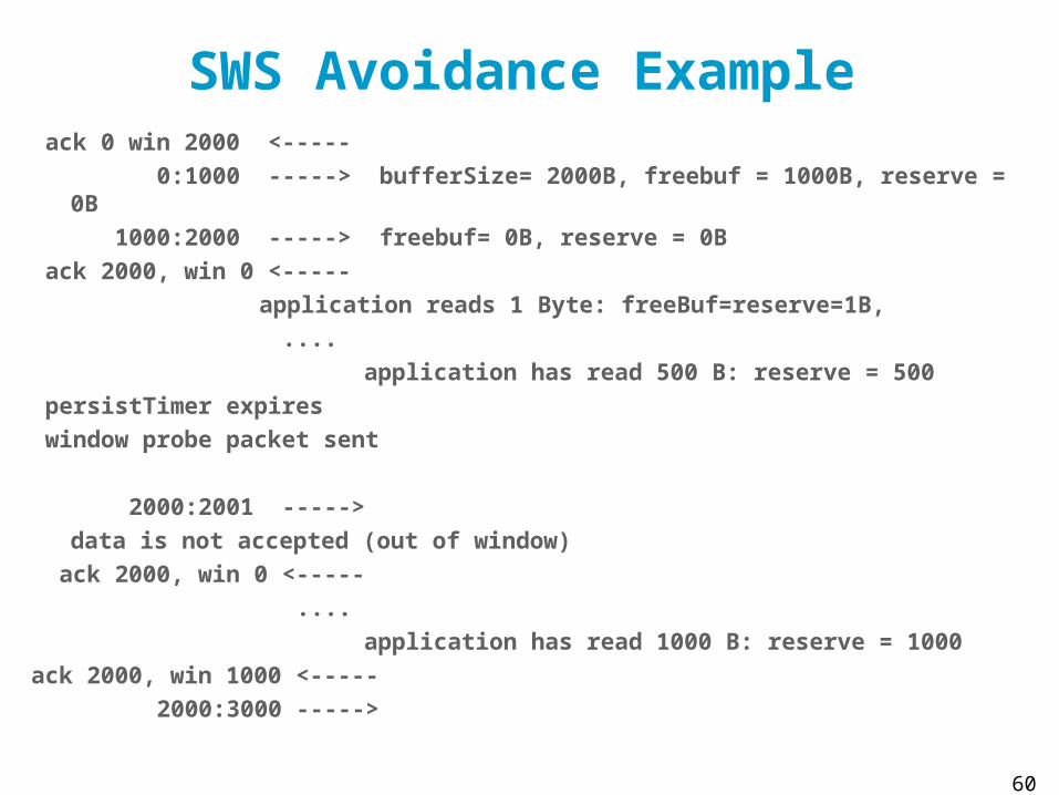
SWS Avoidance Example ack 0 win 2000 <-----
0:1000 -----> bufferSize= 2000B, freebuf = 1000B, reserve = 0B
1000:2000 -----> freebuf= 0B, reserve = 0B
ack 2000, win 0 <-----
application reads 1 Byte: freeBuf=reserve=1B,
....
application has read 500 B: reserve = 500
persistTimer expires
window probe packet sent
2000:2001 ----->
data is not accepted (out of window)
ack 2000, win 0 <-----
....
application has read 1000 B: reserve = 1000
ack 2000, win 1000 <-----
2000:3000 ----->
61
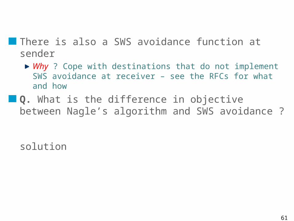
There is also a SWS avoidance function at senderWhy ? Cope with destinations that do not implement SWS avoidance at receiver – see the RFCs for what and how
Q. What is the difference in objective between Nagle’s algorithm and SWS avoidance ?
solution
62
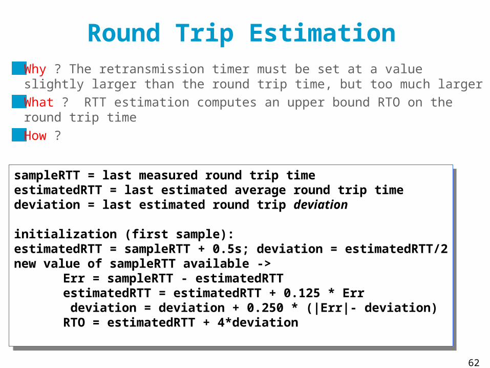
Round Trip EstimationWhy ? The retransmission timer must be set at a value slightly larger than the round trip time, but too much larger
What ? RTT estimation computes an upper bound RTO on the round trip time
How ?
sampleRTT = last measured round trip timeestimatedRTT = last estimated average round trip timedeviation = last estimated round trip deviation
initialization (first sample): estimatedRTT = sampleRTT + 0.5s; deviation = estimatedRTT/2new value of sampleRTT available ->
Err = sampleRTT - estimatedRTTestimatedRTT = estimatedRTT + 0.125 * Err deviation = deviation + 0.250 * (|Err|- deviation) RTO = estimatedRTT + 4*deviation

63
Sample RTO
0
2
4
6
8
10
12
14
1
11
21
31
41
51
61
71
81
91
10
1
11
1
12
1
13
1
14
1
seconds
seconds
RTO
SampledRTT

64
Conclusions
TCP provides a reliable service to the application programmer.
TCP is complex and is complex to use, but is powerful. It works well with various applications such as short interactive messages or large bulk transfer.
TCP is even more complex than we have seen as it also implements congestion control, a topic that we will study in a follow-up lecture.

65
Solutions

66
The Philosophy of Errors in a Layered Model
The physical layer is not completely error-free – there is always some bit error rate (BER).
Information theory tells us that for every channel there is a capacity C such thatAt any rate R < C, arbitrarily small BER can be achievedAt rates R ¸ C, any BER such that H2(BER) > 1 – C/R is achievable
The TCP/IP architecture decidedEvery layer ¸ 2 offers an error free service to the upper layer:
SDUs are either delivered without error or discarded
Example: MAC layerQ1. How does an Ethernet adapter know whether a received Ethernet frames has some bit errors ? What does it do with the frame ?A1. It checks the CRC. If there is an error, the frame is discardedWiFi detects errors with CRC and does retransmissions if neededQ2. Why does not Ethernet do the same ?A2. BER is very small on cabled systems, not on wireless
back

67
The Layered Model Transforms Errors into Packet Losses
Packet losses occur due to error detection by MAC buffer overflow in bridges and routersOther exceptional errors may occur tooQ. give some examplesA. changes in routes may cause some packets to be lost by TTL exhaustion during the transients
back

68
The Capacity of the End-to-End Path
Q. compute the capacity with end-to-end and with hop by hop error recovery A.
Case 1: end-to-end error recoveryEnd to end Packet Error Rate = 1– (1 – p)k
Capacity C1 = R £ (1-p)k
Case 2: hop-by-hop error recoveryCapacity one hop = R £ (1-p)End-to-end capacity C2 = R £ (1-p)
A
R1 R1 R1 R1 R1 R1
B
Loss probability p
k links
back

69
End-to-end Error Recovery is Inefficient when Packet Error Rate is high
The table shows the capacity of an end-to-end path as a function of the packet loss rate pConclusion: end-to-end error recovery is not acceptable when packet loss rate is highQ. How can one reconcile the conflicting arguments for and against hop-by-hop error recovery ?A. 1. Do hop-by-hop error recovery only on links that have high bit error rate: ex on
WiFi, not on Ethernet.2. Do hop-by–hop error recovery at the MAC layer (in the adapter), not in the
router3. In addition, do end-to-end error recovery in hosts
k Packet loss rate
C1 (end-to-end)
C2 (hop-by-hop)
10 0.05 0.6 £ R 0.95 £ R
10 0.0001 0.9990 £ R 0.9999 £ R
back

70
2. Mechanisms for Error Recovery
In this section we discuss the methods for repairing packet losses that are used in the Internet.
We have seen one such method already:Q. which one ?A. the stop and go protocol.
Packets are numbered at sourceDestination sends one acknowledgement for every packet receivedSource waits for ack; if after T1 seconds the ack did not arrive, packet is retransmitted
S
L
Packet 1 Ack 1 Packet 2
Ack 2 Packet 2
T1L’
back

71
Why Sliding Window ?
Why invented ?Overcome limitations of Stop and GoQ. what is the limitation of Stop and Go ?A. when the bandwidth-delay product is not very small, the throughput is small. The protocol wastes time while waiting for acks.
What does it do ?1. Allow mutiple transmissions
But this has a problem: the required buffer at destination may be very large
2. This problem is solved by the sliding window. The sliding window protocol puts a limit on the number of packets that may have to be stored at receive buffer.
P0
A1
P1
P2
A2
Pn
P0 again
Pn+1
P1
P1 P2
P1 P2 ... Pn
P1 P2 ... Pn+1
ReceiveBuffer
back

72
The previous slide shows an example of ARQ protocol, which uses the following details:
1. packets are numbered by source, staring from 0. 2. window size = 4 packets; 3. Acknowledgements are positive and indicate exactly which packet is being
acknowledged4. Loss detection is by timeout at sender when no acknowledgement has
arrived5. When a loss is detected, only the packet that is detected as lost is re-
transmitted (this is called Selective Repeat).
Q. Is it possible with this protocol that a packet is retransmitted whereas it was already received correctly ?A. Yes, if an ack is lost.
back

73
The previous slide shows an example of ARQ protocol, which uses the following details:
1. window size = 4 packets; 2. Acknowledgements are positive and are cumulative, i.e. indicate the highest
packet number upt to which all packets were correctly received3. Loss detection is by timeout at sender4. When a loss is detected, the source starts retransmitting packets from the last
acknowldeged packet (this is called Go Back n).
Q. Is it possible with this protocol that a packet is retransmitted whereas it was correctly received?
A. Yes, for several reasons1. If an ack is lost2. If packet n is lost and packet n+ 1 is not
back

74
The previous slide shows an example of ARQ protocol, which uses the following details:
1. window size = 4 packets;
2. Acknowledgements are positive or negative and are cumulative. A positive ack indicates that packet n was received as well as all packets before it. A negative ack indicates that all packets up to n were received but a packet after it was lost
3. Loss detection is either by timeout at sender or by reception of negative ack.
4. When a loss is detected, the source starts retransmitting packets from the last acknowldeged packet (Go Back n).
Q. What is the benefit of this protocol compared to the previous ?A. If the timer T1 cannot be set very accurately, the previous protocol may wait for a long time before detecting a loss. This protocol reacts more rapidly.
back

75
Are There Alternatives to ARQ ?Coding is an alternative to ARQ.
Forward Error Correction (FEC):Principle:
Make a data block out of n packetsAdd redundancy (ex Reed Solomon codes) to block and generate k+n packetsIf n out of k+n packets are received, the block can be reconstructed
Q. What are the pros and cons ?A. Pro: does not require retransmission. On network with very large delay, this is a benefit.Pro: works better for multicast, since different destinations may have lost different packets.Con: less throughput: redundancy is used even if not needed, ARQ transmits fewer packetsbackIs used for data distribution over satellite linksOther FEC methods are used for voice or video (exploit the fact that some distortion may be allowed – for example: interpolate a lost packet by two adjacent packets)

76
Backpressure Flow Control
Destination sends STOP (= PAUSE) or GO messages
Destination stops sending for x msec after receiving a STOP message
Simple to implement
Q. When does it work well ?A. If bandwidth delay product is smallback
P=0
P0
P=1
P=2
P=3STOP
P1
P2
P3
STOP
GO
P=5
P=6
P=7
P=4

77
Can we use Sliding Window for Flow Control ?
One could use a sliding window for flow control, as followsAssume a source sends packets to a destination using an ARQ protocol with sliding window. The window size is 4 packets and the destination has buffer space for 4 packets. Assume the destination delays sending acks until it has enough free buffer space. For example, destination has just received (but not acked) 4 packets. Destination will send an ack for the 4 packets only when destination application has consumed them.
Q. Does this solve the flow control problem ? A. Yes, since with a sliding window of size W, the number of packets sent but unacknowledged is · W. However, this poses a problem at the source: non acknowledged packets may be retransmitted, whereas they were correctly received.back
78
Why both TCP and UDP ?
Most applications use TCP rather than UDP, as this avoids re-inventing error recovery in every application
But some applications do not need error recovery in the way TCP does it (i.e. by packet retransmission)
For example: Voice applicationsQ. why ?A. delay is important for voice. Packet retransmission introduces too much delay in most cases. backFor example: an application that sends just one message, like name resolution (DNS). TCP sends several packets of overhead before one single useful data message. Such an application is better served by a Stop and Go protocol at the application layer.

79
Losses are Also Detected by “Fast Retransmit”Why invented: retransmission timeout in practice often very approximate thus timeout is often too large. Go back n is less efficient than SRP
What it doesDetect losses earlierRetransmit only the missing packet
How it worksif 3 duplicate acks for the same bytes are received before retransmission timeout, then retransmitQ. which ack is sent last on the figure ?A. A6 back
P1 P2 P3 P4
A1 A2 A2
P5 P6
A2 A2
retransmitP3
A ?
P7

80
Test Your Understanding
Consider the UDP and TCP servicesQ1. what does service mean here ?
A1. the interface between TCPor UDP and the application layerQ2. does UDP transfer the blocks of data delivered by the calling process as
they were submitted ? Analyze: delineation, order, missing blocks.A2. if not lost, the blocks are delivered the same as submitted. Order is generally respected but not always. Some blocks may be missing.
Q3. does TCP transfer the messages delivered by the calling process as they were submitted ? Analyze: delineation, order, missing blocks.A3. the delineation between blocks is lost. TCP does not respect block boundaries; several blocks may be merged or split at the destination. The order of bytes is respected. No byte is missing between the bytes received.
One more questionQ4. Is Stop and Go a sliding window protocol ?
A4. Yes, with window = 1 packet
back

81
Sws avoid.
There is also a SWS avoidance function at senderWhy ? Cope with destinations that do not implement SWS avoidance at receiver – see the RFCs for what and how
Q. What is the difference in objective between Nagle’s algorithm and SWS avoidance ?A. Both aim to avoid sending many small packets. Nagle handles the case of a source application that would repeatedly send many small blocks of data; SWS avoidance handles the case of a destination application that repeatedly consumes small blocks of data. Both algorithms run concurrently.
back