michaelson interferometer instructions
TRANSCRIPT

NCSL International 2995 Wilderness Place, Suite 107 • Boulder, Colorado 80301-5404
Office: (303) 440-3339 • Fax: (303) 440-3384 • [email protected]
1
www.MetrologyCareers.com

NCSL International 2995 Wilderness Place, Suite 107 • Boulder, Colorado 80301-5404
Office: (303) 440-3339 • Fax: (303) 440-3384 • [email protected]
2
Instructions for the NCSLI laser pointer interferometer
Warnings and cautions The laser pointer is a class 3 laser. A person could be injured if the laser beam is pointed into their eyes, or if the laser beam is reflected off a shiny surface into their eyes. Use caution when turning the laser on, and when aligning the interferometer. There are various glass parts (mirrors, beamsplitters, lens). Handling the parts by grabbing the glass could result in cuts. Dropping the parts could break the glass, and flying debris could cause cuts. The rubber bands used to hold the parts could age and break. Test the rubber bands before using. This is not an exhaustive list of possible hazards. Plan your demonstration with care, and execute your demonstration with care.
Introductory material The purpose of this experiment is to demonstrate a Michelson interferometer. The meter is defined as the distance traversed by light (in a vacuum) in a time interval of 1/299 792 458 second. This is realized by the wavelength of a laser. Albert A. Michelson used an interferometer to perform the Michelson-Morley experiment in 1887, and built interferometers at BIPM in the early 1890’s. Michelson was awarded the 1907 Nobel prize in physics "for his optical precision instruments and the spectroscopic and metrological investigations carried out with their aid". This demonstration uses a laser pointer as the light source. The procedure for demonstrating the interferometer is:
1. Setup and alignment of the interferometer, 2. Making a presentation about interferometry and the Michelson interferometer, 3. Demonstrating the interferometer.
This document only covers setup and alignment, and a basic demonstration. A powerpoint is available, showing some of the history of the meter.
Alignment and setup Remove contents from package. The contents are packaged in a pizza box (Figure 1).

NCSL International 2995 Wilderness Place, Suite 107 • Boulder, Colorado 80301-5404
Office: (303) 440-3339 • Fax: (303) 440-3384 • [email protected]
3
Figure 1. Interferometer in the pizza box.
The contents of the package are: • 300 mm × 300 mm base plate • Laser pointer holder and NCSLI laser pointer • Popsicle stick for turning on the laser pointer • Beam splitter holder • Optics holders: 2 holders for mirrors (labeled FSM) and one for the negative lens
(labeled PCV) • viewing block • 1 beam splitter • 2 front surface mirrors • 1 negative lens • Rubber bands for assembly • Clay for assembly • Post-it notes for fine adjustments
Most of these are identified in Figure 2.

NCSL International 2995 Wilderness Place, Suite 107 • Boulder, Colorado 80301-5404
Office: (303) 440-3339 • Fax: (303) 440-3384 • [email protected]
4
Figure 2. Labeled items for the interferometer.
A top-down schematic of the laser interferometer is shown in Figure 3.
Base plate
Holder for laser pointer
Laser pointer
Packaging for optics
Viewing block
Beam splitter holder
Optics. L-R: Beam splitter, 2 front surface mirrors, 1 negative lens
One (of three) mounting blocks for optics
Laser
Mirror (90)
Mirror (straight)
Negative lens
Viewing block
Figure 3. Schematic view of a Michelson laser interferometer.
Beamsplitter
NCSL International 2995 Wilderness Place, Suite 107 • Boulder, Colorado 80301-5404
Office: (303) 440-3339 • Fax: (303) 440-3384 • [email protected]
5
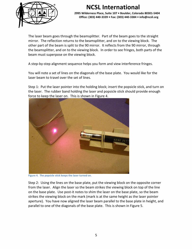
The laser beam goes through the beamsplitter. Part of the beam goes to the straight mirror. The reflection returns to the beamsplitter, and on to the viewing block. The other part of the beam is split to the 90 mirror. It reflects from the 90 mirror, through the beamsplitter, and on to the viewing block. In order to see fringes, both parts of the beam must superpose on the viewing block. A step-by-step alignment sequence helps you form and view interference fringes. You will note a set of lines on the diagonals of the base plate. You would like for the laser beam to travel over the set of lines. Step 1: Put the laser pointer into the holding block; insert the popsicle stick, and turn on the laser. The rubber band holding the laser and popsicle stick should provide enough force to keep the laser on. This is shown in Figure 4.
Figure 4. The popsicle stick keeps the laser turned on.
Step 2: Using the lines on the base plate, put the viewing block on the opposite corner from the laser. Align the laser so the beam strikes the viewing block on top of the line on the base plate. Use post-it notes to shim the laser on the base plate, so the beam strikes the viewing block on the mark (mark is at the same height as the laser pointer aperture). You have now aligned the laser beam parallel to the base plate in height, and parallel to one of the diagonals of the base plate. This is shown in Figure 5.
NCSL International 2995 Wilderness Place, Suite 107 • Boulder, Colorado 80301-5404
Office: (303) 440-3339 • Fax: (303) 440-3384 • [email protected]
6
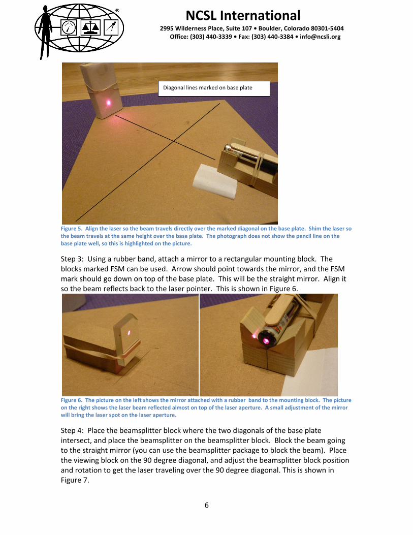
Figure 5. Align the laser so the beam travels directly over the marked diagonal on the base plate. Shim the laser so the beam travels at the same height over the base plate. The photograph does not show the pencil line on the base plate well, so this is highlighted on the picture.
Step 3: Using a rubber band, attach a mirror to a rectangular mounting block. The blocks marked FSM can be used. Arrow should point towards the mirror, and the FSM mark should go down on top of the base plate. This will be the straight mirror. Align it so the beam reflects back to the laser pointer. This is shown in Figure 6.
Figure 6. The picture on the left shows the mirror attached with a rubber band to the mounting block. The picture on the right shows the laser beam reflected almost on top of the laser aperture. A small adjustment of the mirror will bring the laser spot on the laser aperture.
Step 4: Place the beamsplitter block where the two diagonals of the base plate intersect, and place the beamsplitter on the beamsplitter block. Block the beam going to the straight mirror (you can use the beamsplitter package to block the beam). Place the viewing block on the 90 degree diagonal, and adjust the beamsplitter block position and rotation to get the laser traveling over the 90 degree diagonal. This is shown in Figure 7.
Diagonal lines marked on base plate

NCSL International 2995 Wilderness Place, Suite 107 • Boulder, Colorado 80301-5404
Office: (303) 440-3339 • Fax: (303) 440-3384 • [email protected]
7
Figure 7. The beamsplitter is adjusted to reflect the beam to travel over the 90 degree diagonal.
Step 5: Place the other front surface mirror on a mounting block (assemble with a rubber band). Align the mirror to reflect the beam through the beamsplitter, to the viewing block in its final position. This is shown in Figure 8.
Figure 8. The 90 degree mirror is adjusted so the laser beam hits the viewing block in line with the marked diagonals. Note the beamsplitter package used as a beam blocker.
Step 6: Now, block the beam going to the 90 degree mirror. Adjust the straight mirror so the laser hits the viewing block at the same spot where the 90 degree mirror was reflecting the beam. This is shown in Figure 9.

NCSL International 2995 Wilderness Place, Suite 107 • Boulder, Colorado 80301-5404
Office: (303) 440-3339 • Fax: (303) 440-3384 • [email protected]
8
Figure 9. Iterate with blocking one beam and adjusting the other mirror, until you can get the two spots hitting the mark on the viewing block.
Step 7: Use some clay to attach the negative lens on top of a block. Put the block as close to the beam splitter as possible, and adjust so you get a large spot on the viewing block. You may need to do some fine adjustments on the mirrors to get the laser reflections from both front surface mirrors superposed on the viewing block. If you’ve superposed the two reflections, you should see fringes! These are parallel dark and bright lines. Fine adjustments of the mirrors can make the parallel dark and bright lines more widely spaced. Fringes are shown in Figure 10 and 11.
Figure 10. Fringes are formed when the two laser beams are superposed. The negative lens is used to enlarge the image of the fringes for easy viewing.
NCSL International 2995 Wilderness Place, Suite 107 • Boulder, Colorado 80301-5404
Office: (303) 440-3339 • Fax: (303) 440-3384 • [email protected]
9
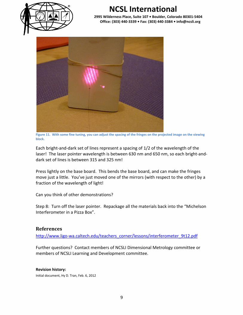
Figure 11. With some fine tuning, you can adjust the spacing of the fringes on the projected image on the viewing block.
Each bright-and-dark set of lines represent a spacing of 1/2 of the wavelength of the laser! The laser pointer wavelength is between 630 nm and 650 nm, so each bright-and-dark set of lines is between 315 and 325 nm! Press lightly on the base board. This bends the base board, and can make the fringes move just a little. You’ve just moved one of the mirrors (with respect to the other) by a fraction of the wavelength of light! Can you think of other demonstrations? Step 8: Turn off the laser pointer. Repackage all the materials back into the “Michelson Interferometer in a Pizza Box”.
References http://www.ligo-wa.caltech.edu/teachers_corner/lessons/interferometer_9t12.pdf Further questions? Contact members of NCSLI Dimensional Metrology committee or members of NCSLI Learning and Development committee.
Revision history: Initial document, Hy D. Tran, Feb. 6, 2012