1 sequential logic design with flip-flops introduction introduction flip-flop characteristic...
TRANSCRIPT
1
Sequential Logic Design with Flip-flops
Introduction
Flip-flop Characteristic Tables
Sequential Circuit Analysis
Flip-flop Input Functions
Analysis: Example #2
Analysis: Example #3
Flip-flop Excitation Tables

2
Lecture 12: Sequential Logic Design with Flip-flops
Sequential Circuit Design
Design: Example #1
Design: Example #2
Design: Example #3
Design of Synchronous Counters

3
Introduction
Sequential circuits has an extra dimension – time. Combinational circuit output depends only on the
present inputs Sequential circuit output depends on the history of
past inputs as well More powerful than combinational circuit, able to
model situations that cannot be modeled by combinational circuits
Building blocks of synchronous sequential logic circuits: gates and flip-flops.
Flip-flops make up the memory M while the gates form one or more combinational subcircuits C1, C2, …, Cq.

4
Flip-flop Characteristic Tables
Each type of flip-flop has its own behavior. The characteristic tables for the various types of flip-flops are shown below:
S R Q(t+1) Comments
0 0 Q(t) No change
0 1 0 Reset
1 0 1 Set
1 1 ? Unpredictable
J K Q(t+1) Comments
0 0 Q(t) No change
0 1 0 Reset
1 0 1 Set
1 1 Q(t)' Toggle
T Q(t+1)
0 Q(t) No change
1 Q(t)' Toggle
D Q(t+1)
0 0 Reset
1 1 Set
JK Flip-flop SR Flip-flop
D Flip-flop T Flip-flop

5
Sequential Circuit Analysis
Given a sequential circuit diagram, analyze its behaviour by deriving its state table and hence its state diagram.
Requires state equations to be derived for the flip-flop inputs, as well as output functions for the circuit outputs other than the flip-flops (if any).
We use A(t) and A(t+1) to represent the present state and next state, respectively, of a flip-flop represented by A.
Alternatively, we could simply use A and A+ for the present state and next state respectively.

6
Sequential Circuit Analysis
Example (using D flip-flops):
State equations:
A+ = A.x + B.x
B+ = A'.x
Output function:
y = (A + B).x'
A
A'
B
B'
y
x
CP
D Q
Q'
D Q
Q'
Figure 1.

7
Sequential Circuit Analysis
From the state equations and output function, we derive the state table, consisting of all possible binary combinations of present states and inputs.
State table Similar to truth table. Inputs and present state on the left side. Outputs and next state on the right side.
m flip-flops and n inputs 2m+n rows.

8
Sequential Circuit Analysis
State table for the circuit of Figure 1:State equations:
A+ = A.x + B.x
B+ = A'.x
Output function:
y = (A + B).x'
Present NextState Input State Output
A B x A+ B+ y
0 0 0 0 0 00 0 1 0 1 00 1 0 0 0 10 1 1 1 1 01 0 0 0 0 11 0 1 1 0 01 1 0 0 0 11 1 1 1 0 0

9
Sequential Circuit Analysis
Alternate form of state table:Present Next
State Input State Output
A B x A+ B+ y
0 0 0 0 0 00 0 1 0 1 00 1 0 0 0 10 1 1 1 1 01 0 0 0 0 11 0 1 1 0 01 1 0 0 0 11 1 1 1 0 0
Present Next State OutputState x=0 x=1 x=0 x=1
AB A+B+ A+B+ y y
00 00 01 0 001 00 11 1 010 00 10 1 011 00 10 1 0

10
Sequential Circuit Analysis
From the state table, we can draw the state diagram.
State diagram Each state is denoted by a circle. Each arrow (between two circles) denotes a transition of the
sequential circuit (a row in state table). A label of the form a/b is attached to each arrow where a
denotes the inputs while b denotes the outputs of the circuit in that transition.
Each combination of the flip-flop values represents a state. Hence, m flip-flops up to 2m states.

11
Sequential Circuit Analysis
State diagram of the circuit of Figure 1:
Present Next State OutputState x=0 x=1 x=0 x=1
AB A+B+ A+B+ y y
00 00 01 0 001 00 11 1 010 00 10 1 011 00 10 1 0 00
01 11
101/0
1/0
1/0
0/1
0/10/0
1/0 0/1
12
Flip-flop Input Functions
The outputs of a sequential circuit are functions of the present states of the flip-flops and the inputs. These are described algebraically by the circuit output functions. In Figure 1: y = (A + B).x'
The part of the circuit that generates inputs to the flip-flops are described algebraically by the flip-flop input functions (or flip-flop input equations).
The flip-flop input functions determine the next state generation.
From the flip-flop input functions and the characteristic tables of the flip-flops, we obtain the next states of the flip-flops.

13
Flip-flop Input Functions
Example: circuit with a JK flip-flop.
We use 2 letters to denote each flip-flop input: the first letter denotes the input of the flip-flop (J or K for JK flip-flop, S or R for SR flip-flop, D for D flip-flop, T for T flip-flop) and the second letter denotes the name of the flip-flop.
A
BC'x
By
CP
J Q
Q'K
B'Cx'
JA = B.C'.x + B'.C.x’
KA = B + y

14
Flip-flop Input Functions
In Figure 1, we obtain the following state equations by observing that Q+ = D for a D flip-flop:
A+ = A.x + B.x (since DA = A.x + B.x)B+ = A'.x (since DB = A'.x)
A
A'
B
B'
y
x
CP
D Q
Q'
D Q
Q'
Figure 1.

15
Analysis: Example #2
Given Figure 2, a sequential circuit with two JK flip-flops A and B, and one input x.
Obtain the flip-flop input functions from the circuit:JA = B JB = x'KA = B.x' KB = A'.x + A.x' = A x
A
B
x
CP
J Q
Q'K
J Q
Q'KFigure 2.

16
Analysis: Example #2
Flip-flop input functions:JA = B JB = x'KA = B.x' JB = A'.x + A.x' = A x
Fill the state table using the above functions, knowing the characteristics of the flip-flops used.
Present Nextstate Input state Flip-flop inputs
A B x A+ B+ JA KA JB KB
0 0 0 0 0 1 00 0 1 0 0 0 10 1 0 1 1 1 00 1 1 1 0 0 11 0 0 0 0 1 11 0 1 0 0 0 01 1 0 1 1 1 11 1 1 1 0 0 0
0 10 01 11 01 11 00 01 1
J K Q(t+1) Comments
0 0 Q(t) No change
0 1 0 Reset
1 0 1 Set
1 1 Q(t)' Toggle

17
Analysis: Example #2
Draw the state diagram from the state table.
Present Nextstate Input state Flip-flop inputs
A B x A+ B+ JA KA JB KB
0 0 0 0 1 0 0 1 00 0 1 0 0 0 0 0 10 1 0 1 1 1 1 1 00 1 1 1 0 1 0 0 11 0 0 1 1 0 0 1 11 0 1 1 0 0 0 0 01 1 0 0 0 1 1 1 11 1 1 1 1 1 0 0 0
00
01 10
11
1
0
1
0
0
1
0
1

18
Analysis: Example #3
Derive the state table and state diagram of the following circuit.
Flip-flop input functions:JA = B JB = KB = (A x)' = A.x + A'.x' KA = B'
J Q
Q'K
J Q
Q'K
A
x
CP
B
y
Figure 3.

19
Analysis: Example #3
Flip-flop input functions:JA = B JB = KB = (A x)' = A.x + A'.x' KA = B'
State table:
0 10 01 01 10 00 11 11 0
Present Nextstate Input state Output Flip-flop inputs
A B x A+ B+ y JA KA JB KB
0 0 0 0 0 1 1 10 0 1 1 0 1 0 00 1 0 1 1 0 1 10 1 1 0 1 0 0 01 0 0 1 0 1 0 01 0 1 0 0 1 1 11 1 0 0 1 0 0 01 1 1 1 1 0 1 1

20
Analysis: Example #3
State diagram:Present Next
state Input state Output Flip-flop inputs
A B x A+ B+ y JA KA JB KB
0 0 0 0 1 0 0 1 1 10 0 1 0 0 1 0 1 0 00 1 0 1 0 1 1 0 1 10 1 1 1 1 0 1 0 0 01 0 0 0 0 1 0 1 0 01 0 1 0 1 0 0 1 1 11 1 0 1 1 0 1 0 0 01 1 1 1 0 1 1 0 1 1
00
01 11
10
1/1
1/0
0/1
0/1
1/1
0/0
0/0
1/0
21
Flip-flop Excitation Tables
Analysis: Starting from a circuit diagram, derive the state table or state diagram.
Design: Starting from a set of specifications (in the form of state equations, state table, or state diagram), derive the logic circuit.
Characteristic tables are used in analysis.
Excitation tables are used in design.

22
Flip-flop Excitation Tables
Excitation tables: given the required transition from present state to next state, determine the flip-flop input(s).
Q Q+ J K
0 0 0 X0 1 1 X1 0 X 11 1 X 0
JK Flip-flop SR Flip-flop
Q Q+ S R
0 0 0 X0 1 1 01 0 0 11 1 X 0
D Flip-flop
Q Q+ D
0 0 00 1 11 0 01 1 1
T Flip-flop
Q Q+ T
0 0 00 1 11 0 11 1 0

23
Sequential Circuit Design
Design procedure: Start with circuit specifications – description of circuit
behaviour. Derive the state table. Perform state reduction if necessary. Perform state assignment. Determine number of flip-flops and label them. Choose the type of flip-flop to be used. Derive circuit excitation and output tables from the state
table. Derive circuit output functions and flip-flop input functions. Draw the logic diagram.

24
Design: Example #1
Given the following state diagram, design the sequential circuit using JK flip-flops.
00
10
110
0
0
01
11
101

25
Design: Example #1
Circuit state/excitation table, using JK flip-flops.
00
10
11
0
0
0
0 1
111
01
Present Next StateState x=0 x=1
AB A+B+ A+B+
00 00 0101 10 0110 10 1111 11 00
Present Nextstate Input state Flip-flop inputs
A B x A+ B+ JA KA JB KB
0 0 0 0 00 0 1 0 10 1 0 1 00 1 1 0 11 0 0 1 01 0 1 1 11 1 0 1 11 1 1 0 0
0 X0 X1 X0 XX 0X 0X 0X 1
0 X1 XX 1X 00 X1 XX 0X 1
Q Q+ J K
0 0 0 X0 1 1 X1 0 X 11 1 X 0
JK Flip-flop’sexcitation table.

26
Design: Example #1
Block diagram.
Combinationalcircuit
A'ABB'
x
KA JA KB JB
BB’AA’
Externalinput(s)
CP
Externaloutput(s)(none)
J
QQ'
K J
QQ'
K
What are to go in here?

27
Design: Example #1
From state table, get flip-flop input functions.
Present Nextstate Input state Flip-flop inputs
A B x A+ B+ JA KA JB KB
0 0 0 0 0 0 X 0 X0 0 1 0 1 0 X 1 X0 1 0 1 0 1 X X 10 1 1 0 1 0 X X 01 0 0 1 0 X 0 0 X1 0 1 1 1 X 0 1 X1 1 0 1 1 X 0 X 01 1 1 0 0 X 1 X 1
A
B
0 1
00 01 11 10
x
ABx
X X X X
1
JA = B.x'
JB = x
A
B
0 1
00 01 11 10
x
ABx
X
1 X X
X1
KA = B.x
A
B
0 1
00 01 11 10
x
ABx
X
1
X XX
KB = (A x)'
A
B
0 1
00 01 11 10
x
ABx
X 1
X 1X
X

28
Design: Example #1
Flip-flop input functions.JA = B.x' JB = xKA = B.x KB = (A x)'
Logic diagram:
x
BA
CP
J
QQ'
K J
QQ'
K

29
Design: Example #2
Design, using D flip-flops, the circuit based on the state table below. (Exercise: Design it using JK flip-flops.)
Present Nextstate Input state Output
A B x A+ B+ y
0 0 0 0 0 00 0 1 0 1 10 1 0 1 0 00 1 1 0 1 01 0 0 1 0 01 0 1 1 1 11 1 0 1 1 01 1 1 0 0 0

30
Design: Example #2
Determine expressions for flip-flop inputs and the circuit output y.
Present Nextstate Input state Output
A B x A+ B+ y
0 0 0 0 0 00 0 1 0 1 10 1 0 1 0 00 1 1 0 1 01 0 0 1 0 01 0 1 1 1 11 1 0 1 1 01 1 1 0 0 0
DA(A, B, x) = m(2,4,5,6)
DB(A, B, x) = m(1,3,5,6)
y(A, B, x) = m(1,5)
DA = A.B' + B.x'A
B
0 1
00 01 11 10
x
ABx
1 1 1
1
DB = A'.x + B'.x + A.B.x'A
B
0 1
00 01 11 10
x
ABx
1
1 1
1
A
B
0 1
00 01 11 10
x
ABx
1
1y = B'.x
31
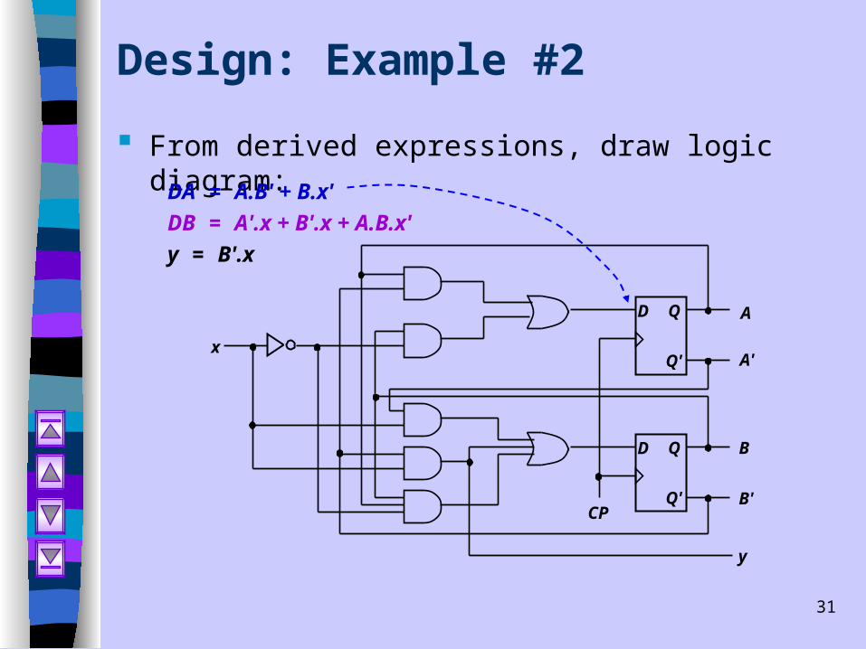
Design: Example #2
From derived expressions, draw logic diagram:
DA = A.B' + B.x'
DB = A'.x + B'.x + A.B.x'
y = B'.x
D Q
Q'
D Q
Q'
A
A'
B
B'
y
CP
x

32
Design: Example #3
Design with unused states.Present Next
state Input state Flip-flop inputs Output
A B C x A+ B+ C+ SA RA SB RB SC RC y
0 0 1 0 0 0 1 0 X 0 X X 0 0
0 0 1 1 0 1 0 0 X 1 0 0 1 0 0 1 0 0 0 1 1 0 X X 0 1 0 0 0 1 0 1 1 0 0 1 0 0 1 0 X 0 0 1 1 0 0 0 1 0 X 0 1 X 0 0 0 1 1 1 1 0 0 1 0 0 1 0 1 0 1 0 0 0 1 0 1 X 0 0 X 1 0 0 1 0 0 1 1 0 0 X 0 0 X 0 X 1 1 0 1 0 0 0 1 0 1 0 X X 0 0 1 0 1 1 1 0 0 X 0 0 X 0 1 1
Given these Derive these
0 0 0 0 X X X X X X X X X X
0 0 0 1 X X X X X X X X X X
Unused state 000:

33
Design: Example #3
From state table, obtain expressions for flip-flop inputs.
A
C
00
01
11
10
00 01 11 10
x
AB
Cx
11B
X
X
XX
X
X X
X
X
SA = B.xA
C
00
01
11
10
00 01 11 10
x
AB
Cx
1
B
X
X
X
X
X
X X
X
X
X
RA = C.x'
B
A
C
00
01
11
10
00 01 11 10
x
AB
Cx
1X
X
X
X
X X X
SB = A'.B'.xRB = B.C
+ B.x'
A
C
00
01
11
10
00 01 11 10
x
AB
Cx
B
X
X
X
1
X
X X X
1
X X X X
1

34
Design: Example #3
From state table, obtain expressions for flip-flop inputs (cont’d).
A
C
00
01
11
10
00 01 11 10
x
AB
Cx
1
1B
X
X
X
X
X
X X
X
X
SC = x'A
C
00
01
11
10
00 01 11 10
x
AB
Cx
1
B
X
X
1X
X
X X
1
X
X RC = x
y = A.x
B
A
C
00
01
11
10
00 01 11 10
x
AB
Cx
1
X
X
X
X X X
1

35
Design: Example #3
From derived expressions, draw logic diagram:SA = B.x SB = A'.B'.x SC = x'RA = C.x' RB = B.C + B.x' RC = x
y = A.x
A
A'
B
B'
y
CP
x S Q
Q'R
S Q
Q'R
S Q
Q'R
C

36
Design of Synchronous Counters
Counter: a sequential circuit that cycles through a sequence of states.
Binary counter: follows the binary sequence. An n-bit binary counter (with n flip-flops) counts from 0 to 2n-1.
Example 1: A 3-bit binary counter (using T flip-flops).
001
000
111
010
011
100
110
101
Present Next Flip-flopstate state inputs
A2 A1 A0 A2+ A1
+ A0+ TA2 TA1 TA0
0 0 0 0 0 1 0 0 10 0 1 0 1 0 0 1 10 1 0 0 1 1 0 0 10 1 1 1 0 0 1 1 11 0 0 1 0 1 0 0 11 0 1 1 1 0 0 1 11 1 0 1 1 1 0 0 11 1 1 0 0 0 1 1 1

37
Design of Synchronous Counters
3-bit binary counter (cont’d).Present Next Flip-flop
state state inputsA2 A1 A0 A2
+ A1+ A0
+ TA2 TA1 TA0
0 0 0 0 0 1 0 0 10 0 1 0 1 0 0 1 10 1 0 0 1 1 0 0 10 1 1 1 0 0 1 1 11 0 0 1 0 1 0 0 11 0 1 1 1 0 0 1 11 1 0 1 1 1 0 0 11 1 1 0 0 0 1 1 1
TA2 = A1.A0
A2
A1
A0
1
1
TA1 = A0 TA0 = 1
A2
A1
A0
1
1 1
1
A2
A1
A0
1 1 1
11 1 1
1

38
Design of Synchronous Counters
3-bit binary counter (cont’d).
TA2 = A1.A0 TA1 = A0 TA0 = 1
1
A2
CPT
Q
T
Q
T
Q
A1 A0

39
Design of Synchronous Counters
Example 2: Counter with non-binary sequence:
000 001 010 100 101 110 and back to 000
001
000
010
100
110
101
Present Nextstate state Flip-flop inputs
A B C A+ B+ C+ JA KA JB KB JC KC
0 0 0 0 0 1 0 X 0 X 1 X0 0 1 0 1 0 0 X 1 X X 10 1 0 1 0 0 1 X X 1 0 X1 0 0 1 0 1 X 0 0 X 1 X1 0 1 1 1 0 X 0 1 X X 11 1 0 0 0 0 X 1 X 1 0 X
JA = B JB = C JC = B'KA = B KB = 1 KC = 1

40
Design of Synchronous Counters
Counter with non-binary sequence (cont’d). JA = B JB = C JC = B'KA = B KB = 1 KC = 1
CP
A
1
J
QQ'
KJ
QQ'
K J
QQ'
K
B C
001
000
010
100
110
101
111
011

41
Summary
Sequential circuits have memory and they are more powerful than combinational circuits.
Analyzing sequential circuits Flip-flop characteristic table State Table State diagram
Designing sequential circuits Flip-flop excitation table State assignment Circuit output function Flip-flop input function