1 propagation aspects for smart antennas in wireless systems jack h. winters at&t labs -...
TRANSCRIPT
1
PROPAGATION ASPECTS FOR SMART ANTENNAS IN WIRELESS SYSTEMS
JACK H. WINTERS
AT&T Labs - Research
Red Bank, NJ 07701-7033
July 17, 2000

2
OUTLINE
• Antenna types• Potential gains• Propagation issues• Measurements needed• Conclusions
3
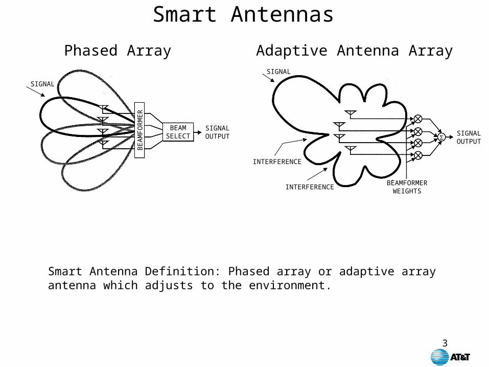
Smart Antennas
Smart Antenna Definition: Phased array or adaptive array antenna which adjusts to the environment.
SIGNAL OUTPUT
SIGNAL
INTERFERENCE
INTERFERENCEBEAMFORMER
WEIGHTS
SIGNAL OUTPUT
BEAM SELECT
SIGNAL
BE
AM
FOR
ME
R
Adaptive Antenna ArrayPhased Array
4
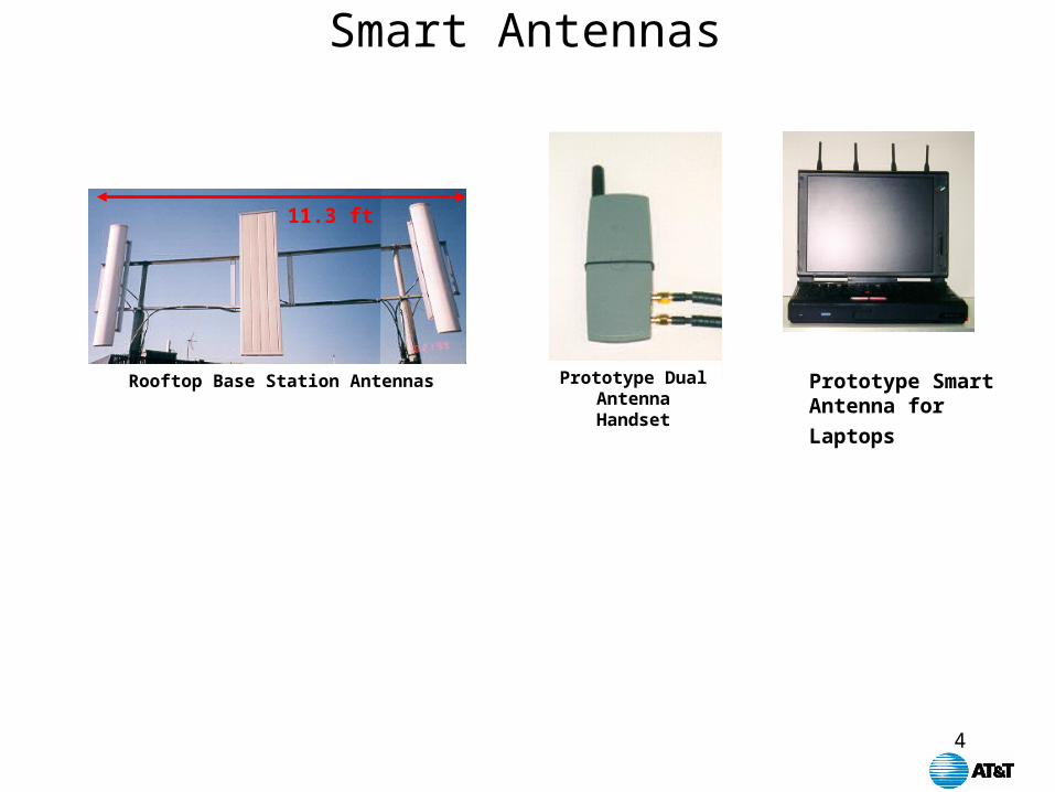
Smart Antennas
Rooftop Base Station Antennas
11.3 ft
Prototype Dual Antenna Handset
Prototype Smart
Antenna for Laptops
5
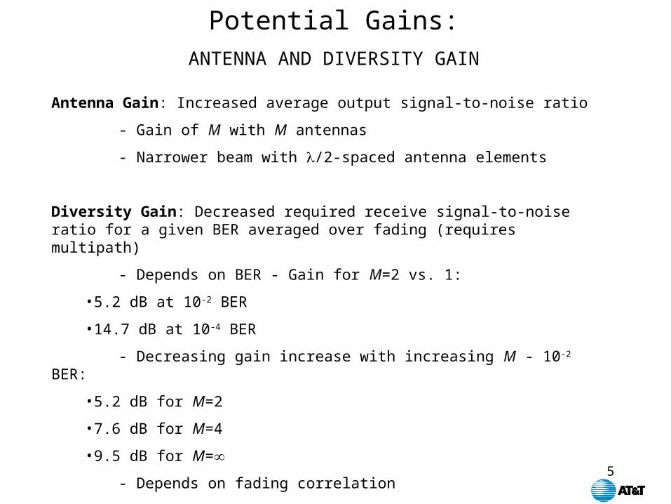
Potential Gains:ANTENNA AND DIVERSITY GAIN
Antenna Gain: Increased average output signal-to-noise ratio
- Gain of M with M antennas
- Narrower beam with /2-spaced antenna elements
Diversity Gain: Decreased required receive signal-to-noise ratio for a given BER averaged over fading (requires multipath)
- Depends on BER - Gain for M=2 vs. 1:
•5.2 dB at 10-2 BER
•14.7 dB at 10-4 BER
- Decreasing gain increase with increasing M - 10-2 BER:
•5.2 dB for M=2
•7.6 dB for M=4
•9.5 dB for M=
- Depends on fading correlation

6
Potential Gains:
• Range increase: Antenna gain of M plus M-fold multipath diversity gain
• Capacity increase: Suppress up to M-1 interferers for higher frequency reuse
• Data rate increase: MIMO increase with M spatial channels
7
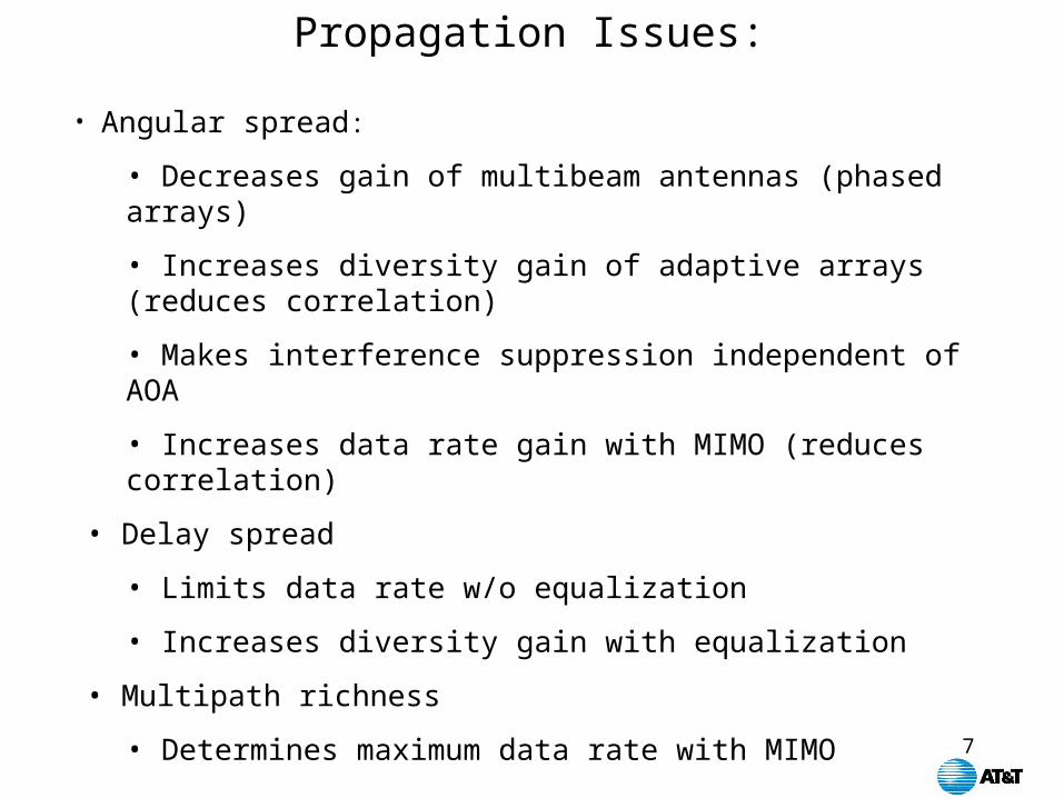
Propagation Issues:
• Angular spread:
• Decreases gain of multibeam antennas (phased arrays)
• Increases diversity gain of adaptive arrays (reduces correlation)
• Makes interference suppression independent of AOA
• Increases data rate gain with MIMO (reduces correlation)
• Delay spread
• Limits data rate w/o equalization
• Increases diversity gain with equalization
• Multipath richness
• Determines maximum data rate with MIMO
8
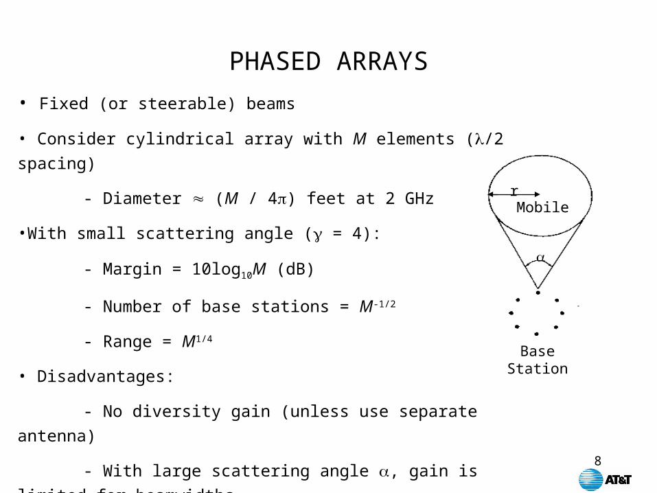
• Fixed (or steerable) beams
• Consider cylindrical array with M elements (/2 spacing)
- Diameter (M / 4) feet at 2 GHz
•With small scattering angle ( = 4):
- Margin = 10log10M (dB)
- Number of base stations = M-1/2
- Range = M1/4
• Disadvantages:
- No diversity gain (unless use separate antenna)
- With large scattering angle , gain is limited for beamwidths
PHASED ARRAYS
Base Station
Mobiler

9
Fixed Multibeam Antenna
Range Increase for IS-136
• Increases gain for better coverage
• Range increase is limited by angular spread
• No spatial diversity gain
• Can be used on downlink or uplink
Adaptive Array
• Range increase independent of angular spread
• Diversity gain increases with antenna spacing
• Can be used on uplink with fixed multibeam downlink

10
INTERFERENCE NULLINGLine-Of-Sight Systems
Utilizes spatial dimension of radio environment to:• Maximize signal-to-interference-plus-noise ratio• Increase gain towards desired signal• Null interference: M-1 interferers with M antennas
User 1
User 2
User 1
Signal•••
11
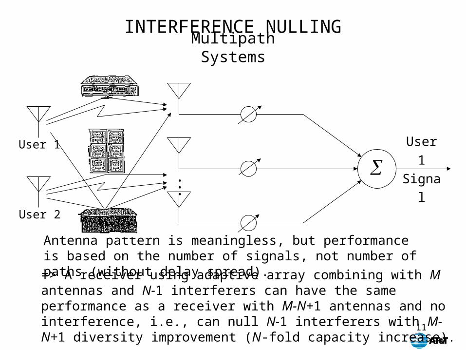
INTERFERENCE NULLINGMultipath Systems
User 1
User 2
User 1
Signal•••
Antenna pattern is meaningless, but performance is based on the number of signals, not number of paths (without delay spread).
=> A receiver using adaptive array combining with M antennas and N-1 interferers can have the same performance as a receiver with M-N+1 antennas and no interference, i.e., can null N-1 interferers with M-N+1 diversity improvement (N-fold capacity increase).

12
INTERFERENCE SUPPRESSION
Spatial Diversity: S/I = 0dB, AAA with 4 antennas vs. REF with 2 antennas
- ADJACENT INTERFERER
0
-0.5
-1
-1.5
-2
-2.5
-3
-3.5
-410 20 300
AAA(avg.)REF (avg.)
AAA (data)·REF (data)
TheoryLaboratory Results
BE
R (
log)
SNR (dB)
13
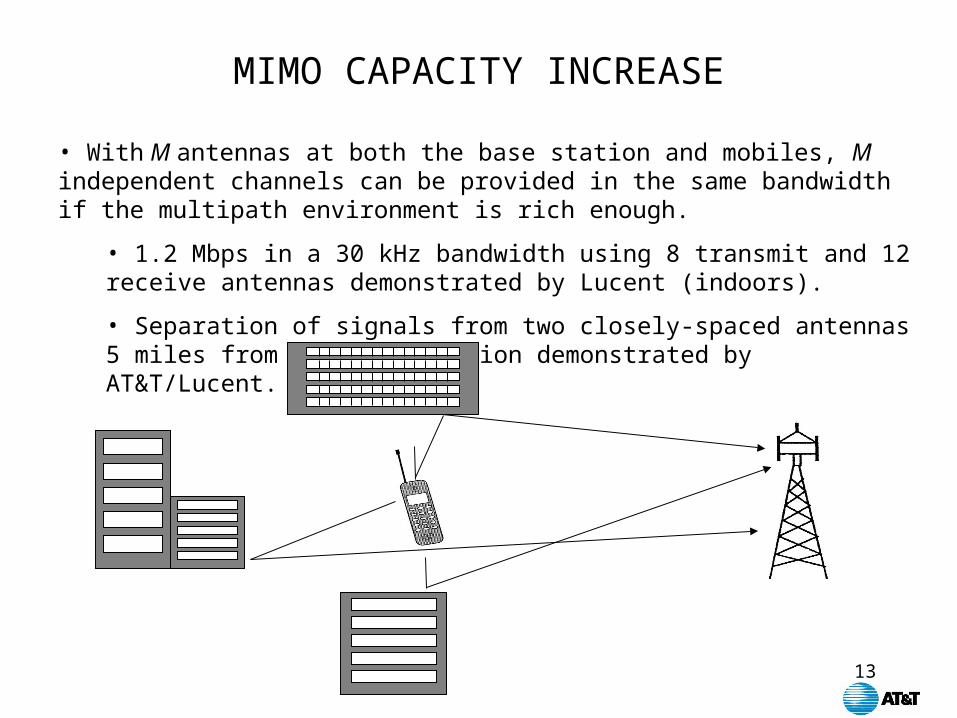
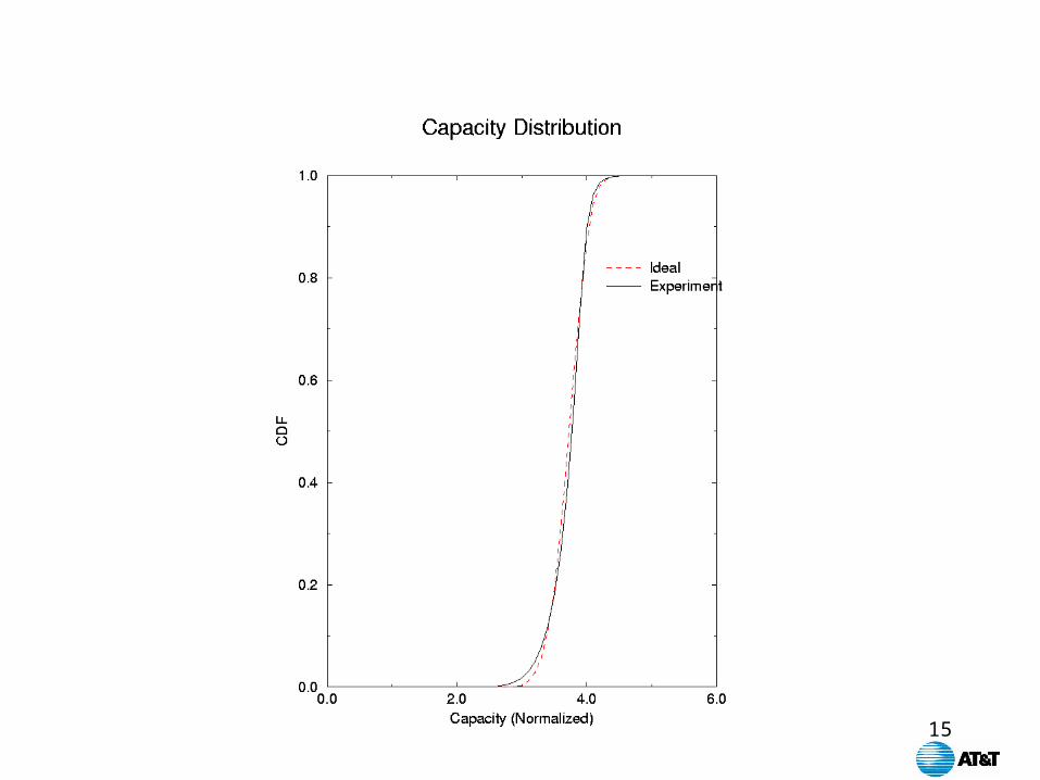
MIMO CAPACITY INCREASE
• With M antennas at both the base station and mobiles, M independent channels can be provided in the same bandwidth if the multipath environment is rich enough.
• 1.2 Mbps in a 30 kHz bandwidth using 8 transmit and 12 receive antennas demonstrated by Lucent (indoors).
• Separation of signals from two closely-spaced antennas 5 miles from the base station demonstrated by AT&T/Lucent.
14
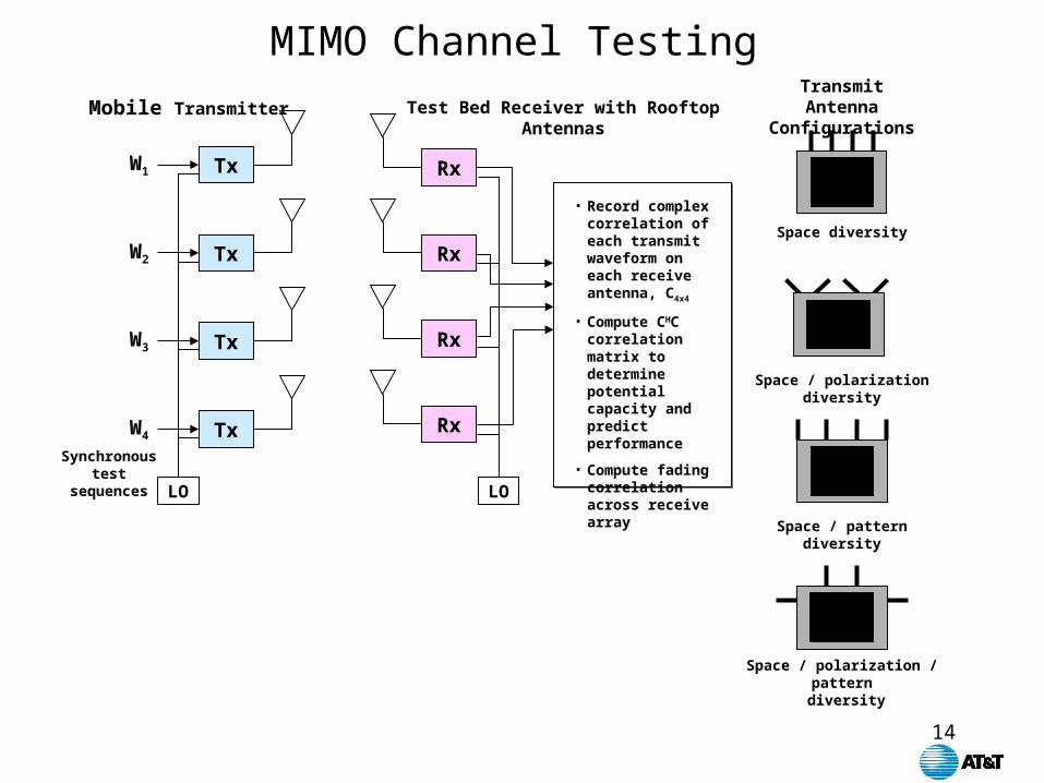
MIMO Channel Testing
TxW1
TxW2
TxW3
TxW4
LO
Synchronoustest
sequences
Rx
Rx
Rx
Rx
• Record complex correlation of each transmit waveform on each receive antenna, C4x4
• Compute CHC correlation matrix to determine potential capacity and predict performance
• Compute fading correlation across receive array
LO
Mobile Transmitter Test Bed Receiver with RooftopAntennas
Transmit Antenna Configurations
Space diversity
Space / polarization diversity
Space / pattern diversity
Space / polarization / pattern diversity
15

16
• Multipath richness for MIMO:– 2-fold for rooftop to rooftop (fixed wireless)
– At least 4-fold for outdoor
– As high as 150-fold indoor
• Delay spread
• Angular spread
• Polarization
Measurements Needed:

17
• Propagation environment influences smart antenna architecture and wireless system gains:– Large angular spread decreases effectiveness of multibeam
antennas but increases adaptive array’s range, interference suppression, MIMO data rate increase
– Large delay spread limits data rate, but with S-T processing or OFDM increases diversity gain
– Multipath limits range, but with MIMO increases data rate
• Additional measurements in wide range of environments still needed
Conclusions