1 an introduction to mpls timothy g. griffin [email protected] griffin november 21, 2002...
Post on 19-Dec-2015
222 views
TRANSCRIPT

1
An Introduction to MPLS
Timothy G. Griffin
http://www.research.att.com/~griffin
November 21, 2002
Research

2
What’s all this talk about MPLS?
• “MPLS is going to solve all of our problems”• “MPLS is a solution in search of a problem”• “MPLS is all about traffic engineering”• “MPLS is what I wish on all of my competitors” • “MPLS is all about virtual private networks”• “MPLS solves network operations problems”• “MPLS creates network operations problems”• “MPLS is all about lowering operational costs”• “MPLS is going to cost more than its worth”• “MPLS is the natural next step in Internet evolution”• “MPLS is too complicated to survive in the Internet”
But what is MPLS anyway?

3
Goals of this Tutorial
• To understand MPLS from a purely technical point of view– avoid the hype– avoid the cynicism
• To understand the broad technical issues without getting lost in the vast number of details– the gains– the costs– the tradeoffs

4
Keep in Mind
• MPLS is an emerging technology• Many technical issues have not yet been resolved• Interest and enthusiasm is not universal, but primarily
found in large providers (and their vendors)• Standards are rapidly evolving• Implementations are rapidly evolving• Operational experience and expertise still very scarce
Expect interoperability problems and feature availability problems for the next few years

5
Outline• Why MPLS?
– Problems with current IP routing and forwarding– Complexity of overlay model
• What is MPLS? – Label swapping – Label distribution– Constraint based routing
• What applications could exploit MPLS? – Traffic Engineering– Virtual Private Networks
• Both Layer 2 and Layer 3 VPNs

6
IP forwarding paths are implemented with destination-based next hop tables
R
R
RA
B
C
D
R1
R2
R3
R4 R5
EDest. Nxt Hop
R4R3R3R4DirectR4
Dest. Nxt Hop
A B C D Edefault
R2R2DirectR5R5R2
Dest. Nxt Hop
A B C D Edefault
R1DirectR3R1R3R1
Default toupstreamrouter
A B C D Edefault

7
IP Forwarding Process
Forwarding Process
IP Forwarding Table Router
1. Remove a packet from an input queue
3. Match packet’s destination to a table entry
2. Check for sanity, decrement TTL field
4. Place packet on correct output queue
If queuesget full, just
drop packets!
If queuesget full, just
drop packets!

8
IP routing protocols assume all forwarding is destination-based
A
B
C
The next-hop forwarding paradigmdoes not allow router R to choosea route to A based on who originatedthe traffic, B or C.
RThe Fish

9
IP forwarding tables are maintained by dynamic routing protocols
IP Forwarding TableOSPFDomain
RIPDomain
BGP
OS kernel
OSPF Process
OSPF Routing tables
RIP Process
RIP Routing tables
BGP Process
BGP Routing tables

10
Shortest Path Routing: Link weights tend to attract or repel all traffic
A
B
C1 1
12
A
B
C
1
1
1
2
D
D

11
Overlay Networks
Layer 2
C
Layer 3
A
C
B
A
B
C
(virtual circuits)

12
Advantages of Overlay Networks
• ATM and Frame Relay switches offer high reliability and low cost
• Virtual circuits can be reengineered without changing the layer 3 network
• Large degree of control over traffic• Detailed per-circuit statistics • Isolates layer 2 network management from
the details of higher layer services

13
Problems with Overlay Networks• Often use proprietary protocols and
management tools • Often requires “full meshing” of statically
provisioned virtual circuits• ATM cell tax ---- about 20% of bandwidth• If layer 3 is all IP, then the overlay model
seems overly complicated and costly• Advances in optical networking cast some
doubt on the entire approach
Overlay model is just fine when layer 2 network providesdiverse non IP services.

14
Blur Layer 2 and 3?
router switch(ATM, Frame)
what is it? this is not a router
this is not a switch

15
Sanity Check?
• The problems with IP forwarding and routing do not require technologies like MPLS– Many can be addressed with simple solutions. Like
the design of simple networks!– The problems are not “show stoppers”– The MPLS cure will have side effects– For many applications, TCP/IP handles congestion
very well
• Technologies like MPLS may be very valuable if they can enable new services and generate new revenue

16
Sign of the Times:New Sub-IP area in the IETF
• Multiprotocol Label Switching (mpls)• Common Control and Management Protocols (ccamp)• Internet Traffic Engineering (tewg) • Provider Provisioned Virtual Private Networks (ppvpn)• IP over Optics (ipo)• IP over Resilient Packet Rings (iporpr)• General Switch Management Protocol (gsmp)
See http://www.ietf.org/html.charters/foo-charter.html, where foo is the working group acronym.

17
MPLS = MultiProtocol Label Switching
Physical
Data Link
MPLS
Network• A “Layer 2.5” tunneling
protocol• Based on ATM-like notion of
“label swapping”• A simple way of labeling each
network layer packet• Independent of Link Layer• Independent of Network Layer• Used to set up “Label-switched
paths” (LSP), similar to ATM PVCs
RFC 3031 : Multiprotocol Label Switching Architecture

18
Generic MPLS Encapsulation
0 1 2 3 0 1 2 3 4 5 6 7 8 9 0 1 2 3 4 5 6 7 8 9 0 1 2 3 4 5 6 7 8 9 0 1+-+-+-+-+-+-+-+-+-+-+-+-+-+-+-+-+-+-+-+-+-+-+-+-+-+-+-+-+-+-+-+-+ | Label | Exp |S| TTL | +-+-+-+-+-+-+-+-+-+-+-+-+-+-+-+-+-+-+-+-+-+-+-+-+-+-+-+-+-+-+-+-+
Layer 2 Header MPLS Label 1 MPLS Label 2 MPLS Label n Layer 3 Packet …
• Label: Label Value, 20 bits• Exp: Experimental, 3 bits• S: Bottom of Stack, 1 bit• TTL: Time to Live, 8 bits
Often called a “shim” (or “sham”) header
RFC 3032. MPLS Label Stack Encoding

19
Forwarding via Label Swapping
Labels are short, fixed-length values.
417 data 288 data

20
Popping Labels
data 288 data
288 data577data577

21
Pushing Labels
data288 data
288 data577 data577

22
A Label Switched Path (LSP)
417 data 666 data 233 data datadata
POP! PUSH!SWAP! SWAP!
A label switched path“tail end” “head end”
Often called an MPLS tunnel: payload headers are not Inspected inside of an LSP. Payload could be MPLS …

23
Label Switched Routers
The data plane
IPIP Forwarding TableIP inIP out
IP
Label Swapping Table
MPLS inMPLS out
77 data 23 data
represents IP Lookup + label push
represents label pop + IP lookup

24
Forwarding Equivalence Class (FEC)
417 IP1 666 IP1 IP1 IP1
IP2 IP2
233 IP1
417 IP2 233 IP2666 IP2
Packets IP1 and IP2 are forwarded in the same way --- they are in the same FEC.
Network layer headers are not inspected inside an MPLS LSP. This means that inside of the tunnelthe LSRs do not need full IP forwarding table.

25
LSP Merge
111 IP1 666 IP1 IP1 IP1
IP2 IP2
233 IP1
417 IP2912 IP2823 IP2
417 IP1 666 IP1 IP1 IP1
IP2 IP2
233 IP1
417 IP2912 IP2823 IP2
LSP merge

26
Penultimate Hop Popping
417 IP 666 IP 233 IP IP IP
POP +IP Lookup PUSHSWAP SWAP
666 IP 233 IP IP IP
IP Lookup PUSHPOP SWAP
IP

27
LSP Hierarchy via Label Stacking
23 IP1
PUSH
IP1
23 IP1
POP
IP1
IP2 IP2
PUSHPOP
23 IP11723 IP18823 IP144
66 IP21766 IP2
66 IP2 66 IP28866 IP244
Did I get carried away on this slide?
28
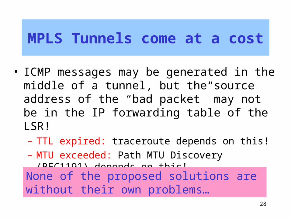
MPLS Tunnels come at a cost
• ICMP messages may be generated in the middle of a tunnel, but the source address of the “bad packet” may not be in the IP forwarding table of the LSR!– TTL expired: traceroute depends on this!– MTU exceeded: Path MTU Discovery (RFC1191)
depends on this!
None of the proposed solutions are without their own problems…

29
MPLS also supports “native encapsulation”
Layer 2 PPP Ethernet ATM Frame
generic encapsulationMPLS
generic encapsulation
generic encapsulation
.
.
.
.
.
.
.
.
.
rest of label stack
IP datagram
VPI/VCI DLCI

30
But Native Labels May Cause Big Headaches
• No TTL!– Loop detection?– Loop prevention?
• LSP merge may not be supported– Label bindings cannot flow from destination
to source, but must be requested at source
MPLS was initially designed to exploit the existence of ATM hardware and reduce the complexity of overlay networks.But IP/MPLS with native ATM labels results in a large number of problems and complications.

31
Basic MPLS Control Plane
MPLS control plane = IP control plane + label distribution
Label distribution protocols are needed to (1) create label FEC bindings (2) distribute bindings to neighbors, (3) maintain consistent label swapping tables

32
Label Distribution: Option I
“Piggyback” label information on top of existing IP routing protocol
• Guarantees consistency of IP forwarding tables and MPLS label swapping tables
• No “new” protocol required
• Allows only traditional destination-based, hop-by-hop forwarding paths
• Some IP routing protocols are not suitable • Need explicit binding of label to FEC• Link state protocols (OSPF, ISIS) are implicit, and so
are not good piggyback candidates• Distance vector (RIP) and path vector (BGP) are good
candidates. Example: BGP+
GoodPoints
BadPoints

33
Label Distribution: Option II
Create new label distribution protocol(s)
• Compatible with “Link State” routing protocols• Not limited to destination-based, hop-by-hop
forwarding paths
• Additional complexity of new protocol and interactions with existing protocols
• Transient inconsistencies between IP forwarding tables and MPLS label swapping tables
GoodPoints
BadPoints
Examples: LDP (IETF) and TDP (Cisco proprietary)

34
The Control Plane
IPIP Forwarding TableIP inIP out
IP
Label Swapping Table
MPLS inMPLS out
77 data 23 data
IP Routing Protocols+
IP Routing Tables
Label distribution protocols+
Label Binding Tables
Routing messages
Label distribution messages

35
Label Distribution with BGP
Carrying Label Information in BGP-4draft-ietf-mpls-bgp4-05.txt (1/2001)
Associates a label (or label stack) with the BGP next hop.
Uses multiprotocol features of BGP:
RFC 2283. Multiprotocol Extensions for BGP-4
So routes with labels are in a different address space than a vanilla routes (no labels)

36
BGP piggyback not required for simple iBGP optimization
417 IP 666 IP IP IP 233 IP
AS 888AS 444
BGP route Internal BGP
Map traffic to the LSP thatterminates at the egress routerchosen by BGP
A B
Routers A and B do not need full routing tables.They only need IGP routes (and label bindings).
37
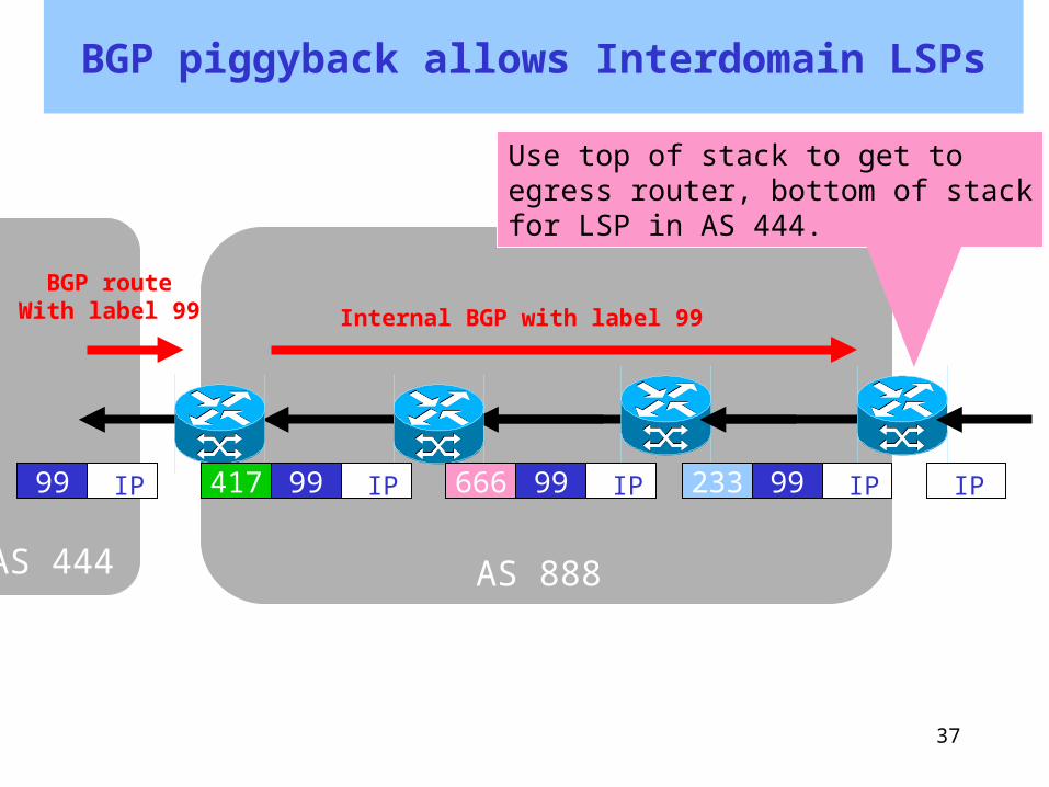
BGP piggyback allows Interdomain LSPs
IP
AS 888AS 444
BGP routeWith label 99 Internal BGP with label 99
Use top of stack to get to egress router, bottom of stackfor LSP in AS 444.
IP99 233 IP99666 IP99417 IP99

38
MPLS tunnels can decrease size of core routing state
• Core routers need only IGP routes and LSPs for IGP routes
• Implies less route oscillation• Implies less memory• Implies less CPU usage
BUT: still need route reflectors to avoid full meshand/or to reduce BGP table size at border routers
BUT: since your core routers do not have full tablesyou now have all of the MPLS problems associated with ICMP source unknown (TTL, MTU, traceroute …)
Are thesereally
problems?

39
Label Distribution Protocol (LDP)
RFC 3036. LDP Specification. (1/2001)
• Dynamic distribution of label binding information• Supports only vanilla IP hop-by-hop paths• LSR discovery• Reliable transport with TCP• Incremental maintenance of label swapping tables
(only deltas are exchanged)• Designed to be extensible with Type-Length-Value
(TLV) coding of messages• Modes of behavior that are negotiated during
session initialization• Label retention (liberal or conservative)• LSP control (ordered or independent)• Label assignment (unsolicited or on-demand)

40
LDP Message Categories
• Discovery messages: used to announce and maintain the presence of an LSR in a network.
• Session messages: used to establish, maintain, and terminate sessions between LDP peers.
• Advertisement messages: used to create, change, and delete label mappings for FECs.
• Notification messages: used to provide advisory information and to signal error information.
41
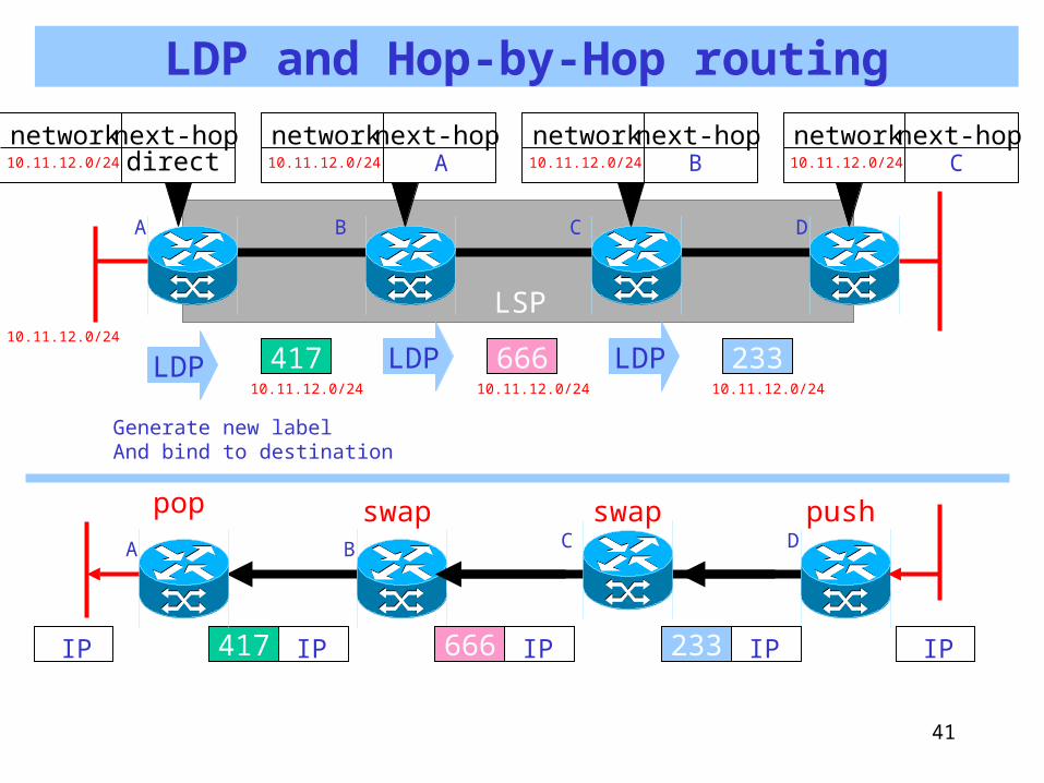
LDP and Hop-by-Hop routing
417 IP 666 IP IP IP 233 IP
LSP10.11.12.0/24
A B C D
41710.11.12.0/24
LDP LDP LDP666 23310.11.12.0/2410.11.12.0/24
10.11.12.0/24
next-hopnetworkdirect 10.11.12.0/24
next-hopnetwork A 10.11.12.0/24
next-hopnetworkB 10.11.12.0/24
next-hopnetworkC
Generate new labelAnd bind to destination
pop swap swap pushDCBA

42
MPLS Traffic Engineering
“A major goal of Internet Traffic Engineering is to facilitate efficient and reliable network operations while simultaneously optimizing network resource utilization and performance.”
RFC 2702Requirements for Traffic Engineering over MPLS
Intra-Domain
A Framework for Internet Traffic EngineeringDraft-ietf-tewg-framework-02.txt
Intra-Domain
“The optimization goals of traffic engineering are To enhance the performance of IP traffic while utilizing Network resources economically and reliably.”

43
TE May Require Going Beyond Hop-by-Hop Routing
• Explicit routes– Allow traffic sources to set up paths
• Constraint based routing– Chose only best paths that do no violate
some constraints– Needs explicit routing– May need resource reservation
• Traffic classification– Map traffic to appropriate LSPs
44
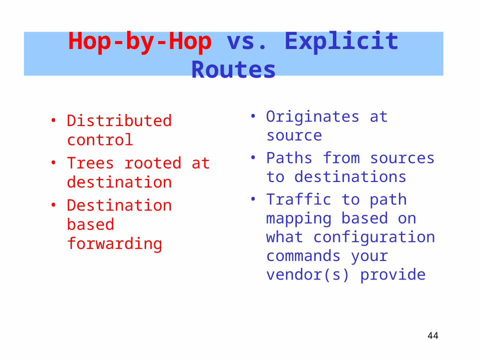
Hop-by-Hop vs. Explicit Routes
• Distributed control• Trees rooted at
destination• Destination based
forwarding
• Originates at source • Paths from sources
to destinations• Traffic to path
mapping based on what configuration commands your vendor(s) provide

45
Explicit path Setup
417 IP 666 IP IP IP 233 IP
LSP
A B C D
417LSPID 17
reply 666 233
pop swap swap push
REQUESTLSPID 17
Requestpath
D->C->B->Awith LSPID 17
LSPID 17LSPID 17replyreply
REQUESTLSPID 17
REQUESTLSPID 17

46
Constraint Based Routing
1. Specify path constraints2. Extend topology database to include
resource and constraint information 3. Find paths that do not violate constraints
and optimize some metric4. Signal to reserve resources along path5. Set up LSP along path (with explicit route) 6. Map ingress traffic to the appropriate LSPs
Basic components
Extend Link StateProtocols (IS-IS, OSPF)
Extend RSVP or LDPor both!
Problem here: OSPF areas hide information for scalability. So these
extensions work best onlywithin an area…
Problem here: what is the “correct” resourcemodel for IP services?Note: (3) could be offline,
or online (perhaps an extension to OSPF)

47
Resource Reservation + Label Distribution
Two emerging/competing/dueling approaches:
RSVP
+ +
LDP
CR-LDPRSVP-TE
Add labeldistributionand explicit routes to a resource reservation protocol
Add explicit routes and resource
reservation to alabel distribution
protocol
Constraint-Based LSP Setup using LDP draft-ietf-mpls-cr-lpd-05.txt
RSVP-TE: Extensions to RSVP for LSP Tunnelsdraft-ietf-mpls-rsvp-lsp-tunnel-08.txt

48
RSVP-TE vs. CR-LPD
• Soft state periodically refreshed
• IntServe QoS model
• State maintained incrementally
• New QoS model derived from ATM and Frame Relay
RSVP-TE CR-LDP
And the QoS model determines the additional information attached to links and nodes and distributed with extended link state protocols…
And what about that other Internet QoS model, diffserve?

49
A closer look at CR-LDP
• Defines new TLV encodings and procedures for – Explicit routing (strict and loose)– Route pinning (nail down some segments of a loosely
routed path)– Traffic parameter specification
• Peak rate• Committed rate• Weight • Resource class or color
– LSP preemption (reroute existing paths to accommodate a new path)
– LSP Identifiers (LSPIDs)

50
The Fish Revisited
A
B
CLPS1
LPS2
Need at least one explicit route to A

51
Use Shortest Paths to get beyond Shortest Paths!
A
B
DCLPS
Vanilla IP forwarding
The IP routing protocol at LSR A is configured to (privately) see A -> C LSPas one link with weight 1.
2
1
2
1
1

52
MPLS TE: Is it worth the cost?
• Much of the traffic across a (transit) ISPs network is interdomain traffic– Congestion is most common on peering links– The current work on MPLS TE does not apply to
interdomain links! (Actually, it does not even work well across OSPF areas…)
• MPLS TE is probably most valuable when IP services require more than best effort– VPNs with SLAs? – Supporting differentiated services?
53
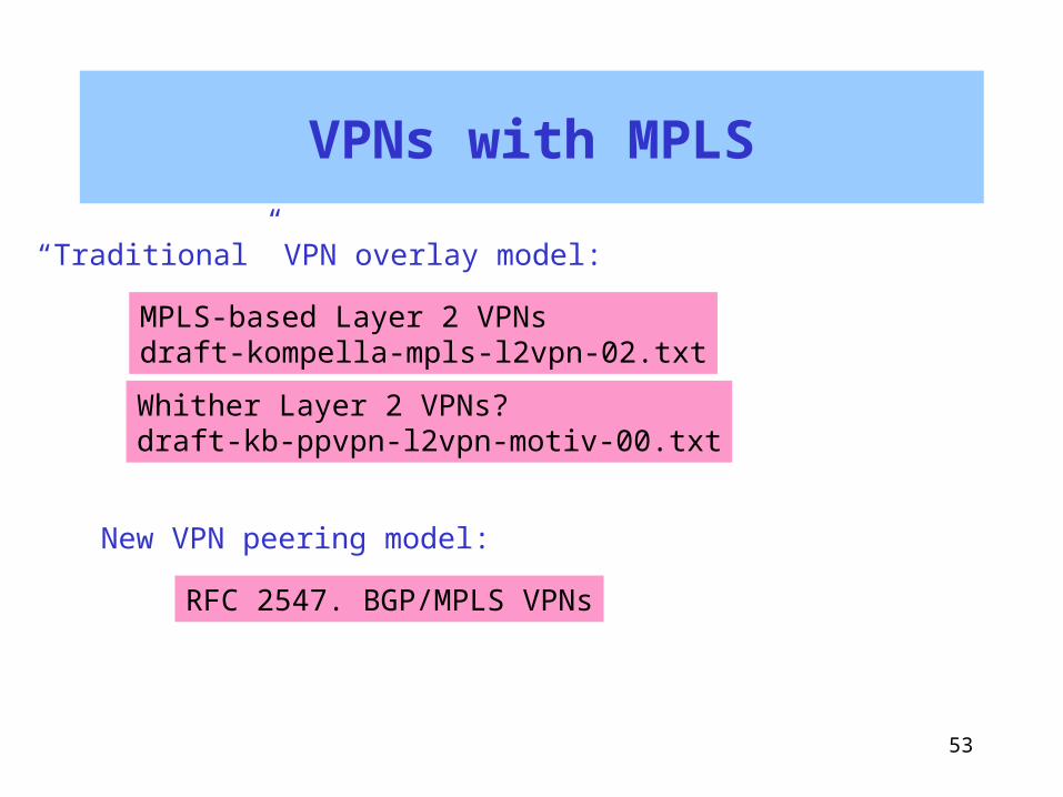
VPNs with MPLS
MPLS-based Layer 2 VPNsdraft-kompella-mpls-l2vpn-02.txt
RFC 2547. BGP/MPLS VPNs
Whither Layer 2 VPNs?draft-kb-ppvpn-l2vpn-motiv-00.txt
“Traditional” VPN overlay model:
New VPN peering model:

54
Traditional Overlay VPNs
C
Customer’s Layer 3 VPN
A
C
B
A
B
C
Provider’s Layer 2 Network(ATM, Frame Relay, X.25)

55
Why Not Use MPLS Tunnels?
C
Customer’s Layer 3 VPN
A
C
B
A
B
C
Provider’s MPLS enabled network
MPLS LSP
MPLS LSP
MPLS LSP

56
Potential Advantages of MPLS Layer 2 VPNs
• Provider needs only a single network infrastructure to support public IP, and VPN services, traffic engineered services, and differentiated services
• Additional routing burden on provider is bounded• Clean separation of administrative responsibilities.
Service provider does MPLS connectivity, customer does layer 3 connectivity
• Easy transition for customers currently using traditional Layer 2 VPNs

57
BGP/MPLS VPNs
• RFC 2547• Is Peer Model of VPN (not Overlay)• Also draft-rosen-rfc2547bis-02.txt• Cisco configuration info :
– http://www.cisco.com/univercd/cc/td/doc/product/software/ios120/120newft/120t/120t5/vpn.htm
AT&T’s IPFR service is based on this RFC.
Note that the Model of this RFC could be implemented without MPLS. See BGP/IPsec VPN <draft-declercq-bgp-ipsec-vpn-00.txt>

58
RFC 2547 Model
VPN Provider Network
VPN 1
VPN 2 VPN 1
VPN 2

59
CEs and PEs
Customer Site
Provider Network
CE = customer edge
PE = provider edge

60
VPN Address Overlap Means Vanilla Forwarding Tables Can’t Work
Site 1
Site 3
Site 2 p1
p2
VPRN 2
p1
Dest. Nxt Hop
p1 p2
????
Provider
Site 4p2
VPRN 1

61
Vanilla forwarding tables are out
Site 1
Site 3
Site 2 VPRN 1 p1
p3
VPRN 2
p2
Dest. Nxt Hop
p1 p2 p3
s1s2s3
Provider
Violates isolationGuarantee ofA VPN: site 1 canExchange traffic withSite 2!
VPN Overlap Means Vanilla Forwarding Tables Can’t Work

62
RFC 2547 : Per site forwarding tables
Site 1
Site 3
Site 2 VPRN 1 p1
p3
VPRN 2
p2
Provider
Dest. Nxt Hop
p1 p3
s1s3
Dest. Nxt Hop
p2 s2
Dest. Nxt Hop
p2 s2
Site 1 FT Site 3 FT
Site 2 FT
Called VRFs, for "VPN Routing and Forwarding" tables.

63
Tunnels required across backbone
Site 1
Site 3
Site 2 VPRN 1 p1
p3
VPRN 2
p2
Site 4
VPRN 3
p3

64
RFC 2547 Summary
• Piggyback VPN information on BGP• New address family• New attributes for membership
• New Per-site forwarding tables (VRFs)• Use MPLS Tunnels between PEs
• No need for VPN routes on backbone LSRs, only on PEs

65
Layer 2 VPNs vs. BGP/MPLS VPNs
• Customer routing stays with customer
• May allow an easier transition for customers currently using Frame/ATM circuits
• Familiar paradigm• Easier to extend to multiple
providers
• Customer routing is “outsourced” to provider
• Transition may be complicated if customer has many extranets or multiple providers
• New “peering” paradigm• Not clear how multiple
provider will work (IMHO)
66
Summary
• provides an efficient and scalable tunneling mechanism
• provides an efficient and scalable mechanism for extending IP routing with explicit routes
MPLS is an interesting and potentially valuable technology because it

67
More info on MPLS
• MPLS working group– http://www.ietf.org/html.charters/mpls-charter.html
• MPLS email list archive – http://cell.onecall.net/cell-relay/archives/mpls/mpls.index.html
• MPLS Resource Center– http://www.mplsrc.com
• Peter Ashwood-Smith’s NANOG Tutorial– http://www.nanog.org/mtg-9910/mpls.html
• MPLS: Technology and Applications. By Bruce Davie and Yakov Rekhter. Morgan Kaufmann. 2000.
• MPLS: Is it all it's cracked up to be? Talk by Pravin K. Johri – http://buckaroo.mt.att.com/~pravin/docs/mpls.pdf

68
More info on MPLS TE
• tewg working group– http://www.ietf.org/html.charters/tewg-charter.html
• NANOG Tutorial by Jeff Doyle and Chris Summers– http://www.nanog.org/mtg-0006/mpls.html
• NANOG Tutorial by Robert Raszuk– http://www.nanog.org/mtg-0002/robert.html

69
More info on MPLS VPNs
• PPVPN working group– http://www.ietf.org/html.charters/ppvpn-charter.html
• PPVPN Archive– http://nbvpn.francetelecom.com
• NANOG Panel:Provider-Provisioned VPNs– http://www.nanog.org/mtg-0102/jessica.html
• MPLS and VPN Architectures. By Ivan Pepelnjak and Jim Guichard. Cisco Press. 2001