1-gigabit ethernet mac core with pcs/pma sublayers ... · physical_interface one of the following...
TRANSCRIPT
zozo
Featuresbull Single-speed 1-gigabitsecond
Ethernet Media Access Controller(MAC)
bull Designed to IEEE 8023-2002 specification
bull Reconciliation sublayer with optional GMII
bull Optional Full-Duplex Physical Coding Sublayer (PCS)for 1000BASE-X with Ten-Bit Interface (TBI) in theVirtex-II and Spartan-3 families
bull Optional Full-Duplex Physical Coding Sublayer (PCS)with Physical Medium Attachment (PMA) for1000BASE-X in the Virtex-II Pro family
bull Configurable Half Duplex and Full Duplex operationwith GMII in the Virtex-II family
bull Configured and monitored through an independentmicroprocessor-neutral interface
bull Powerful statistics gathering to internal counters(statistic vectors are also output externally for useraccess)
bull Configurable flow control through MAC Control pauseframes symmetrically or asymmetrically enabled
bull Optional MDIO interface to managed objects in PHYlayers (MII Management)
bull Support of VLAN frames to specification IEEE8023-2002
bull Configurable support of jumbo frames of any length
bull Configurable inter frame gap adjustment
bull Configurable in-band FCS field passing on bothtransmit and receive paths
bull Optional PCS supports Auto-Negotiation forinformation exchange with a link partner
bull Available under terms of the SignOnce IP License
1-Gigabit Ethernet MAC Corewith PCSPMA Sublayers(1000BASE-X) or GMII v40
DS200 December 11 2003 Product Specification
LogiCOREtrade Facts
Core Specifics
Supported Family
(GMII configuration)
Virtextrade-E (-7)
Virtex-IItrade (-4)
Virtex-II Protrade(-5)
Spartantrade-IIE (-7)
Spartan-3 (-4)
Supported Family
(1000BASE-X PCS withTBI configuration)
Virtex-II (-4)
Virtex-II Pro(-5)
Spartan-3 (-4)
Supported Family
(1000BASE-X PCS amp PMAconfiguration)
Virtex-II Pro(-5)
Performance 125 MHz internal clock
Size 581 - 1850 slices
Global Clock Buffers 2 - 4
Provided with Core
Documentation Product Specification
Design File FormatsEDIF and NGC netlist HDLwrapper
Constraints File UCF
Design Tools Requirements
Xilinx Core Tools v61i SP3
Support
Provided by Xilinx
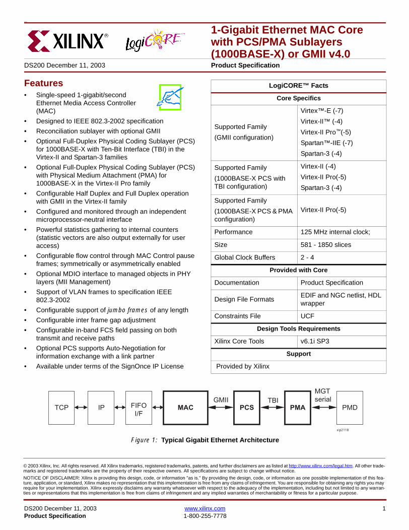
Figure 1 Typical Gigabit Ethernet Architecture
TCP IP FIFOIF
MAC PCS PMA PMD
xip2118
GMII TBIMGTserial
DS200 December 11 2003 wwwxilinxcom 1Product Specification 1-800-255-7778
copy 2003 Xilinx Inc All rights reserved All Xilinx trademarks registered trademarks patents and further disclaimers are as listed at httpwwwxilinxcomlegalhtm All other trade-marks and registered trademarks are the property of their respective owners All specifications are subject to change without notice
NOTICE OF DISCLAIMER Xilinx is providing this design code or information as is By providing the design code or information as one possible implementation of this fea-ture application or standard Xilinx makes no representation that this implementation is free from any claims of infringement You are responsible for obtaining any rights you mayrequire for your implementation Xilinx expressly disclaims any warranty whatsoever with respect to the adequacy of the implementation including but not limited to any warran-ties or representations that this implementation is free from claims of infringement and any implied warranties of merchantability or fitness for a particular purpose
1-Gigabit Ethernet MAC Core with PCSPMA Sublayers (1000BASE-X) or GMII v40 R
MAC OverviewThe 1-Gigabit Ethernet MAC is part of the Ethernet architec-ture displayed in Figure 1 The part of this architecture fromthe MAC to the right is defined in specification IEEE8023-2002
A block diagram of the MAC core is displayed in Figure 2which shows the major functional blocks of the MAC
bull Client interface
bull Transmit engine
bull Flow control block
bull Receive engine
bull Reconciliation sublayer (RS)
bull Optional management interface and MDIO
bull Optional statistics block
bull Optional GMII interface
bull Optional PCSPMA sublayers for 1000BASE-X
The client interface has fully independent 8-bit interfaces forboth transmit and receive to support full-duplex operation
Configuration of the core access to the statistics block andaccess to the MDIO port are accessed through the optionalmanagement interface a 32 bit processor-neutral datapathway that is independent of the Ethernet data pathwayWhen the management interface is omitted configuration ofthe core can still be made via an alternative configurationvector
The Gigabit Media Independent Interface (GMII) is the inter-face available to all supported device families In the Vir-tex-II family the GMII can be replaced by a 1000BASE-XPCS with Ten Bit Interface (TBI) In the Virtex-II Pro familythe GMII or TBI can be replaced with 1000BASE-X PCSand PMA sublayers this uses the Rocket IOtrade Multi-Giga-bit Transceiver (MGT) technology to transmit and receive125 Gbps serial data over differential lines
Figure 2 Functional Block Diagram of the 1 Gigabit Ethernet MAC
FLOW CONTROL
TRANSMIT ENGINE
RECEIVE ENGINE
RE
CO
NC
ILIA
TIO
N S
UB
LAY
ER
CLI
EN
T IN
TE
RFA
CE
OptionalCONFIGURATION
OptionalSTATISTICS
OptionalMDIO
ClientInterface
ManagementInterface
OP
TIO
NA
L G
MII
INT
ER
FAC
E
OP
TIO
NA
L P
CS
PM
A S
UB
LAY
ER
S
xip2130
2 wwwxilinxcom DS200 December 11 20031-800-255-7778 Product Specification
1-Gigabit Ethernet MAC Core with PCSPMA Sublayers (1000BASE-X) or GMII v40R
Xilinx CORE GeneratorThe 1-Gigabit Ethernet MAC Core is generated through theXilinx CORE Generatortrade system The following sectionsdescribe the graphical user interface (GUI) options and thegenerated output files
GUI Interface
Component Name
The component name is used as the base name of the out-put files generated for the core Names must begin with aletter and must be composed from the following charactersa through z 0 through 9 and ldquo_rdquo
Half Duplex Capable
Select this option to have the MAC work in both full-duplexand half-duplex modes select the Half Duplex Capableoption
The default is half-duplex capability Note that half-duplexcapability is not supported in the Virtex-E or Spartan-IIEfamilies
Management Interface
Select this option if you wish to include the optional Man-agement Interface (see page 30) If this option is notselected the core will be generated with a configurationvector
The default is to have the management interface
Statistics Gathering
Select this option to include the optional Statistical Gather-ing with the core (see page 34) This option is available onlyif the core includes the optional management interface Thestatistics vectors are available whether or not this option isselected
The default is to gather statistics
Memory Type
If the statistics gathering option is selected it is possible tochoose which memory type the statistics are stored in Thechoices are Block Memory or Distributed Memory Thechoice of these should be based on the availability ofresources in your design There is no performance or func-tional difference between the memory types
The default type is the Block Memory Note that DistributedMemory is not supported in the Virtex-E or Spartan-IIE fam-ilies
Physical Interface
Depending on the target Xilinx FPGA architecture it may bepossible to select from three different physical interfacechoices for the core
bull GMII - see the optional GMII on page 40
bull TBI - see the optional PCS on page 43
bull PHY - see the optional PCS amp PMA sublayers onpage 46
The TBI option is not supported in the Virtex-E or Spar-tan-IIE families The PHY option is supported in the Virtex-IIPro family only
The default is the GMII physical interface
Parameter Values in the XCO FileXCO file parameter names and their values are identical tothe names and values shown in the GUI except that under-score characters (_) are used instead of spaces The text inan XCO file is case insensitive
Table 1 shows the XCO file parameters and values andsummarizes the GUI defaults The following is an exampleof the CSET parameters in an XCO file
CSET component_name = abc123CSET physical_interface = gmiiCSET statistics_gathering = trueCSET half_duplex_capable = trueCSET memory_type = block_memoryCSET management_interface = true
Table 1 XCO File Values and Default Values
Parameter XCO File Values Default GUI Setting
component_name ASCII text starting with a letter and based upon the followingcharacter set az 09 and _
blank
physical_interface One of the following keywords gmii tbi phy gmii
statistics_gathering One of the following keywords true false true
half_duplex_capable One of the following keywords true false true
memory_type One of the following keywords block_memory distributed_memory block_memory
management_interface One of the following keywords true false true
DS200 December 11 2003 wwwxilinxcom 3Product Specification 1-800-255-7778
1-Gigabit Ethernet MAC Core with PCSPMA Sublayers (1000BASE-X) or GMII v40 R
Output GenerationThe output files generated from the CORE Generator areplaced in the CORE Generator project directory The outputfiles include two netlist files supporting CORE Generatorfiles a readme file and a subdirectory containing examplewrapper files and scripts to take the core through the Xilinximplementation software and simulate the core using the
Modelsim simulator by Model Technology See the gener-ated readme files for explanations about these files
Device UtilizationTable 2 provides approximate slice counts for the corersquosvarious options when instantiated in a Virtex-II Pro device
Table 2 Device Utilization
Parameter Values Device Resources
PhysicalInterface
HalfDuplex
ManagementInterface
Statistics Gathering
Slices LUT Registers BRAM GCLK
GMII TBI PHYDistributed
MemoryBlock
Memory
Yes No No Yes Yes Yes No 1545 2159 1654 0 3
Yes No No Yes Yes No Yes 1420 1745 1561 2 3
Yes No No Yes Yes No No 932 1140 991 0 3
Yes No No Yes No No No 781 969 831 0 2
Yes No No No Yes Yes No 1315 1752 1359 0 3
Yes No No No Yes No Yes 1159 1525 1317 2 3
Yes No No No Yes No No 742 884 793 0 3
Yes No No No No No No 581 708 630 0 2
No Yes No No Yes Yes No 1850 2345 1934 2 4
No Yes No No Yes No Yes 1697 1880 1899 4 4
No Yes No No Yes No No 1295 1404 1380 2 4
No Yes No No No No No 1122 1226 1213 2 3
No No Yes No Yes Yes No 1725 1773 1791 0 3
No No Yes No Yes No Yes 1580 1838 1775 2 3
No No Yes No Yes No No 1172 1394 1236 0 3
No No Yes No No No No 1005 1183 1066 0 2
1 Half Duplex Logic is only available with the GMII2 Statistics Gathering is only available when the Management Interface is selected
4 wwwxilinxcom DS200 December 11 20031-800-255-7778 Product Specification
1-Gigabit Ethernet MAC Core with PCSPMA Sublayers (1000BASE-X) or GMII v40R
Interface DescriptionAll ports of the core (with the exception of the Rocket IOserial ports of the optional PCSPMA sublayers) are internalconnections in FPGA fabric An example wrapper is deliv-ered with the core which adds IBUFs OBUFs and IOBflip-flops where appropriate to the external signals of theGMII or TBI IOBs are also added to the remaining uncon-nected ports to allow the example design to be taken
through the Xilinx implementation software In addition allclock management logic is placed in this example wrapperthis allows the user more flexibility in implementation forexample in designs using multiple cores
The example wrapper is provided in both VHDL and Verilog
Interface Signals for MAC with physical_interface=gmii and management_interface=true
Figure 3 Component Pinout for MAC with GMII Interface using the optional Management Interface
GTX_CLK
TX_CLK
GMII_RX_CLK
MDCMDIO_IN
GMII_RXD[70]
GMII_TXD[70]GMII_TX_ENGMII_TX_ER
TX_DATA[70]
TX_ACKTX_UNDERRUN
PAUSE_REQPAUSE_VAL[150]
RX_CLK
HOST_CLKHOST_OPCODE[10]
HOST_ADDR[90]HOST_WR_DATA[310]HOST_RD_DATA[310]
HOST_MIIM_SELHOST_REQ
HOST_MIIM_RDY
RESET
RX_DATA[70]
RX_GOOD_FRAMERX_BAD_FRAME
TX_COLLISIONTX_RETRANSMIT
TX_DATA_VALID
RX_DATA_VALID
GMII_TX_CLK
GMII_COLGMII_CRS
GMII_RX_DVGMII_RX_ER
TX_CLK Domain
RX_CLK Domain
HOST_CLK Domain
TX_IFG_DELAY[70]
TX_STATISTICS_VECTOR[280]TX_STATISTICS_VALID
RX_STATISTICS_VECTOR[220]RX_STATISTICS_VALID
MDIO_OUTMDIO_TRI
DS200 December 11 2003 wwwxilinxcom 5Product Specification 1-800-255-7778
1-Gigabit Ethernet MAC Core with PCSPMA Sublayers (1000BASE-X) or GMII v40 R
Interface Signals for MAC with physical_interface=gmii and management_interface=false
Figure 4 Component Pinout for MAC with GMII Interface without the optional Management Interface
GTX_CLK
TX_CLK
GMII_RX_CLKGMII_RXD[70]
GMII_TXD[70]GMII_TX_ENGMII_TX_ER
TX_DATA[70]
TX_ACKTX_UNDERRUN
PAUSE_REQPAUSE_VAL[150]
RX_CLK
CONFIGURATION_VECTOR[630]
RESET
RX_DATA[70]
RX_GOOD_FRAMERX_BAD_FRAME
TX_COLLISIONTX_RETRANSMIT
TX_DATA_VALID
RX_DATA_VALID
GMII_TX_CLK
GMII_COLGMII_CRS
GMII_RX_DVGMII_RX_ER
TX_CLK Domain
RX_CLK Domain
TX_IFG_DELAY[70]
TX_STATISTICS_VECTOR[280]TX_STATISTICS_VALID
RX_STATISTICS_VECTOR[220]RX_STATISTICS_VALID
6 wwwxilinxcom DS200 December 11 20031-800-255-7778 Product Specification
1-Gigabit Ethernet MAC Core with PCSPMA Sublayers (1000BASE-X) or GMII v40R
Interface Signals for MAC with physical_interface=tbi and management_interface=true
Figure 5 Component Pinout for MAC with PCS and TBI using the optional Management Interface
GTX_CLK
TX_CLK
MDCMDIO_IN
RX_CODE_GROUP1[90]
TX_CODE_GROUP[90]PMA_TX_CLK
LOC_REF
TX_DATA[70]
TX_ACKTX_UNDERRUN
PAUSE_REQPAUSE_VAL[150]
RX_CLK
HOST_CLKHOST_OPCODE[10]
HOST_ADDR[90]HOST_WR_DATA[310]HOST_RD_DATA[310]
HOST_MIIM_SELHOST_REQ
HOST_MIIM_RDY
RESET
RX_DATA[70]
RX_GOOD_FRAMERX_BAD_FRAME
TX_COLLISIONTX_RETRANSMIT
TX_DATA_VALID
RX_DATA_VALID
EWRAP
PMA_RX_CLK0PMA_RX_CLK1
TX_CLKRX_CLK Domain
HOST_CLK Domain
TX_IFG_DELAY[70]
TX_STATISTICS_VECTOR[280]TX_STATISTICS_VALID
RX_STATISTICS_VECTOR[220]RX_STATISTICS_VALID
MDIO_OUTMDIO_TRI
EN_CDET
RX_CODE_GROUP0[90]
SIGNAL_DETECT
PHYAD[40]
DS200 December 11 2003 wwwxilinxcom 7Product Specification 1-800-255-7778
1-Gigabit Ethernet MAC Core with PCSPMA Sublayers (1000BASE-X) or GMII v40 R
Interface Signals for MAC with physical_interface=tbi and management_interface=false
Figure 6 Component Pinout for MAC with PCS and TBI without the optional Management Interface
GTX_CLK
TX_CLK
MDC_INMDIO_IN
RX_CODE_GROUP1[90]
TX_CODE_GROUP[90]PMA_TX_CLK
LOC_REF
TX_DATA[70]
TX_ACKTX_UNDERRUN
PAUSE_REQPAUSE_VAL[150]
RX_CLK
CONFIGURATION_VECTOR[630]
RESET
RX_DATA[70]
RX_GOOD_FRAMERX_BAD_FRAME
TX_COLLISIONTX_RETRANSMIT
TX_DATA_VALID
RX_DATA_VALID
EWRAP
PMA_RX_CLK0PMA_RX_CLK1
TX_CLKRX_CLK Domain
TX_IFG_DELAY[70]
TX_STATISTICS_VECTOR[280]TX_STATISTICS_VALID
RX_STATISTICS_VECTOR[220]RX_STATISTICS_VALID
MDIO_OUTMDIO_TRI
EN_CDET
RX_CODE_GROUP0[90]
PHYAD[40]
SIGNAL_DETECT
8 wwwxilinxcom DS200 December 11 20031-800-255-7778 Product Specification
1-Gigabit Ethernet MAC Core with PCSPMA Sublayers (1000BASE-X) or GMII v40R
Interface Signals for MAC with physical_interface=phy and management_interface=true
Figure 7 Component Pinout for MAC with PCS amp PMA Sublayers using the optional Management Interface
REFCLK
TX_CLK
MDCMDIO_IN
TXPTXN
TX_DATA[70]
TX_ACKTX_UNDERRUN
PAUSE_REQPAUSE_VAL[150]
RX_CLK
HOST_CLKHOST_OPCODE[10]
HOST_ADDR[90]HOST_WR_DATA[310]HOST_RD_DATA[310]
HOST_MIIM_SELHOST_REQ
HOST_MIIM_RDY
RESET
RX_DATA[70]
RX_GOOD_FRAMERX_BAD_FRAME
TX_COLLISIONTX_RETRANSMIT
TX_DATA_VALID
RX_DATA_VALID
RXPRXN
TX_CLKRX_CLK Domain
HOST_CLK Domain
TX_IFG_DELAY[70]
TX_STATISTICS_VECTOR[280]TX_STATISTICS_VALID
RX_STATISTICS_VECTOR[220]RX_STATISTICS_VALID
PHYAD[40]
SIGNAL_DETECT
MDIO_OUTMDIO_TRI
USRCLKUSRCLK2
DCM_LOCKED
REFCLK2BREFCLK
BREFCLK2REFCLKSEL
DS200 December 11 2003 wwwxilinxcom 9Product Specification 1-800-255-7778
1-Gigabit Ethernet MAC Core with PCSPMA Sublayers (1000BASE-X) or GMII v40 R
Interface Signals for MAC with physical_interface=phy and management_interface=false
Figure 8 Component Pinout for MAC with PCS amp PMA Sublayers without the optional Management Interface
TX_CLK
MDC_INMDIO_IN
TXPTXN
TX_DATA[70]
TX_ACKTX_UNDERRUN
PAUSE_REQPAUSE_VAL[150]
RX_CLK
CONFIGURATION_VECTOR[630]
RX_DATA[70]
RX_GOOD_FRAMERX_BAD_FRAME
TX_COLLISIONTX_RETRANSMIT
TX_DATA_VALID
RX_DATA_VALID
RXPRXN
TX_CLKRX_CLK Domain
TX_IFG_DELAY[70]
TX_STATISTICS_VECTOR[280]TX_STATISTICS_VALID
RX_STATISTICS_VECTOR[220]RX_STATISTICS_VALID
SIGNAL_DETECT
MDIO_OUTMDIO_TRI
REFCLKRESET
PHYAD[40]
USRCLKUSRCLK2
DCM_LOCKED
REFCLK2BREFCLK
BREFCLK2REFCLKSEL
10 wwwxilinxcom DS200 December 11 20031-800-255-7778 Product Specification
1-Gigabit Ethernet MAC Core with PCSPMA Sublayers (1000BASE-X) or GMII v40R
Client Side Interface Signal Definition
Table 3 describes the client-side transmit signals of the MAC core These signals are used to transmit data from the clientto the MAC core
Table 4 describes the client-side receive signals These signals are used by the MAC core to transfer data to the client
Table 3 Transmit Client Interface Signal Pins
Signal Direction Description
TX_CLK Output Clock for transmit client interface 125 MHz nominal
TX_DATA[70] Input Frame data to be transmitted is supplied on this port
TX_DATA_VALID Input Control signal for TX_DATA port
TX_IFG_DELAY[70] InputControl signal for configurable Inter Frame Gap adjustment SeeTransmitter on page 16 for timing diagrams
TX_ACK OutputHandshaking signal Asserted when the current data on TX_DATA hasbeen accepted See Transmitter on page 16 for timing diagrams
TX_UNDERRUN Input Asserted by client to force MAC core to corrupt the current frame
TX_COLLISION OutputAsserted by the MAC core to signal a collision on the medium and that anytransmission in progress should be aborted Always 0 when the MAC coreis in full-duplex mode
TX_RETRANSMIT Output
When asserted at the same time as the TX_COLLISION signal thissignals the client that the aborted frame should be resupplied to the MACcore for retransmission Always 0 when the MAC core is in full-duplexmode
TX_STATISTICS_VECTOR[280] OutputThis gives information on the last frame transmitted See Transmitter onpage 16 for vector contents
TX_STATISTICS_VALID OutputAsserted at end of frame transmission indicating that theTX_STATISTICS_VECTOR is valid
Notes1 All the above signals are synchronous to TX_CLK and Active High
Table 4 Receive Client Interface Signal Pins
Signal Direction Description
RX_CLK Output Clock for receive client interface 125 MHz nominal
RX_DATA[70] Output Frame data received is supplied on this port
RX_DATA_VALID Output Control signal for the RX_DATA port
RX_GOOD_FRAME OutputAsserted at end of frame reception to indicate that the frame should beprocessed by the MAC client See Receiver on page 24
RX_BAD_FRAME OutputAsserted at end of frame reception to indicate that the frame should bediscarded by the MAC client See Receiver on page 24
RX_STATISTICS_VECTOR[220] OutputProvides information about the last frame received See Receiver onpage 24 for the vector contents
RX_STATISTICS_VALID OutputAsserted at end of frame reception indicating that theRX_STATISTICS_VECTOR is valid
Notes1 All signals above are synchronous to RX_CLK and Active High
DS200 December 11 2003 wwwxilinxcom 11Product Specification 1-800-255-7778
1-Gigabit Ethernet MAC Core with PCSPMA Sublayers (1000BASE-X) or GMII v40 R
Table 5 describes the signals used by the client to request a flow control action from the transmit engine Flow control framesreceived by the MAC are automatically handled (if the MAC is configured to do so)
Table 6 describes the optional signals used by the client to access the management features of the MAC core includingconfiguration status statistics and MDIO access
Table 7 describes the alternative to the optional Management Interface signals This describes the Configuration Vectorwhich uses direct inputs to the core to replace the functionality of the MAC Configuration bits when the ManagementInterface is not used
Notes1 All bits of CONFIGURATION_VECTOR are registered on input but may be treated as asynchronous inputs
Table 5 Flow Control Interface Signal Pinout
Signal Direction Description
PAUSE_REQ InputPause request sends a pause frame down the link See Transmitting a PAUSE ControlFrame on page 29
PAUSE_VAL[150] Input Pause value inserted into the parameter field of the transmitted pause frame
Notes1 These signals are synchronous to TX_CLK and are Active High
Table 6 Optional Management Interface Signal Pinout (management_interface=true)
Signal Direction Description
HOST_CLK InputClock for management interface See Optional Management Interface(management_interface=true) on page 30 for the signal frequency range
HOST_OPCODE[10] InputDefines operation to be performed over MDIO interface Bit 1 is also used inconfiguration register access See Configuration Registers on page 30
HOST_ADDR[90] Input Address of register to be accessed
HOST_WR_DATA[310] Input Data to write to register
HOST_RD_DATA[310] Output Data read from register
HOST_MIIM_SEL InputWhen asserted the MDIO interface is accessed When disasserted the MACinternal configuration or statistical counter registers are accessed
HOST_REQ InputUsed to signal a transaction on the MDIO interface or to read from the statisticregisters See Optional Management Interface (management_interface=true) onpage 30
HOST_MIIM_RDY OutputWhen high the MDIO interface has completed any pending transaction and isready for a new transaction
Notes1 All signals above are synchronous to HOST_CLK and are Active High
Table 7 Alternative to the Optional Management Interface Configuration Vector Signal Pinout(management_interface=false)
Signal Direction Description
CONFIGURATION_VECTOR[630]
Input The Configuration Vector is used to replace the functionality of theMAC Configuration Registers when the Management Interface is notused See Optional Configuration Vector (management_interface =false) on page 38
12 wwwxilinxcom DS200 December 11 20031-800-255-7778 Product Specification
1-Gigabit Ethernet MAC Core with PCSPMA Sublayers (1000BASE-X) or GMII v40R
Table 8 describes the reset signal
Physical Interface Signal Definition
Table 9 describes the MDIO (MII Management) interface signals of the MAC core These signals are typically connected tothe MDIO port of a PHY device either off-chip or an SoC-integrated core The MDIO format is defined in IEEE8023 clause22
Table 10 describes the optional GMII signals of the MAC core These are typically attached to a PHY module either off-chipor internally integrated The GMII is defined in IEEE8023 clause 35
Table 8 Reset Signal
Signal Direction Description
RESET Input Asynchronous reset for entire core See Reset circuit on page 42 for moreinformation on the reset circuit
Table 9 MDIO Interface Signal Pinout
Signal Direction Description
MDC OutputManagement Clock derived from HOST_CLK on the basis of supplied configuration datawhen the optional Management Interface is used See Optional Management Interface(management_interface=true) on page 30
MDC_IN InputWhen the Optional Management Interface is not used access to the optional PhysicalCoding Sublayer (PCS) must be provided by an external MDIO Controller In this situationthe Management Clock is an input to the core
MDIO_IN Input Input data signal for communication with PHY configuration and status Tie high if unused
MDIO_OUT Output Output data signal for communication with PHY configuration and status
MDIO_TRI OutputTristate control for MDIO signals 0 signals that the value on MDIO_OUT should be
asserted onto the MDIO bus
Table 10 Optional GMII Interface Signal Pinout (physical_interface=gmii)
Signal Direction Description
GTX_CLK InputClock signal at 125 MHz Other transmit clocks are derived from this clock as illustratedin Figure 28 Tolerance must be within IEEE 8023-2002 specification
GMII_TXD[70] Output Transmit data to PHY
GMII_TX_EN Output Data Enable control signal to PHY
GMII_TX_ER Output Error control signal to PHY
GMII_TX_CLK Output Clock out to PHY
GMII_CRS Input Control signal from PHY
GMII_COL Input Control signal from PHY
GMII_RX_CLK Input Recovered clock from received data stream by PHY
GMII_RXD[70] Input Received data from PHY
GMII_RX_DV Input Data Valid control signal from PHY
GMII_RX_ER Input Error control signal from PHY
DS200 December 11 2003 wwwxilinxcom 13Product Specification 1-800-255-7778
1-Gigabit Ethernet MAC Core with PCSPMA Sublayers (1000BASE-X) or GMII v40 R
Table 11 describes the TBI (Ten-Bit interface) signals of the MAC core These are typically attached to a PMA SERDESmodule These signals optionally replace the GMII signals described in Table 10 to extend the functionality of the core toinclude the PCS for 1000BASE-X The TBI is defined in IEEE8023 clause 36
Notes
PHYAD and SIGNAL_DETECT are asynchronous inputs SIGNAL_DETECT is Active High
Table 11 Optional TBI Interface Signal Pinout (physical_interface=tbi)
Signal Direction Description
GTX_CLK InputClock signal at 125 MHz Other transmit clocks will be derived from this clock asillustrated in Figure 32 Tolerance must be within IEEE 8023-2002 specification
TX_CODE_GROUP[90] Output 10-bit parallel transmit data to PMA Sublayer (SERDES)
PMA_TX_CLK Output Transmit clock signal to PMA Sublayer (SERDES) at 125MHz
LOC_REF OutputCauses the PMA sublayer clock recovery unit to lock to PMA_TX_CLK Thissignal is tied to Ground
EWRAP Output
This signal is set from the PCS Control Register 0 bit 14 (loopback) See PCSManaged Register Block (physical_interface = tbi or phy) on page 49 Whenhigh this instructs the PMA sublayer to electrically loop the transmitter data to thereceiver
RX_CODE_GROUP0[90] Input10-bit parallel received data from PMA Sublayer (SERDES) synchronous toPMA_RX_CLK0
RX_CODE_GROUP1[90] Input10-bit parallel received data from PMA Sublayer (SERDES) synchronous toPMA_RX_CLK1
PMA_RX_CLK0 Input Received clock signal from PMA Sublayer (SERDES) at 625MHz
PMA_RX_CLK1 InputReceived clock signal from PMA Sublayer (SERDES) at 625MHz This is 180degrees out of phase with PMA_RX_CLK0
EN_CDET OutputEnables the PMA Sublayer to perform comma realignment driven from the PCSstate machine during the Loss-Of-Sync state
PHYAD[40] Input PHY address of MDIO register set for the PCS
SIGNAL_DETECT Input
Signal direct from PMD sublayer indicating the presence of light detected at theoptical receiver If driven high this indicates that the optical receiver has detectedlight If driven low this indicates the absence of light
If unused tie high to enable the operation the core
14 wwwxilinxcom DS200 December 11 20031-800-255-7778 Product Specification
1-Gigabit Ethernet MAC Core with PCSPMA Sublayers (1000BASE-X) or GMII v40R
Table 12 describes the interface signals for the Optional PCSPMA sublayer of the MAC core These signals optionallyreplace the GMII signals described in Table 10 to extend the functionality of the core to include the PCS and PMA sublayersfor 1000BASE-X This option uses the Virtex-II Pro Rocket IO functionality which is integrated into the core The PMAsublayer for 1000BASE-X is defined in IEEE8023 clause 36
Notes1 PHYAD and SIGNAL_DETECT are asynchronous inputs SIGNAL_DETECT is Active High
Table 12 Optional PCSPMA sublayer Interface Signal Pinout (physical_interface=phy)
Signal Direction Description
REFCLK InputHigh Quality Reference clock for Multi-Gigabit Transceivers (625 MHz) See Rocket IOUser Guide
REFCLK2 Input Alternative High Quality Reference clock for Multi-Gigabit Transceivers (625 MHz) SeeRocket IO User Guide
BREFCLK Input Alternative High Quality Reference clock for Multi-Gigabit Transceivers (625 MHz)This optionally replaces REFCLK See Rocket IO User Guide
BREFCLK2 Input Alternative High Quality Reference clock for Multi-Gigabit Transceivers (625 MHz)This optionally replaces REFCLK2 See Rocket IO User Guide
REFCLKSEL Input Selects between either (B)REFCLK or (B)REFCLK2 as the input clock source to theMGT See Rocket IO User Guide
USERCLK InputClock signal at 625 MHz This is connected to the TXUSRCLK and RXUSRCLK portsof the Rocket IO MGT This may be derived from (B)REFCLK using a DCM asillustrated in Figure 35
USERCLK2 InputClock signal at 125 MHz This is connected to the TXUSRCLK2 and RXUSRCLK2 portsof the Rocket IO MGT This may be derived from (B)REFCLK using a DCM asillustrated in Figure 35
DCM_LOCKED InputIf a DCM is used to derive USRCLK and USRCLK2 as illustrated in Figure 35 theLOCKED port of the DCM must be connected to the DCM_LOCKED port of the coreThe core will hold itrsquos Rocket IO MGT in reset until DCM_LOCKED is driven to logic 1
TXPTXN OutputDifferential pair for serial transmission from PMA to PMD The clock is embedded in thedata stream
RXPRXN InputDifferential pair for serial reception from PMD to PMA The clock is extracted from thedata stream
PHYAD[40] Input PHY address of MDIO register set for the PCS
SIGNAL_DETECT Input
Signal direct from PMD sublayer indicating the presence of light detected at the opticalreceiver If driven high this indicates that the optical receiver has detected light If drivenlow this indicates the absence of light
If unused tie high to enable the operation the core
DS200 December 11 2003 wwwxilinxcom 15Product Specification 1-800-255-7778
1-Gigabit Ethernet MAC Core with PCSPMA Sublayers (1000BASE-X) or GMII v40 R
Functional Description
Client InterfaceThe client interface is designed for maximum flexibility inmatching to a client switching fabric or network processorinterface
The data pathway is 8 bits wide in both the transmit andreceive directions with each pathway synchronous to theTX_CLK and RX_CLK respectively for completely indepen-dent full duplex operation
Transmitter
Normal Frame Transmission
The timing of a normal outbound frame transfer can be seenin Figure 9 When the client wants to transmit a frame itplaces the first column of data onto the TX_DATA port andasserts a ldquo1rdquo onto TX_DATA_VALID
When the MAC core has read this first byte of data it willassert the TX_ACK signal on the next and subsequent ris-ing clock edges the client must provide the remainder ofthe data for the frame
The end of frame is signalled to the MAC core by takingTX_DATA_VALID Low
In-Band Parameter Encoding
For maximum flexibility in switching applications the Ether-net frame parameters (destination address sourceaddress lengthtype and optionally FCS) are encodedwithin the same data stream that the frame payload is trans-ferred upon rather than on separate ports This is illustratedin the timing diagrams Definitions of the abbreviations usedin the timing diagrams are described in Table 13
Figure 9 Normal Frame Transmission Across Client Interface
Table 13 Abbreviations Used in Timing Diagrams
Abbreviation Definition
DA Destination Address 6 bytes
SA Source Address 6 bytes
LT LengthType Field 2 bytes
FCS Frame Check Sequence 4 bytes
TX_CLK
TX_DATA[70]
TX_DATA_VALID
TX_ACK
TX_UNDERRUN
DA SA DATALT
TX_COLLISION
TX_RETRANSMIT
xip2133
16 wwwxilinxcom DS200 December 11 20031-800-255-7778 Product Specification
1-Gigabit Ethernet MAC Core with PCSPMA Sublayers (1000BASE-X) or GMII v40R
Padding
When fewer than 46 bytes of data are supplied by the clientto the MAC core the transmitter module will add padding upto the minimum frame length The exception to this is whenthe MAC core is configured for client-passed FCS in thiscase the client must also supply the padding to maintain theminimum frame length (see Client-Supplied FCS Passing)
Client-Supplied FCS Passing
If the MAC core is configured to have the FCS field passedin by the client (see Configuration Registers on page 30)the transmission timing is as depicted in Figure 10 In thiscase it is the responsibility of the client to ensure that theframe meets the Ethernet minimum frame length require-ments the MAC core will not perform any padding of thepayload
Figure 10 Frame Transmission with Client-supplied FCS
TX_CLK
TX_DATA[70]
TX_DATA_VALID
TX_ACK
TX_UNDERRUN
DA SA DATA FCSLT
TX_COLLISION
TX_RETRANSMIT
xip2134
DS200 December 11 2003 wwwxilinxcom 17Product Specification 1-800-255-7778
1-Gigabit Ethernet MAC Core with PCSPMA Sublayers (1000BASE-X) or GMII v40 R
Client Underrun
The timing of an aborted transfer can be seen in Figure 11This may happen for instance if a FIFO connected to theclient interface empties before a frame is completed Whenthe client asserts TX_UNDERRUN during a frame transmis-sion the MAC core will insert an error code to corrupt the
current frame and then fall back to idle transmission It isthe responsibility of the client to re-queue the aborted framefor transmission
When an underrun occurs TX_DATA_VALID may beasserted on the clock cycle after the TX_UNDERRUNassertion to request a new transmission
Figure 11 Frame Transmission with Underrun
TX_CLK
TX_DATA[70]
TX_DATA_VALID
TX_ACK
TX_UNDERRUN
DA SA DATALT
TX_COLLISION
TX_RETRANSMIT
xip2135
18 wwwxilinxcom DS200 December 11 20031-800-255-7778 Product Specification
1-Gigabit Ethernet MAC Core with PCSPMA Sublayers (1000BASE-X) or GMII v40R
Back-to-Back Transfers
Figure 12 shows the case where the MAC client is immedi-ately ready to transmit a second frame of data followingcompletion of its first frame In this figure the end of the firstframe is shown on the left On the clock cycle immediatelyfollowing the final byte of the first frame TX_DATA_VALIDis taken low by the client and is taken high one clock cyclelater to indicate that the first byte of the destination addressof the second frame is on TX_DATA awaiting transmission
When the MAC core is ready to accept data TX_ACK isasserted and the transmission continues in the same man-ner as in the case of the single frame The MAC core willdefer the assertion of TX_ACK appropriately to comply withinter-packet gap requirements and flow control requests
If the MAC core is operating in half-duplex mode the timingshown in Figure 12 is required to take advantage of framebursting the MAC core is only guaranteed to retain controlof the medium if the TX_DATA_VALID signal is low for a sin-gle clock cycle For more information on frame bursting seeIEEE 8023-2002
Figure 12 Back to Back Frame Transmission
TX_CLK
TX_DATA[70]
TX_DATA_VALID
TX_ACK
TX_UNDERRUN
TX_COLLISION
TX_RETRANSMIT
xip2136
DS200 December 11 2003 wwwxilinxcom 19Product Specification 1-800-255-7778
1-Gigabit Ethernet MAC Core with PCSPMA Sublayers (1000BASE-X) or GMII v40 R
VLAN Tagged Frames
Transmission of a VLAN tagged frame (if enabled) can beseen in Figure 13 Note that the handshaking signalsacross the interface do not change however the VLANtype tag 81-00 must be supplied by the client to signify that
the frame is VLAN tagged The client also supplies the twobytes of Tag Control Information V1 and V2 at the appro-priate times in the data stream More information on thecontents of these two bytes can be found in IEEE8023-2002
Maximum Permitted Frame Length
The maximum legal length of a frame specified in IEEE8023-2002 is 1518 bytes for non-VLAN tagged framesVLAN tagged frames may be extended to 1522 bytesWhen jumbo frame handling is disabled and the clientattempts to transmit a frame which exceeds the maximumlegal length the MAC core will insert an error code to cor-
rupt the current frame and the frame will be truncated to themaximum legal length When jumbo frame handling isenabled frames which are longer than the legal maximumare transmitted error-free
For more information on enabling and disabling jumboframe handling see Configuration Registers on page 30
Figure 13 Transmission of a VLAN Tagged Frame
TX_CLK
TX_DATA[70]
TX_DATA_VALID
TX_ACK
TX_UNDERRUN
DA SA DATALTVLANtag
81 00V1V2
TX_COLLISION
TX_RETRANSMIT
xip2137
20 wwwxilinxcom DS200 December 11 20031-800-255-7778 Product Specification
1-Gigabit Ethernet MAC Core with PCSPMA Sublayers (1000BASE-X) or GMII v40R
Frame Collisions - Half Duplex Operation Only
In half duplex Ethernet operation collisions will occur on themedium as a matter of course this is how the arbitrationalgorithm is fulfilled In case of a collision the MAC core sig-nals to the client that data may need to be resupplied as fol-lows
If there is a collision the TX_COLLISION signal will be setto ldquo1rdquo by the MAC core If a frame is in progress the clientmust abort the transfer and take TX_DATA_VALID to ldquo0rdquo
If the TX_RETRANSMIT signal is ldquo1rdquo in the same clockcycle that the TX_COLLISION signal is ldquo1rdquo the client must
resubmit the previous frame to the MAC core for retrans-mission TX_DATA_VALID must be asserted to the MACcore within 8 clock cycles of the TX_COLLISION signal inorder to meet Ethernet timing requirements See Figure 14
If the TX_RETRANSMIT signal is ldquo0rdquo in the same clockcycle that the TX_COLLISION signal is ldquo1rdquo the number ofretries for this frame has exceeded the Ethernet specifica-tion and the frame should be dropped by the client The cli-ent can then make any new frame available to the MAC fortransmission without timing restriction See Figure 15
Figure 14 Collision Handling - Frame retransmission required
Figure 15 Collision Handling - No frame retransmission required
TX_CLK
TX_DATA[70]
TX_DATA_VALID
TX_ACK
TX_UNDERRUN
TX_COLLISION
TX_RETRANSMIT
8 clocks max
xip2138
TX_CLK
TX_DATA[70]
TX_DATA_VALID
TX_ACK
TX_UNDERRUN
TX_COLLISION
TX_RETRANSMIT
xip2139
DS200 December 11 2003 wwwxilinxcom 21Product Specification 1-800-255-7778
1-Gigabit Ethernet MAC Core with PCSPMA Sublayers (1000BASE-X) or GMII v40 R
Interframe Gap Adjustment
The user can elect to vary the length of the inter fame gapIf this function is selected (via a configuration bit in thetransmitter control register see Configuration Registerson page 30) then the MAC will exert back pressure to delaythe transmission of the next frame until the requested num-ber of Idle cycles has elapsed The number of Idle cycles iscontrolled by the value on the TX_IFG_DELAY port at thestart of frame transmission Figure 16 shows the MAC oper-ating in this mode
Reducing the Inter fame gap to below the IEEE 8023-2002minimum of 12 Idles is supported in Full Duplex onlydesigns and will transmit an absolute minimum of 4 Idles Ifthe Interframe gap adjustment is reduced below 12 Idlesthen the accuracy of the Optional Statistical Gathering(statistics_gathering=true) Counters cannot be guaranteedHowever the TX_STATISTIC_VECTOR andRX_STATISTIC_VECTOR will always remain correct
Transmitter Statistics Vector
The statistics for the frame transmitted are contained withinthe TX_STATISTICS_VECTOR The vector is driven syn-chronously by the transmitter clock TX_CLK followingframe transmission The bit field definition for the Vector isdefined in Table 14
All bit fields with the exception of BYTE_VALID are validonly when the TX_STATISTICS_VALID is asserted This isillustrated in Figure 17 BYTE_VALID is significant on everyTX_CLK cycle
TX_STATISTICS_VECTOR bits 25 down to 17 inclusive arefor half duplex only and will be set to logic 0 when operatingin full duplex mode
Figure 16 Interframe Gap Adjustment
TX_CLK
TX_DATA[70]
TX_DATA_VALID
TX_ACK
DA SA
TX_IFG_DELAY
IFG ADJUST VALUE
0x0D
13 Idles inserted
DA
Next IFG ADJUST VALUE
xip2140
Figure 17 Transmitter Statistics Vector Timing
TX_CLK
TX_STATISTICS_VECTOR[280]
TX_STATISTICS_VALID
xip2141
22 wwwxilinxcom DS200 December 11 20031-800-255-7778 Product Specification
1-Gigabit Ethernet MAC Core with PCSPMA Sublayers (1000BASE-X) or GMII v40R
Table 14 Bit Definition for the Transmitter Statistics Vector
TX_STATISTICS_VECTOR Name Description
28 PAUSE_FRAME_TRANSMITTEDAsserted if the previous frame was a pause framethat the MAC itself initiated in response to aPAUSE_REQ assertion
27 BYTE_VALID
Asserted if a MAC frame byte (DA to FCS inclusive)is in the process of being transmitted This is valid onevery clock cycle
Do not use this as an enable signal to indicate thatdata is present on GMII_TXD[70]
26 Reserved Returns logic 0
25 down to 22 TX_ATTEMPTS[30]
The number of attempts that have been made totransmit the previous frame This is a 4-bit number0 should be interpreted as 1 attempt 1 as 2attempts up until 15 as 16 attempts
21 Reserved Returns logic 0
20 EXCESSIVE_COLLISIONAsserted if a collision has been detected on each ofthe last 16 attempts to transmit the previous frame
19 LATE_COLLISIONAsserted if a late collision occurred during frametransmission
18 EXCESSIVE_DEFERRALAsserted if the previous frame was deferred for anexcessive amount of time as defined by the constantldquomaxDeferTimerdquo in IEEE 8023-2002
17 TX_DEFERRED Asserted if transmission of the frame was deferred
16 VLAN_FRAMEAsserted if the previous frame contained a VLANidentifier in the LengthType field when transmitterVLAN operation is enabled
15 down to 5 FRAME_LENGTH_COUNTThe length of the previous frame in number of bytesThe count will stick at 2047 for any Jumbo frameslarger than this value
4 CONTROL_FRAMEAsserted if the previous frame had the special MACControl Type code 88-08 in the LengthType field
3 UNDERRUN_FRAMEAsserted if the previous frame contained anunderrun error
2 MULTICAST_FRAMEAsserted if the previous frame contained a multicastaddress in the Destination Address field
1 BROADCAST_FRAMEAsserted if the previous frame contained abroadcast address in the Destination Address field
0 SUCCESSFUL_FRAMEAsserted if the previous frame was transmittedwithout error
DS200 December 11 2003 wwwxilinxcom 23Product Specification 1-800-255-7778
1-Gigabit Ethernet MAC Core with PCSPMA Sublayers (1000BASE-X) or GMII v40 R
Receiver
Normal Frame Reception
The timing of a normal inbound frame transfer can be seenin Figure 18 The client must be prepared to accept data atany time there is no buffering within the MAC to allow forlatency in the receive client Once frame reception begins
data is transferred on consecutive clock cycles to thereceive client until the frame is complete The MAC assertsthe RX_GOOD_FRAME signal to indicate that the framewas successfully received and that the frame should beanalyzed by the client
Frame parameters (destination address source addresslengthtype and optionally FCS) are supplied on the databus according to the timing diagram The abbreviations arethe same as those described in Table 13 on page 16
If the LengthType field in the frame has the Length interpre-tation and this indicates that the inbound frame has beenpadded to meet the Ethernet minimum frame size specifica-tion then this padding will not be passed to the client in thedata payload The exception to this is in the case whereFCS passing is enabled see Client-Supplied FCS Pass-ing on page 25
Therefore when Client-Supplied FCS passing is disabledRX_DATA_VALID = lsquo0rsquo between frames for the duration ofthe Padding field (if present) the FCS field carrier exten-sion (if present) the interframe gap following the frame andthe preamble field of the next frame When Client-Supplied
FCS passing is enabled RX_DATA_VALID = lsquo0rsquo betweenframes for the duration of carrier extension (if present) theinterframe gap and the preamble field of the followingframe
RX_GOOD_FRAME RX_BAD_FRAME timing
Although the timing diagram in Figure 18 shows theRX_GOOD_FRAME signal asserted shortly after the lastvalid data on RX_DATA this is not always the case TheRX_GOOD_FRAME or RX_BAD_FRAME signals areasserted only after all frame checks are completed This isafter the FCS field has been received (and after reception ofcarrier extension if present)
Therefore either RX_GOOD_FRAME or RX_BAD_FRAMEis asserted following frame reception at the beginning of theinterframe gap
Figure 18 Normal Frame Reception
RX_CLK
RX_DATA[70]
RX_DATA_VALID
RX_GOOD_FRAME
RX_BAD_FRAME
DA SA DATALT
xip2142
24 wwwxilinxcom DS200 December 11 20031-800-255-7778 Product Specification
1-Gigabit Ethernet MAC Core with PCSPMA Sublayers (1000BASE-X) or GMII v40R
Frame Reception with Errors
The case of an unsuccessful frame reception (for examplea fragment frame or a frame with an incorrect FCS) can beseen in Figure 19 In this case the RX_BAD_FRAME signal
is asserted to the client at the end of the frame It is then theresponsibility of the client to drop the data already trans-ferred for this frame
Figure 19 Frame Reception with Error
Client-Supplied FCS Passing
If the MAC core is configured to pass the FCS field to the cli-ent (see Configuration Registers on page 30) then this ishandled as shown in Figure 20
In this case any padding inserted into the frame to meetEthernet minimum frame length specifications will be leftintact and passed to the client
Note that even though the FCS is passed up to the client itis also verified by the MAC core and RX_BAD_FRAMEasserted if the FCS check fails
RX_CLK
RX_DATA[70]
RX_DATA_VALID
RX_GOOD_FRAME
RX_BAD_FRAME
DA SA DATALT
xip2144
Figure 20 Frame Reception with In-Band FCS Field
RX_CLK
RX_DATA[70]
RX_DATA_VALID
RX_GOOD_FRAME
RX_BAD_FRAME
DA SA DATALT FCS
xip2145
DS200 December 11 2003 wwwxilinxcom 25Product Specification 1-800-255-7778
1-Gigabit Ethernet MAC Core with PCSPMA Sublayers (1000BASE-X) or GMII v40 R
VLAN Tagged Frames
The reception of a VLAN tagged frame (if enabled) can beseen in Figure 21 The VLAN frame is passed to the clientso that the frame may be identified as VLAN tagged this is
followed by the Tag Control Information bytes V1 and V2More information on the interpretation of these bytes maybe found in IEEE 8023-2002 standard
Maximum Permitted Frame Length
The maximum legal length of a frame specified in IEEE8023-2002 is 1518 bytes for non-VLAN tagged framesVLAN tagged frames may be extended to 1522 bytesWhen jumbo frame handling is disabled and the corereceives a frame which exceeds the maximum legal lengthRX_BAD_FRAME will be asserted When jumbo framehandling is enabled frames which are longer than the legalmaximum are received in the same way as shorter frames
For more information on enabling and disabling jumboframe handling see Configuration Registers on page 30
LengthType Field Error Checks
Enabled
Default operation is with the LengthType error checkingenabled (see Receiver Configuration Word 1 on page 31)In this mode the following checks are made on all framesreceived If either of these checks fail then the frame ismarked as BAD
bull A value in the LengthType field that is greater than orequal to decimal 46 but less than decimal 1536 (aLength interpretation) is checked against the actualdata length received
bull A value in the LengthType field that is less thandecimal 46 is checked to see that the data field ispadded to exactly 46 bytes (so that the resultant frameis minimum frame size 64 bytes total in length)
Furthermore if Padding is indicated (the LengthType fieldis less than decimal 46) and Client-Supplied FCS Passing isdisabled then the Length value in the LengthType field willbe used to deassert RX_DATA_VALID after the indicatednumber of data bytes so that the Padding bytes areremoved from the frame
Disabled
When the LengthType error checking is disabled (seeReceiver Configuration Word 1 on page 31) theLengthType error checks described above are not per-formed A frame containing only these errors will be markedas GOOD
Furthermore if Padding is indicated and Client-SuppliedFCS Passing is disabled then a Length Value in theLengthType field will not be used to deassertRX_DATA_VALID Instead RX_DATA_VALID will be deas-serted before the start of the FCS field in this way any pad-ding will not be removed from the frame
Figure 21 Reception of a VLAN Tagged Frame
RX_CLK
RX_DATA[70]
RX_DATA_VALID
RX_GOOD_FRAME
RX_BAD_FRAME
DA SA DATALT
81 00 V1 V2
VLANtag
xip2146
26 wwwxilinxcom DS200 December 11 20031-800-255-7778 Product Specification
1-Gigabit Ethernet MAC Core with PCSPMA Sublayers (1000BASE-X) or GMII v40R
Receiver Statistics Vector
The statistics for the frame received are contained withinthe RX_STATISTICS_VECTOR The vector is driven syn-chronously by the receiver clock RX_CLK following framereception The bit field definition for the Vector is defined inTable 15
All bit fields with the exception of BYTE_VALID are validonly when the RX_STATISTICS_VALID is asserted This isillustrated in Figure 22 BYTE_VALID is significant on everyRX_CLK cycle
Figure 22 Receiver Statistics Vector Timing
RX_CLK
RX_STATISTICS_VECTOR[220]
RX_STATISTICS_VALID
xip2147
Table 15 Bit Definition for the Receiver Statistics Vector
RX_STATISTICS_VECTOR Name Description
22LENGTHTYPE Out ofRange
Asserted if the lengthtype field contained a length valuethat did not match the number of MAC client data bytesreceived Also high if the lengthtype field indicated thatthe frame contained padding but the number of MAC cli-ent data bytes received was not equal to 64 bytes (min-imum frame size)
The exception to the above is when the LengthTypeField Error Checks are disabled in which case this bitwill not be asserted
21 BAD_OPCODE
Asserted if the previous frame was error-free andcontained the special Control Frame identifier in theLengthType field but contained an opcode that isunsupported by the MAC (Any Opcode other thanPAUSE)
20 FLOW_CONTROL_FRAME
Asserted if the previous frame was error-freecontained the special Control Frame identifier in theLengthType field contained a Destination Addressthat matched either the MAC Control MulticastAddress or the configured source address of the MACcontained the supported PAUSE opcode and wasacted upon by the MAC
19 BYTE_VALID
Asserted if a MAC frame byte (DA to FCS inclusive) isin the process of being received This is valid on everyclock cycle
Do not use this as an enable signal to indicate thatdata is present on RX_DATA[70]
18 VLAN_FRAMEAsserted if the previous frame contained a VLANidentifier in the LengthType field when receiver VLANoperation is enabled
DS200 December 11 2003 wwwxilinxcom 27Product Specification 1-800-255-7778
1-Gigabit Ethernet MAC Core with PCSPMA Sublayers (1000BASE-X) or GMII v40 R
17 OUT_OF_BOUNDS
Asserted if the previous frame exceeded the specifiedIEEE8023-2002 maximum legal length (seeMaximum Permitted Frame Length on page 26) Thisis only valid if Jumbo frames are disabled
16 CONTROL_FRAMEAsserted if the previous frame contained the specialControl Frame identifier in the LengthType field
15 down to 5 FRAME_LENGTH_COUNTThe length of the previous frame in number of bytesThe count will stick at 2047 for any Jumbo frameslarger than this value
4 MULTICAST_FRAMEAsserted if the previous frame contained a multicastaddress in the Destination Address field
3 BROADCAST_FRAMEAsserted if the previous frame contained the broadcastaddress in the Destination Address field
2 FCS_ERRORAsserted if the previous frame received had anincorrect FCS value or the MAC detected error codesduring frame reception
1 BAD_FRAME1 Asserted if the previous frame received containederrors
0 GOOD_FRAME1 Asserted if the previous frame received was error-free
1 If the LengthType Field Error Checks are disabled then a frame which contains this type of error will be marked as a GOOD_FRAMEproviding no additional errors were detected
Table 15 Bit Definition for the Receiver Statistics Vector
RX_STATISTICS_VECTOR Name Description
28 wwwxilinxcom DS200 December 11 20031-800-255-7778 Product Specification
1-Gigabit Ethernet MAC Core with PCSPMA Sublayers (1000BASE-X) or GMII v40R
Flow ControlThe flow control block is designed to Clause 31 of the IEEE8023-2002 standard The MAC may be configured to sendpause frames and to act upon their reception These twobehaviors can be configured asymmetrically see Configu-ration Registers on page 30
Transmitting a PAUSE Control Frame
The client initiates a flow control frame by assertingPAUSE_REQ while the pause value is on the PAUSE_VALbus These signals are synchronous to TX_CLK The timingof this can be seen in Figure 23
If the MAC core is configured to support transmit flow con-trol this action causes the core to transmit a PAUSE controlframe on the link with the PAUSE parameter set to thevalue on PAUSE_VAL in the cycle when PAUSE_REQ wasasserted This will not disrupt any frame transmission inprogress but will take priority over any pending frame trans-
mission This frame will be transmitted even if the transmit-ter is in the paused state itself
Receiving a Pause Control Frame
When an error-free frame is received by the MAC core thefollowing checks are made
1 The Destination Address field is matched against theMAC Control Multicast address or the configuredSource Address for the MAC (see ConfigurationRegisters on page 30)
2 The LengthType field is matched against the MACControl Type code
3 The opcode field contents are matched against thePAUSE opcode if check 2 is true
If any of the above checks are false or the MAC Flow Con-trol logic for the receiver is disabled the frame is ignored bythe Flow Control logic and passed up to the client
If the frame passes all of the above checks is of minimumlegal size and the MAC Flow Control logic for the receiver isenabled the pause value parameter in the frame is thenused to inhibit transmitter operation for the time defined inthe IEEE8023-2002 specification This inhibit is imple-mented using the same back pressure scheme shown inFigure 12 Because the received pause frame has beenacted upon it is passed to the client with RX_BAD_FRAMEasserted to indicate to the client that it should be dropped
Reception of any frame for which check 2 is true and whichis not of legal minimum length is considered an invalid Con-trol frame This will be ignored by the Flow Control logic andpassed to the client with RX_BAD_FRAME asserted
Figure 23 Pause Request Timing
TX_CLK
PAUSE_VAL[150]
PAUSE_REQ
xip2148
DS200 December 11 2003 wwwxilinxcom 29Product Specification 1-800-255-7778
1-Gigabit Ethernet MAC Core with PCSPMA Sublayers (1000BASE-X) or GMII v40 R
Optional Management Interface(management_interface=true)The management interface is a processor-independentinterface with standard address data and control signals Itmay be used as is or a wrapper may be applied (not sup-plied) to interface to common bus architectures
This interface is used for
bull Configuration of the MAC core
bull Access to optional statistics counters for use by higherlayers for example SNMP
bull access through the MDIO interface to the managementregisters located in the PHY attached to the MAC core
The management interface is accessed differently depend-ing on the type of transaction a truth table showing whichaccess method is required for each transaction type isshown in Table 16 These access methods are described inthe following sections
HOST_CLK Frequency
The management interface clock HOST_CLK is used toderive the MDIO clock MDC and is therefore subject tosome frequency restrictions This HOST_CLK must be
ge 10 MHz
le 100 MHz
Configuring the MAC core to derive the MDC signal fromthis clock is detailed in MDIO Interface on page 37
Configuration Registers
After power up or reset the client may reconfigure the coreparameters from their defaults such as flow control supportConfiguration changes can be written at any time Both thereceiver and transmitter logic will only respond to configura-tion changes during Inter Frame Gaps The exceptions tothis are the configurable resets which take effect immedi-ately
Configuration of the MAC core is performed through a reg-ister bank accessed through the management interfaceThe configuration registers available in the core are detailedin Table 17 As can be seen the address has some implicitdonrsquot care bits any access to an address in the rangesshown will perform a 32-bit read or write from the same con-figuration word
Table 16 Management Interface Transaction Types
Transaction HOST_MIIM_SEL HOST_ADDR[9]
Configuration 0 1
Statistics 0 0
MIIM access 1 X
Table 17 Configuration Registers
Address Description
0x200-0x23F Receiver Configuration (Word 0)
0x240-0x27F Receiver Configuration (Word 1)
0x280-0x2BF Transmitter Configuration
0x2C0-0x2FF Flow Control Configuration
0x300-0x33F Reserved
0x340-0x37F Management Configuration
30 wwwxilinxcom DS200 December 11 20031-800-255-7778 Product Specification
1-Gigabit Ethernet MAC Core with PCSPMA Sublayers (1000BASE-X) or GMII v40R
The register contents for the two receiver configuration words can be seen in Table 18 and Table 19
Notes1 In changing the receiverrsquos mode from Half Duplex to Full Duplex there is a period of time of up to 24 us following the mode change
when no new receiver statistics can be stored in the optional Statistical Counters
Table 18 Receiver Configuration Word 0
Bit Default Value Description
31-0 All 0rsquos
Pause frame MAC Source Address[310] This address is used by the MAC tomatch against the Destination Address of any incoming flow control frames It isalso used by the flow control block as the Source Address (SA) for any outboundflow control frames
The address is ordered so the first byte transmittedreceived is the lowestpositioned byte in the register for example a MAC address ofAA-BB-CC-DD-EE-FF would be stored in Address[470] as 0xFFEEDDCCBBAA
Table 19 Receiver Configuration Word 1
Bit Default Value Description
15-0 All 0rsquos Pause frame MAC Source Address[4732] See description in Table 18
24-16 NA Reserved
25 0
LengthType Error Check Disable When this bit is set to ldquo1rdquo the core will notperform the LengthType field error checks as described in LengthType FieldError Checks on page 26 When this bit is set to ldquo0rdquo the LengthType field checkswill be performed this is normal operation
26 0Half Duplex If ldquo1rdquo the receiver will operate in half duplex mode If ldquo0rdquo the receiverwill operate in full duplex mode Has no effect if XCO parameterhalf_duplex_capable = false
27 0VLAN Enable When this bit is set to ldquo1rdquo VLAN tagged frames will be acceptedby the receiver
28 1Receiver Enable If set to ldquo1rdquo the receiver block will be operational If set to ldquo0rdquothe block will ignore activity on the physical interface RX port
29 0
In-band FCS Enable When this bit is ldquo1rdquo the MAC receiver will pass the FCS fieldup to the client as described in Client-Supplied FCS Passing on page 25 Whenit is ldquo0rdquo the client will not be passed the FCS In both cases the FCS will beverified on the frame
30 0Jumbo Frame Enable When this bit is set to ldquo1rdquo the MAC receiver will acceptframes over the specified IEEE8023-2002 maximum legal length When this bitis ldquo0rdquo the MAC will only accept frames up to the specified maximum
31 0Reset When this bit is set to ldquo1rdquo the receiver will be reset The bit will thenautomatically revert to ldquo0rdquo Note that this reset will also set all of the receiverconfiguration registers to their default values
DS200 December 11 2003 wwwxilinxcom 31Product Specification 1-800-255-7778
1-Gigabit Ethernet MAC Core with PCSPMA Sublayers (1000BASE-X) or GMII v40 R
The register contents for the Transmitter Configuration Word are described in Table 20
Notes1 In changing the transmitterrsquos mode from Half Duplex to Full Duplex there is a period of time of up to 24 us following the mode change
when no new transmitter statistics can be stored in the optional Statistical Counters
Table 20 Transmitter Configuration Word
Bit Default Value Description
24-0 NA Reserved
25 0
Interframe Gap Adjust Enable If lsquo1rsquo the transmitter will read the value on the portTX_IFG_DELAY at the start of frame transmission and adjust the interframe gapfollowing the frame accordingly See Interframe Gap Adjustment on page 22 Ifldquo0rdquo the transmitter will output a minimum Inter Frame Gap of twelve clock cyclesas specified in IEEE8023-2002
26 0Half Duplex If lsquo1rsquo the transmitter will operate in half duplex mode If lsquo0rsquo thetransmitter will operate in full duplex mode Has no effect if XCO parameterhalf_duplex_capable = false
27 0VLAN Enable When this bit is set to 1 the transmitter will allow the transmissionof VLAN tagged frames
28 1Transmit Enable When this bit is 1 the transmitter is operational When it is 0the transmitter is disabled
29 0
In-band FCS Enable When this bit is lsquo1rsquo the MAC transmitter will expect the FCSfield to be passed in by the client as described in Client-Supplied FCS Passingon page 17 When this bit is ldquo0rdquo the MAC transmitter will append padding asrequired compute the FCS and append it to the frame
30 0
Jumbo Frame Enable When this bit is set to ldquo1rdquo the MAC transmitter will sendframes that are greater than the specified IEEE8023-2002 maximum legallength When this bit is ldquo0rdquo the MAC will only send frames up to the specifiedmaximum
31 0Reset When this bit is set to ldquo1rdquo the transmitter will be reset The bit will thenautomatically revert to ldquo0rdquo Note that this reset will also set all of the transmitterconfiguration registers to their default values
32 wwwxilinxcom DS200 December 11 20031-800-255-7778 Product Specification
1-Gigabit Ethernet MAC Core with PCSPMA Sublayers (1000BASE-X) or GMII v40R
The register contents for the Flow Control Configuration Word are described in Table 21
The register contents for the Management Configuration Word are described in Table 22
Writing to the configuration registers through the manage-ment interface is depicted in Figure 24 When accessing theconfiguration registers (ie when HOST_ADDR[9] = lsquo1rsquo andHOST_MIIM_SEL = lsquo0rsquo) the upper bit of HOST_OPCODEfunctions as an Active Low write enable signal The lowerHOST_OPCODE bit is a ldquodonrsquot carerdquo
Reading from the configuration register words is similar butthe upper HOST_OPCODE bit should be lsquo1rsquo This is shownin Figure 25 In this case the contents of the register appearon HOST_RD_DATA the HOST_CLK edge after the regis-ter address is asserted onto HOST_ADDR
Table 21 Flow Control Configuration Word
Bit Default Value Description
28-0 NA Reserved
29 1
Flow Control Enable (RX) When this bit is lsquo1rsquo received flow control frames willinhibit the transmitter operation as described in Receiving a Pause ControlFrame on page 29 When this bit is lsquo0rsquo received flow control frames will alwaysbe passed up to the client
30 1Flow Control Enable (TX) When this bit is lsquo1rsquo asserting the PAUSE_REQ signalwill send a flow control frame out from the transmitter When this bit is 0 assertingthe PAUSE_REQ signal has no effect
31 NA Reserved
Table 22 Management Configuration Word
Bits Default Value Description
4-0 All 0rsquos Clock Divide[40] See MDIO Interface on page 37
5 0MDIO Enable When this bit is 1 the MDIO interface can be used to accessattached PHY devices When this bit is 0 the MDIO interface is disabled and theMDIO signals remain inactive
31-6 NA Reserved
Figure 24 Configuration Register Write Timing
HOST_CLK
HOST_ADDR[80]
HOST_ADDR[9]
HOST_OPCODE[1]
HOST_MIIM_SEL
HOST_WR_DATA[310]xip2149
Figure 25 Configuration Register Read Timing
HOST_CLK
HOST_ADDR[80]
HOST_ADDR[9]
HOST_OPCODE[1]
HOST_MIIM_SEL
HOST_RD_DATA[310]
xip2150
DS200 December 11 2003 wwwxilinxcom 33Product Specification 1-800-255-7778
1-Gigabit Ethernet MAC Core with PCSPMA Sublayers (1000BASE-X) or GMII v40 R
Optional Statistical Gathering(statistics_gathering=true)
During operation the MAC core collects statistics on thesuccess and failure of various operations for processing by
station management entities (STA) further up the protocolstack These statistics are accessed by the host through theoptional management interface A complete list of statisticssupported is described in Table 23
Table 23 Statistics Registers
Address Name Description
0x000 Frames Received OK1 A count of error-free frames received
0x001 Frame Check Sequence Errors A count of received frames that failed the CRC check and were at least64 bytes in length
0x002 Broadcast Frames Received OK1A count of frames that were successfully received and were directed tothe broadcast group address
0x003 Multicast Frames Received OK1 A count of frames that were successfully received and were directed toa non broadcast group address
0x004 64 byte Frames Received OK1 A count of error-free frames received that were 64 bytes in length
0x005 65-127 byte Frames Received OK1A count of error-free frames received that were between 65 and 127bytes in length
0x006 128-255 byte Frames Received OK1A count of error-free frames received that were between 128 and 255bytes in length
0x007 256-511 byte Frames Received OK1A count of error-free frames received that were between 256 and 511bytes in length
0x008512-1023 byte Frames ReceivedOK1
A count of error-free frames received that were between 512 and 1023bytes in length
0x0091024-MaxFrameSize byte FramesReceived OK1
A count of error-free frames received that were between 1024 bytes andthe specified IEEE8023-2002 maximum legal length (see MaximumPermitted Frame Length on page 26)
0x00A Control Frames Received OKA count of error-free frames received that contained the specialControl Frame identifier in the LengthType field
0x00B LengthType Out of Range
A count of frames received that were at least 64 bytes in length wherethe lengthtype field contained a length value that did not match thenumber of MAC client data bytes received
The counter also increments for frames in which the lengthtype fieldindicated that the frame contained padding but where the number ofMAC client data bytes received was greater than 64 bytes (minimumframe size)
The exception to the above is when the LengthType Field Error Checksare disabled in which case this counter will not increment
0x00C VLAN Tagged Frames Received OKA count of error-free VLAN frames received This counter will only incre-ment when the receiver is configured for VLAN operation
0x00D Pause Frames Received OK
A count of error-free frames received that contained the MAC Controltype identifier 88-08 in the LengthType field contained a Destinationaddress that matched either the MAC Control multicast address or theconfigured source address of the MAC contained the PAUSE opcodeand were acted upon by the MAC
0x00EControl Frames Received withUnsupported Opcode
A count of error-free frames received that contained the MAC Controltype identifier 88-08 in the LengthType field but were received with anopcode other than the PAUSE opcode
34 wwwxilinxcom DS200 December 11 20031-800-255-7778 Product Specification
1-Gigabit Ethernet MAC Core with PCSPMA Sublayers (1000BASE-X) or GMII v40R
0x00F Oversize Frames Received OK1A count of otherwise error-free frames received that exceeded the max-imum legal frame length specified in IEEE 8023-2002 (see MaximumPermitted Frame Length on page 26)
0x010 Undersize frames receivedA count of the number of frames received that were less than 64 bytesin length but were otherwise well formed
0x011 Fragment frames receivedA count of the number of frames received that were less than 64 bytesin length and had a bad Frame Check Sequence field
0x012 Received bytesA count of bytes of frames that are received (Destination Address toFrame Check Sequence inclusive)
0x013 Transmitted bytesA count of bytes of frames that are transmitted (Destination Address toFrame Check Sequence inclusive)
0x020 Frames Transmitted OK A count of error-free frames transmitted
0x021 Broadcast Frames Transmitted OK A count of error-free frames that were transmitted to the broadcastaddress
0x022 Multicast Frames Transmitted OK A count of error-free frames that were transmitted to a group destina-tion address other than broadcast
0x023 Underrun Errors
A count of frames that would otherwise be transmitted by the core butcould not be completed due to the assertion of TX_UNDERRUN duringthe frame transmission This will not count frames which are less than64 bytes in length
0x024 Control Frames Transmitted OKA count of error-free frames transmitted that contained the MACControl Frame type identifier 88-08 in the LengthType field
0x025 64 byte Frames Transmitted OK A count of error-free frames transmitted that were 64 bytes in length
0x026 65-127 byte Frames Transmitted OKA count of error-free frames transmitted that were between 65 and 127bytes in length
0x027128-255 byte Frames TransmittedOK
A count of error-free frames transmitted that were between 128 and 255bytes in length
0x028256-511 byte Frames TransmittedOK
A count of error-free frames transmitted that were between 256 and 511bytes in length
0x029512-1023 byte Frames TransmittedOK
A count of error-free frames transmitted that were between 512 and1023 bytes in length
0x02A1024-MaxFrameSize byte FramesTransmitted OK
A count of error-free frames transmitted that were between 1024 and thespecified IEEE8023-2002 maximum legal length (see Maximum Per-mitted Frame Length on page 20)
0x02BVLAN Tagged Frames TransmittedOK
A count of error-free VLAN frames transmitted This counter will onlyincrement when the transmitter is configured for VLAN operation
0x02C Pause Frames Transmitted OKA count of error-free PAUSE frames generated and transmitted by thecore in response to an assertion of PAUSE_REQ
0x02D Oversize Frames Transmitted OKA count of otherwise error-free frames transmitted that exceeded themaximum legal frame length specified in IEEE 8023-2002 (see Maxi-mum Permitted Frame Length on page 20)
0x02E Single Collision Frames A count of frames that are involved in a single collision but are subse-quently transmitted successfully (Half Duplex Mode only)
Table 23 Statistics Registers (Continued)
Address Name Description
DS200 December 11 2003 wwwxilinxcom 35Product Specification 1-800-255-7778
1-Gigabit Ethernet MAC Core with PCSPMA Sublayers (1000BASE-X) or GMII v40 R
Each of these statistic registers is 64 bits wide and thereforemust be read in a two-cycle transfer The timing of this pro-cess is shown in Figure 26 Six clocks after the read trans-action is initiated the least significant word (LSW) of thestatistics counter appears on the HOST_RD_DATA bus
and a clock cycle later the most significant word (MSW)appears For accurate statistic values 64 clock ticks (ofTX_CLK for transmit statistics or RX_CLK for receive statis-tics) must elapse after the last frame is sent or receivedthrough the MAC core
0x02F Multiple Collision Frames A count of frames that are involved in more than one collision but aresubsequently transmitted successfully (Half Duplex Mode only)
0x040 Frames with Deferred Transmissions A count of frames whose transmission was delayed on its first attemptbecause the medium was busy (Half Duplex Mode only)
0x041 Late Collisions
A count of the times that a collision has been detected later than oneslotTime from the start of the packet transmission A late collision iscounted twice both as a collision and as a lateCollision (Half DuplexMode only)
0x042Frames Aborted due to Excesscollisions
A count of the frames that due to excessive collisions are not transmit-ted successfully (Half Duplex Mode only)
0x043 Carrier Sense ErrorsA count of times that the GMII_CRS signal was not asserted or wasdisasserted during the transmission of a frame without collision (HalfDuplex Mode only)
0x044 Frames with Excess DeferralA count of frames that deferred transmission for an excessive period oftime (Half Duplex Mode only)
1 If the LengthType Field Error Checks are disabled then these counters will still increment for received frames which contain this typeof error (providing no additional errors were detected)
Table 23 Statistics Registers (Continued)
Address Name Description
Figure 26 Statistic Register Read Timing
HOST_CLK
HOST_ADDR[80]
HOST_ADDR[9]
HOST_REQ
HOST_MIIM_SEL
HOST_RD_DATA[310]
6 CLOCKS
LSW MSW
xip2151
36 wwwxilinxcom DS200 December 11 20031-800-255-7778 Product Specification
1-Gigabit Ethernet MAC Core with PCSPMA Sublayers (1000BASE-X) or GMII v40R
MDIO Interface
The management interface is also used to access the MDIO(MII Management) interface of the MAC core this interfaceis used to access the Managed Information Block (MIB) ofthe PHY components attached to the MAC core
The MDIO interface supplies a clock to the externaldevices MDC This clock is derived from the HOST_CLKsignal using the value in the Clock Divide[40] configurationregister The frequency of the MDIO clock is given by thefollowing equation
The frequency of MDC given by this equation should notexceed 25 MHz in order to comply with the IEEE8023-2002 specification for this interface To prevent MDCfrom being out of specification the Clock Divide[40] valuepowers up at 00000 and while this value is in the register itis impossible to enable the MDIO interface
For details of the register map of PHY layer devices and afuller description of the operation of the MDIO interfaceitself see IEEE specification 8023-2002
Access to the MDIO interface through the managementinterface is depicted in the timing diagram in Figure 27
For MDIO transactions the following points apply
bull HOST_OPCODE maps to the OP (opcode) field of theMDIO frame
bull HOST_ADDR maps to the two address fields of theMDIO frame PHY_ADDR is HOST_ADDR[95] andREG_ADDR is HOST_ADDR[40]
bull HOST_WR_DATA[150] maps into the data field of the
MDIO frame when performing a write operation
bull The data field of the MDIO frame maps intoHOST_RD_DATA[150] when performing a readoperation
The MAC core signals to the host that it is ready for anMDIO transaction by asserting HOST_MIIM_RDY A read orwrite transaction on the MDIO is initiated by a pulse on the
fMDC
fHOST_CLK
1 Clock Divide[40]+( ) 2times-------------------------------------------------------------------=
Figure 27 MDIO Access Through Management Interface
HOST_CLK
HOST_ADDR[90]
HOST_OPCODE[10]
HOST_REQ
HOST_MIIM_SEL
HOST_RD_DATA[150]
HOST_WR_DATA[150]
HOST_RDY
If a read transaction is initiated the HOST_RD_DATA bus is valid at the point indicated If a write transaction is initiated the HOST_WR_DATA bus must be valid at the indicated point Simultaneous read and write is not permitted
xip2152
DS200 December 11 2003 wwwxilinxcom 37Product Specification 1-800-255-7778
1-Gigabit Ethernet MAC Core with PCSPMA Sublayers (1000BASE-X) or GMII v40 R
HOST_REQ signal This pulse is ignored if the MDIO inter-face already has a transaction in progress
The MAC core then disasserts the HOST_MIIM_RDY signalwhile the transaction across the MDIO is in progress Whenthe transaction across the MDIO interface has been com-pleted the HOST_MIIM_RDY signal will be asserted by theMAC core if the transaction is a read the data will also beavailable on the HOST_RD_DATA[150] bus at this time
Optional Configuration Vector(management_interface = false)If the optional Management interface is omitted from thecore all of relevant configuration signals are brought out of
the core These signals are bundled into theCONFIGURATION_VECTOR signal The bit mapping of theconfiguration vector signal is defined in Table 24 See thecorresponding entry in the configuration register tables forthe full description of each signal
Note that these configuration vector signals can bechanged by the user at any time however with the excep-tion of the reset and the flow control configuration signalsthey will not take effect until the current frame has com-pleted transmission or reception
The ldquoClockrdquo heading denotes which clock domain the con-figuration signal is registered into before use by the core Itis not necessary to drive the signal from this clock domain
Table 24 Configuration Vector Bit Definition
Bit(s)Configuration Register
cross reference Clock Description
47 downto 0
Receiver ConfigurationWord 0 bits 31-0 andReceiver ConfigurationWord 1 bits 15-0
RX_CLK
Pause frame MAC Source Address[470] This address isused by the MAC core to match against the DestinationAddress of any incoming flow control frames and as theSource Address for any outbound flow control frames
The address is ordered such that the first byte transmitted orreceived is the least significant byte in the register forexample a MAC address of AA-BB-CC-DD-EE-FF will bestored in bite [470] as 0xFFEEDDCCBBAA
48Receiver ConfigurationWord 1 bit 26
RX_CLKReceiver Half Duplex If lsquo1rsquo the receiver operates in halfduplex mode If lsquo0rsquo the receiver operates in full duplex modeHas no effect if XCO parameter half_duplex_capable = false
49Receiver ConfigurationWord 1 bit 27
RX_CLKReceiver VLAN Enable When this bit is set to 1 VLANtagged frames are accepted by the receiver
50Receiver ConfigurationWord 1 bit 28
RX_CLKReceiver Enable If set to 1 the receiver block is operationalIf set to 0 the block ignores activity on the physical interfaceRX port
51Receiver ConfigurationWord 1 bit 29
RX_CLK
Receiver In-band FCS Enable When this bit is lsquo1rsquo the MACreceiver will pass the FCS field up to the client as describedin Client-Supplied FCS Passing on page 25 When it is lsquo0rsquothe MAC receiver will not pass the FCS field In both casesthe FCS field will be verified on the frame
52Receiver ConfigurationWord 1 bit 30
RX_CLK
Receiver Jumbo Frame Enable When this bit is lsquo0rsquo thereceiver will not pass frames longer than the maximum legalframe size specified in IEEE 8023-2002 (see MaximumPermitted Frame Length on page 26) When it is lsquo1rsquo thereceiver will not have an upper limit on frame size
53Receiver ConfigurationWord 1 bit 31
NA
Receiver Reset When this bit is lsquo1rsquo the receiver is held inreset
This signal is an input to the reset circuit for the receiverblock See Reset circuit on page 42 for more information
54TransmitterConfiguration Word bit25
TX_CLK
Transmitter Interframe Gap Adjust enable If lsquo1rsquo then thetransmitter will read the value of the TX_IFG_DELAY port andset the Interframe Gap accordingly If lsquo0rsquo the transmitter willalways insert at least the legal minimum Interframe Gap
38 wwwxilinxcom DS200 December 11 20031-800-255-7778 Product Specification
1-Gigabit Ethernet MAC Core with PCSPMA Sublayers (1000BASE-X) or GMII v40R
55TransmitterConfiguration Word bit26
TX_CLK
Transmitter Half Duplex If lsquo1rsquo the transmitter operates in halfduplex mode If lsquo0rsquo the transmitter operates in full duplexmode Has no effect if XCO parameter half_duplex_capable= false
56TransmitterConfiguration Word bit27
TX_CLKTransmitter VLAN Enable When this bit is set to lsquo1rsquo thetransmitter allows the transmission of VLAN tagged frames
57TransmitterConfiguration Word bit28
TX_CLKTransmitter Enable When this bit is 1 the transmitter will beoperational When it is 0 the transmitter is disabled
58TransmitterConfiguration Word bit29
TX_CLK
Transmitter In-Band FCS Enable When this bit is lsquo1rsquo theMAC transmitter will expect the FCS field to be pass in by theclient as described in Client-Supplied FCS Passing onpage 17 When it is lsquo0rsquo the MAC transmitter will appendpadding as required compute the FCS and append it to theframe
59TransmitterConfiguration Word bit30
TX_CLK
Transmitter Jumbo Frame Enable When this bit is lsquo1rsquo theMAC transmitter will allow frames larger than the maximumlegal frame length specified in IEEE 8023-2002 to be sentWhen set to lsquo0rsquo the MAC transmitter will only allow frames upto the legal maximum to be sent
60TransmitterConfiguration Word bit31
NA
Transmitter Reset When this bit is lsquo1rsquo the MAC transmitter isheld in reset
This signal is an input to the reset circuit for the transmitterblock See Reset circuit on page 42 for more information
61Flow ControlConfiguration Word bit29
TX_CLK
Transmit Flow Control Enable When this bit is lsquo1rsquo assertingthe PAUSE_REQ signal causes the MAC core to send a flowcontrol frame out from the transmitter as described inReceiving a Pause Control Frame on page 29 When this bitis lsquo0rsquo asserting the PAUSE_REQ signal will have no effect
62Flow ControlConfiguration Word bit30
RX_CLK
Receive Flow Control Enable When this bit is lsquo1rsquo receivedflow control frames will inhibit the transmitter operation asdescribed in Receiving a Pause Control Frame on page 29When it is lsquo0rsquo received flow frames are passed up to theclient
63Receiver ConfigurationWord 1 bit 25
RX_CLK
LengthType Error Check Disable When this bit is lsquo1rsquo thecore will not perform the LengthType field error checks asdescribed in LengthType Field Error Checks on page 26When it is set to lsquo0rsquo the LengthType field checks will beperformed this is normal operation
Table 24 Configuration Vector Bit Definition (Continued)
Bit(s)Configuration Register
cross reference Clock Description
DS200 December 11 2003 wwwxilinxcom 39Product Specification 1-800-255-7778
1-Gigabit Ethernet MAC Core with PCSPMA Sublayers (1000BASE-X) or GMII v40 R
Optional GMII (physical_interface=gmii)The GMII is designed to IEEE 8023-2002 Clause 35 Thisutilizes IOrsquos of the Xilinx devices using inputoutput buffersand inputoutput flip-flops to maximize setup and hold mar-gins All IO logic is placed in the example wrapper that isdelivered with the core In addition all clock managementlogic for the core is instanced in this example wrapper thisallows multiple instances of the core to share clocks Theexample wrapper is provided in both VHDL and Verilog
Clock Management
Figure 28 illustrates the clock management used with theGMII interface All clocks illustrated have a frequency of125MHz
GTX_CLK must be provided to the MAC core This is a highquality clock which satisfies the IEEE8023-2002 require-ments It is expected that this clock will be derived from anexternal oscillator and connected into the device through anIBUFG as illustrated The clock source must then be routedonto a global clock network by connecting it to a BUFGWithin the MAC core this global clock is used by all MACtransmitter logic The MAC Client can obtain this clock byconnecting to the TX_CLK signal output from the coreGMII_TX_CLK is derived from this global clock by invertingit and routing it to an OBUF
GMII_RX_CLK is received through an IBUFG This clock isthen routed onto a global clock network by connecting it to aBUFG The resulting global clock is used by all MACreceiver logic
Figure 28 Clock Management with GMII
IBUFG
IBUFG
OBUF
BUFG
BUFG
TX_CLK
RX_CLK
GTX_CLK
GMII_TX_CLK
GMII_RX_CLK
Example Wrapper
xip2153
MAC Core
TX_CLK
RX_CLK
GMII_TX_CLK
GMII_RX_CLK
GTX_CLK
40 wwwxilinxcom DS200 December 11 20031-800-255-7778 Product Specification
1-Gigabit Ethernet MAC Core with PCSPMA Sublayers (1000BASE-X) or GMII v40R
Clock Sharing between Multiple cores
Figure 29 illustrates how it is possible to share clockresources across multiple instantiations of the core whenusing the optional GMII
GTX_CLK may be shared between multiple cores as illus-trated resulting in a common transmitter clock domainacross the device
A common receiver clock domain is not possible each corewill receive an independent receiver clock from its GMII asillustrated
Although not illustrated if the optional Management Inter-face is used HOST_CLK can also be shared betweencores
Figure 29 Clock Management with multiple instances of the MAC with GMII
IBUFG
OBUF
BUFG
TX_CLK
RX_CLK_1
GMII_TX_CLK_1
GMII_RX_CLK_1
MAC Core
TX_CLK
RX_CLK
GMII_TX_CLK
GMII_RX_CLK
GTX_CLK
MAC Core
TX_CLK
RX_CLK
GMII_TX_CLK
GMII_RX_CLK
GTX_CLK
IBUFG
BUFG
GTX_CLK
IBUFG
OBUF
GMII_TX_CLK_2
GMII_RX_CLK_2
BUFG
TX_CLK
RX_CLK_2
DS200 December 11 2003 wwwxilinxcom 41Product Specification 1-800-255-7778
1-Gigabit Ethernet MAC Core with PCSPMA Sublayers (1000BASE-X) or GMII v40 R
Reset circuit
Internally the core is divided up into clockreset domainswhich group together elements with the common clock andreset signals The reset circuitry for one of these domains isis illustrated in Figure 30 This circuit provides controllableskews on the reset nets within the design
More information on the operation and rationale behind thiscircuit can be found in Ken Chapmanrsquos Xilinx TechXclusiveldquoGet Smart About Resetrdquo athttpwwwxilinxcomsupporttechxclusivesglobal-techX19htm
Figure 30 Reset circuit for one clockreset domain
FDP
PRED
C
Q
FDP
PRED
C
Q
FDP
PRED
C
Q
FDP
PRED
C
Q
PRE PRE PRE
0
RESET
Management Reset
Clock
Core Registers
42 wwwxilinxcom DS200 December 11 20031-800-255-7778 Product Specification
1-Gigabit Ethernet MAC Core with PCSPMA Sublayers (1000BASE-X) or GMII v40R
Optional PCS with Ten-Bit Interface (TBI) for 1000BASE-X (physical_interface=tbi)The Full-Duplex Physical Coding Sublayer (PCS) for1000BASE-X is defined in IEEE 8023-2002 Clauses 36and 37 This functionality is only available in the Virtex-IIand Spartan3 families of FPGA devices
A block diagram of the PCS is shown in Figure 31 Themajor functional blocks of the PCS are
bull Transmit engine
bull Auto-negotiation block
bull Receive engine and synchronization block
bull PCS managed register block
bull 8B10B encoder block
bull 8B10B decoder block
bull Receiver elastic buffer
The PCS Managed Register Block is accessed through theMDIO Interface as if it were an externally connected PHYThis configures the operation of the PCS and Auto-Negoti-ation See PCS Managed Register Block
(physical_interface = tbi or phy) on page 49 The corersquosoptional Management Interface can be used to control theMDIO Interface as described by MDIO Interface onpage 37 When the optional Management Interface is notpresent the PCS Managed Register Block must beaccessed via an MDIO controller which is not provided bythe core
The 8B10B encodingdecoding blocks are implemented byconfiguring two Block SelectRAM modules as ROM Theseare used as large look-up tables The remaining PCS func-tionality such as code group encodingdecoding the Man-aged Register Block and Auto-Negotiation areimplemented in CLB logic
The Receiver Elastic buffer enables the 10-bit parallel datareceived from the PMA sublayer alternatively onPMA_RX_CLK0 and PMA_RX_CLK1 clock edges to betransferred onto the internal 125MHz clock domain derivedfrom GTX_CLK (see Clock Management) This buffer isimplemented in Distributed Memory
Figure 31 Functional Block Diagram of the 1-Gigabit Ethernet PCS with TBI Interface
PCS TRANSMIT ENGINE
PCS RECEIVE ENGINE ampSYNCHRONISATION
PCSMANAGEMENT
MDIOInterface
AUTO-NEGOTIATION
MAC TXInterface
MAC RXInterface
8B10BEncoder
8B10BDecoder
RX Elastic Buffer
TBI Interface
DS200 December 11 2003 wwwxilinxcom 43Product Specification 1-800-255-7778
1-Gigabit Ethernet MAC Core with PCSPMA Sublayers (1000BASE-X) or GMII v40 R
TBI Interface
The TBI is designed to IEEE 8023-2002 Clause 363 Thisutilizes IOrsquos of the Xilinx devices using inputoutput buffersand inputoutput flip-flops to maximize setup and hold mar-gins All IO logic is placed in the example wrapper that isdelivered with the core In addition all clock managementlogic for the core is instantiated in this example wrapperthis allows multiple instances of the core to share clocksThe example wrapper is provided in both VHDL and Verilog
Clock Management
Figure 32 illustrates the clock management used with theTBI interface
GTX_CLK must be provided to the MAC core This is a highquality clock of frequency 125MHz which satisfies theIEEE8023-2002 requirements It is expected that this clockwill be derived from an external oscillator and connected
into the device through an IBUFG as illustrated The clocksource must then be routed onto a global clock network byconnecting it to a BUFG Within the MAC core this globalclock is used by all MAC transmitter logic PMA_TX_CLK isderived from this global clock by inverting it and routing it toan OBUF
PMA_RX_CLK0 and PMA_RX_CLK1 are each receivedthrough an IBUFG These clocks are then routed onto glo-bal clock networks by connecting each to a BUFGPMA_RX_CLK0 and PMA_RX_CLK1 are each 625MHzclocks Data from the TBI is received alternatively on the ris-ing edge of PMA_RX_CLK0 followed by the rising edge ofPMA_RX_CLK1 using IOB Double-Data Rate input regis-ters This data is then written into the Receiver ElasticBuffer Data is read out of the Elastic Buffer using the globalclock derived from GTX_CLK all the remaining receiverlogic is synchronous to this clock
Figure 32 Clock Management for PCS with TBI Interface
IBUFG
IBUFG
OBUF
BUFG
BUFG
TX_CLK
RX_CLK
GTX_CLK
PMA_TX_CLK
PMA_RX_CLK0
MAC Core
RX ELASTICBUFFER
Example Wrapper
TX_CLK
RX_CLK
GTX_CLK
PMA_TX_CLK
PMA_RX_CLK0
IBUFGBUFGPMA_RX_CLK1
PMA_RX_CLK1
44 wwwxilinxcom DS200 December 11 20031-800-255-7778 Product Specification
1-Gigabit Ethernet MAC Core with PCSPMA Sublayers (1000BASE-X) or GMII v40R
Clock Sharing between Multiple cores
Figure 33 illustrates how it is possible to share clockresources across multiple instantiations of the core whenusing the optional PCS with TBI
GTX_CLK may be shared between multiple cores as illus-trated resulting in a common transmitter clock domainacross the device
Each core will receive independent PMA_RX_CLK0 andPMA_RX_CLK1 clocks from its TBI as illustrated whichcannot be shared
Although not illustrated if the optional Management Inter-face is used HOST_CLK can also be shared betweencores
Figure 33 Clock Management with multiple instances of the MAC with PCS and TBI
Reset circuit
The reset circuits within the MAC when the TBI interface is implemented is the same as that in the GMII case details ofthese circuits can be found on page 42
IBUFG
OBUF
BUFG
TX_CLK
RX_CLK
PMA_TX_CLK_1
PMA_RX_CLK0_1
MAC Core
RX ELASTICBUFFER
TX_CLK
RX_CLK
GTX_CLK
PMA_TX_CLK
PMA_RX_CLK0
IBUFGBUFGPMA_RX_CLK1_1
PMA_RX_CLK1
IBUFG
BUFG
GTX_CLK
IBUFG
OBUF
BUFG
TX_CLK
RX_CLK
PMA_TX_CLK_2
PMA_RX_CLK0_2
MAC Core
RX ELASTICBUFFER
TX_CLK
RX_CLK
GTX_CLK
PMA_TX_CLK
PMA_RX_CLK0
IBUFGBUFGPMA_RX_CLK1_2
PMA_RX_CLK1
DS200 December 11 2003 wwwxilinxcom 45Product Specification 1-800-255-7778
1-Gigabit Ethernet MAC Core with PCSPMA Sublayers (1000BASE-X) or GMII v40 R
Optional PCS and PMA Sublayers for 1000BASE-X (physical_interface=phy)The Full-Duplex Physical Coding Sublayer (PCS) withPhysical Medium Attachment (PMA) for 1000BASE-X isdefined in IEEE 8023-2002 Clauses 36 and 37 This func-tionality is only available in the Virtex-II Pro family of FPGAdevices
A block diagram of the PCS and PMA sublayers can beseen in Figure 34 The functional blocks of the PCS andPMA sublayers may replace the optional GMII interfaceThe functional blocks of the PCS and PMA sublayers are
bull PCS Transmit Engine
bull Auto-Negotiation block
bull Receive Engine and Synchronization Block
bull PCS Managed Register Block
bull Rocket IO Multi-Gigabit Transceiver
The PCS Managed Register Block is accessed through theMDIO Interface as if it were an externally connected PHYThis configures the operation of the PCS PMA sublayerand Auto-NegotiationSee PCS Managed Register Block(physical_interface = tbi or phy) on page 49 The corersquosoptional Management Interface can be used to control theMDIO Interface as described by MDIO Interface onpage 37 When the optional Management Interface is notpresent the PCS Managed Register Block must beaccessed via an MDIO controller which is not provided bythe core
The Rocket IO Multi-Gigabit Transceiver (MGT) providessome of the PCS layer functionality such as 8B10B encod-ingdecoding and the PMA serdes The remaining PCSfunctionality such as code group encodingdecoding theManaged Register Block and Auto-Negotiation are imple-mented in CLB logic
Figure 34 Functional Block Diagram of the 1-Gigabit Ethernet PCSPMA Sublayer Extension
PCS TRANSMIT ENGINE
PCS RECEIVE ENGINE ampSYNCHRONISATION
RO
CK
ET
IO
MU
LTI-
GIG
TR
AN
SC
EIV
ER
PCSMANAGEMENT
MDIOInterface
AUTO-NEGOTIATION
TXPTXN
RXPRXN
MAC TXInterface
MAC RXInterface
xip2154
46 wwwxilinxcom DS200 December 11 20031-800-255-7778 Product Specification
1-Gigabit Ethernet MAC Core with PCSPMA Sublayers (1000BASE-X) or GMII v40R
Clock Management
Figure 35 illustrates the clock management that should beused with the optional PCS and PMA sublayers for1000BASE-X This logic is implemented in the examplewrapper that is delivered with the core This provides flexi-bility because the design can be modified to use eitherREFCLK or BREFCLK (please refer to Rocket IO docu-mentation) It would also allow multiple instances of the coreto share clocks The example wrapper is provided in bothVHDL and Verilog
(B)REFCLK must be provided to the MAC core This clockmust be derived from an external oscillator and connectedto the core through an IBUFG as illustrated (B)REFCLK isa high quality clock of frequency 625 MHz which satisfiesthe Rocket IO Multi-Gigabit Transceiver (MGT) require-ments
(B)REFCLK is routed to both the core and a DCM From theDCM the CLK2X180 output is routed to a BUFG to providethe device with a global 125 MHz clock (connected toUSERCLK2 input on the core) Within the core bothTX_CLK and RX_CLK share this global 125 MHz clocksource which is used by all transmitter and receiver logicThis is made possible by the RX_ELASTIC_BUFFER func-tionality of the Rocket IO MGT (refer to Virtex-II Pro docu-mentation) The MAC Client can obtain this clock byconnecting to either the TX_CLK or the RX_CLK signalsoutput from the core
From the DCM the CLK0 output is routed to a BUFG to pro-vide the device with a global 625MHz clock This is con-nected to the USRCLK input of the core
Figure 35 Clock Management with PCSPMA Sublayers
DCM
CLKIN CLK0
CLK2X180FB
BUFG
BUFG
IBUFG
TX_CLK
RX_CLK
(B)REFCLK
TXUSRCLK
(B)REFCLK
TXUSRCLK2RXUSRCLKRXUSRCLK2
GT_ETHERNET
Example Wrapper
xip2155
MAC Core
(B)REFCLK
USRCLK
USRCLK2
TX_CLK
RX_CLK
DS200 December 11 2003 wwwxilinxcom 47Product Specification 1-800-255-7778
1-Gigabit Ethernet MAC Core with PCSPMA Sublayers (1000BASE-X) or GMII v40 R
Clock Sharing between Multiple Cores
Figure 36 illustrates how it is possible to share clockresources across multiple instantiations of the core whenusing the optional PCSPMA sublayers For each coreUSERCLK and USERCLK2 must always be derived asshown from the BREFCLK or REFCLK used by that core
Note that when using the fixed routing resources of BREF-CLK Rocket IO MGTs along the top edge of the devicemust use a separate BREFCLK routing resource to thosealong the bottom edge of the device (Refer to Virtex-II Prodocumentation)
Although not illustrated if the optional Management Inter-face is used HOST_CLK can also be shared betweencores
Figure 36 Clock Management with multiple instances of the MAC with PCS and PMA sublayers
Reset circuit
The reset circuits within the MAC when the PCS and PMA sublayers are implemented is the same as that in the GMII casedetails of these circuits can be found on page 42
DCM
CLKIN CLK0
CLK2X180FB
BUFG
BUFG
IBUFG
(B)REFCLK
TXUSRCLK
(B)REFCLK
TXUSRCLK2RXUSRCLKRXUSRCLK2
GT_ETHERNET(B)REFCLK
USERCLK
USERCLK2
MAC core
TXUSRCLK
(B)REFCLK
TXUSRCLK2RXUSRCLKRXUSRCLK2
GT_ETHERNET(B)REFCLK
USERCLK
USERCLK2
MAC core
48 wwwxilinxcom DS200 December 11 20031-800-255-7778 Product Specification
1-Gigabit Ethernet MAC Core with PCSPMA Sublayers (1000BASE-X) or GMII v40R
PCS Managed Register Block (physical_interface = tbi or phy)The PCS in both the TBI interface and the PCSPMA (usingthe Virtex-II Pro Rocket IO) versions contain the full Man-aged Register Block defined in IEEE 8023-2002 clause 37
This utilizes ten dedicated management registersaccessed via the MDIO interface These are defined inTable 25 to Table 33 inclusive
Table 25 Control Register (Register 0)
Bit(s) Name Description Attributes Default Value
015 Reset1 = PCSPMA reset
0 = Normal Operation
ReadWrite
Self Clearing0
014 Loopback1 = Enable Loopback Mode
0 = Disable Loopback ModeReadWrite 0
013SpeedSelection (LSB)
The core always returns a 0 for this bitTogether with bit 06 speed selection of 1000Mbs is identified
Returns 0 0
012Auto-NegotiationEnable
1 = Enable Auto-Negotiation Process
0 = Disable Auto-Negotiation ProcessReadWrite 1
011 Power Down
1 = Power down
0 = Normal operation
When set to ldquo1rdquo the Rocket IO MGT is placedin a low power state This bit requires a reset(see bit 015) to clear
Read Write 0
010 Isolate1 = Electrically Isolate PHY from GMII
0 = Normal operationReadWrite 1
09Restart Auto-Negotiation
1 = Restart Auto-Negotiation Process
0 = Normal Operation
ReadWrite
Self Clearing0
08 Duplex ModeThe core always returns a 1 for this bit tosignal Full-Duplex Mode
Returns 1 1
07 Collision TestThe core always returns a 0 for this bit todisable COL test
Returns 0 0
06SpeedSelection(MSB)
The core always returns a 1 for this bitTogether with bit 013 speed selection of1000 Mbs is identified
Returns 1 1
050 Reserved Always returns 0rsquos writes ignored Returns 0rsquos 000000
DS200 December 11 2003 wwwxilinxcom 49Product Specification 1-800-255-7778
1-Gigabit Ethernet MAC Core with PCSPMA Sublayers (1000BASE-X) or GMII v40 R
Table 26 Status Register (Register 1)
Bit(s) Name Description Attributes Default Value
115 100BASE-T4The core always returns a 0 for this bitbecause 100BASE-T4 is not supported
Returns 0 0
114100BASE-XFullDuplex
The core always returns a 0 for this bitbecause 100BASE-X Full Duplex is notsupported
Returns 0 0
113100BASE-XHalf Duplex
The core always returns a 0 for this bitbecause 100BASE-X Half Duplex is notsupported
Returns 0 0
11210 Mbs FullDuplex
The core always returns a 0 for this bitbecause 10 Mbs Full Duplex is notsupported
Returns 0 0
11110 Mbs HalfDuplex
The core always returns a 0 for this bitbecause 10 Mbs Half Duplex is notsupported
Returns 0 0
110100BASE-T2Full Duplex
The core always returns a 0 for this bitbecause 100BASE-T2 Full Duplex is notsupported
Returns 0 0
19100BASE-T2Half Duplex
The core always returns a 0 for this bitbecause 100BASE-T2 Half Duplex is notsupported
Returns 0 0
18ExtendedStatus
The core always returns a 1 for this bit toindicate the presence of the ExtendedRegister (Register 15)
Returns 1 1
17 Reserved Always return 0 writes ignored Returns 0 0
16MF PreambleSuppression
The core always returns a 1 for this bit toindicate that Management Frame PreambleSuppression is supported
Returns 1 1
15Auto-NegotiationComplete
1 = Auto-Negotiation process completed
0 = Auto-Negotiation process not completedRead Only 0
14 Remote Fault1 = Remote fault condition detected
0 = No remote fault condition detected
Read Only
Self Clearing on read0
13Auto-NegotiationAbility
The core always returns a 1 for this bit toindicate that the PHY is capable ofAuto-Negotiation
Returns 1 1
12 Link Status1 = Link is up
0 = Link is down
Read Only
Self Clearing on read0
11 Jabber DetectThe core always returns a 0 for this bitbecause Jabber Detect is not supported
Returns 0 0
10ExtendedCapability
The core always returns a 0 for this bitbecause no extended register set issupported
Returns 0 0
50 wwwxilinxcom DS200 December 11 20031-800-255-7778 Product Specification
1-Gigabit Ethernet MAC Core with PCSPMA Sublayers (1000BASE-X) or GMII v40R
Table 27 PHY Identifier (Registers 2 and 3)
Bit(s) Name Description Attributes Default Value
2150OrganizationallyUniqueIdentifier
Always returns 0s Returns 0s 0000000000000000
31510OrganizationallyUniqueIdentifier
Always returns 0s Returns 0s 000000
394Manufacturerrsquosmodel number
Always returns 0s Returns 0s 000000
330RevisionNumber
Always returns 0s Returns 0s 0000
Table 28 Auto-Negotiation Advertisement Register (Register 4)
Bit(s) Name Description Attributes Default Value
415 Next Page1 = Next Page functionality is advertised
0 = Next Page functionality is not advertisedReadWrite 0
414 Reserved Always returns 0 writes ignored Returns 0 0
41312 Remote Fault
00 = No Error
01 = Offline
10 = Link Failure
11 = Auto-Negotiation Error
ReadWrite
Self clearing to 00afterAuto-Negotiation
00
4119 Reserved Always return 0 writes ignored Returns 0 0
487 Pause
00 = No PAUSE
01 = Asymmetric PAUSE towards linkpartner
10 = Symmetic PAUSE
11 = Both Symmetric PAUSE andAsymmetric PAUSE towards link partner
ReadWrite 11
46 Half DuplexThe core always returns a 0 for this bitbecause Half Duplex Mode is not supported
Returns 0 0
45 Full Duplex1 = Full Duplex Mode is advertised
0 = Full Duplex Mode is not advertisedReadWrite 1
440 Reserved Always returns 0s writes ignored Returns 0s 00000
DS200 December 11 2003 wwwxilinxcom 51Product Specification 1-800-255-7778
1-Gigabit Ethernet MAC Core with PCSPMA Sublayers (1000BASE-X) or GMII v40 R
Table 29 Auto-Negotiation Link Partner Ability Base Register (Register 5)
Bit(s) Name Description Attributes Default Value
515 Next Page1 = Next Page functionality is supported
0 = Next Page functionality is not supportedRead Only 0
514 AcknowledgeUsed by Auto-Negotiation function toindicate reception of a link partnerrsquos base ornext page
Read Only 0
51312 Remote Fault
00 = No Error
01 = Offline
10 = Link Failure
11 = Auto-Negotiation Error
Read Only 00
5119 Reserved Always returns 0s Returns 0s 000
587 Pause
00 = No PAUSE
01 = Asymmetric PAUSE supported
10 = Symmetic PAUSE supported
11 = Both Symmetric PAUSE andAsymmetric PAUSE supported
Read Only 00
56 Half Duplex1 = Half Duplex Mode is supported
0 = Half Duplex Mode is not supportedRead Only 0
55 Full Duplex1 = Full Duplex Mode is supported
0 = Full Duplex Mode is not supportedRead Only 0
540 Reserved Always returns 0s Returns 0s 00000
Table 30 Auto-Negotiation Expansion Register (Register 6)
Bit(s) Name Description Attributes Default Value
6153 Reserved Always returns 0s Returns 0s 0000000000000
62 Next Page AbleThe core always returns a 1 for this bitbecause the device is Next Page Able
Returns 1 1
61 Page Received1 = A new page has been received
0 = A new page has not been received
Read Only
Self Clearing on read0
60 Reserved Always returns 0s Returns 0s 0000000
52 wwwxilinxcom DS200 December 11 20031-800-255-7778 Product Specification
1-Gigabit Ethernet MAC Core with PCSPMA Sublayers (1000BASE-X) or GMII v40R
Table 31 Auto-Negotiation Next Page Transmit Register (Register 7)
Bit(s) Name Description Attributes Default Value
715 Next Page1 = Additional Next Page(s) will follow
0 = Last pageReadWrite 0
714 Reserved Always returns 0 Returns 0 0
713 Message Page1 = Message Page
0 = Unformatted PageReadWrite 1
712 Acknowledge 21 = Will comply with message
0 = Cannot comply with messageReadWrite 0
711 ToggleValue will toggle between subsequent NextPages
Read Only 0
7100Message UnformattedCode Field
Message Code Field or Unformatted PageEncoding as dictated by 713
ReadWrite00000000001
(Null Message Code)
Table 32 Auto-Negotiation Next Page Receive Register (Register 8)
Bit(s) Name Description Attributes Default Value
815 Next Page1 = Additional Next Page(s) follows
0 = Last pageRead Only 0
814 AcknowledgeUsed by Auto-Negotiation function toindicate reception of a link partnerrsquos base ornext page
Read Only 0
813 Message Page1 = Message Page
0 = Unformatted PageRead Only 0
812 Acknowledge 21 = Will comply with message
0 = Cannot comply with messageRead Only 0
811 ToggleValue toggles between subsequent andNext Pages
Read Only 0
8100Message UnformattedCode Field
Message Code Field or Unformatted PageEncoding as dictated by 813
Read Only 00000000000
DS200 December 11 2003 wwwxilinxcom 53Product Specification 1-800-255-7778
1-Gigabit Ethernet MAC Core with PCSPMA Sublayers (1000BASE-X) or GMII v40 R
)
Referencesbull IEEE 8023-2002
bull Virtex-E User Guide
bull Spartan-II E User Guide
bull Virtex-II User Guide
bull Virtex-II Pro User Guide
Related InformationXilinx products are not intended for use in life support appli-ances devices or systems Use of a Xilinx product in suchapplications without the written consent of the appropriateXilinx officer is prohibited
Ordering InformationThis Xilinx LogiCORE module is provided under theSignOnce IP Site License A free evaluation version of themodule is available
Once purchased the core may be downloaded from the Xil-inx IP Center for use with the Xilinx CORE Generator Sys-temtrade v61i SP3 and later The Xilinx CORE GeneratorSystem tool is bundled with all Alliance Series Softwarepackages at no additional charge
Please contact your local Xilinx sales representative or visitthe Xilinx Silicon Xpresso Cafe for pricing and availability onXilinx LogiCORE modules and software Information onadditional Xilinx LogiCORE modules is available on the Xil-inx IP Center
Revision HistoryThe following table shows the revision history for this document
Table 33 Extended Status Register (Register 15)
Bit(s) Name Description Attributes Default Value
15151000BASE-XFull Duplex
The core always returns a 1 for this bitbecause 1000BASE-X Full Duplex issupported
Returns 1 1
15141000BASE-XHalf Duplex
The core always returns a 0 for this bitbecause 1000BASE-X Half Duplex is notsupported
Returns 0 0
15131000BASE-TFull Duplex
The core always returns a 0 for this bitbecause 1000BASE-T Full Duplex is notsupported
Returns 0 0
15121000BASE-THalf Duplex
The core always returns a 0 for this bitbecause 1000BASE-T Half Duplex is notsupported
Returns 0 0
15110 Reserved Always returns 0s Returns 0s 000000000000
Date Version Revision
032803 11 Revision History added to document
043003 20 Revised to v30 standards
121103 30 Updated to v40 release
54 wwwxilinxcom DS200 December 11 20031-800-255-7778 Product Specification
- 1-Gigabit Ethernet MAC Core with PCSPMA Sublayers (1000BASE-X) or GMII v40
-
- Features
- MAC Overview
- Xilinx CORE Generator
- GUI Interface
- Parameter Values in the XCO File
- Output Generation
- Device Utilization
- Interface Description
- Interface Signals for MAC with physical_interface=gmii and management_interface=true
- Interface Signals for MAC with physical_interface=gmii and management_interface=false
- Interface Signals for MAC with physical_interface=tbi and management_interface=true
- Interface Signals for MAC with physical_interface=tbi and management_interface=false
- Interface Signals for MAC with physical_interface=phy and management_interface=true
- Interface Signals for MAC with physical_interface=phy and management_interface=false
- Client Side Interface Signal Definition
- Physical Interface Signal Definition
- Functional Description
- Client Interface
- Transmitter
- Receiver
- Flow Control
- Optional Management Interface (management_interface=true)
- Optional Configuration Vector (management_interface = false)
- Optional GMII (physical_interface=gmii)
- Optional PCS with Ten-Bit Interface (TBI) for 1000BASE-X (physical_interface=tbi)
- Optional PCS and PMA Sublayers for 1000BASE-X (physical_interface=phy)
- PCS Managed Register Block (physical_interface = tbi or phy)
- References
- Related Information
- Ordering Information
- Revision History
-
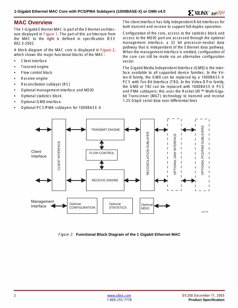
1-Gigabit Ethernet MAC Core with PCSPMA Sublayers (1000BASE-X) or GMII v40 R
MAC OverviewThe 1-Gigabit Ethernet MAC is part of the Ethernet architec-ture displayed in Figure 1 The part of this architecture fromthe MAC to the right is defined in specification IEEE8023-2002
A block diagram of the MAC core is displayed in Figure 2which shows the major functional blocks of the MAC
bull Client interface
bull Transmit engine
bull Flow control block
bull Receive engine
bull Reconciliation sublayer (RS)
bull Optional management interface and MDIO
bull Optional statistics block
bull Optional GMII interface
bull Optional PCSPMA sublayers for 1000BASE-X
The client interface has fully independent 8-bit interfaces forboth transmit and receive to support full-duplex operation
Configuration of the core access to the statistics block andaccess to the MDIO port are accessed through the optionalmanagement interface a 32 bit processor-neutral datapathway that is independent of the Ethernet data pathwayWhen the management interface is omitted configuration ofthe core can still be made via an alternative configurationvector
The Gigabit Media Independent Interface (GMII) is the inter-face available to all supported device families In the Vir-tex-II family the GMII can be replaced by a 1000BASE-XPCS with Ten Bit Interface (TBI) In the Virtex-II Pro familythe GMII or TBI can be replaced with 1000BASE-X PCSand PMA sublayers this uses the Rocket IOtrade Multi-Giga-bit Transceiver (MGT) technology to transmit and receive125 Gbps serial data over differential lines
Figure 2 Functional Block Diagram of the 1 Gigabit Ethernet MAC
FLOW CONTROL
TRANSMIT ENGINE
RECEIVE ENGINE
RE
CO
NC
ILIA
TIO
N S
UB
LAY
ER
CLI
EN
T IN
TE
RFA
CE
OptionalCONFIGURATION
OptionalSTATISTICS
OptionalMDIO
ClientInterface
ManagementInterface
OP
TIO
NA
L G
MII
INT
ER
FAC
E
OP
TIO
NA
L P
CS
PM
A S
UB
LAY
ER
S
xip2130
2 wwwxilinxcom DS200 December 11 20031-800-255-7778 Product Specification
1-Gigabit Ethernet MAC Core with PCSPMA Sublayers (1000BASE-X) or GMII v40R
Xilinx CORE GeneratorThe 1-Gigabit Ethernet MAC Core is generated through theXilinx CORE Generatortrade system The following sectionsdescribe the graphical user interface (GUI) options and thegenerated output files
GUI Interface
Component Name
The component name is used as the base name of the out-put files generated for the core Names must begin with aletter and must be composed from the following charactersa through z 0 through 9 and ldquo_rdquo
Half Duplex Capable
Select this option to have the MAC work in both full-duplexand half-duplex modes select the Half Duplex Capableoption
The default is half-duplex capability Note that half-duplexcapability is not supported in the Virtex-E or Spartan-IIEfamilies
Management Interface
Select this option if you wish to include the optional Man-agement Interface (see page 30) If this option is notselected the core will be generated with a configurationvector
The default is to have the management interface
Statistics Gathering
Select this option to include the optional Statistical Gather-ing with the core (see page 34) This option is available onlyif the core includes the optional management interface Thestatistics vectors are available whether or not this option isselected
The default is to gather statistics
Memory Type
If the statistics gathering option is selected it is possible tochoose which memory type the statistics are stored in Thechoices are Block Memory or Distributed Memory Thechoice of these should be based on the availability ofresources in your design There is no performance or func-tional difference between the memory types
The default type is the Block Memory Note that DistributedMemory is not supported in the Virtex-E or Spartan-IIE fam-ilies
Physical Interface
Depending on the target Xilinx FPGA architecture it may bepossible to select from three different physical interfacechoices for the core
bull GMII - see the optional GMII on page 40
bull TBI - see the optional PCS on page 43
bull PHY - see the optional PCS amp PMA sublayers onpage 46
The TBI option is not supported in the Virtex-E or Spar-tan-IIE families The PHY option is supported in the Virtex-IIPro family only
The default is the GMII physical interface
Parameter Values in the XCO FileXCO file parameter names and their values are identical tothe names and values shown in the GUI except that under-score characters (_) are used instead of spaces The text inan XCO file is case insensitive
Table 1 shows the XCO file parameters and values andsummarizes the GUI defaults The following is an exampleof the CSET parameters in an XCO file
CSET component_name = abc123CSET physical_interface = gmiiCSET statistics_gathering = trueCSET half_duplex_capable = trueCSET memory_type = block_memoryCSET management_interface = true
Table 1 XCO File Values and Default Values
Parameter XCO File Values Default GUI Setting
component_name ASCII text starting with a letter and based upon the followingcharacter set az 09 and _
blank
physical_interface One of the following keywords gmii tbi phy gmii
statistics_gathering One of the following keywords true false true
half_duplex_capable One of the following keywords true false true
memory_type One of the following keywords block_memory distributed_memory block_memory
management_interface One of the following keywords true false true
DS200 December 11 2003 wwwxilinxcom 3Product Specification 1-800-255-7778
1-Gigabit Ethernet MAC Core with PCSPMA Sublayers (1000BASE-X) or GMII v40 R
Output GenerationThe output files generated from the CORE Generator areplaced in the CORE Generator project directory The outputfiles include two netlist files supporting CORE Generatorfiles a readme file and a subdirectory containing examplewrapper files and scripts to take the core through the Xilinximplementation software and simulate the core using the
Modelsim simulator by Model Technology See the gener-ated readme files for explanations about these files
Device UtilizationTable 2 provides approximate slice counts for the corersquosvarious options when instantiated in a Virtex-II Pro device
Table 2 Device Utilization
Parameter Values Device Resources
PhysicalInterface
HalfDuplex
ManagementInterface
Statistics Gathering
Slices LUT Registers BRAM GCLK
GMII TBI PHYDistributed
MemoryBlock
Memory
Yes No No Yes Yes Yes No 1545 2159 1654 0 3
Yes No No Yes Yes No Yes 1420 1745 1561 2 3
Yes No No Yes Yes No No 932 1140 991 0 3
Yes No No Yes No No No 781 969 831 0 2
Yes No No No Yes Yes No 1315 1752 1359 0 3
Yes No No No Yes No Yes 1159 1525 1317 2 3
Yes No No No Yes No No 742 884 793 0 3
Yes No No No No No No 581 708 630 0 2
No Yes No No Yes Yes No 1850 2345 1934 2 4
No Yes No No Yes No Yes 1697 1880 1899 4 4
No Yes No No Yes No No 1295 1404 1380 2 4
No Yes No No No No No 1122 1226 1213 2 3
No No Yes No Yes Yes No 1725 1773 1791 0 3
No No Yes No Yes No Yes 1580 1838 1775 2 3
No No Yes No Yes No No 1172 1394 1236 0 3
No No Yes No No No No 1005 1183 1066 0 2
1 Half Duplex Logic is only available with the GMII2 Statistics Gathering is only available when the Management Interface is selected
4 wwwxilinxcom DS200 December 11 20031-800-255-7778 Product Specification
1-Gigabit Ethernet MAC Core with PCSPMA Sublayers (1000BASE-X) or GMII v40R
Interface DescriptionAll ports of the core (with the exception of the Rocket IOserial ports of the optional PCSPMA sublayers) are internalconnections in FPGA fabric An example wrapper is deliv-ered with the core which adds IBUFs OBUFs and IOBflip-flops where appropriate to the external signals of theGMII or TBI IOBs are also added to the remaining uncon-nected ports to allow the example design to be taken
through the Xilinx implementation software In addition allclock management logic is placed in this example wrapperthis allows the user more flexibility in implementation forexample in designs using multiple cores
The example wrapper is provided in both VHDL and Verilog
Interface Signals for MAC with physical_interface=gmii and management_interface=true
Figure 3 Component Pinout for MAC with GMII Interface using the optional Management Interface
GTX_CLK
TX_CLK
GMII_RX_CLK
MDCMDIO_IN
GMII_RXD[70]
GMII_TXD[70]GMII_TX_ENGMII_TX_ER
TX_DATA[70]
TX_ACKTX_UNDERRUN
PAUSE_REQPAUSE_VAL[150]
RX_CLK
HOST_CLKHOST_OPCODE[10]
HOST_ADDR[90]HOST_WR_DATA[310]HOST_RD_DATA[310]
HOST_MIIM_SELHOST_REQ
HOST_MIIM_RDY
RESET
RX_DATA[70]
RX_GOOD_FRAMERX_BAD_FRAME
TX_COLLISIONTX_RETRANSMIT
TX_DATA_VALID
RX_DATA_VALID
GMII_TX_CLK
GMII_COLGMII_CRS
GMII_RX_DVGMII_RX_ER
TX_CLK Domain
RX_CLK Domain
HOST_CLK Domain
TX_IFG_DELAY[70]
TX_STATISTICS_VECTOR[280]TX_STATISTICS_VALID
RX_STATISTICS_VECTOR[220]RX_STATISTICS_VALID
MDIO_OUTMDIO_TRI
DS200 December 11 2003 wwwxilinxcom 5Product Specification 1-800-255-7778
1-Gigabit Ethernet MAC Core with PCSPMA Sublayers (1000BASE-X) or GMII v40 R
Interface Signals for MAC with physical_interface=gmii and management_interface=false
Figure 4 Component Pinout for MAC with GMII Interface without the optional Management Interface
GTX_CLK
TX_CLK
GMII_RX_CLKGMII_RXD[70]
GMII_TXD[70]GMII_TX_ENGMII_TX_ER
TX_DATA[70]
TX_ACKTX_UNDERRUN
PAUSE_REQPAUSE_VAL[150]
RX_CLK
CONFIGURATION_VECTOR[630]
RESET
RX_DATA[70]
RX_GOOD_FRAMERX_BAD_FRAME
TX_COLLISIONTX_RETRANSMIT
TX_DATA_VALID
RX_DATA_VALID
GMII_TX_CLK
GMII_COLGMII_CRS
GMII_RX_DVGMII_RX_ER
TX_CLK Domain
RX_CLK Domain
TX_IFG_DELAY[70]
TX_STATISTICS_VECTOR[280]TX_STATISTICS_VALID
RX_STATISTICS_VECTOR[220]RX_STATISTICS_VALID
6 wwwxilinxcom DS200 December 11 20031-800-255-7778 Product Specification
1-Gigabit Ethernet MAC Core with PCSPMA Sublayers (1000BASE-X) or GMII v40R
Interface Signals for MAC with physical_interface=tbi and management_interface=true
Figure 5 Component Pinout for MAC with PCS and TBI using the optional Management Interface
GTX_CLK
TX_CLK
MDCMDIO_IN
RX_CODE_GROUP1[90]
TX_CODE_GROUP[90]PMA_TX_CLK
LOC_REF
TX_DATA[70]
TX_ACKTX_UNDERRUN
PAUSE_REQPAUSE_VAL[150]
RX_CLK
HOST_CLKHOST_OPCODE[10]
HOST_ADDR[90]HOST_WR_DATA[310]HOST_RD_DATA[310]
HOST_MIIM_SELHOST_REQ
HOST_MIIM_RDY
RESET
RX_DATA[70]
RX_GOOD_FRAMERX_BAD_FRAME
TX_COLLISIONTX_RETRANSMIT
TX_DATA_VALID
RX_DATA_VALID
EWRAP
PMA_RX_CLK0PMA_RX_CLK1
TX_CLKRX_CLK Domain
HOST_CLK Domain
TX_IFG_DELAY[70]
TX_STATISTICS_VECTOR[280]TX_STATISTICS_VALID
RX_STATISTICS_VECTOR[220]RX_STATISTICS_VALID
MDIO_OUTMDIO_TRI
EN_CDET
RX_CODE_GROUP0[90]
SIGNAL_DETECT
PHYAD[40]
DS200 December 11 2003 wwwxilinxcom 7Product Specification 1-800-255-7778
1-Gigabit Ethernet MAC Core with PCSPMA Sublayers (1000BASE-X) or GMII v40 R
Interface Signals for MAC with physical_interface=tbi and management_interface=false
Figure 6 Component Pinout for MAC with PCS and TBI without the optional Management Interface
GTX_CLK
TX_CLK
MDC_INMDIO_IN
RX_CODE_GROUP1[90]
TX_CODE_GROUP[90]PMA_TX_CLK
LOC_REF
TX_DATA[70]
TX_ACKTX_UNDERRUN
PAUSE_REQPAUSE_VAL[150]
RX_CLK
CONFIGURATION_VECTOR[630]
RESET
RX_DATA[70]
RX_GOOD_FRAMERX_BAD_FRAME
TX_COLLISIONTX_RETRANSMIT
TX_DATA_VALID
RX_DATA_VALID
EWRAP
PMA_RX_CLK0PMA_RX_CLK1
TX_CLKRX_CLK Domain
TX_IFG_DELAY[70]
TX_STATISTICS_VECTOR[280]TX_STATISTICS_VALID
RX_STATISTICS_VECTOR[220]RX_STATISTICS_VALID
MDIO_OUTMDIO_TRI
EN_CDET
RX_CODE_GROUP0[90]
PHYAD[40]
SIGNAL_DETECT
8 wwwxilinxcom DS200 December 11 20031-800-255-7778 Product Specification
1-Gigabit Ethernet MAC Core with PCSPMA Sublayers (1000BASE-X) or GMII v40R
Interface Signals for MAC with physical_interface=phy and management_interface=true
Figure 7 Component Pinout for MAC with PCS amp PMA Sublayers using the optional Management Interface
REFCLK
TX_CLK
MDCMDIO_IN
TXPTXN
TX_DATA[70]
TX_ACKTX_UNDERRUN
PAUSE_REQPAUSE_VAL[150]
RX_CLK
HOST_CLKHOST_OPCODE[10]
HOST_ADDR[90]HOST_WR_DATA[310]HOST_RD_DATA[310]
HOST_MIIM_SELHOST_REQ
HOST_MIIM_RDY
RESET
RX_DATA[70]
RX_GOOD_FRAMERX_BAD_FRAME
TX_COLLISIONTX_RETRANSMIT
TX_DATA_VALID
RX_DATA_VALID
RXPRXN
TX_CLKRX_CLK Domain
HOST_CLK Domain
TX_IFG_DELAY[70]
TX_STATISTICS_VECTOR[280]TX_STATISTICS_VALID
RX_STATISTICS_VECTOR[220]RX_STATISTICS_VALID
PHYAD[40]
SIGNAL_DETECT
MDIO_OUTMDIO_TRI
USRCLKUSRCLK2
DCM_LOCKED
REFCLK2BREFCLK
BREFCLK2REFCLKSEL
DS200 December 11 2003 wwwxilinxcom 9Product Specification 1-800-255-7778
1-Gigabit Ethernet MAC Core with PCSPMA Sublayers (1000BASE-X) or GMII v40 R
Interface Signals for MAC with physical_interface=phy and management_interface=false
Figure 8 Component Pinout for MAC with PCS amp PMA Sublayers without the optional Management Interface
TX_CLK
MDC_INMDIO_IN
TXPTXN
TX_DATA[70]
TX_ACKTX_UNDERRUN
PAUSE_REQPAUSE_VAL[150]
RX_CLK
CONFIGURATION_VECTOR[630]
RX_DATA[70]
RX_GOOD_FRAMERX_BAD_FRAME
TX_COLLISIONTX_RETRANSMIT
TX_DATA_VALID
RX_DATA_VALID
RXPRXN
TX_CLKRX_CLK Domain
TX_IFG_DELAY[70]
TX_STATISTICS_VECTOR[280]TX_STATISTICS_VALID
RX_STATISTICS_VECTOR[220]RX_STATISTICS_VALID
SIGNAL_DETECT
MDIO_OUTMDIO_TRI
REFCLKRESET
PHYAD[40]
USRCLKUSRCLK2
DCM_LOCKED
REFCLK2BREFCLK
BREFCLK2REFCLKSEL
10 wwwxilinxcom DS200 December 11 20031-800-255-7778 Product Specification
1-Gigabit Ethernet MAC Core with PCSPMA Sublayers (1000BASE-X) or GMII v40R
Client Side Interface Signal Definition
Table 3 describes the client-side transmit signals of the MAC core These signals are used to transmit data from the clientto the MAC core
Table 4 describes the client-side receive signals These signals are used by the MAC core to transfer data to the client
Table 3 Transmit Client Interface Signal Pins
Signal Direction Description
TX_CLK Output Clock for transmit client interface 125 MHz nominal
TX_DATA[70] Input Frame data to be transmitted is supplied on this port
TX_DATA_VALID Input Control signal for TX_DATA port
TX_IFG_DELAY[70] InputControl signal for configurable Inter Frame Gap adjustment SeeTransmitter on page 16 for timing diagrams
TX_ACK OutputHandshaking signal Asserted when the current data on TX_DATA hasbeen accepted See Transmitter on page 16 for timing diagrams
TX_UNDERRUN Input Asserted by client to force MAC core to corrupt the current frame
TX_COLLISION OutputAsserted by the MAC core to signal a collision on the medium and that anytransmission in progress should be aborted Always 0 when the MAC coreis in full-duplex mode
TX_RETRANSMIT Output
When asserted at the same time as the TX_COLLISION signal thissignals the client that the aborted frame should be resupplied to the MACcore for retransmission Always 0 when the MAC core is in full-duplexmode
TX_STATISTICS_VECTOR[280] OutputThis gives information on the last frame transmitted See Transmitter onpage 16 for vector contents
TX_STATISTICS_VALID OutputAsserted at end of frame transmission indicating that theTX_STATISTICS_VECTOR is valid
Notes1 All the above signals are synchronous to TX_CLK and Active High
Table 4 Receive Client Interface Signal Pins
Signal Direction Description
RX_CLK Output Clock for receive client interface 125 MHz nominal
RX_DATA[70] Output Frame data received is supplied on this port
RX_DATA_VALID Output Control signal for the RX_DATA port
RX_GOOD_FRAME OutputAsserted at end of frame reception to indicate that the frame should beprocessed by the MAC client See Receiver on page 24
RX_BAD_FRAME OutputAsserted at end of frame reception to indicate that the frame should bediscarded by the MAC client See Receiver on page 24
RX_STATISTICS_VECTOR[220] OutputProvides information about the last frame received See Receiver onpage 24 for the vector contents
RX_STATISTICS_VALID OutputAsserted at end of frame reception indicating that theRX_STATISTICS_VECTOR is valid
Notes1 All signals above are synchronous to RX_CLK and Active High
DS200 December 11 2003 wwwxilinxcom 11Product Specification 1-800-255-7778
1-Gigabit Ethernet MAC Core with PCSPMA Sublayers (1000BASE-X) or GMII v40 R
Table 5 describes the signals used by the client to request a flow control action from the transmit engine Flow control framesreceived by the MAC are automatically handled (if the MAC is configured to do so)
Table 6 describes the optional signals used by the client to access the management features of the MAC core includingconfiguration status statistics and MDIO access
Table 7 describes the alternative to the optional Management Interface signals This describes the Configuration Vectorwhich uses direct inputs to the core to replace the functionality of the MAC Configuration bits when the ManagementInterface is not used
Notes1 All bits of CONFIGURATION_VECTOR are registered on input but may be treated as asynchronous inputs
Table 5 Flow Control Interface Signal Pinout
Signal Direction Description
PAUSE_REQ InputPause request sends a pause frame down the link See Transmitting a PAUSE ControlFrame on page 29
PAUSE_VAL[150] Input Pause value inserted into the parameter field of the transmitted pause frame
Notes1 These signals are synchronous to TX_CLK and are Active High
Table 6 Optional Management Interface Signal Pinout (management_interface=true)
Signal Direction Description
HOST_CLK InputClock for management interface See Optional Management Interface(management_interface=true) on page 30 for the signal frequency range
HOST_OPCODE[10] InputDefines operation to be performed over MDIO interface Bit 1 is also used inconfiguration register access See Configuration Registers on page 30
HOST_ADDR[90] Input Address of register to be accessed
HOST_WR_DATA[310] Input Data to write to register
HOST_RD_DATA[310] Output Data read from register
HOST_MIIM_SEL InputWhen asserted the MDIO interface is accessed When disasserted the MACinternal configuration or statistical counter registers are accessed
HOST_REQ InputUsed to signal a transaction on the MDIO interface or to read from the statisticregisters See Optional Management Interface (management_interface=true) onpage 30
HOST_MIIM_RDY OutputWhen high the MDIO interface has completed any pending transaction and isready for a new transaction
Notes1 All signals above are synchronous to HOST_CLK and are Active High
Table 7 Alternative to the Optional Management Interface Configuration Vector Signal Pinout(management_interface=false)
Signal Direction Description
CONFIGURATION_VECTOR[630]
Input The Configuration Vector is used to replace the functionality of theMAC Configuration Registers when the Management Interface is notused See Optional Configuration Vector (management_interface =false) on page 38
12 wwwxilinxcom DS200 December 11 20031-800-255-7778 Product Specification
1-Gigabit Ethernet MAC Core with PCSPMA Sublayers (1000BASE-X) or GMII v40R
Table 8 describes the reset signal
Physical Interface Signal Definition
Table 9 describes the MDIO (MII Management) interface signals of the MAC core These signals are typically connected tothe MDIO port of a PHY device either off-chip or an SoC-integrated core The MDIO format is defined in IEEE8023 clause22
Table 10 describes the optional GMII signals of the MAC core These are typically attached to a PHY module either off-chipor internally integrated The GMII is defined in IEEE8023 clause 35
Table 8 Reset Signal
Signal Direction Description
RESET Input Asynchronous reset for entire core See Reset circuit on page 42 for moreinformation on the reset circuit
Table 9 MDIO Interface Signal Pinout
Signal Direction Description
MDC OutputManagement Clock derived from HOST_CLK on the basis of supplied configuration datawhen the optional Management Interface is used See Optional Management Interface(management_interface=true) on page 30
MDC_IN InputWhen the Optional Management Interface is not used access to the optional PhysicalCoding Sublayer (PCS) must be provided by an external MDIO Controller In this situationthe Management Clock is an input to the core
MDIO_IN Input Input data signal for communication with PHY configuration and status Tie high if unused
MDIO_OUT Output Output data signal for communication with PHY configuration and status
MDIO_TRI OutputTristate control for MDIO signals 0 signals that the value on MDIO_OUT should be
asserted onto the MDIO bus
Table 10 Optional GMII Interface Signal Pinout (physical_interface=gmii)
Signal Direction Description
GTX_CLK InputClock signal at 125 MHz Other transmit clocks are derived from this clock as illustratedin Figure 28 Tolerance must be within IEEE 8023-2002 specification
GMII_TXD[70] Output Transmit data to PHY
GMII_TX_EN Output Data Enable control signal to PHY
GMII_TX_ER Output Error control signal to PHY
GMII_TX_CLK Output Clock out to PHY
GMII_CRS Input Control signal from PHY
GMII_COL Input Control signal from PHY
GMII_RX_CLK Input Recovered clock from received data stream by PHY
GMII_RXD[70] Input Received data from PHY
GMII_RX_DV Input Data Valid control signal from PHY
GMII_RX_ER Input Error control signal from PHY
DS200 December 11 2003 wwwxilinxcom 13Product Specification 1-800-255-7778
1-Gigabit Ethernet MAC Core with PCSPMA Sublayers (1000BASE-X) or GMII v40 R
Table 11 describes the TBI (Ten-Bit interface) signals of the MAC core These are typically attached to a PMA SERDESmodule These signals optionally replace the GMII signals described in Table 10 to extend the functionality of the core toinclude the PCS for 1000BASE-X The TBI is defined in IEEE8023 clause 36
Notes
PHYAD and SIGNAL_DETECT are asynchronous inputs SIGNAL_DETECT is Active High
Table 11 Optional TBI Interface Signal Pinout (physical_interface=tbi)
Signal Direction Description
GTX_CLK InputClock signal at 125 MHz Other transmit clocks will be derived from this clock asillustrated in Figure 32 Tolerance must be within IEEE 8023-2002 specification
TX_CODE_GROUP[90] Output 10-bit parallel transmit data to PMA Sublayer (SERDES)
PMA_TX_CLK Output Transmit clock signal to PMA Sublayer (SERDES) at 125MHz
LOC_REF OutputCauses the PMA sublayer clock recovery unit to lock to PMA_TX_CLK Thissignal is tied to Ground
EWRAP Output
This signal is set from the PCS Control Register 0 bit 14 (loopback) See PCSManaged Register Block (physical_interface = tbi or phy) on page 49 Whenhigh this instructs the PMA sublayer to electrically loop the transmitter data to thereceiver
RX_CODE_GROUP0[90] Input10-bit parallel received data from PMA Sublayer (SERDES) synchronous toPMA_RX_CLK0
RX_CODE_GROUP1[90] Input10-bit parallel received data from PMA Sublayer (SERDES) synchronous toPMA_RX_CLK1
PMA_RX_CLK0 Input Received clock signal from PMA Sublayer (SERDES) at 625MHz
PMA_RX_CLK1 InputReceived clock signal from PMA Sublayer (SERDES) at 625MHz This is 180degrees out of phase with PMA_RX_CLK0
EN_CDET OutputEnables the PMA Sublayer to perform comma realignment driven from the PCSstate machine during the Loss-Of-Sync state
PHYAD[40] Input PHY address of MDIO register set for the PCS
SIGNAL_DETECT Input
Signal direct from PMD sublayer indicating the presence of light detected at theoptical receiver If driven high this indicates that the optical receiver has detectedlight If driven low this indicates the absence of light
If unused tie high to enable the operation the core
14 wwwxilinxcom DS200 December 11 20031-800-255-7778 Product Specification
1-Gigabit Ethernet MAC Core with PCSPMA Sublayers (1000BASE-X) or GMII v40R
Table 12 describes the interface signals for the Optional PCSPMA sublayer of the MAC core These signals optionallyreplace the GMII signals described in Table 10 to extend the functionality of the core to include the PCS and PMA sublayersfor 1000BASE-X This option uses the Virtex-II Pro Rocket IO functionality which is integrated into the core The PMAsublayer for 1000BASE-X is defined in IEEE8023 clause 36
Notes1 PHYAD and SIGNAL_DETECT are asynchronous inputs SIGNAL_DETECT is Active High
Table 12 Optional PCSPMA sublayer Interface Signal Pinout (physical_interface=phy)
Signal Direction Description
REFCLK InputHigh Quality Reference clock for Multi-Gigabit Transceivers (625 MHz) See Rocket IOUser Guide
REFCLK2 Input Alternative High Quality Reference clock for Multi-Gigabit Transceivers (625 MHz) SeeRocket IO User Guide
BREFCLK Input Alternative High Quality Reference clock for Multi-Gigabit Transceivers (625 MHz)This optionally replaces REFCLK See Rocket IO User Guide
BREFCLK2 Input Alternative High Quality Reference clock for Multi-Gigabit Transceivers (625 MHz)This optionally replaces REFCLK2 See Rocket IO User Guide
REFCLKSEL Input Selects between either (B)REFCLK or (B)REFCLK2 as the input clock source to theMGT See Rocket IO User Guide
USERCLK InputClock signal at 625 MHz This is connected to the TXUSRCLK and RXUSRCLK portsof the Rocket IO MGT This may be derived from (B)REFCLK using a DCM asillustrated in Figure 35
USERCLK2 InputClock signal at 125 MHz This is connected to the TXUSRCLK2 and RXUSRCLK2 portsof the Rocket IO MGT This may be derived from (B)REFCLK using a DCM asillustrated in Figure 35
DCM_LOCKED InputIf a DCM is used to derive USRCLK and USRCLK2 as illustrated in Figure 35 theLOCKED port of the DCM must be connected to the DCM_LOCKED port of the coreThe core will hold itrsquos Rocket IO MGT in reset until DCM_LOCKED is driven to logic 1
TXPTXN OutputDifferential pair for serial transmission from PMA to PMD The clock is embedded in thedata stream
RXPRXN InputDifferential pair for serial reception from PMD to PMA The clock is extracted from thedata stream
PHYAD[40] Input PHY address of MDIO register set for the PCS
SIGNAL_DETECT Input
Signal direct from PMD sublayer indicating the presence of light detected at the opticalreceiver If driven high this indicates that the optical receiver has detected light If drivenlow this indicates the absence of light
If unused tie high to enable the operation the core
DS200 December 11 2003 wwwxilinxcom 15Product Specification 1-800-255-7778
1-Gigabit Ethernet MAC Core with PCSPMA Sublayers (1000BASE-X) or GMII v40 R
Functional Description
Client InterfaceThe client interface is designed for maximum flexibility inmatching to a client switching fabric or network processorinterface
The data pathway is 8 bits wide in both the transmit andreceive directions with each pathway synchronous to theTX_CLK and RX_CLK respectively for completely indepen-dent full duplex operation
Transmitter
Normal Frame Transmission
The timing of a normal outbound frame transfer can be seenin Figure 9 When the client wants to transmit a frame itplaces the first column of data onto the TX_DATA port andasserts a ldquo1rdquo onto TX_DATA_VALID
When the MAC core has read this first byte of data it willassert the TX_ACK signal on the next and subsequent ris-ing clock edges the client must provide the remainder ofthe data for the frame
The end of frame is signalled to the MAC core by takingTX_DATA_VALID Low
In-Band Parameter Encoding
For maximum flexibility in switching applications the Ether-net frame parameters (destination address sourceaddress lengthtype and optionally FCS) are encodedwithin the same data stream that the frame payload is trans-ferred upon rather than on separate ports This is illustratedin the timing diagrams Definitions of the abbreviations usedin the timing diagrams are described in Table 13
Figure 9 Normal Frame Transmission Across Client Interface
Table 13 Abbreviations Used in Timing Diagrams
Abbreviation Definition
DA Destination Address 6 bytes
SA Source Address 6 bytes
LT LengthType Field 2 bytes
FCS Frame Check Sequence 4 bytes
TX_CLK
TX_DATA[70]
TX_DATA_VALID
TX_ACK
TX_UNDERRUN
DA SA DATALT
TX_COLLISION
TX_RETRANSMIT
xip2133
16 wwwxilinxcom DS200 December 11 20031-800-255-7778 Product Specification
1-Gigabit Ethernet MAC Core with PCSPMA Sublayers (1000BASE-X) or GMII v40R
Padding
When fewer than 46 bytes of data are supplied by the clientto the MAC core the transmitter module will add padding upto the minimum frame length The exception to this is whenthe MAC core is configured for client-passed FCS in thiscase the client must also supply the padding to maintain theminimum frame length (see Client-Supplied FCS Passing)
Client-Supplied FCS Passing
If the MAC core is configured to have the FCS field passedin by the client (see Configuration Registers on page 30)the transmission timing is as depicted in Figure 10 In thiscase it is the responsibility of the client to ensure that theframe meets the Ethernet minimum frame length require-ments the MAC core will not perform any padding of thepayload
Figure 10 Frame Transmission with Client-supplied FCS
TX_CLK
TX_DATA[70]
TX_DATA_VALID
TX_ACK
TX_UNDERRUN
DA SA DATA FCSLT
TX_COLLISION
TX_RETRANSMIT
xip2134
DS200 December 11 2003 wwwxilinxcom 17Product Specification 1-800-255-7778
1-Gigabit Ethernet MAC Core with PCSPMA Sublayers (1000BASE-X) or GMII v40 R
Client Underrun
The timing of an aborted transfer can be seen in Figure 11This may happen for instance if a FIFO connected to theclient interface empties before a frame is completed Whenthe client asserts TX_UNDERRUN during a frame transmis-sion the MAC core will insert an error code to corrupt the
current frame and then fall back to idle transmission It isthe responsibility of the client to re-queue the aborted framefor transmission
When an underrun occurs TX_DATA_VALID may beasserted on the clock cycle after the TX_UNDERRUNassertion to request a new transmission
Figure 11 Frame Transmission with Underrun
TX_CLK
TX_DATA[70]
TX_DATA_VALID
TX_ACK
TX_UNDERRUN
DA SA DATALT
TX_COLLISION
TX_RETRANSMIT
xip2135
18 wwwxilinxcom DS200 December 11 20031-800-255-7778 Product Specification
1-Gigabit Ethernet MAC Core with PCSPMA Sublayers (1000BASE-X) or GMII v40R
Back-to-Back Transfers
Figure 12 shows the case where the MAC client is immedi-ately ready to transmit a second frame of data followingcompletion of its first frame In this figure the end of the firstframe is shown on the left On the clock cycle immediatelyfollowing the final byte of the first frame TX_DATA_VALIDis taken low by the client and is taken high one clock cyclelater to indicate that the first byte of the destination addressof the second frame is on TX_DATA awaiting transmission
When the MAC core is ready to accept data TX_ACK isasserted and the transmission continues in the same man-ner as in the case of the single frame The MAC core willdefer the assertion of TX_ACK appropriately to comply withinter-packet gap requirements and flow control requests
If the MAC core is operating in half-duplex mode the timingshown in Figure 12 is required to take advantage of framebursting the MAC core is only guaranteed to retain controlof the medium if the TX_DATA_VALID signal is low for a sin-gle clock cycle For more information on frame bursting seeIEEE 8023-2002
Figure 12 Back to Back Frame Transmission
TX_CLK
TX_DATA[70]
TX_DATA_VALID
TX_ACK
TX_UNDERRUN
TX_COLLISION
TX_RETRANSMIT
xip2136
DS200 December 11 2003 wwwxilinxcom 19Product Specification 1-800-255-7778
1-Gigabit Ethernet MAC Core with PCSPMA Sublayers (1000BASE-X) or GMII v40 R
VLAN Tagged Frames
Transmission of a VLAN tagged frame (if enabled) can beseen in Figure 13 Note that the handshaking signalsacross the interface do not change however the VLANtype tag 81-00 must be supplied by the client to signify that
the frame is VLAN tagged The client also supplies the twobytes of Tag Control Information V1 and V2 at the appro-priate times in the data stream More information on thecontents of these two bytes can be found in IEEE8023-2002
Maximum Permitted Frame Length
The maximum legal length of a frame specified in IEEE8023-2002 is 1518 bytes for non-VLAN tagged framesVLAN tagged frames may be extended to 1522 bytesWhen jumbo frame handling is disabled and the clientattempts to transmit a frame which exceeds the maximumlegal length the MAC core will insert an error code to cor-
rupt the current frame and the frame will be truncated to themaximum legal length When jumbo frame handling isenabled frames which are longer than the legal maximumare transmitted error-free
For more information on enabling and disabling jumboframe handling see Configuration Registers on page 30
Figure 13 Transmission of a VLAN Tagged Frame
TX_CLK
TX_DATA[70]
TX_DATA_VALID
TX_ACK
TX_UNDERRUN
DA SA DATALTVLANtag
81 00V1V2
TX_COLLISION
TX_RETRANSMIT
xip2137
20 wwwxilinxcom DS200 December 11 20031-800-255-7778 Product Specification
1-Gigabit Ethernet MAC Core with PCSPMA Sublayers (1000BASE-X) or GMII v40R
Frame Collisions - Half Duplex Operation Only
In half duplex Ethernet operation collisions will occur on themedium as a matter of course this is how the arbitrationalgorithm is fulfilled In case of a collision the MAC core sig-nals to the client that data may need to be resupplied as fol-lows
If there is a collision the TX_COLLISION signal will be setto ldquo1rdquo by the MAC core If a frame is in progress the clientmust abort the transfer and take TX_DATA_VALID to ldquo0rdquo
If the TX_RETRANSMIT signal is ldquo1rdquo in the same clockcycle that the TX_COLLISION signal is ldquo1rdquo the client must
resubmit the previous frame to the MAC core for retrans-mission TX_DATA_VALID must be asserted to the MACcore within 8 clock cycles of the TX_COLLISION signal inorder to meet Ethernet timing requirements See Figure 14
If the TX_RETRANSMIT signal is ldquo0rdquo in the same clockcycle that the TX_COLLISION signal is ldquo1rdquo the number ofretries for this frame has exceeded the Ethernet specifica-tion and the frame should be dropped by the client The cli-ent can then make any new frame available to the MAC fortransmission without timing restriction See Figure 15
Figure 14 Collision Handling - Frame retransmission required
Figure 15 Collision Handling - No frame retransmission required
TX_CLK
TX_DATA[70]
TX_DATA_VALID
TX_ACK
TX_UNDERRUN
TX_COLLISION
TX_RETRANSMIT
8 clocks max
xip2138
TX_CLK
TX_DATA[70]
TX_DATA_VALID
TX_ACK
TX_UNDERRUN
TX_COLLISION
TX_RETRANSMIT
xip2139
DS200 December 11 2003 wwwxilinxcom 21Product Specification 1-800-255-7778
1-Gigabit Ethernet MAC Core with PCSPMA Sublayers (1000BASE-X) or GMII v40 R
Interframe Gap Adjustment
The user can elect to vary the length of the inter fame gapIf this function is selected (via a configuration bit in thetransmitter control register see Configuration Registerson page 30) then the MAC will exert back pressure to delaythe transmission of the next frame until the requested num-ber of Idle cycles has elapsed The number of Idle cycles iscontrolled by the value on the TX_IFG_DELAY port at thestart of frame transmission Figure 16 shows the MAC oper-ating in this mode
Reducing the Inter fame gap to below the IEEE 8023-2002minimum of 12 Idles is supported in Full Duplex onlydesigns and will transmit an absolute minimum of 4 Idles Ifthe Interframe gap adjustment is reduced below 12 Idlesthen the accuracy of the Optional Statistical Gathering(statistics_gathering=true) Counters cannot be guaranteedHowever the TX_STATISTIC_VECTOR andRX_STATISTIC_VECTOR will always remain correct
Transmitter Statistics Vector
The statistics for the frame transmitted are contained withinthe TX_STATISTICS_VECTOR The vector is driven syn-chronously by the transmitter clock TX_CLK followingframe transmission The bit field definition for the Vector isdefined in Table 14
All bit fields with the exception of BYTE_VALID are validonly when the TX_STATISTICS_VALID is asserted This isillustrated in Figure 17 BYTE_VALID is significant on everyTX_CLK cycle
TX_STATISTICS_VECTOR bits 25 down to 17 inclusive arefor half duplex only and will be set to logic 0 when operatingin full duplex mode
Figure 16 Interframe Gap Adjustment
TX_CLK
TX_DATA[70]
TX_DATA_VALID
TX_ACK
DA SA
TX_IFG_DELAY
IFG ADJUST VALUE
0x0D
13 Idles inserted
DA
Next IFG ADJUST VALUE
xip2140
Figure 17 Transmitter Statistics Vector Timing
TX_CLK
TX_STATISTICS_VECTOR[280]
TX_STATISTICS_VALID
xip2141
22 wwwxilinxcom DS200 December 11 20031-800-255-7778 Product Specification
1-Gigabit Ethernet MAC Core with PCSPMA Sublayers (1000BASE-X) or GMII v40R
Table 14 Bit Definition for the Transmitter Statistics Vector
TX_STATISTICS_VECTOR Name Description
28 PAUSE_FRAME_TRANSMITTEDAsserted if the previous frame was a pause framethat the MAC itself initiated in response to aPAUSE_REQ assertion
27 BYTE_VALID
Asserted if a MAC frame byte (DA to FCS inclusive)is in the process of being transmitted This is valid onevery clock cycle
Do not use this as an enable signal to indicate thatdata is present on GMII_TXD[70]
26 Reserved Returns logic 0
25 down to 22 TX_ATTEMPTS[30]
The number of attempts that have been made totransmit the previous frame This is a 4-bit number0 should be interpreted as 1 attempt 1 as 2attempts up until 15 as 16 attempts
21 Reserved Returns logic 0
20 EXCESSIVE_COLLISIONAsserted if a collision has been detected on each ofthe last 16 attempts to transmit the previous frame
19 LATE_COLLISIONAsserted if a late collision occurred during frametransmission
18 EXCESSIVE_DEFERRALAsserted if the previous frame was deferred for anexcessive amount of time as defined by the constantldquomaxDeferTimerdquo in IEEE 8023-2002
17 TX_DEFERRED Asserted if transmission of the frame was deferred
16 VLAN_FRAMEAsserted if the previous frame contained a VLANidentifier in the LengthType field when transmitterVLAN operation is enabled
15 down to 5 FRAME_LENGTH_COUNTThe length of the previous frame in number of bytesThe count will stick at 2047 for any Jumbo frameslarger than this value
4 CONTROL_FRAMEAsserted if the previous frame had the special MACControl Type code 88-08 in the LengthType field
3 UNDERRUN_FRAMEAsserted if the previous frame contained anunderrun error
2 MULTICAST_FRAMEAsserted if the previous frame contained a multicastaddress in the Destination Address field
1 BROADCAST_FRAMEAsserted if the previous frame contained abroadcast address in the Destination Address field
0 SUCCESSFUL_FRAMEAsserted if the previous frame was transmittedwithout error
DS200 December 11 2003 wwwxilinxcom 23Product Specification 1-800-255-7778
1-Gigabit Ethernet MAC Core with PCSPMA Sublayers (1000BASE-X) or GMII v40 R
Receiver
Normal Frame Reception
The timing of a normal inbound frame transfer can be seenin Figure 18 The client must be prepared to accept data atany time there is no buffering within the MAC to allow forlatency in the receive client Once frame reception begins
data is transferred on consecutive clock cycles to thereceive client until the frame is complete The MAC assertsthe RX_GOOD_FRAME signal to indicate that the framewas successfully received and that the frame should beanalyzed by the client
Frame parameters (destination address source addresslengthtype and optionally FCS) are supplied on the databus according to the timing diagram The abbreviations arethe same as those described in Table 13 on page 16
If the LengthType field in the frame has the Length interpre-tation and this indicates that the inbound frame has beenpadded to meet the Ethernet minimum frame size specifica-tion then this padding will not be passed to the client in thedata payload The exception to this is in the case whereFCS passing is enabled see Client-Supplied FCS Pass-ing on page 25
Therefore when Client-Supplied FCS passing is disabledRX_DATA_VALID = lsquo0rsquo between frames for the duration ofthe Padding field (if present) the FCS field carrier exten-sion (if present) the interframe gap following the frame andthe preamble field of the next frame When Client-Supplied
FCS passing is enabled RX_DATA_VALID = lsquo0rsquo betweenframes for the duration of carrier extension (if present) theinterframe gap and the preamble field of the followingframe
RX_GOOD_FRAME RX_BAD_FRAME timing
Although the timing diagram in Figure 18 shows theRX_GOOD_FRAME signal asserted shortly after the lastvalid data on RX_DATA this is not always the case TheRX_GOOD_FRAME or RX_BAD_FRAME signals areasserted only after all frame checks are completed This isafter the FCS field has been received (and after reception ofcarrier extension if present)
Therefore either RX_GOOD_FRAME or RX_BAD_FRAMEis asserted following frame reception at the beginning of theinterframe gap
Figure 18 Normal Frame Reception
RX_CLK
RX_DATA[70]
RX_DATA_VALID
RX_GOOD_FRAME
RX_BAD_FRAME
DA SA DATALT
xip2142
24 wwwxilinxcom DS200 December 11 20031-800-255-7778 Product Specification
1-Gigabit Ethernet MAC Core with PCSPMA Sublayers (1000BASE-X) or GMII v40R
Frame Reception with Errors
The case of an unsuccessful frame reception (for examplea fragment frame or a frame with an incorrect FCS) can beseen in Figure 19 In this case the RX_BAD_FRAME signal
is asserted to the client at the end of the frame It is then theresponsibility of the client to drop the data already trans-ferred for this frame
Figure 19 Frame Reception with Error
Client-Supplied FCS Passing
If the MAC core is configured to pass the FCS field to the cli-ent (see Configuration Registers on page 30) then this ishandled as shown in Figure 20
In this case any padding inserted into the frame to meetEthernet minimum frame length specifications will be leftintact and passed to the client
Note that even though the FCS is passed up to the client itis also verified by the MAC core and RX_BAD_FRAMEasserted if the FCS check fails
RX_CLK
RX_DATA[70]
RX_DATA_VALID
RX_GOOD_FRAME
RX_BAD_FRAME
DA SA DATALT
xip2144
Figure 20 Frame Reception with In-Band FCS Field
RX_CLK
RX_DATA[70]
RX_DATA_VALID
RX_GOOD_FRAME
RX_BAD_FRAME
DA SA DATALT FCS
xip2145
DS200 December 11 2003 wwwxilinxcom 25Product Specification 1-800-255-7778
1-Gigabit Ethernet MAC Core with PCSPMA Sublayers (1000BASE-X) or GMII v40 R
VLAN Tagged Frames
The reception of a VLAN tagged frame (if enabled) can beseen in Figure 21 The VLAN frame is passed to the clientso that the frame may be identified as VLAN tagged this is
followed by the Tag Control Information bytes V1 and V2More information on the interpretation of these bytes maybe found in IEEE 8023-2002 standard
Maximum Permitted Frame Length
The maximum legal length of a frame specified in IEEE8023-2002 is 1518 bytes for non-VLAN tagged framesVLAN tagged frames may be extended to 1522 bytesWhen jumbo frame handling is disabled and the corereceives a frame which exceeds the maximum legal lengthRX_BAD_FRAME will be asserted When jumbo framehandling is enabled frames which are longer than the legalmaximum are received in the same way as shorter frames
For more information on enabling and disabling jumboframe handling see Configuration Registers on page 30
LengthType Field Error Checks
Enabled
Default operation is with the LengthType error checkingenabled (see Receiver Configuration Word 1 on page 31)In this mode the following checks are made on all framesreceived If either of these checks fail then the frame ismarked as BAD
bull A value in the LengthType field that is greater than orequal to decimal 46 but less than decimal 1536 (aLength interpretation) is checked against the actualdata length received
bull A value in the LengthType field that is less thandecimal 46 is checked to see that the data field ispadded to exactly 46 bytes (so that the resultant frameis minimum frame size 64 bytes total in length)
Furthermore if Padding is indicated (the LengthType fieldis less than decimal 46) and Client-Supplied FCS Passing isdisabled then the Length value in the LengthType field willbe used to deassert RX_DATA_VALID after the indicatednumber of data bytes so that the Padding bytes areremoved from the frame
Disabled
When the LengthType error checking is disabled (seeReceiver Configuration Word 1 on page 31) theLengthType error checks described above are not per-formed A frame containing only these errors will be markedas GOOD
Furthermore if Padding is indicated and Client-SuppliedFCS Passing is disabled then a Length Value in theLengthType field will not be used to deassertRX_DATA_VALID Instead RX_DATA_VALID will be deas-serted before the start of the FCS field in this way any pad-ding will not be removed from the frame
Figure 21 Reception of a VLAN Tagged Frame
RX_CLK
RX_DATA[70]
RX_DATA_VALID
RX_GOOD_FRAME
RX_BAD_FRAME
DA SA DATALT
81 00 V1 V2
VLANtag
xip2146
26 wwwxilinxcom DS200 December 11 20031-800-255-7778 Product Specification
1-Gigabit Ethernet MAC Core with PCSPMA Sublayers (1000BASE-X) or GMII v40R
Receiver Statistics Vector
The statistics for the frame received are contained withinthe RX_STATISTICS_VECTOR The vector is driven syn-chronously by the receiver clock RX_CLK following framereception The bit field definition for the Vector is defined inTable 15
All bit fields with the exception of BYTE_VALID are validonly when the RX_STATISTICS_VALID is asserted This isillustrated in Figure 22 BYTE_VALID is significant on everyRX_CLK cycle
Figure 22 Receiver Statistics Vector Timing
RX_CLK
RX_STATISTICS_VECTOR[220]
RX_STATISTICS_VALID
xip2147
Table 15 Bit Definition for the Receiver Statistics Vector
RX_STATISTICS_VECTOR Name Description
22LENGTHTYPE Out ofRange
Asserted if the lengthtype field contained a length valuethat did not match the number of MAC client data bytesreceived Also high if the lengthtype field indicated thatthe frame contained padding but the number of MAC cli-ent data bytes received was not equal to 64 bytes (min-imum frame size)
The exception to the above is when the LengthTypeField Error Checks are disabled in which case this bitwill not be asserted
21 BAD_OPCODE
Asserted if the previous frame was error-free andcontained the special Control Frame identifier in theLengthType field but contained an opcode that isunsupported by the MAC (Any Opcode other thanPAUSE)
20 FLOW_CONTROL_FRAME
Asserted if the previous frame was error-freecontained the special Control Frame identifier in theLengthType field contained a Destination Addressthat matched either the MAC Control MulticastAddress or the configured source address of the MACcontained the supported PAUSE opcode and wasacted upon by the MAC
19 BYTE_VALID
Asserted if a MAC frame byte (DA to FCS inclusive) isin the process of being received This is valid on everyclock cycle
Do not use this as an enable signal to indicate thatdata is present on RX_DATA[70]
18 VLAN_FRAMEAsserted if the previous frame contained a VLANidentifier in the LengthType field when receiver VLANoperation is enabled
DS200 December 11 2003 wwwxilinxcom 27Product Specification 1-800-255-7778
1-Gigabit Ethernet MAC Core with PCSPMA Sublayers (1000BASE-X) or GMII v40 R
17 OUT_OF_BOUNDS
Asserted if the previous frame exceeded the specifiedIEEE8023-2002 maximum legal length (seeMaximum Permitted Frame Length on page 26) Thisis only valid if Jumbo frames are disabled
16 CONTROL_FRAMEAsserted if the previous frame contained the specialControl Frame identifier in the LengthType field
15 down to 5 FRAME_LENGTH_COUNTThe length of the previous frame in number of bytesThe count will stick at 2047 for any Jumbo frameslarger than this value
4 MULTICAST_FRAMEAsserted if the previous frame contained a multicastaddress in the Destination Address field
3 BROADCAST_FRAMEAsserted if the previous frame contained the broadcastaddress in the Destination Address field
2 FCS_ERRORAsserted if the previous frame received had anincorrect FCS value or the MAC detected error codesduring frame reception
1 BAD_FRAME1 Asserted if the previous frame received containederrors
0 GOOD_FRAME1 Asserted if the previous frame received was error-free
1 If the LengthType Field Error Checks are disabled then a frame which contains this type of error will be marked as a GOOD_FRAMEproviding no additional errors were detected
Table 15 Bit Definition for the Receiver Statistics Vector
RX_STATISTICS_VECTOR Name Description
28 wwwxilinxcom DS200 December 11 20031-800-255-7778 Product Specification
1-Gigabit Ethernet MAC Core with PCSPMA Sublayers (1000BASE-X) or GMII v40R
Flow ControlThe flow control block is designed to Clause 31 of the IEEE8023-2002 standard The MAC may be configured to sendpause frames and to act upon their reception These twobehaviors can be configured asymmetrically see Configu-ration Registers on page 30
Transmitting a PAUSE Control Frame
The client initiates a flow control frame by assertingPAUSE_REQ while the pause value is on the PAUSE_VALbus These signals are synchronous to TX_CLK The timingof this can be seen in Figure 23
If the MAC core is configured to support transmit flow con-trol this action causes the core to transmit a PAUSE controlframe on the link with the PAUSE parameter set to thevalue on PAUSE_VAL in the cycle when PAUSE_REQ wasasserted This will not disrupt any frame transmission inprogress but will take priority over any pending frame trans-
mission This frame will be transmitted even if the transmit-ter is in the paused state itself
Receiving a Pause Control Frame
When an error-free frame is received by the MAC core thefollowing checks are made
1 The Destination Address field is matched against theMAC Control Multicast address or the configuredSource Address for the MAC (see ConfigurationRegisters on page 30)
2 The LengthType field is matched against the MACControl Type code
3 The opcode field contents are matched against thePAUSE opcode if check 2 is true
If any of the above checks are false or the MAC Flow Con-trol logic for the receiver is disabled the frame is ignored bythe Flow Control logic and passed up to the client
If the frame passes all of the above checks is of minimumlegal size and the MAC Flow Control logic for the receiver isenabled the pause value parameter in the frame is thenused to inhibit transmitter operation for the time defined inthe IEEE8023-2002 specification This inhibit is imple-mented using the same back pressure scheme shown inFigure 12 Because the received pause frame has beenacted upon it is passed to the client with RX_BAD_FRAMEasserted to indicate to the client that it should be dropped
Reception of any frame for which check 2 is true and whichis not of legal minimum length is considered an invalid Con-trol frame This will be ignored by the Flow Control logic andpassed to the client with RX_BAD_FRAME asserted
Figure 23 Pause Request Timing
TX_CLK
PAUSE_VAL[150]
PAUSE_REQ
xip2148
DS200 December 11 2003 wwwxilinxcom 29Product Specification 1-800-255-7778
1-Gigabit Ethernet MAC Core with PCSPMA Sublayers (1000BASE-X) or GMII v40 R
Optional Management Interface(management_interface=true)The management interface is a processor-independentinterface with standard address data and control signals Itmay be used as is or a wrapper may be applied (not sup-plied) to interface to common bus architectures
This interface is used for
bull Configuration of the MAC core
bull Access to optional statistics counters for use by higherlayers for example SNMP
bull access through the MDIO interface to the managementregisters located in the PHY attached to the MAC core
The management interface is accessed differently depend-ing on the type of transaction a truth table showing whichaccess method is required for each transaction type isshown in Table 16 These access methods are described inthe following sections
HOST_CLK Frequency
The management interface clock HOST_CLK is used toderive the MDIO clock MDC and is therefore subject tosome frequency restrictions This HOST_CLK must be
ge 10 MHz
le 100 MHz
Configuring the MAC core to derive the MDC signal fromthis clock is detailed in MDIO Interface on page 37
Configuration Registers
After power up or reset the client may reconfigure the coreparameters from their defaults such as flow control supportConfiguration changes can be written at any time Both thereceiver and transmitter logic will only respond to configura-tion changes during Inter Frame Gaps The exceptions tothis are the configurable resets which take effect immedi-ately
Configuration of the MAC core is performed through a reg-ister bank accessed through the management interfaceThe configuration registers available in the core are detailedin Table 17 As can be seen the address has some implicitdonrsquot care bits any access to an address in the rangesshown will perform a 32-bit read or write from the same con-figuration word
Table 16 Management Interface Transaction Types
Transaction HOST_MIIM_SEL HOST_ADDR[9]
Configuration 0 1
Statistics 0 0
MIIM access 1 X
Table 17 Configuration Registers
Address Description
0x200-0x23F Receiver Configuration (Word 0)
0x240-0x27F Receiver Configuration (Word 1)
0x280-0x2BF Transmitter Configuration
0x2C0-0x2FF Flow Control Configuration
0x300-0x33F Reserved
0x340-0x37F Management Configuration
30 wwwxilinxcom DS200 December 11 20031-800-255-7778 Product Specification
1-Gigabit Ethernet MAC Core with PCSPMA Sublayers (1000BASE-X) or GMII v40R
The register contents for the two receiver configuration words can be seen in Table 18 and Table 19
Notes1 In changing the receiverrsquos mode from Half Duplex to Full Duplex there is a period of time of up to 24 us following the mode change
when no new receiver statistics can be stored in the optional Statistical Counters
Table 18 Receiver Configuration Word 0
Bit Default Value Description
31-0 All 0rsquos
Pause frame MAC Source Address[310] This address is used by the MAC tomatch against the Destination Address of any incoming flow control frames It isalso used by the flow control block as the Source Address (SA) for any outboundflow control frames
The address is ordered so the first byte transmittedreceived is the lowestpositioned byte in the register for example a MAC address ofAA-BB-CC-DD-EE-FF would be stored in Address[470] as 0xFFEEDDCCBBAA
Table 19 Receiver Configuration Word 1
Bit Default Value Description
15-0 All 0rsquos Pause frame MAC Source Address[4732] See description in Table 18
24-16 NA Reserved
25 0
LengthType Error Check Disable When this bit is set to ldquo1rdquo the core will notperform the LengthType field error checks as described in LengthType FieldError Checks on page 26 When this bit is set to ldquo0rdquo the LengthType field checkswill be performed this is normal operation
26 0Half Duplex If ldquo1rdquo the receiver will operate in half duplex mode If ldquo0rdquo the receiverwill operate in full duplex mode Has no effect if XCO parameterhalf_duplex_capable = false
27 0VLAN Enable When this bit is set to ldquo1rdquo VLAN tagged frames will be acceptedby the receiver
28 1Receiver Enable If set to ldquo1rdquo the receiver block will be operational If set to ldquo0rdquothe block will ignore activity on the physical interface RX port
29 0
In-band FCS Enable When this bit is ldquo1rdquo the MAC receiver will pass the FCS fieldup to the client as described in Client-Supplied FCS Passing on page 25 Whenit is ldquo0rdquo the client will not be passed the FCS In both cases the FCS will beverified on the frame
30 0Jumbo Frame Enable When this bit is set to ldquo1rdquo the MAC receiver will acceptframes over the specified IEEE8023-2002 maximum legal length When this bitis ldquo0rdquo the MAC will only accept frames up to the specified maximum
31 0Reset When this bit is set to ldquo1rdquo the receiver will be reset The bit will thenautomatically revert to ldquo0rdquo Note that this reset will also set all of the receiverconfiguration registers to their default values
DS200 December 11 2003 wwwxilinxcom 31Product Specification 1-800-255-7778
1-Gigabit Ethernet MAC Core with PCSPMA Sublayers (1000BASE-X) or GMII v40 R
The register contents for the Transmitter Configuration Word are described in Table 20
Notes1 In changing the transmitterrsquos mode from Half Duplex to Full Duplex there is a period of time of up to 24 us following the mode change
when no new transmitter statistics can be stored in the optional Statistical Counters
Table 20 Transmitter Configuration Word
Bit Default Value Description
24-0 NA Reserved
25 0
Interframe Gap Adjust Enable If lsquo1rsquo the transmitter will read the value on the portTX_IFG_DELAY at the start of frame transmission and adjust the interframe gapfollowing the frame accordingly See Interframe Gap Adjustment on page 22 Ifldquo0rdquo the transmitter will output a minimum Inter Frame Gap of twelve clock cyclesas specified in IEEE8023-2002
26 0Half Duplex If lsquo1rsquo the transmitter will operate in half duplex mode If lsquo0rsquo thetransmitter will operate in full duplex mode Has no effect if XCO parameterhalf_duplex_capable = false
27 0VLAN Enable When this bit is set to 1 the transmitter will allow the transmissionof VLAN tagged frames
28 1Transmit Enable When this bit is 1 the transmitter is operational When it is 0the transmitter is disabled
29 0
In-band FCS Enable When this bit is lsquo1rsquo the MAC transmitter will expect the FCSfield to be passed in by the client as described in Client-Supplied FCS Passingon page 17 When this bit is ldquo0rdquo the MAC transmitter will append padding asrequired compute the FCS and append it to the frame
30 0
Jumbo Frame Enable When this bit is set to ldquo1rdquo the MAC transmitter will sendframes that are greater than the specified IEEE8023-2002 maximum legallength When this bit is ldquo0rdquo the MAC will only send frames up to the specifiedmaximum
31 0Reset When this bit is set to ldquo1rdquo the transmitter will be reset The bit will thenautomatically revert to ldquo0rdquo Note that this reset will also set all of the transmitterconfiguration registers to their default values
32 wwwxilinxcom DS200 December 11 20031-800-255-7778 Product Specification
1-Gigabit Ethernet MAC Core with PCSPMA Sublayers (1000BASE-X) or GMII v40R
The register contents for the Flow Control Configuration Word are described in Table 21
The register contents for the Management Configuration Word are described in Table 22
Writing to the configuration registers through the manage-ment interface is depicted in Figure 24 When accessing theconfiguration registers (ie when HOST_ADDR[9] = lsquo1rsquo andHOST_MIIM_SEL = lsquo0rsquo) the upper bit of HOST_OPCODEfunctions as an Active Low write enable signal The lowerHOST_OPCODE bit is a ldquodonrsquot carerdquo
Reading from the configuration register words is similar butthe upper HOST_OPCODE bit should be lsquo1rsquo This is shownin Figure 25 In this case the contents of the register appearon HOST_RD_DATA the HOST_CLK edge after the regis-ter address is asserted onto HOST_ADDR
Table 21 Flow Control Configuration Word
Bit Default Value Description
28-0 NA Reserved
29 1
Flow Control Enable (RX) When this bit is lsquo1rsquo received flow control frames willinhibit the transmitter operation as described in Receiving a Pause ControlFrame on page 29 When this bit is lsquo0rsquo received flow control frames will alwaysbe passed up to the client
30 1Flow Control Enable (TX) When this bit is lsquo1rsquo asserting the PAUSE_REQ signalwill send a flow control frame out from the transmitter When this bit is 0 assertingthe PAUSE_REQ signal has no effect
31 NA Reserved
Table 22 Management Configuration Word
Bits Default Value Description
4-0 All 0rsquos Clock Divide[40] See MDIO Interface on page 37
5 0MDIO Enable When this bit is 1 the MDIO interface can be used to accessattached PHY devices When this bit is 0 the MDIO interface is disabled and theMDIO signals remain inactive
31-6 NA Reserved
Figure 24 Configuration Register Write Timing
HOST_CLK
HOST_ADDR[80]
HOST_ADDR[9]
HOST_OPCODE[1]
HOST_MIIM_SEL
HOST_WR_DATA[310]xip2149
Figure 25 Configuration Register Read Timing
HOST_CLK
HOST_ADDR[80]
HOST_ADDR[9]
HOST_OPCODE[1]
HOST_MIIM_SEL
HOST_RD_DATA[310]
xip2150
DS200 December 11 2003 wwwxilinxcom 33Product Specification 1-800-255-7778
1-Gigabit Ethernet MAC Core with PCSPMA Sublayers (1000BASE-X) or GMII v40 R
Optional Statistical Gathering(statistics_gathering=true)
During operation the MAC core collects statistics on thesuccess and failure of various operations for processing by
station management entities (STA) further up the protocolstack These statistics are accessed by the host through theoptional management interface A complete list of statisticssupported is described in Table 23
Table 23 Statistics Registers
Address Name Description
0x000 Frames Received OK1 A count of error-free frames received
0x001 Frame Check Sequence Errors A count of received frames that failed the CRC check and were at least64 bytes in length
0x002 Broadcast Frames Received OK1A count of frames that were successfully received and were directed tothe broadcast group address
0x003 Multicast Frames Received OK1 A count of frames that were successfully received and were directed toa non broadcast group address
0x004 64 byte Frames Received OK1 A count of error-free frames received that were 64 bytes in length
0x005 65-127 byte Frames Received OK1A count of error-free frames received that were between 65 and 127bytes in length
0x006 128-255 byte Frames Received OK1A count of error-free frames received that were between 128 and 255bytes in length
0x007 256-511 byte Frames Received OK1A count of error-free frames received that were between 256 and 511bytes in length
0x008512-1023 byte Frames ReceivedOK1
A count of error-free frames received that were between 512 and 1023bytes in length
0x0091024-MaxFrameSize byte FramesReceived OK1
A count of error-free frames received that were between 1024 bytes andthe specified IEEE8023-2002 maximum legal length (see MaximumPermitted Frame Length on page 26)
0x00A Control Frames Received OKA count of error-free frames received that contained the specialControl Frame identifier in the LengthType field
0x00B LengthType Out of Range
A count of frames received that were at least 64 bytes in length wherethe lengthtype field contained a length value that did not match thenumber of MAC client data bytes received
The counter also increments for frames in which the lengthtype fieldindicated that the frame contained padding but where the number ofMAC client data bytes received was greater than 64 bytes (minimumframe size)
The exception to the above is when the LengthType Field Error Checksare disabled in which case this counter will not increment
0x00C VLAN Tagged Frames Received OKA count of error-free VLAN frames received This counter will only incre-ment when the receiver is configured for VLAN operation
0x00D Pause Frames Received OK
A count of error-free frames received that contained the MAC Controltype identifier 88-08 in the LengthType field contained a Destinationaddress that matched either the MAC Control multicast address or theconfigured source address of the MAC contained the PAUSE opcodeand were acted upon by the MAC
0x00EControl Frames Received withUnsupported Opcode
A count of error-free frames received that contained the MAC Controltype identifier 88-08 in the LengthType field but were received with anopcode other than the PAUSE opcode
34 wwwxilinxcom DS200 December 11 20031-800-255-7778 Product Specification
1-Gigabit Ethernet MAC Core with PCSPMA Sublayers (1000BASE-X) or GMII v40R
0x00F Oversize Frames Received OK1A count of otherwise error-free frames received that exceeded the max-imum legal frame length specified in IEEE 8023-2002 (see MaximumPermitted Frame Length on page 26)
0x010 Undersize frames receivedA count of the number of frames received that were less than 64 bytesin length but were otherwise well formed
0x011 Fragment frames receivedA count of the number of frames received that were less than 64 bytesin length and had a bad Frame Check Sequence field
0x012 Received bytesA count of bytes of frames that are received (Destination Address toFrame Check Sequence inclusive)
0x013 Transmitted bytesA count of bytes of frames that are transmitted (Destination Address toFrame Check Sequence inclusive)
0x020 Frames Transmitted OK A count of error-free frames transmitted
0x021 Broadcast Frames Transmitted OK A count of error-free frames that were transmitted to the broadcastaddress
0x022 Multicast Frames Transmitted OK A count of error-free frames that were transmitted to a group destina-tion address other than broadcast
0x023 Underrun Errors
A count of frames that would otherwise be transmitted by the core butcould not be completed due to the assertion of TX_UNDERRUN duringthe frame transmission This will not count frames which are less than64 bytes in length
0x024 Control Frames Transmitted OKA count of error-free frames transmitted that contained the MACControl Frame type identifier 88-08 in the LengthType field
0x025 64 byte Frames Transmitted OK A count of error-free frames transmitted that were 64 bytes in length
0x026 65-127 byte Frames Transmitted OKA count of error-free frames transmitted that were between 65 and 127bytes in length
0x027128-255 byte Frames TransmittedOK
A count of error-free frames transmitted that were between 128 and 255bytes in length
0x028256-511 byte Frames TransmittedOK
A count of error-free frames transmitted that were between 256 and 511bytes in length
0x029512-1023 byte Frames TransmittedOK
A count of error-free frames transmitted that were between 512 and1023 bytes in length
0x02A1024-MaxFrameSize byte FramesTransmitted OK
A count of error-free frames transmitted that were between 1024 and thespecified IEEE8023-2002 maximum legal length (see Maximum Per-mitted Frame Length on page 20)
0x02BVLAN Tagged Frames TransmittedOK
A count of error-free VLAN frames transmitted This counter will onlyincrement when the transmitter is configured for VLAN operation
0x02C Pause Frames Transmitted OKA count of error-free PAUSE frames generated and transmitted by thecore in response to an assertion of PAUSE_REQ
0x02D Oversize Frames Transmitted OKA count of otherwise error-free frames transmitted that exceeded themaximum legal frame length specified in IEEE 8023-2002 (see Maxi-mum Permitted Frame Length on page 20)
0x02E Single Collision Frames A count of frames that are involved in a single collision but are subse-quently transmitted successfully (Half Duplex Mode only)
Table 23 Statistics Registers (Continued)
Address Name Description
DS200 December 11 2003 wwwxilinxcom 35Product Specification 1-800-255-7778
1-Gigabit Ethernet MAC Core with PCSPMA Sublayers (1000BASE-X) or GMII v40 R
Each of these statistic registers is 64 bits wide and thereforemust be read in a two-cycle transfer The timing of this pro-cess is shown in Figure 26 Six clocks after the read trans-action is initiated the least significant word (LSW) of thestatistics counter appears on the HOST_RD_DATA bus
and a clock cycle later the most significant word (MSW)appears For accurate statistic values 64 clock ticks (ofTX_CLK for transmit statistics or RX_CLK for receive statis-tics) must elapse after the last frame is sent or receivedthrough the MAC core
0x02F Multiple Collision Frames A count of frames that are involved in more than one collision but aresubsequently transmitted successfully (Half Duplex Mode only)
0x040 Frames with Deferred Transmissions A count of frames whose transmission was delayed on its first attemptbecause the medium was busy (Half Duplex Mode only)
0x041 Late Collisions
A count of the times that a collision has been detected later than oneslotTime from the start of the packet transmission A late collision iscounted twice both as a collision and as a lateCollision (Half DuplexMode only)
0x042Frames Aborted due to Excesscollisions
A count of the frames that due to excessive collisions are not transmit-ted successfully (Half Duplex Mode only)
0x043 Carrier Sense ErrorsA count of times that the GMII_CRS signal was not asserted or wasdisasserted during the transmission of a frame without collision (HalfDuplex Mode only)
0x044 Frames with Excess DeferralA count of frames that deferred transmission for an excessive period oftime (Half Duplex Mode only)
1 If the LengthType Field Error Checks are disabled then these counters will still increment for received frames which contain this typeof error (providing no additional errors were detected)
Table 23 Statistics Registers (Continued)
Address Name Description
Figure 26 Statistic Register Read Timing
HOST_CLK
HOST_ADDR[80]
HOST_ADDR[9]
HOST_REQ
HOST_MIIM_SEL
HOST_RD_DATA[310]
6 CLOCKS
LSW MSW
xip2151
36 wwwxilinxcom DS200 December 11 20031-800-255-7778 Product Specification
1-Gigabit Ethernet MAC Core with PCSPMA Sublayers (1000BASE-X) or GMII v40R
MDIO Interface
The management interface is also used to access the MDIO(MII Management) interface of the MAC core this interfaceis used to access the Managed Information Block (MIB) ofthe PHY components attached to the MAC core
The MDIO interface supplies a clock to the externaldevices MDC This clock is derived from the HOST_CLKsignal using the value in the Clock Divide[40] configurationregister The frequency of the MDIO clock is given by thefollowing equation
The frequency of MDC given by this equation should notexceed 25 MHz in order to comply with the IEEE8023-2002 specification for this interface To prevent MDCfrom being out of specification the Clock Divide[40] valuepowers up at 00000 and while this value is in the register itis impossible to enable the MDIO interface
For details of the register map of PHY layer devices and afuller description of the operation of the MDIO interfaceitself see IEEE specification 8023-2002
Access to the MDIO interface through the managementinterface is depicted in the timing diagram in Figure 27
For MDIO transactions the following points apply
bull HOST_OPCODE maps to the OP (opcode) field of theMDIO frame
bull HOST_ADDR maps to the two address fields of theMDIO frame PHY_ADDR is HOST_ADDR[95] andREG_ADDR is HOST_ADDR[40]
bull HOST_WR_DATA[150] maps into the data field of the
MDIO frame when performing a write operation
bull The data field of the MDIO frame maps intoHOST_RD_DATA[150] when performing a readoperation
The MAC core signals to the host that it is ready for anMDIO transaction by asserting HOST_MIIM_RDY A read orwrite transaction on the MDIO is initiated by a pulse on the
fMDC
fHOST_CLK
1 Clock Divide[40]+( ) 2times-------------------------------------------------------------------=
Figure 27 MDIO Access Through Management Interface
HOST_CLK
HOST_ADDR[90]
HOST_OPCODE[10]
HOST_REQ
HOST_MIIM_SEL
HOST_RD_DATA[150]
HOST_WR_DATA[150]
HOST_RDY
If a read transaction is initiated the HOST_RD_DATA bus is valid at the point indicated If a write transaction is initiated the HOST_WR_DATA bus must be valid at the indicated point Simultaneous read and write is not permitted
xip2152
DS200 December 11 2003 wwwxilinxcom 37Product Specification 1-800-255-7778
1-Gigabit Ethernet MAC Core with PCSPMA Sublayers (1000BASE-X) or GMII v40 R
HOST_REQ signal This pulse is ignored if the MDIO inter-face already has a transaction in progress
The MAC core then disasserts the HOST_MIIM_RDY signalwhile the transaction across the MDIO is in progress Whenthe transaction across the MDIO interface has been com-pleted the HOST_MIIM_RDY signal will be asserted by theMAC core if the transaction is a read the data will also beavailable on the HOST_RD_DATA[150] bus at this time
Optional Configuration Vector(management_interface = false)If the optional Management interface is omitted from thecore all of relevant configuration signals are brought out of
the core These signals are bundled into theCONFIGURATION_VECTOR signal The bit mapping of theconfiguration vector signal is defined in Table 24 See thecorresponding entry in the configuration register tables forthe full description of each signal
Note that these configuration vector signals can bechanged by the user at any time however with the excep-tion of the reset and the flow control configuration signalsthey will not take effect until the current frame has com-pleted transmission or reception
The ldquoClockrdquo heading denotes which clock domain the con-figuration signal is registered into before use by the core Itis not necessary to drive the signal from this clock domain
Table 24 Configuration Vector Bit Definition
Bit(s)Configuration Register
cross reference Clock Description
47 downto 0
Receiver ConfigurationWord 0 bits 31-0 andReceiver ConfigurationWord 1 bits 15-0
RX_CLK
Pause frame MAC Source Address[470] This address isused by the MAC core to match against the DestinationAddress of any incoming flow control frames and as theSource Address for any outbound flow control frames
The address is ordered such that the first byte transmitted orreceived is the least significant byte in the register forexample a MAC address of AA-BB-CC-DD-EE-FF will bestored in bite [470] as 0xFFEEDDCCBBAA
48Receiver ConfigurationWord 1 bit 26
RX_CLKReceiver Half Duplex If lsquo1rsquo the receiver operates in halfduplex mode If lsquo0rsquo the receiver operates in full duplex modeHas no effect if XCO parameter half_duplex_capable = false
49Receiver ConfigurationWord 1 bit 27
RX_CLKReceiver VLAN Enable When this bit is set to 1 VLANtagged frames are accepted by the receiver
50Receiver ConfigurationWord 1 bit 28
RX_CLKReceiver Enable If set to 1 the receiver block is operationalIf set to 0 the block ignores activity on the physical interfaceRX port
51Receiver ConfigurationWord 1 bit 29
RX_CLK
Receiver In-band FCS Enable When this bit is lsquo1rsquo the MACreceiver will pass the FCS field up to the client as describedin Client-Supplied FCS Passing on page 25 When it is lsquo0rsquothe MAC receiver will not pass the FCS field In both casesthe FCS field will be verified on the frame
52Receiver ConfigurationWord 1 bit 30
RX_CLK
Receiver Jumbo Frame Enable When this bit is lsquo0rsquo thereceiver will not pass frames longer than the maximum legalframe size specified in IEEE 8023-2002 (see MaximumPermitted Frame Length on page 26) When it is lsquo1rsquo thereceiver will not have an upper limit on frame size
53Receiver ConfigurationWord 1 bit 31
NA
Receiver Reset When this bit is lsquo1rsquo the receiver is held inreset
This signal is an input to the reset circuit for the receiverblock See Reset circuit on page 42 for more information
54TransmitterConfiguration Word bit25
TX_CLK
Transmitter Interframe Gap Adjust enable If lsquo1rsquo then thetransmitter will read the value of the TX_IFG_DELAY port andset the Interframe Gap accordingly If lsquo0rsquo the transmitter willalways insert at least the legal minimum Interframe Gap
38 wwwxilinxcom DS200 December 11 20031-800-255-7778 Product Specification
1-Gigabit Ethernet MAC Core with PCSPMA Sublayers (1000BASE-X) or GMII v40R
55TransmitterConfiguration Word bit26
TX_CLK
Transmitter Half Duplex If lsquo1rsquo the transmitter operates in halfduplex mode If lsquo0rsquo the transmitter operates in full duplexmode Has no effect if XCO parameter half_duplex_capable= false
56TransmitterConfiguration Word bit27
TX_CLKTransmitter VLAN Enable When this bit is set to lsquo1rsquo thetransmitter allows the transmission of VLAN tagged frames
57TransmitterConfiguration Word bit28
TX_CLKTransmitter Enable When this bit is 1 the transmitter will beoperational When it is 0 the transmitter is disabled
58TransmitterConfiguration Word bit29
TX_CLK
Transmitter In-Band FCS Enable When this bit is lsquo1rsquo theMAC transmitter will expect the FCS field to be pass in by theclient as described in Client-Supplied FCS Passing onpage 17 When it is lsquo0rsquo the MAC transmitter will appendpadding as required compute the FCS and append it to theframe
59TransmitterConfiguration Word bit30
TX_CLK
Transmitter Jumbo Frame Enable When this bit is lsquo1rsquo theMAC transmitter will allow frames larger than the maximumlegal frame length specified in IEEE 8023-2002 to be sentWhen set to lsquo0rsquo the MAC transmitter will only allow frames upto the legal maximum to be sent
60TransmitterConfiguration Word bit31
NA
Transmitter Reset When this bit is lsquo1rsquo the MAC transmitter isheld in reset
This signal is an input to the reset circuit for the transmitterblock See Reset circuit on page 42 for more information
61Flow ControlConfiguration Word bit29
TX_CLK
Transmit Flow Control Enable When this bit is lsquo1rsquo assertingthe PAUSE_REQ signal causes the MAC core to send a flowcontrol frame out from the transmitter as described inReceiving a Pause Control Frame on page 29 When this bitis lsquo0rsquo asserting the PAUSE_REQ signal will have no effect
62Flow ControlConfiguration Word bit30
RX_CLK
Receive Flow Control Enable When this bit is lsquo1rsquo receivedflow control frames will inhibit the transmitter operation asdescribed in Receiving a Pause Control Frame on page 29When it is lsquo0rsquo received flow frames are passed up to theclient
63Receiver ConfigurationWord 1 bit 25
RX_CLK
LengthType Error Check Disable When this bit is lsquo1rsquo thecore will not perform the LengthType field error checks asdescribed in LengthType Field Error Checks on page 26When it is set to lsquo0rsquo the LengthType field checks will beperformed this is normal operation
Table 24 Configuration Vector Bit Definition (Continued)
Bit(s)Configuration Register
cross reference Clock Description
DS200 December 11 2003 wwwxilinxcom 39Product Specification 1-800-255-7778
1-Gigabit Ethernet MAC Core with PCSPMA Sublayers (1000BASE-X) or GMII v40 R
Optional GMII (physical_interface=gmii)The GMII is designed to IEEE 8023-2002 Clause 35 Thisutilizes IOrsquos of the Xilinx devices using inputoutput buffersand inputoutput flip-flops to maximize setup and hold mar-gins All IO logic is placed in the example wrapper that isdelivered with the core In addition all clock managementlogic for the core is instanced in this example wrapper thisallows multiple instances of the core to share clocks Theexample wrapper is provided in both VHDL and Verilog
Clock Management
Figure 28 illustrates the clock management used with theGMII interface All clocks illustrated have a frequency of125MHz
GTX_CLK must be provided to the MAC core This is a highquality clock which satisfies the IEEE8023-2002 require-ments It is expected that this clock will be derived from anexternal oscillator and connected into the device through anIBUFG as illustrated The clock source must then be routedonto a global clock network by connecting it to a BUFGWithin the MAC core this global clock is used by all MACtransmitter logic The MAC Client can obtain this clock byconnecting to the TX_CLK signal output from the coreGMII_TX_CLK is derived from this global clock by invertingit and routing it to an OBUF
GMII_RX_CLK is received through an IBUFG This clock isthen routed onto a global clock network by connecting it to aBUFG The resulting global clock is used by all MACreceiver logic
Figure 28 Clock Management with GMII
IBUFG
IBUFG
OBUF
BUFG
BUFG
TX_CLK
RX_CLK
GTX_CLK
GMII_TX_CLK
GMII_RX_CLK
Example Wrapper
xip2153
MAC Core
TX_CLK
RX_CLK
GMII_TX_CLK
GMII_RX_CLK
GTX_CLK
40 wwwxilinxcom DS200 December 11 20031-800-255-7778 Product Specification
1-Gigabit Ethernet MAC Core with PCSPMA Sublayers (1000BASE-X) or GMII v40R
Clock Sharing between Multiple cores
Figure 29 illustrates how it is possible to share clockresources across multiple instantiations of the core whenusing the optional GMII
GTX_CLK may be shared between multiple cores as illus-trated resulting in a common transmitter clock domainacross the device
A common receiver clock domain is not possible each corewill receive an independent receiver clock from its GMII asillustrated
Although not illustrated if the optional Management Inter-face is used HOST_CLK can also be shared betweencores
Figure 29 Clock Management with multiple instances of the MAC with GMII
IBUFG
OBUF
BUFG
TX_CLK
RX_CLK_1
GMII_TX_CLK_1
GMII_RX_CLK_1
MAC Core
TX_CLK
RX_CLK
GMII_TX_CLK
GMII_RX_CLK
GTX_CLK
MAC Core
TX_CLK
RX_CLK
GMII_TX_CLK
GMII_RX_CLK
GTX_CLK
IBUFG
BUFG
GTX_CLK
IBUFG
OBUF
GMII_TX_CLK_2
GMII_RX_CLK_2
BUFG
TX_CLK
RX_CLK_2
DS200 December 11 2003 wwwxilinxcom 41Product Specification 1-800-255-7778
1-Gigabit Ethernet MAC Core with PCSPMA Sublayers (1000BASE-X) or GMII v40 R
Reset circuit
Internally the core is divided up into clockreset domainswhich group together elements with the common clock andreset signals The reset circuitry for one of these domains isis illustrated in Figure 30 This circuit provides controllableskews on the reset nets within the design
More information on the operation and rationale behind thiscircuit can be found in Ken Chapmanrsquos Xilinx TechXclusiveldquoGet Smart About Resetrdquo athttpwwwxilinxcomsupporttechxclusivesglobal-techX19htm
Figure 30 Reset circuit for one clockreset domain
FDP
PRED
C
Q
FDP
PRED
C
Q
FDP
PRED
C
Q
FDP
PRED
C
Q
PRE PRE PRE
0
RESET
Management Reset
Clock
Core Registers
42 wwwxilinxcom DS200 December 11 20031-800-255-7778 Product Specification
1-Gigabit Ethernet MAC Core with PCSPMA Sublayers (1000BASE-X) or GMII v40R
Optional PCS with Ten-Bit Interface (TBI) for 1000BASE-X (physical_interface=tbi)The Full-Duplex Physical Coding Sublayer (PCS) for1000BASE-X is defined in IEEE 8023-2002 Clauses 36and 37 This functionality is only available in the Virtex-IIand Spartan3 families of FPGA devices
A block diagram of the PCS is shown in Figure 31 Themajor functional blocks of the PCS are
bull Transmit engine
bull Auto-negotiation block
bull Receive engine and synchronization block
bull PCS managed register block
bull 8B10B encoder block
bull 8B10B decoder block
bull Receiver elastic buffer
The PCS Managed Register Block is accessed through theMDIO Interface as if it were an externally connected PHYThis configures the operation of the PCS and Auto-Negoti-ation See PCS Managed Register Block
(physical_interface = tbi or phy) on page 49 The corersquosoptional Management Interface can be used to control theMDIO Interface as described by MDIO Interface onpage 37 When the optional Management Interface is notpresent the PCS Managed Register Block must beaccessed via an MDIO controller which is not provided bythe core
The 8B10B encodingdecoding blocks are implemented byconfiguring two Block SelectRAM modules as ROM Theseare used as large look-up tables The remaining PCS func-tionality such as code group encodingdecoding the Man-aged Register Block and Auto-Negotiation areimplemented in CLB logic
The Receiver Elastic buffer enables the 10-bit parallel datareceived from the PMA sublayer alternatively onPMA_RX_CLK0 and PMA_RX_CLK1 clock edges to betransferred onto the internal 125MHz clock domain derivedfrom GTX_CLK (see Clock Management) This buffer isimplemented in Distributed Memory
Figure 31 Functional Block Diagram of the 1-Gigabit Ethernet PCS with TBI Interface
PCS TRANSMIT ENGINE
PCS RECEIVE ENGINE ampSYNCHRONISATION
PCSMANAGEMENT
MDIOInterface
AUTO-NEGOTIATION
MAC TXInterface
MAC RXInterface
8B10BEncoder
8B10BDecoder
RX Elastic Buffer
TBI Interface
DS200 December 11 2003 wwwxilinxcom 43Product Specification 1-800-255-7778
1-Gigabit Ethernet MAC Core with PCSPMA Sublayers (1000BASE-X) or GMII v40 R
TBI Interface
The TBI is designed to IEEE 8023-2002 Clause 363 Thisutilizes IOrsquos of the Xilinx devices using inputoutput buffersand inputoutput flip-flops to maximize setup and hold mar-gins All IO logic is placed in the example wrapper that isdelivered with the core In addition all clock managementlogic for the core is instantiated in this example wrapperthis allows multiple instances of the core to share clocksThe example wrapper is provided in both VHDL and Verilog
Clock Management
Figure 32 illustrates the clock management used with theTBI interface
GTX_CLK must be provided to the MAC core This is a highquality clock of frequency 125MHz which satisfies theIEEE8023-2002 requirements It is expected that this clockwill be derived from an external oscillator and connected
into the device through an IBUFG as illustrated The clocksource must then be routed onto a global clock network byconnecting it to a BUFG Within the MAC core this globalclock is used by all MAC transmitter logic PMA_TX_CLK isderived from this global clock by inverting it and routing it toan OBUF
PMA_RX_CLK0 and PMA_RX_CLK1 are each receivedthrough an IBUFG These clocks are then routed onto glo-bal clock networks by connecting each to a BUFGPMA_RX_CLK0 and PMA_RX_CLK1 are each 625MHzclocks Data from the TBI is received alternatively on the ris-ing edge of PMA_RX_CLK0 followed by the rising edge ofPMA_RX_CLK1 using IOB Double-Data Rate input regis-ters This data is then written into the Receiver ElasticBuffer Data is read out of the Elastic Buffer using the globalclock derived from GTX_CLK all the remaining receiverlogic is synchronous to this clock
Figure 32 Clock Management for PCS with TBI Interface
IBUFG
IBUFG
OBUF
BUFG
BUFG
TX_CLK
RX_CLK
GTX_CLK
PMA_TX_CLK
PMA_RX_CLK0
MAC Core
RX ELASTICBUFFER
Example Wrapper
TX_CLK
RX_CLK
GTX_CLK
PMA_TX_CLK
PMA_RX_CLK0
IBUFGBUFGPMA_RX_CLK1
PMA_RX_CLK1
44 wwwxilinxcom DS200 December 11 20031-800-255-7778 Product Specification
1-Gigabit Ethernet MAC Core with PCSPMA Sublayers (1000BASE-X) or GMII v40R
Clock Sharing between Multiple cores
Figure 33 illustrates how it is possible to share clockresources across multiple instantiations of the core whenusing the optional PCS with TBI
GTX_CLK may be shared between multiple cores as illus-trated resulting in a common transmitter clock domainacross the device
Each core will receive independent PMA_RX_CLK0 andPMA_RX_CLK1 clocks from its TBI as illustrated whichcannot be shared
Although not illustrated if the optional Management Inter-face is used HOST_CLK can also be shared betweencores
Figure 33 Clock Management with multiple instances of the MAC with PCS and TBI
Reset circuit
The reset circuits within the MAC when the TBI interface is implemented is the same as that in the GMII case details ofthese circuits can be found on page 42
IBUFG
OBUF
BUFG
TX_CLK
RX_CLK
PMA_TX_CLK_1
PMA_RX_CLK0_1
MAC Core
RX ELASTICBUFFER
TX_CLK
RX_CLK
GTX_CLK
PMA_TX_CLK
PMA_RX_CLK0
IBUFGBUFGPMA_RX_CLK1_1
PMA_RX_CLK1
IBUFG
BUFG
GTX_CLK
IBUFG
OBUF
BUFG
TX_CLK
RX_CLK
PMA_TX_CLK_2
PMA_RX_CLK0_2
MAC Core
RX ELASTICBUFFER
TX_CLK
RX_CLK
GTX_CLK
PMA_TX_CLK
PMA_RX_CLK0
IBUFGBUFGPMA_RX_CLK1_2
PMA_RX_CLK1
DS200 December 11 2003 wwwxilinxcom 45Product Specification 1-800-255-7778
1-Gigabit Ethernet MAC Core with PCSPMA Sublayers (1000BASE-X) or GMII v40 R
Optional PCS and PMA Sublayers for 1000BASE-X (physical_interface=phy)The Full-Duplex Physical Coding Sublayer (PCS) withPhysical Medium Attachment (PMA) for 1000BASE-X isdefined in IEEE 8023-2002 Clauses 36 and 37 This func-tionality is only available in the Virtex-II Pro family of FPGAdevices
A block diagram of the PCS and PMA sublayers can beseen in Figure 34 The functional blocks of the PCS andPMA sublayers may replace the optional GMII interfaceThe functional blocks of the PCS and PMA sublayers are
bull PCS Transmit Engine
bull Auto-Negotiation block
bull Receive Engine and Synchronization Block
bull PCS Managed Register Block
bull Rocket IO Multi-Gigabit Transceiver
The PCS Managed Register Block is accessed through theMDIO Interface as if it were an externally connected PHYThis configures the operation of the PCS PMA sublayerand Auto-NegotiationSee PCS Managed Register Block(physical_interface = tbi or phy) on page 49 The corersquosoptional Management Interface can be used to control theMDIO Interface as described by MDIO Interface onpage 37 When the optional Management Interface is notpresent the PCS Managed Register Block must beaccessed via an MDIO controller which is not provided bythe core
The Rocket IO Multi-Gigabit Transceiver (MGT) providessome of the PCS layer functionality such as 8B10B encod-ingdecoding and the PMA serdes The remaining PCSfunctionality such as code group encodingdecoding theManaged Register Block and Auto-Negotiation are imple-mented in CLB logic
Figure 34 Functional Block Diagram of the 1-Gigabit Ethernet PCSPMA Sublayer Extension
PCS TRANSMIT ENGINE
PCS RECEIVE ENGINE ampSYNCHRONISATION
RO
CK
ET
IO
MU
LTI-
GIG
TR
AN
SC
EIV
ER
PCSMANAGEMENT
MDIOInterface
AUTO-NEGOTIATION
TXPTXN
RXPRXN
MAC TXInterface
MAC RXInterface
xip2154
46 wwwxilinxcom DS200 December 11 20031-800-255-7778 Product Specification
1-Gigabit Ethernet MAC Core with PCSPMA Sublayers (1000BASE-X) or GMII v40R
Clock Management
Figure 35 illustrates the clock management that should beused with the optional PCS and PMA sublayers for1000BASE-X This logic is implemented in the examplewrapper that is delivered with the core This provides flexi-bility because the design can be modified to use eitherREFCLK or BREFCLK (please refer to Rocket IO docu-mentation) It would also allow multiple instances of the coreto share clocks The example wrapper is provided in bothVHDL and Verilog
(B)REFCLK must be provided to the MAC core This clockmust be derived from an external oscillator and connectedto the core through an IBUFG as illustrated (B)REFCLK isa high quality clock of frequency 625 MHz which satisfiesthe Rocket IO Multi-Gigabit Transceiver (MGT) require-ments
(B)REFCLK is routed to both the core and a DCM From theDCM the CLK2X180 output is routed to a BUFG to providethe device with a global 125 MHz clock (connected toUSERCLK2 input on the core) Within the core bothTX_CLK and RX_CLK share this global 125 MHz clocksource which is used by all transmitter and receiver logicThis is made possible by the RX_ELASTIC_BUFFER func-tionality of the Rocket IO MGT (refer to Virtex-II Pro docu-mentation) The MAC Client can obtain this clock byconnecting to either the TX_CLK or the RX_CLK signalsoutput from the core
From the DCM the CLK0 output is routed to a BUFG to pro-vide the device with a global 625MHz clock This is con-nected to the USRCLK input of the core
Figure 35 Clock Management with PCSPMA Sublayers
DCM
CLKIN CLK0
CLK2X180FB
BUFG
BUFG
IBUFG
TX_CLK
RX_CLK
(B)REFCLK
TXUSRCLK
(B)REFCLK
TXUSRCLK2RXUSRCLKRXUSRCLK2
GT_ETHERNET
Example Wrapper
xip2155
MAC Core
(B)REFCLK
USRCLK
USRCLK2
TX_CLK
RX_CLK
DS200 December 11 2003 wwwxilinxcom 47Product Specification 1-800-255-7778
1-Gigabit Ethernet MAC Core with PCSPMA Sublayers (1000BASE-X) or GMII v40 R
Clock Sharing between Multiple Cores
Figure 36 illustrates how it is possible to share clockresources across multiple instantiations of the core whenusing the optional PCSPMA sublayers For each coreUSERCLK and USERCLK2 must always be derived asshown from the BREFCLK or REFCLK used by that core
Note that when using the fixed routing resources of BREF-CLK Rocket IO MGTs along the top edge of the devicemust use a separate BREFCLK routing resource to thosealong the bottom edge of the device (Refer to Virtex-II Prodocumentation)
Although not illustrated if the optional Management Inter-face is used HOST_CLK can also be shared betweencores
Figure 36 Clock Management with multiple instances of the MAC with PCS and PMA sublayers
Reset circuit
The reset circuits within the MAC when the PCS and PMA sublayers are implemented is the same as that in the GMII casedetails of these circuits can be found on page 42
DCM
CLKIN CLK0
CLK2X180FB
BUFG
BUFG
IBUFG
(B)REFCLK
TXUSRCLK
(B)REFCLK
TXUSRCLK2RXUSRCLKRXUSRCLK2
GT_ETHERNET(B)REFCLK
USERCLK
USERCLK2
MAC core
TXUSRCLK
(B)REFCLK
TXUSRCLK2RXUSRCLKRXUSRCLK2
GT_ETHERNET(B)REFCLK
USERCLK
USERCLK2
MAC core
48 wwwxilinxcom DS200 December 11 20031-800-255-7778 Product Specification
1-Gigabit Ethernet MAC Core with PCSPMA Sublayers (1000BASE-X) or GMII v40R
PCS Managed Register Block (physical_interface = tbi or phy)The PCS in both the TBI interface and the PCSPMA (usingthe Virtex-II Pro Rocket IO) versions contain the full Man-aged Register Block defined in IEEE 8023-2002 clause 37
This utilizes ten dedicated management registersaccessed via the MDIO interface These are defined inTable 25 to Table 33 inclusive
Table 25 Control Register (Register 0)
Bit(s) Name Description Attributes Default Value
015 Reset1 = PCSPMA reset
0 = Normal Operation
ReadWrite
Self Clearing0
014 Loopback1 = Enable Loopback Mode
0 = Disable Loopback ModeReadWrite 0
013SpeedSelection (LSB)
The core always returns a 0 for this bitTogether with bit 06 speed selection of 1000Mbs is identified
Returns 0 0
012Auto-NegotiationEnable
1 = Enable Auto-Negotiation Process
0 = Disable Auto-Negotiation ProcessReadWrite 1
011 Power Down
1 = Power down
0 = Normal operation
When set to ldquo1rdquo the Rocket IO MGT is placedin a low power state This bit requires a reset(see bit 015) to clear
Read Write 0
010 Isolate1 = Electrically Isolate PHY from GMII
0 = Normal operationReadWrite 1
09Restart Auto-Negotiation
1 = Restart Auto-Negotiation Process
0 = Normal Operation
ReadWrite
Self Clearing0
08 Duplex ModeThe core always returns a 1 for this bit tosignal Full-Duplex Mode
Returns 1 1
07 Collision TestThe core always returns a 0 for this bit todisable COL test
Returns 0 0
06SpeedSelection(MSB)
The core always returns a 1 for this bitTogether with bit 013 speed selection of1000 Mbs is identified
Returns 1 1
050 Reserved Always returns 0rsquos writes ignored Returns 0rsquos 000000
DS200 December 11 2003 wwwxilinxcom 49Product Specification 1-800-255-7778
1-Gigabit Ethernet MAC Core with PCSPMA Sublayers (1000BASE-X) or GMII v40 R
Table 26 Status Register (Register 1)
Bit(s) Name Description Attributes Default Value
115 100BASE-T4The core always returns a 0 for this bitbecause 100BASE-T4 is not supported
Returns 0 0
114100BASE-XFullDuplex
The core always returns a 0 for this bitbecause 100BASE-X Full Duplex is notsupported
Returns 0 0
113100BASE-XHalf Duplex
The core always returns a 0 for this bitbecause 100BASE-X Half Duplex is notsupported
Returns 0 0
11210 Mbs FullDuplex
The core always returns a 0 for this bitbecause 10 Mbs Full Duplex is notsupported
Returns 0 0
11110 Mbs HalfDuplex
The core always returns a 0 for this bitbecause 10 Mbs Half Duplex is notsupported
Returns 0 0
110100BASE-T2Full Duplex
The core always returns a 0 for this bitbecause 100BASE-T2 Full Duplex is notsupported
Returns 0 0
19100BASE-T2Half Duplex
The core always returns a 0 for this bitbecause 100BASE-T2 Half Duplex is notsupported
Returns 0 0
18ExtendedStatus
The core always returns a 1 for this bit toindicate the presence of the ExtendedRegister (Register 15)
Returns 1 1
17 Reserved Always return 0 writes ignored Returns 0 0
16MF PreambleSuppression
The core always returns a 1 for this bit toindicate that Management Frame PreambleSuppression is supported
Returns 1 1
15Auto-NegotiationComplete
1 = Auto-Negotiation process completed
0 = Auto-Negotiation process not completedRead Only 0
14 Remote Fault1 = Remote fault condition detected
0 = No remote fault condition detected
Read Only
Self Clearing on read0
13Auto-NegotiationAbility
The core always returns a 1 for this bit toindicate that the PHY is capable ofAuto-Negotiation
Returns 1 1
12 Link Status1 = Link is up
0 = Link is down
Read Only
Self Clearing on read0
11 Jabber DetectThe core always returns a 0 for this bitbecause Jabber Detect is not supported
Returns 0 0
10ExtendedCapability
The core always returns a 0 for this bitbecause no extended register set issupported
Returns 0 0
50 wwwxilinxcom DS200 December 11 20031-800-255-7778 Product Specification
1-Gigabit Ethernet MAC Core with PCSPMA Sublayers (1000BASE-X) or GMII v40R
Table 27 PHY Identifier (Registers 2 and 3)
Bit(s) Name Description Attributes Default Value
2150OrganizationallyUniqueIdentifier
Always returns 0s Returns 0s 0000000000000000
31510OrganizationallyUniqueIdentifier
Always returns 0s Returns 0s 000000
394Manufacturerrsquosmodel number
Always returns 0s Returns 0s 000000
330RevisionNumber
Always returns 0s Returns 0s 0000
Table 28 Auto-Negotiation Advertisement Register (Register 4)
Bit(s) Name Description Attributes Default Value
415 Next Page1 = Next Page functionality is advertised
0 = Next Page functionality is not advertisedReadWrite 0
414 Reserved Always returns 0 writes ignored Returns 0 0
41312 Remote Fault
00 = No Error
01 = Offline
10 = Link Failure
11 = Auto-Negotiation Error
ReadWrite
Self clearing to 00afterAuto-Negotiation
00
4119 Reserved Always return 0 writes ignored Returns 0 0
487 Pause
00 = No PAUSE
01 = Asymmetric PAUSE towards linkpartner
10 = Symmetic PAUSE
11 = Both Symmetric PAUSE andAsymmetric PAUSE towards link partner
ReadWrite 11
46 Half DuplexThe core always returns a 0 for this bitbecause Half Duplex Mode is not supported
Returns 0 0
45 Full Duplex1 = Full Duplex Mode is advertised
0 = Full Duplex Mode is not advertisedReadWrite 1
440 Reserved Always returns 0s writes ignored Returns 0s 00000
DS200 December 11 2003 wwwxilinxcom 51Product Specification 1-800-255-7778
1-Gigabit Ethernet MAC Core with PCSPMA Sublayers (1000BASE-X) or GMII v40 R
Table 29 Auto-Negotiation Link Partner Ability Base Register (Register 5)
Bit(s) Name Description Attributes Default Value
515 Next Page1 = Next Page functionality is supported
0 = Next Page functionality is not supportedRead Only 0
514 AcknowledgeUsed by Auto-Negotiation function toindicate reception of a link partnerrsquos base ornext page
Read Only 0
51312 Remote Fault
00 = No Error
01 = Offline
10 = Link Failure
11 = Auto-Negotiation Error
Read Only 00
5119 Reserved Always returns 0s Returns 0s 000
587 Pause
00 = No PAUSE
01 = Asymmetric PAUSE supported
10 = Symmetic PAUSE supported
11 = Both Symmetric PAUSE andAsymmetric PAUSE supported
Read Only 00
56 Half Duplex1 = Half Duplex Mode is supported
0 = Half Duplex Mode is not supportedRead Only 0
55 Full Duplex1 = Full Duplex Mode is supported
0 = Full Duplex Mode is not supportedRead Only 0
540 Reserved Always returns 0s Returns 0s 00000
Table 30 Auto-Negotiation Expansion Register (Register 6)
Bit(s) Name Description Attributes Default Value
6153 Reserved Always returns 0s Returns 0s 0000000000000
62 Next Page AbleThe core always returns a 1 for this bitbecause the device is Next Page Able
Returns 1 1
61 Page Received1 = A new page has been received
0 = A new page has not been received
Read Only
Self Clearing on read0
60 Reserved Always returns 0s Returns 0s 0000000
52 wwwxilinxcom DS200 December 11 20031-800-255-7778 Product Specification
1-Gigabit Ethernet MAC Core with PCSPMA Sublayers (1000BASE-X) or GMII v40R
Table 31 Auto-Negotiation Next Page Transmit Register (Register 7)
Bit(s) Name Description Attributes Default Value
715 Next Page1 = Additional Next Page(s) will follow
0 = Last pageReadWrite 0
714 Reserved Always returns 0 Returns 0 0
713 Message Page1 = Message Page
0 = Unformatted PageReadWrite 1
712 Acknowledge 21 = Will comply with message
0 = Cannot comply with messageReadWrite 0
711 ToggleValue will toggle between subsequent NextPages
Read Only 0
7100Message UnformattedCode Field
Message Code Field or Unformatted PageEncoding as dictated by 713
ReadWrite00000000001
(Null Message Code)
Table 32 Auto-Negotiation Next Page Receive Register (Register 8)
Bit(s) Name Description Attributes Default Value
815 Next Page1 = Additional Next Page(s) follows
0 = Last pageRead Only 0
814 AcknowledgeUsed by Auto-Negotiation function toindicate reception of a link partnerrsquos base ornext page
Read Only 0
813 Message Page1 = Message Page
0 = Unformatted PageRead Only 0
812 Acknowledge 21 = Will comply with message
0 = Cannot comply with messageRead Only 0
811 ToggleValue toggles between subsequent andNext Pages
Read Only 0
8100Message UnformattedCode Field
Message Code Field or Unformatted PageEncoding as dictated by 813
Read Only 00000000000
DS200 December 11 2003 wwwxilinxcom 53Product Specification 1-800-255-7778
1-Gigabit Ethernet MAC Core with PCSPMA Sublayers (1000BASE-X) or GMII v40 R
)
Referencesbull IEEE 8023-2002
bull Virtex-E User Guide
bull Spartan-II E User Guide
bull Virtex-II User Guide
bull Virtex-II Pro User Guide
Related InformationXilinx products are not intended for use in life support appli-ances devices or systems Use of a Xilinx product in suchapplications without the written consent of the appropriateXilinx officer is prohibited
Ordering InformationThis Xilinx LogiCORE module is provided under theSignOnce IP Site License A free evaluation version of themodule is available
Once purchased the core may be downloaded from the Xil-inx IP Center for use with the Xilinx CORE Generator Sys-temtrade v61i SP3 and later The Xilinx CORE GeneratorSystem tool is bundled with all Alliance Series Softwarepackages at no additional charge
Please contact your local Xilinx sales representative or visitthe Xilinx Silicon Xpresso Cafe for pricing and availability onXilinx LogiCORE modules and software Information onadditional Xilinx LogiCORE modules is available on the Xil-inx IP Center
Revision HistoryThe following table shows the revision history for this document
Table 33 Extended Status Register (Register 15)
Bit(s) Name Description Attributes Default Value
15151000BASE-XFull Duplex
The core always returns a 1 for this bitbecause 1000BASE-X Full Duplex issupported
Returns 1 1
15141000BASE-XHalf Duplex
The core always returns a 0 for this bitbecause 1000BASE-X Half Duplex is notsupported
Returns 0 0
15131000BASE-TFull Duplex
The core always returns a 0 for this bitbecause 1000BASE-T Full Duplex is notsupported
Returns 0 0
15121000BASE-THalf Duplex
The core always returns a 0 for this bitbecause 1000BASE-T Half Duplex is notsupported
Returns 0 0
15110 Reserved Always returns 0s Returns 0s 000000000000
Date Version Revision
032803 11 Revision History added to document
043003 20 Revised to v30 standards
121103 30 Updated to v40 release
54 wwwxilinxcom DS200 December 11 20031-800-255-7778 Product Specification
- 1-Gigabit Ethernet MAC Core with PCSPMA Sublayers (1000BASE-X) or GMII v40
-
- Features
- MAC Overview
- Xilinx CORE Generator
- GUI Interface
- Parameter Values in the XCO File
- Output Generation
- Device Utilization
- Interface Description
- Interface Signals for MAC with physical_interface=gmii and management_interface=true
- Interface Signals for MAC with physical_interface=gmii and management_interface=false
- Interface Signals for MAC with physical_interface=tbi and management_interface=true
- Interface Signals for MAC with physical_interface=tbi and management_interface=false
- Interface Signals for MAC with physical_interface=phy and management_interface=true
- Interface Signals for MAC with physical_interface=phy and management_interface=false
- Client Side Interface Signal Definition
- Physical Interface Signal Definition
- Functional Description
- Client Interface
- Transmitter
- Receiver
- Flow Control
- Optional Management Interface (management_interface=true)
- Optional Configuration Vector (management_interface = false)
- Optional GMII (physical_interface=gmii)
- Optional PCS with Ten-Bit Interface (TBI) for 1000BASE-X (physical_interface=tbi)
- Optional PCS and PMA Sublayers for 1000BASE-X (physical_interface=phy)
- PCS Managed Register Block (physical_interface = tbi or phy)
- References
- Related Information
- Ordering Information
- Revision History
-
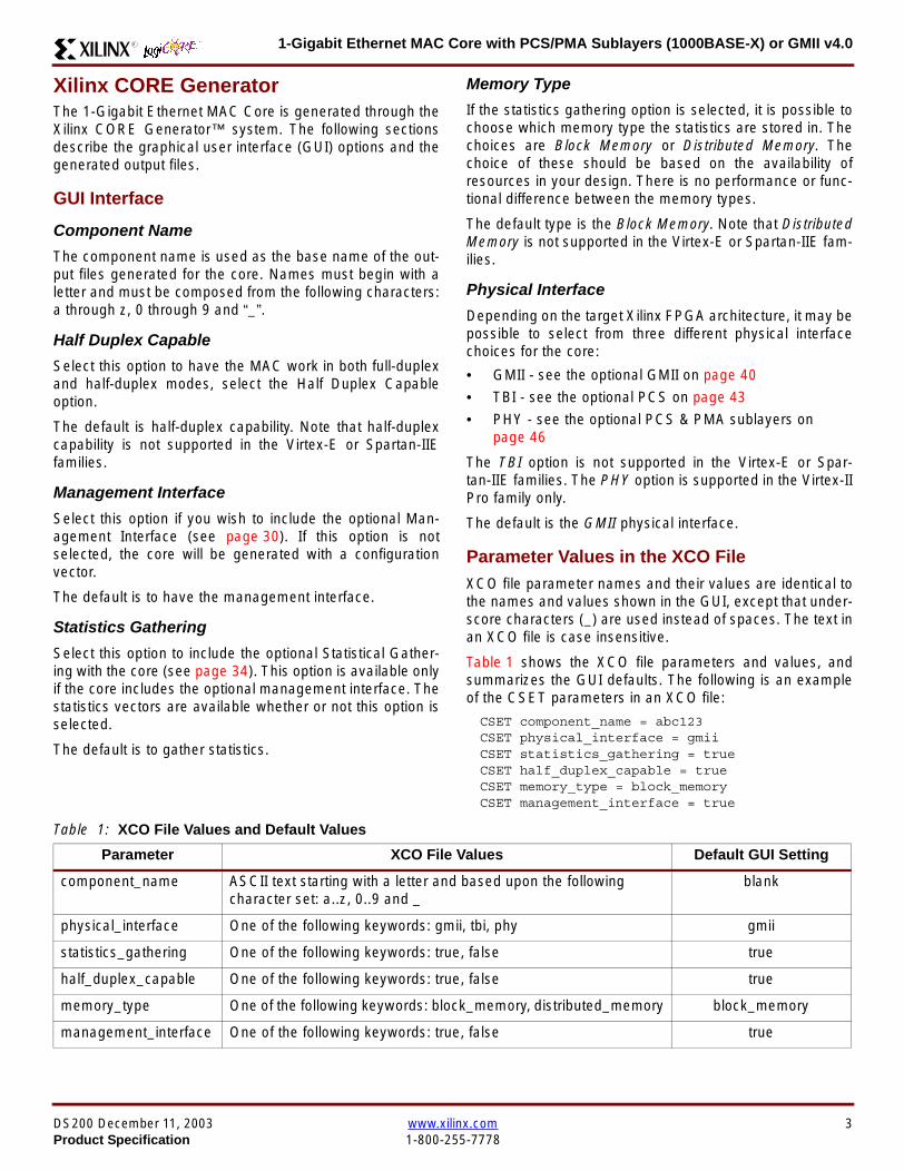
1-Gigabit Ethernet MAC Core with PCSPMA Sublayers (1000BASE-X) or GMII v40R
Xilinx CORE GeneratorThe 1-Gigabit Ethernet MAC Core is generated through theXilinx CORE Generatortrade system The following sectionsdescribe the graphical user interface (GUI) options and thegenerated output files
GUI Interface
Component Name
The component name is used as the base name of the out-put files generated for the core Names must begin with aletter and must be composed from the following charactersa through z 0 through 9 and ldquo_rdquo
Half Duplex Capable
Select this option to have the MAC work in both full-duplexand half-duplex modes select the Half Duplex Capableoption
The default is half-duplex capability Note that half-duplexcapability is not supported in the Virtex-E or Spartan-IIEfamilies
Management Interface
Select this option if you wish to include the optional Man-agement Interface (see page 30) If this option is notselected the core will be generated with a configurationvector
The default is to have the management interface
Statistics Gathering
Select this option to include the optional Statistical Gather-ing with the core (see page 34) This option is available onlyif the core includes the optional management interface Thestatistics vectors are available whether or not this option isselected
The default is to gather statistics
Memory Type
If the statistics gathering option is selected it is possible tochoose which memory type the statistics are stored in Thechoices are Block Memory or Distributed Memory Thechoice of these should be based on the availability ofresources in your design There is no performance or func-tional difference between the memory types
The default type is the Block Memory Note that DistributedMemory is not supported in the Virtex-E or Spartan-IIE fam-ilies
Physical Interface
Depending on the target Xilinx FPGA architecture it may bepossible to select from three different physical interfacechoices for the core
bull GMII - see the optional GMII on page 40
bull TBI - see the optional PCS on page 43
bull PHY - see the optional PCS amp PMA sublayers onpage 46
The TBI option is not supported in the Virtex-E or Spar-tan-IIE families The PHY option is supported in the Virtex-IIPro family only
The default is the GMII physical interface
Parameter Values in the XCO FileXCO file parameter names and their values are identical tothe names and values shown in the GUI except that under-score characters (_) are used instead of spaces The text inan XCO file is case insensitive
Table 1 shows the XCO file parameters and values andsummarizes the GUI defaults The following is an exampleof the CSET parameters in an XCO file
CSET component_name = abc123CSET physical_interface = gmiiCSET statistics_gathering = trueCSET half_duplex_capable = trueCSET memory_type = block_memoryCSET management_interface = true
Table 1 XCO File Values and Default Values
Parameter XCO File Values Default GUI Setting
component_name ASCII text starting with a letter and based upon the followingcharacter set az 09 and _
blank
physical_interface One of the following keywords gmii tbi phy gmii
statistics_gathering One of the following keywords true false true
half_duplex_capable One of the following keywords true false true
memory_type One of the following keywords block_memory distributed_memory block_memory
management_interface One of the following keywords true false true
DS200 December 11 2003 wwwxilinxcom 3Product Specification 1-800-255-7778
1-Gigabit Ethernet MAC Core with PCSPMA Sublayers (1000BASE-X) or GMII v40 R
Output GenerationThe output files generated from the CORE Generator areplaced in the CORE Generator project directory The outputfiles include two netlist files supporting CORE Generatorfiles a readme file and a subdirectory containing examplewrapper files and scripts to take the core through the Xilinximplementation software and simulate the core using the
Modelsim simulator by Model Technology See the gener-ated readme files for explanations about these files
Device UtilizationTable 2 provides approximate slice counts for the corersquosvarious options when instantiated in a Virtex-II Pro device
Table 2 Device Utilization
Parameter Values Device Resources
PhysicalInterface
HalfDuplex
ManagementInterface
Statistics Gathering
Slices LUT Registers BRAM GCLK
GMII TBI PHYDistributed
MemoryBlock
Memory
Yes No No Yes Yes Yes No 1545 2159 1654 0 3
Yes No No Yes Yes No Yes 1420 1745 1561 2 3
Yes No No Yes Yes No No 932 1140 991 0 3
Yes No No Yes No No No 781 969 831 0 2
Yes No No No Yes Yes No 1315 1752 1359 0 3
Yes No No No Yes No Yes 1159 1525 1317 2 3
Yes No No No Yes No No 742 884 793 0 3
Yes No No No No No No 581 708 630 0 2
No Yes No No Yes Yes No 1850 2345 1934 2 4
No Yes No No Yes No Yes 1697 1880 1899 4 4
No Yes No No Yes No No 1295 1404 1380 2 4
No Yes No No No No No 1122 1226 1213 2 3
No No Yes No Yes Yes No 1725 1773 1791 0 3
No No Yes No Yes No Yes 1580 1838 1775 2 3
No No Yes No Yes No No 1172 1394 1236 0 3
No No Yes No No No No 1005 1183 1066 0 2
1 Half Duplex Logic is only available with the GMII2 Statistics Gathering is only available when the Management Interface is selected
4 wwwxilinxcom DS200 December 11 20031-800-255-7778 Product Specification
1-Gigabit Ethernet MAC Core with PCSPMA Sublayers (1000BASE-X) or GMII v40R
Interface DescriptionAll ports of the core (with the exception of the Rocket IOserial ports of the optional PCSPMA sublayers) are internalconnections in FPGA fabric An example wrapper is deliv-ered with the core which adds IBUFs OBUFs and IOBflip-flops where appropriate to the external signals of theGMII or TBI IOBs are also added to the remaining uncon-nected ports to allow the example design to be taken
through the Xilinx implementation software In addition allclock management logic is placed in this example wrapperthis allows the user more flexibility in implementation forexample in designs using multiple cores
The example wrapper is provided in both VHDL and Verilog
Interface Signals for MAC with physical_interface=gmii and management_interface=true
Figure 3 Component Pinout for MAC with GMII Interface using the optional Management Interface
GTX_CLK
TX_CLK
GMII_RX_CLK
MDCMDIO_IN
GMII_RXD[70]
GMII_TXD[70]GMII_TX_ENGMII_TX_ER
TX_DATA[70]
TX_ACKTX_UNDERRUN
PAUSE_REQPAUSE_VAL[150]
RX_CLK
HOST_CLKHOST_OPCODE[10]
HOST_ADDR[90]HOST_WR_DATA[310]HOST_RD_DATA[310]
HOST_MIIM_SELHOST_REQ
HOST_MIIM_RDY
RESET
RX_DATA[70]
RX_GOOD_FRAMERX_BAD_FRAME
TX_COLLISIONTX_RETRANSMIT
TX_DATA_VALID
RX_DATA_VALID
GMII_TX_CLK
GMII_COLGMII_CRS
GMII_RX_DVGMII_RX_ER
TX_CLK Domain
RX_CLK Domain
HOST_CLK Domain
TX_IFG_DELAY[70]
TX_STATISTICS_VECTOR[280]TX_STATISTICS_VALID
RX_STATISTICS_VECTOR[220]RX_STATISTICS_VALID
MDIO_OUTMDIO_TRI
DS200 December 11 2003 wwwxilinxcom 5Product Specification 1-800-255-7778
1-Gigabit Ethernet MAC Core with PCSPMA Sublayers (1000BASE-X) or GMII v40 R
Interface Signals for MAC with physical_interface=gmii and management_interface=false
Figure 4 Component Pinout for MAC with GMII Interface without the optional Management Interface
GTX_CLK
TX_CLK
GMII_RX_CLKGMII_RXD[70]
GMII_TXD[70]GMII_TX_ENGMII_TX_ER
TX_DATA[70]
TX_ACKTX_UNDERRUN
PAUSE_REQPAUSE_VAL[150]
RX_CLK
CONFIGURATION_VECTOR[630]
RESET
RX_DATA[70]
RX_GOOD_FRAMERX_BAD_FRAME
TX_COLLISIONTX_RETRANSMIT
TX_DATA_VALID
RX_DATA_VALID
GMII_TX_CLK
GMII_COLGMII_CRS
GMII_RX_DVGMII_RX_ER
TX_CLK Domain
RX_CLK Domain
TX_IFG_DELAY[70]
TX_STATISTICS_VECTOR[280]TX_STATISTICS_VALID
RX_STATISTICS_VECTOR[220]RX_STATISTICS_VALID
6 wwwxilinxcom DS200 December 11 20031-800-255-7778 Product Specification
1-Gigabit Ethernet MAC Core with PCSPMA Sublayers (1000BASE-X) or GMII v40R
Interface Signals for MAC with physical_interface=tbi and management_interface=true
Figure 5 Component Pinout for MAC with PCS and TBI using the optional Management Interface
GTX_CLK
TX_CLK
MDCMDIO_IN
RX_CODE_GROUP1[90]
TX_CODE_GROUP[90]PMA_TX_CLK
LOC_REF
TX_DATA[70]
TX_ACKTX_UNDERRUN
PAUSE_REQPAUSE_VAL[150]
RX_CLK
HOST_CLKHOST_OPCODE[10]
HOST_ADDR[90]HOST_WR_DATA[310]HOST_RD_DATA[310]
HOST_MIIM_SELHOST_REQ
HOST_MIIM_RDY
RESET
RX_DATA[70]
RX_GOOD_FRAMERX_BAD_FRAME
TX_COLLISIONTX_RETRANSMIT
TX_DATA_VALID
RX_DATA_VALID
EWRAP
PMA_RX_CLK0PMA_RX_CLK1
TX_CLKRX_CLK Domain
HOST_CLK Domain
TX_IFG_DELAY[70]
TX_STATISTICS_VECTOR[280]TX_STATISTICS_VALID
RX_STATISTICS_VECTOR[220]RX_STATISTICS_VALID
MDIO_OUTMDIO_TRI
EN_CDET
RX_CODE_GROUP0[90]
SIGNAL_DETECT
PHYAD[40]
DS200 December 11 2003 wwwxilinxcom 7Product Specification 1-800-255-7778
1-Gigabit Ethernet MAC Core with PCSPMA Sublayers (1000BASE-X) or GMII v40 R
Interface Signals for MAC with physical_interface=tbi and management_interface=false
Figure 6 Component Pinout for MAC with PCS and TBI without the optional Management Interface
GTX_CLK
TX_CLK
MDC_INMDIO_IN
RX_CODE_GROUP1[90]
TX_CODE_GROUP[90]PMA_TX_CLK
LOC_REF
TX_DATA[70]
TX_ACKTX_UNDERRUN
PAUSE_REQPAUSE_VAL[150]
RX_CLK
CONFIGURATION_VECTOR[630]
RESET
RX_DATA[70]
RX_GOOD_FRAMERX_BAD_FRAME
TX_COLLISIONTX_RETRANSMIT
TX_DATA_VALID
RX_DATA_VALID
EWRAP
PMA_RX_CLK0PMA_RX_CLK1
TX_CLKRX_CLK Domain
TX_IFG_DELAY[70]
TX_STATISTICS_VECTOR[280]TX_STATISTICS_VALID
RX_STATISTICS_VECTOR[220]RX_STATISTICS_VALID
MDIO_OUTMDIO_TRI
EN_CDET
RX_CODE_GROUP0[90]
PHYAD[40]
SIGNAL_DETECT
8 wwwxilinxcom DS200 December 11 20031-800-255-7778 Product Specification
1-Gigabit Ethernet MAC Core with PCSPMA Sublayers (1000BASE-X) or GMII v40R
Interface Signals for MAC with physical_interface=phy and management_interface=true
Figure 7 Component Pinout for MAC with PCS amp PMA Sublayers using the optional Management Interface
REFCLK
TX_CLK
MDCMDIO_IN
TXPTXN
TX_DATA[70]
TX_ACKTX_UNDERRUN
PAUSE_REQPAUSE_VAL[150]
RX_CLK
HOST_CLKHOST_OPCODE[10]
HOST_ADDR[90]HOST_WR_DATA[310]HOST_RD_DATA[310]
HOST_MIIM_SELHOST_REQ
HOST_MIIM_RDY
RESET
RX_DATA[70]
RX_GOOD_FRAMERX_BAD_FRAME
TX_COLLISIONTX_RETRANSMIT
TX_DATA_VALID
RX_DATA_VALID
RXPRXN
TX_CLKRX_CLK Domain
HOST_CLK Domain
TX_IFG_DELAY[70]
TX_STATISTICS_VECTOR[280]TX_STATISTICS_VALID
RX_STATISTICS_VECTOR[220]RX_STATISTICS_VALID
PHYAD[40]
SIGNAL_DETECT
MDIO_OUTMDIO_TRI
USRCLKUSRCLK2
DCM_LOCKED
REFCLK2BREFCLK
BREFCLK2REFCLKSEL
DS200 December 11 2003 wwwxilinxcom 9Product Specification 1-800-255-7778
1-Gigabit Ethernet MAC Core with PCSPMA Sublayers (1000BASE-X) or GMII v40 R
Interface Signals for MAC with physical_interface=phy and management_interface=false
Figure 8 Component Pinout for MAC with PCS amp PMA Sublayers without the optional Management Interface
TX_CLK
MDC_INMDIO_IN
TXPTXN
TX_DATA[70]
TX_ACKTX_UNDERRUN
PAUSE_REQPAUSE_VAL[150]
RX_CLK
CONFIGURATION_VECTOR[630]
RX_DATA[70]
RX_GOOD_FRAMERX_BAD_FRAME
TX_COLLISIONTX_RETRANSMIT
TX_DATA_VALID
RX_DATA_VALID
RXPRXN
TX_CLKRX_CLK Domain
TX_IFG_DELAY[70]
TX_STATISTICS_VECTOR[280]TX_STATISTICS_VALID
RX_STATISTICS_VECTOR[220]RX_STATISTICS_VALID
SIGNAL_DETECT
MDIO_OUTMDIO_TRI
REFCLKRESET
PHYAD[40]
USRCLKUSRCLK2
DCM_LOCKED
REFCLK2BREFCLK
BREFCLK2REFCLKSEL
10 wwwxilinxcom DS200 December 11 20031-800-255-7778 Product Specification
1-Gigabit Ethernet MAC Core with PCSPMA Sublayers (1000BASE-X) or GMII v40R
Client Side Interface Signal Definition
Table 3 describes the client-side transmit signals of the MAC core These signals are used to transmit data from the clientto the MAC core
Table 4 describes the client-side receive signals These signals are used by the MAC core to transfer data to the client
Table 3 Transmit Client Interface Signal Pins
Signal Direction Description
TX_CLK Output Clock for transmit client interface 125 MHz nominal
TX_DATA[70] Input Frame data to be transmitted is supplied on this port
TX_DATA_VALID Input Control signal for TX_DATA port
TX_IFG_DELAY[70] InputControl signal for configurable Inter Frame Gap adjustment SeeTransmitter on page 16 for timing diagrams
TX_ACK OutputHandshaking signal Asserted when the current data on TX_DATA hasbeen accepted See Transmitter on page 16 for timing diagrams
TX_UNDERRUN Input Asserted by client to force MAC core to corrupt the current frame
TX_COLLISION OutputAsserted by the MAC core to signal a collision on the medium and that anytransmission in progress should be aborted Always 0 when the MAC coreis in full-duplex mode
TX_RETRANSMIT Output
When asserted at the same time as the TX_COLLISION signal thissignals the client that the aborted frame should be resupplied to the MACcore for retransmission Always 0 when the MAC core is in full-duplexmode
TX_STATISTICS_VECTOR[280] OutputThis gives information on the last frame transmitted See Transmitter onpage 16 for vector contents
TX_STATISTICS_VALID OutputAsserted at end of frame transmission indicating that theTX_STATISTICS_VECTOR is valid
Notes1 All the above signals are synchronous to TX_CLK and Active High
Table 4 Receive Client Interface Signal Pins
Signal Direction Description
RX_CLK Output Clock for receive client interface 125 MHz nominal
RX_DATA[70] Output Frame data received is supplied on this port
RX_DATA_VALID Output Control signal for the RX_DATA port
RX_GOOD_FRAME OutputAsserted at end of frame reception to indicate that the frame should beprocessed by the MAC client See Receiver on page 24
RX_BAD_FRAME OutputAsserted at end of frame reception to indicate that the frame should bediscarded by the MAC client See Receiver on page 24
RX_STATISTICS_VECTOR[220] OutputProvides information about the last frame received See Receiver onpage 24 for the vector contents
RX_STATISTICS_VALID OutputAsserted at end of frame reception indicating that theRX_STATISTICS_VECTOR is valid
Notes1 All signals above are synchronous to RX_CLK and Active High
DS200 December 11 2003 wwwxilinxcom 11Product Specification 1-800-255-7778
1-Gigabit Ethernet MAC Core with PCSPMA Sublayers (1000BASE-X) or GMII v40 R
Table 5 describes the signals used by the client to request a flow control action from the transmit engine Flow control framesreceived by the MAC are automatically handled (if the MAC is configured to do so)
Table 6 describes the optional signals used by the client to access the management features of the MAC core includingconfiguration status statistics and MDIO access
Table 7 describes the alternative to the optional Management Interface signals This describes the Configuration Vectorwhich uses direct inputs to the core to replace the functionality of the MAC Configuration bits when the ManagementInterface is not used
Notes1 All bits of CONFIGURATION_VECTOR are registered on input but may be treated as asynchronous inputs
Table 5 Flow Control Interface Signal Pinout
Signal Direction Description
PAUSE_REQ InputPause request sends a pause frame down the link See Transmitting a PAUSE ControlFrame on page 29
PAUSE_VAL[150] Input Pause value inserted into the parameter field of the transmitted pause frame
Notes1 These signals are synchronous to TX_CLK and are Active High
Table 6 Optional Management Interface Signal Pinout (management_interface=true)
Signal Direction Description
HOST_CLK InputClock for management interface See Optional Management Interface(management_interface=true) on page 30 for the signal frequency range
HOST_OPCODE[10] InputDefines operation to be performed over MDIO interface Bit 1 is also used inconfiguration register access See Configuration Registers on page 30
HOST_ADDR[90] Input Address of register to be accessed
HOST_WR_DATA[310] Input Data to write to register
HOST_RD_DATA[310] Output Data read from register
HOST_MIIM_SEL InputWhen asserted the MDIO interface is accessed When disasserted the MACinternal configuration or statistical counter registers are accessed
HOST_REQ InputUsed to signal a transaction on the MDIO interface or to read from the statisticregisters See Optional Management Interface (management_interface=true) onpage 30
HOST_MIIM_RDY OutputWhen high the MDIO interface has completed any pending transaction and isready for a new transaction
Notes1 All signals above are synchronous to HOST_CLK and are Active High
Table 7 Alternative to the Optional Management Interface Configuration Vector Signal Pinout(management_interface=false)
Signal Direction Description
CONFIGURATION_VECTOR[630]
Input The Configuration Vector is used to replace the functionality of theMAC Configuration Registers when the Management Interface is notused See Optional Configuration Vector (management_interface =false) on page 38
12 wwwxilinxcom DS200 December 11 20031-800-255-7778 Product Specification
1-Gigabit Ethernet MAC Core with PCSPMA Sublayers (1000BASE-X) or GMII v40R
Table 8 describes the reset signal
Physical Interface Signal Definition
Table 9 describes the MDIO (MII Management) interface signals of the MAC core These signals are typically connected tothe MDIO port of a PHY device either off-chip or an SoC-integrated core The MDIO format is defined in IEEE8023 clause22
Table 10 describes the optional GMII signals of the MAC core These are typically attached to a PHY module either off-chipor internally integrated The GMII is defined in IEEE8023 clause 35
Table 8 Reset Signal
Signal Direction Description
RESET Input Asynchronous reset for entire core See Reset circuit on page 42 for moreinformation on the reset circuit
Table 9 MDIO Interface Signal Pinout
Signal Direction Description
MDC OutputManagement Clock derived from HOST_CLK on the basis of supplied configuration datawhen the optional Management Interface is used See Optional Management Interface(management_interface=true) on page 30
MDC_IN InputWhen the Optional Management Interface is not used access to the optional PhysicalCoding Sublayer (PCS) must be provided by an external MDIO Controller In this situationthe Management Clock is an input to the core
MDIO_IN Input Input data signal for communication with PHY configuration and status Tie high if unused
MDIO_OUT Output Output data signal for communication with PHY configuration and status
MDIO_TRI OutputTristate control for MDIO signals 0 signals that the value on MDIO_OUT should be
asserted onto the MDIO bus
Table 10 Optional GMII Interface Signal Pinout (physical_interface=gmii)
Signal Direction Description
GTX_CLK InputClock signal at 125 MHz Other transmit clocks are derived from this clock as illustratedin Figure 28 Tolerance must be within IEEE 8023-2002 specification
GMII_TXD[70] Output Transmit data to PHY
GMII_TX_EN Output Data Enable control signal to PHY
GMII_TX_ER Output Error control signal to PHY
GMII_TX_CLK Output Clock out to PHY
GMII_CRS Input Control signal from PHY
GMII_COL Input Control signal from PHY
GMII_RX_CLK Input Recovered clock from received data stream by PHY
GMII_RXD[70] Input Received data from PHY
GMII_RX_DV Input Data Valid control signal from PHY
GMII_RX_ER Input Error control signal from PHY
DS200 December 11 2003 wwwxilinxcom 13Product Specification 1-800-255-7778
1-Gigabit Ethernet MAC Core with PCSPMA Sublayers (1000BASE-X) or GMII v40 R
Table 11 describes the TBI (Ten-Bit interface) signals of the MAC core These are typically attached to a PMA SERDESmodule These signals optionally replace the GMII signals described in Table 10 to extend the functionality of the core toinclude the PCS for 1000BASE-X The TBI is defined in IEEE8023 clause 36
Notes
PHYAD and SIGNAL_DETECT are asynchronous inputs SIGNAL_DETECT is Active High
Table 11 Optional TBI Interface Signal Pinout (physical_interface=tbi)
Signal Direction Description
GTX_CLK InputClock signal at 125 MHz Other transmit clocks will be derived from this clock asillustrated in Figure 32 Tolerance must be within IEEE 8023-2002 specification
TX_CODE_GROUP[90] Output 10-bit parallel transmit data to PMA Sublayer (SERDES)
PMA_TX_CLK Output Transmit clock signal to PMA Sublayer (SERDES) at 125MHz
LOC_REF OutputCauses the PMA sublayer clock recovery unit to lock to PMA_TX_CLK Thissignal is tied to Ground
EWRAP Output
This signal is set from the PCS Control Register 0 bit 14 (loopback) See PCSManaged Register Block (physical_interface = tbi or phy) on page 49 Whenhigh this instructs the PMA sublayer to electrically loop the transmitter data to thereceiver
RX_CODE_GROUP0[90] Input10-bit parallel received data from PMA Sublayer (SERDES) synchronous toPMA_RX_CLK0
RX_CODE_GROUP1[90] Input10-bit parallel received data from PMA Sublayer (SERDES) synchronous toPMA_RX_CLK1
PMA_RX_CLK0 Input Received clock signal from PMA Sublayer (SERDES) at 625MHz
PMA_RX_CLK1 InputReceived clock signal from PMA Sublayer (SERDES) at 625MHz This is 180degrees out of phase with PMA_RX_CLK0
EN_CDET OutputEnables the PMA Sublayer to perform comma realignment driven from the PCSstate machine during the Loss-Of-Sync state
PHYAD[40] Input PHY address of MDIO register set for the PCS
SIGNAL_DETECT Input
Signal direct from PMD sublayer indicating the presence of light detected at theoptical receiver If driven high this indicates that the optical receiver has detectedlight If driven low this indicates the absence of light
If unused tie high to enable the operation the core
14 wwwxilinxcom DS200 December 11 20031-800-255-7778 Product Specification
1-Gigabit Ethernet MAC Core with PCSPMA Sublayers (1000BASE-X) or GMII v40R
Table 12 describes the interface signals for the Optional PCSPMA sublayer of the MAC core These signals optionallyreplace the GMII signals described in Table 10 to extend the functionality of the core to include the PCS and PMA sublayersfor 1000BASE-X This option uses the Virtex-II Pro Rocket IO functionality which is integrated into the core The PMAsublayer for 1000BASE-X is defined in IEEE8023 clause 36
Notes1 PHYAD and SIGNAL_DETECT are asynchronous inputs SIGNAL_DETECT is Active High
Table 12 Optional PCSPMA sublayer Interface Signal Pinout (physical_interface=phy)
Signal Direction Description
REFCLK InputHigh Quality Reference clock for Multi-Gigabit Transceivers (625 MHz) See Rocket IOUser Guide
REFCLK2 Input Alternative High Quality Reference clock for Multi-Gigabit Transceivers (625 MHz) SeeRocket IO User Guide
BREFCLK Input Alternative High Quality Reference clock for Multi-Gigabit Transceivers (625 MHz)This optionally replaces REFCLK See Rocket IO User Guide
BREFCLK2 Input Alternative High Quality Reference clock for Multi-Gigabit Transceivers (625 MHz)This optionally replaces REFCLK2 See Rocket IO User Guide
REFCLKSEL Input Selects between either (B)REFCLK or (B)REFCLK2 as the input clock source to theMGT See Rocket IO User Guide
USERCLK InputClock signal at 625 MHz This is connected to the TXUSRCLK and RXUSRCLK portsof the Rocket IO MGT This may be derived from (B)REFCLK using a DCM asillustrated in Figure 35
USERCLK2 InputClock signal at 125 MHz This is connected to the TXUSRCLK2 and RXUSRCLK2 portsof the Rocket IO MGT This may be derived from (B)REFCLK using a DCM asillustrated in Figure 35
DCM_LOCKED InputIf a DCM is used to derive USRCLK and USRCLK2 as illustrated in Figure 35 theLOCKED port of the DCM must be connected to the DCM_LOCKED port of the coreThe core will hold itrsquos Rocket IO MGT in reset until DCM_LOCKED is driven to logic 1
TXPTXN OutputDifferential pair for serial transmission from PMA to PMD The clock is embedded in thedata stream
RXPRXN InputDifferential pair for serial reception from PMD to PMA The clock is extracted from thedata stream
PHYAD[40] Input PHY address of MDIO register set for the PCS
SIGNAL_DETECT Input
Signal direct from PMD sublayer indicating the presence of light detected at the opticalreceiver If driven high this indicates that the optical receiver has detected light If drivenlow this indicates the absence of light
If unused tie high to enable the operation the core
DS200 December 11 2003 wwwxilinxcom 15Product Specification 1-800-255-7778
1-Gigabit Ethernet MAC Core with PCSPMA Sublayers (1000BASE-X) or GMII v40 R
Functional Description
Client InterfaceThe client interface is designed for maximum flexibility inmatching to a client switching fabric or network processorinterface
The data pathway is 8 bits wide in both the transmit andreceive directions with each pathway synchronous to theTX_CLK and RX_CLK respectively for completely indepen-dent full duplex operation
Transmitter
Normal Frame Transmission
The timing of a normal outbound frame transfer can be seenin Figure 9 When the client wants to transmit a frame itplaces the first column of data onto the TX_DATA port andasserts a ldquo1rdquo onto TX_DATA_VALID
When the MAC core has read this first byte of data it willassert the TX_ACK signal on the next and subsequent ris-ing clock edges the client must provide the remainder ofthe data for the frame
The end of frame is signalled to the MAC core by takingTX_DATA_VALID Low
In-Band Parameter Encoding
For maximum flexibility in switching applications the Ether-net frame parameters (destination address sourceaddress lengthtype and optionally FCS) are encodedwithin the same data stream that the frame payload is trans-ferred upon rather than on separate ports This is illustratedin the timing diagrams Definitions of the abbreviations usedin the timing diagrams are described in Table 13
Figure 9 Normal Frame Transmission Across Client Interface
Table 13 Abbreviations Used in Timing Diagrams
Abbreviation Definition
DA Destination Address 6 bytes
SA Source Address 6 bytes
LT LengthType Field 2 bytes
FCS Frame Check Sequence 4 bytes
TX_CLK
TX_DATA[70]
TX_DATA_VALID
TX_ACK
TX_UNDERRUN
DA SA DATALT
TX_COLLISION
TX_RETRANSMIT
xip2133
16 wwwxilinxcom DS200 December 11 20031-800-255-7778 Product Specification
1-Gigabit Ethernet MAC Core with PCSPMA Sublayers (1000BASE-X) or GMII v40R
Padding
When fewer than 46 bytes of data are supplied by the clientto the MAC core the transmitter module will add padding upto the minimum frame length The exception to this is whenthe MAC core is configured for client-passed FCS in thiscase the client must also supply the padding to maintain theminimum frame length (see Client-Supplied FCS Passing)
Client-Supplied FCS Passing
If the MAC core is configured to have the FCS field passedin by the client (see Configuration Registers on page 30)the transmission timing is as depicted in Figure 10 In thiscase it is the responsibility of the client to ensure that theframe meets the Ethernet minimum frame length require-ments the MAC core will not perform any padding of thepayload
Figure 10 Frame Transmission with Client-supplied FCS
TX_CLK
TX_DATA[70]
TX_DATA_VALID
TX_ACK
TX_UNDERRUN
DA SA DATA FCSLT
TX_COLLISION
TX_RETRANSMIT
xip2134
DS200 December 11 2003 wwwxilinxcom 17Product Specification 1-800-255-7778
1-Gigabit Ethernet MAC Core with PCSPMA Sublayers (1000BASE-X) or GMII v40 R
Client Underrun
The timing of an aborted transfer can be seen in Figure 11This may happen for instance if a FIFO connected to theclient interface empties before a frame is completed Whenthe client asserts TX_UNDERRUN during a frame transmis-sion the MAC core will insert an error code to corrupt the
current frame and then fall back to idle transmission It isthe responsibility of the client to re-queue the aborted framefor transmission
When an underrun occurs TX_DATA_VALID may beasserted on the clock cycle after the TX_UNDERRUNassertion to request a new transmission
Figure 11 Frame Transmission with Underrun
TX_CLK
TX_DATA[70]
TX_DATA_VALID
TX_ACK
TX_UNDERRUN
DA SA DATALT
TX_COLLISION
TX_RETRANSMIT
xip2135
18 wwwxilinxcom DS200 December 11 20031-800-255-7778 Product Specification
1-Gigabit Ethernet MAC Core with PCSPMA Sublayers (1000BASE-X) or GMII v40R
Back-to-Back Transfers
Figure 12 shows the case where the MAC client is immedi-ately ready to transmit a second frame of data followingcompletion of its first frame In this figure the end of the firstframe is shown on the left On the clock cycle immediatelyfollowing the final byte of the first frame TX_DATA_VALIDis taken low by the client and is taken high one clock cyclelater to indicate that the first byte of the destination addressof the second frame is on TX_DATA awaiting transmission
When the MAC core is ready to accept data TX_ACK isasserted and the transmission continues in the same man-ner as in the case of the single frame The MAC core willdefer the assertion of TX_ACK appropriately to comply withinter-packet gap requirements and flow control requests
If the MAC core is operating in half-duplex mode the timingshown in Figure 12 is required to take advantage of framebursting the MAC core is only guaranteed to retain controlof the medium if the TX_DATA_VALID signal is low for a sin-gle clock cycle For more information on frame bursting seeIEEE 8023-2002
Figure 12 Back to Back Frame Transmission
TX_CLK
TX_DATA[70]
TX_DATA_VALID
TX_ACK
TX_UNDERRUN
TX_COLLISION
TX_RETRANSMIT
xip2136
DS200 December 11 2003 wwwxilinxcom 19Product Specification 1-800-255-7778
1-Gigabit Ethernet MAC Core with PCSPMA Sublayers (1000BASE-X) or GMII v40 R
VLAN Tagged Frames
Transmission of a VLAN tagged frame (if enabled) can beseen in Figure 13 Note that the handshaking signalsacross the interface do not change however the VLANtype tag 81-00 must be supplied by the client to signify that
the frame is VLAN tagged The client also supplies the twobytes of Tag Control Information V1 and V2 at the appro-priate times in the data stream More information on thecontents of these two bytes can be found in IEEE8023-2002
Maximum Permitted Frame Length
The maximum legal length of a frame specified in IEEE8023-2002 is 1518 bytes for non-VLAN tagged framesVLAN tagged frames may be extended to 1522 bytesWhen jumbo frame handling is disabled and the clientattempts to transmit a frame which exceeds the maximumlegal length the MAC core will insert an error code to cor-
rupt the current frame and the frame will be truncated to themaximum legal length When jumbo frame handling isenabled frames which are longer than the legal maximumare transmitted error-free
For more information on enabling and disabling jumboframe handling see Configuration Registers on page 30
Figure 13 Transmission of a VLAN Tagged Frame
TX_CLK
TX_DATA[70]
TX_DATA_VALID
TX_ACK
TX_UNDERRUN
DA SA DATALTVLANtag
81 00V1V2
TX_COLLISION
TX_RETRANSMIT
xip2137
20 wwwxilinxcom DS200 December 11 20031-800-255-7778 Product Specification
1-Gigabit Ethernet MAC Core with PCSPMA Sublayers (1000BASE-X) or GMII v40R
Frame Collisions - Half Duplex Operation Only
In half duplex Ethernet operation collisions will occur on themedium as a matter of course this is how the arbitrationalgorithm is fulfilled In case of a collision the MAC core sig-nals to the client that data may need to be resupplied as fol-lows
If there is a collision the TX_COLLISION signal will be setto ldquo1rdquo by the MAC core If a frame is in progress the clientmust abort the transfer and take TX_DATA_VALID to ldquo0rdquo
If the TX_RETRANSMIT signal is ldquo1rdquo in the same clockcycle that the TX_COLLISION signal is ldquo1rdquo the client must
resubmit the previous frame to the MAC core for retrans-mission TX_DATA_VALID must be asserted to the MACcore within 8 clock cycles of the TX_COLLISION signal inorder to meet Ethernet timing requirements See Figure 14
If the TX_RETRANSMIT signal is ldquo0rdquo in the same clockcycle that the TX_COLLISION signal is ldquo1rdquo the number ofretries for this frame has exceeded the Ethernet specifica-tion and the frame should be dropped by the client The cli-ent can then make any new frame available to the MAC fortransmission without timing restriction See Figure 15
Figure 14 Collision Handling - Frame retransmission required
Figure 15 Collision Handling - No frame retransmission required
TX_CLK
TX_DATA[70]
TX_DATA_VALID
TX_ACK
TX_UNDERRUN
TX_COLLISION
TX_RETRANSMIT
8 clocks max
xip2138
TX_CLK
TX_DATA[70]
TX_DATA_VALID
TX_ACK
TX_UNDERRUN
TX_COLLISION
TX_RETRANSMIT
xip2139
DS200 December 11 2003 wwwxilinxcom 21Product Specification 1-800-255-7778
1-Gigabit Ethernet MAC Core with PCSPMA Sublayers (1000BASE-X) or GMII v40 R
Interframe Gap Adjustment
The user can elect to vary the length of the inter fame gapIf this function is selected (via a configuration bit in thetransmitter control register see Configuration Registerson page 30) then the MAC will exert back pressure to delaythe transmission of the next frame until the requested num-ber of Idle cycles has elapsed The number of Idle cycles iscontrolled by the value on the TX_IFG_DELAY port at thestart of frame transmission Figure 16 shows the MAC oper-ating in this mode
Reducing the Inter fame gap to below the IEEE 8023-2002minimum of 12 Idles is supported in Full Duplex onlydesigns and will transmit an absolute minimum of 4 Idles Ifthe Interframe gap adjustment is reduced below 12 Idlesthen the accuracy of the Optional Statistical Gathering(statistics_gathering=true) Counters cannot be guaranteedHowever the TX_STATISTIC_VECTOR andRX_STATISTIC_VECTOR will always remain correct
Transmitter Statistics Vector
The statistics for the frame transmitted are contained withinthe TX_STATISTICS_VECTOR The vector is driven syn-chronously by the transmitter clock TX_CLK followingframe transmission The bit field definition for the Vector isdefined in Table 14
All bit fields with the exception of BYTE_VALID are validonly when the TX_STATISTICS_VALID is asserted This isillustrated in Figure 17 BYTE_VALID is significant on everyTX_CLK cycle
TX_STATISTICS_VECTOR bits 25 down to 17 inclusive arefor half duplex only and will be set to logic 0 when operatingin full duplex mode
Figure 16 Interframe Gap Adjustment
TX_CLK
TX_DATA[70]
TX_DATA_VALID
TX_ACK
DA SA
TX_IFG_DELAY
IFG ADJUST VALUE
0x0D
13 Idles inserted
DA
Next IFG ADJUST VALUE
xip2140
Figure 17 Transmitter Statistics Vector Timing
TX_CLK
TX_STATISTICS_VECTOR[280]
TX_STATISTICS_VALID
xip2141
22 wwwxilinxcom DS200 December 11 20031-800-255-7778 Product Specification
1-Gigabit Ethernet MAC Core with PCSPMA Sublayers (1000BASE-X) or GMII v40R
Table 14 Bit Definition for the Transmitter Statistics Vector
TX_STATISTICS_VECTOR Name Description
28 PAUSE_FRAME_TRANSMITTEDAsserted if the previous frame was a pause framethat the MAC itself initiated in response to aPAUSE_REQ assertion
27 BYTE_VALID
Asserted if a MAC frame byte (DA to FCS inclusive)is in the process of being transmitted This is valid onevery clock cycle
Do not use this as an enable signal to indicate thatdata is present on GMII_TXD[70]
26 Reserved Returns logic 0
25 down to 22 TX_ATTEMPTS[30]
The number of attempts that have been made totransmit the previous frame This is a 4-bit number0 should be interpreted as 1 attempt 1 as 2attempts up until 15 as 16 attempts
21 Reserved Returns logic 0
20 EXCESSIVE_COLLISIONAsserted if a collision has been detected on each ofthe last 16 attempts to transmit the previous frame
19 LATE_COLLISIONAsserted if a late collision occurred during frametransmission
18 EXCESSIVE_DEFERRALAsserted if the previous frame was deferred for anexcessive amount of time as defined by the constantldquomaxDeferTimerdquo in IEEE 8023-2002
17 TX_DEFERRED Asserted if transmission of the frame was deferred
16 VLAN_FRAMEAsserted if the previous frame contained a VLANidentifier in the LengthType field when transmitterVLAN operation is enabled
15 down to 5 FRAME_LENGTH_COUNTThe length of the previous frame in number of bytesThe count will stick at 2047 for any Jumbo frameslarger than this value
4 CONTROL_FRAMEAsserted if the previous frame had the special MACControl Type code 88-08 in the LengthType field
3 UNDERRUN_FRAMEAsserted if the previous frame contained anunderrun error
2 MULTICAST_FRAMEAsserted if the previous frame contained a multicastaddress in the Destination Address field
1 BROADCAST_FRAMEAsserted if the previous frame contained abroadcast address in the Destination Address field
0 SUCCESSFUL_FRAMEAsserted if the previous frame was transmittedwithout error
DS200 December 11 2003 wwwxilinxcom 23Product Specification 1-800-255-7778
1-Gigabit Ethernet MAC Core with PCSPMA Sublayers (1000BASE-X) or GMII v40 R
Receiver
Normal Frame Reception
The timing of a normal inbound frame transfer can be seenin Figure 18 The client must be prepared to accept data atany time there is no buffering within the MAC to allow forlatency in the receive client Once frame reception begins
data is transferred on consecutive clock cycles to thereceive client until the frame is complete The MAC assertsthe RX_GOOD_FRAME signal to indicate that the framewas successfully received and that the frame should beanalyzed by the client
Frame parameters (destination address source addresslengthtype and optionally FCS) are supplied on the databus according to the timing diagram The abbreviations arethe same as those described in Table 13 on page 16
If the LengthType field in the frame has the Length interpre-tation and this indicates that the inbound frame has beenpadded to meet the Ethernet minimum frame size specifica-tion then this padding will not be passed to the client in thedata payload The exception to this is in the case whereFCS passing is enabled see Client-Supplied FCS Pass-ing on page 25
Therefore when Client-Supplied FCS passing is disabledRX_DATA_VALID = lsquo0rsquo between frames for the duration ofthe Padding field (if present) the FCS field carrier exten-sion (if present) the interframe gap following the frame andthe preamble field of the next frame When Client-Supplied
FCS passing is enabled RX_DATA_VALID = lsquo0rsquo betweenframes for the duration of carrier extension (if present) theinterframe gap and the preamble field of the followingframe
RX_GOOD_FRAME RX_BAD_FRAME timing
Although the timing diagram in Figure 18 shows theRX_GOOD_FRAME signal asserted shortly after the lastvalid data on RX_DATA this is not always the case TheRX_GOOD_FRAME or RX_BAD_FRAME signals areasserted only after all frame checks are completed This isafter the FCS field has been received (and after reception ofcarrier extension if present)
Therefore either RX_GOOD_FRAME or RX_BAD_FRAMEis asserted following frame reception at the beginning of theinterframe gap
Figure 18 Normal Frame Reception
RX_CLK
RX_DATA[70]
RX_DATA_VALID
RX_GOOD_FRAME
RX_BAD_FRAME
DA SA DATALT
xip2142
24 wwwxilinxcom DS200 December 11 20031-800-255-7778 Product Specification
1-Gigabit Ethernet MAC Core with PCSPMA Sublayers (1000BASE-X) or GMII v40R
Frame Reception with Errors
The case of an unsuccessful frame reception (for examplea fragment frame or a frame with an incorrect FCS) can beseen in Figure 19 In this case the RX_BAD_FRAME signal
is asserted to the client at the end of the frame It is then theresponsibility of the client to drop the data already trans-ferred for this frame
Figure 19 Frame Reception with Error
Client-Supplied FCS Passing
If the MAC core is configured to pass the FCS field to the cli-ent (see Configuration Registers on page 30) then this ishandled as shown in Figure 20
In this case any padding inserted into the frame to meetEthernet minimum frame length specifications will be leftintact and passed to the client
Note that even though the FCS is passed up to the client itis also verified by the MAC core and RX_BAD_FRAMEasserted if the FCS check fails
RX_CLK
RX_DATA[70]
RX_DATA_VALID
RX_GOOD_FRAME
RX_BAD_FRAME
DA SA DATALT
xip2144
Figure 20 Frame Reception with In-Band FCS Field
RX_CLK
RX_DATA[70]
RX_DATA_VALID
RX_GOOD_FRAME
RX_BAD_FRAME
DA SA DATALT FCS
xip2145
DS200 December 11 2003 wwwxilinxcom 25Product Specification 1-800-255-7778
1-Gigabit Ethernet MAC Core with PCSPMA Sublayers (1000BASE-X) or GMII v40 R
VLAN Tagged Frames
The reception of a VLAN tagged frame (if enabled) can beseen in Figure 21 The VLAN frame is passed to the clientso that the frame may be identified as VLAN tagged this is
followed by the Tag Control Information bytes V1 and V2More information on the interpretation of these bytes maybe found in IEEE 8023-2002 standard
Maximum Permitted Frame Length
The maximum legal length of a frame specified in IEEE8023-2002 is 1518 bytes for non-VLAN tagged framesVLAN tagged frames may be extended to 1522 bytesWhen jumbo frame handling is disabled and the corereceives a frame which exceeds the maximum legal lengthRX_BAD_FRAME will be asserted When jumbo framehandling is enabled frames which are longer than the legalmaximum are received in the same way as shorter frames
For more information on enabling and disabling jumboframe handling see Configuration Registers on page 30
LengthType Field Error Checks
Enabled
Default operation is with the LengthType error checkingenabled (see Receiver Configuration Word 1 on page 31)In this mode the following checks are made on all framesreceived If either of these checks fail then the frame ismarked as BAD
bull A value in the LengthType field that is greater than orequal to decimal 46 but less than decimal 1536 (aLength interpretation) is checked against the actualdata length received
bull A value in the LengthType field that is less thandecimal 46 is checked to see that the data field ispadded to exactly 46 bytes (so that the resultant frameis minimum frame size 64 bytes total in length)
Furthermore if Padding is indicated (the LengthType fieldis less than decimal 46) and Client-Supplied FCS Passing isdisabled then the Length value in the LengthType field willbe used to deassert RX_DATA_VALID after the indicatednumber of data bytes so that the Padding bytes areremoved from the frame
Disabled
When the LengthType error checking is disabled (seeReceiver Configuration Word 1 on page 31) theLengthType error checks described above are not per-formed A frame containing only these errors will be markedas GOOD
Furthermore if Padding is indicated and Client-SuppliedFCS Passing is disabled then a Length Value in theLengthType field will not be used to deassertRX_DATA_VALID Instead RX_DATA_VALID will be deas-serted before the start of the FCS field in this way any pad-ding will not be removed from the frame
Figure 21 Reception of a VLAN Tagged Frame
RX_CLK
RX_DATA[70]
RX_DATA_VALID
RX_GOOD_FRAME
RX_BAD_FRAME
DA SA DATALT
81 00 V1 V2
VLANtag
xip2146
26 wwwxilinxcom DS200 December 11 20031-800-255-7778 Product Specification
1-Gigabit Ethernet MAC Core with PCSPMA Sublayers (1000BASE-X) or GMII v40R
Receiver Statistics Vector
The statistics for the frame received are contained withinthe RX_STATISTICS_VECTOR The vector is driven syn-chronously by the receiver clock RX_CLK following framereception The bit field definition for the Vector is defined inTable 15
All bit fields with the exception of BYTE_VALID are validonly when the RX_STATISTICS_VALID is asserted This isillustrated in Figure 22 BYTE_VALID is significant on everyRX_CLK cycle
Figure 22 Receiver Statistics Vector Timing
RX_CLK
RX_STATISTICS_VECTOR[220]
RX_STATISTICS_VALID
xip2147
Table 15 Bit Definition for the Receiver Statistics Vector
RX_STATISTICS_VECTOR Name Description
22LENGTHTYPE Out ofRange
Asserted if the lengthtype field contained a length valuethat did not match the number of MAC client data bytesreceived Also high if the lengthtype field indicated thatthe frame contained padding but the number of MAC cli-ent data bytes received was not equal to 64 bytes (min-imum frame size)
The exception to the above is when the LengthTypeField Error Checks are disabled in which case this bitwill not be asserted
21 BAD_OPCODE
Asserted if the previous frame was error-free andcontained the special Control Frame identifier in theLengthType field but contained an opcode that isunsupported by the MAC (Any Opcode other thanPAUSE)
20 FLOW_CONTROL_FRAME
Asserted if the previous frame was error-freecontained the special Control Frame identifier in theLengthType field contained a Destination Addressthat matched either the MAC Control MulticastAddress or the configured source address of the MACcontained the supported PAUSE opcode and wasacted upon by the MAC
19 BYTE_VALID
Asserted if a MAC frame byte (DA to FCS inclusive) isin the process of being received This is valid on everyclock cycle
Do not use this as an enable signal to indicate thatdata is present on RX_DATA[70]
18 VLAN_FRAMEAsserted if the previous frame contained a VLANidentifier in the LengthType field when receiver VLANoperation is enabled
DS200 December 11 2003 wwwxilinxcom 27Product Specification 1-800-255-7778
1-Gigabit Ethernet MAC Core with PCSPMA Sublayers (1000BASE-X) or GMII v40 R
17 OUT_OF_BOUNDS
Asserted if the previous frame exceeded the specifiedIEEE8023-2002 maximum legal length (seeMaximum Permitted Frame Length on page 26) Thisis only valid if Jumbo frames are disabled
16 CONTROL_FRAMEAsserted if the previous frame contained the specialControl Frame identifier in the LengthType field
15 down to 5 FRAME_LENGTH_COUNTThe length of the previous frame in number of bytesThe count will stick at 2047 for any Jumbo frameslarger than this value
4 MULTICAST_FRAMEAsserted if the previous frame contained a multicastaddress in the Destination Address field
3 BROADCAST_FRAMEAsserted if the previous frame contained the broadcastaddress in the Destination Address field
2 FCS_ERRORAsserted if the previous frame received had anincorrect FCS value or the MAC detected error codesduring frame reception
1 BAD_FRAME1 Asserted if the previous frame received containederrors
0 GOOD_FRAME1 Asserted if the previous frame received was error-free
1 If the LengthType Field Error Checks are disabled then a frame which contains this type of error will be marked as a GOOD_FRAMEproviding no additional errors were detected
Table 15 Bit Definition for the Receiver Statistics Vector
RX_STATISTICS_VECTOR Name Description
28 wwwxilinxcom DS200 December 11 20031-800-255-7778 Product Specification
1-Gigabit Ethernet MAC Core with PCSPMA Sublayers (1000BASE-X) or GMII v40R
Flow ControlThe flow control block is designed to Clause 31 of the IEEE8023-2002 standard The MAC may be configured to sendpause frames and to act upon their reception These twobehaviors can be configured asymmetrically see Configu-ration Registers on page 30
Transmitting a PAUSE Control Frame
The client initiates a flow control frame by assertingPAUSE_REQ while the pause value is on the PAUSE_VALbus These signals are synchronous to TX_CLK The timingof this can be seen in Figure 23
If the MAC core is configured to support transmit flow con-trol this action causes the core to transmit a PAUSE controlframe on the link with the PAUSE parameter set to thevalue on PAUSE_VAL in the cycle when PAUSE_REQ wasasserted This will not disrupt any frame transmission inprogress but will take priority over any pending frame trans-
mission This frame will be transmitted even if the transmit-ter is in the paused state itself
Receiving a Pause Control Frame
When an error-free frame is received by the MAC core thefollowing checks are made
1 The Destination Address field is matched against theMAC Control Multicast address or the configuredSource Address for the MAC (see ConfigurationRegisters on page 30)
2 The LengthType field is matched against the MACControl Type code
3 The opcode field contents are matched against thePAUSE opcode if check 2 is true
If any of the above checks are false or the MAC Flow Con-trol logic for the receiver is disabled the frame is ignored bythe Flow Control logic and passed up to the client
If the frame passes all of the above checks is of minimumlegal size and the MAC Flow Control logic for the receiver isenabled the pause value parameter in the frame is thenused to inhibit transmitter operation for the time defined inthe IEEE8023-2002 specification This inhibit is imple-mented using the same back pressure scheme shown inFigure 12 Because the received pause frame has beenacted upon it is passed to the client with RX_BAD_FRAMEasserted to indicate to the client that it should be dropped
Reception of any frame for which check 2 is true and whichis not of legal minimum length is considered an invalid Con-trol frame This will be ignored by the Flow Control logic andpassed to the client with RX_BAD_FRAME asserted
Figure 23 Pause Request Timing
TX_CLK
PAUSE_VAL[150]
PAUSE_REQ
xip2148
DS200 December 11 2003 wwwxilinxcom 29Product Specification 1-800-255-7778
1-Gigabit Ethernet MAC Core with PCSPMA Sublayers (1000BASE-X) or GMII v40 R
Optional Management Interface(management_interface=true)The management interface is a processor-independentinterface with standard address data and control signals Itmay be used as is or a wrapper may be applied (not sup-plied) to interface to common bus architectures
This interface is used for
bull Configuration of the MAC core
bull Access to optional statistics counters for use by higherlayers for example SNMP
bull access through the MDIO interface to the managementregisters located in the PHY attached to the MAC core
The management interface is accessed differently depend-ing on the type of transaction a truth table showing whichaccess method is required for each transaction type isshown in Table 16 These access methods are described inthe following sections
HOST_CLK Frequency
The management interface clock HOST_CLK is used toderive the MDIO clock MDC and is therefore subject tosome frequency restrictions This HOST_CLK must be
ge 10 MHz
le 100 MHz
Configuring the MAC core to derive the MDC signal fromthis clock is detailed in MDIO Interface on page 37
Configuration Registers
After power up or reset the client may reconfigure the coreparameters from their defaults such as flow control supportConfiguration changes can be written at any time Both thereceiver and transmitter logic will only respond to configura-tion changes during Inter Frame Gaps The exceptions tothis are the configurable resets which take effect immedi-ately
Configuration of the MAC core is performed through a reg-ister bank accessed through the management interfaceThe configuration registers available in the core are detailedin Table 17 As can be seen the address has some implicitdonrsquot care bits any access to an address in the rangesshown will perform a 32-bit read or write from the same con-figuration word
Table 16 Management Interface Transaction Types
Transaction HOST_MIIM_SEL HOST_ADDR[9]
Configuration 0 1
Statistics 0 0
MIIM access 1 X
Table 17 Configuration Registers
Address Description
0x200-0x23F Receiver Configuration (Word 0)
0x240-0x27F Receiver Configuration (Word 1)
0x280-0x2BF Transmitter Configuration
0x2C0-0x2FF Flow Control Configuration
0x300-0x33F Reserved
0x340-0x37F Management Configuration
30 wwwxilinxcom DS200 December 11 20031-800-255-7778 Product Specification
1-Gigabit Ethernet MAC Core with PCSPMA Sublayers (1000BASE-X) or GMII v40R
The register contents for the two receiver configuration words can be seen in Table 18 and Table 19
Notes1 In changing the receiverrsquos mode from Half Duplex to Full Duplex there is a period of time of up to 24 us following the mode change
when no new receiver statistics can be stored in the optional Statistical Counters
Table 18 Receiver Configuration Word 0
Bit Default Value Description
31-0 All 0rsquos
Pause frame MAC Source Address[310] This address is used by the MAC tomatch against the Destination Address of any incoming flow control frames It isalso used by the flow control block as the Source Address (SA) for any outboundflow control frames
The address is ordered so the first byte transmittedreceived is the lowestpositioned byte in the register for example a MAC address ofAA-BB-CC-DD-EE-FF would be stored in Address[470] as 0xFFEEDDCCBBAA
Table 19 Receiver Configuration Word 1
Bit Default Value Description
15-0 All 0rsquos Pause frame MAC Source Address[4732] See description in Table 18
24-16 NA Reserved
25 0
LengthType Error Check Disable When this bit is set to ldquo1rdquo the core will notperform the LengthType field error checks as described in LengthType FieldError Checks on page 26 When this bit is set to ldquo0rdquo the LengthType field checkswill be performed this is normal operation
26 0Half Duplex If ldquo1rdquo the receiver will operate in half duplex mode If ldquo0rdquo the receiverwill operate in full duplex mode Has no effect if XCO parameterhalf_duplex_capable = false
27 0VLAN Enable When this bit is set to ldquo1rdquo VLAN tagged frames will be acceptedby the receiver
28 1Receiver Enable If set to ldquo1rdquo the receiver block will be operational If set to ldquo0rdquothe block will ignore activity on the physical interface RX port
29 0
In-band FCS Enable When this bit is ldquo1rdquo the MAC receiver will pass the FCS fieldup to the client as described in Client-Supplied FCS Passing on page 25 Whenit is ldquo0rdquo the client will not be passed the FCS In both cases the FCS will beverified on the frame
30 0Jumbo Frame Enable When this bit is set to ldquo1rdquo the MAC receiver will acceptframes over the specified IEEE8023-2002 maximum legal length When this bitis ldquo0rdquo the MAC will only accept frames up to the specified maximum
31 0Reset When this bit is set to ldquo1rdquo the receiver will be reset The bit will thenautomatically revert to ldquo0rdquo Note that this reset will also set all of the receiverconfiguration registers to their default values
DS200 December 11 2003 wwwxilinxcom 31Product Specification 1-800-255-7778
1-Gigabit Ethernet MAC Core with PCSPMA Sublayers (1000BASE-X) or GMII v40 R
The register contents for the Transmitter Configuration Word are described in Table 20
Notes1 In changing the transmitterrsquos mode from Half Duplex to Full Duplex there is a period of time of up to 24 us following the mode change
when no new transmitter statistics can be stored in the optional Statistical Counters
Table 20 Transmitter Configuration Word
Bit Default Value Description
24-0 NA Reserved
25 0
Interframe Gap Adjust Enable If lsquo1rsquo the transmitter will read the value on the portTX_IFG_DELAY at the start of frame transmission and adjust the interframe gapfollowing the frame accordingly See Interframe Gap Adjustment on page 22 Ifldquo0rdquo the transmitter will output a minimum Inter Frame Gap of twelve clock cyclesas specified in IEEE8023-2002
26 0Half Duplex If lsquo1rsquo the transmitter will operate in half duplex mode If lsquo0rsquo thetransmitter will operate in full duplex mode Has no effect if XCO parameterhalf_duplex_capable = false
27 0VLAN Enable When this bit is set to 1 the transmitter will allow the transmissionof VLAN tagged frames
28 1Transmit Enable When this bit is 1 the transmitter is operational When it is 0the transmitter is disabled
29 0
In-band FCS Enable When this bit is lsquo1rsquo the MAC transmitter will expect the FCSfield to be passed in by the client as described in Client-Supplied FCS Passingon page 17 When this bit is ldquo0rdquo the MAC transmitter will append padding asrequired compute the FCS and append it to the frame
30 0
Jumbo Frame Enable When this bit is set to ldquo1rdquo the MAC transmitter will sendframes that are greater than the specified IEEE8023-2002 maximum legallength When this bit is ldquo0rdquo the MAC will only send frames up to the specifiedmaximum
31 0Reset When this bit is set to ldquo1rdquo the transmitter will be reset The bit will thenautomatically revert to ldquo0rdquo Note that this reset will also set all of the transmitterconfiguration registers to their default values
32 wwwxilinxcom DS200 December 11 20031-800-255-7778 Product Specification
1-Gigabit Ethernet MAC Core with PCSPMA Sublayers (1000BASE-X) or GMII v40R
The register contents for the Flow Control Configuration Word are described in Table 21
The register contents for the Management Configuration Word are described in Table 22
Writing to the configuration registers through the manage-ment interface is depicted in Figure 24 When accessing theconfiguration registers (ie when HOST_ADDR[9] = lsquo1rsquo andHOST_MIIM_SEL = lsquo0rsquo) the upper bit of HOST_OPCODEfunctions as an Active Low write enable signal The lowerHOST_OPCODE bit is a ldquodonrsquot carerdquo
Reading from the configuration register words is similar butthe upper HOST_OPCODE bit should be lsquo1rsquo This is shownin Figure 25 In this case the contents of the register appearon HOST_RD_DATA the HOST_CLK edge after the regis-ter address is asserted onto HOST_ADDR
Table 21 Flow Control Configuration Word
Bit Default Value Description
28-0 NA Reserved
29 1
Flow Control Enable (RX) When this bit is lsquo1rsquo received flow control frames willinhibit the transmitter operation as described in Receiving a Pause ControlFrame on page 29 When this bit is lsquo0rsquo received flow control frames will alwaysbe passed up to the client
30 1Flow Control Enable (TX) When this bit is lsquo1rsquo asserting the PAUSE_REQ signalwill send a flow control frame out from the transmitter When this bit is 0 assertingthe PAUSE_REQ signal has no effect
31 NA Reserved
Table 22 Management Configuration Word
Bits Default Value Description
4-0 All 0rsquos Clock Divide[40] See MDIO Interface on page 37
5 0MDIO Enable When this bit is 1 the MDIO interface can be used to accessattached PHY devices When this bit is 0 the MDIO interface is disabled and theMDIO signals remain inactive
31-6 NA Reserved
Figure 24 Configuration Register Write Timing
HOST_CLK
HOST_ADDR[80]
HOST_ADDR[9]
HOST_OPCODE[1]
HOST_MIIM_SEL
HOST_WR_DATA[310]xip2149
Figure 25 Configuration Register Read Timing
HOST_CLK
HOST_ADDR[80]
HOST_ADDR[9]
HOST_OPCODE[1]
HOST_MIIM_SEL
HOST_RD_DATA[310]
xip2150
DS200 December 11 2003 wwwxilinxcom 33Product Specification 1-800-255-7778
1-Gigabit Ethernet MAC Core with PCSPMA Sublayers (1000BASE-X) or GMII v40 R
Optional Statistical Gathering(statistics_gathering=true)
During operation the MAC core collects statistics on thesuccess and failure of various operations for processing by
station management entities (STA) further up the protocolstack These statistics are accessed by the host through theoptional management interface A complete list of statisticssupported is described in Table 23
Table 23 Statistics Registers
Address Name Description
0x000 Frames Received OK1 A count of error-free frames received
0x001 Frame Check Sequence Errors A count of received frames that failed the CRC check and were at least64 bytes in length
0x002 Broadcast Frames Received OK1A count of frames that were successfully received and were directed tothe broadcast group address
0x003 Multicast Frames Received OK1 A count of frames that were successfully received and were directed toa non broadcast group address
0x004 64 byte Frames Received OK1 A count of error-free frames received that were 64 bytes in length
0x005 65-127 byte Frames Received OK1A count of error-free frames received that were between 65 and 127bytes in length
0x006 128-255 byte Frames Received OK1A count of error-free frames received that were between 128 and 255bytes in length
0x007 256-511 byte Frames Received OK1A count of error-free frames received that were between 256 and 511bytes in length
0x008512-1023 byte Frames ReceivedOK1
A count of error-free frames received that were between 512 and 1023bytes in length
0x0091024-MaxFrameSize byte FramesReceived OK1
A count of error-free frames received that were between 1024 bytes andthe specified IEEE8023-2002 maximum legal length (see MaximumPermitted Frame Length on page 26)
0x00A Control Frames Received OKA count of error-free frames received that contained the specialControl Frame identifier in the LengthType field
0x00B LengthType Out of Range
A count of frames received that were at least 64 bytes in length wherethe lengthtype field contained a length value that did not match thenumber of MAC client data bytes received
The counter also increments for frames in which the lengthtype fieldindicated that the frame contained padding but where the number ofMAC client data bytes received was greater than 64 bytes (minimumframe size)
The exception to the above is when the LengthType Field Error Checksare disabled in which case this counter will not increment
0x00C VLAN Tagged Frames Received OKA count of error-free VLAN frames received This counter will only incre-ment when the receiver is configured for VLAN operation
0x00D Pause Frames Received OK
A count of error-free frames received that contained the MAC Controltype identifier 88-08 in the LengthType field contained a Destinationaddress that matched either the MAC Control multicast address or theconfigured source address of the MAC contained the PAUSE opcodeand were acted upon by the MAC
0x00EControl Frames Received withUnsupported Opcode
A count of error-free frames received that contained the MAC Controltype identifier 88-08 in the LengthType field but were received with anopcode other than the PAUSE opcode
34 wwwxilinxcom DS200 December 11 20031-800-255-7778 Product Specification
1-Gigabit Ethernet MAC Core with PCSPMA Sublayers (1000BASE-X) or GMII v40R
0x00F Oversize Frames Received OK1A count of otherwise error-free frames received that exceeded the max-imum legal frame length specified in IEEE 8023-2002 (see MaximumPermitted Frame Length on page 26)
0x010 Undersize frames receivedA count of the number of frames received that were less than 64 bytesin length but were otherwise well formed
0x011 Fragment frames receivedA count of the number of frames received that were less than 64 bytesin length and had a bad Frame Check Sequence field
0x012 Received bytesA count of bytes of frames that are received (Destination Address toFrame Check Sequence inclusive)
0x013 Transmitted bytesA count of bytes of frames that are transmitted (Destination Address toFrame Check Sequence inclusive)
0x020 Frames Transmitted OK A count of error-free frames transmitted
0x021 Broadcast Frames Transmitted OK A count of error-free frames that were transmitted to the broadcastaddress
0x022 Multicast Frames Transmitted OK A count of error-free frames that were transmitted to a group destina-tion address other than broadcast
0x023 Underrun Errors
A count of frames that would otherwise be transmitted by the core butcould not be completed due to the assertion of TX_UNDERRUN duringthe frame transmission This will not count frames which are less than64 bytes in length
0x024 Control Frames Transmitted OKA count of error-free frames transmitted that contained the MACControl Frame type identifier 88-08 in the LengthType field
0x025 64 byte Frames Transmitted OK A count of error-free frames transmitted that were 64 bytes in length
0x026 65-127 byte Frames Transmitted OKA count of error-free frames transmitted that were between 65 and 127bytes in length
0x027128-255 byte Frames TransmittedOK
A count of error-free frames transmitted that were between 128 and 255bytes in length
0x028256-511 byte Frames TransmittedOK
A count of error-free frames transmitted that were between 256 and 511bytes in length
0x029512-1023 byte Frames TransmittedOK
A count of error-free frames transmitted that were between 512 and1023 bytes in length
0x02A1024-MaxFrameSize byte FramesTransmitted OK
A count of error-free frames transmitted that were between 1024 and thespecified IEEE8023-2002 maximum legal length (see Maximum Per-mitted Frame Length on page 20)
0x02BVLAN Tagged Frames TransmittedOK
A count of error-free VLAN frames transmitted This counter will onlyincrement when the transmitter is configured for VLAN operation
0x02C Pause Frames Transmitted OKA count of error-free PAUSE frames generated and transmitted by thecore in response to an assertion of PAUSE_REQ
0x02D Oversize Frames Transmitted OKA count of otherwise error-free frames transmitted that exceeded themaximum legal frame length specified in IEEE 8023-2002 (see Maxi-mum Permitted Frame Length on page 20)
0x02E Single Collision Frames A count of frames that are involved in a single collision but are subse-quently transmitted successfully (Half Duplex Mode only)
Table 23 Statistics Registers (Continued)
Address Name Description
DS200 December 11 2003 wwwxilinxcom 35Product Specification 1-800-255-7778
1-Gigabit Ethernet MAC Core with PCSPMA Sublayers (1000BASE-X) or GMII v40 R
Each of these statistic registers is 64 bits wide and thereforemust be read in a two-cycle transfer The timing of this pro-cess is shown in Figure 26 Six clocks after the read trans-action is initiated the least significant word (LSW) of thestatistics counter appears on the HOST_RD_DATA bus
and a clock cycle later the most significant word (MSW)appears For accurate statistic values 64 clock ticks (ofTX_CLK for transmit statistics or RX_CLK for receive statis-tics) must elapse after the last frame is sent or receivedthrough the MAC core
0x02F Multiple Collision Frames A count of frames that are involved in more than one collision but aresubsequently transmitted successfully (Half Duplex Mode only)
0x040 Frames with Deferred Transmissions A count of frames whose transmission was delayed on its first attemptbecause the medium was busy (Half Duplex Mode only)
0x041 Late Collisions
A count of the times that a collision has been detected later than oneslotTime from the start of the packet transmission A late collision iscounted twice both as a collision and as a lateCollision (Half DuplexMode only)
0x042Frames Aborted due to Excesscollisions
A count of the frames that due to excessive collisions are not transmit-ted successfully (Half Duplex Mode only)
0x043 Carrier Sense ErrorsA count of times that the GMII_CRS signal was not asserted or wasdisasserted during the transmission of a frame without collision (HalfDuplex Mode only)
0x044 Frames with Excess DeferralA count of frames that deferred transmission for an excessive period oftime (Half Duplex Mode only)
1 If the LengthType Field Error Checks are disabled then these counters will still increment for received frames which contain this typeof error (providing no additional errors were detected)
Table 23 Statistics Registers (Continued)
Address Name Description
Figure 26 Statistic Register Read Timing
HOST_CLK
HOST_ADDR[80]
HOST_ADDR[9]
HOST_REQ
HOST_MIIM_SEL
HOST_RD_DATA[310]
6 CLOCKS
LSW MSW
xip2151
36 wwwxilinxcom DS200 December 11 20031-800-255-7778 Product Specification
1-Gigabit Ethernet MAC Core with PCSPMA Sublayers (1000BASE-X) or GMII v40R
MDIO Interface
The management interface is also used to access the MDIO(MII Management) interface of the MAC core this interfaceis used to access the Managed Information Block (MIB) ofthe PHY components attached to the MAC core
The MDIO interface supplies a clock to the externaldevices MDC This clock is derived from the HOST_CLKsignal using the value in the Clock Divide[40] configurationregister The frequency of the MDIO clock is given by thefollowing equation
The frequency of MDC given by this equation should notexceed 25 MHz in order to comply with the IEEE8023-2002 specification for this interface To prevent MDCfrom being out of specification the Clock Divide[40] valuepowers up at 00000 and while this value is in the register itis impossible to enable the MDIO interface
For details of the register map of PHY layer devices and afuller description of the operation of the MDIO interfaceitself see IEEE specification 8023-2002
Access to the MDIO interface through the managementinterface is depicted in the timing diagram in Figure 27
For MDIO transactions the following points apply
bull HOST_OPCODE maps to the OP (opcode) field of theMDIO frame
bull HOST_ADDR maps to the two address fields of theMDIO frame PHY_ADDR is HOST_ADDR[95] andREG_ADDR is HOST_ADDR[40]
bull HOST_WR_DATA[150] maps into the data field of the
MDIO frame when performing a write operation
bull The data field of the MDIO frame maps intoHOST_RD_DATA[150] when performing a readoperation
The MAC core signals to the host that it is ready for anMDIO transaction by asserting HOST_MIIM_RDY A read orwrite transaction on the MDIO is initiated by a pulse on the
fMDC
fHOST_CLK
1 Clock Divide[40]+( ) 2times-------------------------------------------------------------------=
Figure 27 MDIO Access Through Management Interface
HOST_CLK
HOST_ADDR[90]
HOST_OPCODE[10]
HOST_REQ
HOST_MIIM_SEL
HOST_RD_DATA[150]
HOST_WR_DATA[150]
HOST_RDY
If a read transaction is initiated the HOST_RD_DATA bus is valid at the point indicated If a write transaction is initiated the HOST_WR_DATA bus must be valid at the indicated point Simultaneous read and write is not permitted
xip2152
DS200 December 11 2003 wwwxilinxcom 37Product Specification 1-800-255-7778
1-Gigabit Ethernet MAC Core with PCSPMA Sublayers (1000BASE-X) or GMII v40 R
HOST_REQ signal This pulse is ignored if the MDIO inter-face already has a transaction in progress
The MAC core then disasserts the HOST_MIIM_RDY signalwhile the transaction across the MDIO is in progress Whenthe transaction across the MDIO interface has been com-pleted the HOST_MIIM_RDY signal will be asserted by theMAC core if the transaction is a read the data will also beavailable on the HOST_RD_DATA[150] bus at this time
Optional Configuration Vector(management_interface = false)If the optional Management interface is omitted from thecore all of relevant configuration signals are brought out of
the core These signals are bundled into theCONFIGURATION_VECTOR signal The bit mapping of theconfiguration vector signal is defined in Table 24 See thecorresponding entry in the configuration register tables forthe full description of each signal
Note that these configuration vector signals can bechanged by the user at any time however with the excep-tion of the reset and the flow control configuration signalsthey will not take effect until the current frame has com-pleted transmission or reception
The ldquoClockrdquo heading denotes which clock domain the con-figuration signal is registered into before use by the core Itis not necessary to drive the signal from this clock domain
Table 24 Configuration Vector Bit Definition
Bit(s)Configuration Register
cross reference Clock Description
47 downto 0
Receiver ConfigurationWord 0 bits 31-0 andReceiver ConfigurationWord 1 bits 15-0
RX_CLK
Pause frame MAC Source Address[470] This address isused by the MAC core to match against the DestinationAddress of any incoming flow control frames and as theSource Address for any outbound flow control frames
The address is ordered such that the first byte transmitted orreceived is the least significant byte in the register forexample a MAC address of AA-BB-CC-DD-EE-FF will bestored in bite [470] as 0xFFEEDDCCBBAA
48Receiver ConfigurationWord 1 bit 26
RX_CLKReceiver Half Duplex If lsquo1rsquo the receiver operates in halfduplex mode If lsquo0rsquo the receiver operates in full duplex modeHas no effect if XCO parameter half_duplex_capable = false
49Receiver ConfigurationWord 1 bit 27
RX_CLKReceiver VLAN Enable When this bit is set to 1 VLANtagged frames are accepted by the receiver
50Receiver ConfigurationWord 1 bit 28
RX_CLKReceiver Enable If set to 1 the receiver block is operationalIf set to 0 the block ignores activity on the physical interfaceRX port
51Receiver ConfigurationWord 1 bit 29
RX_CLK
Receiver In-band FCS Enable When this bit is lsquo1rsquo the MACreceiver will pass the FCS field up to the client as describedin Client-Supplied FCS Passing on page 25 When it is lsquo0rsquothe MAC receiver will not pass the FCS field In both casesthe FCS field will be verified on the frame
52Receiver ConfigurationWord 1 bit 30
RX_CLK
Receiver Jumbo Frame Enable When this bit is lsquo0rsquo thereceiver will not pass frames longer than the maximum legalframe size specified in IEEE 8023-2002 (see MaximumPermitted Frame Length on page 26) When it is lsquo1rsquo thereceiver will not have an upper limit on frame size
53Receiver ConfigurationWord 1 bit 31
NA
Receiver Reset When this bit is lsquo1rsquo the receiver is held inreset
This signal is an input to the reset circuit for the receiverblock See Reset circuit on page 42 for more information
54TransmitterConfiguration Word bit25
TX_CLK
Transmitter Interframe Gap Adjust enable If lsquo1rsquo then thetransmitter will read the value of the TX_IFG_DELAY port andset the Interframe Gap accordingly If lsquo0rsquo the transmitter willalways insert at least the legal minimum Interframe Gap
38 wwwxilinxcom DS200 December 11 20031-800-255-7778 Product Specification
1-Gigabit Ethernet MAC Core with PCSPMA Sublayers (1000BASE-X) or GMII v40R
55TransmitterConfiguration Word bit26
TX_CLK
Transmitter Half Duplex If lsquo1rsquo the transmitter operates in halfduplex mode If lsquo0rsquo the transmitter operates in full duplexmode Has no effect if XCO parameter half_duplex_capable= false
56TransmitterConfiguration Word bit27
TX_CLKTransmitter VLAN Enable When this bit is set to lsquo1rsquo thetransmitter allows the transmission of VLAN tagged frames
57TransmitterConfiguration Word bit28
TX_CLKTransmitter Enable When this bit is 1 the transmitter will beoperational When it is 0 the transmitter is disabled
58TransmitterConfiguration Word bit29
TX_CLK
Transmitter In-Band FCS Enable When this bit is lsquo1rsquo theMAC transmitter will expect the FCS field to be pass in by theclient as described in Client-Supplied FCS Passing onpage 17 When it is lsquo0rsquo the MAC transmitter will appendpadding as required compute the FCS and append it to theframe
59TransmitterConfiguration Word bit30
TX_CLK
Transmitter Jumbo Frame Enable When this bit is lsquo1rsquo theMAC transmitter will allow frames larger than the maximumlegal frame length specified in IEEE 8023-2002 to be sentWhen set to lsquo0rsquo the MAC transmitter will only allow frames upto the legal maximum to be sent
60TransmitterConfiguration Word bit31
NA
Transmitter Reset When this bit is lsquo1rsquo the MAC transmitter isheld in reset
This signal is an input to the reset circuit for the transmitterblock See Reset circuit on page 42 for more information
61Flow ControlConfiguration Word bit29
TX_CLK
Transmit Flow Control Enable When this bit is lsquo1rsquo assertingthe PAUSE_REQ signal causes the MAC core to send a flowcontrol frame out from the transmitter as described inReceiving a Pause Control Frame on page 29 When this bitis lsquo0rsquo asserting the PAUSE_REQ signal will have no effect
62Flow ControlConfiguration Word bit30
RX_CLK
Receive Flow Control Enable When this bit is lsquo1rsquo receivedflow control frames will inhibit the transmitter operation asdescribed in Receiving a Pause Control Frame on page 29When it is lsquo0rsquo received flow frames are passed up to theclient
63Receiver ConfigurationWord 1 bit 25
RX_CLK
LengthType Error Check Disable When this bit is lsquo1rsquo thecore will not perform the LengthType field error checks asdescribed in LengthType Field Error Checks on page 26When it is set to lsquo0rsquo the LengthType field checks will beperformed this is normal operation
Table 24 Configuration Vector Bit Definition (Continued)
Bit(s)Configuration Register
cross reference Clock Description
DS200 December 11 2003 wwwxilinxcom 39Product Specification 1-800-255-7778
1-Gigabit Ethernet MAC Core with PCSPMA Sublayers (1000BASE-X) or GMII v40 R
Optional GMII (physical_interface=gmii)The GMII is designed to IEEE 8023-2002 Clause 35 Thisutilizes IOrsquos of the Xilinx devices using inputoutput buffersand inputoutput flip-flops to maximize setup and hold mar-gins All IO logic is placed in the example wrapper that isdelivered with the core In addition all clock managementlogic for the core is instanced in this example wrapper thisallows multiple instances of the core to share clocks Theexample wrapper is provided in both VHDL and Verilog
Clock Management
Figure 28 illustrates the clock management used with theGMII interface All clocks illustrated have a frequency of125MHz
GTX_CLK must be provided to the MAC core This is a highquality clock which satisfies the IEEE8023-2002 require-ments It is expected that this clock will be derived from anexternal oscillator and connected into the device through anIBUFG as illustrated The clock source must then be routedonto a global clock network by connecting it to a BUFGWithin the MAC core this global clock is used by all MACtransmitter logic The MAC Client can obtain this clock byconnecting to the TX_CLK signal output from the coreGMII_TX_CLK is derived from this global clock by invertingit and routing it to an OBUF
GMII_RX_CLK is received through an IBUFG This clock isthen routed onto a global clock network by connecting it to aBUFG The resulting global clock is used by all MACreceiver logic
Figure 28 Clock Management with GMII
IBUFG
IBUFG
OBUF
BUFG
BUFG
TX_CLK
RX_CLK
GTX_CLK
GMII_TX_CLK
GMII_RX_CLK
Example Wrapper
xip2153
MAC Core
TX_CLK
RX_CLK
GMII_TX_CLK
GMII_RX_CLK
GTX_CLK
40 wwwxilinxcom DS200 December 11 20031-800-255-7778 Product Specification
1-Gigabit Ethernet MAC Core with PCSPMA Sublayers (1000BASE-X) or GMII v40R
Clock Sharing between Multiple cores
Figure 29 illustrates how it is possible to share clockresources across multiple instantiations of the core whenusing the optional GMII
GTX_CLK may be shared between multiple cores as illus-trated resulting in a common transmitter clock domainacross the device
A common receiver clock domain is not possible each corewill receive an independent receiver clock from its GMII asillustrated
Although not illustrated if the optional Management Inter-face is used HOST_CLK can also be shared betweencores
Figure 29 Clock Management with multiple instances of the MAC with GMII
IBUFG
OBUF
BUFG
TX_CLK
RX_CLK_1
GMII_TX_CLK_1
GMII_RX_CLK_1
MAC Core
TX_CLK
RX_CLK
GMII_TX_CLK
GMII_RX_CLK
GTX_CLK
MAC Core
TX_CLK
RX_CLK
GMII_TX_CLK
GMII_RX_CLK
GTX_CLK
IBUFG
BUFG
GTX_CLK
IBUFG
OBUF
GMII_TX_CLK_2
GMII_RX_CLK_2
BUFG
TX_CLK
RX_CLK_2
DS200 December 11 2003 wwwxilinxcom 41Product Specification 1-800-255-7778
1-Gigabit Ethernet MAC Core with PCSPMA Sublayers (1000BASE-X) or GMII v40 R
Reset circuit
Internally the core is divided up into clockreset domainswhich group together elements with the common clock andreset signals The reset circuitry for one of these domains isis illustrated in Figure 30 This circuit provides controllableskews on the reset nets within the design
More information on the operation and rationale behind thiscircuit can be found in Ken Chapmanrsquos Xilinx TechXclusiveldquoGet Smart About Resetrdquo athttpwwwxilinxcomsupporttechxclusivesglobal-techX19htm
Figure 30 Reset circuit for one clockreset domain
FDP
PRED
C
Q
FDP
PRED
C
Q
FDP
PRED
C
Q
FDP
PRED
C
Q
PRE PRE PRE
0
RESET
Management Reset
Clock
Core Registers
42 wwwxilinxcom DS200 December 11 20031-800-255-7778 Product Specification
1-Gigabit Ethernet MAC Core with PCSPMA Sublayers (1000BASE-X) or GMII v40R
Optional PCS with Ten-Bit Interface (TBI) for 1000BASE-X (physical_interface=tbi)The Full-Duplex Physical Coding Sublayer (PCS) for1000BASE-X is defined in IEEE 8023-2002 Clauses 36and 37 This functionality is only available in the Virtex-IIand Spartan3 families of FPGA devices
A block diagram of the PCS is shown in Figure 31 Themajor functional blocks of the PCS are
bull Transmit engine
bull Auto-negotiation block
bull Receive engine and synchronization block
bull PCS managed register block
bull 8B10B encoder block
bull 8B10B decoder block
bull Receiver elastic buffer
The PCS Managed Register Block is accessed through theMDIO Interface as if it were an externally connected PHYThis configures the operation of the PCS and Auto-Negoti-ation See PCS Managed Register Block
(physical_interface = tbi or phy) on page 49 The corersquosoptional Management Interface can be used to control theMDIO Interface as described by MDIO Interface onpage 37 When the optional Management Interface is notpresent the PCS Managed Register Block must beaccessed via an MDIO controller which is not provided bythe core
The 8B10B encodingdecoding blocks are implemented byconfiguring two Block SelectRAM modules as ROM Theseare used as large look-up tables The remaining PCS func-tionality such as code group encodingdecoding the Man-aged Register Block and Auto-Negotiation areimplemented in CLB logic
The Receiver Elastic buffer enables the 10-bit parallel datareceived from the PMA sublayer alternatively onPMA_RX_CLK0 and PMA_RX_CLK1 clock edges to betransferred onto the internal 125MHz clock domain derivedfrom GTX_CLK (see Clock Management) This buffer isimplemented in Distributed Memory
Figure 31 Functional Block Diagram of the 1-Gigabit Ethernet PCS with TBI Interface
PCS TRANSMIT ENGINE
PCS RECEIVE ENGINE ampSYNCHRONISATION
PCSMANAGEMENT
MDIOInterface
AUTO-NEGOTIATION
MAC TXInterface
MAC RXInterface
8B10BEncoder
8B10BDecoder
RX Elastic Buffer
TBI Interface
DS200 December 11 2003 wwwxilinxcom 43Product Specification 1-800-255-7778
1-Gigabit Ethernet MAC Core with PCSPMA Sublayers (1000BASE-X) or GMII v40 R
TBI Interface
The TBI is designed to IEEE 8023-2002 Clause 363 Thisutilizes IOrsquos of the Xilinx devices using inputoutput buffersand inputoutput flip-flops to maximize setup and hold mar-gins All IO logic is placed in the example wrapper that isdelivered with the core In addition all clock managementlogic for the core is instantiated in this example wrapperthis allows multiple instances of the core to share clocksThe example wrapper is provided in both VHDL and Verilog
Clock Management
Figure 32 illustrates the clock management used with theTBI interface
GTX_CLK must be provided to the MAC core This is a highquality clock of frequency 125MHz which satisfies theIEEE8023-2002 requirements It is expected that this clockwill be derived from an external oscillator and connected
into the device through an IBUFG as illustrated The clocksource must then be routed onto a global clock network byconnecting it to a BUFG Within the MAC core this globalclock is used by all MAC transmitter logic PMA_TX_CLK isderived from this global clock by inverting it and routing it toan OBUF
PMA_RX_CLK0 and PMA_RX_CLK1 are each receivedthrough an IBUFG These clocks are then routed onto glo-bal clock networks by connecting each to a BUFGPMA_RX_CLK0 and PMA_RX_CLK1 are each 625MHzclocks Data from the TBI is received alternatively on the ris-ing edge of PMA_RX_CLK0 followed by the rising edge ofPMA_RX_CLK1 using IOB Double-Data Rate input regis-ters This data is then written into the Receiver ElasticBuffer Data is read out of the Elastic Buffer using the globalclock derived from GTX_CLK all the remaining receiverlogic is synchronous to this clock
Figure 32 Clock Management for PCS with TBI Interface
IBUFG
IBUFG
OBUF
BUFG
BUFG
TX_CLK
RX_CLK
GTX_CLK
PMA_TX_CLK
PMA_RX_CLK0
MAC Core
RX ELASTICBUFFER
Example Wrapper
TX_CLK
RX_CLK
GTX_CLK
PMA_TX_CLK
PMA_RX_CLK0
IBUFGBUFGPMA_RX_CLK1
PMA_RX_CLK1
44 wwwxilinxcom DS200 December 11 20031-800-255-7778 Product Specification
1-Gigabit Ethernet MAC Core with PCSPMA Sublayers (1000BASE-X) or GMII v40R
Clock Sharing between Multiple cores
Figure 33 illustrates how it is possible to share clockresources across multiple instantiations of the core whenusing the optional PCS with TBI
GTX_CLK may be shared between multiple cores as illus-trated resulting in a common transmitter clock domainacross the device
Each core will receive independent PMA_RX_CLK0 andPMA_RX_CLK1 clocks from its TBI as illustrated whichcannot be shared
Although not illustrated if the optional Management Inter-face is used HOST_CLK can also be shared betweencores
Figure 33 Clock Management with multiple instances of the MAC with PCS and TBI
Reset circuit
The reset circuits within the MAC when the TBI interface is implemented is the same as that in the GMII case details ofthese circuits can be found on page 42
IBUFG
OBUF
BUFG
TX_CLK
RX_CLK
PMA_TX_CLK_1
PMA_RX_CLK0_1
MAC Core
RX ELASTICBUFFER
TX_CLK
RX_CLK
GTX_CLK
PMA_TX_CLK
PMA_RX_CLK0
IBUFGBUFGPMA_RX_CLK1_1
PMA_RX_CLK1
IBUFG
BUFG
GTX_CLK
IBUFG
OBUF
BUFG
TX_CLK
RX_CLK
PMA_TX_CLK_2
PMA_RX_CLK0_2
MAC Core
RX ELASTICBUFFER
TX_CLK
RX_CLK
GTX_CLK
PMA_TX_CLK
PMA_RX_CLK0
IBUFGBUFGPMA_RX_CLK1_2
PMA_RX_CLK1
DS200 December 11 2003 wwwxilinxcom 45Product Specification 1-800-255-7778
1-Gigabit Ethernet MAC Core with PCSPMA Sublayers (1000BASE-X) or GMII v40 R
Optional PCS and PMA Sublayers for 1000BASE-X (physical_interface=phy)The Full-Duplex Physical Coding Sublayer (PCS) withPhysical Medium Attachment (PMA) for 1000BASE-X isdefined in IEEE 8023-2002 Clauses 36 and 37 This func-tionality is only available in the Virtex-II Pro family of FPGAdevices
A block diagram of the PCS and PMA sublayers can beseen in Figure 34 The functional blocks of the PCS andPMA sublayers may replace the optional GMII interfaceThe functional blocks of the PCS and PMA sublayers are
bull PCS Transmit Engine
bull Auto-Negotiation block
bull Receive Engine and Synchronization Block
bull PCS Managed Register Block
bull Rocket IO Multi-Gigabit Transceiver
The PCS Managed Register Block is accessed through theMDIO Interface as if it were an externally connected PHYThis configures the operation of the PCS PMA sublayerand Auto-NegotiationSee PCS Managed Register Block(physical_interface = tbi or phy) on page 49 The corersquosoptional Management Interface can be used to control theMDIO Interface as described by MDIO Interface onpage 37 When the optional Management Interface is notpresent the PCS Managed Register Block must beaccessed via an MDIO controller which is not provided bythe core
The Rocket IO Multi-Gigabit Transceiver (MGT) providessome of the PCS layer functionality such as 8B10B encod-ingdecoding and the PMA serdes The remaining PCSfunctionality such as code group encodingdecoding theManaged Register Block and Auto-Negotiation are imple-mented in CLB logic
Figure 34 Functional Block Diagram of the 1-Gigabit Ethernet PCSPMA Sublayer Extension
PCS TRANSMIT ENGINE
PCS RECEIVE ENGINE ampSYNCHRONISATION
RO
CK
ET
IO
MU
LTI-
GIG
TR
AN
SC
EIV
ER
PCSMANAGEMENT
MDIOInterface
AUTO-NEGOTIATION
TXPTXN
RXPRXN
MAC TXInterface
MAC RXInterface
xip2154
46 wwwxilinxcom DS200 December 11 20031-800-255-7778 Product Specification
1-Gigabit Ethernet MAC Core with PCSPMA Sublayers (1000BASE-X) or GMII v40R
Clock Management
Figure 35 illustrates the clock management that should beused with the optional PCS and PMA sublayers for1000BASE-X This logic is implemented in the examplewrapper that is delivered with the core This provides flexi-bility because the design can be modified to use eitherREFCLK or BREFCLK (please refer to Rocket IO docu-mentation) It would also allow multiple instances of the coreto share clocks The example wrapper is provided in bothVHDL and Verilog
(B)REFCLK must be provided to the MAC core This clockmust be derived from an external oscillator and connectedto the core through an IBUFG as illustrated (B)REFCLK isa high quality clock of frequency 625 MHz which satisfiesthe Rocket IO Multi-Gigabit Transceiver (MGT) require-ments
(B)REFCLK is routed to both the core and a DCM From theDCM the CLK2X180 output is routed to a BUFG to providethe device with a global 125 MHz clock (connected toUSERCLK2 input on the core) Within the core bothTX_CLK and RX_CLK share this global 125 MHz clocksource which is used by all transmitter and receiver logicThis is made possible by the RX_ELASTIC_BUFFER func-tionality of the Rocket IO MGT (refer to Virtex-II Pro docu-mentation) The MAC Client can obtain this clock byconnecting to either the TX_CLK or the RX_CLK signalsoutput from the core
From the DCM the CLK0 output is routed to a BUFG to pro-vide the device with a global 625MHz clock This is con-nected to the USRCLK input of the core
Figure 35 Clock Management with PCSPMA Sublayers
DCM
CLKIN CLK0
CLK2X180FB
BUFG
BUFG
IBUFG
TX_CLK
RX_CLK
(B)REFCLK
TXUSRCLK
(B)REFCLK
TXUSRCLK2RXUSRCLKRXUSRCLK2
GT_ETHERNET
Example Wrapper
xip2155
MAC Core
(B)REFCLK
USRCLK
USRCLK2
TX_CLK
RX_CLK
DS200 December 11 2003 wwwxilinxcom 47Product Specification 1-800-255-7778
1-Gigabit Ethernet MAC Core with PCSPMA Sublayers (1000BASE-X) or GMII v40 R
Clock Sharing between Multiple Cores
Figure 36 illustrates how it is possible to share clockresources across multiple instantiations of the core whenusing the optional PCSPMA sublayers For each coreUSERCLK and USERCLK2 must always be derived asshown from the BREFCLK or REFCLK used by that core
Note that when using the fixed routing resources of BREF-CLK Rocket IO MGTs along the top edge of the devicemust use a separate BREFCLK routing resource to thosealong the bottom edge of the device (Refer to Virtex-II Prodocumentation)
Although not illustrated if the optional Management Inter-face is used HOST_CLK can also be shared betweencores
Figure 36 Clock Management with multiple instances of the MAC with PCS and PMA sublayers
Reset circuit
The reset circuits within the MAC when the PCS and PMA sublayers are implemented is the same as that in the GMII casedetails of these circuits can be found on page 42
DCM
CLKIN CLK0
CLK2X180FB
BUFG
BUFG
IBUFG
(B)REFCLK
TXUSRCLK
(B)REFCLK
TXUSRCLK2RXUSRCLKRXUSRCLK2
GT_ETHERNET(B)REFCLK
USERCLK
USERCLK2
MAC core
TXUSRCLK
(B)REFCLK
TXUSRCLK2RXUSRCLKRXUSRCLK2
GT_ETHERNET(B)REFCLK
USERCLK
USERCLK2
MAC core
48 wwwxilinxcom DS200 December 11 20031-800-255-7778 Product Specification
1-Gigabit Ethernet MAC Core with PCSPMA Sublayers (1000BASE-X) or GMII v40R
PCS Managed Register Block (physical_interface = tbi or phy)The PCS in both the TBI interface and the PCSPMA (usingthe Virtex-II Pro Rocket IO) versions contain the full Man-aged Register Block defined in IEEE 8023-2002 clause 37
This utilizes ten dedicated management registersaccessed via the MDIO interface These are defined inTable 25 to Table 33 inclusive
Table 25 Control Register (Register 0)
Bit(s) Name Description Attributes Default Value
015 Reset1 = PCSPMA reset
0 = Normal Operation
ReadWrite
Self Clearing0
014 Loopback1 = Enable Loopback Mode
0 = Disable Loopback ModeReadWrite 0
013SpeedSelection (LSB)
The core always returns a 0 for this bitTogether with bit 06 speed selection of 1000Mbs is identified
Returns 0 0
012Auto-NegotiationEnable
1 = Enable Auto-Negotiation Process
0 = Disable Auto-Negotiation ProcessReadWrite 1
011 Power Down
1 = Power down
0 = Normal operation
When set to ldquo1rdquo the Rocket IO MGT is placedin a low power state This bit requires a reset(see bit 015) to clear
Read Write 0
010 Isolate1 = Electrically Isolate PHY from GMII
0 = Normal operationReadWrite 1
09Restart Auto-Negotiation
1 = Restart Auto-Negotiation Process
0 = Normal Operation
ReadWrite
Self Clearing0
08 Duplex ModeThe core always returns a 1 for this bit tosignal Full-Duplex Mode
Returns 1 1
07 Collision TestThe core always returns a 0 for this bit todisable COL test
Returns 0 0
06SpeedSelection(MSB)
The core always returns a 1 for this bitTogether with bit 013 speed selection of1000 Mbs is identified
Returns 1 1
050 Reserved Always returns 0rsquos writes ignored Returns 0rsquos 000000
DS200 December 11 2003 wwwxilinxcom 49Product Specification 1-800-255-7778
1-Gigabit Ethernet MAC Core with PCSPMA Sublayers (1000BASE-X) or GMII v40 R
Table 26 Status Register (Register 1)
Bit(s) Name Description Attributes Default Value
115 100BASE-T4The core always returns a 0 for this bitbecause 100BASE-T4 is not supported
Returns 0 0
114100BASE-XFullDuplex
The core always returns a 0 for this bitbecause 100BASE-X Full Duplex is notsupported
Returns 0 0
113100BASE-XHalf Duplex
The core always returns a 0 for this bitbecause 100BASE-X Half Duplex is notsupported
Returns 0 0
11210 Mbs FullDuplex
The core always returns a 0 for this bitbecause 10 Mbs Full Duplex is notsupported
Returns 0 0
11110 Mbs HalfDuplex
The core always returns a 0 for this bitbecause 10 Mbs Half Duplex is notsupported
Returns 0 0
110100BASE-T2Full Duplex
The core always returns a 0 for this bitbecause 100BASE-T2 Full Duplex is notsupported
Returns 0 0
19100BASE-T2Half Duplex
The core always returns a 0 for this bitbecause 100BASE-T2 Half Duplex is notsupported
Returns 0 0
18ExtendedStatus
The core always returns a 1 for this bit toindicate the presence of the ExtendedRegister (Register 15)
Returns 1 1
17 Reserved Always return 0 writes ignored Returns 0 0
16MF PreambleSuppression
The core always returns a 1 for this bit toindicate that Management Frame PreambleSuppression is supported
Returns 1 1
15Auto-NegotiationComplete
1 = Auto-Negotiation process completed
0 = Auto-Negotiation process not completedRead Only 0
14 Remote Fault1 = Remote fault condition detected
0 = No remote fault condition detected
Read Only
Self Clearing on read0
13Auto-NegotiationAbility
The core always returns a 1 for this bit toindicate that the PHY is capable ofAuto-Negotiation
Returns 1 1
12 Link Status1 = Link is up
0 = Link is down
Read Only
Self Clearing on read0
11 Jabber DetectThe core always returns a 0 for this bitbecause Jabber Detect is not supported
Returns 0 0
10ExtendedCapability
The core always returns a 0 for this bitbecause no extended register set issupported
Returns 0 0
50 wwwxilinxcom DS200 December 11 20031-800-255-7778 Product Specification
1-Gigabit Ethernet MAC Core with PCSPMA Sublayers (1000BASE-X) or GMII v40R
Table 27 PHY Identifier (Registers 2 and 3)
Bit(s) Name Description Attributes Default Value
2150OrganizationallyUniqueIdentifier
Always returns 0s Returns 0s 0000000000000000
31510OrganizationallyUniqueIdentifier
Always returns 0s Returns 0s 000000
394Manufacturerrsquosmodel number
Always returns 0s Returns 0s 000000
330RevisionNumber
Always returns 0s Returns 0s 0000
Table 28 Auto-Negotiation Advertisement Register (Register 4)
Bit(s) Name Description Attributes Default Value
415 Next Page1 = Next Page functionality is advertised
0 = Next Page functionality is not advertisedReadWrite 0
414 Reserved Always returns 0 writes ignored Returns 0 0
41312 Remote Fault
00 = No Error
01 = Offline
10 = Link Failure
11 = Auto-Negotiation Error
ReadWrite
Self clearing to 00afterAuto-Negotiation
00
4119 Reserved Always return 0 writes ignored Returns 0 0
487 Pause
00 = No PAUSE
01 = Asymmetric PAUSE towards linkpartner
10 = Symmetic PAUSE
11 = Both Symmetric PAUSE andAsymmetric PAUSE towards link partner
ReadWrite 11
46 Half DuplexThe core always returns a 0 for this bitbecause Half Duplex Mode is not supported
Returns 0 0
45 Full Duplex1 = Full Duplex Mode is advertised
0 = Full Duplex Mode is not advertisedReadWrite 1
440 Reserved Always returns 0s writes ignored Returns 0s 00000
DS200 December 11 2003 wwwxilinxcom 51Product Specification 1-800-255-7778
1-Gigabit Ethernet MAC Core with PCSPMA Sublayers (1000BASE-X) or GMII v40 R
Table 29 Auto-Negotiation Link Partner Ability Base Register (Register 5)
Bit(s) Name Description Attributes Default Value
515 Next Page1 = Next Page functionality is supported
0 = Next Page functionality is not supportedRead Only 0
514 AcknowledgeUsed by Auto-Negotiation function toindicate reception of a link partnerrsquos base ornext page
Read Only 0
51312 Remote Fault
00 = No Error
01 = Offline
10 = Link Failure
11 = Auto-Negotiation Error
Read Only 00
5119 Reserved Always returns 0s Returns 0s 000
587 Pause
00 = No PAUSE
01 = Asymmetric PAUSE supported
10 = Symmetic PAUSE supported
11 = Both Symmetric PAUSE andAsymmetric PAUSE supported
Read Only 00
56 Half Duplex1 = Half Duplex Mode is supported
0 = Half Duplex Mode is not supportedRead Only 0
55 Full Duplex1 = Full Duplex Mode is supported
0 = Full Duplex Mode is not supportedRead Only 0
540 Reserved Always returns 0s Returns 0s 00000
Table 30 Auto-Negotiation Expansion Register (Register 6)
Bit(s) Name Description Attributes Default Value
6153 Reserved Always returns 0s Returns 0s 0000000000000
62 Next Page AbleThe core always returns a 1 for this bitbecause the device is Next Page Able
Returns 1 1
61 Page Received1 = A new page has been received
0 = A new page has not been received
Read Only
Self Clearing on read0
60 Reserved Always returns 0s Returns 0s 0000000
52 wwwxilinxcom DS200 December 11 20031-800-255-7778 Product Specification
1-Gigabit Ethernet MAC Core with PCSPMA Sublayers (1000BASE-X) or GMII v40R
Table 31 Auto-Negotiation Next Page Transmit Register (Register 7)
Bit(s) Name Description Attributes Default Value
715 Next Page1 = Additional Next Page(s) will follow
0 = Last pageReadWrite 0
714 Reserved Always returns 0 Returns 0 0
713 Message Page1 = Message Page
0 = Unformatted PageReadWrite 1
712 Acknowledge 21 = Will comply with message
0 = Cannot comply with messageReadWrite 0
711 ToggleValue will toggle between subsequent NextPages
Read Only 0
7100Message UnformattedCode Field
Message Code Field or Unformatted PageEncoding as dictated by 713
ReadWrite00000000001
(Null Message Code)
Table 32 Auto-Negotiation Next Page Receive Register (Register 8)
Bit(s) Name Description Attributes Default Value
815 Next Page1 = Additional Next Page(s) follows
0 = Last pageRead Only 0
814 AcknowledgeUsed by Auto-Negotiation function toindicate reception of a link partnerrsquos base ornext page
Read Only 0
813 Message Page1 = Message Page
0 = Unformatted PageRead Only 0
812 Acknowledge 21 = Will comply with message
0 = Cannot comply with messageRead Only 0
811 ToggleValue toggles between subsequent andNext Pages
Read Only 0
8100Message UnformattedCode Field
Message Code Field or Unformatted PageEncoding as dictated by 813
Read Only 00000000000
DS200 December 11 2003 wwwxilinxcom 53Product Specification 1-800-255-7778
1-Gigabit Ethernet MAC Core with PCSPMA Sublayers (1000BASE-X) or GMII v40 R
)
Referencesbull IEEE 8023-2002
bull Virtex-E User Guide
bull Spartan-II E User Guide
bull Virtex-II User Guide
bull Virtex-II Pro User Guide
Related InformationXilinx products are not intended for use in life support appli-ances devices or systems Use of a Xilinx product in suchapplications without the written consent of the appropriateXilinx officer is prohibited
Ordering InformationThis Xilinx LogiCORE module is provided under theSignOnce IP Site License A free evaluation version of themodule is available
Once purchased the core may be downloaded from the Xil-inx IP Center for use with the Xilinx CORE Generator Sys-temtrade v61i SP3 and later The Xilinx CORE GeneratorSystem tool is bundled with all Alliance Series Softwarepackages at no additional charge
Please contact your local Xilinx sales representative or visitthe Xilinx Silicon Xpresso Cafe for pricing and availability onXilinx LogiCORE modules and software Information onadditional Xilinx LogiCORE modules is available on the Xil-inx IP Center
Revision HistoryThe following table shows the revision history for this document
Table 33 Extended Status Register (Register 15)
Bit(s) Name Description Attributes Default Value
15151000BASE-XFull Duplex
The core always returns a 1 for this bitbecause 1000BASE-X Full Duplex issupported
Returns 1 1
15141000BASE-XHalf Duplex
The core always returns a 0 for this bitbecause 1000BASE-X Half Duplex is notsupported
Returns 0 0
15131000BASE-TFull Duplex
The core always returns a 0 for this bitbecause 1000BASE-T Full Duplex is notsupported
Returns 0 0
15121000BASE-THalf Duplex
The core always returns a 0 for this bitbecause 1000BASE-T Half Duplex is notsupported
Returns 0 0
15110 Reserved Always returns 0s Returns 0s 000000000000
Date Version Revision
032803 11 Revision History added to document
043003 20 Revised to v30 standards
121103 30 Updated to v40 release
54 wwwxilinxcom DS200 December 11 20031-800-255-7778 Product Specification
- 1-Gigabit Ethernet MAC Core with PCSPMA Sublayers (1000BASE-X) or GMII v40
-
- Features
- MAC Overview
- Xilinx CORE Generator
- GUI Interface
- Parameter Values in the XCO File
- Output Generation
- Device Utilization
- Interface Description
- Interface Signals for MAC with physical_interface=gmii and management_interface=true
- Interface Signals for MAC with physical_interface=gmii and management_interface=false
- Interface Signals for MAC with physical_interface=tbi and management_interface=true
- Interface Signals for MAC with physical_interface=tbi and management_interface=false
- Interface Signals for MAC with physical_interface=phy and management_interface=true
- Interface Signals for MAC with physical_interface=phy and management_interface=false
- Client Side Interface Signal Definition
- Physical Interface Signal Definition
- Functional Description
- Client Interface
- Transmitter
- Receiver
- Flow Control
- Optional Management Interface (management_interface=true)
- Optional Configuration Vector (management_interface = false)
- Optional GMII (physical_interface=gmii)
- Optional PCS with Ten-Bit Interface (TBI) for 1000BASE-X (physical_interface=tbi)
- Optional PCS and PMA Sublayers for 1000BASE-X (physical_interface=phy)
- PCS Managed Register Block (physical_interface = tbi or phy)
- References
- Related Information
- Ordering Information
- Revision History
-

1-Gigabit Ethernet MAC Core with PCSPMA Sublayers (1000BASE-X) or GMII v40 R
Output GenerationThe output files generated from the CORE Generator areplaced in the CORE Generator project directory The outputfiles include two netlist files supporting CORE Generatorfiles a readme file and a subdirectory containing examplewrapper files and scripts to take the core through the Xilinximplementation software and simulate the core using the
Modelsim simulator by Model Technology See the gener-ated readme files for explanations about these files
Device UtilizationTable 2 provides approximate slice counts for the corersquosvarious options when instantiated in a Virtex-II Pro device
Table 2 Device Utilization
Parameter Values Device Resources
PhysicalInterface
HalfDuplex
ManagementInterface
Statistics Gathering
Slices LUT Registers BRAM GCLK
GMII TBI PHYDistributed
MemoryBlock
Memory
Yes No No Yes Yes Yes No 1545 2159 1654 0 3
Yes No No Yes Yes No Yes 1420 1745 1561 2 3
Yes No No Yes Yes No No 932 1140 991 0 3
Yes No No Yes No No No 781 969 831 0 2
Yes No No No Yes Yes No 1315 1752 1359 0 3
Yes No No No Yes No Yes 1159 1525 1317 2 3
Yes No No No Yes No No 742 884 793 0 3
Yes No No No No No No 581 708 630 0 2
No Yes No No Yes Yes No 1850 2345 1934 2 4
No Yes No No Yes No Yes 1697 1880 1899 4 4
No Yes No No Yes No No 1295 1404 1380 2 4
No Yes No No No No No 1122 1226 1213 2 3
No No Yes No Yes Yes No 1725 1773 1791 0 3
No No Yes No Yes No Yes 1580 1838 1775 2 3
No No Yes No Yes No No 1172 1394 1236 0 3
No No Yes No No No No 1005 1183 1066 0 2
1 Half Duplex Logic is only available with the GMII2 Statistics Gathering is only available when the Management Interface is selected
4 wwwxilinxcom DS200 December 11 20031-800-255-7778 Product Specification
1-Gigabit Ethernet MAC Core with PCSPMA Sublayers (1000BASE-X) or GMII v40R
Interface DescriptionAll ports of the core (with the exception of the Rocket IOserial ports of the optional PCSPMA sublayers) are internalconnections in FPGA fabric An example wrapper is deliv-ered with the core which adds IBUFs OBUFs and IOBflip-flops where appropriate to the external signals of theGMII or TBI IOBs are also added to the remaining uncon-nected ports to allow the example design to be taken
through the Xilinx implementation software In addition allclock management logic is placed in this example wrapperthis allows the user more flexibility in implementation forexample in designs using multiple cores
The example wrapper is provided in both VHDL and Verilog
Interface Signals for MAC with physical_interface=gmii and management_interface=true
Figure 3 Component Pinout for MAC with GMII Interface using the optional Management Interface
GTX_CLK
TX_CLK
GMII_RX_CLK
MDCMDIO_IN
GMII_RXD[70]
GMII_TXD[70]GMII_TX_ENGMII_TX_ER
TX_DATA[70]
TX_ACKTX_UNDERRUN
PAUSE_REQPAUSE_VAL[150]
RX_CLK
HOST_CLKHOST_OPCODE[10]
HOST_ADDR[90]HOST_WR_DATA[310]HOST_RD_DATA[310]
HOST_MIIM_SELHOST_REQ
HOST_MIIM_RDY
RESET
RX_DATA[70]
RX_GOOD_FRAMERX_BAD_FRAME
TX_COLLISIONTX_RETRANSMIT
TX_DATA_VALID
RX_DATA_VALID
GMII_TX_CLK
GMII_COLGMII_CRS
GMII_RX_DVGMII_RX_ER
TX_CLK Domain
RX_CLK Domain
HOST_CLK Domain
TX_IFG_DELAY[70]
TX_STATISTICS_VECTOR[280]TX_STATISTICS_VALID
RX_STATISTICS_VECTOR[220]RX_STATISTICS_VALID
MDIO_OUTMDIO_TRI
DS200 December 11 2003 wwwxilinxcom 5Product Specification 1-800-255-7778
1-Gigabit Ethernet MAC Core with PCSPMA Sublayers (1000BASE-X) or GMII v40 R
Interface Signals for MAC with physical_interface=gmii and management_interface=false
Figure 4 Component Pinout for MAC with GMII Interface without the optional Management Interface
GTX_CLK
TX_CLK
GMII_RX_CLKGMII_RXD[70]
GMII_TXD[70]GMII_TX_ENGMII_TX_ER
TX_DATA[70]
TX_ACKTX_UNDERRUN
PAUSE_REQPAUSE_VAL[150]
RX_CLK
CONFIGURATION_VECTOR[630]
RESET
RX_DATA[70]
RX_GOOD_FRAMERX_BAD_FRAME
TX_COLLISIONTX_RETRANSMIT
TX_DATA_VALID
RX_DATA_VALID
GMII_TX_CLK
GMII_COLGMII_CRS
GMII_RX_DVGMII_RX_ER
TX_CLK Domain
RX_CLK Domain
TX_IFG_DELAY[70]
TX_STATISTICS_VECTOR[280]TX_STATISTICS_VALID
RX_STATISTICS_VECTOR[220]RX_STATISTICS_VALID
6 wwwxilinxcom DS200 December 11 20031-800-255-7778 Product Specification
1-Gigabit Ethernet MAC Core with PCSPMA Sublayers (1000BASE-X) or GMII v40R
Interface Signals for MAC with physical_interface=tbi and management_interface=true
Figure 5 Component Pinout for MAC with PCS and TBI using the optional Management Interface
GTX_CLK
TX_CLK
MDCMDIO_IN
RX_CODE_GROUP1[90]
TX_CODE_GROUP[90]PMA_TX_CLK
LOC_REF
TX_DATA[70]
TX_ACKTX_UNDERRUN
PAUSE_REQPAUSE_VAL[150]
RX_CLK
HOST_CLKHOST_OPCODE[10]
HOST_ADDR[90]HOST_WR_DATA[310]HOST_RD_DATA[310]
HOST_MIIM_SELHOST_REQ
HOST_MIIM_RDY
RESET
RX_DATA[70]
RX_GOOD_FRAMERX_BAD_FRAME
TX_COLLISIONTX_RETRANSMIT
TX_DATA_VALID
RX_DATA_VALID
EWRAP
PMA_RX_CLK0PMA_RX_CLK1
TX_CLKRX_CLK Domain
HOST_CLK Domain
TX_IFG_DELAY[70]
TX_STATISTICS_VECTOR[280]TX_STATISTICS_VALID
RX_STATISTICS_VECTOR[220]RX_STATISTICS_VALID
MDIO_OUTMDIO_TRI
EN_CDET
RX_CODE_GROUP0[90]
SIGNAL_DETECT
PHYAD[40]
DS200 December 11 2003 wwwxilinxcom 7Product Specification 1-800-255-7778
1-Gigabit Ethernet MAC Core with PCSPMA Sublayers (1000BASE-X) or GMII v40 R
Interface Signals for MAC with physical_interface=tbi and management_interface=false
Figure 6 Component Pinout for MAC with PCS and TBI without the optional Management Interface
GTX_CLK
TX_CLK
MDC_INMDIO_IN
RX_CODE_GROUP1[90]
TX_CODE_GROUP[90]PMA_TX_CLK
LOC_REF
TX_DATA[70]
TX_ACKTX_UNDERRUN
PAUSE_REQPAUSE_VAL[150]
RX_CLK
CONFIGURATION_VECTOR[630]
RESET
RX_DATA[70]
RX_GOOD_FRAMERX_BAD_FRAME
TX_COLLISIONTX_RETRANSMIT
TX_DATA_VALID
RX_DATA_VALID
EWRAP
PMA_RX_CLK0PMA_RX_CLK1
TX_CLKRX_CLK Domain
TX_IFG_DELAY[70]
TX_STATISTICS_VECTOR[280]TX_STATISTICS_VALID
RX_STATISTICS_VECTOR[220]RX_STATISTICS_VALID
MDIO_OUTMDIO_TRI
EN_CDET
RX_CODE_GROUP0[90]
PHYAD[40]
SIGNAL_DETECT
8 wwwxilinxcom DS200 December 11 20031-800-255-7778 Product Specification
1-Gigabit Ethernet MAC Core with PCSPMA Sublayers (1000BASE-X) or GMII v40R
Interface Signals for MAC with physical_interface=phy and management_interface=true
Figure 7 Component Pinout for MAC with PCS amp PMA Sublayers using the optional Management Interface
REFCLK
TX_CLK
MDCMDIO_IN
TXPTXN
TX_DATA[70]
TX_ACKTX_UNDERRUN
PAUSE_REQPAUSE_VAL[150]
RX_CLK
HOST_CLKHOST_OPCODE[10]
HOST_ADDR[90]HOST_WR_DATA[310]HOST_RD_DATA[310]
HOST_MIIM_SELHOST_REQ
HOST_MIIM_RDY
RESET
RX_DATA[70]
RX_GOOD_FRAMERX_BAD_FRAME
TX_COLLISIONTX_RETRANSMIT
TX_DATA_VALID
RX_DATA_VALID
RXPRXN
TX_CLKRX_CLK Domain
HOST_CLK Domain
TX_IFG_DELAY[70]
TX_STATISTICS_VECTOR[280]TX_STATISTICS_VALID
RX_STATISTICS_VECTOR[220]RX_STATISTICS_VALID
PHYAD[40]
SIGNAL_DETECT
MDIO_OUTMDIO_TRI
USRCLKUSRCLK2
DCM_LOCKED
REFCLK2BREFCLK
BREFCLK2REFCLKSEL
DS200 December 11 2003 wwwxilinxcom 9Product Specification 1-800-255-7778
1-Gigabit Ethernet MAC Core with PCSPMA Sublayers (1000BASE-X) or GMII v40 R
Interface Signals for MAC with physical_interface=phy and management_interface=false
Figure 8 Component Pinout for MAC with PCS amp PMA Sublayers without the optional Management Interface
TX_CLK
MDC_INMDIO_IN
TXPTXN
TX_DATA[70]
TX_ACKTX_UNDERRUN
PAUSE_REQPAUSE_VAL[150]
RX_CLK
CONFIGURATION_VECTOR[630]
RX_DATA[70]
RX_GOOD_FRAMERX_BAD_FRAME
TX_COLLISIONTX_RETRANSMIT
TX_DATA_VALID
RX_DATA_VALID
RXPRXN
TX_CLKRX_CLK Domain
TX_IFG_DELAY[70]
TX_STATISTICS_VECTOR[280]TX_STATISTICS_VALID
RX_STATISTICS_VECTOR[220]RX_STATISTICS_VALID
SIGNAL_DETECT
MDIO_OUTMDIO_TRI
REFCLKRESET
PHYAD[40]
USRCLKUSRCLK2
DCM_LOCKED
REFCLK2BREFCLK
BREFCLK2REFCLKSEL
10 wwwxilinxcom DS200 December 11 20031-800-255-7778 Product Specification
1-Gigabit Ethernet MAC Core with PCSPMA Sublayers (1000BASE-X) or GMII v40R
Client Side Interface Signal Definition
Table 3 describes the client-side transmit signals of the MAC core These signals are used to transmit data from the clientto the MAC core
Table 4 describes the client-side receive signals These signals are used by the MAC core to transfer data to the client
Table 3 Transmit Client Interface Signal Pins
Signal Direction Description
TX_CLK Output Clock for transmit client interface 125 MHz nominal
TX_DATA[70] Input Frame data to be transmitted is supplied on this port
TX_DATA_VALID Input Control signal for TX_DATA port
TX_IFG_DELAY[70] InputControl signal for configurable Inter Frame Gap adjustment SeeTransmitter on page 16 for timing diagrams
TX_ACK OutputHandshaking signal Asserted when the current data on TX_DATA hasbeen accepted See Transmitter on page 16 for timing diagrams
TX_UNDERRUN Input Asserted by client to force MAC core to corrupt the current frame
TX_COLLISION OutputAsserted by the MAC core to signal a collision on the medium and that anytransmission in progress should be aborted Always 0 when the MAC coreis in full-duplex mode
TX_RETRANSMIT Output
When asserted at the same time as the TX_COLLISION signal thissignals the client that the aborted frame should be resupplied to the MACcore for retransmission Always 0 when the MAC core is in full-duplexmode
TX_STATISTICS_VECTOR[280] OutputThis gives information on the last frame transmitted See Transmitter onpage 16 for vector contents
TX_STATISTICS_VALID OutputAsserted at end of frame transmission indicating that theTX_STATISTICS_VECTOR is valid
Notes1 All the above signals are synchronous to TX_CLK and Active High
Table 4 Receive Client Interface Signal Pins
Signal Direction Description
RX_CLK Output Clock for receive client interface 125 MHz nominal
RX_DATA[70] Output Frame data received is supplied on this port
RX_DATA_VALID Output Control signal for the RX_DATA port
RX_GOOD_FRAME OutputAsserted at end of frame reception to indicate that the frame should beprocessed by the MAC client See Receiver on page 24
RX_BAD_FRAME OutputAsserted at end of frame reception to indicate that the frame should bediscarded by the MAC client See Receiver on page 24
RX_STATISTICS_VECTOR[220] OutputProvides information about the last frame received See Receiver onpage 24 for the vector contents
RX_STATISTICS_VALID OutputAsserted at end of frame reception indicating that theRX_STATISTICS_VECTOR is valid
Notes1 All signals above are synchronous to RX_CLK and Active High
DS200 December 11 2003 wwwxilinxcom 11Product Specification 1-800-255-7778
1-Gigabit Ethernet MAC Core with PCSPMA Sublayers (1000BASE-X) or GMII v40 R
Table 5 describes the signals used by the client to request a flow control action from the transmit engine Flow control framesreceived by the MAC are automatically handled (if the MAC is configured to do so)
Table 6 describes the optional signals used by the client to access the management features of the MAC core includingconfiguration status statistics and MDIO access
Table 7 describes the alternative to the optional Management Interface signals This describes the Configuration Vectorwhich uses direct inputs to the core to replace the functionality of the MAC Configuration bits when the ManagementInterface is not used
Notes1 All bits of CONFIGURATION_VECTOR are registered on input but may be treated as asynchronous inputs
Table 5 Flow Control Interface Signal Pinout
Signal Direction Description
PAUSE_REQ InputPause request sends a pause frame down the link See Transmitting a PAUSE ControlFrame on page 29
PAUSE_VAL[150] Input Pause value inserted into the parameter field of the transmitted pause frame
Notes1 These signals are synchronous to TX_CLK and are Active High
Table 6 Optional Management Interface Signal Pinout (management_interface=true)
Signal Direction Description
HOST_CLK InputClock for management interface See Optional Management Interface(management_interface=true) on page 30 for the signal frequency range
HOST_OPCODE[10] InputDefines operation to be performed over MDIO interface Bit 1 is also used inconfiguration register access See Configuration Registers on page 30
HOST_ADDR[90] Input Address of register to be accessed
HOST_WR_DATA[310] Input Data to write to register
HOST_RD_DATA[310] Output Data read from register
HOST_MIIM_SEL InputWhen asserted the MDIO interface is accessed When disasserted the MACinternal configuration or statistical counter registers are accessed
HOST_REQ InputUsed to signal a transaction on the MDIO interface or to read from the statisticregisters See Optional Management Interface (management_interface=true) onpage 30
HOST_MIIM_RDY OutputWhen high the MDIO interface has completed any pending transaction and isready for a new transaction
Notes1 All signals above are synchronous to HOST_CLK and are Active High
Table 7 Alternative to the Optional Management Interface Configuration Vector Signal Pinout(management_interface=false)
Signal Direction Description
CONFIGURATION_VECTOR[630]
Input The Configuration Vector is used to replace the functionality of theMAC Configuration Registers when the Management Interface is notused See Optional Configuration Vector (management_interface =false) on page 38
12 wwwxilinxcom DS200 December 11 20031-800-255-7778 Product Specification
1-Gigabit Ethernet MAC Core with PCSPMA Sublayers (1000BASE-X) or GMII v40R
Table 8 describes the reset signal
Physical Interface Signal Definition
Table 9 describes the MDIO (MII Management) interface signals of the MAC core These signals are typically connected tothe MDIO port of a PHY device either off-chip or an SoC-integrated core The MDIO format is defined in IEEE8023 clause22
Table 10 describes the optional GMII signals of the MAC core These are typically attached to a PHY module either off-chipor internally integrated The GMII is defined in IEEE8023 clause 35
Table 8 Reset Signal
Signal Direction Description
RESET Input Asynchronous reset for entire core See Reset circuit on page 42 for moreinformation on the reset circuit
Table 9 MDIO Interface Signal Pinout
Signal Direction Description
MDC OutputManagement Clock derived from HOST_CLK on the basis of supplied configuration datawhen the optional Management Interface is used See Optional Management Interface(management_interface=true) on page 30
MDC_IN InputWhen the Optional Management Interface is not used access to the optional PhysicalCoding Sublayer (PCS) must be provided by an external MDIO Controller In this situationthe Management Clock is an input to the core
MDIO_IN Input Input data signal for communication with PHY configuration and status Tie high if unused
MDIO_OUT Output Output data signal for communication with PHY configuration and status
MDIO_TRI OutputTristate control for MDIO signals 0 signals that the value on MDIO_OUT should be
asserted onto the MDIO bus
Table 10 Optional GMII Interface Signal Pinout (physical_interface=gmii)
Signal Direction Description
GTX_CLK InputClock signal at 125 MHz Other transmit clocks are derived from this clock as illustratedin Figure 28 Tolerance must be within IEEE 8023-2002 specification
GMII_TXD[70] Output Transmit data to PHY
GMII_TX_EN Output Data Enable control signal to PHY
GMII_TX_ER Output Error control signal to PHY
GMII_TX_CLK Output Clock out to PHY
GMII_CRS Input Control signal from PHY
GMII_COL Input Control signal from PHY
GMII_RX_CLK Input Recovered clock from received data stream by PHY
GMII_RXD[70] Input Received data from PHY
GMII_RX_DV Input Data Valid control signal from PHY
GMII_RX_ER Input Error control signal from PHY
DS200 December 11 2003 wwwxilinxcom 13Product Specification 1-800-255-7778
1-Gigabit Ethernet MAC Core with PCSPMA Sublayers (1000BASE-X) or GMII v40 R
Table 11 describes the TBI (Ten-Bit interface) signals of the MAC core These are typically attached to a PMA SERDESmodule These signals optionally replace the GMII signals described in Table 10 to extend the functionality of the core toinclude the PCS for 1000BASE-X The TBI is defined in IEEE8023 clause 36
Notes
PHYAD and SIGNAL_DETECT are asynchronous inputs SIGNAL_DETECT is Active High
Table 11 Optional TBI Interface Signal Pinout (physical_interface=tbi)
Signal Direction Description
GTX_CLK InputClock signal at 125 MHz Other transmit clocks will be derived from this clock asillustrated in Figure 32 Tolerance must be within IEEE 8023-2002 specification
TX_CODE_GROUP[90] Output 10-bit parallel transmit data to PMA Sublayer (SERDES)
PMA_TX_CLK Output Transmit clock signal to PMA Sublayer (SERDES) at 125MHz
LOC_REF OutputCauses the PMA sublayer clock recovery unit to lock to PMA_TX_CLK Thissignal is tied to Ground
EWRAP Output
This signal is set from the PCS Control Register 0 bit 14 (loopback) See PCSManaged Register Block (physical_interface = tbi or phy) on page 49 Whenhigh this instructs the PMA sublayer to electrically loop the transmitter data to thereceiver
RX_CODE_GROUP0[90] Input10-bit parallel received data from PMA Sublayer (SERDES) synchronous toPMA_RX_CLK0
RX_CODE_GROUP1[90] Input10-bit parallel received data from PMA Sublayer (SERDES) synchronous toPMA_RX_CLK1
PMA_RX_CLK0 Input Received clock signal from PMA Sublayer (SERDES) at 625MHz
PMA_RX_CLK1 InputReceived clock signal from PMA Sublayer (SERDES) at 625MHz This is 180degrees out of phase with PMA_RX_CLK0
EN_CDET OutputEnables the PMA Sublayer to perform comma realignment driven from the PCSstate machine during the Loss-Of-Sync state
PHYAD[40] Input PHY address of MDIO register set for the PCS
SIGNAL_DETECT Input
Signal direct from PMD sublayer indicating the presence of light detected at theoptical receiver If driven high this indicates that the optical receiver has detectedlight If driven low this indicates the absence of light
If unused tie high to enable the operation the core
14 wwwxilinxcom DS200 December 11 20031-800-255-7778 Product Specification
1-Gigabit Ethernet MAC Core with PCSPMA Sublayers (1000BASE-X) or GMII v40R
Table 12 describes the interface signals for the Optional PCSPMA sublayer of the MAC core These signals optionallyreplace the GMII signals described in Table 10 to extend the functionality of the core to include the PCS and PMA sublayersfor 1000BASE-X This option uses the Virtex-II Pro Rocket IO functionality which is integrated into the core The PMAsublayer for 1000BASE-X is defined in IEEE8023 clause 36
Notes1 PHYAD and SIGNAL_DETECT are asynchronous inputs SIGNAL_DETECT is Active High
Table 12 Optional PCSPMA sublayer Interface Signal Pinout (physical_interface=phy)
Signal Direction Description
REFCLK InputHigh Quality Reference clock for Multi-Gigabit Transceivers (625 MHz) See Rocket IOUser Guide
REFCLK2 Input Alternative High Quality Reference clock for Multi-Gigabit Transceivers (625 MHz) SeeRocket IO User Guide
BREFCLK Input Alternative High Quality Reference clock for Multi-Gigabit Transceivers (625 MHz)This optionally replaces REFCLK See Rocket IO User Guide
BREFCLK2 Input Alternative High Quality Reference clock for Multi-Gigabit Transceivers (625 MHz)This optionally replaces REFCLK2 See Rocket IO User Guide
REFCLKSEL Input Selects between either (B)REFCLK or (B)REFCLK2 as the input clock source to theMGT See Rocket IO User Guide
USERCLK InputClock signal at 625 MHz This is connected to the TXUSRCLK and RXUSRCLK portsof the Rocket IO MGT This may be derived from (B)REFCLK using a DCM asillustrated in Figure 35
USERCLK2 InputClock signal at 125 MHz This is connected to the TXUSRCLK2 and RXUSRCLK2 portsof the Rocket IO MGT This may be derived from (B)REFCLK using a DCM asillustrated in Figure 35
DCM_LOCKED InputIf a DCM is used to derive USRCLK and USRCLK2 as illustrated in Figure 35 theLOCKED port of the DCM must be connected to the DCM_LOCKED port of the coreThe core will hold itrsquos Rocket IO MGT in reset until DCM_LOCKED is driven to logic 1
TXPTXN OutputDifferential pair for serial transmission from PMA to PMD The clock is embedded in thedata stream
RXPRXN InputDifferential pair for serial reception from PMD to PMA The clock is extracted from thedata stream
PHYAD[40] Input PHY address of MDIO register set for the PCS
SIGNAL_DETECT Input
Signal direct from PMD sublayer indicating the presence of light detected at the opticalreceiver If driven high this indicates that the optical receiver has detected light If drivenlow this indicates the absence of light
If unused tie high to enable the operation the core
DS200 December 11 2003 wwwxilinxcom 15Product Specification 1-800-255-7778
1-Gigabit Ethernet MAC Core with PCSPMA Sublayers (1000BASE-X) or GMII v40 R
Functional Description
Client InterfaceThe client interface is designed for maximum flexibility inmatching to a client switching fabric or network processorinterface
The data pathway is 8 bits wide in both the transmit andreceive directions with each pathway synchronous to theTX_CLK and RX_CLK respectively for completely indepen-dent full duplex operation
Transmitter
Normal Frame Transmission
The timing of a normal outbound frame transfer can be seenin Figure 9 When the client wants to transmit a frame itplaces the first column of data onto the TX_DATA port andasserts a ldquo1rdquo onto TX_DATA_VALID
When the MAC core has read this first byte of data it willassert the TX_ACK signal on the next and subsequent ris-ing clock edges the client must provide the remainder ofthe data for the frame
The end of frame is signalled to the MAC core by takingTX_DATA_VALID Low
In-Band Parameter Encoding
For maximum flexibility in switching applications the Ether-net frame parameters (destination address sourceaddress lengthtype and optionally FCS) are encodedwithin the same data stream that the frame payload is trans-ferred upon rather than on separate ports This is illustratedin the timing diagrams Definitions of the abbreviations usedin the timing diagrams are described in Table 13
Figure 9 Normal Frame Transmission Across Client Interface
Table 13 Abbreviations Used in Timing Diagrams
Abbreviation Definition
DA Destination Address 6 bytes
SA Source Address 6 bytes
LT LengthType Field 2 bytes
FCS Frame Check Sequence 4 bytes
TX_CLK
TX_DATA[70]
TX_DATA_VALID
TX_ACK
TX_UNDERRUN
DA SA DATALT
TX_COLLISION
TX_RETRANSMIT
xip2133
16 wwwxilinxcom DS200 December 11 20031-800-255-7778 Product Specification
1-Gigabit Ethernet MAC Core with PCSPMA Sublayers (1000BASE-X) or GMII v40R
Padding
When fewer than 46 bytes of data are supplied by the clientto the MAC core the transmitter module will add padding upto the minimum frame length The exception to this is whenthe MAC core is configured for client-passed FCS in thiscase the client must also supply the padding to maintain theminimum frame length (see Client-Supplied FCS Passing)
Client-Supplied FCS Passing
If the MAC core is configured to have the FCS field passedin by the client (see Configuration Registers on page 30)the transmission timing is as depicted in Figure 10 In thiscase it is the responsibility of the client to ensure that theframe meets the Ethernet minimum frame length require-ments the MAC core will not perform any padding of thepayload
Figure 10 Frame Transmission with Client-supplied FCS
TX_CLK
TX_DATA[70]
TX_DATA_VALID
TX_ACK
TX_UNDERRUN
DA SA DATA FCSLT
TX_COLLISION
TX_RETRANSMIT
xip2134
DS200 December 11 2003 wwwxilinxcom 17Product Specification 1-800-255-7778
1-Gigabit Ethernet MAC Core with PCSPMA Sublayers (1000BASE-X) or GMII v40 R
Client Underrun
The timing of an aborted transfer can be seen in Figure 11This may happen for instance if a FIFO connected to theclient interface empties before a frame is completed Whenthe client asserts TX_UNDERRUN during a frame transmis-sion the MAC core will insert an error code to corrupt the
current frame and then fall back to idle transmission It isthe responsibility of the client to re-queue the aborted framefor transmission
When an underrun occurs TX_DATA_VALID may beasserted on the clock cycle after the TX_UNDERRUNassertion to request a new transmission
Figure 11 Frame Transmission with Underrun
TX_CLK
TX_DATA[70]
TX_DATA_VALID
TX_ACK
TX_UNDERRUN
DA SA DATALT
TX_COLLISION
TX_RETRANSMIT
xip2135
18 wwwxilinxcom DS200 December 11 20031-800-255-7778 Product Specification
1-Gigabit Ethernet MAC Core with PCSPMA Sublayers (1000BASE-X) or GMII v40R
Back-to-Back Transfers
Figure 12 shows the case where the MAC client is immedi-ately ready to transmit a second frame of data followingcompletion of its first frame In this figure the end of the firstframe is shown on the left On the clock cycle immediatelyfollowing the final byte of the first frame TX_DATA_VALIDis taken low by the client and is taken high one clock cyclelater to indicate that the first byte of the destination addressof the second frame is on TX_DATA awaiting transmission
When the MAC core is ready to accept data TX_ACK isasserted and the transmission continues in the same man-ner as in the case of the single frame The MAC core willdefer the assertion of TX_ACK appropriately to comply withinter-packet gap requirements and flow control requests
If the MAC core is operating in half-duplex mode the timingshown in Figure 12 is required to take advantage of framebursting the MAC core is only guaranteed to retain controlof the medium if the TX_DATA_VALID signal is low for a sin-gle clock cycle For more information on frame bursting seeIEEE 8023-2002
Figure 12 Back to Back Frame Transmission
TX_CLK
TX_DATA[70]
TX_DATA_VALID
TX_ACK
TX_UNDERRUN
TX_COLLISION
TX_RETRANSMIT
xip2136
DS200 December 11 2003 wwwxilinxcom 19Product Specification 1-800-255-7778
1-Gigabit Ethernet MAC Core with PCSPMA Sublayers (1000BASE-X) or GMII v40 R
VLAN Tagged Frames
Transmission of a VLAN tagged frame (if enabled) can beseen in Figure 13 Note that the handshaking signalsacross the interface do not change however the VLANtype tag 81-00 must be supplied by the client to signify that
the frame is VLAN tagged The client also supplies the twobytes of Tag Control Information V1 and V2 at the appro-priate times in the data stream More information on thecontents of these two bytes can be found in IEEE8023-2002
Maximum Permitted Frame Length
The maximum legal length of a frame specified in IEEE8023-2002 is 1518 bytes for non-VLAN tagged framesVLAN tagged frames may be extended to 1522 bytesWhen jumbo frame handling is disabled and the clientattempts to transmit a frame which exceeds the maximumlegal length the MAC core will insert an error code to cor-
rupt the current frame and the frame will be truncated to themaximum legal length When jumbo frame handling isenabled frames which are longer than the legal maximumare transmitted error-free
For more information on enabling and disabling jumboframe handling see Configuration Registers on page 30
Figure 13 Transmission of a VLAN Tagged Frame
TX_CLK
TX_DATA[70]
TX_DATA_VALID
TX_ACK
TX_UNDERRUN
DA SA DATALTVLANtag
81 00V1V2
TX_COLLISION
TX_RETRANSMIT
xip2137
20 wwwxilinxcom DS200 December 11 20031-800-255-7778 Product Specification
1-Gigabit Ethernet MAC Core with PCSPMA Sublayers (1000BASE-X) or GMII v40R
Frame Collisions - Half Duplex Operation Only
In half duplex Ethernet operation collisions will occur on themedium as a matter of course this is how the arbitrationalgorithm is fulfilled In case of a collision the MAC core sig-nals to the client that data may need to be resupplied as fol-lows
If there is a collision the TX_COLLISION signal will be setto ldquo1rdquo by the MAC core If a frame is in progress the clientmust abort the transfer and take TX_DATA_VALID to ldquo0rdquo
If the TX_RETRANSMIT signal is ldquo1rdquo in the same clockcycle that the TX_COLLISION signal is ldquo1rdquo the client must
resubmit the previous frame to the MAC core for retrans-mission TX_DATA_VALID must be asserted to the MACcore within 8 clock cycles of the TX_COLLISION signal inorder to meet Ethernet timing requirements See Figure 14
If the TX_RETRANSMIT signal is ldquo0rdquo in the same clockcycle that the TX_COLLISION signal is ldquo1rdquo the number ofretries for this frame has exceeded the Ethernet specifica-tion and the frame should be dropped by the client The cli-ent can then make any new frame available to the MAC fortransmission without timing restriction See Figure 15
Figure 14 Collision Handling - Frame retransmission required
Figure 15 Collision Handling - No frame retransmission required
TX_CLK
TX_DATA[70]
TX_DATA_VALID
TX_ACK
TX_UNDERRUN
TX_COLLISION
TX_RETRANSMIT
8 clocks max
xip2138
TX_CLK
TX_DATA[70]
TX_DATA_VALID
TX_ACK
TX_UNDERRUN
TX_COLLISION
TX_RETRANSMIT
xip2139
DS200 December 11 2003 wwwxilinxcom 21Product Specification 1-800-255-7778
1-Gigabit Ethernet MAC Core with PCSPMA Sublayers (1000BASE-X) or GMII v40 R
Interframe Gap Adjustment
The user can elect to vary the length of the inter fame gapIf this function is selected (via a configuration bit in thetransmitter control register see Configuration Registerson page 30) then the MAC will exert back pressure to delaythe transmission of the next frame until the requested num-ber of Idle cycles has elapsed The number of Idle cycles iscontrolled by the value on the TX_IFG_DELAY port at thestart of frame transmission Figure 16 shows the MAC oper-ating in this mode
Reducing the Inter fame gap to below the IEEE 8023-2002minimum of 12 Idles is supported in Full Duplex onlydesigns and will transmit an absolute minimum of 4 Idles Ifthe Interframe gap adjustment is reduced below 12 Idlesthen the accuracy of the Optional Statistical Gathering(statistics_gathering=true) Counters cannot be guaranteedHowever the TX_STATISTIC_VECTOR andRX_STATISTIC_VECTOR will always remain correct
Transmitter Statistics Vector
The statistics for the frame transmitted are contained withinthe TX_STATISTICS_VECTOR The vector is driven syn-chronously by the transmitter clock TX_CLK followingframe transmission The bit field definition for the Vector isdefined in Table 14
All bit fields with the exception of BYTE_VALID are validonly when the TX_STATISTICS_VALID is asserted This isillustrated in Figure 17 BYTE_VALID is significant on everyTX_CLK cycle
TX_STATISTICS_VECTOR bits 25 down to 17 inclusive arefor half duplex only and will be set to logic 0 when operatingin full duplex mode
Figure 16 Interframe Gap Adjustment
TX_CLK
TX_DATA[70]
TX_DATA_VALID
TX_ACK
DA SA
TX_IFG_DELAY
IFG ADJUST VALUE
0x0D
13 Idles inserted
DA
Next IFG ADJUST VALUE
xip2140
Figure 17 Transmitter Statistics Vector Timing
TX_CLK
TX_STATISTICS_VECTOR[280]
TX_STATISTICS_VALID
xip2141
22 wwwxilinxcom DS200 December 11 20031-800-255-7778 Product Specification
1-Gigabit Ethernet MAC Core with PCSPMA Sublayers (1000BASE-X) or GMII v40R
Table 14 Bit Definition for the Transmitter Statistics Vector
TX_STATISTICS_VECTOR Name Description
28 PAUSE_FRAME_TRANSMITTEDAsserted if the previous frame was a pause framethat the MAC itself initiated in response to aPAUSE_REQ assertion
27 BYTE_VALID
Asserted if a MAC frame byte (DA to FCS inclusive)is in the process of being transmitted This is valid onevery clock cycle
Do not use this as an enable signal to indicate thatdata is present on GMII_TXD[70]
26 Reserved Returns logic 0
25 down to 22 TX_ATTEMPTS[30]
The number of attempts that have been made totransmit the previous frame This is a 4-bit number0 should be interpreted as 1 attempt 1 as 2attempts up until 15 as 16 attempts
21 Reserved Returns logic 0
20 EXCESSIVE_COLLISIONAsserted if a collision has been detected on each ofthe last 16 attempts to transmit the previous frame
19 LATE_COLLISIONAsserted if a late collision occurred during frametransmission
18 EXCESSIVE_DEFERRALAsserted if the previous frame was deferred for anexcessive amount of time as defined by the constantldquomaxDeferTimerdquo in IEEE 8023-2002
17 TX_DEFERRED Asserted if transmission of the frame was deferred
16 VLAN_FRAMEAsserted if the previous frame contained a VLANidentifier in the LengthType field when transmitterVLAN operation is enabled
15 down to 5 FRAME_LENGTH_COUNTThe length of the previous frame in number of bytesThe count will stick at 2047 for any Jumbo frameslarger than this value
4 CONTROL_FRAMEAsserted if the previous frame had the special MACControl Type code 88-08 in the LengthType field
3 UNDERRUN_FRAMEAsserted if the previous frame contained anunderrun error
2 MULTICAST_FRAMEAsserted if the previous frame contained a multicastaddress in the Destination Address field
1 BROADCAST_FRAMEAsserted if the previous frame contained abroadcast address in the Destination Address field
0 SUCCESSFUL_FRAMEAsserted if the previous frame was transmittedwithout error
DS200 December 11 2003 wwwxilinxcom 23Product Specification 1-800-255-7778
1-Gigabit Ethernet MAC Core with PCSPMA Sublayers (1000BASE-X) or GMII v40 R
Receiver
Normal Frame Reception
The timing of a normal inbound frame transfer can be seenin Figure 18 The client must be prepared to accept data atany time there is no buffering within the MAC to allow forlatency in the receive client Once frame reception begins
data is transferred on consecutive clock cycles to thereceive client until the frame is complete The MAC assertsthe RX_GOOD_FRAME signal to indicate that the framewas successfully received and that the frame should beanalyzed by the client
Frame parameters (destination address source addresslengthtype and optionally FCS) are supplied on the databus according to the timing diagram The abbreviations arethe same as those described in Table 13 on page 16
If the LengthType field in the frame has the Length interpre-tation and this indicates that the inbound frame has beenpadded to meet the Ethernet minimum frame size specifica-tion then this padding will not be passed to the client in thedata payload The exception to this is in the case whereFCS passing is enabled see Client-Supplied FCS Pass-ing on page 25
Therefore when Client-Supplied FCS passing is disabledRX_DATA_VALID = lsquo0rsquo between frames for the duration ofthe Padding field (if present) the FCS field carrier exten-sion (if present) the interframe gap following the frame andthe preamble field of the next frame When Client-Supplied
FCS passing is enabled RX_DATA_VALID = lsquo0rsquo betweenframes for the duration of carrier extension (if present) theinterframe gap and the preamble field of the followingframe
RX_GOOD_FRAME RX_BAD_FRAME timing
Although the timing diagram in Figure 18 shows theRX_GOOD_FRAME signal asserted shortly after the lastvalid data on RX_DATA this is not always the case TheRX_GOOD_FRAME or RX_BAD_FRAME signals areasserted only after all frame checks are completed This isafter the FCS field has been received (and after reception ofcarrier extension if present)
Therefore either RX_GOOD_FRAME or RX_BAD_FRAMEis asserted following frame reception at the beginning of theinterframe gap
Figure 18 Normal Frame Reception
RX_CLK
RX_DATA[70]
RX_DATA_VALID
RX_GOOD_FRAME
RX_BAD_FRAME
DA SA DATALT
xip2142
24 wwwxilinxcom DS200 December 11 20031-800-255-7778 Product Specification
1-Gigabit Ethernet MAC Core with PCSPMA Sublayers (1000BASE-X) or GMII v40R
Frame Reception with Errors
The case of an unsuccessful frame reception (for examplea fragment frame or a frame with an incorrect FCS) can beseen in Figure 19 In this case the RX_BAD_FRAME signal
is asserted to the client at the end of the frame It is then theresponsibility of the client to drop the data already trans-ferred for this frame
Figure 19 Frame Reception with Error
Client-Supplied FCS Passing
If the MAC core is configured to pass the FCS field to the cli-ent (see Configuration Registers on page 30) then this ishandled as shown in Figure 20
In this case any padding inserted into the frame to meetEthernet minimum frame length specifications will be leftintact and passed to the client
Note that even though the FCS is passed up to the client itis also verified by the MAC core and RX_BAD_FRAMEasserted if the FCS check fails
RX_CLK
RX_DATA[70]
RX_DATA_VALID
RX_GOOD_FRAME
RX_BAD_FRAME
DA SA DATALT
xip2144
Figure 20 Frame Reception with In-Band FCS Field
RX_CLK
RX_DATA[70]
RX_DATA_VALID
RX_GOOD_FRAME
RX_BAD_FRAME
DA SA DATALT FCS
xip2145
DS200 December 11 2003 wwwxilinxcom 25Product Specification 1-800-255-7778
1-Gigabit Ethernet MAC Core with PCSPMA Sublayers (1000BASE-X) or GMII v40 R
VLAN Tagged Frames
The reception of a VLAN tagged frame (if enabled) can beseen in Figure 21 The VLAN frame is passed to the clientso that the frame may be identified as VLAN tagged this is
followed by the Tag Control Information bytes V1 and V2More information on the interpretation of these bytes maybe found in IEEE 8023-2002 standard
Maximum Permitted Frame Length
The maximum legal length of a frame specified in IEEE8023-2002 is 1518 bytes for non-VLAN tagged framesVLAN tagged frames may be extended to 1522 bytesWhen jumbo frame handling is disabled and the corereceives a frame which exceeds the maximum legal lengthRX_BAD_FRAME will be asserted When jumbo framehandling is enabled frames which are longer than the legalmaximum are received in the same way as shorter frames
For more information on enabling and disabling jumboframe handling see Configuration Registers on page 30
LengthType Field Error Checks
Enabled
Default operation is with the LengthType error checkingenabled (see Receiver Configuration Word 1 on page 31)In this mode the following checks are made on all framesreceived If either of these checks fail then the frame ismarked as BAD
bull A value in the LengthType field that is greater than orequal to decimal 46 but less than decimal 1536 (aLength interpretation) is checked against the actualdata length received
bull A value in the LengthType field that is less thandecimal 46 is checked to see that the data field ispadded to exactly 46 bytes (so that the resultant frameis minimum frame size 64 bytes total in length)
Furthermore if Padding is indicated (the LengthType fieldis less than decimal 46) and Client-Supplied FCS Passing isdisabled then the Length value in the LengthType field willbe used to deassert RX_DATA_VALID after the indicatednumber of data bytes so that the Padding bytes areremoved from the frame
Disabled
When the LengthType error checking is disabled (seeReceiver Configuration Word 1 on page 31) theLengthType error checks described above are not per-formed A frame containing only these errors will be markedas GOOD
Furthermore if Padding is indicated and Client-SuppliedFCS Passing is disabled then a Length Value in theLengthType field will not be used to deassertRX_DATA_VALID Instead RX_DATA_VALID will be deas-serted before the start of the FCS field in this way any pad-ding will not be removed from the frame
Figure 21 Reception of a VLAN Tagged Frame
RX_CLK
RX_DATA[70]
RX_DATA_VALID
RX_GOOD_FRAME
RX_BAD_FRAME
DA SA DATALT
81 00 V1 V2
VLANtag
xip2146
26 wwwxilinxcom DS200 December 11 20031-800-255-7778 Product Specification
1-Gigabit Ethernet MAC Core with PCSPMA Sublayers (1000BASE-X) or GMII v40R
Receiver Statistics Vector
The statistics for the frame received are contained withinthe RX_STATISTICS_VECTOR The vector is driven syn-chronously by the receiver clock RX_CLK following framereception The bit field definition for the Vector is defined inTable 15
All bit fields with the exception of BYTE_VALID are validonly when the RX_STATISTICS_VALID is asserted This isillustrated in Figure 22 BYTE_VALID is significant on everyRX_CLK cycle
Figure 22 Receiver Statistics Vector Timing
RX_CLK
RX_STATISTICS_VECTOR[220]
RX_STATISTICS_VALID
xip2147
Table 15 Bit Definition for the Receiver Statistics Vector
RX_STATISTICS_VECTOR Name Description
22LENGTHTYPE Out ofRange
Asserted if the lengthtype field contained a length valuethat did not match the number of MAC client data bytesreceived Also high if the lengthtype field indicated thatthe frame contained padding but the number of MAC cli-ent data bytes received was not equal to 64 bytes (min-imum frame size)
The exception to the above is when the LengthTypeField Error Checks are disabled in which case this bitwill not be asserted
21 BAD_OPCODE
Asserted if the previous frame was error-free andcontained the special Control Frame identifier in theLengthType field but contained an opcode that isunsupported by the MAC (Any Opcode other thanPAUSE)
20 FLOW_CONTROL_FRAME
Asserted if the previous frame was error-freecontained the special Control Frame identifier in theLengthType field contained a Destination Addressthat matched either the MAC Control MulticastAddress or the configured source address of the MACcontained the supported PAUSE opcode and wasacted upon by the MAC
19 BYTE_VALID
Asserted if a MAC frame byte (DA to FCS inclusive) isin the process of being received This is valid on everyclock cycle
Do not use this as an enable signal to indicate thatdata is present on RX_DATA[70]
18 VLAN_FRAMEAsserted if the previous frame contained a VLANidentifier in the LengthType field when receiver VLANoperation is enabled
DS200 December 11 2003 wwwxilinxcom 27Product Specification 1-800-255-7778
1-Gigabit Ethernet MAC Core with PCSPMA Sublayers (1000BASE-X) or GMII v40 R
17 OUT_OF_BOUNDS
Asserted if the previous frame exceeded the specifiedIEEE8023-2002 maximum legal length (seeMaximum Permitted Frame Length on page 26) Thisis only valid if Jumbo frames are disabled
16 CONTROL_FRAMEAsserted if the previous frame contained the specialControl Frame identifier in the LengthType field
15 down to 5 FRAME_LENGTH_COUNTThe length of the previous frame in number of bytesThe count will stick at 2047 for any Jumbo frameslarger than this value
4 MULTICAST_FRAMEAsserted if the previous frame contained a multicastaddress in the Destination Address field
3 BROADCAST_FRAMEAsserted if the previous frame contained the broadcastaddress in the Destination Address field
2 FCS_ERRORAsserted if the previous frame received had anincorrect FCS value or the MAC detected error codesduring frame reception
1 BAD_FRAME1 Asserted if the previous frame received containederrors
0 GOOD_FRAME1 Asserted if the previous frame received was error-free
1 If the LengthType Field Error Checks are disabled then a frame which contains this type of error will be marked as a GOOD_FRAMEproviding no additional errors were detected
Table 15 Bit Definition for the Receiver Statistics Vector
RX_STATISTICS_VECTOR Name Description
28 wwwxilinxcom DS200 December 11 20031-800-255-7778 Product Specification
1-Gigabit Ethernet MAC Core with PCSPMA Sublayers (1000BASE-X) or GMII v40R
Flow ControlThe flow control block is designed to Clause 31 of the IEEE8023-2002 standard The MAC may be configured to sendpause frames and to act upon their reception These twobehaviors can be configured asymmetrically see Configu-ration Registers on page 30
Transmitting a PAUSE Control Frame
The client initiates a flow control frame by assertingPAUSE_REQ while the pause value is on the PAUSE_VALbus These signals are synchronous to TX_CLK The timingof this can be seen in Figure 23
If the MAC core is configured to support transmit flow con-trol this action causes the core to transmit a PAUSE controlframe on the link with the PAUSE parameter set to thevalue on PAUSE_VAL in the cycle when PAUSE_REQ wasasserted This will not disrupt any frame transmission inprogress but will take priority over any pending frame trans-
mission This frame will be transmitted even if the transmit-ter is in the paused state itself
Receiving a Pause Control Frame
When an error-free frame is received by the MAC core thefollowing checks are made
1 The Destination Address field is matched against theMAC Control Multicast address or the configuredSource Address for the MAC (see ConfigurationRegisters on page 30)
2 The LengthType field is matched against the MACControl Type code
3 The opcode field contents are matched against thePAUSE opcode if check 2 is true
If any of the above checks are false or the MAC Flow Con-trol logic for the receiver is disabled the frame is ignored bythe Flow Control logic and passed up to the client
If the frame passes all of the above checks is of minimumlegal size and the MAC Flow Control logic for the receiver isenabled the pause value parameter in the frame is thenused to inhibit transmitter operation for the time defined inthe IEEE8023-2002 specification This inhibit is imple-mented using the same back pressure scheme shown inFigure 12 Because the received pause frame has beenacted upon it is passed to the client with RX_BAD_FRAMEasserted to indicate to the client that it should be dropped
Reception of any frame for which check 2 is true and whichis not of legal minimum length is considered an invalid Con-trol frame This will be ignored by the Flow Control logic andpassed to the client with RX_BAD_FRAME asserted
Figure 23 Pause Request Timing
TX_CLK
PAUSE_VAL[150]
PAUSE_REQ
xip2148
DS200 December 11 2003 wwwxilinxcom 29Product Specification 1-800-255-7778
1-Gigabit Ethernet MAC Core with PCSPMA Sublayers (1000BASE-X) or GMII v40 R
Optional Management Interface(management_interface=true)The management interface is a processor-independentinterface with standard address data and control signals Itmay be used as is or a wrapper may be applied (not sup-plied) to interface to common bus architectures
This interface is used for
bull Configuration of the MAC core
bull Access to optional statistics counters for use by higherlayers for example SNMP
bull access through the MDIO interface to the managementregisters located in the PHY attached to the MAC core
The management interface is accessed differently depend-ing on the type of transaction a truth table showing whichaccess method is required for each transaction type isshown in Table 16 These access methods are described inthe following sections
HOST_CLK Frequency
The management interface clock HOST_CLK is used toderive the MDIO clock MDC and is therefore subject tosome frequency restrictions This HOST_CLK must be
ge 10 MHz
le 100 MHz
Configuring the MAC core to derive the MDC signal fromthis clock is detailed in MDIO Interface on page 37
Configuration Registers
After power up or reset the client may reconfigure the coreparameters from their defaults such as flow control supportConfiguration changes can be written at any time Both thereceiver and transmitter logic will only respond to configura-tion changes during Inter Frame Gaps The exceptions tothis are the configurable resets which take effect immedi-ately
Configuration of the MAC core is performed through a reg-ister bank accessed through the management interfaceThe configuration registers available in the core are detailedin Table 17 As can be seen the address has some implicitdonrsquot care bits any access to an address in the rangesshown will perform a 32-bit read or write from the same con-figuration word
Table 16 Management Interface Transaction Types
Transaction HOST_MIIM_SEL HOST_ADDR[9]
Configuration 0 1
Statistics 0 0
MIIM access 1 X
Table 17 Configuration Registers
Address Description
0x200-0x23F Receiver Configuration (Word 0)
0x240-0x27F Receiver Configuration (Word 1)
0x280-0x2BF Transmitter Configuration
0x2C0-0x2FF Flow Control Configuration
0x300-0x33F Reserved
0x340-0x37F Management Configuration
30 wwwxilinxcom DS200 December 11 20031-800-255-7778 Product Specification
1-Gigabit Ethernet MAC Core with PCSPMA Sublayers (1000BASE-X) or GMII v40R
The register contents for the two receiver configuration words can be seen in Table 18 and Table 19
Notes1 In changing the receiverrsquos mode from Half Duplex to Full Duplex there is a period of time of up to 24 us following the mode change
when no new receiver statistics can be stored in the optional Statistical Counters
Table 18 Receiver Configuration Word 0
Bit Default Value Description
31-0 All 0rsquos
Pause frame MAC Source Address[310] This address is used by the MAC tomatch against the Destination Address of any incoming flow control frames It isalso used by the flow control block as the Source Address (SA) for any outboundflow control frames
The address is ordered so the first byte transmittedreceived is the lowestpositioned byte in the register for example a MAC address ofAA-BB-CC-DD-EE-FF would be stored in Address[470] as 0xFFEEDDCCBBAA
Table 19 Receiver Configuration Word 1
Bit Default Value Description
15-0 All 0rsquos Pause frame MAC Source Address[4732] See description in Table 18
24-16 NA Reserved
25 0
LengthType Error Check Disable When this bit is set to ldquo1rdquo the core will notperform the LengthType field error checks as described in LengthType FieldError Checks on page 26 When this bit is set to ldquo0rdquo the LengthType field checkswill be performed this is normal operation
26 0Half Duplex If ldquo1rdquo the receiver will operate in half duplex mode If ldquo0rdquo the receiverwill operate in full duplex mode Has no effect if XCO parameterhalf_duplex_capable = false
27 0VLAN Enable When this bit is set to ldquo1rdquo VLAN tagged frames will be acceptedby the receiver
28 1Receiver Enable If set to ldquo1rdquo the receiver block will be operational If set to ldquo0rdquothe block will ignore activity on the physical interface RX port
29 0
In-band FCS Enable When this bit is ldquo1rdquo the MAC receiver will pass the FCS fieldup to the client as described in Client-Supplied FCS Passing on page 25 Whenit is ldquo0rdquo the client will not be passed the FCS In both cases the FCS will beverified on the frame
30 0Jumbo Frame Enable When this bit is set to ldquo1rdquo the MAC receiver will acceptframes over the specified IEEE8023-2002 maximum legal length When this bitis ldquo0rdquo the MAC will only accept frames up to the specified maximum
31 0Reset When this bit is set to ldquo1rdquo the receiver will be reset The bit will thenautomatically revert to ldquo0rdquo Note that this reset will also set all of the receiverconfiguration registers to their default values
DS200 December 11 2003 wwwxilinxcom 31Product Specification 1-800-255-7778
1-Gigabit Ethernet MAC Core with PCSPMA Sublayers (1000BASE-X) or GMII v40 R
The register contents for the Transmitter Configuration Word are described in Table 20
Notes1 In changing the transmitterrsquos mode from Half Duplex to Full Duplex there is a period of time of up to 24 us following the mode change
when no new transmitter statistics can be stored in the optional Statistical Counters
Table 20 Transmitter Configuration Word
Bit Default Value Description
24-0 NA Reserved
25 0
Interframe Gap Adjust Enable If lsquo1rsquo the transmitter will read the value on the portTX_IFG_DELAY at the start of frame transmission and adjust the interframe gapfollowing the frame accordingly See Interframe Gap Adjustment on page 22 Ifldquo0rdquo the transmitter will output a minimum Inter Frame Gap of twelve clock cyclesas specified in IEEE8023-2002
26 0Half Duplex If lsquo1rsquo the transmitter will operate in half duplex mode If lsquo0rsquo thetransmitter will operate in full duplex mode Has no effect if XCO parameterhalf_duplex_capable = false
27 0VLAN Enable When this bit is set to 1 the transmitter will allow the transmissionof VLAN tagged frames
28 1Transmit Enable When this bit is 1 the transmitter is operational When it is 0the transmitter is disabled
29 0
In-band FCS Enable When this bit is lsquo1rsquo the MAC transmitter will expect the FCSfield to be passed in by the client as described in Client-Supplied FCS Passingon page 17 When this bit is ldquo0rdquo the MAC transmitter will append padding asrequired compute the FCS and append it to the frame
30 0
Jumbo Frame Enable When this bit is set to ldquo1rdquo the MAC transmitter will sendframes that are greater than the specified IEEE8023-2002 maximum legallength When this bit is ldquo0rdquo the MAC will only send frames up to the specifiedmaximum
31 0Reset When this bit is set to ldquo1rdquo the transmitter will be reset The bit will thenautomatically revert to ldquo0rdquo Note that this reset will also set all of the transmitterconfiguration registers to their default values
32 wwwxilinxcom DS200 December 11 20031-800-255-7778 Product Specification
1-Gigabit Ethernet MAC Core with PCSPMA Sublayers (1000BASE-X) or GMII v40R
The register contents for the Flow Control Configuration Word are described in Table 21
The register contents for the Management Configuration Word are described in Table 22
Writing to the configuration registers through the manage-ment interface is depicted in Figure 24 When accessing theconfiguration registers (ie when HOST_ADDR[9] = lsquo1rsquo andHOST_MIIM_SEL = lsquo0rsquo) the upper bit of HOST_OPCODEfunctions as an Active Low write enable signal The lowerHOST_OPCODE bit is a ldquodonrsquot carerdquo
Reading from the configuration register words is similar butthe upper HOST_OPCODE bit should be lsquo1rsquo This is shownin Figure 25 In this case the contents of the register appearon HOST_RD_DATA the HOST_CLK edge after the regis-ter address is asserted onto HOST_ADDR
Table 21 Flow Control Configuration Word
Bit Default Value Description
28-0 NA Reserved
29 1
Flow Control Enable (RX) When this bit is lsquo1rsquo received flow control frames willinhibit the transmitter operation as described in Receiving a Pause ControlFrame on page 29 When this bit is lsquo0rsquo received flow control frames will alwaysbe passed up to the client
30 1Flow Control Enable (TX) When this bit is lsquo1rsquo asserting the PAUSE_REQ signalwill send a flow control frame out from the transmitter When this bit is 0 assertingthe PAUSE_REQ signal has no effect
31 NA Reserved
Table 22 Management Configuration Word
Bits Default Value Description
4-0 All 0rsquos Clock Divide[40] See MDIO Interface on page 37
5 0MDIO Enable When this bit is 1 the MDIO interface can be used to accessattached PHY devices When this bit is 0 the MDIO interface is disabled and theMDIO signals remain inactive
31-6 NA Reserved
Figure 24 Configuration Register Write Timing
HOST_CLK
HOST_ADDR[80]
HOST_ADDR[9]
HOST_OPCODE[1]
HOST_MIIM_SEL
HOST_WR_DATA[310]xip2149
Figure 25 Configuration Register Read Timing
HOST_CLK
HOST_ADDR[80]
HOST_ADDR[9]
HOST_OPCODE[1]
HOST_MIIM_SEL
HOST_RD_DATA[310]
xip2150
DS200 December 11 2003 wwwxilinxcom 33Product Specification 1-800-255-7778
1-Gigabit Ethernet MAC Core with PCSPMA Sublayers (1000BASE-X) or GMII v40 R
Optional Statistical Gathering(statistics_gathering=true)
During operation the MAC core collects statistics on thesuccess and failure of various operations for processing by
station management entities (STA) further up the protocolstack These statistics are accessed by the host through theoptional management interface A complete list of statisticssupported is described in Table 23
Table 23 Statistics Registers
Address Name Description
0x000 Frames Received OK1 A count of error-free frames received
0x001 Frame Check Sequence Errors A count of received frames that failed the CRC check and were at least64 bytes in length
0x002 Broadcast Frames Received OK1A count of frames that were successfully received and were directed tothe broadcast group address
0x003 Multicast Frames Received OK1 A count of frames that were successfully received and were directed toa non broadcast group address
0x004 64 byte Frames Received OK1 A count of error-free frames received that were 64 bytes in length
0x005 65-127 byte Frames Received OK1A count of error-free frames received that were between 65 and 127bytes in length
0x006 128-255 byte Frames Received OK1A count of error-free frames received that were between 128 and 255bytes in length
0x007 256-511 byte Frames Received OK1A count of error-free frames received that were between 256 and 511bytes in length
0x008512-1023 byte Frames ReceivedOK1
A count of error-free frames received that were between 512 and 1023bytes in length
0x0091024-MaxFrameSize byte FramesReceived OK1
A count of error-free frames received that were between 1024 bytes andthe specified IEEE8023-2002 maximum legal length (see MaximumPermitted Frame Length on page 26)
0x00A Control Frames Received OKA count of error-free frames received that contained the specialControl Frame identifier in the LengthType field
0x00B LengthType Out of Range
A count of frames received that were at least 64 bytes in length wherethe lengthtype field contained a length value that did not match thenumber of MAC client data bytes received
The counter also increments for frames in which the lengthtype fieldindicated that the frame contained padding but where the number ofMAC client data bytes received was greater than 64 bytes (minimumframe size)
The exception to the above is when the LengthType Field Error Checksare disabled in which case this counter will not increment
0x00C VLAN Tagged Frames Received OKA count of error-free VLAN frames received This counter will only incre-ment when the receiver is configured for VLAN operation
0x00D Pause Frames Received OK
A count of error-free frames received that contained the MAC Controltype identifier 88-08 in the LengthType field contained a Destinationaddress that matched either the MAC Control multicast address or theconfigured source address of the MAC contained the PAUSE opcodeand were acted upon by the MAC
0x00EControl Frames Received withUnsupported Opcode
A count of error-free frames received that contained the MAC Controltype identifier 88-08 in the LengthType field but were received with anopcode other than the PAUSE opcode
34 wwwxilinxcom DS200 December 11 20031-800-255-7778 Product Specification
1-Gigabit Ethernet MAC Core with PCSPMA Sublayers (1000BASE-X) or GMII v40R
0x00F Oversize Frames Received OK1A count of otherwise error-free frames received that exceeded the max-imum legal frame length specified in IEEE 8023-2002 (see MaximumPermitted Frame Length on page 26)
0x010 Undersize frames receivedA count of the number of frames received that were less than 64 bytesin length but were otherwise well formed
0x011 Fragment frames receivedA count of the number of frames received that were less than 64 bytesin length and had a bad Frame Check Sequence field
0x012 Received bytesA count of bytes of frames that are received (Destination Address toFrame Check Sequence inclusive)
0x013 Transmitted bytesA count of bytes of frames that are transmitted (Destination Address toFrame Check Sequence inclusive)
0x020 Frames Transmitted OK A count of error-free frames transmitted
0x021 Broadcast Frames Transmitted OK A count of error-free frames that were transmitted to the broadcastaddress
0x022 Multicast Frames Transmitted OK A count of error-free frames that were transmitted to a group destina-tion address other than broadcast
0x023 Underrun Errors
A count of frames that would otherwise be transmitted by the core butcould not be completed due to the assertion of TX_UNDERRUN duringthe frame transmission This will not count frames which are less than64 bytes in length
0x024 Control Frames Transmitted OKA count of error-free frames transmitted that contained the MACControl Frame type identifier 88-08 in the LengthType field
0x025 64 byte Frames Transmitted OK A count of error-free frames transmitted that were 64 bytes in length
0x026 65-127 byte Frames Transmitted OKA count of error-free frames transmitted that were between 65 and 127bytes in length
0x027128-255 byte Frames TransmittedOK
A count of error-free frames transmitted that were between 128 and 255bytes in length
0x028256-511 byte Frames TransmittedOK
A count of error-free frames transmitted that were between 256 and 511bytes in length
0x029512-1023 byte Frames TransmittedOK
A count of error-free frames transmitted that were between 512 and1023 bytes in length
0x02A1024-MaxFrameSize byte FramesTransmitted OK
A count of error-free frames transmitted that were between 1024 and thespecified IEEE8023-2002 maximum legal length (see Maximum Per-mitted Frame Length on page 20)
0x02BVLAN Tagged Frames TransmittedOK
A count of error-free VLAN frames transmitted This counter will onlyincrement when the transmitter is configured for VLAN operation
0x02C Pause Frames Transmitted OKA count of error-free PAUSE frames generated and transmitted by thecore in response to an assertion of PAUSE_REQ
0x02D Oversize Frames Transmitted OKA count of otherwise error-free frames transmitted that exceeded themaximum legal frame length specified in IEEE 8023-2002 (see Maxi-mum Permitted Frame Length on page 20)
0x02E Single Collision Frames A count of frames that are involved in a single collision but are subse-quently transmitted successfully (Half Duplex Mode only)
Table 23 Statistics Registers (Continued)
Address Name Description
DS200 December 11 2003 wwwxilinxcom 35Product Specification 1-800-255-7778
1-Gigabit Ethernet MAC Core with PCSPMA Sublayers (1000BASE-X) or GMII v40 R
Each of these statistic registers is 64 bits wide and thereforemust be read in a two-cycle transfer The timing of this pro-cess is shown in Figure 26 Six clocks after the read trans-action is initiated the least significant word (LSW) of thestatistics counter appears on the HOST_RD_DATA bus
and a clock cycle later the most significant word (MSW)appears For accurate statistic values 64 clock ticks (ofTX_CLK for transmit statistics or RX_CLK for receive statis-tics) must elapse after the last frame is sent or receivedthrough the MAC core
0x02F Multiple Collision Frames A count of frames that are involved in more than one collision but aresubsequently transmitted successfully (Half Duplex Mode only)
0x040 Frames with Deferred Transmissions A count of frames whose transmission was delayed on its first attemptbecause the medium was busy (Half Duplex Mode only)
0x041 Late Collisions
A count of the times that a collision has been detected later than oneslotTime from the start of the packet transmission A late collision iscounted twice both as a collision and as a lateCollision (Half DuplexMode only)
0x042Frames Aborted due to Excesscollisions
A count of the frames that due to excessive collisions are not transmit-ted successfully (Half Duplex Mode only)
0x043 Carrier Sense ErrorsA count of times that the GMII_CRS signal was not asserted or wasdisasserted during the transmission of a frame without collision (HalfDuplex Mode only)
0x044 Frames with Excess DeferralA count of frames that deferred transmission for an excessive period oftime (Half Duplex Mode only)
1 If the LengthType Field Error Checks are disabled then these counters will still increment for received frames which contain this typeof error (providing no additional errors were detected)
Table 23 Statistics Registers (Continued)
Address Name Description
Figure 26 Statistic Register Read Timing
HOST_CLK
HOST_ADDR[80]
HOST_ADDR[9]
HOST_REQ
HOST_MIIM_SEL
HOST_RD_DATA[310]
6 CLOCKS
LSW MSW
xip2151
36 wwwxilinxcom DS200 December 11 20031-800-255-7778 Product Specification
1-Gigabit Ethernet MAC Core with PCSPMA Sublayers (1000BASE-X) or GMII v40R
MDIO Interface
The management interface is also used to access the MDIO(MII Management) interface of the MAC core this interfaceis used to access the Managed Information Block (MIB) ofthe PHY components attached to the MAC core
The MDIO interface supplies a clock to the externaldevices MDC This clock is derived from the HOST_CLKsignal using the value in the Clock Divide[40] configurationregister The frequency of the MDIO clock is given by thefollowing equation
The frequency of MDC given by this equation should notexceed 25 MHz in order to comply with the IEEE8023-2002 specification for this interface To prevent MDCfrom being out of specification the Clock Divide[40] valuepowers up at 00000 and while this value is in the register itis impossible to enable the MDIO interface
For details of the register map of PHY layer devices and afuller description of the operation of the MDIO interfaceitself see IEEE specification 8023-2002
Access to the MDIO interface through the managementinterface is depicted in the timing diagram in Figure 27
For MDIO transactions the following points apply
bull HOST_OPCODE maps to the OP (opcode) field of theMDIO frame
bull HOST_ADDR maps to the two address fields of theMDIO frame PHY_ADDR is HOST_ADDR[95] andREG_ADDR is HOST_ADDR[40]
bull HOST_WR_DATA[150] maps into the data field of the
MDIO frame when performing a write operation
bull The data field of the MDIO frame maps intoHOST_RD_DATA[150] when performing a readoperation
The MAC core signals to the host that it is ready for anMDIO transaction by asserting HOST_MIIM_RDY A read orwrite transaction on the MDIO is initiated by a pulse on the
fMDC
fHOST_CLK
1 Clock Divide[40]+( ) 2times-------------------------------------------------------------------=
Figure 27 MDIO Access Through Management Interface
HOST_CLK
HOST_ADDR[90]
HOST_OPCODE[10]
HOST_REQ
HOST_MIIM_SEL
HOST_RD_DATA[150]
HOST_WR_DATA[150]
HOST_RDY
If a read transaction is initiated the HOST_RD_DATA bus is valid at the point indicated If a write transaction is initiated the HOST_WR_DATA bus must be valid at the indicated point Simultaneous read and write is not permitted
xip2152
DS200 December 11 2003 wwwxilinxcom 37Product Specification 1-800-255-7778
1-Gigabit Ethernet MAC Core with PCSPMA Sublayers (1000BASE-X) or GMII v40 R
HOST_REQ signal This pulse is ignored if the MDIO inter-face already has a transaction in progress
The MAC core then disasserts the HOST_MIIM_RDY signalwhile the transaction across the MDIO is in progress Whenthe transaction across the MDIO interface has been com-pleted the HOST_MIIM_RDY signal will be asserted by theMAC core if the transaction is a read the data will also beavailable on the HOST_RD_DATA[150] bus at this time
Optional Configuration Vector(management_interface = false)If the optional Management interface is omitted from thecore all of relevant configuration signals are brought out of
the core These signals are bundled into theCONFIGURATION_VECTOR signal The bit mapping of theconfiguration vector signal is defined in Table 24 See thecorresponding entry in the configuration register tables forthe full description of each signal
Note that these configuration vector signals can bechanged by the user at any time however with the excep-tion of the reset and the flow control configuration signalsthey will not take effect until the current frame has com-pleted transmission or reception
The ldquoClockrdquo heading denotes which clock domain the con-figuration signal is registered into before use by the core Itis not necessary to drive the signal from this clock domain
Table 24 Configuration Vector Bit Definition
Bit(s)Configuration Register
cross reference Clock Description
47 downto 0
Receiver ConfigurationWord 0 bits 31-0 andReceiver ConfigurationWord 1 bits 15-0
RX_CLK
Pause frame MAC Source Address[470] This address isused by the MAC core to match against the DestinationAddress of any incoming flow control frames and as theSource Address for any outbound flow control frames
The address is ordered such that the first byte transmitted orreceived is the least significant byte in the register forexample a MAC address of AA-BB-CC-DD-EE-FF will bestored in bite [470] as 0xFFEEDDCCBBAA
48Receiver ConfigurationWord 1 bit 26
RX_CLKReceiver Half Duplex If lsquo1rsquo the receiver operates in halfduplex mode If lsquo0rsquo the receiver operates in full duplex modeHas no effect if XCO parameter half_duplex_capable = false
49Receiver ConfigurationWord 1 bit 27
RX_CLKReceiver VLAN Enable When this bit is set to 1 VLANtagged frames are accepted by the receiver
50Receiver ConfigurationWord 1 bit 28
RX_CLKReceiver Enable If set to 1 the receiver block is operationalIf set to 0 the block ignores activity on the physical interfaceRX port
51Receiver ConfigurationWord 1 bit 29
RX_CLK
Receiver In-band FCS Enable When this bit is lsquo1rsquo the MACreceiver will pass the FCS field up to the client as describedin Client-Supplied FCS Passing on page 25 When it is lsquo0rsquothe MAC receiver will not pass the FCS field In both casesthe FCS field will be verified on the frame
52Receiver ConfigurationWord 1 bit 30
RX_CLK
Receiver Jumbo Frame Enable When this bit is lsquo0rsquo thereceiver will not pass frames longer than the maximum legalframe size specified in IEEE 8023-2002 (see MaximumPermitted Frame Length on page 26) When it is lsquo1rsquo thereceiver will not have an upper limit on frame size
53Receiver ConfigurationWord 1 bit 31
NA
Receiver Reset When this bit is lsquo1rsquo the receiver is held inreset
This signal is an input to the reset circuit for the receiverblock See Reset circuit on page 42 for more information
54TransmitterConfiguration Word bit25
TX_CLK
Transmitter Interframe Gap Adjust enable If lsquo1rsquo then thetransmitter will read the value of the TX_IFG_DELAY port andset the Interframe Gap accordingly If lsquo0rsquo the transmitter willalways insert at least the legal minimum Interframe Gap
38 wwwxilinxcom DS200 December 11 20031-800-255-7778 Product Specification
1-Gigabit Ethernet MAC Core with PCSPMA Sublayers (1000BASE-X) or GMII v40R
55TransmitterConfiguration Word bit26
TX_CLK
Transmitter Half Duplex If lsquo1rsquo the transmitter operates in halfduplex mode If lsquo0rsquo the transmitter operates in full duplexmode Has no effect if XCO parameter half_duplex_capable= false
56TransmitterConfiguration Word bit27
TX_CLKTransmitter VLAN Enable When this bit is set to lsquo1rsquo thetransmitter allows the transmission of VLAN tagged frames
57TransmitterConfiguration Word bit28
TX_CLKTransmitter Enable When this bit is 1 the transmitter will beoperational When it is 0 the transmitter is disabled
58TransmitterConfiguration Word bit29
TX_CLK
Transmitter In-Band FCS Enable When this bit is lsquo1rsquo theMAC transmitter will expect the FCS field to be pass in by theclient as described in Client-Supplied FCS Passing onpage 17 When it is lsquo0rsquo the MAC transmitter will appendpadding as required compute the FCS and append it to theframe
59TransmitterConfiguration Word bit30
TX_CLK
Transmitter Jumbo Frame Enable When this bit is lsquo1rsquo theMAC transmitter will allow frames larger than the maximumlegal frame length specified in IEEE 8023-2002 to be sentWhen set to lsquo0rsquo the MAC transmitter will only allow frames upto the legal maximum to be sent
60TransmitterConfiguration Word bit31
NA
Transmitter Reset When this bit is lsquo1rsquo the MAC transmitter isheld in reset
This signal is an input to the reset circuit for the transmitterblock See Reset circuit on page 42 for more information
61Flow ControlConfiguration Word bit29
TX_CLK
Transmit Flow Control Enable When this bit is lsquo1rsquo assertingthe PAUSE_REQ signal causes the MAC core to send a flowcontrol frame out from the transmitter as described inReceiving a Pause Control Frame on page 29 When this bitis lsquo0rsquo asserting the PAUSE_REQ signal will have no effect
62Flow ControlConfiguration Word bit30
RX_CLK
Receive Flow Control Enable When this bit is lsquo1rsquo receivedflow control frames will inhibit the transmitter operation asdescribed in Receiving a Pause Control Frame on page 29When it is lsquo0rsquo received flow frames are passed up to theclient
63Receiver ConfigurationWord 1 bit 25
RX_CLK
LengthType Error Check Disable When this bit is lsquo1rsquo thecore will not perform the LengthType field error checks asdescribed in LengthType Field Error Checks on page 26When it is set to lsquo0rsquo the LengthType field checks will beperformed this is normal operation
Table 24 Configuration Vector Bit Definition (Continued)
Bit(s)Configuration Register
cross reference Clock Description
DS200 December 11 2003 wwwxilinxcom 39Product Specification 1-800-255-7778
1-Gigabit Ethernet MAC Core with PCSPMA Sublayers (1000BASE-X) or GMII v40 R
Optional GMII (physical_interface=gmii)The GMII is designed to IEEE 8023-2002 Clause 35 Thisutilizes IOrsquos of the Xilinx devices using inputoutput buffersand inputoutput flip-flops to maximize setup and hold mar-gins All IO logic is placed in the example wrapper that isdelivered with the core In addition all clock managementlogic for the core is instanced in this example wrapper thisallows multiple instances of the core to share clocks Theexample wrapper is provided in both VHDL and Verilog
Clock Management
Figure 28 illustrates the clock management used with theGMII interface All clocks illustrated have a frequency of125MHz
GTX_CLK must be provided to the MAC core This is a highquality clock which satisfies the IEEE8023-2002 require-ments It is expected that this clock will be derived from anexternal oscillator and connected into the device through anIBUFG as illustrated The clock source must then be routedonto a global clock network by connecting it to a BUFGWithin the MAC core this global clock is used by all MACtransmitter logic The MAC Client can obtain this clock byconnecting to the TX_CLK signal output from the coreGMII_TX_CLK is derived from this global clock by invertingit and routing it to an OBUF
GMII_RX_CLK is received through an IBUFG This clock isthen routed onto a global clock network by connecting it to aBUFG The resulting global clock is used by all MACreceiver logic
Figure 28 Clock Management with GMII
IBUFG
IBUFG
OBUF
BUFG
BUFG
TX_CLK
RX_CLK
GTX_CLK
GMII_TX_CLK
GMII_RX_CLK
Example Wrapper
xip2153
MAC Core
TX_CLK
RX_CLK
GMII_TX_CLK
GMII_RX_CLK
GTX_CLK
40 wwwxilinxcom DS200 December 11 20031-800-255-7778 Product Specification
1-Gigabit Ethernet MAC Core with PCSPMA Sublayers (1000BASE-X) or GMII v40R
Clock Sharing between Multiple cores
Figure 29 illustrates how it is possible to share clockresources across multiple instantiations of the core whenusing the optional GMII
GTX_CLK may be shared between multiple cores as illus-trated resulting in a common transmitter clock domainacross the device
A common receiver clock domain is not possible each corewill receive an independent receiver clock from its GMII asillustrated
Although not illustrated if the optional Management Inter-face is used HOST_CLK can also be shared betweencores
Figure 29 Clock Management with multiple instances of the MAC with GMII
IBUFG
OBUF
BUFG
TX_CLK
RX_CLK_1
GMII_TX_CLK_1
GMII_RX_CLK_1
MAC Core
TX_CLK
RX_CLK
GMII_TX_CLK
GMII_RX_CLK
GTX_CLK
MAC Core
TX_CLK
RX_CLK
GMII_TX_CLK
GMII_RX_CLK
GTX_CLK
IBUFG
BUFG
GTX_CLK
IBUFG
OBUF
GMII_TX_CLK_2
GMII_RX_CLK_2
BUFG
TX_CLK
RX_CLK_2
DS200 December 11 2003 wwwxilinxcom 41Product Specification 1-800-255-7778
1-Gigabit Ethernet MAC Core with PCSPMA Sublayers (1000BASE-X) or GMII v40 R
Reset circuit
Internally the core is divided up into clockreset domainswhich group together elements with the common clock andreset signals The reset circuitry for one of these domains isis illustrated in Figure 30 This circuit provides controllableskews on the reset nets within the design
More information on the operation and rationale behind thiscircuit can be found in Ken Chapmanrsquos Xilinx TechXclusiveldquoGet Smart About Resetrdquo athttpwwwxilinxcomsupporttechxclusivesglobal-techX19htm
Figure 30 Reset circuit for one clockreset domain
FDP
PRED
C
Q
FDP
PRED
C
Q
FDP
PRED
C
Q
FDP
PRED
C
Q
PRE PRE PRE
0
RESET
Management Reset
Clock
Core Registers
42 wwwxilinxcom DS200 December 11 20031-800-255-7778 Product Specification
1-Gigabit Ethernet MAC Core with PCSPMA Sublayers (1000BASE-X) or GMII v40R
Optional PCS with Ten-Bit Interface (TBI) for 1000BASE-X (physical_interface=tbi)The Full-Duplex Physical Coding Sublayer (PCS) for1000BASE-X is defined in IEEE 8023-2002 Clauses 36and 37 This functionality is only available in the Virtex-IIand Spartan3 families of FPGA devices
A block diagram of the PCS is shown in Figure 31 Themajor functional blocks of the PCS are
bull Transmit engine
bull Auto-negotiation block
bull Receive engine and synchronization block
bull PCS managed register block
bull 8B10B encoder block
bull 8B10B decoder block
bull Receiver elastic buffer
The PCS Managed Register Block is accessed through theMDIO Interface as if it were an externally connected PHYThis configures the operation of the PCS and Auto-Negoti-ation See PCS Managed Register Block
(physical_interface = tbi or phy) on page 49 The corersquosoptional Management Interface can be used to control theMDIO Interface as described by MDIO Interface onpage 37 When the optional Management Interface is notpresent the PCS Managed Register Block must beaccessed via an MDIO controller which is not provided bythe core
The 8B10B encodingdecoding blocks are implemented byconfiguring two Block SelectRAM modules as ROM Theseare used as large look-up tables The remaining PCS func-tionality such as code group encodingdecoding the Man-aged Register Block and Auto-Negotiation areimplemented in CLB logic
The Receiver Elastic buffer enables the 10-bit parallel datareceived from the PMA sublayer alternatively onPMA_RX_CLK0 and PMA_RX_CLK1 clock edges to betransferred onto the internal 125MHz clock domain derivedfrom GTX_CLK (see Clock Management) This buffer isimplemented in Distributed Memory
Figure 31 Functional Block Diagram of the 1-Gigabit Ethernet PCS with TBI Interface
PCS TRANSMIT ENGINE
PCS RECEIVE ENGINE ampSYNCHRONISATION
PCSMANAGEMENT
MDIOInterface
AUTO-NEGOTIATION
MAC TXInterface
MAC RXInterface
8B10BEncoder
8B10BDecoder
RX Elastic Buffer
TBI Interface
DS200 December 11 2003 wwwxilinxcom 43Product Specification 1-800-255-7778
1-Gigabit Ethernet MAC Core with PCSPMA Sublayers (1000BASE-X) or GMII v40 R
TBI Interface
The TBI is designed to IEEE 8023-2002 Clause 363 Thisutilizes IOrsquos of the Xilinx devices using inputoutput buffersand inputoutput flip-flops to maximize setup and hold mar-gins All IO logic is placed in the example wrapper that isdelivered with the core In addition all clock managementlogic for the core is instantiated in this example wrapperthis allows multiple instances of the core to share clocksThe example wrapper is provided in both VHDL and Verilog
Clock Management
Figure 32 illustrates the clock management used with theTBI interface
GTX_CLK must be provided to the MAC core This is a highquality clock of frequency 125MHz which satisfies theIEEE8023-2002 requirements It is expected that this clockwill be derived from an external oscillator and connected
into the device through an IBUFG as illustrated The clocksource must then be routed onto a global clock network byconnecting it to a BUFG Within the MAC core this globalclock is used by all MAC transmitter logic PMA_TX_CLK isderived from this global clock by inverting it and routing it toan OBUF
PMA_RX_CLK0 and PMA_RX_CLK1 are each receivedthrough an IBUFG These clocks are then routed onto glo-bal clock networks by connecting each to a BUFGPMA_RX_CLK0 and PMA_RX_CLK1 are each 625MHzclocks Data from the TBI is received alternatively on the ris-ing edge of PMA_RX_CLK0 followed by the rising edge ofPMA_RX_CLK1 using IOB Double-Data Rate input regis-ters This data is then written into the Receiver ElasticBuffer Data is read out of the Elastic Buffer using the globalclock derived from GTX_CLK all the remaining receiverlogic is synchronous to this clock
Figure 32 Clock Management for PCS with TBI Interface
IBUFG
IBUFG
OBUF
BUFG
BUFG
TX_CLK
RX_CLK
GTX_CLK
PMA_TX_CLK
PMA_RX_CLK0
MAC Core
RX ELASTICBUFFER
Example Wrapper
TX_CLK
RX_CLK
GTX_CLK
PMA_TX_CLK
PMA_RX_CLK0
IBUFGBUFGPMA_RX_CLK1
PMA_RX_CLK1
44 wwwxilinxcom DS200 December 11 20031-800-255-7778 Product Specification
1-Gigabit Ethernet MAC Core with PCSPMA Sublayers (1000BASE-X) or GMII v40R
Clock Sharing between Multiple cores
Figure 33 illustrates how it is possible to share clockresources across multiple instantiations of the core whenusing the optional PCS with TBI
GTX_CLK may be shared between multiple cores as illus-trated resulting in a common transmitter clock domainacross the device
Each core will receive independent PMA_RX_CLK0 andPMA_RX_CLK1 clocks from its TBI as illustrated whichcannot be shared
Although not illustrated if the optional Management Inter-face is used HOST_CLK can also be shared betweencores
Figure 33 Clock Management with multiple instances of the MAC with PCS and TBI
Reset circuit
The reset circuits within the MAC when the TBI interface is implemented is the same as that in the GMII case details ofthese circuits can be found on page 42
IBUFG
OBUF
BUFG
TX_CLK
RX_CLK
PMA_TX_CLK_1
PMA_RX_CLK0_1
MAC Core
RX ELASTICBUFFER
TX_CLK
RX_CLK
GTX_CLK
PMA_TX_CLK
PMA_RX_CLK0
IBUFGBUFGPMA_RX_CLK1_1
PMA_RX_CLK1
IBUFG
BUFG
GTX_CLK
IBUFG
OBUF
BUFG
TX_CLK
RX_CLK
PMA_TX_CLK_2
PMA_RX_CLK0_2
MAC Core
RX ELASTICBUFFER
TX_CLK
RX_CLK
GTX_CLK
PMA_TX_CLK
PMA_RX_CLK0
IBUFGBUFGPMA_RX_CLK1_2
PMA_RX_CLK1
DS200 December 11 2003 wwwxilinxcom 45Product Specification 1-800-255-7778
1-Gigabit Ethernet MAC Core with PCSPMA Sublayers (1000BASE-X) or GMII v40 R
Optional PCS and PMA Sublayers for 1000BASE-X (physical_interface=phy)The Full-Duplex Physical Coding Sublayer (PCS) withPhysical Medium Attachment (PMA) for 1000BASE-X isdefined in IEEE 8023-2002 Clauses 36 and 37 This func-tionality is only available in the Virtex-II Pro family of FPGAdevices
A block diagram of the PCS and PMA sublayers can beseen in Figure 34 The functional blocks of the PCS andPMA sublayers may replace the optional GMII interfaceThe functional blocks of the PCS and PMA sublayers are
bull PCS Transmit Engine
bull Auto-Negotiation block
bull Receive Engine and Synchronization Block
bull PCS Managed Register Block
bull Rocket IO Multi-Gigabit Transceiver
The PCS Managed Register Block is accessed through theMDIO Interface as if it were an externally connected PHYThis configures the operation of the PCS PMA sublayerand Auto-NegotiationSee PCS Managed Register Block(physical_interface = tbi or phy) on page 49 The corersquosoptional Management Interface can be used to control theMDIO Interface as described by MDIO Interface onpage 37 When the optional Management Interface is notpresent the PCS Managed Register Block must beaccessed via an MDIO controller which is not provided bythe core
The Rocket IO Multi-Gigabit Transceiver (MGT) providessome of the PCS layer functionality such as 8B10B encod-ingdecoding and the PMA serdes The remaining PCSfunctionality such as code group encodingdecoding theManaged Register Block and Auto-Negotiation are imple-mented in CLB logic
Figure 34 Functional Block Diagram of the 1-Gigabit Ethernet PCSPMA Sublayer Extension
PCS TRANSMIT ENGINE
PCS RECEIVE ENGINE ampSYNCHRONISATION
RO
CK
ET
IO
MU
LTI-
GIG
TR
AN
SC
EIV
ER
PCSMANAGEMENT
MDIOInterface
AUTO-NEGOTIATION
TXPTXN
RXPRXN
MAC TXInterface
MAC RXInterface
xip2154
46 wwwxilinxcom DS200 December 11 20031-800-255-7778 Product Specification
1-Gigabit Ethernet MAC Core with PCSPMA Sublayers (1000BASE-X) or GMII v40R
Clock Management
Figure 35 illustrates the clock management that should beused with the optional PCS and PMA sublayers for1000BASE-X This logic is implemented in the examplewrapper that is delivered with the core This provides flexi-bility because the design can be modified to use eitherREFCLK or BREFCLK (please refer to Rocket IO docu-mentation) It would also allow multiple instances of the coreto share clocks The example wrapper is provided in bothVHDL and Verilog
(B)REFCLK must be provided to the MAC core This clockmust be derived from an external oscillator and connectedto the core through an IBUFG as illustrated (B)REFCLK isa high quality clock of frequency 625 MHz which satisfiesthe Rocket IO Multi-Gigabit Transceiver (MGT) require-ments
(B)REFCLK is routed to both the core and a DCM From theDCM the CLK2X180 output is routed to a BUFG to providethe device with a global 125 MHz clock (connected toUSERCLK2 input on the core) Within the core bothTX_CLK and RX_CLK share this global 125 MHz clocksource which is used by all transmitter and receiver logicThis is made possible by the RX_ELASTIC_BUFFER func-tionality of the Rocket IO MGT (refer to Virtex-II Pro docu-mentation) The MAC Client can obtain this clock byconnecting to either the TX_CLK or the RX_CLK signalsoutput from the core
From the DCM the CLK0 output is routed to a BUFG to pro-vide the device with a global 625MHz clock This is con-nected to the USRCLK input of the core
Figure 35 Clock Management with PCSPMA Sublayers
DCM
CLKIN CLK0
CLK2X180FB
BUFG
BUFG
IBUFG
TX_CLK
RX_CLK
(B)REFCLK
TXUSRCLK
(B)REFCLK
TXUSRCLK2RXUSRCLKRXUSRCLK2
GT_ETHERNET
Example Wrapper
xip2155
MAC Core
(B)REFCLK
USRCLK
USRCLK2
TX_CLK
RX_CLK
DS200 December 11 2003 wwwxilinxcom 47Product Specification 1-800-255-7778
1-Gigabit Ethernet MAC Core with PCSPMA Sublayers (1000BASE-X) or GMII v40 R
Clock Sharing between Multiple Cores
Figure 36 illustrates how it is possible to share clockresources across multiple instantiations of the core whenusing the optional PCSPMA sublayers For each coreUSERCLK and USERCLK2 must always be derived asshown from the BREFCLK or REFCLK used by that core
Note that when using the fixed routing resources of BREF-CLK Rocket IO MGTs along the top edge of the devicemust use a separate BREFCLK routing resource to thosealong the bottom edge of the device (Refer to Virtex-II Prodocumentation)
Although not illustrated if the optional Management Inter-face is used HOST_CLK can also be shared betweencores
Figure 36 Clock Management with multiple instances of the MAC with PCS and PMA sublayers
Reset circuit
The reset circuits within the MAC when the PCS and PMA sublayers are implemented is the same as that in the GMII casedetails of these circuits can be found on page 42
DCM
CLKIN CLK0
CLK2X180FB
BUFG
BUFG
IBUFG
(B)REFCLK
TXUSRCLK
(B)REFCLK
TXUSRCLK2RXUSRCLKRXUSRCLK2
GT_ETHERNET(B)REFCLK
USERCLK
USERCLK2
MAC core
TXUSRCLK
(B)REFCLK
TXUSRCLK2RXUSRCLKRXUSRCLK2
GT_ETHERNET(B)REFCLK
USERCLK
USERCLK2
MAC core
48 wwwxilinxcom DS200 December 11 20031-800-255-7778 Product Specification
1-Gigabit Ethernet MAC Core with PCSPMA Sublayers (1000BASE-X) or GMII v40R
PCS Managed Register Block (physical_interface = tbi or phy)The PCS in both the TBI interface and the PCSPMA (usingthe Virtex-II Pro Rocket IO) versions contain the full Man-aged Register Block defined in IEEE 8023-2002 clause 37
This utilizes ten dedicated management registersaccessed via the MDIO interface These are defined inTable 25 to Table 33 inclusive
Table 25 Control Register (Register 0)
Bit(s) Name Description Attributes Default Value
015 Reset1 = PCSPMA reset
0 = Normal Operation
ReadWrite
Self Clearing0
014 Loopback1 = Enable Loopback Mode
0 = Disable Loopback ModeReadWrite 0
013SpeedSelection (LSB)
The core always returns a 0 for this bitTogether with bit 06 speed selection of 1000Mbs is identified
Returns 0 0
012Auto-NegotiationEnable
1 = Enable Auto-Negotiation Process
0 = Disable Auto-Negotiation ProcessReadWrite 1
011 Power Down
1 = Power down
0 = Normal operation
When set to ldquo1rdquo the Rocket IO MGT is placedin a low power state This bit requires a reset(see bit 015) to clear
Read Write 0
010 Isolate1 = Electrically Isolate PHY from GMII
0 = Normal operationReadWrite 1
09Restart Auto-Negotiation
1 = Restart Auto-Negotiation Process
0 = Normal Operation
ReadWrite
Self Clearing0
08 Duplex ModeThe core always returns a 1 for this bit tosignal Full-Duplex Mode
Returns 1 1
07 Collision TestThe core always returns a 0 for this bit todisable COL test
Returns 0 0
06SpeedSelection(MSB)
The core always returns a 1 for this bitTogether with bit 013 speed selection of1000 Mbs is identified
Returns 1 1
050 Reserved Always returns 0rsquos writes ignored Returns 0rsquos 000000
DS200 December 11 2003 wwwxilinxcom 49Product Specification 1-800-255-7778
1-Gigabit Ethernet MAC Core with PCSPMA Sublayers (1000BASE-X) or GMII v40 R
Table 26 Status Register (Register 1)
Bit(s) Name Description Attributes Default Value
115 100BASE-T4The core always returns a 0 for this bitbecause 100BASE-T4 is not supported
Returns 0 0
114100BASE-XFullDuplex
The core always returns a 0 for this bitbecause 100BASE-X Full Duplex is notsupported
Returns 0 0
113100BASE-XHalf Duplex
The core always returns a 0 for this bitbecause 100BASE-X Half Duplex is notsupported
Returns 0 0
11210 Mbs FullDuplex
The core always returns a 0 for this bitbecause 10 Mbs Full Duplex is notsupported
Returns 0 0
11110 Mbs HalfDuplex
The core always returns a 0 for this bitbecause 10 Mbs Half Duplex is notsupported
Returns 0 0
110100BASE-T2Full Duplex
The core always returns a 0 for this bitbecause 100BASE-T2 Full Duplex is notsupported
Returns 0 0
19100BASE-T2Half Duplex
The core always returns a 0 for this bitbecause 100BASE-T2 Half Duplex is notsupported
Returns 0 0
18ExtendedStatus
The core always returns a 1 for this bit toindicate the presence of the ExtendedRegister (Register 15)
Returns 1 1
17 Reserved Always return 0 writes ignored Returns 0 0
16MF PreambleSuppression
The core always returns a 1 for this bit toindicate that Management Frame PreambleSuppression is supported
Returns 1 1
15Auto-NegotiationComplete
1 = Auto-Negotiation process completed
0 = Auto-Negotiation process not completedRead Only 0
14 Remote Fault1 = Remote fault condition detected
0 = No remote fault condition detected
Read Only
Self Clearing on read0
13Auto-NegotiationAbility
The core always returns a 1 for this bit toindicate that the PHY is capable ofAuto-Negotiation
Returns 1 1
12 Link Status1 = Link is up
0 = Link is down
Read Only
Self Clearing on read0
11 Jabber DetectThe core always returns a 0 for this bitbecause Jabber Detect is not supported
Returns 0 0
10ExtendedCapability
The core always returns a 0 for this bitbecause no extended register set issupported
Returns 0 0
50 wwwxilinxcom DS200 December 11 20031-800-255-7778 Product Specification
1-Gigabit Ethernet MAC Core with PCSPMA Sublayers (1000BASE-X) or GMII v40R
Table 27 PHY Identifier (Registers 2 and 3)
Bit(s) Name Description Attributes Default Value
2150OrganizationallyUniqueIdentifier
Always returns 0s Returns 0s 0000000000000000
31510OrganizationallyUniqueIdentifier
Always returns 0s Returns 0s 000000
394Manufacturerrsquosmodel number
Always returns 0s Returns 0s 000000
330RevisionNumber
Always returns 0s Returns 0s 0000
Table 28 Auto-Negotiation Advertisement Register (Register 4)
Bit(s) Name Description Attributes Default Value
415 Next Page1 = Next Page functionality is advertised
0 = Next Page functionality is not advertisedReadWrite 0
414 Reserved Always returns 0 writes ignored Returns 0 0
41312 Remote Fault
00 = No Error
01 = Offline
10 = Link Failure
11 = Auto-Negotiation Error
ReadWrite
Self clearing to 00afterAuto-Negotiation
00
4119 Reserved Always return 0 writes ignored Returns 0 0
487 Pause
00 = No PAUSE
01 = Asymmetric PAUSE towards linkpartner
10 = Symmetic PAUSE
11 = Both Symmetric PAUSE andAsymmetric PAUSE towards link partner
ReadWrite 11
46 Half DuplexThe core always returns a 0 for this bitbecause Half Duplex Mode is not supported
Returns 0 0
45 Full Duplex1 = Full Duplex Mode is advertised
0 = Full Duplex Mode is not advertisedReadWrite 1
440 Reserved Always returns 0s writes ignored Returns 0s 00000
DS200 December 11 2003 wwwxilinxcom 51Product Specification 1-800-255-7778
1-Gigabit Ethernet MAC Core with PCSPMA Sublayers (1000BASE-X) or GMII v40 R
Table 29 Auto-Negotiation Link Partner Ability Base Register (Register 5)
Bit(s) Name Description Attributes Default Value
515 Next Page1 = Next Page functionality is supported
0 = Next Page functionality is not supportedRead Only 0
514 AcknowledgeUsed by Auto-Negotiation function toindicate reception of a link partnerrsquos base ornext page
Read Only 0
51312 Remote Fault
00 = No Error
01 = Offline
10 = Link Failure
11 = Auto-Negotiation Error
Read Only 00
5119 Reserved Always returns 0s Returns 0s 000
587 Pause
00 = No PAUSE
01 = Asymmetric PAUSE supported
10 = Symmetic PAUSE supported
11 = Both Symmetric PAUSE andAsymmetric PAUSE supported
Read Only 00
56 Half Duplex1 = Half Duplex Mode is supported
0 = Half Duplex Mode is not supportedRead Only 0
55 Full Duplex1 = Full Duplex Mode is supported
0 = Full Duplex Mode is not supportedRead Only 0
540 Reserved Always returns 0s Returns 0s 00000
Table 30 Auto-Negotiation Expansion Register (Register 6)
Bit(s) Name Description Attributes Default Value
6153 Reserved Always returns 0s Returns 0s 0000000000000
62 Next Page AbleThe core always returns a 1 for this bitbecause the device is Next Page Able
Returns 1 1
61 Page Received1 = A new page has been received
0 = A new page has not been received
Read Only
Self Clearing on read0
60 Reserved Always returns 0s Returns 0s 0000000
52 wwwxilinxcom DS200 December 11 20031-800-255-7778 Product Specification
1-Gigabit Ethernet MAC Core with PCSPMA Sublayers (1000BASE-X) or GMII v40R
Table 31 Auto-Negotiation Next Page Transmit Register (Register 7)
Bit(s) Name Description Attributes Default Value
715 Next Page1 = Additional Next Page(s) will follow
0 = Last pageReadWrite 0
714 Reserved Always returns 0 Returns 0 0
713 Message Page1 = Message Page
0 = Unformatted PageReadWrite 1
712 Acknowledge 21 = Will comply with message
0 = Cannot comply with messageReadWrite 0
711 ToggleValue will toggle between subsequent NextPages
Read Only 0
7100Message UnformattedCode Field
Message Code Field or Unformatted PageEncoding as dictated by 713
ReadWrite00000000001
(Null Message Code)
Table 32 Auto-Negotiation Next Page Receive Register (Register 8)
Bit(s) Name Description Attributes Default Value
815 Next Page1 = Additional Next Page(s) follows
0 = Last pageRead Only 0
814 AcknowledgeUsed by Auto-Negotiation function toindicate reception of a link partnerrsquos base ornext page
Read Only 0
813 Message Page1 = Message Page
0 = Unformatted PageRead Only 0
812 Acknowledge 21 = Will comply with message
0 = Cannot comply with messageRead Only 0
811 ToggleValue toggles between subsequent andNext Pages
Read Only 0
8100Message UnformattedCode Field
Message Code Field or Unformatted PageEncoding as dictated by 813
Read Only 00000000000
DS200 December 11 2003 wwwxilinxcom 53Product Specification 1-800-255-7778
1-Gigabit Ethernet MAC Core with PCSPMA Sublayers (1000BASE-X) or GMII v40 R
)
Referencesbull IEEE 8023-2002
bull Virtex-E User Guide
bull Spartan-II E User Guide
bull Virtex-II User Guide
bull Virtex-II Pro User Guide
Related InformationXilinx products are not intended for use in life support appli-ances devices or systems Use of a Xilinx product in suchapplications without the written consent of the appropriateXilinx officer is prohibited
Ordering InformationThis Xilinx LogiCORE module is provided under theSignOnce IP Site License A free evaluation version of themodule is available
Once purchased the core may be downloaded from the Xil-inx IP Center for use with the Xilinx CORE Generator Sys-temtrade v61i SP3 and later The Xilinx CORE GeneratorSystem tool is bundled with all Alliance Series Softwarepackages at no additional charge
Please contact your local Xilinx sales representative or visitthe Xilinx Silicon Xpresso Cafe for pricing and availability onXilinx LogiCORE modules and software Information onadditional Xilinx LogiCORE modules is available on the Xil-inx IP Center
Revision HistoryThe following table shows the revision history for this document
Table 33 Extended Status Register (Register 15)
Bit(s) Name Description Attributes Default Value
15151000BASE-XFull Duplex
The core always returns a 1 for this bitbecause 1000BASE-X Full Duplex issupported
Returns 1 1
15141000BASE-XHalf Duplex
The core always returns a 0 for this bitbecause 1000BASE-X Half Duplex is notsupported
Returns 0 0
15131000BASE-TFull Duplex
The core always returns a 0 for this bitbecause 1000BASE-T Full Duplex is notsupported
Returns 0 0
15121000BASE-THalf Duplex
The core always returns a 0 for this bitbecause 1000BASE-T Half Duplex is notsupported
Returns 0 0
15110 Reserved Always returns 0s Returns 0s 000000000000
Date Version Revision
032803 11 Revision History added to document
043003 20 Revised to v30 standards
121103 30 Updated to v40 release
54 wwwxilinxcom DS200 December 11 20031-800-255-7778 Product Specification
- 1-Gigabit Ethernet MAC Core with PCSPMA Sublayers (1000BASE-X) or GMII v40
-
- Features
- MAC Overview
- Xilinx CORE Generator
- GUI Interface
- Parameter Values in the XCO File
- Output Generation
- Device Utilization
- Interface Description
- Interface Signals for MAC with physical_interface=gmii and management_interface=true
- Interface Signals for MAC with physical_interface=gmii and management_interface=false
- Interface Signals for MAC with physical_interface=tbi and management_interface=true
- Interface Signals for MAC with physical_interface=tbi and management_interface=false
- Interface Signals for MAC with physical_interface=phy and management_interface=true
- Interface Signals for MAC with physical_interface=phy and management_interface=false
- Client Side Interface Signal Definition
- Physical Interface Signal Definition
- Functional Description
- Client Interface
- Transmitter
- Receiver
- Flow Control
- Optional Management Interface (management_interface=true)
- Optional Configuration Vector (management_interface = false)
- Optional GMII (physical_interface=gmii)
- Optional PCS with Ten-Bit Interface (TBI) for 1000BASE-X (physical_interface=tbi)
- Optional PCS and PMA Sublayers for 1000BASE-X (physical_interface=phy)
- PCS Managed Register Block (physical_interface = tbi or phy)
- References
- Related Information
- Ordering Information
- Revision History
-
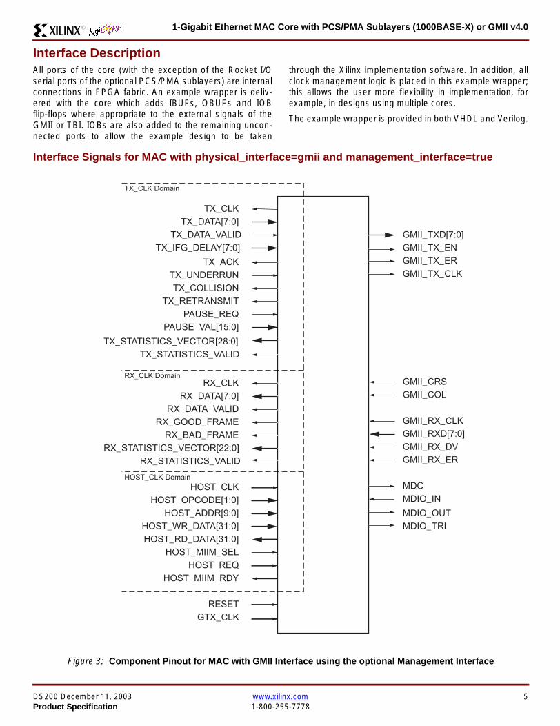
1-Gigabit Ethernet MAC Core with PCSPMA Sublayers (1000BASE-X) or GMII v40R
Interface DescriptionAll ports of the core (with the exception of the Rocket IOserial ports of the optional PCSPMA sublayers) are internalconnections in FPGA fabric An example wrapper is deliv-ered with the core which adds IBUFs OBUFs and IOBflip-flops where appropriate to the external signals of theGMII or TBI IOBs are also added to the remaining uncon-nected ports to allow the example design to be taken
through the Xilinx implementation software In addition allclock management logic is placed in this example wrapperthis allows the user more flexibility in implementation forexample in designs using multiple cores
The example wrapper is provided in both VHDL and Verilog
Interface Signals for MAC with physical_interface=gmii and management_interface=true
Figure 3 Component Pinout for MAC with GMII Interface using the optional Management Interface
GTX_CLK
TX_CLK
GMII_RX_CLK
MDCMDIO_IN
GMII_RXD[70]
GMII_TXD[70]GMII_TX_ENGMII_TX_ER
TX_DATA[70]
TX_ACKTX_UNDERRUN
PAUSE_REQPAUSE_VAL[150]
RX_CLK
HOST_CLKHOST_OPCODE[10]
HOST_ADDR[90]HOST_WR_DATA[310]HOST_RD_DATA[310]
HOST_MIIM_SELHOST_REQ
HOST_MIIM_RDY
RESET
RX_DATA[70]
RX_GOOD_FRAMERX_BAD_FRAME
TX_COLLISIONTX_RETRANSMIT
TX_DATA_VALID
RX_DATA_VALID
GMII_TX_CLK
GMII_COLGMII_CRS
GMII_RX_DVGMII_RX_ER
TX_CLK Domain
RX_CLK Domain
HOST_CLK Domain
TX_IFG_DELAY[70]
TX_STATISTICS_VECTOR[280]TX_STATISTICS_VALID
RX_STATISTICS_VECTOR[220]RX_STATISTICS_VALID
MDIO_OUTMDIO_TRI
DS200 December 11 2003 wwwxilinxcom 5Product Specification 1-800-255-7778
1-Gigabit Ethernet MAC Core with PCSPMA Sublayers (1000BASE-X) or GMII v40 R
Interface Signals for MAC with physical_interface=gmii and management_interface=false
Figure 4 Component Pinout for MAC with GMII Interface without the optional Management Interface
GTX_CLK
TX_CLK
GMII_RX_CLKGMII_RXD[70]
GMII_TXD[70]GMII_TX_ENGMII_TX_ER
TX_DATA[70]
TX_ACKTX_UNDERRUN
PAUSE_REQPAUSE_VAL[150]
RX_CLK
CONFIGURATION_VECTOR[630]
RESET
RX_DATA[70]
RX_GOOD_FRAMERX_BAD_FRAME
TX_COLLISIONTX_RETRANSMIT
TX_DATA_VALID
RX_DATA_VALID
GMII_TX_CLK
GMII_COLGMII_CRS
GMII_RX_DVGMII_RX_ER
TX_CLK Domain
RX_CLK Domain
TX_IFG_DELAY[70]
TX_STATISTICS_VECTOR[280]TX_STATISTICS_VALID
RX_STATISTICS_VECTOR[220]RX_STATISTICS_VALID
6 wwwxilinxcom DS200 December 11 20031-800-255-7778 Product Specification
1-Gigabit Ethernet MAC Core with PCSPMA Sublayers (1000BASE-X) or GMII v40R
Interface Signals for MAC with physical_interface=tbi and management_interface=true
Figure 5 Component Pinout for MAC with PCS and TBI using the optional Management Interface
GTX_CLK
TX_CLK
MDCMDIO_IN
RX_CODE_GROUP1[90]
TX_CODE_GROUP[90]PMA_TX_CLK
LOC_REF
TX_DATA[70]
TX_ACKTX_UNDERRUN
PAUSE_REQPAUSE_VAL[150]
RX_CLK
HOST_CLKHOST_OPCODE[10]
HOST_ADDR[90]HOST_WR_DATA[310]HOST_RD_DATA[310]
HOST_MIIM_SELHOST_REQ
HOST_MIIM_RDY
RESET
RX_DATA[70]
RX_GOOD_FRAMERX_BAD_FRAME
TX_COLLISIONTX_RETRANSMIT
TX_DATA_VALID
RX_DATA_VALID
EWRAP
PMA_RX_CLK0PMA_RX_CLK1
TX_CLKRX_CLK Domain
HOST_CLK Domain
TX_IFG_DELAY[70]
TX_STATISTICS_VECTOR[280]TX_STATISTICS_VALID
RX_STATISTICS_VECTOR[220]RX_STATISTICS_VALID
MDIO_OUTMDIO_TRI
EN_CDET
RX_CODE_GROUP0[90]
SIGNAL_DETECT
PHYAD[40]
DS200 December 11 2003 wwwxilinxcom 7Product Specification 1-800-255-7778
1-Gigabit Ethernet MAC Core with PCSPMA Sublayers (1000BASE-X) or GMII v40 R
Interface Signals for MAC with physical_interface=tbi and management_interface=false
Figure 6 Component Pinout for MAC with PCS and TBI without the optional Management Interface
GTX_CLK
TX_CLK
MDC_INMDIO_IN
RX_CODE_GROUP1[90]
TX_CODE_GROUP[90]PMA_TX_CLK
LOC_REF
TX_DATA[70]
TX_ACKTX_UNDERRUN
PAUSE_REQPAUSE_VAL[150]
RX_CLK
CONFIGURATION_VECTOR[630]
RESET
RX_DATA[70]
RX_GOOD_FRAMERX_BAD_FRAME
TX_COLLISIONTX_RETRANSMIT
TX_DATA_VALID
RX_DATA_VALID
EWRAP
PMA_RX_CLK0PMA_RX_CLK1
TX_CLKRX_CLK Domain
TX_IFG_DELAY[70]
TX_STATISTICS_VECTOR[280]TX_STATISTICS_VALID
RX_STATISTICS_VECTOR[220]RX_STATISTICS_VALID
MDIO_OUTMDIO_TRI
EN_CDET
RX_CODE_GROUP0[90]
PHYAD[40]
SIGNAL_DETECT
8 wwwxilinxcom DS200 December 11 20031-800-255-7778 Product Specification
1-Gigabit Ethernet MAC Core with PCSPMA Sublayers (1000BASE-X) or GMII v40R
Interface Signals for MAC with physical_interface=phy and management_interface=true
Figure 7 Component Pinout for MAC with PCS amp PMA Sublayers using the optional Management Interface
REFCLK
TX_CLK
MDCMDIO_IN
TXPTXN
TX_DATA[70]
TX_ACKTX_UNDERRUN
PAUSE_REQPAUSE_VAL[150]
RX_CLK
HOST_CLKHOST_OPCODE[10]
HOST_ADDR[90]HOST_WR_DATA[310]HOST_RD_DATA[310]
HOST_MIIM_SELHOST_REQ
HOST_MIIM_RDY
RESET
RX_DATA[70]
RX_GOOD_FRAMERX_BAD_FRAME
TX_COLLISIONTX_RETRANSMIT
TX_DATA_VALID
RX_DATA_VALID
RXPRXN
TX_CLKRX_CLK Domain
HOST_CLK Domain
TX_IFG_DELAY[70]
TX_STATISTICS_VECTOR[280]TX_STATISTICS_VALID
RX_STATISTICS_VECTOR[220]RX_STATISTICS_VALID
PHYAD[40]
SIGNAL_DETECT
MDIO_OUTMDIO_TRI
USRCLKUSRCLK2
DCM_LOCKED
REFCLK2BREFCLK
BREFCLK2REFCLKSEL
DS200 December 11 2003 wwwxilinxcom 9Product Specification 1-800-255-7778
1-Gigabit Ethernet MAC Core with PCSPMA Sublayers (1000BASE-X) or GMII v40 R
Interface Signals for MAC with physical_interface=phy and management_interface=false
Figure 8 Component Pinout for MAC with PCS amp PMA Sublayers without the optional Management Interface
TX_CLK
MDC_INMDIO_IN
TXPTXN
TX_DATA[70]
TX_ACKTX_UNDERRUN
PAUSE_REQPAUSE_VAL[150]
RX_CLK
CONFIGURATION_VECTOR[630]
RX_DATA[70]
RX_GOOD_FRAMERX_BAD_FRAME
TX_COLLISIONTX_RETRANSMIT
TX_DATA_VALID
RX_DATA_VALID
RXPRXN
TX_CLKRX_CLK Domain
TX_IFG_DELAY[70]
TX_STATISTICS_VECTOR[280]TX_STATISTICS_VALID
RX_STATISTICS_VECTOR[220]RX_STATISTICS_VALID
SIGNAL_DETECT
MDIO_OUTMDIO_TRI
REFCLKRESET
PHYAD[40]
USRCLKUSRCLK2
DCM_LOCKED
REFCLK2BREFCLK
BREFCLK2REFCLKSEL
10 wwwxilinxcom DS200 December 11 20031-800-255-7778 Product Specification
1-Gigabit Ethernet MAC Core with PCSPMA Sublayers (1000BASE-X) or GMII v40R
Client Side Interface Signal Definition
Table 3 describes the client-side transmit signals of the MAC core These signals are used to transmit data from the clientto the MAC core
Table 4 describes the client-side receive signals These signals are used by the MAC core to transfer data to the client
Table 3 Transmit Client Interface Signal Pins
Signal Direction Description
TX_CLK Output Clock for transmit client interface 125 MHz nominal
TX_DATA[70] Input Frame data to be transmitted is supplied on this port
TX_DATA_VALID Input Control signal for TX_DATA port
TX_IFG_DELAY[70] InputControl signal for configurable Inter Frame Gap adjustment SeeTransmitter on page 16 for timing diagrams
TX_ACK OutputHandshaking signal Asserted when the current data on TX_DATA hasbeen accepted See Transmitter on page 16 for timing diagrams
TX_UNDERRUN Input Asserted by client to force MAC core to corrupt the current frame
TX_COLLISION OutputAsserted by the MAC core to signal a collision on the medium and that anytransmission in progress should be aborted Always 0 when the MAC coreis in full-duplex mode
TX_RETRANSMIT Output
When asserted at the same time as the TX_COLLISION signal thissignals the client that the aborted frame should be resupplied to the MACcore for retransmission Always 0 when the MAC core is in full-duplexmode
TX_STATISTICS_VECTOR[280] OutputThis gives information on the last frame transmitted See Transmitter onpage 16 for vector contents
TX_STATISTICS_VALID OutputAsserted at end of frame transmission indicating that theTX_STATISTICS_VECTOR is valid
Notes1 All the above signals are synchronous to TX_CLK and Active High
Table 4 Receive Client Interface Signal Pins
Signal Direction Description
RX_CLK Output Clock for receive client interface 125 MHz nominal
RX_DATA[70] Output Frame data received is supplied on this port
RX_DATA_VALID Output Control signal for the RX_DATA port
RX_GOOD_FRAME OutputAsserted at end of frame reception to indicate that the frame should beprocessed by the MAC client See Receiver on page 24
RX_BAD_FRAME OutputAsserted at end of frame reception to indicate that the frame should bediscarded by the MAC client See Receiver on page 24
RX_STATISTICS_VECTOR[220] OutputProvides information about the last frame received See Receiver onpage 24 for the vector contents
RX_STATISTICS_VALID OutputAsserted at end of frame reception indicating that theRX_STATISTICS_VECTOR is valid
Notes1 All signals above are synchronous to RX_CLK and Active High
DS200 December 11 2003 wwwxilinxcom 11Product Specification 1-800-255-7778
1-Gigabit Ethernet MAC Core with PCSPMA Sublayers (1000BASE-X) or GMII v40 R
Table 5 describes the signals used by the client to request a flow control action from the transmit engine Flow control framesreceived by the MAC are automatically handled (if the MAC is configured to do so)
Table 6 describes the optional signals used by the client to access the management features of the MAC core includingconfiguration status statistics and MDIO access
Table 7 describes the alternative to the optional Management Interface signals This describes the Configuration Vectorwhich uses direct inputs to the core to replace the functionality of the MAC Configuration bits when the ManagementInterface is not used
Notes1 All bits of CONFIGURATION_VECTOR are registered on input but may be treated as asynchronous inputs
Table 5 Flow Control Interface Signal Pinout
Signal Direction Description
PAUSE_REQ InputPause request sends a pause frame down the link See Transmitting a PAUSE ControlFrame on page 29
PAUSE_VAL[150] Input Pause value inserted into the parameter field of the transmitted pause frame
Notes1 These signals are synchronous to TX_CLK and are Active High
Table 6 Optional Management Interface Signal Pinout (management_interface=true)
Signal Direction Description
HOST_CLK InputClock for management interface See Optional Management Interface(management_interface=true) on page 30 for the signal frequency range
HOST_OPCODE[10] InputDefines operation to be performed over MDIO interface Bit 1 is also used inconfiguration register access See Configuration Registers on page 30
HOST_ADDR[90] Input Address of register to be accessed
HOST_WR_DATA[310] Input Data to write to register
HOST_RD_DATA[310] Output Data read from register
HOST_MIIM_SEL InputWhen asserted the MDIO interface is accessed When disasserted the MACinternal configuration or statistical counter registers are accessed
HOST_REQ InputUsed to signal a transaction on the MDIO interface or to read from the statisticregisters See Optional Management Interface (management_interface=true) onpage 30
HOST_MIIM_RDY OutputWhen high the MDIO interface has completed any pending transaction and isready for a new transaction
Notes1 All signals above are synchronous to HOST_CLK and are Active High
Table 7 Alternative to the Optional Management Interface Configuration Vector Signal Pinout(management_interface=false)
Signal Direction Description
CONFIGURATION_VECTOR[630]
Input The Configuration Vector is used to replace the functionality of theMAC Configuration Registers when the Management Interface is notused See Optional Configuration Vector (management_interface =false) on page 38
12 wwwxilinxcom DS200 December 11 20031-800-255-7778 Product Specification
1-Gigabit Ethernet MAC Core with PCSPMA Sublayers (1000BASE-X) or GMII v40R
Table 8 describes the reset signal
Physical Interface Signal Definition
Table 9 describes the MDIO (MII Management) interface signals of the MAC core These signals are typically connected tothe MDIO port of a PHY device either off-chip or an SoC-integrated core The MDIO format is defined in IEEE8023 clause22
Table 10 describes the optional GMII signals of the MAC core These are typically attached to a PHY module either off-chipor internally integrated The GMII is defined in IEEE8023 clause 35
Table 8 Reset Signal
Signal Direction Description
RESET Input Asynchronous reset for entire core See Reset circuit on page 42 for moreinformation on the reset circuit
Table 9 MDIO Interface Signal Pinout
Signal Direction Description
MDC OutputManagement Clock derived from HOST_CLK on the basis of supplied configuration datawhen the optional Management Interface is used See Optional Management Interface(management_interface=true) on page 30
MDC_IN InputWhen the Optional Management Interface is not used access to the optional PhysicalCoding Sublayer (PCS) must be provided by an external MDIO Controller In this situationthe Management Clock is an input to the core
MDIO_IN Input Input data signal for communication with PHY configuration and status Tie high if unused
MDIO_OUT Output Output data signal for communication with PHY configuration and status
MDIO_TRI OutputTristate control for MDIO signals 0 signals that the value on MDIO_OUT should be
asserted onto the MDIO bus
Table 10 Optional GMII Interface Signal Pinout (physical_interface=gmii)
Signal Direction Description
GTX_CLK InputClock signal at 125 MHz Other transmit clocks are derived from this clock as illustratedin Figure 28 Tolerance must be within IEEE 8023-2002 specification
GMII_TXD[70] Output Transmit data to PHY
GMII_TX_EN Output Data Enable control signal to PHY
GMII_TX_ER Output Error control signal to PHY
GMII_TX_CLK Output Clock out to PHY
GMII_CRS Input Control signal from PHY
GMII_COL Input Control signal from PHY
GMII_RX_CLK Input Recovered clock from received data stream by PHY
GMII_RXD[70] Input Received data from PHY
GMII_RX_DV Input Data Valid control signal from PHY
GMII_RX_ER Input Error control signal from PHY
DS200 December 11 2003 wwwxilinxcom 13Product Specification 1-800-255-7778
1-Gigabit Ethernet MAC Core with PCSPMA Sublayers (1000BASE-X) or GMII v40 R
Table 11 describes the TBI (Ten-Bit interface) signals of the MAC core These are typically attached to a PMA SERDESmodule These signals optionally replace the GMII signals described in Table 10 to extend the functionality of the core toinclude the PCS for 1000BASE-X The TBI is defined in IEEE8023 clause 36
Notes
PHYAD and SIGNAL_DETECT are asynchronous inputs SIGNAL_DETECT is Active High
Table 11 Optional TBI Interface Signal Pinout (physical_interface=tbi)
Signal Direction Description
GTX_CLK InputClock signal at 125 MHz Other transmit clocks will be derived from this clock asillustrated in Figure 32 Tolerance must be within IEEE 8023-2002 specification
TX_CODE_GROUP[90] Output 10-bit parallel transmit data to PMA Sublayer (SERDES)
PMA_TX_CLK Output Transmit clock signal to PMA Sublayer (SERDES) at 125MHz
LOC_REF OutputCauses the PMA sublayer clock recovery unit to lock to PMA_TX_CLK Thissignal is tied to Ground
EWRAP Output
This signal is set from the PCS Control Register 0 bit 14 (loopback) See PCSManaged Register Block (physical_interface = tbi or phy) on page 49 Whenhigh this instructs the PMA sublayer to electrically loop the transmitter data to thereceiver
RX_CODE_GROUP0[90] Input10-bit parallel received data from PMA Sublayer (SERDES) synchronous toPMA_RX_CLK0
RX_CODE_GROUP1[90] Input10-bit parallel received data from PMA Sublayer (SERDES) synchronous toPMA_RX_CLK1
PMA_RX_CLK0 Input Received clock signal from PMA Sublayer (SERDES) at 625MHz
PMA_RX_CLK1 InputReceived clock signal from PMA Sublayer (SERDES) at 625MHz This is 180degrees out of phase with PMA_RX_CLK0
EN_CDET OutputEnables the PMA Sublayer to perform comma realignment driven from the PCSstate machine during the Loss-Of-Sync state
PHYAD[40] Input PHY address of MDIO register set for the PCS
SIGNAL_DETECT Input
Signal direct from PMD sublayer indicating the presence of light detected at theoptical receiver If driven high this indicates that the optical receiver has detectedlight If driven low this indicates the absence of light
If unused tie high to enable the operation the core
14 wwwxilinxcom DS200 December 11 20031-800-255-7778 Product Specification
1-Gigabit Ethernet MAC Core with PCSPMA Sublayers (1000BASE-X) or GMII v40R
Table 12 describes the interface signals for the Optional PCSPMA sublayer of the MAC core These signals optionallyreplace the GMII signals described in Table 10 to extend the functionality of the core to include the PCS and PMA sublayersfor 1000BASE-X This option uses the Virtex-II Pro Rocket IO functionality which is integrated into the core The PMAsublayer for 1000BASE-X is defined in IEEE8023 clause 36
Notes1 PHYAD and SIGNAL_DETECT are asynchronous inputs SIGNAL_DETECT is Active High
Table 12 Optional PCSPMA sublayer Interface Signal Pinout (physical_interface=phy)
Signal Direction Description
REFCLK InputHigh Quality Reference clock for Multi-Gigabit Transceivers (625 MHz) See Rocket IOUser Guide
REFCLK2 Input Alternative High Quality Reference clock for Multi-Gigabit Transceivers (625 MHz) SeeRocket IO User Guide
BREFCLK Input Alternative High Quality Reference clock for Multi-Gigabit Transceivers (625 MHz)This optionally replaces REFCLK See Rocket IO User Guide
BREFCLK2 Input Alternative High Quality Reference clock for Multi-Gigabit Transceivers (625 MHz)This optionally replaces REFCLK2 See Rocket IO User Guide
REFCLKSEL Input Selects between either (B)REFCLK or (B)REFCLK2 as the input clock source to theMGT See Rocket IO User Guide
USERCLK InputClock signal at 625 MHz This is connected to the TXUSRCLK and RXUSRCLK portsof the Rocket IO MGT This may be derived from (B)REFCLK using a DCM asillustrated in Figure 35
USERCLK2 InputClock signal at 125 MHz This is connected to the TXUSRCLK2 and RXUSRCLK2 portsof the Rocket IO MGT This may be derived from (B)REFCLK using a DCM asillustrated in Figure 35
DCM_LOCKED InputIf a DCM is used to derive USRCLK and USRCLK2 as illustrated in Figure 35 theLOCKED port of the DCM must be connected to the DCM_LOCKED port of the coreThe core will hold itrsquos Rocket IO MGT in reset until DCM_LOCKED is driven to logic 1
TXPTXN OutputDifferential pair for serial transmission from PMA to PMD The clock is embedded in thedata stream
RXPRXN InputDifferential pair for serial reception from PMD to PMA The clock is extracted from thedata stream
PHYAD[40] Input PHY address of MDIO register set for the PCS
SIGNAL_DETECT Input
Signal direct from PMD sublayer indicating the presence of light detected at the opticalreceiver If driven high this indicates that the optical receiver has detected light If drivenlow this indicates the absence of light
If unused tie high to enable the operation the core
DS200 December 11 2003 wwwxilinxcom 15Product Specification 1-800-255-7778
1-Gigabit Ethernet MAC Core with PCSPMA Sublayers (1000BASE-X) or GMII v40 R
Functional Description
Client InterfaceThe client interface is designed for maximum flexibility inmatching to a client switching fabric or network processorinterface
The data pathway is 8 bits wide in both the transmit andreceive directions with each pathway synchronous to theTX_CLK and RX_CLK respectively for completely indepen-dent full duplex operation
Transmitter
Normal Frame Transmission
The timing of a normal outbound frame transfer can be seenin Figure 9 When the client wants to transmit a frame itplaces the first column of data onto the TX_DATA port andasserts a ldquo1rdquo onto TX_DATA_VALID
When the MAC core has read this first byte of data it willassert the TX_ACK signal on the next and subsequent ris-ing clock edges the client must provide the remainder ofthe data for the frame
The end of frame is signalled to the MAC core by takingTX_DATA_VALID Low
In-Band Parameter Encoding
For maximum flexibility in switching applications the Ether-net frame parameters (destination address sourceaddress lengthtype and optionally FCS) are encodedwithin the same data stream that the frame payload is trans-ferred upon rather than on separate ports This is illustratedin the timing diagrams Definitions of the abbreviations usedin the timing diagrams are described in Table 13
Figure 9 Normal Frame Transmission Across Client Interface
Table 13 Abbreviations Used in Timing Diagrams
Abbreviation Definition
DA Destination Address 6 bytes
SA Source Address 6 bytes
LT LengthType Field 2 bytes
FCS Frame Check Sequence 4 bytes
TX_CLK
TX_DATA[70]
TX_DATA_VALID
TX_ACK
TX_UNDERRUN
DA SA DATALT
TX_COLLISION
TX_RETRANSMIT
xip2133
16 wwwxilinxcom DS200 December 11 20031-800-255-7778 Product Specification
1-Gigabit Ethernet MAC Core with PCSPMA Sublayers (1000BASE-X) or GMII v40R
Padding
When fewer than 46 bytes of data are supplied by the clientto the MAC core the transmitter module will add padding upto the minimum frame length The exception to this is whenthe MAC core is configured for client-passed FCS in thiscase the client must also supply the padding to maintain theminimum frame length (see Client-Supplied FCS Passing)
Client-Supplied FCS Passing
If the MAC core is configured to have the FCS field passedin by the client (see Configuration Registers on page 30)the transmission timing is as depicted in Figure 10 In thiscase it is the responsibility of the client to ensure that theframe meets the Ethernet minimum frame length require-ments the MAC core will not perform any padding of thepayload
Figure 10 Frame Transmission with Client-supplied FCS
TX_CLK
TX_DATA[70]
TX_DATA_VALID
TX_ACK
TX_UNDERRUN
DA SA DATA FCSLT
TX_COLLISION
TX_RETRANSMIT
xip2134
DS200 December 11 2003 wwwxilinxcom 17Product Specification 1-800-255-7778
1-Gigabit Ethernet MAC Core with PCSPMA Sublayers (1000BASE-X) or GMII v40 R
Client Underrun
The timing of an aborted transfer can be seen in Figure 11This may happen for instance if a FIFO connected to theclient interface empties before a frame is completed Whenthe client asserts TX_UNDERRUN during a frame transmis-sion the MAC core will insert an error code to corrupt the
current frame and then fall back to idle transmission It isthe responsibility of the client to re-queue the aborted framefor transmission
When an underrun occurs TX_DATA_VALID may beasserted on the clock cycle after the TX_UNDERRUNassertion to request a new transmission
Figure 11 Frame Transmission with Underrun
TX_CLK
TX_DATA[70]
TX_DATA_VALID
TX_ACK
TX_UNDERRUN
DA SA DATALT
TX_COLLISION
TX_RETRANSMIT
xip2135
18 wwwxilinxcom DS200 December 11 20031-800-255-7778 Product Specification
1-Gigabit Ethernet MAC Core with PCSPMA Sublayers (1000BASE-X) or GMII v40R
Back-to-Back Transfers
Figure 12 shows the case where the MAC client is immedi-ately ready to transmit a second frame of data followingcompletion of its first frame In this figure the end of the firstframe is shown on the left On the clock cycle immediatelyfollowing the final byte of the first frame TX_DATA_VALIDis taken low by the client and is taken high one clock cyclelater to indicate that the first byte of the destination addressof the second frame is on TX_DATA awaiting transmission
When the MAC core is ready to accept data TX_ACK isasserted and the transmission continues in the same man-ner as in the case of the single frame The MAC core willdefer the assertion of TX_ACK appropriately to comply withinter-packet gap requirements and flow control requests
If the MAC core is operating in half-duplex mode the timingshown in Figure 12 is required to take advantage of framebursting the MAC core is only guaranteed to retain controlof the medium if the TX_DATA_VALID signal is low for a sin-gle clock cycle For more information on frame bursting seeIEEE 8023-2002
Figure 12 Back to Back Frame Transmission
TX_CLK
TX_DATA[70]
TX_DATA_VALID
TX_ACK
TX_UNDERRUN
TX_COLLISION
TX_RETRANSMIT
xip2136
DS200 December 11 2003 wwwxilinxcom 19Product Specification 1-800-255-7778
1-Gigabit Ethernet MAC Core with PCSPMA Sublayers (1000BASE-X) or GMII v40 R
VLAN Tagged Frames
Transmission of a VLAN tagged frame (if enabled) can beseen in Figure 13 Note that the handshaking signalsacross the interface do not change however the VLANtype tag 81-00 must be supplied by the client to signify that
the frame is VLAN tagged The client also supplies the twobytes of Tag Control Information V1 and V2 at the appro-priate times in the data stream More information on thecontents of these two bytes can be found in IEEE8023-2002
Maximum Permitted Frame Length
The maximum legal length of a frame specified in IEEE8023-2002 is 1518 bytes for non-VLAN tagged framesVLAN tagged frames may be extended to 1522 bytesWhen jumbo frame handling is disabled and the clientattempts to transmit a frame which exceeds the maximumlegal length the MAC core will insert an error code to cor-
rupt the current frame and the frame will be truncated to themaximum legal length When jumbo frame handling isenabled frames which are longer than the legal maximumare transmitted error-free
For more information on enabling and disabling jumboframe handling see Configuration Registers on page 30
Figure 13 Transmission of a VLAN Tagged Frame
TX_CLK
TX_DATA[70]
TX_DATA_VALID
TX_ACK
TX_UNDERRUN
DA SA DATALTVLANtag
81 00V1V2
TX_COLLISION
TX_RETRANSMIT
xip2137
20 wwwxilinxcom DS200 December 11 20031-800-255-7778 Product Specification
1-Gigabit Ethernet MAC Core with PCSPMA Sublayers (1000BASE-X) or GMII v40R
Frame Collisions - Half Duplex Operation Only
In half duplex Ethernet operation collisions will occur on themedium as a matter of course this is how the arbitrationalgorithm is fulfilled In case of a collision the MAC core sig-nals to the client that data may need to be resupplied as fol-lows
If there is a collision the TX_COLLISION signal will be setto ldquo1rdquo by the MAC core If a frame is in progress the clientmust abort the transfer and take TX_DATA_VALID to ldquo0rdquo
If the TX_RETRANSMIT signal is ldquo1rdquo in the same clockcycle that the TX_COLLISION signal is ldquo1rdquo the client must
resubmit the previous frame to the MAC core for retrans-mission TX_DATA_VALID must be asserted to the MACcore within 8 clock cycles of the TX_COLLISION signal inorder to meet Ethernet timing requirements See Figure 14
If the TX_RETRANSMIT signal is ldquo0rdquo in the same clockcycle that the TX_COLLISION signal is ldquo1rdquo the number ofretries for this frame has exceeded the Ethernet specifica-tion and the frame should be dropped by the client The cli-ent can then make any new frame available to the MAC fortransmission without timing restriction See Figure 15
Figure 14 Collision Handling - Frame retransmission required
Figure 15 Collision Handling - No frame retransmission required
TX_CLK
TX_DATA[70]
TX_DATA_VALID
TX_ACK
TX_UNDERRUN
TX_COLLISION
TX_RETRANSMIT
8 clocks max
xip2138
TX_CLK
TX_DATA[70]
TX_DATA_VALID
TX_ACK
TX_UNDERRUN
TX_COLLISION
TX_RETRANSMIT
xip2139
DS200 December 11 2003 wwwxilinxcom 21Product Specification 1-800-255-7778
1-Gigabit Ethernet MAC Core with PCSPMA Sublayers (1000BASE-X) or GMII v40 R
Interframe Gap Adjustment
The user can elect to vary the length of the inter fame gapIf this function is selected (via a configuration bit in thetransmitter control register see Configuration Registerson page 30) then the MAC will exert back pressure to delaythe transmission of the next frame until the requested num-ber of Idle cycles has elapsed The number of Idle cycles iscontrolled by the value on the TX_IFG_DELAY port at thestart of frame transmission Figure 16 shows the MAC oper-ating in this mode
Reducing the Inter fame gap to below the IEEE 8023-2002minimum of 12 Idles is supported in Full Duplex onlydesigns and will transmit an absolute minimum of 4 Idles Ifthe Interframe gap adjustment is reduced below 12 Idlesthen the accuracy of the Optional Statistical Gathering(statistics_gathering=true) Counters cannot be guaranteedHowever the TX_STATISTIC_VECTOR andRX_STATISTIC_VECTOR will always remain correct
Transmitter Statistics Vector
The statistics for the frame transmitted are contained withinthe TX_STATISTICS_VECTOR The vector is driven syn-chronously by the transmitter clock TX_CLK followingframe transmission The bit field definition for the Vector isdefined in Table 14
All bit fields with the exception of BYTE_VALID are validonly when the TX_STATISTICS_VALID is asserted This isillustrated in Figure 17 BYTE_VALID is significant on everyTX_CLK cycle
TX_STATISTICS_VECTOR bits 25 down to 17 inclusive arefor half duplex only and will be set to logic 0 when operatingin full duplex mode
Figure 16 Interframe Gap Adjustment
TX_CLK
TX_DATA[70]
TX_DATA_VALID
TX_ACK
DA SA
TX_IFG_DELAY
IFG ADJUST VALUE
0x0D
13 Idles inserted
DA
Next IFG ADJUST VALUE
xip2140
Figure 17 Transmitter Statistics Vector Timing
TX_CLK
TX_STATISTICS_VECTOR[280]
TX_STATISTICS_VALID
xip2141
22 wwwxilinxcom DS200 December 11 20031-800-255-7778 Product Specification
1-Gigabit Ethernet MAC Core with PCSPMA Sublayers (1000BASE-X) or GMII v40R
Table 14 Bit Definition for the Transmitter Statistics Vector
TX_STATISTICS_VECTOR Name Description
28 PAUSE_FRAME_TRANSMITTEDAsserted if the previous frame was a pause framethat the MAC itself initiated in response to aPAUSE_REQ assertion
27 BYTE_VALID
Asserted if a MAC frame byte (DA to FCS inclusive)is in the process of being transmitted This is valid onevery clock cycle
Do not use this as an enable signal to indicate thatdata is present on GMII_TXD[70]
26 Reserved Returns logic 0
25 down to 22 TX_ATTEMPTS[30]
The number of attempts that have been made totransmit the previous frame This is a 4-bit number0 should be interpreted as 1 attempt 1 as 2attempts up until 15 as 16 attempts
21 Reserved Returns logic 0
20 EXCESSIVE_COLLISIONAsserted if a collision has been detected on each ofthe last 16 attempts to transmit the previous frame
19 LATE_COLLISIONAsserted if a late collision occurred during frametransmission
18 EXCESSIVE_DEFERRALAsserted if the previous frame was deferred for anexcessive amount of time as defined by the constantldquomaxDeferTimerdquo in IEEE 8023-2002
17 TX_DEFERRED Asserted if transmission of the frame was deferred
16 VLAN_FRAMEAsserted if the previous frame contained a VLANidentifier in the LengthType field when transmitterVLAN operation is enabled
15 down to 5 FRAME_LENGTH_COUNTThe length of the previous frame in number of bytesThe count will stick at 2047 for any Jumbo frameslarger than this value
4 CONTROL_FRAMEAsserted if the previous frame had the special MACControl Type code 88-08 in the LengthType field
3 UNDERRUN_FRAMEAsserted if the previous frame contained anunderrun error
2 MULTICAST_FRAMEAsserted if the previous frame contained a multicastaddress in the Destination Address field
1 BROADCAST_FRAMEAsserted if the previous frame contained abroadcast address in the Destination Address field
0 SUCCESSFUL_FRAMEAsserted if the previous frame was transmittedwithout error
DS200 December 11 2003 wwwxilinxcom 23Product Specification 1-800-255-7778
1-Gigabit Ethernet MAC Core with PCSPMA Sublayers (1000BASE-X) or GMII v40 R
Receiver
Normal Frame Reception
The timing of a normal inbound frame transfer can be seenin Figure 18 The client must be prepared to accept data atany time there is no buffering within the MAC to allow forlatency in the receive client Once frame reception begins
data is transferred on consecutive clock cycles to thereceive client until the frame is complete The MAC assertsthe RX_GOOD_FRAME signal to indicate that the framewas successfully received and that the frame should beanalyzed by the client
Frame parameters (destination address source addresslengthtype and optionally FCS) are supplied on the databus according to the timing diagram The abbreviations arethe same as those described in Table 13 on page 16
If the LengthType field in the frame has the Length interpre-tation and this indicates that the inbound frame has beenpadded to meet the Ethernet minimum frame size specifica-tion then this padding will not be passed to the client in thedata payload The exception to this is in the case whereFCS passing is enabled see Client-Supplied FCS Pass-ing on page 25
Therefore when Client-Supplied FCS passing is disabledRX_DATA_VALID = lsquo0rsquo between frames for the duration ofthe Padding field (if present) the FCS field carrier exten-sion (if present) the interframe gap following the frame andthe preamble field of the next frame When Client-Supplied
FCS passing is enabled RX_DATA_VALID = lsquo0rsquo betweenframes for the duration of carrier extension (if present) theinterframe gap and the preamble field of the followingframe
RX_GOOD_FRAME RX_BAD_FRAME timing
Although the timing diagram in Figure 18 shows theRX_GOOD_FRAME signal asserted shortly after the lastvalid data on RX_DATA this is not always the case TheRX_GOOD_FRAME or RX_BAD_FRAME signals areasserted only after all frame checks are completed This isafter the FCS field has been received (and after reception ofcarrier extension if present)
Therefore either RX_GOOD_FRAME or RX_BAD_FRAMEis asserted following frame reception at the beginning of theinterframe gap
Figure 18 Normal Frame Reception
RX_CLK
RX_DATA[70]
RX_DATA_VALID
RX_GOOD_FRAME
RX_BAD_FRAME
DA SA DATALT
xip2142
24 wwwxilinxcom DS200 December 11 20031-800-255-7778 Product Specification
1-Gigabit Ethernet MAC Core with PCSPMA Sublayers (1000BASE-X) or GMII v40R
Frame Reception with Errors
The case of an unsuccessful frame reception (for examplea fragment frame or a frame with an incorrect FCS) can beseen in Figure 19 In this case the RX_BAD_FRAME signal
is asserted to the client at the end of the frame It is then theresponsibility of the client to drop the data already trans-ferred for this frame
Figure 19 Frame Reception with Error
Client-Supplied FCS Passing
If the MAC core is configured to pass the FCS field to the cli-ent (see Configuration Registers on page 30) then this ishandled as shown in Figure 20
In this case any padding inserted into the frame to meetEthernet minimum frame length specifications will be leftintact and passed to the client
Note that even though the FCS is passed up to the client itis also verified by the MAC core and RX_BAD_FRAMEasserted if the FCS check fails
RX_CLK
RX_DATA[70]
RX_DATA_VALID
RX_GOOD_FRAME
RX_BAD_FRAME
DA SA DATALT
xip2144
Figure 20 Frame Reception with In-Band FCS Field
RX_CLK
RX_DATA[70]
RX_DATA_VALID
RX_GOOD_FRAME
RX_BAD_FRAME
DA SA DATALT FCS
xip2145
DS200 December 11 2003 wwwxilinxcom 25Product Specification 1-800-255-7778
1-Gigabit Ethernet MAC Core with PCSPMA Sublayers (1000BASE-X) or GMII v40 R
VLAN Tagged Frames
The reception of a VLAN tagged frame (if enabled) can beseen in Figure 21 The VLAN frame is passed to the clientso that the frame may be identified as VLAN tagged this is
followed by the Tag Control Information bytes V1 and V2More information on the interpretation of these bytes maybe found in IEEE 8023-2002 standard
Maximum Permitted Frame Length
The maximum legal length of a frame specified in IEEE8023-2002 is 1518 bytes for non-VLAN tagged framesVLAN tagged frames may be extended to 1522 bytesWhen jumbo frame handling is disabled and the corereceives a frame which exceeds the maximum legal lengthRX_BAD_FRAME will be asserted When jumbo framehandling is enabled frames which are longer than the legalmaximum are received in the same way as shorter frames
For more information on enabling and disabling jumboframe handling see Configuration Registers on page 30
LengthType Field Error Checks
Enabled
Default operation is with the LengthType error checkingenabled (see Receiver Configuration Word 1 on page 31)In this mode the following checks are made on all framesreceived If either of these checks fail then the frame ismarked as BAD
bull A value in the LengthType field that is greater than orequal to decimal 46 but less than decimal 1536 (aLength interpretation) is checked against the actualdata length received
bull A value in the LengthType field that is less thandecimal 46 is checked to see that the data field ispadded to exactly 46 bytes (so that the resultant frameis minimum frame size 64 bytes total in length)
Furthermore if Padding is indicated (the LengthType fieldis less than decimal 46) and Client-Supplied FCS Passing isdisabled then the Length value in the LengthType field willbe used to deassert RX_DATA_VALID after the indicatednumber of data bytes so that the Padding bytes areremoved from the frame
Disabled
When the LengthType error checking is disabled (seeReceiver Configuration Word 1 on page 31) theLengthType error checks described above are not per-formed A frame containing only these errors will be markedas GOOD
Furthermore if Padding is indicated and Client-SuppliedFCS Passing is disabled then a Length Value in theLengthType field will not be used to deassertRX_DATA_VALID Instead RX_DATA_VALID will be deas-serted before the start of the FCS field in this way any pad-ding will not be removed from the frame
Figure 21 Reception of a VLAN Tagged Frame
RX_CLK
RX_DATA[70]
RX_DATA_VALID
RX_GOOD_FRAME
RX_BAD_FRAME
DA SA DATALT
81 00 V1 V2
VLANtag
xip2146
26 wwwxilinxcom DS200 December 11 20031-800-255-7778 Product Specification
1-Gigabit Ethernet MAC Core with PCSPMA Sublayers (1000BASE-X) or GMII v40R
Receiver Statistics Vector
The statistics for the frame received are contained withinthe RX_STATISTICS_VECTOR The vector is driven syn-chronously by the receiver clock RX_CLK following framereception The bit field definition for the Vector is defined inTable 15
All bit fields with the exception of BYTE_VALID are validonly when the RX_STATISTICS_VALID is asserted This isillustrated in Figure 22 BYTE_VALID is significant on everyRX_CLK cycle
Figure 22 Receiver Statistics Vector Timing
RX_CLK
RX_STATISTICS_VECTOR[220]
RX_STATISTICS_VALID
xip2147
Table 15 Bit Definition for the Receiver Statistics Vector
RX_STATISTICS_VECTOR Name Description
22LENGTHTYPE Out ofRange
Asserted if the lengthtype field contained a length valuethat did not match the number of MAC client data bytesreceived Also high if the lengthtype field indicated thatthe frame contained padding but the number of MAC cli-ent data bytes received was not equal to 64 bytes (min-imum frame size)
The exception to the above is when the LengthTypeField Error Checks are disabled in which case this bitwill not be asserted
21 BAD_OPCODE
Asserted if the previous frame was error-free andcontained the special Control Frame identifier in theLengthType field but contained an opcode that isunsupported by the MAC (Any Opcode other thanPAUSE)
20 FLOW_CONTROL_FRAME
Asserted if the previous frame was error-freecontained the special Control Frame identifier in theLengthType field contained a Destination Addressthat matched either the MAC Control MulticastAddress or the configured source address of the MACcontained the supported PAUSE opcode and wasacted upon by the MAC
19 BYTE_VALID
Asserted if a MAC frame byte (DA to FCS inclusive) isin the process of being received This is valid on everyclock cycle
Do not use this as an enable signal to indicate thatdata is present on RX_DATA[70]
18 VLAN_FRAMEAsserted if the previous frame contained a VLANidentifier in the LengthType field when receiver VLANoperation is enabled
DS200 December 11 2003 wwwxilinxcom 27Product Specification 1-800-255-7778
1-Gigabit Ethernet MAC Core with PCSPMA Sublayers (1000BASE-X) or GMII v40 R
17 OUT_OF_BOUNDS
Asserted if the previous frame exceeded the specifiedIEEE8023-2002 maximum legal length (seeMaximum Permitted Frame Length on page 26) Thisis only valid if Jumbo frames are disabled
16 CONTROL_FRAMEAsserted if the previous frame contained the specialControl Frame identifier in the LengthType field
15 down to 5 FRAME_LENGTH_COUNTThe length of the previous frame in number of bytesThe count will stick at 2047 for any Jumbo frameslarger than this value
4 MULTICAST_FRAMEAsserted if the previous frame contained a multicastaddress in the Destination Address field
3 BROADCAST_FRAMEAsserted if the previous frame contained the broadcastaddress in the Destination Address field
2 FCS_ERRORAsserted if the previous frame received had anincorrect FCS value or the MAC detected error codesduring frame reception
1 BAD_FRAME1 Asserted if the previous frame received containederrors
0 GOOD_FRAME1 Asserted if the previous frame received was error-free
1 If the LengthType Field Error Checks are disabled then a frame which contains this type of error will be marked as a GOOD_FRAMEproviding no additional errors were detected
Table 15 Bit Definition for the Receiver Statistics Vector
RX_STATISTICS_VECTOR Name Description
28 wwwxilinxcom DS200 December 11 20031-800-255-7778 Product Specification
1-Gigabit Ethernet MAC Core with PCSPMA Sublayers (1000BASE-X) or GMII v40R
Flow ControlThe flow control block is designed to Clause 31 of the IEEE8023-2002 standard The MAC may be configured to sendpause frames and to act upon their reception These twobehaviors can be configured asymmetrically see Configu-ration Registers on page 30
Transmitting a PAUSE Control Frame
The client initiates a flow control frame by assertingPAUSE_REQ while the pause value is on the PAUSE_VALbus These signals are synchronous to TX_CLK The timingof this can be seen in Figure 23
If the MAC core is configured to support transmit flow con-trol this action causes the core to transmit a PAUSE controlframe on the link with the PAUSE parameter set to thevalue on PAUSE_VAL in the cycle when PAUSE_REQ wasasserted This will not disrupt any frame transmission inprogress but will take priority over any pending frame trans-
mission This frame will be transmitted even if the transmit-ter is in the paused state itself
Receiving a Pause Control Frame
When an error-free frame is received by the MAC core thefollowing checks are made
1 The Destination Address field is matched against theMAC Control Multicast address or the configuredSource Address for the MAC (see ConfigurationRegisters on page 30)
2 The LengthType field is matched against the MACControl Type code
3 The opcode field contents are matched against thePAUSE opcode if check 2 is true
If any of the above checks are false or the MAC Flow Con-trol logic for the receiver is disabled the frame is ignored bythe Flow Control logic and passed up to the client
If the frame passes all of the above checks is of minimumlegal size and the MAC Flow Control logic for the receiver isenabled the pause value parameter in the frame is thenused to inhibit transmitter operation for the time defined inthe IEEE8023-2002 specification This inhibit is imple-mented using the same back pressure scheme shown inFigure 12 Because the received pause frame has beenacted upon it is passed to the client with RX_BAD_FRAMEasserted to indicate to the client that it should be dropped
Reception of any frame for which check 2 is true and whichis not of legal minimum length is considered an invalid Con-trol frame This will be ignored by the Flow Control logic andpassed to the client with RX_BAD_FRAME asserted
Figure 23 Pause Request Timing
TX_CLK
PAUSE_VAL[150]
PAUSE_REQ
xip2148
DS200 December 11 2003 wwwxilinxcom 29Product Specification 1-800-255-7778
1-Gigabit Ethernet MAC Core with PCSPMA Sublayers (1000BASE-X) or GMII v40 R
Optional Management Interface(management_interface=true)The management interface is a processor-independentinterface with standard address data and control signals Itmay be used as is or a wrapper may be applied (not sup-plied) to interface to common bus architectures
This interface is used for
bull Configuration of the MAC core
bull Access to optional statistics counters for use by higherlayers for example SNMP
bull access through the MDIO interface to the managementregisters located in the PHY attached to the MAC core
The management interface is accessed differently depend-ing on the type of transaction a truth table showing whichaccess method is required for each transaction type isshown in Table 16 These access methods are described inthe following sections
HOST_CLK Frequency
The management interface clock HOST_CLK is used toderive the MDIO clock MDC and is therefore subject tosome frequency restrictions This HOST_CLK must be
ge 10 MHz
le 100 MHz
Configuring the MAC core to derive the MDC signal fromthis clock is detailed in MDIO Interface on page 37
Configuration Registers
After power up or reset the client may reconfigure the coreparameters from their defaults such as flow control supportConfiguration changes can be written at any time Both thereceiver and transmitter logic will only respond to configura-tion changes during Inter Frame Gaps The exceptions tothis are the configurable resets which take effect immedi-ately
Configuration of the MAC core is performed through a reg-ister bank accessed through the management interfaceThe configuration registers available in the core are detailedin Table 17 As can be seen the address has some implicitdonrsquot care bits any access to an address in the rangesshown will perform a 32-bit read or write from the same con-figuration word
Table 16 Management Interface Transaction Types
Transaction HOST_MIIM_SEL HOST_ADDR[9]
Configuration 0 1
Statistics 0 0
MIIM access 1 X
Table 17 Configuration Registers
Address Description
0x200-0x23F Receiver Configuration (Word 0)
0x240-0x27F Receiver Configuration (Word 1)
0x280-0x2BF Transmitter Configuration
0x2C0-0x2FF Flow Control Configuration
0x300-0x33F Reserved
0x340-0x37F Management Configuration
30 wwwxilinxcom DS200 December 11 20031-800-255-7778 Product Specification
1-Gigabit Ethernet MAC Core with PCSPMA Sublayers (1000BASE-X) or GMII v40R
The register contents for the two receiver configuration words can be seen in Table 18 and Table 19
Notes1 In changing the receiverrsquos mode from Half Duplex to Full Duplex there is a period of time of up to 24 us following the mode change
when no new receiver statistics can be stored in the optional Statistical Counters
Table 18 Receiver Configuration Word 0
Bit Default Value Description
31-0 All 0rsquos
Pause frame MAC Source Address[310] This address is used by the MAC tomatch against the Destination Address of any incoming flow control frames It isalso used by the flow control block as the Source Address (SA) for any outboundflow control frames
The address is ordered so the first byte transmittedreceived is the lowestpositioned byte in the register for example a MAC address ofAA-BB-CC-DD-EE-FF would be stored in Address[470] as 0xFFEEDDCCBBAA
Table 19 Receiver Configuration Word 1
Bit Default Value Description
15-0 All 0rsquos Pause frame MAC Source Address[4732] See description in Table 18
24-16 NA Reserved
25 0
LengthType Error Check Disable When this bit is set to ldquo1rdquo the core will notperform the LengthType field error checks as described in LengthType FieldError Checks on page 26 When this bit is set to ldquo0rdquo the LengthType field checkswill be performed this is normal operation
26 0Half Duplex If ldquo1rdquo the receiver will operate in half duplex mode If ldquo0rdquo the receiverwill operate in full duplex mode Has no effect if XCO parameterhalf_duplex_capable = false
27 0VLAN Enable When this bit is set to ldquo1rdquo VLAN tagged frames will be acceptedby the receiver
28 1Receiver Enable If set to ldquo1rdquo the receiver block will be operational If set to ldquo0rdquothe block will ignore activity on the physical interface RX port
29 0
In-band FCS Enable When this bit is ldquo1rdquo the MAC receiver will pass the FCS fieldup to the client as described in Client-Supplied FCS Passing on page 25 Whenit is ldquo0rdquo the client will not be passed the FCS In both cases the FCS will beverified on the frame
30 0Jumbo Frame Enable When this bit is set to ldquo1rdquo the MAC receiver will acceptframes over the specified IEEE8023-2002 maximum legal length When this bitis ldquo0rdquo the MAC will only accept frames up to the specified maximum
31 0Reset When this bit is set to ldquo1rdquo the receiver will be reset The bit will thenautomatically revert to ldquo0rdquo Note that this reset will also set all of the receiverconfiguration registers to their default values
DS200 December 11 2003 wwwxilinxcom 31Product Specification 1-800-255-7778
1-Gigabit Ethernet MAC Core with PCSPMA Sublayers (1000BASE-X) or GMII v40 R
The register contents for the Transmitter Configuration Word are described in Table 20
Notes1 In changing the transmitterrsquos mode from Half Duplex to Full Duplex there is a period of time of up to 24 us following the mode change
when no new transmitter statistics can be stored in the optional Statistical Counters
Table 20 Transmitter Configuration Word
Bit Default Value Description
24-0 NA Reserved
25 0
Interframe Gap Adjust Enable If lsquo1rsquo the transmitter will read the value on the portTX_IFG_DELAY at the start of frame transmission and adjust the interframe gapfollowing the frame accordingly See Interframe Gap Adjustment on page 22 Ifldquo0rdquo the transmitter will output a minimum Inter Frame Gap of twelve clock cyclesas specified in IEEE8023-2002
26 0Half Duplex If lsquo1rsquo the transmitter will operate in half duplex mode If lsquo0rsquo thetransmitter will operate in full duplex mode Has no effect if XCO parameterhalf_duplex_capable = false
27 0VLAN Enable When this bit is set to 1 the transmitter will allow the transmissionof VLAN tagged frames
28 1Transmit Enable When this bit is 1 the transmitter is operational When it is 0the transmitter is disabled
29 0
In-band FCS Enable When this bit is lsquo1rsquo the MAC transmitter will expect the FCSfield to be passed in by the client as described in Client-Supplied FCS Passingon page 17 When this bit is ldquo0rdquo the MAC transmitter will append padding asrequired compute the FCS and append it to the frame
30 0
Jumbo Frame Enable When this bit is set to ldquo1rdquo the MAC transmitter will sendframes that are greater than the specified IEEE8023-2002 maximum legallength When this bit is ldquo0rdquo the MAC will only send frames up to the specifiedmaximum
31 0Reset When this bit is set to ldquo1rdquo the transmitter will be reset The bit will thenautomatically revert to ldquo0rdquo Note that this reset will also set all of the transmitterconfiguration registers to their default values
32 wwwxilinxcom DS200 December 11 20031-800-255-7778 Product Specification
1-Gigabit Ethernet MAC Core with PCSPMA Sublayers (1000BASE-X) or GMII v40R
The register contents for the Flow Control Configuration Word are described in Table 21
The register contents for the Management Configuration Word are described in Table 22
Writing to the configuration registers through the manage-ment interface is depicted in Figure 24 When accessing theconfiguration registers (ie when HOST_ADDR[9] = lsquo1rsquo andHOST_MIIM_SEL = lsquo0rsquo) the upper bit of HOST_OPCODEfunctions as an Active Low write enable signal The lowerHOST_OPCODE bit is a ldquodonrsquot carerdquo
Reading from the configuration register words is similar butthe upper HOST_OPCODE bit should be lsquo1rsquo This is shownin Figure 25 In this case the contents of the register appearon HOST_RD_DATA the HOST_CLK edge after the regis-ter address is asserted onto HOST_ADDR
Table 21 Flow Control Configuration Word
Bit Default Value Description
28-0 NA Reserved
29 1
Flow Control Enable (RX) When this bit is lsquo1rsquo received flow control frames willinhibit the transmitter operation as described in Receiving a Pause ControlFrame on page 29 When this bit is lsquo0rsquo received flow control frames will alwaysbe passed up to the client
30 1Flow Control Enable (TX) When this bit is lsquo1rsquo asserting the PAUSE_REQ signalwill send a flow control frame out from the transmitter When this bit is 0 assertingthe PAUSE_REQ signal has no effect
31 NA Reserved
Table 22 Management Configuration Word
Bits Default Value Description
4-0 All 0rsquos Clock Divide[40] See MDIO Interface on page 37
5 0MDIO Enable When this bit is 1 the MDIO interface can be used to accessattached PHY devices When this bit is 0 the MDIO interface is disabled and theMDIO signals remain inactive
31-6 NA Reserved
Figure 24 Configuration Register Write Timing
HOST_CLK
HOST_ADDR[80]
HOST_ADDR[9]
HOST_OPCODE[1]
HOST_MIIM_SEL
HOST_WR_DATA[310]xip2149
Figure 25 Configuration Register Read Timing
HOST_CLK
HOST_ADDR[80]
HOST_ADDR[9]
HOST_OPCODE[1]
HOST_MIIM_SEL
HOST_RD_DATA[310]
xip2150
DS200 December 11 2003 wwwxilinxcom 33Product Specification 1-800-255-7778
1-Gigabit Ethernet MAC Core with PCSPMA Sublayers (1000BASE-X) or GMII v40 R
Optional Statistical Gathering(statistics_gathering=true)
During operation the MAC core collects statistics on thesuccess and failure of various operations for processing by
station management entities (STA) further up the protocolstack These statistics are accessed by the host through theoptional management interface A complete list of statisticssupported is described in Table 23
Table 23 Statistics Registers
Address Name Description
0x000 Frames Received OK1 A count of error-free frames received
0x001 Frame Check Sequence Errors A count of received frames that failed the CRC check and were at least64 bytes in length
0x002 Broadcast Frames Received OK1A count of frames that were successfully received and were directed tothe broadcast group address
0x003 Multicast Frames Received OK1 A count of frames that were successfully received and were directed toa non broadcast group address
0x004 64 byte Frames Received OK1 A count of error-free frames received that were 64 bytes in length
0x005 65-127 byte Frames Received OK1A count of error-free frames received that were between 65 and 127bytes in length
0x006 128-255 byte Frames Received OK1A count of error-free frames received that were between 128 and 255bytes in length
0x007 256-511 byte Frames Received OK1A count of error-free frames received that were between 256 and 511bytes in length
0x008512-1023 byte Frames ReceivedOK1
A count of error-free frames received that were between 512 and 1023bytes in length
0x0091024-MaxFrameSize byte FramesReceived OK1
A count of error-free frames received that were between 1024 bytes andthe specified IEEE8023-2002 maximum legal length (see MaximumPermitted Frame Length on page 26)
0x00A Control Frames Received OKA count of error-free frames received that contained the specialControl Frame identifier in the LengthType field
0x00B LengthType Out of Range
A count of frames received that were at least 64 bytes in length wherethe lengthtype field contained a length value that did not match thenumber of MAC client data bytes received
The counter also increments for frames in which the lengthtype fieldindicated that the frame contained padding but where the number ofMAC client data bytes received was greater than 64 bytes (minimumframe size)
The exception to the above is when the LengthType Field Error Checksare disabled in which case this counter will not increment
0x00C VLAN Tagged Frames Received OKA count of error-free VLAN frames received This counter will only incre-ment when the receiver is configured for VLAN operation
0x00D Pause Frames Received OK
A count of error-free frames received that contained the MAC Controltype identifier 88-08 in the LengthType field contained a Destinationaddress that matched either the MAC Control multicast address or theconfigured source address of the MAC contained the PAUSE opcodeand were acted upon by the MAC
0x00EControl Frames Received withUnsupported Opcode
A count of error-free frames received that contained the MAC Controltype identifier 88-08 in the LengthType field but were received with anopcode other than the PAUSE opcode
34 wwwxilinxcom DS200 December 11 20031-800-255-7778 Product Specification
1-Gigabit Ethernet MAC Core with PCSPMA Sublayers (1000BASE-X) or GMII v40R
0x00F Oversize Frames Received OK1A count of otherwise error-free frames received that exceeded the max-imum legal frame length specified in IEEE 8023-2002 (see MaximumPermitted Frame Length on page 26)
0x010 Undersize frames receivedA count of the number of frames received that were less than 64 bytesin length but were otherwise well formed
0x011 Fragment frames receivedA count of the number of frames received that were less than 64 bytesin length and had a bad Frame Check Sequence field
0x012 Received bytesA count of bytes of frames that are received (Destination Address toFrame Check Sequence inclusive)
0x013 Transmitted bytesA count of bytes of frames that are transmitted (Destination Address toFrame Check Sequence inclusive)
0x020 Frames Transmitted OK A count of error-free frames transmitted
0x021 Broadcast Frames Transmitted OK A count of error-free frames that were transmitted to the broadcastaddress
0x022 Multicast Frames Transmitted OK A count of error-free frames that were transmitted to a group destina-tion address other than broadcast
0x023 Underrun Errors
A count of frames that would otherwise be transmitted by the core butcould not be completed due to the assertion of TX_UNDERRUN duringthe frame transmission This will not count frames which are less than64 bytes in length
0x024 Control Frames Transmitted OKA count of error-free frames transmitted that contained the MACControl Frame type identifier 88-08 in the LengthType field
0x025 64 byte Frames Transmitted OK A count of error-free frames transmitted that were 64 bytes in length
0x026 65-127 byte Frames Transmitted OKA count of error-free frames transmitted that were between 65 and 127bytes in length
0x027128-255 byte Frames TransmittedOK
A count of error-free frames transmitted that were between 128 and 255bytes in length
0x028256-511 byte Frames TransmittedOK
A count of error-free frames transmitted that were between 256 and 511bytes in length
0x029512-1023 byte Frames TransmittedOK
A count of error-free frames transmitted that were between 512 and1023 bytes in length
0x02A1024-MaxFrameSize byte FramesTransmitted OK
A count of error-free frames transmitted that were between 1024 and thespecified IEEE8023-2002 maximum legal length (see Maximum Per-mitted Frame Length on page 20)
0x02BVLAN Tagged Frames TransmittedOK
A count of error-free VLAN frames transmitted This counter will onlyincrement when the transmitter is configured for VLAN operation
0x02C Pause Frames Transmitted OKA count of error-free PAUSE frames generated and transmitted by thecore in response to an assertion of PAUSE_REQ
0x02D Oversize Frames Transmitted OKA count of otherwise error-free frames transmitted that exceeded themaximum legal frame length specified in IEEE 8023-2002 (see Maxi-mum Permitted Frame Length on page 20)
0x02E Single Collision Frames A count of frames that are involved in a single collision but are subse-quently transmitted successfully (Half Duplex Mode only)
Table 23 Statistics Registers (Continued)
Address Name Description
DS200 December 11 2003 wwwxilinxcom 35Product Specification 1-800-255-7778
1-Gigabit Ethernet MAC Core with PCSPMA Sublayers (1000BASE-X) or GMII v40 R
Each of these statistic registers is 64 bits wide and thereforemust be read in a two-cycle transfer The timing of this pro-cess is shown in Figure 26 Six clocks after the read trans-action is initiated the least significant word (LSW) of thestatistics counter appears on the HOST_RD_DATA bus
and a clock cycle later the most significant word (MSW)appears For accurate statistic values 64 clock ticks (ofTX_CLK for transmit statistics or RX_CLK for receive statis-tics) must elapse after the last frame is sent or receivedthrough the MAC core
0x02F Multiple Collision Frames A count of frames that are involved in more than one collision but aresubsequently transmitted successfully (Half Duplex Mode only)
0x040 Frames with Deferred Transmissions A count of frames whose transmission was delayed on its first attemptbecause the medium was busy (Half Duplex Mode only)
0x041 Late Collisions
A count of the times that a collision has been detected later than oneslotTime from the start of the packet transmission A late collision iscounted twice both as a collision and as a lateCollision (Half DuplexMode only)
0x042Frames Aborted due to Excesscollisions
A count of the frames that due to excessive collisions are not transmit-ted successfully (Half Duplex Mode only)
0x043 Carrier Sense ErrorsA count of times that the GMII_CRS signal was not asserted or wasdisasserted during the transmission of a frame without collision (HalfDuplex Mode only)
0x044 Frames with Excess DeferralA count of frames that deferred transmission for an excessive period oftime (Half Duplex Mode only)
1 If the LengthType Field Error Checks are disabled then these counters will still increment for received frames which contain this typeof error (providing no additional errors were detected)
Table 23 Statistics Registers (Continued)
Address Name Description
Figure 26 Statistic Register Read Timing
HOST_CLK
HOST_ADDR[80]
HOST_ADDR[9]
HOST_REQ
HOST_MIIM_SEL
HOST_RD_DATA[310]
6 CLOCKS
LSW MSW
xip2151
36 wwwxilinxcom DS200 December 11 20031-800-255-7778 Product Specification
1-Gigabit Ethernet MAC Core with PCSPMA Sublayers (1000BASE-X) or GMII v40R
MDIO Interface
The management interface is also used to access the MDIO(MII Management) interface of the MAC core this interfaceis used to access the Managed Information Block (MIB) ofthe PHY components attached to the MAC core
The MDIO interface supplies a clock to the externaldevices MDC This clock is derived from the HOST_CLKsignal using the value in the Clock Divide[40] configurationregister The frequency of the MDIO clock is given by thefollowing equation
The frequency of MDC given by this equation should notexceed 25 MHz in order to comply with the IEEE8023-2002 specification for this interface To prevent MDCfrom being out of specification the Clock Divide[40] valuepowers up at 00000 and while this value is in the register itis impossible to enable the MDIO interface
For details of the register map of PHY layer devices and afuller description of the operation of the MDIO interfaceitself see IEEE specification 8023-2002
Access to the MDIO interface through the managementinterface is depicted in the timing diagram in Figure 27
For MDIO transactions the following points apply
bull HOST_OPCODE maps to the OP (opcode) field of theMDIO frame
bull HOST_ADDR maps to the two address fields of theMDIO frame PHY_ADDR is HOST_ADDR[95] andREG_ADDR is HOST_ADDR[40]
bull HOST_WR_DATA[150] maps into the data field of the
MDIO frame when performing a write operation
bull The data field of the MDIO frame maps intoHOST_RD_DATA[150] when performing a readoperation
The MAC core signals to the host that it is ready for anMDIO transaction by asserting HOST_MIIM_RDY A read orwrite transaction on the MDIO is initiated by a pulse on the
fMDC
fHOST_CLK
1 Clock Divide[40]+( ) 2times-------------------------------------------------------------------=
Figure 27 MDIO Access Through Management Interface
HOST_CLK
HOST_ADDR[90]
HOST_OPCODE[10]
HOST_REQ
HOST_MIIM_SEL
HOST_RD_DATA[150]
HOST_WR_DATA[150]
HOST_RDY
If a read transaction is initiated the HOST_RD_DATA bus is valid at the point indicated If a write transaction is initiated the HOST_WR_DATA bus must be valid at the indicated point Simultaneous read and write is not permitted
xip2152
DS200 December 11 2003 wwwxilinxcom 37Product Specification 1-800-255-7778
1-Gigabit Ethernet MAC Core with PCSPMA Sublayers (1000BASE-X) or GMII v40 R
HOST_REQ signal This pulse is ignored if the MDIO inter-face already has a transaction in progress
The MAC core then disasserts the HOST_MIIM_RDY signalwhile the transaction across the MDIO is in progress Whenthe transaction across the MDIO interface has been com-pleted the HOST_MIIM_RDY signal will be asserted by theMAC core if the transaction is a read the data will also beavailable on the HOST_RD_DATA[150] bus at this time
Optional Configuration Vector(management_interface = false)If the optional Management interface is omitted from thecore all of relevant configuration signals are brought out of
the core These signals are bundled into theCONFIGURATION_VECTOR signal The bit mapping of theconfiguration vector signal is defined in Table 24 See thecorresponding entry in the configuration register tables forthe full description of each signal
Note that these configuration vector signals can bechanged by the user at any time however with the excep-tion of the reset and the flow control configuration signalsthey will not take effect until the current frame has com-pleted transmission or reception
The ldquoClockrdquo heading denotes which clock domain the con-figuration signal is registered into before use by the core Itis not necessary to drive the signal from this clock domain
Table 24 Configuration Vector Bit Definition
Bit(s)Configuration Register
cross reference Clock Description
47 downto 0
Receiver ConfigurationWord 0 bits 31-0 andReceiver ConfigurationWord 1 bits 15-0
RX_CLK
Pause frame MAC Source Address[470] This address isused by the MAC core to match against the DestinationAddress of any incoming flow control frames and as theSource Address for any outbound flow control frames
The address is ordered such that the first byte transmitted orreceived is the least significant byte in the register forexample a MAC address of AA-BB-CC-DD-EE-FF will bestored in bite [470] as 0xFFEEDDCCBBAA
48Receiver ConfigurationWord 1 bit 26
RX_CLKReceiver Half Duplex If lsquo1rsquo the receiver operates in halfduplex mode If lsquo0rsquo the receiver operates in full duplex modeHas no effect if XCO parameter half_duplex_capable = false
49Receiver ConfigurationWord 1 bit 27
RX_CLKReceiver VLAN Enable When this bit is set to 1 VLANtagged frames are accepted by the receiver
50Receiver ConfigurationWord 1 bit 28
RX_CLKReceiver Enable If set to 1 the receiver block is operationalIf set to 0 the block ignores activity on the physical interfaceRX port
51Receiver ConfigurationWord 1 bit 29
RX_CLK
Receiver In-band FCS Enable When this bit is lsquo1rsquo the MACreceiver will pass the FCS field up to the client as describedin Client-Supplied FCS Passing on page 25 When it is lsquo0rsquothe MAC receiver will not pass the FCS field In both casesthe FCS field will be verified on the frame
52Receiver ConfigurationWord 1 bit 30
RX_CLK
Receiver Jumbo Frame Enable When this bit is lsquo0rsquo thereceiver will not pass frames longer than the maximum legalframe size specified in IEEE 8023-2002 (see MaximumPermitted Frame Length on page 26) When it is lsquo1rsquo thereceiver will not have an upper limit on frame size
53Receiver ConfigurationWord 1 bit 31
NA
Receiver Reset When this bit is lsquo1rsquo the receiver is held inreset
This signal is an input to the reset circuit for the receiverblock See Reset circuit on page 42 for more information
54TransmitterConfiguration Word bit25
TX_CLK
Transmitter Interframe Gap Adjust enable If lsquo1rsquo then thetransmitter will read the value of the TX_IFG_DELAY port andset the Interframe Gap accordingly If lsquo0rsquo the transmitter willalways insert at least the legal minimum Interframe Gap
38 wwwxilinxcom DS200 December 11 20031-800-255-7778 Product Specification
1-Gigabit Ethernet MAC Core with PCSPMA Sublayers (1000BASE-X) or GMII v40R
55TransmitterConfiguration Word bit26
TX_CLK
Transmitter Half Duplex If lsquo1rsquo the transmitter operates in halfduplex mode If lsquo0rsquo the transmitter operates in full duplexmode Has no effect if XCO parameter half_duplex_capable= false
56TransmitterConfiguration Word bit27
TX_CLKTransmitter VLAN Enable When this bit is set to lsquo1rsquo thetransmitter allows the transmission of VLAN tagged frames
57TransmitterConfiguration Word bit28
TX_CLKTransmitter Enable When this bit is 1 the transmitter will beoperational When it is 0 the transmitter is disabled
58TransmitterConfiguration Word bit29
TX_CLK
Transmitter In-Band FCS Enable When this bit is lsquo1rsquo theMAC transmitter will expect the FCS field to be pass in by theclient as described in Client-Supplied FCS Passing onpage 17 When it is lsquo0rsquo the MAC transmitter will appendpadding as required compute the FCS and append it to theframe
59TransmitterConfiguration Word bit30
TX_CLK
Transmitter Jumbo Frame Enable When this bit is lsquo1rsquo theMAC transmitter will allow frames larger than the maximumlegal frame length specified in IEEE 8023-2002 to be sentWhen set to lsquo0rsquo the MAC transmitter will only allow frames upto the legal maximum to be sent
60TransmitterConfiguration Word bit31
NA
Transmitter Reset When this bit is lsquo1rsquo the MAC transmitter isheld in reset
This signal is an input to the reset circuit for the transmitterblock See Reset circuit on page 42 for more information
61Flow ControlConfiguration Word bit29
TX_CLK
Transmit Flow Control Enable When this bit is lsquo1rsquo assertingthe PAUSE_REQ signal causes the MAC core to send a flowcontrol frame out from the transmitter as described inReceiving a Pause Control Frame on page 29 When this bitis lsquo0rsquo asserting the PAUSE_REQ signal will have no effect
62Flow ControlConfiguration Word bit30
RX_CLK
Receive Flow Control Enable When this bit is lsquo1rsquo receivedflow control frames will inhibit the transmitter operation asdescribed in Receiving a Pause Control Frame on page 29When it is lsquo0rsquo received flow frames are passed up to theclient
63Receiver ConfigurationWord 1 bit 25
RX_CLK
LengthType Error Check Disable When this bit is lsquo1rsquo thecore will not perform the LengthType field error checks asdescribed in LengthType Field Error Checks on page 26When it is set to lsquo0rsquo the LengthType field checks will beperformed this is normal operation
Table 24 Configuration Vector Bit Definition (Continued)
Bit(s)Configuration Register
cross reference Clock Description
DS200 December 11 2003 wwwxilinxcom 39Product Specification 1-800-255-7778
1-Gigabit Ethernet MAC Core with PCSPMA Sublayers (1000BASE-X) or GMII v40 R
Optional GMII (physical_interface=gmii)The GMII is designed to IEEE 8023-2002 Clause 35 Thisutilizes IOrsquos of the Xilinx devices using inputoutput buffersand inputoutput flip-flops to maximize setup and hold mar-gins All IO logic is placed in the example wrapper that isdelivered with the core In addition all clock managementlogic for the core is instanced in this example wrapper thisallows multiple instances of the core to share clocks Theexample wrapper is provided in both VHDL and Verilog
Clock Management
Figure 28 illustrates the clock management used with theGMII interface All clocks illustrated have a frequency of125MHz
GTX_CLK must be provided to the MAC core This is a highquality clock which satisfies the IEEE8023-2002 require-ments It is expected that this clock will be derived from anexternal oscillator and connected into the device through anIBUFG as illustrated The clock source must then be routedonto a global clock network by connecting it to a BUFGWithin the MAC core this global clock is used by all MACtransmitter logic The MAC Client can obtain this clock byconnecting to the TX_CLK signal output from the coreGMII_TX_CLK is derived from this global clock by invertingit and routing it to an OBUF
GMII_RX_CLK is received through an IBUFG This clock isthen routed onto a global clock network by connecting it to aBUFG The resulting global clock is used by all MACreceiver logic
Figure 28 Clock Management with GMII
IBUFG
IBUFG
OBUF
BUFG
BUFG
TX_CLK
RX_CLK
GTX_CLK
GMII_TX_CLK
GMII_RX_CLK
Example Wrapper
xip2153
MAC Core
TX_CLK
RX_CLK
GMII_TX_CLK
GMII_RX_CLK
GTX_CLK
40 wwwxilinxcom DS200 December 11 20031-800-255-7778 Product Specification
1-Gigabit Ethernet MAC Core with PCSPMA Sublayers (1000BASE-X) or GMII v40R
Clock Sharing between Multiple cores
Figure 29 illustrates how it is possible to share clockresources across multiple instantiations of the core whenusing the optional GMII
GTX_CLK may be shared between multiple cores as illus-trated resulting in a common transmitter clock domainacross the device
A common receiver clock domain is not possible each corewill receive an independent receiver clock from its GMII asillustrated
Although not illustrated if the optional Management Inter-face is used HOST_CLK can also be shared betweencores
Figure 29 Clock Management with multiple instances of the MAC with GMII
IBUFG
OBUF
BUFG
TX_CLK
RX_CLK_1
GMII_TX_CLK_1
GMII_RX_CLK_1
MAC Core
TX_CLK
RX_CLK
GMII_TX_CLK
GMII_RX_CLK
GTX_CLK
MAC Core
TX_CLK
RX_CLK
GMII_TX_CLK
GMII_RX_CLK
GTX_CLK
IBUFG
BUFG
GTX_CLK
IBUFG
OBUF
GMII_TX_CLK_2
GMII_RX_CLK_2
BUFG
TX_CLK
RX_CLK_2
DS200 December 11 2003 wwwxilinxcom 41Product Specification 1-800-255-7778
1-Gigabit Ethernet MAC Core with PCSPMA Sublayers (1000BASE-X) or GMII v40 R
Reset circuit
Internally the core is divided up into clockreset domainswhich group together elements with the common clock andreset signals The reset circuitry for one of these domains isis illustrated in Figure 30 This circuit provides controllableskews on the reset nets within the design
More information on the operation and rationale behind thiscircuit can be found in Ken Chapmanrsquos Xilinx TechXclusiveldquoGet Smart About Resetrdquo athttpwwwxilinxcomsupporttechxclusivesglobal-techX19htm
Figure 30 Reset circuit for one clockreset domain
FDP
PRED
C
Q
FDP
PRED
C
Q
FDP
PRED
C
Q
FDP
PRED
C
Q
PRE PRE PRE
0
RESET
Management Reset
Clock
Core Registers
42 wwwxilinxcom DS200 December 11 20031-800-255-7778 Product Specification
1-Gigabit Ethernet MAC Core with PCSPMA Sublayers (1000BASE-X) or GMII v40R
Optional PCS with Ten-Bit Interface (TBI) for 1000BASE-X (physical_interface=tbi)The Full-Duplex Physical Coding Sublayer (PCS) for1000BASE-X is defined in IEEE 8023-2002 Clauses 36and 37 This functionality is only available in the Virtex-IIand Spartan3 families of FPGA devices
A block diagram of the PCS is shown in Figure 31 Themajor functional blocks of the PCS are
bull Transmit engine
bull Auto-negotiation block
bull Receive engine and synchronization block
bull PCS managed register block
bull 8B10B encoder block
bull 8B10B decoder block
bull Receiver elastic buffer
The PCS Managed Register Block is accessed through theMDIO Interface as if it were an externally connected PHYThis configures the operation of the PCS and Auto-Negoti-ation See PCS Managed Register Block
(physical_interface = tbi or phy) on page 49 The corersquosoptional Management Interface can be used to control theMDIO Interface as described by MDIO Interface onpage 37 When the optional Management Interface is notpresent the PCS Managed Register Block must beaccessed via an MDIO controller which is not provided bythe core
The 8B10B encodingdecoding blocks are implemented byconfiguring two Block SelectRAM modules as ROM Theseare used as large look-up tables The remaining PCS func-tionality such as code group encodingdecoding the Man-aged Register Block and Auto-Negotiation areimplemented in CLB logic
The Receiver Elastic buffer enables the 10-bit parallel datareceived from the PMA sublayer alternatively onPMA_RX_CLK0 and PMA_RX_CLK1 clock edges to betransferred onto the internal 125MHz clock domain derivedfrom GTX_CLK (see Clock Management) This buffer isimplemented in Distributed Memory
Figure 31 Functional Block Diagram of the 1-Gigabit Ethernet PCS with TBI Interface
PCS TRANSMIT ENGINE
PCS RECEIVE ENGINE ampSYNCHRONISATION
PCSMANAGEMENT
MDIOInterface
AUTO-NEGOTIATION
MAC TXInterface
MAC RXInterface
8B10BEncoder
8B10BDecoder
RX Elastic Buffer
TBI Interface
DS200 December 11 2003 wwwxilinxcom 43Product Specification 1-800-255-7778
1-Gigabit Ethernet MAC Core with PCSPMA Sublayers (1000BASE-X) or GMII v40 R
TBI Interface
The TBI is designed to IEEE 8023-2002 Clause 363 Thisutilizes IOrsquos of the Xilinx devices using inputoutput buffersand inputoutput flip-flops to maximize setup and hold mar-gins All IO logic is placed in the example wrapper that isdelivered with the core In addition all clock managementlogic for the core is instantiated in this example wrapperthis allows multiple instances of the core to share clocksThe example wrapper is provided in both VHDL and Verilog
Clock Management
Figure 32 illustrates the clock management used with theTBI interface
GTX_CLK must be provided to the MAC core This is a highquality clock of frequency 125MHz which satisfies theIEEE8023-2002 requirements It is expected that this clockwill be derived from an external oscillator and connected
into the device through an IBUFG as illustrated The clocksource must then be routed onto a global clock network byconnecting it to a BUFG Within the MAC core this globalclock is used by all MAC transmitter logic PMA_TX_CLK isderived from this global clock by inverting it and routing it toan OBUF
PMA_RX_CLK0 and PMA_RX_CLK1 are each receivedthrough an IBUFG These clocks are then routed onto glo-bal clock networks by connecting each to a BUFGPMA_RX_CLK0 and PMA_RX_CLK1 are each 625MHzclocks Data from the TBI is received alternatively on the ris-ing edge of PMA_RX_CLK0 followed by the rising edge ofPMA_RX_CLK1 using IOB Double-Data Rate input regis-ters This data is then written into the Receiver ElasticBuffer Data is read out of the Elastic Buffer using the globalclock derived from GTX_CLK all the remaining receiverlogic is synchronous to this clock
Figure 32 Clock Management for PCS with TBI Interface
IBUFG
IBUFG
OBUF
BUFG
BUFG
TX_CLK
RX_CLK
GTX_CLK
PMA_TX_CLK
PMA_RX_CLK0
MAC Core
RX ELASTICBUFFER
Example Wrapper
TX_CLK
RX_CLK
GTX_CLK
PMA_TX_CLK
PMA_RX_CLK0
IBUFGBUFGPMA_RX_CLK1
PMA_RX_CLK1
44 wwwxilinxcom DS200 December 11 20031-800-255-7778 Product Specification
1-Gigabit Ethernet MAC Core with PCSPMA Sublayers (1000BASE-X) or GMII v40R
Clock Sharing between Multiple cores
Figure 33 illustrates how it is possible to share clockresources across multiple instantiations of the core whenusing the optional PCS with TBI
GTX_CLK may be shared between multiple cores as illus-trated resulting in a common transmitter clock domainacross the device
Each core will receive independent PMA_RX_CLK0 andPMA_RX_CLK1 clocks from its TBI as illustrated whichcannot be shared
Although not illustrated if the optional Management Inter-face is used HOST_CLK can also be shared betweencores
Figure 33 Clock Management with multiple instances of the MAC with PCS and TBI
Reset circuit
The reset circuits within the MAC when the TBI interface is implemented is the same as that in the GMII case details ofthese circuits can be found on page 42
IBUFG
OBUF
BUFG
TX_CLK
RX_CLK
PMA_TX_CLK_1
PMA_RX_CLK0_1
MAC Core
RX ELASTICBUFFER
TX_CLK
RX_CLK
GTX_CLK
PMA_TX_CLK
PMA_RX_CLK0
IBUFGBUFGPMA_RX_CLK1_1
PMA_RX_CLK1
IBUFG
BUFG
GTX_CLK
IBUFG
OBUF
BUFG
TX_CLK
RX_CLK
PMA_TX_CLK_2
PMA_RX_CLK0_2
MAC Core
RX ELASTICBUFFER
TX_CLK
RX_CLK
GTX_CLK
PMA_TX_CLK
PMA_RX_CLK0
IBUFGBUFGPMA_RX_CLK1_2
PMA_RX_CLK1
DS200 December 11 2003 wwwxilinxcom 45Product Specification 1-800-255-7778
1-Gigabit Ethernet MAC Core with PCSPMA Sublayers (1000BASE-X) or GMII v40 R
Optional PCS and PMA Sublayers for 1000BASE-X (physical_interface=phy)The Full-Duplex Physical Coding Sublayer (PCS) withPhysical Medium Attachment (PMA) for 1000BASE-X isdefined in IEEE 8023-2002 Clauses 36 and 37 This func-tionality is only available in the Virtex-II Pro family of FPGAdevices
A block diagram of the PCS and PMA sublayers can beseen in Figure 34 The functional blocks of the PCS andPMA sublayers may replace the optional GMII interfaceThe functional blocks of the PCS and PMA sublayers are
bull PCS Transmit Engine
bull Auto-Negotiation block
bull Receive Engine and Synchronization Block
bull PCS Managed Register Block
bull Rocket IO Multi-Gigabit Transceiver
The PCS Managed Register Block is accessed through theMDIO Interface as if it were an externally connected PHYThis configures the operation of the PCS PMA sublayerand Auto-NegotiationSee PCS Managed Register Block(physical_interface = tbi or phy) on page 49 The corersquosoptional Management Interface can be used to control theMDIO Interface as described by MDIO Interface onpage 37 When the optional Management Interface is notpresent the PCS Managed Register Block must beaccessed via an MDIO controller which is not provided bythe core
The Rocket IO Multi-Gigabit Transceiver (MGT) providessome of the PCS layer functionality such as 8B10B encod-ingdecoding and the PMA serdes The remaining PCSfunctionality such as code group encodingdecoding theManaged Register Block and Auto-Negotiation are imple-mented in CLB logic
Figure 34 Functional Block Diagram of the 1-Gigabit Ethernet PCSPMA Sublayer Extension
PCS TRANSMIT ENGINE
PCS RECEIVE ENGINE ampSYNCHRONISATION
RO
CK
ET
IO
MU
LTI-
GIG
TR
AN
SC
EIV
ER
PCSMANAGEMENT
MDIOInterface
AUTO-NEGOTIATION
TXPTXN
RXPRXN
MAC TXInterface
MAC RXInterface
xip2154
46 wwwxilinxcom DS200 December 11 20031-800-255-7778 Product Specification
1-Gigabit Ethernet MAC Core with PCSPMA Sublayers (1000BASE-X) or GMII v40R
Clock Management
Figure 35 illustrates the clock management that should beused with the optional PCS and PMA sublayers for1000BASE-X This logic is implemented in the examplewrapper that is delivered with the core This provides flexi-bility because the design can be modified to use eitherREFCLK or BREFCLK (please refer to Rocket IO docu-mentation) It would also allow multiple instances of the coreto share clocks The example wrapper is provided in bothVHDL and Verilog
(B)REFCLK must be provided to the MAC core This clockmust be derived from an external oscillator and connectedto the core through an IBUFG as illustrated (B)REFCLK isa high quality clock of frequency 625 MHz which satisfiesthe Rocket IO Multi-Gigabit Transceiver (MGT) require-ments
(B)REFCLK is routed to both the core and a DCM From theDCM the CLK2X180 output is routed to a BUFG to providethe device with a global 125 MHz clock (connected toUSERCLK2 input on the core) Within the core bothTX_CLK and RX_CLK share this global 125 MHz clocksource which is used by all transmitter and receiver logicThis is made possible by the RX_ELASTIC_BUFFER func-tionality of the Rocket IO MGT (refer to Virtex-II Pro docu-mentation) The MAC Client can obtain this clock byconnecting to either the TX_CLK or the RX_CLK signalsoutput from the core
From the DCM the CLK0 output is routed to a BUFG to pro-vide the device with a global 625MHz clock This is con-nected to the USRCLK input of the core
Figure 35 Clock Management with PCSPMA Sublayers
DCM
CLKIN CLK0
CLK2X180FB
BUFG
BUFG
IBUFG
TX_CLK
RX_CLK
(B)REFCLK
TXUSRCLK
(B)REFCLK
TXUSRCLK2RXUSRCLKRXUSRCLK2
GT_ETHERNET
Example Wrapper
xip2155
MAC Core
(B)REFCLK
USRCLK
USRCLK2
TX_CLK
RX_CLK
DS200 December 11 2003 wwwxilinxcom 47Product Specification 1-800-255-7778
1-Gigabit Ethernet MAC Core with PCSPMA Sublayers (1000BASE-X) or GMII v40 R
Clock Sharing between Multiple Cores
Figure 36 illustrates how it is possible to share clockresources across multiple instantiations of the core whenusing the optional PCSPMA sublayers For each coreUSERCLK and USERCLK2 must always be derived asshown from the BREFCLK or REFCLK used by that core
Note that when using the fixed routing resources of BREF-CLK Rocket IO MGTs along the top edge of the devicemust use a separate BREFCLK routing resource to thosealong the bottom edge of the device (Refer to Virtex-II Prodocumentation)
Although not illustrated if the optional Management Inter-face is used HOST_CLK can also be shared betweencores
Figure 36 Clock Management with multiple instances of the MAC with PCS and PMA sublayers
Reset circuit
The reset circuits within the MAC when the PCS and PMA sublayers are implemented is the same as that in the GMII casedetails of these circuits can be found on page 42
DCM
CLKIN CLK0
CLK2X180FB
BUFG
BUFG
IBUFG
(B)REFCLK
TXUSRCLK
(B)REFCLK
TXUSRCLK2RXUSRCLKRXUSRCLK2
GT_ETHERNET(B)REFCLK
USERCLK
USERCLK2
MAC core
TXUSRCLK
(B)REFCLK
TXUSRCLK2RXUSRCLKRXUSRCLK2
GT_ETHERNET(B)REFCLK
USERCLK
USERCLK2
MAC core
48 wwwxilinxcom DS200 December 11 20031-800-255-7778 Product Specification
1-Gigabit Ethernet MAC Core with PCSPMA Sublayers (1000BASE-X) or GMII v40R
PCS Managed Register Block (physical_interface = tbi or phy)The PCS in both the TBI interface and the PCSPMA (usingthe Virtex-II Pro Rocket IO) versions contain the full Man-aged Register Block defined in IEEE 8023-2002 clause 37
This utilizes ten dedicated management registersaccessed via the MDIO interface These are defined inTable 25 to Table 33 inclusive
Table 25 Control Register (Register 0)
Bit(s) Name Description Attributes Default Value
015 Reset1 = PCSPMA reset
0 = Normal Operation
ReadWrite
Self Clearing0
014 Loopback1 = Enable Loopback Mode
0 = Disable Loopback ModeReadWrite 0
013SpeedSelection (LSB)
The core always returns a 0 for this bitTogether with bit 06 speed selection of 1000Mbs is identified
Returns 0 0
012Auto-NegotiationEnable
1 = Enable Auto-Negotiation Process
0 = Disable Auto-Negotiation ProcessReadWrite 1
011 Power Down
1 = Power down
0 = Normal operation
When set to ldquo1rdquo the Rocket IO MGT is placedin a low power state This bit requires a reset(see bit 015) to clear
Read Write 0
010 Isolate1 = Electrically Isolate PHY from GMII
0 = Normal operationReadWrite 1
09Restart Auto-Negotiation
1 = Restart Auto-Negotiation Process
0 = Normal Operation
ReadWrite
Self Clearing0
08 Duplex ModeThe core always returns a 1 for this bit tosignal Full-Duplex Mode
Returns 1 1
07 Collision TestThe core always returns a 0 for this bit todisable COL test
Returns 0 0
06SpeedSelection(MSB)
The core always returns a 1 for this bitTogether with bit 013 speed selection of1000 Mbs is identified
Returns 1 1
050 Reserved Always returns 0rsquos writes ignored Returns 0rsquos 000000
DS200 December 11 2003 wwwxilinxcom 49Product Specification 1-800-255-7778
1-Gigabit Ethernet MAC Core with PCSPMA Sublayers (1000BASE-X) or GMII v40 R
Table 26 Status Register (Register 1)
Bit(s) Name Description Attributes Default Value
115 100BASE-T4The core always returns a 0 for this bitbecause 100BASE-T4 is not supported
Returns 0 0
114100BASE-XFullDuplex
The core always returns a 0 for this bitbecause 100BASE-X Full Duplex is notsupported
Returns 0 0
113100BASE-XHalf Duplex
The core always returns a 0 for this bitbecause 100BASE-X Half Duplex is notsupported
Returns 0 0
11210 Mbs FullDuplex
The core always returns a 0 for this bitbecause 10 Mbs Full Duplex is notsupported
Returns 0 0
11110 Mbs HalfDuplex
The core always returns a 0 for this bitbecause 10 Mbs Half Duplex is notsupported
Returns 0 0
110100BASE-T2Full Duplex
The core always returns a 0 for this bitbecause 100BASE-T2 Full Duplex is notsupported
Returns 0 0
19100BASE-T2Half Duplex
The core always returns a 0 for this bitbecause 100BASE-T2 Half Duplex is notsupported
Returns 0 0
18ExtendedStatus
The core always returns a 1 for this bit toindicate the presence of the ExtendedRegister (Register 15)
Returns 1 1
17 Reserved Always return 0 writes ignored Returns 0 0
16MF PreambleSuppression
The core always returns a 1 for this bit toindicate that Management Frame PreambleSuppression is supported
Returns 1 1
15Auto-NegotiationComplete
1 = Auto-Negotiation process completed
0 = Auto-Negotiation process not completedRead Only 0
14 Remote Fault1 = Remote fault condition detected
0 = No remote fault condition detected
Read Only
Self Clearing on read0
13Auto-NegotiationAbility
The core always returns a 1 for this bit toindicate that the PHY is capable ofAuto-Negotiation
Returns 1 1
12 Link Status1 = Link is up
0 = Link is down
Read Only
Self Clearing on read0
11 Jabber DetectThe core always returns a 0 for this bitbecause Jabber Detect is not supported
Returns 0 0
10ExtendedCapability
The core always returns a 0 for this bitbecause no extended register set issupported
Returns 0 0
50 wwwxilinxcom DS200 December 11 20031-800-255-7778 Product Specification
1-Gigabit Ethernet MAC Core with PCSPMA Sublayers (1000BASE-X) or GMII v40R
Table 27 PHY Identifier (Registers 2 and 3)
Bit(s) Name Description Attributes Default Value
2150OrganizationallyUniqueIdentifier
Always returns 0s Returns 0s 0000000000000000
31510OrganizationallyUniqueIdentifier
Always returns 0s Returns 0s 000000
394Manufacturerrsquosmodel number
Always returns 0s Returns 0s 000000
330RevisionNumber
Always returns 0s Returns 0s 0000
Table 28 Auto-Negotiation Advertisement Register (Register 4)
Bit(s) Name Description Attributes Default Value
415 Next Page1 = Next Page functionality is advertised
0 = Next Page functionality is not advertisedReadWrite 0
414 Reserved Always returns 0 writes ignored Returns 0 0
41312 Remote Fault
00 = No Error
01 = Offline
10 = Link Failure
11 = Auto-Negotiation Error
ReadWrite
Self clearing to 00afterAuto-Negotiation
00
4119 Reserved Always return 0 writes ignored Returns 0 0
487 Pause
00 = No PAUSE
01 = Asymmetric PAUSE towards linkpartner
10 = Symmetic PAUSE
11 = Both Symmetric PAUSE andAsymmetric PAUSE towards link partner
ReadWrite 11
46 Half DuplexThe core always returns a 0 for this bitbecause Half Duplex Mode is not supported
Returns 0 0
45 Full Duplex1 = Full Duplex Mode is advertised
0 = Full Duplex Mode is not advertisedReadWrite 1
440 Reserved Always returns 0s writes ignored Returns 0s 00000
DS200 December 11 2003 wwwxilinxcom 51Product Specification 1-800-255-7778
1-Gigabit Ethernet MAC Core with PCSPMA Sublayers (1000BASE-X) or GMII v40 R
Table 29 Auto-Negotiation Link Partner Ability Base Register (Register 5)
Bit(s) Name Description Attributes Default Value
515 Next Page1 = Next Page functionality is supported
0 = Next Page functionality is not supportedRead Only 0
514 AcknowledgeUsed by Auto-Negotiation function toindicate reception of a link partnerrsquos base ornext page
Read Only 0
51312 Remote Fault
00 = No Error
01 = Offline
10 = Link Failure
11 = Auto-Negotiation Error
Read Only 00
5119 Reserved Always returns 0s Returns 0s 000
587 Pause
00 = No PAUSE
01 = Asymmetric PAUSE supported
10 = Symmetic PAUSE supported
11 = Both Symmetric PAUSE andAsymmetric PAUSE supported
Read Only 00
56 Half Duplex1 = Half Duplex Mode is supported
0 = Half Duplex Mode is not supportedRead Only 0
55 Full Duplex1 = Full Duplex Mode is supported
0 = Full Duplex Mode is not supportedRead Only 0
540 Reserved Always returns 0s Returns 0s 00000
Table 30 Auto-Negotiation Expansion Register (Register 6)
Bit(s) Name Description Attributes Default Value
6153 Reserved Always returns 0s Returns 0s 0000000000000
62 Next Page AbleThe core always returns a 1 for this bitbecause the device is Next Page Able
Returns 1 1
61 Page Received1 = A new page has been received
0 = A new page has not been received
Read Only
Self Clearing on read0
60 Reserved Always returns 0s Returns 0s 0000000
52 wwwxilinxcom DS200 December 11 20031-800-255-7778 Product Specification
1-Gigabit Ethernet MAC Core with PCSPMA Sublayers (1000BASE-X) or GMII v40R
Table 31 Auto-Negotiation Next Page Transmit Register (Register 7)
Bit(s) Name Description Attributes Default Value
715 Next Page1 = Additional Next Page(s) will follow
0 = Last pageReadWrite 0
714 Reserved Always returns 0 Returns 0 0
713 Message Page1 = Message Page
0 = Unformatted PageReadWrite 1
712 Acknowledge 21 = Will comply with message
0 = Cannot comply with messageReadWrite 0
711 ToggleValue will toggle between subsequent NextPages
Read Only 0
7100Message UnformattedCode Field
Message Code Field or Unformatted PageEncoding as dictated by 713
ReadWrite00000000001
(Null Message Code)
Table 32 Auto-Negotiation Next Page Receive Register (Register 8)
Bit(s) Name Description Attributes Default Value
815 Next Page1 = Additional Next Page(s) follows
0 = Last pageRead Only 0
814 AcknowledgeUsed by Auto-Negotiation function toindicate reception of a link partnerrsquos base ornext page
Read Only 0
813 Message Page1 = Message Page
0 = Unformatted PageRead Only 0
812 Acknowledge 21 = Will comply with message
0 = Cannot comply with messageRead Only 0
811 ToggleValue toggles between subsequent andNext Pages
Read Only 0
8100Message UnformattedCode Field
Message Code Field or Unformatted PageEncoding as dictated by 813
Read Only 00000000000
DS200 December 11 2003 wwwxilinxcom 53Product Specification 1-800-255-7778
1-Gigabit Ethernet MAC Core with PCSPMA Sublayers (1000BASE-X) or GMII v40 R
)
Referencesbull IEEE 8023-2002
bull Virtex-E User Guide
bull Spartan-II E User Guide
bull Virtex-II User Guide
bull Virtex-II Pro User Guide
Related InformationXilinx products are not intended for use in life support appli-ances devices or systems Use of a Xilinx product in suchapplications without the written consent of the appropriateXilinx officer is prohibited
Ordering InformationThis Xilinx LogiCORE module is provided under theSignOnce IP Site License A free evaluation version of themodule is available
Once purchased the core may be downloaded from the Xil-inx IP Center for use with the Xilinx CORE Generator Sys-temtrade v61i SP3 and later The Xilinx CORE GeneratorSystem tool is bundled with all Alliance Series Softwarepackages at no additional charge
Please contact your local Xilinx sales representative or visitthe Xilinx Silicon Xpresso Cafe for pricing and availability onXilinx LogiCORE modules and software Information onadditional Xilinx LogiCORE modules is available on the Xil-inx IP Center
Revision HistoryThe following table shows the revision history for this document
Table 33 Extended Status Register (Register 15)
Bit(s) Name Description Attributes Default Value
15151000BASE-XFull Duplex
The core always returns a 1 for this bitbecause 1000BASE-X Full Duplex issupported
Returns 1 1
15141000BASE-XHalf Duplex
The core always returns a 0 for this bitbecause 1000BASE-X Half Duplex is notsupported
Returns 0 0
15131000BASE-TFull Duplex
The core always returns a 0 for this bitbecause 1000BASE-T Full Duplex is notsupported
Returns 0 0
15121000BASE-THalf Duplex
The core always returns a 0 for this bitbecause 1000BASE-T Half Duplex is notsupported
Returns 0 0
15110 Reserved Always returns 0s Returns 0s 000000000000
Date Version Revision
032803 11 Revision History added to document
043003 20 Revised to v30 standards
121103 30 Updated to v40 release
54 wwwxilinxcom DS200 December 11 20031-800-255-7778 Product Specification
- 1-Gigabit Ethernet MAC Core with PCSPMA Sublayers (1000BASE-X) or GMII v40
-
- Features
- MAC Overview
- Xilinx CORE Generator
- GUI Interface
- Parameter Values in the XCO File
- Output Generation
- Device Utilization
- Interface Description
- Interface Signals for MAC with physical_interface=gmii and management_interface=true
- Interface Signals for MAC with physical_interface=gmii and management_interface=false
- Interface Signals for MAC with physical_interface=tbi and management_interface=true
- Interface Signals for MAC with physical_interface=tbi and management_interface=false
- Interface Signals for MAC with physical_interface=phy and management_interface=true
- Interface Signals for MAC with physical_interface=phy and management_interface=false
- Client Side Interface Signal Definition
- Physical Interface Signal Definition
- Functional Description
- Client Interface
- Transmitter
- Receiver
- Flow Control
- Optional Management Interface (management_interface=true)
- Optional Configuration Vector (management_interface = false)
- Optional GMII (physical_interface=gmii)
- Optional PCS with Ten-Bit Interface (TBI) for 1000BASE-X (physical_interface=tbi)
- Optional PCS and PMA Sublayers for 1000BASE-X (physical_interface=phy)
- PCS Managed Register Block (physical_interface = tbi or phy)
- References
- Related Information
- Ordering Information
- Revision History
-

1-Gigabit Ethernet MAC Core with PCSPMA Sublayers (1000BASE-X) or GMII v40 R
Interface Signals for MAC with physical_interface=gmii and management_interface=false
Figure 4 Component Pinout for MAC with GMII Interface without the optional Management Interface
GTX_CLK
TX_CLK
GMII_RX_CLKGMII_RXD[70]
GMII_TXD[70]GMII_TX_ENGMII_TX_ER
TX_DATA[70]
TX_ACKTX_UNDERRUN
PAUSE_REQPAUSE_VAL[150]
RX_CLK
CONFIGURATION_VECTOR[630]
RESET
RX_DATA[70]
RX_GOOD_FRAMERX_BAD_FRAME
TX_COLLISIONTX_RETRANSMIT
TX_DATA_VALID
RX_DATA_VALID
GMII_TX_CLK
GMII_COLGMII_CRS
GMII_RX_DVGMII_RX_ER
TX_CLK Domain
RX_CLK Domain
TX_IFG_DELAY[70]
TX_STATISTICS_VECTOR[280]TX_STATISTICS_VALID
RX_STATISTICS_VECTOR[220]RX_STATISTICS_VALID
6 wwwxilinxcom DS200 December 11 20031-800-255-7778 Product Specification
1-Gigabit Ethernet MAC Core with PCSPMA Sublayers (1000BASE-X) or GMII v40R
Interface Signals for MAC with physical_interface=tbi and management_interface=true
Figure 5 Component Pinout for MAC with PCS and TBI using the optional Management Interface
GTX_CLK
TX_CLK
MDCMDIO_IN
RX_CODE_GROUP1[90]
TX_CODE_GROUP[90]PMA_TX_CLK
LOC_REF
TX_DATA[70]
TX_ACKTX_UNDERRUN
PAUSE_REQPAUSE_VAL[150]
RX_CLK
HOST_CLKHOST_OPCODE[10]
HOST_ADDR[90]HOST_WR_DATA[310]HOST_RD_DATA[310]
HOST_MIIM_SELHOST_REQ
HOST_MIIM_RDY
RESET
RX_DATA[70]
RX_GOOD_FRAMERX_BAD_FRAME
TX_COLLISIONTX_RETRANSMIT
TX_DATA_VALID
RX_DATA_VALID
EWRAP
PMA_RX_CLK0PMA_RX_CLK1
TX_CLKRX_CLK Domain
HOST_CLK Domain
TX_IFG_DELAY[70]
TX_STATISTICS_VECTOR[280]TX_STATISTICS_VALID
RX_STATISTICS_VECTOR[220]RX_STATISTICS_VALID
MDIO_OUTMDIO_TRI
EN_CDET
RX_CODE_GROUP0[90]
SIGNAL_DETECT
PHYAD[40]
DS200 December 11 2003 wwwxilinxcom 7Product Specification 1-800-255-7778
1-Gigabit Ethernet MAC Core with PCSPMA Sublayers (1000BASE-X) or GMII v40 R
Interface Signals for MAC with physical_interface=tbi and management_interface=false
Figure 6 Component Pinout for MAC with PCS and TBI without the optional Management Interface
GTX_CLK
TX_CLK
MDC_INMDIO_IN
RX_CODE_GROUP1[90]
TX_CODE_GROUP[90]PMA_TX_CLK
LOC_REF
TX_DATA[70]
TX_ACKTX_UNDERRUN
PAUSE_REQPAUSE_VAL[150]
RX_CLK
CONFIGURATION_VECTOR[630]
RESET
RX_DATA[70]
RX_GOOD_FRAMERX_BAD_FRAME
TX_COLLISIONTX_RETRANSMIT
TX_DATA_VALID
RX_DATA_VALID
EWRAP
PMA_RX_CLK0PMA_RX_CLK1
TX_CLKRX_CLK Domain
TX_IFG_DELAY[70]
TX_STATISTICS_VECTOR[280]TX_STATISTICS_VALID
RX_STATISTICS_VECTOR[220]RX_STATISTICS_VALID
MDIO_OUTMDIO_TRI
EN_CDET
RX_CODE_GROUP0[90]
PHYAD[40]
SIGNAL_DETECT
8 wwwxilinxcom DS200 December 11 20031-800-255-7778 Product Specification
1-Gigabit Ethernet MAC Core with PCSPMA Sublayers (1000BASE-X) or GMII v40R
Interface Signals for MAC with physical_interface=phy and management_interface=true
Figure 7 Component Pinout for MAC with PCS amp PMA Sublayers using the optional Management Interface
REFCLK
TX_CLK
MDCMDIO_IN
TXPTXN
TX_DATA[70]
TX_ACKTX_UNDERRUN
PAUSE_REQPAUSE_VAL[150]
RX_CLK
HOST_CLKHOST_OPCODE[10]
HOST_ADDR[90]HOST_WR_DATA[310]HOST_RD_DATA[310]
HOST_MIIM_SELHOST_REQ
HOST_MIIM_RDY
RESET
RX_DATA[70]
RX_GOOD_FRAMERX_BAD_FRAME
TX_COLLISIONTX_RETRANSMIT
TX_DATA_VALID
RX_DATA_VALID
RXPRXN
TX_CLKRX_CLK Domain
HOST_CLK Domain
TX_IFG_DELAY[70]
TX_STATISTICS_VECTOR[280]TX_STATISTICS_VALID
RX_STATISTICS_VECTOR[220]RX_STATISTICS_VALID
PHYAD[40]
SIGNAL_DETECT
MDIO_OUTMDIO_TRI
USRCLKUSRCLK2
DCM_LOCKED
REFCLK2BREFCLK
BREFCLK2REFCLKSEL
DS200 December 11 2003 wwwxilinxcom 9Product Specification 1-800-255-7778
1-Gigabit Ethernet MAC Core with PCSPMA Sublayers (1000BASE-X) or GMII v40 R
Interface Signals for MAC with physical_interface=phy and management_interface=false
Figure 8 Component Pinout for MAC with PCS amp PMA Sublayers without the optional Management Interface
TX_CLK
MDC_INMDIO_IN
TXPTXN
TX_DATA[70]
TX_ACKTX_UNDERRUN
PAUSE_REQPAUSE_VAL[150]
RX_CLK
CONFIGURATION_VECTOR[630]
RX_DATA[70]
RX_GOOD_FRAMERX_BAD_FRAME
TX_COLLISIONTX_RETRANSMIT
TX_DATA_VALID
RX_DATA_VALID
RXPRXN
TX_CLKRX_CLK Domain
TX_IFG_DELAY[70]
TX_STATISTICS_VECTOR[280]TX_STATISTICS_VALID
RX_STATISTICS_VECTOR[220]RX_STATISTICS_VALID
SIGNAL_DETECT
MDIO_OUTMDIO_TRI
REFCLKRESET
PHYAD[40]
USRCLKUSRCLK2
DCM_LOCKED
REFCLK2BREFCLK
BREFCLK2REFCLKSEL
10 wwwxilinxcom DS200 December 11 20031-800-255-7778 Product Specification
1-Gigabit Ethernet MAC Core with PCSPMA Sublayers (1000BASE-X) or GMII v40R
Client Side Interface Signal Definition
Table 3 describes the client-side transmit signals of the MAC core These signals are used to transmit data from the clientto the MAC core
Table 4 describes the client-side receive signals These signals are used by the MAC core to transfer data to the client
Table 3 Transmit Client Interface Signal Pins
Signal Direction Description
TX_CLK Output Clock for transmit client interface 125 MHz nominal
TX_DATA[70] Input Frame data to be transmitted is supplied on this port
TX_DATA_VALID Input Control signal for TX_DATA port
TX_IFG_DELAY[70] InputControl signal for configurable Inter Frame Gap adjustment SeeTransmitter on page 16 for timing diagrams
TX_ACK OutputHandshaking signal Asserted when the current data on TX_DATA hasbeen accepted See Transmitter on page 16 for timing diagrams
TX_UNDERRUN Input Asserted by client to force MAC core to corrupt the current frame
TX_COLLISION OutputAsserted by the MAC core to signal a collision on the medium and that anytransmission in progress should be aborted Always 0 when the MAC coreis in full-duplex mode
TX_RETRANSMIT Output
When asserted at the same time as the TX_COLLISION signal thissignals the client that the aborted frame should be resupplied to the MACcore for retransmission Always 0 when the MAC core is in full-duplexmode
TX_STATISTICS_VECTOR[280] OutputThis gives information on the last frame transmitted See Transmitter onpage 16 for vector contents
TX_STATISTICS_VALID OutputAsserted at end of frame transmission indicating that theTX_STATISTICS_VECTOR is valid
Notes1 All the above signals are synchronous to TX_CLK and Active High
Table 4 Receive Client Interface Signal Pins
Signal Direction Description
RX_CLK Output Clock for receive client interface 125 MHz nominal
RX_DATA[70] Output Frame data received is supplied on this port
RX_DATA_VALID Output Control signal for the RX_DATA port
RX_GOOD_FRAME OutputAsserted at end of frame reception to indicate that the frame should beprocessed by the MAC client See Receiver on page 24
RX_BAD_FRAME OutputAsserted at end of frame reception to indicate that the frame should bediscarded by the MAC client See Receiver on page 24
RX_STATISTICS_VECTOR[220] OutputProvides information about the last frame received See Receiver onpage 24 for the vector contents
RX_STATISTICS_VALID OutputAsserted at end of frame reception indicating that theRX_STATISTICS_VECTOR is valid
Notes1 All signals above are synchronous to RX_CLK and Active High
DS200 December 11 2003 wwwxilinxcom 11Product Specification 1-800-255-7778
1-Gigabit Ethernet MAC Core with PCSPMA Sublayers (1000BASE-X) or GMII v40 R
Table 5 describes the signals used by the client to request a flow control action from the transmit engine Flow control framesreceived by the MAC are automatically handled (if the MAC is configured to do so)
Table 6 describes the optional signals used by the client to access the management features of the MAC core includingconfiguration status statistics and MDIO access
Table 7 describes the alternative to the optional Management Interface signals This describes the Configuration Vectorwhich uses direct inputs to the core to replace the functionality of the MAC Configuration bits when the ManagementInterface is not used
Notes1 All bits of CONFIGURATION_VECTOR are registered on input but may be treated as asynchronous inputs
Table 5 Flow Control Interface Signal Pinout
Signal Direction Description
PAUSE_REQ InputPause request sends a pause frame down the link See Transmitting a PAUSE ControlFrame on page 29
PAUSE_VAL[150] Input Pause value inserted into the parameter field of the transmitted pause frame
Notes1 These signals are synchronous to TX_CLK and are Active High
Table 6 Optional Management Interface Signal Pinout (management_interface=true)
Signal Direction Description
HOST_CLK InputClock for management interface See Optional Management Interface(management_interface=true) on page 30 for the signal frequency range
HOST_OPCODE[10] InputDefines operation to be performed over MDIO interface Bit 1 is also used inconfiguration register access See Configuration Registers on page 30
HOST_ADDR[90] Input Address of register to be accessed
HOST_WR_DATA[310] Input Data to write to register
HOST_RD_DATA[310] Output Data read from register
HOST_MIIM_SEL InputWhen asserted the MDIO interface is accessed When disasserted the MACinternal configuration or statistical counter registers are accessed
HOST_REQ InputUsed to signal a transaction on the MDIO interface or to read from the statisticregisters See Optional Management Interface (management_interface=true) onpage 30
HOST_MIIM_RDY OutputWhen high the MDIO interface has completed any pending transaction and isready for a new transaction
Notes1 All signals above are synchronous to HOST_CLK and are Active High
Table 7 Alternative to the Optional Management Interface Configuration Vector Signal Pinout(management_interface=false)
Signal Direction Description
CONFIGURATION_VECTOR[630]
Input The Configuration Vector is used to replace the functionality of theMAC Configuration Registers when the Management Interface is notused See Optional Configuration Vector (management_interface =false) on page 38
12 wwwxilinxcom DS200 December 11 20031-800-255-7778 Product Specification
1-Gigabit Ethernet MAC Core with PCSPMA Sublayers (1000BASE-X) or GMII v40R
Table 8 describes the reset signal
Physical Interface Signal Definition
Table 9 describes the MDIO (MII Management) interface signals of the MAC core These signals are typically connected tothe MDIO port of a PHY device either off-chip or an SoC-integrated core The MDIO format is defined in IEEE8023 clause22
Table 10 describes the optional GMII signals of the MAC core These are typically attached to a PHY module either off-chipor internally integrated The GMII is defined in IEEE8023 clause 35
Table 8 Reset Signal
Signal Direction Description
RESET Input Asynchronous reset for entire core See Reset circuit on page 42 for moreinformation on the reset circuit
Table 9 MDIO Interface Signal Pinout
Signal Direction Description
MDC OutputManagement Clock derived from HOST_CLK on the basis of supplied configuration datawhen the optional Management Interface is used See Optional Management Interface(management_interface=true) on page 30
MDC_IN InputWhen the Optional Management Interface is not used access to the optional PhysicalCoding Sublayer (PCS) must be provided by an external MDIO Controller In this situationthe Management Clock is an input to the core
MDIO_IN Input Input data signal for communication with PHY configuration and status Tie high if unused
MDIO_OUT Output Output data signal for communication with PHY configuration and status
MDIO_TRI OutputTristate control for MDIO signals 0 signals that the value on MDIO_OUT should be
asserted onto the MDIO bus
Table 10 Optional GMII Interface Signal Pinout (physical_interface=gmii)
Signal Direction Description
GTX_CLK InputClock signal at 125 MHz Other transmit clocks are derived from this clock as illustratedin Figure 28 Tolerance must be within IEEE 8023-2002 specification
GMII_TXD[70] Output Transmit data to PHY
GMII_TX_EN Output Data Enable control signal to PHY
GMII_TX_ER Output Error control signal to PHY
GMII_TX_CLK Output Clock out to PHY
GMII_CRS Input Control signal from PHY
GMII_COL Input Control signal from PHY
GMII_RX_CLK Input Recovered clock from received data stream by PHY
GMII_RXD[70] Input Received data from PHY
GMII_RX_DV Input Data Valid control signal from PHY
GMII_RX_ER Input Error control signal from PHY
DS200 December 11 2003 wwwxilinxcom 13Product Specification 1-800-255-7778
1-Gigabit Ethernet MAC Core with PCSPMA Sublayers (1000BASE-X) or GMII v40 R
Table 11 describes the TBI (Ten-Bit interface) signals of the MAC core These are typically attached to a PMA SERDESmodule These signals optionally replace the GMII signals described in Table 10 to extend the functionality of the core toinclude the PCS for 1000BASE-X The TBI is defined in IEEE8023 clause 36
Notes
PHYAD and SIGNAL_DETECT are asynchronous inputs SIGNAL_DETECT is Active High
Table 11 Optional TBI Interface Signal Pinout (physical_interface=tbi)
Signal Direction Description
GTX_CLK InputClock signal at 125 MHz Other transmit clocks will be derived from this clock asillustrated in Figure 32 Tolerance must be within IEEE 8023-2002 specification
TX_CODE_GROUP[90] Output 10-bit parallel transmit data to PMA Sublayer (SERDES)
PMA_TX_CLK Output Transmit clock signal to PMA Sublayer (SERDES) at 125MHz
LOC_REF OutputCauses the PMA sublayer clock recovery unit to lock to PMA_TX_CLK Thissignal is tied to Ground
EWRAP Output
This signal is set from the PCS Control Register 0 bit 14 (loopback) See PCSManaged Register Block (physical_interface = tbi or phy) on page 49 Whenhigh this instructs the PMA sublayer to electrically loop the transmitter data to thereceiver
RX_CODE_GROUP0[90] Input10-bit parallel received data from PMA Sublayer (SERDES) synchronous toPMA_RX_CLK0
RX_CODE_GROUP1[90] Input10-bit parallel received data from PMA Sublayer (SERDES) synchronous toPMA_RX_CLK1
PMA_RX_CLK0 Input Received clock signal from PMA Sublayer (SERDES) at 625MHz
PMA_RX_CLK1 InputReceived clock signal from PMA Sublayer (SERDES) at 625MHz This is 180degrees out of phase with PMA_RX_CLK0
EN_CDET OutputEnables the PMA Sublayer to perform comma realignment driven from the PCSstate machine during the Loss-Of-Sync state
PHYAD[40] Input PHY address of MDIO register set for the PCS
SIGNAL_DETECT Input
Signal direct from PMD sublayer indicating the presence of light detected at theoptical receiver If driven high this indicates that the optical receiver has detectedlight If driven low this indicates the absence of light
If unused tie high to enable the operation the core
14 wwwxilinxcom DS200 December 11 20031-800-255-7778 Product Specification
1-Gigabit Ethernet MAC Core with PCSPMA Sublayers (1000BASE-X) or GMII v40R
Table 12 describes the interface signals for the Optional PCSPMA sublayer of the MAC core These signals optionallyreplace the GMII signals described in Table 10 to extend the functionality of the core to include the PCS and PMA sublayersfor 1000BASE-X This option uses the Virtex-II Pro Rocket IO functionality which is integrated into the core The PMAsublayer for 1000BASE-X is defined in IEEE8023 clause 36
Notes1 PHYAD and SIGNAL_DETECT are asynchronous inputs SIGNAL_DETECT is Active High
Table 12 Optional PCSPMA sublayer Interface Signal Pinout (physical_interface=phy)
Signal Direction Description
REFCLK InputHigh Quality Reference clock for Multi-Gigabit Transceivers (625 MHz) See Rocket IOUser Guide
REFCLK2 Input Alternative High Quality Reference clock for Multi-Gigabit Transceivers (625 MHz) SeeRocket IO User Guide
BREFCLK Input Alternative High Quality Reference clock for Multi-Gigabit Transceivers (625 MHz)This optionally replaces REFCLK See Rocket IO User Guide
BREFCLK2 Input Alternative High Quality Reference clock for Multi-Gigabit Transceivers (625 MHz)This optionally replaces REFCLK2 See Rocket IO User Guide
REFCLKSEL Input Selects between either (B)REFCLK or (B)REFCLK2 as the input clock source to theMGT See Rocket IO User Guide
USERCLK InputClock signal at 625 MHz This is connected to the TXUSRCLK and RXUSRCLK portsof the Rocket IO MGT This may be derived from (B)REFCLK using a DCM asillustrated in Figure 35
USERCLK2 InputClock signal at 125 MHz This is connected to the TXUSRCLK2 and RXUSRCLK2 portsof the Rocket IO MGT This may be derived from (B)REFCLK using a DCM asillustrated in Figure 35
DCM_LOCKED InputIf a DCM is used to derive USRCLK and USRCLK2 as illustrated in Figure 35 theLOCKED port of the DCM must be connected to the DCM_LOCKED port of the coreThe core will hold itrsquos Rocket IO MGT in reset until DCM_LOCKED is driven to logic 1
TXPTXN OutputDifferential pair for serial transmission from PMA to PMD The clock is embedded in thedata stream
RXPRXN InputDifferential pair for serial reception from PMD to PMA The clock is extracted from thedata stream
PHYAD[40] Input PHY address of MDIO register set for the PCS
SIGNAL_DETECT Input
Signal direct from PMD sublayer indicating the presence of light detected at the opticalreceiver If driven high this indicates that the optical receiver has detected light If drivenlow this indicates the absence of light
If unused tie high to enable the operation the core
DS200 December 11 2003 wwwxilinxcom 15Product Specification 1-800-255-7778
1-Gigabit Ethernet MAC Core with PCSPMA Sublayers (1000BASE-X) or GMII v40 R
Functional Description
Client InterfaceThe client interface is designed for maximum flexibility inmatching to a client switching fabric or network processorinterface
The data pathway is 8 bits wide in both the transmit andreceive directions with each pathway synchronous to theTX_CLK and RX_CLK respectively for completely indepen-dent full duplex operation
Transmitter
Normal Frame Transmission
The timing of a normal outbound frame transfer can be seenin Figure 9 When the client wants to transmit a frame itplaces the first column of data onto the TX_DATA port andasserts a ldquo1rdquo onto TX_DATA_VALID
When the MAC core has read this first byte of data it willassert the TX_ACK signal on the next and subsequent ris-ing clock edges the client must provide the remainder ofthe data for the frame
The end of frame is signalled to the MAC core by takingTX_DATA_VALID Low
In-Band Parameter Encoding
For maximum flexibility in switching applications the Ether-net frame parameters (destination address sourceaddress lengthtype and optionally FCS) are encodedwithin the same data stream that the frame payload is trans-ferred upon rather than on separate ports This is illustratedin the timing diagrams Definitions of the abbreviations usedin the timing diagrams are described in Table 13
Figure 9 Normal Frame Transmission Across Client Interface
Table 13 Abbreviations Used in Timing Diagrams
Abbreviation Definition
DA Destination Address 6 bytes
SA Source Address 6 bytes
LT LengthType Field 2 bytes
FCS Frame Check Sequence 4 bytes
TX_CLK
TX_DATA[70]
TX_DATA_VALID
TX_ACK
TX_UNDERRUN
DA SA DATALT
TX_COLLISION
TX_RETRANSMIT
xip2133
16 wwwxilinxcom DS200 December 11 20031-800-255-7778 Product Specification
1-Gigabit Ethernet MAC Core with PCSPMA Sublayers (1000BASE-X) or GMII v40R
Padding
When fewer than 46 bytes of data are supplied by the clientto the MAC core the transmitter module will add padding upto the minimum frame length The exception to this is whenthe MAC core is configured for client-passed FCS in thiscase the client must also supply the padding to maintain theminimum frame length (see Client-Supplied FCS Passing)
Client-Supplied FCS Passing
If the MAC core is configured to have the FCS field passedin by the client (see Configuration Registers on page 30)the transmission timing is as depicted in Figure 10 In thiscase it is the responsibility of the client to ensure that theframe meets the Ethernet minimum frame length require-ments the MAC core will not perform any padding of thepayload
Figure 10 Frame Transmission with Client-supplied FCS
TX_CLK
TX_DATA[70]
TX_DATA_VALID
TX_ACK
TX_UNDERRUN
DA SA DATA FCSLT
TX_COLLISION
TX_RETRANSMIT
xip2134
DS200 December 11 2003 wwwxilinxcom 17Product Specification 1-800-255-7778
1-Gigabit Ethernet MAC Core with PCSPMA Sublayers (1000BASE-X) or GMII v40 R
Client Underrun
The timing of an aborted transfer can be seen in Figure 11This may happen for instance if a FIFO connected to theclient interface empties before a frame is completed Whenthe client asserts TX_UNDERRUN during a frame transmis-sion the MAC core will insert an error code to corrupt the
current frame and then fall back to idle transmission It isthe responsibility of the client to re-queue the aborted framefor transmission
When an underrun occurs TX_DATA_VALID may beasserted on the clock cycle after the TX_UNDERRUNassertion to request a new transmission
Figure 11 Frame Transmission with Underrun
TX_CLK
TX_DATA[70]
TX_DATA_VALID
TX_ACK
TX_UNDERRUN
DA SA DATALT
TX_COLLISION
TX_RETRANSMIT
xip2135
18 wwwxilinxcom DS200 December 11 20031-800-255-7778 Product Specification
1-Gigabit Ethernet MAC Core with PCSPMA Sublayers (1000BASE-X) or GMII v40R
Back-to-Back Transfers
Figure 12 shows the case where the MAC client is immedi-ately ready to transmit a second frame of data followingcompletion of its first frame In this figure the end of the firstframe is shown on the left On the clock cycle immediatelyfollowing the final byte of the first frame TX_DATA_VALIDis taken low by the client and is taken high one clock cyclelater to indicate that the first byte of the destination addressof the second frame is on TX_DATA awaiting transmission
When the MAC core is ready to accept data TX_ACK isasserted and the transmission continues in the same man-ner as in the case of the single frame The MAC core willdefer the assertion of TX_ACK appropriately to comply withinter-packet gap requirements and flow control requests
If the MAC core is operating in half-duplex mode the timingshown in Figure 12 is required to take advantage of framebursting the MAC core is only guaranteed to retain controlof the medium if the TX_DATA_VALID signal is low for a sin-gle clock cycle For more information on frame bursting seeIEEE 8023-2002
Figure 12 Back to Back Frame Transmission
TX_CLK
TX_DATA[70]
TX_DATA_VALID
TX_ACK
TX_UNDERRUN
TX_COLLISION
TX_RETRANSMIT
xip2136
DS200 December 11 2003 wwwxilinxcom 19Product Specification 1-800-255-7778
1-Gigabit Ethernet MAC Core with PCSPMA Sublayers (1000BASE-X) or GMII v40 R
VLAN Tagged Frames
Transmission of a VLAN tagged frame (if enabled) can beseen in Figure 13 Note that the handshaking signalsacross the interface do not change however the VLANtype tag 81-00 must be supplied by the client to signify that
the frame is VLAN tagged The client also supplies the twobytes of Tag Control Information V1 and V2 at the appro-priate times in the data stream More information on thecontents of these two bytes can be found in IEEE8023-2002
Maximum Permitted Frame Length
The maximum legal length of a frame specified in IEEE8023-2002 is 1518 bytes for non-VLAN tagged framesVLAN tagged frames may be extended to 1522 bytesWhen jumbo frame handling is disabled and the clientattempts to transmit a frame which exceeds the maximumlegal length the MAC core will insert an error code to cor-
rupt the current frame and the frame will be truncated to themaximum legal length When jumbo frame handling isenabled frames which are longer than the legal maximumare transmitted error-free
For more information on enabling and disabling jumboframe handling see Configuration Registers on page 30
Figure 13 Transmission of a VLAN Tagged Frame
TX_CLK
TX_DATA[70]
TX_DATA_VALID
TX_ACK
TX_UNDERRUN
DA SA DATALTVLANtag
81 00V1V2
TX_COLLISION
TX_RETRANSMIT
xip2137
20 wwwxilinxcom DS200 December 11 20031-800-255-7778 Product Specification
1-Gigabit Ethernet MAC Core with PCSPMA Sublayers (1000BASE-X) or GMII v40R
Frame Collisions - Half Duplex Operation Only
In half duplex Ethernet operation collisions will occur on themedium as a matter of course this is how the arbitrationalgorithm is fulfilled In case of a collision the MAC core sig-nals to the client that data may need to be resupplied as fol-lows
If there is a collision the TX_COLLISION signal will be setto ldquo1rdquo by the MAC core If a frame is in progress the clientmust abort the transfer and take TX_DATA_VALID to ldquo0rdquo
If the TX_RETRANSMIT signal is ldquo1rdquo in the same clockcycle that the TX_COLLISION signal is ldquo1rdquo the client must
resubmit the previous frame to the MAC core for retrans-mission TX_DATA_VALID must be asserted to the MACcore within 8 clock cycles of the TX_COLLISION signal inorder to meet Ethernet timing requirements See Figure 14
If the TX_RETRANSMIT signal is ldquo0rdquo in the same clockcycle that the TX_COLLISION signal is ldquo1rdquo the number ofretries for this frame has exceeded the Ethernet specifica-tion and the frame should be dropped by the client The cli-ent can then make any new frame available to the MAC fortransmission without timing restriction See Figure 15
Figure 14 Collision Handling - Frame retransmission required
Figure 15 Collision Handling - No frame retransmission required
TX_CLK
TX_DATA[70]
TX_DATA_VALID
TX_ACK
TX_UNDERRUN
TX_COLLISION
TX_RETRANSMIT
8 clocks max
xip2138
TX_CLK
TX_DATA[70]
TX_DATA_VALID
TX_ACK
TX_UNDERRUN
TX_COLLISION
TX_RETRANSMIT
xip2139
DS200 December 11 2003 wwwxilinxcom 21Product Specification 1-800-255-7778
1-Gigabit Ethernet MAC Core with PCSPMA Sublayers (1000BASE-X) or GMII v40 R
Interframe Gap Adjustment
The user can elect to vary the length of the inter fame gapIf this function is selected (via a configuration bit in thetransmitter control register see Configuration Registerson page 30) then the MAC will exert back pressure to delaythe transmission of the next frame until the requested num-ber of Idle cycles has elapsed The number of Idle cycles iscontrolled by the value on the TX_IFG_DELAY port at thestart of frame transmission Figure 16 shows the MAC oper-ating in this mode
Reducing the Inter fame gap to below the IEEE 8023-2002minimum of 12 Idles is supported in Full Duplex onlydesigns and will transmit an absolute minimum of 4 Idles Ifthe Interframe gap adjustment is reduced below 12 Idlesthen the accuracy of the Optional Statistical Gathering(statistics_gathering=true) Counters cannot be guaranteedHowever the TX_STATISTIC_VECTOR andRX_STATISTIC_VECTOR will always remain correct
Transmitter Statistics Vector
The statistics for the frame transmitted are contained withinthe TX_STATISTICS_VECTOR The vector is driven syn-chronously by the transmitter clock TX_CLK followingframe transmission The bit field definition for the Vector isdefined in Table 14
All bit fields with the exception of BYTE_VALID are validonly when the TX_STATISTICS_VALID is asserted This isillustrated in Figure 17 BYTE_VALID is significant on everyTX_CLK cycle
TX_STATISTICS_VECTOR bits 25 down to 17 inclusive arefor half duplex only and will be set to logic 0 when operatingin full duplex mode
Figure 16 Interframe Gap Adjustment
TX_CLK
TX_DATA[70]
TX_DATA_VALID
TX_ACK
DA SA
TX_IFG_DELAY
IFG ADJUST VALUE
0x0D
13 Idles inserted
DA
Next IFG ADJUST VALUE
xip2140
Figure 17 Transmitter Statistics Vector Timing
TX_CLK
TX_STATISTICS_VECTOR[280]
TX_STATISTICS_VALID
xip2141
22 wwwxilinxcom DS200 December 11 20031-800-255-7778 Product Specification
1-Gigabit Ethernet MAC Core with PCSPMA Sublayers (1000BASE-X) or GMII v40R
Table 14 Bit Definition for the Transmitter Statistics Vector
TX_STATISTICS_VECTOR Name Description
28 PAUSE_FRAME_TRANSMITTEDAsserted if the previous frame was a pause framethat the MAC itself initiated in response to aPAUSE_REQ assertion
27 BYTE_VALID
Asserted if a MAC frame byte (DA to FCS inclusive)is in the process of being transmitted This is valid onevery clock cycle
Do not use this as an enable signal to indicate thatdata is present on GMII_TXD[70]
26 Reserved Returns logic 0
25 down to 22 TX_ATTEMPTS[30]
The number of attempts that have been made totransmit the previous frame This is a 4-bit number0 should be interpreted as 1 attempt 1 as 2attempts up until 15 as 16 attempts
21 Reserved Returns logic 0
20 EXCESSIVE_COLLISIONAsserted if a collision has been detected on each ofthe last 16 attempts to transmit the previous frame
19 LATE_COLLISIONAsserted if a late collision occurred during frametransmission
18 EXCESSIVE_DEFERRALAsserted if the previous frame was deferred for anexcessive amount of time as defined by the constantldquomaxDeferTimerdquo in IEEE 8023-2002
17 TX_DEFERRED Asserted if transmission of the frame was deferred
16 VLAN_FRAMEAsserted if the previous frame contained a VLANidentifier in the LengthType field when transmitterVLAN operation is enabled
15 down to 5 FRAME_LENGTH_COUNTThe length of the previous frame in number of bytesThe count will stick at 2047 for any Jumbo frameslarger than this value
4 CONTROL_FRAMEAsserted if the previous frame had the special MACControl Type code 88-08 in the LengthType field
3 UNDERRUN_FRAMEAsserted if the previous frame contained anunderrun error
2 MULTICAST_FRAMEAsserted if the previous frame contained a multicastaddress in the Destination Address field
1 BROADCAST_FRAMEAsserted if the previous frame contained abroadcast address in the Destination Address field
0 SUCCESSFUL_FRAMEAsserted if the previous frame was transmittedwithout error
DS200 December 11 2003 wwwxilinxcom 23Product Specification 1-800-255-7778
1-Gigabit Ethernet MAC Core with PCSPMA Sublayers (1000BASE-X) or GMII v40 R
Receiver
Normal Frame Reception
The timing of a normal inbound frame transfer can be seenin Figure 18 The client must be prepared to accept data atany time there is no buffering within the MAC to allow forlatency in the receive client Once frame reception begins
data is transferred on consecutive clock cycles to thereceive client until the frame is complete The MAC assertsthe RX_GOOD_FRAME signal to indicate that the framewas successfully received and that the frame should beanalyzed by the client
Frame parameters (destination address source addresslengthtype and optionally FCS) are supplied on the databus according to the timing diagram The abbreviations arethe same as those described in Table 13 on page 16
If the LengthType field in the frame has the Length interpre-tation and this indicates that the inbound frame has beenpadded to meet the Ethernet minimum frame size specifica-tion then this padding will not be passed to the client in thedata payload The exception to this is in the case whereFCS passing is enabled see Client-Supplied FCS Pass-ing on page 25
Therefore when Client-Supplied FCS passing is disabledRX_DATA_VALID = lsquo0rsquo between frames for the duration ofthe Padding field (if present) the FCS field carrier exten-sion (if present) the interframe gap following the frame andthe preamble field of the next frame When Client-Supplied
FCS passing is enabled RX_DATA_VALID = lsquo0rsquo betweenframes for the duration of carrier extension (if present) theinterframe gap and the preamble field of the followingframe
RX_GOOD_FRAME RX_BAD_FRAME timing
Although the timing diagram in Figure 18 shows theRX_GOOD_FRAME signal asserted shortly after the lastvalid data on RX_DATA this is not always the case TheRX_GOOD_FRAME or RX_BAD_FRAME signals areasserted only after all frame checks are completed This isafter the FCS field has been received (and after reception ofcarrier extension if present)
Therefore either RX_GOOD_FRAME or RX_BAD_FRAMEis asserted following frame reception at the beginning of theinterframe gap
Figure 18 Normal Frame Reception
RX_CLK
RX_DATA[70]
RX_DATA_VALID
RX_GOOD_FRAME
RX_BAD_FRAME
DA SA DATALT
xip2142
24 wwwxilinxcom DS200 December 11 20031-800-255-7778 Product Specification
1-Gigabit Ethernet MAC Core with PCSPMA Sublayers (1000BASE-X) or GMII v40R
Frame Reception with Errors
The case of an unsuccessful frame reception (for examplea fragment frame or a frame with an incorrect FCS) can beseen in Figure 19 In this case the RX_BAD_FRAME signal
is asserted to the client at the end of the frame It is then theresponsibility of the client to drop the data already trans-ferred for this frame
Figure 19 Frame Reception with Error
Client-Supplied FCS Passing
If the MAC core is configured to pass the FCS field to the cli-ent (see Configuration Registers on page 30) then this ishandled as shown in Figure 20
In this case any padding inserted into the frame to meetEthernet minimum frame length specifications will be leftintact and passed to the client
Note that even though the FCS is passed up to the client itis also verified by the MAC core and RX_BAD_FRAMEasserted if the FCS check fails
RX_CLK
RX_DATA[70]
RX_DATA_VALID
RX_GOOD_FRAME
RX_BAD_FRAME
DA SA DATALT
xip2144
Figure 20 Frame Reception with In-Band FCS Field
RX_CLK
RX_DATA[70]
RX_DATA_VALID
RX_GOOD_FRAME
RX_BAD_FRAME
DA SA DATALT FCS
xip2145
DS200 December 11 2003 wwwxilinxcom 25Product Specification 1-800-255-7778
1-Gigabit Ethernet MAC Core with PCSPMA Sublayers (1000BASE-X) or GMII v40 R
VLAN Tagged Frames
The reception of a VLAN tagged frame (if enabled) can beseen in Figure 21 The VLAN frame is passed to the clientso that the frame may be identified as VLAN tagged this is
followed by the Tag Control Information bytes V1 and V2More information on the interpretation of these bytes maybe found in IEEE 8023-2002 standard
Maximum Permitted Frame Length
The maximum legal length of a frame specified in IEEE8023-2002 is 1518 bytes for non-VLAN tagged framesVLAN tagged frames may be extended to 1522 bytesWhen jumbo frame handling is disabled and the corereceives a frame which exceeds the maximum legal lengthRX_BAD_FRAME will be asserted When jumbo framehandling is enabled frames which are longer than the legalmaximum are received in the same way as shorter frames
For more information on enabling and disabling jumboframe handling see Configuration Registers on page 30
LengthType Field Error Checks
Enabled
Default operation is with the LengthType error checkingenabled (see Receiver Configuration Word 1 on page 31)In this mode the following checks are made on all framesreceived If either of these checks fail then the frame ismarked as BAD
bull A value in the LengthType field that is greater than orequal to decimal 46 but less than decimal 1536 (aLength interpretation) is checked against the actualdata length received
bull A value in the LengthType field that is less thandecimal 46 is checked to see that the data field ispadded to exactly 46 bytes (so that the resultant frameis minimum frame size 64 bytes total in length)
Furthermore if Padding is indicated (the LengthType fieldis less than decimal 46) and Client-Supplied FCS Passing isdisabled then the Length value in the LengthType field willbe used to deassert RX_DATA_VALID after the indicatednumber of data bytes so that the Padding bytes areremoved from the frame
Disabled
When the LengthType error checking is disabled (seeReceiver Configuration Word 1 on page 31) theLengthType error checks described above are not per-formed A frame containing only these errors will be markedas GOOD
Furthermore if Padding is indicated and Client-SuppliedFCS Passing is disabled then a Length Value in theLengthType field will not be used to deassertRX_DATA_VALID Instead RX_DATA_VALID will be deas-serted before the start of the FCS field in this way any pad-ding will not be removed from the frame
Figure 21 Reception of a VLAN Tagged Frame
RX_CLK
RX_DATA[70]
RX_DATA_VALID
RX_GOOD_FRAME
RX_BAD_FRAME
DA SA DATALT
81 00 V1 V2
VLANtag
xip2146
26 wwwxilinxcom DS200 December 11 20031-800-255-7778 Product Specification
1-Gigabit Ethernet MAC Core with PCSPMA Sublayers (1000BASE-X) or GMII v40R
Receiver Statistics Vector
The statistics for the frame received are contained withinthe RX_STATISTICS_VECTOR The vector is driven syn-chronously by the receiver clock RX_CLK following framereception The bit field definition for the Vector is defined inTable 15
All bit fields with the exception of BYTE_VALID are validonly when the RX_STATISTICS_VALID is asserted This isillustrated in Figure 22 BYTE_VALID is significant on everyRX_CLK cycle
Figure 22 Receiver Statistics Vector Timing
RX_CLK
RX_STATISTICS_VECTOR[220]
RX_STATISTICS_VALID
xip2147
Table 15 Bit Definition for the Receiver Statistics Vector
RX_STATISTICS_VECTOR Name Description
22LENGTHTYPE Out ofRange
Asserted if the lengthtype field contained a length valuethat did not match the number of MAC client data bytesreceived Also high if the lengthtype field indicated thatthe frame contained padding but the number of MAC cli-ent data bytes received was not equal to 64 bytes (min-imum frame size)
The exception to the above is when the LengthTypeField Error Checks are disabled in which case this bitwill not be asserted
21 BAD_OPCODE
Asserted if the previous frame was error-free andcontained the special Control Frame identifier in theLengthType field but contained an opcode that isunsupported by the MAC (Any Opcode other thanPAUSE)
20 FLOW_CONTROL_FRAME
Asserted if the previous frame was error-freecontained the special Control Frame identifier in theLengthType field contained a Destination Addressthat matched either the MAC Control MulticastAddress or the configured source address of the MACcontained the supported PAUSE opcode and wasacted upon by the MAC
19 BYTE_VALID
Asserted if a MAC frame byte (DA to FCS inclusive) isin the process of being received This is valid on everyclock cycle
Do not use this as an enable signal to indicate thatdata is present on RX_DATA[70]
18 VLAN_FRAMEAsserted if the previous frame contained a VLANidentifier in the LengthType field when receiver VLANoperation is enabled
DS200 December 11 2003 wwwxilinxcom 27Product Specification 1-800-255-7778
1-Gigabit Ethernet MAC Core with PCSPMA Sublayers (1000BASE-X) or GMII v40 R
17 OUT_OF_BOUNDS
Asserted if the previous frame exceeded the specifiedIEEE8023-2002 maximum legal length (seeMaximum Permitted Frame Length on page 26) Thisis only valid if Jumbo frames are disabled
16 CONTROL_FRAMEAsserted if the previous frame contained the specialControl Frame identifier in the LengthType field
15 down to 5 FRAME_LENGTH_COUNTThe length of the previous frame in number of bytesThe count will stick at 2047 for any Jumbo frameslarger than this value
4 MULTICAST_FRAMEAsserted if the previous frame contained a multicastaddress in the Destination Address field
3 BROADCAST_FRAMEAsserted if the previous frame contained the broadcastaddress in the Destination Address field
2 FCS_ERRORAsserted if the previous frame received had anincorrect FCS value or the MAC detected error codesduring frame reception
1 BAD_FRAME1 Asserted if the previous frame received containederrors
0 GOOD_FRAME1 Asserted if the previous frame received was error-free
1 If the LengthType Field Error Checks are disabled then a frame which contains this type of error will be marked as a GOOD_FRAMEproviding no additional errors were detected
Table 15 Bit Definition for the Receiver Statistics Vector
RX_STATISTICS_VECTOR Name Description
28 wwwxilinxcom DS200 December 11 20031-800-255-7778 Product Specification
1-Gigabit Ethernet MAC Core with PCSPMA Sublayers (1000BASE-X) or GMII v40R
Flow ControlThe flow control block is designed to Clause 31 of the IEEE8023-2002 standard The MAC may be configured to sendpause frames and to act upon their reception These twobehaviors can be configured asymmetrically see Configu-ration Registers on page 30
Transmitting a PAUSE Control Frame
The client initiates a flow control frame by assertingPAUSE_REQ while the pause value is on the PAUSE_VALbus These signals are synchronous to TX_CLK The timingof this can be seen in Figure 23
If the MAC core is configured to support transmit flow con-trol this action causes the core to transmit a PAUSE controlframe on the link with the PAUSE parameter set to thevalue on PAUSE_VAL in the cycle when PAUSE_REQ wasasserted This will not disrupt any frame transmission inprogress but will take priority over any pending frame trans-
mission This frame will be transmitted even if the transmit-ter is in the paused state itself
Receiving a Pause Control Frame
When an error-free frame is received by the MAC core thefollowing checks are made
1 The Destination Address field is matched against theMAC Control Multicast address or the configuredSource Address for the MAC (see ConfigurationRegisters on page 30)
2 The LengthType field is matched against the MACControl Type code
3 The opcode field contents are matched against thePAUSE opcode if check 2 is true
If any of the above checks are false or the MAC Flow Con-trol logic for the receiver is disabled the frame is ignored bythe Flow Control logic and passed up to the client
If the frame passes all of the above checks is of minimumlegal size and the MAC Flow Control logic for the receiver isenabled the pause value parameter in the frame is thenused to inhibit transmitter operation for the time defined inthe IEEE8023-2002 specification This inhibit is imple-mented using the same back pressure scheme shown inFigure 12 Because the received pause frame has beenacted upon it is passed to the client with RX_BAD_FRAMEasserted to indicate to the client that it should be dropped
Reception of any frame for which check 2 is true and whichis not of legal minimum length is considered an invalid Con-trol frame This will be ignored by the Flow Control logic andpassed to the client with RX_BAD_FRAME asserted
Figure 23 Pause Request Timing
TX_CLK
PAUSE_VAL[150]
PAUSE_REQ
xip2148
DS200 December 11 2003 wwwxilinxcom 29Product Specification 1-800-255-7778
1-Gigabit Ethernet MAC Core with PCSPMA Sublayers (1000BASE-X) or GMII v40 R
Optional Management Interface(management_interface=true)The management interface is a processor-independentinterface with standard address data and control signals Itmay be used as is or a wrapper may be applied (not sup-plied) to interface to common bus architectures
This interface is used for
bull Configuration of the MAC core
bull Access to optional statistics counters for use by higherlayers for example SNMP
bull access through the MDIO interface to the managementregisters located in the PHY attached to the MAC core
The management interface is accessed differently depend-ing on the type of transaction a truth table showing whichaccess method is required for each transaction type isshown in Table 16 These access methods are described inthe following sections
HOST_CLK Frequency
The management interface clock HOST_CLK is used toderive the MDIO clock MDC and is therefore subject tosome frequency restrictions This HOST_CLK must be
ge 10 MHz
le 100 MHz
Configuring the MAC core to derive the MDC signal fromthis clock is detailed in MDIO Interface on page 37
Configuration Registers
After power up or reset the client may reconfigure the coreparameters from their defaults such as flow control supportConfiguration changes can be written at any time Both thereceiver and transmitter logic will only respond to configura-tion changes during Inter Frame Gaps The exceptions tothis are the configurable resets which take effect immedi-ately
Configuration of the MAC core is performed through a reg-ister bank accessed through the management interfaceThe configuration registers available in the core are detailedin Table 17 As can be seen the address has some implicitdonrsquot care bits any access to an address in the rangesshown will perform a 32-bit read or write from the same con-figuration word
Table 16 Management Interface Transaction Types
Transaction HOST_MIIM_SEL HOST_ADDR[9]
Configuration 0 1
Statistics 0 0
MIIM access 1 X
Table 17 Configuration Registers
Address Description
0x200-0x23F Receiver Configuration (Word 0)
0x240-0x27F Receiver Configuration (Word 1)
0x280-0x2BF Transmitter Configuration
0x2C0-0x2FF Flow Control Configuration
0x300-0x33F Reserved
0x340-0x37F Management Configuration
30 wwwxilinxcom DS200 December 11 20031-800-255-7778 Product Specification
1-Gigabit Ethernet MAC Core with PCSPMA Sublayers (1000BASE-X) or GMII v40R
The register contents for the two receiver configuration words can be seen in Table 18 and Table 19
Notes1 In changing the receiverrsquos mode from Half Duplex to Full Duplex there is a period of time of up to 24 us following the mode change
when no new receiver statistics can be stored in the optional Statistical Counters
Table 18 Receiver Configuration Word 0
Bit Default Value Description
31-0 All 0rsquos
Pause frame MAC Source Address[310] This address is used by the MAC tomatch against the Destination Address of any incoming flow control frames It isalso used by the flow control block as the Source Address (SA) for any outboundflow control frames
The address is ordered so the first byte transmittedreceived is the lowestpositioned byte in the register for example a MAC address ofAA-BB-CC-DD-EE-FF would be stored in Address[470] as 0xFFEEDDCCBBAA
Table 19 Receiver Configuration Word 1
Bit Default Value Description
15-0 All 0rsquos Pause frame MAC Source Address[4732] See description in Table 18
24-16 NA Reserved
25 0
LengthType Error Check Disable When this bit is set to ldquo1rdquo the core will notperform the LengthType field error checks as described in LengthType FieldError Checks on page 26 When this bit is set to ldquo0rdquo the LengthType field checkswill be performed this is normal operation
26 0Half Duplex If ldquo1rdquo the receiver will operate in half duplex mode If ldquo0rdquo the receiverwill operate in full duplex mode Has no effect if XCO parameterhalf_duplex_capable = false
27 0VLAN Enable When this bit is set to ldquo1rdquo VLAN tagged frames will be acceptedby the receiver
28 1Receiver Enable If set to ldquo1rdquo the receiver block will be operational If set to ldquo0rdquothe block will ignore activity on the physical interface RX port
29 0
In-band FCS Enable When this bit is ldquo1rdquo the MAC receiver will pass the FCS fieldup to the client as described in Client-Supplied FCS Passing on page 25 Whenit is ldquo0rdquo the client will not be passed the FCS In both cases the FCS will beverified on the frame
30 0Jumbo Frame Enable When this bit is set to ldquo1rdquo the MAC receiver will acceptframes over the specified IEEE8023-2002 maximum legal length When this bitis ldquo0rdquo the MAC will only accept frames up to the specified maximum
31 0Reset When this bit is set to ldquo1rdquo the receiver will be reset The bit will thenautomatically revert to ldquo0rdquo Note that this reset will also set all of the receiverconfiguration registers to their default values
DS200 December 11 2003 wwwxilinxcom 31Product Specification 1-800-255-7778
1-Gigabit Ethernet MAC Core with PCSPMA Sublayers (1000BASE-X) or GMII v40 R
The register contents for the Transmitter Configuration Word are described in Table 20
Notes1 In changing the transmitterrsquos mode from Half Duplex to Full Duplex there is a period of time of up to 24 us following the mode change
when no new transmitter statistics can be stored in the optional Statistical Counters
Table 20 Transmitter Configuration Word
Bit Default Value Description
24-0 NA Reserved
25 0
Interframe Gap Adjust Enable If lsquo1rsquo the transmitter will read the value on the portTX_IFG_DELAY at the start of frame transmission and adjust the interframe gapfollowing the frame accordingly See Interframe Gap Adjustment on page 22 Ifldquo0rdquo the transmitter will output a minimum Inter Frame Gap of twelve clock cyclesas specified in IEEE8023-2002
26 0Half Duplex If lsquo1rsquo the transmitter will operate in half duplex mode If lsquo0rsquo thetransmitter will operate in full duplex mode Has no effect if XCO parameterhalf_duplex_capable = false
27 0VLAN Enable When this bit is set to 1 the transmitter will allow the transmissionof VLAN tagged frames
28 1Transmit Enable When this bit is 1 the transmitter is operational When it is 0the transmitter is disabled
29 0
In-band FCS Enable When this bit is lsquo1rsquo the MAC transmitter will expect the FCSfield to be passed in by the client as described in Client-Supplied FCS Passingon page 17 When this bit is ldquo0rdquo the MAC transmitter will append padding asrequired compute the FCS and append it to the frame
30 0
Jumbo Frame Enable When this bit is set to ldquo1rdquo the MAC transmitter will sendframes that are greater than the specified IEEE8023-2002 maximum legallength When this bit is ldquo0rdquo the MAC will only send frames up to the specifiedmaximum
31 0Reset When this bit is set to ldquo1rdquo the transmitter will be reset The bit will thenautomatically revert to ldquo0rdquo Note that this reset will also set all of the transmitterconfiguration registers to their default values
32 wwwxilinxcom DS200 December 11 20031-800-255-7778 Product Specification
1-Gigabit Ethernet MAC Core with PCSPMA Sublayers (1000BASE-X) or GMII v40R
The register contents for the Flow Control Configuration Word are described in Table 21
The register contents for the Management Configuration Word are described in Table 22
Writing to the configuration registers through the manage-ment interface is depicted in Figure 24 When accessing theconfiguration registers (ie when HOST_ADDR[9] = lsquo1rsquo andHOST_MIIM_SEL = lsquo0rsquo) the upper bit of HOST_OPCODEfunctions as an Active Low write enable signal The lowerHOST_OPCODE bit is a ldquodonrsquot carerdquo
Reading from the configuration register words is similar butthe upper HOST_OPCODE bit should be lsquo1rsquo This is shownin Figure 25 In this case the contents of the register appearon HOST_RD_DATA the HOST_CLK edge after the regis-ter address is asserted onto HOST_ADDR
Table 21 Flow Control Configuration Word
Bit Default Value Description
28-0 NA Reserved
29 1
Flow Control Enable (RX) When this bit is lsquo1rsquo received flow control frames willinhibit the transmitter operation as described in Receiving a Pause ControlFrame on page 29 When this bit is lsquo0rsquo received flow control frames will alwaysbe passed up to the client
30 1Flow Control Enable (TX) When this bit is lsquo1rsquo asserting the PAUSE_REQ signalwill send a flow control frame out from the transmitter When this bit is 0 assertingthe PAUSE_REQ signal has no effect
31 NA Reserved
Table 22 Management Configuration Word
Bits Default Value Description
4-0 All 0rsquos Clock Divide[40] See MDIO Interface on page 37
5 0MDIO Enable When this bit is 1 the MDIO interface can be used to accessattached PHY devices When this bit is 0 the MDIO interface is disabled and theMDIO signals remain inactive
31-6 NA Reserved
Figure 24 Configuration Register Write Timing
HOST_CLK
HOST_ADDR[80]
HOST_ADDR[9]
HOST_OPCODE[1]
HOST_MIIM_SEL
HOST_WR_DATA[310]xip2149
Figure 25 Configuration Register Read Timing
HOST_CLK
HOST_ADDR[80]
HOST_ADDR[9]
HOST_OPCODE[1]
HOST_MIIM_SEL
HOST_RD_DATA[310]
xip2150
DS200 December 11 2003 wwwxilinxcom 33Product Specification 1-800-255-7778
1-Gigabit Ethernet MAC Core with PCSPMA Sublayers (1000BASE-X) or GMII v40 R
Optional Statistical Gathering(statistics_gathering=true)
During operation the MAC core collects statistics on thesuccess and failure of various operations for processing by
station management entities (STA) further up the protocolstack These statistics are accessed by the host through theoptional management interface A complete list of statisticssupported is described in Table 23
Table 23 Statistics Registers
Address Name Description
0x000 Frames Received OK1 A count of error-free frames received
0x001 Frame Check Sequence Errors A count of received frames that failed the CRC check and were at least64 bytes in length
0x002 Broadcast Frames Received OK1A count of frames that were successfully received and were directed tothe broadcast group address
0x003 Multicast Frames Received OK1 A count of frames that were successfully received and were directed toa non broadcast group address
0x004 64 byte Frames Received OK1 A count of error-free frames received that were 64 bytes in length
0x005 65-127 byte Frames Received OK1A count of error-free frames received that were between 65 and 127bytes in length
0x006 128-255 byte Frames Received OK1A count of error-free frames received that were between 128 and 255bytes in length
0x007 256-511 byte Frames Received OK1A count of error-free frames received that were between 256 and 511bytes in length
0x008512-1023 byte Frames ReceivedOK1
A count of error-free frames received that were between 512 and 1023bytes in length
0x0091024-MaxFrameSize byte FramesReceived OK1
A count of error-free frames received that were between 1024 bytes andthe specified IEEE8023-2002 maximum legal length (see MaximumPermitted Frame Length on page 26)
0x00A Control Frames Received OKA count of error-free frames received that contained the specialControl Frame identifier in the LengthType field
0x00B LengthType Out of Range
A count of frames received that were at least 64 bytes in length wherethe lengthtype field contained a length value that did not match thenumber of MAC client data bytes received
The counter also increments for frames in which the lengthtype fieldindicated that the frame contained padding but where the number ofMAC client data bytes received was greater than 64 bytes (minimumframe size)
The exception to the above is when the LengthType Field Error Checksare disabled in which case this counter will not increment
0x00C VLAN Tagged Frames Received OKA count of error-free VLAN frames received This counter will only incre-ment when the receiver is configured for VLAN operation
0x00D Pause Frames Received OK
A count of error-free frames received that contained the MAC Controltype identifier 88-08 in the LengthType field contained a Destinationaddress that matched either the MAC Control multicast address or theconfigured source address of the MAC contained the PAUSE opcodeand were acted upon by the MAC
0x00EControl Frames Received withUnsupported Opcode
A count of error-free frames received that contained the MAC Controltype identifier 88-08 in the LengthType field but were received with anopcode other than the PAUSE opcode
34 wwwxilinxcom DS200 December 11 20031-800-255-7778 Product Specification
1-Gigabit Ethernet MAC Core with PCSPMA Sublayers (1000BASE-X) or GMII v40R
0x00F Oversize Frames Received OK1A count of otherwise error-free frames received that exceeded the max-imum legal frame length specified in IEEE 8023-2002 (see MaximumPermitted Frame Length on page 26)
0x010 Undersize frames receivedA count of the number of frames received that were less than 64 bytesin length but were otherwise well formed
0x011 Fragment frames receivedA count of the number of frames received that were less than 64 bytesin length and had a bad Frame Check Sequence field
0x012 Received bytesA count of bytes of frames that are received (Destination Address toFrame Check Sequence inclusive)
0x013 Transmitted bytesA count of bytes of frames that are transmitted (Destination Address toFrame Check Sequence inclusive)
0x020 Frames Transmitted OK A count of error-free frames transmitted
0x021 Broadcast Frames Transmitted OK A count of error-free frames that were transmitted to the broadcastaddress
0x022 Multicast Frames Transmitted OK A count of error-free frames that were transmitted to a group destina-tion address other than broadcast
0x023 Underrun Errors
A count of frames that would otherwise be transmitted by the core butcould not be completed due to the assertion of TX_UNDERRUN duringthe frame transmission This will not count frames which are less than64 bytes in length
0x024 Control Frames Transmitted OKA count of error-free frames transmitted that contained the MACControl Frame type identifier 88-08 in the LengthType field
0x025 64 byte Frames Transmitted OK A count of error-free frames transmitted that were 64 bytes in length
0x026 65-127 byte Frames Transmitted OKA count of error-free frames transmitted that were between 65 and 127bytes in length
0x027128-255 byte Frames TransmittedOK
A count of error-free frames transmitted that were between 128 and 255bytes in length
0x028256-511 byte Frames TransmittedOK
A count of error-free frames transmitted that were between 256 and 511bytes in length
0x029512-1023 byte Frames TransmittedOK
A count of error-free frames transmitted that were between 512 and1023 bytes in length
0x02A1024-MaxFrameSize byte FramesTransmitted OK
A count of error-free frames transmitted that were between 1024 and thespecified IEEE8023-2002 maximum legal length (see Maximum Per-mitted Frame Length on page 20)
0x02BVLAN Tagged Frames TransmittedOK
A count of error-free VLAN frames transmitted This counter will onlyincrement when the transmitter is configured for VLAN operation
0x02C Pause Frames Transmitted OKA count of error-free PAUSE frames generated and transmitted by thecore in response to an assertion of PAUSE_REQ
0x02D Oversize Frames Transmitted OKA count of otherwise error-free frames transmitted that exceeded themaximum legal frame length specified in IEEE 8023-2002 (see Maxi-mum Permitted Frame Length on page 20)
0x02E Single Collision Frames A count of frames that are involved in a single collision but are subse-quently transmitted successfully (Half Duplex Mode only)
Table 23 Statistics Registers (Continued)
Address Name Description
DS200 December 11 2003 wwwxilinxcom 35Product Specification 1-800-255-7778
1-Gigabit Ethernet MAC Core with PCSPMA Sublayers (1000BASE-X) or GMII v40 R
Each of these statistic registers is 64 bits wide and thereforemust be read in a two-cycle transfer The timing of this pro-cess is shown in Figure 26 Six clocks after the read trans-action is initiated the least significant word (LSW) of thestatistics counter appears on the HOST_RD_DATA bus
and a clock cycle later the most significant word (MSW)appears For accurate statistic values 64 clock ticks (ofTX_CLK for transmit statistics or RX_CLK for receive statis-tics) must elapse after the last frame is sent or receivedthrough the MAC core
0x02F Multiple Collision Frames A count of frames that are involved in more than one collision but aresubsequently transmitted successfully (Half Duplex Mode only)
0x040 Frames with Deferred Transmissions A count of frames whose transmission was delayed on its first attemptbecause the medium was busy (Half Duplex Mode only)
0x041 Late Collisions
A count of the times that a collision has been detected later than oneslotTime from the start of the packet transmission A late collision iscounted twice both as a collision and as a lateCollision (Half DuplexMode only)
0x042Frames Aborted due to Excesscollisions
A count of the frames that due to excessive collisions are not transmit-ted successfully (Half Duplex Mode only)
0x043 Carrier Sense ErrorsA count of times that the GMII_CRS signal was not asserted or wasdisasserted during the transmission of a frame without collision (HalfDuplex Mode only)
0x044 Frames with Excess DeferralA count of frames that deferred transmission for an excessive period oftime (Half Duplex Mode only)
1 If the LengthType Field Error Checks are disabled then these counters will still increment for received frames which contain this typeof error (providing no additional errors were detected)
Table 23 Statistics Registers (Continued)
Address Name Description
Figure 26 Statistic Register Read Timing
HOST_CLK
HOST_ADDR[80]
HOST_ADDR[9]
HOST_REQ
HOST_MIIM_SEL
HOST_RD_DATA[310]
6 CLOCKS
LSW MSW
xip2151
36 wwwxilinxcom DS200 December 11 20031-800-255-7778 Product Specification
1-Gigabit Ethernet MAC Core with PCSPMA Sublayers (1000BASE-X) or GMII v40R
MDIO Interface
The management interface is also used to access the MDIO(MII Management) interface of the MAC core this interfaceis used to access the Managed Information Block (MIB) ofthe PHY components attached to the MAC core
The MDIO interface supplies a clock to the externaldevices MDC This clock is derived from the HOST_CLKsignal using the value in the Clock Divide[40] configurationregister The frequency of the MDIO clock is given by thefollowing equation
The frequency of MDC given by this equation should notexceed 25 MHz in order to comply with the IEEE8023-2002 specification for this interface To prevent MDCfrom being out of specification the Clock Divide[40] valuepowers up at 00000 and while this value is in the register itis impossible to enable the MDIO interface
For details of the register map of PHY layer devices and afuller description of the operation of the MDIO interfaceitself see IEEE specification 8023-2002
Access to the MDIO interface through the managementinterface is depicted in the timing diagram in Figure 27
For MDIO transactions the following points apply
bull HOST_OPCODE maps to the OP (opcode) field of theMDIO frame
bull HOST_ADDR maps to the two address fields of theMDIO frame PHY_ADDR is HOST_ADDR[95] andREG_ADDR is HOST_ADDR[40]
bull HOST_WR_DATA[150] maps into the data field of the
MDIO frame when performing a write operation
bull The data field of the MDIO frame maps intoHOST_RD_DATA[150] when performing a readoperation
The MAC core signals to the host that it is ready for anMDIO transaction by asserting HOST_MIIM_RDY A read orwrite transaction on the MDIO is initiated by a pulse on the
fMDC
fHOST_CLK
1 Clock Divide[40]+( ) 2times-------------------------------------------------------------------=
Figure 27 MDIO Access Through Management Interface
HOST_CLK
HOST_ADDR[90]
HOST_OPCODE[10]
HOST_REQ
HOST_MIIM_SEL
HOST_RD_DATA[150]
HOST_WR_DATA[150]
HOST_RDY
If a read transaction is initiated the HOST_RD_DATA bus is valid at the point indicated If a write transaction is initiated the HOST_WR_DATA bus must be valid at the indicated point Simultaneous read and write is not permitted
xip2152
DS200 December 11 2003 wwwxilinxcom 37Product Specification 1-800-255-7778
1-Gigabit Ethernet MAC Core with PCSPMA Sublayers (1000BASE-X) or GMII v40 R
HOST_REQ signal This pulse is ignored if the MDIO inter-face already has a transaction in progress
The MAC core then disasserts the HOST_MIIM_RDY signalwhile the transaction across the MDIO is in progress Whenthe transaction across the MDIO interface has been com-pleted the HOST_MIIM_RDY signal will be asserted by theMAC core if the transaction is a read the data will also beavailable on the HOST_RD_DATA[150] bus at this time
Optional Configuration Vector(management_interface = false)If the optional Management interface is omitted from thecore all of relevant configuration signals are brought out of
the core These signals are bundled into theCONFIGURATION_VECTOR signal The bit mapping of theconfiguration vector signal is defined in Table 24 See thecorresponding entry in the configuration register tables forthe full description of each signal
Note that these configuration vector signals can bechanged by the user at any time however with the excep-tion of the reset and the flow control configuration signalsthey will not take effect until the current frame has com-pleted transmission or reception
The ldquoClockrdquo heading denotes which clock domain the con-figuration signal is registered into before use by the core Itis not necessary to drive the signal from this clock domain
Table 24 Configuration Vector Bit Definition
Bit(s)Configuration Register
cross reference Clock Description
47 downto 0
Receiver ConfigurationWord 0 bits 31-0 andReceiver ConfigurationWord 1 bits 15-0
RX_CLK
Pause frame MAC Source Address[470] This address isused by the MAC core to match against the DestinationAddress of any incoming flow control frames and as theSource Address for any outbound flow control frames
The address is ordered such that the first byte transmitted orreceived is the least significant byte in the register forexample a MAC address of AA-BB-CC-DD-EE-FF will bestored in bite [470] as 0xFFEEDDCCBBAA
48Receiver ConfigurationWord 1 bit 26
RX_CLKReceiver Half Duplex If lsquo1rsquo the receiver operates in halfduplex mode If lsquo0rsquo the receiver operates in full duplex modeHas no effect if XCO parameter half_duplex_capable = false
49Receiver ConfigurationWord 1 bit 27
RX_CLKReceiver VLAN Enable When this bit is set to 1 VLANtagged frames are accepted by the receiver
50Receiver ConfigurationWord 1 bit 28
RX_CLKReceiver Enable If set to 1 the receiver block is operationalIf set to 0 the block ignores activity on the physical interfaceRX port
51Receiver ConfigurationWord 1 bit 29
RX_CLK
Receiver In-band FCS Enable When this bit is lsquo1rsquo the MACreceiver will pass the FCS field up to the client as describedin Client-Supplied FCS Passing on page 25 When it is lsquo0rsquothe MAC receiver will not pass the FCS field In both casesthe FCS field will be verified on the frame
52Receiver ConfigurationWord 1 bit 30
RX_CLK
Receiver Jumbo Frame Enable When this bit is lsquo0rsquo thereceiver will not pass frames longer than the maximum legalframe size specified in IEEE 8023-2002 (see MaximumPermitted Frame Length on page 26) When it is lsquo1rsquo thereceiver will not have an upper limit on frame size
53Receiver ConfigurationWord 1 bit 31
NA
Receiver Reset When this bit is lsquo1rsquo the receiver is held inreset
This signal is an input to the reset circuit for the receiverblock See Reset circuit on page 42 for more information
54TransmitterConfiguration Word bit25
TX_CLK
Transmitter Interframe Gap Adjust enable If lsquo1rsquo then thetransmitter will read the value of the TX_IFG_DELAY port andset the Interframe Gap accordingly If lsquo0rsquo the transmitter willalways insert at least the legal minimum Interframe Gap
38 wwwxilinxcom DS200 December 11 20031-800-255-7778 Product Specification
1-Gigabit Ethernet MAC Core with PCSPMA Sublayers (1000BASE-X) or GMII v40R
55TransmitterConfiguration Word bit26
TX_CLK
Transmitter Half Duplex If lsquo1rsquo the transmitter operates in halfduplex mode If lsquo0rsquo the transmitter operates in full duplexmode Has no effect if XCO parameter half_duplex_capable= false
56TransmitterConfiguration Word bit27
TX_CLKTransmitter VLAN Enable When this bit is set to lsquo1rsquo thetransmitter allows the transmission of VLAN tagged frames
57TransmitterConfiguration Word bit28
TX_CLKTransmitter Enable When this bit is 1 the transmitter will beoperational When it is 0 the transmitter is disabled
58TransmitterConfiguration Word bit29
TX_CLK
Transmitter In-Band FCS Enable When this bit is lsquo1rsquo theMAC transmitter will expect the FCS field to be pass in by theclient as described in Client-Supplied FCS Passing onpage 17 When it is lsquo0rsquo the MAC transmitter will appendpadding as required compute the FCS and append it to theframe
59TransmitterConfiguration Word bit30
TX_CLK
Transmitter Jumbo Frame Enable When this bit is lsquo1rsquo theMAC transmitter will allow frames larger than the maximumlegal frame length specified in IEEE 8023-2002 to be sentWhen set to lsquo0rsquo the MAC transmitter will only allow frames upto the legal maximum to be sent
60TransmitterConfiguration Word bit31
NA
Transmitter Reset When this bit is lsquo1rsquo the MAC transmitter isheld in reset
This signal is an input to the reset circuit for the transmitterblock See Reset circuit on page 42 for more information
61Flow ControlConfiguration Word bit29
TX_CLK
Transmit Flow Control Enable When this bit is lsquo1rsquo assertingthe PAUSE_REQ signal causes the MAC core to send a flowcontrol frame out from the transmitter as described inReceiving a Pause Control Frame on page 29 When this bitis lsquo0rsquo asserting the PAUSE_REQ signal will have no effect
62Flow ControlConfiguration Word bit30
RX_CLK
Receive Flow Control Enable When this bit is lsquo1rsquo receivedflow control frames will inhibit the transmitter operation asdescribed in Receiving a Pause Control Frame on page 29When it is lsquo0rsquo received flow frames are passed up to theclient
63Receiver ConfigurationWord 1 bit 25
RX_CLK
LengthType Error Check Disable When this bit is lsquo1rsquo thecore will not perform the LengthType field error checks asdescribed in LengthType Field Error Checks on page 26When it is set to lsquo0rsquo the LengthType field checks will beperformed this is normal operation
Table 24 Configuration Vector Bit Definition (Continued)
Bit(s)Configuration Register
cross reference Clock Description
DS200 December 11 2003 wwwxilinxcom 39Product Specification 1-800-255-7778
1-Gigabit Ethernet MAC Core with PCSPMA Sublayers (1000BASE-X) or GMII v40 R
Optional GMII (physical_interface=gmii)The GMII is designed to IEEE 8023-2002 Clause 35 Thisutilizes IOrsquos of the Xilinx devices using inputoutput buffersand inputoutput flip-flops to maximize setup and hold mar-gins All IO logic is placed in the example wrapper that isdelivered with the core In addition all clock managementlogic for the core is instanced in this example wrapper thisallows multiple instances of the core to share clocks Theexample wrapper is provided in both VHDL and Verilog
Clock Management
Figure 28 illustrates the clock management used with theGMII interface All clocks illustrated have a frequency of125MHz
GTX_CLK must be provided to the MAC core This is a highquality clock which satisfies the IEEE8023-2002 require-ments It is expected that this clock will be derived from anexternal oscillator and connected into the device through anIBUFG as illustrated The clock source must then be routedonto a global clock network by connecting it to a BUFGWithin the MAC core this global clock is used by all MACtransmitter logic The MAC Client can obtain this clock byconnecting to the TX_CLK signal output from the coreGMII_TX_CLK is derived from this global clock by invertingit and routing it to an OBUF
GMII_RX_CLK is received through an IBUFG This clock isthen routed onto a global clock network by connecting it to aBUFG The resulting global clock is used by all MACreceiver logic
Figure 28 Clock Management with GMII
IBUFG
IBUFG
OBUF
BUFG
BUFG
TX_CLK
RX_CLK
GTX_CLK
GMII_TX_CLK
GMII_RX_CLK
Example Wrapper
xip2153
MAC Core
TX_CLK
RX_CLK
GMII_TX_CLK
GMII_RX_CLK
GTX_CLK
40 wwwxilinxcom DS200 December 11 20031-800-255-7778 Product Specification
1-Gigabit Ethernet MAC Core with PCSPMA Sublayers (1000BASE-X) or GMII v40R
Clock Sharing between Multiple cores
Figure 29 illustrates how it is possible to share clockresources across multiple instantiations of the core whenusing the optional GMII
GTX_CLK may be shared between multiple cores as illus-trated resulting in a common transmitter clock domainacross the device
A common receiver clock domain is not possible each corewill receive an independent receiver clock from its GMII asillustrated
Although not illustrated if the optional Management Inter-face is used HOST_CLK can also be shared betweencores
Figure 29 Clock Management with multiple instances of the MAC with GMII
IBUFG
OBUF
BUFG
TX_CLK
RX_CLK_1
GMII_TX_CLK_1
GMII_RX_CLK_1
MAC Core
TX_CLK
RX_CLK
GMII_TX_CLK
GMII_RX_CLK
GTX_CLK
MAC Core
TX_CLK
RX_CLK
GMII_TX_CLK
GMII_RX_CLK
GTX_CLK
IBUFG
BUFG
GTX_CLK
IBUFG
OBUF
GMII_TX_CLK_2
GMII_RX_CLK_2
BUFG
TX_CLK
RX_CLK_2
DS200 December 11 2003 wwwxilinxcom 41Product Specification 1-800-255-7778
1-Gigabit Ethernet MAC Core with PCSPMA Sublayers (1000BASE-X) or GMII v40 R
Reset circuit
Internally the core is divided up into clockreset domainswhich group together elements with the common clock andreset signals The reset circuitry for one of these domains isis illustrated in Figure 30 This circuit provides controllableskews on the reset nets within the design
More information on the operation and rationale behind thiscircuit can be found in Ken Chapmanrsquos Xilinx TechXclusiveldquoGet Smart About Resetrdquo athttpwwwxilinxcomsupporttechxclusivesglobal-techX19htm
Figure 30 Reset circuit for one clockreset domain
FDP
PRED
C
Q
FDP
PRED
C
Q
FDP
PRED
C
Q
FDP
PRED
C
Q
PRE PRE PRE
0
RESET
Management Reset
Clock
Core Registers
42 wwwxilinxcom DS200 December 11 20031-800-255-7778 Product Specification
1-Gigabit Ethernet MAC Core with PCSPMA Sublayers (1000BASE-X) or GMII v40R
Optional PCS with Ten-Bit Interface (TBI) for 1000BASE-X (physical_interface=tbi)The Full-Duplex Physical Coding Sublayer (PCS) for1000BASE-X is defined in IEEE 8023-2002 Clauses 36and 37 This functionality is only available in the Virtex-IIand Spartan3 families of FPGA devices
A block diagram of the PCS is shown in Figure 31 Themajor functional blocks of the PCS are
bull Transmit engine
bull Auto-negotiation block
bull Receive engine and synchronization block
bull PCS managed register block
bull 8B10B encoder block
bull 8B10B decoder block
bull Receiver elastic buffer
The PCS Managed Register Block is accessed through theMDIO Interface as if it were an externally connected PHYThis configures the operation of the PCS and Auto-Negoti-ation See PCS Managed Register Block
(physical_interface = tbi or phy) on page 49 The corersquosoptional Management Interface can be used to control theMDIO Interface as described by MDIO Interface onpage 37 When the optional Management Interface is notpresent the PCS Managed Register Block must beaccessed via an MDIO controller which is not provided bythe core
The 8B10B encodingdecoding blocks are implemented byconfiguring two Block SelectRAM modules as ROM Theseare used as large look-up tables The remaining PCS func-tionality such as code group encodingdecoding the Man-aged Register Block and Auto-Negotiation areimplemented in CLB logic
The Receiver Elastic buffer enables the 10-bit parallel datareceived from the PMA sublayer alternatively onPMA_RX_CLK0 and PMA_RX_CLK1 clock edges to betransferred onto the internal 125MHz clock domain derivedfrom GTX_CLK (see Clock Management) This buffer isimplemented in Distributed Memory
Figure 31 Functional Block Diagram of the 1-Gigabit Ethernet PCS with TBI Interface
PCS TRANSMIT ENGINE
PCS RECEIVE ENGINE ampSYNCHRONISATION
PCSMANAGEMENT
MDIOInterface
AUTO-NEGOTIATION
MAC TXInterface
MAC RXInterface
8B10BEncoder
8B10BDecoder
RX Elastic Buffer
TBI Interface
DS200 December 11 2003 wwwxilinxcom 43Product Specification 1-800-255-7778
1-Gigabit Ethernet MAC Core with PCSPMA Sublayers (1000BASE-X) or GMII v40 R
TBI Interface
The TBI is designed to IEEE 8023-2002 Clause 363 Thisutilizes IOrsquos of the Xilinx devices using inputoutput buffersand inputoutput flip-flops to maximize setup and hold mar-gins All IO logic is placed in the example wrapper that isdelivered with the core In addition all clock managementlogic for the core is instantiated in this example wrapperthis allows multiple instances of the core to share clocksThe example wrapper is provided in both VHDL and Verilog
Clock Management
Figure 32 illustrates the clock management used with theTBI interface
GTX_CLK must be provided to the MAC core This is a highquality clock of frequency 125MHz which satisfies theIEEE8023-2002 requirements It is expected that this clockwill be derived from an external oscillator and connected
into the device through an IBUFG as illustrated The clocksource must then be routed onto a global clock network byconnecting it to a BUFG Within the MAC core this globalclock is used by all MAC transmitter logic PMA_TX_CLK isderived from this global clock by inverting it and routing it toan OBUF
PMA_RX_CLK0 and PMA_RX_CLK1 are each receivedthrough an IBUFG These clocks are then routed onto glo-bal clock networks by connecting each to a BUFGPMA_RX_CLK0 and PMA_RX_CLK1 are each 625MHzclocks Data from the TBI is received alternatively on the ris-ing edge of PMA_RX_CLK0 followed by the rising edge ofPMA_RX_CLK1 using IOB Double-Data Rate input regis-ters This data is then written into the Receiver ElasticBuffer Data is read out of the Elastic Buffer using the globalclock derived from GTX_CLK all the remaining receiverlogic is synchronous to this clock
Figure 32 Clock Management for PCS with TBI Interface
IBUFG
IBUFG
OBUF
BUFG
BUFG
TX_CLK
RX_CLK
GTX_CLK
PMA_TX_CLK
PMA_RX_CLK0
MAC Core
RX ELASTICBUFFER
Example Wrapper
TX_CLK
RX_CLK
GTX_CLK
PMA_TX_CLK
PMA_RX_CLK0
IBUFGBUFGPMA_RX_CLK1
PMA_RX_CLK1
44 wwwxilinxcom DS200 December 11 20031-800-255-7778 Product Specification
1-Gigabit Ethernet MAC Core with PCSPMA Sublayers (1000BASE-X) or GMII v40R
Clock Sharing between Multiple cores
Figure 33 illustrates how it is possible to share clockresources across multiple instantiations of the core whenusing the optional PCS with TBI
GTX_CLK may be shared between multiple cores as illus-trated resulting in a common transmitter clock domainacross the device
Each core will receive independent PMA_RX_CLK0 andPMA_RX_CLK1 clocks from its TBI as illustrated whichcannot be shared
Although not illustrated if the optional Management Inter-face is used HOST_CLK can also be shared betweencores
Figure 33 Clock Management with multiple instances of the MAC with PCS and TBI
Reset circuit
The reset circuits within the MAC when the TBI interface is implemented is the same as that in the GMII case details ofthese circuits can be found on page 42
IBUFG
OBUF
BUFG
TX_CLK
RX_CLK
PMA_TX_CLK_1
PMA_RX_CLK0_1
MAC Core
RX ELASTICBUFFER
TX_CLK
RX_CLK
GTX_CLK
PMA_TX_CLK
PMA_RX_CLK0
IBUFGBUFGPMA_RX_CLK1_1
PMA_RX_CLK1
IBUFG
BUFG
GTX_CLK
IBUFG
OBUF
BUFG
TX_CLK
RX_CLK
PMA_TX_CLK_2
PMA_RX_CLK0_2
MAC Core
RX ELASTICBUFFER
TX_CLK
RX_CLK
GTX_CLK
PMA_TX_CLK
PMA_RX_CLK0
IBUFGBUFGPMA_RX_CLK1_2
PMA_RX_CLK1
DS200 December 11 2003 wwwxilinxcom 45Product Specification 1-800-255-7778
1-Gigabit Ethernet MAC Core with PCSPMA Sublayers (1000BASE-X) or GMII v40 R
Optional PCS and PMA Sublayers for 1000BASE-X (physical_interface=phy)The Full-Duplex Physical Coding Sublayer (PCS) withPhysical Medium Attachment (PMA) for 1000BASE-X isdefined in IEEE 8023-2002 Clauses 36 and 37 This func-tionality is only available in the Virtex-II Pro family of FPGAdevices
A block diagram of the PCS and PMA sublayers can beseen in Figure 34 The functional blocks of the PCS andPMA sublayers may replace the optional GMII interfaceThe functional blocks of the PCS and PMA sublayers are
bull PCS Transmit Engine
bull Auto-Negotiation block
bull Receive Engine and Synchronization Block
bull PCS Managed Register Block
bull Rocket IO Multi-Gigabit Transceiver
The PCS Managed Register Block is accessed through theMDIO Interface as if it were an externally connected PHYThis configures the operation of the PCS PMA sublayerand Auto-NegotiationSee PCS Managed Register Block(physical_interface = tbi or phy) on page 49 The corersquosoptional Management Interface can be used to control theMDIO Interface as described by MDIO Interface onpage 37 When the optional Management Interface is notpresent the PCS Managed Register Block must beaccessed via an MDIO controller which is not provided bythe core
The Rocket IO Multi-Gigabit Transceiver (MGT) providessome of the PCS layer functionality such as 8B10B encod-ingdecoding and the PMA serdes The remaining PCSfunctionality such as code group encodingdecoding theManaged Register Block and Auto-Negotiation are imple-mented in CLB logic
Figure 34 Functional Block Diagram of the 1-Gigabit Ethernet PCSPMA Sublayer Extension
PCS TRANSMIT ENGINE
PCS RECEIVE ENGINE ampSYNCHRONISATION
RO
CK
ET
IO
MU
LTI-
GIG
TR
AN
SC
EIV
ER
PCSMANAGEMENT
MDIOInterface
AUTO-NEGOTIATION
TXPTXN
RXPRXN
MAC TXInterface
MAC RXInterface
xip2154
46 wwwxilinxcom DS200 December 11 20031-800-255-7778 Product Specification
1-Gigabit Ethernet MAC Core with PCSPMA Sublayers (1000BASE-X) or GMII v40R
Clock Management
Figure 35 illustrates the clock management that should beused with the optional PCS and PMA sublayers for1000BASE-X This logic is implemented in the examplewrapper that is delivered with the core This provides flexi-bility because the design can be modified to use eitherREFCLK or BREFCLK (please refer to Rocket IO docu-mentation) It would also allow multiple instances of the coreto share clocks The example wrapper is provided in bothVHDL and Verilog
(B)REFCLK must be provided to the MAC core This clockmust be derived from an external oscillator and connectedto the core through an IBUFG as illustrated (B)REFCLK isa high quality clock of frequency 625 MHz which satisfiesthe Rocket IO Multi-Gigabit Transceiver (MGT) require-ments
(B)REFCLK is routed to both the core and a DCM From theDCM the CLK2X180 output is routed to a BUFG to providethe device with a global 125 MHz clock (connected toUSERCLK2 input on the core) Within the core bothTX_CLK and RX_CLK share this global 125 MHz clocksource which is used by all transmitter and receiver logicThis is made possible by the RX_ELASTIC_BUFFER func-tionality of the Rocket IO MGT (refer to Virtex-II Pro docu-mentation) The MAC Client can obtain this clock byconnecting to either the TX_CLK or the RX_CLK signalsoutput from the core
From the DCM the CLK0 output is routed to a BUFG to pro-vide the device with a global 625MHz clock This is con-nected to the USRCLK input of the core
Figure 35 Clock Management with PCSPMA Sublayers
DCM
CLKIN CLK0
CLK2X180FB
BUFG
BUFG
IBUFG
TX_CLK
RX_CLK
(B)REFCLK
TXUSRCLK
(B)REFCLK
TXUSRCLK2RXUSRCLKRXUSRCLK2
GT_ETHERNET
Example Wrapper
xip2155
MAC Core
(B)REFCLK
USRCLK
USRCLK2
TX_CLK
RX_CLK
DS200 December 11 2003 wwwxilinxcom 47Product Specification 1-800-255-7778
1-Gigabit Ethernet MAC Core with PCSPMA Sublayers (1000BASE-X) or GMII v40 R
Clock Sharing between Multiple Cores
Figure 36 illustrates how it is possible to share clockresources across multiple instantiations of the core whenusing the optional PCSPMA sublayers For each coreUSERCLK and USERCLK2 must always be derived asshown from the BREFCLK or REFCLK used by that core
Note that when using the fixed routing resources of BREF-CLK Rocket IO MGTs along the top edge of the devicemust use a separate BREFCLK routing resource to thosealong the bottom edge of the device (Refer to Virtex-II Prodocumentation)
Although not illustrated if the optional Management Inter-face is used HOST_CLK can also be shared betweencores
Figure 36 Clock Management with multiple instances of the MAC with PCS and PMA sublayers
Reset circuit
The reset circuits within the MAC when the PCS and PMA sublayers are implemented is the same as that in the GMII casedetails of these circuits can be found on page 42
DCM
CLKIN CLK0
CLK2X180FB
BUFG
BUFG
IBUFG
(B)REFCLK
TXUSRCLK
(B)REFCLK
TXUSRCLK2RXUSRCLKRXUSRCLK2
GT_ETHERNET(B)REFCLK
USERCLK
USERCLK2
MAC core
TXUSRCLK
(B)REFCLK
TXUSRCLK2RXUSRCLKRXUSRCLK2
GT_ETHERNET(B)REFCLK
USERCLK
USERCLK2
MAC core
48 wwwxilinxcom DS200 December 11 20031-800-255-7778 Product Specification
1-Gigabit Ethernet MAC Core with PCSPMA Sublayers (1000BASE-X) or GMII v40R
PCS Managed Register Block (physical_interface = tbi or phy)The PCS in both the TBI interface and the PCSPMA (usingthe Virtex-II Pro Rocket IO) versions contain the full Man-aged Register Block defined in IEEE 8023-2002 clause 37
This utilizes ten dedicated management registersaccessed via the MDIO interface These are defined inTable 25 to Table 33 inclusive
Table 25 Control Register (Register 0)
Bit(s) Name Description Attributes Default Value
015 Reset1 = PCSPMA reset
0 = Normal Operation
ReadWrite
Self Clearing0
014 Loopback1 = Enable Loopback Mode
0 = Disable Loopback ModeReadWrite 0
013SpeedSelection (LSB)
The core always returns a 0 for this bitTogether with bit 06 speed selection of 1000Mbs is identified
Returns 0 0
012Auto-NegotiationEnable
1 = Enable Auto-Negotiation Process
0 = Disable Auto-Negotiation ProcessReadWrite 1
011 Power Down
1 = Power down
0 = Normal operation
When set to ldquo1rdquo the Rocket IO MGT is placedin a low power state This bit requires a reset(see bit 015) to clear
Read Write 0
010 Isolate1 = Electrically Isolate PHY from GMII
0 = Normal operationReadWrite 1
09Restart Auto-Negotiation
1 = Restart Auto-Negotiation Process
0 = Normal Operation
ReadWrite
Self Clearing0
08 Duplex ModeThe core always returns a 1 for this bit tosignal Full-Duplex Mode
Returns 1 1
07 Collision TestThe core always returns a 0 for this bit todisable COL test
Returns 0 0
06SpeedSelection(MSB)
The core always returns a 1 for this bitTogether with bit 013 speed selection of1000 Mbs is identified
Returns 1 1
050 Reserved Always returns 0rsquos writes ignored Returns 0rsquos 000000
DS200 December 11 2003 wwwxilinxcom 49Product Specification 1-800-255-7778
1-Gigabit Ethernet MAC Core with PCSPMA Sublayers (1000BASE-X) or GMII v40 R
Table 26 Status Register (Register 1)
Bit(s) Name Description Attributes Default Value
115 100BASE-T4The core always returns a 0 for this bitbecause 100BASE-T4 is not supported
Returns 0 0
114100BASE-XFullDuplex
The core always returns a 0 for this bitbecause 100BASE-X Full Duplex is notsupported
Returns 0 0
113100BASE-XHalf Duplex
The core always returns a 0 for this bitbecause 100BASE-X Half Duplex is notsupported
Returns 0 0
11210 Mbs FullDuplex
The core always returns a 0 for this bitbecause 10 Mbs Full Duplex is notsupported
Returns 0 0
11110 Mbs HalfDuplex
The core always returns a 0 for this bitbecause 10 Mbs Half Duplex is notsupported
Returns 0 0
110100BASE-T2Full Duplex
The core always returns a 0 for this bitbecause 100BASE-T2 Full Duplex is notsupported
Returns 0 0
19100BASE-T2Half Duplex
The core always returns a 0 for this bitbecause 100BASE-T2 Half Duplex is notsupported
Returns 0 0
18ExtendedStatus
The core always returns a 1 for this bit toindicate the presence of the ExtendedRegister (Register 15)
Returns 1 1
17 Reserved Always return 0 writes ignored Returns 0 0
16MF PreambleSuppression
The core always returns a 1 for this bit toindicate that Management Frame PreambleSuppression is supported
Returns 1 1
15Auto-NegotiationComplete
1 = Auto-Negotiation process completed
0 = Auto-Negotiation process not completedRead Only 0
14 Remote Fault1 = Remote fault condition detected
0 = No remote fault condition detected
Read Only
Self Clearing on read0
13Auto-NegotiationAbility
The core always returns a 1 for this bit toindicate that the PHY is capable ofAuto-Negotiation
Returns 1 1
12 Link Status1 = Link is up
0 = Link is down
Read Only
Self Clearing on read0
11 Jabber DetectThe core always returns a 0 for this bitbecause Jabber Detect is not supported
Returns 0 0
10ExtendedCapability
The core always returns a 0 for this bitbecause no extended register set issupported
Returns 0 0
50 wwwxilinxcom DS200 December 11 20031-800-255-7778 Product Specification
1-Gigabit Ethernet MAC Core with PCSPMA Sublayers (1000BASE-X) or GMII v40R
Table 27 PHY Identifier (Registers 2 and 3)
Bit(s) Name Description Attributes Default Value
2150OrganizationallyUniqueIdentifier
Always returns 0s Returns 0s 0000000000000000
31510OrganizationallyUniqueIdentifier
Always returns 0s Returns 0s 000000
394Manufacturerrsquosmodel number
Always returns 0s Returns 0s 000000
330RevisionNumber
Always returns 0s Returns 0s 0000
Table 28 Auto-Negotiation Advertisement Register (Register 4)
Bit(s) Name Description Attributes Default Value
415 Next Page1 = Next Page functionality is advertised
0 = Next Page functionality is not advertisedReadWrite 0
414 Reserved Always returns 0 writes ignored Returns 0 0
41312 Remote Fault
00 = No Error
01 = Offline
10 = Link Failure
11 = Auto-Negotiation Error
ReadWrite
Self clearing to 00afterAuto-Negotiation
00
4119 Reserved Always return 0 writes ignored Returns 0 0
487 Pause
00 = No PAUSE
01 = Asymmetric PAUSE towards linkpartner
10 = Symmetic PAUSE
11 = Both Symmetric PAUSE andAsymmetric PAUSE towards link partner
ReadWrite 11
46 Half DuplexThe core always returns a 0 for this bitbecause Half Duplex Mode is not supported
Returns 0 0
45 Full Duplex1 = Full Duplex Mode is advertised
0 = Full Duplex Mode is not advertisedReadWrite 1
440 Reserved Always returns 0s writes ignored Returns 0s 00000
DS200 December 11 2003 wwwxilinxcom 51Product Specification 1-800-255-7778
1-Gigabit Ethernet MAC Core with PCSPMA Sublayers (1000BASE-X) or GMII v40 R
Table 29 Auto-Negotiation Link Partner Ability Base Register (Register 5)
Bit(s) Name Description Attributes Default Value
515 Next Page1 = Next Page functionality is supported
0 = Next Page functionality is not supportedRead Only 0
514 AcknowledgeUsed by Auto-Negotiation function toindicate reception of a link partnerrsquos base ornext page
Read Only 0
51312 Remote Fault
00 = No Error
01 = Offline
10 = Link Failure
11 = Auto-Negotiation Error
Read Only 00
5119 Reserved Always returns 0s Returns 0s 000
587 Pause
00 = No PAUSE
01 = Asymmetric PAUSE supported
10 = Symmetic PAUSE supported
11 = Both Symmetric PAUSE andAsymmetric PAUSE supported
Read Only 00
56 Half Duplex1 = Half Duplex Mode is supported
0 = Half Duplex Mode is not supportedRead Only 0
55 Full Duplex1 = Full Duplex Mode is supported
0 = Full Duplex Mode is not supportedRead Only 0
540 Reserved Always returns 0s Returns 0s 00000
Table 30 Auto-Negotiation Expansion Register (Register 6)
Bit(s) Name Description Attributes Default Value
6153 Reserved Always returns 0s Returns 0s 0000000000000
62 Next Page AbleThe core always returns a 1 for this bitbecause the device is Next Page Able
Returns 1 1
61 Page Received1 = A new page has been received
0 = A new page has not been received
Read Only
Self Clearing on read0
60 Reserved Always returns 0s Returns 0s 0000000
52 wwwxilinxcom DS200 December 11 20031-800-255-7778 Product Specification
1-Gigabit Ethernet MAC Core with PCSPMA Sublayers (1000BASE-X) or GMII v40R
Table 31 Auto-Negotiation Next Page Transmit Register (Register 7)
Bit(s) Name Description Attributes Default Value
715 Next Page1 = Additional Next Page(s) will follow
0 = Last pageReadWrite 0
714 Reserved Always returns 0 Returns 0 0
713 Message Page1 = Message Page
0 = Unformatted PageReadWrite 1
712 Acknowledge 21 = Will comply with message
0 = Cannot comply with messageReadWrite 0
711 ToggleValue will toggle between subsequent NextPages
Read Only 0
7100Message UnformattedCode Field
Message Code Field or Unformatted PageEncoding as dictated by 713
ReadWrite00000000001
(Null Message Code)
Table 32 Auto-Negotiation Next Page Receive Register (Register 8)
Bit(s) Name Description Attributes Default Value
815 Next Page1 = Additional Next Page(s) follows
0 = Last pageRead Only 0
814 AcknowledgeUsed by Auto-Negotiation function toindicate reception of a link partnerrsquos base ornext page
Read Only 0
813 Message Page1 = Message Page
0 = Unformatted PageRead Only 0
812 Acknowledge 21 = Will comply with message
0 = Cannot comply with messageRead Only 0
811 ToggleValue toggles between subsequent andNext Pages
Read Only 0
8100Message UnformattedCode Field
Message Code Field or Unformatted PageEncoding as dictated by 813
Read Only 00000000000
DS200 December 11 2003 wwwxilinxcom 53Product Specification 1-800-255-7778
1-Gigabit Ethernet MAC Core with PCSPMA Sublayers (1000BASE-X) or GMII v40 R
)
Referencesbull IEEE 8023-2002
bull Virtex-E User Guide
bull Spartan-II E User Guide
bull Virtex-II User Guide
bull Virtex-II Pro User Guide
Related InformationXilinx products are not intended for use in life support appli-ances devices or systems Use of a Xilinx product in suchapplications without the written consent of the appropriateXilinx officer is prohibited
Ordering InformationThis Xilinx LogiCORE module is provided under theSignOnce IP Site License A free evaluation version of themodule is available
Once purchased the core may be downloaded from the Xil-inx IP Center for use with the Xilinx CORE Generator Sys-temtrade v61i SP3 and later The Xilinx CORE GeneratorSystem tool is bundled with all Alliance Series Softwarepackages at no additional charge
Please contact your local Xilinx sales representative or visitthe Xilinx Silicon Xpresso Cafe for pricing and availability onXilinx LogiCORE modules and software Information onadditional Xilinx LogiCORE modules is available on the Xil-inx IP Center
Revision HistoryThe following table shows the revision history for this document
Table 33 Extended Status Register (Register 15)
Bit(s) Name Description Attributes Default Value
15151000BASE-XFull Duplex
The core always returns a 1 for this bitbecause 1000BASE-X Full Duplex issupported
Returns 1 1
15141000BASE-XHalf Duplex
The core always returns a 0 for this bitbecause 1000BASE-X Half Duplex is notsupported
Returns 0 0
15131000BASE-TFull Duplex
The core always returns a 0 for this bitbecause 1000BASE-T Full Duplex is notsupported
Returns 0 0
15121000BASE-THalf Duplex
The core always returns a 0 for this bitbecause 1000BASE-T Half Duplex is notsupported
Returns 0 0
15110 Reserved Always returns 0s Returns 0s 000000000000
Date Version Revision
032803 11 Revision History added to document
043003 20 Revised to v30 standards
121103 30 Updated to v40 release
54 wwwxilinxcom DS200 December 11 20031-800-255-7778 Product Specification
- 1-Gigabit Ethernet MAC Core with PCSPMA Sublayers (1000BASE-X) or GMII v40
-
- Features
- MAC Overview
- Xilinx CORE Generator
- GUI Interface
- Parameter Values in the XCO File
- Output Generation
- Device Utilization
- Interface Description
- Interface Signals for MAC with physical_interface=gmii and management_interface=true
- Interface Signals for MAC with physical_interface=gmii and management_interface=false
- Interface Signals for MAC with physical_interface=tbi and management_interface=true
- Interface Signals for MAC with physical_interface=tbi and management_interface=false
- Interface Signals for MAC with physical_interface=phy and management_interface=true
- Interface Signals for MAC with physical_interface=phy and management_interface=false
- Client Side Interface Signal Definition
- Physical Interface Signal Definition
- Functional Description
- Client Interface
- Transmitter
- Receiver
- Flow Control
- Optional Management Interface (management_interface=true)
- Optional Configuration Vector (management_interface = false)
- Optional GMII (physical_interface=gmii)
- Optional PCS with Ten-Bit Interface (TBI) for 1000BASE-X (physical_interface=tbi)
- Optional PCS and PMA Sublayers for 1000BASE-X (physical_interface=phy)
- PCS Managed Register Block (physical_interface = tbi or phy)
- References
- Related Information
- Ordering Information
- Revision History
-
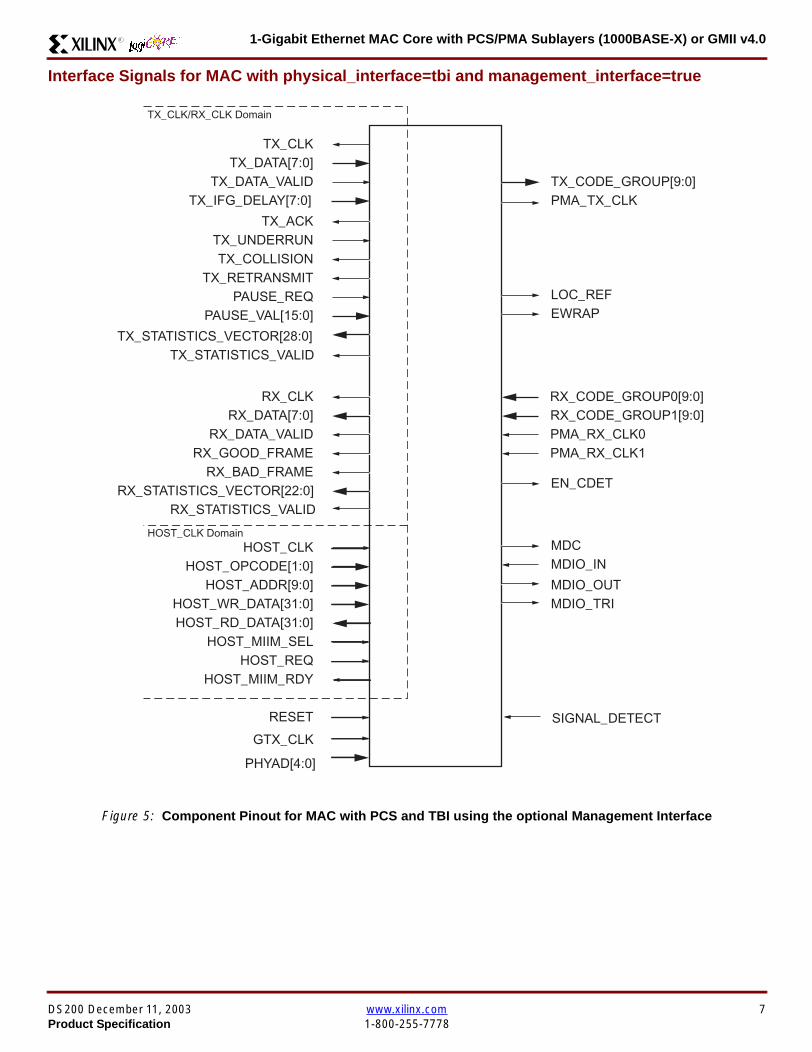
1-Gigabit Ethernet MAC Core with PCSPMA Sublayers (1000BASE-X) or GMII v40R
Interface Signals for MAC with physical_interface=tbi and management_interface=true
Figure 5 Component Pinout for MAC with PCS and TBI using the optional Management Interface
GTX_CLK
TX_CLK
MDCMDIO_IN
RX_CODE_GROUP1[90]
TX_CODE_GROUP[90]PMA_TX_CLK
LOC_REF
TX_DATA[70]
TX_ACKTX_UNDERRUN
PAUSE_REQPAUSE_VAL[150]
RX_CLK
HOST_CLKHOST_OPCODE[10]
HOST_ADDR[90]HOST_WR_DATA[310]HOST_RD_DATA[310]
HOST_MIIM_SELHOST_REQ
HOST_MIIM_RDY
RESET
RX_DATA[70]
RX_GOOD_FRAMERX_BAD_FRAME
TX_COLLISIONTX_RETRANSMIT
TX_DATA_VALID
RX_DATA_VALID
EWRAP
PMA_RX_CLK0PMA_RX_CLK1
TX_CLKRX_CLK Domain
HOST_CLK Domain
TX_IFG_DELAY[70]
TX_STATISTICS_VECTOR[280]TX_STATISTICS_VALID
RX_STATISTICS_VECTOR[220]RX_STATISTICS_VALID
MDIO_OUTMDIO_TRI
EN_CDET
RX_CODE_GROUP0[90]
SIGNAL_DETECT
PHYAD[40]
DS200 December 11 2003 wwwxilinxcom 7Product Specification 1-800-255-7778
1-Gigabit Ethernet MAC Core with PCSPMA Sublayers (1000BASE-X) or GMII v40 R
Interface Signals for MAC with physical_interface=tbi and management_interface=false
Figure 6 Component Pinout for MAC with PCS and TBI without the optional Management Interface
GTX_CLK
TX_CLK
MDC_INMDIO_IN
RX_CODE_GROUP1[90]
TX_CODE_GROUP[90]PMA_TX_CLK
LOC_REF
TX_DATA[70]
TX_ACKTX_UNDERRUN
PAUSE_REQPAUSE_VAL[150]
RX_CLK
CONFIGURATION_VECTOR[630]
RESET
RX_DATA[70]
RX_GOOD_FRAMERX_BAD_FRAME
TX_COLLISIONTX_RETRANSMIT
TX_DATA_VALID
RX_DATA_VALID
EWRAP
PMA_RX_CLK0PMA_RX_CLK1
TX_CLKRX_CLK Domain
TX_IFG_DELAY[70]
TX_STATISTICS_VECTOR[280]TX_STATISTICS_VALID
RX_STATISTICS_VECTOR[220]RX_STATISTICS_VALID
MDIO_OUTMDIO_TRI
EN_CDET
RX_CODE_GROUP0[90]
PHYAD[40]
SIGNAL_DETECT
8 wwwxilinxcom DS200 December 11 20031-800-255-7778 Product Specification
1-Gigabit Ethernet MAC Core with PCSPMA Sublayers (1000BASE-X) or GMII v40R
Interface Signals for MAC with physical_interface=phy and management_interface=true
Figure 7 Component Pinout for MAC with PCS amp PMA Sublayers using the optional Management Interface
REFCLK
TX_CLK
MDCMDIO_IN
TXPTXN
TX_DATA[70]
TX_ACKTX_UNDERRUN
PAUSE_REQPAUSE_VAL[150]
RX_CLK
HOST_CLKHOST_OPCODE[10]
HOST_ADDR[90]HOST_WR_DATA[310]HOST_RD_DATA[310]
HOST_MIIM_SELHOST_REQ
HOST_MIIM_RDY
RESET
RX_DATA[70]
RX_GOOD_FRAMERX_BAD_FRAME
TX_COLLISIONTX_RETRANSMIT
TX_DATA_VALID
RX_DATA_VALID
RXPRXN
TX_CLKRX_CLK Domain
HOST_CLK Domain
TX_IFG_DELAY[70]
TX_STATISTICS_VECTOR[280]TX_STATISTICS_VALID
RX_STATISTICS_VECTOR[220]RX_STATISTICS_VALID
PHYAD[40]
SIGNAL_DETECT
MDIO_OUTMDIO_TRI
USRCLKUSRCLK2
DCM_LOCKED
REFCLK2BREFCLK
BREFCLK2REFCLKSEL
DS200 December 11 2003 wwwxilinxcom 9Product Specification 1-800-255-7778
1-Gigabit Ethernet MAC Core with PCSPMA Sublayers (1000BASE-X) or GMII v40 R
Interface Signals for MAC with physical_interface=phy and management_interface=false
Figure 8 Component Pinout for MAC with PCS amp PMA Sublayers without the optional Management Interface
TX_CLK
MDC_INMDIO_IN
TXPTXN
TX_DATA[70]
TX_ACKTX_UNDERRUN
PAUSE_REQPAUSE_VAL[150]
RX_CLK
CONFIGURATION_VECTOR[630]
RX_DATA[70]
RX_GOOD_FRAMERX_BAD_FRAME
TX_COLLISIONTX_RETRANSMIT
TX_DATA_VALID
RX_DATA_VALID
RXPRXN
TX_CLKRX_CLK Domain
TX_IFG_DELAY[70]
TX_STATISTICS_VECTOR[280]TX_STATISTICS_VALID
RX_STATISTICS_VECTOR[220]RX_STATISTICS_VALID
SIGNAL_DETECT
MDIO_OUTMDIO_TRI
REFCLKRESET
PHYAD[40]
USRCLKUSRCLK2
DCM_LOCKED
REFCLK2BREFCLK
BREFCLK2REFCLKSEL
10 wwwxilinxcom DS200 December 11 20031-800-255-7778 Product Specification
1-Gigabit Ethernet MAC Core with PCSPMA Sublayers (1000BASE-X) or GMII v40R
Client Side Interface Signal Definition
Table 3 describes the client-side transmit signals of the MAC core These signals are used to transmit data from the clientto the MAC core
Table 4 describes the client-side receive signals These signals are used by the MAC core to transfer data to the client
Table 3 Transmit Client Interface Signal Pins
Signal Direction Description
TX_CLK Output Clock for transmit client interface 125 MHz nominal
TX_DATA[70] Input Frame data to be transmitted is supplied on this port
TX_DATA_VALID Input Control signal for TX_DATA port
TX_IFG_DELAY[70] InputControl signal for configurable Inter Frame Gap adjustment SeeTransmitter on page 16 for timing diagrams
TX_ACK OutputHandshaking signal Asserted when the current data on TX_DATA hasbeen accepted See Transmitter on page 16 for timing diagrams
TX_UNDERRUN Input Asserted by client to force MAC core to corrupt the current frame
TX_COLLISION OutputAsserted by the MAC core to signal a collision on the medium and that anytransmission in progress should be aborted Always 0 when the MAC coreis in full-duplex mode
TX_RETRANSMIT Output
When asserted at the same time as the TX_COLLISION signal thissignals the client that the aborted frame should be resupplied to the MACcore for retransmission Always 0 when the MAC core is in full-duplexmode
TX_STATISTICS_VECTOR[280] OutputThis gives information on the last frame transmitted See Transmitter onpage 16 for vector contents
TX_STATISTICS_VALID OutputAsserted at end of frame transmission indicating that theTX_STATISTICS_VECTOR is valid
Notes1 All the above signals are synchronous to TX_CLK and Active High
Table 4 Receive Client Interface Signal Pins
Signal Direction Description
RX_CLK Output Clock for receive client interface 125 MHz nominal
RX_DATA[70] Output Frame data received is supplied on this port
RX_DATA_VALID Output Control signal for the RX_DATA port
RX_GOOD_FRAME OutputAsserted at end of frame reception to indicate that the frame should beprocessed by the MAC client See Receiver on page 24
RX_BAD_FRAME OutputAsserted at end of frame reception to indicate that the frame should bediscarded by the MAC client See Receiver on page 24
RX_STATISTICS_VECTOR[220] OutputProvides information about the last frame received See Receiver onpage 24 for the vector contents
RX_STATISTICS_VALID OutputAsserted at end of frame reception indicating that theRX_STATISTICS_VECTOR is valid
Notes1 All signals above are synchronous to RX_CLK and Active High
DS200 December 11 2003 wwwxilinxcom 11Product Specification 1-800-255-7778
1-Gigabit Ethernet MAC Core with PCSPMA Sublayers (1000BASE-X) or GMII v40 R
Table 5 describes the signals used by the client to request a flow control action from the transmit engine Flow control framesreceived by the MAC are automatically handled (if the MAC is configured to do so)
Table 6 describes the optional signals used by the client to access the management features of the MAC core includingconfiguration status statistics and MDIO access
Table 7 describes the alternative to the optional Management Interface signals This describes the Configuration Vectorwhich uses direct inputs to the core to replace the functionality of the MAC Configuration bits when the ManagementInterface is not used
Notes1 All bits of CONFIGURATION_VECTOR are registered on input but may be treated as asynchronous inputs
Table 5 Flow Control Interface Signal Pinout
Signal Direction Description
PAUSE_REQ InputPause request sends a pause frame down the link See Transmitting a PAUSE ControlFrame on page 29
PAUSE_VAL[150] Input Pause value inserted into the parameter field of the transmitted pause frame
Notes1 These signals are synchronous to TX_CLK and are Active High
Table 6 Optional Management Interface Signal Pinout (management_interface=true)
Signal Direction Description
HOST_CLK InputClock for management interface See Optional Management Interface(management_interface=true) on page 30 for the signal frequency range
HOST_OPCODE[10] InputDefines operation to be performed over MDIO interface Bit 1 is also used inconfiguration register access See Configuration Registers on page 30
HOST_ADDR[90] Input Address of register to be accessed
HOST_WR_DATA[310] Input Data to write to register
HOST_RD_DATA[310] Output Data read from register
HOST_MIIM_SEL InputWhen asserted the MDIO interface is accessed When disasserted the MACinternal configuration or statistical counter registers are accessed
HOST_REQ InputUsed to signal a transaction on the MDIO interface or to read from the statisticregisters See Optional Management Interface (management_interface=true) onpage 30
HOST_MIIM_RDY OutputWhen high the MDIO interface has completed any pending transaction and isready for a new transaction
Notes1 All signals above are synchronous to HOST_CLK and are Active High
Table 7 Alternative to the Optional Management Interface Configuration Vector Signal Pinout(management_interface=false)
Signal Direction Description
CONFIGURATION_VECTOR[630]
Input The Configuration Vector is used to replace the functionality of theMAC Configuration Registers when the Management Interface is notused See Optional Configuration Vector (management_interface =false) on page 38
12 wwwxilinxcom DS200 December 11 20031-800-255-7778 Product Specification
1-Gigabit Ethernet MAC Core with PCSPMA Sublayers (1000BASE-X) or GMII v40R
Table 8 describes the reset signal
Physical Interface Signal Definition
Table 9 describes the MDIO (MII Management) interface signals of the MAC core These signals are typically connected tothe MDIO port of a PHY device either off-chip or an SoC-integrated core The MDIO format is defined in IEEE8023 clause22
Table 10 describes the optional GMII signals of the MAC core These are typically attached to a PHY module either off-chipor internally integrated The GMII is defined in IEEE8023 clause 35
Table 8 Reset Signal
Signal Direction Description
RESET Input Asynchronous reset for entire core See Reset circuit on page 42 for moreinformation on the reset circuit
Table 9 MDIO Interface Signal Pinout
Signal Direction Description
MDC OutputManagement Clock derived from HOST_CLK on the basis of supplied configuration datawhen the optional Management Interface is used See Optional Management Interface(management_interface=true) on page 30
MDC_IN InputWhen the Optional Management Interface is not used access to the optional PhysicalCoding Sublayer (PCS) must be provided by an external MDIO Controller In this situationthe Management Clock is an input to the core
MDIO_IN Input Input data signal for communication with PHY configuration and status Tie high if unused
MDIO_OUT Output Output data signal for communication with PHY configuration and status
MDIO_TRI OutputTristate control for MDIO signals 0 signals that the value on MDIO_OUT should be
asserted onto the MDIO bus
Table 10 Optional GMII Interface Signal Pinout (physical_interface=gmii)
Signal Direction Description
GTX_CLK InputClock signal at 125 MHz Other transmit clocks are derived from this clock as illustratedin Figure 28 Tolerance must be within IEEE 8023-2002 specification
GMII_TXD[70] Output Transmit data to PHY
GMII_TX_EN Output Data Enable control signal to PHY
GMII_TX_ER Output Error control signal to PHY
GMII_TX_CLK Output Clock out to PHY
GMII_CRS Input Control signal from PHY
GMII_COL Input Control signal from PHY
GMII_RX_CLK Input Recovered clock from received data stream by PHY
GMII_RXD[70] Input Received data from PHY
GMII_RX_DV Input Data Valid control signal from PHY
GMII_RX_ER Input Error control signal from PHY
DS200 December 11 2003 wwwxilinxcom 13Product Specification 1-800-255-7778
1-Gigabit Ethernet MAC Core with PCSPMA Sublayers (1000BASE-X) or GMII v40 R
Table 11 describes the TBI (Ten-Bit interface) signals of the MAC core These are typically attached to a PMA SERDESmodule These signals optionally replace the GMII signals described in Table 10 to extend the functionality of the core toinclude the PCS for 1000BASE-X The TBI is defined in IEEE8023 clause 36
Notes
PHYAD and SIGNAL_DETECT are asynchronous inputs SIGNAL_DETECT is Active High
Table 11 Optional TBI Interface Signal Pinout (physical_interface=tbi)
Signal Direction Description
GTX_CLK InputClock signal at 125 MHz Other transmit clocks will be derived from this clock asillustrated in Figure 32 Tolerance must be within IEEE 8023-2002 specification
TX_CODE_GROUP[90] Output 10-bit parallel transmit data to PMA Sublayer (SERDES)
PMA_TX_CLK Output Transmit clock signal to PMA Sublayer (SERDES) at 125MHz
LOC_REF OutputCauses the PMA sublayer clock recovery unit to lock to PMA_TX_CLK Thissignal is tied to Ground
EWRAP Output
This signal is set from the PCS Control Register 0 bit 14 (loopback) See PCSManaged Register Block (physical_interface = tbi or phy) on page 49 Whenhigh this instructs the PMA sublayer to electrically loop the transmitter data to thereceiver
RX_CODE_GROUP0[90] Input10-bit parallel received data from PMA Sublayer (SERDES) synchronous toPMA_RX_CLK0
RX_CODE_GROUP1[90] Input10-bit parallel received data from PMA Sublayer (SERDES) synchronous toPMA_RX_CLK1
PMA_RX_CLK0 Input Received clock signal from PMA Sublayer (SERDES) at 625MHz
PMA_RX_CLK1 InputReceived clock signal from PMA Sublayer (SERDES) at 625MHz This is 180degrees out of phase with PMA_RX_CLK0
EN_CDET OutputEnables the PMA Sublayer to perform comma realignment driven from the PCSstate machine during the Loss-Of-Sync state
PHYAD[40] Input PHY address of MDIO register set for the PCS
SIGNAL_DETECT Input
Signal direct from PMD sublayer indicating the presence of light detected at theoptical receiver If driven high this indicates that the optical receiver has detectedlight If driven low this indicates the absence of light
If unused tie high to enable the operation the core
14 wwwxilinxcom DS200 December 11 20031-800-255-7778 Product Specification
1-Gigabit Ethernet MAC Core with PCSPMA Sublayers (1000BASE-X) or GMII v40R
Table 12 describes the interface signals for the Optional PCSPMA sublayer of the MAC core These signals optionallyreplace the GMII signals described in Table 10 to extend the functionality of the core to include the PCS and PMA sublayersfor 1000BASE-X This option uses the Virtex-II Pro Rocket IO functionality which is integrated into the core The PMAsublayer for 1000BASE-X is defined in IEEE8023 clause 36
Notes1 PHYAD and SIGNAL_DETECT are asynchronous inputs SIGNAL_DETECT is Active High
Table 12 Optional PCSPMA sublayer Interface Signal Pinout (physical_interface=phy)
Signal Direction Description
REFCLK InputHigh Quality Reference clock for Multi-Gigabit Transceivers (625 MHz) See Rocket IOUser Guide
REFCLK2 Input Alternative High Quality Reference clock for Multi-Gigabit Transceivers (625 MHz) SeeRocket IO User Guide
BREFCLK Input Alternative High Quality Reference clock for Multi-Gigabit Transceivers (625 MHz)This optionally replaces REFCLK See Rocket IO User Guide
BREFCLK2 Input Alternative High Quality Reference clock for Multi-Gigabit Transceivers (625 MHz)This optionally replaces REFCLK2 See Rocket IO User Guide
REFCLKSEL Input Selects between either (B)REFCLK or (B)REFCLK2 as the input clock source to theMGT See Rocket IO User Guide
USERCLK InputClock signal at 625 MHz This is connected to the TXUSRCLK and RXUSRCLK portsof the Rocket IO MGT This may be derived from (B)REFCLK using a DCM asillustrated in Figure 35
USERCLK2 InputClock signal at 125 MHz This is connected to the TXUSRCLK2 and RXUSRCLK2 portsof the Rocket IO MGT This may be derived from (B)REFCLK using a DCM asillustrated in Figure 35
DCM_LOCKED InputIf a DCM is used to derive USRCLK and USRCLK2 as illustrated in Figure 35 theLOCKED port of the DCM must be connected to the DCM_LOCKED port of the coreThe core will hold itrsquos Rocket IO MGT in reset until DCM_LOCKED is driven to logic 1
TXPTXN OutputDifferential pair for serial transmission from PMA to PMD The clock is embedded in thedata stream
RXPRXN InputDifferential pair for serial reception from PMD to PMA The clock is extracted from thedata stream
PHYAD[40] Input PHY address of MDIO register set for the PCS
SIGNAL_DETECT Input
Signal direct from PMD sublayer indicating the presence of light detected at the opticalreceiver If driven high this indicates that the optical receiver has detected light If drivenlow this indicates the absence of light
If unused tie high to enable the operation the core
DS200 December 11 2003 wwwxilinxcom 15Product Specification 1-800-255-7778
1-Gigabit Ethernet MAC Core with PCSPMA Sublayers (1000BASE-X) or GMII v40 R
Functional Description
Client InterfaceThe client interface is designed for maximum flexibility inmatching to a client switching fabric or network processorinterface
The data pathway is 8 bits wide in both the transmit andreceive directions with each pathway synchronous to theTX_CLK and RX_CLK respectively for completely indepen-dent full duplex operation
Transmitter
Normal Frame Transmission
The timing of a normal outbound frame transfer can be seenin Figure 9 When the client wants to transmit a frame itplaces the first column of data onto the TX_DATA port andasserts a ldquo1rdquo onto TX_DATA_VALID
When the MAC core has read this first byte of data it willassert the TX_ACK signal on the next and subsequent ris-ing clock edges the client must provide the remainder ofthe data for the frame
The end of frame is signalled to the MAC core by takingTX_DATA_VALID Low
In-Band Parameter Encoding
For maximum flexibility in switching applications the Ether-net frame parameters (destination address sourceaddress lengthtype and optionally FCS) are encodedwithin the same data stream that the frame payload is trans-ferred upon rather than on separate ports This is illustratedin the timing diagrams Definitions of the abbreviations usedin the timing diagrams are described in Table 13
Figure 9 Normal Frame Transmission Across Client Interface
Table 13 Abbreviations Used in Timing Diagrams
Abbreviation Definition
DA Destination Address 6 bytes
SA Source Address 6 bytes
LT LengthType Field 2 bytes
FCS Frame Check Sequence 4 bytes
TX_CLK
TX_DATA[70]
TX_DATA_VALID
TX_ACK
TX_UNDERRUN
DA SA DATALT
TX_COLLISION
TX_RETRANSMIT
xip2133
16 wwwxilinxcom DS200 December 11 20031-800-255-7778 Product Specification
1-Gigabit Ethernet MAC Core with PCSPMA Sublayers (1000BASE-X) or GMII v40R
Padding
When fewer than 46 bytes of data are supplied by the clientto the MAC core the transmitter module will add padding upto the minimum frame length The exception to this is whenthe MAC core is configured for client-passed FCS in thiscase the client must also supply the padding to maintain theminimum frame length (see Client-Supplied FCS Passing)
Client-Supplied FCS Passing
If the MAC core is configured to have the FCS field passedin by the client (see Configuration Registers on page 30)the transmission timing is as depicted in Figure 10 In thiscase it is the responsibility of the client to ensure that theframe meets the Ethernet minimum frame length require-ments the MAC core will not perform any padding of thepayload
Figure 10 Frame Transmission with Client-supplied FCS
TX_CLK
TX_DATA[70]
TX_DATA_VALID
TX_ACK
TX_UNDERRUN
DA SA DATA FCSLT
TX_COLLISION
TX_RETRANSMIT
xip2134
DS200 December 11 2003 wwwxilinxcom 17Product Specification 1-800-255-7778
1-Gigabit Ethernet MAC Core with PCSPMA Sublayers (1000BASE-X) or GMII v40 R
Client Underrun
The timing of an aborted transfer can be seen in Figure 11This may happen for instance if a FIFO connected to theclient interface empties before a frame is completed Whenthe client asserts TX_UNDERRUN during a frame transmis-sion the MAC core will insert an error code to corrupt the
current frame and then fall back to idle transmission It isthe responsibility of the client to re-queue the aborted framefor transmission
When an underrun occurs TX_DATA_VALID may beasserted on the clock cycle after the TX_UNDERRUNassertion to request a new transmission
Figure 11 Frame Transmission with Underrun
TX_CLK
TX_DATA[70]
TX_DATA_VALID
TX_ACK
TX_UNDERRUN
DA SA DATALT
TX_COLLISION
TX_RETRANSMIT
xip2135
18 wwwxilinxcom DS200 December 11 20031-800-255-7778 Product Specification
1-Gigabit Ethernet MAC Core with PCSPMA Sublayers (1000BASE-X) or GMII v40R
Back-to-Back Transfers
Figure 12 shows the case where the MAC client is immedi-ately ready to transmit a second frame of data followingcompletion of its first frame In this figure the end of the firstframe is shown on the left On the clock cycle immediatelyfollowing the final byte of the first frame TX_DATA_VALIDis taken low by the client and is taken high one clock cyclelater to indicate that the first byte of the destination addressof the second frame is on TX_DATA awaiting transmission
When the MAC core is ready to accept data TX_ACK isasserted and the transmission continues in the same man-ner as in the case of the single frame The MAC core willdefer the assertion of TX_ACK appropriately to comply withinter-packet gap requirements and flow control requests
If the MAC core is operating in half-duplex mode the timingshown in Figure 12 is required to take advantage of framebursting the MAC core is only guaranteed to retain controlof the medium if the TX_DATA_VALID signal is low for a sin-gle clock cycle For more information on frame bursting seeIEEE 8023-2002
Figure 12 Back to Back Frame Transmission
TX_CLK
TX_DATA[70]
TX_DATA_VALID
TX_ACK
TX_UNDERRUN
TX_COLLISION
TX_RETRANSMIT
xip2136
DS200 December 11 2003 wwwxilinxcom 19Product Specification 1-800-255-7778
1-Gigabit Ethernet MAC Core with PCSPMA Sublayers (1000BASE-X) or GMII v40 R
VLAN Tagged Frames
Transmission of a VLAN tagged frame (if enabled) can beseen in Figure 13 Note that the handshaking signalsacross the interface do not change however the VLANtype tag 81-00 must be supplied by the client to signify that
the frame is VLAN tagged The client also supplies the twobytes of Tag Control Information V1 and V2 at the appro-priate times in the data stream More information on thecontents of these two bytes can be found in IEEE8023-2002
Maximum Permitted Frame Length
The maximum legal length of a frame specified in IEEE8023-2002 is 1518 bytes for non-VLAN tagged framesVLAN tagged frames may be extended to 1522 bytesWhen jumbo frame handling is disabled and the clientattempts to transmit a frame which exceeds the maximumlegal length the MAC core will insert an error code to cor-
rupt the current frame and the frame will be truncated to themaximum legal length When jumbo frame handling isenabled frames which are longer than the legal maximumare transmitted error-free
For more information on enabling and disabling jumboframe handling see Configuration Registers on page 30
Figure 13 Transmission of a VLAN Tagged Frame
TX_CLK
TX_DATA[70]
TX_DATA_VALID
TX_ACK
TX_UNDERRUN
DA SA DATALTVLANtag
81 00V1V2
TX_COLLISION
TX_RETRANSMIT
xip2137
20 wwwxilinxcom DS200 December 11 20031-800-255-7778 Product Specification
1-Gigabit Ethernet MAC Core with PCSPMA Sublayers (1000BASE-X) or GMII v40R
Frame Collisions - Half Duplex Operation Only
In half duplex Ethernet operation collisions will occur on themedium as a matter of course this is how the arbitrationalgorithm is fulfilled In case of a collision the MAC core sig-nals to the client that data may need to be resupplied as fol-lows
If there is a collision the TX_COLLISION signal will be setto ldquo1rdquo by the MAC core If a frame is in progress the clientmust abort the transfer and take TX_DATA_VALID to ldquo0rdquo
If the TX_RETRANSMIT signal is ldquo1rdquo in the same clockcycle that the TX_COLLISION signal is ldquo1rdquo the client must
resubmit the previous frame to the MAC core for retrans-mission TX_DATA_VALID must be asserted to the MACcore within 8 clock cycles of the TX_COLLISION signal inorder to meet Ethernet timing requirements See Figure 14
If the TX_RETRANSMIT signal is ldquo0rdquo in the same clockcycle that the TX_COLLISION signal is ldquo1rdquo the number ofretries for this frame has exceeded the Ethernet specifica-tion and the frame should be dropped by the client The cli-ent can then make any new frame available to the MAC fortransmission without timing restriction See Figure 15
Figure 14 Collision Handling - Frame retransmission required
Figure 15 Collision Handling - No frame retransmission required
TX_CLK
TX_DATA[70]
TX_DATA_VALID
TX_ACK
TX_UNDERRUN
TX_COLLISION
TX_RETRANSMIT
8 clocks max
xip2138
TX_CLK
TX_DATA[70]
TX_DATA_VALID
TX_ACK
TX_UNDERRUN
TX_COLLISION
TX_RETRANSMIT
xip2139
DS200 December 11 2003 wwwxilinxcom 21Product Specification 1-800-255-7778
1-Gigabit Ethernet MAC Core with PCSPMA Sublayers (1000BASE-X) or GMII v40 R
Interframe Gap Adjustment
The user can elect to vary the length of the inter fame gapIf this function is selected (via a configuration bit in thetransmitter control register see Configuration Registerson page 30) then the MAC will exert back pressure to delaythe transmission of the next frame until the requested num-ber of Idle cycles has elapsed The number of Idle cycles iscontrolled by the value on the TX_IFG_DELAY port at thestart of frame transmission Figure 16 shows the MAC oper-ating in this mode
Reducing the Inter fame gap to below the IEEE 8023-2002minimum of 12 Idles is supported in Full Duplex onlydesigns and will transmit an absolute minimum of 4 Idles Ifthe Interframe gap adjustment is reduced below 12 Idlesthen the accuracy of the Optional Statistical Gathering(statistics_gathering=true) Counters cannot be guaranteedHowever the TX_STATISTIC_VECTOR andRX_STATISTIC_VECTOR will always remain correct
Transmitter Statistics Vector
The statistics for the frame transmitted are contained withinthe TX_STATISTICS_VECTOR The vector is driven syn-chronously by the transmitter clock TX_CLK followingframe transmission The bit field definition for the Vector isdefined in Table 14
All bit fields with the exception of BYTE_VALID are validonly when the TX_STATISTICS_VALID is asserted This isillustrated in Figure 17 BYTE_VALID is significant on everyTX_CLK cycle
TX_STATISTICS_VECTOR bits 25 down to 17 inclusive arefor half duplex only and will be set to logic 0 when operatingin full duplex mode
Figure 16 Interframe Gap Adjustment
TX_CLK
TX_DATA[70]
TX_DATA_VALID
TX_ACK
DA SA
TX_IFG_DELAY
IFG ADJUST VALUE
0x0D
13 Idles inserted
DA
Next IFG ADJUST VALUE
xip2140
Figure 17 Transmitter Statistics Vector Timing
TX_CLK
TX_STATISTICS_VECTOR[280]
TX_STATISTICS_VALID
xip2141
22 wwwxilinxcom DS200 December 11 20031-800-255-7778 Product Specification
1-Gigabit Ethernet MAC Core with PCSPMA Sublayers (1000BASE-X) or GMII v40R
Table 14 Bit Definition for the Transmitter Statistics Vector
TX_STATISTICS_VECTOR Name Description
28 PAUSE_FRAME_TRANSMITTEDAsserted if the previous frame was a pause framethat the MAC itself initiated in response to aPAUSE_REQ assertion
27 BYTE_VALID
Asserted if a MAC frame byte (DA to FCS inclusive)is in the process of being transmitted This is valid onevery clock cycle
Do not use this as an enable signal to indicate thatdata is present on GMII_TXD[70]
26 Reserved Returns logic 0
25 down to 22 TX_ATTEMPTS[30]
The number of attempts that have been made totransmit the previous frame This is a 4-bit number0 should be interpreted as 1 attempt 1 as 2attempts up until 15 as 16 attempts
21 Reserved Returns logic 0
20 EXCESSIVE_COLLISIONAsserted if a collision has been detected on each ofthe last 16 attempts to transmit the previous frame
19 LATE_COLLISIONAsserted if a late collision occurred during frametransmission
18 EXCESSIVE_DEFERRALAsserted if the previous frame was deferred for anexcessive amount of time as defined by the constantldquomaxDeferTimerdquo in IEEE 8023-2002
17 TX_DEFERRED Asserted if transmission of the frame was deferred
16 VLAN_FRAMEAsserted if the previous frame contained a VLANidentifier in the LengthType field when transmitterVLAN operation is enabled
15 down to 5 FRAME_LENGTH_COUNTThe length of the previous frame in number of bytesThe count will stick at 2047 for any Jumbo frameslarger than this value
4 CONTROL_FRAMEAsserted if the previous frame had the special MACControl Type code 88-08 in the LengthType field
3 UNDERRUN_FRAMEAsserted if the previous frame contained anunderrun error
2 MULTICAST_FRAMEAsserted if the previous frame contained a multicastaddress in the Destination Address field
1 BROADCAST_FRAMEAsserted if the previous frame contained abroadcast address in the Destination Address field
0 SUCCESSFUL_FRAMEAsserted if the previous frame was transmittedwithout error
DS200 December 11 2003 wwwxilinxcom 23Product Specification 1-800-255-7778
1-Gigabit Ethernet MAC Core with PCSPMA Sublayers (1000BASE-X) or GMII v40 R
Receiver
Normal Frame Reception
The timing of a normal inbound frame transfer can be seenin Figure 18 The client must be prepared to accept data atany time there is no buffering within the MAC to allow forlatency in the receive client Once frame reception begins
data is transferred on consecutive clock cycles to thereceive client until the frame is complete The MAC assertsthe RX_GOOD_FRAME signal to indicate that the framewas successfully received and that the frame should beanalyzed by the client
Frame parameters (destination address source addresslengthtype and optionally FCS) are supplied on the databus according to the timing diagram The abbreviations arethe same as those described in Table 13 on page 16
If the LengthType field in the frame has the Length interpre-tation and this indicates that the inbound frame has beenpadded to meet the Ethernet minimum frame size specifica-tion then this padding will not be passed to the client in thedata payload The exception to this is in the case whereFCS passing is enabled see Client-Supplied FCS Pass-ing on page 25
Therefore when Client-Supplied FCS passing is disabledRX_DATA_VALID = lsquo0rsquo between frames for the duration ofthe Padding field (if present) the FCS field carrier exten-sion (if present) the interframe gap following the frame andthe preamble field of the next frame When Client-Supplied
FCS passing is enabled RX_DATA_VALID = lsquo0rsquo betweenframes for the duration of carrier extension (if present) theinterframe gap and the preamble field of the followingframe
RX_GOOD_FRAME RX_BAD_FRAME timing
Although the timing diagram in Figure 18 shows theRX_GOOD_FRAME signal asserted shortly after the lastvalid data on RX_DATA this is not always the case TheRX_GOOD_FRAME or RX_BAD_FRAME signals areasserted only after all frame checks are completed This isafter the FCS field has been received (and after reception ofcarrier extension if present)
Therefore either RX_GOOD_FRAME or RX_BAD_FRAMEis asserted following frame reception at the beginning of theinterframe gap
Figure 18 Normal Frame Reception
RX_CLK
RX_DATA[70]
RX_DATA_VALID
RX_GOOD_FRAME
RX_BAD_FRAME
DA SA DATALT
xip2142
24 wwwxilinxcom DS200 December 11 20031-800-255-7778 Product Specification
1-Gigabit Ethernet MAC Core with PCSPMA Sublayers (1000BASE-X) or GMII v40R
Frame Reception with Errors
The case of an unsuccessful frame reception (for examplea fragment frame or a frame with an incorrect FCS) can beseen in Figure 19 In this case the RX_BAD_FRAME signal
is asserted to the client at the end of the frame It is then theresponsibility of the client to drop the data already trans-ferred for this frame
Figure 19 Frame Reception with Error
Client-Supplied FCS Passing
If the MAC core is configured to pass the FCS field to the cli-ent (see Configuration Registers on page 30) then this ishandled as shown in Figure 20
In this case any padding inserted into the frame to meetEthernet minimum frame length specifications will be leftintact and passed to the client
Note that even though the FCS is passed up to the client itis also verified by the MAC core and RX_BAD_FRAMEasserted if the FCS check fails
RX_CLK
RX_DATA[70]
RX_DATA_VALID
RX_GOOD_FRAME
RX_BAD_FRAME
DA SA DATALT
xip2144
Figure 20 Frame Reception with In-Band FCS Field
RX_CLK
RX_DATA[70]
RX_DATA_VALID
RX_GOOD_FRAME
RX_BAD_FRAME
DA SA DATALT FCS
xip2145
DS200 December 11 2003 wwwxilinxcom 25Product Specification 1-800-255-7778
1-Gigabit Ethernet MAC Core with PCSPMA Sublayers (1000BASE-X) or GMII v40 R
VLAN Tagged Frames
The reception of a VLAN tagged frame (if enabled) can beseen in Figure 21 The VLAN frame is passed to the clientso that the frame may be identified as VLAN tagged this is
followed by the Tag Control Information bytes V1 and V2More information on the interpretation of these bytes maybe found in IEEE 8023-2002 standard
Maximum Permitted Frame Length
The maximum legal length of a frame specified in IEEE8023-2002 is 1518 bytes for non-VLAN tagged framesVLAN tagged frames may be extended to 1522 bytesWhen jumbo frame handling is disabled and the corereceives a frame which exceeds the maximum legal lengthRX_BAD_FRAME will be asserted When jumbo framehandling is enabled frames which are longer than the legalmaximum are received in the same way as shorter frames
For more information on enabling and disabling jumboframe handling see Configuration Registers on page 30
LengthType Field Error Checks
Enabled
Default operation is with the LengthType error checkingenabled (see Receiver Configuration Word 1 on page 31)In this mode the following checks are made on all framesreceived If either of these checks fail then the frame ismarked as BAD
bull A value in the LengthType field that is greater than orequal to decimal 46 but less than decimal 1536 (aLength interpretation) is checked against the actualdata length received
bull A value in the LengthType field that is less thandecimal 46 is checked to see that the data field ispadded to exactly 46 bytes (so that the resultant frameis minimum frame size 64 bytes total in length)
Furthermore if Padding is indicated (the LengthType fieldis less than decimal 46) and Client-Supplied FCS Passing isdisabled then the Length value in the LengthType field willbe used to deassert RX_DATA_VALID after the indicatednumber of data bytes so that the Padding bytes areremoved from the frame
Disabled
When the LengthType error checking is disabled (seeReceiver Configuration Word 1 on page 31) theLengthType error checks described above are not per-formed A frame containing only these errors will be markedas GOOD
Furthermore if Padding is indicated and Client-SuppliedFCS Passing is disabled then a Length Value in theLengthType field will not be used to deassertRX_DATA_VALID Instead RX_DATA_VALID will be deas-serted before the start of the FCS field in this way any pad-ding will not be removed from the frame
Figure 21 Reception of a VLAN Tagged Frame
RX_CLK
RX_DATA[70]
RX_DATA_VALID
RX_GOOD_FRAME
RX_BAD_FRAME
DA SA DATALT
81 00 V1 V2
VLANtag
xip2146
26 wwwxilinxcom DS200 December 11 20031-800-255-7778 Product Specification
1-Gigabit Ethernet MAC Core with PCSPMA Sublayers (1000BASE-X) or GMII v40R
Receiver Statistics Vector
The statistics for the frame received are contained withinthe RX_STATISTICS_VECTOR The vector is driven syn-chronously by the receiver clock RX_CLK following framereception The bit field definition for the Vector is defined inTable 15
All bit fields with the exception of BYTE_VALID are validonly when the RX_STATISTICS_VALID is asserted This isillustrated in Figure 22 BYTE_VALID is significant on everyRX_CLK cycle
Figure 22 Receiver Statistics Vector Timing
RX_CLK
RX_STATISTICS_VECTOR[220]
RX_STATISTICS_VALID
xip2147
Table 15 Bit Definition for the Receiver Statistics Vector
RX_STATISTICS_VECTOR Name Description
22LENGTHTYPE Out ofRange
Asserted if the lengthtype field contained a length valuethat did not match the number of MAC client data bytesreceived Also high if the lengthtype field indicated thatthe frame contained padding but the number of MAC cli-ent data bytes received was not equal to 64 bytes (min-imum frame size)
The exception to the above is when the LengthTypeField Error Checks are disabled in which case this bitwill not be asserted
21 BAD_OPCODE
Asserted if the previous frame was error-free andcontained the special Control Frame identifier in theLengthType field but contained an opcode that isunsupported by the MAC (Any Opcode other thanPAUSE)
20 FLOW_CONTROL_FRAME
Asserted if the previous frame was error-freecontained the special Control Frame identifier in theLengthType field contained a Destination Addressthat matched either the MAC Control MulticastAddress or the configured source address of the MACcontained the supported PAUSE opcode and wasacted upon by the MAC
19 BYTE_VALID
Asserted if a MAC frame byte (DA to FCS inclusive) isin the process of being received This is valid on everyclock cycle
Do not use this as an enable signal to indicate thatdata is present on RX_DATA[70]
18 VLAN_FRAMEAsserted if the previous frame contained a VLANidentifier in the LengthType field when receiver VLANoperation is enabled
DS200 December 11 2003 wwwxilinxcom 27Product Specification 1-800-255-7778
1-Gigabit Ethernet MAC Core with PCSPMA Sublayers (1000BASE-X) or GMII v40 R
17 OUT_OF_BOUNDS
Asserted if the previous frame exceeded the specifiedIEEE8023-2002 maximum legal length (seeMaximum Permitted Frame Length on page 26) Thisis only valid if Jumbo frames are disabled
16 CONTROL_FRAMEAsserted if the previous frame contained the specialControl Frame identifier in the LengthType field
15 down to 5 FRAME_LENGTH_COUNTThe length of the previous frame in number of bytesThe count will stick at 2047 for any Jumbo frameslarger than this value
4 MULTICAST_FRAMEAsserted if the previous frame contained a multicastaddress in the Destination Address field
3 BROADCAST_FRAMEAsserted if the previous frame contained the broadcastaddress in the Destination Address field
2 FCS_ERRORAsserted if the previous frame received had anincorrect FCS value or the MAC detected error codesduring frame reception
1 BAD_FRAME1 Asserted if the previous frame received containederrors
0 GOOD_FRAME1 Asserted if the previous frame received was error-free
1 If the LengthType Field Error Checks are disabled then a frame which contains this type of error will be marked as a GOOD_FRAMEproviding no additional errors were detected
Table 15 Bit Definition for the Receiver Statistics Vector
RX_STATISTICS_VECTOR Name Description
28 wwwxilinxcom DS200 December 11 20031-800-255-7778 Product Specification
1-Gigabit Ethernet MAC Core with PCSPMA Sublayers (1000BASE-X) or GMII v40R
Flow ControlThe flow control block is designed to Clause 31 of the IEEE8023-2002 standard The MAC may be configured to sendpause frames and to act upon their reception These twobehaviors can be configured asymmetrically see Configu-ration Registers on page 30
Transmitting a PAUSE Control Frame
The client initiates a flow control frame by assertingPAUSE_REQ while the pause value is on the PAUSE_VALbus These signals are synchronous to TX_CLK The timingof this can be seen in Figure 23
If the MAC core is configured to support transmit flow con-trol this action causes the core to transmit a PAUSE controlframe on the link with the PAUSE parameter set to thevalue on PAUSE_VAL in the cycle when PAUSE_REQ wasasserted This will not disrupt any frame transmission inprogress but will take priority over any pending frame trans-
mission This frame will be transmitted even if the transmit-ter is in the paused state itself
Receiving a Pause Control Frame
When an error-free frame is received by the MAC core thefollowing checks are made
1 The Destination Address field is matched against theMAC Control Multicast address or the configuredSource Address for the MAC (see ConfigurationRegisters on page 30)
2 The LengthType field is matched against the MACControl Type code
3 The opcode field contents are matched against thePAUSE opcode if check 2 is true
If any of the above checks are false or the MAC Flow Con-trol logic for the receiver is disabled the frame is ignored bythe Flow Control logic and passed up to the client
If the frame passes all of the above checks is of minimumlegal size and the MAC Flow Control logic for the receiver isenabled the pause value parameter in the frame is thenused to inhibit transmitter operation for the time defined inthe IEEE8023-2002 specification This inhibit is imple-mented using the same back pressure scheme shown inFigure 12 Because the received pause frame has beenacted upon it is passed to the client with RX_BAD_FRAMEasserted to indicate to the client that it should be dropped
Reception of any frame for which check 2 is true and whichis not of legal minimum length is considered an invalid Con-trol frame This will be ignored by the Flow Control logic andpassed to the client with RX_BAD_FRAME asserted
Figure 23 Pause Request Timing
TX_CLK
PAUSE_VAL[150]
PAUSE_REQ
xip2148
DS200 December 11 2003 wwwxilinxcom 29Product Specification 1-800-255-7778
1-Gigabit Ethernet MAC Core with PCSPMA Sublayers (1000BASE-X) or GMII v40 R
Optional Management Interface(management_interface=true)The management interface is a processor-independentinterface with standard address data and control signals Itmay be used as is or a wrapper may be applied (not sup-plied) to interface to common bus architectures
This interface is used for
bull Configuration of the MAC core
bull Access to optional statistics counters for use by higherlayers for example SNMP
bull access through the MDIO interface to the managementregisters located in the PHY attached to the MAC core
The management interface is accessed differently depend-ing on the type of transaction a truth table showing whichaccess method is required for each transaction type isshown in Table 16 These access methods are described inthe following sections
HOST_CLK Frequency
The management interface clock HOST_CLK is used toderive the MDIO clock MDC and is therefore subject tosome frequency restrictions This HOST_CLK must be
ge 10 MHz
le 100 MHz
Configuring the MAC core to derive the MDC signal fromthis clock is detailed in MDIO Interface on page 37
Configuration Registers
After power up or reset the client may reconfigure the coreparameters from their defaults such as flow control supportConfiguration changes can be written at any time Both thereceiver and transmitter logic will only respond to configura-tion changes during Inter Frame Gaps The exceptions tothis are the configurable resets which take effect immedi-ately
Configuration of the MAC core is performed through a reg-ister bank accessed through the management interfaceThe configuration registers available in the core are detailedin Table 17 As can be seen the address has some implicitdonrsquot care bits any access to an address in the rangesshown will perform a 32-bit read or write from the same con-figuration word
Table 16 Management Interface Transaction Types
Transaction HOST_MIIM_SEL HOST_ADDR[9]
Configuration 0 1
Statistics 0 0
MIIM access 1 X
Table 17 Configuration Registers
Address Description
0x200-0x23F Receiver Configuration (Word 0)
0x240-0x27F Receiver Configuration (Word 1)
0x280-0x2BF Transmitter Configuration
0x2C0-0x2FF Flow Control Configuration
0x300-0x33F Reserved
0x340-0x37F Management Configuration
30 wwwxilinxcom DS200 December 11 20031-800-255-7778 Product Specification
1-Gigabit Ethernet MAC Core with PCSPMA Sublayers (1000BASE-X) or GMII v40R
The register contents for the two receiver configuration words can be seen in Table 18 and Table 19
Notes1 In changing the receiverrsquos mode from Half Duplex to Full Duplex there is a period of time of up to 24 us following the mode change
when no new receiver statistics can be stored in the optional Statistical Counters
Table 18 Receiver Configuration Word 0
Bit Default Value Description
31-0 All 0rsquos
Pause frame MAC Source Address[310] This address is used by the MAC tomatch against the Destination Address of any incoming flow control frames It isalso used by the flow control block as the Source Address (SA) for any outboundflow control frames
The address is ordered so the first byte transmittedreceived is the lowestpositioned byte in the register for example a MAC address ofAA-BB-CC-DD-EE-FF would be stored in Address[470] as 0xFFEEDDCCBBAA
Table 19 Receiver Configuration Word 1
Bit Default Value Description
15-0 All 0rsquos Pause frame MAC Source Address[4732] See description in Table 18
24-16 NA Reserved
25 0
LengthType Error Check Disable When this bit is set to ldquo1rdquo the core will notperform the LengthType field error checks as described in LengthType FieldError Checks on page 26 When this bit is set to ldquo0rdquo the LengthType field checkswill be performed this is normal operation
26 0Half Duplex If ldquo1rdquo the receiver will operate in half duplex mode If ldquo0rdquo the receiverwill operate in full duplex mode Has no effect if XCO parameterhalf_duplex_capable = false
27 0VLAN Enable When this bit is set to ldquo1rdquo VLAN tagged frames will be acceptedby the receiver
28 1Receiver Enable If set to ldquo1rdquo the receiver block will be operational If set to ldquo0rdquothe block will ignore activity on the physical interface RX port
29 0
In-band FCS Enable When this bit is ldquo1rdquo the MAC receiver will pass the FCS fieldup to the client as described in Client-Supplied FCS Passing on page 25 Whenit is ldquo0rdquo the client will not be passed the FCS In both cases the FCS will beverified on the frame
30 0Jumbo Frame Enable When this bit is set to ldquo1rdquo the MAC receiver will acceptframes over the specified IEEE8023-2002 maximum legal length When this bitis ldquo0rdquo the MAC will only accept frames up to the specified maximum
31 0Reset When this bit is set to ldquo1rdquo the receiver will be reset The bit will thenautomatically revert to ldquo0rdquo Note that this reset will also set all of the receiverconfiguration registers to their default values
DS200 December 11 2003 wwwxilinxcom 31Product Specification 1-800-255-7778
1-Gigabit Ethernet MAC Core with PCSPMA Sublayers (1000BASE-X) or GMII v40 R
The register contents for the Transmitter Configuration Word are described in Table 20
Notes1 In changing the transmitterrsquos mode from Half Duplex to Full Duplex there is a period of time of up to 24 us following the mode change
when no new transmitter statistics can be stored in the optional Statistical Counters
Table 20 Transmitter Configuration Word
Bit Default Value Description
24-0 NA Reserved
25 0
Interframe Gap Adjust Enable If lsquo1rsquo the transmitter will read the value on the portTX_IFG_DELAY at the start of frame transmission and adjust the interframe gapfollowing the frame accordingly See Interframe Gap Adjustment on page 22 Ifldquo0rdquo the transmitter will output a minimum Inter Frame Gap of twelve clock cyclesas specified in IEEE8023-2002
26 0Half Duplex If lsquo1rsquo the transmitter will operate in half duplex mode If lsquo0rsquo thetransmitter will operate in full duplex mode Has no effect if XCO parameterhalf_duplex_capable = false
27 0VLAN Enable When this bit is set to 1 the transmitter will allow the transmissionof VLAN tagged frames
28 1Transmit Enable When this bit is 1 the transmitter is operational When it is 0the transmitter is disabled
29 0
In-band FCS Enable When this bit is lsquo1rsquo the MAC transmitter will expect the FCSfield to be passed in by the client as described in Client-Supplied FCS Passingon page 17 When this bit is ldquo0rdquo the MAC transmitter will append padding asrequired compute the FCS and append it to the frame
30 0
Jumbo Frame Enable When this bit is set to ldquo1rdquo the MAC transmitter will sendframes that are greater than the specified IEEE8023-2002 maximum legallength When this bit is ldquo0rdquo the MAC will only send frames up to the specifiedmaximum
31 0Reset When this bit is set to ldquo1rdquo the transmitter will be reset The bit will thenautomatically revert to ldquo0rdquo Note that this reset will also set all of the transmitterconfiguration registers to their default values
32 wwwxilinxcom DS200 December 11 20031-800-255-7778 Product Specification
1-Gigabit Ethernet MAC Core with PCSPMA Sublayers (1000BASE-X) or GMII v40R
The register contents for the Flow Control Configuration Word are described in Table 21
The register contents for the Management Configuration Word are described in Table 22
Writing to the configuration registers through the manage-ment interface is depicted in Figure 24 When accessing theconfiguration registers (ie when HOST_ADDR[9] = lsquo1rsquo andHOST_MIIM_SEL = lsquo0rsquo) the upper bit of HOST_OPCODEfunctions as an Active Low write enable signal The lowerHOST_OPCODE bit is a ldquodonrsquot carerdquo
Reading from the configuration register words is similar butthe upper HOST_OPCODE bit should be lsquo1rsquo This is shownin Figure 25 In this case the contents of the register appearon HOST_RD_DATA the HOST_CLK edge after the regis-ter address is asserted onto HOST_ADDR
Table 21 Flow Control Configuration Word
Bit Default Value Description
28-0 NA Reserved
29 1
Flow Control Enable (RX) When this bit is lsquo1rsquo received flow control frames willinhibit the transmitter operation as described in Receiving a Pause ControlFrame on page 29 When this bit is lsquo0rsquo received flow control frames will alwaysbe passed up to the client
30 1Flow Control Enable (TX) When this bit is lsquo1rsquo asserting the PAUSE_REQ signalwill send a flow control frame out from the transmitter When this bit is 0 assertingthe PAUSE_REQ signal has no effect
31 NA Reserved
Table 22 Management Configuration Word
Bits Default Value Description
4-0 All 0rsquos Clock Divide[40] See MDIO Interface on page 37
5 0MDIO Enable When this bit is 1 the MDIO interface can be used to accessattached PHY devices When this bit is 0 the MDIO interface is disabled and theMDIO signals remain inactive
31-6 NA Reserved
Figure 24 Configuration Register Write Timing
HOST_CLK
HOST_ADDR[80]
HOST_ADDR[9]
HOST_OPCODE[1]
HOST_MIIM_SEL
HOST_WR_DATA[310]xip2149
Figure 25 Configuration Register Read Timing
HOST_CLK
HOST_ADDR[80]
HOST_ADDR[9]
HOST_OPCODE[1]
HOST_MIIM_SEL
HOST_RD_DATA[310]
xip2150
DS200 December 11 2003 wwwxilinxcom 33Product Specification 1-800-255-7778
1-Gigabit Ethernet MAC Core with PCSPMA Sublayers (1000BASE-X) or GMII v40 R
Optional Statistical Gathering(statistics_gathering=true)
During operation the MAC core collects statistics on thesuccess and failure of various operations for processing by
station management entities (STA) further up the protocolstack These statistics are accessed by the host through theoptional management interface A complete list of statisticssupported is described in Table 23
Table 23 Statistics Registers
Address Name Description
0x000 Frames Received OK1 A count of error-free frames received
0x001 Frame Check Sequence Errors A count of received frames that failed the CRC check and were at least64 bytes in length
0x002 Broadcast Frames Received OK1A count of frames that were successfully received and were directed tothe broadcast group address
0x003 Multicast Frames Received OK1 A count of frames that were successfully received and were directed toa non broadcast group address
0x004 64 byte Frames Received OK1 A count of error-free frames received that were 64 bytes in length
0x005 65-127 byte Frames Received OK1A count of error-free frames received that were between 65 and 127bytes in length
0x006 128-255 byte Frames Received OK1A count of error-free frames received that were between 128 and 255bytes in length
0x007 256-511 byte Frames Received OK1A count of error-free frames received that were between 256 and 511bytes in length
0x008512-1023 byte Frames ReceivedOK1
A count of error-free frames received that were between 512 and 1023bytes in length
0x0091024-MaxFrameSize byte FramesReceived OK1
A count of error-free frames received that were between 1024 bytes andthe specified IEEE8023-2002 maximum legal length (see MaximumPermitted Frame Length on page 26)
0x00A Control Frames Received OKA count of error-free frames received that contained the specialControl Frame identifier in the LengthType field
0x00B LengthType Out of Range
A count of frames received that were at least 64 bytes in length wherethe lengthtype field contained a length value that did not match thenumber of MAC client data bytes received
The counter also increments for frames in which the lengthtype fieldindicated that the frame contained padding but where the number ofMAC client data bytes received was greater than 64 bytes (minimumframe size)
The exception to the above is when the LengthType Field Error Checksare disabled in which case this counter will not increment
0x00C VLAN Tagged Frames Received OKA count of error-free VLAN frames received This counter will only incre-ment when the receiver is configured for VLAN operation
0x00D Pause Frames Received OK
A count of error-free frames received that contained the MAC Controltype identifier 88-08 in the LengthType field contained a Destinationaddress that matched either the MAC Control multicast address or theconfigured source address of the MAC contained the PAUSE opcodeand were acted upon by the MAC
0x00EControl Frames Received withUnsupported Opcode
A count of error-free frames received that contained the MAC Controltype identifier 88-08 in the LengthType field but were received with anopcode other than the PAUSE opcode
34 wwwxilinxcom DS200 December 11 20031-800-255-7778 Product Specification
1-Gigabit Ethernet MAC Core with PCSPMA Sublayers (1000BASE-X) or GMII v40R
0x00F Oversize Frames Received OK1A count of otherwise error-free frames received that exceeded the max-imum legal frame length specified in IEEE 8023-2002 (see MaximumPermitted Frame Length on page 26)
0x010 Undersize frames receivedA count of the number of frames received that were less than 64 bytesin length but were otherwise well formed
0x011 Fragment frames receivedA count of the number of frames received that were less than 64 bytesin length and had a bad Frame Check Sequence field
0x012 Received bytesA count of bytes of frames that are received (Destination Address toFrame Check Sequence inclusive)
0x013 Transmitted bytesA count of bytes of frames that are transmitted (Destination Address toFrame Check Sequence inclusive)
0x020 Frames Transmitted OK A count of error-free frames transmitted
0x021 Broadcast Frames Transmitted OK A count of error-free frames that were transmitted to the broadcastaddress
0x022 Multicast Frames Transmitted OK A count of error-free frames that were transmitted to a group destina-tion address other than broadcast
0x023 Underrun Errors
A count of frames that would otherwise be transmitted by the core butcould not be completed due to the assertion of TX_UNDERRUN duringthe frame transmission This will not count frames which are less than64 bytes in length
0x024 Control Frames Transmitted OKA count of error-free frames transmitted that contained the MACControl Frame type identifier 88-08 in the LengthType field
0x025 64 byte Frames Transmitted OK A count of error-free frames transmitted that were 64 bytes in length
0x026 65-127 byte Frames Transmitted OKA count of error-free frames transmitted that were between 65 and 127bytes in length
0x027128-255 byte Frames TransmittedOK
A count of error-free frames transmitted that were between 128 and 255bytes in length
0x028256-511 byte Frames TransmittedOK
A count of error-free frames transmitted that were between 256 and 511bytes in length
0x029512-1023 byte Frames TransmittedOK
A count of error-free frames transmitted that were between 512 and1023 bytes in length
0x02A1024-MaxFrameSize byte FramesTransmitted OK
A count of error-free frames transmitted that were between 1024 and thespecified IEEE8023-2002 maximum legal length (see Maximum Per-mitted Frame Length on page 20)
0x02BVLAN Tagged Frames TransmittedOK
A count of error-free VLAN frames transmitted This counter will onlyincrement when the transmitter is configured for VLAN operation
0x02C Pause Frames Transmitted OKA count of error-free PAUSE frames generated and transmitted by thecore in response to an assertion of PAUSE_REQ
0x02D Oversize Frames Transmitted OKA count of otherwise error-free frames transmitted that exceeded themaximum legal frame length specified in IEEE 8023-2002 (see Maxi-mum Permitted Frame Length on page 20)
0x02E Single Collision Frames A count of frames that are involved in a single collision but are subse-quently transmitted successfully (Half Duplex Mode only)
Table 23 Statistics Registers (Continued)
Address Name Description
DS200 December 11 2003 wwwxilinxcom 35Product Specification 1-800-255-7778
1-Gigabit Ethernet MAC Core with PCSPMA Sublayers (1000BASE-X) or GMII v40 R
Each of these statistic registers is 64 bits wide and thereforemust be read in a two-cycle transfer The timing of this pro-cess is shown in Figure 26 Six clocks after the read trans-action is initiated the least significant word (LSW) of thestatistics counter appears on the HOST_RD_DATA bus
and a clock cycle later the most significant word (MSW)appears For accurate statistic values 64 clock ticks (ofTX_CLK for transmit statistics or RX_CLK for receive statis-tics) must elapse after the last frame is sent or receivedthrough the MAC core
0x02F Multiple Collision Frames A count of frames that are involved in more than one collision but aresubsequently transmitted successfully (Half Duplex Mode only)
0x040 Frames with Deferred Transmissions A count of frames whose transmission was delayed on its first attemptbecause the medium was busy (Half Duplex Mode only)
0x041 Late Collisions
A count of the times that a collision has been detected later than oneslotTime from the start of the packet transmission A late collision iscounted twice both as a collision and as a lateCollision (Half DuplexMode only)
0x042Frames Aborted due to Excesscollisions
A count of the frames that due to excessive collisions are not transmit-ted successfully (Half Duplex Mode only)
0x043 Carrier Sense ErrorsA count of times that the GMII_CRS signal was not asserted or wasdisasserted during the transmission of a frame without collision (HalfDuplex Mode only)
0x044 Frames with Excess DeferralA count of frames that deferred transmission for an excessive period oftime (Half Duplex Mode only)
1 If the LengthType Field Error Checks are disabled then these counters will still increment for received frames which contain this typeof error (providing no additional errors were detected)
Table 23 Statistics Registers (Continued)
Address Name Description
Figure 26 Statistic Register Read Timing
HOST_CLK
HOST_ADDR[80]
HOST_ADDR[9]
HOST_REQ
HOST_MIIM_SEL
HOST_RD_DATA[310]
6 CLOCKS
LSW MSW
xip2151
36 wwwxilinxcom DS200 December 11 20031-800-255-7778 Product Specification
1-Gigabit Ethernet MAC Core with PCSPMA Sublayers (1000BASE-X) or GMII v40R
MDIO Interface
The management interface is also used to access the MDIO(MII Management) interface of the MAC core this interfaceis used to access the Managed Information Block (MIB) ofthe PHY components attached to the MAC core
The MDIO interface supplies a clock to the externaldevices MDC This clock is derived from the HOST_CLKsignal using the value in the Clock Divide[40] configurationregister The frequency of the MDIO clock is given by thefollowing equation
The frequency of MDC given by this equation should notexceed 25 MHz in order to comply with the IEEE8023-2002 specification for this interface To prevent MDCfrom being out of specification the Clock Divide[40] valuepowers up at 00000 and while this value is in the register itis impossible to enable the MDIO interface
For details of the register map of PHY layer devices and afuller description of the operation of the MDIO interfaceitself see IEEE specification 8023-2002
Access to the MDIO interface through the managementinterface is depicted in the timing diagram in Figure 27
For MDIO transactions the following points apply
bull HOST_OPCODE maps to the OP (opcode) field of theMDIO frame
bull HOST_ADDR maps to the two address fields of theMDIO frame PHY_ADDR is HOST_ADDR[95] andREG_ADDR is HOST_ADDR[40]
bull HOST_WR_DATA[150] maps into the data field of the
MDIO frame when performing a write operation
bull The data field of the MDIO frame maps intoHOST_RD_DATA[150] when performing a readoperation
The MAC core signals to the host that it is ready for anMDIO transaction by asserting HOST_MIIM_RDY A read orwrite transaction on the MDIO is initiated by a pulse on the
fMDC
fHOST_CLK
1 Clock Divide[40]+( ) 2times-------------------------------------------------------------------=
Figure 27 MDIO Access Through Management Interface
HOST_CLK
HOST_ADDR[90]
HOST_OPCODE[10]
HOST_REQ
HOST_MIIM_SEL
HOST_RD_DATA[150]
HOST_WR_DATA[150]
HOST_RDY
If a read transaction is initiated the HOST_RD_DATA bus is valid at the point indicated If a write transaction is initiated the HOST_WR_DATA bus must be valid at the indicated point Simultaneous read and write is not permitted
xip2152
DS200 December 11 2003 wwwxilinxcom 37Product Specification 1-800-255-7778
1-Gigabit Ethernet MAC Core with PCSPMA Sublayers (1000BASE-X) or GMII v40 R
HOST_REQ signal This pulse is ignored if the MDIO inter-face already has a transaction in progress
The MAC core then disasserts the HOST_MIIM_RDY signalwhile the transaction across the MDIO is in progress Whenthe transaction across the MDIO interface has been com-pleted the HOST_MIIM_RDY signal will be asserted by theMAC core if the transaction is a read the data will also beavailable on the HOST_RD_DATA[150] bus at this time
Optional Configuration Vector(management_interface = false)If the optional Management interface is omitted from thecore all of relevant configuration signals are brought out of
the core These signals are bundled into theCONFIGURATION_VECTOR signal The bit mapping of theconfiguration vector signal is defined in Table 24 See thecorresponding entry in the configuration register tables forthe full description of each signal
Note that these configuration vector signals can bechanged by the user at any time however with the excep-tion of the reset and the flow control configuration signalsthey will not take effect until the current frame has com-pleted transmission or reception
The ldquoClockrdquo heading denotes which clock domain the con-figuration signal is registered into before use by the core Itis not necessary to drive the signal from this clock domain
Table 24 Configuration Vector Bit Definition
Bit(s)Configuration Register
cross reference Clock Description
47 downto 0
Receiver ConfigurationWord 0 bits 31-0 andReceiver ConfigurationWord 1 bits 15-0
RX_CLK
Pause frame MAC Source Address[470] This address isused by the MAC core to match against the DestinationAddress of any incoming flow control frames and as theSource Address for any outbound flow control frames
The address is ordered such that the first byte transmitted orreceived is the least significant byte in the register forexample a MAC address of AA-BB-CC-DD-EE-FF will bestored in bite [470] as 0xFFEEDDCCBBAA
48Receiver ConfigurationWord 1 bit 26
RX_CLKReceiver Half Duplex If lsquo1rsquo the receiver operates in halfduplex mode If lsquo0rsquo the receiver operates in full duplex modeHas no effect if XCO parameter half_duplex_capable = false
49Receiver ConfigurationWord 1 bit 27
RX_CLKReceiver VLAN Enable When this bit is set to 1 VLANtagged frames are accepted by the receiver
50Receiver ConfigurationWord 1 bit 28
RX_CLKReceiver Enable If set to 1 the receiver block is operationalIf set to 0 the block ignores activity on the physical interfaceRX port
51Receiver ConfigurationWord 1 bit 29
RX_CLK
Receiver In-band FCS Enable When this bit is lsquo1rsquo the MACreceiver will pass the FCS field up to the client as describedin Client-Supplied FCS Passing on page 25 When it is lsquo0rsquothe MAC receiver will not pass the FCS field In both casesthe FCS field will be verified on the frame
52Receiver ConfigurationWord 1 bit 30
RX_CLK
Receiver Jumbo Frame Enable When this bit is lsquo0rsquo thereceiver will not pass frames longer than the maximum legalframe size specified in IEEE 8023-2002 (see MaximumPermitted Frame Length on page 26) When it is lsquo1rsquo thereceiver will not have an upper limit on frame size
53Receiver ConfigurationWord 1 bit 31
NA
Receiver Reset When this bit is lsquo1rsquo the receiver is held inreset
This signal is an input to the reset circuit for the receiverblock See Reset circuit on page 42 for more information
54TransmitterConfiguration Word bit25
TX_CLK
Transmitter Interframe Gap Adjust enable If lsquo1rsquo then thetransmitter will read the value of the TX_IFG_DELAY port andset the Interframe Gap accordingly If lsquo0rsquo the transmitter willalways insert at least the legal minimum Interframe Gap
38 wwwxilinxcom DS200 December 11 20031-800-255-7778 Product Specification
1-Gigabit Ethernet MAC Core with PCSPMA Sublayers (1000BASE-X) or GMII v40R
55TransmitterConfiguration Word bit26
TX_CLK
Transmitter Half Duplex If lsquo1rsquo the transmitter operates in halfduplex mode If lsquo0rsquo the transmitter operates in full duplexmode Has no effect if XCO parameter half_duplex_capable= false
56TransmitterConfiguration Word bit27
TX_CLKTransmitter VLAN Enable When this bit is set to lsquo1rsquo thetransmitter allows the transmission of VLAN tagged frames
57TransmitterConfiguration Word bit28
TX_CLKTransmitter Enable When this bit is 1 the transmitter will beoperational When it is 0 the transmitter is disabled
58TransmitterConfiguration Word bit29
TX_CLK
Transmitter In-Band FCS Enable When this bit is lsquo1rsquo theMAC transmitter will expect the FCS field to be pass in by theclient as described in Client-Supplied FCS Passing onpage 17 When it is lsquo0rsquo the MAC transmitter will appendpadding as required compute the FCS and append it to theframe
59TransmitterConfiguration Word bit30
TX_CLK
Transmitter Jumbo Frame Enable When this bit is lsquo1rsquo theMAC transmitter will allow frames larger than the maximumlegal frame length specified in IEEE 8023-2002 to be sentWhen set to lsquo0rsquo the MAC transmitter will only allow frames upto the legal maximum to be sent
60TransmitterConfiguration Word bit31
NA
Transmitter Reset When this bit is lsquo1rsquo the MAC transmitter isheld in reset
This signal is an input to the reset circuit for the transmitterblock See Reset circuit on page 42 for more information
61Flow ControlConfiguration Word bit29
TX_CLK
Transmit Flow Control Enable When this bit is lsquo1rsquo assertingthe PAUSE_REQ signal causes the MAC core to send a flowcontrol frame out from the transmitter as described inReceiving a Pause Control Frame on page 29 When this bitis lsquo0rsquo asserting the PAUSE_REQ signal will have no effect
62Flow ControlConfiguration Word bit30
RX_CLK
Receive Flow Control Enable When this bit is lsquo1rsquo receivedflow control frames will inhibit the transmitter operation asdescribed in Receiving a Pause Control Frame on page 29When it is lsquo0rsquo received flow frames are passed up to theclient
63Receiver ConfigurationWord 1 bit 25
RX_CLK
LengthType Error Check Disable When this bit is lsquo1rsquo thecore will not perform the LengthType field error checks asdescribed in LengthType Field Error Checks on page 26When it is set to lsquo0rsquo the LengthType field checks will beperformed this is normal operation
Table 24 Configuration Vector Bit Definition (Continued)
Bit(s)Configuration Register
cross reference Clock Description
DS200 December 11 2003 wwwxilinxcom 39Product Specification 1-800-255-7778
1-Gigabit Ethernet MAC Core with PCSPMA Sublayers (1000BASE-X) or GMII v40 R
Optional GMII (physical_interface=gmii)The GMII is designed to IEEE 8023-2002 Clause 35 Thisutilizes IOrsquos of the Xilinx devices using inputoutput buffersand inputoutput flip-flops to maximize setup and hold mar-gins All IO logic is placed in the example wrapper that isdelivered with the core In addition all clock managementlogic for the core is instanced in this example wrapper thisallows multiple instances of the core to share clocks Theexample wrapper is provided in both VHDL and Verilog
Clock Management
Figure 28 illustrates the clock management used with theGMII interface All clocks illustrated have a frequency of125MHz
GTX_CLK must be provided to the MAC core This is a highquality clock which satisfies the IEEE8023-2002 require-ments It is expected that this clock will be derived from anexternal oscillator and connected into the device through anIBUFG as illustrated The clock source must then be routedonto a global clock network by connecting it to a BUFGWithin the MAC core this global clock is used by all MACtransmitter logic The MAC Client can obtain this clock byconnecting to the TX_CLK signal output from the coreGMII_TX_CLK is derived from this global clock by invertingit and routing it to an OBUF
GMII_RX_CLK is received through an IBUFG This clock isthen routed onto a global clock network by connecting it to aBUFG The resulting global clock is used by all MACreceiver logic
Figure 28 Clock Management with GMII
IBUFG
IBUFG
OBUF
BUFG
BUFG
TX_CLK
RX_CLK
GTX_CLK
GMII_TX_CLK
GMII_RX_CLK
Example Wrapper
xip2153
MAC Core
TX_CLK
RX_CLK
GMII_TX_CLK
GMII_RX_CLK
GTX_CLK
40 wwwxilinxcom DS200 December 11 20031-800-255-7778 Product Specification
1-Gigabit Ethernet MAC Core with PCSPMA Sublayers (1000BASE-X) or GMII v40R
Clock Sharing between Multiple cores
Figure 29 illustrates how it is possible to share clockresources across multiple instantiations of the core whenusing the optional GMII
GTX_CLK may be shared between multiple cores as illus-trated resulting in a common transmitter clock domainacross the device
A common receiver clock domain is not possible each corewill receive an independent receiver clock from its GMII asillustrated
Although not illustrated if the optional Management Inter-face is used HOST_CLK can also be shared betweencores
Figure 29 Clock Management with multiple instances of the MAC with GMII
IBUFG
OBUF
BUFG
TX_CLK
RX_CLK_1
GMII_TX_CLK_1
GMII_RX_CLK_1
MAC Core
TX_CLK
RX_CLK
GMII_TX_CLK
GMII_RX_CLK
GTX_CLK
MAC Core
TX_CLK
RX_CLK
GMII_TX_CLK
GMII_RX_CLK
GTX_CLK
IBUFG
BUFG
GTX_CLK
IBUFG
OBUF
GMII_TX_CLK_2
GMII_RX_CLK_2
BUFG
TX_CLK
RX_CLK_2
DS200 December 11 2003 wwwxilinxcom 41Product Specification 1-800-255-7778
1-Gigabit Ethernet MAC Core with PCSPMA Sublayers (1000BASE-X) or GMII v40 R
Reset circuit
Internally the core is divided up into clockreset domainswhich group together elements with the common clock andreset signals The reset circuitry for one of these domains isis illustrated in Figure 30 This circuit provides controllableskews on the reset nets within the design
More information on the operation and rationale behind thiscircuit can be found in Ken Chapmanrsquos Xilinx TechXclusiveldquoGet Smart About Resetrdquo athttpwwwxilinxcomsupporttechxclusivesglobal-techX19htm
Figure 30 Reset circuit for one clockreset domain
FDP
PRED
C
Q
FDP
PRED
C
Q
FDP
PRED
C
Q
FDP
PRED
C
Q
PRE PRE PRE
0
RESET
Management Reset
Clock
Core Registers
42 wwwxilinxcom DS200 December 11 20031-800-255-7778 Product Specification
1-Gigabit Ethernet MAC Core with PCSPMA Sublayers (1000BASE-X) or GMII v40R
Optional PCS with Ten-Bit Interface (TBI) for 1000BASE-X (physical_interface=tbi)The Full-Duplex Physical Coding Sublayer (PCS) for1000BASE-X is defined in IEEE 8023-2002 Clauses 36and 37 This functionality is only available in the Virtex-IIand Spartan3 families of FPGA devices
A block diagram of the PCS is shown in Figure 31 Themajor functional blocks of the PCS are
bull Transmit engine
bull Auto-negotiation block
bull Receive engine and synchronization block
bull PCS managed register block
bull 8B10B encoder block
bull 8B10B decoder block
bull Receiver elastic buffer
The PCS Managed Register Block is accessed through theMDIO Interface as if it were an externally connected PHYThis configures the operation of the PCS and Auto-Negoti-ation See PCS Managed Register Block
(physical_interface = tbi or phy) on page 49 The corersquosoptional Management Interface can be used to control theMDIO Interface as described by MDIO Interface onpage 37 When the optional Management Interface is notpresent the PCS Managed Register Block must beaccessed via an MDIO controller which is not provided bythe core
The 8B10B encodingdecoding blocks are implemented byconfiguring two Block SelectRAM modules as ROM Theseare used as large look-up tables The remaining PCS func-tionality such as code group encodingdecoding the Man-aged Register Block and Auto-Negotiation areimplemented in CLB logic
The Receiver Elastic buffer enables the 10-bit parallel datareceived from the PMA sublayer alternatively onPMA_RX_CLK0 and PMA_RX_CLK1 clock edges to betransferred onto the internal 125MHz clock domain derivedfrom GTX_CLK (see Clock Management) This buffer isimplemented in Distributed Memory
Figure 31 Functional Block Diagram of the 1-Gigabit Ethernet PCS with TBI Interface
PCS TRANSMIT ENGINE
PCS RECEIVE ENGINE ampSYNCHRONISATION
PCSMANAGEMENT
MDIOInterface
AUTO-NEGOTIATION
MAC TXInterface
MAC RXInterface
8B10BEncoder
8B10BDecoder
RX Elastic Buffer
TBI Interface
DS200 December 11 2003 wwwxilinxcom 43Product Specification 1-800-255-7778
1-Gigabit Ethernet MAC Core with PCSPMA Sublayers (1000BASE-X) or GMII v40 R
TBI Interface
The TBI is designed to IEEE 8023-2002 Clause 363 Thisutilizes IOrsquos of the Xilinx devices using inputoutput buffersand inputoutput flip-flops to maximize setup and hold mar-gins All IO logic is placed in the example wrapper that isdelivered with the core In addition all clock managementlogic for the core is instantiated in this example wrapperthis allows multiple instances of the core to share clocksThe example wrapper is provided in both VHDL and Verilog
Clock Management
Figure 32 illustrates the clock management used with theTBI interface
GTX_CLK must be provided to the MAC core This is a highquality clock of frequency 125MHz which satisfies theIEEE8023-2002 requirements It is expected that this clockwill be derived from an external oscillator and connected
into the device through an IBUFG as illustrated The clocksource must then be routed onto a global clock network byconnecting it to a BUFG Within the MAC core this globalclock is used by all MAC transmitter logic PMA_TX_CLK isderived from this global clock by inverting it and routing it toan OBUF
PMA_RX_CLK0 and PMA_RX_CLK1 are each receivedthrough an IBUFG These clocks are then routed onto glo-bal clock networks by connecting each to a BUFGPMA_RX_CLK0 and PMA_RX_CLK1 are each 625MHzclocks Data from the TBI is received alternatively on the ris-ing edge of PMA_RX_CLK0 followed by the rising edge ofPMA_RX_CLK1 using IOB Double-Data Rate input regis-ters This data is then written into the Receiver ElasticBuffer Data is read out of the Elastic Buffer using the globalclock derived from GTX_CLK all the remaining receiverlogic is synchronous to this clock
Figure 32 Clock Management for PCS with TBI Interface
IBUFG
IBUFG
OBUF
BUFG
BUFG
TX_CLK
RX_CLK
GTX_CLK
PMA_TX_CLK
PMA_RX_CLK0
MAC Core
RX ELASTICBUFFER
Example Wrapper
TX_CLK
RX_CLK
GTX_CLK
PMA_TX_CLK
PMA_RX_CLK0
IBUFGBUFGPMA_RX_CLK1
PMA_RX_CLK1
44 wwwxilinxcom DS200 December 11 20031-800-255-7778 Product Specification
1-Gigabit Ethernet MAC Core with PCSPMA Sublayers (1000BASE-X) or GMII v40R
Clock Sharing between Multiple cores
Figure 33 illustrates how it is possible to share clockresources across multiple instantiations of the core whenusing the optional PCS with TBI
GTX_CLK may be shared between multiple cores as illus-trated resulting in a common transmitter clock domainacross the device
Each core will receive independent PMA_RX_CLK0 andPMA_RX_CLK1 clocks from its TBI as illustrated whichcannot be shared
Although not illustrated if the optional Management Inter-face is used HOST_CLK can also be shared betweencores
Figure 33 Clock Management with multiple instances of the MAC with PCS and TBI
Reset circuit
The reset circuits within the MAC when the TBI interface is implemented is the same as that in the GMII case details ofthese circuits can be found on page 42
IBUFG
OBUF
BUFG
TX_CLK
RX_CLK
PMA_TX_CLK_1
PMA_RX_CLK0_1
MAC Core
RX ELASTICBUFFER
TX_CLK
RX_CLK
GTX_CLK
PMA_TX_CLK
PMA_RX_CLK0
IBUFGBUFGPMA_RX_CLK1_1
PMA_RX_CLK1
IBUFG
BUFG
GTX_CLK
IBUFG
OBUF
BUFG
TX_CLK
RX_CLK
PMA_TX_CLK_2
PMA_RX_CLK0_2
MAC Core
RX ELASTICBUFFER
TX_CLK
RX_CLK
GTX_CLK
PMA_TX_CLK
PMA_RX_CLK0
IBUFGBUFGPMA_RX_CLK1_2
PMA_RX_CLK1
DS200 December 11 2003 wwwxilinxcom 45Product Specification 1-800-255-7778
1-Gigabit Ethernet MAC Core with PCSPMA Sublayers (1000BASE-X) or GMII v40 R
Optional PCS and PMA Sublayers for 1000BASE-X (physical_interface=phy)The Full-Duplex Physical Coding Sublayer (PCS) withPhysical Medium Attachment (PMA) for 1000BASE-X isdefined in IEEE 8023-2002 Clauses 36 and 37 This func-tionality is only available in the Virtex-II Pro family of FPGAdevices
A block diagram of the PCS and PMA sublayers can beseen in Figure 34 The functional blocks of the PCS andPMA sublayers may replace the optional GMII interfaceThe functional blocks of the PCS and PMA sublayers are
bull PCS Transmit Engine
bull Auto-Negotiation block
bull Receive Engine and Synchronization Block
bull PCS Managed Register Block
bull Rocket IO Multi-Gigabit Transceiver
The PCS Managed Register Block is accessed through theMDIO Interface as if it were an externally connected PHYThis configures the operation of the PCS PMA sublayerand Auto-NegotiationSee PCS Managed Register Block(physical_interface = tbi or phy) on page 49 The corersquosoptional Management Interface can be used to control theMDIO Interface as described by MDIO Interface onpage 37 When the optional Management Interface is notpresent the PCS Managed Register Block must beaccessed via an MDIO controller which is not provided bythe core
The Rocket IO Multi-Gigabit Transceiver (MGT) providessome of the PCS layer functionality such as 8B10B encod-ingdecoding and the PMA serdes The remaining PCSfunctionality such as code group encodingdecoding theManaged Register Block and Auto-Negotiation are imple-mented in CLB logic
Figure 34 Functional Block Diagram of the 1-Gigabit Ethernet PCSPMA Sublayer Extension
PCS TRANSMIT ENGINE
PCS RECEIVE ENGINE ampSYNCHRONISATION
RO
CK
ET
IO
MU
LTI-
GIG
TR
AN
SC
EIV
ER
PCSMANAGEMENT
MDIOInterface
AUTO-NEGOTIATION
TXPTXN
RXPRXN
MAC TXInterface
MAC RXInterface
xip2154
46 wwwxilinxcom DS200 December 11 20031-800-255-7778 Product Specification
1-Gigabit Ethernet MAC Core with PCSPMA Sublayers (1000BASE-X) or GMII v40R
Clock Management
Figure 35 illustrates the clock management that should beused with the optional PCS and PMA sublayers for1000BASE-X This logic is implemented in the examplewrapper that is delivered with the core This provides flexi-bility because the design can be modified to use eitherREFCLK or BREFCLK (please refer to Rocket IO docu-mentation) It would also allow multiple instances of the coreto share clocks The example wrapper is provided in bothVHDL and Verilog
(B)REFCLK must be provided to the MAC core This clockmust be derived from an external oscillator and connectedto the core through an IBUFG as illustrated (B)REFCLK isa high quality clock of frequency 625 MHz which satisfiesthe Rocket IO Multi-Gigabit Transceiver (MGT) require-ments
(B)REFCLK is routed to both the core and a DCM From theDCM the CLK2X180 output is routed to a BUFG to providethe device with a global 125 MHz clock (connected toUSERCLK2 input on the core) Within the core bothTX_CLK and RX_CLK share this global 125 MHz clocksource which is used by all transmitter and receiver logicThis is made possible by the RX_ELASTIC_BUFFER func-tionality of the Rocket IO MGT (refer to Virtex-II Pro docu-mentation) The MAC Client can obtain this clock byconnecting to either the TX_CLK or the RX_CLK signalsoutput from the core
From the DCM the CLK0 output is routed to a BUFG to pro-vide the device with a global 625MHz clock This is con-nected to the USRCLK input of the core
Figure 35 Clock Management with PCSPMA Sublayers
DCM
CLKIN CLK0
CLK2X180FB
BUFG
BUFG
IBUFG
TX_CLK
RX_CLK
(B)REFCLK
TXUSRCLK
(B)REFCLK
TXUSRCLK2RXUSRCLKRXUSRCLK2
GT_ETHERNET
Example Wrapper
xip2155
MAC Core
(B)REFCLK
USRCLK
USRCLK2
TX_CLK
RX_CLK
DS200 December 11 2003 wwwxilinxcom 47Product Specification 1-800-255-7778
1-Gigabit Ethernet MAC Core with PCSPMA Sublayers (1000BASE-X) or GMII v40 R
Clock Sharing between Multiple Cores
Figure 36 illustrates how it is possible to share clockresources across multiple instantiations of the core whenusing the optional PCSPMA sublayers For each coreUSERCLK and USERCLK2 must always be derived asshown from the BREFCLK or REFCLK used by that core
Note that when using the fixed routing resources of BREF-CLK Rocket IO MGTs along the top edge of the devicemust use a separate BREFCLK routing resource to thosealong the bottom edge of the device (Refer to Virtex-II Prodocumentation)
Although not illustrated if the optional Management Inter-face is used HOST_CLK can also be shared betweencores
Figure 36 Clock Management with multiple instances of the MAC with PCS and PMA sublayers
Reset circuit
The reset circuits within the MAC when the PCS and PMA sublayers are implemented is the same as that in the GMII casedetails of these circuits can be found on page 42
DCM
CLKIN CLK0
CLK2X180FB
BUFG
BUFG
IBUFG
(B)REFCLK
TXUSRCLK
(B)REFCLK
TXUSRCLK2RXUSRCLKRXUSRCLK2
GT_ETHERNET(B)REFCLK
USERCLK
USERCLK2
MAC core
TXUSRCLK
(B)REFCLK
TXUSRCLK2RXUSRCLKRXUSRCLK2
GT_ETHERNET(B)REFCLK
USERCLK
USERCLK2
MAC core
48 wwwxilinxcom DS200 December 11 20031-800-255-7778 Product Specification
1-Gigabit Ethernet MAC Core with PCSPMA Sublayers (1000BASE-X) or GMII v40R
PCS Managed Register Block (physical_interface = tbi or phy)The PCS in both the TBI interface and the PCSPMA (usingthe Virtex-II Pro Rocket IO) versions contain the full Man-aged Register Block defined in IEEE 8023-2002 clause 37
This utilizes ten dedicated management registersaccessed via the MDIO interface These are defined inTable 25 to Table 33 inclusive
Table 25 Control Register (Register 0)
Bit(s) Name Description Attributes Default Value
015 Reset1 = PCSPMA reset
0 = Normal Operation
ReadWrite
Self Clearing0
014 Loopback1 = Enable Loopback Mode
0 = Disable Loopback ModeReadWrite 0
013SpeedSelection (LSB)
The core always returns a 0 for this bitTogether with bit 06 speed selection of 1000Mbs is identified
Returns 0 0
012Auto-NegotiationEnable
1 = Enable Auto-Negotiation Process
0 = Disable Auto-Negotiation ProcessReadWrite 1
011 Power Down
1 = Power down
0 = Normal operation
When set to ldquo1rdquo the Rocket IO MGT is placedin a low power state This bit requires a reset(see bit 015) to clear
Read Write 0
010 Isolate1 = Electrically Isolate PHY from GMII
0 = Normal operationReadWrite 1
09Restart Auto-Negotiation
1 = Restart Auto-Negotiation Process
0 = Normal Operation
ReadWrite
Self Clearing0
08 Duplex ModeThe core always returns a 1 for this bit tosignal Full-Duplex Mode
Returns 1 1
07 Collision TestThe core always returns a 0 for this bit todisable COL test
Returns 0 0
06SpeedSelection(MSB)
The core always returns a 1 for this bitTogether with bit 013 speed selection of1000 Mbs is identified
Returns 1 1
050 Reserved Always returns 0rsquos writes ignored Returns 0rsquos 000000
DS200 December 11 2003 wwwxilinxcom 49Product Specification 1-800-255-7778
1-Gigabit Ethernet MAC Core with PCSPMA Sublayers (1000BASE-X) or GMII v40 R
Table 26 Status Register (Register 1)
Bit(s) Name Description Attributes Default Value
115 100BASE-T4The core always returns a 0 for this bitbecause 100BASE-T4 is not supported
Returns 0 0
114100BASE-XFullDuplex
The core always returns a 0 for this bitbecause 100BASE-X Full Duplex is notsupported
Returns 0 0
113100BASE-XHalf Duplex
The core always returns a 0 for this bitbecause 100BASE-X Half Duplex is notsupported
Returns 0 0
11210 Mbs FullDuplex
The core always returns a 0 for this bitbecause 10 Mbs Full Duplex is notsupported
Returns 0 0
11110 Mbs HalfDuplex
The core always returns a 0 for this bitbecause 10 Mbs Half Duplex is notsupported
Returns 0 0
110100BASE-T2Full Duplex
The core always returns a 0 for this bitbecause 100BASE-T2 Full Duplex is notsupported
Returns 0 0
19100BASE-T2Half Duplex
The core always returns a 0 for this bitbecause 100BASE-T2 Half Duplex is notsupported
Returns 0 0
18ExtendedStatus
The core always returns a 1 for this bit toindicate the presence of the ExtendedRegister (Register 15)
Returns 1 1
17 Reserved Always return 0 writes ignored Returns 0 0
16MF PreambleSuppression
The core always returns a 1 for this bit toindicate that Management Frame PreambleSuppression is supported
Returns 1 1
15Auto-NegotiationComplete
1 = Auto-Negotiation process completed
0 = Auto-Negotiation process not completedRead Only 0
14 Remote Fault1 = Remote fault condition detected
0 = No remote fault condition detected
Read Only
Self Clearing on read0
13Auto-NegotiationAbility
The core always returns a 1 for this bit toindicate that the PHY is capable ofAuto-Negotiation
Returns 1 1
12 Link Status1 = Link is up
0 = Link is down
Read Only
Self Clearing on read0
11 Jabber DetectThe core always returns a 0 for this bitbecause Jabber Detect is not supported
Returns 0 0
10ExtendedCapability
The core always returns a 0 for this bitbecause no extended register set issupported
Returns 0 0
50 wwwxilinxcom DS200 December 11 20031-800-255-7778 Product Specification
1-Gigabit Ethernet MAC Core with PCSPMA Sublayers (1000BASE-X) or GMII v40R
Table 27 PHY Identifier (Registers 2 and 3)
Bit(s) Name Description Attributes Default Value
2150OrganizationallyUniqueIdentifier
Always returns 0s Returns 0s 0000000000000000
31510OrganizationallyUniqueIdentifier
Always returns 0s Returns 0s 000000
394Manufacturerrsquosmodel number
Always returns 0s Returns 0s 000000
330RevisionNumber
Always returns 0s Returns 0s 0000
Table 28 Auto-Negotiation Advertisement Register (Register 4)
Bit(s) Name Description Attributes Default Value
415 Next Page1 = Next Page functionality is advertised
0 = Next Page functionality is not advertisedReadWrite 0
414 Reserved Always returns 0 writes ignored Returns 0 0
41312 Remote Fault
00 = No Error
01 = Offline
10 = Link Failure
11 = Auto-Negotiation Error
ReadWrite
Self clearing to 00afterAuto-Negotiation
00
4119 Reserved Always return 0 writes ignored Returns 0 0
487 Pause
00 = No PAUSE
01 = Asymmetric PAUSE towards linkpartner
10 = Symmetic PAUSE
11 = Both Symmetric PAUSE andAsymmetric PAUSE towards link partner
ReadWrite 11
46 Half DuplexThe core always returns a 0 for this bitbecause Half Duplex Mode is not supported
Returns 0 0
45 Full Duplex1 = Full Duplex Mode is advertised
0 = Full Duplex Mode is not advertisedReadWrite 1
440 Reserved Always returns 0s writes ignored Returns 0s 00000
DS200 December 11 2003 wwwxilinxcom 51Product Specification 1-800-255-7778
1-Gigabit Ethernet MAC Core with PCSPMA Sublayers (1000BASE-X) or GMII v40 R
Table 29 Auto-Negotiation Link Partner Ability Base Register (Register 5)
Bit(s) Name Description Attributes Default Value
515 Next Page1 = Next Page functionality is supported
0 = Next Page functionality is not supportedRead Only 0
514 AcknowledgeUsed by Auto-Negotiation function toindicate reception of a link partnerrsquos base ornext page
Read Only 0
51312 Remote Fault
00 = No Error
01 = Offline
10 = Link Failure
11 = Auto-Negotiation Error
Read Only 00
5119 Reserved Always returns 0s Returns 0s 000
587 Pause
00 = No PAUSE
01 = Asymmetric PAUSE supported
10 = Symmetic PAUSE supported
11 = Both Symmetric PAUSE andAsymmetric PAUSE supported
Read Only 00
56 Half Duplex1 = Half Duplex Mode is supported
0 = Half Duplex Mode is not supportedRead Only 0
55 Full Duplex1 = Full Duplex Mode is supported
0 = Full Duplex Mode is not supportedRead Only 0
540 Reserved Always returns 0s Returns 0s 00000
Table 30 Auto-Negotiation Expansion Register (Register 6)
Bit(s) Name Description Attributes Default Value
6153 Reserved Always returns 0s Returns 0s 0000000000000
62 Next Page AbleThe core always returns a 1 for this bitbecause the device is Next Page Able
Returns 1 1
61 Page Received1 = A new page has been received
0 = A new page has not been received
Read Only
Self Clearing on read0
60 Reserved Always returns 0s Returns 0s 0000000
52 wwwxilinxcom DS200 December 11 20031-800-255-7778 Product Specification
1-Gigabit Ethernet MAC Core with PCSPMA Sublayers (1000BASE-X) or GMII v40R
Table 31 Auto-Negotiation Next Page Transmit Register (Register 7)
Bit(s) Name Description Attributes Default Value
715 Next Page1 = Additional Next Page(s) will follow
0 = Last pageReadWrite 0
714 Reserved Always returns 0 Returns 0 0
713 Message Page1 = Message Page
0 = Unformatted PageReadWrite 1
712 Acknowledge 21 = Will comply with message
0 = Cannot comply with messageReadWrite 0
711 ToggleValue will toggle between subsequent NextPages
Read Only 0
7100Message UnformattedCode Field
Message Code Field or Unformatted PageEncoding as dictated by 713
ReadWrite00000000001
(Null Message Code)
Table 32 Auto-Negotiation Next Page Receive Register (Register 8)
Bit(s) Name Description Attributes Default Value
815 Next Page1 = Additional Next Page(s) follows
0 = Last pageRead Only 0
814 AcknowledgeUsed by Auto-Negotiation function toindicate reception of a link partnerrsquos base ornext page
Read Only 0
813 Message Page1 = Message Page
0 = Unformatted PageRead Only 0
812 Acknowledge 21 = Will comply with message
0 = Cannot comply with messageRead Only 0
811 ToggleValue toggles between subsequent andNext Pages
Read Only 0
8100Message UnformattedCode Field
Message Code Field or Unformatted PageEncoding as dictated by 813
Read Only 00000000000
DS200 December 11 2003 wwwxilinxcom 53Product Specification 1-800-255-7778
1-Gigabit Ethernet MAC Core with PCSPMA Sublayers (1000BASE-X) or GMII v40 R
)
Referencesbull IEEE 8023-2002
bull Virtex-E User Guide
bull Spartan-II E User Guide
bull Virtex-II User Guide
bull Virtex-II Pro User Guide
Related InformationXilinx products are not intended for use in life support appli-ances devices or systems Use of a Xilinx product in suchapplications without the written consent of the appropriateXilinx officer is prohibited
Ordering InformationThis Xilinx LogiCORE module is provided under theSignOnce IP Site License A free evaluation version of themodule is available
Once purchased the core may be downloaded from the Xil-inx IP Center for use with the Xilinx CORE Generator Sys-temtrade v61i SP3 and later The Xilinx CORE GeneratorSystem tool is bundled with all Alliance Series Softwarepackages at no additional charge
Please contact your local Xilinx sales representative or visitthe Xilinx Silicon Xpresso Cafe for pricing and availability onXilinx LogiCORE modules and software Information onadditional Xilinx LogiCORE modules is available on the Xil-inx IP Center
Revision HistoryThe following table shows the revision history for this document
Table 33 Extended Status Register (Register 15)
Bit(s) Name Description Attributes Default Value
15151000BASE-XFull Duplex
The core always returns a 1 for this bitbecause 1000BASE-X Full Duplex issupported
Returns 1 1
15141000BASE-XHalf Duplex
The core always returns a 0 for this bitbecause 1000BASE-X Half Duplex is notsupported
Returns 0 0
15131000BASE-TFull Duplex
The core always returns a 0 for this bitbecause 1000BASE-T Full Duplex is notsupported
Returns 0 0
15121000BASE-THalf Duplex
The core always returns a 0 for this bitbecause 1000BASE-T Half Duplex is notsupported
Returns 0 0
15110 Reserved Always returns 0s Returns 0s 000000000000
Date Version Revision
032803 11 Revision History added to document
043003 20 Revised to v30 standards
121103 30 Updated to v40 release
54 wwwxilinxcom DS200 December 11 20031-800-255-7778 Product Specification
- 1-Gigabit Ethernet MAC Core with PCSPMA Sublayers (1000BASE-X) or GMII v40
-
- Features
- MAC Overview
- Xilinx CORE Generator
- GUI Interface
- Parameter Values in the XCO File
- Output Generation
- Device Utilization
- Interface Description
- Interface Signals for MAC with physical_interface=gmii and management_interface=true
- Interface Signals for MAC with physical_interface=gmii and management_interface=false
- Interface Signals for MAC with physical_interface=tbi and management_interface=true
- Interface Signals for MAC with physical_interface=tbi and management_interface=false
- Interface Signals for MAC with physical_interface=phy and management_interface=true
- Interface Signals for MAC with physical_interface=phy and management_interface=false
- Client Side Interface Signal Definition
- Physical Interface Signal Definition
- Functional Description
- Client Interface
- Transmitter
- Receiver
- Flow Control
- Optional Management Interface (management_interface=true)
- Optional Configuration Vector (management_interface = false)
- Optional GMII (physical_interface=gmii)
- Optional PCS with Ten-Bit Interface (TBI) for 1000BASE-X (physical_interface=tbi)
- Optional PCS and PMA Sublayers for 1000BASE-X (physical_interface=phy)
- PCS Managed Register Block (physical_interface = tbi or phy)
- References
- Related Information
- Ordering Information
- Revision History
-
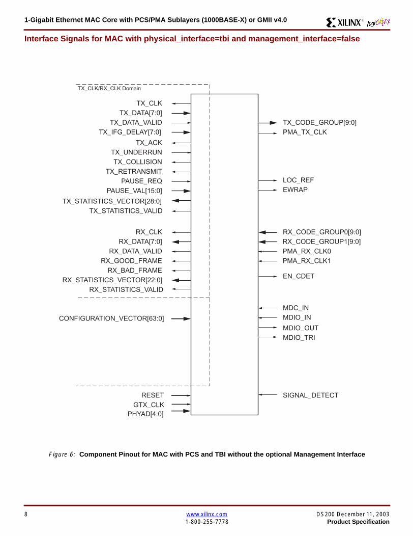
1-Gigabit Ethernet MAC Core with PCSPMA Sublayers (1000BASE-X) or GMII v40 R
Interface Signals for MAC with physical_interface=tbi and management_interface=false
Figure 6 Component Pinout for MAC with PCS and TBI without the optional Management Interface
GTX_CLK
TX_CLK
MDC_INMDIO_IN
RX_CODE_GROUP1[90]
TX_CODE_GROUP[90]PMA_TX_CLK
LOC_REF
TX_DATA[70]
TX_ACKTX_UNDERRUN
PAUSE_REQPAUSE_VAL[150]
RX_CLK
CONFIGURATION_VECTOR[630]
RESET
RX_DATA[70]
RX_GOOD_FRAMERX_BAD_FRAME
TX_COLLISIONTX_RETRANSMIT
TX_DATA_VALID
RX_DATA_VALID
EWRAP
PMA_RX_CLK0PMA_RX_CLK1
TX_CLKRX_CLK Domain
TX_IFG_DELAY[70]
TX_STATISTICS_VECTOR[280]TX_STATISTICS_VALID
RX_STATISTICS_VECTOR[220]RX_STATISTICS_VALID
MDIO_OUTMDIO_TRI
EN_CDET
RX_CODE_GROUP0[90]
PHYAD[40]
SIGNAL_DETECT
8 wwwxilinxcom DS200 December 11 20031-800-255-7778 Product Specification
1-Gigabit Ethernet MAC Core with PCSPMA Sublayers (1000BASE-X) or GMII v40R
Interface Signals for MAC with physical_interface=phy and management_interface=true
Figure 7 Component Pinout for MAC with PCS amp PMA Sublayers using the optional Management Interface
REFCLK
TX_CLK
MDCMDIO_IN
TXPTXN
TX_DATA[70]
TX_ACKTX_UNDERRUN
PAUSE_REQPAUSE_VAL[150]
RX_CLK
HOST_CLKHOST_OPCODE[10]
HOST_ADDR[90]HOST_WR_DATA[310]HOST_RD_DATA[310]
HOST_MIIM_SELHOST_REQ
HOST_MIIM_RDY
RESET
RX_DATA[70]
RX_GOOD_FRAMERX_BAD_FRAME
TX_COLLISIONTX_RETRANSMIT
TX_DATA_VALID
RX_DATA_VALID
RXPRXN
TX_CLKRX_CLK Domain
HOST_CLK Domain
TX_IFG_DELAY[70]
TX_STATISTICS_VECTOR[280]TX_STATISTICS_VALID
RX_STATISTICS_VECTOR[220]RX_STATISTICS_VALID
PHYAD[40]
SIGNAL_DETECT
MDIO_OUTMDIO_TRI
USRCLKUSRCLK2
DCM_LOCKED
REFCLK2BREFCLK
BREFCLK2REFCLKSEL
DS200 December 11 2003 wwwxilinxcom 9Product Specification 1-800-255-7778
1-Gigabit Ethernet MAC Core with PCSPMA Sublayers (1000BASE-X) or GMII v40 R
Interface Signals for MAC with physical_interface=phy and management_interface=false
Figure 8 Component Pinout for MAC with PCS amp PMA Sublayers without the optional Management Interface
TX_CLK
MDC_INMDIO_IN
TXPTXN
TX_DATA[70]
TX_ACKTX_UNDERRUN
PAUSE_REQPAUSE_VAL[150]
RX_CLK
CONFIGURATION_VECTOR[630]
RX_DATA[70]
RX_GOOD_FRAMERX_BAD_FRAME
TX_COLLISIONTX_RETRANSMIT
TX_DATA_VALID
RX_DATA_VALID
RXPRXN
TX_CLKRX_CLK Domain
TX_IFG_DELAY[70]
TX_STATISTICS_VECTOR[280]TX_STATISTICS_VALID
RX_STATISTICS_VECTOR[220]RX_STATISTICS_VALID
SIGNAL_DETECT
MDIO_OUTMDIO_TRI
REFCLKRESET
PHYAD[40]
USRCLKUSRCLK2
DCM_LOCKED
REFCLK2BREFCLK
BREFCLK2REFCLKSEL
10 wwwxilinxcom DS200 December 11 20031-800-255-7778 Product Specification
1-Gigabit Ethernet MAC Core with PCSPMA Sublayers (1000BASE-X) or GMII v40R
Client Side Interface Signal Definition
Table 3 describes the client-side transmit signals of the MAC core These signals are used to transmit data from the clientto the MAC core
Table 4 describes the client-side receive signals These signals are used by the MAC core to transfer data to the client
Table 3 Transmit Client Interface Signal Pins
Signal Direction Description
TX_CLK Output Clock for transmit client interface 125 MHz nominal
TX_DATA[70] Input Frame data to be transmitted is supplied on this port
TX_DATA_VALID Input Control signal for TX_DATA port
TX_IFG_DELAY[70] InputControl signal for configurable Inter Frame Gap adjustment SeeTransmitter on page 16 for timing diagrams
TX_ACK OutputHandshaking signal Asserted when the current data on TX_DATA hasbeen accepted See Transmitter on page 16 for timing diagrams
TX_UNDERRUN Input Asserted by client to force MAC core to corrupt the current frame
TX_COLLISION OutputAsserted by the MAC core to signal a collision on the medium and that anytransmission in progress should be aborted Always 0 when the MAC coreis in full-duplex mode
TX_RETRANSMIT Output
When asserted at the same time as the TX_COLLISION signal thissignals the client that the aborted frame should be resupplied to the MACcore for retransmission Always 0 when the MAC core is in full-duplexmode
TX_STATISTICS_VECTOR[280] OutputThis gives information on the last frame transmitted See Transmitter onpage 16 for vector contents
TX_STATISTICS_VALID OutputAsserted at end of frame transmission indicating that theTX_STATISTICS_VECTOR is valid
Notes1 All the above signals are synchronous to TX_CLK and Active High
Table 4 Receive Client Interface Signal Pins
Signal Direction Description
RX_CLK Output Clock for receive client interface 125 MHz nominal
RX_DATA[70] Output Frame data received is supplied on this port
RX_DATA_VALID Output Control signal for the RX_DATA port
RX_GOOD_FRAME OutputAsserted at end of frame reception to indicate that the frame should beprocessed by the MAC client See Receiver on page 24
RX_BAD_FRAME OutputAsserted at end of frame reception to indicate that the frame should bediscarded by the MAC client See Receiver on page 24
RX_STATISTICS_VECTOR[220] OutputProvides information about the last frame received See Receiver onpage 24 for the vector contents
RX_STATISTICS_VALID OutputAsserted at end of frame reception indicating that theRX_STATISTICS_VECTOR is valid
Notes1 All signals above are synchronous to RX_CLK and Active High
DS200 December 11 2003 wwwxilinxcom 11Product Specification 1-800-255-7778
1-Gigabit Ethernet MAC Core with PCSPMA Sublayers (1000BASE-X) or GMII v40 R
Table 5 describes the signals used by the client to request a flow control action from the transmit engine Flow control framesreceived by the MAC are automatically handled (if the MAC is configured to do so)
Table 6 describes the optional signals used by the client to access the management features of the MAC core includingconfiguration status statistics and MDIO access
Table 7 describes the alternative to the optional Management Interface signals This describes the Configuration Vectorwhich uses direct inputs to the core to replace the functionality of the MAC Configuration bits when the ManagementInterface is not used
Notes1 All bits of CONFIGURATION_VECTOR are registered on input but may be treated as asynchronous inputs
Table 5 Flow Control Interface Signal Pinout
Signal Direction Description
PAUSE_REQ InputPause request sends a pause frame down the link See Transmitting a PAUSE ControlFrame on page 29
PAUSE_VAL[150] Input Pause value inserted into the parameter field of the transmitted pause frame
Notes1 These signals are synchronous to TX_CLK and are Active High
Table 6 Optional Management Interface Signal Pinout (management_interface=true)
Signal Direction Description
HOST_CLK InputClock for management interface See Optional Management Interface(management_interface=true) on page 30 for the signal frequency range
HOST_OPCODE[10] InputDefines operation to be performed over MDIO interface Bit 1 is also used inconfiguration register access See Configuration Registers on page 30
HOST_ADDR[90] Input Address of register to be accessed
HOST_WR_DATA[310] Input Data to write to register
HOST_RD_DATA[310] Output Data read from register
HOST_MIIM_SEL InputWhen asserted the MDIO interface is accessed When disasserted the MACinternal configuration or statistical counter registers are accessed
HOST_REQ InputUsed to signal a transaction on the MDIO interface or to read from the statisticregisters See Optional Management Interface (management_interface=true) onpage 30
HOST_MIIM_RDY OutputWhen high the MDIO interface has completed any pending transaction and isready for a new transaction
Notes1 All signals above are synchronous to HOST_CLK and are Active High
Table 7 Alternative to the Optional Management Interface Configuration Vector Signal Pinout(management_interface=false)
Signal Direction Description
CONFIGURATION_VECTOR[630]
Input The Configuration Vector is used to replace the functionality of theMAC Configuration Registers when the Management Interface is notused See Optional Configuration Vector (management_interface =false) on page 38
12 wwwxilinxcom DS200 December 11 20031-800-255-7778 Product Specification
1-Gigabit Ethernet MAC Core with PCSPMA Sublayers (1000BASE-X) or GMII v40R
Table 8 describes the reset signal
Physical Interface Signal Definition
Table 9 describes the MDIO (MII Management) interface signals of the MAC core These signals are typically connected tothe MDIO port of a PHY device either off-chip or an SoC-integrated core The MDIO format is defined in IEEE8023 clause22
Table 10 describes the optional GMII signals of the MAC core These are typically attached to a PHY module either off-chipor internally integrated The GMII is defined in IEEE8023 clause 35
Table 8 Reset Signal
Signal Direction Description
RESET Input Asynchronous reset for entire core See Reset circuit on page 42 for moreinformation on the reset circuit
Table 9 MDIO Interface Signal Pinout
Signal Direction Description
MDC OutputManagement Clock derived from HOST_CLK on the basis of supplied configuration datawhen the optional Management Interface is used See Optional Management Interface(management_interface=true) on page 30
MDC_IN InputWhen the Optional Management Interface is not used access to the optional PhysicalCoding Sublayer (PCS) must be provided by an external MDIO Controller In this situationthe Management Clock is an input to the core
MDIO_IN Input Input data signal for communication with PHY configuration and status Tie high if unused
MDIO_OUT Output Output data signal for communication with PHY configuration and status
MDIO_TRI OutputTristate control for MDIO signals 0 signals that the value on MDIO_OUT should be
asserted onto the MDIO bus
Table 10 Optional GMII Interface Signal Pinout (physical_interface=gmii)
Signal Direction Description
GTX_CLK InputClock signal at 125 MHz Other transmit clocks are derived from this clock as illustratedin Figure 28 Tolerance must be within IEEE 8023-2002 specification
GMII_TXD[70] Output Transmit data to PHY
GMII_TX_EN Output Data Enable control signal to PHY
GMII_TX_ER Output Error control signal to PHY
GMII_TX_CLK Output Clock out to PHY
GMII_CRS Input Control signal from PHY
GMII_COL Input Control signal from PHY
GMII_RX_CLK Input Recovered clock from received data stream by PHY
GMII_RXD[70] Input Received data from PHY
GMII_RX_DV Input Data Valid control signal from PHY
GMII_RX_ER Input Error control signal from PHY
DS200 December 11 2003 wwwxilinxcom 13Product Specification 1-800-255-7778
1-Gigabit Ethernet MAC Core with PCSPMA Sublayers (1000BASE-X) or GMII v40 R
Table 11 describes the TBI (Ten-Bit interface) signals of the MAC core These are typically attached to a PMA SERDESmodule These signals optionally replace the GMII signals described in Table 10 to extend the functionality of the core toinclude the PCS for 1000BASE-X The TBI is defined in IEEE8023 clause 36
Notes
PHYAD and SIGNAL_DETECT are asynchronous inputs SIGNAL_DETECT is Active High
Table 11 Optional TBI Interface Signal Pinout (physical_interface=tbi)
Signal Direction Description
GTX_CLK InputClock signal at 125 MHz Other transmit clocks will be derived from this clock asillustrated in Figure 32 Tolerance must be within IEEE 8023-2002 specification
TX_CODE_GROUP[90] Output 10-bit parallel transmit data to PMA Sublayer (SERDES)
PMA_TX_CLK Output Transmit clock signal to PMA Sublayer (SERDES) at 125MHz
LOC_REF OutputCauses the PMA sublayer clock recovery unit to lock to PMA_TX_CLK Thissignal is tied to Ground
EWRAP Output
This signal is set from the PCS Control Register 0 bit 14 (loopback) See PCSManaged Register Block (physical_interface = tbi or phy) on page 49 Whenhigh this instructs the PMA sublayer to electrically loop the transmitter data to thereceiver
RX_CODE_GROUP0[90] Input10-bit parallel received data from PMA Sublayer (SERDES) synchronous toPMA_RX_CLK0
RX_CODE_GROUP1[90] Input10-bit parallel received data from PMA Sublayer (SERDES) synchronous toPMA_RX_CLK1
PMA_RX_CLK0 Input Received clock signal from PMA Sublayer (SERDES) at 625MHz
PMA_RX_CLK1 InputReceived clock signal from PMA Sublayer (SERDES) at 625MHz This is 180degrees out of phase with PMA_RX_CLK0
EN_CDET OutputEnables the PMA Sublayer to perform comma realignment driven from the PCSstate machine during the Loss-Of-Sync state
PHYAD[40] Input PHY address of MDIO register set for the PCS
SIGNAL_DETECT Input
Signal direct from PMD sublayer indicating the presence of light detected at theoptical receiver If driven high this indicates that the optical receiver has detectedlight If driven low this indicates the absence of light
If unused tie high to enable the operation the core
14 wwwxilinxcom DS200 December 11 20031-800-255-7778 Product Specification
1-Gigabit Ethernet MAC Core with PCSPMA Sublayers (1000BASE-X) or GMII v40R
Table 12 describes the interface signals for the Optional PCSPMA sublayer of the MAC core These signals optionallyreplace the GMII signals described in Table 10 to extend the functionality of the core to include the PCS and PMA sublayersfor 1000BASE-X This option uses the Virtex-II Pro Rocket IO functionality which is integrated into the core The PMAsublayer for 1000BASE-X is defined in IEEE8023 clause 36
Notes1 PHYAD and SIGNAL_DETECT are asynchronous inputs SIGNAL_DETECT is Active High
Table 12 Optional PCSPMA sublayer Interface Signal Pinout (physical_interface=phy)
Signal Direction Description
REFCLK InputHigh Quality Reference clock for Multi-Gigabit Transceivers (625 MHz) See Rocket IOUser Guide
REFCLK2 Input Alternative High Quality Reference clock for Multi-Gigabit Transceivers (625 MHz) SeeRocket IO User Guide
BREFCLK Input Alternative High Quality Reference clock for Multi-Gigabit Transceivers (625 MHz)This optionally replaces REFCLK See Rocket IO User Guide
BREFCLK2 Input Alternative High Quality Reference clock for Multi-Gigabit Transceivers (625 MHz)This optionally replaces REFCLK2 See Rocket IO User Guide
REFCLKSEL Input Selects between either (B)REFCLK or (B)REFCLK2 as the input clock source to theMGT See Rocket IO User Guide
USERCLK InputClock signal at 625 MHz This is connected to the TXUSRCLK and RXUSRCLK portsof the Rocket IO MGT This may be derived from (B)REFCLK using a DCM asillustrated in Figure 35
USERCLK2 InputClock signal at 125 MHz This is connected to the TXUSRCLK2 and RXUSRCLK2 portsof the Rocket IO MGT This may be derived from (B)REFCLK using a DCM asillustrated in Figure 35
DCM_LOCKED InputIf a DCM is used to derive USRCLK and USRCLK2 as illustrated in Figure 35 theLOCKED port of the DCM must be connected to the DCM_LOCKED port of the coreThe core will hold itrsquos Rocket IO MGT in reset until DCM_LOCKED is driven to logic 1
TXPTXN OutputDifferential pair for serial transmission from PMA to PMD The clock is embedded in thedata stream
RXPRXN InputDifferential pair for serial reception from PMD to PMA The clock is extracted from thedata stream
PHYAD[40] Input PHY address of MDIO register set for the PCS
SIGNAL_DETECT Input
Signal direct from PMD sublayer indicating the presence of light detected at the opticalreceiver If driven high this indicates that the optical receiver has detected light If drivenlow this indicates the absence of light
If unused tie high to enable the operation the core
DS200 December 11 2003 wwwxilinxcom 15Product Specification 1-800-255-7778
1-Gigabit Ethernet MAC Core with PCSPMA Sublayers (1000BASE-X) or GMII v40 R
Functional Description
Client InterfaceThe client interface is designed for maximum flexibility inmatching to a client switching fabric or network processorinterface
The data pathway is 8 bits wide in both the transmit andreceive directions with each pathway synchronous to theTX_CLK and RX_CLK respectively for completely indepen-dent full duplex operation
Transmitter
Normal Frame Transmission
The timing of a normal outbound frame transfer can be seenin Figure 9 When the client wants to transmit a frame itplaces the first column of data onto the TX_DATA port andasserts a ldquo1rdquo onto TX_DATA_VALID
When the MAC core has read this first byte of data it willassert the TX_ACK signal on the next and subsequent ris-ing clock edges the client must provide the remainder ofthe data for the frame
The end of frame is signalled to the MAC core by takingTX_DATA_VALID Low
In-Band Parameter Encoding
For maximum flexibility in switching applications the Ether-net frame parameters (destination address sourceaddress lengthtype and optionally FCS) are encodedwithin the same data stream that the frame payload is trans-ferred upon rather than on separate ports This is illustratedin the timing diagrams Definitions of the abbreviations usedin the timing diagrams are described in Table 13
Figure 9 Normal Frame Transmission Across Client Interface
Table 13 Abbreviations Used in Timing Diagrams
Abbreviation Definition
DA Destination Address 6 bytes
SA Source Address 6 bytes
LT LengthType Field 2 bytes
FCS Frame Check Sequence 4 bytes
TX_CLK
TX_DATA[70]
TX_DATA_VALID
TX_ACK
TX_UNDERRUN
DA SA DATALT
TX_COLLISION
TX_RETRANSMIT
xip2133
16 wwwxilinxcom DS200 December 11 20031-800-255-7778 Product Specification
1-Gigabit Ethernet MAC Core with PCSPMA Sublayers (1000BASE-X) or GMII v40R
Padding
When fewer than 46 bytes of data are supplied by the clientto the MAC core the transmitter module will add padding upto the minimum frame length The exception to this is whenthe MAC core is configured for client-passed FCS in thiscase the client must also supply the padding to maintain theminimum frame length (see Client-Supplied FCS Passing)
Client-Supplied FCS Passing
If the MAC core is configured to have the FCS field passedin by the client (see Configuration Registers on page 30)the transmission timing is as depicted in Figure 10 In thiscase it is the responsibility of the client to ensure that theframe meets the Ethernet minimum frame length require-ments the MAC core will not perform any padding of thepayload
Figure 10 Frame Transmission with Client-supplied FCS
TX_CLK
TX_DATA[70]
TX_DATA_VALID
TX_ACK
TX_UNDERRUN
DA SA DATA FCSLT
TX_COLLISION
TX_RETRANSMIT
xip2134
DS200 December 11 2003 wwwxilinxcom 17Product Specification 1-800-255-7778
1-Gigabit Ethernet MAC Core with PCSPMA Sublayers (1000BASE-X) or GMII v40 R
Client Underrun
The timing of an aborted transfer can be seen in Figure 11This may happen for instance if a FIFO connected to theclient interface empties before a frame is completed Whenthe client asserts TX_UNDERRUN during a frame transmis-sion the MAC core will insert an error code to corrupt the
current frame and then fall back to idle transmission It isthe responsibility of the client to re-queue the aborted framefor transmission
When an underrun occurs TX_DATA_VALID may beasserted on the clock cycle after the TX_UNDERRUNassertion to request a new transmission
Figure 11 Frame Transmission with Underrun
TX_CLK
TX_DATA[70]
TX_DATA_VALID
TX_ACK
TX_UNDERRUN
DA SA DATALT
TX_COLLISION
TX_RETRANSMIT
xip2135
18 wwwxilinxcom DS200 December 11 20031-800-255-7778 Product Specification
1-Gigabit Ethernet MAC Core with PCSPMA Sublayers (1000BASE-X) or GMII v40R
Back-to-Back Transfers
Figure 12 shows the case where the MAC client is immedi-ately ready to transmit a second frame of data followingcompletion of its first frame In this figure the end of the firstframe is shown on the left On the clock cycle immediatelyfollowing the final byte of the first frame TX_DATA_VALIDis taken low by the client and is taken high one clock cyclelater to indicate that the first byte of the destination addressof the second frame is on TX_DATA awaiting transmission
When the MAC core is ready to accept data TX_ACK isasserted and the transmission continues in the same man-ner as in the case of the single frame The MAC core willdefer the assertion of TX_ACK appropriately to comply withinter-packet gap requirements and flow control requests
If the MAC core is operating in half-duplex mode the timingshown in Figure 12 is required to take advantage of framebursting the MAC core is only guaranteed to retain controlof the medium if the TX_DATA_VALID signal is low for a sin-gle clock cycle For more information on frame bursting seeIEEE 8023-2002
Figure 12 Back to Back Frame Transmission
TX_CLK
TX_DATA[70]
TX_DATA_VALID
TX_ACK
TX_UNDERRUN
TX_COLLISION
TX_RETRANSMIT
xip2136
DS200 December 11 2003 wwwxilinxcom 19Product Specification 1-800-255-7778
1-Gigabit Ethernet MAC Core with PCSPMA Sublayers (1000BASE-X) or GMII v40 R
VLAN Tagged Frames
Transmission of a VLAN tagged frame (if enabled) can beseen in Figure 13 Note that the handshaking signalsacross the interface do not change however the VLANtype tag 81-00 must be supplied by the client to signify that
the frame is VLAN tagged The client also supplies the twobytes of Tag Control Information V1 and V2 at the appro-priate times in the data stream More information on thecontents of these two bytes can be found in IEEE8023-2002
Maximum Permitted Frame Length
The maximum legal length of a frame specified in IEEE8023-2002 is 1518 bytes for non-VLAN tagged framesVLAN tagged frames may be extended to 1522 bytesWhen jumbo frame handling is disabled and the clientattempts to transmit a frame which exceeds the maximumlegal length the MAC core will insert an error code to cor-
rupt the current frame and the frame will be truncated to themaximum legal length When jumbo frame handling isenabled frames which are longer than the legal maximumare transmitted error-free
For more information on enabling and disabling jumboframe handling see Configuration Registers on page 30
Figure 13 Transmission of a VLAN Tagged Frame
TX_CLK
TX_DATA[70]
TX_DATA_VALID
TX_ACK
TX_UNDERRUN
DA SA DATALTVLANtag
81 00V1V2
TX_COLLISION
TX_RETRANSMIT
xip2137
20 wwwxilinxcom DS200 December 11 20031-800-255-7778 Product Specification
1-Gigabit Ethernet MAC Core with PCSPMA Sublayers (1000BASE-X) or GMII v40R
Frame Collisions - Half Duplex Operation Only
In half duplex Ethernet operation collisions will occur on themedium as a matter of course this is how the arbitrationalgorithm is fulfilled In case of a collision the MAC core sig-nals to the client that data may need to be resupplied as fol-lows
If there is a collision the TX_COLLISION signal will be setto ldquo1rdquo by the MAC core If a frame is in progress the clientmust abort the transfer and take TX_DATA_VALID to ldquo0rdquo
If the TX_RETRANSMIT signal is ldquo1rdquo in the same clockcycle that the TX_COLLISION signal is ldquo1rdquo the client must
resubmit the previous frame to the MAC core for retrans-mission TX_DATA_VALID must be asserted to the MACcore within 8 clock cycles of the TX_COLLISION signal inorder to meet Ethernet timing requirements See Figure 14
If the TX_RETRANSMIT signal is ldquo0rdquo in the same clockcycle that the TX_COLLISION signal is ldquo1rdquo the number ofretries for this frame has exceeded the Ethernet specifica-tion and the frame should be dropped by the client The cli-ent can then make any new frame available to the MAC fortransmission without timing restriction See Figure 15
Figure 14 Collision Handling - Frame retransmission required
Figure 15 Collision Handling - No frame retransmission required
TX_CLK
TX_DATA[70]
TX_DATA_VALID
TX_ACK
TX_UNDERRUN
TX_COLLISION
TX_RETRANSMIT
8 clocks max
xip2138
TX_CLK
TX_DATA[70]
TX_DATA_VALID
TX_ACK
TX_UNDERRUN
TX_COLLISION
TX_RETRANSMIT
xip2139
DS200 December 11 2003 wwwxilinxcom 21Product Specification 1-800-255-7778
1-Gigabit Ethernet MAC Core with PCSPMA Sublayers (1000BASE-X) or GMII v40 R
Interframe Gap Adjustment
The user can elect to vary the length of the inter fame gapIf this function is selected (via a configuration bit in thetransmitter control register see Configuration Registerson page 30) then the MAC will exert back pressure to delaythe transmission of the next frame until the requested num-ber of Idle cycles has elapsed The number of Idle cycles iscontrolled by the value on the TX_IFG_DELAY port at thestart of frame transmission Figure 16 shows the MAC oper-ating in this mode
Reducing the Inter fame gap to below the IEEE 8023-2002minimum of 12 Idles is supported in Full Duplex onlydesigns and will transmit an absolute minimum of 4 Idles Ifthe Interframe gap adjustment is reduced below 12 Idlesthen the accuracy of the Optional Statistical Gathering(statistics_gathering=true) Counters cannot be guaranteedHowever the TX_STATISTIC_VECTOR andRX_STATISTIC_VECTOR will always remain correct
Transmitter Statistics Vector
The statistics for the frame transmitted are contained withinthe TX_STATISTICS_VECTOR The vector is driven syn-chronously by the transmitter clock TX_CLK followingframe transmission The bit field definition for the Vector isdefined in Table 14
All bit fields with the exception of BYTE_VALID are validonly when the TX_STATISTICS_VALID is asserted This isillustrated in Figure 17 BYTE_VALID is significant on everyTX_CLK cycle
TX_STATISTICS_VECTOR bits 25 down to 17 inclusive arefor half duplex only and will be set to logic 0 when operatingin full duplex mode
Figure 16 Interframe Gap Adjustment
TX_CLK
TX_DATA[70]
TX_DATA_VALID
TX_ACK
DA SA
TX_IFG_DELAY
IFG ADJUST VALUE
0x0D
13 Idles inserted
DA
Next IFG ADJUST VALUE
xip2140
Figure 17 Transmitter Statistics Vector Timing
TX_CLK
TX_STATISTICS_VECTOR[280]
TX_STATISTICS_VALID
xip2141
22 wwwxilinxcom DS200 December 11 20031-800-255-7778 Product Specification
1-Gigabit Ethernet MAC Core with PCSPMA Sublayers (1000BASE-X) or GMII v40R
Table 14 Bit Definition for the Transmitter Statistics Vector
TX_STATISTICS_VECTOR Name Description
28 PAUSE_FRAME_TRANSMITTEDAsserted if the previous frame was a pause framethat the MAC itself initiated in response to aPAUSE_REQ assertion
27 BYTE_VALID
Asserted if a MAC frame byte (DA to FCS inclusive)is in the process of being transmitted This is valid onevery clock cycle
Do not use this as an enable signal to indicate thatdata is present on GMII_TXD[70]
26 Reserved Returns logic 0
25 down to 22 TX_ATTEMPTS[30]
The number of attempts that have been made totransmit the previous frame This is a 4-bit number0 should be interpreted as 1 attempt 1 as 2attempts up until 15 as 16 attempts
21 Reserved Returns logic 0
20 EXCESSIVE_COLLISIONAsserted if a collision has been detected on each ofthe last 16 attempts to transmit the previous frame
19 LATE_COLLISIONAsserted if a late collision occurred during frametransmission
18 EXCESSIVE_DEFERRALAsserted if the previous frame was deferred for anexcessive amount of time as defined by the constantldquomaxDeferTimerdquo in IEEE 8023-2002
17 TX_DEFERRED Asserted if transmission of the frame was deferred
16 VLAN_FRAMEAsserted if the previous frame contained a VLANidentifier in the LengthType field when transmitterVLAN operation is enabled
15 down to 5 FRAME_LENGTH_COUNTThe length of the previous frame in number of bytesThe count will stick at 2047 for any Jumbo frameslarger than this value
4 CONTROL_FRAMEAsserted if the previous frame had the special MACControl Type code 88-08 in the LengthType field
3 UNDERRUN_FRAMEAsserted if the previous frame contained anunderrun error
2 MULTICAST_FRAMEAsserted if the previous frame contained a multicastaddress in the Destination Address field
1 BROADCAST_FRAMEAsserted if the previous frame contained abroadcast address in the Destination Address field
0 SUCCESSFUL_FRAMEAsserted if the previous frame was transmittedwithout error
DS200 December 11 2003 wwwxilinxcom 23Product Specification 1-800-255-7778
1-Gigabit Ethernet MAC Core with PCSPMA Sublayers (1000BASE-X) or GMII v40 R
Receiver
Normal Frame Reception
The timing of a normal inbound frame transfer can be seenin Figure 18 The client must be prepared to accept data atany time there is no buffering within the MAC to allow forlatency in the receive client Once frame reception begins
data is transferred on consecutive clock cycles to thereceive client until the frame is complete The MAC assertsthe RX_GOOD_FRAME signal to indicate that the framewas successfully received and that the frame should beanalyzed by the client
Frame parameters (destination address source addresslengthtype and optionally FCS) are supplied on the databus according to the timing diagram The abbreviations arethe same as those described in Table 13 on page 16
If the LengthType field in the frame has the Length interpre-tation and this indicates that the inbound frame has beenpadded to meet the Ethernet minimum frame size specifica-tion then this padding will not be passed to the client in thedata payload The exception to this is in the case whereFCS passing is enabled see Client-Supplied FCS Pass-ing on page 25
Therefore when Client-Supplied FCS passing is disabledRX_DATA_VALID = lsquo0rsquo between frames for the duration ofthe Padding field (if present) the FCS field carrier exten-sion (if present) the interframe gap following the frame andthe preamble field of the next frame When Client-Supplied
FCS passing is enabled RX_DATA_VALID = lsquo0rsquo betweenframes for the duration of carrier extension (if present) theinterframe gap and the preamble field of the followingframe
RX_GOOD_FRAME RX_BAD_FRAME timing
Although the timing diagram in Figure 18 shows theRX_GOOD_FRAME signal asserted shortly after the lastvalid data on RX_DATA this is not always the case TheRX_GOOD_FRAME or RX_BAD_FRAME signals areasserted only after all frame checks are completed This isafter the FCS field has been received (and after reception ofcarrier extension if present)
Therefore either RX_GOOD_FRAME or RX_BAD_FRAMEis asserted following frame reception at the beginning of theinterframe gap
Figure 18 Normal Frame Reception
RX_CLK
RX_DATA[70]
RX_DATA_VALID
RX_GOOD_FRAME
RX_BAD_FRAME
DA SA DATALT
xip2142
24 wwwxilinxcom DS200 December 11 20031-800-255-7778 Product Specification
1-Gigabit Ethernet MAC Core with PCSPMA Sublayers (1000BASE-X) or GMII v40R
Frame Reception with Errors
The case of an unsuccessful frame reception (for examplea fragment frame or a frame with an incorrect FCS) can beseen in Figure 19 In this case the RX_BAD_FRAME signal
is asserted to the client at the end of the frame It is then theresponsibility of the client to drop the data already trans-ferred for this frame
Figure 19 Frame Reception with Error
Client-Supplied FCS Passing
If the MAC core is configured to pass the FCS field to the cli-ent (see Configuration Registers on page 30) then this ishandled as shown in Figure 20
In this case any padding inserted into the frame to meetEthernet minimum frame length specifications will be leftintact and passed to the client
Note that even though the FCS is passed up to the client itis also verified by the MAC core and RX_BAD_FRAMEasserted if the FCS check fails
RX_CLK
RX_DATA[70]
RX_DATA_VALID
RX_GOOD_FRAME
RX_BAD_FRAME
DA SA DATALT
xip2144
Figure 20 Frame Reception with In-Band FCS Field
RX_CLK
RX_DATA[70]
RX_DATA_VALID
RX_GOOD_FRAME
RX_BAD_FRAME
DA SA DATALT FCS
xip2145
DS200 December 11 2003 wwwxilinxcom 25Product Specification 1-800-255-7778
1-Gigabit Ethernet MAC Core with PCSPMA Sublayers (1000BASE-X) or GMII v40 R
VLAN Tagged Frames
The reception of a VLAN tagged frame (if enabled) can beseen in Figure 21 The VLAN frame is passed to the clientso that the frame may be identified as VLAN tagged this is
followed by the Tag Control Information bytes V1 and V2More information on the interpretation of these bytes maybe found in IEEE 8023-2002 standard
Maximum Permitted Frame Length
The maximum legal length of a frame specified in IEEE8023-2002 is 1518 bytes for non-VLAN tagged framesVLAN tagged frames may be extended to 1522 bytesWhen jumbo frame handling is disabled and the corereceives a frame which exceeds the maximum legal lengthRX_BAD_FRAME will be asserted When jumbo framehandling is enabled frames which are longer than the legalmaximum are received in the same way as shorter frames
For more information on enabling and disabling jumboframe handling see Configuration Registers on page 30
LengthType Field Error Checks
Enabled
Default operation is with the LengthType error checkingenabled (see Receiver Configuration Word 1 on page 31)In this mode the following checks are made on all framesreceived If either of these checks fail then the frame ismarked as BAD
bull A value in the LengthType field that is greater than orequal to decimal 46 but less than decimal 1536 (aLength interpretation) is checked against the actualdata length received
bull A value in the LengthType field that is less thandecimal 46 is checked to see that the data field ispadded to exactly 46 bytes (so that the resultant frameis minimum frame size 64 bytes total in length)
Furthermore if Padding is indicated (the LengthType fieldis less than decimal 46) and Client-Supplied FCS Passing isdisabled then the Length value in the LengthType field willbe used to deassert RX_DATA_VALID after the indicatednumber of data bytes so that the Padding bytes areremoved from the frame
Disabled
When the LengthType error checking is disabled (seeReceiver Configuration Word 1 on page 31) theLengthType error checks described above are not per-formed A frame containing only these errors will be markedas GOOD
Furthermore if Padding is indicated and Client-SuppliedFCS Passing is disabled then a Length Value in theLengthType field will not be used to deassertRX_DATA_VALID Instead RX_DATA_VALID will be deas-serted before the start of the FCS field in this way any pad-ding will not be removed from the frame
Figure 21 Reception of a VLAN Tagged Frame
RX_CLK
RX_DATA[70]
RX_DATA_VALID
RX_GOOD_FRAME
RX_BAD_FRAME
DA SA DATALT
81 00 V1 V2
VLANtag
xip2146
26 wwwxilinxcom DS200 December 11 20031-800-255-7778 Product Specification
1-Gigabit Ethernet MAC Core with PCSPMA Sublayers (1000BASE-X) or GMII v40R
Receiver Statistics Vector
The statistics for the frame received are contained withinthe RX_STATISTICS_VECTOR The vector is driven syn-chronously by the receiver clock RX_CLK following framereception The bit field definition for the Vector is defined inTable 15
All bit fields with the exception of BYTE_VALID are validonly when the RX_STATISTICS_VALID is asserted This isillustrated in Figure 22 BYTE_VALID is significant on everyRX_CLK cycle
Figure 22 Receiver Statistics Vector Timing
RX_CLK
RX_STATISTICS_VECTOR[220]
RX_STATISTICS_VALID
xip2147
Table 15 Bit Definition for the Receiver Statistics Vector
RX_STATISTICS_VECTOR Name Description
22LENGTHTYPE Out ofRange
Asserted if the lengthtype field contained a length valuethat did not match the number of MAC client data bytesreceived Also high if the lengthtype field indicated thatthe frame contained padding but the number of MAC cli-ent data bytes received was not equal to 64 bytes (min-imum frame size)
The exception to the above is when the LengthTypeField Error Checks are disabled in which case this bitwill not be asserted
21 BAD_OPCODE
Asserted if the previous frame was error-free andcontained the special Control Frame identifier in theLengthType field but contained an opcode that isunsupported by the MAC (Any Opcode other thanPAUSE)
20 FLOW_CONTROL_FRAME
Asserted if the previous frame was error-freecontained the special Control Frame identifier in theLengthType field contained a Destination Addressthat matched either the MAC Control MulticastAddress or the configured source address of the MACcontained the supported PAUSE opcode and wasacted upon by the MAC
19 BYTE_VALID
Asserted if a MAC frame byte (DA to FCS inclusive) isin the process of being received This is valid on everyclock cycle
Do not use this as an enable signal to indicate thatdata is present on RX_DATA[70]
18 VLAN_FRAMEAsserted if the previous frame contained a VLANidentifier in the LengthType field when receiver VLANoperation is enabled
DS200 December 11 2003 wwwxilinxcom 27Product Specification 1-800-255-7778
1-Gigabit Ethernet MAC Core with PCSPMA Sublayers (1000BASE-X) or GMII v40 R
17 OUT_OF_BOUNDS
Asserted if the previous frame exceeded the specifiedIEEE8023-2002 maximum legal length (seeMaximum Permitted Frame Length on page 26) Thisis only valid if Jumbo frames are disabled
16 CONTROL_FRAMEAsserted if the previous frame contained the specialControl Frame identifier in the LengthType field
15 down to 5 FRAME_LENGTH_COUNTThe length of the previous frame in number of bytesThe count will stick at 2047 for any Jumbo frameslarger than this value
4 MULTICAST_FRAMEAsserted if the previous frame contained a multicastaddress in the Destination Address field
3 BROADCAST_FRAMEAsserted if the previous frame contained the broadcastaddress in the Destination Address field
2 FCS_ERRORAsserted if the previous frame received had anincorrect FCS value or the MAC detected error codesduring frame reception
1 BAD_FRAME1 Asserted if the previous frame received containederrors
0 GOOD_FRAME1 Asserted if the previous frame received was error-free
1 If the LengthType Field Error Checks are disabled then a frame which contains this type of error will be marked as a GOOD_FRAMEproviding no additional errors were detected
Table 15 Bit Definition for the Receiver Statistics Vector
RX_STATISTICS_VECTOR Name Description
28 wwwxilinxcom DS200 December 11 20031-800-255-7778 Product Specification
1-Gigabit Ethernet MAC Core with PCSPMA Sublayers (1000BASE-X) or GMII v40R
Flow ControlThe flow control block is designed to Clause 31 of the IEEE8023-2002 standard The MAC may be configured to sendpause frames and to act upon their reception These twobehaviors can be configured asymmetrically see Configu-ration Registers on page 30
Transmitting a PAUSE Control Frame
The client initiates a flow control frame by assertingPAUSE_REQ while the pause value is on the PAUSE_VALbus These signals are synchronous to TX_CLK The timingof this can be seen in Figure 23
If the MAC core is configured to support transmit flow con-trol this action causes the core to transmit a PAUSE controlframe on the link with the PAUSE parameter set to thevalue on PAUSE_VAL in the cycle when PAUSE_REQ wasasserted This will not disrupt any frame transmission inprogress but will take priority over any pending frame trans-
mission This frame will be transmitted even if the transmit-ter is in the paused state itself
Receiving a Pause Control Frame
When an error-free frame is received by the MAC core thefollowing checks are made
1 The Destination Address field is matched against theMAC Control Multicast address or the configuredSource Address for the MAC (see ConfigurationRegisters on page 30)
2 The LengthType field is matched against the MACControl Type code
3 The opcode field contents are matched against thePAUSE opcode if check 2 is true
If any of the above checks are false or the MAC Flow Con-trol logic for the receiver is disabled the frame is ignored bythe Flow Control logic and passed up to the client
If the frame passes all of the above checks is of minimumlegal size and the MAC Flow Control logic for the receiver isenabled the pause value parameter in the frame is thenused to inhibit transmitter operation for the time defined inthe IEEE8023-2002 specification This inhibit is imple-mented using the same back pressure scheme shown inFigure 12 Because the received pause frame has beenacted upon it is passed to the client with RX_BAD_FRAMEasserted to indicate to the client that it should be dropped
Reception of any frame for which check 2 is true and whichis not of legal minimum length is considered an invalid Con-trol frame This will be ignored by the Flow Control logic andpassed to the client with RX_BAD_FRAME asserted
Figure 23 Pause Request Timing
TX_CLK
PAUSE_VAL[150]
PAUSE_REQ
xip2148
DS200 December 11 2003 wwwxilinxcom 29Product Specification 1-800-255-7778
1-Gigabit Ethernet MAC Core with PCSPMA Sublayers (1000BASE-X) or GMII v40 R
Optional Management Interface(management_interface=true)The management interface is a processor-independentinterface with standard address data and control signals Itmay be used as is or a wrapper may be applied (not sup-plied) to interface to common bus architectures
This interface is used for
bull Configuration of the MAC core
bull Access to optional statistics counters for use by higherlayers for example SNMP
bull access through the MDIO interface to the managementregisters located in the PHY attached to the MAC core
The management interface is accessed differently depend-ing on the type of transaction a truth table showing whichaccess method is required for each transaction type isshown in Table 16 These access methods are described inthe following sections
HOST_CLK Frequency
The management interface clock HOST_CLK is used toderive the MDIO clock MDC and is therefore subject tosome frequency restrictions This HOST_CLK must be
ge 10 MHz
le 100 MHz
Configuring the MAC core to derive the MDC signal fromthis clock is detailed in MDIO Interface on page 37
Configuration Registers
After power up or reset the client may reconfigure the coreparameters from their defaults such as flow control supportConfiguration changes can be written at any time Both thereceiver and transmitter logic will only respond to configura-tion changes during Inter Frame Gaps The exceptions tothis are the configurable resets which take effect immedi-ately
Configuration of the MAC core is performed through a reg-ister bank accessed through the management interfaceThe configuration registers available in the core are detailedin Table 17 As can be seen the address has some implicitdonrsquot care bits any access to an address in the rangesshown will perform a 32-bit read or write from the same con-figuration word
Table 16 Management Interface Transaction Types
Transaction HOST_MIIM_SEL HOST_ADDR[9]
Configuration 0 1
Statistics 0 0
MIIM access 1 X
Table 17 Configuration Registers
Address Description
0x200-0x23F Receiver Configuration (Word 0)
0x240-0x27F Receiver Configuration (Word 1)
0x280-0x2BF Transmitter Configuration
0x2C0-0x2FF Flow Control Configuration
0x300-0x33F Reserved
0x340-0x37F Management Configuration
30 wwwxilinxcom DS200 December 11 20031-800-255-7778 Product Specification
1-Gigabit Ethernet MAC Core with PCSPMA Sublayers (1000BASE-X) or GMII v40R
The register contents for the two receiver configuration words can be seen in Table 18 and Table 19
Notes1 In changing the receiverrsquos mode from Half Duplex to Full Duplex there is a period of time of up to 24 us following the mode change
when no new receiver statistics can be stored in the optional Statistical Counters
Table 18 Receiver Configuration Word 0
Bit Default Value Description
31-0 All 0rsquos
Pause frame MAC Source Address[310] This address is used by the MAC tomatch against the Destination Address of any incoming flow control frames It isalso used by the flow control block as the Source Address (SA) for any outboundflow control frames
The address is ordered so the first byte transmittedreceived is the lowestpositioned byte in the register for example a MAC address ofAA-BB-CC-DD-EE-FF would be stored in Address[470] as 0xFFEEDDCCBBAA
Table 19 Receiver Configuration Word 1
Bit Default Value Description
15-0 All 0rsquos Pause frame MAC Source Address[4732] See description in Table 18
24-16 NA Reserved
25 0
LengthType Error Check Disable When this bit is set to ldquo1rdquo the core will notperform the LengthType field error checks as described in LengthType FieldError Checks on page 26 When this bit is set to ldquo0rdquo the LengthType field checkswill be performed this is normal operation
26 0Half Duplex If ldquo1rdquo the receiver will operate in half duplex mode If ldquo0rdquo the receiverwill operate in full duplex mode Has no effect if XCO parameterhalf_duplex_capable = false
27 0VLAN Enable When this bit is set to ldquo1rdquo VLAN tagged frames will be acceptedby the receiver
28 1Receiver Enable If set to ldquo1rdquo the receiver block will be operational If set to ldquo0rdquothe block will ignore activity on the physical interface RX port
29 0
In-band FCS Enable When this bit is ldquo1rdquo the MAC receiver will pass the FCS fieldup to the client as described in Client-Supplied FCS Passing on page 25 Whenit is ldquo0rdquo the client will not be passed the FCS In both cases the FCS will beverified on the frame
30 0Jumbo Frame Enable When this bit is set to ldquo1rdquo the MAC receiver will acceptframes over the specified IEEE8023-2002 maximum legal length When this bitis ldquo0rdquo the MAC will only accept frames up to the specified maximum
31 0Reset When this bit is set to ldquo1rdquo the receiver will be reset The bit will thenautomatically revert to ldquo0rdquo Note that this reset will also set all of the receiverconfiguration registers to their default values
DS200 December 11 2003 wwwxilinxcom 31Product Specification 1-800-255-7778
1-Gigabit Ethernet MAC Core with PCSPMA Sublayers (1000BASE-X) or GMII v40 R
The register contents for the Transmitter Configuration Word are described in Table 20
Notes1 In changing the transmitterrsquos mode from Half Duplex to Full Duplex there is a period of time of up to 24 us following the mode change
when no new transmitter statistics can be stored in the optional Statistical Counters
Table 20 Transmitter Configuration Word
Bit Default Value Description
24-0 NA Reserved
25 0
Interframe Gap Adjust Enable If lsquo1rsquo the transmitter will read the value on the portTX_IFG_DELAY at the start of frame transmission and adjust the interframe gapfollowing the frame accordingly See Interframe Gap Adjustment on page 22 Ifldquo0rdquo the transmitter will output a minimum Inter Frame Gap of twelve clock cyclesas specified in IEEE8023-2002
26 0Half Duplex If lsquo1rsquo the transmitter will operate in half duplex mode If lsquo0rsquo thetransmitter will operate in full duplex mode Has no effect if XCO parameterhalf_duplex_capable = false
27 0VLAN Enable When this bit is set to 1 the transmitter will allow the transmissionof VLAN tagged frames
28 1Transmit Enable When this bit is 1 the transmitter is operational When it is 0the transmitter is disabled
29 0
In-band FCS Enable When this bit is lsquo1rsquo the MAC transmitter will expect the FCSfield to be passed in by the client as described in Client-Supplied FCS Passingon page 17 When this bit is ldquo0rdquo the MAC transmitter will append padding asrequired compute the FCS and append it to the frame
30 0
Jumbo Frame Enable When this bit is set to ldquo1rdquo the MAC transmitter will sendframes that are greater than the specified IEEE8023-2002 maximum legallength When this bit is ldquo0rdquo the MAC will only send frames up to the specifiedmaximum
31 0Reset When this bit is set to ldquo1rdquo the transmitter will be reset The bit will thenautomatically revert to ldquo0rdquo Note that this reset will also set all of the transmitterconfiguration registers to their default values
32 wwwxilinxcom DS200 December 11 20031-800-255-7778 Product Specification
1-Gigabit Ethernet MAC Core with PCSPMA Sublayers (1000BASE-X) or GMII v40R
The register contents for the Flow Control Configuration Word are described in Table 21
The register contents for the Management Configuration Word are described in Table 22
Writing to the configuration registers through the manage-ment interface is depicted in Figure 24 When accessing theconfiguration registers (ie when HOST_ADDR[9] = lsquo1rsquo andHOST_MIIM_SEL = lsquo0rsquo) the upper bit of HOST_OPCODEfunctions as an Active Low write enable signal The lowerHOST_OPCODE bit is a ldquodonrsquot carerdquo
Reading from the configuration register words is similar butthe upper HOST_OPCODE bit should be lsquo1rsquo This is shownin Figure 25 In this case the contents of the register appearon HOST_RD_DATA the HOST_CLK edge after the regis-ter address is asserted onto HOST_ADDR
Table 21 Flow Control Configuration Word
Bit Default Value Description
28-0 NA Reserved
29 1
Flow Control Enable (RX) When this bit is lsquo1rsquo received flow control frames willinhibit the transmitter operation as described in Receiving a Pause ControlFrame on page 29 When this bit is lsquo0rsquo received flow control frames will alwaysbe passed up to the client
30 1Flow Control Enable (TX) When this bit is lsquo1rsquo asserting the PAUSE_REQ signalwill send a flow control frame out from the transmitter When this bit is 0 assertingthe PAUSE_REQ signal has no effect
31 NA Reserved
Table 22 Management Configuration Word
Bits Default Value Description
4-0 All 0rsquos Clock Divide[40] See MDIO Interface on page 37
5 0MDIO Enable When this bit is 1 the MDIO interface can be used to accessattached PHY devices When this bit is 0 the MDIO interface is disabled and theMDIO signals remain inactive
31-6 NA Reserved
Figure 24 Configuration Register Write Timing
HOST_CLK
HOST_ADDR[80]
HOST_ADDR[9]
HOST_OPCODE[1]
HOST_MIIM_SEL
HOST_WR_DATA[310]xip2149
Figure 25 Configuration Register Read Timing
HOST_CLK
HOST_ADDR[80]
HOST_ADDR[9]
HOST_OPCODE[1]
HOST_MIIM_SEL
HOST_RD_DATA[310]
xip2150
DS200 December 11 2003 wwwxilinxcom 33Product Specification 1-800-255-7778
1-Gigabit Ethernet MAC Core with PCSPMA Sublayers (1000BASE-X) or GMII v40 R
Optional Statistical Gathering(statistics_gathering=true)
During operation the MAC core collects statistics on thesuccess and failure of various operations for processing by
station management entities (STA) further up the protocolstack These statistics are accessed by the host through theoptional management interface A complete list of statisticssupported is described in Table 23
Table 23 Statistics Registers
Address Name Description
0x000 Frames Received OK1 A count of error-free frames received
0x001 Frame Check Sequence Errors A count of received frames that failed the CRC check and were at least64 bytes in length
0x002 Broadcast Frames Received OK1A count of frames that were successfully received and were directed tothe broadcast group address
0x003 Multicast Frames Received OK1 A count of frames that were successfully received and were directed toa non broadcast group address
0x004 64 byte Frames Received OK1 A count of error-free frames received that were 64 bytes in length
0x005 65-127 byte Frames Received OK1A count of error-free frames received that were between 65 and 127bytes in length
0x006 128-255 byte Frames Received OK1A count of error-free frames received that were between 128 and 255bytes in length
0x007 256-511 byte Frames Received OK1A count of error-free frames received that were between 256 and 511bytes in length
0x008512-1023 byte Frames ReceivedOK1
A count of error-free frames received that were between 512 and 1023bytes in length
0x0091024-MaxFrameSize byte FramesReceived OK1
A count of error-free frames received that were between 1024 bytes andthe specified IEEE8023-2002 maximum legal length (see MaximumPermitted Frame Length on page 26)
0x00A Control Frames Received OKA count of error-free frames received that contained the specialControl Frame identifier in the LengthType field
0x00B LengthType Out of Range
A count of frames received that were at least 64 bytes in length wherethe lengthtype field contained a length value that did not match thenumber of MAC client data bytes received
The counter also increments for frames in which the lengthtype fieldindicated that the frame contained padding but where the number ofMAC client data bytes received was greater than 64 bytes (minimumframe size)
The exception to the above is when the LengthType Field Error Checksare disabled in which case this counter will not increment
0x00C VLAN Tagged Frames Received OKA count of error-free VLAN frames received This counter will only incre-ment when the receiver is configured for VLAN operation
0x00D Pause Frames Received OK
A count of error-free frames received that contained the MAC Controltype identifier 88-08 in the LengthType field contained a Destinationaddress that matched either the MAC Control multicast address or theconfigured source address of the MAC contained the PAUSE opcodeand were acted upon by the MAC
0x00EControl Frames Received withUnsupported Opcode
A count of error-free frames received that contained the MAC Controltype identifier 88-08 in the LengthType field but were received with anopcode other than the PAUSE opcode
34 wwwxilinxcom DS200 December 11 20031-800-255-7778 Product Specification
1-Gigabit Ethernet MAC Core with PCSPMA Sublayers (1000BASE-X) or GMII v40R
0x00F Oversize Frames Received OK1A count of otherwise error-free frames received that exceeded the max-imum legal frame length specified in IEEE 8023-2002 (see MaximumPermitted Frame Length on page 26)
0x010 Undersize frames receivedA count of the number of frames received that were less than 64 bytesin length but were otherwise well formed
0x011 Fragment frames receivedA count of the number of frames received that were less than 64 bytesin length and had a bad Frame Check Sequence field
0x012 Received bytesA count of bytes of frames that are received (Destination Address toFrame Check Sequence inclusive)
0x013 Transmitted bytesA count of bytes of frames that are transmitted (Destination Address toFrame Check Sequence inclusive)
0x020 Frames Transmitted OK A count of error-free frames transmitted
0x021 Broadcast Frames Transmitted OK A count of error-free frames that were transmitted to the broadcastaddress
0x022 Multicast Frames Transmitted OK A count of error-free frames that were transmitted to a group destina-tion address other than broadcast
0x023 Underrun Errors
A count of frames that would otherwise be transmitted by the core butcould not be completed due to the assertion of TX_UNDERRUN duringthe frame transmission This will not count frames which are less than64 bytes in length
0x024 Control Frames Transmitted OKA count of error-free frames transmitted that contained the MACControl Frame type identifier 88-08 in the LengthType field
0x025 64 byte Frames Transmitted OK A count of error-free frames transmitted that were 64 bytes in length
0x026 65-127 byte Frames Transmitted OKA count of error-free frames transmitted that were between 65 and 127bytes in length
0x027128-255 byte Frames TransmittedOK
A count of error-free frames transmitted that were between 128 and 255bytes in length
0x028256-511 byte Frames TransmittedOK
A count of error-free frames transmitted that were between 256 and 511bytes in length
0x029512-1023 byte Frames TransmittedOK
A count of error-free frames transmitted that were between 512 and1023 bytes in length
0x02A1024-MaxFrameSize byte FramesTransmitted OK
A count of error-free frames transmitted that were between 1024 and thespecified IEEE8023-2002 maximum legal length (see Maximum Per-mitted Frame Length on page 20)
0x02BVLAN Tagged Frames TransmittedOK
A count of error-free VLAN frames transmitted This counter will onlyincrement when the transmitter is configured for VLAN operation
0x02C Pause Frames Transmitted OKA count of error-free PAUSE frames generated and transmitted by thecore in response to an assertion of PAUSE_REQ
0x02D Oversize Frames Transmitted OKA count of otherwise error-free frames transmitted that exceeded themaximum legal frame length specified in IEEE 8023-2002 (see Maxi-mum Permitted Frame Length on page 20)
0x02E Single Collision Frames A count of frames that are involved in a single collision but are subse-quently transmitted successfully (Half Duplex Mode only)
Table 23 Statistics Registers (Continued)
Address Name Description
DS200 December 11 2003 wwwxilinxcom 35Product Specification 1-800-255-7778
1-Gigabit Ethernet MAC Core with PCSPMA Sublayers (1000BASE-X) or GMII v40 R
Each of these statistic registers is 64 bits wide and thereforemust be read in a two-cycle transfer The timing of this pro-cess is shown in Figure 26 Six clocks after the read trans-action is initiated the least significant word (LSW) of thestatistics counter appears on the HOST_RD_DATA bus
and a clock cycle later the most significant word (MSW)appears For accurate statistic values 64 clock ticks (ofTX_CLK for transmit statistics or RX_CLK for receive statis-tics) must elapse after the last frame is sent or receivedthrough the MAC core
0x02F Multiple Collision Frames A count of frames that are involved in more than one collision but aresubsequently transmitted successfully (Half Duplex Mode only)
0x040 Frames with Deferred Transmissions A count of frames whose transmission was delayed on its first attemptbecause the medium was busy (Half Duplex Mode only)
0x041 Late Collisions
A count of the times that a collision has been detected later than oneslotTime from the start of the packet transmission A late collision iscounted twice both as a collision and as a lateCollision (Half DuplexMode only)
0x042Frames Aborted due to Excesscollisions
A count of the frames that due to excessive collisions are not transmit-ted successfully (Half Duplex Mode only)
0x043 Carrier Sense ErrorsA count of times that the GMII_CRS signal was not asserted or wasdisasserted during the transmission of a frame without collision (HalfDuplex Mode only)
0x044 Frames with Excess DeferralA count of frames that deferred transmission for an excessive period oftime (Half Duplex Mode only)
1 If the LengthType Field Error Checks are disabled then these counters will still increment for received frames which contain this typeof error (providing no additional errors were detected)
Table 23 Statistics Registers (Continued)
Address Name Description
Figure 26 Statistic Register Read Timing
HOST_CLK
HOST_ADDR[80]
HOST_ADDR[9]
HOST_REQ
HOST_MIIM_SEL
HOST_RD_DATA[310]
6 CLOCKS
LSW MSW
xip2151
36 wwwxilinxcom DS200 December 11 20031-800-255-7778 Product Specification
1-Gigabit Ethernet MAC Core with PCSPMA Sublayers (1000BASE-X) or GMII v40R
MDIO Interface
The management interface is also used to access the MDIO(MII Management) interface of the MAC core this interfaceis used to access the Managed Information Block (MIB) ofthe PHY components attached to the MAC core
The MDIO interface supplies a clock to the externaldevices MDC This clock is derived from the HOST_CLKsignal using the value in the Clock Divide[40] configurationregister The frequency of the MDIO clock is given by thefollowing equation
The frequency of MDC given by this equation should notexceed 25 MHz in order to comply with the IEEE8023-2002 specification for this interface To prevent MDCfrom being out of specification the Clock Divide[40] valuepowers up at 00000 and while this value is in the register itis impossible to enable the MDIO interface
For details of the register map of PHY layer devices and afuller description of the operation of the MDIO interfaceitself see IEEE specification 8023-2002
Access to the MDIO interface through the managementinterface is depicted in the timing diagram in Figure 27
For MDIO transactions the following points apply
bull HOST_OPCODE maps to the OP (opcode) field of theMDIO frame
bull HOST_ADDR maps to the two address fields of theMDIO frame PHY_ADDR is HOST_ADDR[95] andREG_ADDR is HOST_ADDR[40]
bull HOST_WR_DATA[150] maps into the data field of the
MDIO frame when performing a write operation
bull The data field of the MDIO frame maps intoHOST_RD_DATA[150] when performing a readoperation
The MAC core signals to the host that it is ready for anMDIO transaction by asserting HOST_MIIM_RDY A read orwrite transaction on the MDIO is initiated by a pulse on the
fMDC
fHOST_CLK
1 Clock Divide[40]+( ) 2times-------------------------------------------------------------------=
Figure 27 MDIO Access Through Management Interface
HOST_CLK
HOST_ADDR[90]
HOST_OPCODE[10]
HOST_REQ
HOST_MIIM_SEL
HOST_RD_DATA[150]
HOST_WR_DATA[150]
HOST_RDY
If a read transaction is initiated the HOST_RD_DATA bus is valid at the point indicated If a write transaction is initiated the HOST_WR_DATA bus must be valid at the indicated point Simultaneous read and write is not permitted
xip2152
DS200 December 11 2003 wwwxilinxcom 37Product Specification 1-800-255-7778
1-Gigabit Ethernet MAC Core with PCSPMA Sublayers (1000BASE-X) or GMII v40 R
HOST_REQ signal This pulse is ignored if the MDIO inter-face already has a transaction in progress
The MAC core then disasserts the HOST_MIIM_RDY signalwhile the transaction across the MDIO is in progress Whenthe transaction across the MDIO interface has been com-pleted the HOST_MIIM_RDY signal will be asserted by theMAC core if the transaction is a read the data will also beavailable on the HOST_RD_DATA[150] bus at this time
Optional Configuration Vector(management_interface = false)If the optional Management interface is omitted from thecore all of relevant configuration signals are brought out of
the core These signals are bundled into theCONFIGURATION_VECTOR signal The bit mapping of theconfiguration vector signal is defined in Table 24 See thecorresponding entry in the configuration register tables forthe full description of each signal
Note that these configuration vector signals can bechanged by the user at any time however with the excep-tion of the reset and the flow control configuration signalsthey will not take effect until the current frame has com-pleted transmission or reception
The ldquoClockrdquo heading denotes which clock domain the con-figuration signal is registered into before use by the core Itis not necessary to drive the signal from this clock domain
Table 24 Configuration Vector Bit Definition
Bit(s)Configuration Register
cross reference Clock Description
47 downto 0
Receiver ConfigurationWord 0 bits 31-0 andReceiver ConfigurationWord 1 bits 15-0
RX_CLK
Pause frame MAC Source Address[470] This address isused by the MAC core to match against the DestinationAddress of any incoming flow control frames and as theSource Address for any outbound flow control frames
The address is ordered such that the first byte transmitted orreceived is the least significant byte in the register forexample a MAC address of AA-BB-CC-DD-EE-FF will bestored in bite [470] as 0xFFEEDDCCBBAA
48Receiver ConfigurationWord 1 bit 26
RX_CLKReceiver Half Duplex If lsquo1rsquo the receiver operates in halfduplex mode If lsquo0rsquo the receiver operates in full duplex modeHas no effect if XCO parameter half_duplex_capable = false
49Receiver ConfigurationWord 1 bit 27
RX_CLKReceiver VLAN Enable When this bit is set to 1 VLANtagged frames are accepted by the receiver
50Receiver ConfigurationWord 1 bit 28
RX_CLKReceiver Enable If set to 1 the receiver block is operationalIf set to 0 the block ignores activity on the physical interfaceRX port
51Receiver ConfigurationWord 1 bit 29
RX_CLK
Receiver In-band FCS Enable When this bit is lsquo1rsquo the MACreceiver will pass the FCS field up to the client as describedin Client-Supplied FCS Passing on page 25 When it is lsquo0rsquothe MAC receiver will not pass the FCS field In both casesthe FCS field will be verified on the frame
52Receiver ConfigurationWord 1 bit 30
RX_CLK
Receiver Jumbo Frame Enable When this bit is lsquo0rsquo thereceiver will not pass frames longer than the maximum legalframe size specified in IEEE 8023-2002 (see MaximumPermitted Frame Length on page 26) When it is lsquo1rsquo thereceiver will not have an upper limit on frame size
53Receiver ConfigurationWord 1 bit 31
NA
Receiver Reset When this bit is lsquo1rsquo the receiver is held inreset
This signal is an input to the reset circuit for the receiverblock See Reset circuit on page 42 for more information
54TransmitterConfiguration Word bit25
TX_CLK
Transmitter Interframe Gap Adjust enable If lsquo1rsquo then thetransmitter will read the value of the TX_IFG_DELAY port andset the Interframe Gap accordingly If lsquo0rsquo the transmitter willalways insert at least the legal minimum Interframe Gap
38 wwwxilinxcom DS200 December 11 20031-800-255-7778 Product Specification
1-Gigabit Ethernet MAC Core with PCSPMA Sublayers (1000BASE-X) or GMII v40R
55TransmitterConfiguration Word bit26
TX_CLK
Transmitter Half Duplex If lsquo1rsquo the transmitter operates in halfduplex mode If lsquo0rsquo the transmitter operates in full duplexmode Has no effect if XCO parameter half_duplex_capable= false
56TransmitterConfiguration Word bit27
TX_CLKTransmitter VLAN Enable When this bit is set to lsquo1rsquo thetransmitter allows the transmission of VLAN tagged frames
57TransmitterConfiguration Word bit28
TX_CLKTransmitter Enable When this bit is 1 the transmitter will beoperational When it is 0 the transmitter is disabled
58TransmitterConfiguration Word bit29
TX_CLK
Transmitter In-Band FCS Enable When this bit is lsquo1rsquo theMAC transmitter will expect the FCS field to be pass in by theclient as described in Client-Supplied FCS Passing onpage 17 When it is lsquo0rsquo the MAC transmitter will appendpadding as required compute the FCS and append it to theframe
59TransmitterConfiguration Word bit30
TX_CLK
Transmitter Jumbo Frame Enable When this bit is lsquo1rsquo theMAC transmitter will allow frames larger than the maximumlegal frame length specified in IEEE 8023-2002 to be sentWhen set to lsquo0rsquo the MAC transmitter will only allow frames upto the legal maximum to be sent
60TransmitterConfiguration Word bit31
NA
Transmitter Reset When this bit is lsquo1rsquo the MAC transmitter isheld in reset
This signal is an input to the reset circuit for the transmitterblock See Reset circuit on page 42 for more information
61Flow ControlConfiguration Word bit29
TX_CLK
Transmit Flow Control Enable When this bit is lsquo1rsquo assertingthe PAUSE_REQ signal causes the MAC core to send a flowcontrol frame out from the transmitter as described inReceiving a Pause Control Frame on page 29 When this bitis lsquo0rsquo asserting the PAUSE_REQ signal will have no effect
62Flow ControlConfiguration Word bit30
RX_CLK
Receive Flow Control Enable When this bit is lsquo1rsquo receivedflow control frames will inhibit the transmitter operation asdescribed in Receiving a Pause Control Frame on page 29When it is lsquo0rsquo received flow frames are passed up to theclient
63Receiver ConfigurationWord 1 bit 25
RX_CLK
LengthType Error Check Disable When this bit is lsquo1rsquo thecore will not perform the LengthType field error checks asdescribed in LengthType Field Error Checks on page 26When it is set to lsquo0rsquo the LengthType field checks will beperformed this is normal operation
Table 24 Configuration Vector Bit Definition (Continued)
Bit(s)Configuration Register
cross reference Clock Description
DS200 December 11 2003 wwwxilinxcom 39Product Specification 1-800-255-7778
1-Gigabit Ethernet MAC Core with PCSPMA Sublayers (1000BASE-X) or GMII v40 R
Optional GMII (physical_interface=gmii)The GMII is designed to IEEE 8023-2002 Clause 35 Thisutilizes IOrsquos of the Xilinx devices using inputoutput buffersand inputoutput flip-flops to maximize setup and hold mar-gins All IO logic is placed in the example wrapper that isdelivered with the core In addition all clock managementlogic for the core is instanced in this example wrapper thisallows multiple instances of the core to share clocks Theexample wrapper is provided in both VHDL and Verilog
Clock Management
Figure 28 illustrates the clock management used with theGMII interface All clocks illustrated have a frequency of125MHz
GTX_CLK must be provided to the MAC core This is a highquality clock which satisfies the IEEE8023-2002 require-ments It is expected that this clock will be derived from anexternal oscillator and connected into the device through anIBUFG as illustrated The clock source must then be routedonto a global clock network by connecting it to a BUFGWithin the MAC core this global clock is used by all MACtransmitter logic The MAC Client can obtain this clock byconnecting to the TX_CLK signal output from the coreGMII_TX_CLK is derived from this global clock by invertingit and routing it to an OBUF
GMII_RX_CLK is received through an IBUFG This clock isthen routed onto a global clock network by connecting it to aBUFG The resulting global clock is used by all MACreceiver logic
Figure 28 Clock Management with GMII
IBUFG
IBUFG
OBUF
BUFG
BUFG
TX_CLK
RX_CLK
GTX_CLK
GMII_TX_CLK
GMII_RX_CLK
Example Wrapper
xip2153
MAC Core
TX_CLK
RX_CLK
GMII_TX_CLK
GMII_RX_CLK
GTX_CLK
40 wwwxilinxcom DS200 December 11 20031-800-255-7778 Product Specification
1-Gigabit Ethernet MAC Core with PCSPMA Sublayers (1000BASE-X) or GMII v40R
Clock Sharing between Multiple cores
Figure 29 illustrates how it is possible to share clockresources across multiple instantiations of the core whenusing the optional GMII
GTX_CLK may be shared between multiple cores as illus-trated resulting in a common transmitter clock domainacross the device
A common receiver clock domain is not possible each corewill receive an independent receiver clock from its GMII asillustrated
Although not illustrated if the optional Management Inter-face is used HOST_CLK can also be shared betweencores
Figure 29 Clock Management with multiple instances of the MAC with GMII
IBUFG
OBUF
BUFG
TX_CLK
RX_CLK_1
GMII_TX_CLK_1
GMII_RX_CLK_1
MAC Core
TX_CLK
RX_CLK
GMII_TX_CLK
GMII_RX_CLK
GTX_CLK
MAC Core
TX_CLK
RX_CLK
GMII_TX_CLK
GMII_RX_CLK
GTX_CLK
IBUFG
BUFG
GTX_CLK
IBUFG
OBUF
GMII_TX_CLK_2
GMII_RX_CLK_2
BUFG
TX_CLK
RX_CLK_2
DS200 December 11 2003 wwwxilinxcom 41Product Specification 1-800-255-7778
1-Gigabit Ethernet MAC Core with PCSPMA Sublayers (1000BASE-X) or GMII v40 R
Reset circuit
Internally the core is divided up into clockreset domainswhich group together elements with the common clock andreset signals The reset circuitry for one of these domains isis illustrated in Figure 30 This circuit provides controllableskews on the reset nets within the design
More information on the operation and rationale behind thiscircuit can be found in Ken Chapmanrsquos Xilinx TechXclusiveldquoGet Smart About Resetrdquo athttpwwwxilinxcomsupporttechxclusivesglobal-techX19htm
Figure 30 Reset circuit for one clockreset domain
FDP
PRED
C
Q
FDP
PRED
C
Q
FDP
PRED
C
Q
FDP
PRED
C
Q
PRE PRE PRE
0
RESET
Management Reset
Clock
Core Registers
42 wwwxilinxcom DS200 December 11 20031-800-255-7778 Product Specification
1-Gigabit Ethernet MAC Core with PCSPMA Sublayers (1000BASE-X) or GMII v40R
Optional PCS with Ten-Bit Interface (TBI) for 1000BASE-X (physical_interface=tbi)The Full-Duplex Physical Coding Sublayer (PCS) for1000BASE-X is defined in IEEE 8023-2002 Clauses 36and 37 This functionality is only available in the Virtex-IIand Spartan3 families of FPGA devices
A block diagram of the PCS is shown in Figure 31 Themajor functional blocks of the PCS are
bull Transmit engine
bull Auto-negotiation block
bull Receive engine and synchronization block
bull PCS managed register block
bull 8B10B encoder block
bull 8B10B decoder block
bull Receiver elastic buffer
The PCS Managed Register Block is accessed through theMDIO Interface as if it were an externally connected PHYThis configures the operation of the PCS and Auto-Negoti-ation See PCS Managed Register Block
(physical_interface = tbi or phy) on page 49 The corersquosoptional Management Interface can be used to control theMDIO Interface as described by MDIO Interface onpage 37 When the optional Management Interface is notpresent the PCS Managed Register Block must beaccessed via an MDIO controller which is not provided bythe core
The 8B10B encodingdecoding blocks are implemented byconfiguring two Block SelectRAM modules as ROM Theseare used as large look-up tables The remaining PCS func-tionality such as code group encodingdecoding the Man-aged Register Block and Auto-Negotiation areimplemented in CLB logic
The Receiver Elastic buffer enables the 10-bit parallel datareceived from the PMA sublayer alternatively onPMA_RX_CLK0 and PMA_RX_CLK1 clock edges to betransferred onto the internal 125MHz clock domain derivedfrom GTX_CLK (see Clock Management) This buffer isimplemented in Distributed Memory
Figure 31 Functional Block Diagram of the 1-Gigabit Ethernet PCS with TBI Interface
PCS TRANSMIT ENGINE
PCS RECEIVE ENGINE ampSYNCHRONISATION
PCSMANAGEMENT
MDIOInterface
AUTO-NEGOTIATION
MAC TXInterface
MAC RXInterface
8B10BEncoder
8B10BDecoder
RX Elastic Buffer
TBI Interface
DS200 December 11 2003 wwwxilinxcom 43Product Specification 1-800-255-7778
1-Gigabit Ethernet MAC Core with PCSPMA Sublayers (1000BASE-X) or GMII v40 R
TBI Interface
The TBI is designed to IEEE 8023-2002 Clause 363 Thisutilizes IOrsquos of the Xilinx devices using inputoutput buffersand inputoutput flip-flops to maximize setup and hold mar-gins All IO logic is placed in the example wrapper that isdelivered with the core In addition all clock managementlogic for the core is instantiated in this example wrapperthis allows multiple instances of the core to share clocksThe example wrapper is provided in both VHDL and Verilog
Clock Management
Figure 32 illustrates the clock management used with theTBI interface
GTX_CLK must be provided to the MAC core This is a highquality clock of frequency 125MHz which satisfies theIEEE8023-2002 requirements It is expected that this clockwill be derived from an external oscillator and connected
into the device through an IBUFG as illustrated The clocksource must then be routed onto a global clock network byconnecting it to a BUFG Within the MAC core this globalclock is used by all MAC transmitter logic PMA_TX_CLK isderived from this global clock by inverting it and routing it toan OBUF
PMA_RX_CLK0 and PMA_RX_CLK1 are each receivedthrough an IBUFG These clocks are then routed onto glo-bal clock networks by connecting each to a BUFGPMA_RX_CLK0 and PMA_RX_CLK1 are each 625MHzclocks Data from the TBI is received alternatively on the ris-ing edge of PMA_RX_CLK0 followed by the rising edge ofPMA_RX_CLK1 using IOB Double-Data Rate input regis-ters This data is then written into the Receiver ElasticBuffer Data is read out of the Elastic Buffer using the globalclock derived from GTX_CLK all the remaining receiverlogic is synchronous to this clock
Figure 32 Clock Management for PCS with TBI Interface
IBUFG
IBUFG
OBUF
BUFG
BUFG
TX_CLK
RX_CLK
GTX_CLK
PMA_TX_CLK
PMA_RX_CLK0
MAC Core
RX ELASTICBUFFER
Example Wrapper
TX_CLK
RX_CLK
GTX_CLK
PMA_TX_CLK
PMA_RX_CLK0
IBUFGBUFGPMA_RX_CLK1
PMA_RX_CLK1
44 wwwxilinxcom DS200 December 11 20031-800-255-7778 Product Specification
1-Gigabit Ethernet MAC Core with PCSPMA Sublayers (1000BASE-X) or GMII v40R
Clock Sharing between Multiple cores
Figure 33 illustrates how it is possible to share clockresources across multiple instantiations of the core whenusing the optional PCS with TBI
GTX_CLK may be shared between multiple cores as illus-trated resulting in a common transmitter clock domainacross the device
Each core will receive independent PMA_RX_CLK0 andPMA_RX_CLK1 clocks from its TBI as illustrated whichcannot be shared
Although not illustrated if the optional Management Inter-face is used HOST_CLK can also be shared betweencores
Figure 33 Clock Management with multiple instances of the MAC with PCS and TBI
Reset circuit
The reset circuits within the MAC when the TBI interface is implemented is the same as that in the GMII case details ofthese circuits can be found on page 42
IBUFG
OBUF
BUFG
TX_CLK
RX_CLK
PMA_TX_CLK_1
PMA_RX_CLK0_1
MAC Core
RX ELASTICBUFFER
TX_CLK
RX_CLK
GTX_CLK
PMA_TX_CLK
PMA_RX_CLK0
IBUFGBUFGPMA_RX_CLK1_1
PMA_RX_CLK1
IBUFG
BUFG
GTX_CLK
IBUFG
OBUF
BUFG
TX_CLK
RX_CLK
PMA_TX_CLK_2
PMA_RX_CLK0_2
MAC Core
RX ELASTICBUFFER
TX_CLK
RX_CLK
GTX_CLK
PMA_TX_CLK
PMA_RX_CLK0
IBUFGBUFGPMA_RX_CLK1_2
PMA_RX_CLK1
DS200 December 11 2003 wwwxilinxcom 45Product Specification 1-800-255-7778
1-Gigabit Ethernet MAC Core with PCSPMA Sublayers (1000BASE-X) or GMII v40 R
Optional PCS and PMA Sublayers for 1000BASE-X (physical_interface=phy)The Full-Duplex Physical Coding Sublayer (PCS) withPhysical Medium Attachment (PMA) for 1000BASE-X isdefined in IEEE 8023-2002 Clauses 36 and 37 This func-tionality is only available in the Virtex-II Pro family of FPGAdevices
A block diagram of the PCS and PMA sublayers can beseen in Figure 34 The functional blocks of the PCS andPMA sublayers may replace the optional GMII interfaceThe functional blocks of the PCS and PMA sublayers are
bull PCS Transmit Engine
bull Auto-Negotiation block
bull Receive Engine and Synchronization Block
bull PCS Managed Register Block
bull Rocket IO Multi-Gigabit Transceiver
The PCS Managed Register Block is accessed through theMDIO Interface as if it were an externally connected PHYThis configures the operation of the PCS PMA sublayerand Auto-NegotiationSee PCS Managed Register Block(physical_interface = tbi or phy) on page 49 The corersquosoptional Management Interface can be used to control theMDIO Interface as described by MDIO Interface onpage 37 When the optional Management Interface is notpresent the PCS Managed Register Block must beaccessed via an MDIO controller which is not provided bythe core
The Rocket IO Multi-Gigabit Transceiver (MGT) providessome of the PCS layer functionality such as 8B10B encod-ingdecoding and the PMA serdes The remaining PCSfunctionality such as code group encodingdecoding theManaged Register Block and Auto-Negotiation are imple-mented in CLB logic
Figure 34 Functional Block Diagram of the 1-Gigabit Ethernet PCSPMA Sublayer Extension
PCS TRANSMIT ENGINE
PCS RECEIVE ENGINE ampSYNCHRONISATION
RO
CK
ET
IO
MU
LTI-
GIG
TR
AN
SC
EIV
ER
PCSMANAGEMENT
MDIOInterface
AUTO-NEGOTIATION
TXPTXN
RXPRXN
MAC TXInterface
MAC RXInterface
xip2154
46 wwwxilinxcom DS200 December 11 20031-800-255-7778 Product Specification
1-Gigabit Ethernet MAC Core with PCSPMA Sublayers (1000BASE-X) or GMII v40R
Clock Management
Figure 35 illustrates the clock management that should beused with the optional PCS and PMA sublayers for1000BASE-X This logic is implemented in the examplewrapper that is delivered with the core This provides flexi-bility because the design can be modified to use eitherREFCLK or BREFCLK (please refer to Rocket IO docu-mentation) It would also allow multiple instances of the coreto share clocks The example wrapper is provided in bothVHDL and Verilog
(B)REFCLK must be provided to the MAC core This clockmust be derived from an external oscillator and connectedto the core through an IBUFG as illustrated (B)REFCLK isa high quality clock of frequency 625 MHz which satisfiesthe Rocket IO Multi-Gigabit Transceiver (MGT) require-ments
(B)REFCLK is routed to both the core and a DCM From theDCM the CLK2X180 output is routed to a BUFG to providethe device with a global 125 MHz clock (connected toUSERCLK2 input on the core) Within the core bothTX_CLK and RX_CLK share this global 125 MHz clocksource which is used by all transmitter and receiver logicThis is made possible by the RX_ELASTIC_BUFFER func-tionality of the Rocket IO MGT (refer to Virtex-II Pro docu-mentation) The MAC Client can obtain this clock byconnecting to either the TX_CLK or the RX_CLK signalsoutput from the core
From the DCM the CLK0 output is routed to a BUFG to pro-vide the device with a global 625MHz clock This is con-nected to the USRCLK input of the core
Figure 35 Clock Management with PCSPMA Sublayers
DCM
CLKIN CLK0
CLK2X180FB
BUFG
BUFG
IBUFG
TX_CLK
RX_CLK
(B)REFCLK
TXUSRCLK
(B)REFCLK
TXUSRCLK2RXUSRCLKRXUSRCLK2
GT_ETHERNET
Example Wrapper
xip2155
MAC Core
(B)REFCLK
USRCLK
USRCLK2
TX_CLK
RX_CLK
DS200 December 11 2003 wwwxilinxcom 47Product Specification 1-800-255-7778
1-Gigabit Ethernet MAC Core with PCSPMA Sublayers (1000BASE-X) or GMII v40 R
Clock Sharing between Multiple Cores
Figure 36 illustrates how it is possible to share clockresources across multiple instantiations of the core whenusing the optional PCSPMA sublayers For each coreUSERCLK and USERCLK2 must always be derived asshown from the BREFCLK or REFCLK used by that core
Note that when using the fixed routing resources of BREF-CLK Rocket IO MGTs along the top edge of the devicemust use a separate BREFCLK routing resource to thosealong the bottom edge of the device (Refer to Virtex-II Prodocumentation)
Although not illustrated if the optional Management Inter-face is used HOST_CLK can also be shared betweencores
Figure 36 Clock Management with multiple instances of the MAC with PCS and PMA sublayers
Reset circuit
The reset circuits within the MAC when the PCS and PMA sublayers are implemented is the same as that in the GMII casedetails of these circuits can be found on page 42
DCM
CLKIN CLK0
CLK2X180FB
BUFG
BUFG
IBUFG
(B)REFCLK
TXUSRCLK
(B)REFCLK
TXUSRCLK2RXUSRCLKRXUSRCLK2
GT_ETHERNET(B)REFCLK
USERCLK
USERCLK2
MAC core
TXUSRCLK
(B)REFCLK
TXUSRCLK2RXUSRCLKRXUSRCLK2
GT_ETHERNET(B)REFCLK
USERCLK
USERCLK2
MAC core
48 wwwxilinxcom DS200 December 11 20031-800-255-7778 Product Specification
1-Gigabit Ethernet MAC Core with PCSPMA Sublayers (1000BASE-X) or GMII v40R
PCS Managed Register Block (physical_interface = tbi or phy)The PCS in both the TBI interface and the PCSPMA (usingthe Virtex-II Pro Rocket IO) versions contain the full Man-aged Register Block defined in IEEE 8023-2002 clause 37
This utilizes ten dedicated management registersaccessed via the MDIO interface These are defined inTable 25 to Table 33 inclusive
Table 25 Control Register (Register 0)
Bit(s) Name Description Attributes Default Value
015 Reset1 = PCSPMA reset
0 = Normal Operation
ReadWrite
Self Clearing0
014 Loopback1 = Enable Loopback Mode
0 = Disable Loopback ModeReadWrite 0
013SpeedSelection (LSB)
The core always returns a 0 for this bitTogether with bit 06 speed selection of 1000Mbs is identified
Returns 0 0
012Auto-NegotiationEnable
1 = Enable Auto-Negotiation Process
0 = Disable Auto-Negotiation ProcessReadWrite 1
011 Power Down
1 = Power down
0 = Normal operation
When set to ldquo1rdquo the Rocket IO MGT is placedin a low power state This bit requires a reset(see bit 015) to clear
Read Write 0
010 Isolate1 = Electrically Isolate PHY from GMII
0 = Normal operationReadWrite 1
09Restart Auto-Negotiation
1 = Restart Auto-Negotiation Process
0 = Normal Operation
ReadWrite
Self Clearing0
08 Duplex ModeThe core always returns a 1 for this bit tosignal Full-Duplex Mode
Returns 1 1
07 Collision TestThe core always returns a 0 for this bit todisable COL test
Returns 0 0
06SpeedSelection(MSB)
The core always returns a 1 for this bitTogether with bit 013 speed selection of1000 Mbs is identified
Returns 1 1
050 Reserved Always returns 0rsquos writes ignored Returns 0rsquos 000000
DS200 December 11 2003 wwwxilinxcom 49Product Specification 1-800-255-7778
1-Gigabit Ethernet MAC Core with PCSPMA Sublayers (1000BASE-X) or GMII v40 R
Table 26 Status Register (Register 1)
Bit(s) Name Description Attributes Default Value
115 100BASE-T4The core always returns a 0 for this bitbecause 100BASE-T4 is not supported
Returns 0 0
114100BASE-XFullDuplex
The core always returns a 0 for this bitbecause 100BASE-X Full Duplex is notsupported
Returns 0 0
113100BASE-XHalf Duplex
The core always returns a 0 for this bitbecause 100BASE-X Half Duplex is notsupported
Returns 0 0
11210 Mbs FullDuplex
The core always returns a 0 for this bitbecause 10 Mbs Full Duplex is notsupported
Returns 0 0
11110 Mbs HalfDuplex
The core always returns a 0 for this bitbecause 10 Mbs Half Duplex is notsupported
Returns 0 0
110100BASE-T2Full Duplex
The core always returns a 0 for this bitbecause 100BASE-T2 Full Duplex is notsupported
Returns 0 0
19100BASE-T2Half Duplex
The core always returns a 0 for this bitbecause 100BASE-T2 Half Duplex is notsupported
Returns 0 0
18ExtendedStatus
The core always returns a 1 for this bit toindicate the presence of the ExtendedRegister (Register 15)
Returns 1 1
17 Reserved Always return 0 writes ignored Returns 0 0
16MF PreambleSuppression
The core always returns a 1 for this bit toindicate that Management Frame PreambleSuppression is supported
Returns 1 1
15Auto-NegotiationComplete
1 = Auto-Negotiation process completed
0 = Auto-Negotiation process not completedRead Only 0
14 Remote Fault1 = Remote fault condition detected
0 = No remote fault condition detected
Read Only
Self Clearing on read0
13Auto-NegotiationAbility
The core always returns a 1 for this bit toindicate that the PHY is capable ofAuto-Negotiation
Returns 1 1
12 Link Status1 = Link is up
0 = Link is down
Read Only
Self Clearing on read0
11 Jabber DetectThe core always returns a 0 for this bitbecause Jabber Detect is not supported
Returns 0 0
10ExtendedCapability
The core always returns a 0 for this bitbecause no extended register set issupported
Returns 0 0
50 wwwxilinxcom DS200 December 11 20031-800-255-7778 Product Specification
1-Gigabit Ethernet MAC Core with PCSPMA Sublayers (1000BASE-X) or GMII v40R
Table 27 PHY Identifier (Registers 2 and 3)
Bit(s) Name Description Attributes Default Value
2150OrganizationallyUniqueIdentifier
Always returns 0s Returns 0s 0000000000000000
31510OrganizationallyUniqueIdentifier
Always returns 0s Returns 0s 000000
394Manufacturerrsquosmodel number
Always returns 0s Returns 0s 000000
330RevisionNumber
Always returns 0s Returns 0s 0000
Table 28 Auto-Negotiation Advertisement Register (Register 4)
Bit(s) Name Description Attributes Default Value
415 Next Page1 = Next Page functionality is advertised
0 = Next Page functionality is not advertisedReadWrite 0
414 Reserved Always returns 0 writes ignored Returns 0 0
41312 Remote Fault
00 = No Error
01 = Offline
10 = Link Failure
11 = Auto-Negotiation Error
ReadWrite
Self clearing to 00afterAuto-Negotiation
00
4119 Reserved Always return 0 writes ignored Returns 0 0
487 Pause
00 = No PAUSE
01 = Asymmetric PAUSE towards linkpartner
10 = Symmetic PAUSE
11 = Both Symmetric PAUSE andAsymmetric PAUSE towards link partner
ReadWrite 11
46 Half DuplexThe core always returns a 0 for this bitbecause Half Duplex Mode is not supported
Returns 0 0
45 Full Duplex1 = Full Duplex Mode is advertised
0 = Full Duplex Mode is not advertisedReadWrite 1
440 Reserved Always returns 0s writes ignored Returns 0s 00000
DS200 December 11 2003 wwwxilinxcom 51Product Specification 1-800-255-7778
1-Gigabit Ethernet MAC Core with PCSPMA Sublayers (1000BASE-X) or GMII v40 R
Table 29 Auto-Negotiation Link Partner Ability Base Register (Register 5)
Bit(s) Name Description Attributes Default Value
515 Next Page1 = Next Page functionality is supported
0 = Next Page functionality is not supportedRead Only 0
514 AcknowledgeUsed by Auto-Negotiation function toindicate reception of a link partnerrsquos base ornext page
Read Only 0
51312 Remote Fault
00 = No Error
01 = Offline
10 = Link Failure
11 = Auto-Negotiation Error
Read Only 00
5119 Reserved Always returns 0s Returns 0s 000
587 Pause
00 = No PAUSE
01 = Asymmetric PAUSE supported
10 = Symmetic PAUSE supported
11 = Both Symmetric PAUSE andAsymmetric PAUSE supported
Read Only 00
56 Half Duplex1 = Half Duplex Mode is supported
0 = Half Duplex Mode is not supportedRead Only 0
55 Full Duplex1 = Full Duplex Mode is supported
0 = Full Duplex Mode is not supportedRead Only 0
540 Reserved Always returns 0s Returns 0s 00000
Table 30 Auto-Negotiation Expansion Register (Register 6)
Bit(s) Name Description Attributes Default Value
6153 Reserved Always returns 0s Returns 0s 0000000000000
62 Next Page AbleThe core always returns a 1 for this bitbecause the device is Next Page Able
Returns 1 1
61 Page Received1 = A new page has been received
0 = A new page has not been received
Read Only
Self Clearing on read0
60 Reserved Always returns 0s Returns 0s 0000000
52 wwwxilinxcom DS200 December 11 20031-800-255-7778 Product Specification
1-Gigabit Ethernet MAC Core with PCSPMA Sublayers (1000BASE-X) or GMII v40R
Table 31 Auto-Negotiation Next Page Transmit Register (Register 7)
Bit(s) Name Description Attributes Default Value
715 Next Page1 = Additional Next Page(s) will follow
0 = Last pageReadWrite 0
714 Reserved Always returns 0 Returns 0 0
713 Message Page1 = Message Page
0 = Unformatted PageReadWrite 1
712 Acknowledge 21 = Will comply with message
0 = Cannot comply with messageReadWrite 0
711 ToggleValue will toggle between subsequent NextPages
Read Only 0
7100Message UnformattedCode Field
Message Code Field or Unformatted PageEncoding as dictated by 713
ReadWrite00000000001
(Null Message Code)
Table 32 Auto-Negotiation Next Page Receive Register (Register 8)
Bit(s) Name Description Attributes Default Value
815 Next Page1 = Additional Next Page(s) follows
0 = Last pageRead Only 0
814 AcknowledgeUsed by Auto-Negotiation function toindicate reception of a link partnerrsquos base ornext page
Read Only 0
813 Message Page1 = Message Page
0 = Unformatted PageRead Only 0
812 Acknowledge 21 = Will comply with message
0 = Cannot comply with messageRead Only 0
811 ToggleValue toggles between subsequent andNext Pages
Read Only 0
8100Message UnformattedCode Field
Message Code Field or Unformatted PageEncoding as dictated by 813
Read Only 00000000000
DS200 December 11 2003 wwwxilinxcom 53Product Specification 1-800-255-7778
1-Gigabit Ethernet MAC Core with PCSPMA Sublayers (1000BASE-X) or GMII v40 R
)
Referencesbull IEEE 8023-2002
bull Virtex-E User Guide
bull Spartan-II E User Guide
bull Virtex-II User Guide
bull Virtex-II Pro User Guide
Related InformationXilinx products are not intended for use in life support appli-ances devices or systems Use of a Xilinx product in suchapplications without the written consent of the appropriateXilinx officer is prohibited
Ordering InformationThis Xilinx LogiCORE module is provided under theSignOnce IP Site License A free evaluation version of themodule is available
Once purchased the core may be downloaded from the Xil-inx IP Center for use with the Xilinx CORE Generator Sys-temtrade v61i SP3 and later The Xilinx CORE GeneratorSystem tool is bundled with all Alliance Series Softwarepackages at no additional charge
Please contact your local Xilinx sales representative or visitthe Xilinx Silicon Xpresso Cafe for pricing and availability onXilinx LogiCORE modules and software Information onadditional Xilinx LogiCORE modules is available on the Xil-inx IP Center
Revision HistoryThe following table shows the revision history for this document
Table 33 Extended Status Register (Register 15)
Bit(s) Name Description Attributes Default Value
15151000BASE-XFull Duplex
The core always returns a 1 for this bitbecause 1000BASE-X Full Duplex issupported
Returns 1 1
15141000BASE-XHalf Duplex
The core always returns a 0 for this bitbecause 1000BASE-X Half Duplex is notsupported
Returns 0 0
15131000BASE-TFull Duplex
The core always returns a 0 for this bitbecause 1000BASE-T Full Duplex is notsupported
Returns 0 0
15121000BASE-THalf Duplex
The core always returns a 0 for this bitbecause 1000BASE-T Half Duplex is notsupported
Returns 0 0
15110 Reserved Always returns 0s Returns 0s 000000000000
Date Version Revision
032803 11 Revision History added to document
043003 20 Revised to v30 standards
121103 30 Updated to v40 release
54 wwwxilinxcom DS200 December 11 20031-800-255-7778 Product Specification
- 1-Gigabit Ethernet MAC Core with PCSPMA Sublayers (1000BASE-X) or GMII v40
-
- Features
- MAC Overview
- Xilinx CORE Generator
- GUI Interface
- Parameter Values in the XCO File
- Output Generation
- Device Utilization
- Interface Description
- Interface Signals for MAC with physical_interface=gmii and management_interface=true
- Interface Signals for MAC with physical_interface=gmii and management_interface=false
- Interface Signals for MAC with physical_interface=tbi and management_interface=true
- Interface Signals for MAC with physical_interface=tbi and management_interface=false
- Interface Signals for MAC with physical_interface=phy and management_interface=true
- Interface Signals for MAC with physical_interface=phy and management_interface=false
- Client Side Interface Signal Definition
- Physical Interface Signal Definition
- Functional Description
- Client Interface
- Transmitter
- Receiver
- Flow Control
- Optional Management Interface (management_interface=true)
- Optional Configuration Vector (management_interface = false)
- Optional GMII (physical_interface=gmii)
- Optional PCS with Ten-Bit Interface (TBI) for 1000BASE-X (physical_interface=tbi)
- Optional PCS and PMA Sublayers for 1000BASE-X (physical_interface=phy)
- PCS Managed Register Block (physical_interface = tbi or phy)
- References
- Related Information
- Ordering Information
- Revision History
-
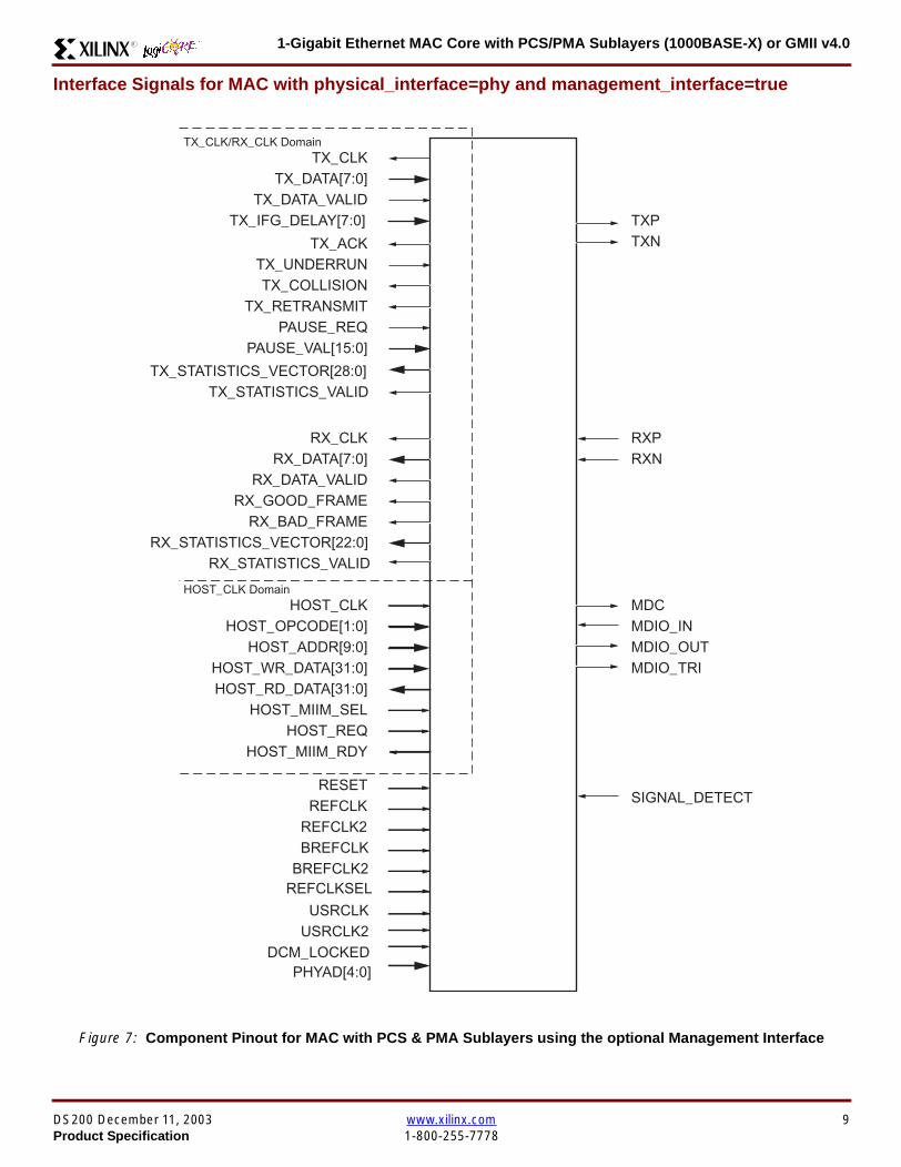
1-Gigabit Ethernet MAC Core with PCSPMA Sublayers (1000BASE-X) or GMII v40R
Interface Signals for MAC with physical_interface=phy and management_interface=true
Figure 7 Component Pinout for MAC with PCS amp PMA Sublayers using the optional Management Interface
REFCLK
TX_CLK
MDCMDIO_IN
TXPTXN
TX_DATA[70]
TX_ACKTX_UNDERRUN
PAUSE_REQPAUSE_VAL[150]
RX_CLK
HOST_CLKHOST_OPCODE[10]
HOST_ADDR[90]HOST_WR_DATA[310]HOST_RD_DATA[310]
HOST_MIIM_SELHOST_REQ
HOST_MIIM_RDY
RESET
RX_DATA[70]
RX_GOOD_FRAMERX_BAD_FRAME
TX_COLLISIONTX_RETRANSMIT
TX_DATA_VALID
RX_DATA_VALID
RXPRXN
TX_CLKRX_CLK Domain
HOST_CLK Domain
TX_IFG_DELAY[70]
TX_STATISTICS_VECTOR[280]TX_STATISTICS_VALID
RX_STATISTICS_VECTOR[220]RX_STATISTICS_VALID
PHYAD[40]
SIGNAL_DETECT
MDIO_OUTMDIO_TRI
USRCLKUSRCLK2
DCM_LOCKED
REFCLK2BREFCLK
BREFCLK2REFCLKSEL
DS200 December 11 2003 wwwxilinxcom 9Product Specification 1-800-255-7778
1-Gigabit Ethernet MAC Core with PCSPMA Sublayers (1000BASE-X) or GMII v40 R
Interface Signals for MAC with physical_interface=phy and management_interface=false
Figure 8 Component Pinout for MAC with PCS amp PMA Sublayers without the optional Management Interface
TX_CLK
MDC_INMDIO_IN
TXPTXN
TX_DATA[70]
TX_ACKTX_UNDERRUN
PAUSE_REQPAUSE_VAL[150]
RX_CLK
CONFIGURATION_VECTOR[630]
RX_DATA[70]
RX_GOOD_FRAMERX_BAD_FRAME
TX_COLLISIONTX_RETRANSMIT
TX_DATA_VALID
RX_DATA_VALID
RXPRXN
TX_CLKRX_CLK Domain
TX_IFG_DELAY[70]
TX_STATISTICS_VECTOR[280]TX_STATISTICS_VALID
RX_STATISTICS_VECTOR[220]RX_STATISTICS_VALID
SIGNAL_DETECT
MDIO_OUTMDIO_TRI
REFCLKRESET
PHYAD[40]
USRCLKUSRCLK2
DCM_LOCKED
REFCLK2BREFCLK
BREFCLK2REFCLKSEL
10 wwwxilinxcom DS200 December 11 20031-800-255-7778 Product Specification
1-Gigabit Ethernet MAC Core with PCSPMA Sublayers (1000BASE-X) or GMII v40R
Client Side Interface Signal Definition
Table 3 describes the client-side transmit signals of the MAC core These signals are used to transmit data from the clientto the MAC core
Table 4 describes the client-side receive signals These signals are used by the MAC core to transfer data to the client
Table 3 Transmit Client Interface Signal Pins
Signal Direction Description
TX_CLK Output Clock for transmit client interface 125 MHz nominal
TX_DATA[70] Input Frame data to be transmitted is supplied on this port
TX_DATA_VALID Input Control signal for TX_DATA port
TX_IFG_DELAY[70] InputControl signal for configurable Inter Frame Gap adjustment SeeTransmitter on page 16 for timing diagrams
TX_ACK OutputHandshaking signal Asserted when the current data on TX_DATA hasbeen accepted See Transmitter on page 16 for timing diagrams
TX_UNDERRUN Input Asserted by client to force MAC core to corrupt the current frame
TX_COLLISION OutputAsserted by the MAC core to signal a collision on the medium and that anytransmission in progress should be aborted Always 0 when the MAC coreis in full-duplex mode
TX_RETRANSMIT Output
When asserted at the same time as the TX_COLLISION signal thissignals the client that the aborted frame should be resupplied to the MACcore for retransmission Always 0 when the MAC core is in full-duplexmode
TX_STATISTICS_VECTOR[280] OutputThis gives information on the last frame transmitted See Transmitter onpage 16 for vector contents
TX_STATISTICS_VALID OutputAsserted at end of frame transmission indicating that theTX_STATISTICS_VECTOR is valid
Notes1 All the above signals are synchronous to TX_CLK and Active High
Table 4 Receive Client Interface Signal Pins
Signal Direction Description
RX_CLK Output Clock for receive client interface 125 MHz nominal
RX_DATA[70] Output Frame data received is supplied on this port
RX_DATA_VALID Output Control signal for the RX_DATA port
RX_GOOD_FRAME OutputAsserted at end of frame reception to indicate that the frame should beprocessed by the MAC client See Receiver on page 24
RX_BAD_FRAME OutputAsserted at end of frame reception to indicate that the frame should bediscarded by the MAC client See Receiver on page 24
RX_STATISTICS_VECTOR[220] OutputProvides information about the last frame received See Receiver onpage 24 for the vector contents
RX_STATISTICS_VALID OutputAsserted at end of frame reception indicating that theRX_STATISTICS_VECTOR is valid
Notes1 All signals above are synchronous to RX_CLK and Active High
DS200 December 11 2003 wwwxilinxcom 11Product Specification 1-800-255-7778
1-Gigabit Ethernet MAC Core with PCSPMA Sublayers (1000BASE-X) or GMII v40 R
Table 5 describes the signals used by the client to request a flow control action from the transmit engine Flow control framesreceived by the MAC are automatically handled (if the MAC is configured to do so)
Table 6 describes the optional signals used by the client to access the management features of the MAC core includingconfiguration status statistics and MDIO access
Table 7 describes the alternative to the optional Management Interface signals This describes the Configuration Vectorwhich uses direct inputs to the core to replace the functionality of the MAC Configuration bits when the ManagementInterface is not used
Notes1 All bits of CONFIGURATION_VECTOR are registered on input but may be treated as asynchronous inputs
Table 5 Flow Control Interface Signal Pinout
Signal Direction Description
PAUSE_REQ InputPause request sends a pause frame down the link See Transmitting a PAUSE ControlFrame on page 29
PAUSE_VAL[150] Input Pause value inserted into the parameter field of the transmitted pause frame
Notes1 These signals are synchronous to TX_CLK and are Active High
Table 6 Optional Management Interface Signal Pinout (management_interface=true)
Signal Direction Description
HOST_CLK InputClock for management interface See Optional Management Interface(management_interface=true) on page 30 for the signal frequency range
HOST_OPCODE[10] InputDefines operation to be performed over MDIO interface Bit 1 is also used inconfiguration register access See Configuration Registers on page 30
HOST_ADDR[90] Input Address of register to be accessed
HOST_WR_DATA[310] Input Data to write to register
HOST_RD_DATA[310] Output Data read from register
HOST_MIIM_SEL InputWhen asserted the MDIO interface is accessed When disasserted the MACinternal configuration or statistical counter registers are accessed
HOST_REQ InputUsed to signal a transaction on the MDIO interface or to read from the statisticregisters See Optional Management Interface (management_interface=true) onpage 30
HOST_MIIM_RDY OutputWhen high the MDIO interface has completed any pending transaction and isready for a new transaction
Notes1 All signals above are synchronous to HOST_CLK and are Active High
Table 7 Alternative to the Optional Management Interface Configuration Vector Signal Pinout(management_interface=false)
Signal Direction Description
CONFIGURATION_VECTOR[630]
Input The Configuration Vector is used to replace the functionality of theMAC Configuration Registers when the Management Interface is notused See Optional Configuration Vector (management_interface =false) on page 38
12 wwwxilinxcom DS200 December 11 20031-800-255-7778 Product Specification
1-Gigabit Ethernet MAC Core with PCSPMA Sublayers (1000BASE-X) or GMII v40R
Table 8 describes the reset signal
Physical Interface Signal Definition
Table 9 describes the MDIO (MII Management) interface signals of the MAC core These signals are typically connected tothe MDIO port of a PHY device either off-chip or an SoC-integrated core The MDIO format is defined in IEEE8023 clause22
Table 10 describes the optional GMII signals of the MAC core These are typically attached to a PHY module either off-chipor internally integrated The GMII is defined in IEEE8023 clause 35
Table 8 Reset Signal
Signal Direction Description
RESET Input Asynchronous reset for entire core See Reset circuit on page 42 for moreinformation on the reset circuit
Table 9 MDIO Interface Signal Pinout
Signal Direction Description
MDC OutputManagement Clock derived from HOST_CLK on the basis of supplied configuration datawhen the optional Management Interface is used See Optional Management Interface(management_interface=true) on page 30
MDC_IN InputWhen the Optional Management Interface is not used access to the optional PhysicalCoding Sublayer (PCS) must be provided by an external MDIO Controller In this situationthe Management Clock is an input to the core
MDIO_IN Input Input data signal for communication with PHY configuration and status Tie high if unused
MDIO_OUT Output Output data signal for communication with PHY configuration and status
MDIO_TRI OutputTristate control for MDIO signals 0 signals that the value on MDIO_OUT should be
asserted onto the MDIO bus
Table 10 Optional GMII Interface Signal Pinout (physical_interface=gmii)
Signal Direction Description
GTX_CLK InputClock signal at 125 MHz Other transmit clocks are derived from this clock as illustratedin Figure 28 Tolerance must be within IEEE 8023-2002 specification
GMII_TXD[70] Output Transmit data to PHY
GMII_TX_EN Output Data Enable control signal to PHY
GMII_TX_ER Output Error control signal to PHY
GMII_TX_CLK Output Clock out to PHY
GMII_CRS Input Control signal from PHY
GMII_COL Input Control signal from PHY
GMII_RX_CLK Input Recovered clock from received data stream by PHY
GMII_RXD[70] Input Received data from PHY
GMII_RX_DV Input Data Valid control signal from PHY
GMII_RX_ER Input Error control signal from PHY
DS200 December 11 2003 wwwxilinxcom 13Product Specification 1-800-255-7778
1-Gigabit Ethernet MAC Core with PCSPMA Sublayers (1000BASE-X) or GMII v40 R
Table 11 describes the TBI (Ten-Bit interface) signals of the MAC core These are typically attached to a PMA SERDESmodule These signals optionally replace the GMII signals described in Table 10 to extend the functionality of the core toinclude the PCS for 1000BASE-X The TBI is defined in IEEE8023 clause 36
Notes
PHYAD and SIGNAL_DETECT are asynchronous inputs SIGNAL_DETECT is Active High
Table 11 Optional TBI Interface Signal Pinout (physical_interface=tbi)
Signal Direction Description
GTX_CLK InputClock signal at 125 MHz Other transmit clocks will be derived from this clock asillustrated in Figure 32 Tolerance must be within IEEE 8023-2002 specification
TX_CODE_GROUP[90] Output 10-bit parallel transmit data to PMA Sublayer (SERDES)
PMA_TX_CLK Output Transmit clock signal to PMA Sublayer (SERDES) at 125MHz
LOC_REF OutputCauses the PMA sublayer clock recovery unit to lock to PMA_TX_CLK Thissignal is tied to Ground
EWRAP Output
This signal is set from the PCS Control Register 0 bit 14 (loopback) See PCSManaged Register Block (physical_interface = tbi or phy) on page 49 Whenhigh this instructs the PMA sublayer to electrically loop the transmitter data to thereceiver
RX_CODE_GROUP0[90] Input10-bit parallel received data from PMA Sublayer (SERDES) synchronous toPMA_RX_CLK0
RX_CODE_GROUP1[90] Input10-bit parallel received data from PMA Sublayer (SERDES) synchronous toPMA_RX_CLK1
PMA_RX_CLK0 Input Received clock signal from PMA Sublayer (SERDES) at 625MHz
PMA_RX_CLK1 InputReceived clock signal from PMA Sublayer (SERDES) at 625MHz This is 180degrees out of phase with PMA_RX_CLK0
EN_CDET OutputEnables the PMA Sublayer to perform comma realignment driven from the PCSstate machine during the Loss-Of-Sync state
PHYAD[40] Input PHY address of MDIO register set for the PCS
SIGNAL_DETECT Input
Signal direct from PMD sublayer indicating the presence of light detected at theoptical receiver If driven high this indicates that the optical receiver has detectedlight If driven low this indicates the absence of light
If unused tie high to enable the operation the core
14 wwwxilinxcom DS200 December 11 20031-800-255-7778 Product Specification
1-Gigabit Ethernet MAC Core with PCSPMA Sublayers (1000BASE-X) or GMII v40R
Table 12 describes the interface signals for the Optional PCSPMA sublayer of the MAC core These signals optionallyreplace the GMII signals described in Table 10 to extend the functionality of the core to include the PCS and PMA sublayersfor 1000BASE-X This option uses the Virtex-II Pro Rocket IO functionality which is integrated into the core The PMAsublayer for 1000BASE-X is defined in IEEE8023 clause 36
Notes1 PHYAD and SIGNAL_DETECT are asynchronous inputs SIGNAL_DETECT is Active High
Table 12 Optional PCSPMA sublayer Interface Signal Pinout (physical_interface=phy)
Signal Direction Description
REFCLK InputHigh Quality Reference clock for Multi-Gigabit Transceivers (625 MHz) See Rocket IOUser Guide
REFCLK2 Input Alternative High Quality Reference clock for Multi-Gigabit Transceivers (625 MHz) SeeRocket IO User Guide
BREFCLK Input Alternative High Quality Reference clock for Multi-Gigabit Transceivers (625 MHz)This optionally replaces REFCLK See Rocket IO User Guide
BREFCLK2 Input Alternative High Quality Reference clock for Multi-Gigabit Transceivers (625 MHz)This optionally replaces REFCLK2 See Rocket IO User Guide
REFCLKSEL Input Selects between either (B)REFCLK or (B)REFCLK2 as the input clock source to theMGT See Rocket IO User Guide
USERCLK InputClock signal at 625 MHz This is connected to the TXUSRCLK and RXUSRCLK portsof the Rocket IO MGT This may be derived from (B)REFCLK using a DCM asillustrated in Figure 35
USERCLK2 InputClock signal at 125 MHz This is connected to the TXUSRCLK2 and RXUSRCLK2 portsof the Rocket IO MGT This may be derived from (B)REFCLK using a DCM asillustrated in Figure 35
DCM_LOCKED InputIf a DCM is used to derive USRCLK and USRCLK2 as illustrated in Figure 35 theLOCKED port of the DCM must be connected to the DCM_LOCKED port of the coreThe core will hold itrsquos Rocket IO MGT in reset until DCM_LOCKED is driven to logic 1
TXPTXN OutputDifferential pair for serial transmission from PMA to PMD The clock is embedded in thedata stream
RXPRXN InputDifferential pair for serial reception from PMD to PMA The clock is extracted from thedata stream
PHYAD[40] Input PHY address of MDIO register set for the PCS
SIGNAL_DETECT Input
Signal direct from PMD sublayer indicating the presence of light detected at the opticalreceiver If driven high this indicates that the optical receiver has detected light If drivenlow this indicates the absence of light
If unused tie high to enable the operation the core
DS200 December 11 2003 wwwxilinxcom 15Product Specification 1-800-255-7778
1-Gigabit Ethernet MAC Core with PCSPMA Sublayers (1000BASE-X) or GMII v40 R
Functional Description
Client InterfaceThe client interface is designed for maximum flexibility inmatching to a client switching fabric or network processorinterface
The data pathway is 8 bits wide in both the transmit andreceive directions with each pathway synchronous to theTX_CLK and RX_CLK respectively for completely indepen-dent full duplex operation
Transmitter
Normal Frame Transmission
The timing of a normal outbound frame transfer can be seenin Figure 9 When the client wants to transmit a frame itplaces the first column of data onto the TX_DATA port andasserts a ldquo1rdquo onto TX_DATA_VALID
When the MAC core has read this first byte of data it willassert the TX_ACK signal on the next and subsequent ris-ing clock edges the client must provide the remainder ofthe data for the frame
The end of frame is signalled to the MAC core by takingTX_DATA_VALID Low
In-Band Parameter Encoding
For maximum flexibility in switching applications the Ether-net frame parameters (destination address sourceaddress lengthtype and optionally FCS) are encodedwithin the same data stream that the frame payload is trans-ferred upon rather than on separate ports This is illustratedin the timing diagrams Definitions of the abbreviations usedin the timing diagrams are described in Table 13
Figure 9 Normal Frame Transmission Across Client Interface
Table 13 Abbreviations Used in Timing Diagrams
Abbreviation Definition
DA Destination Address 6 bytes
SA Source Address 6 bytes
LT LengthType Field 2 bytes
FCS Frame Check Sequence 4 bytes
TX_CLK
TX_DATA[70]
TX_DATA_VALID
TX_ACK
TX_UNDERRUN
DA SA DATALT
TX_COLLISION
TX_RETRANSMIT
xip2133
16 wwwxilinxcom DS200 December 11 20031-800-255-7778 Product Specification
1-Gigabit Ethernet MAC Core with PCSPMA Sublayers (1000BASE-X) or GMII v40R
Padding
When fewer than 46 bytes of data are supplied by the clientto the MAC core the transmitter module will add padding upto the minimum frame length The exception to this is whenthe MAC core is configured for client-passed FCS in thiscase the client must also supply the padding to maintain theminimum frame length (see Client-Supplied FCS Passing)
Client-Supplied FCS Passing
If the MAC core is configured to have the FCS field passedin by the client (see Configuration Registers on page 30)the transmission timing is as depicted in Figure 10 In thiscase it is the responsibility of the client to ensure that theframe meets the Ethernet minimum frame length require-ments the MAC core will not perform any padding of thepayload
Figure 10 Frame Transmission with Client-supplied FCS
TX_CLK
TX_DATA[70]
TX_DATA_VALID
TX_ACK
TX_UNDERRUN
DA SA DATA FCSLT
TX_COLLISION
TX_RETRANSMIT
xip2134
DS200 December 11 2003 wwwxilinxcom 17Product Specification 1-800-255-7778
1-Gigabit Ethernet MAC Core with PCSPMA Sublayers (1000BASE-X) or GMII v40 R
Client Underrun
The timing of an aborted transfer can be seen in Figure 11This may happen for instance if a FIFO connected to theclient interface empties before a frame is completed Whenthe client asserts TX_UNDERRUN during a frame transmis-sion the MAC core will insert an error code to corrupt the
current frame and then fall back to idle transmission It isthe responsibility of the client to re-queue the aborted framefor transmission
When an underrun occurs TX_DATA_VALID may beasserted on the clock cycle after the TX_UNDERRUNassertion to request a new transmission
Figure 11 Frame Transmission with Underrun
TX_CLK
TX_DATA[70]
TX_DATA_VALID
TX_ACK
TX_UNDERRUN
DA SA DATALT
TX_COLLISION
TX_RETRANSMIT
xip2135
18 wwwxilinxcom DS200 December 11 20031-800-255-7778 Product Specification
1-Gigabit Ethernet MAC Core with PCSPMA Sublayers (1000BASE-X) or GMII v40R
Back-to-Back Transfers
Figure 12 shows the case where the MAC client is immedi-ately ready to transmit a second frame of data followingcompletion of its first frame In this figure the end of the firstframe is shown on the left On the clock cycle immediatelyfollowing the final byte of the first frame TX_DATA_VALIDis taken low by the client and is taken high one clock cyclelater to indicate that the first byte of the destination addressof the second frame is on TX_DATA awaiting transmission
When the MAC core is ready to accept data TX_ACK isasserted and the transmission continues in the same man-ner as in the case of the single frame The MAC core willdefer the assertion of TX_ACK appropriately to comply withinter-packet gap requirements and flow control requests
If the MAC core is operating in half-duplex mode the timingshown in Figure 12 is required to take advantage of framebursting the MAC core is only guaranteed to retain controlof the medium if the TX_DATA_VALID signal is low for a sin-gle clock cycle For more information on frame bursting seeIEEE 8023-2002
Figure 12 Back to Back Frame Transmission
TX_CLK
TX_DATA[70]
TX_DATA_VALID
TX_ACK
TX_UNDERRUN
TX_COLLISION
TX_RETRANSMIT
xip2136
DS200 December 11 2003 wwwxilinxcom 19Product Specification 1-800-255-7778
1-Gigabit Ethernet MAC Core with PCSPMA Sublayers (1000BASE-X) or GMII v40 R
VLAN Tagged Frames
Transmission of a VLAN tagged frame (if enabled) can beseen in Figure 13 Note that the handshaking signalsacross the interface do not change however the VLANtype tag 81-00 must be supplied by the client to signify that
the frame is VLAN tagged The client also supplies the twobytes of Tag Control Information V1 and V2 at the appro-priate times in the data stream More information on thecontents of these two bytes can be found in IEEE8023-2002
Maximum Permitted Frame Length
The maximum legal length of a frame specified in IEEE8023-2002 is 1518 bytes for non-VLAN tagged framesVLAN tagged frames may be extended to 1522 bytesWhen jumbo frame handling is disabled and the clientattempts to transmit a frame which exceeds the maximumlegal length the MAC core will insert an error code to cor-
rupt the current frame and the frame will be truncated to themaximum legal length When jumbo frame handling isenabled frames which are longer than the legal maximumare transmitted error-free
For more information on enabling and disabling jumboframe handling see Configuration Registers on page 30
Figure 13 Transmission of a VLAN Tagged Frame
TX_CLK
TX_DATA[70]
TX_DATA_VALID
TX_ACK
TX_UNDERRUN
DA SA DATALTVLANtag
81 00V1V2
TX_COLLISION
TX_RETRANSMIT
xip2137
20 wwwxilinxcom DS200 December 11 20031-800-255-7778 Product Specification
1-Gigabit Ethernet MAC Core with PCSPMA Sublayers (1000BASE-X) or GMII v40R
Frame Collisions - Half Duplex Operation Only
In half duplex Ethernet operation collisions will occur on themedium as a matter of course this is how the arbitrationalgorithm is fulfilled In case of a collision the MAC core sig-nals to the client that data may need to be resupplied as fol-lows
If there is a collision the TX_COLLISION signal will be setto ldquo1rdquo by the MAC core If a frame is in progress the clientmust abort the transfer and take TX_DATA_VALID to ldquo0rdquo
If the TX_RETRANSMIT signal is ldquo1rdquo in the same clockcycle that the TX_COLLISION signal is ldquo1rdquo the client must
resubmit the previous frame to the MAC core for retrans-mission TX_DATA_VALID must be asserted to the MACcore within 8 clock cycles of the TX_COLLISION signal inorder to meet Ethernet timing requirements See Figure 14
If the TX_RETRANSMIT signal is ldquo0rdquo in the same clockcycle that the TX_COLLISION signal is ldquo1rdquo the number ofretries for this frame has exceeded the Ethernet specifica-tion and the frame should be dropped by the client The cli-ent can then make any new frame available to the MAC fortransmission without timing restriction See Figure 15
Figure 14 Collision Handling - Frame retransmission required
Figure 15 Collision Handling - No frame retransmission required
TX_CLK
TX_DATA[70]
TX_DATA_VALID
TX_ACK
TX_UNDERRUN
TX_COLLISION
TX_RETRANSMIT
8 clocks max
xip2138
TX_CLK
TX_DATA[70]
TX_DATA_VALID
TX_ACK
TX_UNDERRUN
TX_COLLISION
TX_RETRANSMIT
xip2139
DS200 December 11 2003 wwwxilinxcom 21Product Specification 1-800-255-7778
1-Gigabit Ethernet MAC Core with PCSPMA Sublayers (1000BASE-X) or GMII v40 R
Interframe Gap Adjustment
The user can elect to vary the length of the inter fame gapIf this function is selected (via a configuration bit in thetransmitter control register see Configuration Registerson page 30) then the MAC will exert back pressure to delaythe transmission of the next frame until the requested num-ber of Idle cycles has elapsed The number of Idle cycles iscontrolled by the value on the TX_IFG_DELAY port at thestart of frame transmission Figure 16 shows the MAC oper-ating in this mode
Reducing the Inter fame gap to below the IEEE 8023-2002minimum of 12 Idles is supported in Full Duplex onlydesigns and will transmit an absolute minimum of 4 Idles Ifthe Interframe gap adjustment is reduced below 12 Idlesthen the accuracy of the Optional Statistical Gathering(statistics_gathering=true) Counters cannot be guaranteedHowever the TX_STATISTIC_VECTOR andRX_STATISTIC_VECTOR will always remain correct
Transmitter Statistics Vector
The statistics for the frame transmitted are contained withinthe TX_STATISTICS_VECTOR The vector is driven syn-chronously by the transmitter clock TX_CLK followingframe transmission The bit field definition for the Vector isdefined in Table 14
All bit fields with the exception of BYTE_VALID are validonly when the TX_STATISTICS_VALID is asserted This isillustrated in Figure 17 BYTE_VALID is significant on everyTX_CLK cycle
TX_STATISTICS_VECTOR bits 25 down to 17 inclusive arefor half duplex only and will be set to logic 0 when operatingin full duplex mode
Figure 16 Interframe Gap Adjustment
TX_CLK
TX_DATA[70]
TX_DATA_VALID
TX_ACK
DA SA
TX_IFG_DELAY
IFG ADJUST VALUE
0x0D
13 Idles inserted
DA
Next IFG ADJUST VALUE
xip2140
Figure 17 Transmitter Statistics Vector Timing
TX_CLK
TX_STATISTICS_VECTOR[280]
TX_STATISTICS_VALID
xip2141
22 wwwxilinxcom DS200 December 11 20031-800-255-7778 Product Specification
1-Gigabit Ethernet MAC Core with PCSPMA Sublayers (1000BASE-X) or GMII v40R
Table 14 Bit Definition for the Transmitter Statistics Vector
TX_STATISTICS_VECTOR Name Description
28 PAUSE_FRAME_TRANSMITTEDAsserted if the previous frame was a pause framethat the MAC itself initiated in response to aPAUSE_REQ assertion
27 BYTE_VALID
Asserted if a MAC frame byte (DA to FCS inclusive)is in the process of being transmitted This is valid onevery clock cycle
Do not use this as an enable signal to indicate thatdata is present on GMII_TXD[70]
26 Reserved Returns logic 0
25 down to 22 TX_ATTEMPTS[30]
The number of attempts that have been made totransmit the previous frame This is a 4-bit number0 should be interpreted as 1 attempt 1 as 2attempts up until 15 as 16 attempts
21 Reserved Returns logic 0
20 EXCESSIVE_COLLISIONAsserted if a collision has been detected on each ofthe last 16 attempts to transmit the previous frame
19 LATE_COLLISIONAsserted if a late collision occurred during frametransmission
18 EXCESSIVE_DEFERRALAsserted if the previous frame was deferred for anexcessive amount of time as defined by the constantldquomaxDeferTimerdquo in IEEE 8023-2002
17 TX_DEFERRED Asserted if transmission of the frame was deferred
16 VLAN_FRAMEAsserted if the previous frame contained a VLANidentifier in the LengthType field when transmitterVLAN operation is enabled
15 down to 5 FRAME_LENGTH_COUNTThe length of the previous frame in number of bytesThe count will stick at 2047 for any Jumbo frameslarger than this value
4 CONTROL_FRAMEAsserted if the previous frame had the special MACControl Type code 88-08 in the LengthType field
3 UNDERRUN_FRAMEAsserted if the previous frame contained anunderrun error
2 MULTICAST_FRAMEAsserted if the previous frame contained a multicastaddress in the Destination Address field
1 BROADCAST_FRAMEAsserted if the previous frame contained abroadcast address in the Destination Address field
0 SUCCESSFUL_FRAMEAsserted if the previous frame was transmittedwithout error
DS200 December 11 2003 wwwxilinxcom 23Product Specification 1-800-255-7778
1-Gigabit Ethernet MAC Core with PCSPMA Sublayers (1000BASE-X) or GMII v40 R
Receiver
Normal Frame Reception
The timing of a normal inbound frame transfer can be seenin Figure 18 The client must be prepared to accept data atany time there is no buffering within the MAC to allow forlatency in the receive client Once frame reception begins
data is transferred on consecutive clock cycles to thereceive client until the frame is complete The MAC assertsthe RX_GOOD_FRAME signal to indicate that the framewas successfully received and that the frame should beanalyzed by the client
Frame parameters (destination address source addresslengthtype and optionally FCS) are supplied on the databus according to the timing diagram The abbreviations arethe same as those described in Table 13 on page 16
If the LengthType field in the frame has the Length interpre-tation and this indicates that the inbound frame has beenpadded to meet the Ethernet minimum frame size specifica-tion then this padding will not be passed to the client in thedata payload The exception to this is in the case whereFCS passing is enabled see Client-Supplied FCS Pass-ing on page 25
Therefore when Client-Supplied FCS passing is disabledRX_DATA_VALID = lsquo0rsquo between frames for the duration ofthe Padding field (if present) the FCS field carrier exten-sion (if present) the interframe gap following the frame andthe preamble field of the next frame When Client-Supplied
FCS passing is enabled RX_DATA_VALID = lsquo0rsquo betweenframes for the duration of carrier extension (if present) theinterframe gap and the preamble field of the followingframe
RX_GOOD_FRAME RX_BAD_FRAME timing
Although the timing diagram in Figure 18 shows theRX_GOOD_FRAME signal asserted shortly after the lastvalid data on RX_DATA this is not always the case TheRX_GOOD_FRAME or RX_BAD_FRAME signals areasserted only after all frame checks are completed This isafter the FCS field has been received (and after reception ofcarrier extension if present)
Therefore either RX_GOOD_FRAME or RX_BAD_FRAMEis asserted following frame reception at the beginning of theinterframe gap
Figure 18 Normal Frame Reception
RX_CLK
RX_DATA[70]
RX_DATA_VALID
RX_GOOD_FRAME
RX_BAD_FRAME
DA SA DATALT
xip2142
24 wwwxilinxcom DS200 December 11 20031-800-255-7778 Product Specification
1-Gigabit Ethernet MAC Core with PCSPMA Sublayers (1000BASE-X) or GMII v40R
Frame Reception with Errors
The case of an unsuccessful frame reception (for examplea fragment frame or a frame with an incorrect FCS) can beseen in Figure 19 In this case the RX_BAD_FRAME signal
is asserted to the client at the end of the frame It is then theresponsibility of the client to drop the data already trans-ferred for this frame
Figure 19 Frame Reception with Error
Client-Supplied FCS Passing
If the MAC core is configured to pass the FCS field to the cli-ent (see Configuration Registers on page 30) then this ishandled as shown in Figure 20
In this case any padding inserted into the frame to meetEthernet minimum frame length specifications will be leftintact and passed to the client
Note that even though the FCS is passed up to the client itis also verified by the MAC core and RX_BAD_FRAMEasserted if the FCS check fails
RX_CLK
RX_DATA[70]
RX_DATA_VALID
RX_GOOD_FRAME
RX_BAD_FRAME
DA SA DATALT
xip2144
Figure 20 Frame Reception with In-Band FCS Field
RX_CLK
RX_DATA[70]
RX_DATA_VALID
RX_GOOD_FRAME
RX_BAD_FRAME
DA SA DATALT FCS
xip2145
DS200 December 11 2003 wwwxilinxcom 25Product Specification 1-800-255-7778
1-Gigabit Ethernet MAC Core with PCSPMA Sublayers (1000BASE-X) or GMII v40 R
VLAN Tagged Frames
The reception of a VLAN tagged frame (if enabled) can beseen in Figure 21 The VLAN frame is passed to the clientso that the frame may be identified as VLAN tagged this is
followed by the Tag Control Information bytes V1 and V2More information on the interpretation of these bytes maybe found in IEEE 8023-2002 standard
Maximum Permitted Frame Length
The maximum legal length of a frame specified in IEEE8023-2002 is 1518 bytes for non-VLAN tagged framesVLAN tagged frames may be extended to 1522 bytesWhen jumbo frame handling is disabled and the corereceives a frame which exceeds the maximum legal lengthRX_BAD_FRAME will be asserted When jumbo framehandling is enabled frames which are longer than the legalmaximum are received in the same way as shorter frames
For more information on enabling and disabling jumboframe handling see Configuration Registers on page 30
LengthType Field Error Checks
Enabled
Default operation is with the LengthType error checkingenabled (see Receiver Configuration Word 1 on page 31)In this mode the following checks are made on all framesreceived If either of these checks fail then the frame ismarked as BAD
bull A value in the LengthType field that is greater than orequal to decimal 46 but less than decimal 1536 (aLength interpretation) is checked against the actualdata length received
bull A value in the LengthType field that is less thandecimal 46 is checked to see that the data field ispadded to exactly 46 bytes (so that the resultant frameis minimum frame size 64 bytes total in length)
Furthermore if Padding is indicated (the LengthType fieldis less than decimal 46) and Client-Supplied FCS Passing isdisabled then the Length value in the LengthType field willbe used to deassert RX_DATA_VALID after the indicatednumber of data bytes so that the Padding bytes areremoved from the frame
Disabled
When the LengthType error checking is disabled (seeReceiver Configuration Word 1 on page 31) theLengthType error checks described above are not per-formed A frame containing only these errors will be markedas GOOD
Furthermore if Padding is indicated and Client-SuppliedFCS Passing is disabled then a Length Value in theLengthType field will not be used to deassertRX_DATA_VALID Instead RX_DATA_VALID will be deas-serted before the start of the FCS field in this way any pad-ding will not be removed from the frame
Figure 21 Reception of a VLAN Tagged Frame
RX_CLK
RX_DATA[70]
RX_DATA_VALID
RX_GOOD_FRAME
RX_BAD_FRAME
DA SA DATALT
81 00 V1 V2
VLANtag
xip2146
26 wwwxilinxcom DS200 December 11 20031-800-255-7778 Product Specification
1-Gigabit Ethernet MAC Core with PCSPMA Sublayers (1000BASE-X) or GMII v40R
Receiver Statistics Vector
The statistics for the frame received are contained withinthe RX_STATISTICS_VECTOR The vector is driven syn-chronously by the receiver clock RX_CLK following framereception The bit field definition for the Vector is defined inTable 15
All bit fields with the exception of BYTE_VALID are validonly when the RX_STATISTICS_VALID is asserted This isillustrated in Figure 22 BYTE_VALID is significant on everyRX_CLK cycle
Figure 22 Receiver Statistics Vector Timing
RX_CLK
RX_STATISTICS_VECTOR[220]
RX_STATISTICS_VALID
xip2147
Table 15 Bit Definition for the Receiver Statistics Vector
RX_STATISTICS_VECTOR Name Description
22LENGTHTYPE Out ofRange
Asserted if the lengthtype field contained a length valuethat did not match the number of MAC client data bytesreceived Also high if the lengthtype field indicated thatthe frame contained padding but the number of MAC cli-ent data bytes received was not equal to 64 bytes (min-imum frame size)
The exception to the above is when the LengthTypeField Error Checks are disabled in which case this bitwill not be asserted
21 BAD_OPCODE
Asserted if the previous frame was error-free andcontained the special Control Frame identifier in theLengthType field but contained an opcode that isunsupported by the MAC (Any Opcode other thanPAUSE)
20 FLOW_CONTROL_FRAME
Asserted if the previous frame was error-freecontained the special Control Frame identifier in theLengthType field contained a Destination Addressthat matched either the MAC Control MulticastAddress or the configured source address of the MACcontained the supported PAUSE opcode and wasacted upon by the MAC
19 BYTE_VALID
Asserted if a MAC frame byte (DA to FCS inclusive) isin the process of being received This is valid on everyclock cycle
Do not use this as an enable signal to indicate thatdata is present on RX_DATA[70]
18 VLAN_FRAMEAsserted if the previous frame contained a VLANidentifier in the LengthType field when receiver VLANoperation is enabled
DS200 December 11 2003 wwwxilinxcom 27Product Specification 1-800-255-7778
1-Gigabit Ethernet MAC Core with PCSPMA Sublayers (1000BASE-X) or GMII v40 R
17 OUT_OF_BOUNDS
Asserted if the previous frame exceeded the specifiedIEEE8023-2002 maximum legal length (seeMaximum Permitted Frame Length on page 26) Thisis only valid if Jumbo frames are disabled
16 CONTROL_FRAMEAsserted if the previous frame contained the specialControl Frame identifier in the LengthType field
15 down to 5 FRAME_LENGTH_COUNTThe length of the previous frame in number of bytesThe count will stick at 2047 for any Jumbo frameslarger than this value
4 MULTICAST_FRAMEAsserted if the previous frame contained a multicastaddress in the Destination Address field
3 BROADCAST_FRAMEAsserted if the previous frame contained the broadcastaddress in the Destination Address field
2 FCS_ERRORAsserted if the previous frame received had anincorrect FCS value or the MAC detected error codesduring frame reception
1 BAD_FRAME1 Asserted if the previous frame received containederrors
0 GOOD_FRAME1 Asserted if the previous frame received was error-free
1 If the LengthType Field Error Checks are disabled then a frame which contains this type of error will be marked as a GOOD_FRAMEproviding no additional errors were detected
Table 15 Bit Definition for the Receiver Statistics Vector
RX_STATISTICS_VECTOR Name Description
28 wwwxilinxcom DS200 December 11 20031-800-255-7778 Product Specification
1-Gigabit Ethernet MAC Core with PCSPMA Sublayers (1000BASE-X) or GMII v40R
Flow ControlThe flow control block is designed to Clause 31 of the IEEE8023-2002 standard The MAC may be configured to sendpause frames and to act upon their reception These twobehaviors can be configured asymmetrically see Configu-ration Registers on page 30
Transmitting a PAUSE Control Frame
The client initiates a flow control frame by assertingPAUSE_REQ while the pause value is on the PAUSE_VALbus These signals are synchronous to TX_CLK The timingof this can be seen in Figure 23
If the MAC core is configured to support transmit flow con-trol this action causes the core to transmit a PAUSE controlframe on the link with the PAUSE parameter set to thevalue on PAUSE_VAL in the cycle when PAUSE_REQ wasasserted This will not disrupt any frame transmission inprogress but will take priority over any pending frame trans-
mission This frame will be transmitted even if the transmit-ter is in the paused state itself
Receiving a Pause Control Frame
When an error-free frame is received by the MAC core thefollowing checks are made
1 The Destination Address field is matched against theMAC Control Multicast address or the configuredSource Address for the MAC (see ConfigurationRegisters on page 30)
2 The LengthType field is matched against the MACControl Type code
3 The opcode field contents are matched against thePAUSE opcode if check 2 is true
If any of the above checks are false or the MAC Flow Con-trol logic for the receiver is disabled the frame is ignored bythe Flow Control logic and passed up to the client
If the frame passes all of the above checks is of minimumlegal size and the MAC Flow Control logic for the receiver isenabled the pause value parameter in the frame is thenused to inhibit transmitter operation for the time defined inthe IEEE8023-2002 specification This inhibit is imple-mented using the same back pressure scheme shown inFigure 12 Because the received pause frame has beenacted upon it is passed to the client with RX_BAD_FRAMEasserted to indicate to the client that it should be dropped
Reception of any frame for which check 2 is true and whichis not of legal minimum length is considered an invalid Con-trol frame This will be ignored by the Flow Control logic andpassed to the client with RX_BAD_FRAME asserted
Figure 23 Pause Request Timing
TX_CLK
PAUSE_VAL[150]
PAUSE_REQ
xip2148
DS200 December 11 2003 wwwxilinxcom 29Product Specification 1-800-255-7778
1-Gigabit Ethernet MAC Core with PCSPMA Sublayers (1000BASE-X) or GMII v40 R
Optional Management Interface(management_interface=true)The management interface is a processor-independentinterface with standard address data and control signals Itmay be used as is or a wrapper may be applied (not sup-plied) to interface to common bus architectures
This interface is used for
bull Configuration of the MAC core
bull Access to optional statistics counters for use by higherlayers for example SNMP
bull access through the MDIO interface to the managementregisters located in the PHY attached to the MAC core
The management interface is accessed differently depend-ing on the type of transaction a truth table showing whichaccess method is required for each transaction type isshown in Table 16 These access methods are described inthe following sections
HOST_CLK Frequency
The management interface clock HOST_CLK is used toderive the MDIO clock MDC and is therefore subject tosome frequency restrictions This HOST_CLK must be
ge 10 MHz
le 100 MHz
Configuring the MAC core to derive the MDC signal fromthis clock is detailed in MDIO Interface on page 37
Configuration Registers
After power up or reset the client may reconfigure the coreparameters from their defaults such as flow control supportConfiguration changes can be written at any time Both thereceiver and transmitter logic will only respond to configura-tion changes during Inter Frame Gaps The exceptions tothis are the configurable resets which take effect immedi-ately
Configuration of the MAC core is performed through a reg-ister bank accessed through the management interfaceThe configuration registers available in the core are detailedin Table 17 As can be seen the address has some implicitdonrsquot care bits any access to an address in the rangesshown will perform a 32-bit read or write from the same con-figuration word
Table 16 Management Interface Transaction Types
Transaction HOST_MIIM_SEL HOST_ADDR[9]
Configuration 0 1
Statistics 0 0
MIIM access 1 X
Table 17 Configuration Registers
Address Description
0x200-0x23F Receiver Configuration (Word 0)
0x240-0x27F Receiver Configuration (Word 1)
0x280-0x2BF Transmitter Configuration
0x2C0-0x2FF Flow Control Configuration
0x300-0x33F Reserved
0x340-0x37F Management Configuration
30 wwwxilinxcom DS200 December 11 20031-800-255-7778 Product Specification
1-Gigabit Ethernet MAC Core with PCSPMA Sublayers (1000BASE-X) or GMII v40R
The register contents for the two receiver configuration words can be seen in Table 18 and Table 19
Notes1 In changing the receiverrsquos mode from Half Duplex to Full Duplex there is a period of time of up to 24 us following the mode change
when no new receiver statistics can be stored in the optional Statistical Counters
Table 18 Receiver Configuration Word 0
Bit Default Value Description
31-0 All 0rsquos
Pause frame MAC Source Address[310] This address is used by the MAC tomatch against the Destination Address of any incoming flow control frames It isalso used by the flow control block as the Source Address (SA) for any outboundflow control frames
The address is ordered so the first byte transmittedreceived is the lowestpositioned byte in the register for example a MAC address ofAA-BB-CC-DD-EE-FF would be stored in Address[470] as 0xFFEEDDCCBBAA
Table 19 Receiver Configuration Word 1
Bit Default Value Description
15-0 All 0rsquos Pause frame MAC Source Address[4732] See description in Table 18
24-16 NA Reserved
25 0
LengthType Error Check Disable When this bit is set to ldquo1rdquo the core will notperform the LengthType field error checks as described in LengthType FieldError Checks on page 26 When this bit is set to ldquo0rdquo the LengthType field checkswill be performed this is normal operation
26 0Half Duplex If ldquo1rdquo the receiver will operate in half duplex mode If ldquo0rdquo the receiverwill operate in full duplex mode Has no effect if XCO parameterhalf_duplex_capable = false
27 0VLAN Enable When this bit is set to ldquo1rdquo VLAN tagged frames will be acceptedby the receiver
28 1Receiver Enable If set to ldquo1rdquo the receiver block will be operational If set to ldquo0rdquothe block will ignore activity on the physical interface RX port
29 0
In-band FCS Enable When this bit is ldquo1rdquo the MAC receiver will pass the FCS fieldup to the client as described in Client-Supplied FCS Passing on page 25 Whenit is ldquo0rdquo the client will not be passed the FCS In both cases the FCS will beverified on the frame
30 0Jumbo Frame Enable When this bit is set to ldquo1rdquo the MAC receiver will acceptframes over the specified IEEE8023-2002 maximum legal length When this bitis ldquo0rdquo the MAC will only accept frames up to the specified maximum
31 0Reset When this bit is set to ldquo1rdquo the receiver will be reset The bit will thenautomatically revert to ldquo0rdquo Note that this reset will also set all of the receiverconfiguration registers to their default values
DS200 December 11 2003 wwwxilinxcom 31Product Specification 1-800-255-7778
1-Gigabit Ethernet MAC Core with PCSPMA Sublayers (1000BASE-X) or GMII v40 R
The register contents for the Transmitter Configuration Word are described in Table 20
Notes1 In changing the transmitterrsquos mode from Half Duplex to Full Duplex there is a period of time of up to 24 us following the mode change
when no new transmitter statistics can be stored in the optional Statistical Counters
Table 20 Transmitter Configuration Word
Bit Default Value Description
24-0 NA Reserved
25 0
Interframe Gap Adjust Enable If lsquo1rsquo the transmitter will read the value on the portTX_IFG_DELAY at the start of frame transmission and adjust the interframe gapfollowing the frame accordingly See Interframe Gap Adjustment on page 22 Ifldquo0rdquo the transmitter will output a minimum Inter Frame Gap of twelve clock cyclesas specified in IEEE8023-2002
26 0Half Duplex If lsquo1rsquo the transmitter will operate in half duplex mode If lsquo0rsquo thetransmitter will operate in full duplex mode Has no effect if XCO parameterhalf_duplex_capable = false
27 0VLAN Enable When this bit is set to 1 the transmitter will allow the transmissionof VLAN tagged frames
28 1Transmit Enable When this bit is 1 the transmitter is operational When it is 0the transmitter is disabled
29 0
In-band FCS Enable When this bit is lsquo1rsquo the MAC transmitter will expect the FCSfield to be passed in by the client as described in Client-Supplied FCS Passingon page 17 When this bit is ldquo0rdquo the MAC transmitter will append padding asrequired compute the FCS and append it to the frame
30 0
Jumbo Frame Enable When this bit is set to ldquo1rdquo the MAC transmitter will sendframes that are greater than the specified IEEE8023-2002 maximum legallength When this bit is ldquo0rdquo the MAC will only send frames up to the specifiedmaximum
31 0Reset When this bit is set to ldquo1rdquo the transmitter will be reset The bit will thenautomatically revert to ldquo0rdquo Note that this reset will also set all of the transmitterconfiguration registers to their default values
32 wwwxilinxcom DS200 December 11 20031-800-255-7778 Product Specification
1-Gigabit Ethernet MAC Core with PCSPMA Sublayers (1000BASE-X) or GMII v40R
The register contents for the Flow Control Configuration Word are described in Table 21
The register contents for the Management Configuration Word are described in Table 22
Writing to the configuration registers through the manage-ment interface is depicted in Figure 24 When accessing theconfiguration registers (ie when HOST_ADDR[9] = lsquo1rsquo andHOST_MIIM_SEL = lsquo0rsquo) the upper bit of HOST_OPCODEfunctions as an Active Low write enable signal The lowerHOST_OPCODE bit is a ldquodonrsquot carerdquo
Reading from the configuration register words is similar butthe upper HOST_OPCODE bit should be lsquo1rsquo This is shownin Figure 25 In this case the contents of the register appearon HOST_RD_DATA the HOST_CLK edge after the regis-ter address is asserted onto HOST_ADDR
Table 21 Flow Control Configuration Word
Bit Default Value Description
28-0 NA Reserved
29 1
Flow Control Enable (RX) When this bit is lsquo1rsquo received flow control frames willinhibit the transmitter operation as described in Receiving a Pause ControlFrame on page 29 When this bit is lsquo0rsquo received flow control frames will alwaysbe passed up to the client
30 1Flow Control Enable (TX) When this bit is lsquo1rsquo asserting the PAUSE_REQ signalwill send a flow control frame out from the transmitter When this bit is 0 assertingthe PAUSE_REQ signal has no effect
31 NA Reserved
Table 22 Management Configuration Word
Bits Default Value Description
4-0 All 0rsquos Clock Divide[40] See MDIO Interface on page 37
5 0MDIO Enable When this bit is 1 the MDIO interface can be used to accessattached PHY devices When this bit is 0 the MDIO interface is disabled and theMDIO signals remain inactive
31-6 NA Reserved
Figure 24 Configuration Register Write Timing
HOST_CLK
HOST_ADDR[80]
HOST_ADDR[9]
HOST_OPCODE[1]
HOST_MIIM_SEL
HOST_WR_DATA[310]xip2149
Figure 25 Configuration Register Read Timing
HOST_CLK
HOST_ADDR[80]
HOST_ADDR[9]
HOST_OPCODE[1]
HOST_MIIM_SEL
HOST_RD_DATA[310]
xip2150
DS200 December 11 2003 wwwxilinxcom 33Product Specification 1-800-255-7778
1-Gigabit Ethernet MAC Core with PCSPMA Sublayers (1000BASE-X) or GMII v40 R
Optional Statistical Gathering(statistics_gathering=true)
During operation the MAC core collects statistics on thesuccess and failure of various operations for processing by
station management entities (STA) further up the protocolstack These statistics are accessed by the host through theoptional management interface A complete list of statisticssupported is described in Table 23
Table 23 Statistics Registers
Address Name Description
0x000 Frames Received OK1 A count of error-free frames received
0x001 Frame Check Sequence Errors A count of received frames that failed the CRC check and were at least64 bytes in length
0x002 Broadcast Frames Received OK1A count of frames that were successfully received and were directed tothe broadcast group address
0x003 Multicast Frames Received OK1 A count of frames that were successfully received and were directed toa non broadcast group address
0x004 64 byte Frames Received OK1 A count of error-free frames received that were 64 bytes in length
0x005 65-127 byte Frames Received OK1A count of error-free frames received that were between 65 and 127bytes in length
0x006 128-255 byte Frames Received OK1A count of error-free frames received that were between 128 and 255bytes in length
0x007 256-511 byte Frames Received OK1A count of error-free frames received that were between 256 and 511bytes in length
0x008512-1023 byte Frames ReceivedOK1
A count of error-free frames received that were between 512 and 1023bytes in length
0x0091024-MaxFrameSize byte FramesReceived OK1
A count of error-free frames received that were between 1024 bytes andthe specified IEEE8023-2002 maximum legal length (see MaximumPermitted Frame Length on page 26)
0x00A Control Frames Received OKA count of error-free frames received that contained the specialControl Frame identifier in the LengthType field
0x00B LengthType Out of Range
A count of frames received that were at least 64 bytes in length wherethe lengthtype field contained a length value that did not match thenumber of MAC client data bytes received
The counter also increments for frames in which the lengthtype fieldindicated that the frame contained padding but where the number ofMAC client data bytes received was greater than 64 bytes (minimumframe size)
The exception to the above is when the LengthType Field Error Checksare disabled in which case this counter will not increment
0x00C VLAN Tagged Frames Received OKA count of error-free VLAN frames received This counter will only incre-ment when the receiver is configured for VLAN operation
0x00D Pause Frames Received OK
A count of error-free frames received that contained the MAC Controltype identifier 88-08 in the LengthType field contained a Destinationaddress that matched either the MAC Control multicast address or theconfigured source address of the MAC contained the PAUSE opcodeand were acted upon by the MAC
0x00EControl Frames Received withUnsupported Opcode
A count of error-free frames received that contained the MAC Controltype identifier 88-08 in the LengthType field but were received with anopcode other than the PAUSE opcode
34 wwwxilinxcom DS200 December 11 20031-800-255-7778 Product Specification
1-Gigabit Ethernet MAC Core with PCSPMA Sublayers (1000BASE-X) or GMII v40R
0x00F Oversize Frames Received OK1A count of otherwise error-free frames received that exceeded the max-imum legal frame length specified in IEEE 8023-2002 (see MaximumPermitted Frame Length on page 26)
0x010 Undersize frames receivedA count of the number of frames received that were less than 64 bytesin length but were otherwise well formed
0x011 Fragment frames receivedA count of the number of frames received that were less than 64 bytesin length and had a bad Frame Check Sequence field
0x012 Received bytesA count of bytes of frames that are received (Destination Address toFrame Check Sequence inclusive)
0x013 Transmitted bytesA count of bytes of frames that are transmitted (Destination Address toFrame Check Sequence inclusive)
0x020 Frames Transmitted OK A count of error-free frames transmitted
0x021 Broadcast Frames Transmitted OK A count of error-free frames that were transmitted to the broadcastaddress
0x022 Multicast Frames Transmitted OK A count of error-free frames that were transmitted to a group destina-tion address other than broadcast
0x023 Underrun Errors
A count of frames that would otherwise be transmitted by the core butcould not be completed due to the assertion of TX_UNDERRUN duringthe frame transmission This will not count frames which are less than64 bytes in length
0x024 Control Frames Transmitted OKA count of error-free frames transmitted that contained the MACControl Frame type identifier 88-08 in the LengthType field
0x025 64 byte Frames Transmitted OK A count of error-free frames transmitted that were 64 bytes in length
0x026 65-127 byte Frames Transmitted OKA count of error-free frames transmitted that were between 65 and 127bytes in length
0x027128-255 byte Frames TransmittedOK
A count of error-free frames transmitted that were between 128 and 255bytes in length
0x028256-511 byte Frames TransmittedOK
A count of error-free frames transmitted that were between 256 and 511bytes in length
0x029512-1023 byte Frames TransmittedOK
A count of error-free frames transmitted that were between 512 and1023 bytes in length
0x02A1024-MaxFrameSize byte FramesTransmitted OK
A count of error-free frames transmitted that were between 1024 and thespecified IEEE8023-2002 maximum legal length (see Maximum Per-mitted Frame Length on page 20)
0x02BVLAN Tagged Frames TransmittedOK
A count of error-free VLAN frames transmitted This counter will onlyincrement when the transmitter is configured for VLAN operation
0x02C Pause Frames Transmitted OKA count of error-free PAUSE frames generated and transmitted by thecore in response to an assertion of PAUSE_REQ
0x02D Oversize Frames Transmitted OKA count of otherwise error-free frames transmitted that exceeded themaximum legal frame length specified in IEEE 8023-2002 (see Maxi-mum Permitted Frame Length on page 20)
0x02E Single Collision Frames A count of frames that are involved in a single collision but are subse-quently transmitted successfully (Half Duplex Mode only)
Table 23 Statistics Registers (Continued)
Address Name Description
DS200 December 11 2003 wwwxilinxcom 35Product Specification 1-800-255-7778
1-Gigabit Ethernet MAC Core with PCSPMA Sublayers (1000BASE-X) or GMII v40 R
Each of these statistic registers is 64 bits wide and thereforemust be read in a two-cycle transfer The timing of this pro-cess is shown in Figure 26 Six clocks after the read trans-action is initiated the least significant word (LSW) of thestatistics counter appears on the HOST_RD_DATA bus
and a clock cycle later the most significant word (MSW)appears For accurate statistic values 64 clock ticks (ofTX_CLK for transmit statistics or RX_CLK for receive statis-tics) must elapse after the last frame is sent or receivedthrough the MAC core
0x02F Multiple Collision Frames A count of frames that are involved in more than one collision but aresubsequently transmitted successfully (Half Duplex Mode only)
0x040 Frames with Deferred Transmissions A count of frames whose transmission was delayed on its first attemptbecause the medium was busy (Half Duplex Mode only)
0x041 Late Collisions
A count of the times that a collision has been detected later than oneslotTime from the start of the packet transmission A late collision iscounted twice both as a collision and as a lateCollision (Half DuplexMode only)
0x042Frames Aborted due to Excesscollisions
A count of the frames that due to excessive collisions are not transmit-ted successfully (Half Duplex Mode only)
0x043 Carrier Sense ErrorsA count of times that the GMII_CRS signal was not asserted or wasdisasserted during the transmission of a frame without collision (HalfDuplex Mode only)
0x044 Frames with Excess DeferralA count of frames that deferred transmission for an excessive period oftime (Half Duplex Mode only)
1 If the LengthType Field Error Checks are disabled then these counters will still increment for received frames which contain this typeof error (providing no additional errors were detected)
Table 23 Statistics Registers (Continued)
Address Name Description
Figure 26 Statistic Register Read Timing
HOST_CLK
HOST_ADDR[80]
HOST_ADDR[9]
HOST_REQ
HOST_MIIM_SEL
HOST_RD_DATA[310]
6 CLOCKS
LSW MSW
xip2151
36 wwwxilinxcom DS200 December 11 20031-800-255-7778 Product Specification
1-Gigabit Ethernet MAC Core with PCSPMA Sublayers (1000BASE-X) or GMII v40R
MDIO Interface
The management interface is also used to access the MDIO(MII Management) interface of the MAC core this interfaceis used to access the Managed Information Block (MIB) ofthe PHY components attached to the MAC core
The MDIO interface supplies a clock to the externaldevices MDC This clock is derived from the HOST_CLKsignal using the value in the Clock Divide[40] configurationregister The frequency of the MDIO clock is given by thefollowing equation
The frequency of MDC given by this equation should notexceed 25 MHz in order to comply with the IEEE8023-2002 specification for this interface To prevent MDCfrom being out of specification the Clock Divide[40] valuepowers up at 00000 and while this value is in the register itis impossible to enable the MDIO interface
For details of the register map of PHY layer devices and afuller description of the operation of the MDIO interfaceitself see IEEE specification 8023-2002
Access to the MDIO interface through the managementinterface is depicted in the timing diagram in Figure 27
For MDIO transactions the following points apply
bull HOST_OPCODE maps to the OP (opcode) field of theMDIO frame
bull HOST_ADDR maps to the two address fields of theMDIO frame PHY_ADDR is HOST_ADDR[95] andREG_ADDR is HOST_ADDR[40]
bull HOST_WR_DATA[150] maps into the data field of the
MDIO frame when performing a write operation
bull The data field of the MDIO frame maps intoHOST_RD_DATA[150] when performing a readoperation
The MAC core signals to the host that it is ready for anMDIO transaction by asserting HOST_MIIM_RDY A read orwrite transaction on the MDIO is initiated by a pulse on the
fMDC
fHOST_CLK
1 Clock Divide[40]+( ) 2times-------------------------------------------------------------------=
Figure 27 MDIO Access Through Management Interface
HOST_CLK
HOST_ADDR[90]
HOST_OPCODE[10]
HOST_REQ
HOST_MIIM_SEL
HOST_RD_DATA[150]
HOST_WR_DATA[150]
HOST_RDY
If a read transaction is initiated the HOST_RD_DATA bus is valid at the point indicated If a write transaction is initiated the HOST_WR_DATA bus must be valid at the indicated point Simultaneous read and write is not permitted
xip2152
DS200 December 11 2003 wwwxilinxcom 37Product Specification 1-800-255-7778
1-Gigabit Ethernet MAC Core with PCSPMA Sublayers (1000BASE-X) or GMII v40 R
HOST_REQ signal This pulse is ignored if the MDIO inter-face already has a transaction in progress
The MAC core then disasserts the HOST_MIIM_RDY signalwhile the transaction across the MDIO is in progress Whenthe transaction across the MDIO interface has been com-pleted the HOST_MIIM_RDY signal will be asserted by theMAC core if the transaction is a read the data will also beavailable on the HOST_RD_DATA[150] bus at this time
Optional Configuration Vector(management_interface = false)If the optional Management interface is omitted from thecore all of relevant configuration signals are brought out of
the core These signals are bundled into theCONFIGURATION_VECTOR signal The bit mapping of theconfiguration vector signal is defined in Table 24 See thecorresponding entry in the configuration register tables forthe full description of each signal
Note that these configuration vector signals can bechanged by the user at any time however with the excep-tion of the reset and the flow control configuration signalsthey will not take effect until the current frame has com-pleted transmission or reception
The ldquoClockrdquo heading denotes which clock domain the con-figuration signal is registered into before use by the core Itis not necessary to drive the signal from this clock domain
Table 24 Configuration Vector Bit Definition
Bit(s)Configuration Register
cross reference Clock Description
47 downto 0
Receiver ConfigurationWord 0 bits 31-0 andReceiver ConfigurationWord 1 bits 15-0
RX_CLK
Pause frame MAC Source Address[470] This address isused by the MAC core to match against the DestinationAddress of any incoming flow control frames and as theSource Address for any outbound flow control frames
The address is ordered such that the first byte transmitted orreceived is the least significant byte in the register forexample a MAC address of AA-BB-CC-DD-EE-FF will bestored in bite [470] as 0xFFEEDDCCBBAA
48Receiver ConfigurationWord 1 bit 26
RX_CLKReceiver Half Duplex If lsquo1rsquo the receiver operates in halfduplex mode If lsquo0rsquo the receiver operates in full duplex modeHas no effect if XCO parameter half_duplex_capable = false
49Receiver ConfigurationWord 1 bit 27
RX_CLKReceiver VLAN Enable When this bit is set to 1 VLANtagged frames are accepted by the receiver
50Receiver ConfigurationWord 1 bit 28
RX_CLKReceiver Enable If set to 1 the receiver block is operationalIf set to 0 the block ignores activity on the physical interfaceRX port
51Receiver ConfigurationWord 1 bit 29
RX_CLK
Receiver In-band FCS Enable When this bit is lsquo1rsquo the MACreceiver will pass the FCS field up to the client as describedin Client-Supplied FCS Passing on page 25 When it is lsquo0rsquothe MAC receiver will not pass the FCS field In both casesthe FCS field will be verified on the frame
52Receiver ConfigurationWord 1 bit 30
RX_CLK
Receiver Jumbo Frame Enable When this bit is lsquo0rsquo thereceiver will not pass frames longer than the maximum legalframe size specified in IEEE 8023-2002 (see MaximumPermitted Frame Length on page 26) When it is lsquo1rsquo thereceiver will not have an upper limit on frame size
53Receiver ConfigurationWord 1 bit 31
NA
Receiver Reset When this bit is lsquo1rsquo the receiver is held inreset
This signal is an input to the reset circuit for the receiverblock See Reset circuit on page 42 for more information
54TransmitterConfiguration Word bit25
TX_CLK
Transmitter Interframe Gap Adjust enable If lsquo1rsquo then thetransmitter will read the value of the TX_IFG_DELAY port andset the Interframe Gap accordingly If lsquo0rsquo the transmitter willalways insert at least the legal minimum Interframe Gap
38 wwwxilinxcom DS200 December 11 20031-800-255-7778 Product Specification
1-Gigabit Ethernet MAC Core with PCSPMA Sublayers (1000BASE-X) or GMII v40R
55TransmitterConfiguration Word bit26
TX_CLK
Transmitter Half Duplex If lsquo1rsquo the transmitter operates in halfduplex mode If lsquo0rsquo the transmitter operates in full duplexmode Has no effect if XCO parameter half_duplex_capable= false
56TransmitterConfiguration Word bit27
TX_CLKTransmitter VLAN Enable When this bit is set to lsquo1rsquo thetransmitter allows the transmission of VLAN tagged frames
57TransmitterConfiguration Word bit28
TX_CLKTransmitter Enable When this bit is 1 the transmitter will beoperational When it is 0 the transmitter is disabled
58TransmitterConfiguration Word bit29
TX_CLK
Transmitter In-Band FCS Enable When this bit is lsquo1rsquo theMAC transmitter will expect the FCS field to be pass in by theclient as described in Client-Supplied FCS Passing onpage 17 When it is lsquo0rsquo the MAC transmitter will appendpadding as required compute the FCS and append it to theframe
59TransmitterConfiguration Word bit30
TX_CLK
Transmitter Jumbo Frame Enable When this bit is lsquo1rsquo theMAC transmitter will allow frames larger than the maximumlegal frame length specified in IEEE 8023-2002 to be sentWhen set to lsquo0rsquo the MAC transmitter will only allow frames upto the legal maximum to be sent
60TransmitterConfiguration Word bit31
NA
Transmitter Reset When this bit is lsquo1rsquo the MAC transmitter isheld in reset
This signal is an input to the reset circuit for the transmitterblock See Reset circuit on page 42 for more information
61Flow ControlConfiguration Word bit29
TX_CLK
Transmit Flow Control Enable When this bit is lsquo1rsquo assertingthe PAUSE_REQ signal causes the MAC core to send a flowcontrol frame out from the transmitter as described inReceiving a Pause Control Frame on page 29 When this bitis lsquo0rsquo asserting the PAUSE_REQ signal will have no effect
62Flow ControlConfiguration Word bit30
RX_CLK
Receive Flow Control Enable When this bit is lsquo1rsquo receivedflow control frames will inhibit the transmitter operation asdescribed in Receiving a Pause Control Frame on page 29When it is lsquo0rsquo received flow frames are passed up to theclient
63Receiver ConfigurationWord 1 bit 25
RX_CLK
LengthType Error Check Disable When this bit is lsquo1rsquo thecore will not perform the LengthType field error checks asdescribed in LengthType Field Error Checks on page 26When it is set to lsquo0rsquo the LengthType field checks will beperformed this is normal operation
Table 24 Configuration Vector Bit Definition (Continued)
Bit(s)Configuration Register
cross reference Clock Description
DS200 December 11 2003 wwwxilinxcom 39Product Specification 1-800-255-7778
1-Gigabit Ethernet MAC Core with PCSPMA Sublayers (1000BASE-X) or GMII v40 R
Optional GMII (physical_interface=gmii)The GMII is designed to IEEE 8023-2002 Clause 35 Thisutilizes IOrsquos of the Xilinx devices using inputoutput buffersand inputoutput flip-flops to maximize setup and hold mar-gins All IO logic is placed in the example wrapper that isdelivered with the core In addition all clock managementlogic for the core is instanced in this example wrapper thisallows multiple instances of the core to share clocks Theexample wrapper is provided in both VHDL and Verilog
Clock Management
Figure 28 illustrates the clock management used with theGMII interface All clocks illustrated have a frequency of125MHz
GTX_CLK must be provided to the MAC core This is a highquality clock which satisfies the IEEE8023-2002 require-ments It is expected that this clock will be derived from anexternal oscillator and connected into the device through anIBUFG as illustrated The clock source must then be routedonto a global clock network by connecting it to a BUFGWithin the MAC core this global clock is used by all MACtransmitter logic The MAC Client can obtain this clock byconnecting to the TX_CLK signal output from the coreGMII_TX_CLK is derived from this global clock by invertingit and routing it to an OBUF
GMII_RX_CLK is received through an IBUFG This clock isthen routed onto a global clock network by connecting it to aBUFG The resulting global clock is used by all MACreceiver logic
Figure 28 Clock Management with GMII
IBUFG
IBUFG
OBUF
BUFG
BUFG
TX_CLK
RX_CLK
GTX_CLK
GMII_TX_CLK
GMII_RX_CLK
Example Wrapper
xip2153
MAC Core
TX_CLK
RX_CLK
GMII_TX_CLK
GMII_RX_CLK
GTX_CLK
40 wwwxilinxcom DS200 December 11 20031-800-255-7778 Product Specification
1-Gigabit Ethernet MAC Core with PCSPMA Sublayers (1000BASE-X) or GMII v40R
Clock Sharing between Multiple cores
Figure 29 illustrates how it is possible to share clockresources across multiple instantiations of the core whenusing the optional GMII
GTX_CLK may be shared between multiple cores as illus-trated resulting in a common transmitter clock domainacross the device
A common receiver clock domain is not possible each corewill receive an independent receiver clock from its GMII asillustrated
Although not illustrated if the optional Management Inter-face is used HOST_CLK can also be shared betweencores
Figure 29 Clock Management with multiple instances of the MAC with GMII
IBUFG
OBUF
BUFG
TX_CLK
RX_CLK_1
GMII_TX_CLK_1
GMII_RX_CLK_1
MAC Core
TX_CLK
RX_CLK
GMII_TX_CLK
GMII_RX_CLK
GTX_CLK
MAC Core
TX_CLK
RX_CLK
GMII_TX_CLK
GMII_RX_CLK
GTX_CLK
IBUFG
BUFG
GTX_CLK
IBUFG
OBUF
GMII_TX_CLK_2
GMII_RX_CLK_2
BUFG
TX_CLK
RX_CLK_2
DS200 December 11 2003 wwwxilinxcom 41Product Specification 1-800-255-7778
1-Gigabit Ethernet MAC Core with PCSPMA Sublayers (1000BASE-X) or GMII v40 R
Reset circuit
Internally the core is divided up into clockreset domainswhich group together elements with the common clock andreset signals The reset circuitry for one of these domains isis illustrated in Figure 30 This circuit provides controllableskews on the reset nets within the design
More information on the operation and rationale behind thiscircuit can be found in Ken Chapmanrsquos Xilinx TechXclusiveldquoGet Smart About Resetrdquo athttpwwwxilinxcomsupporttechxclusivesglobal-techX19htm
Figure 30 Reset circuit for one clockreset domain
FDP
PRED
C
Q
FDP
PRED
C
Q
FDP
PRED
C
Q
FDP
PRED
C
Q
PRE PRE PRE
0
RESET
Management Reset
Clock
Core Registers
42 wwwxilinxcom DS200 December 11 20031-800-255-7778 Product Specification
1-Gigabit Ethernet MAC Core with PCSPMA Sublayers (1000BASE-X) or GMII v40R
Optional PCS with Ten-Bit Interface (TBI) for 1000BASE-X (physical_interface=tbi)The Full-Duplex Physical Coding Sublayer (PCS) for1000BASE-X is defined in IEEE 8023-2002 Clauses 36and 37 This functionality is only available in the Virtex-IIand Spartan3 families of FPGA devices
A block diagram of the PCS is shown in Figure 31 Themajor functional blocks of the PCS are
bull Transmit engine
bull Auto-negotiation block
bull Receive engine and synchronization block
bull PCS managed register block
bull 8B10B encoder block
bull 8B10B decoder block
bull Receiver elastic buffer
The PCS Managed Register Block is accessed through theMDIO Interface as if it were an externally connected PHYThis configures the operation of the PCS and Auto-Negoti-ation See PCS Managed Register Block
(physical_interface = tbi or phy) on page 49 The corersquosoptional Management Interface can be used to control theMDIO Interface as described by MDIO Interface onpage 37 When the optional Management Interface is notpresent the PCS Managed Register Block must beaccessed via an MDIO controller which is not provided bythe core
The 8B10B encodingdecoding blocks are implemented byconfiguring two Block SelectRAM modules as ROM Theseare used as large look-up tables The remaining PCS func-tionality such as code group encodingdecoding the Man-aged Register Block and Auto-Negotiation areimplemented in CLB logic
The Receiver Elastic buffer enables the 10-bit parallel datareceived from the PMA sublayer alternatively onPMA_RX_CLK0 and PMA_RX_CLK1 clock edges to betransferred onto the internal 125MHz clock domain derivedfrom GTX_CLK (see Clock Management) This buffer isimplemented in Distributed Memory
Figure 31 Functional Block Diagram of the 1-Gigabit Ethernet PCS with TBI Interface
PCS TRANSMIT ENGINE
PCS RECEIVE ENGINE ampSYNCHRONISATION
PCSMANAGEMENT
MDIOInterface
AUTO-NEGOTIATION
MAC TXInterface
MAC RXInterface
8B10BEncoder
8B10BDecoder
RX Elastic Buffer
TBI Interface
DS200 December 11 2003 wwwxilinxcom 43Product Specification 1-800-255-7778
1-Gigabit Ethernet MAC Core with PCSPMA Sublayers (1000BASE-X) or GMII v40 R
TBI Interface
The TBI is designed to IEEE 8023-2002 Clause 363 Thisutilizes IOrsquos of the Xilinx devices using inputoutput buffersand inputoutput flip-flops to maximize setup and hold mar-gins All IO logic is placed in the example wrapper that isdelivered with the core In addition all clock managementlogic for the core is instantiated in this example wrapperthis allows multiple instances of the core to share clocksThe example wrapper is provided in both VHDL and Verilog
Clock Management
Figure 32 illustrates the clock management used with theTBI interface
GTX_CLK must be provided to the MAC core This is a highquality clock of frequency 125MHz which satisfies theIEEE8023-2002 requirements It is expected that this clockwill be derived from an external oscillator and connected
into the device through an IBUFG as illustrated The clocksource must then be routed onto a global clock network byconnecting it to a BUFG Within the MAC core this globalclock is used by all MAC transmitter logic PMA_TX_CLK isderived from this global clock by inverting it and routing it toan OBUF
PMA_RX_CLK0 and PMA_RX_CLK1 are each receivedthrough an IBUFG These clocks are then routed onto glo-bal clock networks by connecting each to a BUFGPMA_RX_CLK0 and PMA_RX_CLK1 are each 625MHzclocks Data from the TBI is received alternatively on the ris-ing edge of PMA_RX_CLK0 followed by the rising edge ofPMA_RX_CLK1 using IOB Double-Data Rate input regis-ters This data is then written into the Receiver ElasticBuffer Data is read out of the Elastic Buffer using the globalclock derived from GTX_CLK all the remaining receiverlogic is synchronous to this clock
Figure 32 Clock Management for PCS with TBI Interface
IBUFG
IBUFG
OBUF
BUFG
BUFG
TX_CLK
RX_CLK
GTX_CLK
PMA_TX_CLK
PMA_RX_CLK0
MAC Core
RX ELASTICBUFFER
Example Wrapper
TX_CLK
RX_CLK
GTX_CLK
PMA_TX_CLK
PMA_RX_CLK0
IBUFGBUFGPMA_RX_CLK1
PMA_RX_CLK1
44 wwwxilinxcom DS200 December 11 20031-800-255-7778 Product Specification
1-Gigabit Ethernet MAC Core with PCSPMA Sublayers (1000BASE-X) or GMII v40R
Clock Sharing between Multiple cores
Figure 33 illustrates how it is possible to share clockresources across multiple instantiations of the core whenusing the optional PCS with TBI
GTX_CLK may be shared between multiple cores as illus-trated resulting in a common transmitter clock domainacross the device
Each core will receive independent PMA_RX_CLK0 andPMA_RX_CLK1 clocks from its TBI as illustrated whichcannot be shared
Although not illustrated if the optional Management Inter-face is used HOST_CLK can also be shared betweencores
Figure 33 Clock Management with multiple instances of the MAC with PCS and TBI
Reset circuit
The reset circuits within the MAC when the TBI interface is implemented is the same as that in the GMII case details ofthese circuits can be found on page 42
IBUFG
OBUF
BUFG
TX_CLK
RX_CLK
PMA_TX_CLK_1
PMA_RX_CLK0_1
MAC Core
RX ELASTICBUFFER
TX_CLK
RX_CLK
GTX_CLK
PMA_TX_CLK
PMA_RX_CLK0
IBUFGBUFGPMA_RX_CLK1_1
PMA_RX_CLK1
IBUFG
BUFG
GTX_CLK
IBUFG
OBUF
BUFG
TX_CLK
RX_CLK
PMA_TX_CLK_2
PMA_RX_CLK0_2
MAC Core
RX ELASTICBUFFER
TX_CLK
RX_CLK
GTX_CLK
PMA_TX_CLK
PMA_RX_CLK0
IBUFGBUFGPMA_RX_CLK1_2
PMA_RX_CLK1
DS200 December 11 2003 wwwxilinxcom 45Product Specification 1-800-255-7778
1-Gigabit Ethernet MAC Core with PCSPMA Sublayers (1000BASE-X) or GMII v40 R
Optional PCS and PMA Sublayers for 1000BASE-X (physical_interface=phy)The Full-Duplex Physical Coding Sublayer (PCS) withPhysical Medium Attachment (PMA) for 1000BASE-X isdefined in IEEE 8023-2002 Clauses 36 and 37 This func-tionality is only available in the Virtex-II Pro family of FPGAdevices
A block diagram of the PCS and PMA sublayers can beseen in Figure 34 The functional blocks of the PCS andPMA sublayers may replace the optional GMII interfaceThe functional blocks of the PCS and PMA sublayers are
bull PCS Transmit Engine
bull Auto-Negotiation block
bull Receive Engine and Synchronization Block
bull PCS Managed Register Block
bull Rocket IO Multi-Gigabit Transceiver
The PCS Managed Register Block is accessed through theMDIO Interface as if it were an externally connected PHYThis configures the operation of the PCS PMA sublayerand Auto-NegotiationSee PCS Managed Register Block(physical_interface = tbi or phy) on page 49 The corersquosoptional Management Interface can be used to control theMDIO Interface as described by MDIO Interface onpage 37 When the optional Management Interface is notpresent the PCS Managed Register Block must beaccessed via an MDIO controller which is not provided bythe core
The Rocket IO Multi-Gigabit Transceiver (MGT) providessome of the PCS layer functionality such as 8B10B encod-ingdecoding and the PMA serdes The remaining PCSfunctionality such as code group encodingdecoding theManaged Register Block and Auto-Negotiation are imple-mented in CLB logic
Figure 34 Functional Block Diagram of the 1-Gigabit Ethernet PCSPMA Sublayer Extension
PCS TRANSMIT ENGINE
PCS RECEIVE ENGINE ampSYNCHRONISATION
RO
CK
ET
IO
MU
LTI-
GIG
TR
AN
SC
EIV
ER
PCSMANAGEMENT
MDIOInterface
AUTO-NEGOTIATION
TXPTXN
RXPRXN
MAC TXInterface
MAC RXInterface
xip2154
46 wwwxilinxcom DS200 December 11 20031-800-255-7778 Product Specification
1-Gigabit Ethernet MAC Core with PCSPMA Sublayers (1000BASE-X) or GMII v40R
Clock Management
Figure 35 illustrates the clock management that should beused with the optional PCS and PMA sublayers for1000BASE-X This logic is implemented in the examplewrapper that is delivered with the core This provides flexi-bility because the design can be modified to use eitherREFCLK or BREFCLK (please refer to Rocket IO docu-mentation) It would also allow multiple instances of the coreto share clocks The example wrapper is provided in bothVHDL and Verilog
(B)REFCLK must be provided to the MAC core This clockmust be derived from an external oscillator and connectedto the core through an IBUFG as illustrated (B)REFCLK isa high quality clock of frequency 625 MHz which satisfiesthe Rocket IO Multi-Gigabit Transceiver (MGT) require-ments
(B)REFCLK is routed to both the core and a DCM From theDCM the CLK2X180 output is routed to a BUFG to providethe device with a global 125 MHz clock (connected toUSERCLK2 input on the core) Within the core bothTX_CLK and RX_CLK share this global 125 MHz clocksource which is used by all transmitter and receiver logicThis is made possible by the RX_ELASTIC_BUFFER func-tionality of the Rocket IO MGT (refer to Virtex-II Pro docu-mentation) The MAC Client can obtain this clock byconnecting to either the TX_CLK or the RX_CLK signalsoutput from the core
From the DCM the CLK0 output is routed to a BUFG to pro-vide the device with a global 625MHz clock This is con-nected to the USRCLK input of the core
Figure 35 Clock Management with PCSPMA Sublayers
DCM
CLKIN CLK0
CLK2X180FB
BUFG
BUFG
IBUFG
TX_CLK
RX_CLK
(B)REFCLK
TXUSRCLK
(B)REFCLK
TXUSRCLK2RXUSRCLKRXUSRCLK2
GT_ETHERNET
Example Wrapper
xip2155
MAC Core
(B)REFCLK
USRCLK
USRCLK2
TX_CLK
RX_CLK
DS200 December 11 2003 wwwxilinxcom 47Product Specification 1-800-255-7778
1-Gigabit Ethernet MAC Core with PCSPMA Sublayers (1000BASE-X) or GMII v40 R
Clock Sharing between Multiple Cores
Figure 36 illustrates how it is possible to share clockresources across multiple instantiations of the core whenusing the optional PCSPMA sublayers For each coreUSERCLK and USERCLK2 must always be derived asshown from the BREFCLK or REFCLK used by that core
Note that when using the fixed routing resources of BREF-CLK Rocket IO MGTs along the top edge of the devicemust use a separate BREFCLK routing resource to thosealong the bottom edge of the device (Refer to Virtex-II Prodocumentation)
Although not illustrated if the optional Management Inter-face is used HOST_CLK can also be shared betweencores
Figure 36 Clock Management with multiple instances of the MAC with PCS and PMA sublayers
Reset circuit
The reset circuits within the MAC when the PCS and PMA sublayers are implemented is the same as that in the GMII casedetails of these circuits can be found on page 42
DCM
CLKIN CLK0
CLK2X180FB
BUFG
BUFG
IBUFG
(B)REFCLK
TXUSRCLK
(B)REFCLK
TXUSRCLK2RXUSRCLKRXUSRCLK2
GT_ETHERNET(B)REFCLK
USERCLK
USERCLK2
MAC core
TXUSRCLK
(B)REFCLK
TXUSRCLK2RXUSRCLKRXUSRCLK2
GT_ETHERNET(B)REFCLK
USERCLK
USERCLK2
MAC core
48 wwwxilinxcom DS200 December 11 20031-800-255-7778 Product Specification
1-Gigabit Ethernet MAC Core with PCSPMA Sublayers (1000BASE-X) or GMII v40R
PCS Managed Register Block (physical_interface = tbi or phy)The PCS in both the TBI interface and the PCSPMA (usingthe Virtex-II Pro Rocket IO) versions contain the full Man-aged Register Block defined in IEEE 8023-2002 clause 37
This utilizes ten dedicated management registersaccessed via the MDIO interface These are defined inTable 25 to Table 33 inclusive
Table 25 Control Register (Register 0)
Bit(s) Name Description Attributes Default Value
015 Reset1 = PCSPMA reset
0 = Normal Operation
ReadWrite
Self Clearing0
014 Loopback1 = Enable Loopback Mode
0 = Disable Loopback ModeReadWrite 0
013SpeedSelection (LSB)
The core always returns a 0 for this bitTogether with bit 06 speed selection of 1000Mbs is identified
Returns 0 0
012Auto-NegotiationEnable
1 = Enable Auto-Negotiation Process
0 = Disable Auto-Negotiation ProcessReadWrite 1
011 Power Down
1 = Power down
0 = Normal operation
When set to ldquo1rdquo the Rocket IO MGT is placedin a low power state This bit requires a reset(see bit 015) to clear
Read Write 0
010 Isolate1 = Electrically Isolate PHY from GMII
0 = Normal operationReadWrite 1
09Restart Auto-Negotiation
1 = Restart Auto-Negotiation Process
0 = Normal Operation
ReadWrite
Self Clearing0
08 Duplex ModeThe core always returns a 1 for this bit tosignal Full-Duplex Mode
Returns 1 1
07 Collision TestThe core always returns a 0 for this bit todisable COL test
Returns 0 0
06SpeedSelection(MSB)
The core always returns a 1 for this bitTogether with bit 013 speed selection of1000 Mbs is identified
Returns 1 1
050 Reserved Always returns 0rsquos writes ignored Returns 0rsquos 000000
DS200 December 11 2003 wwwxilinxcom 49Product Specification 1-800-255-7778
1-Gigabit Ethernet MAC Core with PCSPMA Sublayers (1000BASE-X) or GMII v40 R
Table 26 Status Register (Register 1)
Bit(s) Name Description Attributes Default Value
115 100BASE-T4The core always returns a 0 for this bitbecause 100BASE-T4 is not supported
Returns 0 0
114100BASE-XFullDuplex
The core always returns a 0 for this bitbecause 100BASE-X Full Duplex is notsupported
Returns 0 0
113100BASE-XHalf Duplex
The core always returns a 0 for this bitbecause 100BASE-X Half Duplex is notsupported
Returns 0 0
11210 Mbs FullDuplex
The core always returns a 0 for this bitbecause 10 Mbs Full Duplex is notsupported
Returns 0 0
11110 Mbs HalfDuplex
The core always returns a 0 for this bitbecause 10 Mbs Half Duplex is notsupported
Returns 0 0
110100BASE-T2Full Duplex
The core always returns a 0 for this bitbecause 100BASE-T2 Full Duplex is notsupported
Returns 0 0
19100BASE-T2Half Duplex
The core always returns a 0 for this bitbecause 100BASE-T2 Half Duplex is notsupported
Returns 0 0
18ExtendedStatus
The core always returns a 1 for this bit toindicate the presence of the ExtendedRegister (Register 15)
Returns 1 1
17 Reserved Always return 0 writes ignored Returns 0 0
16MF PreambleSuppression
The core always returns a 1 for this bit toindicate that Management Frame PreambleSuppression is supported
Returns 1 1
15Auto-NegotiationComplete
1 = Auto-Negotiation process completed
0 = Auto-Negotiation process not completedRead Only 0
14 Remote Fault1 = Remote fault condition detected
0 = No remote fault condition detected
Read Only
Self Clearing on read0
13Auto-NegotiationAbility
The core always returns a 1 for this bit toindicate that the PHY is capable ofAuto-Negotiation
Returns 1 1
12 Link Status1 = Link is up
0 = Link is down
Read Only
Self Clearing on read0
11 Jabber DetectThe core always returns a 0 for this bitbecause Jabber Detect is not supported
Returns 0 0
10ExtendedCapability
The core always returns a 0 for this bitbecause no extended register set issupported
Returns 0 0
50 wwwxilinxcom DS200 December 11 20031-800-255-7778 Product Specification
1-Gigabit Ethernet MAC Core with PCSPMA Sublayers (1000BASE-X) or GMII v40R
Table 27 PHY Identifier (Registers 2 and 3)
Bit(s) Name Description Attributes Default Value
2150OrganizationallyUniqueIdentifier
Always returns 0s Returns 0s 0000000000000000
31510OrganizationallyUniqueIdentifier
Always returns 0s Returns 0s 000000
394Manufacturerrsquosmodel number
Always returns 0s Returns 0s 000000
330RevisionNumber
Always returns 0s Returns 0s 0000
Table 28 Auto-Negotiation Advertisement Register (Register 4)
Bit(s) Name Description Attributes Default Value
415 Next Page1 = Next Page functionality is advertised
0 = Next Page functionality is not advertisedReadWrite 0
414 Reserved Always returns 0 writes ignored Returns 0 0
41312 Remote Fault
00 = No Error
01 = Offline
10 = Link Failure
11 = Auto-Negotiation Error
ReadWrite
Self clearing to 00afterAuto-Negotiation
00
4119 Reserved Always return 0 writes ignored Returns 0 0
487 Pause
00 = No PAUSE
01 = Asymmetric PAUSE towards linkpartner
10 = Symmetic PAUSE
11 = Both Symmetric PAUSE andAsymmetric PAUSE towards link partner
ReadWrite 11
46 Half DuplexThe core always returns a 0 for this bitbecause Half Duplex Mode is not supported
Returns 0 0
45 Full Duplex1 = Full Duplex Mode is advertised
0 = Full Duplex Mode is not advertisedReadWrite 1
440 Reserved Always returns 0s writes ignored Returns 0s 00000
DS200 December 11 2003 wwwxilinxcom 51Product Specification 1-800-255-7778
1-Gigabit Ethernet MAC Core with PCSPMA Sublayers (1000BASE-X) or GMII v40 R
Table 29 Auto-Negotiation Link Partner Ability Base Register (Register 5)
Bit(s) Name Description Attributes Default Value
515 Next Page1 = Next Page functionality is supported
0 = Next Page functionality is not supportedRead Only 0
514 AcknowledgeUsed by Auto-Negotiation function toindicate reception of a link partnerrsquos base ornext page
Read Only 0
51312 Remote Fault
00 = No Error
01 = Offline
10 = Link Failure
11 = Auto-Negotiation Error
Read Only 00
5119 Reserved Always returns 0s Returns 0s 000
587 Pause
00 = No PAUSE
01 = Asymmetric PAUSE supported
10 = Symmetic PAUSE supported
11 = Both Symmetric PAUSE andAsymmetric PAUSE supported
Read Only 00
56 Half Duplex1 = Half Duplex Mode is supported
0 = Half Duplex Mode is not supportedRead Only 0
55 Full Duplex1 = Full Duplex Mode is supported
0 = Full Duplex Mode is not supportedRead Only 0
540 Reserved Always returns 0s Returns 0s 00000
Table 30 Auto-Negotiation Expansion Register (Register 6)
Bit(s) Name Description Attributes Default Value
6153 Reserved Always returns 0s Returns 0s 0000000000000
62 Next Page AbleThe core always returns a 1 for this bitbecause the device is Next Page Able
Returns 1 1
61 Page Received1 = A new page has been received
0 = A new page has not been received
Read Only
Self Clearing on read0
60 Reserved Always returns 0s Returns 0s 0000000
52 wwwxilinxcom DS200 December 11 20031-800-255-7778 Product Specification
1-Gigabit Ethernet MAC Core with PCSPMA Sublayers (1000BASE-X) or GMII v40R
Table 31 Auto-Negotiation Next Page Transmit Register (Register 7)
Bit(s) Name Description Attributes Default Value
715 Next Page1 = Additional Next Page(s) will follow
0 = Last pageReadWrite 0
714 Reserved Always returns 0 Returns 0 0
713 Message Page1 = Message Page
0 = Unformatted PageReadWrite 1
712 Acknowledge 21 = Will comply with message
0 = Cannot comply with messageReadWrite 0
711 ToggleValue will toggle between subsequent NextPages
Read Only 0
7100Message UnformattedCode Field
Message Code Field or Unformatted PageEncoding as dictated by 713
ReadWrite00000000001
(Null Message Code)
Table 32 Auto-Negotiation Next Page Receive Register (Register 8)
Bit(s) Name Description Attributes Default Value
815 Next Page1 = Additional Next Page(s) follows
0 = Last pageRead Only 0
814 AcknowledgeUsed by Auto-Negotiation function toindicate reception of a link partnerrsquos base ornext page
Read Only 0
813 Message Page1 = Message Page
0 = Unformatted PageRead Only 0
812 Acknowledge 21 = Will comply with message
0 = Cannot comply with messageRead Only 0
811 ToggleValue toggles between subsequent andNext Pages
Read Only 0
8100Message UnformattedCode Field
Message Code Field or Unformatted PageEncoding as dictated by 813
Read Only 00000000000
DS200 December 11 2003 wwwxilinxcom 53Product Specification 1-800-255-7778
1-Gigabit Ethernet MAC Core with PCSPMA Sublayers (1000BASE-X) or GMII v40 R
)
Referencesbull IEEE 8023-2002
bull Virtex-E User Guide
bull Spartan-II E User Guide
bull Virtex-II User Guide
bull Virtex-II Pro User Guide
Related InformationXilinx products are not intended for use in life support appli-ances devices or systems Use of a Xilinx product in suchapplications without the written consent of the appropriateXilinx officer is prohibited
Ordering InformationThis Xilinx LogiCORE module is provided under theSignOnce IP Site License A free evaluation version of themodule is available
Once purchased the core may be downloaded from the Xil-inx IP Center for use with the Xilinx CORE Generator Sys-temtrade v61i SP3 and later The Xilinx CORE GeneratorSystem tool is bundled with all Alliance Series Softwarepackages at no additional charge
Please contact your local Xilinx sales representative or visitthe Xilinx Silicon Xpresso Cafe for pricing and availability onXilinx LogiCORE modules and software Information onadditional Xilinx LogiCORE modules is available on the Xil-inx IP Center
Revision HistoryThe following table shows the revision history for this document
Table 33 Extended Status Register (Register 15)
Bit(s) Name Description Attributes Default Value
15151000BASE-XFull Duplex
The core always returns a 1 for this bitbecause 1000BASE-X Full Duplex issupported
Returns 1 1
15141000BASE-XHalf Duplex
The core always returns a 0 for this bitbecause 1000BASE-X Half Duplex is notsupported
Returns 0 0
15131000BASE-TFull Duplex
The core always returns a 0 for this bitbecause 1000BASE-T Full Duplex is notsupported
Returns 0 0
15121000BASE-THalf Duplex
The core always returns a 0 for this bitbecause 1000BASE-T Half Duplex is notsupported
Returns 0 0
15110 Reserved Always returns 0s Returns 0s 000000000000
Date Version Revision
032803 11 Revision History added to document
043003 20 Revised to v30 standards
121103 30 Updated to v40 release
54 wwwxilinxcom DS200 December 11 20031-800-255-7778 Product Specification
- 1-Gigabit Ethernet MAC Core with PCSPMA Sublayers (1000BASE-X) or GMII v40
-
- Features
- MAC Overview
- Xilinx CORE Generator
- GUI Interface
- Parameter Values in the XCO File
- Output Generation
- Device Utilization
- Interface Description
- Interface Signals for MAC with physical_interface=gmii and management_interface=true
- Interface Signals for MAC with physical_interface=gmii and management_interface=false
- Interface Signals for MAC with physical_interface=tbi and management_interface=true
- Interface Signals for MAC with physical_interface=tbi and management_interface=false
- Interface Signals for MAC with physical_interface=phy and management_interface=true
- Interface Signals for MAC with physical_interface=phy and management_interface=false
- Client Side Interface Signal Definition
- Physical Interface Signal Definition
- Functional Description
- Client Interface
- Transmitter
- Receiver
- Flow Control
- Optional Management Interface (management_interface=true)
- Optional Configuration Vector (management_interface = false)
- Optional GMII (physical_interface=gmii)
- Optional PCS with Ten-Bit Interface (TBI) for 1000BASE-X (physical_interface=tbi)
- Optional PCS and PMA Sublayers for 1000BASE-X (physical_interface=phy)
- PCS Managed Register Block (physical_interface = tbi or phy)
- References
- Related Information
- Ordering Information
- Revision History
-
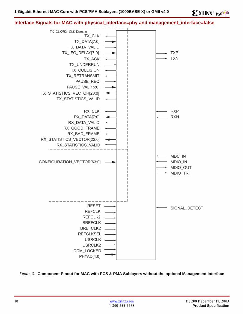
1-Gigabit Ethernet MAC Core with PCSPMA Sublayers (1000BASE-X) or GMII v40 R
Interface Signals for MAC with physical_interface=phy and management_interface=false
Figure 8 Component Pinout for MAC with PCS amp PMA Sublayers without the optional Management Interface
TX_CLK
MDC_INMDIO_IN
TXPTXN
TX_DATA[70]
TX_ACKTX_UNDERRUN
PAUSE_REQPAUSE_VAL[150]
RX_CLK
CONFIGURATION_VECTOR[630]
RX_DATA[70]
RX_GOOD_FRAMERX_BAD_FRAME
TX_COLLISIONTX_RETRANSMIT
TX_DATA_VALID
RX_DATA_VALID
RXPRXN
TX_CLKRX_CLK Domain
TX_IFG_DELAY[70]
TX_STATISTICS_VECTOR[280]TX_STATISTICS_VALID
RX_STATISTICS_VECTOR[220]RX_STATISTICS_VALID
SIGNAL_DETECT
MDIO_OUTMDIO_TRI
REFCLKRESET
PHYAD[40]
USRCLKUSRCLK2
DCM_LOCKED
REFCLK2BREFCLK
BREFCLK2REFCLKSEL
10 wwwxilinxcom DS200 December 11 20031-800-255-7778 Product Specification
1-Gigabit Ethernet MAC Core with PCSPMA Sublayers (1000BASE-X) or GMII v40R
Client Side Interface Signal Definition
Table 3 describes the client-side transmit signals of the MAC core These signals are used to transmit data from the clientto the MAC core
Table 4 describes the client-side receive signals These signals are used by the MAC core to transfer data to the client
Table 3 Transmit Client Interface Signal Pins
Signal Direction Description
TX_CLK Output Clock for transmit client interface 125 MHz nominal
TX_DATA[70] Input Frame data to be transmitted is supplied on this port
TX_DATA_VALID Input Control signal for TX_DATA port
TX_IFG_DELAY[70] InputControl signal for configurable Inter Frame Gap adjustment SeeTransmitter on page 16 for timing diagrams
TX_ACK OutputHandshaking signal Asserted when the current data on TX_DATA hasbeen accepted See Transmitter on page 16 for timing diagrams
TX_UNDERRUN Input Asserted by client to force MAC core to corrupt the current frame
TX_COLLISION OutputAsserted by the MAC core to signal a collision on the medium and that anytransmission in progress should be aborted Always 0 when the MAC coreis in full-duplex mode
TX_RETRANSMIT Output
When asserted at the same time as the TX_COLLISION signal thissignals the client that the aborted frame should be resupplied to the MACcore for retransmission Always 0 when the MAC core is in full-duplexmode
TX_STATISTICS_VECTOR[280] OutputThis gives information on the last frame transmitted See Transmitter onpage 16 for vector contents
TX_STATISTICS_VALID OutputAsserted at end of frame transmission indicating that theTX_STATISTICS_VECTOR is valid
Notes1 All the above signals are synchronous to TX_CLK and Active High
Table 4 Receive Client Interface Signal Pins
Signal Direction Description
RX_CLK Output Clock for receive client interface 125 MHz nominal
RX_DATA[70] Output Frame data received is supplied on this port
RX_DATA_VALID Output Control signal for the RX_DATA port
RX_GOOD_FRAME OutputAsserted at end of frame reception to indicate that the frame should beprocessed by the MAC client See Receiver on page 24
RX_BAD_FRAME OutputAsserted at end of frame reception to indicate that the frame should bediscarded by the MAC client See Receiver on page 24
RX_STATISTICS_VECTOR[220] OutputProvides information about the last frame received See Receiver onpage 24 for the vector contents
RX_STATISTICS_VALID OutputAsserted at end of frame reception indicating that theRX_STATISTICS_VECTOR is valid
Notes1 All signals above are synchronous to RX_CLK and Active High
DS200 December 11 2003 wwwxilinxcom 11Product Specification 1-800-255-7778
1-Gigabit Ethernet MAC Core with PCSPMA Sublayers (1000BASE-X) or GMII v40 R
Table 5 describes the signals used by the client to request a flow control action from the transmit engine Flow control framesreceived by the MAC are automatically handled (if the MAC is configured to do so)
Table 6 describes the optional signals used by the client to access the management features of the MAC core includingconfiguration status statistics and MDIO access
Table 7 describes the alternative to the optional Management Interface signals This describes the Configuration Vectorwhich uses direct inputs to the core to replace the functionality of the MAC Configuration bits when the ManagementInterface is not used
Notes1 All bits of CONFIGURATION_VECTOR are registered on input but may be treated as asynchronous inputs
Table 5 Flow Control Interface Signal Pinout
Signal Direction Description
PAUSE_REQ InputPause request sends a pause frame down the link See Transmitting a PAUSE ControlFrame on page 29
PAUSE_VAL[150] Input Pause value inserted into the parameter field of the transmitted pause frame
Notes1 These signals are synchronous to TX_CLK and are Active High
Table 6 Optional Management Interface Signal Pinout (management_interface=true)
Signal Direction Description
HOST_CLK InputClock for management interface See Optional Management Interface(management_interface=true) on page 30 for the signal frequency range
HOST_OPCODE[10] InputDefines operation to be performed over MDIO interface Bit 1 is also used inconfiguration register access See Configuration Registers on page 30
HOST_ADDR[90] Input Address of register to be accessed
HOST_WR_DATA[310] Input Data to write to register
HOST_RD_DATA[310] Output Data read from register
HOST_MIIM_SEL InputWhen asserted the MDIO interface is accessed When disasserted the MACinternal configuration or statistical counter registers are accessed
HOST_REQ InputUsed to signal a transaction on the MDIO interface or to read from the statisticregisters See Optional Management Interface (management_interface=true) onpage 30
HOST_MIIM_RDY OutputWhen high the MDIO interface has completed any pending transaction and isready for a new transaction
Notes1 All signals above are synchronous to HOST_CLK and are Active High
Table 7 Alternative to the Optional Management Interface Configuration Vector Signal Pinout(management_interface=false)
Signal Direction Description
CONFIGURATION_VECTOR[630]
Input The Configuration Vector is used to replace the functionality of theMAC Configuration Registers when the Management Interface is notused See Optional Configuration Vector (management_interface =false) on page 38
12 wwwxilinxcom DS200 December 11 20031-800-255-7778 Product Specification
1-Gigabit Ethernet MAC Core with PCSPMA Sublayers (1000BASE-X) or GMII v40R
Table 8 describes the reset signal
Physical Interface Signal Definition
Table 9 describes the MDIO (MII Management) interface signals of the MAC core These signals are typically connected tothe MDIO port of a PHY device either off-chip or an SoC-integrated core The MDIO format is defined in IEEE8023 clause22
Table 10 describes the optional GMII signals of the MAC core These are typically attached to a PHY module either off-chipor internally integrated The GMII is defined in IEEE8023 clause 35
Table 8 Reset Signal
Signal Direction Description
RESET Input Asynchronous reset for entire core See Reset circuit on page 42 for moreinformation on the reset circuit
Table 9 MDIO Interface Signal Pinout
Signal Direction Description
MDC OutputManagement Clock derived from HOST_CLK on the basis of supplied configuration datawhen the optional Management Interface is used See Optional Management Interface(management_interface=true) on page 30
MDC_IN InputWhen the Optional Management Interface is not used access to the optional PhysicalCoding Sublayer (PCS) must be provided by an external MDIO Controller In this situationthe Management Clock is an input to the core
MDIO_IN Input Input data signal for communication with PHY configuration and status Tie high if unused
MDIO_OUT Output Output data signal for communication with PHY configuration and status
MDIO_TRI OutputTristate control for MDIO signals 0 signals that the value on MDIO_OUT should be
asserted onto the MDIO bus
Table 10 Optional GMII Interface Signal Pinout (physical_interface=gmii)
Signal Direction Description
GTX_CLK InputClock signal at 125 MHz Other transmit clocks are derived from this clock as illustratedin Figure 28 Tolerance must be within IEEE 8023-2002 specification
GMII_TXD[70] Output Transmit data to PHY
GMII_TX_EN Output Data Enable control signal to PHY
GMII_TX_ER Output Error control signal to PHY
GMII_TX_CLK Output Clock out to PHY
GMII_CRS Input Control signal from PHY
GMII_COL Input Control signal from PHY
GMII_RX_CLK Input Recovered clock from received data stream by PHY
GMII_RXD[70] Input Received data from PHY
GMII_RX_DV Input Data Valid control signal from PHY
GMII_RX_ER Input Error control signal from PHY
DS200 December 11 2003 wwwxilinxcom 13Product Specification 1-800-255-7778
1-Gigabit Ethernet MAC Core with PCSPMA Sublayers (1000BASE-X) or GMII v40 R
Table 11 describes the TBI (Ten-Bit interface) signals of the MAC core These are typically attached to a PMA SERDESmodule These signals optionally replace the GMII signals described in Table 10 to extend the functionality of the core toinclude the PCS for 1000BASE-X The TBI is defined in IEEE8023 clause 36
Notes
PHYAD and SIGNAL_DETECT are asynchronous inputs SIGNAL_DETECT is Active High
Table 11 Optional TBI Interface Signal Pinout (physical_interface=tbi)
Signal Direction Description
GTX_CLK InputClock signal at 125 MHz Other transmit clocks will be derived from this clock asillustrated in Figure 32 Tolerance must be within IEEE 8023-2002 specification
TX_CODE_GROUP[90] Output 10-bit parallel transmit data to PMA Sublayer (SERDES)
PMA_TX_CLK Output Transmit clock signal to PMA Sublayer (SERDES) at 125MHz
LOC_REF OutputCauses the PMA sublayer clock recovery unit to lock to PMA_TX_CLK Thissignal is tied to Ground
EWRAP Output
This signal is set from the PCS Control Register 0 bit 14 (loopback) See PCSManaged Register Block (physical_interface = tbi or phy) on page 49 Whenhigh this instructs the PMA sublayer to electrically loop the transmitter data to thereceiver
RX_CODE_GROUP0[90] Input10-bit parallel received data from PMA Sublayer (SERDES) synchronous toPMA_RX_CLK0
RX_CODE_GROUP1[90] Input10-bit parallel received data from PMA Sublayer (SERDES) synchronous toPMA_RX_CLK1
PMA_RX_CLK0 Input Received clock signal from PMA Sublayer (SERDES) at 625MHz
PMA_RX_CLK1 InputReceived clock signal from PMA Sublayer (SERDES) at 625MHz This is 180degrees out of phase with PMA_RX_CLK0
EN_CDET OutputEnables the PMA Sublayer to perform comma realignment driven from the PCSstate machine during the Loss-Of-Sync state
PHYAD[40] Input PHY address of MDIO register set for the PCS
SIGNAL_DETECT Input
Signal direct from PMD sublayer indicating the presence of light detected at theoptical receiver If driven high this indicates that the optical receiver has detectedlight If driven low this indicates the absence of light
If unused tie high to enable the operation the core
14 wwwxilinxcom DS200 December 11 20031-800-255-7778 Product Specification
1-Gigabit Ethernet MAC Core with PCSPMA Sublayers (1000BASE-X) or GMII v40R
Table 12 describes the interface signals for the Optional PCSPMA sublayer of the MAC core These signals optionallyreplace the GMII signals described in Table 10 to extend the functionality of the core to include the PCS and PMA sublayersfor 1000BASE-X This option uses the Virtex-II Pro Rocket IO functionality which is integrated into the core The PMAsublayer for 1000BASE-X is defined in IEEE8023 clause 36
Notes1 PHYAD and SIGNAL_DETECT are asynchronous inputs SIGNAL_DETECT is Active High
Table 12 Optional PCSPMA sublayer Interface Signal Pinout (physical_interface=phy)
Signal Direction Description
REFCLK InputHigh Quality Reference clock for Multi-Gigabit Transceivers (625 MHz) See Rocket IOUser Guide
REFCLK2 Input Alternative High Quality Reference clock for Multi-Gigabit Transceivers (625 MHz) SeeRocket IO User Guide
BREFCLK Input Alternative High Quality Reference clock for Multi-Gigabit Transceivers (625 MHz)This optionally replaces REFCLK See Rocket IO User Guide
BREFCLK2 Input Alternative High Quality Reference clock for Multi-Gigabit Transceivers (625 MHz)This optionally replaces REFCLK2 See Rocket IO User Guide
REFCLKSEL Input Selects between either (B)REFCLK or (B)REFCLK2 as the input clock source to theMGT See Rocket IO User Guide
USERCLK InputClock signal at 625 MHz This is connected to the TXUSRCLK and RXUSRCLK portsof the Rocket IO MGT This may be derived from (B)REFCLK using a DCM asillustrated in Figure 35
USERCLK2 InputClock signal at 125 MHz This is connected to the TXUSRCLK2 and RXUSRCLK2 portsof the Rocket IO MGT This may be derived from (B)REFCLK using a DCM asillustrated in Figure 35
DCM_LOCKED InputIf a DCM is used to derive USRCLK and USRCLK2 as illustrated in Figure 35 theLOCKED port of the DCM must be connected to the DCM_LOCKED port of the coreThe core will hold itrsquos Rocket IO MGT in reset until DCM_LOCKED is driven to logic 1
TXPTXN OutputDifferential pair for serial transmission from PMA to PMD The clock is embedded in thedata stream
RXPRXN InputDifferential pair for serial reception from PMD to PMA The clock is extracted from thedata stream
PHYAD[40] Input PHY address of MDIO register set for the PCS
SIGNAL_DETECT Input
Signal direct from PMD sublayer indicating the presence of light detected at the opticalreceiver If driven high this indicates that the optical receiver has detected light If drivenlow this indicates the absence of light
If unused tie high to enable the operation the core
DS200 December 11 2003 wwwxilinxcom 15Product Specification 1-800-255-7778
1-Gigabit Ethernet MAC Core with PCSPMA Sublayers (1000BASE-X) or GMII v40 R
Functional Description
Client InterfaceThe client interface is designed for maximum flexibility inmatching to a client switching fabric or network processorinterface
The data pathway is 8 bits wide in both the transmit andreceive directions with each pathway synchronous to theTX_CLK and RX_CLK respectively for completely indepen-dent full duplex operation
Transmitter
Normal Frame Transmission
The timing of a normal outbound frame transfer can be seenin Figure 9 When the client wants to transmit a frame itplaces the first column of data onto the TX_DATA port andasserts a ldquo1rdquo onto TX_DATA_VALID
When the MAC core has read this first byte of data it willassert the TX_ACK signal on the next and subsequent ris-ing clock edges the client must provide the remainder ofthe data for the frame
The end of frame is signalled to the MAC core by takingTX_DATA_VALID Low
In-Band Parameter Encoding
For maximum flexibility in switching applications the Ether-net frame parameters (destination address sourceaddress lengthtype and optionally FCS) are encodedwithin the same data stream that the frame payload is trans-ferred upon rather than on separate ports This is illustratedin the timing diagrams Definitions of the abbreviations usedin the timing diagrams are described in Table 13
Figure 9 Normal Frame Transmission Across Client Interface
Table 13 Abbreviations Used in Timing Diagrams
Abbreviation Definition
DA Destination Address 6 bytes
SA Source Address 6 bytes
LT LengthType Field 2 bytes
FCS Frame Check Sequence 4 bytes
TX_CLK
TX_DATA[70]
TX_DATA_VALID
TX_ACK
TX_UNDERRUN
DA SA DATALT
TX_COLLISION
TX_RETRANSMIT
xip2133
16 wwwxilinxcom DS200 December 11 20031-800-255-7778 Product Specification
1-Gigabit Ethernet MAC Core with PCSPMA Sublayers (1000BASE-X) or GMII v40R
Padding
When fewer than 46 bytes of data are supplied by the clientto the MAC core the transmitter module will add padding upto the minimum frame length The exception to this is whenthe MAC core is configured for client-passed FCS in thiscase the client must also supply the padding to maintain theminimum frame length (see Client-Supplied FCS Passing)
Client-Supplied FCS Passing
If the MAC core is configured to have the FCS field passedin by the client (see Configuration Registers on page 30)the transmission timing is as depicted in Figure 10 In thiscase it is the responsibility of the client to ensure that theframe meets the Ethernet minimum frame length require-ments the MAC core will not perform any padding of thepayload
Figure 10 Frame Transmission with Client-supplied FCS
TX_CLK
TX_DATA[70]
TX_DATA_VALID
TX_ACK
TX_UNDERRUN
DA SA DATA FCSLT
TX_COLLISION
TX_RETRANSMIT
xip2134
DS200 December 11 2003 wwwxilinxcom 17Product Specification 1-800-255-7778
1-Gigabit Ethernet MAC Core with PCSPMA Sublayers (1000BASE-X) or GMII v40 R
Client Underrun
The timing of an aborted transfer can be seen in Figure 11This may happen for instance if a FIFO connected to theclient interface empties before a frame is completed Whenthe client asserts TX_UNDERRUN during a frame transmis-sion the MAC core will insert an error code to corrupt the
current frame and then fall back to idle transmission It isthe responsibility of the client to re-queue the aborted framefor transmission
When an underrun occurs TX_DATA_VALID may beasserted on the clock cycle after the TX_UNDERRUNassertion to request a new transmission
Figure 11 Frame Transmission with Underrun
TX_CLK
TX_DATA[70]
TX_DATA_VALID
TX_ACK
TX_UNDERRUN
DA SA DATALT
TX_COLLISION
TX_RETRANSMIT
xip2135
18 wwwxilinxcom DS200 December 11 20031-800-255-7778 Product Specification
1-Gigabit Ethernet MAC Core with PCSPMA Sublayers (1000BASE-X) or GMII v40R
Back-to-Back Transfers
Figure 12 shows the case where the MAC client is immedi-ately ready to transmit a second frame of data followingcompletion of its first frame In this figure the end of the firstframe is shown on the left On the clock cycle immediatelyfollowing the final byte of the first frame TX_DATA_VALIDis taken low by the client and is taken high one clock cyclelater to indicate that the first byte of the destination addressof the second frame is on TX_DATA awaiting transmission
When the MAC core is ready to accept data TX_ACK isasserted and the transmission continues in the same man-ner as in the case of the single frame The MAC core willdefer the assertion of TX_ACK appropriately to comply withinter-packet gap requirements and flow control requests
If the MAC core is operating in half-duplex mode the timingshown in Figure 12 is required to take advantage of framebursting the MAC core is only guaranteed to retain controlof the medium if the TX_DATA_VALID signal is low for a sin-gle clock cycle For more information on frame bursting seeIEEE 8023-2002
Figure 12 Back to Back Frame Transmission
TX_CLK
TX_DATA[70]
TX_DATA_VALID
TX_ACK
TX_UNDERRUN
TX_COLLISION
TX_RETRANSMIT
xip2136
DS200 December 11 2003 wwwxilinxcom 19Product Specification 1-800-255-7778
1-Gigabit Ethernet MAC Core with PCSPMA Sublayers (1000BASE-X) or GMII v40 R
VLAN Tagged Frames
Transmission of a VLAN tagged frame (if enabled) can beseen in Figure 13 Note that the handshaking signalsacross the interface do not change however the VLANtype tag 81-00 must be supplied by the client to signify that
the frame is VLAN tagged The client also supplies the twobytes of Tag Control Information V1 and V2 at the appro-priate times in the data stream More information on thecontents of these two bytes can be found in IEEE8023-2002
Maximum Permitted Frame Length
The maximum legal length of a frame specified in IEEE8023-2002 is 1518 bytes for non-VLAN tagged framesVLAN tagged frames may be extended to 1522 bytesWhen jumbo frame handling is disabled and the clientattempts to transmit a frame which exceeds the maximumlegal length the MAC core will insert an error code to cor-
rupt the current frame and the frame will be truncated to themaximum legal length When jumbo frame handling isenabled frames which are longer than the legal maximumare transmitted error-free
For more information on enabling and disabling jumboframe handling see Configuration Registers on page 30
Figure 13 Transmission of a VLAN Tagged Frame
TX_CLK
TX_DATA[70]
TX_DATA_VALID
TX_ACK
TX_UNDERRUN
DA SA DATALTVLANtag
81 00V1V2
TX_COLLISION
TX_RETRANSMIT
xip2137
20 wwwxilinxcom DS200 December 11 20031-800-255-7778 Product Specification
1-Gigabit Ethernet MAC Core with PCSPMA Sublayers (1000BASE-X) or GMII v40R
Frame Collisions - Half Duplex Operation Only
In half duplex Ethernet operation collisions will occur on themedium as a matter of course this is how the arbitrationalgorithm is fulfilled In case of a collision the MAC core sig-nals to the client that data may need to be resupplied as fol-lows
If there is a collision the TX_COLLISION signal will be setto ldquo1rdquo by the MAC core If a frame is in progress the clientmust abort the transfer and take TX_DATA_VALID to ldquo0rdquo
If the TX_RETRANSMIT signal is ldquo1rdquo in the same clockcycle that the TX_COLLISION signal is ldquo1rdquo the client must
resubmit the previous frame to the MAC core for retrans-mission TX_DATA_VALID must be asserted to the MACcore within 8 clock cycles of the TX_COLLISION signal inorder to meet Ethernet timing requirements See Figure 14
If the TX_RETRANSMIT signal is ldquo0rdquo in the same clockcycle that the TX_COLLISION signal is ldquo1rdquo the number ofretries for this frame has exceeded the Ethernet specifica-tion and the frame should be dropped by the client The cli-ent can then make any new frame available to the MAC fortransmission without timing restriction See Figure 15
Figure 14 Collision Handling - Frame retransmission required
Figure 15 Collision Handling - No frame retransmission required
TX_CLK
TX_DATA[70]
TX_DATA_VALID
TX_ACK
TX_UNDERRUN
TX_COLLISION
TX_RETRANSMIT
8 clocks max
xip2138
TX_CLK
TX_DATA[70]
TX_DATA_VALID
TX_ACK
TX_UNDERRUN
TX_COLLISION
TX_RETRANSMIT
xip2139
DS200 December 11 2003 wwwxilinxcom 21Product Specification 1-800-255-7778
1-Gigabit Ethernet MAC Core with PCSPMA Sublayers (1000BASE-X) or GMII v40 R
Interframe Gap Adjustment
The user can elect to vary the length of the inter fame gapIf this function is selected (via a configuration bit in thetransmitter control register see Configuration Registerson page 30) then the MAC will exert back pressure to delaythe transmission of the next frame until the requested num-ber of Idle cycles has elapsed The number of Idle cycles iscontrolled by the value on the TX_IFG_DELAY port at thestart of frame transmission Figure 16 shows the MAC oper-ating in this mode
Reducing the Inter fame gap to below the IEEE 8023-2002minimum of 12 Idles is supported in Full Duplex onlydesigns and will transmit an absolute minimum of 4 Idles Ifthe Interframe gap adjustment is reduced below 12 Idlesthen the accuracy of the Optional Statistical Gathering(statistics_gathering=true) Counters cannot be guaranteedHowever the TX_STATISTIC_VECTOR andRX_STATISTIC_VECTOR will always remain correct
Transmitter Statistics Vector
The statistics for the frame transmitted are contained withinthe TX_STATISTICS_VECTOR The vector is driven syn-chronously by the transmitter clock TX_CLK followingframe transmission The bit field definition for the Vector isdefined in Table 14
All bit fields with the exception of BYTE_VALID are validonly when the TX_STATISTICS_VALID is asserted This isillustrated in Figure 17 BYTE_VALID is significant on everyTX_CLK cycle
TX_STATISTICS_VECTOR bits 25 down to 17 inclusive arefor half duplex only and will be set to logic 0 when operatingin full duplex mode
Figure 16 Interframe Gap Adjustment
TX_CLK
TX_DATA[70]
TX_DATA_VALID
TX_ACK
DA SA
TX_IFG_DELAY
IFG ADJUST VALUE
0x0D
13 Idles inserted
DA
Next IFG ADJUST VALUE
xip2140
Figure 17 Transmitter Statistics Vector Timing
TX_CLK
TX_STATISTICS_VECTOR[280]
TX_STATISTICS_VALID
xip2141
22 wwwxilinxcom DS200 December 11 20031-800-255-7778 Product Specification
1-Gigabit Ethernet MAC Core with PCSPMA Sublayers (1000BASE-X) or GMII v40R
Table 14 Bit Definition for the Transmitter Statistics Vector
TX_STATISTICS_VECTOR Name Description
28 PAUSE_FRAME_TRANSMITTEDAsserted if the previous frame was a pause framethat the MAC itself initiated in response to aPAUSE_REQ assertion
27 BYTE_VALID
Asserted if a MAC frame byte (DA to FCS inclusive)is in the process of being transmitted This is valid onevery clock cycle
Do not use this as an enable signal to indicate thatdata is present on GMII_TXD[70]
26 Reserved Returns logic 0
25 down to 22 TX_ATTEMPTS[30]
The number of attempts that have been made totransmit the previous frame This is a 4-bit number0 should be interpreted as 1 attempt 1 as 2attempts up until 15 as 16 attempts
21 Reserved Returns logic 0
20 EXCESSIVE_COLLISIONAsserted if a collision has been detected on each ofthe last 16 attempts to transmit the previous frame
19 LATE_COLLISIONAsserted if a late collision occurred during frametransmission
18 EXCESSIVE_DEFERRALAsserted if the previous frame was deferred for anexcessive amount of time as defined by the constantldquomaxDeferTimerdquo in IEEE 8023-2002
17 TX_DEFERRED Asserted if transmission of the frame was deferred
16 VLAN_FRAMEAsserted if the previous frame contained a VLANidentifier in the LengthType field when transmitterVLAN operation is enabled
15 down to 5 FRAME_LENGTH_COUNTThe length of the previous frame in number of bytesThe count will stick at 2047 for any Jumbo frameslarger than this value
4 CONTROL_FRAMEAsserted if the previous frame had the special MACControl Type code 88-08 in the LengthType field
3 UNDERRUN_FRAMEAsserted if the previous frame contained anunderrun error
2 MULTICAST_FRAMEAsserted if the previous frame contained a multicastaddress in the Destination Address field
1 BROADCAST_FRAMEAsserted if the previous frame contained abroadcast address in the Destination Address field
0 SUCCESSFUL_FRAMEAsserted if the previous frame was transmittedwithout error
DS200 December 11 2003 wwwxilinxcom 23Product Specification 1-800-255-7778
1-Gigabit Ethernet MAC Core with PCSPMA Sublayers (1000BASE-X) or GMII v40 R
Receiver
Normal Frame Reception
The timing of a normal inbound frame transfer can be seenin Figure 18 The client must be prepared to accept data atany time there is no buffering within the MAC to allow forlatency in the receive client Once frame reception begins
data is transferred on consecutive clock cycles to thereceive client until the frame is complete The MAC assertsthe RX_GOOD_FRAME signal to indicate that the framewas successfully received and that the frame should beanalyzed by the client
Frame parameters (destination address source addresslengthtype and optionally FCS) are supplied on the databus according to the timing diagram The abbreviations arethe same as those described in Table 13 on page 16
If the LengthType field in the frame has the Length interpre-tation and this indicates that the inbound frame has beenpadded to meet the Ethernet minimum frame size specifica-tion then this padding will not be passed to the client in thedata payload The exception to this is in the case whereFCS passing is enabled see Client-Supplied FCS Pass-ing on page 25
Therefore when Client-Supplied FCS passing is disabledRX_DATA_VALID = lsquo0rsquo between frames for the duration ofthe Padding field (if present) the FCS field carrier exten-sion (if present) the interframe gap following the frame andthe preamble field of the next frame When Client-Supplied
FCS passing is enabled RX_DATA_VALID = lsquo0rsquo betweenframes for the duration of carrier extension (if present) theinterframe gap and the preamble field of the followingframe
RX_GOOD_FRAME RX_BAD_FRAME timing
Although the timing diagram in Figure 18 shows theRX_GOOD_FRAME signal asserted shortly after the lastvalid data on RX_DATA this is not always the case TheRX_GOOD_FRAME or RX_BAD_FRAME signals areasserted only after all frame checks are completed This isafter the FCS field has been received (and after reception ofcarrier extension if present)
Therefore either RX_GOOD_FRAME or RX_BAD_FRAMEis asserted following frame reception at the beginning of theinterframe gap
Figure 18 Normal Frame Reception
RX_CLK
RX_DATA[70]
RX_DATA_VALID
RX_GOOD_FRAME
RX_BAD_FRAME
DA SA DATALT
xip2142
24 wwwxilinxcom DS200 December 11 20031-800-255-7778 Product Specification
1-Gigabit Ethernet MAC Core with PCSPMA Sublayers (1000BASE-X) or GMII v40R
Frame Reception with Errors
The case of an unsuccessful frame reception (for examplea fragment frame or a frame with an incorrect FCS) can beseen in Figure 19 In this case the RX_BAD_FRAME signal
is asserted to the client at the end of the frame It is then theresponsibility of the client to drop the data already trans-ferred for this frame
Figure 19 Frame Reception with Error
Client-Supplied FCS Passing
If the MAC core is configured to pass the FCS field to the cli-ent (see Configuration Registers on page 30) then this ishandled as shown in Figure 20
In this case any padding inserted into the frame to meetEthernet minimum frame length specifications will be leftintact and passed to the client
Note that even though the FCS is passed up to the client itis also verified by the MAC core and RX_BAD_FRAMEasserted if the FCS check fails
RX_CLK
RX_DATA[70]
RX_DATA_VALID
RX_GOOD_FRAME
RX_BAD_FRAME
DA SA DATALT
xip2144
Figure 20 Frame Reception with In-Band FCS Field
RX_CLK
RX_DATA[70]
RX_DATA_VALID
RX_GOOD_FRAME
RX_BAD_FRAME
DA SA DATALT FCS
xip2145
DS200 December 11 2003 wwwxilinxcom 25Product Specification 1-800-255-7778
1-Gigabit Ethernet MAC Core with PCSPMA Sublayers (1000BASE-X) or GMII v40 R
VLAN Tagged Frames
The reception of a VLAN tagged frame (if enabled) can beseen in Figure 21 The VLAN frame is passed to the clientso that the frame may be identified as VLAN tagged this is
followed by the Tag Control Information bytes V1 and V2More information on the interpretation of these bytes maybe found in IEEE 8023-2002 standard
Maximum Permitted Frame Length
The maximum legal length of a frame specified in IEEE8023-2002 is 1518 bytes for non-VLAN tagged framesVLAN tagged frames may be extended to 1522 bytesWhen jumbo frame handling is disabled and the corereceives a frame which exceeds the maximum legal lengthRX_BAD_FRAME will be asserted When jumbo framehandling is enabled frames which are longer than the legalmaximum are received in the same way as shorter frames
For more information on enabling and disabling jumboframe handling see Configuration Registers on page 30
LengthType Field Error Checks
Enabled
Default operation is with the LengthType error checkingenabled (see Receiver Configuration Word 1 on page 31)In this mode the following checks are made on all framesreceived If either of these checks fail then the frame ismarked as BAD
bull A value in the LengthType field that is greater than orequal to decimal 46 but less than decimal 1536 (aLength interpretation) is checked against the actualdata length received
bull A value in the LengthType field that is less thandecimal 46 is checked to see that the data field ispadded to exactly 46 bytes (so that the resultant frameis minimum frame size 64 bytes total in length)
Furthermore if Padding is indicated (the LengthType fieldis less than decimal 46) and Client-Supplied FCS Passing isdisabled then the Length value in the LengthType field willbe used to deassert RX_DATA_VALID after the indicatednumber of data bytes so that the Padding bytes areremoved from the frame
Disabled
When the LengthType error checking is disabled (seeReceiver Configuration Word 1 on page 31) theLengthType error checks described above are not per-formed A frame containing only these errors will be markedas GOOD
Furthermore if Padding is indicated and Client-SuppliedFCS Passing is disabled then a Length Value in theLengthType field will not be used to deassertRX_DATA_VALID Instead RX_DATA_VALID will be deas-serted before the start of the FCS field in this way any pad-ding will not be removed from the frame
Figure 21 Reception of a VLAN Tagged Frame
RX_CLK
RX_DATA[70]
RX_DATA_VALID
RX_GOOD_FRAME
RX_BAD_FRAME
DA SA DATALT
81 00 V1 V2
VLANtag
xip2146
26 wwwxilinxcom DS200 December 11 20031-800-255-7778 Product Specification
1-Gigabit Ethernet MAC Core with PCSPMA Sublayers (1000BASE-X) or GMII v40R
Receiver Statistics Vector
The statistics for the frame received are contained withinthe RX_STATISTICS_VECTOR The vector is driven syn-chronously by the receiver clock RX_CLK following framereception The bit field definition for the Vector is defined inTable 15
All bit fields with the exception of BYTE_VALID are validonly when the RX_STATISTICS_VALID is asserted This isillustrated in Figure 22 BYTE_VALID is significant on everyRX_CLK cycle
Figure 22 Receiver Statistics Vector Timing
RX_CLK
RX_STATISTICS_VECTOR[220]
RX_STATISTICS_VALID
xip2147
Table 15 Bit Definition for the Receiver Statistics Vector
RX_STATISTICS_VECTOR Name Description
22LENGTHTYPE Out ofRange
Asserted if the lengthtype field contained a length valuethat did not match the number of MAC client data bytesreceived Also high if the lengthtype field indicated thatthe frame contained padding but the number of MAC cli-ent data bytes received was not equal to 64 bytes (min-imum frame size)
The exception to the above is when the LengthTypeField Error Checks are disabled in which case this bitwill not be asserted
21 BAD_OPCODE
Asserted if the previous frame was error-free andcontained the special Control Frame identifier in theLengthType field but contained an opcode that isunsupported by the MAC (Any Opcode other thanPAUSE)
20 FLOW_CONTROL_FRAME
Asserted if the previous frame was error-freecontained the special Control Frame identifier in theLengthType field contained a Destination Addressthat matched either the MAC Control MulticastAddress or the configured source address of the MACcontained the supported PAUSE opcode and wasacted upon by the MAC
19 BYTE_VALID
Asserted if a MAC frame byte (DA to FCS inclusive) isin the process of being received This is valid on everyclock cycle
Do not use this as an enable signal to indicate thatdata is present on RX_DATA[70]
18 VLAN_FRAMEAsserted if the previous frame contained a VLANidentifier in the LengthType field when receiver VLANoperation is enabled
DS200 December 11 2003 wwwxilinxcom 27Product Specification 1-800-255-7778
1-Gigabit Ethernet MAC Core with PCSPMA Sublayers (1000BASE-X) or GMII v40 R
17 OUT_OF_BOUNDS
Asserted if the previous frame exceeded the specifiedIEEE8023-2002 maximum legal length (seeMaximum Permitted Frame Length on page 26) Thisis only valid if Jumbo frames are disabled
16 CONTROL_FRAMEAsserted if the previous frame contained the specialControl Frame identifier in the LengthType field
15 down to 5 FRAME_LENGTH_COUNTThe length of the previous frame in number of bytesThe count will stick at 2047 for any Jumbo frameslarger than this value
4 MULTICAST_FRAMEAsserted if the previous frame contained a multicastaddress in the Destination Address field
3 BROADCAST_FRAMEAsserted if the previous frame contained the broadcastaddress in the Destination Address field
2 FCS_ERRORAsserted if the previous frame received had anincorrect FCS value or the MAC detected error codesduring frame reception
1 BAD_FRAME1 Asserted if the previous frame received containederrors
0 GOOD_FRAME1 Asserted if the previous frame received was error-free
1 If the LengthType Field Error Checks are disabled then a frame which contains this type of error will be marked as a GOOD_FRAMEproviding no additional errors were detected
Table 15 Bit Definition for the Receiver Statistics Vector
RX_STATISTICS_VECTOR Name Description
28 wwwxilinxcom DS200 December 11 20031-800-255-7778 Product Specification
1-Gigabit Ethernet MAC Core with PCSPMA Sublayers (1000BASE-X) or GMII v40R
Flow ControlThe flow control block is designed to Clause 31 of the IEEE8023-2002 standard The MAC may be configured to sendpause frames and to act upon their reception These twobehaviors can be configured asymmetrically see Configu-ration Registers on page 30
Transmitting a PAUSE Control Frame
The client initiates a flow control frame by assertingPAUSE_REQ while the pause value is on the PAUSE_VALbus These signals are synchronous to TX_CLK The timingof this can be seen in Figure 23
If the MAC core is configured to support transmit flow con-trol this action causes the core to transmit a PAUSE controlframe on the link with the PAUSE parameter set to thevalue on PAUSE_VAL in the cycle when PAUSE_REQ wasasserted This will not disrupt any frame transmission inprogress but will take priority over any pending frame trans-
mission This frame will be transmitted even if the transmit-ter is in the paused state itself
Receiving a Pause Control Frame
When an error-free frame is received by the MAC core thefollowing checks are made
1 The Destination Address field is matched against theMAC Control Multicast address or the configuredSource Address for the MAC (see ConfigurationRegisters on page 30)
2 The LengthType field is matched against the MACControl Type code
3 The opcode field contents are matched against thePAUSE opcode if check 2 is true
If any of the above checks are false or the MAC Flow Con-trol logic for the receiver is disabled the frame is ignored bythe Flow Control logic and passed up to the client
If the frame passes all of the above checks is of minimumlegal size and the MAC Flow Control logic for the receiver isenabled the pause value parameter in the frame is thenused to inhibit transmitter operation for the time defined inthe IEEE8023-2002 specification This inhibit is imple-mented using the same back pressure scheme shown inFigure 12 Because the received pause frame has beenacted upon it is passed to the client with RX_BAD_FRAMEasserted to indicate to the client that it should be dropped
Reception of any frame for which check 2 is true and whichis not of legal minimum length is considered an invalid Con-trol frame This will be ignored by the Flow Control logic andpassed to the client with RX_BAD_FRAME asserted
Figure 23 Pause Request Timing
TX_CLK
PAUSE_VAL[150]
PAUSE_REQ
xip2148
DS200 December 11 2003 wwwxilinxcom 29Product Specification 1-800-255-7778
1-Gigabit Ethernet MAC Core with PCSPMA Sublayers (1000BASE-X) or GMII v40 R
Optional Management Interface(management_interface=true)The management interface is a processor-independentinterface with standard address data and control signals Itmay be used as is or a wrapper may be applied (not sup-plied) to interface to common bus architectures
This interface is used for
bull Configuration of the MAC core
bull Access to optional statistics counters for use by higherlayers for example SNMP
bull access through the MDIO interface to the managementregisters located in the PHY attached to the MAC core
The management interface is accessed differently depend-ing on the type of transaction a truth table showing whichaccess method is required for each transaction type isshown in Table 16 These access methods are described inthe following sections
HOST_CLK Frequency
The management interface clock HOST_CLK is used toderive the MDIO clock MDC and is therefore subject tosome frequency restrictions This HOST_CLK must be
ge 10 MHz
le 100 MHz
Configuring the MAC core to derive the MDC signal fromthis clock is detailed in MDIO Interface on page 37
Configuration Registers
After power up or reset the client may reconfigure the coreparameters from their defaults such as flow control supportConfiguration changes can be written at any time Both thereceiver and transmitter logic will only respond to configura-tion changes during Inter Frame Gaps The exceptions tothis are the configurable resets which take effect immedi-ately
Configuration of the MAC core is performed through a reg-ister bank accessed through the management interfaceThe configuration registers available in the core are detailedin Table 17 As can be seen the address has some implicitdonrsquot care bits any access to an address in the rangesshown will perform a 32-bit read or write from the same con-figuration word
Table 16 Management Interface Transaction Types
Transaction HOST_MIIM_SEL HOST_ADDR[9]
Configuration 0 1
Statistics 0 0
MIIM access 1 X
Table 17 Configuration Registers
Address Description
0x200-0x23F Receiver Configuration (Word 0)
0x240-0x27F Receiver Configuration (Word 1)
0x280-0x2BF Transmitter Configuration
0x2C0-0x2FF Flow Control Configuration
0x300-0x33F Reserved
0x340-0x37F Management Configuration
30 wwwxilinxcom DS200 December 11 20031-800-255-7778 Product Specification
1-Gigabit Ethernet MAC Core with PCSPMA Sublayers (1000BASE-X) or GMII v40R
The register contents for the two receiver configuration words can be seen in Table 18 and Table 19
Notes1 In changing the receiverrsquos mode from Half Duplex to Full Duplex there is a period of time of up to 24 us following the mode change
when no new receiver statistics can be stored in the optional Statistical Counters
Table 18 Receiver Configuration Word 0
Bit Default Value Description
31-0 All 0rsquos
Pause frame MAC Source Address[310] This address is used by the MAC tomatch against the Destination Address of any incoming flow control frames It isalso used by the flow control block as the Source Address (SA) for any outboundflow control frames
The address is ordered so the first byte transmittedreceived is the lowestpositioned byte in the register for example a MAC address ofAA-BB-CC-DD-EE-FF would be stored in Address[470] as 0xFFEEDDCCBBAA
Table 19 Receiver Configuration Word 1
Bit Default Value Description
15-0 All 0rsquos Pause frame MAC Source Address[4732] See description in Table 18
24-16 NA Reserved
25 0
LengthType Error Check Disable When this bit is set to ldquo1rdquo the core will notperform the LengthType field error checks as described in LengthType FieldError Checks on page 26 When this bit is set to ldquo0rdquo the LengthType field checkswill be performed this is normal operation
26 0Half Duplex If ldquo1rdquo the receiver will operate in half duplex mode If ldquo0rdquo the receiverwill operate in full duplex mode Has no effect if XCO parameterhalf_duplex_capable = false
27 0VLAN Enable When this bit is set to ldquo1rdquo VLAN tagged frames will be acceptedby the receiver
28 1Receiver Enable If set to ldquo1rdquo the receiver block will be operational If set to ldquo0rdquothe block will ignore activity on the physical interface RX port
29 0
In-band FCS Enable When this bit is ldquo1rdquo the MAC receiver will pass the FCS fieldup to the client as described in Client-Supplied FCS Passing on page 25 Whenit is ldquo0rdquo the client will not be passed the FCS In both cases the FCS will beverified on the frame
30 0Jumbo Frame Enable When this bit is set to ldquo1rdquo the MAC receiver will acceptframes over the specified IEEE8023-2002 maximum legal length When this bitis ldquo0rdquo the MAC will only accept frames up to the specified maximum
31 0Reset When this bit is set to ldquo1rdquo the receiver will be reset The bit will thenautomatically revert to ldquo0rdquo Note that this reset will also set all of the receiverconfiguration registers to their default values
DS200 December 11 2003 wwwxilinxcom 31Product Specification 1-800-255-7778
1-Gigabit Ethernet MAC Core with PCSPMA Sublayers (1000BASE-X) or GMII v40 R
The register contents for the Transmitter Configuration Word are described in Table 20
Notes1 In changing the transmitterrsquos mode from Half Duplex to Full Duplex there is a period of time of up to 24 us following the mode change
when no new transmitter statistics can be stored in the optional Statistical Counters
Table 20 Transmitter Configuration Word
Bit Default Value Description
24-0 NA Reserved
25 0
Interframe Gap Adjust Enable If lsquo1rsquo the transmitter will read the value on the portTX_IFG_DELAY at the start of frame transmission and adjust the interframe gapfollowing the frame accordingly See Interframe Gap Adjustment on page 22 Ifldquo0rdquo the transmitter will output a minimum Inter Frame Gap of twelve clock cyclesas specified in IEEE8023-2002
26 0Half Duplex If lsquo1rsquo the transmitter will operate in half duplex mode If lsquo0rsquo thetransmitter will operate in full duplex mode Has no effect if XCO parameterhalf_duplex_capable = false
27 0VLAN Enable When this bit is set to 1 the transmitter will allow the transmissionof VLAN tagged frames
28 1Transmit Enable When this bit is 1 the transmitter is operational When it is 0the transmitter is disabled
29 0
In-band FCS Enable When this bit is lsquo1rsquo the MAC transmitter will expect the FCSfield to be passed in by the client as described in Client-Supplied FCS Passingon page 17 When this bit is ldquo0rdquo the MAC transmitter will append padding asrequired compute the FCS and append it to the frame
30 0
Jumbo Frame Enable When this bit is set to ldquo1rdquo the MAC transmitter will sendframes that are greater than the specified IEEE8023-2002 maximum legallength When this bit is ldquo0rdquo the MAC will only send frames up to the specifiedmaximum
31 0Reset When this bit is set to ldquo1rdquo the transmitter will be reset The bit will thenautomatically revert to ldquo0rdquo Note that this reset will also set all of the transmitterconfiguration registers to their default values
32 wwwxilinxcom DS200 December 11 20031-800-255-7778 Product Specification
1-Gigabit Ethernet MAC Core with PCSPMA Sublayers (1000BASE-X) or GMII v40R
The register contents for the Flow Control Configuration Word are described in Table 21
The register contents for the Management Configuration Word are described in Table 22
Writing to the configuration registers through the manage-ment interface is depicted in Figure 24 When accessing theconfiguration registers (ie when HOST_ADDR[9] = lsquo1rsquo andHOST_MIIM_SEL = lsquo0rsquo) the upper bit of HOST_OPCODEfunctions as an Active Low write enable signal The lowerHOST_OPCODE bit is a ldquodonrsquot carerdquo
Reading from the configuration register words is similar butthe upper HOST_OPCODE bit should be lsquo1rsquo This is shownin Figure 25 In this case the contents of the register appearon HOST_RD_DATA the HOST_CLK edge after the regis-ter address is asserted onto HOST_ADDR
Table 21 Flow Control Configuration Word
Bit Default Value Description
28-0 NA Reserved
29 1
Flow Control Enable (RX) When this bit is lsquo1rsquo received flow control frames willinhibit the transmitter operation as described in Receiving a Pause ControlFrame on page 29 When this bit is lsquo0rsquo received flow control frames will alwaysbe passed up to the client
30 1Flow Control Enable (TX) When this bit is lsquo1rsquo asserting the PAUSE_REQ signalwill send a flow control frame out from the transmitter When this bit is 0 assertingthe PAUSE_REQ signal has no effect
31 NA Reserved
Table 22 Management Configuration Word
Bits Default Value Description
4-0 All 0rsquos Clock Divide[40] See MDIO Interface on page 37
5 0MDIO Enable When this bit is 1 the MDIO interface can be used to accessattached PHY devices When this bit is 0 the MDIO interface is disabled and theMDIO signals remain inactive
31-6 NA Reserved
Figure 24 Configuration Register Write Timing
HOST_CLK
HOST_ADDR[80]
HOST_ADDR[9]
HOST_OPCODE[1]
HOST_MIIM_SEL
HOST_WR_DATA[310]xip2149
Figure 25 Configuration Register Read Timing
HOST_CLK
HOST_ADDR[80]
HOST_ADDR[9]
HOST_OPCODE[1]
HOST_MIIM_SEL
HOST_RD_DATA[310]
xip2150
DS200 December 11 2003 wwwxilinxcom 33Product Specification 1-800-255-7778
1-Gigabit Ethernet MAC Core with PCSPMA Sublayers (1000BASE-X) or GMII v40 R
Optional Statistical Gathering(statistics_gathering=true)
During operation the MAC core collects statistics on thesuccess and failure of various operations for processing by
station management entities (STA) further up the protocolstack These statistics are accessed by the host through theoptional management interface A complete list of statisticssupported is described in Table 23
Table 23 Statistics Registers
Address Name Description
0x000 Frames Received OK1 A count of error-free frames received
0x001 Frame Check Sequence Errors A count of received frames that failed the CRC check and were at least64 bytes in length
0x002 Broadcast Frames Received OK1A count of frames that were successfully received and were directed tothe broadcast group address
0x003 Multicast Frames Received OK1 A count of frames that were successfully received and were directed toa non broadcast group address
0x004 64 byte Frames Received OK1 A count of error-free frames received that were 64 bytes in length
0x005 65-127 byte Frames Received OK1A count of error-free frames received that were between 65 and 127bytes in length
0x006 128-255 byte Frames Received OK1A count of error-free frames received that were between 128 and 255bytes in length
0x007 256-511 byte Frames Received OK1A count of error-free frames received that were between 256 and 511bytes in length
0x008512-1023 byte Frames ReceivedOK1
A count of error-free frames received that were between 512 and 1023bytes in length
0x0091024-MaxFrameSize byte FramesReceived OK1
A count of error-free frames received that were between 1024 bytes andthe specified IEEE8023-2002 maximum legal length (see MaximumPermitted Frame Length on page 26)
0x00A Control Frames Received OKA count of error-free frames received that contained the specialControl Frame identifier in the LengthType field
0x00B LengthType Out of Range
A count of frames received that were at least 64 bytes in length wherethe lengthtype field contained a length value that did not match thenumber of MAC client data bytes received
The counter also increments for frames in which the lengthtype fieldindicated that the frame contained padding but where the number ofMAC client data bytes received was greater than 64 bytes (minimumframe size)
The exception to the above is when the LengthType Field Error Checksare disabled in which case this counter will not increment
0x00C VLAN Tagged Frames Received OKA count of error-free VLAN frames received This counter will only incre-ment when the receiver is configured for VLAN operation
0x00D Pause Frames Received OK
A count of error-free frames received that contained the MAC Controltype identifier 88-08 in the LengthType field contained a Destinationaddress that matched either the MAC Control multicast address or theconfigured source address of the MAC contained the PAUSE opcodeand were acted upon by the MAC
0x00EControl Frames Received withUnsupported Opcode
A count of error-free frames received that contained the MAC Controltype identifier 88-08 in the LengthType field but were received with anopcode other than the PAUSE opcode
34 wwwxilinxcom DS200 December 11 20031-800-255-7778 Product Specification
1-Gigabit Ethernet MAC Core with PCSPMA Sublayers (1000BASE-X) or GMII v40R
0x00F Oversize Frames Received OK1A count of otherwise error-free frames received that exceeded the max-imum legal frame length specified in IEEE 8023-2002 (see MaximumPermitted Frame Length on page 26)
0x010 Undersize frames receivedA count of the number of frames received that were less than 64 bytesin length but were otherwise well formed
0x011 Fragment frames receivedA count of the number of frames received that were less than 64 bytesin length and had a bad Frame Check Sequence field
0x012 Received bytesA count of bytes of frames that are received (Destination Address toFrame Check Sequence inclusive)
0x013 Transmitted bytesA count of bytes of frames that are transmitted (Destination Address toFrame Check Sequence inclusive)
0x020 Frames Transmitted OK A count of error-free frames transmitted
0x021 Broadcast Frames Transmitted OK A count of error-free frames that were transmitted to the broadcastaddress
0x022 Multicast Frames Transmitted OK A count of error-free frames that were transmitted to a group destina-tion address other than broadcast
0x023 Underrun Errors
A count of frames that would otherwise be transmitted by the core butcould not be completed due to the assertion of TX_UNDERRUN duringthe frame transmission This will not count frames which are less than64 bytes in length
0x024 Control Frames Transmitted OKA count of error-free frames transmitted that contained the MACControl Frame type identifier 88-08 in the LengthType field
0x025 64 byte Frames Transmitted OK A count of error-free frames transmitted that were 64 bytes in length
0x026 65-127 byte Frames Transmitted OKA count of error-free frames transmitted that were between 65 and 127bytes in length
0x027128-255 byte Frames TransmittedOK
A count of error-free frames transmitted that were between 128 and 255bytes in length
0x028256-511 byte Frames TransmittedOK
A count of error-free frames transmitted that were between 256 and 511bytes in length
0x029512-1023 byte Frames TransmittedOK
A count of error-free frames transmitted that were between 512 and1023 bytes in length
0x02A1024-MaxFrameSize byte FramesTransmitted OK
A count of error-free frames transmitted that were between 1024 and thespecified IEEE8023-2002 maximum legal length (see Maximum Per-mitted Frame Length on page 20)
0x02BVLAN Tagged Frames TransmittedOK
A count of error-free VLAN frames transmitted This counter will onlyincrement when the transmitter is configured for VLAN operation
0x02C Pause Frames Transmitted OKA count of error-free PAUSE frames generated and transmitted by thecore in response to an assertion of PAUSE_REQ
0x02D Oversize Frames Transmitted OKA count of otherwise error-free frames transmitted that exceeded themaximum legal frame length specified in IEEE 8023-2002 (see Maxi-mum Permitted Frame Length on page 20)
0x02E Single Collision Frames A count of frames that are involved in a single collision but are subse-quently transmitted successfully (Half Duplex Mode only)
Table 23 Statistics Registers (Continued)
Address Name Description
DS200 December 11 2003 wwwxilinxcom 35Product Specification 1-800-255-7778
1-Gigabit Ethernet MAC Core with PCSPMA Sublayers (1000BASE-X) or GMII v40 R
Each of these statistic registers is 64 bits wide and thereforemust be read in a two-cycle transfer The timing of this pro-cess is shown in Figure 26 Six clocks after the read trans-action is initiated the least significant word (LSW) of thestatistics counter appears on the HOST_RD_DATA bus
and a clock cycle later the most significant word (MSW)appears For accurate statistic values 64 clock ticks (ofTX_CLK for transmit statistics or RX_CLK for receive statis-tics) must elapse after the last frame is sent or receivedthrough the MAC core
0x02F Multiple Collision Frames A count of frames that are involved in more than one collision but aresubsequently transmitted successfully (Half Duplex Mode only)
0x040 Frames with Deferred Transmissions A count of frames whose transmission was delayed on its first attemptbecause the medium was busy (Half Duplex Mode only)
0x041 Late Collisions
A count of the times that a collision has been detected later than oneslotTime from the start of the packet transmission A late collision iscounted twice both as a collision and as a lateCollision (Half DuplexMode only)
0x042Frames Aborted due to Excesscollisions
A count of the frames that due to excessive collisions are not transmit-ted successfully (Half Duplex Mode only)
0x043 Carrier Sense ErrorsA count of times that the GMII_CRS signal was not asserted or wasdisasserted during the transmission of a frame without collision (HalfDuplex Mode only)
0x044 Frames with Excess DeferralA count of frames that deferred transmission for an excessive period oftime (Half Duplex Mode only)
1 If the LengthType Field Error Checks are disabled then these counters will still increment for received frames which contain this typeof error (providing no additional errors were detected)
Table 23 Statistics Registers (Continued)
Address Name Description
Figure 26 Statistic Register Read Timing
HOST_CLK
HOST_ADDR[80]
HOST_ADDR[9]
HOST_REQ
HOST_MIIM_SEL
HOST_RD_DATA[310]
6 CLOCKS
LSW MSW
xip2151
36 wwwxilinxcom DS200 December 11 20031-800-255-7778 Product Specification
1-Gigabit Ethernet MAC Core with PCSPMA Sublayers (1000BASE-X) or GMII v40R
MDIO Interface
The management interface is also used to access the MDIO(MII Management) interface of the MAC core this interfaceis used to access the Managed Information Block (MIB) ofthe PHY components attached to the MAC core
The MDIO interface supplies a clock to the externaldevices MDC This clock is derived from the HOST_CLKsignal using the value in the Clock Divide[40] configurationregister The frequency of the MDIO clock is given by thefollowing equation
The frequency of MDC given by this equation should notexceed 25 MHz in order to comply with the IEEE8023-2002 specification for this interface To prevent MDCfrom being out of specification the Clock Divide[40] valuepowers up at 00000 and while this value is in the register itis impossible to enable the MDIO interface
For details of the register map of PHY layer devices and afuller description of the operation of the MDIO interfaceitself see IEEE specification 8023-2002
Access to the MDIO interface through the managementinterface is depicted in the timing diagram in Figure 27
For MDIO transactions the following points apply
bull HOST_OPCODE maps to the OP (opcode) field of theMDIO frame
bull HOST_ADDR maps to the two address fields of theMDIO frame PHY_ADDR is HOST_ADDR[95] andREG_ADDR is HOST_ADDR[40]
bull HOST_WR_DATA[150] maps into the data field of the
MDIO frame when performing a write operation
bull The data field of the MDIO frame maps intoHOST_RD_DATA[150] when performing a readoperation
The MAC core signals to the host that it is ready for anMDIO transaction by asserting HOST_MIIM_RDY A read orwrite transaction on the MDIO is initiated by a pulse on the
fMDC
fHOST_CLK
1 Clock Divide[40]+( ) 2times-------------------------------------------------------------------=
Figure 27 MDIO Access Through Management Interface
HOST_CLK
HOST_ADDR[90]
HOST_OPCODE[10]
HOST_REQ
HOST_MIIM_SEL
HOST_RD_DATA[150]
HOST_WR_DATA[150]
HOST_RDY
If a read transaction is initiated the HOST_RD_DATA bus is valid at the point indicated If a write transaction is initiated the HOST_WR_DATA bus must be valid at the indicated point Simultaneous read and write is not permitted
xip2152
DS200 December 11 2003 wwwxilinxcom 37Product Specification 1-800-255-7778
1-Gigabit Ethernet MAC Core with PCSPMA Sublayers (1000BASE-X) or GMII v40 R
HOST_REQ signal This pulse is ignored if the MDIO inter-face already has a transaction in progress
The MAC core then disasserts the HOST_MIIM_RDY signalwhile the transaction across the MDIO is in progress Whenthe transaction across the MDIO interface has been com-pleted the HOST_MIIM_RDY signal will be asserted by theMAC core if the transaction is a read the data will also beavailable on the HOST_RD_DATA[150] bus at this time
Optional Configuration Vector(management_interface = false)If the optional Management interface is omitted from thecore all of relevant configuration signals are brought out of
the core These signals are bundled into theCONFIGURATION_VECTOR signal The bit mapping of theconfiguration vector signal is defined in Table 24 See thecorresponding entry in the configuration register tables forthe full description of each signal
Note that these configuration vector signals can bechanged by the user at any time however with the excep-tion of the reset and the flow control configuration signalsthey will not take effect until the current frame has com-pleted transmission or reception
The ldquoClockrdquo heading denotes which clock domain the con-figuration signal is registered into before use by the core Itis not necessary to drive the signal from this clock domain
Table 24 Configuration Vector Bit Definition
Bit(s)Configuration Register
cross reference Clock Description
47 downto 0
Receiver ConfigurationWord 0 bits 31-0 andReceiver ConfigurationWord 1 bits 15-0
RX_CLK
Pause frame MAC Source Address[470] This address isused by the MAC core to match against the DestinationAddress of any incoming flow control frames and as theSource Address for any outbound flow control frames
The address is ordered such that the first byte transmitted orreceived is the least significant byte in the register forexample a MAC address of AA-BB-CC-DD-EE-FF will bestored in bite [470] as 0xFFEEDDCCBBAA
48Receiver ConfigurationWord 1 bit 26
RX_CLKReceiver Half Duplex If lsquo1rsquo the receiver operates in halfduplex mode If lsquo0rsquo the receiver operates in full duplex modeHas no effect if XCO parameter half_duplex_capable = false
49Receiver ConfigurationWord 1 bit 27
RX_CLKReceiver VLAN Enable When this bit is set to 1 VLANtagged frames are accepted by the receiver
50Receiver ConfigurationWord 1 bit 28
RX_CLKReceiver Enable If set to 1 the receiver block is operationalIf set to 0 the block ignores activity on the physical interfaceRX port
51Receiver ConfigurationWord 1 bit 29
RX_CLK
Receiver In-band FCS Enable When this bit is lsquo1rsquo the MACreceiver will pass the FCS field up to the client as describedin Client-Supplied FCS Passing on page 25 When it is lsquo0rsquothe MAC receiver will not pass the FCS field In both casesthe FCS field will be verified on the frame
52Receiver ConfigurationWord 1 bit 30
RX_CLK
Receiver Jumbo Frame Enable When this bit is lsquo0rsquo thereceiver will not pass frames longer than the maximum legalframe size specified in IEEE 8023-2002 (see MaximumPermitted Frame Length on page 26) When it is lsquo1rsquo thereceiver will not have an upper limit on frame size
53Receiver ConfigurationWord 1 bit 31
NA
Receiver Reset When this bit is lsquo1rsquo the receiver is held inreset
This signal is an input to the reset circuit for the receiverblock See Reset circuit on page 42 for more information
54TransmitterConfiguration Word bit25
TX_CLK
Transmitter Interframe Gap Adjust enable If lsquo1rsquo then thetransmitter will read the value of the TX_IFG_DELAY port andset the Interframe Gap accordingly If lsquo0rsquo the transmitter willalways insert at least the legal minimum Interframe Gap
38 wwwxilinxcom DS200 December 11 20031-800-255-7778 Product Specification
1-Gigabit Ethernet MAC Core with PCSPMA Sublayers (1000BASE-X) or GMII v40R
55TransmitterConfiguration Word bit26
TX_CLK
Transmitter Half Duplex If lsquo1rsquo the transmitter operates in halfduplex mode If lsquo0rsquo the transmitter operates in full duplexmode Has no effect if XCO parameter half_duplex_capable= false
56TransmitterConfiguration Word bit27
TX_CLKTransmitter VLAN Enable When this bit is set to lsquo1rsquo thetransmitter allows the transmission of VLAN tagged frames
57TransmitterConfiguration Word bit28
TX_CLKTransmitter Enable When this bit is 1 the transmitter will beoperational When it is 0 the transmitter is disabled
58TransmitterConfiguration Word bit29
TX_CLK
Transmitter In-Band FCS Enable When this bit is lsquo1rsquo theMAC transmitter will expect the FCS field to be pass in by theclient as described in Client-Supplied FCS Passing onpage 17 When it is lsquo0rsquo the MAC transmitter will appendpadding as required compute the FCS and append it to theframe
59TransmitterConfiguration Word bit30
TX_CLK
Transmitter Jumbo Frame Enable When this bit is lsquo1rsquo theMAC transmitter will allow frames larger than the maximumlegal frame length specified in IEEE 8023-2002 to be sentWhen set to lsquo0rsquo the MAC transmitter will only allow frames upto the legal maximum to be sent
60TransmitterConfiguration Word bit31
NA
Transmitter Reset When this bit is lsquo1rsquo the MAC transmitter isheld in reset
This signal is an input to the reset circuit for the transmitterblock See Reset circuit on page 42 for more information
61Flow ControlConfiguration Word bit29
TX_CLK
Transmit Flow Control Enable When this bit is lsquo1rsquo assertingthe PAUSE_REQ signal causes the MAC core to send a flowcontrol frame out from the transmitter as described inReceiving a Pause Control Frame on page 29 When this bitis lsquo0rsquo asserting the PAUSE_REQ signal will have no effect
62Flow ControlConfiguration Word bit30
RX_CLK
Receive Flow Control Enable When this bit is lsquo1rsquo receivedflow control frames will inhibit the transmitter operation asdescribed in Receiving a Pause Control Frame on page 29When it is lsquo0rsquo received flow frames are passed up to theclient
63Receiver ConfigurationWord 1 bit 25
RX_CLK
LengthType Error Check Disable When this bit is lsquo1rsquo thecore will not perform the LengthType field error checks asdescribed in LengthType Field Error Checks on page 26When it is set to lsquo0rsquo the LengthType field checks will beperformed this is normal operation
Table 24 Configuration Vector Bit Definition (Continued)
Bit(s)Configuration Register
cross reference Clock Description
DS200 December 11 2003 wwwxilinxcom 39Product Specification 1-800-255-7778
1-Gigabit Ethernet MAC Core with PCSPMA Sublayers (1000BASE-X) or GMII v40 R
Optional GMII (physical_interface=gmii)The GMII is designed to IEEE 8023-2002 Clause 35 Thisutilizes IOrsquos of the Xilinx devices using inputoutput buffersand inputoutput flip-flops to maximize setup and hold mar-gins All IO logic is placed in the example wrapper that isdelivered with the core In addition all clock managementlogic for the core is instanced in this example wrapper thisallows multiple instances of the core to share clocks Theexample wrapper is provided in both VHDL and Verilog
Clock Management
Figure 28 illustrates the clock management used with theGMII interface All clocks illustrated have a frequency of125MHz
GTX_CLK must be provided to the MAC core This is a highquality clock which satisfies the IEEE8023-2002 require-ments It is expected that this clock will be derived from anexternal oscillator and connected into the device through anIBUFG as illustrated The clock source must then be routedonto a global clock network by connecting it to a BUFGWithin the MAC core this global clock is used by all MACtransmitter logic The MAC Client can obtain this clock byconnecting to the TX_CLK signal output from the coreGMII_TX_CLK is derived from this global clock by invertingit and routing it to an OBUF
GMII_RX_CLK is received through an IBUFG This clock isthen routed onto a global clock network by connecting it to aBUFG The resulting global clock is used by all MACreceiver logic
Figure 28 Clock Management with GMII
IBUFG
IBUFG
OBUF
BUFG
BUFG
TX_CLK
RX_CLK
GTX_CLK
GMII_TX_CLK
GMII_RX_CLK
Example Wrapper
xip2153
MAC Core
TX_CLK
RX_CLK
GMII_TX_CLK
GMII_RX_CLK
GTX_CLK
40 wwwxilinxcom DS200 December 11 20031-800-255-7778 Product Specification
1-Gigabit Ethernet MAC Core with PCSPMA Sublayers (1000BASE-X) or GMII v40R
Clock Sharing between Multiple cores
Figure 29 illustrates how it is possible to share clockresources across multiple instantiations of the core whenusing the optional GMII
GTX_CLK may be shared between multiple cores as illus-trated resulting in a common transmitter clock domainacross the device
A common receiver clock domain is not possible each corewill receive an independent receiver clock from its GMII asillustrated
Although not illustrated if the optional Management Inter-face is used HOST_CLK can also be shared betweencores
Figure 29 Clock Management with multiple instances of the MAC with GMII
IBUFG
OBUF
BUFG
TX_CLK
RX_CLK_1
GMII_TX_CLK_1
GMII_RX_CLK_1
MAC Core
TX_CLK
RX_CLK
GMII_TX_CLK
GMII_RX_CLK
GTX_CLK
MAC Core
TX_CLK
RX_CLK
GMII_TX_CLK
GMII_RX_CLK
GTX_CLK
IBUFG
BUFG
GTX_CLK
IBUFG
OBUF
GMII_TX_CLK_2
GMII_RX_CLK_2
BUFG
TX_CLK
RX_CLK_2
DS200 December 11 2003 wwwxilinxcom 41Product Specification 1-800-255-7778
1-Gigabit Ethernet MAC Core with PCSPMA Sublayers (1000BASE-X) or GMII v40 R
Reset circuit
Internally the core is divided up into clockreset domainswhich group together elements with the common clock andreset signals The reset circuitry for one of these domains isis illustrated in Figure 30 This circuit provides controllableskews on the reset nets within the design
More information on the operation and rationale behind thiscircuit can be found in Ken Chapmanrsquos Xilinx TechXclusiveldquoGet Smart About Resetrdquo athttpwwwxilinxcomsupporttechxclusivesglobal-techX19htm
Figure 30 Reset circuit for one clockreset domain
FDP
PRED
C
Q
FDP
PRED
C
Q
FDP
PRED
C
Q
FDP
PRED
C
Q
PRE PRE PRE
0
RESET
Management Reset
Clock
Core Registers
42 wwwxilinxcom DS200 December 11 20031-800-255-7778 Product Specification
1-Gigabit Ethernet MAC Core with PCSPMA Sublayers (1000BASE-X) or GMII v40R
Optional PCS with Ten-Bit Interface (TBI) for 1000BASE-X (physical_interface=tbi)The Full-Duplex Physical Coding Sublayer (PCS) for1000BASE-X is defined in IEEE 8023-2002 Clauses 36and 37 This functionality is only available in the Virtex-IIand Spartan3 families of FPGA devices
A block diagram of the PCS is shown in Figure 31 Themajor functional blocks of the PCS are
bull Transmit engine
bull Auto-negotiation block
bull Receive engine and synchronization block
bull PCS managed register block
bull 8B10B encoder block
bull 8B10B decoder block
bull Receiver elastic buffer
The PCS Managed Register Block is accessed through theMDIO Interface as if it were an externally connected PHYThis configures the operation of the PCS and Auto-Negoti-ation See PCS Managed Register Block
(physical_interface = tbi or phy) on page 49 The corersquosoptional Management Interface can be used to control theMDIO Interface as described by MDIO Interface onpage 37 When the optional Management Interface is notpresent the PCS Managed Register Block must beaccessed via an MDIO controller which is not provided bythe core
The 8B10B encodingdecoding blocks are implemented byconfiguring two Block SelectRAM modules as ROM Theseare used as large look-up tables The remaining PCS func-tionality such as code group encodingdecoding the Man-aged Register Block and Auto-Negotiation areimplemented in CLB logic
The Receiver Elastic buffer enables the 10-bit parallel datareceived from the PMA sublayer alternatively onPMA_RX_CLK0 and PMA_RX_CLK1 clock edges to betransferred onto the internal 125MHz clock domain derivedfrom GTX_CLK (see Clock Management) This buffer isimplemented in Distributed Memory
Figure 31 Functional Block Diagram of the 1-Gigabit Ethernet PCS with TBI Interface
PCS TRANSMIT ENGINE
PCS RECEIVE ENGINE ampSYNCHRONISATION
PCSMANAGEMENT
MDIOInterface
AUTO-NEGOTIATION
MAC TXInterface
MAC RXInterface
8B10BEncoder
8B10BDecoder
RX Elastic Buffer
TBI Interface
DS200 December 11 2003 wwwxilinxcom 43Product Specification 1-800-255-7778
1-Gigabit Ethernet MAC Core with PCSPMA Sublayers (1000BASE-X) or GMII v40 R
TBI Interface
The TBI is designed to IEEE 8023-2002 Clause 363 Thisutilizes IOrsquos of the Xilinx devices using inputoutput buffersand inputoutput flip-flops to maximize setup and hold mar-gins All IO logic is placed in the example wrapper that isdelivered with the core In addition all clock managementlogic for the core is instantiated in this example wrapperthis allows multiple instances of the core to share clocksThe example wrapper is provided in both VHDL and Verilog
Clock Management
Figure 32 illustrates the clock management used with theTBI interface
GTX_CLK must be provided to the MAC core This is a highquality clock of frequency 125MHz which satisfies theIEEE8023-2002 requirements It is expected that this clockwill be derived from an external oscillator and connected
into the device through an IBUFG as illustrated The clocksource must then be routed onto a global clock network byconnecting it to a BUFG Within the MAC core this globalclock is used by all MAC transmitter logic PMA_TX_CLK isderived from this global clock by inverting it and routing it toan OBUF
PMA_RX_CLK0 and PMA_RX_CLK1 are each receivedthrough an IBUFG These clocks are then routed onto glo-bal clock networks by connecting each to a BUFGPMA_RX_CLK0 and PMA_RX_CLK1 are each 625MHzclocks Data from the TBI is received alternatively on the ris-ing edge of PMA_RX_CLK0 followed by the rising edge ofPMA_RX_CLK1 using IOB Double-Data Rate input regis-ters This data is then written into the Receiver ElasticBuffer Data is read out of the Elastic Buffer using the globalclock derived from GTX_CLK all the remaining receiverlogic is synchronous to this clock
Figure 32 Clock Management for PCS with TBI Interface
IBUFG
IBUFG
OBUF
BUFG
BUFG
TX_CLK
RX_CLK
GTX_CLK
PMA_TX_CLK
PMA_RX_CLK0
MAC Core
RX ELASTICBUFFER
Example Wrapper
TX_CLK
RX_CLK
GTX_CLK
PMA_TX_CLK
PMA_RX_CLK0
IBUFGBUFGPMA_RX_CLK1
PMA_RX_CLK1
44 wwwxilinxcom DS200 December 11 20031-800-255-7778 Product Specification
1-Gigabit Ethernet MAC Core with PCSPMA Sublayers (1000BASE-X) or GMII v40R
Clock Sharing between Multiple cores
Figure 33 illustrates how it is possible to share clockresources across multiple instantiations of the core whenusing the optional PCS with TBI
GTX_CLK may be shared between multiple cores as illus-trated resulting in a common transmitter clock domainacross the device
Each core will receive independent PMA_RX_CLK0 andPMA_RX_CLK1 clocks from its TBI as illustrated whichcannot be shared
Although not illustrated if the optional Management Inter-face is used HOST_CLK can also be shared betweencores
Figure 33 Clock Management with multiple instances of the MAC with PCS and TBI
Reset circuit
The reset circuits within the MAC when the TBI interface is implemented is the same as that in the GMII case details ofthese circuits can be found on page 42
IBUFG
OBUF
BUFG
TX_CLK
RX_CLK
PMA_TX_CLK_1
PMA_RX_CLK0_1
MAC Core
RX ELASTICBUFFER
TX_CLK
RX_CLK
GTX_CLK
PMA_TX_CLK
PMA_RX_CLK0
IBUFGBUFGPMA_RX_CLK1_1
PMA_RX_CLK1
IBUFG
BUFG
GTX_CLK
IBUFG
OBUF
BUFG
TX_CLK
RX_CLK
PMA_TX_CLK_2
PMA_RX_CLK0_2
MAC Core
RX ELASTICBUFFER
TX_CLK
RX_CLK
GTX_CLK
PMA_TX_CLK
PMA_RX_CLK0
IBUFGBUFGPMA_RX_CLK1_2
PMA_RX_CLK1
DS200 December 11 2003 wwwxilinxcom 45Product Specification 1-800-255-7778
1-Gigabit Ethernet MAC Core with PCSPMA Sublayers (1000BASE-X) or GMII v40 R
Optional PCS and PMA Sublayers for 1000BASE-X (physical_interface=phy)The Full-Duplex Physical Coding Sublayer (PCS) withPhysical Medium Attachment (PMA) for 1000BASE-X isdefined in IEEE 8023-2002 Clauses 36 and 37 This func-tionality is only available in the Virtex-II Pro family of FPGAdevices
A block diagram of the PCS and PMA sublayers can beseen in Figure 34 The functional blocks of the PCS andPMA sublayers may replace the optional GMII interfaceThe functional blocks of the PCS and PMA sublayers are
bull PCS Transmit Engine
bull Auto-Negotiation block
bull Receive Engine and Synchronization Block
bull PCS Managed Register Block
bull Rocket IO Multi-Gigabit Transceiver
The PCS Managed Register Block is accessed through theMDIO Interface as if it were an externally connected PHYThis configures the operation of the PCS PMA sublayerand Auto-NegotiationSee PCS Managed Register Block(physical_interface = tbi or phy) on page 49 The corersquosoptional Management Interface can be used to control theMDIO Interface as described by MDIO Interface onpage 37 When the optional Management Interface is notpresent the PCS Managed Register Block must beaccessed via an MDIO controller which is not provided bythe core
The Rocket IO Multi-Gigabit Transceiver (MGT) providessome of the PCS layer functionality such as 8B10B encod-ingdecoding and the PMA serdes The remaining PCSfunctionality such as code group encodingdecoding theManaged Register Block and Auto-Negotiation are imple-mented in CLB logic
Figure 34 Functional Block Diagram of the 1-Gigabit Ethernet PCSPMA Sublayer Extension
PCS TRANSMIT ENGINE
PCS RECEIVE ENGINE ampSYNCHRONISATION
RO
CK
ET
IO
MU
LTI-
GIG
TR
AN
SC
EIV
ER
PCSMANAGEMENT
MDIOInterface
AUTO-NEGOTIATION
TXPTXN
RXPRXN
MAC TXInterface
MAC RXInterface
xip2154
46 wwwxilinxcom DS200 December 11 20031-800-255-7778 Product Specification
1-Gigabit Ethernet MAC Core with PCSPMA Sublayers (1000BASE-X) or GMII v40R
Clock Management
Figure 35 illustrates the clock management that should beused with the optional PCS and PMA sublayers for1000BASE-X This logic is implemented in the examplewrapper that is delivered with the core This provides flexi-bility because the design can be modified to use eitherREFCLK or BREFCLK (please refer to Rocket IO docu-mentation) It would also allow multiple instances of the coreto share clocks The example wrapper is provided in bothVHDL and Verilog
(B)REFCLK must be provided to the MAC core This clockmust be derived from an external oscillator and connectedto the core through an IBUFG as illustrated (B)REFCLK isa high quality clock of frequency 625 MHz which satisfiesthe Rocket IO Multi-Gigabit Transceiver (MGT) require-ments
(B)REFCLK is routed to both the core and a DCM From theDCM the CLK2X180 output is routed to a BUFG to providethe device with a global 125 MHz clock (connected toUSERCLK2 input on the core) Within the core bothTX_CLK and RX_CLK share this global 125 MHz clocksource which is used by all transmitter and receiver logicThis is made possible by the RX_ELASTIC_BUFFER func-tionality of the Rocket IO MGT (refer to Virtex-II Pro docu-mentation) The MAC Client can obtain this clock byconnecting to either the TX_CLK or the RX_CLK signalsoutput from the core
From the DCM the CLK0 output is routed to a BUFG to pro-vide the device with a global 625MHz clock This is con-nected to the USRCLK input of the core
Figure 35 Clock Management with PCSPMA Sublayers
DCM
CLKIN CLK0
CLK2X180FB
BUFG
BUFG
IBUFG
TX_CLK
RX_CLK
(B)REFCLK
TXUSRCLK
(B)REFCLK
TXUSRCLK2RXUSRCLKRXUSRCLK2
GT_ETHERNET
Example Wrapper
xip2155
MAC Core
(B)REFCLK
USRCLK
USRCLK2
TX_CLK
RX_CLK
DS200 December 11 2003 wwwxilinxcom 47Product Specification 1-800-255-7778
1-Gigabit Ethernet MAC Core with PCSPMA Sublayers (1000BASE-X) or GMII v40 R
Clock Sharing between Multiple Cores
Figure 36 illustrates how it is possible to share clockresources across multiple instantiations of the core whenusing the optional PCSPMA sublayers For each coreUSERCLK and USERCLK2 must always be derived asshown from the BREFCLK or REFCLK used by that core
Note that when using the fixed routing resources of BREF-CLK Rocket IO MGTs along the top edge of the devicemust use a separate BREFCLK routing resource to thosealong the bottom edge of the device (Refer to Virtex-II Prodocumentation)
Although not illustrated if the optional Management Inter-face is used HOST_CLK can also be shared betweencores
Figure 36 Clock Management with multiple instances of the MAC with PCS and PMA sublayers
Reset circuit
The reset circuits within the MAC when the PCS and PMA sublayers are implemented is the same as that in the GMII casedetails of these circuits can be found on page 42
DCM
CLKIN CLK0
CLK2X180FB
BUFG
BUFG
IBUFG
(B)REFCLK
TXUSRCLK
(B)REFCLK
TXUSRCLK2RXUSRCLKRXUSRCLK2
GT_ETHERNET(B)REFCLK
USERCLK
USERCLK2
MAC core
TXUSRCLK
(B)REFCLK
TXUSRCLK2RXUSRCLKRXUSRCLK2
GT_ETHERNET(B)REFCLK
USERCLK
USERCLK2
MAC core
48 wwwxilinxcom DS200 December 11 20031-800-255-7778 Product Specification
1-Gigabit Ethernet MAC Core with PCSPMA Sublayers (1000BASE-X) or GMII v40R
PCS Managed Register Block (physical_interface = tbi or phy)The PCS in both the TBI interface and the PCSPMA (usingthe Virtex-II Pro Rocket IO) versions contain the full Man-aged Register Block defined in IEEE 8023-2002 clause 37
This utilizes ten dedicated management registersaccessed via the MDIO interface These are defined inTable 25 to Table 33 inclusive
Table 25 Control Register (Register 0)
Bit(s) Name Description Attributes Default Value
015 Reset1 = PCSPMA reset
0 = Normal Operation
ReadWrite
Self Clearing0
014 Loopback1 = Enable Loopback Mode
0 = Disable Loopback ModeReadWrite 0
013SpeedSelection (LSB)
The core always returns a 0 for this bitTogether with bit 06 speed selection of 1000Mbs is identified
Returns 0 0
012Auto-NegotiationEnable
1 = Enable Auto-Negotiation Process
0 = Disable Auto-Negotiation ProcessReadWrite 1
011 Power Down
1 = Power down
0 = Normal operation
When set to ldquo1rdquo the Rocket IO MGT is placedin a low power state This bit requires a reset(see bit 015) to clear
Read Write 0
010 Isolate1 = Electrically Isolate PHY from GMII
0 = Normal operationReadWrite 1
09Restart Auto-Negotiation
1 = Restart Auto-Negotiation Process
0 = Normal Operation
ReadWrite
Self Clearing0
08 Duplex ModeThe core always returns a 1 for this bit tosignal Full-Duplex Mode
Returns 1 1
07 Collision TestThe core always returns a 0 for this bit todisable COL test
Returns 0 0
06SpeedSelection(MSB)
The core always returns a 1 for this bitTogether with bit 013 speed selection of1000 Mbs is identified
Returns 1 1
050 Reserved Always returns 0rsquos writes ignored Returns 0rsquos 000000
DS200 December 11 2003 wwwxilinxcom 49Product Specification 1-800-255-7778
1-Gigabit Ethernet MAC Core with PCSPMA Sublayers (1000BASE-X) or GMII v40 R
Table 26 Status Register (Register 1)
Bit(s) Name Description Attributes Default Value
115 100BASE-T4The core always returns a 0 for this bitbecause 100BASE-T4 is not supported
Returns 0 0
114100BASE-XFullDuplex
The core always returns a 0 for this bitbecause 100BASE-X Full Duplex is notsupported
Returns 0 0
113100BASE-XHalf Duplex
The core always returns a 0 for this bitbecause 100BASE-X Half Duplex is notsupported
Returns 0 0
11210 Mbs FullDuplex
The core always returns a 0 for this bitbecause 10 Mbs Full Duplex is notsupported
Returns 0 0
11110 Mbs HalfDuplex
The core always returns a 0 for this bitbecause 10 Mbs Half Duplex is notsupported
Returns 0 0
110100BASE-T2Full Duplex
The core always returns a 0 for this bitbecause 100BASE-T2 Full Duplex is notsupported
Returns 0 0
19100BASE-T2Half Duplex
The core always returns a 0 for this bitbecause 100BASE-T2 Half Duplex is notsupported
Returns 0 0
18ExtendedStatus
The core always returns a 1 for this bit toindicate the presence of the ExtendedRegister (Register 15)
Returns 1 1
17 Reserved Always return 0 writes ignored Returns 0 0
16MF PreambleSuppression
The core always returns a 1 for this bit toindicate that Management Frame PreambleSuppression is supported
Returns 1 1
15Auto-NegotiationComplete
1 = Auto-Negotiation process completed
0 = Auto-Negotiation process not completedRead Only 0
14 Remote Fault1 = Remote fault condition detected
0 = No remote fault condition detected
Read Only
Self Clearing on read0
13Auto-NegotiationAbility
The core always returns a 1 for this bit toindicate that the PHY is capable ofAuto-Negotiation
Returns 1 1
12 Link Status1 = Link is up
0 = Link is down
Read Only
Self Clearing on read0
11 Jabber DetectThe core always returns a 0 for this bitbecause Jabber Detect is not supported
Returns 0 0
10ExtendedCapability
The core always returns a 0 for this bitbecause no extended register set issupported
Returns 0 0
50 wwwxilinxcom DS200 December 11 20031-800-255-7778 Product Specification
1-Gigabit Ethernet MAC Core with PCSPMA Sublayers (1000BASE-X) or GMII v40R
Table 27 PHY Identifier (Registers 2 and 3)
Bit(s) Name Description Attributes Default Value
2150OrganizationallyUniqueIdentifier
Always returns 0s Returns 0s 0000000000000000
31510OrganizationallyUniqueIdentifier
Always returns 0s Returns 0s 000000
394Manufacturerrsquosmodel number
Always returns 0s Returns 0s 000000
330RevisionNumber
Always returns 0s Returns 0s 0000
Table 28 Auto-Negotiation Advertisement Register (Register 4)
Bit(s) Name Description Attributes Default Value
415 Next Page1 = Next Page functionality is advertised
0 = Next Page functionality is not advertisedReadWrite 0
414 Reserved Always returns 0 writes ignored Returns 0 0
41312 Remote Fault
00 = No Error
01 = Offline
10 = Link Failure
11 = Auto-Negotiation Error
ReadWrite
Self clearing to 00afterAuto-Negotiation
00
4119 Reserved Always return 0 writes ignored Returns 0 0
487 Pause
00 = No PAUSE
01 = Asymmetric PAUSE towards linkpartner
10 = Symmetic PAUSE
11 = Both Symmetric PAUSE andAsymmetric PAUSE towards link partner
ReadWrite 11
46 Half DuplexThe core always returns a 0 for this bitbecause Half Duplex Mode is not supported
Returns 0 0
45 Full Duplex1 = Full Duplex Mode is advertised
0 = Full Duplex Mode is not advertisedReadWrite 1
440 Reserved Always returns 0s writes ignored Returns 0s 00000
DS200 December 11 2003 wwwxilinxcom 51Product Specification 1-800-255-7778
1-Gigabit Ethernet MAC Core with PCSPMA Sublayers (1000BASE-X) or GMII v40 R
Table 29 Auto-Negotiation Link Partner Ability Base Register (Register 5)
Bit(s) Name Description Attributes Default Value
515 Next Page1 = Next Page functionality is supported
0 = Next Page functionality is not supportedRead Only 0
514 AcknowledgeUsed by Auto-Negotiation function toindicate reception of a link partnerrsquos base ornext page
Read Only 0
51312 Remote Fault
00 = No Error
01 = Offline
10 = Link Failure
11 = Auto-Negotiation Error
Read Only 00
5119 Reserved Always returns 0s Returns 0s 000
587 Pause
00 = No PAUSE
01 = Asymmetric PAUSE supported
10 = Symmetic PAUSE supported
11 = Both Symmetric PAUSE andAsymmetric PAUSE supported
Read Only 00
56 Half Duplex1 = Half Duplex Mode is supported
0 = Half Duplex Mode is not supportedRead Only 0
55 Full Duplex1 = Full Duplex Mode is supported
0 = Full Duplex Mode is not supportedRead Only 0
540 Reserved Always returns 0s Returns 0s 00000
Table 30 Auto-Negotiation Expansion Register (Register 6)
Bit(s) Name Description Attributes Default Value
6153 Reserved Always returns 0s Returns 0s 0000000000000
62 Next Page AbleThe core always returns a 1 for this bitbecause the device is Next Page Able
Returns 1 1
61 Page Received1 = A new page has been received
0 = A new page has not been received
Read Only
Self Clearing on read0
60 Reserved Always returns 0s Returns 0s 0000000
52 wwwxilinxcom DS200 December 11 20031-800-255-7778 Product Specification
1-Gigabit Ethernet MAC Core with PCSPMA Sublayers (1000BASE-X) or GMII v40R
Table 31 Auto-Negotiation Next Page Transmit Register (Register 7)
Bit(s) Name Description Attributes Default Value
715 Next Page1 = Additional Next Page(s) will follow
0 = Last pageReadWrite 0
714 Reserved Always returns 0 Returns 0 0
713 Message Page1 = Message Page
0 = Unformatted PageReadWrite 1
712 Acknowledge 21 = Will comply with message
0 = Cannot comply with messageReadWrite 0
711 ToggleValue will toggle between subsequent NextPages
Read Only 0
7100Message UnformattedCode Field
Message Code Field or Unformatted PageEncoding as dictated by 713
ReadWrite00000000001
(Null Message Code)
Table 32 Auto-Negotiation Next Page Receive Register (Register 8)
Bit(s) Name Description Attributes Default Value
815 Next Page1 = Additional Next Page(s) follows
0 = Last pageRead Only 0
814 AcknowledgeUsed by Auto-Negotiation function toindicate reception of a link partnerrsquos base ornext page
Read Only 0
813 Message Page1 = Message Page
0 = Unformatted PageRead Only 0
812 Acknowledge 21 = Will comply with message
0 = Cannot comply with messageRead Only 0
811 ToggleValue toggles between subsequent andNext Pages
Read Only 0
8100Message UnformattedCode Field
Message Code Field or Unformatted PageEncoding as dictated by 813
Read Only 00000000000
DS200 December 11 2003 wwwxilinxcom 53Product Specification 1-800-255-7778
1-Gigabit Ethernet MAC Core with PCSPMA Sublayers (1000BASE-X) or GMII v40 R
)
Referencesbull IEEE 8023-2002
bull Virtex-E User Guide
bull Spartan-II E User Guide
bull Virtex-II User Guide
bull Virtex-II Pro User Guide
Related InformationXilinx products are not intended for use in life support appli-ances devices or systems Use of a Xilinx product in suchapplications without the written consent of the appropriateXilinx officer is prohibited
Ordering InformationThis Xilinx LogiCORE module is provided under theSignOnce IP Site License A free evaluation version of themodule is available
Once purchased the core may be downloaded from the Xil-inx IP Center for use with the Xilinx CORE Generator Sys-temtrade v61i SP3 and later The Xilinx CORE GeneratorSystem tool is bundled with all Alliance Series Softwarepackages at no additional charge
Please contact your local Xilinx sales representative or visitthe Xilinx Silicon Xpresso Cafe for pricing and availability onXilinx LogiCORE modules and software Information onadditional Xilinx LogiCORE modules is available on the Xil-inx IP Center
Revision HistoryThe following table shows the revision history for this document
Table 33 Extended Status Register (Register 15)
Bit(s) Name Description Attributes Default Value
15151000BASE-XFull Duplex
The core always returns a 1 for this bitbecause 1000BASE-X Full Duplex issupported
Returns 1 1
15141000BASE-XHalf Duplex
The core always returns a 0 for this bitbecause 1000BASE-X Half Duplex is notsupported
Returns 0 0
15131000BASE-TFull Duplex
The core always returns a 0 for this bitbecause 1000BASE-T Full Duplex is notsupported
Returns 0 0
15121000BASE-THalf Duplex
The core always returns a 0 for this bitbecause 1000BASE-T Half Duplex is notsupported
Returns 0 0
15110 Reserved Always returns 0s Returns 0s 000000000000
Date Version Revision
032803 11 Revision History added to document
043003 20 Revised to v30 standards
121103 30 Updated to v40 release
54 wwwxilinxcom DS200 December 11 20031-800-255-7778 Product Specification
- 1-Gigabit Ethernet MAC Core with PCSPMA Sublayers (1000BASE-X) or GMII v40
-
- Features
- MAC Overview
- Xilinx CORE Generator
- GUI Interface
- Parameter Values in the XCO File
- Output Generation
- Device Utilization
- Interface Description
- Interface Signals for MAC with physical_interface=gmii and management_interface=true
- Interface Signals for MAC with physical_interface=gmii and management_interface=false
- Interface Signals for MAC with physical_interface=tbi and management_interface=true
- Interface Signals for MAC with physical_interface=tbi and management_interface=false
- Interface Signals for MAC with physical_interface=phy and management_interface=true
- Interface Signals for MAC with physical_interface=phy and management_interface=false
- Client Side Interface Signal Definition
- Physical Interface Signal Definition
- Functional Description
- Client Interface
- Transmitter
- Receiver
- Flow Control
- Optional Management Interface (management_interface=true)
- Optional Configuration Vector (management_interface = false)
- Optional GMII (physical_interface=gmii)
- Optional PCS with Ten-Bit Interface (TBI) for 1000BASE-X (physical_interface=tbi)
- Optional PCS and PMA Sublayers for 1000BASE-X (physical_interface=phy)
- PCS Managed Register Block (physical_interface = tbi or phy)
- References
- Related Information
- Ordering Information
- Revision History
-
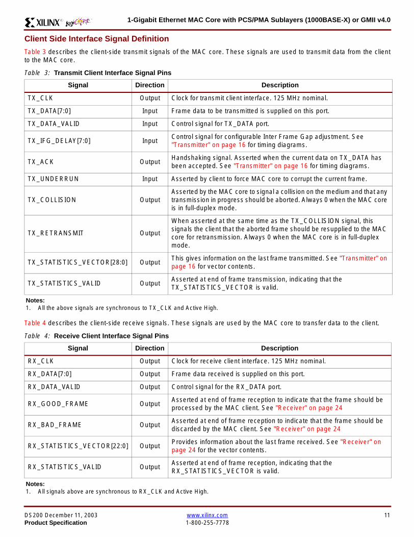
1-Gigabit Ethernet MAC Core with PCSPMA Sublayers (1000BASE-X) or GMII v40R
Client Side Interface Signal Definition
Table 3 describes the client-side transmit signals of the MAC core These signals are used to transmit data from the clientto the MAC core
Table 4 describes the client-side receive signals These signals are used by the MAC core to transfer data to the client
Table 3 Transmit Client Interface Signal Pins
Signal Direction Description
TX_CLK Output Clock for transmit client interface 125 MHz nominal
TX_DATA[70] Input Frame data to be transmitted is supplied on this port
TX_DATA_VALID Input Control signal for TX_DATA port
TX_IFG_DELAY[70] InputControl signal for configurable Inter Frame Gap adjustment SeeTransmitter on page 16 for timing diagrams
TX_ACK OutputHandshaking signal Asserted when the current data on TX_DATA hasbeen accepted See Transmitter on page 16 for timing diagrams
TX_UNDERRUN Input Asserted by client to force MAC core to corrupt the current frame
TX_COLLISION OutputAsserted by the MAC core to signal a collision on the medium and that anytransmission in progress should be aborted Always 0 when the MAC coreis in full-duplex mode
TX_RETRANSMIT Output
When asserted at the same time as the TX_COLLISION signal thissignals the client that the aborted frame should be resupplied to the MACcore for retransmission Always 0 when the MAC core is in full-duplexmode
TX_STATISTICS_VECTOR[280] OutputThis gives information on the last frame transmitted See Transmitter onpage 16 for vector contents
TX_STATISTICS_VALID OutputAsserted at end of frame transmission indicating that theTX_STATISTICS_VECTOR is valid
Notes1 All the above signals are synchronous to TX_CLK and Active High
Table 4 Receive Client Interface Signal Pins
Signal Direction Description
RX_CLK Output Clock for receive client interface 125 MHz nominal
RX_DATA[70] Output Frame data received is supplied on this port
RX_DATA_VALID Output Control signal for the RX_DATA port
RX_GOOD_FRAME OutputAsserted at end of frame reception to indicate that the frame should beprocessed by the MAC client See Receiver on page 24
RX_BAD_FRAME OutputAsserted at end of frame reception to indicate that the frame should bediscarded by the MAC client See Receiver on page 24
RX_STATISTICS_VECTOR[220] OutputProvides information about the last frame received See Receiver onpage 24 for the vector contents
RX_STATISTICS_VALID OutputAsserted at end of frame reception indicating that theRX_STATISTICS_VECTOR is valid
Notes1 All signals above are synchronous to RX_CLK and Active High
DS200 December 11 2003 wwwxilinxcom 11Product Specification 1-800-255-7778
1-Gigabit Ethernet MAC Core with PCSPMA Sublayers (1000BASE-X) or GMII v40 R
Table 5 describes the signals used by the client to request a flow control action from the transmit engine Flow control framesreceived by the MAC are automatically handled (if the MAC is configured to do so)
Table 6 describes the optional signals used by the client to access the management features of the MAC core includingconfiguration status statistics and MDIO access
Table 7 describes the alternative to the optional Management Interface signals This describes the Configuration Vectorwhich uses direct inputs to the core to replace the functionality of the MAC Configuration bits when the ManagementInterface is not used
Notes1 All bits of CONFIGURATION_VECTOR are registered on input but may be treated as asynchronous inputs
Table 5 Flow Control Interface Signal Pinout
Signal Direction Description
PAUSE_REQ InputPause request sends a pause frame down the link See Transmitting a PAUSE ControlFrame on page 29
PAUSE_VAL[150] Input Pause value inserted into the parameter field of the transmitted pause frame
Notes1 These signals are synchronous to TX_CLK and are Active High
Table 6 Optional Management Interface Signal Pinout (management_interface=true)
Signal Direction Description
HOST_CLK InputClock for management interface See Optional Management Interface(management_interface=true) on page 30 for the signal frequency range
HOST_OPCODE[10] InputDefines operation to be performed over MDIO interface Bit 1 is also used inconfiguration register access See Configuration Registers on page 30
HOST_ADDR[90] Input Address of register to be accessed
HOST_WR_DATA[310] Input Data to write to register
HOST_RD_DATA[310] Output Data read from register
HOST_MIIM_SEL InputWhen asserted the MDIO interface is accessed When disasserted the MACinternal configuration or statistical counter registers are accessed
HOST_REQ InputUsed to signal a transaction on the MDIO interface or to read from the statisticregisters See Optional Management Interface (management_interface=true) onpage 30
HOST_MIIM_RDY OutputWhen high the MDIO interface has completed any pending transaction and isready for a new transaction
Notes1 All signals above are synchronous to HOST_CLK and are Active High
Table 7 Alternative to the Optional Management Interface Configuration Vector Signal Pinout(management_interface=false)
Signal Direction Description
CONFIGURATION_VECTOR[630]
Input The Configuration Vector is used to replace the functionality of theMAC Configuration Registers when the Management Interface is notused See Optional Configuration Vector (management_interface =false) on page 38
12 wwwxilinxcom DS200 December 11 20031-800-255-7778 Product Specification
1-Gigabit Ethernet MAC Core with PCSPMA Sublayers (1000BASE-X) or GMII v40R
Table 8 describes the reset signal
Physical Interface Signal Definition
Table 9 describes the MDIO (MII Management) interface signals of the MAC core These signals are typically connected tothe MDIO port of a PHY device either off-chip or an SoC-integrated core The MDIO format is defined in IEEE8023 clause22
Table 10 describes the optional GMII signals of the MAC core These are typically attached to a PHY module either off-chipor internally integrated The GMII is defined in IEEE8023 clause 35
Table 8 Reset Signal
Signal Direction Description
RESET Input Asynchronous reset for entire core See Reset circuit on page 42 for moreinformation on the reset circuit
Table 9 MDIO Interface Signal Pinout
Signal Direction Description
MDC OutputManagement Clock derived from HOST_CLK on the basis of supplied configuration datawhen the optional Management Interface is used See Optional Management Interface(management_interface=true) on page 30
MDC_IN InputWhen the Optional Management Interface is not used access to the optional PhysicalCoding Sublayer (PCS) must be provided by an external MDIO Controller In this situationthe Management Clock is an input to the core
MDIO_IN Input Input data signal for communication with PHY configuration and status Tie high if unused
MDIO_OUT Output Output data signal for communication with PHY configuration and status
MDIO_TRI OutputTristate control for MDIO signals 0 signals that the value on MDIO_OUT should be
asserted onto the MDIO bus
Table 10 Optional GMII Interface Signal Pinout (physical_interface=gmii)
Signal Direction Description
GTX_CLK InputClock signal at 125 MHz Other transmit clocks are derived from this clock as illustratedin Figure 28 Tolerance must be within IEEE 8023-2002 specification
GMII_TXD[70] Output Transmit data to PHY
GMII_TX_EN Output Data Enable control signal to PHY
GMII_TX_ER Output Error control signal to PHY
GMII_TX_CLK Output Clock out to PHY
GMII_CRS Input Control signal from PHY
GMII_COL Input Control signal from PHY
GMII_RX_CLK Input Recovered clock from received data stream by PHY
GMII_RXD[70] Input Received data from PHY
GMII_RX_DV Input Data Valid control signal from PHY
GMII_RX_ER Input Error control signal from PHY
DS200 December 11 2003 wwwxilinxcom 13Product Specification 1-800-255-7778
1-Gigabit Ethernet MAC Core with PCSPMA Sublayers (1000BASE-X) or GMII v40 R
Table 11 describes the TBI (Ten-Bit interface) signals of the MAC core These are typically attached to a PMA SERDESmodule These signals optionally replace the GMII signals described in Table 10 to extend the functionality of the core toinclude the PCS for 1000BASE-X The TBI is defined in IEEE8023 clause 36
Notes
PHYAD and SIGNAL_DETECT are asynchronous inputs SIGNAL_DETECT is Active High
Table 11 Optional TBI Interface Signal Pinout (physical_interface=tbi)
Signal Direction Description
GTX_CLK InputClock signal at 125 MHz Other transmit clocks will be derived from this clock asillustrated in Figure 32 Tolerance must be within IEEE 8023-2002 specification
TX_CODE_GROUP[90] Output 10-bit parallel transmit data to PMA Sublayer (SERDES)
PMA_TX_CLK Output Transmit clock signal to PMA Sublayer (SERDES) at 125MHz
LOC_REF OutputCauses the PMA sublayer clock recovery unit to lock to PMA_TX_CLK Thissignal is tied to Ground
EWRAP Output
This signal is set from the PCS Control Register 0 bit 14 (loopback) See PCSManaged Register Block (physical_interface = tbi or phy) on page 49 Whenhigh this instructs the PMA sublayer to electrically loop the transmitter data to thereceiver
RX_CODE_GROUP0[90] Input10-bit parallel received data from PMA Sublayer (SERDES) synchronous toPMA_RX_CLK0
RX_CODE_GROUP1[90] Input10-bit parallel received data from PMA Sublayer (SERDES) synchronous toPMA_RX_CLK1
PMA_RX_CLK0 Input Received clock signal from PMA Sublayer (SERDES) at 625MHz
PMA_RX_CLK1 InputReceived clock signal from PMA Sublayer (SERDES) at 625MHz This is 180degrees out of phase with PMA_RX_CLK0
EN_CDET OutputEnables the PMA Sublayer to perform comma realignment driven from the PCSstate machine during the Loss-Of-Sync state
PHYAD[40] Input PHY address of MDIO register set for the PCS
SIGNAL_DETECT Input
Signal direct from PMD sublayer indicating the presence of light detected at theoptical receiver If driven high this indicates that the optical receiver has detectedlight If driven low this indicates the absence of light
If unused tie high to enable the operation the core
14 wwwxilinxcom DS200 December 11 20031-800-255-7778 Product Specification
1-Gigabit Ethernet MAC Core with PCSPMA Sublayers (1000BASE-X) or GMII v40R
Table 12 describes the interface signals for the Optional PCSPMA sublayer of the MAC core These signals optionallyreplace the GMII signals described in Table 10 to extend the functionality of the core to include the PCS and PMA sublayersfor 1000BASE-X This option uses the Virtex-II Pro Rocket IO functionality which is integrated into the core The PMAsublayer for 1000BASE-X is defined in IEEE8023 clause 36
Notes1 PHYAD and SIGNAL_DETECT are asynchronous inputs SIGNAL_DETECT is Active High
Table 12 Optional PCSPMA sublayer Interface Signal Pinout (physical_interface=phy)
Signal Direction Description
REFCLK InputHigh Quality Reference clock for Multi-Gigabit Transceivers (625 MHz) See Rocket IOUser Guide
REFCLK2 Input Alternative High Quality Reference clock for Multi-Gigabit Transceivers (625 MHz) SeeRocket IO User Guide
BREFCLK Input Alternative High Quality Reference clock for Multi-Gigabit Transceivers (625 MHz)This optionally replaces REFCLK See Rocket IO User Guide
BREFCLK2 Input Alternative High Quality Reference clock for Multi-Gigabit Transceivers (625 MHz)This optionally replaces REFCLK2 See Rocket IO User Guide
REFCLKSEL Input Selects between either (B)REFCLK or (B)REFCLK2 as the input clock source to theMGT See Rocket IO User Guide
USERCLK InputClock signal at 625 MHz This is connected to the TXUSRCLK and RXUSRCLK portsof the Rocket IO MGT This may be derived from (B)REFCLK using a DCM asillustrated in Figure 35
USERCLK2 InputClock signal at 125 MHz This is connected to the TXUSRCLK2 and RXUSRCLK2 portsof the Rocket IO MGT This may be derived from (B)REFCLK using a DCM asillustrated in Figure 35
DCM_LOCKED InputIf a DCM is used to derive USRCLK and USRCLK2 as illustrated in Figure 35 theLOCKED port of the DCM must be connected to the DCM_LOCKED port of the coreThe core will hold itrsquos Rocket IO MGT in reset until DCM_LOCKED is driven to logic 1
TXPTXN OutputDifferential pair for serial transmission from PMA to PMD The clock is embedded in thedata stream
RXPRXN InputDifferential pair for serial reception from PMD to PMA The clock is extracted from thedata stream
PHYAD[40] Input PHY address of MDIO register set for the PCS
SIGNAL_DETECT Input
Signal direct from PMD sublayer indicating the presence of light detected at the opticalreceiver If driven high this indicates that the optical receiver has detected light If drivenlow this indicates the absence of light
If unused tie high to enable the operation the core
DS200 December 11 2003 wwwxilinxcom 15Product Specification 1-800-255-7778
1-Gigabit Ethernet MAC Core with PCSPMA Sublayers (1000BASE-X) or GMII v40 R
Functional Description
Client InterfaceThe client interface is designed for maximum flexibility inmatching to a client switching fabric or network processorinterface
The data pathway is 8 bits wide in both the transmit andreceive directions with each pathway synchronous to theTX_CLK and RX_CLK respectively for completely indepen-dent full duplex operation
Transmitter
Normal Frame Transmission
The timing of a normal outbound frame transfer can be seenin Figure 9 When the client wants to transmit a frame itplaces the first column of data onto the TX_DATA port andasserts a ldquo1rdquo onto TX_DATA_VALID
When the MAC core has read this first byte of data it willassert the TX_ACK signal on the next and subsequent ris-ing clock edges the client must provide the remainder ofthe data for the frame
The end of frame is signalled to the MAC core by takingTX_DATA_VALID Low
In-Band Parameter Encoding
For maximum flexibility in switching applications the Ether-net frame parameters (destination address sourceaddress lengthtype and optionally FCS) are encodedwithin the same data stream that the frame payload is trans-ferred upon rather than on separate ports This is illustratedin the timing diagrams Definitions of the abbreviations usedin the timing diagrams are described in Table 13
Figure 9 Normal Frame Transmission Across Client Interface
Table 13 Abbreviations Used in Timing Diagrams
Abbreviation Definition
DA Destination Address 6 bytes
SA Source Address 6 bytes
LT LengthType Field 2 bytes
FCS Frame Check Sequence 4 bytes
TX_CLK
TX_DATA[70]
TX_DATA_VALID
TX_ACK
TX_UNDERRUN
DA SA DATALT
TX_COLLISION
TX_RETRANSMIT
xip2133
16 wwwxilinxcom DS200 December 11 20031-800-255-7778 Product Specification
1-Gigabit Ethernet MAC Core with PCSPMA Sublayers (1000BASE-X) or GMII v40R
Padding
When fewer than 46 bytes of data are supplied by the clientto the MAC core the transmitter module will add padding upto the minimum frame length The exception to this is whenthe MAC core is configured for client-passed FCS in thiscase the client must also supply the padding to maintain theminimum frame length (see Client-Supplied FCS Passing)
Client-Supplied FCS Passing
If the MAC core is configured to have the FCS field passedin by the client (see Configuration Registers on page 30)the transmission timing is as depicted in Figure 10 In thiscase it is the responsibility of the client to ensure that theframe meets the Ethernet minimum frame length require-ments the MAC core will not perform any padding of thepayload
Figure 10 Frame Transmission with Client-supplied FCS
TX_CLK
TX_DATA[70]
TX_DATA_VALID
TX_ACK
TX_UNDERRUN
DA SA DATA FCSLT
TX_COLLISION
TX_RETRANSMIT
xip2134
DS200 December 11 2003 wwwxilinxcom 17Product Specification 1-800-255-7778
1-Gigabit Ethernet MAC Core with PCSPMA Sublayers (1000BASE-X) or GMII v40 R
Client Underrun
The timing of an aborted transfer can be seen in Figure 11This may happen for instance if a FIFO connected to theclient interface empties before a frame is completed Whenthe client asserts TX_UNDERRUN during a frame transmis-sion the MAC core will insert an error code to corrupt the
current frame and then fall back to idle transmission It isthe responsibility of the client to re-queue the aborted framefor transmission
When an underrun occurs TX_DATA_VALID may beasserted on the clock cycle after the TX_UNDERRUNassertion to request a new transmission
Figure 11 Frame Transmission with Underrun
TX_CLK
TX_DATA[70]
TX_DATA_VALID
TX_ACK
TX_UNDERRUN
DA SA DATALT
TX_COLLISION
TX_RETRANSMIT
xip2135
18 wwwxilinxcom DS200 December 11 20031-800-255-7778 Product Specification
1-Gigabit Ethernet MAC Core with PCSPMA Sublayers (1000BASE-X) or GMII v40R
Back-to-Back Transfers
Figure 12 shows the case where the MAC client is immedi-ately ready to transmit a second frame of data followingcompletion of its first frame In this figure the end of the firstframe is shown on the left On the clock cycle immediatelyfollowing the final byte of the first frame TX_DATA_VALIDis taken low by the client and is taken high one clock cyclelater to indicate that the first byte of the destination addressof the second frame is on TX_DATA awaiting transmission
When the MAC core is ready to accept data TX_ACK isasserted and the transmission continues in the same man-ner as in the case of the single frame The MAC core willdefer the assertion of TX_ACK appropriately to comply withinter-packet gap requirements and flow control requests
If the MAC core is operating in half-duplex mode the timingshown in Figure 12 is required to take advantage of framebursting the MAC core is only guaranteed to retain controlof the medium if the TX_DATA_VALID signal is low for a sin-gle clock cycle For more information on frame bursting seeIEEE 8023-2002
Figure 12 Back to Back Frame Transmission
TX_CLK
TX_DATA[70]
TX_DATA_VALID
TX_ACK
TX_UNDERRUN
TX_COLLISION
TX_RETRANSMIT
xip2136
DS200 December 11 2003 wwwxilinxcom 19Product Specification 1-800-255-7778
1-Gigabit Ethernet MAC Core with PCSPMA Sublayers (1000BASE-X) or GMII v40 R
VLAN Tagged Frames
Transmission of a VLAN tagged frame (if enabled) can beseen in Figure 13 Note that the handshaking signalsacross the interface do not change however the VLANtype tag 81-00 must be supplied by the client to signify that
the frame is VLAN tagged The client also supplies the twobytes of Tag Control Information V1 and V2 at the appro-priate times in the data stream More information on thecontents of these two bytes can be found in IEEE8023-2002
Maximum Permitted Frame Length
The maximum legal length of a frame specified in IEEE8023-2002 is 1518 bytes for non-VLAN tagged framesVLAN tagged frames may be extended to 1522 bytesWhen jumbo frame handling is disabled and the clientattempts to transmit a frame which exceeds the maximumlegal length the MAC core will insert an error code to cor-
rupt the current frame and the frame will be truncated to themaximum legal length When jumbo frame handling isenabled frames which are longer than the legal maximumare transmitted error-free
For more information on enabling and disabling jumboframe handling see Configuration Registers on page 30
Figure 13 Transmission of a VLAN Tagged Frame
TX_CLK
TX_DATA[70]
TX_DATA_VALID
TX_ACK
TX_UNDERRUN
DA SA DATALTVLANtag
81 00V1V2
TX_COLLISION
TX_RETRANSMIT
xip2137
20 wwwxilinxcom DS200 December 11 20031-800-255-7778 Product Specification
1-Gigabit Ethernet MAC Core with PCSPMA Sublayers (1000BASE-X) or GMII v40R
Frame Collisions - Half Duplex Operation Only
In half duplex Ethernet operation collisions will occur on themedium as a matter of course this is how the arbitrationalgorithm is fulfilled In case of a collision the MAC core sig-nals to the client that data may need to be resupplied as fol-lows
If there is a collision the TX_COLLISION signal will be setto ldquo1rdquo by the MAC core If a frame is in progress the clientmust abort the transfer and take TX_DATA_VALID to ldquo0rdquo
If the TX_RETRANSMIT signal is ldquo1rdquo in the same clockcycle that the TX_COLLISION signal is ldquo1rdquo the client must
resubmit the previous frame to the MAC core for retrans-mission TX_DATA_VALID must be asserted to the MACcore within 8 clock cycles of the TX_COLLISION signal inorder to meet Ethernet timing requirements See Figure 14
If the TX_RETRANSMIT signal is ldquo0rdquo in the same clockcycle that the TX_COLLISION signal is ldquo1rdquo the number ofretries for this frame has exceeded the Ethernet specifica-tion and the frame should be dropped by the client The cli-ent can then make any new frame available to the MAC fortransmission without timing restriction See Figure 15
Figure 14 Collision Handling - Frame retransmission required
Figure 15 Collision Handling - No frame retransmission required
TX_CLK
TX_DATA[70]
TX_DATA_VALID
TX_ACK
TX_UNDERRUN
TX_COLLISION
TX_RETRANSMIT
8 clocks max
xip2138
TX_CLK
TX_DATA[70]
TX_DATA_VALID
TX_ACK
TX_UNDERRUN
TX_COLLISION
TX_RETRANSMIT
xip2139
DS200 December 11 2003 wwwxilinxcom 21Product Specification 1-800-255-7778
1-Gigabit Ethernet MAC Core with PCSPMA Sublayers (1000BASE-X) or GMII v40 R
Interframe Gap Adjustment
The user can elect to vary the length of the inter fame gapIf this function is selected (via a configuration bit in thetransmitter control register see Configuration Registerson page 30) then the MAC will exert back pressure to delaythe transmission of the next frame until the requested num-ber of Idle cycles has elapsed The number of Idle cycles iscontrolled by the value on the TX_IFG_DELAY port at thestart of frame transmission Figure 16 shows the MAC oper-ating in this mode
Reducing the Inter fame gap to below the IEEE 8023-2002minimum of 12 Idles is supported in Full Duplex onlydesigns and will transmit an absolute minimum of 4 Idles Ifthe Interframe gap adjustment is reduced below 12 Idlesthen the accuracy of the Optional Statistical Gathering(statistics_gathering=true) Counters cannot be guaranteedHowever the TX_STATISTIC_VECTOR andRX_STATISTIC_VECTOR will always remain correct
Transmitter Statistics Vector
The statistics for the frame transmitted are contained withinthe TX_STATISTICS_VECTOR The vector is driven syn-chronously by the transmitter clock TX_CLK followingframe transmission The bit field definition for the Vector isdefined in Table 14
All bit fields with the exception of BYTE_VALID are validonly when the TX_STATISTICS_VALID is asserted This isillustrated in Figure 17 BYTE_VALID is significant on everyTX_CLK cycle
TX_STATISTICS_VECTOR bits 25 down to 17 inclusive arefor half duplex only and will be set to logic 0 when operatingin full duplex mode
Figure 16 Interframe Gap Adjustment
TX_CLK
TX_DATA[70]
TX_DATA_VALID
TX_ACK
DA SA
TX_IFG_DELAY
IFG ADJUST VALUE
0x0D
13 Idles inserted
DA
Next IFG ADJUST VALUE
xip2140
Figure 17 Transmitter Statistics Vector Timing
TX_CLK
TX_STATISTICS_VECTOR[280]
TX_STATISTICS_VALID
xip2141
22 wwwxilinxcom DS200 December 11 20031-800-255-7778 Product Specification
1-Gigabit Ethernet MAC Core with PCSPMA Sublayers (1000BASE-X) or GMII v40R
Table 14 Bit Definition for the Transmitter Statistics Vector
TX_STATISTICS_VECTOR Name Description
28 PAUSE_FRAME_TRANSMITTEDAsserted if the previous frame was a pause framethat the MAC itself initiated in response to aPAUSE_REQ assertion
27 BYTE_VALID
Asserted if a MAC frame byte (DA to FCS inclusive)is in the process of being transmitted This is valid onevery clock cycle
Do not use this as an enable signal to indicate thatdata is present on GMII_TXD[70]
26 Reserved Returns logic 0
25 down to 22 TX_ATTEMPTS[30]
The number of attempts that have been made totransmit the previous frame This is a 4-bit number0 should be interpreted as 1 attempt 1 as 2attempts up until 15 as 16 attempts
21 Reserved Returns logic 0
20 EXCESSIVE_COLLISIONAsserted if a collision has been detected on each ofthe last 16 attempts to transmit the previous frame
19 LATE_COLLISIONAsserted if a late collision occurred during frametransmission
18 EXCESSIVE_DEFERRALAsserted if the previous frame was deferred for anexcessive amount of time as defined by the constantldquomaxDeferTimerdquo in IEEE 8023-2002
17 TX_DEFERRED Asserted if transmission of the frame was deferred
16 VLAN_FRAMEAsserted if the previous frame contained a VLANidentifier in the LengthType field when transmitterVLAN operation is enabled
15 down to 5 FRAME_LENGTH_COUNTThe length of the previous frame in number of bytesThe count will stick at 2047 for any Jumbo frameslarger than this value
4 CONTROL_FRAMEAsserted if the previous frame had the special MACControl Type code 88-08 in the LengthType field
3 UNDERRUN_FRAMEAsserted if the previous frame contained anunderrun error
2 MULTICAST_FRAMEAsserted if the previous frame contained a multicastaddress in the Destination Address field
1 BROADCAST_FRAMEAsserted if the previous frame contained abroadcast address in the Destination Address field
0 SUCCESSFUL_FRAMEAsserted if the previous frame was transmittedwithout error
DS200 December 11 2003 wwwxilinxcom 23Product Specification 1-800-255-7778
1-Gigabit Ethernet MAC Core with PCSPMA Sublayers (1000BASE-X) or GMII v40 R
Receiver
Normal Frame Reception
The timing of a normal inbound frame transfer can be seenin Figure 18 The client must be prepared to accept data atany time there is no buffering within the MAC to allow forlatency in the receive client Once frame reception begins
data is transferred on consecutive clock cycles to thereceive client until the frame is complete The MAC assertsthe RX_GOOD_FRAME signal to indicate that the framewas successfully received and that the frame should beanalyzed by the client
Frame parameters (destination address source addresslengthtype and optionally FCS) are supplied on the databus according to the timing diagram The abbreviations arethe same as those described in Table 13 on page 16
If the LengthType field in the frame has the Length interpre-tation and this indicates that the inbound frame has beenpadded to meet the Ethernet minimum frame size specifica-tion then this padding will not be passed to the client in thedata payload The exception to this is in the case whereFCS passing is enabled see Client-Supplied FCS Pass-ing on page 25
Therefore when Client-Supplied FCS passing is disabledRX_DATA_VALID = lsquo0rsquo between frames for the duration ofthe Padding field (if present) the FCS field carrier exten-sion (if present) the interframe gap following the frame andthe preamble field of the next frame When Client-Supplied
FCS passing is enabled RX_DATA_VALID = lsquo0rsquo betweenframes for the duration of carrier extension (if present) theinterframe gap and the preamble field of the followingframe
RX_GOOD_FRAME RX_BAD_FRAME timing
Although the timing diagram in Figure 18 shows theRX_GOOD_FRAME signal asserted shortly after the lastvalid data on RX_DATA this is not always the case TheRX_GOOD_FRAME or RX_BAD_FRAME signals areasserted only after all frame checks are completed This isafter the FCS field has been received (and after reception ofcarrier extension if present)
Therefore either RX_GOOD_FRAME or RX_BAD_FRAMEis asserted following frame reception at the beginning of theinterframe gap
Figure 18 Normal Frame Reception
RX_CLK
RX_DATA[70]
RX_DATA_VALID
RX_GOOD_FRAME
RX_BAD_FRAME
DA SA DATALT
xip2142
24 wwwxilinxcom DS200 December 11 20031-800-255-7778 Product Specification
1-Gigabit Ethernet MAC Core with PCSPMA Sublayers (1000BASE-X) or GMII v40R
Frame Reception with Errors
The case of an unsuccessful frame reception (for examplea fragment frame or a frame with an incorrect FCS) can beseen in Figure 19 In this case the RX_BAD_FRAME signal
is asserted to the client at the end of the frame It is then theresponsibility of the client to drop the data already trans-ferred for this frame
Figure 19 Frame Reception with Error
Client-Supplied FCS Passing
If the MAC core is configured to pass the FCS field to the cli-ent (see Configuration Registers on page 30) then this ishandled as shown in Figure 20
In this case any padding inserted into the frame to meetEthernet minimum frame length specifications will be leftintact and passed to the client
Note that even though the FCS is passed up to the client itis also verified by the MAC core and RX_BAD_FRAMEasserted if the FCS check fails
RX_CLK
RX_DATA[70]
RX_DATA_VALID
RX_GOOD_FRAME
RX_BAD_FRAME
DA SA DATALT
xip2144
Figure 20 Frame Reception with In-Band FCS Field
RX_CLK
RX_DATA[70]
RX_DATA_VALID
RX_GOOD_FRAME
RX_BAD_FRAME
DA SA DATALT FCS
xip2145
DS200 December 11 2003 wwwxilinxcom 25Product Specification 1-800-255-7778
1-Gigabit Ethernet MAC Core with PCSPMA Sublayers (1000BASE-X) or GMII v40 R
VLAN Tagged Frames
The reception of a VLAN tagged frame (if enabled) can beseen in Figure 21 The VLAN frame is passed to the clientso that the frame may be identified as VLAN tagged this is
followed by the Tag Control Information bytes V1 and V2More information on the interpretation of these bytes maybe found in IEEE 8023-2002 standard
Maximum Permitted Frame Length
The maximum legal length of a frame specified in IEEE8023-2002 is 1518 bytes for non-VLAN tagged framesVLAN tagged frames may be extended to 1522 bytesWhen jumbo frame handling is disabled and the corereceives a frame which exceeds the maximum legal lengthRX_BAD_FRAME will be asserted When jumbo framehandling is enabled frames which are longer than the legalmaximum are received in the same way as shorter frames
For more information on enabling and disabling jumboframe handling see Configuration Registers on page 30
LengthType Field Error Checks
Enabled
Default operation is with the LengthType error checkingenabled (see Receiver Configuration Word 1 on page 31)In this mode the following checks are made on all framesreceived If either of these checks fail then the frame ismarked as BAD
bull A value in the LengthType field that is greater than orequal to decimal 46 but less than decimal 1536 (aLength interpretation) is checked against the actualdata length received
bull A value in the LengthType field that is less thandecimal 46 is checked to see that the data field ispadded to exactly 46 bytes (so that the resultant frameis minimum frame size 64 bytes total in length)
Furthermore if Padding is indicated (the LengthType fieldis less than decimal 46) and Client-Supplied FCS Passing isdisabled then the Length value in the LengthType field willbe used to deassert RX_DATA_VALID after the indicatednumber of data bytes so that the Padding bytes areremoved from the frame
Disabled
When the LengthType error checking is disabled (seeReceiver Configuration Word 1 on page 31) theLengthType error checks described above are not per-formed A frame containing only these errors will be markedas GOOD
Furthermore if Padding is indicated and Client-SuppliedFCS Passing is disabled then a Length Value in theLengthType field will not be used to deassertRX_DATA_VALID Instead RX_DATA_VALID will be deas-serted before the start of the FCS field in this way any pad-ding will not be removed from the frame
Figure 21 Reception of a VLAN Tagged Frame
RX_CLK
RX_DATA[70]
RX_DATA_VALID
RX_GOOD_FRAME
RX_BAD_FRAME
DA SA DATALT
81 00 V1 V2
VLANtag
xip2146
26 wwwxilinxcom DS200 December 11 20031-800-255-7778 Product Specification
1-Gigabit Ethernet MAC Core with PCSPMA Sublayers (1000BASE-X) or GMII v40R
Receiver Statistics Vector
The statistics for the frame received are contained withinthe RX_STATISTICS_VECTOR The vector is driven syn-chronously by the receiver clock RX_CLK following framereception The bit field definition for the Vector is defined inTable 15
All bit fields with the exception of BYTE_VALID are validonly when the RX_STATISTICS_VALID is asserted This isillustrated in Figure 22 BYTE_VALID is significant on everyRX_CLK cycle
Figure 22 Receiver Statistics Vector Timing
RX_CLK
RX_STATISTICS_VECTOR[220]
RX_STATISTICS_VALID
xip2147
Table 15 Bit Definition for the Receiver Statistics Vector
RX_STATISTICS_VECTOR Name Description
22LENGTHTYPE Out ofRange
Asserted if the lengthtype field contained a length valuethat did not match the number of MAC client data bytesreceived Also high if the lengthtype field indicated thatthe frame contained padding but the number of MAC cli-ent data bytes received was not equal to 64 bytes (min-imum frame size)
The exception to the above is when the LengthTypeField Error Checks are disabled in which case this bitwill not be asserted
21 BAD_OPCODE
Asserted if the previous frame was error-free andcontained the special Control Frame identifier in theLengthType field but contained an opcode that isunsupported by the MAC (Any Opcode other thanPAUSE)
20 FLOW_CONTROL_FRAME
Asserted if the previous frame was error-freecontained the special Control Frame identifier in theLengthType field contained a Destination Addressthat matched either the MAC Control MulticastAddress or the configured source address of the MACcontained the supported PAUSE opcode and wasacted upon by the MAC
19 BYTE_VALID
Asserted if a MAC frame byte (DA to FCS inclusive) isin the process of being received This is valid on everyclock cycle
Do not use this as an enable signal to indicate thatdata is present on RX_DATA[70]
18 VLAN_FRAMEAsserted if the previous frame contained a VLANidentifier in the LengthType field when receiver VLANoperation is enabled
DS200 December 11 2003 wwwxilinxcom 27Product Specification 1-800-255-7778
1-Gigabit Ethernet MAC Core with PCSPMA Sublayers (1000BASE-X) or GMII v40 R
17 OUT_OF_BOUNDS
Asserted if the previous frame exceeded the specifiedIEEE8023-2002 maximum legal length (seeMaximum Permitted Frame Length on page 26) Thisis only valid if Jumbo frames are disabled
16 CONTROL_FRAMEAsserted if the previous frame contained the specialControl Frame identifier in the LengthType field
15 down to 5 FRAME_LENGTH_COUNTThe length of the previous frame in number of bytesThe count will stick at 2047 for any Jumbo frameslarger than this value
4 MULTICAST_FRAMEAsserted if the previous frame contained a multicastaddress in the Destination Address field
3 BROADCAST_FRAMEAsserted if the previous frame contained the broadcastaddress in the Destination Address field
2 FCS_ERRORAsserted if the previous frame received had anincorrect FCS value or the MAC detected error codesduring frame reception
1 BAD_FRAME1 Asserted if the previous frame received containederrors
0 GOOD_FRAME1 Asserted if the previous frame received was error-free
1 If the LengthType Field Error Checks are disabled then a frame which contains this type of error will be marked as a GOOD_FRAMEproviding no additional errors were detected
Table 15 Bit Definition for the Receiver Statistics Vector
RX_STATISTICS_VECTOR Name Description
28 wwwxilinxcom DS200 December 11 20031-800-255-7778 Product Specification
1-Gigabit Ethernet MAC Core with PCSPMA Sublayers (1000BASE-X) or GMII v40R
Flow ControlThe flow control block is designed to Clause 31 of the IEEE8023-2002 standard The MAC may be configured to sendpause frames and to act upon their reception These twobehaviors can be configured asymmetrically see Configu-ration Registers on page 30
Transmitting a PAUSE Control Frame
The client initiates a flow control frame by assertingPAUSE_REQ while the pause value is on the PAUSE_VALbus These signals are synchronous to TX_CLK The timingof this can be seen in Figure 23
If the MAC core is configured to support transmit flow con-trol this action causes the core to transmit a PAUSE controlframe on the link with the PAUSE parameter set to thevalue on PAUSE_VAL in the cycle when PAUSE_REQ wasasserted This will not disrupt any frame transmission inprogress but will take priority over any pending frame trans-
mission This frame will be transmitted even if the transmit-ter is in the paused state itself
Receiving a Pause Control Frame
When an error-free frame is received by the MAC core thefollowing checks are made
1 The Destination Address field is matched against theMAC Control Multicast address or the configuredSource Address for the MAC (see ConfigurationRegisters on page 30)
2 The LengthType field is matched against the MACControl Type code
3 The opcode field contents are matched against thePAUSE opcode if check 2 is true
If any of the above checks are false or the MAC Flow Con-trol logic for the receiver is disabled the frame is ignored bythe Flow Control logic and passed up to the client
If the frame passes all of the above checks is of minimumlegal size and the MAC Flow Control logic for the receiver isenabled the pause value parameter in the frame is thenused to inhibit transmitter operation for the time defined inthe IEEE8023-2002 specification This inhibit is imple-mented using the same back pressure scheme shown inFigure 12 Because the received pause frame has beenacted upon it is passed to the client with RX_BAD_FRAMEasserted to indicate to the client that it should be dropped
Reception of any frame for which check 2 is true and whichis not of legal minimum length is considered an invalid Con-trol frame This will be ignored by the Flow Control logic andpassed to the client with RX_BAD_FRAME asserted
Figure 23 Pause Request Timing
TX_CLK
PAUSE_VAL[150]
PAUSE_REQ
xip2148
DS200 December 11 2003 wwwxilinxcom 29Product Specification 1-800-255-7778
1-Gigabit Ethernet MAC Core with PCSPMA Sublayers (1000BASE-X) or GMII v40 R
Optional Management Interface(management_interface=true)The management interface is a processor-independentinterface with standard address data and control signals Itmay be used as is or a wrapper may be applied (not sup-plied) to interface to common bus architectures
This interface is used for
bull Configuration of the MAC core
bull Access to optional statistics counters for use by higherlayers for example SNMP
bull access through the MDIO interface to the managementregisters located in the PHY attached to the MAC core
The management interface is accessed differently depend-ing on the type of transaction a truth table showing whichaccess method is required for each transaction type isshown in Table 16 These access methods are described inthe following sections
HOST_CLK Frequency
The management interface clock HOST_CLK is used toderive the MDIO clock MDC and is therefore subject tosome frequency restrictions This HOST_CLK must be
ge 10 MHz
le 100 MHz
Configuring the MAC core to derive the MDC signal fromthis clock is detailed in MDIO Interface on page 37
Configuration Registers
After power up or reset the client may reconfigure the coreparameters from their defaults such as flow control supportConfiguration changes can be written at any time Both thereceiver and transmitter logic will only respond to configura-tion changes during Inter Frame Gaps The exceptions tothis are the configurable resets which take effect immedi-ately
Configuration of the MAC core is performed through a reg-ister bank accessed through the management interfaceThe configuration registers available in the core are detailedin Table 17 As can be seen the address has some implicitdonrsquot care bits any access to an address in the rangesshown will perform a 32-bit read or write from the same con-figuration word
Table 16 Management Interface Transaction Types
Transaction HOST_MIIM_SEL HOST_ADDR[9]
Configuration 0 1
Statistics 0 0
MIIM access 1 X
Table 17 Configuration Registers
Address Description
0x200-0x23F Receiver Configuration (Word 0)
0x240-0x27F Receiver Configuration (Word 1)
0x280-0x2BF Transmitter Configuration
0x2C0-0x2FF Flow Control Configuration
0x300-0x33F Reserved
0x340-0x37F Management Configuration
30 wwwxilinxcom DS200 December 11 20031-800-255-7778 Product Specification
1-Gigabit Ethernet MAC Core with PCSPMA Sublayers (1000BASE-X) or GMII v40R
The register contents for the two receiver configuration words can be seen in Table 18 and Table 19
Notes1 In changing the receiverrsquos mode from Half Duplex to Full Duplex there is a period of time of up to 24 us following the mode change
when no new receiver statistics can be stored in the optional Statistical Counters
Table 18 Receiver Configuration Word 0
Bit Default Value Description
31-0 All 0rsquos
Pause frame MAC Source Address[310] This address is used by the MAC tomatch against the Destination Address of any incoming flow control frames It isalso used by the flow control block as the Source Address (SA) for any outboundflow control frames
The address is ordered so the first byte transmittedreceived is the lowestpositioned byte in the register for example a MAC address ofAA-BB-CC-DD-EE-FF would be stored in Address[470] as 0xFFEEDDCCBBAA
Table 19 Receiver Configuration Word 1
Bit Default Value Description
15-0 All 0rsquos Pause frame MAC Source Address[4732] See description in Table 18
24-16 NA Reserved
25 0
LengthType Error Check Disable When this bit is set to ldquo1rdquo the core will notperform the LengthType field error checks as described in LengthType FieldError Checks on page 26 When this bit is set to ldquo0rdquo the LengthType field checkswill be performed this is normal operation
26 0Half Duplex If ldquo1rdquo the receiver will operate in half duplex mode If ldquo0rdquo the receiverwill operate in full duplex mode Has no effect if XCO parameterhalf_duplex_capable = false
27 0VLAN Enable When this bit is set to ldquo1rdquo VLAN tagged frames will be acceptedby the receiver
28 1Receiver Enable If set to ldquo1rdquo the receiver block will be operational If set to ldquo0rdquothe block will ignore activity on the physical interface RX port
29 0
In-band FCS Enable When this bit is ldquo1rdquo the MAC receiver will pass the FCS fieldup to the client as described in Client-Supplied FCS Passing on page 25 Whenit is ldquo0rdquo the client will not be passed the FCS In both cases the FCS will beverified on the frame
30 0Jumbo Frame Enable When this bit is set to ldquo1rdquo the MAC receiver will acceptframes over the specified IEEE8023-2002 maximum legal length When this bitis ldquo0rdquo the MAC will only accept frames up to the specified maximum
31 0Reset When this bit is set to ldquo1rdquo the receiver will be reset The bit will thenautomatically revert to ldquo0rdquo Note that this reset will also set all of the receiverconfiguration registers to their default values
DS200 December 11 2003 wwwxilinxcom 31Product Specification 1-800-255-7778
1-Gigabit Ethernet MAC Core with PCSPMA Sublayers (1000BASE-X) or GMII v40 R
The register contents for the Transmitter Configuration Word are described in Table 20
Notes1 In changing the transmitterrsquos mode from Half Duplex to Full Duplex there is a period of time of up to 24 us following the mode change
when no new transmitter statistics can be stored in the optional Statistical Counters
Table 20 Transmitter Configuration Word
Bit Default Value Description
24-0 NA Reserved
25 0
Interframe Gap Adjust Enable If lsquo1rsquo the transmitter will read the value on the portTX_IFG_DELAY at the start of frame transmission and adjust the interframe gapfollowing the frame accordingly See Interframe Gap Adjustment on page 22 Ifldquo0rdquo the transmitter will output a minimum Inter Frame Gap of twelve clock cyclesas specified in IEEE8023-2002
26 0Half Duplex If lsquo1rsquo the transmitter will operate in half duplex mode If lsquo0rsquo thetransmitter will operate in full duplex mode Has no effect if XCO parameterhalf_duplex_capable = false
27 0VLAN Enable When this bit is set to 1 the transmitter will allow the transmissionof VLAN tagged frames
28 1Transmit Enable When this bit is 1 the transmitter is operational When it is 0the transmitter is disabled
29 0
In-band FCS Enable When this bit is lsquo1rsquo the MAC transmitter will expect the FCSfield to be passed in by the client as described in Client-Supplied FCS Passingon page 17 When this bit is ldquo0rdquo the MAC transmitter will append padding asrequired compute the FCS and append it to the frame
30 0
Jumbo Frame Enable When this bit is set to ldquo1rdquo the MAC transmitter will sendframes that are greater than the specified IEEE8023-2002 maximum legallength When this bit is ldquo0rdquo the MAC will only send frames up to the specifiedmaximum
31 0Reset When this bit is set to ldquo1rdquo the transmitter will be reset The bit will thenautomatically revert to ldquo0rdquo Note that this reset will also set all of the transmitterconfiguration registers to their default values
32 wwwxilinxcom DS200 December 11 20031-800-255-7778 Product Specification
1-Gigabit Ethernet MAC Core with PCSPMA Sublayers (1000BASE-X) or GMII v40R
The register contents for the Flow Control Configuration Word are described in Table 21
The register contents for the Management Configuration Word are described in Table 22
Writing to the configuration registers through the manage-ment interface is depicted in Figure 24 When accessing theconfiguration registers (ie when HOST_ADDR[9] = lsquo1rsquo andHOST_MIIM_SEL = lsquo0rsquo) the upper bit of HOST_OPCODEfunctions as an Active Low write enable signal The lowerHOST_OPCODE bit is a ldquodonrsquot carerdquo
Reading from the configuration register words is similar butthe upper HOST_OPCODE bit should be lsquo1rsquo This is shownin Figure 25 In this case the contents of the register appearon HOST_RD_DATA the HOST_CLK edge after the regis-ter address is asserted onto HOST_ADDR
Table 21 Flow Control Configuration Word
Bit Default Value Description
28-0 NA Reserved
29 1
Flow Control Enable (RX) When this bit is lsquo1rsquo received flow control frames willinhibit the transmitter operation as described in Receiving a Pause ControlFrame on page 29 When this bit is lsquo0rsquo received flow control frames will alwaysbe passed up to the client
30 1Flow Control Enable (TX) When this bit is lsquo1rsquo asserting the PAUSE_REQ signalwill send a flow control frame out from the transmitter When this bit is 0 assertingthe PAUSE_REQ signal has no effect
31 NA Reserved
Table 22 Management Configuration Word
Bits Default Value Description
4-0 All 0rsquos Clock Divide[40] See MDIO Interface on page 37
5 0MDIO Enable When this bit is 1 the MDIO interface can be used to accessattached PHY devices When this bit is 0 the MDIO interface is disabled and theMDIO signals remain inactive
31-6 NA Reserved
Figure 24 Configuration Register Write Timing
HOST_CLK
HOST_ADDR[80]
HOST_ADDR[9]
HOST_OPCODE[1]
HOST_MIIM_SEL
HOST_WR_DATA[310]xip2149
Figure 25 Configuration Register Read Timing
HOST_CLK
HOST_ADDR[80]
HOST_ADDR[9]
HOST_OPCODE[1]
HOST_MIIM_SEL
HOST_RD_DATA[310]
xip2150
DS200 December 11 2003 wwwxilinxcom 33Product Specification 1-800-255-7778
1-Gigabit Ethernet MAC Core with PCSPMA Sublayers (1000BASE-X) or GMII v40 R
Optional Statistical Gathering(statistics_gathering=true)
During operation the MAC core collects statistics on thesuccess and failure of various operations for processing by
station management entities (STA) further up the protocolstack These statistics are accessed by the host through theoptional management interface A complete list of statisticssupported is described in Table 23
Table 23 Statistics Registers
Address Name Description
0x000 Frames Received OK1 A count of error-free frames received
0x001 Frame Check Sequence Errors A count of received frames that failed the CRC check and were at least64 bytes in length
0x002 Broadcast Frames Received OK1A count of frames that were successfully received and were directed tothe broadcast group address
0x003 Multicast Frames Received OK1 A count of frames that were successfully received and were directed toa non broadcast group address
0x004 64 byte Frames Received OK1 A count of error-free frames received that were 64 bytes in length
0x005 65-127 byte Frames Received OK1A count of error-free frames received that were between 65 and 127bytes in length
0x006 128-255 byte Frames Received OK1A count of error-free frames received that were between 128 and 255bytes in length
0x007 256-511 byte Frames Received OK1A count of error-free frames received that were between 256 and 511bytes in length
0x008512-1023 byte Frames ReceivedOK1
A count of error-free frames received that were between 512 and 1023bytes in length
0x0091024-MaxFrameSize byte FramesReceived OK1
A count of error-free frames received that were between 1024 bytes andthe specified IEEE8023-2002 maximum legal length (see MaximumPermitted Frame Length on page 26)
0x00A Control Frames Received OKA count of error-free frames received that contained the specialControl Frame identifier in the LengthType field
0x00B LengthType Out of Range
A count of frames received that were at least 64 bytes in length wherethe lengthtype field contained a length value that did not match thenumber of MAC client data bytes received
The counter also increments for frames in which the lengthtype fieldindicated that the frame contained padding but where the number ofMAC client data bytes received was greater than 64 bytes (minimumframe size)
The exception to the above is when the LengthType Field Error Checksare disabled in which case this counter will not increment
0x00C VLAN Tagged Frames Received OKA count of error-free VLAN frames received This counter will only incre-ment when the receiver is configured for VLAN operation
0x00D Pause Frames Received OK
A count of error-free frames received that contained the MAC Controltype identifier 88-08 in the LengthType field contained a Destinationaddress that matched either the MAC Control multicast address or theconfigured source address of the MAC contained the PAUSE opcodeand were acted upon by the MAC
0x00EControl Frames Received withUnsupported Opcode
A count of error-free frames received that contained the MAC Controltype identifier 88-08 in the LengthType field but were received with anopcode other than the PAUSE opcode
34 wwwxilinxcom DS200 December 11 20031-800-255-7778 Product Specification
1-Gigabit Ethernet MAC Core with PCSPMA Sublayers (1000BASE-X) or GMII v40R
0x00F Oversize Frames Received OK1A count of otherwise error-free frames received that exceeded the max-imum legal frame length specified in IEEE 8023-2002 (see MaximumPermitted Frame Length on page 26)
0x010 Undersize frames receivedA count of the number of frames received that were less than 64 bytesin length but were otherwise well formed
0x011 Fragment frames receivedA count of the number of frames received that were less than 64 bytesin length and had a bad Frame Check Sequence field
0x012 Received bytesA count of bytes of frames that are received (Destination Address toFrame Check Sequence inclusive)
0x013 Transmitted bytesA count of bytes of frames that are transmitted (Destination Address toFrame Check Sequence inclusive)
0x020 Frames Transmitted OK A count of error-free frames transmitted
0x021 Broadcast Frames Transmitted OK A count of error-free frames that were transmitted to the broadcastaddress
0x022 Multicast Frames Transmitted OK A count of error-free frames that were transmitted to a group destina-tion address other than broadcast
0x023 Underrun Errors
A count of frames that would otherwise be transmitted by the core butcould not be completed due to the assertion of TX_UNDERRUN duringthe frame transmission This will not count frames which are less than64 bytes in length
0x024 Control Frames Transmitted OKA count of error-free frames transmitted that contained the MACControl Frame type identifier 88-08 in the LengthType field
0x025 64 byte Frames Transmitted OK A count of error-free frames transmitted that were 64 bytes in length
0x026 65-127 byte Frames Transmitted OKA count of error-free frames transmitted that were between 65 and 127bytes in length
0x027128-255 byte Frames TransmittedOK
A count of error-free frames transmitted that were between 128 and 255bytes in length
0x028256-511 byte Frames TransmittedOK
A count of error-free frames transmitted that were between 256 and 511bytes in length
0x029512-1023 byte Frames TransmittedOK
A count of error-free frames transmitted that were between 512 and1023 bytes in length
0x02A1024-MaxFrameSize byte FramesTransmitted OK
A count of error-free frames transmitted that were between 1024 and thespecified IEEE8023-2002 maximum legal length (see Maximum Per-mitted Frame Length on page 20)
0x02BVLAN Tagged Frames TransmittedOK
A count of error-free VLAN frames transmitted This counter will onlyincrement when the transmitter is configured for VLAN operation
0x02C Pause Frames Transmitted OKA count of error-free PAUSE frames generated and transmitted by thecore in response to an assertion of PAUSE_REQ
0x02D Oversize Frames Transmitted OKA count of otherwise error-free frames transmitted that exceeded themaximum legal frame length specified in IEEE 8023-2002 (see Maxi-mum Permitted Frame Length on page 20)
0x02E Single Collision Frames A count of frames that are involved in a single collision but are subse-quently transmitted successfully (Half Duplex Mode only)
Table 23 Statistics Registers (Continued)
Address Name Description
DS200 December 11 2003 wwwxilinxcom 35Product Specification 1-800-255-7778
1-Gigabit Ethernet MAC Core with PCSPMA Sublayers (1000BASE-X) or GMII v40 R
Each of these statistic registers is 64 bits wide and thereforemust be read in a two-cycle transfer The timing of this pro-cess is shown in Figure 26 Six clocks after the read trans-action is initiated the least significant word (LSW) of thestatistics counter appears on the HOST_RD_DATA bus
and a clock cycle later the most significant word (MSW)appears For accurate statistic values 64 clock ticks (ofTX_CLK for transmit statistics or RX_CLK for receive statis-tics) must elapse after the last frame is sent or receivedthrough the MAC core
0x02F Multiple Collision Frames A count of frames that are involved in more than one collision but aresubsequently transmitted successfully (Half Duplex Mode only)
0x040 Frames with Deferred Transmissions A count of frames whose transmission was delayed on its first attemptbecause the medium was busy (Half Duplex Mode only)
0x041 Late Collisions
A count of the times that a collision has been detected later than oneslotTime from the start of the packet transmission A late collision iscounted twice both as a collision and as a lateCollision (Half DuplexMode only)
0x042Frames Aborted due to Excesscollisions
A count of the frames that due to excessive collisions are not transmit-ted successfully (Half Duplex Mode only)
0x043 Carrier Sense ErrorsA count of times that the GMII_CRS signal was not asserted or wasdisasserted during the transmission of a frame without collision (HalfDuplex Mode only)
0x044 Frames with Excess DeferralA count of frames that deferred transmission for an excessive period oftime (Half Duplex Mode only)
1 If the LengthType Field Error Checks are disabled then these counters will still increment for received frames which contain this typeof error (providing no additional errors were detected)
Table 23 Statistics Registers (Continued)
Address Name Description
Figure 26 Statistic Register Read Timing
HOST_CLK
HOST_ADDR[80]
HOST_ADDR[9]
HOST_REQ
HOST_MIIM_SEL
HOST_RD_DATA[310]
6 CLOCKS
LSW MSW
xip2151
36 wwwxilinxcom DS200 December 11 20031-800-255-7778 Product Specification
1-Gigabit Ethernet MAC Core with PCSPMA Sublayers (1000BASE-X) or GMII v40R
MDIO Interface
The management interface is also used to access the MDIO(MII Management) interface of the MAC core this interfaceis used to access the Managed Information Block (MIB) ofthe PHY components attached to the MAC core
The MDIO interface supplies a clock to the externaldevices MDC This clock is derived from the HOST_CLKsignal using the value in the Clock Divide[40] configurationregister The frequency of the MDIO clock is given by thefollowing equation
The frequency of MDC given by this equation should notexceed 25 MHz in order to comply with the IEEE8023-2002 specification for this interface To prevent MDCfrom being out of specification the Clock Divide[40] valuepowers up at 00000 and while this value is in the register itis impossible to enable the MDIO interface
For details of the register map of PHY layer devices and afuller description of the operation of the MDIO interfaceitself see IEEE specification 8023-2002
Access to the MDIO interface through the managementinterface is depicted in the timing diagram in Figure 27
For MDIO transactions the following points apply
bull HOST_OPCODE maps to the OP (opcode) field of theMDIO frame
bull HOST_ADDR maps to the two address fields of theMDIO frame PHY_ADDR is HOST_ADDR[95] andREG_ADDR is HOST_ADDR[40]
bull HOST_WR_DATA[150] maps into the data field of the
MDIO frame when performing a write operation
bull The data field of the MDIO frame maps intoHOST_RD_DATA[150] when performing a readoperation
The MAC core signals to the host that it is ready for anMDIO transaction by asserting HOST_MIIM_RDY A read orwrite transaction on the MDIO is initiated by a pulse on the
fMDC
fHOST_CLK
1 Clock Divide[40]+( ) 2times-------------------------------------------------------------------=
Figure 27 MDIO Access Through Management Interface
HOST_CLK
HOST_ADDR[90]
HOST_OPCODE[10]
HOST_REQ
HOST_MIIM_SEL
HOST_RD_DATA[150]
HOST_WR_DATA[150]
HOST_RDY
If a read transaction is initiated the HOST_RD_DATA bus is valid at the point indicated If a write transaction is initiated the HOST_WR_DATA bus must be valid at the indicated point Simultaneous read and write is not permitted
xip2152
DS200 December 11 2003 wwwxilinxcom 37Product Specification 1-800-255-7778
1-Gigabit Ethernet MAC Core with PCSPMA Sublayers (1000BASE-X) or GMII v40 R
HOST_REQ signal This pulse is ignored if the MDIO inter-face already has a transaction in progress
The MAC core then disasserts the HOST_MIIM_RDY signalwhile the transaction across the MDIO is in progress Whenthe transaction across the MDIO interface has been com-pleted the HOST_MIIM_RDY signal will be asserted by theMAC core if the transaction is a read the data will also beavailable on the HOST_RD_DATA[150] bus at this time
Optional Configuration Vector(management_interface = false)If the optional Management interface is omitted from thecore all of relevant configuration signals are brought out of
the core These signals are bundled into theCONFIGURATION_VECTOR signal The bit mapping of theconfiguration vector signal is defined in Table 24 See thecorresponding entry in the configuration register tables forthe full description of each signal
Note that these configuration vector signals can bechanged by the user at any time however with the excep-tion of the reset and the flow control configuration signalsthey will not take effect until the current frame has com-pleted transmission or reception
The ldquoClockrdquo heading denotes which clock domain the con-figuration signal is registered into before use by the core Itis not necessary to drive the signal from this clock domain
Table 24 Configuration Vector Bit Definition
Bit(s)Configuration Register
cross reference Clock Description
47 downto 0
Receiver ConfigurationWord 0 bits 31-0 andReceiver ConfigurationWord 1 bits 15-0
RX_CLK
Pause frame MAC Source Address[470] This address isused by the MAC core to match against the DestinationAddress of any incoming flow control frames and as theSource Address for any outbound flow control frames
The address is ordered such that the first byte transmitted orreceived is the least significant byte in the register forexample a MAC address of AA-BB-CC-DD-EE-FF will bestored in bite [470] as 0xFFEEDDCCBBAA
48Receiver ConfigurationWord 1 bit 26
RX_CLKReceiver Half Duplex If lsquo1rsquo the receiver operates in halfduplex mode If lsquo0rsquo the receiver operates in full duplex modeHas no effect if XCO parameter half_duplex_capable = false
49Receiver ConfigurationWord 1 bit 27
RX_CLKReceiver VLAN Enable When this bit is set to 1 VLANtagged frames are accepted by the receiver
50Receiver ConfigurationWord 1 bit 28
RX_CLKReceiver Enable If set to 1 the receiver block is operationalIf set to 0 the block ignores activity on the physical interfaceRX port
51Receiver ConfigurationWord 1 bit 29
RX_CLK
Receiver In-band FCS Enable When this bit is lsquo1rsquo the MACreceiver will pass the FCS field up to the client as describedin Client-Supplied FCS Passing on page 25 When it is lsquo0rsquothe MAC receiver will not pass the FCS field In both casesthe FCS field will be verified on the frame
52Receiver ConfigurationWord 1 bit 30
RX_CLK
Receiver Jumbo Frame Enable When this bit is lsquo0rsquo thereceiver will not pass frames longer than the maximum legalframe size specified in IEEE 8023-2002 (see MaximumPermitted Frame Length on page 26) When it is lsquo1rsquo thereceiver will not have an upper limit on frame size
53Receiver ConfigurationWord 1 bit 31
NA
Receiver Reset When this bit is lsquo1rsquo the receiver is held inreset
This signal is an input to the reset circuit for the receiverblock See Reset circuit on page 42 for more information
54TransmitterConfiguration Word bit25
TX_CLK
Transmitter Interframe Gap Adjust enable If lsquo1rsquo then thetransmitter will read the value of the TX_IFG_DELAY port andset the Interframe Gap accordingly If lsquo0rsquo the transmitter willalways insert at least the legal minimum Interframe Gap
38 wwwxilinxcom DS200 December 11 20031-800-255-7778 Product Specification
1-Gigabit Ethernet MAC Core with PCSPMA Sublayers (1000BASE-X) or GMII v40R
55TransmitterConfiguration Word bit26
TX_CLK
Transmitter Half Duplex If lsquo1rsquo the transmitter operates in halfduplex mode If lsquo0rsquo the transmitter operates in full duplexmode Has no effect if XCO parameter half_duplex_capable= false
56TransmitterConfiguration Word bit27
TX_CLKTransmitter VLAN Enable When this bit is set to lsquo1rsquo thetransmitter allows the transmission of VLAN tagged frames
57TransmitterConfiguration Word bit28
TX_CLKTransmitter Enable When this bit is 1 the transmitter will beoperational When it is 0 the transmitter is disabled
58TransmitterConfiguration Word bit29
TX_CLK
Transmitter In-Band FCS Enable When this bit is lsquo1rsquo theMAC transmitter will expect the FCS field to be pass in by theclient as described in Client-Supplied FCS Passing onpage 17 When it is lsquo0rsquo the MAC transmitter will appendpadding as required compute the FCS and append it to theframe
59TransmitterConfiguration Word bit30
TX_CLK
Transmitter Jumbo Frame Enable When this bit is lsquo1rsquo theMAC transmitter will allow frames larger than the maximumlegal frame length specified in IEEE 8023-2002 to be sentWhen set to lsquo0rsquo the MAC transmitter will only allow frames upto the legal maximum to be sent
60TransmitterConfiguration Word bit31
NA
Transmitter Reset When this bit is lsquo1rsquo the MAC transmitter isheld in reset
This signal is an input to the reset circuit for the transmitterblock See Reset circuit on page 42 for more information
61Flow ControlConfiguration Word bit29
TX_CLK
Transmit Flow Control Enable When this bit is lsquo1rsquo assertingthe PAUSE_REQ signal causes the MAC core to send a flowcontrol frame out from the transmitter as described inReceiving a Pause Control Frame on page 29 When this bitis lsquo0rsquo asserting the PAUSE_REQ signal will have no effect
62Flow ControlConfiguration Word bit30
RX_CLK
Receive Flow Control Enable When this bit is lsquo1rsquo receivedflow control frames will inhibit the transmitter operation asdescribed in Receiving a Pause Control Frame on page 29When it is lsquo0rsquo received flow frames are passed up to theclient
63Receiver ConfigurationWord 1 bit 25
RX_CLK
LengthType Error Check Disable When this bit is lsquo1rsquo thecore will not perform the LengthType field error checks asdescribed in LengthType Field Error Checks on page 26When it is set to lsquo0rsquo the LengthType field checks will beperformed this is normal operation
Table 24 Configuration Vector Bit Definition (Continued)
Bit(s)Configuration Register
cross reference Clock Description
DS200 December 11 2003 wwwxilinxcom 39Product Specification 1-800-255-7778
1-Gigabit Ethernet MAC Core with PCSPMA Sublayers (1000BASE-X) or GMII v40 R
Optional GMII (physical_interface=gmii)The GMII is designed to IEEE 8023-2002 Clause 35 Thisutilizes IOrsquos of the Xilinx devices using inputoutput buffersand inputoutput flip-flops to maximize setup and hold mar-gins All IO logic is placed in the example wrapper that isdelivered with the core In addition all clock managementlogic for the core is instanced in this example wrapper thisallows multiple instances of the core to share clocks Theexample wrapper is provided in both VHDL and Verilog
Clock Management
Figure 28 illustrates the clock management used with theGMII interface All clocks illustrated have a frequency of125MHz
GTX_CLK must be provided to the MAC core This is a highquality clock which satisfies the IEEE8023-2002 require-ments It is expected that this clock will be derived from anexternal oscillator and connected into the device through anIBUFG as illustrated The clock source must then be routedonto a global clock network by connecting it to a BUFGWithin the MAC core this global clock is used by all MACtransmitter logic The MAC Client can obtain this clock byconnecting to the TX_CLK signal output from the coreGMII_TX_CLK is derived from this global clock by invertingit and routing it to an OBUF
GMII_RX_CLK is received through an IBUFG This clock isthen routed onto a global clock network by connecting it to aBUFG The resulting global clock is used by all MACreceiver logic
Figure 28 Clock Management with GMII
IBUFG
IBUFG
OBUF
BUFG
BUFG
TX_CLK
RX_CLK
GTX_CLK
GMII_TX_CLK
GMII_RX_CLK
Example Wrapper
xip2153
MAC Core
TX_CLK
RX_CLK
GMII_TX_CLK
GMII_RX_CLK
GTX_CLK
40 wwwxilinxcom DS200 December 11 20031-800-255-7778 Product Specification
1-Gigabit Ethernet MAC Core with PCSPMA Sublayers (1000BASE-X) or GMII v40R
Clock Sharing between Multiple cores
Figure 29 illustrates how it is possible to share clockresources across multiple instantiations of the core whenusing the optional GMII
GTX_CLK may be shared between multiple cores as illus-trated resulting in a common transmitter clock domainacross the device
A common receiver clock domain is not possible each corewill receive an independent receiver clock from its GMII asillustrated
Although not illustrated if the optional Management Inter-face is used HOST_CLK can also be shared betweencores
Figure 29 Clock Management with multiple instances of the MAC with GMII
IBUFG
OBUF
BUFG
TX_CLK
RX_CLK_1
GMII_TX_CLK_1
GMII_RX_CLK_1
MAC Core
TX_CLK
RX_CLK
GMII_TX_CLK
GMII_RX_CLK
GTX_CLK
MAC Core
TX_CLK
RX_CLK
GMII_TX_CLK
GMII_RX_CLK
GTX_CLK
IBUFG
BUFG
GTX_CLK
IBUFG
OBUF
GMII_TX_CLK_2
GMII_RX_CLK_2
BUFG
TX_CLK
RX_CLK_2
DS200 December 11 2003 wwwxilinxcom 41Product Specification 1-800-255-7778
1-Gigabit Ethernet MAC Core with PCSPMA Sublayers (1000BASE-X) or GMII v40 R
Reset circuit
Internally the core is divided up into clockreset domainswhich group together elements with the common clock andreset signals The reset circuitry for one of these domains isis illustrated in Figure 30 This circuit provides controllableskews on the reset nets within the design
More information on the operation and rationale behind thiscircuit can be found in Ken Chapmanrsquos Xilinx TechXclusiveldquoGet Smart About Resetrdquo athttpwwwxilinxcomsupporttechxclusivesglobal-techX19htm
Figure 30 Reset circuit for one clockreset domain
FDP
PRED
C
Q
FDP
PRED
C
Q
FDP
PRED
C
Q
FDP
PRED
C
Q
PRE PRE PRE
0
RESET
Management Reset
Clock
Core Registers
42 wwwxilinxcom DS200 December 11 20031-800-255-7778 Product Specification
1-Gigabit Ethernet MAC Core with PCSPMA Sublayers (1000BASE-X) or GMII v40R
Optional PCS with Ten-Bit Interface (TBI) for 1000BASE-X (physical_interface=tbi)The Full-Duplex Physical Coding Sublayer (PCS) for1000BASE-X is defined in IEEE 8023-2002 Clauses 36and 37 This functionality is only available in the Virtex-IIand Spartan3 families of FPGA devices
A block diagram of the PCS is shown in Figure 31 Themajor functional blocks of the PCS are
bull Transmit engine
bull Auto-negotiation block
bull Receive engine and synchronization block
bull PCS managed register block
bull 8B10B encoder block
bull 8B10B decoder block
bull Receiver elastic buffer
The PCS Managed Register Block is accessed through theMDIO Interface as if it were an externally connected PHYThis configures the operation of the PCS and Auto-Negoti-ation See PCS Managed Register Block
(physical_interface = tbi or phy) on page 49 The corersquosoptional Management Interface can be used to control theMDIO Interface as described by MDIO Interface onpage 37 When the optional Management Interface is notpresent the PCS Managed Register Block must beaccessed via an MDIO controller which is not provided bythe core
The 8B10B encodingdecoding blocks are implemented byconfiguring two Block SelectRAM modules as ROM Theseare used as large look-up tables The remaining PCS func-tionality such as code group encodingdecoding the Man-aged Register Block and Auto-Negotiation areimplemented in CLB logic
The Receiver Elastic buffer enables the 10-bit parallel datareceived from the PMA sublayer alternatively onPMA_RX_CLK0 and PMA_RX_CLK1 clock edges to betransferred onto the internal 125MHz clock domain derivedfrom GTX_CLK (see Clock Management) This buffer isimplemented in Distributed Memory
Figure 31 Functional Block Diagram of the 1-Gigabit Ethernet PCS with TBI Interface
PCS TRANSMIT ENGINE
PCS RECEIVE ENGINE ampSYNCHRONISATION
PCSMANAGEMENT
MDIOInterface
AUTO-NEGOTIATION
MAC TXInterface
MAC RXInterface
8B10BEncoder
8B10BDecoder
RX Elastic Buffer
TBI Interface
DS200 December 11 2003 wwwxilinxcom 43Product Specification 1-800-255-7778
1-Gigabit Ethernet MAC Core with PCSPMA Sublayers (1000BASE-X) or GMII v40 R
TBI Interface
The TBI is designed to IEEE 8023-2002 Clause 363 Thisutilizes IOrsquos of the Xilinx devices using inputoutput buffersand inputoutput flip-flops to maximize setup and hold mar-gins All IO logic is placed in the example wrapper that isdelivered with the core In addition all clock managementlogic for the core is instantiated in this example wrapperthis allows multiple instances of the core to share clocksThe example wrapper is provided in both VHDL and Verilog
Clock Management
Figure 32 illustrates the clock management used with theTBI interface
GTX_CLK must be provided to the MAC core This is a highquality clock of frequency 125MHz which satisfies theIEEE8023-2002 requirements It is expected that this clockwill be derived from an external oscillator and connected
into the device through an IBUFG as illustrated The clocksource must then be routed onto a global clock network byconnecting it to a BUFG Within the MAC core this globalclock is used by all MAC transmitter logic PMA_TX_CLK isderived from this global clock by inverting it and routing it toan OBUF
PMA_RX_CLK0 and PMA_RX_CLK1 are each receivedthrough an IBUFG These clocks are then routed onto glo-bal clock networks by connecting each to a BUFGPMA_RX_CLK0 and PMA_RX_CLK1 are each 625MHzclocks Data from the TBI is received alternatively on the ris-ing edge of PMA_RX_CLK0 followed by the rising edge ofPMA_RX_CLK1 using IOB Double-Data Rate input regis-ters This data is then written into the Receiver ElasticBuffer Data is read out of the Elastic Buffer using the globalclock derived from GTX_CLK all the remaining receiverlogic is synchronous to this clock
Figure 32 Clock Management for PCS with TBI Interface
IBUFG
IBUFG
OBUF
BUFG
BUFG
TX_CLK
RX_CLK
GTX_CLK
PMA_TX_CLK
PMA_RX_CLK0
MAC Core
RX ELASTICBUFFER
Example Wrapper
TX_CLK
RX_CLK
GTX_CLK
PMA_TX_CLK
PMA_RX_CLK0
IBUFGBUFGPMA_RX_CLK1
PMA_RX_CLK1
44 wwwxilinxcom DS200 December 11 20031-800-255-7778 Product Specification
1-Gigabit Ethernet MAC Core with PCSPMA Sublayers (1000BASE-X) or GMII v40R
Clock Sharing between Multiple cores
Figure 33 illustrates how it is possible to share clockresources across multiple instantiations of the core whenusing the optional PCS with TBI
GTX_CLK may be shared between multiple cores as illus-trated resulting in a common transmitter clock domainacross the device
Each core will receive independent PMA_RX_CLK0 andPMA_RX_CLK1 clocks from its TBI as illustrated whichcannot be shared
Although not illustrated if the optional Management Inter-face is used HOST_CLK can also be shared betweencores
Figure 33 Clock Management with multiple instances of the MAC with PCS and TBI
Reset circuit
The reset circuits within the MAC when the TBI interface is implemented is the same as that in the GMII case details ofthese circuits can be found on page 42
IBUFG
OBUF
BUFG
TX_CLK
RX_CLK
PMA_TX_CLK_1
PMA_RX_CLK0_1
MAC Core
RX ELASTICBUFFER
TX_CLK
RX_CLK
GTX_CLK
PMA_TX_CLK
PMA_RX_CLK0
IBUFGBUFGPMA_RX_CLK1_1
PMA_RX_CLK1
IBUFG
BUFG
GTX_CLK
IBUFG
OBUF
BUFG
TX_CLK
RX_CLK
PMA_TX_CLK_2
PMA_RX_CLK0_2
MAC Core
RX ELASTICBUFFER
TX_CLK
RX_CLK
GTX_CLK
PMA_TX_CLK
PMA_RX_CLK0
IBUFGBUFGPMA_RX_CLK1_2
PMA_RX_CLK1
DS200 December 11 2003 wwwxilinxcom 45Product Specification 1-800-255-7778
1-Gigabit Ethernet MAC Core with PCSPMA Sublayers (1000BASE-X) or GMII v40 R
Optional PCS and PMA Sublayers for 1000BASE-X (physical_interface=phy)The Full-Duplex Physical Coding Sublayer (PCS) withPhysical Medium Attachment (PMA) for 1000BASE-X isdefined in IEEE 8023-2002 Clauses 36 and 37 This func-tionality is only available in the Virtex-II Pro family of FPGAdevices
A block diagram of the PCS and PMA sublayers can beseen in Figure 34 The functional blocks of the PCS andPMA sublayers may replace the optional GMII interfaceThe functional blocks of the PCS and PMA sublayers are
bull PCS Transmit Engine
bull Auto-Negotiation block
bull Receive Engine and Synchronization Block
bull PCS Managed Register Block
bull Rocket IO Multi-Gigabit Transceiver
The PCS Managed Register Block is accessed through theMDIO Interface as if it were an externally connected PHYThis configures the operation of the PCS PMA sublayerand Auto-NegotiationSee PCS Managed Register Block(physical_interface = tbi or phy) on page 49 The corersquosoptional Management Interface can be used to control theMDIO Interface as described by MDIO Interface onpage 37 When the optional Management Interface is notpresent the PCS Managed Register Block must beaccessed via an MDIO controller which is not provided bythe core
The Rocket IO Multi-Gigabit Transceiver (MGT) providessome of the PCS layer functionality such as 8B10B encod-ingdecoding and the PMA serdes The remaining PCSfunctionality such as code group encodingdecoding theManaged Register Block and Auto-Negotiation are imple-mented in CLB logic
Figure 34 Functional Block Diagram of the 1-Gigabit Ethernet PCSPMA Sublayer Extension
PCS TRANSMIT ENGINE
PCS RECEIVE ENGINE ampSYNCHRONISATION
RO
CK
ET
IO
MU
LTI-
GIG
TR
AN
SC
EIV
ER
PCSMANAGEMENT
MDIOInterface
AUTO-NEGOTIATION
TXPTXN
RXPRXN
MAC TXInterface
MAC RXInterface
xip2154
46 wwwxilinxcom DS200 December 11 20031-800-255-7778 Product Specification
1-Gigabit Ethernet MAC Core with PCSPMA Sublayers (1000BASE-X) or GMII v40R
Clock Management
Figure 35 illustrates the clock management that should beused with the optional PCS and PMA sublayers for1000BASE-X This logic is implemented in the examplewrapper that is delivered with the core This provides flexi-bility because the design can be modified to use eitherREFCLK or BREFCLK (please refer to Rocket IO docu-mentation) It would also allow multiple instances of the coreto share clocks The example wrapper is provided in bothVHDL and Verilog
(B)REFCLK must be provided to the MAC core This clockmust be derived from an external oscillator and connectedto the core through an IBUFG as illustrated (B)REFCLK isa high quality clock of frequency 625 MHz which satisfiesthe Rocket IO Multi-Gigabit Transceiver (MGT) require-ments
(B)REFCLK is routed to both the core and a DCM From theDCM the CLK2X180 output is routed to a BUFG to providethe device with a global 125 MHz clock (connected toUSERCLK2 input on the core) Within the core bothTX_CLK and RX_CLK share this global 125 MHz clocksource which is used by all transmitter and receiver logicThis is made possible by the RX_ELASTIC_BUFFER func-tionality of the Rocket IO MGT (refer to Virtex-II Pro docu-mentation) The MAC Client can obtain this clock byconnecting to either the TX_CLK or the RX_CLK signalsoutput from the core
From the DCM the CLK0 output is routed to a BUFG to pro-vide the device with a global 625MHz clock This is con-nected to the USRCLK input of the core
Figure 35 Clock Management with PCSPMA Sublayers
DCM
CLKIN CLK0
CLK2X180FB
BUFG
BUFG
IBUFG
TX_CLK
RX_CLK
(B)REFCLK
TXUSRCLK
(B)REFCLK
TXUSRCLK2RXUSRCLKRXUSRCLK2
GT_ETHERNET
Example Wrapper
xip2155
MAC Core
(B)REFCLK
USRCLK
USRCLK2
TX_CLK
RX_CLK
DS200 December 11 2003 wwwxilinxcom 47Product Specification 1-800-255-7778
1-Gigabit Ethernet MAC Core with PCSPMA Sublayers (1000BASE-X) or GMII v40 R
Clock Sharing between Multiple Cores
Figure 36 illustrates how it is possible to share clockresources across multiple instantiations of the core whenusing the optional PCSPMA sublayers For each coreUSERCLK and USERCLK2 must always be derived asshown from the BREFCLK or REFCLK used by that core
Note that when using the fixed routing resources of BREF-CLK Rocket IO MGTs along the top edge of the devicemust use a separate BREFCLK routing resource to thosealong the bottom edge of the device (Refer to Virtex-II Prodocumentation)
Although not illustrated if the optional Management Inter-face is used HOST_CLK can also be shared betweencores
Figure 36 Clock Management with multiple instances of the MAC with PCS and PMA sublayers
Reset circuit
The reset circuits within the MAC when the PCS and PMA sublayers are implemented is the same as that in the GMII casedetails of these circuits can be found on page 42
DCM
CLKIN CLK0
CLK2X180FB
BUFG
BUFG
IBUFG
(B)REFCLK
TXUSRCLK
(B)REFCLK
TXUSRCLK2RXUSRCLKRXUSRCLK2
GT_ETHERNET(B)REFCLK
USERCLK
USERCLK2
MAC core
TXUSRCLK
(B)REFCLK
TXUSRCLK2RXUSRCLKRXUSRCLK2
GT_ETHERNET(B)REFCLK
USERCLK
USERCLK2
MAC core
48 wwwxilinxcom DS200 December 11 20031-800-255-7778 Product Specification
1-Gigabit Ethernet MAC Core with PCSPMA Sublayers (1000BASE-X) or GMII v40R
PCS Managed Register Block (physical_interface = tbi or phy)The PCS in both the TBI interface and the PCSPMA (usingthe Virtex-II Pro Rocket IO) versions contain the full Man-aged Register Block defined in IEEE 8023-2002 clause 37
This utilizes ten dedicated management registersaccessed via the MDIO interface These are defined inTable 25 to Table 33 inclusive
Table 25 Control Register (Register 0)
Bit(s) Name Description Attributes Default Value
015 Reset1 = PCSPMA reset
0 = Normal Operation
ReadWrite
Self Clearing0
014 Loopback1 = Enable Loopback Mode
0 = Disable Loopback ModeReadWrite 0
013SpeedSelection (LSB)
The core always returns a 0 for this bitTogether with bit 06 speed selection of 1000Mbs is identified
Returns 0 0
012Auto-NegotiationEnable
1 = Enable Auto-Negotiation Process
0 = Disable Auto-Negotiation ProcessReadWrite 1
011 Power Down
1 = Power down
0 = Normal operation
When set to ldquo1rdquo the Rocket IO MGT is placedin a low power state This bit requires a reset(see bit 015) to clear
Read Write 0
010 Isolate1 = Electrically Isolate PHY from GMII
0 = Normal operationReadWrite 1
09Restart Auto-Negotiation
1 = Restart Auto-Negotiation Process
0 = Normal Operation
ReadWrite
Self Clearing0
08 Duplex ModeThe core always returns a 1 for this bit tosignal Full-Duplex Mode
Returns 1 1
07 Collision TestThe core always returns a 0 for this bit todisable COL test
Returns 0 0
06SpeedSelection(MSB)
The core always returns a 1 for this bitTogether with bit 013 speed selection of1000 Mbs is identified
Returns 1 1
050 Reserved Always returns 0rsquos writes ignored Returns 0rsquos 000000
DS200 December 11 2003 wwwxilinxcom 49Product Specification 1-800-255-7778
1-Gigabit Ethernet MAC Core with PCSPMA Sublayers (1000BASE-X) or GMII v40 R
Table 26 Status Register (Register 1)
Bit(s) Name Description Attributes Default Value
115 100BASE-T4The core always returns a 0 for this bitbecause 100BASE-T4 is not supported
Returns 0 0
114100BASE-XFullDuplex
The core always returns a 0 for this bitbecause 100BASE-X Full Duplex is notsupported
Returns 0 0
113100BASE-XHalf Duplex
The core always returns a 0 for this bitbecause 100BASE-X Half Duplex is notsupported
Returns 0 0
11210 Mbs FullDuplex
The core always returns a 0 for this bitbecause 10 Mbs Full Duplex is notsupported
Returns 0 0
11110 Mbs HalfDuplex
The core always returns a 0 for this bitbecause 10 Mbs Half Duplex is notsupported
Returns 0 0
110100BASE-T2Full Duplex
The core always returns a 0 for this bitbecause 100BASE-T2 Full Duplex is notsupported
Returns 0 0
19100BASE-T2Half Duplex
The core always returns a 0 for this bitbecause 100BASE-T2 Half Duplex is notsupported
Returns 0 0
18ExtendedStatus
The core always returns a 1 for this bit toindicate the presence of the ExtendedRegister (Register 15)
Returns 1 1
17 Reserved Always return 0 writes ignored Returns 0 0
16MF PreambleSuppression
The core always returns a 1 for this bit toindicate that Management Frame PreambleSuppression is supported
Returns 1 1
15Auto-NegotiationComplete
1 = Auto-Negotiation process completed
0 = Auto-Negotiation process not completedRead Only 0
14 Remote Fault1 = Remote fault condition detected
0 = No remote fault condition detected
Read Only
Self Clearing on read0
13Auto-NegotiationAbility
The core always returns a 1 for this bit toindicate that the PHY is capable ofAuto-Negotiation
Returns 1 1
12 Link Status1 = Link is up
0 = Link is down
Read Only
Self Clearing on read0
11 Jabber DetectThe core always returns a 0 for this bitbecause Jabber Detect is not supported
Returns 0 0
10ExtendedCapability
The core always returns a 0 for this bitbecause no extended register set issupported
Returns 0 0
50 wwwxilinxcom DS200 December 11 20031-800-255-7778 Product Specification
1-Gigabit Ethernet MAC Core with PCSPMA Sublayers (1000BASE-X) or GMII v40R
Table 27 PHY Identifier (Registers 2 and 3)
Bit(s) Name Description Attributes Default Value
2150OrganizationallyUniqueIdentifier
Always returns 0s Returns 0s 0000000000000000
31510OrganizationallyUniqueIdentifier
Always returns 0s Returns 0s 000000
394Manufacturerrsquosmodel number
Always returns 0s Returns 0s 000000
330RevisionNumber
Always returns 0s Returns 0s 0000
Table 28 Auto-Negotiation Advertisement Register (Register 4)
Bit(s) Name Description Attributes Default Value
415 Next Page1 = Next Page functionality is advertised
0 = Next Page functionality is not advertisedReadWrite 0
414 Reserved Always returns 0 writes ignored Returns 0 0
41312 Remote Fault
00 = No Error
01 = Offline
10 = Link Failure
11 = Auto-Negotiation Error
ReadWrite
Self clearing to 00afterAuto-Negotiation
00
4119 Reserved Always return 0 writes ignored Returns 0 0
487 Pause
00 = No PAUSE
01 = Asymmetric PAUSE towards linkpartner
10 = Symmetic PAUSE
11 = Both Symmetric PAUSE andAsymmetric PAUSE towards link partner
ReadWrite 11
46 Half DuplexThe core always returns a 0 for this bitbecause Half Duplex Mode is not supported
Returns 0 0
45 Full Duplex1 = Full Duplex Mode is advertised
0 = Full Duplex Mode is not advertisedReadWrite 1
440 Reserved Always returns 0s writes ignored Returns 0s 00000
DS200 December 11 2003 wwwxilinxcom 51Product Specification 1-800-255-7778
1-Gigabit Ethernet MAC Core with PCSPMA Sublayers (1000BASE-X) or GMII v40 R
Table 29 Auto-Negotiation Link Partner Ability Base Register (Register 5)
Bit(s) Name Description Attributes Default Value
515 Next Page1 = Next Page functionality is supported
0 = Next Page functionality is not supportedRead Only 0
514 AcknowledgeUsed by Auto-Negotiation function toindicate reception of a link partnerrsquos base ornext page
Read Only 0
51312 Remote Fault
00 = No Error
01 = Offline
10 = Link Failure
11 = Auto-Negotiation Error
Read Only 00
5119 Reserved Always returns 0s Returns 0s 000
587 Pause
00 = No PAUSE
01 = Asymmetric PAUSE supported
10 = Symmetic PAUSE supported
11 = Both Symmetric PAUSE andAsymmetric PAUSE supported
Read Only 00
56 Half Duplex1 = Half Duplex Mode is supported
0 = Half Duplex Mode is not supportedRead Only 0
55 Full Duplex1 = Full Duplex Mode is supported
0 = Full Duplex Mode is not supportedRead Only 0
540 Reserved Always returns 0s Returns 0s 00000
Table 30 Auto-Negotiation Expansion Register (Register 6)
Bit(s) Name Description Attributes Default Value
6153 Reserved Always returns 0s Returns 0s 0000000000000
62 Next Page AbleThe core always returns a 1 for this bitbecause the device is Next Page Able
Returns 1 1
61 Page Received1 = A new page has been received
0 = A new page has not been received
Read Only
Self Clearing on read0
60 Reserved Always returns 0s Returns 0s 0000000
52 wwwxilinxcom DS200 December 11 20031-800-255-7778 Product Specification
1-Gigabit Ethernet MAC Core with PCSPMA Sublayers (1000BASE-X) or GMII v40R
Table 31 Auto-Negotiation Next Page Transmit Register (Register 7)
Bit(s) Name Description Attributes Default Value
715 Next Page1 = Additional Next Page(s) will follow
0 = Last pageReadWrite 0
714 Reserved Always returns 0 Returns 0 0
713 Message Page1 = Message Page
0 = Unformatted PageReadWrite 1
712 Acknowledge 21 = Will comply with message
0 = Cannot comply with messageReadWrite 0
711 ToggleValue will toggle between subsequent NextPages
Read Only 0
7100Message UnformattedCode Field
Message Code Field or Unformatted PageEncoding as dictated by 713
ReadWrite00000000001
(Null Message Code)
Table 32 Auto-Negotiation Next Page Receive Register (Register 8)
Bit(s) Name Description Attributes Default Value
815 Next Page1 = Additional Next Page(s) follows
0 = Last pageRead Only 0
814 AcknowledgeUsed by Auto-Negotiation function toindicate reception of a link partnerrsquos base ornext page
Read Only 0
813 Message Page1 = Message Page
0 = Unformatted PageRead Only 0
812 Acknowledge 21 = Will comply with message
0 = Cannot comply with messageRead Only 0
811 ToggleValue toggles between subsequent andNext Pages
Read Only 0
8100Message UnformattedCode Field
Message Code Field or Unformatted PageEncoding as dictated by 813
Read Only 00000000000
DS200 December 11 2003 wwwxilinxcom 53Product Specification 1-800-255-7778
1-Gigabit Ethernet MAC Core with PCSPMA Sublayers (1000BASE-X) or GMII v40 R
)
Referencesbull IEEE 8023-2002
bull Virtex-E User Guide
bull Spartan-II E User Guide
bull Virtex-II User Guide
bull Virtex-II Pro User Guide
Related InformationXilinx products are not intended for use in life support appli-ances devices or systems Use of a Xilinx product in suchapplications without the written consent of the appropriateXilinx officer is prohibited
Ordering InformationThis Xilinx LogiCORE module is provided under theSignOnce IP Site License A free evaluation version of themodule is available
Once purchased the core may be downloaded from the Xil-inx IP Center for use with the Xilinx CORE Generator Sys-temtrade v61i SP3 and later The Xilinx CORE GeneratorSystem tool is bundled with all Alliance Series Softwarepackages at no additional charge
Please contact your local Xilinx sales representative or visitthe Xilinx Silicon Xpresso Cafe for pricing and availability onXilinx LogiCORE modules and software Information onadditional Xilinx LogiCORE modules is available on the Xil-inx IP Center
Revision HistoryThe following table shows the revision history for this document
Table 33 Extended Status Register (Register 15)
Bit(s) Name Description Attributes Default Value
15151000BASE-XFull Duplex
The core always returns a 1 for this bitbecause 1000BASE-X Full Duplex issupported
Returns 1 1
15141000BASE-XHalf Duplex
The core always returns a 0 for this bitbecause 1000BASE-X Half Duplex is notsupported
Returns 0 0
15131000BASE-TFull Duplex
The core always returns a 0 for this bitbecause 1000BASE-T Full Duplex is notsupported
Returns 0 0
15121000BASE-THalf Duplex
The core always returns a 0 for this bitbecause 1000BASE-T Half Duplex is notsupported
Returns 0 0
15110 Reserved Always returns 0s Returns 0s 000000000000
Date Version Revision
032803 11 Revision History added to document
043003 20 Revised to v30 standards
121103 30 Updated to v40 release
54 wwwxilinxcom DS200 December 11 20031-800-255-7778 Product Specification
- 1-Gigabit Ethernet MAC Core with PCSPMA Sublayers (1000BASE-X) or GMII v40
-
- Features
- MAC Overview
- Xilinx CORE Generator
- GUI Interface
- Parameter Values in the XCO File
- Output Generation
- Device Utilization
- Interface Description
- Interface Signals for MAC with physical_interface=gmii and management_interface=true
- Interface Signals for MAC with physical_interface=gmii and management_interface=false
- Interface Signals for MAC with physical_interface=tbi and management_interface=true
- Interface Signals for MAC with physical_interface=tbi and management_interface=false
- Interface Signals for MAC with physical_interface=phy and management_interface=true
- Interface Signals for MAC with physical_interface=phy and management_interface=false
- Client Side Interface Signal Definition
- Physical Interface Signal Definition
- Functional Description
- Client Interface
- Transmitter
- Receiver
- Flow Control
- Optional Management Interface (management_interface=true)
- Optional Configuration Vector (management_interface = false)
- Optional GMII (physical_interface=gmii)
- Optional PCS with Ten-Bit Interface (TBI) for 1000BASE-X (physical_interface=tbi)
- Optional PCS and PMA Sublayers for 1000BASE-X (physical_interface=phy)
- PCS Managed Register Block (physical_interface = tbi or phy)
- References
- Related Information
- Ordering Information
- Revision History
-

1-Gigabit Ethernet MAC Core with PCSPMA Sublayers (1000BASE-X) or GMII v40 R
Table 5 describes the signals used by the client to request a flow control action from the transmit engine Flow control framesreceived by the MAC are automatically handled (if the MAC is configured to do so)
Table 6 describes the optional signals used by the client to access the management features of the MAC core includingconfiguration status statistics and MDIO access
Table 7 describes the alternative to the optional Management Interface signals This describes the Configuration Vectorwhich uses direct inputs to the core to replace the functionality of the MAC Configuration bits when the ManagementInterface is not used
Notes1 All bits of CONFIGURATION_VECTOR are registered on input but may be treated as asynchronous inputs
Table 5 Flow Control Interface Signal Pinout
Signal Direction Description
PAUSE_REQ InputPause request sends a pause frame down the link See Transmitting a PAUSE ControlFrame on page 29
PAUSE_VAL[150] Input Pause value inserted into the parameter field of the transmitted pause frame
Notes1 These signals are synchronous to TX_CLK and are Active High
Table 6 Optional Management Interface Signal Pinout (management_interface=true)
Signal Direction Description
HOST_CLK InputClock for management interface See Optional Management Interface(management_interface=true) on page 30 for the signal frequency range
HOST_OPCODE[10] InputDefines operation to be performed over MDIO interface Bit 1 is also used inconfiguration register access See Configuration Registers on page 30
HOST_ADDR[90] Input Address of register to be accessed
HOST_WR_DATA[310] Input Data to write to register
HOST_RD_DATA[310] Output Data read from register
HOST_MIIM_SEL InputWhen asserted the MDIO interface is accessed When disasserted the MACinternal configuration or statistical counter registers are accessed
HOST_REQ InputUsed to signal a transaction on the MDIO interface or to read from the statisticregisters See Optional Management Interface (management_interface=true) onpage 30
HOST_MIIM_RDY OutputWhen high the MDIO interface has completed any pending transaction and isready for a new transaction
Notes1 All signals above are synchronous to HOST_CLK and are Active High
Table 7 Alternative to the Optional Management Interface Configuration Vector Signal Pinout(management_interface=false)
Signal Direction Description
CONFIGURATION_VECTOR[630]
Input The Configuration Vector is used to replace the functionality of theMAC Configuration Registers when the Management Interface is notused See Optional Configuration Vector (management_interface =false) on page 38
12 wwwxilinxcom DS200 December 11 20031-800-255-7778 Product Specification
1-Gigabit Ethernet MAC Core with PCSPMA Sublayers (1000BASE-X) or GMII v40R
Table 8 describes the reset signal
Physical Interface Signal Definition
Table 9 describes the MDIO (MII Management) interface signals of the MAC core These signals are typically connected tothe MDIO port of a PHY device either off-chip or an SoC-integrated core The MDIO format is defined in IEEE8023 clause22
Table 10 describes the optional GMII signals of the MAC core These are typically attached to a PHY module either off-chipor internally integrated The GMII is defined in IEEE8023 clause 35
Table 8 Reset Signal
Signal Direction Description
RESET Input Asynchronous reset for entire core See Reset circuit on page 42 for moreinformation on the reset circuit
Table 9 MDIO Interface Signal Pinout
Signal Direction Description
MDC OutputManagement Clock derived from HOST_CLK on the basis of supplied configuration datawhen the optional Management Interface is used See Optional Management Interface(management_interface=true) on page 30
MDC_IN InputWhen the Optional Management Interface is not used access to the optional PhysicalCoding Sublayer (PCS) must be provided by an external MDIO Controller In this situationthe Management Clock is an input to the core
MDIO_IN Input Input data signal for communication with PHY configuration and status Tie high if unused
MDIO_OUT Output Output data signal for communication with PHY configuration and status
MDIO_TRI OutputTristate control for MDIO signals 0 signals that the value on MDIO_OUT should be
asserted onto the MDIO bus
Table 10 Optional GMII Interface Signal Pinout (physical_interface=gmii)
Signal Direction Description
GTX_CLK InputClock signal at 125 MHz Other transmit clocks are derived from this clock as illustratedin Figure 28 Tolerance must be within IEEE 8023-2002 specification
GMII_TXD[70] Output Transmit data to PHY
GMII_TX_EN Output Data Enable control signal to PHY
GMII_TX_ER Output Error control signal to PHY
GMII_TX_CLK Output Clock out to PHY
GMII_CRS Input Control signal from PHY
GMII_COL Input Control signal from PHY
GMII_RX_CLK Input Recovered clock from received data stream by PHY
GMII_RXD[70] Input Received data from PHY
GMII_RX_DV Input Data Valid control signal from PHY
GMII_RX_ER Input Error control signal from PHY
DS200 December 11 2003 wwwxilinxcom 13Product Specification 1-800-255-7778
1-Gigabit Ethernet MAC Core with PCSPMA Sublayers (1000BASE-X) or GMII v40 R
Table 11 describes the TBI (Ten-Bit interface) signals of the MAC core These are typically attached to a PMA SERDESmodule These signals optionally replace the GMII signals described in Table 10 to extend the functionality of the core toinclude the PCS for 1000BASE-X The TBI is defined in IEEE8023 clause 36
Notes
PHYAD and SIGNAL_DETECT are asynchronous inputs SIGNAL_DETECT is Active High
Table 11 Optional TBI Interface Signal Pinout (physical_interface=tbi)
Signal Direction Description
GTX_CLK InputClock signal at 125 MHz Other transmit clocks will be derived from this clock asillustrated in Figure 32 Tolerance must be within IEEE 8023-2002 specification
TX_CODE_GROUP[90] Output 10-bit parallel transmit data to PMA Sublayer (SERDES)
PMA_TX_CLK Output Transmit clock signal to PMA Sublayer (SERDES) at 125MHz
LOC_REF OutputCauses the PMA sublayer clock recovery unit to lock to PMA_TX_CLK Thissignal is tied to Ground
EWRAP Output
This signal is set from the PCS Control Register 0 bit 14 (loopback) See PCSManaged Register Block (physical_interface = tbi or phy) on page 49 Whenhigh this instructs the PMA sublayer to electrically loop the transmitter data to thereceiver
RX_CODE_GROUP0[90] Input10-bit parallel received data from PMA Sublayer (SERDES) synchronous toPMA_RX_CLK0
RX_CODE_GROUP1[90] Input10-bit parallel received data from PMA Sublayer (SERDES) synchronous toPMA_RX_CLK1
PMA_RX_CLK0 Input Received clock signal from PMA Sublayer (SERDES) at 625MHz
PMA_RX_CLK1 InputReceived clock signal from PMA Sublayer (SERDES) at 625MHz This is 180degrees out of phase with PMA_RX_CLK0
EN_CDET OutputEnables the PMA Sublayer to perform comma realignment driven from the PCSstate machine during the Loss-Of-Sync state
PHYAD[40] Input PHY address of MDIO register set for the PCS
SIGNAL_DETECT Input
Signal direct from PMD sublayer indicating the presence of light detected at theoptical receiver If driven high this indicates that the optical receiver has detectedlight If driven low this indicates the absence of light
If unused tie high to enable the operation the core
14 wwwxilinxcom DS200 December 11 20031-800-255-7778 Product Specification
1-Gigabit Ethernet MAC Core with PCSPMA Sublayers (1000BASE-X) or GMII v40R
Table 12 describes the interface signals for the Optional PCSPMA sublayer of the MAC core These signals optionallyreplace the GMII signals described in Table 10 to extend the functionality of the core to include the PCS and PMA sublayersfor 1000BASE-X This option uses the Virtex-II Pro Rocket IO functionality which is integrated into the core The PMAsublayer for 1000BASE-X is defined in IEEE8023 clause 36
Notes1 PHYAD and SIGNAL_DETECT are asynchronous inputs SIGNAL_DETECT is Active High
Table 12 Optional PCSPMA sublayer Interface Signal Pinout (physical_interface=phy)
Signal Direction Description
REFCLK InputHigh Quality Reference clock for Multi-Gigabit Transceivers (625 MHz) See Rocket IOUser Guide
REFCLK2 Input Alternative High Quality Reference clock for Multi-Gigabit Transceivers (625 MHz) SeeRocket IO User Guide
BREFCLK Input Alternative High Quality Reference clock for Multi-Gigabit Transceivers (625 MHz)This optionally replaces REFCLK See Rocket IO User Guide
BREFCLK2 Input Alternative High Quality Reference clock for Multi-Gigabit Transceivers (625 MHz)This optionally replaces REFCLK2 See Rocket IO User Guide
REFCLKSEL Input Selects between either (B)REFCLK or (B)REFCLK2 as the input clock source to theMGT See Rocket IO User Guide
USERCLK InputClock signal at 625 MHz This is connected to the TXUSRCLK and RXUSRCLK portsof the Rocket IO MGT This may be derived from (B)REFCLK using a DCM asillustrated in Figure 35
USERCLK2 InputClock signal at 125 MHz This is connected to the TXUSRCLK2 and RXUSRCLK2 portsof the Rocket IO MGT This may be derived from (B)REFCLK using a DCM asillustrated in Figure 35
DCM_LOCKED InputIf a DCM is used to derive USRCLK and USRCLK2 as illustrated in Figure 35 theLOCKED port of the DCM must be connected to the DCM_LOCKED port of the coreThe core will hold itrsquos Rocket IO MGT in reset until DCM_LOCKED is driven to logic 1
TXPTXN OutputDifferential pair for serial transmission from PMA to PMD The clock is embedded in thedata stream
RXPRXN InputDifferential pair for serial reception from PMD to PMA The clock is extracted from thedata stream
PHYAD[40] Input PHY address of MDIO register set for the PCS
SIGNAL_DETECT Input
Signal direct from PMD sublayer indicating the presence of light detected at the opticalreceiver If driven high this indicates that the optical receiver has detected light If drivenlow this indicates the absence of light
If unused tie high to enable the operation the core
DS200 December 11 2003 wwwxilinxcom 15Product Specification 1-800-255-7778
1-Gigabit Ethernet MAC Core with PCSPMA Sublayers (1000BASE-X) or GMII v40 R
Functional Description
Client InterfaceThe client interface is designed for maximum flexibility inmatching to a client switching fabric or network processorinterface
The data pathway is 8 bits wide in both the transmit andreceive directions with each pathway synchronous to theTX_CLK and RX_CLK respectively for completely indepen-dent full duplex operation
Transmitter
Normal Frame Transmission
The timing of a normal outbound frame transfer can be seenin Figure 9 When the client wants to transmit a frame itplaces the first column of data onto the TX_DATA port andasserts a ldquo1rdquo onto TX_DATA_VALID
When the MAC core has read this first byte of data it willassert the TX_ACK signal on the next and subsequent ris-ing clock edges the client must provide the remainder ofthe data for the frame
The end of frame is signalled to the MAC core by takingTX_DATA_VALID Low
In-Band Parameter Encoding
For maximum flexibility in switching applications the Ether-net frame parameters (destination address sourceaddress lengthtype and optionally FCS) are encodedwithin the same data stream that the frame payload is trans-ferred upon rather than on separate ports This is illustratedin the timing diagrams Definitions of the abbreviations usedin the timing diagrams are described in Table 13
Figure 9 Normal Frame Transmission Across Client Interface
Table 13 Abbreviations Used in Timing Diagrams
Abbreviation Definition
DA Destination Address 6 bytes
SA Source Address 6 bytes
LT LengthType Field 2 bytes
FCS Frame Check Sequence 4 bytes
TX_CLK
TX_DATA[70]
TX_DATA_VALID
TX_ACK
TX_UNDERRUN
DA SA DATALT
TX_COLLISION
TX_RETRANSMIT
xip2133
16 wwwxilinxcom DS200 December 11 20031-800-255-7778 Product Specification
1-Gigabit Ethernet MAC Core with PCSPMA Sublayers (1000BASE-X) or GMII v40R
Padding
When fewer than 46 bytes of data are supplied by the clientto the MAC core the transmitter module will add padding upto the minimum frame length The exception to this is whenthe MAC core is configured for client-passed FCS in thiscase the client must also supply the padding to maintain theminimum frame length (see Client-Supplied FCS Passing)
Client-Supplied FCS Passing
If the MAC core is configured to have the FCS field passedin by the client (see Configuration Registers on page 30)the transmission timing is as depicted in Figure 10 In thiscase it is the responsibility of the client to ensure that theframe meets the Ethernet minimum frame length require-ments the MAC core will not perform any padding of thepayload
Figure 10 Frame Transmission with Client-supplied FCS
TX_CLK
TX_DATA[70]
TX_DATA_VALID
TX_ACK
TX_UNDERRUN
DA SA DATA FCSLT
TX_COLLISION
TX_RETRANSMIT
xip2134
DS200 December 11 2003 wwwxilinxcom 17Product Specification 1-800-255-7778
1-Gigabit Ethernet MAC Core with PCSPMA Sublayers (1000BASE-X) or GMII v40 R
Client Underrun
The timing of an aborted transfer can be seen in Figure 11This may happen for instance if a FIFO connected to theclient interface empties before a frame is completed Whenthe client asserts TX_UNDERRUN during a frame transmis-sion the MAC core will insert an error code to corrupt the
current frame and then fall back to idle transmission It isthe responsibility of the client to re-queue the aborted framefor transmission
When an underrun occurs TX_DATA_VALID may beasserted on the clock cycle after the TX_UNDERRUNassertion to request a new transmission
Figure 11 Frame Transmission with Underrun
TX_CLK
TX_DATA[70]
TX_DATA_VALID
TX_ACK
TX_UNDERRUN
DA SA DATALT
TX_COLLISION
TX_RETRANSMIT
xip2135
18 wwwxilinxcom DS200 December 11 20031-800-255-7778 Product Specification
1-Gigabit Ethernet MAC Core with PCSPMA Sublayers (1000BASE-X) or GMII v40R
Back-to-Back Transfers
Figure 12 shows the case where the MAC client is immedi-ately ready to transmit a second frame of data followingcompletion of its first frame In this figure the end of the firstframe is shown on the left On the clock cycle immediatelyfollowing the final byte of the first frame TX_DATA_VALIDis taken low by the client and is taken high one clock cyclelater to indicate that the first byte of the destination addressof the second frame is on TX_DATA awaiting transmission
When the MAC core is ready to accept data TX_ACK isasserted and the transmission continues in the same man-ner as in the case of the single frame The MAC core willdefer the assertion of TX_ACK appropriately to comply withinter-packet gap requirements and flow control requests
If the MAC core is operating in half-duplex mode the timingshown in Figure 12 is required to take advantage of framebursting the MAC core is only guaranteed to retain controlof the medium if the TX_DATA_VALID signal is low for a sin-gle clock cycle For more information on frame bursting seeIEEE 8023-2002
Figure 12 Back to Back Frame Transmission
TX_CLK
TX_DATA[70]
TX_DATA_VALID
TX_ACK
TX_UNDERRUN
TX_COLLISION
TX_RETRANSMIT
xip2136
DS200 December 11 2003 wwwxilinxcom 19Product Specification 1-800-255-7778
1-Gigabit Ethernet MAC Core with PCSPMA Sublayers (1000BASE-X) or GMII v40 R
VLAN Tagged Frames
Transmission of a VLAN tagged frame (if enabled) can beseen in Figure 13 Note that the handshaking signalsacross the interface do not change however the VLANtype tag 81-00 must be supplied by the client to signify that
the frame is VLAN tagged The client also supplies the twobytes of Tag Control Information V1 and V2 at the appro-priate times in the data stream More information on thecontents of these two bytes can be found in IEEE8023-2002
Maximum Permitted Frame Length
The maximum legal length of a frame specified in IEEE8023-2002 is 1518 bytes for non-VLAN tagged framesVLAN tagged frames may be extended to 1522 bytesWhen jumbo frame handling is disabled and the clientattempts to transmit a frame which exceeds the maximumlegal length the MAC core will insert an error code to cor-
rupt the current frame and the frame will be truncated to themaximum legal length When jumbo frame handling isenabled frames which are longer than the legal maximumare transmitted error-free
For more information on enabling and disabling jumboframe handling see Configuration Registers on page 30
Figure 13 Transmission of a VLAN Tagged Frame
TX_CLK
TX_DATA[70]
TX_DATA_VALID
TX_ACK
TX_UNDERRUN
DA SA DATALTVLANtag
81 00V1V2
TX_COLLISION
TX_RETRANSMIT
xip2137
20 wwwxilinxcom DS200 December 11 20031-800-255-7778 Product Specification
1-Gigabit Ethernet MAC Core with PCSPMA Sublayers (1000BASE-X) or GMII v40R
Frame Collisions - Half Duplex Operation Only
In half duplex Ethernet operation collisions will occur on themedium as a matter of course this is how the arbitrationalgorithm is fulfilled In case of a collision the MAC core sig-nals to the client that data may need to be resupplied as fol-lows
If there is a collision the TX_COLLISION signal will be setto ldquo1rdquo by the MAC core If a frame is in progress the clientmust abort the transfer and take TX_DATA_VALID to ldquo0rdquo
If the TX_RETRANSMIT signal is ldquo1rdquo in the same clockcycle that the TX_COLLISION signal is ldquo1rdquo the client must
resubmit the previous frame to the MAC core for retrans-mission TX_DATA_VALID must be asserted to the MACcore within 8 clock cycles of the TX_COLLISION signal inorder to meet Ethernet timing requirements See Figure 14
If the TX_RETRANSMIT signal is ldquo0rdquo in the same clockcycle that the TX_COLLISION signal is ldquo1rdquo the number ofretries for this frame has exceeded the Ethernet specifica-tion and the frame should be dropped by the client The cli-ent can then make any new frame available to the MAC fortransmission without timing restriction See Figure 15
Figure 14 Collision Handling - Frame retransmission required
Figure 15 Collision Handling - No frame retransmission required
TX_CLK
TX_DATA[70]
TX_DATA_VALID
TX_ACK
TX_UNDERRUN
TX_COLLISION
TX_RETRANSMIT
8 clocks max
xip2138
TX_CLK
TX_DATA[70]
TX_DATA_VALID
TX_ACK
TX_UNDERRUN
TX_COLLISION
TX_RETRANSMIT
xip2139
DS200 December 11 2003 wwwxilinxcom 21Product Specification 1-800-255-7778
1-Gigabit Ethernet MAC Core with PCSPMA Sublayers (1000BASE-X) or GMII v40 R
Interframe Gap Adjustment
The user can elect to vary the length of the inter fame gapIf this function is selected (via a configuration bit in thetransmitter control register see Configuration Registerson page 30) then the MAC will exert back pressure to delaythe transmission of the next frame until the requested num-ber of Idle cycles has elapsed The number of Idle cycles iscontrolled by the value on the TX_IFG_DELAY port at thestart of frame transmission Figure 16 shows the MAC oper-ating in this mode
Reducing the Inter fame gap to below the IEEE 8023-2002minimum of 12 Idles is supported in Full Duplex onlydesigns and will transmit an absolute minimum of 4 Idles Ifthe Interframe gap adjustment is reduced below 12 Idlesthen the accuracy of the Optional Statistical Gathering(statistics_gathering=true) Counters cannot be guaranteedHowever the TX_STATISTIC_VECTOR andRX_STATISTIC_VECTOR will always remain correct
Transmitter Statistics Vector
The statistics for the frame transmitted are contained withinthe TX_STATISTICS_VECTOR The vector is driven syn-chronously by the transmitter clock TX_CLK followingframe transmission The bit field definition for the Vector isdefined in Table 14
All bit fields with the exception of BYTE_VALID are validonly when the TX_STATISTICS_VALID is asserted This isillustrated in Figure 17 BYTE_VALID is significant on everyTX_CLK cycle
TX_STATISTICS_VECTOR bits 25 down to 17 inclusive arefor half duplex only and will be set to logic 0 when operatingin full duplex mode
Figure 16 Interframe Gap Adjustment
TX_CLK
TX_DATA[70]
TX_DATA_VALID
TX_ACK
DA SA
TX_IFG_DELAY
IFG ADJUST VALUE
0x0D
13 Idles inserted
DA
Next IFG ADJUST VALUE
xip2140
Figure 17 Transmitter Statistics Vector Timing
TX_CLK
TX_STATISTICS_VECTOR[280]
TX_STATISTICS_VALID
xip2141
22 wwwxilinxcom DS200 December 11 20031-800-255-7778 Product Specification
1-Gigabit Ethernet MAC Core with PCSPMA Sublayers (1000BASE-X) or GMII v40R
Table 14 Bit Definition for the Transmitter Statistics Vector
TX_STATISTICS_VECTOR Name Description
28 PAUSE_FRAME_TRANSMITTEDAsserted if the previous frame was a pause framethat the MAC itself initiated in response to aPAUSE_REQ assertion
27 BYTE_VALID
Asserted if a MAC frame byte (DA to FCS inclusive)is in the process of being transmitted This is valid onevery clock cycle
Do not use this as an enable signal to indicate thatdata is present on GMII_TXD[70]
26 Reserved Returns logic 0
25 down to 22 TX_ATTEMPTS[30]
The number of attempts that have been made totransmit the previous frame This is a 4-bit number0 should be interpreted as 1 attempt 1 as 2attempts up until 15 as 16 attempts
21 Reserved Returns logic 0
20 EXCESSIVE_COLLISIONAsserted if a collision has been detected on each ofthe last 16 attempts to transmit the previous frame
19 LATE_COLLISIONAsserted if a late collision occurred during frametransmission
18 EXCESSIVE_DEFERRALAsserted if the previous frame was deferred for anexcessive amount of time as defined by the constantldquomaxDeferTimerdquo in IEEE 8023-2002
17 TX_DEFERRED Asserted if transmission of the frame was deferred
16 VLAN_FRAMEAsserted if the previous frame contained a VLANidentifier in the LengthType field when transmitterVLAN operation is enabled
15 down to 5 FRAME_LENGTH_COUNTThe length of the previous frame in number of bytesThe count will stick at 2047 for any Jumbo frameslarger than this value
4 CONTROL_FRAMEAsserted if the previous frame had the special MACControl Type code 88-08 in the LengthType field
3 UNDERRUN_FRAMEAsserted if the previous frame contained anunderrun error
2 MULTICAST_FRAMEAsserted if the previous frame contained a multicastaddress in the Destination Address field
1 BROADCAST_FRAMEAsserted if the previous frame contained abroadcast address in the Destination Address field
0 SUCCESSFUL_FRAMEAsserted if the previous frame was transmittedwithout error
DS200 December 11 2003 wwwxilinxcom 23Product Specification 1-800-255-7778
1-Gigabit Ethernet MAC Core with PCSPMA Sublayers (1000BASE-X) or GMII v40 R
Receiver
Normal Frame Reception
The timing of a normal inbound frame transfer can be seenin Figure 18 The client must be prepared to accept data atany time there is no buffering within the MAC to allow forlatency in the receive client Once frame reception begins
data is transferred on consecutive clock cycles to thereceive client until the frame is complete The MAC assertsthe RX_GOOD_FRAME signal to indicate that the framewas successfully received and that the frame should beanalyzed by the client
Frame parameters (destination address source addresslengthtype and optionally FCS) are supplied on the databus according to the timing diagram The abbreviations arethe same as those described in Table 13 on page 16
If the LengthType field in the frame has the Length interpre-tation and this indicates that the inbound frame has beenpadded to meet the Ethernet minimum frame size specifica-tion then this padding will not be passed to the client in thedata payload The exception to this is in the case whereFCS passing is enabled see Client-Supplied FCS Pass-ing on page 25
Therefore when Client-Supplied FCS passing is disabledRX_DATA_VALID = lsquo0rsquo between frames for the duration ofthe Padding field (if present) the FCS field carrier exten-sion (if present) the interframe gap following the frame andthe preamble field of the next frame When Client-Supplied
FCS passing is enabled RX_DATA_VALID = lsquo0rsquo betweenframes for the duration of carrier extension (if present) theinterframe gap and the preamble field of the followingframe
RX_GOOD_FRAME RX_BAD_FRAME timing
Although the timing diagram in Figure 18 shows theRX_GOOD_FRAME signal asserted shortly after the lastvalid data on RX_DATA this is not always the case TheRX_GOOD_FRAME or RX_BAD_FRAME signals areasserted only after all frame checks are completed This isafter the FCS field has been received (and after reception ofcarrier extension if present)
Therefore either RX_GOOD_FRAME or RX_BAD_FRAMEis asserted following frame reception at the beginning of theinterframe gap
Figure 18 Normal Frame Reception
RX_CLK
RX_DATA[70]
RX_DATA_VALID
RX_GOOD_FRAME
RX_BAD_FRAME
DA SA DATALT
xip2142
24 wwwxilinxcom DS200 December 11 20031-800-255-7778 Product Specification
1-Gigabit Ethernet MAC Core with PCSPMA Sublayers (1000BASE-X) or GMII v40R
Frame Reception with Errors
The case of an unsuccessful frame reception (for examplea fragment frame or a frame with an incorrect FCS) can beseen in Figure 19 In this case the RX_BAD_FRAME signal
is asserted to the client at the end of the frame It is then theresponsibility of the client to drop the data already trans-ferred for this frame
Figure 19 Frame Reception with Error
Client-Supplied FCS Passing
If the MAC core is configured to pass the FCS field to the cli-ent (see Configuration Registers on page 30) then this ishandled as shown in Figure 20
In this case any padding inserted into the frame to meetEthernet minimum frame length specifications will be leftintact and passed to the client
Note that even though the FCS is passed up to the client itis also verified by the MAC core and RX_BAD_FRAMEasserted if the FCS check fails
RX_CLK
RX_DATA[70]
RX_DATA_VALID
RX_GOOD_FRAME
RX_BAD_FRAME
DA SA DATALT
xip2144
Figure 20 Frame Reception with In-Band FCS Field
RX_CLK
RX_DATA[70]
RX_DATA_VALID
RX_GOOD_FRAME
RX_BAD_FRAME
DA SA DATALT FCS
xip2145
DS200 December 11 2003 wwwxilinxcom 25Product Specification 1-800-255-7778
1-Gigabit Ethernet MAC Core with PCSPMA Sublayers (1000BASE-X) or GMII v40 R
VLAN Tagged Frames
The reception of a VLAN tagged frame (if enabled) can beseen in Figure 21 The VLAN frame is passed to the clientso that the frame may be identified as VLAN tagged this is
followed by the Tag Control Information bytes V1 and V2More information on the interpretation of these bytes maybe found in IEEE 8023-2002 standard
Maximum Permitted Frame Length
The maximum legal length of a frame specified in IEEE8023-2002 is 1518 bytes for non-VLAN tagged framesVLAN tagged frames may be extended to 1522 bytesWhen jumbo frame handling is disabled and the corereceives a frame which exceeds the maximum legal lengthRX_BAD_FRAME will be asserted When jumbo framehandling is enabled frames which are longer than the legalmaximum are received in the same way as shorter frames
For more information on enabling and disabling jumboframe handling see Configuration Registers on page 30
LengthType Field Error Checks
Enabled
Default operation is with the LengthType error checkingenabled (see Receiver Configuration Word 1 on page 31)In this mode the following checks are made on all framesreceived If either of these checks fail then the frame ismarked as BAD
bull A value in the LengthType field that is greater than orequal to decimal 46 but less than decimal 1536 (aLength interpretation) is checked against the actualdata length received
bull A value in the LengthType field that is less thandecimal 46 is checked to see that the data field ispadded to exactly 46 bytes (so that the resultant frameis minimum frame size 64 bytes total in length)
Furthermore if Padding is indicated (the LengthType fieldis less than decimal 46) and Client-Supplied FCS Passing isdisabled then the Length value in the LengthType field willbe used to deassert RX_DATA_VALID after the indicatednumber of data bytes so that the Padding bytes areremoved from the frame
Disabled
When the LengthType error checking is disabled (seeReceiver Configuration Word 1 on page 31) theLengthType error checks described above are not per-formed A frame containing only these errors will be markedas GOOD
Furthermore if Padding is indicated and Client-SuppliedFCS Passing is disabled then a Length Value in theLengthType field will not be used to deassertRX_DATA_VALID Instead RX_DATA_VALID will be deas-serted before the start of the FCS field in this way any pad-ding will not be removed from the frame
Figure 21 Reception of a VLAN Tagged Frame
RX_CLK
RX_DATA[70]
RX_DATA_VALID
RX_GOOD_FRAME
RX_BAD_FRAME
DA SA DATALT
81 00 V1 V2
VLANtag
xip2146
26 wwwxilinxcom DS200 December 11 20031-800-255-7778 Product Specification
1-Gigabit Ethernet MAC Core with PCSPMA Sublayers (1000BASE-X) or GMII v40R
Receiver Statistics Vector
The statistics for the frame received are contained withinthe RX_STATISTICS_VECTOR The vector is driven syn-chronously by the receiver clock RX_CLK following framereception The bit field definition for the Vector is defined inTable 15
All bit fields with the exception of BYTE_VALID are validonly when the RX_STATISTICS_VALID is asserted This isillustrated in Figure 22 BYTE_VALID is significant on everyRX_CLK cycle
Figure 22 Receiver Statistics Vector Timing
RX_CLK
RX_STATISTICS_VECTOR[220]
RX_STATISTICS_VALID
xip2147
Table 15 Bit Definition for the Receiver Statistics Vector
RX_STATISTICS_VECTOR Name Description
22LENGTHTYPE Out ofRange
Asserted if the lengthtype field contained a length valuethat did not match the number of MAC client data bytesreceived Also high if the lengthtype field indicated thatthe frame contained padding but the number of MAC cli-ent data bytes received was not equal to 64 bytes (min-imum frame size)
The exception to the above is when the LengthTypeField Error Checks are disabled in which case this bitwill not be asserted
21 BAD_OPCODE
Asserted if the previous frame was error-free andcontained the special Control Frame identifier in theLengthType field but contained an opcode that isunsupported by the MAC (Any Opcode other thanPAUSE)
20 FLOW_CONTROL_FRAME
Asserted if the previous frame was error-freecontained the special Control Frame identifier in theLengthType field contained a Destination Addressthat matched either the MAC Control MulticastAddress or the configured source address of the MACcontained the supported PAUSE opcode and wasacted upon by the MAC
19 BYTE_VALID
Asserted if a MAC frame byte (DA to FCS inclusive) isin the process of being received This is valid on everyclock cycle
Do not use this as an enable signal to indicate thatdata is present on RX_DATA[70]
18 VLAN_FRAMEAsserted if the previous frame contained a VLANidentifier in the LengthType field when receiver VLANoperation is enabled
DS200 December 11 2003 wwwxilinxcom 27Product Specification 1-800-255-7778
1-Gigabit Ethernet MAC Core with PCSPMA Sublayers (1000BASE-X) or GMII v40 R
17 OUT_OF_BOUNDS
Asserted if the previous frame exceeded the specifiedIEEE8023-2002 maximum legal length (seeMaximum Permitted Frame Length on page 26) Thisis only valid if Jumbo frames are disabled
16 CONTROL_FRAMEAsserted if the previous frame contained the specialControl Frame identifier in the LengthType field
15 down to 5 FRAME_LENGTH_COUNTThe length of the previous frame in number of bytesThe count will stick at 2047 for any Jumbo frameslarger than this value
4 MULTICAST_FRAMEAsserted if the previous frame contained a multicastaddress in the Destination Address field
3 BROADCAST_FRAMEAsserted if the previous frame contained the broadcastaddress in the Destination Address field
2 FCS_ERRORAsserted if the previous frame received had anincorrect FCS value or the MAC detected error codesduring frame reception
1 BAD_FRAME1 Asserted if the previous frame received containederrors
0 GOOD_FRAME1 Asserted if the previous frame received was error-free
1 If the LengthType Field Error Checks are disabled then a frame which contains this type of error will be marked as a GOOD_FRAMEproviding no additional errors were detected
Table 15 Bit Definition for the Receiver Statistics Vector
RX_STATISTICS_VECTOR Name Description
28 wwwxilinxcom DS200 December 11 20031-800-255-7778 Product Specification
1-Gigabit Ethernet MAC Core with PCSPMA Sublayers (1000BASE-X) or GMII v40R
Flow ControlThe flow control block is designed to Clause 31 of the IEEE8023-2002 standard The MAC may be configured to sendpause frames and to act upon their reception These twobehaviors can be configured asymmetrically see Configu-ration Registers on page 30
Transmitting a PAUSE Control Frame
The client initiates a flow control frame by assertingPAUSE_REQ while the pause value is on the PAUSE_VALbus These signals are synchronous to TX_CLK The timingof this can be seen in Figure 23
If the MAC core is configured to support transmit flow con-trol this action causes the core to transmit a PAUSE controlframe on the link with the PAUSE parameter set to thevalue on PAUSE_VAL in the cycle when PAUSE_REQ wasasserted This will not disrupt any frame transmission inprogress but will take priority over any pending frame trans-
mission This frame will be transmitted even if the transmit-ter is in the paused state itself
Receiving a Pause Control Frame
When an error-free frame is received by the MAC core thefollowing checks are made
1 The Destination Address field is matched against theMAC Control Multicast address or the configuredSource Address for the MAC (see ConfigurationRegisters on page 30)
2 The LengthType field is matched against the MACControl Type code
3 The opcode field contents are matched against thePAUSE opcode if check 2 is true
If any of the above checks are false or the MAC Flow Con-trol logic for the receiver is disabled the frame is ignored bythe Flow Control logic and passed up to the client
If the frame passes all of the above checks is of minimumlegal size and the MAC Flow Control logic for the receiver isenabled the pause value parameter in the frame is thenused to inhibit transmitter operation for the time defined inthe IEEE8023-2002 specification This inhibit is imple-mented using the same back pressure scheme shown inFigure 12 Because the received pause frame has beenacted upon it is passed to the client with RX_BAD_FRAMEasserted to indicate to the client that it should be dropped
Reception of any frame for which check 2 is true and whichis not of legal minimum length is considered an invalid Con-trol frame This will be ignored by the Flow Control logic andpassed to the client with RX_BAD_FRAME asserted
Figure 23 Pause Request Timing
TX_CLK
PAUSE_VAL[150]
PAUSE_REQ
xip2148
DS200 December 11 2003 wwwxilinxcom 29Product Specification 1-800-255-7778
1-Gigabit Ethernet MAC Core with PCSPMA Sublayers (1000BASE-X) or GMII v40 R
Optional Management Interface(management_interface=true)The management interface is a processor-independentinterface with standard address data and control signals Itmay be used as is or a wrapper may be applied (not sup-plied) to interface to common bus architectures
This interface is used for
bull Configuration of the MAC core
bull Access to optional statistics counters for use by higherlayers for example SNMP
bull access through the MDIO interface to the managementregisters located in the PHY attached to the MAC core
The management interface is accessed differently depend-ing on the type of transaction a truth table showing whichaccess method is required for each transaction type isshown in Table 16 These access methods are described inthe following sections
HOST_CLK Frequency
The management interface clock HOST_CLK is used toderive the MDIO clock MDC and is therefore subject tosome frequency restrictions This HOST_CLK must be
ge 10 MHz
le 100 MHz
Configuring the MAC core to derive the MDC signal fromthis clock is detailed in MDIO Interface on page 37
Configuration Registers
After power up or reset the client may reconfigure the coreparameters from their defaults such as flow control supportConfiguration changes can be written at any time Both thereceiver and transmitter logic will only respond to configura-tion changes during Inter Frame Gaps The exceptions tothis are the configurable resets which take effect immedi-ately
Configuration of the MAC core is performed through a reg-ister bank accessed through the management interfaceThe configuration registers available in the core are detailedin Table 17 As can be seen the address has some implicitdonrsquot care bits any access to an address in the rangesshown will perform a 32-bit read or write from the same con-figuration word
Table 16 Management Interface Transaction Types
Transaction HOST_MIIM_SEL HOST_ADDR[9]
Configuration 0 1
Statistics 0 0
MIIM access 1 X
Table 17 Configuration Registers
Address Description
0x200-0x23F Receiver Configuration (Word 0)
0x240-0x27F Receiver Configuration (Word 1)
0x280-0x2BF Transmitter Configuration
0x2C0-0x2FF Flow Control Configuration
0x300-0x33F Reserved
0x340-0x37F Management Configuration
30 wwwxilinxcom DS200 December 11 20031-800-255-7778 Product Specification
1-Gigabit Ethernet MAC Core with PCSPMA Sublayers (1000BASE-X) or GMII v40R
The register contents for the two receiver configuration words can be seen in Table 18 and Table 19
Notes1 In changing the receiverrsquos mode from Half Duplex to Full Duplex there is a period of time of up to 24 us following the mode change
when no new receiver statistics can be stored in the optional Statistical Counters
Table 18 Receiver Configuration Word 0
Bit Default Value Description
31-0 All 0rsquos
Pause frame MAC Source Address[310] This address is used by the MAC tomatch against the Destination Address of any incoming flow control frames It isalso used by the flow control block as the Source Address (SA) for any outboundflow control frames
The address is ordered so the first byte transmittedreceived is the lowestpositioned byte in the register for example a MAC address ofAA-BB-CC-DD-EE-FF would be stored in Address[470] as 0xFFEEDDCCBBAA
Table 19 Receiver Configuration Word 1
Bit Default Value Description
15-0 All 0rsquos Pause frame MAC Source Address[4732] See description in Table 18
24-16 NA Reserved
25 0
LengthType Error Check Disable When this bit is set to ldquo1rdquo the core will notperform the LengthType field error checks as described in LengthType FieldError Checks on page 26 When this bit is set to ldquo0rdquo the LengthType field checkswill be performed this is normal operation
26 0Half Duplex If ldquo1rdquo the receiver will operate in half duplex mode If ldquo0rdquo the receiverwill operate in full duplex mode Has no effect if XCO parameterhalf_duplex_capable = false
27 0VLAN Enable When this bit is set to ldquo1rdquo VLAN tagged frames will be acceptedby the receiver
28 1Receiver Enable If set to ldquo1rdquo the receiver block will be operational If set to ldquo0rdquothe block will ignore activity on the physical interface RX port
29 0
In-band FCS Enable When this bit is ldquo1rdquo the MAC receiver will pass the FCS fieldup to the client as described in Client-Supplied FCS Passing on page 25 Whenit is ldquo0rdquo the client will not be passed the FCS In both cases the FCS will beverified on the frame
30 0Jumbo Frame Enable When this bit is set to ldquo1rdquo the MAC receiver will acceptframes over the specified IEEE8023-2002 maximum legal length When this bitis ldquo0rdquo the MAC will only accept frames up to the specified maximum
31 0Reset When this bit is set to ldquo1rdquo the receiver will be reset The bit will thenautomatically revert to ldquo0rdquo Note that this reset will also set all of the receiverconfiguration registers to their default values
DS200 December 11 2003 wwwxilinxcom 31Product Specification 1-800-255-7778
1-Gigabit Ethernet MAC Core with PCSPMA Sublayers (1000BASE-X) or GMII v40 R
The register contents for the Transmitter Configuration Word are described in Table 20
Notes1 In changing the transmitterrsquos mode from Half Duplex to Full Duplex there is a period of time of up to 24 us following the mode change
when no new transmitter statistics can be stored in the optional Statistical Counters
Table 20 Transmitter Configuration Word
Bit Default Value Description
24-0 NA Reserved
25 0
Interframe Gap Adjust Enable If lsquo1rsquo the transmitter will read the value on the portTX_IFG_DELAY at the start of frame transmission and adjust the interframe gapfollowing the frame accordingly See Interframe Gap Adjustment on page 22 Ifldquo0rdquo the transmitter will output a minimum Inter Frame Gap of twelve clock cyclesas specified in IEEE8023-2002
26 0Half Duplex If lsquo1rsquo the transmitter will operate in half duplex mode If lsquo0rsquo thetransmitter will operate in full duplex mode Has no effect if XCO parameterhalf_duplex_capable = false
27 0VLAN Enable When this bit is set to 1 the transmitter will allow the transmissionof VLAN tagged frames
28 1Transmit Enable When this bit is 1 the transmitter is operational When it is 0the transmitter is disabled
29 0
In-band FCS Enable When this bit is lsquo1rsquo the MAC transmitter will expect the FCSfield to be passed in by the client as described in Client-Supplied FCS Passingon page 17 When this bit is ldquo0rdquo the MAC transmitter will append padding asrequired compute the FCS and append it to the frame
30 0
Jumbo Frame Enable When this bit is set to ldquo1rdquo the MAC transmitter will sendframes that are greater than the specified IEEE8023-2002 maximum legallength When this bit is ldquo0rdquo the MAC will only send frames up to the specifiedmaximum
31 0Reset When this bit is set to ldquo1rdquo the transmitter will be reset The bit will thenautomatically revert to ldquo0rdquo Note that this reset will also set all of the transmitterconfiguration registers to their default values
32 wwwxilinxcom DS200 December 11 20031-800-255-7778 Product Specification
1-Gigabit Ethernet MAC Core with PCSPMA Sublayers (1000BASE-X) or GMII v40R
The register contents for the Flow Control Configuration Word are described in Table 21
The register contents for the Management Configuration Word are described in Table 22
Writing to the configuration registers through the manage-ment interface is depicted in Figure 24 When accessing theconfiguration registers (ie when HOST_ADDR[9] = lsquo1rsquo andHOST_MIIM_SEL = lsquo0rsquo) the upper bit of HOST_OPCODEfunctions as an Active Low write enable signal The lowerHOST_OPCODE bit is a ldquodonrsquot carerdquo
Reading from the configuration register words is similar butthe upper HOST_OPCODE bit should be lsquo1rsquo This is shownin Figure 25 In this case the contents of the register appearon HOST_RD_DATA the HOST_CLK edge after the regis-ter address is asserted onto HOST_ADDR
Table 21 Flow Control Configuration Word
Bit Default Value Description
28-0 NA Reserved
29 1
Flow Control Enable (RX) When this bit is lsquo1rsquo received flow control frames willinhibit the transmitter operation as described in Receiving a Pause ControlFrame on page 29 When this bit is lsquo0rsquo received flow control frames will alwaysbe passed up to the client
30 1Flow Control Enable (TX) When this bit is lsquo1rsquo asserting the PAUSE_REQ signalwill send a flow control frame out from the transmitter When this bit is 0 assertingthe PAUSE_REQ signal has no effect
31 NA Reserved
Table 22 Management Configuration Word
Bits Default Value Description
4-0 All 0rsquos Clock Divide[40] See MDIO Interface on page 37
5 0MDIO Enable When this bit is 1 the MDIO interface can be used to accessattached PHY devices When this bit is 0 the MDIO interface is disabled and theMDIO signals remain inactive
31-6 NA Reserved
Figure 24 Configuration Register Write Timing
HOST_CLK
HOST_ADDR[80]
HOST_ADDR[9]
HOST_OPCODE[1]
HOST_MIIM_SEL
HOST_WR_DATA[310]xip2149
Figure 25 Configuration Register Read Timing
HOST_CLK
HOST_ADDR[80]
HOST_ADDR[9]
HOST_OPCODE[1]
HOST_MIIM_SEL
HOST_RD_DATA[310]
xip2150
DS200 December 11 2003 wwwxilinxcom 33Product Specification 1-800-255-7778
1-Gigabit Ethernet MAC Core with PCSPMA Sublayers (1000BASE-X) or GMII v40 R
Optional Statistical Gathering(statistics_gathering=true)
During operation the MAC core collects statistics on thesuccess and failure of various operations for processing by
station management entities (STA) further up the protocolstack These statistics are accessed by the host through theoptional management interface A complete list of statisticssupported is described in Table 23
Table 23 Statistics Registers
Address Name Description
0x000 Frames Received OK1 A count of error-free frames received
0x001 Frame Check Sequence Errors A count of received frames that failed the CRC check and were at least64 bytes in length
0x002 Broadcast Frames Received OK1A count of frames that were successfully received and were directed tothe broadcast group address
0x003 Multicast Frames Received OK1 A count of frames that were successfully received and were directed toa non broadcast group address
0x004 64 byte Frames Received OK1 A count of error-free frames received that were 64 bytes in length
0x005 65-127 byte Frames Received OK1A count of error-free frames received that were between 65 and 127bytes in length
0x006 128-255 byte Frames Received OK1A count of error-free frames received that were between 128 and 255bytes in length
0x007 256-511 byte Frames Received OK1A count of error-free frames received that were between 256 and 511bytes in length
0x008512-1023 byte Frames ReceivedOK1
A count of error-free frames received that were between 512 and 1023bytes in length
0x0091024-MaxFrameSize byte FramesReceived OK1
A count of error-free frames received that were between 1024 bytes andthe specified IEEE8023-2002 maximum legal length (see MaximumPermitted Frame Length on page 26)
0x00A Control Frames Received OKA count of error-free frames received that contained the specialControl Frame identifier in the LengthType field
0x00B LengthType Out of Range
A count of frames received that were at least 64 bytes in length wherethe lengthtype field contained a length value that did not match thenumber of MAC client data bytes received
The counter also increments for frames in which the lengthtype fieldindicated that the frame contained padding but where the number ofMAC client data bytes received was greater than 64 bytes (minimumframe size)
The exception to the above is when the LengthType Field Error Checksare disabled in which case this counter will not increment
0x00C VLAN Tagged Frames Received OKA count of error-free VLAN frames received This counter will only incre-ment when the receiver is configured for VLAN operation
0x00D Pause Frames Received OK
A count of error-free frames received that contained the MAC Controltype identifier 88-08 in the LengthType field contained a Destinationaddress that matched either the MAC Control multicast address or theconfigured source address of the MAC contained the PAUSE opcodeand were acted upon by the MAC
0x00EControl Frames Received withUnsupported Opcode
A count of error-free frames received that contained the MAC Controltype identifier 88-08 in the LengthType field but were received with anopcode other than the PAUSE opcode
34 wwwxilinxcom DS200 December 11 20031-800-255-7778 Product Specification
1-Gigabit Ethernet MAC Core with PCSPMA Sublayers (1000BASE-X) or GMII v40R
0x00F Oversize Frames Received OK1A count of otherwise error-free frames received that exceeded the max-imum legal frame length specified in IEEE 8023-2002 (see MaximumPermitted Frame Length on page 26)
0x010 Undersize frames receivedA count of the number of frames received that were less than 64 bytesin length but were otherwise well formed
0x011 Fragment frames receivedA count of the number of frames received that were less than 64 bytesin length and had a bad Frame Check Sequence field
0x012 Received bytesA count of bytes of frames that are received (Destination Address toFrame Check Sequence inclusive)
0x013 Transmitted bytesA count of bytes of frames that are transmitted (Destination Address toFrame Check Sequence inclusive)
0x020 Frames Transmitted OK A count of error-free frames transmitted
0x021 Broadcast Frames Transmitted OK A count of error-free frames that were transmitted to the broadcastaddress
0x022 Multicast Frames Transmitted OK A count of error-free frames that were transmitted to a group destina-tion address other than broadcast
0x023 Underrun Errors
A count of frames that would otherwise be transmitted by the core butcould not be completed due to the assertion of TX_UNDERRUN duringthe frame transmission This will not count frames which are less than64 bytes in length
0x024 Control Frames Transmitted OKA count of error-free frames transmitted that contained the MACControl Frame type identifier 88-08 in the LengthType field
0x025 64 byte Frames Transmitted OK A count of error-free frames transmitted that were 64 bytes in length
0x026 65-127 byte Frames Transmitted OKA count of error-free frames transmitted that were between 65 and 127bytes in length
0x027128-255 byte Frames TransmittedOK
A count of error-free frames transmitted that were between 128 and 255bytes in length
0x028256-511 byte Frames TransmittedOK
A count of error-free frames transmitted that were between 256 and 511bytes in length
0x029512-1023 byte Frames TransmittedOK
A count of error-free frames transmitted that were between 512 and1023 bytes in length
0x02A1024-MaxFrameSize byte FramesTransmitted OK
A count of error-free frames transmitted that were between 1024 and thespecified IEEE8023-2002 maximum legal length (see Maximum Per-mitted Frame Length on page 20)
0x02BVLAN Tagged Frames TransmittedOK
A count of error-free VLAN frames transmitted This counter will onlyincrement when the transmitter is configured for VLAN operation
0x02C Pause Frames Transmitted OKA count of error-free PAUSE frames generated and transmitted by thecore in response to an assertion of PAUSE_REQ
0x02D Oversize Frames Transmitted OKA count of otherwise error-free frames transmitted that exceeded themaximum legal frame length specified in IEEE 8023-2002 (see Maxi-mum Permitted Frame Length on page 20)
0x02E Single Collision Frames A count of frames that are involved in a single collision but are subse-quently transmitted successfully (Half Duplex Mode only)
Table 23 Statistics Registers (Continued)
Address Name Description
DS200 December 11 2003 wwwxilinxcom 35Product Specification 1-800-255-7778
1-Gigabit Ethernet MAC Core with PCSPMA Sublayers (1000BASE-X) or GMII v40 R
Each of these statistic registers is 64 bits wide and thereforemust be read in a two-cycle transfer The timing of this pro-cess is shown in Figure 26 Six clocks after the read trans-action is initiated the least significant word (LSW) of thestatistics counter appears on the HOST_RD_DATA bus
and a clock cycle later the most significant word (MSW)appears For accurate statistic values 64 clock ticks (ofTX_CLK for transmit statistics or RX_CLK for receive statis-tics) must elapse after the last frame is sent or receivedthrough the MAC core
0x02F Multiple Collision Frames A count of frames that are involved in more than one collision but aresubsequently transmitted successfully (Half Duplex Mode only)
0x040 Frames with Deferred Transmissions A count of frames whose transmission was delayed on its first attemptbecause the medium was busy (Half Duplex Mode only)
0x041 Late Collisions
A count of the times that a collision has been detected later than oneslotTime from the start of the packet transmission A late collision iscounted twice both as a collision and as a lateCollision (Half DuplexMode only)
0x042Frames Aborted due to Excesscollisions
A count of the frames that due to excessive collisions are not transmit-ted successfully (Half Duplex Mode only)
0x043 Carrier Sense ErrorsA count of times that the GMII_CRS signal was not asserted or wasdisasserted during the transmission of a frame without collision (HalfDuplex Mode only)
0x044 Frames with Excess DeferralA count of frames that deferred transmission for an excessive period oftime (Half Duplex Mode only)
1 If the LengthType Field Error Checks are disabled then these counters will still increment for received frames which contain this typeof error (providing no additional errors were detected)
Table 23 Statistics Registers (Continued)
Address Name Description
Figure 26 Statistic Register Read Timing
HOST_CLK
HOST_ADDR[80]
HOST_ADDR[9]
HOST_REQ
HOST_MIIM_SEL
HOST_RD_DATA[310]
6 CLOCKS
LSW MSW
xip2151
36 wwwxilinxcom DS200 December 11 20031-800-255-7778 Product Specification
1-Gigabit Ethernet MAC Core with PCSPMA Sublayers (1000BASE-X) or GMII v40R
MDIO Interface
The management interface is also used to access the MDIO(MII Management) interface of the MAC core this interfaceis used to access the Managed Information Block (MIB) ofthe PHY components attached to the MAC core
The MDIO interface supplies a clock to the externaldevices MDC This clock is derived from the HOST_CLKsignal using the value in the Clock Divide[40] configurationregister The frequency of the MDIO clock is given by thefollowing equation
The frequency of MDC given by this equation should notexceed 25 MHz in order to comply with the IEEE8023-2002 specification for this interface To prevent MDCfrom being out of specification the Clock Divide[40] valuepowers up at 00000 and while this value is in the register itis impossible to enable the MDIO interface
For details of the register map of PHY layer devices and afuller description of the operation of the MDIO interfaceitself see IEEE specification 8023-2002
Access to the MDIO interface through the managementinterface is depicted in the timing diagram in Figure 27
For MDIO transactions the following points apply
bull HOST_OPCODE maps to the OP (opcode) field of theMDIO frame
bull HOST_ADDR maps to the two address fields of theMDIO frame PHY_ADDR is HOST_ADDR[95] andREG_ADDR is HOST_ADDR[40]
bull HOST_WR_DATA[150] maps into the data field of the
MDIO frame when performing a write operation
bull The data field of the MDIO frame maps intoHOST_RD_DATA[150] when performing a readoperation
The MAC core signals to the host that it is ready for anMDIO transaction by asserting HOST_MIIM_RDY A read orwrite transaction on the MDIO is initiated by a pulse on the
fMDC
fHOST_CLK
1 Clock Divide[40]+( ) 2times-------------------------------------------------------------------=
Figure 27 MDIO Access Through Management Interface
HOST_CLK
HOST_ADDR[90]
HOST_OPCODE[10]
HOST_REQ
HOST_MIIM_SEL
HOST_RD_DATA[150]
HOST_WR_DATA[150]
HOST_RDY
If a read transaction is initiated the HOST_RD_DATA bus is valid at the point indicated If a write transaction is initiated the HOST_WR_DATA bus must be valid at the indicated point Simultaneous read and write is not permitted
xip2152
DS200 December 11 2003 wwwxilinxcom 37Product Specification 1-800-255-7778
1-Gigabit Ethernet MAC Core with PCSPMA Sublayers (1000BASE-X) or GMII v40 R
HOST_REQ signal This pulse is ignored if the MDIO inter-face already has a transaction in progress
The MAC core then disasserts the HOST_MIIM_RDY signalwhile the transaction across the MDIO is in progress Whenthe transaction across the MDIO interface has been com-pleted the HOST_MIIM_RDY signal will be asserted by theMAC core if the transaction is a read the data will also beavailable on the HOST_RD_DATA[150] bus at this time
Optional Configuration Vector(management_interface = false)If the optional Management interface is omitted from thecore all of relevant configuration signals are brought out of
the core These signals are bundled into theCONFIGURATION_VECTOR signal The bit mapping of theconfiguration vector signal is defined in Table 24 See thecorresponding entry in the configuration register tables forthe full description of each signal
Note that these configuration vector signals can bechanged by the user at any time however with the excep-tion of the reset and the flow control configuration signalsthey will not take effect until the current frame has com-pleted transmission or reception
The ldquoClockrdquo heading denotes which clock domain the con-figuration signal is registered into before use by the core Itis not necessary to drive the signal from this clock domain
Table 24 Configuration Vector Bit Definition
Bit(s)Configuration Register
cross reference Clock Description
47 downto 0
Receiver ConfigurationWord 0 bits 31-0 andReceiver ConfigurationWord 1 bits 15-0
RX_CLK
Pause frame MAC Source Address[470] This address isused by the MAC core to match against the DestinationAddress of any incoming flow control frames and as theSource Address for any outbound flow control frames
The address is ordered such that the first byte transmitted orreceived is the least significant byte in the register forexample a MAC address of AA-BB-CC-DD-EE-FF will bestored in bite [470] as 0xFFEEDDCCBBAA
48Receiver ConfigurationWord 1 bit 26
RX_CLKReceiver Half Duplex If lsquo1rsquo the receiver operates in halfduplex mode If lsquo0rsquo the receiver operates in full duplex modeHas no effect if XCO parameter half_duplex_capable = false
49Receiver ConfigurationWord 1 bit 27
RX_CLKReceiver VLAN Enable When this bit is set to 1 VLANtagged frames are accepted by the receiver
50Receiver ConfigurationWord 1 bit 28
RX_CLKReceiver Enable If set to 1 the receiver block is operationalIf set to 0 the block ignores activity on the physical interfaceRX port
51Receiver ConfigurationWord 1 bit 29
RX_CLK
Receiver In-band FCS Enable When this bit is lsquo1rsquo the MACreceiver will pass the FCS field up to the client as describedin Client-Supplied FCS Passing on page 25 When it is lsquo0rsquothe MAC receiver will not pass the FCS field In both casesthe FCS field will be verified on the frame
52Receiver ConfigurationWord 1 bit 30
RX_CLK
Receiver Jumbo Frame Enable When this bit is lsquo0rsquo thereceiver will not pass frames longer than the maximum legalframe size specified in IEEE 8023-2002 (see MaximumPermitted Frame Length on page 26) When it is lsquo1rsquo thereceiver will not have an upper limit on frame size
53Receiver ConfigurationWord 1 bit 31
NA
Receiver Reset When this bit is lsquo1rsquo the receiver is held inreset
This signal is an input to the reset circuit for the receiverblock See Reset circuit on page 42 for more information
54TransmitterConfiguration Word bit25
TX_CLK
Transmitter Interframe Gap Adjust enable If lsquo1rsquo then thetransmitter will read the value of the TX_IFG_DELAY port andset the Interframe Gap accordingly If lsquo0rsquo the transmitter willalways insert at least the legal minimum Interframe Gap
38 wwwxilinxcom DS200 December 11 20031-800-255-7778 Product Specification
1-Gigabit Ethernet MAC Core with PCSPMA Sublayers (1000BASE-X) or GMII v40R
55TransmitterConfiguration Word bit26
TX_CLK
Transmitter Half Duplex If lsquo1rsquo the transmitter operates in halfduplex mode If lsquo0rsquo the transmitter operates in full duplexmode Has no effect if XCO parameter half_duplex_capable= false
56TransmitterConfiguration Word bit27
TX_CLKTransmitter VLAN Enable When this bit is set to lsquo1rsquo thetransmitter allows the transmission of VLAN tagged frames
57TransmitterConfiguration Word bit28
TX_CLKTransmitter Enable When this bit is 1 the transmitter will beoperational When it is 0 the transmitter is disabled
58TransmitterConfiguration Word bit29
TX_CLK
Transmitter In-Band FCS Enable When this bit is lsquo1rsquo theMAC transmitter will expect the FCS field to be pass in by theclient as described in Client-Supplied FCS Passing onpage 17 When it is lsquo0rsquo the MAC transmitter will appendpadding as required compute the FCS and append it to theframe
59TransmitterConfiguration Word bit30
TX_CLK
Transmitter Jumbo Frame Enable When this bit is lsquo1rsquo theMAC transmitter will allow frames larger than the maximumlegal frame length specified in IEEE 8023-2002 to be sentWhen set to lsquo0rsquo the MAC transmitter will only allow frames upto the legal maximum to be sent
60TransmitterConfiguration Word bit31
NA
Transmitter Reset When this bit is lsquo1rsquo the MAC transmitter isheld in reset
This signal is an input to the reset circuit for the transmitterblock See Reset circuit on page 42 for more information
61Flow ControlConfiguration Word bit29
TX_CLK
Transmit Flow Control Enable When this bit is lsquo1rsquo assertingthe PAUSE_REQ signal causes the MAC core to send a flowcontrol frame out from the transmitter as described inReceiving a Pause Control Frame on page 29 When this bitis lsquo0rsquo asserting the PAUSE_REQ signal will have no effect
62Flow ControlConfiguration Word bit30
RX_CLK
Receive Flow Control Enable When this bit is lsquo1rsquo receivedflow control frames will inhibit the transmitter operation asdescribed in Receiving a Pause Control Frame on page 29When it is lsquo0rsquo received flow frames are passed up to theclient
63Receiver ConfigurationWord 1 bit 25
RX_CLK
LengthType Error Check Disable When this bit is lsquo1rsquo thecore will not perform the LengthType field error checks asdescribed in LengthType Field Error Checks on page 26When it is set to lsquo0rsquo the LengthType field checks will beperformed this is normal operation
Table 24 Configuration Vector Bit Definition (Continued)
Bit(s)Configuration Register
cross reference Clock Description
DS200 December 11 2003 wwwxilinxcom 39Product Specification 1-800-255-7778
1-Gigabit Ethernet MAC Core with PCSPMA Sublayers (1000BASE-X) or GMII v40 R
Optional GMII (physical_interface=gmii)The GMII is designed to IEEE 8023-2002 Clause 35 Thisutilizes IOrsquos of the Xilinx devices using inputoutput buffersand inputoutput flip-flops to maximize setup and hold mar-gins All IO logic is placed in the example wrapper that isdelivered with the core In addition all clock managementlogic for the core is instanced in this example wrapper thisallows multiple instances of the core to share clocks Theexample wrapper is provided in both VHDL and Verilog
Clock Management
Figure 28 illustrates the clock management used with theGMII interface All clocks illustrated have a frequency of125MHz
GTX_CLK must be provided to the MAC core This is a highquality clock which satisfies the IEEE8023-2002 require-ments It is expected that this clock will be derived from anexternal oscillator and connected into the device through anIBUFG as illustrated The clock source must then be routedonto a global clock network by connecting it to a BUFGWithin the MAC core this global clock is used by all MACtransmitter logic The MAC Client can obtain this clock byconnecting to the TX_CLK signal output from the coreGMII_TX_CLK is derived from this global clock by invertingit and routing it to an OBUF
GMII_RX_CLK is received through an IBUFG This clock isthen routed onto a global clock network by connecting it to aBUFG The resulting global clock is used by all MACreceiver logic
Figure 28 Clock Management with GMII
IBUFG
IBUFG
OBUF
BUFG
BUFG
TX_CLK
RX_CLK
GTX_CLK
GMII_TX_CLK
GMII_RX_CLK
Example Wrapper
xip2153
MAC Core
TX_CLK
RX_CLK
GMII_TX_CLK
GMII_RX_CLK
GTX_CLK
40 wwwxilinxcom DS200 December 11 20031-800-255-7778 Product Specification
1-Gigabit Ethernet MAC Core with PCSPMA Sublayers (1000BASE-X) or GMII v40R
Clock Sharing between Multiple cores
Figure 29 illustrates how it is possible to share clockresources across multiple instantiations of the core whenusing the optional GMII
GTX_CLK may be shared between multiple cores as illus-trated resulting in a common transmitter clock domainacross the device
A common receiver clock domain is not possible each corewill receive an independent receiver clock from its GMII asillustrated
Although not illustrated if the optional Management Inter-face is used HOST_CLK can also be shared betweencores
Figure 29 Clock Management with multiple instances of the MAC with GMII
IBUFG
OBUF
BUFG
TX_CLK
RX_CLK_1
GMII_TX_CLK_1
GMII_RX_CLK_1
MAC Core
TX_CLK
RX_CLK
GMII_TX_CLK
GMII_RX_CLK
GTX_CLK
MAC Core
TX_CLK
RX_CLK
GMII_TX_CLK
GMII_RX_CLK
GTX_CLK
IBUFG
BUFG
GTX_CLK
IBUFG
OBUF
GMII_TX_CLK_2
GMII_RX_CLK_2
BUFG
TX_CLK
RX_CLK_2
DS200 December 11 2003 wwwxilinxcom 41Product Specification 1-800-255-7778
1-Gigabit Ethernet MAC Core with PCSPMA Sublayers (1000BASE-X) or GMII v40 R
Reset circuit
Internally the core is divided up into clockreset domainswhich group together elements with the common clock andreset signals The reset circuitry for one of these domains isis illustrated in Figure 30 This circuit provides controllableskews on the reset nets within the design
More information on the operation and rationale behind thiscircuit can be found in Ken Chapmanrsquos Xilinx TechXclusiveldquoGet Smart About Resetrdquo athttpwwwxilinxcomsupporttechxclusivesglobal-techX19htm
Figure 30 Reset circuit for one clockreset domain
FDP
PRED
C
Q
FDP
PRED
C
Q
FDP
PRED
C
Q
FDP
PRED
C
Q
PRE PRE PRE
0
RESET
Management Reset
Clock
Core Registers
42 wwwxilinxcom DS200 December 11 20031-800-255-7778 Product Specification
1-Gigabit Ethernet MAC Core with PCSPMA Sublayers (1000BASE-X) or GMII v40R
Optional PCS with Ten-Bit Interface (TBI) for 1000BASE-X (physical_interface=tbi)The Full-Duplex Physical Coding Sublayer (PCS) for1000BASE-X is defined in IEEE 8023-2002 Clauses 36and 37 This functionality is only available in the Virtex-IIand Spartan3 families of FPGA devices
A block diagram of the PCS is shown in Figure 31 Themajor functional blocks of the PCS are
bull Transmit engine
bull Auto-negotiation block
bull Receive engine and synchronization block
bull PCS managed register block
bull 8B10B encoder block
bull 8B10B decoder block
bull Receiver elastic buffer
The PCS Managed Register Block is accessed through theMDIO Interface as if it were an externally connected PHYThis configures the operation of the PCS and Auto-Negoti-ation See PCS Managed Register Block
(physical_interface = tbi or phy) on page 49 The corersquosoptional Management Interface can be used to control theMDIO Interface as described by MDIO Interface onpage 37 When the optional Management Interface is notpresent the PCS Managed Register Block must beaccessed via an MDIO controller which is not provided bythe core
The 8B10B encodingdecoding blocks are implemented byconfiguring two Block SelectRAM modules as ROM Theseare used as large look-up tables The remaining PCS func-tionality such as code group encodingdecoding the Man-aged Register Block and Auto-Negotiation areimplemented in CLB logic
The Receiver Elastic buffer enables the 10-bit parallel datareceived from the PMA sublayer alternatively onPMA_RX_CLK0 and PMA_RX_CLK1 clock edges to betransferred onto the internal 125MHz clock domain derivedfrom GTX_CLK (see Clock Management) This buffer isimplemented in Distributed Memory
Figure 31 Functional Block Diagram of the 1-Gigabit Ethernet PCS with TBI Interface
PCS TRANSMIT ENGINE
PCS RECEIVE ENGINE ampSYNCHRONISATION
PCSMANAGEMENT
MDIOInterface
AUTO-NEGOTIATION
MAC TXInterface
MAC RXInterface
8B10BEncoder
8B10BDecoder
RX Elastic Buffer
TBI Interface
DS200 December 11 2003 wwwxilinxcom 43Product Specification 1-800-255-7778
1-Gigabit Ethernet MAC Core with PCSPMA Sublayers (1000BASE-X) or GMII v40 R
TBI Interface
The TBI is designed to IEEE 8023-2002 Clause 363 Thisutilizes IOrsquos of the Xilinx devices using inputoutput buffersand inputoutput flip-flops to maximize setup and hold mar-gins All IO logic is placed in the example wrapper that isdelivered with the core In addition all clock managementlogic for the core is instantiated in this example wrapperthis allows multiple instances of the core to share clocksThe example wrapper is provided in both VHDL and Verilog
Clock Management
Figure 32 illustrates the clock management used with theTBI interface
GTX_CLK must be provided to the MAC core This is a highquality clock of frequency 125MHz which satisfies theIEEE8023-2002 requirements It is expected that this clockwill be derived from an external oscillator and connected
into the device through an IBUFG as illustrated The clocksource must then be routed onto a global clock network byconnecting it to a BUFG Within the MAC core this globalclock is used by all MAC transmitter logic PMA_TX_CLK isderived from this global clock by inverting it and routing it toan OBUF
PMA_RX_CLK0 and PMA_RX_CLK1 are each receivedthrough an IBUFG These clocks are then routed onto glo-bal clock networks by connecting each to a BUFGPMA_RX_CLK0 and PMA_RX_CLK1 are each 625MHzclocks Data from the TBI is received alternatively on the ris-ing edge of PMA_RX_CLK0 followed by the rising edge ofPMA_RX_CLK1 using IOB Double-Data Rate input regis-ters This data is then written into the Receiver ElasticBuffer Data is read out of the Elastic Buffer using the globalclock derived from GTX_CLK all the remaining receiverlogic is synchronous to this clock
Figure 32 Clock Management for PCS with TBI Interface
IBUFG
IBUFG
OBUF
BUFG
BUFG
TX_CLK
RX_CLK
GTX_CLK
PMA_TX_CLK
PMA_RX_CLK0
MAC Core
RX ELASTICBUFFER
Example Wrapper
TX_CLK
RX_CLK
GTX_CLK
PMA_TX_CLK
PMA_RX_CLK0
IBUFGBUFGPMA_RX_CLK1
PMA_RX_CLK1
44 wwwxilinxcom DS200 December 11 20031-800-255-7778 Product Specification
1-Gigabit Ethernet MAC Core with PCSPMA Sublayers (1000BASE-X) or GMII v40R
Clock Sharing between Multiple cores
Figure 33 illustrates how it is possible to share clockresources across multiple instantiations of the core whenusing the optional PCS with TBI
GTX_CLK may be shared between multiple cores as illus-trated resulting in a common transmitter clock domainacross the device
Each core will receive independent PMA_RX_CLK0 andPMA_RX_CLK1 clocks from its TBI as illustrated whichcannot be shared
Although not illustrated if the optional Management Inter-face is used HOST_CLK can also be shared betweencores
Figure 33 Clock Management with multiple instances of the MAC with PCS and TBI
Reset circuit
The reset circuits within the MAC when the TBI interface is implemented is the same as that in the GMII case details ofthese circuits can be found on page 42
IBUFG
OBUF
BUFG
TX_CLK
RX_CLK
PMA_TX_CLK_1
PMA_RX_CLK0_1
MAC Core
RX ELASTICBUFFER
TX_CLK
RX_CLK
GTX_CLK
PMA_TX_CLK
PMA_RX_CLK0
IBUFGBUFGPMA_RX_CLK1_1
PMA_RX_CLK1
IBUFG
BUFG
GTX_CLK
IBUFG
OBUF
BUFG
TX_CLK
RX_CLK
PMA_TX_CLK_2
PMA_RX_CLK0_2
MAC Core
RX ELASTICBUFFER
TX_CLK
RX_CLK
GTX_CLK
PMA_TX_CLK
PMA_RX_CLK0
IBUFGBUFGPMA_RX_CLK1_2
PMA_RX_CLK1
DS200 December 11 2003 wwwxilinxcom 45Product Specification 1-800-255-7778
1-Gigabit Ethernet MAC Core with PCSPMA Sublayers (1000BASE-X) or GMII v40 R
Optional PCS and PMA Sublayers for 1000BASE-X (physical_interface=phy)The Full-Duplex Physical Coding Sublayer (PCS) withPhysical Medium Attachment (PMA) for 1000BASE-X isdefined in IEEE 8023-2002 Clauses 36 and 37 This func-tionality is only available in the Virtex-II Pro family of FPGAdevices
A block diagram of the PCS and PMA sublayers can beseen in Figure 34 The functional blocks of the PCS andPMA sublayers may replace the optional GMII interfaceThe functional blocks of the PCS and PMA sublayers are
bull PCS Transmit Engine
bull Auto-Negotiation block
bull Receive Engine and Synchronization Block
bull PCS Managed Register Block
bull Rocket IO Multi-Gigabit Transceiver
The PCS Managed Register Block is accessed through theMDIO Interface as if it were an externally connected PHYThis configures the operation of the PCS PMA sublayerand Auto-NegotiationSee PCS Managed Register Block(physical_interface = tbi or phy) on page 49 The corersquosoptional Management Interface can be used to control theMDIO Interface as described by MDIO Interface onpage 37 When the optional Management Interface is notpresent the PCS Managed Register Block must beaccessed via an MDIO controller which is not provided bythe core
The Rocket IO Multi-Gigabit Transceiver (MGT) providessome of the PCS layer functionality such as 8B10B encod-ingdecoding and the PMA serdes The remaining PCSfunctionality such as code group encodingdecoding theManaged Register Block and Auto-Negotiation are imple-mented in CLB logic
Figure 34 Functional Block Diagram of the 1-Gigabit Ethernet PCSPMA Sublayer Extension
PCS TRANSMIT ENGINE
PCS RECEIVE ENGINE ampSYNCHRONISATION
RO
CK
ET
IO
MU
LTI-
GIG
TR
AN
SC
EIV
ER
PCSMANAGEMENT
MDIOInterface
AUTO-NEGOTIATION
TXPTXN
RXPRXN
MAC TXInterface
MAC RXInterface
xip2154
46 wwwxilinxcom DS200 December 11 20031-800-255-7778 Product Specification
1-Gigabit Ethernet MAC Core with PCSPMA Sublayers (1000BASE-X) or GMII v40R
Clock Management
Figure 35 illustrates the clock management that should beused with the optional PCS and PMA sublayers for1000BASE-X This logic is implemented in the examplewrapper that is delivered with the core This provides flexi-bility because the design can be modified to use eitherREFCLK or BREFCLK (please refer to Rocket IO docu-mentation) It would also allow multiple instances of the coreto share clocks The example wrapper is provided in bothVHDL and Verilog
(B)REFCLK must be provided to the MAC core This clockmust be derived from an external oscillator and connectedto the core through an IBUFG as illustrated (B)REFCLK isa high quality clock of frequency 625 MHz which satisfiesthe Rocket IO Multi-Gigabit Transceiver (MGT) require-ments
(B)REFCLK is routed to both the core and a DCM From theDCM the CLK2X180 output is routed to a BUFG to providethe device with a global 125 MHz clock (connected toUSERCLK2 input on the core) Within the core bothTX_CLK and RX_CLK share this global 125 MHz clocksource which is used by all transmitter and receiver logicThis is made possible by the RX_ELASTIC_BUFFER func-tionality of the Rocket IO MGT (refer to Virtex-II Pro docu-mentation) The MAC Client can obtain this clock byconnecting to either the TX_CLK or the RX_CLK signalsoutput from the core
From the DCM the CLK0 output is routed to a BUFG to pro-vide the device with a global 625MHz clock This is con-nected to the USRCLK input of the core
Figure 35 Clock Management with PCSPMA Sublayers
DCM
CLKIN CLK0
CLK2X180FB
BUFG
BUFG
IBUFG
TX_CLK
RX_CLK
(B)REFCLK
TXUSRCLK
(B)REFCLK
TXUSRCLK2RXUSRCLKRXUSRCLK2
GT_ETHERNET
Example Wrapper
xip2155
MAC Core
(B)REFCLK
USRCLK
USRCLK2
TX_CLK
RX_CLK
DS200 December 11 2003 wwwxilinxcom 47Product Specification 1-800-255-7778
1-Gigabit Ethernet MAC Core with PCSPMA Sublayers (1000BASE-X) or GMII v40 R
Clock Sharing between Multiple Cores
Figure 36 illustrates how it is possible to share clockresources across multiple instantiations of the core whenusing the optional PCSPMA sublayers For each coreUSERCLK and USERCLK2 must always be derived asshown from the BREFCLK or REFCLK used by that core
Note that when using the fixed routing resources of BREF-CLK Rocket IO MGTs along the top edge of the devicemust use a separate BREFCLK routing resource to thosealong the bottom edge of the device (Refer to Virtex-II Prodocumentation)
Although not illustrated if the optional Management Inter-face is used HOST_CLK can also be shared betweencores
Figure 36 Clock Management with multiple instances of the MAC with PCS and PMA sublayers
Reset circuit
The reset circuits within the MAC when the PCS and PMA sublayers are implemented is the same as that in the GMII casedetails of these circuits can be found on page 42
DCM
CLKIN CLK0
CLK2X180FB
BUFG
BUFG
IBUFG
(B)REFCLK
TXUSRCLK
(B)REFCLK
TXUSRCLK2RXUSRCLKRXUSRCLK2
GT_ETHERNET(B)REFCLK
USERCLK
USERCLK2
MAC core
TXUSRCLK
(B)REFCLK
TXUSRCLK2RXUSRCLKRXUSRCLK2
GT_ETHERNET(B)REFCLK
USERCLK
USERCLK2
MAC core
48 wwwxilinxcom DS200 December 11 20031-800-255-7778 Product Specification
1-Gigabit Ethernet MAC Core with PCSPMA Sublayers (1000BASE-X) or GMII v40R
PCS Managed Register Block (physical_interface = tbi or phy)The PCS in both the TBI interface and the PCSPMA (usingthe Virtex-II Pro Rocket IO) versions contain the full Man-aged Register Block defined in IEEE 8023-2002 clause 37
This utilizes ten dedicated management registersaccessed via the MDIO interface These are defined inTable 25 to Table 33 inclusive
Table 25 Control Register (Register 0)
Bit(s) Name Description Attributes Default Value
015 Reset1 = PCSPMA reset
0 = Normal Operation
ReadWrite
Self Clearing0
014 Loopback1 = Enable Loopback Mode
0 = Disable Loopback ModeReadWrite 0
013SpeedSelection (LSB)
The core always returns a 0 for this bitTogether with bit 06 speed selection of 1000Mbs is identified
Returns 0 0
012Auto-NegotiationEnable
1 = Enable Auto-Negotiation Process
0 = Disable Auto-Negotiation ProcessReadWrite 1
011 Power Down
1 = Power down
0 = Normal operation
When set to ldquo1rdquo the Rocket IO MGT is placedin a low power state This bit requires a reset(see bit 015) to clear
Read Write 0
010 Isolate1 = Electrically Isolate PHY from GMII
0 = Normal operationReadWrite 1
09Restart Auto-Negotiation
1 = Restart Auto-Negotiation Process
0 = Normal Operation
ReadWrite
Self Clearing0
08 Duplex ModeThe core always returns a 1 for this bit tosignal Full-Duplex Mode
Returns 1 1
07 Collision TestThe core always returns a 0 for this bit todisable COL test
Returns 0 0
06SpeedSelection(MSB)
The core always returns a 1 for this bitTogether with bit 013 speed selection of1000 Mbs is identified
Returns 1 1
050 Reserved Always returns 0rsquos writes ignored Returns 0rsquos 000000
DS200 December 11 2003 wwwxilinxcom 49Product Specification 1-800-255-7778
1-Gigabit Ethernet MAC Core with PCSPMA Sublayers (1000BASE-X) or GMII v40 R
Table 26 Status Register (Register 1)
Bit(s) Name Description Attributes Default Value
115 100BASE-T4The core always returns a 0 for this bitbecause 100BASE-T4 is not supported
Returns 0 0
114100BASE-XFullDuplex
The core always returns a 0 for this bitbecause 100BASE-X Full Duplex is notsupported
Returns 0 0
113100BASE-XHalf Duplex
The core always returns a 0 for this bitbecause 100BASE-X Half Duplex is notsupported
Returns 0 0
11210 Mbs FullDuplex
The core always returns a 0 for this bitbecause 10 Mbs Full Duplex is notsupported
Returns 0 0
11110 Mbs HalfDuplex
The core always returns a 0 for this bitbecause 10 Mbs Half Duplex is notsupported
Returns 0 0
110100BASE-T2Full Duplex
The core always returns a 0 for this bitbecause 100BASE-T2 Full Duplex is notsupported
Returns 0 0
19100BASE-T2Half Duplex
The core always returns a 0 for this bitbecause 100BASE-T2 Half Duplex is notsupported
Returns 0 0
18ExtendedStatus
The core always returns a 1 for this bit toindicate the presence of the ExtendedRegister (Register 15)
Returns 1 1
17 Reserved Always return 0 writes ignored Returns 0 0
16MF PreambleSuppression
The core always returns a 1 for this bit toindicate that Management Frame PreambleSuppression is supported
Returns 1 1
15Auto-NegotiationComplete
1 = Auto-Negotiation process completed
0 = Auto-Negotiation process not completedRead Only 0
14 Remote Fault1 = Remote fault condition detected
0 = No remote fault condition detected
Read Only
Self Clearing on read0
13Auto-NegotiationAbility
The core always returns a 1 for this bit toindicate that the PHY is capable ofAuto-Negotiation
Returns 1 1
12 Link Status1 = Link is up
0 = Link is down
Read Only
Self Clearing on read0
11 Jabber DetectThe core always returns a 0 for this bitbecause Jabber Detect is not supported
Returns 0 0
10ExtendedCapability
The core always returns a 0 for this bitbecause no extended register set issupported
Returns 0 0
50 wwwxilinxcom DS200 December 11 20031-800-255-7778 Product Specification
1-Gigabit Ethernet MAC Core with PCSPMA Sublayers (1000BASE-X) or GMII v40R
Table 27 PHY Identifier (Registers 2 and 3)
Bit(s) Name Description Attributes Default Value
2150OrganizationallyUniqueIdentifier
Always returns 0s Returns 0s 0000000000000000
31510OrganizationallyUniqueIdentifier
Always returns 0s Returns 0s 000000
394Manufacturerrsquosmodel number
Always returns 0s Returns 0s 000000
330RevisionNumber
Always returns 0s Returns 0s 0000
Table 28 Auto-Negotiation Advertisement Register (Register 4)
Bit(s) Name Description Attributes Default Value
415 Next Page1 = Next Page functionality is advertised
0 = Next Page functionality is not advertisedReadWrite 0
414 Reserved Always returns 0 writes ignored Returns 0 0
41312 Remote Fault
00 = No Error
01 = Offline
10 = Link Failure
11 = Auto-Negotiation Error
ReadWrite
Self clearing to 00afterAuto-Negotiation
00
4119 Reserved Always return 0 writes ignored Returns 0 0
487 Pause
00 = No PAUSE
01 = Asymmetric PAUSE towards linkpartner
10 = Symmetic PAUSE
11 = Both Symmetric PAUSE andAsymmetric PAUSE towards link partner
ReadWrite 11
46 Half DuplexThe core always returns a 0 for this bitbecause Half Duplex Mode is not supported
Returns 0 0
45 Full Duplex1 = Full Duplex Mode is advertised
0 = Full Duplex Mode is not advertisedReadWrite 1
440 Reserved Always returns 0s writes ignored Returns 0s 00000
DS200 December 11 2003 wwwxilinxcom 51Product Specification 1-800-255-7778
1-Gigabit Ethernet MAC Core with PCSPMA Sublayers (1000BASE-X) or GMII v40 R
Table 29 Auto-Negotiation Link Partner Ability Base Register (Register 5)
Bit(s) Name Description Attributes Default Value
515 Next Page1 = Next Page functionality is supported
0 = Next Page functionality is not supportedRead Only 0
514 AcknowledgeUsed by Auto-Negotiation function toindicate reception of a link partnerrsquos base ornext page
Read Only 0
51312 Remote Fault
00 = No Error
01 = Offline
10 = Link Failure
11 = Auto-Negotiation Error
Read Only 00
5119 Reserved Always returns 0s Returns 0s 000
587 Pause
00 = No PAUSE
01 = Asymmetric PAUSE supported
10 = Symmetic PAUSE supported
11 = Both Symmetric PAUSE andAsymmetric PAUSE supported
Read Only 00
56 Half Duplex1 = Half Duplex Mode is supported
0 = Half Duplex Mode is not supportedRead Only 0
55 Full Duplex1 = Full Duplex Mode is supported
0 = Full Duplex Mode is not supportedRead Only 0
540 Reserved Always returns 0s Returns 0s 00000
Table 30 Auto-Negotiation Expansion Register (Register 6)
Bit(s) Name Description Attributes Default Value
6153 Reserved Always returns 0s Returns 0s 0000000000000
62 Next Page AbleThe core always returns a 1 for this bitbecause the device is Next Page Able
Returns 1 1
61 Page Received1 = A new page has been received
0 = A new page has not been received
Read Only
Self Clearing on read0
60 Reserved Always returns 0s Returns 0s 0000000
52 wwwxilinxcom DS200 December 11 20031-800-255-7778 Product Specification
1-Gigabit Ethernet MAC Core with PCSPMA Sublayers (1000BASE-X) or GMII v40R
Table 31 Auto-Negotiation Next Page Transmit Register (Register 7)
Bit(s) Name Description Attributes Default Value
715 Next Page1 = Additional Next Page(s) will follow
0 = Last pageReadWrite 0
714 Reserved Always returns 0 Returns 0 0
713 Message Page1 = Message Page
0 = Unformatted PageReadWrite 1
712 Acknowledge 21 = Will comply with message
0 = Cannot comply with messageReadWrite 0
711 ToggleValue will toggle between subsequent NextPages
Read Only 0
7100Message UnformattedCode Field
Message Code Field or Unformatted PageEncoding as dictated by 713
ReadWrite00000000001
(Null Message Code)
Table 32 Auto-Negotiation Next Page Receive Register (Register 8)
Bit(s) Name Description Attributes Default Value
815 Next Page1 = Additional Next Page(s) follows
0 = Last pageRead Only 0
814 AcknowledgeUsed by Auto-Negotiation function toindicate reception of a link partnerrsquos base ornext page
Read Only 0
813 Message Page1 = Message Page
0 = Unformatted PageRead Only 0
812 Acknowledge 21 = Will comply with message
0 = Cannot comply with messageRead Only 0
811 ToggleValue toggles between subsequent andNext Pages
Read Only 0
8100Message UnformattedCode Field
Message Code Field or Unformatted PageEncoding as dictated by 813
Read Only 00000000000
DS200 December 11 2003 wwwxilinxcom 53Product Specification 1-800-255-7778
1-Gigabit Ethernet MAC Core with PCSPMA Sublayers (1000BASE-X) or GMII v40 R
)
Referencesbull IEEE 8023-2002
bull Virtex-E User Guide
bull Spartan-II E User Guide
bull Virtex-II User Guide
bull Virtex-II Pro User Guide
Related InformationXilinx products are not intended for use in life support appli-ances devices or systems Use of a Xilinx product in suchapplications without the written consent of the appropriateXilinx officer is prohibited
Ordering InformationThis Xilinx LogiCORE module is provided under theSignOnce IP Site License A free evaluation version of themodule is available
Once purchased the core may be downloaded from the Xil-inx IP Center for use with the Xilinx CORE Generator Sys-temtrade v61i SP3 and later The Xilinx CORE GeneratorSystem tool is bundled with all Alliance Series Softwarepackages at no additional charge
Please contact your local Xilinx sales representative or visitthe Xilinx Silicon Xpresso Cafe for pricing and availability onXilinx LogiCORE modules and software Information onadditional Xilinx LogiCORE modules is available on the Xil-inx IP Center
Revision HistoryThe following table shows the revision history for this document
Table 33 Extended Status Register (Register 15)
Bit(s) Name Description Attributes Default Value
15151000BASE-XFull Duplex
The core always returns a 1 for this bitbecause 1000BASE-X Full Duplex issupported
Returns 1 1
15141000BASE-XHalf Duplex
The core always returns a 0 for this bitbecause 1000BASE-X Half Duplex is notsupported
Returns 0 0
15131000BASE-TFull Duplex
The core always returns a 0 for this bitbecause 1000BASE-T Full Duplex is notsupported
Returns 0 0
15121000BASE-THalf Duplex
The core always returns a 0 for this bitbecause 1000BASE-T Half Duplex is notsupported
Returns 0 0
15110 Reserved Always returns 0s Returns 0s 000000000000
Date Version Revision
032803 11 Revision History added to document
043003 20 Revised to v30 standards
121103 30 Updated to v40 release
54 wwwxilinxcom DS200 December 11 20031-800-255-7778 Product Specification
- 1-Gigabit Ethernet MAC Core with PCSPMA Sublayers (1000BASE-X) or GMII v40
-
- Features
- MAC Overview
- Xilinx CORE Generator
- GUI Interface
- Parameter Values in the XCO File
- Output Generation
- Device Utilization
- Interface Description
- Interface Signals for MAC with physical_interface=gmii and management_interface=true
- Interface Signals for MAC with physical_interface=gmii and management_interface=false
- Interface Signals for MAC with physical_interface=tbi and management_interface=true
- Interface Signals for MAC with physical_interface=tbi and management_interface=false
- Interface Signals for MAC with physical_interface=phy and management_interface=true
- Interface Signals for MAC with physical_interface=phy and management_interface=false
- Client Side Interface Signal Definition
- Physical Interface Signal Definition
- Functional Description
- Client Interface
- Transmitter
- Receiver
- Flow Control
- Optional Management Interface (management_interface=true)
- Optional Configuration Vector (management_interface = false)
- Optional GMII (physical_interface=gmii)
- Optional PCS with Ten-Bit Interface (TBI) for 1000BASE-X (physical_interface=tbi)
- Optional PCS and PMA Sublayers for 1000BASE-X (physical_interface=phy)
- PCS Managed Register Block (physical_interface = tbi or phy)
- References
- Related Information
- Ordering Information
- Revision History
-
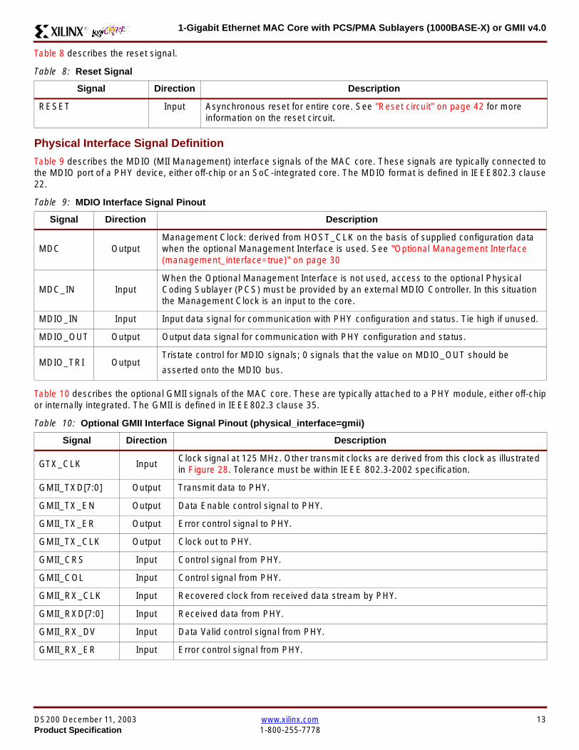
1-Gigabit Ethernet MAC Core with PCSPMA Sublayers (1000BASE-X) or GMII v40R
Table 8 describes the reset signal
Physical Interface Signal Definition
Table 9 describes the MDIO (MII Management) interface signals of the MAC core These signals are typically connected tothe MDIO port of a PHY device either off-chip or an SoC-integrated core The MDIO format is defined in IEEE8023 clause22
Table 10 describes the optional GMII signals of the MAC core These are typically attached to a PHY module either off-chipor internally integrated The GMII is defined in IEEE8023 clause 35
Table 8 Reset Signal
Signal Direction Description
RESET Input Asynchronous reset for entire core See Reset circuit on page 42 for moreinformation on the reset circuit
Table 9 MDIO Interface Signal Pinout
Signal Direction Description
MDC OutputManagement Clock derived from HOST_CLK on the basis of supplied configuration datawhen the optional Management Interface is used See Optional Management Interface(management_interface=true) on page 30
MDC_IN InputWhen the Optional Management Interface is not used access to the optional PhysicalCoding Sublayer (PCS) must be provided by an external MDIO Controller In this situationthe Management Clock is an input to the core
MDIO_IN Input Input data signal for communication with PHY configuration and status Tie high if unused
MDIO_OUT Output Output data signal for communication with PHY configuration and status
MDIO_TRI OutputTristate control for MDIO signals 0 signals that the value on MDIO_OUT should be
asserted onto the MDIO bus
Table 10 Optional GMII Interface Signal Pinout (physical_interface=gmii)
Signal Direction Description
GTX_CLK InputClock signal at 125 MHz Other transmit clocks are derived from this clock as illustratedin Figure 28 Tolerance must be within IEEE 8023-2002 specification
GMII_TXD[70] Output Transmit data to PHY
GMII_TX_EN Output Data Enable control signal to PHY
GMII_TX_ER Output Error control signal to PHY
GMII_TX_CLK Output Clock out to PHY
GMII_CRS Input Control signal from PHY
GMII_COL Input Control signal from PHY
GMII_RX_CLK Input Recovered clock from received data stream by PHY
GMII_RXD[70] Input Received data from PHY
GMII_RX_DV Input Data Valid control signal from PHY
GMII_RX_ER Input Error control signal from PHY
DS200 December 11 2003 wwwxilinxcom 13Product Specification 1-800-255-7778
1-Gigabit Ethernet MAC Core with PCSPMA Sublayers (1000BASE-X) or GMII v40 R
Table 11 describes the TBI (Ten-Bit interface) signals of the MAC core These are typically attached to a PMA SERDESmodule These signals optionally replace the GMII signals described in Table 10 to extend the functionality of the core toinclude the PCS for 1000BASE-X The TBI is defined in IEEE8023 clause 36
Notes
PHYAD and SIGNAL_DETECT are asynchronous inputs SIGNAL_DETECT is Active High
Table 11 Optional TBI Interface Signal Pinout (physical_interface=tbi)
Signal Direction Description
GTX_CLK InputClock signal at 125 MHz Other transmit clocks will be derived from this clock asillustrated in Figure 32 Tolerance must be within IEEE 8023-2002 specification
TX_CODE_GROUP[90] Output 10-bit parallel transmit data to PMA Sublayer (SERDES)
PMA_TX_CLK Output Transmit clock signal to PMA Sublayer (SERDES) at 125MHz
LOC_REF OutputCauses the PMA sublayer clock recovery unit to lock to PMA_TX_CLK Thissignal is tied to Ground
EWRAP Output
This signal is set from the PCS Control Register 0 bit 14 (loopback) See PCSManaged Register Block (physical_interface = tbi or phy) on page 49 Whenhigh this instructs the PMA sublayer to electrically loop the transmitter data to thereceiver
RX_CODE_GROUP0[90] Input10-bit parallel received data from PMA Sublayer (SERDES) synchronous toPMA_RX_CLK0
RX_CODE_GROUP1[90] Input10-bit parallel received data from PMA Sublayer (SERDES) synchronous toPMA_RX_CLK1
PMA_RX_CLK0 Input Received clock signal from PMA Sublayer (SERDES) at 625MHz
PMA_RX_CLK1 InputReceived clock signal from PMA Sublayer (SERDES) at 625MHz This is 180degrees out of phase with PMA_RX_CLK0
EN_CDET OutputEnables the PMA Sublayer to perform comma realignment driven from the PCSstate machine during the Loss-Of-Sync state
PHYAD[40] Input PHY address of MDIO register set for the PCS
SIGNAL_DETECT Input
Signal direct from PMD sublayer indicating the presence of light detected at theoptical receiver If driven high this indicates that the optical receiver has detectedlight If driven low this indicates the absence of light
If unused tie high to enable the operation the core
14 wwwxilinxcom DS200 December 11 20031-800-255-7778 Product Specification
1-Gigabit Ethernet MAC Core with PCSPMA Sublayers (1000BASE-X) or GMII v40R
Table 12 describes the interface signals for the Optional PCSPMA sublayer of the MAC core These signals optionallyreplace the GMII signals described in Table 10 to extend the functionality of the core to include the PCS and PMA sublayersfor 1000BASE-X This option uses the Virtex-II Pro Rocket IO functionality which is integrated into the core The PMAsublayer for 1000BASE-X is defined in IEEE8023 clause 36
Notes1 PHYAD and SIGNAL_DETECT are asynchronous inputs SIGNAL_DETECT is Active High
Table 12 Optional PCSPMA sublayer Interface Signal Pinout (physical_interface=phy)
Signal Direction Description
REFCLK InputHigh Quality Reference clock for Multi-Gigabit Transceivers (625 MHz) See Rocket IOUser Guide
REFCLK2 Input Alternative High Quality Reference clock for Multi-Gigabit Transceivers (625 MHz) SeeRocket IO User Guide
BREFCLK Input Alternative High Quality Reference clock for Multi-Gigabit Transceivers (625 MHz)This optionally replaces REFCLK See Rocket IO User Guide
BREFCLK2 Input Alternative High Quality Reference clock for Multi-Gigabit Transceivers (625 MHz)This optionally replaces REFCLK2 See Rocket IO User Guide
REFCLKSEL Input Selects between either (B)REFCLK or (B)REFCLK2 as the input clock source to theMGT See Rocket IO User Guide
USERCLK InputClock signal at 625 MHz This is connected to the TXUSRCLK and RXUSRCLK portsof the Rocket IO MGT This may be derived from (B)REFCLK using a DCM asillustrated in Figure 35
USERCLK2 InputClock signal at 125 MHz This is connected to the TXUSRCLK2 and RXUSRCLK2 portsof the Rocket IO MGT This may be derived from (B)REFCLK using a DCM asillustrated in Figure 35
DCM_LOCKED InputIf a DCM is used to derive USRCLK and USRCLK2 as illustrated in Figure 35 theLOCKED port of the DCM must be connected to the DCM_LOCKED port of the coreThe core will hold itrsquos Rocket IO MGT in reset until DCM_LOCKED is driven to logic 1
TXPTXN OutputDifferential pair for serial transmission from PMA to PMD The clock is embedded in thedata stream
RXPRXN InputDifferential pair for serial reception from PMD to PMA The clock is extracted from thedata stream
PHYAD[40] Input PHY address of MDIO register set for the PCS
SIGNAL_DETECT Input
Signal direct from PMD sublayer indicating the presence of light detected at the opticalreceiver If driven high this indicates that the optical receiver has detected light If drivenlow this indicates the absence of light
If unused tie high to enable the operation the core
DS200 December 11 2003 wwwxilinxcom 15Product Specification 1-800-255-7778
1-Gigabit Ethernet MAC Core with PCSPMA Sublayers (1000BASE-X) or GMII v40 R
Functional Description
Client InterfaceThe client interface is designed for maximum flexibility inmatching to a client switching fabric or network processorinterface
The data pathway is 8 bits wide in both the transmit andreceive directions with each pathway synchronous to theTX_CLK and RX_CLK respectively for completely indepen-dent full duplex operation
Transmitter
Normal Frame Transmission
The timing of a normal outbound frame transfer can be seenin Figure 9 When the client wants to transmit a frame itplaces the first column of data onto the TX_DATA port andasserts a ldquo1rdquo onto TX_DATA_VALID
When the MAC core has read this first byte of data it willassert the TX_ACK signal on the next and subsequent ris-ing clock edges the client must provide the remainder ofthe data for the frame
The end of frame is signalled to the MAC core by takingTX_DATA_VALID Low
In-Band Parameter Encoding
For maximum flexibility in switching applications the Ether-net frame parameters (destination address sourceaddress lengthtype and optionally FCS) are encodedwithin the same data stream that the frame payload is trans-ferred upon rather than on separate ports This is illustratedin the timing diagrams Definitions of the abbreviations usedin the timing diagrams are described in Table 13
Figure 9 Normal Frame Transmission Across Client Interface
Table 13 Abbreviations Used in Timing Diagrams
Abbreviation Definition
DA Destination Address 6 bytes
SA Source Address 6 bytes
LT LengthType Field 2 bytes
FCS Frame Check Sequence 4 bytes
TX_CLK
TX_DATA[70]
TX_DATA_VALID
TX_ACK
TX_UNDERRUN
DA SA DATALT
TX_COLLISION
TX_RETRANSMIT
xip2133
16 wwwxilinxcom DS200 December 11 20031-800-255-7778 Product Specification
1-Gigabit Ethernet MAC Core with PCSPMA Sublayers (1000BASE-X) or GMII v40R
Padding
When fewer than 46 bytes of data are supplied by the clientto the MAC core the transmitter module will add padding upto the minimum frame length The exception to this is whenthe MAC core is configured for client-passed FCS in thiscase the client must also supply the padding to maintain theminimum frame length (see Client-Supplied FCS Passing)
Client-Supplied FCS Passing
If the MAC core is configured to have the FCS field passedin by the client (see Configuration Registers on page 30)the transmission timing is as depicted in Figure 10 In thiscase it is the responsibility of the client to ensure that theframe meets the Ethernet minimum frame length require-ments the MAC core will not perform any padding of thepayload
Figure 10 Frame Transmission with Client-supplied FCS
TX_CLK
TX_DATA[70]
TX_DATA_VALID
TX_ACK
TX_UNDERRUN
DA SA DATA FCSLT
TX_COLLISION
TX_RETRANSMIT
xip2134
DS200 December 11 2003 wwwxilinxcom 17Product Specification 1-800-255-7778
1-Gigabit Ethernet MAC Core with PCSPMA Sublayers (1000BASE-X) or GMII v40 R
Client Underrun
The timing of an aborted transfer can be seen in Figure 11This may happen for instance if a FIFO connected to theclient interface empties before a frame is completed Whenthe client asserts TX_UNDERRUN during a frame transmis-sion the MAC core will insert an error code to corrupt the
current frame and then fall back to idle transmission It isthe responsibility of the client to re-queue the aborted framefor transmission
When an underrun occurs TX_DATA_VALID may beasserted on the clock cycle after the TX_UNDERRUNassertion to request a new transmission
Figure 11 Frame Transmission with Underrun
TX_CLK
TX_DATA[70]
TX_DATA_VALID
TX_ACK
TX_UNDERRUN
DA SA DATALT
TX_COLLISION
TX_RETRANSMIT
xip2135
18 wwwxilinxcom DS200 December 11 20031-800-255-7778 Product Specification
1-Gigabit Ethernet MAC Core with PCSPMA Sublayers (1000BASE-X) or GMII v40R
Back-to-Back Transfers
Figure 12 shows the case where the MAC client is immedi-ately ready to transmit a second frame of data followingcompletion of its first frame In this figure the end of the firstframe is shown on the left On the clock cycle immediatelyfollowing the final byte of the first frame TX_DATA_VALIDis taken low by the client and is taken high one clock cyclelater to indicate that the first byte of the destination addressof the second frame is on TX_DATA awaiting transmission
When the MAC core is ready to accept data TX_ACK isasserted and the transmission continues in the same man-ner as in the case of the single frame The MAC core willdefer the assertion of TX_ACK appropriately to comply withinter-packet gap requirements and flow control requests
If the MAC core is operating in half-duplex mode the timingshown in Figure 12 is required to take advantage of framebursting the MAC core is only guaranteed to retain controlof the medium if the TX_DATA_VALID signal is low for a sin-gle clock cycle For more information on frame bursting seeIEEE 8023-2002
Figure 12 Back to Back Frame Transmission
TX_CLK
TX_DATA[70]
TX_DATA_VALID
TX_ACK
TX_UNDERRUN
TX_COLLISION
TX_RETRANSMIT
xip2136
DS200 December 11 2003 wwwxilinxcom 19Product Specification 1-800-255-7778
1-Gigabit Ethernet MAC Core with PCSPMA Sublayers (1000BASE-X) or GMII v40 R
VLAN Tagged Frames
Transmission of a VLAN tagged frame (if enabled) can beseen in Figure 13 Note that the handshaking signalsacross the interface do not change however the VLANtype tag 81-00 must be supplied by the client to signify that
the frame is VLAN tagged The client also supplies the twobytes of Tag Control Information V1 and V2 at the appro-priate times in the data stream More information on thecontents of these two bytes can be found in IEEE8023-2002
Maximum Permitted Frame Length
The maximum legal length of a frame specified in IEEE8023-2002 is 1518 bytes for non-VLAN tagged framesVLAN tagged frames may be extended to 1522 bytesWhen jumbo frame handling is disabled and the clientattempts to transmit a frame which exceeds the maximumlegal length the MAC core will insert an error code to cor-
rupt the current frame and the frame will be truncated to themaximum legal length When jumbo frame handling isenabled frames which are longer than the legal maximumare transmitted error-free
For more information on enabling and disabling jumboframe handling see Configuration Registers on page 30
Figure 13 Transmission of a VLAN Tagged Frame
TX_CLK
TX_DATA[70]
TX_DATA_VALID
TX_ACK
TX_UNDERRUN
DA SA DATALTVLANtag
81 00V1V2
TX_COLLISION
TX_RETRANSMIT
xip2137
20 wwwxilinxcom DS200 December 11 20031-800-255-7778 Product Specification
1-Gigabit Ethernet MAC Core with PCSPMA Sublayers (1000BASE-X) or GMII v40R
Frame Collisions - Half Duplex Operation Only
In half duplex Ethernet operation collisions will occur on themedium as a matter of course this is how the arbitrationalgorithm is fulfilled In case of a collision the MAC core sig-nals to the client that data may need to be resupplied as fol-lows
If there is a collision the TX_COLLISION signal will be setto ldquo1rdquo by the MAC core If a frame is in progress the clientmust abort the transfer and take TX_DATA_VALID to ldquo0rdquo
If the TX_RETRANSMIT signal is ldquo1rdquo in the same clockcycle that the TX_COLLISION signal is ldquo1rdquo the client must
resubmit the previous frame to the MAC core for retrans-mission TX_DATA_VALID must be asserted to the MACcore within 8 clock cycles of the TX_COLLISION signal inorder to meet Ethernet timing requirements See Figure 14
If the TX_RETRANSMIT signal is ldquo0rdquo in the same clockcycle that the TX_COLLISION signal is ldquo1rdquo the number ofretries for this frame has exceeded the Ethernet specifica-tion and the frame should be dropped by the client The cli-ent can then make any new frame available to the MAC fortransmission without timing restriction See Figure 15
Figure 14 Collision Handling - Frame retransmission required
Figure 15 Collision Handling - No frame retransmission required
TX_CLK
TX_DATA[70]
TX_DATA_VALID
TX_ACK
TX_UNDERRUN
TX_COLLISION
TX_RETRANSMIT
8 clocks max
xip2138
TX_CLK
TX_DATA[70]
TX_DATA_VALID
TX_ACK
TX_UNDERRUN
TX_COLLISION
TX_RETRANSMIT
xip2139
DS200 December 11 2003 wwwxilinxcom 21Product Specification 1-800-255-7778
1-Gigabit Ethernet MAC Core with PCSPMA Sublayers (1000BASE-X) or GMII v40 R
Interframe Gap Adjustment
The user can elect to vary the length of the inter fame gapIf this function is selected (via a configuration bit in thetransmitter control register see Configuration Registerson page 30) then the MAC will exert back pressure to delaythe transmission of the next frame until the requested num-ber of Idle cycles has elapsed The number of Idle cycles iscontrolled by the value on the TX_IFG_DELAY port at thestart of frame transmission Figure 16 shows the MAC oper-ating in this mode
Reducing the Inter fame gap to below the IEEE 8023-2002minimum of 12 Idles is supported in Full Duplex onlydesigns and will transmit an absolute minimum of 4 Idles Ifthe Interframe gap adjustment is reduced below 12 Idlesthen the accuracy of the Optional Statistical Gathering(statistics_gathering=true) Counters cannot be guaranteedHowever the TX_STATISTIC_VECTOR andRX_STATISTIC_VECTOR will always remain correct
Transmitter Statistics Vector
The statistics for the frame transmitted are contained withinthe TX_STATISTICS_VECTOR The vector is driven syn-chronously by the transmitter clock TX_CLK followingframe transmission The bit field definition for the Vector isdefined in Table 14
All bit fields with the exception of BYTE_VALID are validonly when the TX_STATISTICS_VALID is asserted This isillustrated in Figure 17 BYTE_VALID is significant on everyTX_CLK cycle
TX_STATISTICS_VECTOR bits 25 down to 17 inclusive arefor half duplex only and will be set to logic 0 when operatingin full duplex mode
Figure 16 Interframe Gap Adjustment
TX_CLK
TX_DATA[70]
TX_DATA_VALID
TX_ACK
DA SA
TX_IFG_DELAY
IFG ADJUST VALUE
0x0D
13 Idles inserted
DA
Next IFG ADJUST VALUE
xip2140
Figure 17 Transmitter Statistics Vector Timing
TX_CLK
TX_STATISTICS_VECTOR[280]
TX_STATISTICS_VALID
xip2141
22 wwwxilinxcom DS200 December 11 20031-800-255-7778 Product Specification
1-Gigabit Ethernet MAC Core with PCSPMA Sublayers (1000BASE-X) or GMII v40R
Table 14 Bit Definition for the Transmitter Statistics Vector
TX_STATISTICS_VECTOR Name Description
28 PAUSE_FRAME_TRANSMITTEDAsserted if the previous frame was a pause framethat the MAC itself initiated in response to aPAUSE_REQ assertion
27 BYTE_VALID
Asserted if a MAC frame byte (DA to FCS inclusive)is in the process of being transmitted This is valid onevery clock cycle
Do not use this as an enable signal to indicate thatdata is present on GMII_TXD[70]
26 Reserved Returns logic 0
25 down to 22 TX_ATTEMPTS[30]
The number of attempts that have been made totransmit the previous frame This is a 4-bit number0 should be interpreted as 1 attempt 1 as 2attempts up until 15 as 16 attempts
21 Reserved Returns logic 0
20 EXCESSIVE_COLLISIONAsserted if a collision has been detected on each ofthe last 16 attempts to transmit the previous frame
19 LATE_COLLISIONAsserted if a late collision occurred during frametransmission
18 EXCESSIVE_DEFERRALAsserted if the previous frame was deferred for anexcessive amount of time as defined by the constantldquomaxDeferTimerdquo in IEEE 8023-2002
17 TX_DEFERRED Asserted if transmission of the frame was deferred
16 VLAN_FRAMEAsserted if the previous frame contained a VLANidentifier in the LengthType field when transmitterVLAN operation is enabled
15 down to 5 FRAME_LENGTH_COUNTThe length of the previous frame in number of bytesThe count will stick at 2047 for any Jumbo frameslarger than this value
4 CONTROL_FRAMEAsserted if the previous frame had the special MACControl Type code 88-08 in the LengthType field
3 UNDERRUN_FRAMEAsserted if the previous frame contained anunderrun error
2 MULTICAST_FRAMEAsserted if the previous frame contained a multicastaddress in the Destination Address field
1 BROADCAST_FRAMEAsserted if the previous frame contained abroadcast address in the Destination Address field
0 SUCCESSFUL_FRAMEAsserted if the previous frame was transmittedwithout error
DS200 December 11 2003 wwwxilinxcom 23Product Specification 1-800-255-7778
1-Gigabit Ethernet MAC Core with PCSPMA Sublayers (1000BASE-X) or GMII v40 R
Receiver
Normal Frame Reception
The timing of a normal inbound frame transfer can be seenin Figure 18 The client must be prepared to accept data atany time there is no buffering within the MAC to allow forlatency in the receive client Once frame reception begins
data is transferred on consecutive clock cycles to thereceive client until the frame is complete The MAC assertsthe RX_GOOD_FRAME signal to indicate that the framewas successfully received and that the frame should beanalyzed by the client
Frame parameters (destination address source addresslengthtype and optionally FCS) are supplied on the databus according to the timing diagram The abbreviations arethe same as those described in Table 13 on page 16
If the LengthType field in the frame has the Length interpre-tation and this indicates that the inbound frame has beenpadded to meet the Ethernet minimum frame size specifica-tion then this padding will not be passed to the client in thedata payload The exception to this is in the case whereFCS passing is enabled see Client-Supplied FCS Pass-ing on page 25
Therefore when Client-Supplied FCS passing is disabledRX_DATA_VALID = lsquo0rsquo between frames for the duration ofthe Padding field (if present) the FCS field carrier exten-sion (if present) the interframe gap following the frame andthe preamble field of the next frame When Client-Supplied
FCS passing is enabled RX_DATA_VALID = lsquo0rsquo betweenframes for the duration of carrier extension (if present) theinterframe gap and the preamble field of the followingframe
RX_GOOD_FRAME RX_BAD_FRAME timing
Although the timing diagram in Figure 18 shows theRX_GOOD_FRAME signal asserted shortly after the lastvalid data on RX_DATA this is not always the case TheRX_GOOD_FRAME or RX_BAD_FRAME signals areasserted only after all frame checks are completed This isafter the FCS field has been received (and after reception ofcarrier extension if present)
Therefore either RX_GOOD_FRAME or RX_BAD_FRAMEis asserted following frame reception at the beginning of theinterframe gap
Figure 18 Normal Frame Reception
RX_CLK
RX_DATA[70]
RX_DATA_VALID
RX_GOOD_FRAME
RX_BAD_FRAME
DA SA DATALT
xip2142
24 wwwxilinxcom DS200 December 11 20031-800-255-7778 Product Specification
1-Gigabit Ethernet MAC Core with PCSPMA Sublayers (1000BASE-X) or GMII v40R
Frame Reception with Errors
The case of an unsuccessful frame reception (for examplea fragment frame or a frame with an incorrect FCS) can beseen in Figure 19 In this case the RX_BAD_FRAME signal
is asserted to the client at the end of the frame It is then theresponsibility of the client to drop the data already trans-ferred for this frame
Figure 19 Frame Reception with Error
Client-Supplied FCS Passing
If the MAC core is configured to pass the FCS field to the cli-ent (see Configuration Registers on page 30) then this ishandled as shown in Figure 20
In this case any padding inserted into the frame to meetEthernet minimum frame length specifications will be leftintact and passed to the client
Note that even though the FCS is passed up to the client itis also verified by the MAC core and RX_BAD_FRAMEasserted if the FCS check fails
RX_CLK
RX_DATA[70]
RX_DATA_VALID
RX_GOOD_FRAME
RX_BAD_FRAME
DA SA DATALT
xip2144
Figure 20 Frame Reception with In-Band FCS Field
RX_CLK
RX_DATA[70]
RX_DATA_VALID
RX_GOOD_FRAME
RX_BAD_FRAME
DA SA DATALT FCS
xip2145
DS200 December 11 2003 wwwxilinxcom 25Product Specification 1-800-255-7778
1-Gigabit Ethernet MAC Core with PCSPMA Sublayers (1000BASE-X) or GMII v40 R
VLAN Tagged Frames
The reception of a VLAN tagged frame (if enabled) can beseen in Figure 21 The VLAN frame is passed to the clientso that the frame may be identified as VLAN tagged this is
followed by the Tag Control Information bytes V1 and V2More information on the interpretation of these bytes maybe found in IEEE 8023-2002 standard
Maximum Permitted Frame Length
The maximum legal length of a frame specified in IEEE8023-2002 is 1518 bytes for non-VLAN tagged framesVLAN tagged frames may be extended to 1522 bytesWhen jumbo frame handling is disabled and the corereceives a frame which exceeds the maximum legal lengthRX_BAD_FRAME will be asserted When jumbo framehandling is enabled frames which are longer than the legalmaximum are received in the same way as shorter frames
For more information on enabling and disabling jumboframe handling see Configuration Registers on page 30
LengthType Field Error Checks
Enabled
Default operation is with the LengthType error checkingenabled (see Receiver Configuration Word 1 on page 31)In this mode the following checks are made on all framesreceived If either of these checks fail then the frame ismarked as BAD
bull A value in the LengthType field that is greater than orequal to decimal 46 but less than decimal 1536 (aLength interpretation) is checked against the actualdata length received
bull A value in the LengthType field that is less thandecimal 46 is checked to see that the data field ispadded to exactly 46 bytes (so that the resultant frameis minimum frame size 64 bytes total in length)
Furthermore if Padding is indicated (the LengthType fieldis less than decimal 46) and Client-Supplied FCS Passing isdisabled then the Length value in the LengthType field willbe used to deassert RX_DATA_VALID after the indicatednumber of data bytes so that the Padding bytes areremoved from the frame
Disabled
When the LengthType error checking is disabled (seeReceiver Configuration Word 1 on page 31) theLengthType error checks described above are not per-formed A frame containing only these errors will be markedas GOOD
Furthermore if Padding is indicated and Client-SuppliedFCS Passing is disabled then a Length Value in theLengthType field will not be used to deassertRX_DATA_VALID Instead RX_DATA_VALID will be deas-serted before the start of the FCS field in this way any pad-ding will not be removed from the frame
Figure 21 Reception of a VLAN Tagged Frame
RX_CLK
RX_DATA[70]
RX_DATA_VALID
RX_GOOD_FRAME
RX_BAD_FRAME
DA SA DATALT
81 00 V1 V2
VLANtag
xip2146
26 wwwxilinxcom DS200 December 11 20031-800-255-7778 Product Specification
1-Gigabit Ethernet MAC Core with PCSPMA Sublayers (1000BASE-X) or GMII v40R
Receiver Statistics Vector
The statistics for the frame received are contained withinthe RX_STATISTICS_VECTOR The vector is driven syn-chronously by the receiver clock RX_CLK following framereception The bit field definition for the Vector is defined inTable 15
All bit fields with the exception of BYTE_VALID are validonly when the RX_STATISTICS_VALID is asserted This isillustrated in Figure 22 BYTE_VALID is significant on everyRX_CLK cycle
Figure 22 Receiver Statistics Vector Timing
RX_CLK
RX_STATISTICS_VECTOR[220]
RX_STATISTICS_VALID
xip2147
Table 15 Bit Definition for the Receiver Statistics Vector
RX_STATISTICS_VECTOR Name Description
22LENGTHTYPE Out ofRange
Asserted if the lengthtype field contained a length valuethat did not match the number of MAC client data bytesreceived Also high if the lengthtype field indicated thatthe frame contained padding but the number of MAC cli-ent data bytes received was not equal to 64 bytes (min-imum frame size)
The exception to the above is when the LengthTypeField Error Checks are disabled in which case this bitwill not be asserted
21 BAD_OPCODE
Asserted if the previous frame was error-free andcontained the special Control Frame identifier in theLengthType field but contained an opcode that isunsupported by the MAC (Any Opcode other thanPAUSE)
20 FLOW_CONTROL_FRAME
Asserted if the previous frame was error-freecontained the special Control Frame identifier in theLengthType field contained a Destination Addressthat matched either the MAC Control MulticastAddress or the configured source address of the MACcontained the supported PAUSE opcode and wasacted upon by the MAC
19 BYTE_VALID
Asserted if a MAC frame byte (DA to FCS inclusive) isin the process of being received This is valid on everyclock cycle
Do not use this as an enable signal to indicate thatdata is present on RX_DATA[70]
18 VLAN_FRAMEAsserted if the previous frame contained a VLANidentifier in the LengthType field when receiver VLANoperation is enabled
DS200 December 11 2003 wwwxilinxcom 27Product Specification 1-800-255-7778
1-Gigabit Ethernet MAC Core with PCSPMA Sublayers (1000BASE-X) or GMII v40 R
17 OUT_OF_BOUNDS
Asserted if the previous frame exceeded the specifiedIEEE8023-2002 maximum legal length (seeMaximum Permitted Frame Length on page 26) Thisis only valid if Jumbo frames are disabled
16 CONTROL_FRAMEAsserted if the previous frame contained the specialControl Frame identifier in the LengthType field
15 down to 5 FRAME_LENGTH_COUNTThe length of the previous frame in number of bytesThe count will stick at 2047 for any Jumbo frameslarger than this value
4 MULTICAST_FRAMEAsserted if the previous frame contained a multicastaddress in the Destination Address field
3 BROADCAST_FRAMEAsserted if the previous frame contained the broadcastaddress in the Destination Address field
2 FCS_ERRORAsserted if the previous frame received had anincorrect FCS value or the MAC detected error codesduring frame reception
1 BAD_FRAME1 Asserted if the previous frame received containederrors
0 GOOD_FRAME1 Asserted if the previous frame received was error-free
1 If the LengthType Field Error Checks are disabled then a frame which contains this type of error will be marked as a GOOD_FRAMEproviding no additional errors were detected
Table 15 Bit Definition for the Receiver Statistics Vector
RX_STATISTICS_VECTOR Name Description
28 wwwxilinxcom DS200 December 11 20031-800-255-7778 Product Specification
1-Gigabit Ethernet MAC Core with PCSPMA Sublayers (1000BASE-X) or GMII v40R
Flow ControlThe flow control block is designed to Clause 31 of the IEEE8023-2002 standard The MAC may be configured to sendpause frames and to act upon their reception These twobehaviors can be configured asymmetrically see Configu-ration Registers on page 30
Transmitting a PAUSE Control Frame
The client initiates a flow control frame by assertingPAUSE_REQ while the pause value is on the PAUSE_VALbus These signals are synchronous to TX_CLK The timingof this can be seen in Figure 23
If the MAC core is configured to support transmit flow con-trol this action causes the core to transmit a PAUSE controlframe on the link with the PAUSE parameter set to thevalue on PAUSE_VAL in the cycle when PAUSE_REQ wasasserted This will not disrupt any frame transmission inprogress but will take priority over any pending frame trans-
mission This frame will be transmitted even if the transmit-ter is in the paused state itself
Receiving a Pause Control Frame
When an error-free frame is received by the MAC core thefollowing checks are made
1 The Destination Address field is matched against theMAC Control Multicast address or the configuredSource Address for the MAC (see ConfigurationRegisters on page 30)
2 The LengthType field is matched against the MACControl Type code
3 The opcode field contents are matched against thePAUSE opcode if check 2 is true
If any of the above checks are false or the MAC Flow Con-trol logic for the receiver is disabled the frame is ignored bythe Flow Control logic and passed up to the client
If the frame passes all of the above checks is of minimumlegal size and the MAC Flow Control logic for the receiver isenabled the pause value parameter in the frame is thenused to inhibit transmitter operation for the time defined inthe IEEE8023-2002 specification This inhibit is imple-mented using the same back pressure scheme shown inFigure 12 Because the received pause frame has beenacted upon it is passed to the client with RX_BAD_FRAMEasserted to indicate to the client that it should be dropped
Reception of any frame for which check 2 is true and whichis not of legal minimum length is considered an invalid Con-trol frame This will be ignored by the Flow Control logic andpassed to the client with RX_BAD_FRAME asserted
Figure 23 Pause Request Timing
TX_CLK
PAUSE_VAL[150]
PAUSE_REQ
xip2148
DS200 December 11 2003 wwwxilinxcom 29Product Specification 1-800-255-7778
1-Gigabit Ethernet MAC Core with PCSPMA Sublayers (1000BASE-X) or GMII v40 R
Optional Management Interface(management_interface=true)The management interface is a processor-independentinterface with standard address data and control signals Itmay be used as is or a wrapper may be applied (not sup-plied) to interface to common bus architectures
This interface is used for
bull Configuration of the MAC core
bull Access to optional statistics counters for use by higherlayers for example SNMP
bull access through the MDIO interface to the managementregisters located in the PHY attached to the MAC core
The management interface is accessed differently depend-ing on the type of transaction a truth table showing whichaccess method is required for each transaction type isshown in Table 16 These access methods are described inthe following sections
HOST_CLK Frequency
The management interface clock HOST_CLK is used toderive the MDIO clock MDC and is therefore subject tosome frequency restrictions This HOST_CLK must be
ge 10 MHz
le 100 MHz
Configuring the MAC core to derive the MDC signal fromthis clock is detailed in MDIO Interface on page 37
Configuration Registers
After power up or reset the client may reconfigure the coreparameters from their defaults such as flow control supportConfiguration changes can be written at any time Both thereceiver and transmitter logic will only respond to configura-tion changes during Inter Frame Gaps The exceptions tothis are the configurable resets which take effect immedi-ately
Configuration of the MAC core is performed through a reg-ister bank accessed through the management interfaceThe configuration registers available in the core are detailedin Table 17 As can be seen the address has some implicitdonrsquot care bits any access to an address in the rangesshown will perform a 32-bit read or write from the same con-figuration word
Table 16 Management Interface Transaction Types
Transaction HOST_MIIM_SEL HOST_ADDR[9]
Configuration 0 1
Statistics 0 0
MIIM access 1 X
Table 17 Configuration Registers
Address Description
0x200-0x23F Receiver Configuration (Word 0)
0x240-0x27F Receiver Configuration (Word 1)
0x280-0x2BF Transmitter Configuration
0x2C0-0x2FF Flow Control Configuration
0x300-0x33F Reserved
0x340-0x37F Management Configuration
30 wwwxilinxcom DS200 December 11 20031-800-255-7778 Product Specification
1-Gigabit Ethernet MAC Core with PCSPMA Sublayers (1000BASE-X) or GMII v40R
The register contents for the two receiver configuration words can be seen in Table 18 and Table 19
Notes1 In changing the receiverrsquos mode from Half Duplex to Full Duplex there is a period of time of up to 24 us following the mode change
when no new receiver statistics can be stored in the optional Statistical Counters
Table 18 Receiver Configuration Word 0
Bit Default Value Description
31-0 All 0rsquos
Pause frame MAC Source Address[310] This address is used by the MAC tomatch against the Destination Address of any incoming flow control frames It isalso used by the flow control block as the Source Address (SA) for any outboundflow control frames
The address is ordered so the first byte transmittedreceived is the lowestpositioned byte in the register for example a MAC address ofAA-BB-CC-DD-EE-FF would be stored in Address[470] as 0xFFEEDDCCBBAA
Table 19 Receiver Configuration Word 1
Bit Default Value Description
15-0 All 0rsquos Pause frame MAC Source Address[4732] See description in Table 18
24-16 NA Reserved
25 0
LengthType Error Check Disable When this bit is set to ldquo1rdquo the core will notperform the LengthType field error checks as described in LengthType FieldError Checks on page 26 When this bit is set to ldquo0rdquo the LengthType field checkswill be performed this is normal operation
26 0Half Duplex If ldquo1rdquo the receiver will operate in half duplex mode If ldquo0rdquo the receiverwill operate in full duplex mode Has no effect if XCO parameterhalf_duplex_capable = false
27 0VLAN Enable When this bit is set to ldquo1rdquo VLAN tagged frames will be acceptedby the receiver
28 1Receiver Enable If set to ldquo1rdquo the receiver block will be operational If set to ldquo0rdquothe block will ignore activity on the physical interface RX port
29 0
In-band FCS Enable When this bit is ldquo1rdquo the MAC receiver will pass the FCS fieldup to the client as described in Client-Supplied FCS Passing on page 25 Whenit is ldquo0rdquo the client will not be passed the FCS In both cases the FCS will beverified on the frame
30 0Jumbo Frame Enable When this bit is set to ldquo1rdquo the MAC receiver will acceptframes over the specified IEEE8023-2002 maximum legal length When this bitis ldquo0rdquo the MAC will only accept frames up to the specified maximum
31 0Reset When this bit is set to ldquo1rdquo the receiver will be reset The bit will thenautomatically revert to ldquo0rdquo Note that this reset will also set all of the receiverconfiguration registers to their default values
DS200 December 11 2003 wwwxilinxcom 31Product Specification 1-800-255-7778
1-Gigabit Ethernet MAC Core with PCSPMA Sublayers (1000BASE-X) or GMII v40 R
The register contents for the Transmitter Configuration Word are described in Table 20
Notes1 In changing the transmitterrsquos mode from Half Duplex to Full Duplex there is a period of time of up to 24 us following the mode change
when no new transmitter statistics can be stored in the optional Statistical Counters
Table 20 Transmitter Configuration Word
Bit Default Value Description
24-0 NA Reserved
25 0
Interframe Gap Adjust Enable If lsquo1rsquo the transmitter will read the value on the portTX_IFG_DELAY at the start of frame transmission and adjust the interframe gapfollowing the frame accordingly See Interframe Gap Adjustment on page 22 Ifldquo0rdquo the transmitter will output a minimum Inter Frame Gap of twelve clock cyclesas specified in IEEE8023-2002
26 0Half Duplex If lsquo1rsquo the transmitter will operate in half duplex mode If lsquo0rsquo thetransmitter will operate in full duplex mode Has no effect if XCO parameterhalf_duplex_capable = false
27 0VLAN Enable When this bit is set to 1 the transmitter will allow the transmissionof VLAN tagged frames
28 1Transmit Enable When this bit is 1 the transmitter is operational When it is 0the transmitter is disabled
29 0
In-band FCS Enable When this bit is lsquo1rsquo the MAC transmitter will expect the FCSfield to be passed in by the client as described in Client-Supplied FCS Passingon page 17 When this bit is ldquo0rdquo the MAC transmitter will append padding asrequired compute the FCS and append it to the frame
30 0
Jumbo Frame Enable When this bit is set to ldquo1rdquo the MAC transmitter will sendframes that are greater than the specified IEEE8023-2002 maximum legallength When this bit is ldquo0rdquo the MAC will only send frames up to the specifiedmaximum
31 0Reset When this bit is set to ldquo1rdquo the transmitter will be reset The bit will thenautomatically revert to ldquo0rdquo Note that this reset will also set all of the transmitterconfiguration registers to their default values
32 wwwxilinxcom DS200 December 11 20031-800-255-7778 Product Specification
1-Gigabit Ethernet MAC Core with PCSPMA Sublayers (1000BASE-X) or GMII v40R
The register contents for the Flow Control Configuration Word are described in Table 21
The register contents for the Management Configuration Word are described in Table 22
Writing to the configuration registers through the manage-ment interface is depicted in Figure 24 When accessing theconfiguration registers (ie when HOST_ADDR[9] = lsquo1rsquo andHOST_MIIM_SEL = lsquo0rsquo) the upper bit of HOST_OPCODEfunctions as an Active Low write enable signal The lowerHOST_OPCODE bit is a ldquodonrsquot carerdquo
Reading from the configuration register words is similar butthe upper HOST_OPCODE bit should be lsquo1rsquo This is shownin Figure 25 In this case the contents of the register appearon HOST_RD_DATA the HOST_CLK edge after the regis-ter address is asserted onto HOST_ADDR
Table 21 Flow Control Configuration Word
Bit Default Value Description
28-0 NA Reserved
29 1
Flow Control Enable (RX) When this bit is lsquo1rsquo received flow control frames willinhibit the transmitter operation as described in Receiving a Pause ControlFrame on page 29 When this bit is lsquo0rsquo received flow control frames will alwaysbe passed up to the client
30 1Flow Control Enable (TX) When this bit is lsquo1rsquo asserting the PAUSE_REQ signalwill send a flow control frame out from the transmitter When this bit is 0 assertingthe PAUSE_REQ signal has no effect
31 NA Reserved
Table 22 Management Configuration Word
Bits Default Value Description
4-0 All 0rsquos Clock Divide[40] See MDIO Interface on page 37
5 0MDIO Enable When this bit is 1 the MDIO interface can be used to accessattached PHY devices When this bit is 0 the MDIO interface is disabled and theMDIO signals remain inactive
31-6 NA Reserved
Figure 24 Configuration Register Write Timing
HOST_CLK
HOST_ADDR[80]
HOST_ADDR[9]
HOST_OPCODE[1]
HOST_MIIM_SEL
HOST_WR_DATA[310]xip2149
Figure 25 Configuration Register Read Timing
HOST_CLK
HOST_ADDR[80]
HOST_ADDR[9]
HOST_OPCODE[1]
HOST_MIIM_SEL
HOST_RD_DATA[310]
xip2150
DS200 December 11 2003 wwwxilinxcom 33Product Specification 1-800-255-7778
1-Gigabit Ethernet MAC Core with PCSPMA Sublayers (1000BASE-X) or GMII v40 R
Optional Statistical Gathering(statistics_gathering=true)
During operation the MAC core collects statistics on thesuccess and failure of various operations for processing by
station management entities (STA) further up the protocolstack These statistics are accessed by the host through theoptional management interface A complete list of statisticssupported is described in Table 23
Table 23 Statistics Registers
Address Name Description
0x000 Frames Received OK1 A count of error-free frames received
0x001 Frame Check Sequence Errors A count of received frames that failed the CRC check and were at least64 bytes in length
0x002 Broadcast Frames Received OK1A count of frames that were successfully received and were directed tothe broadcast group address
0x003 Multicast Frames Received OK1 A count of frames that were successfully received and were directed toa non broadcast group address
0x004 64 byte Frames Received OK1 A count of error-free frames received that were 64 bytes in length
0x005 65-127 byte Frames Received OK1A count of error-free frames received that were between 65 and 127bytes in length
0x006 128-255 byte Frames Received OK1A count of error-free frames received that were between 128 and 255bytes in length
0x007 256-511 byte Frames Received OK1A count of error-free frames received that were between 256 and 511bytes in length
0x008512-1023 byte Frames ReceivedOK1
A count of error-free frames received that were between 512 and 1023bytes in length
0x0091024-MaxFrameSize byte FramesReceived OK1
A count of error-free frames received that were between 1024 bytes andthe specified IEEE8023-2002 maximum legal length (see MaximumPermitted Frame Length on page 26)
0x00A Control Frames Received OKA count of error-free frames received that contained the specialControl Frame identifier in the LengthType field
0x00B LengthType Out of Range
A count of frames received that were at least 64 bytes in length wherethe lengthtype field contained a length value that did not match thenumber of MAC client data bytes received
The counter also increments for frames in which the lengthtype fieldindicated that the frame contained padding but where the number ofMAC client data bytes received was greater than 64 bytes (minimumframe size)
The exception to the above is when the LengthType Field Error Checksare disabled in which case this counter will not increment
0x00C VLAN Tagged Frames Received OKA count of error-free VLAN frames received This counter will only incre-ment when the receiver is configured for VLAN operation
0x00D Pause Frames Received OK
A count of error-free frames received that contained the MAC Controltype identifier 88-08 in the LengthType field contained a Destinationaddress that matched either the MAC Control multicast address or theconfigured source address of the MAC contained the PAUSE opcodeand were acted upon by the MAC
0x00EControl Frames Received withUnsupported Opcode
A count of error-free frames received that contained the MAC Controltype identifier 88-08 in the LengthType field but were received with anopcode other than the PAUSE opcode
34 wwwxilinxcom DS200 December 11 20031-800-255-7778 Product Specification
1-Gigabit Ethernet MAC Core with PCSPMA Sublayers (1000BASE-X) or GMII v40R
0x00F Oversize Frames Received OK1A count of otherwise error-free frames received that exceeded the max-imum legal frame length specified in IEEE 8023-2002 (see MaximumPermitted Frame Length on page 26)
0x010 Undersize frames receivedA count of the number of frames received that were less than 64 bytesin length but were otherwise well formed
0x011 Fragment frames receivedA count of the number of frames received that were less than 64 bytesin length and had a bad Frame Check Sequence field
0x012 Received bytesA count of bytes of frames that are received (Destination Address toFrame Check Sequence inclusive)
0x013 Transmitted bytesA count of bytes of frames that are transmitted (Destination Address toFrame Check Sequence inclusive)
0x020 Frames Transmitted OK A count of error-free frames transmitted
0x021 Broadcast Frames Transmitted OK A count of error-free frames that were transmitted to the broadcastaddress
0x022 Multicast Frames Transmitted OK A count of error-free frames that were transmitted to a group destina-tion address other than broadcast
0x023 Underrun Errors
A count of frames that would otherwise be transmitted by the core butcould not be completed due to the assertion of TX_UNDERRUN duringthe frame transmission This will not count frames which are less than64 bytes in length
0x024 Control Frames Transmitted OKA count of error-free frames transmitted that contained the MACControl Frame type identifier 88-08 in the LengthType field
0x025 64 byte Frames Transmitted OK A count of error-free frames transmitted that were 64 bytes in length
0x026 65-127 byte Frames Transmitted OKA count of error-free frames transmitted that were between 65 and 127bytes in length
0x027128-255 byte Frames TransmittedOK
A count of error-free frames transmitted that were between 128 and 255bytes in length
0x028256-511 byte Frames TransmittedOK
A count of error-free frames transmitted that were between 256 and 511bytes in length
0x029512-1023 byte Frames TransmittedOK
A count of error-free frames transmitted that were between 512 and1023 bytes in length
0x02A1024-MaxFrameSize byte FramesTransmitted OK
A count of error-free frames transmitted that were between 1024 and thespecified IEEE8023-2002 maximum legal length (see Maximum Per-mitted Frame Length on page 20)
0x02BVLAN Tagged Frames TransmittedOK
A count of error-free VLAN frames transmitted This counter will onlyincrement when the transmitter is configured for VLAN operation
0x02C Pause Frames Transmitted OKA count of error-free PAUSE frames generated and transmitted by thecore in response to an assertion of PAUSE_REQ
0x02D Oversize Frames Transmitted OKA count of otherwise error-free frames transmitted that exceeded themaximum legal frame length specified in IEEE 8023-2002 (see Maxi-mum Permitted Frame Length on page 20)
0x02E Single Collision Frames A count of frames that are involved in a single collision but are subse-quently transmitted successfully (Half Duplex Mode only)
Table 23 Statistics Registers (Continued)
Address Name Description
DS200 December 11 2003 wwwxilinxcom 35Product Specification 1-800-255-7778
1-Gigabit Ethernet MAC Core with PCSPMA Sublayers (1000BASE-X) or GMII v40 R
Each of these statistic registers is 64 bits wide and thereforemust be read in a two-cycle transfer The timing of this pro-cess is shown in Figure 26 Six clocks after the read trans-action is initiated the least significant word (LSW) of thestatistics counter appears on the HOST_RD_DATA bus
and a clock cycle later the most significant word (MSW)appears For accurate statistic values 64 clock ticks (ofTX_CLK for transmit statistics or RX_CLK for receive statis-tics) must elapse after the last frame is sent or receivedthrough the MAC core
0x02F Multiple Collision Frames A count of frames that are involved in more than one collision but aresubsequently transmitted successfully (Half Duplex Mode only)
0x040 Frames with Deferred Transmissions A count of frames whose transmission was delayed on its first attemptbecause the medium was busy (Half Duplex Mode only)
0x041 Late Collisions
A count of the times that a collision has been detected later than oneslotTime from the start of the packet transmission A late collision iscounted twice both as a collision and as a lateCollision (Half DuplexMode only)
0x042Frames Aborted due to Excesscollisions
A count of the frames that due to excessive collisions are not transmit-ted successfully (Half Duplex Mode only)
0x043 Carrier Sense ErrorsA count of times that the GMII_CRS signal was not asserted or wasdisasserted during the transmission of a frame without collision (HalfDuplex Mode only)
0x044 Frames with Excess DeferralA count of frames that deferred transmission for an excessive period oftime (Half Duplex Mode only)
1 If the LengthType Field Error Checks are disabled then these counters will still increment for received frames which contain this typeof error (providing no additional errors were detected)
Table 23 Statistics Registers (Continued)
Address Name Description
Figure 26 Statistic Register Read Timing
HOST_CLK
HOST_ADDR[80]
HOST_ADDR[9]
HOST_REQ
HOST_MIIM_SEL
HOST_RD_DATA[310]
6 CLOCKS
LSW MSW
xip2151
36 wwwxilinxcom DS200 December 11 20031-800-255-7778 Product Specification
1-Gigabit Ethernet MAC Core with PCSPMA Sublayers (1000BASE-X) or GMII v40R
MDIO Interface
The management interface is also used to access the MDIO(MII Management) interface of the MAC core this interfaceis used to access the Managed Information Block (MIB) ofthe PHY components attached to the MAC core
The MDIO interface supplies a clock to the externaldevices MDC This clock is derived from the HOST_CLKsignal using the value in the Clock Divide[40] configurationregister The frequency of the MDIO clock is given by thefollowing equation
The frequency of MDC given by this equation should notexceed 25 MHz in order to comply with the IEEE8023-2002 specification for this interface To prevent MDCfrom being out of specification the Clock Divide[40] valuepowers up at 00000 and while this value is in the register itis impossible to enable the MDIO interface
For details of the register map of PHY layer devices and afuller description of the operation of the MDIO interfaceitself see IEEE specification 8023-2002
Access to the MDIO interface through the managementinterface is depicted in the timing diagram in Figure 27
For MDIO transactions the following points apply
bull HOST_OPCODE maps to the OP (opcode) field of theMDIO frame
bull HOST_ADDR maps to the two address fields of theMDIO frame PHY_ADDR is HOST_ADDR[95] andREG_ADDR is HOST_ADDR[40]
bull HOST_WR_DATA[150] maps into the data field of the
MDIO frame when performing a write operation
bull The data field of the MDIO frame maps intoHOST_RD_DATA[150] when performing a readoperation
The MAC core signals to the host that it is ready for anMDIO transaction by asserting HOST_MIIM_RDY A read orwrite transaction on the MDIO is initiated by a pulse on the
fMDC
fHOST_CLK
1 Clock Divide[40]+( ) 2times-------------------------------------------------------------------=
Figure 27 MDIO Access Through Management Interface
HOST_CLK
HOST_ADDR[90]
HOST_OPCODE[10]
HOST_REQ
HOST_MIIM_SEL
HOST_RD_DATA[150]
HOST_WR_DATA[150]
HOST_RDY
If a read transaction is initiated the HOST_RD_DATA bus is valid at the point indicated If a write transaction is initiated the HOST_WR_DATA bus must be valid at the indicated point Simultaneous read and write is not permitted
xip2152
DS200 December 11 2003 wwwxilinxcom 37Product Specification 1-800-255-7778
1-Gigabit Ethernet MAC Core with PCSPMA Sublayers (1000BASE-X) or GMII v40 R
HOST_REQ signal This pulse is ignored if the MDIO inter-face already has a transaction in progress
The MAC core then disasserts the HOST_MIIM_RDY signalwhile the transaction across the MDIO is in progress Whenthe transaction across the MDIO interface has been com-pleted the HOST_MIIM_RDY signal will be asserted by theMAC core if the transaction is a read the data will also beavailable on the HOST_RD_DATA[150] bus at this time
Optional Configuration Vector(management_interface = false)If the optional Management interface is omitted from thecore all of relevant configuration signals are brought out of
the core These signals are bundled into theCONFIGURATION_VECTOR signal The bit mapping of theconfiguration vector signal is defined in Table 24 See thecorresponding entry in the configuration register tables forthe full description of each signal
Note that these configuration vector signals can bechanged by the user at any time however with the excep-tion of the reset and the flow control configuration signalsthey will not take effect until the current frame has com-pleted transmission or reception
The ldquoClockrdquo heading denotes which clock domain the con-figuration signal is registered into before use by the core Itis not necessary to drive the signal from this clock domain
Table 24 Configuration Vector Bit Definition
Bit(s)Configuration Register
cross reference Clock Description
47 downto 0
Receiver ConfigurationWord 0 bits 31-0 andReceiver ConfigurationWord 1 bits 15-0
RX_CLK
Pause frame MAC Source Address[470] This address isused by the MAC core to match against the DestinationAddress of any incoming flow control frames and as theSource Address for any outbound flow control frames
The address is ordered such that the first byte transmitted orreceived is the least significant byte in the register forexample a MAC address of AA-BB-CC-DD-EE-FF will bestored in bite [470] as 0xFFEEDDCCBBAA
48Receiver ConfigurationWord 1 bit 26
RX_CLKReceiver Half Duplex If lsquo1rsquo the receiver operates in halfduplex mode If lsquo0rsquo the receiver operates in full duplex modeHas no effect if XCO parameter half_duplex_capable = false
49Receiver ConfigurationWord 1 bit 27
RX_CLKReceiver VLAN Enable When this bit is set to 1 VLANtagged frames are accepted by the receiver
50Receiver ConfigurationWord 1 bit 28
RX_CLKReceiver Enable If set to 1 the receiver block is operationalIf set to 0 the block ignores activity on the physical interfaceRX port
51Receiver ConfigurationWord 1 bit 29
RX_CLK
Receiver In-band FCS Enable When this bit is lsquo1rsquo the MACreceiver will pass the FCS field up to the client as describedin Client-Supplied FCS Passing on page 25 When it is lsquo0rsquothe MAC receiver will not pass the FCS field In both casesthe FCS field will be verified on the frame
52Receiver ConfigurationWord 1 bit 30
RX_CLK
Receiver Jumbo Frame Enable When this bit is lsquo0rsquo thereceiver will not pass frames longer than the maximum legalframe size specified in IEEE 8023-2002 (see MaximumPermitted Frame Length on page 26) When it is lsquo1rsquo thereceiver will not have an upper limit on frame size
53Receiver ConfigurationWord 1 bit 31
NA
Receiver Reset When this bit is lsquo1rsquo the receiver is held inreset
This signal is an input to the reset circuit for the receiverblock See Reset circuit on page 42 for more information
54TransmitterConfiguration Word bit25
TX_CLK
Transmitter Interframe Gap Adjust enable If lsquo1rsquo then thetransmitter will read the value of the TX_IFG_DELAY port andset the Interframe Gap accordingly If lsquo0rsquo the transmitter willalways insert at least the legal minimum Interframe Gap
38 wwwxilinxcom DS200 December 11 20031-800-255-7778 Product Specification
1-Gigabit Ethernet MAC Core with PCSPMA Sublayers (1000BASE-X) or GMII v40R
55TransmitterConfiguration Word bit26
TX_CLK
Transmitter Half Duplex If lsquo1rsquo the transmitter operates in halfduplex mode If lsquo0rsquo the transmitter operates in full duplexmode Has no effect if XCO parameter half_duplex_capable= false
56TransmitterConfiguration Word bit27
TX_CLKTransmitter VLAN Enable When this bit is set to lsquo1rsquo thetransmitter allows the transmission of VLAN tagged frames
57TransmitterConfiguration Word bit28
TX_CLKTransmitter Enable When this bit is 1 the transmitter will beoperational When it is 0 the transmitter is disabled
58TransmitterConfiguration Word bit29
TX_CLK
Transmitter In-Band FCS Enable When this bit is lsquo1rsquo theMAC transmitter will expect the FCS field to be pass in by theclient as described in Client-Supplied FCS Passing onpage 17 When it is lsquo0rsquo the MAC transmitter will appendpadding as required compute the FCS and append it to theframe
59TransmitterConfiguration Word bit30
TX_CLK
Transmitter Jumbo Frame Enable When this bit is lsquo1rsquo theMAC transmitter will allow frames larger than the maximumlegal frame length specified in IEEE 8023-2002 to be sentWhen set to lsquo0rsquo the MAC transmitter will only allow frames upto the legal maximum to be sent
60TransmitterConfiguration Word bit31
NA
Transmitter Reset When this bit is lsquo1rsquo the MAC transmitter isheld in reset
This signal is an input to the reset circuit for the transmitterblock See Reset circuit on page 42 for more information
61Flow ControlConfiguration Word bit29
TX_CLK
Transmit Flow Control Enable When this bit is lsquo1rsquo assertingthe PAUSE_REQ signal causes the MAC core to send a flowcontrol frame out from the transmitter as described inReceiving a Pause Control Frame on page 29 When this bitis lsquo0rsquo asserting the PAUSE_REQ signal will have no effect
62Flow ControlConfiguration Word bit30
RX_CLK
Receive Flow Control Enable When this bit is lsquo1rsquo receivedflow control frames will inhibit the transmitter operation asdescribed in Receiving a Pause Control Frame on page 29When it is lsquo0rsquo received flow frames are passed up to theclient
63Receiver ConfigurationWord 1 bit 25
RX_CLK
LengthType Error Check Disable When this bit is lsquo1rsquo thecore will not perform the LengthType field error checks asdescribed in LengthType Field Error Checks on page 26When it is set to lsquo0rsquo the LengthType field checks will beperformed this is normal operation
Table 24 Configuration Vector Bit Definition (Continued)
Bit(s)Configuration Register
cross reference Clock Description
DS200 December 11 2003 wwwxilinxcom 39Product Specification 1-800-255-7778
1-Gigabit Ethernet MAC Core with PCSPMA Sublayers (1000BASE-X) or GMII v40 R
Optional GMII (physical_interface=gmii)The GMII is designed to IEEE 8023-2002 Clause 35 Thisutilizes IOrsquos of the Xilinx devices using inputoutput buffersand inputoutput flip-flops to maximize setup and hold mar-gins All IO logic is placed in the example wrapper that isdelivered with the core In addition all clock managementlogic for the core is instanced in this example wrapper thisallows multiple instances of the core to share clocks Theexample wrapper is provided in both VHDL and Verilog
Clock Management
Figure 28 illustrates the clock management used with theGMII interface All clocks illustrated have a frequency of125MHz
GTX_CLK must be provided to the MAC core This is a highquality clock which satisfies the IEEE8023-2002 require-ments It is expected that this clock will be derived from anexternal oscillator and connected into the device through anIBUFG as illustrated The clock source must then be routedonto a global clock network by connecting it to a BUFGWithin the MAC core this global clock is used by all MACtransmitter logic The MAC Client can obtain this clock byconnecting to the TX_CLK signal output from the coreGMII_TX_CLK is derived from this global clock by invertingit and routing it to an OBUF
GMII_RX_CLK is received through an IBUFG This clock isthen routed onto a global clock network by connecting it to aBUFG The resulting global clock is used by all MACreceiver logic
Figure 28 Clock Management with GMII
IBUFG
IBUFG
OBUF
BUFG
BUFG
TX_CLK
RX_CLK
GTX_CLK
GMII_TX_CLK
GMII_RX_CLK
Example Wrapper
xip2153
MAC Core
TX_CLK
RX_CLK
GMII_TX_CLK
GMII_RX_CLK
GTX_CLK
40 wwwxilinxcom DS200 December 11 20031-800-255-7778 Product Specification
1-Gigabit Ethernet MAC Core with PCSPMA Sublayers (1000BASE-X) or GMII v40R
Clock Sharing between Multiple cores
Figure 29 illustrates how it is possible to share clockresources across multiple instantiations of the core whenusing the optional GMII
GTX_CLK may be shared between multiple cores as illus-trated resulting in a common transmitter clock domainacross the device
A common receiver clock domain is not possible each corewill receive an independent receiver clock from its GMII asillustrated
Although not illustrated if the optional Management Inter-face is used HOST_CLK can also be shared betweencores
Figure 29 Clock Management with multiple instances of the MAC with GMII
IBUFG
OBUF
BUFG
TX_CLK
RX_CLK_1
GMII_TX_CLK_1
GMII_RX_CLK_1
MAC Core
TX_CLK
RX_CLK
GMII_TX_CLK
GMII_RX_CLK
GTX_CLK
MAC Core
TX_CLK
RX_CLK
GMII_TX_CLK
GMII_RX_CLK
GTX_CLK
IBUFG
BUFG
GTX_CLK
IBUFG
OBUF
GMII_TX_CLK_2
GMII_RX_CLK_2
BUFG
TX_CLK
RX_CLK_2
DS200 December 11 2003 wwwxilinxcom 41Product Specification 1-800-255-7778
1-Gigabit Ethernet MAC Core with PCSPMA Sublayers (1000BASE-X) or GMII v40 R
Reset circuit
Internally the core is divided up into clockreset domainswhich group together elements with the common clock andreset signals The reset circuitry for one of these domains isis illustrated in Figure 30 This circuit provides controllableskews on the reset nets within the design
More information on the operation and rationale behind thiscircuit can be found in Ken Chapmanrsquos Xilinx TechXclusiveldquoGet Smart About Resetrdquo athttpwwwxilinxcomsupporttechxclusivesglobal-techX19htm
Figure 30 Reset circuit for one clockreset domain
FDP
PRED
C
Q
FDP
PRED
C
Q
FDP
PRED
C
Q
FDP
PRED
C
Q
PRE PRE PRE
0
RESET
Management Reset
Clock
Core Registers
42 wwwxilinxcom DS200 December 11 20031-800-255-7778 Product Specification
1-Gigabit Ethernet MAC Core with PCSPMA Sublayers (1000BASE-X) or GMII v40R
Optional PCS with Ten-Bit Interface (TBI) for 1000BASE-X (physical_interface=tbi)The Full-Duplex Physical Coding Sublayer (PCS) for1000BASE-X is defined in IEEE 8023-2002 Clauses 36and 37 This functionality is only available in the Virtex-IIand Spartan3 families of FPGA devices
A block diagram of the PCS is shown in Figure 31 Themajor functional blocks of the PCS are
bull Transmit engine
bull Auto-negotiation block
bull Receive engine and synchronization block
bull PCS managed register block
bull 8B10B encoder block
bull 8B10B decoder block
bull Receiver elastic buffer
The PCS Managed Register Block is accessed through theMDIO Interface as if it were an externally connected PHYThis configures the operation of the PCS and Auto-Negoti-ation See PCS Managed Register Block
(physical_interface = tbi or phy) on page 49 The corersquosoptional Management Interface can be used to control theMDIO Interface as described by MDIO Interface onpage 37 When the optional Management Interface is notpresent the PCS Managed Register Block must beaccessed via an MDIO controller which is not provided bythe core
The 8B10B encodingdecoding blocks are implemented byconfiguring two Block SelectRAM modules as ROM Theseare used as large look-up tables The remaining PCS func-tionality such as code group encodingdecoding the Man-aged Register Block and Auto-Negotiation areimplemented in CLB logic
The Receiver Elastic buffer enables the 10-bit parallel datareceived from the PMA sublayer alternatively onPMA_RX_CLK0 and PMA_RX_CLK1 clock edges to betransferred onto the internal 125MHz clock domain derivedfrom GTX_CLK (see Clock Management) This buffer isimplemented in Distributed Memory
Figure 31 Functional Block Diagram of the 1-Gigabit Ethernet PCS with TBI Interface
PCS TRANSMIT ENGINE
PCS RECEIVE ENGINE ampSYNCHRONISATION
PCSMANAGEMENT
MDIOInterface
AUTO-NEGOTIATION
MAC TXInterface
MAC RXInterface
8B10BEncoder
8B10BDecoder
RX Elastic Buffer
TBI Interface
DS200 December 11 2003 wwwxilinxcom 43Product Specification 1-800-255-7778
1-Gigabit Ethernet MAC Core with PCSPMA Sublayers (1000BASE-X) or GMII v40 R
TBI Interface
The TBI is designed to IEEE 8023-2002 Clause 363 Thisutilizes IOrsquos of the Xilinx devices using inputoutput buffersand inputoutput flip-flops to maximize setup and hold mar-gins All IO logic is placed in the example wrapper that isdelivered with the core In addition all clock managementlogic for the core is instantiated in this example wrapperthis allows multiple instances of the core to share clocksThe example wrapper is provided in both VHDL and Verilog
Clock Management
Figure 32 illustrates the clock management used with theTBI interface
GTX_CLK must be provided to the MAC core This is a highquality clock of frequency 125MHz which satisfies theIEEE8023-2002 requirements It is expected that this clockwill be derived from an external oscillator and connected
into the device through an IBUFG as illustrated The clocksource must then be routed onto a global clock network byconnecting it to a BUFG Within the MAC core this globalclock is used by all MAC transmitter logic PMA_TX_CLK isderived from this global clock by inverting it and routing it toan OBUF
PMA_RX_CLK0 and PMA_RX_CLK1 are each receivedthrough an IBUFG These clocks are then routed onto glo-bal clock networks by connecting each to a BUFGPMA_RX_CLK0 and PMA_RX_CLK1 are each 625MHzclocks Data from the TBI is received alternatively on the ris-ing edge of PMA_RX_CLK0 followed by the rising edge ofPMA_RX_CLK1 using IOB Double-Data Rate input regis-ters This data is then written into the Receiver ElasticBuffer Data is read out of the Elastic Buffer using the globalclock derived from GTX_CLK all the remaining receiverlogic is synchronous to this clock
Figure 32 Clock Management for PCS with TBI Interface
IBUFG
IBUFG
OBUF
BUFG
BUFG
TX_CLK
RX_CLK
GTX_CLK
PMA_TX_CLK
PMA_RX_CLK0
MAC Core
RX ELASTICBUFFER
Example Wrapper
TX_CLK
RX_CLK
GTX_CLK
PMA_TX_CLK
PMA_RX_CLK0
IBUFGBUFGPMA_RX_CLK1
PMA_RX_CLK1
44 wwwxilinxcom DS200 December 11 20031-800-255-7778 Product Specification
1-Gigabit Ethernet MAC Core with PCSPMA Sublayers (1000BASE-X) or GMII v40R
Clock Sharing between Multiple cores
Figure 33 illustrates how it is possible to share clockresources across multiple instantiations of the core whenusing the optional PCS with TBI
GTX_CLK may be shared between multiple cores as illus-trated resulting in a common transmitter clock domainacross the device
Each core will receive independent PMA_RX_CLK0 andPMA_RX_CLK1 clocks from its TBI as illustrated whichcannot be shared
Although not illustrated if the optional Management Inter-face is used HOST_CLK can also be shared betweencores
Figure 33 Clock Management with multiple instances of the MAC with PCS and TBI
Reset circuit
The reset circuits within the MAC when the TBI interface is implemented is the same as that in the GMII case details ofthese circuits can be found on page 42
IBUFG
OBUF
BUFG
TX_CLK
RX_CLK
PMA_TX_CLK_1
PMA_RX_CLK0_1
MAC Core
RX ELASTICBUFFER
TX_CLK
RX_CLK
GTX_CLK
PMA_TX_CLK
PMA_RX_CLK0
IBUFGBUFGPMA_RX_CLK1_1
PMA_RX_CLK1
IBUFG
BUFG
GTX_CLK
IBUFG
OBUF
BUFG
TX_CLK
RX_CLK
PMA_TX_CLK_2
PMA_RX_CLK0_2
MAC Core
RX ELASTICBUFFER
TX_CLK
RX_CLK
GTX_CLK
PMA_TX_CLK
PMA_RX_CLK0
IBUFGBUFGPMA_RX_CLK1_2
PMA_RX_CLK1
DS200 December 11 2003 wwwxilinxcom 45Product Specification 1-800-255-7778
1-Gigabit Ethernet MAC Core with PCSPMA Sublayers (1000BASE-X) or GMII v40 R
Optional PCS and PMA Sublayers for 1000BASE-X (physical_interface=phy)The Full-Duplex Physical Coding Sublayer (PCS) withPhysical Medium Attachment (PMA) for 1000BASE-X isdefined in IEEE 8023-2002 Clauses 36 and 37 This func-tionality is only available in the Virtex-II Pro family of FPGAdevices
A block diagram of the PCS and PMA sublayers can beseen in Figure 34 The functional blocks of the PCS andPMA sublayers may replace the optional GMII interfaceThe functional blocks of the PCS and PMA sublayers are
bull PCS Transmit Engine
bull Auto-Negotiation block
bull Receive Engine and Synchronization Block
bull PCS Managed Register Block
bull Rocket IO Multi-Gigabit Transceiver
The PCS Managed Register Block is accessed through theMDIO Interface as if it were an externally connected PHYThis configures the operation of the PCS PMA sublayerand Auto-NegotiationSee PCS Managed Register Block(physical_interface = tbi or phy) on page 49 The corersquosoptional Management Interface can be used to control theMDIO Interface as described by MDIO Interface onpage 37 When the optional Management Interface is notpresent the PCS Managed Register Block must beaccessed via an MDIO controller which is not provided bythe core
The Rocket IO Multi-Gigabit Transceiver (MGT) providessome of the PCS layer functionality such as 8B10B encod-ingdecoding and the PMA serdes The remaining PCSfunctionality such as code group encodingdecoding theManaged Register Block and Auto-Negotiation are imple-mented in CLB logic
Figure 34 Functional Block Diagram of the 1-Gigabit Ethernet PCSPMA Sublayer Extension
PCS TRANSMIT ENGINE
PCS RECEIVE ENGINE ampSYNCHRONISATION
RO
CK
ET
IO
MU
LTI-
GIG
TR
AN
SC
EIV
ER
PCSMANAGEMENT
MDIOInterface
AUTO-NEGOTIATION
TXPTXN
RXPRXN
MAC TXInterface
MAC RXInterface
xip2154
46 wwwxilinxcom DS200 December 11 20031-800-255-7778 Product Specification
1-Gigabit Ethernet MAC Core with PCSPMA Sublayers (1000BASE-X) or GMII v40R
Clock Management
Figure 35 illustrates the clock management that should beused with the optional PCS and PMA sublayers for1000BASE-X This logic is implemented in the examplewrapper that is delivered with the core This provides flexi-bility because the design can be modified to use eitherREFCLK or BREFCLK (please refer to Rocket IO docu-mentation) It would also allow multiple instances of the coreto share clocks The example wrapper is provided in bothVHDL and Verilog
(B)REFCLK must be provided to the MAC core This clockmust be derived from an external oscillator and connectedto the core through an IBUFG as illustrated (B)REFCLK isa high quality clock of frequency 625 MHz which satisfiesthe Rocket IO Multi-Gigabit Transceiver (MGT) require-ments
(B)REFCLK is routed to both the core and a DCM From theDCM the CLK2X180 output is routed to a BUFG to providethe device with a global 125 MHz clock (connected toUSERCLK2 input on the core) Within the core bothTX_CLK and RX_CLK share this global 125 MHz clocksource which is used by all transmitter and receiver logicThis is made possible by the RX_ELASTIC_BUFFER func-tionality of the Rocket IO MGT (refer to Virtex-II Pro docu-mentation) The MAC Client can obtain this clock byconnecting to either the TX_CLK or the RX_CLK signalsoutput from the core
From the DCM the CLK0 output is routed to a BUFG to pro-vide the device with a global 625MHz clock This is con-nected to the USRCLK input of the core
Figure 35 Clock Management with PCSPMA Sublayers
DCM
CLKIN CLK0
CLK2X180FB
BUFG
BUFG
IBUFG
TX_CLK
RX_CLK
(B)REFCLK
TXUSRCLK
(B)REFCLK
TXUSRCLK2RXUSRCLKRXUSRCLK2
GT_ETHERNET
Example Wrapper
xip2155
MAC Core
(B)REFCLK
USRCLK
USRCLK2
TX_CLK
RX_CLK
DS200 December 11 2003 wwwxilinxcom 47Product Specification 1-800-255-7778
1-Gigabit Ethernet MAC Core with PCSPMA Sublayers (1000BASE-X) or GMII v40 R
Clock Sharing between Multiple Cores
Figure 36 illustrates how it is possible to share clockresources across multiple instantiations of the core whenusing the optional PCSPMA sublayers For each coreUSERCLK and USERCLK2 must always be derived asshown from the BREFCLK or REFCLK used by that core
Note that when using the fixed routing resources of BREF-CLK Rocket IO MGTs along the top edge of the devicemust use a separate BREFCLK routing resource to thosealong the bottom edge of the device (Refer to Virtex-II Prodocumentation)
Although not illustrated if the optional Management Inter-face is used HOST_CLK can also be shared betweencores
Figure 36 Clock Management with multiple instances of the MAC with PCS and PMA sublayers
Reset circuit
The reset circuits within the MAC when the PCS and PMA sublayers are implemented is the same as that in the GMII casedetails of these circuits can be found on page 42
DCM
CLKIN CLK0
CLK2X180FB
BUFG
BUFG
IBUFG
(B)REFCLK
TXUSRCLK
(B)REFCLK
TXUSRCLK2RXUSRCLKRXUSRCLK2
GT_ETHERNET(B)REFCLK
USERCLK
USERCLK2
MAC core
TXUSRCLK
(B)REFCLK
TXUSRCLK2RXUSRCLKRXUSRCLK2
GT_ETHERNET(B)REFCLK
USERCLK
USERCLK2
MAC core
48 wwwxilinxcom DS200 December 11 20031-800-255-7778 Product Specification
1-Gigabit Ethernet MAC Core with PCSPMA Sublayers (1000BASE-X) or GMII v40R
PCS Managed Register Block (physical_interface = tbi or phy)The PCS in both the TBI interface and the PCSPMA (usingthe Virtex-II Pro Rocket IO) versions contain the full Man-aged Register Block defined in IEEE 8023-2002 clause 37
This utilizes ten dedicated management registersaccessed via the MDIO interface These are defined inTable 25 to Table 33 inclusive
Table 25 Control Register (Register 0)
Bit(s) Name Description Attributes Default Value
015 Reset1 = PCSPMA reset
0 = Normal Operation
ReadWrite
Self Clearing0
014 Loopback1 = Enable Loopback Mode
0 = Disable Loopback ModeReadWrite 0
013SpeedSelection (LSB)
The core always returns a 0 for this bitTogether with bit 06 speed selection of 1000Mbs is identified
Returns 0 0
012Auto-NegotiationEnable
1 = Enable Auto-Negotiation Process
0 = Disable Auto-Negotiation ProcessReadWrite 1
011 Power Down
1 = Power down
0 = Normal operation
When set to ldquo1rdquo the Rocket IO MGT is placedin a low power state This bit requires a reset(see bit 015) to clear
Read Write 0
010 Isolate1 = Electrically Isolate PHY from GMII
0 = Normal operationReadWrite 1
09Restart Auto-Negotiation
1 = Restart Auto-Negotiation Process
0 = Normal Operation
ReadWrite
Self Clearing0
08 Duplex ModeThe core always returns a 1 for this bit tosignal Full-Duplex Mode
Returns 1 1
07 Collision TestThe core always returns a 0 for this bit todisable COL test
Returns 0 0
06SpeedSelection(MSB)
The core always returns a 1 for this bitTogether with bit 013 speed selection of1000 Mbs is identified
Returns 1 1
050 Reserved Always returns 0rsquos writes ignored Returns 0rsquos 000000
DS200 December 11 2003 wwwxilinxcom 49Product Specification 1-800-255-7778
1-Gigabit Ethernet MAC Core with PCSPMA Sublayers (1000BASE-X) or GMII v40 R
Table 26 Status Register (Register 1)
Bit(s) Name Description Attributes Default Value
115 100BASE-T4The core always returns a 0 for this bitbecause 100BASE-T4 is not supported
Returns 0 0
114100BASE-XFullDuplex
The core always returns a 0 for this bitbecause 100BASE-X Full Duplex is notsupported
Returns 0 0
113100BASE-XHalf Duplex
The core always returns a 0 for this bitbecause 100BASE-X Half Duplex is notsupported
Returns 0 0
11210 Mbs FullDuplex
The core always returns a 0 for this bitbecause 10 Mbs Full Duplex is notsupported
Returns 0 0
11110 Mbs HalfDuplex
The core always returns a 0 for this bitbecause 10 Mbs Half Duplex is notsupported
Returns 0 0
110100BASE-T2Full Duplex
The core always returns a 0 for this bitbecause 100BASE-T2 Full Duplex is notsupported
Returns 0 0
19100BASE-T2Half Duplex
The core always returns a 0 for this bitbecause 100BASE-T2 Half Duplex is notsupported
Returns 0 0
18ExtendedStatus
The core always returns a 1 for this bit toindicate the presence of the ExtendedRegister (Register 15)
Returns 1 1
17 Reserved Always return 0 writes ignored Returns 0 0
16MF PreambleSuppression
The core always returns a 1 for this bit toindicate that Management Frame PreambleSuppression is supported
Returns 1 1
15Auto-NegotiationComplete
1 = Auto-Negotiation process completed
0 = Auto-Negotiation process not completedRead Only 0
14 Remote Fault1 = Remote fault condition detected
0 = No remote fault condition detected
Read Only
Self Clearing on read0
13Auto-NegotiationAbility
The core always returns a 1 for this bit toindicate that the PHY is capable ofAuto-Negotiation
Returns 1 1
12 Link Status1 = Link is up
0 = Link is down
Read Only
Self Clearing on read0
11 Jabber DetectThe core always returns a 0 for this bitbecause Jabber Detect is not supported
Returns 0 0
10ExtendedCapability
The core always returns a 0 for this bitbecause no extended register set issupported
Returns 0 0
50 wwwxilinxcom DS200 December 11 20031-800-255-7778 Product Specification
1-Gigabit Ethernet MAC Core with PCSPMA Sublayers (1000BASE-X) or GMII v40R
Table 27 PHY Identifier (Registers 2 and 3)
Bit(s) Name Description Attributes Default Value
2150OrganizationallyUniqueIdentifier
Always returns 0s Returns 0s 0000000000000000
31510OrganizationallyUniqueIdentifier
Always returns 0s Returns 0s 000000
394Manufacturerrsquosmodel number
Always returns 0s Returns 0s 000000
330RevisionNumber
Always returns 0s Returns 0s 0000
Table 28 Auto-Negotiation Advertisement Register (Register 4)
Bit(s) Name Description Attributes Default Value
415 Next Page1 = Next Page functionality is advertised
0 = Next Page functionality is not advertisedReadWrite 0
414 Reserved Always returns 0 writes ignored Returns 0 0
41312 Remote Fault
00 = No Error
01 = Offline
10 = Link Failure
11 = Auto-Negotiation Error
ReadWrite
Self clearing to 00afterAuto-Negotiation
00
4119 Reserved Always return 0 writes ignored Returns 0 0
487 Pause
00 = No PAUSE
01 = Asymmetric PAUSE towards linkpartner
10 = Symmetic PAUSE
11 = Both Symmetric PAUSE andAsymmetric PAUSE towards link partner
ReadWrite 11
46 Half DuplexThe core always returns a 0 for this bitbecause Half Duplex Mode is not supported
Returns 0 0
45 Full Duplex1 = Full Duplex Mode is advertised
0 = Full Duplex Mode is not advertisedReadWrite 1
440 Reserved Always returns 0s writes ignored Returns 0s 00000
DS200 December 11 2003 wwwxilinxcom 51Product Specification 1-800-255-7778
1-Gigabit Ethernet MAC Core with PCSPMA Sublayers (1000BASE-X) or GMII v40 R
Table 29 Auto-Negotiation Link Partner Ability Base Register (Register 5)
Bit(s) Name Description Attributes Default Value
515 Next Page1 = Next Page functionality is supported
0 = Next Page functionality is not supportedRead Only 0
514 AcknowledgeUsed by Auto-Negotiation function toindicate reception of a link partnerrsquos base ornext page
Read Only 0
51312 Remote Fault
00 = No Error
01 = Offline
10 = Link Failure
11 = Auto-Negotiation Error
Read Only 00
5119 Reserved Always returns 0s Returns 0s 000
587 Pause
00 = No PAUSE
01 = Asymmetric PAUSE supported
10 = Symmetic PAUSE supported
11 = Both Symmetric PAUSE andAsymmetric PAUSE supported
Read Only 00
56 Half Duplex1 = Half Duplex Mode is supported
0 = Half Duplex Mode is not supportedRead Only 0
55 Full Duplex1 = Full Duplex Mode is supported
0 = Full Duplex Mode is not supportedRead Only 0
540 Reserved Always returns 0s Returns 0s 00000
Table 30 Auto-Negotiation Expansion Register (Register 6)
Bit(s) Name Description Attributes Default Value
6153 Reserved Always returns 0s Returns 0s 0000000000000
62 Next Page AbleThe core always returns a 1 for this bitbecause the device is Next Page Able
Returns 1 1
61 Page Received1 = A new page has been received
0 = A new page has not been received
Read Only
Self Clearing on read0
60 Reserved Always returns 0s Returns 0s 0000000
52 wwwxilinxcom DS200 December 11 20031-800-255-7778 Product Specification
1-Gigabit Ethernet MAC Core with PCSPMA Sublayers (1000BASE-X) or GMII v40R
Table 31 Auto-Negotiation Next Page Transmit Register (Register 7)
Bit(s) Name Description Attributes Default Value
715 Next Page1 = Additional Next Page(s) will follow
0 = Last pageReadWrite 0
714 Reserved Always returns 0 Returns 0 0
713 Message Page1 = Message Page
0 = Unformatted PageReadWrite 1
712 Acknowledge 21 = Will comply with message
0 = Cannot comply with messageReadWrite 0
711 ToggleValue will toggle between subsequent NextPages
Read Only 0
7100Message UnformattedCode Field
Message Code Field or Unformatted PageEncoding as dictated by 713
ReadWrite00000000001
(Null Message Code)
Table 32 Auto-Negotiation Next Page Receive Register (Register 8)
Bit(s) Name Description Attributes Default Value
815 Next Page1 = Additional Next Page(s) follows
0 = Last pageRead Only 0
814 AcknowledgeUsed by Auto-Negotiation function toindicate reception of a link partnerrsquos base ornext page
Read Only 0
813 Message Page1 = Message Page
0 = Unformatted PageRead Only 0
812 Acknowledge 21 = Will comply with message
0 = Cannot comply with messageRead Only 0
811 ToggleValue toggles between subsequent andNext Pages
Read Only 0
8100Message UnformattedCode Field
Message Code Field or Unformatted PageEncoding as dictated by 813
Read Only 00000000000
DS200 December 11 2003 wwwxilinxcom 53Product Specification 1-800-255-7778
1-Gigabit Ethernet MAC Core with PCSPMA Sublayers (1000BASE-X) or GMII v40 R
)
Referencesbull IEEE 8023-2002
bull Virtex-E User Guide
bull Spartan-II E User Guide
bull Virtex-II User Guide
bull Virtex-II Pro User Guide
Related InformationXilinx products are not intended for use in life support appli-ances devices or systems Use of a Xilinx product in suchapplications without the written consent of the appropriateXilinx officer is prohibited
Ordering InformationThis Xilinx LogiCORE module is provided under theSignOnce IP Site License A free evaluation version of themodule is available
Once purchased the core may be downloaded from the Xil-inx IP Center for use with the Xilinx CORE Generator Sys-temtrade v61i SP3 and later The Xilinx CORE GeneratorSystem tool is bundled with all Alliance Series Softwarepackages at no additional charge
Please contact your local Xilinx sales representative or visitthe Xilinx Silicon Xpresso Cafe for pricing and availability onXilinx LogiCORE modules and software Information onadditional Xilinx LogiCORE modules is available on the Xil-inx IP Center
Revision HistoryThe following table shows the revision history for this document
Table 33 Extended Status Register (Register 15)
Bit(s) Name Description Attributes Default Value
15151000BASE-XFull Duplex
The core always returns a 1 for this bitbecause 1000BASE-X Full Duplex issupported
Returns 1 1
15141000BASE-XHalf Duplex
The core always returns a 0 for this bitbecause 1000BASE-X Half Duplex is notsupported
Returns 0 0
15131000BASE-TFull Duplex
The core always returns a 0 for this bitbecause 1000BASE-T Full Duplex is notsupported
Returns 0 0
15121000BASE-THalf Duplex
The core always returns a 0 for this bitbecause 1000BASE-T Half Duplex is notsupported
Returns 0 0
15110 Reserved Always returns 0s Returns 0s 000000000000
Date Version Revision
032803 11 Revision History added to document
043003 20 Revised to v30 standards
121103 30 Updated to v40 release
54 wwwxilinxcom DS200 December 11 20031-800-255-7778 Product Specification
- 1-Gigabit Ethernet MAC Core with PCSPMA Sublayers (1000BASE-X) or GMII v40
-
- Features
- MAC Overview
- Xilinx CORE Generator
- GUI Interface
- Parameter Values in the XCO File
- Output Generation
- Device Utilization
- Interface Description
- Interface Signals for MAC with physical_interface=gmii and management_interface=true
- Interface Signals for MAC with physical_interface=gmii and management_interface=false
- Interface Signals for MAC with physical_interface=tbi and management_interface=true
- Interface Signals for MAC with physical_interface=tbi and management_interface=false
- Interface Signals for MAC with physical_interface=phy and management_interface=true
- Interface Signals for MAC with physical_interface=phy and management_interface=false
- Client Side Interface Signal Definition
- Physical Interface Signal Definition
- Functional Description
- Client Interface
- Transmitter
- Receiver
- Flow Control
- Optional Management Interface (management_interface=true)
- Optional Configuration Vector (management_interface = false)
- Optional GMII (physical_interface=gmii)
- Optional PCS with Ten-Bit Interface (TBI) for 1000BASE-X (physical_interface=tbi)
- Optional PCS and PMA Sublayers for 1000BASE-X (physical_interface=phy)
- PCS Managed Register Block (physical_interface = tbi or phy)
- References
- Related Information
- Ordering Information
- Revision History
-
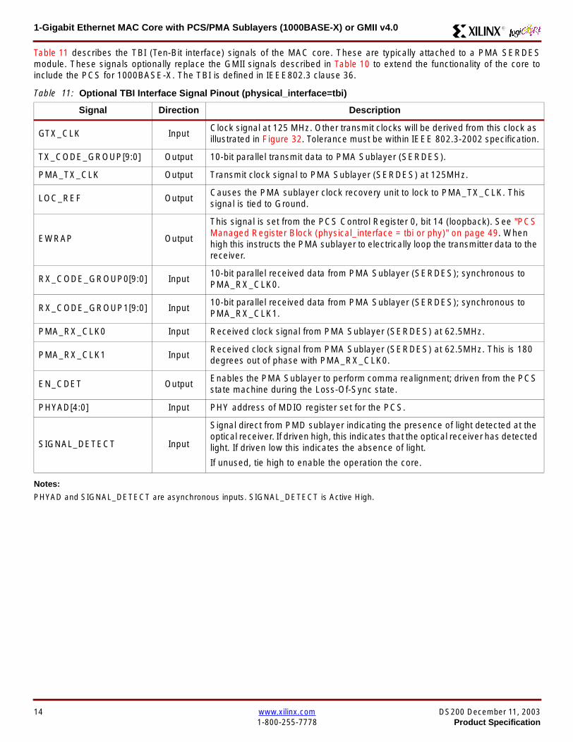
1-Gigabit Ethernet MAC Core with PCSPMA Sublayers (1000BASE-X) or GMII v40 R
Table 11 describes the TBI (Ten-Bit interface) signals of the MAC core These are typically attached to a PMA SERDESmodule These signals optionally replace the GMII signals described in Table 10 to extend the functionality of the core toinclude the PCS for 1000BASE-X The TBI is defined in IEEE8023 clause 36
Notes
PHYAD and SIGNAL_DETECT are asynchronous inputs SIGNAL_DETECT is Active High
Table 11 Optional TBI Interface Signal Pinout (physical_interface=tbi)
Signal Direction Description
GTX_CLK InputClock signal at 125 MHz Other transmit clocks will be derived from this clock asillustrated in Figure 32 Tolerance must be within IEEE 8023-2002 specification
TX_CODE_GROUP[90] Output 10-bit parallel transmit data to PMA Sublayer (SERDES)
PMA_TX_CLK Output Transmit clock signal to PMA Sublayer (SERDES) at 125MHz
LOC_REF OutputCauses the PMA sublayer clock recovery unit to lock to PMA_TX_CLK Thissignal is tied to Ground
EWRAP Output
This signal is set from the PCS Control Register 0 bit 14 (loopback) See PCSManaged Register Block (physical_interface = tbi or phy) on page 49 Whenhigh this instructs the PMA sublayer to electrically loop the transmitter data to thereceiver
RX_CODE_GROUP0[90] Input10-bit parallel received data from PMA Sublayer (SERDES) synchronous toPMA_RX_CLK0
RX_CODE_GROUP1[90] Input10-bit parallel received data from PMA Sublayer (SERDES) synchronous toPMA_RX_CLK1
PMA_RX_CLK0 Input Received clock signal from PMA Sublayer (SERDES) at 625MHz
PMA_RX_CLK1 InputReceived clock signal from PMA Sublayer (SERDES) at 625MHz This is 180degrees out of phase with PMA_RX_CLK0
EN_CDET OutputEnables the PMA Sublayer to perform comma realignment driven from the PCSstate machine during the Loss-Of-Sync state
PHYAD[40] Input PHY address of MDIO register set for the PCS
SIGNAL_DETECT Input
Signal direct from PMD sublayer indicating the presence of light detected at theoptical receiver If driven high this indicates that the optical receiver has detectedlight If driven low this indicates the absence of light
If unused tie high to enable the operation the core
14 wwwxilinxcom DS200 December 11 20031-800-255-7778 Product Specification
1-Gigabit Ethernet MAC Core with PCSPMA Sublayers (1000BASE-X) or GMII v40R
Table 12 describes the interface signals for the Optional PCSPMA sublayer of the MAC core These signals optionallyreplace the GMII signals described in Table 10 to extend the functionality of the core to include the PCS and PMA sublayersfor 1000BASE-X This option uses the Virtex-II Pro Rocket IO functionality which is integrated into the core The PMAsublayer for 1000BASE-X is defined in IEEE8023 clause 36
Notes1 PHYAD and SIGNAL_DETECT are asynchronous inputs SIGNAL_DETECT is Active High
Table 12 Optional PCSPMA sublayer Interface Signal Pinout (physical_interface=phy)
Signal Direction Description
REFCLK InputHigh Quality Reference clock for Multi-Gigabit Transceivers (625 MHz) See Rocket IOUser Guide
REFCLK2 Input Alternative High Quality Reference clock for Multi-Gigabit Transceivers (625 MHz) SeeRocket IO User Guide
BREFCLK Input Alternative High Quality Reference clock for Multi-Gigabit Transceivers (625 MHz)This optionally replaces REFCLK See Rocket IO User Guide
BREFCLK2 Input Alternative High Quality Reference clock for Multi-Gigabit Transceivers (625 MHz)This optionally replaces REFCLK2 See Rocket IO User Guide
REFCLKSEL Input Selects between either (B)REFCLK or (B)REFCLK2 as the input clock source to theMGT See Rocket IO User Guide
USERCLK InputClock signal at 625 MHz This is connected to the TXUSRCLK and RXUSRCLK portsof the Rocket IO MGT This may be derived from (B)REFCLK using a DCM asillustrated in Figure 35
USERCLK2 InputClock signal at 125 MHz This is connected to the TXUSRCLK2 and RXUSRCLK2 portsof the Rocket IO MGT This may be derived from (B)REFCLK using a DCM asillustrated in Figure 35
DCM_LOCKED InputIf a DCM is used to derive USRCLK and USRCLK2 as illustrated in Figure 35 theLOCKED port of the DCM must be connected to the DCM_LOCKED port of the coreThe core will hold itrsquos Rocket IO MGT in reset until DCM_LOCKED is driven to logic 1
TXPTXN OutputDifferential pair for serial transmission from PMA to PMD The clock is embedded in thedata stream
RXPRXN InputDifferential pair for serial reception from PMD to PMA The clock is extracted from thedata stream
PHYAD[40] Input PHY address of MDIO register set for the PCS
SIGNAL_DETECT Input
Signal direct from PMD sublayer indicating the presence of light detected at the opticalreceiver If driven high this indicates that the optical receiver has detected light If drivenlow this indicates the absence of light
If unused tie high to enable the operation the core
DS200 December 11 2003 wwwxilinxcom 15Product Specification 1-800-255-7778
1-Gigabit Ethernet MAC Core with PCSPMA Sublayers (1000BASE-X) or GMII v40 R
Functional Description
Client InterfaceThe client interface is designed for maximum flexibility inmatching to a client switching fabric or network processorinterface
The data pathway is 8 bits wide in both the transmit andreceive directions with each pathway synchronous to theTX_CLK and RX_CLK respectively for completely indepen-dent full duplex operation
Transmitter
Normal Frame Transmission
The timing of a normal outbound frame transfer can be seenin Figure 9 When the client wants to transmit a frame itplaces the first column of data onto the TX_DATA port andasserts a ldquo1rdquo onto TX_DATA_VALID
When the MAC core has read this first byte of data it willassert the TX_ACK signal on the next and subsequent ris-ing clock edges the client must provide the remainder ofthe data for the frame
The end of frame is signalled to the MAC core by takingTX_DATA_VALID Low
In-Band Parameter Encoding
For maximum flexibility in switching applications the Ether-net frame parameters (destination address sourceaddress lengthtype and optionally FCS) are encodedwithin the same data stream that the frame payload is trans-ferred upon rather than on separate ports This is illustratedin the timing diagrams Definitions of the abbreviations usedin the timing diagrams are described in Table 13
Figure 9 Normal Frame Transmission Across Client Interface
Table 13 Abbreviations Used in Timing Diagrams
Abbreviation Definition
DA Destination Address 6 bytes
SA Source Address 6 bytes
LT LengthType Field 2 bytes
FCS Frame Check Sequence 4 bytes
TX_CLK
TX_DATA[70]
TX_DATA_VALID
TX_ACK
TX_UNDERRUN
DA SA DATALT
TX_COLLISION
TX_RETRANSMIT
xip2133
16 wwwxilinxcom DS200 December 11 20031-800-255-7778 Product Specification
1-Gigabit Ethernet MAC Core with PCSPMA Sublayers (1000BASE-X) or GMII v40R
Padding
When fewer than 46 bytes of data are supplied by the clientto the MAC core the transmitter module will add padding upto the minimum frame length The exception to this is whenthe MAC core is configured for client-passed FCS in thiscase the client must also supply the padding to maintain theminimum frame length (see Client-Supplied FCS Passing)
Client-Supplied FCS Passing
If the MAC core is configured to have the FCS field passedin by the client (see Configuration Registers on page 30)the transmission timing is as depicted in Figure 10 In thiscase it is the responsibility of the client to ensure that theframe meets the Ethernet minimum frame length require-ments the MAC core will not perform any padding of thepayload
Figure 10 Frame Transmission with Client-supplied FCS
TX_CLK
TX_DATA[70]
TX_DATA_VALID
TX_ACK
TX_UNDERRUN
DA SA DATA FCSLT
TX_COLLISION
TX_RETRANSMIT
xip2134
DS200 December 11 2003 wwwxilinxcom 17Product Specification 1-800-255-7778
1-Gigabit Ethernet MAC Core with PCSPMA Sublayers (1000BASE-X) or GMII v40 R
Client Underrun
The timing of an aborted transfer can be seen in Figure 11This may happen for instance if a FIFO connected to theclient interface empties before a frame is completed Whenthe client asserts TX_UNDERRUN during a frame transmis-sion the MAC core will insert an error code to corrupt the
current frame and then fall back to idle transmission It isthe responsibility of the client to re-queue the aborted framefor transmission
When an underrun occurs TX_DATA_VALID may beasserted on the clock cycle after the TX_UNDERRUNassertion to request a new transmission
Figure 11 Frame Transmission with Underrun
TX_CLK
TX_DATA[70]
TX_DATA_VALID
TX_ACK
TX_UNDERRUN
DA SA DATALT
TX_COLLISION
TX_RETRANSMIT
xip2135
18 wwwxilinxcom DS200 December 11 20031-800-255-7778 Product Specification
1-Gigabit Ethernet MAC Core with PCSPMA Sublayers (1000BASE-X) or GMII v40R
Back-to-Back Transfers
Figure 12 shows the case where the MAC client is immedi-ately ready to transmit a second frame of data followingcompletion of its first frame In this figure the end of the firstframe is shown on the left On the clock cycle immediatelyfollowing the final byte of the first frame TX_DATA_VALIDis taken low by the client and is taken high one clock cyclelater to indicate that the first byte of the destination addressof the second frame is on TX_DATA awaiting transmission
When the MAC core is ready to accept data TX_ACK isasserted and the transmission continues in the same man-ner as in the case of the single frame The MAC core willdefer the assertion of TX_ACK appropriately to comply withinter-packet gap requirements and flow control requests
If the MAC core is operating in half-duplex mode the timingshown in Figure 12 is required to take advantage of framebursting the MAC core is only guaranteed to retain controlof the medium if the TX_DATA_VALID signal is low for a sin-gle clock cycle For more information on frame bursting seeIEEE 8023-2002
Figure 12 Back to Back Frame Transmission
TX_CLK
TX_DATA[70]
TX_DATA_VALID
TX_ACK
TX_UNDERRUN
TX_COLLISION
TX_RETRANSMIT
xip2136
DS200 December 11 2003 wwwxilinxcom 19Product Specification 1-800-255-7778
1-Gigabit Ethernet MAC Core with PCSPMA Sublayers (1000BASE-X) or GMII v40 R
VLAN Tagged Frames
Transmission of a VLAN tagged frame (if enabled) can beseen in Figure 13 Note that the handshaking signalsacross the interface do not change however the VLANtype tag 81-00 must be supplied by the client to signify that
the frame is VLAN tagged The client also supplies the twobytes of Tag Control Information V1 and V2 at the appro-priate times in the data stream More information on thecontents of these two bytes can be found in IEEE8023-2002
Maximum Permitted Frame Length
The maximum legal length of a frame specified in IEEE8023-2002 is 1518 bytes for non-VLAN tagged framesVLAN tagged frames may be extended to 1522 bytesWhen jumbo frame handling is disabled and the clientattempts to transmit a frame which exceeds the maximumlegal length the MAC core will insert an error code to cor-
rupt the current frame and the frame will be truncated to themaximum legal length When jumbo frame handling isenabled frames which are longer than the legal maximumare transmitted error-free
For more information on enabling and disabling jumboframe handling see Configuration Registers on page 30
Figure 13 Transmission of a VLAN Tagged Frame
TX_CLK
TX_DATA[70]
TX_DATA_VALID
TX_ACK
TX_UNDERRUN
DA SA DATALTVLANtag
81 00V1V2
TX_COLLISION
TX_RETRANSMIT
xip2137
20 wwwxilinxcom DS200 December 11 20031-800-255-7778 Product Specification
1-Gigabit Ethernet MAC Core with PCSPMA Sublayers (1000BASE-X) or GMII v40R
Frame Collisions - Half Duplex Operation Only
In half duplex Ethernet operation collisions will occur on themedium as a matter of course this is how the arbitrationalgorithm is fulfilled In case of a collision the MAC core sig-nals to the client that data may need to be resupplied as fol-lows
If there is a collision the TX_COLLISION signal will be setto ldquo1rdquo by the MAC core If a frame is in progress the clientmust abort the transfer and take TX_DATA_VALID to ldquo0rdquo
If the TX_RETRANSMIT signal is ldquo1rdquo in the same clockcycle that the TX_COLLISION signal is ldquo1rdquo the client must
resubmit the previous frame to the MAC core for retrans-mission TX_DATA_VALID must be asserted to the MACcore within 8 clock cycles of the TX_COLLISION signal inorder to meet Ethernet timing requirements See Figure 14
If the TX_RETRANSMIT signal is ldquo0rdquo in the same clockcycle that the TX_COLLISION signal is ldquo1rdquo the number ofretries for this frame has exceeded the Ethernet specifica-tion and the frame should be dropped by the client The cli-ent can then make any new frame available to the MAC fortransmission without timing restriction See Figure 15
Figure 14 Collision Handling - Frame retransmission required
Figure 15 Collision Handling - No frame retransmission required
TX_CLK
TX_DATA[70]
TX_DATA_VALID
TX_ACK
TX_UNDERRUN
TX_COLLISION
TX_RETRANSMIT
8 clocks max
xip2138
TX_CLK
TX_DATA[70]
TX_DATA_VALID
TX_ACK
TX_UNDERRUN
TX_COLLISION
TX_RETRANSMIT
xip2139
DS200 December 11 2003 wwwxilinxcom 21Product Specification 1-800-255-7778
1-Gigabit Ethernet MAC Core with PCSPMA Sublayers (1000BASE-X) or GMII v40 R
Interframe Gap Adjustment
The user can elect to vary the length of the inter fame gapIf this function is selected (via a configuration bit in thetransmitter control register see Configuration Registerson page 30) then the MAC will exert back pressure to delaythe transmission of the next frame until the requested num-ber of Idle cycles has elapsed The number of Idle cycles iscontrolled by the value on the TX_IFG_DELAY port at thestart of frame transmission Figure 16 shows the MAC oper-ating in this mode
Reducing the Inter fame gap to below the IEEE 8023-2002minimum of 12 Idles is supported in Full Duplex onlydesigns and will transmit an absolute minimum of 4 Idles Ifthe Interframe gap adjustment is reduced below 12 Idlesthen the accuracy of the Optional Statistical Gathering(statistics_gathering=true) Counters cannot be guaranteedHowever the TX_STATISTIC_VECTOR andRX_STATISTIC_VECTOR will always remain correct
Transmitter Statistics Vector
The statistics for the frame transmitted are contained withinthe TX_STATISTICS_VECTOR The vector is driven syn-chronously by the transmitter clock TX_CLK followingframe transmission The bit field definition for the Vector isdefined in Table 14
All bit fields with the exception of BYTE_VALID are validonly when the TX_STATISTICS_VALID is asserted This isillustrated in Figure 17 BYTE_VALID is significant on everyTX_CLK cycle
TX_STATISTICS_VECTOR bits 25 down to 17 inclusive arefor half duplex only and will be set to logic 0 when operatingin full duplex mode
Figure 16 Interframe Gap Adjustment
TX_CLK
TX_DATA[70]
TX_DATA_VALID
TX_ACK
DA SA
TX_IFG_DELAY
IFG ADJUST VALUE
0x0D
13 Idles inserted
DA
Next IFG ADJUST VALUE
xip2140
Figure 17 Transmitter Statistics Vector Timing
TX_CLK
TX_STATISTICS_VECTOR[280]
TX_STATISTICS_VALID
xip2141
22 wwwxilinxcom DS200 December 11 20031-800-255-7778 Product Specification
1-Gigabit Ethernet MAC Core with PCSPMA Sublayers (1000BASE-X) or GMII v40R
Table 14 Bit Definition for the Transmitter Statistics Vector
TX_STATISTICS_VECTOR Name Description
28 PAUSE_FRAME_TRANSMITTEDAsserted if the previous frame was a pause framethat the MAC itself initiated in response to aPAUSE_REQ assertion
27 BYTE_VALID
Asserted if a MAC frame byte (DA to FCS inclusive)is in the process of being transmitted This is valid onevery clock cycle
Do not use this as an enable signal to indicate thatdata is present on GMII_TXD[70]
26 Reserved Returns logic 0
25 down to 22 TX_ATTEMPTS[30]
The number of attempts that have been made totransmit the previous frame This is a 4-bit number0 should be interpreted as 1 attempt 1 as 2attempts up until 15 as 16 attempts
21 Reserved Returns logic 0
20 EXCESSIVE_COLLISIONAsserted if a collision has been detected on each ofthe last 16 attempts to transmit the previous frame
19 LATE_COLLISIONAsserted if a late collision occurred during frametransmission
18 EXCESSIVE_DEFERRALAsserted if the previous frame was deferred for anexcessive amount of time as defined by the constantldquomaxDeferTimerdquo in IEEE 8023-2002
17 TX_DEFERRED Asserted if transmission of the frame was deferred
16 VLAN_FRAMEAsserted if the previous frame contained a VLANidentifier in the LengthType field when transmitterVLAN operation is enabled
15 down to 5 FRAME_LENGTH_COUNTThe length of the previous frame in number of bytesThe count will stick at 2047 for any Jumbo frameslarger than this value
4 CONTROL_FRAMEAsserted if the previous frame had the special MACControl Type code 88-08 in the LengthType field
3 UNDERRUN_FRAMEAsserted if the previous frame contained anunderrun error
2 MULTICAST_FRAMEAsserted if the previous frame contained a multicastaddress in the Destination Address field
1 BROADCAST_FRAMEAsserted if the previous frame contained abroadcast address in the Destination Address field
0 SUCCESSFUL_FRAMEAsserted if the previous frame was transmittedwithout error
DS200 December 11 2003 wwwxilinxcom 23Product Specification 1-800-255-7778
1-Gigabit Ethernet MAC Core with PCSPMA Sublayers (1000BASE-X) or GMII v40 R
Receiver
Normal Frame Reception
The timing of a normal inbound frame transfer can be seenin Figure 18 The client must be prepared to accept data atany time there is no buffering within the MAC to allow forlatency in the receive client Once frame reception begins
data is transferred on consecutive clock cycles to thereceive client until the frame is complete The MAC assertsthe RX_GOOD_FRAME signal to indicate that the framewas successfully received and that the frame should beanalyzed by the client
Frame parameters (destination address source addresslengthtype and optionally FCS) are supplied on the databus according to the timing diagram The abbreviations arethe same as those described in Table 13 on page 16
If the LengthType field in the frame has the Length interpre-tation and this indicates that the inbound frame has beenpadded to meet the Ethernet minimum frame size specifica-tion then this padding will not be passed to the client in thedata payload The exception to this is in the case whereFCS passing is enabled see Client-Supplied FCS Pass-ing on page 25
Therefore when Client-Supplied FCS passing is disabledRX_DATA_VALID = lsquo0rsquo between frames for the duration ofthe Padding field (if present) the FCS field carrier exten-sion (if present) the interframe gap following the frame andthe preamble field of the next frame When Client-Supplied
FCS passing is enabled RX_DATA_VALID = lsquo0rsquo betweenframes for the duration of carrier extension (if present) theinterframe gap and the preamble field of the followingframe
RX_GOOD_FRAME RX_BAD_FRAME timing
Although the timing diagram in Figure 18 shows theRX_GOOD_FRAME signal asserted shortly after the lastvalid data on RX_DATA this is not always the case TheRX_GOOD_FRAME or RX_BAD_FRAME signals areasserted only after all frame checks are completed This isafter the FCS field has been received (and after reception ofcarrier extension if present)
Therefore either RX_GOOD_FRAME or RX_BAD_FRAMEis asserted following frame reception at the beginning of theinterframe gap
Figure 18 Normal Frame Reception
RX_CLK
RX_DATA[70]
RX_DATA_VALID
RX_GOOD_FRAME
RX_BAD_FRAME
DA SA DATALT
xip2142
24 wwwxilinxcom DS200 December 11 20031-800-255-7778 Product Specification
1-Gigabit Ethernet MAC Core with PCSPMA Sublayers (1000BASE-X) or GMII v40R
Frame Reception with Errors
The case of an unsuccessful frame reception (for examplea fragment frame or a frame with an incorrect FCS) can beseen in Figure 19 In this case the RX_BAD_FRAME signal
is asserted to the client at the end of the frame It is then theresponsibility of the client to drop the data already trans-ferred for this frame
Figure 19 Frame Reception with Error
Client-Supplied FCS Passing
If the MAC core is configured to pass the FCS field to the cli-ent (see Configuration Registers on page 30) then this ishandled as shown in Figure 20
In this case any padding inserted into the frame to meetEthernet minimum frame length specifications will be leftintact and passed to the client
Note that even though the FCS is passed up to the client itis also verified by the MAC core and RX_BAD_FRAMEasserted if the FCS check fails
RX_CLK
RX_DATA[70]
RX_DATA_VALID
RX_GOOD_FRAME
RX_BAD_FRAME
DA SA DATALT
xip2144
Figure 20 Frame Reception with In-Band FCS Field
RX_CLK
RX_DATA[70]
RX_DATA_VALID
RX_GOOD_FRAME
RX_BAD_FRAME
DA SA DATALT FCS
xip2145
DS200 December 11 2003 wwwxilinxcom 25Product Specification 1-800-255-7778
1-Gigabit Ethernet MAC Core with PCSPMA Sublayers (1000BASE-X) or GMII v40 R
VLAN Tagged Frames
The reception of a VLAN tagged frame (if enabled) can beseen in Figure 21 The VLAN frame is passed to the clientso that the frame may be identified as VLAN tagged this is
followed by the Tag Control Information bytes V1 and V2More information on the interpretation of these bytes maybe found in IEEE 8023-2002 standard
Maximum Permitted Frame Length
The maximum legal length of a frame specified in IEEE8023-2002 is 1518 bytes for non-VLAN tagged framesVLAN tagged frames may be extended to 1522 bytesWhen jumbo frame handling is disabled and the corereceives a frame which exceeds the maximum legal lengthRX_BAD_FRAME will be asserted When jumbo framehandling is enabled frames which are longer than the legalmaximum are received in the same way as shorter frames
For more information on enabling and disabling jumboframe handling see Configuration Registers on page 30
LengthType Field Error Checks
Enabled
Default operation is with the LengthType error checkingenabled (see Receiver Configuration Word 1 on page 31)In this mode the following checks are made on all framesreceived If either of these checks fail then the frame ismarked as BAD
bull A value in the LengthType field that is greater than orequal to decimal 46 but less than decimal 1536 (aLength interpretation) is checked against the actualdata length received
bull A value in the LengthType field that is less thandecimal 46 is checked to see that the data field ispadded to exactly 46 bytes (so that the resultant frameis minimum frame size 64 bytes total in length)
Furthermore if Padding is indicated (the LengthType fieldis less than decimal 46) and Client-Supplied FCS Passing isdisabled then the Length value in the LengthType field willbe used to deassert RX_DATA_VALID after the indicatednumber of data bytes so that the Padding bytes areremoved from the frame
Disabled
When the LengthType error checking is disabled (seeReceiver Configuration Word 1 on page 31) theLengthType error checks described above are not per-formed A frame containing only these errors will be markedas GOOD
Furthermore if Padding is indicated and Client-SuppliedFCS Passing is disabled then a Length Value in theLengthType field will not be used to deassertRX_DATA_VALID Instead RX_DATA_VALID will be deas-serted before the start of the FCS field in this way any pad-ding will not be removed from the frame
Figure 21 Reception of a VLAN Tagged Frame
RX_CLK
RX_DATA[70]
RX_DATA_VALID
RX_GOOD_FRAME
RX_BAD_FRAME
DA SA DATALT
81 00 V1 V2
VLANtag
xip2146
26 wwwxilinxcom DS200 December 11 20031-800-255-7778 Product Specification
1-Gigabit Ethernet MAC Core with PCSPMA Sublayers (1000BASE-X) or GMII v40R
Receiver Statistics Vector
The statistics for the frame received are contained withinthe RX_STATISTICS_VECTOR The vector is driven syn-chronously by the receiver clock RX_CLK following framereception The bit field definition for the Vector is defined inTable 15
All bit fields with the exception of BYTE_VALID are validonly when the RX_STATISTICS_VALID is asserted This isillustrated in Figure 22 BYTE_VALID is significant on everyRX_CLK cycle
Figure 22 Receiver Statistics Vector Timing
RX_CLK
RX_STATISTICS_VECTOR[220]
RX_STATISTICS_VALID
xip2147
Table 15 Bit Definition for the Receiver Statistics Vector
RX_STATISTICS_VECTOR Name Description
22LENGTHTYPE Out ofRange
Asserted if the lengthtype field contained a length valuethat did not match the number of MAC client data bytesreceived Also high if the lengthtype field indicated thatthe frame contained padding but the number of MAC cli-ent data bytes received was not equal to 64 bytes (min-imum frame size)
The exception to the above is when the LengthTypeField Error Checks are disabled in which case this bitwill not be asserted
21 BAD_OPCODE
Asserted if the previous frame was error-free andcontained the special Control Frame identifier in theLengthType field but contained an opcode that isunsupported by the MAC (Any Opcode other thanPAUSE)
20 FLOW_CONTROL_FRAME
Asserted if the previous frame was error-freecontained the special Control Frame identifier in theLengthType field contained a Destination Addressthat matched either the MAC Control MulticastAddress or the configured source address of the MACcontained the supported PAUSE opcode and wasacted upon by the MAC
19 BYTE_VALID
Asserted if a MAC frame byte (DA to FCS inclusive) isin the process of being received This is valid on everyclock cycle
Do not use this as an enable signal to indicate thatdata is present on RX_DATA[70]
18 VLAN_FRAMEAsserted if the previous frame contained a VLANidentifier in the LengthType field when receiver VLANoperation is enabled
DS200 December 11 2003 wwwxilinxcom 27Product Specification 1-800-255-7778
1-Gigabit Ethernet MAC Core with PCSPMA Sublayers (1000BASE-X) or GMII v40 R
17 OUT_OF_BOUNDS
Asserted if the previous frame exceeded the specifiedIEEE8023-2002 maximum legal length (seeMaximum Permitted Frame Length on page 26) Thisis only valid if Jumbo frames are disabled
16 CONTROL_FRAMEAsserted if the previous frame contained the specialControl Frame identifier in the LengthType field
15 down to 5 FRAME_LENGTH_COUNTThe length of the previous frame in number of bytesThe count will stick at 2047 for any Jumbo frameslarger than this value
4 MULTICAST_FRAMEAsserted if the previous frame contained a multicastaddress in the Destination Address field
3 BROADCAST_FRAMEAsserted if the previous frame contained the broadcastaddress in the Destination Address field
2 FCS_ERRORAsserted if the previous frame received had anincorrect FCS value or the MAC detected error codesduring frame reception
1 BAD_FRAME1 Asserted if the previous frame received containederrors
0 GOOD_FRAME1 Asserted if the previous frame received was error-free
1 If the LengthType Field Error Checks are disabled then a frame which contains this type of error will be marked as a GOOD_FRAMEproviding no additional errors were detected
Table 15 Bit Definition for the Receiver Statistics Vector
RX_STATISTICS_VECTOR Name Description
28 wwwxilinxcom DS200 December 11 20031-800-255-7778 Product Specification
1-Gigabit Ethernet MAC Core with PCSPMA Sublayers (1000BASE-X) or GMII v40R
Flow ControlThe flow control block is designed to Clause 31 of the IEEE8023-2002 standard The MAC may be configured to sendpause frames and to act upon their reception These twobehaviors can be configured asymmetrically see Configu-ration Registers on page 30
Transmitting a PAUSE Control Frame
The client initiates a flow control frame by assertingPAUSE_REQ while the pause value is on the PAUSE_VALbus These signals are synchronous to TX_CLK The timingof this can be seen in Figure 23
If the MAC core is configured to support transmit flow con-trol this action causes the core to transmit a PAUSE controlframe on the link with the PAUSE parameter set to thevalue on PAUSE_VAL in the cycle when PAUSE_REQ wasasserted This will not disrupt any frame transmission inprogress but will take priority over any pending frame trans-
mission This frame will be transmitted even if the transmit-ter is in the paused state itself
Receiving a Pause Control Frame
When an error-free frame is received by the MAC core thefollowing checks are made
1 The Destination Address field is matched against theMAC Control Multicast address or the configuredSource Address for the MAC (see ConfigurationRegisters on page 30)
2 The LengthType field is matched against the MACControl Type code
3 The opcode field contents are matched against thePAUSE opcode if check 2 is true
If any of the above checks are false or the MAC Flow Con-trol logic for the receiver is disabled the frame is ignored bythe Flow Control logic and passed up to the client
If the frame passes all of the above checks is of minimumlegal size and the MAC Flow Control logic for the receiver isenabled the pause value parameter in the frame is thenused to inhibit transmitter operation for the time defined inthe IEEE8023-2002 specification This inhibit is imple-mented using the same back pressure scheme shown inFigure 12 Because the received pause frame has beenacted upon it is passed to the client with RX_BAD_FRAMEasserted to indicate to the client that it should be dropped
Reception of any frame for which check 2 is true and whichis not of legal minimum length is considered an invalid Con-trol frame This will be ignored by the Flow Control logic andpassed to the client with RX_BAD_FRAME asserted
Figure 23 Pause Request Timing
TX_CLK
PAUSE_VAL[150]
PAUSE_REQ
xip2148
DS200 December 11 2003 wwwxilinxcom 29Product Specification 1-800-255-7778
1-Gigabit Ethernet MAC Core with PCSPMA Sublayers (1000BASE-X) or GMII v40 R
Optional Management Interface(management_interface=true)The management interface is a processor-independentinterface with standard address data and control signals Itmay be used as is or a wrapper may be applied (not sup-plied) to interface to common bus architectures
This interface is used for
bull Configuration of the MAC core
bull Access to optional statistics counters for use by higherlayers for example SNMP
bull access through the MDIO interface to the managementregisters located in the PHY attached to the MAC core
The management interface is accessed differently depend-ing on the type of transaction a truth table showing whichaccess method is required for each transaction type isshown in Table 16 These access methods are described inthe following sections
HOST_CLK Frequency
The management interface clock HOST_CLK is used toderive the MDIO clock MDC and is therefore subject tosome frequency restrictions This HOST_CLK must be
ge 10 MHz
le 100 MHz
Configuring the MAC core to derive the MDC signal fromthis clock is detailed in MDIO Interface on page 37
Configuration Registers
After power up or reset the client may reconfigure the coreparameters from their defaults such as flow control supportConfiguration changes can be written at any time Both thereceiver and transmitter logic will only respond to configura-tion changes during Inter Frame Gaps The exceptions tothis are the configurable resets which take effect immedi-ately
Configuration of the MAC core is performed through a reg-ister bank accessed through the management interfaceThe configuration registers available in the core are detailedin Table 17 As can be seen the address has some implicitdonrsquot care bits any access to an address in the rangesshown will perform a 32-bit read or write from the same con-figuration word
Table 16 Management Interface Transaction Types
Transaction HOST_MIIM_SEL HOST_ADDR[9]
Configuration 0 1
Statistics 0 0
MIIM access 1 X
Table 17 Configuration Registers
Address Description
0x200-0x23F Receiver Configuration (Word 0)
0x240-0x27F Receiver Configuration (Word 1)
0x280-0x2BF Transmitter Configuration
0x2C0-0x2FF Flow Control Configuration
0x300-0x33F Reserved
0x340-0x37F Management Configuration
30 wwwxilinxcom DS200 December 11 20031-800-255-7778 Product Specification
1-Gigabit Ethernet MAC Core with PCSPMA Sublayers (1000BASE-X) or GMII v40R
The register contents for the two receiver configuration words can be seen in Table 18 and Table 19
Notes1 In changing the receiverrsquos mode from Half Duplex to Full Duplex there is a period of time of up to 24 us following the mode change
when no new receiver statistics can be stored in the optional Statistical Counters
Table 18 Receiver Configuration Word 0
Bit Default Value Description
31-0 All 0rsquos
Pause frame MAC Source Address[310] This address is used by the MAC tomatch against the Destination Address of any incoming flow control frames It isalso used by the flow control block as the Source Address (SA) for any outboundflow control frames
The address is ordered so the first byte transmittedreceived is the lowestpositioned byte in the register for example a MAC address ofAA-BB-CC-DD-EE-FF would be stored in Address[470] as 0xFFEEDDCCBBAA
Table 19 Receiver Configuration Word 1
Bit Default Value Description
15-0 All 0rsquos Pause frame MAC Source Address[4732] See description in Table 18
24-16 NA Reserved
25 0
LengthType Error Check Disable When this bit is set to ldquo1rdquo the core will notperform the LengthType field error checks as described in LengthType FieldError Checks on page 26 When this bit is set to ldquo0rdquo the LengthType field checkswill be performed this is normal operation
26 0Half Duplex If ldquo1rdquo the receiver will operate in half duplex mode If ldquo0rdquo the receiverwill operate in full duplex mode Has no effect if XCO parameterhalf_duplex_capable = false
27 0VLAN Enable When this bit is set to ldquo1rdquo VLAN tagged frames will be acceptedby the receiver
28 1Receiver Enable If set to ldquo1rdquo the receiver block will be operational If set to ldquo0rdquothe block will ignore activity on the physical interface RX port
29 0
In-band FCS Enable When this bit is ldquo1rdquo the MAC receiver will pass the FCS fieldup to the client as described in Client-Supplied FCS Passing on page 25 Whenit is ldquo0rdquo the client will not be passed the FCS In both cases the FCS will beverified on the frame
30 0Jumbo Frame Enable When this bit is set to ldquo1rdquo the MAC receiver will acceptframes over the specified IEEE8023-2002 maximum legal length When this bitis ldquo0rdquo the MAC will only accept frames up to the specified maximum
31 0Reset When this bit is set to ldquo1rdquo the receiver will be reset The bit will thenautomatically revert to ldquo0rdquo Note that this reset will also set all of the receiverconfiguration registers to their default values
DS200 December 11 2003 wwwxilinxcom 31Product Specification 1-800-255-7778
1-Gigabit Ethernet MAC Core with PCSPMA Sublayers (1000BASE-X) or GMII v40 R
The register contents for the Transmitter Configuration Word are described in Table 20
Notes1 In changing the transmitterrsquos mode from Half Duplex to Full Duplex there is a period of time of up to 24 us following the mode change
when no new transmitter statistics can be stored in the optional Statistical Counters
Table 20 Transmitter Configuration Word
Bit Default Value Description
24-0 NA Reserved
25 0
Interframe Gap Adjust Enable If lsquo1rsquo the transmitter will read the value on the portTX_IFG_DELAY at the start of frame transmission and adjust the interframe gapfollowing the frame accordingly See Interframe Gap Adjustment on page 22 Ifldquo0rdquo the transmitter will output a minimum Inter Frame Gap of twelve clock cyclesas specified in IEEE8023-2002
26 0Half Duplex If lsquo1rsquo the transmitter will operate in half duplex mode If lsquo0rsquo thetransmitter will operate in full duplex mode Has no effect if XCO parameterhalf_duplex_capable = false
27 0VLAN Enable When this bit is set to 1 the transmitter will allow the transmissionof VLAN tagged frames
28 1Transmit Enable When this bit is 1 the transmitter is operational When it is 0the transmitter is disabled
29 0
In-band FCS Enable When this bit is lsquo1rsquo the MAC transmitter will expect the FCSfield to be passed in by the client as described in Client-Supplied FCS Passingon page 17 When this bit is ldquo0rdquo the MAC transmitter will append padding asrequired compute the FCS and append it to the frame
30 0
Jumbo Frame Enable When this bit is set to ldquo1rdquo the MAC transmitter will sendframes that are greater than the specified IEEE8023-2002 maximum legallength When this bit is ldquo0rdquo the MAC will only send frames up to the specifiedmaximum
31 0Reset When this bit is set to ldquo1rdquo the transmitter will be reset The bit will thenautomatically revert to ldquo0rdquo Note that this reset will also set all of the transmitterconfiguration registers to their default values
32 wwwxilinxcom DS200 December 11 20031-800-255-7778 Product Specification
1-Gigabit Ethernet MAC Core with PCSPMA Sublayers (1000BASE-X) or GMII v40R
The register contents for the Flow Control Configuration Word are described in Table 21
The register contents for the Management Configuration Word are described in Table 22
Writing to the configuration registers through the manage-ment interface is depicted in Figure 24 When accessing theconfiguration registers (ie when HOST_ADDR[9] = lsquo1rsquo andHOST_MIIM_SEL = lsquo0rsquo) the upper bit of HOST_OPCODEfunctions as an Active Low write enable signal The lowerHOST_OPCODE bit is a ldquodonrsquot carerdquo
Reading from the configuration register words is similar butthe upper HOST_OPCODE bit should be lsquo1rsquo This is shownin Figure 25 In this case the contents of the register appearon HOST_RD_DATA the HOST_CLK edge after the regis-ter address is asserted onto HOST_ADDR
Table 21 Flow Control Configuration Word
Bit Default Value Description
28-0 NA Reserved
29 1
Flow Control Enable (RX) When this bit is lsquo1rsquo received flow control frames willinhibit the transmitter operation as described in Receiving a Pause ControlFrame on page 29 When this bit is lsquo0rsquo received flow control frames will alwaysbe passed up to the client
30 1Flow Control Enable (TX) When this bit is lsquo1rsquo asserting the PAUSE_REQ signalwill send a flow control frame out from the transmitter When this bit is 0 assertingthe PAUSE_REQ signal has no effect
31 NA Reserved
Table 22 Management Configuration Word
Bits Default Value Description
4-0 All 0rsquos Clock Divide[40] See MDIO Interface on page 37
5 0MDIO Enable When this bit is 1 the MDIO interface can be used to accessattached PHY devices When this bit is 0 the MDIO interface is disabled and theMDIO signals remain inactive
31-6 NA Reserved
Figure 24 Configuration Register Write Timing
HOST_CLK
HOST_ADDR[80]
HOST_ADDR[9]
HOST_OPCODE[1]
HOST_MIIM_SEL
HOST_WR_DATA[310]xip2149
Figure 25 Configuration Register Read Timing
HOST_CLK
HOST_ADDR[80]
HOST_ADDR[9]
HOST_OPCODE[1]
HOST_MIIM_SEL
HOST_RD_DATA[310]
xip2150
DS200 December 11 2003 wwwxilinxcom 33Product Specification 1-800-255-7778
1-Gigabit Ethernet MAC Core with PCSPMA Sublayers (1000BASE-X) or GMII v40 R
Optional Statistical Gathering(statistics_gathering=true)
During operation the MAC core collects statistics on thesuccess and failure of various operations for processing by
station management entities (STA) further up the protocolstack These statistics are accessed by the host through theoptional management interface A complete list of statisticssupported is described in Table 23
Table 23 Statistics Registers
Address Name Description
0x000 Frames Received OK1 A count of error-free frames received
0x001 Frame Check Sequence Errors A count of received frames that failed the CRC check and were at least64 bytes in length
0x002 Broadcast Frames Received OK1A count of frames that were successfully received and were directed tothe broadcast group address
0x003 Multicast Frames Received OK1 A count of frames that were successfully received and were directed toa non broadcast group address
0x004 64 byte Frames Received OK1 A count of error-free frames received that were 64 bytes in length
0x005 65-127 byte Frames Received OK1A count of error-free frames received that were between 65 and 127bytes in length
0x006 128-255 byte Frames Received OK1A count of error-free frames received that were between 128 and 255bytes in length
0x007 256-511 byte Frames Received OK1A count of error-free frames received that were between 256 and 511bytes in length
0x008512-1023 byte Frames ReceivedOK1
A count of error-free frames received that were between 512 and 1023bytes in length
0x0091024-MaxFrameSize byte FramesReceived OK1
A count of error-free frames received that were between 1024 bytes andthe specified IEEE8023-2002 maximum legal length (see MaximumPermitted Frame Length on page 26)
0x00A Control Frames Received OKA count of error-free frames received that contained the specialControl Frame identifier in the LengthType field
0x00B LengthType Out of Range
A count of frames received that were at least 64 bytes in length wherethe lengthtype field contained a length value that did not match thenumber of MAC client data bytes received
The counter also increments for frames in which the lengthtype fieldindicated that the frame contained padding but where the number ofMAC client data bytes received was greater than 64 bytes (minimumframe size)
The exception to the above is when the LengthType Field Error Checksare disabled in which case this counter will not increment
0x00C VLAN Tagged Frames Received OKA count of error-free VLAN frames received This counter will only incre-ment when the receiver is configured for VLAN operation
0x00D Pause Frames Received OK
A count of error-free frames received that contained the MAC Controltype identifier 88-08 in the LengthType field contained a Destinationaddress that matched either the MAC Control multicast address or theconfigured source address of the MAC contained the PAUSE opcodeand were acted upon by the MAC
0x00EControl Frames Received withUnsupported Opcode
A count of error-free frames received that contained the MAC Controltype identifier 88-08 in the LengthType field but were received with anopcode other than the PAUSE opcode
34 wwwxilinxcom DS200 December 11 20031-800-255-7778 Product Specification
1-Gigabit Ethernet MAC Core with PCSPMA Sublayers (1000BASE-X) or GMII v40R
0x00F Oversize Frames Received OK1A count of otherwise error-free frames received that exceeded the max-imum legal frame length specified in IEEE 8023-2002 (see MaximumPermitted Frame Length on page 26)
0x010 Undersize frames receivedA count of the number of frames received that were less than 64 bytesin length but were otherwise well formed
0x011 Fragment frames receivedA count of the number of frames received that were less than 64 bytesin length and had a bad Frame Check Sequence field
0x012 Received bytesA count of bytes of frames that are received (Destination Address toFrame Check Sequence inclusive)
0x013 Transmitted bytesA count of bytes of frames that are transmitted (Destination Address toFrame Check Sequence inclusive)
0x020 Frames Transmitted OK A count of error-free frames transmitted
0x021 Broadcast Frames Transmitted OK A count of error-free frames that were transmitted to the broadcastaddress
0x022 Multicast Frames Transmitted OK A count of error-free frames that were transmitted to a group destina-tion address other than broadcast
0x023 Underrun Errors
A count of frames that would otherwise be transmitted by the core butcould not be completed due to the assertion of TX_UNDERRUN duringthe frame transmission This will not count frames which are less than64 bytes in length
0x024 Control Frames Transmitted OKA count of error-free frames transmitted that contained the MACControl Frame type identifier 88-08 in the LengthType field
0x025 64 byte Frames Transmitted OK A count of error-free frames transmitted that were 64 bytes in length
0x026 65-127 byte Frames Transmitted OKA count of error-free frames transmitted that were between 65 and 127bytes in length
0x027128-255 byte Frames TransmittedOK
A count of error-free frames transmitted that were between 128 and 255bytes in length
0x028256-511 byte Frames TransmittedOK
A count of error-free frames transmitted that were between 256 and 511bytes in length
0x029512-1023 byte Frames TransmittedOK
A count of error-free frames transmitted that were between 512 and1023 bytes in length
0x02A1024-MaxFrameSize byte FramesTransmitted OK
A count of error-free frames transmitted that were between 1024 and thespecified IEEE8023-2002 maximum legal length (see Maximum Per-mitted Frame Length on page 20)
0x02BVLAN Tagged Frames TransmittedOK
A count of error-free VLAN frames transmitted This counter will onlyincrement when the transmitter is configured for VLAN operation
0x02C Pause Frames Transmitted OKA count of error-free PAUSE frames generated and transmitted by thecore in response to an assertion of PAUSE_REQ
0x02D Oversize Frames Transmitted OKA count of otherwise error-free frames transmitted that exceeded themaximum legal frame length specified in IEEE 8023-2002 (see Maxi-mum Permitted Frame Length on page 20)
0x02E Single Collision Frames A count of frames that are involved in a single collision but are subse-quently transmitted successfully (Half Duplex Mode only)
Table 23 Statistics Registers (Continued)
Address Name Description
DS200 December 11 2003 wwwxilinxcom 35Product Specification 1-800-255-7778
1-Gigabit Ethernet MAC Core with PCSPMA Sublayers (1000BASE-X) or GMII v40 R
Each of these statistic registers is 64 bits wide and thereforemust be read in a two-cycle transfer The timing of this pro-cess is shown in Figure 26 Six clocks after the read trans-action is initiated the least significant word (LSW) of thestatistics counter appears on the HOST_RD_DATA bus
and a clock cycle later the most significant word (MSW)appears For accurate statistic values 64 clock ticks (ofTX_CLK for transmit statistics or RX_CLK for receive statis-tics) must elapse after the last frame is sent or receivedthrough the MAC core
0x02F Multiple Collision Frames A count of frames that are involved in more than one collision but aresubsequently transmitted successfully (Half Duplex Mode only)
0x040 Frames with Deferred Transmissions A count of frames whose transmission was delayed on its first attemptbecause the medium was busy (Half Duplex Mode only)
0x041 Late Collisions
A count of the times that a collision has been detected later than oneslotTime from the start of the packet transmission A late collision iscounted twice both as a collision and as a lateCollision (Half DuplexMode only)
0x042Frames Aborted due to Excesscollisions
A count of the frames that due to excessive collisions are not transmit-ted successfully (Half Duplex Mode only)
0x043 Carrier Sense ErrorsA count of times that the GMII_CRS signal was not asserted or wasdisasserted during the transmission of a frame without collision (HalfDuplex Mode only)
0x044 Frames with Excess DeferralA count of frames that deferred transmission for an excessive period oftime (Half Duplex Mode only)
1 If the LengthType Field Error Checks are disabled then these counters will still increment for received frames which contain this typeof error (providing no additional errors were detected)
Table 23 Statistics Registers (Continued)
Address Name Description
Figure 26 Statistic Register Read Timing
HOST_CLK
HOST_ADDR[80]
HOST_ADDR[9]
HOST_REQ
HOST_MIIM_SEL
HOST_RD_DATA[310]
6 CLOCKS
LSW MSW
xip2151
36 wwwxilinxcom DS200 December 11 20031-800-255-7778 Product Specification
1-Gigabit Ethernet MAC Core with PCSPMA Sublayers (1000BASE-X) or GMII v40R
MDIO Interface
The management interface is also used to access the MDIO(MII Management) interface of the MAC core this interfaceis used to access the Managed Information Block (MIB) ofthe PHY components attached to the MAC core
The MDIO interface supplies a clock to the externaldevices MDC This clock is derived from the HOST_CLKsignal using the value in the Clock Divide[40] configurationregister The frequency of the MDIO clock is given by thefollowing equation
The frequency of MDC given by this equation should notexceed 25 MHz in order to comply with the IEEE8023-2002 specification for this interface To prevent MDCfrom being out of specification the Clock Divide[40] valuepowers up at 00000 and while this value is in the register itis impossible to enable the MDIO interface
For details of the register map of PHY layer devices and afuller description of the operation of the MDIO interfaceitself see IEEE specification 8023-2002
Access to the MDIO interface through the managementinterface is depicted in the timing diagram in Figure 27
For MDIO transactions the following points apply
bull HOST_OPCODE maps to the OP (opcode) field of theMDIO frame
bull HOST_ADDR maps to the two address fields of theMDIO frame PHY_ADDR is HOST_ADDR[95] andREG_ADDR is HOST_ADDR[40]
bull HOST_WR_DATA[150] maps into the data field of the
MDIO frame when performing a write operation
bull The data field of the MDIO frame maps intoHOST_RD_DATA[150] when performing a readoperation
The MAC core signals to the host that it is ready for anMDIO transaction by asserting HOST_MIIM_RDY A read orwrite transaction on the MDIO is initiated by a pulse on the
fMDC
fHOST_CLK
1 Clock Divide[40]+( ) 2times-------------------------------------------------------------------=
Figure 27 MDIO Access Through Management Interface
HOST_CLK
HOST_ADDR[90]
HOST_OPCODE[10]
HOST_REQ
HOST_MIIM_SEL
HOST_RD_DATA[150]
HOST_WR_DATA[150]
HOST_RDY
If a read transaction is initiated the HOST_RD_DATA bus is valid at the point indicated If a write transaction is initiated the HOST_WR_DATA bus must be valid at the indicated point Simultaneous read and write is not permitted
xip2152
DS200 December 11 2003 wwwxilinxcom 37Product Specification 1-800-255-7778
1-Gigabit Ethernet MAC Core with PCSPMA Sublayers (1000BASE-X) or GMII v40 R
HOST_REQ signal This pulse is ignored if the MDIO inter-face already has a transaction in progress
The MAC core then disasserts the HOST_MIIM_RDY signalwhile the transaction across the MDIO is in progress Whenthe transaction across the MDIO interface has been com-pleted the HOST_MIIM_RDY signal will be asserted by theMAC core if the transaction is a read the data will also beavailable on the HOST_RD_DATA[150] bus at this time
Optional Configuration Vector(management_interface = false)If the optional Management interface is omitted from thecore all of relevant configuration signals are brought out of
the core These signals are bundled into theCONFIGURATION_VECTOR signal The bit mapping of theconfiguration vector signal is defined in Table 24 See thecorresponding entry in the configuration register tables forthe full description of each signal
Note that these configuration vector signals can bechanged by the user at any time however with the excep-tion of the reset and the flow control configuration signalsthey will not take effect until the current frame has com-pleted transmission or reception
The ldquoClockrdquo heading denotes which clock domain the con-figuration signal is registered into before use by the core Itis not necessary to drive the signal from this clock domain
Table 24 Configuration Vector Bit Definition
Bit(s)Configuration Register
cross reference Clock Description
47 downto 0
Receiver ConfigurationWord 0 bits 31-0 andReceiver ConfigurationWord 1 bits 15-0
RX_CLK
Pause frame MAC Source Address[470] This address isused by the MAC core to match against the DestinationAddress of any incoming flow control frames and as theSource Address for any outbound flow control frames
The address is ordered such that the first byte transmitted orreceived is the least significant byte in the register forexample a MAC address of AA-BB-CC-DD-EE-FF will bestored in bite [470] as 0xFFEEDDCCBBAA
48Receiver ConfigurationWord 1 bit 26
RX_CLKReceiver Half Duplex If lsquo1rsquo the receiver operates in halfduplex mode If lsquo0rsquo the receiver operates in full duplex modeHas no effect if XCO parameter half_duplex_capable = false
49Receiver ConfigurationWord 1 bit 27
RX_CLKReceiver VLAN Enable When this bit is set to 1 VLANtagged frames are accepted by the receiver
50Receiver ConfigurationWord 1 bit 28
RX_CLKReceiver Enable If set to 1 the receiver block is operationalIf set to 0 the block ignores activity on the physical interfaceRX port
51Receiver ConfigurationWord 1 bit 29
RX_CLK
Receiver In-band FCS Enable When this bit is lsquo1rsquo the MACreceiver will pass the FCS field up to the client as describedin Client-Supplied FCS Passing on page 25 When it is lsquo0rsquothe MAC receiver will not pass the FCS field In both casesthe FCS field will be verified on the frame
52Receiver ConfigurationWord 1 bit 30
RX_CLK
Receiver Jumbo Frame Enable When this bit is lsquo0rsquo thereceiver will not pass frames longer than the maximum legalframe size specified in IEEE 8023-2002 (see MaximumPermitted Frame Length on page 26) When it is lsquo1rsquo thereceiver will not have an upper limit on frame size
53Receiver ConfigurationWord 1 bit 31
NA
Receiver Reset When this bit is lsquo1rsquo the receiver is held inreset
This signal is an input to the reset circuit for the receiverblock See Reset circuit on page 42 for more information
54TransmitterConfiguration Word bit25
TX_CLK
Transmitter Interframe Gap Adjust enable If lsquo1rsquo then thetransmitter will read the value of the TX_IFG_DELAY port andset the Interframe Gap accordingly If lsquo0rsquo the transmitter willalways insert at least the legal minimum Interframe Gap
38 wwwxilinxcom DS200 December 11 20031-800-255-7778 Product Specification
1-Gigabit Ethernet MAC Core with PCSPMA Sublayers (1000BASE-X) or GMII v40R
55TransmitterConfiguration Word bit26
TX_CLK
Transmitter Half Duplex If lsquo1rsquo the transmitter operates in halfduplex mode If lsquo0rsquo the transmitter operates in full duplexmode Has no effect if XCO parameter half_duplex_capable= false
56TransmitterConfiguration Word bit27
TX_CLKTransmitter VLAN Enable When this bit is set to lsquo1rsquo thetransmitter allows the transmission of VLAN tagged frames
57TransmitterConfiguration Word bit28
TX_CLKTransmitter Enable When this bit is 1 the transmitter will beoperational When it is 0 the transmitter is disabled
58TransmitterConfiguration Word bit29
TX_CLK
Transmitter In-Band FCS Enable When this bit is lsquo1rsquo theMAC transmitter will expect the FCS field to be pass in by theclient as described in Client-Supplied FCS Passing onpage 17 When it is lsquo0rsquo the MAC transmitter will appendpadding as required compute the FCS and append it to theframe
59TransmitterConfiguration Word bit30
TX_CLK
Transmitter Jumbo Frame Enable When this bit is lsquo1rsquo theMAC transmitter will allow frames larger than the maximumlegal frame length specified in IEEE 8023-2002 to be sentWhen set to lsquo0rsquo the MAC transmitter will only allow frames upto the legal maximum to be sent
60TransmitterConfiguration Word bit31
NA
Transmitter Reset When this bit is lsquo1rsquo the MAC transmitter isheld in reset
This signal is an input to the reset circuit for the transmitterblock See Reset circuit on page 42 for more information
61Flow ControlConfiguration Word bit29
TX_CLK
Transmit Flow Control Enable When this bit is lsquo1rsquo assertingthe PAUSE_REQ signal causes the MAC core to send a flowcontrol frame out from the transmitter as described inReceiving a Pause Control Frame on page 29 When this bitis lsquo0rsquo asserting the PAUSE_REQ signal will have no effect
62Flow ControlConfiguration Word bit30
RX_CLK
Receive Flow Control Enable When this bit is lsquo1rsquo receivedflow control frames will inhibit the transmitter operation asdescribed in Receiving a Pause Control Frame on page 29When it is lsquo0rsquo received flow frames are passed up to theclient
63Receiver ConfigurationWord 1 bit 25
RX_CLK
LengthType Error Check Disable When this bit is lsquo1rsquo thecore will not perform the LengthType field error checks asdescribed in LengthType Field Error Checks on page 26When it is set to lsquo0rsquo the LengthType field checks will beperformed this is normal operation
Table 24 Configuration Vector Bit Definition (Continued)
Bit(s)Configuration Register
cross reference Clock Description
DS200 December 11 2003 wwwxilinxcom 39Product Specification 1-800-255-7778
1-Gigabit Ethernet MAC Core with PCSPMA Sublayers (1000BASE-X) or GMII v40 R
Optional GMII (physical_interface=gmii)The GMII is designed to IEEE 8023-2002 Clause 35 Thisutilizes IOrsquos of the Xilinx devices using inputoutput buffersand inputoutput flip-flops to maximize setup and hold mar-gins All IO logic is placed in the example wrapper that isdelivered with the core In addition all clock managementlogic for the core is instanced in this example wrapper thisallows multiple instances of the core to share clocks Theexample wrapper is provided in both VHDL and Verilog
Clock Management
Figure 28 illustrates the clock management used with theGMII interface All clocks illustrated have a frequency of125MHz
GTX_CLK must be provided to the MAC core This is a highquality clock which satisfies the IEEE8023-2002 require-ments It is expected that this clock will be derived from anexternal oscillator and connected into the device through anIBUFG as illustrated The clock source must then be routedonto a global clock network by connecting it to a BUFGWithin the MAC core this global clock is used by all MACtransmitter logic The MAC Client can obtain this clock byconnecting to the TX_CLK signal output from the coreGMII_TX_CLK is derived from this global clock by invertingit and routing it to an OBUF
GMII_RX_CLK is received through an IBUFG This clock isthen routed onto a global clock network by connecting it to aBUFG The resulting global clock is used by all MACreceiver logic
Figure 28 Clock Management with GMII
IBUFG
IBUFG
OBUF
BUFG
BUFG
TX_CLK
RX_CLK
GTX_CLK
GMII_TX_CLK
GMII_RX_CLK
Example Wrapper
xip2153
MAC Core
TX_CLK
RX_CLK
GMII_TX_CLK
GMII_RX_CLK
GTX_CLK
40 wwwxilinxcom DS200 December 11 20031-800-255-7778 Product Specification
1-Gigabit Ethernet MAC Core with PCSPMA Sublayers (1000BASE-X) or GMII v40R
Clock Sharing between Multiple cores
Figure 29 illustrates how it is possible to share clockresources across multiple instantiations of the core whenusing the optional GMII
GTX_CLK may be shared between multiple cores as illus-trated resulting in a common transmitter clock domainacross the device
A common receiver clock domain is not possible each corewill receive an independent receiver clock from its GMII asillustrated
Although not illustrated if the optional Management Inter-face is used HOST_CLK can also be shared betweencores
Figure 29 Clock Management with multiple instances of the MAC with GMII
IBUFG
OBUF
BUFG
TX_CLK
RX_CLK_1
GMII_TX_CLK_1
GMII_RX_CLK_1
MAC Core
TX_CLK
RX_CLK
GMII_TX_CLK
GMII_RX_CLK
GTX_CLK
MAC Core
TX_CLK
RX_CLK
GMII_TX_CLK
GMII_RX_CLK
GTX_CLK
IBUFG
BUFG
GTX_CLK
IBUFG
OBUF
GMII_TX_CLK_2
GMII_RX_CLK_2
BUFG
TX_CLK
RX_CLK_2
DS200 December 11 2003 wwwxilinxcom 41Product Specification 1-800-255-7778
1-Gigabit Ethernet MAC Core with PCSPMA Sublayers (1000BASE-X) or GMII v40 R
Reset circuit
Internally the core is divided up into clockreset domainswhich group together elements with the common clock andreset signals The reset circuitry for one of these domains isis illustrated in Figure 30 This circuit provides controllableskews on the reset nets within the design
More information on the operation and rationale behind thiscircuit can be found in Ken Chapmanrsquos Xilinx TechXclusiveldquoGet Smart About Resetrdquo athttpwwwxilinxcomsupporttechxclusivesglobal-techX19htm
Figure 30 Reset circuit for one clockreset domain
FDP
PRED
C
Q
FDP
PRED
C
Q
FDP
PRED
C
Q
FDP
PRED
C
Q
PRE PRE PRE
0
RESET
Management Reset
Clock
Core Registers
42 wwwxilinxcom DS200 December 11 20031-800-255-7778 Product Specification
1-Gigabit Ethernet MAC Core with PCSPMA Sublayers (1000BASE-X) or GMII v40R
Optional PCS with Ten-Bit Interface (TBI) for 1000BASE-X (physical_interface=tbi)The Full-Duplex Physical Coding Sublayer (PCS) for1000BASE-X is defined in IEEE 8023-2002 Clauses 36and 37 This functionality is only available in the Virtex-IIand Spartan3 families of FPGA devices
A block diagram of the PCS is shown in Figure 31 Themajor functional blocks of the PCS are
bull Transmit engine
bull Auto-negotiation block
bull Receive engine and synchronization block
bull PCS managed register block
bull 8B10B encoder block
bull 8B10B decoder block
bull Receiver elastic buffer
The PCS Managed Register Block is accessed through theMDIO Interface as if it were an externally connected PHYThis configures the operation of the PCS and Auto-Negoti-ation See PCS Managed Register Block
(physical_interface = tbi or phy) on page 49 The corersquosoptional Management Interface can be used to control theMDIO Interface as described by MDIO Interface onpage 37 When the optional Management Interface is notpresent the PCS Managed Register Block must beaccessed via an MDIO controller which is not provided bythe core
The 8B10B encodingdecoding blocks are implemented byconfiguring two Block SelectRAM modules as ROM Theseare used as large look-up tables The remaining PCS func-tionality such as code group encodingdecoding the Man-aged Register Block and Auto-Negotiation areimplemented in CLB logic
The Receiver Elastic buffer enables the 10-bit parallel datareceived from the PMA sublayer alternatively onPMA_RX_CLK0 and PMA_RX_CLK1 clock edges to betransferred onto the internal 125MHz clock domain derivedfrom GTX_CLK (see Clock Management) This buffer isimplemented in Distributed Memory
Figure 31 Functional Block Diagram of the 1-Gigabit Ethernet PCS with TBI Interface
PCS TRANSMIT ENGINE
PCS RECEIVE ENGINE ampSYNCHRONISATION
PCSMANAGEMENT
MDIOInterface
AUTO-NEGOTIATION
MAC TXInterface
MAC RXInterface
8B10BEncoder
8B10BDecoder
RX Elastic Buffer
TBI Interface
DS200 December 11 2003 wwwxilinxcom 43Product Specification 1-800-255-7778
1-Gigabit Ethernet MAC Core with PCSPMA Sublayers (1000BASE-X) or GMII v40 R
TBI Interface
The TBI is designed to IEEE 8023-2002 Clause 363 Thisutilizes IOrsquos of the Xilinx devices using inputoutput buffersand inputoutput flip-flops to maximize setup and hold mar-gins All IO logic is placed in the example wrapper that isdelivered with the core In addition all clock managementlogic for the core is instantiated in this example wrapperthis allows multiple instances of the core to share clocksThe example wrapper is provided in both VHDL and Verilog
Clock Management
Figure 32 illustrates the clock management used with theTBI interface
GTX_CLK must be provided to the MAC core This is a highquality clock of frequency 125MHz which satisfies theIEEE8023-2002 requirements It is expected that this clockwill be derived from an external oscillator and connected
into the device through an IBUFG as illustrated The clocksource must then be routed onto a global clock network byconnecting it to a BUFG Within the MAC core this globalclock is used by all MAC transmitter logic PMA_TX_CLK isderived from this global clock by inverting it and routing it toan OBUF
PMA_RX_CLK0 and PMA_RX_CLK1 are each receivedthrough an IBUFG These clocks are then routed onto glo-bal clock networks by connecting each to a BUFGPMA_RX_CLK0 and PMA_RX_CLK1 are each 625MHzclocks Data from the TBI is received alternatively on the ris-ing edge of PMA_RX_CLK0 followed by the rising edge ofPMA_RX_CLK1 using IOB Double-Data Rate input regis-ters This data is then written into the Receiver ElasticBuffer Data is read out of the Elastic Buffer using the globalclock derived from GTX_CLK all the remaining receiverlogic is synchronous to this clock
Figure 32 Clock Management for PCS with TBI Interface
IBUFG
IBUFG
OBUF
BUFG
BUFG
TX_CLK
RX_CLK
GTX_CLK
PMA_TX_CLK
PMA_RX_CLK0
MAC Core
RX ELASTICBUFFER
Example Wrapper
TX_CLK
RX_CLK
GTX_CLK
PMA_TX_CLK
PMA_RX_CLK0
IBUFGBUFGPMA_RX_CLK1
PMA_RX_CLK1
44 wwwxilinxcom DS200 December 11 20031-800-255-7778 Product Specification
1-Gigabit Ethernet MAC Core with PCSPMA Sublayers (1000BASE-X) or GMII v40R
Clock Sharing between Multiple cores
Figure 33 illustrates how it is possible to share clockresources across multiple instantiations of the core whenusing the optional PCS with TBI
GTX_CLK may be shared between multiple cores as illus-trated resulting in a common transmitter clock domainacross the device
Each core will receive independent PMA_RX_CLK0 andPMA_RX_CLK1 clocks from its TBI as illustrated whichcannot be shared
Although not illustrated if the optional Management Inter-face is used HOST_CLK can also be shared betweencores
Figure 33 Clock Management with multiple instances of the MAC with PCS and TBI
Reset circuit
The reset circuits within the MAC when the TBI interface is implemented is the same as that in the GMII case details ofthese circuits can be found on page 42
IBUFG
OBUF
BUFG
TX_CLK
RX_CLK
PMA_TX_CLK_1
PMA_RX_CLK0_1
MAC Core
RX ELASTICBUFFER
TX_CLK
RX_CLK
GTX_CLK
PMA_TX_CLK
PMA_RX_CLK0
IBUFGBUFGPMA_RX_CLK1_1
PMA_RX_CLK1
IBUFG
BUFG
GTX_CLK
IBUFG
OBUF
BUFG
TX_CLK
RX_CLK
PMA_TX_CLK_2
PMA_RX_CLK0_2
MAC Core
RX ELASTICBUFFER
TX_CLK
RX_CLK
GTX_CLK
PMA_TX_CLK
PMA_RX_CLK0
IBUFGBUFGPMA_RX_CLK1_2
PMA_RX_CLK1
DS200 December 11 2003 wwwxilinxcom 45Product Specification 1-800-255-7778
1-Gigabit Ethernet MAC Core with PCSPMA Sublayers (1000BASE-X) or GMII v40 R
Optional PCS and PMA Sublayers for 1000BASE-X (physical_interface=phy)The Full-Duplex Physical Coding Sublayer (PCS) withPhysical Medium Attachment (PMA) for 1000BASE-X isdefined in IEEE 8023-2002 Clauses 36 and 37 This func-tionality is only available in the Virtex-II Pro family of FPGAdevices
A block diagram of the PCS and PMA sublayers can beseen in Figure 34 The functional blocks of the PCS andPMA sublayers may replace the optional GMII interfaceThe functional blocks of the PCS and PMA sublayers are
bull PCS Transmit Engine
bull Auto-Negotiation block
bull Receive Engine and Synchronization Block
bull PCS Managed Register Block
bull Rocket IO Multi-Gigabit Transceiver
The PCS Managed Register Block is accessed through theMDIO Interface as if it were an externally connected PHYThis configures the operation of the PCS PMA sublayerand Auto-NegotiationSee PCS Managed Register Block(physical_interface = tbi or phy) on page 49 The corersquosoptional Management Interface can be used to control theMDIO Interface as described by MDIO Interface onpage 37 When the optional Management Interface is notpresent the PCS Managed Register Block must beaccessed via an MDIO controller which is not provided bythe core
The Rocket IO Multi-Gigabit Transceiver (MGT) providessome of the PCS layer functionality such as 8B10B encod-ingdecoding and the PMA serdes The remaining PCSfunctionality such as code group encodingdecoding theManaged Register Block and Auto-Negotiation are imple-mented in CLB logic
Figure 34 Functional Block Diagram of the 1-Gigabit Ethernet PCSPMA Sublayer Extension
PCS TRANSMIT ENGINE
PCS RECEIVE ENGINE ampSYNCHRONISATION
RO
CK
ET
IO
MU
LTI-
GIG
TR
AN
SC
EIV
ER
PCSMANAGEMENT
MDIOInterface
AUTO-NEGOTIATION
TXPTXN
RXPRXN
MAC TXInterface
MAC RXInterface
xip2154
46 wwwxilinxcom DS200 December 11 20031-800-255-7778 Product Specification
1-Gigabit Ethernet MAC Core with PCSPMA Sublayers (1000BASE-X) or GMII v40R
Clock Management
Figure 35 illustrates the clock management that should beused with the optional PCS and PMA sublayers for1000BASE-X This logic is implemented in the examplewrapper that is delivered with the core This provides flexi-bility because the design can be modified to use eitherREFCLK or BREFCLK (please refer to Rocket IO docu-mentation) It would also allow multiple instances of the coreto share clocks The example wrapper is provided in bothVHDL and Verilog
(B)REFCLK must be provided to the MAC core This clockmust be derived from an external oscillator and connectedto the core through an IBUFG as illustrated (B)REFCLK isa high quality clock of frequency 625 MHz which satisfiesthe Rocket IO Multi-Gigabit Transceiver (MGT) require-ments
(B)REFCLK is routed to both the core and a DCM From theDCM the CLK2X180 output is routed to a BUFG to providethe device with a global 125 MHz clock (connected toUSERCLK2 input on the core) Within the core bothTX_CLK and RX_CLK share this global 125 MHz clocksource which is used by all transmitter and receiver logicThis is made possible by the RX_ELASTIC_BUFFER func-tionality of the Rocket IO MGT (refer to Virtex-II Pro docu-mentation) The MAC Client can obtain this clock byconnecting to either the TX_CLK or the RX_CLK signalsoutput from the core
From the DCM the CLK0 output is routed to a BUFG to pro-vide the device with a global 625MHz clock This is con-nected to the USRCLK input of the core
Figure 35 Clock Management with PCSPMA Sublayers
DCM
CLKIN CLK0
CLK2X180FB
BUFG
BUFG
IBUFG
TX_CLK
RX_CLK
(B)REFCLK
TXUSRCLK
(B)REFCLK
TXUSRCLK2RXUSRCLKRXUSRCLK2
GT_ETHERNET
Example Wrapper
xip2155
MAC Core
(B)REFCLK
USRCLK
USRCLK2
TX_CLK
RX_CLK
DS200 December 11 2003 wwwxilinxcom 47Product Specification 1-800-255-7778
1-Gigabit Ethernet MAC Core with PCSPMA Sublayers (1000BASE-X) or GMII v40 R
Clock Sharing between Multiple Cores
Figure 36 illustrates how it is possible to share clockresources across multiple instantiations of the core whenusing the optional PCSPMA sublayers For each coreUSERCLK and USERCLK2 must always be derived asshown from the BREFCLK or REFCLK used by that core
Note that when using the fixed routing resources of BREF-CLK Rocket IO MGTs along the top edge of the devicemust use a separate BREFCLK routing resource to thosealong the bottom edge of the device (Refer to Virtex-II Prodocumentation)
Although not illustrated if the optional Management Inter-face is used HOST_CLK can also be shared betweencores
Figure 36 Clock Management with multiple instances of the MAC with PCS and PMA sublayers
Reset circuit
The reset circuits within the MAC when the PCS and PMA sublayers are implemented is the same as that in the GMII casedetails of these circuits can be found on page 42
DCM
CLKIN CLK0
CLK2X180FB
BUFG
BUFG
IBUFG
(B)REFCLK
TXUSRCLK
(B)REFCLK
TXUSRCLK2RXUSRCLKRXUSRCLK2
GT_ETHERNET(B)REFCLK
USERCLK
USERCLK2
MAC core
TXUSRCLK
(B)REFCLK
TXUSRCLK2RXUSRCLKRXUSRCLK2
GT_ETHERNET(B)REFCLK
USERCLK
USERCLK2
MAC core
48 wwwxilinxcom DS200 December 11 20031-800-255-7778 Product Specification
1-Gigabit Ethernet MAC Core with PCSPMA Sublayers (1000BASE-X) or GMII v40R
PCS Managed Register Block (physical_interface = tbi or phy)The PCS in both the TBI interface and the PCSPMA (usingthe Virtex-II Pro Rocket IO) versions contain the full Man-aged Register Block defined in IEEE 8023-2002 clause 37
This utilizes ten dedicated management registersaccessed via the MDIO interface These are defined inTable 25 to Table 33 inclusive
Table 25 Control Register (Register 0)
Bit(s) Name Description Attributes Default Value
015 Reset1 = PCSPMA reset
0 = Normal Operation
ReadWrite
Self Clearing0
014 Loopback1 = Enable Loopback Mode
0 = Disable Loopback ModeReadWrite 0
013SpeedSelection (LSB)
The core always returns a 0 for this bitTogether with bit 06 speed selection of 1000Mbs is identified
Returns 0 0
012Auto-NegotiationEnable
1 = Enable Auto-Negotiation Process
0 = Disable Auto-Negotiation ProcessReadWrite 1
011 Power Down
1 = Power down
0 = Normal operation
When set to ldquo1rdquo the Rocket IO MGT is placedin a low power state This bit requires a reset(see bit 015) to clear
Read Write 0
010 Isolate1 = Electrically Isolate PHY from GMII
0 = Normal operationReadWrite 1
09Restart Auto-Negotiation
1 = Restart Auto-Negotiation Process
0 = Normal Operation
ReadWrite
Self Clearing0
08 Duplex ModeThe core always returns a 1 for this bit tosignal Full-Duplex Mode
Returns 1 1
07 Collision TestThe core always returns a 0 for this bit todisable COL test
Returns 0 0
06SpeedSelection(MSB)
The core always returns a 1 for this bitTogether with bit 013 speed selection of1000 Mbs is identified
Returns 1 1
050 Reserved Always returns 0rsquos writes ignored Returns 0rsquos 000000
DS200 December 11 2003 wwwxilinxcom 49Product Specification 1-800-255-7778
1-Gigabit Ethernet MAC Core with PCSPMA Sublayers (1000BASE-X) or GMII v40 R
Table 26 Status Register (Register 1)
Bit(s) Name Description Attributes Default Value
115 100BASE-T4The core always returns a 0 for this bitbecause 100BASE-T4 is not supported
Returns 0 0
114100BASE-XFullDuplex
The core always returns a 0 for this bitbecause 100BASE-X Full Duplex is notsupported
Returns 0 0
113100BASE-XHalf Duplex
The core always returns a 0 for this bitbecause 100BASE-X Half Duplex is notsupported
Returns 0 0
11210 Mbs FullDuplex
The core always returns a 0 for this bitbecause 10 Mbs Full Duplex is notsupported
Returns 0 0
11110 Mbs HalfDuplex
The core always returns a 0 for this bitbecause 10 Mbs Half Duplex is notsupported
Returns 0 0
110100BASE-T2Full Duplex
The core always returns a 0 for this bitbecause 100BASE-T2 Full Duplex is notsupported
Returns 0 0
19100BASE-T2Half Duplex
The core always returns a 0 for this bitbecause 100BASE-T2 Half Duplex is notsupported
Returns 0 0
18ExtendedStatus
The core always returns a 1 for this bit toindicate the presence of the ExtendedRegister (Register 15)
Returns 1 1
17 Reserved Always return 0 writes ignored Returns 0 0
16MF PreambleSuppression
The core always returns a 1 for this bit toindicate that Management Frame PreambleSuppression is supported
Returns 1 1
15Auto-NegotiationComplete
1 = Auto-Negotiation process completed
0 = Auto-Negotiation process not completedRead Only 0
14 Remote Fault1 = Remote fault condition detected
0 = No remote fault condition detected
Read Only
Self Clearing on read0
13Auto-NegotiationAbility
The core always returns a 1 for this bit toindicate that the PHY is capable ofAuto-Negotiation
Returns 1 1
12 Link Status1 = Link is up
0 = Link is down
Read Only
Self Clearing on read0
11 Jabber DetectThe core always returns a 0 for this bitbecause Jabber Detect is not supported
Returns 0 0
10ExtendedCapability
The core always returns a 0 for this bitbecause no extended register set issupported
Returns 0 0
50 wwwxilinxcom DS200 December 11 20031-800-255-7778 Product Specification
1-Gigabit Ethernet MAC Core with PCSPMA Sublayers (1000BASE-X) or GMII v40R
Table 27 PHY Identifier (Registers 2 and 3)
Bit(s) Name Description Attributes Default Value
2150OrganizationallyUniqueIdentifier
Always returns 0s Returns 0s 0000000000000000
31510OrganizationallyUniqueIdentifier
Always returns 0s Returns 0s 000000
394Manufacturerrsquosmodel number
Always returns 0s Returns 0s 000000
330RevisionNumber
Always returns 0s Returns 0s 0000
Table 28 Auto-Negotiation Advertisement Register (Register 4)
Bit(s) Name Description Attributes Default Value
415 Next Page1 = Next Page functionality is advertised
0 = Next Page functionality is not advertisedReadWrite 0
414 Reserved Always returns 0 writes ignored Returns 0 0
41312 Remote Fault
00 = No Error
01 = Offline
10 = Link Failure
11 = Auto-Negotiation Error
ReadWrite
Self clearing to 00afterAuto-Negotiation
00
4119 Reserved Always return 0 writes ignored Returns 0 0
487 Pause
00 = No PAUSE
01 = Asymmetric PAUSE towards linkpartner
10 = Symmetic PAUSE
11 = Both Symmetric PAUSE andAsymmetric PAUSE towards link partner
ReadWrite 11
46 Half DuplexThe core always returns a 0 for this bitbecause Half Duplex Mode is not supported
Returns 0 0
45 Full Duplex1 = Full Duplex Mode is advertised
0 = Full Duplex Mode is not advertisedReadWrite 1
440 Reserved Always returns 0s writes ignored Returns 0s 00000
DS200 December 11 2003 wwwxilinxcom 51Product Specification 1-800-255-7778
1-Gigabit Ethernet MAC Core with PCSPMA Sublayers (1000BASE-X) or GMII v40 R
Table 29 Auto-Negotiation Link Partner Ability Base Register (Register 5)
Bit(s) Name Description Attributes Default Value
515 Next Page1 = Next Page functionality is supported
0 = Next Page functionality is not supportedRead Only 0
514 AcknowledgeUsed by Auto-Negotiation function toindicate reception of a link partnerrsquos base ornext page
Read Only 0
51312 Remote Fault
00 = No Error
01 = Offline
10 = Link Failure
11 = Auto-Negotiation Error
Read Only 00
5119 Reserved Always returns 0s Returns 0s 000
587 Pause
00 = No PAUSE
01 = Asymmetric PAUSE supported
10 = Symmetic PAUSE supported
11 = Both Symmetric PAUSE andAsymmetric PAUSE supported
Read Only 00
56 Half Duplex1 = Half Duplex Mode is supported
0 = Half Duplex Mode is not supportedRead Only 0
55 Full Duplex1 = Full Duplex Mode is supported
0 = Full Duplex Mode is not supportedRead Only 0
540 Reserved Always returns 0s Returns 0s 00000
Table 30 Auto-Negotiation Expansion Register (Register 6)
Bit(s) Name Description Attributes Default Value
6153 Reserved Always returns 0s Returns 0s 0000000000000
62 Next Page AbleThe core always returns a 1 for this bitbecause the device is Next Page Able
Returns 1 1
61 Page Received1 = A new page has been received
0 = A new page has not been received
Read Only
Self Clearing on read0
60 Reserved Always returns 0s Returns 0s 0000000
52 wwwxilinxcom DS200 December 11 20031-800-255-7778 Product Specification
1-Gigabit Ethernet MAC Core with PCSPMA Sublayers (1000BASE-X) or GMII v40R
Table 31 Auto-Negotiation Next Page Transmit Register (Register 7)
Bit(s) Name Description Attributes Default Value
715 Next Page1 = Additional Next Page(s) will follow
0 = Last pageReadWrite 0
714 Reserved Always returns 0 Returns 0 0
713 Message Page1 = Message Page
0 = Unformatted PageReadWrite 1
712 Acknowledge 21 = Will comply with message
0 = Cannot comply with messageReadWrite 0
711 ToggleValue will toggle between subsequent NextPages
Read Only 0
7100Message UnformattedCode Field
Message Code Field or Unformatted PageEncoding as dictated by 713
ReadWrite00000000001
(Null Message Code)
Table 32 Auto-Negotiation Next Page Receive Register (Register 8)
Bit(s) Name Description Attributes Default Value
815 Next Page1 = Additional Next Page(s) follows
0 = Last pageRead Only 0
814 AcknowledgeUsed by Auto-Negotiation function toindicate reception of a link partnerrsquos base ornext page
Read Only 0
813 Message Page1 = Message Page
0 = Unformatted PageRead Only 0
812 Acknowledge 21 = Will comply with message
0 = Cannot comply with messageRead Only 0
811 ToggleValue toggles between subsequent andNext Pages
Read Only 0
8100Message UnformattedCode Field
Message Code Field or Unformatted PageEncoding as dictated by 813
Read Only 00000000000
DS200 December 11 2003 wwwxilinxcom 53Product Specification 1-800-255-7778
1-Gigabit Ethernet MAC Core with PCSPMA Sublayers (1000BASE-X) or GMII v40 R
)
Referencesbull IEEE 8023-2002
bull Virtex-E User Guide
bull Spartan-II E User Guide
bull Virtex-II User Guide
bull Virtex-II Pro User Guide
Related InformationXilinx products are not intended for use in life support appli-ances devices or systems Use of a Xilinx product in suchapplications without the written consent of the appropriateXilinx officer is prohibited
Ordering InformationThis Xilinx LogiCORE module is provided under theSignOnce IP Site License A free evaluation version of themodule is available
Once purchased the core may be downloaded from the Xil-inx IP Center for use with the Xilinx CORE Generator Sys-temtrade v61i SP3 and later The Xilinx CORE GeneratorSystem tool is bundled with all Alliance Series Softwarepackages at no additional charge
Please contact your local Xilinx sales representative or visitthe Xilinx Silicon Xpresso Cafe for pricing and availability onXilinx LogiCORE modules and software Information onadditional Xilinx LogiCORE modules is available on the Xil-inx IP Center
Revision HistoryThe following table shows the revision history for this document
Table 33 Extended Status Register (Register 15)
Bit(s) Name Description Attributes Default Value
15151000BASE-XFull Duplex
The core always returns a 1 for this bitbecause 1000BASE-X Full Duplex issupported
Returns 1 1
15141000BASE-XHalf Duplex
The core always returns a 0 for this bitbecause 1000BASE-X Half Duplex is notsupported
Returns 0 0
15131000BASE-TFull Duplex
The core always returns a 0 for this bitbecause 1000BASE-T Full Duplex is notsupported
Returns 0 0
15121000BASE-THalf Duplex
The core always returns a 0 for this bitbecause 1000BASE-T Half Duplex is notsupported
Returns 0 0
15110 Reserved Always returns 0s Returns 0s 000000000000
Date Version Revision
032803 11 Revision History added to document
043003 20 Revised to v30 standards
121103 30 Updated to v40 release
54 wwwxilinxcom DS200 December 11 20031-800-255-7778 Product Specification
- 1-Gigabit Ethernet MAC Core with PCSPMA Sublayers (1000BASE-X) or GMII v40
-
- Features
- MAC Overview
- Xilinx CORE Generator
- GUI Interface
- Parameter Values in the XCO File
- Output Generation
- Device Utilization
- Interface Description
- Interface Signals for MAC with physical_interface=gmii and management_interface=true
- Interface Signals for MAC with physical_interface=gmii and management_interface=false
- Interface Signals for MAC with physical_interface=tbi and management_interface=true
- Interface Signals for MAC with physical_interface=tbi and management_interface=false
- Interface Signals for MAC with physical_interface=phy and management_interface=true
- Interface Signals for MAC with physical_interface=phy and management_interface=false
- Client Side Interface Signal Definition
- Physical Interface Signal Definition
- Functional Description
- Client Interface
- Transmitter
- Receiver
- Flow Control
- Optional Management Interface (management_interface=true)
- Optional Configuration Vector (management_interface = false)
- Optional GMII (physical_interface=gmii)
- Optional PCS with Ten-Bit Interface (TBI) for 1000BASE-X (physical_interface=tbi)
- Optional PCS and PMA Sublayers for 1000BASE-X (physical_interface=phy)
- PCS Managed Register Block (physical_interface = tbi or phy)
- References
- Related Information
- Ordering Information
- Revision History
-
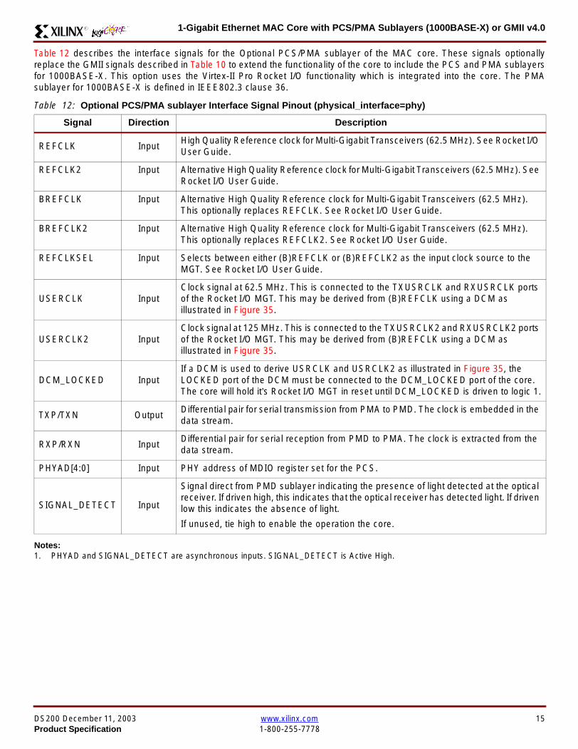
1-Gigabit Ethernet MAC Core with PCSPMA Sublayers (1000BASE-X) or GMII v40R
Table 12 describes the interface signals for the Optional PCSPMA sublayer of the MAC core These signals optionallyreplace the GMII signals described in Table 10 to extend the functionality of the core to include the PCS and PMA sublayersfor 1000BASE-X This option uses the Virtex-II Pro Rocket IO functionality which is integrated into the core The PMAsublayer for 1000BASE-X is defined in IEEE8023 clause 36
Notes1 PHYAD and SIGNAL_DETECT are asynchronous inputs SIGNAL_DETECT is Active High
Table 12 Optional PCSPMA sublayer Interface Signal Pinout (physical_interface=phy)
Signal Direction Description
REFCLK InputHigh Quality Reference clock for Multi-Gigabit Transceivers (625 MHz) See Rocket IOUser Guide
REFCLK2 Input Alternative High Quality Reference clock for Multi-Gigabit Transceivers (625 MHz) SeeRocket IO User Guide
BREFCLK Input Alternative High Quality Reference clock for Multi-Gigabit Transceivers (625 MHz)This optionally replaces REFCLK See Rocket IO User Guide
BREFCLK2 Input Alternative High Quality Reference clock for Multi-Gigabit Transceivers (625 MHz)This optionally replaces REFCLK2 See Rocket IO User Guide
REFCLKSEL Input Selects between either (B)REFCLK or (B)REFCLK2 as the input clock source to theMGT See Rocket IO User Guide
USERCLK InputClock signal at 625 MHz This is connected to the TXUSRCLK and RXUSRCLK portsof the Rocket IO MGT This may be derived from (B)REFCLK using a DCM asillustrated in Figure 35
USERCLK2 InputClock signal at 125 MHz This is connected to the TXUSRCLK2 and RXUSRCLK2 portsof the Rocket IO MGT This may be derived from (B)REFCLK using a DCM asillustrated in Figure 35
DCM_LOCKED InputIf a DCM is used to derive USRCLK and USRCLK2 as illustrated in Figure 35 theLOCKED port of the DCM must be connected to the DCM_LOCKED port of the coreThe core will hold itrsquos Rocket IO MGT in reset until DCM_LOCKED is driven to logic 1
TXPTXN OutputDifferential pair for serial transmission from PMA to PMD The clock is embedded in thedata stream
RXPRXN InputDifferential pair for serial reception from PMD to PMA The clock is extracted from thedata stream
PHYAD[40] Input PHY address of MDIO register set for the PCS
SIGNAL_DETECT Input
Signal direct from PMD sublayer indicating the presence of light detected at the opticalreceiver If driven high this indicates that the optical receiver has detected light If drivenlow this indicates the absence of light
If unused tie high to enable the operation the core
DS200 December 11 2003 wwwxilinxcom 15Product Specification 1-800-255-7778
1-Gigabit Ethernet MAC Core with PCSPMA Sublayers (1000BASE-X) or GMII v40 R
Functional Description
Client InterfaceThe client interface is designed for maximum flexibility inmatching to a client switching fabric or network processorinterface
The data pathway is 8 bits wide in both the transmit andreceive directions with each pathway synchronous to theTX_CLK and RX_CLK respectively for completely indepen-dent full duplex operation
Transmitter
Normal Frame Transmission
The timing of a normal outbound frame transfer can be seenin Figure 9 When the client wants to transmit a frame itplaces the first column of data onto the TX_DATA port andasserts a ldquo1rdquo onto TX_DATA_VALID
When the MAC core has read this first byte of data it willassert the TX_ACK signal on the next and subsequent ris-ing clock edges the client must provide the remainder ofthe data for the frame
The end of frame is signalled to the MAC core by takingTX_DATA_VALID Low
In-Band Parameter Encoding
For maximum flexibility in switching applications the Ether-net frame parameters (destination address sourceaddress lengthtype and optionally FCS) are encodedwithin the same data stream that the frame payload is trans-ferred upon rather than on separate ports This is illustratedin the timing diagrams Definitions of the abbreviations usedin the timing diagrams are described in Table 13
Figure 9 Normal Frame Transmission Across Client Interface
Table 13 Abbreviations Used in Timing Diagrams
Abbreviation Definition
DA Destination Address 6 bytes
SA Source Address 6 bytes
LT LengthType Field 2 bytes
FCS Frame Check Sequence 4 bytes
TX_CLK
TX_DATA[70]
TX_DATA_VALID
TX_ACK
TX_UNDERRUN
DA SA DATALT
TX_COLLISION
TX_RETRANSMIT
xip2133
16 wwwxilinxcom DS200 December 11 20031-800-255-7778 Product Specification
1-Gigabit Ethernet MAC Core with PCSPMA Sublayers (1000BASE-X) or GMII v40R
Padding
When fewer than 46 bytes of data are supplied by the clientto the MAC core the transmitter module will add padding upto the minimum frame length The exception to this is whenthe MAC core is configured for client-passed FCS in thiscase the client must also supply the padding to maintain theminimum frame length (see Client-Supplied FCS Passing)
Client-Supplied FCS Passing
If the MAC core is configured to have the FCS field passedin by the client (see Configuration Registers on page 30)the transmission timing is as depicted in Figure 10 In thiscase it is the responsibility of the client to ensure that theframe meets the Ethernet minimum frame length require-ments the MAC core will not perform any padding of thepayload
Figure 10 Frame Transmission with Client-supplied FCS
TX_CLK
TX_DATA[70]
TX_DATA_VALID
TX_ACK
TX_UNDERRUN
DA SA DATA FCSLT
TX_COLLISION
TX_RETRANSMIT
xip2134
DS200 December 11 2003 wwwxilinxcom 17Product Specification 1-800-255-7778
1-Gigabit Ethernet MAC Core with PCSPMA Sublayers (1000BASE-X) or GMII v40 R
Client Underrun
The timing of an aborted transfer can be seen in Figure 11This may happen for instance if a FIFO connected to theclient interface empties before a frame is completed Whenthe client asserts TX_UNDERRUN during a frame transmis-sion the MAC core will insert an error code to corrupt the
current frame and then fall back to idle transmission It isthe responsibility of the client to re-queue the aborted framefor transmission
When an underrun occurs TX_DATA_VALID may beasserted on the clock cycle after the TX_UNDERRUNassertion to request a new transmission
Figure 11 Frame Transmission with Underrun
TX_CLK
TX_DATA[70]
TX_DATA_VALID
TX_ACK
TX_UNDERRUN
DA SA DATALT
TX_COLLISION
TX_RETRANSMIT
xip2135
18 wwwxilinxcom DS200 December 11 20031-800-255-7778 Product Specification
1-Gigabit Ethernet MAC Core with PCSPMA Sublayers (1000BASE-X) or GMII v40R
Back-to-Back Transfers
Figure 12 shows the case where the MAC client is immedi-ately ready to transmit a second frame of data followingcompletion of its first frame In this figure the end of the firstframe is shown on the left On the clock cycle immediatelyfollowing the final byte of the first frame TX_DATA_VALIDis taken low by the client and is taken high one clock cyclelater to indicate that the first byte of the destination addressof the second frame is on TX_DATA awaiting transmission
When the MAC core is ready to accept data TX_ACK isasserted and the transmission continues in the same man-ner as in the case of the single frame The MAC core willdefer the assertion of TX_ACK appropriately to comply withinter-packet gap requirements and flow control requests
If the MAC core is operating in half-duplex mode the timingshown in Figure 12 is required to take advantage of framebursting the MAC core is only guaranteed to retain controlof the medium if the TX_DATA_VALID signal is low for a sin-gle clock cycle For more information on frame bursting seeIEEE 8023-2002
Figure 12 Back to Back Frame Transmission
TX_CLK
TX_DATA[70]
TX_DATA_VALID
TX_ACK
TX_UNDERRUN
TX_COLLISION
TX_RETRANSMIT
xip2136
DS200 December 11 2003 wwwxilinxcom 19Product Specification 1-800-255-7778
1-Gigabit Ethernet MAC Core with PCSPMA Sublayers (1000BASE-X) or GMII v40 R
VLAN Tagged Frames
Transmission of a VLAN tagged frame (if enabled) can beseen in Figure 13 Note that the handshaking signalsacross the interface do not change however the VLANtype tag 81-00 must be supplied by the client to signify that
the frame is VLAN tagged The client also supplies the twobytes of Tag Control Information V1 and V2 at the appro-priate times in the data stream More information on thecontents of these two bytes can be found in IEEE8023-2002
Maximum Permitted Frame Length
The maximum legal length of a frame specified in IEEE8023-2002 is 1518 bytes for non-VLAN tagged framesVLAN tagged frames may be extended to 1522 bytesWhen jumbo frame handling is disabled and the clientattempts to transmit a frame which exceeds the maximumlegal length the MAC core will insert an error code to cor-
rupt the current frame and the frame will be truncated to themaximum legal length When jumbo frame handling isenabled frames which are longer than the legal maximumare transmitted error-free
For more information on enabling and disabling jumboframe handling see Configuration Registers on page 30
Figure 13 Transmission of a VLAN Tagged Frame
TX_CLK
TX_DATA[70]
TX_DATA_VALID
TX_ACK
TX_UNDERRUN
DA SA DATALTVLANtag
81 00V1V2
TX_COLLISION
TX_RETRANSMIT
xip2137
20 wwwxilinxcom DS200 December 11 20031-800-255-7778 Product Specification
1-Gigabit Ethernet MAC Core with PCSPMA Sublayers (1000BASE-X) or GMII v40R
Frame Collisions - Half Duplex Operation Only
In half duplex Ethernet operation collisions will occur on themedium as a matter of course this is how the arbitrationalgorithm is fulfilled In case of a collision the MAC core sig-nals to the client that data may need to be resupplied as fol-lows
If there is a collision the TX_COLLISION signal will be setto ldquo1rdquo by the MAC core If a frame is in progress the clientmust abort the transfer and take TX_DATA_VALID to ldquo0rdquo
If the TX_RETRANSMIT signal is ldquo1rdquo in the same clockcycle that the TX_COLLISION signal is ldquo1rdquo the client must
resubmit the previous frame to the MAC core for retrans-mission TX_DATA_VALID must be asserted to the MACcore within 8 clock cycles of the TX_COLLISION signal inorder to meet Ethernet timing requirements See Figure 14
If the TX_RETRANSMIT signal is ldquo0rdquo in the same clockcycle that the TX_COLLISION signal is ldquo1rdquo the number ofretries for this frame has exceeded the Ethernet specifica-tion and the frame should be dropped by the client The cli-ent can then make any new frame available to the MAC fortransmission without timing restriction See Figure 15
Figure 14 Collision Handling - Frame retransmission required
Figure 15 Collision Handling - No frame retransmission required
TX_CLK
TX_DATA[70]
TX_DATA_VALID
TX_ACK
TX_UNDERRUN
TX_COLLISION
TX_RETRANSMIT
8 clocks max
xip2138
TX_CLK
TX_DATA[70]
TX_DATA_VALID
TX_ACK
TX_UNDERRUN
TX_COLLISION
TX_RETRANSMIT
xip2139
DS200 December 11 2003 wwwxilinxcom 21Product Specification 1-800-255-7778
1-Gigabit Ethernet MAC Core with PCSPMA Sublayers (1000BASE-X) or GMII v40 R
Interframe Gap Adjustment
The user can elect to vary the length of the inter fame gapIf this function is selected (via a configuration bit in thetransmitter control register see Configuration Registerson page 30) then the MAC will exert back pressure to delaythe transmission of the next frame until the requested num-ber of Idle cycles has elapsed The number of Idle cycles iscontrolled by the value on the TX_IFG_DELAY port at thestart of frame transmission Figure 16 shows the MAC oper-ating in this mode
Reducing the Inter fame gap to below the IEEE 8023-2002minimum of 12 Idles is supported in Full Duplex onlydesigns and will transmit an absolute minimum of 4 Idles Ifthe Interframe gap adjustment is reduced below 12 Idlesthen the accuracy of the Optional Statistical Gathering(statistics_gathering=true) Counters cannot be guaranteedHowever the TX_STATISTIC_VECTOR andRX_STATISTIC_VECTOR will always remain correct
Transmitter Statistics Vector
The statistics for the frame transmitted are contained withinthe TX_STATISTICS_VECTOR The vector is driven syn-chronously by the transmitter clock TX_CLK followingframe transmission The bit field definition for the Vector isdefined in Table 14
All bit fields with the exception of BYTE_VALID are validonly when the TX_STATISTICS_VALID is asserted This isillustrated in Figure 17 BYTE_VALID is significant on everyTX_CLK cycle
TX_STATISTICS_VECTOR bits 25 down to 17 inclusive arefor half duplex only and will be set to logic 0 when operatingin full duplex mode
Figure 16 Interframe Gap Adjustment
TX_CLK
TX_DATA[70]
TX_DATA_VALID
TX_ACK
DA SA
TX_IFG_DELAY
IFG ADJUST VALUE
0x0D
13 Idles inserted
DA
Next IFG ADJUST VALUE
xip2140
Figure 17 Transmitter Statistics Vector Timing
TX_CLK
TX_STATISTICS_VECTOR[280]
TX_STATISTICS_VALID
xip2141
22 wwwxilinxcom DS200 December 11 20031-800-255-7778 Product Specification
1-Gigabit Ethernet MAC Core with PCSPMA Sublayers (1000BASE-X) or GMII v40R
Table 14 Bit Definition for the Transmitter Statistics Vector
TX_STATISTICS_VECTOR Name Description
28 PAUSE_FRAME_TRANSMITTEDAsserted if the previous frame was a pause framethat the MAC itself initiated in response to aPAUSE_REQ assertion
27 BYTE_VALID
Asserted if a MAC frame byte (DA to FCS inclusive)is in the process of being transmitted This is valid onevery clock cycle
Do not use this as an enable signal to indicate thatdata is present on GMII_TXD[70]
26 Reserved Returns logic 0
25 down to 22 TX_ATTEMPTS[30]
The number of attempts that have been made totransmit the previous frame This is a 4-bit number0 should be interpreted as 1 attempt 1 as 2attempts up until 15 as 16 attempts
21 Reserved Returns logic 0
20 EXCESSIVE_COLLISIONAsserted if a collision has been detected on each ofthe last 16 attempts to transmit the previous frame
19 LATE_COLLISIONAsserted if a late collision occurred during frametransmission
18 EXCESSIVE_DEFERRALAsserted if the previous frame was deferred for anexcessive amount of time as defined by the constantldquomaxDeferTimerdquo in IEEE 8023-2002
17 TX_DEFERRED Asserted if transmission of the frame was deferred
16 VLAN_FRAMEAsserted if the previous frame contained a VLANidentifier in the LengthType field when transmitterVLAN operation is enabled
15 down to 5 FRAME_LENGTH_COUNTThe length of the previous frame in number of bytesThe count will stick at 2047 for any Jumbo frameslarger than this value
4 CONTROL_FRAMEAsserted if the previous frame had the special MACControl Type code 88-08 in the LengthType field
3 UNDERRUN_FRAMEAsserted if the previous frame contained anunderrun error
2 MULTICAST_FRAMEAsserted if the previous frame contained a multicastaddress in the Destination Address field
1 BROADCAST_FRAMEAsserted if the previous frame contained abroadcast address in the Destination Address field
0 SUCCESSFUL_FRAMEAsserted if the previous frame was transmittedwithout error
DS200 December 11 2003 wwwxilinxcom 23Product Specification 1-800-255-7778
1-Gigabit Ethernet MAC Core with PCSPMA Sublayers (1000BASE-X) or GMII v40 R
Receiver
Normal Frame Reception
The timing of a normal inbound frame transfer can be seenin Figure 18 The client must be prepared to accept data atany time there is no buffering within the MAC to allow forlatency in the receive client Once frame reception begins
data is transferred on consecutive clock cycles to thereceive client until the frame is complete The MAC assertsthe RX_GOOD_FRAME signal to indicate that the framewas successfully received and that the frame should beanalyzed by the client
Frame parameters (destination address source addresslengthtype and optionally FCS) are supplied on the databus according to the timing diagram The abbreviations arethe same as those described in Table 13 on page 16
If the LengthType field in the frame has the Length interpre-tation and this indicates that the inbound frame has beenpadded to meet the Ethernet minimum frame size specifica-tion then this padding will not be passed to the client in thedata payload The exception to this is in the case whereFCS passing is enabled see Client-Supplied FCS Pass-ing on page 25
Therefore when Client-Supplied FCS passing is disabledRX_DATA_VALID = lsquo0rsquo between frames for the duration ofthe Padding field (if present) the FCS field carrier exten-sion (if present) the interframe gap following the frame andthe preamble field of the next frame When Client-Supplied
FCS passing is enabled RX_DATA_VALID = lsquo0rsquo betweenframes for the duration of carrier extension (if present) theinterframe gap and the preamble field of the followingframe
RX_GOOD_FRAME RX_BAD_FRAME timing
Although the timing diagram in Figure 18 shows theRX_GOOD_FRAME signal asserted shortly after the lastvalid data on RX_DATA this is not always the case TheRX_GOOD_FRAME or RX_BAD_FRAME signals areasserted only after all frame checks are completed This isafter the FCS field has been received (and after reception ofcarrier extension if present)
Therefore either RX_GOOD_FRAME or RX_BAD_FRAMEis asserted following frame reception at the beginning of theinterframe gap
Figure 18 Normal Frame Reception
RX_CLK
RX_DATA[70]
RX_DATA_VALID
RX_GOOD_FRAME
RX_BAD_FRAME
DA SA DATALT
xip2142
24 wwwxilinxcom DS200 December 11 20031-800-255-7778 Product Specification
1-Gigabit Ethernet MAC Core with PCSPMA Sublayers (1000BASE-X) or GMII v40R
Frame Reception with Errors
The case of an unsuccessful frame reception (for examplea fragment frame or a frame with an incorrect FCS) can beseen in Figure 19 In this case the RX_BAD_FRAME signal
is asserted to the client at the end of the frame It is then theresponsibility of the client to drop the data already trans-ferred for this frame
Figure 19 Frame Reception with Error
Client-Supplied FCS Passing
If the MAC core is configured to pass the FCS field to the cli-ent (see Configuration Registers on page 30) then this ishandled as shown in Figure 20
In this case any padding inserted into the frame to meetEthernet minimum frame length specifications will be leftintact and passed to the client
Note that even though the FCS is passed up to the client itis also verified by the MAC core and RX_BAD_FRAMEasserted if the FCS check fails
RX_CLK
RX_DATA[70]
RX_DATA_VALID
RX_GOOD_FRAME
RX_BAD_FRAME
DA SA DATALT
xip2144
Figure 20 Frame Reception with In-Band FCS Field
RX_CLK
RX_DATA[70]
RX_DATA_VALID
RX_GOOD_FRAME
RX_BAD_FRAME
DA SA DATALT FCS
xip2145
DS200 December 11 2003 wwwxilinxcom 25Product Specification 1-800-255-7778
1-Gigabit Ethernet MAC Core with PCSPMA Sublayers (1000BASE-X) or GMII v40 R
VLAN Tagged Frames
The reception of a VLAN tagged frame (if enabled) can beseen in Figure 21 The VLAN frame is passed to the clientso that the frame may be identified as VLAN tagged this is
followed by the Tag Control Information bytes V1 and V2More information on the interpretation of these bytes maybe found in IEEE 8023-2002 standard
Maximum Permitted Frame Length
The maximum legal length of a frame specified in IEEE8023-2002 is 1518 bytes for non-VLAN tagged framesVLAN tagged frames may be extended to 1522 bytesWhen jumbo frame handling is disabled and the corereceives a frame which exceeds the maximum legal lengthRX_BAD_FRAME will be asserted When jumbo framehandling is enabled frames which are longer than the legalmaximum are received in the same way as shorter frames
For more information on enabling and disabling jumboframe handling see Configuration Registers on page 30
LengthType Field Error Checks
Enabled
Default operation is with the LengthType error checkingenabled (see Receiver Configuration Word 1 on page 31)In this mode the following checks are made on all framesreceived If either of these checks fail then the frame ismarked as BAD
bull A value in the LengthType field that is greater than orequal to decimal 46 but less than decimal 1536 (aLength interpretation) is checked against the actualdata length received
bull A value in the LengthType field that is less thandecimal 46 is checked to see that the data field ispadded to exactly 46 bytes (so that the resultant frameis minimum frame size 64 bytes total in length)
Furthermore if Padding is indicated (the LengthType fieldis less than decimal 46) and Client-Supplied FCS Passing isdisabled then the Length value in the LengthType field willbe used to deassert RX_DATA_VALID after the indicatednumber of data bytes so that the Padding bytes areremoved from the frame
Disabled
When the LengthType error checking is disabled (seeReceiver Configuration Word 1 on page 31) theLengthType error checks described above are not per-formed A frame containing only these errors will be markedas GOOD
Furthermore if Padding is indicated and Client-SuppliedFCS Passing is disabled then a Length Value in theLengthType field will not be used to deassertRX_DATA_VALID Instead RX_DATA_VALID will be deas-serted before the start of the FCS field in this way any pad-ding will not be removed from the frame
Figure 21 Reception of a VLAN Tagged Frame
RX_CLK
RX_DATA[70]
RX_DATA_VALID
RX_GOOD_FRAME
RX_BAD_FRAME
DA SA DATALT
81 00 V1 V2
VLANtag
xip2146
26 wwwxilinxcom DS200 December 11 20031-800-255-7778 Product Specification
1-Gigabit Ethernet MAC Core with PCSPMA Sublayers (1000BASE-X) or GMII v40R
Receiver Statistics Vector
The statistics for the frame received are contained withinthe RX_STATISTICS_VECTOR The vector is driven syn-chronously by the receiver clock RX_CLK following framereception The bit field definition for the Vector is defined inTable 15
All bit fields with the exception of BYTE_VALID are validonly when the RX_STATISTICS_VALID is asserted This isillustrated in Figure 22 BYTE_VALID is significant on everyRX_CLK cycle
Figure 22 Receiver Statistics Vector Timing
RX_CLK
RX_STATISTICS_VECTOR[220]
RX_STATISTICS_VALID
xip2147
Table 15 Bit Definition for the Receiver Statistics Vector
RX_STATISTICS_VECTOR Name Description
22LENGTHTYPE Out ofRange
Asserted if the lengthtype field contained a length valuethat did not match the number of MAC client data bytesreceived Also high if the lengthtype field indicated thatthe frame contained padding but the number of MAC cli-ent data bytes received was not equal to 64 bytes (min-imum frame size)
The exception to the above is when the LengthTypeField Error Checks are disabled in which case this bitwill not be asserted
21 BAD_OPCODE
Asserted if the previous frame was error-free andcontained the special Control Frame identifier in theLengthType field but contained an opcode that isunsupported by the MAC (Any Opcode other thanPAUSE)
20 FLOW_CONTROL_FRAME
Asserted if the previous frame was error-freecontained the special Control Frame identifier in theLengthType field contained a Destination Addressthat matched either the MAC Control MulticastAddress or the configured source address of the MACcontained the supported PAUSE opcode and wasacted upon by the MAC
19 BYTE_VALID
Asserted if a MAC frame byte (DA to FCS inclusive) isin the process of being received This is valid on everyclock cycle
Do not use this as an enable signal to indicate thatdata is present on RX_DATA[70]
18 VLAN_FRAMEAsserted if the previous frame contained a VLANidentifier in the LengthType field when receiver VLANoperation is enabled
DS200 December 11 2003 wwwxilinxcom 27Product Specification 1-800-255-7778
1-Gigabit Ethernet MAC Core with PCSPMA Sublayers (1000BASE-X) or GMII v40 R
17 OUT_OF_BOUNDS
Asserted if the previous frame exceeded the specifiedIEEE8023-2002 maximum legal length (seeMaximum Permitted Frame Length on page 26) Thisis only valid if Jumbo frames are disabled
16 CONTROL_FRAMEAsserted if the previous frame contained the specialControl Frame identifier in the LengthType field
15 down to 5 FRAME_LENGTH_COUNTThe length of the previous frame in number of bytesThe count will stick at 2047 for any Jumbo frameslarger than this value
4 MULTICAST_FRAMEAsserted if the previous frame contained a multicastaddress in the Destination Address field
3 BROADCAST_FRAMEAsserted if the previous frame contained the broadcastaddress in the Destination Address field
2 FCS_ERRORAsserted if the previous frame received had anincorrect FCS value or the MAC detected error codesduring frame reception
1 BAD_FRAME1 Asserted if the previous frame received containederrors
0 GOOD_FRAME1 Asserted if the previous frame received was error-free
1 If the LengthType Field Error Checks are disabled then a frame which contains this type of error will be marked as a GOOD_FRAMEproviding no additional errors were detected
Table 15 Bit Definition for the Receiver Statistics Vector
RX_STATISTICS_VECTOR Name Description
28 wwwxilinxcom DS200 December 11 20031-800-255-7778 Product Specification
1-Gigabit Ethernet MAC Core with PCSPMA Sublayers (1000BASE-X) or GMII v40R
Flow ControlThe flow control block is designed to Clause 31 of the IEEE8023-2002 standard The MAC may be configured to sendpause frames and to act upon their reception These twobehaviors can be configured asymmetrically see Configu-ration Registers on page 30
Transmitting a PAUSE Control Frame
The client initiates a flow control frame by assertingPAUSE_REQ while the pause value is on the PAUSE_VALbus These signals are synchronous to TX_CLK The timingof this can be seen in Figure 23
If the MAC core is configured to support transmit flow con-trol this action causes the core to transmit a PAUSE controlframe on the link with the PAUSE parameter set to thevalue on PAUSE_VAL in the cycle when PAUSE_REQ wasasserted This will not disrupt any frame transmission inprogress but will take priority over any pending frame trans-
mission This frame will be transmitted even if the transmit-ter is in the paused state itself
Receiving a Pause Control Frame
When an error-free frame is received by the MAC core thefollowing checks are made
1 The Destination Address field is matched against theMAC Control Multicast address or the configuredSource Address for the MAC (see ConfigurationRegisters on page 30)
2 The LengthType field is matched against the MACControl Type code
3 The opcode field contents are matched against thePAUSE opcode if check 2 is true
If any of the above checks are false or the MAC Flow Con-trol logic for the receiver is disabled the frame is ignored bythe Flow Control logic and passed up to the client
If the frame passes all of the above checks is of minimumlegal size and the MAC Flow Control logic for the receiver isenabled the pause value parameter in the frame is thenused to inhibit transmitter operation for the time defined inthe IEEE8023-2002 specification This inhibit is imple-mented using the same back pressure scheme shown inFigure 12 Because the received pause frame has beenacted upon it is passed to the client with RX_BAD_FRAMEasserted to indicate to the client that it should be dropped
Reception of any frame for which check 2 is true and whichis not of legal minimum length is considered an invalid Con-trol frame This will be ignored by the Flow Control logic andpassed to the client with RX_BAD_FRAME asserted
Figure 23 Pause Request Timing
TX_CLK
PAUSE_VAL[150]
PAUSE_REQ
xip2148
DS200 December 11 2003 wwwxilinxcom 29Product Specification 1-800-255-7778
1-Gigabit Ethernet MAC Core with PCSPMA Sublayers (1000BASE-X) or GMII v40 R
Optional Management Interface(management_interface=true)The management interface is a processor-independentinterface with standard address data and control signals Itmay be used as is or a wrapper may be applied (not sup-plied) to interface to common bus architectures
This interface is used for
bull Configuration of the MAC core
bull Access to optional statistics counters for use by higherlayers for example SNMP
bull access through the MDIO interface to the managementregisters located in the PHY attached to the MAC core
The management interface is accessed differently depend-ing on the type of transaction a truth table showing whichaccess method is required for each transaction type isshown in Table 16 These access methods are described inthe following sections
HOST_CLK Frequency
The management interface clock HOST_CLK is used toderive the MDIO clock MDC and is therefore subject tosome frequency restrictions This HOST_CLK must be
ge 10 MHz
le 100 MHz
Configuring the MAC core to derive the MDC signal fromthis clock is detailed in MDIO Interface on page 37
Configuration Registers
After power up or reset the client may reconfigure the coreparameters from their defaults such as flow control supportConfiguration changes can be written at any time Both thereceiver and transmitter logic will only respond to configura-tion changes during Inter Frame Gaps The exceptions tothis are the configurable resets which take effect immedi-ately
Configuration of the MAC core is performed through a reg-ister bank accessed through the management interfaceThe configuration registers available in the core are detailedin Table 17 As can be seen the address has some implicitdonrsquot care bits any access to an address in the rangesshown will perform a 32-bit read or write from the same con-figuration word
Table 16 Management Interface Transaction Types
Transaction HOST_MIIM_SEL HOST_ADDR[9]
Configuration 0 1
Statistics 0 0
MIIM access 1 X
Table 17 Configuration Registers
Address Description
0x200-0x23F Receiver Configuration (Word 0)
0x240-0x27F Receiver Configuration (Word 1)
0x280-0x2BF Transmitter Configuration
0x2C0-0x2FF Flow Control Configuration
0x300-0x33F Reserved
0x340-0x37F Management Configuration
30 wwwxilinxcom DS200 December 11 20031-800-255-7778 Product Specification
1-Gigabit Ethernet MAC Core with PCSPMA Sublayers (1000BASE-X) or GMII v40R
The register contents for the two receiver configuration words can be seen in Table 18 and Table 19
Notes1 In changing the receiverrsquos mode from Half Duplex to Full Duplex there is a period of time of up to 24 us following the mode change
when no new receiver statistics can be stored in the optional Statistical Counters
Table 18 Receiver Configuration Word 0
Bit Default Value Description
31-0 All 0rsquos
Pause frame MAC Source Address[310] This address is used by the MAC tomatch against the Destination Address of any incoming flow control frames It isalso used by the flow control block as the Source Address (SA) for any outboundflow control frames
The address is ordered so the first byte transmittedreceived is the lowestpositioned byte in the register for example a MAC address ofAA-BB-CC-DD-EE-FF would be stored in Address[470] as 0xFFEEDDCCBBAA
Table 19 Receiver Configuration Word 1
Bit Default Value Description
15-0 All 0rsquos Pause frame MAC Source Address[4732] See description in Table 18
24-16 NA Reserved
25 0
LengthType Error Check Disable When this bit is set to ldquo1rdquo the core will notperform the LengthType field error checks as described in LengthType FieldError Checks on page 26 When this bit is set to ldquo0rdquo the LengthType field checkswill be performed this is normal operation
26 0Half Duplex If ldquo1rdquo the receiver will operate in half duplex mode If ldquo0rdquo the receiverwill operate in full duplex mode Has no effect if XCO parameterhalf_duplex_capable = false
27 0VLAN Enable When this bit is set to ldquo1rdquo VLAN tagged frames will be acceptedby the receiver
28 1Receiver Enable If set to ldquo1rdquo the receiver block will be operational If set to ldquo0rdquothe block will ignore activity on the physical interface RX port
29 0
In-band FCS Enable When this bit is ldquo1rdquo the MAC receiver will pass the FCS fieldup to the client as described in Client-Supplied FCS Passing on page 25 Whenit is ldquo0rdquo the client will not be passed the FCS In both cases the FCS will beverified on the frame
30 0Jumbo Frame Enable When this bit is set to ldquo1rdquo the MAC receiver will acceptframes over the specified IEEE8023-2002 maximum legal length When this bitis ldquo0rdquo the MAC will only accept frames up to the specified maximum
31 0Reset When this bit is set to ldquo1rdquo the receiver will be reset The bit will thenautomatically revert to ldquo0rdquo Note that this reset will also set all of the receiverconfiguration registers to their default values
DS200 December 11 2003 wwwxilinxcom 31Product Specification 1-800-255-7778
1-Gigabit Ethernet MAC Core with PCSPMA Sublayers (1000BASE-X) or GMII v40 R
The register contents for the Transmitter Configuration Word are described in Table 20
Notes1 In changing the transmitterrsquos mode from Half Duplex to Full Duplex there is a period of time of up to 24 us following the mode change
when no new transmitter statistics can be stored in the optional Statistical Counters
Table 20 Transmitter Configuration Word
Bit Default Value Description
24-0 NA Reserved
25 0
Interframe Gap Adjust Enable If lsquo1rsquo the transmitter will read the value on the portTX_IFG_DELAY at the start of frame transmission and adjust the interframe gapfollowing the frame accordingly See Interframe Gap Adjustment on page 22 Ifldquo0rdquo the transmitter will output a minimum Inter Frame Gap of twelve clock cyclesas specified in IEEE8023-2002
26 0Half Duplex If lsquo1rsquo the transmitter will operate in half duplex mode If lsquo0rsquo thetransmitter will operate in full duplex mode Has no effect if XCO parameterhalf_duplex_capable = false
27 0VLAN Enable When this bit is set to 1 the transmitter will allow the transmissionof VLAN tagged frames
28 1Transmit Enable When this bit is 1 the transmitter is operational When it is 0the transmitter is disabled
29 0
In-band FCS Enable When this bit is lsquo1rsquo the MAC transmitter will expect the FCSfield to be passed in by the client as described in Client-Supplied FCS Passingon page 17 When this bit is ldquo0rdquo the MAC transmitter will append padding asrequired compute the FCS and append it to the frame
30 0
Jumbo Frame Enable When this bit is set to ldquo1rdquo the MAC transmitter will sendframes that are greater than the specified IEEE8023-2002 maximum legallength When this bit is ldquo0rdquo the MAC will only send frames up to the specifiedmaximum
31 0Reset When this bit is set to ldquo1rdquo the transmitter will be reset The bit will thenautomatically revert to ldquo0rdquo Note that this reset will also set all of the transmitterconfiguration registers to their default values
32 wwwxilinxcom DS200 December 11 20031-800-255-7778 Product Specification
1-Gigabit Ethernet MAC Core with PCSPMA Sublayers (1000BASE-X) or GMII v40R
The register contents for the Flow Control Configuration Word are described in Table 21
The register contents for the Management Configuration Word are described in Table 22
Writing to the configuration registers through the manage-ment interface is depicted in Figure 24 When accessing theconfiguration registers (ie when HOST_ADDR[9] = lsquo1rsquo andHOST_MIIM_SEL = lsquo0rsquo) the upper bit of HOST_OPCODEfunctions as an Active Low write enable signal The lowerHOST_OPCODE bit is a ldquodonrsquot carerdquo
Reading from the configuration register words is similar butthe upper HOST_OPCODE bit should be lsquo1rsquo This is shownin Figure 25 In this case the contents of the register appearon HOST_RD_DATA the HOST_CLK edge after the regis-ter address is asserted onto HOST_ADDR
Table 21 Flow Control Configuration Word
Bit Default Value Description
28-0 NA Reserved
29 1
Flow Control Enable (RX) When this bit is lsquo1rsquo received flow control frames willinhibit the transmitter operation as described in Receiving a Pause ControlFrame on page 29 When this bit is lsquo0rsquo received flow control frames will alwaysbe passed up to the client
30 1Flow Control Enable (TX) When this bit is lsquo1rsquo asserting the PAUSE_REQ signalwill send a flow control frame out from the transmitter When this bit is 0 assertingthe PAUSE_REQ signal has no effect
31 NA Reserved
Table 22 Management Configuration Word
Bits Default Value Description
4-0 All 0rsquos Clock Divide[40] See MDIO Interface on page 37
5 0MDIO Enable When this bit is 1 the MDIO interface can be used to accessattached PHY devices When this bit is 0 the MDIO interface is disabled and theMDIO signals remain inactive
31-6 NA Reserved
Figure 24 Configuration Register Write Timing
HOST_CLK
HOST_ADDR[80]
HOST_ADDR[9]
HOST_OPCODE[1]
HOST_MIIM_SEL
HOST_WR_DATA[310]xip2149
Figure 25 Configuration Register Read Timing
HOST_CLK
HOST_ADDR[80]
HOST_ADDR[9]
HOST_OPCODE[1]
HOST_MIIM_SEL
HOST_RD_DATA[310]
xip2150
DS200 December 11 2003 wwwxilinxcom 33Product Specification 1-800-255-7778
1-Gigabit Ethernet MAC Core with PCSPMA Sublayers (1000BASE-X) or GMII v40 R
Optional Statistical Gathering(statistics_gathering=true)
During operation the MAC core collects statistics on thesuccess and failure of various operations for processing by
station management entities (STA) further up the protocolstack These statistics are accessed by the host through theoptional management interface A complete list of statisticssupported is described in Table 23
Table 23 Statistics Registers
Address Name Description
0x000 Frames Received OK1 A count of error-free frames received
0x001 Frame Check Sequence Errors A count of received frames that failed the CRC check and were at least64 bytes in length
0x002 Broadcast Frames Received OK1A count of frames that were successfully received and were directed tothe broadcast group address
0x003 Multicast Frames Received OK1 A count of frames that were successfully received and were directed toa non broadcast group address
0x004 64 byte Frames Received OK1 A count of error-free frames received that were 64 bytes in length
0x005 65-127 byte Frames Received OK1A count of error-free frames received that were between 65 and 127bytes in length
0x006 128-255 byte Frames Received OK1A count of error-free frames received that were between 128 and 255bytes in length
0x007 256-511 byte Frames Received OK1A count of error-free frames received that were between 256 and 511bytes in length
0x008512-1023 byte Frames ReceivedOK1
A count of error-free frames received that were between 512 and 1023bytes in length
0x0091024-MaxFrameSize byte FramesReceived OK1
A count of error-free frames received that were between 1024 bytes andthe specified IEEE8023-2002 maximum legal length (see MaximumPermitted Frame Length on page 26)
0x00A Control Frames Received OKA count of error-free frames received that contained the specialControl Frame identifier in the LengthType field
0x00B LengthType Out of Range
A count of frames received that were at least 64 bytes in length wherethe lengthtype field contained a length value that did not match thenumber of MAC client data bytes received
The counter also increments for frames in which the lengthtype fieldindicated that the frame contained padding but where the number ofMAC client data bytes received was greater than 64 bytes (minimumframe size)
The exception to the above is when the LengthType Field Error Checksare disabled in which case this counter will not increment
0x00C VLAN Tagged Frames Received OKA count of error-free VLAN frames received This counter will only incre-ment when the receiver is configured for VLAN operation
0x00D Pause Frames Received OK
A count of error-free frames received that contained the MAC Controltype identifier 88-08 in the LengthType field contained a Destinationaddress that matched either the MAC Control multicast address or theconfigured source address of the MAC contained the PAUSE opcodeand were acted upon by the MAC
0x00EControl Frames Received withUnsupported Opcode
A count of error-free frames received that contained the MAC Controltype identifier 88-08 in the LengthType field but were received with anopcode other than the PAUSE opcode
34 wwwxilinxcom DS200 December 11 20031-800-255-7778 Product Specification
1-Gigabit Ethernet MAC Core with PCSPMA Sublayers (1000BASE-X) or GMII v40R
0x00F Oversize Frames Received OK1A count of otherwise error-free frames received that exceeded the max-imum legal frame length specified in IEEE 8023-2002 (see MaximumPermitted Frame Length on page 26)
0x010 Undersize frames receivedA count of the number of frames received that were less than 64 bytesin length but were otherwise well formed
0x011 Fragment frames receivedA count of the number of frames received that were less than 64 bytesin length and had a bad Frame Check Sequence field
0x012 Received bytesA count of bytes of frames that are received (Destination Address toFrame Check Sequence inclusive)
0x013 Transmitted bytesA count of bytes of frames that are transmitted (Destination Address toFrame Check Sequence inclusive)
0x020 Frames Transmitted OK A count of error-free frames transmitted
0x021 Broadcast Frames Transmitted OK A count of error-free frames that were transmitted to the broadcastaddress
0x022 Multicast Frames Transmitted OK A count of error-free frames that were transmitted to a group destina-tion address other than broadcast
0x023 Underrun Errors
A count of frames that would otherwise be transmitted by the core butcould not be completed due to the assertion of TX_UNDERRUN duringthe frame transmission This will not count frames which are less than64 bytes in length
0x024 Control Frames Transmitted OKA count of error-free frames transmitted that contained the MACControl Frame type identifier 88-08 in the LengthType field
0x025 64 byte Frames Transmitted OK A count of error-free frames transmitted that were 64 bytes in length
0x026 65-127 byte Frames Transmitted OKA count of error-free frames transmitted that were between 65 and 127bytes in length
0x027128-255 byte Frames TransmittedOK
A count of error-free frames transmitted that were between 128 and 255bytes in length
0x028256-511 byte Frames TransmittedOK
A count of error-free frames transmitted that were between 256 and 511bytes in length
0x029512-1023 byte Frames TransmittedOK
A count of error-free frames transmitted that were between 512 and1023 bytes in length
0x02A1024-MaxFrameSize byte FramesTransmitted OK
A count of error-free frames transmitted that were between 1024 and thespecified IEEE8023-2002 maximum legal length (see Maximum Per-mitted Frame Length on page 20)
0x02BVLAN Tagged Frames TransmittedOK
A count of error-free VLAN frames transmitted This counter will onlyincrement when the transmitter is configured for VLAN operation
0x02C Pause Frames Transmitted OKA count of error-free PAUSE frames generated and transmitted by thecore in response to an assertion of PAUSE_REQ
0x02D Oversize Frames Transmitted OKA count of otherwise error-free frames transmitted that exceeded themaximum legal frame length specified in IEEE 8023-2002 (see Maxi-mum Permitted Frame Length on page 20)
0x02E Single Collision Frames A count of frames that are involved in a single collision but are subse-quently transmitted successfully (Half Duplex Mode only)
Table 23 Statistics Registers (Continued)
Address Name Description
DS200 December 11 2003 wwwxilinxcom 35Product Specification 1-800-255-7778
1-Gigabit Ethernet MAC Core with PCSPMA Sublayers (1000BASE-X) or GMII v40 R
Each of these statistic registers is 64 bits wide and thereforemust be read in a two-cycle transfer The timing of this pro-cess is shown in Figure 26 Six clocks after the read trans-action is initiated the least significant word (LSW) of thestatistics counter appears on the HOST_RD_DATA bus
and a clock cycle later the most significant word (MSW)appears For accurate statistic values 64 clock ticks (ofTX_CLK for transmit statistics or RX_CLK for receive statis-tics) must elapse after the last frame is sent or receivedthrough the MAC core
0x02F Multiple Collision Frames A count of frames that are involved in more than one collision but aresubsequently transmitted successfully (Half Duplex Mode only)
0x040 Frames with Deferred Transmissions A count of frames whose transmission was delayed on its first attemptbecause the medium was busy (Half Duplex Mode only)
0x041 Late Collisions
A count of the times that a collision has been detected later than oneslotTime from the start of the packet transmission A late collision iscounted twice both as a collision and as a lateCollision (Half DuplexMode only)
0x042Frames Aborted due to Excesscollisions
A count of the frames that due to excessive collisions are not transmit-ted successfully (Half Duplex Mode only)
0x043 Carrier Sense ErrorsA count of times that the GMII_CRS signal was not asserted or wasdisasserted during the transmission of a frame without collision (HalfDuplex Mode only)
0x044 Frames with Excess DeferralA count of frames that deferred transmission for an excessive period oftime (Half Duplex Mode only)
1 If the LengthType Field Error Checks are disabled then these counters will still increment for received frames which contain this typeof error (providing no additional errors were detected)
Table 23 Statistics Registers (Continued)
Address Name Description
Figure 26 Statistic Register Read Timing
HOST_CLK
HOST_ADDR[80]
HOST_ADDR[9]
HOST_REQ
HOST_MIIM_SEL
HOST_RD_DATA[310]
6 CLOCKS
LSW MSW
xip2151
36 wwwxilinxcom DS200 December 11 20031-800-255-7778 Product Specification
1-Gigabit Ethernet MAC Core with PCSPMA Sublayers (1000BASE-X) or GMII v40R
MDIO Interface
The management interface is also used to access the MDIO(MII Management) interface of the MAC core this interfaceis used to access the Managed Information Block (MIB) ofthe PHY components attached to the MAC core
The MDIO interface supplies a clock to the externaldevices MDC This clock is derived from the HOST_CLKsignal using the value in the Clock Divide[40] configurationregister The frequency of the MDIO clock is given by thefollowing equation
The frequency of MDC given by this equation should notexceed 25 MHz in order to comply with the IEEE8023-2002 specification for this interface To prevent MDCfrom being out of specification the Clock Divide[40] valuepowers up at 00000 and while this value is in the register itis impossible to enable the MDIO interface
For details of the register map of PHY layer devices and afuller description of the operation of the MDIO interfaceitself see IEEE specification 8023-2002
Access to the MDIO interface through the managementinterface is depicted in the timing diagram in Figure 27
For MDIO transactions the following points apply
bull HOST_OPCODE maps to the OP (opcode) field of theMDIO frame
bull HOST_ADDR maps to the two address fields of theMDIO frame PHY_ADDR is HOST_ADDR[95] andREG_ADDR is HOST_ADDR[40]
bull HOST_WR_DATA[150] maps into the data field of the
MDIO frame when performing a write operation
bull The data field of the MDIO frame maps intoHOST_RD_DATA[150] when performing a readoperation
The MAC core signals to the host that it is ready for anMDIO transaction by asserting HOST_MIIM_RDY A read orwrite transaction on the MDIO is initiated by a pulse on the
fMDC
fHOST_CLK
1 Clock Divide[40]+( ) 2times-------------------------------------------------------------------=
Figure 27 MDIO Access Through Management Interface
HOST_CLK
HOST_ADDR[90]
HOST_OPCODE[10]
HOST_REQ
HOST_MIIM_SEL
HOST_RD_DATA[150]
HOST_WR_DATA[150]
HOST_RDY
If a read transaction is initiated the HOST_RD_DATA bus is valid at the point indicated If a write transaction is initiated the HOST_WR_DATA bus must be valid at the indicated point Simultaneous read and write is not permitted
xip2152
DS200 December 11 2003 wwwxilinxcom 37Product Specification 1-800-255-7778
1-Gigabit Ethernet MAC Core with PCSPMA Sublayers (1000BASE-X) or GMII v40 R
HOST_REQ signal This pulse is ignored if the MDIO inter-face already has a transaction in progress
The MAC core then disasserts the HOST_MIIM_RDY signalwhile the transaction across the MDIO is in progress Whenthe transaction across the MDIO interface has been com-pleted the HOST_MIIM_RDY signal will be asserted by theMAC core if the transaction is a read the data will also beavailable on the HOST_RD_DATA[150] bus at this time
Optional Configuration Vector(management_interface = false)If the optional Management interface is omitted from thecore all of relevant configuration signals are brought out of
the core These signals are bundled into theCONFIGURATION_VECTOR signal The bit mapping of theconfiguration vector signal is defined in Table 24 See thecorresponding entry in the configuration register tables forthe full description of each signal
Note that these configuration vector signals can bechanged by the user at any time however with the excep-tion of the reset and the flow control configuration signalsthey will not take effect until the current frame has com-pleted transmission or reception
The ldquoClockrdquo heading denotes which clock domain the con-figuration signal is registered into before use by the core Itis not necessary to drive the signal from this clock domain
Table 24 Configuration Vector Bit Definition
Bit(s)Configuration Register
cross reference Clock Description
47 downto 0
Receiver ConfigurationWord 0 bits 31-0 andReceiver ConfigurationWord 1 bits 15-0
RX_CLK
Pause frame MAC Source Address[470] This address isused by the MAC core to match against the DestinationAddress of any incoming flow control frames and as theSource Address for any outbound flow control frames
The address is ordered such that the first byte transmitted orreceived is the least significant byte in the register forexample a MAC address of AA-BB-CC-DD-EE-FF will bestored in bite [470] as 0xFFEEDDCCBBAA
48Receiver ConfigurationWord 1 bit 26
RX_CLKReceiver Half Duplex If lsquo1rsquo the receiver operates in halfduplex mode If lsquo0rsquo the receiver operates in full duplex modeHas no effect if XCO parameter half_duplex_capable = false
49Receiver ConfigurationWord 1 bit 27
RX_CLKReceiver VLAN Enable When this bit is set to 1 VLANtagged frames are accepted by the receiver
50Receiver ConfigurationWord 1 bit 28
RX_CLKReceiver Enable If set to 1 the receiver block is operationalIf set to 0 the block ignores activity on the physical interfaceRX port
51Receiver ConfigurationWord 1 bit 29
RX_CLK
Receiver In-band FCS Enable When this bit is lsquo1rsquo the MACreceiver will pass the FCS field up to the client as describedin Client-Supplied FCS Passing on page 25 When it is lsquo0rsquothe MAC receiver will not pass the FCS field In both casesthe FCS field will be verified on the frame
52Receiver ConfigurationWord 1 bit 30
RX_CLK
Receiver Jumbo Frame Enable When this bit is lsquo0rsquo thereceiver will not pass frames longer than the maximum legalframe size specified in IEEE 8023-2002 (see MaximumPermitted Frame Length on page 26) When it is lsquo1rsquo thereceiver will not have an upper limit on frame size
53Receiver ConfigurationWord 1 bit 31
NA
Receiver Reset When this bit is lsquo1rsquo the receiver is held inreset
This signal is an input to the reset circuit for the receiverblock See Reset circuit on page 42 for more information
54TransmitterConfiguration Word bit25
TX_CLK
Transmitter Interframe Gap Adjust enable If lsquo1rsquo then thetransmitter will read the value of the TX_IFG_DELAY port andset the Interframe Gap accordingly If lsquo0rsquo the transmitter willalways insert at least the legal minimum Interframe Gap
38 wwwxilinxcom DS200 December 11 20031-800-255-7778 Product Specification
1-Gigabit Ethernet MAC Core with PCSPMA Sublayers (1000BASE-X) or GMII v40R
55TransmitterConfiguration Word bit26
TX_CLK
Transmitter Half Duplex If lsquo1rsquo the transmitter operates in halfduplex mode If lsquo0rsquo the transmitter operates in full duplexmode Has no effect if XCO parameter half_duplex_capable= false
56TransmitterConfiguration Word bit27
TX_CLKTransmitter VLAN Enable When this bit is set to lsquo1rsquo thetransmitter allows the transmission of VLAN tagged frames
57TransmitterConfiguration Word bit28
TX_CLKTransmitter Enable When this bit is 1 the transmitter will beoperational When it is 0 the transmitter is disabled
58TransmitterConfiguration Word bit29
TX_CLK
Transmitter In-Band FCS Enable When this bit is lsquo1rsquo theMAC transmitter will expect the FCS field to be pass in by theclient as described in Client-Supplied FCS Passing onpage 17 When it is lsquo0rsquo the MAC transmitter will appendpadding as required compute the FCS and append it to theframe
59TransmitterConfiguration Word bit30
TX_CLK
Transmitter Jumbo Frame Enable When this bit is lsquo1rsquo theMAC transmitter will allow frames larger than the maximumlegal frame length specified in IEEE 8023-2002 to be sentWhen set to lsquo0rsquo the MAC transmitter will only allow frames upto the legal maximum to be sent
60TransmitterConfiguration Word bit31
NA
Transmitter Reset When this bit is lsquo1rsquo the MAC transmitter isheld in reset
This signal is an input to the reset circuit for the transmitterblock See Reset circuit on page 42 for more information
61Flow ControlConfiguration Word bit29
TX_CLK
Transmit Flow Control Enable When this bit is lsquo1rsquo assertingthe PAUSE_REQ signal causes the MAC core to send a flowcontrol frame out from the transmitter as described inReceiving a Pause Control Frame on page 29 When this bitis lsquo0rsquo asserting the PAUSE_REQ signal will have no effect
62Flow ControlConfiguration Word bit30
RX_CLK
Receive Flow Control Enable When this bit is lsquo1rsquo receivedflow control frames will inhibit the transmitter operation asdescribed in Receiving a Pause Control Frame on page 29When it is lsquo0rsquo received flow frames are passed up to theclient
63Receiver ConfigurationWord 1 bit 25
RX_CLK
LengthType Error Check Disable When this bit is lsquo1rsquo thecore will not perform the LengthType field error checks asdescribed in LengthType Field Error Checks on page 26When it is set to lsquo0rsquo the LengthType field checks will beperformed this is normal operation
Table 24 Configuration Vector Bit Definition (Continued)
Bit(s)Configuration Register
cross reference Clock Description
DS200 December 11 2003 wwwxilinxcom 39Product Specification 1-800-255-7778
1-Gigabit Ethernet MAC Core with PCSPMA Sublayers (1000BASE-X) or GMII v40 R
Optional GMII (physical_interface=gmii)The GMII is designed to IEEE 8023-2002 Clause 35 Thisutilizes IOrsquos of the Xilinx devices using inputoutput buffersand inputoutput flip-flops to maximize setup and hold mar-gins All IO logic is placed in the example wrapper that isdelivered with the core In addition all clock managementlogic for the core is instanced in this example wrapper thisallows multiple instances of the core to share clocks Theexample wrapper is provided in both VHDL and Verilog
Clock Management
Figure 28 illustrates the clock management used with theGMII interface All clocks illustrated have a frequency of125MHz
GTX_CLK must be provided to the MAC core This is a highquality clock which satisfies the IEEE8023-2002 require-ments It is expected that this clock will be derived from anexternal oscillator and connected into the device through anIBUFG as illustrated The clock source must then be routedonto a global clock network by connecting it to a BUFGWithin the MAC core this global clock is used by all MACtransmitter logic The MAC Client can obtain this clock byconnecting to the TX_CLK signal output from the coreGMII_TX_CLK is derived from this global clock by invertingit and routing it to an OBUF
GMII_RX_CLK is received through an IBUFG This clock isthen routed onto a global clock network by connecting it to aBUFG The resulting global clock is used by all MACreceiver logic
Figure 28 Clock Management with GMII
IBUFG
IBUFG
OBUF
BUFG
BUFG
TX_CLK
RX_CLK
GTX_CLK
GMII_TX_CLK
GMII_RX_CLK
Example Wrapper
xip2153
MAC Core
TX_CLK
RX_CLK
GMII_TX_CLK
GMII_RX_CLK
GTX_CLK
40 wwwxilinxcom DS200 December 11 20031-800-255-7778 Product Specification
1-Gigabit Ethernet MAC Core with PCSPMA Sublayers (1000BASE-X) or GMII v40R
Clock Sharing between Multiple cores
Figure 29 illustrates how it is possible to share clockresources across multiple instantiations of the core whenusing the optional GMII
GTX_CLK may be shared between multiple cores as illus-trated resulting in a common transmitter clock domainacross the device
A common receiver clock domain is not possible each corewill receive an independent receiver clock from its GMII asillustrated
Although not illustrated if the optional Management Inter-face is used HOST_CLK can also be shared betweencores
Figure 29 Clock Management with multiple instances of the MAC with GMII
IBUFG
OBUF
BUFG
TX_CLK
RX_CLK_1
GMII_TX_CLK_1
GMII_RX_CLK_1
MAC Core
TX_CLK
RX_CLK
GMII_TX_CLK
GMII_RX_CLK
GTX_CLK
MAC Core
TX_CLK
RX_CLK
GMII_TX_CLK
GMII_RX_CLK
GTX_CLK
IBUFG
BUFG
GTX_CLK
IBUFG
OBUF
GMII_TX_CLK_2
GMII_RX_CLK_2
BUFG
TX_CLK
RX_CLK_2
DS200 December 11 2003 wwwxilinxcom 41Product Specification 1-800-255-7778
1-Gigabit Ethernet MAC Core with PCSPMA Sublayers (1000BASE-X) or GMII v40 R
Reset circuit
Internally the core is divided up into clockreset domainswhich group together elements with the common clock andreset signals The reset circuitry for one of these domains isis illustrated in Figure 30 This circuit provides controllableskews on the reset nets within the design
More information on the operation and rationale behind thiscircuit can be found in Ken Chapmanrsquos Xilinx TechXclusiveldquoGet Smart About Resetrdquo athttpwwwxilinxcomsupporttechxclusivesglobal-techX19htm
Figure 30 Reset circuit for one clockreset domain
FDP
PRED
C
Q
FDP
PRED
C
Q
FDP
PRED
C
Q
FDP
PRED
C
Q
PRE PRE PRE
0
RESET
Management Reset
Clock
Core Registers
42 wwwxilinxcom DS200 December 11 20031-800-255-7778 Product Specification
1-Gigabit Ethernet MAC Core with PCSPMA Sublayers (1000BASE-X) or GMII v40R
Optional PCS with Ten-Bit Interface (TBI) for 1000BASE-X (physical_interface=tbi)The Full-Duplex Physical Coding Sublayer (PCS) for1000BASE-X is defined in IEEE 8023-2002 Clauses 36and 37 This functionality is only available in the Virtex-IIand Spartan3 families of FPGA devices
A block diagram of the PCS is shown in Figure 31 Themajor functional blocks of the PCS are
bull Transmit engine
bull Auto-negotiation block
bull Receive engine and synchronization block
bull PCS managed register block
bull 8B10B encoder block
bull 8B10B decoder block
bull Receiver elastic buffer
The PCS Managed Register Block is accessed through theMDIO Interface as if it were an externally connected PHYThis configures the operation of the PCS and Auto-Negoti-ation See PCS Managed Register Block
(physical_interface = tbi or phy) on page 49 The corersquosoptional Management Interface can be used to control theMDIO Interface as described by MDIO Interface onpage 37 When the optional Management Interface is notpresent the PCS Managed Register Block must beaccessed via an MDIO controller which is not provided bythe core
The 8B10B encodingdecoding blocks are implemented byconfiguring two Block SelectRAM modules as ROM Theseare used as large look-up tables The remaining PCS func-tionality such as code group encodingdecoding the Man-aged Register Block and Auto-Negotiation areimplemented in CLB logic
The Receiver Elastic buffer enables the 10-bit parallel datareceived from the PMA sublayer alternatively onPMA_RX_CLK0 and PMA_RX_CLK1 clock edges to betransferred onto the internal 125MHz clock domain derivedfrom GTX_CLK (see Clock Management) This buffer isimplemented in Distributed Memory
Figure 31 Functional Block Diagram of the 1-Gigabit Ethernet PCS with TBI Interface
PCS TRANSMIT ENGINE
PCS RECEIVE ENGINE ampSYNCHRONISATION
PCSMANAGEMENT
MDIOInterface
AUTO-NEGOTIATION
MAC TXInterface
MAC RXInterface
8B10BEncoder
8B10BDecoder
RX Elastic Buffer
TBI Interface
DS200 December 11 2003 wwwxilinxcom 43Product Specification 1-800-255-7778
1-Gigabit Ethernet MAC Core with PCSPMA Sublayers (1000BASE-X) or GMII v40 R
TBI Interface
The TBI is designed to IEEE 8023-2002 Clause 363 Thisutilizes IOrsquos of the Xilinx devices using inputoutput buffersand inputoutput flip-flops to maximize setup and hold mar-gins All IO logic is placed in the example wrapper that isdelivered with the core In addition all clock managementlogic for the core is instantiated in this example wrapperthis allows multiple instances of the core to share clocksThe example wrapper is provided in both VHDL and Verilog
Clock Management
Figure 32 illustrates the clock management used with theTBI interface
GTX_CLK must be provided to the MAC core This is a highquality clock of frequency 125MHz which satisfies theIEEE8023-2002 requirements It is expected that this clockwill be derived from an external oscillator and connected
into the device through an IBUFG as illustrated The clocksource must then be routed onto a global clock network byconnecting it to a BUFG Within the MAC core this globalclock is used by all MAC transmitter logic PMA_TX_CLK isderived from this global clock by inverting it and routing it toan OBUF
PMA_RX_CLK0 and PMA_RX_CLK1 are each receivedthrough an IBUFG These clocks are then routed onto glo-bal clock networks by connecting each to a BUFGPMA_RX_CLK0 and PMA_RX_CLK1 are each 625MHzclocks Data from the TBI is received alternatively on the ris-ing edge of PMA_RX_CLK0 followed by the rising edge ofPMA_RX_CLK1 using IOB Double-Data Rate input regis-ters This data is then written into the Receiver ElasticBuffer Data is read out of the Elastic Buffer using the globalclock derived from GTX_CLK all the remaining receiverlogic is synchronous to this clock
Figure 32 Clock Management for PCS with TBI Interface
IBUFG
IBUFG
OBUF
BUFG
BUFG
TX_CLK
RX_CLK
GTX_CLK
PMA_TX_CLK
PMA_RX_CLK0
MAC Core
RX ELASTICBUFFER
Example Wrapper
TX_CLK
RX_CLK
GTX_CLK
PMA_TX_CLK
PMA_RX_CLK0
IBUFGBUFGPMA_RX_CLK1
PMA_RX_CLK1
44 wwwxilinxcom DS200 December 11 20031-800-255-7778 Product Specification
1-Gigabit Ethernet MAC Core with PCSPMA Sublayers (1000BASE-X) or GMII v40R
Clock Sharing between Multiple cores
Figure 33 illustrates how it is possible to share clockresources across multiple instantiations of the core whenusing the optional PCS with TBI
GTX_CLK may be shared between multiple cores as illus-trated resulting in a common transmitter clock domainacross the device
Each core will receive independent PMA_RX_CLK0 andPMA_RX_CLK1 clocks from its TBI as illustrated whichcannot be shared
Although not illustrated if the optional Management Inter-face is used HOST_CLK can also be shared betweencores
Figure 33 Clock Management with multiple instances of the MAC with PCS and TBI
Reset circuit
The reset circuits within the MAC when the TBI interface is implemented is the same as that in the GMII case details ofthese circuits can be found on page 42
IBUFG
OBUF
BUFG
TX_CLK
RX_CLK
PMA_TX_CLK_1
PMA_RX_CLK0_1
MAC Core
RX ELASTICBUFFER
TX_CLK
RX_CLK
GTX_CLK
PMA_TX_CLK
PMA_RX_CLK0
IBUFGBUFGPMA_RX_CLK1_1
PMA_RX_CLK1
IBUFG
BUFG
GTX_CLK
IBUFG
OBUF
BUFG
TX_CLK
RX_CLK
PMA_TX_CLK_2
PMA_RX_CLK0_2
MAC Core
RX ELASTICBUFFER
TX_CLK
RX_CLK
GTX_CLK
PMA_TX_CLK
PMA_RX_CLK0
IBUFGBUFGPMA_RX_CLK1_2
PMA_RX_CLK1
DS200 December 11 2003 wwwxilinxcom 45Product Specification 1-800-255-7778
1-Gigabit Ethernet MAC Core with PCSPMA Sublayers (1000BASE-X) or GMII v40 R
Optional PCS and PMA Sublayers for 1000BASE-X (physical_interface=phy)The Full-Duplex Physical Coding Sublayer (PCS) withPhysical Medium Attachment (PMA) for 1000BASE-X isdefined in IEEE 8023-2002 Clauses 36 and 37 This func-tionality is only available in the Virtex-II Pro family of FPGAdevices
A block diagram of the PCS and PMA sublayers can beseen in Figure 34 The functional blocks of the PCS andPMA sublayers may replace the optional GMII interfaceThe functional blocks of the PCS and PMA sublayers are
bull PCS Transmit Engine
bull Auto-Negotiation block
bull Receive Engine and Synchronization Block
bull PCS Managed Register Block
bull Rocket IO Multi-Gigabit Transceiver
The PCS Managed Register Block is accessed through theMDIO Interface as if it were an externally connected PHYThis configures the operation of the PCS PMA sublayerand Auto-NegotiationSee PCS Managed Register Block(physical_interface = tbi or phy) on page 49 The corersquosoptional Management Interface can be used to control theMDIO Interface as described by MDIO Interface onpage 37 When the optional Management Interface is notpresent the PCS Managed Register Block must beaccessed via an MDIO controller which is not provided bythe core
The Rocket IO Multi-Gigabit Transceiver (MGT) providessome of the PCS layer functionality such as 8B10B encod-ingdecoding and the PMA serdes The remaining PCSfunctionality such as code group encodingdecoding theManaged Register Block and Auto-Negotiation are imple-mented in CLB logic
Figure 34 Functional Block Diagram of the 1-Gigabit Ethernet PCSPMA Sublayer Extension
PCS TRANSMIT ENGINE
PCS RECEIVE ENGINE ampSYNCHRONISATION
RO
CK
ET
IO
MU
LTI-
GIG
TR
AN
SC
EIV
ER
PCSMANAGEMENT
MDIOInterface
AUTO-NEGOTIATION
TXPTXN
RXPRXN
MAC TXInterface
MAC RXInterface
xip2154
46 wwwxilinxcom DS200 December 11 20031-800-255-7778 Product Specification
1-Gigabit Ethernet MAC Core with PCSPMA Sublayers (1000BASE-X) or GMII v40R
Clock Management
Figure 35 illustrates the clock management that should beused with the optional PCS and PMA sublayers for1000BASE-X This logic is implemented in the examplewrapper that is delivered with the core This provides flexi-bility because the design can be modified to use eitherREFCLK or BREFCLK (please refer to Rocket IO docu-mentation) It would also allow multiple instances of the coreto share clocks The example wrapper is provided in bothVHDL and Verilog
(B)REFCLK must be provided to the MAC core This clockmust be derived from an external oscillator and connectedto the core through an IBUFG as illustrated (B)REFCLK isa high quality clock of frequency 625 MHz which satisfiesthe Rocket IO Multi-Gigabit Transceiver (MGT) require-ments
(B)REFCLK is routed to both the core and a DCM From theDCM the CLK2X180 output is routed to a BUFG to providethe device with a global 125 MHz clock (connected toUSERCLK2 input on the core) Within the core bothTX_CLK and RX_CLK share this global 125 MHz clocksource which is used by all transmitter and receiver logicThis is made possible by the RX_ELASTIC_BUFFER func-tionality of the Rocket IO MGT (refer to Virtex-II Pro docu-mentation) The MAC Client can obtain this clock byconnecting to either the TX_CLK or the RX_CLK signalsoutput from the core
From the DCM the CLK0 output is routed to a BUFG to pro-vide the device with a global 625MHz clock This is con-nected to the USRCLK input of the core
Figure 35 Clock Management with PCSPMA Sublayers
DCM
CLKIN CLK0
CLK2X180FB
BUFG
BUFG
IBUFG
TX_CLK
RX_CLK
(B)REFCLK
TXUSRCLK
(B)REFCLK
TXUSRCLK2RXUSRCLKRXUSRCLK2
GT_ETHERNET
Example Wrapper
xip2155
MAC Core
(B)REFCLK
USRCLK
USRCLK2
TX_CLK
RX_CLK
DS200 December 11 2003 wwwxilinxcom 47Product Specification 1-800-255-7778
1-Gigabit Ethernet MAC Core with PCSPMA Sublayers (1000BASE-X) or GMII v40 R
Clock Sharing between Multiple Cores
Figure 36 illustrates how it is possible to share clockresources across multiple instantiations of the core whenusing the optional PCSPMA sublayers For each coreUSERCLK and USERCLK2 must always be derived asshown from the BREFCLK or REFCLK used by that core
Note that when using the fixed routing resources of BREF-CLK Rocket IO MGTs along the top edge of the devicemust use a separate BREFCLK routing resource to thosealong the bottom edge of the device (Refer to Virtex-II Prodocumentation)
Although not illustrated if the optional Management Inter-face is used HOST_CLK can also be shared betweencores
Figure 36 Clock Management with multiple instances of the MAC with PCS and PMA sublayers
Reset circuit
The reset circuits within the MAC when the PCS and PMA sublayers are implemented is the same as that in the GMII casedetails of these circuits can be found on page 42
DCM
CLKIN CLK0
CLK2X180FB
BUFG
BUFG
IBUFG
(B)REFCLK
TXUSRCLK
(B)REFCLK
TXUSRCLK2RXUSRCLKRXUSRCLK2
GT_ETHERNET(B)REFCLK
USERCLK
USERCLK2
MAC core
TXUSRCLK
(B)REFCLK
TXUSRCLK2RXUSRCLKRXUSRCLK2
GT_ETHERNET(B)REFCLK
USERCLK
USERCLK2
MAC core
48 wwwxilinxcom DS200 December 11 20031-800-255-7778 Product Specification
1-Gigabit Ethernet MAC Core with PCSPMA Sublayers (1000BASE-X) or GMII v40R
PCS Managed Register Block (physical_interface = tbi or phy)The PCS in both the TBI interface and the PCSPMA (usingthe Virtex-II Pro Rocket IO) versions contain the full Man-aged Register Block defined in IEEE 8023-2002 clause 37
This utilizes ten dedicated management registersaccessed via the MDIO interface These are defined inTable 25 to Table 33 inclusive
Table 25 Control Register (Register 0)
Bit(s) Name Description Attributes Default Value
015 Reset1 = PCSPMA reset
0 = Normal Operation
ReadWrite
Self Clearing0
014 Loopback1 = Enable Loopback Mode
0 = Disable Loopback ModeReadWrite 0
013SpeedSelection (LSB)
The core always returns a 0 for this bitTogether with bit 06 speed selection of 1000Mbs is identified
Returns 0 0
012Auto-NegotiationEnable
1 = Enable Auto-Negotiation Process
0 = Disable Auto-Negotiation ProcessReadWrite 1
011 Power Down
1 = Power down
0 = Normal operation
When set to ldquo1rdquo the Rocket IO MGT is placedin a low power state This bit requires a reset(see bit 015) to clear
Read Write 0
010 Isolate1 = Electrically Isolate PHY from GMII
0 = Normal operationReadWrite 1
09Restart Auto-Negotiation
1 = Restart Auto-Negotiation Process
0 = Normal Operation
ReadWrite
Self Clearing0
08 Duplex ModeThe core always returns a 1 for this bit tosignal Full-Duplex Mode
Returns 1 1
07 Collision TestThe core always returns a 0 for this bit todisable COL test
Returns 0 0
06SpeedSelection(MSB)
The core always returns a 1 for this bitTogether with bit 013 speed selection of1000 Mbs is identified
Returns 1 1
050 Reserved Always returns 0rsquos writes ignored Returns 0rsquos 000000
DS200 December 11 2003 wwwxilinxcom 49Product Specification 1-800-255-7778
1-Gigabit Ethernet MAC Core with PCSPMA Sublayers (1000BASE-X) or GMII v40 R
Table 26 Status Register (Register 1)
Bit(s) Name Description Attributes Default Value
115 100BASE-T4The core always returns a 0 for this bitbecause 100BASE-T4 is not supported
Returns 0 0
114100BASE-XFullDuplex
The core always returns a 0 for this bitbecause 100BASE-X Full Duplex is notsupported
Returns 0 0
113100BASE-XHalf Duplex
The core always returns a 0 for this bitbecause 100BASE-X Half Duplex is notsupported
Returns 0 0
11210 Mbs FullDuplex
The core always returns a 0 for this bitbecause 10 Mbs Full Duplex is notsupported
Returns 0 0
11110 Mbs HalfDuplex
The core always returns a 0 for this bitbecause 10 Mbs Half Duplex is notsupported
Returns 0 0
110100BASE-T2Full Duplex
The core always returns a 0 for this bitbecause 100BASE-T2 Full Duplex is notsupported
Returns 0 0
19100BASE-T2Half Duplex
The core always returns a 0 for this bitbecause 100BASE-T2 Half Duplex is notsupported
Returns 0 0
18ExtendedStatus
The core always returns a 1 for this bit toindicate the presence of the ExtendedRegister (Register 15)
Returns 1 1
17 Reserved Always return 0 writes ignored Returns 0 0
16MF PreambleSuppression
The core always returns a 1 for this bit toindicate that Management Frame PreambleSuppression is supported
Returns 1 1
15Auto-NegotiationComplete
1 = Auto-Negotiation process completed
0 = Auto-Negotiation process not completedRead Only 0
14 Remote Fault1 = Remote fault condition detected
0 = No remote fault condition detected
Read Only
Self Clearing on read0
13Auto-NegotiationAbility
The core always returns a 1 for this bit toindicate that the PHY is capable ofAuto-Negotiation
Returns 1 1
12 Link Status1 = Link is up
0 = Link is down
Read Only
Self Clearing on read0
11 Jabber DetectThe core always returns a 0 for this bitbecause Jabber Detect is not supported
Returns 0 0
10ExtendedCapability
The core always returns a 0 for this bitbecause no extended register set issupported
Returns 0 0
50 wwwxilinxcom DS200 December 11 20031-800-255-7778 Product Specification
1-Gigabit Ethernet MAC Core with PCSPMA Sublayers (1000BASE-X) or GMII v40R
Table 27 PHY Identifier (Registers 2 and 3)
Bit(s) Name Description Attributes Default Value
2150OrganizationallyUniqueIdentifier
Always returns 0s Returns 0s 0000000000000000
31510OrganizationallyUniqueIdentifier
Always returns 0s Returns 0s 000000
394Manufacturerrsquosmodel number
Always returns 0s Returns 0s 000000
330RevisionNumber
Always returns 0s Returns 0s 0000
Table 28 Auto-Negotiation Advertisement Register (Register 4)
Bit(s) Name Description Attributes Default Value
415 Next Page1 = Next Page functionality is advertised
0 = Next Page functionality is not advertisedReadWrite 0
414 Reserved Always returns 0 writes ignored Returns 0 0
41312 Remote Fault
00 = No Error
01 = Offline
10 = Link Failure
11 = Auto-Negotiation Error
ReadWrite
Self clearing to 00afterAuto-Negotiation
00
4119 Reserved Always return 0 writes ignored Returns 0 0
487 Pause
00 = No PAUSE
01 = Asymmetric PAUSE towards linkpartner
10 = Symmetic PAUSE
11 = Both Symmetric PAUSE andAsymmetric PAUSE towards link partner
ReadWrite 11
46 Half DuplexThe core always returns a 0 for this bitbecause Half Duplex Mode is not supported
Returns 0 0
45 Full Duplex1 = Full Duplex Mode is advertised
0 = Full Duplex Mode is not advertisedReadWrite 1
440 Reserved Always returns 0s writes ignored Returns 0s 00000
DS200 December 11 2003 wwwxilinxcom 51Product Specification 1-800-255-7778
1-Gigabit Ethernet MAC Core with PCSPMA Sublayers (1000BASE-X) or GMII v40 R
Table 29 Auto-Negotiation Link Partner Ability Base Register (Register 5)
Bit(s) Name Description Attributes Default Value
515 Next Page1 = Next Page functionality is supported
0 = Next Page functionality is not supportedRead Only 0
514 AcknowledgeUsed by Auto-Negotiation function toindicate reception of a link partnerrsquos base ornext page
Read Only 0
51312 Remote Fault
00 = No Error
01 = Offline
10 = Link Failure
11 = Auto-Negotiation Error
Read Only 00
5119 Reserved Always returns 0s Returns 0s 000
587 Pause
00 = No PAUSE
01 = Asymmetric PAUSE supported
10 = Symmetic PAUSE supported
11 = Both Symmetric PAUSE andAsymmetric PAUSE supported
Read Only 00
56 Half Duplex1 = Half Duplex Mode is supported
0 = Half Duplex Mode is not supportedRead Only 0
55 Full Duplex1 = Full Duplex Mode is supported
0 = Full Duplex Mode is not supportedRead Only 0
540 Reserved Always returns 0s Returns 0s 00000
Table 30 Auto-Negotiation Expansion Register (Register 6)
Bit(s) Name Description Attributes Default Value
6153 Reserved Always returns 0s Returns 0s 0000000000000
62 Next Page AbleThe core always returns a 1 for this bitbecause the device is Next Page Able
Returns 1 1
61 Page Received1 = A new page has been received
0 = A new page has not been received
Read Only
Self Clearing on read0
60 Reserved Always returns 0s Returns 0s 0000000
52 wwwxilinxcom DS200 December 11 20031-800-255-7778 Product Specification
1-Gigabit Ethernet MAC Core with PCSPMA Sublayers (1000BASE-X) or GMII v40R
Table 31 Auto-Negotiation Next Page Transmit Register (Register 7)
Bit(s) Name Description Attributes Default Value
715 Next Page1 = Additional Next Page(s) will follow
0 = Last pageReadWrite 0
714 Reserved Always returns 0 Returns 0 0
713 Message Page1 = Message Page
0 = Unformatted PageReadWrite 1
712 Acknowledge 21 = Will comply with message
0 = Cannot comply with messageReadWrite 0
711 ToggleValue will toggle between subsequent NextPages
Read Only 0
7100Message UnformattedCode Field
Message Code Field or Unformatted PageEncoding as dictated by 713
ReadWrite00000000001
(Null Message Code)
Table 32 Auto-Negotiation Next Page Receive Register (Register 8)
Bit(s) Name Description Attributes Default Value
815 Next Page1 = Additional Next Page(s) follows
0 = Last pageRead Only 0
814 AcknowledgeUsed by Auto-Negotiation function toindicate reception of a link partnerrsquos base ornext page
Read Only 0
813 Message Page1 = Message Page
0 = Unformatted PageRead Only 0
812 Acknowledge 21 = Will comply with message
0 = Cannot comply with messageRead Only 0
811 ToggleValue toggles between subsequent andNext Pages
Read Only 0
8100Message UnformattedCode Field
Message Code Field or Unformatted PageEncoding as dictated by 813
Read Only 00000000000
DS200 December 11 2003 wwwxilinxcom 53Product Specification 1-800-255-7778
1-Gigabit Ethernet MAC Core with PCSPMA Sublayers (1000BASE-X) or GMII v40 R
)
Referencesbull IEEE 8023-2002
bull Virtex-E User Guide
bull Spartan-II E User Guide
bull Virtex-II User Guide
bull Virtex-II Pro User Guide
Related InformationXilinx products are not intended for use in life support appli-ances devices or systems Use of a Xilinx product in suchapplications without the written consent of the appropriateXilinx officer is prohibited
Ordering InformationThis Xilinx LogiCORE module is provided under theSignOnce IP Site License A free evaluation version of themodule is available
Once purchased the core may be downloaded from the Xil-inx IP Center for use with the Xilinx CORE Generator Sys-temtrade v61i SP3 and later The Xilinx CORE GeneratorSystem tool is bundled with all Alliance Series Softwarepackages at no additional charge
Please contact your local Xilinx sales representative or visitthe Xilinx Silicon Xpresso Cafe for pricing and availability onXilinx LogiCORE modules and software Information onadditional Xilinx LogiCORE modules is available on the Xil-inx IP Center
Revision HistoryThe following table shows the revision history for this document
Table 33 Extended Status Register (Register 15)
Bit(s) Name Description Attributes Default Value
15151000BASE-XFull Duplex
The core always returns a 1 for this bitbecause 1000BASE-X Full Duplex issupported
Returns 1 1
15141000BASE-XHalf Duplex
The core always returns a 0 for this bitbecause 1000BASE-X Half Duplex is notsupported
Returns 0 0
15131000BASE-TFull Duplex
The core always returns a 0 for this bitbecause 1000BASE-T Full Duplex is notsupported
Returns 0 0
15121000BASE-THalf Duplex
The core always returns a 0 for this bitbecause 1000BASE-T Half Duplex is notsupported
Returns 0 0
15110 Reserved Always returns 0s Returns 0s 000000000000
Date Version Revision
032803 11 Revision History added to document
043003 20 Revised to v30 standards
121103 30 Updated to v40 release
54 wwwxilinxcom DS200 December 11 20031-800-255-7778 Product Specification
- 1-Gigabit Ethernet MAC Core with PCSPMA Sublayers (1000BASE-X) or GMII v40
-
- Features
- MAC Overview
- Xilinx CORE Generator
- GUI Interface
- Parameter Values in the XCO File
- Output Generation
- Device Utilization
- Interface Description
- Interface Signals for MAC with physical_interface=gmii and management_interface=true
- Interface Signals for MAC with physical_interface=gmii and management_interface=false
- Interface Signals for MAC with physical_interface=tbi and management_interface=true
- Interface Signals for MAC with physical_interface=tbi and management_interface=false
- Interface Signals for MAC with physical_interface=phy and management_interface=true
- Interface Signals for MAC with physical_interface=phy and management_interface=false
- Client Side Interface Signal Definition
- Physical Interface Signal Definition
- Functional Description
- Client Interface
- Transmitter
- Receiver
- Flow Control
- Optional Management Interface (management_interface=true)
- Optional Configuration Vector (management_interface = false)
- Optional GMII (physical_interface=gmii)
- Optional PCS with Ten-Bit Interface (TBI) for 1000BASE-X (physical_interface=tbi)
- Optional PCS and PMA Sublayers for 1000BASE-X (physical_interface=phy)
- PCS Managed Register Block (physical_interface = tbi or phy)
- References
- Related Information
- Ordering Information
- Revision History
-
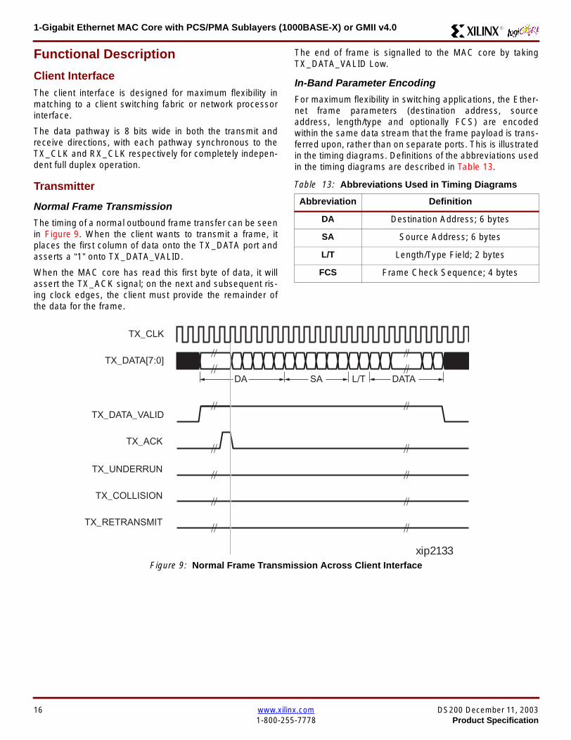
1-Gigabit Ethernet MAC Core with PCSPMA Sublayers (1000BASE-X) or GMII v40 R
Functional Description
Client InterfaceThe client interface is designed for maximum flexibility inmatching to a client switching fabric or network processorinterface
The data pathway is 8 bits wide in both the transmit andreceive directions with each pathway synchronous to theTX_CLK and RX_CLK respectively for completely indepen-dent full duplex operation
Transmitter
Normal Frame Transmission
The timing of a normal outbound frame transfer can be seenin Figure 9 When the client wants to transmit a frame itplaces the first column of data onto the TX_DATA port andasserts a ldquo1rdquo onto TX_DATA_VALID
When the MAC core has read this first byte of data it willassert the TX_ACK signal on the next and subsequent ris-ing clock edges the client must provide the remainder ofthe data for the frame
The end of frame is signalled to the MAC core by takingTX_DATA_VALID Low
In-Band Parameter Encoding
For maximum flexibility in switching applications the Ether-net frame parameters (destination address sourceaddress lengthtype and optionally FCS) are encodedwithin the same data stream that the frame payload is trans-ferred upon rather than on separate ports This is illustratedin the timing diagrams Definitions of the abbreviations usedin the timing diagrams are described in Table 13
Figure 9 Normal Frame Transmission Across Client Interface
Table 13 Abbreviations Used in Timing Diagrams
Abbreviation Definition
DA Destination Address 6 bytes
SA Source Address 6 bytes
LT LengthType Field 2 bytes
FCS Frame Check Sequence 4 bytes
TX_CLK
TX_DATA[70]
TX_DATA_VALID
TX_ACK
TX_UNDERRUN
DA SA DATALT
TX_COLLISION
TX_RETRANSMIT
xip2133
16 wwwxilinxcom DS200 December 11 20031-800-255-7778 Product Specification
1-Gigabit Ethernet MAC Core with PCSPMA Sublayers (1000BASE-X) or GMII v40R
Padding
When fewer than 46 bytes of data are supplied by the clientto the MAC core the transmitter module will add padding upto the minimum frame length The exception to this is whenthe MAC core is configured for client-passed FCS in thiscase the client must also supply the padding to maintain theminimum frame length (see Client-Supplied FCS Passing)
Client-Supplied FCS Passing
If the MAC core is configured to have the FCS field passedin by the client (see Configuration Registers on page 30)the transmission timing is as depicted in Figure 10 In thiscase it is the responsibility of the client to ensure that theframe meets the Ethernet minimum frame length require-ments the MAC core will not perform any padding of thepayload
Figure 10 Frame Transmission with Client-supplied FCS
TX_CLK
TX_DATA[70]
TX_DATA_VALID
TX_ACK
TX_UNDERRUN
DA SA DATA FCSLT
TX_COLLISION
TX_RETRANSMIT
xip2134
DS200 December 11 2003 wwwxilinxcom 17Product Specification 1-800-255-7778
1-Gigabit Ethernet MAC Core with PCSPMA Sublayers (1000BASE-X) or GMII v40 R
Client Underrun
The timing of an aborted transfer can be seen in Figure 11This may happen for instance if a FIFO connected to theclient interface empties before a frame is completed Whenthe client asserts TX_UNDERRUN during a frame transmis-sion the MAC core will insert an error code to corrupt the
current frame and then fall back to idle transmission It isthe responsibility of the client to re-queue the aborted framefor transmission
When an underrun occurs TX_DATA_VALID may beasserted on the clock cycle after the TX_UNDERRUNassertion to request a new transmission
Figure 11 Frame Transmission with Underrun
TX_CLK
TX_DATA[70]
TX_DATA_VALID
TX_ACK
TX_UNDERRUN
DA SA DATALT
TX_COLLISION
TX_RETRANSMIT
xip2135
18 wwwxilinxcom DS200 December 11 20031-800-255-7778 Product Specification
1-Gigabit Ethernet MAC Core with PCSPMA Sublayers (1000BASE-X) or GMII v40R
Back-to-Back Transfers
Figure 12 shows the case where the MAC client is immedi-ately ready to transmit a second frame of data followingcompletion of its first frame In this figure the end of the firstframe is shown on the left On the clock cycle immediatelyfollowing the final byte of the first frame TX_DATA_VALIDis taken low by the client and is taken high one clock cyclelater to indicate that the first byte of the destination addressof the second frame is on TX_DATA awaiting transmission
When the MAC core is ready to accept data TX_ACK isasserted and the transmission continues in the same man-ner as in the case of the single frame The MAC core willdefer the assertion of TX_ACK appropriately to comply withinter-packet gap requirements and flow control requests
If the MAC core is operating in half-duplex mode the timingshown in Figure 12 is required to take advantage of framebursting the MAC core is only guaranteed to retain controlof the medium if the TX_DATA_VALID signal is low for a sin-gle clock cycle For more information on frame bursting seeIEEE 8023-2002
Figure 12 Back to Back Frame Transmission
TX_CLK
TX_DATA[70]
TX_DATA_VALID
TX_ACK
TX_UNDERRUN
TX_COLLISION
TX_RETRANSMIT
xip2136
DS200 December 11 2003 wwwxilinxcom 19Product Specification 1-800-255-7778
1-Gigabit Ethernet MAC Core with PCSPMA Sublayers (1000BASE-X) or GMII v40 R
VLAN Tagged Frames
Transmission of a VLAN tagged frame (if enabled) can beseen in Figure 13 Note that the handshaking signalsacross the interface do not change however the VLANtype tag 81-00 must be supplied by the client to signify that
the frame is VLAN tagged The client also supplies the twobytes of Tag Control Information V1 and V2 at the appro-priate times in the data stream More information on thecontents of these two bytes can be found in IEEE8023-2002
Maximum Permitted Frame Length
The maximum legal length of a frame specified in IEEE8023-2002 is 1518 bytes for non-VLAN tagged framesVLAN tagged frames may be extended to 1522 bytesWhen jumbo frame handling is disabled and the clientattempts to transmit a frame which exceeds the maximumlegal length the MAC core will insert an error code to cor-
rupt the current frame and the frame will be truncated to themaximum legal length When jumbo frame handling isenabled frames which are longer than the legal maximumare transmitted error-free
For more information on enabling and disabling jumboframe handling see Configuration Registers on page 30
Figure 13 Transmission of a VLAN Tagged Frame
TX_CLK
TX_DATA[70]
TX_DATA_VALID
TX_ACK
TX_UNDERRUN
DA SA DATALTVLANtag
81 00V1V2
TX_COLLISION
TX_RETRANSMIT
xip2137
20 wwwxilinxcom DS200 December 11 20031-800-255-7778 Product Specification
1-Gigabit Ethernet MAC Core with PCSPMA Sublayers (1000BASE-X) or GMII v40R
Frame Collisions - Half Duplex Operation Only
In half duplex Ethernet operation collisions will occur on themedium as a matter of course this is how the arbitrationalgorithm is fulfilled In case of a collision the MAC core sig-nals to the client that data may need to be resupplied as fol-lows
If there is a collision the TX_COLLISION signal will be setto ldquo1rdquo by the MAC core If a frame is in progress the clientmust abort the transfer and take TX_DATA_VALID to ldquo0rdquo
If the TX_RETRANSMIT signal is ldquo1rdquo in the same clockcycle that the TX_COLLISION signal is ldquo1rdquo the client must
resubmit the previous frame to the MAC core for retrans-mission TX_DATA_VALID must be asserted to the MACcore within 8 clock cycles of the TX_COLLISION signal inorder to meet Ethernet timing requirements See Figure 14
If the TX_RETRANSMIT signal is ldquo0rdquo in the same clockcycle that the TX_COLLISION signal is ldquo1rdquo the number ofretries for this frame has exceeded the Ethernet specifica-tion and the frame should be dropped by the client The cli-ent can then make any new frame available to the MAC fortransmission without timing restriction See Figure 15
Figure 14 Collision Handling - Frame retransmission required
Figure 15 Collision Handling - No frame retransmission required
TX_CLK
TX_DATA[70]
TX_DATA_VALID
TX_ACK
TX_UNDERRUN
TX_COLLISION
TX_RETRANSMIT
8 clocks max
xip2138
TX_CLK
TX_DATA[70]
TX_DATA_VALID
TX_ACK
TX_UNDERRUN
TX_COLLISION
TX_RETRANSMIT
xip2139
DS200 December 11 2003 wwwxilinxcom 21Product Specification 1-800-255-7778
1-Gigabit Ethernet MAC Core with PCSPMA Sublayers (1000BASE-X) or GMII v40 R
Interframe Gap Adjustment
The user can elect to vary the length of the inter fame gapIf this function is selected (via a configuration bit in thetransmitter control register see Configuration Registerson page 30) then the MAC will exert back pressure to delaythe transmission of the next frame until the requested num-ber of Idle cycles has elapsed The number of Idle cycles iscontrolled by the value on the TX_IFG_DELAY port at thestart of frame transmission Figure 16 shows the MAC oper-ating in this mode
Reducing the Inter fame gap to below the IEEE 8023-2002minimum of 12 Idles is supported in Full Duplex onlydesigns and will transmit an absolute minimum of 4 Idles Ifthe Interframe gap adjustment is reduced below 12 Idlesthen the accuracy of the Optional Statistical Gathering(statistics_gathering=true) Counters cannot be guaranteedHowever the TX_STATISTIC_VECTOR andRX_STATISTIC_VECTOR will always remain correct
Transmitter Statistics Vector
The statistics for the frame transmitted are contained withinthe TX_STATISTICS_VECTOR The vector is driven syn-chronously by the transmitter clock TX_CLK followingframe transmission The bit field definition for the Vector isdefined in Table 14
All bit fields with the exception of BYTE_VALID are validonly when the TX_STATISTICS_VALID is asserted This isillustrated in Figure 17 BYTE_VALID is significant on everyTX_CLK cycle
TX_STATISTICS_VECTOR bits 25 down to 17 inclusive arefor half duplex only and will be set to logic 0 when operatingin full duplex mode
Figure 16 Interframe Gap Adjustment
TX_CLK
TX_DATA[70]
TX_DATA_VALID
TX_ACK
DA SA
TX_IFG_DELAY
IFG ADJUST VALUE
0x0D
13 Idles inserted
DA
Next IFG ADJUST VALUE
xip2140
Figure 17 Transmitter Statistics Vector Timing
TX_CLK
TX_STATISTICS_VECTOR[280]
TX_STATISTICS_VALID
xip2141
22 wwwxilinxcom DS200 December 11 20031-800-255-7778 Product Specification
1-Gigabit Ethernet MAC Core with PCSPMA Sublayers (1000BASE-X) or GMII v40R
Table 14 Bit Definition for the Transmitter Statistics Vector
TX_STATISTICS_VECTOR Name Description
28 PAUSE_FRAME_TRANSMITTEDAsserted if the previous frame was a pause framethat the MAC itself initiated in response to aPAUSE_REQ assertion
27 BYTE_VALID
Asserted if a MAC frame byte (DA to FCS inclusive)is in the process of being transmitted This is valid onevery clock cycle
Do not use this as an enable signal to indicate thatdata is present on GMII_TXD[70]
26 Reserved Returns logic 0
25 down to 22 TX_ATTEMPTS[30]
The number of attempts that have been made totransmit the previous frame This is a 4-bit number0 should be interpreted as 1 attempt 1 as 2attempts up until 15 as 16 attempts
21 Reserved Returns logic 0
20 EXCESSIVE_COLLISIONAsserted if a collision has been detected on each ofthe last 16 attempts to transmit the previous frame
19 LATE_COLLISIONAsserted if a late collision occurred during frametransmission
18 EXCESSIVE_DEFERRALAsserted if the previous frame was deferred for anexcessive amount of time as defined by the constantldquomaxDeferTimerdquo in IEEE 8023-2002
17 TX_DEFERRED Asserted if transmission of the frame was deferred
16 VLAN_FRAMEAsserted if the previous frame contained a VLANidentifier in the LengthType field when transmitterVLAN operation is enabled
15 down to 5 FRAME_LENGTH_COUNTThe length of the previous frame in number of bytesThe count will stick at 2047 for any Jumbo frameslarger than this value
4 CONTROL_FRAMEAsserted if the previous frame had the special MACControl Type code 88-08 in the LengthType field
3 UNDERRUN_FRAMEAsserted if the previous frame contained anunderrun error
2 MULTICAST_FRAMEAsserted if the previous frame contained a multicastaddress in the Destination Address field
1 BROADCAST_FRAMEAsserted if the previous frame contained abroadcast address in the Destination Address field
0 SUCCESSFUL_FRAMEAsserted if the previous frame was transmittedwithout error
DS200 December 11 2003 wwwxilinxcom 23Product Specification 1-800-255-7778
1-Gigabit Ethernet MAC Core with PCSPMA Sublayers (1000BASE-X) or GMII v40 R
Receiver
Normal Frame Reception
The timing of a normal inbound frame transfer can be seenin Figure 18 The client must be prepared to accept data atany time there is no buffering within the MAC to allow forlatency in the receive client Once frame reception begins
data is transferred on consecutive clock cycles to thereceive client until the frame is complete The MAC assertsthe RX_GOOD_FRAME signal to indicate that the framewas successfully received and that the frame should beanalyzed by the client
Frame parameters (destination address source addresslengthtype and optionally FCS) are supplied on the databus according to the timing diagram The abbreviations arethe same as those described in Table 13 on page 16
If the LengthType field in the frame has the Length interpre-tation and this indicates that the inbound frame has beenpadded to meet the Ethernet minimum frame size specifica-tion then this padding will not be passed to the client in thedata payload The exception to this is in the case whereFCS passing is enabled see Client-Supplied FCS Pass-ing on page 25
Therefore when Client-Supplied FCS passing is disabledRX_DATA_VALID = lsquo0rsquo between frames for the duration ofthe Padding field (if present) the FCS field carrier exten-sion (if present) the interframe gap following the frame andthe preamble field of the next frame When Client-Supplied
FCS passing is enabled RX_DATA_VALID = lsquo0rsquo betweenframes for the duration of carrier extension (if present) theinterframe gap and the preamble field of the followingframe
RX_GOOD_FRAME RX_BAD_FRAME timing
Although the timing diagram in Figure 18 shows theRX_GOOD_FRAME signal asserted shortly after the lastvalid data on RX_DATA this is not always the case TheRX_GOOD_FRAME or RX_BAD_FRAME signals areasserted only after all frame checks are completed This isafter the FCS field has been received (and after reception ofcarrier extension if present)
Therefore either RX_GOOD_FRAME or RX_BAD_FRAMEis asserted following frame reception at the beginning of theinterframe gap
Figure 18 Normal Frame Reception
RX_CLK
RX_DATA[70]
RX_DATA_VALID
RX_GOOD_FRAME
RX_BAD_FRAME
DA SA DATALT
xip2142
24 wwwxilinxcom DS200 December 11 20031-800-255-7778 Product Specification
1-Gigabit Ethernet MAC Core with PCSPMA Sublayers (1000BASE-X) or GMII v40R
Frame Reception with Errors
The case of an unsuccessful frame reception (for examplea fragment frame or a frame with an incorrect FCS) can beseen in Figure 19 In this case the RX_BAD_FRAME signal
is asserted to the client at the end of the frame It is then theresponsibility of the client to drop the data already trans-ferred for this frame
Figure 19 Frame Reception with Error
Client-Supplied FCS Passing
If the MAC core is configured to pass the FCS field to the cli-ent (see Configuration Registers on page 30) then this ishandled as shown in Figure 20
In this case any padding inserted into the frame to meetEthernet minimum frame length specifications will be leftintact and passed to the client
Note that even though the FCS is passed up to the client itis also verified by the MAC core and RX_BAD_FRAMEasserted if the FCS check fails
RX_CLK
RX_DATA[70]
RX_DATA_VALID
RX_GOOD_FRAME
RX_BAD_FRAME
DA SA DATALT
xip2144
Figure 20 Frame Reception with In-Band FCS Field
RX_CLK
RX_DATA[70]
RX_DATA_VALID
RX_GOOD_FRAME
RX_BAD_FRAME
DA SA DATALT FCS
xip2145
DS200 December 11 2003 wwwxilinxcom 25Product Specification 1-800-255-7778
1-Gigabit Ethernet MAC Core with PCSPMA Sublayers (1000BASE-X) or GMII v40 R
VLAN Tagged Frames
The reception of a VLAN tagged frame (if enabled) can beseen in Figure 21 The VLAN frame is passed to the clientso that the frame may be identified as VLAN tagged this is
followed by the Tag Control Information bytes V1 and V2More information on the interpretation of these bytes maybe found in IEEE 8023-2002 standard
Maximum Permitted Frame Length
The maximum legal length of a frame specified in IEEE8023-2002 is 1518 bytes for non-VLAN tagged framesVLAN tagged frames may be extended to 1522 bytesWhen jumbo frame handling is disabled and the corereceives a frame which exceeds the maximum legal lengthRX_BAD_FRAME will be asserted When jumbo framehandling is enabled frames which are longer than the legalmaximum are received in the same way as shorter frames
For more information on enabling and disabling jumboframe handling see Configuration Registers on page 30
LengthType Field Error Checks
Enabled
Default operation is with the LengthType error checkingenabled (see Receiver Configuration Word 1 on page 31)In this mode the following checks are made on all framesreceived If either of these checks fail then the frame ismarked as BAD
bull A value in the LengthType field that is greater than orequal to decimal 46 but less than decimal 1536 (aLength interpretation) is checked against the actualdata length received
bull A value in the LengthType field that is less thandecimal 46 is checked to see that the data field ispadded to exactly 46 bytes (so that the resultant frameis minimum frame size 64 bytes total in length)
Furthermore if Padding is indicated (the LengthType fieldis less than decimal 46) and Client-Supplied FCS Passing isdisabled then the Length value in the LengthType field willbe used to deassert RX_DATA_VALID after the indicatednumber of data bytes so that the Padding bytes areremoved from the frame
Disabled
When the LengthType error checking is disabled (seeReceiver Configuration Word 1 on page 31) theLengthType error checks described above are not per-formed A frame containing only these errors will be markedas GOOD
Furthermore if Padding is indicated and Client-SuppliedFCS Passing is disabled then a Length Value in theLengthType field will not be used to deassertRX_DATA_VALID Instead RX_DATA_VALID will be deas-serted before the start of the FCS field in this way any pad-ding will not be removed from the frame
Figure 21 Reception of a VLAN Tagged Frame
RX_CLK
RX_DATA[70]
RX_DATA_VALID
RX_GOOD_FRAME
RX_BAD_FRAME
DA SA DATALT
81 00 V1 V2
VLANtag
xip2146
26 wwwxilinxcom DS200 December 11 20031-800-255-7778 Product Specification
1-Gigabit Ethernet MAC Core with PCSPMA Sublayers (1000BASE-X) or GMII v40R
Receiver Statistics Vector
The statistics for the frame received are contained withinthe RX_STATISTICS_VECTOR The vector is driven syn-chronously by the receiver clock RX_CLK following framereception The bit field definition for the Vector is defined inTable 15
All bit fields with the exception of BYTE_VALID are validonly when the RX_STATISTICS_VALID is asserted This isillustrated in Figure 22 BYTE_VALID is significant on everyRX_CLK cycle
Figure 22 Receiver Statistics Vector Timing
RX_CLK
RX_STATISTICS_VECTOR[220]
RX_STATISTICS_VALID
xip2147
Table 15 Bit Definition for the Receiver Statistics Vector
RX_STATISTICS_VECTOR Name Description
22LENGTHTYPE Out ofRange
Asserted if the lengthtype field contained a length valuethat did not match the number of MAC client data bytesreceived Also high if the lengthtype field indicated thatthe frame contained padding but the number of MAC cli-ent data bytes received was not equal to 64 bytes (min-imum frame size)
The exception to the above is when the LengthTypeField Error Checks are disabled in which case this bitwill not be asserted
21 BAD_OPCODE
Asserted if the previous frame was error-free andcontained the special Control Frame identifier in theLengthType field but contained an opcode that isunsupported by the MAC (Any Opcode other thanPAUSE)
20 FLOW_CONTROL_FRAME
Asserted if the previous frame was error-freecontained the special Control Frame identifier in theLengthType field contained a Destination Addressthat matched either the MAC Control MulticastAddress or the configured source address of the MACcontained the supported PAUSE opcode and wasacted upon by the MAC
19 BYTE_VALID
Asserted if a MAC frame byte (DA to FCS inclusive) isin the process of being received This is valid on everyclock cycle
Do not use this as an enable signal to indicate thatdata is present on RX_DATA[70]
18 VLAN_FRAMEAsserted if the previous frame contained a VLANidentifier in the LengthType field when receiver VLANoperation is enabled
DS200 December 11 2003 wwwxilinxcom 27Product Specification 1-800-255-7778
1-Gigabit Ethernet MAC Core with PCSPMA Sublayers (1000BASE-X) or GMII v40 R
17 OUT_OF_BOUNDS
Asserted if the previous frame exceeded the specifiedIEEE8023-2002 maximum legal length (seeMaximum Permitted Frame Length on page 26) Thisis only valid if Jumbo frames are disabled
16 CONTROL_FRAMEAsserted if the previous frame contained the specialControl Frame identifier in the LengthType field
15 down to 5 FRAME_LENGTH_COUNTThe length of the previous frame in number of bytesThe count will stick at 2047 for any Jumbo frameslarger than this value
4 MULTICAST_FRAMEAsserted if the previous frame contained a multicastaddress in the Destination Address field
3 BROADCAST_FRAMEAsserted if the previous frame contained the broadcastaddress in the Destination Address field
2 FCS_ERRORAsserted if the previous frame received had anincorrect FCS value or the MAC detected error codesduring frame reception
1 BAD_FRAME1 Asserted if the previous frame received containederrors
0 GOOD_FRAME1 Asserted if the previous frame received was error-free
1 If the LengthType Field Error Checks are disabled then a frame which contains this type of error will be marked as a GOOD_FRAMEproviding no additional errors were detected
Table 15 Bit Definition for the Receiver Statistics Vector
RX_STATISTICS_VECTOR Name Description
28 wwwxilinxcom DS200 December 11 20031-800-255-7778 Product Specification
1-Gigabit Ethernet MAC Core with PCSPMA Sublayers (1000BASE-X) or GMII v40R
Flow ControlThe flow control block is designed to Clause 31 of the IEEE8023-2002 standard The MAC may be configured to sendpause frames and to act upon their reception These twobehaviors can be configured asymmetrically see Configu-ration Registers on page 30
Transmitting a PAUSE Control Frame
The client initiates a flow control frame by assertingPAUSE_REQ while the pause value is on the PAUSE_VALbus These signals are synchronous to TX_CLK The timingof this can be seen in Figure 23
If the MAC core is configured to support transmit flow con-trol this action causes the core to transmit a PAUSE controlframe on the link with the PAUSE parameter set to thevalue on PAUSE_VAL in the cycle when PAUSE_REQ wasasserted This will not disrupt any frame transmission inprogress but will take priority over any pending frame trans-
mission This frame will be transmitted even if the transmit-ter is in the paused state itself
Receiving a Pause Control Frame
When an error-free frame is received by the MAC core thefollowing checks are made
1 The Destination Address field is matched against theMAC Control Multicast address or the configuredSource Address for the MAC (see ConfigurationRegisters on page 30)
2 The LengthType field is matched against the MACControl Type code
3 The opcode field contents are matched against thePAUSE opcode if check 2 is true
If any of the above checks are false or the MAC Flow Con-trol logic for the receiver is disabled the frame is ignored bythe Flow Control logic and passed up to the client
If the frame passes all of the above checks is of minimumlegal size and the MAC Flow Control logic for the receiver isenabled the pause value parameter in the frame is thenused to inhibit transmitter operation for the time defined inthe IEEE8023-2002 specification This inhibit is imple-mented using the same back pressure scheme shown inFigure 12 Because the received pause frame has beenacted upon it is passed to the client with RX_BAD_FRAMEasserted to indicate to the client that it should be dropped
Reception of any frame for which check 2 is true and whichis not of legal minimum length is considered an invalid Con-trol frame This will be ignored by the Flow Control logic andpassed to the client with RX_BAD_FRAME asserted
Figure 23 Pause Request Timing
TX_CLK
PAUSE_VAL[150]
PAUSE_REQ
xip2148
DS200 December 11 2003 wwwxilinxcom 29Product Specification 1-800-255-7778
1-Gigabit Ethernet MAC Core with PCSPMA Sublayers (1000BASE-X) or GMII v40 R
Optional Management Interface(management_interface=true)The management interface is a processor-independentinterface with standard address data and control signals Itmay be used as is or a wrapper may be applied (not sup-plied) to interface to common bus architectures
This interface is used for
bull Configuration of the MAC core
bull Access to optional statistics counters for use by higherlayers for example SNMP
bull access through the MDIO interface to the managementregisters located in the PHY attached to the MAC core
The management interface is accessed differently depend-ing on the type of transaction a truth table showing whichaccess method is required for each transaction type isshown in Table 16 These access methods are described inthe following sections
HOST_CLK Frequency
The management interface clock HOST_CLK is used toderive the MDIO clock MDC and is therefore subject tosome frequency restrictions This HOST_CLK must be
ge 10 MHz
le 100 MHz
Configuring the MAC core to derive the MDC signal fromthis clock is detailed in MDIO Interface on page 37
Configuration Registers
After power up or reset the client may reconfigure the coreparameters from their defaults such as flow control supportConfiguration changes can be written at any time Both thereceiver and transmitter logic will only respond to configura-tion changes during Inter Frame Gaps The exceptions tothis are the configurable resets which take effect immedi-ately
Configuration of the MAC core is performed through a reg-ister bank accessed through the management interfaceThe configuration registers available in the core are detailedin Table 17 As can be seen the address has some implicitdonrsquot care bits any access to an address in the rangesshown will perform a 32-bit read or write from the same con-figuration word
Table 16 Management Interface Transaction Types
Transaction HOST_MIIM_SEL HOST_ADDR[9]
Configuration 0 1
Statistics 0 0
MIIM access 1 X
Table 17 Configuration Registers
Address Description
0x200-0x23F Receiver Configuration (Word 0)
0x240-0x27F Receiver Configuration (Word 1)
0x280-0x2BF Transmitter Configuration
0x2C0-0x2FF Flow Control Configuration
0x300-0x33F Reserved
0x340-0x37F Management Configuration
30 wwwxilinxcom DS200 December 11 20031-800-255-7778 Product Specification
1-Gigabit Ethernet MAC Core with PCSPMA Sublayers (1000BASE-X) or GMII v40R
The register contents for the two receiver configuration words can be seen in Table 18 and Table 19
Notes1 In changing the receiverrsquos mode from Half Duplex to Full Duplex there is a period of time of up to 24 us following the mode change
when no new receiver statistics can be stored in the optional Statistical Counters
Table 18 Receiver Configuration Word 0
Bit Default Value Description
31-0 All 0rsquos
Pause frame MAC Source Address[310] This address is used by the MAC tomatch against the Destination Address of any incoming flow control frames It isalso used by the flow control block as the Source Address (SA) for any outboundflow control frames
The address is ordered so the first byte transmittedreceived is the lowestpositioned byte in the register for example a MAC address ofAA-BB-CC-DD-EE-FF would be stored in Address[470] as 0xFFEEDDCCBBAA
Table 19 Receiver Configuration Word 1
Bit Default Value Description
15-0 All 0rsquos Pause frame MAC Source Address[4732] See description in Table 18
24-16 NA Reserved
25 0
LengthType Error Check Disable When this bit is set to ldquo1rdquo the core will notperform the LengthType field error checks as described in LengthType FieldError Checks on page 26 When this bit is set to ldquo0rdquo the LengthType field checkswill be performed this is normal operation
26 0Half Duplex If ldquo1rdquo the receiver will operate in half duplex mode If ldquo0rdquo the receiverwill operate in full duplex mode Has no effect if XCO parameterhalf_duplex_capable = false
27 0VLAN Enable When this bit is set to ldquo1rdquo VLAN tagged frames will be acceptedby the receiver
28 1Receiver Enable If set to ldquo1rdquo the receiver block will be operational If set to ldquo0rdquothe block will ignore activity on the physical interface RX port
29 0
In-band FCS Enable When this bit is ldquo1rdquo the MAC receiver will pass the FCS fieldup to the client as described in Client-Supplied FCS Passing on page 25 Whenit is ldquo0rdquo the client will not be passed the FCS In both cases the FCS will beverified on the frame
30 0Jumbo Frame Enable When this bit is set to ldquo1rdquo the MAC receiver will acceptframes over the specified IEEE8023-2002 maximum legal length When this bitis ldquo0rdquo the MAC will only accept frames up to the specified maximum
31 0Reset When this bit is set to ldquo1rdquo the receiver will be reset The bit will thenautomatically revert to ldquo0rdquo Note that this reset will also set all of the receiverconfiguration registers to their default values
DS200 December 11 2003 wwwxilinxcom 31Product Specification 1-800-255-7778
1-Gigabit Ethernet MAC Core with PCSPMA Sublayers (1000BASE-X) or GMII v40 R
The register contents for the Transmitter Configuration Word are described in Table 20
Notes1 In changing the transmitterrsquos mode from Half Duplex to Full Duplex there is a period of time of up to 24 us following the mode change
when no new transmitter statistics can be stored in the optional Statistical Counters
Table 20 Transmitter Configuration Word
Bit Default Value Description
24-0 NA Reserved
25 0
Interframe Gap Adjust Enable If lsquo1rsquo the transmitter will read the value on the portTX_IFG_DELAY at the start of frame transmission and adjust the interframe gapfollowing the frame accordingly See Interframe Gap Adjustment on page 22 Ifldquo0rdquo the transmitter will output a minimum Inter Frame Gap of twelve clock cyclesas specified in IEEE8023-2002
26 0Half Duplex If lsquo1rsquo the transmitter will operate in half duplex mode If lsquo0rsquo thetransmitter will operate in full duplex mode Has no effect if XCO parameterhalf_duplex_capable = false
27 0VLAN Enable When this bit is set to 1 the transmitter will allow the transmissionof VLAN tagged frames
28 1Transmit Enable When this bit is 1 the transmitter is operational When it is 0the transmitter is disabled
29 0
In-band FCS Enable When this bit is lsquo1rsquo the MAC transmitter will expect the FCSfield to be passed in by the client as described in Client-Supplied FCS Passingon page 17 When this bit is ldquo0rdquo the MAC transmitter will append padding asrequired compute the FCS and append it to the frame
30 0
Jumbo Frame Enable When this bit is set to ldquo1rdquo the MAC transmitter will sendframes that are greater than the specified IEEE8023-2002 maximum legallength When this bit is ldquo0rdquo the MAC will only send frames up to the specifiedmaximum
31 0Reset When this bit is set to ldquo1rdquo the transmitter will be reset The bit will thenautomatically revert to ldquo0rdquo Note that this reset will also set all of the transmitterconfiguration registers to their default values
32 wwwxilinxcom DS200 December 11 20031-800-255-7778 Product Specification
1-Gigabit Ethernet MAC Core with PCSPMA Sublayers (1000BASE-X) or GMII v40R
The register contents for the Flow Control Configuration Word are described in Table 21
The register contents for the Management Configuration Word are described in Table 22
Writing to the configuration registers through the manage-ment interface is depicted in Figure 24 When accessing theconfiguration registers (ie when HOST_ADDR[9] = lsquo1rsquo andHOST_MIIM_SEL = lsquo0rsquo) the upper bit of HOST_OPCODEfunctions as an Active Low write enable signal The lowerHOST_OPCODE bit is a ldquodonrsquot carerdquo
Reading from the configuration register words is similar butthe upper HOST_OPCODE bit should be lsquo1rsquo This is shownin Figure 25 In this case the contents of the register appearon HOST_RD_DATA the HOST_CLK edge after the regis-ter address is asserted onto HOST_ADDR
Table 21 Flow Control Configuration Word
Bit Default Value Description
28-0 NA Reserved
29 1
Flow Control Enable (RX) When this bit is lsquo1rsquo received flow control frames willinhibit the transmitter operation as described in Receiving a Pause ControlFrame on page 29 When this bit is lsquo0rsquo received flow control frames will alwaysbe passed up to the client
30 1Flow Control Enable (TX) When this bit is lsquo1rsquo asserting the PAUSE_REQ signalwill send a flow control frame out from the transmitter When this bit is 0 assertingthe PAUSE_REQ signal has no effect
31 NA Reserved
Table 22 Management Configuration Word
Bits Default Value Description
4-0 All 0rsquos Clock Divide[40] See MDIO Interface on page 37
5 0MDIO Enable When this bit is 1 the MDIO interface can be used to accessattached PHY devices When this bit is 0 the MDIO interface is disabled and theMDIO signals remain inactive
31-6 NA Reserved
Figure 24 Configuration Register Write Timing
HOST_CLK
HOST_ADDR[80]
HOST_ADDR[9]
HOST_OPCODE[1]
HOST_MIIM_SEL
HOST_WR_DATA[310]xip2149
Figure 25 Configuration Register Read Timing
HOST_CLK
HOST_ADDR[80]
HOST_ADDR[9]
HOST_OPCODE[1]
HOST_MIIM_SEL
HOST_RD_DATA[310]
xip2150
DS200 December 11 2003 wwwxilinxcom 33Product Specification 1-800-255-7778
1-Gigabit Ethernet MAC Core with PCSPMA Sublayers (1000BASE-X) or GMII v40 R
Optional Statistical Gathering(statistics_gathering=true)
During operation the MAC core collects statistics on thesuccess and failure of various operations for processing by
station management entities (STA) further up the protocolstack These statistics are accessed by the host through theoptional management interface A complete list of statisticssupported is described in Table 23
Table 23 Statistics Registers
Address Name Description
0x000 Frames Received OK1 A count of error-free frames received
0x001 Frame Check Sequence Errors A count of received frames that failed the CRC check and were at least64 bytes in length
0x002 Broadcast Frames Received OK1A count of frames that were successfully received and were directed tothe broadcast group address
0x003 Multicast Frames Received OK1 A count of frames that were successfully received and were directed toa non broadcast group address
0x004 64 byte Frames Received OK1 A count of error-free frames received that were 64 bytes in length
0x005 65-127 byte Frames Received OK1A count of error-free frames received that were between 65 and 127bytes in length
0x006 128-255 byte Frames Received OK1A count of error-free frames received that were between 128 and 255bytes in length
0x007 256-511 byte Frames Received OK1A count of error-free frames received that were between 256 and 511bytes in length
0x008512-1023 byte Frames ReceivedOK1
A count of error-free frames received that were between 512 and 1023bytes in length
0x0091024-MaxFrameSize byte FramesReceived OK1
A count of error-free frames received that were between 1024 bytes andthe specified IEEE8023-2002 maximum legal length (see MaximumPermitted Frame Length on page 26)
0x00A Control Frames Received OKA count of error-free frames received that contained the specialControl Frame identifier in the LengthType field
0x00B LengthType Out of Range
A count of frames received that were at least 64 bytes in length wherethe lengthtype field contained a length value that did not match thenumber of MAC client data bytes received
The counter also increments for frames in which the lengthtype fieldindicated that the frame contained padding but where the number ofMAC client data bytes received was greater than 64 bytes (minimumframe size)
The exception to the above is when the LengthType Field Error Checksare disabled in which case this counter will not increment
0x00C VLAN Tagged Frames Received OKA count of error-free VLAN frames received This counter will only incre-ment when the receiver is configured for VLAN operation
0x00D Pause Frames Received OK
A count of error-free frames received that contained the MAC Controltype identifier 88-08 in the LengthType field contained a Destinationaddress that matched either the MAC Control multicast address or theconfigured source address of the MAC contained the PAUSE opcodeand were acted upon by the MAC
0x00EControl Frames Received withUnsupported Opcode
A count of error-free frames received that contained the MAC Controltype identifier 88-08 in the LengthType field but were received with anopcode other than the PAUSE opcode
34 wwwxilinxcom DS200 December 11 20031-800-255-7778 Product Specification
1-Gigabit Ethernet MAC Core with PCSPMA Sublayers (1000BASE-X) or GMII v40R
0x00F Oversize Frames Received OK1A count of otherwise error-free frames received that exceeded the max-imum legal frame length specified in IEEE 8023-2002 (see MaximumPermitted Frame Length on page 26)
0x010 Undersize frames receivedA count of the number of frames received that were less than 64 bytesin length but were otherwise well formed
0x011 Fragment frames receivedA count of the number of frames received that were less than 64 bytesin length and had a bad Frame Check Sequence field
0x012 Received bytesA count of bytes of frames that are received (Destination Address toFrame Check Sequence inclusive)
0x013 Transmitted bytesA count of bytes of frames that are transmitted (Destination Address toFrame Check Sequence inclusive)
0x020 Frames Transmitted OK A count of error-free frames transmitted
0x021 Broadcast Frames Transmitted OK A count of error-free frames that were transmitted to the broadcastaddress
0x022 Multicast Frames Transmitted OK A count of error-free frames that were transmitted to a group destina-tion address other than broadcast
0x023 Underrun Errors
A count of frames that would otherwise be transmitted by the core butcould not be completed due to the assertion of TX_UNDERRUN duringthe frame transmission This will not count frames which are less than64 bytes in length
0x024 Control Frames Transmitted OKA count of error-free frames transmitted that contained the MACControl Frame type identifier 88-08 in the LengthType field
0x025 64 byte Frames Transmitted OK A count of error-free frames transmitted that were 64 bytes in length
0x026 65-127 byte Frames Transmitted OKA count of error-free frames transmitted that were between 65 and 127bytes in length
0x027128-255 byte Frames TransmittedOK
A count of error-free frames transmitted that were between 128 and 255bytes in length
0x028256-511 byte Frames TransmittedOK
A count of error-free frames transmitted that were between 256 and 511bytes in length
0x029512-1023 byte Frames TransmittedOK
A count of error-free frames transmitted that were between 512 and1023 bytes in length
0x02A1024-MaxFrameSize byte FramesTransmitted OK
A count of error-free frames transmitted that were between 1024 and thespecified IEEE8023-2002 maximum legal length (see Maximum Per-mitted Frame Length on page 20)
0x02BVLAN Tagged Frames TransmittedOK
A count of error-free VLAN frames transmitted This counter will onlyincrement when the transmitter is configured for VLAN operation
0x02C Pause Frames Transmitted OKA count of error-free PAUSE frames generated and transmitted by thecore in response to an assertion of PAUSE_REQ
0x02D Oversize Frames Transmitted OKA count of otherwise error-free frames transmitted that exceeded themaximum legal frame length specified in IEEE 8023-2002 (see Maxi-mum Permitted Frame Length on page 20)
0x02E Single Collision Frames A count of frames that are involved in a single collision but are subse-quently transmitted successfully (Half Duplex Mode only)
Table 23 Statistics Registers (Continued)
Address Name Description
DS200 December 11 2003 wwwxilinxcom 35Product Specification 1-800-255-7778
1-Gigabit Ethernet MAC Core with PCSPMA Sublayers (1000BASE-X) or GMII v40 R
Each of these statistic registers is 64 bits wide and thereforemust be read in a two-cycle transfer The timing of this pro-cess is shown in Figure 26 Six clocks after the read trans-action is initiated the least significant word (LSW) of thestatistics counter appears on the HOST_RD_DATA bus
and a clock cycle later the most significant word (MSW)appears For accurate statistic values 64 clock ticks (ofTX_CLK for transmit statistics or RX_CLK for receive statis-tics) must elapse after the last frame is sent or receivedthrough the MAC core
0x02F Multiple Collision Frames A count of frames that are involved in more than one collision but aresubsequently transmitted successfully (Half Duplex Mode only)
0x040 Frames with Deferred Transmissions A count of frames whose transmission was delayed on its first attemptbecause the medium was busy (Half Duplex Mode only)
0x041 Late Collisions
A count of the times that a collision has been detected later than oneslotTime from the start of the packet transmission A late collision iscounted twice both as a collision and as a lateCollision (Half DuplexMode only)
0x042Frames Aborted due to Excesscollisions
A count of the frames that due to excessive collisions are not transmit-ted successfully (Half Duplex Mode only)
0x043 Carrier Sense ErrorsA count of times that the GMII_CRS signal was not asserted or wasdisasserted during the transmission of a frame without collision (HalfDuplex Mode only)
0x044 Frames with Excess DeferralA count of frames that deferred transmission for an excessive period oftime (Half Duplex Mode only)
1 If the LengthType Field Error Checks are disabled then these counters will still increment for received frames which contain this typeof error (providing no additional errors were detected)
Table 23 Statistics Registers (Continued)
Address Name Description
Figure 26 Statistic Register Read Timing
HOST_CLK
HOST_ADDR[80]
HOST_ADDR[9]
HOST_REQ
HOST_MIIM_SEL
HOST_RD_DATA[310]
6 CLOCKS
LSW MSW
xip2151
36 wwwxilinxcom DS200 December 11 20031-800-255-7778 Product Specification
1-Gigabit Ethernet MAC Core with PCSPMA Sublayers (1000BASE-X) or GMII v40R
MDIO Interface
The management interface is also used to access the MDIO(MII Management) interface of the MAC core this interfaceis used to access the Managed Information Block (MIB) ofthe PHY components attached to the MAC core
The MDIO interface supplies a clock to the externaldevices MDC This clock is derived from the HOST_CLKsignal using the value in the Clock Divide[40] configurationregister The frequency of the MDIO clock is given by thefollowing equation
The frequency of MDC given by this equation should notexceed 25 MHz in order to comply with the IEEE8023-2002 specification for this interface To prevent MDCfrom being out of specification the Clock Divide[40] valuepowers up at 00000 and while this value is in the register itis impossible to enable the MDIO interface
For details of the register map of PHY layer devices and afuller description of the operation of the MDIO interfaceitself see IEEE specification 8023-2002
Access to the MDIO interface through the managementinterface is depicted in the timing diagram in Figure 27
For MDIO transactions the following points apply
bull HOST_OPCODE maps to the OP (opcode) field of theMDIO frame
bull HOST_ADDR maps to the two address fields of theMDIO frame PHY_ADDR is HOST_ADDR[95] andREG_ADDR is HOST_ADDR[40]
bull HOST_WR_DATA[150] maps into the data field of the
MDIO frame when performing a write operation
bull The data field of the MDIO frame maps intoHOST_RD_DATA[150] when performing a readoperation
The MAC core signals to the host that it is ready for anMDIO transaction by asserting HOST_MIIM_RDY A read orwrite transaction on the MDIO is initiated by a pulse on the
fMDC
fHOST_CLK
1 Clock Divide[40]+( ) 2times-------------------------------------------------------------------=
Figure 27 MDIO Access Through Management Interface
HOST_CLK
HOST_ADDR[90]
HOST_OPCODE[10]
HOST_REQ
HOST_MIIM_SEL
HOST_RD_DATA[150]
HOST_WR_DATA[150]
HOST_RDY
If a read transaction is initiated the HOST_RD_DATA bus is valid at the point indicated If a write transaction is initiated the HOST_WR_DATA bus must be valid at the indicated point Simultaneous read and write is not permitted
xip2152
DS200 December 11 2003 wwwxilinxcom 37Product Specification 1-800-255-7778
1-Gigabit Ethernet MAC Core with PCSPMA Sublayers (1000BASE-X) or GMII v40 R
HOST_REQ signal This pulse is ignored if the MDIO inter-face already has a transaction in progress
The MAC core then disasserts the HOST_MIIM_RDY signalwhile the transaction across the MDIO is in progress Whenthe transaction across the MDIO interface has been com-pleted the HOST_MIIM_RDY signal will be asserted by theMAC core if the transaction is a read the data will also beavailable on the HOST_RD_DATA[150] bus at this time
Optional Configuration Vector(management_interface = false)If the optional Management interface is omitted from thecore all of relevant configuration signals are brought out of
the core These signals are bundled into theCONFIGURATION_VECTOR signal The bit mapping of theconfiguration vector signal is defined in Table 24 See thecorresponding entry in the configuration register tables forthe full description of each signal
Note that these configuration vector signals can bechanged by the user at any time however with the excep-tion of the reset and the flow control configuration signalsthey will not take effect until the current frame has com-pleted transmission or reception
The ldquoClockrdquo heading denotes which clock domain the con-figuration signal is registered into before use by the core Itis not necessary to drive the signal from this clock domain
Table 24 Configuration Vector Bit Definition
Bit(s)Configuration Register
cross reference Clock Description
47 downto 0
Receiver ConfigurationWord 0 bits 31-0 andReceiver ConfigurationWord 1 bits 15-0
RX_CLK
Pause frame MAC Source Address[470] This address isused by the MAC core to match against the DestinationAddress of any incoming flow control frames and as theSource Address for any outbound flow control frames
The address is ordered such that the first byte transmitted orreceived is the least significant byte in the register forexample a MAC address of AA-BB-CC-DD-EE-FF will bestored in bite [470] as 0xFFEEDDCCBBAA
48Receiver ConfigurationWord 1 bit 26
RX_CLKReceiver Half Duplex If lsquo1rsquo the receiver operates in halfduplex mode If lsquo0rsquo the receiver operates in full duplex modeHas no effect if XCO parameter half_duplex_capable = false
49Receiver ConfigurationWord 1 bit 27
RX_CLKReceiver VLAN Enable When this bit is set to 1 VLANtagged frames are accepted by the receiver
50Receiver ConfigurationWord 1 bit 28
RX_CLKReceiver Enable If set to 1 the receiver block is operationalIf set to 0 the block ignores activity on the physical interfaceRX port
51Receiver ConfigurationWord 1 bit 29
RX_CLK
Receiver In-band FCS Enable When this bit is lsquo1rsquo the MACreceiver will pass the FCS field up to the client as describedin Client-Supplied FCS Passing on page 25 When it is lsquo0rsquothe MAC receiver will not pass the FCS field In both casesthe FCS field will be verified on the frame
52Receiver ConfigurationWord 1 bit 30
RX_CLK
Receiver Jumbo Frame Enable When this bit is lsquo0rsquo thereceiver will not pass frames longer than the maximum legalframe size specified in IEEE 8023-2002 (see MaximumPermitted Frame Length on page 26) When it is lsquo1rsquo thereceiver will not have an upper limit on frame size
53Receiver ConfigurationWord 1 bit 31
NA
Receiver Reset When this bit is lsquo1rsquo the receiver is held inreset
This signal is an input to the reset circuit for the receiverblock See Reset circuit on page 42 for more information
54TransmitterConfiguration Word bit25
TX_CLK
Transmitter Interframe Gap Adjust enable If lsquo1rsquo then thetransmitter will read the value of the TX_IFG_DELAY port andset the Interframe Gap accordingly If lsquo0rsquo the transmitter willalways insert at least the legal minimum Interframe Gap
38 wwwxilinxcom DS200 December 11 20031-800-255-7778 Product Specification
1-Gigabit Ethernet MAC Core with PCSPMA Sublayers (1000BASE-X) or GMII v40R
55TransmitterConfiguration Word bit26
TX_CLK
Transmitter Half Duplex If lsquo1rsquo the transmitter operates in halfduplex mode If lsquo0rsquo the transmitter operates in full duplexmode Has no effect if XCO parameter half_duplex_capable= false
56TransmitterConfiguration Word bit27
TX_CLKTransmitter VLAN Enable When this bit is set to lsquo1rsquo thetransmitter allows the transmission of VLAN tagged frames
57TransmitterConfiguration Word bit28
TX_CLKTransmitter Enable When this bit is 1 the transmitter will beoperational When it is 0 the transmitter is disabled
58TransmitterConfiguration Word bit29
TX_CLK
Transmitter In-Band FCS Enable When this bit is lsquo1rsquo theMAC transmitter will expect the FCS field to be pass in by theclient as described in Client-Supplied FCS Passing onpage 17 When it is lsquo0rsquo the MAC transmitter will appendpadding as required compute the FCS and append it to theframe
59TransmitterConfiguration Word bit30
TX_CLK
Transmitter Jumbo Frame Enable When this bit is lsquo1rsquo theMAC transmitter will allow frames larger than the maximumlegal frame length specified in IEEE 8023-2002 to be sentWhen set to lsquo0rsquo the MAC transmitter will only allow frames upto the legal maximum to be sent
60TransmitterConfiguration Word bit31
NA
Transmitter Reset When this bit is lsquo1rsquo the MAC transmitter isheld in reset
This signal is an input to the reset circuit for the transmitterblock See Reset circuit on page 42 for more information
61Flow ControlConfiguration Word bit29
TX_CLK
Transmit Flow Control Enable When this bit is lsquo1rsquo assertingthe PAUSE_REQ signal causes the MAC core to send a flowcontrol frame out from the transmitter as described inReceiving a Pause Control Frame on page 29 When this bitis lsquo0rsquo asserting the PAUSE_REQ signal will have no effect
62Flow ControlConfiguration Word bit30
RX_CLK
Receive Flow Control Enable When this bit is lsquo1rsquo receivedflow control frames will inhibit the transmitter operation asdescribed in Receiving a Pause Control Frame on page 29When it is lsquo0rsquo received flow frames are passed up to theclient
63Receiver ConfigurationWord 1 bit 25
RX_CLK
LengthType Error Check Disable When this bit is lsquo1rsquo thecore will not perform the LengthType field error checks asdescribed in LengthType Field Error Checks on page 26When it is set to lsquo0rsquo the LengthType field checks will beperformed this is normal operation
Table 24 Configuration Vector Bit Definition (Continued)
Bit(s)Configuration Register
cross reference Clock Description
DS200 December 11 2003 wwwxilinxcom 39Product Specification 1-800-255-7778
1-Gigabit Ethernet MAC Core with PCSPMA Sublayers (1000BASE-X) or GMII v40 R
Optional GMII (physical_interface=gmii)The GMII is designed to IEEE 8023-2002 Clause 35 Thisutilizes IOrsquos of the Xilinx devices using inputoutput buffersand inputoutput flip-flops to maximize setup and hold mar-gins All IO logic is placed in the example wrapper that isdelivered with the core In addition all clock managementlogic for the core is instanced in this example wrapper thisallows multiple instances of the core to share clocks Theexample wrapper is provided in both VHDL and Verilog
Clock Management
Figure 28 illustrates the clock management used with theGMII interface All clocks illustrated have a frequency of125MHz
GTX_CLK must be provided to the MAC core This is a highquality clock which satisfies the IEEE8023-2002 require-ments It is expected that this clock will be derived from anexternal oscillator and connected into the device through anIBUFG as illustrated The clock source must then be routedonto a global clock network by connecting it to a BUFGWithin the MAC core this global clock is used by all MACtransmitter logic The MAC Client can obtain this clock byconnecting to the TX_CLK signal output from the coreGMII_TX_CLK is derived from this global clock by invertingit and routing it to an OBUF
GMII_RX_CLK is received through an IBUFG This clock isthen routed onto a global clock network by connecting it to aBUFG The resulting global clock is used by all MACreceiver logic
Figure 28 Clock Management with GMII
IBUFG
IBUFG
OBUF
BUFG
BUFG
TX_CLK
RX_CLK
GTX_CLK
GMII_TX_CLK
GMII_RX_CLK
Example Wrapper
xip2153
MAC Core
TX_CLK
RX_CLK
GMII_TX_CLK
GMII_RX_CLK
GTX_CLK
40 wwwxilinxcom DS200 December 11 20031-800-255-7778 Product Specification
1-Gigabit Ethernet MAC Core with PCSPMA Sublayers (1000BASE-X) or GMII v40R
Clock Sharing between Multiple cores
Figure 29 illustrates how it is possible to share clockresources across multiple instantiations of the core whenusing the optional GMII
GTX_CLK may be shared between multiple cores as illus-trated resulting in a common transmitter clock domainacross the device
A common receiver clock domain is not possible each corewill receive an independent receiver clock from its GMII asillustrated
Although not illustrated if the optional Management Inter-face is used HOST_CLK can also be shared betweencores
Figure 29 Clock Management with multiple instances of the MAC with GMII
IBUFG
OBUF
BUFG
TX_CLK
RX_CLK_1
GMII_TX_CLK_1
GMII_RX_CLK_1
MAC Core
TX_CLK
RX_CLK
GMII_TX_CLK
GMII_RX_CLK
GTX_CLK
MAC Core
TX_CLK
RX_CLK
GMII_TX_CLK
GMII_RX_CLK
GTX_CLK
IBUFG
BUFG
GTX_CLK
IBUFG
OBUF
GMII_TX_CLK_2
GMII_RX_CLK_2
BUFG
TX_CLK
RX_CLK_2
DS200 December 11 2003 wwwxilinxcom 41Product Specification 1-800-255-7778
1-Gigabit Ethernet MAC Core with PCSPMA Sublayers (1000BASE-X) or GMII v40 R
Reset circuit
Internally the core is divided up into clockreset domainswhich group together elements with the common clock andreset signals The reset circuitry for one of these domains isis illustrated in Figure 30 This circuit provides controllableskews on the reset nets within the design
More information on the operation and rationale behind thiscircuit can be found in Ken Chapmanrsquos Xilinx TechXclusiveldquoGet Smart About Resetrdquo athttpwwwxilinxcomsupporttechxclusivesglobal-techX19htm
Figure 30 Reset circuit for one clockreset domain
FDP
PRED
C
Q
FDP
PRED
C
Q
FDP
PRED
C
Q
FDP
PRED
C
Q
PRE PRE PRE
0
RESET
Management Reset
Clock
Core Registers
42 wwwxilinxcom DS200 December 11 20031-800-255-7778 Product Specification
1-Gigabit Ethernet MAC Core with PCSPMA Sublayers (1000BASE-X) or GMII v40R
Optional PCS with Ten-Bit Interface (TBI) for 1000BASE-X (physical_interface=tbi)The Full-Duplex Physical Coding Sublayer (PCS) for1000BASE-X is defined in IEEE 8023-2002 Clauses 36and 37 This functionality is only available in the Virtex-IIand Spartan3 families of FPGA devices
A block diagram of the PCS is shown in Figure 31 Themajor functional blocks of the PCS are
bull Transmit engine
bull Auto-negotiation block
bull Receive engine and synchronization block
bull PCS managed register block
bull 8B10B encoder block
bull 8B10B decoder block
bull Receiver elastic buffer
The PCS Managed Register Block is accessed through theMDIO Interface as if it were an externally connected PHYThis configures the operation of the PCS and Auto-Negoti-ation See PCS Managed Register Block
(physical_interface = tbi or phy) on page 49 The corersquosoptional Management Interface can be used to control theMDIO Interface as described by MDIO Interface onpage 37 When the optional Management Interface is notpresent the PCS Managed Register Block must beaccessed via an MDIO controller which is not provided bythe core
The 8B10B encodingdecoding blocks are implemented byconfiguring two Block SelectRAM modules as ROM Theseare used as large look-up tables The remaining PCS func-tionality such as code group encodingdecoding the Man-aged Register Block and Auto-Negotiation areimplemented in CLB logic
The Receiver Elastic buffer enables the 10-bit parallel datareceived from the PMA sublayer alternatively onPMA_RX_CLK0 and PMA_RX_CLK1 clock edges to betransferred onto the internal 125MHz clock domain derivedfrom GTX_CLK (see Clock Management) This buffer isimplemented in Distributed Memory
Figure 31 Functional Block Diagram of the 1-Gigabit Ethernet PCS with TBI Interface
PCS TRANSMIT ENGINE
PCS RECEIVE ENGINE ampSYNCHRONISATION
PCSMANAGEMENT
MDIOInterface
AUTO-NEGOTIATION
MAC TXInterface
MAC RXInterface
8B10BEncoder
8B10BDecoder
RX Elastic Buffer
TBI Interface
DS200 December 11 2003 wwwxilinxcom 43Product Specification 1-800-255-7778
1-Gigabit Ethernet MAC Core with PCSPMA Sublayers (1000BASE-X) or GMII v40 R
TBI Interface
The TBI is designed to IEEE 8023-2002 Clause 363 Thisutilizes IOrsquos of the Xilinx devices using inputoutput buffersand inputoutput flip-flops to maximize setup and hold mar-gins All IO logic is placed in the example wrapper that isdelivered with the core In addition all clock managementlogic for the core is instantiated in this example wrapperthis allows multiple instances of the core to share clocksThe example wrapper is provided in both VHDL and Verilog
Clock Management
Figure 32 illustrates the clock management used with theTBI interface
GTX_CLK must be provided to the MAC core This is a highquality clock of frequency 125MHz which satisfies theIEEE8023-2002 requirements It is expected that this clockwill be derived from an external oscillator and connected
into the device through an IBUFG as illustrated The clocksource must then be routed onto a global clock network byconnecting it to a BUFG Within the MAC core this globalclock is used by all MAC transmitter logic PMA_TX_CLK isderived from this global clock by inverting it and routing it toan OBUF
PMA_RX_CLK0 and PMA_RX_CLK1 are each receivedthrough an IBUFG These clocks are then routed onto glo-bal clock networks by connecting each to a BUFGPMA_RX_CLK0 and PMA_RX_CLK1 are each 625MHzclocks Data from the TBI is received alternatively on the ris-ing edge of PMA_RX_CLK0 followed by the rising edge ofPMA_RX_CLK1 using IOB Double-Data Rate input regis-ters This data is then written into the Receiver ElasticBuffer Data is read out of the Elastic Buffer using the globalclock derived from GTX_CLK all the remaining receiverlogic is synchronous to this clock
Figure 32 Clock Management for PCS with TBI Interface
IBUFG
IBUFG
OBUF
BUFG
BUFG
TX_CLK
RX_CLK
GTX_CLK
PMA_TX_CLK
PMA_RX_CLK0
MAC Core
RX ELASTICBUFFER
Example Wrapper
TX_CLK
RX_CLK
GTX_CLK
PMA_TX_CLK
PMA_RX_CLK0
IBUFGBUFGPMA_RX_CLK1
PMA_RX_CLK1
44 wwwxilinxcom DS200 December 11 20031-800-255-7778 Product Specification
1-Gigabit Ethernet MAC Core with PCSPMA Sublayers (1000BASE-X) or GMII v40R
Clock Sharing between Multiple cores
Figure 33 illustrates how it is possible to share clockresources across multiple instantiations of the core whenusing the optional PCS with TBI
GTX_CLK may be shared between multiple cores as illus-trated resulting in a common transmitter clock domainacross the device
Each core will receive independent PMA_RX_CLK0 andPMA_RX_CLK1 clocks from its TBI as illustrated whichcannot be shared
Although not illustrated if the optional Management Inter-face is used HOST_CLK can also be shared betweencores
Figure 33 Clock Management with multiple instances of the MAC with PCS and TBI
Reset circuit
The reset circuits within the MAC when the TBI interface is implemented is the same as that in the GMII case details ofthese circuits can be found on page 42
IBUFG
OBUF
BUFG
TX_CLK
RX_CLK
PMA_TX_CLK_1
PMA_RX_CLK0_1
MAC Core
RX ELASTICBUFFER
TX_CLK
RX_CLK
GTX_CLK
PMA_TX_CLK
PMA_RX_CLK0
IBUFGBUFGPMA_RX_CLK1_1
PMA_RX_CLK1
IBUFG
BUFG
GTX_CLK
IBUFG
OBUF
BUFG
TX_CLK
RX_CLK
PMA_TX_CLK_2
PMA_RX_CLK0_2
MAC Core
RX ELASTICBUFFER
TX_CLK
RX_CLK
GTX_CLK
PMA_TX_CLK
PMA_RX_CLK0
IBUFGBUFGPMA_RX_CLK1_2
PMA_RX_CLK1
DS200 December 11 2003 wwwxilinxcom 45Product Specification 1-800-255-7778
1-Gigabit Ethernet MAC Core with PCSPMA Sublayers (1000BASE-X) or GMII v40 R
Optional PCS and PMA Sublayers for 1000BASE-X (physical_interface=phy)The Full-Duplex Physical Coding Sublayer (PCS) withPhysical Medium Attachment (PMA) for 1000BASE-X isdefined in IEEE 8023-2002 Clauses 36 and 37 This func-tionality is only available in the Virtex-II Pro family of FPGAdevices
A block diagram of the PCS and PMA sublayers can beseen in Figure 34 The functional blocks of the PCS andPMA sublayers may replace the optional GMII interfaceThe functional blocks of the PCS and PMA sublayers are
bull PCS Transmit Engine
bull Auto-Negotiation block
bull Receive Engine and Synchronization Block
bull PCS Managed Register Block
bull Rocket IO Multi-Gigabit Transceiver
The PCS Managed Register Block is accessed through theMDIO Interface as if it were an externally connected PHYThis configures the operation of the PCS PMA sublayerand Auto-NegotiationSee PCS Managed Register Block(physical_interface = tbi or phy) on page 49 The corersquosoptional Management Interface can be used to control theMDIO Interface as described by MDIO Interface onpage 37 When the optional Management Interface is notpresent the PCS Managed Register Block must beaccessed via an MDIO controller which is not provided bythe core
The Rocket IO Multi-Gigabit Transceiver (MGT) providessome of the PCS layer functionality such as 8B10B encod-ingdecoding and the PMA serdes The remaining PCSfunctionality such as code group encodingdecoding theManaged Register Block and Auto-Negotiation are imple-mented in CLB logic
Figure 34 Functional Block Diagram of the 1-Gigabit Ethernet PCSPMA Sublayer Extension
PCS TRANSMIT ENGINE
PCS RECEIVE ENGINE ampSYNCHRONISATION
RO
CK
ET
IO
MU
LTI-
GIG
TR
AN
SC
EIV
ER
PCSMANAGEMENT
MDIOInterface
AUTO-NEGOTIATION
TXPTXN
RXPRXN
MAC TXInterface
MAC RXInterface
xip2154
46 wwwxilinxcom DS200 December 11 20031-800-255-7778 Product Specification
1-Gigabit Ethernet MAC Core with PCSPMA Sublayers (1000BASE-X) or GMII v40R
Clock Management
Figure 35 illustrates the clock management that should beused with the optional PCS and PMA sublayers for1000BASE-X This logic is implemented in the examplewrapper that is delivered with the core This provides flexi-bility because the design can be modified to use eitherREFCLK or BREFCLK (please refer to Rocket IO docu-mentation) It would also allow multiple instances of the coreto share clocks The example wrapper is provided in bothVHDL and Verilog
(B)REFCLK must be provided to the MAC core This clockmust be derived from an external oscillator and connectedto the core through an IBUFG as illustrated (B)REFCLK isa high quality clock of frequency 625 MHz which satisfiesthe Rocket IO Multi-Gigabit Transceiver (MGT) require-ments
(B)REFCLK is routed to both the core and a DCM From theDCM the CLK2X180 output is routed to a BUFG to providethe device with a global 125 MHz clock (connected toUSERCLK2 input on the core) Within the core bothTX_CLK and RX_CLK share this global 125 MHz clocksource which is used by all transmitter and receiver logicThis is made possible by the RX_ELASTIC_BUFFER func-tionality of the Rocket IO MGT (refer to Virtex-II Pro docu-mentation) The MAC Client can obtain this clock byconnecting to either the TX_CLK or the RX_CLK signalsoutput from the core
From the DCM the CLK0 output is routed to a BUFG to pro-vide the device with a global 625MHz clock This is con-nected to the USRCLK input of the core
Figure 35 Clock Management with PCSPMA Sublayers
DCM
CLKIN CLK0
CLK2X180FB
BUFG
BUFG
IBUFG
TX_CLK
RX_CLK
(B)REFCLK
TXUSRCLK
(B)REFCLK
TXUSRCLK2RXUSRCLKRXUSRCLK2
GT_ETHERNET
Example Wrapper
xip2155
MAC Core
(B)REFCLK
USRCLK
USRCLK2
TX_CLK
RX_CLK
DS200 December 11 2003 wwwxilinxcom 47Product Specification 1-800-255-7778
1-Gigabit Ethernet MAC Core with PCSPMA Sublayers (1000BASE-X) or GMII v40 R
Clock Sharing between Multiple Cores
Figure 36 illustrates how it is possible to share clockresources across multiple instantiations of the core whenusing the optional PCSPMA sublayers For each coreUSERCLK and USERCLK2 must always be derived asshown from the BREFCLK or REFCLK used by that core
Note that when using the fixed routing resources of BREF-CLK Rocket IO MGTs along the top edge of the devicemust use a separate BREFCLK routing resource to thosealong the bottom edge of the device (Refer to Virtex-II Prodocumentation)
Although not illustrated if the optional Management Inter-face is used HOST_CLK can also be shared betweencores
Figure 36 Clock Management with multiple instances of the MAC with PCS and PMA sublayers
Reset circuit
The reset circuits within the MAC when the PCS and PMA sublayers are implemented is the same as that in the GMII casedetails of these circuits can be found on page 42
DCM
CLKIN CLK0
CLK2X180FB
BUFG
BUFG
IBUFG
(B)REFCLK
TXUSRCLK
(B)REFCLK
TXUSRCLK2RXUSRCLKRXUSRCLK2
GT_ETHERNET(B)REFCLK
USERCLK
USERCLK2
MAC core
TXUSRCLK
(B)REFCLK
TXUSRCLK2RXUSRCLKRXUSRCLK2
GT_ETHERNET(B)REFCLK
USERCLK
USERCLK2
MAC core
48 wwwxilinxcom DS200 December 11 20031-800-255-7778 Product Specification
1-Gigabit Ethernet MAC Core with PCSPMA Sublayers (1000BASE-X) or GMII v40R
PCS Managed Register Block (physical_interface = tbi or phy)The PCS in both the TBI interface and the PCSPMA (usingthe Virtex-II Pro Rocket IO) versions contain the full Man-aged Register Block defined in IEEE 8023-2002 clause 37
This utilizes ten dedicated management registersaccessed via the MDIO interface These are defined inTable 25 to Table 33 inclusive
Table 25 Control Register (Register 0)
Bit(s) Name Description Attributes Default Value
015 Reset1 = PCSPMA reset
0 = Normal Operation
ReadWrite
Self Clearing0
014 Loopback1 = Enable Loopback Mode
0 = Disable Loopback ModeReadWrite 0
013SpeedSelection (LSB)
The core always returns a 0 for this bitTogether with bit 06 speed selection of 1000Mbs is identified
Returns 0 0
012Auto-NegotiationEnable
1 = Enable Auto-Negotiation Process
0 = Disable Auto-Negotiation ProcessReadWrite 1
011 Power Down
1 = Power down
0 = Normal operation
When set to ldquo1rdquo the Rocket IO MGT is placedin a low power state This bit requires a reset(see bit 015) to clear
Read Write 0
010 Isolate1 = Electrically Isolate PHY from GMII
0 = Normal operationReadWrite 1
09Restart Auto-Negotiation
1 = Restart Auto-Negotiation Process
0 = Normal Operation
ReadWrite
Self Clearing0
08 Duplex ModeThe core always returns a 1 for this bit tosignal Full-Duplex Mode
Returns 1 1
07 Collision TestThe core always returns a 0 for this bit todisable COL test
Returns 0 0
06SpeedSelection(MSB)
The core always returns a 1 for this bitTogether with bit 013 speed selection of1000 Mbs is identified
Returns 1 1
050 Reserved Always returns 0rsquos writes ignored Returns 0rsquos 000000
DS200 December 11 2003 wwwxilinxcom 49Product Specification 1-800-255-7778
1-Gigabit Ethernet MAC Core with PCSPMA Sublayers (1000BASE-X) or GMII v40 R
Table 26 Status Register (Register 1)
Bit(s) Name Description Attributes Default Value
115 100BASE-T4The core always returns a 0 for this bitbecause 100BASE-T4 is not supported
Returns 0 0
114100BASE-XFullDuplex
The core always returns a 0 for this bitbecause 100BASE-X Full Duplex is notsupported
Returns 0 0
113100BASE-XHalf Duplex
The core always returns a 0 for this bitbecause 100BASE-X Half Duplex is notsupported
Returns 0 0
11210 Mbs FullDuplex
The core always returns a 0 for this bitbecause 10 Mbs Full Duplex is notsupported
Returns 0 0
11110 Mbs HalfDuplex
The core always returns a 0 for this bitbecause 10 Mbs Half Duplex is notsupported
Returns 0 0
110100BASE-T2Full Duplex
The core always returns a 0 for this bitbecause 100BASE-T2 Full Duplex is notsupported
Returns 0 0
19100BASE-T2Half Duplex
The core always returns a 0 for this bitbecause 100BASE-T2 Half Duplex is notsupported
Returns 0 0
18ExtendedStatus
The core always returns a 1 for this bit toindicate the presence of the ExtendedRegister (Register 15)
Returns 1 1
17 Reserved Always return 0 writes ignored Returns 0 0
16MF PreambleSuppression
The core always returns a 1 for this bit toindicate that Management Frame PreambleSuppression is supported
Returns 1 1
15Auto-NegotiationComplete
1 = Auto-Negotiation process completed
0 = Auto-Negotiation process not completedRead Only 0
14 Remote Fault1 = Remote fault condition detected
0 = No remote fault condition detected
Read Only
Self Clearing on read0
13Auto-NegotiationAbility
The core always returns a 1 for this bit toindicate that the PHY is capable ofAuto-Negotiation
Returns 1 1
12 Link Status1 = Link is up
0 = Link is down
Read Only
Self Clearing on read0
11 Jabber DetectThe core always returns a 0 for this bitbecause Jabber Detect is not supported
Returns 0 0
10ExtendedCapability
The core always returns a 0 for this bitbecause no extended register set issupported
Returns 0 0
50 wwwxilinxcom DS200 December 11 20031-800-255-7778 Product Specification
1-Gigabit Ethernet MAC Core with PCSPMA Sublayers (1000BASE-X) or GMII v40R
Table 27 PHY Identifier (Registers 2 and 3)
Bit(s) Name Description Attributes Default Value
2150OrganizationallyUniqueIdentifier
Always returns 0s Returns 0s 0000000000000000
31510OrganizationallyUniqueIdentifier
Always returns 0s Returns 0s 000000
394Manufacturerrsquosmodel number
Always returns 0s Returns 0s 000000
330RevisionNumber
Always returns 0s Returns 0s 0000
Table 28 Auto-Negotiation Advertisement Register (Register 4)
Bit(s) Name Description Attributes Default Value
415 Next Page1 = Next Page functionality is advertised
0 = Next Page functionality is not advertisedReadWrite 0
414 Reserved Always returns 0 writes ignored Returns 0 0
41312 Remote Fault
00 = No Error
01 = Offline
10 = Link Failure
11 = Auto-Negotiation Error
ReadWrite
Self clearing to 00afterAuto-Negotiation
00
4119 Reserved Always return 0 writes ignored Returns 0 0
487 Pause
00 = No PAUSE
01 = Asymmetric PAUSE towards linkpartner
10 = Symmetic PAUSE
11 = Both Symmetric PAUSE andAsymmetric PAUSE towards link partner
ReadWrite 11
46 Half DuplexThe core always returns a 0 for this bitbecause Half Duplex Mode is not supported
Returns 0 0
45 Full Duplex1 = Full Duplex Mode is advertised
0 = Full Duplex Mode is not advertisedReadWrite 1
440 Reserved Always returns 0s writes ignored Returns 0s 00000
DS200 December 11 2003 wwwxilinxcom 51Product Specification 1-800-255-7778
1-Gigabit Ethernet MAC Core with PCSPMA Sublayers (1000BASE-X) or GMII v40 R
Table 29 Auto-Negotiation Link Partner Ability Base Register (Register 5)
Bit(s) Name Description Attributes Default Value
515 Next Page1 = Next Page functionality is supported
0 = Next Page functionality is not supportedRead Only 0
514 AcknowledgeUsed by Auto-Negotiation function toindicate reception of a link partnerrsquos base ornext page
Read Only 0
51312 Remote Fault
00 = No Error
01 = Offline
10 = Link Failure
11 = Auto-Negotiation Error
Read Only 00
5119 Reserved Always returns 0s Returns 0s 000
587 Pause
00 = No PAUSE
01 = Asymmetric PAUSE supported
10 = Symmetic PAUSE supported
11 = Both Symmetric PAUSE andAsymmetric PAUSE supported
Read Only 00
56 Half Duplex1 = Half Duplex Mode is supported
0 = Half Duplex Mode is not supportedRead Only 0
55 Full Duplex1 = Full Duplex Mode is supported
0 = Full Duplex Mode is not supportedRead Only 0
540 Reserved Always returns 0s Returns 0s 00000
Table 30 Auto-Negotiation Expansion Register (Register 6)
Bit(s) Name Description Attributes Default Value
6153 Reserved Always returns 0s Returns 0s 0000000000000
62 Next Page AbleThe core always returns a 1 for this bitbecause the device is Next Page Able
Returns 1 1
61 Page Received1 = A new page has been received
0 = A new page has not been received
Read Only
Self Clearing on read0
60 Reserved Always returns 0s Returns 0s 0000000
52 wwwxilinxcom DS200 December 11 20031-800-255-7778 Product Specification
1-Gigabit Ethernet MAC Core with PCSPMA Sublayers (1000BASE-X) or GMII v40R
Table 31 Auto-Negotiation Next Page Transmit Register (Register 7)
Bit(s) Name Description Attributes Default Value
715 Next Page1 = Additional Next Page(s) will follow
0 = Last pageReadWrite 0
714 Reserved Always returns 0 Returns 0 0
713 Message Page1 = Message Page
0 = Unformatted PageReadWrite 1
712 Acknowledge 21 = Will comply with message
0 = Cannot comply with messageReadWrite 0
711 ToggleValue will toggle between subsequent NextPages
Read Only 0
7100Message UnformattedCode Field
Message Code Field or Unformatted PageEncoding as dictated by 713
ReadWrite00000000001
(Null Message Code)
Table 32 Auto-Negotiation Next Page Receive Register (Register 8)
Bit(s) Name Description Attributes Default Value
815 Next Page1 = Additional Next Page(s) follows
0 = Last pageRead Only 0
814 AcknowledgeUsed by Auto-Negotiation function toindicate reception of a link partnerrsquos base ornext page
Read Only 0
813 Message Page1 = Message Page
0 = Unformatted PageRead Only 0
812 Acknowledge 21 = Will comply with message
0 = Cannot comply with messageRead Only 0
811 ToggleValue toggles between subsequent andNext Pages
Read Only 0
8100Message UnformattedCode Field
Message Code Field or Unformatted PageEncoding as dictated by 813
Read Only 00000000000
DS200 December 11 2003 wwwxilinxcom 53Product Specification 1-800-255-7778
1-Gigabit Ethernet MAC Core with PCSPMA Sublayers (1000BASE-X) or GMII v40 R
)
Referencesbull IEEE 8023-2002
bull Virtex-E User Guide
bull Spartan-II E User Guide
bull Virtex-II User Guide
bull Virtex-II Pro User Guide
Related InformationXilinx products are not intended for use in life support appli-ances devices or systems Use of a Xilinx product in suchapplications without the written consent of the appropriateXilinx officer is prohibited
Ordering InformationThis Xilinx LogiCORE module is provided under theSignOnce IP Site License A free evaluation version of themodule is available
Once purchased the core may be downloaded from the Xil-inx IP Center for use with the Xilinx CORE Generator Sys-temtrade v61i SP3 and later The Xilinx CORE GeneratorSystem tool is bundled with all Alliance Series Softwarepackages at no additional charge
Please contact your local Xilinx sales representative or visitthe Xilinx Silicon Xpresso Cafe for pricing and availability onXilinx LogiCORE modules and software Information onadditional Xilinx LogiCORE modules is available on the Xil-inx IP Center
Revision HistoryThe following table shows the revision history for this document
Table 33 Extended Status Register (Register 15)
Bit(s) Name Description Attributes Default Value
15151000BASE-XFull Duplex
The core always returns a 1 for this bitbecause 1000BASE-X Full Duplex issupported
Returns 1 1
15141000BASE-XHalf Duplex
The core always returns a 0 for this bitbecause 1000BASE-X Half Duplex is notsupported
Returns 0 0
15131000BASE-TFull Duplex
The core always returns a 0 for this bitbecause 1000BASE-T Full Duplex is notsupported
Returns 0 0
15121000BASE-THalf Duplex
The core always returns a 0 for this bitbecause 1000BASE-T Half Duplex is notsupported
Returns 0 0
15110 Reserved Always returns 0s Returns 0s 000000000000
Date Version Revision
032803 11 Revision History added to document
043003 20 Revised to v30 standards
121103 30 Updated to v40 release
54 wwwxilinxcom DS200 December 11 20031-800-255-7778 Product Specification
- 1-Gigabit Ethernet MAC Core with PCSPMA Sublayers (1000BASE-X) or GMII v40
-
- Features
- MAC Overview
- Xilinx CORE Generator
- GUI Interface
- Parameter Values in the XCO File
- Output Generation
- Device Utilization
- Interface Description
- Interface Signals for MAC with physical_interface=gmii and management_interface=true
- Interface Signals for MAC with physical_interface=gmii and management_interface=false
- Interface Signals for MAC with physical_interface=tbi and management_interface=true
- Interface Signals for MAC with physical_interface=tbi and management_interface=false
- Interface Signals for MAC with physical_interface=phy and management_interface=true
- Interface Signals for MAC with physical_interface=phy and management_interface=false
- Client Side Interface Signal Definition
- Physical Interface Signal Definition
- Functional Description
- Client Interface
- Transmitter
- Receiver
- Flow Control
- Optional Management Interface (management_interface=true)
- Optional Configuration Vector (management_interface = false)
- Optional GMII (physical_interface=gmii)
- Optional PCS with Ten-Bit Interface (TBI) for 1000BASE-X (physical_interface=tbi)
- Optional PCS and PMA Sublayers for 1000BASE-X (physical_interface=phy)
- PCS Managed Register Block (physical_interface = tbi or phy)
- References
- Related Information
- Ordering Information
- Revision History
-

1-Gigabit Ethernet MAC Core with PCSPMA Sublayers (1000BASE-X) or GMII v40R
Padding
When fewer than 46 bytes of data are supplied by the clientto the MAC core the transmitter module will add padding upto the minimum frame length The exception to this is whenthe MAC core is configured for client-passed FCS in thiscase the client must also supply the padding to maintain theminimum frame length (see Client-Supplied FCS Passing)
Client-Supplied FCS Passing
If the MAC core is configured to have the FCS field passedin by the client (see Configuration Registers on page 30)the transmission timing is as depicted in Figure 10 In thiscase it is the responsibility of the client to ensure that theframe meets the Ethernet minimum frame length require-ments the MAC core will not perform any padding of thepayload
Figure 10 Frame Transmission with Client-supplied FCS
TX_CLK
TX_DATA[70]
TX_DATA_VALID
TX_ACK
TX_UNDERRUN
DA SA DATA FCSLT
TX_COLLISION
TX_RETRANSMIT
xip2134
DS200 December 11 2003 wwwxilinxcom 17Product Specification 1-800-255-7778
1-Gigabit Ethernet MAC Core with PCSPMA Sublayers (1000BASE-X) or GMII v40 R
Client Underrun
The timing of an aborted transfer can be seen in Figure 11This may happen for instance if a FIFO connected to theclient interface empties before a frame is completed Whenthe client asserts TX_UNDERRUN during a frame transmis-sion the MAC core will insert an error code to corrupt the
current frame and then fall back to idle transmission It isthe responsibility of the client to re-queue the aborted framefor transmission
When an underrun occurs TX_DATA_VALID may beasserted on the clock cycle after the TX_UNDERRUNassertion to request a new transmission
Figure 11 Frame Transmission with Underrun
TX_CLK
TX_DATA[70]
TX_DATA_VALID
TX_ACK
TX_UNDERRUN
DA SA DATALT
TX_COLLISION
TX_RETRANSMIT
xip2135
18 wwwxilinxcom DS200 December 11 20031-800-255-7778 Product Specification
1-Gigabit Ethernet MAC Core with PCSPMA Sublayers (1000BASE-X) or GMII v40R
Back-to-Back Transfers
Figure 12 shows the case where the MAC client is immedi-ately ready to transmit a second frame of data followingcompletion of its first frame In this figure the end of the firstframe is shown on the left On the clock cycle immediatelyfollowing the final byte of the first frame TX_DATA_VALIDis taken low by the client and is taken high one clock cyclelater to indicate that the first byte of the destination addressof the second frame is on TX_DATA awaiting transmission
When the MAC core is ready to accept data TX_ACK isasserted and the transmission continues in the same man-ner as in the case of the single frame The MAC core willdefer the assertion of TX_ACK appropriately to comply withinter-packet gap requirements and flow control requests
If the MAC core is operating in half-duplex mode the timingshown in Figure 12 is required to take advantage of framebursting the MAC core is only guaranteed to retain controlof the medium if the TX_DATA_VALID signal is low for a sin-gle clock cycle For more information on frame bursting seeIEEE 8023-2002
Figure 12 Back to Back Frame Transmission
TX_CLK
TX_DATA[70]
TX_DATA_VALID
TX_ACK
TX_UNDERRUN
TX_COLLISION
TX_RETRANSMIT
xip2136
DS200 December 11 2003 wwwxilinxcom 19Product Specification 1-800-255-7778
1-Gigabit Ethernet MAC Core with PCSPMA Sublayers (1000BASE-X) or GMII v40 R
VLAN Tagged Frames
Transmission of a VLAN tagged frame (if enabled) can beseen in Figure 13 Note that the handshaking signalsacross the interface do not change however the VLANtype tag 81-00 must be supplied by the client to signify that
the frame is VLAN tagged The client also supplies the twobytes of Tag Control Information V1 and V2 at the appro-priate times in the data stream More information on thecontents of these two bytes can be found in IEEE8023-2002
Maximum Permitted Frame Length
The maximum legal length of a frame specified in IEEE8023-2002 is 1518 bytes for non-VLAN tagged framesVLAN tagged frames may be extended to 1522 bytesWhen jumbo frame handling is disabled and the clientattempts to transmit a frame which exceeds the maximumlegal length the MAC core will insert an error code to cor-
rupt the current frame and the frame will be truncated to themaximum legal length When jumbo frame handling isenabled frames which are longer than the legal maximumare transmitted error-free
For more information on enabling and disabling jumboframe handling see Configuration Registers on page 30
Figure 13 Transmission of a VLAN Tagged Frame
TX_CLK
TX_DATA[70]
TX_DATA_VALID
TX_ACK
TX_UNDERRUN
DA SA DATALTVLANtag
81 00V1V2
TX_COLLISION
TX_RETRANSMIT
xip2137
20 wwwxilinxcom DS200 December 11 20031-800-255-7778 Product Specification
1-Gigabit Ethernet MAC Core with PCSPMA Sublayers (1000BASE-X) or GMII v40R
Frame Collisions - Half Duplex Operation Only
In half duplex Ethernet operation collisions will occur on themedium as a matter of course this is how the arbitrationalgorithm is fulfilled In case of a collision the MAC core sig-nals to the client that data may need to be resupplied as fol-lows
If there is a collision the TX_COLLISION signal will be setto ldquo1rdquo by the MAC core If a frame is in progress the clientmust abort the transfer and take TX_DATA_VALID to ldquo0rdquo
If the TX_RETRANSMIT signal is ldquo1rdquo in the same clockcycle that the TX_COLLISION signal is ldquo1rdquo the client must
resubmit the previous frame to the MAC core for retrans-mission TX_DATA_VALID must be asserted to the MACcore within 8 clock cycles of the TX_COLLISION signal inorder to meet Ethernet timing requirements See Figure 14
If the TX_RETRANSMIT signal is ldquo0rdquo in the same clockcycle that the TX_COLLISION signal is ldquo1rdquo the number ofretries for this frame has exceeded the Ethernet specifica-tion and the frame should be dropped by the client The cli-ent can then make any new frame available to the MAC fortransmission without timing restriction See Figure 15
Figure 14 Collision Handling - Frame retransmission required
Figure 15 Collision Handling - No frame retransmission required
TX_CLK
TX_DATA[70]
TX_DATA_VALID
TX_ACK
TX_UNDERRUN
TX_COLLISION
TX_RETRANSMIT
8 clocks max
xip2138
TX_CLK
TX_DATA[70]
TX_DATA_VALID
TX_ACK
TX_UNDERRUN
TX_COLLISION
TX_RETRANSMIT
xip2139
DS200 December 11 2003 wwwxilinxcom 21Product Specification 1-800-255-7778
1-Gigabit Ethernet MAC Core with PCSPMA Sublayers (1000BASE-X) or GMII v40 R
Interframe Gap Adjustment
The user can elect to vary the length of the inter fame gapIf this function is selected (via a configuration bit in thetransmitter control register see Configuration Registerson page 30) then the MAC will exert back pressure to delaythe transmission of the next frame until the requested num-ber of Idle cycles has elapsed The number of Idle cycles iscontrolled by the value on the TX_IFG_DELAY port at thestart of frame transmission Figure 16 shows the MAC oper-ating in this mode
Reducing the Inter fame gap to below the IEEE 8023-2002minimum of 12 Idles is supported in Full Duplex onlydesigns and will transmit an absolute minimum of 4 Idles Ifthe Interframe gap adjustment is reduced below 12 Idlesthen the accuracy of the Optional Statistical Gathering(statistics_gathering=true) Counters cannot be guaranteedHowever the TX_STATISTIC_VECTOR andRX_STATISTIC_VECTOR will always remain correct
Transmitter Statistics Vector
The statistics for the frame transmitted are contained withinthe TX_STATISTICS_VECTOR The vector is driven syn-chronously by the transmitter clock TX_CLK followingframe transmission The bit field definition for the Vector isdefined in Table 14
All bit fields with the exception of BYTE_VALID are validonly when the TX_STATISTICS_VALID is asserted This isillustrated in Figure 17 BYTE_VALID is significant on everyTX_CLK cycle
TX_STATISTICS_VECTOR bits 25 down to 17 inclusive arefor half duplex only and will be set to logic 0 when operatingin full duplex mode
Figure 16 Interframe Gap Adjustment
TX_CLK
TX_DATA[70]
TX_DATA_VALID
TX_ACK
DA SA
TX_IFG_DELAY
IFG ADJUST VALUE
0x0D
13 Idles inserted
DA
Next IFG ADJUST VALUE
xip2140
Figure 17 Transmitter Statistics Vector Timing
TX_CLK
TX_STATISTICS_VECTOR[280]
TX_STATISTICS_VALID
xip2141
22 wwwxilinxcom DS200 December 11 20031-800-255-7778 Product Specification
1-Gigabit Ethernet MAC Core with PCSPMA Sublayers (1000BASE-X) or GMII v40R
Table 14 Bit Definition for the Transmitter Statistics Vector
TX_STATISTICS_VECTOR Name Description
28 PAUSE_FRAME_TRANSMITTEDAsserted if the previous frame was a pause framethat the MAC itself initiated in response to aPAUSE_REQ assertion
27 BYTE_VALID
Asserted if a MAC frame byte (DA to FCS inclusive)is in the process of being transmitted This is valid onevery clock cycle
Do not use this as an enable signal to indicate thatdata is present on GMII_TXD[70]
26 Reserved Returns logic 0
25 down to 22 TX_ATTEMPTS[30]
The number of attempts that have been made totransmit the previous frame This is a 4-bit number0 should be interpreted as 1 attempt 1 as 2attempts up until 15 as 16 attempts
21 Reserved Returns logic 0
20 EXCESSIVE_COLLISIONAsserted if a collision has been detected on each ofthe last 16 attempts to transmit the previous frame
19 LATE_COLLISIONAsserted if a late collision occurred during frametransmission
18 EXCESSIVE_DEFERRALAsserted if the previous frame was deferred for anexcessive amount of time as defined by the constantldquomaxDeferTimerdquo in IEEE 8023-2002
17 TX_DEFERRED Asserted if transmission of the frame was deferred
16 VLAN_FRAMEAsserted if the previous frame contained a VLANidentifier in the LengthType field when transmitterVLAN operation is enabled
15 down to 5 FRAME_LENGTH_COUNTThe length of the previous frame in number of bytesThe count will stick at 2047 for any Jumbo frameslarger than this value
4 CONTROL_FRAMEAsserted if the previous frame had the special MACControl Type code 88-08 in the LengthType field
3 UNDERRUN_FRAMEAsserted if the previous frame contained anunderrun error
2 MULTICAST_FRAMEAsserted if the previous frame contained a multicastaddress in the Destination Address field
1 BROADCAST_FRAMEAsserted if the previous frame contained abroadcast address in the Destination Address field
0 SUCCESSFUL_FRAMEAsserted if the previous frame was transmittedwithout error
DS200 December 11 2003 wwwxilinxcom 23Product Specification 1-800-255-7778
1-Gigabit Ethernet MAC Core with PCSPMA Sublayers (1000BASE-X) or GMII v40 R
Receiver
Normal Frame Reception
The timing of a normal inbound frame transfer can be seenin Figure 18 The client must be prepared to accept data atany time there is no buffering within the MAC to allow forlatency in the receive client Once frame reception begins
data is transferred on consecutive clock cycles to thereceive client until the frame is complete The MAC assertsthe RX_GOOD_FRAME signal to indicate that the framewas successfully received and that the frame should beanalyzed by the client
Frame parameters (destination address source addresslengthtype and optionally FCS) are supplied on the databus according to the timing diagram The abbreviations arethe same as those described in Table 13 on page 16
If the LengthType field in the frame has the Length interpre-tation and this indicates that the inbound frame has beenpadded to meet the Ethernet minimum frame size specifica-tion then this padding will not be passed to the client in thedata payload The exception to this is in the case whereFCS passing is enabled see Client-Supplied FCS Pass-ing on page 25
Therefore when Client-Supplied FCS passing is disabledRX_DATA_VALID = lsquo0rsquo between frames for the duration ofthe Padding field (if present) the FCS field carrier exten-sion (if present) the interframe gap following the frame andthe preamble field of the next frame When Client-Supplied
FCS passing is enabled RX_DATA_VALID = lsquo0rsquo betweenframes for the duration of carrier extension (if present) theinterframe gap and the preamble field of the followingframe
RX_GOOD_FRAME RX_BAD_FRAME timing
Although the timing diagram in Figure 18 shows theRX_GOOD_FRAME signal asserted shortly after the lastvalid data on RX_DATA this is not always the case TheRX_GOOD_FRAME or RX_BAD_FRAME signals areasserted only after all frame checks are completed This isafter the FCS field has been received (and after reception ofcarrier extension if present)
Therefore either RX_GOOD_FRAME or RX_BAD_FRAMEis asserted following frame reception at the beginning of theinterframe gap
Figure 18 Normal Frame Reception
RX_CLK
RX_DATA[70]
RX_DATA_VALID
RX_GOOD_FRAME
RX_BAD_FRAME
DA SA DATALT
xip2142
24 wwwxilinxcom DS200 December 11 20031-800-255-7778 Product Specification
1-Gigabit Ethernet MAC Core with PCSPMA Sublayers (1000BASE-X) or GMII v40R
Frame Reception with Errors
The case of an unsuccessful frame reception (for examplea fragment frame or a frame with an incorrect FCS) can beseen in Figure 19 In this case the RX_BAD_FRAME signal
is asserted to the client at the end of the frame It is then theresponsibility of the client to drop the data already trans-ferred for this frame
Figure 19 Frame Reception with Error
Client-Supplied FCS Passing
If the MAC core is configured to pass the FCS field to the cli-ent (see Configuration Registers on page 30) then this ishandled as shown in Figure 20
In this case any padding inserted into the frame to meetEthernet minimum frame length specifications will be leftintact and passed to the client
Note that even though the FCS is passed up to the client itis also verified by the MAC core and RX_BAD_FRAMEasserted if the FCS check fails
RX_CLK
RX_DATA[70]
RX_DATA_VALID
RX_GOOD_FRAME
RX_BAD_FRAME
DA SA DATALT
xip2144
Figure 20 Frame Reception with In-Band FCS Field
RX_CLK
RX_DATA[70]
RX_DATA_VALID
RX_GOOD_FRAME
RX_BAD_FRAME
DA SA DATALT FCS
xip2145
DS200 December 11 2003 wwwxilinxcom 25Product Specification 1-800-255-7778
1-Gigabit Ethernet MAC Core with PCSPMA Sublayers (1000BASE-X) or GMII v40 R
VLAN Tagged Frames
The reception of a VLAN tagged frame (if enabled) can beseen in Figure 21 The VLAN frame is passed to the clientso that the frame may be identified as VLAN tagged this is
followed by the Tag Control Information bytes V1 and V2More information on the interpretation of these bytes maybe found in IEEE 8023-2002 standard
Maximum Permitted Frame Length
The maximum legal length of a frame specified in IEEE8023-2002 is 1518 bytes for non-VLAN tagged framesVLAN tagged frames may be extended to 1522 bytesWhen jumbo frame handling is disabled and the corereceives a frame which exceeds the maximum legal lengthRX_BAD_FRAME will be asserted When jumbo framehandling is enabled frames which are longer than the legalmaximum are received in the same way as shorter frames
For more information on enabling and disabling jumboframe handling see Configuration Registers on page 30
LengthType Field Error Checks
Enabled
Default operation is with the LengthType error checkingenabled (see Receiver Configuration Word 1 on page 31)In this mode the following checks are made on all framesreceived If either of these checks fail then the frame ismarked as BAD
bull A value in the LengthType field that is greater than orequal to decimal 46 but less than decimal 1536 (aLength interpretation) is checked against the actualdata length received
bull A value in the LengthType field that is less thandecimal 46 is checked to see that the data field ispadded to exactly 46 bytes (so that the resultant frameis minimum frame size 64 bytes total in length)
Furthermore if Padding is indicated (the LengthType fieldis less than decimal 46) and Client-Supplied FCS Passing isdisabled then the Length value in the LengthType field willbe used to deassert RX_DATA_VALID after the indicatednumber of data bytes so that the Padding bytes areremoved from the frame
Disabled
When the LengthType error checking is disabled (seeReceiver Configuration Word 1 on page 31) theLengthType error checks described above are not per-formed A frame containing only these errors will be markedas GOOD
Furthermore if Padding is indicated and Client-SuppliedFCS Passing is disabled then a Length Value in theLengthType field will not be used to deassertRX_DATA_VALID Instead RX_DATA_VALID will be deas-serted before the start of the FCS field in this way any pad-ding will not be removed from the frame
Figure 21 Reception of a VLAN Tagged Frame
RX_CLK
RX_DATA[70]
RX_DATA_VALID
RX_GOOD_FRAME
RX_BAD_FRAME
DA SA DATALT
81 00 V1 V2
VLANtag
xip2146
26 wwwxilinxcom DS200 December 11 20031-800-255-7778 Product Specification
1-Gigabit Ethernet MAC Core with PCSPMA Sublayers (1000BASE-X) or GMII v40R
Receiver Statistics Vector
The statistics for the frame received are contained withinthe RX_STATISTICS_VECTOR The vector is driven syn-chronously by the receiver clock RX_CLK following framereception The bit field definition for the Vector is defined inTable 15
All bit fields with the exception of BYTE_VALID are validonly when the RX_STATISTICS_VALID is asserted This isillustrated in Figure 22 BYTE_VALID is significant on everyRX_CLK cycle
Figure 22 Receiver Statistics Vector Timing
RX_CLK
RX_STATISTICS_VECTOR[220]
RX_STATISTICS_VALID
xip2147
Table 15 Bit Definition for the Receiver Statistics Vector
RX_STATISTICS_VECTOR Name Description
22LENGTHTYPE Out ofRange
Asserted if the lengthtype field contained a length valuethat did not match the number of MAC client data bytesreceived Also high if the lengthtype field indicated thatthe frame contained padding but the number of MAC cli-ent data bytes received was not equal to 64 bytes (min-imum frame size)
The exception to the above is when the LengthTypeField Error Checks are disabled in which case this bitwill not be asserted
21 BAD_OPCODE
Asserted if the previous frame was error-free andcontained the special Control Frame identifier in theLengthType field but contained an opcode that isunsupported by the MAC (Any Opcode other thanPAUSE)
20 FLOW_CONTROL_FRAME
Asserted if the previous frame was error-freecontained the special Control Frame identifier in theLengthType field contained a Destination Addressthat matched either the MAC Control MulticastAddress or the configured source address of the MACcontained the supported PAUSE opcode and wasacted upon by the MAC
19 BYTE_VALID
Asserted if a MAC frame byte (DA to FCS inclusive) isin the process of being received This is valid on everyclock cycle
Do not use this as an enable signal to indicate thatdata is present on RX_DATA[70]
18 VLAN_FRAMEAsserted if the previous frame contained a VLANidentifier in the LengthType field when receiver VLANoperation is enabled
DS200 December 11 2003 wwwxilinxcom 27Product Specification 1-800-255-7778
1-Gigabit Ethernet MAC Core with PCSPMA Sublayers (1000BASE-X) or GMII v40 R
17 OUT_OF_BOUNDS
Asserted if the previous frame exceeded the specifiedIEEE8023-2002 maximum legal length (seeMaximum Permitted Frame Length on page 26) Thisis only valid if Jumbo frames are disabled
16 CONTROL_FRAMEAsserted if the previous frame contained the specialControl Frame identifier in the LengthType field
15 down to 5 FRAME_LENGTH_COUNTThe length of the previous frame in number of bytesThe count will stick at 2047 for any Jumbo frameslarger than this value
4 MULTICAST_FRAMEAsserted if the previous frame contained a multicastaddress in the Destination Address field
3 BROADCAST_FRAMEAsserted if the previous frame contained the broadcastaddress in the Destination Address field
2 FCS_ERRORAsserted if the previous frame received had anincorrect FCS value or the MAC detected error codesduring frame reception
1 BAD_FRAME1 Asserted if the previous frame received containederrors
0 GOOD_FRAME1 Asserted if the previous frame received was error-free
1 If the LengthType Field Error Checks are disabled then a frame which contains this type of error will be marked as a GOOD_FRAMEproviding no additional errors were detected
Table 15 Bit Definition for the Receiver Statistics Vector
RX_STATISTICS_VECTOR Name Description
28 wwwxilinxcom DS200 December 11 20031-800-255-7778 Product Specification
1-Gigabit Ethernet MAC Core with PCSPMA Sublayers (1000BASE-X) or GMII v40R
Flow ControlThe flow control block is designed to Clause 31 of the IEEE8023-2002 standard The MAC may be configured to sendpause frames and to act upon their reception These twobehaviors can be configured asymmetrically see Configu-ration Registers on page 30
Transmitting a PAUSE Control Frame
The client initiates a flow control frame by assertingPAUSE_REQ while the pause value is on the PAUSE_VALbus These signals are synchronous to TX_CLK The timingof this can be seen in Figure 23
If the MAC core is configured to support transmit flow con-trol this action causes the core to transmit a PAUSE controlframe on the link with the PAUSE parameter set to thevalue on PAUSE_VAL in the cycle when PAUSE_REQ wasasserted This will not disrupt any frame transmission inprogress but will take priority over any pending frame trans-
mission This frame will be transmitted even if the transmit-ter is in the paused state itself
Receiving a Pause Control Frame
When an error-free frame is received by the MAC core thefollowing checks are made
1 The Destination Address field is matched against theMAC Control Multicast address or the configuredSource Address for the MAC (see ConfigurationRegisters on page 30)
2 The LengthType field is matched against the MACControl Type code
3 The opcode field contents are matched against thePAUSE opcode if check 2 is true
If any of the above checks are false or the MAC Flow Con-trol logic for the receiver is disabled the frame is ignored bythe Flow Control logic and passed up to the client
If the frame passes all of the above checks is of minimumlegal size and the MAC Flow Control logic for the receiver isenabled the pause value parameter in the frame is thenused to inhibit transmitter operation for the time defined inthe IEEE8023-2002 specification This inhibit is imple-mented using the same back pressure scheme shown inFigure 12 Because the received pause frame has beenacted upon it is passed to the client with RX_BAD_FRAMEasserted to indicate to the client that it should be dropped
Reception of any frame for which check 2 is true and whichis not of legal minimum length is considered an invalid Con-trol frame This will be ignored by the Flow Control logic andpassed to the client with RX_BAD_FRAME asserted
Figure 23 Pause Request Timing
TX_CLK
PAUSE_VAL[150]
PAUSE_REQ
xip2148
DS200 December 11 2003 wwwxilinxcom 29Product Specification 1-800-255-7778
1-Gigabit Ethernet MAC Core with PCSPMA Sublayers (1000BASE-X) or GMII v40 R
Optional Management Interface(management_interface=true)The management interface is a processor-independentinterface with standard address data and control signals Itmay be used as is or a wrapper may be applied (not sup-plied) to interface to common bus architectures
This interface is used for
bull Configuration of the MAC core
bull Access to optional statistics counters for use by higherlayers for example SNMP
bull access through the MDIO interface to the managementregisters located in the PHY attached to the MAC core
The management interface is accessed differently depend-ing on the type of transaction a truth table showing whichaccess method is required for each transaction type isshown in Table 16 These access methods are described inthe following sections
HOST_CLK Frequency
The management interface clock HOST_CLK is used toderive the MDIO clock MDC and is therefore subject tosome frequency restrictions This HOST_CLK must be
ge 10 MHz
le 100 MHz
Configuring the MAC core to derive the MDC signal fromthis clock is detailed in MDIO Interface on page 37
Configuration Registers
After power up or reset the client may reconfigure the coreparameters from their defaults such as flow control supportConfiguration changes can be written at any time Both thereceiver and transmitter logic will only respond to configura-tion changes during Inter Frame Gaps The exceptions tothis are the configurable resets which take effect immedi-ately
Configuration of the MAC core is performed through a reg-ister bank accessed through the management interfaceThe configuration registers available in the core are detailedin Table 17 As can be seen the address has some implicitdonrsquot care bits any access to an address in the rangesshown will perform a 32-bit read or write from the same con-figuration word
Table 16 Management Interface Transaction Types
Transaction HOST_MIIM_SEL HOST_ADDR[9]
Configuration 0 1
Statistics 0 0
MIIM access 1 X
Table 17 Configuration Registers
Address Description
0x200-0x23F Receiver Configuration (Word 0)
0x240-0x27F Receiver Configuration (Word 1)
0x280-0x2BF Transmitter Configuration
0x2C0-0x2FF Flow Control Configuration
0x300-0x33F Reserved
0x340-0x37F Management Configuration
30 wwwxilinxcom DS200 December 11 20031-800-255-7778 Product Specification
1-Gigabit Ethernet MAC Core with PCSPMA Sublayers (1000BASE-X) or GMII v40R
The register contents for the two receiver configuration words can be seen in Table 18 and Table 19
Notes1 In changing the receiverrsquos mode from Half Duplex to Full Duplex there is a period of time of up to 24 us following the mode change
when no new receiver statistics can be stored in the optional Statistical Counters
Table 18 Receiver Configuration Word 0
Bit Default Value Description
31-0 All 0rsquos
Pause frame MAC Source Address[310] This address is used by the MAC tomatch against the Destination Address of any incoming flow control frames It isalso used by the flow control block as the Source Address (SA) for any outboundflow control frames
The address is ordered so the first byte transmittedreceived is the lowestpositioned byte in the register for example a MAC address ofAA-BB-CC-DD-EE-FF would be stored in Address[470] as 0xFFEEDDCCBBAA
Table 19 Receiver Configuration Word 1
Bit Default Value Description
15-0 All 0rsquos Pause frame MAC Source Address[4732] See description in Table 18
24-16 NA Reserved
25 0
LengthType Error Check Disable When this bit is set to ldquo1rdquo the core will notperform the LengthType field error checks as described in LengthType FieldError Checks on page 26 When this bit is set to ldquo0rdquo the LengthType field checkswill be performed this is normal operation
26 0Half Duplex If ldquo1rdquo the receiver will operate in half duplex mode If ldquo0rdquo the receiverwill operate in full duplex mode Has no effect if XCO parameterhalf_duplex_capable = false
27 0VLAN Enable When this bit is set to ldquo1rdquo VLAN tagged frames will be acceptedby the receiver
28 1Receiver Enable If set to ldquo1rdquo the receiver block will be operational If set to ldquo0rdquothe block will ignore activity on the physical interface RX port
29 0
In-band FCS Enable When this bit is ldquo1rdquo the MAC receiver will pass the FCS fieldup to the client as described in Client-Supplied FCS Passing on page 25 Whenit is ldquo0rdquo the client will not be passed the FCS In both cases the FCS will beverified on the frame
30 0Jumbo Frame Enable When this bit is set to ldquo1rdquo the MAC receiver will acceptframes over the specified IEEE8023-2002 maximum legal length When this bitis ldquo0rdquo the MAC will only accept frames up to the specified maximum
31 0Reset When this bit is set to ldquo1rdquo the receiver will be reset The bit will thenautomatically revert to ldquo0rdquo Note that this reset will also set all of the receiverconfiguration registers to their default values
DS200 December 11 2003 wwwxilinxcom 31Product Specification 1-800-255-7778
1-Gigabit Ethernet MAC Core with PCSPMA Sublayers (1000BASE-X) or GMII v40 R
The register contents for the Transmitter Configuration Word are described in Table 20
Notes1 In changing the transmitterrsquos mode from Half Duplex to Full Duplex there is a period of time of up to 24 us following the mode change
when no new transmitter statistics can be stored in the optional Statistical Counters
Table 20 Transmitter Configuration Word
Bit Default Value Description
24-0 NA Reserved
25 0
Interframe Gap Adjust Enable If lsquo1rsquo the transmitter will read the value on the portTX_IFG_DELAY at the start of frame transmission and adjust the interframe gapfollowing the frame accordingly See Interframe Gap Adjustment on page 22 Ifldquo0rdquo the transmitter will output a minimum Inter Frame Gap of twelve clock cyclesas specified in IEEE8023-2002
26 0Half Duplex If lsquo1rsquo the transmitter will operate in half duplex mode If lsquo0rsquo thetransmitter will operate in full duplex mode Has no effect if XCO parameterhalf_duplex_capable = false
27 0VLAN Enable When this bit is set to 1 the transmitter will allow the transmissionof VLAN tagged frames
28 1Transmit Enable When this bit is 1 the transmitter is operational When it is 0the transmitter is disabled
29 0
In-band FCS Enable When this bit is lsquo1rsquo the MAC transmitter will expect the FCSfield to be passed in by the client as described in Client-Supplied FCS Passingon page 17 When this bit is ldquo0rdquo the MAC transmitter will append padding asrequired compute the FCS and append it to the frame
30 0
Jumbo Frame Enable When this bit is set to ldquo1rdquo the MAC transmitter will sendframes that are greater than the specified IEEE8023-2002 maximum legallength When this bit is ldquo0rdquo the MAC will only send frames up to the specifiedmaximum
31 0Reset When this bit is set to ldquo1rdquo the transmitter will be reset The bit will thenautomatically revert to ldquo0rdquo Note that this reset will also set all of the transmitterconfiguration registers to their default values
32 wwwxilinxcom DS200 December 11 20031-800-255-7778 Product Specification
1-Gigabit Ethernet MAC Core with PCSPMA Sublayers (1000BASE-X) or GMII v40R
The register contents for the Flow Control Configuration Word are described in Table 21
The register contents for the Management Configuration Word are described in Table 22
Writing to the configuration registers through the manage-ment interface is depicted in Figure 24 When accessing theconfiguration registers (ie when HOST_ADDR[9] = lsquo1rsquo andHOST_MIIM_SEL = lsquo0rsquo) the upper bit of HOST_OPCODEfunctions as an Active Low write enable signal The lowerHOST_OPCODE bit is a ldquodonrsquot carerdquo
Reading from the configuration register words is similar butthe upper HOST_OPCODE bit should be lsquo1rsquo This is shownin Figure 25 In this case the contents of the register appearon HOST_RD_DATA the HOST_CLK edge after the regis-ter address is asserted onto HOST_ADDR
Table 21 Flow Control Configuration Word
Bit Default Value Description
28-0 NA Reserved
29 1
Flow Control Enable (RX) When this bit is lsquo1rsquo received flow control frames willinhibit the transmitter operation as described in Receiving a Pause ControlFrame on page 29 When this bit is lsquo0rsquo received flow control frames will alwaysbe passed up to the client
30 1Flow Control Enable (TX) When this bit is lsquo1rsquo asserting the PAUSE_REQ signalwill send a flow control frame out from the transmitter When this bit is 0 assertingthe PAUSE_REQ signal has no effect
31 NA Reserved
Table 22 Management Configuration Word
Bits Default Value Description
4-0 All 0rsquos Clock Divide[40] See MDIO Interface on page 37
5 0MDIO Enable When this bit is 1 the MDIO interface can be used to accessattached PHY devices When this bit is 0 the MDIO interface is disabled and theMDIO signals remain inactive
31-6 NA Reserved
Figure 24 Configuration Register Write Timing
HOST_CLK
HOST_ADDR[80]
HOST_ADDR[9]
HOST_OPCODE[1]
HOST_MIIM_SEL
HOST_WR_DATA[310]xip2149
Figure 25 Configuration Register Read Timing
HOST_CLK
HOST_ADDR[80]
HOST_ADDR[9]
HOST_OPCODE[1]
HOST_MIIM_SEL
HOST_RD_DATA[310]
xip2150
DS200 December 11 2003 wwwxilinxcom 33Product Specification 1-800-255-7778
1-Gigabit Ethernet MAC Core with PCSPMA Sublayers (1000BASE-X) or GMII v40 R
Optional Statistical Gathering(statistics_gathering=true)
During operation the MAC core collects statistics on thesuccess and failure of various operations for processing by
station management entities (STA) further up the protocolstack These statistics are accessed by the host through theoptional management interface A complete list of statisticssupported is described in Table 23
Table 23 Statistics Registers
Address Name Description
0x000 Frames Received OK1 A count of error-free frames received
0x001 Frame Check Sequence Errors A count of received frames that failed the CRC check and were at least64 bytes in length
0x002 Broadcast Frames Received OK1A count of frames that were successfully received and were directed tothe broadcast group address
0x003 Multicast Frames Received OK1 A count of frames that were successfully received and were directed toa non broadcast group address
0x004 64 byte Frames Received OK1 A count of error-free frames received that were 64 bytes in length
0x005 65-127 byte Frames Received OK1A count of error-free frames received that were between 65 and 127bytes in length
0x006 128-255 byte Frames Received OK1A count of error-free frames received that were between 128 and 255bytes in length
0x007 256-511 byte Frames Received OK1A count of error-free frames received that were between 256 and 511bytes in length
0x008512-1023 byte Frames ReceivedOK1
A count of error-free frames received that were between 512 and 1023bytes in length
0x0091024-MaxFrameSize byte FramesReceived OK1
A count of error-free frames received that were between 1024 bytes andthe specified IEEE8023-2002 maximum legal length (see MaximumPermitted Frame Length on page 26)
0x00A Control Frames Received OKA count of error-free frames received that contained the specialControl Frame identifier in the LengthType field
0x00B LengthType Out of Range
A count of frames received that were at least 64 bytes in length wherethe lengthtype field contained a length value that did not match thenumber of MAC client data bytes received
The counter also increments for frames in which the lengthtype fieldindicated that the frame contained padding but where the number ofMAC client data bytes received was greater than 64 bytes (minimumframe size)
The exception to the above is when the LengthType Field Error Checksare disabled in which case this counter will not increment
0x00C VLAN Tagged Frames Received OKA count of error-free VLAN frames received This counter will only incre-ment when the receiver is configured for VLAN operation
0x00D Pause Frames Received OK
A count of error-free frames received that contained the MAC Controltype identifier 88-08 in the LengthType field contained a Destinationaddress that matched either the MAC Control multicast address or theconfigured source address of the MAC contained the PAUSE opcodeand were acted upon by the MAC
0x00EControl Frames Received withUnsupported Opcode
A count of error-free frames received that contained the MAC Controltype identifier 88-08 in the LengthType field but were received with anopcode other than the PAUSE opcode
34 wwwxilinxcom DS200 December 11 20031-800-255-7778 Product Specification
1-Gigabit Ethernet MAC Core with PCSPMA Sublayers (1000BASE-X) or GMII v40R
0x00F Oversize Frames Received OK1A count of otherwise error-free frames received that exceeded the max-imum legal frame length specified in IEEE 8023-2002 (see MaximumPermitted Frame Length on page 26)
0x010 Undersize frames receivedA count of the number of frames received that were less than 64 bytesin length but were otherwise well formed
0x011 Fragment frames receivedA count of the number of frames received that were less than 64 bytesin length and had a bad Frame Check Sequence field
0x012 Received bytesA count of bytes of frames that are received (Destination Address toFrame Check Sequence inclusive)
0x013 Transmitted bytesA count of bytes of frames that are transmitted (Destination Address toFrame Check Sequence inclusive)
0x020 Frames Transmitted OK A count of error-free frames transmitted
0x021 Broadcast Frames Transmitted OK A count of error-free frames that were transmitted to the broadcastaddress
0x022 Multicast Frames Transmitted OK A count of error-free frames that were transmitted to a group destina-tion address other than broadcast
0x023 Underrun Errors
A count of frames that would otherwise be transmitted by the core butcould not be completed due to the assertion of TX_UNDERRUN duringthe frame transmission This will not count frames which are less than64 bytes in length
0x024 Control Frames Transmitted OKA count of error-free frames transmitted that contained the MACControl Frame type identifier 88-08 in the LengthType field
0x025 64 byte Frames Transmitted OK A count of error-free frames transmitted that were 64 bytes in length
0x026 65-127 byte Frames Transmitted OKA count of error-free frames transmitted that were between 65 and 127bytes in length
0x027128-255 byte Frames TransmittedOK
A count of error-free frames transmitted that were between 128 and 255bytes in length
0x028256-511 byte Frames TransmittedOK
A count of error-free frames transmitted that were between 256 and 511bytes in length
0x029512-1023 byte Frames TransmittedOK
A count of error-free frames transmitted that were between 512 and1023 bytes in length
0x02A1024-MaxFrameSize byte FramesTransmitted OK
A count of error-free frames transmitted that were between 1024 and thespecified IEEE8023-2002 maximum legal length (see Maximum Per-mitted Frame Length on page 20)
0x02BVLAN Tagged Frames TransmittedOK
A count of error-free VLAN frames transmitted This counter will onlyincrement when the transmitter is configured for VLAN operation
0x02C Pause Frames Transmitted OKA count of error-free PAUSE frames generated and transmitted by thecore in response to an assertion of PAUSE_REQ
0x02D Oversize Frames Transmitted OKA count of otherwise error-free frames transmitted that exceeded themaximum legal frame length specified in IEEE 8023-2002 (see Maxi-mum Permitted Frame Length on page 20)
0x02E Single Collision Frames A count of frames that are involved in a single collision but are subse-quently transmitted successfully (Half Duplex Mode only)
Table 23 Statistics Registers (Continued)
Address Name Description
DS200 December 11 2003 wwwxilinxcom 35Product Specification 1-800-255-7778
1-Gigabit Ethernet MAC Core with PCSPMA Sublayers (1000BASE-X) or GMII v40 R
Each of these statistic registers is 64 bits wide and thereforemust be read in a two-cycle transfer The timing of this pro-cess is shown in Figure 26 Six clocks after the read trans-action is initiated the least significant word (LSW) of thestatistics counter appears on the HOST_RD_DATA bus
and a clock cycle later the most significant word (MSW)appears For accurate statistic values 64 clock ticks (ofTX_CLK for transmit statistics or RX_CLK for receive statis-tics) must elapse after the last frame is sent or receivedthrough the MAC core
0x02F Multiple Collision Frames A count of frames that are involved in more than one collision but aresubsequently transmitted successfully (Half Duplex Mode only)
0x040 Frames with Deferred Transmissions A count of frames whose transmission was delayed on its first attemptbecause the medium was busy (Half Duplex Mode only)
0x041 Late Collisions
A count of the times that a collision has been detected later than oneslotTime from the start of the packet transmission A late collision iscounted twice both as a collision and as a lateCollision (Half DuplexMode only)
0x042Frames Aborted due to Excesscollisions
A count of the frames that due to excessive collisions are not transmit-ted successfully (Half Duplex Mode only)
0x043 Carrier Sense ErrorsA count of times that the GMII_CRS signal was not asserted or wasdisasserted during the transmission of a frame without collision (HalfDuplex Mode only)
0x044 Frames with Excess DeferralA count of frames that deferred transmission for an excessive period oftime (Half Duplex Mode only)
1 If the LengthType Field Error Checks are disabled then these counters will still increment for received frames which contain this typeof error (providing no additional errors were detected)
Table 23 Statistics Registers (Continued)
Address Name Description
Figure 26 Statistic Register Read Timing
HOST_CLK
HOST_ADDR[80]
HOST_ADDR[9]
HOST_REQ
HOST_MIIM_SEL
HOST_RD_DATA[310]
6 CLOCKS
LSW MSW
xip2151
36 wwwxilinxcom DS200 December 11 20031-800-255-7778 Product Specification
1-Gigabit Ethernet MAC Core with PCSPMA Sublayers (1000BASE-X) or GMII v40R
MDIO Interface
The management interface is also used to access the MDIO(MII Management) interface of the MAC core this interfaceis used to access the Managed Information Block (MIB) ofthe PHY components attached to the MAC core
The MDIO interface supplies a clock to the externaldevices MDC This clock is derived from the HOST_CLKsignal using the value in the Clock Divide[40] configurationregister The frequency of the MDIO clock is given by thefollowing equation
The frequency of MDC given by this equation should notexceed 25 MHz in order to comply with the IEEE8023-2002 specification for this interface To prevent MDCfrom being out of specification the Clock Divide[40] valuepowers up at 00000 and while this value is in the register itis impossible to enable the MDIO interface
For details of the register map of PHY layer devices and afuller description of the operation of the MDIO interfaceitself see IEEE specification 8023-2002
Access to the MDIO interface through the managementinterface is depicted in the timing diagram in Figure 27
For MDIO transactions the following points apply
bull HOST_OPCODE maps to the OP (opcode) field of theMDIO frame
bull HOST_ADDR maps to the two address fields of theMDIO frame PHY_ADDR is HOST_ADDR[95] andREG_ADDR is HOST_ADDR[40]
bull HOST_WR_DATA[150] maps into the data field of the
MDIO frame when performing a write operation
bull The data field of the MDIO frame maps intoHOST_RD_DATA[150] when performing a readoperation
The MAC core signals to the host that it is ready for anMDIO transaction by asserting HOST_MIIM_RDY A read orwrite transaction on the MDIO is initiated by a pulse on the
fMDC
fHOST_CLK
1 Clock Divide[40]+( ) 2times-------------------------------------------------------------------=
Figure 27 MDIO Access Through Management Interface
HOST_CLK
HOST_ADDR[90]
HOST_OPCODE[10]
HOST_REQ
HOST_MIIM_SEL
HOST_RD_DATA[150]
HOST_WR_DATA[150]
HOST_RDY
If a read transaction is initiated the HOST_RD_DATA bus is valid at the point indicated If a write transaction is initiated the HOST_WR_DATA bus must be valid at the indicated point Simultaneous read and write is not permitted
xip2152
DS200 December 11 2003 wwwxilinxcom 37Product Specification 1-800-255-7778
1-Gigabit Ethernet MAC Core with PCSPMA Sublayers (1000BASE-X) or GMII v40 R
HOST_REQ signal This pulse is ignored if the MDIO inter-face already has a transaction in progress
The MAC core then disasserts the HOST_MIIM_RDY signalwhile the transaction across the MDIO is in progress Whenthe transaction across the MDIO interface has been com-pleted the HOST_MIIM_RDY signal will be asserted by theMAC core if the transaction is a read the data will also beavailable on the HOST_RD_DATA[150] bus at this time
Optional Configuration Vector(management_interface = false)If the optional Management interface is omitted from thecore all of relevant configuration signals are brought out of
the core These signals are bundled into theCONFIGURATION_VECTOR signal The bit mapping of theconfiguration vector signal is defined in Table 24 See thecorresponding entry in the configuration register tables forthe full description of each signal
Note that these configuration vector signals can bechanged by the user at any time however with the excep-tion of the reset and the flow control configuration signalsthey will not take effect until the current frame has com-pleted transmission or reception
The ldquoClockrdquo heading denotes which clock domain the con-figuration signal is registered into before use by the core Itis not necessary to drive the signal from this clock domain
Table 24 Configuration Vector Bit Definition
Bit(s)Configuration Register
cross reference Clock Description
47 downto 0
Receiver ConfigurationWord 0 bits 31-0 andReceiver ConfigurationWord 1 bits 15-0
RX_CLK
Pause frame MAC Source Address[470] This address isused by the MAC core to match against the DestinationAddress of any incoming flow control frames and as theSource Address for any outbound flow control frames
The address is ordered such that the first byte transmitted orreceived is the least significant byte in the register forexample a MAC address of AA-BB-CC-DD-EE-FF will bestored in bite [470] as 0xFFEEDDCCBBAA
48Receiver ConfigurationWord 1 bit 26
RX_CLKReceiver Half Duplex If lsquo1rsquo the receiver operates in halfduplex mode If lsquo0rsquo the receiver operates in full duplex modeHas no effect if XCO parameter half_duplex_capable = false
49Receiver ConfigurationWord 1 bit 27
RX_CLKReceiver VLAN Enable When this bit is set to 1 VLANtagged frames are accepted by the receiver
50Receiver ConfigurationWord 1 bit 28
RX_CLKReceiver Enable If set to 1 the receiver block is operationalIf set to 0 the block ignores activity on the physical interfaceRX port
51Receiver ConfigurationWord 1 bit 29
RX_CLK
Receiver In-band FCS Enable When this bit is lsquo1rsquo the MACreceiver will pass the FCS field up to the client as describedin Client-Supplied FCS Passing on page 25 When it is lsquo0rsquothe MAC receiver will not pass the FCS field In both casesthe FCS field will be verified on the frame
52Receiver ConfigurationWord 1 bit 30
RX_CLK
Receiver Jumbo Frame Enable When this bit is lsquo0rsquo thereceiver will not pass frames longer than the maximum legalframe size specified in IEEE 8023-2002 (see MaximumPermitted Frame Length on page 26) When it is lsquo1rsquo thereceiver will not have an upper limit on frame size
53Receiver ConfigurationWord 1 bit 31
NA
Receiver Reset When this bit is lsquo1rsquo the receiver is held inreset
This signal is an input to the reset circuit for the receiverblock See Reset circuit on page 42 for more information
54TransmitterConfiguration Word bit25
TX_CLK
Transmitter Interframe Gap Adjust enable If lsquo1rsquo then thetransmitter will read the value of the TX_IFG_DELAY port andset the Interframe Gap accordingly If lsquo0rsquo the transmitter willalways insert at least the legal minimum Interframe Gap
38 wwwxilinxcom DS200 December 11 20031-800-255-7778 Product Specification
1-Gigabit Ethernet MAC Core with PCSPMA Sublayers (1000BASE-X) or GMII v40R
55TransmitterConfiguration Word bit26
TX_CLK
Transmitter Half Duplex If lsquo1rsquo the transmitter operates in halfduplex mode If lsquo0rsquo the transmitter operates in full duplexmode Has no effect if XCO parameter half_duplex_capable= false
56TransmitterConfiguration Word bit27
TX_CLKTransmitter VLAN Enable When this bit is set to lsquo1rsquo thetransmitter allows the transmission of VLAN tagged frames
57TransmitterConfiguration Word bit28
TX_CLKTransmitter Enable When this bit is 1 the transmitter will beoperational When it is 0 the transmitter is disabled
58TransmitterConfiguration Word bit29
TX_CLK
Transmitter In-Band FCS Enable When this bit is lsquo1rsquo theMAC transmitter will expect the FCS field to be pass in by theclient as described in Client-Supplied FCS Passing onpage 17 When it is lsquo0rsquo the MAC transmitter will appendpadding as required compute the FCS and append it to theframe
59TransmitterConfiguration Word bit30
TX_CLK
Transmitter Jumbo Frame Enable When this bit is lsquo1rsquo theMAC transmitter will allow frames larger than the maximumlegal frame length specified in IEEE 8023-2002 to be sentWhen set to lsquo0rsquo the MAC transmitter will only allow frames upto the legal maximum to be sent
60TransmitterConfiguration Word bit31
NA
Transmitter Reset When this bit is lsquo1rsquo the MAC transmitter isheld in reset
This signal is an input to the reset circuit for the transmitterblock See Reset circuit on page 42 for more information
61Flow ControlConfiguration Word bit29
TX_CLK
Transmit Flow Control Enable When this bit is lsquo1rsquo assertingthe PAUSE_REQ signal causes the MAC core to send a flowcontrol frame out from the transmitter as described inReceiving a Pause Control Frame on page 29 When this bitis lsquo0rsquo asserting the PAUSE_REQ signal will have no effect
62Flow ControlConfiguration Word bit30
RX_CLK
Receive Flow Control Enable When this bit is lsquo1rsquo receivedflow control frames will inhibit the transmitter operation asdescribed in Receiving a Pause Control Frame on page 29When it is lsquo0rsquo received flow frames are passed up to theclient
63Receiver ConfigurationWord 1 bit 25
RX_CLK
LengthType Error Check Disable When this bit is lsquo1rsquo thecore will not perform the LengthType field error checks asdescribed in LengthType Field Error Checks on page 26When it is set to lsquo0rsquo the LengthType field checks will beperformed this is normal operation
Table 24 Configuration Vector Bit Definition (Continued)
Bit(s)Configuration Register
cross reference Clock Description
DS200 December 11 2003 wwwxilinxcom 39Product Specification 1-800-255-7778
1-Gigabit Ethernet MAC Core with PCSPMA Sublayers (1000BASE-X) or GMII v40 R
Optional GMII (physical_interface=gmii)The GMII is designed to IEEE 8023-2002 Clause 35 Thisutilizes IOrsquos of the Xilinx devices using inputoutput buffersand inputoutput flip-flops to maximize setup and hold mar-gins All IO logic is placed in the example wrapper that isdelivered with the core In addition all clock managementlogic for the core is instanced in this example wrapper thisallows multiple instances of the core to share clocks Theexample wrapper is provided in both VHDL and Verilog
Clock Management
Figure 28 illustrates the clock management used with theGMII interface All clocks illustrated have a frequency of125MHz
GTX_CLK must be provided to the MAC core This is a highquality clock which satisfies the IEEE8023-2002 require-ments It is expected that this clock will be derived from anexternal oscillator and connected into the device through anIBUFG as illustrated The clock source must then be routedonto a global clock network by connecting it to a BUFGWithin the MAC core this global clock is used by all MACtransmitter logic The MAC Client can obtain this clock byconnecting to the TX_CLK signal output from the coreGMII_TX_CLK is derived from this global clock by invertingit and routing it to an OBUF
GMII_RX_CLK is received through an IBUFG This clock isthen routed onto a global clock network by connecting it to aBUFG The resulting global clock is used by all MACreceiver logic
Figure 28 Clock Management with GMII
IBUFG
IBUFG
OBUF
BUFG
BUFG
TX_CLK
RX_CLK
GTX_CLK
GMII_TX_CLK
GMII_RX_CLK
Example Wrapper
xip2153
MAC Core
TX_CLK
RX_CLK
GMII_TX_CLK
GMII_RX_CLK
GTX_CLK
40 wwwxilinxcom DS200 December 11 20031-800-255-7778 Product Specification
1-Gigabit Ethernet MAC Core with PCSPMA Sublayers (1000BASE-X) or GMII v40R
Clock Sharing between Multiple cores
Figure 29 illustrates how it is possible to share clockresources across multiple instantiations of the core whenusing the optional GMII
GTX_CLK may be shared between multiple cores as illus-trated resulting in a common transmitter clock domainacross the device
A common receiver clock domain is not possible each corewill receive an independent receiver clock from its GMII asillustrated
Although not illustrated if the optional Management Inter-face is used HOST_CLK can also be shared betweencores
Figure 29 Clock Management with multiple instances of the MAC with GMII
IBUFG
OBUF
BUFG
TX_CLK
RX_CLK_1
GMII_TX_CLK_1
GMII_RX_CLK_1
MAC Core
TX_CLK
RX_CLK
GMII_TX_CLK
GMII_RX_CLK
GTX_CLK
MAC Core
TX_CLK
RX_CLK
GMII_TX_CLK
GMII_RX_CLK
GTX_CLK
IBUFG
BUFG
GTX_CLK
IBUFG
OBUF
GMII_TX_CLK_2
GMII_RX_CLK_2
BUFG
TX_CLK
RX_CLK_2
DS200 December 11 2003 wwwxilinxcom 41Product Specification 1-800-255-7778
1-Gigabit Ethernet MAC Core with PCSPMA Sublayers (1000BASE-X) or GMII v40 R
Reset circuit
Internally the core is divided up into clockreset domainswhich group together elements with the common clock andreset signals The reset circuitry for one of these domains isis illustrated in Figure 30 This circuit provides controllableskews on the reset nets within the design
More information on the operation and rationale behind thiscircuit can be found in Ken Chapmanrsquos Xilinx TechXclusiveldquoGet Smart About Resetrdquo athttpwwwxilinxcomsupporttechxclusivesglobal-techX19htm
Figure 30 Reset circuit for one clockreset domain
FDP
PRED
C
Q
FDP
PRED
C
Q
FDP
PRED
C
Q
FDP
PRED
C
Q
PRE PRE PRE
0
RESET
Management Reset
Clock
Core Registers
42 wwwxilinxcom DS200 December 11 20031-800-255-7778 Product Specification
1-Gigabit Ethernet MAC Core with PCSPMA Sublayers (1000BASE-X) or GMII v40R
Optional PCS with Ten-Bit Interface (TBI) for 1000BASE-X (physical_interface=tbi)The Full-Duplex Physical Coding Sublayer (PCS) for1000BASE-X is defined in IEEE 8023-2002 Clauses 36and 37 This functionality is only available in the Virtex-IIand Spartan3 families of FPGA devices
A block diagram of the PCS is shown in Figure 31 Themajor functional blocks of the PCS are
bull Transmit engine
bull Auto-negotiation block
bull Receive engine and synchronization block
bull PCS managed register block
bull 8B10B encoder block
bull 8B10B decoder block
bull Receiver elastic buffer
The PCS Managed Register Block is accessed through theMDIO Interface as if it were an externally connected PHYThis configures the operation of the PCS and Auto-Negoti-ation See PCS Managed Register Block
(physical_interface = tbi or phy) on page 49 The corersquosoptional Management Interface can be used to control theMDIO Interface as described by MDIO Interface onpage 37 When the optional Management Interface is notpresent the PCS Managed Register Block must beaccessed via an MDIO controller which is not provided bythe core
The 8B10B encodingdecoding blocks are implemented byconfiguring two Block SelectRAM modules as ROM Theseare used as large look-up tables The remaining PCS func-tionality such as code group encodingdecoding the Man-aged Register Block and Auto-Negotiation areimplemented in CLB logic
The Receiver Elastic buffer enables the 10-bit parallel datareceived from the PMA sublayer alternatively onPMA_RX_CLK0 and PMA_RX_CLK1 clock edges to betransferred onto the internal 125MHz clock domain derivedfrom GTX_CLK (see Clock Management) This buffer isimplemented in Distributed Memory
Figure 31 Functional Block Diagram of the 1-Gigabit Ethernet PCS with TBI Interface
PCS TRANSMIT ENGINE
PCS RECEIVE ENGINE ampSYNCHRONISATION
PCSMANAGEMENT
MDIOInterface
AUTO-NEGOTIATION
MAC TXInterface
MAC RXInterface
8B10BEncoder
8B10BDecoder
RX Elastic Buffer
TBI Interface
DS200 December 11 2003 wwwxilinxcom 43Product Specification 1-800-255-7778
1-Gigabit Ethernet MAC Core with PCSPMA Sublayers (1000BASE-X) or GMII v40 R
TBI Interface
The TBI is designed to IEEE 8023-2002 Clause 363 Thisutilizes IOrsquos of the Xilinx devices using inputoutput buffersand inputoutput flip-flops to maximize setup and hold mar-gins All IO logic is placed in the example wrapper that isdelivered with the core In addition all clock managementlogic for the core is instantiated in this example wrapperthis allows multiple instances of the core to share clocksThe example wrapper is provided in both VHDL and Verilog
Clock Management
Figure 32 illustrates the clock management used with theTBI interface
GTX_CLK must be provided to the MAC core This is a highquality clock of frequency 125MHz which satisfies theIEEE8023-2002 requirements It is expected that this clockwill be derived from an external oscillator and connected
into the device through an IBUFG as illustrated The clocksource must then be routed onto a global clock network byconnecting it to a BUFG Within the MAC core this globalclock is used by all MAC transmitter logic PMA_TX_CLK isderived from this global clock by inverting it and routing it toan OBUF
PMA_RX_CLK0 and PMA_RX_CLK1 are each receivedthrough an IBUFG These clocks are then routed onto glo-bal clock networks by connecting each to a BUFGPMA_RX_CLK0 and PMA_RX_CLK1 are each 625MHzclocks Data from the TBI is received alternatively on the ris-ing edge of PMA_RX_CLK0 followed by the rising edge ofPMA_RX_CLK1 using IOB Double-Data Rate input regis-ters This data is then written into the Receiver ElasticBuffer Data is read out of the Elastic Buffer using the globalclock derived from GTX_CLK all the remaining receiverlogic is synchronous to this clock
Figure 32 Clock Management for PCS with TBI Interface
IBUFG
IBUFG
OBUF
BUFG
BUFG
TX_CLK
RX_CLK
GTX_CLK
PMA_TX_CLK
PMA_RX_CLK0
MAC Core
RX ELASTICBUFFER
Example Wrapper
TX_CLK
RX_CLK
GTX_CLK
PMA_TX_CLK
PMA_RX_CLK0
IBUFGBUFGPMA_RX_CLK1
PMA_RX_CLK1
44 wwwxilinxcom DS200 December 11 20031-800-255-7778 Product Specification
1-Gigabit Ethernet MAC Core with PCSPMA Sublayers (1000BASE-X) or GMII v40R
Clock Sharing between Multiple cores
Figure 33 illustrates how it is possible to share clockresources across multiple instantiations of the core whenusing the optional PCS with TBI
GTX_CLK may be shared between multiple cores as illus-trated resulting in a common transmitter clock domainacross the device
Each core will receive independent PMA_RX_CLK0 andPMA_RX_CLK1 clocks from its TBI as illustrated whichcannot be shared
Although not illustrated if the optional Management Inter-face is used HOST_CLK can also be shared betweencores
Figure 33 Clock Management with multiple instances of the MAC with PCS and TBI
Reset circuit
The reset circuits within the MAC when the TBI interface is implemented is the same as that in the GMII case details ofthese circuits can be found on page 42
IBUFG
OBUF
BUFG
TX_CLK
RX_CLK
PMA_TX_CLK_1
PMA_RX_CLK0_1
MAC Core
RX ELASTICBUFFER
TX_CLK
RX_CLK
GTX_CLK
PMA_TX_CLK
PMA_RX_CLK0
IBUFGBUFGPMA_RX_CLK1_1
PMA_RX_CLK1
IBUFG
BUFG
GTX_CLK
IBUFG
OBUF
BUFG
TX_CLK
RX_CLK
PMA_TX_CLK_2
PMA_RX_CLK0_2
MAC Core
RX ELASTICBUFFER
TX_CLK
RX_CLK
GTX_CLK
PMA_TX_CLK
PMA_RX_CLK0
IBUFGBUFGPMA_RX_CLK1_2
PMA_RX_CLK1
DS200 December 11 2003 wwwxilinxcom 45Product Specification 1-800-255-7778
1-Gigabit Ethernet MAC Core with PCSPMA Sublayers (1000BASE-X) or GMII v40 R
Optional PCS and PMA Sublayers for 1000BASE-X (physical_interface=phy)The Full-Duplex Physical Coding Sublayer (PCS) withPhysical Medium Attachment (PMA) for 1000BASE-X isdefined in IEEE 8023-2002 Clauses 36 and 37 This func-tionality is only available in the Virtex-II Pro family of FPGAdevices
A block diagram of the PCS and PMA sublayers can beseen in Figure 34 The functional blocks of the PCS andPMA sublayers may replace the optional GMII interfaceThe functional blocks of the PCS and PMA sublayers are
bull PCS Transmit Engine
bull Auto-Negotiation block
bull Receive Engine and Synchronization Block
bull PCS Managed Register Block
bull Rocket IO Multi-Gigabit Transceiver
The PCS Managed Register Block is accessed through theMDIO Interface as if it were an externally connected PHYThis configures the operation of the PCS PMA sublayerand Auto-NegotiationSee PCS Managed Register Block(physical_interface = tbi or phy) on page 49 The corersquosoptional Management Interface can be used to control theMDIO Interface as described by MDIO Interface onpage 37 When the optional Management Interface is notpresent the PCS Managed Register Block must beaccessed via an MDIO controller which is not provided bythe core
The Rocket IO Multi-Gigabit Transceiver (MGT) providessome of the PCS layer functionality such as 8B10B encod-ingdecoding and the PMA serdes The remaining PCSfunctionality such as code group encodingdecoding theManaged Register Block and Auto-Negotiation are imple-mented in CLB logic
Figure 34 Functional Block Diagram of the 1-Gigabit Ethernet PCSPMA Sublayer Extension
PCS TRANSMIT ENGINE
PCS RECEIVE ENGINE ampSYNCHRONISATION
RO
CK
ET
IO
MU
LTI-
GIG
TR
AN
SC
EIV
ER
PCSMANAGEMENT
MDIOInterface
AUTO-NEGOTIATION
TXPTXN
RXPRXN
MAC TXInterface
MAC RXInterface
xip2154
46 wwwxilinxcom DS200 December 11 20031-800-255-7778 Product Specification
1-Gigabit Ethernet MAC Core with PCSPMA Sublayers (1000BASE-X) or GMII v40R
Clock Management
Figure 35 illustrates the clock management that should beused with the optional PCS and PMA sublayers for1000BASE-X This logic is implemented in the examplewrapper that is delivered with the core This provides flexi-bility because the design can be modified to use eitherREFCLK or BREFCLK (please refer to Rocket IO docu-mentation) It would also allow multiple instances of the coreto share clocks The example wrapper is provided in bothVHDL and Verilog
(B)REFCLK must be provided to the MAC core This clockmust be derived from an external oscillator and connectedto the core through an IBUFG as illustrated (B)REFCLK isa high quality clock of frequency 625 MHz which satisfiesthe Rocket IO Multi-Gigabit Transceiver (MGT) require-ments
(B)REFCLK is routed to both the core and a DCM From theDCM the CLK2X180 output is routed to a BUFG to providethe device with a global 125 MHz clock (connected toUSERCLK2 input on the core) Within the core bothTX_CLK and RX_CLK share this global 125 MHz clocksource which is used by all transmitter and receiver logicThis is made possible by the RX_ELASTIC_BUFFER func-tionality of the Rocket IO MGT (refer to Virtex-II Pro docu-mentation) The MAC Client can obtain this clock byconnecting to either the TX_CLK or the RX_CLK signalsoutput from the core
From the DCM the CLK0 output is routed to a BUFG to pro-vide the device with a global 625MHz clock This is con-nected to the USRCLK input of the core
Figure 35 Clock Management with PCSPMA Sublayers
DCM
CLKIN CLK0
CLK2X180FB
BUFG
BUFG
IBUFG
TX_CLK
RX_CLK
(B)REFCLK
TXUSRCLK
(B)REFCLK
TXUSRCLK2RXUSRCLKRXUSRCLK2
GT_ETHERNET
Example Wrapper
xip2155
MAC Core
(B)REFCLK
USRCLK
USRCLK2
TX_CLK
RX_CLK
DS200 December 11 2003 wwwxilinxcom 47Product Specification 1-800-255-7778
1-Gigabit Ethernet MAC Core with PCSPMA Sublayers (1000BASE-X) or GMII v40 R
Clock Sharing between Multiple Cores
Figure 36 illustrates how it is possible to share clockresources across multiple instantiations of the core whenusing the optional PCSPMA sublayers For each coreUSERCLK and USERCLK2 must always be derived asshown from the BREFCLK or REFCLK used by that core
Note that when using the fixed routing resources of BREF-CLK Rocket IO MGTs along the top edge of the devicemust use a separate BREFCLK routing resource to thosealong the bottom edge of the device (Refer to Virtex-II Prodocumentation)
Although not illustrated if the optional Management Inter-face is used HOST_CLK can also be shared betweencores
Figure 36 Clock Management with multiple instances of the MAC with PCS and PMA sublayers
Reset circuit
The reset circuits within the MAC when the PCS and PMA sublayers are implemented is the same as that in the GMII casedetails of these circuits can be found on page 42
DCM
CLKIN CLK0
CLK2X180FB
BUFG
BUFG
IBUFG
(B)REFCLK
TXUSRCLK
(B)REFCLK
TXUSRCLK2RXUSRCLKRXUSRCLK2
GT_ETHERNET(B)REFCLK
USERCLK
USERCLK2
MAC core
TXUSRCLK
(B)REFCLK
TXUSRCLK2RXUSRCLKRXUSRCLK2
GT_ETHERNET(B)REFCLK
USERCLK
USERCLK2
MAC core
48 wwwxilinxcom DS200 December 11 20031-800-255-7778 Product Specification
1-Gigabit Ethernet MAC Core with PCSPMA Sublayers (1000BASE-X) or GMII v40R
PCS Managed Register Block (physical_interface = tbi or phy)The PCS in both the TBI interface and the PCSPMA (usingthe Virtex-II Pro Rocket IO) versions contain the full Man-aged Register Block defined in IEEE 8023-2002 clause 37
This utilizes ten dedicated management registersaccessed via the MDIO interface These are defined inTable 25 to Table 33 inclusive
Table 25 Control Register (Register 0)
Bit(s) Name Description Attributes Default Value
015 Reset1 = PCSPMA reset
0 = Normal Operation
ReadWrite
Self Clearing0
014 Loopback1 = Enable Loopback Mode
0 = Disable Loopback ModeReadWrite 0
013SpeedSelection (LSB)
The core always returns a 0 for this bitTogether with bit 06 speed selection of 1000Mbs is identified
Returns 0 0
012Auto-NegotiationEnable
1 = Enable Auto-Negotiation Process
0 = Disable Auto-Negotiation ProcessReadWrite 1
011 Power Down
1 = Power down
0 = Normal operation
When set to ldquo1rdquo the Rocket IO MGT is placedin a low power state This bit requires a reset(see bit 015) to clear
Read Write 0
010 Isolate1 = Electrically Isolate PHY from GMII
0 = Normal operationReadWrite 1
09Restart Auto-Negotiation
1 = Restart Auto-Negotiation Process
0 = Normal Operation
ReadWrite
Self Clearing0
08 Duplex ModeThe core always returns a 1 for this bit tosignal Full-Duplex Mode
Returns 1 1
07 Collision TestThe core always returns a 0 for this bit todisable COL test
Returns 0 0
06SpeedSelection(MSB)
The core always returns a 1 for this bitTogether with bit 013 speed selection of1000 Mbs is identified
Returns 1 1
050 Reserved Always returns 0rsquos writes ignored Returns 0rsquos 000000
DS200 December 11 2003 wwwxilinxcom 49Product Specification 1-800-255-7778
1-Gigabit Ethernet MAC Core with PCSPMA Sublayers (1000BASE-X) or GMII v40 R
Table 26 Status Register (Register 1)
Bit(s) Name Description Attributes Default Value
115 100BASE-T4The core always returns a 0 for this bitbecause 100BASE-T4 is not supported
Returns 0 0
114100BASE-XFullDuplex
The core always returns a 0 for this bitbecause 100BASE-X Full Duplex is notsupported
Returns 0 0
113100BASE-XHalf Duplex
The core always returns a 0 for this bitbecause 100BASE-X Half Duplex is notsupported
Returns 0 0
11210 Mbs FullDuplex
The core always returns a 0 for this bitbecause 10 Mbs Full Duplex is notsupported
Returns 0 0
11110 Mbs HalfDuplex
The core always returns a 0 for this bitbecause 10 Mbs Half Duplex is notsupported
Returns 0 0
110100BASE-T2Full Duplex
The core always returns a 0 for this bitbecause 100BASE-T2 Full Duplex is notsupported
Returns 0 0
19100BASE-T2Half Duplex
The core always returns a 0 for this bitbecause 100BASE-T2 Half Duplex is notsupported
Returns 0 0
18ExtendedStatus
The core always returns a 1 for this bit toindicate the presence of the ExtendedRegister (Register 15)
Returns 1 1
17 Reserved Always return 0 writes ignored Returns 0 0
16MF PreambleSuppression
The core always returns a 1 for this bit toindicate that Management Frame PreambleSuppression is supported
Returns 1 1
15Auto-NegotiationComplete
1 = Auto-Negotiation process completed
0 = Auto-Negotiation process not completedRead Only 0
14 Remote Fault1 = Remote fault condition detected
0 = No remote fault condition detected
Read Only
Self Clearing on read0
13Auto-NegotiationAbility
The core always returns a 1 for this bit toindicate that the PHY is capable ofAuto-Negotiation
Returns 1 1
12 Link Status1 = Link is up
0 = Link is down
Read Only
Self Clearing on read0
11 Jabber DetectThe core always returns a 0 for this bitbecause Jabber Detect is not supported
Returns 0 0
10ExtendedCapability
The core always returns a 0 for this bitbecause no extended register set issupported
Returns 0 0
50 wwwxilinxcom DS200 December 11 20031-800-255-7778 Product Specification
1-Gigabit Ethernet MAC Core with PCSPMA Sublayers (1000BASE-X) or GMII v40R
Table 27 PHY Identifier (Registers 2 and 3)
Bit(s) Name Description Attributes Default Value
2150OrganizationallyUniqueIdentifier
Always returns 0s Returns 0s 0000000000000000
31510OrganizationallyUniqueIdentifier
Always returns 0s Returns 0s 000000
394Manufacturerrsquosmodel number
Always returns 0s Returns 0s 000000
330RevisionNumber
Always returns 0s Returns 0s 0000
Table 28 Auto-Negotiation Advertisement Register (Register 4)
Bit(s) Name Description Attributes Default Value
415 Next Page1 = Next Page functionality is advertised
0 = Next Page functionality is not advertisedReadWrite 0
414 Reserved Always returns 0 writes ignored Returns 0 0
41312 Remote Fault
00 = No Error
01 = Offline
10 = Link Failure
11 = Auto-Negotiation Error
ReadWrite
Self clearing to 00afterAuto-Negotiation
00
4119 Reserved Always return 0 writes ignored Returns 0 0
487 Pause
00 = No PAUSE
01 = Asymmetric PAUSE towards linkpartner
10 = Symmetic PAUSE
11 = Both Symmetric PAUSE andAsymmetric PAUSE towards link partner
ReadWrite 11
46 Half DuplexThe core always returns a 0 for this bitbecause Half Duplex Mode is not supported
Returns 0 0
45 Full Duplex1 = Full Duplex Mode is advertised
0 = Full Duplex Mode is not advertisedReadWrite 1
440 Reserved Always returns 0s writes ignored Returns 0s 00000
DS200 December 11 2003 wwwxilinxcom 51Product Specification 1-800-255-7778
1-Gigabit Ethernet MAC Core with PCSPMA Sublayers (1000BASE-X) or GMII v40 R
Table 29 Auto-Negotiation Link Partner Ability Base Register (Register 5)
Bit(s) Name Description Attributes Default Value
515 Next Page1 = Next Page functionality is supported
0 = Next Page functionality is not supportedRead Only 0
514 AcknowledgeUsed by Auto-Negotiation function toindicate reception of a link partnerrsquos base ornext page
Read Only 0
51312 Remote Fault
00 = No Error
01 = Offline
10 = Link Failure
11 = Auto-Negotiation Error
Read Only 00
5119 Reserved Always returns 0s Returns 0s 000
587 Pause
00 = No PAUSE
01 = Asymmetric PAUSE supported
10 = Symmetic PAUSE supported
11 = Both Symmetric PAUSE andAsymmetric PAUSE supported
Read Only 00
56 Half Duplex1 = Half Duplex Mode is supported
0 = Half Duplex Mode is not supportedRead Only 0
55 Full Duplex1 = Full Duplex Mode is supported
0 = Full Duplex Mode is not supportedRead Only 0
540 Reserved Always returns 0s Returns 0s 00000
Table 30 Auto-Negotiation Expansion Register (Register 6)
Bit(s) Name Description Attributes Default Value
6153 Reserved Always returns 0s Returns 0s 0000000000000
62 Next Page AbleThe core always returns a 1 for this bitbecause the device is Next Page Able
Returns 1 1
61 Page Received1 = A new page has been received
0 = A new page has not been received
Read Only
Self Clearing on read0
60 Reserved Always returns 0s Returns 0s 0000000
52 wwwxilinxcom DS200 December 11 20031-800-255-7778 Product Specification
1-Gigabit Ethernet MAC Core with PCSPMA Sublayers (1000BASE-X) or GMII v40R
Table 31 Auto-Negotiation Next Page Transmit Register (Register 7)
Bit(s) Name Description Attributes Default Value
715 Next Page1 = Additional Next Page(s) will follow
0 = Last pageReadWrite 0
714 Reserved Always returns 0 Returns 0 0
713 Message Page1 = Message Page
0 = Unformatted PageReadWrite 1
712 Acknowledge 21 = Will comply with message
0 = Cannot comply with messageReadWrite 0
711 ToggleValue will toggle between subsequent NextPages
Read Only 0
7100Message UnformattedCode Field
Message Code Field or Unformatted PageEncoding as dictated by 713
ReadWrite00000000001
(Null Message Code)
Table 32 Auto-Negotiation Next Page Receive Register (Register 8)
Bit(s) Name Description Attributes Default Value
815 Next Page1 = Additional Next Page(s) follows
0 = Last pageRead Only 0
814 AcknowledgeUsed by Auto-Negotiation function toindicate reception of a link partnerrsquos base ornext page
Read Only 0
813 Message Page1 = Message Page
0 = Unformatted PageRead Only 0
812 Acknowledge 21 = Will comply with message
0 = Cannot comply with messageRead Only 0
811 ToggleValue toggles between subsequent andNext Pages
Read Only 0
8100Message UnformattedCode Field
Message Code Field or Unformatted PageEncoding as dictated by 813
Read Only 00000000000
DS200 December 11 2003 wwwxilinxcom 53Product Specification 1-800-255-7778
1-Gigabit Ethernet MAC Core with PCSPMA Sublayers (1000BASE-X) or GMII v40 R
)
Referencesbull IEEE 8023-2002
bull Virtex-E User Guide
bull Spartan-II E User Guide
bull Virtex-II User Guide
bull Virtex-II Pro User Guide
Related InformationXilinx products are not intended for use in life support appli-ances devices or systems Use of a Xilinx product in suchapplications without the written consent of the appropriateXilinx officer is prohibited
Ordering InformationThis Xilinx LogiCORE module is provided under theSignOnce IP Site License A free evaluation version of themodule is available
Once purchased the core may be downloaded from the Xil-inx IP Center for use with the Xilinx CORE Generator Sys-temtrade v61i SP3 and later The Xilinx CORE GeneratorSystem tool is bundled with all Alliance Series Softwarepackages at no additional charge
Please contact your local Xilinx sales representative or visitthe Xilinx Silicon Xpresso Cafe for pricing and availability onXilinx LogiCORE modules and software Information onadditional Xilinx LogiCORE modules is available on the Xil-inx IP Center
Revision HistoryThe following table shows the revision history for this document
Table 33 Extended Status Register (Register 15)
Bit(s) Name Description Attributes Default Value
15151000BASE-XFull Duplex
The core always returns a 1 for this bitbecause 1000BASE-X Full Duplex issupported
Returns 1 1
15141000BASE-XHalf Duplex
The core always returns a 0 for this bitbecause 1000BASE-X Half Duplex is notsupported
Returns 0 0
15131000BASE-TFull Duplex
The core always returns a 0 for this bitbecause 1000BASE-T Full Duplex is notsupported
Returns 0 0
15121000BASE-THalf Duplex
The core always returns a 0 for this bitbecause 1000BASE-T Half Duplex is notsupported
Returns 0 0
15110 Reserved Always returns 0s Returns 0s 000000000000
Date Version Revision
032803 11 Revision History added to document
043003 20 Revised to v30 standards
121103 30 Updated to v40 release
54 wwwxilinxcom DS200 December 11 20031-800-255-7778 Product Specification
- 1-Gigabit Ethernet MAC Core with PCSPMA Sublayers (1000BASE-X) or GMII v40
-
- Features
- MAC Overview
- Xilinx CORE Generator
- GUI Interface
- Parameter Values in the XCO File
- Output Generation
- Device Utilization
- Interface Description
- Interface Signals for MAC with physical_interface=gmii and management_interface=true
- Interface Signals for MAC with physical_interface=gmii and management_interface=false
- Interface Signals for MAC with physical_interface=tbi and management_interface=true
- Interface Signals for MAC with physical_interface=tbi and management_interface=false
- Interface Signals for MAC with physical_interface=phy and management_interface=true
- Interface Signals for MAC with physical_interface=phy and management_interface=false
- Client Side Interface Signal Definition
- Physical Interface Signal Definition
- Functional Description
- Client Interface
- Transmitter
- Receiver
- Flow Control
- Optional Management Interface (management_interface=true)
- Optional Configuration Vector (management_interface = false)
- Optional GMII (physical_interface=gmii)
- Optional PCS with Ten-Bit Interface (TBI) for 1000BASE-X (physical_interface=tbi)
- Optional PCS and PMA Sublayers for 1000BASE-X (physical_interface=phy)
- PCS Managed Register Block (physical_interface = tbi or phy)
- References
- Related Information
- Ordering Information
- Revision History
-

1-Gigabit Ethernet MAC Core with PCSPMA Sublayers (1000BASE-X) or GMII v40 R
Client Underrun
The timing of an aborted transfer can be seen in Figure 11This may happen for instance if a FIFO connected to theclient interface empties before a frame is completed Whenthe client asserts TX_UNDERRUN during a frame transmis-sion the MAC core will insert an error code to corrupt the
current frame and then fall back to idle transmission It isthe responsibility of the client to re-queue the aborted framefor transmission
When an underrun occurs TX_DATA_VALID may beasserted on the clock cycle after the TX_UNDERRUNassertion to request a new transmission
Figure 11 Frame Transmission with Underrun
TX_CLK
TX_DATA[70]
TX_DATA_VALID
TX_ACK
TX_UNDERRUN
DA SA DATALT
TX_COLLISION
TX_RETRANSMIT
xip2135
18 wwwxilinxcom DS200 December 11 20031-800-255-7778 Product Specification
1-Gigabit Ethernet MAC Core with PCSPMA Sublayers (1000BASE-X) or GMII v40R
Back-to-Back Transfers
Figure 12 shows the case where the MAC client is immedi-ately ready to transmit a second frame of data followingcompletion of its first frame In this figure the end of the firstframe is shown on the left On the clock cycle immediatelyfollowing the final byte of the first frame TX_DATA_VALIDis taken low by the client and is taken high one clock cyclelater to indicate that the first byte of the destination addressof the second frame is on TX_DATA awaiting transmission
When the MAC core is ready to accept data TX_ACK isasserted and the transmission continues in the same man-ner as in the case of the single frame The MAC core willdefer the assertion of TX_ACK appropriately to comply withinter-packet gap requirements and flow control requests
If the MAC core is operating in half-duplex mode the timingshown in Figure 12 is required to take advantage of framebursting the MAC core is only guaranteed to retain controlof the medium if the TX_DATA_VALID signal is low for a sin-gle clock cycle For more information on frame bursting seeIEEE 8023-2002
Figure 12 Back to Back Frame Transmission
TX_CLK
TX_DATA[70]
TX_DATA_VALID
TX_ACK
TX_UNDERRUN
TX_COLLISION
TX_RETRANSMIT
xip2136
DS200 December 11 2003 wwwxilinxcom 19Product Specification 1-800-255-7778
1-Gigabit Ethernet MAC Core with PCSPMA Sublayers (1000BASE-X) or GMII v40 R
VLAN Tagged Frames
Transmission of a VLAN tagged frame (if enabled) can beseen in Figure 13 Note that the handshaking signalsacross the interface do not change however the VLANtype tag 81-00 must be supplied by the client to signify that
the frame is VLAN tagged The client also supplies the twobytes of Tag Control Information V1 and V2 at the appro-priate times in the data stream More information on thecontents of these two bytes can be found in IEEE8023-2002
Maximum Permitted Frame Length
The maximum legal length of a frame specified in IEEE8023-2002 is 1518 bytes for non-VLAN tagged framesVLAN tagged frames may be extended to 1522 bytesWhen jumbo frame handling is disabled and the clientattempts to transmit a frame which exceeds the maximumlegal length the MAC core will insert an error code to cor-
rupt the current frame and the frame will be truncated to themaximum legal length When jumbo frame handling isenabled frames which are longer than the legal maximumare transmitted error-free
For more information on enabling and disabling jumboframe handling see Configuration Registers on page 30
Figure 13 Transmission of a VLAN Tagged Frame
TX_CLK
TX_DATA[70]
TX_DATA_VALID
TX_ACK
TX_UNDERRUN
DA SA DATALTVLANtag
81 00V1V2
TX_COLLISION
TX_RETRANSMIT
xip2137
20 wwwxilinxcom DS200 December 11 20031-800-255-7778 Product Specification
1-Gigabit Ethernet MAC Core with PCSPMA Sublayers (1000BASE-X) or GMII v40R
Frame Collisions - Half Duplex Operation Only
In half duplex Ethernet operation collisions will occur on themedium as a matter of course this is how the arbitrationalgorithm is fulfilled In case of a collision the MAC core sig-nals to the client that data may need to be resupplied as fol-lows
If there is a collision the TX_COLLISION signal will be setto ldquo1rdquo by the MAC core If a frame is in progress the clientmust abort the transfer and take TX_DATA_VALID to ldquo0rdquo
If the TX_RETRANSMIT signal is ldquo1rdquo in the same clockcycle that the TX_COLLISION signal is ldquo1rdquo the client must
resubmit the previous frame to the MAC core for retrans-mission TX_DATA_VALID must be asserted to the MACcore within 8 clock cycles of the TX_COLLISION signal inorder to meet Ethernet timing requirements See Figure 14
If the TX_RETRANSMIT signal is ldquo0rdquo in the same clockcycle that the TX_COLLISION signal is ldquo1rdquo the number ofretries for this frame has exceeded the Ethernet specifica-tion and the frame should be dropped by the client The cli-ent can then make any new frame available to the MAC fortransmission without timing restriction See Figure 15
Figure 14 Collision Handling - Frame retransmission required
Figure 15 Collision Handling - No frame retransmission required
TX_CLK
TX_DATA[70]
TX_DATA_VALID
TX_ACK
TX_UNDERRUN
TX_COLLISION
TX_RETRANSMIT
8 clocks max
xip2138
TX_CLK
TX_DATA[70]
TX_DATA_VALID
TX_ACK
TX_UNDERRUN
TX_COLLISION
TX_RETRANSMIT
xip2139
DS200 December 11 2003 wwwxilinxcom 21Product Specification 1-800-255-7778
1-Gigabit Ethernet MAC Core with PCSPMA Sublayers (1000BASE-X) or GMII v40 R
Interframe Gap Adjustment
The user can elect to vary the length of the inter fame gapIf this function is selected (via a configuration bit in thetransmitter control register see Configuration Registerson page 30) then the MAC will exert back pressure to delaythe transmission of the next frame until the requested num-ber of Idle cycles has elapsed The number of Idle cycles iscontrolled by the value on the TX_IFG_DELAY port at thestart of frame transmission Figure 16 shows the MAC oper-ating in this mode
Reducing the Inter fame gap to below the IEEE 8023-2002minimum of 12 Idles is supported in Full Duplex onlydesigns and will transmit an absolute minimum of 4 Idles Ifthe Interframe gap adjustment is reduced below 12 Idlesthen the accuracy of the Optional Statistical Gathering(statistics_gathering=true) Counters cannot be guaranteedHowever the TX_STATISTIC_VECTOR andRX_STATISTIC_VECTOR will always remain correct
Transmitter Statistics Vector
The statistics for the frame transmitted are contained withinthe TX_STATISTICS_VECTOR The vector is driven syn-chronously by the transmitter clock TX_CLK followingframe transmission The bit field definition for the Vector isdefined in Table 14
All bit fields with the exception of BYTE_VALID are validonly when the TX_STATISTICS_VALID is asserted This isillustrated in Figure 17 BYTE_VALID is significant on everyTX_CLK cycle
TX_STATISTICS_VECTOR bits 25 down to 17 inclusive arefor half duplex only and will be set to logic 0 when operatingin full duplex mode
Figure 16 Interframe Gap Adjustment
TX_CLK
TX_DATA[70]
TX_DATA_VALID
TX_ACK
DA SA
TX_IFG_DELAY
IFG ADJUST VALUE
0x0D
13 Idles inserted
DA
Next IFG ADJUST VALUE
xip2140
Figure 17 Transmitter Statistics Vector Timing
TX_CLK
TX_STATISTICS_VECTOR[280]
TX_STATISTICS_VALID
xip2141
22 wwwxilinxcom DS200 December 11 20031-800-255-7778 Product Specification
1-Gigabit Ethernet MAC Core with PCSPMA Sublayers (1000BASE-X) or GMII v40R
Table 14 Bit Definition for the Transmitter Statistics Vector
TX_STATISTICS_VECTOR Name Description
28 PAUSE_FRAME_TRANSMITTEDAsserted if the previous frame was a pause framethat the MAC itself initiated in response to aPAUSE_REQ assertion
27 BYTE_VALID
Asserted if a MAC frame byte (DA to FCS inclusive)is in the process of being transmitted This is valid onevery clock cycle
Do not use this as an enable signal to indicate thatdata is present on GMII_TXD[70]
26 Reserved Returns logic 0
25 down to 22 TX_ATTEMPTS[30]
The number of attempts that have been made totransmit the previous frame This is a 4-bit number0 should be interpreted as 1 attempt 1 as 2attempts up until 15 as 16 attempts
21 Reserved Returns logic 0
20 EXCESSIVE_COLLISIONAsserted if a collision has been detected on each ofthe last 16 attempts to transmit the previous frame
19 LATE_COLLISIONAsserted if a late collision occurred during frametransmission
18 EXCESSIVE_DEFERRALAsserted if the previous frame was deferred for anexcessive amount of time as defined by the constantldquomaxDeferTimerdquo in IEEE 8023-2002
17 TX_DEFERRED Asserted if transmission of the frame was deferred
16 VLAN_FRAMEAsserted if the previous frame contained a VLANidentifier in the LengthType field when transmitterVLAN operation is enabled
15 down to 5 FRAME_LENGTH_COUNTThe length of the previous frame in number of bytesThe count will stick at 2047 for any Jumbo frameslarger than this value
4 CONTROL_FRAMEAsserted if the previous frame had the special MACControl Type code 88-08 in the LengthType field
3 UNDERRUN_FRAMEAsserted if the previous frame contained anunderrun error
2 MULTICAST_FRAMEAsserted if the previous frame contained a multicastaddress in the Destination Address field
1 BROADCAST_FRAMEAsserted if the previous frame contained abroadcast address in the Destination Address field
0 SUCCESSFUL_FRAMEAsserted if the previous frame was transmittedwithout error
DS200 December 11 2003 wwwxilinxcom 23Product Specification 1-800-255-7778
1-Gigabit Ethernet MAC Core with PCSPMA Sublayers (1000BASE-X) or GMII v40 R
Receiver
Normal Frame Reception
The timing of a normal inbound frame transfer can be seenin Figure 18 The client must be prepared to accept data atany time there is no buffering within the MAC to allow forlatency in the receive client Once frame reception begins
data is transferred on consecutive clock cycles to thereceive client until the frame is complete The MAC assertsthe RX_GOOD_FRAME signal to indicate that the framewas successfully received and that the frame should beanalyzed by the client
Frame parameters (destination address source addresslengthtype and optionally FCS) are supplied on the databus according to the timing diagram The abbreviations arethe same as those described in Table 13 on page 16
If the LengthType field in the frame has the Length interpre-tation and this indicates that the inbound frame has beenpadded to meet the Ethernet minimum frame size specifica-tion then this padding will not be passed to the client in thedata payload The exception to this is in the case whereFCS passing is enabled see Client-Supplied FCS Pass-ing on page 25
Therefore when Client-Supplied FCS passing is disabledRX_DATA_VALID = lsquo0rsquo between frames for the duration ofthe Padding field (if present) the FCS field carrier exten-sion (if present) the interframe gap following the frame andthe preamble field of the next frame When Client-Supplied
FCS passing is enabled RX_DATA_VALID = lsquo0rsquo betweenframes for the duration of carrier extension (if present) theinterframe gap and the preamble field of the followingframe
RX_GOOD_FRAME RX_BAD_FRAME timing
Although the timing diagram in Figure 18 shows theRX_GOOD_FRAME signal asserted shortly after the lastvalid data on RX_DATA this is not always the case TheRX_GOOD_FRAME or RX_BAD_FRAME signals areasserted only after all frame checks are completed This isafter the FCS field has been received (and after reception ofcarrier extension if present)
Therefore either RX_GOOD_FRAME or RX_BAD_FRAMEis asserted following frame reception at the beginning of theinterframe gap
Figure 18 Normal Frame Reception
RX_CLK
RX_DATA[70]
RX_DATA_VALID
RX_GOOD_FRAME
RX_BAD_FRAME
DA SA DATALT
xip2142
24 wwwxilinxcom DS200 December 11 20031-800-255-7778 Product Specification
1-Gigabit Ethernet MAC Core with PCSPMA Sublayers (1000BASE-X) or GMII v40R
Frame Reception with Errors
The case of an unsuccessful frame reception (for examplea fragment frame or a frame with an incorrect FCS) can beseen in Figure 19 In this case the RX_BAD_FRAME signal
is asserted to the client at the end of the frame It is then theresponsibility of the client to drop the data already trans-ferred for this frame
Figure 19 Frame Reception with Error
Client-Supplied FCS Passing
If the MAC core is configured to pass the FCS field to the cli-ent (see Configuration Registers on page 30) then this ishandled as shown in Figure 20
In this case any padding inserted into the frame to meetEthernet minimum frame length specifications will be leftintact and passed to the client
Note that even though the FCS is passed up to the client itis also verified by the MAC core and RX_BAD_FRAMEasserted if the FCS check fails
RX_CLK
RX_DATA[70]
RX_DATA_VALID
RX_GOOD_FRAME
RX_BAD_FRAME
DA SA DATALT
xip2144
Figure 20 Frame Reception with In-Band FCS Field
RX_CLK
RX_DATA[70]
RX_DATA_VALID
RX_GOOD_FRAME
RX_BAD_FRAME
DA SA DATALT FCS
xip2145
DS200 December 11 2003 wwwxilinxcom 25Product Specification 1-800-255-7778
1-Gigabit Ethernet MAC Core with PCSPMA Sublayers (1000BASE-X) or GMII v40 R
VLAN Tagged Frames
The reception of a VLAN tagged frame (if enabled) can beseen in Figure 21 The VLAN frame is passed to the clientso that the frame may be identified as VLAN tagged this is
followed by the Tag Control Information bytes V1 and V2More information on the interpretation of these bytes maybe found in IEEE 8023-2002 standard
Maximum Permitted Frame Length
The maximum legal length of a frame specified in IEEE8023-2002 is 1518 bytes for non-VLAN tagged framesVLAN tagged frames may be extended to 1522 bytesWhen jumbo frame handling is disabled and the corereceives a frame which exceeds the maximum legal lengthRX_BAD_FRAME will be asserted When jumbo framehandling is enabled frames which are longer than the legalmaximum are received in the same way as shorter frames
For more information on enabling and disabling jumboframe handling see Configuration Registers on page 30
LengthType Field Error Checks
Enabled
Default operation is with the LengthType error checkingenabled (see Receiver Configuration Word 1 on page 31)In this mode the following checks are made on all framesreceived If either of these checks fail then the frame ismarked as BAD
bull A value in the LengthType field that is greater than orequal to decimal 46 but less than decimal 1536 (aLength interpretation) is checked against the actualdata length received
bull A value in the LengthType field that is less thandecimal 46 is checked to see that the data field ispadded to exactly 46 bytes (so that the resultant frameis minimum frame size 64 bytes total in length)
Furthermore if Padding is indicated (the LengthType fieldis less than decimal 46) and Client-Supplied FCS Passing isdisabled then the Length value in the LengthType field willbe used to deassert RX_DATA_VALID after the indicatednumber of data bytes so that the Padding bytes areremoved from the frame
Disabled
When the LengthType error checking is disabled (seeReceiver Configuration Word 1 on page 31) theLengthType error checks described above are not per-formed A frame containing only these errors will be markedas GOOD
Furthermore if Padding is indicated and Client-SuppliedFCS Passing is disabled then a Length Value in theLengthType field will not be used to deassertRX_DATA_VALID Instead RX_DATA_VALID will be deas-serted before the start of the FCS field in this way any pad-ding will not be removed from the frame
Figure 21 Reception of a VLAN Tagged Frame
RX_CLK
RX_DATA[70]
RX_DATA_VALID
RX_GOOD_FRAME
RX_BAD_FRAME
DA SA DATALT
81 00 V1 V2
VLANtag
xip2146
26 wwwxilinxcom DS200 December 11 20031-800-255-7778 Product Specification
1-Gigabit Ethernet MAC Core with PCSPMA Sublayers (1000BASE-X) or GMII v40R
Receiver Statistics Vector
The statistics for the frame received are contained withinthe RX_STATISTICS_VECTOR The vector is driven syn-chronously by the receiver clock RX_CLK following framereception The bit field definition for the Vector is defined inTable 15
All bit fields with the exception of BYTE_VALID are validonly when the RX_STATISTICS_VALID is asserted This isillustrated in Figure 22 BYTE_VALID is significant on everyRX_CLK cycle
Figure 22 Receiver Statistics Vector Timing
RX_CLK
RX_STATISTICS_VECTOR[220]
RX_STATISTICS_VALID
xip2147
Table 15 Bit Definition for the Receiver Statistics Vector
RX_STATISTICS_VECTOR Name Description
22LENGTHTYPE Out ofRange
Asserted if the lengthtype field contained a length valuethat did not match the number of MAC client data bytesreceived Also high if the lengthtype field indicated thatthe frame contained padding but the number of MAC cli-ent data bytes received was not equal to 64 bytes (min-imum frame size)
The exception to the above is when the LengthTypeField Error Checks are disabled in which case this bitwill not be asserted
21 BAD_OPCODE
Asserted if the previous frame was error-free andcontained the special Control Frame identifier in theLengthType field but contained an opcode that isunsupported by the MAC (Any Opcode other thanPAUSE)
20 FLOW_CONTROL_FRAME
Asserted if the previous frame was error-freecontained the special Control Frame identifier in theLengthType field contained a Destination Addressthat matched either the MAC Control MulticastAddress or the configured source address of the MACcontained the supported PAUSE opcode and wasacted upon by the MAC
19 BYTE_VALID
Asserted if a MAC frame byte (DA to FCS inclusive) isin the process of being received This is valid on everyclock cycle
Do not use this as an enable signal to indicate thatdata is present on RX_DATA[70]
18 VLAN_FRAMEAsserted if the previous frame contained a VLANidentifier in the LengthType field when receiver VLANoperation is enabled
DS200 December 11 2003 wwwxilinxcom 27Product Specification 1-800-255-7778
1-Gigabit Ethernet MAC Core with PCSPMA Sublayers (1000BASE-X) or GMII v40 R
17 OUT_OF_BOUNDS
Asserted if the previous frame exceeded the specifiedIEEE8023-2002 maximum legal length (seeMaximum Permitted Frame Length on page 26) Thisis only valid if Jumbo frames are disabled
16 CONTROL_FRAMEAsserted if the previous frame contained the specialControl Frame identifier in the LengthType field
15 down to 5 FRAME_LENGTH_COUNTThe length of the previous frame in number of bytesThe count will stick at 2047 for any Jumbo frameslarger than this value
4 MULTICAST_FRAMEAsserted if the previous frame contained a multicastaddress in the Destination Address field
3 BROADCAST_FRAMEAsserted if the previous frame contained the broadcastaddress in the Destination Address field
2 FCS_ERRORAsserted if the previous frame received had anincorrect FCS value or the MAC detected error codesduring frame reception
1 BAD_FRAME1 Asserted if the previous frame received containederrors
0 GOOD_FRAME1 Asserted if the previous frame received was error-free
1 If the LengthType Field Error Checks are disabled then a frame which contains this type of error will be marked as a GOOD_FRAMEproviding no additional errors were detected
Table 15 Bit Definition for the Receiver Statistics Vector
RX_STATISTICS_VECTOR Name Description
28 wwwxilinxcom DS200 December 11 20031-800-255-7778 Product Specification
1-Gigabit Ethernet MAC Core with PCSPMA Sublayers (1000BASE-X) or GMII v40R
Flow ControlThe flow control block is designed to Clause 31 of the IEEE8023-2002 standard The MAC may be configured to sendpause frames and to act upon their reception These twobehaviors can be configured asymmetrically see Configu-ration Registers on page 30
Transmitting a PAUSE Control Frame
The client initiates a flow control frame by assertingPAUSE_REQ while the pause value is on the PAUSE_VALbus These signals are synchronous to TX_CLK The timingof this can be seen in Figure 23
If the MAC core is configured to support transmit flow con-trol this action causes the core to transmit a PAUSE controlframe on the link with the PAUSE parameter set to thevalue on PAUSE_VAL in the cycle when PAUSE_REQ wasasserted This will not disrupt any frame transmission inprogress but will take priority over any pending frame trans-
mission This frame will be transmitted even if the transmit-ter is in the paused state itself
Receiving a Pause Control Frame
When an error-free frame is received by the MAC core thefollowing checks are made
1 The Destination Address field is matched against theMAC Control Multicast address or the configuredSource Address for the MAC (see ConfigurationRegisters on page 30)
2 The LengthType field is matched against the MACControl Type code
3 The opcode field contents are matched against thePAUSE opcode if check 2 is true
If any of the above checks are false or the MAC Flow Con-trol logic for the receiver is disabled the frame is ignored bythe Flow Control logic and passed up to the client
If the frame passes all of the above checks is of minimumlegal size and the MAC Flow Control logic for the receiver isenabled the pause value parameter in the frame is thenused to inhibit transmitter operation for the time defined inthe IEEE8023-2002 specification This inhibit is imple-mented using the same back pressure scheme shown inFigure 12 Because the received pause frame has beenacted upon it is passed to the client with RX_BAD_FRAMEasserted to indicate to the client that it should be dropped
Reception of any frame for which check 2 is true and whichis not of legal minimum length is considered an invalid Con-trol frame This will be ignored by the Flow Control logic andpassed to the client with RX_BAD_FRAME asserted
Figure 23 Pause Request Timing
TX_CLK
PAUSE_VAL[150]
PAUSE_REQ
xip2148
DS200 December 11 2003 wwwxilinxcom 29Product Specification 1-800-255-7778
1-Gigabit Ethernet MAC Core with PCSPMA Sublayers (1000BASE-X) or GMII v40 R
Optional Management Interface(management_interface=true)The management interface is a processor-independentinterface with standard address data and control signals Itmay be used as is or a wrapper may be applied (not sup-plied) to interface to common bus architectures
This interface is used for
bull Configuration of the MAC core
bull Access to optional statistics counters for use by higherlayers for example SNMP
bull access through the MDIO interface to the managementregisters located in the PHY attached to the MAC core
The management interface is accessed differently depend-ing on the type of transaction a truth table showing whichaccess method is required for each transaction type isshown in Table 16 These access methods are described inthe following sections
HOST_CLK Frequency
The management interface clock HOST_CLK is used toderive the MDIO clock MDC and is therefore subject tosome frequency restrictions This HOST_CLK must be
ge 10 MHz
le 100 MHz
Configuring the MAC core to derive the MDC signal fromthis clock is detailed in MDIO Interface on page 37
Configuration Registers
After power up or reset the client may reconfigure the coreparameters from their defaults such as flow control supportConfiguration changes can be written at any time Both thereceiver and transmitter logic will only respond to configura-tion changes during Inter Frame Gaps The exceptions tothis are the configurable resets which take effect immedi-ately
Configuration of the MAC core is performed through a reg-ister bank accessed through the management interfaceThe configuration registers available in the core are detailedin Table 17 As can be seen the address has some implicitdonrsquot care bits any access to an address in the rangesshown will perform a 32-bit read or write from the same con-figuration word
Table 16 Management Interface Transaction Types
Transaction HOST_MIIM_SEL HOST_ADDR[9]
Configuration 0 1
Statistics 0 0
MIIM access 1 X
Table 17 Configuration Registers
Address Description
0x200-0x23F Receiver Configuration (Word 0)
0x240-0x27F Receiver Configuration (Word 1)
0x280-0x2BF Transmitter Configuration
0x2C0-0x2FF Flow Control Configuration
0x300-0x33F Reserved
0x340-0x37F Management Configuration
30 wwwxilinxcom DS200 December 11 20031-800-255-7778 Product Specification
1-Gigabit Ethernet MAC Core with PCSPMA Sublayers (1000BASE-X) or GMII v40R
The register contents for the two receiver configuration words can be seen in Table 18 and Table 19
Notes1 In changing the receiverrsquos mode from Half Duplex to Full Duplex there is a period of time of up to 24 us following the mode change
when no new receiver statistics can be stored in the optional Statistical Counters
Table 18 Receiver Configuration Word 0
Bit Default Value Description
31-0 All 0rsquos
Pause frame MAC Source Address[310] This address is used by the MAC tomatch against the Destination Address of any incoming flow control frames It isalso used by the flow control block as the Source Address (SA) for any outboundflow control frames
The address is ordered so the first byte transmittedreceived is the lowestpositioned byte in the register for example a MAC address ofAA-BB-CC-DD-EE-FF would be stored in Address[470] as 0xFFEEDDCCBBAA
Table 19 Receiver Configuration Word 1
Bit Default Value Description
15-0 All 0rsquos Pause frame MAC Source Address[4732] See description in Table 18
24-16 NA Reserved
25 0
LengthType Error Check Disable When this bit is set to ldquo1rdquo the core will notperform the LengthType field error checks as described in LengthType FieldError Checks on page 26 When this bit is set to ldquo0rdquo the LengthType field checkswill be performed this is normal operation
26 0Half Duplex If ldquo1rdquo the receiver will operate in half duplex mode If ldquo0rdquo the receiverwill operate in full duplex mode Has no effect if XCO parameterhalf_duplex_capable = false
27 0VLAN Enable When this bit is set to ldquo1rdquo VLAN tagged frames will be acceptedby the receiver
28 1Receiver Enable If set to ldquo1rdquo the receiver block will be operational If set to ldquo0rdquothe block will ignore activity on the physical interface RX port
29 0
In-band FCS Enable When this bit is ldquo1rdquo the MAC receiver will pass the FCS fieldup to the client as described in Client-Supplied FCS Passing on page 25 Whenit is ldquo0rdquo the client will not be passed the FCS In both cases the FCS will beverified on the frame
30 0Jumbo Frame Enable When this bit is set to ldquo1rdquo the MAC receiver will acceptframes over the specified IEEE8023-2002 maximum legal length When this bitis ldquo0rdquo the MAC will only accept frames up to the specified maximum
31 0Reset When this bit is set to ldquo1rdquo the receiver will be reset The bit will thenautomatically revert to ldquo0rdquo Note that this reset will also set all of the receiverconfiguration registers to their default values
DS200 December 11 2003 wwwxilinxcom 31Product Specification 1-800-255-7778
1-Gigabit Ethernet MAC Core with PCSPMA Sublayers (1000BASE-X) or GMII v40 R
The register contents for the Transmitter Configuration Word are described in Table 20
Notes1 In changing the transmitterrsquos mode from Half Duplex to Full Duplex there is a period of time of up to 24 us following the mode change
when no new transmitter statistics can be stored in the optional Statistical Counters
Table 20 Transmitter Configuration Word
Bit Default Value Description
24-0 NA Reserved
25 0
Interframe Gap Adjust Enable If lsquo1rsquo the transmitter will read the value on the portTX_IFG_DELAY at the start of frame transmission and adjust the interframe gapfollowing the frame accordingly See Interframe Gap Adjustment on page 22 Ifldquo0rdquo the transmitter will output a minimum Inter Frame Gap of twelve clock cyclesas specified in IEEE8023-2002
26 0Half Duplex If lsquo1rsquo the transmitter will operate in half duplex mode If lsquo0rsquo thetransmitter will operate in full duplex mode Has no effect if XCO parameterhalf_duplex_capable = false
27 0VLAN Enable When this bit is set to 1 the transmitter will allow the transmissionof VLAN tagged frames
28 1Transmit Enable When this bit is 1 the transmitter is operational When it is 0the transmitter is disabled
29 0
In-band FCS Enable When this bit is lsquo1rsquo the MAC transmitter will expect the FCSfield to be passed in by the client as described in Client-Supplied FCS Passingon page 17 When this bit is ldquo0rdquo the MAC transmitter will append padding asrequired compute the FCS and append it to the frame
30 0
Jumbo Frame Enable When this bit is set to ldquo1rdquo the MAC transmitter will sendframes that are greater than the specified IEEE8023-2002 maximum legallength When this bit is ldquo0rdquo the MAC will only send frames up to the specifiedmaximum
31 0Reset When this bit is set to ldquo1rdquo the transmitter will be reset The bit will thenautomatically revert to ldquo0rdquo Note that this reset will also set all of the transmitterconfiguration registers to their default values
32 wwwxilinxcom DS200 December 11 20031-800-255-7778 Product Specification
1-Gigabit Ethernet MAC Core with PCSPMA Sublayers (1000BASE-X) or GMII v40R
The register contents for the Flow Control Configuration Word are described in Table 21
The register contents for the Management Configuration Word are described in Table 22
Writing to the configuration registers through the manage-ment interface is depicted in Figure 24 When accessing theconfiguration registers (ie when HOST_ADDR[9] = lsquo1rsquo andHOST_MIIM_SEL = lsquo0rsquo) the upper bit of HOST_OPCODEfunctions as an Active Low write enable signal The lowerHOST_OPCODE bit is a ldquodonrsquot carerdquo
Reading from the configuration register words is similar butthe upper HOST_OPCODE bit should be lsquo1rsquo This is shownin Figure 25 In this case the contents of the register appearon HOST_RD_DATA the HOST_CLK edge after the regis-ter address is asserted onto HOST_ADDR
Table 21 Flow Control Configuration Word
Bit Default Value Description
28-0 NA Reserved
29 1
Flow Control Enable (RX) When this bit is lsquo1rsquo received flow control frames willinhibit the transmitter operation as described in Receiving a Pause ControlFrame on page 29 When this bit is lsquo0rsquo received flow control frames will alwaysbe passed up to the client
30 1Flow Control Enable (TX) When this bit is lsquo1rsquo asserting the PAUSE_REQ signalwill send a flow control frame out from the transmitter When this bit is 0 assertingthe PAUSE_REQ signal has no effect
31 NA Reserved
Table 22 Management Configuration Word
Bits Default Value Description
4-0 All 0rsquos Clock Divide[40] See MDIO Interface on page 37
5 0MDIO Enable When this bit is 1 the MDIO interface can be used to accessattached PHY devices When this bit is 0 the MDIO interface is disabled and theMDIO signals remain inactive
31-6 NA Reserved
Figure 24 Configuration Register Write Timing
HOST_CLK
HOST_ADDR[80]
HOST_ADDR[9]
HOST_OPCODE[1]
HOST_MIIM_SEL
HOST_WR_DATA[310]xip2149
Figure 25 Configuration Register Read Timing
HOST_CLK
HOST_ADDR[80]
HOST_ADDR[9]
HOST_OPCODE[1]
HOST_MIIM_SEL
HOST_RD_DATA[310]
xip2150
DS200 December 11 2003 wwwxilinxcom 33Product Specification 1-800-255-7778
1-Gigabit Ethernet MAC Core with PCSPMA Sublayers (1000BASE-X) or GMII v40 R
Optional Statistical Gathering(statistics_gathering=true)
During operation the MAC core collects statistics on thesuccess and failure of various operations for processing by
station management entities (STA) further up the protocolstack These statistics are accessed by the host through theoptional management interface A complete list of statisticssupported is described in Table 23
Table 23 Statistics Registers
Address Name Description
0x000 Frames Received OK1 A count of error-free frames received
0x001 Frame Check Sequence Errors A count of received frames that failed the CRC check and were at least64 bytes in length
0x002 Broadcast Frames Received OK1A count of frames that were successfully received and were directed tothe broadcast group address
0x003 Multicast Frames Received OK1 A count of frames that were successfully received and were directed toa non broadcast group address
0x004 64 byte Frames Received OK1 A count of error-free frames received that were 64 bytes in length
0x005 65-127 byte Frames Received OK1A count of error-free frames received that were between 65 and 127bytes in length
0x006 128-255 byte Frames Received OK1A count of error-free frames received that were between 128 and 255bytes in length
0x007 256-511 byte Frames Received OK1A count of error-free frames received that were between 256 and 511bytes in length
0x008512-1023 byte Frames ReceivedOK1
A count of error-free frames received that were between 512 and 1023bytes in length
0x0091024-MaxFrameSize byte FramesReceived OK1
A count of error-free frames received that were between 1024 bytes andthe specified IEEE8023-2002 maximum legal length (see MaximumPermitted Frame Length on page 26)
0x00A Control Frames Received OKA count of error-free frames received that contained the specialControl Frame identifier in the LengthType field
0x00B LengthType Out of Range
A count of frames received that were at least 64 bytes in length wherethe lengthtype field contained a length value that did not match thenumber of MAC client data bytes received
The counter also increments for frames in which the lengthtype fieldindicated that the frame contained padding but where the number ofMAC client data bytes received was greater than 64 bytes (minimumframe size)
The exception to the above is when the LengthType Field Error Checksare disabled in which case this counter will not increment
0x00C VLAN Tagged Frames Received OKA count of error-free VLAN frames received This counter will only incre-ment when the receiver is configured for VLAN operation
0x00D Pause Frames Received OK
A count of error-free frames received that contained the MAC Controltype identifier 88-08 in the LengthType field contained a Destinationaddress that matched either the MAC Control multicast address or theconfigured source address of the MAC contained the PAUSE opcodeand were acted upon by the MAC
0x00EControl Frames Received withUnsupported Opcode
A count of error-free frames received that contained the MAC Controltype identifier 88-08 in the LengthType field but were received with anopcode other than the PAUSE opcode
34 wwwxilinxcom DS200 December 11 20031-800-255-7778 Product Specification
1-Gigabit Ethernet MAC Core with PCSPMA Sublayers (1000BASE-X) or GMII v40R
0x00F Oversize Frames Received OK1A count of otherwise error-free frames received that exceeded the max-imum legal frame length specified in IEEE 8023-2002 (see MaximumPermitted Frame Length on page 26)
0x010 Undersize frames receivedA count of the number of frames received that were less than 64 bytesin length but were otherwise well formed
0x011 Fragment frames receivedA count of the number of frames received that were less than 64 bytesin length and had a bad Frame Check Sequence field
0x012 Received bytesA count of bytes of frames that are received (Destination Address toFrame Check Sequence inclusive)
0x013 Transmitted bytesA count of bytes of frames that are transmitted (Destination Address toFrame Check Sequence inclusive)
0x020 Frames Transmitted OK A count of error-free frames transmitted
0x021 Broadcast Frames Transmitted OK A count of error-free frames that were transmitted to the broadcastaddress
0x022 Multicast Frames Transmitted OK A count of error-free frames that were transmitted to a group destina-tion address other than broadcast
0x023 Underrun Errors
A count of frames that would otherwise be transmitted by the core butcould not be completed due to the assertion of TX_UNDERRUN duringthe frame transmission This will not count frames which are less than64 bytes in length
0x024 Control Frames Transmitted OKA count of error-free frames transmitted that contained the MACControl Frame type identifier 88-08 in the LengthType field
0x025 64 byte Frames Transmitted OK A count of error-free frames transmitted that were 64 bytes in length
0x026 65-127 byte Frames Transmitted OKA count of error-free frames transmitted that were between 65 and 127bytes in length
0x027128-255 byte Frames TransmittedOK
A count of error-free frames transmitted that were between 128 and 255bytes in length
0x028256-511 byte Frames TransmittedOK
A count of error-free frames transmitted that were between 256 and 511bytes in length
0x029512-1023 byte Frames TransmittedOK
A count of error-free frames transmitted that were between 512 and1023 bytes in length
0x02A1024-MaxFrameSize byte FramesTransmitted OK
A count of error-free frames transmitted that were between 1024 and thespecified IEEE8023-2002 maximum legal length (see Maximum Per-mitted Frame Length on page 20)
0x02BVLAN Tagged Frames TransmittedOK
A count of error-free VLAN frames transmitted This counter will onlyincrement when the transmitter is configured for VLAN operation
0x02C Pause Frames Transmitted OKA count of error-free PAUSE frames generated and transmitted by thecore in response to an assertion of PAUSE_REQ
0x02D Oversize Frames Transmitted OKA count of otherwise error-free frames transmitted that exceeded themaximum legal frame length specified in IEEE 8023-2002 (see Maxi-mum Permitted Frame Length on page 20)
0x02E Single Collision Frames A count of frames that are involved in a single collision but are subse-quently transmitted successfully (Half Duplex Mode only)
Table 23 Statistics Registers (Continued)
Address Name Description
DS200 December 11 2003 wwwxilinxcom 35Product Specification 1-800-255-7778
1-Gigabit Ethernet MAC Core with PCSPMA Sublayers (1000BASE-X) or GMII v40 R
Each of these statistic registers is 64 bits wide and thereforemust be read in a two-cycle transfer The timing of this pro-cess is shown in Figure 26 Six clocks after the read trans-action is initiated the least significant word (LSW) of thestatistics counter appears on the HOST_RD_DATA bus
and a clock cycle later the most significant word (MSW)appears For accurate statistic values 64 clock ticks (ofTX_CLK for transmit statistics or RX_CLK for receive statis-tics) must elapse after the last frame is sent or receivedthrough the MAC core
0x02F Multiple Collision Frames A count of frames that are involved in more than one collision but aresubsequently transmitted successfully (Half Duplex Mode only)
0x040 Frames with Deferred Transmissions A count of frames whose transmission was delayed on its first attemptbecause the medium was busy (Half Duplex Mode only)
0x041 Late Collisions
A count of the times that a collision has been detected later than oneslotTime from the start of the packet transmission A late collision iscounted twice both as a collision and as a lateCollision (Half DuplexMode only)
0x042Frames Aborted due to Excesscollisions
A count of the frames that due to excessive collisions are not transmit-ted successfully (Half Duplex Mode only)
0x043 Carrier Sense ErrorsA count of times that the GMII_CRS signal was not asserted or wasdisasserted during the transmission of a frame without collision (HalfDuplex Mode only)
0x044 Frames with Excess DeferralA count of frames that deferred transmission for an excessive period oftime (Half Duplex Mode only)
1 If the LengthType Field Error Checks are disabled then these counters will still increment for received frames which contain this typeof error (providing no additional errors were detected)
Table 23 Statistics Registers (Continued)
Address Name Description
Figure 26 Statistic Register Read Timing
HOST_CLK
HOST_ADDR[80]
HOST_ADDR[9]
HOST_REQ
HOST_MIIM_SEL
HOST_RD_DATA[310]
6 CLOCKS
LSW MSW
xip2151
36 wwwxilinxcom DS200 December 11 20031-800-255-7778 Product Specification
1-Gigabit Ethernet MAC Core with PCSPMA Sublayers (1000BASE-X) or GMII v40R
MDIO Interface
The management interface is also used to access the MDIO(MII Management) interface of the MAC core this interfaceis used to access the Managed Information Block (MIB) ofthe PHY components attached to the MAC core
The MDIO interface supplies a clock to the externaldevices MDC This clock is derived from the HOST_CLKsignal using the value in the Clock Divide[40] configurationregister The frequency of the MDIO clock is given by thefollowing equation
The frequency of MDC given by this equation should notexceed 25 MHz in order to comply with the IEEE8023-2002 specification for this interface To prevent MDCfrom being out of specification the Clock Divide[40] valuepowers up at 00000 and while this value is in the register itis impossible to enable the MDIO interface
For details of the register map of PHY layer devices and afuller description of the operation of the MDIO interfaceitself see IEEE specification 8023-2002
Access to the MDIO interface through the managementinterface is depicted in the timing diagram in Figure 27
For MDIO transactions the following points apply
bull HOST_OPCODE maps to the OP (opcode) field of theMDIO frame
bull HOST_ADDR maps to the two address fields of theMDIO frame PHY_ADDR is HOST_ADDR[95] andREG_ADDR is HOST_ADDR[40]
bull HOST_WR_DATA[150] maps into the data field of the
MDIO frame when performing a write operation
bull The data field of the MDIO frame maps intoHOST_RD_DATA[150] when performing a readoperation
The MAC core signals to the host that it is ready for anMDIO transaction by asserting HOST_MIIM_RDY A read orwrite transaction on the MDIO is initiated by a pulse on the
fMDC
fHOST_CLK
1 Clock Divide[40]+( ) 2times-------------------------------------------------------------------=
Figure 27 MDIO Access Through Management Interface
HOST_CLK
HOST_ADDR[90]
HOST_OPCODE[10]
HOST_REQ
HOST_MIIM_SEL
HOST_RD_DATA[150]
HOST_WR_DATA[150]
HOST_RDY
If a read transaction is initiated the HOST_RD_DATA bus is valid at the point indicated If a write transaction is initiated the HOST_WR_DATA bus must be valid at the indicated point Simultaneous read and write is not permitted
xip2152
DS200 December 11 2003 wwwxilinxcom 37Product Specification 1-800-255-7778
1-Gigabit Ethernet MAC Core with PCSPMA Sublayers (1000BASE-X) or GMII v40 R
HOST_REQ signal This pulse is ignored if the MDIO inter-face already has a transaction in progress
The MAC core then disasserts the HOST_MIIM_RDY signalwhile the transaction across the MDIO is in progress Whenthe transaction across the MDIO interface has been com-pleted the HOST_MIIM_RDY signal will be asserted by theMAC core if the transaction is a read the data will also beavailable on the HOST_RD_DATA[150] bus at this time
Optional Configuration Vector(management_interface = false)If the optional Management interface is omitted from thecore all of relevant configuration signals are brought out of
the core These signals are bundled into theCONFIGURATION_VECTOR signal The bit mapping of theconfiguration vector signal is defined in Table 24 See thecorresponding entry in the configuration register tables forthe full description of each signal
Note that these configuration vector signals can bechanged by the user at any time however with the excep-tion of the reset and the flow control configuration signalsthey will not take effect until the current frame has com-pleted transmission or reception
The ldquoClockrdquo heading denotes which clock domain the con-figuration signal is registered into before use by the core Itis not necessary to drive the signal from this clock domain
Table 24 Configuration Vector Bit Definition
Bit(s)Configuration Register
cross reference Clock Description
47 downto 0
Receiver ConfigurationWord 0 bits 31-0 andReceiver ConfigurationWord 1 bits 15-0
RX_CLK
Pause frame MAC Source Address[470] This address isused by the MAC core to match against the DestinationAddress of any incoming flow control frames and as theSource Address for any outbound flow control frames
The address is ordered such that the first byte transmitted orreceived is the least significant byte in the register forexample a MAC address of AA-BB-CC-DD-EE-FF will bestored in bite [470] as 0xFFEEDDCCBBAA
48Receiver ConfigurationWord 1 bit 26
RX_CLKReceiver Half Duplex If lsquo1rsquo the receiver operates in halfduplex mode If lsquo0rsquo the receiver operates in full duplex modeHas no effect if XCO parameter half_duplex_capable = false
49Receiver ConfigurationWord 1 bit 27
RX_CLKReceiver VLAN Enable When this bit is set to 1 VLANtagged frames are accepted by the receiver
50Receiver ConfigurationWord 1 bit 28
RX_CLKReceiver Enable If set to 1 the receiver block is operationalIf set to 0 the block ignores activity on the physical interfaceRX port
51Receiver ConfigurationWord 1 bit 29
RX_CLK
Receiver In-band FCS Enable When this bit is lsquo1rsquo the MACreceiver will pass the FCS field up to the client as describedin Client-Supplied FCS Passing on page 25 When it is lsquo0rsquothe MAC receiver will not pass the FCS field In both casesthe FCS field will be verified on the frame
52Receiver ConfigurationWord 1 bit 30
RX_CLK
Receiver Jumbo Frame Enable When this bit is lsquo0rsquo thereceiver will not pass frames longer than the maximum legalframe size specified in IEEE 8023-2002 (see MaximumPermitted Frame Length on page 26) When it is lsquo1rsquo thereceiver will not have an upper limit on frame size
53Receiver ConfigurationWord 1 bit 31
NA
Receiver Reset When this bit is lsquo1rsquo the receiver is held inreset
This signal is an input to the reset circuit for the receiverblock See Reset circuit on page 42 for more information
54TransmitterConfiguration Word bit25
TX_CLK
Transmitter Interframe Gap Adjust enable If lsquo1rsquo then thetransmitter will read the value of the TX_IFG_DELAY port andset the Interframe Gap accordingly If lsquo0rsquo the transmitter willalways insert at least the legal minimum Interframe Gap
38 wwwxilinxcom DS200 December 11 20031-800-255-7778 Product Specification
1-Gigabit Ethernet MAC Core with PCSPMA Sublayers (1000BASE-X) or GMII v40R
55TransmitterConfiguration Word bit26
TX_CLK
Transmitter Half Duplex If lsquo1rsquo the transmitter operates in halfduplex mode If lsquo0rsquo the transmitter operates in full duplexmode Has no effect if XCO parameter half_duplex_capable= false
56TransmitterConfiguration Word bit27
TX_CLKTransmitter VLAN Enable When this bit is set to lsquo1rsquo thetransmitter allows the transmission of VLAN tagged frames
57TransmitterConfiguration Word bit28
TX_CLKTransmitter Enable When this bit is 1 the transmitter will beoperational When it is 0 the transmitter is disabled
58TransmitterConfiguration Word bit29
TX_CLK
Transmitter In-Band FCS Enable When this bit is lsquo1rsquo theMAC transmitter will expect the FCS field to be pass in by theclient as described in Client-Supplied FCS Passing onpage 17 When it is lsquo0rsquo the MAC transmitter will appendpadding as required compute the FCS and append it to theframe
59TransmitterConfiguration Word bit30
TX_CLK
Transmitter Jumbo Frame Enable When this bit is lsquo1rsquo theMAC transmitter will allow frames larger than the maximumlegal frame length specified in IEEE 8023-2002 to be sentWhen set to lsquo0rsquo the MAC transmitter will only allow frames upto the legal maximum to be sent
60TransmitterConfiguration Word bit31
NA
Transmitter Reset When this bit is lsquo1rsquo the MAC transmitter isheld in reset
This signal is an input to the reset circuit for the transmitterblock See Reset circuit on page 42 for more information
61Flow ControlConfiguration Word bit29
TX_CLK
Transmit Flow Control Enable When this bit is lsquo1rsquo assertingthe PAUSE_REQ signal causes the MAC core to send a flowcontrol frame out from the transmitter as described inReceiving a Pause Control Frame on page 29 When this bitis lsquo0rsquo asserting the PAUSE_REQ signal will have no effect
62Flow ControlConfiguration Word bit30
RX_CLK
Receive Flow Control Enable When this bit is lsquo1rsquo receivedflow control frames will inhibit the transmitter operation asdescribed in Receiving a Pause Control Frame on page 29When it is lsquo0rsquo received flow frames are passed up to theclient
63Receiver ConfigurationWord 1 bit 25
RX_CLK
LengthType Error Check Disable When this bit is lsquo1rsquo thecore will not perform the LengthType field error checks asdescribed in LengthType Field Error Checks on page 26When it is set to lsquo0rsquo the LengthType field checks will beperformed this is normal operation
Table 24 Configuration Vector Bit Definition (Continued)
Bit(s)Configuration Register
cross reference Clock Description
DS200 December 11 2003 wwwxilinxcom 39Product Specification 1-800-255-7778
1-Gigabit Ethernet MAC Core with PCSPMA Sublayers (1000BASE-X) or GMII v40 R
Optional GMII (physical_interface=gmii)The GMII is designed to IEEE 8023-2002 Clause 35 Thisutilizes IOrsquos of the Xilinx devices using inputoutput buffersand inputoutput flip-flops to maximize setup and hold mar-gins All IO logic is placed in the example wrapper that isdelivered with the core In addition all clock managementlogic for the core is instanced in this example wrapper thisallows multiple instances of the core to share clocks Theexample wrapper is provided in both VHDL and Verilog
Clock Management
Figure 28 illustrates the clock management used with theGMII interface All clocks illustrated have a frequency of125MHz
GTX_CLK must be provided to the MAC core This is a highquality clock which satisfies the IEEE8023-2002 require-ments It is expected that this clock will be derived from anexternal oscillator and connected into the device through anIBUFG as illustrated The clock source must then be routedonto a global clock network by connecting it to a BUFGWithin the MAC core this global clock is used by all MACtransmitter logic The MAC Client can obtain this clock byconnecting to the TX_CLK signal output from the coreGMII_TX_CLK is derived from this global clock by invertingit and routing it to an OBUF
GMII_RX_CLK is received through an IBUFG This clock isthen routed onto a global clock network by connecting it to aBUFG The resulting global clock is used by all MACreceiver logic
Figure 28 Clock Management with GMII
IBUFG
IBUFG
OBUF
BUFG
BUFG
TX_CLK
RX_CLK
GTX_CLK
GMII_TX_CLK
GMII_RX_CLK
Example Wrapper
xip2153
MAC Core
TX_CLK
RX_CLK
GMII_TX_CLK
GMII_RX_CLK
GTX_CLK
40 wwwxilinxcom DS200 December 11 20031-800-255-7778 Product Specification
1-Gigabit Ethernet MAC Core with PCSPMA Sublayers (1000BASE-X) or GMII v40R
Clock Sharing between Multiple cores
Figure 29 illustrates how it is possible to share clockresources across multiple instantiations of the core whenusing the optional GMII
GTX_CLK may be shared between multiple cores as illus-trated resulting in a common transmitter clock domainacross the device
A common receiver clock domain is not possible each corewill receive an independent receiver clock from its GMII asillustrated
Although not illustrated if the optional Management Inter-face is used HOST_CLK can also be shared betweencores
Figure 29 Clock Management with multiple instances of the MAC with GMII
IBUFG
OBUF
BUFG
TX_CLK
RX_CLK_1
GMII_TX_CLK_1
GMII_RX_CLK_1
MAC Core
TX_CLK
RX_CLK
GMII_TX_CLK
GMII_RX_CLK
GTX_CLK
MAC Core
TX_CLK
RX_CLK
GMII_TX_CLK
GMII_RX_CLK
GTX_CLK
IBUFG
BUFG
GTX_CLK
IBUFG
OBUF
GMII_TX_CLK_2
GMII_RX_CLK_2
BUFG
TX_CLK
RX_CLK_2
DS200 December 11 2003 wwwxilinxcom 41Product Specification 1-800-255-7778
1-Gigabit Ethernet MAC Core with PCSPMA Sublayers (1000BASE-X) or GMII v40 R
Reset circuit
Internally the core is divided up into clockreset domainswhich group together elements with the common clock andreset signals The reset circuitry for one of these domains isis illustrated in Figure 30 This circuit provides controllableskews on the reset nets within the design
More information on the operation and rationale behind thiscircuit can be found in Ken Chapmanrsquos Xilinx TechXclusiveldquoGet Smart About Resetrdquo athttpwwwxilinxcomsupporttechxclusivesglobal-techX19htm
Figure 30 Reset circuit for one clockreset domain
FDP
PRED
C
Q
FDP
PRED
C
Q
FDP
PRED
C
Q
FDP
PRED
C
Q
PRE PRE PRE
0
RESET
Management Reset
Clock
Core Registers
42 wwwxilinxcom DS200 December 11 20031-800-255-7778 Product Specification
1-Gigabit Ethernet MAC Core with PCSPMA Sublayers (1000BASE-X) or GMII v40R
Optional PCS with Ten-Bit Interface (TBI) for 1000BASE-X (physical_interface=tbi)The Full-Duplex Physical Coding Sublayer (PCS) for1000BASE-X is defined in IEEE 8023-2002 Clauses 36and 37 This functionality is only available in the Virtex-IIand Spartan3 families of FPGA devices
A block diagram of the PCS is shown in Figure 31 Themajor functional blocks of the PCS are
bull Transmit engine
bull Auto-negotiation block
bull Receive engine and synchronization block
bull PCS managed register block
bull 8B10B encoder block
bull 8B10B decoder block
bull Receiver elastic buffer
The PCS Managed Register Block is accessed through theMDIO Interface as if it were an externally connected PHYThis configures the operation of the PCS and Auto-Negoti-ation See PCS Managed Register Block
(physical_interface = tbi or phy) on page 49 The corersquosoptional Management Interface can be used to control theMDIO Interface as described by MDIO Interface onpage 37 When the optional Management Interface is notpresent the PCS Managed Register Block must beaccessed via an MDIO controller which is not provided bythe core
The 8B10B encodingdecoding blocks are implemented byconfiguring two Block SelectRAM modules as ROM Theseare used as large look-up tables The remaining PCS func-tionality such as code group encodingdecoding the Man-aged Register Block and Auto-Negotiation areimplemented in CLB logic
The Receiver Elastic buffer enables the 10-bit parallel datareceived from the PMA sublayer alternatively onPMA_RX_CLK0 and PMA_RX_CLK1 clock edges to betransferred onto the internal 125MHz clock domain derivedfrom GTX_CLK (see Clock Management) This buffer isimplemented in Distributed Memory
Figure 31 Functional Block Diagram of the 1-Gigabit Ethernet PCS with TBI Interface
PCS TRANSMIT ENGINE
PCS RECEIVE ENGINE ampSYNCHRONISATION
PCSMANAGEMENT
MDIOInterface
AUTO-NEGOTIATION
MAC TXInterface
MAC RXInterface
8B10BEncoder
8B10BDecoder
RX Elastic Buffer
TBI Interface
DS200 December 11 2003 wwwxilinxcom 43Product Specification 1-800-255-7778
1-Gigabit Ethernet MAC Core with PCSPMA Sublayers (1000BASE-X) or GMII v40 R
TBI Interface
The TBI is designed to IEEE 8023-2002 Clause 363 Thisutilizes IOrsquos of the Xilinx devices using inputoutput buffersand inputoutput flip-flops to maximize setup and hold mar-gins All IO logic is placed in the example wrapper that isdelivered with the core In addition all clock managementlogic for the core is instantiated in this example wrapperthis allows multiple instances of the core to share clocksThe example wrapper is provided in both VHDL and Verilog
Clock Management
Figure 32 illustrates the clock management used with theTBI interface
GTX_CLK must be provided to the MAC core This is a highquality clock of frequency 125MHz which satisfies theIEEE8023-2002 requirements It is expected that this clockwill be derived from an external oscillator and connected
into the device through an IBUFG as illustrated The clocksource must then be routed onto a global clock network byconnecting it to a BUFG Within the MAC core this globalclock is used by all MAC transmitter logic PMA_TX_CLK isderived from this global clock by inverting it and routing it toan OBUF
PMA_RX_CLK0 and PMA_RX_CLK1 are each receivedthrough an IBUFG These clocks are then routed onto glo-bal clock networks by connecting each to a BUFGPMA_RX_CLK0 and PMA_RX_CLK1 are each 625MHzclocks Data from the TBI is received alternatively on the ris-ing edge of PMA_RX_CLK0 followed by the rising edge ofPMA_RX_CLK1 using IOB Double-Data Rate input regis-ters This data is then written into the Receiver ElasticBuffer Data is read out of the Elastic Buffer using the globalclock derived from GTX_CLK all the remaining receiverlogic is synchronous to this clock
Figure 32 Clock Management for PCS with TBI Interface
IBUFG
IBUFG
OBUF
BUFG
BUFG
TX_CLK
RX_CLK
GTX_CLK
PMA_TX_CLK
PMA_RX_CLK0
MAC Core
RX ELASTICBUFFER
Example Wrapper
TX_CLK
RX_CLK
GTX_CLK
PMA_TX_CLK
PMA_RX_CLK0
IBUFGBUFGPMA_RX_CLK1
PMA_RX_CLK1
44 wwwxilinxcom DS200 December 11 20031-800-255-7778 Product Specification
1-Gigabit Ethernet MAC Core with PCSPMA Sublayers (1000BASE-X) or GMII v40R
Clock Sharing between Multiple cores
Figure 33 illustrates how it is possible to share clockresources across multiple instantiations of the core whenusing the optional PCS with TBI
GTX_CLK may be shared between multiple cores as illus-trated resulting in a common transmitter clock domainacross the device
Each core will receive independent PMA_RX_CLK0 andPMA_RX_CLK1 clocks from its TBI as illustrated whichcannot be shared
Although not illustrated if the optional Management Inter-face is used HOST_CLK can also be shared betweencores
Figure 33 Clock Management with multiple instances of the MAC with PCS and TBI
Reset circuit
The reset circuits within the MAC when the TBI interface is implemented is the same as that in the GMII case details ofthese circuits can be found on page 42
IBUFG
OBUF
BUFG
TX_CLK
RX_CLK
PMA_TX_CLK_1
PMA_RX_CLK0_1
MAC Core
RX ELASTICBUFFER
TX_CLK
RX_CLK
GTX_CLK
PMA_TX_CLK
PMA_RX_CLK0
IBUFGBUFGPMA_RX_CLK1_1
PMA_RX_CLK1
IBUFG
BUFG
GTX_CLK
IBUFG
OBUF
BUFG
TX_CLK
RX_CLK
PMA_TX_CLK_2
PMA_RX_CLK0_2
MAC Core
RX ELASTICBUFFER
TX_CLK
RX_CLK
GTX_CLK
PMA_TX_CLK
PMA_RX_CLK0
IBUFGBUFGPMA_RX_CLK1_2
PMA_RX_CLK1
DS200 December 11 2003 wwwxilinxcom 45Product Specification 1-800-255-7778
1-Gigabit Ethernet MAC Core with PCSPMA Sublayers (1000BASE-X) or GMII v40 R
Optional PCS and PMA Sublayers for 1000BASE-X (physical_interface=phy)The Full-Duplex Physical Coding Sublayer (PCS) withPhysical Medium Attachment (PMA) for 1000BASE-X isdefined in IEEE 8023-2002 Clauses 36 and 37 This func-tionality is only available in the Virtex-II Pro family of FPGAdevices
A block diagram of the PCS and PMA sublayers can beseen in Figure 34 The functional blocks of the PCS andPMA sublayers may replace the optional GMII interfaceThe functional blocks of the PCS and PMA sublayers are
bull PCS Transmit Engine
bull Auto-Negotiation block
bull Receive Engine and Synchronization Block
bull PCS Managed Register Block
bull Rocket IO Multi-Gigabit Transceiver
The PCS Managed Register Block is accessed through theMDIO Interface as if it were an externally connected PHYThis configures the operation of the PCS PMA sublayerand Auto-NegotiationSee PCS Managed Register Block(physical_interface = tbi or phy) on page 49 The corersquosoptional Management Interface can be used to control theMDIO Interface as described by MDIO Interface onpage 37 When the optional Management Interface is notpresent the PCS Managed Register Block must beaccessed via an MDIO controller which is not provided bythe core
The Rocket IO Multi-Gigabit Transceiver (MGT) providessome of the PCS layer functionality such as 8B10B encod-ingdecoding and the PMA serdes The remaining PCSfunctionality such as code group encodingdecoding theManaged Register Block and Auto-Negotiation are imple-mented in CLB logic
Figure 34 Functional Block Diagram of the 1-Gigabit Ethernet PCSPMA Sublayer Extension
PCS TRANSMIT ENGINE
PCS RECEIVE ENGINE ampSYNCHRONISATION
RO
CK
ET
IO
MU
LTI-
GIG
TR
AN
SC
EIV
ER
PCSMANAGEMENT
MDIOInterface
AUTO-NEGOTIATION
TXPTXN
RXPRXN
MAC TXInterface
MAC RXInterface
xip2154
46 wwwxilinxcom DS200 December 11 20031-800-255-7778 Product Specification
1-Gigabit Ethernet MAC Core with PCSPMA Sublayers (1000BASE-X) or GMII v40R
Clock Management
Figure 35 illustrates the clock management that should beused with the optional PCS and PMA sublayers for1000BASE-X This logic is implemented in the examplewrapper that is delivered with the core This provides flexi-bility because the design can be modified to use eitherREFCLK or BREFCLK (please refer to Rocket IO docu-mentation) It would also allow multiple instances of the coreto share clocks The example wrapper is provided in bothVHDL and Verilog
(B)REFCLK must be provided to the MAC core This clockmust be derived from an external oscillator and connectedto the core through an IBUFG as illustrated (B)REFCLK isa high quality clock of frequency 625 MHz which satisfiesthe Rocket IO Multi-Gigabit Transceiver (MGT) require-ments
(B)REFCLK is routed to both the core and a DCM From theDCM the CLK2X180 output is routed to a BUFG to providethe device with a global 125 MHz clock (connected toUSERCLK2 input on the core) Within the core bothTX_CLK and RX_CLK share this global 125 MHz clocksource which is used by all transmitter and receiver logicThis is made possible by the RX_ELASTIC_BUFFER func-tionality of the Rocket IO MGT (refer to Virtex-II Pro docu-mentation) The MAC Client can obtain this clock byconnecting to either the TX_CLK or the RX_CLK signalsoutput from the core
From the DCM the CLK0 output is routed to a BUFG to pro-vide the device with a global 625MHz clock This is con-nected to the USRCLK input of the core
Figure 35 Clock Management with PCSPMA Sublayers
DCM
CLKIN CLK0
CLK2X180FB
BUFG
BUFG
IBUFG
TX_CLK
RX_CLK
(B)REFCLK
TXUSRCLK
(B)REFCLK
TXUSRCLK2RXUSRCLKRXUSRCLK2
GT_ETHERNET
Example Wrapper
xip2155
MAC Core
(B)REFCLK
USRCLK
USRCLK2
TX_CLK
RX_CLK
DS200 December 11 2003 wwwxilinxcom 47Product Specification 1-800-255-7778
1-Gigabit Ethernet MAC Core with PCSPMA Sublayers (1000BASE-X) or GMII v40 R
Clock Sharing between Multiple Cores
Figure 36 illustrates how it is possible to share clockresources across multiple instantiations of the core whenusing the optional PCSPMA sublayers For each coreUSERCLK and USERCLK2 must always be derived asshown from the BREFCLK or REFCLK used by that core
Note that when using the fixed routing resources of BREF-CLK Rocket IO MGTs along the top edge of the devicemust use a separate BREFCLK routing resource to thosealong the bottom edge of the device (Refer to Virtex-II Prodocumentation)
Although not illustrated if the optional Management Inter-face is used HOST_CLK can also be shared betweencores
Figure 36 Clock Management with multiple instances of the MAC with PCS and PMA sublayers
Reset circuit
The reset circuits within the MAC when the PCS and PMA sublayers are implemented is the same as that in the GMII casedetails of these circuits can be found on page 42
DCM
CLKIN CLK0
CLK2X180FB
BUFG
BUFG
IBUFG
(B)REFCLK
TXUSRCLK
(B)REFCLK
TXUSRCLK2RXUSRCLKRXUSRCLK2
GT_ETHERNET(B)REFCLK
USERCLK
USERCLK2
MAC core
TXUSRCLK
(B)REFCLK
TXUSRCLK2RXUSRCLKRXUSRCLK2
GT_ETHERNET(B)REFCLK
USERCLK
USERCLK2
MAC core
48 wwwxilinxcom DS200 December 11 20031-800-255-7778 Product Specification
1-Gigabit Ethernet MAC Core with PCSPMA Sublayers (1000BASE-X) or GMII v40R
PCS Managed Register Block (physical_interface = tbi or phy)The PCS in both the TBI interface and the PCSPMA (usingthe Virtex-II Pro Rocket IO) versions contain the full Man-aged Register Block defined in IEEE 8023-2002 clause 37
This utilizes ten dedicated management registersaccessed via the MDIO interface These are defined inTable 25 to Table 33 inclusive
Table 25 Control Register (Register 0)
Bit(s) Name Description Attributes Default Value
015 Reset1 = PCSPMA reset
0 = Normal Operation
ReadWrite
Self Clearing0
014 Loopback1 = Enable Loopback Mode
0 = Disable Loopback ModeReadWrite 0
013SpeedSelection (LSB)
The core always returns a 0 for this bitTogether with bit 06 speed selection of 1000Mbs is identified
Returns 0 0
012Auto-NegotiationEnable
1 = Enable Auto-Negotiation Process
0 = Disable Auto-Negotiation ProcessReadWrite 1
011 Power Down
1 = Power down
0 = Normal operation
When set to ldquo1rdquo the Rocket IO MGT is placedin a low power state This bit requires a reset(see bit 015) to clear
Read Write 0
010 Isolate1 = Electrically Isolate PHY from GMII
0 = Normal operationReadWrite 1
09Restart Auto-Negotiation
1 = Restart Auto-Negotiation Process
0 = Normal Operation
ReadWrite
Self Clearing0
08 Duplex ModeThe core always returns a 1 for this bit tosignal Full-Duplex Mode
Returns 1 1
07 Collision TestThe core always returns a 0 for this bit todisable COL test
Returns 0 0
06SpeedSelection(MSB)
The core always returns a 1 for this bitTogether with bit 013 speed selection of1000 Mbs is identified
Returns 1 1
050 Reserved Always returns 0rsquos writes ignored Returns 0rsquos 000000
DS200 December 11 2003 wwwxilinxcom 49Product Specification 1-800-255-7778
1-Gigabit Ethernet MAC Core with PCSPMA Sublayers (1000BASE-X) or GMII v40 R
Table 26 Status Register (Register 1)
Bit(s) Name Description Attributes Default Value
115 100BASE-T4The core always returns a 0 for this bitbecause 100BASE-T4 is not supported
Returns 0 0
114100BASE-XFullDuplex
The core always returns a 0 for this bitbecause 100BASE-X Full Duplex is notsupported
Returns 0 0
113100BASE-XHalf Duplex
The core always returns a 0 for this bitbecause 100BASE-X Half Duplex is notsupported
Returns 0 0
11210 Mbs FullDuplex
The core always returns a 0 for this bitbecause 10 Mbs Full Duplex is notsupported
Returns 0 0
11110 Mbs HalfDuplex
The core always returns a 0 for this bitbecause 10 Mbs Half Duplex is notsupported
Returns 0 0
110100BASE-T2Full Duplex
The core always returns a 0 for this bitbecause 100BASE-T2 Full Duplex is notsupported
Returns 0 0
19100BASE-T2Half Duplex
The core always returns a 0 for this bitbecause 100BASE-T2 Half Duplex is notsupported
Returns 0 0
18ExtendedStatus
The core always returns a 1 for this bit toindicate the presence of the ExtendedRegister (Register 15)
Returns 1 1
17 Reserved Always return 0 writes ignored Returns 0 0
16MF PreambleSuppression
The core always returns a 1 for this bit toindicate that Management Frame PreambleSuppression is supported
Returns 1 1
15Auto-NegotiationComplete
1 = Auto-Negotiation process completed
0 = Auto-Negotiation process not completedRead Only 0
14 Remote Fault1 = Remote fault condition detected
0 = No remote fault condition detected
Read Only
Self Clearing on read0
13Auto-NegotiationAbility
The core always returns a 1 for this bit toindicate that the PHY is capable ofAuto-Negotiation
Returns 1 1
12 Link Status1 = Link is up
0 = Link is down
Read Only
Self Clearing on read0
11 Jabber DetectThe core always returns a 0 for this bitbecause Jabber Detect is not supported
Returns 0 0
10ExtendedCapability
The core always returns a 0 for this bitbecause no extended register set issupported
Returns 0 0
50 wwwxilinxcom DS200 December 11 20031-800-255-7778 Product Specification
1-Gigabit Ethernet MAC Core with PCSPMA Sublayers (1000BASE-X) or GMII v40R
Table 27 PHY Identifier (Registers 2 and 3)
Bit(s) Name Description Attributes Default Value
2150OrganizationallyUniqueIdentifier
Always returns 0s Returns 0s 0000000000000000
31510OrganizationallyUniqueIdentifier
Always returns 0s Returns 0s 000000
394Manufacturerrsquosmodel number
Always returns 0s Returns 0s 000000
330RevisionNumber
Always returns 0s Returns 0s 0000
Table 28 Auto-Negotiation Advertisement Register (Register 4)
Bit(s) Name Description Attributes Default Value
415 Next Page1 = Next Page functionality is advertised
0 = Next Page functionality is not advertisedReadWrite 0
414 Reserved Always returns 0 writes ignored Returns 0 0
41312 Remote Fault
00 = No Error
01 = Offline
10 = Link Failure
11 = Auto-Negotiation Error
ReadWrite
Self clearing to 00afterAuto-Negotiation
00
4119 Reserved Always return 0 writes ignored Returns 0 0
487 Pause
00 = No PAUSE
01 = Asymmetric PAUSE towards linkpartner
10 = Symmetic PAUSE
11 = Both Symmetric PAUSE andAsymmetric PAUSE towards link partner
ReadWrite 11
46 Half DuplexThe core always returns a 0 for this bitbecause Half Duplex Mode is not supported
Returns 0 0
45 Full Duplex1 = Full Duplex Mode is advertised
0 = Full Duplex Mode is not advertisedReadWrite 1
440 Reserved Always returns 0s writes ignored Returns 0s 00000
DS200 December 11 2003 wwwxilinxcom 51Product Specification 1-800-255-7778
1-Gigabit Ethernet MAC Core with PCSPMA Sublayers (1000BASE-X) or GMII v40 R
Table 29 Auto-Negotiation Link Partner Ability Base Register (Register 5)
Bit(s) Name Description Attributes Default Value
515 Next Page1 = Next Page functionality is supported
0 = Next Page functionality is not supportedRead Only 0
514 AcknowledgeUsed by Auto-Negotiation function toindicate reception of a link partnerrsquos base ornext page
Read Only 0
51312 Remote Fault
00 = No Error
01 = Offline
10 = Link Failure
11 = Auto-Negotiation Error
Read Only 00
5119 Reserved Always returns 0s Returns 0s 000
587 Pause
00 = No PAUSE
01 = Asymmetric PAUSE supported
10 = Symmetic PAUSE supported
11 = Both Symmetric PAUSE andAsymmetric PAUSE supported
Read Only 00
56 Half Duplex1 = Half Duplex Mode is supported
0 = Half Duplex Mode is not supportedRead Only 0
55 Full Duplex1 = Full Duplex Mode is supported
0 = Full Duplex Mode is not supportedRead Only 0
540 Reserved Always returns 0s Returns 0s 00000
Table 30 Auto-Negotiation Expansion Register (Register 6)
Bit(s) Name Description Attributes Default Value
6153 Reserved Always returns 0s Returns 0s 0000000000000
62 Next Page AbleThe core always returns a 1 for this bitbecause the device is Next Page Able
Returns 1 1
61 Page Received1 = A new page has been received
0 = A new page has not been received
Read Only
Self Clearing on read0
60 Reserved Always returns 0s Returns 0s 0000000
52 wwwxilinxcom DS200 December 11 20031-800-255-7778 Product Specification
1-Gigabit Ethernet MAC Core with PCSPMA Sublayers (1000BASE-X) or GMII v40R
Table 31 Auto-Negotiation Next Page Transmit Register (Register 7)
Bit(s) Name Description Attributes Default Value
715 Next Page1 = Additional Next Page(s) will follow
0 = Last pageReadWrite 0
714 Reserved Always returns 0 Returns 0 0
713 Message Page1 = Message Page
0 = Unformatted PageReadWrite 1
712 Acknowledge 21 = Will comply with message
0 = Cannot comply with messageReadWrite 0
711 ToggleValue will toggle between subsequent NextPages
Read Only 0
7100Message UnformattedCode Field
Message Code Field or Unformatted PageEncoding as dictated by 713
ReadWrite00000000001
(Null Message Code)
Table 32 Auto-Negotiation Next Page Receive Register (Register 8)
Bit(s) Name Description Attributes Default Value
815 Next Page1 = Additional Next Page(s) follows
0 = Last pageRead Only 0
814 AcknowledgeUsed by Auto-Negotiation function toindicate reception of a link partnerrsquos base ornext page
Read Only 0
813 Message Page1 = Message Page
0 = Unformatted PageRead Only 0
812 Acknowledge 21 = Will comply with message
0 = Cannot comply with messageRead Only 0
811 ToggleValue toggles between subsequent andNext Pages
Read Only 0
8100Message UnformattedCode Field
Message Code Field or Unformatted PageEncoding as dictated by 813
Read Only 00000000000
DS200 December 11 2003 wwwxilinxcom 53Product Specification 1-800-255-7778
1-Gigabit Ethernet MAC Core with PCSPMA Sublayers (1000BASE-X) or GMII v40 R
)
Referencesbull IEEE 8023-2002
bull Virtex-E User Guide
bull Spartan-II E User Guide
bull Virtex-II User Guide
bull Virtex-II Pro User Guide
Related InformationXilinx products are not intended for use in life support appli-ances devices or systems Use of a Xilinx product in suchapplications without the written consent of the appropriateXilinx officer is prohibited
Ordering InformationThis Xilinx LogiCORE module is provided under theSignOnce IP Site License A free evaluation version of themodule is available
Once purchased the core may be downloaded from the Xil-inx IP Center for use with the Xilinx CORE Generator Sys-temtrade v61i SP3 and later The Xilinx CORE GeneratorSystem tool is bundled with all Alliance Series Softwarepackages at no additional charge
Please contact your local Xilinx sales representative or visitthe Xilinx Silicon Xpresso Cafe for pricing and availability onXilinx LogiCORE modules and software Information onadditional Xilinx LogiCORE modules is available on the Xil-inx IP Center
Revision HistoryThe following table shows the revision history for this document
Table 33 Extended Status Register (Register 15)
Bit(s) Name Description Attributes Default Value
15151000BASE-XFull Duplex
The core always returns a 1 for this bitbecause 1000BASE-X Full Duplex issupported
Returns 1 1
15141000BASE-XHalf Duplex
The core always returns a 0 for this bitbecause 1000BASE-X Half Duplex is notsupported
Returns 0 0
15131000BASE-TFull Duplex
The core always returns a 0 for this bitbecause 1000BASE-T Full Duplex is notsupported
Returns 0 0
15121000BASE-THalf Duplex
The core always returns a 0 for this bitbecause 1000BASE-T Half Duplex is notsupported
Returns 0 0
15110 Reserved Always returns 0s Returns 0s 000000000000
Date Version Revision
032803 11 Revision History added to document
043003 20 Revised to v30 standards
121103 30 Updated to v40 release
54 wwwxilinxcom DS200 December 11 20031-800-255-7778 Product Specification
- 1-Gigabit Ethernet MAC Core with PCSPMA Sublayers (1000BASE-X) or GMII v40
-
- Features
- MAC Overview
- Xilinx CORE Generator
- GUI Interface
- Parameter Values in the XCO File
- Output Generation
- Device Utilization
- Interface Description
- Interface Signals for MAC with physical_interface=gmii and management_interface=true
- Interface Signals for MAC with physical_interface=gmii and management_interface=false
- Interface Signals for MAC with physical_interface=tbi and management_interface=true
- Interface Signals for MAC with physical_interface=tbi and management_interface=false
- Interface Signals for MAC with physical_interface=phy and management_interface=true
- Interface Signals for MAC with physical_interface=phy and management_interface=false
- Client Side Interface Signal Definition
- Physical Interface Signal Definition
- Functional Description
- Client Interface
- Transmitter
- Receiver
- Flow Control
- Optional Management Interface (management_interface=true)
- Optional Configuration Vector (management_interface = false)
- Optional GMII (physical_interface=gmii)
- Optional PCS with Ten-Bit Interface (TBI) for 1000BASE-X (physical_interface=tbi)
- Optional PCS and PMA Sublayers for 1000BASE-X (physical_interface=phy)
- PCS Managed Register Block (physical_interface = tbi or phy)
- References
- Related Information
- Ordering Information
- Revision History
-
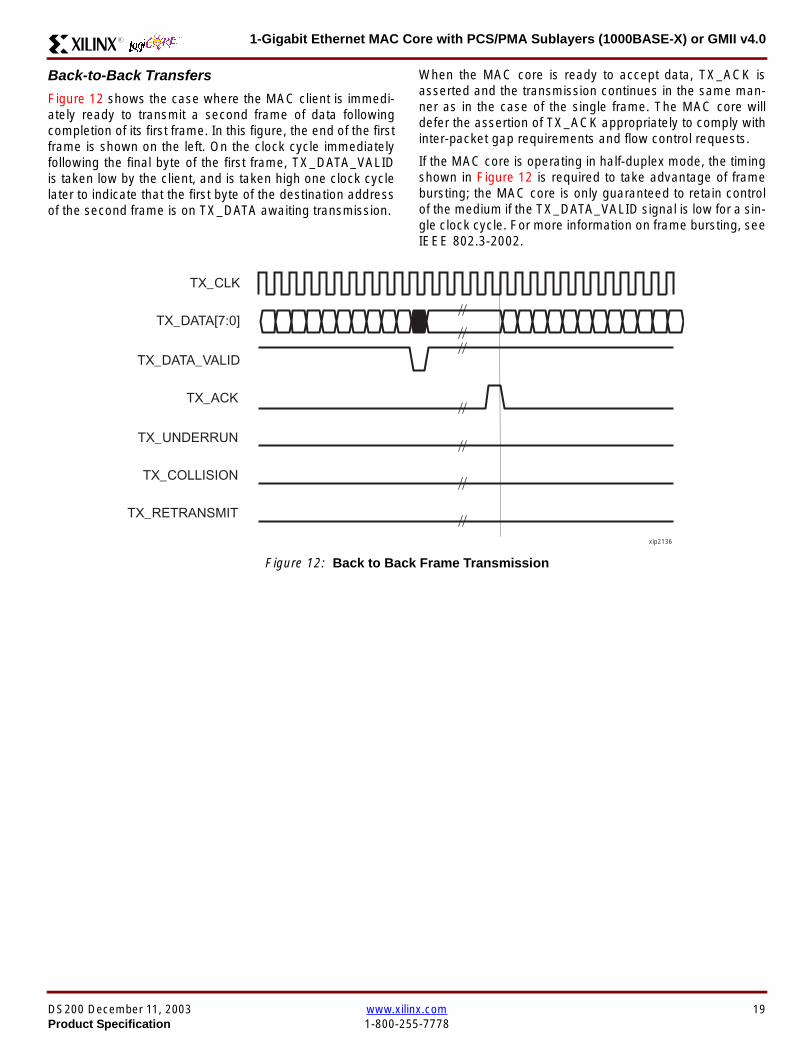
1-Gigabit Ethernet MAC Core with PCSPMA Sublayers (1000BASE-X) or GMII v40R
Back-to-Back Transfers
Figure 12 shows the case where the MAC client is immedi-ately ready to transmit a second frame of data followingcompletion of its first frame In this figure the end of the firstframe is shown on the left On the clock cycle immediatelyfollowing the final byte of the first frame TX_DATA_VALIDis taken low by the client and is taken high one clock cyclelater to indicate that the first byte of the destination addressof the second frame is on TX_DATA awaiting transmission
When the MAC core is ready to accept data TX_ACK isasserted and the transmission continues in the same man-ner as in the case of the single frame The MAC core willdefer the assertion of TX_ACK appropriately to comply withinter-packet gap requirements and flow control requests
If the MAC core is operating in half-duplex mode the timingshown in Figure 12 is required to take advantage of framebursting the MAC core is only guaranteed to retain controlof the medium if the TX_DATA_VALID signal is low for a sin-gle clock cycle For more information on frame bursting seeIEEE 8023-2002
Figure 12 Back to Back Frame Transmission
TX_CLK
TX_DATA[70]
TX_DATA_VALID
TX_ACK
TX_UNDERRUN
TX_COLLISION
TX_RETRANSMIT
xip2136
DS200 December 11 2003 wwwxilinxcom 19Product Specification 1-800-255-7778
1-Gigabit Ethernet MAC Core with PCSPMA Sublayers (1000BASE-X) or GMII v40 R
VLAN Tagged Frames
Transmission of a VLAN tagged frame (if enabled) can beseen in Figure 13 Note that the handshaking signalsacross the interface do not change however the VLANtype tag 81-00 must be supplied by the client to signify that
the frame is VLAN tagged The client also supplies the twobytes of Tag Control Information V1 and V2 at the appro-priate times in the data stream More information on thecontents of these two bytes can be found in IEEE8023-2002
Maximum Permitted Frame Length
The maximum legal length of a frame specified in IEEE8023-2002 is 1518 bytes for non-VLAN tagged framesVLAN tagged frames may be extended to 1522 bytesWhen jumbo frame handling is disabled and the clientattempts to transmit a frame which exceeds the maximumlegal length the MAC core will insert an error code to cor-
rupt the current frame and the frame will be truncated to themaximum legal length When jumbo frame handling isenabled frames which are longer than the legal maximumare transmitted error-free
For more information on enabling and disabling jumboframe handling see Configuration Registers on page 30
Figure 13 Transmission of a VLAN Tagged Frame
TX_CLK
TX_DATA[70]
TX_DATA_VALID
TX_ACK
TX_UNDERRUN
DA SA DATALTVLANtag
81 00V1V2
TX_COLLISION
TX_RETRANSMIT
xip2137
20 wwwxilinxcom DS200 December 11 20031-800-255-7778 Product Specification
1-Gigabit Ethernet MAC Core with PCSPMA Sublayers (1000BASE-X) or GMII v40R
Frame Collisions - Half Duplex Operation Only
In half duplex Ethernet operation collisions will occur on themedium as a matter of course this is how the arbitrationalgorithm is fulfilled In case of a collision the MAC core sig-nals to the client that data may need to be resupplied as fol-lows
If there is a collision the TX_COLLISION signal will be setto ldquo1rdquo by the MAC core If a frame is in progress the clientmust abort the transfer and take TX_DATA_VALID to ldquo0rdquo
If the TX_RETRANSMIT signal is ldquo1rdquo in the same clockcycle that the TX_COLLISION signal is ldquo1rdquo the client must
resubmit the previous frame to the MAC core for retrans-mission TX_DATA_VALID must be asserted to the MACcore within 8 clock cycles of the TX_COLLISION signal inorder to meet Ethernet timing requirements See Figure 14
If the TX_RETRANSMIT signal is ldquo0rdquo in the same clockcycle that the TX_COLLISION signal is ldquo1rdquo the number ofretries for this frame has exceeded the Ethernet specifica-tion and the frame should be dropped by the client The cli-ent can then make any new frame available to the MAC fortransmission without timing restriction See Figure 15
Figure 14 Collision Handling - Frame retransmission required
Figure 15 Collision Handling - No frame retransmission required
TX_CLK
TX_DATA[70]
TX_DATA_VALID
TX_ACK
TX_UNDERRUN
TX_COLLISION
TX_RETRANSMIT
8 clocks max
xip2138
TX_CLK
TX_DATA[70]
TX_DATA_VALID
TX_ACK
TX_UNDERRUN
TX_COLLISION
TX_RETRANSMIT
xip2139
DS200 December 11 2003 wwwxilinxcom 21Product Specification 1-800-255-7778
1-Gigabit Ethernet MAC Core with PCSPMA Sublayers (1000BASE-X) or GMII v40 R
Interframe Gap Adjustment
The user can elect to vary the length of the inter fame gapIf this function is selected (via a configuration bit in thetransmitter control register see Configuration Registerson page 30) then the MAC will exert back pressure to delaythe transmission of the next frame until the requested num-ber of Idle cycles has elapsed The number of Idle cycles iscontrolled by the value on the TX_IFG_DELAY port at thestart of frame transmission Figure 16 shows the MAC oper-ating in this mode
Reducing the Inter fame gap to below the IEEE 8023-2002minimum of 12 Idles is supported in Full Duplex onlydesigns and will transmit an absolute minimum of 4 Idles Ifthe Interframe gap adjustment is reduced below 12 Idlesthen the accuracy of the Optional Statistical Gathering(statistics_gathering=true) Counters cannot be guaranteedHowever the TX_STATISTIC_VECTOR andRX_STATISTIC_VECTOR will always remain correct
Transmitter Statistics Vector
The statistics for the frame transmitted are contained withinthe TX_STATISTICS_VECTOR The vector is driven syn-chronously by the transmitter clock TX_CLK followingframe transmission The bit field definition for the Vector isdefined in Table 14
All bit fields with the exception of BYTE_VALID are validonly when the TX_STATISTICS_VALID is asserted This isillustrated in Figure 17 BYTE_VALID is significant on everyTX_CLK cycle
TX_STATISTICS_VECTOR bits 25 down to 17 inclusive arefor half duplex only and will be set to logic 0 when operatingin full duplex mode
Figure 16 Interframe Gap Adjustment
TX_CLK
TX_DATA[70]
TX_DATA_VALID
TX_ACK
DA SA
TX_IFG_DELAY
IFG ADJUST VALUE
0x0D
13 Idles inserted
DA
Next IFG ADJUST VALUE
xip2140
Figure 17 Transmitter Statistics Vector Timing
TX_CLK
TX_STATISTICS_VECTOR[280]
TX_STATISTICS_VALID
xip2141
22 wwwxilinxcom DS200 December 11 20031-800-255-7778 Product Specification
1-Gigabit Ethernet MAC Core with PCSPMA Sublayers (1000BASE-X) or GMII v40R
Table 14 Bit Definition for the Transmitter Statistics Vector
TX_STATISTICS_VECTOR Name Description
28 PAUSE_FRAME_TRANSMITTEDAsserted if the previous frame was a pause framethat the MAC itself initiated in response to aPAUSE_REQ assertion
27 BYTE_VALID
Asserted if a MAC frame byte (DA to FCS inclusive)is in the process of being transmitted This is valid onevery clock cycle
Do not use this as an enable signal to indicate thatdata is present on GMII_TXD[70]
26 Reserved Returns logic 0
25 down to 22 TX_ATTEMPTS[30]
The number of attempts that have been made totransmit the previous frame This is a 4-bit number0 should be interpreted as 1 attempt 1 as 2attempts up until 15 as 16 attempts
21 Reserved Returns logic 0
20 EXCESSIVE_COLLISIONAsserted if a collision has been detected on each ofthe last 16 attempts to transmit the previous frame
19 LATE_COLLISIONAsserted if a late collision occurred during frametransmission
18 EXCESSIVE_DEFERRALAsserted if the previous frame was deferred for anexcessive amount of time as defined by the constantldquomaxDeferTimerdquo in IEEE 8023-2002
17 TX_DEFERRED Asserted if transmission of the frame was deferred
16 VLAN_FRAMEAsserted if the previous frame contained a VLANidentifier in the LengthType field when transmitterVLAN operation is enabled
15 down to 5 FRAME_LENGTH_COUNTThe length of the previous frame in number of bytesThe count will stick at 2047 for any Jumbo frameslarger than this value
4 CONTROL_FRAMEAsserted if the previous frame had the special MACControl Type code 88-08 in the LengthType field
3 UNDERRUN_FRAMEAsserted if the previous frame contained anunderrun error
2 MULTICAST_FRAMEAsserted if the previous frame contained a multicastaddress in the Destination Address field
1 BROADCAST_FRAMEAsserted if the previous frame contained abroadcast address in the Destination Address field
0 SUCCESSFUL_FRAMEAsserted if the previous frame was transmittedwithout error
DS200 December 11 2003 wwwxilinxcom 23Product Specification 1-800-255-7778
1-Gigabit Ethernet MAC Core with PCSPMA Sublayers (1000BASE-X) or GMII v40 R
Receiver
Normal Frame Reception
The timing of a normal inbound frame transfer can be seenin Figure 18 The client must be prepared to accept data atany time there is no buffering within the MAC to allow forlatency in the receive client Once frame reception begins
data is transferred on consecutive clock cycles to thereceive client until the frame is complete The MAC assertsthe RX_GOOD_FRAME signal to indicate that the framewas successfully received and that the frame should beanalyzed by the client
Frame parameters (destination address source addresslengthtype and optionally FCS) are supplied on the databus according to the timing diagram The abbreviations arethe same as those described in Table 13 on page 16
If the LengthType field in the frame has the Length interpre-tation and this indicates that the inbound frame has beenpadded to meet the Ethernet minimum frame size specifica-tion then this padding will not be passed to the client in thedata payload The exception to this is in the case whereFCS passing is enabled see Client-Supplied FCS Pass-ing on page 25
Therefore when Client-Supplied FCS passing is disabledRX_DATA_VALID = lsquo0rsquo between frames for the duration ofthe Padding field (if present) the FCS field carrier exten-sion (if present) the interframe gap following the frame andthe preamble field of the next frame When Client-Supplied
FCS passing is enabled RX_DATA_VALID = lsquo0rsquo betweenframes for the duration of carrier extension (if present) theinterframe gap and the preamble field of the followingframe
RX_GOOD_FRAME RX_BAD_FRAME timing
Although the timing diagram in Figure 18 shows theRX_GOOD_FRAME signal asserted shortly after the lastvalid data on RX_DATA this is not always the case TheRX_GOOD_FRAME or RX_BAD_FRAME signals areasserted only after all frame checks are completed This isafter the FCS field has been received (and after reception ofcarrier extension if present)
Therefore either RX_GOOD_FRAME or RX_BAD_FRAMEis asserted following frame reception at the beginning of theinterframe gap
Figure 18 Normal Frame Reception
RX_CLK
RX_DATA[70]
RX_DATA_VALID
RX_GOOD_FRAME
RX_BAD_FRAME
DA SA DATALT
xip2142
24 wwwxilinxcom DS200 December 11 20031-800-255-7778 Product Specification
1-Gigabit Ethernet MAC Core with PCSPMA Sublayers (1000BASE-X) or GMII v40R
Frame Reception with Errors
The case of an unsuccessful frame reception (for examplea fragment frame or a frame with an incorrect FCS) can beseen in Figure 19 In this case the RX_BAD_FRAME signal
is asserted to the client at the end of the frame It is then theresponsibility of the client to drop the data already trans-ferred for this frame
Figure 19 Frame Reception with Error
Client-Supplied FCS Passing
If the MAC core is configured to pass the FCS field to the cli-ent (see Configuration Registers on page 30) then this ishandled as shown in Figure 20
In this case any padding inserted into the frame to meetEthernet minimum frame length specifications will be leftintact and passed to the client
Note that even though the FCS is passed up to the client itis also verified by the MAC core and RX_BAD_FRAMEasserted if the FCS check fails
RX_CLK
RX_DATA[70]
RX_DATA_VALID
RX_GOOD_FRAME
RX_BAD_FRAME
DA SA DATALT
xip2144
Figure 20 Frame Reception with In-Band FCS Field
RX_CLK
RX_DATA[70]
RX_DATA_VALID
RX_GOOD_FRAME
RX_BAD_FRAME
DA SA DATALT FCS
xip2145
DS200 December 11 2003 wwwxilinxcom 25Product Specification 1-800-255-7778
1-Gigabit Ethernet MAC Core with PCSPMA Sublayers (1000BASE-X) or GMII v40 R
VLAN Tagged Frames
The reception of a VLAN tagged frame (if enabled) can beseen in Figure 21 The VLAN frame is passed to the clientso that the frame may be identified as VLAN tagged this is
followed by the Tag Control Information bytes V1 and V2More information on the interpretation of these bytes maybe found in IEEE 8023-2002 standard
Maximum Permitted Frame Length
The maximum legal length of a frame specified in IEEE8023-2002 is 1518 bytes for non-VLAN tagged framesVLAN tagged frames may be extended to 1522 bytesWhen jumbo frame handling is disabled and the corereceives a frame which exceeds the maximum legal lengthRX_BAD_FRAME will be asserted When jumbo framehandling is enabled frames which are longer than the legalmaximum are received in the same way as shorter frames
For more information on enabling and disabling jumboframe handling see Configuration Registers on page 30
LengthType Field Error Checks
Enabled
Default operation is with the LengthType error checkingenabled (see Receiver Configuration Word 1 on page 31)In this mode the following checks are made on all framesreceived If either of these checks fail then the frame ismarked as BAD
bull A value in the LengthType field that is greater than orequal to decimal 46 but less than decimal 1536 (aLength interpretation) is checked against the actualdata length received
bull A value in the LengthType field that is less thandecimal 46 is checked to see that the data field ispadded to exactly 46 bytes (so that the resultant frameis minimum frame size 64 bytes total in length)
Furthermore if Padding is indicated (the LengthType fieldis less than decimal 46) and Client-Supplied FCS Passing isdisabled then the Length value in the LengthType field willbe used to deassert RX_DATA_VALID after the indicatednumber of data bytes so that the Padding bytes areremoved from the frame
Disabled
When the LengthType error checking is disabled (seeReceiver Configuration Word 1 on page 31) theLengthType error checks described above are not per-formed A frame containing only these errors will be markedas GOOD
Furthermore if Padding is indicated and Client-SuppliedFCS Passing is disabled then a Length Value in theLengthType field will not be used to deassertRX_DATA_VALID Instead RX_DATA_VALID will be deas-serted before the start of the FCS field in this way any pad-ding will not be removed from the frame
Figure 21 Reception of a VLAN Tagged Frame
RX_CLK
RX_DATA[70]
RX_DATA_VALID
RX_GOOD_FRAME
RX_BAD_FRAME
DA SA DATALT
81 00 V1 V2
VLANtag
xip2146
26 wwwxilinxcom DS200 December 11 20031-800-255-7778 Product Specification
1-Gigabit Ethernet MAC Core with PCSPMA Sublayers (1000BASE-X) or GMII v40R
Receiver Statistics Vector
The statistics for the frame received are contained withinthe RX_STATISTICS_VECTOR The vector is driven syn-chronously by the receiver clock RX_CLK following framereception The bit field definition for the Vector is defined inTable 15
All bit fields with the exception of BYTE_VALID are validonly when the RX_STATISTICS_VALID is asserted This isillustrated in Figure 22 BYTE_VALID is significant on everyRX_CLK cycle
Figure 22 Receiver Statistics Vector Timing
RX_CLK
RX_STATISTICS_VECTOR[220]
RX_STATISTICS_VALID
xip2147
Table 15 Bit Definition for the Receiver Statistics Vector
RX_STATISTICS_VECTOR Name Description
22LENGTHTYPE Out ofRange
Asserted if the lengthtype field contained a length valuethat did not match the number of MAC client data bytesreceived Also high if the lengthtype field indicated thatthe frame contained padding but the number of MAC cli-ent data bytes received was not equal to 64 bytes (min-imum frame size)
The exception to the above is when the LengthTypeField Error Checks are disabled in which case this bitwill not be asserted
21 BAD_OPCODE
Asserted if the previous frame was error-free andcontained the special Control Frame identifier in theLengthType field but contained an opcode that isunsupported by the MAC (Any Opcode other thanPAUSE)
20 FLOW_CONTROL_FRAME
Asserted if the previous frame was error-freecontained the special Control Frame identifier in theLengthType field contained a Destination Addressthat matched either the MAC Control MulticastAddress or the configured source address of the MACcontained the supported PAUSE opcode and wasacted upon by the MAC
19 BYTE_VALID
Asserted if a MAC frame byte (DA to FCS inclusive) isin the process of being received This is valid on everyclock cycle
Do not use this as an enable signal to indicate thatdata is present on RX_DATA[70]
18 VLAN_FRAMEAsserted if the previous frame contained a VLANidentifier in the LengthType field when receiver VLANoperation is enabled
DS200 December 11 2003 wwwxilinxcom 27Product Specification 1-800-255-7778
1-Gigabit Ethernet MAC Core with PCSPMA Sublayers (1000BASE-X) or GMII v40 R
17 OUT_OF_BOUNDS
Asserted if the previous frame exceeded the specifiedIEEE8023-2002 maximum legal length (seeMaximum Permitted Frame Length on page 26) Thisis only valid if Jumbo frames are disabled
16 CONTROL_FRAMEAsserted if the previous frame contained the specialControl Frame identifier in the LengthType field
15 down to 5 FRAME_LENGTH_COUNTThe length of the previous frame in number of bytesThe count will stick at 2047 for any Jumbo frameslarger than this value
4 MULTICAST_FRAMEAsserted if the previous frame contained a multicastaddress in the Destination Address field
3 BROADCAST_FRAMEAsserted if the previous frame contained the broadcastaddress in the Destination Address field
2 FCS_ERRORAsserted if the previous frame received had anincorrect FCS value or the MAC detected error codesduring frame reception
1 BAD_FRAME1 Asserted if the previous frame received containederrors
0 GOOD_FRAME1 Asserted if the previous frame received was error-free
1 If the LengthType Field Error Checks are disabled then a frame which contains this type of error will be marked as a GOOD_FRAMEproviding no additional errors were detected
Table 15 Bit Definition for the Receiver Statistics Vector
RX_STATISTICS_VECTOR Name Description
28 wwwxilinxcom DS200 December 11 20031-800-255-7778 Product Specification
1-Gigabit Ethernet MAC Core with PCSPMA Sublayers (1000BASE-X) or GMII v40R
Flow ControlThe flow control block is designed to Clause 31 of the IEEE8023-2002 standard The MAC may be configured to sendpause frames and to act upon their reception These twobehaviors can be configured asymmetrically see Configu-ration Registers on page 30
Transmitting a PAUSE Control Frame
The client initiates a flow control frame by assertingPAUSE_REQ while the pause value is on the PAUSE_VALbus These signals are synchronous to TX_CLK The timingof this can be seen in Figure 23
If the MAC core is configured to support transmit flow con-trol this action causes the core to transmit a PAUSE controlframe on the link with the PAUSE parameter set to thevalue on PAUSE_VAL in the cycle when PAUSE_REQ wasasserted This will not disrupt any frame transmission inprogress but will take priority over any pending frame trans-
mission This frame will be transmitted even if the transmit-ter is in the paused state itself
Receiving a Pause Control Frame
When an error-free frame is received by the MAC core thefollowing checks are made
1 The Destination Address field is matched against theMAC Control Multicast address or the configuredSource Address for the MAC (see ConfigurationRegisters on page 30)
2 The LengthType field is matched against the MACControl Type code
3 The opcode field contents are matched against thePAUSE opcode if check 2 is true
If any of the above checks are false or the MAC Flow Con-trol logic for the receiver is disabled the frame is ignored bythe Flow Control logic and passed up to the client
If the frame passes all of the above checks is of minimumlegal size and the MAC Flow Control logic for the receiver isenabled the pause value parameter in the frame is thenused to inhibit transmitter operation for the time defined inthe IEEE8023-2002 specification This inhibit is imple-mented using the same back pressure scheme shown inFigure 12 Because the received pause frame has beenacted upon it is passed to the client with RX_BAD_FRAMEasserted to indicate to the client that it should be dropped
Reception of any frame for which check 2 is true and whichis not of legal minimum length is considered an invalid Con-trol frame This will be ignored by the Flow Control logic andpassed to the client with RX_BAD_FRAME asserted
Figure 23 Pause Request Timing
TX_CLK
PAUSE_VAL[150]
PAUSE_REQ
xip2148
DS200 December 11 2003 wwwxilinxcom 29Product Specification 1-800-255-7778
1-Gigabit Ethernet MAC Core with PCSPMA Sublayers (1000BASE-X) or GMII v40 R
Optional Management Interface(management_interface=true)The management interface is a processor-independentinterface with standard address data and control signals Itmay be used as is or a wrapper may be applied (not sup-plied) to interface to common bus architectures
This interface is used for
bull Configuration of the MAC core
bull Access to optional statistics counters for use by higherlayers for example SNMP
bull access through the MDIO interface to the managementregisters located in the PHY attached to the MAC core
The management interface is accessed differently depend-ing on the type of transaction a truth table showing whichaccess method is required for each transaction type isshown in Table 16 These access methods are described inthe following sections
HOST_CLK Frequency
The management interface clock HOST_CLK is used toderive the MDIO clock MDC and is therefore subject tosome frequency restrictions This HOST_CLK must be
ge 10 MHz
le 100 MHz
Configuring the MAC core to derive the MDC signal fromthis clock is detailed in MDIO Interface on page 37
Configuration Registers
After power up or reset the client may reconfigure the coreparameters from their defaults such as flow control supportConfiguration changes can be written at any time Both thereceiver and transmitter logic will only respond to configura-tion changes during Inter Frame Gaps The exceptions tothis are the configurable resets which take effect immedi-ately
Configuration of the MAC core is performed through a reg-ister bank accessed through the management interfaceThe configuration registers available in the core are detailedin Table 17 As can be seen the address has some implicitdonrsquot care bits any access to an address in the rangesshown will perform a 32-bit read or write from the same con-figuration word
Table 16 Management Interface Transaction Types
Transaction HOST_MIIM_SEL HOST_ADDR[9]
Configuration 0 1
Statistics 0 0
MIIM access 1 X
Table 17 Configuration Registers
Address Description
0x200-0x23F Receiver Configuration (Word 0)
0x240-0x27F Receiver Configuration (Word 1)
0x280-0x2BF Transmitter Configuration
0x2C0-0x2FF Flow Control Configuration
0x300-0x33F Reserved
0x340-0x37F Management Configuration
30 wwwxilinxcom DS200 December 11 20031-800-255-7778 Product Specification
1-Gigabit Ethernet MAC Core with PCSPMA Sublayers (1000BASE-X) or GMII v40R
The register contents for the two receiver configuration words can be seen in Table 18 and Table 19
Notes1 In changing the receiverrsquos mode from Half Duplex to Full Duplex there is a period of time of up to 24 us following the mode change
when no new receiver statistics can be stored in the optional Statistical Counters
Table 18 Receiver Configuration Word 0
Bit Default Value Description
31-0 All 0rsquos
Pause frame MAC Source Address[310] This address is used by the MAC tomatch against the Destination Address of any incoming flow control frames It isalso used by the flow control block as the Source Address (SA) for any outboundflow control frames
The address is ordered so the first byte transmittedreceived is the lowestpositioned byte in the register for example a MAC address ofAA-BB-CC-DD-EE-FF would be stored in Address[470] as 0xFFEEDDCCBBAA
Table 19 Receiver Configuration Word 1
Bit Default Value Description
15-0 All 0rsquos Pause frame MAC Source Address[4732] See description in Table 18
24-16 NA Reserved
25 0
LengthType Error Check Disable When this bit is set to ldquo1rdquo the core will notperform the LengthType field error checks as described in LengthType FieldError Checks on page 26 When this bit is set to ldquo0rdquo the LengthType field checkswill be performed this is normal operation
26 0Half Duplex If ldquo1rdquo the receiver will operate in half duplex mode If ldquo0rdquo the receiverwill operate in full duplex mode Has no effect if XCO parameterhalf_duplex_capable = false
27 0VLAN Enable When this bit is set to ldquo1rdquo VLAN tagged frames will be acceptedby the receiver
28 1Receiver Enable If set to ldquo1rdquo the receiver block will be operational If set to ldquo0rdquothe block will ignore activity on the physical interface RX port
29 0
In-band FCS Enable When this bit is ldquo1rdquo the MAC receiver will pass the FCS fieldup to the client as described in Client-Supplied FCS Passing on page 25 Whenit is ldquo0rdquo the client will not be passed the FCS In both cases the FCS will beverified on the frame
30 0Jumbo Frame Enable When this bit is set to ldquo1rdquo the MAC receiver will acceptframes over the specified IEEE8023-2002 maximum legal length When this bitis ldquo0rdquo the MAC will only accept frames up to the specified maximum
31 0Reset When this bit is set to ldquo1rdquo the receiver will be reset The bit will thenautomatically revert to ldquo0rdquo Note that this reset will also set all of the receiverconfiguration registers to their default values
DS200 December 11 2003 wwwxilinxcom 31Product Specification 1-800-255-7778
1-Gigabit Ethernet MAC Core with PCSPMA Sublayers (1000BASE-X) or GMII v40 R
The register contents for the Transmitter Configuration Word are described in Table 20
Notes1 In changing the transmitterrsquos mode from Half Duplex to Full Duplex there is a period of time of up to 24 us following the mode change
when no new transmitter statistics can be stored in the optional Statistical Counters
Table 20 Transmitter Configuration Word
Bit Default Value Description
24-0 NA Reserved
25 0
Interframe Gap Adjust Enable If lsquo1rsquo the transmitter will read the value on the portTX_IFG_DELAY at the start of frame transmission and adjust the interframe gapfollowing the frame accordingly See Interframe Gap Adjustment on page 22 Ifldquo0rdquo the transmitter will output a minimum Inter Frame Gap of twelve clock cyclesas specified in IEEE8023-2002
26 0Half Duplex If lsquo1rsquo the transmitter will operate in half duplex mode If lsquo0rsquo thetransmitter will operate in full duplex mode Has no effect if XCO parameterhalf_duplex_capable = false
27 0VLAN Enable When this bit is set to 1 the transmitter will allow the transmissionof VLAN tagged frames
28 1Transmit Enable When this bit is 1 the transmitter is operational When it is 0the transmitter is disabled
29 0
In-band FCS Enable When this bit is lsquo1rsquo the MAC transmitter will expect the FCSfield to be passed in by the client as described in Client-Supplied FCS Passingon page 17 When this bit is ldquo0rdquo the MAC transmitter will append padding asrequired compute the FCS and append it to the frame
30 0
Jumbo Frame Enable When this bit is set to ldquo1rdquo the MAC transmitter will sendframes that are greater than the specified IEEE8023-2002 maximum legallength When this bit is ldquo0rdquo the MAC will only send frames up to the specifiedmaximum
31 0Reset When this bit is set to ldquo1rdquo the transmitter will be reset The bit will thenautomatically revert to ldquo0rdquo Note that this reset will also set all of the transmitterconfiguration registers to their default values
32 wwwxilinxcom DS200 December 11 20031-800-255-7778 Product Specification
1-Gigabit Ethernet MAC Core with PCSPMA Sublayers (1000BASE-X) or GMII v40R
The register contents for the Flow Control Configuration Word are described in Table 21
The register contents for the Management Configuration Word are described in Table 22
Writing to the configuration registers through the manage-ment interface is depicted in Figure 24 When accessing theconfiguration registers (ie when HOST_ADDR[9] = lsquo1rsquo andHOST_MIIM_SEL = lsquo0rsquo) the upper bit of HOST_OPCODEfunctions as an Active Low write enable signal The lowerHOST_OPCODE bit is a ldquodonrsquot carerdquo
Reading from the configuration register words is similar butthe upper HOST_OPCODE bit should be lsquo1rsquo This is shownin Figure 25 In this case the contents of the register appearon HOST_RD_DATA the HOST_CLK edge after the regis-ter address is asserted onto HOST_ADDR
Table 21 Flow Control Configuration Word
Bit Default Value Description
28-0 NA Reserved
29 1
Flow Control Enable (RX) When this bit is lsquo1rsquo received flow control frames willinhibit the transmitter operation as described in Receiving a Pause ControlFrame on page 29 When this bit is lsquo0rsquo received flow control frames will alwaysbe passed up to the client
30 1Flow Control Enable (TX) When this bit is lsquo1rsquo asserting the PAUSE_REQ signalwill send a flow control frame out from the transmitter When this bit is 0 assertingthe PAUSE_REQ signal has no effect
31 NA Reserved
Table 22 Management Configuration Word
Bits Default Value Description
4-0 All 0rsquos Clock Divide[40] See MDIO Interface on page 37
5 0MDIO Enable When this bit is 1 the MDIO interface can be used to accessattached PHY devices When this bit is 0 the MDIO interface is disabled and theMDIO signals remain inactive
31-6 NA Reserved
Figure 24 Configuration Register Write Timing
HOST_CLK
HOST_ADDR[80]
HOST_ADDR[9]
HOST_OPCODE[1]
HOST_MIIM_SEL
HOST_WR_DATA[310]xip2149
Figure 25 Configuration Register Read Timing
HOST_CLK
HOST_ADDR[80]
HOST_ADDR[9]
HOST_OPCODE[1]
HOST_MIIM_SEL
HOST_RD_DATA[310]
xip2150
DS200 December 11 2003 wwwxilinxcom 33Product Specification 1-800-255-7778
1-Gigabit Ethernet MAC Core with PCSPMA Sublayers (1000BASE-X) or GMII v40 R
Optional Statistical Gathering(statistics_gathering=true)
During operation the MAC core collects statistics on thesuccess and failure of various operations for processing by
station management entities (STA) further up the protocolstack These statistics are accessed by the host through theoptional management interface A complete list of statisticssupported is described in Table 23
Table 23 Statistics Registers
Address Name Description
0x000 Frames Received OK1 A count of error-free frames received
0x001 Frame Check Sequence Errors A count of received frames that failed the CRC check and were at least64 bytes in length
0x002 Broadcast Frames Received OK1A count of frames that were successfully received and were directed tothe broadcast group address
0x003 Multicast Frames Received OK1 A count of frames that were successfully received and were directed toa non broadcast group address
0x004 64 byte Frames Received OK1 A count of error-free frames received that were 64 bytes in length
0x005 65-127 byte Frames Received OK1A count of error-free frames received that were between 65 and 127bytes in length
0x006 128-255 byte Frames Received OK1A count of error-free frames received that were between 128 and 255bytes in length
0x007 256-511 byte Frames Received OK1A count of error-free frames received that were between 256 and 511bytes in length
0x008512-1023 byte Frames ReceivedOK1
A count of error-free frames received that were between 512 and 1023bytes in length
0x0091024-MaxFrameSize byte FramesReceived OK1
A count of error-free frames received that were between 1024 bytes andthe specified IEEE8023-2002 maximum legal length (see MaximumPermitted Frame Length on page 26)
0x00A Control Frames Received OKA count of error-free frames received that contained the specialControl Frame identifier in the LengthType field
0x00B LengthType Out of Range
A count of frames received that were at least 64 bytes in length wherethe lengthtype field contained a length value that did not match thenumber of MAC client data bytes received
The counter also increments for frames in which the lengthtype fieldindicated that the frame contained padding but where the number ofMAC client data bytes received was greater than 64 bytes (minimumframe size)
The exception to the above is when the LengthType Field Error Checksare disabled in which case this counter will not increment
0x00C VLAN Tagged Frames Received OKA count of error-free VLAN frames received This counter will only incre-ment when the receiver is configured for VLAN operation
0x00D Pause Frames Received OK
A count of error-free frames received that contained the MAC Controltype identifier 88-08 in the LengthType field contained a Destinationaddress that matched either the MAC Control multicast address or theconfigured source address of the MAC contained the PAUSE opcodeand were acted upon by the MAC
0x00EControl Frames Received withUnsupported Opcode
A count of error-free frames received that contained the MAC Controltype identifier 88-08 in the LengthType field but were received with anopcode other than the PAUSE opcode
34 wwwxilinxcom DS200 December 11 20031-800-255-7778 Product Specification
1-Gigabit Ethernet MAC Core with PCSPMA Sublayers (1000BASE-X) or GMII v40R
0x00F Oversize Frames Received OK1A count of otherwise error-free frames received that exceeded the max-imum legal frame length specified in IEEE 8023-2002 (see MaximumPermitted Frame Length on page 26)
0x010 Undersize frames receivedA count of the number of frames received that were less than 64 bytesin length but were otherwise well formed
0x011 Fragment frames receivedA count of the number of frames received that were less than 64 bytesin length and had a bad Frame Check Sequence field
0x012 Received bytesA count of bytes of frames that are received (Destination Address toFrame Check Sequence inclusive)
0x013 Transmitted bytesA count of bytes of frames that are transmitted (Destination Address toFrame Check Sequence inclusive)
0x020 Frames Transmitted OK A count of error-free frames transmitted
0x021 Broadcast Frames Transmitted OK A count of error-free frames that were transmitted to the broadcastaddress
0x022 Multicast Frames Transmitted OK A count of error-free frames that were transmitted to a group destina-tion address other than broadcast
0x023 Underrun Errors
A count of frames that would otherwise be transmitted by the core butcould not be completed due to the assertion of TX_UNDERRUN duringthe frame transmission This will not count frames which are less than64 bytes in length
0x024 Control Frames Transmitted OKA count of error-free frames transmitted that contained the MACControl Frame type identifier 88-08 in the LengthType field
0x025 64 byte Frames Transmitted OK A count of error-free frames transmitted that were 64 bytes in length
0x026 65-127 byte Frames Transmitted OKA count of error-free frames transmitted that were between 65 and 127bytes in length
0x027128-255 byte Frames TransmittedOK
A count of error-free frames transmitted that were between 128 and 255bytes in length
0x028256-511 byte Frames TransmittedOK
A count of error-free frames transmitted that were between 256 and 511bytes in length
0x029512-1023 byte Frames TransmittedOK
A count of error-free frames transmitted that were between 512 and1023 bytes in length
0x02A1024-MaxFrameSize byte FramesTransmitted OK
A count of error-free frames transmitted that were between 1024 and thespecified IEEE8023-2002 maximum legal length (see Maximum Per-mitted Frame Length on page 20)
0x02BVLAN Tagged Frames TransmittedOK
A count of error-free VLAN frames transmitted This counter will onlyincrement when the transmitter is configured for VLAN operation
0x02C Pause Frames Transmitted OKA count of error-free PAUSE frames generated and transmitted by thecore in response to an assertion of PAUSE_REQ
0x02D Oversize Frames Transmitted OKA count of otherwise error-free frames transmitted that exceeded themaximum legal frame length specified in IEEE 8023-2002 (see Maxi-mum Permitted Frame Length on page 20)
0x02E Single Collision Frames A count of frames that are involved in a single collision but are subse-quently transmitted successfully (Half Duplex Mode only)
Table 23 Statistics Registers (Continued)
Address Name Description
DS200 December 11 2003 wwwxilinxcom 35Product Specification 1-800-255-7778
1-Gigabit Ethernet MAC Core with PCSPMA Sublayers (1000BASE-X) or GMII v40 R
Each of these statistic registers is 64 bits wide and thereforemust be read in a two-cycle transfer The timing of this pro-cess is shown in Figure 26 Six clocks after the read trans-action is initiated the least significant word (LSW) of thestatistics counter appears on the HOST_RD_DATA bus
and a clock cycle later the most significant word (MSW)appears For accurate statistic values 64 clock ticks (ofTX_CLK for transmit statistics or RX_CLK for receive statis-tics) must elapse after the last frame is sent or receivedthrough the MAC core
0x02F Multiple Collision Frames A count of frames that are involved in more than one collision but aresubsequently transmitted successfully (Half Duplex Mode only)
0x040 Frames with Deferred Transmissions A count of frames whose transmission was delayed on its first attemptbecause the medium was busy (Half Duplex Mode only)
0x041 Late Collisions
A count of the times that a collision has been detected later than oneslotTime from the start of the packet transmission A late collision iscounted twice both as a collision and as a lateCollision (Half DuplexMode only)
0x042Frames Aborted due to Excesscollisions
A count of the frames that due to excessive collisions are not transmit-ted successfully (Half Duplex Mode only)
0x043 Carrier Sense ErrorsA count of times that the GMII_CRS signal was not asserted or wasdisasserted during the transmission of a frame without collision (HalfDuplex Mode only)
0x044 Frames with Excess DeferralA count of frames that deferred transmission for an excessive period oftime (Half Duplex Mode only)
1 If the LengthType Field Error Checks are disabled then these counters will still increment for received frames which contain this typeof error (providing no additional errors were detected)
Table 23 Statistics Registers (Continued)
Address Name Description
Figure 26 Statistic Register Read Timing
HOST_CLK
HOST_ADDR[80]
HOST_ADDR[9]
HOST_REQ
HOST_MIIM_SEL
HOST_RD_DATA[310]
6 CLOCKS
LSW MSW
xip2151
36 wwwxilinxcom DS200 December 11 20031-800-255-7778 Product Specification
1-Gigabit Ethernet MAC Core with PCSPMA Sublayers (1000BASE-X) or GMII v40R
MDIO Interface
The management interface is also used to access the MDIO(MII Management) interface of the MAC core this interfaceis used to access the Managed Information Block (MIB) ofthe PHY components attached to the MAC core
The MDIO interface supplies a clock to the externaldevices MDC This clock is derived from the HOST_CLKsignal using the value in the Clock Divide[40] configurationregister The frequency of the MDIO clock is given by thefollowing equation
The frequency of MDC given by this equation should notexceed 25 MHz in order to comply with the IEEE8023-2002 specification for this interface To prevent MDCfrom being out of specification the Clock Divide[40] valuepowers up at 00000 and while this value is in the register itis impossible to enable the MDIO interface
For details of the register map of PHY layer devices and afuller description of the operation of the MDIO interfaceitself see IEEE specification 8023-2002
Access to the MDIO interface through the managementinterface is depicted in the timing diagram in Figure 27
For MDIO transactions the following points apply
bull HOST_OPCODE maps to the OP (opcode) field of theMDIO frame
bull HOST_ADDR maps to the two address fields of theMDIO frame PHY_ADDR is HOST_ADDR[95] andREG_ADDR is HOST_ADDR[40]
bull HOST_WR_DATA[150] maps into the data field of the
MDIO frame when performing a write operation
bull The data field of the MDIO frame maps intoHOST_RD_DATA[150] when performing a readoperation
The MAC core signals to the host that it is ready for anMDIO transaction by asserting HOST_MIIM_RDY A read orwrite transaction on the MDIO is initiated by a pulse on the
fMDC
fHOST_CLK
1 Clock Divide[40]+( ) 2times-------------------------------------------------------------------=
Figure 27 MDIO Access Through Management Interface
HOST_CLK
HOST_ADDR[90]
HOST_OPCODE[10]
HOST_REQ
HOST_MIIM_SEL
HOST_RD_DATA[150]
HOST_WR_DATA[150]
HOST_RDY
If a read transaction is initiated the HOST_RD_DATA bus is valid at the point indicated If a write transaction is initiated the HOST_WR_DATA bus must be valid at the indicated point Simultaneous read and write is not permitted
xip2152
DS200 December 11 2003 wwwxilinxcom 37Product Specification 1-800-255-7778
1-Gigabit Ethernet MAC Core with PCSPMA Sublayers (1000BASE-X) or GMII v40 R
HOST_REQ signal This pulse is ignored if the MDIO inter-face already has a transaction in progress
The MAC core then disasserts the HOST_MIIM_RDY signalwhile the transaction across the MDIO is in progress Whenthe transaction across the MDIO interface has been com-pleted the HOST_MIIM_RDY signal will be asserted by theMAC core if the transaction is a read the data will also beavailable on the HOST_RD_DATA[150] bus at this time
Optional Configuration Vector(management_interface = false)If the optional Management interface is omitted from thecore all of relevant configuration signals are brought out of
the core These signals are bundled into theCONFIGURATION_VECTOR signal The bit mapping of theconfiguration vector signal is defined in Table 24 See thecorresponding entry in the configuration register tables forthe full description of each signal
Note that these configuration vector signals can bechanged by the user at any time however with the excep-tion of the reset and the flow control configuration signalsthey will not take effect until the current frame has com-pleted transmission or reception
The ldquoClockrdquo heading denotes which clock domain the con-figuration signal is registered into before use by the core Itis not necessary to drive the signal from this clock domain
Table 24 Configuration Vector Bit Definition
Bit(s)Configuration Register
cross reference Clock Description
47 downto 0
Receiver ConfigurationWord 0 bits 31-0 andReceiver ConfigurationWord 1 bits 15-0
RX_CLK
Pause frame MAC Source Address[470] This address isused by the MAC core to match against the DestinationAddress of any incoming flow control frames and as theSource Address for any outbound flow control frames
The address is ordered such that the first byte transmitted orreceived is the least significant byte in the register forexample a MAC address of AA-BB-CC-DD-EE-FF will bestored in bite [470] as 0xFFEEDDCCBBAA
48Receiver ConfigurationWord 1 bit 26
RX_CLKReceiver Half Duplex If lsquo1rsquo the receiver operates in halfduplex mode If lsquo0rsquo the receiver operates in full duplex modeHas no effect if XCO parameter half_duplex_capable = false
49Receiver ConfigurationWord 1 bit 27
RX_CLKReceiver VLAN Enable When this bit is set to 1 VLANtagged frames are accepted by the receiver
50Receiver ConfigurationWord 1 bit 28
RX_CLKReceiver Enable If set to 1 the receiver block is operationalIf set to 0 the block ignores activity on the physical interfaceRX port
51Receiver ConfigurationWord 1 bit 29
RX_CLK
Receiver In-band FCS Enable When this bit is lsquo1rsquo the MACreceiver will pass the FCS field up to the client as describedin Client-Supplied FCS Passing on page 25 When it is lsquo0rsquothe MAC receiver will not pass the FCS field In both casesthe FCS field will be verified on the frame
52Receiver ConfigurationWord 1 bit 30
RX_CLK
Receiver Jumbo Frame Enable When this bit is lsquo0rsquo thereceiver will not pass frames longer than the maximum legalframe size specified in IEEE 8023-2002 (see MaximumPermitted Frame Length on page 26) When it is lsquo1rsquo thereceiver will not have an upper limit on frame size
53Receiver ConfigurationWord 1 bit 31
NA
Receiver Reset When this bit is lsquo1rsquo the receiver is held inreset
This signal is an input to the reset circuit for the receiverblock See Reset circuit on page 42 for more information
54TransmitterConfiguration Word bit25
TX_CLK
Transmitter Interframe Gap Adjust enable If lsquo1rsquo then thetransmitter will read the value of the TX_IFG_DELAY port andset the Interframe Gap accordingly If lsquo0rsquo the transmitter willalways insert at least the legal minimum Interframe Gap
38 wwwxilinxcom DS200 December 11 20031-800-255-7778 Product Specification
1-Gigabit Ethernet MAC Core with PCSPMA Sublayers (1000BASE-X) or GMII v40R
55TransmitterConfiguration Word bit26
TX_CLK
Transmitter Half Duplex If lsquo1rsquo the transmitter operates in halfduplex mode If lsquo0rsquo the transmitter operates in full duplexmode Has no effect if XCO parameter half_duplex_capable= false
56TransmitterConfiguration Word bit27
TX_CLKTransmitter VLAN Enable When this bit is set to lsquo1rsquo thetransmitter allows the transmission of VLAN tagged frames
57TransmitterConfiguration Word bit28
TX_CLKTransmitter Enable When this bit is 1 the transmitter will beoperational When it is 0 the transmitter is disabled
58TransmitterConfiguration Word bit29
TX_CLK
Transmitter In-Band FCS Enable When this bit is lsquo1rsquo theMAC transmitter will expect the FCS field to be pass in by theclient as described in Client-Supplied FCS Passing onpage 17 When it is lsquo0rsquo the MAC transmitter will appendpadding as required compute the FCS and append it to theframe
59TransmitterConfiguration Word bit30
TX_CLK
Transmitter Jumbo Frame Enable When this bit is lsquo1rsquo theMAC transmitter will allow frames larger than the maximumlegal frame length specified in IEEE 8023-2002 to be sentWhen set to lsquo0rsquo the MAC transmitter will only allow frames upto the legal maximum to be sent
60TransmitterConfiguration Word bit31
NA
Transmitter Reset When this bit is lsquo1rsquo the MAC transmitter isheld in reset
This signal is an input to the reset circuit for the transmitterblock See Reset circuit on page 42 for more information
61Flow ControlConfiguration Word bit29
TX_CLK
Transmit Flow Control Enable When this bit is lsquo1rsquo assertingthe PAUSE_REQ signal causes the MAC core to send a flowcontrol frame out from the transmitter as described inReceiving a Pause Control Frame on page 29 When this bitis lsquo0rsquo asserting the PAUSE_REQ signal will have no effect
62Flow ControlConfiguration Word bit30
RX_CLK
Receive Flow Control Enable When this bit is lsquo1rsquo receivedflow control frames will inhibit the transmitter operation asdescribed in Receiving a Pause Control Frame on page 29When it is lsquo0rsquo received flow frames are passed up to theclient
63Receiver ConfigurationWord 1 bit 25
RX_CLK
LengthType Error Check Disable When this bit is lsquo1rsquo thecore will not perform the LengthType field error checks asdescribed in LengthType Field Error Checks on page 26When it is set to lsquo0rsquo the LengthType field checks will beperformed this is normal operation
Table 24 Configuration Vector Bit Definition (Continued)
Bit(s)Configuration Register
cross reference Clock Description
DS200 December 11 2003 wwwxilinxcom 39Product Specification 1-800-255-7778
1-Gigabit Ethernet MAC Core with PCSPMA Sublayers (1000BASE-X) or GMII v40 R
Optional GMII (physical_interface=gmii)The GMII is designed to IEEE 8023-2002 Clause 35 Thisutilizes IOrsquos of the Xilinx devices using inputoutput buffersand inputoutput flip-flops to maximize setup and hold mar-gins All IO logic is placed in the example wrapper that isdelivered with the core In addition all clock managementlogic for the core is instanced in this example wrapper thisallows multiple instances of the core to share clocks Theexample wrapper is provided in both VHDL and Verilog
Clock Management
Figure 28 illustrates the clock management used with theGMII interface All clocks illustrated have a frequency of125MHz
GTX_CLK must be provided to the MAC core This is a highquality clock which satisfies the IEEE8023-2002 require-ments It is expected that this clock will be derived from anexternal oscillator and connected into the device through anIBUFG as illustrated The clock source must then be routedonto a global clock network by connecting it to a BUFGWithin the MAC core this global clock is used by all MACtransmitter logic The MAC Client can obtain this clock byconnecting to the TX_CLK signal output from the coreGMII_TX_CLK is derived from this global clock by invertingit and routing it to an OBUF
GMII_RX_CLK is received through an IBUFG This clock isthen routed onto a global clock network by connecting it to aBUFG The resulting global clock is used by all MACreceiver logic
Figure 28 Clock Management with GMII
IBUFG
IBUFG
OBUF
BUFG
BUFG
TX_CLK
RX_CLK
GTX_CLK
GMII_TX_CLK
GMII_RX_CLK
Example Wrapper
xip2153
MAC Core
TX_CLK
RX_CLK
GMII_TX_CLK
GMII_RX_CLK
GTX_CLK
40 wwwxilinxcom DS200 December 11 20031-800-255-7778 Product Specification
1-Gigabit Ethernet MAC Core with PCSPMA Sublayers (1000BASE-X) or GMII v40R
Clock Sharing between Multiple cores
Figure 29 illustrates how it is possible to share clockresources across multiple instantiations of the core whenusing the optional GMII
GTX_CLK may be shared between multiple cores as illus-trated resulting in a common transmitter clock domainacross the device
A common receiver clock domain is not possible each corewill receive an independent receiver clock from its GMII asillustrated
Although not illustrated if the optional Management Inter-face is used HOST_CLK can also be shared betweencores
Figure 29 Clock Management with multiple instances of the MAC with GMII
IBUFG
OBUF
BUFG
TX_CLK
RX_CLK_1
GMII_TX_CLK_1
GMII_RX_CLK_1
MAC Core
TX_CLK
RX_CLK
GMII_TX_CLK
GMII_RX_CLK
GTX_CLK
MAC Core
TX_CLK
RX_CLK
GMII_TX_CLK
GMII_RX_CLK
GTX_CLK
IBUFG
BUFG
GTX_CLK
IBUFG
OBUF
GMII_TX_CLK_2
GMII_RX_CLK_2
BUFG
TX_CLK
RX_CLK_2
DS200 December 11 2003 wwwxilinxcom 41Product Specification 1-800-255-7778
1-Gigabit Ethernet MAC Core with PCSPMA Sublayers (1000BASE-X) or GMII v40 R
Reset circuit
Internally the core is divided up into clockreset domainswhich group together elements with the common clock andreset signals The reset circuitry for one of these domains isis illustrated in Figure 30 This circuit provides controllableskews on the reset nets within the design
More information on the operation and rationale behind thiscircuit can be found in Ken Chapmanrsquos Xilinx TechXclusiveldquoGet Smart About Resetrdquo athttpwwwxilinxcomsupporttechxclusivesglobal-techX19htm
Figure 30 Reset circuit for one clockreset domain
FDP
PRED
C
Q
FDP
PRED
C
Q
FDP
PRED
C
Q
FDP
PRED
C
Q
PRE PRE PRE
0
RESET
Management Reset
Clock
Core Registers
42 wwwxilinxcom DS200 December 11 20031-800-255-7778 Product Specification
1-Gigabit Ethernet MAC Core with PCSPMA Sublayers (1000BASE-X) or GMII v40R
Optional PCS with Ten-Bit Interface (TBI) for 1000BASE-X (physical_interface=tbi)The Full-Duplex Physical Coding Sublayer (PCS) for1000BASE-X is defined in IEEE 8023-2002 Clauses 36and 37 This functionality is only available in the Virtex-IIand Spartan3 families of FPGA devices
A block diagram of the PCS is shown in Figure 31 Themajor functional blocks of the PCS are
bull Transmit engine
bull Auto-negotiation block
bull Receive engine and synchronization block
bull PCS managed register block
bull 8B10B encoder block
bull 8B10B decoder block
bull Receiver elastic buffer
The PCS Managed Register Block is accessed through theMDIO Interface as if it were an externally connected PHYThis configures the operation of the PCS and Auto-Negoti-ation See PCS Managed Register Block
(physical_interface = tbi or phy) on page 49 The corersquosoptional Management Interface can be used to control theMDIO Interface as described by MDIO Interface onpage 37 When the optional Management Interface is notpresent the PCS Managed Register Block must beaccessed via an MDIO controller which is not provided bythe core
The 8B10B encodingdecoding blocks are implemented byconfiguring two Block SelectRAM modules as ROM Theseare used as large look-up tables The remaining PCS func-tionality such as code group encodingdecoding the Man-aged Register Block and Auto-Negotiation areimplemented in CLB logic
The Receiver Elastic buffer enables the 10-bit parallel datareceived from the PMA sublayer alternatively onPMA_RX_CLK0 and PMA_RX_CLK1 clock edges to betransferred onto the internal 125MHz clock domain derivedfrom GTX_CLK (see Clock Management) This buffer isimplemented in Distributed Memory
Figure 31 Functional Block Diagram of the 1-Gigabit Ethernet PCS with TBI Interface
PCS TRANSMIT ENGINE
PCS RECEIVE ENGINE ampSYNCHRONISATION
PCSMANAGEMENT
MDIOInterface
AUTO-NEGOTIATION
MAC TXInterface
MAC RXInterface
8B10BEncoder
8B10BDecoder
RX Elastic Buffer
TBI Interface
DS200 December 11 2003 wwwxilinxcom 43Product Specification 1-800-255-7778
1-Gigabit Ethernet MAC Core with PCSPMA Sublayers (1000BASE-X) or GMII v40 R
TBI Interface
The TBI is designed to IEEE 8023-2002 Clause 363 Thisutilizes IOrsquos of the Xilinx devices using inputoutput buffersand inputoutput flip-flops to maximize setup and hold mar-gins All IO logic is placed in the example wrapper that isdelivered with the core In addition all clock managementlogic for the core is instantiated in this example wrapperthis allows multiple instances of the core to share clocksThe example wrapper is provided in both VHDL and Verilog
Clock Management
Figure 32 illustrates the clock management used with theTBI interface
GTX_CLK must be provided to the MAC core This is a highquality clock of frequency 125MHz which satisfies theIEEE8023-2002 requirements It is expected that this clockwill be derived from an external oscillator and connected
into the device through an IBUFG as illustrated The clocksource must then be routed onto a global clock network byconnecting it to a BUFG Within the MAC core this globalclock is used by all MAC transmitter logic PMA_TX_CLK isderived from this global clock by inverting it and routing it toan OBUF
PMA_RX_CLK0 and PMA_RX_CLK1 are each receivedthrough an IBUFG These clocks are then routed onto glo-bal clock networks by connecting each to a BUFGPMA_RX_CLK0 and PMA_RX_CLK1 are each 625MHzclocks Data from the TBI is received alternatively on the ris-ing edge of PMA_RX_CLK0 followed by the rising edge ofPMA_RX_CLK1 using IOB Double-Data Rate input regis-ters This data is then written into the Receiver ElasticBuffer Data is read out of the Elastic Buffer using the globalclock derived from GTX_CLK all the remaining receiverlogic is synchronous to this clock
Figure 32 Clock Management for PCS with TBI Interface
IBUFG
IBUFG
OBUF
BUFG
BUFG
TX_CLK
RX_CLK
GTX_CLK
PMA_TX_CLK
PMA_RX_CLK0
MAC Core
RX ELASTICBUFFER
Example Wrapper
TX_CLK
RX_CLK
GTX_CLK
PMA_TX_CLK
PMA_RX_CLK0
IBUFGBUFGPMA_RX_CLK1
PMA_RX_CLK1
44 wwwxilinxcom DS200 December 11 20031-800-255-7778 Product Specification
1-Gigabit Ethernet MAC Core with PCSPMA Sublayers (1000BASE-X) or GMII v40R
Clock Sharing between Multiple cores
Figure 33 illustrates how it is possible to share clockresources across multiple instantiations of the core whenusing the optional PCS with TBI
GTX_CLK may be shared between multiple cores as illus-trated resulting in a common transmitter clock domainacross the device
Each core will receive independent PMA_RX_CLK0 andPMA_RX_CLK1 clocks from its TBI as illustrated whichcannot be shared
Although not illustrated if the optional Management Inter-face is used HOST_CLK can also be shared betweencores
Figure 33 Clock Management with multiple instances of the MAC with PCS and TBI
Reset circuit
The reset circuits within the MAC when the TBI interface is implemented is the same as that in the GMII case details ofthese circuits can be found on page 42
IBUFG
OBUF
BUFG
TX_CLK
RX_CLK
PMA_TX_CLK_1
PMA_RX_CLK0_1
MAC Core
RX ELASTICBUFFER
TX_CLK
RX_CLK
GTX_CLK
PMA_TX_CLK
PMA_RX_CLK0
IBUFGBUFGPMA_RX_CLK1_1
PMA_RX_CLK1
IBUFG
BUFG
GTX_CLK
IBUFG
OBUF
BUFG
TX_CLK
RX_CLK
PMA_TX_CLK_2
PMA_RX_CLK0_2
MAC Core
RX ELASTICBUFFER
TX_CLK
RX_CLK
GTX_CLK
PMA_TX_CLK
PMA_RX_CLK0
IBUFGBUFGPMA_RX_CLK1_2
PMA_RX_CLK1
DS200 December 11 2003 wwwxilinxcom 45Product Specification 1-800-255-7778
1-Gigabit Ethernet MAC Core with PCSPMA Sublayers (1000BASE-X) or GMII v40 R
Optional PCS and PMA Sublayers for 1000BASE-X (physical_interface=phy)The Full-Duplex Physical Coding Sublayer (PCS) withPhysical Medium Attachment (PMA) for 1000BASE-X isdefined in IEEE 8023-2002 Clauses 36 and 37 This func-tionality is only available in the Virtex-II Pro family of FPGAdevices
A block diagram of the PCS and PMA sublayers can beseen in Figure 34 The functional blocks of the PCS andPMA sublayers may replace the optional GMII interfaceThe functional blocks of the PCS and PMA sublayers are
bull PCS Transmit Engine
bull Auto-Negotiation block
bull Receive Engine and Synchronization Block
bull PCS Managed Register Block
bull Rocket IO Multi-Gigabit Transceiver
The PCS Managed Register Block is accessed through theMDIO Interface as if it were an externally connected PHYThis configures the operation of the PCS PMA sublayerand Auto-NegotiationSee PCS Managed Register Block(physical_interface = tbi or phy) on page 49 The corersquosoptional Management Interface can be used to control theMDIO Interface as described by MDIO Interface onpage 37 When the optional Management Interface is notpresent the PCS Managed Register Block must beaccessed via an MDIO controller which is not provided bythe core
The Rocket IO Multi-Gigabit Transceiver (MGT) providessome of the PCS layer functionality such as 8B10B encod-ingdecoding and the PMA serdes The remaining PCSfunctionality such as code group encodingdecoding theManaged Register Block and Auto-Negotiation are imple-mented in CLB logic
Figure 34 Functional Block Diagram of the 1-Gigabit Ethernet PCSPMA Sublayer Extension
PCS TRANSMIT ENGINE
PCS RECEIVE ENGINE ampSYNCHRONISATION
RO
CK
ET
IO
MU
LTI-
GIG
TR
AN
SC
EIV
ER
PCSMANAGEMENT
MDIOInterface
AUTO-NEGOTIATION
TXPTXN
RXPRXN
MAC TXInterface
MAC RXInterface
xip2154
46 wwwxilinxcom DS200 December 11 20031-800-255-7778 Product Specification
1-Gigabit Ethernet MAC Core with PCSPMA Sublayers (1000BASE-X) or GMII v40R
Clock Management
Figure 35 illustrates the clock management that should beused with the optional PCS and PMA sublayers for1000BASE-X This logic is implemented in the examplewrapper that is delivered with the core This provides flexi-bility because the design can be modified to use eitherREFCLK or BREFCLK (please refer to Rocket IO docu-mentation) It would also allow multiple instances of the coreto share clocks The example wrapper is provided in bothVHDL and Verilog
(B)REFCLK must be provided to the MAC core This clockmust be derived from an external oscillator and connectedto the core through an IBUFG as illustrated (B)REFCLK isa high quality clock of frequency 625 MHz which satisfiesthe Rocket IO Multi-Gigabit Transceiver (MGT) require-ments
(B)REFCLK is routed to both the core and a DCM From theDCM the CLK2X180 output is routed to a BUFG to providethe device with a global 125 MHz clock (connected toUSERCLK2 input on the core) Within the core bothTX_CLK and RX_CLK share this global 125 MHz clocksource which is used by all transmitter and receiver logicThis is made possible by the RX_ELASTIC_BUFFER func-tionality of the Rocket IO MGT (refer to Virtex-II Pro docu-mentation) The MAC Client can obtain this clock byconnecting to either the TX_CLK or the RX_CLK signalsoutput from the core
From the DCM the CLK0 output is routed to a BUFG to pro-vide the device with a global 625MHz clock This is con-nected to the USRCLK input of the core
Figure 35 Clock Management with PCSPMA Sublayers
DCM
CLKIN CLK0
CLK2X180FB
BUFG
BUFG
IBUFG
TX_CLK
RX_CLK
(B)REFCLK
TXUSRCLK
(B)REFCLK
TXUSRCLK2RXUSRCLKRXUSRCLK2
GT_ETHERNET
Example Wrapper
xip2155
MAC Core
(B)REFCLK
USRCLK
USRCLK2
TX_CLK
RX_CLK
DS200 December 11 2003 wwwxilinxcom 47Product Specification 1-800-255-7778
1-Gigabit Ethernet MAC Core with PCSPMA Sublayers (1000BASE-X) or GMII v40 R
Clock Sharing between Multiple Cores
Figure 36 illustrates how it is possible to share clockresources across multiple instantiations of the core whenusing the optional PCSPMA sublayers For each coreUSERCLK and USERCLK2 must always be derived asshown from the BREFCLK or REFCLK used by that core
Note that when using the fixed routing resources of BREF-CLK Rocket IO MGTs along the top edge of the devicemust use a separate BREFCLK routing resource to thosealong the bottom edge of the device (Refer to Virtex-II Prodocumentation)
Although not illustrated if the optional Management Inter-face is used HOST_CLK can also be shared betweencores
Figure 36 Clock Management with multiple instances of the MAC with PCS and PMA sublayers
Reset circuit
The reset circuits within the MAC when the PCS and PMA sublayers are implemented is the same as that in the GMII casedetails of these circuits can be found on page 42
DCM
CLKIN CLK0
CLK2X180FB
BUFG
BUFG
IBUFG
(B)REFCLK
TXUSRCLK
(B)REFCLK
TXUSRCLK2RXUSRCLKRXUSRCLK2
GT_ETHERNET(B)REFCLK
USERCLK
USERCLK2
MAC core
TXUSRCLK
(B)REFCLK
TXUSRCLK2RXUSRCLKRXUSRCLK2
GT_ETHERNET(B)REFCLK
USERCLK
USERCLK2
MAC core
48 wwwxilinxcom DS200 December 11 20031-800-255-7778 Product Specification
1-Gigabit Ethernet MAC Core with PCSPMA Sublayers (1000BASE-X) or GMII v40R
PCS Managed Register Block (physical_interface = tbi or phy)The PCS in both the TBI interface and the PCSPMA (usingthe Virtex-II Pro Rocket IO) versions contain the full Man-aged Register Block defined in IEEE 8023-2002 clause 37
This utilizes ten dedicated management registersaccessed via the MDIO interface These are defined inTable 25 to Table 33 inclusive
Table 25 Control Register (Register 0)
Bit(s) Name Description Attributes Default Value
015 Reset1 = PCSPMA reset
0 = Normal Operation
ReadWrite
Self Clearing0
014 Loopback1 = Enable Loopback Mode
0 = Disable Loopback ModeReadWrite 0
013SpeedSelection (LSB)
The core always returns a 0 for this bitTogether with bit 06 speed selection of 1000Mbs is identified
Returns 0 0
012Auto-NegotiationEnable
1 = Enable Auto-Negotiation Process
0 = Disable Auto-Negotiation ProcessReadWrite 1
011 Power Down
1 = Power down
0 = Normal operation
When set to ldquo1rdquo the Rocket IO MGT is placedin a low power state This bit requires a reset(see bit 015) to clear
Read Write 0
010 Isolate1 = Electrically Isolate PHY from GMII
0 = Normal operationReadWrite 1
09Restart Auto-Negotiation
1 = Restart Auto-Negotiation Process
0 = Normal Operation
ReadWrite
Self Clearing0
08 Duplex ModeThe core always returns a 1 for this bit tosignal Full-Duplex Mode
Returns 1 1
07 Collision TestThe core always returns a 0 for this bit todisable COL test
Returns 0 0
06SpeedSelection(MSB)
The core always returns a 1 for this bitTogether with bit 013 speed selection of1000 Mbs is identified
Returns 1 1
050 Reserved Always returns 0rsquos writes ignored Returns 0rsquos 000000
DS200 December 11 2003 wwwxilinxcom 49Product Specification 1-800-255-7778
1-Gigabit Ethernet MAC Core with PCSPMA Sublayers (1000BASE-X) or GMII v40 R
Table 26 Status Register (Register 1)
Bit(s) Name Description Attributes Default Value
115 100BASE-T4The core always returns a 0 for this bitbecause 100BASE-T4 is not supported
Returns 0 0
114100BASE-XFullDuplex
The core always returns a 0 for this bitbecause 100BASE-X Full Duplex is notsupported
Returns 0 0
113100BASE-XHalf Duplex
The core always returns a 0 for this bitbecause 100BASE-X Half Duplex is notsupported
Returns 0 0
11210 Mbs FullDuplex
The core always returns a 0 for this bitbecause 10 Mbs Full Duplex is notsupported
Returns 0 0
11110 Mbs HalfDuplex
The core always returns a 0 for this bitbecause 10 Mbs Half Duplex is notsupported
Returns 0 0
110100BASE-T2Full Duplex
The core always returns a 0 for this bitbecause 100BASE-T2 Full Duplex is notsupported
Returns 0 0
19100BASE-T2Half Duplex
The core always returns a 0 for this bitbecause 100BASE-T2 Half Duplex is notsupported
Returns 0 0
18ExtendedStatus
The core always returns a 1 for this bit toindicate the presence of the ExtendedRegister (Register 15)
Returns 1 1
17 Reserved Always return 0 writes ignored Returns 0 0
16MF PreambleSuppression
The core always returns a 1 for this bit toindicate that Management Frame PreambleSuppression is supported
Returns 1 1
15Auto-NegotiationComplete
1 = Auto-Negotiation process completed
0 = Auto-Negotiation process not completedRead Only 0
14 Remote Fault1 = Remote fault condition detected
0 = No remote fault condition detected
Read Only
Self Clearing on read0
13Auto-NegotiationAbility
The core always returns a 1 for this bit toindicate that the PHY is capable ofAuto-Negotiation
Returns 1 1
12 Link Status1 = Link is up
0 = Link is down
Read Only
Self Clearing on read0
11 Jabber DetectThe core always returns a 0 for this bitbecause Jabber Detect is not supported
Returns 0 0
10ExtendedCapability
The core always returns a 0 for this bitbecause no extended register set issupported
Returns 0 0
50 wwwxilinxcom DS200 December 11 20031-800-255-7778 Product Specification
1-Gigabit Ethernet MAC Core with PCSPMA Sublayers (1000BASE-X) or GMII v40R
Table 27 PHY Identifier (Registers 2 and 3)
Bit(s) Name Description Attributes Default Value
2150OrganizationallyUniqueIdentifier
Always returns 0s Returns 0s 0000000000000000
31510OrganizationallyUniqueIdentifier
Always returns 0s Returns 0s 000000
394Manufacturerrsquosmodel number
Always returns 0s Returns 0s 000000
330RevisionNumber
Always returns 0s Returns 0s 0000
Table 28 Auto-Negotiation Advertisement Register (Register 4)
Bit(s) Name Description Attributes Default Value
415 Next Page1 = Next Page functionality is advertised
0 = Next Page functionality is not advertisedReadWrite 0
414 Reserved Always returns 0 writes ignored Returns 0 0
41312 Remote Fault
00 = No Error
01 = Offline
10 = Link Failure
11 = Auto-Negotiation Error
ReadWrite
Self clearing to 00afterAuto-Negotiation
00
4119 Reserved Always return 0 writes ignored Returns 0 0
487 Pause
00 = No PAUSE
01 = Asymmetric PAUSE towards linkpartner
10 = Symmetic PAUSE
11 = Both Symmetric PAUSE andAsymmetric PAUSE towards link partner
ReadWrite 11
46 Half DuplexThe core always returns a 0 for this bitbecause Half Duplex Mode is not supported
Returns 0 0
45 Full Duplex1 = Full Duplex Mode is advertised
0 = Full Duplex Mode is not advertisedReadWrite 1
440 Reserved Always returns 0s writes ignored Returns 0s 00000
DS200 December 11 2003 wwwxilinxcom 51Product Specification 1-800-255-7778
1-Gigabit Ethernet MAC Core with PCSPMA Sublayers (1000BASE-X) or GMII v40 R
Table 29 Auto-Negotiation Link Partner Ability Base Register (Register 5)
Bit(s) Name Description Attributes Default Value
515 Next Page1 = Next Page functionality is supported
0 = Next Page functionality is not supportedRead Only 0
514 AcknowledgeUsed by Auto-Negotiation function toindicate reception of a link partnerrsquos base ornext page
Read Only 0
51312 Remote Fault
00 = No Error
01 = Offline
10 = Link Failure
11 = Auto-Negotiation Error
Read Only 00
5119 Reserved Always returns 0s Returns 0s 000
587 Pause
00 = No PAUSE
01 = Asymmetric PAUSE supported
10 = Symmetic PAUSE supported
11 = Both Symmetric PAUSE andAsymmetric PAUSE supported
Read Only 00
56 Half Duplex1 = Half Duplex Mode is supported
0 = Half Duplex Mode is not supportedRead Only 0
55 Full Duplex1 = Full Duplex Mode is supported
0 = Full Duplex Mode is not supportedRead Only 0
540 Reserved Always returns 0s Returns 0s 00000
Table 30 Auto-Negotiation Expansion Register (Register 6)
Bit(s) Name Description Attributes Default Value
6153 Reserved Always returns 0s Returns 0s 0000000000000
62 Next Page AbleThe core always returns a 1 for this bitbecause the device is Next Page Able
Returns 1 1
61 Page Received1 = A new page has been received
0 = A new page has not been received
Read Only
Self Clearing on read0
60 Reserved Always returns 0s Returns 0s 0000000
52 wwwxilinxcom DS200 December 11 20031-800-255-7778 Product Specification
1-Gigabit Ethernet MAC Core with PCSPMA Sublayers (1000BASE-X) or GMII v40R
Table 31 Auto-Negotiation Next Page Transmit Register (Register 7)
Bit(s) Name Description Attributes Default Value
715 Next Page1 = Additional Next Page(s) will follow
0 = Last pageReadWrite 0
714 Reserved Always returns 0 Returns 0 0
713 Message Page1 = Message Page
0 = Unformatted PageReadWrite 1
712 Acknowledge 21 = Will comply with message
0 = Cannot comply with messageReadWrite 0
711 ToggleValue will toggle between subsequent NextPages
Read Only 0
7100Message UnformattedCode Field
Message Code Field or Unformatted PageEncoding as dictated by 713
ReadWrite00000000001
(Null Message Code)
Table 32 Auto-Negotiation Next Page Receive Register (Register 8)
Bit(s) Name Description Attributes Default Value
815 Next Page1 = Additional Next Page(s) follows
0 = Last pageRead Only 0
814 AcknowledgeUsed by Auto-Negotiation function toindicate reception of a link partnerrsquos base ornext page
Read Only 0
813 Message Page1 = Message Page
0 = Unformatted PageRead Only 0
812 Acknowledge 21 = Will comply with message
0 = Cannot comply with messageRead Only 0
811 ToggleValue toggles between subsequent andNext Pages
Read Only 0
8100Message UnformattedCode Field
Message Code Field or Unformatted PageEncoding as dictated by 813
Read Only 00000000000
DS200 December 11 2003 wwwxilinxcom 53Product Specification 1-800-255-7778
1-Gigabit Ethernet MAC Core with PCSPMA Sublayers (1000BASE-X) or GMII v40 R
)
Referencesbull IEEE 8023-2002
bull Virtex-E User Guide
bull Spartan-II E User Guide
bull Virtex-II User Guide
bull Virtex-II Pro User Guide
Related InformationXilinx products are not intended for use in life support appli-ances devices or systems Use of a Xilinx product in suchapplications without the written consent of the appropriateXilinx officer is prohibited
Ordering InformationThis Xilinx LogiCORE module is provided under theSignOnce IP Site License A free evaluation version of themodule is available
Once purchased the core may be downloaded from the Xil-inx IP Center for use with the Xilinx CORE Generator Sys-temtrade v61i SP3 and later The Xilinx CORE GeneratorSystem tool is bundled with all Alliance Series Softwarepackages at no additional charge
Please contact your local Xilinx sales representative or visitthe Xilinx Silicon Xpresso Cafe for pricing and availability onXilinx LogiCORE modules and software Information onadditional Xilinx LogiCORE modules is available on the Xil-inx IP Center
Revision HistoryThe following table shows the revision history for this document
Table 33 Extended Status Register (Register 15)
Bit(s) Name Description Attributes Default Value
15151000BASE-XFull Duplex
The core always returns a 1 for this bitbecause 1000BASE-X Full Duplex issupported
Returns 1 1
15141000BASE-XHalf Duplex
The core always returns a 0 for this bitbecause 1000BASE-X Half Duplex is notsupported
Returns 0 0
15131000BASE-TFull Duplex
The core always returns a 0 for this bitbecause 1000BASE-T Full Duplex is notsupported
Returns 0 0
15121000BASE-THalf Duplex
The core always returns a 0 for this bitbecause 1000BASE-T Half Duplex is notsupported
Returns 0 0
15110 Reserved Always returns 0s Returns 0s 000000000000
Date Version Revision
032803 11 Revision History added to document
043003 20 Revised to v30 standards
121103 30 Updated to v40 release
54 wwwxilinxcom DS200 December 11 20031-800-255-7778 Product Specification
- 1-Gigabit Ethernet MAC Core with PCSPMA Sublayers (1000BASE-X) or GMII v40
-
- Features
- MAC Overview
- Xilinx CORE Generator
- GUI Interface
- Parameter Values in the XCO File
- Output Generation
- Device Utilization
- Interface Description
- Interface Signals for MAC with physical_interface=gmii and management_interface=true
- Interface Signals for MAC with physical_interface=gmii and management_interface=false
- Interface Signals for MAC with physical_interface=tbi and management_interface=true
- Interface Signals for MAC with physical_interface=tbi and management_interface=false
- Interface Signals for MAC with physical_interface=phy and management_interface=true
- Interface Signals for MAC with physical_interface=phy and management_interface=false
- Client Side Interface Signal Definition
- Physical Interface Signal Definition
- Functional Description
- Client Interface
- Transmitter
- Receiver
- Flow Control
- Optional Management Interface (management_interface=true)
- Optional Configuration Vector (management_interface = false)
- Optional GMII (physical_interface=gmii)
- Optional PCS with Ten-Bit Interface (TBI) for 1000BASE-X (physical_interface=tbi)
- Optional PCS and PMA Sublayers for 1000BASE-X (physical_interface=phy)
- PCS Managed Register Block (physical_interface = tbi or phy)
- References
- Related Information
- Ordering Information
- Revision History
-
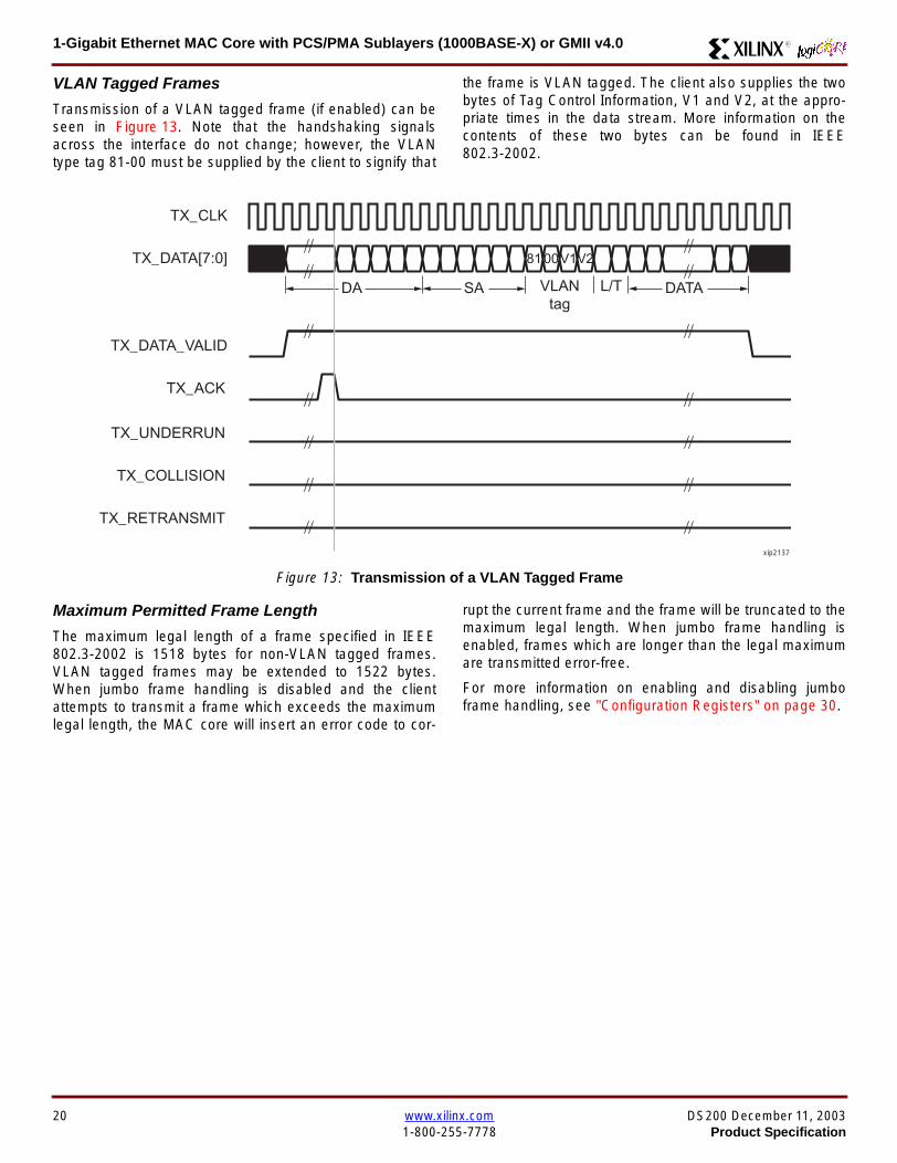
1-Gigabit Ethernet MAC Core with PCSPMA Sublayers (1000BASE-X) or GMII v40 R
VLAN Tagged Frames
Transmission of a VLAN tagged frame (if enabled) can beseen in Figure 13 Note that the handshaking signalsacross the interface do not change however the VLANtype tag 81-00 must be supplied by the client to signify that
the frame is VLAN tagged The client also supplies the twobytes of Tag Control Information V1 and V2 at the appro-priate times in the data stream More information on thecontents of these two bytes can be found in IEEE8023-2002
Maximum Permitted Frame Length
The maximum legal length of a frame specified in IEEE8023-2002 is 1518 bytes for non-VLAN tagged framesVLAN tagged frames may be extended to 1522 bytesWhen jumbo frame handling is disabled and the clientattempts to transmit a frame which exceeds the maximumlegal length the MAC core will insert an error code to cor-
rupt the current frame and the frame will be truncated to themaximum legal length When jumbo frame handling isenabled frames which are longer than the legal maximumare transmitted error-free
For more information on enabling and disabling jumboframe handling see Configuration Registers on page 30
Figure 13 Transmission of a VLAN Tagged Frame
TX_CLK
TX_DATA[70]
TX_DATA_VALID
TX_ACK
TX_UNDERRUN
DA SA DATALTVLANtag
81 00V1V2
TX_COLLISION
TX_RETRANSMIT
xip2137
20 wwwxilinxcom DS200 December 11 20031-800-255-7778 Product Specification
1-Gigabit Ethernet MAC Core with PCSPMA Sublayers (1000BASE-X) or GMII v40R
Frame Collisions - Half Duplex Operation Only
In half duplex Ethernet operation collisions will occur on themedium as a matter of course this is how the arbitrationalgorithm is fulfilled In case of a collision the MAC core sig-nals to the client that data may need to be resupplied as fol-lows
If there is a collision the TX_COLLISION signal will be setto ldquo1rdquo by the MAC core If a frame is in progress the clientmust abort the transfer and take TX_DATA_VALID to ldquo0rdquo
If the TX_RETRANSMIT signal is ldquo1rdquo in the same clockcycle that the TX_COLLISION signal is ldquo1rdquo the client must
resubmit the previous frame to the MAC core for retrans-mission TX_DATA_VALID must be asserted to the MACcore within 8 clock cycles of the TX_COLLISION signal inorder to meet Ethernet timing requirements See Figure 14
If the TX_RETRANSMIT signal is ldquo0rdquo in the same clockcycle that the TX_COLLISION signal is ldquo1rdquo the number ofretries for this frame has exceeded the Ethernet specifica-tion and the frame should be dropped by the client The cli-ent can then make any new frame available to the MAC fortransmission without timing restriction See Figure 15
Figure 14 Collision Handling - Frame retransmission required
Figure 15 Collision Handling - No frame retransmission required
TX_CLK
TX_DATA[70]
TX_DATA_VALID
TX_ACK
TX_UNDERRUN
TX_COLLISION
TX_RETRANSMIT
8 clocks max
xip2138
TX_CLK
TX_DATA[70]
TX_DATA_VALID
TX_ACK
TX_UNDERRUN
TX_COLLISION
TX_RETRANSMIT
xip2139
DS200 December 11 2003 wwwxilinxcom 21Product Specification 1-800-255-7778
1-Gigabit Ethernet MAC Core with PCSPMA Sublayers (1000BASE-X) or GMII v40 R
Interframe Gap Adjustment
The user can elect to vary the length of the inter fame gapIf this function is selected (via a configuration bit in thetransmitter control register see Configuration Registerson page 30) then the MAC will exert back pressure to delaythe transmission of the next frame until the requested num-ber of Idle cycles has elapsed The number of Idle cycles iscontrolled by the value on the TX_IFG_DELAY port at thestart of frame transmission Figure 16 shows the MAC oper-ating in this mode
Reducing the Inter fame gap to below the IEEE 8023-2002minimum of 12 Idles is supported in Full Duplex onlydesigns and will transmit an absolute minimum of 4 Idles Ifthe Interframe gap adjustment is reduced below 12 Idlesthen the accuracy of the Optional Statistical Gathering(statistics_gathering=true) Counters cannot be guaranteedHowever the TX_STATISTIC_VECTOR andRX_STATISTIC_VECTOR will always remain correct
Transmitter Statistics Vector
The statistics for the frame transmitted are contained withinthe TX_STATISTICS_VECTOR The vector is driven syn-chronously by the transmitter clock TX_CLK followingframe transmission The bit field definition for the Vector isdefined in Table 14
All bit fields with the exception of BYTE_VALID are validonly when the TX_STATISTICS_VALID is asserted This isillustrated in Figure 17 BYTE_VALID is significant on everyTX_CLK cycle
TX_STATISTICS_VECTOR bits 25 down to 17 inclusive arefor half duplex only and will be set to logic 0 when operatingin full duplex mode
Figure 16 Interframe Gap Adjustment
TX_CLK
TX_DATA[70]
TX_DATA_VALID
TX_ACK
DA SA
TX_IFG_DELAY
IFG ADJUST VALUE
0x0D
13 Idles inserted
DA
Next IFG ADJUST VALUE
xip2140
Figure 17 Transmitter Statistics Vector Timing
TX_CLK
TX_STATISTICS_VECTOR[280]
TX_STATISTICS_VALID
xip2141
22 wwwxilinxcom DS200 December 11 20031-800-255-7778 Product Specification
1-Gigabit Ethernet MAC Core with PCSPMA Sublayers (1000BASE-X) or GMII v40R
Table 14 Bit Definition for the Transmitter Statistics Vector
TX_STATISTICS_VECTOR Name Description
28 PAUSE_FRAME_TRANSMITTEDAsserted if the previous frame was a pause framethat the MAC itself initiated in response to aPAUSE_REQ assertion
27 BYTE_VALID
Asserted if a MAC frame byte (DA to FCS inclusive)is in the process of being transmitted This is valid onevery clock cycle
Do not use this as an enable signal to indicate thatdata is present on GMII_TXD[70]
26 Reserved Returns logic 0
25 down to 22 TX_ATTEMPTS[30]
The number of attempts that have been made totransmit the previous frame This is a 4-bit number0 should be interpreted as 1 attempt 1 as 2attempts up until 15 as 16 attempts
21 Reserved Returns logic 0
20 EXCESSIVE_COLLISIONAsserted if a collision has been detected on each ofthe last 16 attempts to transmit the previous frame
19 LATE_COLLISIONAsserted if a late collision occurred during frametransmission
18 EXCESSIVE_DEFERRALAsserted if the previous frame was deferred for anexcessive amount of time as defined by the constantldquomaxDeferTimerdquo in IEEE 8023-2002
17 TX_DEFERRED Asserted if transmission of the frame was deferred
16 VLAN_FRAMEAsserted if the previous frame contained a VLANidentifier in the LengthType field when transmitterVLAN operation is enabled
15 down to 5 FRAME_LENGTH_COUNTThe length of the previous frame in number of bytesThe count will stick at 2047 for any Jumbo frameslarger than this value
4 CONTROL_FRAMEAsserted if the previous frame had the special MACControl Type code 88-08 in the LengthType field
3 UNDERRUN_FRAMEAsserted if the previous frame contained anunderrun error
2 MULTICAST_FRAMEAsserted if the previous frame contained a multicastaddress in the Destination Address field
1 BROADCAST_FRAMEAsserted if the previous frame contained abroadcast address in the Destination Address field
0 SUCCESSFUL_FRAMEAsserted if the previous frame was transmittedwithout error
DS200 December 11 2003 wwwxilinxcom 23Product Specification 1-800-255-7778
1-Gigabit Ethernet MAC Core with PCSPMA Sublayers (1000BASE-X) or GMII v40 R
Receiver
Normal Frame Reception
The timing of a normal inbound frame transfer can be seenin Figure 18 The client must be prepared to accept data atany time there is no buffering within the MAC to allow forlatency in the receive client Once frame reception begins
data is transferred on consecutive clock cycles to thereceive client until the frame is complete The MAC assertsthe RX_GOOD_FRAME signal to indicate that the framewas successfully received and that the frame should beanalyzed by the client
Frame parameters (destination address source addresslengthtype and optionally FCS) are supplied on the databus according to the timing diagram The abbreviations arethe same as those described in Table 13 on page 16
If the LengthType field in the frame has the Length interpre-tation and this indicates that the inbound frame has beenpadded to meet the Ethernet minimum frame size specifica-tion then this padding will not be passed to the client in thedata payload The exception to this is in the case whereFCS passing is enabled see Client-Supplied FCS Pass-ing on page 25
Therefore when Client-Supplied FCS passing is disabledRX_DATA_VALID = lsquo0rsquo between frames for the duration ofthe Padding field (if present) the FCS field carrier exten-sion (if present) the interframe gap following the frame andthe preamble field of the next frame When Client-Supplied
FCS passing is enabled RX_DATA_VALID = lsquo0rsquo betweenframes for the duration of carrier extension (if present) theinterframe gap and the preamble field of the followingframe
RX_GOOD_FRAME RX_BAD_FRAME timing
Although the timing diagram in Figure 18 shows theRX_GOOD_FRAME signal asserted shortly after the lastvalid data on RX_DATA this is not always the case TheRX_GOOD_FRAME or RX_BAD_FRAME signals areasserted only after all frame checks are completed This isafter the FCS field has been received (and after reception ofcarrier extension if present)
Therefore either RX_GOOD_FRAME or RX_BAD_FRAMEis asserted following frame reception at the beginning of theinterframe gap
Figure 18 Normal Frame Reception
RX_CLK
RX_DATA[70]
RX_DATA_VALID
RX_GOOD_FRAME
RX_BAD_FRAME
DA SA DATALT
xip2142
24 wwwxilinxcom DS200 December 11 20031-800-255-7778 Product Specification
1-Gigabit Ethernet MAC Core with PCSPMA Sublayers (1000BASE-X) or GMII v40R
Frame Reception with Errors
The case of an unsuccessful frame reception (for examplea fragment frame or a frame with an incorrect FCS) can beseen in Figure 19 In this case the RX_BAD_FRAME signal
is asserted to the client at the end of the frame It is then theresponsibility of the client to drop the data already trans-ferred for this frame
Figure 19 Frame Reception with Error
Client-Supplied FCS Passing
If the MAC core is configured to pass the FCS field to the cli-ent (see Configuration Registers on page 30) then this ishandled as shown in Figure 20
In this case any padding inserted into the frame to meetEthernet minimum frame length specifications will be leftintact and passed to the client
Note that even though the FCS is passed up to the client itis also verified by the MAC core and RX_BAD_FRAMEasserted if the FCS check fails
RX_CLK
RX_DATA[70]
RX_DATA_VALID
RX_GOOD_FRAME
RX_BAD_FRAME
DA SA DATALT
xip2144
Figure 20 Frame Reception with In-Band FCS Field
RX_CLK
RX_DATA[70]
RX_DATA_VALID
RX_GOOD_FRAME
RX_BAD_FRAME
DA SA DATALT FCS
xip2145
DS200 December 11 2003 wwwxilinxcom 25Product Specification 1-800-255-7778
1-Gigabit Ethernet MAC Core with PCSPMA Sublayers (1000BASE-X) or GMII v40 R
VLAN Tagged Frames
The reception of a VLAN tagged frame (if enabled) can beseen in Figure 21 The VLAN frame is passed to the clientso that the frame may be identified as VLAN tagged this is
followed by the Tag Control Information bytes V1 and V2More information on the interpretation of these bytes maybe found in IEEE 8023-2002 standard
Maximum Permitted Frame Length
The maximum legal length of a frame specified in IEEE8023-2002 is 1518 bytes for non-VLAN tagged framesVLAN tagged frames may be extended to 1522 bytesWhen jumbo frame handling is disabled and the corereceives a frame which exceeds the maximum legal lengthRX_BAD_FRAME will be asserted When jumbo framehandling is enabled frames which are longer than the legalmaximum are received in the same way as shorter frames
For more information on enabling and disabling jumboframe handling see Configuration Registers on page 30
LengthType Field Error Checks
Enabled
Default operation is with the LengthType error checkingenabled (see Receiver Configuration Word 1 on page 31)In this mode the following checks are made on all framesreceived If either of these checks fail then the frame ismarked as BAD
bull A value in the LengthType field that is greater than orequal to decimal 46 but less than decimal 1536 (aLength interpretation) is checked against the actualdata length received
bull A value in the LengthType field that is less thandecimal 46 is checked to see that the data field ispadded to exactly 46 bytes (so that the resultant frameis minimum frame size 64 bytes total in length)
Furthermore if Padding is indicated (the LengthType fieldis less than decimal 46) and Client-Supplied FCS Passing isdisabled then the Length value in the LengthType field willbe used to deassert RX_DATA_VALID after the indicatednumber of data bytes so that the Padding bytes areremoved from the frame
Disabled
When the LengthType error checking is disabled (seeReceiver Configuration Word 1 on page 31) theLengthType error checks described above are not per-formed A frame containing only these errors will be markedas GOOD
Furthermore if Padding is indicated and Client-SuppliedFCS Passing is disabled then a Length Value in theLengthType field will not be used to deassertRX_DATA_VALID Instead RX_DATA_VALID will be deas-serted before the start of the FCS field in this way any pad-ding will not be removed from the frame
Figure 21 Reception of a VLAN Tagged Frame
RX_CLK
RX_DATA[70]
RX_DATA_VALID
RX_GOOD_FRAME
RX_BAD_FRAME
DA SA DATALT
81 00 V1 V2
VLANtag
xip2146
26 wwwxilinxcom DS200 December 11 20031-800-255-7778 Product Specification
1-Gigabit Ethernet MAC Core with PCSPMA Sublayers (1000BASE-X) or GMII v40R
Receiver Statistics Vector
The statistics for the frame received are contained withinthe RX_STATISTICS_VECTOR The vector is driven syn-chronously by the receiver clock RX_CLK following framereception The bit field definition for the Vector is defined inTable 15
All bit fields with the exception of BYTE_VALID are validonly when the RX_STATISTICS_VALID is asserted This isillustrated in Figure 22 BYTE_VALID is significant on everyRX_CLK cycle
Figure 22 Receiver Statistics Vector Timing
RX_CLK
RX_STATISTICS_VECTOR[220]
RX_STATISTICS_VALID
xip2147
Table 15 Bit Definition for the Receiver Statistics Vector
RX_STATISTICS_VECTOR Name Description
22LENGTHTYPE Out ofRange
Asserted if the lengthtype field contained a length valuethat did not match the number of MAC client data bytesreceived Also high if the lengthtype field indicated thatthe frame contained padding but the number of MAC cli-ent data bytes received was not equal to 64 bytes (min-imum frame size)
The exception to the above is when the LengthTypeField Error Checks are disabled in which case this bitwill not be asserted
21 BAD_OPCODE
Asserted if the previous frame was error-free andcontained the special Control Frame identifier in theLengthType field but contained an opcode that isunsupported by the MAC (Any Opcode other thanPAUSE)
20 FLOW_CONTROL_FRAME
Asserted if the previous frame was error-freecontained the special Control Frame identifier in theLengthType field contained a Destination Addressthat matched either the MAC Control MulticastAddress or the configured source address of the MACcontained the supported PAUSE opcode and wasacted upon by the MAC
19 BYTE_VALID
Asserted if a MAC frame byte (DA to FCS inclusive) isin the process of being received This is valid on everyclock cycle
Do not use this as an enable signal to indicate thatdata is present on RX_DATA[70]
18 VLAN_FRAMEAsserted if the previous frame contained a VLANidentifier in the LengthType field when receiver VLANoperation is enabled
DS200 December 11 2003 wwwxilinxcom 27Product Specification 1-800-255-7778
1-Gigabit Ethernet MAC Core with PCSPMA Sublayers (1000BASE-X) or GMII v40 R
17 OUT_OF_BOUNDS
Asserted if the previous frame exceeded the specifiedIEEE8023-2002 maximum legal length (seeMaximum Permitted Frame Length on page 26) Thisis only valid if Jumbo frames are disabled
16 CONTROL_FRAMEAsserted if the previous frame contained the specialControl Frame identifier in the LengthType field
15 down to 5 FRAME_LENGTH_COUNTThe length of the previous frame in number of bytesThe count will stick at 2047 for any Jumbo frameslarger than this value
4 MULTICAST_FRAMEAsserted if the previous frame contained a multicastaddress in the Destination Address field
3 BROADCAST_FRAMEAsserted if the previous frame contained the broadcastaddress in the Destination Address field
2 FCS_ERRORAsserted if the previous frame received had anincorrect FCS value or the MAC detected error codesduring frame reception
1 BAD_FRAME1 Asserted if the previous frame received containederrors
0 GOOD_FRAME1 Asserted if the previous frame received was error-free
1 If the LengthType Field Error Checks are disabled then a frame which contains this type of error will be marked as a GOOD_FRAMEproviding no additional errors were detected
Table 15 Bit Definition for the Receiver Statistics Vector
RX_STATISTICS_VECTOR Name Description
28 wwwxilinxcom DS200 December 11 20031-800-255-7778 Product Specification
1-Gigabit Ethernet MAC Core with PCSPMA Sublayers (1000BASE-X) or GMII v40R
Flow ControlThe flow control block is designed to Clause 31 of the IEEE8023-2002 standard The MAC may be configured to sendpause frames and to act upon their reception These twobehaviors can be configured asymmetrically see Configu-ration Registers on page 30
Transmitting a PAUSE Control Frame
The client initiates a flow control frame by assertingPAUSE_REQ while the pause value is on the PAUSE_VALbus These signals are synchronous to TX_CLK The timingof this can be seen in Figure 23
If the MAC core is configured to support transmit flow con-trol this action causes the core to transmit a PAUSE controlframe on the link with the PAUSE parameter set to thevalue on PAUSE_VAL in the cycle when PAUSE_REQ wasasserted This will not disrupt any frame transmission inprogress but will take priority over any pending frame trans-
mission This frame will be transmitted even if the transmit-ter is in the paused state itself
Receiving a Pause Control Frame
When an error-free frame is received by the MAC core thefollowing checks are made
1 The Destination Address field is matched against theMAC Control Multicast address or the configuredSource Address for the MAC (see ConfigurationRegisters on page 30)
2 The LengthType field is matched against the MACControl Type code
3 The opcode field contents are matched against thePAUSE opcode if check 2 is true
If any of the above checks are false or the MAC Flow Con-trol logic for the receiver is disabled the frame is ignored bythe Flow Control logic and passed up to the client
If the frame passes all of the above checks is of minimumlegal size and the MAC Flow Control logic for the receiver isenabled the pause value parameter in the frame is thenused to inhibit transmitter operation for the time defined inthe IEEE8023-2002 specification This inhibit is imple-mented using the same back pressure scheme shown inFigure 12 Because the received pause frame has beenacted upon it is passed to the client with RX_BAD_FRAMEasserted to indicate to the client that it should be dropped
Reception of any frame for which check 2 is true and whichis not of legal minimum length is considered an invalid Con-trol frame This will be ignored by the Flow Control logic andpassed to the client with RX_BAD_FRAME asserted
Figure 23 Pause Request Timing
TX_CLK
PAUSE_VAL[150]
PAUSE_REQ
xip2148
DS200 December 11 2003 wwwxilinxcom 29Product Specification 1-800-255-7778
1-Gigabit Ethernet MAC Core with PCSPMA Sublayers (1000BASE-X) or GMII v40 R
Optional Management Interface(management_interface=true)The management interface is a processor-independentinterface with standard address data and control signals Itmay be used as is or a wrapper may be applied (not sup-plied) to interface to common bus architectures
This interface is used for
bull Configuration of the MAC core
bull Access to optional statistics counters for use by higherlayers for example SNMP
bull access through the MDIO interface to the managementregisters located in the PHY attached to the MAC core
The management interface is accessed differently depend-ing on the type of transaction a truth table showing whichaccess method is required for each transaction type isshown in Table 16 These access methods are described inthe following sections
HOST_CLK Frequency
The management interface clock HOST_CLK is used toderive the MDIO clock MDC and is therefore subject tosome frequency restrictions This HOST_CLK must be
ge 10 MHz
le 100 MHz
Configuring the MAC core to derive the MDC signal fromthis clock is detailed in MDIO Interface on page 37
Configuration Registers
After power up or reset the client may reconfigure the coreparameters from their defaults such as flow control supportConfiguration changes can be written at any time Both thereceiver and transmitter logic will only respond to configura-tion changes during Inter Frame Gaps The exceptions tothis are the configurable resets which take effect immedi-ately
Configuration of the MAC core is performed through a reg-ister bank accessed through the management interfaceThe configuration registers available in the core are detailedin Table 17 As can be seen the address has some implicitdonrsquot care bits any access to an address in the rangesshown will perform a 32-bit read or write from the same con-figuration word
Table 16 Management Interface Transaction Types
Transaction HOST_MIIM_SEL HOST_ADDR[9]
Configuration 0 1
Statistics 0 0
MIIM access 1 X
Table 17 Configuration Registers
Address Description
0x200-0x23F Receiver Configuration (Word 0)
0x240-0x27F Receiver Configuration (Word 1)
0x280-0x2BF Transmitter Configuration
0x2C0-0x2FF Flow Control Configuration
0x300-0x33F Reserved
0x340-0x37F Management Configuration
30 wwwxilinxcom DS200 December 11 20031-800-255-7778 Product Specification
1-Gigabit Ethernet MAC Core with PCSPMA Sublayers (1000BASE-X) or GMII v40R
The register contents for the two receiver configuration words can be seen in Table 18 and Table 19
Notes1 In changing the receiverrsquos mode from Half Duplex to Full Duplex there is a period of time of up to 24 us following the mode change
when no new receiver statistics can be stored in the optional Statistical Counters
Table 18 Receiver Configuration Word 0
Bit Default Value Description
31-0 All 0rsquos
Pause frame MAC Source Address[310] This address is used by the MAC tomatch against the Destination Address of any incoming flow control frames It isalso used by the flow control block as the Source Address (SA) for any outboundflow control frames
The address is ordered so the first byte transmittedreceived is the lowestpositioned byte in the register for example a MAC address ofAA-BB-CC-DD-EE-FF would be stored in Address[470] as 0xFFEEDDCCBBAA
Table 19 Receiver Configuration Word 1
Bit Default Value Description
15-0 All 0rsquos Pause frame MAC Source Address[4732] See description in Table 18
24-16 NA Reserved
25 0
LengthType Error Check Disable When this bit is set to ldquo1rdquo the core will notperform the LengthType field error checks as described in LengthType FieldError Checks on page 26 When this bit is set to ldquo0rdquo the LengthType field checkswill be performed this is normal operation
26 0Half Duplex If ldquo1rdquo the receiver will operate in half duplex mode If ldquo0rdquo the receiverwill operate in full duplex mode Has no effect if XCO parameterhalf_duplex_capable = false
27 0VLAN Enable When this bit is set to ldquo1rdquo VLAN tagged frames will be acceptedby the receiver
28 1Receiver Enable If set to ldquo1rdquo the receiver block will be operational If set to ldquo0rdquothe block will ignore activity on the physical interface RX port
29 0
In-band FCS Enable When this bit is ldquo1rdquo the MAC receiver will pass the FCS fieldup to the client as described in Client-Supplied FCS Passing on page 25 Whenit is ldquo0rdquo the client will not be passed the FCS In both cases the FCS will beverified on the frame
30 0Jumbo Frame Enable When this bit is set to ldquo1rdquo the MAC receiver will acceptframes over the specified IEEE8023-2002 maximum legal length When this bitis ldquo0rdquo the MAC will only accept frames up to the specified maximum
31 0Reset When this bit is set to ldquo1rdquo the receiver will be reset The bit will thenautomatically revert to ldquo0rdquo Note that this reset will also set all of the receiverconfiguration registers to their default values
DS200 December 11 2003 wwwxilinxcom 31Product Specification 1-800-255-7778
1-Gigabit Ethernet MAC Core with PCSPMA Sublayers (1000BASE-X) or GMII v40 R
The register contents for the Transmitter Configuration Word are described in Table 20
Notes1 In changing the transmitterrsquos mode from Half Duplex to Full Duplex there is a period of time of up to 24 us following the mode change
when no new transmitter statistics can be stored in the optional Statistical Counters
Table 20 Transmitter Configuration Word
Bit Default Value Description
24-0 NA Reserved
25 0
Interframe Gap Adjust Enable If lsquo1rsquo the transmitter will read the value on the portTX_IFG_DELAY at the start of frame transmission and adjust the interframe gapfollowing the frame accordingly See Interframe Gap Adjustment on page 22 Ifldquo0rdquo the transmitter will output a minimum Inter Frame Gap of twelve clock cyclesas specified in IEEE8023-2002
26 0Half Duplex If lsquo1rsquo the transmitter will operate in half duplex mode If lsquo0rsquo thetransmitter will operate in full duplex mode Has no effect if XCO parameterhalf_duplex_capable = false
27 0VLAN Enable When this bit is set to 1 the transmitter will allow the transmissionof VLAN tagged frames
28 1Transmit Enable When this bit is 1 the transmitter is operational When it is 0the transmitter is disabled
29 0
In-band FCS Enable When this bit is lsquo1rsquo the MAC transmitter will expect the FCSfield to be passed in by the client as described in Client-Supplied FCS Passingon page 17 When this bit is ldquo0rdquo the MAC transmitter will append padding asrequired compute the FCS and append it to the frame
30 0
Jumbo Frame Enable When this bit is set to ldquo1rdquo the MAC transmitter will sendframes that are greater than the specified IEEE8023-2002 maximum legallength When this bit is ldquo0rdquo the MAC will only send frames up to the specifiedmaximum
31 0Reset When this bit is set to ldquo1rdquo the transmitter will be reset The bit will thenautomatically revert to ldquo0rdquo Note that this reset will also set all of the transmitterconfiguration registers to their default values
32 wwwxilinxcom DS200 December 11 20031-800-255-7778 Product Specification
1-Gigabit Ethernet MAC Core with PCSPMA Sublayers (1000BASE-X) or GMII v40R
The register contents for the Flow Control Configuration Word are described in Table 21
The register contents for the Management Configuration Word are described in Table 22
Writing to the configuration registers through the manage-ment interface is depicted in Figure 24 When accessing theconfiguration registers (ie when HOST_ADDR[9] = lsquo1rsquo andHOST_MIIM_SEL = lsquo0rsquo) the upper bit of HOST_OPCODEfunctions as an Active Low write enable signal The lowerHOST_OPCODE bit is a ldquodonrsquot carerdquo
Reading from the configuration register words is similar butthe upper HOST_OPCODE bit should be lsquo1rsquo This is shownin Figure 25 In this case the contents of the register appearon HOST_RD_DATA the HOST_CLK edge after the regis-ter address is asserted onto HOST_ADDR
Table 21 Flow Control Configuration Word
Bit Default Value Description
28-0 NA Reserved
29 1
Flow Control Enable (RX) When this bit is lsquo1rsquo received flow control frames willinhibit the transmitter operation as described in Receiving a Pause ControlFrame on page 29 When this bit is lsquo0rsquo received flow control frames will alwaysbe passed up to the client
30 1Flow Control Enable (TX) When this bit is lsquo1rsquo asserting the PAUSE_REQ signalwill send a flow control frame out from the transmitter When this bit is 0 assertingthe PAUSE_REQ signal has no effect
31 NA Reserved
Table 22 Management Configuration Word
Bits Default Value Description
4-0 All 0rsquos Clock Divide[40] See MDIO Interface on page 37
5 0MDIO Enable When this bit is 1 the MDIO interface can be used to accessattached PHY devices When this bit is 0 the MDIO interface is disabled and theMDIO signals remain inactive
31-6 NA Reserved
Figure 24 Configuration Register Write Timing
HOST_CLK
HOST_ADDR[80]
HOST_ADDR[9]
HOST_OPCODE[1]
HOST_MIIM_SEL
HOST_WR_DATA[310]xip2149
Figure 25 Configuration Register Read Timing
HOST_CLK
HOST_ADDR[80]
HOST_ADDR[9]
HOST_OPCODE[1]
HOST_MIIM_SEL
HOST_RD_DATA[310]
xip2150
DS200 December 11 2003 wwwxilinxcom 33Product Specification 1-800-255-7778
1-Gigabit Ethernet MAC Core with PCSPMA Sublayers (1000BASE-X) or GMII v40 R
Optional Statistical Gathering(statistics_gathering=true)
During operation the MAC core collects statistics on thesuccess and failure of various operations for processing by
station management entities (STA) further up the protocolstack These statistics are accessed by the host through theoptional management interface A complete list of statisticssupported is described in Table 23
Table 23 Statistics Registers
Address Name Description
0x000 Frames Received OK1 A count of error-free frames received
0x001 Frame Check Sequence Errors A count of received frames that failed the CRC check and were at least64 bytes in length
0x002 Broadcast Frames Received OK1A count of frames that were successfully received and were directed tothe broadcast group address
0x003 Multicast Frames Received OK1 A count of frames that were successfully received and were directed toa non broadcast group address
0x004 64 byte Frames Received OK1 A count of error-free frames received that were 64 bytes in length
0x005 65-127 byte Frames Received OK1A count of error-free frames received that were between 65 and 127bytes in length
0x006 128-255 byte Frames Received OK1A count of error-free frames received that were between 128 and 255bytes in length
0x007 256-511 byte Frames Received OK1A count of error-free frames received that were between 256 and 511bytes in length
0x008512-1023 byte Frames ReceivedOK1
A count of error-free frames received that were between 512 and 1023bytes in length
0x0091024-MaxFrameSize byte FramesReceived OK1
A count of error-free frames received that were between 1024 bytes andthe specified IEEE8023-2002 maximum legal length (see MaximumPermitted Frame Length on page 26)
0x00A Control Frames Received OKA count of error-free frames received that contained the specialControl Frame identifier in the LengthType field
0x00B LengthType Out of Range
A count of frames received that were at least 64 bytes in length wherethe lengthtype field contained a length value that did not match thenumber of MAC client data bytes received
The counter also increments for frames in which the lengthtype fieldindicated that the frame contained padding but where the number ofMAC client data bytes received was greater than 64 bytes (minimumframe size)
The exception to the above is when the LengthType Field Error Checksare disabled in which case this counter will not increment
0x00C VLAN Tagged Frames Received OKA count of error-free VLAN frames received This counter will only incre-ment when the receiver is configured for VLAN operation
0x00D Pause Frames Received OK
A count of error-free frames received that contained the MAC Controltype identifier 88-08 in the LengthType field contained a Destinationaddress that matched either the MAC Control multicast address or theconfigured source address of the MAC contained the PAUSE opcodeand were acted upon by the MAC
0x00EControl Frames Received withUnsupported Opcode
A count of error-free frames received that contained the MAC Controltype identifier 88-08 in the LengthType field but were received with anopcode other than the PAUSE opcode
34 wwwxilinxcom DS200 December 11 20031-800-255-7778 Product Specification
1-Gigabit Ethernet MAC Core with PCSPMA Sublayers (1000BASE-X) or GMII v40R
0x00F Oversize Frames Received OK1A count of otherwise error-free frames received that exceeded the max-imum legal frame length specified in IEEE 8023-2002 (see MaximumPermitted Frame Length on page 26)
0x010 Undersize frames receivedA count of the number of frames received that were less than 64 bytesin length but were otherwise well formed
0x011 Fragment frames receivedA count of the number of frames received that were less than 64 bytesin length and had a bad Frame Check Sequence field
0x012 Received bytesA count of bytes of frames that are received (Destination Address toFrame Check Sequence inclusive)
0x013 Transmitted bytesA count of bytes of frames that are transmitted (Destination Address toFrame Check Sequence inclusive)
0x020 Frames Transmitted OK A count of error-free frames transmitted
0x021 Broadcast Frames Transmitted OK A count of error-free frames that were transmitted to the broadcastaddress
0x022 Multicast Frames Transmitted OK A count of error-free frames that were transmitted to a group destina-tion address other than broadcast
0x023 Underrun Errors
A count of frames that would otherwise be transmitted by the core butcould not be completed due to the assertion of TX_UNDERRUN duringthe frame transmission This will not count frames which are less than64 bytes in length
0x024 Control Frames Transmitted OKA count of error-free frames transmitted that contained the MACControl Frame type identifier 88-08 in the LengthType field
0x025 64 byte Frames Transmitted OK A count of error-free frames transmitted that were 64 bytes in length
0x026 65-127 byte Frames Transmitted OKA count of error-free frames transmitted that were between 65 and 127bytes in length
0x027128-255 byte Frames TransmittedOK
A count of error-free frames transmitted that were between 128 and 255bytes in length
0x028256-511 byte Frames TransmittedOK
A count of error-free frames transmitted that were between 256 and 511bytes in length
0x029512-1023 byte Frames TransmittedOK
A count of error-free frames transmitted that were between 512 and1023 bytes in length
0x02A1024-MaxFrameSize byte FramesTransmitted OK
A count of error-free frames transmitted that were between 1024 and thespecified IEEE8023-2002 maximum legal length (see Maximum Per-mitted Frame Length on page 20)
0x02BVLAN Tagged Frames TransmittedOK
A count of error-free VLAN frames transmitted This counter will onlyincrement when the transmitter is configured for VLAN operation
0x02C Pause Frames Transmitted OKA count of error-free PAUSE frames generated and transmitted by thecore in response to an assertion of PAUSE_REQ
0x02D Oversize Frames Transmitted OKA count of otherwise error-free frames transmitted that exceeded themaximum legal frame length specified in IEEE 8023-2002 (see Maxi-mum Permitted Frame Length on page 20)
0x02E Single Collision Frames A count of frames that are involved in a single collision but are subse-quently transmitted successfully (Half Duplex Mode only)
Table 23 Statistics Registers (Continued)
Address Name Description
DS200 December 11 2003 wwwxilinxcom 35Product Specification 1-800-255-7778
1-Gigabit Ethernet MAC Core with PCSPMA Sublayers (1000BASE-X) or GMII v40 R
Each of these statistic registers is 64 bits wide and thereforemust be read in a two-cycle transfer The timing of this pro-cess is shown in Figure 26 Six clocks after the read trans-action is initiated the least significant word (LSW) of thestatistics counter appears on the HOST_RD_DATA bus
and a clock cycle later the most significant word (MSW)appears For accurate statistic values 64 clock ticks (ofTX_CLK for transmit statistics or RX_CLK for receive statis-tics) must elapse after the last frame is sent or receivedthrough the MAC core
0x02F Multiple Collision Frames A count of frames that are involved in more than one collision but aresubsequently transmitted successfully (Half Duplex Mode only)
0x040 Frames with Deferred Transmissions A count of frames whose transmission was delayed on its first attemptbecause the medium was busy (Half Duplex Mode only)
0x041 Late Collisions
A count of the times that a collision has been detected later than oneslotTime from the start of the packet transmission A late collision iscounted twice both as a collision and as a lateCollision (Half DuplexMode only)
0x042Frames Aborted due to Excesscollisions
A count of the frames that due to excessive collisions are not transmit-ted successfully (Half Duplex Mode only)
0x043 Carrier Sense ErrorsA count of times that the GMII_CRS signal was not asserted or wasdisasserted during the transmission of a frame without collision (HalfDuplex Mode only)
0x044 Frames with Excess DeferralA count of frames that deferred transmission for an excessive period oftime (Half Duplex Mode only)
1 If the LengthType Field Error Checks are disabled then these counters will still increment for received frames which contain this typeof error (providing no additional errors were detected)
Table 23 Statistics Registers (Continued)
Address Name Description
Figure 26 Statistic Register Read Timing
HOST_CLK
HOST_ADDR[80]
HOST_ADDR[9]
HOST_REQ
HOST_MIIM_SEL
HOST_RD_DATA[310]
6 CLOCKS
LSW MSW
xip2151
36 wwwxilinxcom DS200 December 11 20031-800-255-7778 Product Specification
1-Gigabit Ethernet MAC Core with PCSPMA Sublayers (1000BASE-X) or GMII v40R
MDIO Interface
The management interface is also used to access the MDIO(MII Management) interface of the MAC core this interfaceis used to access the Managed Information Block (MIB) ofthe PHY components attached to the MAC core
The MDIO interface supplies a clock to the externaldevices MDC This clock is derived from the HOST_CLKsignal using the value in the Clock Divide[40] configurationregister The frequency of the MDIO clock is given by thefollowing equation
The frequency of MDC given by this equation should notexceed 25 MHz in order to comply with the IEEE8023-2002 specification for this interface To prevent MDCfrom being out of specification the Clock Divide[40] valuepowers up at 00000 and while this value is in the register itis impossible to enable the MDIO interface
For details of the register map of PHY layer devices and afuller description of the operation of the MDIO interfaceitself see IEEE specification 8023-2002
Access to the MDIO interface through the managementinterface is depicted in the timing diagram in Figure 27
For MDIO transactions the following points apply
bull HOST_OPCODE maps to the OP (opcode) field of theMDIO frame
bull HOST_ADDR maps to the two address fields of theMDIO frame PHY_ADDR is HOST_ADDR[95] andREG_ADDR is HOST_ADDR[40]
bull HOST_WR_DATA[150] maps into the data field of the
MDIO frame when performing a write operation
bull The data field of the MDIO frame maps intoHOST_RD_DATA[150] when performing a readoperation
The MAC core signals to the host that it is ready for anMDIO transaction by asserting HOST_MIIM_RDY A read orwrite transaction on the MDIO is initiated by a pulse on the
fMDC
fHOST_CLK
1 Clock Divide[40]+( ) 2times-------------------------------------------------------------------=
Figure 27 MDIO Access Through Management Interface
HOST_CLK
HOST_ADDR[90]
HOST_OPCODE[10]
HOST_REQ
HOST_MIIM_SEL
HOST_RD_DATA[150]
HOST_WR_DATA[150]
HOST_RDY
If a read transaction is initiated the HOST_RD_DATA bus is valid at the point indicated If a write transaction is initiated the HOST_WR_DATA bus must be valid at the indicated point Simultaneous read and write is not permitted
xip2152
DS200 December 11 2003 wwwxilinxcom 37Product Specification 1-800-255-7778
1-Gigabit Ethernet MAC Core with PCSPMA Sublayers (1000BASE-X) or GMII v40 R
HOST_REQ signal This pulse is ignored if the MDIO inter-face already has a transaction in progress
The MAC core then disasserts the HOST_MIIM_RDY signalwhile the transaction across the MDIO is in progress Whenthe transaction across the MDIO interface has been com-pleted the HOST_MIIM_RDY signal will be asserted by theMAC core if the transaction is a read the data will also beavailable on the HOST_RD_DATA[150] bus at this time
Optional Configuration Vector(management_interface = false)If the optional Management interface is omitted from thecore all of relevant configuration signals are brought out of
the core These signals are bundled into theCONFIGURATION_VECTOR signal The bit mapping of theconfiguration vector signal is defined in Table 24 See thecorresponding entry in the configuration register tables forthe full description of each signal
Note that these configuration vector signals can bechanged by the user at any time however with the excep-tion of the reset and the flow control configuration signalsthey will not take effect until the current frame has com-pleted transmission or reception
The ldquoClockrdquo heading denotes which clock domain the con-figuration signal is registered into before use by the core Itis not necessary to drive the signal from this clock domain
Table 24 Configuration Vector Bit Definition
Bit(s)Configuration Register
cross reference Clock Description
47 downto 0
Receiver ConfigurationWord 0 bits 31-0 andReceiver ConfigurationWord 1 bits 15-0
RX_CLK
Pause frame MAC Source Address[470] This address isused by the MAC core to match against the DestinationAddress of any incoming flow control frames and as theSource Address for any outbound flow control frames
The address is ordered such that the first byte transmitted orreceived is the least significant byte in the register forexample a MAC address of AA-BB-CC-DD-EE-FF will bestored in bite [470] as 0xFFEEDDCCBBAA
48Receiver ConfigurationWord 1 bit 26
RX_CLKReceiver Half Duplex If lsquo1rsquo the receiver operates in halfduplex mode If lsquo0rsquo the receiver operates in full duplex modeHas no effect if XCO parameter half_duplex_capable = false
49Receiver ConfigurationWord 1 bit 27
RX_CLKReceiver VLAN Enable When this bit is set to 1 VLANtagged frames are accepted by the receiver
50Receiver ConfigurationWord 1 bit 28
RX_CLKReceiver Enable If set to 1 the receiver block is operationalIf set to 0 the block ignores activity on the physical interfaceRX port
51Receiver ConfigurationWord 1 bit 29
RX_CLK
Receiver In-band FCS Enable When this bit is lsquo1rsquo the MACreceiver will pass the FCS field up to the client as describedin Client-Supplied FCS Passing on page 25 When it is lsquo0rsquothe MAC receiver will not pass the FCS field In both casesthe FCS field will be verified on the frame
52Receiver ConfigurationWord 1 bit 30
RX_CLK
Receiver Jumbo Frame Enable When this bit is lsquo0rsquo thereceiver will not pass frames longer than the maximum legalframe size specified in IEEE 8023-2002 (see MaximumPermitted Frame Length on page 26) When it is lsquo1rsquo thereceiver will not have an upper limit on frame size
53Receiver ConfigurationWord 1 bit 31
NA
Receiver Reset When this bit is lsquo1rsquo the receiver is held inreset
This signal is an input to the reset circuit for the receiverblock See Reset circuit on page 42 for more information
54TransmitterConfiguration Word bit25
TX_CLK
Transmitter Interframe Gap Adjust enable If lsquo1rsquo then thetransmitter will read the value of the TX_IFG_DELAY port andset the Interframe Gap accordingly If lsquo0rsquo the transmitter willalways insert at least the legal minimum Interframe Gap
38 wwwxilinxcom DS200 December 11 20031-800-255-7778 Product Specification
1-Gigabit Ethernet MAC Core with PCSPMA Sublayers (1000BASE-X) or GMII v40R
55TransmitterConfiguration Word bit26
TX_CLK
Transmitter Half Duplex If lsquo1rsquo the transmitter operates in halfduplex mode If lsquo0rsquo the transmitter operates in full duplexmode Has no effect if XCO parameter half_duplex_capable= false
56TransmitterConfiguration Word bit27
TX_CLKTransmitter VLAN Enable When this bit is set to lsquo1rsquo thetransmitter allows the transmission of VLAN tagged frames
57TransmitterConfiguration Word bit28
TX_CLKTransmitter Enable When this bit is 1 the transmitter will beoperational When it is 0 the transmitter is disabled
58TransmitterConfiguration Word bit29
TX_CLK
Transmitter In-Band FCS Enable When this bit is lsquo1rsquo theMAC transmitter will expect the FCS field to be pass in by theclient as described in Client-Supplied FCS Passing onpage 17 When it is lsquo0rsquo the MAC transmitter will appendpadding as required compute the FCS and append it to theframe
59TransmitterConfiguration Word bit30
TX_CLK
Transmitter Jumbo Frame Enable When this bit is lsquo1rsquo theMAC transmitter will allow frames larger than the maximumlegal frame length specified in IEEE 8023-2002 to be sentWhen set to lsquo0rsquo the MAC transmitter will only allow frames upto the legal maximum to be sent
60TransmitterConfiguration Word bit31
NA
Transmitter Reset When this bit is lsquo1rsquo the MAC transmitter isheld in reset
This signal is an input to the reset circuit for the transmitterblock See Reset circuit on page 42 for more information
61Flow ControlConfiguration Word bit29
TX_CLK
Transmit Flow Control Enable When this bit is lsquo1rsquo assertingthe PAUSE_REQ signal causes the MAC core to send a flowcontrol frame out from the transmitter as described inReceiving a Pause Control Frame on page 29 When this bitis lsquo0rsquo asserting the PAUSE_REQ signal will have no effect
62Flow ControlConfiguration Word bit30
RX_CLK
Receive Flow Control Enable When this bit is lsquo1rsquo receivedflow control frames will inhibit the transmitter operation asdescribed in Receiving a Pause Control Frame on page 29When it is lsquo0rsquo received flow frames are passed up to theclient
63Receiver ConfigurationWord 1 bit 25
RX_CLK
LengthType Error Check Disable When this bit is lsquo1rsquo thecore will not perform the LengthType field error checks asdescribed in LengthType Field Error Checks on page 26When it is set to lsquo0rsquo the LengthType field checks will beperformed this is normal operation
Table 24 Configuration Vector Bit Definition (Continued)
Bit(s)Configuration Register
cross reference Clock Description
DS200 December 11 2003 wwwxilinxcom 39Product Specification 1-800-255-7778
1-Gigabit Ethernet MAC Core with PCSPMA Sublayers (1000BASE-X) or GMII v40 R
Optional GMII (physical_interface=gmii)The GMII is designed to IEEE 8023-2002 Clause 35 Thisutilizes IOrsquos of the Xilinx devices using inputoutput buffersand inputoutput flip-flops to maximize setup and hold mar-gins All IO logic is placed in the example wrapper that isdelivered with the core In addition all clock managementlogic for the core is instanced in this example wrapper thisallows multiple instances of the core to share clocks Theexample wrapper is provided in both VHDL and Verilog
Clock Management
Figure 28 illustrates the clock management used with theGMII interface All clocks illustrated have a frequency of125MHz
GTX_CLK must be provided to the MAC core This is a highquality clock which satisfies the IEEE8023-2002 require-ments It is expected that this clock will be derived from anexternal oscillator and connected into the device through anIBUFG as illustrated The clock source must then be routedonto a global clock network by connecting it to a BUFGWithin the MAC core this global clock is used by all MACtransmitter logic The MAC Client can obtain this clock byconnecting to the TX_CLK signal output from the coreGMII_TX_CLK is derived from this global clock by invertingit and routing it to an OBUF
GMII_RX_CLK is received through an IBUFG This clock isthen routed onto a global clock network by connecting it to aBUFG The resulting global clock is used by all MACreceiver logic
Figure 28 Clock Management with GMII
IBUFG
IBUFG
OBUF
BUFG
BUFG
TX_CLK
RX_CLK
GTX_CLK
GMII_TX_CLK
GMII_RX_CLK
Example Wrapper
xip2153
MAC Core
TX_CLK
RX_CLK
GMII_TX_CLK
GMII_RX_CLK
GTX_CLK
40 wwwxilinxcom DS200 December 11 20031-800-255-7778 Product Specification
1-Gigabit Ethernet MAC Core with PCSPMA Sublayers (1000BASE-X) or GMII v40R
Clock Sharing between Multiple cores
Figure 29 illustrates how it is possible to share clockresources across multiple instantiations of the core whenusing the optional GMII
GTX_CLK may be shared between multiple cores as illus-trated resulting in a common transmitter clock domainacross the device
A common receiver clock domain is not possible each corewill receive an independent receiver clock from its GMII asillustrated
Although not illustrated if the optional Management Inter-face is used HOST_CLK can also be shared betweencores
Figure 29 Clock Management with multiple instances of the MAC with GMII
IBUFG
OBUF
BUFG
TX_CLK
RX_CLK_1
GMII_TX_CLK_1
GMII_RX_CLK_1
MAC Core
TX_CLK
RX_CLK
GMII_TX_CLK
GMII_RX_CLK
GTX_CLK
MAC Core
TX_CLK
RX_CLK
GMII_TX_CLK
GMII_RX_CLK
GTX_CLK
IBUFG
BUFG
GTX_CLK
IBUFG
OBUF
GMII_TX_CLK_2
GMII_RX_CLK_2
BUFG
TX_CLK
RX_CLK_2
DS200 December 11 2003 wwwxilinxcom 41Product Specification 1-800-255-7778
1-Gigabit Ethernet MAC Core with PCSPMA Sublayers (1000BASE-X) or GMII v40 R
Reset circuit
Internally the core is divided up into clockreset domainswhich group together elements with the common clock andreset signals The reset circuitry for one of these domains isis illustrated in Figure 30 This circuit provides controllableskews on the reset nets within the design
More information on the operation and rationale behind thiscircuit can be found in Ken Chapmanrsquos Xilinx TechXclusiveldquoGet Smart About Resetrdquo athttpwwwxilinxcomsupporttechxclusivesglobal-techX19htm
Figure 30 Reset circuit for one clockreset domain
FDP
PRED
C
Q
FDP
PRED
C
Q
FDP
PRED
C
Q
FDP
PRED
C
Q
PRE PRE PRE
0
RESET
Management Reset
Clock
Core Registers
42 wwwxilinxcom DS200 December 11 20031-800-255-7778 Product Specification
1-Gigabit Ethernet MAC Core with PCSPMA Sublayers (1000BASE-X) or GMII v40R
Optional PCS with Ten-Bit Interface (TBI) for 1000BASE-X (physical_interface=tbi)The Full-Duplex Physical Coding Sublayer (PCS) for1000BASE-X is defined in IEEE 8023-2002 Clauses 36and 37 This functionality is only available in the Virtex-IIand Spartan3 families of FPGA devices
A block diagram of the PCS is shown in Figure 31 Themajor functional blocks of the PCS are
bull Transmit engine
bull Auto-negotiation block
bull Receive engine and synchronization block
bull PCS managed register block
bull 8B10B encoder block
bull 8B10B decoder block
bull Receiver elastic buffer
The PCS Managed Register Block is accessed through theMDIO Interface as if it were an externally connected PHYThis configures the operation of the PCS and Auto-Negoti-ation See PCS Managed Register Block
(physical_interface = tbi or phy) on page 49 The corersquosoptional Management Interface can be used to control theMDIO Interface as described by MDIO Interface onpage 37 When the optional Management Interface is notpresent the PCS Managed Register Block must beaccessed via an MDIO controller which is not provided bythe core
The 8B10B encodingdecoding blocks are implemented byconfiguring two Block SelectRAM modules as ROM Theseare used as large look-up tables The remaining PCS func-tionality such as code group encodingdecoding the Man-aged Register Block and Auto-Negotiation areimplemented in CLB logic
The Receiver Elastic buffer enables the 10-bit parallel datareceived from the PMA sublayer alternatively onPMA_RX_CLK0 and PMA_RX_CLK1 clock edges to betransferred onto the internal 125MHz clock domain derivedfrom GTX_CLK (see Clock Management) This buffer isimplemented in Distributed Memory
Figure 31 Functional Block Diagram of the 1-Gigabit Ethernet PCS with TBI Interface
PCS TRANSMIT ENGINE
PCS RECEIVE ENGINE ampSYNCHRONISATION
PCSMANAGEMENT
MDIOInterface
AUTO-NEGOTIATION
MAC TXInterface
MAC RXInterface
8B10BEncoder
8B10BDecoder
RX Elastic Buffer
TBI Interface
DS200 December 11 2003 wwwxilinxcom 43Product Specification 1-800-255-7778
1-Gigabit Ethernet MAC Core with PCSPMA Sublayers (1000BASE-X) or GMII v40 R
TBI Interface
The TBI is designed to IEEE 8023-2002 Clause 363 Thisutilizes IOrsquos of the Xilinx devices using inputoutput buffersand inputoutput flip-flops to maximize setup and hold mar-gins All IO logic is placed in the example wrapper that isdelivered with the core In addition all clock managementlogic for the core is instantiated in this example wrapperthis allows multiple instances of the core to share clocksThe example wrapper is provided in both VHDL and Verilog
Clock Management
Figure 32 illustrates the clock management used with theTBI interface
GTX_CLK must be provided to the MAC core This is a highquality clock of frequency 125MHz which satisfies theIEEE8023-2002 requirements It is expected that this clockwill be derived from an external oscillator and connected
into the device through an IBUFG as illustrated The clocksource must then be routed onto a global clock network byconnecting it to a BUFG Within the MAC core this globalclock is used by all MAC transmitter logic PMA_TX_CLK isderived from this global clock by inverting it and routing it toan OBUF
PMA_RX_CLK0 and PMA_RX_CLK1 are each receivedthrough an IBUFG These clocks are then routed onto glo-bal clock networks by connecting each to a BUFGPMA_RX_CLK0 and PMA_RX_CLK1 are each 625MHzclocks Data from the TBI is received alternatively on the ris-ing edge of PMA_RX_CLK0 followed by the rising edge ofPMA_RX_CLK1 using IOB Double-Data Rate input regis-ters This data is then written into the Receiver ElasticBuffer Data is read out of the Elastic Buffer using the globalclock derived from GTX_CLK all the remaining receiverlogic is synchronous to this clock
Figure 32 Clock Management for PCS with TBI Interface
IBUFG
IBUFG
OBUF
BUFG
BUFG
TX_CLK
RX_CLK
GTX_CLK
PMA_TX_CLK
PMA_RX_CLK0
MAC Core
RX ELASTICBUFFER
Example Wrapper
TX_CLK
RX_CLK
GTX_CLK
PMA_TX_CLK
PMA_RX_CLK0
IBUFGBUFGPMA_RX_CLK1
PMA_RX_CLK1
44 wwwxilinxcom DS200 December 11 20031-800-255-7778 Product Specification
1-Gigabit Ethernet MAC Core with PCSPMA Sublayers (1000BASE-X) or GMII v40R
Clock Sharing between Multiple cores
Figure 33 illustrates how it is possible to share clockresources across multiple instantiations of the core whenusing the optional PCS with TBI
GTX_CLK may be shared between multiple cores as illus-trated resulting in a common transmitter clock domainacross the device
Each core will receive independent PMA_RX_CLK0 andPMA_RX_CLK1 clocks from its TBI as illustrated whichcannot be shared
Although not illustrated if the optional Management Inter-face is used HOST_CLK can also be shared betweencores
Figure 33 Clock Management with multiple instances of the MAC with PCS and TBI
Reset circuit
The reset circuits within the MAC when the TBI interface is implemented is the same as that in the GMII case details ofthese circuits can be found on page 42
IBUFG
OBUF
BUFG
TX_CLK
RX_CLK
PMA_TX_CLK_1
PMA_RX_CLK0_1
MAC Core
RX ELASTICBUFFER
TX_CLK
RX_CLK
GTX_CLK
PMA_TX_CLK
PMA_RX_CLK0
IBUFGBUFGPMA_RX_CLK1_1
PMA_RX_CLK1
IBUFG
BUFG
GTX_CLK
IBUFG
OBUF
BUFG
TX_CLK
RX_CLK
PMA_TX_CLK_2
PMA_RX_CLK0_2
MAC Core
RX ELASTICBUFFER
TX_CLK
RX_CLK
GTX_CLK
PMA_TX_CLK
PMA_RX_CLK0
IBUFGBUFGPMA_RX_CLK1_2
PMA_RX_CLK1
DS200 December 11 2003 wwwxilinxcom 45Product Specification 1-800-255-7778
1-Gigabit Ethernet MAC Core with PCSPMA Sublayers (1000BASE-X) or GMII v40 R
Optional PCS and PMA Sublayers for 1000BASE-X (physical_interface=phy)The Full-Duplex Physical Coding Sublayer (PCS) withPhysical Medium Attachment (PMA) for 1000BASE-X isdefined in IEEE 8023-2002 Clauses 36 and 37 This func-tionality is only available in the Virtex-II Pro family of FPGAdevices
A block diagram of the PCS and PMA sublayers can beseen in Figure 34 The functional blocks of the PCS andPMA sublayers may replace the optional GMII interfaceThe functional blocks of the PCS and PMA sublayers are
bull PCS Transmit Engine
bull Auto-Negotiation block
bull Receive Engine and Synchronization Block
bull PCS Managed Register Block
bull Rocket IO Multi-Gigabit Transceiver
The PCS Managed Register Block is accessed through theMDIO Interface as if it were an externally connected PHYThis configures the operation of the PCS PMA sublayerand Auto-NegotiationSee PCS Managed Register Block(physical_interface = tbi or phy) on page 49 The corersquosoptional Management Interface can be used to control theMDIO Interface as described by MDIO Interface onpage 37 When the optional Management Interface is notpresent the PCS Managed Register Block must beaccessed via an MDIO controller which is not provided bythe core
The Rocket IO Multi-Gigabit Transceiver (MGT) providessome of the PCS layer functionality such as 8B10B encod-ingdecoding and the PMA serdes The remaining PCSfunctionality such as code group encodingdecoding theManaged Register Block and Auto-Negotiation are imple-mented in CLB logic
Figure 34 Functional Block Diagram of the 1-Gigabit Ethernet PCSPMA Sublayer Extension
PCS TRANSMIT ENGINE
PCS RECEIVE ENGINE ampSYNCHRONISATION
RO
CK
ET
IO
MU
LTI-
GIG
TR
AN
SC
EIV
ER
PCSMANAGEMENT
MDIOInterface
AUTO-NEGOTIATION
TXPTXN
RXPRXN
MAC TXInterface
MAC RXInterface
xip2154
46 wwwxilinxcom DS200 December 11 20031-800-255-7778 Product Specification
1-Gigabit Ethernet MAC Core with PCSPMA Sublayers (1000BASE-X) or GMII v40R
Clock Management
Figure 35 illustrates the clock management that should beused with the optional PCS and PMA sublayers for1000BASE-X This logic is implemented in the examplewrapper that is delivered with the core This provides flexi-bility because the design can be modified to use eitherREFCLK or BREFCLK (please refer to Rocket IO docu-mentation) It would also allow multiple instances of the coreto share clocks The example wrapper is provided in bothVHDL and Verilog
(B)REFCLK must be provided to the MAC core This clockmust be derived from an external oscillator and connectedto the core through an IBUFG as illustrated (B)REFCLK isa high quality clock of frequency 625 MHz which satisfiesthe Rocket IO Multi-Gigabit Transceiver (MGT) require-ments
(B)REFCLK is routed to both the core and a DCM From theDCM the CLK2X180 output is routed to a BUFG to providethe device with a global 125 MHz clock (connected toUSERCLK2 input on the core) Within the core bothTX_CLK and RX_CLK share this global 125 MHz clocksource which is used by all transmitter and receiver logicThis is made possible by the RX_ELASTIC_BUFFER func-tionality of the Rocket IO MGT (refer to Virtex-II Pro docu-mentation) The MAC Client can obtain this clock byconnecting to either the TX_CLK or the RX_CLK signalsoutput from the core
From the DCM the CLK0 output is routed to a BUFG to pro-vide the device with a global 625MHz clock This is con-nected to the USRCLK input of the core
Figure 35 Clock Management with PCSPMA Sublayers
DCM
CLKIN CLK0
CLK2X180FB
BUFG
BUFG
IBUFG
TX_CLK
RX_CLK
(B)REFCLK
TXUSRCLK
(B)REFCLK
TXUSRCLK2RXUSRCLKRXUSRCLK2
GT_ETHERNET
Example Wrapper
xip2155
MAC Core
(B)REFCLK
USRCLK
USRCLK2
TX_CLK
RX_CLK
DS200 December 11 2003 wwwxilinxcom 47Product Specification 1-800-255-7778
1-Gigabit Ethernet MAC Core with PCSPMA Sublayers (1000BASE-X) or GMII v40 R
Clock Sharing between Multiple Cores
Figure 36 illustrates how it is possible to share clockresources across multiple instantiations of the core whenusing the optional PCSPMA sublayers For each coreUSERCLK and USERCLK2 must always be derived asshown from the BREFCLK or REFCLK used by that core
Note that when using the fixed routing resources of BREF-CLK Rocket IO MGTs along the top edge of the devicemust use a separate BREFCLK routing resource to thosealong the bottom edge of the device (Refer to Virtex-II Prodocumentation)
Although not illustrated if the optional Management Inter-face is used HOST_CLK can also be shared betweencores
Figure 36 Clock Management with multiple instances of the MAC with PCS and PMA sublayers
Reset circuit
The reset circuits within the MAC when the PCS and PMA sublayers are implemented is the same as that in the GMII casedetails of these circuits can be found on page 42
DCM
CLKIN CLK0
CLK2X180FB
BUFG
BUFG
IBUFG
(B)REFCLK
TXUSRCLK
(B)REFCLK
TXUSRCLK2RXUSRCLKRXUSRCLK2
GT_ETHERNET(B)REFCLK
USERCLK
USERCLK2
MAC core
TXUSRCLK
(B)REFCLK
TXUSRCLK2RXUSRCLKRXUSRCLK2
GT_ETHERNET(B)REFCLK
USERCLK
USERCLK2
MAC core
48 wwwxilinxcom DS200 December 11 20031-800-255-7778 Product Specification
1-Gigabit Ethernet MAC Core with PCSPMA Sublayers (1000BASE-X) or GMII v40R
PCS Managed Register Block (physical_interface = tbi or phy)The PCS in both the TBI interface and the PCSPMA (usingthe Virtex-II Pro Rocket IO) versions contain the full Man-aged Register Block defined in IEEE 8023-2002 clause 37
This utilizes ten dedicated management registersaccessed via the MDIO interface These are defined inTable 25 to Table 33 inclusive
Table 25 Control Register (Register 0)
Bit(s) Name Description Attributes Default Value
015 Reset1 = PCSPMA reset
0 = Normal Operation
ReadWrite
Self Clearing0
014 Loopback1 = Enable Loopback Mode
0 = Disable Loopback ModeReadWrite 0
013SpeedSelection (LSB)
The core always returns a 0 for this bitTogether with bit 06 speed selection of 1000Mbs is identified
Returns 0 0
012Auto-NegotiationEnable
1 = Enable Auto-Negotiation Process
0 = Disable Auto-Negotiation ProcessReadWrite 1
011 Power Down
1 = Power down
0 = Normal operation
When set to ldquo1rdquo the Rocket IO MGT is placedin a low power state This bit requires a reset(see bit 015) to clear
Read Write 0
010 Isolate1 = Electrically Isolate PHY from GMII
0 = Normal operationReadWrite 1
09Restart Auto-Negotiation
1 = Restart Auto-Negotiation Process
0 = Normal Operation
ReadWrite
Self Clearing0
08 Duplex ModeThe core always returns a 1 for this bit tosignal Full-Duplex Mode
Returns 1 1
07 Collision TestThe core always returns a 0 for this bit todisable COL test
Returns 0 0
06SpeedSelection(MSB)
The core always returns a 1 for this bitTogether with bit 013 speed selection of1000 Mbs is identified
Returns 1 1
050 Reserved Always returns 0rsquos writes ignored Returns 0rsquos 000000
DS200 December 11 2003 wwwxilinxcom 49Product Specification 1-800-255-7778
1-Gigabit Ethernet MAC Core with PCSPMA Sublayers (1000BASE-X) or GMII v40 R
Table 26 Status Register (Register 1)
Bit(s) Name Description Attributes Default Value
115 100BASE-T4The core always returns a 0 for this bitbecause 100BASE-T4 is not supported
Returns 0 0
114100BASE-XFullDuplex
The core always returns a 0 for this bitbecause 100BASE-X Full Duplex is notsupported
Returns 0 0
113100BASE-XHalf Duplex
The core always returns a 0 for this bitbecause 100BASE-X Half Duplex is notsupported
Returns 0 0
11210 Mbs FullDuplex
The core always returns a 0 for this bitbecause 10 Mbs Full Duplex is notsupported
Returns 0 0
11110 Mbs HalfDuplex
The core always returns a 0 for this bitbecause 10 Mbs Half Duplex is notsupported
Returns 0 0
110100BASE-T2Full Duplex
The core always returns a 0 for this bitbecause 100BASE-T2 Full Duplex is notsupported
Returns 0 0
19100BASE-T2Half Duplex
The core always returns a 0 for this bitbecause 100BASE-T2 Half Duplex is notsupported
Returns 0 0
18ExtendedStatus
The core always returns a 1 for this bit toindicate the presence of the ExtendedRegister (Register 15)
Returns 1 1
17 Reserved Always return 0 writes ignored Returns 0 0
16MF PreambleSuppression
The core always returns a 1 for this bit toindicate that Management Frame PreambleSuppression is supported
Returns 1 1
15Auto-NegotiationComplete
1 = Auto-Negotiation process completed
0 = Auto-Negotiation process not completedRead Only 0
14 Remote Fault1 = Remote fault condition detected
0 = No remote fault condition detected
Read Only
Self Clearing on read0
13Auto-NegotiationAbility
The core always returns a 1 for this bit toindicate that the PHY is capable ofAuto-Negotiation
Returns 1 1
12 Link Status1 = Link is up
0 = Link is down
Read Only
Self Clearing on read0
11 Jabber DetectThe core always returns a 0 for this bitbecause Jabber Detect is not supported
Returns 0 0
10ExtendedCapability
The core always returns a 0 for this bitbecause no extended register set issupported
Returns 0 0
50 wwwxilinxcom DS200 December 11 20031-800-255-7778 Product Specification
1-Gigabit Ethernet MAC Core with PCSPMA Sublayers (1000BASE-X) or GMII v40R
Table 27 PHY Identifier (Registers 2 and 3)
Bit(s) Name Description Attributes Default Value
2150OrganizationallyUniqueIdentifier
Always returns 0s Returns 0s 0000000000000000
31510OrganizationallyUniqueIdentifier
Always returns 0s Returns 0s 000000
394Manufacturerrsquosmodel number
Always returns 0s Returns 0s 000000
330RevisionNumber
Always returns 0s Returns 0s 0000
Table 28 Auto-Negotiation Advertisement Register (Register 4)
Bit(s) Name Description Attributes Default Value
415 Next Page1 = Next Page functionality is advertised
0 = Next Page functionality is not advertisedReadWrite 0
414 Reserved Always returns 0 writes ignored Returns 0 0
41312 Remote Fault
00 = No Error
01 = Offline
10 = Link Failure
11 = Auto-Negotiation Error
ReadWrite
Self clearing to 00afterAuto-Negotiation
00
4119 Reserved Always return 0 writes ignored Returns 0 0
487 Pause
00 = No PAUSE
01 = Asymmetric PAUSE towards linkpartner
10 = Symmetic PAUSE
11 = Both Symmetric PAUSE andAsymmetric PAUSE towards link partner
ReadWrite 11
46 Half DuplexThe core always returns a 0 for this bitbecause Half Duplex Mode is not supported
Returns 0 0
45 Full Duplex1 = Full Duplex Mode is advertised
0 = Full Duplex Mode is not advertisedReadWrite 1
440 Reserved Always returns 0s writes ignored Returns 0s 00000
DS200 December 11 2003 wwwxilinxcom 51Product Specification 1-800-255-7778
1-Gigabit Ethernet MAC Core with PCSPMA Sublayers (1000BASE-X) or GMII v40 R
Table 29 Auto-Negotiation Link Partner Ability Base Register (Register 5)
Bit(s) Name Description Attributes Default Value
515 Next Page1 = Next Page functionality is supported
0 = Next Page functionality is not supportedRead Only 0
514 AcknowledgeUsed by Auto-Negotiation function toindicate reception of a link partnerrsquos base ornext page
Read Only 0
51312 Remote Fault
00 = No Error
01 = Offline
10 = Link Failure
11 = Auto-Negotiation Error
Read Only 00
5119 Reserved Always returns 0s Returns 0s 000
587 Pause
00 = No PAUSE
01 = Asymmetric PAUSE supported
10 = Symmetic PAUSE supported
11 = Both Symmetric PAUSE andAsymmetric PAUSE supported
Read Only 00
56 Half Duplex1 = Half Duplex Mode is supported
0 = Half Duplex Mode is not supportedRead Only 0
55 Full Duplex1 = Full Duplex Mode is supported
0 = Full Duplex Mode is not supportedRead Only 0
540 Reserved Always returns 0s Returns 0s 00000
Table 30 Auto-Negotiation Expansion Register (Register 6)
Bit(s) Name Description Attributes Default Value
6153 Reserved Always returns 0s Returns 0s 0000000000000
62 Next Page AbleThe core always returns a 1 for this bitbecause the device is Next Page Able
Returns 1 1
61 Page Received1 = A new page has been received
0 = A new page has not been received
Read Only
Self Clearing on read0
60 Reserved Always returns 0s Returns 0s 0000000
52 wwwxilinxcom DS200 December 11 20031-800-255-7778 Product Specification
1-Gigabit Ethernet MAC Core with PCSPMA Sublayers (1000BASE-X) or GMII v40R
Table 31 Auto-Negotiation Next Page Transmit Register (Register 7)
Bit(s) Name Description Attributes Default Value
715 Next Page1 = Additional Next Page(s) will follow
0 = Last pageReadWrite 0
714 Reserved Always returns 0 Returns 0 0
713 Message Page1 = Message Page
0 = Unformatted PageReadWrite 1
712 Acknowledge 21 = Will comply with message
0 = Cannot comply with messageReadWrite 0
711 ToggleValue will toggle between subsequent NextPages
Read Only 0
7100Message UnformattedCode Field
Message Code Field or Unformatted PageEncoding as dictated by 713
ReadWrite00000000001
(Null Message Code)
Table 32 Auto-Negotiation Next Page Receive Register (Register 8)
Bit(s) Name Description Attributes Default Value
815 Next Page1 = Additional Next Page(s) follows
0 = Last pageRead Only 0
814 AcknowledgeUsed by Auto-Negotiation function toindicate reception of a link partnerrsquos base ornext page
Read Only 0
813 Message Page1 = Message Page
0 = Unformatted PageRead Only 0
812 Acknowledge 21 = Will comply with message
0 = Cannot comply with messageRead Only 0
811 ToggleValue toggles between subsequent andNext Pages
Read Only 0
8100Message UnformattedCode Field
Message Code Field or Unformatted PageEncoding as dictated by 813
Read Only 00000000000
DS200 December 11 2003 wwwxilinxcom 53Product Specification 1-800-255-7778
1-Gigabit Ethernet MAC Core with PCSPMA Sublayers (1000BASE-X) or GMII v40 R
)
Referencesbull IEEE 8023-2002
bull Virtex-E User Guide
bull Spartan-II E User Guide
bull Virtex-II User Guide
bull Virtex-II Pro User Guide
Related InformationXilinx products are not intended for use in life support appli-ances devices or systems Use of a Xilinx product in suchapplications without the written consent of the appropriateXilinx officer is prohibited
Ordering InformationThis Xilinx LogiCORE module is provided under theSignOnce IP Site License A free evaluation version of themodule is available
Once purchased the core may be downloaded from the Xil-inx IP Center for use with the Xilinx CORE Generator Sys-temtrade v61i SP3 and later The Xilinx CORE GeneratorSystem tool is bundled with all Alliance Series Softwarepackages at no additional charge
Please contact your local Xilinx sales representative or visitthe Xilinx Silicon Xpresso Cafe for pricing and availability onXilinx LogiCORE modules and software Information onadditional Xilinx LogiCORE modules is available on the Xil-inx IP Center
Revision HistoryThe following table shows the revision history for this document
Table 33 Extended Status Register (Register 15)
Bit(s) Name Description Attributes Default Value
15151000BASE-XFull Duplex
The core always returns a 1 for this bitbecause 1000BASE-X Full Duplex issupported
Returns 1 1
15141000BASE-XHalf Duplex
The core always returns a 0 for this bitbecause 1000BASE-X Half Duplex is notsupported
Returns 0 0
15131000BASE-TFull Duplex
The core always returns a 0 for this bitbecause 1000BASE-T Full Duplex is notsupported
Returns 0 0
15121000BASE-THalf Duplex
The core always returns a 0 for this bitbecause 1000BASE-T Half Duplex is notsupported
Returns 0 0
15110 Reserved Always returns 0s Returns 0s 000000000000
Date Version Revision
032803 11 Revision History added to document
043003 20 Revised to v30 standards
121103 30 Updated to v40 release
54 wwwxilinxcom DS200 December 11 20031-800-255-7778 Product Specification
- 1-Gigabit Ethernet MAC Core with PCSPMA Sublayers (1000BASE-X) or GMII v40
-
- Features
- MAC Overview
- Xilinx CORE Generator
- GUI Interface
- Parameter Values in the XCO File
- Output Generation
- Device Utilization
- Interface Description
- Interface Signals for MAC with physical_interface=gmii and management_interface=true
- Interface Signals for MAC with physical_interface=gmii and management_interface=false
- Interface Signals for MAC with physical_interface=tbi and management_interface=true
- Interface Signals for MAC with physical_interface=tbi and management_interface=false
- Interface Signals for MAC with physical_interface=phy and management_interface=true
- Interface Signals for MAC with physical_interface=phy and management_interface=false
- Client Side Interface Signal Definition
- Physical Interface Signal Definition
- Functional Description
- Client Interface
- Transmitter
- Receiver
- Flow Control
- Optional Management Interface (management_interface=true)
- Optional Configuration Vector (management_interface = false)
- Optional GMII (physical_interface=gmii)
- Optional PCS with Ten-Bit Interface (TBI) for 1000BASE-X (physical_interface=tbi)
- Optional PCS and PMA Sublayers for 1000BASE-X (physical_interface=phy)
- PCS Managed Register Block (physical_interface = tbi or phy)
- References
- Related Information
- Ordering Information
- Revision History
-
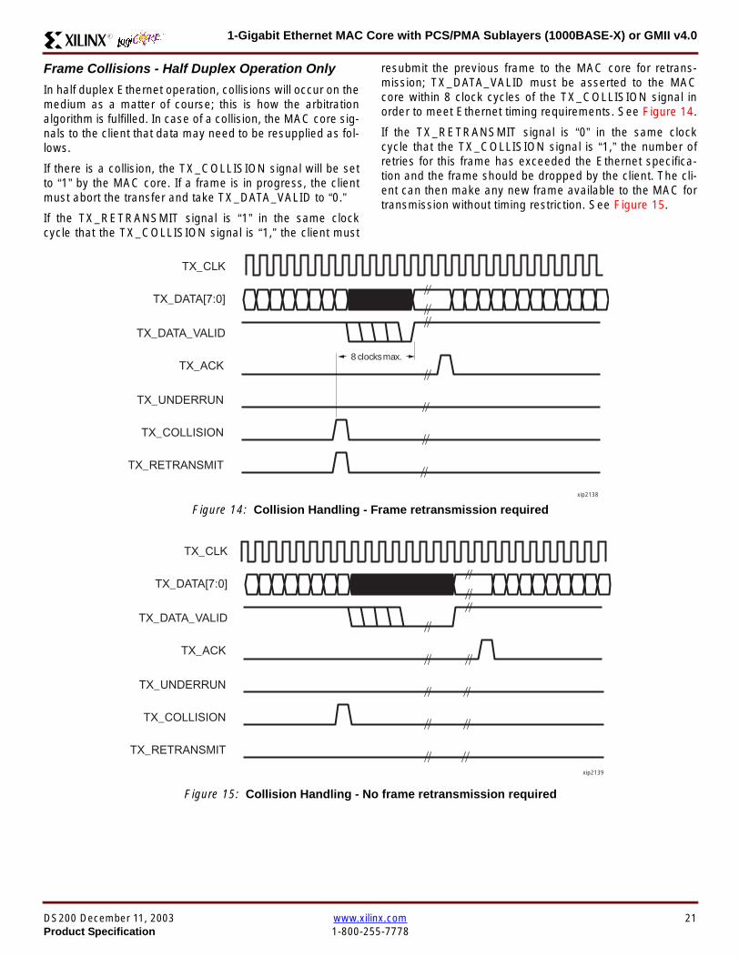
1-Gigabit Ethernet MAC Core with PCSPMA Sublayers (1000BASE-X) or GMII v40R
Frame Collisions - Half Duplex Operation Only
In half duplex Ethernet operation collisions will occur on themedium as a matter of course this is how the arbitrationalgorithm is fulfilled In case of a collision the MAC core sig-nals to the client that data may need to be resupplied as fol-lows
If there is a collision the TX_COLLISION signal will be setto ldquo1rdquo by the MAC core If a frame is in progress the clientmust abort the transfer and take TX_DATA_VALID to ldquo0rdquo
If the TX_RETRANSMIT signal is ldquo1rdquo in the same clockcycle that the TX_COLLISION signal is ldquo1rdquo the client must
resubmit the previous frame to the MAC core for retrans-mission TX_DATA_VALID must be asserted to the MACcore within 8 clock cycles of the TX_COLLISION signal inorder to meet Ethernet timing requirements See Figure 14
If the TX_RETRANSMIT signal is ldquo0rdquo in the same clockcycle that the TX_COLLISION signal is ldquo1rdquo the number ofretries for this frame has exceeded the Ethernet specifica-tion and the frame should be dropped by the client The cli-ent can then make any new frame available to the MAC fortransmission without timing restriction See Figure 15
Figure 14 Collision Handling - Frame retransmission required
Figure 15 Collision Handling - No frame retransmission required
TX_CLK
TX_DATA[70]
TX_DATA_VALID
TX_ACK
TX_UNDERRUN
TX_COLLISION
TX_RETRANSMIT
8 clocks max
xip2138
TX_CLK
TX_DATA[70]
TX_DATA_VALID
TX_ACK
TX_UNDERRUN
TX_COLLISION
TX_RETRANSMIT
xip2139
DS200 December 11 2003 wwwxilinxcom 21Product Specification 1-800-255-7778
1-Gigabit Ethernet MAC Core with PCSPMA Sublayers (1000BASE-X) or GMII v40 R
Interframe Gap Adjustment
The user can elect to vary the length of the inter fame gapIf this function is selected (via a configuration bit in thetransmitter control register see Configuration Registerson page 30) then the MAC will exert back pressure to delaythe transmission of the next frame until the requested num-ber of Idle cycles has elapsed The number of Idle cycles iscontrolled by the value on the TX_IFG_DELAY port at thestart of frame transmission Figure 16 shows the MAC oper-ating in this mode
Reducing the Inter fame gap to below the IEEE 8023-2002minimum of 12 Idles is supported in Full Duplex onlydesigns and will transmit an absolute minimum of 4 Idles Ifthe Interframe gap adjustment is reduced below 12 Idlesthen the accuracy of the Optional Statistical Gathering(statistics_gathering=true) Counters cannot be guaranteedHowever the TX_STATISTIC_VECTOR andRX_STATISTIC_VECTOR will always remain correct
Transmitter Statistics Vector
The statistics for the frame transmitted are contained withinthe TX_STATISTICS_VECTOR The vector is driven syn-chronously by the transmitter clock TX_CLK followingframe transmission The bit field definition for the Vector isdefined in Table 14
All bit fields with the exception of BYTE_VALID are validonly when the TX_STATISTICS_VALID is asserted This isillustrated in Figure 17 BYTE_VALID is significant on everyTX_CLK cycle
TX_STATISTICS_VECTOR bits 25 down to 17 inclusive arefor half duplex only and will be set to logic 0 when operatingin full duplex mode
Figure 16 Interframe Gap Adjustment
TX_CLK
TX_DATA[70]
TX_DATA_VALID
TX_ACK
DA SA
TX_IFG_DELAY
IFG ADJUST VALUE
0x0D
13 Idles inserted
DA
Next IFG ADJUST VALUE
xip2140
Figure 17 Transmitter Statistics Vector Timing
TX_CLK
TX_STATISTICS_VECTOR[280]
TX_STATISTICS_VALID
xip2141
22 wwwxilinxcom DS200 December 11 20031-800-255-7778 Product Specification
1-Gigabit Ethernet MAC Core with PCSPMA Sublayers (1000BASE-X) or GMII v40R
Table 14 Bit Definition for the Transmitter Statistics Vector
TX_STATISTICS_VECTOR Name Description
28 PAUSE_FRAME_TRANSMITTEDAsserted if the previous frame was a pause framethat the MAC itself initiated in response to aPAUSE_REQ assertion
27 BYTE_VALID
Asserted if a MAC frame byte (DA to FCS inclusive)is in the process of being transmitted This is valid onevery clock cycle
Do not use this as an enable signal to indicate thatdata is present on GMII_TXD[70]
26 Reserved Returns logic 0
25 down to 22 TX_ATTEMPTS[30]
The number of attempts that have been made totransmit the previous frame This is a 4-bit number0 should be interpreted as 1 attempt 1 as 2attempts up until 15 as 16 attempts
21 Reserved Returns logic 0
20 EXCESSIVE_COLLISIONAsserted if a collision has been detected on each ofthe last 16 attempts to transmit the previous frame
19 LATE_COLLISIONAsserted if a late collision occurred during frametransmission
18 EXCESSIVE_DEFERRALAsserted if the previous frame was deferred for anexcessive amount of time as defined by the constantldquomaxDeferTimerdquo in IEEE 8023-2002
17 TX_DEFERRED Asserted if transmission of the frame was deferred
16 VLAN_FRAMEAsserted if the previous frame contained a VLANidentifier in the LengthType field when transmitterVLAN operation is enabled
15 down to 5 FRAME_LENGTH_COUNTThe length of the previous frame in number of bytesThe count will stick at 2047 for any Jumbo frameslarger than this value
4 CONTROL_FRAMEAsserted if the previous frame had the special MACControl Type code 88-08 in the LengthType field
3 UNDERRUN_FRAMEAsserted if the previous frame contained anunderrun error
2 MULTICAST_FRAMEAsserted if the previous frame contained a multicastaddress in the Destination Address field
1 BROADCAST_FRAMEAsserted if the previous frame contained abroadcast address in the Destination Address field
0 SUCCESSFUL_FRAMEAsserted if the previous frame was transmittedwithout error
DS200 December 11 2003 wwwxilinxcom 23Product Specification 1-800-255-7778
1-Gigabit Ethernet MAC Core with PCSPMA Sublayers (1000BASE-X) or GMII v40 R
Receiver
Normal Frame Reception
The timing of a normal inbound frame transfer can be seenin Figure 18 The client must be prepared to accept data atany time there is no buffering within the MAC to allow forlatency in the receive client Once frame reception begins
data is transferred on consecutive clock cycles to thereceive client until the frame is complete The MAC assertsthe RX_GOOD_FRAME signal to indicate that the framewas successfully received and that the frame should beanalyzed by the client
Frame parameters (destination address source addresslengthtype and optionally FCS) are supplied on the databus according to the timing diagram The abbreviations arethe same as those described in Table 13 on page 16
If the LengthType field in the frame has the Length interpre-tation and this indicates that the inbound frame has beenpadded to meet the Ethernet minimum frame size specifica-tion then this padding will not be passed to the client in thedata payload The exception to this is in the case whereFCS passing is enabled see Client-Supplied FCS Pass-ing on page 25
Therefore when Client-Supplied FCS passing is disabledRX_DATA_VALID = lsquo0rsquo between frames for the duration ofthe Padding field (if present) the FCS field carrier exten-sion (if present) the interframe gap following the frame andthe preamble field of the next frame When Client-Supplied
FCS passing is enabled RX_DATA_VALID = lsquo0rsquo betweenframes for the duration of carrier extension (if present) theinterframe gap and the preamble field of the followingframe
RX_GOOD_FRAME RX_BAD_FRAME timing
Although the timing diagram in Figure 18 shows theRX_GOOD_FRAME signal asserted shortly after the lastvalid data on RX_DATA this is not always the case TheRX_GOOD_FRAME or RX_BAD_FRAME signals areasserted only after all frame checks are completed This isafter the FCS field has been received (and after reception ofcarrier extension if present)
Therefore either RX_GOOD_FRAME or RX_BAD_FRAMEis asserted following frame reception at the beginning of theinterframe gap
Figure 18 Normal Frame Reception
RX_CLK
RX_DATA[70]
RX_DATA_VALID
RX_GOOD_FRAME
RX_BAD_FRAME
DA SA DATALT
xip2142
24 wwwxilinxcom DS200 December 11 20031-800-255-7778 Product Specification
1-Gigabit Ethernet MAC Core with PCSPMA Sublayers (1000BASE-X) or GMII v40R
Frame Reception with Errors
The case of an unsuccessful frame reception (for examplea fragment frame or a frame with an incorrect FCS) can beseen in Figure 19 In this case the RX_BAD_FRAME signal
is asserted to the client at the end of the frame It is then theresponsibility of the client to drop the data already trans-ferred for this frame
Figure 19 Frame Reception with Error
Client-Supplied FCS Passing
If the MAC core is configured to pass the FCS field to the cli-ent (see Configuration Registers on page 30) then this ishandled as shown in Figure 20
In this case any padding inserted into the frame to meetEthernet minimum frame length specifications will be leftintact and passed to the client
Note that even though the FCS is passed up to the client itis also verified by the MAC core and RX_BAD_FRAMEasserted if the FCS check fails
RX_CLK
RX_DATA[70]
RX_DATA_VALID
RX_GOOD_FRAME
RX_BAD_FRAME
DA SA DATALT
xip2144
Figure 20 Frame Reception with In-Band FCS Field
RX_CLK
RX_DATA[70]
RX_DATA_VALID
RX_GOOD_FRAME
RX_BAD_FRAME
DA SA DATALT FCS
xip2145
DS200 December 11 2003 wwwxilinxcom 25Product Specification 1-800-255-7778
1-Gigabit Ethernet MAC Core with PCSPMA Sublayers (1000BASE-X) or GMII v40 R
VLAN Tagged Frames
The reception of a VLAN tagged frame (if enabled) can beseen in Figure 21 The VLAN frame is passed to the clientso that the frame may be identified as VLAN tagged this is
followed by the Tag Control Information bytes V1 and V2More information on the interpretation of these bytes maybe found in IEEE 8023-2002 standard
Maximum Permitted Frame Length
The maximum legal length of a frame specified in IEEE8023-2002 is 1518 bytes for non-VLAN tagged framesVLAN tagged frames may be extended to 1522 bytesWhen jumbo frame handling is disabled and the corereceives a frame which exceeds the maximum legal lengthRX_BAD_FRAME will be asserted When jumbo framehandling is enabled frames which are longer than the legalmaximum are received in the same way as shorter frames
For more information on enabling and disabling jumboframe handling see Configuration Registers on page 30
LengthType Field Error Checks
Enabled
Default operation is with the LengthType error checkingenabled (see Receiver Configuration Word 1 on page 31)In this mode the following checks are made on all framesreceived If either of these checks fail then the frame ismarked as BAD
bull A value in the LengthType field that is greater than orequal to decimal 46 but less than decimal 1536 (aLength interpretation) is checked against the actualdata length received
bull A value in the LengthType field that is less thandecimal 46 is checked to see that the data field ispadded to exactly 46 bytes (so that the resultant frameis minimum frame size 64 bytes total in length)
Furthermore if Padding is indicated (the LengthType fieldis less than decimal 46) and Client-Supplied FCS Passing isdisabled then the Length value in the LengthType field willbe used to deassert RX_DATA_VALID after the indicatednumber of data bytes so that the Padding bytes areremoved from the frame
Disabled
When the LengthType error checking is disabled (seeReceiver Configuration Word 1 on page 31) theLengthType error checks described above are not per-formed A frame containing only these errors will be markedas GOOD
Furthermore if Padding is indicated and Client-SuppliedFCS Passing is disabled then a Length Value in theLengthType field will not be used to deassertRX_DATA_VALID Instead RX_DATA_VALID will be deas-serted before the start of the FCS field in this way any pad-ding will not be removed from the frame
Figure 21 Reception of a VLAN Tagged Frame
RX_CLK
RX_DATA[70]
RX_DATA_VALID
RX_GOOD_FRAME
RX_BAD_FRAME
DA SA DATALT
81 00 V1 V2
VLANtag
xip2146
26 wwwxilinxcom DS200 December 11 20031-800-255-7778 Product Specification
1-Gigabit Ethernet MAC Core with PCSPMA Sublayers (1000BASE-X) or GMII v40R
Receiver Statistics Vector
The statistics for the frame received are contained withinthe RX_STATISTICS_VECTOR The vector is driven syn-chronously by the receiver clock RX_CLK following framereception The bit field definition for the Vector is defined inTable 15
All bit fields with the exception of BYTE_VALID are validonly when the RX_STATISTICS_VALID is asserted This isillustrated in Figure 22 BYTE_VALID is significant on everyRX_CLK cycle
Figure 22 Receiver Statistics Vector Timing
RX_CLK
RX_STATISTICS_VECTOR[220]
RX_STATISTICS_VALID
xip2147
Table 15 Bit Definition for the Receiver Statistics Vector
RX_STATISTICS_VECTOR Name Description
22LENGTHTYPE Out ofRange
Asserted if the lengthtype field contained a length valuethat did not match the number of MAC client data bytesreceived Also high if the lengthtype field indicated thatthe frame contained padding but the number of MAC cli-ent data bytes received was not equal to 64 bytes (min-imum frame size)
The exception to the above is when the LengthTypeField Error Checks are disabled in which case this bitwill not be asserted
21 BAD_OPCODE
Asserted if the previous frame was error-free andcontained the special Control Frame identifier in theLengthType field but contained an opcode that isunsupported by the MAC (Any Opcode other thanPAUSE)
20 FLOW_CONTROL_FRAME
Asserted if the previous frame was error-freecontained the special Control Frame identifier in theLengthType field contained a Destination Addressthat matched either the MAC Control MulticastAddress or the configured source address of the MACcontained the supported PAUSE opcode and wasacted upon by the MAC
19 BYTE_VALID
Asserted if a MAC frame byte (DA to FCS inclusive) isin the process of being received This is valid on everyclock cycle
Do not use this as an enable signal to indicate thatdata is present on RX_DATA[70]
18 VLAN_FRAMEAsserted if the previous frame contained a VLANidentifier in the LengthType field when receiver VLANoperation is enabled
DS200 December 11 2003 wwwxilinxcom 27Product Specification 1-800-255-7778
1-Gigabit Ethernet MAC Core with PCSPMA Sublayers (1000BASE-X) or GMII v40 R
17 OUT_OF_BOUNDS
Asserted if the previous frame exceeded the specifiedIEEE8023-2002 maximum legal length (seeMaximum Permitted Frame Length on page 26) Thisis only valid if Jumbo frames are disabled
16 CONTROL_FRAMEAsserted if the previous frame contained the specialControl Frame identifier in the LengthType field
15 down to 5 FRAME_LENGTH_COUNTThe length of the previous frame in number of bytesThe count will stick at 2047 for any Jumbo frameslarger than this value
4 MULTICAST_FRAMEAsserted if the previous frame contained a multicastaddress in the Destination Address field
3 BROADCAST_FRAMEAsserted if the previous frame contained the broadcastaddress in the Destination Address field
2 FCS_ERRORAsserted if the previous frame received had anincorrect FCS value or the MAC detected error codesduring frame reception
1 BAD_FRAME1 Asserted if the previous frame received containederrors
0 GOOD_FRAME1 Asserted if the previous frame received was error-free
1 If the LengthType Field Error Checks are disabled then a frame which contains this type of error will be marked as a GOOD_FRAMEproviding no additional errors were detected
Table 15 Bit Definition for the Receiver Statistics Vector
RX_STATISTICS_VECTOR Name Description
28 wwwxilinxcom DS200 December 11 20031-800-255-7778 Product Specification
1-Gigabit Ethernet MAC Core with PCSPMA Sublayers (1000BASE-X) or GMII v40R
Flow ControlThe flow control block is designed to Clause 31 of the IEEE8023-2002 standard The MAC may be configured to sendpause frames and to act upon their reception These twobehaviors can be configured asymmetrically see Configu-ration Registers on page 30
Transmitting a PAUSE Control Frame
The client initiates a flow control frame by assertingPAUSE_REQ while the pause value is on the PAUSE_VALbus These signals are synchronous to TX_CLK The timingof this can be seen in Figure 23
If the MAC core is configured to support transmit flow con-trol this action causes the core to transmit a PAUSE controlframe on the link with the PAUSE parameter set to thevalue on PAUSE_VAL in the cycle when PAUSE_REQ wasasserted This will not disrupt any frame transmission inprogress but will take priority over any pending frame trans-
mission This frame will be transmitted even if the transmit-ter is in the paused state itself
Receiving a Pause Control Frame
When an error-free frame is received by the MAC core thefollowing checks are made
1 The Destination Address field is matched against theMAC Control Multicast address or the configuredSource Address for the MAC (see ConfigurationRegisters on page 30)
2 The LengthType field is matched against the MACControl Type code
3 The opcode field contents are matched against thePAUSE opcode if check 2 is true
If any of the above checks are false or the MAC Flow Con-trol logic for the receiver is disabled the frame is ignored bythe Flow Control logic and passed up to the client
If the frame passes all of the above checks is of minimumlegal size and the MAC Flow Control logic for the receiver isenabled the pause value parameter in the frame is thenused to inhibit transmitter operation for the time defined inthe IEEE8023-2002 specification This inhibit is imple-mented using the same back pressure scheme shown inFigure 12 Because the received pause frame has beenacted upon it is passed to the client with RX_BAD_FRAMEasserted to indicate to the client that it should be dropped
Reception of any frame for which check 2 is true and whichis not of legal minimum length is considered an invalid Con-trol frame This will be ignored by the Flow Control logic andpassed to the client with RX_BAD_FRAME asserted
Figure 23 Pause Request Timing
TX_CLK
PAUSE_VAL[150]
PAUSE_REQ
xip2148
DS200 December 11 2003 wwwxilinxcom 29Product Specification 1-800-255-7778
1-Gigabit Ethernet MAC Core with PCSPMA Sublayers (1000BASE-X) or GMII v40 R
Optional Management Interface(management_interface=true)The management interface is a processor-independentinterface with standard address data and control signals Itmay be used as is or a wrapper may be applied (not sup-plied) to interface to common bus architectures
This interface is used for
bull Configuration of the MAC core
bull Access to optional statistics counters for use by higherlayers for example SNMP
bull access through the MDIO interface to the managementregisters located in the PHY attached to the MAC core
The management interface is accessed differently depend-ing on the type of transaction a truth table showing whichaccess method is required for each transaction type isshown in Table 16 These access methods are described inthe following sections
HOST_CLK Frequency
The management interface clock HOST_CLK is used toderive the MDIO clock MDC and is therefore subject tosome frequency restrictions This HOST_CLK must be
ge 10 MHz
le 100 MHz
Configuring the MAC core to derive the MDC signal fromthis clock is detailed in MDIO Interface on page 37
Configuration Registers
After power up or reset the client may reconfigure the coreparameters from their defaults such as flow control supportConfiguration changes can be written at any time Both thereceiver and transmitter logic will only respond to configura-tion changes during Inter Frame Gaps The exceptions tothis are the configurable resets which take effect immedi-ately
Configuration of the MAC core is performed through a reg-ister bank accessed through the management interfaceThe configuration registers available in the core are detailedin Table 17 As can be seen the address has some implicitdonrsquot care bits any access to an address in the rangesshown will perform a 32-bit read or write from the same con-figuration word
Table 16 Management Interface Transaction Types
Transaction HOST_MIIM_SEL HOST_ADDR[9]
Configuration 0 1
Statistics 0 0
MIIM access 1 X
Table 17 Configuration Registers
Address Description
0x200-0x23F Receiver Configuration (Word 0)
0x240-0x27F Receiver Configuration (Word 1)
0x280-0x2BF Transmitter Configuration
0x2C0-0x2FF Flow Control Configuration
0x300-0x33F Reserved
0x340-0x37F Management Configuration
30 wwwxilinxcom DS200 December 11 20031-800-255-7778 Product Specification
1-Gigabit Ethernet MAC Core with PCSPMA Sublayers (1000BASE-X) or GMII v40R
The register contents for the two receiver configuration words can be seen in Table 18 and Table 19
Notes1 In changing the receiverrsquos mode from Half Duplex to Full Duplex there is a period of time of up to 24 us following the mode change
when no new receiver statistics can be stored in the optional Statistical Counters
Table 18 Receiver Configuration Word 0
Bit Default Value Description
31-0 All 0rsquos
Pause frame MAC Source Address[310] This address is used by the MAC tomatch against the Destination Address of any incoming flow control frames It isalso used by the flow control block as the Source Address (SA) for any outboundflow control frames
The address is ordered so the first byte transmittedreceived is the lowestpositioned byte in the register for example a MAC address ofAA-BB-CC-DD-EE-FF would be stored in Address[470] as 0xFFEEDDCCBBAA
Table 19 Receiver Configuration Word 1
Bit Default Value Description
15-0 All 0rsquos Pause frame MAC Source Address[4732] See description in Table 18
24-16 NA Reserved
25 0
LengthType Error Check Disable When this bit is set to ldquo1rdquo the core will notperform the LengthType field error checks as described in LengthType FieldError Checks on page 26 When this bit is set to ldquo0rdquo the LengthType field checkswill be performed this is normal operation
26 0Half Duplex If ldquo1rdquo the receiver will operate in half duplex mode If ldquo0rdquo the receiverwill operate in full duplex mode Has no effect if XCO parameterhalf_duplex_capable = false
27 0VLAN Enable When this bit is set to ldquo1rdquo VLAN tagged frames will be acceptedby the receiver
28 1Receiver Enable If set to ldquo1rdquo the receiver block will be operational If set to ldquo0rdquothe block will ignore activity on the physical interface RX port
29 0
In-band FCS Enable When this bit is ldquo1rdquo the MAC receiver will pass the FCS fieldup to the client as described in Client-Supplied FCS Passing on page 25 Whenit is ldquo0rdquo the client will not be passed the FCS In both cases the FCS will beverified on the frame
30 0Jumbo Frame Enable When this bit is set to ldquo1rdquo the MAC receiver will acceptframes over the specified IEEE8023-2002 maximum legal length When this bitis ldquo0rdquo the MAC will only accept frames up to the specified maximum
31 0Reset When this bit is set to ldquo1rdquo the receiver will be reset The bit will thenautomatically revert to ldquo0rdquo Note that this reset will also set all of the receiverconfiguration registers to their default values
DS200 December 11 2003 wwwxilinxcom 31Product Specification 1-800-255-7778
1-Gigabit Ethernet MAC Core with PCSPMA Sublayers (1000BASE-X) or GMII v40 R
The register contents for the Transmitter Configuration Word are described in Table 20
Notes1 In changing the transmitterrsquos mode from Half Duplex to Full Duplex there is a period of time of up to 24 us following the mode change
when no new transmitter statistics can be stored in the optional Statistical Counters
Table 20 Transmitter Configuration Word
Bit Default Value Description
24-0 NA Reserved
25 0
Interframe Gap Adjust Enable If lsquo1rsquo the transmitter will read the value on the portTX_IFG_DELAY at the start of frame transmission and adjust the interframe gapfollowing the frame accordingly See Interframe Gap Adjustment on page 22 Ifldquo0rdquo the transmitter will output a minimum Inter Frame Gap of twelve clock cyclesas specified in IEEE8023-2002
26 0Half Duplex If lsquo1rsquo the transmitter will operate in half duplex mode If lsquo0rsquo thetransmitter will operate in full duplex mode Has no effect if XCO parameterhalf_duplex_capable = false
27 0VLAN Enable When this bit is set to 1 the transmitter will allow the transmissionof VLAN tagged frames
28 1Transmit Enable When this bit is 1 the transmitter is operational When it is 0the transmitter is disabled
29 0
In-band FCS Enable When this bit is lsquo1rsquo the MAC transmitter will expect the FCSfield to be passed in by the client as described in Client-Supplied FCS Passingon page 17 When this bit is ldquo0rdquo the MAC transmitter will append padding asrequired compute the FCS and append it to the frame
30 0
Jumbo Frame Enable When this bit is set to ldquo1rdquo the MAC transmitter will sendframes that are greater than the specified IEEE8023-2002 maximum legallength When this bit is ldquo0rdquo the MAC will only send frames up to the specifiedmaximum
31 0Reset When this bit is set to ldquo1rdquo the transmitter will be reset The bit will thenautomatically revert to ldquo0rdquo Note that this reset will also set all of the transmitterconfiguration registers to their default values
32 wwwxilinxcom DS200 December 11 20031-800-255-7778 Product Specification
1-Gigabit Ethernet MAC Core with PCSPMA Sublayers (1000BASE-X) or GMII v40R
The register contents for the Flow Control Configuration Word are described in Table 21
The register contents for the Management Configuration Word are described in Table 22
Writing to the configuration registers through the manage-ment interface is depicted in Figure 24 When accessing theconfiguration registers (ie when HOST_ADDR[9] = lsquo1rsquo andHOST_MIIM_SEL = lsquo0rsquo) the upper bit of HOST_OPCODEfunctions as an Active Low write enable signal The lowerHOST_OPCODE bit is a ldquodonrsquot carerdquo
Reading from the configuration register words is similar butthe upper HOST_OPCODE bit should be lsquo1rsquo This is shownin Figure 25 In this case the contents of the register appearon HOST_RD_DATA the HOST_CLK edge after the regis-ter address is asserted onto HOST_ADDR
Table 21 Flow Control Configuration Word
Bit Default Value Description
28-0 NA Reserved
29 1
Flow Control Enable (RX) When this bit is lsquo1rsquo received flow control frames willinhibit the transmitter operation as described in Receiving a Pause ControlFrame on page 29 When this bit is lsquo0rsquo received flow control frames will alwaysbe passed up to the client
30 1Flow Control Enable (TX) When this bit is lsquo1rsquo asserting the PAUSE_REQ signalwill send a flow control frame out from the transmitter When this bit is 0 assertingthe PAUSE_REQ signal has no effect
31 NA Reserved
Table 22 Management Configuration Word
Bits Default Value Description
4-0 All 0rsquos Clock Divide[40] See MDIO Interface on page 37
5 0MDIO Enable When this bit is 1 the MDIO interface can be used to accessattached PHY devices When this bit is 0 the MDIO interface is disabled and theMDIO signals remain inactive
31-6 NA Reserved
Figure 24 Configuration Register Write Timing
HOST_CLK
HOST_ADDR[80]
HOST_ADDR[9]
HOST_OPCODE[1]
HOST_MIIM_SEL
HOST_WR_DATA[310]xip2149
Figure 25 Configuration Register Read Timing
HOST_CLK
HOST_ADDR[80]
HOST_ADDR[9]
HOST_OPCODE[1]
HOST_MIIM_SEL
HOST_RD_DATA[310]
xip2150
DS200 December 11 2003 wwwxilinxcom 33Product Specification 1-800-255-7778
1-Gigabit Ethernet MAC Core with PCSPMA Sublayers (1000BASE-X) or GMII v40 R
Optional Statistical Gathering(statistics_gathering=true)
During operation the MAC core collects statistics on thesuccess and failure of various operations for processing by
station management entities (STA) further up the protocolstack These statistics are accessed by the host through theoptional management interface A complete list of statisticssupported is described in Table 23
Table 23 Statistics Registers
Address Name Description
0x000 Frames Received OK1 A count of error-free frames received
0x001 Frame Check Sequence Errors A count of received frames that failed the CRC check and were at least64 bytes in length
0x002 Broadcast Frames Received OK1A count of frames that were successfully received and were directed tothe broadcast group address
0x003 Multicast Frames Received OK1 A count of frames that were successfully received and were directed toa non broadcast group address
0x004 64 byte Frames Received OK1 A count of error-free frames received that were 64 bytes in length
0x005 65-127 byte Frames Received OK1A count of error-free frames received that were between 65 and 127bytes in length
0x006 128-255 byte Frames Received OK1A count of error-free frames received that were between 128 and 255bytes in length
0x007 256-511 byte Frames Received OK1A count of error-free frames received that were between 256 and 511bytes in length
0x008512-1023 byte Frames ReceivedOK1
A count of error-free frames received that were between 512 and 1023bytes in length
0x0091024-MaxFrameSize byte FramesReceived OK1
A count of error-free frames received that were between 1024 bytes andthe specified IEEE8023-2002 maximum legal length (see MaximumPermitted Frame Length on page 26)
0x00A Control Frames Received OKA count of error-free frames received that contained the specialControl Frame identifier in the LengthType field
0x00B LengthType Out of Range
A count of frames received that were at least 64 bytes in length wherethe lengthtype field contained a length value that did not match thenumber of MAC client data bytes received
The counter also increments for frames in which the lengthtype fieldindicated that the frame contained padding but where the number ofMAC client data bytes received was greater than 64 bytes (minimumframe size)
The exception to the above is when the LengthType Field Error Checksare disabled in which case this counter will not increment
0x00C VLAN Tagged Frames Received OKA count of error-free VLAN frames received This counter will only incre-ment when the receiver is configured for VLAN operation
0x00D Pause Frames Received OK
A count of error-free frames received that contained the MAC Controltype identifier 88-08 in the LengthType field contained a Destinationaddress that matched either the MAC Control multicast address or theconfigured source address of the MAC contained the PAUSE opcodeand were acted upon by the MAC
0x00EControl Frames Received withUnsupported Opcode
A count of error-free frames received that contained the MAC Controltype identifier 88-08 in the LengthType field but were received with anopcode other than the PAUSE opcode
34 wwwxilinxcom DS200 December 11 20031-800-255-7778 Product Specification
1-Gigabit Ethernet MAC Core with PCSPMA Sublayers (1000BASE-X) or GMII v40R
0x00F Oversize Frames Received OK1A count of otherwise error-free frames received that exceeded the max-imum legal frame length specified in IEEE 8023-2002 (see MaximumPermitted Frame Length on page 26)
0x010 Undersize frames receivedA count of the number of frames received that were less than 64 bytesin length but were otherwise well formed
0x011 Fragment frames receivedA count of the number of frames received that were less than 64 bytesin length and had a bad Frame Check Sequence field
0x012 Received bytesA count of bytes of frames that are received (Destination Address toFrame Check Sequence inclusive)
0x013 Transmitted bytesA count of bytes of frames that are transmitted (Destination Address toFrame Check Sequence inclusive)
0x020 Frames Transmitted OK A count of error-free frames transmitted
0x021 Broadcast Frames Transmitted OK A count of error-free frames that were transmitted to the broadcastaddress
0x022 Multicast Frames Transmitted OK A count of error-free frames that were transmitted to a group destina-tion address other than broadcast
0x023 Underrun Errors
A count of frames that would otherwise be transmitted by the core butcould not be completed due to the assertion of TX_UNDERRUN duringthe frame transmission This will not count frames which are less than64 bytes in length
0x024 Control Frames Transmitted OKA count of error-free frames transmitted that contained the MACControl Frame type identifier 88-08 in the LengthType field
0x025 64 byte Frames Transmitted OK A count of error-free frames transmitted that were 64 bytes in length
0x026 65-127 byte Frames Transmitted OKA count of error-free frames transmitted that were between 65 and 127bytes in length
0x027128-255 byte Frames TransmittedOK
A count of error-free frames transmitted that were between 128 and 255bytes in length
0x028256-511 byte Frames TransmittedOK
A count of error-free frames transmitted that were between 256 and 511bytes in length
0x029512-1023 byte Frames TransmittedOK
A count of error-free frames transmitted that were between 512 and1023 bytes in length
0x02A1024-MaxFrameSize byte FramesTransmitted OK
A count of error-free frames transmitted that were between 1024 and thespecified IEEE8023-2002 maximum legal length (see Maximum Per-mitted Frame Length on page 20)
0x02BVLAN Tagged Frames TransmittedOK
A count of error-free VLAN frames transmitted This counter will onlyincrement when the transmitter is configured for VLAN operation
0x02C Pause Frames Transmitted OKA count of error-free PAUSE frames generated and transmitted by thecore in response to an assertion of PAUSE_REQ
0x02D Oversize Frames Transmitted OKA count of otherwise error-free frames transmitted that exceeded themaximum legal frame length specified in IEEE 8023-2002 (see Maxi-mum Permitted Frame Length on page 20)
0x02E Single Collision Frames A count of frames that are involved in a single collision but are subse-quently transmitted successfully (Half Duplex Mode only)
Table 23 Statistics Registers (Continued)
Address Name Description
DS200 December 11 2003 wwwxilinxcom 35Product Specification 1-800-255-7778
1-Gigabit Ethernet MAC Core with PCSPMA Sublayers (1000BASE-X) or GMII v40 R
Each of these statistic registers is 64 bits wide and thereforemust be read in a two-cycle transfer The timing of this pro-cess is shown in Figure 26 Six clocks after the read trans-action is initiated the least significant word (LSW) of thestatistics counter appears on the HOST_RD_DATA bus
and a clock cycle later the most significant word (MSW)appears For accurate statistic values 64 clock ticks (ofTX_CLK for transmit statistics or RX_CLK for receive statis-tics) must elapse after the last frame is sent or receivedthrough the MAC core
0x02F Multiple Collision Frames A count of frames that are involved in more than one collision but aresubsequently transmitted successfully (Half Duplex Mode only)
0x040 Frames with Deferred Transmissions A count of frames whose transmission was delayed on its first attemptbecause the medium was busy (Half Duplex Mode only)
0x041 Late Collisions
A count of the times that a collision has been detected later than oneslotTime from the start of the packet transmission A late collision iscounted twice both as a collision and as a lateCollision (Half DuplexMode only)
0x042Frames Aborted due to Excesscollisions
A count of the frames that due to excessive collisions are not transmit-ted successfully (Half Duplex Mode only)
0x043 Carrier Sense ErrorsA count of times that the GMII_CRS signal was not asserted or wasdisasserted during the transmission of a frame without collision (HalfDuplex Mode only)
0x044 Frames with Excess DeferralA count of frames that deferred transmission for an excessive period oftime (Half Duplex Mode only)
1 If the LengthType Field Error Checks are disabled then these counters will still increment for received frames which contain this typeof error (providing no additional errors were detected)
Table 23 Statistics Registers (Continued)
Address Name Description
Figure 26 Statistic Register Read Timing
HOST_CLK
HOST_ADDR[80]
HOST_ADDR[9]
HOST_REQ
HOST_MIIM_SEL
HOST_RD_DATA[310]
6 CLOCKS
LSW MSW
xip2151
36 wwwxilinxcom DS200 December 11 20031-800-255-7778 Product Specification
1-Gigabit Ethernet MAC Core with PCSPMA Sublayers (1000BASE-X) or GMII v40R
MDIO Interface
The management interface is also used to access the MDIO(MII Management) interface of the MAC core this interfaceis used to access the Managed Information Block (MIB) ofthe PHY components attached to the MAC core
The MDIO interface supplies a clock to the externaldevices MDC This clock is derived from the HOST_CLKsignal using the value in the Clock Divide[40] configurationregister The frequency of the MDIO clock is given by thefollowing equation
The frequency of MDC given by this equation should notexceed 25 MHz in order to comply with the IEEE8023-2002 specification for this interface To prevent MDCfrom being out of specification the Clock Divide[40] valuepowers up at 00000 and while this value is in the register itis impossible to enable the MDIO interface
For details of the register map of PHY layer devices and afuller description of the operation of the MDIO interfaceitself see IEEE specification 8023-2002
Access to the MDIO interface through the managementinterface is depicted in the timing diagram in Figure 27
For MDIO transactions the following points apply
bull HOST_OPCODE maps to the OP (opcode) field of theMDIO frame
bull HOST_ADDR maps to the two address fields of theMDIO frame PHY_ADDR is HOST_ADDR[95] andREG_ADDR is HOST_ADDR[40]
bull HOST_WR_DATA[150] maps into the data field of the
MDIO frame when performing a write operation
bull The data field of the MDIO frame maps intoHOST_RD_DATA[150] when performing a readoperation
The MAC core signals to the host that it is ready for anMDIO transaction by asserting HOST_MIIM_RDY A read orwrite transaction on the MDIO is initiated by a pulse on the
fMDC
fHOST_CLK
1 Clock Divide[40]+( ) 2times-------------------------------------------------------------------=
Figure 27 MDIO Access Through Management Interface
HOST_CLK
HOST_ADDR[90]
HOST_OPCODE[10]
HOST_REQ
HOST_MIIM_SEL
HOST_RD_DATA[150]
HOST_WR_DATA[150]
HOST_RDY
If a read transaction is initiated the HOST_RD_DATA bus is valid at the point indicated If a write transaction is initiated the HOST_WR_DATA bus must be valid at the indicated point Simultaneous read and write is not permitted
xip2152
DS200 December 11 2003 wwwxilinxcom 37Product Specification 1-800-255-7778
1-Gigabit Ethernet MAC Core with PCSPMA Sublayers (1000BASE-X) or GMII v40 R
HOST_REQ signal This pulse is ignored if the MDIO inter-face already has a transaction in progress
The MAC core then disasserts the HOST_MIIM_RDY signalwhile the transaction across the MDIO is in progress Whenthe transaction across the MDIO interface has been com-pleted the HOST_MIIM_RDY signal will be asserted by theMAC core if the transaction is a read the data will also beavailable on the HOST_RD_DATA[150] bus at this time
Optional Configuration Vector(management_interface = false)If the optional Management interface is omitted from thecore all of relevant configuration signals are brought out of
the core These signals are bundled into theCONFIGURATION_VECTOR signal The bit mapping of theconfiguration vector signal is defined in Table 24 See thecorresponding entry in the configuration register tables forthe full description of each signal
Note that these configuration vector signals can bechanged by the user at any time however with the excep-tion of the reset and the flow control configuration signalsthey will not take effect until the current frame has com-pleted transmission or reception
The ldquoClockrdquo heading denotes which clock domain the con-figuration signal is registered into before use by the core Itis not necessary to drive the signal from this clock domain
Table 24 Configuration Vector Bit Definition
Bit(s)Configuration Register
cross reference Clock Description
47 downto 0
Receiver ConfigurationWord 0 bits 31-0 andReceiver ConfigurationWord 1 bits 15-0
RX_CLK
Pause frame MAC Source Address[470] This address isused by the MAC core to match against the DestinationAddress of any incoming flow control frames and as theSource Address for any outbound flow control frames
The address is ordered such that the first byte transmitted orreceived is the least significant byte in the register forexample a MAC address of AA-BB-CC-DD-EE-FF will bestored in bite [470] as 0xFFEEDDCCBBAA
48Receiver ConfigurationWord 1 bit 26
RX_CLKReceiver Half Duplex If lsquo1rsquo the receiver operates in halfduplex mode If lsquo0rsquo the receiver operates in full duplex modeHas no effect if XCO parameter half_duplex_capable = false
49Receiver ConfigurationWord 1 bit 27
RX_CLKReceiver VLAN Enable When this bit is set to 1 VLANtagged frames are accepted by the receiver
50Receiver ConfigurationWord 1 bit 28
RX_CLKReceiver Enable If set to 1 the receiver block is operationalIf set to 0 the block ignores activity on the physical interfaceRX port
51Receiver ConfigurationWord 1 bit 29
RX_CLK
Receiver In-band FCS Enable When this bit is lsquo1rsquo the MACreceiver will pass the FCS field up to the client as describedin Client-Supplied FCS Passing on page 25 When it is lsquo0rsquothe MAC receiver will not pass the FCS field In both casesthe FCS field will be verified on the frame
52Receiver ConfigurationWord 1 bit 30
RX_CLK
Receiver Jumbo Frame Enable When this bit is lsquo0rsquo thereceiver will not pass frames longer than the maximum legalframe size specified in IEEE 8023-2002 (see MaximumPermitted Frame Length on page 26) When it is lsquo1rsquo thereceiver will not have an upper limit on frame size
53Receiver ConfigurationWord 1 bit 31
NA
Receiver Reset When this bit is lsquo1rsquo the receiver is held inreset
This signal is an input to the reset circuit for the receiverblock See Reset circuit on page 42 for more information
54TransmitterConfiguration Word bit25
TX_CLK
Transmitter Interframe Gap Adjust enable If lsquo1rsquo then thetransmitter will read the value of the TX_IFG_DELAY port andset the Interframe Gap accordingly If lsquo0rsquo the transmitter willalways insert at least the legal minimum Interframe Gap
38 wwwxilinxcom DS200 December 11 20031-800-255-7778 Product Specification
1-Gigabit Ethernet MAC Core with PCSPMA Sublayers (1000BASE-X) or GMII v40R
55TransmitterConfiguration Word bit26
TX_CLK
Transmitter Half Duplex If lsquo1rsquo the transmitter operates in halfduplex mode If lsquo0rsquo the transmitter operates in full duplexmode Has no effect if XCO parameter half_duplex_capable= false
56TransmitterConfiguration Word bit27
TX_CLKTransmitter VLAN Enable When this bit is set to lsquo1rsquo thetransmitter allows the transmission of VLAN tagged frames
57TransmitterConfiguration Word bit28
TX_CLKTransmitter Enable When this bit is 1 the transmitter will beoperational When it is 0 the transmitter is disabled
58TransmitterConfiguration Word bit29
TX_CLK
Transmitter In-Band FCS Enable When this bit is lsquo1rsquo theMAC transmitter will expect the FCS field to be pass in by theclient as described in Client-Supplied FCS Passing onpage 17 When it is lsquo0rsquo the MAC transmitter will appendpadding as required compute the FCS and append it to theframe
59TransmitterConfiguration Word bit30
TX_CLK
Transmitter Jumbo Frame Enable When this bit is lsquo1rsquo theMAC transmitter will allow frames larger than the maximumlegal frame length specified in IEEE 8023-2002 to be sentWhen set to lsquo0rsquo the MAC transmitter will only allow frames upto the legal maximum to be sent
60TransmitterConfiguration Word bit31
NA
Transmitter Reset When this bit is lsquo1rsquo the MAC transmitter isheld in reset
This signal is an input to the reset circuit for the transmitterblock See Reset circuit on page 42 for more information
61Flow ControlConfiguration Word bit29
TX_CLK
Transmit Flow Control Enable When this bit is lsquo1rsquo assertingthe PAUSE_REQ signal causes the MAC core to send a flowcontrol frame out from the transmitter as described inReceiving a Pause Control Frame on page 29 When this bitis lsquo0rsquo asserting the PAUSE_REQ signal will have no effect
62Flow ControlConfiguration Word bit30
RX_CLK
Receive Flow Control Enable When this bit is lsquo1rsquo receivedflow control frames will inhibit the transmitter operation asdescribed in Receiving a Pause Control Frame on page 29When it is lsquo0rsquo received flow frames are passed up to theclient
63Receiver ConfigurationWord 1 bit 25
RX_CLK
LengthType Error Check Disable When this bit is lsquo1rsquo thecore will not perform the LengthType field error checks asdescribed in LengthType Field Error Checks on page 26When it is set to lsquo0rsquo the LengthType field checks will beperformed this is normal operation
Table 24 Configuration Vector Bit Definition (Continued)
Bit(s)Configuration Register
cross reference Clock Description
DS200 December 11 2003 wwwxilinxcom 39Product Specification 1-800-255-7778
1-Gigabit Ethernet MAC Core with PCSPMA Sublayers (1000BASE-X) or GMII v40 R
Optional GMII (physical_interface=gmii)The GMII is designed to IEEE 8023-2002 Clause 35 Thisutilizes IOrsquos of the Xilinx devices using inputoutput buffersand inputoutput flip-flops to maximize setup and hold mar-gins All IO logic is placed in the example wrapper that isdelivered with the core In addition all clock managementlogic for the core is instanced in this example wrapper thisallows multiple instances of the core to share clocks Theexample wrapper is provided in both VHDL and Verilog
Clock Management
Figure 28 illustrates the clock management used with theGMII interface All clocks illustrated have a frequency of125MHz
GTX_CLK must be provided to the MAC core This is a highquality clock which satisfies the IEEE8023-2002 require-ments It is expected that this clock will be derived from anexternal oscillator and connected into the device through anIBUFG as illustrated The clock source must then be routedonto a global clock network by connecting it to a BUFGWithin the MAC core this global clock is used by all MACtransmitter logic The MAC Client can obtain this clock byconnecting to the TX_CLK signal output from the coreGMII_TX_CLK is derived from this global clock by invertingit and routing it to an OBUF
GMII_RX_CLK is received through an IBUFG This clock isthen routed onto a global clock network by connecting it to aBUFG The resulting global clock is used by all MACreceiver logic
Figure 28 Clock Management with GMII
IBUFG
IBUFG
OBUF
BUFG
BUFG
TX_CLK
RX_CLK
GTX_CLK
GMII_TX_CLK
GMII_RX_CLK
Example Wrapper
xip2153
MAC Core
TX_CLK
RX_CLK
GMII_TX_CLK
GMII_RX_CLK
GTX_CLK
40 wwwxilinxcom DS200 December 11 20031-800-255-7778 Product Specification
1-Gigabit Ethernet MAC Core with PCSPMA Sublayers (1000BASE-X) or GMII v40R
Clock Sharing between Multiple cores
Figure 29 illustrates how it is possible to share clockresources across multiple instantiations of the core whenusing the optional GMII
GTX_CLK may be shared between multiple cores as illus-trated resulting in a common transmitter clock domainacross the device
A common receiver clock domain is not possible each corewill receive an independent receiver clock from its GMII asillustrated
Although not illustrated if the optional Management Inter-face is used HOST_CLK can also be shared betweencores
Figure 29 Clock Management with multiple instances of the MAC with GMII
IBUFG
OBUF
BUFG
TX_CLK
RX_CLK_1
GMII_TX_CLK_1
GMII_RX_CLK_1
MAC Core
TX_CLK
RX_CLK
GMII_TX_CLK
GMII_RX_CLK
GTX_CLK
MAC Core
TX_CLK
RX_CLK
GMII_TX_CLK
GMII_RX_CLK
GTX_CLK
IBUFG
BUFG
GTX_CLK
IBUFG
OBUF
GMII_TX_CLK_2
GMII_RX_CLK_2
BUFG
TX_CLK
RX_CLK_2
DS200 December 11 2003 wwwxilinxcom 41Product Specification 1-800-255-7778
1-Gigabit Ethernet MAC Core with PCSPMA Sublayers (1000BASE-X) or GMII v40 R
Reset circuit
Internally the core is divided up into clockreset domainswhich group together elements with the common clock andreset signals The reset circuitry for one of these domains isis illustrated in Figure 30 This circuit provides controllableskews on the reset nets within the design
More information on the operation and rationale behind thiscircuit can be found in Ken Chapmanrsquos Xilinx TechXclusiveldquoGet Smart About Resetrdquo athttpwwwxilinxcomsupporttechxclusivesglobal-techX19htm
Figure 30 Reset circuit for one clockreset domain
FDP
PRED
C
Q
FDP
PRED
C
Q
FDP
PRED
C
Q
FDP
PRED
C
Q
PRE PRE PRE
0
RESET
Management Reset
Clock
Core Registers
42 wwwxilinxcom DS200 December 11 20031-800-255-7778 Product Specification
1-Gigabit Ethernet MAC Core with PCSPMA Sublayers (1000BASE-X) or GMII v40R
Optional PCS with Ten-Bit Interface (TBI) for 1000BASE-X (physical_interface=tbi)The Full-Duplex Physical Coding Sublayer (PCS) for1000BASE-X is defined in IEEE 8023-2002 Clauses 36and 37 This functionality is only available in the Virtex-IIand Spartan3 families of FPGA devices
A block diagram of the PCS is shown in Figure 31 Themajor functional blocks of the PCS are
bull Transmit engine
bull Auto-negotiation block
bull Receive engine and synchronization block
bull PCS managed register block
bull 8B10B encoder block
bull 8B10B decoder block
bull Receiver elastic buffer
The PCS Managed Register Block is accessed through theMDIO Interface as if it were an externally connected PHYThis configures the operation of the PCS and Auto-Negoti-ation See PCS Managed Register Block
(physical_interface = tbi or phy) on page 49 The corersquosoptional Management Interface can be used to control theMDIO Interface as described by MDIO Interface onpage 37 When the optional Management Interface is notpresent the PCS Managed Register Block must beaccessed via an MDIO controller which is not provided bythe core
The 8B10B encodingdecoding blocks are implemented byconfiguring two Block SelectRAM modules as ROM Theseare used as large look-up tables The remaining PCS func-tionality such as code group encodingdecoding the Man-aged Register Block and Auto-Negotiation areimplemented in CLB logic
The Receiver Elastic buffer enables the 10-bit parallel datareceived from the PMA sublayer alternatively onPMA_RX_CLK0 and PMA_RX_CLK1 clock edges to betransferred onto the internal 125MHz clock domain derivedfrom GTX_CLK (see Clock Management) This buffer isimplemented in Distributed Memory
Figure 31 Functional Block Diagram of the 1-Gigabit Ethernet PCS with TBI Interface
PCS TRANSMIT ENGINE
PCS RECEIVE ENGINE ampSYNCHRONISATION
PCSMANAGEMENT
MDIOInterface
AUTO-NEGOTIATION
MAC TXInterface
MAC RXInterface
8B10BEncoder
8B10BDecoder
RX Elastic Buffer
TBI Interface
DS200 December 11 2003 wwwxilinxcom 43Product Specification 1-800-255-7778
1-Gigabit Ethernet MAC Core with PCSPMA Sublayers (1000BASE-X) or GMII v40 R
TBI Interface
The TBI is designed to IEEE 8023-2002 Clause 363 Thisutilizes IOrsquos of the Xilinx devices using inputoutput buffersand inputoutput flip-flops to maximize setup and hold mar-gins All IO logic is placed in the example wrapper that isdelivered with the core In addition all clock managementlogic for the core is instantiated in this example wrapperthis allows multiple instances of the core to share clocksThe example wrapper is provided in both VHDL and Verilog
Clock Management
Figure 32 illustrates the clock management used with theTBI interface
GTX_CLK must be provided to the MAC core This is a highquality clock of frequency 125MHz which satisfies theIEEE8023-2002 requirements It is expected that this clockwill be derived from an external oscillator and connected
into the device through an IBUFG as illustrated The clocksource must then be routed onto a global clock network byconnecting it to a BUFG Within the MAC core this globalclock is used by all MAC transmitter logic PMA_TX_CLK isderived from this global clock by inverting it and routing it toan OBUF
PMA_RX_CLK0 and PMA_RX_CLK1 are each receivedthrough an IBUFG These clocks are then routed onto glo-bal clock networks by connecting each to a BUFGPMA_RX_CLK0 and PMA_RX_CLK1 are each 625MHzclocks Data from the TBI is received alternatively on the ris-ing edge of PMA_RX_CLK0 followed by the rising edge ofPMA_RX_CLK1 using IOB Double-Data Rate input regis-ters This data is then written into the Receiver ElasticBuffer Data is read out of the Elastic Buffer using the globalclock derived from GTX_CLK all the remaining receiverlogic is synchronous to this clock
Figure 32 Clock Management for PCS with TBI Interface
IBUFG
IBUFG
OBUF
BUFG
BUFG
TX_CLK
RX_CLK
GTX_CLK
PMA_TX_CLK
PMA_RX_CLK0
MAC Core
RX ELASTICBUFFER
Example Wrapper
TX_CLK
RX_CLK
GTX_CLK
PMA_TX_CLK
PMA_RX_CLK0
IBUFGBUFGPMA_RX_CLK1
PMA_RX_CLK1
44 wwwxilinxcom DS200 December 11 20031-800-255-7778 Product Specification
1-Gigabit Ethernet MAC Core with PCSPMA Sublayers (1000BASE-X) or GMII v40R
Clock Sharing between Multiple cores
Figure 33 illustrates how it is possible to share clockresources across multiple instantiations of the core whenusing the optional PCS with TBI
GTX_CLK may be shared between multiple cores as illus-trated resulting in a common transmitter clock domainacross the device
Each core will receive independent PMA_RX_CLK0 andPMA_RX_CLK1 clocks from its TBI as illustrated whichcannot be shared
Although not illustrated if the optional Management Inter-face is used HOST_CLK can also be shared betweencores
Figure 33 Clock Management with multiple instances of the MAC with PCS and TBI
Reset circuit
The reset circuits within the MAC when the TBI interface is implemented is the same as that in the GMII case details ofthese circuits can be found on page 42
IBUFG
OBUF
BUFG
TX_CLK
RX_CLK
PMA_TX_CLK_1
PMA_RX_CLK0_1
MAC Core
RX ELASTICBUFFER
TX_CLK
RX_CLK
GTX_CLK
PMA_TX_CLK
PMA_RX_CLK0
IBUFGBUFGPMA_RX_CLK1_1
PMA_RX_CLK1
IBUFG
BUFG
GTX_CLK
IBUFG
OBUF
BUFG
TX_CLK
RX_CLK
PMA_TX_CLK_2
PMA_RX_CLK0_2
MAC Core
RX ELASTICBUFFER
TX_CLK
RX_CLK
GTX_CLK
PMA_TX_CLK
PMA_RX_CLK0
IBUFGBUFGPMA_RX_CLK1_2
PMA_RX_CLK1
DS200 December 11 2003 wwwxilinxcom 45Product Specification 1-800-255-7778
1-Gigabit Ethernet MAC Core with PCSPMA Sublayers (1000BASE-X) or GMII v40 R
Optional PCS and PMA Sublayers for 1000BASE-X (physical_interface=phy)The Full-Duplex Physical Coding Sublayer (PCS) withPhysical Medium Attachment (PMA) for 1000BASE-X isdefined in IEEE 8023-2002 Clauses 36 and 37 This func-tionality is only available in the Virtex-II Pro family of FPGAdevices
A block diagram of the PCS and PMA sublayers can beseen in Figure 34 The functional blocks of the PCS andPMA sublayers may replace the optional GMII interfaceThe functional blocks of the PCS and PMA sublayers are
bull PCS Transmit Engine
bull Auto-Negotiation block
bull Receive Engine and Synchronization Block
bull PCS Managed Register Block
bull Rocket IO Multi-Gigabit Transceiver
The PCS Managed Register Block is accessed through theMDIO Interface as if it were an externally connected PHYThis configures the operation of the PCS PMA sublayerand Auto-NegotiationSee PCS Managed Register Block(physical_interface = tbi or phy) on page 49 The corersquosoptional Management Interface can be used to control theMDIO Interface as described by MDIO Interface onpage 37 When the optional Management Interface is notpresent the PCS Managed Register Block must beaccessed via an MDIO controller which is not provided bythe core
The Rocket IO Multi-Gigabit Transceiver (MGT) providessome of the PCS layer functionality such as 8B10B encod-ingdecoding and the PMA serdes The remaining PCSfunctionality such as code group encodingdecoding theManaged Register Block and Auto-Negotiation are imple-mented in CLB logic
Figure 34 Functional Block Diagram of the 1-Gigabit Ethernet PCSPMA Sublayer Extension
PCS TRANSMIT ENGINE
PCS RECEIVE ENGINE ampSYNCHRONISATION
RO
CK
ET
IO
MU
LTI-
GIG
TR
AN
SC
EIV
ER
PCSMANAGEMENT
MDIOInterface
AUTO-NEGOTIATION
TXPTXN
RXPRXN
MAC TXInterface
MAC RXInterface
xip2154
46 wwwxilinxcom DS200 December 11 20031-800-255-7778 Product Specification
1-Gigabit Ethernet MAC Core with PCSPMA Sublayers (1000BASE-X) or GMII v40R
Clock Management
Figure 35 illustrates the clock management that should beused with the optional PCS and PMA sublayers for1000BASE-X This logic is implemented in the examplewrapper that is delivered with the core This provides flexi-bility because the design can be modified to use eitherREFCLK or BREFCLK (please refer to Rocket IO docu-mentation) It would also allow multiple instances of the coreto share clocks The example wrapper is provided in bothVHDL and Verilog
(B)REFCLK must be provided to the MAC core This clockmust be derived from an external oscillator and connectedto the core through an IBUFG as illustrated (B)REFCLK isa high quality clock of frequency 625 MHz which satisfiesthe Rocket IO Multi-Gigabit Transceiver (MGT) require-ments
(B)REFCLK is routed to both the core and a DCM From theDCM the CLK2X180 output is routed to a BUFG to providethe device with a global 125 MHz clock (connected toUSERCLK2 input on the core) Within the core bothTX_CLK and RX_CLK share this global 125 MHz clocksource which is used by all transmitter and receiver logicThis is made possible by the RX_ELASTIC_BUFFER func-tionality of the Rocket IO MGT (refer to Virtex-II Pro docu-mentation) The MAC Client can obtain this clock byconnecting to either the TX_CLK or the RX_CLK signalsoutput from the core
From the DCM the CLK0 output is routed to a BUFG to pro-vide the device with a global 625MHz clock This is con-nected to the USRCLK input of the core
Figure 35 Clock Management with PCSPMA Sublayers
DCM
CLKIN CLK0
CLK2X180FB
BUFG
BUFG
IBUFG
TX_CLK
RX_CLK
(B)REFCLK
TXUSRCLK
(B)REFCLK
TXUSRCLK2RXUSRCLKRXUSRCLK2
GT_ETHERNET
Example Wrapper
xip2155
MAC Core
(B)REFCLK
USRCLK
USRCLK2
TX_CLK
RX_CLK
DS200 December 11 2003 wwwxilinxcom 47Product Specification 1-800-255-7778
1-Gigabit Ethernet MAC Core with PCSPMA Sublayers (1000BASE-X) or GMII v40 R
Clock Sharing between Multiple Cores
Figure 36 illustrates how it is possible to share clockresources across multiple instantiations of the core whenusing the optional PCSPMA sublayers For each coreUSERCLK and USERCLK2 must always be derived asshown from the BREFCLK or REFCLK used by that core
Note that when using the fixed routing resources of BREF-CLK Rocket IO MGTs along the top edge of the devicemust use a separate BREFCLK routing resource to thosealong the bottom edge of the device (Refer to Virtex-II Prodocumentation)
Although not illustrated if the optional Management Inter-face is used HOST_CLK can also be shared betweencores
Figure 36 Clock Management with multiple instances of the MAC with PCS and PMA sublayers
Reset circuit
The reset circuits within the MAC when the PCS and PMA sublayers are implemented is the same as that in the GMII casedetails of these circuits can be found on page 42
DCM
CLKIN CLK0
CLK2X180FB
BUFG
BUFG
IBUFG
(B)REFCLK
TXUSRCLK
(B)REFCLK
TXUSRCLK2RXUSRCLKRXUSRCLK2
GT_ETHERNET(B)REFCLK
USERCLK
USERCLK2
MAC core
TXUSRCLK
(B)REFCLK
TXUSRCLK2RXUSRCLKRXUSRCLK2
GT_ETHERNET(B)REFCLK
USERCLK
USERCLK2
MAC core
48 wwwxilinxcom DS200 December 11 20031-800-255-7778 Product Specification
1-Gigabit Ethernet MAC Core with PCSPMA Sublayers (1000BASE-X) or GMII v40R
PCS Managed Register Block (physical_interface = tbi or phy)The PCS in both the TBI interface and the PCSPMA (usingthe Virtex-II Pro Rocket IO) versions contain the full Man-aged Register Block defined in IEEE 8023-2002 clause 37
This utilizes ten dedicated management registersaccessed via the MDIO interface These are defined inTable 25 to Table 33 inclusive
Table 25 Control Register (Register 0)
Bit(s) Name Description Attributes Default Value
015 Reset1 = PCSPMA reset
0 = Normal Operation
ReadWrite
Self Clearing0
014 Loopback1 = Enable Loopback Mode
0 = Disable Loopback ModeReadWrite 0
013SpeedSelection (LSB)
The core always returns a 0 for this bitTogether with bit 06 speed selection of 1000Mbs is identified
Returns 0 0
012Auto-NegotiationEnable
1 = Enable Auto-Negotiation Process
0 = Disable Auto-Negotiation ProcessReadWrite 1
011 Power Down
1 = Power down
0 = Normal operation
When set to ldquo1rdquo the Rocket IO MGT is placedin a low power state This bit requires a reset(see bit 015) to clear
Read Write 0
010 Isolate1 = Electrically Isolate PHY from GMII
0 = Normal operationReadWrite 1
09Restart Auto-Negotiation
1 = Restart Auto-Negotiation Process
0 = Normal Operation
ReadWrite
Self Clearing0
08 Duplex ModeThe core always returns a 1 for this bit tosignal Full-Duplex Mode
Returns 1 1
07 Collision TestThe core always returns a 0 for this bit todisable COL test
Returns 0 0
06SpeedSelection(MSB)
The core always returns a 1 for this bitTogether with bit 013 speed selection of1000 Mbs is identified
Returns 1 1
050 Reserved Always returns 0rsquos writes ignored Returns 0rsquos 000000
DS200 December 11 2003 wwwxilinxcom 49Product Specification 1-800-255-7778
1-Gigabit Ethernet MAC Core with PCSPMA Sublayers (1000BASE-X) or GMII v40 R
Table 26 Status Register (Register 1)
Bit(s) Name Description Attributes Default Value
115 100BASE-T4The core always returns a 0 for this bitbecause 100BASE-T4 is not supported
Returns 0 0
114100BASE-XFullDuplex
The core always returns a 0 for this bitbecause 100BASE-X Full Duplex is notsupported
Returns 0 0
113100BASE-XHalf Duplex
The core always returns a 0 for this bitbecause 100BASE-X Half Duplex is notsupported
Returns 0 0
11210 Mbs FullDuplex
The core always returns a 0 for this bitbecause 10 Mbs Full Duplex is notsupported
Returns 0 0
11110 Mbs HalfDuplex
The core always returns a 0 for this bitbecause 10 Mbs Half Duplex is notsupported
Returns 0 0
110100BASE-T2Full Duplex
The core always returns a 0 for this bitbecause 100BASE-T2 Full Duplex is notsupported
Returns 0 0
19100BASE-T2Half Duplex
The core always returns a 0 for this bitbecause 100BASE-T2 Half Duplex is notsupported
Returns 0 0
18ExtendedStatus
The core always returns a 1 for this bit toindicate the presence of the ExtendedRegister (Register 15)
Returns 1 1
17 Reserved Always return 0 writes ignored Returns 0 0
16MF PreambleSuppression
The core always returns a 1 for this bit toindicate that Management Frame PreambleSuppression is supported
Returns 1 1
15Auto-NegotiationComplete
1 = Auto-Negotiation process completed
0 = Auto-Negotiation process not completedRead Only 0
14 Remote Fault1 = Remote fault condition detected
0 = No remote fault condition detected
Read Only
Self Clearing on read0
13Auto-NegotiationAbility
The core always returns a 1 for this bit toindicate that the PHY is capable ofAuto-Negotiation
Returns 1 1
12 Link Status1 = Link is up
0 = Link is down
Read Only
Self Clearing on read0
11 Jabber DetectThe core always returns a 0 for this bitbecause Jabber Detect is not supported
Returns 0 0
10ExtendedCapability
The core always returns a 0 for this bitbecause no extended register set issupported
Returns 0 0
50 wwwxilinxcom DS200 December 11 20031-800-255-7778 Product Specification
1-Gigabit Ethernet MAC Core with PCSPMA Sublayers (1000BASE-X) or GMII v40R
Table 27 PHY Identifier (Registers 2 and 3)
Bit(s) Name Description Attributes Default Value
2150OrganizationallyUniqueIdentifier
Always returns 0s Returns 0s 0000000000000000
31510OrganizationallyUniqueIdentifier
Always returns 0s Returns 0s 000000
394Manufacturerrsquosmodel number
Always returns 0s Returns 0s 000000
330RevisionNumber
Always returns 0s Returns 0s 0000
Table 28 Auto-Negotiation Advertisement Register (Register 4)
Bit(s) Name Description Attributes Default Value
415 Next Page1 = Next Page functionality is advertised
0 = Next Page functionality is not advertisedReadWrite 0
414 Reserved Always returns 0 writes ignored Returns 0 0
41312 Remote Fault
00 = No Error
01 = Offline
10 = Link Failure
11 = Auto-Negotiation Error
ReadWrite
Self clearing to 00afterAuto-Negotiation
00
4119 Reserved Always return 0 writes ignored Returns 0 0
487 Pause
00 = No PAUSE
01 = Asymmetric PAUSE towards linkpartner
10 = Symmetic PAUSE
11 = Both Symmetric PAUSE andAsymmetric PAUSE towards link partner
ReadWrite 11
46 Half DuplexThe core always returns a 0 for this bitbecause Half Duplex Mode is not supported
Returns 0 0
45 Full Duplex1 = Full Duplex Mode is advertised
0 = Full Duplex Mode is not advertisedReadWrite 1
440 Reserved Always returns 0s writes ignored Returns 0s 00000
DS200 December 11 2003 wwwxilinxcom 51Product Specification 1-800-255-7778
1-Gigabit Ethernet MAC Core with PCSPMA Sublayers (1000BASE-X) or GMII v40 R
Table 29 Auto-Negotiation Link Partner Ability Base Register (Register 5)
Bit(s) Name Description Attributes Default Value
515 Next Page1 = Next Page functionality is supported
0 = Next Page functionality is not supportedRead Only 0
514 AcknowledgeUsed by Auto-Negotiation function toindicate reception of a link partnerrsquos base ornext page
Read Only 0
51312 Remote Fault
00 = No Error
01 = Offline
10 = Link Failure
11 = Auto-Negotiation Error
Read Only 00
5119 Reserved Always returns 0s Returns 0s 000
587 Pause
00 = No PAUSE
01 = Asymmetric PAUSE supported
10 = Symmetic PAUSE supported
11 = Both Symmetric PAUSE andAsymmetric PAUSE supported
Read Only 00
56 Half Duplex1 = Half Duplex Mode is supported
0 = Half Duplex Mode is not supportedRead Only 0
55 Full Duplex1 = Full Duplex Mode is supported
0 = Full Duplex Mode is not supportedRead Only 0
540 Reserved Always returns 0s Returns 0s 00000
Table 30 Auto-Negotiation Expansion Register (Register 6)
Bit(s) Name Description Attributes Default Value
6153 Reserved Always returns 0s Returns 0s 0000000000000
62 Next Page AbleThe core always returns a 1 for this bitbecause the device is Next Page Able
Returns 1 1
61 Page Received1 = A new page has been received
0 = A new page has not been received
Read Only
Self Clearing on read0
60 Reserved Always returns 0s Returns 0s 0000000
52 wwwxilinxcom DS200 December 11 20031-800-255-7778 Product Specification
1-Gigabit Ethernet MAC Core with PCSPMA Sublayers (1000BASE-X) or GMII v40R
Table 31 Auto-Negotiation Next Page Transmit Register (Register 7)
Bit(s) Name Description Attributes Default Value
715 Next Page1 = Additional Next Page(s) will follow
0 = Last pageReadWrite 0
714 Reserved Always returns 0 Returns 0 0
713 Message Page1 = Message Page
0 = Unformatted PageReadWrite 1
712 Acknowledge 21 = Will comply with message
0 = Cannot comply with messageReadWrite 0
711 ToggleValue will toggle between subsequent NextPages
Read Only 0
7100Message UnformattedCode Field
Message Code Field or Unformatted PageEncoding as dictated by 713
ReadWrite00000000001
(Null Message Code)
Table 32 Auto-Negotiation Next Page Receive Register (Register 8)
Bit(s) Name Description Attributes Default Value
815 Next Page1 = Additional Next Page(s) follows
0 = Last pageRead Only 0
814 AcknowledgeUsed by Auto-Negotiation function toindicate reception of a link partnerrsquos base ornext page
Read Only 0
813 Message Page1 = Message Page
0 = Unformatted PageRead Only 0
812 Acknowledge 21 = Will comply with message
0 = Cannot comply with messageRead Only 0
811 ToggleValue toggles between subsequent andNext Pages
Read Only 0
8100Message UnformattedCode Field
Message Code Field or Unformatted PageEncoding as dictated by 813
Read Only 00000000000
DS200 December 11 2003 wwwxilinxcom 53Product Specification 1-800-255-7778
1-Gigabit Ethernet MAC Core with PCSPMA Sublayers (1000BASE-X) or GMII v40 R
)
Referencesbull IEEE 8023-2002
bull Virtex-E User Guide
bull Spartan-II E User Guide
bull Virtex-II User Guide
bull Virtex-II Pro User Guide
Related InformationXilinx products are not intended for use in life support appli-ances devices or systems Use of a Xilinx product in suchapplications without the written consent of the appropriateXilinx officer is prohibited
Ordering InformationThis Xilinx LogiCORE module is provided under theSignOnce IP Site License A free evaluation version of themodule is available
Once purchased the core may be downloaded from the Xil-inx IP Center for use with the Xilinx CORE Generator Sys-temtrade v61i SP3 and later The Xilinx CORE GeneratorSystem tool is bundled with all Alliance Series Softwarepackages at no additional charge
Please contact your local Xilinx sales representative or visitthe Xilinx Silicon Xpresso Cafe for pricing and availability onXilinx LogiCORE modules and software Information onadditional Xilinx LogiCORE modules is available on the Xil-inx IP Center
Revision HistoryThe following table shows the revision history for this document
Table 33 Extended Status Register (Register 15)
Bit(s) Name Description Attributes Default Value
15151000BASE-XFull Duplex
The core always returns a 1 for this bitbecause 1000BASE-X Full Duplex issupported
Returns 1 1
15141000BASE-XHalf Duplex
The core always returns a 0 for this bitbecause 1000BASE-X Half Duplex is notsupported
Returns 0 0
15131000BASE-TFull Duplex
The core always returns a 0 for this bitbecause 1000BASE-T Full Duplex is notsupported
Returns 0 0
15121000BASE-THalf Duplex
The core always returns a 0 for this bitbecause 1000BASE-T Half Duplex is notsupported
Returns 0 0
15110 Reserved Always returns 0s Returns 0s 000000000000
Date Version Revision
032803 11 Revision History added to document
043003 20 Revised to v30 standards
121103 30 Updated to v40 release
54 wwwxilinxcom DS200 December 11 20031-800-255-7778 Product Specification
- 1-Gigabit Ethernet MAC Core with PCSPMA Sublayers (1000BASE-X) or GMII v40
-
- Features
- MAC Overview
- Xilinx CORE Generator
- GUI Interface
- Parameter Values in the XCO File
- Output Generation
- Device Utilization
- Interface Description
- Interface Signals for MAC with physical_interface=gmii and management_interface=true
- Interface Signals for MAC with physical_interface=gmii and management_interface=false
- Interface Signals for MAC with physical_interface=tbi and management_interface=true
- Interface Signals for MAC with physical_interface=tbi and management_interface=false
- Interface Signals for MAC with physical_interface=phy and management_interface=true
- Interface Signals for MAC with physical_interface=phy and management_interface=false
- Client Side Interface Signal Definition
- Physical Interface Signal Definition
- Functional Description
- Client Interface
- Transmitter
- Receiver
- Flow Control
- Optional Management Interface (management_interface=true)
- Optional Configuration Vector (management_interface = false)
- Optional GMII (physical_interface=gmii)
- Optional PCS with Ten-Bit Interface (TBI) for 1000BASE-X (physical_interface=tbi)
- Optional PCS and PMA Sublayers for 1000BASE-X (physical_interface=phy)
- PCS Managed Register Block (physical_interface = tbi or phy)
- References
- Related Information
- Ordering Information
- Revision History
-
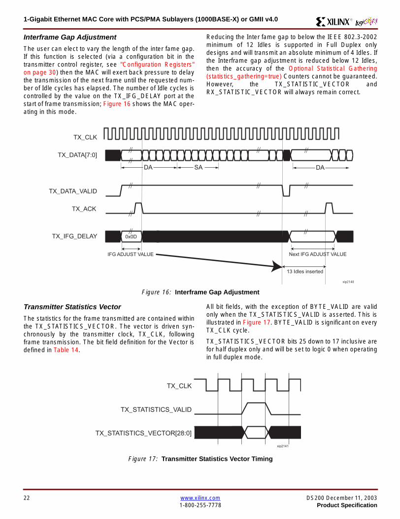
1-Gigabit Ethernet MAC Core with PCSPMA Sublayers (1000BASE-X) or GMII v40 R
Interframe Gap Adjustment
The user can elect to vary the length of the inter fame gapIf this function is selected (via a configuration bit in thetransmitter control register see Configuration Registerson page 30) then the MAC will exert back pressure to delaythe transmission of the next frame until the requested num-ber of Idle cycles has elapsed The number of Idle cycles iscontrolled by the value on the TX_IFG_DELAY port at thestart of frame transmission Figure 16 shows the MAC oper-ating in this mode
Reducing the Inter fame gap to below the IEEE 8023-2002minimum of 12 Idles is supported in Full Duplex onlydesigns and will transmit an absolute minimum of 4 Idles Ifthe Interframe gap adjustment is reduced below 12 Idlesthen the accuracy of the Optional Statistical Gathering(statistics_gathering=true) Counters cannot be guaranteedHowever the TX_STATISTIC_VECTOR andRX_STATISTIC_VECTOR will always remain correct
Transmitter Statistics Vector
The statistics for the frame transmitted are contained withinthe TX_STATISTICS_VECTOR The vector is driven syn-chronously by the transmitter clock TX_CLK followingframe transmission The bit field definition for the Vector isdefined in Table 14
All bit fields with the exception of BYTE_VALID are validonly when the TX_STATISTICS_VALID is asserted This isillustrated in Figure 17 BYTE_VALID is significant on everyTX_CLK cycle
TX_STATISTICS_VECTOR bits 25 down to 17 inclusive arefor half duplex only and will be set to logic 0 when operatingin full duplex mode
Figure 16 Interframe Gap Adjustment
TX_CLK
TX_DATA[70]
TX_DATA_VALID
TX_ACK
DA SA
TX_IFG_DELAY
IFG ADJUST VALUE
0x0D
13 Idles inserted
DA
Next IFG ADJUST VALUE
xip2140
Figure 17 Transmitter Statistics Vector Timing
TX_CLK
TX_STATISTICS_VECTOR[280]
TX_STATISTICS_VALID
xip2141
22 wwwxilinxcom DS200 December 11 20031-800-255-7778 Product Specification
1-Gigabit Ethernet MAC Core with PCSPMA Sublayers (1000BASE-X) or GMII v40R
Table 14 Bit Definition for the Transmitter Statistics Vector
TX_STATISTICS_VECTOR Name Description
28 PAUSE_FRAME_TRANSMITTEDAsserted if the previous frame was a pause framethat the MAC itself initiated in response to aPAUSE_REQ assertion
27 BYTE_VALID
Asserted if a MAC frame byte (DA to FCS inclusive)is in the process of being transmitted This is valid onevery clock cycle
Do not use this as an enable signal to indicate thatdata is present on GMII_TXD[70]
26 Reserved Returns logic 0
25 down to 22 TX_ATTEMPTS[30]
The number of attempts that have been made totransmit the previous frame This is a 4-bit number0 should be interpreted as 1 attempt 1 as 2attempts up until 15 as 16 attempts
21 Reserved Returns logic 0
20 EXCESSIVE_COLLISIONAsserted if a collision has been detected on each ofthe last 16 attempts to transmit the previous frame
19 LATE_COLLISIONAsserted if a late collision occurred during frametransmission
18 EXCESSIVE_DEFERRALAsserted if the previous frame was deferred for anexcessive amount of time as defined by the constantldquomaxDeferTimerdquo in IEEE 8023-2002
17 TX_DEFERRED Asserted if transmission of the frame was deferred
16 VLAN_FRAMEAsserted if the previous frame contained a VLANidentifier in the LengthType field when transmitterVLAN operation is enabled
15 down to 5 FRAME_LENGTH_COUNTThe length of the previous frame in number of bytesThe count will stick at 2047 for any Jumbo frameslarger than this value
4 CONTROL_FRAMEAsserted if the previous frame had the special MACControl Type code 88-08 in the LengthType field
3 UNDERRUN_FRAMEAsserted if the previous frame contained anunderrun error
2 MULTICAST_FRAMEAsserted if the previous frame contained a multicastaddress in the Destination Address field
1 BROADCAST_FRAMEAsserted if the previous frame contained abroadcast address in the Destination Address field
0 SUCCESSFUL_FRAMEAsserted if the previous frame was transmittedwithout error
DS200 December 11 2003 wwwxilinxcom 23Product Specification 1-800-255-7778
1-Gigabit Ethernet MAC Core with PCSPMA Sublayers (1000BASE-X) or GMII v40 R
Receiver
Normal Frame Reception
The timing of a normal inbound frame transfer can be seenin Figure 18 The client must be prepared to accept data atany time there is no buffering within the MAC to allow forlatency in the receive client Once frame reception begins
data is transferred on consecutive clock cycles to thereceive client until the frame is complete The MAC assertsthe RX_GOOD_FRAME signal to indicate that the framewas successfully received and that the frame should beanalyzed by the client
Frame parameters (destination address source addresslengthtype and optionally FCS) are supplied on the databus according to the timing diagram The abbreviations arethe same as those described in Table 13 on page 16
If the LengthType field in the frame has the Length interpre-tation and this indicates that the inbound frame has beenpadded to meet the Ethernet minimum frame size specifica-tion then this padding will not be passed to the client in thedata payload The exception to this is in the case whereFCS passing is enabled see Client-Supplied FCS Pass-ing on page 25
Therefore when Client-Supplied FCS passing is disabledRX_DATA_VALID = lsquo0rsquo between frames for the duration ofthe Padding field (if present) the FCS field carrier exten-sion (if present) the interframe gap following the frame andthe preamble field of the next frame When Client-Supplied
FCS passing is enabled RX_DATA_VALID = lsquo0rsquo betweenframes for the duration of carrier extension (if present) theinterframe gap and the preamble field of the followingframe
RX_GOOD_FRAME RX_BAD_FRAME timing
Although the timing diagram in Figure 18 shows theRX_GOOD_FRAME signal asserted shortly after the lastvalid data on RX_DATA this is not always the case TheRX_GOOD_FRAME or RX_BAD_FRAME signals areasserted only after all frame checks are completed This isafter the FCS field has been received (and after reception ofcarrier extension if present)
Therefore either RX_GOOD_FRAME or RX_BAD_FRAMEis asserted following frame reception at the beginning of theinterframe gap
Figure 18 Normal Frame Reception
RX_CLK
RX_DATA[70]
RX_DATA_VALID
RX_GOOD_FRAME
RX_BAD_FRAME
DA SA DATALT
xip2142
24 wwwxilinxcom DS200 December 11 20031-800-255-7778 Product Specification
1-Gigabit Ethernet MAC Core with PCSPMA Sublayers (1000BASE-X) or GMII v40R
Frame Reception with Errors
The case of an unsuccessful frame reception (for examplea fragment frame or a frame with an incorrect FCS) can beseen in Figure 19 In this case the RX_BAD_FRAME signal
is asserted to the client at the end of the frame It is then theresponsibility of the client to drop the data already trans-ferred for this frame
Figure 19 Frame Reception with Error
Client-Supplied FCS Passing
If the MAC core is configured to pass the FCS field to the cli-ent (see Configuration Registers on page 30) then this ishandled as shown in Figure 20
In this case any padding inserted into the frame to meetEthernet minimum frame length specifications will be leftintact and passed to the client
Note that even though the FCS is passed up to the client itis also verified by the MAC core and RX_BAD_FRAMEasserted if the FCS check fails
RX_CLK
RX_DATA[70]
RX_DATA_VALID
RX_GOOD_FRAME
RX_BAD_FRAME
DA SA DATALT
xip2144
Figure 20 Frame Reception with In-Band FCS Field
RX_CLK
RX_DATA[70]
RX_DATA_VALID
RX_GOOD_FRAME
RX_BAD_FRAME
DA SA DATALT FCS
xip2145
DS200 December 11 2003 wwwxilinxcom 25Product Specification 1-800-255-7778
1-Gigabit Ethernet MAC Core with PCSPMA Sublayers (1000BASE-X) or GMII v40 R
VLAN Tagged Frames
The reception of a VLAN tagged frame (if enabled) can beseen in Figure 21 The VLAN frame is passed to the clientso that the frame may be identified as VLAN tagged this is
followed by the Tag Control Information bytes V1 and V2More information on the interpretation of these bytes maybe found in IEEE 8023-2002 standard
Maximum Permitted Frame Length
The maximum legal length of a frame specified in IEEE8023-2002 is 1518 bytes for non-VLAN tagged framesVLAN tagged frames may be extended to 1522 bytesWhen jumbo frame handling is disabled and the corereceives a frame which exceeds the maximum legal lengthRX_BAD_FRAME will be asserted When jumbo framehandling is enabled frames which are longer than the legalmaximum are received in the same way as shorter frames
For more information on enabling and disabling jumboframe handling see Configuration Registers on page 30
LengthType Field Error Checks
Enabled
Default operation is with the LengthType error checkingenabled (see Receiver Configuration Word 1 on page 31)In this mode the following checks are made on all framesreceived If either of these checks fail then the frame ismarked as BAD
bull A value in the LengthType field that is greater than orequal to decimal 46 but less than decimal 1536 (aLength interpretation) is checked against the actualdata length received
bull A value in the LengthType field that is less thandecimal 46 is checked to see that the data field ispadded to exactly 46 bytes (so that the resultant frameis minimum frame size 64 bytes total in length)
Furthermore if Padding is indicated (the LengthType fieldis less than decimal 46) and Client-Supplied FCS Passing isdisabled then the Length value in the LengthType field willbe used to deassert RX_DATA_VALID after the indicatednumber of data bytes so that the Padding bytes areremoved from the frame
Disabled
When the LengthType error checking is disabled (seeReceiver Configuration Word 1 on page 31) theLengthType error checks described above are not per-formed A frame containing only these errors will be markedas GOOD
Furthermore if Padding is indicated and Client-SuppliedFCS Passing is disabled then a Length Value in theLengthType field will not be used to deassertRX_DATA_VALID Instead RX_DATA_VALID will be deas-serted before the start of the FCS field in this way any pad-ding will not be removed from the frame
Figure 21 Reception of a VLAN Tagged Frame
RX_CLK
RX_DATA[70]
RX_DATA_VALID
RX_GOOD_FRAME
RX_BAD_FRAME
DA SA DATALT
81 00 V1 V2
VLANtag
xip2146
26 wwwxilinxcom DS200 December 11 20031-800-255-7778 Product Specification
1-Gigabit Ethernet MAC Core with PCSPMA Sublayers (1000BASE-X) or GMII v40R
Receiver Statistics Vector
The statistics for the frame received are contained withinthe RX_STATISTICS_VECTOR The vector is driven syn-chronously by the receiver clock RX_CLK following framereception The bit field definition for the Vector is defined inTable 15
All bit fields with the exception of BYTE_VALID are validonly when the RX_STATISTICS_VALID is asserted This isillustrated in Figure 22 BYTE_VALID is significant on everyRX_CLK cycle
Figure 22 Receiver Statistics Vector Timing
RX_CLK
RX_STATISTICS_VECTOR[220]
RX_STATISTICS_VALID
xip2147
Table 15 Bit Definition for the Receiver Statistics Vector
RX_STATISTICS_VECTOR Name Description
22LENGTHTYPE Out ofRange
Asserted if the lengthtype field contained a length valuethat did not match the number of MAC client data bytesreceived Also high if the lengthtype field indicated thatthe frame contained padding but the number of MAC cli-ent data bytes received was not equal to 64 bytes (min-imum frame size)
The exception to the above is when the LengthTypeField Error Checks are disabled in which case this bitwill not be asserted
21 BAD_OPCODE
Asserted if the previous frame was error-free andcontained the special Control Frame identifier in theLengthType field but contained an opcode that isunsupported by the MAC (Any Opcode other thanPAUSE)
20 FLOW_CONTROL_FRAME
Asserted if the previous frame was error-freecontained the special Control Frame identifier in theLengthType field contained a Destination Addressthat matched either the MAC Control MulticastAddress or the configured source address of the MACcontained the supported PAUSE opcode and wasacted upon by the MAC
19 BYTE_VALID
Asserted if a MAC frame byte (DA to FCS inclusive) isin the process of being received This is valid on everyclock cycle
Do not use this as an enable signal to indicate thatdata is present on RX_DATA[70]
18 VLAN_FRAMEAsserted if the previous frame contained a VLANidentifier in the LengthType field when receiver VLANoperation is enabled
DS200 December 11 2003 wwwxilinxcom 27Product Specification 1-800-255-7778
1-Gigabit Ethernet MAC Core with PCSPMA Sublayers (1000BASE-X) or GMII v40 R
17 OUT_OF_BOUNDS
Asserted if the previous frame exceeded the specifiedIEEE8023-2002 maximum legal length (seeMaximum Permitted Frame Length on page 26) Thisis only valid if Jumbo frames are disabled
16 CONTROL_FRAMEAsserted if the previous frame contained the specialControl Frame identifier in the LengthType field
15 down to 5 FRAME_LENGTH_COUNTThe length of the previous frame in number of bytesThe count will stick at 2047 for any Jumbo frameslarger than this value
4 MULTICAST_FRAMEAsserted if the previous frame contained a multicastaddress in the Destination Address field
3 BROADCAST_FRAMEAsserted if the previous frame contained the broadcastaddress in the Destination Address field
2 FCS_ERRORAsserted if the previous frame received had anincorrect FCS value or the MAC detected error codesduring frame reception
1 BAD_FRAME1 Asserted if the previous frame received containederrors
0 GOOD_FRAME1 Asserted if the previous frame received was error-free
1 If the LengthType Field Error Checks are disabled then a frame which contains this type of error will be marked as a GOOD_FRAMEproviding no additional errors were detected
Table 15 Bit Definition for the Receiver Statistics Vector
RX_STATISTICS_VECTOR Name Description
28 wwwxilinxcom DS200 December 11 20031-800-255-7778 Product Specification
1-Gigabit Ethernet MAC Core with PCSPMA Sublayers (1000BASE-X) or GMII v40R
Flow ControlThe flow control block is designed to Clause 31 of the IEEE8023-2002 standard The MAC may be configured to sendpause frames and to act upon their reception These twobehaviors can be configured asymmetrically see Configu-ration Registers on page 30
Transmitting a PAUSE Control Frame
The client initiates a flow control frame by assertingPAUSE_REQ while the pause value is on the PAUSE_VALbus These signals are synchronous to TX_CLK The timingof this can be seen in Figure 23
If the MAC core is configured to support transmit flow con-trol this action causes the core to transmit a PAUSE controlframe on the link with the PAUSE parameter set to thevalue on PAUSE_VAL in the cycle when PAUSE_REQ wasasserted This will not disrupt any frame transmission inprogress but will take priority over any pending frame trans-
mission This frame will be transmitted even if the transmit-ter is in the paused state itself
Receiving a Pause Control Frame
When an error-free frame is received by the MAC core thefollowing checks are made
1 The Destination Address field is matched against theMAC Control Multicast address or the configuredSource Address for the MAC (see ConfigurationRegisters on page 30)
2 The LengthType field is matched against the MACControl Type code
3 The opcode field contents are matched against thePAUSE opcode if check 2 is true
If any of the above checks are false or the MAC Flow Con-trol logic for the receiver is disabled the frame is ignored bythe Flow Control logic and passed up to the client
If the frame passes all of the above checks is of minimumlegal size and the MAC Flow Control logic for the receiver isenabled the pause value parameter in the frame is thenused to inhibit transmitter operation for the time defined inthe IEEE8023-2002 specification This inhibit is imple-mented using the same back pressure scheme shown inFigure 12 Because the received pause frame has beenacted upon it is passed to the client with RX_BAD_FRAMEasserted to indicate to the client that it should be dropped
Reception of any frame for which check 2 is true and whichis not of legal minimum length is considered an invalid Con-trol frame This will be ignored by the Flow Control logic andpassed to the client with RX_BAD_FRAME asserted
Figure 23 Pause Request Timing
TX_CLK
PAUSE_VAL[150]
PAUSE_REQ
xip2148
DS200 December 11 2003 wwwxilinxcom 29Product Specification 1-800-255-7778
1-Gigabit Ethernet MAC Core with PCSPMA Sublayers (1000BASE-X) or GMII v40 R
Optional Management Interface(management_interface=true)The management interface is a processor-independentinterface with standard address data and control signals Itmay be used as is or a wrapper may be applied (not sup-plied) to interface to common bus architectures
This interface is used for
bull Configuration of the MAC core
bull Access to optional statistics counters for use by higherlayers for example SNMP
bull access through the MDIO interface to the managementregisters located in the PHY attached to the MAC core
The management interface is accessed differently depend-ing on the type of transaction a truth table showing whichaccess method is required for each transaction type isshown in Table 16 These access methods are described inthe following sections
HOST_CLK Frequency
The management interface clock HOST_CLK is used toderive the MDIO clock MDC and is therefore subject tosome frequency restrictions This HOST_CLK must be
ge 10 MHz
le 100 MHz
Configuring the MAC core to derive the MDC signal fromthis clock is detailed in MDIO Interface on page 37
Configuration Registers
After power up or reset the client may reconfigure the coreparameters from their defaults such as flow control supportConfiguration changes can be written at any time Both thereceiver and transmitter logic will only respond to configura-tion changes during Inter Frame Gaps The exceptions tothis are the configurable resets which take effect immedi-ately
Configuration of the MAC core is performed through a reg-ister bank accessed through the management interfaceThe configuration registers available in the core are detailedin Table 17 As can be seen the address has some implicitdonrsquot care bits any access to an address in the rangesshown will perform a 32-bit read or write from the same con-figuration word
Table 16 Management Interface Transaction Types
Transaction HOST_MIIM_SEL HOST_ADDR[9]
Configuration 0 1
Statistics 0 0
MIIM access 1 X
Table 17 Configuration Registers
Address Description
0x200-0x23F Receiver Configuration (Word 0)
0x240-0x27F Receiver Configuration (Word 1)
0x280-0x2BF Transmitter Configuration
0x2C0-0x2FF Flow Control Configuration
0x300-0x33F Reserved
0x340-0x37F Management Configuration
30 wwwxilinxcom DS200 December 11 20031-800-255-7778 Product Specification
1-Gigabit Ethernet MAC Core with PCSPMA Sublayers (1000BASE-X) or GMII v40R
The register contents for the two receiver configuration words can be seen in Table 18 and Table 19
Notes1 In changing the receiverrsquos mode from Half Duplex to Full Duplex there is a period of time of up to 24 us following the mode change
when no new receiver statistics can be stored in the optional Statistical Counters
Table 18 Receiver Configuration Word 0
Bit Default Value Description
31-0 All 0rsquos
Pause frame MAC Source Address[310] This address is used by the MAC tomatch against the Destination Address of any incoming flow control frames It isalso used by the flow control block as the Source Address (SA) for any outboundflow control frames
The address is ordered so the first byte transmittedreceived is the lowestpositioned byte in the register for example a MAC address ofAA-BB-CC-DD-EE-FF would be stored in Address[470] as 0xFFEEDDCCBBAA
Table 19 Receiver Configuration Word 1
Bit Default Value Description
15-0 All 0rsquos Pause frame MAC Source Address[4732] See description in Table 18
24-16 NA Reserved
25 0
LengthType Error Check Disable When this bit is set to ldquo1rdquo the core will notperform the LengthType field error checks as described in LengthType FieldError Checks on page 26 When this bit is set to ldquo0rdquo the LengthType field checkswill be performed this is normal operation
26 0Half Duplex If ldquo1rdquo the receiver will operate in half duplex mode If ldquo0rdquo the receiverwill operate in full duplex mode Has no effect if XCO parameterhalf_duplex_capable = false
27 0VLAN Enable When this bit is set to ldquo1rdquo VLAN tagged frames will be acceptedby the receiver
28 1Receiver Enable If set to ldquo1rdquo the receiver block will be operational If set to ldquo0rdquothe block will ignore activity on the physical interface RX port
29 0
In-band FCS Enable When this bit is ldquo1rdquo the MAC receiver will pass the FCS fieldup to the client as described in Client-Supplied FCS Passing on page 25 Whenit is ldquo0rdquo the client will not be passed the FCS In both cases the FCS will beverified on the frame
30 0Jumbo Frame Enable When this bit is set to ldquo1rdquo the MAC receiver will acceptframes over the specified IEEE8023-2002 maximum legal length When this bitis ldquo0rdquo the MAC will only accept frames up to the specified maximum
31 0Reset When this bit is set to ldquo1rdquo the receiver will be reset The bit will thenautomatically revert to ldquo0rdquo Note that this reset will also set all of the receiverconfiguration registers to their default values
DS200 December 11 2003 wwwxilinxcom 31Product Specification 1-800-255-7778
1-Gigabit Ethernet MAC Core with PCSPMA Sublayers (1000BASE-X) or GMII v40 R
The register contents for the Transmitter Configuration Word are described in Table 20
Notes1 In changing the transmitterrsquos mode from Half Duplex to Full Duplex there is a period of time of up to 24 us following the mode change
when no new transmitter statistics can be stored in the optional Statistical Counters
Table 20 Transmitter Configuration Word
Bit Default Value Description
24-0 NA Reserved
25 0
Interframe Gap Adjust Enable If lsquo1rsquo the transmitter will read the value on the portTX_IFG_DELAY at the start of frame transmission and adjust the interframe gapfollowing the frame accordingly See Interframe Gap Adjustment on page 22 Ifldquo0rdquo the transmitter will output a minimum Inter Frame Gap of twelve clock cyclesas specified in IEEE8023-2002
26 0Half Duplex If lsquo1rsquo the transmitter will operate in half duplex mode If lsquo0rsquo thetransmitter will operate in full duplex mode Has no effect if XCO parameterhalf_duplex_capable = false
27 0VLAN Enable When this bit is set to 1 the transmitter will allow the transmissionof VLAN tagged frames
28 1Transmit Enable When this bit is 1 the transmitter is operational When it is 0the transmitter is disabled
29 0
In-band FCS Enable When this bit is lsquo1rsquo the MAC transmitter will expect the FCSfield to be passed in by the client as described in Client-Supplied FCS Passingon page 17 When this bit is ldquo0rdquo the MAC transmitter will append padding asrequired compute the FCS and append it to the frame
30 0
Jumbo Frame Enable When this bit is set to ldquo1rdquo the MAC transmitter will sendframes that are greater than the specified IEEE8023-2002 maximum legallength When this bit is ldquo0rdquo the MAC will only send frames up to the specifiedmaximum
31 0Reset When this bit is set to ldquo1rdquo the transmitter will be reset The bit will thenautomatically revert to ldquo0rdquo Note that this reset will also set all of the transmitterconfiguration registers to their default values
32 wwwxilinxcom DS200 December 11 20031-800-255-7778 Product Specification
1-Gigabit Ethernet MAC Core with PCSPMA Sublayers (1000BASE-X) or GMII v40R
The register contents for the Flow Control Configuration Word are described in Table 21
The register contents for the Management Configuration Word are described in Table 22
Writing to the configuration registers through the manage-ment interface is depicted in Figure 24 When accessing theconfiguration registers (ie when HOST_ADDR[9] = lsquo1rsquo andHOST_MIIM_SEL = lsquo0rsquo) the upper bit of HOST_OPCODEfunctions as an Active Low write enable signal The lowerHOST_OPCODE bit is a ldquodonrsquot carerdquo
Reading from the configuration register words is similar butthe upper HOST_OPCODE bit should be lsquo1rsquo This is shownin Figure 25 In this case the contents of the register appearon HOST_RD_DATA the HOST_CLK edge after the regis-ter address is asserted onto HOST_ADDR
Table 21 Flow Control Configuration Word
Bit Default Value Description
28-0 NA Reserved
29 1
Flow Control Enable (RX) When this bit is lsquo1rsquo received flow control frames willinhibit the transmitter operation as described in Receiving a Pause ControlFrame on page 29 When this bit is lsquo0rsquo received flow control frames will alwaysbe passed up to the client
30 1Flow Control Enable (TX) When this bit is lsquo1rsquo asserting the PAUSE_REQ signalwill send a flow control frame out from the transmitter When this bit is 0 assertingthe PAUSE_REQ signal has no effect
31 NA Reserved
Table 22 Management Configuration Word
Bits Default Value Description
4-0 All 0rsquos Clock Divide[40] See MDIO Interface on page 37
5 0MDIO Enable When this bit is 1 the MDIO interface can be used to accessattached PHY devices When this bit is 0 the MDIO interface is disabled and theMDIO signals remain inactive
31-6 NA Reserved
Figure 24 Configuration Register Write Timing
HOST_CLK
HOST_ADDR[80]
HOST_ADDR[9]
HOST_OPCODE[1]
HOST_MIIM_SEL
HOST_WR_DATA[310]xip2149
Figure 25 Configuration Register Read Timing
HOST_CLK
HOST_ADDR[80]
HOST_ADDR[9]
HOST_OPCODE[1]
HOST_MIIM_SEL
HOST_RD_DATA[310]
xip2150
DS200 December 11 2003 wwwxilinxcom 33Product Specification 1-800-255-7778
1-Gigabit Ethernet MAC Core with PCSPMA Sublayers (1000BASE-X) or GMII v40 R
Optional Statistical Gathering(statistics_gathering=true)
During operation the MAC core collects statistics on thesuccess and failure of various operations for processing by
station management entities (STA) further up the protocolstack These statistics are accessed by the host through theoptional management interface A complete list of statisticssupported is described in Table 23
Table 23 Statistics Registers
Address Name Description
0x000 Frames Received OK1 A count of error-free frames received
0x001 Frame Check Sequence Errors A count of received frames that failed the CRC check and were at least64 bytes in length
0x002 Broadcast Frames Received OK1A count of frames that were successfully received and were directed tothe broadcast group address
0x003 Multicast Frames Received OK1 A count of frames that were successfully received and were directed toa non broadcast group address
0x004 64 byte Frames Received OK1 A count of error-free frames received that were 64 bytes in length
0x005 65-127 byte Frames Received OK1A count of error-free frames received that were between 65 and 127bytes in length
0x006 128-255 byte Frames Received OK1A count of error-free frames received that were between 128 and 255bytes in length
0x007 256-511 byte Frames Received OK1A count of error-free frames received that were between 256 and 511bytes in length
0x008512-1023 byte Frames ReceivedOK1
A count of error-free frames received that were between 512 and 1023bytes in length
0x0091024-MaxFrameSize byte FramesReceived OK1
A count of error-free frames received that were between 1024 bytes andthe specified IEEE8023-2002 maximum legal length (see MaximumPermitted Frame Length on page 26)
0x00A Control Frames Received OKA count of error-free frames received that contained the specialControl Frame identifier in the LengthType field
0x00B LengthType Out of Range
A count of frames received that were at least 64 bytes in length wherethe lengthtype field contained a length value that did not match thenumber of MAC client data bytes received
The counter also increments for frames in which the lengthtype fieldindicated that the frame contained padding but where the number ofMAC client data bytes received was greater than 64 bytes (minimumframe size)
The exception to the above is when the LengthType Field Error Checksare disabled in which case this counter will not increment
0x00C VLAN Tagged Frames Received OKA count of error-free VLAN frames received This counter will only incre-ment when the receiver is configured for VLAN operation
0x00D Pause Frames Received OK
A count of error-free frames received that contained the MAC Controltype identifier 88-08 in the LengthType field contained a Destinationaddress that matched either the MAC Control multicast address or theconfigured source address of the MAC contained the PAUSE opcodeand were acted upon by the MAC
0x00EControl Frames Received withUnsupported Opcode
A count of error-free frames received that contained the MAC Controltype identifier 88-08 in the LengthType field but were received with anopcode other than the PAUSE opcode
34 wwwxilinxcom DS200 December 11 20031-800-255-7778 Product Specification
1-Gigabit Ethernet MAC Core with PCSPMA Sublayers (1000BASE-X) or GMII v40R
0x00F Oversize Frames Received OK1A count of otherwise error-free frames received that exceeded the max-imum legal frame length specified in IEEE 8023-2002 (see MaximumPermitted Frame Length on page 26)
0x010 Undersize frames receivedA count of the number of frames received that were less than 64 bytesin length but were otherwise well formed
0x011 Fragment frames receivedA count of the number of frames received that were less than 64 bytesin length and had a bad Frame Check Sequence field
0x012 Received bytesA count of bytes of frames that are received (Destination Address toFrame Check Sequence inclusive)
0x013 Transmitted bytesA count of bytes of frames that are transmitted (Destination Address toFrame Check Sequence inclusive)
0x020 Frames Transmitted OK A count of error-free frames transmitted
0x021 Broadcast Frames Transmitted OK A count of error-free frames that were transmitted to the broadcastaddress
0x022 Multicast Frames Transmitted OK A count of error-free frames that were transmitted to a group destina-tion address other than broadcast
0x023 Underrun Errors
A count of frames that would otherwise be transmitted by the core butcould not be completed due to the assertion of TX_UNDERRUN duringthe frame transmission This will not count frames which are less than64 bytes in length
0x024 Control Frames Transmitted OKA count of error-free frames transmitted that contained the MACControl Frame type identifier 88-08 in the LengthType field
0x025 64 byte Frames Transmitted OK A count of error-free frames transmitted that were 64 bytes in length
0x026 65-127 byte Frames Transmitted OKA count of error-free frames transmitted that were between 65 and 127bytes in length
0x027128-255 byte Frames TransmittedOK
A count of error-free frames transmitted that were between 128 and 255bytes in length
0x028256-511 byte Frames TransmittedOK
A count of error-free frames transmitted that were between 256 and 511bytes in length
0x029512-1023 byte Frames TransmittedOK
A count of error-free frames transmitted that were between 512 and1023 bytes in length
0x02A1024-MaxFrameSize byte FramesTransmitted OK
A count of error-free frames transmitted that were between 1024 and thespecified IEEE8023-2002 maximum legal length (see Maximum Per-mitted Frame Length on page 20)
0x02BVLAN Tagged Frames TransmittedOK
A count of error-free VLAN frames transmitted This counter will onlyincrement when the transmitter is configured for VLAN operation
0x02C Pause Frames Transmitted OKA count of error-free PAUSE frames generated and transmitted by thecore in response to an assertion of PAUSE_REQ
0x02D Oversize Frames Transmitted OKA count of otherwise error-free frames transmitted that exceeded themaximum legal frame length specified in IEEE 8023-2002 (see Maxi-mum Permitted Frame Length on page 20)
0x02E Single Collision Frames A count of frames that are involved in a single collision but are subse-quently transmitted successfully (Half Duplex Mode only)
Table 23 Statistics Registers (Continued)
Address Name Description
DS200 December 11 2003 wwwxilinxcom 35Product Specification 1-800-255-7778
1-Gigabit Ethernet MAC Core with PCSPMA Sublayers (1000BASE-X) or GMII v40 R
Each of these statistic registers is 64 bits wide and thereforemust be read in a two-cycle transfer The timing of this pro-cess is shown in Figure 26 Six clocks after the read trans-action is initiated the least significant word (LSW) of thestatistics counter appears on the HOST_RD_DATA bus
and a clock cycle later the most significant word (MSW)appears For accurate statistic values 64 clock ticks (ofTX_CLK for transmit statistics or RX_CLK for receive statis-tics) must elapse after the last frame is sent or receivedthrough the MAC core
0x02F Multiple Collision Frames A count of frames that are involved in more than one collision but aresubsequently transmitted successfully (Half Duplex Mode only)
0x040 Frames with Deferred Transmissions A count of frames whose transmission was delayed on its first attemptbecause the medium was busy (Half Duplex Mode only)
0x041 Late Collisions
A count of the times that a collision has been detected later than oneslotTime from the start of the packet transmission A late collision iscounted twice both as a collision and as a lateCollision (Half DuplexMode only)
0x042Frames Aborted due to Excesscollisions
A count of the frames that due to excessive collisions are not transmit-ted successfully (Half Duplex Mode only)
0x043 Carrier Sense ErrorsA count of times that the GMII_CRS signal was not asserted or wasdisasserted during the transmission of a frame without collision (HalfDuplex Mode only)
0x044 Frames with Excess DeferralA count of frames that deferred transmission for an excessive period oftime (Half Duplex Mode only)
1 If the LengthType Field Error Checks are disabled then these counters will still increment for received frames which contain this typeof error (providing no additional errors were detected)
Table 23 Statistics Registers (Continued)
Address Name Description
Figure 26 Statistic Register Read Timing
HOST_CLK
HOST_ADDR[80]
HOST_ADDR[9]
HOST_REQ
HOST_MIIM_SEL
HOST_RD_DATA[310]
6 CLOCKS
LSW MSW
xip2151
36 wwwxilinxcom DS200 December 11 20031-800-255-7778 Product Specification
1-Gigabit Ethernet MAC Core with PCSPMA Sublayers (1000BASE-X) or GMII v40R
MDIO Interface
The management interface is also used to access the MDIO(MII Management) interface of the MAC core this interfaceis used to access the Managed Information Block (MIB) ofthe PHY components attached to the MAC core
The MDIO interface supplies a clock to the externaldevices MDC This clock is derived from the HOST_CLKsignal using the value in the Clock Divide[40] configurationregister The frequency of the MDIO clock is given by thefollowing equation
The frequency of MDC given by this equation should notexceed 25 MHz in order to comply with the IEEE8023-2002 specification for this interface To prevent MDCfrom being out of specification the Clock Divide[40] valuepowers up at 00000 and while this value is in the register itis impossible to enable the MDIO interface
For details of the register map of PHY layer devices and afuller description of the operation of the MDIO interfaceitself see IEEE specification 8023-2002
Access to the MDIO interface through the managementinterface is depicted in the timing diagram in Figure 27
For MDIO transactions the following points apply
bull HOST_OPCODE maps to the OP (opcode) field of theMDIO frame
bull HOST_ADDR maps to the two address fields of theMDIO frame PHY_ADDR is HOST_ADDR[95] andREG_ADDR is HOST_ADDR[40]
bull HOST_WR_DATA[150] maps into the data field of the
MDIO frame when performing a write operation
bull The data field of the MDIO frame maps intoHOST_RD_DATA[150] when performing a readoperation
The MAC core signals to the host that it is ready for anMDIO transaction by asserting HOST_MIIM_RDY A read orwrite transaction on the MDIO is initiated by a pulse on the
fMDC
fHOST_CLK
1 Clock Divide[40]+( ) 2times-------------------------------------------------------------------=
Figure 27 MDIO Access Through Management Interface
HOST_CLK
HOST_ADDR[90]
HOST_OPCODE[10]
HOST_REQ
HOST_MIIM_SEL
HOST_RD_DATA[150]
HOST_WR_DATA[150]
HOST_RDY
If a read transaction is initiated the HOST_RD_DATA bus is valid at the point indicated If a write transaction is initiated the HOST_WR_DATA bus must be valid at the indicated point Simultaneous read and write is not permitted
xip2152
DS200 December 11 2003 wwwxilinxcom 37Product Specification 1-800-255-7778
1-Gigabit Ethernet MAC Core with PCSPMA Sublayers (1000BASE-X) or GMII v40 R
HOST_REQ signal This pulse is ignored if the MDIO inter-face already has a transaction in progress
The MAC core then disasserts the HOST_MIIM_RDY signalwhile the transaction across the MDIO is in progress Whenthe transaction across the MDIO interface has been com-pleted the HOST_MIIM_RDY signal will be asserted by theMAC core if the transaction is a read the data will also beavailable on the HOST_RD_DATA[150] bus at this time
Optional Configuration Vector(management_interface = false)If the optional Management interface is omitted from thecore all of relevant configuration signals are brought out of
the core These signals are bundled into theCONFIGURATION_VECTOR signal The bit mapping of theconfiguration vector signal is defined in Table 24 See thecorresponding entry in the configuration register tables forthe full description of each signal
Note that these configuration vector signals can bechanged by the user at any time however with the excep-tion of the reset and the flow control configuration signalsthey will not take effect until the current frame has com-pleted transmission or reception
The ldquoClockrdquo heading denotes which clock domain the con-figuration signal is registered into before use by the core Itis not necessary to drive the signal from this clock domain
Table 24 Configuration Vector Bit Definition
Bit(s)Configuration Register
cross reference Clock Description
47 downto 0
Receiver ConfigurationWord 0 bits 31-0 andReceiver ConfigurationWord 1 bits 15-0
RX_CLK
Pause frame MAC Source Address[470] This address isused by the MAC core to match against the DestinationAddress of any incoming flow control frames and as theSource Address for any outbound flow control frames
The address is ordered such that the first byte transmitted orreceived is the least significant byte in the register forexample a MAC address of AA-BB-CC-DD-EE-FF will bestored in bite [470] as 0xFFEEDDCCBBAA
48Receiver ConfigurationWord 1 bit 26
RX_CLKReceiver Half Duplex If lsquo1rsquo the receiver operates in halfduplex mode If lsquo0rsquo the receiver operates in full duplex modeHas no effect if XCO parameter half_duplex_capable = false
49Receiver ConfigurationWord 1 bit 27
RX_CLKReceiver VLAN Enable When this bit is set to 1 VLANtagged frames are accepted by the receiver
50Receiver ConfigurationWord 1 bit 28
RX_CLKReceiver Enable If set to 1 the receiver block is operationalIf set to 0 the block ignores activity on the physical interfaceRX port
51Receiver ConfigurationWord 1 bit 29
RX_CLK
Receiver In-band FCS Enable When this bit is lsquo1rsquo the MACreceiver will pass the FCS field up to the client as describedin Client-Supplied FCS Passing on page 25 When it is lsquo0rsquothe MAC receiver will not pass the FCS field In both casesthe FCS field will be verified on the frame
52Receiver ConfigurationWord 1 bit 30
RX_CLK
Receiver Jumbo Frame Enable When this bit is lsquo0rsquo thereceiver will not pass frames longer than the maximum legalframe size specified in IEEE 8023-2002 (see MaximumPermitted Frame Length on page 26) When it is lsquo1rsquo thereceiver will not have an upper limit on frame size
53Receiver ConfigurationWord 1 bit 31
NA
Receiver Reset When this bit is lsquo1rsquo the receiver is held inreset
This signal is an input to the reset circuit for the receiverblock See Reset circuit on page 42 for more information
54TransmitterConfiguration Word bit25
TX_CLK
Transmitter Interframe Gap Adjust enable If lsquo1rsquo then thetransmitter will read the value of the TX_IFG_DELAY port andset the Interframe Gap accordingly If lsquo0rsquo the transmitter willalways insert at least the legal minimum Interframe Gap
38 wwwxilinxcom DS200 December 11 20031-800-255-7778 Product Specification
1-Gigabit Ethernet MAC Core with PCSPMA Sublayers (1000BASE-X) or GMII v40R
55TransmitterConfiguration Word bit26
TX_CLK
Transmitter Half Duplex If lsquo1rsquo the transmitter operates in halfduplex mode If lsquo0rsquo the transmitter operates in full duplexmode Has no effect if XCO parameter half_duplex_capable= false
56TransmitterConfiguration Word bit27
TX_CLKTransmitter VLAN Enable When this bit is set to lsquo1rsquo thetransmitter allows the transmission of VLAN tagged frames
57TransmitterConfiguration Word bit28
TX_CLKTransmitter Enable When this bit is 1 the transmitter will beoperational When it is 0 the transmitter is disabled
58TransmitterConfiguration Word bit29
TX_CLK
Transmitter In-Band FCS Enable When this bit is lsquo1rsquo theMAC transmitter will expect the FCS field to be pass in by theclient as described in Client-Supplied FCS Passing onpage 17 When it is lsquo0rsquo the MAC transmitter will appendpadding as required compute the FCS and append it to theframe
59TransmitterConfiguration Word bit30
TX_CLK
Transmitter Jumbo Frame Enable When this bit is lsquo1rsquo theMAC transmitter will allow frames larger than the maximumlegal frame length specified in IEEE 8023-2002 to be sentWhen set to lsquo0rsquo the MAC transmitter will only allow frames upto the legal maximum to be sent
60TransmitterConfiguration Word bit31
NA
Transmitter Reset When this bit is lsquo1rsquo the MAC transmitter isheld in reset
This signal is an input to the reset circuit for the transmitterblock See Reset circuit on page 42 for more information
61Flow ControlConfiguration Word bit29
TX_CLK
Transmit Flow Control Enable When this bit is lsquo1rsquo assertingthe PAUSE_REQ signal causes the MAC core to send a flowcontrol frame out from the transmitter as described inReceiving a Pause Control Frame on page 29 When this bitis lsquo0rsquo asserting the PAUSE_REQ signal will have no effect
62Flow ControlConfiguration Word bit30
RX_CLK
Receive Flow Control Enable When this bit is lsquo1rsquo receivedflow control frames will inhibit the transmitter operation asdescribed in Receiving a Pause Control Frame on page 29When it is lsquo0rsquo received flow frames are passed up to theclient
63Receiver ConfigurationWord 1 bit 25
RX_CLK
LengthType Error Check Disable When this bit is lsquo1rsquo thecore will not perform the LengthType field error checks asdescribed in LengthType Field Error Checks on page 26When it is set to lsquo0rsquo the LengthType field checks will beperformed this is normal operation
Table 24 Configuration Vector Bit Definition (Continued)
Bit(s)Configuration Register
cross reference Clock Description
DS200 December 11 2003 wwwxilinxcom 39Product Specification 1-800-255-7778
1-Gigabit Ethernet MAC Core with PCSPMA Sublayers (1000BASE-X) or GMII v40 R
Optional GMII (physical_interface=gmii)The GMII is designed to IEEE 8023-2002 Clause 35 Thisutilizes IOrsquos of the Xilinx devices using inputoutput buffersand inputoutput flip-flops to maximize setup and hold mar-gins All IO logic is placed in the example wrapper that isdelivered with the core In addition all clock managementlogic for the core is instanced in this example wrapper thisallows multiple instances of the core to share clocks Theexample wrapper is provided in both VHDL and Verilog
Clock Management
Figure 28 illustrates the clock management used with theGMII interface All clocks illustrated have a frequency of125MHz
GTX_CLK must be provided to the MAC core This is a highquality clock which satisfies the IEEE8023-2002 require-ments It is expected that this clock will be derived from anexternal oscillator and connected into the device through anIBUFG as illustrated The clock source must then be routedonto a global clock network by connecting it to a BUFGWithin the MAC core this global clock is used by all MACtransmitter logic The MAC Client can obtain this clock byconnecting to the TX_CLK signal output from the coreGMII_TX_CLK is derived from this global clock by invertingit and routing it to an OBUF
GMII_RX_CLK is received through an IBUFG This clock isthen routed onto a global clock network by connecting it to aBUFG The resulting global clock is used by all MACreceiver logic
Figure 28 Clock Management with GMII
IBUFG
IBUFG
OBUF
BUFG
BUFG
TX_CLK
RX_CLK
GTX_CLK
GMII_TX_CLK
GMII_RX_CLK
Example Wrapper
xip2153
MAC Core
TX_CLK
RX_CLK
GMII_TX_CLK
GMII_RX_CLK
GTX_CLK
40 wwwxilinxcom DS200 December 11 20031-800-255-7778 Product Specification
1-Gigabit Ethernet MAC Core with PCSPMA Sublayers (1000BASE-X) or GMII v40R
Clock Sharing between Multiple cores
Figure 29 illustrates how it is possible to share clockresources across multiple instantiations of the core whenusing the optional GMII
GTX_CLK may be shared between multiple cores as illus-trated resulting in a common transmitter clock domainacross the device
A common receiver clock domain is not possible each corewill receive an independent receiver clock from its GMII asillustrated
Although not illustrated if the optional Management Inter-face is used HOST_CLK can also be shared betweencores
Figure 29 Clock Management with multiple instances of the MAC with GMII
IBUFG
OBUF
BUFG
TX_CLK
RX_CLK_1
GMII_TX_CLK_1
GMII_RX_CLK_1
MAC Core
TX_CLK
RX_CLK
GMII_TX_CLK
GMII_RX_CLK
GTX_CLK
MAC Core
TX_CLK
RX_CLK
GMII_TX_CLK
GMII_RX_CLK
GTX_CLK
IBUFG
BUFG
GTX_CLK
IBUFG
OBUF
GMII_TX_CLK_2
GMII_RX_CLK_2
BUFG
TX_CLK
RX_CLK_2
DS200 December 11 2003 wwwxilinxcom 41Product Specification 1-800-255-7778
1-Gigabit Ethernet MAC Core with PCSPMA Sublayers (1000BASE-X) or GMII v40 R
Reset circuit
Internally the core is divided up into clockreset domainswhich group together elements with the common clock andreset signals The reset circuitry for one of these domains isis illustrated in Figure 30 This circuit provides controllableskews on the reset nets within the design
More information on the operation and rationale behind thiscircuit can be found in Ken Chapmanrsquos Xilinx TechXclusiveldquoGet Smart About Resetrdquo athttpwwwxilinxcomsupporttechxclusivesglobal-techX19htm
Figure 30 Reset circuit for one clockreset domain
FDP
PRED
C
Q
FDP
PRED
C
Q
FDP
PRED
C
Q
FDP
PRED
C
Q
PRE PRE PRE
0
RESET
Management Reset
Clock
Core Registers
42 wwwxilinxcom DS200 December 11 20031-800-255-7778 Product Specification
1-Gigabit Ethernet MAC Core with PCSPMA Sublayers (1000BASE-X) or GMII v40R
Optional PCS with Ten-Bit Interface (TBI) for 1000BASE-X (physical_interface=tbi)The Full-Duplex Physical Coding Sublayer (PCS) for1000BASE-X is defined in IEEE 8023-2002 Clauses 36and 37 This functionality is only available in the Virtex-IIand Spartan3 families of FPGA devices
A block diagram of the PCS is shown in Figure 31 Themajor functional blocks of the PCS are
bull Transmit engine
bull Auto-negotiation block
bull Receive engine and synchronization block
bull PCS managed register block
bull 8B10B encoder block
bull 8B10B decoder block
bull Receiver elastic buffer
The PCS Managed Register Block is accessed through theMDIO Interface as if it were an externally connected PHYThis configures the operation of the PCS and Auto-Negoti-ation See PCS Managed Register Block
(physical_interface = tbi or phy) on page 49 The corersquosoptional Management Interface can be used to control theMDIO Interface as described by MDIO Interface onpage 37 When the optional Management Interface is notpresent the PCS Managed Register Block must beaccessed via an MDIO controller which is not provided bythe core
The 8B10B encodingdecoding blocks are implemented byconfiguring two Block SelectRAM modules as ROM Theseare used as large look-up tables The remaining PCS func-tionality such as code group encodingdecoding the Man-aged Register Block and Auto-Negotiation areimplemented in CLB logic
The Receiver Elastic buffer enables the 10-bit parallel datareceived from the PMA sublayer alternatively onPMA_RX_CLK0 and PMA_RX_CLK1 clock edges to betransferred onto the internal 125MHz clock domain derivedfrom GTX_CLK (see Clock Management) This buffer isimplemented in Distributed Memory
Figure 31 Functional Block Diagram of the 1-Gigabit Ethernet PCS with TBI Interface
PCS TRANSMIT ENGINE
PCS RECEIVE ENGINE ampSYNCHRONISATION
PCSMANAGEMENT
MDIOInterface
AUTO-NEGOTIATION
MAC TXInterface
MAC RXInterface
8B10BEncoder
8B10BDecoder
RX Elastic Buffer
TBI Interface
DS200 December 11 2003 wwwxilinxcom 43Product Specification 1-800-255-7778
1-Gigabit Ethernet MAC Core with PCSPMA Sublayers (1000BASE-X) or GMII v40 R
TBI Interface
The TBI is designed to IEEE 8023-2002 Clause 363 Thisutilizes IOrsquos of the Xilinx devices using inputoutput buffersand inputoutput flip-flops to maximize setup and hold mar-gins All IO logic is placed in the example wrapper that isdelivered with the core In addition all clock managementlogic for the core is instantiated in this example wrapperthis allows multiple instances of the core to share clocksThe example wrapper is provided in both VHDL and Verilog
Clock Management
Figure 32 illustrates the clock management used with theTBI interface
GTX_CLK must be provided to the MAC core This is a highquality clock of frequency 125MHz which satisfies theIEEE8023-2002 requirements It is expected that this clockwill be derived from an external oscillator and connected
into the device through an IBUFG as illustrated The clocksource must then be routed onto a global clock network byconnecting it to a BUFG Within the MAC core this globalclock is used by all MAC transmitter logic PMA_TX_CLK isderived from this global clock by inverting it and routing it toan OBUF
PMA_RX_CLK0 and PMA_RX_CLK1 are each receivedthrough an IBUFG These clocks are then routed onto glo-bal clock networks by connecting each to a BUFGPMA_RX_CLK0 and PMA_RX_CLK1 are each 625MHzclocks Data from the TBI is received alternatively on the ris-ing edge of PMA_RX_CLK0 followed by the rising edge ofPMA_RX_CLK1 using IOB Double-Data Rate input regis-ters This data is then written into the Receiver ElasticBuffer Data is read out of the Elastic Buffer using the globalclock derived from GTX_CLK all the remaining receiverlogic is synchronous to this clock
Figure 32 Clock Management for PCS with TBI Interface
IBUFG
IBUFG
OBUF
BUFG
BUFG
TX_CLK
RX_CLK
GTX_CLK
PMA_TX_CLK
PMA_RX_CLK0
MAC Core
RX ELASTICBUFFER
Example Wrapper
TX_CLK
RX_CLK
GTX_CLK
PMA_TX_CLK
PMA_RX_CLK0
IBUFGBUFGPMA_RX_CLK1
PMA_RX_CLK1
44 wwwxilinxcom DS200 December 11 20031-800-255-7778 Product Specification
1-Gigabit Ethernet MAC Core with PCSPMA Sublayers (1000BASE-X) or GMII v40R
Clock Sharing between Multiple cores
Figure 33 illustrates how it is possible to share clockresources across multiple instantiations of the core whenusing the optional PCS with TBI
GTX_CLK may be shared between multiple cores as illus-trated resulting in a common transmitter clock domainacross the device
Each core will receive independent PMA_RX_CLK0 andPMA_RX_CLK1 clocks from its TBI as illustrated whichcannot be shared
Although not illustrated if the optional Management Inter-face is used HOST_CLK can also be shared betweencores
Figure 33 Clock Management with multiple instances of the MAC with PCS and TBI
Reset circuit
The reset circuits within the MAC when the TBI interface is implemented is the same as that in the GMII case details ofthese circuits can be found on page 42
IBUFG
OBUF
BUFG
TX_CLK
RX_CLK
PMA_TX_CLK_1
PMA_RX_CLK0_1
MAC Core
RX ELASTICBUFFER
TX_CLK
RX_CLK
GTX_CLK
PMA_TX_CLK
PMA_RX_CLK0
IBUFGBUFGPMA_RX_CLK1_1
PMA_RX_CLK1
IBUFG
BUFG
GTX_CLK
IBUFG
OBUF
BUFG
TX_CLK
RX_CLK
PMA_TX_CLK_2
PMA_RX_CLK0_2
MAC Core
RX ELASTICBUFFER
TX_CLK
RX_CLK
GTX_CLK
PMA_TX_CLK
PMA_RX_CLK0
IBUFGBUFGPMA_RX_CLK1_2
PMA_RX_CLK1
DS200 December 11 2003 wwwxilinxcom 45Product Specification 1-800-255-7778
1-Gigabit Ethernet MAC Core with PCSPMA Sublayers (1000BASE-X) or GMII v40 R
Optional PCS and PMA Sublayers for 1000BASE-X (physical_interface=phy)The Full-Duplex Physical Coding Sublayer (PCS) withPhysical Medium Attachment (PMA) for 1000BASE-X isdefined in IEEE 8023-2002 Clauses 36 and 37 This func-tionality is only available in the Virtex-II Pro family of FPGAdevices
A block diagram of the PCS and PMA sublayers can beseen in Figure 34 The functional blocks of the PCS andPMA sublayers may replace the optional GMII interfaceThe functional blocks of the PCS and PMA sublayers are
bull PCS Transmit Engine
bull Auto-Negotiation block
bull Receive Engine and Synchronization Block
bull PCS Managed Register Block
bull Rocket IO Multi-Gigabit Transceiver
The PCS Managed Register Block is accessed through theMDIO Interface as if it were an externally connected PHYThis configures the operation of the PCS PMA sublayerand Auto-NegotiationSee PCS Managed Register Block(physical_interface = tbi or phy) on page 49 The corersquosoptional Management Interface can be used to control theMDIO Interface as described by MDIO Interface onpage 37 When the optional Management Interface is notpresent the PCS Managed Register Block must beaccessed via an MDIO controller which is not provided bythe core
The Rocket IO Multi-Gigabit Transceiver (MGT) providessome of the PCS layer functionality such as 8B10B encod-ingdecoding and the PMA serdes The remaining PCSfunctionality such as code group encodingdecoding theManaged Register Block and Auto-Negotiation are imple-mented in CLB logic
Figure 34 Functional Block Diagram of the 1-Gigabit Ethernet PCSPMA Sublayer Extension
PCS TRANSMIT ENGINE
PCS RECEIVE ENGINE ampSYNCHRONISATION
RO
CK
ET
IO
MU
LTI-
GIG
TR
AN
SC
EIV
ER
PCSMANAGEMENT
MDIOInterface
AUTO-NEGOTIATION
TXPTXN
RXPRXN
MAC TXInterface
MAC RXInterface
xip2154
46 wwwxilinxcom DS200 December 11 20031-800-255-7778 Product Specification
1-Gigabit Ethernet MAC Core with PCSPMA Sublayers (1000BASE-X) or GMII v40R
Clock Management
Figure 35 illustrates the clock management that should beused with the optional PCS and PMA sublayers for1000BASE-X This logic is implemented in the examplewrapper that is delivered with the core This provides flexi-bility because the design can be modified to use eitherREFCLK or BREFCLK (please refer to Rocket IO docu-mentation) It would also allow multiple instances of the coreto share clocks The example wrapper is provided in bothVHDL and Verilog
(B)REFCLK must be provided to the MAC core This clockmust be derived from an external oscillator and connectedto the core through an IBUFG as illustrated (B)REFCLK isa high quality clock of frequency 625 MHz which satisfiesthe Rocket IO Multi-Gigabit Transceiver (MGT) require-ments
(B)REFCLK is routed to both the core and a DCM From theDCM the CLK2X180 output is routed to a BUFG to providethe device with a global 125 MHz clock (connected toUSERCLK2 input on the core) Within the core bothTX_CLK and RX_CLK share this global 125 MHz clocksource which is used by all transmitter and receiver logicThis is made possible by the RX_ELASTIC_BUFFER func-tionality of the Rocket IO MGT (refer to Virtex-II Pro docu-mentation) The MAC Client can obtain this clock byconnecting to either the TX_CLK or the RX_CLK signalsoutput from the core
From the DCM the CLK0 output is routed to a BUFG to pro-vide the device with a global 625MHz clock This is con-nected to the USRCLK input of the core
Figure 35 Clock Management with PCSPMA Sublayers
DCM
CLKIN CLK0
CLK2X180FB
BUFG
BUFG
IBUFG
TX_CLK
RX_CLK
(B)REFCLK
TXUSRCLK
(B)REFCLK
TXUSRCLK2RXUSRCLKRXUSRCLK2
GT_ETHERNET
Example Wrapper
xip2155
MAC Core
(B)REFCLK
USRCLK
USRCLK2
TX_CLK
RX_CLK
DS200 December 11 2003 wwwxilinxcom 47Product Specification 1-800-255-7778
1-Gigabit Ethernet MAC Core with PCSPMA Sublayers (1000BASE-X) or GMII v40 R
Clock Sharing between Multiple Cores
Figure 36 illustrates how it is possible to share clockresources across multiple instantiations of the core whenusing the optional PCSPMA sublayers For each coreUSERCLK and USERCLK2 must always be derived asshown from the BREFCLK or REFCLK used by that core
Note that when using the fixed routing resources of BREF-CLK Rocket IO MGTs along the top edge of the devicemust use a separate BREFCLK routing resource to thosealong the bottom edge of the device (Refer to Virtex-II Prodocumentation)
Although not illustrated if the optional Management Inter-face is used HOST_CLK can also be shared betweencores
Figure 36 Clock Management with multiple instances of the MAC with PCS and PMA sublayers
Reset circuit
The reset circuits within the MAC when the PCS and PMA sublayers are implemented is the same as that in the GMII casedetails of these circuits can be found on page 42
DCM
CLKIN CLK0
CLK2X180FB
BUFG
BUFG
IBUFG
(B)REFCLK
TXUSRCLK
(B)REFCLK
TXUSRCLK2RXUSRCLKRXUSRCLK2
GT_ETHERNET(B)REFCLK
USERCLK
USERCLK2
MAC core
TXUSRCLK
(B)REFCLK
TXUSRCLK2RXUSRCLKRXUSRCLK2
GT_ETHERNET(B)REFCLK
USERCLK
USERCLK2
MAC core
48 wwwxilinxcom DS200 December 11 20031-800-255-7778 Product Specification
1-Gigabit Ethernet MAC Core with PCSPMA Sublayers (1000BASE-X) or GMII v40R
PCS Managed Register Block (physical_interface = tbi or phy)The PCS in both the TBI interface and the PCSPMA (usingthe Virtex-II Pro Rocket IO) versions contain the full Man-aged Register Block defined in IEEE 8023-2002 clause 37
This utilizes ten dedicated management registersaccessed via the MDIO interface These are defined inTable 25 to Table 33 inclusive
Table 25 Control Register (Register 0)
Bit(s) Name Description Attributes Default Value
015 Reset1 = PCSPMA reset
0 = Normal Operation
ReadWrite
Self Clearing0
014 Loopback1 = Enable Loopback Mode
0 = Disable Loopback ModeReadWrite 0
013SpeedSelection (LSB)
The core always returns a 0 for this bitTogether with bit 06 speed selection of 1000Mbs is identified
Returns 0 0
012Auto-NegotiationEnable
1 = Enable Auto-Negotiation Process
0 = Disable Auto-Negotiation ProcessReadWrite 1
011 Power Down
1 = Power down
0 = Normal operation
When set to ldquo1rdquo the Rocket IO MGT is placedin a low power state This bit requires a reset(see bit 015) to clear
Read Write 0
010 Isolate1 = Electrically Isolate PHY from GMII
0 = Normal operationReadWrite 1
09Restart Auto-Negotiation
1 = Restart Auto-Negotiation Process
0 = Normal Operation
ReadWrite
Self Clearing0
08 Duplex ModeThe core always returns a 1 for this bit tosignal Full-Duplex Mode
Returns 1 1
07 Collision TestThe core always returns a 0 for this bit todisable COL test
Returns 0 0
06SpeedSelection(MSB)
The core always returns a 1 for this bitTogether with bit 013 speed selection of1000 Mbs is identified
Returns 1 1
050 Reserved Always returns 0rsquos writes ignored Returns 0rsquos 000000
DS200 December 11 2003 wwwxilinxcom 49Product Specification 1-800-255-7778
1-Gigabit Ethernet MAC Core with PCSPMA Sublayers (1000BASE-X) or GMII v40 R
Table 26 Status Register (Register 1)
Bit(s) Name Description Attributes Default Value
115 100BASE-T4The core always returns a 0 for this bitbecause 100BASE-T4 is not supported
Returns 0 0
114100BASE-XFullDuplex
The core always returns a 0 for this bitbecause 100BASE-X Full Duplex is notsupported
Returns 0 0
113100BASE-XHalf Duplex
The core always returns a 0 for this bitbecause 100BASE-X Half Duplex is notsupported
Returns 0 0
11210 Mbs FullDuplex
The core always returns a 0 for this bitbecause 10 Mbs Full Duplex is notsupported
Returns 0 0
11110 Mbs HalfDuplex
The core always returns a 0 for this bitbecause 10 Mbs Half Duplex is notsupported
Returns 0 0
110100BASE-T2Full Duplex
The core always returns a 0 for this bitbecause 100BASE-T2 Full Duplex is notsupported
Returns 0 0
19100BASE-T2Half Duplex
The core always returns a 0 for this bitbecause 100BASE-T2 Half Duplex is notsupported
Returns 0 0
18ExtendedStatus
The core always returns a 1 for this bit toindicate the presence of the ExtendedRegister (Register 15)
Returns 1 1
17 Reserved Always return 0 writes ignored Returns 0 0
16MF PreambleSuppression
The core always returns a 1 for this bit toindicate that Management Frame PreambleSuppression is supported
Returns 1 1
15Auto-NegotiationComplete
1 = Auto-Negotiation process completed
0 = Auto-Negotiation process not completedRead Only 0
14 Remote Fault1 = Remote fault condition detected
0 = No remote fault condition detected
Read Only
Self Clearing on read0
13Auto-NegotiationAbility
The core always returns a 1 for this bit toindicate that the PHY is capable ofAuto-Negotiation
Returns 1 1
12 Link Status1 = Link is up
0 = Link is down
Read Only
Self Clearing on read0
11 Jabber DetectThe core always returns a 0 for this bitbecause Jabber Detect is not supported
Returns 0 0
10ExtendedCapability
The core always returns a 0 for this bitbecause no extended register set issupported
Returns 0 0
50 wwwxilinxcom DS200 December 11 20031-800-255-7778 Product Specification
1-Gigabit Ethernet MAC Core with PCSPMA Sublayers (1000BASE-X) or GMII v40R
Table 27 PHY Identifier (Registers 2 and 3)
Bit(s) Name Description Attributes Default Value
2150OrganizationallyUniqueIdentifier
Always returns 0s Returns 0s 0000000000000000
31510OrganizationallyUniqueIdentifier
Always returns 0s Returns 0s 000000
394Manufacturerrsquosmodel number
Always returns 0s Returns 0s 000000
330RevisionNumber
Always returns 0s Returns 0s 0000
Table 28 Auto-Negotiation Advertisement Register (Register 4)
Bit(s) Name Description Attributes Default Value
415 Next Page1 = Next Page functionality is advertised
0 = Next Page functionality is not advertisedReadWrite 0
414 Reserved Always returns 0 writes ignored Returns 0 0
41312 Remote Fault
00 = No Error
01 = Offline
10 = Link Failure
11 = Auto-Negotiation Error
ReadWrite
Self clearing to 00afterAuto-Negotiation
00
4119 Reserved Always return 0 writes ignored Returns 0 0
487 Pause
00 = No PAUSE
01 = Asymmetric PAUSE towards linkpartner
10 = Symmetic PAUSE
11 = Both Symmetric PAUSE andAsymmetric PAUSE towards link partner
ReadWrite 11
46 Half DuplexThe core always returns a 0 for this bitbecause Half Duplex Mode is not supported
Returns 0 0
45 Full Duplex1 = Full Duplex Mode is advertised
0 = Full Duplex Mode is not advertisedReadWrite 1
440 Reserved Always returns 0s writes ignored Returns 0s 00000
DS200 December 11 2003 wwwxilinxcom 51Product Specification 1-800-255-7778
1-Gigabit Ethernet MAC Core with PCSPMA Sublayers (1000BASE-X) or GMII v40 R
Table 29 Auto-Negotiation Link Partner Ability Base Register (Register 5)
Bit(s) Name Description Attributes Default Value
515 Next Page1 = Next Page functionality is supported
0 = Next Page functionality is not supportedRead Only 0
514 AcknowledgeUsed by Auto-Negotiation function toindicate reception of a link partnerrsquos base ornext page
Read Only 0
51312 Remote Fault
00 = No Error
01 = Offline
10 = Link Failure
11 = Auto-Negotiation Error
Read Only 00
5119 Reserved Always returns 0s Returns 0s 000
587 Pause
00 = No PAUSE
01 = Asymmetric PAUSE supported
10 = Symmetic PAUSE supported
11 = Both Symmetric PAUSE andAsymmetric PAUSE supported
Read Only 00
56 Half Duplex1 = Half Duplex Mode is supported
0 = Half Duplex Mode is not supportedRead Only 0
55 Full Duplex1 = Full Duplex Mode is supported
0 = Full Duplex Mode is not supportedRead Only 0
540 Reserved Always returns 0s Returns 0s 00000
Table 30 Auto-Negotiation Expansion Register (Register 6)
Bit(s) Name Description Attributes Default Value
6153 Reserved Always returns 0s Returns 0s 0000000000000
62 Next Page AbleThe core always returns a 1 for this bitbecause the device is Next Page Able
Returns 1 1
61 Page Received1 = A new page has been received
0 = A new page has not been received
Read Only
Self Clearing on read0
60 Reserved Always returns 0s Returns 0s 0000000
52 wwwxilinxcom DS200 December 11 20031-800-255-7778 Product Specification
1-Gigabit Ethernet MAC Core with PCSPMA Sublayers (1000BASE-X) or GMII v40R
Table 31 Auto-Negotiation Next Page Transmit Register (Register 7)
Bit(s) Name Description Attributes Default Value
715 Next Page1 = Additional Next Page(s) will follow
0 = Last pageReadWrite 0
714 Reserved Always returns 0 Returns 0 0
713 Message Page1 = Message Page
0 = Unformatted PageReadWrite 1
712 Acknowledge 21 = Will comply with message
0 = Cannot comply with messageReadWrite 0
711 ToggleValue will toggle between subsequent NextPages
Read Only 0
7100Message UnformattedCode Field
Message Code Field or Unformatted PageEncoding as dictated by 713
ReadWrite00000000001
(Null Message Code)
Table 32 Auto-Negotiation Next Page Receive Register (Register 8)
Bit(s) Name Description Attributes Default Value
815 Next Page1 = Additional Next Page(s) follows
0 = Last pageRead Only 0
814 AcknowledgeUsed by Auto-Negotiation function toindicate reception of a link partnerrsquos base ornext page
Read Only 0
813 Message Page1 = Message Page
0 = Unformatted PageRead Only 0
812 Acknowledge 21 = Will comply with message
0 = Cannot comply with messageRead Only 0
811 ToggleValue toggles between subsequent andNext Pages
Read Only 0
8100Message UnformattedCode Field
Message Code Field or Unformatted PageEncoding as dictated by 813
Read Only 00000000000
DS200 December 11 2003 wwwxilinxcom 53Product Specification 1-800-255-7778
1-Gigabit Ethernet MAC Core with PCSPMA Sublayers (1000BASE-X) or GMII v40 R
)
Referencesbull IEEE 8023-2002
bull Virtex-E User Guide
bull Spartan-II E User Guide
bull Virtex-II User Guide
bull Virtex-II Pro User Guide
Related InformationXilinx products are not intended for use in life support appli-ances devices or systems Use of a Xilinx product in suchapplications without the written consent of the appropriateXilinx officer is prohibited
Ordering InformationThis Xilinx LogiCORE module is provided under theSignOnce IP Site License A free evaluation version of themodule is available
Once purchased the core may be downloaded from the Xil-inx IP Center for use with the Xilinx CORE Generator Sys-temtrade v61i SP3 and later The Xilinx CORE GeneratorSystem tool is bundled with all Alliance Series Softwarepackages at no additional charge
Please contact your local Xilinx sales representative or visitthe Xilinx Silicon Xpresso Cafe for pricing and availability onXilinx LogiCORE modules and software Information onadditional Xilinx LogiCORE modules is available on the Xil-inx IP Center
Revision HistoryThe following table shows the revision history for this document
Table 33 Extended Status Register (Register 15)
Bit(s) Name Description Attributes Default Value
15151000BASE-XFull Duplex
The core always returns a 1 for this bitbecause 1000BASE-X Full Duplex issupported
Returns 1 1
15141000BASE-XHalf Duplex
The core always returns a 0 for this bitbecause 1000BASE-X Half Duplex is notsupported
Returns 0 0
15131000BASE-TFull Duplex
The core always returns a 0 for this bitbecause 1000BASE-T Full Duplex is notsupported
Returns 0 0
15121000BASE-THalf Duplex
The core always returns a 0 for this bitbecause 1000BASE-T Half Duplex is notsupported
Returns 0 0
15110 Reserved Always returns 0s Returns 0s 000000000000
Date Version Revision
032803 11 Revision History added to document
043003 20 Revised to v30 standards
121103 30 Updated to v40 release
54 wwwxilinxcom DS200 December 11 20031-800-255-7778 Product Specification
- 1-Gigabit Ethernet MAC Core with PCSPMA Sublayers (1000BASE-X) or GMII v40
-
- Features
- MAC Overview
- Xilinx CORE Generator
- GUI Interface
- Parameter Values in the XCO File
- Output Generation
- Device Utilization
- Interface Description
- Interface Signals for MAC with physical_interface=gmii and management_interface=true
- Interface Signals for MAC with physical_interface=gmii and management_interface=false
- Interface Signals for MAC with physical_interface=tbi and management_interface=true
- Interface Signals for MAC with physical_interface=tbi and management_interface=false
- Interface Signals for MAC with physical_interface=phy and management_interface=true
- Interface Signals for MAC with physical_interface=phy and management_interface=false
- Client Side Interface Signal Definition
- Physical Interface Signal Definition
- Functional Description
- Client Interface
- Transmitter
- Receiver
- Flow Control
- Optional Management Interface (management_interface=true)
- Optional Configuration Vector (management_interface = false)
- Optional GMII (physical_interface=gmii)
- Optional PCS with Ten-Bit Interface (TBI) for 1000BASE-X (physical_interface=tbi)
- Optional PCS and PMA Sublayers for 1000BASE-X (physical_interface=phy)
- PCS Managed Register Block (physical_interface = tbi or phy)
- References
- Related Information
- Ordering Information
- Revision History
-
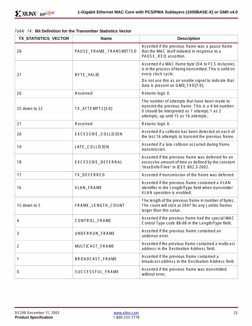
1-Gigabit Ethernet MAC Core with PCSPMA Sublayers (1000BASE-X) or GMII v40R
Table 14 Bit Definition for the Transmitter Statistics Vector
TX_STATISTICS_VECTOR Name Description
28 PAUSE_FRAME_TRANSMITTEDAsserted if the previous frame was a pause framethat the MAC itself initiated in response to aPAUSE_REQ assertion
27 BYTE_VALID
Asserted if a MAC frame byte (DA to FCS inclusive)is in the process of being transmitted This is valid onevery clock cycle
Do not use this as an enable signal to indicate thatdata is present on GMII_TXD[70]
26 Reserved Returns logic 0
25 down to 22 TX_ATTEMPTS[30]
The number of attempts that have been made totransmit the previous frame This is a 4-bit number0 should be interpreted as 1 attempt 1 as 2attempts up until 15 as 16 attempts
21 Reserved Returns logic 0
20 EXCESSIVE_COLLISIONAsserted if a collision has been detected on each ofthe last 16 attempts to transmit the previous frame
19 LATE_COLLISIONAsserted if a late collision occurred during frametransmission
18 EXCESSIVE_DEFERRALAsserted if the previous frame was deferred for anexcessive amount of time as defined by the constantldquomaxDeferTimerdquo in IEEE 8023-2002
17 TX_DEFERRED Asserted if transmission of the frame was deferred
16 VLAN_FRAMEAsserted if the previous frame contained a VLANidentifier in the LengthType field when transmitterVLAN operation is enabled
15 down to 5 FRAME_LENGTH_COUNTThe length of the previous frame in number of bytesThe count will stick at 2047 for any Jumbo frameslarger than this value
4 CONTROL_FRAMEAsserted if the previous frame had the special MACControl Type code 88-08 in the LengthType field
3 UNDERRUN_FRAMEAsserted if the previous frame contained anunderrun error
2 MULTICAST_FRAMEAsserted if the previous frame contained a multicastaddress in the Destination Address field
1 BROADCAST_FRAMEAsserted if the previous frame contained abroadcast address in the Destination Address field
0 SUCCESSFUL_FRAMEAsserted if the previous frame was transmittedwithout error
DS200 December 11 2003 wwwxilinxcom 23Product Specification 1-800-255-7778
1-Gigabit Ethernet MAC Core with PCSPMA Sublayers (1000BASE-X) or GMII v40 R
Receiver
Normal Frame Reception
The timing of a normal inbound frame transfer can be seenin Figure 18 The client must be prepared to accept data atany time there is no buffering within the MAC to allow forlatency in the receive client Once frame reception begins
data is transferred on consecutive clock cycles to thereceive client until the frame is complete The MAC assertsthe RX_GOOD_FRAME signal to indicate that the framewas successfully received and that the frame should beanalyzed by the client
Frame parameters (destination address source addresslengthtype and optionally FCS) are supplied on the databus according to the timing diagram The abbreviations arethe same as those described in Table 13 on page 16
If the LengthType field in the frame has the Length interpre-tation and this indicates that the inbound frame has beenpadded to meet the Ethernet minimum frame size specifica-tion then this padding will not be passed to the client in thedata payload The exception to this is in the case whereFCS passing is enabled see Client-Supplied FCS Pass-ing on page 25
Therefore when Client-Supplied FCS passing is disabledRX_DATA_VALID = lsquo0rsquo between frames for the duration ofthe Padding field (if present) the FCS field carrier exten-sion (if present) the interframe gap following the frame andthe preamble field of the next frame When Client-Supplied
FCS passing is enabled RX_DATA_VALID = lsquo0rsquo betweenframes for the duration of carrier extension (if present) theinterframe gap and the preamble field of the followingframe
RX_GOOD_FRAME RX_BAD_FRAME timing
Although the timing diagram in Figure 18 shows theRX_GOOD_FRAME signal asserted shortly after the lastvalid data on RX_DATA this is not always the case TheRX_GOOD_FRAME or RX_BAD_FRAME signals areasserted only after all frame checks are completed This isafter the FCS field has been received (and after reception ofcarrier extension if present)
Therefore either RX_GOOD_FRAME or RX_BAD_FRAMEis asserted following frame reception at the beginning of theinterframe gap
Figure 18 Normal Frame Reception
RX_CLK
RX_DATA[70]
RX_DATA_VALID
RX_GOOD_FRAME
RX_BAD_FRAME
DA SA DATALT
xip2142
24 wwwxilinxcom DS200 December 11 20031-800-255-7778 Product Specification
1-Gigabit Ethernet MAC Core with PCSPMA Sublayers (1000BASE-X) or GMII v40R
Frame Reception with Errors
The case of an unsuccessful frame reception (for examplea fragment frame or a frame with an incorrect FCS) can beseen in Figure 19 In this case the RX_BAD_FRAME signal
is asserted to the client at the end of the frame It is then theresponsibility of the client to drop the data already trans-ferred for this frame
Figure 19 Frame Reception with Error
Client-Supplied FCS Passing
If the MAC core is configured to pass the FCS field to the cli-ent (see Configuration Registers on page 30) then this ishandled as shown in Figure 20
In this case any padding inserted into the frame to meetEthernet minimum frame length specifications will be leftintact and passed to the client
Note that even though the FCS is passed up to the client itis also verified by the MAC core and RX_BAD_FRAMEasserted if the FCS check fails
RX_CLK
RX_DATA[70]
RX_DATA_VALID
RX_GOOD_FRAME
RX_BAD_FRAME
DA SA DATALT
xip2144
Figure 20 Frame Reception with In-Band FCS Field
RX_CLK
RX_DATA[70]
RX_DATA_VALID
RX_GOOD_FRAME
RX_BAD_FRAME
DA SA DATALT FCS
xip2145
DS200 December 11 2003 wwwxilinxcom 25Product Specification 1-800-255-7778
1-Gigabit Ethernet MAC Core with PCSPMA Sublayers (1000BASE-X) or GMII v40 R
VLAN Tagged Frames
The reception of a VLAN tagged frame (if enabled) can beseen in Figure 21 The VLAN frame is passed to the clientso that the frame may be identified as VLAN tagged this is
followed by the Tag Control Information bytes V1 and V2More information on the interpretation of these bytes maybe found in IEEE 8023-2002 standard
Maximum Permitted Frame Length
The maximum legal length of a frame specified in IEEE8023-2002 is 1518 bytes for non-VLAN tagged framesVLAN tagged frames may be extended to 1522 bytesWhen jumbo frame handling is disabled and the corereceives a frame which exceeds the maximum legal lengthRX_BAD_FRAME will be asserted When jumbo framehandling is enabled frames which are longer than the legalmaximum are received in the same way as shorter frames
For more information on enabling and disabling jumboframe handling see Configuration Registers on page 30
LengthType Field Error Checks
Enabled
Default operation is with the LengthType error checkingenabled (see Receiver Configuration Word 1 on page 31)In this mode the following checks are made on all framesreceived If either of these checks fail then the frame ismarked as BAD
bull A value in the LengthType field that is greater than orequal to decimal 46 but less than decimal 1536 (aLength interpretation) is checked against the actualdata length received
bull A value in the LengthType field that is less thandecimal 46 is checked to see that the data field ispadded to exactly 46 bytes (so that the resultant frameis minimum frame size 64 bytes total in length)
Furthermore if Padding is indicated (the LengthType fieldis less than decimal 46) and Client-Supplied FCS Passing isdisabled then the Length value in the LengthType field willbe used to deassert RX_DATA_VALID after the indicatednumber of data bytes so that the Padding bytes areremoved from the frame
Disabled
When the LengthType error checking is disabled (seeReceiver Configuration Word 1 on page 31) theLengthType error checks described above are not per-formed A frame containing only these errors will be markedas GOOD
Furthermore if Padding is indicated and Client-SuppliedFCS Passing is disabled then a Length Value in theLengthType field will not be used to deassertRX_DATA_VALID Instead RX_DATA_VALID will be deas-serted before the start of the FCS field in this way any pad-ding will not be removed from the frame
Figure 21 Reception of a VLAN Tagged Frame
RX_CLK
RX_DATA[70]
RX_DATA_VALID
RX_GOOD_FRAME
RX_BAD_FRAME
DA SA DATALT
81 00 V1 V2
VLANtag
xip2146
26 wwwxilinxcom DS200 December 11 20031-800-255-7778 Product Specification
1-Gigabit Ethernet MAC Core with PCSPMA Sublayers (1000BASE-X) or GMII v40R
Receiver Statistics Vector
The statistics for the frame received are contained withinthe RX_STATISTICS_VECTOR The vector is driven syn-chronously by the receiver clock RX_CLK following framereception The bit field definition for the Vector is defined inTable 15
All bit fields with the exception of BYTE_VALID are validonly when the RX_STATISTICS_VALID is asserted This isillustrated in Figure 22 BYTE_VALID is significant on everyRX_CLK cycle
Figure 22 Receiver Statistics Vector Timing
RX_CLK
RX_STATISTICS_VECTOR[220]
RX_STATISTICS_VALID
xip2147
Table 15 Bit Definition for the Receiver Statistics Vector
RX_STATISTICS_VECTOR Name Description
22LENGTHTYPE Out ofRange
Asserted if the lengthtype field contained a length valuethat did not match the number of MAC client data bytesreceived Also high if the lengthtype field indicated thatthe frame contained padding but the number of MAC cli-ent data bytes received was not equal to 64 bytes (min-imum frame size)
The exception to the above is when the LengthTypeField Error Checks are disabled in which case this bitwill not be asserted
21 BAD_OPCODE
Asserted if the previous frame was error-free andcontained the special Control Frame identifier in theLengthType field but contained an opcode that isunsupported by the MAC (Any Opcode other thanPAUSE)
20 FLOW_CONTROL_FRAME
Asserted if the previous frame was error-freecontained the special Control Frame identifier in theLengthType field contained a Destination Addressthat matched either the MAC Control MulticastAddress or the configured source address of the MACcontained the supported PAUSE opcode and wasacted upon by the MAC
19 BYTE_VALID
Asserted if a MAC frame byte (DA to FCS inclusive) isin the process of being received This is valid on everyclock cycle
Do not use this as an enable signal to indicate thatdata is present on RX_DATA[70]
18 VLAN_FRAMEAsserted if the previous frame contained a VLANidentifier in the LengthType field when receiver VLANoperation is enabled
DS200 December 11 2003 wwwxilinxcom 27Product Specification 1-800-255-7778
1-Gigabit Ethernet MAC Core with PCSPMA Sublayers (1000BASE-X) or GMII v40 R
17 OUT_OF_BOUNDS
Asserted if the previous frame exceeded the specifiedIEEE8023-2002 maximum legal length (seeMaximum Permitted Frame Length on page 26) Thisis only valid if Jumbo frames are disabled
16 CONTROL_FRAMEAsserted if the previous frame contained the specialControl Frame identifier in the LengthType field
15 down to 5 FRAME_LENGTH_COUNTThe length of the previous frame in number of bytesThe count will stick at 2047 for any Jumbo frameslarger than this value
4 MULTICAST_FRAMEAsserted if the previous frame contained a multicastaddress in the Destination Address field
3 BROADCAST_FRAMEAsserted if the previous frame contained the broadcastaddress in the Destination Address field
2 FCS_ERRORAsserted if the previous frame received had anincorrect FCS value or the MAC detected error codesduring frame reception
1 BAD_FRAME1 Asserted if the previous frame received containederrors
0 GOOD_FRAME1 Asserted if the previous frame received was error-free
1 If the LengthType Field Error Checks are disabled then a frame which contains this type of error will be marked as a GOOD_FRAMEproviding no additional errors were detected
Table 15 Bit Definition for the Receiver Statistics Vector
RX_STATISTICS_VECTOR Name Description
28 wwwxilinxcom DS200 December 11 20031-800-255-7778 Product Specification
1-Gigabit Ethernet MAC Core with PCSPMA Sublayers (1000BASE-X) or GMII v40R
Flow ControlThe flow control block is designed to Clause 31 of the IEEE8023-2002 standard The MAC may be configured to sendpause frames and to act upon their reception These twobehaviors can be configured asymmetrically see Configu-ration Registers on page 30
Transmitting a PAUSE Control Frame
The client initiates a flow control frame by assertingPAUSE_REQ while the pause value is on the PAUSE_VALbus These signals are synchronous to TX_CLK The timingof this can be seen in Figure 23
If the MAC core is configured to support transmit flow con-trol this action causes the core to transmit a PAUSE controlframe on the link with the PAUSE parameter set to thevalue on PAUSE_VAL in the cycle when PAUSE_REQ wasasserted This will not disrupt any frame transmission inprogress but will take priority over any pending frame trans-
mission This frame will be transmitted even if the transmit-ter is in the paused state itself
Receiving a Pause Control Frame
When an error-free frame is received by the MAC core thefollowing checks are made
1 The Destination Address field is matched against theMAC Control Multicast address or the configuredSource Address for the MAC (see ConfigurationRegisters on page 30)
2 The LengthType field is matched against the MACControl Type code
3 The opcode field contents are matched against thePAUSE opcode if check 2 is true
If any of the above checks are false or the MAC Flow Con-trol logic for the receiver is disabled the frame is ignored bythe Flow Control logic and passed up to the client
If the frame passes all of the above checks is of minimumlegal size and the MAC Flow Control logic for the receiver isenabled the pause value parameter in the frame is thenused to inhibit transmitter operation for the time defined inthe IEEE8023-2002 specification This inhibit is imple-mented using the same back pressure scheme shown inFigure 12 Because the received pause frame has beenacted upon it is passed to the client with RX_BAD_FRAMEasserted to indicate to the client that it should be dropped
Reception of any frame for which check 2 is true and whichis not of legal minimum length is considered an invalid Con-trol frame This will be ignored by the Flow Control logic andpassed to the client with RX_BAD_FRAME asserted
Figure 23 Pause Request Timing
TX_CLK
PAUSE_VAL[150]
PAUSE_REQ
xip2148
DS200 December 11 2003 wwwxilinxcom 29Product Specification 1-800-255-7778
1-Gigabit Ethernet MAC Core with PCSPMA Sublayers (1000BASE-X) or GMII v40 R
Optional Management Interface(management_interface=true)The management interface is a processor-independentinterface with standard address data and control signals Itmay be used as is or a wrapper may be applied (not sup-plied) to interface to common bus architectures
This interface is used for
bull Configuration of the MAC core
bull Access to optional statistics counters for use by higherlayers for example SNMP
bull access through the MDIO interface to the managementregisters located in the PHY attached to the MAC core
The management interface is accessed differently depend-ing on the type of transaction a truth table showing whichaccess method is required for each transaction type isshown in Table 16 These access methods are described inthe following sections
HOST_CLK Frequency
The management interface clock HOST_CLK is used toderive the MDIO clock MDC and is therefore subject tosome frequency restrictions This HOST_CLK must be
ge 10 MHz
le 100 MHz
Configuring the MAC core to derive the MDC signal fromthis clock is detailed in MDIO Interface on page 37
Configuration Registers
After power up or reset the client may reconfigure the coreparameters from their defaults such as flow control supportConfiguration changes can be written at any time Both thereceiver and transmitter logic will only respond to configura-tion changes during Inter Frame Gaps The exceptions tothis are the configurable resets which take effect immedi-ately
Configuration of the MAC core is performed through a reg-ister bank accessed through the management interfaceThe configuration registers available in the core are detailedin Table 17 As can be seen the address has some implicitdonrsquot care bits any access to an address in the rangesshown will perform a 32-bit read or write from the same con-figuration word
Table 16 Management Interface Transaction Types
Transaction HOST_MIIM_SEL HOST_ADDR[9]
Configuration 0 1
Statistics 0 0
MIIM access 1 X
Table 17 Configuration Registers
Address Description
0x200-0x23F Receiver Configuration (Word 0)
0x240-0x27F Receiver Configuration (Word 1)
0x280-0x2BF Transmitter Configuration
0x2C0-0x2FF Flow Control Configuration
0x300-0x33F Reserved
0x340-0x37F Management Configuration
30 wwwxilinxcom DS200 December 11 20031-800-255-7778 Product Specification
1-Gigabit Ethernet MAC Core with PCSPMA Sublayers (1000BASE-X) or GMII v40R
The register contents for the two receiver configuration words can be seen in Table 18 and Table 19
Notes1 In changing the receiverrsquos mode from Half Duplex to Full Duplex there is a period of time of up to 24 us following the mode change
when no new receiver statistics can be stored in the optional Statistical Counters
Table 18 Receiver Configuration Word 0
Bit Default Value Description
31-0 All 0rsquos
Pause frame MAC Source Address[310] This address is used by the MAC tomatch against the Destination Address of any incoming flow control frames It isalso used by the flow control block as the Source Address (SA) for any outboundflow control frames
The address is ordered so the first byte transmittedreceived is the lowestpositioned byte in the register for example a MAC address ofAA-BB-CC-DD-EE-FF would be stored in Address[470] as 0xFFEEDDCCBBAA
Table 19 Receiver Configuration Word 1
Bit Default Value Description
15-0 All 0rsquos Pause frame MAC Source Address[4732] See description in Table 18
24-16 NA Reserved
25 0
LengthType Error Check Disable When this bit is set to ldquo1rdquo the core will notperform the LengthType field error checks as described in LengthType FieldError Checks on page 26 When this bit is set to ldquo0rdquo the LengthType field checkswill be performed this is normal operation
26 0Half Duplex If ldquo1rdquo the receiver will operate in half duplex mode If ldquo0rdquo the receiverwill operate in full duplex mode Has no effect if XCO parameterhalf_duplex_capable = false
27 0VLAN Enable When this bit is set to ldquo1rdquo VLAN tagged frames will be acceptedby the receiver
28 1Receiver Enable If set to ldquo1rdquo the receiver block will be operational If set to ldquo0rdquothe block will ignore activity on the physical interface RX port
29 0
In-band FCS Enable When this bit is ldquo1rdquo the MAC receiver will pass the FCS fieldup to the client as described in Client-Supplied FCS Passing on page 25 Whenit is ldquo0rdquo the client will not be passed the FCS In both cases the FCS will beverified on the frame
30 0Jumbo Frame Enable When this bit is set to ldquo1rdquo the MAC receiver will acceptframes over the specified IEEE8023-2002 maximum legal length When this bitis ldquo0rdquo the MAC will only accept frames up to the specified maximum
31 0Reset When this bit is set to ldquo1rdquo the receiver will be reset The bit will thenautomatically revert to ldquo0rdquo Note that this reset will also set all of the receiverconfiguration registers to their default values
DS200 December 11 2003 wwwxilinxcom 31Product Specification 1-800-255-7778
1-Gigabit Ethernet MAC Core with PCSPMA Sublayers (1000BASE-X) or GMII v40 R
The register contents for the Transmitter Configuration Word are described in Table 20
Notes1 In changing the transmitterrsquos mode from Half Duplex to Full Duplex there is a period of time of up to 24 us following the mode change
when no new transmitter statistics can be stored in the optional Statistical Counters
Table 20 Transmitter Configuration Word
Bit Default Value Description
24-0 NA Reserved
25 0
Interframe Gap Adjust Enable If lsquo1rsquo the transmitter will read the value on the portTX_IFG_DELAY at the start of frame transmission and adjust the interframe gapfollowing the frame accordingly See Interframe Gap Adjustment on page 22 Ifldquo0rdquo the transmitter will output a minimum Inter Frame Gap of twelve clock cyclesas specified in IEEE8023-2002
26 0Half Duplex If lsquo1rsquo the transmitter will operate in half duplex mode If lsquo0rsquo thetransmitter will operate in full duplex mode Has no effect if XCO parameterhalf_duplex_capable = false
27 0VLAN Enable When this bit is set to 1 the transmitter will allow the transmissionof VLAN tagged frames
28 1Transmit Enable When this bit is 1 the transmitter is operational When it is 0the transmitter is disabled
29 0
In-band FCS Enable When this bit is lsquo1rsquo the MAC transmitter will expect the FCSfield to be passed in by the client as described in Client-Supplied FCS Passingon page 17 When this bit is ldquo0rdquo the MAC transmitter will append padding asrequired compute the FCS and append it to the frame
30 0
Jumbo Frame Enable When this bit is set to ldquo1rdquo the MAC transmitter will sendframes that are greater than the specified IEEE8023-2002 maximum legallength When this bit is ldquo0rdquo the MAC will only send frames up to the specifiedmaximum
31 0Reset When this bit is set to ldquo1rdquo the transmitter will be reset The bit will thenautomatically revert to ldquo0rdquo Note that this reset will also set all of the transmitterconfiguration registers to their default values
32 wwwxilinxcom DS200 December 11 20031-800-255-7778 Product Specification
1-Gigabit Ethernet MAC Core with PCSPMA Sublayers (1000BASE-X) or GMII v40R
The register contents for the Flow Control Configuration Word are described in Table 21
The register contents for the Management Configuration Word are described in Table 22
Writing to the configuration registers through the manage-ment interface is depicted in Figure 24 When accessing theconfiguration registers (ie when HOST_ADDR[9] = lsquo1rsquo andHOST_MIIM_SEL = lsquo0rsquo) the upper bit of HOST_OPCODEfunctions as an Active Low write enable signal The lowerHOST_OPCODE bit is a ldquodonrsquot carerdquo
Reading from the configuration register words is similar butthe upper HOST_OPCODE bit should be lsquo1rsquo This is shownin Figure 25 In this case the contents of the register appearon HOST_RD_DATA the HOST_CLK edge after the regis-ter address is asserted onto HOST_ADDR
Table 21 Flow Control Configuration Word
Bit Default Value Description
28-0 NA Reserved
29 1
Flow Control Enable (RX) When this bit is lsquo1rsquo received flow control frames willinhibit the transmitter operation as described in Receiving a Pause ControlFrame on page 29 When this bit is lsquo0rsquo received flow control frames will alwaysbe passed up to the client
30 1Flow Control Enable (TX) When this bit is lsquo1rsquo asserting the PAUSE_REQ signalwill send a flow control frame out from the transmitter When this bit is 0 assertingthe PAUSE_REQ signal has no effect
31 NA Reserved
Table 22 Management Configuration Word
Bits Default Value Description
4-0 All 0rsquos Clock Divide[40] See MDIO Interface on page 37
5 0MDIO Enable When this bit is 1 the MDIO interface can be used to accessattached PHY devices When this bit is 0 the MDIO interface is disabled and theMDIO signals remain inactive
31-6 NA Reserved
Figure 24 Configuration Register Write Timing
HOST_CLK
HOST_ADDR[80]
HOST_ADDR[9]
HOST_OPCODE[1]
HOST_MIIM_SEL
HOST_WR_DATA[310]xip2149
Figure 25 Configuration Register Read Timing
HOST_CLK
HOST_ADDR[80]
HOST_ADDR[9]
HOST_OPCODE[1]
HOST_MIIM_SEL
HOST_RD_DATA[310]
xip2150
DS200 December 11 2003 wwwxilinxcom 33Product Specification 1-800-255-7778
1-Gigabit Ethernet MAC Core with PCSPMA Sublayers (1000BASE-X) or GMII v40 R
Optional Statistical Gathering(statistics_gathering=true)
During operation the MAC core collects statistics on thesuccess and failure of various operations for processing by
station management entities (STA) further up the protocolstack These statistics are accessed by the host through theoptional management interface A complete list of statisticssupported is described in Table 23
Table 23 Statistics Registers
Address Name Description
0x000 Frames Received OK1 A count of error-free frames received
0x001 Frame Check Sequence Errors A count of received frames that failed the CRC check and were at least64 bytes in length
0x002 Broadcast Frames Received OK1A count of frames that were successfully received and were directed tothe broadcast group address
0x003 Multicast Frames Received OK1 A count of frames that were successfully received and were directed toa non broadcast group address
0x004 64 byte Frames Received OK1 A count of error-free frames received that were 64 bytes in length
0x005 65-127 byte Frames Received OK1A count of error-free frames received that were between 65 and 127bytes in length
0x006 128-255 byte Frames Received OK1A count of error-free frames received that were between 128 and 255bytes in length
0x007 256-511 byte Frames Received OK1A count of error-free frames received that were between 256 and 511bytes in length
0x008512-1023 byte Frames ReceivedOK1
A count of error-free frames received that were between 512 and 1023bytes in length
0x0091024-MaxFrameSize byte FramesReceived OK1
A count of error-free frames received that were between 1024 bytes andthe specified IEEE8023-2002 maximum legal length (see MaximumPermitted Frame Length on page 26)
0x00A Control Frames Received OKA count of error-free frames received that contained the specialControl Frame identifier in the LengthType field
0x00B LengthType Out of Range
A count of frames received that were at least 64 bytes in length wherethe lengthtype field contained a length value that did not match thenumber of MAC client data bytes received
The counter also increments for frames in which the lengthtype fieldindicated that the frame contained padding but where the number ofMAC client data bytes received was greater than 64 bytes (minimumframe size)
The exception to the above is when the LengthType Field Error Checksare disabled in which case this counter will not increment
0x00C VLAN Tagged Frames Received OKA count of error-free VLAN frames received This counter will only incre-ment when the receiver is configured for VLAN operation
0x00D Pause Frames Received OK
A count of error-free frames received that contained the MAC Controltype identifier 88-08 in the LengthType field contained a Destinationaddress that matched either the MAC Control multicast address or theconfigured source address of the MAC contained the PAUSE opcodeand were acted upon by the MAC
0x00EControl Frames Received withUnsupported Opcode
A count of error-free frames received that contained the MAC Controltype identifier 88-08 in the LengthType field but were received with anopcode other than the PAUSE opcode
34 wwwxilinxcom DS200 December 11 20031-800-255-7778 Product Specification
1-Gigabit Ethernet MAC Core with PCSPMA Sublayers (1000BASE-X) or GMII v40R
0x00F Oversize Frames Received OK1A count of otherwise error-free frames received that exceeded the max-imum legal frame length specified in IEEE 8023-2002 (see MaximumPermitted Frame Length on page 26)
0x010 Undersize frames receivedA count of the number of frames received that were less than 64 bytesin length but were otherwise well formed
0x011 Fragment frames receivedA count of the number of frames received that were less than 64 bytesin length and had a bad Frame Check Sequence field
0x012 Received bytesA count of bytes of frames that are received (Destination Address toFrame Check Sequence inclusive)
0x013 Transmitted bytesA count of bytes of frames that are transmitted (Destination Address toFrame Check Sequence inclusive)
0x020 Frames Transmitted OK A count of error-free frames transmitted
0x021 Broadcast Frames Transmitted OK A count of error-free frames that were transmitted to the broadcastaddress
0x022 Multicast Frames Transmitted OK A count of error-free frames that were transmitted to a group destina-tion address other than broadcast
0x023 Underrun Errors
A count of frames that would otherwise be transmitted by the core butcould not be completed due to the assertion of TX_UNDERRUN duringthe frame transmission This will not count frames which are less than64 bytes in length
0x024 Control Frames Transmitted OKA count of error-free frames transmitted that contained the MACControl Frame type identifier 88-08 in the LengthType field
0x025 64 byte Frames Transmitted OK A count of error-free frames transmitted that were 64 bytes in length
0x026 65-127 byte Frames Transmitted OKA count of error-free frames transmitted that were between 65 and 127bytes in length
0x027128-255 byte Frames TransmittedOK
A count of error-free frames transmitted that were between 128 and 255bytes in length
0x028256-511 byte Frames TransmittedOK
A count of error-free frames transmitted that were between 256 and 511bytes in length
0x029512-1023 byte Frames TransmittedOK
A count of error-free frames transmitted that were between 512 and1023 bytes in length
0x02A1024-MaxFrameSize byte FramesTransmitted OK
A count of error-free frames transmitted that were between 1024 and thespecified IEEE8023-2002 maximum legal length (see Maximum Per-mitted Frame Length on page 20)
0x02BVLAN Tagged Frames TransmittedOK
A count of error-free VLAN frames transmitted This counter will onlyincrement when the transmitter is configured for VLAN operation
0x02C Pause Frames Transmitted OKA count of error-free PAUSE frames generated and transmitted by thecore in response to an assertion of PAUSE_REQ
0x02D Oversize Frames Transmitted OKA count of otherwise error-free frames transmitted that exceeded themaximum legal frame length specified in IEEE 8023-2002 (see Maxi-mum Permitted Frame Length on page 20)
0x02E Single Collision Frames A count of frames that are involved in a single collision but are subse-quently transmitted successfully (Half Duplex Mode only)
Table 23 Statistics Registers (Continued)
Address Name Description
DS200 December 11 2003 wwwxilinxcom 35Product Specification 1-800-255-7778
1-Gigabit Ethernet MAC Core with PCSPMA Sublayers (1000BASE-X) or GMII v40 R
Each of these statistic registers is 64 bits wide and thereforemust be read in a two-cycle transfer The timing of this pro-cess is shown in Figure 26 Six clocks after the read trans-action is initiated the least significant word (LSW) of thestatistics counter appears on the HOST_RD_DATA bus
and a clock cycle later the most significant word (MSW)appears For accurate statistic values 64 clock ticks (ofTX_CLK for transmit statistics or RX_CLK for receive statis-tics) must elapse after the last frame is sent or receivedthrough the MAC core
0x02F Multiple Collision Frames A count of frames that are involved in more than one collision but aresubsequently transmitted successfully (Half Duplex Mode only)
0x040 Frames with Deferred Transmissions A count of frames whose transmission was delayed on its first attemptbecause the medium was busy (Half Duplex Mode only)
0x041 Late Collisions
A count of the times that a collision has been detected later than oneslotTime from the start of the packet transmission A late collision iscounted twice both as a collision and as a lateCollision (Half DuplexMode only)
0x042Frames Aborted due to Excesscollisions
A count of the frames that due to excessive collisions are not transmit-ted successfully (Half Duplex Mode only)
0x043 Carrier Sense ErrorsA count of times that the GMII_CRS signal was not asserted or wasdisasserted during the transmission of a frame without collision (HalfDuplex Mode only)
0x044 Frames with Excess DeferralA count of frames that deferred transmission for an excessive period oftime (Half Duplex Mode only)
1 If the LengthType Field Error Checks are disabled then these counters will still increment for received frames which contain this typeof error (providing no additional errors were detected)
Table 23 Statistics Registers (Continued)
Address Name Description
Figure 26 Statistic Register Read Timing
HOST_CLK
HOST_ADDR[80]
HOST_ADDR[9]
HOST_REQ
HOST_MIIM_SEL
HOST_RD_DATA[310]
6 CLOCKS
LSW MSW
xip2151
36 wwwxilinxcom DS200 December 11 20031-800-255-7778 Product Specification
1-Gigabit Ethernet MAC Core with PCSPMA Sublayers (1000BASE-X) or GMII v40R
MDIO Interface
The management interface is also used to access the MDIO(MII Management) interface of the MAC core this interfaceis used to access the Managed Information Block (MIB) ofthe PHY components attached to the MAC core
The MDIO interface supplies a clock to the externaldevices MDC This clock is derived from the HOST_CLKsignal using the value in the Clock Divide[40] configurationregister The frequency of the MDIO clock is given by thefollowing equation
The frequency of MDC given by this equation should notexceed 25 MHz in order to comply with the IEEE8023-2002 specification for this interface To prevent MDCfrom being out of specification the Clock Divide[40] valuepowers up at 00000 and while this value is in the register itis impossible to enable the MDIO interface
For details of the register map of PHY layer devices and afuller description of the operation of the MDIO interfaceitself see IEEE specification 8023-2002
Access to the MDIO interface through the managementinterface is depicted in the timing diagram in Figure 27
For MDIO transactions the following points apply
bull HOST_OPCODE maps to the OP (opcode) field of theMDIO frame
bull HOST_ADDR maps to the two address fields of theMDIO frame PHY_ADDR is HOST_ADDR[95] andREG_ADDR is HOST_ADDR[40]
bull HOST_WR_DATA[150] maps into the data field of the
MDIO frame when performing a write operation
bull The data field of the MDIO frame maps intoHOST_RD_DATA[150] when performing a readoperation
The MAC core signals to the host that it is ready for anMDIO transaction by asserting HOST_MIIM_RDY A read orwrite transaction on the MDIO is initiated by a pulse on the
fMDC
fHOST_CLK
1 Clock Divide[40]+( ) 2times-------------------------------------------------------------------=
Figure 27 MDIO Access Through Management Interface
HOST_CLK
HOST_ADDR[90]
HOST_OPCODE[10]
HOST_REQ
HOST_MIIM_SEL
HOST_RD_DATA[150]
HOST_WR_DATA[150]
HOST_RDY
If a read transaction is initiated the HOST_RD_DATA bus is valid at the point indicated If a write transaction is initiated the HOST_WR_DATA bus must be valid at the indicated point Simultaneous read and write is not permitted
xip2152
DS200 December 11 2003 wwwxilinxcom 37Product Specification 1-800-255-7778
1-Gigabit Ethernet MAC Core with PCSPMA Sublayers (1000BASE-X) or GMII v40 R
HOST_REQ signal This pulse is ignored if the MDIO inter-face already has a transaction in progress
The MAC core then disasserts the HOST_MIIM_RDY signalwhile the transaction across the MDIO is in progress Whenthe transaction across the MDIO interface has been com-pleted the HOST_MIIM_RDY signal will be asserted by theMAC core if the transaction is a read the data will also beavailable on the HOST_RD_DATA[150] bus at this time
Optional Configuration Vector(management_interface = false)If the optional Management interface is omitted from thecore all of relevant configuration signals are brought out of
the core These signals are bundled into theCONFIGURATION_VECTOR signal The bit mapping of theconfiguration vector signal is defined in Table 24 See thecorresponding entry in the configuration register tables forthe full description of each signal
Note that these configuration vector signals can bechanged by the user at any time however with the excep-tion of the reset and the flow control configuration signalsthey will not take effect until the current frame has com-pleted transmission or reception
The ldquoClockrdquo heading denotes which clock domain the con-figuration signal is registered into before use by the core Itis not necessary to drive the signal from this clock domain
Table 24 Configuration Vector Bit Definition
Bit(s)Configuration Register
cross reference Clock Description
47 downto 0
Receiver ConfigurationWord 0 bits 31-0 andReceiver ConfigurationWord 1 bits 15-0
RX_CLK
Pause frame MAC Source Address[470] This address isused by the MAC core to match against the DestinationAddress of any incoming flow control frames and as theSource Address for any outbound flow control frames
The address is ordered such that the first byte transmitted orreceived is the least significant byte in the register forexample a MAC address of AA-BB-CC-DD-EE-FF will bestored in bite [470] as 0xFFEEDDCCBBAA
48Receiver ConfigurationWord 1 bit 26
RX_CLKReceiver Half Duplex If lsquo1rsquo the receiver operates in halfduplex mode If lsquo0rsquo the receiver operates in full duplex modeHas no effect if XCO parameter half_duplex_capable = false
49Receiver ConfigurationWord 1 bit 27
RX_CLKReceiver VLAN Enable When this bit is set to 1 VLANtagged frames are accepted by the receiver
50Receiver ConfigurationWord 1 bit 28
RX_CLKReceiver Enable If set to 1 the receiver block is operationalIf set to 0 the block ignores activity on the physical interfaceRX port
51Receiver ConfigurationWord 1 bit 29
RX_CLK
Receiver In-band FCS Enable When this bit is lsquo1rsquo the MACreceiver will pass the FCS field up to the client as describedin Client-Supplied FCS Passing on page 25 When it is lsquo0rsquothe MAC receiver will not pass the FCS field In both casesthe FCS field will be verified on the frame
52Receiver ConfigurationWord 1 bit 30
RX_CLK
Receiver Jumbo Frame Enable When this bit is lsquo0rsquo thereceiver will not pass frames longer than the maximum legalframe size specified in IEEE 8023-2002 (see MaximumPermitted Frame Length on page 26) When it is lsquo1rsquo thereceiver will not have an upper limit on frame size
53Receiver ConfigurationWord 1 bit 31
NA
Receiver Reset When this bit is lsquo1rsquo the receiver is held inreset
This signal is an input to the reset circuit for the receiverblock See Reset circuit on page 42 for more information
54TransmitterConfiguration Word bit25
TX_CLK
Transmitter Interframe Gap Adjust enable If lsquo1rsquo then thetransmitter will read the value of the TX_IFG_DELAY port andset the Interframe Gap accordingly If lsquo0rsquo the transmitter willalways insert at least the legal minimum Interframe Gap
38 wwwxilinxcom DS200 December 11 20031-800-255-7778 Product Specification
1-Gigabit Ethernet MAC Core with PCSPMA Sublayers (1000BASE-X) or GMII v40R
55TransmitterConfiguration Word bit26
TX_CLK
Transmitter Half Duplex If lsquo1rsquo the transmitter operates in halfduplex mode If lsquo0rsquo the transmitter operates in full duplexmode Has no effect if XCO parameter half_duplex_capable= false
56TransmitterConfiguration Word bit27
TX_CLKTransmitter VLAN Enable When this bit is set to lsquo1rsquo thetransmitter allows the transmission of VLAN tagged frames
57TransmitterConfiguration Word bit28
TX_CLKTransmitter Enable When this bit is 1 the transmitter will beoperational When it is 0 the transmitter is disabled
58TransmitterConfiguration Word bit29
TX_CLK
Transmitter In-Band FCS Enable When this bit is lsquo1rsquo theMAC transmitter will expect the FCS field to be pass in by theclient as described in Client-Supplied FCS Passing onpage 17 When it is lsquo0rsquo the MAC transmitter will appendpadding as required compute the FCS and append it to theframe
59TransmitterConfiguration Word bit30
TX_CLK
Transmitter Jumbo Frame Enable When this bit is lsquo1rsquo theMAC transmitter will allow frames larger than the maximumlegal frame length specified in IEEE 8023-2002 to be sentWhen set to lsquo0rsquo the MAC transmitter will only allow frames upto the legal maximum to be sent
60TransmitterConfiguration Word bit31
NA
Transmitter Reset When this bit is lsquo1rsquo the MAC transmitter isheld in reset
This signal is an input to the reset circuit for the transmitterblock See Reset circuit on page 42 for more information
61Flow ControlConfiguration Word bit29
TX_CLK
Transmit Flow Control Enable When this bit is lsquo1rsquo assertingthe PAUSE_REQ signal causes the MAC core to send a flowcontrol frame out from the transmitter as described inReceiving a Pause Control Frame on page 29 When this bitis lsquo0rsquo asserting the PAUSE_REQ signal will have no effect
62Flow ControlConfiguration Word bit30
RX_CLK
Receive Flow Control Enable When this bit is lsquo1rsquo receivedflow control frames will inhibit the transmitter operation asdescribed in Receiving a Pause Control Frame on page 29When it is lsquo0rsquo received flow frames are passed up to theclient
63Receiver ConfigurationWord 1 bit 25
RX_CLK
LengthType Error Check Disable When this bit is lsquo1rsquo thecore will not perform the LengthType field error checks asdescribed in LengthType Field Error Checks on page 26When it is set to lsquo0rsquo the LengthType field checks will beperformed this is normal operation
Table 24 Configuration Vector Bit Definition (Continued)
Bit(s)Configuration Register
cross reference Clock Description
DS200 December 11 2003 wwwxilinxcom 39Product Specification 1-800-255-7778
1-Gigabit Ethernet MAC Core with PCSPMA Sublayers (1000BASE-X) or GMII v40 R
Optional GMII (physical_interface=gmii)The GMII is designed to IEEE 8023-2002 Clause 35 Thisutilizes IOrsquos of the Xilinx devices using inputoutput buffersand inputoutput flip-flops to maximize setup and hold mar-gins All IO logic is placed in the example wrapper that isdelivered with the core In addition all clock managementlogic for the core is instanced in this example wrapper thisallows multiple instances of the core to share clocks Theexample wrapper is provided in both VHDL and Verilog
Clock Management
Figure 28 illustrates the clock management used with theGMII interface All clocks illustrated have a frequency of125MHz
GTX_CLK must be provided to the MAC core This is a highquality clock which satisfies the IEEE8023-2002 require-ments It is expected that this clock will be derived from anexternal oscillator and connected into the device through anIBUFG as illustrated The clock source must then be routedonto a global clock network by connecting it to a BUFGWithin the MAC core this global clock is used by all MACtransmitter logic The MAC Client can obtain this clock byconnecting to the TX_CLK signal output from the coreGMII_TX_CLK is derived from this global clock by invertingit and routing it to an OBUF
GMII_RX_CLK is received through an IBUFG This clock isthen routed onto a global clock network by connecting it to aBUFG The resulting global clock is used by all MACreceiver logic
Figure 28 Clock Management with GMII
IBUFG
IBUFG
OBUF
BUFG
BUFG
TX_CLK
RX_CLK
GTX_CLK
GMII_TX_CLK
GMII_RX_CLK
Example Wrapper
xip2153
MAC Core
TX_CLK
RX_CLK
GMII_TX_CLK
GMII_RX_CLK
GTX_CLK
40 wwwxilinxcom DS200 December 11 20031-800-255-7778 Product Specification
1-Gigabit Ethernet MAC Core with PCSPMA Sublayers (1000BASE-X) or GMII v40R
Clock Sharing between Multiple cores
Figure 29 illustrates how it is possible to share clockresources across multiple instantiations of the core whenusing the optional GMII
GTX_CLK may be shared between multiple cores as illus-trated resulting in a common transmitter clock domainacross the device
A common receiver clock domain is not possible each corewill receive an independent receiver clock from its GMII asillustrated
Although not illustrated if the optional Management Inter-face is used HOST_CLK can also be shared betweencores
Figure 29 Clock Management with multiple instances of the MAC with GMII
IBUFG
OBUF
BUFG
TX_CLK
RX_CLK_1
GMII_TX_CLK_1
GMII_RX_CLK_1
MAC Core
TX_CLK
RX_CLK
GMII_TX_CLK
GMII_RX_CLK
GTX_CLK
MAC Core
TX_CLK
RX_CLK
GMII_TX_CLK
GMII_RX_CLK
GTX_CLK
IBUFG
BUFG
GTX_CLK
IBUFG
OBUF
GMII_TX_CLK_2
GMII_RX_CLK_2
BUFG
TX_CLK
RX_CLK_2
DS200 December 11 2003 wwwxilinxcom 41Product Specification 1-800-255-7778
1-Gigabit Ethernet MAC Core with PCSPMA Sublayers (1000BASE-X) or GMII v40 R
Reset circuit
Internally the core is divided up into clockreset domainswhich group together elements with the common clock andreset signals The reset circuitry for one of these domains isis illustrated in Figure 30 This circuit provides controllableskews on the reset nets within the design
More information on the operation and rationale behind thiscircuit can be found in Ken Chapmanrsquos Xilinx TechXclusiveldquoGet Smart About Resetrdquo athttpwwwxilinxcomsupporttechxclusivesglobal-techX19htm
Figure 30 Reset circuit for one clockreset domain
FDP
PRED
C
Q
FDP
PRED
C
Q
FDP
PRED
C
Q
FDP
PRED
C
Q
PRE PRE PRE
0
RESET
Management Reset
Clock
Core Registers
42 wwwxilinxcom DS200 December 11 20031-800-255-7778 Product Specification
1-Gigabit Ethernet MAC Core with PCSPMA Sublayers (1000BASE-X) or GMII v40R
Optional PCS with Ten-Bit Interface (TBI) for 1000BASE-X (physical_interface=tbi)The Full-Duplex Physical Coding Sublayer (PCS) for1000BASE-X is defined in IEEE 8023-2002 Clauses 36and 37 This functionality is only available in the Virtex-IIand Spartan3 families of FPGA devices
A block diagram of the PCS is shown in Figure 31 Themajor functional blocks of the PCS are
bull Transmit engine
bull Auto-negotiation block
bull Receive engine and synchronization block
bull PCS managed register block
bull 8B10B encoder block
bull 8B10B decoder block
bull Receiver elastic buffer
The PCS Managed Register Block is accessed through theMDIO Interface as if it were an externally connected PHYThis configures the operation of the PCS and Auto-Negoti-ation See PCS Managed Register Block
(physical_interface = tbi or phy) on page 49 The corersquosoptional Management Interface can be used to control theMDIO Interface as described by MDIO Interface onpage 37 When the optional Management Interface is notpresent the PCS Managed Register Block must beaccessed via an MDIO controller which is not provided bythe core
The 8B10B encodingdecoding blocks are implemented byconfiguring two Block SelectRAM modules as ROM Theseare used as large look-up tables The remaining PCS func-tionality such as code group encodingdecoding the Man-aged Register Block and Auto-Negotiation areimplemented in CLB logic
The Receiver Elastic buffer enables the 10-bit parallel datareceived from the PMA sublayer alternatively onPMA_RX_CLK0 and PMA_RX_CLK1 clock edges to betransferred onto the internal 125MHz clock domain derivedfrom GTX_CLK (see Clock Management) This buffer isimplemented in Distributed Memory
Figure 31 Functional Block Diagram of the 1-Gigabit Ethernet PCS with TBI Interface
PCS TRANSMIT ENGINE
PCS RECEIVE ENGINE ampSYNCHRONISATION
PCSMANAGEMENT
MDIOInterface
AUTO-NEGOTIATION
MAC TXInterface
MAC RXInterface
8B10BEncoder
8B10BDecoder
RX Elastic Buffer
TBI Interface
DS200 December 11 2003 wwwxilinxcom 43Product Specification 1-800-255-7778
1-Gigabit Ethernet MAC Core with PCSPMA Sublayers (1000BASE-X) or GMII v40 R
TBI Interface
The TBI is designed to IEEE 8023-2002 Clause 363 Thisutilizes IOrsquos of the Xilinx devices using inputoutput buffersand inputoutput flip-flops to maximize setup and hold mar-gins All IO logic is placed in the example wrapper that isdelivered with the core In addition all clock managementlogic for the core is instantiated in this example wrapperthis allows multiple instances of the core to share clocksThe example wrapper is provided in both VHDL and Verilog
Clock Management
Figure 32 illustrates the clock management used with theTBI interface
GTX_CLK must be provided to the MAC core This is a highquality clock of frequency 125MHz which satisfies theIEEE8023-2002 requirements It is expected that this clockwill be derived from an external oscillator and connected
into the device through an IBUFG as illustrated The clocksource must then be routed onto a global clock network byconnecting it to a BUFG Within the MAC core this globalclock is used by all MAC transmitter logic PMA_TX_CLK isderived from this global clock by inverting it and routing it toan OBUF
PMA_RX_CLK0 and PMA_RX_CLK1 are each receivedthrough an IBUFG These clocks are then routed onto glo-bal clock networks by connecting each to a BUFGPMA_RX_CLK0 and PMA_RX_CLK1 are each 625MHzclocks Data from the TBI is received alternatively on the ris-ing edge of PMA_RX_CLK0 followed by the rising edge ofPMA_RX_CLK1 using IOB Double-Data Rate input regis-ters This data is then written into the Receiver ElasticBuffer Data is read out of the Elastic Buffer using the globalclock derived from GTX_CLK all the remaining receiverlogic is synchronous to this clock
Figure 32 Clock Management for PCS with TBI Interface
IBUFG
IBUFG
OBUF
BUFG
BUFG
TX_CLK
RX_CLK
GTX_CLK
PMA_TX_CLK
PMA_RX_CLK0
MAC Core
RX ELASTICBUFFER
Example Wrapper
TX_CLK
RX_CLK
GTX_CLK
PMA_TX_CLK
PMA_RX_CLK0
IBUFGBUFGPMA_RX_CLK1
PMA_RX_CLK1
44 wwwxilinxcom DS200 December 11 20031-800-255-7778 Product Specification
1-Gigabit Ethernet MAC Core with PCSPMA Sublayers (1000BASE-X) or GMII v40R
Clock Sharing between Multiple cores
Figure 33 illustrates how it is possible to share clockresources across multiple instantiations of the core whenusing the optional PCS with TBI
GTX_CLK may be shared between multiple cores as illus-trated resulting in a common transmitter clock domainacross the device
Each core will receive independent PMA_RX_CLK0 andPMA_RX_CLK1 clocks from its TBI as illustrated whichcannot be shared
Although not illustrated if the optional Management Inter-face is used HOST_CLK can also be shared betweencores
Figure 33 Clock Management with multiple instances of the MAC with PCS and TBI
Reset circuit
The reset circuits within the MAC when the TBI interface is implemented is the same as that in the GMII case details ofthese circuits can be found on page 42
IBUFG
OBUF
BUFG
TX_CLK
RX_CLK
PMA_TX_CLK_1
PMA_RX_CLK0_1
MAC Core
RX ELASTICBUFFER
TX_CLK
RX_CLK
GTX_CLK
PMA_TX_CLK
PMA_RX_CLK0
IBUFGBUFGPMA_RX_CLK1_1
PMA_RX_CLK1
IBUFG
BUFG
GTX_CLK
IBUFG
OBUF
BUFG
TX_CLK
RX_CLK
PMA_TX_CLK_2
PMA_RX_CLK0_2
MAC Core
RX ELASTICBUFFER
TX_CLK
RX_CLK
GTX_CLK
PMA_TX_CLK
PMA_RX_CLK0
IBUFGBUFGPMA_RX_CLK1_2
PMA_RX_CLK1
DS200 December 11 2003 wwwxilinxcom 45Product Specification 1-800-255-7778
1-Gigabit Ethernet MAC Core with PCSPMA Sublayers (1000BASE-X) or GMII v40 R
Optional PCS and PMA Sublayers for 1000BASE-X (physical_interface=phy)The Full-Duplex Physical Coding Sublayer (PCS) withPhysical Medium Attachment (PMA) for 1000BASE-X isdefined in IEEE 8023-2002 Clauses 36 and 37 This func-tionality is only available in the Virtex-II Pro family of FPGAdevices
A block diagram of the PCS and PMA sublayers can beseen in Figure 34 The functional blocks of the PCS andPMA sublayers may replace the optional GMII interfaceThe functional blocks of the PCS and PMA sublayers are
bull PCS Transmit Engine
bull Auto-Negotiation block
bull Receive Engine and Synchronization Block
bull PCS Managed Register Block
bull Rocket IO Multi-Gigabit Transceiver
The PCS Managed Register Block is accessed through theMDIO Interface as if it were an externally connected PHYThis configures the operation of the PCS PMA sublayerand Auto-NegotiationSee PCS Managed Register Block(physical_interface = tbi or phy) on page 49 The corersquosoptional Management Interface can be used to control theMDIO Interface as described by MDIO Interface onpage 37 When the optional Management Interface is notpresent the PCS Managed Register Block must beaccessed via an MDIO controller which is not provided bythe core
The Rocket IO Multi-Gigabit Transceiver (MGT) providessome of the PCS layer functionality such as 8B10B encod-ingdecoding and the PMA serdes The remaining PCSfunctionality such as code group encodingdecoding theManaged Register Block and Auto-Negotiation are imple-mented in CLB logic
Figure 34 Functional Block Diagram of the 1-Gigabit Ethernet PCSPMA Sublayer Extension
PCS TRANSMIT ENGINE
PCS RECEIVE ENGINE ampSYNCHRONISATION
RO
CK
ET
IO
MU
LTI-
GIG
TR
AN
SC
EIV
ER
PCSMANAGEMENT
MDIOInterface
AUTO-NEGOTIATION
TXPTXN
RXPRXN
MAC TXInterface
MAC RXInterface
xip2154
46 wwwxilinxcom DS200 December 11 20031-800-255-7778 Product Specification
1-Gigabit Ethernet MAC Core with PCSPMA Sublayers (1000BASE-X) or GMII v40R
Clock Management
Figure 35 illustrates the clock management that should beused with the optional PCS and PMA sublayers for1000BASE-X This logic is implemented in the examplewrapper that is delivered with the core This provides flexi-bility because the design can be modified to use eitherREFCLK or BREFCLK (please refer to Rocket IO docu-mentation) It would also allow multiple instances of the coreto share clocks The example wrapper is provided in bothVHDL and Verilog
(B)REFCLK must be provided to the MAC core This clockmust be derived from an external oscillator and connectedto the core through an IBUFG as illustrated (B)REFCLK isa high quality clock of frequency 625 MHz which satisfiesthe Rocket IO Multi-Gigabit Transceiver (MGT) require-ments
(B)REFCLK is routed to both the core and a DCM From theDCM the CLK2X180 output is routed to a BUFG to providethe device with a global 125 MHz clock (connected toUSERCLK2 input on the core) Within the core bothTX_CLK and RX_CLK share this global 125 MHz clocksource which is used by all transmitter and receiver logicThis is made possible by the RX_ELASTIC_BUFFER func-tionality of the Rocket IO MGT (refer to Virtex-II Pro docu-mentation) The MAC Client can obtain this clock byconnecting to either the TX_CLK or the RX_CLK signalsoutput from the core
From the DCM the CLK0 output is routed to a BUFG to pro-vide the device with a global 625MHz clock This is con-nected to the USRCLK input of the core
Figure 35 Clock Management with PCSPMA Sublayers
DCM
CLKIN CLK0
CLK2X180FB
BUFG
BUFG
IBUFG
TX_CLK
RX_CLK
(B)REFCLK
TXUSRCLK
(B)REFCLK
TXUSRCLK2RXUSRCLKRXUSRCLK2
GT_ETHERNET
Example Wrapper
xip2155
MAC Core
(B)REFCLK
USRCLK
USRCLK2
TX_CLK
RX_CLK
DS200 December 11 2003 wwwxilinxcom 47Product Specification 1-800-255-7778
1-Gigabit Ethernet MAC Core with PCSPMA Sublayers (1000BASE-X) or GMII v40 R
Clock Sharing between Multiple Cores
Figure 36 illustrates how it is possible to share clockresources across multiple instantiations of the core whenusing the optional PCSPMA sublayers For each coreUSERCLK and USERCLK2 must always be derived asshown from the BREFCLK or REFCLK used by that core
Note that when using the fixed routing resources of BREF-CLK Rocket IO MGTs along the top edge of the devicemust use a separate BREFCLK routing resource to thosealong the bottom edge of the device (Refer to Virtex-II Prodocumentation)
Although not illustrated if the optional Management Inter-face is used HOST_CLK can also be shared betweencores
Figure 36 Clock Management with multiple instances of the MAC with PCS and PMA sublayers
Reset circuit
The reset circuits within the MAC when the PCS and PMA sublayers are implemented is the same as that in the GMII casedetails of these circuits can be found on page 42
DCM
CLKIN CLK0
CLK2X180FB
BUFG
BUFG
IBUFG
(B)REFCLK
TXUSRCLK
(B)REFCLK
TXUSRCLK2RXUSRCLKRXUSRCLK2
GT_ETHERNET(B)REFCLK
USERCLK
USERCLK2
MAC core
TXUSRCLK
(B)REFCLK
TXUSRCLK2RXUSRCLKRXUSRCLK2
GT_ETHERNET(B)REFCLK
USERCLK
USERCLK2
MAC core
48 wwwxilinxcom DS200 December 11 20031-800-255-7778 Product Specification
1-Gigabit Ethernet MAC Core with PCSPMA Sublayers (1000BASE-X) or GMII v40R
PCS Managed Register Block (physical_interface = tbi or phy)The PCS in both the TBI interface and the PCSPMA (usingthe Virtex-II Pro Rocket IO) versions contain the full Man-aged Register Block defined in IEEE 8023-2002 clause 37
This utilizes ten dedicated management registersaccessed via the MDIO interface These are defined inTable 25 to Table 33 inclusive
Table 25 Control Register (Register 0)
Bit(s) Name Description Attributes Default Value
015 Reset1 = PCSPMA reset
0 = Normal Operation
ReadWrite
Self Clearing0
014 Loopback1 = Enable Loopback Mode
0 = Disable Loopback ModeReadWrite 0
013SpeedSelection (LSB)
The core always returns a 0 for this bitTogether with bit 06 speed selection of 1000Mbs is identified
Returns 0 0
012Auto-NegotiationEnable
1 = Enable Auto-Negotiation Process
0 = Disable Auto-Negotiation ProcessReadWrite 1
011 Power Down
1 = Power down
0 = Normal operation
When set to ldquo1rdquo the Rocket IO MGT is placedin a low power state This bit requires a reset(see bit 015) to clear
Read Write 0
010 Isolate1 = Electrically Isolate PHY from GMII
0 = Normal operationReadWrite 1
09Restart Auto-Negotiation
1 = Restart Auto-Negotiation Process
0 = Normal Operation
ReadWrite
Self Clearing0
08 Duplex ModeThe core always returns a 1 for this bit tosignal Full-Duplex Mode
Returns 1 1
07 Collision TestThe core always returns a 0 for this bit todisable COL test
Returns 0 0
06SpeedSelection(MSB)
The core always returns a 1 for this bitTogether with bit 013 speed selection of1000 Mbs is identified
Returns 1 1
050 Reserved Always returns 0rsquos writes ignored Returns 0rsquos 000000
DS200 December 11 2003 wwwxilinxcom 49Product Specification 1-800-255-7778
1-Gigabit Ethernet MAC Core with PCSPMA Sublayers (1000BASE-X) or GMII v40 R
Table 26 Status Register (Register 1)
Bit(s) Name Description Attributes Default Value
115 100BASE-T4The core always returns a 0 for this bitbecause 100BASE-T4 is not supported
Returns 0 0
114100BASE-XFullDuplex
The core always returns a 0 for this bitbecause 100BASE-X Full Duplex is notsupported
Returns 0 0
113100BASE-XHalf Duplex
The core always returns a 0 for this bitbecause 100BASE-X Half Duplex is notsupported
Returns 0 0
11210 Mbs FullDuplex
The core always returns a 0 for this bitbecause 10 Mbs Full Duplex is notsupported
Returns 0 0
11110 Mbs HalfDuplex
The core always returns a 0 for this bitbecause 10 Mbs Half Duplex is notsupported
Returns 0 0
110100BASE-T2Full Duplex
The core always returns a 0 for this bitbecause 100BASE-T2 Full Duplex is notsupported
Returns 0 0
19100BASE-T2Half Duplex
The core always returns a 0 for this bitbecause 100BASE-T2 Half Duplex is notsupported
Returns 0 0
18ExtendedStatus
The core always returns a 1 for this bit toindicate the presence of the ExtendedRegister (Register 15)
Returns 1 1
17 Reserved Always return 0 writes ignored Returns 0 0
16MF PreambleSuppression
The core always returns a 1 for this bit toindicate that Management Frame PreambleSuppression is supported
Returns 1 1
15Auto-NegotiationComplete
1 = Auto-Negotiation process completed
0 = Auto-Negotiation process not completedRead Only 0
14 Remote Fault1 = Remote fault condition detected
0 = No remote fault condition detected
Read Only
Self Clearing on read0
13Auto-NegotiationAbility
The core always returns a 1 for this bit toindicate that the PHY is capable ofAuto-Negotiation
Returns 1 1
12 Link Status1 = Link is up
0 = Link is down
Read Only
Self Clearing on read0
11 Jabber DetectThe core always returns a 0 for this bitbecause Jabber Detect is not supported
Returns 0 0
10ExtendedCapability
The core always returns a 0 for this bitbecause no extended register set issupported
Returns 0 0
50 wwwxilinxcom DS200 December 11 20031-800-255-7778 Product Specification
1-Gigabit Ethernet MAC Core with PCSPMA Sublayers (1000BASE-X) or GMII v40R
Table 27 PHY Identifier (Registers 2 and 3)
Bit(s) Name Description Attributes Default Value
2150OrganizationallyUniqueIdentifier
Always returns 0s Returns 0s 0000000000000000
31510OrganizationallyUniqueIdentifier
Always returns 0s Returns 0s 000000
394Manufacturerrsquosmodel number
Always returns 0s Returns 0s 000000
330RevisionNumber
Always returns 0s Returns 0s 0000
Table 28 Auto-Negotiation Advertisement Register (Register 4)
Bit(s) Name Description Attributes Default Value
415 Next Page1 = Next Page functionality is advertised
0 = Next Page functionality is not advertisedReadWrite 0
414 Reserved Always returns 0 writes ignored Returns 0 0
41312 Remote Fault
00 = No Error
01 = Offline
10 = Link Failure
11 = Auto-Negotiation Error
ReadWrite
Self clearing to 00afterAuto-Negotiation
00
4119 Reserved Always return 0 writes ignored Returns 0 0
487 Pause
00 = No PAUSE
01 = Asymmetric PAUSE towards linkpartner
10 = Symmetic PAUSE
11 = Both Symmetric PAUSE andAsymmetric PAUSE towards link partner
ReadWrite 11
46 Half DuplexThe core always returns a 0 for this bitbecause Half Duplex Mode is not supported
Returns 0 0
45 Full Duplex1 = Full Duplex Mode is advertised
0 = Full Duplex Mode is not advertisedReadWrite 1
440 Reserved Always returns 0s writes ignored Returns 0s 00000
DS200 December 11 2003 wwwxilinxcom 51Product Specification 1-800-255-7778
1-Gigabit Ethernet MAC Core with PCSPMA Sublayers (1000BASE-X) or GMII v40 R
Table 29 Auto-Negotiation Link Partner Ability Base Register (Register 5)
Bit(s) Name Description Attributes Default Value
515 Next Page1 = Next Page functionality is supported
0 = Next Page functionality is not supportedRead Only 0
514 AcknowledgeUsed by Auto-Negotiation function toindicate reception of a link partnerrsquos base ornext page
Read Only 0
51312 Remote Fault
00 = No Error
01 = Offline
10 = Link Failure
11 = Auto-Negotiation Error
Read Only 00
5119 Reserved Always returns 0s Returns 0s 000
587 Pause
00 = No PAUSE
01 = Asymmetric PAUSE supported
10 = Symmetic PAUSE supported
11 = Both Symmetric PAUSE andAsymmetric PAUSE supported
Read Only 00
56 Half Duplex1 = Half Duplex Mode is supported
0 = Half Duplex Mode is not supportedRead Only 0
55 Full Duplex1 = Full Duplex Mode is supported
0 = Full Duplex Mode is not supportedRead Only 0
540 Reserved Always returns 0s Returns 0s 00000
Table 30 Auto-Negotiation Expansion Register (Register 6)
Bit(s) Name Description Attributes Default Value
6153 Reserved Always returns 0s Returns 0s 0000000000000
62 Next Page AbleThe core always returns a 1 for this bitbecause the device is Next Page Able
Returns 1 1
61 Page Received1 = A new page has been received
0 = A new page has not been received
Read Only
Self Clearing on read0
60 Reserved Always returns 0s Returns 0s 0000000
52 wwwxilinxcom DS200 December 11 20031-800-255-7778 Product Specification
1-Gigabit Ethernet MAC Core with PCSPMA Sublayers (1000BASE-X) or GMII v40R
Table 31 Auto-Negotiation Next Page Transmit Register (Register 7)
Bit(s) Name Description Attributes Default Value
715 Next Page1 = Additional Next Page(s) will follow
0 = Last pageReadWrite 0
714 Reserved Always returns 0 Returns 0 0
713 Message Page1 = Message Page
0 = Unformatted PageReadWrite 1
712 Acknowledge 21 = Will comply with message
0 = Cannot comply with messageReadWrite 0
711 ToggleValue will toggle between subsequent NextPages
Read Only 0
7100Message UnformattedCode Field
Message Code Field or Unformatted PageEncoding as dictated by 713
ReadWrite00000000001
(Null Message Code)
Table 32 Auto-Negotiation Next Page Receive Register (Register 8)
Bit(s) Name Description Attributes Default Value
815 Next Page1 = Additional Next Page(s) follows
0 = Last pageRead Only 0
814 AcknowledgeUsed by Auto-Negotiation function toindicate reception of a link partnerrsquos base ornext page
Read Only 0
813 Message Page1 = Message Page
0 = Unformatted PageRead Only 0
812 Acknowledge 21 = Will comply with message
0 = Cannot comply with messageRead Only 0
811 ToggleValue toggles between subsequent andNext Pages
Read Only 0
8100Message UnformattedCode Field
Message Code Field or Unformatted PageEncoding as dictated by 813
Read Only 00000000000
DS200 December 11 2003 wwwxilinxcom 53Product Specification 1-800-255-7778
1-Gigabit Ethernet MAC Core with PCSPMA Sublayers (1000BASE-X) or GMII v40 R
)
Referencesbull IEEE 8023-2002
bull Virtex-E User Guide
bull Spartan-II E User Guide
bull Virtex-II User Guide
bull Virtex-II Pro User Guide
Related InformationXilinx products are not intended for use in life support appli-ances devices or systems Use of a Xilinx product in suchapplications without the written consent of the appropriateXilinx officer is prohibited
Ordering InformationThis Xilinx LogiCORE module is provided under theSignOnce IP Site License A free evaluation version of themodule is available
Once purchased the core may be downloaded from the Xil-inx IP Center for use with the Xilinx CORE Generator Sys-temtrade v61i SP3 and later The Xilinx CORE GeneratorSystem tool is bundled with all Alliance Series Softwarepackages at no additional charge
Please contact your local Xilinx sales representative or visitthe Xilinx Silicon Xpresso Cafe for pricing and availability onXilinx LogiCORE modules and software Information onadditional Xilinx LogiCORE modules is available on the Xil-inx IP Center
Revision HistoryThe following table shows the revision history for this document
Table 33 Extended Status Register (Register 15)
Bit(s) Name Description Attributes Default Value
15151000BASE-XFull Duplex
The core always returns a 1 for this bitbecause 1000BASE-X Full Duplex issupported
Returns 1 1
15141000BASE-XHalf Duplex
The core always returns a 0 for this bitbecause 1000BASE-X Half Duplex is notsupported
Returns 0 0
15131000BASE-TFull Duplex
The core always returns a 0 for this bitbecause 1000BASE-T Full Duplex is notsupported
Returns 0 0
15121000BASE-THalf Duplex
The core always returns a 0 for this bitbecause 1000BASE-T Half Duplex is notsupported
Returns 0 0
15110 Reserved Always returns 0s Returns 0s 000000000000
Date Version Revision
032803 11 Revision History added to document
043003 20 Revised to v30 standards
121103 30 Updated to v40 release
54 wwwxilinxcom DS200 December 11 20031-800-255-7778 Product Specification
- 1-Gigabit Ethernet MAC Core with PCSPMA Sublayers (1000BASE-X) or GMII v40
-
- Features
- MAC Overview
- Xilinx CORE Generator
- GUI Interface
- Parameter Values in the XCO File
- Output Generation
- Device Utilization
- Interface Description
- Interface Signals for MAC with physical_interface=gmii and management_interface=true
- Interface Signals for MAC with physical_interface=gmii and management_interface=false
- Interface Signals for MAC with physical_interface=tbi and management_interface=true
- Interface Signals for MAC with physical_interface=tbi and management_interface=false
- Interface Signals for MAC with physical_interface=phy and management_interface=true
- Interface Signals for MAC with physical_interface=phy and management_interface=false
- Client Side Interface Signal Definition
- Physical Interface Signal Definition
- Functional Description
- Client Interface
- Transmitter
- Receiver
- Flow Control
- Optional Management Interface (management_interface=true)
- Optional Configuration Vector (management_interface = false)
- Optional GMII (physical_interface=gmii)
- Optional PCS with Ten-Bit Interface (TBI) for 1000BASE-X (physical_interface=tbi)
- Optional PCS and PMA Sublayers for 1000BASE-X (physical_interface=phy)
- PCS Managed Register Block (physical_interface = tbi or phy)
- References
- Related Information
- Ordering Information
- Revision History
-
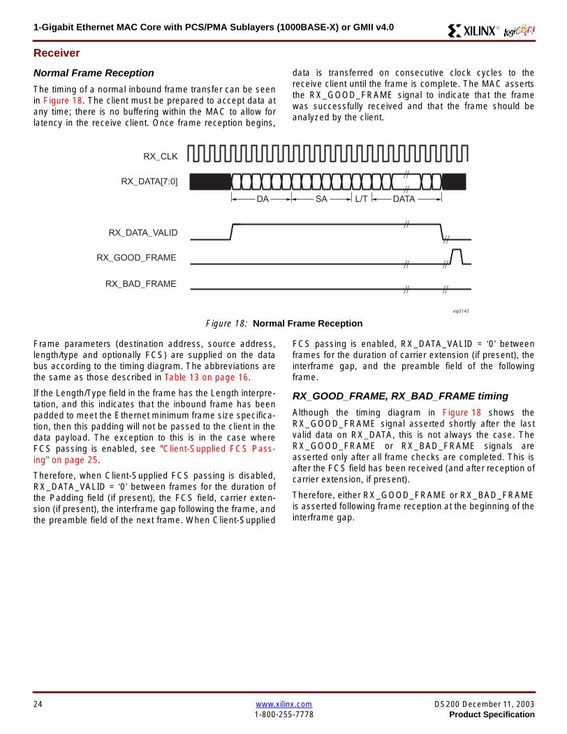
1-Gigabit Ethernet MAC Core with PCSPMA Sublayers (1000BASE-X) or GMII v40 R
Receiver
Normal Frame Reception
The timing of a normal inbound frame transfer can be seenin Figure 18 The client must be prepared to accept data atany time there is no buffering within the MAC to allow forlatency in the receive client Once frame reception begins
data is transferred on consecutive clock cycles to thereceive client until the frame is complete The MAC assertsthe RX_GOOD_FRAME signal to indicate that the framewas successfully received and that the frame should beanalyzed by the client
Frame parameters (destination address source addresslengthtype and optionally FCS) are supplied on the databus according to the timing diagram The abbreviations arethe same as those described in Table 13 on page 16
If the LengthType field in the frame has the Length interpre-tation and this indicates that the inbound frame has beenpadded to meet the Ethernet minimum frame size specifica-tion then this padding will not be passed to the client in thedata payload The exception to this is in the case whereFCS passing is enabled see Client-Supplied FCS Pass-ing on page 25
Therefore when Client-Supplied FCS passing is disabledRX_DATA_VALID = lsquo0rsquo between frames for the duration ofthe Padding field (if present) the FCS field carrier exten-sion (if present) the interframe gap following the frame andthe preamble field of the next frame When Client-Supplied
FCS passing is enabled RX_DATA_VALID = lsquo0rsquo betweenframes for the duration of carrier extension (if present) theinterframe gap and the preamble field of the followingframe
RX_GOOD_FRAME RX_BAD_FRAME timing
Although the timing diagram in Figure 18 shows theRX_GOOD_FRAME signal asserted shortly after the lastvalid data on RX_DATA this is not always the case TheRX_GOOD_FRAME or RX_BAD_FRAME signals areasserted only after all frame checks are completed This isafter the FCS field has been received (and after reception ofcarrier extension if present)
Therefore either RX_GOOD_FRAME or RX_BAD_FRAMEis asserted following frame reception at the beginning of theinterframe gap
Figure 18 Normal Frame Reception
RX_CLK
RX_DATA[70]
RX_DATA_VALID
RX_GOOD_FRAME
RX_BAD_FRAME
DA SA DATALT
xip2142
24 wwwxilinxcom DS200 December 11 20031-800-255-7778 Product Specification
1-Gigabit Ethernet MAC Core with PCSPMA Sublayers (1000BASE-X) or GMII v40R
Frame Reception with Errors
The case of an unsuccessful frame reception (for examplea fragment frame or a frame with an incorrect FCS) can beseen in Figure 19 In this case the RX_BAD_FRAME signal
is asserted to the client at the end of the frame It is then theresponsibility of the client to drop the data already trans-ferred for this frame
Figure 19 Frame Reception with Error
Client-Supplied FCS Passing
If the MAC core is configured to pass the FCS field to the cli-ent (see Configuration Registers on page 30) then this ishandled as shown in Figure 20
In this case any padding inserted into the frame to meetEthernet minimum frame length specifications will be leftintact and passed to the client
Note that even though the FCS is passed up to the client itis also verified by the MAC core and RX_BAD_FRAMEasserted if the FCS check fails
RX_CLK
RX_DATA[70]
RX_DATA_VALID
RX_GOOD_FRAME
RX_BAD_FRAME
DA SA DATALT
xip2144
Figure 20 Frame Reception with In-Band FCS Field
RX_CLK
RX_DATA[70]
RX_DATA_VALID
RX_GOOD_FRAME
RX_BAD_FRAME
DA SA DATALT FCS
xip2145
DS200 December 11 2003 wwwxilinxcom 25Product Specification 1-800-255-7778
1-Gigabit Ethernet MAC Core with PCSPMA Sublayers (1000BASE-X) or GMII v40 R
VLAN Tagged Frames
The reception of a VLAN tagged frame (if enabled) can beseen in Figure 21 The VLAN frame is passed to the clientso that the frame may be identified as VLAN tagged this is
followed by the Tag Control Information bytes V1 and V2More information on the interpretation of these bytes maybe found in IEEE 8023-2002 standard
Maximum Permitted Frame Length
The maximum legal length of a frame specified in IEEE8023-2002 is 1518 bytes for non-VLAN tagged framesVLAN tagged frames may be extended to 1522 bytesWhen jumbo frame handling is disabled and the corereceives a frame which exceeds the maximum legal lengthRX_BAD_FRAME will be asserted When jumbo framehandling is enabled frames which are longer than the legalmaximum are received in the same way as shorter frames
For more information on enabling and disabling jumboframe handling see Configuration Registers on page 30
LengthType Field Error Checks
Enabled
Default operation is with the LengthType error checkingenabled (see Receiver Configuration Word 1 on page 31)In this mode the following checks are made on all framesreceived If either of these checks fail then the frame ismarked as BAD
bull A value in the LengthType field that is greater than orequal to decimal 46 but less than decimal 1536 (aLength interpretation) is checked against the actualdata length received
bull A value in the LengthType field that is less thandecimal 46 is checked to see that the data field ispadded to exactly 46 bytes (so that the resultant frameis minimum frame size 64 bytes total in length)
Furthermore if Padding is indicated (the LengthType fieldis less than decimal 46) and Client-Supplied FCS Passing isdisabled then the Length value in the LengthType field willbe used to deassert RX_DATA_VALID after the indicatednumber of data bytes so that the Padding bytes areremoved from the frame
Disabled
When the LengthType error checking is disabled (seeReceiver Configuration Word 1 on page 31) theLengthType error checks described above are not per-formed A frame containing only these errors will be markedas GOOD
Furthermore if Padding is indicated and Client-SuppliedFCS Passing is disabled then a Length Value in theLengthType field will not be used to deassertRX_DATA_VALID Instead RX_DATA_VALID will be deas-serted before the start of the FCS field in this way any pad-ding will not be removed from the frame
Figure 21 Reception of a VLAN Tagged Frame
RX_CLK
RX_DATA[70]
RX_DATA_VALID
RX_GOOD_FRAME
RX_BAD_FRAME
DA SA DATALT
81 00 V1 V2
VLANtag
xip2146
26 wwwxilinxcom DS200 December 11 20031-800-255-7778 Product Specification
1-Gigabit Ethernet MAC Core with PCSPMA Sublayers (1000BASE-X) or GMII v40R
Receiver Statistics Vector
The statistics for the frame received are contained withinthe RX_STATISTICS_VECTOR The vector is driven syn-chronously by the receiver clock RX_CLK following framereception The bit field definition for the Vector is defined inTable 15
All bit fields with the exception of BYTE_VALID are validonly when the RX_STATISTICS_VALID is asserted This isillustrated in Figure 22 BYTE_VALID is significant on everyRX_CLK cycle
Figure 22 Receiver Statistics Vector Timing
RX_CLK
RX_STATISTICS_VECTOR[220]
RX_STATISTICS_VALID
xip2147
Table 15 Bit Definition for the Receiver Statistics Vector
RX_STATISTICS_VECTOR Name Description
22LENGTHTYPE Out ofRange
Asserted if the lengthtype field contained a length valuethat did not match the number of MAC client data bytesreceived Also high if the lengthtype field indicated thatthe frame contained padding but the number of MAC cli-ent data bytes received was not equal to 64 bytes (min-imum frame size)
The exception to the above is when the LengthTypeField Error Checks are disabled in which case this bitwill not be asserted
21 BAD_OPCODE
Asserted if the previous frame was error-free andcontained the special Control Frame identifier in theLengthType field but contained an opcode that isunsupported by the MAC (Any Opcode other thanPAUSE)
20 FLOW_CONTROL_FRAME
Asserted if the previous frame was error-freecontained the special Control Frame identifier in theLengthType field contained a Destination Addressthat matched either the MAC Control MulticastAddress or the configured source address of the MACcontained the supported PAUSE opcode and wasacted upon by the MAC
19 BYTE_VALID
Asserted if a MAC frame byte (DA to FCS inclusive) isin the process of being received This is valid on everyclock cycle
Do not use this as an enable signal to indicate thatdata is present on RX_DATA[70]
18 VLAN_FRAMEAsserted if the previous frame contained a VLANidentifier in the LengthType field when receiver VLANoperation is enabled
DS200 December 11 2003 wwwxilinxcom 27Product Specification 1-800-255-7778
1-Gigabit Ethernet MAC Core with PCSPMA Sublayers (1000BASE-X) or GMII v40 R
17 OUT_OF_BOUNDS
Asserted if the previous frame exceeded the specifiedIEEE8023-2002 maximum legal length (seeMaximum Permitted Frame Length on page 26) Thisis only valid if Jumbo frames are disabled
16 CONTROL_FRAMEAsserted if the previous frame contained the specialControl Frame identifier in the LengthType field
15 down to 5 FRAME_LENGTH_COUNTThe length of the previous frame in number of bytesThe count will stick at 2047 for any Jumbo frameslarger than this value
4 MULTICAST_FRAMEAsserted if the previous frame contained a multicastaddress in the Destination Address field
3 BROADCAST_FRAMEAsserted if the previous frame contained the broadcastaddress in the Destination Address field
2 FCS_ERRORAsserted if the previous frame received had anincorrect FCS value or the MAC detected error codesduring frame reception
1 BAD_FRAME1 Asserted if the previous frame received containederrors
0 GOOD_FRAME1 Asserted if the previous frame received was error-free
1 If the LengthType Field Error Checks are disabled then a frame which contains this type of error will be marked as a GOOD_FRAMEproviding no additional errors were detected
Table 15 Bit Definition for the Receiver Statistics Vector
RX_STATISTICS_VECTOR Name Description
28 wwwxilinxcom DS200 December 11 20031-800-255-7778 Product Specification
1-Gigabit Ethernet MAC Core with PCSPMA Sublayers (1000BASE-X) or GMII v40R
Flow ControlThe flow control block is designed to Clause 31 of the IEEE8023-2002 standard The MAC may be configured to sendpause frames and to act upon their reception These twobehaviors can be configured asymmetrically see Configu-ration Registers on page 30
Transmitting a PAUSE Control Frame
The client initiates a flow control frame by assertingPAUSE_REQ while the pause value is on the PAUSE_VALbus These signals are synchronous to TX_CLK The timingof this can be seen in Figure 23
If the MAC core is configured to support transmit flow con-trol this action causes the core to transmit a PAUSE controlframe on the link with the PAUSE parameter set to thevalue on PAUSE_VAL in the cycle when PAUSE_REQ wasasserted This will not disrupt any frame transmission inprogress but will take priority over any pending frame trans-
mission This frame will be transmitted even if the transmit-ter is in the paused state itself
Receiving a Pause Control Frame
When an error-free frame is received by the MAC core thefollowing checks are made
1 The Destination Address field is matched against theMAC Control Multicast address or the configuredSource Address for the MAC (see ConfigurationRegisters on page 30)
2 The LengthType field is matched against the MACControl Type code
3 The opcode field contents are matched against thePAUSE opcode if check 2 is true
If any of the above checks are false or the MAC Flow Con-trol logic for the receiver is disabled the frame is ignored bythe Flow Control logic and passed up to the client
If the frame passes all of the above checks is of minimumlegal size and the MAC Flow Control logic for the receiver isenabled the pause value parameter in the frame is thenused to inhibit transmitter operation for the time defined inthe IEEE8023-2002 specification This inhibit is imple-mented using the same back pressure scheme shown inFigure 12 Because the received pause frame has beenacted upon it is passed to the client with RX_BAD_FRAMEasserted to indicate to the client that it should be dropped
Reception of any frame for which check 2 is true and whichis not of legal minimum length is considered an invalid Con-trol frame This will be ignored by the Flow Control logic andpassed to the client with RX_BAD_FRAME asserted
Figure 23 Pause Request Timing
TX_CLK
PAUSE_VAL[150]
PAUSE_REQ
xip2148
DS200 December 11 2003 wwwxilinxcom 29Product Specification 1-800-255-7778
1-Gigabit Ethernet MAC Core with PCSPMA Sublayers (1000BASE-X) or GMII v40 R
Optional Management Interface(management_interface=true)The management interface is a processor-independentinterface with standard address data and control signals Itmay be used as is or a wrapper may be applied (not sup-plied) to interface to common bus architectures
This interface is used for
bull Configuration of the MAC core
bull Access to optional statistics counters for use by higherlayers for example SNMP
bull access through the MDIO interface to the managementregisters located in the PHY attached to the MAC core
The management interface is accessed differently depend-ing on the type of transaction a truth table showing whichaccess method is required for each transaction type isshown in Table 16 These access methods are described inthe following sections
HOST_CLK Frequency
The management interface clock HOST_CLK is used toderive the MDIO clock MDC and is therefore subject tosome frequency restrictions This HOST_CLK must be
ge 10 MHz
le 100 MHz
Configuring the MAC core to derive the MDC signal fromthis clock is detailed in MDIO Interface on page 37
Configuration Registers
After power up or reset the client may reconfigure the coreparameters from their defaults such as flow control supportConfiguration changes can be written at any time Both thereceiver and transmitter logic will only respond to configura-tion changes during Inter Frame Gaps The exceptions tothis are the configurable resets which take effect immedi-ately
Configuration of the MAC core is performed through a reg-ister bank accessed through the management interfaceThe configuration registers available in the core are detailedin Table 17 As can be seen the address has some implicitdonrsquot care bits any access to an address in the rangesshown will perform a 32-bit read or write from the same con-figuration word
Table 16 Management Interface Transaction Types
Transaction HOST_MIIM_SEL HOST_ADDR[9]
Configuration 0 1
Statistics 0 0
MIIM access 1 X
Table 17 Configuration Registers
Address Description
0x200-0x23F Receiver Configuration (Word 0)
0x240-0x27F Receiver Configuration (Word 1)
0x280-0x2BF Transmitter Configuration
0x2C0-0x2FF Flow Control Configuration
0x300-0x33F Reserved
0x340-0x37F Management Configuration
30 wwwxilinxcom DS200 December 11 20031-800-255-7778 Product Specification
1-Gigabit Ethernet MAC Core with PCSPMA Sublayers (1000BASE-X) or GMII v40R
The register contents for the two receiver configuration words can be seen in Table 18 and Table 19
Notes1 In changing the receiverrsquos mode from Half Duplex to Full Duplex there is a period of time of up to 24 us following the mode change
when no new receiver statistics can be stored in the optional Statistical Counters
Table 18 Receiver Configuration Word 0
Bit Default Value Description
31-0 All 0rsquos
Pause frame MAC Source Address[310] This address is used by the MAC tomatch against the Destination Address of any incoming flow control frames It isalso used by the flow control block as the Source Address (SA) for any outboundflow control frames
The address is ordered so the first byte transmittedreceived is the lowestpositioned byte in the register for example a MAC address ofAA-BB-CC-DD-EE-FF would be stored in Address[470] as 0xFFEEDDCCBBAA
Table 19 Receiver Configuration Word 1
Bit Default Value Description
15-0 All 0rsquos Pause frame MAC Source Address[4732] See description in Table 18
24-16 NA Reserved
25 0
LengthType Error Check Disable When this bit is set to ldquo1rdquo the core will notperform the LengthType field error checks as described in LengthType FieldError Checks on page 26 When this bit is set to ldquo0rdquo the LengthType field checkswill be performed this is normal operation
26 0Half Duplex If ldquo1rdquo the receiver will operate in half duplex mode If ldquo0rdquo the receiverwill operate in full duplex mode Has no effect if XCO parameterhalf_duplex_capable = false
27 0VLAN Enable When this bit is set to ldquo1rdquo VLAN tagged frames will be acceptedby the receiver
28 1Receiver Enable If set to ldquo1rdquo the receiver block will be operational If set to ldquo0rdquothe block will ignore activity on the physical interface RX port
29 0
In-band FCS Enable When this bit is ldquo1rdquo the MAC receiver will pass the FCS fieldup to the client as described in Client-Supplied FCS Passing on page 25 Whenit is ldquo0rdquo the client will not be passed the FCS In both cases the FCS will beverified on the frame
30 0Jumbo Frame Enable When this bit is set to ldquo1rdquo the MAC receiver will acceptframes over the specified IEEE8023-2002 maximum legal length When this bitis ldquo0rdquo the MAC will only accept frames up to the specified maximum
31 0Reset When this bit is set to ldquo1rdquo the receiver will be reset The bit will thenautomatically revert to ldquo0rdquo Note that this reset will also set all of the receiverconfiguration registers to their default values
DS200 December 11 2003 wwwxilinxcom 31Product Specification 1-800-255-7778
1-Gigabit Ethernet MAC Core with PCSPMA Sublayers (1000BASE-X) or GMII v40 R
The register contents for the Transmitter Configuration Word are described in Table 20
Notes1 In changing the transmitterrsquos mode from Half Duplex to Full Duplex there is a period of time of up to 24 us following the mode change
when no new transmitter statistics can be stored in the optional Statistical Counters
Table 20 Transmitter Configuration Word
Bit Default Value Description
24-0 NA Reserved
25 0
Interframe Gap Adjust Enable If lsquo1rsquo the transmitter will read the value on the portTX_IFG_DELAY at the start of frame transmission and adjust the interframe gapfollowing the frame accordingly See Interframe Gap Adjustment on page 22 Ifldquo0rdquo the transmitter will output a minimum Inter Frame Gap of twelve clock cyclesas specified in IEEE8023-2002
26 0Half Duplex If lsquo1rsquo the transmitter will operate in half duplex mode If lsquo0rsquo thetransmitter will operate in full duplex mode Has no effect if XCO parameterhalf_duplex_capable = false
27 0VLAN Enable When this bit is set to 1 the transmitter will allow the transmissionof VLAN tagged frames
28 1Transmit Enable When this bit is 1 the transmitter is operational When it is 0the transmitter is disabled
29 0
In-band FCS Enable When this bit is lsquo1rsquo the MAC transmitter will expect the FCSfield to be passed in by the client as described in Client-Supplied FCS Passingon page 17 When this bit is ldquo0rdquo the MAC transmitter will append padding asrequired compute the FCS and append it to the frame
30 0
Jumbo Frame Enable When this bit is set to ldquo1rdquo the MAC transmitter will sendframes that are greater than the specified IEEE8023-2002 maximum legallength When this bit is ldquo0rdquo the MAC will only send frames up to the specifiedmaximum
31 0Reset When this bit is set to ldquo1rdquo the transmitter will be reset The bit will thenautomatically revert to ldquo0rdquo Note that this reset will also set all of the transmitterconfiguration registers to their default values
32 wwwxilinxcom DS200 December 11 20031-800-255-7778 Product Specification
1-Gigabit Ethernet MAC Core with PCSPMA Sublayers (1000BASE-X) or GMII v40R
The register contents for the Flow Control Configuration Word are described in Table 21
The register contents for the Management Configuration Word are described in Table 22
Writing to the configuration registers through the manage-ment interface is depicted in Figure 24 When accessing theconfiguration registers (ie when HOST_ADDR[9] = lsquo1rsquo andHOST_MIIM_SEL = lsquo0rsquo) the upper bit of HOST_OPCODEfunctions as an Active Low write enable signal The lowerHOST_OPCODE bit is a ldquodonrsquot carerdquo
Reading from the configuration register words is similar butthe upper HOST_OPCODE bit should be lsquo1rsquo This is shownin Figure 25 In this case the contents of the register appearon HOST_RD_DATA the HOST_CLK edge after the regis-ter address is asserted onto HOST_ADDR
Table 21 Flow Control Configuration Word
Bit Default Value Description
28-0 NA Reserved
29 1
Flow Control Enable (RX) When this bit is lsquo1rsquo received flow control frames willinhibit the transmitter operation as described in Receiving a Pause ControlFrame on page 29 When this bit is lsquo0rsquo received flow control frames will alwaysbe passed up to the client
30 1Flow Control Enable (TX) When this bit is lsquo1rsquo asserting the PAUSE_REQ signalwill send a flow control frame out from the transmitter When this bit is 0 assertingthe PAUSE_REQ signal has no effect
31 NA Reserved
Table 22 Management Configuration Word
Bits Default Value Description
4-0 All 0rsquos Clock Divide[40] See MDIO Interface on page 37
5 0MDIO Enable When this bit is 1 the MDIO interface can be used to accessattached PHY devices When this bit is 0 the MDIO interface is disabled and theMDIO signals remain inactive
31-6 NA Reserved
Figure 24 Configuration Register Write Timing
HOST_CLK
HOST_ADDR[80]
HOST_ADDR[9]
HOST_OPCODE[1]
HOST_MIIM_SEL
HOST_WR_DATA[310]xip2149
Figure 25 Configuration Register Read Timing
HOST_CLK
HOST_ADDR[80]
HOST_ADDR[9]
HOST_OPCODE[1]
HOST_MIIM_SEL
HOST_RD_DATA[310]
xip2150
DS200 December 11 2003 wwwxilinxcom 33Product Specification 1-800-255-7778
1-Gigabit Ethernet MAC Core with PCSPMA Sublayers (1000BASE-X) or GMII v40 R
Optional Statistical Gathering(statistics_gathering=true)
During operation the MAC core collects statistics on thesuccess and failure of various operations for processing by
station management entities (STA) further up the protocolstack These statistics are accessed by the host through theoptional management interface A complete list of statisticssupported is described in Table 23
Table 23 Statistics Registers
Address Name Description
0x000 Frames Received OK1 A count of error-free frames received
0x001 Frame Check Sequence Errors A count of received frames that failed the CRC check and were at least64 bytes in length
0x002 Broadcast Frames Received OK1A count of frames that were successfully received and were directed tothe broadcast group address
0x003 Multicast Frames Received OK1 A count of frames that were successfully received and were directed toa non broadcast group address
0x004 64 byte Frames Received OK1 A count of error-free frames received that were 64 bytes in length
0x005 65-127 byte Frames Received OK1A count of error-free frames received that were between 65 and 127bytes in length
0x006 128-255 byte Frames Received OK1A count of error-free frames received that were between 128 and 255bytes in length
0x007 256-511 byte Frames Received OK1A count of error-free frames received that were between 256 and 511bytes in length
0x008512-1023 byte Frames ReceivedOK1
A count of error-free frames received that were between 512 and 1023bytes in length
0x0091024-MaxFrameSize byte FramesReceived OK1
A count of error-free frames received that were between 1024 bytes andthe specified IEEE8023-2002 maximum legal length (see MaximumPermitted Frame Length on page 26)
0x00A Control Frames Received OKA count of error-free frames received that contained the specialControl Frame identifier in the LengthType field
0x00B LengthType Out of Range
A count of frames received that were at least 64 bytes in length wherethe lengthtype field contained a length value that did not match thenumber of MAC client data bytes received
The counter also increments for frames in which the lengthtype fieldindicated that the frame contained padding but where the number ofMAC client data bytes received was greater than 64 bytes (minimumframe size)
The exception to the above is when the LengthType Field Error Checksare disabled in which case this counter will not increment
0x00C VLAN Tagged Frames Received OKA count of error-free VLAN frames received This counter will only incre-ment when the receiver is configured for VLAN operation
0x00D Pause Frames Received OK
A count of error-free frames received that contained the MAC Controltype identifier 88-08 in the LengthType field contained a Destinationaddress that matched either the MAC Control multicast address or theconfigured source address of the MAC contained the PAUSE opcodeand were acted upon by the MAC
0x00EControl Frames Received withUnsupported Opcode
A count of error-free frames received that contained the MAC Controltype identifier 88-08 in the LengthType field but were received with anopcode other than the PAUSE opcode
34 wwwxilinxcom DS200 December 11 20031-800-255-7778 Product Specification
1-Gigabit Ethernet MAC Core with PCSPMA Sublayers (1000BASE-X) or GMII v40R
0x00F Oversize Frames Received OK1A count of otherwise error-free frames received that exceeded the max-imum legal frame length specified in IEEE 8023-2002 (see MaximumPermitted Frame Length on page 26)
0x010 Undersize frames receivedA count of the number of frames received that were less than 64 bytesin length but were otherwise well formed
0x011 Fragment frames receivedA count of the number of frames received that were less than 64 bytesin length and had a bad Frame Check Sequence field
0x012 Received bytesA count of bytes of frames that are received (Destination Address toFrame Check Sequence inclusive)
0x013 Transmitted bytesA count of bytes of frames that are transmitted (Destination Address toFrame Check Sequence inclusive)
0x020 Frames Transmitted OK A count of error-free frames transmitted
0x021 Broadcast Frames Transmitted OK A count of error-free frames that were transmitted to the broadcastaddress
0x022 Multicast Frames Transmitted OK A count of error-free frames that were transmitted to a group destina-tion address other than broadcast
0x023 Underrun Errors
A count of frames that would otherwise be transmitted by the core butcould not be completed due to the assertion of TX_UNDERRUN duringthe frame transmission This will not count frames which are less than64 bytes in length
0x024 Control Frames Transmitted OKA count of error-free frames transmitted that contained the MACControl Frame type identifier 88-08 in the LengthType field
0x025 64 byte Frames Transmitted OK A count of error-free frames transmitted that were 64 bytes in length
0x026 65-127 byte Frames Transmitted OKA count of error-free frames transmitted that were between 65 and 127bytes in length
0x027128-255 byte Frames TransmittedOK
A count of error-free frames transmitted that were between 128 and 255bytes in length
0x028256-511 byte Frames TransmittedOK
A count of error-free frames transmitted that were between 256 and 511bytes in length
0x029512-1023 byte Frames TransmittedOK
A count of error-free frames transmitted that were between 512 and1023 bytes in length
0x02A1024-MaxFrameSize byte FramesTransmitted OK
A count of error-free frames transmitted that were between 1024 and thespecified IEEE8023-2002 maximum legal length (see Maximum Per-mitted Frame Length on page 20)
0x02BVLAN Tagged Frames TransmittedOK
A count of error-free VLAN frames transmitted This counter will onlyincrement when the transmitter is configured for VLAN operation
0x02C Pause Frames Transmitted OKA count of error-free PAUSE frames generated and transmitted by thecore in response to an assertion of PAUSE_REQ
0x02D Oversize Frames Transmitted OKA count of otherwise error-free frames transmitted that exceeded themaximum legal frame length specified in IEEE 8023-2002 (see Maxi-mum Permitted Frame Length on page 20)
0x02E Single Collision Frames A count of frames that are involved in a single collision but are subse-quently transmitted successfully (Half Duplex Mode only)
Table 23 Statistics Registers (Continued)
Address Name Description
DS200 December 11 2003 wwwxilinxcom 35Product Specification 1-800-255-7778
1-Gigabit Ethernet MAC Core with PCSPMA Sublayers (1000BASE-X) or GMII v40 R
Each of these statistic registers is 64 bits wide and thereforemust be read in a two-cycle transfer The timing of this pro-cess is shown in Figure 26 Six clocks after the read trans-action is initiated the least significant word (LSW) of thestatistics counter appears on the HOST_RD_DATA bus
and a clock cycle later the most significant word (MSW)appears For accurate statistic values 64 clock ticks (ofTX_CLK for transmit statistics or RX_CLK for receive statis-tics) must elapse after the last frame is sent or receivedthrough the MAC core
0x02F Multiple Collision Frames A count of frames that are involved in more than one collision but aresubsequently transmitted successfully (Half Duplex Mode only)
0x040 Frames with Deferred Transmissions A count of frames whose transmission was delayed on its first attemptbecause the medium was busy (Half Duplex Mode only)
0x041 Late Collisions
A count of the times that a collision has been detected later than oneslotTime from the start of the packet transmission A late collision iscounted twice both as a collision and as a lateCollision (Half DuplexMode only)
0x042Frames Aborted due to Excesscollisions
A count of the frames that due to excessive collisions are not transmit-ted successfully (Half Duplex Mode only)
0x043 Carrier Sense ErrorsA count of times that the GMII_CRS signal was not asserted or wasdisasserted during the transmission of a frame without collision (HalfDuplex Mode only)
0x044 Frames with Excess DeferralA count of frames that deferred transmission for an excessive period oftime (Half Duplex Mode only)
1 If the LengthType Field Error Checks are disabled then these counters will still increment for received frames which contain this typeof error (providing no additional errors were detected)
Table 23 Statistics Registers (Continued)
Address Name Description
Figure 26 Statistic Register Read Timing
HOST_CLK
HOST_ADDR[80]
HOST_ADDR[9]
HOST_REQ
HOST_MIIM_SEL
HOST_RD_DATA[310]
6 CLOCKS
LSW MSW
xip2151
36 wwwxilinxcom DS200 December 11 20031-800-255-7778 Product Specification
1-Gigabit Ethernet MAC Core with PCSPMA Sublayers (1000BASE-X) or GMII v40R
MDIO Interface
The management interface is also used to access the MDIO(MII Management) interface of the MAC core this interfaceis used to access the Managed Information Block (MIB) ofthe PHY components attached to the MAC core
The MDIO interface supplies a clock to the externaldevices MDC This clock is derived from the HOST_CLKsignal using the value in the Clock Divide[40] configurationregister The frequency of the MDIO clock is given by thefollowing equation
The frequency of MDC given by this equation should notexceed 25 MHz in order to comply with the IEEE8023-2002 specification for this interface To prevent MDCfrom being out of specification the Clock Divide[40] valuepowers up at 00000 and while this value is in the register itis impossible to enable the MDIO interface
For details of the register map of PHY layer devices and afuller description of the operation of the MDIO interfaceitself see IEEE specification 8023-2002
Access to the MDIO interface through the managementinterface is depicted in the timing diagram in Figure 27
For MDIO transactions the following points apply
bull HOST_OPCODE maps to the OP (opcode) field of theMDIO frame
bull HOST_ADDR maps to the two address fields of theMDIO frame PHY_ADDR is HOST_ADDR[95] andREG_ADDR is HOST_ADDR[40]
bull HOST_WR_DATA[150] maps into the data field of the
MDIO frame when performing a write operation
bull The data field of the MDIO frame maps intoHOST_RD_DATA[150] when performing a readoperation
The MAC core signals to the host that it is ready for anMDIO transaction by asserting HOST_MIIM_RDY A read orwrite transaction on the MDIO is initiated by a pulse on the
fMDC
fHOST_CLK
1 Clock Divide[40]+( ) 2times-------------------------------------------------------------------=
Figure 27 MDIO Access Through Management Interface
HOST_CLK
HOST_ADDR[90]
HOST_OPCODE[10]
HOST_REQ
HOST_MIIM_SEL
HOST_RD_DATA[150]
HOST_WR_DATA[150]
HOST_RDY
If a read transaction is initiated the HOST_RD_DATA bus is valid at the point indicated If a write transaction is initiated the HOST_WR_DATA bus must be valid at the indicated point Simultaneous read and write is not permitted
xip2152
DS200 December 11 2003 wwwxilinxcom 37Product Specification 1-800-255-7778
1-Gigabit Ethernet MAC Core with PCSPMA Sublayers (1000BASE-X) or GMII v40 R
HOST_REQ signal This pulse is ignored if the MDIO inter-face already has a transaction in progress
The MAC core then disasserts the HOST_MIIM_RDY signalwhile the transaction across the MDIO is in progress Whenthe transaction across the MDIO interface has been com-pleted the HOST_MIIM_RDY signal will be asserted by theMAC core if the transaction is a read the data will also beavailable on the HOST_RD_DATA[150] bus at this time
Optional Configuration Vector(management_interface = false)If the optional Management interface is omitted from thecore all of relevant configuration signals are brought out of
the core These signals are bundled into theCONFIGURATION_VECTOR signal The bit mapping of theconfiguration vector signal is defined in Table 24 See thecorresponding entry in the configuration register tables forthe full description of each signal
Note that these configuration vector signals can bechanged by the user at any time however with the excep-tion of the reset and the flow control configuration signalsthey will not take effect until the current frame has com-pleted transmission or reception
The ldquoClockrdquo heading denotes which clock domain the con-figuration signal is registered into before use by the core Itis not necessary to drive the signal from this clock domain
Table 24 Configuration Vector Bit Definition
Bit(s)Configuration Register
cross reference Clock Description
47 downto 0
Receiver ConfigurationWord 0 bits 31-0 andReceiver ConfigurationWord 1 bits 15-0
RX_CLK
Pause frame MAC Source Address[470] This address isused by the MAC core to match against the DestinationAddress of any incoming flow control frames and as theSource Address for any outbound flow control frames
The address is ordered such that the first byte transmitted orreceived is the least significant byte in the register forexample a MAC address of AA-BB-CC-DD-EE-FF will bestored in bite [470] as 0xFFEEDDCCBBAA
48Receiver ConfigurationWord 1 bit 26
RX_CLKReceiver Half Duplex If lsquo1rsquo the receiver operates in halfduplex mode If lsquo0rsquo the receiver operates in full duplex modeHas no effect if XCO parameter half_duplex_capable = false
49Receiver ConfigurationWord 1 bit 27
RX_CLKReceiver VLAN Enable When this bit is set to 1 VLANtagged frames are accepted by the receiver
50Receiver ConfigurationWord 1 bit 28
RX_CLKReceiver Enable If set to 1 the receiver block is operationalIf set to 0 the block ignores activity on the physical interfaceRX port
51Receiver ConfigurationWord 1 bit 29
RX_CLK
Receiver In-band FCS Enable When this bit is lsquo1rsquo the MACreceiver will pass the FCS field up to the client as describedin Client-Supplied FCS Passing on page 25 When it is lsquo0rsquothe MAC receiver will not pass the FCS field In both casesthe FCS field will be verified on the frame
52Receiver ConfigurationWord 1 bit 30
RX_CLK
Receiver Jumbo Frame Enable When this bit is lsquo0rsquo thereceiver will not pass frames longer than the maximum legalframe size specified in IEEE 8023-2002 (see MaximumPermitted Frame Length on page 26) When it is lsquo1rsquo thereceiver will not have an upper limit on frame size
53Receiver ConfigurationWord 1 bit 31
NA
Receiver Reset When this bit is lsquo1rsquo the receiver is held inreset
This signal is an input to the reset circuit for the receiverblock See Reset circuit on page 42 for more information
54TransmitterConfiguration Word bit25
TX_CLK
Transmitter Interframe Gap Adjust enable If lsquo1rsquo then thetransmitter will read the value of the TX_IFG_DELAY port andset the Interframe Gap accordingly If lsquo0rsquo the transmitter willalways insert at least the legal minimum Interframe Gap
38 wwwxilinxcom DS200 December 11 20031-800-255-7778 Product Specification
1-Gigabit Ethernet MAC Core with PCSPMA Sublayers (1000BASE-X) or GMII v40R
55TransmitterConfiguration Word bit26
TX_CLK
Transmitter Half Duplex If lsquo1rsquo the transmitter operates in halfduplex mode If lsquo0rsquo the transmitter operates in full duplexmode Has no effect if XCO parameter half_duplex_capable= false
56TransmitterConfiguration Word bit27
TX_CLKTransmitter VLAN Enable When this bit is set to lsquo1rsquo thetransmitter allows the transmission of VLAN tagged frames
57TransmitterConfiguration Word bit28
TX_CLKTransmitter Enable When this bit is 1 the transmitter will beoperational When it is 0 the transmitter is disabled
58TransmitterConfiguration Word bit29
TX_CLK
Transmitter In-Band FCS Enable When this bit is lsquo1rsquo theMAC transmitter will expect the FCS field to be pass in by theclient as described in Client-Supplied FCS Passing onpage 17 When it is lsquo0rsquo the MAC transmitter will appendpadding as required compute the FCS and append it to theframe
59TransmitterConfiguration Word bit30
TX_CLK
Transmitter Jumbo Frame Enable When this bit is lsquo1rsquo theMAC transmitter will allow frames larger than the maximumlegal frame length specified in IEEE 8023-2002 to be sentWhen set to lsquo0rsquo the MAC transmitter will only allow frames upto the legal maximum to be sent
60TransmitterConfiguration Word bit31
NA
Transmitter Reset When this bit is lsquo1rsquo the MAC transmitter isheld in reset
This signal is an input to the reset circuit for the transmitterblock See Reset circuit on page 42 for more information
61Flow ControlConfiguration Word bit29
TX_CLK
Transmit Flow Control Enable When this bit is lsquo1rsquo assertingthe PAUSE_REQ signal causes the MAC core to send a flowcontrol frame out from the transmitter as described inReceiving a Pause Control Frame on page 29 When this bitis lsquo0rsquo asserting the PAUSE_REQ signal will have no effect
62Flow ControlConfiguration Word bit30
RX_CLK
Receive Flow Control Enable When this bit is lsquo1rsquo receivedflow control frames will inhibit the transmitter operation asdescribed in Receiving a Pause Control Frame on page 29When it is lsquo0rsquo received flow frames are passed up to theclient
63Receiver ConfigurationWord 1 bit 25
RX_CLK
LengthType Error Check Disable When this bit is lsquo1rsquo thecore will not perform the LengthType field error checks asdescribed in LengthType Field Error Checks on page 26When it is set to lsquo0rsquo the LengthType field checks will beperformed this is normal operation
Table 24 Configuration Vector Bit Definition (Continued)
Bit(s)Configuration Register
cross reference Clock Description
DS200 December 11 2003 wwwxilinxcom 39Product Specification 1-800-255-7778
1-Gigabit Ethernet MAC Core with PCSPMA Sublayers (1000BASE-X) or GMII v40 R
Optional GMII (physical_interface=gmii)The GMII is designed to IEEE 8023-2002 Clause 35 Thisutilizes IOrsquos of the Xilinx devices using inputoutput buffersand inputoutput flip-flops to maximize setup and hold mar-gins All IO logic is placed in the example wrapper that isdelivered with the core In addition all clock managementlogic for the core is instanced in this example wrapper thisallows multiple instances of the core to share clocks Theexample wrapper is provided in both VHDL and Verilog
Clock Management
Figure 28 illustrates the clock management used with theGMII interface All clocks illustrated have a frequency of125MHz
GTX_CLK must be provided to the MAC core This is a highquality clock which satisfies the IEEE8023-2002 require-ments It is expected that this clock will be derived from anexternal oscillator and connected into the device through anIBUFG as illustrated The clock source must then be routedonto a global clock network by connecting it to a BUFGWithin the MAC core this global clock is used by all MACtransmitter logic The MAC Client can obtain this clock byconnecting to the TX_CLK signal output from the coreGMII_TX_CLK is derived from this global clock by invertingit and routing it to an OBUF
GMII_RX_CLK is received through an IBUFG This clock isthen routed onto a global clock network by connecting it to aBUFG The resulting global clock is used by all MACreceiver logic
Figure 28 Clock Management with GMII
IBUFG
IBUFG
OBUF
BUFG
BUFG
TX_CLK
RX_CLK
GTX_CLK
GMII_TX_CLK
GMII_RX_CLK
Example Wrapper
xip2153
MAC Core
TX_CLK
RX_CLK
GMII_TX_CLK
GMII_RX_CLK
GTX_CLK
40 wwwxilinxcom DS200 December 11 20031-800-255-7778 Product Specification
1-Gigabit Ethernet MAC Core with PCSPMA Sublayers (1000BASE-X) or GMII v40R
Clock Sharing between Multiple cores
Figure 29 illustrates how it is possible to share clockresources across multiple instantiations of the core whenusing the optional GMII
GTX_CLK may be shared between multiple cores as illus-trated resulting in a common transmitter clock domainacross the device
A common receiver clock domain is not possible each corewill receive an independent receiver clock from its GMII asillustrated
Although not illustrated if the optional Management Inter-face is used HOST_CLK can also be shared betweencores
Figure 29 Clock Management with multiple instances of the MAC with GMII
IBUFG
OBUF
BUFG
TX_CLK
RX_CLK_1
GMII_TX_CLK_1
GMII_RX_CLK_1
MAC Core
TX_CLK
RX_CLK
GMII_TX_CLK
GMII_RX_CLK
GTX_CLK
MAC Core
TX_CLK
RX_CLK
GMII_TX_CLK
GMII_RX_CLK
GTX_CLK
IBUFG
BUFG
GTX_CLK
IBUFG
OBUF
GMII_TX_CLK_2
GMII_RX_CLK_2
BUFG
TX_CLK
RX_CLK_2
DS200 December 11 2003 wwwxilinxcom 41Product Specification 1-800-255-7778
1-Gigabit Ethernet MAC Core with PCSPMA Sublayers (1000BASE-X) or GMII v40 R
Reset circuit
Internally the core is divided up into clockreset domainswhich group together elements with the common clock andreset signals The reset circuitry for one of these domains isis illustrated in Figure 30 This circuit provides controllableskews on the reset nets within the design
More information on the operation and rationale behind thiscircuit can be found in Ken Chapmanrsquos Xilinx TechXclusiveldquoGet Smart About Resetrdquo athttpwwwxilinxcomsupporttechxclusivesglobal-techX19htm
Figure 30 Reset circuit for one clockreset domain
FDP
PRED
C
Q
FDP
PRED
C
Q
FDP
PRED
C
Q
FDP
PRED
C
Q
PRE PRE PRE
0
RESET
Management Reset
Clock
Core Registers
42 wwwxilinxcom DS200 December 11 20031-800-255-7778 Product Specification
1-Gigabit Ethernet MAC Core with PCSPMA Sublayers (1000BASE-X) or GMII v40R
Optional PCS with Ten-Bit Interface (TBI) for 1000BASE-X (physical_interface=tbi)The Full-Duplex Physical Coding Sublayer (PCS) for1000BASE-X is defined in IEEE 8023-2002 Clauses 36and 37 This functionality is only available in the Virtex-IIand Spartan3 families of FPGA devices
A block diagram of the PCS is shown in Figure 31 Themajor functional blocks of the PCS are
bull Transmit engine
bull Auto-negotiation block
bull Receive engine and synchronization block
bull PCS managed register block
bull 8B10B encoder block
bull 8B10B decoder block
bull Receiver elastic buffer
The PCS Managed Register Block is accessed through theMDIO Interface as if it were an externally connected PHYThis configures the operation of the PCS and Auto-Negoti-ation See PCS Managed Register Block
(physical_interface = tbi or phy) on page 49 The corersquosoptional Management Interface can be used to control theMDIO Interface as described by MDIO Interface onpage 37 When the optional Management Interface is notpresent the PCS Managed Register Block must beaccessed via an MDIO controller which is not provided bythe core
The 8B10B encodingdecoding blocks are implemented byconfiguring two Block SelectRAM modules as ROM Theseare used as large look-up tables The remaining PCS func-tionality such as code group encodingdecoding the Man-aged Register Block and Auto-Negotiation areimplemented in CLB logic
The Receiver Elastic buffer enables the 10-bit parallel datareceived from the PMA sublayer alternatively onPMA_RX_CLK0 and PMA_RX_CLK1 clock edges to betransferred onto the internal 125MHz clock domain derivedfrom GTX_CLK (see Clock Management) This buffer isimplemented in Distributed Memory
Figure 31 Functional Block Diagram of the 1-Gigabit Ethernet PCS with TBI Interface
PCS TRANSMIT ENGINE
PCS RECEIVE ENGINE ampSYNCHRONISATION
PCSMANAGEMENT
MDIOInterface
AUTO-NEGOTIATION
MAC TXInterface
MAC RXInterface
8B10BEncoder
8B10BDecoder
RX Elastic Buffer
TBI Interface
DS200 December 11 2003 wwwxilinxcom 43Product Specification 1-800-255-7778
1-Gigabit Ethernet MAC Core with PCSPMA Sublayers (1000BASE-X) or GMII v40 R
TBI Interface
The TBI is designed to IEEE 8023-2002 Clause 363 Thisutilizes IOrsquos of the Xilinx devices using inputoutput buffersand inputoutput flip-flops to maximize setup and hold mar-gins All IO logic is placed in the example wrapper that isdelivered with the core In addition all clock managementlogic for the core is instantiated in this example wrapperthis allows multiple instances of the core to share clocksThe example wrapper is provided in both VHDL and Verilog
Clock Management
Figure 32 illustrates the clock management used with theTBI interface
GTX_CLK must be provided to the MAC core This is a highquality clock of frequency 125MHz which satisfies theIEEE8023-2002 requirements It is expected that this clockwill be derived from an external oscillator and connected
into the device through an IBUFG as illustrated The clocksource must then be routed onto a global clock network byconnecting it to a BUFG Within the MAC core this globalclock is used by all MAC transmitter logic PMA_TX_CLK isderived from this global clock by inverting it and routing it toan OBUF
PMA_RX_CLK0 and PMA_RX_CLK1 are each receivedthrough an IBUFG These clocks are then routed onto glo-bal clock networks by connecting each to a BUFGPMA_RX_CLK0 and PMA_RX_CLK1 are each 625MHzclocks Data from the TBI is received alternatively on the ris-ing edge of PMA_RX_CLK0 followed by the rising edge ofPMA_RX_CLK1 using IOB Double-Data Rate input regis-ters This data is then written into the Receiver ElasticBuffer Data is read out of the Elastic Buffer using the globalclock derived from GTX_CLK all the remaining receiverlogic is synchronous to this clock
Figure 32 Clock Management for PCS with TBI Interface
IBUFG
IBUFG
OBUF
BUFG
BUFG
TX_CLK
RX_CLK
GTX_CLK
PMA_TX_CLK
PMA_RX_CLK0
MAC Core
RX ELASTICBUFFER
Example Wrapper
TX_CLK
RX_CLK
GTX_CLK
PMA_TX_CLK
PMA_RX_CLK0
IBUFGBUFGPMA_RX_CLK1
PMA_RX_CLK1
44 wwwxilinxcom DS200 December 11 20031-800-255-7778 Product Specification
1-Gigabit Ethernet MAC Core with PCSPMA Sublayers (1000BASE-X) or GMII v40R
Clock Sharing between Multiple cores
Figure 33 illustrates how it is possible to share clockresources across multiple instantiations of the core whenusing the optional PCS with TBI
GTX_CLK may be shared between multiple cores as illus-trated resulting in a common transmitter clock domainacross the device
Each core will receive independent PMA_RX_CLK0 andPMA_RX_CLK1 clocks from its TBI as illustrated whichcannot be shared
Although not illustrated if the optional Management Inter-face is used HOST_CLK can also be shared betweencores
Figure 33 Clock Management with multiple instances of the MAC with PCS and TBI
Reset circuit
The reset circuits within the MAC when the TBI interface is implemented is the same as that in the GMII case details ofthese circuits can be found on page 42
IBUFG
OBUF
BUFG
TX_CLK
RX_CLK
PMA_TX_CLK_1
PMA_RX_CLK0_1
MAC Core
RX ELASTICBUFFER
TX_CLK
RX_CLK
GTX_CLK
PMA_TX_CLK
PMA_RX_CLK0
IBUFGBUFGPMA_RX_CLK1_1
PMA_RX_CLK1
IBUFG
BUFG
GTX_CLK
IBUFG
OBUF
BUFG
TX_CLK
RX_CLK
PMA_TX_CLK_2
PMA_RX_CLK0_2
MAC Core
RX ELASTICBUFFER
TX_CLK
RX_CLK
GTX_CLK
PMA_TX_CLK
PMA_RX_CLK0
IBUFGBUFGPMA_RX_CLK1_2
PMA_RX_CLK1
DS200 December 11 2003 wwwxilinxcom 45Product Specification 1-800-255-7778
1-Gigabit Ethernet MAC Core with PCSPMA Sublayers (1000BASE-X) or GMII v40 R
Optional PCS and PMA Sublayers for 1000BASE-X (physical_interface=phy)The Full-Duplex Physical Coding Sublayer (PCS) withPhysical Medium Attachment (PMA) for 1000BASE-X isdefined in IEEE 8023-2002 Clauses 36 and 37 This func-tionality is only available in the Virtex-II Pro family of FPGAdevices
A block diagram of the PCS and PMA sublayers can beseen in Figure 34 The functional blocks of the PCS andPMA sublayers may replace the optional GMII interfaceThe functional blocks of the PCS and PMA sublayers are
bull PCS Transmit Engine
bull Auto-Negotiation block
bull Receive Engine and Synchronization Block
bull PCS Managed Register Block
bull Rocket IO Multi-Gigabit Transceiver
The PCS Managed Register Block is accessed through theMDIO Interface as if it were an externally connected PHYThis configures the operation of the PCS PMA sublayerand Auto-NegotiationSee PCS Managed Register Block(physical_interface = tbi or phy) on page 49 The corersquosoptional Management Interface can be used to control theMDIO Interface as described by MDIO Interface onpage 37 When the optional Management Interface is notpresent the PCS Managed Register Block must beaccessed via an MDIO controller which is not provided bythe core
The Rocket IO Multi-Gigabit Transceiver (MGT) providessome of the PCS layer functionality such as 8B10B encod-ingdecoding and the PMA serdes The remaining PCSfunctionality such as code group encodingdecoding theManaged Register Block and Auto-Negotiation are imple-mented in CLB logic
Figure 34 Functional Block Diagram of the 1-Gigabit Ethernet PCSPMA Sublayer Extension
PCS TRANSMIT ENGINE
PCS RECEIVE ENGINE ampSYNCHRONISATION
RO
CK
ET
IO
MU
LTI-
GIG
TR
AN
SC
EIV
ER
PCSMANAGEMENT
MDIOInterface
AUTO-NEGOTIATION
TXPTXN
RXPRXN
MAC TXInterface
MAC RXInterface
xip2154
46 wwwxilinxcom DS200 December 11 20031-800-255-7778 Product Specification
1-Gigabit Ethernet MAC Core with PCSPMA Sublayers (1000BASE-X) or GMII v40R
Clock Management
Figure 35 illustrates the clock management that should beused with the optional PCS and PMA sublayers for1000BASE-X This logic is implemented in the examplewrapper that is delivered with the core This provides flexi-bility because the design can be modified to use eitherREFCLK or BREFCLK (please refer to Rocket IO docu-mentation) It would also allow multiple instances of the coreto share clocks The example wrapper is provided in bothVHDL and Verilog
(B)REFCLK must be provided to the MAC core This clockmust be derived from an external oscillator and connectedto the core through an IBUFG as illustrated (B)REFCLK isa high quality clock of frequency 625 MHz which satisfiesthe Rocket IO Multi-Gigabit Transceiver (MGT) require-ments
(B)REFCLK is routed to both the core and a DCM From theDCM the CLK2X180 output is routed to a BUFG to providethe device with a global 125 MHz clock (connected toUSERCLK2 input on the core) Within the core bothTX_CLK and RX_CLK share this global 125 MHz clocksource which is used by all transmitter and receiver logicThis is made possible by the RX_ELASTIC_BUFFER func-tionality of the Rocket IO MGT (refer to Virtex-II Pro docu-mentation) The MAC Client can obtain this clock byconnecting to either the TX_CLK or the RX_CLK signalsoutput from the core
From the DCM the CLK0 output is routed to a BUFG to pro-vide the device with a global 625MHz clock This is con-nected to the USRCLK input of the core
Figure 35 Clock Management with PCSPMA Sublayers
DCM
CLKIN CLK0
CLK2X180FB
BUFG
BUFG
IBUFG
TX_CLK
RX_CLK
(B)REFCLK
TXUSRCLK
(B)REFCLK
TXUSRCLK2RXUSRCLKRXUSRCLK2
GT_ETHERNET
Example Wrapper
xip2155
MAC Core
(B)REFCLK
USRCLK
USRCLK2
TX_CLK
RX_CLK
DS200 December 11 2003 wwwxilinxcom 47Product Specification 1-800-255-7778
1-Gigabit Ethernet MAC Core with PCSPMA Sublayers (1000BASE-X) or GMII v40 R
Clock Sharing between Multiple Cores
Figure 36 illustrates how it is possible to share clockresources across multiple instantiations of the core whenusing the optional PCSPMA sublayers For each coreUSERCLK and USERCLK2 must always be derived asshown from the BREFCLK or REFCLK used by that core
Note that when using the fixed routing resources of BREF-CLK Rocket IO MGTs along the top edge of the devicemust use a separate BREFCLK routing resource to thosealong the bottom edge of the device (Refer to Virtex-II Prodocumentation)
Although not illustrated if the optional Management Inter-face is used HOST_CLK can also be shared betweencores
Figure 36 Clock Management with multiple instances of the MAC with PCS and PMA sublayers
Reset circuit
The reset circuits within the MAC when the PCS and PMA sublayers are implemented is the same as that in the GMII casedetails of these circuits can be found on page 42
DCM
CLKIN CLK0
CLK2X180FB
BUFG
BUFG
IBUFG
(B)REFCLK
TXUSRCLK
(B)REFCLK
TXUSRCLK2RXUSRCLKRXUSRCLK2
GT_ETHERNET(B)REFCLK
USERCLK
USERCLK2
MAC core
TXUSRCLK
(B)REFCLK
TXUSRCLK2RXUSRCLKRXUSRCLK2
GT_ETHERNET(B)REFCLK
USERCLK
USERCLK2
MAC core
48 wwwxilinxcom DS200 December 11 20031-800-255-7778 Product Specification
1-Gigabit Ethernet MAC Core with PCSPMA Sublayers (1000BASE-X) or GMII v40R
PCS Managed Register Block (physical_interface = tbi or phy)The PCS in both the TBI interface and the PCSPMA (usingthe Virtex-II Pro Rocket IO) versions contain the full Man-aged Register Block defined in IEEE 8023-2002 clause 37
This utilizes ten dedicated management registersaccessed via the MDIO interface These are defined inTable 25 to Table 33 inclusive
Table 25 Control Register (Register 0)
Bit(s) Name Description Attributes Default Value
015 Reset1 = PCSPMA reset
0 = Normal Operation
ReadWrite
Self Clearing0
014 Loopback1 = Enable Loopback Mode
0 = Disable Loopback ModeReadWrite 0
013SpeedSelection (LSB)
The core always returns a 0 for this bitTogether with bit 06 speed selection of 1000Mbs is identified
Returns 0 0
012Auto-NegotiationEnable
1 = Enable Auto-Negotiation Process
0 = Disable Auto-Negotiation ProcessReadWrite 1
011 Power Down
1 = Power down
0 = Normal operation
When set to ldquo1rdquo the Rocket IO MGT is placedin a low power state This bit requires a reset(see bit 015) to clear
Read Write 0
010 Isolate1 = Electrically Isolate PHY from GMII
0 = Normal operationReadWrite 1
09Restart Auto-Negotiation
1 = Restart Auto-Negotiation Process
0 = Normal Operation
ReadWrite
Self Clearing0
08 Duplex ModeThe core always returns a 1 for this bit tosignal Full-Duplex Mode
Returns 1 1
07 Collision TestThe core always returns a 0 for this bit todisable COL test
Returns 0 0
06SpeedSelection(MSB)
The core always returns a 1 for this bitTogether with bit 013 speed selection of1000 Mbs is identified
Returns 1 1
050 Reserved Always returns 0rsquos writes ignored Returns 0rsquos 000000
DS200 December 11 2003 wwwxilinxcom 49Product Specification 1-800-255-7778
1-Gigabit Ethernet MAC Core with PCSPMA Sublayers (1000BASE-X) or GMII v40 R
Table 26 Status Register (Register 1)
Bit(s) Name Description Attributes Default Value
115 100BASE-T4The core always returns a 0 for this bitbecause 100BASE-T4 is not supported
Returns 0 0
114100BASE-XFullDuplex
The core always returns a 0 for this bitbecause 100BASE-X Full Duplex is notsupported
Returns 0 0
113100BASE-XHalf Duplex
The core always returns a 0 for this bitbecause 100BASE-X Half Duplex is notsupported
Returns 0 0
11210 Mbs FullDuplex
The core always returns a 0 for this bitbecause 10 Mbs Full Duplex is notsupported
Returns 0 0
11110 Mbs HalfDuplex
The core always returns a 0 for this bitbecause 10 Mbs Half Duplex is notsupported
Returns 0 0
110100BASE-T2Full Duplex
The core always returns a 0 for this bitbecause 100BASE-T2 Full Duplex is notsupported
Returns 0 0
19100BASE-T2Half Duplex
The core always returns a 0 for this bitbecause 100BASE-T2 Half Duplex is notsupported
Returns 0 0
18ExtendedStatus
The core always returns a 1 for this bit toindicate the presence of the ExtendedRegister (Register 15)
Returns 1 1
17 Reserved Always return 0 writes ignored Returns 0 0
16MF PreambleSuppression
The core always returns a 1 for this bit toindicate that Management Frame PreambleSuppression is supported
Returns 1 1
15Auto-NegotiationComplete
1 = Auto-Negotiation process completed
0 = Auto-Negotiation process not completedRead Only 0
14 Remote Fault1 = Remote fault condition detected
0 = No remote fault condition detected
Read Only
Self Clearing on read0
13Auto-NegotiationAbility
The core always returns a 1 for this bit toindicate that the PHY is capable ofAuto-Negotiation
Returns 1 1
12 Link Status1 = Link is up
0 = Link is down
Read Only
Self Clearing on read0
11 Jabber DetectThe core always returns a 0 for this bitbecause Jabber Detect is not supported
Returns 0 0
10ExtendedCapability
The core always returns a 0 for this bitbecause no extended register set issupported
Returns 0 0
50 wwwxilinxcom DS200 December 11 20031-800-255-7778 Product Specification
1-Gigabit Ethernet MAC Core with PCSPMA Sublayers (1000BASE-X) or GMII v40R
Table 27 PHY Identifier (Registers 2 and 3)
Bit(s) Name Description Attributes Default Value
2150OrganizationallyUniqueIdentifier
Always returns 0s Returns 0s 0000000000000000
31510OrganizationallyUniqueIdentifier
Always returns 0s Returns 0s 000000
394Manufacturerrsquosmodel number
Always returns 0s Returns 0s 000000
330RevisionNumber
Always returns 0s Returns 0s 0000
Table 28 Auto-Negotiation Advertisement Register (Register 4)
Bit(s) Name Description Attributes Default Value
415 Next Page1 = Next Page functionality is advertised
0 = Next Page functionality is not advertisedReadWrite 0
414 Reserved Always returns 0 writes ignored Returns 0 0
41312 Remote Fault
00 = No Error
01 = Offline
10 = Link Failure
11 = Auto-Negotiation Error
ReadWrite
Self clearing to 00afterAuto-Negotiation
00
4119 Reserved Always return 0 writes ignored Returns 0 0
487 Pause
00 = No PAUSE
01 = Asymmetric PAUSE towards linkpartner
10 = Symmetic PAUSE
11 = Both Symmetric PAUSE andAsymmetric PAUSE towards link partner
ReadWrite 11
46 Half DuplexThe core always returns a 0 for this bitbecause Half Duplex Mode is not supported
Returns 0 0
45 Full Duplex1 = Full Duplex Mode is advertised
0 = Full Duplex Mode is not advertisedReadWrite 1
440 Reserved Always returns 0s writes ignored Returns 0s 00000
DS200 December 11 2003 wwwxilinxcom 51Product Specification 1-800-255-7778
1-Gigabit Ethernet MAC Core with PCSPMA Sublayers (1000BASE-X) or GMII v40 R
Table 29 Auto-Negotiation Link Partner Ability Base Register (Register 5)
Bit(s) Name Description Attributes Default Value
515 Next Page1 = Next Page functionality is supported
0 = Next Page functionality is not supportedRead Only 0
514 AcknowledgeUsed by Auto-Negotiation function toindicate reception of a link partnerrsquos base ornext page
Read Only 0
51312 Remote Fault
00 = No Error
01 = Offline
10 = Link Failure
11 = Auto-Negotiation Error
Read Only 00
5119 Reserved Always returns 0s Returns 0s 000
587 Pause
00 = No PAUSE
01 = Asymmetric PAUSE supported
10 = Symmetic PAUSE supported
11 = Both Symmetric PAUSE andAsymmetric PAUSE supported
Read Only 00
56 Half Duplex1 = Half Duplex Mode is supported
0 = Half Duplex Mode is not supportedRead Only 0
55 Full Duplex1 = Full Duplex Mode is supported
0 = Full Duplex Mode is not supportedRead Only 0
540 Reserved Always returns 0s Returns 0s 00000
Table 30 Auto-Negotiation Expansion Register (Register 6)
Bit(s) Name Description Attributes Default Value
6153 Reserved Always returns 0s Returns 0s 0000000000000
62 Next Page AbleThe core always returns a 1 for this bitbecause the device is Next Page Able
Returns 1 1
61 Page Received1 = A new page has been received
0 = A new page has not been received
Read Only
Self Clearing on read0
60 Reserved Always returns 0s Returns 0s 0000000
52 wwwxilinxcom DS200 December 11 20031-800-255-7778 Product Specification
1-Gigabit Ethernet MAC Core with PCSPMA Sublayers (1000BASE-X) or GMII v40R
Table 31 Auto-Negotiation Next Page Transmit Register (Register 7)
Bit(s) Name Description Attributes Default Value
715 Next Page1 = Additional Next Page(s) will follow
0 = Last pageReadWrite 0
714 Reserved Always returns 0 Returns 0 0
713 Message Page1 = Message Page
0 = Unformatted PageReadWrite 1
712 Acknowledge 21 = Will comply with message
0 = Cannot comply with messageReadWrite 0
711 ToggleValue will toggle between subsequent NextPages
Read Only 0
7100Message UnformattedCode Field
Message Code Field or Unformatted PageEncoding as dictated by 713
ReadWrite00000000001
(Null Message Code)
Table 32 Auto-Negotiation Next Page Receive Register (Register 8)
Bit(s) Name Description Attributes Default Value
815 Next Page1 = Additional Next Page(s) follows
0 = Last pageRead Only 0
814 AcknowledgeUsed by Auto-Negotiation function toindicate reception of a link partnerrsquos base ornext page
Read Only 0
813 Message Page1 = Message Page
0 = Unformatted PageRead Only 0
812 Acknowledge 21 = Will comply with message
0 = Cannot comply with messageRead Only 0
811 ToggleValue toggles between subsequent andNext Pages
Read Only 0
8100Message UnformattedCode Field
Message Code Field or Unformatted PageEncoding as dictated by 813
Read Only 00000000000
DS200 December 11 2003 wwwxilinxcom 53Product Specification 1-800-255-7778
1-Gigabit Ethernet MAC Core with PCSPMA Sublayers (1000BASE-X) or GMII v40 R
)
Referencesbull IEEE 8023-2002
bull Virtex-E User Guide
bull Spartan-II E User Guide
bull Virtex-II User Guide
bull Virtex-II Pro User Guide
Related InformationXilinx products are not intended for use in life support appli-ances devices or systems Use of a Xilinx product in suchapplications without the written consent of the appropriateXilinx officer is prohibited
Ordering InformationThis Xilinx LogiCORE module is provided under theSignOnce IP Site License A free evaluation version of themodule is available
Once purchased the core may be downloaded from the Xil-inx IP Center for use with the Xilinx CORE Generator Sys-temtrade v61i SP3 and later The Xilinx CORE GeneratorSystem tool is bundled with all Alliance Series Softwarepackages at no additional charge
Please contact your local Xilinx sales representative or visitthe Xilinx Silicon Xpresso Cafe for pricing and availability onXilinx LogiCORE modules and software Information onadditional Xilinx LogiCORE modules is available on the Xil-inx IP Center
Revision HistoryThe following table shows the revision history for this document
Table 33 Extended Status Register (Register 15)
Bit(s) Name Description Attributes Default Value
15151000BASE-XFull Duplex
The core always returns a 1 for this bitbecause 1000BASE-X Full Duplex issupported
Returns 1 1
15141000BASE-XHalf Duplex
The core always returns a 0 for this bitbecause 1000BASE-X Half Duplex is notsupported
Returns 0 0
15131000BASE-TFull Duplex
The core always returns a 0 for this bitbecause 1000BASE-T Full Duplex is notsupported
Returns 0 0
15121000BASE-THalf Duplex
The core always returns a 0 for this bitbecause 1000BASE-T Half Duplex is notsupported
Returns 0 0
15110 Reserved Always returns 0s Returns 0s 000000000000
Date Version Revision
032803 11 Revision History added to document
043003 20 Revised to v30 standards
121103 30 Updated to v40 release
54 wwwxilinxcom DS200 December 11 20031-800-255-7778 Product Specification
- 1-Gigabit Ethernet MAC Core with PCSPMA Sublayers (1000BASE-X) or GMII v40
-
- Features
- MAC Overview
- Xilinx CORE Generator
- GUI Interface
- Parameter Values in the XCO File
- Output Generation
- Device Utilization
- Interface Description
- Interface Signals for MAC with physical_interface=gmii and management_interface=true
- Interface Signals for MAC with physical_interface=gmii and management_interface=false
- Interface Signals for MAC with physical_interface=tbi and management_interface=true
- Interface Signals for MAC with physical_interface=tbi and management_interface=false
- Interface Signals for MAC with physical_interface=phy and management_interface=true
- Interface Signals for MAC with physical_interface=phy and management_interface=false
- Client Side Interface Signal Definition
- Physical Interface Signal Definition
- Functional Description
- Client Interface
- Transmitter
- Receiver
- Flow Control
- Optional Management Interface (management_interface=true)
- Optional Configuration Vector (management_interface = false)
- Optional GMII (physical_interface=gmii)
- Optional PCS with Ten-Bit Interface (TBI) for 1000BASE-X (physical_interface=tbi)
- Optional PCS and PMA Sublayers for 1000BASE-X (physical_interface=phy)
- PCS Managed Register Block (physical_interface = tbi or phy)
- References
- Related Information
- Ordering Information
- Revision History
-
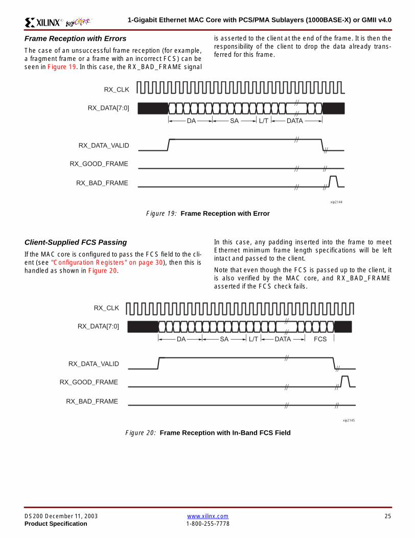
1-Gigabit Ethernet MAC Core with PCSPMA Sublayers (1000BASE-X) or GMII v40R
Frame Reception with Errors
The case of an unsuccessful frame reception (for examplea fragment frame or a frame with an incorrect FCS) can beseen in Figure 19 In this case the RX_BAD_FRAME signal
is asserted to the client at the end of the frame It is then theresponsibility of the client to drop the data already trans-ferred for this frame
Figure 19 Frame Reception with Error
Client-Supplied FCS Passing
If the MAC core is configured to pass the FCS field to the cli-ent (see Configuration Registers on page 30) then this ishandled as shown in Figure 20
In this case any padding inserted into the frame to meetEthernet minimum frame length specifications will be leftintact and passed to the client
Note that even though the FCS is passed up to the client itis also verified by the MAC core and RX_BAD_FRAMEasserted if the FCS check fails
RX_CLK
RX_DATA[70]
RX_DATA_VALID
RX_GOOD_FRAME
RX_BAD_FRAME
DA SA DATALT
xip2144
Figure 20 Frame Reception with In-Band FCS Field
RX_CLK
RX_DATA[70]
RX_DATA_VALID
RX_GOOD_FRAME
RX_BAD_FRAME
DA SA DATALT FCS
xip2145
DS200 December 11 2003 wwwxilinxcom 25Product Specification 1-800-255-7778
1-Gigabit Ethernet MAC Core with PCSPMA Sublayers (1000BASE-X) or GMII v40 R
VLAN Tagged Frames
The reception of a VLAN tagged frame (if enabled) can beseen in Figure 21 The VLAN frame is passed to the clientso that the frame may be identified as VLAN tagged this is
followed by the Tag Control Information bytes V1 and V2More information on the interpretation of these bytes maybe found in IEEE 8023-2002 standard
Maximum Permitted Frame Length
The maximum legal length of a frame specified in IEEE8023-2002 is 1518 bytes for non-VLAN tagged framesVLAN tagged frames may be extended to 1522 bytesWhen jumbo frame handling is disabled and the corereceives a frame which exceeds the maximum legal lengthRX_BAD_FRAME will be asserted When jumbo framehandling is enabled frames which are longer than the legalmaximum are received in the same way as shorter frames
For more information on enabling and disabling jumboframe handling see Configuration Registers on page 30
LengthType Field Error Checks
Enabled
Default operation is with the LengthType error checkingenabled (see Receiver Configuration Word 1 on page 31)In this mode the following checks are made on all framesreceived If either of these checks fail then the frame ismarked as BAD
bull A value in the LengthType field that is greater than orequal to decimal 46 but less than decimal 1536 (aLength interpretation) is checked against the actualdata length received
bull A value in the LengthType field that is less thandecimal 46 is checked to see that the data field ispadded to exactly 46 bytes (so that the resultant frameis minimum frame size 64 bytes total in length)
Furthermore if Padding is indicated (the LengthType fieldis less than decimal 46) and Client-Supplied FCS Passing isdisabled then the Length value in the LengthType field willbe used to deassert RX_DATA_VALID after the indicatednumber of data bytes so that the Padding bytes areremoved from the frame
Disabled
When the LengthType error checking is disabled (seeReceiver Configuration Word 1 on page 31) theLengthType error checks described above are not per-formed A frame containing only these errors will be markedas GOOD
Furthermore if Padding is indicated and Client-SuppliedFCS Passing is disabled then a Length Value in theLengthType field will not be used to deassertRX_DATA_VALID Instead RX_DATA_VALID will be deas-serted before the start of the FCS field in this way any pad-ding will not be removed from the frame
Figure 21 Reception of a VLAN Tagged Frame
RX_CLK
RX_DATA[70]
RX_DATA_VALID
RX_GOOD_FRAME
RX_BAD_FRAME
DA SA DATALT
81 00 V1 V2
VLANtag
xip2146
26 wwwxilinxcom DS200 December 11 20031-800-255-7778 Product Specification
1-Gigabit Ethernet MAC Core with PCSPMA Sublayers (1000BASE-X) or GMII v40R
Receiver Statistics Vector
The statistics for the frame received are contained withinthe RX_STATISTICS_VECTOR The vector is driven syn-chronously by the receiver clock RX_CLK following framereception The bit field definition for the Vector is defined inTable 15
All bit fields with the exception of BYTE_VALID are validonly when the RX_STATISTICS_VALID is asserted This isillustrated in Figure 22 BYTE_VALID is significant on everyRX_CLK cycle
Figure 22 Receiver Statistics Vector Timing
RX_CLK
RX_STATISTICS_VECTOR[220]
RX_STATISTICS_VALID
xip2147
Table 15 Bit Definition for the Receiver Statistics Vector
RX_STATISTICS_VECTOR Name Description
22LENGTHTYPE Out ofRange
Asserted if the lengthtype field contained a length valuethat did not match the number of MAC client data bytesreceived Also high if the lengthtype field indicated thatthe frame contained padding but the number of MAC cli-ent data bytes received was not equal to 64 bytes (min-imum frame size)
The exception to the above is when the LengthTypeField Error Checks are disabled in which case this bitwill not be asserted
21 BAD_OPCODE
Asserted if the previous frame was error-free andcontained the special Control Frame identifier in theLengthType field but contained an opcode that isunsupported by the MAC (Any Opcode other thanPAUSE)
20 FLOW_CONTROL_FRAME
Asserted if the previous frame was error-freecontained the special Control Frame identifier in theLengthType field contained a Destination Addressthat matched either the MAC Control MulticastAddress or the configured source address of the MACcontained the supported PAUSE opcode and wasacted upon by the MAC
19 BYTE_VALID
Asserted if a MAC frame byte (DA to FCS inclusive) isin the process of being received This is valid on everyclock cycle
Do not use this as an enable signal to indicate thatdata is present on RX_DATA[70]
18 VLAN_FRAMEAsserted if the previous frame contained a VLANidentifier in the LengthType field when receiver VLANoperation is enabled
DS200 December 11 2003 wwwxilinxcom 27Product Specification 1-800-255-7778
1-Gigabit Ethernet MAC Core with PCSPMA Sublayers (1000BASE-X) or GMII v40 R
17 OUT_OF_BOUNDS
Asserted if the previous frame exceeded the specifiedIEEE8023-2002 maximum legal length (seeMaximum Permitted Frame Length on page 26) Thisis only valid if Jumbo frames are disabled
16 CONTROL_FRAMEAsserted if the previous frame contained the specialControl Frame identifier in the LengthType field
15 down to 5 FRAME_LENGTH_COUNTThe length of the previous frame in number of bytesThe count will stick at 2047 for any Jumbo frameslarger than this value
4 MULTICAST_FRAMEAsserted if the previous frame contained a multicastaddress in the Destination Address field
3 BROADCAST_FRAMEAsserted if the previous frame contained the broadcastaddress in the Destination Address field
2 FCS_ERRORAsserted if the previous frame received had anincorrect FCS value or the MAC detected error codesduring frame reception
1 BAD_FRAME1 Asserted if the previous frame received containederrors
0 GOOD_FRAME1 Asserted if the previous frame received was error-free
1 If the LengthType Field Error Checks are disabled then a frame which contains this type of error will be marked as a GOOD_FRAMEproviding no additional errors were detected
Table 15 Bit Definition for the Receiver Statistics Vector
RX_STATISTICS_VECTOR Name Description
28 wwwxilinxcom DS200 December 11 20031-800-255-7778 Product Specification
1-Gigabit Ethernet MAC Core with PCSPMA Sublayers (1000BASE-X) or GMII v40R
Flow ControlThe flow control block is designed to Clause 31 of the IEEE8023-2002 standard The MAC may be configured to sendpause frames and to act upon their reception These twobehaviors can be configured asymmetrically see Configu-ration Registers on page 30
Transmitting a PAUSE Control Frame
The client initiates a flow control frame by assertingPAUSE_REQ while the pause value is on the PAUSE_VALbus These signals are synchronous to TX_CLK The timingof this can be seen in Figure 23
If the MAC core is configured to support transmit flow con-trol this action causes the core to transmit a PAUSE controlframe on the link with the PAUSE parameter set to thevalue on PAUSE_VAL in the cycle when PAUSE_REQ wasasserted This will not disrupt any frame transmission inprogress but will take priority over any pending frame trans-
mission This frame will be transmitted even if the transmit-ter is in the paused state itself
Receiving a Pause Control Frame
When an error-free frame is received by the MAC core thefollowing checks are made
1 The Destination Address field is matched against theMAC Control Multicast address or the configuredSource Address for the MAC (see ConfigurationRegisters on page 30)
2 The LengthType field is matched against the MACControl Type code
3 The opcode field contents are matched against thePAUSE opcode if check 2 is true
If any of the above checks are false or the MAC Flow Con-trol logic for the receiver is disabled the frame is ignored bythe Flow Control logic and passed up to the client
If the frame passes all of the above checks is of minimumlegal size and the MAC Flow Control logic for the receiver isenabled the pause value parameter in the frame is thenused to inhibit transmitter operation for the time defined inthe IEEE8023-2002 specification This inhibit is imple-mented using the same back pressure scheme shown inFigure 12 Because the received pause frame has beenacted upon it is passed to the client with RX_BAD_FRAMEasserted to indicate to the client that it should be dropped
Reception of any frame for which check 2 is true and whichis not of legal minimum length is considered an invalid Con-trol frame This will be ignored by the Flow Control logic andpassed to the client with RX_BAD_FRAME asserted
Figure 23 Pause Request Timing
TX_CLK
PAUSE_VAL[150]
PAUSE_REQ
xip2148
DS200 December 11 2003 wwwxilinxcom 29Product Specification 1-800-255-7778
1-Gigabit Ethernet MAC Core with PCSPMA Sublayers (1000BASE-X) or GMII v40 R
Optional Management Interface(management_interface=true)The management interface is a processor-independentinterface with standard address data and control signals Itmay be used as is or a wrapper may be applied (not sup-plied) to interface to common bus architectures
This interface is used for
bull Configuration of the MAC core
bull Access to optional statistics counters for use by higherlayers for example SNMP
bull access through the MDIO interface to the managementregisters located in the PHY attached to the MAC core
The management interface is accessed differently depend-ing on the type of transaction a truth table showing whichaccess method is required for each transaction type isshown in Table 16 These access methods are described inthe following sections
HOST_CLK Frequency
The management interface clock HOST_CLK is used toderive the MDIO clock MDC and is therefore subject tosome frequency restrictions This HOST_CLK must be
ge 10 MHz
le 100 MHz
Configuring the MAC core to derive the MDC signal fromthis clock is detailed in MDIO Interface on page 37
Configuration Registers
After power up or reset the client may reconfigure the coreparameters from their defaults such as flow control supportConfiguration changes can be written at any time Both thereceiver and transmitter logic will only respond to configura-tion changes during Inter Frame Gaps The exceptions tothis are the configurable resets which take effect immedi-ately
Configuration of the MAC core is performed through a reg-ister bank accessed through the management interfaceThe configuration registers available in the core are detailedin Table 17 As can be seen the address has some implicitdonrsquot care bits any access to an address in the rangesshown will perform a 32-bit read or write from the same con-figuration word
Table 16 Management Interface Transaction Types
Transaction HOST_MIIM_SEL HOST_ADDR[9]
Configuration 0 1
Statistics 0 0
MIIM access 1 X
Table 17 Configuration Registers
Address Description
0x200-0x23F Receiver Configuration (Word 0)
0x240-0x27F Receiver Configuration (Word 1)
0x280-0x2BF Transmitter Configuration
0x2C0-0x2FF Flow Control Configuration
0x300-0x33F Reserved
0x340-0x37F Management Configuration
30 wwwxilinxcom DS200 December 11 20031-800-255-7778 Product Specification
1-Gigabit Ethernet MAC Core with PCSPMA Sublayers (1000BASE-X) or GMII v40R
The register contents for the two receiver configuration words can be seen in Table 18 and Table 19
Notes1 In changing the receiverrsquos mode from Half Duplex to Full Duplex there is a period of time of up to 24 us following the mode change
when no new receiver statistics can be stored in the optional Statistical Counters
Table 18 Receiver Configuration Word 0
Bit Default Value Description
31-0 All 0rsquos
Pause frame MAC Source Address[310] This address is used by the MAC tomatch against the Destination Address of any incoming flow control frames It isalso used by the flow control block as the Source Address (SA) for any outboundflow control frames
The address is ordered so the first byte transmittedreceived is the lowestpositioned byte in the register for example a MAC address ofAA-BB-CC-DD-EE-FF would be stored in Address[470] as 0xFFEEDDCCBBAA
Table 19 Receiver Configuration Word 1
Bit Default Value Description
15-0 All 0rsquos Pause frame MAC Source Address[4732] See description in Table 18
24-16 NA Reserved
25 0
LengthType Error Check Disable When this bit is set to ldquo1rdquo the core will notperform the LengthType field error checks as described in LengthType FieldError Checks on page 26 When this bit is set to ldquo0rdquo the LengthType field checkswill be performed this is normal operation
26 0Half Duplex If ldquo1rdquo the receiver will operate in half duplex mode If ldquo0rdquo the receiverwill operate in full duplex mode Has no effect if XCO parameterhalf_duplex_capable = false
27 0VLAN Enable When this bit is set to ldquo1rdquo VLAN tagged frames will be acceptedby the receiver
28 1Receiver Enable If set to ldquo1rdquo the receiver block will be operational If set to ldquo0rdquothe block will ignore activity on the physical interface RX port
29 0
In-band FCS Enable When this bit is ldquo1rdquo the MAC receiver will pass the FCS fieldup to the client as described in Client-Supplied FCS Passing on page 25 Whenit is ldquo0rdquo the client will not be passed the FCS In both cases the FCS will beverified on the frame
30 0Jumbo Frame Enable When this bit is set to ldquo1rdquo the MAC receiver will acceptframes over the specified IEEE8023-2002 maximum legal length When this bitis ldquo0rdquo the MAC will only accept frames up to the specified maximum
31 0Reset When this bit is set to ldquo1rdquo the receiver will be reset The bit will thenautomatically revert to ldquo0rdquo Note that this reset will also set all of the receiverconfiguration registers to their default values
DS200 December 11 2003 wwwxilinxcom 31Product Specification 1-800-255-7778
1-Gigabit Ethernet MAC Core with PCSPMA Sublayers (1000BASE-X) or GMII v40 R
The register contents for the Transmitter Configuration Word are described in Table 20
Notes1 In changing the transmitterrsquos mode from Half Duplex to Full Duplex there is a period of time of up to 24 us following the mode change
when no new transmitter statistics can be stored in the optional Statistical Counters
Table 20 Transmitter Configuration Word
Bit Default Value Description
24-0 NA Reserved
25 0
Interframe Gap Adjust Enable If lsquo1rsquo the transmitter will read the value on the portTX_IFG_DELAY at the start of frame transmission and adjust the interframe gapfollowing the frame accordingly See Interframe Gap Adjustment on page 22 Ifldquo0rdquo the transmitter will output a minimum Inter Frame Gap of twelve clock cyclesas specified in IEEE8023-2002
26 0Half Duplex If lsquo1rsquo the transmitter will operate in half duplex mode If lsquo0rsquo thetransmitter will operate in full duplex mode Has no effect if XCO parameterhalf_duplex_capable = false
27 0VLAN Enable When this bit is set to 1 the transmitter will allow the transmissionof VLAN tagged frames
28 1Transmit Enable When this bit is 1 the transmitter is operational When it is 0the transmitter is disabled
29 0
In-band FCS Enable When this bit is lsquo1rsquo the MAC transmitter will expect the FCSfield to be passed in by the client as described in Client-Supplied FCS Passingon page 17 When this bit is ldquo0rdquo the MAC transmitter will append padding asrequired compute the FCS and append it to the frame
30 0
Jumbo Frame Enable When this bit is set to ldquo1rdquo the MAC transmitter will sendframes that are greater than the specified IEEE8023-2002 maximum legallength When this bit is ldquo0rdquo the MAC will only send frames up to the specifiedmaximum
31 0Reset When this bit is set to ldquo1rdquo the transmitter will be reset The bit will thenautomatically revert to ldquo0rdquo Note that this reset will also set all of the transmitterconfiguration registers to their default values
32 wwwxilinxcom DS200 December 11 20031-800-255-7778 Product Specification
1-Gigabit Ethernet MAC Core with PCSPMA Sublayers (1000BASE-X) or GMII v40R
The register contents for the Flow Control Configuration Word are described in Table 21
The register contents for the Management Configuration Word are described in Table 22
Writing to the configuration registers through the manage-ment interface is depicted in Figure 24 When accessing theconfiguration registers (ie when HOST_ADDR[9] = lsquo1rsquo andHOST_MIIM_SEL = lsquo0rsquo) the upper bit of HOST_OPCODEfunctions as an Active Low write enable signal The lowerHOST_OPCODE bit is a ldquodonrsquot carerdquo
Reading from the configuration register words is similar butthe upper HOST_OPCODE bit should be lsquo1rsquo This is shownin Figure 25 In this case the contents of the register appearon HOST_RD_DATA the HOST_CLK edge after the regis-ter address is asserted onto HOST_ADDR
Table 21 Flow Control Configuration Word
Bit Default Value Description
28-0 NA Reserved
29 1
Flow Control Enable (RX) When this bit is lsquo1rsquo received flow control frames willinhibit the transmitter operation as described in Receiving a Pause ControlFrame on page 29 When this bit is lsquo0rsquo received flow control frames will alwaysbe passed up to the client
30 1Flow Control Enable (TX) When this bit is lsquo1rsquo asserting the PAUSE_REQ signalwill send a flow control frame out from the transmitter When this bit is 0 assertingthe PAUSE_REQ signal has no effect
31 NA Reserved
Table 22 Management Configuration Word
Bits Default Value Description
4-0 All 0rsquos Clock Divide[40] See MDIO Interface on page 37
5 0MDIO Enable When this bit is 1 the MDIO interface can be used to accessattached PHY devices When this bit is 0 the MDIO interface is disabled and theMDIO signals remain inactive
31-6 NA Reserved
Figure 24 Configuration Register Write Timing
HOST_CLK
HOST_ADDR[80]
HOST_ADDR[9]
HOST_OPCODE[1]
HOST_MIIM_SEL
HOST_WR_DATA[310]xip2149
Figure 25 Configuration Register Read Timing
HOST_CLK
HOST_ADDR[80]
HOST_ADDR[9]
HOST_OPCODE[1]
HOST_MIIM_SEL
HOST_RD_DATA[310]
xip2150
DS200 December 11 2003 wwwxilinxcom 33Product Specification 1-800-255-7778
1-Gigabit Ethernet MAC Core with PCSPMA Sublayers (1000BASE-X) or GMII v40 R
Optional Statistical Gathering(statistics_gathering=true)
During operation the MAC core collects statistics on thesuccess and failure of various operations for processing by
station management entities (STA) further up the protocolstack These statistics are accessed by the host through theoptional management interface A complete list of statisticssupported is described in Table 23
Table 23 Statistics Registers
Address Name Description
0x000 Frames Received OK1 A count of error-free frames received
0x001 Frame Check Sequence Errors A count of received frames that failed the CRC check and were at least64 bytes in length
0x002 Broadcast Frames Received OK1A count of frames that were successfully received and were directed tothe broadcast group address
0x003 Multicast Frames Received OK1 A count of frames that were successfully received and were directed toa non broadcast group address
0x004 64 byte Frames Received OK1 A count of error-free frames received that were 64 bytes in length
0x005 65-127 byte Frames Received OK1A count of error-free frames received that were between 65 and 127bytes in length
0x006 128-255 byte Frames Received OK1A count of error-free frames received that were between 128 and 255bytes in length
0x007 256-511 byte Frames Received OK1A count of error-free frames received that were between 256 and 511bytes in length
0x008512-1023 byte Frames ReceivedOK1
A count of error-free frames received that were between 512 and 1023bytes in length
0x0091024-MaxFrameSize byte FramesReceived OK1
A count of error-free frames received that were between 1024 bytes andthe specified IEEE8023-2002 maximum legal length (see MaximumPermitted Frame Length on page 26)
0x00A Control Frames Received OKA count of error-free frames received that contained the specialControl Frame identifier in the LengthType field
0x00B LengthType Out of Range
A count of frames received that were at least 64 bytes in length wherethe lengthtype field contained a length value that did not match thenumber of MAC client data bytes received
The counter also increments for frames in which the lengthtype fieldindicated that the frame contained padding but where the number ofMAC client data bytes received was greater than 64 bytes (minimumframe size)
The exception to the above is when the LengthType Field Error Checksare disabled in which case this counter will not increment
0x00C VLAN Tagged Frames Received OKA count of error-free VLAN frames received This counter will only incre-ment when the receiver is configured for VLAN operation
0x00D Pause Frames Received OK
A count of error-free frames received that contained the MAC Controltype identifier 88-08 in the LengthType field contained a Destinationaddress that matched either the MAC Control multicast address or theconfigured source address of the MAC contained the PAUSE opcodeand were acted upon by the MAC
0x00EControl Frames Received withUnsupported Opcode
A count of error-free frames received that contained the MAC Controltype identifier 88-08 in the LengthType field but were received with anopcode other than the PAUSE opcode
34 wwwxilinxcom DS200 December 11 20031-800-255-7778 Product Specification
1-Gigabit Ethernet MAC Core with PCSPMA Sublayers (1000BASE-X) or GMII v40R
0x00F Oversize Frames Received OK1A count of otherwise error-free frames received that exceeded the max-imum legal frame length specified in IEEE 8023-2002 (see MaximumPermitted Frame Length on page 26)
0x010 Undersize frames receivedA count of the number of frames received that were less than 64 bytesin length but were otherwise well formed
0x011 Fragment frames receivedA count of the number of frames received that were less than 64 bytesin length and had a bad Frame Check Sequence field
0x012 Received bytesA count of bytes of frames that are received (Destination Address toFrame Check Sequence inclusive)
0x013 Transmitted bytesA count of bytes of frames that are transmitted (Destination Address toFrame Check Sequence inclusive)
0x020 Frames Transmitted OK A count of error-free frames transmitted
0x021 Broadcast Frames Transmitted OK A count of error-free frames that were transmitted to the broadcastaddress
0x022 Multicast Frames Transmitted OK A count of error-free frames that were transmitted to a group destina-tion address other than broadcast
0x023 Underrun Errors
A count of frames that would otherwise be transmitted by the core butcould not be completed due to the assertion of TX_UNDERRUN duringthe frame transmission This will not count frames which are less than64 bytes in length
0x024 Control Frames Transmitted OKA count of error-free frames transmitted that contained the MACControl Frame type identifier 88-08 in the LengthType field
0x025 64 byte Frames Transmitted OK A count of error-free frames transmitted that were 64 bytes in length
0x026 65-127 byte Frames Transmitted OKA count of error-free frames transmitted that were between 65 and 127bytes in length
0x027128-255 byte Frames TransmittedOK
A count of error-free frames transmitted that were between 128 and 255bytes in length
0x028256-511 byte Frames TransmittedOK
A count of error-free frames transmitted that were between 256 and 511bytes in length
0x029512-1023 byte Frames TransmittedOK
A count of error-free frames transmitted that were between 512 and1023 bytes in length
0x02A1024-MaxFrameSize byte FramesTransmitted OK
A count of error-free frames transmitted that were between 1024 and thespecified IEEE8023-2002 maximum legal length (see Maximum Per-mitted Frame Length on page 20)
0x02BVLAN Tagged Frames TransmittedOK
A count of error-free VLAN frames transmitted This counter will onlyincrement when the transmitter is configured for VLAN operation
0x02C Pause Frames Transmitted OKA count of error-free PAUSE frames generated and transmitted by thecore in response to an assertion of PAUSE_REQ
0x02D Oversize Frames Transmitted OKA count of otherwise error-free frames transmitted that exceeded themaximum legal frame length specified in IEEE 8023-2002 (see Maxi-mum Permitted Frame Length on page 20)
0x02E Single Collision Frames A count of frames that are involved in a single collision but are subse-quently transmitted successfully (Half Duplex Mode only)
Table 23 Statistics Registers (Continued)
Address Name Description
DS200 December 11 2003 wwwxilinxcom 35Product Specification 1-800-255-7778
1-Gigabit Ethernet MAC Core with PCSPMA Sublayers (1000BASE-X) or GMII v40 R
Each of these statistic registers is 64 bits wide and thereforemust be read in a two-cycle transfer The timing of this pro-cess is shown in Figure 26 Six clocks after the read trans-action is initiated the least significant word (LSW) of thestatistics counter appears on the HOST_RD_DATA bus
and a clock cycle later the most significant word (MSW)appears For accurate statistic values 64 clock ticks (ofTX_CLK for transmit statistics or RX_CLK for receive statis-tics) must elapse after the last frame is sent or receivedthrough the MAC core
0x02F Multiple Collision Frames A count of frames that are involved in more than one collision but aresubsequently transmitted successfully (Half Duplex Mode only)
0x040 Frames with Deferred Transmissions A count of frames whose transmission was delayed on its first attemptbecause the medium was busy (Half Duplex Mode only)
0x041 Late Collisions
A count of the times that a collision has been detected later than oneslotTime from the start of the packet transmission A late collision iscounted twice both as a collision and as a lateCollision (Half DuplexMode only)
0x042Frames Aborted due to Excesscollisions
A count of the frames that due to excessive collisions are not transmit-ted successfully (Half Duplex Mode only)
0x043 Carrier Sense ErrorsA count of times that the GMII_CRS signal was not asserted or wasdisasserted during the transmission of a frame without collision (HalfDuplex Mode only)
0x044 Frames with Excess DeferralA count of frames that deferred transmission for an excessive period oftime (Half Duplex Mode only)
1 If the LengthType Field Error Checks are disabled then these counters will still increment for received frames which contain this typeof error (providing no additional errors were detected)
Table 23 Statistics Registers (Continued)
Address Name Description
Figure 26 Statistic Register Read Timing
HOST_CLK
HOST_ADDR[80]
HOST_ADDR[9]
HOST_REQ
HOST_MIIM_SEL
HOST_RD_DATA[310]
6 CLOCKS
LSW MSW
xip2151
36 wwwxilinxcom DS200 December 11 20031-800-255-7778 Product Specification
1-Gigabit Ethernet MAC Core with PCSPMA Sublayers (1000BASE-X) or GMII v40R
MDIO Interface
The management interface is also used to access the MDIO(MII Management) interface of the MAC core this interfaceis used to access the Managed Information Block (MIB) ofthe PHY components attached to the MAC core
The MDIO interface supplies a clock to the externaldevices MDC This clock is derived from the HOST_CLKsignal using the value in the Clock Divide[40] configurationregister The frequency of the MDIO clock is given by thefollowing equation
The frequency of MDC given by this equation should notexceed 25 MHz in order to comply with the IEEE8023-2002 specification for this interface To prevent MDCfrom being out of specification the Clock Divide[40] valuepowers up at 00000 and while this value is in the register itis impossible to enable the MDIO interface
For details of the register map of PHY layer devices and afuller description of the operation of the MDIO interfaceitself see IEEE specification 8023-2002
Access to the MDIO interface through the managementinterface is depicted in the timing diagram in Figure 27
For MDIO transactions the following points apply
bull HOST_OPCODE maps to the OP (opcode) field of theMDIO frame
bull HOST_ADDR maps to the two address fields of theMDIO frame PHY_ADDR is HOST_ADDR[95] andREG_ADDR is HOST_ADDR[40]
bull HOST_WR_DATA[150] maps into the data field of the
MDIO frame when performing a write operation
bull The data field of the MDIO frame maps intoHOST_RD_DATA[150] when performing a readoperation
The MAC core signals to the host that it is ready for anMDIO transaction by asserting HOST_MIIM_RDY A read orwrite transaction on the MDIO is initiated by a pulse on the
fMDC
fHOST_CLK
1 Clock Divide[40]+( ) 2times-------------------------------------------------------------------=
Figure 27 MDIO Access Through Management Interface
HOST_CLK
HOST_ADDR[90]
HOST_OPCODE[10]
HOST_REQ
HOST_MIIM_SEL
HOST_RD_DATA[150]
HOST_WR_DATA[150]
HOST_RDY
If a read transaction is initiated the HOST_RD_DATA bus is valid at the point indicated If a write transaction is initiated the HOST_WR_DATA bus must be valid at the indicated point Simultaneous read and write is not permitted
xip2152
DS200 December 11 2003 wwwxilinxcom 37Product Specification 1-800-255-7778
1-Gigabit Ethernet MAC Core with PCSPMA Sublayers (1000BASE-X) or GMII v40 R
HOST_REQ signal This pulse is ignored if the MDIO inter-face already has a transaction in progress
The MAC core then disasserts the HOST_MIIM_RDY signalwhile the transaction across the MDIO is in progress Whenthe transaction across the MDIO interface has been com-pleted the HOST_MIIM_RDY signal will be asserted by theMAC core if the transaction is a read the data will also beavailable on the HOST_RD_DATA[150] bus at this time
Optional Configuration Vector(management_interface = false)If the optional Management interface is omitted from thecore all of relevant configuration signals are brought out of
the core These signals are bundled into theCONFIGURATION_VECTOR signal The bit mapping of theconfiguration vector signal is defined in Table 24 See thecorresponding entry in the configuration register tables forthe full description of each signal
Note that these configuration vector signals can bechanged by the user at any time however with the excep-tion of the reset and the flow control configuration signalsthey will not take effect until the current frame has com-pleted transmission or reception
The ldquoClockrdquo heading denotes which clock domain the con-figuration signal is registered into before use by the core Itis not necessary to drive the signal from this clock domain
Table 24 Configuration Vector Bit Definition
Bit(s)Configuration Register
cross reference Clock Description
47 downto 0
Receiver ConfigurationWord 0 bits 31-0 andReceiver ConfigurationWord 1 bits 15-0
RX_CLK
Pause frame MAC Source Address[470] This address isused by the MAC core to match against the DestinationAddress of any incoming flow control frames and as theSource Address for any outbound flow control frames
The address is ordered such that the first byte transmitted orreceived is the least significant byte in the register forexample a MAC address of AA-BB-CC-DD-EE-FF will bestored in bite [470] as 0xFFEEDDCCBBAA
48Receiver ConfigurationWord 1 bit 26
RX_CLKReceiver Half Duplex If lsquo1rsquo the receiver operates in halfduplex mode If lsquo0rsquo the receiver operates in full duplex modeHas no effect if XCO parameter half_duplex_capable = false
49Receiver ConfigurationWord 1 bit 27
RX_CLKReceiver VLAN Enable When this bit is set to 1 VLANtagged frames are accepted by the receiver
50Receiver ConfigurationWord 1 bit 28
RX_CLKReceiver Enable If set to 1 the receiver block is operationalIf set to 0 the block ignores activity on the physical interfaceRX port
51Receiver ConfigurationWord 1 bit 29
RX_CLK
Receiver In-band FCS Enable When this bit is lsquo1rsquo the MACreceiver will pass the FCS field up to the client as describedin Client-Supplied FCS Passing on page 25 When it is lsquo0rsquothe MAC receiver will not pass the FCS field In both casesthe FCS field will be verified on the frame
52Receiver ConfigurationWord 1 bit 30
RX_CLK
Receiver Jumbo Frame Enable When this bit is lsquo0rsquo thereceiver will not pass frames longer than the maximum legalframe size specified in IEEE 8023-2002 (see MaximumPermitted Frame Length on page 26) When it is lsquo1rsquo thereceiver will not have an upper limit on frame size
53Receiver ConfigurationWord 1 bit 31
NA
Receiver Reset When this bit is lsquo1rsquo the receiver is held inreset
This signal is an input to the reset circuit for the receiverblock See Reset circuit on page 42 for more information
54TransmitterConfiguration Word bit25
TX_CLK
Transmitter Interframe Gap Adjust enable If lsquo1rsquo then thetransmitter will read the value of the TX_IFG_DELAY port andset the Interframe Gap accordingly If lsquo0rsquo the transmitter willalways insert at least the legal minimum Interframe Gap
38 wwwxilinxcom DS200 December 11 20031-800-255-7778 Product Specification
1-Gigabit Ethernet MAC Core with PCSPMA Sublayers (1000BASE-X) or GMII v40R
55TransmitterConfiguration Word bit26
TX_CLK
Transmitter Half Duplex If lsquo1rsquo the transmitter operates in halfduplex mode If lsquo0rsquo the transmitter operates in full duplexmode Has no effect if XCO parameter half_duplex_capable= false
56TransmitterConfiguration Word bit27
TX_CLKTransmitter VLAN Enable When this bit is set to lsquo1rsquo thetransmitter allows the transmission of VLAN tagged frames
57TransmitterConfiguration Word bit28
TX_CLKTransmitter Enable When this bit is 1 the transmitter will beoperational When it is 0 the transmitter is disabled
58TransmitterConfiguration Word bit29
TX_CLK
Transmitter In-Band FCS Enable When this bit is lsquo1rsquo theMAC transmitter will expect the FCS field to be pass in by theclient as described in Client-Supplied FCS Passing onpage 17 When it is lsquo0rsquo the MAC transmitter will appendpadding as required compute the FCS and append it to theframe
59TransmitterConfiguration Word bit30
TX_CLK
Transmitter Jumbo Frame Enable When this bit is lsquo1rsquo theMAC transmitter will allow frames larger than the maximumlegal frame length specified in IEEE 8023-2002 to be sentWhen set to lsquo0rsquo the MAC transmitter will only allow frames upto the legal maximum to be sent
60TransmitterConfiguration Word bit31
NA
Transmitter Reset When this bit is lsquo1rsquo the MAC transmitter isheld in reset
This signal is an input to the reset circuit for the transmitterblock See Reset circuit on page 42 for more information
61Flow ControlConfiguration Word bit29
TX_CLK
Transmit Flow Control Enable When this bit is lsquo1rsquo assertingthe PAUSE_REQ signal causes the MAC core to send a flowcontrol frame out from the transmitter as described inReceiving a Pause Control Frame on page 29 When this bitis lsquo0rsquo asserting the PAUSE_REQ signal will have no effect
62Flow ControlConfiguration Word bit30
RX_CLK
Receive Flow Control Enable When this bit is lsquo1rsquo receivedflow control frames will inhibit the transmitter operation asdescribed in Receiving a Pause Control Frame on page 29When it is lsquo0rsquo received flow frames are passed up to theclient
63Receiver ConfigurationWord 1 bit 25
RX_CLK
LengthType Error Check Disable When this bit is lsquo1rsquo thecore will not perform the LengthType field error checks asdescribed in LengthType Field Error Checks on page 26When it is set to lsquo0rsquo the LengthType field checks will beperformed this is normal operation
Table 24 Configuration Vector Bit Definition (Continued)
Bit(s)Configuration Register
cross reference Clock Description
DS200 December 11 2003 wwwxilinxcom 39Product Specification 1-800-255-7778
1-Gigabit Ethernet MAC Core with PCSPMA Sublayers (1000BASE-X) or GMII v40 R
Optional GMII (physical_interface=gmii)The GMII is designed to IEEE 8023-2002 Clause 35 Thisutilizes IOrsquos of the Xilinx devices using inputoutput buffersand inputoutput flip-flops to maximize setup and hold mar-gins All IO logic is placed in the example wrapper that isdelivered with the core In addition all clock managementlogic for the core is instanced in this example wrapper thisallows multiple instances of the core to share clocks Theexample wrapper is provided in both VHDL and Verilog
Clock Management
Figure 28 illustrates the clock management used with theGMII interface All clocks illustrated have a frequency of125MHz
GTX_CLK must be provided to the MAC core This is a highquality clock which satisfies the IEEE8023-2002 require-ments It is expected that this clock will be derived from anexternal oscillator and connected into the device through anIBUFG as illustrated The clock source must then be routedonto a global clock network by connecting it to a BUFGWithin the MAC core this global clock is used by all MACtransmitter logic The MAC Client can obtain this clock byconnecting to the TX_CLK signal output from the coreGMII_TX_CLK is derived from this global clock by invertingit and routing it to an OBUF
GMII_RX_CLK is received through an IBUFG This clock isthen routed onto a global clock network by connecting it to aBUFG The resulting global clock is used by all MACreceiver logic
Figure 28 Clock Management with GMII
IBUFG
IBUFG
OBUF
BUFG
BUFG
TX_CLK
RX_CLK
GTX_CLK
GMII_TX_CLK
GMII_RX_CLK
Example Wrapper
xip2153
MAC Core
TX_CLK
RX_CLK
GMII_TX_CLK
GMII_RX_CLK
GTX_CLK
40 wwwxilinxcom DS200 December 11 20031-800-255-7778 Product Specification
1-Gigabit Ethernet MAC Core with PCSPMA Sublayers (1000BASE-X) or GMII v40R
Clock Sharing between Multiple cores
Figure 29 illustrates how it is possible to share clockresources across multiple instantiations of the core whenusing the optional GMII
GTX_CLK may be shared between multiple cores as illus-trated resulting in a common transmitter clock domainacross the device
A common receiver clock domain is not possible each corewill receive an independent receiver clock from its GMII asillustrated
Although not illustrated if the optional Management Inter-face is used HOST_CLK can also be shared betweencores
Figure 29 Clock Management with multiple instances of the MAC with GMII
IBUFG
OBUF
BUFG
TX_CLK
RX_CLK_1
GMII_TX_CLK_1
GMII_RX_CLK_1
MAC Core
TX_CLK
RX_CLK
GMII_TX_CLK
GMII_RX_CLK
GTX_CLK
MAC Core
TX_CLK
RX_CLK
GMII_TX_CLK
GMII_RX_CLK
GTX_CLK
IBUFG
BUFG
GTX_CLK
IBUFG
OBUF
GMII_TX_CLK_2
GMII_RX_CLK_2
BUFG
TX_CLK
RX_CLK_2
DS200 December 11 2003 wwwxilinxcom 41Product Specification 1-800-255-7778
1-Gigabit Ethernet MAC Core with PCSPMA Sublayers (1000BASE-X) or GMII v40 R
Reset circuit
Internally the core is divided up into clockreset domainswhich group together elements with the common clock andreset signals The reset circuitry for one of these domains isis illustrated in Figure 30 This circuit provides controllableskews on the reset nets within the design
More information on the operation and rationale behind thiscircuit can be found in Ken Chapmanrsquos Xilinx TechXclusiveldquoGet Smart About Resetrdquo athttpwwwxilinxcomsupporttechxclusivesglobal-techX19htm
Figure 30 Reset circuit for one clockreset domain
FDP
PRED
C
Q
FDP
PRED
C
Q
FDP
PRED
C
Q
FDP
PRED
C
Q
PRE PRE PRE
0
RESET
Management Reset
Clock
Core Registers
42 wwwxilinxcom DS200 December 11 20031-800-255-7778 Product Specification
1-Gigabit Ethernet MAC Core with PCSPMA Sublayers (1000BASE-X) or GMII v40R
Optional PCS with Ten-Bit Interface (TBI) for 1000BASE-X (physical_interface=tbi)The Full-Duplex Physical Coding Sublayer (PCS) for1000BASE-X is defined in IEEE 8023-2002 Clauses 36and 37 This functionality is only available in the Virtex-IIand Spartan3 families of FPGA devices
A block diagram of the PCS is shown in Figure 31 Themajor functional blocks of the PCS are
bull Transmit engine
bull Auto-negotiation block
bull Receive engine and synchronization block
bull PCS managed register block
bull 8B10B encoder block
bull 8B10B decoder block
bull Receiver elastic buffer
The PCS Managed Register Block is accessed through theMDIO Interface as if it were an externally connected PHYThis configures the operation of the PCS and Auto-Negoti-ation See PCS Managed Register Block
(physical_interface = tbi or phy) on page 49 The corersquosoptional Management Interface can be used to control theMDIO Interface as described by MDIO Interface onpage 37 When the optional Management Interface is notpresent the PCS Managed Register Block must beaccessed via an MDIO controller which is not provided bythe core
The 8B10B encodingdecoding blocks are implemented byconfiguring two Block SelectRAM modules as ROM Theseare used as large look-up tables The remaining PCS func-tionality such as code group encodingdecoding the Man-aged Register Block and Auto-Negotiation areimplemented in CLB logic
The Receiver Elastic buffer enables the 10-bit parallel datareceived from the PMA sublayer alternatively onPMA_RX_CLK0 and PMA_RX_CLK1 clock edges to betransferred onto the internal 125MHz clock domain derivedfrom GTX_CLK (see Clock Management) This buffer isimplemented in Distributed Memory
Figure 31 Functional Block Diagram of the 1-Gigabit Ethernet PCS with TBI Interface
PCS TRANSMIT ENGINE
PCS RECEIVE ENGINE ampSYNCHRONISATION
PCSMANAGEMENT
MDIOInterface
AUTO-NEGOTIATION
MAC TXInterface
MAC RXInterface
8B10BEncoder
8B10BDecoder
RX Elastic Buffer
TBI Interface
DS200 December 11 2003 wwwxilinxcom 43Product Specification 1-800-255-7778
1-Gigabit Ethernet MAC Core with PCSPMA Sublayers (1000BASE-X) or GMII v40 R
TBI Interface
The TBI is designed to IEEE 8023-2002 Clause 363 Thisutilizes IOrsquos of the Xilinx devices using inputoutput buffersand inputoutput flip-flops to maximize setup and hold mar-gins All IO logic is placed in the example wrapper that isdelivered with the core In addition all clock managementlogic for the core is instantiated in this example wrapperthis allows multiple instances of the core to share clocksThe example wrapper is provided in both VHDL and Verilog
Clock Management
Figure 32 illustrates the clock management used with theTBI interface
GTX_CLK must be provided to the MAC core This is a highquality clock of frequency 125MHz which satisfies theIEEE8023-2002 requirements It is expected that this clockwill be derived from an external oscillator and connected
into the device through an IBUFG as illustrated The clocksource must then be routed onto a global clock network byconnecting it to a BUFG Within the MAC core this globalclock is used by all MAC transmitter logic PMA_TX_CLK isderived from this global clock by inverting it and routing it toan OBUF
PMA_RX_CLK0 and PMA_RX_CLK1 are each receivedthrough an IBUFG These clocks are then routed onto glo-bal clock networks by connecting each to a BUFGPMA_RX_CLK0 and PMA_RX_CLK1 are each 625MHzclocks Data from the TBI is received alternatively on the ris-ing edge of PMA_RX_CLK0 followed by the rising edge ofPMA_RX_CLK1 using IOB Double-Data Rate input regis-ters This data is then written into the Receiver ElasticBuffer Data is read out of the Elastic Buffer using the globalclock derived from GTX_CLK all the remaining receiverlogic is synchronous to this clock
Figure 32 Clock Management for PCS with TBI Interface
IBUFG
IBUFG
OBUF
BUFG
BUFG
TX_CLK
RX_CLK
GTX_CLK
PMA_TX_CLK
PMA_RX_CLK0
MAC Core
RX ELASTICBUFFER
Example Wrapper
TX_CLK
RX_CLK
GTX_CLK
PMA_TX_CLK
PMA_RX_CLK0
IBUFGBUFGPMA_RX_CLK1
PMA_RX_CLK1
44 wwwxilinxcom DS200 December 11 20031-800-255-7778 Product Specification
1-Gigabit Ethernet MAC Core with PCSPMA Sublayers (1000BASE-X) or GMII v40R
Clock Sharing between Multiple cores
Figure 33 illustrates how it is possible to share clockresources across multiple instantiations of the core whenusing the optional PCS with TBI
GTX_CLK may be shared between multiple cores as illus-trated resulting in a common transmitter clock domainacross the device
Each core will receive independent PMA_RX_CLK0 andPMA_RX_CLK1 clocks from its TBI as illustrated whichcannot be shared
Although not illustrated if the optional Management Inter-face is used HOST_CLK can also be shared betweencores
Figure 33 Clock Management with multiple instances of the MAC with PCS and TBI
Reset circuit
The reset circuits within the MAC when the TBI interface is implemented is the same as that in the GMII case details ofthese circuits can be found on page 42
IBUFG
OBUF
BUFG
TX_CLK
RX_CLK
PMA_TX_CLK_1
PMA_RX_CLK0_1
MAC Core
RX ELASTICBUFFER
TX_CLK
RX_CLK
GTX_CLK
PMA_TX_CLK
PMA_RX_CLK0
IBUFGBUFGPMA_RX_CLK1_1
PMA_RX_CLK1
IBUFG
BUFG
GTX_CLK
IBUFG
OBUF
BUFG
TX_CLK
RX_CLK
PMA_TX_CLK_2
PMA_RX_CLK0_2
MAC Core
RX ELASTICBUFFER
TX_CLK
RX_CLK
GTX_CLK
PMA_TX_CLK
PMA_RX_CLK0
IBUFGBUFGPMA_RX_CLK1_2
PMA_RX_CLK1
DS200 December 11 2003 wwwxilinxcom 45Product Specification 1-800-255-7778
1-Gigabit Ethernet MAC Core with PCSPMA Sublayers (1000BASE-X) or GMII v40 R
Optional PCS and PMA Sublayers for 1000BASE-X (physical_interface=phy)The Full-Duplex Physical Coding Sublayer (PCS) withPhysical Medium Attachment (PMA) for 1000BASE-X isdefined in IEEE 8023-2002 Clauses 36 and 37 This func-tionality is only available in the Virtex-II Pro family of FPGAdevices
A block diagram of the PCS and PMA sublayers can beseen in Figure 34 The functional blocks of the PCS andPMA sublayers may replace the optional GMII interfaceThe functional blocks of the PCS and PMA sublayers are
bull PCS Transmit Engine
bull Auto-Negotiation block
bull Receive Engine and Synchronization Block
bull PCS Managed Register Block
bull Rocket IO Multi-Gigabit Transceiver
The PCS Managed Register Block is accessed through theMDIO Interface as if it were an externally connected PHYThis configures the operation of the PCS PMA sublayerand Auto-NegotiationSee PCS Managed Register Block(physical_interface = tbi or phy) on page 49 The corersquosoptional Management Interface can be used to control theMDIO Interface as described by MDIO Interface onpage 37 When the optional Management Interface is notpresent the PCS Managed Register Block must beaccessed via an MDIO controller which is not provided bythe core
The Rocket IO Multi-Gigabit Transceiver (MGT) providessome of the PCS layer functionality such as 8B10B encod-ingdecoding and the PMA serdes The remaining PCSfunctionality such as code group encodingdecoding theManaged Register Block and Auto-Negotiation are imple-mented in CLB logic
Figure 34 Functional Block Diagram of the 1-Gigabit Ethernet PCSPMA Sublayer Extension
PCS TRANSMIT ENGINE
PCS RECEIVE ENGINE ampSYNCHRONISATION
RO
CK
ET
IO
MU
LTI-
GIG
TR
AN
SC
EIV
ER
PCSMANAGEMENT
MDIOInterface
AUTO-NEGOTIATION
TXPTXN
RXPRXN
MAC TXInterface
MAC RXInterface
xip2154
46 wwwxilinxcom DS200 December 11 20031-800-255-7778 Product Specification
1-Gigabit Ethernet MAC Core with PCSPMA Sublayers (1000BASE-X) or GMII v40R
Clock Management
Figure 35 illustrates the clock management that should beused with the optional PCS and PMA sublayers for1000BASE-X This logic is implemented in the examplewrapper that is delivered with the core This provides flexi-bility because the design can be modified to use eitherREFCLK or BREFCLK (please refer to Rocket IO docu-mentation) It would also allow multiple instances of the coreto share clocks The example wrapper is provided in bothVHDL and Verilog
(B)REFCLK must be provided to the MAC core This clockmust be derived from an external oscillator and connectedto the core through an IBUFG as illustrated (B)REFCLK isa high quality clock of frequency 625 MHz which satisfiesthe Rocket IO Multi-Gigabit Transceiver (MGT) require-ments
(B)REFCLK is routed to both the core and a DCM From theDCM the CLK2X180 output is routed to a BUFG to providethe device with a global 125 MHz clock (connected toUSERCLK2 input on the core) Within the core bothTX_CLK and RX_CLK share this global 125 MHz clocksource which is used by all transmitter and receiver logicThis is made possible by the RX_ELASTIC_BUFFER func-tionality of the Rocket IO MGT (refer to Virtex-II Pro docu-mentation) The MAC Client can obtain this clock byconnecting to either the TX_CLK or the RX_CLK signalsoutput from the core
From the DCM the CLK0 output is routed to a BUFG to pro-vide the device with a global 625MHz clock This is con-nected to the USRCLK input of the core
Figure 35 Clock Management with PCSPMA Sublayers
DCM
CLKIN CLK0
CLK2X180FB
BUFG
BUFG
IBUFG
TX_CLK
RX_CLK
(B)REFCLK
TXUSRCLK
(B)REFCLK
TXUSRCLK2RXUSRCLKRXUSRCLK2
GT_ETHERNET
Example Wrapper
xip2155
MAC Core
(B)REFCLK
USRCLK
USRCLK2
TX_CLK
RX_CLK
DS200 December 11 2003 wwwxilinxcom 47Product Specification 1-800-255-7778
1-Gigabit Ethernet MAC Core with PCSPMA Sublayers (1000BASE-X) or GMII v40 R
Clock Sharing between Multiple Cores
Figure 36 illustrates how it is possible to share clockresources across multiple instantiations of the core whenusing the optional PCSPMA sublayers For each coreUSERCLK and USERCLK2 must always be derived asshown from the BREFCLK or REFCLK used by that core
Note that when using the fixed routing resources of BREF-CLK Rocket IO MGTs along the top edge of the devicemust use a separate BREFCLK routing resource to thosealong the bottom edge of the device (Refer to Virtex-II Prodocumentation)
Although not illustrated if the optional Management Inter-face is used HOST_CLK can also be shared betweencores
Figure 36 Clock Management with multiple instances of the MAC with PCS and PMA sublayers
Reset circuit
The reset circuits within the MAC when the PCS and PMA sublayers are implemented is the same as that in the GMII casedetails of these circuits can be found on page 42
DCM
CLKIN CLK0
CLK2X180FB
BUFG
BUFG
IBUFG
(B)REFCLK
TXUSRCLK
(B)REFCLK
TXUSRCLK2RXUSRCLKRXUSRCLK2
GT_ETHERNET(B)REFCLK
USERCLK
USERCLK2
MAC core
TXUSRCLK
(B)REFCLK
TXUSRCLK2RXUSRCLKRXUSRCLK2
GT_ETHERNET(B)REFCLK
USERCLK
USERCLK2
MAC core
48 wwwxilinxcom DS200 December 11 20031-800-255-7778 Product Specification
1-Gigabit Ethernet MAC Core with PCSPMA Sublayers (1000BASE-X) or GMII v40R
PCS Managed Register Block (physical_interface = tbi or phy)The PCS in both the TBI interface and the PCSPMA (usingthe Virtex-II Pro Rocket IO) versions contain the full Man-aged Register Block defined in IEEE 8023-2002 clause 37
This utilizes ten dedicated management registersaccessed via the MDIO interface These are defined inTable 25 to Table 33 inclusive
Table 25 Control Register (Register 0)
Bit(s) Name Description Attributes Default Value
015 Reset1 = PCSPMA reset
0 = Normal Operation
ReadWrite
Self Clearing0
014 Loopback1 = Enable Loopback Mode
0 = Disable Loopback ModeReadWrite 0
013SpeedSelection (LSB)
The core always returns a 0 for this bitTogether with bit 06 speed selection of 1000Mbs is identified
Returns 0 0
012Auto-NegotiationEnable
1 = Enable Auto-Negotiation Process
0 = Disable Auto-Negotiation ProcessReadWrite 1
011 Power Down
1 = Power down
0 = Normal operation
When set to ldquo1rdquo the Rocket IO MGT is placedin a low power state This bit requires a reset(see bit 015) to clear
Read Write 0
010 Isolate1 = Electrically Isolate PHY from GMII
0 = Normal operationReadWrite 1
09Restart Auto-Negotiation
1 = Restart Auto-Negotiation Process
0 = Normal Operation
ReadWrite
Self Clearing0
08 Duplex ModeThe core always returns a 1 for this bit tosignal Full-Duplex Mode
Returns 1 1
07 Collision TestThe core always returns a 0 for this bit todisable COL test
Returns 0 0
06SpeedSelection(MSB)
The core always returns a 1 for this bitTogether with bit 013 speed selection of1000 Mbs is identified
Returns 1 1
050 Reserved Always returns 0rsquos writes ignored Returns 0rsquos 000000
DS200 December 11 2003 wwwxilinxcom 49Product Specification 1-800-255-7778
1-Gigabit Ethernet MAC Core with PCSPMA Sublayers (1000BASE-X) or GMII v40 R
Table 26 Status Register (Register 1)
Bit(s) Name Description Attributes Default Value
115 100BASE-T4The core always returns a 0 for this bitbecause 100BASE-T4 is not supported
Returns 0 0
114100BASE-XFullDuplex
The core always returns a 0 for this bitbecause 100BASE-X Full Duplex is notsupported
Returns 0 0
113100BASE-XHalf Duplex
The core always returns a 0 for this bitbecause 100BASE-X Half Duplex is notsupported
Returns 0 0
11210 Mbs FullDuplex
The core always returns a 0 for this bitbecause 10 Mbs Full Duplex is notsupported
Returns 0 0
11110 Mbs HalfDuplex
The core always returns a 0 for this bitbecause 10 Mbs Half Duplex is notsupported
Returns 0 0
110100BASE-T2Full Duplex
The core always returns a 0 for this bitbecause 100BASE-T2 Full Duplex is notsupported
Returns 0 0
19100BASE-T2Half Duplex
The core always returns a 0 for this bitbecause 100BASE-T2 Half Duplex is notsupported
Returns 0 0
18ExtendedStatus
The core always returns a 1 for this bit toindicate the presence of the ExtendedRegister (Register 15)
Returns 1 1
17 Reserved Always return 0 writes ignored Returns 0 0
16MF PreambleSuppression
The core always returns a 1 for this bit toindicate that Management Frame PreambleSuppression is supported
Returns 1 1
15Auto-NegotiationComplete
1 = Auto-Negotiation process completed
0 = Auto-Negotiation process not completedRead Only 0
14 Remote Fault1 = Remote fault condition detected
0 = No remote fault condition detected
Read Only
Self Clearing on read0
13Auto-NegotiationAbility
The core always returns a 1 for this bit toindicate that the PHY is capable ofAuto-Negotiation
Returns 1 1
12 Link Status1 = Link is up
0 = Link is down
Read Only
Self Clearing on read0
11 Jabber DetectThe core always returns a 0 for this bitbecause Jabber Detect is not supported
Returns 0 0
10ExtendedCapability
The core always returns a 0 for this bitbecause no extended register set issupported
Returns 0 0
50 wwwxilinxcom DS200 December 11 20031-800-255-7778 Product Specification
1-Gigabit Ethernet MAC Core with PCSPMA Sublayers (1000BASE-X) or GMII v40R
Table 27 PHY Identifier (Registers 2 and 3)
Bit(s) Name Description Attributes Default Value
2150OrganizationallyUniqueIdentifier
Always returns 0s Returns 0s 0000000000000000
31510OrganizationallyUniqueIdentifier
Always returns 0s Returns 0s 000000
394Manufacturerrsquosmodel number
Always returns 0s Returns 0s 000000
330RevisionNumber
Always returns 0s Returns 0s 0000
Table 28 Auto-Negotiation Advertisement Register (Register 4)
Bit(s) Name Description Attributes Default Value
415 Next Page1 = Next Page functionality is advertised
0 = Next Page functionality is not advertisedReadWrite 0
414 Reserved Always returns 0 writes ignored Returns 0 0
41312 Remote Fault
00 = No Error
01 = Offline
10 = Link Failure
11 = Auto-Negotiation Error
ReadWrite
Self clearing to 00afterAuto-Negotiation
00
4119 Reserved Always return 0 writes ignored Returns 0 0
487 Pause
00 = No PAUSE
01 = Asymmetric PAUSE towards linkpartner
10 = Symmetic PAUSE
11 = Both Symmetric PAUSE andAsymmetric PAUSE towards link partner
ReadWrite 11
46 Half DuplexThe core always returns a 0 for this bitbecause Half Duplex Mode is not supported
Returns 0 0
45 Full Duplex1 = Full Duplex Mode is advertised
0 = Full Duplex Mode is not advertisedReadWrite 1
440 Reserved Always returns 0s writes ignored Returns 0s 00000
DS200 December 11 2003 wwwxilinxcom 51Product Specification 1-800-255-7778
1-Gigabit Ethernet MAC Core with PCSPMA Sublayers (1000BASE-X) or GMII v40 R
Table 29 Auto-Negotiation Link Partner Ability Base Register (Register 5)
Bit(s) Name Description Attributes Default Value
515 Next Page1 = Next Page functionality is supported
0 = Next Page functionality is not supportedRead Only 0
514 AcknowledgeUsed by Auto-Negotiation function toindicate reception of a link partnerrsquos base ornext page
Read Only 0
51312 Remote Fault
00 = No Error
01 = Offline
10 = Link Failure
11 = Auto-Negotiation Error
Read Only 00
5119 Reserved Always returns 0s Returns 0s 000
587 Pause
00 = No PAUSE
01 = Asymmetric PAUSE supported
10 = Symmetic PAUSE supported
11 = Both Symmetric PAUSE andAsymmetric PAUSE supported
Read Only 00
56 Half Duplex1 = Half Duplex Mode is supported
0 = Half Duplex Mode is not supportedRead Only 0
55 Full Duplex1 = Full Duplex Mode is supported
0 = Full Duplex Mode is not supportedRead Only 0
540 Reserved Always returns 0s Returns 0s 00000
Table 30 Auto-Negotiation Expansion Register (Register 6)
Bit(s) Name Description Attributes Default Value
6153 Reserved Always returns 0s Returns 0s 0000000000000
62 Next Page AbleThe core always returns a 1 for this bitbecause the device is Next Page Able
Returns 1 1
61 Page Received1 = A new page has been received
0 = A new page has not been received
Read Only
Self Clearing on read0
60 Reserved Always returns 0s Returns 0s 0000000
52 wwwxilinxcom DS200 December 11 20031-800-255-7778 Product Specification
1-Gigabit Ethernet MAC Core with PCSPMA Sublayers (1000BASE-X) or GMII v40R
Table 31 Auto-Negotiation Next Page Transmit Register (Register 7)
Bit(s) Name Description Attributes Default Value
715 Next Page1 = Additional Next Page(s) will follow
0 = Last pageReadWrite 0
714 Reserved Always returns 0 Returns 0 0
713 Message Page1 = Message Page
0 = Unformatted PageReadWrite 1
712 Acknowledge 21 = Will comply with message
0 = Cannot comply with messageReadWrite 0
711 ToggleValue will toggle between subsequent NextPages
Read Only 0
7100Message UnformattedCode Field
Message Code Field or Unformatted PageEncoding as dictated by 713
ReadWrite00000000001
(Null Message Code)
Table 32 Auto-Negotiation Next Page Receive Register (Register 8)
Bit(s) Name Description Attributes Default Value
815 Next Page1 = Additional Next Page(s) follows
0 = Last pageRead Only 0
814 AcknowledgeUsed by Auto-Negotiation function toindicate reception of a link partnerrsquos base ornext page
Read Only 0
813 Message Page1 = Message Page
0 = Unformatted PageRead Only 0
812 Acknowledge 21 = Will comply with message
0 = Cannot comply with messageRead Only 0
811 ToggleValue toggles between subsequent andNext Pages
Read Only 0
8100Message UnformattedCode Field
Message Code Field or Unformatted PageEncoding as dictated by 813
Read Only 00000000000
DS200 December 11 2003 wwwxilinxcom 53Product Specification 1-800-255-7778
1-Gigabit Ethernet MAC Core with PCSPMA Sublayers (1000BASE-X) or GMII v40 R
)
Referencesbull IEEE 8023-2002
bull Virtex-E User Guide
bull Spartan-II E User Guide
bull Virtex-II User Guide
bull Virtex-II Pro User Guide
Related InformationXilinx products are not intended for use in life support appli-ances devices or systems Use of a Xilinx product in suchapplications without the written consent of the appropriateXilinx officer is prohibited
Ordering InformationThis Xilinx LogiCORE module is provided under theSignOnce IP Site License A free evaluation version of themodule is available
Once purchased the core may be downloaded from the Xil-inx IP Center for use with the Xilinx CORE Generator Sys-temtrade v61i SP3 and later The Xilinx CORE GeneratorSystem tool is bundled with all Alliance Series Softwarepackages at no additional charge
Please contact your local Xilinx sales representative or visitthe Xilinx Silicon Xpresso Cafe for pricing and availability onXilinx LogiCORE modules and software Information onadditional Xilinx LogiCORE modules is available on the Xil-inx IP Center
Revision HistoryThe following table shows the revision history for this document
Table 33 Extended Status Register (Register 15)
Bit(s) Name Description Attributes Default Value
15151000BASE-XFull Duplex
The core always returns a 1 for this bitbecause 1000BASE-X Full Duplex issupported
Returns 1 1
15141000BASE-XHalf Duplex
The core always returns a 0 for this bitbecause 1000BASE-X Half Duplex is notsupported
Returns 0 0
15131000BASE-TFull Duplex
The core always returns a 0 for this bitbecause 1000BASE-T Full Duplex is notsupported
Returns 0 0
15121000BASE-THalf Duplex
The core always returns a 0 for this bitbecause 1000BASE-T Half Duplex is notsupported
Returns 0 0
15110 Reserved Always returns 0s Returns 0s 000000000000
Date Version Revision
032803 11 Revision History added to document
043003 20 Revised to v30 standards
121103 30 Updated to v40 release
54 wwwxilinxcom DS200 December 11 20031-800-255-7778 Product Specification
- 1-Gigabit Ethernet MAC Core with PCSPMA Sublayers (1000BASE-X) or GMII v40
-
- Features
- MAC Overview
- Xilinx CORE Generator
- GUI Interface
- Parameter Values in the XCO File
- Output Generation
- Device Utilization
- Interface Description
- Interface Signals for MAC with physical_interface=gmii and management_interface=true
- Interface Signals for MAC with physical_interface=gmii and management_interface=false
- Interface Signals for MAC with physical_interface=tbi and management_interface=true
- Interface Signals for MAC with physical_interface=tbi and management_interface=false
- Interface Signals for MAC with physical_interface=phy and management_interface=true
- Interface Signals for MAC with physical_interface=phy and management_interface=false
- Client Side Interface Signal Definition
- Physical Interface Signal Definition
- Functional Description
- Client Interface
- Transmitter
- Receiver
- Flow Control
- Optional Management Interface (management_interface=true)
- Optional Configuration Vector (management_interface = false)
- Optional GMII (physical_interface=gmii)
- Optional PCS with Ten-Bit Interface (TBI) for 1000BASE-X (physical_interface=tbi)
- Optional PCS and PMA Sublayers for 1000BASE-X (physical_interface=phy)
- PCS Managed Register Block (physical_interface = tbi or phy)
- References
- Related Information
- Ordering Information
- Revision History
-
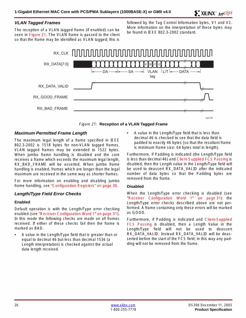
1-Gigabit Ethernet MAC Core with PCSPMA Sublayers (1000BASE-X) or GMII v40 R
VLAN Tagged Frames
The reception of a VLAN tagged frame (if enabled) can beseen in Figure 21 The VLAN frame is passed to the clientso that the frame may be identified as VLAN tagged this is
followed by the Tag Control Information bytes V1 and V2More information on the interpretation of these bytes maybe found in IEEE 8023-2002 standard
Maximum Permitted Frame Length
The maximum legal length of a frame specified in IEEE8023-2002 is 1518 bytes for non-VLAN tagged framesVLAN tagged frames may be extended to 1522 bytesWhen jumbo frame handling is disabled and the corereceives a frame which exceeds the maximum legal lengthRX_BAD_FRAME will be asserted When jumbo framehandling is enabled frames which are longer than the legalmaximum are received in the same way as shorter frames
For more information on enabling and disabling jumboframe handling see Configuration Registers on page 30
LengthType Field Error Checks
Enabled
Default operation is with the LengthType error checkingenabled (see Receiver Configuration Word 1 on page 31)In this mode the following checks are made on all framesreceived If either of these checks fail then the frame ismarked as BAD
bull A value in the LengthType field that is greater than orequal to decimal 46 but less than decimal 1536 (aLength interpretation) is checked against the actualdata length received
bull A value in the LengthType field that is less thandecimal 46 is checked to see that the data field ispadded to exactly 46 bytes (so that the resultant frameis minimum frame size 64 bytes total in length)
Furthermore if Padding is indicated (the LengthType fieldis less than decimal 46) and Client-Supplied FCS Passing isdisabled then the Length value in the LengthType field willbe used to deassert RX_DATA_VALID after the indicatednumber of data bytes so that the Padding bytes areremoved from the frame
Disabled
When the LengthType error checking is disabled (seeReceiver Configuration Word 1 on page 31) theLengthType error checks described above are not per-formed A frame containing only these errors will be markedas GOOD
Furthermore if Padding is indicated and Client-SuppliedFCS Passing is disabled then a Length Value in theLengthType field will not be used to deassertRX_DATA_VALID Instead RX_DATA_VALID will be deas-serted before the start of the FCS field in this way any pad-ding will not be removed from the frame
Figure 21 Reception of a VLAN Tagged Frame
RX_CLK
RX_DATA[70]
RX_DATA_VALID
RX_GOOD_FRAME
RX_BAD_FRAME
DA SA DATALT
81 00 V1 V2
VLANtag
xip2146
26 wwwxilinxcom DS200 December 11 20031-800-255-7778 Product Specification
1-Gigabit Ethernet MAC Core with PCSPMA Sublayers (1000BASE-X) or GMII v40R
Receiver Statistics Vector
The statistics for the frame received are contained withinthe RX_STATISTICS_VECTOR The vector is driven syn-chronously by the receiver clock RX_CLK following framereception The bit field definition for the Vector is defined inTable 15
All bit fields with the exception of BYTE_VALID are validonly when the RX_STATISTICS_VALID is asserted This isillustrated in Figure 22 BYTE_VALID is significant on everyRX_CLK cycle
Figure 22 Receiver Statistics Vector Timing
RX_CLK
RX_STATISTICS_VECTOR[220]
RX_STATISTICS_VALID
xip2147
Table 15 Bit Definition for the Receiver Statistics Vector
RX_STATISTICS_VECTOR Name Description
22LENGTHTYPE Out ofRange
Asserted if the lengthtype field contained a length valuethat did not match the number of MAC client data bytesreceived Also high if the lengthtype field indicated thatthe frame contained padding but the number of MAC cli-ent data bytes received was not equal to 64 bytes (min-imum frame size)
The exception to the above is when the LengthTypeField Error Checks are disabled in which case this bitwill not be asserted
21 BAD_OPCODE
Asserted if the previous frame was error-free andcontained the special Control Frame identifier in theLengthType field but contained an opcode that isunsupported by the MAC (Any Opcode other thanPAUSE)
20 FLOW_CONTROL_FRAME
Asserted if the previous frame was error-freecontained the special Control Frame identifier in theLengthType field contained a Destination Addressthat matched either the MAC Control MulticastAddress or the configured source address of the MACcontained the supported PAUSE opcode and wasacted upon by the MAC
19 BYTE_VALID
Asserted if a MAC frame byte (DA to FCS inclusive) isin the process of being received This is valid on everyclock cycle
Do not use this as an enable signal to indicate thatdata is present on RX_DATA[70]
18 VLAN_FRAMEAsserted if the previous frame contained a VLANidentifier in the LengthType field when receiver VLANoperation is enabled
DS200 December 11 2003 wwwxilinxcom 27Product Specification 1-800-255-7778
1-Gigabit Ethernet MAC Core with PCSPMA Sublayers (1000BASE-X) or GMII v40 R
17 OUT_OF_BOUNDS
Asserted if the previous frame exceeded the specifiedIEEE8023-2002 maximum legal length (seeMaximum Permitted Frame Length on page 26) Thisis only valid if Jumbo frames are disabled
16 CONTROL_FRAMEAsserted if the previous frame contained the specialControl Frame identifier in the LengthType field
15 down to 5 FRAME_LENGTH_COUNTThe length of the previous frame in number of bytesThe count will stick at 2047 for any Jumbo frameslarger than this value
4 MULTICAST_FRAMEAsserted if the previous frame contained a multicastaddress in the Destination Address field
3 BROADCAST_FRAMEAsserted if the previous frame contained the broadcastaddress in the Destination Address field
2 FCS_ERRORAsserted if the previous frame received had anincorrect FCS value or the MAC detected error codesduring frame reception
1 BAD_FRAME1 Asserted if the previous frame received containederrors
0 GOOD_FRAME1 Asserted if the previous frame received was error-free
1 If the LengthType Field Error Checks are disabled then a frame which contains this type of error will be marked as a GOOD_FRAMEproviding no additional errors were detected
Table 15 Bit Definition for the Receiver Statistics Vector
RX_STATISTICS_VECTOR Name Description
28 wwwxilinxcom DS200 December 11 20031-800-255-7778 Product Specification
1-Gigabit Ethernet MAC Core with PCSPMA Sublayers (1000BASE-X) or GMII v40R
Flow ControlThe flow control block is designed to Clause 31 of the IEEE8023-2002 standard The MAC may be configured to sendpause frames and to act upon their reception These twobehaviors can be configured asymmetrically see Configu-ration Registers on page 30
Transmitting a PAUSE Control Frame
The client initiates a flow control frame by assertingPAUSE_REQ while the pause value is on the PAUSE_VALbus These signals are synchronous to TX_CLK The timingof this can be seen in Figure 23
If the MAC core is configured to support transmit flow con-trol this action causes the core to transmit a PAUSE controlframe on the link with the PAUSE parameter set to thevalue on PAUSE_VAL in the cycle when PAUSE_REQ wasasserted This will not disrupt any frame transmission inprogress but will take priority over any pending frame trans-
mission This frame will be transmitted even if the transmit-ter is in the paused state itself
Receiving a Pause Control Frame
When an error-free frame is received by the MAC core thefollowing checks are made
1 The Destination Address field is matched against theMAC Control Multicast address or the configuredSource Address for the MAC (see ConfigurationRegisters on page 30)
2 The LengthType field is matched against the MACControl Type code
3 The opcode field contents are matched against thePAUSE opcode if check 2 is true
If any of the above checks are false or the MAC Flow Con-trol logic for the receiver is disabled the frame is ignored bythe Flow Control logic and passed up to the client
If the frame passes all of the above checks is of minimumlegal size and the MAC Flow Control logic for the receiver isenabled the pause value parameter in the frame is thenused to inhibit transmitter operation for the time defined inthe IEEE8023-2002 specification This inhibit is imple-mented using the same back pressure scheme shown inFigure 12 Because the received pause frame has beenacted upon it is passed to the client with RX_BAD_FRAMEasserted to indicate to the client that it should be dropped
Reception of any frame for which check 2 is true and whichis not of legal minimum length is considered an invalid Con-trol frame This will be ignored by the Flow Control logic andpassed to the client with RX_BAD_FRAME asserted
Figure 23 Pause Request Timing
TX_CLK
PAUSE_VAL[150]
PAUSE_REQ
xip2148
DS200 December 11 2003 wwwxilinxcom 29Product Specification 1-800-255-7778
1-Gigabit Ethernet MAC Core with PCSPMA Sublayers (1000BASE-X) or GMII v40 R
Optional Management Interface(management_interface=true)The management interface is a processor-independentinterface with standard address data and control signals Itmay be used as is or a wrapper may be applied (not sup-plied) to interface to common bus architectures
This interface is used for
bull Configuration of the MAC core
bull Access to optional statistics counters for use by higherlayers for example SNMP
bull access through the MDIO interface to the managementregisters located in the PHY attached to the MAC core
The management interface is accessed differently depend-ing on the type of transaction a truth table showing whichaccess method is required for each transaction type isshown in Table 16 These access methods are described inthe following sections
HOST_CLK Frequency
The management interface clock HOST_CLK is used toderive the MDIO clock MDC and is therefore subject tosome frequency restrictions This HOST_CLK must be
ge 10 MHz
le 100 MHz
Configuring the MAC core to derive the MDC signal fromthis clock is detailed in MDIO Interface on page 37
Configuration Registers
After power up or reset the client may reconfigure the coreparameters from their defaults such as flow control supportConfiguration changes can be written at any time Both thereceiver and transmitter logic will only respond to configura-tion changes during Inter Frame Gaps The exceptions tothis are the configurable resets which take effect immedi-ately
Configuration of the MAC core is performed through a reg-ister bank accessed through the management interfaceThe configuration registers available in the core are detailedin Table 17 As can be seen the address has some implicitdonrsquot care bits any access to an address in the rangesshown will perform a 32-bit read or write from the same con-figuration word
Table 16 Management Interface Transaction Types
Transaction HOST_MIIM_SEL HOST_ADDR[9]
Configuration 0 1
Statistics 0 0
MIIM access 1 X
Table 17 Configuration Registers
Address Description
0x200-0x23F Receiver Configuration (Word 0)
0x240-0x27F Receiver Configuration (Word 1)
0x280-0x2BF Transmitter Configuration
0x2C0-0x2FF Flow Control Configuration
0x300-0x33F Reserved
0x340-0x37F Management Configuration
30 wwwxilinxcom DS200 December 11 20031-800-255-7778 Product Specification
1-Gigabit Ethernet MAC Core with PCSPMA Sublayers (1000BASE-X) or GMII v40R
The register contents for the two receiver configuration words can be seen in Table 18 and Table 19
Notes1 In changing the receiverrsquos mode from Half Duplex to Full Duplex there is a period of time of up to 24 us following the mode change
when no new receiver statistics can be stored in the optional Statistical Counters
Table 18 Receiver Configuration Word 0
Bit Default Value Description
31-0 All 0rsquos
Pause frame MAC Source Address[310] This address is used by the MAC tomatch against the Destination Address of any incoming flow control frames It isalso used by the flow control block as the Source Address (SA) for any outboundflow control frames
The address is ordered so the first byte transmittedreceived is the lowestpositioned byte in the register for example a MAC address ofAA-BB-CC-DD-EE-FF would be stored in Address[470] as 0xFFEEDDCCBBAA
Table 19 Receiver Configuration Word 1
Bit Default Value Description
15-0 All 0rsquos Pause frame MAC Source Address[4732] See description in Table 18
24-16 NA Reserved
25 0
LengthType Error Check Disable When this bit is set to ldquo1rdquo the core will notperform the LengthType field error checks as described in LengthType FieldError Checks on page 26 When this bit is set to ldquo0rdquo the LengthType field checkswill be performed this is normal operation
26 0Half Duplex If ldquo1rdquo the receiver will operate in half duplex mode If ldquo0rdquo the receiverwill operate in full duplex mode Has no effect if XCO parameterhalf_duplex_capable = false
27 0VLAN Enable When this bit is set to ldquo1rdquo VLAN tagged frames will be acceptedby the receiver
28 1Receiver Enable If set to ldquo1rdquo the receiver block will be operational If set to ldquo0rdquothe block will ignore activity on the physical interface RX port
29 0
In-band FCS Enable When this bit is ldquo1rdquo the MAC receiver will pass the FCS fieldup to the client as described in Client-Supplied FCS Passing on page 25 Whenit is ldquo0rdquo the client will not be passed the FCS In both cases the FCS will beverified on the frame
30 0Jumbo Frame Enable When this bit is set to ldquo1rdquo the MAC receiver will acceptframes over the specified IEEE8023-2002 maximum legal length When this bitis ldquo0rdquo the MAC will only accept frames up to the specified maximum
31 0Reset When this bit is set to ldquo1rdquo the receiver will be reset The bit will thenautomatically revert to ldquo0rdquo Note that this reset will also set all of the receiverconfiguration registers to their default values
DS200 December 11 2003 wwwxilinxcom 31Product Specification 1-800-255-7778
1-Gigabit Ethernet MAC Core with PCSPMA Sublayers (1000BASE-X) or GMII v40 R
The register contents for the Transmitter Configuration Word are described in Table 20
Notes1 In changing the transmitterrsquos mode from Half Duplex to Full Duplex there is a period of time of up to 24 us following the mode change
when no new transmitter statistics can be stored in the optional Statistical Counters
Table 20 Transmitter Configuration Word
Bit Default Value Description
24-0 NA Reserved
25 0
Interframe Gap Adjust Enable If lsquo1rsquo the transmitter will read the value on the portTX_IFG_DELAY at the start of frame transmission and adjust the interframe gapfollowing the frame accordingly See Interframe Gap Adjustment on page 22 Ifldquo0rdquo the transmitter will output a minimum Inter Frame Gap of twelve clock cyclesas specified in IEEE8023-2002
26 0Half Duplex If lsquo1rsquo the transmitter will operate in half duplex mode If lsquo0rsquo thetransmitter will operate in full duplex mode Has no effect if XCO parameterhalf_duplex_capable = false
27 0VLAN Enable When this bit is set to 1 the transmitter will allow the transmissionof VLAN tagged frames
28 1Transmit Enable When this bit is 1 the transmitter is operational When it is 0the transmitter is disabled
29 0
In-band FCS Enable When this bit is lsquo1rsquo the MAC transmitter will expect the FCSfield to be passed in by the client as described in Client-Supplied FCS Passingon page 17 When this bit is ldquo0rdquo the MAC transmitter will append padding asrequired compute the FCS and append it to the frame
30 0
Jumbo Frame Enable When this bit is set to ldquo1rdquo the MAC transmitter will sendframes that are greater than the specified IEEE8023-2002 maximum legallength When this bit is ldquo0rdquo the MAC will only send frames up to the specifiedmaximum
31 0Reset When this bit is set to ldquo1rdquo the transmitter will be reset The bit will thenautomatically revert to ldquo0rdquo Note that this reset will also set all of the transmitterconfiguration registers to their default values
32 wwwxilinxcom DS200 December 11 20031-800-255-7778 Product Specification
1-Gigabit Ethernet MAC Core with PCSPMA Sublayers (1000BASE-X) or GMII v40R
The register contents for the Flow Control Configuration Word are described in Table 21
The register contents for the Management Configuration Word are described in Table 22
Writing to the configuration registers through the manage-ment interface is depicted in Figure 24 When accessing theconfiguration registers (ie when HOST_ADDR[9] = lsquo1rsquo andHOST_MIIM_SEL = lsquo0rsquo) the upper bit of HOST_OPCODEfunctions as an Active Low write enable signal The lowerHOST_OPCODE bit is a ldquodonrsquot carerdquo
Reading from the configuration register words is similar butthe upper HOST_OPCODE bit should be lsquo1rsquo This is shownin Figure 25 In this case the contents of the register appearon HOST_RD_DATA the HOST_CLK edge after the regis-ter address is asserted onto HOST_ADDR
Table 21 Flow Control Configuration Word
Bit Default Value Description
28-0 NA Reserved
29 1
Flow Control Enable (RX) When this bit is lsquo1rsquo received flow control frames willinhibit the transmitter operation as described in Receiving a Pause ControlFrame on page 29 When this bit is lsquo0rsquo received flow control frames will alwaysbe passed up to the client
30 1Flow Control Enable (TX) When this bit is lsquo1rsquo asserting the PAUSE_REQ signalwill send a flow control frame out from the transmitter When this bit is 0 assertingthe PAUSE_REQ signal has no effect
31 NA Reserved
Table 22 Management Configuration Word
Bits Default Value Description
4-0 All 0rsquos Clock Divide[40] See MDIO Interface on page 37
5 0MDIO Enable When this bit is 1 the MDIO interface can be used to accessattached PHY devices When this bit is 0 the MDIO interface is disabled and theMDIO signals remain inactive
31-6 NA Reserved
Figure 24 Configuration Register Write Timing
HOST_CLK
HOST_ADDR[80]
HOST_ADDR[9]
HOST_OPCODE[1]
HOST_MIIM_SEL
HOST_WR_DATA[310]xip2149
Figure 25 Configuration Register Read Timing
HOST_CLK
HOST_ADDR[80]
HOST_ADDR[9]
HOST_OPCODE[1]
HOST_MIIM_SEL
HOST_RD_DATA[310]
xip2150
DS200 December 11 2003 wwwxilinxcom 33Product Specification 1-800-255-7778
1-Gigabit Ethernet MAC Core with PCSPMA Sublayers (1000BASE-X) or GMII v40 R
Optional Statistical Gathering(statistics_gathering=true)
During operation the MAC core collects statistics on thesuccess and failure of various operations for processing by
station management entities (STA) further up the protocolstack These statistics are accessed by the host through theoptional management interface A complete list of statisticssupported is described in Table 23
Table 23 Statistics Registers
Address Name Description
0x000 Frames Received OK1 A count of error-free frames received
0x001 Frame Check Sequence Errors A count of received frames that failed the CRC check and were at least64 bytes in length
0x002 Broadcast Frames Received OK1A count of frames that were successfully received and were directed tothe broadcast group address
0x003 Multicast Frames Received OK1 A count of frames that were successfully received and were directed toa non broadcast group address
0x004 64 byte Frames Received OK1 A count of error-free frames received that were 64 bytes in length
0x005 65-127 byte Frames Received OK1A count of error-free frames received that were between 65 and 127bytes in length
0x006 128-255 byte Frames Received OK1A count of error-free frames received that were between 128 and 255bytes in length
0x007 256-511 byte Frames Received OK1A count of error-free frames received that were between 256 and 511bytes in length
0x008512-1023 byte Frames ReceivedOK1
A count of error-free frames received that were between 512 and 1023bytes in length
0x0091024-MaxFrameSize byte FramesReceived OK1
A count of error-free frames received that were between 1024 bytes andthe specified IEEE8023-2002 maximum legal length (see MaximumPermitted Frame Length on page 26)
0x00A Control Frames Received OKA count of error-free frames received that contained the specialControl Frame identifier in the LengthType field
0x00B LengthType Out of Range
A count of frames received that were at least 64 bytes in length wherethe lengthtype field contained a length value that did not match thenumber of MAC client data bytes received
The counter also increments for frames in which the lengthtype fieldindicated that the frame contained padding but where the number ofMAC client data bytes received was greater than 64 bytes (minimumframe size)
The exception to the above is when the LengthType Field Error Checksare disabled in which case this counter will not increment
0x00C VLAN Tagged Frames Received OKA count of error-free VLAN frames received This counter will only incre-ment when the receiver is configured for VLAN operation
0x00D Pause Frames Received OK
A count of error-free frames received that contained the MAC Controltype identifier 88-08 in the LengthType field contained a Destinationaddress that matched either the MAC Control multicast address or theconfigured source address of the MAC contained the PAUSE opcodeand were acted upon by the MAC
0x00EControl Frames Received withUnsupported Opcode
A count of error-free frames received that contained the MAC Controltype identifier 88-08 in the LengthType field but were received with anopcode other than the PAUSE opcode
34 wwwxilinxcom DS200 December 11 20031-800-255-7778 Product Specification
1-Gigabit Ethernet MAC Core with PCSPMA Sublayers (1000BASE-X) or GMII v40R
0x00F Oversize Frames Received OK1A count of otherwise error-free frames received that exceeded the max-imum legal frame length specified in IEEE 8023-2002 (see MaximumPermitted Frame Length on page 26)
0x010 Undersize frames receivedA count of the number of frames received that were less than 64 bytesin length but were otherwise well formed
0x011 Fragment frames receivedA count of the number of frames received that were less than 64 bytesin length and had a bad Frame Check Sequence field
0x012 Received bytesA count of bytes of frames that are received (Destination Address toFrame Check Sequence inclusive)
0x013 Transmitted bytesA count of bytes of frames that are transmitted (Destination Address toFrame Check Sequence inclusive)
0x020 Frames Transmitted OK A count of error-free frames transmitted
0x021 Broadcast Frames Transmitted OK A count of error-free frames that were transmitted to the broadcastaddress
0x022 Multicast Frames Transmitted OK A count of error-free frames that were transmitted to a group destina-tion address other than broadcast
0x023 Underrun Errors
A count of frames that would otherwise be transmitted by the core butcould not be completed due to the assertion of TX_UNDERRUN duringthe frame transmission This will not count frames which are less than64 bytes in length
0x024 Control Frames Transmitted OKA count of error-free frames transmitted that contained the MACControl Frame type identifier 88-08 in the LengthType field
0x025 64 byte Frames Transmitted OK A count of error-free frames transmitted that were 64 bytes in length
0x026 65-127 byte Frames Transmitted OKA count of error-free frames transmitted that were between 65 and 127bytes in length
0x027128-255 byte Frames TransmittedOK
A count of error-free frames transmitted that were between 128 and 255bytes in length
0x028256-511 byte Frames TransmittedOK
A count of error-free frames transmitted that were between 256 and 511bytes in length
0x029512-1023 byte Frames TransmittedOK
A count of error-free frames transmitted that were between 512 and1023 bytes in length
0x02A1024-MaxFrameSize byte FramesTransmitted OK
A count of error-free frames transmitted that were between 1024 and thespecified IEEE8023-2002 maximum legal length (see Maximum Per-mitted Frame Length on page 20)
0x02BVLAN Tagged Frames TransmittedOK
A count of error-free VLAN frames transmitted This counter will onlyincrement when the transmitter is configured for VLAN operation
0x02C Pause Frames Transmitted OKA count of error-free PAUSE frames generated and transmitted by thecore in response to an assertion of PAUSE_REQ
0x02D Oversize Frames Transmitted OKA count of otherwise error-free frames transmitted that exceeded themaximum legal frame length specified in IEEE 8023-2002 (see Maxi-mum Permitted Frame Length on page 20)
0x02E Single Collision Frames A count of frames that are involved in a single collision but are subse-quently transmitted successfully (Half Duplex Mode only)
Table 23 Statistics Registers (Continued)
Address Name Description
DS200 December 11 2003 wwwxilinxcom 35Product Specification 1-800-255-7778
1-Gigabit Ethernet MAC Core with PCSPMA Sublayers (1000BASE-X) or GMII v40 R
Each of these statistic registers is 64 bits wide and thereforemust be read in a two-cycle transfer The timing of this pro-cess is shown in Figure 26 Six clocks after the read trans-action is initiated the least significant word (LSW) of thestatistics counter appears on the HOST_RD_DATA bus
and a clock cycle later the most significant word (MSW)appears For accurate statistic values 64 clock ticks (ofTX_CLK for transmit statistics or RX_CLK for receive statis-tics) must elapse after the last frame is sent or receivedthrough the MAC core
0x02F Multiple Collision Frames A count of frames that are involved in more than one collision but aresubsequently transmitted successfully (Half Duplex Mode only)
0x040 Frames with Deferred Transmissions A count of frames whose transmission was delayed on its first attemptbecause the medium was busy (Half Duplex Mode only)
0x041 Late Collisions
A count of the times that a collision has been detected later than oneslotTime from the start of the packet transmission A late collision iscounted twice both as a collision and as a lateCollision (Half DuplexMode only)
0x042Frames Aborted due to Excesscollisions
A count of the frames that due to excessive collisions are not transmit-ted successfully (Half Duplex Mode only)
0x043 Carrier Sense ErrorsA count of times that the GMII_CRS signal was not asserted or wasdisasserted during the transmission of a frame without collision (HalfDuplex Mode only)
0x044 Frames with Excess DeferralA count of frames that deferred transmission for an excessive period oftime (Half Duplex Mode only)
1 If the LengthType Field Error Checks are disabled then these counters will still increment for received frames which contain this typeof error (providing no additional errors were detected)
Table 23 Statistics Registers (Continued)
Address Name Description
Figure 26 Statistic Register Read Timing
HOST_CLK
HOST_ADDR[80]
HOST_ADDR[9]
HOST_REQ
HOST_MIIM_SEL
HOST_RD_DATA[310]
6 CLOCKS
LSW MSW
xip2151
36 wwwxilinxcom DS200 December 11 20031-800-255-7778 Product Specification
1-Gigabit Ethernet MAC Core with PCSPMA Sublayers (1000BASE-X) or GMII v40R
MDIO Interface
The management interface is also used to access the MDIO(MII Management) interface of the MAC core this interfaceis used to access the Managed Information Block (MIB) ofthe PHY components attached to the MAC core
The MDIO interface supplies a clock to the externaldevices MDC This clock is derived from the HOST_CLKsignal using the value in the Clock Divide[40] configurationregister The frequency of the MDIO clock is given by thefollowing equation
The frequency of MDC given by this equation should notexceed 25 MHz in order to comply with the IEEE8023-2002 specification for this interface To prevent MDCfrom being out of specification the Clock Divide[40] valuepowers up at 00000 and while this value is in the register itis impossible to enable the MDIO interface
For details of the register map of PHY layer devices and afuller description of the operation of the MDIO interfaceitself see IEEE specification 8023-2002
Access to the MDIO interface through the managementinterface is depicted in the timing diagram in Figure 27
For MDIO transactions the following points apply
bull HOST_OPCODE maps to the OP (opcode) field of theMDIO frame
bull HOST_ADDR maps to the two address fields of theMDIO frame PHY_ADDR is HOST_ADDR[95] andREG_ADDR is HOST_ADDR[40]
bull HOST_WR_DATA[150] maps into the data field of the
MDIO frame when performing a write operation
bull The data field of the MDIO frame maps intoHOST_RD_DATA[150] when performing a readoperation
The MAC core signals to the host that it is ready for anMDIO transaction by asserting HOST_MIIM_RDY A read orwrite transaction on the MDIO is initiated by a pulse on the
fMDC
fHOST_CLK
1 Clock Divide[40]+( ) 2times-------------------------------------------------------------------=
Figure 27 MDIO Access Through Management Interface
HOST_CLK
HOST_ADDR[90]
HOST_OPCODE[10]
HOST_REQ
HOST_MIIM_SEL
HOST_RD_DATA[150]
HOST_WR_DATA[150]
HOST_RDY
If a read transaction is initiated the HOST_RD_DATA bus is valid at the point indicated If a write transaction is initiated the HOST_WR_DATA bus must be valid at the indicated point Simultaneous read and write is not permitted
xip2152
DS200 December 11 2003 wwwxilinxcom 37Product Specification 1-800-255-7778
1-Gigabit Ethernet MAC Core with PCSPMA Sublayers (1000BASE-X) or GMII v40 R
HOST_REQ signal This pulse is ignored if the MDIO inter-face already has a transaction in progress
The MAC core then disasserts the HOST_MIIM_RDY signalwhile the transaction across the MDIO is in progress Whenthe transaction across the MDIO interface has been com-pleted the HOST_MIIM_RDY signal will be asserted by theMAC core if the transaction is a read the data will also beavailable on the HOST_RD_DATA[150] bus at this time
Optional Configuration Vector(management_interface = false)If the optional Management interface is omitted from thecore all of relevant configuration signals are brought out of
the core These signals are bundled into theCONFIGURATION_VECTOR signal The bit mapping of theconfiguration vector signal is defined in Table 24 See thecorresponding entry in the configuration register tables forthe full description of each signal
Note that these configuration vector signals can bechanged by the user at any time however with the excep-tion of the reset and the flow control configuration signalsthey will not take effect until the current frame has com-pleted transmission or reception
The ldquoClockrdquo heading denotes which clock domain the con-figuration signal is registered into before use by the core Itis not necessary to drive the signal from this clock domain
Table 24 Configuration Vector Bit Definition
Bit(s)Configuration Register
cross reference Clock Description
47 downto 0
Receiver ConfigurationWord 0 bits 31-0 andReceiver ConfigurationWord 1 bits 15-0
RX_CLK
Pause frame MAC Source Address[470] This address isused by the MAC core to match against the DestinationAddress of any incoming flow control frames and as theSource Address for any outbound flow control frames
The address is ordered such that the first byte transmitted orreceived is the least significant byte in the register forexample a MAC address of AA-BB-CC-DD-EE-FF will bestored in bite [470] as 0xFFEEDDCCBBAA
48Receiver ConfigurationWord 1 bit 26
RX_CLKReceiver Half Duplex If lsquo1rsquo the receiver operates in halfduplex mode If lsquo0rsquo the receiver operates in full duplex modeHas no effect if XCO parameter half_duplex_capable = false
49Receiver ConfigurationWord 1 bit 27
RX_CLKReceiver VLAN Enable When this bit is set to 1 VLANtagged frames are accepted by the receiver
50Receiver ConfigurationWord 1 bit 28
RX_CLKReceiver Enable If set to 1 the receiver block is operationalIf set to 0 the block ignores activity on the physical interfaceRX port
51Receiver ConfigurationWord 1 bit 29
RX_CLK
Receiver In-band FCS Enable When this bit is lsquo1rsquo the MACreceiver will pass the FCS field up to the client as describedin Client-Supplied FCS Passing on page 25 When it is lsquo0rsquothe MAC receiver will not pass the FCS field In both casesthe FCS field will be verified on the frame
52Receiver ConfigurationWord 1 bit 30
RX_CLK
Receiver Jumbo Frame Enable When this bit is lsquo0rsquo thereceiver will not pass frames longer than the maximum legalframe size specified in IEEE 8023-2002 (see MaximumPermitted Frame Length on page 26) When it is lsquo1rsquo thereceiver will not have an upper limit on frame size
53Receiver ConfigurationWord 1 bit 31
NA
Receiver Reset When this bit is lsquo1rsquo the receiver is held inreset
This signal is an input to the reset circuit for the receiverblock See Reset circuit on page 42 for more information
54TransmitterConfiguration Word bit25
TX_CLK
Transmitter Interframe Gap Adjust enable If lsquo1rsquo then thetransmitter will read the value of the TX_IFG_DELAY port andset the Interframe Gap accordingly If lsquo0rsquo the transmitter willalways insert at least the legal minimum Interframe Gap
38 wwwxilinxcom DS200 December 11 20031-800-255-7778 Product Specification
1-Gigabit Ethernet MAC Core with PCSPMA Sublayers (1000BASE-X) or GMII v40R
55TransmitterConfiguration Word bit26
TX_CLK
Transmitter Half Duplex If lsquo1rsquo the transmitter operates in halfduplex mode If lsquo0rsquo the transmitter operates in full duplexmode Has no effect if XCO parameter half_duplex_capable= false
56TransmitterConfiguration Word bit27
TX_CLKTransmitter VLAN Enable When this bit is set to lsquo1rsquo thetransmitter allows the transmission of VLAN tagged frames
57TransmitterConfiguration Word bit28
TX_CLKTransmitter Enable When this bit is 1 the transmitter will beoperational When it is 0 the transmitter is disabled
58TransmitterConfiguration Word bit29
TX_CLK
Transmitter In-Band FCS Enable When this bit is lsquo1rsquo theMAC transmitter will expect the FCS field to be pass in by theclient as described in Client-Supplied FCS Passing onpage 17 When it is lsquo0rsquo the MAC transmitter will appendpadding as required compute the FCS and append it to theframe
59TransmitterConfiguration Word bit30
TX_CLK
Transmitter Jumbo Frame Enable When this bit is lsquo1rsquo theMAC transmitter will allow frames larger than the maximumlegal frame length specified in IEEE 8023-2002 to be sentWhen set to lsquo0rsquo the MAC transmitter will only allow frames upto the legal maximum to be sent
60TransmitterConfiguration Word bit31
NA
Transmitter Reset When this bit is lsquo1rsquo the MAC transmitter isheld in reset
This signal is an input to the reset circuit for the transmitterblock See Reset circuit on page 42 for more information
61Flow ControlConfiguration Word bit29
TX_CLK
Transmit Flow Control Enable When this bit is lsquo1rsquo assertingthe PAUSE_REQ signal causes the MAC core to send a flowcontrol frame out from the transmitter as described inReceiving a Pause Control Frame on page 29 When this bitis lsquo0rsquo asserting the PAUSE_REQ signal will have no effect
62Flow ControlConfiguration Word bit30
RX_CLK
Receive Flow Control Enable When this bit is lsquo1rsquo receivedflow control frames will inhibit the transmitter operation asdescribed in Receiving a Pause Control Frame on page 29When it is lsquo0rsquo received flow frames are passed up to theclient
63Receiver ConfigurationWord 1 bit 25
RX_CLK
LengthType Error Check Disable When this bit is lsquo1rsquo thecore will not perform the LengthType field error checks asdescribed in LengthType Field Error Checks on page 26When it is set to lsquo0rsquo the LengthType field checks will beperformed this is normal operation
Table 24 Configuration Vector Bit Definition (Continued)
Bit(s)Configuration Register
cross reference Clock Description
DS200 December 11 2003 wwwxilinxcom 39Product Specification 1-800-255-7778
1-Gigabit Ethernet MAC Core with PCSPMA Sublayers (1000BASE-X) or GMII v40 R
Optional GMII (physical_interface=gmii)The GMII is designed to IEEE 8023-2002 Clause 35 Thisutilizes IOrsquos of the Xilinx devices using inputoutput buffersand inputoutput flip-flops to maximize setup and hold mar-gins All IO logic is placed in the example wrapper that isdelivered with the core In addition all clock managementlogic for the core is instanced in this example wrapper thisallows multiple instances of the core to share clocks Theexample wrapper is provided in both VHDL and Verilog
Clock Management
Figure 28 illustrates the clock management used with theGMII interface All clocks illustrated have a frequency of125MHz
GTX_CLK must be provided to the MAC core This is a highquality clock which satisfies the IEEE8023-2002 require-ments It is expected that this clock will be derived from anexternal oscillator and connected into the device through anIBUFG as illustrated The clock source must then be routedonto a global clock network by connecting it to a BUFGWithin the MAC core this global clock is used by all MACtransmitter logic The MAC Client can obtain this clock byconnecting to the TX_CLK signal output from the coreGMII_TX_CLK is derived from this global clock by invertingit and routing it to an OBUF
GMII_RX_CLK is received through an IBUFG This clock isthen routed onto a global clock network by connecting it to aBUFG The resulting global clock is used by all MACreceiver logic
Figure 28 Clock Management with GMII
IBUFG
IBUFG
OBUF
BUFG
BUFG
TX_CLK
RX_CLK
GTX_CLK
GMII_TX_CLK
GMII_RX_CLK
Example Wrapper
xip2153
MAC Core
TX_CLK
RX_CLK
GMII_TX_CLK
GMII_RX_CLK
GTX_CLK
40 wwwxilinxcom DS200 December 11 20031-800-255-7778 Product Specification
1-Gigabit Ethernet MAC Core with PCSPMA Sublayers (1000BASE-X) or GMII v40R
Clock Sharing between Multiple cores
Figure 29 illustrates how it is possible to share clockresources across multiple instantiations of the core whenusing the optional GMII
GTX_CLK may be shared between multiple cores as illus-trated resulting in a common transmitter clock domainacross the device
A common receiver clock domain is not possible each corewill receive an independent receiver clock from its GMII asillustrated
Although not illustrated if the optional Management Inter-face is used HOST_CLK can also be shared betweencores
Figure 29 Clock Management with multiple instances of the MAC with GMII
IBUFG
OBUF
BUFG
TX_CLK
RX_CLK_1
GMII_TX_CLK_1
GMII_RX_CLK_1
MAC Core
TX_CLK
RX_CLK
GMII_TX_CLK
GMII_RX_CLK
GTX_CLK
MAC Core
TX_CLK
RX_CLK
GMII_TX_CLK
GMII_RX_CLK
GTX_CLK
IBUFG
BUFG
GTX_CLK
IBUFG
OBUF
GMII_TX_CLK_2
GMII_RX_CLK_2
BUFG
TX_CLK
RX_CLK_2
DS200 December 11 2003 wwwxilinxcom 41Product Specification 1-800-255-7778
1-Gigabit Ethernet MAC Core with PCSPMA Sublayers (1000BASE-X) or GMII v40 R
Reset circuit
Internally the core is divided up into clockreset domainswhich group together elements with the common clock andreset signals The reset circuitry for one of these domains isis illustrated in Figure 30 This circuit provides controllableskews on the reset nets within the design
More information on the operation and rationale behind thiscircuit can be found in Ken Chapmanrsquos Xilinx TechXclusiveldquoGet Smart About Resetrdquo athttpwwwxilinxcomsupporttechxclusivesglobal-techX19htm
Figure 30 Reset circuit for one clockreset domain
FDP
PRED
C
Q
FDP
PRED
C
Q
FDP
PRED
C
Q
FDP
PRED
C
Q
PRE PRE PRE
0
RESET
Management Reset
Clock
Core Registers
42 wwwxilinxcom DS200 December 11 20031-800-255-7778 Product Specification
1-Gigabit Ethernet MAC Core with PCSPMA Sublayers (1000BASE-X) or GMII v40R
Optional PCS with Ten-Bit Interface (TBI) for 1000BASE-X (physical_interface=tbi)The Full-Duplex Physical Coding Sublayer (PCS) for1000BASE-X is defined in IEEE 8023-2002 Clauses 36and 37 This functionality is only available in the Virtex-IIand Spartan3 families of FPGA devices
A block diagram of the PCS is shown in Figure 31 Themajor functional blocks of the PCS are
bull Transmit engine
bull Auto-negotiation block
bull Receive engine and synchronization block
bull PCS managed register block
bull 8B10B encoder block
bull 8B10B decoder block
bull Receiver elastic buffer
The PCS Managed Register Block is accessed through theMDIO Interface as if it were an externally connected PHYThis configures the operation of the PCS and Auto-Negoti-ation See PCS Managed Register Block
(physical_interface = tbi or phy) on page 49 The corersquosoptional Management Interface can be used to control theMDIO Interface as described by MDIO Interface onpage 37 When the optional Management Interface is notpresent the PCS Managed Register Block must beaccessed via an MDIO controller which is not provided bythe core
The 8B10B encodingdecoding blocks are implemented byconfiguring two Block SelectRAM modules as ROM Theseare used as large look-up tables The remaining PCS func-tionality such as code group encodingdecoding the Man-aged Register Block and Auto-Negotiation areimplemented in CLB logic
The Receiver Elastic buffer enables the 10-bit parallel datareceived from the PMA sublayer alternatively onPMA_RX_CLK0 and PMA_RX_CLK1 clock edges to betransferred onto the internal 125MHz clock domain derivedfrom GTX_CLK (see Clock Management) This buffer isimplemented in Distributed Memory
Figure 31 Functional Block Diagram of the 1-Gigabit Ethernet PCS with TBI Interface
PCS TRANSMIT ENGINE
PCS RECEIVE ENGINE ampSYNCHRONISATION
PCSMANAGEMENT
MDIOInterface
AUTO-NEGOTIATION
MAC TXInterface
MAC RXInterface
8B10BEncoder
8B10BDecoder
RX Elastic Buffer
TBI Interface
DS200 December 11 2003 wwwxilinxcom 43Product Specification 1-800-255-7778
1-Gigabit Ethernet MAC Core with PCSPMA Sublayers (1000BASE-X) or GMII v40 R
TBI Interface
The TBI is designed to IEEE 8023-2002 Clause 363 Thisutilizes IOrsquos of the Xilinx devices using inputoutput buffersand inputoutput flip-flops to maximize setup and hold mar-gins All IO logic is placed in the example wrapper that isdelivered with the core In addition all clock managementlogic for the core is instantiated in this example wrapperthis allows multiple instances of the core to share clocksThe example wrapper is provided in both VHDL and Verilog
Clock Management
Figure 32 illustrates the clock management used with theTBI interface
GTX_CLK must be provided to the MAC core This is a highquality clock of frequency 125MHz which satisfies theIEEE8023-2002 requirements It is expected that this clockwill be derived from an external oscillator and connected
into the device through an IBUFG as illustrated The clocksource must then be routed onto a global clock network byconnecting it to a BUFG Within the MAC core this globalclock is used by all MAC transmitter logic PMA_TX_CLK isderived from this global clock by inverting it and routing it toan OBUF
PMA_RX_CLK0 and PMA_RX_CLK1 are each receivedthrough an IBUFG These clocks are then routed onto glo-bal clock networks by connecting each to a BUFGPMA_RX_CLK0 and PMA_RX_CLK1 are each 625MHzclocks Data from the TBI is received alternatively on the ris-ing edge of PMA_RX_CLK0 followed by the rising edge ofPMA_RX_CLK1 using IOB Double-Data Rate input regis-ters This data is then written into the Receiver ElasticBuffer Data is read out of the Elastic Buffer using the globalclock derived from GTX_CLK all the remaining receiverlogic is synchronous to this clock
Figure 32 Clock Management for PCS with TBI Interface
IBUFG
IBUFG
OBUF
BUFG
BUFG
TX_CLK
RX_CLK
GTX_CLK
PMA_TX_CLK
PMA_RX_CLK0
MAC Core
RX ELASTICBUFFER
Example Wrapper
TX_CLK
RX_CLK
GTX_CLK
PMA_TX_CLK
PMA_RX_CLK0
IBUFGBUFGPMA_RX_CLK1
PMA_RX_CLK1
44 wwwxilinxcom DS200 December 11 20031-800-255-7778 Product Specification
1-Gigabit Ethernet MAC Core with PCSPMA Sublayers (1000BASE-X) or GMII v40R
Clock Sharing between Multiple cores
Figure 33 illustrates how it is possible to share clockresources across multiple instantiations of the core whenusing the optional PCS with TBI
GTX_CLK may be shared between multiple cores as illus-trated resulting in a common transmitter clock domainacross the device
Each core will receive independent PMA_RX_CLK0 andPMA_RX_CLK1 clocks from its TBI as illustrated whichcannot be shared
Although not illustrated if the optional Management Inter-face is used HOST_CLK can also be shared betweencores
Figure 33 Clock Management with multiple instances of the MAC with PCS and TBI
Reset circuit
The reset circuits within the MAC when the TBI interface is implemented is the same as that in the GMII case details ofthese circuits can be found on page 42
IBUFG
OBUF
BUFG
TX_CLK
RX_CLK
PMA_TX_CLK_1
PMA_RX_CLK0_1
MAC Core
RX ELASTICBUFFER
TX_CLK
RX_CLK
GTX_CLK
PMA_TX_CLK
PMA_RX_CLK0
IBUFGBUFGPMA_RX_CLK1_1
PMA_RX_CLK1
IBUFG
BUFG
GTX_CLK
IBUFG
OBUF
BUFG
TX_CLK
RX_CLK
PMA_TX_CLK_2
PMA_RX_CLK0_2
MAC Core
RX ELASTICBUFFER
TX_CLK
RX_CLK
GTX_CLK
PMA_TX_CLK
PMA_RX_CLK0
IBUFGBUFGPMA_RX_CLK1_2
PMA_RX_CLK1
DS200 December 11 2003 wwwxilinxcom 45Product Specification 1-800-255-7778
1-Gigabit Ethernet MAC Core with PCSPMA Sublayers (1000BASE-X) or GMII v40 R
Optional PCS and PMA Sublayers for 1000BASE-X (physical_interface=phy)The Full-Duplex Physical Coding Sublayer (PCS) withPhysical Medium Attachment (PMA) for 1000BASE-X isdefined in IEEE 8023-2002 Clauses 36 and 37 This func-tionality is only available in the Virtex-II Pro family of FPGAdevices
A block diagram of the PCS and PMA sublayers can beseen in Figure 34 The functional blocks of the PCS andPMA sublayers may replace the optional GMII interfaceThe functional blocks of the PCS and PMA sublayers are
bull PCS Transmit Engine
bull Auto-Negotiation block
bull Receive Engine and Synchronization Block
bull PCS Managed Register Block
bull Rocket IO Multi-Gigabit Transceiver
The PCS Managed Register Block is accessed through theMDIO Interface as if it were an externally connected PHYThis configures the operation of the PCS PMA sublayerand Auto-NegotiationSee PCS Managed Register Block(physical_interface = tbi or phy) on page 49 The corersquosoptional Management Interface can be used to control theMDIO Interface as described by MDIO Interface onpage 37 When the optional Management Interface is notpresent the PCS Managed Register Block must beaccessed via an MDIO controller which is not provided bythe core
The Rocket IO Multi-Gigabit Transceiver (MGT) providessome of the PCS layer functionality such as 8B10B encod-ingdecoding and the PMA serdes The remaining PCSfunctionality such as code group encodingdecoding theManaged Register Block and Auto-Negotiation are imple-mented in CLB logic
Figure 34 Functional Block Diagram of the 1-Gigabit Ethernet PCSPMA Sublayer Extension
PCS TRANSMIT ENGINE
PCS RECEIVE ENGINE ampSYNCHRONISATION
RO
CK
ET
IO
MU
LTI-
GIG
TR
AN
SC
EIV
ER
PCSMANAGEMENT
MDIOInterface
AUTO-NEGOTIATION
TXPTXN
RXPRXN
MAC TXInterface
MAC RXInterface
xip2154
46 wwwxilinxcom DS200 December 11 20031-800-255-7778 Product Specification
1-Gigabit Ethernet MAC Core with PCSPMA Sublayers (1000BASE-X) or GMII v40R
Clock Management
Figure 35 illustrates the clock management that should beused with the optional PCS and PMA sublayers for1000BASE-X This logic is implemented in the examplewrapper that is delivered with the core This provides flexi-bility because the design can be modified to use eitherREFCLK or BREFCLK (please refer to Rocket IO docu-mentation) It would also allow multiple instances of the coreto share clocks The example wrapper is provided in bothVHDL and Verilog
(B)REFCLK must be provided to the MAC core This clockmust be derived from an external oscillator and connectedto the core through an IBUFG as illustrated (B)REFCLK isa high quality clock of frequency 625 MHz which satisfiesthe Rocket IO Multi-Gigabit Transceiver (MGT) require-ments
(B)REFCLK is routed to both the core and a DCM From theDCM the CLK2X180 output is routed to a BUFG to providethe device with a global 125 MHz clock (connected toUSERCLK2 input on the core) Within the core bothTX_CLK and RX_CLK share this global 125 MHz clocksource which is used by all transmitter and receiver logicThis is made possible by the RX_ELASTIC_BUFFER func-tionality of the Rocket IO MGT (refer to Virtex-II Pro docu-mentation) The MAC Client can obtain this clock byconnecting to either the TX_CLK or the RX_CLK signalsoutput from the core
From the DCM the CLK0 output is routed to a BUFG to pro-vide the device with a global 625MHz clock This is con-nected to the USRCLK input of the core
Figure 35 Clock Management with PCSPMA Sublayers
DCM
CLKIN CLK0
CLK2X180FB
BUFG
BUFG
IBUFG
TX_CLK
RX_CLK
(B)REFCLK
TXUSRCLK
(B)REFCLK
TXUSRCLK2RXUSRCLKRXUSRCLK2
GT_ETHERNET
Example Wrapper
xip2155
MAC Core
(B)REFCLK
USRCLK
USRCLK2
TX_CLK
RX_CLK
DS200 December 11 2003 wwwxilinxcom 47Product Specification 1-800-255-7778
1-Gigabit Ethernet MAC Core with PCSPMA Sublayers (1000BASE-X) or GMII v40 R
Clock Sharing between Multiple Cores
Figure 36 illustrates how it is possible to share clockresources across multiple instantiations of the core whenusing the optional PCSPMA sublayers For each coreUSERCLK and USERCLK2 must always be derived asshown from the BREFCLK or REFCLK used by that core
Note that when using the fixed routing resources of BREF-CLK Rocket IO MGTs along the top edge of the devicemust use a separate BREFCLK routing resource to thosealong the bottom edge of the device (Refer to Virtex-II Prodocumentation)
Although not illustrated if the optional Management Inter-face is used HOST_CLK can also be shared betweencores
Figure 36 Clock Management with multiple instances of the MAC with PCS and PMA sublayers
Reset circuit
The reset circuits within the MAC when the PCS and PMA sublayers are implemented is the same as that in the GMII casedetails of these circuits can be found on page 42
DCM
CLKIN CLK0
CLK2X180FB
BUFG
BUFG
IBUFG
(B)REFCLK
TXUSRCLK
(B)REFCLK
TXUSRCLK2RXUSRCLKRXUSRCLK2
GT_ETHERNET(B)REFCLK
USERCLK
USERCLK2
MAC core
TXUSRCLK
(B)REFCLK
TXUSRCLK2RXUSRCLKRXUSRCLK2
GT_ETHERNET(B)REFCLK
USERCLK
USERCLK2
MAC core
48 wwwxilinxcom DS200 December 11 20031-800-255-7778 Product Specification
1-Gigabit Ethernet MAC Core with PCSPMA Sublayers (1000BASE-X) or GMII v40R
PCS Managed Register Block (physical_interface = tbi or phy)The PCS in both the TBI interface and the PCSPMA (usingthe Virtex-II Pro Rocket IO) versions contain the full Man-aged Register Block defined in IEEE 8023-2002 clause 37
This utilizes ten dedicated management registersaccessed via the MDIO interface These are defined inTable 25 to Table 33 inclusive
Table 25 Control Register (Register 0)
Bit(s) Name Description Attributes Default Value
015 Reset1 = PCSPMA reset
0 = Normal Operation
ReadWrite
Self Clearing0
014 Loopback1 = Enable Loopback Mode
0 = Disable Loopback ModeReadWrite 0
013SpeedSelection (LSB)
The core always returns a 0 for this bitTogether with bit 06 speed selection of 1000Mbs is identified
Returns 0 0
012Auto-NegotiationEnable
1 = Enable Auto-Negotiation Process
0 = Disable Auto-Negotiation ProcessReadWrite 1
011 Power Down
1 = Power down
0 = Normal operation
When set to ldquo1rdquo the Rocket IO MGT is placedin a low power state This bit requires a reset(see bit 015) to clear
Read Write 0
010 Isolate1 = Electrically Isolate PHY from GMII
0 = Normal operationReadWrite 1
09Restart Auto-Negotiation
1 = Restart Auto-Negotiation Process
0 = Normal Operation
ReadWrite
Self Clearing0
08 Duplex ModeThe core always returns a 1 for this bit tosignal Full-Duplex Mode
Returns 1 1
07 Collision TestThe core always returns a 0 for this bit todisable COL test
Returns 0 0
06SpeedSelection(MSB)
The core always returns a 1 for this bitTogether with bit 013 speed selection of1000 Mbs is identified
Returns 1 1
050 Reserved Always returns 0rsquos writes ignored Returns 0rsquos 000000
DS200 December 11 2003 wwwxilinxcom 49Product Specification 1-800-255-7778
1-Gigabit Ethernet MAC Core with PCSPMA Sublayers (1000BASE-X) or GMII v40 R
Table 26 Status Register (Register 1)
Bit(s) Name Description Attributes Default Value
115 100BASE-T4The core always returns a 0 for this bitbecause 100BASE-T4 is not supported
Returns 0 0
114100BASE-XFullDuplex
The core always returns a 0 for this bitbecause 100BASE-X Full Duplex is notsupported
Returns 0 0
113100BASE-XHalf Duplex
The core always returns a 0 for this bitbecause 100BASE-X Half Duplex is notsupported
Returns 0 0
11210 Mbs FullDuplex
The core always returns a 0 for this bitbecause 10 Mbs Full Duplex is notsupported
Returns 0 0
11110 Mbs HalfDuplex
The core always returns a 0 for this bitbecause 10 Mbs Half Duplex is notsupported
Returns 0 0
110100BASE-T2Full Duplex
The core always returns a 0 for this bitbecause 100BASE-T2 Full Duplex is notsupported
Returns 0 0
19100BASE-T2Half Duplex
The core always returns a 0 for this bitbecause 100BASE-T2 Half Duplex is notsupported
Returns 0 0
18ExtendedStatus
The core always returns a 1 for this bit toindicate the presence of the ExtendedRegister (Register 15)
Returns 1 1
17 Reserved Always return 0 writes ignored Returns 0 0
16MF PreambleSuppression
The core always returns a 1 for this bit toindicate that Management Frame PreambleSuppression is supported
Returns 1 1
15Auto-NegotiationComplete
1 = Auto-Negotiation process completed
0 = Auto-Negotiation process not completedRead Only 0
14 Remote Fault1 = Remote fault condition detected
0 = No remote fault condition detected
Read Only
Self Clearing on read0
13Auto-NegotiationAbility
The core always returns a 1 for this bit toindicate that the PHY is capable ofAuto-Negotiation
Returns 1 1
12 Link Status1 = Link is up
0 = Link is down
Read Only
Self Clearing on read0
11 Jabber DetectThe core always returns a 0 for this bitbecause Jabber Detect is not supported
Returns 0 0
10ExtendedCapability
The core always returns a 0 for this bitbecause no extended register set issupported
Returns 0 0
50 wwwxilinxcom DS200 December 11 20031-800-255-7778 Product Specification
1-Gigabit Ethernet MAC Core with PCSPMA Sublayers (1000BASE-X) or GMII v40R
Table 27 PHY Identifier (Registers 2 and 3)
Bit(s) Name Description Attributes Default Value
2150OrganizationallyUniqueIdentifier
Always returns 0s Returns 0s 0000000000000000
31510OrganizationallyUniqueIdentifier
Always returns 0s Returns 0s 000000
394Manufacturerrsquosmodel number
Always returns 0s Returns 0s 000000
330RevisionNumber
Always returns 0s Returns 0s 0000
Table 28 Auto-Negotiation Advertisement Register (Register 4)
Bit(s) Name Description Attributes Default Value
415 Next Page1 = Next Page functionality is advertised
0 = Next Page functionality is not advertisedReadWrite 0
414 Reserved Always returns 0 writes ignored Returns 0 0
41312 Remote Fault
00 = No Error
01 = Offline
10 = Link Failure
11 = Auto-Negotiation Error
ReadWrite
Self clearing to 00afterAuto-Negotiation
00
4119 Reserved Always return 0 writes ignored Returns 0 0
487 Pause
00 = No PAUSE
01 = Asymmetric PAUSE towards linkpartner
10 = Symmetic PAUSE
11 = Both Symmetric PAUSE andAsymmetric PAUSE towards link partner
ReadWrite 11
46 Half DuplexThe core always returns a 0 for this bitbecause Half Duplex Mode is not supported
Returns 0 0
45 Full Duplex1 = Full Duplex Mode is advertised
0 = Full Duplex Mode is not advertisedReadWrite 1
440 Reserved Always returns 0s writes ignored Returns 0s 00000
DS200 December 11 2003 wwwxilinxcom 51Product Specification 1-800-255-7778
1-Gigabit Ethernet MAC Core with PCSPMA Sublayers (1000BASE-X) or GMII v40 R
Table 29 Auto-Negotiation Link Partner Ability Base Register (Register 5)
Bit(s) Name Description Attributes Default Value
515 Next Page1 = Next Page functionality is supported
0 = Next Page functionality is not supportedRead Only 0
514 AcknowledgeUsed by Auto-Negotiation function toindicate reception of a link partnerrsquos base ornext page
Read Only 0
51312 Remote Fault
00 = No Error
01 = Offline
10 = Link Failure
11 = Auto-Negotiation Error
Read Only 00
5119 Reserved Always returns 0s Returns 0s 000
587 Pause
00 = No PAUSE
01 = Asymmetric PAUSE supported
10 = Symmetic PAUSE supported
11 = Both Symmetric PAUSE andAsymmetric PAUSE supported
Read Only 00
56 Half Duplex1 = Half Duplex Mode is supported
0 = Half Duplex Mode is not supportedRead Only 0
55 Full Duplex1 = Full Duplex Mode is supported
0 = Full Duplex Mode is not supportedRead Only 0
540 Reserved Always returns 0s Returns 0s 00000
Table 30 Auto-Negotiation Expansion Register (Register 6)
Bit(s) Name Description Attributes Default Value
6153 Reserved Always returns 0s Returns 0s 0000000000000
62 Next Page AbleThe core always returns a 1 for this bitbecause the device is Next Page Able
Returns 1 1
61 Page Received1 = A new page has been received
0 = A new page has not been received
Read Only
Self Clearing on read0
60 Reserved Always returns 0s Returns 0s 0000000
52 wwwxilinxcom DS200 December 11 20031-800-255-7778 Product Specification
1-Gigabit Ethernet MAC Core with PCSPMA Sublayers (1000BASE-X) or GMII v40R
Table 31 Auto-Negotiation Next Page Transmit Register (Register 7)
Bit(s) Name Description Attributes Default Value
715 Next Page1 = Additional Next Page(s) will follow
0 = Last pageReadWrite 0
714 Reserved Always returns 0 Returns 0 0
713 Message Page1 = Message Page
0 = Unformatted PageReadWrite 1
712 Acknowledge 21 = Will comply with message
0 = Cannot comply with messageReadWrite 0
711 ToggleValue will toggle between subsequent NextPages
Read Only 0
7100Message UnformattedCode Field
Message Code Field or Unformatted PageEncoding as dictated by 713
ReadWrite00000000001
(Null Message Code)
Table 32 Auto-Negotiation Next Page Receive Register (Register 8)
Bit(s) Name Description Attributes Default Value
815 Next Page1 = Additional Next Page(s) follows
0 = Last pageRead Only 0
814 AcknowledgeUsed by Auto-Negotiation function toindicate reception of a link partnerrsquos base ornext page
Read Only 0
813 Message Page1 = Message Page
0 = Unformatted PageRead Only 0
812 Acknowledge 21 = Will comply with message
0 = Cannot comply with messageRead Only 0
811 ToggleValue toggles between subsequent andNext Pages
Read Only 0
8100Message UnformattedCode Field
Message Code Field or Unformatted PageEncoding as dictated by 813
Read Only 00000000000
DS200 December 11 2003 wwwxilinxcom 53Product Specification 1-800-255-7778
1-Gigabit Ethernet MAC Core with PCSPMA Sublayers (1000BASE-X) or GMII v40 R
)
Referencesbull IEEE 8023-2002
bull Virtex-E User Guide
bull Spartan-II E User Guide
bull Virtex-II User Guide
bull Virtex-II Pro User Guide
Related InformationXilinx products are not intended for use in life support appli-ances devices or systems Use of a Xilinx product in suchapplications without the written consent of the appropriateXilinx officer is prohibited
Ordering InformationThis Xilinx LogiCORE module is provided under theSignOnce IP Site License A free evaluation version of themodule is available
Once purchased the core may be downloaded from the Xil-inx IP Center for use with the Xilinx CORE Generator Sys-temtrade v61i SP3 and later The Xilinx CORE GeneratorSystem tool is bundled with all Alliance Series Softwarepackages at no additional charge
Please contact your local Xilinx sales representative or visitthe Xilinx Silicon Xpresso Cafe for pricing and availability onXilinx LogiCORE modules and software Information onadditional Xilinx LogiCORE modules is available on the Xil-inx IP Center
Revision HistoryThe following table shows the revision history for this document
Table 33 Extended Status Register (Register 15)
Bit(s) Name Description Attributes Default Value
15151000BASE-XFull Duplex
The core always returns a 1 for this bitbecause 1000BASE-X Full Duplex issupported
Returns 1 1
15141000BASE-XHalf Duplex
The core always returns a 0 for this bitbecause 1000BASE-X Half Duplex is notsupported
Returns 0 0
15131000BASE-TFull Duplex
The core always returns a 0 for this bitbecause 1000BASE-T Full Duplex is notsupported
Returns 0 0
15121000BASE-THalf Duplex
The core always returns a 0 for this bitbecause 1000BASE-T Half Duplex is notsupported
Returns 0 0
15110 Reserved Always returns 0s Returns 0s 000000000000
Date Version Revision
032803 11 Revision History added to document
043003 20 Revised to v30 standards
121103 30 Updated to v40 release
54 wwwxilinxcom DS200 December 11 20031-800-255-7778 Product Specification
- 1-Gigabit Ethernet MAC Core with PCSPMA Sublayers (1000BASE-X) or GMII v40
-
- Features
- MAC Overview
- Xilinx CORE Generator
- GUI Interface
- Parameter Values in the XCO File
- Output Generation
- Device Utilization
- Interface Description
- Interface Signals for MAC with physical_interface=gmii and management_interface=true
- Interface Signals for MAC with physical_interface=gmii and management_interface=false
- Interface Signals for MAC with physical_interface=tbi and management_interface=true
- Interface Signals for MAC with physical_interface=tbi and management_interface=false
- Interface Signals for MAC with physical_interface=phy and management_interface=true
- Interface Signals for MAC with physical_interface=phy and management_interface=false
- Client Side Interface Signal Definition
- Physical Interface Signal Definition
- Functional Description
- Client Interface
- Transmitter
- Receiver
- Flow Control
- Optional Management Interface (management_interface=true)
- Optional Configuration Vector (management_interface = false)
- Optional GMII (physical_interface=gmii)
- Optional PCS with Ten-Bit Interface (TBI) for 1000BASE-X (physical_interface=tbi)
- Optional PCS and PMA Sublayers for 1000BASE-X (physical_interface=phy)
- PCS Managed Register Block (physical_interface = tbi or phy)
- References
- Related Information
- Ordering Information
- Revision History
-
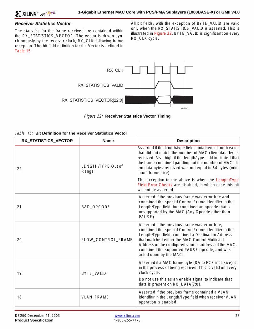
1-Gigabit Ethernet MAC Core with PCSPMA Sublayers (1000BASE-X) or GMII v40R
Receiver Statistics Vector
The statistics for the frame received are contained withinthe RX_STATISTICS_VECTOR The vector is driven syn-chronously by the receiver clock RX_CLK following framereception The bit field definition for the Vector is defined inTable 15
All bit fields with the exception of BYTE_VALID are validonly when the RX_STATISTICS_VALID is asserted This isillustrated in Figure 22 BYTE_VALID is significant on everyRX_CLK cycle
Figure 22 Receiver Statistics Vector Timing
RX_CLK
RX_STATISTICS_VECTOR[220]
RX_STATISTICS_VALID
xip2147
Table 15 Bit Definition for the Receiver Statistics Vector
RX_STATISTICS_VECTOR Name Description
22LENGTHTYPE Out ofRange
Asserted if the lengthtype field contained a length valuethat did not match the number of MAC client data bytesreceived Also high if the lengthtype field indicated thatthe frame contained padding but the number of MAC cli-ent data bytes received was not equal to 64 bytes (min-imum frame size)
The exception to the above is when the LengthTypeField Error Checks are disabled in which case this bitwill not be asserted
21 BAD_OPCODE
Asserted if the previous frame was error-free andcontained the special Control Frame identifier in theLengthType field but contained an opcode that isunsupported by the MAC (Any Opcode other thanPAUSE)
20 FLOW_CONTROL_FRAME
Asserted if the previous frame was error-freecontained the special Control Frame identifier in theLengthType field contained a Destination Addressthat matched either the MAC Control MulticastAddress or the configured source address of the MACcontained the supported PAUSE opcode and wasacted upon by the MAC
19 BYTE_VALID
Asserted if a MAC frame byte (DA to FCS inclusive) isin the process of being received This is valid on everyclock cycle
Do not use this as an enable signal to indicate thatdata is present on RX_DATA[70]
18 VLAN_FRAMEAsserted if the previous frame contained a VLANidentifier in the LengthType field when receiver VLANoperation is enabled
DS200 December 11 2003 wwwxilinxcom 27Product Specification 1-800-255-7778
1-Gigabit Ethernet MAC Core with PCSPMA Sublayers (1000BASE-X) or GMII v40 R
17 OUT_OF_BOUNDS
Asserted if the previous frame exceeded the specifiedIEEE8023-2002 maximum legal length (seeMaximum Permitted Frame Length on page 26) Thisis only valid if Jumbo frames are disabled
16 CONTROL_FRAMEAsserted if the previous frame contained the specialControl Frame identifier in the LengthType field
15 down to 5 FRAME_LENGTH_COUNTThe length of the previous frame in number of bytesThe count will stick at 2047 for any Jumbo frameslarger than this value
4 MULTICAST_FRAMEAsserted if the previous frame contained a multicastaddress in the Destination Address field
3 BROADCAST_FRAMEAsserted if the previous frame contained the broadcastaddress in the Destination Address field
2 FCS_ERRORAsserted if the previous frame received had anincorrect FCS value or the MAC detected error codesduring frame reception
1 BAD_FRAME1 Asserted if the previous frame received containederrors
0 GOOD_FRAME1 Asserted if the previous frame received was error-free
1 If the LengthType Field Error Checks are disabled then a frame which contains this type of error will be marked as a GOOD_FRAMEproviding no additional errors were detected
Table 15 Bit Definition for the Receiver Statistics Vector
RX_STATISTICS_VECTOR Name Description
28 wwwxilinxcom DS200 December 11 20031-800-255-7778 Product Specification
1-Gigabit Ethernet MAC Core with PCSPMA Sublayers (1000BASE-X) or GMII v40R
Flow ControlThe flow control block is designed to Clause 31 of the IEEE8023-2002 standard The MAC may be configured to sendpause frames and to act upon their reception These twobehaviors can be configured asymmetrically see Configu-ration Registers on page 30
Transmitting a PAUSE Control Frame
The client initiates a flow control frame by assertingPAUSE_REQ while the pause value is on the PAUSE_VALbus These signals are synchronous to TX_CLK The timingof this can be seen in Figure 23
If the MAC core is configured to support transmit flow con-trol this action causes the core to transmit a PAUSE controlframe on the link with the PAUSE parameter set to thevalue on PAUSE_VAL in the cycle when PAUSE_REQ wasasserted This will not disrupt any frame transmission inprogress but will take priority over any pending frame trans-
mission This frame will be transmitted even if the transmit-ter is in the paused state itself
Receiving a Pause Control Frame
When an error-free frame is received by the MAC core thefollowing checks are made
1 The Destination Address field is matched against theMAC Control Multicast address or the configuredSource Address for the MAC (see ConfigurationRegisters on page 30)
2 The LengthType field is matched against the MACControl Type code
3 The opcode field contents are matched against thePAUSE opcode if check 2 is true
If any of the above checks are false or the MAC Flow Con-trol logic for the receiver is disabled the frame is ignored bythe Flow Control logic and passed up to the client
If the frame passes all of the above checks is of minimumlegal size and the MAC Flow Control logic for the receiver isenabled the pause value parameter in the frame is thenused to inhibit transmitter operation for the time defined inthe IEEE8023-2002 specification This inhibit is imple-mented using the same back pressure scheme shown inFigure 12 Because the received pause frame has beenacted upon it is passed to the client with RX_BAD_FRAMEasserted to indicate to the client that it should be dropped
Reception of any frame for which check 2 is true and whichis not of legal minimum length is considered an invalid Con-trol frame This will be ignored by the Flow Control logic andpassed to the client with RX_BAD_FRAME asserted
Figure 23 Pause Request Timing
TX_CLK
PAUSE_VAL[150]
PAUSE_REQ
xip2148
DS200 December 11 2003 wwwxilinxcom 29Product Specification 1-800-255-7778
1-Gigabit Ethernet MAC Core with PCSPMA Sublayers (1000BASE-X) or GMII v40 R
Optional Management Interface(management_interface=true)The management interface is a processor-independentinterface with standard address data and control signals Itmay be used as is or a wrapper may be applied (not sup-plied) to interface to common bus architectures
This interface is used for
bull Configuration of the MAC core
bull Access to optional statistics counters for use by higherlayers for example SNMP
bull access through the MDIO interface to the managementregisters located in the PHY attached to the MAC core
The management interface is accessed differently depend-ing on the type of transaction a truth table showing whichaccess method is required for each transaction type isshown in Table 16 These access methods are described inthe following sections
HOST_CLK Frequency
The management interface clock HOST_CLK is used toderive the MDIO clock MDC and is therefore subject tosome frequency restrictions This HOST_CLK must be
ge 10 MHz
le 100 MHz
Configuring the MAC core to derive the MDC signal fromthis clock is detailed in MDIO Interface on page 37
Configuration Registers
After power up or reset the client may reconfigure the coreparameters from their defaults such as flow control supportConfiguration changes can be written at any time Both thereceiver and transmitter logic will only respond to configura-tion changes during Inter Frame Gaps The exceptions tothis are the configurable resets which take effect immedi-ately
Configuration of the MAC core is performed through a reg-ister bank accessed through the management interfaceThe configuration registers available in the core are detailedin Table 17 As can be seen the address has some implicitdonrsquot care bits any access to an address in the rangesshown will perform a 32-bit read or write from the same con-figuration word
Table 16 Management Interface Transaction Types
Transaction HOST_MIIM_SEL HOST_ADDR[9]
Configuration 0 1
Statistics 0 0
MIIM access 1 X
Table 17 Configuration Registers
Address Description
0x200-0x23F Receiver Configuration (Word 0)
0x240-0x27F Receiver Configuration (Word 1)
0x280-0x2BF Transmitter Configuration
0x2C0-0x2FF Flow Control Configuration
0x300-0x33F Reserved
0x340-0x37F Management Configuration
30 wwwxilinxcom DS200 December 11 20031-800-255-7778 Product Specification
1-Gigabit Ethernet MAC Core with PCSPMA Sublayers (1000BASE-X) or GMII v40R
The register contents for the two receiver configuration words can be seen in Table 18 and Table 19
Notes1 In changing the receiverrsquos mode from Half Duplex to Full Duplex there is a period of time of up to 24 us following the mode change
when no new receiver statistics can be stored in the optional Statistical Counters
Table 18 Receiver Configuration Word 0
Bit Default Value Description
31-0 All 0rsquos
Pause frame MAC Source Address[310] This address is used by the MAC tomatch against the Destination Address of any incoming flow control frames It isalso used by the flow control block as the Source Address (SA) for any outboundflow control frames
The address is ordered so the first byte transmittedreceived is the lowestpositioned byte in the register for example a MAC address ofAA-BB-CC-DD-EE-FF would be stored in Address[470] as 0xFFEEDDCCBBAA
Table 19 Receiver Configuration Word 1
Bit Default Value Description
15-0 All 0rsquos Pause frame MAC Source Address[4732] See description in Table 18
24-16 NA Reserved
25 0
LengthType Error Check Disable When this bit is set to ldquo1rdquo the core will notperform the LengthType field error checks as described in LengthType FieldError Checks on page 26 When this bit is set to ldquo0rdquo the LengthType field checkswill be performed this is normal operation
26 0Half Duplex If ldquo1rdquo the receiver will operate in half duplex mode If ldquo0rdquo the receiverwill operate in full duplex mode Has no effect if XCO parameterhalf_duplex_capable = false
27 0VLAN Enable When this bit is set to ldquo1rdquo VLAN tagged frames will be acceptedby the receiver
28 1Receiver Enable If set to ldquo1rdquo the receiver block will be operational If set to ldquo0rdquothe block will ignore activity on the physical interface RX port
29 0
In-band FCS Enable When this bit is ldquo1rdquo the MAC receiver will pass the FCS fieldup to the client as described in Client-Supplied FCS Passing on page 25 Whenit is ldquo0rdquo the client will not be passed the FCS In both cases the FCS will beverified on the frame
30 0Jumbo Frame Enable When this bit is set to ldquo1rdquo the MAC receiver will acceptframes over the specified IEEE8023-2002 maximum legal length When this bitis ldquo0rdquo the MAC will only accept frames up to the specified maximum
31 0Reset When this bit is set to ldquo1rdquo the receiver will be reset The bit will thenautomatically revert to ldquo0rdquo Note that this reset will also set all of the receiverconfiguration registers to their default values
DS200 December 11 2003 wwwxilinxcom 31Product Specification 1-800-255-7778
1-Gigabit Ethernet MAC Core with PCSPMA Sublayers (1000BASE-X) or GMII v40 R
The register contents for the Transmitter Configuration Word are described in Table 20
Notes1 In changing the transmitterrsquos mode from Half Duplex to Full Duplex there is a period of time of up to 24 us following the mode change
when no new transmitter statistics can be stored in the optional Statistical Counters
Table 20 Transmitter Configuration Word
Bit Default Value Description
24-0 NA Reserved
25 0
Interframe Gap Adjust Enable If lsquo1rsquo the transmitter will read the value on the portTX_IFG_DELAY at the start of frame transmission and adjust the interframe gapfollowing the frame accordingly See Interframe Gap Adjustment on page 22 Ifldquo0rdquo the transmitter will output a minimum Inter Frame Gap of twelve clock cyclesas specified in IEEE8023-2002
26 0Half Duplex If lsquo1rsquo the transmitter will operate in half duplex mode If lsquo0rsquo thetransmitter will operate in full duplex mode Has no effect if XCO parameterhalf_duplex_capable = false
27 0VLAN Enable When this bit is set to 1 the transmitter will allow the transmissionof VLAN tagged frames
28 1Transmit Enable When this bit is 1 the transmitter is operational When it is 0the transmitter is disabled
29 0
In-band FCS Enable When this bit is lsquo1rsquo the MAC transmitter will expect the FCSfield to be passed in by the client as described in Client-Supplied FCS Passingon page 17 When this bit is ldquo0rdquo the MAC transmitter will append padding asrequired compute the FCS and append it to the frame
30 0
Jumbo Frame Enable When this bit is set to ldquo1rdquo the MAC transmitter will sendframes that are greater than the specified IEEE8023-2002 maximum legallength When this bit is ldquo0rdquo the MAC will only send frames up to the specifiedmaximum
31 0Reset When this bit is set to ldquo1rdquo the transmitter will be reset The bit will thenautomatically revert to ldquo0rdquo Note that this reset will also set all of the transmitterconfiguration registers to their default values
32 wwwxilinxcom DS200 December 11 20031-800-255-7778 Product Specification
1-Gigabit Ethernet MAC Core with PCSPMA Sublayers (1000BASE-X) or GMII v40R
The register contents for the Flow Control Configuration Word are described in Table 21
The register contents for the Management Configuration Word are described in Table 22
Writing to the configuration registers through the manage-ment interface is depicted in Figure 24 When accessing theconfiguration registers (ie when HOST_ADDR[9] = lsquo1rsquo andHOST_MIIM_SEL = lsquo0rsquo) the upper bit of HOST_OPCODEfunctions as an Active Low write enable signal The lowerHOST_OPCODE bit is a ldquodonrsquot carerdquo
Reading from the configuration register words is similar butthe upper HOST_OPCODE bit should be lsquo1rsquo This is shownin Figure 25 In this case the contents of the register appearon HOST_RD_DATA the HOST_CLK edge after the regis-ter address is asserted onto HOST_ADDR
Table 21 Flow Control Configuration Word
Bit Default Value Description
28-0 NA Reserved
29 1
Flow Control Enable (RX) When this bit is lsquo1rsquo received flow control frames willinhibit the transmitter operation as described in Receiving a Pause ControlFrame on page 29 When this bit is lsquo0rsquo received flow control frames will alwaysbe passed up to the client
30 1Flow Control Enable (TX) When this bit is lsquo1rsquo asserting the PAUSE_REQ signalwill send a flow control frame out from the transmitter When this bit is 0 assertingthe PAUSE_REQ signal has no effect
31 NA Reserved
Table 22 Management Configuration Word
Bits Default Value Description
4-0 All 0rsquos Clock Divide[40] See MDIO Interface on page 37
5 0MDIO Enable When this bit is 1 the MDIO interface can be used to accessattached PHY devices When this bit is 0 the MDIO interface is disabled and theMDIO signals remain inactive
31-6 NA Reserved
Figure 24 Configuration Register Write Timing
HOST_CLK
HOST_ADDR[80]
HOST_ADDR[9]
HOST_OPCODE[1]
HOST_MIIM_SEL
HOST_WR_DATA[310]xip2149
Figure 25 Configuration Register Read Timing
HOST_CLK
HOST_ADDR[80]
HOST_ADDR[9]
HOST_OPCODE[1]
HOST_MIIM_SEL
HOST_RD_DATA[310]
xip2150
DS200 December 11 2003 wwwxilinxcom 33Product Specification 1-800-255-7778
1-Gigabit Ethernet MAC Core with PCSPMA Sublayers (1000BASE-X) or GMII v40 R
Optional Statistical Gathering(statistics_gathering=true)
During operation the MAC core collects statistics on thesuccess and failure of various operations for processing by
station management entities (STA) further up the protocolstack These statistics are accessed by the host through theoptional management interface A complete list of statisticssupported is described in Table 23
Table 23 Statistics Registers
Address Name Description
0x000 Frames Received OK1 A count of error-free frames received
0x001 Frame Check Sequence Errors A count of received frames that failed the CRC check and were at least64 bytes in length
0x002 Broadcast Frames Received OK1A count of frames that were successfully received and were directed tothe broadcast group address
0x003 Multicast Frames Received OK1 A count of frames that were successfully received and were directed toa non broadcast group address
0x004 64 byte Frames Received OK1 A count of error-free frames received that were 64 bytes in length
0x005 65-127 byte Frames Received OK1A count of error-free frames received that were between 65 and 127bytes in length
0x006 128-255 byte Frames Received OK1A count of error-free frames received that were between 128 and 255bytes in length
0x007 256-511 byte Frames Received OK1A count of error-free frames received that were between 256 and 511bytes in length
0x008512-1023 byte Frames ReceivedOK1
A count of error-free frames received that were between 512 and 1023bytes in length
0x0091024-MaxFrameSize byte FramesReceived OK1
A count of error-free frames received that were between 1024 bytes andthe specified IEEE8023-2002 maximum legal length (see MaximumPermitted Frame Length on page 26)
0x00A Control Frames Received OKA count of error-free frames received that contained the specialControl Frame identifier in the LengthType field
0x00B LengthType Out of Range
A count of frames received that were at least 64 bytes in length wherethe lengthtype field contained a length value that did not match thenumber of MAC client data bytes received
The counter also increments for frames in which the lengthtype fieldindicated that the frame contained padding but where the number ofMAC client data bytes received was greater than 64 bytes (minimumframe size)
The exception to the above is when the LengthType Field Error Checksare disabled in which case this counter will not increment
0x00C VLAN Tagged Frames Received OKA count of error-free VLAN frames received This counter will only incre-ment when the receiver is configured for VLAN operation
0x00D Pause Frames Received OK
A count of error-free frames received that contained the MAC Controltype identifier 88-08 in the LengthType field contained a Destinationaddress that matched either the MAC Control multicast address or theconfigured source address of the MAC contained the PAUSE opcodeand were acted upon by the MAC
0x00EControl Frames Received withUnsupported Opcode
A count of error-free frames received that contained the MAC Controltype identifier 88-08 in the LengthType field but were received with anopcode other than the PAUSE opcode
34 wwwxilinxcom DS200 December 11 20031-800-255-7778 Product Specification
1-Gigabit Ethernet MAC Core with PCSPMA Sublayers (1000BASE-X) or GMII v40R
0x00F Oversize Frames Received OK1A count of otherwise error-free frames received that exceeded the max-imum legal frame length specified in IEEE 8023-2002 (see MaximumPermitted Frame Length on page 26)
0x010 Undersize frames receivedA count of the number of frames received that were less than 64 bytesin length but were otherwise well formed
0x011 Fragment frames receivedA count of the number of frames received that were less than 64 bytesin length and had a bad Frame Check Sequence field
0x012 Received bytesA count of bytes of frames that are received (Destination Address toFrame Check Sequence inclusive)
0x013 Transmitted bytesA count of bytes of frames that are transmitted (Destination Address toFrame Check Sequence inclusive)
0x020 Frames Transmitted OK A count of error-free frames transmitted
0x021 Broadcast Frames Transmitted OK A count of error-free frames that were transmitted to the broadcastaddress
0x022 Multicast Frames Transmitted OK A count of error-free frames that were transmitted to a group destina-tion address other than broadcast
0x023 Underrun Errors
A count of frames that would otherwise be transmitted by the core butcould not be completed due to the assertion of TX_UNDERRUN duringthe frame transmission This will not count frames which are less than64 bytes in length
0x024 Control Frames Transmitted OKA count of error-free frames transmitted that contained the MACControl Frame type identifier 88-08 in the LengthType field
0x025 64 byte Frames Transmitted OK A count of error-free frames transmitted that were 64 bytes in length
0x026 65-127 byte Frames Transmitted OKA count of error-free frames transmitted that were between 65 and 127bytes in length
0x027128-255 byte Frames TransmittedOK
A count of error-free frames transmitted that were between 128 and 255bytes in length
0x028256-511 byte Frames TransmittedOK
A count of error-free frames transmitted that were between 256 and 511bytes in length
0x029512-1023 byte Frames TransmittedOK
A count of error-free frames transmitted that were between 512 and1023 bytes in length
0x02A1024-MaxFrameSize byte FramesTransmitted OK
A count of error-free frames transmitted that were between 1024 and thespecified IEEE8023-2002 maximum legal length (see Maximum Per-mitted Frame Length on page 20)
0x02BVLAN Tagged Frames TransmittedOK
A count of error-free VLAN frames transmitted This counter will onlyincrement when the transmitter is configured for VLAN operation
0x02C Pause Frames Transmitted OKA count of error-free PAUSE frames generated and transmitted by thecore in response to an assertion of PAUSE_REQ
0x02D Oversize Frames Transmitted OKA count of otherwise error-free frames transmitted that exceeded themaximum legal frame length specified in IEEE 8023-2002 (see Maxi-mum Permitted Frame Length on page 20)
0x02E Single Collision Frames A count of frames that are involved in a single collision but are subse-quently transmitted successfully (Half Duplex Mode only)
Table 23 Statistics Registers (Continued)
Address Name Description
DS200 December 11 2003 wwwxilinxcom 35Product Specification 1-800-255-7778
1-Gigabit Ethernet MAC Core with PCSPMA Sublayers (1000BASE-X) or GMII v40 R
Each of these statistic registers is 64 bits wide and thereforemust be read in a two-cycle transfer The timing of this pro-cess is shown in Figure 26 Six clocks after the read trans-action is initiated the least significant word (LSW) of thestatistics counter appears on the HOST_RD_DATA bus
and a clock cycle later the most significant word (MSW)appears For accurate statistic values 64 clock ticks (ofTX_CLK for transmit statistics or RX_CLK for receive statis-tics) must elapse after the last frame is sent or receivedthrough the MAC core
0x02F Multiple Collision Frames A count of frames that are involved in more than one collision but aresubsequently transmitted successfully (Half Duplex Mode only)
0x040 Frames with Deferred Transmissions A count of frames whose transmission was delayed on its first attemptbecause the medium was busy (Half Duplex Mode only)
0x041 Late Collisions
A count of the times that a collision has been detected later than oneslotTime from the start of the packet transmission A late collision iscounted twice both as a collision and as a lateCollision (Half DuplexMode only)
0x042Frames Aborted due to Excesscollisions
A count of the frames that due to excessive collisions are not transmit-ted successfully (Half Duplex Mode only)
0x043 Carrier Sense ErrorsA count of times that the GMII_CRS signal was not asserted or wasdisasserted during the transmission of a frame without collision (HalfDuplex Mode only)
0x044 Frames with Excess DeferralA count of frames that deferred transmission for an excessive period oftime (Half Duplex Mode only)
1 If the LengthType Field Error Checks are disabled then these counters will still increment for received frames which contain this typeof error (providing no additional errors were detected)
Table 23 Statistics Registers (Continued)
Address Name Description
Figure 26 Statistic Register Read Timing
HOST_CLK
HOST_ADDR[80]
HOST_ADDR[9]
HOST_REQ
HOST_MIIM_SEL
HOST_RD_DATA[310]
6 CLOCKS
LSW MSW
xip2151
36 wwwxilinxcom DS200 December 11 20031-800-255-7778 Product Specification
1-Gigabit Ethernet MAC Core with PCSPMA Sublayers (1000BASE-X) or GMII v40R
MDIO Interface
The management interface is also used to access the MDIO(MII Management) interface of the MAC core this interfaceis used to access the Managed Information Block (MIB) ofthe PHY components attached to the MAC core
The MDIO interface supplies a clock to the externaldevices MDC This clock is derived from the HOST_CLKsignal using the value in the Clock Divide[40] configurationregister The frequency of the MDIO clock is given by thefollowing equation
The frequency of MDC given by this equation should notexceed 25 MHz in order to comply with the IEEE8023-2002 specification for this interface To prevent MDCfrom being out of specification the Clock Divide[40] valuepowers up at 00000 and while this value is in the register itis impossible to enable the MDIO interface
For details of the register map of PHY layer devices and afuller description of the operation of the MDIO interfaceitself see IEEE specification 8023-2002
Access to the MDIO interface through the managementinterface is depicted in the timing diagram in Figure 27
For MDIO transactions the following points apply
bull HOST_OPCODE maps to the OP (opcode) field of theMDIO frame
bull HOST_ADDR maps to the two address fields of theMDIO frame PHY_ADDR is HOST_ADDR[95] andREG_ADDR is HOST_ADDR[40]
bull HOST_WR_DATA[150] maps into the data field of the
MDIO frame when performing a write operation
bull The data field of the MDIO frame maps intoHOST_RD_DATA[150] when performing a readoperation
The MAC core signals to the host that it is ready for anMDIO transaction by asserting HOST_MIIM_RDY A read orwrite transaction on the MDIO is initiated by a pulse on the
fMDC
fHOST_CLK
1 Clock Divide[40]+( ) 2times-------------------------------------------------------------------=
Figure 27 MDIO Access Through Management Interface
HOST_CLK
HOST_ADDR[90]
HOST_OPCODE[10]
HOST_REQ
HOST_MIIM_SEL
HOST_RD_DATA[150]
HOST_WR_DATA[150]
HOST_RDY
If a read transaction is initiated the HOST_RD_DATA bus is valid at the point indicated If a write transaction is initiated the HOST_WR_DATA bus must be valid at the indicated point Simultaneous read and write is not permitted
xip2152
DS200 December 11 2003 wwwxilinxcom 37Product Specification 1-800-255-7778
1-Gigabit Ethernet MAC Core with PCSPMA Sublayers (1000BASE-X) or GMII v40 R
HOST_REQ signal This pulse is ignored if the MDIO inter-face already has a transaction in progress
The MAC core then disasserts the HOST_MIIM_RDY signalwhile the transaction across the MDIO is in progress Whenthe transaction across the MDIO interface has been com-pleted the HOST_MIIM_RDY signal will be asserted by theMAC core if the transaction is a read the data will also beavailable on the HOST_RD_DATA[150] bus at this time
Optional Configuration Vector(management_interface = false)If the optional Management interface is omitted from thecore all of relevant configuration signals are brought out of
the core These signals are bundled into theCONFIGURATION_VECTOR signal The bit mapping of theconfiguration vector signal is defined in Table 24 See thecorresponding entry in the configuration register tables forthe full description of each signal
Note that these configuration vector signals can bechanged by the user at any time however with the excep-tion of the reset and the flow control configuration signalsthey will not take effect until the current frame has com-pleted transmission or reception
The ldquoClockrdquo heading denotes which clock domain the con-figuration signal is registered into before use by the core Itis not necessary to drive the signal from this clock domain
Table 24 Configuration Vector Bit Definition
Bit(s)Configuration Register
cross reference Clock Description
47 downto 0
Receiver ConfigurationWord 0 bits 31-0 andReceiver ConfigurationWord 1 bits 15-0
RX_CLK
Pause frame MAC Source Address[470] This address isused by the MAC core to match against the DestinationAddress of any incoming flow control frames and as theSource Address for any outbound flow control frames
The address is ordered such that the first byte transmitted orreceived is the least significant byte in the register forexample a MAC address of AA-BB-CC-DD-EE-FF will bestored in bite [470] as 0xFFEEDDCCBBAA
48Receiver ConfigurationWord 1 bit 26
RX_CLKReceiver Half Duplex If lsquo1rsquo the receiver operates in halfduplex mode If lsquo0rsquo the receiver operates in full duplex modeHas no effect if XCO parameter half_duplex_capable = false
49Receiver ConfigurationWord 1 bit 27
RX_CLKReceiver VLAN Enable When this bit is set to 1 VLANtagged frames are accepted by the receiver
50Receiver ConfigurationWord 1 bit 28
RX_CLKReceiver Enable If set to 1 the receiver block is operationalIf set to 0 the block ignores activity on the physical interfaceRX port
51Receiver ConfigurationWord 1 bit 29
RX_CLK
Receiver In-band FCS Enable When this bit is lsquo1rsquo the MACreceiver will pass the FCS field up to the client as describedin Client-Supplied FCS Passing on page 25 When it is lsquo0rsquothe MAC receiver will not pass the FCS field In both casesthe FCS field will be verified on the frame
52Receiver ConfigurationWord 1 bit 30
RX_CLK
Receiver Jumbo Frame Enable When this bit is lsquo0rsquo thereceiver will not pass frames longer than the maximum legalframe size specified in IEEE 8023-2002 (see MaximumPermitted Frame Length on page 26) When it is lsquo1rsquo thereceiver will not have an upper limit on frame size
53Receiver ConfigurationWord 1 bit 31
NA
Receiver Reset When this bit is lsquo1rsquo the receiver is held inreset
This signal is an input to the reset circuit for the receiverblock See Reset circuit on page 42 for more information
54TransmitterConfiguration Word bit25
TX_CLK
Transmitter Interframe Gap Adjust enable If lsquo1rsquo then thetransmitter will read the value of the TX_IFG_DELAY port andset the Interframe Gap accordingly If lsquo0rsquo the transmitter willalways insert at least the legal minimum Interframe Gap
38 wwwxilinxcom DS200 December 11 20031-800-255-7778 Product Specification
1-Gigabit Ethernet MAC Core with PCSPMA Sublayers (1000BASE-X) or GMII v40R
55TransmitterConfiguration Word bit26
TX_CLK
Transmitter Half Duplex If lsquo1rsquo the transmitter operates in halfduplex mode If lsquo0rsquo the transmitter operates in full duplexmode Has no effect if XCO parameter half_duplex_capable= false
56TransmitterConfiguration Word bit27
TX_CLKTransmitter VLAN Enable When this bit is set to lsquo1rsquo thetransmitter allows the transmission of VLAN tagged frames
57TransmitterConfiguration Word bit28
TX_CLKTransmitter Enable When this bit is 1 the transmitter will beoperational When it is 0 the transmitter is disabled
58TransmitterConfiguration Word bit29
TX_CLK
Transmitter In-Band FCS Enable When this bit is lsquo1rsquo theMAC transmitter will expect the FCS field to be pass in by theclient as described in Client-Supplied FCS Passing onpage 17 When it is lsquo0rsquo the MAC transmitter will appendpadding as required compute the FCS and append it to theframe
59TransmitterConfiguration Word bit30
TX_CLK
Transmitter Jumbo Frame Enable When this bit is lsquo1rsquo theMAC transmitter will allow frames larger than the maximumlegal frame length specified in IEEE 8023-2002 to be sentWhen set to lsquo0rsquo the MAC transmitter will only allow frames upto the legal maximum to be sent
60TransmitterConfiguration Word bit31
NA
Transmitter Reset When this bit is lsquo1rsquo the MAC transmitter isheld in reset
This signal is an input to the reset circuit for the transmitterblock See Reset circuit on page 42 for more information
61Flow ControlConfiguration Word bit29
TX_CLK
Transmit Flow Control Enable When this bit is lsquo1rsquo assertingthe PAUSE_REQ signal causes the MAC core to send a flowcontrol frame out from the transmitter as described inReceiving a Pause Control Frame on page 29 When this bitis lsquo0rsquo asserting the PAUSE_REQ signal will have no effect
62Flow ControlConfiguration Word bit30
RX_CLK
Receive Flow Control Enable When this bit is lsquo1rsquo receivedflow control frames will inhibit the transmitter operation asdescribed in Receiving a Pause Control Frame on page 29When it is lsquo0rsquo received flow frames are passed up to theclient
63Receiver ConfigurationWord 1 bit 25
RX_CLK
LengthType Error Check Disable When this bit is lsquo1rsquo thecore will not perform the LengthType field error checks asdescribed in LengthType Field Error Checks on page 26When it is set to lsquo0rsquo the LengthType field checks will beperformed this is normal operation
Table 24 Configuration Vector Bit Definition (Continued)
Bit(s)Configuration Register
cross reference Clock Description
DS200 December 11 2003 wwwxilinxcom 39Product Specification 1-800-255-7778
1-Gigabit Ethernet MAC Core with PCSPMA Sublayers (1000BASE-X) or GMII v40 R
Optional GMII (physical_interface=gmii)The GMII is designed to IEEE 8023-2002 Clause 35 Thisutilizes IOrsquos of the Xilinx devices using inputoutput buffersand inputoutput flip-flops to maximize setup and hold mar-gins All IO logic is placed in the example wrapper that isdelivered with the core In addition all clock managementlogic for the core is instanced in this example wrapper thisallows multiple instances of the core to share clocks Theexample wrapper is provided in both VHDL and Verilog
Clock Management
Figure 28 illustrates the clock management used with theGMII interface All clocks illustrated have a frequency of125MHz
GTX_CLK must be provided to the MAC core This is a highquality clock which satisfies the IEEE8023-2002 require-ments It is expected that this clock will be derived from anexternal oscillator and connected into the device through anIBUFG as illustrated The clock source must then be routedonto a global clock network by connecting it to a BUFGWithin the MAC core this global clock is used by all MACtransmitter logic The MAC Client can obtain this clock byconnecting to the TX_CLK signal output from the coreGMII_TX_CLK is derived from this global clock by invertingit and routing it to an OBUF
GMII_RX_CLK is received through an IBUFG This clock isthen routed onto a global clock network by connecting it to aBUFG The resulting global clock is used by all MACreceiver logic
Figure 28 Clock Management with GMII
IBUFG
IBUFG
OBUF
BUFG
BUFG
TX_CLK
RX_CLK
GTX_CLK
GMII_TX_CLK
GMII_RX_CLK
Example Wrapper
xip2153
MAC Core
TX_CLK
RX_CLK
GMII_TX_CLK
GMII_RX_CLK
GTX_CLK
40 wwwxilinxcom DS200 December 11 20031-800-255-7778 Product Specification
1-Gigabit Ethernet MAC Core with PCSPMA Sublayers (1000BASE-X) or GMII v40R
Clock Sharing between Multiple cores
Figure 29 illustrates how it is possible to share clockresources across multiple instantiations of the core whenusing the optional GMII
GTX_CLK may be shared between multiple cores as illus-trated resulting in a common transmitter clock domainacross the device
A common receiver clock domain is not possible each corewill receive an independent receiver clock from its GMII asillustrated
Although not illustrated if the optional Management Inter-face is used HOST_CLK can also be shared betweencores
Figure 29 Clock Management with multiple instances of the MAC with GMII
IBUFG
OBUF
BUFG
TX_CLK
RX_CLK_1
GMII_TX_CLK_1
GMII_RX_CLK_1
MAC Core
TX_CLK
RX_CLK
GMII_TX_CLK
GMII_RX_CLK
GTX_CLK
MAC Core
TX_CLK
RX_CLK
GMII_TX_CLK
GMII_RX_CLK
GTX_CLK
IBUFG
BUFG
GTX_CLK
IBUFG
OBUF
GMII_TX_CLK_2
GMII_RX_CLK_2
BUFG
TX_CLK
RX_CLK_2
DS200 December 11 2003 wwwxilinxcom 41Product Specification 1-800-255-7778
1-Gigabit Ethernet MAC Core with PCSPMA Sublayers (1000BASE-X) or GMII v40 R
Reset circuit
Internally the core is divided up into clockreset domainswhich group together elements with the common clock andreset signals The reset circuitry for one of these domains isis illustrated in Figure 30 This circuit provides controllableskews on the reset nets within the design
More information on the operation and rationale behind thiscircuit can be found in Ken Chapmanrsquos Xilinx TechXclusiveldquoGet Smart About Resetrdquo athttpwwwxilinxcomsupporttechxclusivesglobal-techX19htm
Figure 30 Reset circuit for one clockreset domain
FDP
PRED
C
Q
FDP
PRED
C
Q
FDP
PRED
C
Q
FDP
PRED
C
Q
PRE PRE PRE
0
RESET
Management Reset
Clock
Core Registers
42 wwwxilinxcom DS200 December 11 20031-800-255-7778 Product Specification
1-Gigabit Ethernet MAC Core with PCSPMA Sublayers (1000BASE-X) or GMII v40R
Optional PCS with Ten-Bit Interface (TBI) for 1000BASE-X (physical_interface=tbi)The Full-Duplex Physical Coding Sublayer (PCS) for1000BASE-X is defined in IEEE 8023-2002 Clauses 36and 37 This functionality is only available in the Virtex-IIand Spartan3 families of FPGA devices
A block diagram of the PCS is shown in Figure 31 Themajor functional blocks of the PCS are
bull Transmit engine
bull Auto-negotiation block
bull Receive engine and synchronization block
bull PCS managed register block
bull 8B10B encoder block
bull 8B10B decoder block
bull Receiver elastic buffer
The PCS Managed Register Block is accessed through theMDIO Interface as if it were an externally connected PHYThis configures the operation of the PCS and Auto-Negoti-ation See PCS Managed Register Block
(physical_interface = tbi or phy) on page 49 The corersquosoptional Management Interface can be used to control theMDIO Interface as described by MDIO Interface onpage 37 When the optional Management Interface is notpresent the PCS Managed Register Block must beaccessed via an MDIO controller which is not provided bythe core
The 8B10B encodingdecoding blocks are implemented byconfiguring two Block SelectRAM modules as ROM Theseare used as large look-up tables The remaining PCS func-tionality such as code group encodingdecoding the Man-aged Register Block and Auto-Negotiation areimplemented in CLB logic
The Receiver Elastic buffer enables the 10-bit parallel datareceived from the PMA sublayer alternatively onPMA_RX_CLK0 and PMA_RX_CLK1 clock edges to betransferred onto the internal 125MHz clock domain derivedfrom GTX_CLK (see Clock Management) This buffer isimplemented in Distributed Memory
Figure 31 Functional Block Diagram of the 1-Gigabit Ethernet PCS with TBI Interface
PCS TRANSMIT ENGINE
PCS RECEIVE ENGINE ampSYNCHRONISATION
PCSMANAGEMENT
MDIOInterface
AUTO-NEGOTIATION
MAC TXInterface
MAC RXInterface
8B10BEncoder
8B10BDecoder
RX Elastic Buffer
TBI Interface
DS200 December 11 2003 wwwxilinxcom 43Product Specification 1-800-255-7778
1-Gigabit Ethernet MAC Core with PCSPMA Sublayers (1000BASE-X) or GMII v40 R
TBI Interface
The TBI is designed to IEEE 8023-2002 Clause 363 Thisutilizes IOrsquos of the Xilinx devices using inputoutput buffersand inputoutput flip-flops to maximize setup and hold mar-gins All IO logic is placed in the example wrapper that isdelivered with the core In addition all clock managementlogic for the core is instantiated in this example wrapperthis allows multiple instances of the core to share clocksThe example wrapper is provided in both VHDL and Verilog
Clock Management
Figure 32 illustrates the clock management used with theTBI interface
GTX_CLK must be provided to the MAC core This is a highquality clock of frequency 125MHz which satisfies theIEEE8023-2002 requirements It is expected that this clockwill be derived from an external oscillator and connected
into the device through an IBUFG as illustrated The clocksource must then be routed onto a global clock network byconnecting it to a BUFG Within the MAC core this globalclock is used by all MAC transmitter logic PMA_TX_CLK isderived from this global clock by inverting it and routing it toan OBUF
PMA_RX_CLK0 and PMA_RX_CLK1 are each receivedthrough an IBUFG These clocks are then routed onto glo-bal clock networks by connecting each to a BUFGPMA_RX_CLK0 and PMA_RX_CLK1 are each 625MHzclocks Data from the TBI is received alternatively on the ris-ing edge of PMA_RX_CLK0 followed by the rising edge ofPMA_RX_CLK1 using IOB Double-Data Rate input regis-ters This data is then written into the Receiver ElasticBuffer Data is read out of the Elastic Buffer using the globalclock derived from GTX_CLK all the remaining receiverlogic is synchronous to this clock
Figure 32 Clock Management for PCS with TBI Interface
IBUFG
IBUFG
OBUF
BUFG
BUFG
TX_CLK
RX_CLK
GTX_CLK
PMA_TX_CLK
PMA_RX_CLK0
MAC Core
RX ELASTICBUFFER
Example Wrapper
TX_CLK
RX_CLK
GTX_CLK
PMA_TX_CLK
PMA_RX_CLK0
IBUFGBUFGPMA_RX_CLK1
PMA_RX_CLK1
44 wwwxilinxcom DS200 December 11 20031-800-255-7778 Product Specification
1-Gigabit Ethernet MAC Core with PCSPMA Sublayers (1000BASE-X) or GMII v40R
Clock Sharing between Multiple cores
Figure 33 illustrates how it is possible to share clockresources across multiple instantiations of the core whenusing the optional PCS with TBI
GTX_CLK may be shared between multiple cores as illus-trated resulting in a common transmitter clock domainacross the device
Each core will receive independent PMA_RX_CLK0 andPMA_RX_CLK1 clocks from its TBI as illustrated whichcannot be shared
Although not illustrated if the optional Management Inter-face is used HOST_CLK can also be shared betweencores
Figure 33 Clock Management with multiple instances of the MAC with PCS and TBI
Reset circuit
The reset circuits within the MAC when the TBI interface is implemented is the same as that in the GMII case details ofthese circuits can be found on page 42
IBUFG
OBUF
BUFG
TX_CLK
RX_CLK
PMA_TX_CLK_1
PMA_RX_CLK0_1
MAC Core
RX ELASTICBUFFER
TX_CLK
RX_CLK
GTX_CLK
PMA_TX_CLK
PMA_RX_CLK0
IBUFGBUFGPMA_RX_CLK1_1
PMA_RX_CLK1
IBUFG
BUFG
GTX_CLK
IBUFG
OBUF
BUFG
TX_CLK
RX_CLK
PMA_TX_CLK_2
PMA_RX_CLK0_2
MAC Core
RX ELASTICBUFFER
TX_CLK
RX_CLK
GTX_CLK
PMA_TX_CLK
PMA_RX_CLK0
IBUFGBUFGPMA_RX_CLK1_2
PMA_RX_CLK1
DS200 December 11 2003 wwwxilinxcom 45Product Specification 1-800-255-7778
1-Gigabit Ethernet MAC Core with PCSPMA Sublayers (1000BASE-X) or GMII v40 R
Optional PCS and PMA Sublayers for 1000BASE-X (physical_interface=phy)The Full-Duplex Physical Coding Sublayer (PCS) withPhysical Medium Attachment (PMA) for 1000BASE-X isdefined in IEEE 8023-2002 Clauses 36 and 37 This func-tionality is only available in the Virtex-II Pro family of FPGAdevices
A block diagram of the PCS and PMA sublayers can beseen in Figure 34 The functional blocks of the PCS andPMA sublayers may replace the optional GMII interfaceThe functional blocks of the PCS and PMA sublayers are
bull PCS Transmit Engine
bull Auto-Negotiation block
bull Receive Engine and Synchronization Block
bull PCS Managed Register Block
bull Rocket IO Multi-Gigabit Transceiver
The PCS Managed Register Block is accessed through theMDIO Interface as if it were an externally connected PHYThis configures the operation of the PCS PMA sublayerand Auto-NegotiationSee PCS Managed Register Block(physical_interface = tbi or phy) on page 49 The corersquosoptional Management Interface can be used to control theMDIO Interface as described by MDIO Interface onpage 37 When the optional Management Interface is notpresent the PCS Managed Register Block must beaccessed via an MDIO controller which is not provided bythe core
The Rocket IO Multi-Gigabit Transceiver (MGT) providessome of the PCS layer functionality such as 8B10B encod-ingdecoding and the PMA serdes The remaining PCSfunctionality such as code group encodingdecoding theManaged Register Block and Auto-Negotiation are imple-mented in CLB logic
Figure 34 Functional Block Diagram of the 1-Gigabit Ethernet PCSPMA Sublayer Extension
PCS TRANSMIT ENGINE
PCS RECEIVE ENGINE ampSYNCHRONISATION
RO
CK
ET
IO
MU
LTI-
GIG
TR
AN
SC
EIV
ER
PCSMANAGEMENT
MDIOInterface
AUTO-NEGOTIATION
TXPTXN
RXPRXN
MAC TXInterface
MAC RXInterface
xip2154
46 wwwxilinxcom DS200 December 11 20031-800-255-7778 Product Specification
1-Gigabit Ethernet MAC Core with PCSPMA Sublayers (1000BASE-X) or GMII v40R
Clock Management
Figure 35 illustrates the clock management that should beused with the optional PCS and PMA sublayers for1000BASE-X This logic is implemented in the examplewrapper that is delivered with the core This provides flexi-bility because the design can be modified to use eitherREFCLK or BREFCLK (please refer to Rocket IO docu-mentation) It would also allow multiple instances of the coreto share clocks The example wrapper is provided in bothVHDL and Verilog
(B)REFCLK must be provided to the MAC core This clockmust be derived from an external oscillator and connectedto the core through an IBUFG as illustrated (B)REFCLK isa high quality clock of frequency 625 MHz which satisfiesthe Rocket IO Multi-Gigabit Transceiver (MGT) require-ments
(B)REFCLK is routed to both the core and a DCM From theDCM the CLK2X180 output is routed to a BUFG to providethe device with a global 125 MHz clock (connected toUSERCLK2 input on the core) Within the core bothTX_CLK and RX_CLK share this global 125 MHz clocksource which is used by all transmitter and receiver logicThis is made possible by the RX_ELASTIC_BUFFER func-tionality of the Rocket IO MGT (refer to Virtex-II Pro docu-mentation) The MAC Client can obtain this clock byconnecting to either the TX_CLK or the RX_CLK signalsoutput from the core
From the DCM the CLK0 output is routed to a BUFG to pro-vide the device with a global 625MHz clock This is con-nected to the USRCLK input of the core
Figure 35 Clock Management with PCSPMA Sublayers
DCM
CLKIN CLK0
CLK2X180FB
BUFG
BUFG
IBUFG
TX_CLK
RX_CLK
(B)REFCLK
TXUSRCLK
(B)REFCLK
TXUSRCLK2RXUSRCLKRXUSRCLK2
GT_ETHERNET
Example Wrapper
xip2155
MAC Core
(B)REFCLK
USRCLK
USRCLK2
TX_CLK
RX_CLK
DS200 December 11 2003 wwwxilinxcom 47Product Specification 1-800-255-7778
1-Gigabit Ethernet MAC Core with PCSPMA Sublayers (1000BASE-X) or GMII v40 R
Clock Sharing between Multiple Cores
Figure 36 illustrates how it is possible to share clockresources across multiple instantiations of the core whenusing the optional PCSPMA sublayers For each coreUSERCLK and USERCLK2 must always be derived asshown from the BREFCLK or REFCLK used by that core
Note that when using the fixed routing resources of BREF-CLK Rocket IO MGTs along the top edge of the devicemust use a separate BREFCLK routing resource to thosealong the bottom edge of the device (Refer to Virtex-II Prodocumentation)
Although not illustrated if the optional Management Inter-face is used HOST_CLK can also be shared betweencores
Figure 36 Clock Management with multiple instances of the MAC with PCS and PMA sublayers
Reset circuit
The reset circuits within the MAC when the PCS and PMA sublayers are implemented is the same as that in the GMII casedetails of these circuits can be found on page 42
DCM
CLKIN CLK0
CLK2X180FB
BUFG
BUFG
IBUFG
(B)REFCLK
TXUSRCLK
(B)REFCLK
TXUSRCLK2RXUSRCLKRXUSRCLK2
GT_ETHERNET(B)REFCLK
USERCLK
USERCLK2
MAC core
TXUSRCLK
(B)REFCLK
TXUSRCLK2RXUSRCLKRXUSRCLK2
GT_ETHERNET(B)REFCLK
USERCLK
USERCLK2
MAC core
48 wwwxilinxcom DS200 December 11 20031-800-255-7778 Product Specification
1-Gigabit Ethernet MAC Core with PCSPMA Sublayers (1000BASE-X) or GMII v40R
PCS Managed Register Block (physical_interface = tbi or phy)The PCS in both the TBI interface and the PCSPMA (usingthe Virtex-II Pro Rocket IO) versions contain the full Man-aged Register Block defined in IEEE 8023-2002 clause 37
This utilizes ten dedicated management registersaccessed via the MDIO interface These are defined inTable 25 to Table 33 inclusive
Table 25 Control Register (Register 0)
Bit(s) Name Description Attributes Default Value
015 Reset1 = PCSPMA reset
0 = Normal Operation
ReadWrite
Self Clearing0
014 Loopback1 = Enable Loopback Mode
0 = Disable Loopback ModeReadWrite 0
013SpeedSelection (LSB)
The core always returns a 0 for this bitTogether with bit 06 speed selection of 1000Mbs is identified
Returns 0 0
012Auto-NegotiationEnable
1 = Enable Auto-Negotiation Process
0 = Disable Auto-Negotiation ProcessReadWrite 1
011 Power Down
1 = Power down
0 = Normal operation
When set to ldquo1rdquo the Rocket IO MGT is placedin a low power state This bit requires a reset(see bit 015) to clear
Read Write 0
010 Isolate1 = Electrically Isolate PHY from GMII
0 = Normal operationReadWrite 1
09Restart Auto-Negotiation
1 = Restart Auto-Negotiation Process
0 = Normal Operation
ReadWrite
Self Clearing0
08 Duplex ModeThe core always returns a 1 for this bit tosignal Full-Duplex Mode
Returns 1 1
07 Collision TestThe core always returns a 0 for this bit todisable COL test
Returns 0 0
06SpeedSelection(MSB)
The core always returns a 1 for this bitTogether with bit 013 speed selection of1000 Mbs is identified
Returns 1 1
050 Reserved Always returns 0rsquos writes ignored Returns 0rsquos 000000
DS200 December 11 2003 wwwxilinxcom 49Product Specification 1-800-255-7778
1-Gigabit Ethernet MAC Core with PCSPMA Sublayers (1000BASE-X) or GMII v40 R
Table 26 Status Register (Register 1)
Bit(s) Name Description Attributes Default Value
115 100BASE-T4The core always returns a 0 for this bitbecause 100BASE-T4 is not supported
Returns 0 0
114100BASE-XFullDuplex
The core always returns a 0 for this bitbecause 100BASE-X Full Duplex is notsupported
Returns 0 0
113100BASE-XHalf Duplex
The core always returns a 0 for this bitbecause 100BASE-X Half Duplex is notsupported
Returns 0 0
11210 Mbs FullDuplex
The core always returns a 0 for this bitbecause 10 Mbs Full Duplex is notsupported
Returns 0 0
11110 Mbs HalfDuplex
The core always returns a 0 for this bitbecause 10 Mbs Half Duplex is notsupported
Returns 0 0
110100BASE-T2Full Duplex
The core always returns a 0 for this bitbecause 100BASE-T2 Full Duplex is notsupported
Returns 0 0
19100BASE-T2Half Duplex
The core always returns a 0 for this bitbecause 100BASE-T2 Half Duplex is notsupported
Returns 0 0
18ExtendedStatus
The core always returns a 1 for this bit toindicate the presence of the ExtendedRegister (Register 15)
Returns 1 1
17 Reserved Always return 0 writes ignored Returns 0 0
16MF PreambleSuppression
The core always returns a 1 for this bit toindicate that Management Frame PreambleSuppression is supported
Returns 1 1
15Auto-NegotiationComplete
1 = Auto-Negotiation process completed
0 = Auto-Negotiation process not completedRead Only 0
14 Remote Fault1 = Remote fault condition detected
0 = No remote fault condition detected
Read Only
Self Clearing on read0
13Auto-NegotiationAbility
The core always returns a 1 for this bit toindicate that the PHY is capable ofAuto-Negotiation
Returns 1 1
12 Link Status1 = Link is up
0 = Link is down
Read Only
Self Clearing on read0
11 Jabber DetectThe core always returns a 0 for this bitbecause Jabber Detect is not supported
Returns 0 0
10ExtendedCapability
The core always returns a 0 for this bitbecause no extended register set issupported
Returns 0 0
50 wwwxilinxcom DS200 December 11 20031-800-255-7778 Product Specification
1-Gigabit Ethernet MAC Core with PCSPMA Sublayers (1000BASE-X) or GMII v40R
Table 27 PHY Identifier (Registers 2 and 3)
Bit(s) Name Description Attributes Default Value
2150OrganizationallyUniqueIdentifier
Always returns 0s Returns 0s 0000000000000000
31510OrganizationallyUniqueIdentifier
Always returns 0s Returns 0s 000000
394Manufacturerrsquosmodel number
Always returns 0s Returns 0s 000000
330RevisionNumber
Always returns 0s Returns 0s 0000
Table 28 Auto-Negotiation Advertisement Register (Register 4)
Bit(s) Name Description Attributes Default Value
415 Next Page1 = Next Page functionality is advertised
0 = Next Page functionality is not advertisedReadWrite 0
414 Reserved Always returns 0 writes ignored Returns 0 0
41312 Remote Fault
00 = No Error
01 = Offline
10 = Link Failure
11 = Auto-Negotiation Error
ReadWrite
Self clearing to 00afterAuto-Negotiation
00
4119 Reserved Always return 0 writes ignored Returns 0 0
487 Pause
00 = No PAUSE
01 = Asymmetric PAUSE towards linkpartner
10 = Symmetic PAUSE
11 = Both Symmetric PAUSE andAsymmetric PAUSE towards link partner
ReadWrite 11
46 Half DuplexThe core always returns a 0 for this bitbecause Half Duplex Mode is not supported
Returns 0 0
45 Full Duplex1 = Full Duplex Mode is advertised
0 = Full Duplex Mode is not advertisedReadWrite 1
440 Reserved Always returns 0s writes ignored Returns 0s 00000
DS200 December 11 2003 wwwxilinxcom 51Product Specification 1-800-255-7778
1-Gigabit Ethernet MAC Core with PCSPMA Sublayers (1000BASE-X) or GMII v40 R
Table 29 Auto-Negotiation Link Partner Ability Base Register (Register 5)
Bit(s) Name Description Attributes Default Value
515 Next Page1 = Next Page functionality is supported
0 = Next Page functionality is not supportedRead Only 0
514 AcknowledgeUsed by Auto-Negotiation function toindicate reception of a link partnerrsquos base ornext page
Read Only 0
51312 Remote Fault
00 = No Error
01 = Offline
10 = Link Failure
11 = Auto-Negotiation Error
Read Only 00
5119 Reserved Always returns 0s Returns 0s 000
587 Pause
00 = No PAUSE
01 = Asymmetric PAUSE supported
10 = Symmetic PAUSE supported
11 = Both Symmetric PAUSE andAsymmetric PAUSE supported
Read Only 00
56 Half Duplex1 = Half Duplex Mode is supported
0 = Half Duplex Mode is not supportedRead Only 0
55 Full Duplex1 = Full Duplex Mode is supported
0 = Full Duplex Mode is not supportedRead Only 0
540 Reserved Always returns 0s Returns 0s 00000
Table 30 Auto-Negotiation Expansion Register (Register 6)
Bit(s) Name Description Attributes Default Value
6153 Reserved Always returns 0s Returns 0s 0000000000000
62 Next Page AbleThe core always returns a 1 for this bitbecause the device is Next Page Able
Returns 1 1
61 Page Received1 = A new page has been received
0 = A new page has not been received
Read Only
Self Clearing on read0
60 Reserved Always returns 0s Returns 0s 0000000
52 wwwxilinxcom DS200 December 11 20031-800-255-7778 Product Specification
1-Gigabit Ethernet MAC Core with PCSPMA Sublayers (1000BASE-X) or GMII v40R
Table 31 Auto-Negotiation Next Page Transmit Register (Register 7)
Bit(s) Name Description Attributes Default Value
715 Next Page1 = Additional Next Page(s) will follow
0 = Last pageReadWrite 0
714 Reserved Always returns 0 Returns 0 0
713 Message Page1 = Message Page
0 = Unformatted PageReadWrite 1
712 Acknowledge 21 = Will comply with message
0 = Cannot comply with messageReadWrite 0
711 ToggleValue will toggle between subsequent NextPages
Read Only 0
7100Message UnformattedCode Field
Message Code Field or Unformatted PageEncoding as dictated by 713
ReadWrite00000000001
(Null Message Code)
Table 32 Auto-Negotiation Next Page Receive Register (Register 8)
Bit(s) Name Description Attributes Default Value
815 Next Page1 = Additional Next Page(s) follows
0 = Last pageRead Only 0
814 AcknowledgeUsed by Auto-Negotiation function toindicate reception of a link partnerrsquos base ornext page
Read Only 0
813 Message Page1 = Message Page
0 = Unformatted PageRead Only 0
812 Acknowledge 21 = Will comply with message
0 = Cannot comply with messageRead Only 0
811 ToggleValue toggles between subsequent andNext Pages
Read Only 0
8100Message UnformattedCode Field
Message Code Field or Unformatted PageEncoding as dictated by 813
Read Only 00000000000
DS200 December 11 2003 wwwxilinxcom 53Product Specification 1-800-255-7778
1-Gigabit Ethernet MAC Core with PCSPMA Sublayers (1000BASE-X) or GMII v40 R
)
Referencesbull IEEE 8023-2002
bull Virtex-E User Guide
bull Spartan-II E User Guide
bull Virtex-II User Guide
bull Virtex-II Pro User Guide
Related InformationXilinx products are not intended for use in life support appli-ances devices or systems Use of a Xilinx product in suchapplications without the written consent of the appropriateXilinx officer is prohibited
Ordering InformationThis Xilinx LogiCORE module is provided under theSignOnce IP Site License A free evaluation version of themodule is available
Once purchased the core may be downloaded from the Xil-inx IP Center for use with the Xilinx CORE Generator Sys-temtrade v61i SP3 and later The Xilinx CORE GeneratorSystem tool is bundled with all Alliance Series Softwarepackages at no additional charge
Please contact your local Xilinx sales representative or visitthe Xilinx Silicon Xpresso Cafe for pricing and availability onXilinx LogiCORE modules and software Information onadditional Xilinx LogiCORE modules is available on the Xil-inx IP Center
Revision HistoryThe following table shows the revision history for this document
Table 33 Extended Status Register (Register 15)
Bit(s) Name Description Attributes Default Value
15151000BASE-XFull Duplex
The core always returns a 1 for this bitbecause 1000BASE-X Full Duplex issupported
Returns 1 1
15141000BASE-XHalf Duplex
The core always returns a 0 for this bitbecause 1000BASE-X Half Duplex is notsupported
Returns 0 0
15131000BASE-TFull Duplex
The core always returns a 0 for this bitbecause 1000BASE-T Full Duplex is notsupported
Returns 0 0
15121000BASE-THalf Duplex
The core always returns a 0 for this bitbecause 1000BASE-T Half Duplex is notsupported
Returns 0 0
15110 Reserved Always returns 0s Returns 0s 000000000000
Date Version Revision
032803 11 Revision History added to document
043003 20 Revised to v30 standards
121103 30 Updated to v40 release
54 wwwxilinxcom DS200 December 11 20031-800-255-7778 Product Specification
- 1-Gigabit Ethernet MAC Core with PCSPMA Sublayers (1000BASE-X) or GMII v40
-
- Features
- MAC Overview
- Xilinx CORE Generator
- GUI Interface
- Parameter Values in the XCO File
- Output Generation
- Device Utilization
- Interface Description
- Interface Signals for MAC with physical_interface=gmii and management_interface=true
- Interface Signals for MAC with physical_interface=gmii and management_interface=false
- Interface Signals for MAC with physical_interface=tbi and management_interface=true
- Interface Signals for MAC with physical_interface=tbi and management_interface=false
- Interface Signals for MAC with physical_interface=phy and management_interface=true
- Interface Signals for MAC with physical_interface=phy and management_interface=false
- Client Side Interface Signal Definition
- Physical Interface Signal Definition
- Functional Description
- Client Interface
- Transmitter
- Receiver
- Flow Control
- Optional Management Interface (management_interface=true)
- Optional Configuration Vector (management_interface = false)
- Optional GMII (physical_interface=gmii)
- Optional PCS with Ten-Bit Interface (TBI) for 1000BASE-X (physical_interface=tbi)
- Optional PCS and PMA Sublayers for 1000BASE-X (physical_interface=phy)
- PCS Managed Register Block (physical_interface = tbi or phy)
- References
- Related Information
- Ordering Information
- Revision History
-
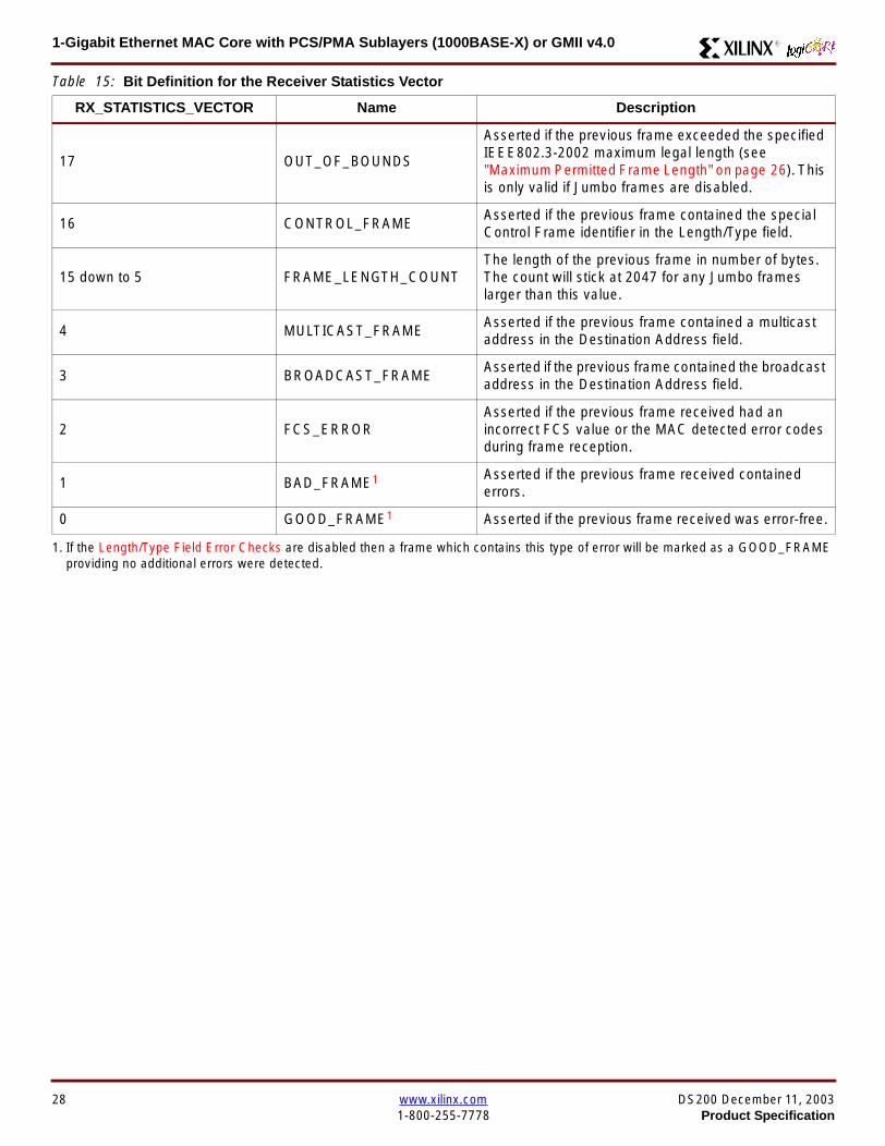
1-Gigabit Ethernet MAC Core with PCSPMA Sublayers (1000BASE-X) or GMII v40 R
17 OUT_OF_BOUNDS
Asserted if the previous frame exceeded the specifiedIEEE8023-2002 maximum legal length (seeMaximum Permitted Frame Length on page 26) Thisis only valid if Jumbo frames are disabled
16 CONTROL_FRAMEAsserted if the previous frame contained the specialControl Frame identifier in the LengthType field
15 down to 5 FRAME_LENGTH_COUNTThe length of the previous frame in number of bytesThe count will stick at 2047 for any Jumbo frameslarger than this value
4 MULTICAST_FRAMEAsserted if the previous frame contained a multicastaddress in the Destination Address field
3 BROADCAST_FRAMEAsserted if the previous frame contained the broadcastaddress in the Destination Address field
2 FCS_ERRORAsserted if the previous frame received had anincorrect FCS value or the MAC detected error codesduring frame reception
1 BAD_FRAME1 Asserted if the previous frame received containederrors
0 GOOD_FRAME1 Asserted if the previous frame received was error-free
1 If the LengthType Field Error Checks are disabled then a frame which contains this type of error will be marked as a GOOD_FRAMEproviding no additional errors were detected
Table 15 Bit Definition for the Receiver Statistics Vector
RX_STATISTICS_VECTOR Name Description
28 wwwxilinxcom DS200 December 11 20031-800-255-7778 Product Specification
1-Gigabit Ethernet MAC Core with PCSPMA Sublayers (1000BASE-X) or GMII v40R
Flow ControlThe flow control block is designed to Clause 31 of the IEEE8023-2002 standard The MAC may be configured to sendpause frames and to act upon their reception These twobehaviors can be configured asymmetrically see Configu-ration Registers on page 30
Transmitting a PAUSE Control Frame
The client initiates a flow control frame by assertingPAUSE_REQ while the pause value is on the PAUSE_VALbus These signals are synchronous to TX_CLK The timingof this can be seen in Figure 23
If the MAC core is configured to support transmit flow con-trol this action causes the core to transmit a PAUSE controlframe on the link with the PAUSE parameter set to thevalue on PAUSE_VAL in the cycle when PAUSE_REQ wasasserted This will not disrupt any frame transmission inprogress but will take priority over any pending frame trans-
mission This frame will be transmitted even if the transmit-ter is in the paused state itself
Receiving a Pause Control Frame
When an error-free frame is received by the MAC core thefollowing checks are made
1 The Destination Address field is matched against theMAC Control Multicast address or the configuredSource Address for the MAC (see ConfigurationRegisters on page 30)
2 The LengthType field is matched against the MACControl Type code
3 The opcode field contents are matched against thePAUSE opcode if check 2 is true
If any of the above checks are false or the MAC Flow Con-trol logic for the receiver is disabled the frame is ignored bythe Flow Control logic and passed up to the client
If the frame passes all of the above checks is of minimumlegal size and the MAC Flow Control logic for the receiver isenabled the pause value parameter in the frame is thenused to inhibit transmitter operation for the time defined inthe IEEE8023-2002 specification This inhibit is imple-mented using the same back pressure scheme shown inFigure 12 Because the received pause frame has beenacted upon it is passed to the client with RX_BAD_FRAMEasserted to indicate to the client that it should be dropped
Reception of any frame for which check 2 is true and whichis not of legal minimum length is considered an invalid Con-trol frame This will be ignored by the Flow Control logic andpassed to the client with RX_BAD_FRAME asserted
Figure 23 Pause Request Timing
TX_CLK
PAUSE_VAL[150]
PAUSE_REQ
xip2148
DS200 December 11 2003 wwwxilinxcom 29Product Specification 1-800-255-7778
1-Gigabit Ethernet MAC Core with PCSPMA Sublayers (1000BASE-X) or GMII v40 R
Optional Management Interface(management_interface=true)The management interface is a processor-independentinterface with standard address data and control signals Itmay be used as is or a wrapper may be applied (not sup-plied) to interface to common bus architectures
This interface is used for
bull Configuration of the MAC core
bull Access to optional statistics counters for use by higherlayers for example SNMP
bull access through the MDIO interface to the managementregisters located in the PHY attached to the MAC core
The management interface is accessed differently depend-ing on the type of transaction a truth table showing whichaccess method is required for each transaction type isshown in Table 16 These access methods are described inthe following sections
HOST_CLK Frequency
The management interface clock HOST_CLK is used toderive the MDIO clock MDC and is therefore subject tosome frequency restrictions This HOST_CLK must be
ge 10 MHz
le 100 MHz
Configuring the MAC core to derive the MDC signal fromthis clock is detailed in MDIO Interface on page 37
Configuration Registers
After power up or reset the client may reconfigure the coreparameters from their defaults such as flow control supportConfiguration changes can be written at any time Both thereceiver and transmitter logic will only respond to configura-tion changes during Inter Frame Gaps The exceptions tothis are the configurable resets which take effect immedi-ately
Configuration of the MAC core is performed through a reg-ister bank accessed through the management interfaceThe configuration registers available in the core are detailedin Table 17 As can be seen the address has some implicitdonrsquot care bits any access to an address in the rangesshown will perform a 32-bit read or write from the same con-figuration word
Table 16 Management Interface Transaction Types
Transaction HOST_MIIM_SEL HOST_ADDR[9]
Configuration 0 1
Statistics 0 0
MIIM access 1 X
Table 17 Configuration Registers
Address Description
0x200-0x23F Receiver Configuration (Word 0)
0x240-0x27F Receiver Configuration (Word 1)
0x280-0x2BF Transmitter Configuration
0x2C0-0x2FF Flow Control Configuration
0x300-0x33F Reserved
0x340-0x37F Management Configuration
30 wwwxilinxcom DS200 December 11 20031-800-255-7778 Product Specification
1-Gigabit Ethernet MAC Core with PCSPMA Sublayers (1000BASE-X) or GMII v40R
The register contents for the two receiver configuration words can be seen in Table 18 and Table 19
Notes1 In changing the receiverrsquos mode from Half Duplex to Full Duplex there is a period of time of up to 24 us following the mode change
when no new receiver statistics can be stored in the optional Statistical Counters
Table 18 Receiver Configuration Word 0
Bit Default Value Description
31-0 All 0rsquos
Pause frame MAC Source Address[310] This address is used by the MAC tomatch against the Destination Address of any incoming flow control frames It isalso used by the flow control block as the Source Address (SA) for any outboundflow control frames
The address is ordered so the first byte transmittedreceived is the lowestpositioned byte in the register for example a MAC address ofAA-BB-CC-DD-EE-FF would be stored in Address[470] as 0xFFEEDDCCBBAA
Table 19 Receiver Configuration Word 1
Bit Default Value Description
15-0 All 0rsquos Pause frame MAC Source Address[4732] See description in Table 18
24-16 NA Reserved
25 0
LengthType Error Check Disable When this bit is set to ldquo1rdquo the core will notperform the LengthType field error checks as described in LengthType FieldError Checks on page 26 When this bit is set to ldquo0rdquo the LengthType field checkswill be performed this is normal operation
26 0Half Duplex If ldquo1rdquo the receiver will operate in half duplex mode If ldquo0rdquo the receiverwill operate in full duplex mode Has no effect if XCO parameterhalf_duplex_capable = false
27 0VLAN Enable When this bit is set to ldquo1rdquo VLAN tagged frames will be acceptedby the receiver
28 1Receiver Enable If set to ldquo1rdquo the receiver block will be operational If set to ldquo0rdquothe block will ignore activity on the physical interface RX port
29 0
In-band FCS Enable When this bit is ldquo1rdquo the MAC receiver will pass the FCS fieldup to the client as described in Client-Supplied FCS Passing on page 25 Whenit is ldquo0rdquo the client will not be passed the FCS In both cases the FCS will beverified on the frame
30 0Jumbo Frame Enable When this bit is set to ldquo1rdquo the MAC receiver will acceptframes over the specified IEEE8023-2002 maximum legal length When this bitis ldquo0rdquo the MAC will only accept frames up to the specified maximum
31 0Reset When this bit is set to ldquo1rdquo the receiver will be reset The bit will thenautomatically revert to ldquo0rdquo Note that this reset will also set all of the receiverconfiguration registers to their default values
DS200 December 11 2003 wwwxilinxcom 31Product Specification 1-800-255-7778
1-Gigabit Ethernet MAC Core with PCSPMA Sublayers (1000BASE-X) or GMII v40 R
The register contents for the Transmitter Configuration Word are described in Table 20
Notes1 In changing the transmitterrsquos mode from Half Duplex to Full Duplex there is a period of time of up to 24 us following the mode change
when no new transmitter statistics can be stored in the optional Statistical Counters
Table 20 Transmitter Configuration Word
Bit Default Value Description
24-0 NA Reserved
25 0
Interframe Gap Adjust Enable If lsquo1rsquo the transmitter will read the value on the portTX_IFG_DELAY at the start of frame transmission and adjust the interframe gapfollowing the frame accordingly See Interframe Gap Adjustment on page 22 Ifldquo0rdquo the transmitter will output a minimum Inter Frame Gap of twelve clock cyclesas specified in IEEE8023-2002
26 0Half Duplex If lsquo1rsquo the transmitter will operate in half duplex mode If lsquo0rsquo thetransmitter will operate in full duplex mode Has no effect if XCO parameterhalf_duplex_capable = false
27 0VLAN Enable When this bit is set to 1 the transmitter will allow the transmissionof VLAN tagged frames
28 1Transmit Enable When this bit is 1 the transmitter is operational When it is 0the transmitter is disabled
29 0
In-band FCS Enable When this bit is lsquo1rsquo the MAC transmitter will expect the FCSfield to be passed in by the client as described in Client-Supplied FCS Passingon page 17 When this bit is ldquo0rdquo the MAC transmitter will append padding asrequired compute the FCS and append it to the frame
30 0
Jumbo Frame Enable When this bit is set to ldquo1rdquo the MAC transmitter will sendframes that are greater than the specified IEEE8023-2002 maximum legallength When this bit is ldquo0rdquo the MAC will only send frames up to the specifiedmaximum
31 0Reset When this bit is set to ldquo1rdquo the transmitter will be reset The bit will thenautomatically revert to ldquo0rdquo Note that this reset will also set all of the transmitterconfiguration registers to their default values
32 wwwxilinxcom DS200 December 11 20031-800-255-7778 Product Specification
1-Gigabit Ethernet MAC Core with PCSPMA Sublayers (1000BASE-X) or GMII v40R
The register contents for the Flow Control Configuration Word are described in Table 21
The register contents for the Management Configuration Word are described in Table 22
Writing to the configuration registers through the manage-ment interface is depicted in Figure 24 When accessing theconfiguration registers (ie when HOST_ADDR[9] = lsquo1rsquo andHOST_MIIM_SEL = lsquo0rsquo) the upper bit of HOST_OPCODEfunctions as an Active Low write enable signal The lowerHOST_OPCODE bit is a ldquodonrsquot carerdquo
Reading from the configuration register words is similar butthe upper HOST_OPCODE bit should be lsquo1rsquo This is shownin Figure 25 In this case the contents of the register appearon HOST_RD_DATA the HOST_CLK edge after the regis-ter address is asserted onto HOST_ADDR
Table 21 Flow Control Configuration Word
Bit Default Value Description
28-0 NA Reserved
29 1
Flow Control Enable (RX) When this bit is lsquo1rsquo received flow control frames willinhibit the transmitter operation as described in Receiving a Pause ControlFrame on page 29 When this bit is lsquo0rsquo received flow control frames will alwaysbe passed up to the client
30 1Flow Control Enable (TX) When this bit is lsquo1rsquo asserting the PAUSE_REQ signalwill send a flow control frame out from the transmitter When this bit is 0 assertingthe PAUSE_REQ signal has no effect
31 NA Reserved
Table 22 Management Configuration Word
Bits Default Value Description
4-0 All 0rsquos Clock Divide[40] See MDIO Interface on page 37
5 0MDIO Enable When this bit is 1 the MDIO interface can be used to accessattached PHY devices When this bit is 0 the MDIO interface is disabled and theMDIO signals remain inactive
31-6 NA Reserved
Figure 24 Configuration Register Write Timing
HOST_CLK
HOST_ADDR[80]
HOST_ADDR[9]
HOST_OPCODE[1]
HOST_MIIM_SEL
HOST_WR_DATA[310]xip2149
Figure 25 Configuration Register Read Timing
HOST_CLK
HOST_ADDR[80]
HOST_ADDR[9]
HOST_OPCODE[1]
HOST_MIIM_SEL
HOST_RD_DATA[310]
xip2150
DS200 December 11 2003 wwwxilinxcom 33Product Specification 1-800-255-7778
1-Gigabit Ethernet MAC Core with PCSPMA Sublayers (1000BASE-X) or GMII v40 R
Optional Statistical Gathering(statistics_gathering=true)
During operation the MAC core collects statistics on thesuccess and failure of various operations for processing by
station management entities (STA) further up the protocolstack These statistics are accessed by the host through theoptional management interface A complete list of statisticssupported is described in Table 23
Table 23 Statistics Registers
Address Name Description
0x000 Frames Received OK1 A count of error-free frames received
0x001 Frame Check Sequence Errors A count of received frames that failed the CRC check and were at least64 bytes in length
0x002 Broadcast Frames Received OK1A count of frames that were successfully received and were directed tothe broadcast group address
0x003 Multicast Frames Received OK1 A count of frames that were successfully received and were directed toa non broadcast group address
0x004 64 byte Frames Received OK1 A count of error-free frames received that were 64 bytes in length
0x005 65-127 byte Frames Received OK1A count of error-free frames received that were between 65 and 127bytes in length
0x006 128-255 byte Frames Received OK1A count of error-free frames received that were between 128 and 255bytes in length
0x007 256-511 byte Frames Received OK1A count of error-free frames received that were between 256 and 511bytes in length
0x008512-1023 byte Frames ReceivedOK1
A count of error-free frames received that were between 512 and 1023bytes in length
0x0091024-MaxFrameSize byte FramesReceived OK1
A count of error-free frames received that were between 1024 bytes andthe specified IEEE8023-2002 maximum legal length (see MaximumPermitted Frame Length on page 26)
0x00A Control Frames Received OKA count of error-free frames received that contained the specialControl Frame identifier in the LengthType field
0x00B LengthType Out of Range
A count of frames received that were at least 64 bytes in length wherethe lengthtype field contained a length value that did not match thenumber of MAC client data bytes received
The counter also increments for frames in which the lengthtype fieldindicated that the frame contained padding but where the number ofMAC client data bytes received was greater than 64 bytes (minimumframe size)
The exception to the above is when the LengthType Field Error Checksare disabled in which case this counter will not increment
0x00C VLAN Tagged Frames Received OKA count of error-free VLAN frames received This counter will only incre-ment when the receiver is configured for VLAN operation
0x00D Pause Frames Received OK
A count of error-free frames received that contained the MAC Controltype identifier 88-08 in the LengthType field contained a Destinationaddress that matched either the MAC Control multicast address or theconfigured source address of the MAC contained the PAUSE opcodeand were acted upon by the MAC
0x00EControl Frames Received withUnsupported Opcode
A count of error-free frames received that contained the MAC Controltype identifier 88-08 in the LengthType field but were received with anopcode other than the PAUSE opcode
34 wwwxilinxcom DS200 December 11 20031-800-255-7778 Product Specification
1-Gigabit Ethernet MAC Core with PCSPMA Sublayers (1000BASE-X) or GMII v40R
0x00F Oversize Frames Received OK1A count of otherwise error-free frames received that exceeded the max-imum legal frame length specified in IEEE 8023-2002 (see MaximumPermitted Frame Length on page 26)
0x010 Undersize frames receivedA count of the number of frames received that were less than 64 bytesin length but were otherwise well formed
0x011 Fragment frames receivedA count of the number of frames received that were less than 64 bytesin length and had a bad Frame Check Sequence field
0x012 Received bytesA count of bytes of frames that are received (Destination Address toFrame Check Sequence inclusive)
0x013 Transmitted bytesA count of bytes of frames that are transmitted (Destination Address toFrame Check Sequence inclusive)
0x020 Frames Transmitted OK A count of error-free frames transmitted
0x021 Broadcast Frames Transmitted OK A count of error-free frames that were transmitted to the broadcastaddress
0x022 Multicast Frames Transmitted OK A count of error-free frames that were transmitted to a group destina-tion address other than broadcast
0x023 Underrun Errors
A count of frames that would otherwise be transmitted by the core butcould not be completed due to the assertion of TX_UNDERRUN duringthe frame transmission This will not count frames which are less than64 bytes in length
0x024 Control Frames Transmitted OKA count of error-free frames transmitted that contained the MACControl Frame type identifier 88-08 in the LengthType field
0x025 64 byte Frames Transmitted OK A count of error-free frames transmitted that were 64 bytes in length
0x026 65-127 byte Frames Transmitted OKA count of error-free frames transmitted that were between 65 and 127bytes in length
0x027128-255 byte Frames TransmittedOK
A count of error-free frames transmitted that were between 128 and 255bytes in length
0x028256-511 byte Frames TransmittedOK
A count of error-free frames transmitted that were between 256 and 511bytes in length
0x029512-1023 byte Frames TransmittedOK
A count of error-free frames transmitted that were between 512 and1023 bytes in length
0x02A1024-MaxFrameSize byte FramesTransmitted OK
A count of error-free frames transmitted that were between 1024 and thespecified IEEE8023-2002 maximum legal length (see Maximum Per-mitted Frame Length on page 20)
0x02BVLAN Tagged Frames TransmittedOK
A count of error-free VLAN frames transmitted This counter will onlyincrement when the transmitter is configured for VLAN operation
0x02C Pause Frames Transmitted OKA count of error-free PAUSE frames generated and transmitted by thecore in response to an assertion of PAUSE_REQ
0x02D Oversize Frames Transmitted OKA count of otherwise error-free frames transmitted that exceeded themaximum legal frame length specified in IEEE 8023-2002 (see Maxi-mum Permitted Frame Length on page 20)
0x02E Single Collision Frames A count of frames that are involved in a single collision but are subse-quently transmitted successfully (Half Duplex Mode only)
Table 23 Statistics Registers (Continued)
Address Name Description
DS200 December 11 2003 wwwxilinxcom 35Product Specification 1-800-255-7778
1-Gigabit Ethernet MAC Core with PCSPMA Sublayers (1000BASE-X) or GMII v40 R
Each of these statistic registers is 64 bits wide and thereforemust be read in a two-cycle transfer The timing of this pro-cess is shown in Figure 26 Six clocks after the read trans-action is initiated the least significant word (LSW) of thestatistics counter appears on the HOST_RD_DATA bus
and a clock cycle later the most significant word (MSW)appears For accurate statistic values 64 clock ticks (ofTX_CLK for transmit statistics or RX_CLK for receive statis-tics) must elapse after the last frame is sent or receivedthrough the MAC core
0x02F Multiple Collision Frames A count of frames that are involved in more than one collision but aresubsequently transmitted successfully (Half Duplex Mode only)
0x040 Frames with Deferred Transmissions A count of frames whose transmission was delayed on its first attemptbecause the medium was busy (Half Duplex Mode only)
0x041 Late Collisions
A count of the times that a collision has been detected later than oneslotTime from the start of the packet transmission A late collision iscounted twice both as a collision and as a lateCollision (Half DuplexMode only)
0x042Frames Aborted due to Excesscollisions
A count of the frames that due to excessive collisions are not transmit-ted successfully (Half Duplex Mode only)
0x043 Carrier Sense ErrorsA count of times that the GMII_CRS signal was not asserted or wasdisasserted during the transmission of a frame without collision (HalfDuplex Mode only)
0x044 Frames with Excess DeferralA count of frames that deferred transmission for an excessive period oftime (Half Duplex Mode only)
1 If the LengthType Field Error Checks are disabled then these counters will still increment for received frames which contain this typeof error (providing no additional errors were detected)
Table 23 Statistics Registers (Continued)
Address Name Description
Figure 26 Statistic Register Read Timing
HOST_CLK
HOST_ADDR[80]
HOST_ADDR[9]
HOST_REQ
HOST_MIIM_SEL
HOST_RD_DATA[310]
6 CLOCKS
LSW MSW
xip2151
36 wwwxilinxcom DS200 December 11 20031-800-255-7778 Product Specification
1-Gigabit Ethernet MAC Core with PCSPMA Sublayers (1000BASE-X) or GMII v40R
MDIO Interface
The management interface is also used to access the MDIO(MII Management) interface of the MAC core this interfaceis used to access the Managed Information Block (MIB) ofthe PHY components attached to the MAC core
The MDIO interface supplies a clock to the externaldevices MDC This clock is derived from the HOST_CLKsignal using the value in the Clock Divide[40] configurationregister The frequency of the MDIO clock is given by thefollowing equation
The frequency of MDC given by this equation should notexceed 25 MHz in order to comply with the IEEE8023-2002 specification for this interface To prevent MDCfrom being out of specification the Clock Divide[40] valuepowers up at 00000 and while this value is in the register itis impossible to enable the MDIO interface
For details of the register map of PHY layer devices and afuller description of the operation of the MDIO interfaceitself see IEEE specification 8023-2002
Access to the MDIO interface through the managementinterface is depicted in the timing diagram in Figure 27
For MDIO transactions the following points apply
bull HOST_OPCODE maps to the OP (opcode) field of theMDIO frame
bull HOST_ADDR maps to the two address fields of theMDIO frame PHY_ADDR is HOST_ADDR[95] andREG_ADDR is HOST_ADDR[40]
bull HOST_WR_DATA[150] maps into the data field of the
MDIO frame when performing a write operation
bull The data field of the MDIO frame maps intoHOST_RD_DATA[150] when performing a readoperation
The MAC core signals to the host that it is ready for anMDIO transaction by asserting HOST_MIIM_RDY A read orwrite transaction on the MDIO is initiated by a pulse on the
fMDC
fHOST_CLK
1 Clock Divide[40]+( ) 2times-------------------------------------------------------------------=
Figure 27 MDIO Access Through Management Interface
HOST_CLK
HOST_ADDR[90]
HOST_OPCODE[10]
HOST_REQ
HOST_MIIM_SEL
HOST_RD_DATA[150]
HOST_WR_DATA[150]
HOST_RDY
If a read transaction is initiated the HOST_RD_DATA bus is valid at the point indicated If a write transaction is initiated the HOST_WR_DATA bus must be valid at the indicated point Simultaneous read and write is not permitted
xip2152
DS200 December 11 2003 wwwxilinxcom 37Product Specification 1-800-255-7778
1-Gigabit Ethernet MAC Core with PCSPMA Sublayers (1000BASE-X) or GMII v40 R
HOST_REQ signal This pulse is ignored if the MDIO inter-face already has a transaction in progress
The MAC core then disasserts the HOST_MIIM_RDY signalwhile the transaction across the MDIO is in progress Whenthe transaction across the MDIO interface has been com-pleted the HOST_MIIM_RDY signal will be asserted by theMAC core if the transaction is a read the data will also beavailable on the HOST_RD_DATA[150] bus at this time
Optional Configuration Vector(management_interface = false)If the optional Management interface is omitted from thecore all of relevant configuration signals are brought out of
the core These signals are bundled into theCONFIGURATION_VECTOR signal The bit mapping of theconfiguration vector signal is defined in Table 24 See thecorresponding entry in the configuration register tables forthe full description of each signal
Note that these configuration vector signals can bechanged by the user at any time however with the excep-tion of the reset and the flow control configuration signalsthey will not take effect until the current frame has com-pleted transmission or reception
The ldquoClockrdquo heading denotes which clock domain the con-figuration signal is registered into before use by the core Itis not necessary to drive the signal from this clock domain
Table 24 Configuration Vector Bit Definition
Bit(s)Configuration Register
cross reference Clock Description
47 downto 0
Receiver ConfigurationWord 0 bits 31-0 andReceiver ConfigurationWord 1 bits 15-0
RX_CLK
Pause frame MAC Source Address[470] This address isused by the MAC core to match against the DestinationAddress of any incoming flow control frames and as theSource Address for any outbound flow control frames
The address is ordered such that the first byte transmitted orreceived is the least significant byte in the register forexample a MAC address of AA-BB-CC-DD-EE-FF will bestored in bite [470] as 0xFFEEDDCCBBAA
48Receiver ConfigurationWord 1 bit 26
RX_CLKReceiver Half Duplex If lsquo1rsquo the receiver operates in halfduplex mode If lsquo0rsquo the receiver operates in full duplex modeHas no effect if XCO parameter half_duplex_capable = false
49Receiver ConfigurationWord 1 bit 27
RX_CLKReceiver VLAN Enable When this bit is set to 1 VLANtagged frames are accepted by the receiver
50Receiver ConfigurationWord 1 bit 28
RX_CLKReceiver Enable If set to 1 the receiver block is operationalIf set to 0 the block ignores activity on the physical interfaceRX port
51Receiver ConfigurationWord 1 bit 29
RX_CLK
Receiver In-band FCS Enable When this bit is lsquo1rsquo the MACreceiver will pass the FCS field up to the client as describedin Client-Supplied FCS Passing on page 25 When it is lsquo0rsquothe MAC receiver will not pass the FCS field In both casesthe FCS field will be verified on the frame
52Receiver ConfigurationWord 1 bit 30
RX_CLK
Receiver Jumbo Frame Enable When this bit is lsquo0rsquo thereceiver will not pass frames longer than the maximum legalframe size specified in IEEE 8023-2002 (see MaximumPermitted Frame Length on page 26) When it is lsquo1rsquo thereceiver will not have an upper limit on frame size
53Receiver ConfigurationWord 1 bit 31
NA
Receiver Reset When this bit is lsquo1rsquo the receiver is held inreset
This signal is an input to the reset circuit for the receiverblock See Reset circuit on page 42 for more information
54TransmitterConfiguration Word bit25
TX_CLK
Transmitter Interframe Gap Adjust enable If lsquo1rsquo then thetransmitter will read the value of the TX_IFG_DELAY port andset the Interframe Gap accordingly If lsquo0rsquo the transmitter willalways insert at least the legal minimum Interframe Gap
38 wwwxilinxcom DS200 December 11 20031-800-255-7778 Product Specification
1-Gigabit Ethernet MAC Core with PCSPMA Sublayers (1000BASE-X) or GMII v40R
55TransmitterConfiguration Word bit26
TX_CLK
Transmitter Half Duplex If lsquo1rsquo the transmitter operates in halfduplex mode If lsquo0rsquo the transmitter operates in full duplexmode Has no effect if XCO parameter half_duplex_capable= false
56TransmitterConfiguration Word bit27
TX_CLKTransmitter VLAN Enable When this bit is set to lsquo1rsquo thetransmitter allows the transmission of VLAN tagged frames
57TransmitterConfiguration Word bit28
TX_CLKTransmitter Enable When this bit is 1 the transmitter will beoperational When it is 0 the transmitter is disabled
58TransmitterConfiguration Word bit29
TX_CLK
Transmitter In-Band FCS Enable When this bit is lsquo1rsquo theMAC transmitter will expect the FCS field to be pass in by theclient as described in Client-Supplied FCS Passing onpage 17 When it is lsquo0rsquo the MAC transmitter will appendpadding as required compute the FCS and append it to theframe
59TransmitterConfiguration Word bit30
TX_CLK
Transmitter Jumbo Frame Enable When this bit is lsquo1rsquo theMAC transmitter will allow frames larger than the maximumlegal frame length specified in IEEE 8023-2002 to be sentWhen set to lsquo0rsquo the MAC transmitter will only allow frames upto the legal maximum to be sent
60TransmitterConfiguration Word bit31
NA
Transmitter Reset When this bit is lsquo1rsquo the MAC transmitter isheld in reset
This signal is an input to the reset circuit for the transmitterblock See Reset circuit on page 42 for more information
61Flow ControlConfiguration Word bit29
TX_CLK
Transmit Flow Control Enable When this bit is lsquo1rsquo assertingthe PAUSE_REQ signal causes the MAC core to send a flowcontrol frame out from the transmitter as described inReceiving a Pause Control Frame on page 29 When this bitis lsquo0rsquo asserting the PAUSE_REQ signal will have no effect
62Flow ControlConfiguration Word bit30
RX_CLK
Receive Flow Control Enable When this bit is lsquo1rsquo receivedflow control frames will inhibit the transmitter operation asdescribed in Receiving a Pause Control Frame on page 29When it is lsquo0rsquo received flow frames are passed up to theclient
63Receiver ConfigurationWord 1 bit 25
RX_CLK
LengthType Error Check Disable When this bit is lsquo1rsquo thecore will not perform the LengthType field error checks asdescribed in LengthType Field Error Checks on page 26When it is set to lsquo0rsquo the LengthType field checks will beperformed this is normal operation
Table 24 Configuration Vector Bit Definition (Continued)
Bit(s)Configuration Register
cross reference Clock Description
DS200 December 11 2003 wwwxilinxcom 39Product Specification 1-800-255-7778
1-Gigabit Ethernet MAC Core with PCSPMA Sublayers (1000BASE-X) or GMII v40 R
Optional GMII (physical_interface=gmii)The GMII is designed to IEEE 8023-2002 Clause 35 Thisutilizes IOrsquos of the Xilinx devices using inputoutput buffersand inputoutput flip-flops to maximize setup and hold mar-gins All IO logic is placed in the example wrapper that isdelivered with the core In addition all clock managementlogic for the core is instanced in this example wrapper thisallows multiple instances of the core to share clocks Theexample wrapper is provided in both VHDL and Verilog
Clock Management
Figure 28 illustrates the clock management used with theGMII interface All clocks illustrated have a frequency of125MHz
GTX_CLK must be provided to the MAC core This is a highquality clock which satisfies the IEEE8023-2002 require-ments It is expected that this clock will be derived from anexternal oscillator and connected into the device through anIBUFG as illustrated The clock source must then be routedonto a global clock network by connecting it to a BUFGWithin the MAC core this global clock is used by all MACtransmitter logic The MAC Client can obtain this clock byconnecting to the TX_CLK signal output from the coreGMII_TX_CLK is derived from this global clock by invertingit and routing it to an OBUF
GMII_RX_CLK is received through an IBUFG This clock isthen routed onto a global clock network by connecting it to aBUFG The resulting global clock is used by all MACreceiver logic
Figure 28 Clock Management with GMII
IBUFG
IBUFG
OBUF
BUFG
BUFG
TX_CLK
RX_CLK
GTX_CLK
GMII_TX_CLK
GMII_RX_CLK
Example Wrapper
xip2153
MAC Core
TX_CLK
RX_CLK
GMII_TX_CLK
GMII_RX_CLK
GTX_CLK
40 wwwxilinxcom DS200 December 11 20031-800-255-7778 Product Specification
1-Gigabit Ethernet MAC Core with PCSPMA Sublayers (1000BASE-X) or GMII v40R
Clock Sharing between Multiple cores
Figure 29 illustrates how it is possible to share clockresources across multiple instantiations of the core whenusing the optional GMII
GTX_CLK may be shared between multiple cores as illus-trated resulting in a common transmitter clock domainacross the device
A common receiver clock domain is not possible each corewill receive an independent receiver clock from its GMII asillustrated
Although not illustrated if the optional Management Inter-face is used HOST_CLK can also be shared betweencores
Figure 29 Clock Management with multiple instances of the MAC with GMII
IBUFG
OBUF
BUFG
TX_CLK
RX_CLK_1
GMII_TX_CLK_1
GMII_RX_CLK_1
MAC Core
TX_CLK
RX_CLK
GMII_TX_CLK
GMII_RX_CLK
GTX_CLK
MAC Core
TX_CLK
RX_CLK
GMII_TX_CLK
GMII_RX_CLK
GTX_CLK
IBUFG
BUFG
GTX_CLK
IBUFG
OBUF
GMII_TX_CLK_2
GMII_RX_CLK_2
BUFG
TX_CLK
RX_CLK_2
DS200 December 11 2003 wwwxilinxcom 41Product Specification 1-800-255-7778
1-Gigabit Ethernet MAC Core with PCSPMA Sublayers (1000BASE-X) or GMII v40 R
Reset circuit
Internally the core is divided up into clockreset domainswhich group together elements with the common clock andreset signals The reset circuitry for one of these domains isis illustrated in Figure 30 This circuit provides controllableskews on the reset nets within the design
More information on the operation and rationale behind thiscircuit can be found in Ken Chapmanrsquos Xilinx TechXclusiveldquoGet Smart About Resetrdquo athttpwwwxilinxcomsupporttechxclusivesglobal-techX19htm
Figure 30 Reset circuit for one clockreset domain
FDP
PRED
C
Q
FDP
PRED
C
Q
FDP
PRED
C
Q
FDP
PRED
C
Q
PRE PRE PRE
0
RESET
Management Reset
Clock
Core Registers
42 wwwxilinxcom DS200 December 11 20031-800-255-7778 Product Specification
1-Gigabit Ethernet MAC Core with PCSPMA Sublayers (1000BASE-X) or GMII v40R
Optional PCS with Ten-Bit Interface (TBI) for 1000BASE-X (physical_interface=tbi)The Full-Duplex Physical Coding Sublayer (PCS) for1000BASE-X is defined in IEEE 8023-2002 Clauses 36and 37 This functionality is only available in the Virtex-IIand Spartan3 families of FPGA devices
A block diagram of the PCS is shown in Figure 31 Themajor functional blocks of the PCS are
bull Transmit engine
bull Auto-negotiation block
bull Receive engine and synchronization block
bull PCS managed register block
bull 8B10B encoder block
bull 8B10B decoder block
bull Receiver elastic buffer
The PCS Managed Register Block is accessed through theMDIO Interface as if it were an externally connected PHYThis configures the operation of the PCS and Auto-Negoti-ation See PCS Managed Register Block
(physical_interface = tbi or phy) on page 49 The corersquosoptional Management Interface can be used to control theMDIO Interface as described by MDIO Interface onpage 37 When the optional Management Interface is notpresent the PCS Managed Register Block must beaccessed via an MDIO controller which is not provided bythe core
The 8B10B encodingdecoding blocks are implemented byconfiguring two Block SelectRAM modules as ROM Theseare used as large look-up tables The remaining PCS func-tionality such as code group encodingdecoding the Man-aged Register Block and Auto-Negotiation areimplemented in CLB logic
The Receiver Elastic buffer enables the 10-bit parallel datareceived from the PMA sublayer alternatively onPMA_RX_CLK0 and PMA_RX_CLK1 clock edges to betransferred onto the internal 125MHz clock domain derivedfrom GTX_CLK (see Clock Management) This buffer isimplemented in Distributed Memory
Figure 31 Functional Block Diagram of the 1-Gigabit Ethernet PCS with TBI Interface
PCS TRANSMIT ENGINE
PCS RECEIVE ENGINE ampSYNCHRONISATION
PCSMANAGEMENT
MDIOInterface
AUTO-NEGOTIATION
MAC TXInterface
MAC RXInterface
8B10BEncoder
8B10BDecoder
RX Elastic Buffer
TBI Interface
DS200 December 11 2003 wwwxilinxcom 43Product Specification 1-800-255-7778
1-Gigabit Ethernet MAC Core with PCSPMA Sublayers (1000BASE-X) or GMII v40 R
TBI Interface
The TBI is designed to IEEE 8023-2002 Clause 363 Thisutilizes IOrsquos of the Xilinx devices using inputoutput buffersand inputoutput flip-flops to maximize setup and hold mar-gins All IO logic is placed in the example wrapper that isdelivered with the core In addition all clock managementlogic for the core is instantiated in this example wrapperthis allows multiple instances of the core to share clocksThe example wrapper is provided in both VHDL and Verilog
Clock Management
Figure 32 illustrates the clock management used with theTBI interface
GTX_CLK must be provided to the MAC core This is a highquality clock of frequency 125MHz which satisfies theIEEE8023-2002 requirements It is expected that this clockwill be derived from an external oscillator and connected
into the device through an IBUFG as illustrated The clocksource must then be routed onto a global clock network byconnecting it to a BUFG Within the MAC core this globalclock is used by all MAC transmitter logic PMA_TX_CLK isderived from this global clock by inverting it and routing it toan OBUF
PMA_RX_CLK0 and PMA_RX_CLK1 are each receivedthrough an IBUFG These clocks are then routed onto glo-bal clock networks by connecting each to a BUFGPMA_RX_CLK0 and PMA_RX_CLK1 are each 625MHzclocks Data from the TBI is received alternatively on the ris-ing edge of PMA_RX_CLK0 followed by the rising edge ofPMA_RX_CLK1 using IOB Double-Data Rate input regis-ters This data is then written into the Receiver ElasticBuffer Data is read out of the Elastic Buffer using the globalclock derived from GTX_CLK all the remaining receiverlogic is synchronous to this clock
Figure 32 Clock Management for PCS with TBI Interface
IBUFG
IBUFG
OBUF
BUFG
BUFG
TX_CLK
RX_CLK
GTX_CLK
PMA_TX_CLK
PMA_RX_CLK0
MAC Core
RX ELASTICBUFFER
Example Wrapper
TX_CLK
RX_CLK
GTX_CLK
PMA_TX_CLK
PMA_RX_CLK0
IBUFGBUFGPMA_RX_CLK1
PMA_RX_CLK1
44 wwwxilinxcom DS200 December 11 20031-800-255-7778 Product Specification
1-Gigabit Ethernet MAC Core with PCSPMA Sublayers (1000BASE-X) or GMII v40R
Clock Sharing between Multiple cores
Figure 33 illustrates how it is possible to share clockresources across multiple instantiations of the core whenusing the optional PCS with TBI
GTX_CLK may be shared between multiple cores as illus-trated resulting in a common transmitter clock domainacross the device
Each core will receive independent PMA_RX_CLK0 andPMA_RX_CLK1 clocks from its TBI as illustrated whichcannot be shared
Although not illustrated if the optional Management Inter-face is used HOST_CLK can also be shared betweencores
Figure 33 Clock Management with multiple instances of the MAC with PCS and TBI
Reset circuit
The reset circuits within the MAC when the TBI interface is implemented is the same as that in the GMII case details ofthese circuits can be found on page 42
IBUFG
OBUF
BUFG
TX_CLK
RX_CLK
PMA_TX_CLK_1
PMA_RX_CLK0_1
MAC Core
RX ELASTICBUFFER
TX_CLK
RX_CLK
GTX_CLK
PMA_TX_CLK
PMA_RX_CLK0
IBUFGBUFGPMA_RX_CLK1_1
PMA_RX_CLK1
IBUFG
BUFG
GTX_CLK
IBUFG
OBUF
BUFG
TX_CLK
RX_CLK
PMA_TX_CLK_2
PMA_RX_CLK0_2
MAC Core
RX ELASTICBUFFER
TX_CLK
RX_CLK
GTX_CLK
PMA_TX_CLK
PMA_RX_CLK0
IBUFGBUFGPMA_RX_CLK1_2
PMA_RX_CLK1
DS200 December 11 2003 wwwxilinxcom 45Product Specification 1-800-255-7778
1-Gigabit Ethernet MAC Core with PCSPMA Sublayers (1000BASE-X) or GMII v40 R
Optional PCS and PMA Sublayers for 1000BASE-X (physical_interface=phy)The Full-Duplex Physical Coding Sublayer (PCS) withPhysical Medium Attachment (PMA) for 1000BASE-X isdefined in IEEE 8023-2002 Clauses 36 and 37 This func-tionality is only available in the Virtex-II Pro family of FPGAdevices
A block diagram of the PCS and PMA sublayers can beseen in Figure 34 The functional blocks of the PCS andPMA sublayers may replace the optional GMII interfaceThe functional blocks of the PCS and PMA sublayers are
bull PCS Transmit Engine
bull Auto-Negotiation block
bull Receive Engine and Synchronization Block
bull PCS Managed Register Block
bull Rocket IO Multi-Gigabit Transceiver
The PCS Managed Register Block is accessed through theMDIO Interface as if it were an externally connected PHYThis configures the operation of the PCS PMA sublayerand Auto-NegotiationSee PCS Managed Register Block(physical_interface = tbi or phy) on page 49 The corersquosoptional Management Interface can be used to control theMDIO Interface as described by MDIO Interface onpage 37 When the optional Management Interface is notpresent the PCS Managed Register Block must beaccessed via an MDIO controller which is not provided bythe core
The Rocket IO Multi-Gigabit Transceiver (MGT) providessome of the PCS layer functionality such as 8B10B encod-ingdecoding and the PMA serdes The remaining PCSfunctionality such as code group encodingdecoding theManaged Register Block and Auto-Negotiation are imple-mented in CLB logic
Figure 34 Functional Block Diagram of the 1-Gigabit Ethernet PCSPMA Sublayer Extension
PCS TRANSMIT ENGINE
PCS RECEIVE ENGINE ampSYNCHRONISATION
RO
CK
ET
IO
MU
LTI-
GIG
TR
AN
SC
EIV
ER
PCSMANAGEMENT
MDIOInterface
AUTO-NEGOTIATION
TXPTXN
RXPRXN
MAC TXInterface
MAC RXInterface
xip2154
46 wwwxilinxcom DS200 December 11 20031-800-255-7778 Product Specification
1-Gigabit Ethernet MAC Core with PCSPMA Sublayers (1000BASE-X) or GMII v40R
Clock Management
Figure 35 illustrates the clock management that should beused with the optional PCS and PMA sublayers for1000BASE-X This logic is implemented in the examplewrapper that is delivered with the core This provides flexi-bility because the design can be modified to use eitherREFCLK or BREFCLK (please refer to Rocket IO docu-mentation) It would also allow multiple instances of the coreto share clocks The example wrapper is provided in bothVHDL and Verilog
(B)REFCLK must be provided to the MAC core This clockmust be derived from an external oscillator and connectedto the core through an IBUFG as illustrated (B)REFCLK isa high quality clock of frequency 625 MHz which satisfiesthe Rocket IO Multi-Gigabit Transceiver (MGT) require-ments
(B)REFCLK is routed to both the core and a DCM From theDCM the CLK2X180 output is routed to a BUFG to providethe device with a global 125 MHz clock (connected toUSERCLK2 input on the core) Within the core bothTX_CLK and RX_CLK share this global 125 MHz clocksource which is used by all transmitter and receiver logicThis is made possible by the RX_ELASTIC_BUFFER func-tionality of the Rocket IO MGT (refer to Virtex-II Pro docu-mentation) The MAC Client can obtain this clock byconnecting to either the TX_CLK or the RX_CLK signalsoutput from the core
From the DCM the CLK0 output is routed to a BUFG to pro-vide the device with a global 625MHz clock This is con-nected to the USRCLK input of the core
Figure 35 Clock Management with PCSPMA Sublayers
DCM
CLKIN CLK0
CLK2X180FB
BUFG
BUFG
IBUFG
TX_CLK
RX_CLK
(B)REFCLK
TXUSRCLK
(B)REFCLK
TXUSRCLK2RXUSRCLKRXUSRCLK2
GT_ETHERNET
Example Wrapper
xip2155
MAC Core
(B)REFCLK
USRCLK
USRCLK2
TX_CLK
RX_CLK
DS200 December 11 2003 wwwxilinxcom 47Product Specification 1-800-255-7778
1-Gigabit Ethernet MAC Core with PCSPMA Sublayers (1000BASE-X) or GMII v40 R
Clock Sharing between Multiple Cores
Figure 36 illustrates how it is possible to share clockresources across multiple instantiations of the core whenusing the optional PCSPMA sublayers For each coreUSERCLK and USERCLK2 must always be derived asshown from the BREFCLK or REFCLK used by that core
Note that when using the fixed routing resources of BREF-CLK Rocket IO MGTs along the top edge of the devicemust use a separate BREFCLK routing resource to thosealong the bottom edge of the device (Refer to Virtex-II Prodocumentation)
Although not illustrated if the optional Management Inter-face is used HOST_CLK can also be shared betweencores
Figure 36 Clock Management with multiple instances of the MAC with PCS and PMA sublayers
Reset circuit
The reset circuits within the MAC when the PCS and PMA sublayers are implemented is the same as that in the GMII casedetails of these circuits can be found on page 42
DCM
CLKIN CLK0
CLK2X180FB
BUFG
BUFG
IBUFG
(B)REFCLK
TXUSRCLK
(B)REFCLK
TXUSRCLK2RXUSRCLKRXUSRCLK2
GT_ETHERNET(B)REFCLK
USERCLK
USERCLK2
MAC core
TXUSRCLK
(B)REFCLK
TXUSRCLK2RXUSRCLKRXUSRCLK2
GT_ETHERNET(B)REFCLK
USERCLK
USERCLK2
MAC core
48 wwwxilinxcom DS200 December 11 20031-800-255-7778 Product Specification
1-Gigabit Ethernet MAC Core with PCSPMA Sublayers (1000BASE-X) or GMII v40R
PCS Managed Register Block (physical_interface = tbi or phy)The PCS in both the TBI interface and the PCSPMA (usingthe Virtex-II Pro Rocket IO) versions contain the full Man-aged Register Block defined in IEEE 8023-2002 clause 37
This utilizes ten dedicated management registersaccessed via the MDIO interface These are defined inTable 25 to Table 33 inclusive
Table 25 Control Register (Register 0)
Bit(s) Name Description Attributes Default Value
015 Reset1 = PCSPMA reset
0 = Normal Operation
ReadWrite
Self Clearing0
014 Loopback1 = Enable Loopback Mode
0 = Disable Loopback ModeReadWrite 0
013SpeedSelection (LSB)
The core always returns a 0 for this bitTogether with bit 06 speed selection of 1000Mbs is identified
Returns 0 0
012Auto-NegotiationEnable
1 = Enable Auto-Negotiation Process
0 = Disable Auto-Negotiation ProcessReadWrite 1
011 Power Down
1 = Power down
0 = Normal operation
When set to ldquo1rdquo the Rocket IO MGT is placedin a low power state This bit requires a reset(see bit 015) to clear
Read Write 0
010 Isolate1 = Electrically Isolate PHY from GMII
0 = Normal operationReadWrite 1
09Restart Auto-Negotiation
1 = Restart Auto-Negotiation Process
0 = Normal Operation
ReadWrite
Self Clearing0
08 Duplex ModeThe core always returns a 1 for this bit tosignal Full-Duplex Mode
Returns 1 1
07 Collision TestThe core always returns a 0 for this bit todisable COL test
Returns 0 0
06SpeedSelection(MSB)
The core always returns a 1 for this bitTogether with bit 013 speed selection of1000 Mbs is identified
Returns 1 1
050 Reserved Always returns 0rsquos writes ignored Returns 0rsquos 000000
DS200 December 11 2003 wwwxilinxcom 49Product Specification 1-800-255-7778
1-Gigabit Ethernet MAC Core with PCSPMA Sublayers (1000BASE-X) or GMII v40 R
Table 26 Status Register (Register 1)
Bit(s) Name Description Attributes Default Value
115 100BASE-T4The core always returns a 0 for this bitbecause 100BASE-T4 is not supported
Returns 0 0
114100BASE-XFullDuplex
The core always returns a 0 for this bitbecause 100BASE-X Full Duplex is notsupported
Returns 0 0
113100BASE-XHalf Duplex
The core always returns a 0 for this bitbecause 100BASE-X Half Duplex is notsupported
Returns 0 0
11210 Mbs FullDuplex
The core always returns a 0 for this bitbecause 10 Mbs Full Duplex is notsupported
Returns 0 0
11110 Mbs HalfDuplex
The core always returns a 0 for this bitbecause 10 Mbs Half Duplex is notsupported
Returns 0 0
110100BASE-T2Full Duplex
The core always returns a 0 for this bitbecause 100BASE-T2 Full Duplex is notsupported
Returns 0 0
19100BASE-T2Half Duplex
The core always returns a 0 for this bitbecause 100BASE-T2 Half Duplex is notsupported
Returns 0 0
18ExtendedStatus
The core always returns a 1 for this bit toindicate the presence of the ExtendedRegister (Register 15)
Returns 1 1
17 Reserved Always return 0 writes ignored Returns 0 0
16MF PreambleSuppression
The core always returns a 1 for this bit toindicate that Management Frame PreambleSuppression is supported
Returns 1 1
15Auto-NegotiationComplete
1 = Auto-Negotiation process completed
0 = Auto-Negotiation process not completedRead Only 0
14 Remote Fault1 = Remote fault condition detected
0 = No remote fault condition detected
Read Only
Self Clearing on read0
13Auto-NegotiationAbility
The core always returns a 1 for this bit toindicate that the PHY is capable ofAuto-Negotiation
Returns 1 1
12 Link Status1 = Link is up
0 = Link is down
Read Only
Self Clearing on read0
11 Jabber DetectThe core always returns a 0 for this bitbecause Jabber Detect is not supported
Returns 0 0
10ExtendedCapability
The core always returns a 0 for this bitbecause no extended register set issupported
Returns 0 0
50 wwwxilinxcom DS200 December 11 20031-800-255-7778 Product Specification
1-Gigabit Ethernet MAC Core with PCSPMA Sublayers (1000BASE-X) or GMII v40R
Table 27 PHY Identifier (Registers 2 and 3)
Bit(s) Name Description Attributes Default Value
2150OrganizationallyUniqueIdentifier
Always returns 0s Returns 0s 0000000000000000
31510OrganizationallyUniqueIdentifier
Always returns 0s Returns 0s 000000
394Manufacturerrsquosmodel number
Always returns 0s Returns 0s 000000
330RevisionNumber
Always returns 0s Returns 0s 0000
Table 28 Auto-Negotiation Advertisement Register (Register 4)
Bit(s) Name Description Attributes Default Value
415 Next Page1 = Next Page functionality is advertised
0 = Next Page functionality is not advertisedReadWrite 0
414 Reserved Always returns 0 writes ignored Returns 0 0
41312 Remote Fault
00 = No Error
01 = Offline
10 = Link Failure
11 = Auto-Negotiation Error
ReadWrite
Self clearing to 00afterAuto-Negotiation
00
4119 Reserved Always return 0 writes ignored Returns 0 0
487 Pause
00 = No PAUSE
01 = Asymmetric PAUSE towards linkpartner
10 = Symmetic PAUSE
11 = Both Symmetric PAUSE andAsymmetric PAUSE towards link partner
ReadWrite 11
46 Half DuplexThe core always returns a 0 for this bitbecause Half Duplex Mode is not supported
Returns 0 0
45 Full Duplex1 = Full Duplex Mode is advertised
0 = Full Duplex Mode is not advertisedReadWrite 1
440 Reserved Always returns 0s writes ignored Returns 0s 00000
DS200 December 11 2003 wwwxilinxcom 51Product Specification 1-800-255-7778
1-Gigabit Ethernet MAC Core with PCSPMA Sublayers (1000BASE-X) or GMII v40 R
Table 29 Auto-Negotiation Link Partner Ability Base Register (Register 5)
Bit(s) Name Description Attributes Default Value
515 Next Page1 = Next Page functionality is supported
0 = Next Page functionality is not supportedRead Only 0
514 AcknowledgeUsed by Auto-Negotiation function toindicate reception of a link partnerrsquos base ornext page
Read Only 0
51312 Remote Fault
00 = No Error
01 = Offline
10 = Link Failure
11 = Auto-Negotiation Error
Read Only 00
5119 Reserved Always returns 0s Returns 0s 000
587 Pause
00 = No PAUSE
01 = Asymmetric PAUSE supported
10 = Symmetic PAUSE supported
11 = Both Symmetric PAUSE andAsymmetric PAUSE supported
Read Only 00
56 Half Duplex1 = Half Duplex Mode is supported
0 = Half Duplex Mode is not supportedRead Only 0
55 Full Duplex1 = Full Duplex Mode is supported
0 = Full Duplex Mode is not supportedRead Only 0
540 Reserved Always returns 0s Returns 0s 00000
Table 30 Auto-Negotiation Expansion Register (Register 6)
Bit(s) Name Description Attributes Default Value
6153 Reserved Always returns 0s Returns 0s 0000000000000
62 Next Page AbleThe core always returns a 1 for this bitbecause the device is Next Page Able
Returns 1 1
61 Page Received1 = A new page has been received
0 = A new page has not been received
Read Only
Self Clearing on read0
60 Reserved Always returns 0s Returns 0s 0000000
52 wwwxilinxcom DS200 December 11 20031-800-255-7778 Product Specification
1-Gigabit Ethernet MAC Core with PCSPMA Sublayers (1000BASE-X) or GMII v40R
Table 31 Auto-Negotiation Next Page Transmit Register (Register 7)
Bit(s) Name Description Attributes Default Value
715 Next Page1 = Additional Next Page(s) will follow
0 = Last pageReadWrite 0
714 Reserved Always returns 0 Returns 0 0
713 Message Page1 = Message Page
0 = Unformatted PageReadWrite 1
712 Acknowledge 21 = Will comply with message
0 = Cannot comply with messageReadWrite 0
711 ToggleValue will toggle between subsequent NextPages
Read Only 0
7100Message UnformattedCode Field
Message Code Field or Unformatted PageEncoding as dictated by 713
ReadWrite00000000001
(Null Message Code)
Table 32 Auto-Negotiation Next Page Receive Register (Register 8)
Bit(s) Name Description Attributes Default Value
815 Next Page1 = Additional Next Page(s) follows
0 = Last pageRead Only 0
814 AcknowledgeUsed by Auto-Negotiation function toindicate reception of a link partnerrsquos base ornext page
Read Only 0
813 Message Page1 = Message Page
0 = Unformatted PageRead Only 0
812 Acknowledge 21 = Will comply with message
0 = Cannot comply with messageRead Only 0
811 ToggleValue toggles between subsequent andNext Pages
Read Only 0
8100Message UnformattedCode Field
Message Code Field or Unformatted PageEncoding as dictated by 813
Read Only 00000000000
DS200 December 11 2003 wwwxilinxcom 53Product Specification 1-800-255-7778
1-Gigabit Ethernet MAC Core with PCSPMA Sublayers (1000BASE-X) or GMII v40 R
)
Referencesbull IEEE 8023-2002
bull Virtex-E User Guide
bull Spartan-II E User Guide
bull Virtex-II User Guide
bull Virtex-II Pro User Guide
Related InformationXilinx products are not intended for use in life support appli-ances devices or systems Use of a Xilinx product in suchapplications without the written consent of the appropriateXilinx officer is prohibited
Ordering InformationThis Xilinx LogiCORE module is provided under theSignOnce IP Site License A free evaluation version of themodule is available
Once purchased the core may be downloaded from the Xil-inx IP Center for use with the Xilinx CORE Generator Sys-temtrade v61i SP3 and later The Xilinx CORE GeneratorSystem tool is bundled with all Alliance Series Softwarepackages at no additional charge
Please contact your local Xilinx sales representative or visitthe Xilinx Silicon Xpresso Cafe for pricing and availability onXilinx LogiCORE modules and software Information onadditional Xilinx LogiCORE modules is available on the Xil-inx IP Center
Revision HistoryThe following table shows the revision history for this document
Table 33 Extended Status Register (Register 15)
Bit(s) Name Description Attributes Default Value
15151000BASE-XFull Duplex
The core always returns a 1 for this bitbecause 1000BASE-X Full Duplex issupported
Returns 1 1
15141000BASE-XHalf Duplex
The core always returns a 0 for this bitbecause 1000BASE-X Half Duplex is notsupported
Returns 0 0
15131000BASE-TFull Duplex
The core always returns a 0 for this bitbecause 1000BASE-T Full Duplex is notsupported
Returns 0 0
15121000BASE-THalf Duplex
The core always returns a 0 for this bitbecause 1000BASE-T Half Duplex is notsupported
Returns 0 0
15110 Reserved Always returns 0s Returns 0s 000000000000
Date Version Revision
032803 11 Revision History added to document
043003 20 Revised to v30 standards
121103 30 Updated to v40 release
54 wwwxilinxcom DS200 December 11 20031-800-255-7778 Product Specification
- 1-Gigabit Ethernet MAC Core with PCSPMA Sublayers (1000BASE-X) or GMII v40
-
- Features
- MAC Overview
- Xilinx CORE Generator
- GUI Interface
- Parameter Values in the XCO File
- Output Generation
- Device Utilization
- Interface Description
- Interface Signals for MAC with physical_interface=gmii and management_interface=true
- Interface Signals for MAC with physical_interface=gmii and management_interface=false
- Interface Signals for MAC with physical_interface=tbi and management_interface=true
- Interface Signals for MAC with physical_interface=tbi and management_interface=false
- Interface Signals for MAC with physical_interface=phy and management_interface=true
- Interface Signals for MAC with physical_interface=phy and management_interface=false
- Client Side Interface Signal Definition
- Physical Interface Signal Definition
- Functional Description
- Client Interface
- Transmitter
- Receiver
- Flow Control
- Optional Management Interface (management_interface=true)
- Optional Configuration Vector (management_interface = false)
- Optional GMII (physical_interface=gmii)
- Optional PCS with Ten-Bit Interface (TBI) for 1000BASE-X (physical_interface=tbi)
- Optional PCS and PMA Sublayers for 1000BASE-X (physical_interface=phy)
- PCS Managed Register Block (physical_interface = tbi or phy)
- References
- Related Information
- Ordering Information
- Revision History
-
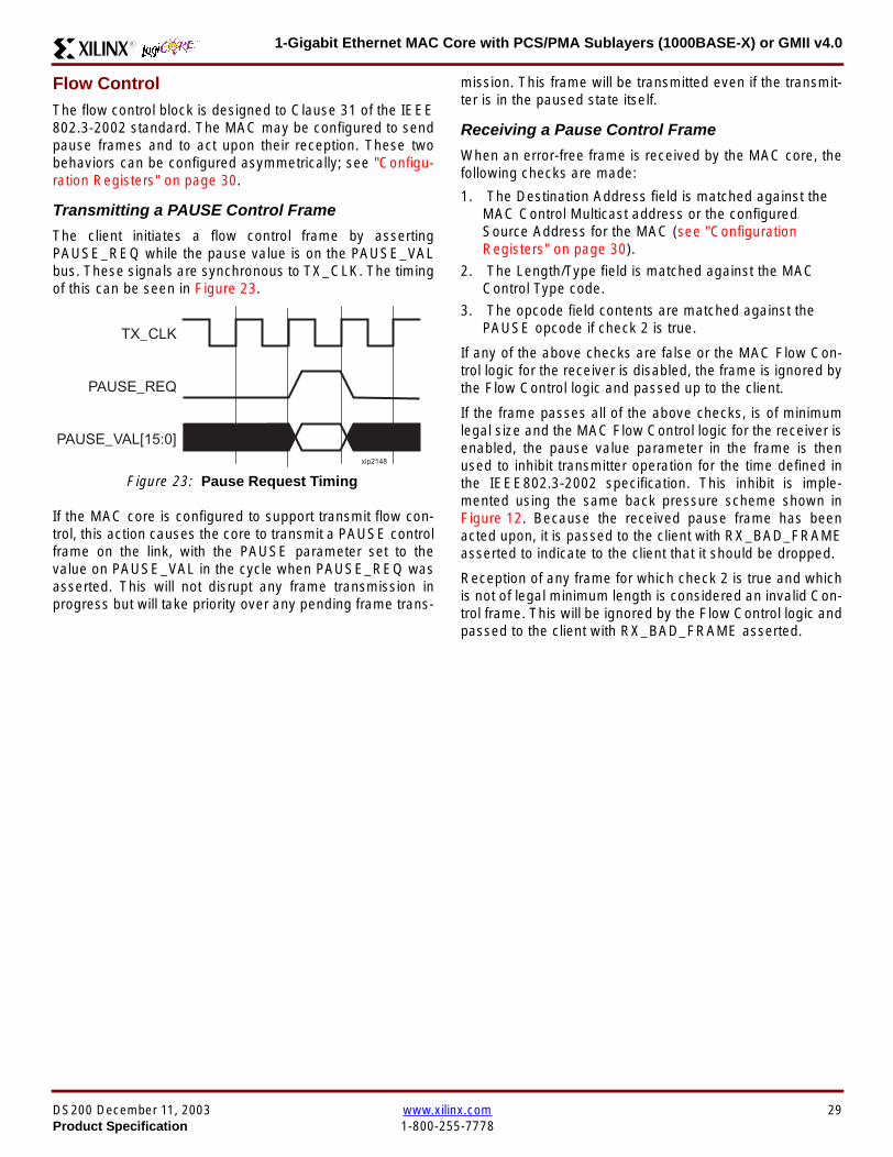
1-Gigabit Ethernet MAC Core with PCSPMA Sublayers (1000BASE-X) or GMII v40R
Flow ControlThe flow control block is designed to Clause 31 of the IEEE8023-2002 standard The MAC may be configured to sendpause frames and to act upon their reception These twobehaviors can be configured asymmetrically see Configu-ration Registers on page 30
Transmitting a PAUSE Control Frame
The client initiates a flow control frame by assertingPAUSE_REQ while the pause value is on the PAUSE_VALbus These signals are synchronous to TX_CLK The timingof this can be seen in Figure 23
If the MAC core is configured to support transmit flow con-trol this action causes the core to transmit a PAUSE controlframe on the link with the PAUSE parameter set to thevalue on PAUSE_VAL in the cycle when PAUSE_REQ wasasserted This will not disrupt any frame transmission inprogress but will take priority over any pending frame trans-
mission This frame will be transmitted even if the transmit-ter is in the paused state itself
Receiving a Pause Control Frame
When an error-free frame is received by the MAC core thefollowing checks are made
1 The Destination Address field is matched against theMAC Control Multicast address or the configuredSource Address for the MAC (see ConfigurationRegisters on page 30)
2 The LengthType field is matched against the MACControl Type code
3 The opcode field contents are matched against thePAUSE opcode if check 2 is true
If any of the above checks are false or the MAC Flow Con-trol logic for the receiver is disabled the frame is ignored bythe Flow Control logic and passed up to the client
If the frame passes all of the above checks is of minimumlegal size and the MAC Flow Control logic for the receiver isenabled the pause value parameter in the frame is thenused to inhibit transmitter operation for the time defined inthe IEEE8023-2002 specification This inhibit is imple-mented using the same back pressure scheme shown inFigure 12 Because the received pause frame has beenacted upon it is passed to the client with RX_BAD_FRAMEasserted to indicate to the client that it should be dropped
Reception of any frame for which check 2 is true and whichis not of legal minimum length is considered an invalid Con-trol frame This will be ignored by the Flow Control logic andpassed to the client with RX_BAD_FRAME asserted
Figure 23 Pause Request Timing
TX_CLK
PAUSE_VAL[150]
PAUSE_REQ
xip2148
DS200 December 11 2003 wwwxilinxcom 29Product Specification 1-800-255-7778
1-Gigabit Ethernet MAC Core with PCSPMA Sublayers (1000BASE-X) or GMII v40 R
Optional Management Interface(management_interface=true)The management interface is a processor-independentinterface with standard address data and control signals Itmay be used as is or a wrapper may be applied (not sup-plied) to interface to common bus architectures
This interface is used for
bull Configuration of the MAC core
bull Access to optional statistics counters for use by higherlayers for example SNMP
bull access through the MDIO interface to the managementregisters located in the PHY attached to the MAC core
The management interface is accessed differently depend-ing on the type of transaction a truth table showing whichaccess method is required for each transaction type isshown in Table 16 These access methods are described inthe following sections
HOST_CLK Frequency
The management interface clock HOST_CLK is used toderive the MDIO clock MDC and is therefore subject tosome frequency restrictions This HOST_CLK must be
ge 10 MHz
le 100 MHz
Configuring the MAC core to derive the MDC signal fromthis clock is detailed in MDIO Interface on page 37
Configuration Registers
After power up or reset the client may reconfigure the coreparameters from their defaults such as flow control supportConfiguration changes can be written at any time Both thereceiver and transmitter logic will only respond to configura-tion changes during Inter Frame Gaps The exceptions tothis are the configurable resets which take effect immedi-ately
Configuration of the MAC core is performed through a reg-ister bank accessed through the management interfaceThe configuration registers available in the core are detailedin Table 17 As can be seen the address has some implicitdonrsquot care bits any access to an address in the rangesshown will perform a 32-bit read or write from the same con-figuration word
Table 16 Management Interface Transaction Types
Transaction HOST_MIIM_SEL HOST_ADDR[9]
Configuration 0 1
Statistics 0 0
MIIM access 1 X
Table 17 Configuration Registers
Address Description
0x200-0x23F Receiver Configuration (Word 0)
0x240-0x27F Receiver Configuration (Word 1)
0x280-0x2BF Transmitter Configuration
0x2C0-0x2FF Flow Control Configuration
0x300-0x33F Reserved
0x340-0x37F Management Configuration
30 wwwxilinxcom DS200 December 11 20031-800-255-7778 Product Specification
1-Gigabit Ethernet MAC Core with PCSPMA Sublayers (1000BASE-X) or GMII v40R
The register contents for the two receiver configuration words can be seen in Table 18 and Table 19
Notes1 In changing the receiverrsquos mode from Half Duplex to Full Duplex there is a period of time of up to 24 us following the mode change
when no new receiver statistics can be stored in the optional Statistical Counters
Table 18 Receiver Configuration Word 0
Bit Default Value Description
31-0 All 0rsquos
Pause frame MAC Source Address[310] This address is used by the MAC tomatch against the Destination Address of any incoming flow control frames It isalso used by the flow control block as the Source Address (SA) for any outboundflow control frames
The address is ordered so the first byte transmittedreceived is the lowestpositioned byte in the register for example a MAC address ofAA-BB-CC-DD-EE-FF would be stored in Address[470] as 0xFFEEDDCCBBAA
Table 19 Receiver Configuration Word 1
Bit Default Value Description
15-0 All 0rsquos Pause frame MAC Source Address[4732] See description in Table 18
24-16 NA Reserved
25 0
LengthType Error Check Disable When this bit is set to ldquo1rdquo the core will notperform the LengthType field error checks as described in LengthType FieldError Checks on page 26 When this bit is set to ldquo0rdquo the LengthType field checkswill be performed this is normal operation
26 0Half Duplex If ldquo1rdquo the receiver will operate in half duplex mode If ldquo0rdquo the receiverwill operate in full duplex mode Has no effect if XCO parameterhalf_duplex_capable = false
27 0VLAN Enable When this bit is set to ldquo1rdquo VLAN tagged frames will be acceptedby the receiver
28 1Receiver Enable If set to ldquo1rdquo the receiver block will be operational If set to ldquo0rdquothe block will ignore activity on the physical interface RX port
29 0
In-band FCS Enable When this bit is ldquo1rdquo the MAC receiver will pass the FCS fieldup to the client as described in Client-Supplied FCS Passing on page 25 Whenit is ldquo0rdquo the client will not be passed the FCS In both cases the FCS will beverified on the frame
30 0Jumbo Frame Enable When this bit is set to ldquo1rdquo the MAC receiver will acceptframes over the specified IEEE8023-2002 maximum legal length When this bitis ldquo0rdquo the MAC will only accept frames up to the specified maximum
31 0Reset When this bit is set to ldquo1rdquo the receiver will be reset The bit will thenautomatically revert to ldquo0rdquo Note that this reset will also set all of the receiverconfiguration registers to their default values
DS200 December 11 2003 wwwxilinxcom 31Product Specification 1-800-255-7778
1-Gigabit Ethernet MAC Core with PCSPMA Sublayers (1000BASE-X) or GMII v40 R
The register contents for the Transmitter Configuration Word are described in Table 20
Notes1 In changing the transmitterrsquos mode from Half Duplex to Full Duplex there is a period of time of up to 24 us following the mode change
when no new transmitter statistics can be stored in the optional Statistical Counters
Table 20 Transmitter Configuration Word
Bit Default Value Description
24-0 NA Reserved
25 0
Interframe Gap Adjust Enable If lsquo1rsquo the transmitter will read the value on the portTX_IFG_DELAY at the start of frame transmission and adjust the interframe gapfollowing the frame accordingly See Interframe Gap Adjustment on page 22 Ifldquo0rdquo the transmitter will output a minimum Inter Frame Gap of twelve clock cyclesas specified in IEEE8023-2002
26 0Half Duplex If lsquo1rsquo the transmitter will operate in half duplex mode If lsquo0rsquo thetransmitter will operate in full duplex mode Has no effect if XCO parameterhalf_duplex_capable = false
27 0VLAN Enable When this bit is set to 1 the transmitter will allow the transmissionof VLAN tagged frames
28 1Transmit Enable When this bit is 1 the transmitter is operational When it is 0the transmitter is disabled
29 0
In-band FCS Enable When this bit is lsquo1rsquo the MAC transmitter will expect the FCSfield to be passed in by the client as described in Client-Supplied FCS Passingon page 17 When this bit is ldquo0rdquo the MAC transmitter will append padding asrequired compute the FCS and append it to the frame
30 0
Jumbo Frame Enable When this bit is set to ldquo1rdquo the MAC transmitter will sendframes that are greater than the specified IEEE8023-2002 maximum legallength When this bit is ldquo0rdquo the MAC will only send frames up to the specifiedmaximum
31 0Reset When this bit is set to ldquo1rdquo the transmitter will be reset The bit will thenautomatically revert to ldquo0rdquo Note that this reset will also set all of the transmitterconfiguration registers to their default values
32 wwwxilinxcom DS200 December 11 20031-800-255-7778 Product Specification
1-Gigabit Ethernet MAC Core with PCSPMA Sublayers (1000BASE-X) or GMII v40R
The register contents for the Flow Control Configuration Word are described in Table 21
The register contents for the Management Configuration Word are described in Table 22
Writing to the configuration registers through the manage-ment interface is depicted in Figure 24 When accessing theconfiguration registers (ie when HOST_ADDR[9] = lsquo1rsquo andHOST_MIIM_SEL = lsquo0rsquo) the upper bit of HOST_OPCODEfunctions as an Active Low write enable signal The lowerHOST_OPCODE bit is a ldquodonrsquot carerdquo
Reading from the configuration register words is similar butthe upper HOST_OPCODE bit should be lsquo1rsquo This is shownin Figure 25 In this case the contents of the register appearon HOST_RD_DATA the HOST_CLK edge after the regis-ter address is asserted onto HOST_ADDR
Table 21 Flow Control Configuration Word
Bit Default Value Description
28-0 NA Reserved
29 1
Flow Control Enable (RX) When this bit is lsquo1rsquo received flow control frames willinhibit the transmitter operation as described in Receiving a Pause ControlFrame on page 29 When this bit is lsquo0rsquo received flow control frames will alwaysbe passed up to the client
30 1Flow Control Enable (TX) When this bit is lsquo1rsquo asserting the PAUSE_REQ signalwill send a flow control frame out from the transmitter When this bit is 0 assertingthe PAUSE_REQ signal has no effect
31 NA Reserved
Table 22 Management Configuration Word
Bits Default Value Description
4-0 All 0rsquos Clock Divide[40] See MDIO Interface on page 37
5 0MDIO Enable When this bit is 1 the MDIO interface can be used to accessattached PHY devices When this bit is 0 the MDIO interface is disabled and theMDIO signals remain inactive
31-6 NA Reserved
Figure 24 Configuration Register Write Timing
HOST_CLK
HOST_ADDR[80]
HOST_ADDR[9]
HOST_OPCODE[1]
HOST_MIIM_SEL
HOST_WR_DATA[310]xip2149
Figure 25 Configuration Register Read Timing
HOST_CLK
HOST_ADDR[80]
HOST_ADDR[9]
HOST_OPCODE[1]
HOST_MIIM_SEL
HOST_RD_DATA[310]
xip2150
DS200 December 11 2003 wwwxilinxcom 33Product Specification 1-800-255-7778
1-Gigabit Ethernet MAC Core with PCSPMA Sublayers (1000BASE-X) or GMII v40 R
Optional Statistical Gathering(statistics_gathering=true)
During operation the MAC core collects statistics on thesuccess and failure of various operations for processing by
station management entities (STA) further up the protocolstack These statistics are accessed by the host through theoptional management interface A complete list of statisticssupported is described in Table 23
Table 23 Statistics Registers
Address Name Description
0x000 Frames Received OK1 A count of error-free frames received
0x001 Frame Check Sequence Errors A count of received frames that failed the CRC check and were at least64 bytes in length
0x002 Broadcast Frames Received OK1A count of frames that were successfully received and were directed tothe broadcast group address
0x003 Multicast Frames Received OK1 A count of frames that were successfully received and were directed toa non broadcast group address
0x004 64 byte Frames Received OK1 A count of error-free frames received that were 64 bytes in length
0x005 65-127 byte Frames Received OK1A count of error-free frames received that were between 65 and 127bytes in length
0x006 128-255 byte Frames Received OK1A count of error-free frames received that were between 128 and 255bytes in length
0x007 256-511 byte Frames Received OK1A count of error-free frames received that were between 256 and 511bytes in length
0x008512-1023 byte Frames ReceivedOK1
A count of error-free frames received that were between 512 and 1023bytes in length
0x0091024-MaxFrameSize byte FramesReceived OK1
A count of error-free frames received that were between 1024 bytes andthe specified IEEE8023-2002 maximum legal length (see MaximumPermitted Frame Length on page 26)
0x00A Control Frames Received OKA count of error-free frames received that contained the specialControl Frame identifier in the LengthType field
0x00B LengthType Out of Range
A count of frames received that were at least 64 bytes in length wherethe lengthtype field contained a length value that did not match thenumber of MAC client data bytes received
The counter also increments for frames in which the lengthtype fieldindicated that the frame contained padding but where the number ofMAC client data bytes received was greater than 64 bytes (minimumframe size)
The exception to the above is when the LengthType Field Error Checksare disabled in which case this counter will not increment
0x00C VLAN Tagged Frames Received OKA count of error-free VLAN frames received This counter will only incre-ment when the receiver is configured for VLAN operation
0x00D Pause Frames Received OK
A count of error-free frames received that contained the MAC Controltype identifier 88-08 in the LengthType field contained a Destinationaddress that matched either the MAC Control multicast address or theconfigured source address of the MAC contained the PAUSE opcodeand were acted upon by the MAC
0x00EControl Frames Received withUnsupported Opcode
A count of error-free frames received that contained the MAC Controltype identifier 88-08 in the LengthType field but were received with anopcode other than the PAUSE opcode
34 wwwxilinxcom DS200 December 11 20031-800-255-7778 Product Specification
1-Gigabit Ethernet MAC Core with PCSPMA Sublayers (1000BASE-X) or GMII v40R
0x00F Oversize Frames Received OK1A count of otherwise error-free frames received that exceeded the max-imum legal frame length specified in IEEE 8023-2002 (see MaximumPermitted Frame Length on page 26)
0x010 Undersize frames receivedA count of the number of frames received that were less than 64 bytesin length but were otherwise well formed
0x011 Fragment frames receivedA count of the number of frames received that were less than 64 bytesin length and had a bad Frame Check Sequence field
0x012 Received bytesA count of bytes of frames that are received (Destination Address toFrame Check Sequence inclusive)
0x013 Transmitted bytesA count of bytes of frames that are transmitted (Destination Address toFrame Check Sequence inclusive)
0x020 Frames Transmitted OK A count of error-free frames transmitted
0x021 Broadcast Frames Transmitted OK A count of error-free frames that were transmitted to the broadcastaddress
0x022 Multicast Frames Transmitted OK A count of error-free frames that were transmitted to a group destina-tion address other than broadcast
0x023 Underrun Errors
A count of frames that would otherwise be transmitted by the core butcould not be completed due to the assertion of TX_UNDERRUN duringthe frame transmission This will not count frames which are less than64 bytes in length
0x024 Control Frames Transmitted OKA count of error-free frames transmitted that contained the MACControl Frame type identifier 88-08 in the LengthType field
0x025 64 byte Frames Transmitted OK A count of error-free frames transmitted that were 64 bytes in length
0x026 65-127 byte Frames Transmitted OKA count of error-free frames transmitted that were between 65 and 127bytes in length
0x027128-255 byte Frames TransmittedOK
A count of error-free frames transmitted that were between 128 and 255bytes in length
0x028256-511 byte Frames TransmittedOK
A count of error-free frames transmitted that were between 256 and 511bytes in length
0x029512-1023 byte Frames TransmittedOK
A count of error-free frames transmitted that were between 512 and1023 bytes in length
0x02A1024-MaxFrameSize byte FramesTransmitted OK
A count of error-free frames transmitted that were between 1024 and thespecified IEEE8023-2002 maximum legal length (see Maximum Per-mitted Frame Length on page 20)
0x02BVLAN Tagged Frames TransmittedOK
A count of error-free VLAN frames transmitted This counter will onlyincrement when the transmitter is configured for VLAN operation
0x02C Pause Frames Transmitted OKA count of error-free PAUSE frames generated and transmitted by thecore in response to an assertion of PAUSE_REQ
0x02D Oversize Frames Transmitted OKA count of otherwise error-free frames transmitted that exceeded themaximum legal frame length specified in IEEE 8023-2002 (see Maxi-mum Permitted Frame Length on page 20)
0x02E Single Collision Frames A count of frames that are involved in a single collision but are subse-quently transmitted successfully (Half Duplex Mode only)
Table 23 Statistics Registers (Continued)
Address Name Description
DS200 December 11 2003 wwwxilinxcom 35Product Specification 1-800-255-7778
1-Gigabit Ethernet MAC Core with PCSPMA Sublayers (1000BASE-X) or GMII v40 R
Each of these statistic registers is 64 bits wide and thereforemust be read in a two-cycle transfer The timing of this pro-cess is shown in Figure 26 Six clocks after the read trans-action is initiated the least significant word (LSW) of thestatistics counter appears on the HOST_RD_DATA bus
and a clock cycle later the most significant word (MSW)appears For accurate statistic values 64 clock ticks (ofTX_CLK for transmit statistics or RX_CLK for receive statis-tics) must elapse after the last frame is sent or receivedthrough the MAC core
0x02F Multiple Collision Frames A count of frames that are involved in more than one collision but aresubsequently transmitted successfully (Half Duplex Mode only)
0x040 Frames with Deferred Transmissions A count of frames whose transmission was delayed on its first attemptbecause the medium was busy (Half Duplex Mode only)
0x041 Late Collisions
A count of the times that a collision has been detected later than oneslotTime from the start of the packet transmission A late collision iscounted twice both as a collision and as a lateCollision (Half DuplexMode only)
0x042Frames Aborted due to Excesscollisions
A count of the frames that due to excessive collisions are not transmit-ted successfully (Half Duplex Mode only)
0x043 Carrier Sense ErrorsA count of times that the GMII_CRS signal was not asserted or wasdisasserted during the transmission of a frame without collision (HalfDuplex Mode only)
0x044 Frames with Excess DeferralA count of frames that deferred transmission for an excessive period oftime (Half Duplex Mode only)
1 If the LengthType Field Error Checks are disabled then these counters will still increment for received frames which contain this typeof error (providing no additional errors were detected)
Table 23 Statistics Registers (Continued)
Address Name Description
Figure 26 Statistic Register Read Timing
HOST_CLK
HOST_ADDR[80]
HOST_ADDR[9]
HOST_REQ
HOST_MIIM_SEL
HOST_RD_DATA[310]
6 CLOCKS
LSW MSW
xip2151
36 wwwxilinxcom DS200 December 11 20031-800-255-7778 Product Specification
1-Gigabit Ethernet MAC Core with PCSPMA Sublayers (1000BASE-X) or GMII v40R
MDIO Interface
The management interface is also used to access the MDIO(MII Management) interface of the MAC core this interfaceis used to access the Managed Information Block (MIB) ofthe PHY components attached to the MAC core
The MDIO interface supplies a clock to the externaldevices MDC This clock is derived from the HOST_CLKsignal using the value in the Clock Divide[40] configurationregister The frequency of the MDIO clock is given by thefollowing equation
The frequency of MDC given by this equation should notexceed 25 MHz in order to comply with the IEEE8023-2002 specification for this interface To prevent MDCfrom being out of specification the Clock Divide[40] valuepowers up at 00000 and while this value is in the register itis impossible to enable the MDIO interface
For details of the register map of PHY layer devices and afuller description of the operation of the MDIO interfaceitself see IEEE specification 8023-2002
Access to the MDIO interface through the managementinterface is depicted in the timing diagram in Figure 27
For MDIO transactions the following points apply
bull HOST_OPCODE maps to the OP (opcode) field of theMDIO frame
bull HOST_ADDR maps to the two address fields of theMDIO frame PHY_ADDR is HOST_ADDR[95] andREG_ADDR is HOST_ADDR[40]
bull HOST_WR_DATA[150] maps into the data field of the
MDIO frame when performing a write operation
bull The data field of the MDIO frame maps intoHOST_RD_DATA[150] when performing a readoperation
The MAC core signals to the host that it is ready for anMDIO transaction by asserting HOST_MIIM_RDY A read orwrite transaction on the MDIO is initiated by a pulse on the
fMDC
fHOST_CLK
1 Clock Divide[40]+( ) 2times-------------------------------------------------------------------=
Figure 27 MDIO Access Through Management Interface
HOST_CLK
HOST_ADDR[90]
HOST_OPCODE[10]
HOST_REQ
HOST_MIIM_SEL
HOST_RD_DATA[150]
HOST_WR_DATA[150]
HOST_RDY
If a read transaction is initiated the HOST_RD_DATA bus is valid at the point indicated If a write transaction is initiated the HOST_WR_DATA bus must be valid at the indicated point Simultaneous read and write is not permitted
xip2152
DS200 December 11 2003 wwwxilinxcom 37Product Specification 1-800-255-7778
1-Gigabit Ethernet MAC Core with PCSPMA Sublayers (1000BASE-X) or GMII v40 R
HOST_REQ signal This pulse is ignored if the MDIO inter-face already has a transaction in progress
The MAC core then disasserts the HOST_MIIM_RDY signalwhile the transaction across the MDIO is in progress Whenthe transaction across the MDIO interface has been com-pleted the HOST_MIIM_RDY signal will be asserted by theMAC core if the transaction is a read the data will also beavailable on the HOST_RD_DATA[150] bus at this time
Optional Configuration Vector(management_interface = false)If the optional Management interface is omitted from thecore all of relevant configuration signals are brought out of
the core These signals are bundled into theCONFIGURATION_VECTOR signal The bit mapping of theconfiguration vector signal is defined in Table 24 See thecorresponding entry in the configuration register tables forthe full description of each signal
Note that these configuration vector signals can bechanged by the user at any time however with the excep-tion of the reset and the flow control configuration signalsthey will not take effect until the current frame has com-pleted transmission or reception
The ldquoClockrdquo heading denotes which clock domain the con-figuration signal is registered into before use by the core Itis not necessary to drive the signal from this clock domain
Table 24 Configuration Vector Bit Definition
Bit(s)Configuration Register
cross reference Clock Description
47 downto 0
Receiver ConfigurationWord 0 bits 31-0 andReceiver ConfigurationWord 1 bits 15-0
RX_CLK
Pause frame MAC Source Address[470] This address isused by the MAC core to match against the DestinationAddress of any incoming flow control frames and as theSource Address for any outbound flow control frames
The address is ordered such that the first byte transmitted orreceived is the least significant byte in the register forexample a MAC address of AA-BB-CC-DD-EE-FF will bestored in bite [470] as 0xFFEEDDCCBBAA
48Receiver ConfigurationWord 1 bit 26
RX_CLKReceiver Half Duplex If lsquo1rsquo the receiver operates in halfduplex mode If lsquo0rsquo the receiver operates in full duplex modeHas no effect if XCO parameter half_duplex_capable = false
49Receiver ConfigurationWord 1 bit 27
RX_CLKReceiver VLAN Enable When this bit is set to 1 VLANtagged frames are accepted by the receiver
50Receiver ConfigurationWord 1 bit 28
RX_CLKReceiver Enable If set to 1 the receiver block is operationalIf set to 0 the block ignores activity on the physical interfaceRX port
51Receiver ConfigurationWord 1 bit 29
RX_CLK
Receiver In-band FCS Enable When this bit is lsquo1rsquo the MACreceiver will pass the FCS field up to the client as describedin Client-Supplied FCS Passing on page 25 When it is lsquo0rsquothe MAC receiver will not pass the FCS field In both casesthe FCS field will be verified on the frame
52Receiver ConfigurationWord 1 bit 30
RX_CLK
Receiver Jumbo Frame Enable When this bit is lsquo0rsquo thereceiver will not pass frames longer than the maximum legalframe size specified in IEEE 8023-2002 (see MaximumPermitted Frame Length on page 26) When it is lsquo1rsquo thereceiver will not have an upper limit on frame size
53Receiver ConfigurationWord 1 bit 31
NA
Receiver Reset When this bit is lsquo1rsquo the receiver is held inreset
This signal is an input to the reset circuit for the receiverblock See Reset circuit on page 42 for more information
54TransmitterConfiguration Word bit25
TX_CLK
Transmitter Interframe Gap Adjust enable If lsquo1rsquo then thetransmitter will read the value of the TX_IFG_DELAY port andset the Interframe Gap accordingly If lsquo0rsquo the transmitter willalways insert at least the legal minimum Interframe Gap
38 wwwxilinxcom DS200 December 11 20031-800-255-7778 Product Specification
1-Gigabit Ethernet MAC Core with PCSPMA Sublayers (1000BASE-X) or GMII v40R
55TransmitterConfiguration Word bit26
TX_CLK
Transmitter Half Duplex If lsquo1rsquo the transmitter operates in halfduplex mode If lsquo0rsquo the transmitter operates in full duplexmode Has no effect if XCO parameter half_duplex_capable= false
56TransmitterConfiguration Word bit27
TX_CLKTransmitter VLAN Enable When this bit is set to lsquo1rsquo thetransmitter allows the transmission of VLAN tagged frames
57TransmitterConfiguration Word bit28
TX_CLKTransmitter Enable When this bit is 1 the transmitter will beoperational When it is 0 the transmitter is disabled
58TransmitterConfiguration Word bit29
TX_CLK
Transmitter In-Band FCS Enable When this bit is lsquo1rsquo theMAC transmitter will expect the FCS field to be pass in by theclient as described in Client-Supplied FCS Passing onpage 17 When it is lsquo0rsquo the MAC transmitter will appendpadding as required compute the FCS and append it to theframe
59TransmitterConfiguration Word bit30
TX_CLK
Transmitter Jumbo Frame Enable When this bit is lsquo1rsquo theMAC transmitter will allow frames larger than the maximumlegal frame length specified in IEEE 8023-2002 to be sentWhen set to lsquo0rsquo the MAC transmitter will only allow frames upto the legal maximum to be sent
60TransmitterConfiguration Word bit31
NA
Transmitter Reset When this bit is lsquo1rsquo the MAC transmitter isheld in reset
This signal is an input to the reset circuit for the transmitterblock See Reset circuit on page 42 for more information
61Flow ControlConfiguration Word bit29
TX_CLK
Transmit Flow Control Enable When this bit is lsquo1rsquo assertingthe PAUSE_REQ signal causes the MAC core to send a flowcontrol frame out from the transmitter as described inReceiving a Pause Control Frame on page 29 When this bitis lsquo0rsquo asserting the PAUSE_REQ signal will have no effect
62Flow ControlConfiguration Word bit30
RX_CLK
Receive Flow Control Enable When this bit is lsquo1rsquo receivedflow control frames will inhibit the transmitter operation asdescribed in Receiving a Pause Control Frame on page 29When it is lsquo0rsquo received flow frames are passed up to theclient
63Receiver ConfigurationWord 1 bit 25
RX_CLK
LengthType Error Check Disable When this bit is lsquo1rsquo thecore will not perform the LengthType field error checks asdescribed in LengthType Field Error Checks on page 26When it is set to lsquo0rsquo the LengthType field checks will beperformed this is normal operation
Table 24 Configuration Vector Bit Definition (Continued)
Bit(s)Configuration Register
cross reference Clock Description
DS200 December 11 2003 wwwxilinxcom 39Product Specification 1-800-255-7778
1-Gigabit Ethernet MAC Core with PCSPMA Sublayers (1000BASE-X) or GMII v40 R
Optional GMII (physical_interface=gmii)The GMII is designed to IEEE 8023-2002 Clause 35 Thisutilizes IOrsquos of the Xilinx devices using inputoutput buffersand inputoutput flip-flops to maximize setup and hold mar-gins All IO logic is placed in the example wrapper that isdelivered with the core In addition all clock managementlogic for the core is instanced in this example wrapper thisallows multiple instances of the core to share clocks Theexample wrapper is provided in both VHDL and Verilog
Clock Management
Figure 28 illustrates the clock management used with theGMII interface All clocks illustrated have a frequency of125MHz
GTX_CLK must be provided to the MAC core This is a highquality clock which satisfies the IEEE8023-2002 require-ments It is expected that this clock will be derived from anexternal oscillator and connected into the device through anIBUFG as illustrated The clock source must then be routedonto a global clock network by connecting it to a BUFGWithin the MAC core this global clock is used by all MACtransmitter logic The MAC Client can obtain this clock byconnecting to the TX_CLK signal output from the coreGMII_TX_CLK is derived from this global clock by invertingit and routing it to an OBUF
GMII_RX_CLK is received through an IBUFG This clock isthen routed onto a global clock network by connecting it to aBUFG The resulting global clock is used by all MACreceiver logic
Figure 28 Clock Management with GMII
IBUFG
IBUFG
OBUF
BUFG
BUFG
TX_CLK
RX_CLK
GTX_CLK
GMII_TX_CLK
GMII_RX_CLK
Example Wrapper
xip2153
MAC Core
TX_CLK
RX_CLK
GMII_TX_CLK
GMII_RX_CLK
GTX_CLK
40 wwwxilinxcom DS200 December 11 20031-800-255-7778 Product Specification
1-Gigabit Ethernet MAC Core with PCSPMA Sublayers (1000BASE-X) or GMII v40R
Clock Sharing between Multiple cores
Figure 29 illustrates how it is possible to share clockresources across multiple instantiations of the core whenusing the optional GMII
GTX_CLK may be shared between multiple cores as illus-trated resulting in a common transmitter clock domainacross the device
A common receiver clock domain is not possible each corewill receive an independent receiver clock from its GMII asillustrated
Although not illustrated if the optional Management Inter-face is used HOST_CLK can also be shared betweencores
Figure 29 Clock Management with multiple instances of the MAC with GMII
IBUFG
OBUF
BUFG
TX_CLK
RX_CLK_1
GMII_TX_CLK_1
GMII_RX_CLK_1
MAC Core
TX_CLK
RX_CLK
GMII_TX_CLK
GMII_RX_CLK
GTX_CLK
MAC Core
TX_CLK
RX_CLK
GMII_TX_CLK
GMII_RX_CLK
GTX_CLK
IBUFG
BUFG
GTX_CLK
IBUFG
OBUF
GMII_TX_CLK_2
GMII_RX_CLK_2
BUFG
TX_CLK
RX_CLK_2
DS200 December 11 2003 wwwxilinxcom 41Product Specification 1-800-255-7778
1-Gigabit Ethernet MAC Core with PCSPMA Sublayers (1000BASE-X) or GMII v40 R
Reset circuit
Internally the core is divided up into clockreset domainswhich group together elements with the common clock andreset signals The reset circuitry for one of these domains isis illustrated in Figure 30 This circuit provides controllableskews on the reset nets within the design
More information on the operation and rationale behind thiscircuit can be found in Ken Chapmanrsquos Xilinx TechXclusiveldquoGet Smart About Resetrdquo athttpwwwxilinxcomsupporttechxclusivesglobal-techX19htm
Figure 30 Reset circuit for one clockreset domain
FDP
PRED
C
Q
FDP
PRED
C
Q
FDP
PRED
C
Q
FDP
PRED
C
Q
PRE PRE PRE
0
RESET
Management Reset
Clock
Core Registers
42 wwwxilinxcom DS200 December 11 20031-800-255-7778 Product Specification
1-Gigabit Ethernet MAC Core with PCSPMA Sublayers (1000BASE-X) or GMII v40R
Optional PCS with Ten-Bit Interface (TBI) for 1000BASE-X (physical_interface=tbi)The Full-Duplex Physical Coding Sublayer (PCS) for1000BASE-X is defined in IEEE 8023-2002 Clauses 36and 37 This functionality is only available in the Virtex-IIand Spartan3 families of FPGA devices
A block diagram of the PCS is shown in Figure 31 Themajor functional blocks of the PCS are
bull Transmit engine
bull Auto-negotiation block
bull Receive engine and synchronization block
bull PCS managed register block
bull 8B10B encoder block
bull 8B10B decoder block
bull Receiver elastic buffer
The PCS Managed Register Block is accessed through theMDIO Interface as if it were an externally connected PHYThis configures the operation of the PCS and Auto-Negoti-ation See PCS Managed Register Block
(physical_interface = tbi or phy) on page 49 The corersquosoptional Management Interface can be used to control theMDIO Interface as described by MDIO Interface onpage 37 When the optional Management Interface is notpresent the PCS Managed Register Block must beaccessed via an MDIO controller which is not provided bythe core
The 8B10B encodingdecoding blocks are implemented byconfiguring two Block SelectRAM modules as ROM Theseare used as large look-up tables The remaining PCS func-tionality such as code group encodingdecoding the Man-aged Register Block and Auto-Negotiation areimplemented in CLB logic
The Receiver Elastic buffer enables the 10-bit parallel datareceived from the PMA sublayer alternatively onPMA_RX_CLK0 and PMA_RX_CLK1 clock edges to betransferred onto the internal 125MHz clock domain derivedfrom GTX_CLK (see Clock Management) This buffer isimplemented in Distributed Memory
Figure 31 Functional Block Diagram of the 1-Gigabit Ethernet PCS with TBI Interface
PCS TRANSMIT ENGINE
PCS RECEIVE ENGINE ampSYNCHRONISATION
PCSMANAGEMENT
MDIOInterface
AUTO-NEGOTIATION
MAC TXInterface
MAC RXInterface
8B10BEncoder
8B10BDecoder
RX Elastic Buffer
TBI Interface
DS200 December 11 2003 wwwxilinxcom 43Product Specification 1-800-255-7778
1-Gigabit Ethernet MAC Core with PCSPMA Sublayers (1000BASE-X) or GMII v40 R
TBI Interface
The TBI is designed to IEEE 8023-2002 Clause 363 Thisutilizes IOrsquos of the Xilinx devices using inputoutput buffersand inputoutput flip-flops to maximize setup and hold mar-gins All IO logic is placed in the example wrapper that isdelivered with the core In addition all clock managementlogic for the core is instantiated in this example wrapperthis allows multiple instances of the core to share clocksThe example wrapper is provided in both VHDL and Verilog
Clock Management
Figure 32 illustrates the clock management used with theTBI interface
GTX_CLK must be provided to the MAC core This is a highquality clock of frequency 125MHz which satisfies theIEEE8023-2002 requirements It is expected that this clockwill be derived from an external oscillator and connected
into the device through an IBUFG as illustrated The clocksource must then be routed onto a global clock network byconnecting it to a BUFG Within the MAC core this globalclock is used by all MAC transmitter logic PMA_TX_CLK isderived from this global clock by inverting it and routing it toan OBUF
PMA_RX_CLK0 and PMA_RX_CLK1 are each receivedthrough an IBUFG These clocks are then routed onto glo-bal clock networks by connecting each to a BUFGPMA_RX_CLK0 and PMA_RX_CLK1 are each 625MHzclocks Data from the TBI is received alternatively on the ris-ing edge of PMA_RX_CLK0 followed by the rising edge ofPMA_RX_CLK1 using IOB Double-Data Rate input regis-ters This data is then written into the Receiver ElasticBuffer Data is read out of the Elastic Buffer using the globalclock derived from GTX_CLK all the remaining receiverlogic is synchronous to this clock
Figure 32 Clock Management for PCS with TBI Interface
IBUFG
IBUFG
OBUF
BUFG
BUFG
TX_CLK
RX_CLK
GTX_CLK
PMA_TX_CLK
PMA_RX_CLK0
MAC Core
RX ELASTICBUFFER
Example Wrapper
TX_CLK
RX_CLK
GTX_CLK
PMA_TX_CLK
PMA_RX_CLK0
IBUFGBUFGPMA_RX_CLK1
PMA_RX_CLK1
44 wwwxilinxcom DS200 December 11 20031-800-255-7778 Product Specification
1-Gigabit Ethernet MAC Core with PCSPMA Sublayers (1000BASE-X) or GMII v40R
Clock Sharing between Multiple cores
Figure 33 illustrates how it is possible to share clockresources across multiple instantiations of the core whenusing the optional PCS with TBI
GTX_CLK may be shared between multiple cores as illus-trated resulting in a common transmitter clock domainacross the device
Each core will receive independent PMA_RX_CLK0 andPMA_RX_CLK1 clocks from its TBI as illustrated whichcannot be shared
Although not illustrated if the optional Management Inter-face is used HOST_CLK can also be shared betweencores
Figure 33 Clock Management with multiple instances of the MAC with PCS and TBI
Reset circuit
The reset circuits within the MAC when the TBI interface is implemented is the same as that in the GMII case details ofthese circuits can be found on page 42
IBUFG
OBUF
BUFG
TX_CLK
RX_CLK
PMA_TX_CLK_1
PMA_RX_CLK0_1
MAC Core
RX ELASTICBUFFER
TX_CLK
RX_CLK
GTX_CLK
PMA_TX_CLK
PMA_RX_CLK0
IBUFGBUFGPMA_RX_CLK1_1
PMA_RX_CLK1
IBUFG
BUFG
GTX_CLK
IBUFG
OBUF
BUFG
TX_CLK
RX_CLK
PMA_TX_CLK_2
PMA_RX_CLK0_2
MAC Core
RX ELASTICBUFFER
TX_CLK
RX_CLK
GTX_CLK
PMA_TX_CLK
PMA_RX_CLK0
IBUFGBUFGPMA_RX_CLK1_2
PMA_RX_CLK1
DS200 December 11 2003 wwwxilinxcom 45Product Specification 1-800-255-7778
1-Gigabit Ethernet MAC Core with PCSPMA Sublayers (1000BASE-X) or GMII v40 R
Optional PCS and PMA Sublayers for 1000BASE-X (physical_interface=phy)The Full-Duplex Physical Coding Sublayer (PCS) withPhysical Medium Attachment (PMA) for 1000BASE-X isdefined in IEEE 8023-2002 Clauses 36 and 37 This func-tionality is only available in the Virtex-II Pro family of FPGAdevices
A block diagram of the PCS and PMA sublayers can beseen in Figure 34 The functional blocks of the PCS andPMA sublayers may replace the optional GMII interfaceThe functional blocks of the PCS and PMA sublayers are
bull PCS Transmit Engine
bull Auto-Negotiation block
bull Receive Engine and Synchronization Block
bull PCS Managed Register Block
bull Rocket IO Multi-Gigabit Transceiver
The PCS Managed Register Block is accessed through theMDIO Interface as if it were an externally connected PHYThis configures the operation of the PCS PMA sublayerand Auto-NegotiationSee PCS Managed Register Block(physical_interface = tbi or phy) on page 49 The corersquosoptional Management Interface can be used to control theMDIO Interface as described by MDIO Interface onpage 37 When the optional Management Interface is notpresent the PCS Managed Register Block must beaccessed via an MDIO controller which is not provided bythe core
The Rocket IO Multi-Gigabit Transceiver (MGT) providessome of the PCS layer functionality such as 8B10B encod-ingdecoding and the PMA serdes The remaining PCSfunctionality such as code group encodingdecoding theManaged Register Block and Auto-Negotiation are imple-mented in CLB logic
Figure 34 Functional Block Diagram of the 1-Gigabit Ethernet PCSPMA Sublayer Extension
PCS TRANSMIT ENGINE
PCS RECEIVE ENGINE ampSYNCHRONISATION
RO
CK
ET
IO
MU
LTI-
GIG
TR
AN
SC
EIV
ER
PCSMANAGEMENT
MDIOInterface
AUTO-NEGOTIATION
TXPTXN
RXPRXN
MAC TXInterface
MAC RXInterface
xip2154
46 wwwxilinxcom DS200 December 11 20031-800-255-7778 Product Specification
1-Gigabit Ethernet MAC Core with PCSPMA Sublayers (1000BASE-X) or GMII v40R
Clock Management
Figure 35 illustrates the clock management that should beused with the optional PCS and PMA sublayers for1000BASE-X This logic is implemented in the examplewrapper that is delivered with the core This provides flexi-bility because the design can be modified to use eitherREFCLK or BREFCLK (please refer to Rocket IO docu-mentation) It would also allow multiple instances of the coreto share clocks The example wrapper is provided in bothVHDL and Verilog
(B)REFCLK must be provided to the MAC core This clockmust be derived from an external oscillator and connectedto the core through an IBUFG as illustrated (B)REFCLK isa high quality clock of frequency 625 MHz which satisfiesthe Rocket IO Multi-Gigabit Transceiver (MGT) require-ments
(B)REFCLK is routed to both the core and a DCM From theDCM the CLK2X180 output is routed to a BUFG to providethe device with a global 125 MHz clock (connected toUSERCLK2 input on the core) Within the core bothTX_CLK and RX_CLK share this global 125 MHz clocksource which is used by all transmitter and receiver logicThis is made possible by the RX_ELASTIC_BUFFER func-tionality of the Rocket IO MGT (refer to Virtex-II Pro docu-mentation) The MAC Client can obtain this clock byconnecting to either the TX_CLK or the RX_CLK signalsoutput from the core
From the DCM the CLK0 output is routed to a BUFG to pro-vide the device with a global 625MHz clock This is con-nected to the USRCLK input of the core
Figure 35 Clock Management with PCSPMA Sublayers
DCM
CLKIN CLK0
CLK2X180FB
BUFG
BUFG
IBUFG
TX_CLK
RX_CLK
(B)REFCLK
TXUSRCLK
(B)REFCLK
TXUSRCLK2RXUSRCLKRXUSRCLK2
GT_ETHERNET
Example Wrapper
xip2155
MAC Core
(B)REFCLK
USRCLK
USRCLK2
TX_CLK
RX_CLK
DS200 December 11 2003 wwwxilinxcom 47Product Specification 1-800-255-7778
1-Gigabit Ethernet MAC Core with PCSPMA Sublayers (1000BASE-X) or GMII v40 R
Clock Sharing between Multiple Cores
Figure 36 illustrates how it is possible to share clockresources across multiple instantiations of the core whenusing the optional PCSPMA sublayers For each coreUSERCLK and USERCLK2 must always be derived asshown from the BREFCLK or REFCLK used by that core
Note that when using the fixed routing resources of BREF-CLK Rocket IO MGTs along the top edge of the devicemust use a separate BREFCLK routing resource to thosealong the bottom edge of the device (Refer to Virtex-II Prodocumentation)
Although not illustrated if the optional Management Inter-face is used HOST_CLK can also be shared betweencores
Figure 36 Clock Management with multiple instances of the MAC with PCS and PMA sublayers
Reset circuit
The reset circuits within the MAC when the PCS and PMA sublayers are implemented is the same as that in the GMII casedetails of these circuits can be found on page 42
DCM
CLKIN CLK0
CLK2X180FB
BUFG
BUFG
IBUFG
(B)REFCLK
TXUSRCLK
(B)REFCLK
TXUSRCLK2RXUSRCLKRXUSRCLK2
GT_ETHERNET(B)REFCLK
USERCLK
USERCLK2
MAC core
TXUSRCLK
(B)REFCLK
TXUSRCLK2RXUSRCLKRXUSRCLK2
GT_ETHERNET(B)REFCLK
USERCLK
USERCLK2
MAC core
48 wwwxilinxcom DS200 December 11 20031-800-255-7778 Product Specification
1-Gigabit Ethernet MAC Core with PCSPMA Sublayers (1000BASE-X) or GMII v40R
PCS Managed Register Block (physical_interface = tbi or phy)The PCS in both the TBI interface and the PCSPMA (usingthe Virtex-II Pro Rocket IO) versions contain the full Man-aged Register Block defined in IEEE 8023-2002 clause 37
This utilizes ten dedicated management registersaccessed via the MDIO interface These are defined inTable 25 to Table 33 inclusive
Table 25 Control Register (Register 0)
Bit(s) Name Description Attributes Default Value
015 Reset1 = PCSPMA reset
0 = Normal Operation
ReadWrite
Self Clearing0
014 Loopback1 = Enable Loopback Mode
0 = Disable Loopback ModeReadWrite 0
013SpeedSelection (LSB)
The core always returns a 0 for this bitTogether with bit 06 speed selection of 1000Mbs is identified
Returns 0 0
012Auto-NegotiationEnable
1 = Enable Auto-Negotiation Process
0 = Disable Auto-Negotiation ProcessReadWrite 1
011 Power Down
1 = Power down
0 = Normal operation
When set to ldquo1rdquo the Rocket IO MGT is placedin a low power state This bit requires a reset(see bit 015) to clear
Read Write 0
010 Isolate1 = Electrically Isolate PHY from GMII
0 = Normal operationReadWrite 1
09Restart Auto-Negotiation
1 = Restart Auto-Negotiation Process
0 = Normal Operation
ReadWrite
Self Clearing0
08 Duplex ModeThe core always returns a 1 for this bit tosignal Full-Duplex Mode
Returns 1 1
07 Collision TestThe core always returns a 0 for this bit todisable COL test
Returns 0 0
06SpeedSelection(MSB)
The core always returns a 1 for this bitTogether with bit 013 speed selection of1000 Mbs is identified
Returns 1 1
050 Reserved Always returns 0rsquos writes ignored Returns 0rsquos 000000
DS200 December 11 2003 wwwxilinxcom 49Product Specification 1-800-255-7778
1-Gigabit Ethernet MAC Core with PCSPMA Sublayers (1000BASE-X) or GMII v40 R
Table 26 Status Register (Register 1)
Bit(s) Name Description Attributes Default Value
115 100BASE-T4The core always returns a 0 for this bitbecause 100BASE-T4 is not supported
Returns 0 0
114100BASE-XFullDuplex
The core always returns a 0 for this bitbecause 100BASE-X Full Duplex is notsupported
Returns 0 0
113100BASE-XHalf Duplex
The core always returns a 0 for this bitbecause 100BASE-X Half Duplex is notsupported
Returns 0 0
11210 Mbs FullDuplex
The core always returns a 0 for this bitbecause 10 Mbs Full Duplex is notsupported
Returns 0 0
11110 Mbs HalfDuplex
The core always returns a 0 for this bitbecause 10 Mbs Half Duplex is notsupported
Returns 0 0
110100BASE-T2Full Duplex
The core always returns a 0 for this bitbecause 100BASE-T2 Full Duplex is notsupported
Returns 0 0
19100BASE-T2Half Duplex
The core always returns a 0 for this bitbecause 100BASE-T2 Half Duplex is notsupported
Returns 0 0
18ExtendedStatus
The core always returns a 1 for this bit toindicate the presence of the ExtendedRegister (Register 15)
Returns 1 1
17 Reserved Always return 0 writes ignored Returns 0 0
16MF PreambleSuppression
The core always returns a 1 for this bit toindicate that Management Frame PreambleSuppression is supported
Returns 1 1
15Auto-NegotiationComplete
1 = Auto-Negotiation process completed
0 = Auto-Negotiation process not completedRead Only 0
14 Remote Fault1 = Remote fault condition detected
0 = No remote fault condition detected
Read Only
Self Clearing on read0
13Auto-NegotiationAbility
The core always returns a 1 for this bit toindicate that the PHY is capable ofAuto-Negotiation
Returns 1 1
12 Link Status1 = Link is up
0 = Link is down
Read Only
Self Clearing on read0
11 Jabber DetectThe core always returns a 0 for this bitbecause Jabber Detect is not supported
Returns 0 0
10ExtendedCapability
The core always returns a 0 for this bitbecause no extended register set issupported
Returns 0 0
50 wwwxilinxcom DS200 December 11 20031-800-255-7778 Product Specification
1-Gigabit Ethernet MAC Core with PCSPMA Sublayers (1000BASE-X) or GMII v40R
Table 27 PHY Identifier (Registers 2 and 3)
Bit(s) Name Description Attributes Default Value
2150OrganizationallyUniqueIdentifier
Always returns 0s Returns 0s 0000000000000000
31510OrganizationallyUniqueIdentifier
Always returns 0s Returns 0s 000000
394Manufacturerrsquosmodel number
Always returns 0s Returns 0s 000000
330RevisionNumber
Always returns 0s Returns 0s 0000
Table 28 Auto-Negotiation Advertisement Register (Register 4)
Bit(s) Name Description Attributes Default Value
415 Next Page1 = Next Page functionality is advertised
0 = Next Page functionality is not advertisedReadWrite 0
414 Reserved Always returns 0 writes ignored Returns 0 0
41312 Remote Fault
00 = No Error
01 = Offline
10 = Link Failure
11 = Auto-Negotiation Error
ReadWrite
Self clearing to 00afterAuto-Negotiation
00
4119 Reserved Always return 0 writes ignored Returns 0 0
487 Pause
00 = No PAUSE
01 = Asymmetric PAUSE towards linkpartner
10 = Symmetic PAUSE
11 = Both Symmetric PAUSE andAsymmetric PAUSE towards link partner
ReadWrite 11
46 Half DuplexThe core always returns a 0 for this bitbecause Half Duplex Mode is not supported
Returns 0 0
45 Full Duplex1 = Full Duplex Mode is advertised
0 = Full Duplex Mode is not advertisedReadWrite 1
440 Reserved Always returns 0s writes ignored Returns 0s 00000
DS200 December 11 2003 wwwxilinxcom 51Product Specification 1-800-255-7778
1-Gigabit Ethernet MAC Core with PCSPMA Sublayers (1000BASE-X) or GMII v40 R
Table 29 Auto-Negotiation Link Partner Ability Base Register (Register 5)
Bit(s) Name Description Attributes Default Value
515 Next Page1 = Next Page functionality is supported
0 = Next Page functionality is not supportedRead Only 0
514 AcknowledgeUsed by Auto-Negotiation function toindicate reception of a link partnerrsquos base ornext page
Read Only 0
51312 Remote Fault
00 = No Error
01 = Offline
10 = Link Failure
11 = Auto-Negotiation Error
Read Only 00
5119 Reserved Always returns 0s Returns 0s 000
587 Pause
00 = No PAUSE
01 = Asymmetric PAUSE supported
10 = Symmetic PAUSE supported
11 = Both Symmetric PAUSE andAsymmetric PAUSE supported
Read Only 00
56 Half Duplex1 = Half Duplex Mode is supported
0 = Half Duplex Mode is not supportedRead Only 0
55 Full Duplex1 = Full Duplex Mode is supported
0 = Full Duplex Mode is not supportedRead Only 0
540 Reserved Always returns 0s Returns 0s 00000
Table 30 Auto-Negotiation Expansion Register (Register 6)
Bit(s) Name Description Attributes Default Value
6153 Reserved Always returns 0s Returns 0s 0000000000000
62 Next Page AbleThe core always returns a 1 for this bitbecause the device is Next Page Able
Returns 1 1
61 Page Received1 = A new page has been received
0 = A new page has not been received
Read Only
Self Clearing on read0
60 Reserved Always returns 0s Returns 0s 0000000
52 wwwxilinxcom DS200 December 11 20031-800-255-7778 Product Specification
1-Gigabit Ethernet MAC Core with PCSPMA Sublayers (1000BASE-X) or GMII v40R
Table 31 Auto-Negotiation Next Page Transmit Register (Register 7)
Bit(s) Name Description Attributes Default Value
715 Next Page1 = Additional Next Page(s) will follow
0 = Last pageReadWrite 0
714 Reserved Always returns 0 Returns 0 0
713 Message Page1 = Message Page
0 = Unformatted PageReadWrite 1
712 Acknowledge 21 = Will comply with message
0 = Cannot comply with messageReadWrite 0
711 ToggleValue will toggle between subsequent NextPages
Read Only 0
7100Message UnformattedCode Field
Message Code Field or Unformatted PageEncoding as dictated by 713
ReadWrite00000000001
(Null Message Code)
Table 32 Auto-Negotiation Next Page Receive Register (Register 8)
Bit(s) Name Description Attributes Default Value
815 Next Page1 = Additional Next Page(s) follows
0 = Last pageRead Only 0
814 AcknowledgeUsed by Auto-Negotiation function toindicate reception of a link partnerrsquos base ornext page
Read Only 0
813 Message Page1 = Message Page
0 = Unformatted PageRead Only 0
812 Acknowledge 21 = Will comply with message
0 = Cannot comply with messageRead Only 0
811 ToggleValue toggles between subsequent andNext Pages
Read Only 0
8100Message UnformattedCode Field
Message Code Field or Unformatted PageEncoding as dictated by 813
Read Only 00000000000
DS200 December 11 2003 wwwxilinxcom 53Product Specification 1-800-255-7778
1-Gigabit Ethernet MAC Core with PCSPMA Sublayers (1000BASE-X) or GMII v40 R
)
Referencesbull IEEE 8023-2002
bull Virtex-E User Guide
bull Spartan-II E User Guide
bull Virtex-II User Guide
bull Virtex-II Pro User Guide
Related InformationXilinx products are not intended for use in life support appli-ances devices or systems Use of a Xilinx product in suchapplications without the written consent of the appropriateXilinx officer is prohibited
Ordering InformationThis Xilinx LogiCORE module is provided under theSignOnce IP Site License A free evaluation version of themodule is available
Once purchased the core may be downloaded from the Xil-inx IP Center for use with the Xilinx CORE Generator Sys-temtrade v61i SP3 and later The Xilinx CORE GeneratorSystem tool is bundled with all Alliance Series Softwarepackages at no additional charge
Please contact your local Xilinx sales representative or visitthe Xilinx Silicon Xpresso Cafe for pricing and availability onXilinx LogiCORE modules and software Information onadditional Xilinx LogiCORE modules is available on the Xil-inx IP Center
Revision HistoryThe following table shows the revision history for this document
Table 33 Extended Status Register (Register 15)
Bit(s) Name Description Attributes Default Value
15151000BASE-XFull Duplex
The core always returns a 1 for this bitbecause 1000BASE-X Full Duplex issupported
Returns 1 1
15141000BASE-XHalf Duplex
The core always returns a 0 for this bitbecause 1000BASE-X Half Duplex is notsupported
Returns 0 0
15131000BASE-TFull Duplex
The core always returns a 0 for this bitbecause 1000BASE-T Full Duplex is notsupported
Returns 0 0
15121000BASE-THalf Duplex
The core always returns a 0 for this bitbecause 1000BASE-T Half Duplex is notsupported
Returns 0 0
15110 Reserved Always returns 0s Returns 0s 000000000000
Date Version Revision
032803 11 Revision History added to document
043003 20 Revised to v30 standards
121103 30 Updated to v40 release
54 wwwxilinxcom DS200 December 11 20031-800-255-7778 Product Specification
- 1-Gigabit Ethernet MAC Core with PCSPMA Sublayers (1000BASE-X) or GMII v40
-
- Features
- MAC Overview
- Xilinx CORE Generator
- GUI Interface
- Parameter Values in the XCO File
- Output Generation
- Device Utilization
- Interface Description
- Interface Signals for MAC with physical_interface=gmii and management_interface=true
- Interface Signals for MAC with physical_interface=gmii and management_interface=false
- Interface Signals for MAC with physical_interface=tbi and management_interface=true
- Interface Signals for MAC with physical_interface=tbi and management_interface=false
- Interface Signals for MAC with physical_interface=phy and management_interface=true
- Interface Signals for MAC with physical_interface=phy and management_interface=false
- Client Side Interface Signal Definition
- Physical Interface Signal Definition
- Functional Description
- Client Interface
- Transmitter
- Receiver
- Flow Control
- Optional Management Interface (management_interface=true)
- Optional Configuration Vector (management_interface = false)
- Optional GMII (physical_interface=gmii)
- Optional PCS with Ten-Bit Interface (TBI) for 1000BASE-X (physical_interface=tbi)
- Optional PCS and PMA Sublayers for 1000BASE-X (physical_interface=phy)
- PCS Managed Register Block (physical_interface = tbi or phy)
- References
- Related Information
- Ordering Information
- Revision History
-
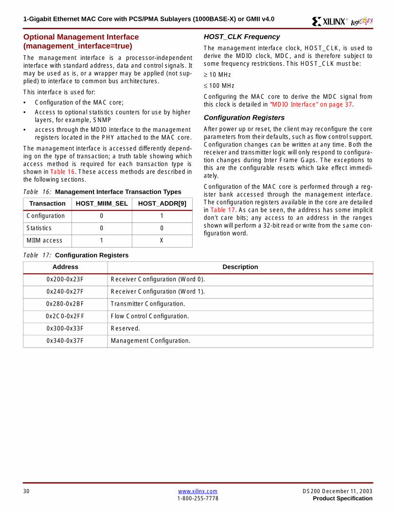
1-Gigabit Ethernet MAC Core with PCSPMA Sublayers (1000BASE-X) or GMII v40 R
Optional Management Interface(management_interface=true)The management interface is a processor-independentinterface with standard address data and control signals Itmay be used as is or a wrapper may be applied (not sup-plied) to interface to common bus architectures
This interface is used for
bull Configuration of the MAC core
bull Access to optional statistics counters for use by higherlayers for example SNMP
bull access through the MDIO interface to the managementregisters located in the PHY attached to the MAC core
The management interface is accessed differently depend-ing on the type of transaction a truth table showing whichaccess method is required for each transaction type isshown in Table 16 These access methods are described inthe following sections
HOST_CLK Frequency
The management interface clock HOST_CLK is used toderive the MDIO clock MDC and is therefore subject tosome frequency restrictions This HOST_CLK must be
ge 10 MHz
le 100 MHz
Configuring the MAC core to derive the MDC signal fromthis clock is detailed in MDIO Interface on page 37
Configuration Registers
After power up or reset the client may reconfigure the coreparameters from their defaults such as flow control supportConfiguration changes can be written at any time Both thereceiver and transmitter logic will only respond to configura-tion changes during Inter Frame Gaps The exceptions tothis are the configurable resets which take effect immedi-ately
Configuration of the MAC core is performed through a reg-ister bank accessed through the management interfaceThe configuration registers available in the core are detailedin Table 17 As can be seen the address has some implicitdonrsquot care bits any access to an address in the rangesshown will perform a 32-bit read or write from the same con-figuration word
Table 16 Management Interface Transaction Types
Transaction HOST_MIIM_SEL HOST_ADDR[9]
Configuration 0 1
Statistics 0 0
MIIM access 1 X
Table 17 Configuration Registers
Address Description
0x200-0x23F Receiver Configuration (Word 0)
0x240-0x27F Receiver Configuration (Word 1)
0x280-0x2BF Transmitter Configuration
0x2C0-0x2FF Flow Control Configuration
0x300-0x33F Reserved
0x340-0x37F Management Configuration
30 wwwxilinxcom DS200 December 11 20031-800-255-7778 Product Specification
1-Gigabit Ethernet MAC Core with PCSPMA Sublayers (1000BASE-X) or GMII v40R
The register contents for the two receiver configuration words can be seen in Table 18 and Table 19
Notes1 In changing the receiverrsquos mode from Half Duplex to Full Duplex there is a period of time of up to 24 us following the mode change
when no new receiver statistics can be stored in the optional Statistical Counters
Table 18 Receiver Configuration Word 0
Bit Default Value Description
31-0 All 0rsquos
Pause frame MAC Source Address[310] This address is used by the MAC tomatch against the Destination Address of any incoming flow control frames It isalso used by the flow control block as the Source Address (SA) for any outboundflow control frames
The address is ordered so the first byte transmittedreceived is the lowestpositioned byte in the register for example a MAC address ofAA-BB-CC-DD-EE-FF would be stored in Address[470] as 0xFFEEDDCCBBAA
Table 19 Receiver Configuration Word 1
Bit Default Value Description
15-0 All 0rsquos Pause frame MAC Source Address[4732] See description in Table 18
24-16 NA Reserved
25 0
LengthType Error Check Disable When this bit is set to ldquo1rdquo the core will notperform the LengthType field error checks as described in LengthType FieldError Checks on page 26 When this bit is set to ldquo0rdquo the LengthType field checkswill be performed this is normal operation
26 0Half Duplex If ldquo1rdquo the receiver will operate in half duplex mode If ldquo0rdquo the receiverwill operate in full duplex mode Has no effect if XCO parameterhalf_duplex_capable = false
27 0VLAN Enable When this bit is set to ldquo1rdquo VLAN tagged frames will be acceptedby the receiver
28 1Receiver Enable If set to ldquo1rdquo the receiver block will be operational If set to ldquo0rdquothe block will ignore activity on the physical interface RX port
29 0
In-band FCS Enable When this bit is ldquo1rdquo the MAC receiver will pass the FCS fieldup to the client as described in Client-Supplied FCS Passing on page 25 Whenit is ldquo0rdquo the client will not be passed the FCS In both cases the FCS will beverified on the frame
30 0Jumbo Frame Enable When this bit is set to ldquo1rdquo the MAC receiver will acceptframes over the specified IEEE8023-2002 maximum legal length When this bitis ldquo0rdquo the MAC will only accept frames up to the specified maximum
31 0Reset When this bit is set to ldquo1rdquo the receiver will be reset The bit will thenautomatically revert to ldquo0rdquo Note that this reset will also set all of the receiverconfiguration registers to their default values
DS200 December 11 2003 wwwxilinxcom 31Product Specification 1-800-255-7778
1-Gigabit Ethernet MAC Core with PCSPMA Sublayers (1000BASE-X) or GMII v40 R
The register contents for the Transmitter Configuration Word are described in Table 20
Notes1 In changing the transmitterrsquos mode from Half Duplex to Full Duplex there is a period of time of up to 24 us following the mode change
when no new transmitter statistics can be stored in the optional Statistical Counters
Table 20 Transmitter Configuration Word
Bit Default Value Description
24-0 NA Reserved
25 0
Interframe Gap Adjust Enable If lsquo1rsquo the transmitter will read the value on the portTX_IFG_DELAY at the start of frame transmission and adjust the interframe gapfollowing the frame accordingly See Interframe Gap Adjustment on page 22 Ifldquo0rdquo the transmitter will output a minimum Inter Frame Gap of twelve clock cyclesas specified in IEEE8023-2002
26 0Half Duplex If lsquo1rsquo the transmitter will operate in half duplex mode If lsquo0rsquo thetransmitter will operate in full duplex mode Has no effect if XCO parameterhalf_duplex_capable = false
27 0VLAN Enable When this bit is set to 1 the transmitter will allow the transmissionof VLAN tagged frames
28 1Transmit Enable When this bit is 1 the transmitter is operational When it is 0the transmitter is disabled
29 0
In-band FCS Enable When this bit is lsquo1rsquo the MAC transmitter will expect the FCSfield to be passed in by the client as described in Client-Supplied FCS Passingon page 17 When this bit is ldquo0rdquo the MAC transmitter will append padding asrequired compute the FCS and append it to the frame
30 0
Jumbo Frame Enable When this bit is set to ldquo1rdquo the MAC transmitter will sendframes that are greater than the specified IEEE8023-2002 maximum legallength When this bit is ldquo0rdquo the MAC will only send frames up to the specifiedmaximum
31 0Reset When this bit is set to ldquo1rdquo the transmitter will be reset The bit will thenautomatically revert to ldquo0rdquo Note that this reset will also set all of the transmitterconfiguration registers to their default values
32 wwwxilinxcom DS200 December 11 20031-800-255-7778 Product Specification
1-Gigabit Ethernet MAC Core with PCSPMA Sublayers (1000BASE-X) or GMII v40R
The register contents for the Flow Control Configuration Word are described in Table 21
The register contents for the Management Configuration Word are described in Table 22
Writing to the configuration registers through the manage-ment interface is depicted in Figure 24 When accessing theconfiguration registers (ie when HOST_ADDR[9] = lsquo1rsquo andHOST_MIIM_SEL = lsquo0rsquo) the upper bit of HOST_OPCODEfunctions as an Active Low write enable signal The lowerHOST_OPCODE bit is a ldquodonrsquot carerdquo
Reading from the configuration register words is similar butthe upper HOST_OPCODE bit should be lsquo1rsquo This is shownin Figure 25 In this case the contents of the register appearon HOST_RD_DATA the HOST_CLK edge after the regis-ter address is asserted onto HOST_ADDR
Table 21 Flow Control Configuration Word
Bit Default Value Description
28-0 NA Reserved
29 1
Flow Control Enable (RX) When this bit is lsquo1rsquo received flow control frames willinhibit the transmitter operation as described in Receiving a Pause ControlFrame on page 29 When this bit is lsquo0rsquo received flow control frames will alwaysbe passed up to the client
30 1Flow Control Enable (TX) When this bit is lsquo1rsquo asserting the PAUSE_REQ signalwill send a flow control frame out from the transmitter When this bit is 0 assertingthe PAUSE_REQ signal has no effect
31 NA Reserved
Table 22 Management Configuration Word
Bits Default Value Description
4-0 All 0rsquos Clock Divide[40] See MDIO Interface on page 37
5 0MDIO Enable When this bit is 1 the MDIO interface can be used to accessattached PHY devices When this bit is 0 the MDIO interface is disabled and theMDIO signals remain inactive
31-6 NA Reserved
Figure 24 Configuration Register Write Timing
HOST_CLK
HOST_ADDR[80]
HOST_ADDR[9]
HOST_OPCODE[1]
HOST_MIIM_SEL
HOST_WR_DATA[310]xip2149
Figure 25 Configuration Register Read Timing
HOST_CLK
HOST_ADDR[80]
HOST_ADDR[9]
HOST_OPCODE[1]
HOST_MIIM_SEL
HOST_RD_DATA[310]
xip2150
DS200 December 11 2003 wwwxilinxcom 33Product Specification 1-800-255-7778
1-Gigabit Ethernet MAC Core with PCSPMA Sublayers (1000BASE-X) or GMII v40 R
Optional Statistical Gathering(statistics_gathering=true)
During operation the MAC core collects statistics on thesuccess and failure of various operations for processing by
station management entities (STA) further up the protocolstack These statistics are accessed by the host through theoptional management interface A complete list of statisticssupported is described in Table 23
Table 23 Statistics Registers
Address Name Description
0x000 Frames Received OK1 A count of error-free frames received
0x001 Frame Check Sequence Errors A count of received frames that failed the CRC check and were at least64 bytes in length
0x002 Broadcast Frames Received OK1A count of frames that were successfully received and were directed tothe broadcast group address
0x003 Multicast Frames Received OK1 A count of frames that were successfully received and were directed toa non broadcast group address
0x004 64 byte Frames Received OK1 A count of error-free frames received that were 64 bytes in length
0x005 65-127 byte Frames Received OK1A count of error-free frames received that were between 65 and 127bytes in length
0x006 128-255 byte Frames Received OK1A count of error-free frames received that were between 128 and 255bytes in length
0x007 256-511 byte Frames Received OK1A count of error-free frames received that were between 256 and 511bytes in length
0x008512-1023 byte Frames ReceivedOK1
A count of error-free frames received that were between 512 and 1023bytes in length
0x0091024-MaxFrameSize byte FramesReceived OK1
A count of error-free frames received that were between 1024 bytes andthe specified IEEE8023-2002 maximum legal length (see MaximumPermitted Frame Length on page 26)
0x00A Control Frames Received OKA count of error-free frames received that contained the specialControl Frame identifier in the LengthType field
0x00B LengthType Out of Range
A count of frames received that were at least 64 bytes in length wherethe lengthtype field contained a length value that did not match thenumber of MAC client data bytes received
The counter also increments for frames in which the lengthtype fieldindicated that the frame contained padding but where the number ofMAC client data bytes received was greater than 64 bytes (minimumframe size)
The exception to the above is when the LengthType Field Error Checksare disabled in which case this counter will not increment
0x00C VLAN Tagged Frames Received OKA count of error-free VLAN frames received This counter will only incre-ment when the receiver is configured for VLAN operation
0x00D Pause Frames Received OK
A count of error-free frames received that contained the MAC Controltype identifier 88-08 in the LengthType field contained a Destinationaddress that matched either the MAC Control multicast address or theconfigured source address of the MAC contained the PAUSE opcodeand were acted upon by the MAC
0x00EControl Frames Received withUnsupported Opcode
A count of error-free frames received that contained the MAC Controltype identifier 88-08 in the LengthType field but were received with anopcode other than the PAUSE opcode
34 wwwxilinxcom DS200 December 11 20031-800-255-7778 Product Specification
1-Gigabit Ethernet MAC Core with PCSPMA Sublayers (1000BASE-X) or GMII v40R
0x00F Oversize Frames Received OK1A count of otherwise error-free frames received that exceeded the max-imum legal frame length specified in IEEE 8023-2002 (see MaximumPermitted Frame Length on page 26)
0x010 Undersize frames receivedA count of the number of frames received that were less than 64 bytesin length but were otherwise well formed
0x011 Fragment frames receivedA count of the number of frames received that were less than 64 bytesin length and had a bad Frame Check Sequence field
0x012 Received bytesA count of bytes of frames that are received (Destination Address toFrame Check Sequence inclusive)
0x013 Transmitted bytesA count of bytes of frames that are transmitted (Destination Address toFrame Check Sequence inclusive)
0x020 Frames Transmitted OK A count of error-free frames transmitted
0x021 Broadcast Frames Transmitted OK A count of error-free frames that were transmitted to the broadcastaddress
0x022 Multicast Frames Transmitted OK A count of error-free frames that were transmitted to a group destina-tion address other than broadcast
0x023 Underrun Errors
A count of frames that would otherwise be transmitted by the core butcould not be completed due to the assertion of TX_UNDERRUN duringthe frame transmission This will not count frames which are less than64 bytes in length
0x024 Control Frames Transmitted OKA count of error-free frames transmitted that contained the MACControl Frame type identifier 88-08 in the LengthType field
0x025 64 byte Frames Transmitted OK A count of error-free frames transmitted that were 64 bytes in length
0x026 65-127 byte Frames Transmitted OKA count of error-free frames transmitted that were between 65 and 127bytes in length
0x027128-255 byte Frames TransmittedOK
A count of error-free frames transmitted that were between 128 and 255bytes in length
0x028256-511 byte Frames TransmittedOK
A count of error-free frames transmitted that were between 256 and 511bytes in length
0x029512-1023 byte Frames TransmittedOK
A count of error-free frames transmitted that were between 512 and1023 bytes in length
0x02A1024-MaxFrameSize byte FramesTransmitted OK
A count of error-free frames transmitted that were between 1024 and thespecified IEEE8023-2002 maximum legal length (see Maximum Per-mitted Frame Length on page 20)
0x02BVLAN Tagged Frames TransmittedOK
A count of error-free VLAN frames transmitted This counter will onlyincrement when the transmitter is configured for VLAN operation
0x02C Pause Frames Transmitted OKA count of error-free PAUSE frames generated and transmitted by thecore in response to an assertion of PAUSE_REQ
0x02D Oversize Frames Transmitted OKA count of otherwise error-free frames transmitted that exceeded themaximum legal frame length specified in IEEE 8023-2002 (see Maxi-mum Permitted Frame Length on page 20)
0x02E Single Collision Frames A count of frames that are involved in a single collision but are subse-quently transmitted successfully (Half Duplex Mode only)
Table 23 Statistics Registers (Continued)
Address Name Description
DS200 December 11 2003 wwwxilinxcom 35Product Specification 1-800-255-7778
1-Gigabit Ethernet MAC Core with PCSPMA Sublayers (1000BASE-X) or GMII v40 R
Each of these statistic registers is 64 bits wide and thereforemust be read in a two-cycle transfer The timing of this pro-cess is shown in Figure 26 Six clocks after the read trans-action is initiated the least significant word (LSW) of thestatistics counter appears on the HOST_RD_DATA bus
and a clock cycle later the most significant word (MSW)appears For accurate statistic values 64 clock ticks (ofTX_CLK for transmit statistics or RX_CLK for receive statis-tics) must elapse after the last frame is sent or receivedthrough the MAC core
0x02F Multiple Collision Frames A count of frames that are involved in more than one collision but aresubsequently transmitted successfully (Half Duplex Mode only)
0x040 Frames with Deferred Transmissions A count of frames whose transmission was delayed on its first attemptbecause the medium was busy (Half Duplex Mode only)
0x041 Late Collisions
A count of the times that a collision has been detected later than oneslotTime from the start of the packet transmission A late collision iscounted twice both as a collision and as a lateCollision (Half DuplexMode only)
0x042Frames Aborted due to Excesscollisions
A count of the frames that due to excessive collisions are not transmit-ted successfully (Half Duplex Mode only)
0x043 Carrier Sense ErrorsA count of times that the GMII_CRS signal was not asserted or wasdisasserted during the transmission of a frame without collision (HalfDuplex Mode only)
0x044 Frames with Excess DeferralA count of frames that deferred transmission for an excessive period oftime (Half Duplex Mode only)
1 If the LengthType Field Error Checks are disabled then these counters will still increment for received frames which contain this typeof error (providing no additional errors were detected)
Table 23 Statistics Registers (Continued)
Address Name Description
Figure 26 Statistic Register Read Timing
HOST_CLK
HOST_ADDR[80]
HOST_ADDR[9]
HOST_REQ
HOST_MIIM_SEL
HOST_RD_DATA[310]
6 CLOCKS
LSW MSW
xip2151
36 wwwxilinxcom DS200 December 11 20031-800-255-7778 Product Specification
1-Gigabit Ethernet MAC Core with PCSPMA Sublayers (1000BASE-X) or GMII v40R
MDIO Interface
The management interface is also used to access the MDIO(MII Management) interface of the MAC core this interfaceis used to access the Managed Information Block (MIB) ofthe PHY components attached to the MAC core
The MDIO interface supplies a clock to the externaldevices MDC This clock is derived from the HOST_CLKsignal using the value in the Clock Divide[40] configurationregister The frequency of the MDIO clock is given by thefollowing equation
The frequency of MDC given by this equation should notexceed 25 MHz in order to comply with the IEEE8023-2002 specification for this interface To prevent MDCfrom being out of specification the Clock Divide[40] valuepowers up at 00000 and while this value is in the register itis impossible to enable the MDIO interface
For details of the register map of PHY layer devices and afuller description of the operation of the MDIO interfaceitself see IEEE specification 8023-2002
Access to the MDIO interface through the managementinterface is depicted in the timing diagram in Figure 27
For MDIO transactions the following points apply
bull HOST_OPCODE maps to the OP (opcode) field of theMDIO frame
bull HOST_ADDR maps to the two address fields of theMDIO frame PHY_ADDR is HOST_ADDR[95] andREG_ADDR is HOST_ADDR[40]
bull HOST_WR_DATA[150] maps into the data field of the
MDIO frame when performing a write operation
bull The data field of the MDIO frame maps intoHOST_RD_DATA[150] when performing a readoperation
The MAC core signals to the host that it is ready for anMDIO transaction by asserting HOST_MIIM_RDY A read orwrite transaction on the MDIO is initiated by a pulse on the
fMDC
fHOST_CLK
1 Clock Divide[40]+( ) 2times-------------------------------------------------------------------=
Figure 27 MDIO Access Through Management Interface
HOST_CLK
HOST_ADDR[90]
HOST_OPCODE[10]
HOST_REQ
HOST_MIIM_SEL
HOST_RD_DATA[150]
HOST_WR_DATA[150]
HOST_RDY
If a read transaction is initiated the HOST_RD_DATA bus is valid at the point indicated If a write transaction is initiated the HOST_WR_DATA bus must be valid at the indicated point Simultaneous read and write is not permitted
xip2152
DS200 December 11 2003 wwwxilinxcom 37Product Specification 1-800-255-7778
1-Gigabit Ethernet MAC Core with PCSPMA Sublayers (1000BASE-X) or GMII v40 R
HOST_REQ signal This pulse is ignored if the MDIO inter-face already has a transaction in progress
The MAC core then disasserts the HOST_MIIM_RDY signalwhile the transaction across the MDIO is in progress Whenthe transaction across the MDIO interface has been com-pleted the HOST_MIIM_RDY signal will be asserted by theMAC core if the transaction is a read the data will also beavailable on the HOST_RD_DATA[150] bus at this time
Optional Configuration Vector(management_interface = false)If the optional Management interface is omitted from thecore all of relevant configuration signals are brought out of
the core These signals are bundled into theCONFIGURATION_VECTOR signal The bit mapping of theconfiguration vector signal is defined in Table 24 See thecorresponding entry in the configuration register tables forthe full description of each signal
Note that these configuration vector signals can bechanged by the user at any time however with the excep-tion of the reset and the flow control configuration signalsthey will not take effect until the current frame has com-pleted transmission or reception
The ldquoClockrdquo heading denotes which clock domain the con-figuration signal is registered into before use by the core Itis not necessary to drive the signal from this clock domain
Table 24 Configuration Vector Bit Definition
Bit(s)Configuration Register
cross reference Clock Description
47 downto 0
Receiver ConfigurationWord 0 bits 31-0 andReceiver ConfigurationWord 1 bits 15-0
RX_CLK
Pause frame MAC Source Address[470] This address isused by the MAC core to match against the DestinationAddress of any incoming flow control frames and as theSource Address for any outbound flow control frames
The address is ordered such that the first byte transmitted orreceived is the least significant byte in the register forexample a MAC address of AA-BB-CC-DD-EE-FF will bestored in bite [470] as 0xFFEEDDCCBBAA
48Receiver ConfigurationWord 1 bit 26
RX_CLKReceiver Half Duplex If lsquo1rsquo the receiver operates in halfduplex mode If lsquo0rsquo the receiver operates in full duplex modeHas no effect if XCO parameter half_duplex_capable = false
49Receiver ConfigurationWord 1 bit 27
RX_CLKReceiver VLAN Enable When this bit is set to 1 VLANtagged frames are accepted by the receiver
50Receiver ConfigurationWord 1 bit 28
RX_CLKReceiver Enable If set to 1 the receiver block is operationalIf set to 0 the block ignores activity on the physical interfaceRX port
51Receiver ConfigurationWord 1 bit 29
RX_CLK
Receiver In-band FCS Enable When this bit is lsquo1rsquo the MACreceiver will pass the FCS field up to the client as describedin Client-Supplied FCS Passing on page 25 When it is lsquo0rsquothe MAC receiver will not pass the FCS field In both casesthe FCS field will be verified on the frame
52Receiver ConfigurationWord 1 bit 30
RX_CLK
Receiver Jumbo Frame Enable When this bit is lsquo0rsquo thereceiver will not pass frames longer than the maximum legalframe size specified in IEEE 8023-2002 (see MaximumPermitted Frame Length on page 26) When it is lsquo1rsquo thereceiver will not have an upper limit on frame size
53Receiver ConfigurationWord 1 bit 31
NA
Receiver Reset When this bit is lsquo1rsquo the receiver is held inreset
This signal is an input to the reset circuit for the receiverblock See Reset circuit on page 42 for more information
54TransmitterConfiguration Word bit25
TX_CLK
Transmitter Interframe Gap Adjust enable If lsquo1rsquo then thetransmitter will read the value of the TX_IFG_DELAY port andset the Interframe Gap accordingly If lsquo0rsquo the transmitter willalways insert at least the legal minimum Interframe Gap
38 wwwxilinxcom DS200 December 11 20031-800-255-7778 Product Specification
1-Gigabit Ethernet MAC Core with PCSPMA Sublayers (1000BASE-X) or GMII v40R
55TransmitterConfiguration Word bit26
TX_CLK
Transmitter Half Duplex If lsquo1rsquo the transmitter operates in halfduplex mode If lsquo0rsquo the transmitter operates in full duplexmode Has no effect if XCO parameter half_duplex_capable= false
56TransmitterConfiguration Word bit27
TX_CLKTransmitter VLAN Enable When this bit is set to lsquo1rsquo thetransmitter allows the transmission of VLAN tagged frames
57TransmitterConfiguration Word bit28
TX_CLKTransmitter Enable When this bit is 1 the transmitter will beoperational When it is 0 the transmitter is disabled
58TransmitterConfiguration Word bit29
TX_CLK
Transmitter In-Band FCS Enable When this bit is lsquo1rsquo theMAC transmitter will expect the FCS field to be pass in by theclient as described in Client-Supplied FCS Passing onpage 17 When it is lsquo0rsquo the MAC transmitter will appendpadding as required compute the FCS and append it to theframe
59TransmitterConfiguration Word bit30
TX_CLK
Transmitter Jumbo Frame Enable When this bit is lsquo1rsquo theMAC transmitter will allow frames larger than the maximumlegal frame length specified in IEEE 8023-2002 to be sentWhen set to lsquo0rsquo the MAC transmitter will only allow frames upto the legal maximum to be sent
60TransmitterConfiguration Word bit31
NA
Transmitter Reset When this bit is lsquo1rsquo the MAC transmitter isheld in reset
This signal is an input to the reset circuit for the transmitterblock See Reset circuit on page 42 for more information
61Flow ControlConfiguration Word bit29
TX_CLK
Transmit Flow Control Enable When this bit is lsquo1rsquo assertingthe PAUSE_REQ signal causes the MAC core to send a flowcontrol frame out from the transmitter as described inReceiving a Pause Control Frame on page 29 When this bitis lsquo0rsquo asserting the PAUSE_REQ signal will have no effect
62Flow ControlConfiguration Word bit30
RX_CLK
Receive Flow Control Enable When this bit is lsquo1rsquo receivedflow control frames will inhibit the transmitter operation asdescribed in Receiving a Pause Control Frame on page 29When it is lsquo0rsquo received flow frames are passed up to theclient
63Receiver ConfigurationWord 1 bit 25
RX_CLK
LengthType Error Check Disable When this bit is lsquo1rsquo thecore will not perform the LengthType field error checks asdescribed in LengthType Field Error Checks on page 26When it is set to lsquo0rsquo the LengthType field checks will beperformed this is normal operation
Table 24 Configuration Vector Bit Definition (Continued)
Bit(s)Configuration Register
cross reference Clock Description
DS200 December 11 2003 wwwxilinxcom 39Product Specification 1-800-255-7778
1-Gigabit Ethernet MAC Core with PCSPMA Sublayers (1000BASE-X) or GMII v40 R
Optional GMII (physical_interface=gmii)The GMII is designed to IEEE 8023-2002 Clause 35 Thisutilizes IOrsquos of the Xilinx devices using inputoutput buffersand inputoutput flip-flops to maximize setup and hold mar-gins All IO logic is placed in the example wrapper that isdelivered with the core In addition all clock managementlogic for the core is instanced in this example wrapper thisallows multiple instances of the core to share clocks Theexample wrapper is provided in both VHDL and Verilog
Clock Management
Figure 28 illustrates the clock management used with theGMII interface All clocks illustrated have a frequency of125MHz
GTX_CLK must be provided to the MAC core This is a highquality clock which satisfies the IEEE8023-2002 require-ments It is expected that this clock will be derived from anexternal oscillator and connected into the device through anIBUFG as illustrated The clock source must then be routedonto a global clock network by connecting it to a BUFGWithin the MAC core this global clock is used by all MACtransmitter logic The MAC Client can obtain this clock byconnecting to the TX_CLK signal output from the coreGMII_TX_CLK is derived from this global clock by invertingit and routing it to an OBUF
GMII_RX_CLK is received through an IBUFG This clock isthen routed onto a global clock network by connecting it to aBUFG The resulting global clock is used by all MACreceiver logic
Figure 28 Clock Management with GMII
IBUFG
IBUFG
OBUF
BUFG
BUFG
TX_CLK
RX_CLK
GTX_CLK
GMII_TX_CLK
GMII_RX_CLK
Example Wrapper
xip2153
MAC Core
TX_CLK
RX_CLK
GMII_TX_CLK
GMII_RX_CLK
GTX_CLK
40 wwwxilinxcom DS200 December 11 20031-800-255-7778 Product Specification
1-Gigabit Ethernet MAC Core with PCSPMA Sublayers (1000BASE-X) or GMII v40R
Clock Sharing between Multiple cores
Figure 29 illustrates how it is possible to share clockresources across multiple instantiations of the core whenusing the optional GMII
GTX_CLK may be shared between multiple cores as illus-trated resulting in a common transmitter clock domainacross the device
A common receiver clock domain is not possible each corewill receive an independent receiver clock from its GMII asillustrated
Although not illustrated if the optional Management Inter-face is used HOST_CLK can also be shared betweencores
Figure 29 Clock Management with multiple instances of the MAC with GMII
IBUFG
OBUF
BUFG
TX_CLK
RX_CLK_1
GMII_TX_CLK_1
GMII_RX_CLK_1
MAC Core
TX_CLK
RX_CLK
GMII_TX_CLK
GMII_RX_CLK
GTX_CLK
MAC Core
TX_CLK
RX_CLK
GMII_TX_CLK
GMII_RX_CLK
GTX_CLK
IBUFG
BUFG
GTX_CLK
IBUFG
OBUF
GMII_TX_CLK_2
GMII_RX_CLK_2
BUFG
TX_CLK
RX_CLK_2
DS200 December 11 2003 wwwxilinxcom 41Product Specification 1-800-255-7778
1-Gigabit Ethernet MAC Core with PCSPMA Sublayers (1000BASE-X) or GMII v40 R
Reset circuit
Internally the core is divided up into clockreset domainswhich group together elements with the common clock andreset signals The reset circuitry for one of these domains isis illustrated in Figure 30 This circuit provides controllableskews on the reset nets within the design
More information on the operation and rationale behind thiscircuit can be found in Ken Chapmanrsquos Xilinx TechXclusiveldquoGet Smart About Resetrdquo athttpwwwxilinxcomsupporttechxclusivesglobal-techX19htm
Figure 30 Reset circuit for one clockreset domain
FDP
PRED
C
Q
FDP
PRED
C
Q
FDP
PRED
C
Q
FDP
PRED
C
Q
PRE PRE PRE
0
RESET
Management Reset
Clock
Core Registers
42 wwwxilinxcom DS200 December 11 20031-800-255-7778 Product Specification
1-Gigabit Ethernet MAC Core with PCSPMA Sublayers (1000BASE-X) or GMII v40R
Optional PCS with Ten-Bit Interface (TBI) for 1000BASE-X (physical_interface=tbi)The Full-Duplex Physical Coding Sublayer (PCS) for1000BASE-X is defined in IEEE 8023-2002 Clauses 36and 37 This functionality is only available in the Virtex-IIand Spartan3 families of FPGA devices
A block diagram of the PCS is shown in Figure 31 Themajor functional blocks of the PCS are
bull Transmit engine
bull Auto-negotiation block
bull Receive engine and synchronization block
bull PCS managed register block
bull 8B10B encoder block
bull 8B10B decoder block
bull Receiver elastic buffer
The PCS Managed Register Block is accessed through theMDIO Interface as if it were an externally connected PHYThis configures the operation of the PCS and Auto-Negoti-ation See PCS Managed Register Block
(physical_interface = tbi or phy) on page 49 The corersquosoptional Management Interface can be used to control theMDIO Interface as described by MDIO Interface onpage 37 When the optional Management Interface is notpresent the PCS Managed Register Block must beaccessed via an MDIO controller which is not provided bythe core
The 8B10B encodingdecoding blocks are implemented byconfiguring two Block SelectRAM modules as ROM Theseare used as large look-up tables The remaining PCS func-tionality such as code group encodingdecoding the Man-aged Register Block and Auto-Negotiation areimplemented in CLB logic
The Receiver Elastic buffer enables the 10-bit parallel datareceived from the PMA sublayer alternatively onPMA_RX_CLK0 and PMA_RX_CLK1 clock edges to betransferred onto the internal 125MHz clock domain derivedfrom GTX_CLK (see Clock Management) This buffer isimplemented in Distributed Memory
Figure 31 Functional Block Diagram of the 1-Gigabit Ethernet PCS with TBI Interface
PCS TRANSMIT ENGINE
PCS RECEIVE ENGINE ampSYNCHRONISATION
PCSMANAGEMENT
MDIOInterface
AUTO-NEGOTIATION
MAC TXInterface
MAC RXInterface
8B10BEncoder
8B10BDecoder
RX Elastic Buffer
TBI Interface
DS200 December 11 2003 wwwxilinxcom 43Product Specification 1-800-255-7778
1-Gigabit Ethernet MAC Core with PCSPMA Sublayers (1000BASE-X) or GMII v40 R
TBI Interface
The TBI is designed to IEEE 8023-2002 Clause 363 Thisutilizes IOrsquos of the Xilinx devices using inputoutput buffersand inputoutput flip-flops to maximize setup and hold mar-gins All IO logic is placed in the example wrapper that isdelivered with the core In addition all clock managementlogic for the core is instantiated in this example wrapperthis allows multiple instances of the core to share clocksThe example wrapper is provided in both VHDL and Verilog
Clock Management
Figure 32 illustrates the clock management used with theTBI interface
GTX_CLK must be provided to the MAC core This is a highquality clock of frequency 125MHz which satisfies theIEEE8023-2002 requirements It is expected that this clockwill be derived from an external oscillator and connected
into the device through an IBUFG as illustrated The clocksource must then be routed onto a global clock network byconnecting it to a BUFG Within the MAC core this globalclock is used by all MAC transmitter logic PMA_TX_CLK isderived from this global clock by inverting it and routing it toan OBUF
PMA_RX_CLK0 and PMA_RX_CLK1 are each receivedthrough an IBUFG These clocks are then routed onto glo-bal clock networks by connecting each to a BUFGPMA_RX_CLK0 and PMA_RX_CLK1 are each 625MHzclocks Data from the TBI is received alternatively on the ris-ing edge of PMA_RX_CLK0 followed by the rising edge ofPMA_RX_CLK1 using IOB Double-Data Rate input regis-ters This data is then written into the Receiver ElasticBuffer Data is read out of the Elastic Buffer using the globalclock derived from GTX_CLK all the remaining receiverlogic is synchronous to this clock
Figure 32 Clock Management for PCS with TBI Interface
IBUFG
IBUFG
OBUF
BUFG
BUFG
TX_CLK
RX_CLK
GTX_CLK
PMA_TX_CLK
PMA_RX_CLK0
MAC Core
RX ELASTICBUFFER
Example Wrapper
TX_CLK
RX_CLK
GTX_CLK
PMA_TX_CLK
PMA_RX_CLK0
IBUFGBUFGPMA_RX_CLK1
PMA_RX_CLK1
44 wwwxilinxcom DS200 December 11 20031-800-255-7778 Product Specification
1-Gigabit Ethernet MAC Core with PCSPMA Sublayers (1000BASE-X) or GMII v40R
Clock Sharing between Multiple cores
Figure 33 illustrates how it is possible to share clockresources across multiple instantiations of the core whenusing the optional PCS with TBI
GTX_CLK may be shared between multiple cores as illus-trated resulting in a common transmitter clock domainacross the device
Each core will receive independent PMA_RX_CLK0 andPMA_RX_CLK1 clocks from its TBI as illustrated whichcannot be shared
Although not illustrated if the optional Management Inter-face is used HOST_CLK can also be shared betweencores
Figure 33 Clock Management with multiple instances of the MAC with PCS and TBI
Reset circuit
The reset circuits within the MAC when the TBI interface is implemented is the same as that in the GMII case details ofthese circuits can be found on page 42
IBUFG
OBUF
BUFG
TX_CLK
RX_CLK
PMA_TX_CLK_1
PMA_RX_CLK0_1
MAC Core
RX ELASTICBUFFER
TX_CLK
RX_CLK
GTX_CLK
PMA_TX_CLK
PMA_RX_CLK0
IBUFGBUFGPMA_RX_CLK1_1
PMA_RX_CLK1
IBUFG
BUFG
GTX_CLK
IBUFG
OBUF
BUFG
TX_CLK
RX_CLK
PMA_TX_CLK_2
PMA_RX_CLK0_2
MAC Core
RX ELASTICBUFFER
TX_CLK
RX_CLK
GTX_CLK
PMA_TX_CLK
PMA_RX_CLK0
IBUFGBUFGPMA_RX_CLK1_2
PMA_RX_CLK1
DS200 December 11 2003 wwwxilinxcom 45Product Specification 1-800-255-7778
1-Gigabit Ethernet MAC Core with PCSPMA Sublayers (1000BASE-X) or GMII v40 R
Optional PCS and PMA Sublayers for 1000BASE-X (physical_interface=phy)The Full-Duplex Physical Coding Sublayer (PCS) withPhysical Medium Attachment (PMA) for 1000BASE-X isdefined in IEEE 8023-2002 Clauses 36 and 37 This func-tionality is only available in the Virtex-II Pro family of FPGAdevices
A block diagram of the PCS and PMA sublayers can beseen in Figure 34 The functional blocks of the PCS andPMA sublayers may replace the optional GMII interfaceThe functional blocks of the PCS and PMA sublayers are
bull PCS Transmit Engine
bull Auto-Negotiation block
bull Receive Engine and Synchronization Block
bull PCS Managed Register Block
bull Rocket IO Multi-Gigabit Transceiver
The PCS Managed Register Block is accessed through theMDIO Interface as if it were an externally connected PHYThis configures the operation of the PCS PMA sublayerand Auto-NegotiationSee PCS Managed Register Block(physical_interface = tbi or phy) on page 49 The corersquosoptional Management Interface can be used to control theMDIO Interface as described by MDIO Interface onpage 37 When the optional Management Interface is notpresent the PCS Managed Register Block must beaccessed via an MDIO controller which is not provided bythe core
The Rocket IO Multi-Gigabit Transceiver (MGT) providessome of the PCS layer functionality such as 8B10B encod-ingdecoding and the PMA serdes The remaining PCSfunctionality such as code group encodingdecoding theManaged Register Block and Auto-Negotiation are imple-mented in CLB logic
Figure 34 Functional Block Diagram of the 1-Gigabit Ethernet PCSPMA Sublayer Extension
PCS TRANSMIT ENGINE
PCS RECEIVE ENGINE ampSYNCHRONISATION
RO
CK
ET
IO
MU
LTI-
GIG
TR
AN
SC
EIV
ER
PCSMANAGEMENT
MDIOInterface
AUTO-NEGOTIATION
TXPTXN
RXPRXN
MAC TXInterface
MAC RXInterface
xip2154
46 wwwxilinxcom DS200 December 11 20031-800-255-7778 Product Specification
1-Gigabit Ethernet MAC Core with PCSPMA Sublayers (1000BASE-X) or GMII v40R
Clock Management
Figure 35 illustrates the clock management that should beused with the optional PCS and PMA sublayers for1000BASE-X This logic is implemented in the examplewrapper that is delivered with the core This provides flexi-bility because the design can be modified to use eitherREFCLK or BREFCLK (please refer to Rocket IO docu-mentation) It would also allow multiple instances of the coreto share clocks The example wrapper is provided in bothVHDL and Verilog
(B)REFCLK must be provided to the MAC core This clockmust be derived from an external oscillator and connectedto the core through an IBUFG as illustrated (B)REFCLK isa high quality clock of frequency 625 MHz which satisfiesthe Rocket IO Multi-Gigabit Transceiver (MGT) require-ments
(B)REFCLK is routed to both the core and a DCM From theDCM the CLK2X180 output is routed to a BUFG to providethe device with a global 125 MHz clock (connected toUSERCLK2 input on the core) Within the core bothTX_CLK and RX_CLK share this global 125 MHz clocksource which is used by all transmitter and receiver logicThis is made possible by the RX_ELASTIC_BUFFER func-tionality of the Rocket IO MGT (refer to Virtex-II Pro docu-mentation) The MAC Client can obtain this clock byconnecting to either the TX_CLK or the RX_CLK signalsoutput from the core
From the DCM the CLK0 output is routed to a BUFG to pro-vide the device with a global 625MHz clock This is con-nected to the USRCLK input of the core
Figure 35 Clock Management with PCSPMA Sublayers
DCM
CLKIN CLK0
CLK2X180FB
BUFG
BUFG
IBUFG
TX_CLK
RX_CLK
(B)REFCLK
TXUSRCLK
(B)REFCLK
TXUSRCLK2RXUSRCLKRXUSRCLK2
GT_ETHERNET
Example Wrapper
xip2155
MAC Core
(B)REFCLK
USRCLK
USRCLK2
TX_CLK
RX_CLK
DS200 December 11 2003 wwwxilinxcom 47Product Specification 1-800-255-7778
1-Gigabit Ethernet MAC Core with PCSPMA Sublayers (1000BASE-X) or GMII v40 R
Clock Sharing between Multiple Cores
Figure 36 illustrates how it is possible to share clockresources across multiple instantiations of the core whenusing the optional PCSPMA sublayers For each coreUSERCLK and USERCLK2 must always be derived asshown from the BREFCLK or REFCLK used by that core
Note that when using the fixed routing resources of BREF-CLK Rocket IO MGTs along the top edge of the devicemust use a separate BREFCLK routing resource to thosealong the bottom edge of the device (Refer to Virtex-II Prodocumentation)
Although not illustrated if the optional Management Inter-face is used HOST_CLK can also be shared betweencores
Figure 36 Clock Management with multiple instances of the MAC with PCS and PMA sublayers
Reset circuit
The reset circuits within the MAC when the PCS and PMA sublayers are implemented is the same as that in the GMII casedetails of these circuits can be found on page 42
DCM
CLKIN CLK0
CLK2X180FB
BUFG
BUFG
IBUFG
(B)REFCLK
TXUSRCLK
(B)REFCLK
TXUSRCLK2RXUSRCLKRXUSRCLK2
GT_ETHERNET(B)REFCLK
USERCLK
USERCLK2
MAC core
TXUSRCLK
(B)REFCLK
TXUSRCLK2RXUSRCLKRXUSRCLK2
GT_ETHERNET(B)REFCLK
USERCLK
USERCLK2
MAC core
48 wwwxilinxcom DS200 December 11 20031-800-255-7778 Product Specification
1-Gigabit Ethernet MAC Core with PCSPMA Sublayers (1000BASE-X) or GMII v40R
PCS Managed Register Block (physical_interface = tbi or phy)The PCS in both the TBI interface and the PCSPMA (usingthe Virtex-II Pro Rocket IO) versions contain the full Man-aged Register Block defined in IEEE 8023-2002 clause 37
This utilizes ten dedicated management registersaccessed via the MDIO interface These are defined inTable 25 to Table 33 inclusive
Table 25 Control Register (Register 0)
Bit(s) Name Description Attributes Default Value
015 Reset1 = PCSPMA reset
0 = Normal Operation
ReadWrite
Self Clearing0
014 Loopback1 = Enable Loopback Mode
0 = Disable Loopback ModeReadWrite 0
013SpeedSelection (LSB)
The core always returns a 0 for this bitTogether with bit 06 speed selection of 1000Mbs is identified
Returns 0 0
012Auto-NegotiationEnable
1 = Enable Auto-Negotiation Process
0 = Disable Auto-Negotiation ProcessReadWrite 1
011 Power Down
1 = Power down
0 = Normal operation
When set to ldquo1rdquo the Rocket IO MGT is placedin a low power state This bit requires a reset(see bit 015) to clear
Read Write 0
010 Isolate1 = Electrically Isolate PHY from GMII
0 = Normal operationReadWrite 1
09Restart Auto-Negotiation
1 = Restart Auto-Negotiation Process
0 = Normal Operation
ReadWrite
Self Clearing0
08 Duplex ModeThe core always returns a 1 for this bit tosignal Full-Duplex Mode
Returns 1 1
07 Collision TestThe core always returns a 0 for this bit todisable COL test
Returns 0 0
06SpeedSelection(MSB)
The core always returns a 1 for this bitTogether with bit 013 speed selection of1000 Mbs is identified
Returns 1 1
050 Reserved Always returns 0rsquos writes ignored Returns 0rsquos 000000
DS200 December 11 2003 wwwxilinxcom 49Product Specification 1-800-255-7778
1-Gigabit Ethernet MAC Core with PCSPMA Sublayers (1000BASE-X) or GMII v40 R
Table 26 Status Register (Register 1)
Bit(s) Name Description Attributes Default Value
115 100BASE-T4The core always returns a 0 for this bitbecause 100BASE-T4 is not supported
Returns 0 0
114100BASE-XFullDuplex
The core always returns a 0 for this bitbecause 100BASE-X Full Duplex is notsupported
Returns 0 0
113100BASE-XHalf Duplex
The core always returns a 0 for this bitbecause 100BASE-X Half Duplex is notsupported
Returns 0 0
11210 Mbs FullDuplex
The core always returns a 0 for this bitbecause 10 Mbs Full Duplex is notsupported
Returns 0 0
11110 Mbs HalfDuplex
The core always returns a 0 for this bitbecause 10 Mbs Half Duplex is notsupported
Returns 0 0
110100BASE-T2Full Duplex
The core always returns a 0 for this bitbecause 100BASE-T2 Full Duplex is notsupported
Returns 0 0
19100BASE-T2Half Duplex
The core always returns a 0 for this bitbecause 100BASE-T2 Half Duplex is notsupported
Returns 0 0
18ExtendedStatus
The core always returns a 1 for this bit toindicate the presence of the ExtendedRegister (Register 15)
Returns 1 1
17 Reserved Always return 0 writes ignored Returns 0 0
16MF PreambleSuppression
The core always returns a 1 for this bit toindicate that Management Frame PreambleSuppression is supported
Returns 1 1
15Auto-NegotiationComplete
1 = Auto-Negotiation process completed
0 = Auto-Negotiation process not completedRead Only 0
14 Remote Fault1 = Remote fault condition detected
0 = No remote fault condition detected
Read Only
Self Clearing on read0
13Auto-NegotiationAbility
The core always returns a 1 for this bit toindicate that the PHY is capable ofAuto-Negotiation
Returns 1 1
12 Link Status1 = Link is up
0 = Link is down
Read Only
Self Clearing on read0
11 Jabber DetectThe core always returns a 0 for this bitbecause Jabber Detect is not supported
Returns 0 0
10ExtendedCapability
The core always returns a 0 for this bitbecause no extended register set issupported
Returns 0 0
50 wwwxilinxcom DS200 December 11 20031-800-255-7778 Product Specification
1-Gigabit Ethernet MAC Core with PCSPMA Sublayers (1000BASE-X) or GMII v40R
Table 27 PHY Identifier (Registers 2 and 3)
Bit(s) Name Description Attributes Default Value
2150OrganizationallyUniqueIdentifier
Always returns 0s Returns 0s 0000000000000000
31510OrganizationallyUniqueIdentifier
Always returns 0s Returns 0s 000000
394Manufacturerrsquosmodel number
Always returns 0s Returns 0s 000000
330RevisionNumber
Always returns 0s Returns 0s 0000
Table 28 Auto-Negotiation Advertisement Register (Register 4)
Bit(s) Name Description Attributes Default Value
415 Next Page1 = Next Page functionality is advertised
0 = Next Page functionality is not advertisedReadWrite 0
414 Reserved Always returns 0 writes ignored Returns 0 0
41312 Remote Fault
00 = No Error
01 = Offline
10 = Link Failure
11 = Auto-Negotiation Error
ReadWrite
Self clearing to 00afterAuto-Negotiation
00
4119 Reserved Always return 0 writes ignored Returns 0 0
487 Pause
00 = No PAUSE
01 = Asymmetric PAUSE towards linkpartner
10 = Symmetic PAUSE
11 = Both Symmetric PAUSE andAsymmetric PAUSE towards link partner
ReadWrite 11
46 Half DuplexThe core always returns a 0 for this bitbecause Half Duplex Mode is not supported
Returns 0 0
45 Full Duplex1 = Full Duplex Mode is advertised
0 = Full Duplex Mode is not advertisedReadWrite 1
440 Reserved Always returns 0s writes ignored Returns 0s 00000
DS200 December 11 2003 wwwxilinxcom 51Product Specification 1-800-255-7778
1-Gigabit Ethernet MAC Core with PCSPMA Sublayers (1000BASE-X) or GMII v40 R
Table 29 Auto-Negotiation Link Partner Ability Base Register (Register 5)
Bit(s) Name Description Attributes Default Value
515 Next Page1 = Next Page functionality is supported
0 = Next Page functionality is not supportedRead Only 0
514 AcknowledgeUsed by Auto-Negotiation function toindicate reception of a link partnerrsquos base ornext page
Read Only 0
51312 Remote Fault
00 = No Error
01 = Offline
10 = Link Failure
11 = Auto-Negotiation Error
Read Only 00
5119 Reserved Always returns 0s Returns 0s 000
587 Pause
00 = No PAUSE
01 = Asymmetric PAUSE supported
10 = Symmetic PAUSE supported
11 = Both Symmetric PAUSE andAsymmetric PAUSE supported
Read Only 00
56 Half Duplex1 = Half Duplex Mode is supported
0 = Half Duplex Mode is not supportedRead Only 0
55 Full Duplex1 = Full Duplex Mode is supported
0 = Full Duplex Mode is not supportedRead Only 0
540 Reserved Always returns 0s Returns 0s 00000
Table 30 Auto-Negotiation Expansion Register (Register 6)
Bit(s) Name Description Attributes Default Value
6153 Reserved Always returns 0s Returns 0s 0000000000000
62 Next Page AbleThe core always returns a 1 for this bitbecause the device is Next Page Able
Returns 1 1
61 Page Received1 = A new page has been received
0 = A new page has not been received
Read Only
Self Clearing on read0
60 Reserved Always returns 0s Returns 0s 0000000
52 wwwxilinxcom DS200 December 11 20031-800-255-7778 Product Specification
1-Gigabit Ethernet MAC Core with PCSPMA Sublayers (1000BASE-X) or GMII v40R
Table 31 Auto-Negotiation Next Page Transmit Register (Register 7)
Bit(s) Name Description Attributes Default Value
715 Next Page1 = Additional Next Page(s) will follow
0 = Last pageReadWrite 0
714 Reserved Always returns 0 Returns 0 0
713 Message Page1 = Message Page
0 = Unformatted PageReadWrite 1
712 Acknowledge 21 = Will comply with message
0 = Cannot comply with messageReadWrite 0
711 ToggleValue will toggle between subsequent NextPages
Read Only 0
7100Message UnformattedCode Field
Message Code Field or Unformatted PageEncoding as dictated by 713
ReadWrite00000000001
(Null Message Code)
Table 32 Auto-Negotiation Next Page Receive Register (Register 8)
Bit(s) Name Description Attributes Default Value
815 Next Page1 = Additional Next Page(s) follows
0 = Last pageRead Only 0
814 AcknowledgeUsed by Auto-Negotiation function toindicate reception of a link partnerrsquos base ornext page
Read Only 0
813 Message Page1 = Message Page
0 = Unformatted PageRead Only 0
812 Acknowledge 21 = Will comply with message
0 = Cannot comply with messageRead Only 0
811 ToggleValue toggles between subsequent andNext Pages
Read Only 0
8100Message UnformattedCode Field
Message Code Field or Unformatted PageEncoding as dictated by 813
Read Only 00000000000
DS200 December 11 2003 wwwxilinxcom 53Product Specification 1-800-255-7778
1-Gigabit Ethernet MAC Core with PCSPMA Sublayers (1000BASE-X) or GMII v40 R
)
Referencesbull IEEE 8023-2002
bull Virtex-E User Guide
bull Spartan-II E User Guide
bull Virtex-II User Guide
bull Virtex-II Pro User Guide
Related InformationXilinx products are not intended for use in life support appli-ances devices or systems Use of a Xilinx product in suchapplications without the written consent of the appropriateXilinx officer is prohibited
Ordering InformationThis Xilinx LogiCORE module is provided under theSignOnce IP Site License A free evaluation version of themodule is available
Once purchased the core may be downloaded from the Xil-inx IP Center for use with the Xilinx CORE Generator Sys-temtrade v61i SP3 and later The Xilinx CORE GeneratorSystem tool is bundled with all Alliance Series Softwarepackages at no additional charge
Please contact your local Xilinx sales representative or visitthe Xilinx Silicon Xpresso Cafe for pricing and availability onXilinx LogiCORE modules and software Information onadditional Xilinx LogiCORE modules is available on the Xil-inx IP Center
Revision HistoryThe following table shows the revision history for this document
Table 33 Extended Status Register (Register 15)
Bit(s) Name Description Attributes Default Value
15151000BASE-XFull Duplex
The core always returns a 1 for this bitbecause 1000BASE-X Full Duplex issupported
Returns 1 1
15141000BASE-XHalf Duplex
The core always returns a 0 for this bitbecause 1000BASE-X Half Duplex is notsupported
Returns 0 0
15131000BASE-TFull Duplex
The core always returns a 0 for this bitbecause 1000BASE-T Full Duplex is notsupported
Returns 0 0
15121000BASE-THalf Duplex
The core always returns a 0 for this bitbecause 1000BASE-T Half Duplex is notsupported
Returns 0 0
15110 Reserved Always returns 0s Returns 0s 000000000000
Date Version Revision
032803 11 Revision History added to document
043003 20 Revised to v30 standards
121103 30 Updated to v40 release
54 wwwxilinxcom DS200 December 11 20031-800-255-7778 Product Specification
- 1-Gigabit Ethernet MAC Core with PCSPMA Sublayers (1000BASE-X) or GMII v40
-
- Features
- MAC Overview
- Xilinx CORE Generator
- GUI Interface
- Parameter Values in the XCO File
- Output Generation
- Device Utilization
- Interface Description
- Interface Signals for MAC with physical_interface=gmii and management_interface=true
- Interface Signals for MAC with physical_interface=gmii and management_interface=false
- Interface Signals for MAC with physical_interface=tbi and management_interface=true
- Interface Signals for MAC with physical_interface=tbi and management_interface=false
- Interface Signals for MAC with physical_interface=phy and management_interface=true
- Interface Signals for MAC with physical_interface=phy and management_interface=false
- Client Side Interface Signal Definition
- Physical Interface Signal Definition
- Functional Description
- Client Interface
- Transmitter
- Receiver
- Flow Control
- Optional Management Interface (management_interface=true)
- Optional Configuration Vector (management_interface = false)
- Optional GMII (physical_interface=gmii)
- Optional PCS with Ten-Bit Interface (TBI) for 1000BASE-X (physical_interface=tbi)
- Optional PCS and PMA Sublayers for 1000BASE-X (physical_interface=phy)
- PCS Managed Register Block (physical_interface = tbi or phy)
- References
- Related Information
- Ordering Information
- Revision History
-

1-Gigabit Ethernet MAC Core with PCSPMA Sublayers (1000BASE-X) or GMII v40R
The register contents for the two receiver configuration words can be seen in Table 18 and Table 19
Notes1 In changing the receiverrsquos mode from Half Duplex to Full Duplex there is a period of time of up to 24 us following the mode change
when no new receiver statistics can be stored in the optional Statistical Counters
Table 18 Receiver Configuration Word 0
Bit Default Value Description
31-0 All 0rsquos
Pause frame MAC Source Address[310] This address is used by the MAC tomatch against the Destination Address of any incoming flow control frames It isalso used by the flow control block as the Source Address (SA) for any outboundflow control frames
The address is ordered so the first byte transmittedreceived is the lowestpositioned byte in the register for example a MAC address ofAA-BB-CC-DD-EE-FF would be stored in Address[470] as 0xFFEEDDCCBBAA
Table 19 Receiver Configuration Word 1
Bit Default Value Description
15-0 All 0rsquos Pause frame MAC Source Address[4732] See description in Table 18
24-16 NA Reserved
25 0
LengthType Error Check Disable When this bit is set to ldquo1rdquo the core will notperform the LengthType field error checks as described in LengthType FieldError Checks on page 26 When this bit is set to ldquo0rdquo the LengthType field checkswill be performed this is normal operation
26 0Half Duplex If ldquo1rdquo the receiver will operate in half duplex mode If ldquo0rdquo the receiverwill operate in full duplex mode Has no effect if XCO parameterhalf_duplex_capable = false
27 0VLAN Enable When this bit is set to ldquo1rdquo VLAN tagged frames will be acceptedby the receiver
28 1Receiver Enable If set to ldquo1rdquo the receiver block will be operational If set to ldquo0rdquothe block will ignore activity on the physical interface RX port
29 0
In-band FCS Enable When this bit is ldquo1rdquo the MAC receiver will pass the FCS fieldup to the client as described in Client-Supplied FCS Passing on page 25 Whenit is ldquo0rdquo the client will not be passed the FCS In both cases the FCS will beverified on the frame
30 0Jumbo Frame Enable When this bit is set to ldquo1rdquo the MAC receiver will acceptframes over the specified IEEE8023-2002 maximum legal length When this bitis ldquo0rdquo the MAC will only accept frames up to the specified maximum
31 0Reset When this bit is set to ldquo1rdquo the receiver will be reset The bit will thenautomatically revert to ldquo0rdquo Note that this reset will also set all of the receiverconfiguration registers to their default values
DS200 December 11 2003 wwwxilinxcom 31Product Specification 1-800-255-7778
1-Gigabit Ethernet MAC Core with PCSPMA Sublayers (1000BASE-X) or GMII v40 R
The register contents for the Transmitter Configuration Word are described in Table 20
Notes1 In changing the transmitterrsquos mode from Half Duplex to Full Duplex there is a period of time of up to 24 us following the mode change
when no new transmitter statistics can be stored in the optional Statistical Counters
Table 20 Transmitter Configuration Word
Bit Default Value Description
24-0 NA Reserved
25 0
Interframe Gap Adjust Enable If lsquo1rsquo the transmitter will read the value on the portTX_IFG_DELAY at the start of frame transmission and adjust the interframe gapfollowing the frame accordingly See Interframe Gap Adjustment on page 22 Ifldquo0rdquo the transmitter will output a minimum Inter Frame Gap of twelve clock cyclesas specified in IEEE8023-2002
26 0Half Duplex If lsquo1rsquo the transmitter will operate in half duplex mode If lsquo0rsquo thetransmitter will operate in full duplex mode Has no effect if XCO parameterhalf_duplex_capable = false
27 0VLAN Enable When this bit is set to 1 the transmitter will allow the transmissionof VLAN tagged frames
28 1Transmit Enable When this bit is 1 the transmitter is operational When it is 0the transmitter is disabled
29 0
In-band FCS Enable When this bit is lsquo1rsquo the MAC transmitter will expect the FCSfield to be passed in by the client as described in Client-Supplied FCS Passingon page 17 When this bit is ldquo0rdquo the MAC transmitter will append padding asrequired compute the FCS and append it to the frame
30 0
Jumbo Frame Enable When this bit is set to ldquo1rdquo the MAC transmitter will sendframes that are greater than the specified IEEE8023-2002 maximum legallength When this bit is ldquo0rdquo the MAC will only send frames up to the specifiedmaximum
31 0Reset When this bit is set to ldquo1rdquo the transmitter will be reset The bit will thenautomatically revert to ldquo0rdquo Note that this reset will also set all of the transmitterconfiguration registers to their default values
32 wwwxilinxcom DS200 December 11 20031-800-255-7778 Product Specification
1-Gigabit Ethernet MAC Core with PCSPMA Sublayers (1000BASE-X) or GMII v40R
The register contents for the Flow Control Configuration Word are described in Table 21
The register contents for the Management Configuration Word are described in Table 22
Writing to the configuration registers through the manage-ment interface is depicted in Figure 24 When accessing theconfiguration registers (ie when HOST_ADDR[9] = lsquo1rsquo andHOST_MIIM_SEL = lsquo0rsquo) the upper bit of HOST_OPCODEfunctions as an Active Low write enable signal The lowerHOST_OPCODE bit is a ldquodonrsquot carerdquo
Reading from the configuration register words is similar butthe upper HOST_OPCODE bit should be lsquo1rsquo This is shownin Figure 25 In this case the contents of the register appearon HOST_RD_DATA the HOST_CLK edge after the regis-ter address is asserted onto HOST_ADDR
Table 21 Flow Control Configuration Word
Bit Default Value Description
28-0 NA Reserved
29 1
Flow Control Enable (RX) When this bit is lsquo1rsquo received flow control frames willinhibit the transmitter operation as described in Receiving a Pause ControlFrame on page 29 When this bit is lsquo0rsquo received flow control frames will alwaysbe passed up to the client
30 1Flow Control Enable (TX) When this bit is lsquo1rsquo asserting the PAUSE_REQ signalwill send a flow control frame out from the transmitter When this bit is 0 assertingthe PAUSE_REQ signal has no effect
31 NA Reserved
Table 22 Management Configuration Word
Bits Default Value Description
4-0 All 0rsquos Clock Divide[40] See MDIO Interface on page 37
5 0MDIO Enable When this bit is 1 the MDIO interface can be used to accessattached PHY devices When this bit is 0 the MDIO interface is disabled and theMDIO signals remain inactive
31-6 NA Reserved
Figure 24 Configuration Register Write Timing
HOST_CLK
HOST_ADDR[80]
HOST_ADDR[9]
HOST_OPCODE[1]
HOST_MIIM_SEL
HOST_WR_DATA[310]xip2149
Figure 25 Configuration Register Read Timing
HOST_CLK
HOST_ADDR[80]
HOST_ADDR[9]
HOST_OPCODE[1]
HOST_MIIM_SEL
HOST_RD_DATA[310]
xip2150
DS200 December 11 2003 wwwxilinxcom 33Product Specification 1-800-255-7778
1-Gigabit Ethernet MAC Core with PCSPMA Sublayers (1000BASE-X) or GMII v40 R
Optional Statistical Gathering(statistics_gathering=true)
During operation the MAC core collects statistics on thesuccess and failure of various operations for processing by
station management entities (STA) further up the protocolstack These statistics are accessed by the host through theoptional management interface A complete list of statisticssupported is described in Table 23
Table 23 Statistics Registers
Address Name Description
0x000 Frames Received OK1 A count of error-free frames received
0x001 Frame Check Sequence Errors A count of received frames that failed the CRC check and were at least64 bytes in length
0x002 Broadcast Frames Received OK1A count of frames that were successfully received and were directed tothe broadcast group address
0x003 Multicast Frames Received OK1 A count of frames that were successfully received and were directed toa non broadcast group address
0x004 64 byte Frames Received OK1 A count of error-free frames received that were 64 bytes in length
0x005 65-127 byte Frames Received OK1A count of error-free frames received that were between 65 and 127bytes in length
0x006 128-255 byte Frames Received OK1A count of error-free frames received that were between 128 and 255bytes in length
0x007 256-511 byte Frames Received OK1A count of error-free frames received that were between 256 and 511bytes in length
0x008512-1023 byte Frames ReceivedOK1
A count of error-free frames received that were between 512 and 1023bytes in length
0x0091024-MaxFrameSize byte FramesReceived OK1
A count of error-free frames received that were between 1024 bytes andthe specified IEEE8023-2002 maximum legal length (see MaximumPermitted Frame Length on page 26)
0x00A Control Frames Received OKA count of error-free frames received that contained the specialControl Frame identifier in the LengthType field
0x00B LengthType Out of Range
A count of frames received that were at least 64 bytes in length wherethe lengthtype field contained a length value that did not match thenumber of MAC client data bytes received
The counter also increments for frames in which the lengthtype fieldindicated that the frame contained padding but where the number ofMAC client data bytes received was greater than 64 bytes (minimumframe size)
The exception to the above is when the LengthType Field Error Checksare disabled in which case this counter will not increment
0x00C VLAN Tagged Frames Received OKA count of error-free VLAN frames received This counter will only incre-ment when the receiver is configured for VLAN operation
0x00D Pause Frames Received OK
A count of error-free frames received that contained the MAC Controltype identifier 88-08 in the LengthType field contained a Destinationaddress that matched either the MAC Control multicast address or theconfigured source address of the MAC contained the PAUSE opcodeand were acted upon by the MAC
0x00EControl Frames Received withUnsupported Opcode
A count of error-free frames received that contained the MAC Controltype identifier 88-08 in the LengthType field but were received with anopcode other than the PAUSE opcode
34 wwwxilinxcom DS200 December 11 20031-800-255-7778 Product Specification
1-Gigabit Ethernet MAC Core with PCSPMA Sublayers (1000BASE-X) or GMII v40R
0x00F Oversize Frames Received OK1A count of otherwise error-free frames received that exceeded the max-imum legal frame length specified in IEEE 8023-2002 (see MaximumPermitted Frame Length on page 26)
0x010 Undersize frames receivedA count of the number of frames received that were less than 64 bytesin length but were otherwise well formed
0x011 Fragment frames receivedA count of the number of frames received that were less than 64 bytesin length and had a bad Frame Check Sequence field
0x012 Received bytesA count of bytes of frames that are received (Destination Address toFrame Check Sequence inclusive)
0x013 Transmitted bytesA count of bytes of frames that are transmitted (Destination Address toFrame Check Sequence inclusive)
0x020 Frames Transmitted OK A count of error-free frames transmitted
0x021 Broadcast Frames Transmitted OK A count of error-free frames that were transmitted to the broadcastaddress
0x022 Multicast Frames Transmitted OK A count of error-free frames that were transmitted to a group destina-tion address other than broadcast
0x023 Underrun Errors
A count of frames that would otherwise be transmitted by the core butcould not be completed due to the assertion of TX_UNDERRUN duringthe frame transmission This will not count frames which are less than64 bytes in length
0x024 Control Frames Transmitted OKA count of error-free frames transmitted that contained the MACControl Frame type identifier 88-08 in the LengthType field
0x025 64 byte Frames Transmitted OK A count of error-free frames transmitted that were 64 bytes in length
0x026 65-127 byte Frames Transmitted OKA count of error-free frames transmitted that were between 65 and 127bytes in length
0x027128-255 byte Frames TransmittedOK
A count of error-free frames transmitted that were between 128 and 255bytes in length
0x028256-511 byte Frames TransmittedOK
A count of error-free frames transmitted that were between 256 and 511bytes in length
0x029512-1023 byte Frames TransmittedOK
A count of error-free frames transmitted that were between 512 and1023 bytes in length
0x02A1024-MaxFrameSize byte FramesTransmitted OK
A count of error-free frames transmitted that were between 1024 and thespecified IEEE8023-2002 maximum legal length (see Maximum Per-mitted Frame Length on page 20)
0x02BVLAN Tagged Frames TransmittedOK
A count of error-free VLAN frames transmitted This counter will onlyincrement when the transmitter is configured for VLAN operation
0x02C Pause Frames Transmitted OKA count of error-free PAUSE frames generated and transmitted by thecore in response to an assertion of PAUSE_REQ
0x02D Oversize Frames Transmitted OKA count of otherwise error-free frames transmitted that exceeded themaximum legal frame length specified in IEEE 8023-2002 (see Maxi-mum Permitted Frame Length on page 20)
0x02E Single Collision Frames A count of frames that are involved in a single collision but are subse-quently transmitted successfully (Half Duplex Mode only)
Table 23 Statistics Registers (Continued)
Address Name Description
DS200 December 11 2003 wwwxilinxcom 35Product Specification 1-800-255-7778
1-Gigabit Ethernet MAC Core with PCSPMA Sublayers (1000BASE-X) or GMII v40 R
Each of these statistic registers is 64 bits wide and thereforemust be read in a two-cycle transfer The timing of this pro-cess is shown in Figure 26 Six clocks after the read trans-action is initiated the least significant word (LSW) of thestatistics counter appears on the HOST_RD_DATA bus
and a clock cycle later the most significant word (MSW)appears For accurate statistic values 64 clock ticks (ofTX_CLK for transmit statistics or RX_CLK for receive statis-tics) must elapse after the last frame is sent or receivedthrough the MAC core
0x02F Multiple Collision Frames A count of frames that are involved in more than one collision but aresubsequently transmitted successfully (Half Duplex Mode only)
0x040 Frames with Deferred Transmissions A count of frames whose transmission was delayed on its first attemptbecause the medium was busy (Half Duplex Mode only)
0x041 Late Collisions
A count of the times that a collision has been detected later than oneslotTime from the start of the packet transmission A late collision iscounted twice both as a collision and as a lateCollision (Half DuplexMode only)
0x042Frames Aborted due to Excesscollisions
A count of the frames that due to excessive collisions are not transmit-ted successfully (Half Duplex Mode only)
0x043 Carrier Sense ErrorsA count of times that the GMII_CRS signal was not asserted or wasdisasserted during the transmission of a frame without collision (HalfDuplex Mode only)
0x044 Frames with Excess DeferralA count of frames that deferred transmission for an excessive period oftime (Half Duplex Mode only)
1 If the LengthType Field Error Checks are disabled then these counters will still increment for received frames which contain this typeof error (providing no additional errors were detected)
Table 23 Statistics Registers (Continued)
Address Name Description
Figure 26 Statistic Register Read Timing
HOST_CLK
HOST_ADDR[80]
HOST_ADDR[9]
HOST_REQ
HOST_MIIM_SEL
HOST_RD_DATA[310]
6 CLOCKS
LSW MSW
xip2151
36 wwwxilinxcom DS200 December 11 20031-800-255-7778 Product Specification
1-Gigabit Ethernet MAC Core with PCSPMA Sublayers (1000BASE-X) or GMII v40R
MDIO Interface
The management interface is also used to access the MDIO(MII Management) interface of the MAC core this interfaceis used to access the Managed Information Block (MIB) ofthe PHY components attached to the MAC core
The MDIO interface supplies a clock to the externaldevices MDC This clock is derived from the HOST_CLKsignal using the value in the Clock Divide[40] configurationregister The frequency of the MDIO clock is given by thefollowing equation
The frequency of MDC given by this equation should notexceed 25 MHz in order to comply with the IEEE8023-2002 specification for this interface To prevent MDCfrom being out of specification the Clock Divide[40] valuepowers up at 00000 and while this value is in the register itis impossible to enable the MDIO interface
For details of the register map of PHY layer devices and afuller description of the operation of the MDIO interfaceitself see IEEE specification 8023-2002
Access to the MDIO interface through the managementinterface is depicted in the timing diagram in Figure 27
For MDIO transactions the following points apply
bull HOST_OPCODE maps to the OP (opcode) field of theMDIO frame
bull HOST_ADDR maps to the two address fields of theMDIO frame PHY_ADDR is HOST_ADDR[95] andREG_ADDR is HOST_ADDR[40]
bull HOST_WR_DATA[150] maps into the data field of the
MDIO frame when performing a write operation
bull The data field of the MDIO frame maps intoHOST_RD_DATA[150] when performing a readoperation
The MAC core signals to the host that it is ready for anMDIO transaction by asserting HOST_MIIM_RDY A read orwrite transaction on the MDIO is initiated by a pulse on the
fMDC
fHOST_CLK
1 Clock Divide[40]+( ) 2times-------------------------------------------------------------------=
Figure 27 MDIO Access Through Management Interface
HOST_CLK
HOST_ADDR[90]
HOST_OPCODE[10]
HOST_REQ
HOST_MIIM_SEL
HOST_RD_DATA[150]
HOST_WR_DATA[150]
HOST_RDY
If a read transaction is initiated the HOST_RD_DATA bus is valid at the point indicated If a write transaction is initiated the HOST_WR_DATA bus must be valid at the indicated point Simultaneous read and write is not permitted
xip2152
DS200 December 11 2003 wwwxilinxcom 37Product Specification 1-800-255-7778
1-Gigabit Ethernet MAC Core with PCSPMA Sublayers (1000BASE-X) or GMII v40 R
HOST_REQ signal This pulse is ignored if the MDIO inter-face already has a transaction in progress
The MAC core then disasserts the HOST_MIIM_RDY signalwhile the transaction across the MDIO is in progress Whenthe transaction across the MDIO interface has been com-pleted the HOST_MIIM_RDY signal will be asserted by theMAC core if the transaction is a read the data will also beavailable on the HOST_RD_DATA[150] bus at this time
Optional Configuration Vector(management_interface = false)If the optional Management interface is omitted from thecore all of relevant configuration signals are brought out of
the core These signals are bundled into theCONFIGURATION_VECTOR signal The bit mapping of theconfiguration vector signal is defined in Table 24 See thecorresponding entry in the configuration register tables forthe full description of each signal
Note that these configuration vector signals can bechanged by the user at any time however with the excep-tion of the reset and the flow control configuration signalsthey will not take effect until the current frame has com-pleted transmission or reception
The ldquoClockrdquo heading denotes which clock domain the con-figuration signal is registered into before use by the core Itis not necessary to drive the signal from this clock domain
Table 24 Configuration Vector Bit Definition
Bit(s)Configuration Register
cross reference Clock Description
47 downto 0
Receiver ConfigurationWord 0 bits 31-0 andReceiver ConfigurationWord 1 bits 15-0
RX_CLK
Pause frame MAC Source Address[470] This address isused by the MAC core to match against the DestinationAddress of any incoming flow control frames and as theSource Address for any outbound flow control frames
The address is ordered such that the first byte transmitted orreceived is the least significant byte in the register forexample a MAC address of AA-BB-CC-DD-EE-FF will bestored in bite [470] as 0xFFEEDDCCBBAA
48Receiver ConfigurationWord 1 bit 26
RX_CLKReceiver Half Duplex If lsquo1rsquo the receiver operates in halfduplex mode If lsquo0rsquo the receiver operates in full duplex modeHas no effect if XCO parameter half_duplex_capable = false
49Receiver ConfigurationWord 1 bit 27
RX_CLKReceiver VLAN Enable When this bit is set to 1 VLANtagged frames are accepted by the receiver
50Receiver ConfigurationWord 1 bit 28
RX_CLKReceiver Enable If set to 1 the receiver block is operationalIf set to 0 the block ignores activity on the physical interfaceRX port
51Receiver ConfigurationWord 1 bit 29
RX_CLK
Receiver In-band FCS Enable When this bit is lsquo1rsquo the MACreceiver will pass the FCS field up to the client as describedin Client-Supplied FCS Passing on page 25 When it is lsquo0rsquothe MAC receiver will not pass the FCS field In both casesthe FCS field will be verified on the frame
52Receiver ConfigurationWord 1 bit 30
RX_CLK
Receiver Jumbo Frame Enable When this bit is lsquo0rsquo thereceiver will not pass frames longer than the maximum legalframe size specified in IEEE 8023-2002 (see MaximumPermitted Frame Length on page 26) When it is lsquo1rsquo thereceiver will not have an upper limit on frame size
53Receiver ConfigurationWord 1 bit 31
NA
Receiver Reset When this bit is lsquo1rsquo the receiver is held inreset
This signal is an input to the reset circuit for the receiverblock See Reset circuit on page 42 for more information
54TransmitterConfiguration Word bit25
TX_CLK
Transmitter Interframe Gap Adjust enable If lsquo1rsquo then thetransmitter will read the value of the TX_IFG_DELAY port andset the Interframe Gap accordingly If lsquo0rsquo the transmitter willalways insert at least the legal minimum Interframe Gap
38 wwwxilinxcom DS200 December 11 20031-800-255-7778 Product Specification
1-Gigabit Ethernet MAC Core with PCSPMA Sublayers (1000BASE-X) or GMII v40R
55TransmitterConfiguration Word bit26
TX_CLK
Transmitter Half Duplex If lsquo1rsquo the transmitter operates in halfduplex mode If lsquo0rsquo the transmitter operates in full duplexmode Has no effect if XCO parameter half_duplex_capable= false
56TransmitterConfiguration Word bit27
TX_CLKTransmitter VLAN Enable When this bit is set to lsquo1rsquo thetransmitter allows the transmission of VLAN tagged frames
57TransmitterConfiguration Word bit28
TX_CLKTransmitter Enable When this bit is 1 the transmitter will beoperational When it is 0 the transmitter is disabled
58TransmitterConfiguration Word bit29
TX_CLK
Transmitter In-Band FCS Enable When this bit is lsquo1rsquo theMAC transmitter will expect the FCS field to be pass in by theclient as described in Client-Supplied FCS Passing onpage 17 When it is lsquo0rsquo the MAC transmitter will appendpadding as required compute the FCS and append it to theframe
59TransmitterConfiguration Word bit30
TX_CLK
Transmitter Jumbo Frame Enable When this bit is lsquo1rsquo theMAC transmitter will allow frames larger than the maximumlegal frame length specified in IEEE 8023-2002 to be sentWhen set to lsquo0rsquo the MAC transmitter will only allow frames upto the legal maximum to be sent
60TransmitterConfiguration Word bit31
NA
Transmitter Reset When this bit is lsquo1rsquo the MAC transmitter isheld in reset
This signal is an input to the reset circuit for the transmitterblock See Reset circuit on page 42 for more information
61Flow ControlConfiguration Word bit29
TX_CLK
Transmit Flow Control Enable When this bit is lsquo1rsquo assertingthe PAUSE_REQ signal causes the MAC core to send a flowcontrol frame out from the transmitter as described inReceiving a Pause Control Frame on page 29 When this bitis lsquo0rsquo asserting the PAUSE_REQ signal will have no effect
62Flow ControlConfiguration Word bit30
RX_CLK
Receive Flow Control Enable When this bit is lsquo1rsquo receivedflow control frames will inhibit the transmitter operation asdescribed in Receiving a Pause Control Frame on page 29When it is lsquo0rsquo received flow frames are passed up to theclient
63Receiver ConfigurationWord 1 bit 25
RX_CLK
LengthType Error Check Disable When this bit is lsquo1rsquo thecore will not perform the LengthType field error checks asdescribed in LengthType Field Error Checks on page 26When it is set to lsquo0rsquo the LengthType field checks will beperformed this is normal operation
Table 24 Configuration Vector Bit Definition (Continued)
Bit(s)Configuration Register
cross reference Clock Description
DS200 December 11 2003 wwwxilinxcom 39Product Specification 1-800-255-7778
1-Gigabit Ethernet MAC Core with PCSPMA Sublayers (1000BASE-X) or GMII v40 R
Optional GMII (physical_interface=gmii)The GMII is designed to IEEE 8023-2002 Clause 35 Thisutilizes IOrsquos of the Xilinx devices using inputoutput buffersand inputoutput flip-flops to maximize setup and hold mar-gins All IO logic is placed in the example wrapper that isdelivered with the core In addition all clock managementlogic for the core is instanced in this example wrapper thisallows multiple instances of the core to share clocks Theexample wrapper is provided in both VHDL and Verilog
Clock Management
Figure 28 illustrates the clock management used with theGMII interface All clocks illustrated have a frequency of125MHz
GTX_CLK must be provided to the MAC core This is a highquality clock which satisfies the IEEE8023-2002 require-ments It is expected that this clock will be derived from anexternal oscillator and connected into the device through anIBUFG as illustrated The clock source must then be routedonto a global clock network by connecting it to a BUFGWithin the MAC core this global clock is used by all MACtransmitter logic The MAC Client can obtain this clock byconnecting to the TX_CLK signal output from the coreGMII_TX_CLK is derived from this global clock by invertingit and routing it to an OBUF
GMII_RX_CLK is received through an IBUFG This clock isthen routed onto a global clock network by connecting it to aBUFG The resulting global clock is used by all MACreceiver logic
Figure 28 Clock Management with GMII
IBUFG
IBUFG
OBUF
BUFG
BUFG
TX_CLK
RX_CLK
GTX_CLK
GMII_TX_CLK
GMII_RX_CLK
Example Wrapper
xip2153
MAC Core
TX_CLK
RX_CLK
GMII_TX_CLK
GMII_RX_CLK
GTX_CLK
40 wwwxilinxcom DS200 December 11 20031-800-255-7778 Product Specification
1-Gigabit Ethernet MAC Core with PCSPMA Sublayers (1000BASE-X) or GMII v40R
Clock Sharing between Multiple cores
Figure 29 illustrates how it is possible to share clockresources across multiple instantiations of the core whenusing the optional GMII
GTX_CLK may be shared between multiple cores as illus-trated resulting in a common transmitter clock domainacross the device
A common receiver clock domain is not possible each corewill receive an independent receiver clock from its GMII asillustrated
Although not illustrated if the optional Management Inter-face is used HOST_CLK can also be shared betweencores
Figure 29 Clock Management with multiple instances of the MAC with GMII
IBUFG
OBUF
BUFG
TX_CLK
RX_CLK_1
GMII_TX_CLK_1
GMII_RX_CLK_1
MAC Core
TX_CLK
RX_CLK
GMII_TX_CLK
GMII_RX_CLK
GTX_CLK
MAC Core
TX_CLK
RX_CLK
GMII_TX_CLK
GMII_RX_CLK
GTX_CLK
IBUFG
BUFG
GTX_CLK
IBUFG
OBUF
GMII_TX_CLK_2
GMII_RX_CLK_2
BUFG
TX_CLK
RX_CLK_2
DS200 December 11 2003 wwwxilinxcom 41Product Specification 1-800-255-7778
1-Gigabit Ethernet MAC Core with PCSPMA Sublayers (1000BASE-X) or GMII v40 R
Reset circuit
Internally the core is divided up into clockreset domainswhich group together elements with the common clock andreset signals The reset circuitry for one of these domains isis illustrated in Figure 30 This circuit provides controllableskews on the reset nets within the design
More information on the operation and rationale behind thiscircuit can be found in Ken Chapmanrsquos Xilinx TechXclusiveldquoGet Smart About Resetrdquo athttpwwwxilinxcomsupporttechxclusivesglobal-techX19htm
Figure 30 Reset circuit for one clockreset domain
FDP
PRED
C
Q
FDP
PRED
C
Q
FDP
PRED
C
Q
FDP
PRED
C
Q
PRE PRE PRE
0
RESET
Management Reset
Clock
Core Registers
42 wwwxilinxcom DS200 December 11 20031-800-255-7778 Product Specification
1-Gigabit Ethernet MAC Core with PCSPMA Sublayers (1000BASE-X) or GMII v40R
Optional PCS with Ten-Bit Interface (TBI) for 1000BASE-X (physical_interface=tbi)The Full-Duplex Physical Coding Sublayer (PCS) for1000BASE-X is defined in IEEE 8023-2002 Clauses 36and 37 This functionality is only available in the Virtex-IIand Spartan3 families of FPGA devices
A block diagram of the PCS is shown in Figure 31 Themajor functional blocks of the PCS are
bull Transmit engine
bull Auto-negotiation block
bull Receive engine and synchronization block
bull PCS managed register block
bull 8B10B encoder block
bull 8B10B decoder block
bull Receiver elastic buffer
The PCS Managed Register Block is accessed through theMDIO Interface as if it were an externally connected PHYThis configures the operation of the PCS and Auto-Negoti-ation See PCS Managed Register Block
(physical_interface = tbi or phy) on page 49 The corersquosoptional Management Interface can be used to control theMDIO Interface as described by MDIO Interface onpage 37 When the optional Management Interface is notpresent the PCS Managed Register Block must beaccessed via an MDIO controller which is not provided bythe core
The 8B10B encodingdecoding blocks are implemented byconfiguring two Block SelectRAM modules as ROM Theseare used as large look-up tables The remaining PCS func-tionality such as code group encodingdecoding the Man-aged Register Block and Auto-Negotiation areimplemented in CLB logic
The Receiver Elastic buffer enables the 10-bit parallel datareceived from the PMA sublayer alternatively onPMA_RX_CLK0 and PMA_RX_CLK1 clock edges to betransferred onto the internal 125MHz clock domain derivedfrom GTX_CLK (see Clock Management) This buffer isimplemented in Distributed Memory
Figure 31 Functional Block Diagram of the 1-Gigabit Ethernet PCS with TBI Interface
PCS TRANSMIT ENGINE
PCS RECEIVE ENGINE ampSYNCHRONISATION
PCSMANAGEMENT
MDIOInterface
AUTO-NEGOTIATION
MAC TXInterface
MAC RXInterface
8B10BEncoder
8B10BDecoder
RX Elastic Buffer
TBI Interface
DS200 December 11 2003 wwwxilinxcom 43Product Specification 1-800-255-7778
1-Gigabit Ethernet MAC Core with PCSPMA Sublayers (1000BASE-X) or GMII v40 R
TBI Interface
The TBI is designed to IEEE 8023-2002 Clause 363 Thisutilizes IOrsquos of the Xilinx devices using inputoutput buffersand inputoutput flip-flops to maximize setup and hold mar-gins All IO logic is placed in the example wrapper that isdelivered with the core In addition all clock managementlogic for the core is instantiated in this example wrapperthis allows multiple instances of the core to share clocksThe example wrapper is provided in both VHDL and Verilog
Clock Management
Figure 32 illustrates the clock management used with theTBI interface
GTX_CLK must be provided to the MAC core This is a highquality clock of frequency 125MHz which satisfies theIEEE8023-2002 requirements It is expected that this clockwill be derived from an external oscillator and connected
into the device through an IBUFG as illustrated The clocksource must then be routed onto a global clock network byconnecting it to a BUFG Within the MAC core this globalclock is used by all MAC transmitter logic PMA_TX_CLK isderived from this global clock by inverting it and routing it toan OBUF
PMA_RX_CLK0 and PMA_RX_CLK1 are each receivedthrough an IBUFG These clocks are then routed onto glo-bal clock networks by connecting each to a BUFGPMA_RX_CLK0 and PMA_RX_CLK1 are each 625MHzclocks Data from the TBI is received alternatively on the ris-ing edge of PMA_RX_CLK0 followed by the rising edge ofPMA_RX_CLK1 using IOB Double-Data Rate input regis-ters This data is then written into the Receiver ElasticBuffer Data is read out of the Elastic Buffer using the globalclock derived from GTX_CLK all the remaining receiverlogic is synchronous to this clock
Figure 32 Clock Management for PCS with TBI Interface
IBUFG
IBUFG
OBUF
BUFG
BUFG
TX_CLK
RX_CLK
GTX_CLK
PMA_TX_CLK
PMA_RX_CLK0
MAC Core
RX ELASTICBUFFER
Example Wrapper
TX_CLK
RX_CLK
GTX_CLK
PMA_TX_CLK
PMA_RX_CLK0
IBUFGBUFGPMA_RX_CLK1
PMA_RX_CLK1
44 wwwxilinxcom DS200 December 11 20031-800-255-7778 Product Specification
1-Gigabit Ethernet MAC Core with PCSPMA Sublayers (1000BASE-X) or GMII v40R
Clock Sharing between Multiple cores
Figure 33 illustrates how it is possible to share clockresources across multiple instantiations of the core whenusing the optional PCS with TBI
GTX_CLK may be shared between multiple cores as illus-trated resulting in a common transmitter clock domainacross the device
Each core will receive independent PMA_RX_CLK0 andPMA_RX_CLK1 clocks from its TBI as illustrated whichcannot be shared
Although not illustrated if the optional Management Inter-face is used HOST_CLK can also be shared betweencores
Figure 33 Clock Management with multiple instances of the MAC with PCS and TBI
Reset circuit
The reset circuits within the MAC when the TBI interface is implemented is the same as that in the GMII case details ofthese circuits can be found on page 42
IBUFG
OBUF
BUFG
TX_CLK
RX_CLK
PMA_TX_CLK_1
PMA_RX_CLK0_1
MAC Core
RX ELASTICBUFFER
TX_CLK
RX_CLK
GTX_CLK
PMA_TX_CLK
PMA_RX_CLK0
IBUFGBUFGPMA_RX_CLK1_1
PMA_RX_CLK1
IBUFG
BUFG
GTX_CLK
IBUFG
OBUF
BUFG
TX_CLK
RX_CLK
PMA_TX_CLK_2
PMA_RX_CLK0_2
MAC Core
RX ELASTICBUFFER
TX_CLK
RX_CLK
GTX_CLK
PMA_TX_CLK
PMA_RX_CLK0
IBUFGBUFGPMA_RX_CLK1_2
PMA_RX_CLK1
DS200 December 11 2003 wwwxilinxcom 45Product Specification 1-800-255-7778
1-Gigabit Ethernet MAC Core with PCSPMA Sublayers (1000BASE-X) or GMII v40 R
Optional PCS and PMA Sublayers for 1000BASE-X (physical_interface=phy)The Full-Duplex Physical Coding Sublayer (PCS) withPhysical Medium Attachment (PMA) for 1000BASE-X isdefined in IEEE 8023-2002 Clauses 36 and 37 This func-tionality is only available in the Virtex-II Pro family of FPGAdevices
A block diagram of the PCS and PMA sublayers can beseen in Figure 34 The functional blocks of the PCS andPMA sublayers may replace the optional GMII interfaceThe functional blocks of the PCS and PMA sublayers are
bull PCS Transmit Engine
bull Auto-Negotiation block
bull Receive Engine and Synchronization Block
bull PCS Managed Register Block
bull Rocket IO Multi-Gigabit Transceiver
The PCS Managed Register Block is accessed through theMDIO Interface as if it were an externally connected PHYThis configures the operation of the PCS PMA sublayerand Auto-NegotiationSee PCS Managed Register Block(physical_interface = tbi or phy) on page 49 The corersquosoptional Management Interface can be used to control theMDIO Interface as described by MDIO Interface onpage 37 When the optional Management Interface is notpresent the PCS Managed Register Block must beaccessed via an MDIO controller which is not provided bythe core
The Rocket IO Multi-Gigabit Transceiver (MGT) providessome of the PCS layer functionality such as 8B10B encod-ingdecoding and the PMA serdes The remaining PCSfunctionality such as code group encodingdecoding theManaged Register Block and Auto-Negotiation are imple-mented in CLB logic
Figure 34 Functional Block Diagram of the 1-Gigabit Ethernet PCSPMA Sublayer Extension
PCS TRANSMIT ENGINE
PCS RECEIVE ENGINE ampSYNCHRONISATION
RO
CK
ET
IO
MU
LTI-
GIG
TR
AN
SC
EIV
ER
PCSMANAGEMENT
MDIOInterface
AUTO-NEGOTIATION
TXPTXN
RXPRXN
MAC TXInterface
MAC RXInterface
xip2154
46 wwwxilinxcom DS200 December 11 20031-800-255-7778 Product Specification
1-Gigabit Ethernet MAC Core with PCSPMA Sublayers (1000BASE-X) or GMII v40R
Clock Management
Figure 35 illustrates the clock management that should beused with the optional PCS and PMA sublayers for1000BASE-X This logic is implemented in the examplewrapper that is delivered with the core This provides flexi-bility because the design can be modified to use eitherREFCLK or BREFCLK (please refer to Rocket IO docu-mentation) It would also allow multiple instances of the coreto share clocks The example wrapper is provided in bothVHDL and Verilog
(B)REFCLK must be provided to the MAC core This clockmust be derived from an external oscillator and connectedto the core through an IBUFG as illustrated (B)REFCLK isa high quality clock of frequency 625 MHz which satisfiesthe Rocket IO Multi-Gigabit Transceiver (MGT) require-ments
(B)REFCLK is routed to both the core and a DCM From theDCM the CLK2X180 output is routed to a BUFG to providethe device with a global 125 MHz clock (connected toUSERCLK2 input on the core) Within the core bothTX_CLK and RX_CLK share this global 125 MHz clocksource which is used by all transmitter and receiver logicThis is made possible by the RX_ELASTIC_BUFFER func-tionality of the Rocket IO MGT (refer to Virtex-II Pro docu-mentation) The MAC Client can obtain this clock byconnecting to either the TX_CLK or the RX_CLK signalsoutput from the core
From the DCM the CLK0 output is routed to a BUFG to pro-vide the device with a global 625MHz clock This is con-nected to the USRCLK input of the core
Figure 35 Clock Management with PCSPMA Sublayers
DCM
CLKIN CLK0
CLK2X180FB
BUFG
BUFG
IBUFG
TX_CLK
RX_CLK
(B)REFCLK
TXUSRCLK
(B)REFCLK
TXUSRCLK2RXUSRCLKRXUSRCLK2
GT_ETHERNET
Example Wrapper
xip2155
MAC Core
(B)REFCLK
USRCLK
USRCLK2
TX_CLK
RX_CLK
DS200 December 11 2003 wwwxilinxcom 47Product Specification 1-800-255-7778
1-Gigabit Ethernet MAC Core with PCSPMA Sublayers (1000BASE-X) or GMII v40 R
Clock Sharing between Multiple Cores
Figure 36 illustrates how it is possible to share clockresources across multiple instantiations of the core whenusing the optional PCSPMA sublayers For each coreUSERCLK and USERCLK2 must always be derived asshown from the BREFCLK or REFCLK used by that core
Note that when using the fixed routing resources of BREF-CLK Rocket IO MGTs along the top edge of the devicemust use a separate BREFCLK routing resource to thosealong the bottom edge of the device (Refer to Virtex-II Prodocumentation)
Although not illustrated if the optional Management Inter-face is used HOST_CLK can also be shared betweencores
Figure 36 Clock Management with multiple instances of the MAC with PCS and PMA sublayers
Reset circuit
The reset circuits within the MAC when the PCS and PMA sublayers are implemented is the same as that in the GMII casedetails of these circuits can be found on page 42
DCM
CLKIN CLK0
CLK2X180FB
BUFG
BUFG
IBUFG
(B)REFCLK
TXUSRCLK
(B)REFCLK
TXUSRCLK2RXUSRCLKRXUSRCLK2
GT_ETHERNET(B)REFCLK
USERCLK
USERCLK2
MAC core
TXUSRCLK
(B)REFCLK
TXUSRCLK2RXUSRCLKRXUSRCLK2
GT_ETHERNET(B)REFCLK
USERCLK
USERCLK2
MAC core
48 wwwxilinxcom DS200 December 11 20031-800-255-7778 Product Specification
1-Gigabit Ethernet MAC Core with PCSPMA Sublayers (1000BASE-X) or GMII v40R
PCS Managed Register Block (physical_interface = tbi or phy)The PCS in both the TBI interface and the PCSPMA (usingthe Virtex-II Pro Rocket IO) versions contain the full Man-aged Register Block defined in IEEE 8023-2002 clause 37
This utilizes ten dedicated management registersaccessed via the MDIO interface These are defined inTable 25 to Table 33 inclusive
Table 25 Control Register (Register 0)
Bit(s) Name Description Attributes Default Value
015 Reset1 = PCSPMA reset
0 = Normal Operation
ReadWrite
Self Clearing0
014 Loopback1 = Enable Loopback Mode
0 = Disable Loopback ModeReadWrite 0
013SpeedSelection (LSB)
The core always returns a 0 for this bitTogether with bit 06 speed selection of 1000Mbs is identified
Returns 0 0
012Auto-NegotiationEnable
1 = Enable Auto-Negotiation Process
0 = Disable Auto-Negotiation ProcessReadWrite 1
011 Power Down
1 = Power down
0 = Normal operation
When set to ldquo1rdquo the Rocket IO MGT is placedin a low power state This bit requires a reset(see bit 015) to clear
Read Write 0
010 Isolate1 = Electrically Isolate PHY from GMII
0 = Normal operationReadWrite 1
09Restart Auto-Negotiation
1 = Restart Auto-Negotiation Process
0 = Normal Operation
ReadWrite
Self Clearing0
08 Duplex ModeThe core always returns a 1 for this bit tosignal Full-Duplex Mode
Returns 1 1
07 Collision TestThe core always returns a 0 for this bit todisable COL test
Returns 0 0
06SpeedSelection(MSB)
The core always returns a 1 for this bitTogether with bit 013 speed selection of1000 Mbs is identified
Returns 1 1
050 Reserved Always returns 0rsquos writes ignored Returns 0rsquos 000000
DS200 December 11 2003 wwwxilinxcom 49Product Specification 1-800-255-7778
1-Gigabit Ethernet MAC Core with PCSPMA Sublayers (1000BASE-X) or GMII v40 R
Table 26 Status Register (Register 1)
Bit(s) Name Description Attributes Default Value
115 100BASE-T4The core always returns a 0 for this bitbecause 100BASE-T4 is not supported
Returns 0 0
114100BASE-XFullDuplex
The core always returns a 0 for this bitbecause 100BASE-X Full Duplex is notsupported
Returns 0 0
113100BASE-XHalf Duplex
The core always returns a 0 for this bitbecause 100BASE-X Half Duplex is notsupported
Returns 0 0
11210 Mbs FullDuplex
The core always returns a 0 for this bitbecause 10 Mbs Full Duplex is notsupported
Returns 0 0
11110 Mbs HalfDuplex
The core always returns a 0 for this bitbecause 10 Mbs Half Duplex is notsupported
Returns 0 0
110100BASE-T2Full Duplex
The core always returns a 0 for this bitbecause 100BASE-T2 Full Duplex is notsupported
Returns 0 0
19100BASE-T2Half Duplex
The core always returns a 0 for this bitbecause 100BASE-T2 Half Duplex is notsupported
Returns 0 0
18ExtendedStatus
The core always returns a 1 for this bit toindicate the presence of the ExtendedRegister (Register 15)
Returns 1 1
17 Reserved Always return 0 writes ignored Returns 0 0
16MF PreambleSuppression
The core always returns a 1 for this bit toindicate that Management Frame PreambleSuppression is supported
Returns 1 1
15Auto-NegotiationComplete
1 = Auto-Negotiation process completed
0 = Auto-Negotiation process not completedRead Only 0
14 Remote Fault1 = Remote fault condition detected
0 = No remote fault condition detected
Read Only
Self Clearing on read0
13Auto-NegotiationAbility
The core always returns a 1 for this bit toindicate that the PHY is capable ofAuto-Negotiation
Returns 1 1
12 Link Status1 = Link is up
0 = Link is down
Read Only
Self Clearing on read0
11 Jabber DetectThe core always returns a 0 for this bitbecause Jabber Detect is not supported
Returns 0 0
10ExtendedCapability
The core always returns a 0 for this bitbecause no extended register set issupported
Returns 0 0
50 wwwxilinxcom DS200 December 11 20031-800-255-7778 Product Specification
1-Gigabit Ethernet MAC Core with PCSPMA Sublayers (1000BASE-X) or GMII v40R
Table 27 PHY Identifier (Registers 2 and 3)
Bit(s) Name Description Attributes Default Value
2150OrganizationallyUniqueIdentifier
Always returns 0s Returns 0s 0000000000000000
31510OrganizationallyUniqueIdentifier
Always returns 0s Returns 0s 000000
394Manufacturerrsquosmodel number
Always returns 0s Returns 0s 000000
330RevisionNumber
Always returns 0s Returns 0s 0000
Table 28 Auto-Negotiation Advertisement Register (Register 4)
Bit(s) Name Description Attributes Default Value
415 Next Page1 = Next Page functionality is advertised
0 = Next Page functionality is not advertisedReadWrite 0
414 Reserved Always returns 0 writes ignored Returns 0 0
41312 Remote Fault
00 = No Error
01 = Offline
10 = Link Failure
11 = Auto-Negotiation Error
ReadWrite
Self clearing to 00afterAuto-Negotiation
00
4119 Reserved Always return 0 writes ignored Returns 0 0
487 Pause
00 = No PAUSE
01 = Asymmetric PAUSE towards linkpartner
10 = Symmetic PAUSE
11 = Both Symmetric PAUSE andAsymmetric PAUSE towards link partner
ReadWrite 11
46 Half DuplexThe core always returns a 0 for this bitbecause Half Duplex Mode is not supported
Returns 0 0
45 Full Duplex1 = Full Duplex Mode is advertised
0 = Full Duplex Mode is not advertisedReadWrite 1
440 Reserved Always returns 0s writes ignored Returns 0s 00000
DS200 December 11 2003 wwwxilinxcom 51Product Specification 1-800-255-7778
1-Gigabit Ethernet MAC Core with PCSPMA Sublayers (1000BASE-X) or GMII v40 R
Table 29 Auto-Negotiation Link Partner Ability Base Register (Register 5)
Bit(s) Name Description Attributes Default Value
515 Next Page1 = Next Page functionality is supported
0 = Next Page functionality is not supportedRead Only 0
514 AcknowledgeUsed by Auto-Negotiation function toindicate reception of a link partnerrsquos base ornext page
Read Only 0
51312 Remote Fault
00 = No Error
01 = Offline
10 = Link Failure
11 = Auto-Negotiation Error
Read Only 00
5119 Reserved Always returns 0s Returns 0s 000
587 Pause
00 = No PAUSE
01 = Asymmetric PAUSE supported
10 = Symmetic PAUSE supported
11 = Both Symmetric PAUSE andAsymmetric PAUSE supported
Read Only 00
56 Half Duplex1 = Half Duplex Mode is supported
0 = Half Duplex Mode is not supportedRead Only 0
55 Full Duplex1 = Full Duplex Mode is supported
0 = Full Duplex Mode is not supportedRead Only 0
540 Reserved Always returns 0s Returns 0s 00000
Table 30 Auto-Negotiation Expansion Register (Register 6)
Bit(s) Name Description Attributes Default Value
6153 Reserved Always returns 0s Returns 0s 0000000000000
62 Next Page AbleThe core always returns a 1 for this bitbecause the device is Next Page Able
Returns 1 1
61 Page Received1 = A new page has been received
0 = A new page has not been received
Read Only
Self Clearing on read0
60 Reserved Always returns 0s Returns 0s 0000000
52 wwwxilinxcom DS200 December 11 20031-800-255-7778 Product Specification
1-Gigabit Ethernet MAC Core with PCSPMA Sublayers (1000BASE-X) or GMII v40R
Table 31 Auto-Negotiation Next Page Transmit Register (Register 7)
Bit(s) Name Description Attributes Default Value
715 Next Page1 = Additional Next Page(s) will follow
0 = Last pageReadWrite 0
714 Reserved Always returns 0 Returns 0 0
713 Message Page1 = Message Page
0 = Unformatted PageReadWrite 1
712 Acknowledge 21 = Will comply with message
0 = Cannot comply with messageReadWrite 0
711 ToggleValue will toggle between subsequent NextPages
Read Only 0
7100Message UnformattedCode Field
Message Code Field or Unformatted PageEncoding as dictated by 713
ReadWrite00000000001
(Null Message Code)
Table 32 Auto-Negotiation Next Page Receive Register (Register 8)
Bit(s) Name Description Attributes Default Value
815 Next Page1 = Additional Next Page(s) follows
0 = Last pageRead Only 0
814 AcknowledgeUsed by Auto-Negotiation function toindicate reception of a link partnerrsquos base ornext page
Read Only 0
813 Message Page1 = Message Page
0 = Unformatted PageRead Only 0
812 Acknowledge 21 = Will comply with message
0 = Cannot comply with messageRead Only 0
811 ToggleValue toggles between subsequent andNext Pages
Read Only 0
8100Message UnformattedCode Field
Message Code Field or Unformatted PageEncoding as dictated by 813
Read Only 00000000000
DS200 December 11 2003 wwwxilinxcom 53Product Specification 1-800-255-7778
1-Gigabit Ethernet MAC Core with PCSPMA Sublayers (1000BASE-X) or GMII v40 R
)
Referencesbull IEEE 8023-2002
bull Virtex-E User Guide
bull Spartan-II E User Guide
bull Virtex-II User Guide
bull Virtex-II Pro User Guide
Related InformationXilinx products are not intended for use in life support appli-ances devices or systems Use of a Xilinx product in suchapplications without the written consent of the appropriateXilinx officer is prohibited
Ordering InformationThis Xilinx LogiCORE module is provided under theSignOnce IP Site License A free evaluation version of themodule is available
Once purchased the core may be downloaded from the Xil-inx IP Center for use with the Xilinx CORE Generator Sys-temtrade v61i SP3 and later The Xilinx CORE GeneratorSystem tool is bundled with all Alliance Series Softwarepackages at no additional charge
Please contact your local Xilinx sales representative or visitthe Xilinx Silicon Xpresso Cafe for pricing and availability onXilinx LogiCORE modules and software Information onadditional Xilinx LogiCORE modules is available on the Xil-inx IP Center
Revision HistoryThe following table shows the revision history for this document
Table 33 Extended Status Register (Register 15)
Bit(s) Name Description Attributes Default Value
15151000BASE-XFull Duplex
The core always returns a 1 for this bitbecause 1000BASE-X Full Duplex issupported
Returns 1 1
15141000BASE-XHalf Duplex
The core always returns a 0 for this bitbecause 1000BASE-X Half Duplex is notsupported
Returns 0 0
15131000BASE-TFull Duplex
The core always returns a 0 for this bitbecause 1000BASE-T Full Duplex is notsupported
Returns 0 0
15121000BASE-THalf Duplex
The core always returns a 0 for this bitbecause 1000BASE-T Half Duplex is notsupported
Returns 0 0
15110 Reserved Always returns 0s Returns 0s 000000000000
Date Version Revision
032803 11 Revision History added to document
043003 20 Revised to v30 standards
121103 30 Updated to v40 release
54 wwwxilinxcom DS200 December 11 20031-800-255-7778 Product Specification
- 1-Gigabit Ethernet MAC Core with PCSPMA Sublayers (1000BASE-X) or GMII v40
-
- Features
- MAC Overview
- Xilinx CORE Generator
- GUI Interface
- Parameter Values in the XCO File
- Output Generation
- Device Utilization
- Interface Description
- Interface Signals for MAC with physical_interface=gmii and management_interface=true
- Interface Signals for MAC with physical_interface=gmii and management_interface=false
- Interface Signals for MAC with physical_interface=tbi and management_interface=true
- Interface Signals for MAC with physical_interface=tbi and management_interface=false
- Interface Signals for MAC with physical_interface=phy and management_interface=true
- Interface Signals for MAC with physical_interface=phy and management_interface=false
- Client Side Interface Signal Definition
- Physical Interface Signal Definition
- Functional Description
- Client Interface
- Transmitter
- Receiver
- Flow Control
- Optional Management Interface (management_interface=true)
- Optional Configuration Vector (management_interface = false)
- Optional GMII (physical_interface=gmii)
- Optional PCS with Ten-Bit Interface (TBI) for 1000BASE-X (physical_interface=tbi)
- Optional PCS and PMA Sublayers for 1000BASE-X (physical_interface=phy)
- PCS Managed Register Block (physical_interface = tbi or phy)
- References
- Related Information
- Ordering Information
- Revision History
-

1-Gigabit Ethernet MAC Core with PCSPMA Sublayers (1000BASE-X) or GMII v40 R
The register contents for the Transmitter Configuration Word are described in Table 20
Notes1 In changing the transmitterrsquos mode from Half Duplex to Full Duplex there is a period of time of up to 24 us following the mode change
when no new transmitter statistics can be stored in the optional Statistical Counters
Table 20 Transmitter Configuration Word
Bit Default Value Description
24-0 NA Reserved
25 0
Interframe Gap Adjust Enable If lsquo1rsquo the transmitter will read the value on the portTX_IFG_DELAY at the start of frame transmission and adjust the interframe gapfollowing the frame accordingly See Interframe Gap Adjustment on page 22 Ifldquo0rdquo the transmitter will output a minimum Inter Frame Gap of twelve clock cyclesas specified in IEEE8023-2002
26 0Half Duplex If lsquo1rsquo the transmitter will operate in half duplex mode If lsquo0rsquo thetransmitter will operate in full duplex mode Has no effect if XCO parameterhalf_duplex_capable = false
27 0VLAN Enable When this bit is set to 1 the transmitter will allow the transmissionof VLAN tagged frames
28 1Transmit Enable When this bit is 1 the transmitter is operational When it is 0the transmitter is disabled
29 0
In-band FCS Enable When this bit is lsquo1rsquo the MAC transmitter will expect the FCSfield to be passed in by the client as described in Client-Supplied FCS Passingon page 17 When this bit is ldquo0rdquo the MAC transmitter will append padding asrequired compute the FCS and append it to the frame
30 0
Jumbo Frame Enable When this bit is set to ldquo1rdquo the MAC transmitter will sendframes that are greater than the specified IEEE8023-2002 maximum legallength When this bit is ldquo0rdquo the MAC will only send frames up to the specifiedmaximum
31 0Reset When this bit is set to ldquo1rdquo the transmitter will be reset The bit will thenautomatically revert to ldquo0rdquo Note that this reset will also set all of the transmitterconfiguration registers to their default values
32 wwwxilinxcom DS200 December 11 20031-800-255-7778 Product Specification
1-Gigabit Ethernet MAC Core with PCSPMA Sublayers (1000BASE-X) or GMII v40R
The register contents for the Flow Control Configuration Word are described in Table 21
The register contents for the Management Configuration Word are described in Table 22
Writing to the configuration registers through the manage-ment interface is depicted in Figure 24 When accessing theconfiguration registers (ie when HOST_ADDR[9] = lsquo1rsquo andHOST_MIIM_SEL = lsquo0rsquo) the upper bit of HOST_OPCODEfunctions as an Active Low write enable signal The lowerHOST_OPCODE bit is a ldquodonrsquot carerdquo
Reading from the configuration register words is similar butthe upper HOST_OPCODE bit should be lsquo1rsquo This is shownin Figure 25 In this case the contents of the register appearon HOST_RD_DATA the HOST_CLK edge after the regis-ter address is asserted onto HOST_ADDR
Table 21 Flow Control Configuration Word
Bit Default Value Description
28-0 NA Reserved
29 1
Flow Control Enable (RX) When this bit is lsquo1rsquo received flow control frames willinhibit the transmitter operation as described in Receiving a Pause ControlFrame on page 29 When this bit is lsquo0rsquo received flow control frames will alwaysbe passed up to the client
30 1Flow Control Enable (TX) When this bit is lsquo1rsquo asserting the PAUSE_REQ signalwill send a flow control frame out from the transmitter When this bit is 0 assertingthe PAUSE_REQ signal has no effect
31 NA Reserved
Table 22 Management Configuration Word
Bits Default Value Description
4-0 All 0rsquos Clock Divide[40] See MDIO Interface on page 37
5 0MDIO Enable When this bit is 1 the MDIO interface can be used to accessattached PHY devices When this bit is 0 the MDIO interface is disabled and theMDIO signals remain inactive
31-6 NA Reserved
Figure 24 Configuration Register Write Timing
HOST_CLK
HOST_ADDR[80]
HOST_ADDR[9]
HOST_OPCODE[1]
HOST_MIIM_SEL
HOST_WR_DATA[310]xip2149
Figure 25 Configuration Register Read Timing
HOST_CLK
HOST_ADDR[80]
HOST_ADDR[9]
HOST_OPCODE[1]
HOST_MIIM_SEL
HOST_RD_DATA[310]
xip2150
DS200 December 11 2003 wwwxilinxcom 33Product Specification 1-800-255-7778
1-Gigabit Ethernet MAC Core with PCSPMA Sublayers (1000BASE-X) or GMII v40 R
Optional Statistical Gathering(statistics_gathering=true)
During operation the MAC core collects statistics on thesuccess and failure of various operations for processing by
station management entities (STA) further up the protocolstack These statistics are accessed by the host through theoptional management interface A complete list of statisticssupported is described in Table 23
Table 23 Statistics Registers
Address Name Description
0x000 Frames Received OK1 A count of error-free frames received
0x001 Frame Check Sequence Errors A count of received frames that failed the CRC check and were at least64 bytes in length
0x002 Broadcast Frames Received OK1A count of frames that were successfully received and were directed tothe broadcast group address
0x003 Multicast Frames Received OK1 A count of frames that were successfully received and were directed toa non broadcast group address
0x004 64 byte Frames Received OK1 A count of error-free frames received that were 64 bytes in length
0x005 65-127 byte Frames Received OK1A count of error-free frames received that were between 65 and 127bytes in length
0x006 128-255 byte Frames Received OK1A count of error-free frames received that were between 128 and 255bytes in length
0x007 256-511 byte Frames Received OK1A count of error-free frames received that were between 256 and 511bytes in length
0x008512-1023 byte Frames ReceivedOK1
A count of error-free frames received that were between 512 and 1023bytes in length
0x0091024-MaxFrameSize byte FramesReceived OK1
A count of error-free frames received that were between 1024 bytes andthe specified IEEE8023-2002 maximum legal length (see MaximumPermitted Frame Length on page 26)
0x00A Control Frames Received OKA count of error-free frames received that contained the specialControl Frame identifier in the LengthType field
0x00B LengthType Out of Range
A count of frames received that were at least 64 bytes in length wherethe lengthtype field contained a length value that did not match thenumber of MAC client data bytes received
The counter also increments for frames in which the lengthtype fieldindicated that the frame contained padding but where the number ofMAC client data bytes received was greater than 64 bytes (minimumframe size)
The exception to the above is when the LengthType Field Error Checksare disabled in which case this counter will not increment
0x00C VLAN Tagged Frames Received OKA count of error-free VLAN frames received This counter will only incre-ment when the receiver is configured for VLAN operation
0x00D Pause Frames Received OK
A count of error-free frames received that contained the MAC Controltype identifier 88-08 in the LengthType field contained a Destinationaddress that matched either the MAC Control multicast address or theconfigured source address of the MAC contained the PAUSE opcodeand were acted upon by the MAC
0x00EControl Frames Received withUnsupported Opcode
A count of error-free frames received that contained the MAC Controltype identifier 88-08 in the LengthType field but were received with anopcode other than the PAUSE opcode
34 wwwxilinxcom DS200 December 11 20031-800-255-7778 Product Specification
1-Gigabit Ethernet MAC Core with PCSPMA Sublayers (1000BASE-X) or GMII v40R
0x00F Oversize Frames Received OK1A count of otherwise error-free frames received that exceeded the max-imum legal frame length specified in IEEE 8023-2002 (see MaximumPermitted Frame Length on page 26)
0x010 Undersize frames receivedA count of the number of frames received that were less than 64 bytesin length but were otherwise well formed
0x011 Fragment frames receivedA count of the number of frames received that were less than 64 bytesin length and had a bad Frame Check Sequence field
0x012 Received bytesA count of bytes of frames that are received (Destination Address toFrame Check Sequence inclusive)
0x013 Transmitted bytesA count of bytes of frames that are transmitted (Destination Address toFrame Check Sequence inclusive)
0x020 Frames Transmitted OK A count of error-free frames transmitted
0x021 Broadcast Frames Transmitted OK A count of error-free frames that were transmitted to the broadcastaddress
0x022 Multicast Frames Transmitted OK A count of error-free frames that were transmitted to a group destina-tion address other than broadcast
0x023 Underrun Errors
A count of frames that would otherwise be transmitted by the core butcould not be completed due to the assertion of TX_UNDERRUN duringthe frame transmission This will not count frames which are less than64 bytes in length
0x024 Control Frames Transmitted OKA count of error-free frames transmitted that contained the MACControl Frame type identifier 88-08 in the LengthType field
0x025 64 byte Frames Transmitted OK A count of error-free frames transmitted that were 64 bytes in length
0x026 65-127 byte Frames Transmitted OKA count of error-free frames transmitted that were between 65 and 127bytes in length
0x027128-255 byte Frames TransmittedOK
A count of error-free frames transmitted that were between 128 and 255bytes in length
0x028256-511 byte Frames TransmittedOK
A count of error-free frames transmitted that were between 256 and 511bytes in length
0x029512-1023 byte Frames TransmittedOK
A count of error-free frames transmitted that were between 512 and1023 bytes in length
0x02A1024-MaxFrameSize byte FramesTransmitted OK
A count of error-free frames transmitted that were between 1024 and thespecified IEEE8023-2002 maximum legal length (see Maximum Per-mitted Frame Length on page 20)
0x02BVLAN Tagged Frames TransmittedOK
A count of error-free VLAN frames transmitted This counter will onlyincrement when the transmitter is configured for VLAN operation
0x02C Pause Frames Transmitted OKA count of error-free PAUSE frames generated and transmitted by thecore in response to an assertion of PAUSE_REQ
0x02D Oversize Frames Transmitted OKA count of otherwise error-free frames transmitted that exceeded themaximum legal frame length specified in IEEE 8023-2002 (see Maxi-mum Permitted Frame Length on page 20)
0x02E Single Collision Frames A count of frames that are involved in a single collision but are subse-quently transmitted successfully (Half Duplex Mode only)
Table 23 Statistics Registers (Continued)
Address Name Description
DS200 December 11 2003 wwwxilinxcom 35Product Specification 1-800-255-7778
1-Gigabit Ethernet MAC Core with PCSPMA Sublayers (1000BASE-X) or GMII v40 R
Each of these statistic registers is 64 bits wide and thereforemust be read in a two-cycle transfer The timing of this pro-cess is shown in Figure 26 Six clocks after the read trans-action is initiated the least significant word (LSW) of thestatistics counter appears on the HOST_RD_DATA bus
and a clock cycle later the most significant word (MSW)appears For accurate statistic values 64 clock ticks (ofTX_CLK for transmit statistics or RX_CLK for receive statis-tics) must elapse after the last frame is sent or receivedthrough the MAC core
0x02F Multiple Collision Frames A count of frames that are involved in more than one collision but aresubsequently transmitted successfully (Half Duplex Mode only)
0x040 Frames with Deferred Transmissions A count of frames whose transmission was delayed on its first attemptbecause the medium was busy (Half Duplex Mode only)
0x041 Late Collisions
A count of the times that a collision has been detected later than oneslotTime from the start of the packet transmission A late collision iscounted twice both as a collision and as a lateCollision (Half DuplexMode only)
0x042Frames Aborted due to Excesscollisions
A count of the frames that due to excessive collisions are not transmit-ted successfully (Half Duplex Mode only)
0x043 Carrier Sense ErrorsA count of times that the GMII_CRS signal was not asserted or wasdisasserted during the transmission of a frame without collision (HalfDuplex Mode only)
0x044 Frames with Excess DeferralA count of frames that deferred transmission for an excessive period oftime (Half Duplex Mode only)
1 If the LengthType Field Error Checks are disabled then these counters will still increment for received frames which contain this typeof error (providing no additional errors were detected)
Table 23 Statistics Registers (Continued)
Address Name Description
Figure 26 Statistic Register Read Timing
HOST_CLK
HOST_ADDR[80]
HOST_ADDR[9]
HOST_REQ
HOST_MIIM_SEL
HOST_RD_DATA[310]
6 CLOCKS
LSW MSW
xip2151
36 wwwxilinxcom DS200 December 11 20031-800-255-7778 Product Specification
1-Gigabit Ethernet MAC Core with PCSPMA Sublayers (1000BASE-X) or GMII v40R
MDIO Interface
The management interface is also used to access the MDIO(MII Management) interface of the MAC core this interfaceis used to access the Managed Information Block (MIB) ofthe PHY components attached to the MAC core
The MDIO interface supplies a clock to the externaldevices MDC This clock is derived from the HOST_CLKsignal using the value in the Clock Divide[40] configurationregister The frequency of the MDIO clock is given by thefollowing equation
The frequency of MDC given by this equation should notexceed 25 MHz in order to comply with the IEEE8023-2002 specification for this interface To prevent MDCfrom being out of specification the Clock Divide[40] valuepowers up at 00000 and while this value is in the register itis impossible to enable the MDIO interface
For details of the register map of PHY layer devices and afuller description of the operation of the MDIO interfaceitself see IEEE specification 8023-2002
Access to the MDIO interface through the managementinterface is depicted in the timing diagram in Figure 27
For MDIO transactions the following points apply
bull HOST_OPCODE maps to the OP (opcode) field of theMDIO frame
bull HOST_ADDR maps to the two address fields of theMDIO frame PHY_ADDR is HOST_ADDR[95] andREG_ADDR is HOST_ADDR[40]
bull HOST_WR_DATA[150] maps into the data field of the
MDIO frame when performing a write operation
bull The data field of the MDIO frame maps intoHOST_RD_DATA[150] when performing a readoperation
The MAC core signals to the host that it is ready for anMDIO transaction by asserting HOST_MIIM_RDY A read orwrite transaction on the MDIO is initiated by a pulse on the
fMDC
fHOST_CLK
1 Clock Divide[40]+( ) 2times-------------------------------------------------------------------=
Figure 27 MDIO Access Through Management Interface
HOST_CLK
HOST_ADDR[90]
HOST_OPCODE[10]
HOST_REQ
HOST_MIIM_SEL
HOST_RD_DATA[150]
HOST_WR_DATA[150]
HOST_RDY
If a read transaction is initiated the HOST_RD_DATA bus is valid at the point indicated If a write transaction is initiated the HOST_WR_DATA bus must be valid at the indicated point Simultaneous read and write is not permitted
xip2152
DS200 December 11 2003 wwwxilinxcom 37Product Specification 1-800-255-7778
1-Gigabit Ethernet MAC Core with PCSPMA Sublayers (1000BASE-X) or GMII v40 R
HOST_REQ signal This pulse is ignored if the MDIO inter-face already has a transaction in progress
The MAC core then disasserts the HOST_MIIM_RDY signalwhile the transaction across the MDIO is in progress Whenthe transaction across the MDIO interface has been com-pleted the HOST_MIIM_RDY signal will be asserted by theMAC core if the transaction is a read the data will also beavailable on the HOST_RD_DATA[150] bus at this time
Optional Configuration Vector(management_interface = false)If the optional Management interface is omitted from thecore all of relevant configuration signals are brought out of
the core These signals are bundled into theCONFIGURATION_VECTOR signal The bit mapping of theconfiguration vector signal is defined in Table 24 See thecorresponding entry in the configuration register tables forthe full description of each signal
Note that these configuration vector signals can bechanged by the user at any time however with the excep-tion of the reset and the flow control configuration signalsthey will not take effect until the current frame has com-pleted transmission or reception
The ldquoClockrdquo heading denotes which clock domain the con-figuration signal is registered into before use by the core Itis not necessary to drive the signal from this clock domain
Table 24 Configuration Vector Bit Definition
Bit(s)Configuration Register
cross reference Clock Description
47 downto 0
Receiver ConfigurationWord 0 bits 31-0 andReceiver ConfigurationWord 1 bits 15-0
RX_CLK
Pause frame MAC Source Address[470] This address isused by the MAC core to match against the DestinationAddress of any incoming flow control frames and as theSource Address for any outbound flow control frames
The address is ordered such that the first byte transmitted orreceived is the least significant byte in the register forexample a MAC address of AA-BB-CC-DD-EE-FF will bestored in bite [470] as 0xFFEEDDCCBBAA
48Receiver ConfigurationWord 1 bit 26
RX_CLKReceiver Half Duplex If lsquo1rsquo the receiver operates in halfduplex mode If lsquo0rsquo the receiver operates in full duplex modeHas no effect if XCO parameter half_duplex_capable = false
49Receiver ConfigurationWord 1 bit 27
RX_CLKReceiver VLAN Enable When this bit is set to 1 VLANtagged frames are accepted by the receiver
50Receiver ConfigurationWord 1 bit 28
RX_CLKReceiver Enable If set to 1 the receiver block is operationalIf set to 0 the block ignores activity on the physical interfaceRX port
51Receiver ConfigurationWord 1 bit 29
RX_CLK
Receiver In-band FCS Enable When this bit is lsquo1rsquo the MACreceiver will pass the FCS field up to the client as describedin Client-Supplied FCS Passing on page 25 When it is lsquo0rsquothe MAC receiver will not pass the FCS field In both casesthe FCS field will be verified on the frame
52Receiver ConfigurationWord 1 bit 30
RX_CLK
Receiver Jumbo Frame Enable When this bit is lsquo0rsquo thereceiver will not pass frames longer than the maximum legalframe size specified in IEEE 8023-2002 (see MaximumPermitted Frame Length on page 26) When it is lsquo1rsquo thereceiver will not have an upper limit on frame size
53Receiver ConfigurationWord 1 bit 31
NA
Receiver Reset When this bit is lsquo1rsquo the receiver is held inreset
This signal is an input to the reset circuit for the receiverblock See Reset circuit on page 42 for more information
54TransmitterConfiguration Word bit25
TX_CLK
Transmitter Interframe Gap Adjust enable If lsquo1rsquo then thetransmitter will read the value of the TX_IFG_DELAY port andset the Interframe Gap accordingly If lsquo0rsquo the transmitter willalways insert at least the legal minimum Interframe Gap
38 wwwxilinxcom DS200 December 11 20031-800-255-7778 Product Specification
1-Gigabit Ethernet MAC Core with PCSPMA Sublayers (1000BASE-X) or GMII v40R
55TransmitterConfiguration Word bit26
TX_CLK
Transmitter Half Duplex If lsquo1rsquo the transmitter operates in halfduplex mode If lsquo0rsquo the transmitter operates in full duplexmode Has no effect if XCO parameter half_duplex_capable= false
56TransmitterConfiguration Word bit27
TX_CLKTransmitter VLAN Enable When this bit is set to lsquo1rsquo thetransmitter allows the transmission of VLAN tagged frames
57TransmitterConfiguration Word bit28
TX_CLKTransmitter Enable When this bit is 1 the transmitter will beoperational When it is 0 the transmitter is disabled
58TransmitterConfiguration Word bit29
TX_CLK
Transmitter In-Band FCS Enable When this bit is lsquo1rsquo theMAC transmitter will expect the FCS field to be pass in by theclient as described in Client-Supplied FCS Passing onpage 17 When it is lsquo0rsquo the MAC transmitter will appendpadding as required compute the FCS and append it to theframe
59TransmitterConfiguration Word bit30
TX_CLK
Transmitter Jumbo Frame Enable When this bit is lsquo1rsquo theMAC transmitter will allow frames larger than the maximumlegal frame length specified in IEEE 8023-2002 to be sentWhen set to lsquo0rsquo the MAC transmitter will only allow frames upto the legal maximum to be sent
60TransmitterConfiguration Word bit31
NA
Transmitter Reset When this bit is lsquo1rsquo the MAC transmitter isheld in reset
This signal is an input to the reset circuit for the transmitterblock See Reset circuit on page 42 for more information
61Flow ControlConfiguration Word bit29
TX_CLK
Transmit Flow Control Enable When this bit is lsquo1rsquo assertingthe PAUSE_REQ signal causes the MAC core to send a flowcontrol frame out from the transmitter as described inReceiving a Pause Control Frame on page 29 When this bitis lsquo0rsquo asserting the PAUSE_REQ signal will have no effect
62Flow ControlConfiguration Word bit30
RX_CLK
Receive Flow Control Enable When this bit is lsquo1rsquo receivedflow control frames will inhibit the transmitter operation asdescribed in Receiving a Pause Control Frame on page 29When it is lsquo0rsquo received flow frames are passed up to theclient
63Receiver ConfigurationWord 1 bit 25
RX_CLK
LengthType Error Check Disable When this bit is lsquo1rsquo thecore will not perform the LengthType field error checks asdescribed in LengthType Field Error Checks on page 26When it is set to lsquo0rsquo the LengthType field checks will beperformed this is normal operation
Table 24 Configuration Vector Bit Definition (Continued)
Bit(s)Configuration Register
cross reference Clock Description
DS200 December 11 2003 wwwxilinxcom 39Product Specification 1-800-255-7778
1-Gigabit Ethernet MAC Core with PCSPMA Sublayers (1000BASE-X) or GMII v40 R
Optional GMII (physical_interface=gmii)The GMII is designed to IEEE 8023-2002 Clause 35 Thisutilizes IOrsquos of the Xilinx devices using inputoutput buffersand inputoutput flip-flops to maximize setup and hold mar-gins All IO logic is placed in the example wrapper that isdelivered with the core In addition all clock managementlogic for the core is instanced in this example wrapper thisallows multiple instances of the core to share clocks Theexample wrapper is provided in both VHDL and Verilog
Clock Management
Figure 28 illustrates the clock management used with theGMII interface All clocks illustrated have a frequency of125MHz
GTX_CLK must be provided to the MAC core This is a highquality clock which satisfies the IEEE8023-2002 require-ments It is expected that this clock will be derived from anexternal oscillator and connected into the device through anIBUFG as illustrated The clock source must then be routedonto a global clock network by connecting it to a BUFGWithin the MAC core this global clock is used by all MACtransmitter logic The MAC Client can obtain this clock byconnecting to the TX_CLK signal output from the coreGMII_TX_CLK is derived from this global clock by invertingit and routing it to an OBUF
GMII_RX_CLK is received through an IBUFG This clock isthen routed onto a global clock network by connecting it to aBUFG The resulting global clock is used by all MACreceiver logic
Figure 28 Clock Management with GMII
IBUFG
IBUFG
OBUF
BUFG
BUFG
TX_CLK
RX_CLK
GTX_CLK
GMII_TX_CLK
GMII_RX_CLK
Example Wrapper
xip2153
MAC Core
TX_CLK
RX_CLK
GMII_TX_CLK
GMII_RX_CLK
GTX_CLK
40 wwwxilinxcom DS200 December 11 20031-800-255-7778 Product Specification
1-Gigabit Ethernet MAC Core with PCSPMA Sublayers (1000BASE-X) or GMII v40R
Clock Sharing between Multiple cores
Figure 29 illustrates how it is possible to share clockresources across multiple instantiations of the core whenusing the optional GMII
GTX_CLK may be shared between multiple cores as illus-trated resulting in a common transmitter clock domainacross the device
A common receiver clock domain is not possible each corewill receive an independent receiver clock from its GMII asillustrated
Although not illustrated if the optional Management Inter-face is used HOST_CLK can also be shared betweencores
Figure 29 Clock Management with multiple instances of the MAC with GMII
IBUFG
OBUF
BUFG
TX_CLK
RX_CLK_1
GMII_TX_CLK_1
GMII_RX_CLK_1
MAC Core
TX_CLK
RX_CLK
GMII_TX_CLK
GMII_RX_CLK
GTX_CLK
MAC Core
TX_CLK
RX_CLK
GMII_TX_CLK
GMII_RX_CLK
GTX_CLK
IBUFG
BUFG
GTX_CLK
IBUFG
OBUF
GMII_TX_CLK_2
GMII_RX_CLK_2
BUFG
TX_CLK
RX_CLK_2
DS200 December 11 2003 wwwxilinxcom 41Product Specification 1-800-255-7778
1-Gigabit Ethernet MAC Core with PCSPMA Sublayers (1000BASE-X) or GMII v40 R
Reset circuit
Internally the core is divided up into clockreset domainswhich group together elements with the common clock andreset signals The reset circuitry for one of these domains isis illustrated in Figure 30 This circuit provides controllableskews on the reset nets within the design
More information on the operation and rationale behind thiscircuit can be found in Ken Chapmanrsquos Xilinx TechXclusiveldquoGet Smart About Resetrdquo athttpwwwxilinxcomsupporttechxclusivesglobal-techX19htm
Figure 30 Reset circuit for one clockreset domain
FDP
PRED
C
Q
FDP
PRED
C
Q
FDP
PRED
C
Q
FDP
PRED
C
Q
PRE PRE PRE
0
RESET
Management Reset
Clock
Core Registers
42 wwwxilinxcom DS200 December 11 20031-800-255-7778 Product Specification
1-Gigabit Ethernet MAC Core with PCSPMA Sublayers (1000BASE-X) or GMII v40R
Optional PCS with Ten-Bit Interface (TBI) for 1000BASE-X (physical_interface=tbi)The Full-Duplex Physical Coding Sublayer (PCS) for1000BASE-X is defined in IEEE 8023-2002 Clauses 36and 37 This functionality is only available in the Virtex-IIand Spartan3 families of FPGA devices
A block diagram of the PCS is shown in Figure 31 Themajor functional blocks of the PCS are
bull Transmit engine
bull Auto-negotiation block
bull Receive engine and synchronization block
bull PCS managed register block
bull 8B10B encoder block
bull 8B10B decoder block
bull Receiver elastic buffer
The PCS Managed Register Block is accessed through theMDIO Interface as if it were an externally connected PHYThis configures the operation of the PCS and Auto-Negoti-ation See PCS Managed Register Block
(physical_interface = tbi or phy) on page 49 The corersquosoptional Management Interface can be used to control theMDIO Interface as described by MDIO Interface onpage 37 When the optional Management Interface is notpresent the PCS Managed Register Block must beaccessed via an MDIO controller which is not provided bythe core
The 8B10B encodingdecoding blocks are implemented byconfiguring two Block SelectRAM modules as ROM Theseare used as large look-up tables The remaining PCS func-tionality such as code group encodingdecoding the Man-aged Register Block and Auto-Negotiation areimplemented in CLB logic
The Receiver Elastic buffer enables the 10-bit parallel datareceived from the PMA sublayer alternatively onPMA_RX_CLK0 and PMA_RX_CLK1 clock edges to betransferred onto the internal 125MHz clock domain derivedfrom GTX_CLK (see Clock Management) This buffer isimplemented in Distributed Memory
Figure 31 Functional Block Diagram of the 1-Gigabit Ethernet PCS with TBI Interface
PCS TRANSMIT ENGINE
PCS RECEIVE ENGINE ampSYNCHRONISATION
PCSMANAGEMENT
MDIOInterface
AUTO-NEGOTIATION
MAC TXInterface
MAC RXInterface
8B10BEncoder
8B10BDecoder
RX Elastic Buffer
TBI Interface
DS200 December 11 2003 wwwxilinxcom 43Product Specification 1-800-255-7778
1-Gigabit Ethernet MAC Core with PCSPMA Sublayers (1000BASE-X) or GMII v40 R
TBI Interface
The TBI is designed to IEEE 8023-2002 Clause 363 Thisutilizes IOrsquos of the Xilinx devices using inputoutput buffersand inputoutput flip-flops to maximize setup and hold mar-gins All IO logic is placed in the example wrapper that isdelivered with the core In addition all clock managementlogic for the core is instantiated in this example wrapperthis allows multiple instances of the core to share clocksThe example wrapper is provided in both VHDL and Verilog
Clock Management
Figure 32 illustrates the clock management used with theTBI interface
GTX_CLK must be provided to the MAC core This is a highquality clock of frequency 125MHz which satisfies theIEEE8023-2002 requirements It is expected that this clockwill be derived from an external oscillator and connected
into the device through an IBUFG as illustrated The clocksource must then be routed onto a global clock network byconnecting it to a BUFG Within the MAC core this globalclock is used by all MAC transmitter logic PMA_TX_CLK isderived from this global clock by inverting it and routing it toan OBUF
PMA_RX_CLK0 and PMA_RX_CLK1 are each receivedthrough an IBUFG These clocks are then routed onto glo-bal clock networks by connecting each to a BUFGPMA_RX_CLK0 and PMA_RX_CLK1 are each 625MHzclocks Data from the TBI is received alternatively on the ris-ing edge of PMA_RX_CLK0 followed by the rising edge ofPMA_RX_CLK1 using IOB Double-Data Rate input regis-ters This data is then written into the Receiver ElasticBuffer Data is read out of the Elastic Buffer using the globalclock derived from GTX_CLK all the remaining receiverlogic is synchronous to this clock
Figure 32 Clock Management for PCS with TBI Interface
IBUFG
IBUFG
OBUF
BUFG
BUFG
TX_CLK
RX_CLK
GTX_CLK
PMA_TX_CLK
PMA_RX_CLK0
MAC Core
RX ELASTICBUFFER
Example Wrapper
TX_CLK
RX_CLK
GTX_CLK
PMA_TX_CLK
PMA_RX_CLK0
IBUFGBUFGPMA_RX_CLK1
PMA_RX_CLK1
44 wwwxilinxcom DS200 December 11 20031-800-255-7778 Product Specification
1-Gigabit Ethernet MAC Core with PCSPMA Sublayers (1000BASE-X) or GMII v40R
Clock Sharing between Multiple cores
Figure 33 illustrates how it is possible to share clockresources across multiple instantiations of the core whenusing the optional PCS with TBI
GTX_CLK may be shared between multiple cores as illus-trated resulting in a common transmitter clock domainacross the device
Each core will receive independent PMA_RX_CLK0 andPMA_RX_CLK1 clocks from its TBI as illustrated whichcannot be shared
Although not illustrated if the optional Management Inter-face is used HOST_CLK can also be shared betweencores
Figure 33 Clock Management with multiple instances of the MAC with PCS and TBI
Reset circuit
The reset circuits within the MAC when the TBI interface is implemented is the same as that in the GMII case details ofthese circuits can be found on page 42
IBUFG
OBUF
BUFG
TX_CLK
RX_CLK
PMA_TX_CLK_1
PMA_RX_CLK0_1
MAC Core
RX ELASTICBUFFER
TX_CLK
RX_CLK
GTX_CLK
PMA_TX_CLK
PMA_RX_CLK0
IBUFGBUFGPMA_RX_CLK1_1
PMA_RX_CLK1
IBUFG
BUFG
GTX_CLK
IBUFG
OBUF
BUFG
TX_CLK
RX_CLK
PMA_TX_CLK_2
PMA_RX_CLK0_2
MAC Core
RX ELASTICBUFFER
TX_CLK
RX_CLK
GTX_CLK
PMA_TX_CLK
PMA_RX_CLK0
IBUFGBUFGPMA_RX_CLK1_2
PMA_RX_CLK1
DS200 December 11 2003 wwwxilinxcom 45Product Specification 1-800-255-7778
1-Gigabit Ethernet MAC Core with PCSPMA Sublayers (1000BASE-X) or GMII v40 R
Optional PCS and PMA Sublayers for 1000BASE-X (physical_interface=phy)The Full-Duplex Physical Coding Sublayer (PCS) withPhysical Medium Attachment (PMA) for 1000BASE-X isdefined in IEEE 8023-2002 Clauses 36 and 37 This func-tionality is only available in the Virtex-II Pro family of FPGAdevices
A block diagram of the PCS and PMA sublayers can beseen in Figure 34 The functional blocks of the PCS andPMA sublayers may replace the optional GMII interfaceThe functional blocks of the PCS and PMA sublayers are
bull PCS Transmit Engine
bull Auto-Negotiation block
bull Receive Engine and Synchronization Block
bull PCS Managed Register Block
bull Rocket IO Multi-Gigabit Transceiver
The PCS Managed Register Block is accessed through theMDIO Interface as if it were an externally connected PHYThis configures the operation of the PCS PMA sublayerand Auto-NegotiationSee PCS Managed Register Block(physical_interface = tbi or phy) on page 49 The corersquosoptional Management Interface can be used to control theMDIO Interface as described by MDIO Interface onpage 37 When the optional Management Interface is notpresent the PCS Managed Register Block must beaccessed via an MDIO controller which is not provided bythe core
The Rocket IO Multi-Gigabit Transceiver (MGT) providessome of the PCS layer functionality such as 8B10B encod-ingdecoding and the PMA serdes The remaining PCSfunctionality such as code group encodingdecoding theManaged Register Block and Auto-Negotiation are imple-mented in CLB logic
Figure 34 Functional Block Diagram of the 1-Gigabit Ethernet PCSPMA Sublayer Extension
PCS TRANSMIT ENGINE
PCS RECEIVE ENGINE ampSYNCHRONISATION
RO
CK
ET
IO
MU
LTI-
GIG
TR
AN
SC
EIV
ER
PCSMANAGEMENT
MDIOInterface
AUTO-NEGOTIATION
TXPTXN
RXPRXN
MAC TXInterface
MAC RXInterface
xip2154
46 wwwxilinxcom DS200 December 11 20031-800-255-7778 Product Specification
1-Gigabit Ethernet MAC Core with PCSPMA Sublayers (1000BASE-X) or GMII v40R
Clock Management
Figure 35 illustrates the clock management that should beused with the optional PCS and PMA sublayers for1000BASE-X This logic is implemented in the examplewrapper that is delivered with the core This provides flexi-bility because the design can be modified to use eitherREFCLK or BREFCLK (please refer to Rocket IO docu-mentation) It would also allow multiple instances of the coreto share clocks The example wrapper is provided in bothVHDL and Verilog
(B)REFCLK must be provided to the MAC core This clockmust be derived from an external oscillator and connectedto the core through an IBUFG as illustrated (B)REFCLK isa high quality clock of frequency 625 MHz which satisfiesthe Rocket IO Multi-Gigabit Transceiver (MGT) require-ments
(B)REFCLK is routed to both the core and a DCM From theDCM the CLK2X180 output is routed to a BUFG to providethe device with a global 125 MHz clock (connected toUSERCLK2 input on the core) Within the core bothTX_CLK and RX_CLK share this global 125 MHz clocksource which is used by all transmitter and receiver logicThis is made possible by the RX_ELASTIC_BUFFER func-tionality of the Rocket IO MGT (refer to Virtex-II Pro docu-mentation) The MAC Client can obtain this clock byconnecting to either the TX_CLK or the RX_CLK signalsoutput from the core
From the DCM the CLK0 output is routed to a BUFG to pro-vide the device with a global 625MHz clock This is con-nected to the USRCLK input of the core
Figure 35 Clock Management with PCSPMA Sublayers
DCM
CLKIN CLK0
CLK2X180FB
BUFG
BUFG
IBUFG
TX_CLK
RX_CLK
(B)REFCLK
TXUSRCLK
(B)REFCLK
TXUSRCLK2RXUSRCLKRXUSRCLK2
GT_ETHERNET
Example Wrapper
xip2155
MAC Core
(B)REFCLK
USRCLK
USRCLK2
TX_CLK
RX_CLK
DS200 December 11 2003 wwwxilinxcom 47Product Specification 1-800-255-7778
1-Gigabit Ethernet MAC Core with PCSPMA Sublayers (1000BASE-X) or GMII v40 R
Clock Sharing between Multiple Cores
Figure 36 illustrates how it is possible to share clockresources across multiple instantiations of the core whenusing the optional PCSPMA sublayers For each coreUSERCLK and USERCLK2 must always be derived asshown from the BREFCLK or REFCLK used by that core
Note that when using the fixed routing resources of BREF-CLK Rocket IO MGTs along the top edge of the devicemust use a separate BREFCLK routing resource to thosealong the bottom edge of the device (Refer to Virtex-II Prodocumentation)
Although not illustrated if the optional Management Inter-face is used HOST_CLK can also be shared betweencores
Figure 36 Clock Management with multiple instances of the MAC with PCS and PMA sublayers
Reset circuit
The reset circuits within the MAC when the PCS and PMA sublayers are implemented is the same as that in the GMII casedetails of these circuits can be found on page 42
DCM
CLKIN CLK0
CLK2X180FB
BUFG
BUFG
IBUFG
(B)REFCLK
TXUSRCLK
(B)REFCLK
TXUSRCLK2RXUSRCLKRXUSRCLK2
GT_ETHERNET(B)REFCLK
USERCLK
USERCLK2
MAC core
TXUSRCLK
(B)REFCLK
TXUSRCLK2RXUSRCLKRXUSRCLK2
GT_ETHERNET(B)REFCLK
USERCLK
USERCLK2
MAC core
48 wwwxilinxcom DS200 December 11 20031-800-255-7778 Product Specification
1-Gigabit Ethernet MAC Core with PCSPMA Sublayers (1000BASE-X) or GMII v40R
PCS Managed Register Block (physical_interface = tbi or phy)The PCS in both the TBI interface and the PCSPMA (usingthe Virtex-II Pro Rocket IO) versions contain the full Man-aged Register Block defined in IEEE 8023-2002 clause 37
This utilizes ten dedicated management registersaccessed via the MDIO interface These are defined inTable 25 to Table 33 inclusive
Table 25 Control Register (Register 0)
Bit(s) Name Description Attributes Default Value
015 Reset1 = PCSPMA reset
0 = Normal Operation
ReadWrite
Self Clearing0
014 Loopback1 = Enable Loopback Mode
0 = Disable Loopback ModeReadWrite 0
013SpeedSelection (LSB)
The core always returns a 0 for this bitTogether with bit 06 speed selection of 1000Mbs is identified
Returns 0 0
012Auto-NegotiationEnable
1 = Enable Auto-Negotiation Process
0 = Disable Auto-Negotiation ProcessReadWrite 1
011 Power Down
1 = Power down
0 = Normal operation
When set to ldquo1rdquo the Rocket IO MGT is placedin a low power state This bit requires a reset(see bit 015) to clear
Read Write 0
010 Isolate1 = Electrically Isolate PHY from GMII
0 = Normal operationReadWrite 1
09Restart Auto-Negotiation
1 = Restart Auto-Negotiation Process
0 = Normal Operation
ReadWrite
Self Clearing0
08 Duplex ModeThe core always returns a 1 for this bit tosignal Full-Duplex Mode
Returns 1 1
07 Collision TestThe core always returns a 0 for this bit todisable COL test
Returns 0 0
06SpeedSelection(MSB)
The core always returns a 1 for this bitTogether with bit 013 speed selection of1000 Mbs is identified
Returns 1 1
050 Reserved Always returns 0rsquos writes ignored Returns 0rsquos 000000
DS200 December 11 2003 wwwxilinxcom 49Product Specification 1-800-255-7778
1-Gigabit Ethernet MAC Core with PCSPMA Sublayers (1000BASE-X) or GMII v40 R
Table 26 Status Register (Register 1)
Bit(s) Name Description Attributes Default Value
115 100BASE-T4The core always returns a 0 for this bitbecause 100BASE-T4 is not supported
Returns 0 0
114100BASE-XFullDuplex
The core always returns a 0 for this bitbecause 100BASE-X Full Duplex is notsupported
Returns 0 0
113100BASE-XHalf Duplex
The core always returns a 0 for this bitbecause 100BASE-X Half Duplex is notsupported
Returns 0 0
11210 Mbs FullDuplex
The core always returns a 0 for this bitbecause 10 Mbs Full Duplex is notsupported
Returns 0 0
11110 Mbs HalfDuplex
The core always returns a 0 for this bitbecause 10 Mbs Half Duplex is notsupported
Returns 0 0
110100BASE-T2Full Duplex
The core always returns a 0 for this bitbecause 100BASE-T2 Full Duplex is notsupported
Returns 0 0
19100BASE-T2Half Duplex
The core always returns a 0 for this bitbecause 100BASE-T2 Half Duplex is notsupported
Returns 0 0
18ExtendedStatus
The core always returns a 1 for this bit toindicate the presence of the ExtendedRegister (Register 15)
Returns 1 1
17 Reserved Always return 0 writes ignored Returns 0 0
16MF PreambleSuppression
The core always returns a 1 for this bit toindicate that Management Frame PreambleSuppression is supported
Returns 1 1
15Auto-NegotiationComplete
1 = Auto-Negotiation process completed
0 = Auto-Negotiation process not completedRead Only 0
14 Remote Fault1 = Remote fault condition detected
0 = No remote fault condition detected
Read Only
Self Clearing on read0
13Auto-NegotiationAbility
The core always returns a 1 for this bit toindicate that the PHY is capable ofAuto-Negotiation
Returns 1 1
12 Link Status1 = Link is up
0 = Link is down
Read Only
Self Clearing on read0
11 Jabber DetectThe core always returns a 0 for this bitbecause Jabber Detect is not supported
Returns 0 0
10ExtendedCapability
The core always returns a 0 for this bitbecause no extended register set issupported
Returns 0 0
50 wwwxilinxcom DS200 December 11 20031-800-255-7778 Product Specification
1-Gigabit Ethernet MAC Core with PCSPMA Sublayers (1000BASE-X) or GMII v40R
Table 27 PHY Identifier (Registers 2 and 3)
Bit(s) Name Description Attributes Default Value
2150OrganizationallyUniqueIdentifier
Always returns 0s Returns 0s 0000000000000000
31510OrganizationallyUniqueIdentifier
Always returns 0s Returns 0s 000000
394Manufacturerrsquosmodel number
Always returns 0s Returns 0s 000000
330RevisionNumber
Always returns 0s Returns 0s 0000
Table 28 Auto-Negotiation Advertisement Register (Register 4)
Bit(s) Name Description Attributes Default Value
415 Next Page1 = Next Page functionality is advertised
0 = Next Page functionality is not advertisedReadWrite 0
414 Reserved Always returns 0 writes ignored Returns 0 0
41312 Remote Fault
00 = No Error
01 = Offline
10 = Link Failure
11 = Auto-Negotiation Error
ReadWrite
Self clearing to 00afterAuto-Negotiation
00
4119 Reserved Always return 0 writes ignored Returns 0 0
487 Pause
00 = No PAUSE
01 = Asymmetric PAUSE towards linkpartner
10 = Symmetic PAUSE
11 = Both Symmetric PAUSE andAsymmetric PAUSE towards link partner
ReadWrite 11
46 Half DuplexThe core always returns a 0 for this bitbecause Half Duplex Mode is not supported
Returns 0 0
45 Full Duplex1 = Full Duplex Mode is advertised
0 = Full Duplex Mode is not advertisedReadWrite 1
440 Reserved Always returns 0s writes ignored Returns 0s 00000
DS200 December 11 2003 wwwxilinxcom 51Product Specification 1-800-255-7778
1-Gigabit Ethernet MAC Core with PCSPMA Sublayers (1000BASE-X) or GMII v40 R
Table 29 Auto-Negotiation Link Partner Ability Base Register (Register 5)
Bit(s) Name Description Attributes Default Value
515 Next Page1 = Next Page functionality is supported
0 = Next Page functionality is not supportedRead Only 0
514 AcknowledgeUsed by Auto-Negotiation function toindicate reception of a link partnerrsquos base ornext page
Read Only 0
51312 Remote Fault
00 = No Error
01 = Offline
10 = Link Failure
11 = Auto-Negotiation Error
Read Only 00
5119 Reserved Always returns 0s Returns 0s 000
587 Pause
00 = No PAUSE
01 = Asymmetric PAUSE supported
10 = Symmetic PAUSE supported
11 = Both Symmetric PAUSE andAsymmetric PAUSE supported
Read Only 00
56 Half Duplex1 = Half Duplex Mode is supported
0 = Half Duplex Mode is not supportedRead Only 0
55 Full Duplex1 = Full Duplex Mode is supported
0 = Full Duplex Mode is not supportedRead Only 0
540 Reserved Always returns 0s Returns 0s 00000
Table 30 Auto-Negotiation Expansion Register (Register 6)
Bit(s) Name Description Attributes Default Value
6153 Reserved Always returns 0s Returns 0s 0000000000000
62 Next Page AbleThe core always returns a 1 for this bitbecause the device is Next Page Able
Returns 1 1
61 Page Received1 = A new page has been received
0 = A new page has not been received
Read Only
Self Clearing on read0
60 Reserved Always returns 0s Returns 0s 0000000
52 wwwxilinxcom DS200 December 11 20031-800-255-7778 Product Specification
1-Gigabit Ethernet MAC Core with PCSPMA Sublayers (1000BASE-X) or GMII v40R
Table 31 Auto-Negotiation Next Page Transmit Register (Register 7)
Bit(s) Name Description Attributes Default Value
715 Next Page1 = Additional Next Page(s) will follow
0 = Last pageReadWrite 0
714 Reserved Always returns 0 Returns 0 0
713 Message Page1 = Message Page
0 = Unformatted PageReadWrite 1
712 Acknowledge 21 = Will comply with message
0 = Cannot comply with messageReadWrite 0
711 ToggleValue will toggle between subsequent NextPages
Read Only 0
7100Message UnformattedCode Field
Message Code Field or Unformatted PageEncoding as dictated by 713
ReadWrite00000000001
(Null Message Code)
Table 32 Auto-Negotiation Next Page Receive Register (Register 8)
Bit(s) Name Description Attributes Default Value
815 Next Page1 = Additional Next Page(s) follows
0 = Last pageRead Only 0
814 AcknowledgeUsed by Auto-Negotiation function toindicate reception of a link partnerrsquos base ornext page
Read Only 0
813 Message Page1 = Message Page
0 = Unformatted PageRead Only 0
812 Acknowledge 21 = Will comply with message
0 = Cannot comply with messageRead Only 0
811 ToggleValue toggles between subsequent andNext Pages
Read Only 0
8100Message UnformattedCode Field
Message Code Field or Unformatted PageEncoding as dictated by 813
Read Only 00000000000
DS200 December 11 2003 wwwxilinxcom 53Product Specification 1-800-255-7778
1-Gigabit Ethernet MAC Core with PCSPMA Sublayers (1000BASE-X) or GMII v40 R
)
Referencesbull IEEE 8023-2002
bull Virtex-E User Guide
bull Spartan-II E User Guide
bull Virtex-II User Guide
bull Virtex-II Pro User Guide
Related InformationXilinx products are not intended for use in life support appli-ances devices or systems Use of a Xilinx product in suchapplications without the written consent of the appropriateXilinx officer is prohibited
Ordering InformationThis Xilinx LogiCORE module is provided under theSignOnce IP Site License A free evaluation version of themodule is available
Once purchased the core may be downloaded from the Xil-inx IP Center for use with the Xilinx CORE Generator Sys-temtrade v61i SP3 and later The Xilinx CORE GeneratorSystem tool is bundled with all Alliance Series Softwarepackages at no additional charge
Please contact your local Xilinx sales representative or visitthe Xilinx Silicon Xpresso Cafe for pricing and availability onXilinx LogiCORE modules and software Information onadditional Xilinx LogiCORE modules is available on the Xil-inx IP Center
Revision HistoryThe following table shows the revision history for this document
Table 33 Extended Status Register (Register 15)
Bit(s) Name Description Attributes Default Value
15151000BASE-XFull Duplex
The core always returns a 1 for this bitbecause 1000BASE-X Full Duplex issupported
Returns 1 1
15141000BASE-XHalf Duplex
The core always returns a 0 for this bitbecause 1000BASE-X Half Duplex is notsupported
Returns 0 0
15131000BASE-TFull Duplex
The core always returns a 0 for this bitbecause 1000BASE-T Full Duplex is notsupported
Returns 0 0
15121000BASE-THalf Duplex
The core always returns a 0 for this bitbecause 1000BASE-T Half Duplex is notsupported
Returns 0 0
15110 Reserved Always returns 0s Returns 0s 000000000000
Date Version Revision
032803 11 Revision History added to document
043003 20 Revised to v30 standards
121103 30 Updated to v40 release
54 wwwxilinxcom DS200 December 11 20031-800-255-7778 Product Specification
- 1-Gigabit Ethernet MAC Core with PCSPMA Sublayers (1000BASE-X) or GMII v40
-
- Features
- MAC Overview
- Xilinx CORE Generator
- GUI Interface
- Parameter Values in the XCO File
- Output Generation
- Device Utilization
- Interface Description
- Interface Signals for MAC with physical_interface=gmii and management_interface=true
- Interface Signals for MAC with physical_interface=gmii and management_interface=false
- Interface Signals for MAC with physical_interface=tbi and management_interface=true
- Interface Signals for MAC with physical_interface=tbi and management_interface=false
- Interface Signals for MAC with physical_interface=phy and management_interface=true
- Interface Signals for MAC with physical_interface=phy and management_interface=false
- Client Side Interface Signal Definition
- Physical Interface Signal Definition
- Functional Description
- Client Interface
- Transmitter
- Receiver
- Flow Control
- Optional Management Interface (management_interface=true)
- Optional Configuration Vector (management_interface = false)
- Optional GMII (physical_interface=gmii)
- Optional PCS with Ten-Bit Interface (TBI) for 1000BASE-X (physical_interface=tbi)
- Optional PCS and PMA Sublayers for 1000BASE-X (physical_interface=phy)
- PCS Managed Register Block (physical_interface = tbi or phy)
- References
- Related Information
- Ordering Information
- Revision History
-
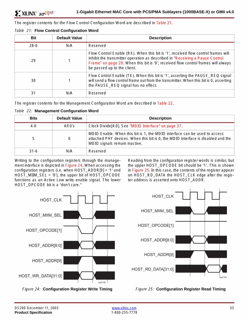
1-Gigabit Ethernet MAC Core with PCSPMA Sublayers (1000BASE-X) or GMII v40R
The register contents for the Flow Control Configuration Word are described in Table 21
The register contents for the Management Configuration Word are described in Table 22
Writing to the configuration registers through the manage-ment interface is depicted in Figure 24 When accessing theconfiguration registers (ie when HOST_ADDR[9] = lsquo1rsquo andHOST_MIIM_SEL = lsquo0rsquo) the upper bit of HOST_OPCODEfunctions as an Active Low write enable signal The lowerHOST_OPCODE bit is a ldquodonrsquot carerdquo
Reading from the configuration register words is similar butthe upper HOST_OPCODE bit should be lsquo1rsquo This is shownin Figure 25 In this case the contents of the register appearon HOST_RD_DATA the HOST_CLK edge after the regis-ter address is asserted onto HOST_ADDR
Table 21 Flow Control Configuration Word
Bit Default Value Description
28-0 NA Reserved
29 1
Flow Control Enable (RX) When this bit is lsquo1rsquo received flow control frames willinhibit the transmitter operation as described in Receiving a Pause ControlFrame on page 29 When this bit is lsquo0rsquo received flow control frames will alwaysbe passed up to the client
30 1Flow Control Enable (TX) When this bit is lsquo1rsquo asserting the PAUSE_REQ signalwill send a flow control frame out from the transmitter When this bit is 0 assertingthe PAUSE_REQ signal has no effect
31 NA Reserved
Table 22 Management Configuration Word
Bits Default Value Description
4-0 All 0rsquos Clock Divide[40] See MDIO Interface on page 37
5 0MDIO Enable When this bit is 1 the MDIO interface can be used to accessattached PHY devices When this bit is 0 the MDIO interface is disabled and theMDIO signals remain inactive
31-6 NA Reserved
Figure 24 Configuration Register Write Timing
HOST_CLK
HOST_ADDR[80]
HOST_ADDR[9]
HOST_OPCODE[1]
HOST_MIIM_SEL
HOST_WR_DATA[310]xip2149
Figure 25 Configuration Register Read Timing
HOST_CLK
HOST_ADDR[80]
HOST_ADDR[9]
HOST_OPCODE[1]
HOST_MIIM_SEL
HOST_RD_DATA[310]
xip2150
DS200 December 11 2003 wwwxilinxcom 33Product Specification 1-800-255-7778
1-Gigabit Ethernet MAC Core with PCSPMA Sublayers (1000BASE-X) or GMII v40 R
Optional Statistical Gathering(statistics_gathering=true)
During operation the MAC core collects statistics on thesuccess and failure of various operations for processing by
station management entities (STA) further up the protocolstack These statistics are accessed by the host through theoptional management interface A complete list of statisticssupported is described in Table 23
Table 23 Statistics Registers
Address Name Description
0x000 Frames Received OK1 A count of error-free frames received
0x001 Frame Check Sequence Errors A count of received frames that failed the CRC check and were at least64 bytes in length
0x002 Broadcast Frames Received OK1A count of frames that were successfully received and were directed tothe broadcast group address
0x003 Multicast Frames Received OK1 A count of frames that were successfully received and were directed toa non broadcast group address
0x004 64 byte Frames Received OK1 A count of error-free frames received that were 64 bytes in length
0x005 65-127 byte Frames Received OK1A count of error-free frames received that were between 65 and 127bytes in length
0x006 128-255 byte Frames Received OK1A count of error-free frames received that were between 128 and 255bytes in length
0x007 256-511 byte Frames Received OK1A count of error-free frames received that were between 256 and 511bytes in length
0x008512-1023 byte Frames ReceivedOK1
A count of error-free frames received that were between 512 and 1023bytes in length
0x0091024-MaxFrameSize byte FramesReceived OK1
A count of error-free frames received that were between 1024 bytes andthe specified IEEE8023-2002 maximum legal length (see MaximumPermitted Frame Length on page 26)
0x00A Control Frames Received OKA count of error-free frames received that contained the specialControl Frame identifier in the LengthType field
0x00B LengthType Out of Range
A count of frames received that were at least 64 bytes in length wherethe lengthtype field contained a length value that did not match thenumber of MAC client data bytes received
The counter also increments for frames in which the lengthtype fieldindicated that the frame contained padding but where the number ofMAC client data bytes received was greater than 64 bytes (minimumframe size)
The exception to the above is when the LengthType Field Error Checksare disabled in which case this counter will not increment
0x00C VLAN Tagged Frames Received OKA count of error-free VLAN frames received This counter will only incre-ment when the receiver is configured for VLAN operation
0x00D Pause Frames Received OK
A count of error-free frames received that contained the MAC Controltype identifier 88-08 in the LengthType field contained a Destinationaddress that matched either the MAC Control multicast address or theconfigured source address of the MAC contained the PAUSE opcodeand were acted upon by the MAC
0x00EControl Frames Received withUnsupported Opcode
A count of error-free frames received that contained the MAC Controltype identifier 88-08 in the LengthType field but were received with anopcode other than the PAUSE opcode
34 wwwxilinxcom DS200 December 11 20031-800-255-7778 Product Specification
1-Gigabit Ethernet MAC Core with PCSPMA Sublayers (1000BASE-X) or GMII v40R
0x00F Oversize Frames Received OK1A count of otherwise error-free frames received that exceeded the max-imum legal frame length specified in IEEE 8023-2002 (see MaximumPermitted Frame Length on page 26)
0x010 Undersize frames receivedA count of the number of frames received that were less than 64 bytesin length but were otherwise well formed
0x011 Fragment frames receivedA count of the number of frames received that were less than 64 bytesin length and had a bad Frame Check Sequence field
0x012 Received bytesA count of bytes of frames that are received (Destination Address toFrame Check Sequence inclusive)
0x013 Transmitted bytesA count of bytes of frames that are transmitted (Destination Address toFrame Check Sequence inclusive)
0x020 Frames Transmitted OK A count of error-free frames transmitted
0x021 Broadcast Frames Transmitted OK A count of error-free frames that were transmitted to the broadcastaddress
0x022 Multicast Frames Transmitted OK A count of error-free frames that were transmitted to a group destina-tion address other than broadcast
0x023 Underrun Errors
A count of frames that would otherwise be transmitted by the core butcould not be completed due to the assertion of TX_UNDERRUN duringthe frame transmission This will not count frames which are less than64 bytes in length
0x024 Control Frames Transmitted OKA count of error-free frames transmitted that contained the MACControl Frame type identifier 88-08 in the LengthType field
0x025 64 byte Frames Transmitted OK A count of error-free frames transmitted that were 64 bytes in length
0x026 65-127 byte Frames Transmitted OKA count of error-free frames transmitted that were between 65 and 127bytes in length
0x027128-255 byte Frames TransmittedOK
A count of error-free frames transmitted that were between 128 and 255bytes in length
0x028256-511 byte Frames TransmittedOK
A count of error-free frames transmitted that were between 256 and 511bytes in length
0x029512-1023 byte Frames TransmittedOK
A count of error-free frames transmitted that were between 512 and1023 bytes in length
0x02A1024-MaxFrameSize byte FramesTransmitted OK
A count of error-free frames transmitted that were between 1024 and thespecified IEEE8023-2002 maximum legal length (see Maximum Per-mitted Frame Length on page 20)
0x02BVLAN Tagged Frames TransmittedOK
A count of error-free VLAN frames transmitted This counter will onlyincrement when the transmitter is configured for VLAN operation
0x02C Pause Frames Transmitted OKA count of error-free PAUSE frames generated and transmitted by thecore in response to an assertion of PAUSE_REQ
0x02D Oversize Frames Transmitted OKA count of otherwise error-free frames transmitted that exceeded themaximum legal frame length specified in IEEE 8023-2002 (see Maxi-mum Permitted Frame Length on page 20)
0x02E Single Collision Frames A count of frames that are involved in a single collision but are subse-quently transmitted successfully (Half Duplex Mode only)
Table 23 Statistics Registers (Continued)
Address Name Description
DS200 December 11 2003 wwwxilinxcom 35Product Specification 1-800-255-7778
1-Gigabit Ethernet MAC Core with PCSPMA Sublayers (1000BASE-X) or GMII v40 R
Each of these statistic registers is 64 bits wide and thereforemust be read in a two-cycle transfer The timing of this pro-cess is shown in Figure 26 Six clocks after the read trans-action is initiated the least significant word (LSW) of thestatistics counter appears on the HOST_RD_DATA bus
and a clock cycle later the most significant word (MSW)appears For accurate statistic values 64 clock ticks (ofTX_CLK for transmit statistics or RX_CLK for receive statis-tics) must elapse after the last frame is sent or receivedthrough the MAC core
0x02F Multiple Collision Frames A count of frames that are involved in more than one collision but aresubsequently transmitted successfully (Half Duplex Mode only)
0x040 Frames with Deferred Transmissions A count of frames whose transmission was delayed on its first attemptbecause the medium was busy (Half Duplex Mode only)
0x041 Late Collisions
A count of the times that a collision has been detected later than oneslotTime from the start of the packet transmission A late collision iscounted twice both as a collision and as a lateCollision (Half DuplexMode only)
0x042Frames Aborted due to Excesscollisions
A count of the frames that due to excessive collisions are not transmit-ted successfully (Half Duplex Mode only)
0x043 Carrier Sense ErrorsA count of times that the GMII_CRS signal was not asserted or wasdisasserted during the transmission of a frame without collision (HalfDuplex Mode only)
0x044 Frames with Excess DeferralA count of frames that deferred transmission for an excessive period oftime (Half Duplex Mode only)
1 If the LengthType Field Error Checks are disabled then these counters will still increment for received frames which contain this typeof error (providing no additional errors were detected)
Table 23 Statistics Registers (Continued)
Address Name Description
Figure 26 Statistic Register Read Timing
HOST_CLK
HOST_ADDR[80]
HOST_ADDR[9]
HOST_REQ
HOST_MIIM_SEL
HOST_RD_DATA[310]
6 CLOCKS
LSW MSW
xip2151
36 wwwxilinxcom DS200 December 11 20031-800-255-7778 Product Specification
1-Gigabit Ethernet MAC Core with PCSPMA Sublayers (1000BASE-X) or GMII v40R
MDIO Interface
The management interface is also used to access the MDIO(MII Management) interface of the MAC core this interfaceis used to access the Managed Information Block (MIB) ofthe PHY components attached to the MAC core
The MDIO interface supplies a clock to the externaldevices MDC This clock is derived from the HOST_CLKsignal using the value in the Clock Divide[40] configurationregister The frequency of the MDIO clock is given by thefollowing equation
The frequency of MDC given by this equation should notexceed 25 MHz in order to comply with the IEEE8023-2002 specification for this interface To prevent MDCfrom being out of specification the Clock Divide[40] valuepowers up at 00000 and while this value is in the register itis impossible to enable the MDIO interface
For details of the register map of PHY layer devices and afuller description of the operation of the MDIO interfaceitself see IEEE specification 8023-2002
Access to the MDIO interface through the managementinterface is depicted in the timing diagram in Figure 27
For MDIO transactions the following points apply
bull HOST_OPCODE maps to the OP (opcode) field of theMDIO frame
bull HOST_ADDR maps to the two address fields of theMDIO frame PHY_ADDR is HOST_ADDR[95] andREG_ADDR is HOST_ADDR[40]
bull HOST_WR_DATA[150] maps into the data field of the
MDIO frame when performing a write operation
bull The data field of the MDIO frame maps intoHOST_RD_DATA[150] when performing a readoperation
The MAC core signals to the host that it is ready for anMDIO transaction by asserting HOST_MIIM_RDY A read orwrite transaction on the MDIO is initiated by a pulse on the
fMDC
fHOST_CLK
1 Clock Divide[40]+( ) 2times-------------------------------------------------------------------=
Figure 27 MDIO Access Through Management Interface
HOST_CLK
HOST_ADDR[90]
HOST_OPCODE[10]
HOST_REQ
HOST_MIIM_SEL
HOST_RD_DATA[150]
HOST_WR_DATA[150]
HOST_RDY
If a read transaction is initiated the HOST_RD_DATA bus is valid at the point indicated If a write transaction is initiated the HOST_WR_DATA bus must be valid at the indicated point Simultaneous read and write is not permitted
xip2152
DS200 December 11 2003 wwwxilinxcom 37Product Specification 1-800-255-7778
1-Gigabit Ethernet MAC Core with PCSPMA Sublayers (1000BASE-X) or GMII v40 R
HOST_REQ signal This pulse is ignored if the MDIO inter-face already has a transaction in progress
The MAC core then disasserts the HOST_MIIM_RDY signalwhile the transaction across the MDIO is in progress Whenthe transaction across the MDIO interface has been com-pleted the HOST_MIIM_RDY signal will be asserted by theMAC core if the transaction is a read the data will also beavailable on the HOST_RD_DATA[150] bus at this time
Optional Configuration Vector(management_interface = false)If the optional Management interface is omitted from thecore all of relevant configuration signals are brought out of
the core These signals are bundled into theCONFIGURATION_VECTOR signal The bit mapping of theconfiguration vector signal is defined in Table 24 See thecorresponding entry in the configuration register tables forthe full description of each signal
Note that these configuration vector signals can bechanged by the user at any time however with the excep-tion of the reset and the flow control configuration signalsthey will not take effect until the current frame has com-pleted transmission or reception
The ldquoClockrdquo heading denotes which clock domain the con-figuration signal is registered into before use by the core Itis not necessary to drive the signal from this clock domain
Table 24 Configuration Vector Bit Definition
Bit(s)Configuration Register
cross reference Clock Description
47 downto 0
Receiver ConfigurationWord 0 bits 31-0 andReceiver ConfigurationWord 1 bits 15-0
RX_CLK
Pause frame MAC Source Address[470] This address isused by the MAC core to match against the DestinationAddress of any incoming flow control frames and as theSource Address for any outbound flow control frames
The address is ordered such that the first byte transmitted orreceived is the least significant byte in the register forexample a MAC address of AA-BB-CC-DD-EE-FF will bestored in bite [470] as 0xFFEEDDCCBBAA
48Receiver ConfigurationWord 1 bit 26
RX_CLKReceiver Half Duplex If lsquo1rsquo the receiver operates in halfduplex mode If lsquo0rsquo the receiver operates in full duplex modeHas no effect if XCO parameter half_duplex_capable = false
49Receiver ConfigurationWord 1 bit 27
RX_CLKReceiver VLAN Enable When this bit is set to 1 VLANtagged frames are accepted by the receiver
50Receiver ConfigurationWord 1 bit 28
RX_CLKReceiver Enable If set to 1 the receiver block is operationalIf set to 0 the block ignores activity on the physical interfaceRX port
51Receiver ConfigurationWord 1 bit 29
RX_CLK
Receiver In-band FCS Enable When this bit is lsquo1rsquo the MACreceiver will pass the FCS field up to the client as describedin Client-Supplied FCS Passing on page 25 When it is lsquo0rsquothe MAC receiver will not pass the FCS field In both casesthe FCS field will be verified on the frame
52Receiver ConfigurationWord 1 bit 30
RX_CLK
Receiver Jumbo Frame Enable When this bit is lsquo0rsquo thereceiver will not pass frames longer than the maximum legalframe size specified in IEEE 8023-2002 (see MaximumPermitted Frame Length on page 26) When it is lsquo1rsquo thereceiver will not have an upper limit on frame size
53Receiver ConfigurationWord 1 bit 31
NA
Receiver Reset When this bit is lsquo1rsquo the receiver is held inreset
This signal is an input to the reset circuit for the receiverblock See Reset circuit on page 42 for more information
54TransmitterConfiguration Word bit25
TX_CLK
Transmitter Interframe Gap Adjust enable If lsquo1rsquo then thetransmitter will read the value of the TX_IFG_DELAY port andset the Interframe Gap accordingly If lsquo0rsquo the transmitter willalways insert at least the legal minimum Interframe Gap
38 wwwxilinxcom DS200 December 11 20031-800-255-7778 Product Specification
1-Gigabit Ethernet MAC Core with PCSPMA Sublayers (1000BASE-X) or GMII v40R
55TransmitterConfiguration Word bit26
TX_CLK
Transmitter Half Duplex If lsquo1rsquo the transmitter operates in halfduplex mode If lsquo0rsquo the transmitter operates in full duplexmode Has no effect if XCO parameter half_duplex_capable= false
56TransmitterConfiguration Word bit27
TX_CLKTransmitter VLAN Enable When this bit is set to lsquo1rsquo thetransmitter allows the transmission of VLAN tagged frames
57TransmitterConfiguration Word bit28
TX_CLKTransmitter Enable When this bit is 1 the transmitter will beoperational When it is 0 the transmitter is disabled
58TransmitterConfiguration Word bit29
TX_CLK
Transmitter In-Band FCS Enable When this bit is lsquo1rsquo theMAC transmitter will expect the FCS field to be pass in by theclient as described in Client-Supplied FCS Passing onpage 17 When it is lsquo0rsquo the MAC transmitter will appendpadding as required compute the FCS and append it to theframe
59TransmitterConfiguration Word bit30
TX_CLK
Transmitter Jumbo Frame Enable When this bit is lsquo1rsquo theMAC transmitter will allow frames larger than the maximumlegal frame length specified in IEEE 8023-2002 to be sentWhen set to lsquo0rsquo the MAC transmitter will only allow frames upto the legal maximum to be sent
60TransmitterConfiguration Word bit31
NA
Transmitter Reset When this bit is lsquo1rsquo the MAC transmitter isheld in reset
This signal is an input to the reset circuit for the transmitterblock See Reset circuit on page 42 for more information
61Flow ControlConfiguration Word bit29
TX_CLK
Transmit Flow Control Enable When this bit is lsquo1rsquo assertingthe PAUSE_REQ signal causes the MAC core to send a flowcontrol frame out from the transmitter as described inReceiving a Pause Control Frame on page 29 When this bitis lsquo0rsquo asserting the PAUSE_REQ signal will have no effect
62Flow ControlConfiguration Word bit30
RX_CLK
Receive Flow Control Enable When this bit is lsquo1rsquo receivedflow control frames will inhibit the transmitter operation asdescribed in Receiving a Pause Control Frame on page 29When it is lsquo0rsquo received flow frames are passed up to theclient
63Receiver ConfigurationWord 1 bit 25
RX_CLK
LengthType Error Check Disable When this bit is lsquo1rsquo thecore will not perform the LengthType field error checks asdescribed in LengthType Field Error Checks on page 26When it is set to lsquo0rsquo the LengthType field checks will beperformed this is normal operation
Table 24 Configuration Vector Bit Definition (Continued)
Bit(s)Configuration Register
cross reference Clock Description
DS200 December 11 2003 wwwxilinxcom 39Product Specification 1-800-255-7778
1-Gigabit Ethernet MAC Core with PCSPMA Sublayers (1000BASE-X) or GMII v40 R
Optional GMII (physical_interface=gmii)The GMII is designed to IEEE 8023-2002 Clause 35 Thisutilizes IOrsquos of the Xilinx devices using inputoutput buffersand inputoutput flip-flops to maximize setup and hold mar-gins All IO logic is placed in the example wrapper that isdelivered with the core In addition all clock managementlogic for the core is instanced in this example wrapper thisallows multiple instances of the core to share clocks Theexample wrapper is provided in both VHDL and Verilog
Clock Management
Figure 28 illustrates the clock management used with theGMII interface All clocks illustrated have a frequency of125MHz
GTX_CLK must be provided to the MAC core This is a highquality clock which satisfies the IEEE8023-2002 require-ments It is expected that this clock will be derived from anexternal oscillator and connected into the device through anIBUFG as illustrated The clock source must then be routedonto a global clock network by connecting it to a BUFGWithin the MAC core this global clock is used by all MACtransmitter logic The MAC Client can obtain this clock byconnecting to the TX_CLK signal output from the coreGMII_TX_CLK is derived from this global clock by invertingit and routing it to an OBUF
GMII_RX_CLK is received through an IBUFG This clock isthen routed onto a global clock network by connecting it to aBUFG The resulting global clock is used by all MACreceiver logic
Figure 28 Clock Management with GMII
IBUFG
IBUFG
OBUF
BUFG
BUFG
TX_CLK
RX_CLK
GTX_CLK
GMII_TX_CLK
GMII_RX_CLK
Example Wrapper
xip2153
MAC Core
TX_CLK
RX_CLK
GMII_TX_CLK
GMII_RX_CLK
GTX_CLK
40 wwwxilinxcom DS200 December 11 20031-800-255-7778 Product Specification
1-Gigabit Ethernet MAC Core with PCSPMA Sublayers (1000BASE-X) or GMII v40R
Clock Sharing between Multiple cores
Figure 29 illustrates how it is possible to share clockresources across multiple instantiations of the core whenusing the optional GMII
GTX_CLK may be shared between multiple cores as illus-trated resulting in a common transmitter clock domainacross the device
A common receiver clock domain is not possible each corewill receive an independent receiver clock from its GMII asillustrated
Although not illustrated if the optional Management Inter-face is used HOST_CLK can also be shared betweencores
Figure 29 Clock Management with multiple instances of the MAC with GMII
IBUFG
OBUF
BUFG
TX_CLK
RX_CLK_1
GMII_TX_CLK_1
GMII_RX_CLK_1
MAC Core
TX_CLK
RX_CLK
GMII_TX_CLK
GMII_RX_CLK
GTX_CLK
MAC Core
TX_CLK
RX_CLK
GMII_TX_CLK
GMII_RX_CLK
GTX_CLK
IBUFG
BUFG
GTX_CLK
IBUFG
OBUF
GMII_TX_CLK_2
GMII_RX_CLK_2
BUFG
TX_CLK
RX_CLK_2
DS200 December 11 2003 wwwxilinxcom 41Product Specification 1-800-255-7778
1-Gigabit Ethernet MAC Core with PCSPMA Sublayers (1000BASE-X) or GMII v40 R
Reset circuit
Internally the core is divided up into clockreset domainswhich group together elements with the common clock andreset signals The reset circuitry for one of these domains isis illustrated in Figure 30 This circuit provides controllableskews on the reset nets within the design
More information on the operation and rationale behind thiscircuit can be found in Ken Chapmanrsquos Xilinx TechXclusiveldquoGet Smart About Resetrdquo athttpwwwxilinxcomsupporttechxclusivesglobal-techX19htm
Figure 30 Reset circuit for one clockreset domain
FDP
PRED
C
Q
FDP
PRED
C
Q
FDP
PRED
C
Q
FDP
PRED
C
Q
PRE PRE PRE
0
RESET
Management Reset
Clock
Core Registers
42 wwwxilinxcom DS200 December 11 20031-800-255-7778 Product Specification
1-Gigabit Ethernet MAC Core with PCSPMA Sublayers (1000BASE-X) or GMII v40R
Optional PCS with Ten-Bit Interface (TBI) for 1000BASE-X (physical_interface=tbi)The Full-Duplex Physical Coding Sublayer (PCS) for1000BASE-X is defined in IEEE 8023-2002 Clauses 36and 37 This functionality is only available in the Virtex-IIand Spartan3 families of FPGA devices
A block diagram of the PCS is shown in Figure 31 Themajor functional blocks of the PCS are
bull Transmit engine
bull Auto-negotiation block
bull Receive engine and synchronization block
bull PCS managed register block
bull 8B10B encoder block
bull 8B10B decoder block
bull Receiver elastic buffer
The PCS Managed Register Block is accessed through theMDIO Interface as if it were an externally connected PHYThis configures the operation of the PCS and Auto-Negoti-ation See PCS Managed Register Block
(physical_interface = tbi or phy) on page 49 The corersquosoptional Management Interface can be used to control theMDIO Interface as described by MDIO Interface onpage 37 When the optional Management Interface is notpresent the PCS Managed Register Block must beaccessed via an MDIO controller which is not provided bythe core
The 8B10B encodingdecoding blocks are implemented byconfiguring two Block SelectRAM modules as ROM Theseare used as large look-up tables The remaining PCS func-tionality such as code group encodingdecoding the Man-aged Register Block and Auto-Negotiation areimplemented in CLB logic
The Receiver Elastic buffer enables the 10-bit parallel datareceived from the PMA sublayer alternatively onPMA_RX_CLK0 and PMA_RX_CLK1 clock edges to betransferred onto the internal 125MHz clock domain derivedfrom GTX_CLK (see Clock Management) This buffer isimplemented in Distributed Memory
Figure 31 Functional Block Diagram of the 1-Gigabit Ethernet PCS with TBI Interface
PCS TRANSMIT ENGINE
PCS RECEIVE ENGINE ampSYNCHRONISATION
PCSMANAGEMENT
MDIOInterface
AUTO-NEGOTIATION
MAC TXInterface
MAC RXInterface
8B10BEncoder
8B10BDecoder
RX Elastic Buffer
TBI Interface
DS200 December 11 2003 wwwxilinxcom 43Product Specification 1-800-255-7778
1-Gigabit Ethernet MAC Core with PCSPMA Sublayers (1000BASE-X) or GMII v40 R
TBI Interface
The TBI is designed to IEEE 8023-2002 Clause 363 Thisutilizes IOrsquos of the Xilinx devices using inputoutput buffersand inputoutput flip-flops to maximize setup and hold mar-gins All IO logic is placed in the example wrapper that isdelivered with the core In addition all clock managementlogic for the core is instantiated in this example wrapperthis allows multiple instances of the core to share clocksThe example wrapper is provided in both VHDL and Verilog
Clock Management
Figure 32 illustrates the clock management used with theTBI interface
GTX_CLK must be provided to the MAC core This is a highquality clock of frequency 125MHz which satisfies theIEEE8023-2002 requirements It is expected that this clockwill be derived from an external oscillator and connected
into the device through an IBUFG as illustrated The clocksource must then be routed onto a global clock network byconnecting it to a BUFG Within the MAC core this globalclock is used by all MAC transmitter logic PMA_TX_CLK isderived from this global clock by inverting it and routing it toan OBUF
PMA_RX_CLK0 and PMA_RX_CLK1 are each receivedthrough an IBUFG These clocks are then routed onto glo-bal clock networks by connecting each to a BUFGPMA_RX_CLK0 and PMA_RX_CLK1 are each 625MHzclocks Data from the TBI is received alternatively on the ris-ing edge of PMA_RX_CLK0 followed by the rising edge ofPMA_RX_CLK1 using IOB Double-Data Rate input regis-ters This data is then written into the Receiver ElasticBuffer Data is read out of the Elastic Buffer using the globalclock derived from GTX_CLK all the remaining receiverlogic is synchronous to this clock
Figure 32 Clock Management for PCS with TBI Interface
IBUFG
IBUFG
OBUF
BUFG
BUFG
TX_CLK
RX_CLK
GTX_CLK
PMA_TX_CLK
PMA_RX_CLK0
MAC Core
RX ELASTICBUFFER
Example Wrapper
TX_CLK
RX_CLK
GTX_CLK
PMA_TX_CLK
PMA_RX_CLK0
IBUFGBUFGPMA_RX_CLK1
PMA_RX_CLK1
44 wwwxilinxcom DS200 December 11 20031-800-255-7778 Product Specification
1-Gigabit Ethernet MAC Core with PCSPMA Sublayers (1000BASE-X) or GMII v40R
Clock Sharing between Multiple cores
Figure 33 illustrates how it is possible to share clockresources across multiple instantiations of the core whenusing the optional PCS with TBI
GTX_CLK may be shared between multiple cores as illus-trated resulting in a common transmitter clock domainacross the device
Each core will receive independent PMA_RX_CLK0 andPMA_RX_CLK1 clocks from its TBI as illustrated whichcannot be shared
Although not illustrated if the optional Management Inter-face is used HOST_CLK can also be shared betweencores
Figure 33 Clock Management with multiple instances of the MAC with PCS and TBI
Reset circuit
The reset circuits within the MAC when the TBI interface is implemented is the same as that in the GMII case details ofthese circuits can be found on page 42
IBUFG
OBUF
BUFG
TX_CLK
RX_CLK
PMA_TX_CLK_1
PMA_RX_CLK0_1
MAC Core
RX ELASTICBUFFER
TX_CLK
RX_CLK
GTX_CLK
PMA_TX_CLK
PMA_RX_CLK0
IBUFGBUFGPMA_RX_CLK1_1
PMA_RX_CLK1
IBUFG
BUFG
GTX_CLK
IBUFG
OBUF
BUFG
TX_CLK
RX_CLK
PMA_TX_CLK_2
PMA_RX_CLK0_2
MAC Core
RX ELASTICBUFFER
TX_CLK
RX_CLK
GTX_CLK
PMA_TX_CLK
PMA_RX_CLK0
IBUFGBUFGPMA_RX_CLK1_2
PMA_RX_CLK1
DS200 December 11 2003 wwwxilinxcom 45Product Specification 1-800-255-7778
1-Gigabit Ethernet MAC Core with PCSPMA Sublayers (1000BASE-X) or GMII v40 R
Optional PCS and PMA Sublayers for 1000BASE-X (physical_interface=phy)The Full-Duplex Physical Coding Sublayer (PCS) withPhysical Medium Attachment (PMA) for 1000BASE-X isdefined in IEEE 8023-2002 Clauses 36 and 37 This func-tionality is only available in the Virtex-II Pro family of FPGAdevices
A block diagram of the PCS and PMA sublayers can beseen in Figure 34 The functional blocks of the PCS andPMA sublayers may replace the optional GMII interfaceThe functional blocks of the PCS and PMA sublayers are
bull PCS Transmit Engine
bull Auto-Negotiation block
bull Receive Engine and Synchronization Block
bull PCS Managed Register Block
bull Rocket IO Multi-Gigabit Transceiver
The PCS Managed Register Block is accessed through theMDIO Interface as if it were an externally connected PHYThis configures the operation of the PCS PMA sublayerand Auto-NegotiationSee PCS Managed Register Block(physical_interface = tbi or phy) on page 49 The corersquosoptional Management Interface can be used to control theMDIO Interface as described by MDIO Interface onpage 37 When the optional Management Interface is notpresent the PCS Managed Register Block must beaccessed via an MDIO controller which is not provided bythe core
The Rocket IO Multi-Gigabit Transceiver (MGT) providessome of the PCS layer functionality such as 8B10B encod-ingdecoding and the PMA serdes The remaining PCSfunctionality such as code group encodingdecoding theManaged Register Block and Auto-Negotiation are imple-mented in CLB logic
Figure 34 Functional Block Diagram of the 1-Gigabit Ethernet PCSPMA Sublayer Extension
PCS TRANSMIT ENGINE
PCS RECEIVE ENGINE ampSYNCHRONISATION
RO
CK
ET
IO
MU
LTI-
GIG
TR
AN
SC
EIV
ER
PCSMANAGEMENT
MDIOInterface
AUTO-NEGOTIATION
TXPTXN
RXPRXN
MAC TXInterface
MAC RXInterface
xip2154
46 wwwxilinxcom DS200 December 11 20031-800-255-7778 Product Specification
1-Gigabit Ethernet MAC Core with PCSPMA Sublayers (1000BASE-X) or GMII v40R
Clock Management
Figure 35 illustrates the clock management that should beused with the optional PCS and PMA sublayers for1000BASE-X This logic is implemented in the examplewrapper that is delivered with the core This provides flexi-bility because the design can be modified to use eitherREFCLK or BREFCLK (please refer to Rocket IO docu-mentation) It would also allow multiple instances of the coreto share clocks The example wrapper is provided in bothVHDL and Verilog
(B)REFCLK must be provided to the MAC core This clockmust be derived from an external oscillator and connectedto the core through an IBUFG as illustrated (B)REFCLK isa high quality clock of frequency 625 MHz which satisfiesthe Rocket IO Multi-Gigabit Transceiver (MGT) require-ments
(B)REFCLK is routed to both the core and a DCM From theDCM the CLK2X180 output is routed to a BUFG to providethe device with a global 125 MHz clock (connected toUSERCLK2 input on the core) Within the core bothTX_CLK and RX_CLK share this global 125 MHz clocksource which is used by all transmitter and receiver logicThis is made possible by the RX_ELASTIC_BUFFER func-tionality of the Rocket IO MGT (refer to Virtex-II Pro docu-mentation) The MAC Client can obtain this clock byconnecting to either the TX_CLK or the RX_CLK signalsoutput from the core
From the DCM the CLK0 output is routed to a BUFG to pro-vide the device with a global 625MHz clock This is con-nected to the USRCLK input of the core
Figure 35 Clock Management with PCSPMA Sublayers
DCM
CLKIN CLK0
CLK2X180FB
BUFG
BUFG
IBUFG
TX_CLK
RX_CLK
(B)REFCLK
TXUSRCLK
(B)REFCLK
TXUSRCLK2RXUSRCLKRXUSRCLK2
GT_ETHERNET
Example Wrapper
xip2155
MAC Core
(B)REFCLK
USRCLK
USRCLK2
TX_CLK
RX_CLK
DS200 December 11 2003 wwwxilinxcom 47Product Specification 1-800-255-7778
1-Gigabit Ethernet MAC Core with PCSPMA Sublayers (1000BASE-X) or GMII v40 R
Clock Sharing between Multiple Cores
Figure 36 illustrates how it is possible to share clockresources across multiple instantiations of the core whenusing the optional PCSPMA sublayers For each coreUSERCLK and USERCLK2 must always be derived asshown from the BREFCLK or REFCLK used by that core
Note that when using the fixed routing resources of BREF-CLK Rocket IO MGTs along the top edge of the devicemust use a separate BREFCLK routing resource to thosealong the bottom edge of the device (Refer to Virtex-II Prodocumentation)
Although not illustrated if the optional Management Inter-face is used HOST_CLK can also be shared betweencores
Figure 36 Clock Management with multiple instances of the MAC with PCS and PMA sublayers
Reset circuit
The reset circuits within the MAC when the PCS and PMA sublayers are implemented is the same as that in the GMII casedetails of these circuits can be found on page 42
DCM
CLKIN CLK0
CLK2X180FB
BUFG
BUFG
IBUFG
(B)REFCLK
TXUSRCLK
(B)REFCLK
TXUSRCLK2RXUSRCLKRXUSRCLK2
GT_ETHERNET(B)REFCLK
USERCLK
USERCLK2
MAC core
TXUSRCLK
(B)REFCLK
TXUSRCLK2RXUSRCLKRXUSRCLK2
GT_ETHERNET(B)REFCLK
USERCLK
USERCLK2
MAC core
48 wwwxilinxcom DS200 December 11 20031-800-255-7778 Product Specification
1-Gigabit Ethernet MAC Core with PCSPMA Sublayers (1000BASE-X) or GMII v40R
PCS Managed Register Block (physical_interface = tbi or phy)The PCS in both the TBI interface and the PCSPMA (usingthe Virtex-II Pro Rocket IO) versions contain the full Man-aged Register Block defined in IEEE 8023-2002 clause 37
This utilizes ten dedicated management registersaccessed via the MDIO interface These are defined inTable 25 to Table 33 inclusive
Table 25 Control Register (Register 0)
Bit(s) Name Description Attributes Default Value
015 Reset1 = PCSPMA reset
0 = Normal Operation
ReadWrite
Self Clearing0
014 Loopback1 = Enable Loopback Mode
0 = Disable Loopback ModeReadWrite 0
013SpeedSelection (LSB)
The core always returns a 0 for this bitTogether with bit 06 speed selection of 1000Mbs is identified
Returns 0 0
012Auto-NegotiationEnable
1 = Enable Auto-Negotiation Process
0 = Disable Auto-Negotiation ProcessReadWrite 1
011 Power Down
1 = Power down
0 = Normal operation
When set to ldquo1rdquo the Rocket IO MGT is placedin a low power state This bit requires a reset(see bit 015) to clear
Read Write 0
010 Isolate1 = Electrically Isolate PHY from GMII
0 = Normal operationReadWrite 1
09Restart Auto-Negotiation
1 = Restart Auto-Negotiation Process
0 = Normal Operation
ReadWrite
Self Clearing0
08 Duplex ModeThe core always returns a 1 for this bit tosignal Full-Duplex Mode
Returns 1 1
07 Collision TestThe core always returns a 0 for this bit todisable COL test
Returns 0 0
06SpeedSelection(MSB)
The core always returns a 1 for this bitTogether with bit 013 speed selection of1000 Mbs is identified
Returns 1 1
050 Reserved Always returns 0rsquos writes ignored Returns 0rsquos 000000
DS200 December 11 2003 wwwxilinxcom 49Product Specification 1-800-255-7778
1-Gigabit Ethernet MAC Core with PCSPMA Sublayers (1000BASE-X) or GMII v40 R
Table 26 Status Register (Register 1)
Bit(s) Name Description Attributes Default Value
115 100BASE-T4The core always returns a 0 for this bitbecause 100BASE-T4 is not supported
Returns 0 0
114100BASE-XFullDuplex
The core always returns a 0 for this bitbecause 100BASE-X Full Duplex is notsupported
Returns 0 0
113100BASE-XHalf Duplex
The core always returns a 0 for this bitbecause 100BASE-X Half Duplex is notsupported
Returns 0 0
11210 Mbs FullDuplex
The core always returns a 0 for this bitbecause 10 Mbs Full Duplex is notsupported
Returns 0 0
11110 Mbs HalfDuplex
The core always returns a 0 for this bitbecause 10 Mbs Half Duplex is notsupported
Returns 0 0
110100BASE-T2Full Duplex
The core always returns a 0 for this bitbecause 100BASE-T2 Full Duplex is notsupported
Returns 0 0
19100BASE-T2Half Duplex
The core always returns a 0 for this bitbecause 100BASE-T2 Half Duplex is notsupported
Returns 0 0
18ExtendedStatus
The core always returns a 1 for this bit toindicate the presence of the ExtendedRegister (Register 15)
Returns 1 1
17 Reserved Always return 0 writes ignored Returns 0 0
16MF PreambleSuppression
The core always returns a 1 for this bit toindicate that Management Frame PreambleSuppression is supported
Returns 1 1
15Auto-NegotiationComplete
1 = Auto-Negotiation process completed
0 = Auto-Negotiation process not completedRead Only 0
14 Remote Fault1 = Remote fault condition detected
0 = No remote fault condition detected
Read Only
Self Clearing on read0
13Auto-NegotiationAbility
The core always returns a 1 for this bit toindicate that the PHY is capable ofAuto-Negotiation
Returns 1 1
12 Link Status1 = Link is up
0 = Link is down
Read Only
Self Clearing on read0
11 Jabber DetectThe core always returns a 0 for this bitbecause Jabber Detect is not supported
Returns 0 0
10ExtendedCapability
The core always returns a 0 for this bitbecause no extended register set issupported
Returns 0 0
50 wwwxilinxcom DS200 December 11 20031-800-255-7778 Product Specification
1-Gigabit Ethernet MAC Core with PCSPMA Sublayers (1000BASE-X) or GMII v40R
Table 27 PHY Identifier (Registers 2 and 3)
Bit(s) Name Description Attributes Default Value
2150OrganizationallyUniqueIdentifier
Always returns 0s Returns 0s 0000000000000000
31510OrganizationallyUniqueIdentifier
Always returns 0s Returns 0s 000000
394Manufacturerrsquosmodel number
Always returns 0s Returns 0s 000000
330RevisionNumber
Always returns 0s Returns 0s 0000
Table 28 Auto-Negotiation Advertisement Register (Register 4)
Bit(s) Name Description Attributes Default Value
415 Next Page1 = Next Page functionality is advertised
0 = Next Page functionality is not advertisedReadWrite 0
414 Reserved Always returns 0 writes ignored Returns 0 0
41312 Remote Fault
00 = No Error
01 = Offline
10 = Link Failure
11 = Auto-Negotiation Error
ReadWrite
Self clearing to 00afterAuto-Negotiation
00
4119 Reserved Always return 0 writes ignored Returns 0 0
487 Pause
00 = No PAUSE
01 = Asymmetric PAUSE towards linkpartner
10 = Symmetic PAUSE
11 = Both Symmetric PAUSE andAsymmetric PAUSE towards link partner
ReadWrite 11
46 Half DuplexThe core always returns a 0 for this bitbecause Half Duplex Mode is not supported
Returns 0 0
45 Full Duplex1 = Full Duplex Mode is advertised
0 = Full Duplex Mode is not advertisedReadWrite 1
440 Reserved Always returns 0s writes ignored Returns 0s 00000
DS200 December 11 2003 wwwxilinxcom 51Product Specification 1-800-255-7778
1-Gigabit Ethernet MAC Core with PCSPMA Sublayers (1000BASE-X) or GMII v40 R
Table 29 Auto-Negotiation Link Partner Ability Base Register (Register 5)
Bit(s) Name Description Attributes Default Value
515 Next Page1 = Next Page functionality is supported
0 = Next Page functionality is not supportedRead Only 0
514 AcknowledgeUsed by Auto-Negotiation function toindicate reception of a link partnerrsquos base ornext page
Read Only 0
51312 Remote Fault
00 = No Error
01 = Offline
10 = Link Failure
11 = Auto-Negotiation Error
Read Only 00
5119 Reserved Always returns 0s Returns 0s 000
587 Pause
00 = No PAUSE
01 = Asymmetric PAUSE supported
10 = Symmetic PAUSE supported
11 = Both Symmetric PAUSE andAsymmetric PAUSE supported
Read Only 00
56 Half Duplex1 = Half Duplex Mode is supported
0 = Half Duplex Mode is not supportedRead Only 0
55 Full Duplex1 = Full Duplex Mode is supported
0 = Full Duplex Mode is not supportedRead Only 0
540 Reserved Always returns 0s Returns 0s 00000
Table 30 Auto-Negotiation Expansion Register (Register 6)
Bit(s) Name Description Attributes Default Value
6153 Reserved Always returns 0s Returns 0s 0000000000000
62 Next Page AbleThe core always returns a 1 for this bitbecause the device is Next Page Able
Returns 1 1
61 Page Received1 = A new page has been received
0 = A new page has not been received
Read Only
Self Clearing on read0
60 Reserved Always returns 0s Returns 0s 0000000
52 wwwxilinxcom DS200 December 11 20031-800-255-7778 Product Specification
1-Gigabit Ethernet MAC Core with PCSPMA Sublayers (1000BASE-X) or GMII v40R
Table 31 Auto-Negotiation Next Page Transmit Register (Register 7)
Bit(s) Name Description Attributes Default Value
715 Next Page1 = Additional Next Page(s) will follow
0 = Last pageReadWrite 0
714 Reserved Always returns 0 Returns 0 0
713 Message Page1 = Message Page
0 = Unformatted PageReadWrite 1
712 Acknowledge 21 = Will comply with message
0 = Cannot comply with messageReadWrite 0
711 ToggleValue will toggle between subsequent NextPages
Read Only 0
7100Message UnformattedCode Field
Message Code Field or Unformatted PageEncoding as dictated by 713
ReadWrite00000000001
(Null Message Code)
Table 32 Auto-Negotiation Next Page Receive Register (Register 8)
Bit(s) Name Description Attributes Default Value
815 Next Page1 = Additional Next Page(s) follows
0 = Last pageRead Only 0
814 AcknowledgeUsed by Auto-Negotiation function toindicate reception of a link partnerrsquos base ornext page
Read Only 0
813 Message Page1 = Message Page
0 = Unformatted PageRead Only 0
812 Acknowledge 21 = Will comply with message
0 = Cannot comply with messageRead Only 0
811 ToggleValue toggles between subsequent andNext Pages
Read Only 0
8100Message UnformattedCode Field
Message Code Field or Unformatted PageEncoding as dictated by 813
Read Only 00000000000
DS200 December 11 2003 wwwxilinxcom 53Product Specification 1-800-255-7778
1-Gigabit Ethernet MAC Core with PCSPMA Sublayers (1000BASE-X) or GMII v40 R
)
Referencesbull IEEE 8023-2002
bull Virtex-E User Guide
bull Spartan-II E User Guide
bull Virtex-II User Guide
bull Virtex-II Pro User Guide
Related InformationXilinx products are not intended for use in life support appli-ances devices or systems Use of a Xilinx product in suchapplications without the written consent of the appropriateXilinx officer is prohibited
Ordering InformationThis Xilinx LogiCORE module is provided under theSignOnce IP Site License A free evaluation version of themodule is available
Once purchased the core may be downloaded from the Xil-inx IP Center for use with the Xilinx CORE Generator Sys-temtrade v61i SP3 and later The Xilinx CORE GeneratorSystem tool is bundled with all Alliance Series Softwarepackages at no additional charge
Please contact your local Xilinx sales representative or visitthe Xilinx Silicon Xpresso Cafe for pricing and availability onXilinx LogiCORE modules and software Information onadditional Xilinx LogiCORE modules is available on the Xil-inx IP Center
Revision HistoryThe following table shows the revision history for this document
Table 33 Extended Status Register (Register 15)
Bit(s) Name Description Attributes Default Value
15151000BASE-XFull Duplex
The core always returns a 1 for this bitbecause 1000BASE-X Full Duplex issupported
Returns 1 1
15141000BASE-XHalf Duplex
The core always returns a 0 for this bitbecause 1000BASE-X Half Duplex is notsupported
Returns 0 0
15131000BASE-TFull Duplex
The core always returns a 0 for this bitbecause 1000BASE-T Full Duplex is notsupported
Returns 0 0
15121000BASE-THalf Duplex
The core always returns a 0 for this bitbecause 1000BASE-T Half Duplex is notsupported
Returns 0 0
15110 Reserved Always returns 0s Returns 0s 000000000000
Date Version Revision
032803 11 Revision History added to document
043003 20 Revised to v30 standards
121103 30 Updated to v40 release
54 wwwxilinxcom DS200 December 11 20031-800-255-7778 Product Specification
- 1-Gigabit Ethernet MAC Core with PCSPMA Sublayers (1000BASE-X) or GMII v40
-
- Features
- MAC Overview
- Xilinx CORE Generator
- GUI Interface
- Parameter Values in the XCO File
- Output Generation
- Device Utilization
- Interface Description
- Interface Signals for MAC with physical_interface=gmii and management_interface=true
- Interface Signals for MAC with physical_interface=gmii and management_interface=false
- Interface Signals for MAC with physical_interface=tbi and management_interface=true
- Interface Signals for MAC with physical_interface=tbi and management_interface=false
- Interface Signals for MAC with physical_interface=phy and management_interface=true
- Interface Signals for MAC with physical_interface=phy and management_interface=false
- Client Side Interface Signal Definition
- Physical Interface Signal Definition
- Functional Description
- Client Interface
- Transmitter
- Receiver
- Flow Control
- Optional Management Interface (management_interface=true)
- Optional Configuration Vector (management_interface = false)
- Optional GMII (physical_interface=gmii)
- Optional PCS with Ten-Bit Interface (TBI) for 1000BASE-X (physical_interface=tbi)
- Optional PCS and PMA Sublayers for 1000BASE-X (physical_interface=phy)
- PCS Managed Register Block (physical_interface = tbi or phy)
- References
- Related Information
- Ordering Information
- Revision History
-
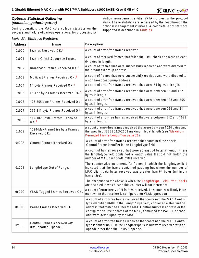
1-Gigabit Ethernet MAC Core with PCSPMA Sublayers (1000BASE-X) or GMII v40 R
Optional Statistical Gathering(statistics_gathering=true)
During operation the MAC core collects statistics on thesuccess and failure of various operations for processing by
station management entities (STA) further up the protocolstack These statistics are accessed by the host through theoptional management interface A complete list of statisticssupported is described in Table 23
Table 23 Statistics Registers
Address Name Description
0x000 Frames Received OK1 A count of error-free frames received
0x001 Frame Check Sequence Errors A count of received frames that failed the CRC check and were at least64 bytes in length
0x002 Broadcast Frames Received OK1A count of frames that were successfully received and were directed tothe broadcast group address
0x003 Multicast Frames Received OK1 A count of frames that were successfully received and were directed toa non broadcast group address
0x004 64 byte Frames Received OK1 A count of error-free frames received that were 64 bytes in length
0x005 65-127 byte Frames Received OK1A count of error-free frames received that were between 65 and 127bytes in length
0x006 128-255 byte Frames Received OK1A count of error-free frames received that were between 128 and 255bytes in length
0x007 256-511 byte Frames Received OK1A count of error-free frames received that were between 256 and 511bytes in length
0x008512-1023 byte Frames ReceivedOK1
A count of error-free frames received that were between 512 and 1023bytes in length
0x0091024-MaxFrameSize byte FramesReceived OK1
A count of error-free frames received that were between 1024 bytes andthe specified IEEE8023-2002 maximum legal length (see MaximumPermitted Frame Length on page 26)
0x00A Control Frames Received OKA count of error-free frames received that contained the specialControl Frame identifier in the LengthType field
0x00B LengthType Out of Range
A count of frames received that were at least 64 bytes in length wherethe lengthtype field contained a length value that did not match thenumber of MAC client data bytes received
The counter also increments for frames in which the lengthtype fieldindicated that the frame contained padding but where the number ofMAC client data bytes received was greater than 64 bytes (minimumframe size)
The exception to the above is when the LengthType Field Error Checksare disabled in which case this counter will not increment
0x00C VLAN Tagged Frames Received OKA count of error-free VLAN frames received This counter will only incre-ment when the receiver is configured for VLAN operation
0x00D Pause Frames Received OK
A count of error-free frames received that contained the MAC Controltype identifier 88-08 in the LengthType field contained a Destinationaddress that matched either the MAC Control multicast address or theconfigured source address of the MAC contained the PAUSE opcodeand were acted upon by the MAC
0x00EControl Frames Received withUnsupported Opcode
A count of error-free frames received that contained the MAC Controltype identifier 88-08 in the LengthType field but were received with anopcode other than the PAUSE opcode
34 wwwxilinxcom DS200 December 11 20031-800-255-7778 Product Specification
1-Gigabit Ethernet MAC Core with PCSPMA Sublayers (1000BASE-X) or GMII v40R
0x00F Oversize Frames Received OK1A count of otherwise error-free frames received that exceeded the max-imum legal frame length specified in IEEE 8023-2002 (see MaximumPermitted Frame Length on page 26)
0x010 Undersize frames receivedA count of the number of frames received that were less than 64 bytesin length but were otherwise well formed
0x011 Fragment frames receivedA count of the number of frames received that were less than 64 bytesin length and had a bad Frame Check Sequence field
0x012 Received bytesA count of bytes of frames that are received (Destination Address toFrame Check Sequence inclusive)
0x013 Transmitted bytesA count of bytes of frames that are transmitted (Destination Address toFrame Check Sequence inclusive)
0x020 Frames Transmitted OK A count of error-free frames transmitted
0x021 Broadcast Frames Transmitted OK A count of error-free frames that were transmitted to the broadcastaddress
0x022 Multicast Frames Transmitted OK A count of error-free frames that were transmitted to a group destina-tion address other than broadcast
0x023 Underrun Errors
A count of frames that would otherwise be transmitted by the core butcould not be completed due to the assertion of TX_UNDERRUN duringthe frame transmission This will not count frames which are less than64 bytes in length
0x024 Control Frames Transmitted OKA count of error-free frames transmitted that contained the MACControl Frame type identifier 88-08 in the LengthType field
0x025 64 byte Frames Transmitted OK A count of error-free frames transmitted that were 64 bytes in length
0x026 65-127 byte Frames Transmitted OKA count of error-free frames transmitted that were between 65 and 127bytes in length
0x027128-255 byte Frames TransmittedOK
A count of error-free frames transmitted that were between 128 and 255bytes in length
0x028256-511 byte Frames TransmittedOK
A count of error-free frames transmitted that were between 256 and 511bytes in length
0x029512-1023 byte Frames TransmittedOK
A count of error-free frames transmitted that were between 512 and1023 bytes in length
0x02A1024-MaxFrameSize byte FramesTransmitted OK
A count of error-free frames transmitted that were between 1024 and thespecified IEEE8023-2002 maximum legal length (see Maximum Per-mitted Frame Length on page 20)
0x02BVLAN Tagged Frames TransmittedOK
A count of error-free VLAN frames transmitted This counter will onlyincrement when the transmitter is configured for VLAN operation
0x02C Pause Frames Transmitted OKA count of error-free PAUSE frames generated and transmitted by thecore in response to an assertion of PAUSE_REQ
0x02D Oversize Frames Transmitted OKA count of otherwise error-free frames transmitted that exceeded themaximum legal frame length specified in IEEE 8023-2002 (see Maxi-mum Permitted Frame Length on page 20)
0x02E Single Collision Frames A count of frames that are involved in a single collision but are subse-quently transmitted successfully (Half Duplex Mode only)
Table 23 Statistics Registers (Continued)
Address Name Description
DS200 December 11 2003 wwwxilinxcom 35Product Specification 1-800-255-7778
1-Gigabit Ethernet MAC Core with PCSPMA Sublayers (1000BASE-X) or GMII v40 R
Each of these statistic registers is 64 bits wide and thereforemust be read in a two-cycle transfer The timing of this pro-cess is shown in Figure 26 Six clocks after the read trans-action is initiated the least significant word (LSW) of thestatistics counter appears on the HOST_RD_DATA bus
and a clock cycle later the most significant word (MSW)appears For accurate statistic values 64 clock ticks (ofTX_CLK for transmit statistics or RX_CLK for receive statis-tics) must elapse after the last frame is sent or receivedthrough the MAC core
0x02F Multiple Collision Frames A count of frames that are involved in more than one collision but aresubsequently transmitted successfully (Half Duplex Mode only)
0x040 Frames with Deferred Transmissions A count of frames whose transmission was delayed on its first attemptbecause the medium was busy (Half Duplex Mode only)
0x041 Late Collisions
A count of the times that a collision has been detected later than oneslotTime from the start of the packet transmission A late collision iscounted twice both as a collision and as a lateCollision (Half DuplexMode only)
0x042Frames Aborted due to Excesscollisions
A count of the frames that due to excessive collisions are not transmit-ted successfully (Half Duplex Mode only)
0x043 Carrier Sense ErrorsA count of times that the GMII_CRS signal was not asserted or wasdisasserted during the transmission of a frame without collision (HalfDuplex Mode only)
0x044 Frames with Excess DeferralA count of frames that deferred transmission for an excessive period oftime (Half Duplex Mode only)
1 If the LengthType Field Error Checks are disabled then these counters will still increment for received frames which contain this typeof error (providing no additional errors were detected)
Table 23 Statistics Registers (Continued)
Address Name Description
Figure 26 Statistic Register Read Timing
HOST_CLK
HOST_ADDR[80]
HOST_ADDR[9]
HOST_REQ
HOST_MIIM_SEL
HOST_RD_DATA[310]
6 CLOCKS
LSW MSW
xip2151
36 wwwxilinxcom DS200 December 11 20031-800-255-7778 Product Specification
1-Gigabit Ethernet MAC Core with PCSPMA Sublayers (1000BASE-X) or GMII v40R
MDIO Interface
The management interface is also used to access the MDIO(MII Management) interface of the MAC core this interfaceis used to access the Managed Information Block (MIB) ofthe PHY components attached to the MAC core
The MDIO interface supplies a clock to the externaldevices MDC This clock is derived from the HOST_CLKsignal using the value in the Clock Divide[40] configurationregister The frequency of the MDIO clock is given by thefollowing equation
The frequency of MDC given by this equation should notexceed 25 MHz in order to comply with the IEEE8023-2002 specification for this interface To prevent MDCfrom being out of specification the Clock Divide[40] valuepowers up at 00000 and while this value is in the register itis impossible to enable the MDIO interface
For details of the register map of PHY layer devices and afuller description of the operation of the MDIO interfaceitself see IEEE specification 8023-2002
Access to the MDIO interface through the managementinterface is depicted in the timing diagram in Figure 27
For MDIO transactions the following points apply
bull HOST_OPCODE maps to the OP (opcode) field of theMDIO frame
bull HOST_ADDR maps to the two address fields of theMDIO frame PHY_ADDR is HOST_ADDR[95] andREG_ADDR is HOST_ADDR[40]
bull HOST_WR_DATA[150] maps into the data field of the
MDIO frame when performing a write operation
bull The data field of the MDIO frame maps intoHOST_RD_DATA[150] when performing a readoperation
The MAC core signals to the host that it is ready for anMDIO transaction by asserting HOST_MIIM_RDY A read orwrite transaction on the MDIO is initiated by a pulse on the
fMDC
fHOST_CLK
1 Clock Divide[40]+( ) 2times-------------------------------------------------------------------=
Figure 27 MDIO Access Through Management Interface
HOST_CLK
HOST_ADDR[90]
HOST_OPCODE[10]
HOST_REQ
HOST_MIIM_SEL
HOST_RD_DATA[150]
HOST_WR_DATA[150]
HOST_RDY
If a read transaction is initiated the HOST_RD_DATA bus is valid at the point indicated If a write transaction is initiated the HOST_WR_DATA bus must be valid at the indicated point Simultaneous read and write is not permitted
xip2152
DS200 December 11 2003 wwwxilinxcom 37Product Specification 1-800-255-7778
1-Gigabit Ethernet MAC Core with PCSPMA Sublayers (1000BASE-X) or GMII v40 R
HOST_REQ signal This pulse is ignored if the MDIO inter-face already has a transaction in progress
The MAC core then disasserts the HOST_MIIM_RDY signalwhile the transaction across the MDIO is in progress Whenthe transaction across the MDIO interface has been com-pleted the HOST_MIIM_RDY signal will be asserted by theMAC core if the transaction is a read the data will also beavailable on the HOST_RD_DATA[150] bus at this time
Optional Configuration Vector(management_interface = false)If the optional Management interface is omitted from thecore all of relevant configuration signals are brought out of
the core These signals are bundled into theCONFIGURATION_VECTOR signal The bit mapping of theconfiguration vector signal is defined in Table 24 See thecorresponding entry in the configuration register tables forthe full description of each signal
Note that these configuration vector signals can bechanged by the user at any time however with the excep-tion of the reset and the flow control configuration signalsthey will not take effect until the current frame has com-pleted transmission or reception
The ldquoClockrdquo heading denotes which clock domain the con-figuration signal is registered into before use by the core Itis not necessary to drive the signal from this clock domain
Table 24 Configuration Vector Bit Definition
Bit(s)Configuration Register
cross reference Clock Description
47 downto 0
Receiver ConfigurationWord 0 bits 31-0 andReceiver ConfigurationWord 1 bits 15-0
RX_CLK
Pause frame MAC Source Address[470] This address isused by the MAC core to match against the DestinationAddress of any incoming flow control frames and as theSource Address for any outbound flow control frames
The address is ordered such that the first byte transmitted orreceived is the least significant byte in the register forexample a MAC address of AA-BB-CC-DD-EE-FF will bestored in bite [470] as 0xFFEEDDCCBBAA
48Receiver ConfigurationWord 1 bit 26
RX_CLKReceiver Half Duplex If lsquo1rsquo the receiver operates in halfduplex mode If lsquo0rsquo the receiver operates in full duplex modeHas no effect if XCO parameter half_duplex_capable = false
49Receiver ConfigurationWord 1 bit 27
RX_CLKReceiver VLAN Enable When this bit is set to 1 VLANtagged frames are accepted by the receiver
50Receiver ConfigurationWord 1 bit 28
RX_CLKReceiver Enable If set to 1 the receiver block is operationalIf set to 0 the block ignores activity on the physical interfaceRX port
51Receiver ConfigurationWord 1 bit 29
RX_CLK
Receiver In-band FCS Enable When this bit is lsquo1rsquo the MACreceiver will pass the FCS field up to the client as describedin Client-Supplied FCS Passing on page 25 When it is lsquo0rsquothe MAC receiver will not pass the FCS field In both casesthe FCS field will be verified on the frame
52Receiver ConfigurationWord 1 bit 30
RX_CLK
Receiver Jumbo Frame Enable When this bit is lsquo0rsquo thereceiver will not pass frames longer than the maximum legalframe size specified in IEEE 8023-2002 (see MaximumPermitted Frame Length on page 26) When it is lsquo1rsquo thereceiver will not have an upper limit on frame size
53Receiver ConfigurationWord 1 bit 31
NA
Receiver Reset When this bit is lsquo1rsquo the receiver is held inreset
This signal is an input to the reset circuit for the receiverblock See Reset circuit on page 42 for more information
54TransmitterConfiguration Word bit25
TX_CLK
Transmitter Interframe Gap Adjust enable If lsquo1rsquo then thetransmitter will read the value of the TX_IFG_DELAY port andset the Interframe Gap accordingly If lsquo0rsquo the transmitter willalways insert at least the legal minimum Interframe Gap
38 wwwxilinxcom DS200 December 11 20031-800-255-7778 Product Specification
1-Gigabit Ethernet MAC Core with PCSPMA Sublayers (1000BASE-X) or GMII v40R
55TransmitterConfiguration Word bit26
TX_CLK
Transmitter Half Duplex If lsquo1rsquo the transmitter operates in halfduplex mode If lsquo0rsquo the transmitter operates in full duplexmode Has no effect if XCO parameter half_duplex_capable= false
56TransmitterConfiguration Word bit27
TX_CLKTransmitter VLAN Enable When this bit is set to lsquo1rsquo thetransmitter allows the transmission of VLAN tagged frames
57TransmitterConfiguration Word bit28
TX_CLKTransmitter Enable When this bit is 1 the transmitter will beoperational When it is 0 the transmitter is disabled
58TransmitterConfiguration Word bit29
TX_CLK
Transmitter In-Band FCS Enable When this bit is lsquo1rsquo theMAC transmitter will expect the FCS field to be pass in by theclient as described in Client-Supplied FCS Passing onpage 17 When it is lsquo0rsquo the MAC transmitter will appendpadding as required compute the FCS and append it to theframe
59TransmitterConfiguration Word bit30
TX_CLK
Transmitter Jumbo Frame Enable When this bit is lsquo1rsquo theMAC transmitter will allow frames larger than the maximumlegal frame length specified in IEEE 8023-2002 to be sentWhen set to lsquo0rsquo the MAC transmitter will only allow frames upto the legal maximum to be sent
60TransmitterConfiguration Word bit31
NA
Transmitter Reset When this bit is lsquo1rsquo the MAC transmitter isheld in reset
This signal is an input to the reset circuit for the transmitterblock See Reset circuit on page 42 for more information
61Flow ControlConfiguration Word bit29
TX_CLK
Transmit Flow Control Enable When this bit is lsquo1rsquo assertingthe PAUSE_REQ signal causes the MAC core to send a flowcontrol frame out from the transmitter as described inReceiving a Pause Control Frame on page 29 When this bitis lsquo0rsquo asserting the PAUSE_REQ signal will have no effect
62Flow ControlConfiguration Word bit30
RX_CLK
Receive Flow Control Enable When this bit is lsquo1rsquo receivedflow control frames will inhibit the transmitter operation asdescribed in Receiving a Pause Control Frame on page 29When it is lsquo0rsquo received flow frames are passed up to theclient
63Receiver ConfigurationWord 1 bit 25
RX_CLK
LengthType Error Check Disable When this bit is lsquo1rsquo thecore will not perform the LengthType field error checks asdescribed in LengthType Field Error Checks on page 26When it is set to lsquo0rsquo the LengthType field checks will beperformed this is normal operation
Table 24 Configuration Vector Bit Definition (Continued)
Bit(s)Configuration Register
cross reference Clock Description
DS200 December 11 2003 wwwxilinxcom 39Product Specification 1-800-255-7778
1-Gigabit Ethernet MAC Core with PCSPMA Sublayers (1000BASE-X) or GMII v40 R
Optional GMII (physical_interface=gmii)The GMII is designed to IEEE 8023-2002 Clause 35 Thisutilizes IOrsquos of the Xilinx devices using inputoutput buffersand inputoutput flip-flops to maximize setup and hold mar-gins All IO logic is placed in the example wrapper that isdelivered with the core In addition all clock managementlogic for the core is instanced in this example wrapper thisallows multiple instances of the core to share clocks Theexample wrapper is provided in both VHDL and Verilog
Clock Management
Figure 28 illustrates the clock management used with theGMII interface All clocks illustrated have a frequency of125MHz
GTX_CLK must be provided to the MAC core This is a highquality clock which satisfies the IEEE8023-2002 require-ments It is expected that this clock will be derived from anexternal oscillator and connected into the device through anIBUFG as illustrated The clock source must then be routedonto a global clock network by connecting it to a BUFGWithin the MAC core this global clock is used by all MACtransmitter logic The MAC Client can obtain this clock byconnecting to the TX_CLK signal output from the coreGMII_TX_CLK is derived from this global clock by invertingit and routing it to an OBUF
GMII_RX_CLK is received through an IBUFG This clock isthen routed onto a global clock network by connecting it to aBUFG The resulting global clock is used by all MACreceiver logic
Figure 28 Clock Management with GMII
IBUFG
IBUFG
OBUF
BUFG
BUFG
TX_CLK
RX_CLK
GTX_CLK
GMII_TX_CLK
GMII_RX_CLK
Example Wrapper
xip2153
MAC Core
TX_CLK
RX_CLK
GMII_TX_CLK
GMII_RX_CLK
GTX_CLK
40 wwwxilinxcom DS200 December 11 20031-800-255-7778 Product Specification
1-Gigabit Ethernet MAC Core with PCSPMA Sublayers (1000BASE-X) or GMII v40R
Clock Sharing between Multiple cores
Figure 29 illustrates how it is possible to share clockresources across multiple instantiations of the core whenusing the optional GMII
GTX_CLK may be shared between multiple cores as illus-trated resulting in a common transmitter clock domainacross the device
A common receiver clock domain is not possible each corewill receive an independent receiver clock from its GMII asillustrated
Although not illustrated if the optional Management Inter-face is used HOST_CLK can also be shared betweencores
Figure 29 Clock Management with multiple instances of the MAC with GMII
IBUFG
OBUF
BUFG
TX_CLK
RX_CLK_1
GMII_TX_CLK_1
GMII_RX_CLK_1
MAC Core
TX_CLK
RX_CLK
GMII_TX_CLK
GMII_RX_CLK
GTX_CLK
MAC Core
TX_CLK
RX_CLK
GMII_TX_CLK
GMII_RX_CLK
GTX_CLK
IBUFG
BUFG
GTX_CLK
IBUFG
OBUF
GMII_TX_CLK_2
GMII_RX_CLK_2
BUFG
TX_CLK
RX_CLK_2
DS200 December 11 2003 wwwxilinxcom 41Product Specification 1-800-255-7778
1-Gigabit Ethernet MAC Core with PCSPMA Sublayers (1000BASE-X) or GMII v40 R
Reset circuit
Internally the core is divided up into clockreset domainswhich group together elements with the common clock andreset signals The reset circuitry for one of these domains isis illustrated in Figure 30 This circuit provides controllableskews on the reset nets within the design
More information on the operation and rationale behind thiscircuit can be found in Ken Chapmanrsquos Xilinx TechXclusiveldquoGet Smart About Resetrdquo athttpwwwxilinxcomsupporttechxclusivesglobal-techX19htm
Figure 30 Reset circuit for one clockreset domain
FDP
PRED
C
Q
FDP
PRED
C
Q
FDP
PRED
C
Q
FDP
PRED
C
Q
PRE PRE PRE
0
RESET
Management Reset
Clock
Core Registers
42 wwwxilinxcom DS200 December 11 20031-800-255-7778 Product Specification
1-Gigabit Ethernet MAC Core with PCSPMA Sublayers (1000BASE-X) or GMII v40R
Optional PCS with Ten-Bit Interface (TBI) for 1000BASE-X (physical_interface=tbi)The Full-Duplex Physical Coding Sublayer (PCS) for1000BASE-X is defined in IEEE 8023-2002 Clauses 36and 37 This functionality is only available in the Virtex-IIand Spartan3 families of FPGA devices
A block diagram of the PCS is shown in Figure 31 Themajor functional blocks of the PCS are
bull Transmit engine
bull Auto-negotiation block
bull Receive engine and synchronization block
bull PCS managed register block
bull 8B10B encoder block
bull 8B10B decoder block
bull Receiver elastic buffer
The PCS Managed Register Block is accessed through theMDIO Interface as if it were an externally connected PHYThis configures the operation of the PCS and Auto-Negoti-ation See PCS Managed Register Block
(physical_interface = tbi or phy) on page 49 The corersquosoptional Management Interface can be used to control theMDIO Interface as described by MDIO Interface onpage 37 When the optional Management Interface is notpresent the PCS Managed Register Block must beaccessed via an MDIO controller which is not provided bythe core
The 8B10B encodingdecoding blocks are implemented byconfiguring two Block SelectRAM modules as ROM Theseare used as large look-up tables The remaining PCS func-tionality such as code group encodingdecoding the Man-aged Register Block and Auto-Negotiation areimplemented in CLB logic
The Receiver Elastic buffer enables the 10-bit parallel datareceived from the PMA sublayer alternatively onPMA_RX_CLK0 and PMA_RX_CLK1 clock edges to betransferred onto the internal 125MHz clock domain derivedfrom GTX_CLK (see Clock Management) This buffer isimplemented in Distributed Memory
Figure 31 Functional Block Diagram of the 1-Gigabit Ethernet PCS with TBI Interface
PCS TRANSMIT ENGINE
PCS RECEIVE ENGINE ampSYNCHRONISATION
PCSMANAGEMENT
MDIOInterface
AUTO-NEGOTIATION
MAC TXInterface
MAC RXInterface
8B10BEncoder
8B10BDecoder
RX Elastic Buffer
TBI Interface
DS200 December 11 2003 wwwxilinxcom 43Product Specification 1-800-255-7778
1-Gigabit Ethernet MAC Core with PCSPMA Sublayers (1000BASE-X) or GMII v40 R
TBI Interface
The TBI is designed to IEEE 8023-2002 Clause 363 Thisutilizes IOrsquos of the Xilinx devices using inputoutput buffersand inputoutput flip-flops to maximize setup and hold mar-gins All IO logic is placed in the example wrapper that isdelivered with the core In addition all clock managementlogic for the core is instantiated in this example wrapperthis allows multiple instances of the core to share clocksThe example wrapper is provided in both VHDL and Verilog
Clock Management
Figure 32 illustrates the clock management used with theTBI interface
GTX_CLK must be provided to the MAC core This is a highquality clock of frequency 125MHz which satisfies theIEEE8023-2002 requirements It is expected that this clockwill be derived from an external oscillator and connected
into the device through an IBUFG as illustrated The clocksource must then be routed onto a global clock network byconnecting it to a BUFG Within the MAC core this globalclock is used by all MAC transmitter logic PMA_TX_CLK isderived from this global clock by inverting it and routing it toan OBUF
PMA_RX_CLK0 and PMA_RX_CLK1 are each receivedthrough an IBUFG These clocks are then routed onto glo-bal clock networks by connecting each to a BUFGPMA_RX_CLK0 and PMA_RX_CLK1 are each 625MHzclocks Data from the TBI is received alternatively on the ris-ing edge of PMA_RX_CLK0 followed by the rising edge ofPMA_RX_CLK1 using IOB Double-Data Rate input regis-ters This data is then written into the Receiver ElasticBuffer Data is read out of the Elastic Buffer using the globalclock derived from GTX_CLK all the remaining receiverlogic is synchronous to this clock
Figure 32 Clock Management for PCS with TBI Interface
IBUFG
IBUFG
OBUF
BUFG
BUFG
TX_CLK
RX_CLK
GTX_CLK
PMA_TX_CLK
PMA_RX_CLK0
MAC Core
RX ELASTICBUFFER
Example Wrapper
TX_CLK
RX_CLK
GTX_CLK
PMA_TX_CLK
PMA_RX_CLK0
IBUFGBUFGPMA_RX_CLK1
PMA_RX_CLK1
44 wwwxilinxcom DS200 December 11 20031-800-255-7778 Product Specification
1-Gigabit Ethernet MAC Core with PCSPMA Sublayers (1000BASE-X) or GMII v40R
Clock Sharing between Multiple cores
Figure 33 illustrates how it is possible to share clockresources across multiple instantiations of the core whenusing the optional PCS with TBI
GTX_CLK may be shared between multiple cores as illus-trated resulting in a common transmitter clock domainacross the device
Each core will receive independent PMA_RX_CLK0 andPMA_RX_CLK1 clocks from its TBI as illustrated whichcannot be shared
Although not illustrated if the optional Management Inter-face is used HOST_CLK can also be shared betweencores
Figure 33 Clock Management with multiple instances of the MAC with PCS and TBI
Reset circuit
The reset circuits within the MAC when the TBI interface is implemented is the same as that in the GMII case details ofthese circuits can be found on page 42
IBUFG
OBUF
BUFG
TX_CLK
RX_CLK
PMA_TX_CLK_1
PMA_RX_CLK0_1
MAC Core
RX ELASTICBUFFER
TX_CLK
RX_CLK
GTX_CLK
PMA_TX_CLK
PMA_RX_CLK0
IBUFGBUFGPMA_RX_CLK1_1
PMA_RX_CLK1
IBUFG
BUFG
GTX_CLK
IBUFG
OBUF
BUFG
TX_CLK
RX_CLK
PMA_TX_CLK_2
PMA_RX_CLK0_2
MAC Core
RX ELASTICBUFFER
TX_CLK
RX_CLK
GTX_CLK
PMA_TX_CLK
PMA_RX_CLK0
IBUFGBUFGPMA_RX_CLK1_2
PMA_RX_CLK1
DS200 December 11 2003 wwwxilinxcom 45Product Specification 1-800-255-7778
1-Gigabit Ethernet MAC Core with PCSPMA Sublayers (1000BASE-X) or GMII v40 R
Optional PCS and PMA Sublayers for 1000BASE-X (physical_interface=phy)The Full-Duplex Physical Coding Sublayer (PCS) withPhysical Medium Attachment (PMA) for 1000BASE-X isdefined in IEEE 8023-2002 Clauses 36 and 37 This func-tionality is only available in the Virtex-II Pro family of FPGAdevices
A block diagram of the PCS and PMA sublayers can beseen in Figure 34 The functional blocks of the PCS andPMA sublayers may replace the optional GMII interfaceThe functional blocks of the PCS and PMA sublayers are
bull PCS Transmit Engine
bull Auto-Negotiation block
bull Receive Engine and Synchronization Block
bull PCS Managed Register Block
bull Rocket IO Multi-Gigabit Transceiver
The PCS Managed Register Block is accessed through theMDIO Interface as if it were an externally connected PHYThis configures the operation of the PCS PMA sublayerand Auto-NegotiationSee PCS Managed Register Block(physical_interface = tbi or phy) on page 49 The corersquosoptional Management Interface can be used to control theMDIO Interface as described by MDIO Interface onpage 37 When the optional Management Interface is notpresent the PCS Managed Register Block must beaccessed via an MDIO controller which is not provided bythe core
The Rocket IO Multi-Gigabit Transceiver (MGT) providessome of the PCS layer functionality such as 8B10B encod-ingdecoding and the PMA serdes The remaining PCSfunctionality such as code group encodingdecoding theManaged Register Block and Auto-Negotiation are imple-mented in CLB logic
Figure 34 Functional Block Diagram of the 1-Gigabit Ethernet PCSPMA Sublayer Extension
PCS TRANSMIT ENGINE
PCS RECEIVE ENGINE ampSYNCHRONISATION
RO
CK
ET
IO
MU
LTI-
GIG
TR
AN
SC
EIV
ER
PCSMANAGEMENT
MDIOInterface
AUTO-NEGOTIATION
TXPTXN
RXPRXN
MAC TXInterface
MAC RXInterface
xip2154
46 wwwxilinxcom DS200 December 11 20031-800-255-7778 Product Specification
1-Gigabit Ethernet MAC Core with PCSPMA Sublayers (1000BASE-X) or GMII v40R
Clock Management
Figure 35 illustrates the clock management that should beused with the optional PCS and PMA sublayers for1000BASE-X This logic is implemented in the examplewrapper that is delivered with the core This provides flexi-bility because the design can be modified to use eitherREFCLK or BREFCLK (please refer to Rocket IO docu-mentation) It would also allow multiple instances of the coreto share clocks The example wrapper is provided in bothVHDL and Verilog
(B)REFCLK must be provided to the MAC core This clockmust be derived from an external oscillator and connectedto the core through an IBUFG as illustrated (B)REFCLK isa high quality clock of frequency 625 MHz which satisfiesthe Rocket IO Multi-Gigabit Transceiver (MGT) require-ments
(B)REFCLK is routed to both the core and a DCM From theDCM the CLK2X180 output is routed to a BUFG to providethe device with a global 125 MHz clock (connected toUSERCLK2 input on the core) Within the core bothTX_CLK and RX_CLK share this global 125 MHz clocksource which is used by all transmitter and receiver logicThis is made possible by the RX_ELASTIC_BUFFER func-tionality of the Rocket IO MGT (refer to Virtex-II Pro docu-mentation) The MAC Client can obtain this clock byconnecting to either the TX_CLK or the RX_CLK signalsoutput from the core
From the DCM the CLK0 output is routed to a BUFG to pro-vide the device with a global 625MHz clock This is con-nected to the USRCLK input of the core
Figure 35 Clock Management with PCSPMA Sublayers
DCM
CLKIN CLK0
CLK2X180FB
BUFG
BUFG
IBUFG
TX_CLK
RX_CLK
(B)REFCLK
TXUSRCLK
(B)REFCLK
TXUSRCLK2RXUSRCLKRXUSRCLK2
GT_ETHERNET
Example Wrapper
xip2155
MAC Core
(B)REFCLK
USRCLK
USRCLK2
TX_CLK
RX_CLK
DS200 December 11 2003 wwwxilinxcom 47Product Specification 1-800-255-7778
1-Gigabit Ethernet MAC Core with PCSPMA Sublayers (1000BASE-X) or GMII v40 R
Clock Sharing between Multiple Cores
Figure 36 illustrates how it is possible to share clockresources across multiple instantiations of the core whenusing the optional PCSPMA sublayers For each coreUSERCLK and USERCLK2 must always be derived asshown from the BREFCLK or REFCLK used by that core
Note that when using the fixed routing resources of BREF-CLK Rocket IO MGTs along the top edge of the devicemust use a separate BREFCLK routing resource to thosealong the bottom edge of the device (Refer to Virtex-II Prodocumentation)
Although not illustrated if the optional Management Inter-face is used HOST_CLK can also be shared betweencores
Figure 36 Clock Management with multiple instances of the MAC with PCS and PMA sublayers
Reset circuit
The reset circuits within the MAC when the PCS and PMA sublayers are implemented is the same as that in the GMII casedetails of these circuits can be found on page 42
DCM
CLKIN CLK0
CLK2X180FB
BUFG
BUFG
IBUFG
(B)REFCLK
TXUSRCLK
(B)REFCLK
TXUSRCLK2RXUSRCLKRXUSRCLK2
GT_ETHERNET(B)REFCLK
USERCLK
USERCLK2
MAC core
TXUSRCLK
(B)REFCLK
TXUSRCLK2RXUSRCLKRXUSRCLK2
GT_ETHERNET(B)REFCLK
USERCLK
USERCLK2
MAC core
48 wwwxilinxcom DS200 December 11 20031-800-255-7778 Product Specification
1-Gigabit Ethernet MAC Core with PCSPMA Sublayers (1000BASE-X) or GMII v40R
PCS Managed Register Block (physical_interface = tbi or phy)The PCS in both the TBI interface and the PCSPMA (usingthe Virtex-II Pro Rocket IO) versions contain the full Man-aged Register Block defined in IEEE 8023-2002 clause 37
This utilizes ten dedicated management registersaccessed via the MDIO interface These are defined inTable 25 to Table 33 inclusive
Table 25 Control Register (Register 0)
Bit(s) Name Description Attributes Default Value
015 Reset1 = PCSPMA reset
0 = Normal Operation
ReadWrite
Self Clearing0
014 Loopback1 = Enable Loopback Mode
0 = Disable Loopback ModeReadWrite 0
013SpeedSelection (LSB)
The core always returns a 0 for this bitTogether with bit 06 speed selection of 1000Mbs is identified
Returns 0 0
012Auto-NegotiationEnable
1 = Enable Auto-Negotiation Process
0 = Disable Auto-Negotiation ProcessReadWrite 1
011 Power Down
1 = Power down
0 = Normal operation
When set to ldquo1rdquo the Rocket IO MGT is placedin a low power state This bit requires a reset(see bit 015) to clear
Read Write 0
010 Isolate1 = Electrically Isolate PHY from GMII
0 = Normal operationReadWrite 1
09Restart Auto-Negotiation
1 = Restart Auto-Negotiation Process
0 = Normal Operation
ReadWrite
Self Clearing0
08 Duplex ModeThe core always returns a 1 for this bit tosignal Full-Duplex Mode
Returns 1 1
07 Collision TestThe core always returns a 0 for this bit todisable COL test
Returns 0 0
06SpeedSelection(MSB)
The core always returns a 1 for this bitTogether with bit 013 speed selection of1000 Mbs is identified
Returns 1 1
050 Reserved Always returns 0rsquos writes ignored Returns 0rsquos 000000
DS200 December 11 2003 wwwxilinxcom 49Product Specification 1-800-255-7778
1-Gigabit Ethernet MAC Core with PCSPMA Sublayers (1000BASE-X) or GMII v40 R
Table 26 Status Register (Register 1)
Bit(s) Name Description Attributes Default Value
115 100BASE-T4The core always returns a 0 for this bitbecause 100BASE-T4 is not supported
Returns 0 0
114100BASE-XFullDuplex
The core always returns a 0 for this bitbecause 100BASE-X Full Duplex is notsupported
Returns 0 0
113100BASE-XHalf Duplex
The core always returns a 0 for this bitbecause 100BASE-X Half Duplex is notsupported
Returns 0 0
11210 Mbs FullDuplex
The core always returns a 0 for this bitbecause 10 Mbs Full Duplex is notsupported
Returns 0 0
11110 Mbs HalfDuplex
The core always returns a 0 for this bitbecause 10 Mbs Half Duplex is notsupported
Returns 0 0
110100BASE-T2Full Duplex
The core always returns a 0 for this bitbecause 100BASE-T2 Full Duplex is notsupported
Returns 0 0
19100BASE-T2Half Duplex
The core always returns a 0 for this bitbecause 100BASE-T2 Half Duplex is notsupported
Returns 0 0
18ExtendedStatus
The core always returns a 1 for this bit toindicate the presence of the ExtendedRegister (Register 15)
Returns 1 1
17 Reserved Always return 0 writes ignored Returns 0 0
16MF PreambleSuppression
The core always returns a 1 for this bit toindicate that Management Frame PreambleSuppression is supported
Returns 1 1
15Auto-NegotiationComplete
1 = Auto-Negotiation process completed
0 = Auto-Negotiation process not completedRead Only 0
14 Remote Fault1 = Remote fault condition detected
0 = No remote fault condition detected
Read Only
Self Clearing on read0
13Auto-NegotiationAbility
The core always returns a 1 for this bit toindicate that the PHY is capable ofAuto-Negotiation
Returns 1 1
12 Link Status1 = Link is up
0 = Link is down
Read Only
Self Clearing on read0
11 Jabber DetectThe core always returns a 0 for this bitbecause Jabber Detect is not supported
Returns 0 0
10ExtendedCapability
The core always returns a 0 for this bitbecause no extended register set issupported
Returns 0 0
50 wwwxilinxcom DS200 December 11 20031-800-255-7778 Product Specification
1-Gigabit Ethernet MAC Core with PCSPMA Sublayers (1000BASE-X) or GMII v40R
Table 27 PHY Identifier (Registers 2 and 3)
Bit(s) Name Description Attributes Default Value
2150OrganizationallyUniqueIdentifier
Always returns 0s Returns 0s 0000000000000000
31510OrganizationallyUniqueIdentifier
Always returns 0s Returns 0s 000000
394Manufacturerrsquosmodel number
Always returns 0s Returns 0s 000000
330RevisionNumber
Always returns 0s Returns 0s 0000
Table 28 Auto-Negotiation Advertisement Register (Register 4)
Bit(s) Name Description Attributes Default Value
415 Next Page1 = Next Page functionality is advertised
0 = Next Page functionality is not advertisedReadWrite 0
414 Reserved Always returns 0 writes ignored Returns 0 0
41312 Remote Fault
00 = No Error
01 = Offline
10 = Link Failure
11 = Auto-Negotiation Error
ReadWrite
Self clearing to 00afterAuto-Negotiation
00
4119 Reserved Always return 0 writes ignored Returns 0 0
487 Pause
00 = No PAUSE
01 = Asymmetric PAUSE towards linkpartner
10 = Symmetic PAUSE
11 = Both Symmetric PAUSE andAsymmetric PAUSE towards link partner
ReadWrite 11
46 Half DuplexThe core always returns a 0 for this bitbecause Half Duplex Mode is not supported
Returns 0 0
45 Full Duplex1 = Full Duplex Mode is advertised
0 = Full Duplex Mode is not advertisedReadWrite 1
440 Reserved Always returns 0s writes ignored Returns 0s 00000
DS200 December 11 2003 wwwxilinxcom 51Product Specification 1-800-255-7778
1-Gigabit Ethernet MAC Core with PCSPMA Sublayers (1000BASE-X) or GMII v40 R
Table 29 Auto-Negotiation Link Partner Ability Base Register (Register 5)
Bit(s) Name Description Attributes Default Value
515 Next Page1 = Next Page functionality is supported
0 = Next Page functionality is not supportedRead Only 0
514 AcknowledgeUsed by Auto-Negotiation function toindicate reception of a link partnerrsquos base ornext page
Read Only 0
51312 Remote Fault
00 = No Error
01 = Offline
10 = Link Failure
11 = Auto-Negotiation Error
Read Only 00
5119 Reserved Always returns 0s Returns 0s 000
587 Pause
00 = No PAUSE
01 = Asymmetric PAUSE supported
10 = Symmetic PAUSE supported
11 = Both Symmetric PAUSE andAsymmetric PAUSE supported
Read Only 00
56 Half Duplex1 = Half Duplex Mode is supported
0 = Half Duplex Mode is not supportedRead Only 0
55 Full Duplex1 = Full Duplex Mode is supported
0 = Full Duplex Mode is not supportedRead Only 0
540 Reserved Always returns 0s Returns 0s 00000
Table 30 Auto-Negotiation Expansion Register (Register 6)
Bit(s) Name Description Attributes Default Value
6153 Reserved Always returns 0s Returns 0s 0000000000000
62 Next Page AbleThe core always returns a 1 for this bitbecause the device is Next Page Able
Returns 1 1
61 Page Received1 = A new page has been received
0 = A new page has not been received
Read Only
Self Clearing on read0
60 Reserved Always returns 0s Returns 0s 0000000
52 wwwxilinxcom DS200 December 11 20031-800-255-7778 Product Specification
1-Gigabit Ethernet MAC Core with PCSPMA Sublayers (1000BASE-X) or GMII v40R
Table 31 Auto-Negotiation Next Page Transmit Register (Register 7)
Bit(s) Name Description Attributes Default Value
715 Next Page1 = Additional Next Page(s) will follow
0 = Last pageReadWrite 0
714 Reserved Always returns 0 Returns 0 0
713 Message Page1 = Message Page
0 = Unformatted PageReadWrite 1
712 Acknowledge 21 = Will comply with message
0 = Cannot comply with messageReadWrite 0
711 ToggleValue will toggle between subsequent NextPages
Read Only 0
7100Message UnformattedCode Field
Message Code Field or Unformatted PageEncoding as dictated by 713
ReadWrite00000000001
(Null Message Code)
Table 32 Auto-Negotiation Next Page Receive Register (Register 8)
Bit(s) Name Description Attributes Default Value
815 Next Page1 = Additional Next Page(s) follows
0 = Last pageRead Only 0
814 AcknowledgeUsed by Auto-Negotiation function toindicate reception of a link partnerrsquos base ornext page
Read Only 0
813 Message Page1 = Message Page
0 = Unformatted PageRead Only 0
812 Acknowledge 21 = Will comply with message
0 = Cannot comply with messageRead Only 0
811 ToggleValue toggles between subsequent andNext Pages
Read Only 0
8100Message UnformattedCode Field
Message Code Field or Unformatted PageEncoding as dictated by 813
Read Only 00000000000
DS200 December 11 2003 wwwxilinxcom 53Product Specification 1-800-255-7778
1-Gigabit Ethernet MAC Core with PCSPMA Sublayers (1000BASE-X) or GMII v40 R
)
Referencesbull IEEE 8023-2002
bull Virtex-E User Guide
bull Spartan-II E User Guide
bull Virtex-II User Guide
bull Virtex-II Pro User Guide
Related InformationXilinx products are not intended for use in life support appli-ances devices or systems Use of a Xilinx product in suchapplications without the written consent of the appropriateXilinx officer is prohibited
Ordering InformationThis Xilinx LogiCORE module is provided under theSignOnce IP Site License A free evaluation version of themodule is available
Once purchased the core may be downloaded from the Xil-inx IP Center for use with the Xilinx CORE Generator Sys-temtrade v61i SP3 and later The Xilinx CORE GeneratorSystem tool is bundled with all Alliance Series Softwarepackages at no additional charge
Please contact your local Xilinx sales representative or visitthe Xilinx Silicon Xpresso Cafe for pricing and availability onXilinx LogiCORE modules and software Information onadditional Xilinx LogiCORE modules is available on the Xil-inx IP Center
Revision HistoryThe following table shows the revision history for this document
Table 33 Extended Status Register (Register 15)
Bit(s) Name Description Attributes Default Value
15151000BASE-XFull Duplex
The core always returns a 1 for this bitbecause 1000BASE-X Full Duplex issupported
Returns 1 1
15141000BASE-XHalf Duplex
The core always returns a 0 for this bitbecause 1000BASE-X Half Duplex is notsupported
Returns 0 0
15131000BASE-TFull Duplex
The core always returns a 0 for this bitbecause 1000BASE-T Full Duplex is notsupported
Returns 0 0
15121000BASE-THalf Duplex
The core always returns a 0 for this bitbecause 1000BASE-T Half Duplex is notsupported
Returns 0 0
15110 Reserved Always returns 0s Returns 0s 000000000000
Date Version Revision
032803 11 Revision History added to document
043003 20 Revised to v30 standards
121103 30 Updated to v40 release
54 wwwxilinxcom DS200 December 11 20031-800-255-7778 Product Specification
- 1-Gigabit Ethernet MAC Core with PCSPMA Sublayers (1000BASE-X) or GMII v40
-
- Features
- MAC Overview
- Xilinx CORE Generator
- GUI Interface
- Parameter Values in the XCO File
- Output Generation
- Device Utilization
- Interface Description
- Interface Signals for MAC with physical_interface=gmii and management_interface=true
- Interface Signals for MAC with physical_interface=gmii and management_interface=false
- Interface Signals for MAC with physical_interface=tbi and management_interface=true
- Interface Signals for MAC with physical_interface=tbi and management_interface=false
- Interface Signals for MAC with physical_interface=phy and management_interface=true
- Interface Signals for MAC with physical_interface=phy and management_interface=false
- Client Side Interface Signal Definition
- Physical Interface Signal Definition
- Functional Description
- Client Interface
- Transmitter
- Receiver
- Flow Control
- Optional Management Interface (management_interface=true)
- Optional Configuration Vector (management_interface = false)
- Optional GMII (physical_interface=gmii)
- Optional PCS with Ten-Bit Interface (TBI) for 1000BASE-X (physical_interface=tbi)
- Optional PCS and PMA Sublayers for 1000BASE-X (physical_interface=phy)
- PCS Managed Register Block (physical_interface = tbi or phy)
- References
- Related Information
- Ordering Information
- Revision History
-
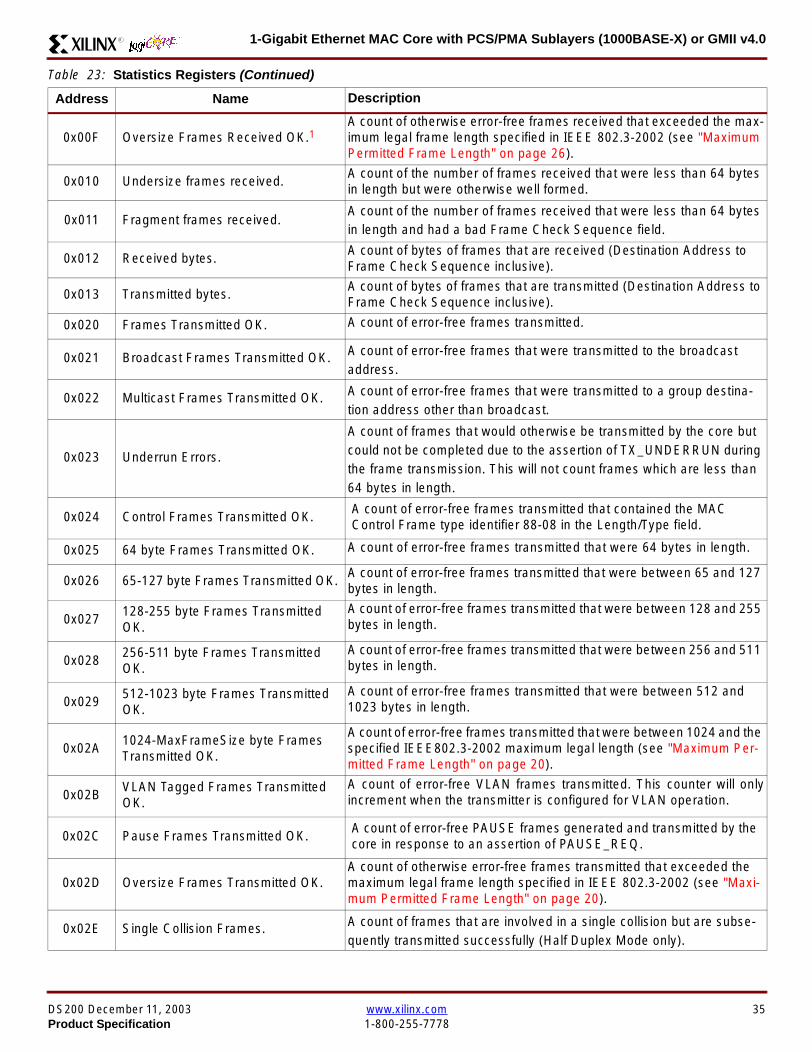
1-Gigabit Ethernet MAC Core with PCSPMA Sublayers (1000BASE-X) or GMII v40R
0x00F Oversize Frames Received OK1A count of otherwise error-free frames received that exceeded the max-imum legal frame length specified in IEEE 8023-2002 (see MaximumPermitted Frame Length on page 26)
0x010 Undersize frames receivedA count of the number of frames received that were less than 64 bytesin length but were otherwise well formed
0x011 Fragment frames receivedA count of the number of frames received that were less than 64 bytesin length and had a bad Frame Check Sequence field
0x012 Received bytesA count of bytes of frames that are received (Destination Address toFrame Check Sequence inclusive)
0x013 Transmitted bytesA count of bytes of frames that are transmitted (Destination Address toFrame Check Sequence inclusive)
0x020 Frames Transmitted OK A count of error-free frames transmitted
0x021 Broadcast Frames Transmitted OK A count of error-free frames that were transmitted to the broadcastaddress
0x022 Multicast Frames Transmitted OK A count of error-free frames that were transmitted to a group destina-tion address other than broadcast
0x023 Underrun Errors
A count of frames that would otherwise be transmitted by the core butcould not be completed due to the assertion of TX_UNDERRUN duringthe frame transmission This will not count frames which are less than64 bytes in length
0x024 Control Frames Transmitted OKA count of error-free frames transmitted that contained the MACControl Frame type identifier 88-08 in the LengthType field
0x025 64 byte Frames Transmitted OK A count of error-free frames transmitted that were 64 bytes in length
0x026 65-127 byte Frames Transmitted OKA count of error-free frames transmitted that were between 65 and 127bytes in length
0x027128-255 byte Frames TransmittedOK
A count of error-free frames transmitted that were between 128 and 255bytes in length
0x028256-511 byte Frames TransmittedOK
A count of error-free frames transmitted that were between 256 and 511bytes in length
0x029512-1023 byte Frames TransmittedOK
A count of error-free frames transmitted that were between 512 and1023 bytes in length
0x02A1024-MaxFrameSize byte FramesTransmitted OK
A count of error-free frames transmitted that were between 1024 and thespecified IEEE8023-2002 maximum legal length (see Maximum Per-mitted Frame Length on page 20)
0x02BVLAN Tagged Frames TransmittedOK
A count of error-free VLAN frames transmitted This counter will onlyincrement when the transmitter is configured for VLAN operation
0x02C Pause Frames Transmitted OKA count of error-free PAUSE frames generated and transmitted by thecore in response to an assertion of PAUSE_REQ
0x02D Oversize Frames Transmitted OKA count of otherwise error-free frames transmitted that exceeded themaximum legal frame length specified in IEEE 8023-2002 (see Maxi-mum Permitted Frame Length on page 20)
0x02E Single Collision Frames A count of frames that are involved in a single collision but are subse-quently transmitted successfully (Half Duplex Mode only)
Table 23 Statistics Registers (Continued)
Address Name Description
DS200 December 11 2003 wwwxilinxcom 35Product Specification 1-800-255-7778
1-Gigabit Ethernet MAC Core with PCSPMA Sublayers (1000BASE-X) or GMII v40 R
Each of these statistic registers is 64 bits wide and thereforemust be read in a two-cycle transfer The timing of this pro-cess is shown in Figure 26 Six clocks after the read trans-action is initiated the least significant word (LSW) of thestatistics counter appears on the HOST_RD_DATA bus
and a clock cycle later the most significant word (MSW)appears For accurate statistic values 64 clock ticks (ofTX_CLK for transmit statistics or RX_CLK for receive statis-tics) must elapse after the last frame is sent or receivedthrough the MAC core
0x02F Multiple Collision Frames A count of frames that are involved in more than one collision but aresubsequently transmitted successfully (Half Duplex Mode only)
0x040 Frames with Deferred Transmissions A count of frames whose transmission was delayed on its first attemptbecause the medium was busy (Half Duplex Mode only)
0x041 Late Collisions
A count of the times that a collision has been detected later than oneslotTime from the start of the packet transmission A late collision iscounted twice both as a collision and as a lateCollision (Half DuplexMode only)
0x042Frames Aborted due to Excesscollisions
A count of the frames that due to excessive collisions are not transmit-ted successfully (Half Duplex Mode only)
0x043 Carrier Sense ErrorsA count of times that the GMII_CRS signal was not asserted or wasdisasserted during the transmission of a frame without collision (HalfDuplex Mode only)
0x044 Frames with Excess DeferralA count of frames that deferred transmission for an excessive period oftime (Half Duplex Mode only)
1 If the LengthType Field Error Checks are disabled then these counters will still increment for received frames which contain this typeof error (providing no additional errors were detected)
Table 23 Statistics Registers (Continued)
Address Name Description
Figure 26 Statistic Register Read Timing
HOST_CLK
HOST_ADDR[80]
HOST_ADDR[9]
HOST_REQ
HOST_MIIM_SEL
HOST_RD_DATA[310]
6 CLOCKS
LSW MSW
xip2151
36 wwwxilinxcom DS200 December 11 20031-800-255-7778 Product Specification
1-Gigabit Ethernet MAC Core with PCSPMA Sublayers (1000BASE-X) or GMII v40R
MDIO Interface
The management interface is also used to access the MDIO(MII Management) interface of the MAC core this interfaceis used to access the Managed Information Block (MIB) ofthe PHY components attached to the MAC core
The MDIO interface supplies a clock to the externaldevices MDC This clock is derived from the HOST_CLKsignal using the value in the Clock Divide[40] configurationregister The frequency of the MDIO clock is given by thefollowing equation
The frequency of MDC given by this equation should notexceed 25 MHz in order to comply with the IEEE8023-2002 specification for this interface To prevent MDCfrom being out of specification the Clock Divide[40] valuepowers up at 00000 and while this value is in the register itis impossible to enable the MDIO interface
For details of the register map of PHY layer devices and afuller description of the operation of the MDIO interfaceitself see IEEE specification 8023-2002
Access to the MDIO interface through the managementinterface is depicted in the timing diagram in Figure 27
For MDIO transactions the following points apply
bull HOST_OPCODE maps to the OP (opcode) field of theMDIO frame
bull HOST_ADDR maps to the two address fields of theMDIO frame PHY_ADDR is HOST_ADDR[95] andREG_ADDR is HOST_ADDR[40]
bull HOST_WR_DATA[150] maps into the data field of the
MDIO frame when performing a write operation
bull The data field of the MDIO frame maps intoHOST_RD_DATA[150] when performing a readoperation
The MAC core signals to the host that it is ready for anMDIO transaction by asserting HOST_MIIM_RDY A read orwrite transaction on the MDIO is initiated by a pulse on the
fMDC
fHOST_CLK
1 Clock Divide[40]+( ) 2times-------------------------------------------------------------------=
Figure 27 MDIO Access Through Management Interface
HOST_CLK
HOST_ADDR[90]
HOST_OPCODE[10]
HOST_REQ
HOST_MIIM_SEL
HOST_RD_DATA[150]
HOST_WR_DATA[150]
HOST_RDY
If a read transaction is initiated the HOST_RD_DATA bus is valid at the point indicated If a write transaction is initiated the HOST_WR_DATA bus must be valid at the indicated point Simultaneous read and write is not permitted
xip2152
DS200 December 11 2003 wwwxilinxcom 37Product Specification 1-800-255-7778
1-Gigabit Ethernet MAC Core with PCSPMA Sublayers (1000BASE-X) or GMII v40 R
HOST_REQ signal This pulse is ignored if the MDIO inter-face already has a transaction in progress
The MAC core then disasserts the HOST_MIIM_RDY signalwhile the transaction across the MDIO is in progress Whenthe transaction across the MDIO interface has been com-pleted the HOST_MIIM_RDY signal will be asserted by theMAC core if the transaction is a read the data will also beavailable on the HOST_RD_DATA[150] bus at this time
Optional Configuration Vector(management_interface = false)If the optional Management interface is omitted from thecore all of relevant configuration signals are brought out of
the core These signals are bundled into theCONFIGURATION_VECTOR signal The bit mapping of theconfiguration vector signal is defined in Table 24 See thecorresponding entry in the configuration register tables forthe full description of each signal
Note that these configuration vector signals can bechanged by the user at any time however with the excep-tion of the reset and the flow control configuration signalsthey will not take effect until the current frame has com-pleted transmission or reception
The ldquoClockrdquo heading denotes which clock domain the con-figuration signal is registered into before use by the core Itis not necessary to drive the signal from this clock domain
Table 24 Configuration Vector Bit Definition
Bit(s)Configuration Register
cross reference Clock Description
47 downto 0
Receiver ConfigurationWord 0 bits 31-0 andReceiver ConfigurationWord 1 bits 15-0
RX_CLK
Pause frame MAC Source Address[470] This address isused by the MAC core to match against the DestinationAddress of any incoming flow control frames and as theSource Address for any outbound flow control frames
The address is ordered such that the first byte transmitted orreceived is the least significant byte in the register forexample a MAC address of AA-BB-CC-DD-EE-FF will bestored in bite [470] as 0xFFEEDDCCBBAA
48Receiver ConfigurationWord 1 bit 26
RX_CLKReceiver Half Duplex If lsquo1rsquo the receiver operates in halfduplex mode If lsquo0rsquo the receiver operates in full duplex modeHas no effect if XCO parameter half_duplex_capable = false
49Receiver ConfigurationWord 1 bit 27
RX_CLKReceiver VLAN Enable When this bit is set to 1 VLANtagged frames are accepted by the receiver
50Receiver ConfigurationWord 1 bit 28
RX_CLKReceiver Enable If set to 1 the receiver block is operationalIf set to 0 the block ignores activity on the physical interfaceRX port
51Receiver ConfigurationWord 1 bit 29
RX_CLK
Receiver In-band FCS Enable When this bit is lsquo1rsquo the MACreceiver will pass the FCS field up to the client as describedin Client-Supplied FCS Passing on page 25 When it is lsquo0rsquothe MAC receiver will not pass the FCS field In both casesthe FCS field will be verified on the frame
52Receiver ConfigurationWord 1 bit 30
RX_CLK
Receiver Jumbo Frame Enable When this bit is lsquo0rsquo thereceiver will not pass frames longer than the maximum legalframe size specified in IEEE 8023-2002 (see MaximumPermitted Frame Length on page 26) When it is lsquo1rsquo thereceiver will not have an upper limit on frame size
53Receiver ConfigurationWord 1 bit 31
NA
Receiver Reset When this bit is lsquo1rsquo the receiver is held inreset
This signal is an input to the reset circuit for the receiverblock See Reset circuit on page 42 for more information
54TransmitterConfiguration Word bit25
TX_CLK
Transmitter Interframe Gap Adjust enable If lsquo1rsquo then thetransmitter will read the value of the TX_IFG_DELAY port andset the Interframe Gap accordingly If lsquo0rsquo the transmitter willalways insert at least the legal minimum Interframe Gap
38 wwwxilinxcom DS200 December 11 20031-800-255-7778 Product Specification
1-Gigabit Ethernet MAC Core with PCSPMA Sublayers (1000BASE-X) or GMII v40R
55TransmitterConfiguration Word bit26
TX_CLK
Transmitter Half Duplex If lsquo1rsquo the transmitter operates in halfduplex mode If lsquo0rsquo the transmitter operates in full duplexmode Has no effect if XCO parameter half_duplex_capable= false
56TransmitterConfiguration Word bit27
TX_CLKTransmitter VLAN Enable When this bit is set to lsquo1rsquo thetransmitter allows the transmission of VLAN tagged frames
57TransmitterConfiguration Word bit28
TX_CLKTransmitter Enable When this bit is 1 the transmitter will beoperational When it is 0 the transmitter is disabled
58TransmitterConfiguration Word bit29
TX_CLK
Transmitter In-Band FCS Enable When this bit is lsquo1rsquo theMAC transmitter will expect the FCS field to be pass in by theclient as described in Client-Supplied FCS Passing onpage 17 When it is lsquo0rsquo the MAC transmitter will appendpadding as required compute the FCS and append it to theframe
59TransmitterConfiguration Word bit30
TX_CLK
Transmitter Jumbo Frame Enable When this bit is lsquo1rsquo theMAC transmitter will allow frames larger than the maximumlegal frame length specified in IEEE 8023-2002 to be sentWhen set to lsquo0rsquo the MAC transmitter will only allow frames upto the legal maximum to be sent
60TransmitterConfiguration Word bit31
NA
Transmitter Reset When this bit is lsquo1rsquo the MAC transmitter isheld in reset
This signal is an input to the reset circuit for the transmitterblock See Reset circuit on page 42 for more information
61Flow ControlConfiguration Word bit29
TX_CLK
Transmit Flow Control Enable When this bit is lsquo1rsquo assertingthe PAUSE_REQ signal causes the MAC core to send a flowcontrol frame out from the transmitter as described inReceiving a Pause Control Frame on page 29 When this bitis lsquo0rsquo asserting the PAUSE_REQ signal will have no effect
62Flow ControlConfiguration Word bit30
RX_CLK
Receive Flow Control Enable When this bit is lsquo1rsquo receivedflow control frames will inhibit the transmitter operation asdescribed in Receiving a Pause Control Frame on page 29When it is lsquo0rsquo received flow frames are passed up to theclient
63Receiver ConfigurationWord 1 bit 25
RX_CLK
LengthType Error Check Disable When this bit is lsquo1rsquo thecore will not perform the LengthType field error checks asdescribed in LengthType Field Error Checks on page 26When it is set to lsquo0rsquo the LengthType field checks will beperformed this is normal operation
Table 24 Configuration Vector Bit Definition (Continued)
Bit(s)Configuration Register
cross reference Clock Description
DS200 December 11 2003 wwwxilinxcom 39Product Specification 1-800-255-7778
1-Gigabit Ethernet MAC Core with PCSPMA Sublayers (1000BASE-X) or GMII v40 R
Optional GMII (physical_interface=gmii)The GMII is designed to IEEE 8023-2002 Clause 35 Thisutilizes IOrsquos of the Xilinx devices using inputoutput buffersand inputoutput flip-flops to maximize setup and hold mar-gins All IO logic is placed in the example wrapper that isdelivered with the core In addition all clock managementlogic for the core is instanced in this example wrapper thisallows multiple instances of the core to share clocks Theexample wrapper is provided in both VHDL and Verilog
Clock Management
Figure 28 illustrates the clock management used with theGMII interface All clocks illustrated have a frequency of125MHz
GTX_CLK must be provided to the MAC core This is a highquality clock which satisfies the IEEE8023-2002 require-ments It is expected that this clock will be derived from anexternal oscillator and connected into the device through anIBUFG as illustrated The clock source must then be routedonto a global clock network by connecting it to a BUFGWithin the MAC core this global clock is used by all MACtransmitter logic The MAC Client can obtain this clock byconnecting to the TX_CLK signal output from the coreGMII_TX_CLK is derived from this global clock by invertingit and routing it to an OBUF
GMII_RX_CLK is received through an IBUFG This clock isthen routed onto a global clock network by connecting it to aBUFG The resulting global clock is used by all MACreceiver logic
Figure 28 Clock Management with GMII
IBUFG
IBUFG
OBUF
BUFG
BUFG
TX_CLK
RX_CLK
GTX_CLK
GMII_TX_CLK
GMII_RX_CLK
Example Wrapper
xip2153
MAC Core
TX_CLK
RX_CLK
GMII_TX_CLK
GMII_RX_CLK
GTX_CLK
40 wwwxilinxcom DS200 December 11 20031-800-255-7778 Product Specification
1-Gigabit Ethernet MAC Core with PCSPMA Sublayers (1000BASE-X) or GMII v40R
Clock Sharing between Multiple cores
Figure 29 illustrates how it is possible to share clockresources across multiple instantiations of the core whenusing the optional GMII
GTX_CLK may be shared between multiple cores as illus-trated resulting in a common transmitter clock domainacross the device
A common receiver clock domain is not possible each corewill receive an independent receiver clock from its GMII asillustrated
Although not illustrated if the optional Management Inter-face is used HOST_CLK can also be shared betweencores
Figure 29 Clock Management with multiple instances of the MAC with GMII
IBUFG
OBUF
BUFG
TX_CLK
RX_CLK_1
GMII_TX_CLK_1
GMII_RX_CLK_1
MAC Core
TX_CLK
RX_CLK
GMII_TX_CLK
GMII_RX_CLK
GTX_CLK
MAC Core
TX_CLK
RX_CLK
GMII_TX_CLK
GMII_RX_CLK
GTX_CLK
IBUFG
BUFG
GTX_CLK
IBUFG
OBUF
GMII_TX_CLK_2
GMII_RX_CLK_2
BUFG
TX_CLK
RX_CLK_2
DS200 December 11 2003 wwwxilinxcom 41Product Specification 1-800-255-7778
1-Gigabit Ethernet MAC Core with PCSPMA Sublayers (1000BASE-X) or GMII v40 R
Reset circuit
Internally the core is divided up into clockreset domainswhich group together elements with the common clock andreset signals The reset circuitry for one of these domains isis illustrated in Figure 30 This circuit provides controllableskews on the reset nets within the design
More information on the operation and rationale behind thiscircuit can be found in Ken Chapmanrsquos Xilinx TechXclusiveldquoGet Smart About Resetrdquo athttpwwwxilinxcomsupporttechxclusivesglobal-techX19htm
Figure 30 Reset circuit for one clockreset domain
FDP
PRED
C
Q
FDP
PRED
C
Q
FDP
PRED
C
Q
FDP
PRED
C
Q
PRE PRE PRE
0
RESET
Management Reset
Clock
Core Registers
42 wwwxilinxcom DS200 December 11 20031-800-255-7778 Product Specification
1-Gigabit Ethernet MAC Core with PCSPMA Sublayers (1000BASE-X) or GMII v40R
Optional PCS with Ten-Bit Interface (TBI) for 1000BASE-X (physical_interface=tbi)The Full-Duplex Physical Coding Sublayer (PCS) for1000BASE-X is defined in IEEE 8023-2002 Clauses 36and 37 This functionality is only available in the Virtex-IIand Spartan3 families of FPGA devices
A block diagram of the PCS is shown in Figure 31 Themajor functional blocks of the PCS are
bull Transmit engine
bull Auto-negotiation block
bull Receive engine and synchronization block
bull PCS managed register block
bull 8B10B encoder block
bull 8B10B decoder block
bull Receiver elastic buffer
The PCS Managed Register Block is accessed through theMDIO Interface as if it were an externally connected PHYThis configures the operation of the PCS and Auto-Negoti-ation See PCS Managed Register Block
(physical_interface = tbi or phy) on page 49 The corersquosoptional Management Interface can be used to control theMDIO Interface as described by MDIO Interface onpage 37 When the optional Management Interface is notpresent the PCS Managed Register Block must beaccessed via an MDIO controller which is not provided bythe core
The 8B10B encodingdecoding blocks are implemented byconfiguring two Block SelectRAM modules as ROM Theseare used as large look-up tables The remaining PCS func-tionality such as code group encodingdecoding the Man-aged Register Block and Auto-Negotiation areimplemented in CLB logic
The Receiver Elastic buffer enables the 10-bit parallel datareceived from the PMA sublayer alternatively onPMA_RX_CLK0 and PMA_RX_CLK1 clock edges to betransferred onto the internal 125MHz clock domain derivedfrom GTX_CLK (see Clock Management) This buffer isimplemented in Distributed Memory
Figure 31 Functional Block Diagram of the 1-Gigabit Ethernet PCS with TBI Interface
PCS TRANSMIT ENGINE
PCS RECEIVE ENGINE ampSYNCHRONISATION
PCSMANAGEMENT
MDIOInterface
AUTO-NEGOTIATION
MAC TXInterface
MAC RXInterface
8B10BEncoder
8B10BDecoder
RX Elastic Buffer
TBI Interface
DS200 December 11 2003 wwwxilinxcom 43Product Specification 1-800-255-7778
1-Gigabit Ethernet MAC Core with PCSPMA Sublayers (1000BASE-X) or GMII v40 R
TBI Interface
The TBI is designed to IEEE 8023-2002 Clause 363 Thisutilizes IOrsquos of the Xilinx devices using inputoutput buffersand inputoutput flip-flops to maximize setup and hold mar-gins All IO logic is placed in the example wrapper that isdelivered with the core In addition all clock managementlogic for the core is instantiated in this example wrapperthis allows multiple instances of the core to share clocksThe example wrapper is provided in both VHDL and Verilog
Clock Management
Figure 32 illustrates the clock management used with theTBI interface
GTX_CLK must be provided to the MAC core This is a highquality clock of frequency 125MHz which satisfies theIEEE8023-2002 requirements It is expected that this clockwill be derived from an external oscillator and connected
into the device through an IBUFG as illustrated The clocksource must then be routed onto a global clock network byconnecting it to a BUFG Within the MAC core this globalclock is used by all MAC transmitter logic PMA_TX_CLK isderived from this global clock by inverting it and routing it toan OBUF
PMA_RX_CLK0 and PMA_RX_CLK1 are each receivedthrough an IBUFG These clocks are then routed onto glo-bal clock networks by connecting each to a BUFGPMA_RX_CLK0 and PMA_RX_CLK1 are each 625MHzclocks Data from the TBI is received alternatively on the ris-ing edge of PMA_RX_CLK0 followed by the rising edge ofPMA_RX_CLK1 using IOB Double-Data Rate input regis-ters This data is then written into the Receiver ElasticBuffer Data is read out of the Elastic Buffer using the globalclock derived from GTX_CLK all the remaining receiverlogic is synchronous to this clock
Figure 32 Clock Management for PCS with TBI Interface
IBUFG
IBUFG
OBUF
BUFG
BUFG
TX_CLK
RX_CLK
GTX_CLK
PMA_TX_CLK
PMA_RX_CLK0
MAC Core
RX ELASTICBUFFER
Example Wrapper
TX_CLK
RX_CLK
GTX_CLK
PMA_TX_CLK
PMA_RX_CLK0
IBUFGBUFGPMA_RX_CLK1
PMA_RX_CLK1
44 wwwxilinxcom DS200 December 11 20031-800-255-7778 Product Specification
1-Gigabit Ethernet MAC Core with PCSPMA Sublayers (1000BASE-X) or GMII v40R
Clock Sharing between Multiple cores
Figure 33 illustrates how it is possible to share clockresources across multiple instantiations of the core whenusing the optional PCS with TBI
GTX_CLK may be shared between multiple cores as illus-trated resulting in a common transmitter clock domainacross the device
Each core will receive independent PMA_RX_CLK0 andPMA_RX_CLK1 clocks from its TBI as illustrated whichcannot be shared
Although not illustrated if the optional Management Inter-face is used HOST_CLK can also be shared betweencores
Figure 33 Clock Management with multiple instances of the MAC with PCS and TBI
Reset circuit
The reset circuits within the MAC when the TBI interface is implemented is the same as that in the GMII case details ofthese circuits can be found on page 42
IBUFG
OBUF
BUFG
TX_CLK
RX_CLK
PMA_TX_CLK_1
PMA_RX_CLK0_1
MAC Core
RX ELASTICBUFFER
TX_CLK
RX_CLK
GTX_CLK
PMA_TX_CLK
PMA_RX_CLK0
IBUFGBUFGPMA_RX_CLK1_1
PMA_RX_CLK1
IBUFG
BUFG
GTX_CLK
IBUFG
OBUF
BUFG
TX_CLK
RX_CLK
PMA_TX_CLK_2
PMA_RX_CLK0_2
MAC Core
RX ELASTICBUFFER
TX_CLK
RX_CLK
GTX_CLK
PMA_TX_CLK
PMA_RX_CLK0
IBUFGBUFGPMA_RX_CLK1_2
PMA_RX_CLK1
DS200 December 11 2003 wwwxilinxcom 45Product Specification 1-800-255-7778
1-Gigabit Ethernet MAC Core with PCSPMA Sublayers (1000BASE-X) or GMII v40 R
Optional PCS and PMA Sublayers for 1000BASE-X (physical_interface=phy)The Full-Duplex Physical Coding Sublayer (PCS) withPhysical Medium Attachment (PMA) for 1000BASE-X isdefined in IEEE 8023-2002 Clauses 36 and 37 This func-tionality is only available in the Virtex-II Pro family of FPGAdevices
A block diagram of the PCS and PMA sublayers can beseen in Figure 34 The functional blocks of the PCS andPMA sublayers may replace the optional GMII interfaceThe functional blocks of the PCS and PMA sublayers are
bull PCS Transmit Engine
bull Auto-Negotiation block
bull Receive Engine and Synchronization Block
bull PCS Managed Register Block
bull Rocket IO Multi-Gigabit Transceiver
The PCS Managed Register Block is accessed through theMDIO Interface as if it were an externally connected PHYThis configures the operation of the PCS PMA sublayerand Auto-NegotiationSee PCS Managed Register Block(physical_interface = tbi or phy) on page 49 The corersquosoptional Management Interface can be used to control theMDIO Interface as described by MDIO Interface onpage 37 When the optional Management Interface is notpresent the PCS Managed Register Block must beaccessed via an MDIO controller which is not provided bythe core
The Rocket IO Multi-Gigabit Transceiver (MGT) providessome of the PCS layer functionality such as 8B10B encod-ingdecoding and the PMA serdes The remaining PCSfunctionality such as code group encodingdecoding theManaged Register Block and Auto-Negotiation are imple-mented in CLB logic
Figure 34 Functional Block Diagram of the 1-Gigabit Ethernet PCSPMA Sublayer Extension
PCS TRANSMIT ENGINE
PCS RECEIVE ENGINE ampSYNCHRONISATION
RO
CK
ET
IO
MU
LTI-
GIG
TR
AN
SC
EIV
ER
PCSMANAGEMENT
MDIOInterface
AUTO-NEGOTIATION
TXPTXN
RXPRXN
MAC TXInterface
MAC RXInterface
xip2154
46 wwwxilinxcom DS200 December 11 20031-800-255-7778 Product Specification
1-Gigabit Ethernet MAC Core with PCSPMA Sublayers (1000BASE-X) or GMII v40R
Clock Management
Figure 35 illustrates the clock management that should beused with the optional PCS and PMA sublayers for1000BASE-X This logic is implemented in the examplewrapper that is delivered with the core This provides flexi-bility because the design can be modified to use eitherREFCLK or BREFCLK (please refer to Rocket IO docu-mentation) It would also allow multiple instances of the coreto share clocks The example wrapper is provided in bothVHDL and Verilog
(B)REFCLK must be provided to the MAC core This clockmust be derived from an external oscillator and connectedto the core through an IBUFG as illustrated (B)REFCLK isa high quality clock of frequency 625 MHz which satisfiesthe Rocket IO Multi-Gigabit Transceiver (MGT) require-ments
(B)REFCLK is routed to both the core and a DCM From theDCM the CLK2X180 output is routed to a BUFG to providethe device with a global 125 MHz clock (connected toUSERCLK2 input on the core) Within the core bothTX_CLK and RX_CLK share this global 125 MHz clocksource which is used by all transmitter and receiver logicThis is made possible by the RX_ELASTIC_BUFFER func-tionality of the Rocket IO MGT (refer to Virtex-II Pro docu-mentation) The MAC Client can obtain this clock byconnecting to either the TX_CLK or the RX_CLK signalsoutput from the core
From the DCM the CLK0 output is routed to a BUFG to pro-vide the device with a global 625MHz clock This is con-nected to the USRCLK input of the core
Figure 35 Clock Management with PCSPMA Sublayers
DCM
CLKIN CLK0
CLK2X180FB
BUFG
BUFG
IBUFG
TX_CLK
RX_CLK
(B)REFCLK
TXUSRCLK
(B)REFCLK
TXUSRCLK2RXUSRCLKRXUSRCLK2
GT_ETHERNET
Example Wrapper
xip2155
MAC Core
(B)REFCLK
USRCLK
USRCLK2
TX_CLK
RX_CLK
DS200 December 11 2003 wwwxilinxcom 47Product Specification 1-800-255-7778
1-Gigabit Ethernet MAC Core with PCSPMA Sublayers (1000BASE-X) or GMII v40 R
Clock Sharing between Multiple Cores
Figure 36 illustrates how it is possible to share clockresources across multiple instantiations of the core whenusing the optional PCSPMA sublayers For each coreUSERCLK and USERCLK2 must always be derived asshown from the BREFCLK or REFCLK used by that core
Note that when using the fixed routing resources of BREF-CLK Rocket IO MGTs along the top edge of the devicemust use a separate BREFCLK routing resource to thosealong the bottom edge of the device (Refer to Virtex-II Prodocumentation)
Although not illustrated if the optional Management Inter-face is used HOST_CLK can also be shared betweencores
Figure 36 Clock Management with multiple instances of the MAC with PCS and PMA sublayers
Reset circuit
The reset circuits within the MAC when the PCS and PMA sublayers are implemented is the same as that in the GMII casedetails of these circuits can be found on page 42
DCM
CLKIN CLK0
CLK2X180FB
BUFG
BUFG
IBUFG
(B)REFCLK
TXUSRCLK
(B)REFCLK
TXUSRCLK2RXUSRCLKRXUSRCLK2
GT_ETHERNET(B)REFCLK
USERCLK
USERCLK2
MAC core
TXUSRCLK
(B)REFCLK
TXUSRCLK2RXUSRCLKRXUSRCLK2
GT_ETHERNET(B)REFCLK
USERCLK
USERCLK2
MAC core
48 wwwxilinxcom DS200 December 11 20031-800-255-7778 Product Specification
1-Gigabit Ethernet MAC Core with PCSPMA Sublayers (1000BASE-X) or GMII v40R
PCS Managed Register Block (physical_interface = tbi or phy)The PCS in both the TBI interface and the PCSPMA (usingthe Virtex-II Pro Rocket IO) versions contain the full Man-aged Register Block defined in IEEE 8023-2002 clause 37
This utilizes ten dedicated management registersaccessed via the MDIO interface These are defined inTable 25 to Table 33 inclusive
Table 25 Control Register (Register 0)
Bit(s) Name Description Attributes Default Value
015 Reset1 = PCSPMA reset
0 = Normal Operation
ReadWrite
Self Clearing0
014 Loopback1 = Enable Loopback Mode
0 = Disable Loopback ModeReadWrite 0
013SpeedSelection (LSB)
The core always returns a 0 for this bitTogether with bit 06 speed selection of 1000Mbs is identified
Returns 0 0
012Auto-NegotiationEnable
1 = Enable Auto-Negotiation Process
0 = Disable Auto-Negotiation ProcessReadWrite 1
011 Power Down
1 = Power down
0 = Normal operation
When set to ldquo1rdquo the Rocket IO MGT is placedin a low power state This bit requires a reset(see bit 015) to clear
Read Write 0
010 Isolate1 = Electrically Isolate PHY from GMII
0 = Normal operationReadWrite 1
09Restart Auto-Negotiation
1 = Restart Auto-Negotiation Process
0 = Normal Operation
ReadWrite
Self Clearing0
08 Duplex ModeThe core always returns a 1 for this bit tosignal Full-Duplex Mode
Returns 1 1
07 Collision TestThe core always returns a 0 for this bit todisable COL test
Returns 0 0
06SpeedSelection(MSB)
The core always returns a 1 for this bitTogether with bit 013 speed selection of1000 Mbs is identified
Returns 1 1
050 Reserved Always returns 0rsquos writes ignored Returns 0rsquos 000000
DS200 December 11 2003 wwwxilinxcom 49Product Specification 1-800-255-7778
1-Gigabit Ethernet MAC Core with PCSPMA Sublayers (1000BASE-X) or GMII v40 R
Table 26 Status Register (Register 1)
Bit(s) Name Description Attributes Default Value
115 100BASE-T4The core always returns a 0 for this bitbecause 100BASE-T4 is not supported
Returns 0 0
114100BASE-XFullDuplex
The core always returns a 0 for this bitbecause 100BASE-X Full Duplex is notsupported
Returns 0 0
113100BASE-XHalf Duplex
The core always returns a 0 for this bitbecause 100BASE-X Half Duplex is notsupported
Returns 0 0
11210 Mbs FullDuplex
The core always returns a 0 for this bitbecause 10 Mbs Full Duplex is notsupported
Returns 0 0
11110 Mbs HalfDuplex
The core always returns a 0 for this bitbecause 10 Mbs Half Duplex is notsupported
Returns 0 0
110100BASE-T2Full Duplex
The core always returns a 0 for this bitbecause 100BASE-T2 Full Duplex is notsupported
Returns 0 0
19100BASE-T2Half Duplex
The core always returns a 0 for this bitbecause 100BASE-T2 Half Duplex is notsupported
Returns 0 0
18ExtendedStatus
The core always returns a 1 for this bit toindicate the presence of the ExtendedRegister (Register 15)
Returns 1 1
17 Reserved Always return 0 writes ignored Returns 0 0
16MF PreambleSuppression
The core always returns a 1 for this bit toindicate that Management Frame PreambleSuppression is supported
Returns 1 1
15Auto-NegotiationComplete
1 = Auto-Negotiation process completed
0 = Auto-Negotiation process not completedRead Only 0
14 Remote Fault1 = Remote fault condition detected
0 = No remote fault condition detected
Read Only
Self Clearing on read0
13Auto-NegotiationAbility
The core always returns a 1 for this bit toindicate that the PHY is capable ofAuto-Negotiation
Returns 1 1
12 Link Status1 = Link is up
0 = Link is down
Read Only
Self Clearing on read0
11 Jabber DetectThe core always returns a 0 for this bitbecause Jabber Detect is not supported
Returns 0 0
10ExtendedCapability
The core always returns a 0 for this bitbecause no extended register set issupported
Returns 0 0
50 wwwxilinxcom DS200 December 11 20031-800-255-7778 Product Specification
1-Gigabit Ethernet MAC Core with PCSPMA Sublayers (1000BASE-X) or GMII v40R
Table 27 PHY Identifier (Registers 2 and 3)
Bit(s) Name Description Attributes Default Value
2150OrganizationallyUniqueIdentifier
Always returns 0s Returns 0s 0000000000000000
31510OrganizationallyUniqueIdentifier
Always returns 0s Returns 0s 000000
394Manufacturerrsquosmodel number
Always returns 0s Returns 0s 000000
330RevisionNumber
Always returns 0s Returns 0s 0000
Table 28 Auto-Negotiation Advertisement Register (Register 4)
Bit(s) Name Description Attributes Default Value
415 Next Page1 = Next Page functionality is advertised
0 = Next Page functionality is not advertisedReadWrite 0
414 Reserved Always returns 0 writes ignored Returns 0 0
41312 Remote Fault
00 = No Error
01 = Offline
10 = Link Failure
11 = Auto-Negotiation Error
ReadWrite
Self clearing to 00afterAuto-Negotiation
00
4119 Reserved Always return 0 writes ignored Returns 0 0
487 Pause
00 = No PAUSE
01 = Asymmetric PAUSE towards linkpartner
10 = Symmetic PAUSE
11 = Both Symmetric PAUSE andAsymmetric PAUSE towards link partner
ReadWrite 11
46 Half DuplexThe core always returns a 0 for this bitbecause Half Duplex Mode is not supported
Returns 0 0
45 Full Duplex1 = Full Duplex Mode is advertised
0 = Full Duplex Mode is not advertisedReadWrite 1
440 Reserved Always returns 0s writes ignored Returns 0s 00000
DS200 December 11 2003 wwwxilinxcom 51Product Specification 1-800-255-7778
1-Gigabit Ethernet MAC Core with PCSPMA Sublayers (1000BASE-X) or GMII v40 R
Table 29 Auto-Negotiation Link Partner Ability Base Register (Register 5)
Bit(s) Name Description Attributes Default Value
515 Next Page1 = Next Page functionality is supported
0 = Next Page functionality is not supportedRead Only 0
514 AcknowledgeUsed by Auto-Negotiation function toindicate reception of a link partnerrsquos base ornext page
Read Only 0
51312 Remote Fault
00 = No Error
01 = Offline
10 = Link Failure
11 = Auto-Negotiation Error
Read Only 00
5119 Reserved Always returns 0s Returns 0s 000
587 Pause
00 = No PAUSE
01 = Asymmetric PAUSE supported
10 = Symmetic PAUSE supported
11 = Both Symmetric PAUSE andAsymmetric PAUSE supported
Read Only 00
56 Half Duplex1 = Half Duplex Mode is supported
0 = Half Duplex Mode is not supportedRead Only 0
55 Full Duplex1 = Full Duplex Mode is supported
0 = Full Duplex Mode is not supportedRead Only 0
540 Reserved Always returns 0s Returns 0s 00000
Table 30 Auto-Negotiation Expansion Register (Register 6)
Bit(s) Name Description Attributes Default Value
6153 Reserved Always returns 0s Returns 0s 0000000000000
62 Next Page AbleThe core always returns a 1 for this bitbecause the device is Next Page Able
Returns 1 1
61 Page Received1 = A new page has been received
0 = A new page has not been received
Read Only
Self Clearing on read0
60 Reserved Always returns 0s Returns 0s 0000000
52 wwwxilinxcom DS200 December 11 20031-800-255-7778 Product Specification
1-Gigabit Ethernet MAC Core with PCSPMA Sublayers (1000BASE-X) or GMII v40R
Table 31 Auto-Negotiation Next Page Transmit Register (Register 7)
Bit(s) Name Description Attributes Default Value
715 Next Page1 = Additional Next Page(s) will follow
0 = Last pageReadWrite 0
714 Reserved Always returns 0 Returns 0 0
713 Message Page1 = Message Page
0 = Unformatted PageReadWrite 1
712 Acknowledge 21 = Will comply with message
0 = Cannot comply with messageReadWrite 0
711 ToggleValue will toggle between subsequent NextPages
Read Only 0
7100Message UnformattedCode Field
Message Code Field or Unformatted PageEncoding as dictated by 713
ReadWrite00000000001
(Null Message Code)
Table 32 Auto-Negotiation Next Page Receive Register (Register 8)
Bit(s) Name Description Attributes Default Value
815 Next Page1 = Additional Next Page(s) follows
0 = Last pageRead Only 0
814 AcknowledgeUsed by Auto-Negotiation function toindicate reception of a link partnerrsquos base ornext page
Read Only 0
813 Message Page1 = Message Page
0 = Unformatted PageRead Only 0
812 Acknowledge 21 = Will comply with message
0 = Cannot comply with messageRead Only 0
811 ToggleValue toggles between subsequent andNext Pages
Read Only 0
8100Message UnformattedCode Field
Message Code Field or Unformatted PageEncoding as dictated by 813
Read Only 00000000000
DS200 December 11 2003 wwwxilinxcom 53Product Specification 1-800-255-7778
1-Gigabit Ethernet MAC Core with PCSPMA Sublayers (1000BASE-X) or GMII v40 R
)
Referencesbull IEEE 8023-2002
bull Virtex-E User Guide
bull Spartan-II E User Guide
bull Virtex-II User Guide
bull Virtex-II Pro User Guide
Related InformationXilinx products are not intended for use in life support appli-ances devices or systems Use of a Xilinx product in suchapplications without the written consent of the appropriateXilinx officer is prohibited
Ordering InformationThis Xilinx LogiCORE module is provided under theSignOnce IP Site License A free evaluation version of themodule is available
Once purchased the core may be downloaded from the Xil-inx IP Center for use with the Xilinx CORE Generator Sys-temtrade v61i SP3 and later The Xilinx CORE GeneratorSystem tool is bundled with all Alliance Series Softwarepackages at no additional charge
Please contact your local Xilinx sales representative or visitthe Xilinx Silicon Xpresso Cafe for pricing and availability onXilinx LogiCORE modules and software Information onadditional Xilinx LogiCORE modules is available on the Xil-inx IP Center
Revision HistoryThe following table shows the revision history for this document
Table 33 Extended Status Register (Register 15)
Bit(s) Name Description Attributes Default Value
15151000BASE-XFull Duplex
The core always returns a 1 for this bitbecause 1000BASE-X Full Duplex issupported
Returns 1 1
15141000BASE-XHalf Duplex
The core always returns a 0 for this bitbecause 1000BASE-X Half Duplex is notsupported
Returns 0 0
15131000BASE-TFull Duplex
The core always returns a 0 for this bitbecause 1000BASE-T Full Duplex is notsupported
Returns 0 0
15121000BASE-THalf Duplex
The core always returns a 0 for this bitbecause 1000BASE-T Half Duplex is notsupported
Returns 0 0
15110 Reserved Always returns 0s Returns 0s 000000000000
Date Version Revision
032803 11 Revision History added to document
043003 20 Revised to v30 standards
121103 30 Updated to v40 release
54 wwwxilinxcom DS200 December 11 20031-800-255-7778 Product Specification
- 1-Gigabit Ethernet MAC Core with PCSPMA Sublayers (1000BASE-X) or GMII v40
-
- Features
- MAC Overview
- Xilinx CORE Generator
- GUI Interface
- Parameter Values in the XCO File
- Output Generation
- Device Utilization
- Interface Description
- Interface Signals for MAC with physical_interface=gmii and management_interface=true
- Interface Signals for MAC with physical_interface=gmii and management_interface=false
- Interface Signals for MAC with physical_interface=tbi and management_interface=true
- Interface Signals for MAC with physical_interface=tbi and management_interface=false
- Interface Signals for MAC with physical_interface=phy and management_interface=true
- Interface Signals for MAC with physical_interface=phy and management_interface=false
- Client Side Interface Signal Definition
- Physical Interface Signal Definition
- Functional Description
- Client Interface
- Transmitter
- Receiver
- Flow Control
- Optional Management Interface (management_interface=true)
- Optional Configuration Vector (management_interface = false)
- Optional GMII (physical_interface=gmii)
- Optional PCS with Ten-Bit Interface (TBI) for 1000BASE-X (physical_interface=tbi)
- Optional PCS and PMA Sublayers for 1000BASE-X (physical_interface=phy)
- PCS Managed Register Block (physical_interface = tbi or phy)
- References
- Related Information
- Ordering Information
- Revision History
-
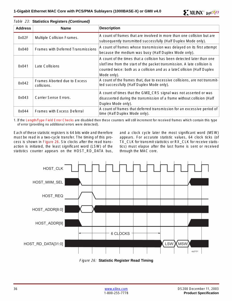
1-Gigabit Ethernet MAC Core with PCSPMA Sublayers (1000BASE-X) or GMII v40 R
Each of these statistic registers is 64 bits wide and thereforemust be read in a two-cycle transfer The timing of this pro-cess is shown in Figure 26 Six clocks after the read trans-action is initiated the least significant word (LSW) of thestatistics counter appears on the HOST_RD_DATA bus
and a clock cycle later the most significant word (MSW)appears For accurate statistic values 64 clock ticks (ofTX_CLK for transmit statistics or RX_CLK for receive statis-tics) must elapse after the last frame is sent or receivedthrough the MAC core
0x02F Multiple Collision Frames A count of frames that are involved in more than one collision but aresubsequently transmitted successfully (Half Duplex Mode only)
0x040 Frames with Deferred Transmissions A count of frames whose transmission was delayed on its first attemptbecause the medium was busy (Half Duplex Mode only)
0x041 Late Collisions
A count of the times that a collision has been detected later than oneslotTime from the start of the packet transmission A late collision iscounted twice both as a collision and as a lateCollision (Half DuplexMode only)
0x042Frames Aborted due to Excesscollisions
A count of the frames that due to excessive collisions are not transmit-ted successfully (Half Duplex Mode only)
0x043 Carrier Sense ErrorsA count of times that the GMII_CRS signal was not asserted or wasdisasserted during the transmission of a frame without collision (HalfDuplex Mode only)
0x044 Frames with Excess DeferralA count of frames that deferred transmission for an excessive period oftime (Half Duplex Mode only)
1 If the LengthType Field Error Checks are disabled then these counters will still increment for received frames which contain this typeof error (providing no additional errors were detected)
Table 23 Statistics Registers (Continued)
Address Name Description
Figure 26 Statistic Register Read Timing
HOST_CLK
HOST_ADDR[80]
HOST_ADDR[9]
HOST_REQ
HOST_MIIM_SEL
HOST_RD_DATA[310]
6 CLOCKS
LSW MSW
xip2151
36 wwwxilinxcom DS200 December 11 20031-800-255-7778 Product Specification
1-Gigabit Ethernet MAC Core with PCSPMA Sublayers (1000BASE-X) or GMII v40R
MDIO Interface
The management interface is also used to access the MDIO(MII Management) interface of the MAC core this interfaceis used to access the Managed Information Block (MIB) ofthe PHY components attached to the MAC core
The MDIO interface supplies a clock to the externaldevices MDC This clock is derived from the HOST_CLKsignal using the value in the Clock Divide[40] configurationregister The frequency of the MDIO clock is given by thefollowing equation
The frequency of MDC given by this equation should notexceed 25 MHz in order to comply with the IEEE8023-2002 specification for this interface To prevent MDCfrom being out of specification the Clock Divide[40] valuepowers up at 00000 and while this value is in the register itis impossible to enable the MDIO interface
For details of the register map of PHY layer devices and afuller description of the operation of the MDIO interfaceitself see IEEE specification 8023-2002
Access to the MDIO interface through the managementinterface is depicted in the timing diagram in Figure 27
For MDIO transactions the following points apply
bull HOST_OPCODE maps to the OP (opcode) field of theMDIO frame
bull HOST_ADDR maps to the two address fields of theMDIO frame PHY_ADDR is HOST_ADDR[95] andREG_ADDR is HOST_ADDR[40]
bull HOST_WR_DATA[150] maps into the data field of the
MDIO frame when performing a write operation
bull The data field of the MDIO frame maps intoHOST_RD_DATA[150] when performing a readoperation
The MAC core signals to the host that it is ready for anMDIO transaction by asserting HOST_MIIM_RDY A read orwrite transaction on the MDIO is initiated by a pulse on the
fMDC
fHOST_CLK
1 Clock Divide[40]+( ) 2times-------------------------------------------------------------------=
Figure 27 MDIO Access Through Management Interface
HOST_CLK
HOST_ADDR[90]
HOST_OPCODE[10]
HOST_REQ
HOST_MIIM_SEL
HOST_RD_DATA[150]
HOST_WR_DATA[150]
HOST_RDY
If a read transaction is initiated the HOST_RD_DATA bus is valid at the point indicated If a write transaction is initiated the HOST_WR_DATA bus must be valid at the indicated point Simultaneous read and write is not permitted
xip2152
DS200 December 11 2003 wwwxilinxcom 37Product Specification 1-800-255-7778
1-Gigabit Ethernet MAC Core with PCSPMA Sublayers (1000BASE-X) or GMII v40 R
HOST_REQ signal This pulse is ignored if the MDIO inter-face already has a transaction in progress
The MAC core then disasserts the HOST_MIIM_RDY signalwhile the transaction across the MDIO is in progress Whenthe transaction across the MDIO interface has been com-pleted the HOST_MIIM_RDY signal will be asserted by theMAC core if the transaction is a read the data will also beavailable on the HOST_RD_DATA[150] bus at this time
Optional Configuration Vector(management_interface = false)If the optional Management interface is omitted from thecore all of relevant configuration signals are brought out of
the core These signals are bundled into theCONFIGURATION_VECTOR signal The bit mapping of theconfiguration vector signal is defined in Table 24 See thecorresponding entry in the configuration register tables forthe full description of each signal
Note that these configuration vector signals can bechanged by the user at any time however with the excep-tion of the reset and the flow control configuration signalsthey will not take effect until the current frame has com-pleted transmission or reception
The ldquoClockrdquo heading denotes which clock domain the con-figuration signal is registered into before use by the core Itis not necessary to drive the signal from this clock domain
Table 24 Configuration Vector Bit Definition
Bit(s)Configuration Register
cross reference Clock Description
47 downto 0
Receiver ConfigurationWord 0 bits 31-0 andReceiver ConfigurationWord 1 bits 15-0
RX_CLK
Pause frame MAC Source Address[470] This address isused by the MAC core to match against the DestinationAddress of any incoming flow control frames and as theSource Address for any outbound flow control frames
The address is ordered such that the first byte transmitted orreceived is the least significant byte in the register forexample a MAC address of AA-BB-CC-DD-EE-FF will bestored in bite [470] as 0xFFEEDDCCBBAA
48Receiver ConfigurationWord 1 bit 26
RX_CLKReceiver Half Duplex If lsquo1rsquo the receiver operates in halfduplex mode If lsquo0rsquo the receiver operates in full duplex modeHas no effect if XCO parameter half_duplex_capable = false
49Receiver ConfigurationWord 1 bit 27
RX_CLKReceiver VLAN Enable When this bit is set to 1 VLANtagged frames are accepted by the receiver
50Receiver ConfigurationWord 1 bit 28
RX_CLKReceiver Enable If set to 1 the receiver block is operationalIf set to 0 the block ignores activity on the physical interfaceRX port
51Receiver ConfigurationWord 1 bit 29
RX_CLK
Receiver In-band FCS Enable When this bit is lsquo1rsquo the MACreceiver will pass the FCS field up to the client as describedin Client-Supplied FCS Passing on page 25 When it is lsquo0rsquothe MAC receiver will not pass the FCS field In both casesthe FCS field will be verified on the frame
52Receiver ConfigurationWord 1 bit 30
RX_CLK
Receiver Jumbo Frame Enable When this bit is lsquo0rsquo thereceiver will not pass frames longer than the maximum legalframe size specified in IEEE 8023-2002 (see MaximumPermitted Frame Length on page 26) When it is lsquo1rsquo thereceiver will not have an upper limit on frame size
53Receiver ConfigurationWord 1 bit 31
NA
Receiver Reset When this bit is lsquo1rsquo the receiver is held inreset
This signal is an input to the reset circuit for the receiverblock See Reset circuit on page 42 for more information
54TransmitterConfiguration Word bit25
TX_CLK
Transmitter Interframe Gap Adjust enable If lsquo1rsquo then thetransmitter will read the value of the TX_IFG_DELAY port andset the Interframe Gap accordingly If lsquo0rsquo the transmitter willalways insert at least the legal minimum Interframe Gap
38 wwwxilinxcom DS200 December 11 20031-800-255-7778 Product Specification
1-Gigabit Ethernet MAC Core with PCSPMA Sublayers (1000BASE-X) or GMII v40R
55TransmitterConfiguration Word bit26
TX_CLK
Transmitter Half Duplex If lsquo1rsquo the transmitter operates in halfduplex mode If lsquo0rsquo the transmitter operates in full duplexmode Has no effect if XCO parameter half_duplex_capable= false
56TransmitterConfiguration Word bit27
TX_CLKTransmitter VLAN Enable When this bit is set to lsquo1rsquo thetransmitter allows the transmission of VLAN tagged frames
57TransmitterConfiguration Word bit28
TX_CLKTransmitter Enable When this bit is 1 the transmitter will beoperational When it is 0 the transmitter is disabled
58TransmitterConfiguration Word bit29
TX_CLK
Transmitter In-Band FCS Enable When this bit is lsquo1rsquo theMAC transmitter will expect the FCS field to be pass in by theclient as described in Client-Supplied FCS Passing onpage 17 When it is lsquo0rsquo the MAC transmitter will appendpadding as required compute the FCS and append it to theframe
59TransmitterConfiguration Word bit30
TX_CLK
Transmitter Jumbo Frame Enable When this bit is lsquo1rsquo theMAC transmitter will allow frames larger than the maximumlegal frame length specified in IEEE 8023-2002 to be sentWhen set to lsquo0rsquo the MAC transmitter will only allow frames upto the legal maximum to be sent
60TransmitterConfiguration Word bit31
NA
Transmitter Reset When this bit is lsquo1rsquo the MAC transmitter isheld in reset
This signal is an input to the reset circuit for the transmitterblock See Reset circuit on page 42 for more information
61Flow ControlConfiguration Word bit29
TX_CLK
Transmit Flow Control Enable When this bit is lsquo1rsquo assertingthe PAUSE_REQ signal causes the MAC core to send a flowcontrol frame out from the transmitter as described inReceiving a Pause Control Frame on page 29 When this bitis lsquo0rsquo asserting the PAUSE_REQ signal will have no effect
62Flow ControlConfiguration Word bit30
RX_CLK
Receive Flow Control Enable When this bit is lsquo1rsquo receivedflow control frames will inhibit the transmitter operation asdescribed in Receiving a Pause Control Frame on page 29When it is lsquo0rsquo received flow frames are passed up to theclient
63Receiver ConfigurationWord 1 bit 25
RX_CLK
LengthType Error Check Disable When this bit is lsquo1rsquo thecore will not perform the LengthType field error checks asdescribed in LengthType Field Error Checks on page 26When it is set to lsquo0rsquo the LengthType field checks will beperformed this is normal operation
Table 24 Configuration Vector Bit Definition (Continued)
Bit(s)Configuration Register
cross reference Clock Description
DS200 December 11 2003 wwwxilinxcom 39Product Specification 1-800-255-7778
1-Gigabit Ethernet MAC Core with PCSPMA Sublayers (1000BASE-X) or GMII v40 R
Optional GMII (physical_interface=gmii)The GMII is designed to IEEE 8023-2002 Clause 35 Thisutilizes IOrsquos of the Xilinx devices using inputoutput buffersand inputoutput flip-flops to maximize setup and hold mar-gins All IO logic is placed in the example wrapper that isdelivered with the core In addition all clock managementlogic for the core is instanced in this example wrapper thisallows multiple instances of the core to share clocks Theexample wrapper is provided in both VHDL and Verilog
Clock Management
Figure 28 illustrates the clock management used with theGMII interface All clocks illustrated have a frequency of125MHz
GTX_CLK must be provided to the MAC core This is a highquality clock which satisfies the IEEE8023-2002 require-ments It is expected that this clock will be derived from anexternal oscillator and connected into the device through anIBUFG as illustrated The clock source must then be routedonto a global clock network by connecting it to a BUFGWithin the MAC core this global clock is used by all MACtransmitter logic The MAC Client can obtain this clock byconnecting to the TX_CLK signal output from the coreGMII_TX_CLK is derived from this global clock by invertingit and routing it to an OBUF
GMII_RX_CLK is received through an IBUFG This clock isthen routed onto a global clock network by connecting it to aBUFG The resulting global clock is used by all MACreceiver logic
Figure 28 Clock Management with GMII
IBUFG
IBUFG
OBUF
BUFG
BUFG
TX_CLK
RX_CLK
GTX_CLK
GMII_TX_CLK
GMII_RX_CLK
Example Wrapper
xip2153
MAC Core
TX_CLK
RX_CLK
GMII_TX_CLK
GMII_RX_CLK
GTX_CLK
40 wwwxilinxcom DS200 December 11 20031-800-255-7778 Product Specification
1-Gigabit Ethernet MAC Core with PCSPMA Sublayers (1000BASE-X) or GMII v40R
Clock Sharing between Multiple cores
Figure 29 illustrates how it is possible to share clockresources across multiple instantiations of the core whenusing the optional GMII
GTX_CLK may be shared between multiple cores as illus-trated resulting in a common transmitter clock domainacross the device
A common receiver clock domain is not possible each corewill receive an independent receiver clock from its GMII asillustrated
Although not illustrated if the optional Management Inter-face is used HOST_CLK can also be shared betweencores
Figure 29 Clock Management with multiple instances of the MAC with GMII
IBUFG
OBUF
BUFG
TX_CLK
RX_CLK_1
GMII_TX_CLK_1
GMII_RX_CLK_1
MAC Core
TX_CLK
RX_CLK
GMII_TX_CLK
GMII_RX_CLK
GTX_CLK
MAC Core
TX_CLK
RX_CLK
GMII_TX_CLK
GMII_RX_CLK
GTX_CLK
IBUFG
BUFG
GTX_CLK
IBUFG
OBUF
GMII_TX_CLK_2
GMII_RX_CLK_2
BUFG
TX_CLK
RX_CLK_2
DS200 December 11 2003 wwwxilinxcom 41Product Specification 1-800-255-7778
1-Gigabit Ethernet MAC Core with PCSPMA Sublayers (1000BASE-X) or GMII v40 R
Reset circuit
Internally the core is divided up into clockreset domainswhich group together elements with the common clock andreset signals The reset circuitry for one of these domains isis illustrated in Figure 30 This circuit provides controllableskews on the reset nets within the design
More information on the operation and rationale behind thiscircuit can be found in Ken Chapmanrsquos Xilinx TechXclusiveldquoGet Smart About Resetrdquo athttpwwwxilinxcomsupporttechxclusivesglobal-techX19htm
Figure 30 Reset circuit for one clockreset domain
FDP
PRED
C
Q
FDP
PRED
C
Q
FDP
PRED
C
Q
FDP
PRED
C
Q
PRE PRE PRE
0
RESET
Management Reset
Clock
Core Registers
42 wwwxilinxcom DS200 December 11 20031-800-255-7778 Product Specification
1-Gigabit Ethernet MAC Core with PCSPMA Sublayers (1000BASE-X) or GMII v40R
Optional PCS with Ten-Bit Interface (TBI) for 1000BASE-X (physical_interface=tbi)The Full-Duplex Physical Coding Sublayer (PCS) for1000BASE-X is defined in IEEE 8023-2002 Clauses 36and 37 This functionality is only available in the Virtex-IIand Spartan3 families of FPGA devices
A block diagram of the PCS is shown in Figure 31 Themajor functional blocks of the PCS are
bull Transmit engine
bull Auto-negotiation block
bull Receive engine and synchronization block
bull PCS managed register block
bull 8B10B encoder block
bull 8B10B decoder block
bull Receiver elastic buffer
The PCS Managed Register Block is accessed through theMDIO Interface as if it were an externally connected PHYThis configures the operation of the PCS and Auto-Negoti-ation See PCS Managed Register Block
(physical_interface = tbi or phy) on page 49 The corersquosoptional Management Interface can be used to control theMDIO Interface as described by MDIO Interface onpage 37 When the optional Management Interface is notpresent the PCS Managed Register Block must beaccessed via an MDIO controller which is not provided bythe core
The 8B10B encodingdecoding blocks are implemented byconfiguring two Block SelectRAM modules as ROM Theseare used as large look-up tables The remaining PCS func-tionality such as code group encodingdecoding the Man-aged Register Block and Auto-Negotiation areimplemented in CLB logic
The Receiver Elastic buffer enables the 10-bit parallel datareceived from the PMA sublayer alternatively onPMA_RX_CLK0 and PMA_RX_CLK1 clock edges to betransferred onto the internal 125MHz clock domain derivedfrom GTX_CLK (see Clock Management) This buffer isimplemented in Distributed Memory
Figure 31 Functional Block Diagram of the 1-Gigabit Ethernet PCS with TBI Interface
PCS TRANSMIT ENGINE
PCS RECEIVE ENGINE ampSYNCHRONISATION
PCSMANAGEMENT
MDIOInterface
AUTO-NEGOTIATION
MAC TXInterface
MAC RXInterface
8B10BEncoder
8B10BDecoder
RX Elastic Buffer
TBI Interface
DS200 December 11 2003 wwwxilinxcom 43Product Specification 1-800-255-7778
1-Gigabit Ethernet MAC Core with PCSPMA Sublayers (1000BASE-X) or GMII v40 R
TBI Interface
The TBI is designed to IEEE 8023-2002 Clause 363 Thisutilizes IOrsquos of the Xilinx devices using inputoutput buffersand inputoutput flip-flops to maximize setup and hold mar-gins All IO logic is placed in the example wrapper that isdelivered with the core In addition all clock managementlogic for the core is instantiated in this example wrapperthis allows multiple instances of the core to share clocksThe example wrapper is provided in both VHDL and Verilog
Clock Management
Figure 32 illustrates the clock management used with theTBI interface
GTX_CLK must be provided to the MAC core This is a highquality clock of frequency 125MHz which satisfies theIEEE8023-2002 requirements It is expected that this clockwill be derived from an external oscillator and connected
into the device through an IBUFG as illustrated The clocksource must then be routed onto a global clock network byconnecting it to a BUFG Within the MAC core this globalclock is used by all MAC transmitter logic PMA_TX_CLK isderived from this global clock by inverting it and routing it toan OBUF
PMA_RX_CLK0 and PMA_RX_CLK1 are each receivedthrough an IBUFG These clocks are then routed onto glo-bal clock networks by connecting each to a BUFGPMA_RX_CLK0 and PMA_RX_CLK1 are each 625MHzclocks Data from the TBI is received alternatively on the ris-ing edge of PMA_RX_CLK0 followed by the rising edge ofPMA_RX_CLK1 using IOB Double-Data Rate input regis-ters This data is then written into the Receiver ElasticBuffer Data is read out of the Elastic Buffer using the globalclock derived from GTX_CLK all the remaining receiverlogic is synchronous to this clock
Figure 32 Clock Management for PCS with TBI Interface
IBUFG
IBUFG
OBUF
BUFG
BUFG
TX_CLK
RX_CLK
GTX_CLK
PMA_TX_CLK
PMA_RX_CLK0
MAC Core
RX ELASTICBUFFER
Example Wrapper
TX_CLK
RX_CLK
GTX_CLK
PMA_TX_CLK
PMA_RX_CLK0
IBUFGBUFGPMA_RX_CLK1
PMA_RX_CLK1
44 wwwxilinxcom DS200 December 11 20031-800-255-7778 Product Specification
1-Gigabit Ethernet MAC Core with PCSPMA Sublayers (1000BASE-X) or GMII v40R
Clock Sharing between Multiple cores
Figure 33 illustrates how it is possible to share clockresources across multiple instantiations of the core whenusing the optional PCS with TBI
GTX_CLK may be shared between multiple cores as illus-trated resulting in a common transmitter clock domainacross the device
Each core will receive independent PMA_RX_CLK0 andPMA_RX_CLK1 clocks from its TBI as illustrated whichcannot be shared
Although not illustrated if the optional Management Inter-face is used HOST_CLK can also be shared betweencores
Figure 33 Clock Management with multiple instances of the MAC with PCS and TBI
Reset circuit
The reset circuits within the MAC when the TBI interface is implemented is the same as that in the GMII case details ofthese circuits can be found on page 42
IBUFG
OBUF
BUFG
TX_CLK
RX_CLK
PMA_TX_CLK_1
PMA_RX_CLK0_1
MAC Core
RX ELASTICBUFFER
TX_CLK
RX_CLK
GTX_CLK
PMA_TX_CLK
PMA_RX_CLK0
IBUFGBUFGPMA_RX_CLK1_1
PMA_RX_CLK1
IBUFG
BUFG
GTX_CLK
IBUFG
OBUF
BUFG
TX_CLK
RX_CLK
PMA_TX_CLK_2
PMA_RX_CLK0_2
MAC Core
RX ELASTICBUFFER
TX_CLK
RX_CLK
GTX_CLK
PMA_TX_CLK
PMA_RX_CLK0
IBUFGBUFGPMA_RX_CLK1_2
PMA_RX_CLK1
DS200 December 11 2003 wwwxilinxcom 45Product Specification 1-800-255-7778
1-Gigabit Ethernet MAC Core with PCSPMA Sublayers (1000BASE-X) or GMII v40 R
Optional PCS and PMA Sublayers for 1000BASE-X (physical_interface=phy)The Full-Duplex Physical Coding Sublayer (PCS) withPhysical Medium Attachment (PMA) for 1000BASE-X isdefined in IEEE 8023-2002 Clauses 36 and 37 This func-tionality is only available in the Virtex-II Pro family of FPGAdevices
A block diagram of the PCS and PMA sublayers can beseen in Figure 34 The functional blocks of the PCS andPMA sublayers may replace the optional GMII interfaceThe functional blocks of the PCS and PMA sublayers are
bull PCS Transmit Engine
bull Auto-Negotiation block
bull Receive Engine and Synchronization Block
bull PCS Managed Register Block
bull Rocket IO Multi-Gigabit Transceiver
The PCS Managed Register Block is accessed through theMDIO Interface as if it were an externally connected PHYThis configures the operation of the PCS PMA sublayerand Auto-NegotiationSee PCS Managed Register Block(physical_interface = tbi or phy) on page 49 The corersquosoptional Management Interface can be used to control theMDIO Interface as described by MDIO Interface onpage 37 When the optional Management Interface is notpresent the PCS Managed Register Block must beaccessed via an MDIO controller which is not provided bythe core
The Rocket IO Multi-Gigabit Transceiver (MGT) providessome of the PCS layer functionality such as 8B10B encod-ingdecoding and the PMA serdes The remaining PCSfunctionality such as code group encodingdecoding theManaged Register Block and Auto-Negotiation are imple-mented in CLB logic
Figure 34 Functional Block Diagram of the 1-Gigabit Ethernet PCSPMA Sublayer Extension
PCS TRANSMIT ENGINE
PCS RECEIVE ENGINE ampSYNCHRONISATION
RO
CK
ET
IO
MU
LTI-
GIG
TR
AN
SC
EIV
ER
PCSMANAGEMENT
MDIOInterface
AUTO-NEGOTIATION
TXPTXN
RXPRXN
MAC TXInterface
MAC RXInterface
xip2154
46 wwwxilinxcom DS200 December 11 20031-800-255-7778 Product Specification
1-Gigabit Ethernet MAC Core with PCSPMA Sublayers (1000BASE-X) or GMII v40R
Clock Management
Figure 35 illustrates the clock management that should beused with the optional PCS and PMA sublayers for1000BASE-X This logic is implemented in the examplewrapper that is delivered with the core This provides flexi-bility because the design can be modified to use eitherREFCLK or BREFCLK (please refer to Rocket IO docu-mentation) It would also allow multiple instances of the coreto share clocks The example wrapper is provided in bothVHDL and Verilog
(B)REFCLK must be provided to the MAC core This clockmust be derived from an external oscillator and connectedto the core through an IBUFG as illustrated (B)REFCLK isa high quality clock of frequency 625 MHz which satisfiesthe Rocket IO Multi-Gigabit Transceiver (MGT) require-ments
(B)REFCLK is routed to both the core and a DCM From theDCM the CLK2X180 output is routed to a BUFG to providethe device with a global 125 MHz clock (connected toUSERCLK2 input on the core) Within the core bothTX_CLK and RX_CLK share this global 125 MHz clocksource which is used by all transmitter and receiver logicThis is made possible by the RX_ELASTIC_BUFFER func-tionality of the Rocket IO MGT (refer to Virtex-II Pro docu-mentation) The MAC Client can obtain this clock byconnecting to either the TX_CLK or the RX_CLK signalsoutput from the core
From the DCM the CLK0 output is routed to a BUFG to pro-vide the device with a global 625MHz clock This is con-nected to the USRCLK input of the core
Figure 35 Clock Management with PCSPMA Sublayers
DCM
CLKIN CLK0
CLK2X180FB
BUFG
BUFG
IBUFG
TX_CLK
RX_CLK
(B)REFCLK
TXUSRCLK
(B)REFCLK
TXUSRCLK2RXUSRCLKRXUSRCLK2
GT_ETHERNET
Example Wrapper
xip2155
MAC Core
(B)REFCLK
USRCLK
USRCLK2
TX_CLK
RX_CLK
DS200 December 11 2003 wwwxilinxcom 47Product Specification 1-800-255-7778
1-Gigabit Ethernet MAC Core with PCSPMA Sublayers (1000BASE-X) or GMII v40 R
Clock Sharing between Multiple Cores
Figure 36 illustrates how it is possible to share clockresources across multiple instantiations of the core whenusing the optional PCSPMA sublayers For each coreUSERCLK and USERCLK2 must always be derived asshown from the BREFCLK or REFCLK used by that core
Note that when using the fixed routing resources of BREF-CLK Rocket IO MGTs along the top edge of the devicemust use a separate BREFCLK routing resource to thosealong the bottom edge of the device (Refer to Virtex-II Prodocumentation)
Although not illustrated if the optional Management Inter-face is used HOST_CLK can also be shared betweencores
Figure 36 Clock Management with multiple instances of the MAC with PCS and PMA sublayers
Reset circuit
The reset circuits within the MAC when the PCS and PMA sublayers are implemented is the same as that in the GMII casedetails of these circuits can be found on page 42
DCM
CLKIN CLK0
CLK2X180FB
BUFG
BUFG
IBUFG
(B)REFCLK
TXUSRCLK
(B)REFCLK
TXUSRCLK2RXUSRCLKRXUSRCLK2
GT_ETHERNET(B)REFCLK
USERCLK
USERCLK2
MAC core
TXUSRCLK
(B)REFCLK
TXUSRCLK2RXUSRCLKRXUSRCLK2
GT_ETHERNET(B)REFCLK
USERCLK
USERCLK2
MAC core
48 wwwxilinxcom DS200 December 11 20031-800-255-7778 Product Specification
1-Gigabit Ethernet MAC Core with PCSPMA Sublayers (1000BASE-X) or GMII v40R
PCS Managed Register Block (physical_interface = tbi or phy)The PCS in both the TBI interface and the PCSPMA (usingthe Virtex-II Pro Rocket IO) versions contain the full Man-aged Register Block defined in IEEE 8023-2002 clause 37
This utilizes ten dedicated management registersaccessed via the MDIO interface These are defined inTable 25 to Table 33 inclusive
Table 25 Control Register (Register 0)
Bit(s) Name Description Attributes Default Value
015 Reset1 = PCSPMA reset
0 = Normal Operation
ReadWrite
Self Clearing0
014 Loopback1 = Enable Loopback Mode
0 = Disable Loopback ModeReadWrite 0
013SpeedSelection (LSB)
The core always returns a 0 for this bitTogether with bit 06 speed selection of 1000Mbs is identified
Returns 0 0
012Auto-NegotiationEnable
1 = Enable Auto-Negotiation Process
0 = Disable Auto-Negotiation ProcessReadWrite 1
011 Power Down
1 = Power down
0 = Normal operation
When set to ldquo1rdquo the Rocket IO MGT is placedin a low power state This bit requires a reset(see bit 015) to clear
Read Write 0
010 Isolate1 = Electrically Isolate PHY from GMII
0 = Normal operationReadWrite 1
09Restart Auto-Negotiation
1 = Restart Auto-Negotiation Process
0 = Normal Operation
ReadWrite
Self Clearing0
08 Duplex ModeThe core always returns a 1 for this bit tosignal Full-Duplex Mode
Returns 1 1
07 Collision TestThe core always returns a 0 for this bit todisable COL test
Returns 0 0
06SpeedSelection(MSB)
The core always returns a 1 for this bitTogether with bit 013 speed selection of1000 Mbs is identified
Returns 1 1
050 Reserved Always returns 0rsquos writes ignored Returns 0rsquos 000000
DS200 December 11 2003 wwwxilinxcom 49Product Specification 1-800-255-7778
1-Gigabit Ethernet MAC Core with PCSPMA Sublayers (1000BASE-X) or GMII v40 R
Table 26 Status Register (Register 1)
Bit(s) Name Description Attributes Default Value
115 100BASE-T4The core always returns a 0 for this bitbecause 100BASE-T4 is not supported
Returns 0 0
114100BASE-XFullDuplex
The core always returns a 0 for this bitbecause 100BASE-X Full Duplex is notsupported
Returns 0 0
113100BASE-XHalf Duplex
The core always returns a 0 for this bitbecause 100BASE-X Half Duplex is notsupported
Returns 0 0
11210 Mbs FullDuplex
The core always returns a 0 for this bitbecause 10 Mbs Full Duplex is notsupported
Returns 0 0
11110 Mbs HalfDuplex
The core always returns a 0 for this bitbecause 10 Mbs Half Duplex is notsupported
Returns 0 0
110100BASE-T2Full Duplex
The core always returns a 0 for this bitbecause 100BASE-T2 Full Duplex is notsupported
Returns 0 0
19100BASE-T2Half Duplex
The core always returns a 0 for this bitbecause 100BASE-T2 Half Duplex is notsupported
Returns 0 0
18ExtendedStatus
The core always returns a 1 for this bit toindicate the presence of the ExtendedRegister (Register 15)
Returns 1 1
17 Reserved Always return 0 writes ignored Returns 0 0
16MF PreambleSuppression
The core always returns a 1 for this bit toindicate that Management Frame PreambleSuppression is supported
Returns 1 1
15Auto-NegotiationComplete
1 = Auto-Negotiation process completed
0 = Auto-Negotiation process not completedRead Only 0
14 Remote Fault1 = Remote fault condition detected
0 = No remote fault condition detected
Read Only
Self Clearing on read0
13Auto-NegotiationAbility
The core always returns a 1 for this bit toindicate that the PHY is capable ofAuto-Negotiation
Returns 1 1
12 Link Status1 = Link is up
0 = Link is down
Read Only
Self Clearing on read0
11 Jabber DetectThe core always returns a 0 for this bitbecause Jabber Detect is not supported
Returns 0 0
10ExtendedCapability
The core always returns a 0 for this bitbecause no extended register set issupported
Returns 0 0
50 wwwxilinxcom DS200 December 11 20031-800-255-7778 Product Specification
1-Gigabit Ethernet MAC Core with PCSPMA Sublayers (1000BASE-X) or GMII v40R
Table 27 PHY Identifier (Registers 2 and 3)
Bit(s) Name Description Attributes Default Value
2150OrganizationallyUniqueIdentifier
Always returns 0s Returns 0s 0000000000000000
31510OrganizationallyUniqueIdentifier
Always returns 0s Returns 0s 000000
394Manufacturerrsquosmodel number
Always returns 0s Returns 0s 000000
330RevisionNumber
Always returns 0s Returns 0s 0000
Table 28 Auto-Negotiation Advertisement Register (Register 4)
Bit(s) Name Description Attributes Default Value
415 Next Page1 = Next Page functionality is advertised
0 = Next Page functionality is not advertisedReadWrite 0
414 Reserved Always returns 0 writes ignored Returns 0 0
41312 Remote Fault
00 = No Error
01 = Offline
10 = Link Failure
11 = Auto-Negotiation Error
ReadWrite
Self clearing to 00afterAuto-Negotiation
00
4119 Reserved Always return 0 writes ignored Returns 0 0
487 Pause
00 = No PAUSE
01 = Asymmetric PAUSE towards linkpartner
10 = Symmetic PAUSE
11 = Both Symmetric PAUSE andAsymmetric PAUSE towards link partner
ReadWrite 11
46 Half DuplexThe core always returns a 0 for this bitbecause Half Duplex Mode is not supported
Returns 0 0
45 Full Duplex1 = Full Duplex Mode is advertised
0 = Full Duplex Mode is not advertisedReadWrite 1
440 Reserved Always returns 0s writes ignored Returns 0s 00000
DS200 December 11 2003 wwwxilinxcom 51Product Specification 1-800-255-7778
1-Gigabit Ethernet MAC Core with PCSPMA Sublayers (1000BASE-X) or GMII v40 R
Table 29 Auto-Negotiation Link Partner Ability Base Register (Register 5)
Bit(s) Name Description Attributes Default Value
515 Next Page1 = Next Page functionality is supported
0 = Next Page functionality is not supportedRead Only 0
514 AcknowledgeUsed by Auto-Negotiation function toindicate reception of a link partnerrsquos base ornext page
Read Only 0
51312 Remote Fault
00 = No Error
01 = Offline
10 = Link Failure
11 = Auto-Negotiation Error
Read Only 00
5119 Reserved Always returns 0s Returns 0s 000
587 Pause
00 = No PAUSE
01 = Asymmetric PAUSE supported
10 = Symmetic PAUSE supported
11 = Both Symmetric PAUSE andAsymmetric PAUSE supported
Read Only 00
56 Half Duplex1 = Half Duplex Mode is supported
0 = Half Duplex Mode is not supportedRead Only 0
55 Full Duplex1 = Full Duplex Mode is supported
0 = Full Duplex Mode is not supportedRead Only 0
540 Reserved Always returns 0s Returns 0s 00000
Table 30 Auto-Negotiation Expansion Register (Register 6)
Bit(s) Name Description Attributes Default Value
6153 Reserved Always returns 0s Returns 0s 0000000000000
62 Next Page AbleThe core always returns a 1 for this bitbecause the device is Next Page Able
Returns 1 1
61 Page Received1 = A new page has been received
0 = A new page has not been received
Read Only
Self Clearing on read0
60 Reserved Always returns 0s Returns 0s 0000000
52 wwwxilinxcom DS200 December 11 20031-800-255-7778 Product Specification
1-Gigabit Ethernet MAC Core with PCSPMA Sublayers (1000BASE-X) or GMII v40R
Table 31 Auto-Negotiation Next Page Transmit Register (Register 7)
Bit(s) Name Description Attributes Default Value
715 Next Page1 = Additional Next Page(s) will follow
0 = Last pageReadWrite 0
714 Reserved Always returns 0 Returns 0 0
713 Message Page1 = Message Page
0 = Unformatted PageReadWrite 1
712 Acknowledge 21 = Will comply with message
0 = Cannot comply with messageReadWrite 0
711 ToggleValue will toggle between subsequent NextPages
Read Only 0
7100Message UnformattedCode Field
Message Code Field or Unformatted PageEncoding as dictated by 713
ReadWrite00000000001
(Null Message Code)
Table 32 Auto-Negotiation Next Page Receive Register (Register 8)
Bit(s) Name Description Attributes Default Value
815 Next Page1 = Additional Next Page(s) follows
0 = Last pageRead Only 0
814 AcknowledgeUsed by Auto-Negotiation function toindicate reception of a link partnerrsquos base ornext page
Read Only 0
813 Message Page1 = Message Page
0 = Unformatted PageRead Only 0
812 Acknowledge 21 = Will comply with message
0 = Cannot comply with messageRead Only 0
811 ToggleValue toggles between subsequent andNext Pages
Read Only 0
8100Message UnformattedCode Field
Message Code Field or Unformatted PageEncoding as dictated by 813
Read Only 00000000000
DS200 December 11 2003 wwwxilinxcom 53Product Specification 1-800-255-7778
1-Gigabit Ethernet MAC Core with PCSPMA Sublayers (1000BASE-X) or GMII v40 R
)
Referencesbull IEEE 8023-2002
bull Virtex-E User Guide
bull Spartan-II E User Guide
bull Virtex-II User Guide
bull Virtex-II Pro User Guide
Related InformationXilinx products are not intended for use in life support appli-ances devices or systems Use of a Xilinx product in suchapplications without the written consent of the appropriateXilinx officer is prohibited
Ordering InformationThis Xilinx LogiCORE module is provided under theSignOnce IP Site License A free evaluation version of themodule is available
Once purchased the core may be downloaded from the Xil-inx IP Center for use with the Xilinx CORE Generator Sys-temtrade v61i SP3 and later The Xilinx CORE GeneratorSystem tool is bundled with all Alliance Series Softwarepackages at no additional charge
Please contact your local Xilinx sales representative or visitthe Xilinx Silicon Xpresso Cafe for pricing and availability onXilinx LogiCORE modules and software Information onadditional Xilinx LogiCORE modules is available on the Xil-inx IP Center
Revision HistoryThe following table shows the revision history for this document
Table 33 Extended Status Register (Register 15)
Bit(s) Name Description Attributes Default Value
15151000BASE-XFull Duplex
The core always returns a 1 for this bitbecause 1000BASE-X Full Duplex issupported
Returns 1 1
15141000BASE-XHalf Duplex
The core always returns a 0 for this bitbecause 1000BASE-X Half Duplex is notsupported
Returns 0 0
15131000BASE-TFull Duplex
The core always returns a 0 for this bitbecause 1000BASE-T Full Duplex is notsupported
Returns 0 0
15121000BASE-THalf Duplex
The core always returns a 0 for this bitbecause 1000BASE-T Half Duplex is notsupported
Returns 0 0
15110 Reserved Always returns 0s Returns 0s 000000000000
Date Version Revision
032803 11 Revision History added to document
043003 20 Revised to v30 standards
121103 30 Updated to v40 release
54 wwwxilinxcom DS200 December 11 20031-800-255-7778 Product Specification
- 1-Gigabit Ethernet MAC Core with PCSPMA Sublayers (1000BASE-X) or GMII v40
-
- Features
- MAC Overview
- Xilinx CORE Generator
- GUI Interface
- Parameter Values in the XCO File
- Output Generation
- Device Utilization
- Interface Description
- Interface Signals for MAC with physical_interface=gmii and management_interface=true
- Interface Signals for MAC with physical_interface=gmii and management_interface=false
- Interface Signals for MAC with physical_interface=tbi and management_interface=true
- Interface Signals for MAC with physical_interface=tbi and management_interface=false
- Interface Signals for MAC with physical_interface=phy and management_interface=true
- Interface Signals for MAC with physical_interface=phy and management_interface=false
- Client Side Interface Signal Definition
- Physical Interface Signal Definition
- Functional Description
- Client Interface
- Transmitter
- Receiver
- Flow Control
- Optional Management Interface (management_interface=true)
- Optional Configuration Vector (management_interface = false)
- Optional GMII (physical_interface=gmii)
- Optional PCS with Ten-Bit Interface (TBI) for 1000BASE-X (physical_interface=tbi)
- Optional PCS and PMA Sublayers for 1000BASE-X (physical_interface=phy)
- PCS Managed Register Block (physical_interface = tbi or phy)
- References
- Related Information
- Ordering Information
- Revision History
-
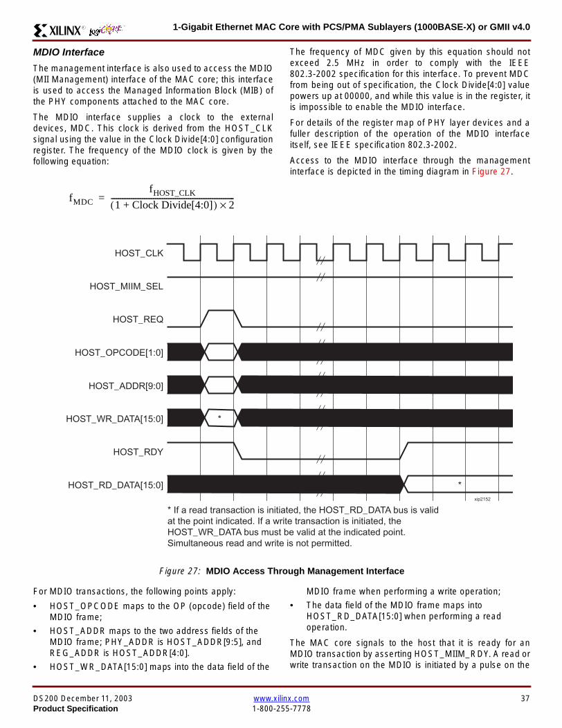
1-Gigabit Ethernet MAC Core with PCSPMA Sublayers (1000BASE-X) or GMII v40R
MDIO Interface
The management interface is also used to access the MDIO(MII Management) interface of the MAC core this interfaceis used to access the Managed Information Block (MIB) ofthe PHY components attached to the MAC core
The MDIO interface supplies a clock to the externaldevices MDC This clock is derived from the HOST_CLKsignal using the value in the Clock Divide[40] configurationregister The frequency of the MDIO clock is given by thefollowing equation
The frequency of MDC given by this equation should notexceed 25 MHz in order to comply with the IEEE8023-2002 specification for this interface To prevent MDCfrom being out of specification the Clock Divide[40] valuepowers up at 00000 and while this value is in the register itis impossible to enable the MDIO interface
For details of the register map of PHY layer devices and afuller description of the operation of the MDIO interfaceitself see IEEE specification 8023-2002
Access to the MDIO interface through the managementinterface is depicted in the timing diagram in Figure 27
For MDIO transactions the following points apply
bull HOST_OPCODE maps to the OP (opcode) field of theMDIO frame
bull HOST_ADDR maps to the two address fields of theMDIO frame PHY_ADDR is HOST_ADDR[95] andREG_ADDR is HOST_ADDR[40]
bull HOST_WR_DATA[150] maps into the data field of the
MDIO frame when performing a write operation
bull The data field of the MDIO frame maps intoHOST_RD_DATA[150] when performing a readoperation
The MAC core signals to the host that it is ready for anMDIO transaction by asserting HOST_MIIM_RDY A read orwrite transaction on the MDIO is initiated by a pulse on the
fMDC
fHOST_CLK
1 Clock Divide[40]+( ) 2times-------------------------------------------------------------------=
Figure 27 MDIO Access Through Management Interface
HOST_CLK
HOST_ADDR[90]
HOST_OPCODE[10]
HOST_REQ
HOST_MIIM_SEL
HOST_RD_DATA[150]
HOST_WR_DATA[150]
HOST_RDY
If a read transaction is initiated the HOST_RD_DATA bus is valid at the point indicated If a write transaction is initiated the HOST_WR_DATA bus must be valid at the indicated point Simultaneous read and write is not permitted
xip2152
DS200 December 11 2003 wwwxilinxcom 37Product Specification 1-800-255-7778
1-Gigabit Ethernet MAC Core with PCSPMA Sublayers (1000BASE-X) or GMII v40 R
HOST_REQ signal This pulse is ignored if the MDIO inter-face already has a transaction in progress
The MAC core then disasserts the HOST_MIIM_RDY signalwhile the transaction across the MDIO is in progress Whenthe transaction across the MDIO interface has been com-pleted the HOST_MIIM_RDY signal will be asserted by theMAC core if the transaction is a read the data will also beavailable on the HOST_RD_DATA[150] bus at this time
Optional Configuration Vector(management_interface = false)If the optional Management interface is omitted from thecore all of relevant configuration signals are brought out of
the core These signals are bundled into theCONFIGURATION_VECTOR signal The bit mapping of theconfiguration vector signal is defined in Table 24 See thecorresponding entry in the configuration register tables forthe full description of each signal
Note that these configuration vector signals can bechanged by the user at any time however with the excep-tion of the reset and the flow control configuration signalsthey will not take effect until the current frame has com-pleted transmission or reception
The ldquoClockrdquo heading denotes which clock domain the con-figuration signal is registered into before use by the core Itis not necessary to drive the signal from this clock domain
Table 24 Configuration Vector Bit Definition
Bit(s)Configuration Register
cross reference Clock Description
47 downto 0
Receiver ConfigurationWord 0 bits 31-0 andReceiver ConfigurationWord 1 bits 15-0
RX_CLK
Pause frame MAC Source Address[470] This address isused by the MAC core to match against the DestinationAddress of any incoming flow control frames and as theSource Address for any outbound flow control frames
The address is ordered such that the first byte transmitted orreceived is the least significant byte in the register forexample a MAC address of AA-BB-CC-DD-EE-FF will bestored in bite [470] as 0xFFEEDDCCBBAA
48Receiver ConfigurationWord 1 bit 26
RX_CLKReceiver Half Duplex If lsquo1rsquo the receiver operates in halfduplex mode If lsquo0rsquo the receiver operates in full duplex modeHas no effect if XCO parameter half_duplex_capable = false
49Receiver ConfigurationWord 1 bit 27
RX_CLKReceiver VLAN Enable When this bit is set to 1 VLANtagged frames are accepted by the receiver
50Receiver ConfigurationWord 1 bit 28
RX_CLKReceiver Enable If set to 1 the receiver block is operationalIf set to 0 the block ignores activity on the physical interfaceRX port
51Receiver ConfigurationWord 1 bit 29
RX_CLK
Receiver In-band FCS Enable When this bit is lsquo1rsquo the MACreceiver will pass the FCS field up to the client as describedin Client-Supplied FCS Passing on page 25 When it is lsquo0rsquothe MAC receiver will not pass the FCS field In both casesthe FCS field will be verified on the frame
52Receiver ConfigurationWord 1 bit 30
RX_CLK
Receiver Jumbo Frame Enable When this bit is lsquo0rsquo thereceiver will not pass frames longer than the maximum legalframe size specified in IEEE 8023-2002 (see MaximumPermitted Frame Length on page 26) When it is lsquo1rsquo thereceiver will not have an upper limit on frame size
53Receiver ConfigurationWord 1 bit 31
NA
Receiver Reset When this bit is lsquo1rsquo the receiver is held inreset
This signal is an input to the reset circuit for the receiverblock See Reset circuit on page 42 for more information
54TransmitterConfiguration Word bit25
TX_CLK
Transmitter Interframe Gap Adjust enable If lsquo1rsquo then thetransmitter will read the value of the TX_IFG_DELAY port andset the Interframe Gap accordingly If lsquo0rsquo the transmitter willalways insert at least the legal minimum Interframe Gap
38 wwwxilinxcom DS200 December 11 20031-800-255-7778 Product Specification
1-Gigabit Ethernet MAC Core with PCSPMA Sublayers (1000BASE-X) or GMII v40R
55TransmitterConfiguration Word bit26
TX_CLK
Transmitter Half Duplex If lsquo1rsquo the transmitter operates in halfduplex mode If lsquo0rsquo the transmitter operates in full duplexmode Has no effect if XCO parameter half_duplex_capable= false
56TransmitterConfiguration Word bit27
TX_CLKTransmitter VLAN Enable When this bit is set to lsquo1rsquo thetransmitter allows the transmission of VLAN tagged frames
57TransmitterConfiguration Word bit28
TX_CLKTransmitter Enable When this bit is 1 the transmitter will beoperational When it is 0 the transmitter is disabled
58TransmitterConfiguration Word bit29
TX_CLK
Transmitter In-Band FCS Enable When this bit is lsquo1rsquo theMAC transmitter will expect the FCS field to be pass in by theclient as described in Client-Supplied FCS Passing onpage 17 When it is lsquo0rsquo the MAC transmitter will appendpadding as required compute the FCS and append it to theframe
59TransmitterConfiguration Word bit30
TX_CLK
Transmitter Jumbo Frame Enable When this bit is lsquo1rsquo theMAC transmitter will allow frames larger than the maximumlegal frame length specified in IEEE 8023-2002 to be sentWhen set to lsquo0rsquo the MAC transmitter will only allow frames upto the legal maximum to be sent
60TransmitterConfiguration Word bit31
NA
Transmitter Reset When this bit is lsquo1rsquo the MAC transmitter isheld in reset
This signal is an input to the reset circuit for the transmitterblock See Reset circuit on page 42 for more information
61Flow ControlConfiguration Word bit29
TX_CLK
Transmit Flow Control Enable When this bit is lsquo1rsquo assertingthe PAUSE_REQ signal causes the MAC core to send a flowcontrol frame out from the transmitter as described inReceiving a Pause Control Frame on page 29 When this bitis lsquo0rsquo asserting the PAUSE_REQ signal will have no effect
62Flow ControlConfiguration Word bit30
RX_CLK
Receive Flow Control Enable When this bit is lsquo1rsquo receivedflow control frames will inhibit the transmitter operation asdescribed in Receiving a Pause Control Frame on page 29When it is lsquo0rsquo received flow frames are passed up to theclient
63Receiver ConfigurationWord 1 bit 25
RX_CLK
LengthType Error Check Disable When this bit is lsquo1rsquo thecore will not perform the LengthType field error checks asdescribed in LengthType Field Error Checks on page 26When it is set to lsquo0rsquo the LengthType field checks will beperformed this is normal operation
Table 24 Configuration Vector Bit Definition (Continued)
Bit(s)Configuration Register
cross reference Clock Description
DS200 December 11 2003 wwwxilinxcom 39Product Specification 1-800-255-7778
1-Gigabit Ethernet MAC Core with PCSPMA Sublayers (1000BASE-X) or GMII v40 R
Optional GMII (physical_interface=gmii)The GMII is designed to IEEE 8023-2002 Clause 35 Thisutilizes IOrsquos of the Xilinx devices using inputoutput buffersand inputoutput flip-flops to maximize setup and hold mar-gins All IO logic is placed in the example wrapper that isdelivered with the core In addition all clock managementlogic for the core is instanced in this example wrapper thisallows multiple instances of the core to share clocks Theexample wrapper is provided in both VHDL and Verilog
Clock Management
Figure 28 illustrates the clock management used with theGMII interface All clocks illustrated have a frequency of125MHz
GTX_CLK must be provided to the MAC core This is a highquality clock which satisfies the IEEE8023-2002 require-ments It is expected that this clock will be derived from anexternal oscillator and connected into the device through anIBUFG as illustrated The clock source must then be routedonto a global clock network by connecting it to a BUFGWithin the MAC core this global clock is used by all MACtransmitter logic The MAC Client can obtain this clock byconnecting to the TX_CLK signal output from the coreGMII_TX_CLK is derived from this global clock by invertingit and routing it to an OBUF
GMII_RX_CLK is received through an IBUFG This clock isthen routed onto a global clock network by connecting it to aBUFG The resulting global clock is used by all MACreceiver logic
Figure 28 Clock Management with GMII
IBUFG
IBUFG
OBUF
BUFG
BUFG
TX_CLK
RX_CLK
GTX_CLK
GMII_TX_CLK
GMII_RX_CLK
Example Wrapper
xip2153
MAC Core
TX_CLK
RX_CLK
GMII_TX_CLK
GMII_RX_CLK
GTX_CLK
40 wwwxilinxcom DS200 December 11 20031-800-255-7778 Product Specification
1-Gigabit Ethernet MAC Core with PCSPMA Sublayers (1000BASE-X) or GMII v40R
Clock Sharing between Multiple cores
Figure 29 illustrates how it is possible to share clockresources across multiple instantiations of the core whenusing the optional GMII
GTX_CLK may be shared between multiple cores as illus-trated resulting in a common transmitter clock domainacross the device
A common receiver clock domain is not possible each corewill receive an independent receiver clock from its GMII asillustrated
Although not illustrated if the optional Management Inter-face is used HOST_CLK can also be shared betweencores
Figure 29 Clock Management with multiple instances of the MAC with GMII
IBUFG
OBUF
BUFG
TX_CLK
RX_CLK_1
GMII_TX_CLK_1
GMII_RX_CLK_1
MAC Core
TX_CLK
RX_CLK
GMII_TX_CLK
GMII_RX_CLK
GTX_CLK
MAC Core
TX_CLK
RX_CLK
GMII_TX_CLK
GMII_RX_CLK
GTX_CLK
IBUFG
BUFG
GTX_CLK
IBUFG
OBUF
GMII_TX_CLK_2
GMII_RX_CLK_2
BUFG
TX_CLK
RX_CLK_2
DS200 December 11 2003 wwwxilinxcom 41Product Specification 1-800-255-7778
1-Gigabit Ethernet MAC Core with PCSPMA Sublayers (1000BASE-X) or GMII v40 R
Reset circuit
Internally the core is divided up into clockreset domainswhich group together elements with the common clock andreset signals The reset circuitry for one of these domains isis illustrated in Figure 30 This circuit provides controllableskews on the reset nets within the design
More information on the operation and rationale behind thiscircuit can be found in Ken Chapmanrsquos Xilinx TechXclusiveldquoGet Smart About Resetrdquo athttpwwwxilinxcomsupporttechxclusivesglobal-techX19htm
Figure 30 Reset circuit for one clockreset domain
FDP
PRED
C
Q
FDP
PRED
C
Q
FDP
PRED
C
Q
FDP
PRED
C
Q
PRE PRE PRE
0
RESET
Management Reset
Clock
Core Registers
42 wwwxilinxcom DS200 December 11 20031-800-255-7778 Product Specification
1-Gigabit Ethernet MAC Core with PCSPMA Sublayers (1000BASE-X) or GMII v40R
Optional PCS with Ten-Bit Interface (TBI) for 1000BASE-X (physical_interface=tbi)The Full-Duplex Physical Coding Sublayer (PCS) for1000BASE-X is defined in IEEE 8023-2002 Clauses 36and 37 This functionality is only available in the Virtex-IIand Spartan3 families of FPGA devices
A block diagram of the PCS is shown in Figure 31 Themajor functional blocks of the PCS are
bull Transmit engine
bull Auto-negotiation block
bull Receive engine and synchronization block
bull PCS managed register block
bull 8B10B encoder block
bull 8B10B decoder block
bull Receiver elastic buffer
The PCS Managed Register Block is accessed through theMDIO Interface as if it were an externally connected PHYThis configures the operation of the PCS and Auto-Negoti-ation See PCS Managed Register Block
(physical_interface = tbi or phy) on page 49 The corersquosoptional Management Interface can be used to control theMDIO Interface as described by MDIO Interface onpage 37 When the optional Management Interface is notpresent the PCS Managed Register Block must beaccessed via an MDIO controller which is not provided bythe core
The 8B10B encodingdecoding blocks are implemented byconfiguring two Block SelectRAM modules as ROM Theseare used as large look-up tables The remaining PCS func-tionality such as code group encodingdecoding the Man-aged Register Block and Auto-Negotiation areimplemented in CLB logic
The Receiver Elastic buffer enables the 10-bit parallel datareceived from the PMA sublayer alternatively onPMA_RX_CLK0 and PMA_RX_CLK1 clock edges to betransferred onto the internal 125MHz clock domain derivedfrom GTX_CLK (see Clock Management) This buffer isimplemented in Distributed Memory
Figure 31 Functional Block Diagram of the 1-Gigabit Ethernet PCS with TBI Interface
PCS TRANSMIT ENGINE
PCS RECEIVE ENGINE ampSYNCHRONISATION
PCSMANAGEMENT
MDIOInterface
AUTO-NEGOTIATION
MAC TXInterface
MAC RXInterface
8B10BEncoder
8B10BDecoder
RX Elastic Buffer
TBI Interface
DS200 December 11 2003 wwwxilinxcom 43Product Specification 1-800-255-7778
1-Gigabit Ethernet MAC Core with PCSPMA Sublayers (1000BASE-X) or GMII v40 R
TBI Interface
The TBI is designed to IEEE 8023-2002 Clause 363 Thisutilizes IOrsquos of the Xilinx devices using inputoutput buffersand inputoutput flip-flops to maximize setup and hold mar-gins All IO logic is placed in the example wrapper that isdelivered with the core In addition all clock managementlogic for the core is instantiated in this example wrapperthis allows multiple instances of the core to share clocksThe example wrapper is provided in both VHDL and Verilog
Clock Management
Figure 32 illustrates the clock management used with theTBI interface
GTX_CLK must be provided to the MAC core This is a highquality clock of frequency 125MHz which satisfies theIEEE8023-2002 requirements It is expected that this clockwill be derived from an external oscillator and connected
into the device through an IBUFG as illustrated The clocksource must then be routed onto a global clock network byconnecting it to a BUFG Within the MAC core this globalclock is used by all MAC transmitter logic PMA_TX_CLK isderived from this global clock by inverting it and routing it toan OBUF
PMA_RX_CLK0 and PMA_RX_CLK1 are each receivedthrough an IBUFG These clocks are then routed onto glo-bal clock networks by connecting each to a BUFGPMA_RX_CLK0 and PMA_RX_CLK1 are each 625MHzclocks Data from the TBI is received alternatively on the ris-ing edge of PMA_RX_CLK0 followed by the rising edge ofPMA_RX_CLK1 using IOB Double-Data Rate input regis-ters This data is then written into the Receiver ElasticBuffer Data is read out of the Elastic Buffer using the globalclock derived from GTX_CLK all the remaining receiverlogic is synchronous to this clock
Figure 32 Clock Management for PCS with TBI Interface
IBUFG
IBUFG
OBUF
BUFG
BUFG
TX_CLK
RX_CLK
GTX_CLK
PMA_TX_CLK
PMA_RX_CLK0
MAC Core
RX ELASTICBUFFER
Example Wrapper
TX_CLK
RX_CLK
GTX_CLK
PMA_TX_CLK
PMA_RX_CLK0
IBUFGBUFGPMA_RX_CLK1
PMA_RX_CLK1
44 wwwxilinxcom DS200 December 11 20031-800-255-7778 Product Specification
1-Gigabit Ethernet MAC Core with PCSPMA Sublayers (1000BASE-X) or GMII v40R
Clock Sharing between Multiple cores
Figure 33 illustrates how it is possible to share clockresources across multiple instantiations of the core whenusing the optional PCS with TBI
GTX_CLK may be shared between multiple cores as illus-trated resulting in a common transmitter clock domainacross the device
Each core will receive independent PMA_RX_CLK0 andPMA_RX_CLK1 clocks from its TBI as illustrated whichcannot be shared
Although not illustrated if the optional Management Inter-face is used HOST_CLK can also be shared betweencores
Figure 33 Clock Management with multiple instances of the MAC with PCS and TBI
Reset circuit
The reset circuits within the MAC when the TBI interface is implemented is the same as that in the GMII case details ofthese circuits can be found on page 42
IBUFG
OBUF
BUFG
TX_CLK
RX_CLK
PMA_TX_CLK_1
PMA_RX_CLK0_1
MAC Core
RX ELASTICBUFFER
TX_CLK
RX_CLK
GTX_CLK
PMA_TX_CLK
PMA_RX_CLK0
IBUFGBUFGPMA_RX_CLK1_1
PMA_RX_CLK1
IBUFG
BUFG
GTX_CLK
IBUFG
OBUF
BUFG
TX_CLK
RX_CLK
PMA_TX_CLK_2
PMA_RX_CLK0_2
MAC Core
RX ELASTICBUFFER
TX_CLK
RX_CLK
GTX_CLK
PMA_TX_CLK
PMA_RX_CLK0
IBUFGBUFGPMA_RX_CLK1_2
PMA_RX_CLK1
DS200 December 11 2003 wwwxilinxcom 45Product Specification 1-800-255-7778
1-Gigabit Ethernet MAC Core with PCSPMA Sublayers (1000BASE-X) or GMII v40 R
Optional PCS and PMA Sublayers for 1000BASE-X (physical_interface=phy)The Full-Duplex Physical Coding Sublayer (PCS) withPhysical Medium Attachment (PMA) for 1000BASE-X isdefined in IEEE 8023-2002 Clauses 36 and 37 This func-tionality is only available in the Virtex-II Pro family of FPGAdevices
A block diagram of the PCS and PMA sublayers can beseen in Figure 34 The functional blocks of the PCS andPMA sublayers may replace the optional GMII interfaceThe functional blocks of the PCS and PMA sublayers are
bull PCS Transmit Engine
bull Auto-Negotiation block
bull Receive Engine and Synchronization Block
bull PCS Managed Register Block
bull Rocket IO Multi-Gigabit Transceiver
The PCS Managed Register Block is accessed through theMDIO Interface as if it were an externally connected PHYThis configures the operation of the PCS PMA sublayerand Auto-NegotiationSee PCS Managed Register Block(physical_interface = tbi or phy) on page 49 The corersquosoptional Management Interface can be used to control theMDIO Interface as described by MDIO Interface onpage 37 When the optional Management Interface is notpresent the PCS Managed Register Block must beaccessed via an MDIO controller which is not provided bythe core
The Rocket IO Multi-Gigabit Transceiver (MGT) providessome of the PCS layer functionality such as 8B10B encod-ingdecoding and the PMA serdes The remaining PCSfunctionality such as code group encodingdecoding theManaged Register Block and Auto-Negotiation are imple-mented in CLB logic
Figure 34 Functional Block Diagram of the 1-Gigabit Ethernet PCSPMA Sublayer Extension
PCS TRANSMIT ENGINE
PCS RECEIVE ENGINE ampSYNCHRONISATION
RO
CK
ET
IO
MU
LTI-
GIG
TR
AN
SC
EIV
ER
PCSMANAGEMENT
MDIOInterface
AUTO-NEGOTIATION
TXPTXN
RXPRXN
MAC TXInterface
MAC RXInterface
xip2154
46 wwwxilinxcom DS200 December 11 20031-800-255-7778 Product Specification
1-Gigabit Ethernet MAC Core with PCSPMA Sublayers (1000BASE-X) or GMII v40R
Clock Management
Figure 35 illustrates the clock management that should beused with the optional PCS and PMA sublayers for1000BASE-X This logic is implemented in the examplewrapper that is delivered with the core This provides flexi-bility because the design can be modified to use eitherREFCLK or BREFCLK (please refer to Rocket IO docu-mentation) It would also allow multiple instances of the coreto share clocks The example wrapper is provided in bothVHDL and Verilog
(B)REFCLK must be provided to the MAC core This clockmust be derived from an external oscillator and connectedto the core through an IBUFG as illustrated (B)REFCLK isa high quality clock of frequency 625 MHz which satisfiesthe Rocket IO Multi-Gigabit Transceiver (MGT) require-ments
(B)REFCLK is routed to both the core and a DCM From theDCM the CLK2X180 output is routed to a BUFG to providethe device with a global 125 MHz clock (connected toUSERCLK2 input on the core) Within the core bothTX_CLK and RX_CLK share this global 125 MHz clocksource which is used by all transmitter and receiver logicThis is made possible by the RX_ELASTIC_BUFFER func-tionality of the Rocket IO MGT (refer to Virtex-II Pro docu-mentation) The MAC Client can obtain this clock byconnecting to either the TX_CLK or the RX_CLK signalsoutput from the core
From the DCM the CLK0 output is routed to a BUFG to pro-vide the device with a global 625MHz clock This is con-nected to the USRCLK input of the core
Figure 35 Clock Management with PCSPMA Sublayers
DCM
CLKIN CLK0
CLK2X180FB
BUFG
BUFG
IBUFG
TX_CLK
RX_CLK
(B)REFCLK
TXUSRCLK
(B)REFCLK
TXUSRCLK2RXUSRCLKRXUSRCLK2
GT_ETHERNET
Example Wrapper
xip2155
MAC Core
(B)REFCLK
USRCLK
USRCLK2
TX_CLK
RX_CLK
DS200 December 11 2003 wwwxilinxcom 47Product Specification 1-800-255-7778
1-Gigabit Ethernet MAC Core with PCSPMA Sublayers (1000BASE-X) or GMII v40 R
Clock Sharing between Multiple Cores
Figure 36 illustrates how it is possible to share clockresources across multiple instantiations of the core whenusing the optional PCSPMA sublayers For each coreUSERCLK and USERCLK2 must always be derived asshown from the BREFCLK or REFCLK used by that core
Note that when using the fixed routing resources of BREF-CLK Rocket IO MGTs along the top edge of the devicemust use a separate BREFCLK routing resource to thosealong the bottom edge of the device (Refer to Virtex-II Prodocumentation)
Although not illustrated if the optional Management Inter-face is used HOST_CLK can also be shared betweencores
Figure 36 Clock Management with multiple instances of the MAC with PCS and PMA sublayers
Reset circuit
The reset circuits within the MAC when the PCS and PMA sublayers are implemented is the same as that in the GMII casedetails of these circuits can be found on page 42
DCM
CLKIN CLK0
CLK2X180FB
BUFG
BUFG
IBUFG
(B)REFCLK
TXUSRCLK
(B)REFCLK
TXUSRCLK2RXUSRCLKRXUSRCLK2
GT_ETHERNET(B)REFCLK
USERCLK
USERCLK2
MAC core
TXUSRCLK
(B)REFCLK
TXUSRCLK2RXUSRCLKRXUSRCLK2
GT_ETHERNET(B)REFCLK
USERCLK
USERCLK2
MAC core
48 wwwxilinxcom DS200 December 11 20031-800-255-7778 Product Specification
1-Gigabit Ethernet MAC Core with PCSPMA Sublayers (1000BASE-X) or GMII v40R
PCS Managed Register Block (physical_interface = tbi or phy)The PCS in both the TBI interface and the PCSPMA (usingthe Virtex-II Pro Rocket IO) versions contain the full Man-aged Register Block defined in IEEE 8023-2002 clause 37
This utilizes ten dedicated management registersaccessed via the MDIO interface These are defined inTable 25 to Table 33 inclusive
Table 25 Control Register (Register 0)
Bit(s) Name Description Attributes Default Value
015 Reset1 = PCSPMA reset
0 = Normal Operation
ReadWrite
Self Clearing0
014 Loopback1 = Enable Loopback Mode
0 = Disable Loopback ModeReadWrite 0
013SpeedSelection (LSB)
The core always returns a 0 for this bitTogether with bit 06 speed selection of 1000Mbs is identified
Returns 0 0
012Auto-NegotiationEnable
1 = Enable Auto-Negotiation Process
0 = Disable Auto-Negotiation ProcessReadWrite 1
011 Power Down
1 = Power down
0 = Normal operation
When set to ldquo1rdquo the Rocket IO MGT is placedin a low power state This bit requires a reset(see bit 015) to clear
Read Write 0
010 Isolate1 = Electrically Isolate PHY from GMII
0 = Normal operationReadWrite 1
09Restart Auto-Negotiation
1 = Restart Auto-Negotiation Process
0 = Normal Operation
ReadWrite
Self Clearing0
08 Duplex ModeThe core always returns a 1 for this bit tosignal Full-Duplex Mode
Returns 1 1
07 Collision TestThe core always returns a 0 for this bit todisable COL test
Returns 0 0
06SpeedSelection(MSB)
The core always returns a 1 for this bitTogether with bit 013 speed selection of1000 Mbs is identified
Returns 1 1
050 Reserved Always returns 0rsquos writes ignored Returns 0rsquos 000000
DS200 December 11 2003 wwwxilinxcom 49Product Specification 1-800-255-7778
1-Gigabit Ethernet MAC Core with PCSPMA Sublayers (1000BASE-X) or GMII v40 R
Table 26 Status Register (Register 1)
Bit(s) Name Description Attributes Default Value
115 100BASE-T4The core always returns a 0 for this bitbecause 100BASE-T4 is not supported
Returns 0 0
114100BASE-XFullDuplex
The core always returns a 0 for this bitbecause 100BASE-X Full Duplex is notsupported
Returns 0 0
113100BASE-XHalf Duplex
The core always returns a 0 for this bitbecause 100BASE-X Half Duplex is notsupported
Returns 0 0
11210 Mbs FullDuplex
The core always returns a 0 for this bitbecause 10 Mbs Full Duplex is notsupported
Returns 0 0
11110 Mbs HalfDuplex
The core always returns a 0 for this bitbecause 10 Mbs Half Duplex is notsupported
Returns 0 0
110100BASE-T2Full Duplex
The core always returns a 0 for this bitbecause 100BASE-T2 Full Duplex is notsupported
Returns 0 0
19100BASE-T2Half Duplex
The core always returns a 0 for this bitbecause 100BASE-T2 Half Duplex is notsupported
Returns 0 0
18ExtendedStatus
The core always returns a 1 for this bit toindicate the presence of the ExtendedRegister (Register 15)
Returns 1 1
17 Reserved Always return 0 writes ignored Returns 0 0
16MF PreambleSuppression
The core always returns a 1 for this bit toindicate that Management Frame PreambleSuppression is supported
Returns 1 1
15Auto-NegotiationComplete
1 = Auto-Negotiation process completed
0 = Auto-Negotiation process not completedRead Only 0
14 Remote Fault1 = Remote fault condition detected
0 = No remote fault condition detected
Read Only
Self Clearing on read0
13Auto-NegotiationAbility
The core always returns a 1 for this bit toindicate that the PHY is capable ofAuto-Negotiation
Returns 1 1
12 Link Status1 = Link is up
0 = Link is down
Read Only
Self Clearing on read0
11 Jabber DetectThe core always returns a 0 for this bitbecause Jabber Detect is not supported
Returns 0 0
10ExtendedCapability
The core always returns a 0 for this bitbecause no extended register set issupported
Returns 0 0
50 wwwxilinxcom DS200 December 11 20031-800-255-7778 Product Specification
1-Gigabit Ethernet MAC Core with PCSPMA Sublayers (1000BASE-X) or GMII v40R
Table 27 PHY Identifier (Registers 2 and 3)
Bit(s) Name Description Attributes Default Value
2150OrganizationallyUniqueIdentifier
Always returns 0s Returns 0s 0000000000000000
31510OrganizationallyUniqueIdentifier
Always returns 0s Returns 0s 000000
394Manufacturerrsquosmodel number
Always returns 0s Returns 0s 000000
330RevisionNumber
Always returns 0s Returns 0s 0000
Table 28 Auto-Negotiation Advertisement Register (Register 4)
Bit(s) Name Description Attributes Default Value
415 Next Page1 = Next Page functionality is advertised
0 = Next Page functionality is not advertisedReadWrite 0
414 Reserved Always returns 0 writes ignored Returns 0 0
41312 Remote Fault
00 = No Error
01 = Offline
10 = Link Failure
11 = Auto-Negotiation Error
ReadWrite
Self clearing to 00afterAuto-Negotiation
00
4119 Reserved Always return 0 writes ignored Returns 0 0
487 Pause
00 = No PAUSE
01 = Asymmetric PAUSE towards linkpartner
10 = Symmetic PAUSE
11 = Both Symmetric PAUSE andAsymmetric PAUSE towards link partner
ReadWrite 11
46 Half DuplexThe core always returns a 0 for this bitbecause Half Duplex Mode is not supported
Returns 0 0
45 Full Duplex1 = Full Duplex Mode is advertised
0 = Full Duplex Mode is not advertisedReadWrite 1
440 Reserved Always returns 0s writes ignored Returns 0s 00000
DS200 December 11 2003 wwwxilinxcom 51Product Specification 1-800-255-7778
1-Gigabit Ethernet MAC Core with PCSPMA Sublayers (1000BASE-X) or GMII v40 R
Table 29 Auto-Negotiation Link Partner Ability Base Register (Register 5)
Bit(s) Name Description Attributes Default Value
515 Next Page1 = Next Page functionality is supported
0 = Next Page functionality is not supportedRead Only 0
514 AcknowledgeUsed by Auto-Negotiation function toindicate reception of a link partnerrsquos base ornext page
Read Only 0
51312 Remote Fault
00 = No Error
01 = Offline
10 = Link Failure
11 = Auto-Negotiation Error
Read Only 00
5119 Reserved Always returns 0s Returns 0s 000
587 Pause
00 = No PAUSE
01 = Asymmetric PAUSE supported
10 = Symmetic PAUSE supported
11 = Both Symmetric PAUSE andAsymmetric PAUSE supported
Read Only 00
56 Half Duplex1 = Half Duplex Mode is supported
0 = Half Duplex Mode is not supportedRead Only 0
55 Full Duplex1 = Full Duplex Mode is supported
0 = Full Duplex Mode is not supportedRead Only 0
540 Reserved Always returns 0s Returns 0s 00000
Table 30 Auto-Negotiation Expansion Register (Register 6)
Bit(s) Name Description Attributes Default Value
6153 Reserved Always returns 0s Returns 0s 0000000000000
62 Next Page AbleThe core always returns a 1 for this bitbecause the device is Next Page Able
Returns 1 1
61 Page Received1 = A new page has been received
0 = A new page has not been received
Read Only
Self Clearing on read0
60 Reserved Always returns 0s Returns 0s 0000000
52 wwwxilinxcom DS200 December 11 20031-800-255-7778 Product Specification
1-Gigabit Ethernet MAC Core with PCSPMA Sublayers (1000BASE-X) or GMII v40R
Table 31 Auto-Negotiation Next Page Transmit Register (Register 7)
Bit(s) Name Description Attributes Default Value
715 Next Page1 = Additional Next Page(s) will follow
0 = Last pageReadWrite 0
714 Reserved Always returns 0 Returns 0 0
713 Message Page1 = Message Page
0 = Unformatted PageReadWrite 1
712 Acknowledge 21 = Will comply with message
0 = Cannot comply with messageReadWrite 0
711 ToggleValue will toggle between subsequent NextPages
Read Only 0
7100Message UnformattedCode Field
Message Code Field or Unformatted PageEncoding as dictated by 713
ReadWrite00000000001
(Null Message Code)
Table 32 Auto-Negotiation Next Page Receive Register (Register 8)
Bit(s) Name Description Attributes Default Value
815 Next Page1 = Additional Next Page(s) follows
0 = Last pageRead Only 0
814 AcknowledgeUsed by Auto-Negotiation function toindicate reception of a link partnerrsquos base ornext page
Read Only 0
813 Message Page1 = Message Page
0 = Unformatted PageRead Only 0
812 Acknowledge 21 = Will comply with message
0 = Cannot comply with messageRead Only 0
811 ToggleValue toggles between subsequent andNext Pages
Read Only 0
8100Message UnformattedCode Field
Message Code Field or Unformatted PageEncoding as dictated by 813
Read Only 00000000000
DS200 December 11 2003 wwwxilinxcom 53Product Specification 1-800-255-7778
1-Gigabit Ethernet MAC Core with PCSPMA Sublayers (1000BASE-X) or GMII v40 R
)
Referencesbull IEEE 8023-2002
bull Virtex-E User Guide
bull Spartan-II E User Guide
bull Virtex-II User Guide
bull Virtex-II Pro User Guide
Related InformationXilinx products are not intended for use in life support appli-ances devices or systems Use of a Xilinx product in suchapplications without the written consent of the appropriateXilinx officer is prohibited
Ordering InformationThis Xilinx LogiCORE module is provided under theSignOnce IP Site License A free evaluation version of themodule is available
Once purchased the core may be downloaded from the Xil-inx IP Center for use with the Xilinx CORE Generator Sys-temtrade v61i SP3 and later The Xilinx CORE GeneratorSystem tool is bundled with all Alliance Series Softwarepackages at no additional charge
Please contact your local Xilinx sales representative or visitthe Xilinx Silicon Xpresso Cafe for pricing and availability onXilinx LogiCORE modules and software Information onadditional Xilinx LogiCORE modules is available on the Xil-inx IP Center
Revision HistoryThe following table shows the revision history for this document
Table 33 Extended Status Register (Register 15)
Bit(s) Name Description Attributes Default Value
15151000BASE-XFull Duplex
The core always returns a 1 for this bitbecause 1000BASE-X Full Duplex issupported
Returns 1 1
15141000BASE-XHalf Duplex
The core always returns a 0 for this bitbecause 1000BASE-X Half Duplex is notsupported
Returns 0 0
15131000BASE-TFull Duplex
The core always returns a 0 for this bitbecause 1000BASE-T Full Duplex is notsupported
Returns 0 0
15121000BASE-THalf Duplex
The core always returns a 0 for this bitbecause 1000BASE-T Half Duplex is notsupported
Returns 0 0
15110 Reserved Always returns 0s Returns 0s 000000000000
Date Version Revision
032803 11 Revision History added to document
043003 20 Revised to v30 standards
121103 30 Updated to v40 release
54 wwwxilinxcom DS200 December 11 20031-800-255-7778 Product Specification
- 1-Gigabit Ethernet MAC Core with PCSPMA Sublayers (1000BASE-X) or GMII v40
-
- Features
- MAC Overview
- Xilinx CORE Generator
- GUI Interface
- Parameter Values in the XCO File
- Output Generation
- Device Utilization
- Interface Description
- Interface Signals for MAC with physical_interface=gmii and management_interface=true
- Interface Signals for MAC with physical_interface=gmii and management_interface=false
- Interface Signals for MAC with physical_interface=tbi and management_interface=true
- Interface Signals for MAC with physical_interface=tbi and management_interface=false
- Interface Signals for MAC with physical_interface=phy and management_interface=true
- Interface Signals for MAC with physical_interface=phy and management_interface=false
- Client Side Interface Signal Definition
- Physical Interface Signal Definition
- Functional Description
- Client Interface
- Transmitter
- Receiver
- Flow Control
- Optional Management Interface (management_interface=true)
- Optional Configuration Vector (management_interface = false)
- Optional GMII (physical_interface=gmii)
- Optional PCS with Ten-Bit Interface (TBI) for 1000BASE-X (physical_interface=tbi)
- Optional PCS and PMA Sublayers for 1000BASE-X (physical_interface=phy)
- PCS Managed Register Block (physical_interface = tbi or phy)
- References
- Related Information
- Ordering Information
- Revision History
-
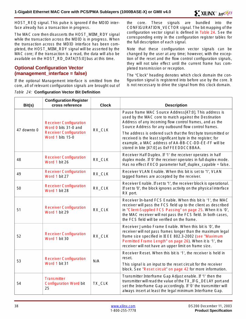
1-Gigabit Ethernet MAC Core with PCSPMA Sublayers (1000BASE-X) or GMII v40 R
HOST_REQ signal This pulse is ignored if the MDIO inter-face already has a transaction in progress
The MAC core then disasserts the HOST_MIIM_RDY signalwhile the transaction across the MDIO is in progress Whenthe transaction across the MDIO interface has been com-pleted the HOST_MIIM_RDY signal will be asserted by theMAC core if the transaction is a read the data will also beavailable on the HOST_RD_DATA[150] bus at this time
Optional Configuration Vector(management_interface = false)If the optional Management interface is omitted from thecore all of relevant configuration signals are brought out of
the core These signals are bundled into theCONFIGURATION_VECTOR signal The bit mapping of theconfiguration vector signal is defined in Table 24 See thecorresponding entry in the configuration register tables forthe full description of each signal
Note that these configuration vector signals can bechanged by the user at any time however with the excep-tion of the reset and the flow control configuration signalsthey will not take effect until the current frame has com-pleted transmission or reception
The ldquoClockrdquo heading denotes which clock domain the con-figuration signal is registered into before use by the core Itis not necessary to drive the signal from this clock domain
Table 24 Configuration Vector Bit Definition
Bit(s)Configuration Register
cross reference Clock Description
47 downto 0
Receiver ConfigurationWord 0 bits 31-0 andReceiver ConfigurationWord 1 bits 15-0
RX_CLK
Pause frame MAC Source Address[470] This address isused by the MAC core to match against the DestinationAddress of any incoming flow control frames and as theSource Address for any outbound flow control frames
The address is ordered such that the first byte transmitted orreceived is the least significant byte in the register forexample a MAC address of AA-BB-CC-DD-EE-FF will bestored in bite [470] as 0xFFEEDDCCBBAA
48Receiver ConfigurationWord 1 bit 26
RX_CLKReceiver Half Duplex If lsquo1rsquo the receiver operates in halfduplex mode If lsquo0rsquo the receiver operates in full duplex modeHas no effect if XCO parameter half_duplex_capable = false
49Receiver ConfigurationWord 1 bit 27
RX_CLKReceiver VLAN Enable When this bit is set to 1 VLANtagged frames are accepted by the receiver
50Receiver ConfigurationWord 1 bit 28
RX_CLKReceiver Enable If set to 1 the receiver block is operationalIf set to 0 the block ignores activity on the physical interfaceRX port
51Receiver ConfigurationWord 1 bit 29
RX_CLK
Receiver In-band FCS Enable When this bit is lsquo1rsquo the MACreceiver will pass the FCS field up to the client as describedin Client-Supplied FCS Passing on page 25 When it is lsquo0rsquothe MAC receiver will not pass the FCS field In both casesthe FCS field will be verified on the frame
52Receiver ConfigurationWord 1 bit 30
RX_CLK
Receiver Jumbo Frame Enable When this bit is lsquo0rsquo thereceiver will not pass frames longer than the maximum legalframe size specified in IEEE 8023-2002 (see MaximumPermitted Frame Length on page 26) When it is lsquo1rsquo thereceiver will not have an upper limit on frame size
53Receiver ConfigurationWord 1 bit 31
NA
Receiver Reset When this bit is lsquo1rsquo the receiver is held inreset
This signal is an input to the reset circuit for the receiverblock See Reset circuit on page 42 for more information
54TransmitterConfiguration Word bit25
TX_CLK
Transmitter Interframe Gap Adjust enable If lsquo1rsquo then thetransmitter will read the value of the TX_IFG_DELAY port andset the Interframe Gap accordingly If lsquo0rsquo the transmitter willalways insert at least the legal minimum Interframe Gap
38 wwwxilinxcom DS200 December 11 20031-800-255-7778 Product Specification
1-Gigabit Ethernet MAC Core with PCSPMA Sublayers (1000BASE-X) or GMII v40R
55TransmitterConfiguration Word bit26
TX_CLK
Transmitter Half Duplex If lsquo1rsquo the transmitter operates in halfduplex mode If lsquo0rsquo the transmitter operates in full duplexmode Has no effect if XCO parameter half_duplex_capable= false
56TransmitterConfiguration Word bit27
TX_CLKTransmitter VLAN Enable When this bit is set to lsquo1rsquo thetransmitter allows the transmission of VLAN tagged frames
57TransmitterConfiguration Word bit28
TX_CLKTransmitter Enable When this bit is 1 the transmitter will beoperational When it is 0 the transmitter is disabled
58TransmitterConfiguration Word bit29
TX_CLK
Transmitter In-Band FCS Enable When this bit is lsquo1rsquo theMAC transmitter will expect the FCS field to be pass in by theclient as described in Client-Supplied FCS Passing onpage 17 When it is lsquo0rsquo the MAC transmitter will appendpadding as required compute the FCS and append it to theframe
59TransmitterConfiguration Word bit30
TX_CLK
Transmitter Jumbo Frame Enable When this bit is lsquo1rsquo theMAC transmitter will allow frames larger than the maximumlegal frame length specified in IEEE 8023-2002 to be sentWhen set to lsquo0rsquo the MAC transmitter will only allow frames upto the legal maximum to be sent
60TransmitterConfiguration Word bit31
NA
Transmitter Reset When this bit is lsquo1rsquo the MAC transmitter isheld in reset
This signal is an input to the reset circuit for the transmitterblock See Reset circuit on page 42 for more information
61Flow ControlConfiguration Word bit29
TX_CLK
Transmit Flow Control Enable When this bit is lsquo1rsquo assertingthe PAUSE_REQ signal causes the MAC core to send a flowcontrol frame out from the transmitter as described inReceiving a Pause Control Frame on page 29 When this bitis lsquo0rsquo asserting the PAUSE_REQ signal will have no effect
62Flow ControlConfiguration Word bit30
RX_CLK
Receive Flow Control Enable When this bit is lsquo1rsquo receivedflow control frames will inhibit the transmitter operation asdescribed in Receiving a Pause Control Frame on page 29When it is lsquo0rsquo received flow frames are passed up to theclient
63Receiver ConfigurationWord 1 bit 25
RX_CLK
LengthType Error Check Disable When this bit is lsquo1rsquo thecore will not perform the LengthType field error checks asdescribed in LengthType Field Error Checks on page 26When it is set to lsquo0rsquo the LengthType field checks will beperformed this is normal operation
Table 24 Configuration Vector Bit Definition (Continued)
Bit(s)Configuration Register
cross reference Clock Description
DS200 December 11 2003 wwwxilinxcom 39Product Specification 1-800-255-7778
1-Gigabit Ethernet MAC Core with PCSPMA Sublayers (1000BASE-X) or GMII v40 R
Optional GMII (physical_interface=gmii)The GMII is designed to IEEE 8023-2002 Clause 35 Thisutilizes IOrsquos of the Xilinx devices using inputoutput buffersand inputoutput flip-flops to maximize setup and hold mar-gins All IO logic is placed in the example wrapper that isdelivered with the core In addition all clock managementlogic for the core is instanced in this example wrapper thisallows multiple instances of the core to share clocks Theexample wrapper is provided in both VHDL and Verilog
Clock Management
Figure 28 illustrates the clock management used with theGMII interface All clocks illustrated have a frequency of125MHz
GTX_CLK must be provided to the MAC core This is a highquality clock which satisfies the IEEE8023-2002 require-ments It is expected that this clock will be derived from anexternal oscillator and connected into the device through anIBUFG as illustrated The clock source must then be routedonto a global clock network by connecting it to a BUFGWithin the MAC core this global clock is used by all MACtransmitter logic The MAC Client can obtain this clock byconnecting to the TX_CLK signal output from the coreGMII_TX_CLK is derived from this global clock by invertingit and routing it to an OBUF
GMII_RX_CLK is received through an IBUFG This clock isthen routed onto a global clock network by connecting it to aBUFG The resulting global clock is used by all MACreceiver logic
Figure 28 Clock Management with GMII
IBUFG
IBUFG
OBUF
BUFG
BUFG
TX_CLK
RX_CLK
GTX_CLK
GMII_TX_CLK
GMII_RX_CLK
Example Wrapper
xip2153
MAC Core
TX_CLK
RX_CLK
GMII_TX_CLK
GMII_RX_CLK
GTX_CLK
40 wwwxilinxcom DS200 December 11 20031-800-255-7778 Product Specification
1-Gigabit Ethernet MAC Core with PCSPMA Sublayers (1000BASE-X) or GMII v40R
Clock Sharing between Multiple cores
Figure 29 illustrates how it is possible to share clockresources across multiple instantiations of the core whenusing the optional GMII
GTX_CLK may be shared between multiple cores as illus-trated resulting in a common transmitter clock domainacross the device
A common receiver clock domain is not possible each corewill receive an independent receiver clock from its GMII asillustrated
Although not illustrated if the optional Management Inter-face is used HOST_CLK can also be shared betweencores
Figure 29 Clock Management with multiple instances of the MAC with GMII
IBUFG
OBUF
BUFG
TX_CLK
RX_CLK_1
GMII_TX_CLK_1
GMII_RX_CLK_1
MAC Core
TX_CLK
RX_CLK
GMII_TX_CLK
GMII_RX_CLK
GTX_CLK
MAC Core
TX_CLK
RX_CLK
GMII_TX_CLK
GMII_RX_CLK
GTX_CLK
IBUFG
BUFG
GTX_CLK
IBUFG
OBUF
GMII_TX_CLK_2
GMII_RX_CLK_2
BUFG
TX_CLK
RX_CLK_2
DS200 December 11 2003 wwwxilinxcom 41Product Specification 1-800-255-7778
1-Gigabit Ethernet MAC Core with PCSPMA Sublayers (1000BASE-X) or GMII v40 R
Reset circuit
Internally the core is divided up into clockreset domainswhich group together elements with the common clock andreset signals The reset circuitry for one of these domains isis illustrated in Figure 30 This circuit provides controllableskews on the reset nets within the design
More information on the operation and rationale behind thiscircuit can be found in Ken Chapmanrsquos Xilinx TechXclusiveldquoGet Smart About Resetrdquo athttpwwwxilinxcomsupporttechxclusivesglobal-techX19htm
Figure 30 Reset circuit for one clockreset domain
FDP
PRED
C
Q
FDP
PRED
C
Q
FDP
PRED
C
Q
FDP
PRED
C
Q
PRE PRE PRE
0
RESET
Management Reset
Clock
Core Registers
42 wwwxilinxcom DS200 December 11 20031-800-255-7778 Product Specification
1-Gigabit Ethernet MAC Core with PCSPMA Sublayers (1000BASE-X) or GMII v40R
Optional PCS with Ten-Bit Interface (TBI) for 1000BASE-X (physical_interface=tbi)The Full-Duplex Physical Coding Sublayer (PCS) for1000BASE-X is defined in IEEE 8023-2002 Clauses 36and 37 This functionality is only available in the Virtex-IIand Spartan3 families of FPGA devices
A block diagram of the PCS is shown in Figure 31 Themajor functional blocks of the PCS are
bull Transmit engine
bull Auto-negotiation block
bull Receive engine and synchronization block
bull PCS managed register block
bull 8B10B encoder block
bull 8B10B decoder block
bull Receiver elastic buffer
The PCS Managed Register Block is accessed through theMDIO Interface as if it were an externally connected PHYThis configures the operation of the PCS and Auto-Negoti-ation See PCS Managed Register Block
(physical_interface = tbi or phy) on page 49 The corersquosoptional Management Interface can be used to control theMDIO Interface as described by MDIO Interface onpage 37 When the optional Management Interface is notpresent the PCS Managed Register Block must beaccessed via an MDIO controller which is not provided bythe core
The 8B10B encodingdecoding blocks are implemented byconfiguring two Block SelectRAM modules as ROM Theseare used as large look-up tables The remaining PCS func-tionality such as code group encodingdecoding the Man-aged Register Block and Auto-Negotiation areimplemented in CLB logic
The Receiver Elastic buffer enables the 10-bit parallel datareceived from the PMA sublayer alternatively onPMA_RX_CLK0 and PMA_RX_CLK1 clock edges to betransferred onto the internal 125MHz clock domain derivedfrom GTX_CLK (see Clock Management) This buffer isimplemented in Distributed Memory
Figure 31 Functional Block Diagram of the 1-Gigabit Ethernet PCS with TBI Interface
PCS TRANSMIT ENGINE
PCS RECEIVE ENGINE ampSYNCHRONISATION
PCSMANAGEMENT
MDIOInterface
AUTO-NEGOTIATION
MAC TXInterface
MAC RXInterface
8B10BEncoder
8B10BDecoder
RX Elastic Buffer
TBI Interface
DS200 December 11 2003 wwwxilinxcom 43Product Specification 1-800-255-7778
1-Gigabit Ethernet MAC Core with PCSPMA Sublayers (1000BASE-X) or GMII v40 R
TBI Interface
The TBI is designed to IEEE 8023-2002 Clause 363 Thisutilizes IOrsquos of the Xilinx devices using inputoutput buffersand inputoutput flip-flops to maximize setup and hold mar-gins All IO logic is placed in the example wrapper that isdelivered with the core In addition all clock managementlogic for the core is instantiated in this example wrapperthis allows multiple instances of the core to share clocksThe example wrapper is provided in both VHDL and Verilog
Clock Management
Figure 32 illustrates the clock management used with theTBI interface
GTX_CLK must be provided to the MAC core This is a highquality clock of frequency 125MHz which satisfies theIEEE8023-2002 requirements It is expected that this clockwill be derived from an external oscillator and connected
into the device through an IBUFG as illustrated The clocksource must then be routed onto a global clock network byconnecting it to a BUFG Within the MAC core this globalclock is used by all MAC transmitter logic PMA_TX_CLK isderived from this global clock by inverting it and routing it toan OBUF
PMA_RX_CLK0 and PMA_RX_CLK1 are each receivedthrough an IBUFG These clocks are then routed onto glo-bal clock networks by connecting each to a BUFGPMA_RX_CLK0 and PMA_RX_CLK1 are each 625MHzclocks Data from the TBI is received alternatively on the ris-ing edge of PMA_RX_CLK0 followed by the rising edge ofPMA_RX_CLK1 using IOB Double-Data Rate input regis-ters This data is then written into the Receiver ElasticBuffer Data is read out of the Elastic Buffer using the globalclock derived from GTX_CLK all the remaining receiverlogic is synchronous to this clock
Figure 32 Clock Management for PCS with TBI Interface
IBUFG
IBUFG
OBUF
BUFG
BUFG
TX_CLK
RX_CLK
GTX_CLK
PMA_TX_CLK
PMA_RX_CLK0
MAC Core
RX ELASTICBUFFER
Example Wrapper
TX_CLK
RX_CLK
GTX_CLK
PMA_TX_CLK
PMA_RX_CLK0
IBUFGBUFGPMA_RX_CLK1
PMA_RX_CLK1
44 wwwxilinxcom DS200 December 11 20031-800-255-7778 Product Specification
1-Gigabit Ethernet MAC Core with PCSPMA Sublayers (1000BASE-X) or GMII v40R
Clock Sharing between Multiple cores
Figure 33 illustrates how it is possible to share clockresources across multiple instantiations of the core whenusing the optional PCS with TBI
GTX_CLK may be shared between multiple cores as illus-trated resulting in a common transmitter clock domainacross the device
Each core will receive independent PMA_RX_CLK0 andPMA_RX_CLK1 clocks from its TBI as illustrated whichcannot be shared
Although not illustrated if the optional Management Inter-face is used HOST_CLK can also be shared betweencores
Figure 33 Clock Management with multiple instances of the MAC with PCS and TBI
Reset circuit
The reset circuits within the MAC when the TBI interface is implemented is the same as that in the GMII case details ofthese circuits can be found on page 42
IBUFG
OBUF
BUFG
TX_CLK
RX_CLK
PMA_TX_CLK_1
PMA_RX_CLK0_1
MAC Core
RX ELASTICBUFFER
TX_CLK
RX_CLK
GTX_CLK
PMA_TX_CLK
PMA_RX_CLK0
IBUFGBUFGPMA_RX_CLK1_1
PMA_RX_CLK1
IBUFG
BUFG
GTX_CLK
IBUFG
OBUF
BUFG
TX_CLK
RX_CLK
PMA_TX_CLK_2
PMA_RX_CLK0_2
MAC Core
RX ELASTICBUFFER
TX_CLK
RX_CLK
GTX_CLK
PMA_TX_CLK
PMA_RX_CLK0
IBUFGBUFGPMA_RX_CLK1_2
PMA_RX_CLK1
DS200 December 11 2003 wwwxilinxcom 45Product Specification 1-800-255-7778
1-Gigabit Ethernet MAC Core with PCSPMA Sublayers (1000BASE-X) or GMII v40 R
Optional PCS and PMA Sublayers for 1000BASE-X (physical_interface=phy)The Full-Duplex Physical Coding Sublayer (PCS) withPhysical Medium Attachment (PMA) for 1000BASE-X isdefined in IEEE 8023-2002 Clauses 36 and 37 This func-tionality is only available in the Virtex-II Pro family of FPGAdevices
A block diagram of the PCS and PMA sublayers can beseen in Figure 34 The functional blocks of the PCS andPMA sublayers may replace the optional GMII interfaceThe functional blocks of the PCS and PMA sublayers are
bull PCS Transmit Engine
bull Auto-Negotiation block
bull Receive Engine and Synchronization Block
bull PCS Managed Register Block
bull Rocket IO Multi-Gigabit Transceiver
The PCS Managed Register Block is accessed through theMDIO Interface as if it were an externally connected PHYThis configures the operation of the PCS PMA sublayerand Auto-NegotiationSee PCS Managed Register Block(physical_interface = tbi or phy) on page 49 The corersquosoptional Management Interface can be used to control theMDIO Interface as described by MDIO Interface onpage 37 When the optional Management Interface is notpresent the PCS Managed Register Block must beaccessed via an MDIO controller which is not provided bythe core
The Rocket IO Multi-Gigabit Transceiver (MGT) providessome of the PCS layer functionality such as 8B10B encod-ingdecoding and the PMA serdes The remaining PCSfunctionality such as code group encodingdecoding theManaged Register Block and Auto-Negotiation are imple-mented in CLB logic
Figure 34 Functional Block Diagram of the 1-Gigabit Ethernet PCSPMA Sublayer Extension
PCS TRANSMIT ENGINE
PCS RECEIVE ENGINE ampSYNCHRONISATION
RO
CK
ET
IO
MU
LTI-
GIG
TR
AN
SC
EIV
ER
PCSMANAGEMENT
MDIOInterface
AUTO-NEGOTIATION
TXPTXN
RXPRXN
MAC TXInterface
MAC RXInterface
xip2154
46 wwwxilinxcom DS200 December 11 20031-800-255-7778 Product Specification
1-Gigabit Ethernet MAC Core with PCSPMA Sublayers (1000BASE-X) or GMII v40R
Clock Management
Figure 35 illustrates the clock management that should beused with the optional PCS and PMA sublayers for1000BASE-X This logic is implemented in the examplewrapper that is delivered with the core This provides flexi-bility because the design can be modified to use eitherREFCLK or BREFCLK (please refer to Rocket IO docu-mentation) It would also allow multiple instances of the coreto share clocks The example wrapper is provided in bothVHDL and Verilog
(B)REFCLK must be provided to the MAC core This clockmust be derived from an external oscillator and connectedto the core through an IBUFG as illustrated (B)REFCLK isa high quality clock of frequency 625 MHz which satisfiesthe Rocket IO Multi-Gigabit Transceiver (MGT) require-ments
(B)REFCLK is routed to both the core and a DCM From theDCM the CLK2X180 output is routed to a BUFG to providethe device with a global 125 MHz clock (connected toUSERCLK2 input on the core) Within the core bothTX_CLK and RX_CLK share this global 125 MHz clocksource which is used by all transmitter and receiver logicThis is made possible by the RX_ELASTIC_BUFFER func-tionality of the Rocket IO MGT (refer to Virtex-II Pro docu-mentation) The MAC Client can obtain this clock byconnecting to either the TX_CLK or the RX_CLK signalsoutput from the core
From the DCM the CLK0 output is routed to a BUFG to pro-vide the device with a global 625MHz clock This is con-nected to the USRCLK input of the core
Figure 35 Clock Management with PCSPMA Sublayers
DCM
CLKIN CLK0
CLK2X180FB
BUFG
BUFG
IBUFG
TX_CLK
RX_CLK
(B)REFCLK
TXUSRCLK
(B)REFCLK
TXUSRCLK2RXUSRCLKRXUSRCLK2
GT_ETHERNET
Example Wrapper
xip2155
MAC Core
(B)REFCLK
USRCLK
USRCLK2
TX_CLK
RX_CLK
DS200 December 11 2003 wwwxilinxcom 47Product Specification 1-800-255-7778
1-Gigabit Ethernet MAC Core with PCSPMA Sublayers (1000BASE-X) or GMII v40 R
Clock Sharing between Multiple Cores
Figure 36 illustrates how it is possible to share clockresources across multiple instantiations of the core whenusing the optional PCSPMA sublayers For each coreUSERCLK and USERCLK2 must always be derived asshown from the BREFCLK or REFCLK used by that core
Note that when using the fixed routing resources of BREF-CLK Rocket IO MGTs along the top edge of the devicemust use a separate BREFCLK routing resource to thosealong the bottom edge of the device (Refer to Virtex-II Prodocumentation)
Although not illustrated if the optional Management Inter-face is used HOST_CLK can also be shared betweencores
Figure 36 Clock Management with multiple instances of the MAC with PCS and PMA sublayers
Reset circuit
The reset circuits within the MAC when the PCS and PMA sublayers are implemented is the same as that in the GMII casedetails of these circuits can be found on page 42
DCM
CLKIN CLK0
CLK2X180FB
BUFG
BUFG
IBUFG
(B)REFCLK
TXUSRCLK
(B)REFCLK
TXUSRCLK2RXUSRCLKRXUSRCLK2
GT_ETHERNET(B)REFCLK
USERCLK
USERCLK2
MAC core
TXUSRCLK
(B)REFCLK
TXUSRCLK2RXUSRCLKRXUSRCLK2
GT_ETHERNET(B)REFCLK
USERCLK
USERCLK2
MAC core
48 wwwxilinxcom DS200 December 11 20031-800-255-7778 Product Specification
1-Gigabit Ethernet MAC Core with PCSPMA Sublayers (1000BASE-X) or GMII v40R
PCS Managed Register Block (physical_interface = tbi or phy)The PCS in both the TBI interface and the PCSPMA (usingthe Virtex-II Pro Rocket IO) versions contain the full Man-aged Register Block defined in IEEE 8023-2002 clause 37
This utilizes ten dedicated management registersaccessed via the MDIO interface These are defined inTable 25 to Table 33 inclusive
Table 25 Control Register (Register 0)
Bit(s) Name Description Attributes Default Value
015 Reset1 = PCSPMA reset
0 = Normal Operation
ReadWrite
Self Clearing0
014 Loopback1 = Enable Loopback Mode
0 = Disable Loopback ModeReadWrite 0
013SpeedSelection (LSB)
The core always returns a 0 for this bitTogether with bit 06 speed selection of 1000Mbs is identified
Returns 0 0
012Auto-NegotiationEnable
1 = Enable Auto-Negotiation Process
0 = Disable Auto-Negotiation ProcessReadWrite 1
011 Power Down
1 = Power down
0 = Normal operation
When set to ldquo1rdquo the Rocket IO MGT is placedin a low power state This bit requires a reset(see bit 015) to clear
Read Write 0
010 Isolate1 = Electrically Isolate PHY from GMII
0 = Normal operationReadWrite 1
09Restart Auto-Negotiation
1 = Restart Auto-Negotiation Process
0 = Normal Operation
ReadWrite
Self Clearing0
08 Duplex ModeThe core always returns a 1 for this bit tosignal Full-Duplex Mode
Returns 1 1
07 Collision TestThe core always returns a 0 for this bit todisable COL test
Returns 0 0
06SpeedSelection(MSB)
The core always returns a 1 for this bitTogether with bit 013 speed selection of1000 Mbs is identified
Returns 1 1
050 Reserved Always returns 0rsquos writes ignored Returns 0rsquos 000000
DS200 December 11 2003 wwwxilinxcom 49Product Specification 1-800-255-7778
1-Gigabit Ethernet MAC Core with PCSPMA Sublayers (1000BASE-X) or GMII v40 R
Table 26 Status Register (Register 1)
Bit(s) Name Description Attributes Default Value
115 100BASE-T4The core always returns a 0 for this bitbecause 100BASE-T4 is not supported
Returns 0 0
114100BASE-XFullDuplex
The core always returns a 0 for this bitbecause 100BASE-X Full Duplex is notsupported
Returns 0 0
113100BASE-XHalf Duplex
The core always returns a 0 for this bitbecause 100BASE-X Half Duplex is notsupported
Returns 0 0
11210 Mbs FullDuplex
The core always returns a 0 for this bitbecause 10 Mbs Full Duplex is notsupported
Returns 0 0
11110 Mbs HalfDuplex
The core always returns a 0 for this bitbecause 10 Mbs Half Duplex is notsupported
Returns 0 0
110100BASE-T2Full Duplex
The core always returns a 0 for this bitbecause 100BASE-T2 Full Duplex is notsupported
Returns 0 0
19100BASE-T2Half Duplex
The core always returns a 0 for this bitbecause 100BASE-T2 Half Duplex is notsupported
Returns 0 0
18ExtendedStatus
The core always returns a 1 for this bit toindicate the presence of the ExtendedRegister (Register 15)
Returns 1 1
17 Reserved Always return 0 writes ignored Returns 0 0
16MF PreambleSuppression
The core always returns a 1 for this bit toindicate that Management Frame PreambleSuppression is supported
Returns 1 1
15Auto-NegotiationComplete
1 = Auto-Negotiation process completed
0 = Auto-Negotiation process not completedRead Only 0
14 Remote Fault1 = Remote fault condition detected
0 = No remote fault condition detected
Read Only
Self Clearing on read0
13Auto-NegotiationAbility
The core always returns a 1 for this bit toindicate that the PHY is capable ofAuto-Negotiation
Returns 1 1
12 Link Status1 = Link is up
0 = Link is down
Read Only
Self Clearing on read0
11 Jabber DetectThe core always returns a 0 for this bitbecause Jabber Detect is not supported
Returns 0 0
10ExtendedCapability
The core always returns a 0 for this bitbecause no extended register set issupported
Returns 0 0
50 wwwxilinxcom DS200 December 11 20031-800-255-7778 Product Specification
1-Gigabit Ethernet MAC Core with PCSPMA Sublayers (1000BASE-X) or GMII v40R
Table 27 PHY Identifier (Registers 2 and 3)
Bit(s) Name Description Attributes Default Value
2150OrganizationallyUniqueIdentifier
Always returns 0s Returns 0s 0000000000000000
31510OrganizationallyUniqueIdentifier
Always returns 0s Returns 0s 000000
394Manufacturerrsquosmodel number
Always returns 0s Returns 0s 000000
330RevisionNumber
Always returns 0s Returns 0s 0000
Table 28 Auto-Negotiation Advertisement Register (Register 4)
Bit(s) Name Description Attributes Default Value
415 Next Page1 = Next Page functionality is advertised
0 = Next Page functionality is not advertisedReadWrite 0
414 Reserved Always returns 0 writes ignored Returns 0 0
41312 Remote Fault
00 = No Error
01 = Offline
10 = Link Failure
11 = Auto-Negotiation Error
ReadWrite
Self clearing to 00afterAuto-Negotiation
00
4119 Reserved Always return 0 writes ignored Returns 0 0
487 Pause
00 = No PAUSE
01 = Asymmetric PAUSE towards linkpartner
10 = Symmetic PAUSE
11 = Both Symmetric PAUSE andAsymmetric PAUSE towards link partner
ReadWrite 11
46 Half DuplexThe core always returns a 0 for this bitbecause Half Duplex Mode is not supported
Returns 0 0
45 Full Duplex1 = Full Duplex Mode is advertised
0 = Full Duplex Mode is not advertisedReadWrite 1
440 Reserved Always returns 0s writes ignored Returns 0s 00000
DS200 December 11 2003 wwwxilinxcom 51Product Specification 1-800-255-7778
1-Gigabit Ethernet MAC Core with PCSPMA Sublayers (1000BASE-X) or GMII v40 R
Table 29 Auto-Negotiation Link Partner Ability Base Register (Register 5)
Bit(s) Name Description Attributes Default Value
515 Next Page1 = Next Page functionality is supported
0 = Next Page functionality is not supportedRead Only 0
514 AcknowledgeUsed by Auto-Negotiation function toindicate reception of a link partnerrsquos base ornext page
Read Only 0
51312 Remote Fault
00 = No Error
01 = Offline
10 = Link Failure
11 = Auto-Negotiation Error
Read Only 00
5119 Reserved Always returns 0s Returns 0s 000
587 Pause
00 = No PAUSE
01 = Asymmetric PAUSE supported
10 = Symmetic PAUSE supported
11 = Both Symmetric PAUSE andAsymmetric PAUSE supported
Read Only 00
56 Half Duplex1 = Half Duplex Mode is supported
0 = Half Duplex Mode is not supportedRead Only 0
55 Full Duplex1 = Full Duplex Mode is supported
0 = Full Duplex Mode is not supportedRead Only 0
540 Reserved Always returns 0s Returns 0s 00000
Table 30 Auto-Negotiation Expansion Register (Register 6)
Bit(s) Name Description Attributes Default Value
6153 Reserved Always returns 0s Returns 0s 0000000000000
62 Next Page AbleThe core always returns a 1 for this bitbecause the device is Next Page Able
Returns 1 1
61 Page Received1 = A new page has been received
0 = A new page has not been received
Read Only
Self Clearing on read0
60 Reserved Always returns 0s Returns 0s 0000000
52 wwwxilinxcom DS200 December 11 20031-800-255-7778 Product Specification
1-Gigabit Ethernet MAC Core with PCSPMA Sublayers (1000BASE-X) or GMII v40R
Table 31 Auto-Negotiation Next Page Transmit Register (Register 7)
Bit(s) Name Description Attributes Default Value
715 Next Page1 = Additional Next Page(s) will follow
0 = Last pageReadWrite 0
714 Reserved Always returns 0 Returns 0 0
713 Message Page1 = Message Page
0 = Unformatted PageReadWrite 1
712 Acknowledge 21 = Will comply with message
0 = Cannot comply with messageReadWrite 0
711 ToggleValue will toggle between subsequent NextPages
Read Only 0
7100Message UnformattedCode Field
Message Code Field or Unformatted PageEncoding as dictated by 713
ReadWrite00000000001
(Null Message Code)
Table 32 Auto-Negotiation Next Page Receive Register (Register 8)
Bit(s) Name Description Attributes Default Value
815 Next Page1 = Additional Next Page(s) follows
0 = Last pageRead Only 0
814 AcknowledgeUsed by Auto-Negotiation function toindicate reception of a link partnerrsquos base ornext page
Read Only 0
813 Message Page1 = Message Page
0 = Unformatted PageRead Only 0
812 Acknowledge 21 = Will comply with message
0 = Cannot comply with messageRead Only 0
811 ToggleValue toggles between subsequent andNext Pages
Read Only 0
8100Message UnformattedCode Field
Message Code Field or Unformatted PageEncoding as dictated by 813
Read Only 00000000000
DS200 December 11 2003 wwwxilinxcom 53Product Specification 1-800-255-7778
1-Gigabit Ethernet MAC Core with PCSPMA Sublayers (1000BASE-X) or GMII v40 R
)
Referencesbull IEEE 8023-2002
bull Virtex-E User Guide
bull Spartan-II E User Guide
bull Virtex-II User Guide
bull Virtex-II Pro User Guide
Related InformationXilinx products are not intended for use in life support appli-ances devices or systems Use of a Xilinx product in suchapplications without the written consent of the appropriateXilinx officer is prohibited
Ordering InformationThis Xilinx LogiCORE module is provided under theSignOnce IP Site License A free evaluation version of themodule is available
Once purchased the core may be downloaded from the Xil-inx IP Center for use with the Xilinx CORE Generator Sys-temtrade v61i SP3 and later The Xilinx CORE GeneratorSystem tool is bundled with all Alliance Series Softwarepackages at no additional charge
Please contact your local Xilinx sales representative or visitthe Xilinx Silicon Xpresso Cafe for pricing and availability onXilinx LogiCORE modules and software Information onadditional Xilinx LogiCORE modules is available on the Xil-inx IP Center
Revision HistoryThe following table shows the revision history for this document
Table 33 Extended Status Register (Register 15)
Bit(s) Name Description Attributes Default Value
15151000BASE-XFull Duplex
The core always returns a 1 for this bitbecause 1000BASE-X Full Duplex issupported
Returns 1 1
15141000BASE-XHalf Duplex
The core always returns a 0 for this bitbecause 1000BASE-X Half Duplex is notsupported
Returns 0 0
15131000BASE-TFull Duplex
The core always returns a 0 for this bitbecause 1000BASE-T Full Duplex is notsupported
Returns 0 0
15121000BASE-THalf Duplex
The core always returns a 0 for this bitbecause 1000BASE-T Half Duplex is notsupported
Returns 0 0
15110 Reserved Always returns 0s Returns 0s 000000000000
Date Version Revision
032803 11 Revision History added to document
043003 20 Revised to v30 standards
121103 30 Updated to v40 release
54 wwwxilinxcom DS200 December 11 20031-800-255-7778 Product Specification
- 1-Gigabit Ethernet MAC Core with PCSPMA Sublayers (1000BASE-X) or GMII v40
-
- Features
- MAC Overview
- Xilinx CORE Generator
- GUI Interface
- Parameter Values in the XCO File
- Output Generation
- Device Utilization
- Interface Description
- Interface Signals for MAC with physical_interface=gmii and management_interface=true
- Interface Signals for MAC with physical_interface=gmii and management_interface=false
- Interface Signals for MAC with physical_interface=tbi and management_interface=true
- Interface Signals for MAC with physical_interface=tbi and management_interface=false
- Interface Signals for MAC with physical_interface=phy and management_interface=true
- Interface Signals for MAC with physical_interface=phy and management_interface=false
- Client Side Interface Signal Definition
- Physical Interface Signal Definition
- Functional Description
- Client Interface
- Transmitter
- Receiver
- Flow Control
- Optional Management Interface (management_interface=true)
- Optional Configuration Vector (management_interface = false)
- Optional GMII (physical_interface=gmii)
- Optional PCS with Ten-Bit Interface (TBI) for 1000BASE-X (physical_interface=tbi)
- Optional PCS and PMA Sublayers for 1000BASE-X (physical_interface=phy)
- PCS Managed Register Block (physical_interface = tbi or phy)
- References
- Related Information
- Ordering Information
- Revision History
-
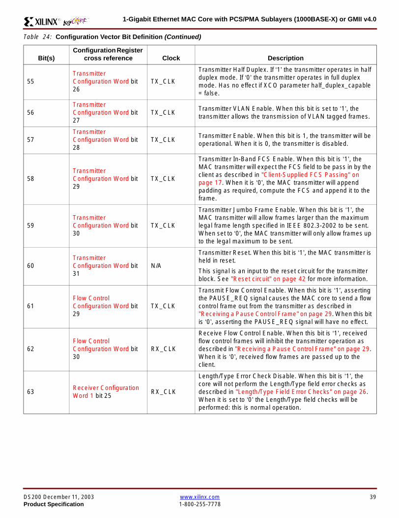
1-Gigabit Ethernet MAC Core with PCSPMA Sublayers (1000BASE-X) or GMII v40R
55TransmitterConfiguration Word bit26
TX_CLK
Transmitter Half Duplex If lsquo1rsquo the transmitter operates in halfduplex mode If lsquo0rsquo the transmitter operates in full duplexmode Has no effect if XCO parameter half_duplex_capable= false
56TransmitterConfiguration Word bit27
TX_CLKTransmitter VLAN Enable When this bit is set to lsquo1rsquo thetransmitter allows the transmission of VLAN tagged frames
57TransmitterConfiguration Word bit28
TX_CLKTransmitter Enable When this bit is 1 the transmitter will beoperational When it is 0 the transmitter is disabled
58TransmitterConfiguration Word bit29
TX_CLK
Transmitter In-Band FCS Enable When this bit is lsquo1rsquo theMAC transmitter will expect the FCS field to be pass in by theclient as described in Client-Supplied FCS Passing onpage 17 When it is lsquo0rsquo the MAC transmitter will appendpadding as required compute the FCS and append it to theframe
59TransmitterConfiguration Word bit30
TX_CLK
Transmitter Jumbo Frame Enable When this bit is lsquo1rsquo theMAC transmitter will allow frames larger than the maximumlegal frame length specified in IEEE 8023-2002 to be sentWhen set to lsquo0rsquo the MAC transmitter will only allow frames upto the legal maximum to be sent
60TransmitterConfiguration Word bit31
NA
Transmitter Reset When this bit is lsquo1rsquo the MAC transmitter isheld in reset
This signal is an input to the reset circuit for the transmitterblock See Reset circuit on page 42 for more information
61Flow ControlConfiguration Word bit29
TX_CLK
Transmit Flow Control Enable When this bit is lsquo1rsquo assertingthe PAUSE_REQ signal causes the MAC core to send a flowcontrol frame out from the transmitter as described inReceiving a Pause Control Frame on page 29 When this bitis lsquo0rsquo asserting the PAUSE_REQ signal will have no effect
62Flow ControlConfiguration Word bit30
RX_CLK
Receive Flow Control Enable When this bit is lsquo1rsquo receivedflow control frames will inhibit the transmitter operation asdescribed in Receiving a Pause Control Frame on page 29When it is lsquo0rsquo received flow frames are passed up to theclient
63Receiver ConfigurationWord 1 bit 25
RX_CLK
LengthType Error Check Disable When this bit is lsquo1rsquo thecore will not perform the LengthType field error checks asdescribed in LengthType Field Error Checks on page 26When it is set to lsquo0rsquo the LengthType field checks will beperformed this is normal operation
Table 24 Configuration Vector Bit Definition (Continued)
Bit(s)Configuration Register
cross reference Clock Description
DS200 December 11 2003 wwwxilinxcom 39Product Specification 1-800-255-7778
1-Gigabit Ethernet MAC Core with PCSPMA Sublayers (1000BASE-X) or GMII v40 R
Optional GMII (physical_interface=gmii)The GMII is designed to IEEE 8023-2002 Clause 35 Thisutilizes IOrsquos of the Xilinx devices using inputoutput buffersand inputoutput flip-flops to maximize setup and hold mar-gins All IO logic is placed in the example wrapper that isdelivered with the core In addition all clock managementlogic for the core is instanced in this example wrapper thisallows multiple instances of the core to share clocks Theexample wrapper is provided in both VHDL and Verilog
Clock Management
Figure 28 illustrates the clock management used with theGMII interface All clocks illustrated have a frequency of125MHz
GTX_CLK must be provided to the MAC core This is a highquality clock which satisfies the IEEE8023-2002 require-ments It is expected that this clock will be derived from anexternal oscillator and connected into the device through anIBUFG as illustrated The clock source must then be routedonto a global clock network by connecting it to a BUFGWithin the MAC core this global clock is used by all MACtransmitter logic The MAC Client can obtain this clock byconnecting to the TX_CLK signal output from the coreGMII_TX_CLK is derived from this global clock by invertingit and routing it to an OBUF
GMII_RX_CLK is received through an IBUFG This clock isthen routed onto a global clock network by connecting it to aBUFG The resulting global clock is used by all MACreceiver logic
Figure 28 Clock Management with GMII
IBUFG
IBUFG
OBUF
BUFG
BUFG
TX_CLK
RX_CLK
GTX_CLK
GMII_TX_CLK
GMII_RX_CLK
Example Wrapper
xip2153
MAC Core
TX_CLK
RX_CLK
GMII_TX_CLK
GMII_RX_CLK
GTX_CLK
40 wwwxilinxcom DS200 December 11 20031-800-255-7778 Product Specification
1-Gigabit Ethernet MAC Core with PCSPMA Sublayers (1000BASE-X) or GMII v40R
Clock Sharing between Multiple cores
Figure 29 illustrates how it is possible to share clockresources across multiple instantiations of the core whenusing the optional GMII
GTX_CLK may be shared between multiple cores as illus-trated resulting in a common transmitter clock domainacross the device
A common receiver clock domain is not possible each corewill receive an independent receiver clock from its GMII asillustrated
Although not illustrated if the optional Management Inter-face is used HOST_CLK can also be shared betweencores
Figure 29 Clock Management with multiple instances of the MAC with GMII
IBUFG
OBUF
BUFG
TX_CLK
RX_CLK_1
GMII_TX_CLK_1
GMII_RX_CLK_1
MAC Core
TX_CLK
RX_CLK
GMII_TX_CLK
GMII_RX_CLK
GTX_CLK
MAC Core
TX_CLK
RX_CLK
GMII_TX_CLK
GMII_RX_CLK
GTX_CLK
IBUFG
BUFG
GTX_CLK
IBUFG
OBUF
GMII_TX_CLK_2
GMII_RX_CLK_2
BUFG
TX_CLK
RX_CLK_2
DS200 December 11 2003 wwwxilinxcom 41Product Specification 1-800-255-7778
1-Gigabit Ethernet MAC Core with PCSPMA Sublayers (1000BASE-X) or GMII v40 R
Reset circuit
Internally the core is divided up into clockreset domainswhich group together elements with the common clock andreset signals The reset circuitry for one of these domains isis illustrated in Figure 30 This circuit provides controllableskews on the reset nets within the design
More information on the operation and rationale behind thiscircuit can be found in Ken Chapmanrsquos Xilinx TechXclusiveldquoGet Smart About Resetrdquo athttpwwwxilinxcomsupporttechxclusivesglobal-techX19htm
Figure 30 Reset circuit for one clockreset domain
FDP
PRED
C
Q
FDP
PRED
C
Q
FDP
PRED
C
Q
FDP
PRED
C
Q
PRE PRE PRE
0
RESET
Management Reset
Clock
Core Registers
42 wwwxilinxcom DS200 December 11 20031-800-255-7778 Product Specification
1-Gigabit Ethernet MAC Core with PCSPMA Sublayers (1000BASE-X) or GMII v40R
Optional PCS with Ten-Bit Interface (TBI) for 1000BASE-X (physical_interface=tbi)The Full-Duplex Physical Coding Sublayer (PCS) for1000BASE-X is defined in IEEE 8023-2002 Clauses 36and 37 This functionality is only available in the Virtex-IIand Spartan3 families of FPGA devices
A block diagram of the PCS is shown in Figure 31 Themajor functional blocks of the PCS are
bull Transmit engine
bull Auto-negotiation block
bull Receive engine and synchronization block
bull PCS managed register block
bull 8B10B encoder block
bull 8B10B decoder block
bull Receiver elastic buffer
The PCS Managed Register Block is accessed through theMDIO Interface as if it were an externally connected PHYThis configures the operation of the PCS and Auto-Negoti-ation See PCS Managed Register Block
(physical_interface = tbi or phy) on page 49 The corersquosoptional Management Interface can be used to control theMDIO Interface as described by MDIO Interface onpage 37 When the optional Management Interface is notpresent the PCS Managed Register Block must beaccessed via an MDIO controller which is not provided bythe core
The 8B10B encodingdecoding blocks are implemented byconfiguring two Block SelectRAM modules as ROM Theseare used as large look-up tables The remaining PCS func-tionality such as code group encodingdecoding the Man-aged Register Block and Auto-Negotiation areimplemented in CLB logic
The Receiver Elastic buffer enables the 10-bit parallel datareceived from the PMA sublayer alternatively onPMA_RX_CLK0 and PMA_RX_CLK1 clock edges to betransferred onto the internal 125MHz clock domain derivedfrom GTX_CLK (see Clock Management) This buffer isimplemented in Distributed Memory
Figure 31 Functional Block Diagram of the 1-Gigabit Ethernet PCS with TBI Interface
PCS TRANSMIT ENGINE
PCS RECEIVE ENGINE ampSYNCHRONISATION
PCSMANAGEMENT
MDIOInterface
AUTO-NEGOTIATION
MAC TXInterface
MAC RXInterface
8B10BEncoder
8B10BDecoder
RX Elastic Buffer
TBI Interface
DS200 December 11 2003 wwwxilinxcom 43Product Specification 1-800-255-7778
1-Gigabit Ethernet MAC Core with PCSPMA Sublayers (1000BASE-X) or GMII v40 R
TBI Interface
The TBI is designed to IEEE 8023-2002 Clause 363 Thisutilizes IOrsquos of the Xilinx devices using inputoutput buffersand inputoutput flip-flops to maximize setup and hold mar-gins All IO logic is placed in the example wrapper that isdelivered with the core In addition all clock managementlogic for the core is instantiated in this example wrapperthis allows multiple instances of the core to share clocksThe example wrapper is provided in both VHDL and Verilog
Clock Management
Figure 32 illustrates the clock management used with theTBI interface
GTX_CLK must be provided to the MAC core This is a highquality clock of frequency 125MHz which satisfies theIEEE8023-2002 requirements It is expected that this clockwill be derived from an external oscillator and connected
into the device through an IBUFG as illustrated The clocksource must then be routed onto a global clock network byconnecting it to a BUFG Within the MAC core this globalclock is used by all MAC transmitter logic PMA_TX_CLK isderived from this global clock by inverting it and routing it toan OBUF
PMA_RX_CLK0 and PMA_RX_CLK1 are each receivedthrough an IBUFG These clocks are then routed onto glo-bal clock networks by connecting each to a BUFGPMA_RX_CLK0 and PMA_RX_CLK1 are each 625MHzclocks Data from the TBI is received alternatively on the ris-ing edge of PMA_RX_CLK0 followed by the rising edge ofPMA_RX_CLK1 using IOB Double-Data Rate input regis-ters This data is then written into the Receiver ElasticBuffer Data is read out of the Elastic Buffer using the globalclock derived from GTX_CLK all the remaining receiverlogic is synchronous to this clock
Figure 32 Clock Management for PCS with TBI Interface
IBUFG
IBUFG
OBUF
BUFG
BUFG
TX_CLK
RX_CLK
GTX_CLK
PMA_TX_CLK
PMA_RX_CLK0
MAC Core
RX ELASTICBUFFER
Example Wrapper
TX_CLK
RX_CLK
GTX_CLK
PMA_TX_CLK
PMA_RX_CLK0
IBUFGBUFGPMA_RX_CLK1
PMA_RX_CLK1
44 wwwxilinxcom DS200 December 11 20031-800-255-7778 Product Specification
1-Gigabit Ethernet MAC Core with PCSPMA Sublayers (1000BASE-X) or GMII v40R
Clock Sharing between Multiple cores
Figure 33 illustrates how it is possible to share clockresources across multiple instantiations of the core whenusing the optional PCS with TBI
GTX_CLK may be shared between multiple cores as illus-trated resulting in a common transmitter clock domainacross the device
Each core will receive independent PMA_RX_CLK0 andPMA_RX_CLK1 clocks from its TBI as illustrated whichcannot be shared
Although not illustrated if the optional Management Inter-face is used HOST_CLK can also be shared betweencores
Figure 33 Clock Management with multiple instances of the MAC with PCS and TBI
Reset circuit
The reset circuits within the MAC when the TBI interface is implemented is the same as that in the GMII case details ofthese circuits can be found on page 42
IBUFG
OBUF
BUFG
TX_CLK
RX_CLK
PMA_TX_CLK_1
PMA_RX_CLK0_1
MAC Core
RX ELASTICBUFFER
TX_CLK
RX_CLK
GTX_CLK
PMA_TX_CLK
PMA_RX_CLK0
IBUFGBUFGPMA_RX_CLK1_1
PMA_RX_CLK1
IBUFG
BUFG
GTX_CLK
IBUFG
OBUF
BUFG
TX_CLK
RX_CLK
PMA_TX_CLK_2
PMA_RX_CLK0_2
MAC Core
RX ELASTICBUFFER
TX_CLK
RX_CLK
GTX_CLK
PMA_TX_CLK
PMA_RX_CLK0
IBUFGBUFGPMA_RX_CLK1_2
PMA_RX_CLK1
DS200 December 11 2003 wwwxilinxcom 45Product Specification 1-800-255-7778
1-Gigabit Ethernet MAC Core with PCSPMA Sublayers (1000BASE-X) or GMII v40 R
Optional PCS and PMA Sublayers for 1000BASE-X (physical_interface=phy)The Full-Duplex Physical Coding Sublayer (PCS) withPhysical Medium Attachment (PMA) for 1000BASE-X isdefined in IEEE 8023-2002 Clauses 36 and 37 This func-tionality is only available in the Virtex-II Pro family of FPGAdevices
A block diagram of the PCS and PMA sublayers can beseen in Figure 34 The functional blocks of the PCS andPMA sublayers may replace the optional GMII interfaceThe functional blocks of the PCS and PMA sublayers are
bull PCS Transmit Engine
bull Auto-Negotiation block
bull Receive Engine and Synchronization Block
bull PCS Managed Register Block
bull Rocket IO Multi-Gigabit Transceiver
The PCS Managed Register Block is accessed through theMDIO Interface as if it were an externally connected PHYThis configures the operation of the PCS PMA sublayerand Auto-NegotiationSee PCS Managed Register Block(physical_interface = tbi or phy) on page 49 The corersquosoptional Management Interface can be used to control theMDIO Interface as described by MDIO Interface onpage 37 When the optional Management Interface is notpresent the PCS Managed Register Block must beaccessed via an MDIO controller which is not provided bythe core
The Rocket IO Multi-Gigabit Transceiver (MGT) providessome of the PCS layer functionality such as 8B10B encod-ingdecoding and the PMA serdes The remaining PCSfunctionality such as code group encodingdecoding theManaged Register Block and Auto-Negotiation are imple-mented in CLB logic
Figure 34 Functional Block Diagram of the 1-Gigabit Ethernet PCSPMA Sublayer Extension
PCS TRANSMIT ENGINE
PCS RECEIVE ENGINE ampSYNCHRONISATION
RO
CK
ET
IO
MU
LTI-
GIG
TR
AN
SC
EIV
ER
PCSMANAGEMENT
MDIOInterface
AUTO-NEGOTIATION
TXPTXN
RXPRXN
MAC TXInterface
MAC RXInterface
xip2154
46 wwwxilinxcom DS200 December 11 20031-800-255-7778 Product Specification
1-Gigabit Ethernet MAC Core with PCSPMA Sublayers (1000BASE-X) or GMII v40R
Clock Management
Figure 35 illustrates the clock management that should beused with the optional PCS and PMA sublayers for1000BASE-X This logic is implemented in the examplewrapper that is delivered with the core This provides flexi-bility because the design can be modified to use eitherREFCLK or BREFCLK (please refer to Rocket IO docu-mentation) It would also allow multiple instances of the coreto share clocks The example wrapper is provided in bothVHDL and Verilog
(B)REFCLK must be provided to the MAC core This clockmust be derived from an external oscillator and connectedto the core through an IBUFG as illustrated (B)REFCLK isa high quality clock of frequency 625 MHz which satisfiesthe Rocket IO Multi-Gigabit Transceiver (MGT) require-ments
(B)REFCLK is routed to both the core and a DCM From theDCM the CLK2X180 output is routed to a BUFG to providethe device with a global 125 MHz clock (connected toUSERCLK2 input on the core) Within the core bothTX_CLK and RX_CLK share this global 125 MHz clocksource which is used by all transmitter and receiver logicThis is made possible by the RX_ELASTIC_BUFFER func-tionality of the Rocket IO MGT (refer to Virtex-II Pro docu-mentation) The MAC Client can obtain this clock byconnecting to either the TX_CLK or the RX_CLK signalsoutput from the core
From the DCM the CLK0 output is routed to a BUFG to pro-vide the device with a global 625MHz clock This is con-nected to the USRCLK input of the core
Figure 35 Clock Management with PCSPMA Sublayers
DCM
CLKIN CLK0
CLK2X180FB
BUFG
BUFG
IBUFG
TX_CLK
RX_CLK
(B)REFCLK
TXUSRCLK
(B)REFCLK
TXUSRCLK2RXUSRCLKRXUSRCLK2
GT_ETHERNET
Example Wrapper
xip2155
MAC Core
(B)REFCLK
USRCLK
USRCLK2
TX_CLK
RX_CLK
DS200 December 11 2003 wwwxilinxcom 47Product Specification 1-800-255-7778
1-Gigabit Ethernet MAC Core with PCSPMA Sublayers (1000BASE-X) or GMII v40 R
Clock Sharing between Multiple Cores
Figure 36 illustrates how it is possible to share clockresources across multiple instantiations of the core whenusing the optional PCSPMA sublayers For each coreUSERCLK and USERCLK2 must always be derived asshown from the BREFCLK or REFCLK used by that core
Note that when using the fixed routing resources of BREF-CLK Rocket IO MGTs along the top edge of the devicemust use a separate BREFCLK routing resource to thosealong the bottom edge of the device (Refer to Virtex-II Prodocumentation)
Although not illustrated if the optional Management Inter-face is used HOST_CLK can also be shared betweencores
Figure 36 Clock Management with multiple instances of the MAC with PCS and PMA sublayers
Reset circuit
The reset circuits within the MAC when the PCS and PMA sublayers are implemented is the same as that in the GMII casedetails of these circuits can be found on page 42
DCM
CLKIN CLK0
CLK2X180FB
BUFG
BUFG
IBUFG
(B)REFCLK
TXUSRCLK
(B)REFCLK
TXUSRCLK2RXUSRCLKRXUSRCLK2
GT_ETHERNET(B)REFCLK
USERCLK
USERCLK2
MAC core
TXUSRCLK
(B)REFCLK
TXUSRCLK2RXUSRCLKRXUSRCLK2
GT_ETHERNET(B)REFCLK
USERCLK
USERCLK2
MAC core
48 wwwxilinxcom DS200 December 11 20031-800-255-7778 Product Specification
1-Gigabit Ethernet MAC Core with PCSPMA Sublayers (1000BASE-X) or GMII v40R
PCS Managed Register Block (physical_interface = tbi or phy)The PCS in both the TBI interface and the PCSPMA (usingthe Virtex-II Pro Rocket IO) versions contain the full Man-aged Register Block defined in IEEE 8023-2002 clause 37
This utilizes ten dedicated management registersaccessed via the MDIO interface These are defined inTable 25 to Table 33 inclusive
Table 25 Control Register (Register 0)
Bit(s) Name Description Attributes Default Value
015 Reset1 = PCSPMA reset
0 = Normal Operation
ReadWrite
Self Clearing0
014 Loopback1 = Enable Loopback Mode
0 = Disable Loopback ModeReadWrite 0
013SpeedSelection (LSB)
The core always returns a 0 for this bitTogether with bit 06 speed selection of 1000Mbs is identified
Returns 0 0
012Auto-NegotiationEnable
1 = Enable Auto-Negotiation Process
0 = Disable Auto-Negotiation ProcessReadWrite 1
011 Power Down
1 = Power down
0 = Normal operation
When set to ldquo1rdquo the Rocket IO MGT is placedin a low power state This bit requires a reset(see bit 015) to clear
Read Write 0
010 Isolate1 = Electrically Isolate PHY from GMII
0 = Normal operationReadWrite 1
09Restart Auto-Negotiation
1 = Restart Auto-Negotiation Process
0 = Normal Operation
ReadWrite
Self Clearing0
08 Duplex ModeThe core always returns a 1 for this bit tosignal Full-Duplex Mode
Returns 1 1
07 Collision TestThe core always returns a 0 for this bit todisable COL test
Returns 0 0
06SpeedSelection(MSB)
The core always returns a 1 for this bitTogether with bit 013 speed selection of1000 Mbs is identified
Returns 1 1
050 Reserved Always returns 0rsquos writes ignored Returns 0rsquos 000000
DS200 December 11 2003 wwwxilinxcom 49Product Specification 1-800-255-7778
1-Gigabit Ethernet MAC Core with PCSPMA Sublayers (1000BASE-X) or GMII v40 R
Table 26 Status Register (Register 1)
Bit(s) Name Description Attributes Default Value
115 100BASE-T4The core always returns a 0 for this bitbecause 100BASE-T4 is not supported
Returns 0 0
114100BASE-XFullDuplex
The core always returns a 0 for this bitbecause 100BASE-X Full Duplex is notsupported
Returns 0 0
113100BASE-XHalf Duplex
The core always returns a 0 for this bitbecause 100BASE-X Half Duplex is notsupported
Returns 0 0
11210 Mbs FullDuplex
The core always returns a 0 for this bitbecause 10 Mbs Full Duplex is notsupported
Returns 0 0
11110 Mbs HalfDuplex
The core always returns a 0 for this bitbecause 10 Mbs Half Duplex is notsupported
Returns 0 0
110100BASE-T2Full Duplex
The core always returns a 0 for this bitbecause 100BASE-T2 Full Duplex is notsupported
Returns 0 0
19100BASE-T2Half Duplex
The core always returns a 0 for this bitbecause 100BASE-T2 Half Duplex is notsupported
Returns 0 0
18ExtendedStatus
The core always returns a 1 for this bit toindicate the presence of the ExtendedRegister (Register 15)
Returns 1 1
17 Reserved Always return 0 writes ignored Returns 0 0
16MF PreambleSuppression
The core always returns a 1 for this bit toindicate that Management Frame PreambleSuppression is supported
Returns 1 1
15Auto-NegotiationComplete
1 = Auto-Negotiation process completed
0 = Auto-Negotiation process not completedRead Only 0
14 Remote Fault1 = Remote fault condition detected
0 = No remote fault condition detected
Read Only
Self Clearing on read0
13Auto-NegotiationAbility
The core always returns a 1 for this bit toindicate that the PHY is capable ofAuto-Negotiation
Returns 1 1
12 Link Status1 = Link is up
0 = Link is down
Read Only
Self Clearing on read0
11 Jabber DetectThe core always returns a 0 for this bitbecause Jabber Detect is not supported
Returns 0 0
10ExtendedCapability
The core always returns a 0 for this bitbecause no extended register set issupported
Returns 0 0
50 wwwxilinxcom DS200 December 11 20031-800-255-7778 Product Specification
1-Gigabit Ethernet MAC Core with PCSPMA Sublayers (1000BASE-X) or GMII v40R
Table 27 PHY Identifier (Registers 2 and 3)
Bit(s) Name Description Attributes Default Value
2150OrganizationallyUniqueIdentifier
Always returns 0s Returns 0s 0000000000000000
31510OrganizationallyUniqueIdentifier
Always returns 0s Returns 0s 000000
394Manufacturerrsquosmodel number
Always returns 0s Returns 0s 000000
330RevisionNumber
Always returns 0s Returns 0s 0000
Table 28 Auto-Negotiation Advertisement Register (Register 4)
Bit(s) Name Description Attributes Default Value
415 Next Page1 = Next Page functionality is advertised
0 = Next Page functionality is not advertisedReadWrite 0
414 Reserved Always returns 0 writes ignored Returns 0 0
41312 Remote Fault
00 = No Error
01 = Offline
10 = Link Failure
11 = Auto-Negotiation Error
ReadWrite
Self clearing to 00afterAuto-Negotiation
00
4119 Reserved Always return 0 writes ignored Returns 0 0
487 Pause
00 = No PAUSE
01 = Asymmetric PAUSE towards linkpartner
10 = Symmetic PAUSE
11 = Both Symmetric PAUSE andAsymmetric PAUSE towards link partner
ReadWrite 11
46 Half DuplexThe core always returns a 0 for this bitbecause Half Duplex Mode is not supported
Returns 0 0
45 Full Duplex1 = Full Duplex Mode is advertised
0 = Full Duplex Mode is not advertisedReadWrite 1
440 Reserved Always returns 0s writes ignored Returns 0s 00000
DS200 December 11 2003 wwwxilinxcom 51Product Specification 1-800-255-7778
1-Gigabit Ethernet MAC Core with PCSPMA Sublayers (1000BASE-X) or GMII v40 R
Table 29 Auto-Negotiation Link Partner Ability Base Register (Register 5)
Bit(s) Name Description Attributes Default Value
515 Next Page1 = Next Page functionality is supported
0 = Next Page functionality is not supportedRead Only 0
514 AcknowledgeUsed by Auto-Negotiation function toindicate reception of a link partnerrsquos base ornext page
Read Only 0
51312 Remote Fault
00 = No Error
01 = Offline
10 = Link Failure
11 = Auto-Negotiation Error
Read Only 00
5119 Reserved Always returns 0s Returns 0s 000
587 Pause
00 = No PAUSE
01 = Asymmetric PAUSE supported
10 = Symmetic PAUSE supported
11 = Both Symmetric PAUSE andAsymmetric PAUSE supported
Read Only 00
56 Half Duplex1 = Half Duplex Mode is supported
0 = Half Duplex Mode is not supportedRead Only 0
55 Full Duplex1 = Full Duplex Mode is supported
0 = Full Duplex Mode is not supportedRead Only 0
540 Reserved Always returns 0s Returns 0s 00000
Table 30 Auto-Negotiation Expansion Register (Register 6)
Bit(s) Name Description Attributes Default Value
6153 Reserved Always returns 0s Returns 0s 0000000000000
62 Next Page AbleThe core always returns a 1 for this bitbecause the device is Next Page Able
Returns 1 1
61 Page Received1 = A new page has been received
0 = A new page has not been received
Read Only
Self Clearing on read0
60 Reserved Always returns 0s Returns 0s 0000000
52 wwwxilinxcom DS200 December 11 20031-800-255-7778 Product Specification
1-Gigabit Ethernet MAC Core with PCSPMA Sublayers (1000BASE-X) or GMII v40R
Table 31 Auto-Negotiation Next Page Transmit Register (Register 7)
Bit(s) Name Description Attributes Default Value
715 Next Page1 = Additional Next Page(s) will follow
0 = Last pageReadWrite 0
714 Reserved Always returns 0 Returns 0 0
713 Message Page1 = Message Page
0 = Unformatted PageReadWrite 1
712 Acknowledge 21 = Will comply with message
0 = Cannot comply with messageReadWrite 0
711 ToggleValue will toggle between subsequent NextPages
Read Only 0
7100Message UnformattedCode Field
Message Code Field or Unformatted PageEncoding as dictated by 713
ReadWrite00000000001
(Null Message Code)
Table 32 Auto-Negotiation Next Page Receive Register (Register 8)
Bit(s) Name Description Attributes Default Value
815 Next Page1 = Additional Next Page(s) follows
0 = Last pageRead Only 0
814 AcknowledgeUsed by Auto-Negotiation function toindicate reception of a link partnerrsquos base ornext page
Read Only 0
813 Message Page1 = Message Page
0 = Unformatted PageRead Only 0
812 Acknowledge 21 = Will comply with message
0 = Cannot comply with messageRead Only 0
811 ToggleValue toggles between subsequent andNext Pages
Read Only 0
8100Message UnformattedCode Field
Message Code Field or Unformatted PageEncoding as dictated by 813
Read Only 00000000000
DS200 December 11 2003 wwwxilinxcom 53Product Specification 1-800-255-7778
1-Gigabit Ethernet MAC Core with PCSPMA Sublayers (1000BASE-X) or GMII v40 R
)
Referencesbull IEEE 8023-2002
bull Virtex-E User Guide
bull Spartan-II E User Guide
bull Virtex-II User Guide
bull Virtex-II Pro User Guide
Related InformationXilinx products are not intended for use in life support appli-ances devices or systems Use of a Xilinx product in suchapplications without the written consent of the appropriateXilinx officer is prohibited
Ordering InformationThis Xilinx LogiCORE module is provided under theSignOnce IP Site License A free evaluation version of themodule is available
Once purchased the core may be downloaded from the Xil-inx IP Center for use with the Xilinx CORE Generator Sys-temtrade v61i SP3 and later The Xilinx CORE GeneratorSystem tool is bundled with all Alliance Series Softwarepackages at no additional charge
Please contact your local Xilinx sales representative or visitthe Xilinx Silicon Xpresso Cafe for pricing and availability onXilinx LogiCORE modules and software Information onadditional Xilinx LogiCORE modules is available on the Xil-inx IP Center
Revision HistoryThe following table shows the revision history for this document
Table 33 Extended Status Register (Register 15)
Bit(s) Name Description Attributes Default Value
15151000BASE-XFull Duplex
The core always returns a 1 for this bitbecause 1000BASE-X Full Duplex issupported
Returns 1 1
15141000BASE-XHalf Duplex
The core always returns a 0 for this bitbecause 1000BASE-X Half Duplex is notsupported
Returns 0 0
15131000BASE-TFull Duplex
The core always returns a 0 for this bitbecause 1000BASE-T Full Duplex is notsupported
Returns 0 0
15121000BASE-THalf Duplex
The core always returns a 0 for this bitbecause 1000BASE-T Half Duplex is notsupported
Returns 0 0
15110 Reserved Always returns 0s Returns 0s 000000000000
Date Version Revision
032803 11 Revision History added to document
043003 20 Revised to v30 standards
121103 30 Updated to v40 release
54 wwwxilinxcom DS200 December 11 20031-800-255-7778 Product Specification
- 1-Gigabit Ethernet MAC Core with PCSPMA Sublayers (1000BASE-X) or GMII v40
-
- Features
- MAC Overview
- Xilinx CORE Generator
- GUI Interface
- Parameter Values in the XCO File
- Output Generation
- Device Utilization
- Interface Description
- Interface Signals for MAC with physical_interface=gmii and management_interface=true
- Interface Signals for MAC with physical_interface=gmii and management_interface=false
- Interface Signals for MAC with physical_interface=tbi and management_interface=true
- Interface Signals for MAC with physical_interface=tbi and management_interface=false
- Interface Signals for MAC with physical_interface=phy and management_interface=true
- Interface Signals for MAC with physical_interface=phy and management_interface=false
- Client Side Interface Signal Definition
- Physical Interface Signal Definition
- Functional Description
- Client Interface
- Transmitter
- Receiver
- Flow Control
- Optional Management Interface (management_interface=true)
- Optional Configuration Vector (management_interface = false)
- Optional GMII (physical_interface=gmii)
- Optional PCS with Ten-Bit Interface (TBI) for 1000BASE-X (physical_interface=tbi)
- Optional PCS and PMA Sublayers for 1000BASE-X (physical_interface=phy)
- PCS Managed Register Block (physical_interface = tbi or phy)
- References
- Related Information
- Ordering Information
- Revision History
-
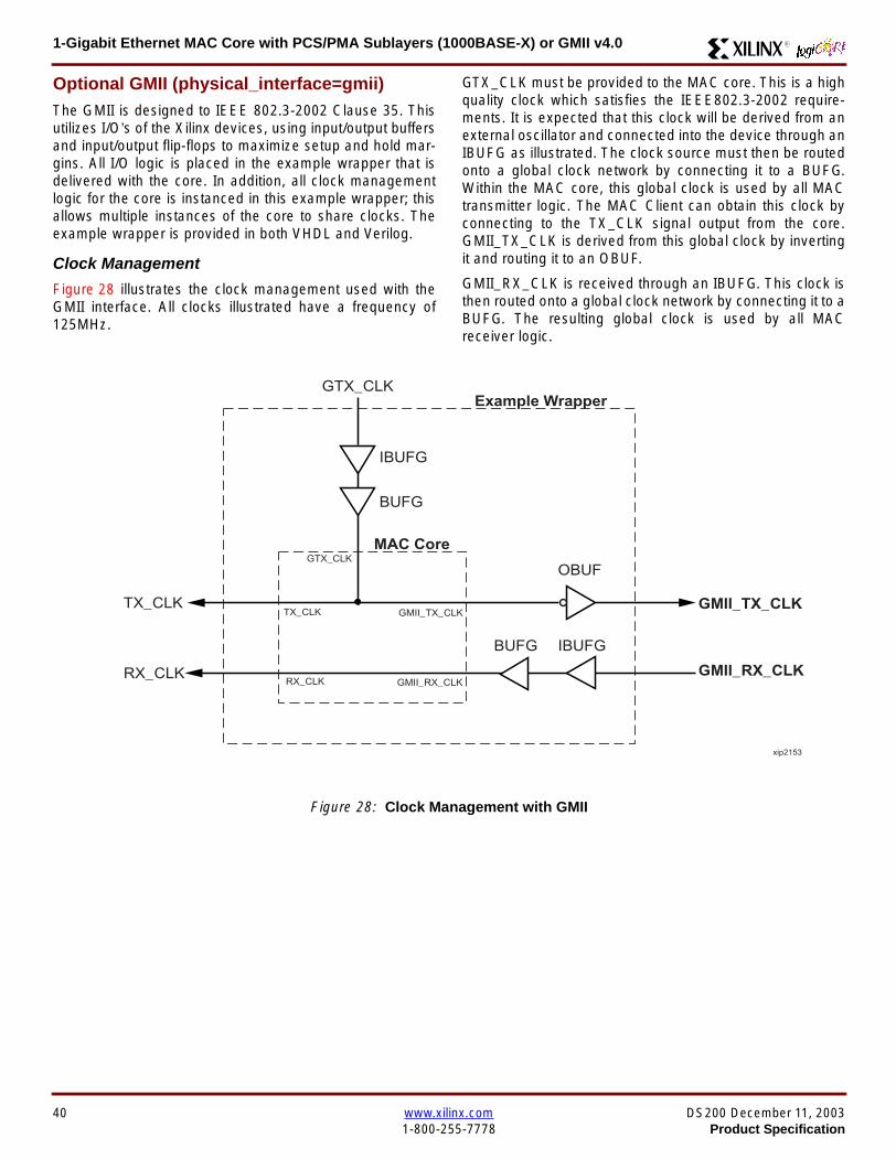
1-Gigabit Ethernet MAC Core with PCSPMA Sublayers (1000BASE-X) or GMII v40 R
Optional GMII (physical_interface=gmii)The GMII is designed to IEEE 8023-2002 Clause 35 Thisutilizes IOrsquos of the Xilinx devices using inputoutput buffersand inputoutput flip-flops to maximize setup and hold mar-gins All IO logic is placed in the example wrapper that isdelivered with the core In addition all clock managementlogic for the core is instanced in this example wrapper thisallows multiple instances of the core to share clocks Theexample wrapper is provided in both VHDL and Verilog
Clock Management
Figure 28 illustrates the clock management used with theGMII interface All clocks illustrated have a frequency of125MHz
GTX_CLK must be provided to the MAC core This is a highquality clock which satisfies the IEEE8023-2002 require-ments It is expected that this clock will be derived from anexternal oscillator and connected into the device through anIBUFG as illustrated The clock source must then be routedonto a global clock network by connecting it to a BUFGWithin the MAC core this global clock is used by all MACtransmitter logic The MAC Client can obtain this clock byconnecting to the TX_CLK signal output from the coreGMII_TX_CLK is derived from this global clock by invertingit and routing it to an OBUF
GMII_RX_CLK is received through an IBUFG This clock isthen routed onto a global clock network by connecting it to aBUFG The resulting global clock is used by all MACreceiver logic
Figure 28 Clock Management with GMII
IBUFG
IBUFG
OBUF
BUFG
BUFG
TX_CLK
RX_CLK
GTX_CLK
GMII_TX_CLK
GMII_RX_CLK
Example Wrapper
xip2153
MAC Core
TX_CLK
RX_CLK
GMII_TX_CLK
GMII_RX_CLK
GTX_CLK
40 wwwxilinxcom DS200 December 11 20031-800-255-7778 Product Specification
1-Gigabit Ethernet MAC Core with PCSPMA Sublayers (1000BASE-X) or GMII v40R
Clock Sharing between Multiple cores
Figure 29 illustrates how it is possible to share clockresources across multiple instantiations of the core whenusing the optional GMII
GTX_CLK may be shared between multiple cores as illus-trated resulting in a common transmitter clock domainacross the device
A common receiver clock domain is not possible each corewill receive an independent receiver clock from its GMII asillustrated
Although not illustrated if the optional Management Inter-face is used HOST_CLK can also be shared betweencores
Figure 29 Clock Management with multiple instances of the MAC with GMII
IBUFG
OBUF
BUFG
TX_CLK
RX_CLK_1
GMII_TX_CLK_1
GMII_RX_CLK_1
MAC Core
TX_CLK
RX_CLK
GMII_TX_CLK
GMII_RX_CLK
GTX_CLK
MAC Core
TX_CLK
RX_CLK
GMII_TX_CLK
GMII_RX_CLK
GTX_CLK
IBUFG
BUFG
GTX_CLK
IBUFG
OBUF
GMII_TX_CLK_2
GMII_RX_CLK_2
BUFG
TX_CLK
RX_CLK_2
DS200 December 11 2003 wwwxilinxcom 41Product Specification 1-800-255-7778
1-Gigabit Ethernet MAC Core with PCSPMA Sublayers (1000BASE-X) or GMII v40 R
Reset circuit
Internally the core is divided up into clockreset domainswhich group together elements with the common clock andreset signals The reset circuitry for one of these domains isis illustrated in Figure 30 This circuit provides controllableskews on the reset nets within the design
More information on the operation and rationale behind thiscircuit can be found in Ken Chapmanrsquos Xilinx TechXclusiveldquoGet Smart About Resetrdquo athttpwwwxilinxcomsupporttechxclusivesglobal-techX19htm
Figure 30 Reset circuit for one clockreset domain
FDP
PRED
C
Q
FDP
PRED
C
Q
FDP
PRED
C
Q
FDP
PRED
C
Q
PRE PRE PRE
0
RESET
Management Reset
Clock
Core Registers
42 wwwxilinxcom DS200 December 11 20031-800-255-7778 Product Specification
1-Gigabit Ethernet MAC Core with PCSPMA Sublayers (1000BASE-X) or GMII v40R
Optional PCS with Ten-Bit Interface (TBI) for 1000BASE-X (physical_interface=tbi)The Full-Duplex Physical Coding Sublayer (PCS) for1000BASE-X is defined in IEEE 8023-2002 Clauses 36and 37 This functionality is only available in the Virtex-IIand Spartan3 families of FPGA devices
A block diagram of the PCS is shown in Figure 31 Themajor functional blocks of the PCS are
bull Transmit engine
bull Auto-negotiation block
bull Receive engine and synchronization block
bull PCS managed register block
bull 8B10B encoder block
bull 8B10B decoder block
bull Receiver elastic buffer
The PCS Managed Register Block is accessed through theMDIO Interface as if it were an externally connected PHYThis configures the operation of the PCS and Auto-Negoti-ation See PCS Managed Register Block
(physical_interface = tbi or phy) on page 49 The corersquosoptional Management Interface can be used to control theMDIO Interface as described by MDIO Interface onpage 37 When the optional Management Interface is notpresent the PCS Managed Register Block must beaccessed via an MDIO controller which is not provided bythe core
The 8B10B encodingdecoding blocks are implemented byconfiguring two Block SelectRAM modules as ROM Theseare used as large look-up tables The remaining PCS func-tionality such as code group encodingdecoding the Man-aged Register Block and Auto-Negotiation areimplemented in CLB logic
The Receiver Elastic buffer enables the 10-bit parallel datareceived from the PMA sublayer alternatively onPMA_RX_CLK0 and PMA_RX_CLK1 clock edges to betransferred onto the internal 125MHz clock domain derivedfrom GTX_CLK (see Clock Management) This buffer isimplemented in Distributed Memory
Figure 31 Functional Block Diagram of the 1-Gigabit Ethernet PCS with TBI Interface
PCS TRANSMIT ENGINE
PCS RECEIVE ENGINE ampSYNCHRONISATION
PCSMANAGEMENT
MDIOInterface
AUTO-NEGOTIATION
MAC TXInterface
MAC RXInterface
8B10BEncoder
8B10BDecoder
RX Elastic Buffer
TBI Interface
DS200 December 11 2003 wwwxilinxcom 43Product Specification 1-800-255-7778
1-Gigabit Ethernet MAC Core with PCSPMA Sublayers (1000BASE-X) or GMII v40 R
TBI Interface
The TBI is designed to IEEE 8023-2002 Clause 363 Thisutilizes IOrsquos of the Xilinx devices using inputoutput buffersand inputoutput flip-flops to maximize setup and hold mar-gins All IO logic is placed in the example wrapper that isdelivered with the core In addition all clock managementlogic for the core is instantiated in this example wrapperthis allows multiple instances of the core to share clocksThe example wrapper is provided in both VHDL and Verilog
Clock Management
Figure 32 illustrates the clock management used with theTBI interface
GTX_CLK must be provided to the MAC core This is a highquality clock of frequency 125MHz which satisfies theIEEE8023-2002 requirements It is expected that this clockwill be derived from an external oscillator and connected
into the device through an IBUFG as illustrated The clocksource must then be routed onto a global clock network byconnecting it to a BUFG Within the MAC core this globalclock is used by all MAC transmitter logic PMA_TX_CLK isderived from this global clock by inverting it and routing it toan OBUF
PMA_RX_CLK0 and PMA_RX_CLK1 are each receivedthrough an IBUFG These clocks are then routed onto glo-bal clock networks by connecting each to a BUFGPMA_RX_CLK0 and PMA_RX_CLK1 are each 625MHzclocks Data from the TBI is received alternatively on the ris-ing edge of PMA_RX_CLK0 followed by the rising edge ofPMA_RX_CLK1 using IOB Double-Data Rate input regis-ters This data is then written into the Receiver ElasticBuffer Data is read out of the Elastic Buffer using the globalclock derived from GTX_CLK all the remaining receiverlogic is synchronous to this clock
Figure 32 Clock Management for PCS with TBI Interface
IBUFG
IBUFG
OBUF
BUFG
BUFG
TX_CLK
RX_CLK
GTX_CLK
PMA_TX_CLK
PMA_RX_CLK0
MAC Core
RX ELASTICBUFFER
Example Wrapper
TX_CLK
RX_CLK
GTX_CLK
PMA_TX_CLK
PMA_RX_CLK0
IBUFGBUFGPMA_RX_CLK1
PMA_RX_CLK1
44 wwwxilinxcom DS200 December 11 20031-800-255-7778 Product Specification
1-Gigabit Ethernet MAC Core with PCSPMA Sublayers (1000BASE-X) or GMII v40R
Clock Sharing between Multiple cores
Figure 33 illustrates how it is possible to share clockresources across multiple instantiations of the core whenusing the optional PCS with TBI
GTX_CLK may be shared between multiple cores as illus-trated resulting in a common transmitter clock domainacross the device
Each core will receive independent PMA_RX_CLK0 andPMA_RX_CLK1 clocks from its TBI as illustrated whichcannot be shared
Although not illustrated if the optional Management Inter-face is used HOST_CLK can also be shared betweencores
Figure 33 Clock Management with multiple instances of the MAC with PCS and TBI
Reset circuit
The reset circuits within the MAC when the TBI interface is implemented is the same as that in the GMII case details ofthese circuits can be found on page 42
IBUFG
OBUF
BUFG
TX_CLK
RX_CLK
PMA_TX_CLK_1
PMA_RX_CLK0_1
MAC Core
RX ELASTICBUFFER
TX_CLK
RX_CLK
GTX_CLK
PMA_TX_CLK
PMA_RX_CLK0
IBUFGBUFGPMA_RX_CLK1_1
PMA_RX_CLK1
IBUFG
BUFG
GTX_CLK
IBUFG
OBUF
BUFG
TX_CLK
RX_CLK
PMA_TX_CLK_2
PMA_RX_CLK0_2
MAC Core
RX ELASTICBUFFER
TX_CLK
RX_CLK
GTX_CLK
PMA_TX_CLK
PMA_RX_CLK0
IBUFGBUFGPMA_RX_CLK1_2
PMA_RX_CLK1
DS200 December 11 2003 wwwxilinxcom 45Product Specification 1-800-255-7778
1-Gigabit Ethernet MAC Core with PCSPMA Sublayers (1000BASE-X) or GMII v40 R
Optional PCS and PMA Sublayers for 1000BASE-X (physical_interface=phy)The Full-Duplex Physical Coding Sublayer (PCS) withPhysical Medium Attachment (PMA) for 1000BASE-X isdefined in IEEE 8023-2002 Clauses 36 and 37 This func-tionality is only available in the Virtex-II Pro family of FPGAdevices
A block diagram of the PCS and PMA sublayers can beseen in Figure 34 The functional blocks of the PCS andPMA sublayers may replace the optional GMII interfaceThe functional blocks of the PCS and PMA sublayers are
bull PCS Transmit Engine
bull Auto-Negotiation block
bull Receive Engine and Synchronization Block
bull PCS Managed Register Block
bull Rocket IO Multi-Gigabit Transceiver
The PCS Managed Register Block is accessed through theMDIO Interface as if it were an externally connected PHYThis configures the operation of the PCS PMA sublayerand Auto-NegotiationSee PCS Managed Register Block(physical_interface = tbi or phy) on page 49 The corersquosoptional Management Interface can be used to control theMDIO Interface as described by MDIO Interface onpage 37 When the optional Management Interface is notpresent the PCS Managed Register Block must beaccessed via an MDIO controller which is not provided bythe core
The Rocket IO Multi-Gigabit Transceiver (MGT) providessome of the PCS layer functionality such as 8B10B encod-ingdecoding and the PMA serdes The remaining PCSfunctionality such as code group encodingdecoding theManaged Register Block and Auto-Negotiation are imple-mented in CLB logic
Figure 34 Functional Block Diagram of the 1-Gigabit Ethernet PCSPMA Sublayer Extension
PCS TRANSMIT ENGINE
PCS RECEIVE ENGINE ampSYNCHRONISATION
RO
CK
ET
IO
MU
LTI-
GIG
TR
AN
SC
EIV
ER
PCSMANAGEMENT
MDIOInterface
AUTO-NEGOTIATION
TXPTXN
RXPRXN
MAC TXInterface
MAC RXInterface
xip2154
46 wwwxilinxcom DS200 December 11 20031-800-255-7778 Product Specification
1-Gigabit Ethernet MAC Core with PCSPMA Sublayers (1000BASE-X) or GMII v40R
Clock Management
Figure 35 illustrates the clock management that should beused with the optional PCS and PMA sublayers for1000BASE-X This logic is implemented in the examplewrapper that is delivered with the core This provides flexi-bility because the design can be modified to use eitherREFCLK or BREFCLK (please refer to Rocket IO docu-mentation) It would also allow multiple instances of the coreto share clocks The example wrapper is provided in bothVHDL and Verilog
(B)REFCLK must be provided to the MAC core This clockmust be derived from an external oscillator and connectedto the core through an IBUFG as illustrated (B)REFCLK isa high quality clock of frequency 625 MHz which satisfiesthe Rocket IO Multi-Gigabit Transceiver (MGT) require-ments
(B)REFCLK is routed to both the core and a DCM From theDCM the CLK2X180 output is routed to a BUFG to providethe device with a global 125 MHz clock (connected toUSERCLK2 input on the core) Within the core bothTX_CLK and RX_CLK share this global 125 MHz clocksource which is used by all transmitter and receiver logicThis is made possible by the RX_ELASTIC_BUFFER func-tionality of the Rocket IO MGT (refer to Virtex-II Pro docu-mentation) The MAC Client can obtain this clock byconnecting to either the TX_CLK or the RX_CLK signalsoutput from the core
From the DCM the CLK0 output is routed to a BUFG to pro-vide the device with a global 625MHz clock This is con-nected to the USRCLK input of the core
Figure 35 Clock Management with PCSPMA Sublayers
DCM
CLKIN CLK0
CLK2X180FB
BUFG
BUFG
IBUFG
TX_CLK
RX_CLK
(B)REFCLK
TXUSRCLK
(B)REFCLK
TXUSRCLK2RXUSRCLKRXUSRCLK2
GT_ETHERNET
Example Wrapper
xip2155
MAC Core
(B)REFCLK
USRCLK
USRCLK2
TX_CLK
RX_CLK
DS200 December 11 2003 wwwxilinxcom 47Product Specification 1-800-255-7778
1-Gigabit Ethernet MAC Core with PCSPMA Sublayers (1000BASE-X) or GMII v40 R
Clock Sharing between Multiple Cores
Figure 36 illustrates how it is possible to share clockresources across multiple instantiations of the core whenusing the optional PCSPMA sublayers For each coreUSERCLK and USERCLK2 must always be derived asshown from the BREFCLK or REFCLK used by that core
Note that when using the fixed routing resources of BREF-CLK Rocket IO MGTs along the top edge of the devicemust use a separate BREFCLK routing resource to thosealong the bottom edge of the device (Refer to Virtex-II Prodocumentation)
Although not illustrated if the optional Management Inter-face is used HOST_CLK can also be shared betweencores
Figure 36 Clock Management with multiple instances of the MAC with PCS and PMA sublayers
Reset circuit
The reset circuits within the MAC when the PCS and PMA sublayers are implemented is the same as that in the GMII casedetails of these circuits can be found on page 42
DCM
CLKIN CLK0
CLK2X180FB
BUFG
BUFG
IBUFG
(B)REFCLK
TXUSRCLK
(B)REFCLK
TXUSRCLK2RXUSRCLKRXUSRCLK2
GT_ETHERNET(B)REFCLK
USERCLK
USERCLK2
MAC core
TXUSRCLK
(B)REFCLK
TXUSRCLK2RXUSRCLKRXUSRCLK2
GT_ETHERNET(B)REFCLK
USERCLK
USERCLK2
MAC core
48 wwwxilinxcom DS200 December 11 20031-800-255-7778 Product Specification
1-Gigabit Ethernet MAC Core with PCSPMA Sublayers (1000BASE-X) or GMII v40R
PCS Managed Register Block (physical_interface = tbi or phy)The PCS in both the TBI interface and the PCSPMA (usingthe Virtex-II Pro Rocket IO) versions contain the full Man-aged Register Block defined in IEEE 8023-2002 clause 37
This utilizes ten dedicated management registersaccessed via the MDIO interface These are defined inTable 25 to Table 33 inclusive
Table 25 Control Register (Register 0)
Bit(s) Name Description Attributes Default Value
015 Reset1 = PCSPMA reset
0 = Normal Operation
ReadWrite
Self Clearing0
014 Loopback1 = Enable Loopback Mode
0 = Disable Loopback ModeReadWrite 0
013SpeedSelection (LSB)
The core always returns a 0 for this bitTogether with bit 06 speed selection of 1000Mbs is identified
Returns 0 0
012Auto-NegotiationEnable
1 = Enable Auto-Negotiation Process
0 = Disable Auto-Negotiation ProcessReadWrite 1
011 Power Down
1 = Power down
0 = Normal operation
When set to ldquo1rdquo the Rocket IO MGT is placedin a low power state This bit requires a reset(see bit 015) to clear
Read Write 0
010 Isolate1 = Electrically Isolate PHY from GMII
0 = Normal operationReadWrite 1
09Restart Auto-Negotiation
1 = Restart Auto-Negotiation Process
0 = Normal Operation
ReadWrite
Self Clearing0
08 Duplex ModeThe core always returns a 1 for this bit tosignal Full-Duplex Mode
Returns 1 1
07 Collision TestThe core always returns a 0 for this bit todisable COL test
Returns 0 0
06SpeedSelection(MSB)
The core always returns a 1 for this bitTogether with bit 013 speed selection of1000 Mbs is identified
Returns 1 1
050 Reserved Always returns 0rsquos writes ignored Returns 0rsquos 000000
DS200 December 11 2003 wwwxilinxcom 49Product Specification 1-800-255-7778
1-Gigabit Ethernet MAC Core with PCSPMA Sublayers (1000BASE-X) or GMII v40 R
Table 26 Status Register (Register 1)
Bit(s) Name Description Attributes Default Value
115 100BASE-T4The core always returns a 0 for this bitbecause 100BASE-T4 is not supported
Returns 0 0
114100BASE-XFullDuplex
The core always returns a 0 for this bitbecause 100BASE-X Full Duplex is notsupported
Returns 0 0
113100BASE-XHalf Duplex
The core always returns a 0 for this bitbecause 100BASE-X Half Duplex is notsupported
Returns 0 0
11210 Mbs FullDuplex
The core always returns a 0 for this bitbecause 10 Mbs Full Duplex is notsupported
Returns 0 0
11110 Mbs HalfDuplex
The core always returns a 0 for this bitbecause 10 Mbs Half Duplex is notsupported
Returns 0 0
110100BASE-T2Full Duplex
The core always returns a 0 for this bitbecause 100BASE-T2 Full Duplex is notsupported
Returns 0 0
19100BASE-T2Half Duplex
The core always returns a 0 for this bitbecause 100BASE-T2 Half Duplex is notsupported
Returns 0 0
18ExtendedStatus
The core always returns a 1 for this bit toindicate the presence of the ExtendedRegister (Register 15)
Returns 1 1
17 Reserved Always return 0 writes ignored Returns 0 0
16MF PreambleSuppression
The core always returns a 1 for this bit toindicate that Management Frame PreambleSuppression is supported
Returns 1 1
15Auto-NegotiationComplete
1 = Auto-Negotiation process completed
0 = Auto-Negotiation process not completedRead Only 0
14 Remote Fault1 = Remote fault condition detected
0 = No remote fault condition detected
Read Only
Self Clearing on read0
13Auto-NegotiationAbility
The core always returns a 1 for this bit toindicate that the PHY is capable ofAuto-Negotiation
Returns 1 1
12 Link Status1 = Link is up
0 = Link is down
Read Only
Self Clearing on read0
11 Jabber DetectThe core always returns a 0 for this bitbecause Jabber Detect is not supported
Returns 0 0
10ExtendedCapability
The core always returns a 0 for this bitbecause no extended register set issupported
Returns 0 0
50 wwwxilinxcom DS200 December 11 20031-800-255-7778 Product Specification
1-Gigabit Ethernet MAC Core with PCSPMA Sublayers (1000BASE-X) or GMII v40R
Table 27 PHY Identifier (Registers 2 and 3)
Bit(s) Name Description Attributes Default Value
2150OrganizationallyUniqueIdentifier
Always returns 0s Returns 0s 0000000000000000
31510OrganizationallyUniqueIdentifier
Always returns 0s Returns 0s 000000
394Manufacturerrsquosmodel number
Always returns 0s Returns 0s 000000
330RevisionNumber
Always returns 0s Returns 0s 0000
Table 28 Auto-Negotiation Advertisement Register (Register 4)
Bit(s) Name Description Attributes Default Value
415 Next Page1 = Next Page functionality is advertised
0 = Next Page functionality is not advertisedReadWrite 0
414 Reserved Always returns 0 writes ignored Returns 0 0
41312 Remote Fault
00 = No Error
01 = Offline
10 = Link Failure
11 = Auto-Negotiation Error
ReadWrite
Self clearing to 00afterAuto-Negotiation
00
4119 Reserved Always return 0 writes ignored Returns 0 0
487 Pause
00 = No PAUSE
01 = Asymmetric PAUSE towards linkpartner
10 = Symmetic PAUSE
11 = Both Symmetric PAUSE andAsymmetric PAUSE towards link partner
ReadWrite 11
46 Half DuplexThe core always returns a 0 for this bitbecause Half Duplex Mode is not supported
Returns 0 0
45 Full Duplex1 = Full Duplex Mode is advertised
0 = Full Duplex Mode is not advertisedReadWrite 1
440 Reserved Always returns 0s writes ignored Returns 0s 00000
DS200 December 11 2003 wwwxilinxcom 51Product Specification 1-800-255-7778
1-Gigabit Ethernet MAC Core with PCSPMA Sublayers (1000BASE-X) or GMII v40 R
Table 29 Auto-Negotiation Link Partner Ability Base Register (Register 5)
Bit(s) Name Description Attributes Default Value
515 Next Page1 = Next Page functionality is supported
0 = Next Page functionality is not supportedRead Only 0
514 AcknowledgeUsed by Auto-Negotiation function toindicate reception of a link partnerrsquos base ornext page
Read Only 0
51312 Remote Fault
00 = No Error
01 = Offline
10 = Link Failure
11 = Auto-Negotiation Error
Read Only 00
5119 Reserved Always returns 0s Returns 0s 000
587 Pause
00 = No PAUSE
01 = Asymmetric PAUSE supported
10 = Symmetic PAUSE supported
11 = Both Symmetric PAUSE andAsymmetric PAUSE supported
Read Only 00
56 Half Duplex1 = Half Duplex Mode is supported
0 = Half Duplex Mode is not supportedRead Only 0
55 Full Duplex1 = Full Duplex Mode is supported
0 = Full Duplex Mode is not supportedRead Only 0
540 Reserved Always returns 0s Returns 0s 00000
Table 30 Auto-Negotiation Expansion Register (Register 6)
Bit(s) Name Description Attributes Default Value
6153 Reserved Always returns 0s Returns 0s 0000000000000
62 Next Page AbleThe core always returns a 1 for this bitbecause the device is Next Page Able
Returns 1 1
61 Page Received1 = A new page has been received
0 = A new page has not been received
Read Only
Self Clearing on read0
60 Reserved Always returns 0s Returns 0s 0000000
52 wwwxilinxcom DS200 December 11 20031-800-255-7778 Product Specification
1-Gigabit Ethernet MAC Core with PCSPMA Sublayers (1000BASE-X) or GMII v40R
Table 31 Auto-Negotiation Next Page Transmit Register (Register 7)
Bit(s) Name Description Attributes Default Value
715 Next Page1 = Additional Next Page(s) will follow
0 = Last pageReadWrite 0
714 Reserved Always returns 0 Returns 0 0
713 Message Page1 = Message Page
0 = Unformatted PageReadWrite 1
712 Acknowledge 21 = Will comply with message
0 = Cannot comply with messageReadWrite 0
711 ToggleValue will toggle between subsequent NextPages
Read Only 0
7100Message UnformattedCode Field
Message Code Field or Unformatted PageEncoding as dictated by 713
ReadWrite00000000001
(Null Message Code)
Table 32 Auto-Negotiation Next Page Receive Register (Register 8)
Bit(s) Name Description Attributes Default Value
815 Next Page1 = Additional Next Page(s) follows
0 = Last pageRead Only 0
814 AcknowledgeUsed by Auto-Negotiation function toindicate reception of a link partnerrsquos base ornext page
Read Only 0
813 Message Page1 = Message Page
0 = Unformatted PageRead Only 0
812 Acknowledge 21 = Will comply with message
0 = Cannot comply with messageRead Only 0
811 ToggleValue toggles between subsequent andNext Pages
Read Only 0
8100Message UnformattedCode Field
Message Code Field or Unformatted PageEncoding as dictated by 813
Read Only 00000000000
DS200 December 11 2003 wwwxilinxcom 53Product Specification 1-800-255-7778
1-Gigabit Ethernet MAC Core with PCSPMA Sublayers (1000BASE-X) or GMII v40 R
)
Referencesbull IEEE 8023-2002
bull Virtex-E User Guide
bull Spartan-II E User Guide
bull Virtex-II User Guide
bull Virtex-II Pro User Guide
Related InformationXilinx products are not intended for use in life support appli-ances devices or systems Use of a Xilinx product in suchapplications without the written consent of the appropriateXilinx officer is prohibited
Ordering InformationThis Xilinx LogiCORE module is provided under theSignOnce IP Site License A free evaluation version of themodule is available
Once purchased the core may be downloaded from the Xil-inx IP Center for use with the Xilinx CORE Generator Sys-temtrade v61i SP3 and later The Xilinx CORE GeneratorSystem tool is bundled with all Alliance Series Softwarepackages at no additional charge
Please contact your local Xilinx sales representative or visitthe Xilinx Silicon Xpresso Cafe for pricing and availability onXilinx LogiCORE modules and software Information onadditional Xilinx LogiCORE modules is available on the Xil-inx IP Center
Revision HistoryThe following table shows the revision history for this document
Table 33 Extended Status Register (Register 15)
Bit(s) Name Description Attributes Default Value
15151000BASE-XFull Duplex
The core always returns a 1 for this bitbecause 1000BASE-X Full Duplex issupported
Returns 1 1
15141000BASE-XHalf Duplex
The core always returns a 0 for this bitbecause 1000BASE-X Half Duplex is notsupported
Returns 0 0
15131000BASE-TFull Duplex
The core always returns a 0 for this bitbecause 1000BASE-T Full Duplex is notsupported
Returns 0 0
15121000BASE-THalf Duplex
The core always returns a 0 for this bitbecause 1000BASE-T Half Duplex is notsupported
Returns 0 0
15110 Reserved Always returns 0s Returns 0s 000000000000
Date Version Revision
032803 11 Revision History added to document
043003 20 Revised to v30 standards
121103 30 Updated to v40 release
54 wwwxilinxcom DS200 December 11 20031-800-255-7778 Product Specification
- 1-Gigabit Ethernet MAC Core with PCSPMA Sublayers (1000BASE-X) or GMII v40
-
- Features
- MAC Overview
- Xilinx CORE Generator
- GUI Interface
- Parameter Values in the XCO File
- Output Generation
- Device Utilization
- Interface Description
- Interface Signals for MAC with physical_interface=gmii and management_interface=true
- Interface Signals for MAC with physical_interface=gmii and management_interface=false
- Interface Signals for MAC with physical_interface=tbi and management_interface=true
- Interface Signals for MAC with physical_interface=tbi and management_interface=false
- Interface Signals for MAC with physical_interface=phy and management_interface=true
- Interface Signals for MAC with physical_interface=phy and management_interface=false
- Client Side Interface Signal Definition
- Physical Interface Signal Definition
- Functional Description
- Client Interface
- Transmitter
- Receiver
- Flow Control
- Optional Management Interface (management_interface=true)
- Optional Configuration Vector (management_interface = false)
- Optional GMII (physical_interface=gmii)
- Optional PCS with Ten-Bit Interface (TBI) for 1000BASE-X (physical_interface=tbi)
- Optional PCS and PMA Sublayers for 1000BASE-X (physical_interface=phy)
- PCS Managed Register Block (physical_interface = tbi or phy)
- References
- Related Information
- Ordering Information
- Revision History
-

1-Gigabit Ethernet MAC Core with PCSPMA Sublayers (1000BASE-X) or GMII v40R
Clock Sharing between Multiple cores
Figure 29 illustrates how it is possible to share clockresources across multiple instantiations of the core whenusing the optional GMII
GTX_CLK may be shared between multiple cores as illus-trated resulting in a common transmitter clock domainacross the device
A common receiver clock domain is not possible each corewill receive an independent receiver clock from its GMII asillustrated
Although not illustrated if the optional Management Inter-face is used HOST_CLK can also be shared betweencores
Figure 29 Clock Management with multiple instances of the MAC with GMII
IBUFG
OBUF
BUFG
TX_CLK
RX_CLK_1
GMII_TX_CLK_1
GMII_RX_CLK_1
MAC Core
TX_CLK
RX_CLK
GMII_TX_CLK
GMII_RX_CLK
GTX_CLK
MAC Core
TX_CLK
RX_CLK
GMII_TX_CLK
GMII_RX_CLK
GTX_CLK
IBUFG
BUFG
GTX_CLK
IBUFG
OBUF
GMII_TX_CLK_2
GMII_RX_CLK_2
BUFG
TX_CLK
RX_CLK_2
DS200 December 11 2003 wwwxilinxcom 41Product Specification 1-800-255-7778
1-Gigabit Ethernet MAC Core with PCSPMA Sublayers (1000BASE-X) or GMII v40 R
Reset circuit
Internally the core is divided up into clockreset domainswhich group together elements with the common clock andreset signals The reset circuitry for one of these domains isis illustrated in Figure 30 This circuit provides controllableskews on the reset nets within the design
More information on the operation and rationale behind thiscircuit can be found in Ken Chapmanrsquos Xilinx TechXclusiveldquoGet Smart About Resetrdquo athttpwwwxilinxcomsupporttechxclusivesglobal-techX19htm
Figure 30 Reset circuit for one clockreset domain
FDP
PRED
C
Q
FDP
PRED
C
Q
FDP
PRED
C
Q
FDP
PRED
C
Q
PRE PRE PRE
0
RESET
Management Reset
Clock
Core Registers
42 wwwxilinxcom DS200 December 11 20031-800-255-7778 Product Specification
1-Gigabit Ethernet MAC Core with PCSPMA Sublayers (1000BASE-X) or GMII v40R
Optional PCS with Ten-Bit Interface (TBI) for 1000BASE-X (physical_interface=tbi)The Full-Duplex Physical Coding Sublayer (PCS) for1000BASE-X is defined in IEEE 8023-2002 Clauses 36and 37 This functionality is only available in the Virtex-IIand Spartan3 families of FPGA devices
A block diagram of the PCS is shown in Figure 31 Themajor functional blocks of the PCS are
bull Transmit engine
bull Auto-negotiation block
bull Receive engine and synchronization block
bull PCS managed register block
bull 8B10B encoder block
bull 8B10B decoder block
bull Receiver elastic buffer
The PCS Managed Register Block is accessed through theMDIO Interface as if it were an externally connected PHYThis configures the operation of the PCS and Auto-Negoti-ation See PCS Managed Register Block
(physical_interface = tbi or phy) on page 49 The corersquosoptional Management Interface can be used to control theMDIO Interface as described by MDIO Interface onpage 37 When the optional Management Interface is notpresent the PCS Managed Register Block must beaccessed via an MDIO controller which is not provided bythe core
The 8B10B encodingdecoding blocks are implemented byconfiguring two Block SelectRAM modules as ROM Theseare used as large look-up tables The remaining PCS func-tionality such as code group encodingdecoding the Man-aged Register Block and Auto-Negotiation areimplemented in CLB logic
The Receiver Elastic buffer enables the 10-bit parallel datareceived from the PMA sublayer alternatively onPMA_RX_CLK0 and PMA_RX_CLK1 clock edges to betransferred onto the internal 125MHz clock domain derivedfrom GTX_CLK (see Clock Management) This buffer isimplemented in Distributed Memory
Figure 31 Functional Block Diagram of the 1-Gigabit Ethernet PCS with TBI Interface
PCS TRANSMIT ENGINE
PCS RECEIVE ENGINE ampSYNCHRONISATION
PCSMANAGEMENT
MDIOInterface
AUTO-NEGOTIATION
MAC TXInterface
MAC RXInterface
8B10BEncoder
8B10BDecoder
RX Elastic Buffer
TBI Interface
DS200 December 11 2003 wwwxilinxcom 43Product Specification 1-800-255-7778
1-Gigabit Ethernet MAC Core with PCSPMA Sublayers (1000BASE-X) or GMII v40 R
TBI Interface
The TBI is designed to IEEE 8023-2002 Clause 363 Thisutilizes IOrsquos of the Xilinx devices using inputoutput buffersand inputoutput flip-flops to maximize setup and hold mar-gins All IO logic is placed in the example wrapper that isdelivered with the core In addition all clock managementlogic for the core is instantiated in this example wrapperthis allows multiple instances of the core to share clocksThe example wrapper is provided in both VHDL and Verilog
Clock Management
Figure 32 illustrates the clock management used with theTBI interface
GTX_CLK must be provided to the MAC core This is a highquality clock of frequency 125MHz which satisfies theIEEE8023-2002 requirements It is expected that this clockwill be derived from an external oscillator and connected
into the device through an IBUFG as illustrated The clocksource must then be routed onto a global clock network byconnecting it to a BUFG Within the MAC core this globalclock is used by all MAC transmitter logic PMA_TX_CLK isderived from this global clock by inverting it and routing it toan OBUF
PMA_RX_CLK0 and PMA_RX_CLK1 are each receivedthrough an IBUFG These clocks are then routed onto glo-bal clock networks by connecting each to a BUFGPMA_RX_CLK0 and PMA_RX_CLK1 are each 625MHzclocks Data from the TBI is received alternatively on the ris-ing edge of PMA_RX_CLK0 followed by the rising edge ofPMA_RX_CLK1 using IOB Double-Data Rate input regis-ters This data is then written into the Receiver ElasticBuffer Data is read out of the Elastic Buffer using the globalclock derived from GTX_CLK all the remaining receiverlogic is synchronous to this clock
Figure 32 Clock Management for PCS with TBI Interface
IBUFG
IBUFG
OBUF
BUFG
BUFG
TX_CLK
RX_CLK
GTX_CLK
PMA_TX_CLK
PMA_RX_CLK0
MAC Core
RX ELASTICBUFFER
Example Wrapper
TX_CLK
RX_CLK
GTX_CLK
PMA_TX_CLK
PMA_RX_CLK0
IBUFGBUFGPMA_RX_CLK1
PMA_RX_CLK1
44 wwwxilinxcom DS200 December 11 20031-800-255-7778 Product Specification
1-Gigabit Ethernet MAC Core with PCSPMA Sublayers (1000BASE-X) or GMII v40R
Clock Sharing between Multiple cores
Figure 33 illustrates how it is possible to share clockresources across multiple instantiations of the core whenusing the optional PCS with TBI
GTX_CLK may be shared between multiple cores as illus-trated resulting in a common transmitter clock domainacross the device
Each core will receive independent PMA_RX_CLK0 andPMA_RX_CLK1 clocks from its TBI as illustrated whichcannot be shared
Although not illustrated if the optional Management Inter-face is used HOST_CLK can also be shared betweencores
Figure 33 Clock Management with multiple instances of the MAC with PCS and TBI
Reset circuit
The reset circuits within the MAC when the TBI interface is implemented is the same as that in the GMII case details ofthese circuits can be found on page 42
IBUFG
OBUF
BUFG
TX_CLK
RX_CLK
PMA_TX_CLK_1
PMA_RX_CLK0_1
MAC Core
RX ELASTICBUFFER
TX_CLK
RX_CLK
GTX_CLK
PMA_TX_CLK
PMA_RX_CLK0
IBUFGBUFGPMA_RX_CLK1_1
PMA_RX_CLK1
IBUFG
BUFG
GTX_CLK
IBUFG
OBUF
BUFG
TX_CLK
RX_CLK
PMA_TX_CLK_2
PMA_RX_CLK0_2
MAC Core
RX ELASTICBUFFER
TX_CLK
RX_CLK
GTX_CLK
PMA_TX_CLK
PMA_RX_CLK0
IBUFGBUFGPMA_RX_CLK1_2
PMA_RX_CLK1
DS200 December 11 2003 wwwxilinxcom 45Product Specification 1-800-255-7778
1-Gigabit Ethernet MAC Core with PCSPMA Sublayers (1000BASE-X) or GMII v40 R
Optional PCS and PMA Sublayers for 1000BASE-X (physical_interface=phy)The Full-Duplex Physical Coding Sublayer (PCS) withPhysical Medium Attachment (PMA) for 1000BASE-X isdefined in IEEE 8023-2002 Clauses 36 and 37 This func-tionality is only available in the Virtex-II Pro family of FPGAdevices
A block diagram of the PCS and PMA sublayers can beseen in Figure 34 The functional blocks of the PCS andPMA sublayers may replace the optional GMII interfaceThe functional blocks of the PCS and PMA sublayers are
bull PCS Transmit Engine
bull Auto-Negotiation block
bull Receive Engine and Synchronization Block
bull PCS Managed Register Block
bull Rocket IO Multi-Gigabit Transceiver
The PCS Managed Register Block is accessed through theMDIO Interface as if it were an externally connected PHYThis configures the operation of the PCS PMA sublayerand Auto-NegotiationSee PCS Managed Register Block(physical_interface = tbi or phy) on page 49 The corersquosoptional Management Interface can be used to control theMDIO Interface as described by MDIO Interface onpage 37 When the optional Management Interface is notpresent the PCS Managed Register Block must beaccessed via an MDIO controller which is not provided bythe core
The Rocket IO Multi-Gigabit Transceiver (MGT) providessome of the PCS layer functionality such as 8B10B encod-ingdecoding and the PMA serdes The remaining PCSfunctionality such as code group encodingdecoding theManaged Register Block and Auto-Negotiation are imple-mented in CLB logic
Figure 34 Functional Block Diagram of the 1-Gigabit Ethernet PCSPMA Sublayer Extension
PCS TRANSMIT ENGINE
PCS RECEIVE ENGINE ampSYNCHRONISATION
RO
CK
ET
IO
MU
LTI-
GIG
TR
AN
SC
EIV
ER
PCSMANAGEMENT
MDIOInterface
AUTO-NEGOTIATION
TXPTXN
RXPRXN
MAC TXInterface
MAC RXInterface
xip2154
46 wwwxilinxcom DS200 December 11 20031-800-255-7778 Product Specification
1-Gigabit Ethernet MAC Core with PCSPMA Sublayers (1000BASE-X) or GMII v40R
Clock Management
Figure 35 illustrates the clock management that should beused with the optional PCS and PMA sublayers for1000BASE-X This logic is implemented in the examplewrapper that is delivered with the core This provides flexi-bility because the design can be modified to use eitherREFCLK or BREFCLK (please refer to Rocket IO docu-mentation) It would also allow multiple instances of the coreto share clocks The example wrapper is provided in bothVHDL and Verilog
(B)REFCLK must be provided to the MAC core This clockmust be derived from an external oscillator and connectedto the core through an IBUFG as illustrated (B)REFCLK isa high quality clock of frequency 625 MHz which satisfiesthe Rocket IO Multi-Gigabit Transceiver (MGT) require-ments
(B)REFCLK is routed to both the core and a DCM From theDCM the CLK2X180 output is routed to a BUFG to providethe device with a global 125 MHz clock (connected toUSERCLK2 input on the core) Within the core bothTX_CLK and RX_CLK share this global 125 MHz clocksource which is used by all transmitter and receiver logicThis is made possible by the RX_ELASTIC_BUFFER func-tionality of the Rocket IO MGT (refer to Virtex-II Pro docu-mentation) The MAC Client can obtain this clock byconnecting to either the TX_CLK or the RX_CLK signalsoutput from the core
From the DCM the CLK0 output is routed to a BUFG to pro-vide the device with a global 625MHz clock This is con-nected to the USRCLK input of the core
Figure 35 Clock Management with PCSPMA Sublayers
DCM
CLKIN CLK0
CLK2X180FB
BUFG
BUFG
IBUFG
TX_CLK
RX_CLK
(B)REFCLK
TXUSRCLK
(B)REFCLK
TXUSRCLK2RXUSRCLKRXUSRCLK2
GT_ETHERNET
Example Wrapper
xip2155
MAC Core
(B)REFCLK
USRCLK
USRCLK2
TX_CLK
RX_CLK
DS200 December 11 2003 wwwxilinxcom 47Product Specification 1-800-255-7778
1-Gigabit Ethernet MAC Core with PCSPMA Sublayers (1000BASE-X) or GMII v40 R
Clock Sharing between Multiple Cores
Figure 36 illustrates how it is possible to share clockresources across multiple instantiations of the core whenusing the optional PCSPMA sublayers For each coreUSERCLK and USERCLK2 must always be derived asshown from the BREFCLK or REFCLK used by that core
Note that when using the fixed routing resources of BREF-CLK Rocket IO MGTs along the top edge of the devicemust use a separate BREFCLK routing resource to thosealong the bottom edge of the device (Refer to Virtex-II Prodocumentation)
Although not illustrated if the optional Management Inter-face is used HOST_CLK can also be shared betweencores
Figure 36 Clock Management with multiple instances of the MAC with PCS and PMA sublayers
Reset circuit
The reset circuits within the MAC when the PCS and PMA sublayers are implemented is the same as that in the GMII casedetails of these circuits can be found on page 42
DCM
CLKIN CLK0
CLK2X180FB
BUFG
BUFG
IBUFG
(B)REFCLK
TXUSRCLK
(B)REFCLK
TXUSRCLK2RXUSRCLKRXUSRCLK2
GT_ETHERNET(B)REFCLK
USERCLK
USERCLK2
MAC core
TXUSRCLK
(B)REFCLK
TXUSRCLK2RXUSRCLKRXUSRCLK2
GT_ETHERNET(B)REFCLK
USERCLK
USERCLK2
MAC core
48 wwwxilinxcom DS200 December 11 20031-800-255-7778 Product Specification
1-Gigabit Ethernet MAC Core with PCSPMA Sublayers (1000BASE-X) or GMII v40R
PCS Managed Register Block (physical_interface = tbi or phy)The PCS in both the TBI interface and the PCSPMA (usingthe Virtex-II Pro Rocket IO) versions contain the full Man-aged Register Block defined in IEEE 8023-2002 clause 37
This utilizes ten dedicated management registersaccessed via the MDIO interface These are defined inTable 25 to Table 33 inclusive
Table 25 Control Register (Register 0)
Bit(s) Name Description Attributes Default Value
015 Reset1 = PCSPMA reset
0 = Normal Operation
ReadWrite
Self Clearing0
014 Loopback1 = Enable Loopback Mode
0 = Disable Loopback ModeReadWrite 0
013SpeedSelection (LSB)
The core always returns a 0 for this bitTogether with bit 06 speed selection of 1000Mbs is identified
Returns 0 0
012Auto-NegotiationEnable
1 = Enable Auto-Negotiation Process
0 = Disable Auto-Negotiation ProcessReadWrite 1
011 Power Down
1 = Power down
0 = Normal operation
When set to ldquo1rdquo the Rocket IO MGT is placedin a low power state This bit requires a reset(see bit 015) to clear
Read Write 0
010 Isolate1 = Electrically Isolate PHY from GMII
0 = Normal operationReadWrite 1
09Restart Auto-Negotiation
1 = Restart Auto-Negotiation Process
0 = Normal Operation
ReadWrite
Self Clearing0
08 Duplex ModeThe core always returns a 1 for this bit tosignal Full-Duplex Mode
Returns 1 1
07 Collision TestThe core always returns a 0 for this bit todisable COL test
Returns 0 0
06SpeedSelection(MSB)
The core always returns a 1 for this bitTogether with bit 013 speed selection of1000 Mbs is identified
Returns 1 1
050 Reserved Always returns 0rsquos writes ignored Returns 0rsquos 000000
DS200 December 11 2003 wwwxilinxcom 49Product Specification 1-800-255-7778
1-Gigabit Ethernet MAC Core with PCSPMA Sublayers (1000BASE-X) or GMII v40 R
Table 26 Status Register (Register 1)
Bit(s) Name Description Attributes Default Value
115 100BASE-T4The core always returns a 0 for this bitbecause 100BASE-T4 is not supported
Returns 0 0
114100BASE-XFullDuplex
The core always returns a 0 for this bitbecause 100BASE-X Full Duplex is notsupported
Returns 0 0
113100BASE-XHalf Duplex
The core always returns a 0 for this bitbecause 100BASE-X Half Duplex is notsupported
Returns 0 0
11210 Mbs FullDuplex
The core always returns a 0 for this bitbecause 10 Mbs Full Duplex is notsupported
Returns 0 0
11110 Mbs HalfDuplex
The core always returns a 0 for this bitbecause 10 Mbs Half Duplex is notsupported
Returns 0 0
110100BASE-T2Full Duplex
The core always returns a 0 for this bitbecause 100BASE-T2 Full Duplex is notsupported
Returns 0 0
19100BASE-T2Half Duplex
The core always returns a 0 for this bitbecause 100BASE-T2 Half Duplex is notsupported
Returns 0 0
18ExtendedStatus
The core always returns a 1 for this bit toindicate the presence of the ExtendedRegister (Register 15)
Returns 1 1
17 Reserved Always return 0 writes ignored Returns 0 0
16MF PreambleSuppression
The core always returns a 1 for this bit toindicate that Management Frame PreambleSuppression is supported
Returns 1 1
15Auto-NegotiationComplete
1 = Auto-Negotiation process completed
0 = Auto-Negotiation process not completedRead Only 0
14 Remote Fault1 = Remote fault condition detected
0 = No remote fault condition detected
Read Only
Self Clearing on read0
13Auto-NegotiationAbility
The core always returns a 1 for this bit toindicate that the PHY is capable ofAuto-Negotiation
Returns 1 1
12 Link Status1 = Link is up
0 = Link is down
Read Only
Self Clearing on read0
11 Jabber DetectThe core always returns a 0 for this bitbecause Jabber Detect is not supported
Returns 0 0
10ExtendedCapability
The core always returns a 0 for this bitbecause no extended register set issupported
Returns 0 0
50 wwwxilinxcom DS200 December 11 20031-800-255-7778 Product Specification
1-Gigabit Ethernet MAC Core with PCSPMA Sublayers (1000BASE-X) or GMII v40R
Table 27 PHY Identifier (Registers 2 and 3)
Bit(s) Name Description Attributes Default Value
2150OrganizationallyUniqueIdentifier
Always returns 0s Returns 0s 0000000000000000
31510OrganizationallyUniqueIdentifier
Always returns 0s Returns 0s 000000
394Manufacturerrsquosmodel number
Always returns 0s Returns 0s 000000
330RevisionNumber
Always returns 0s Returns 0s 0000
Table 28 Auto-Negotiation Advertisement Register (Register 4)
Bit(s) Name Description Attributes Default Value
415 Next Page1 = Next Page functionality is advertised
0 = Next Page functionality is not advertisedReadWrite 0
414 Reserved Always returns 0 writes ignored Returns 0 0
41312 Remote Fault
00 = No Error
01 = Offline
10 = Link Failure
11 = Auto-Negotiation Error
ReadWrite
Self clearing to 00afterAuto-Negotiation
00
4119 Reserved Always return 0 writes ignored Returns 0 0
487 Pause
00 = No PAUSE
01 = Asymmetric PAUSE towards linkpartner
10 = Symmetic PAUSE
11 = Both Symmetric PAUSE andAsymmetric PAUSE towards link partner
ReadWrite 11
46 Half DuplexThe core always returns a 0 for this bitbecause Half Duplex Mode is not supported
Returns 0 0
45 Full Duplex1 = Full Duplex Mode is advertised
0 = Full Duplex Mode is not advertisedReadWrite 1
440 Reserved Always returns 0s writes ignored Returns 0s 00000
DS200 December 11 2003 wwwxilinxcom 51Product Specification 1-800-255-7778
1-Gigabit Ethernet MAC Core with PCSPMA Sublayers (1000BASE-X) or GMII v40 R
Table 29 Auto-Negotiation Link Partner Ability Base Register (Register 5)
Bit(s) Name Description Attributes Default Value
515 Next Page1 = Next Page functionality is supported
0 = Next Page functionality is not supportedRead Only 0
514 AcknowledgeUsed by Auto-Negotiation function toindicate reception of a link partnerrsquos base ornext page
Read Only 0
51312 Remote Fault
00 = No Error
01 = Offline
10 = Link Failure
11 = Auto-Negotiation Error
Read Only 00
5119 Reserved Always returns 0s Returns 0s 000
587 Pause
00 = No PAUSE
01 = Asymmetric PAUSE supported
10 = Symmetic PAUSE supported
11 = Both Symmetric PAUSE andAsymmetric PAUSE supported
Read Only 00
56 Half Duplex1 = Half Duplex Mode is supported
0 = Half Duplex Mode is not supportedRead Only 0
55 Full Duplex1 = Full Duplex Mode is supported
0 = Full Duplex Mode is not supportedRead Only 0
540 Reserved Always returns 0s Returns 0s 00000
Table 30 Auto-Negotiation Expansion Register (Register 6)
Bit(s) Name Description Attributes Default Value
6153 Reserved Always returns 0s Returns 0s 0000000000000
62 Next Page AbleThe core always returns a 1 for this bitbecause the device is Next Page Able
Returns 1 1
61 Page Received1 = A new page has been received
0 = A new page has not been received
Read Only
Self Clearing on read0
60 Reserved Always returns 0s Returns 0s 0000000
52 wwwxilinxcom DS200 December 11 20031-800-255-7778 Product Specification
1-Gigabit Ethernet MAC Core with PCSPMA Sublayers (1000BASE-X) or GMII v40R
Table 31 Auto-Negotiation Next Page Transmit Register (Register 7)
Bit(s) Name Description Attributes Default Value
715 Next Page1 = Additional Next Page(s) will follow
0 = Last pageReadWrite 0
714 Reserved Always returns 0 Returns 0 0
713 Message Page1 = Message Page
0 = Unformatted PageReadWrite 1
712 Acknowledge 21 = Will comply with message
0 = Cannot comply with messageReadWrite 0
711 ToggleValue will toggle between subsequent NextPages
Read Only 0
7100Message UnformattedCode Field
Message Code Field or Unformatted PageEncoding as dictated by 713
ReadWrite00000000001
(Null Message Code)
Table 32 Auto-Negotiation Next Page Receive Register (Register 8)
Bit(s) Name Description Attributes Default Value
815 Next Page1 = Additional Next Page(s) follows
0 = Last pageRead Only 0
814 AcknowledgeUsed by Auto-Negotiation function toindicate reception of a link partnerrsquos base ornext page
Read Only 0
813 Message Page1 = Message Page
0 = Unformatted PageRead Only 0
812 Acknowledge 21 = Will comply with message
0 = Cannot comply with messageRead Only 0
811 ToggleValue toggles between subsequent andNext Pages
Read Only 0
8100Message UnformattedCode Field
Message Code Field or Unformatted PageEncoding as dictated by 813
Read Only 00000000000
DS200 December 11 2003 wwwxilinxcom 53Product Specification 1-800-255-7778
1-Gigabit Ethernet MAC Core with PCSPMA Sublayers (1000BASE-X) or GMII v40 R
)
Referencesbull IEEE 8023-2002
bull Virtex-E User Guide
bull Spartan-II E User Guide
bull Virtex-II User Guide
bull Virtex-II Pro User Guide
Related InformationXilinx products are not intended for use in life support appli-ances devices or systems Use of a Xilinx product in suchapplications without the written consent of the appropriateXilinx officer is prohibited
Ordering InformationThis Xilinx LogiCORE module is provided under theSignOnce IP Site License A free evaluation version of themodule is available
Once purchased the core may be downloaded from the Xil-inx IP Center for use with the Xilinx CORE Generator Sys-temtrade v61i SP3 and later The Xilinx CORE GeneratorSystem tool is bundled with all Alliance Series Softwarepackages at no additional charge
Please contact your local Xilinx sales representative or visitthe Xilinx Silicon Xpresso Cafe for pricing and availability onXilinx LogiCORE modules and software Information onadditional Xilinx LogiCORE modules is available on the Xil-inx IP Center
Revision HistoryThe following table shows the revision history for this document
Table 33 Extended Status Register (Register 15)
Bit(s) Name Description Attributes Default Value
15151000BASE-XFull Duplex
The core always returns a 1 for this bitbecause 1000BASE-X Full Duplex issupported
Returns 1 1
15141000BASE-XHalf Duplex
The core always returns a 0 for this bitbecause 1000BASE-X Half Duplex is notsupported
Returns 0 0
15131000BASE-TFull Duplex
The core always returns a 0 for this bitbecause 1000BASE-T Full Duplex is notsupported
Returns 0 0
15121000BASE-THalf Duplex
The core always returns a 0 for this bitbecause 1000BASE-T Half Duplex is notsupported
Returns 0 0
15110 Reserved Always returns 0s Returns 0s 000000000000
Date Version Revision
032803 11 Revision History added to document
043003 20 Revised to v30 standards
121103 30 Updated to v40 release
54 wwwxilinxcom DS200 December 11 20031-800-255-7778 Product Specification
- 1-Gigabit Ethernet MAC Core with PCSPMA Sublayers (1000BASE-X) or GMII v40
-
- Features
- MAC Overview
- Xilinx CORE Generator
- GUI Interface
- Parameter Values in the XCO File
- Output Generation
- Device Utilization
- Interface Description
- Interface Signals for MAC with physical_interface=gmii and management_interface=true
- Interface Signals for MAC with physical_interface=gmii and management_interface=false
- Interface Signals for MAC with physical_interface=tbi and management_interface=true
- Interface Signals for MAC with physical_interface=tbi and management_interface=false
- Interface Signals for MAC with physical_interface=phy and management_interface=true
- Interface Signals for MAC with physical_interface=phy and management_interface=false
- Client Side Interface Signal Definition
- Physical Interface Signal Definition
- Functional Description
- Client Interface
- Transmitter
- Receiver
- Flow Control
- Optional Management Interface (management_interface=true)
- Optional Configuration Vector (management_interface = false)
- Optional GMII (physical_interface=gmii)
- Optional PCS with Ten-Bit Interface (TBI) for 1000BASE-X (physical_interface=tbi)
- Optional PCS and PMA Sublayers for 1000BASE-X (physical_interface=phy)
- PCS Managed Register Block (physical_interface = tbi or phy)
- References
- Related Information
- Ordering Information
- Revision History
-
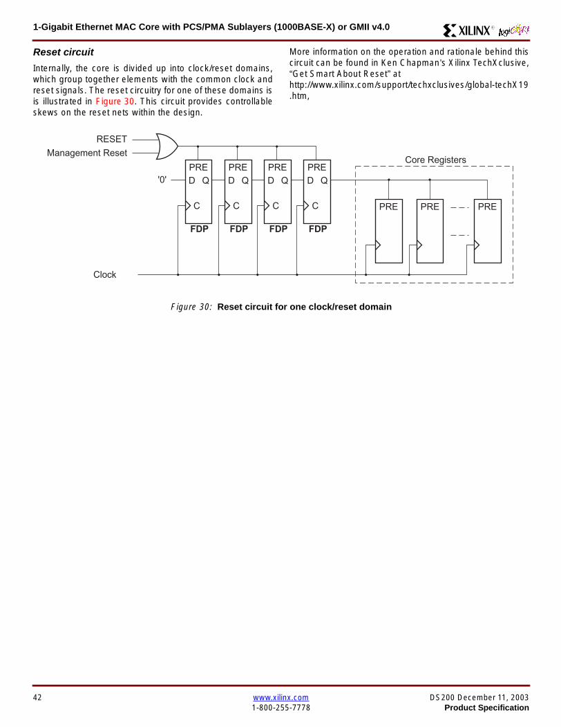
1-Gigabit Ethernet MAC Core with PCSPMA Sublayers (1000BASE-X) or GMII v40 R
Reset circuit
Internally the core is divided up into clockreset domainswhich group together elements with the common clock andreset signals The reset circuitry for one of these domains isis illustrated in Figure 30 This circuit provides controllableskews on the reset nets within the design
More information on the operation and rationale behind thiscircuit can be found in Ken Chapmanrsquos Xilinx TechXclusiveldquoGet Smart About Resetrdquo athttpwwwxilinxcomsupporttechxclusivesglobal-techX19htm
Figure 30 Reset circuit for one clockreset domain
FDP
PRED
C
Q
FDP
PRED
C
Q
FDP
PRED
C
Q
FDP
PRED
C
Q
PRE PRE PRE
0
RESET
Management Reset
Clock
Core Registers
42 wwwxilinxcom DS200 December 11 20031-800-255-7778 Product Specification
1-Gigabit Ethernet MAC Core with PCSPMA Sublayers (1000BASE-X) or GMII v40R
Optional PCS with Ten-Bit Interface (TBI) for 1000BASE-X (physical_interface=tbi)The Full-Duplex Physical Coding Sublayer (PCS) for1000BASE-X is defined in IEEE 8023-2002 Clauses 36and 37 This functionality is only available in the Virtex-IIand Spartan3 families of FPGA devices
A block diagram of the PCS is shown in Figure 31 Themajor functional blocks of the PCS are
bull Transmit engine
bull Auto-negotiation block
bull Receive engine and synchronization block
bull PCS managed register block
bull 8B10B encoder block
bull 8B10B decoder block
bull Receiver elastic buffer
The PCS Managed Register Block is accessed through theMDIO Interface as if it were an externally connected PHYThis configures the operation of the PCS and Auto-Negoti-ation See PCS Managed Register Block
(physical_interface = tbi or phy) on page 49 The corersquosoptional Management Interface can be used to control theMDIO Interface as described by MDIO Interface onpage 37 When the optional Management Interface is notpresent the PCS Managed Register Block must beaccessed via an MDIO controller which is not provided bythe core
The 8B10B encodingdecoding blocks are implemented byconfiguring two Block SelectRAM modules as ROM Theseare used as large look-up tables The remaining PCS func-tionality such as code group encodingdecoding the Man-aged Register Block and Auto-Negotiation areimplemented in CLB logic
The Receiver Elastic buffer enables the 10-bit parallel datareceived from the PMA sublayer alternatively onPMA_RX_CLK0 and PMA_RX_CLK1 clock edges to betransferred onto the internal 125MHz clock domain derivedfrom GTX_CLK (see Clock Management) This buffer isimplemented in Distributed Memory
Figure 31 Functional Block Diagram of the 1-Gigabit Ethernet PCS with TBI Interface
PCS TRANSMIT ENGINE
PCS RECEIVE ENGINE ampSYNCHRONISATION
PCSMANAGEMENT
MDIOInterface
AUTO-NEGOTIATION
MAC TXInterface
MAC RXInterface
8B10BEncoder
8B10BDecoder
RX Elastic Buffer
TBI Interface
DS200 December 11 2003 wwwxilinxcom 43Product Specification 1-800-255-7778
1-Gigabit Ethernet MAC Core with PCSPMA Sublayers (1000BASE-X) or GMII v40 R
TBI Interface
The TBI is designed to IEEE 8023-2002 Clause 363 Thisutilizes IOrsquos of the Xilinx devices using inputoutput buffersand inputoutput flip-flops to maximize setup and hold mar-gins All IO logic is placed in the example wrapper that isdelivered with the core In addition all clock managementlogic for the core is instantiated in this example wrapperthis allows multiple instances of the core to share clocksThe example wrapper is provided in both VHDL and Verilog
Clock Management
Figure 32 illustrates the clock management used with theTBI interface
GTX_CLK must be provided to the MAC core This is a highquality clock of frequency 125MHz which satisfies theIEEE8023-2002 requirements It is expected that this clockwill be derived from an external oscillator and connected
into the device through an IBUFG as illustrated The clocksource must then be routed onto a global clock network byconnecting it to a BUFG Within the MAC core this globalclock is used by all MAC transmitter logic PMA_TX_CLK isderived from this global clock by inverting it and routing it toan OBUF
PMA_RX_CLK0 and PMA_RX_CLK1 are each receivedthrough an IBUFG These clocks are then routed onto glo-bal clock networks by connecting each to a BUFGPMA_RX_CLK0 and PMA_RX_CLK1 are each 625MHzclocks Data from the TBI is received alternatively on the ris-ing edge of PMA_RX_CLK0 followed by the rising edge ofPMA_RX_CLK1 using IOB Double-Data Rate input regis-ters This data is then written into the Receiver ElasticBuffer Data is read out of the Elastic Buffer using the globalclock derived from GTX_CLK all the remaining receiverlogic is synchronous to this clock
Figure 32 Clock Management for PCS with TBI Interface
IBUFG
IBUFG
OBUF
BUFG
BUFG
TX_CLK
RX_CLK
GTX_CLK
PMA_TX_CLK
PMA_RX_CLK0
MAC Core
RX ELASTICBUFFER
Example Wrapper
TX_CLK
RX_CLK
GTX_CLK
PMA_TX_CLK
PMA_RX_CLK0
IBUFGBUFGPMA_RX_CLK1
PMA_RX_CLK1
44 wwwxilinxcom DS200 December 11 20031-800-255-7778 Product Specification
1-Gigabit Ethernet MAC Core with PCSPMA Sublayers (1000BASE-X) or GMII v40R
Clock Sharing between Multiple cores
Figure 33 illustrates how it is possible to share clockresources across multiple instantiations of the core whenusing the optional PCS with TBI
GTX_CLK may be shared between multiple cores as illus-trated resulting in a common transmitter clock domainacross the device
Each core will receive independent PMA_RX_CLK0 andPMA_RX_CLK1 clocks from its TBI as illustrated whichcannot be shared
Although not illustrated if the optional Management Inter-face is used HOST_CLK can also be shared betweencores
Figure 33 Clock Management with multiple instances of the MAC with PCS and TBI
Reset circuit
The reset circuits within the MAC when the TBI interface is implemented is the same as that in the GMII case details ofthese circuits can be found on page 42
IBUFG
OBUF
BUFG
TX_CLK
RX_CLK
PMA_TX_CLK_1
PMA_RX_CLK0_1
MAC Core
RX ELASTICBUFFER
TX_CLK
RX_CLK
GTX_CLK
PMA_TX_CLK
PMA_RX_CLK0
IBUFGBUFGPMA_RX_CLK1_1
PMA_RX_CLK1
IBUFG
BUFG
GTX_CLK
IBUFG
OBUF
BUFG
TX_CLK
RX_CLK
PMA_TX_CLK_2
PMA_RX_CLK0_2
MAC Core
RX ELASTICBUFFER
TX_CLK
RX_CLK
GTX_CLK
PMA_TX_CLK
PMA_RX_CLK0
IBUFGBUFGPMA_RX_CLK1_2
PMA_RX_CLK1
DS200 December 11 2003 wwwxilinxcom 45Product Specification 1-800-255-7778
1-Gigabit Ethernet MAC Core with PCSPMA Sublayers (1000BASE-X) or GMII v40 R
Optional PCS and PMA Sublayers for 1000BASE-X (physical_interface=phy)The Full-Duplex Physical Coding Sublayer (PCS) withPhysical Medium Attachment (PMA) for 1000BASE-X isdefined in IEEE 8023-2002 Clauses 36 and 37 This func-tionality is only available in the Virtex-II Pro family of FPGAdevices
A block diagram of the PCS and PMA sublayers can beseen in Figure 34 The functional blocks of the PCS andPMA sublayers may replace the optional GMII interfaceThe functional blocks of the PCS and PMA sublayers are
bull PCS Transmit Engine
bull Auto-Negotiation block
bull Receive Engine and Synchronization Block
bull PCS Managed Register Block
bull Rocket IO Multi-Gigabit Transceiver
The PCS Managed Register Block is accessed through theMDIO Interface as if it were an externally connected PHYThis configures the operation of the PCS PMA sublayerand Auto-NegotiationSee PCS Managed Register Block(physical_interface = tbi or phy) on page 49 The corersquosoptional Management Interface can be used to control theMDIO Interface as described by MDIO Interface onpage 37 When the optional Management Interface is notpresent the PCS Managed Register Block must beaccessed via an MDIO controller which is not provided bythe core
The Rocket IO Multi-Gigabit Transceiver (MGT) providessome of the PCS layer functionality such as 8B10B encod-ingdecoding and the PMA serdes The remaining PCSfunctionality such as code group encodingdecoding theManaged Register Block and Auto-Negotiation are imple-mented in CLB logic
Figure 34 Functional Block Diagram of the 1-Gigabit Ethernet PCSPMA Sublayer Extension
PCS TRANSMIT ENGINE
PCS RECEIVE ENGINE ampSYNCHRONISATION
RO
CK
ET
IO
MU
LTI-
GIG
TR
AN
SC
EIV
ER
PCSMANAGEMENT
MDIOInterface
AUTO-NEGOTIATION
TXPTXN
RXPRXN
MAC TXInterface
MAC RXInterface
xip2154
46 wwwxilinxcom DS200 December 11 20031-800-255-7778 Product Specification
1-Gigabit Ethernet MAC Core with PCSPMA Sublayers (1000BASE-X) or GMII v40R
Clock Management
Figure 35 illustrates the clock management that should beused with the optional PCS and PMA sublayers for1000BASE-X This logic is implemented in the examplewrapper that is delivered with the core This provides flexi-bility because the design can be modified to use eitherREFCLK or BREFCLK (please refer to Rocket IO docu-mentation) It would also allow multiple instances of the coreto share clocks The example wrapper is provided in bothVHDL and Verilog
(B)REFCLK must be provided to the MAC core This clockmust be derived from an external oscillator and connectedto the core through an IBUFG as illustrated (B)REFCLK isa high quality clock of frequency 625 MHz which satisfiesthe Rocket IO Multi-Gigabit Transceiver (MGT) require-ments
(B)REFCLK is routed to both the core and a DCM From theDCM the CLK2X180 output is routed to a BUFG to providethe device with a global 125 MHz clock (connected toUSERCLK2 input on the core) Within the core bothTX_CLK and RX_CLK share this global 125 MHz clocksource which is used by all transmitter and receiver logicThis is made possible by the RX_ELASTIC_BUFFER func-tionality of the Rocket IO MGT (refer to Virtex-II Pro docu-mentation) The MAC Client can obtain this clock byconnecting to either the TX_CLK or the RX_CLK signalsoutput from the core
From the DCM the CLK0 output is routed to a BUFG to pro-vide the device with a global 625MHz clock This is con-nected to the USRCLK input of the core
Figure 35 Clock Management with PCSPMA Sublayers
DCM
CLKIN CLK0
CLK2X180FB
BUFG
BUFG
IBUFG
TX_CLK
RX_CLK
(B)REFCLK
TXUSRCLK
(B)REFCLK
TXUSRCLK2RXUSRCLKRXUSRCLK2
GT_ETHERNET
Example Wrapper
xip2155
MAC Core
(B)REFCLK
USRCLK
USRCLK2
TX_CLK
RX_CLK
DS200 December 11 2003 wwwxilinxcom 47Product Specification 1-800-255-7778
1-Gigabit Ethernet MAC Core with PCSPMA Sublayers (1000BASE-X) or GMII v40 R
Clock Sharing between Multiple Cores
Figure 36 illustrates how it is possible to share clockresources across multiple instantiations of the core whenusing the optional PCSPMA sublayers For each coreUSERCLK and USERCLK2 must always be derived asshown from the BREFCLK or REFCLK used by that core
Note that when using the fixed routing resources of BREF-CLK Rocket IO MGTs along the top edge of the devicemust use a separate BREFCLK routing resource to thosealong the bottom edge of the device (Refer to Virtex-II Prodocumentation)
Although not illustrated if the optional Management Inter-face is used HOST_CLK can also be shared betweencores
Figure 36 Clock Management with multiple instances of the MAC with PCS and PMA sublayers
Reset circuit
The reset circuits within the MAC when the PCS and PMA sublayers are implemented is the same as that in the GMII casedetails of these circuits can be found on page 42
DCM
CLKIN CLK0
CLK2X180FB
BUFG
BUFG
IBUFG
(B)REFCLK
TXUSRCLK
(B)REFCLK
TXUSRCLK2RXUSRCLKRXUSRCLK2
GT_ETHERNET(B)REFCLK
USERCLK
USERCLK2
MAC core
TXUSRCLK
(B)REFCLK
TXUSRCLK2RXUSRCLKRXUSRCLK2
GT_ETHERNET(B)REFCLK
USERCLK
USERCLK2
MAC core
48 wwwxilinxcom DS200 December 11 20031-800-255-7778 Product Specification
1-Gigabit Ethernet MAC Core with PCSPMA Sublayers (1000BASE-X) or GMII v40R
PCS Managed Register Block (physical_interface = tbi or phy)The PCS in both the TBI interface and the PCSPMA (usingthe Virtex-II Pro Rocket IO) versions contain the full Man-aged Register Block defined in IEEE 8023-2002 clause 37
This utilizes ten dedicated management registersaccessed via the MDIO interface These are defined inTable 25 to Table 33 inclusive
Table 25 Control Register (Register 0)
Bit(s) Name Description Attributes Default Value
015 Reset1 = PCSPMA reset
0 = Normal Operation
ReadWrite
Self Clearing0
014 Loopback1 = Enable Loopback Mode
0 = Disable Loopback ModeReadWrite 0
013SpeedSelection (LSB)
The core always returns a 0 for this bitTogether with bit 06 speed selection of 1000Mbs is identified
Returns 0 0
012Auto-NegotiationEnable
1 = Enable Auto-Negotiation Process
0 = Disable Auto-Negotiation ProcessReadWrite 1
011 Power Down
1 = Power down
0 = Normal operation
When set to ldquo1rdquo the Rocket IO MGT is placedin a low power state This bit requires a reset(see bit 015) to clear
Read Write 0
010 Isolate1 = Electrically Isolate PHY from GMII
0 = Normal operationReadWrite 1
09Restart Auto-Negotiation
1 = Restart Auto-Negotiation Process
0 = Normal Operation
ReadWrite
Self Clearing0
08 Duplex ModeThe core always returns a 1 for this bit tosignal Full-Duplex Mode
Returns 1 1
07 Collision TestThe core always returns a 0 for this bit todisable COL test
Returns 0 0
06SpeedSelection(MSB)
The core always returns a 1 for this bitTogether with bit 013 speed selection of1000 Mbs is identified
Returns 1 1
050 Reserved Always returns 0rsquos writes ignored Returns 0rsquos 000000
DS200 December 11 2003 wwwxilinxcom 49Product Specification 1-800-255-7778
1-Gigabit Ethernet MAC Core with PCSPMA Sublayers (1000BASE-X) or GMII v40 R
Table 26 Status Register (Register 1)
Bit(s) Name Description Attributes Default Value
115 100BASE-T4The core always returns a 0 for this bitbecause 100BASE-T4 is not supported
Returns 0 0
114100BASE-XFullDuplex
The core always returns a 0 for this bitbecause 100BASE-X Full Duplex is notsupported
Returns 0 0
113100BASE-XHalf Duplex
The core always returns a 0 for this bitbecause 100BASE-X Half Duplex is notsupported
Returns 0 0
11210 Mbs FullDuplex
The core always returns a 0 for this bitbecause 10 Mbs Full Duplex is notsupported
Returns 0 0
11110 Mbs HalfDuplex
The core always returns a 0 for this bitbecause 10 Mbs Half Duplex is notsupported
Returns 0 0
110100BASE-T2Full Duplex
The core always returns a 0 for this bitbecause 100BASE-T2 Full Duplex is notsupported
Returns 0 0
19100BASE-T2Half Duplex
The core always returns a 0 for this bitbecause 100BASE-T2 Half Duplex is notsupported
Returns 0 0
18ExtendedStatus
The core always returns a 1 for this bit toindicate the presence of the ExtendedRegister (Register 15)
Returns 1 1
17 Reserved Always return 0 writes ignored Returns 0 0
16MF PreambleSuppression
The core always returns a 1 for this bit toindicate that Management Frame PreambleSuppression is supported
Returns 1 1
15Auto-NegotiationComplete
1 = Auto-Negotiation process completed
0 = Auto-Negotiation process not completedRead Only 0
14 Remote Fault1 = Remote fault condition detected
0 = No remote fault condition detected
Read Only
Self Clearing on read0
13Auto-NegotiationAbility
The core always returns a 1 for this bit toindicate that the PHY is capable ofAuto-Negotiation
Returns 1 1
12 Link Status1 = Link is up
0 = Link is down
Read Only
Self Clearing on read0
11 Jabber DetectThe core always returns a 0 for this bitbecause Jabber Detect is not supported
Returns 0 0
10ExtendedCapability
The core always returns a 0 for this bitbecause no extended register set issupported
Returns 0 0
50 wwwxilinxcom DS200 December 11 20031-800-255-7778 Product Specification
1-Gigabit Ethernet MAC Core with PCSPMA Sublayers (1000BASE-X) or GMII v40R
Table 27 PHY Identifier (Registers 2 and 3)
Bit(s) Name Description Attributes Default Value
2150OrganizationallyUniqueIdentifier
Always returns 0s Returns 0s 0000000000000000
31510OrganizationallyUniqueIdentifier
Always returns 0s Returns 0s 000000
394Manufacturerrsquosmodel number
Always returns 0s Returns 0s 000000
330RevisionNumber
Always returns 0s Returns 0s 0000
Table 28 Auto-Negotiation Advertisement Register (Register 4)
Bit(s) Name Description Attributes Default Value
415 Next Page1 = Next Page functionality is advertised
0 = Next Page functionality is not advertisedReadWrite 0
414 Reserved Always returns 0 writes ignored Returns 0 0
41312 Remote Fault
00 = No Error
01 = Offline
10 = Link Failure
11 = Auto-Negotiation Error
ReadWrite
Self clearing to 00afterAuto-Negotiation
00
4119 Reserved Always return 0 writes ignored Returns 0 0
487 Pause
00 = No PAUSE
01 = Asymmetric PAUSE towards linkpartner
10 = Symmetic PAUSE
11 = Both Symmetric PAUSE andAsymmetric PAUSE towards link partner
ReadWrite 11
46 Half DuplexThe core always returns a 0 for this bitbecause Half Duplex Mode is not supported
Returns 0 0
45 Full Duplex1 = Full Duplex Mode is advertised
0 = Full Duplex Mode is not advertisedReadWrite 1
440 Reserved Always returns 0s writes ignored Returns 0s 00000
DS200 December 11 2003 wwwxilinxcom 51Product Specification 1-800-255-7778
1-Gigabit Ethernet MAC Core with PCSPMA Sublayers (1000BASE-X) or GMII v40 R
Table 29 Auto-Negotiation Link Partner Ability Base Register (Register 5)
Bit(s) Name Description Attributes Default Value
515 Next Page1 = Next Page functionality is supported
0 = Next Page functionality is not supportedRead Only 0
514 AcknowledgeUsed by Auto-Negotiation function toindicate reception of a link partnerrsquos base ornext page
Read Only 0
51312 Remote Fault
00 = No Error
01 = Offline
10 = Link Failure
11 = Auto-Negotiation Error
Read Only 00
5119 Reserved Always returns 0s Returns 0s 000
587 Pause
00 = No PAUSE
01 = Asymmetric PAUSE supported
10 = Symmetic PAUSE supported
11 = Both Symmetric PAUSE andAsymmetric PAUSE supported
Read Only 00
56 Half Duplex1 = Half Duplex Mode is supported
0 = Half Duplex Mode is not supportedRead Only 0
55 Full Duplex1 = Full Duplex Mode is supported
0 = Full Duplex Mode is not supportedRead Only 0
540 Reserved Always returns 0s Returns 0s 00000
Table 30 Auto-Negotiation Expansion Register (Register 6)
Bit(s) Name Description Attributes Default Value
6153 Reserved Always returns 0s Returns 0s 0000000000000
62 Next Page AbleThe core always returns a 1 for this bitbecause the device is Next Page Able
Returns 1 1
61 Page Received1 = A new page has been received
0 = A new page has not been received
Read Only
Self Clearing on read0
60 Reserved Always returns 0s Returns 0s 0000000
52 wwwxilinxcom DS200 December 11 20031-800-255-7778 Product Specification
1-Gigabit Ethernet MAC Core with PCSPMA Sublayers (1000BASE-X) or GMII v40R
Table 31 Auto-Negotiation Next Page Transmit Register (Register 7)
Bit(s) Name Description Attributes Default Value
715 Next Page1 = Additional Next Page(s) will follow
0 = Last pageReadWrite 0
714 Reserved Always returns 0 Returns 0 0
713 Message Page1 = Message Page
0 = Unformatted PageReadWrite 1
712 Acknowledge 21 = Will comply with message
0 = Cannot comply with messageReadWrite 0
711 ToggleValue will toggle between subsequent NextPages
Read Only 0
7100Message UnformattedCode Field
Message Code Field or Unformatted PageEncoding as dictated by 713
ReadWrite00000000001
(Null Message Code)
Table 32 Auto-Negotiation Next Page Receive Register (Register 8)
Bit(s) Name Description Attributes Default Value
815 Next Page1 = Additional Next Page(s) follows
0 = Last pageRead Only 0
814 AcknowledgeUsed by Auto-Negotiation function toindicate reception of a link partnerrsquos base ornext page
Read Only 0
813 Message Page1 = Message Page
0 = Unformatted PageRead Only 0
812 Acknowledge 21 = Will comply with message
0 = Cannot comply with messageRead Only 0
811 ToggleValue toggles between subsequent andNext Pages
Read Only 0
8100Message UnformattedCode Field
Message Code Field or Unformatted PageEncoding as dictated by 813
Read Only 00000000000
DS200 December 11 2003 wwwxilinxcom 53Product Specification 1-800-255-7778
1-Gigabit Ethernet MAC Core with PCSPMA Sublayers (1000BASE-X) or GMII v40 R
)
Referencesbull IEEE 8023-2002
bull Virtex-E User Guide
bull Spartan-II E User Guide
bull Virtex-II User Guide
bull Virtex-II Pro User Guide
Related InformationXilinx products are not intended for use in life support appli-ances devices or systems Use of a Xilinx product in suchapplications without the written consent of the appropriateXilinx officer is prohibited
Ordering InformationThis Xilinx LogiCORE module is provided under theSignOnce IP Site License A free evaluation version of themodule is available
Once purchased the core may be downloaded from the Xil-inx IP Center for use with the Xilinx CORE Generator Sys-temtrade v61i SP3 and later The Xilinx CORE GeneratorSystem tool is bundled with all Alliance Series Softwarepackages at no additional charge
Please contact your local Xilinx sales representative or visitthe Xilinx Silicon Xpresso Cafe for pricing and availability onXilinx LogiCORE modules and software Information onadditional Xilinx LogiCORE modules is available on the Xil-inx IP Center
Revision HistoryThe following table shows the revision history for this document
Table 33 Extended Status Register (Register 15)
Bit(s) Name Description Attributes Default Value
15151000BASE-XFull Duplex
The core always returns a 1 for this bitbecause 1000BASE-X Full Duplex issupported
Returns 1 1
15141000BASE-XHalf Duplex
The core always returns a 0 for this bitbecause 1000BASE-X Half Duplex is notsupported
Returns 0 0
15131000BASE-TFull Duplex
The core always returns a 0 for this bitbecause 1000BASE-T Full Duplex is notsupported
Returns 0 0
15121000BASE-THalf Duplex
The core always returns a 0 for this bitbecause 1000BASE-T Half Duplex is notsupported
Returns 0 0
15110 Reserved Always returns 0s Returns 0s 000000000000
Date Version Revision
032803 11 Revision History added to document
043003 20 Revised to v30 standards
121103 30 Updated to v40 release
54 wwwxilinxcom DS200 December 11 20031-800-255-7778 Product Specification
- 1-Gigabit Ethernet MAC Core with PCSPMA Sublayers (1000BASE-X) or GMII v40
-
- Features
- MAC Overview
- Xilinx CORE Generator
- GUI Interface
- Parameter Values in the XCO File
- Output Generation
- Device Utilization
- Interface Description
- Interface Signals for MAC with physical_interface=gmii and management_interface=true
- Interface Signals for MAC with physical_interface=gmii and management_interface=false
- Interface Signals for MAC with physical_interface=tbi and management_interface=true
- Interface Signals for MAC with physical_interface=tbi and management_interface=false
- Interface Signals for MAC with physical_interface=phy and management_interface=true
- Interface Signals for MAC with physical_interface=phy and management_interface=false
- Client Side Interface Signal Definition
- Physical Interface Signal Definition
- Functional Description
- Client Interface
- Transmitter
- Receiver
- Flow Control
- Optional Management Interface (management_interface=true)
- Optional Configuration Vector (management_interface = false)
- Optional GMII (physical_interface=gmii)
- Optional PCS with Ten-Bit Interface (TBI) for 1000BASE-X (physical_interface=tbi)
- Optional PCS and PMA Sublayers for 1000BASE-X (physical_interface=phy)
- PCS Managed Register Block (physical_interface = tbi or phy)
- References
- Related Information
- Ordering Information
- Revision History
-
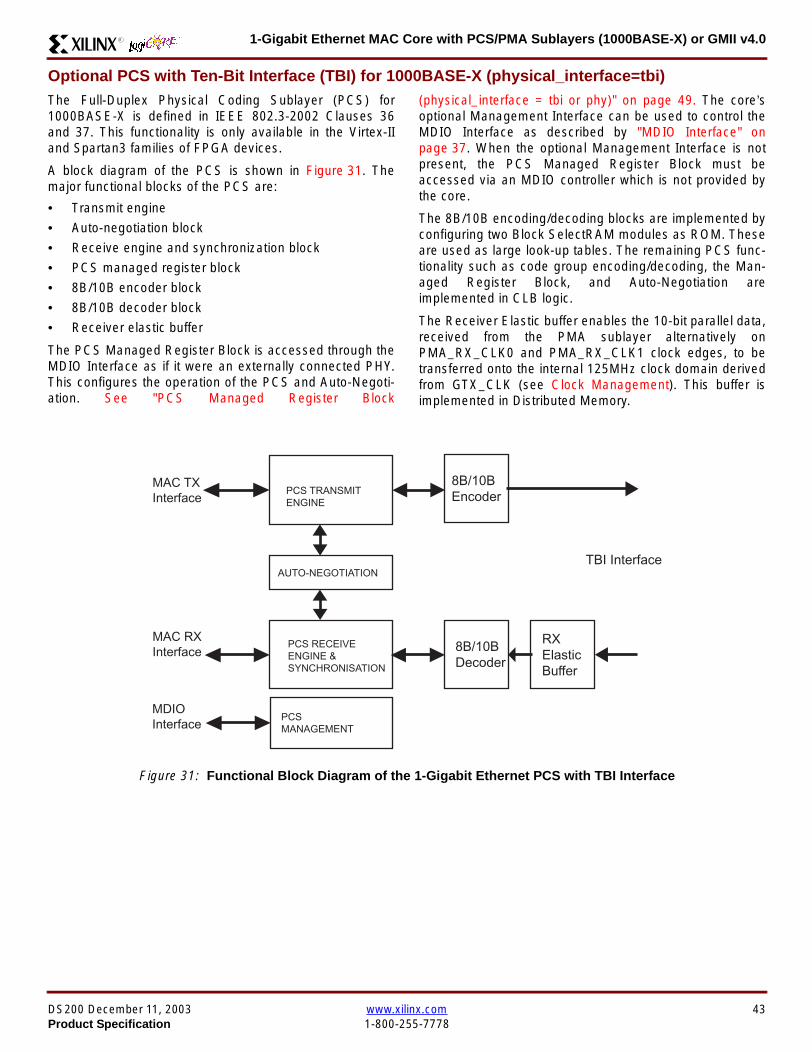
1-Gigabit Ethernet MAC Core with PCSPMA Sublayers (1000BASE-X) or GMII v40R
Optional PCS with Ten-Bit Interface (TBI) for 1000BASE-X (physical_interface=tbi)The Full-Duplex Physical Coding Sublayer (PCS) for1000BASE-X is defined in IEEE 8023-2002 Clauses 36and 37 This functionality is only available in the Virtex-IIand Spartan3 families of FPGA devices
A block diagram of the PCS is shown in Figure 31 Themajor functional blocks of the PCS are
bull Transmit engine
bull Auto-negotiation block
bull Receive engine and synchronization block
bull PCS managed register block
bull 8B10B encoder block
bull 8B10B decoder block
bull Receiver elastic buffer
The PCS Managed Register Block is accessed through theMDIO Interface as if it were an externally connected PHYThis configures the operation of the PCS and Auto-Negoti-ation See PCS Managed Register Block
(physical_interface = tbi or phy) on page 49 The corersquosoptional Management Interface can be used to control theMDIO Interface as described by MDIO Interface onpage 37 When the optional Management Interface is notpresent the PCS Managed Register Block must beaccessed via an MDIO controller which is not provided bythe core
The 8B10B encodingdecoding blocks are implemented byconfiguring two Block SelectRAM modules as ROM Theseare used as large look-up tables The remaining PCS func-tionality such as code group encodingdecoding the Man-aged Register Block and Auto-Negotiation areimplemented in CLB logic
The Receiver Elastic buffer enables the 10-bit parallel datareceived from the PMA sublayer alternatively onPMA_RX_CLK0 and PMA_RX_CLK1 clock edges to betransferred onto the internal 125MHz clock domain derivedfrom GTX_CLK (see Clock Management) This buffer isimplemented in Distributed Memory
Figure 31 Functional Block Diagram of the 1-Gigabit Ethernet PCS with TBI Interface
PCS TRANSMIT ENGINE
PCS RECEIVE ENGINE ampSYNCHRONISATION
PCSMANAGEMENT
MDIOInterface
AUTO-NEGOTIATION
MAC TXInterface
MAC RXInterface
8B10BEncoder
8B10BDecoder
RX Elastic Buffer
TBI Interface
DS200 December 11 2003 wwwxilinxcom 43Product Specification 1-800-255-7778
1-Gigabit Ethernet MAC Core with PCSPMA Sublayers (1000BASE-X) or GMII v40 R
TBI Interface
The TBI is designed to IEEE 8023-2002 Clause 363 Thisutilizes IOrsquos of the Xilinx devices using inputoutput buffersand inputoutput flip-flops to maximize setup and hold mar-gins All IO logic is placed in the example wrapper that isdelivered with the core In addition all clock managementlogic for the core is instantiated in this example wrapperthis allows multiple instances of the core to share clocksThe example wrapper is provided in both VHDL and Verilog
Clock Management
Figure 32 illustrates the clock management used with theTBI interface
GTX_CLK must be provided to the MAC core This is a highquality clock of frequency 125MHz which satisfies theIEEE8023-2002 requirements It is expected that this clockwill be derived from an external oscillator and connected
into the device through an IBUFG as illustrated The clocksource must then be routed onto a global clock network byconnecting it to a BUFG Within the MAC core this globalclock is used by all MAC transmitter logic PMA_TX_CLK isderived from this global clock by inverting it and routing it toan OBUF
PMA_RX_CLK0 and PMA_RX_CLK1 are each receivedthrough an IBUFG These clocks are then routed onto glo-bal clock networks by connecting each to a BUFGPMA_RX_CLK0 and PMA_RX_CLK1 are each 625MHzclocks Data from the TBI is received alternatively on the ris-ing edge of PMA_RX_CLK0 followed by the rising edge ofPMA_RX_CLK1 using IOB Double-Data Rate input regis-ters This data is then written into the Receiver ElasticBuffer Data is read out of the Elastic Buffer using the globalclock derived from GTX_CLK all the remaining receiverlogic is synchronous to this clock
Figure 32 Clock Management for PCS with TBI Interface
IBUFG
IBUFG
OBUF
BUFG
BUFG
TX_CLK
RX_CLK
GTX_CLK
PMA_TX_CLK
PMA_RX_CLK0
MAC Core
RX ELASTICBUFFER
Example Wrapper
TX_CLK
RX_CLK
GTX_CLK
PMA_TX_CLK
PMA_RX_CLK0
IBUFGBUFGPMA_RX_CLK1
PMA_RX_CLK1
44 wwwxilinxcom DS200 December 11 20031-800-255-7778 Product Specification
1-Gigabit Ethernet MAC Core with PCSPMA Sublayers (1000BASE-X) or GMII v40R
Clock Sharing between Multiple cores
Figure 33 illustrates how it is possible to share clockresources across multiple instantiations of the core whenusing the optional PCS with TBI
GTX_CLK may be shared between multiple cores as illus-trated resulting in a common transmitter clock domainacross the device
Each core will receive independent PMA_RX_CLK0 andPMA_RX_CLK1 clocks from its TBI as illustrated whichcannot be shared
Although not illustrated if the optional Management Inter-face is used HOST_CLK can also be shared betweencores
Figure 33 Clock Management with multiple instances of the MAC with PCS and TBI
Reset circuit
The reset circuits within the MAC when the TBI interface is implemented is the same as that in the GMII case details ofthese circuits can be found on page 42
IBUFG
OBUF
BUFG
TX_CLK
RX_CLK
PMA_TX_CLK_1
PMA_RX_CLK0_1
MAC Core
RX ELASTICBUFFER
TX_CLK
RX_CLK
GTX_CLK
PMA_TX_CLK
PMA_RX_CLK0
IBUFGBUFGPMA_RX_CLK1_1
PMA_RX_CLK1
IBUFG
BUFG
GTX_CLK
IBUFG
OBUF
BUFG
TX_CLK
RX_CLK
PMA_TX_CLK_2
PMA_RX_CLK0_2
MAC Core
RX ELASTICBUFFER
TX_CLK
RX_CLK
GTX_CLK
PMA_TX_CLK
PMA_RX_CLK0
IBUFGBUFGPMA_RX_CLK1_2
PMA_RX_CLK1
DS200 December 11 2003 wwwxilinxcom 45Product Specification 1-800-255-7778
1-Gigabit Ethernet MAC Core with PCSPMA Sublayers (1000BASE-X) or GMII v40 R
Optional PCS and PMA Sublayers for 1000BASE-X (physical_interface=phy)The Full-Duplex Physical Coding Sublayer (PCS) withPhysical Medium Attachment (PMA) for 1000BASE-X isdefined in IEEE 8023-2002 Clauses 36 and 37 This func-tionality is only available in the Virtex-II Pro family of FPGAdevices
A block diagram of the PCS and PMA sublayers can beseen in Figure 34 The functional blocks of the PCS andPMA sublayers may replace the optional GMII interfaceThe functional blocks of the PCS and PMA sublayers are
bull PCS Transmit Engine
bull Auto-Negotiation block
bull Receive Engine and Synchronization Block
bull PCS Managed Register Block
bull Rocket IO Multi-Gigabit Transceiver
The PCS Managed Register Block is accessed through theMDIO Interface as if it were an externally connected PHYThis configures the operation of the PCS PMA sublayerand Auto-NegotiationSee PCS Managed Register Block(physical_interface = tbi or phy) on page 49 The corersquosoptional Management Interface can be used to control theMDIO Interface as described by MDIO Interface onpage 37 When the optional Management Interface is notpresent the PCS Managed Register Block must beaccessed via an MDIO controller which is not provided bythe core
The Rocket IO Multi-Gigabit Transceiver (MGT) providessome of the PCS layer functionality such as 8B10B encod-ingdecoding and the PMA serdes The remaining PCSfunctionality such as code group encodingdecoding theManaged Register Block and Auto-Negotiation are imple-mented in CLB logic
Figure 34 Functional Block Diagram of the 1-Gigabit Ethernet PCSPMA Sublayer Extension
PCS TRANSMIT ENGINE
PCS RECEIVE ENGINE ampSYNCHRONISATION
RO
CK
ET
IO
MU
LTI-
GIG
TR
AN
SC
EIV
ER
PCSMANAGEMENT
MDIOInterface
AUTO-NEGOTIATION
TXPTXN
RXPRXN
MAC TXInterface
MAC RXInterface
xip2154
46 wwwxilinxcom DS200 December 11 20031-800-255-7778 Product Specification
1-Gigabit Ethernet MAC Core with PCSPMA Sublayers (1000BASE-X) or GMII v40R
Clock Management
Figure 35 illustrates the clock management that should beused with the optional PCS and PMA sublayers for1000BASE-X This logic is implemented in the examplewrapper that is delivered with the core This provides flexi-bility because the design can be modified to use eitherREFCLK or BREFCLK (please refer to Rocket IO docu-mentation) It would also allow multiple instances of the coreto share clocks The example wrapper is provided in bothVHDL and Verilog
(B)REFCLK must be provided to the MAC core This clockmust be derived from an external oscillator and connectedto the core through an IBUFG as illustrated (B)REFCLK isa high quality clock of frequency 625 MHz which satisfiesthe Rocket IO Multi-Gigabit Transceiver (MGT) require-ments
(B)REFCLK is routed to both the core and a DCM From theDCM the CLK2X180 output is routed to a BUFG to providethe device with a global 125 MHz clock (connected toUSERCLK2 input on the core) Within the core bothTX_CLK and RX_CLK share this global 125 MHz clocksource which is used by all transmitter and receiver logicThis is made possible by the RX_ELASTIC_BUFFER func-tionality of the Rocket IO MGT (refer to Virtex-II Pro docu-mentation) The MAC Client can obtain this clock byconnecting to either the TX_CLK or the RX_CLK signalsoutput from the core
From the DCM the CLK0 output is routed to a BUFG to pro-vide the device with a global 625MHz clock This is con-nected to the USRCLK input of the core
Figure 35 Clock Management with PCSPMA Sublayers
DCM
CLKIN CLK0
CLK2X180FB
BUFG
BUFG
IBUFG
TX_CLK
RX_CLK
(B)REFCLK
TXUSRCLK
(B)REFCLK
TXUSRCLK2RXUSRCLKRXUSRCLK2
GT_ETHERNET
Example Wrapper
xip2155
MAC Core
(B)REFCLK
USRCLK
USRCLK2
TX_CLK
RX_CLK
DS200 December 11 2003 wwwxilinxcom 47Product Specification 1-800-255-7778
1-Gigabit Ethernet MAC Core with PCSPMA Sublayers (1000BASE-X) or GMII v40 R
Clock Sharing between Multiple Cores
Figure 36 illustrates how it is possible to share clockresources across multiple instantiations of the core whenusing the optional PCSPMA sublayers For each coreUSERCLK and USERCLK2 must always be derived asshown from the BREFCLK or REFCLK used by that core
Note that when using the fixed routing resources of BREF-CLK Rocket IO MGTs along the top edge of the devicemust use a separate BREFCLK routing resource to thosealong the bottom edge of the device (Refer to Virtex-II Prodocumentation)
Although not illustrated if the optional Management Inter-face is used HOST_CLK can also be shared betweencores
Figure 36 Clock Management with multiple instances of the MAC with PCS and PMA sublayers
Reset circuit
The reset circuits within the MAC when the PCS and PMA sublayers are implemented is the same as that in the GMII casedetails of these circuits can be found on page 42
DCM
CLKIN CLK0
CLK2X180FB
BUFG
BUFG
IBUFG
(B)REFCLK
TXUSRCLK
(B)REFCLK
TXUSRCLK2RXUSRCLKRXUSRCLK2
GT_ETHERNET(B)REFCLK
USERCLK
USERCLK2
MAC core
TXUSRCLK
(B)REFCLK
TXUSRCLK2RXUSRCLKRXUSRCLK2
GT_ETHERNET(B)REFCLK
USERCLK
USERCLK2
MAC core
48 wwwxilinxcom DS200 December 11 20031-800-255-7778 Product Specification
1-Gigabit Ethernet MAC Core with PCSPMA Sublayers (1000BASE-X) or GMII v40R
PCS Managed Register Block (physical_interface = tbi or phy)The PCS in both the TBI interface and the PCSPMA (usingthe Virtex-II Pro Rocket IO) versions contain the full Man-aged Register Block defined in IEEE 8023-2002 clause 37
This utilizes ten dedicated management registersaccessed via the MDIO interface These are defined inTable 25 to Table 33 inclusive
Table 25 Control Register (Register 0)
Bit(s) Name Description Attributes Default Value
015 Reset1 = PCSPMA reset
0 = Normal Operation
ReadWrite
Self Clearing0
014 Loopback1 = Enable Loopback Mode
0 = Disable Loopback ModeReadWrite 0
013SpeedSelection (LSB)
The core always returns a 0 for this bitTogether with bit 06 speed selection of 1000Mbs is identified
Returns 0 0
012Auto-NegotiationEnable
1 = Enable Auto-Negotiation Process
0 = Disable Auto-Negotiation ProcessReadWrite 1
011 Power Down
1 = Power down
0 = Normal operation
When set to ldquo1rdquo the Rocket IO MGT is placedin a low power state This bit requires a reset(see bit 015) to clear
Read Write 0
010 Isolate1 = Electrically Isolate PHY from GMII
0 = Normal operationReadWrite 1
09Restart Auto-Negotiation
1 = Restart Auto-Negotiation Process
0 = Normal Operation
ReadWrite
Self Clearing0
08 Duplex ModeThe core always returns a 1 for this bit tosignal Full-Duplex Mode
Returns 1 1
07 Collision TestThe core always returns a 0 for this bit todisable COL test
Returns 0 0
06SpeedSelection(MSB)
The core always returns a 1 for this bitTogether with bit 013 speed selection of1000 Mbs is identified
Returns 1 1
050 Reserved Always returns 0rsquos writes ignored Returns 0rsquos 000000
DS200 December 11 2003 wwwxilinxcom 49Product Specification 1-800-255-7778
1-Gigabit Ethernet MAC Core with PCSPMA Sublayers (1000BASE-X) or GMII v40 R
Table 26 Status Register (Register 1)
Bit(s) Name Description Attributes Default Value
115 100BASE-T4The core always returns a 0 for this bitbecause 100BASE-T4 is not supported
Returns 0 0
114100BASE-XFullDuplex
The core always returns a 0 for this bitbecause 100BASE-X Full Duplex is notsupported
Returns 0 0
113100BASE-XHalf Duplex
The core always returns a 0 for this bitbecause 100BASE-X Half Duplex is notsupported
Returns 0 0
11210 Mbs FullDuplex
The core always returns a 0 for this bitbecause 10 Mbs Full Duplex is notsupported
Returns 0 0
11110 Mbs HalfDuplex
The core always returns a 0 for this bitbecause 10 Mbs Half Duplex is notsupported
Returns 0 0
110100BASE-T2Full Duplex
The core always returns a 0 for this bitbecause 100BASE-T2 Full Duplex is notsupported
Returns 0 0
19100BASE-T2Half Duplex
The core always returns a 0 for this bitbecause 100BASE-T2 Half Duplex is notsupported
Returns 0 0
18ExtendedStatus
The core always returns a 1 for this bit toindicate the presence of the ExtendedRegister (Register 15)
Returns 1 1
17 Reserved Always return 0 writes ignored Returns 0 0
16MF PreambleSuppression
The core always returns a 1 for this bit toindicate that Management Frame PreambleSuppression is supported
Returns 1 1
15Auto-NegotiationComplete
1 = Auto-Negotiation process completed
0 = Auto-Negotiation process not completedRead Only 0
14 Remote Fault1 = Remote fault condition detected
0 = No remote fault condition detected
Read Only
Self Clearing on read0
13Auto-NegotiationAbility
The core always returns a 1 for this bit toindicate that the PHY is capable ofAuto-Negotiation
Returns 1 1
12 Link Status1 = Link is up
0 = Link is down
Read Only
Self Clearing on read0
11 Jabber DetectThe core always returns a 0 for this bitbecause Jabber Detect is not supported
Returns 0 0
10ExtendedCapability
The core always returns a 0 for this bitbecause no extended register set issupported
Returns 0 0
50 wwwxilinxcom DS200 December 11 20031-800-255-7778 Product Specification
1-Gigabit Ethernet MAC Core with PCSPMA Sublayers (1000BASE-X) or GMII v40R
Table 27 PHY Identifier (Registers 2 and 3)
Bit(s) Name Description Attributes Default Value
2150OrganizationallyUniqueIdentifier
Always returns 0s Returns 0s 0000000000000000
31510OrganizationallyUniqueIdentifier
Always returns 0s Returns 0s 000000
394Manufacturerrsquosmodel number
Always returns 0s Returns 0s 000000
330RevisionNumber
Always returns 0s Returns 0s 0000
Table 28 Auto-Negotiation Advertisement Register (Register 4)
Bit(s) Name Description Attributes Default Value
415 Next Page1 = Next Page functionality is advertised
0 = Next Page functionality is not advertisedReadWrite 0
414 Reserved Always returns 0 writes ignored Returns 0 0
41312 Remote Fault
00 = No Error
01 = Offline
10 = Link Failure
11 = Auto-Negotiation Error
ReadWrite
Self clearing to 00afterAuto-Negotiation
00
4119 Reserved Always return 0 writes ignored Returns 0 0
487 Pause
00 = No PAUSE
01 = Asymmetric PAUSE towards linkpartner
10 = Symmetic PAUSE
11 = Both Symmetric PAUSE andAsymmetric PAUSE towards link partner
ReadWrite 11
46 Half DuplexThe core always returns a 0 for this bitbecause Half Duplex Mode is not supported
Returns 0 0
45 Full Duplex1 = Full Duplex Mode is advertised
0 = Full Duplex Mode is not advertisedReadWrite 1
440 Reserved Always returns 0s writes ignored Returns 0s 00000
DS200 December 11 2003 wwwxilinxcom 51Product Specification 1-800-255-7778
1-Gigabit Ethernet MAC Core with PCSPMA Sublayers (1000BASE-X) or GMII v40 R
Table 29 Auto-Negotiation Link Partner Ability Base Register (Register 5)
Bit(s) Name Description Attributes Default Value
515 Next Page1 = Next Page functionality is supported
0 = Next Page functionality is not supportedRead Only 0
514 AcknowledgeUsed by Auto-Negotiation function toindicate reception of a link partnerrsquos base ornext page
Read Only 0
51312 Remote Fault
00 = No Error
01 = Offline
10 = Link Failure
11 = Auto-Negotiation Error
Read Only 00
5119 Reserved Always returns 0s Returns 0s 000
587 Pause
00 = No PAUSE
01 = Asymmetric PAUSE supported
10 = Symmetic PAUSE supported
11 = Both Symmetric PAUSE andAsymmetric PAUSE supported
Read Only 00
56 Half Duplex1 = Half Duplex Mode is supported
0 = Half Duplex Mode is not supportedRead Only 0
55 Full Duplex1 = Full Duplex Mode is supported
0 = Full Duplex Mode is not supportedRead Only 0
540 Reserved Always returns 0s Returns 0s 00000
Table 30 Auto-Negotiation Expansion Register (Register 6)
Bit(s) Name Description Attributes Default Value
6153 Reserved Always returns 0s Returns 0s 0000000000000
62 Next Page AbleThe core always returns a 1 for this bitbecause the device is Next Page Able
Returns 1 1
61 Page Received1 = A new page has been received
0 = A new page has not been received
Read Only
Self Clearing on read0
60 Reserved Always returns 0s Returns 0s 0000000
52 wwwxilinxcom DS200 December 11 20031-800-255-7778 Product Specification
1-Gigabit Ethernet MAC Core with PCSPMA Sublayers (1000BASE-X) or GMII v40R
Table 31 Auto-Negotiation Next Page Transmit Register (Register 7)
Bit(s) Name Description Attributes Default Value
715 Next Page1 = Additional Next Page(s) will follow
0 = Last pageReadWrite 0
714 Reserved Always returns 0 Returns 0 0
713 Message Page1 = Message Page
0 = Unformatted PageReadWrite 1
712 Acknowledge 21 = Will comply with message
0 = Cannot comply with messageReadWrite 0
711 ToggleValue will toggle between subsequent NextPages
Read Only 0
7100Message UnformattedCode Field
Message Code Field or Unformatted PageEncoding as dictated by 713
ReadWrite00000000001
(Null Message Code)
Table 32 Auto-Negotiation Next Page Receive Register (Register 8)
Bit(s) Name Description Attributes Default Value
815 Next Page1 = Additional Next Page(s) follows
0 = Last pageRead Only 0
814 AcknowledgeUsed by Auto-Negotiation function toindicate reception of a link partnerrsquos base ornext page
Read Only 0
813 Message Page1 = Message Page
0 = Unformatted PageRead Only 0
812 Acknowledge 21 = Will comply with message
0 = Cannot comply with messageRead Only 0
811 ToggleValue toggles between subsequent andNext Pages
Read Only 0
8100Message UnformattedCode Field
Message Code Field or Unformatted PageEncoding as dictated by 813
Read Only 00000000000
DS200 December 11 2003 wwwxilinxcom 53Product Specification 1-800-255-7778
1-Gigabit Ethernet MAC Core with PCSPMA Sublayers (1000BASE-X) or GMII v40 R
)
Referencesbull IEEE 8023-2002
bull Virtex-E User Guide
bull Spartan-II E User Guide
bull Virtex-II User Guide
bull Virtex-II Pro User Guide
Related InformationXilinx products are not intended for use in life support appli-ances devices or systems Use of a Xilinx product in suchapplications without the written consent of the appropriateXilinx officer is prohibited
Ordering InformationThis Xilinx LogiCORE module is provided under theSignOnce IP Site License A free evaluation version of themodule is available
Once purchased the core may be downloaded from the Xil-inx IP Center for use with the Xilinx CORE Generator Sys-temtrade v61i SP3 and later The Xilinx CORE GeneratorSystem tool is bundled with all Alliance Series Softwarepackages at no additional charge
Please contact your local Xilinx sales representative or visitthe Xilinx Silicon Xpresso Cafe for pricing and availability onXilinx LogiCORE modules and software Information onadditional Xilinx LogiCORE modules is available on the Xil-inx IP Center
Revision HistoryThe following table shows the revision history for this document
Table 33 Extended Status Register (Register 15)
Bit(s) Name Description Attributes Default Value
15151000BASE-XFull Duplex
The core always returns a 1 for this bitbecause 1000BASE-X Full Duplex issupported
Returns 1 1
15141000BASE-XHalf Duplex
The core always returns a 0 for this bitbecause 1000BASE-X Half Duplex is notsupported
Returns 0 0
15131000BASE-TFull Duplex
The core always returns a 0 for this bitbecause 1000BASE-T Full Duplex is notsupported
Returns 0 0
15121000BASE-THalf Duplex
The core always returns a 0 for this bitbecause 1000BASE-T Half Duplex is notsupported
Returns 0 0
15110 Reserved Always returns 0s Returns 0s 000000000000
Date Version Revision
032803 11 Revision History added to document
043003 20 Revised to v30 standards
121103 30 Updated to v40 release
54 wwwxilinxcom DS200 December 11 20031-800-255-7778 Product Specification
- 1-Gigabit Ethernet MAC Core with PCSPMA Sublayers (1000BASE-X) or GMII v40
-
- Features
- MAC Overview
- Xilinx CORE Generator
- GUI Interface
- Parameter Values in the XCO File
- Output Generation
- Device Utilization
- Interface Description
- Interface Signals for MAC with physical_interface=gmii and management_interface=true
- Interface Signals for MAC with physical_interface=gmii and management_interface=false
- Interface Signals for MAC with physical_interface=tbi and management_interface=true
- Interface Signals for MAC with physical_interface=tbi and management_interface=false
- Interface Signals for MAC with physical_interface=phy and management_interface=true
- Interface Signals for MAC with physical_interface=phy and management_interface=false
- Client Side Interface Signal Definition
- Physical Interface Signal Definition
- Functional Description
- Client Interface
- Transmitter
- Receiver
- Flow Control
- Optional Management Interface (management_interface=true)
- Optional Configuration Vector (management_interface = false)
- Optional GMII (physical_interface=gmii)
- Optional PCS with Ten-Bit Interface (TBI) for 1000BASE-X (physical_interface=tbi)
- Optional PCS and PMA Sublayers for 1000BASE-X (physical_interface=phy)
- PCS Managed Register Block (physical_interface = tbi or phy)
- References
- Related Information
- Ordering Information
- Revision History
-

1-Gigabit Ethernet MAC Core with PCSPMA Sublayers (1000BASE-X) or GMII v40 R
TBI Interface
The TBI is designed to IEEE 8023-2002 Clause 363 Thisutilizes IOrsquos of the Xilinx devices using inputoutput buffersand inputoutput flip-flops to maximize setup and hold mar-gins All IO logic is placed in the example wrapper that isdelivered with the core In addition all clock managementlogic for the core is instantiated in this example wrapperthis allows multiple instances of the core to share clocksThe example wrapper is provided in both VHDL and Verilog
Clock Management
Figure 32 illustrates the clock management used with theTBI interface
GTX_CLK must be provided to the MAC core This is a highquality clock of frequency 125MHz which satisfies theIEEE8023-2002 requirements It is expected that this clockwill be derived from an external oscillator and connected
into the device through an IBUFG as illustrated The clocksource must then be routed onto a global clock network byconnecting it to a BUFG Within the MAC core this globalclock is used by all MAC transmitter logic PMA_TX_CLK isderived from this global clock by inverting it and routing it toan OBUF
PMA_RX_CLK0 and PMA_RX_CLK1 are each receivedthrough an IBUFG These clocks are then routed onto glo-bal clock networks by connecting each to a BUFGPMA_RX_CLK0 and PMA_RX_CLK1 are each 625MHzclocks Data from the TBI is received alternatively on the ris-ing edge of PMA_RX_CLK0 followed by the rising edge ofPMA_RX_CLK1 using IOB Double-Data Rate input regis-ters This data is then written into the Receiver ElasticBuffer Data is read out of the Elastic Buffer using the globalclock derived from GTX_CLK all the remaining receiverlogic is synchronous to this clock
Figure 32 Clock Management for PCS with TBI Interface
IBUFG
IBUFG
OBUF
BUFG
BUFG
TX_CLK
RX_CLK
GTX_CLK
PMA_TX_CLK
PMA_RX_CLK0
MAC Core
RX ELASTICBUFFER
Example Wrapper
TX_CLK
RX_CLK
GTX_CLK
PMA_TX_CLK
PMA_RX_CLK0
IBUFGBUFGPMA_RX_CLK1
PMA_RX_CLK1
44 wwwxilinxcom DS200 December 11 20031-800-255-7778 Product Specification
1-Gigabit Ethernet MAC Core with PCSPMA Sublayers (1000BASE-X) or GMII v40R
Clock Sharing between Multiple cores
Figure 33 illustrates how it is possible to share clockresources across multiple instantiations of the core whenusing the optional PCS with TBI
GTX_CLK may be shared between multiple cores as illus-trated resulting in a common transmitter clock domainacross the device
Each core will receive independent PMA_RX_CLK0 andPMA_RX_CLK1 clocks from its TBI as illustrated whichcannot be shared
Although not illustrated if the optional Management Inter-face is used HOST_CLK can also be shared betweencores
Figure 33 Clock Management with multiple instances of the MAC with PCS and TBI
Reset circuit
The reset circuits within the MAC when the TBI interface is implemented is the same as that in the GMII case details ofthese circuits can be found on page 42
IBUFG
OBUF
BUFG
TX_CLK
RX_CLK
PMA_TX_CLK_1
PMA_RX_CLK0_1
MAC Core
RX ELASTICBUFFER
TX_CLK
RX_CLK
GTX_CLK
PMA_TX_CLK
PMA_RX_CLK0
IBUFGBUFGPMA_RX_CLK1_1
PMA_RX_CLK1
IBUFG
BUFG
GTX_CLK
IBUFG
OBUF
BUFG
TX_CLK
RX_CLK
PMA_TX_CLK_2
PMA_RX_CLK0_2
MAC Core
RX ELASTICBUFFER
TX_CLK
RX_CLK
GTX_CLK
PMA_TX_CLK
PMA_RX_CLK0
IBUFGBUFGPMA_RX_CLK1_2
PMA_RX_CLK1
DS200 December 11 2003 wwwxilinxcom 45Product Specification 1-800-255-7778
1-Gigabit Ethernet MAC Core with PCSPMA Sublayers (1000BASE-X) or GMII v40 R
Optional PCS and PMA Sublayers for 1000BASE-X (physical_interface=phy)The Full-Duplex Physical Coding Sublayer (PCS) withPhysical Medium Attachment (PMA) for 1000BASE-X isdefined in IEEE 8023-2002 Clauses 36 and 37 This func-tionality is only available in the Virtex-II Pro family of FPGAdevices
A block diagram of the PCS and PMA sublayers can beseen in Figure 34 The functional blocks of the PCS andPMA sublayers may replace the optional GMII interfaceThe functional blocks of the PCS and PMA sublayers are
bull PCS Transmit Engine
bull Auto-Negotiation block
bull Receive Engine and Synchronization Block
bull PCS Managed Register Block
bull Rocket IO Multi-Gigabit Transceiver
The PCS Managed Register Block is accessed through theMDIO Interface as if it were an externally connected PHYThis configures the operation of the PCS PMA sublayerand Auto-NegotiationSee PCS Managed Register Block(physical_interface = tbi or phy) on page 49 The corersquosoptional Management Interface can be used to control theMDIO Interface as described by MDIO Interface onpage 37 When the optional Management Interface is notpresent the PCS Managed Register Block must beaccessed via an MDIO controller which is not provided bythe core
The Rocket IO Multi-Gigabit Transceiver (MGT) providessome of the PCS layer functionality such as 8B10B encod-ingdecoding and the PMA serdes The remaining PCSfunctionality such as code group encodingdecoding theManaged Register Block and Auto-Negotiation are imple-mented in CLB logic
Figure 34 Functional Block Diagram of the 1-Gigabit Ethernet PCSPMA Sublayer Extension
PCS TRANSMIT ENGINE
PCS RECEIVE ENGINE ampSYNCHRONISATION
RO
CK
ET
IO
MU
LTI-
GIG
TR
AN
SC
EIV
ER
PCSMANAGEMENT
MDIOInterface
AUTO-NEGOTIATION
TXPTXN
RXPRXN
MAC TXInterface
MAC RXInterface
xip2154
46 wwwxilinxcom DS200 December 11 20031-800-255-7778 Product Specification
1-Gigabit Ethernet MAC Core with PCSPMA Sublayers (1000BASE-X) or GMII v40R
Clock Management
Figure 35 illustrates the clock management that should beused with the optional PCS and PMA sublayers for1000BASE-X This logic is implemented in the examplewrapper that is delivered with the core This provides flexi-bility because the design can be modified to use eitherREFCLK or BREFCLK (please refer to Rocket IO docu-mentation) It would also allow multiple instances of the coreto share clocks The example wrapper is provided in bothVHDL and Verilog
(B)REFCLK must be provided to the MAC core This clockmust be derived from an external oscillator and connectedto the core through an IBUFG as illustrated (B)REFCLK isa high quality clock of frequency 625 MHz which satisfiesthe Rocket IO Multi-Gigabit Transceiver (MGT) require-ments
(B)REFCLK is routed to both the core and a DCM From theDCM the CLK2X180 output is routed to a BUFG to providethe device with a global 125 MHz clock (connected toUSERCLK2 input on the core) Within the core bothTX_CLK and RX_CLK share this global 125 MHz clocksource which is used by all transmitter and receiver logicThis is made possible by the RX_ELASTIC_BUFFER func-tionality of the Rocket IO MGT (refer to Virtex-II Pro docu-mentation) The MAC Client can obtain this clock byconnecting to either the TX_CLK or the RX_CLK signalsoutput from the core
From the DCM the CLK0 output is routed to a BUFG to pro-vide the device with a global 625MHz clock This is con-nected to the USRCLK input of the core
Figure 35 Clock Management with PCSPMA Sublayers
DCM
CLKIN CLK0
CLK2X180FB
BUFG
BUFG
IBUFG
TX_CLK
RX_CLK
(B)REFCLK
TXUSRCLK
(B)REFCLK
TXUSRCLK2RXUSRCLKRXUSRCLK2
GT_ETHERNET
Example Wrapper
xip2155
MAC Core
(B)REFCLK
USRCLK
USRCLK2
TX_CLK
RX_CLK
DS200 December 11 2003 wwwxilinxcom 47Product Specification 1-800-255-7778
1-Gigabit Ethernet MAC Core with PCSPMA Sublayers (1000BASE-X) or GMII v40 R
Clock Sharing between Multiple Cores
Figure 36 illustrates how it is possible to share clockresources across multiple instantiations of the core whenusing the optional PCSPMA sublayers For each coreUSERCLK and USERCLK2 must always be derived asshown from the BREFCLK or REFCLK used by that core
Note that when using the fixed routing resources of BREF-CLK Rocket IO MGTs along the top edge of the devicemust use a separate BREFCLK routing resource to thosealong the bottom edge of the device (Refer to Virtex-II Prodocumentation)
Although not illustrated if the optional Management Inter-face is used HOST_CLK can also be shared betweencores
Figure 36 Clock Management with multiple instances of the MAC with PCS and PMA sublayers
Reset circuit
The reset circuits within the MAC when the PCS and PMA sublayers are implemented is the same as that in the GMII casedetails of these circuits can be found on page 42
DCM
CLKIN CLK0
CLK2X180FB
BUFG
BUFG
IBUFG
(B)REFCLK
TXUSRCLK
(B)REFCLK
TXUSRCLK2RXUSRCLKRXUSRCLK2
GT_ETHERNET(B)REFCLK
USERCLK
USERCLK2
MAC core
TXUSRCLK
(B)REFCLK
TXUSRCLK2RXUSRCLKRXUSRCLK2
GT_ETHERNET(B)REFCLK
USERCLK
USERCLK2
MAC core
48 wwwxilinxcom DS200 December 11 20031-800-255-7778 Product Specification
1-Gigabit Ethernet MAC Core with PCSPMA Sublayers (1000BASE-X) or GMII v40R
PCS Managed Register Block (physical_interface = tbi or phy)The PCS in both the TBI interface and the PCSPMA (usingthe Virtex-II Pro Rocket IO) versions contain the full Man-aged Register Block defined in IEEE 8023-2002 clause 37
This utilizes ten dedicated management registersaccessed via the MDIO interface These are defined inTable 25 to Table 33 inclusive
Table 25 Control Register (Register 0)
Bit(s) Name Description Attributes Default Value
015 Reset1 = PCSPMA reset
0 = Normal Operation
ReadWrite
Self Clearing0
014 Loopback1 = Enable Loopback Mode
0 = Disable Loopback ModeReadWrite 0
013SpeedSelection (LSB)
The core always returns a 0 for this bitTogether with bit 06 speed selection of 1000Mbs is identified
Returns 0 0
012Auto-NegotiationEnable
1 = Enable Auto-Negotiation Process
0 = Disable Auto-Negotiation ProcessReadWrite 1
011 Power Down
1 = Power down
0 = Normal operation
When set to ldquo1rdquo the Rocket IO MGT is placedin a low power state This bit requires a reset(see bit 015) to clear
Read Write 0
010 Isolate1 = Electrically Isolate PHY from GMII
0 = Normal operationReadWrite 1
09Restart Auto-Negotiation
1 = Restart Auto-Negotiation Process
0 = Normal Operation
ReadWrite
Self Clearing0
08 Duplex ModeThe core always returns a 1 for this bit tosignal Full-Duplex Mode
Returns 1 1
07 Collision TestThe core always returns a 0 for this bit todisable COL test
Returns 0 0
06SpeedSelection(MSB)
The core always returns a 1 for this bitTogether with bit 013 speed selection of1000 Mbs is identified
Returns 1 1
050 Reserved Always returns 0rsquos writes ignored Returns 0rsquos 000000
DS200 December 11 2003 wwwxilinxcom 49Product Specification 1-800-255-7778
1-Gigabit Ethernet MAC Core with PCSPMA Sublayers (1000BASE-X) or GMII v40 R
Table 26 Status Register (Register 1)
Bit(s) Name Description Attributes Default Value
115 100BASE-T4The core always returns a 0 for this bitbecause 100BASE-T4 is not supported
Returns 0 0
114100BASE-XFullDuplex
The core always returns a 0 for this bitbecause 100BASE-X Full Duplex is notsupported
Returns 0 0
113100BASE-XHalf Duplex
The core always returns a 0 for this bitbecause 100BASE-X Half Duplex is notsupported
Returns 0 0
11210 Mbs FullDuplex
The core always returns a 0 for this bitbecause 10 Mbs Full Duplex is notsupported
Returns 0 0
11110 Mbs HalfDuplex
The core always returns a 0 for this bitbecause 10 Mbs Half Duplex is notsupported
Returns 0 0
110100BASE-T2Full Duplex
The core always returns a 0 for this bitbecause 100BASE-T2 Full Duplex is notsupported
Returns 0 0
19100BASE-T2Half Duplex
The core always returns a 0 for this bitbecause 100BASE-T2 Half Duplex is notsupported
Returns 0 0
18ExtendedStatus
The core always returns a 1 for this bit toindicate the presence of the ExtendedRegister (Register 15)
Returns 1 1
17 Reserved Always return 0 writes ignored Returns 0 0
16MF PreambleSuppression
The core always returns a 1 for this bit toindicate that Management Frame PreambleSuppression is supported
Returns 1 1
15Auto-NegotiationComplete
1 = Auto-Negotiation process completed
0 = Auto-Negotiation process not completedRead Only 0
14 Remote Fault1 = Remote fault condition detected
0 = No remote fault condition detected
Read Only
Self Clearing on read0
13Auto-NegotiationAbility
The core always returns a 1 for this bit toindicate that the PHY is capable ofAuto-Negotiation
Returns 1 1
12 Link Status1 = Link is up
0 = Link is down
Read Only
Self Clearing on read0
11 Jabber DetectThe core always returns a 0 for this bitbecause Jabber Detect is not supported
Returns 0 0
10ExtendedCapability
The core always returns a 0 for this bitbecause no extended register set issupported
Returns 0 0
50 wwwxilinxcom DS200 December 11 20031-800-255-7778 Product Specification
1-Gigabit Ethernet MAC Core with PCSPMA Sublayers (1000BASE-X) or GMII v40R
Table 27 PHY Identifier (Registers 2 and 3)
Bit(s) Name Description Attributes Default Value
2150OrganizationallyUniqueIdentifier
Always returns 0s Returns 0s 0000000000000000
31510OrganizationallyUniqueIdentifier
Always returns 0s Returns 0s 000000
394Manufacturerrsquosmodel number
Always returns 0s Returns 0s 000000
330RevisionNumber
Always returns 0s Returns 0s 0000
Table 28 Auto-Negotiation Advertisement Register (Register 4)
Bit(s) Name Description Attributes Default Value
415 Next Page1 = Next Page functionality is advertised
0 = Next Page functionality is not advertisedReadWrite 0
414 Reserved Always returns 0 writes ignored Returns 0 0
41312 Remote Fault
00 = No Error
01 = Offline
10 = Link Failure
11 = Auto-Negotiation Error
ReadWrite
Self clearing to 00afterAuto-Negotiation
00
4119 Reserved Always return 0 writes ignored Returns 0 0
487 Pause
00 = No PAUSE
01 = Asymmetric PAUSE towards linkpartner
10 = Symmetic PAUSE
11 = Both Symmetric PAUSE andAsymmetric PAUSE towards link partner
ReadWrite 11
46 Half DuplexThe core always returns a 0 for this bitbecause Half Duplex Mode is not supported
Returns 0 0
45 Full Duplex1 = Full Duplex Mode is advertised
0 = Full Duplex Mode is not advertisedReadWrite 1
440 Reserved Always returns 0s writes ignored Returns 0s 00000
DS200 December 11 2003 wwwxilinxcom 51Product Specification 1-800-255-7778
1-Gigabit Ethernet MAC Core with PCSPMA Sublayers (1000BASE-X) or GMII v40 R
Table 29 Auto-Negotiation Link Partner Ability Base Register (Register 5)
Bit(s) Name Description Attributes Default Value
515 Next Page1 = Next Page functionality is supported
0 = Next Page functionality is not supportedRead Only 0
514 AcknowledgeUsed by Auto-Negotiation function toindicate reception of a link partnerrsquos base ornext page
Read Only 0
51312 Remote Fault
00 = No Error
01 = Offline
10 = Link Failure
11 = Auto-Negotiation Error
Read Only 00
5119 Reserved Always returns 0s Returns 0s 000
587 Pause
00 = No PAUSE
01 = Asymmetric PAUSE supported
10 = Symmetic PAUSE supported
11 = Both Symmetric PAUSE andAsymmetric PAUSE supported
Read Only 00
56 Half Duplex1 = Half Duplex Mode is supported
0 = Half Duplex Mode is not supportedRead Only 0
55 Full Duplex1 = Full Duplex Mode is supported
0 = Full Duplex Mode is not supportedRead Only 0
540 Reserved Always returns 0s Returns 0s 00000
Table 30 Auto-Negotiation Expansion Register (Register 6)
Bit(s) Name Description Attributes Default Value
6153 Reserved Always returns 0s Returns 0s 0000000000000
62 Next Page AbleThe core always returns a 1 for this bitbecause the device is Next Page Able
Returns 1 1
61 Page Received1 = A new page has been received
0 = A new page has not been received
Read Only
Self Clearing on read0
60 Reserved Always returns 0s Returns 0s 0000000
52 wwwxilinxcom DS200 December 11 20031-800-255-7778 Product Specification
1-Gigabit Ethernet MAC Core with PCSPMA Sublayers (1000BASE-X) or GMII v40R
Table 31 Auto-Negotiation Next Page Transmit Register (Register 7)
Bit(s) Name Description Attributes Default Value
715 Next Page1 = Additional Next Page(s) will follow
0 = Last pageReadWrite 0
714 Reserved Always returns 0 Returns 0 0
713 Message Page1 = Message Page
0 = Unformatted PageReadWrite 1
712 Acknowledge 21 = Will comply with message
0 = Cannot comply with messageReadWrite 0
711 ToggleValue will toggle between subsequent NextPages
Read Only 0
7100Message UnformattedCode Field
Message Code Field or Unformatted PageEncoding as dictated by 713
ReadWrite00000000001
(Null Message Code)
Table 32 Auto-Negotiation Next Page Receive Register (Register 8)
Bit(s) Name Description Attributes Default Value
815 Next Page1 = Additional Next Page(s) follows
0 = Last pageRead Only 0
814 AcknowledgeUsed by Auto-Negotiation function toindicate reception of a link partnerrsquos base ornext page
Read Only 0
813 Message Page1 = Message Page
0 = Unformatted PageRead Only 0
812 Acknowledge 21 = Will comply with message
0 = Cannot comply with messageRead Only 0
811 ToggleValue toggles between subsequent andNext Pages
Read Only 0
8100Message UnformattedCode Field
Message Code Field or Unformatted PageEncoding as dictated by 813
Read Only 00000000000
DS200 December 11 2003 wwwxilinxcom 53Product Specification 1-800-255-7778
1-Gigabit Ethernet MAC Core with PCSPMA Sublayers (1000BASE-X) or GMII v40 R
)
Referencesbull IEEE 8023-2002
bull Virtex-E User Guide
bull Spartan-II E User Guide
bull Virtex-II User Guide
bull Virtex-II Pro User Guide
Related InformationXilinx products are not intended for use in life support appli-ances devices or systems Use of a Xilinx product in suchapplications without the written consent of the appropriateXilinx officer is prohibited
Ordering InformationThis Xilinx LogiCORE module is provided under theSignOnce IP Site License A free evaluation version of themodule is available
Once purchased the core may be downloaded from the Xil-inx IP Center for use with the Xilinx CORE Generator Sys-temtrade v61i SP3 and later The Xilinx CORE GeneratorSystem tool is bundled with all Alliance Series Softwarepackages at no additional charge
Please contact your local Xilinx sales representative or visitthe Xilinx Silicon Xpresso Cafe for pricing and availability onXilinx LogiCORE modules and software Information onadditional Xilinx LogiCORE modules is available on the Xil-inx IP Center
Revision HistoryThe following table shows the revision history for this document
Table 33 Extended Status Register (Register 15)
Bit(s) Name Description Attributes Default Value
15151000BASE-XFull Duplex
The core always returns a 1 for this bitbecause 1000BASE-X Full Duplex issupported
Returns 1 1
15141000BASE-XHalf Duplex
The core always returns a 0 for this bitbecause 1000BASE-X Half Duplex is notsupported
Returns 0 0
15131000BASE-TFull Duplex
The core always returns a 0 for this bitbecause 1000BASE-T Full Duplex is notsupported
Returns 0 0
15121000BASE-THalf Duplex
The core always returns a 0 for this bitbecause 1000BASE-T Half Duplex is notsupported
Returns 0 0
15110 Reserved Always returns 0s Returns 0s 000000000000
Date Version Revision
032803 11 Revision History added to document
043003 20 Revised to v30 standards
121103 30 Updated to v40 release
54 wwwxilinxcom DS200 December 11 20031-800-255-7778 Product Specification
- 1-Gigabit Ethernet MAC Core with PCSPMA Sublayers (1000BASE-X) or GMII v40
-
- Features
- MAC Overview
- Xilinx CORE Generator
- GUI Interface
- Parameter Values in the XCO File
- Output Generation
- Device Utilization
- Interface Description
- Interface Signals for MAC with physical_interface=gmii and management_interface=true
- Interface Signals for MAC with physical_interface=gmii and management_interface=false
- Interface Signals for MAC with physical_interface=tbi and management_interface=true
- Interface Signals for MAC with physical_interface=tbi and management_interface=false
- Interface Signals for MAC with physical_interface=phy and management_interface=true
- Interface Signals for MAC with physical_interface=phy and management_interface=false
- Client Side Interface Signal Definition
- Physical Interface Signal Definition
- Functional Description
- Client Interface
- Transmitter
- Receiver
- Flow Control
- Optional Management Interface (management_interface=true)
- Optional Configuration Vector (management_interface = false)
- Optional GMII (physical_interface=gmii)
- Optional PCS with Ten-Bit Interface (TBI) for 1000BASE-X (physical_interface=tbi)
- Optional PCS and PMA Sublayers for 1000BASE-X (physical_interface=phy)
- PCS Managed Register Block (physical_interface = tbi or phy)
- References
- Related Information
- Ordering Information
- Revision History
-
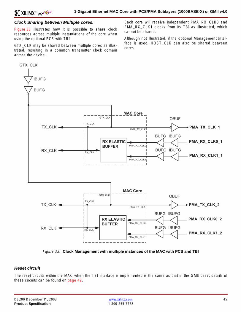
1-Gigabit Ethernet MAC Core with PCSPMA Sublayers (1000BASE-X) or GMII v40R
Clock Sharing between Multiple cores
Figure 33 illustrates how it is possible to share clockresources across multiple instantiations of the core whenusing the optional PCS with TBI
GTX_CLK may be shared between multiple cores as illus-trated resulting in a common transmitter clock domainacross the device
Each core will receive independent PMA_RX_CLK0 andPMA_RX_CLK1 clocks from its TBI as illustrated whichcannot be shared
Although not illustrated if the optional Management Inter-face is used HOST_CLK can also be shared betweencores
Figure 33 Clock Management with multiple instances of the MAC with PCS and TBI
Reset circuit
The reset circuits within the MAC when the TBI interface is implemented is the same as that in the GMII case details ofthese circuits can be found on page 42
IBUFG
OBUF
BUFG
TX_CLK
RX_CLK
PMA_TX_CLK_1
PMA_RX_CLK0_1
MAC Core
RX ELASTICBUFFER
TX_CLK
RX_CLK
GTX_CLK
PMA_TX_CLK
PMA_RX_CLK0
IBUFGBUFGPMA_RX_CLK1_1
PMA_RX_CLK1
IBUFG
BUFG
GTX_CLK
IBUFG
OBUF
BUFG
TX_CLK
RX_CLK
PMA_TX_CLK_2
PMA_RX_CLK0_2
MAC Core
RX ELASTICBUFFER
TX_CLK
RX_CLK
GTX_CLK
PMA_TX_CLK
PMA_RX_CLK0
IBUFGBUFGPMA_RX_CLK1_2
PMA_RX_CLK1
DS200 December 11 2003 wwwxilinxcom 45Product Specification 1-800-255-7778
1-Gigabit Ethernet MAC Core with PCSPMA Sublayers (1000BASE-X) or GMII v40 R
Optional PCS and PMA Sublayers for 1000BASE-X (physical_interface=phy)The Full-Duplex Physical Coding Sublayer (PCS) withPhysical Medium Attachment (PMA) for 1000BASE-X isdefined in IEEE 8023-2002 Clauses 36 and 37 This func-tionality is only available in the Virtex-II Pro family of FPGAdevices
A block diagram of the PCS and PMA sublayers can beseen in Figure 34 The functional blocks of the PCS andPMA sublayers may replace the optional GMII interfaceThe functional blocks of the PCS and PMA sublayers are
bull PCS Transmit Engine
bull Auto-Negotiation block
bull Receive Engine and Synchronization Block
bull PCS Managed Register Block
bull Rocket IO Multi-Gigabit Transceiver
The PCS Managed Register Block is accessed through theMDIO Interface as if it were an externally connected PHYThis configures the operation of the PCS PMA sublayerand Auto-NegotiationSee PCS Managed Register Block(physical_interface = tbi or phy) on page 49 The corersquosoptional Management Interface can be used to control theMDIO Interface as described by MDIO Interface onpage 37 When the optional Management Interface is notpresent the PCS Managed Register Block must beaccessed via an MDIO controller which is not provided bythe core
The Rocket IO Multi-Gigabit Transceiver (MGT) providessome of the PCS layer functionality such as 8B10B encod-ingdecoding and the PMA serdes The remaining PCSfunctionality such as code group encodingdecoding theManaged Register Block and Auto-Negotiation are imple-mented in CLB logic
Figure 34 Functional Block Diagram of the 1-Gigabit Ethernet PCSPMA Sublayer Extension
PCS TRANSMIT ENGINE
PCS RECEIVE ENGINE ampSYNCHRONISATION
RO
CK
ET
IO
MU
LTI-
GIG
TR
AN
SC
EIV
ER
PCSMANAGEMENT
MDIOInterface
AUTO-NEGOTIATION
TXPTXN
RXPRXN
MAC TXInterface
MAC RXInterface
xip2154
46 wwwxilinxcom DS200 December 11 20031-800-255-7778 Product Specification
1-Gigabit Ethernet MAC Core with PCSPMA Sublayers (1000BASE-X) or GMII v40R
Clock Management
Figure 35 illustrates the clock management that should beused with the optional PCS and PMA sublayers for1000BASE-X This logic is implemented in the examplewrapper that is delivered with the core This provides flexi-bility because the design can be modified to use eitherREFCLK or BREFCLK (please refer to Rocket IO docu-mentation) It would also allow multiple instances of the coreto share clocks The example wrapper is provided in bothVHDL and Verilog
(B)REFCLK must be provided to the MAC core This clockmust be derived from an external oscillator and connectedto the core through an IBUFG as illustrated (B)REFCLK isa high quality clock of frequency 625 MHz which satisfiesthe Rocket IO Multi-Gigabit Transceiver (MGT) require-ments
(B)REFCLK is routed to both the core and a DCM From theDCM the CLK2X180 output is routed to a BUFG to providethe device with a global 125 MHz clock (connected toUSERCLK2 input on the core) Within the core bothTX_CLK and RX_CLK share this global 125 MHz clocksource which is used by all transmitter and receiver logicThis is made possible by the RX_ELASTIC_BUFFER func-tionality of the Rocket IO MGT (refer to Virtex-II Pro docu-mentation) The MAC Client can obtain this clock byconnecting to either the TX_CLK or the RX_CLK signalsoutput from the core
From the DCM the CLK0 output is routed to a BUFG to pro-vide the device with a global 625MHz clock This is con-nected to the USRCLK input of the core
Figure 35 Clock Management with PCSPMA Sublayers
DCM
CLKIN CLK0
CLK2X180FB
BUFG
BUFG
IBUFG
TX_CLK
RX_CLK
(B)REFCLK
TXUSRCLK
(B)REFCLK
TXUSRCLK2RXUSRCLKRXUSRCLK2
GT_ETHERNET
Example Wrapper
xip2155
MAC Core
(B)REFCLK
USRCLK
USRCLK2
TX_CLK
RX_CLK
DS200 December 11 2003 wwwxilinxcom 47Product Specification 1-800-255-7778
1-Gigabit Ethernet MAC Core with PCSPMA Sublayers (1000BASE-X) or GMII v40 R
Clock Sharing between Multiple Cores
Figure 36 illustrates how it is possible to share clockresources across multiple instantiations of the core whenusing the optional PCSPMA sublayers For each coreUSERCLK and USERCLK2 must always be derived asshown from the BREFCLK or REFCLK used by that core
Note that when using the fixed routing resources of BREF-CLK Rocket IO MGTs along the top edge of the devicemust use a separate BREFCLK routing resource to thosealong the bottom edge of the device (Refer to Virtex-II Prodocumentation)
Although not illustrated if the optional Management Inter-face is used HOST_CLK can also be shared betweencores
Figure 36 Clock Management with multiple instances of the MAC with PCS and PMA sublayers
Reset circuit
The reset circuits within the MAC when the PCS and PMA sublayers are implemented is the same as that in the GMII casedetails of these circuits can be found on page 42
DCM
CLKIN CLK0
CLK2X180FB
BUFG
BUFG
IBUFG
(B)REFCLK
TXUSRCLK
(B)REFCLK
TXUSRCLK2RXUSRCLKRXUSRCLK2
GT_ETHERNET(B)REFCLK
USERCLK
USERCLK2
MAC core
TXUSRCLK
(B)REFCLK
TXUSRCLK2RXUSRCLKRXUSRCLK2
GT_ETHERNET(B)REFCLK
USERCLK
USERCLK2
MAC core
48 wwwxilinxcom DS200 December 11 20031-800-255-7778 Product Specification
1-Gigabit Ethernet MAC Core with PCSPMA Sublayers (1000BASE-X) or GMII v40R
PCS Managed Register Block (physical_interface = tbi or phy)The PCS in both the TBI interface and the PCSPMA (usingthe Virtex-II Pro Rocket IO) versions contain the full Man-aged Register Block defined in IEEE 8023-2002 clause 37
This utilizes ten dedicated management registersaccessed via the MDIO interface These are defined inTable 25 to Table 33 inclusive
Table 25 Control Register (Register 0)
Bit(s) Name Description Attributes Default Value
015 Reset1 = PCSPMA reset
0 = Normal Operation
ReadWrite
Self Clearing0
014 Loopback1 = Enable Loopback Mode
0 = Disable Loopback ModeReadWrite 0
013SpeedSelection (LSB)
The core always returns a 0 for this bitTogether with bit 06 speed selection of 1000Mbs is identified
Returns 0 0
012Auto-NegotiationEnable
1 = Enable Auto-Negotiation Process
0 = Disable Auto-Negotiation ProcessReadWrite 1
011 Power Down
1 = Power down
0 = Normal operation
When set to ldquo1rdquo the Rocket IO MGT is placedin a low power state This bit requires a reset(see bit 015) to clear
Read Write 0
010 Isolate1 = Electrically Isolate PHY from GMII
0 = Normal operationReadWrite 1
09Restart Auto-Negotiation
1 = Restart Auto-Negotiation Process
0 = Normal Operation
ReadWrite
Self Clearing0
08 Duplex ModeThe core always returns a 1 for this bit tosignal Full-Duplex Mode
Returns 1 1
07 Collision TestThe core always returns a 0 for this bit todisable COL test
Returns 0 0
06SpeedSelection(MSB)
The core always returns a 1 for this bitTogether with bit 013 speed selection of1000 Mbs is identified
Returns 1 1
050 Reserved Always returns 0rsquos writes ignored Returns 0rsquos 000000
DS200 December 11 2003 wwwxilinxcom 49Product Specification 1-800-255-7778
1-Gigabit Ethernet MAC Core with PCSPMA Sublayers (1000BASE-X) or GMII v40 R
Table 26 Status Register (Register 1)
Bit(s) Name Description Attributes Default Value
115 100BASE-T4The core always returns a 0 for this bitbecause 100BASE-T4 is not supported
Returns 0 0
114100BASE-XFullDuplex
The core always returns a 0 for this bitbecause 100BASE-X Full Duplex is notsupported
Returns 0 0
113100BASE-XHalf Duplex
The core always returns a 0 for this bitbecause 100BASE-X Half Duplex is notsupported
Returns 0 0
11210 Mbs FullDuplex
The core always returns a 0 for this bitbecause 10 Mbs Full Duplex is notsupported
Returns 0 0
11110 Mbs HalfDuplex
The core always returns a 0 for this bitbecause 10 Mbs Half Duplex is notsupported
Returns 0 0
110100BASE-T2Full Duplex
The core always returns a 0 for this bitbecause 100BASE-T2 Full Duplex is notsupported
Returns 0 0
19100BASE-T2Half Duplex
The core always returns a 0 for this bitbecause 100BASE-T2 Half Duplex is notsupported
Returns 0 0
18ExtendedStatus
The core always returns a 1 for this bit toindicate the presence of the ExtendedRegister (Register 15)
Returns 1 1
17 Reserved Always return 0 writes ignored Returns 0 0
16MF PreambleSuppression
The core always returns a 1 for this bit toindicate that Management Frame PreambleSuppression is supported
Returns 1 1
15Auto-NegotiationComplete
1 = Auto-Negotiation process completed
0 = Auto-Negotiation process not completedRead Only 0
14 Remote Fault1 = Remote fault condition detected
0 = No remote fault condition detected
Read Only
Self Clearing on read0
13Auto-NegotiationAbility
The core always returns a 1 for this bit toindicate that the PHY is capable ofAuto-Negotiation
Returns 1 1
12 Link Status1 = Link is up
0 = Link is down
Read Only
Self Clearing on read0
11 Jabber DetectThe core always returns a 0 for this bitbecause Jabber Detect is not supported
Returns 0 0
10ExtendedCapability
The core always returns a 0 for this bitbecause no extended register set issupported
Returns 0 0
50 wwwxilinxcom DS200 December 11 20031-800-255-7778 Product Specification
1-Gigabit Ethernet MAC Core with PCSPMA Sublayers (1000BASE-X) or GMII v40R
Table 27 PHY Identifier (Registers 2 and 3)
Bit(s) Name Description Attributes Default Value
2150OrganizationallyUniqueIdentifier
Always returns 0s Returns 0s 0000000000000000
31510OrganizationallyUniqueIdentifier
Always returns 0s Returns 0s 000000
394Manufacturerrsquosmodel number
Always returns 0s Returns 0s 000000
330RevisionNumber
Always returns 0s Returns 0s 0000
Table 28 Auto-Negotiation Advertisement Register (Register 4)
Bit(s) Name Description Attributes Default Value
415 Next Page1 = Next Page functionality is advertised
0 = Next Page functionality is not advertisedReadWrite 0
414 Reserved Always returns 0 writes ignored Returns 0 0
41312 Remote Fault
00 = No Error
01 = Offline
10 = Link Failure
11 = Auto-Negotiation Error
ReadWrite
Self clearing to 00afterAuto-Negotiation
00
4119 Reserved Always return 0 writes ignored Returns 0 0
487 Pause
00 = No PAUSE
01 = Asymmetric PAUSE towards linkpartner
10 = Symmetic PAUSE
11 = Both Symmetric PAUSE andAsymmetric PAUSE towards link partner
ReadWrite 11
46 Half DuplexThe core always returns a 0 for this bitbecause Half Duplex Mode is not supported
Returns 0 0
45 Full Duplex1 = Full Duplex Mode is advertised
0 = Full Duplex Mode is not advertisedReadWrite 1
440 Reserved Always returns 0s writes ignored Returns 0s 00000
DS200 December 11 2003 wwwxilinxcom 51Product Specification 1-800-255-7778
1-Gigabit Ethernet MAC Core with PCSPMA Sublayers (1000BASE-X) or GMII v40 R
Table 29 Auto-Negotiation Link Partner Ability Base Register (Register 5)
Bit(s) Name Description Attributes Default Value
515 Next Page1 = Next Page functionality is supported
0 = Next Page functionality is not supportedRead Only 0
514 AcknowledgeUsed by Auto-Negotiation function toindicate reception of a link partnerrsquos base ornext page
Read Only 0
51312 Remote Fault
00 = No Error
01 = Offline
10 = Link Failure
11 = Auto-Negotiation Error
Read Only 00
5119 Reserved Always returns 0s Returns 0s 000
587 Pause
00 = No PAUSE
01 = Asymmetric PAUSE supported
10 = Symmetic PAUSE supported
11 = Both Symmetric PAUSE andAsymmetric PAUSE supported
Read Only 00
56 Half Duplex1 = Half Duplex Mode is supported
0 = Half Duplex Mode is not supportedRead Only 0
55 Full Duplex1 = Full Duplex Mode is supported
0 = Full Duplex Mode is not supportedRead Only 0
540 Reserved Always returns 0s Returns 0s 00000
Table 30 Auto-Negotiation Expansion Register (Register 6)
Bit(s) Name Description Attributes Default Value
6153 Reserved Always returns 0s Returns 0s 0000000000000
62 Next Page AbleThe core always returns a 1 for this bitbecause the device is Next Page Able
Returns 1 1
61 Page Received1 = A new page has been received
0 = A new page has not been received
Read Only
Self Clearing on read0
60 Reserved Always returns 0s Returns 0s 0000000
52 wwwxilinxcom DS200 December 11 20031-800-255-7778 Product Specification
1-Gigabit Ethernet MAC Core with PCSPMA Sublayers (1000BASE-X) or GMII v40R
Table 31 Auto-Negotiation Next Page Transmit Register (Register 7)
Bit(s) Name Description Attributes Default Value
715 Next Page1 = Additional Next Page(s) will follow
0 = Last pageReadWrite 0
714 Reserved Always returns 0 Returns 0 0
713 Message Page1 = Message Page
0 = Unformatted PageReadWrite 1
712 Acknowledge 21 = Will comply with message
0 = Cannot comply with messageReadWrite 0
711 ToggleValue will toggle between subsequent NextPages
Read Only 0
7100Message UnformattedCode Field
Message Code Field or Unformatted PageEncoding as dictated by 713
ReadWrite00000000001
(Null Message Code)
Table 32 Auto-Negotiation Next Page Receive Register (Register 8)
Bit(s) Name Description Attributes Default Value
815 Next Page1 = Additional Next Page(s) follows
0 = Last pageRead Only 0
814 AcknowledgeUsed by Auto-Negotiation function toindicate reception of a link partnerrsquos base ornext page
Read Only 0
813 Message Page1 = Message Page
0 = Unformatted PageRead Only 0
812 Acknowledge 21 = Will comply with message
0 = Cannot comply with messageRead Only 0
811 ToggleValue toggles between subsequent andNext Pages
Read Only 0
8100Message UnformattedCode Field
Message Code Field or Unformatted PageEncoding as dictated by 813
Read Only 00000000000
DS200 December 11 2003 wwwxilinxcom 53Product Specification 1-800-255-7778
1-Gigabit Ethernet MAC Core with PCSPMA Sublayers (1000BASE-X) or GMII v40 R
)
Referencesbull IEEE 8023-2002
bull Virtex-E User Guide
bull Spartan-II E User Guide
bull Virtex-II User Guide
bull Virtex-II Pro User Guide
Related InformationXilinx products are not intended for use in life support appli-ances devices or systems Use of a Xilinx product in suchapplications without the written consent of the appropriateXilinx officer is prohibited
Ordering InformationThis Xilinx LogiCORE module is provided under theSignOnce IP Site License A free evaluation version of themodule is available
Once purchased the core may be downloaded from the Xil-inx IP Center for use with the Xilinx CORE Generator Sys-temtrade v61i SP3 and later The Xilinx CORE GeneratorSystem tool is bundled with all Alliance Series Softwarepackages at no additional charge
Please contact your local Xilinx sales representative or visitthe Xilinx Silicon Xpresso Cafe for pricing and availability onXilinx LogiCORE modules and software Information onadditional Xilinx LogiCORE modules is available on the Xil-inx IP Center
Revision HistoryThe following table shows the revision history for this document
Table 33 Extended Status Register (Register 15)
Bit(s) Name Description Attributes Default Value
15151000BASE-XFull Duplex
The core always returns a 1 for this bitbecause 1000BASE-X Full Duplex issupported
Returns 1 1
15141000BASE-XHalf Duplex
The core always returns a 0 for this bitbecause 1000BASE-X Half Duplex is notsupported
Returns 0 0
15131000BASE-TFull Duplex
The core always returns a 0 for this bitbecause 1000BASE-T Full Duplex is notsupported
Returns 0 0
15121000BASE-THalf Duplex
The core always returns a 0 for this bitbecause 1000BASE-T Half Duplex is notsupported
Returns 0 0
15110 Reserved Always returns 0s Returns 0s 000000000000
Date Version Revision
032803 11 Revision History added to document
043003 20 Revised to v30 standards
121103 30 Updated to v40 release
54 wwwxilinxcom DS200 December 11 20031-800-255-7778 Product Specification
- 1-Gigabit Ethernet MAC Core with PCSPMA Sublayers (1000BASE-X) or GMII v40
-
- Features
- MAC Overview
- Xilinx CORE Generator
- GUI Interface
- Parameter Values in the XCO File
- Output Generation
- Device Utilization
- Interface Description
- Interface Signals for MAC with physical_interface=gmii and management_interface=true
- Interface Signals for MAC with physical_interface=gmii and management_interface=false
- Interface Signals for MAC with physical_interface=tbi and management_interface=true
- Interface Signals for MAC with physical_interface=tbi and management_interface=false
- Interface Signals for MAC with physical_interface=phy and management_interface=true
- Interface Signals for MAC with physical_interface=phy and management_interface=false
- Client Side Interface Signal Definition
- Physical Interface Signal Definition
- Functional Description
- Client Interface
- Transmitter
- Receiver
- Flow Control
- Optional Management Interface (management_interface=true)
- Optional Configuration Vector (management_interface = false)
- Optional GMII (physical_interface=gmii)
- Optional PCS with Ten-Bit Interface (TBI) for 1000BASE-X (physical_interface=tbi)
- Optional PCS and PMA Sublayers for 1000BASE-X (physical_interface=phy)
- PCS Managed Register Block (physical_interface = tbi or phy)
- References
- Related Information
- Ordering Information
- Revision History
-
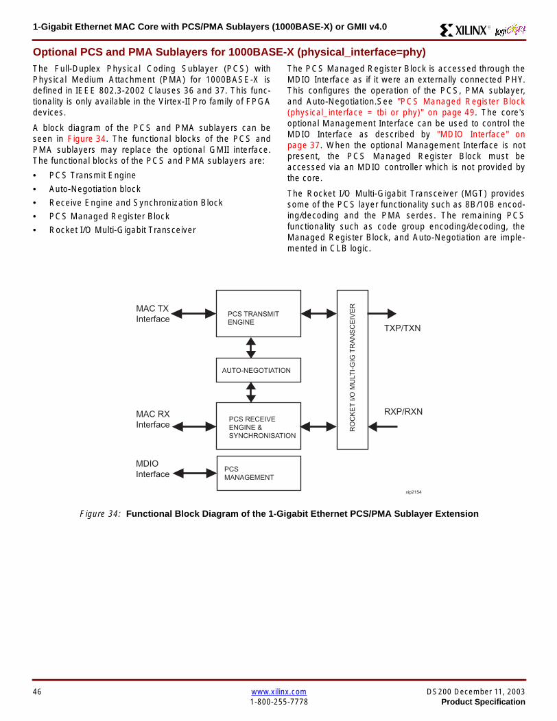
1-Gigabit Ethernet MAC Core with PCSPMA Sublayers (1000BASE-X) or GMII v40 R
Optional PCS and PMA Sublayers for 1000BASE-X (physical_interface=phy)The Full-Duplex Physical Coding Sublayer (PCS) withPhysical Medium Attachment (PMA) for 1000BASE-X isdefined in IEEE 8023-2002 Clauses 36 and 37 This func-tionality is only available in the Virtex-II Pro family of FPGAdevices
A block diagram of the PCS and PMA sublayers can beseen in Figure 34 The functional blocks of the PCS andPMA sublayers may replace the optional GMII interfaceThe functional blocks of the PCS and PMA sublayers are
bull PCS Transmit Engine
bull Auto-Negotiation block
bull Receive Engine and Synchronization Block
bull PCS Managed Register Block
bull Rocket IO Multi-Gigabit Transceiver
The PCS Managed Register Block is accessed through theMDIO Interface as if it were an externally connected PHYThis configures the operation of the PCS PMA sublayerand Auto-NegotiationSee PCS Managed Register Block(physical_interface = tbi or phy) on page 49 The corersquosoptional Management Interface can be used to control theMDIO Interface as described by MDIO Interface onpage 37 When the optional Management Interface is notpresent the PCS Managed Register Block must beaccessed via an MDIO controller which is not provided bythe core
The Rocket IO Multi-Gigabit Transceiver (MGT) providessome of the PCS layer functionality such as 8B10B encod-ingdecoding and the PMA serdes The remaining PCSfunctionality such as code group encodingdecoding theManaged Register Block and Auto-Negotiation are imple-mented in CLB logic
Figure 34 Functional Block Diagram of the 1-Gigabit Ethernet PCSPMA Sublayer Extension
PCS TRANSMIT ENGINE
PCS RECEIVE ENGINE ampSYNCHRONISATION
RO
CK
ET
IO
MU
LTI-
GIG
TR
AN
SC
EIV
ER
PCSMANAGEMENT
MDIOInterface
AUTO-NEGOTIATION
TXPTXN
RXPRXN
MAC TXInterface
MAC RXInterface
xip2154
46 wwwxilinxcom DS200 December 11 20031-800-255-7778 Product Specification
1-Gigabit Ethernet MAC Core with PCSPMA Sublayers (1000BASE-X) or GMII v40R
Clock Management
Figure 35 illustrates the clock management that should beused with the optional PCS and PMA sublayers for1000BASE-X This logic is implemented in the examplewrapper that is delivered with the core This provides flexi-bility because the design can be modified to use eitherREFCLK or BREFCLK (please refer to Rocket IO docu-mentation) It would also allow multiple instances of the coreto share clocks The example wrapper is provided in bothVHDL and Verilog
(B)REFCLK must be provided to the MAC core This clockmust be derived from an external oscillator and connectedto the core through an IBUFG as illustrated (B)REFCLK isa high quality clock of frequency 625 MHz which satisfiesthe Rocket IO Multi-Gigabit Transceiver (MGT) require-ments
(B)REFCLK is routed to both the core and a DCM From theDCM the CLK2X180 output is routed to a BUFG to providethe device with a global 125 MHz clock (connected toUSERCLK2 input on the core) Within the core bothTX_CLK and RX_CLK share this global 125 MHz clocksource which is used by all transmitter and receiver logicThis is made possible by the RX_ELASTIC_BUFFER func-tionality of the Rocket IO MGT (refer to Virtex-II Pro docu-mentation) The MAC Client can obtain this clock byconnecting to either the TX_CLK or the RX_CLK signalsoutput from the core
From the DCM the CLK0 output is routed to a BUFG to pro-vide the device with a global 625MHz clock This is con-nected to the USRCLK input of the core
Figure 35 Clock Management with PCSPMA Sublayers
DCM
CLKIN CLK0
CLK2X180FB
BUFG
BUFG
IBUFG
TX_CLK
RX_CLK
(B)REFCLK
TXUSRCLK
(B)REFCLK
TXUSRCLK2RXUSRCLKRXUSRCLK2
GT_ETHERNET
Example Wrapper
xip2155
MAC Core
(B)REFCLK
USRCLK
USRCLK2
TX_CLK
RX_CLK
DS200 December 11 2003 wwwxilinxcom 47Product Specification 1-800-255-7778
1-Gigabit Ethernet MAC Core with PCSPMA Sublayers (1000BASE-X) or GMII v40 R
Clock Sharing between Multiple Cores
Figure 36 illustrates how it is possible to share clockresources across multiple instantiations of the core whenusing the optional PCSPMA sublayers For each coreUSERCLK and USERCLK2 must always be derived asshown from the BREFCLK or REFCLK used by that core
Note that when using the fixed routing resources of BREF-CLK Rocket IO MGTs along the top edge of the devicemust use a separate BREFCLK routing resource to thosealong the bottom edge of the device (Refer to Virtex-II Prodocumentation)
Although not illustrated if the optional Management Inter-face is used HOST_CLK can also be shared betweencores
Figure 36 Clock Management with multiple instances of the MAC with PCS and PMA sublayers
Reset circuit
The reset circuits within the MAC when the PCS and PMA sublayers are implemented is the same as that in the GMII casedetails of these circuits can be found on page 42
DCM
CLKIN CLK0
CLK2X180FB
BUFG
BUFG
IBUFG
(B)REFCLK
TXUSRCLK
(B)REFCLK
TXUSRCLK2RXUSRCLKRXUSRCLK2
GT_ETHERNET(B)REFCLK
USERCLK
USERCLK2
MAC core
TXUSRCLK
(B)REFCLK
TXUSRCLK2RXUSRCLKRXUSRCLK2
GT_ETHERNET(B)REFCLK
USERCLK
USERCLK2
MAC core
48 wwwxilinxcom DS200 December 11 20031-800-255-7778 Product Specification
1-Gigabit Ethernet MAC Core with PCSPMA Sublayers (1000BASE-X) or GMII v40R
PCS Managed Register Block (physical_interface = tbi or phy)The PCS in both the TBI interface and the PCSPMA (usingthe Virtex-II Pro Rocket IO) versions contain the full Man-aged Register Block defined in IEEE 8023-2002 clause 37
This utilizes ten dedicated management registersaccessed via the MDIO interface These are defined inTable 25 to Table 33 inclusive
Table 25 Control Register (Register 0)
Bit(s) Name Description Attributes Default Value
015 Reset1 = PCSPMA reset
0 = Normal Operation
ReadWrite
Self Clearing0
014 Loopback1 = Enable Loopback Mode
0 = Disable Loopback ModeReadWrite 0
013SpeedSelection (LSB)
The core always returns a 0 for this bitTogether with bit 06 speed selection of 1000Mbs is identified
Returns 0 0
012Auto-NegotiationEnable
1 = Enable Auto-Negotiation Process
0 = Disable Auto-Negotiation ProcessReadWrite 1
011 Power Down
1 = Power down
0 = Normal operation
When set to ldquo1rdquo the Rocket IO MGT is placedin a low power state This bit requires a reset(see bit 015) to clear
Read Write 0
010 Isolate1 = Electrically Isolate PHY from GMII
0 = Normal operationReadWrite 1
09Restart Auto-Negotiation
1 = Restart Auto-Negotiation Process
0 = Normal Operation
ReadWrite
Self Clearing0
08 Duplex ModeThe core always returns a 1 for this bit tosignal Full-Duplex Mode
Returns 1 1
07 Collision TestThe core always returns a 0 for this bit todisable COL test
Returns 0 0
06SpeedSelection(MSB)
The core always returns a 1 for this bitTogether with bit 013 speed selection of1000 Mbs is identified
Returns 1 1
050 Reserved Always returns 0rsquos writes ignored Returns 0rsquos 000000
DS200 December 11 2003 wwwxilinxcom 49Product Specification 1-800-255-7778
1-Gigabit Ethernet MAC Core with PCSPMA Sublayers (1000BASE-X) or GMII v40 R
Table 26 Status Register (Register 1)
Bit(s) Name Description Attributes Default Value
115 100BASE-T4The core always returns a 0 for this bitbecause 100BASE-T4 is not supported
Returns 0 0
114100BASE-XFullDuplex
The core always returns a 0 for this bitbecause 100BASE-X Full Duplex is notsupported
Returns 0 0
113100BASE-XHalf Duplex
The core always returns a 0 for this bitbecause 100BASE-X Half Duplex is notsupported
Returns 0 0
11210 Mbs FullDuplex
The core always returns a 0 for this bitbecause 10 Mbs Full Duplex is notsupported
Returns 0 0
11110 Mbs HalfDuplex
The core always returns a 0 for this bitbecause 10 Mbs Half Duplex is notsupported
Returns 0 0
110100BASE-T2Full Duplex
The core always returns a 0 for this bitbecause 100BASE-T2 Full Duplex is notsupported
Returns 0 0
19100BASE-T2Half Duplex
The core always returns a 0 for this bitbecause 100BASE-T2 Half Duplex is notsupported
Returns 0 0
18ExtendedStatus
The core always returns a 1 for this bit toindicate the presence of the ExtendedRegister (Register 15)
Returns 1 1
17 Reserved Always return 0 writes ignored Returns 0 0
16MF PreambleSuppression
The core always returns a 1 for this bit toindicate that Management Frame PreambleSuppression is supported
Returns 1 1
15Auto-NegotiationComplete
1 = Auto-Negotiation process completed
0 = Auto-Negotiation process not completedRead Only 0
14 Remote Fault1 = Remote fault condition detected
0 = No remote fault condition detected
Read Only
Self Clearing on read0
13Auto-NegotiationAbility
The core always returns a 1 for this bit toindicate that the PHY is capable ofAuto-Negotiation
Returns 1 1
12 Link Status1 = Link is up
0 = Link is down
Read Only
Self Clearing on read0
11 Jabber DetectThe core always returns a 0 for this bitbecause Jabber Detect is not supported
Returns 0 0
10ExtendedCapability
The core always returns a 0 for this bitbecause no extended register set issupported
Returns 0 0
50 wwwxilinxcom DS200 December 11 20031-800-255-7778 Product Specification
1-Gigabit Ethernet MAC Core with PCSPMA Sublayers (1000BASE-X) or GMII v40R
Table 27 PHY Identifier (Registers 2 and 3)
Bit(s) Name Description Attributes Default Value
2150OrganizationallyUniqueIdentifier
Always returns 0s Returns 0s 0000000000000000
31510OrganizationallyUniqueIdentifier
Always returns 0s Returns 0s 000000
394Manufacturerrsquosmodel number
Always returns 0s Returns 0s 000000
330RevisionNumber
Always returns 0s Returns 0s 0000
Table 28 Auto-Negotiation Advertisement Register (Register 4)
Bit(s) Name Description Attributes Default Value
415 Next Page1 = Next Page functionality is advertised
0 = Next Page functionality is not advertisedReadWrite 0
414 Reserved Always returns 0 writes ignored Returns 0 0
41312 Remote Fault
00 = No Error
01 = Offline
10 = Link Failure
11 = Auto-Negotiation Error
ReadWrite
Self clearing to 00afterAuto-Negotiation
00
4119 Reserved Always return 0 writes ignored Returns 0 0
487 Pause
00 = No PAUSE
01 = Asymmetric PAUSE towards linkpartner
10 = Symmetic PAUSE
11 = Both Symmetric PAUSE andAsymmetric PAUSE towards link partner
ReadWrite 11
46 Half DuplexThe core always returns a 0 for this bitbecause Half Duplex Mode is not supported
Returns 0 0
45 Full Duplex1 = Full Duplex Mode is advertised
0 = Full Duplex Mode is not advertisedReadWrite 1
440 Reserved Always returns 0s writes ignored Returns 0s 00000
DS200 December 11 2003 wwwxilinxcom 51Product Specification 1-800-255-7778
1-Gigabit Ethernet MAC Core with PCSPMA Sublayers (1000BASE-X) or GMII v40 R
Table 29 Auto-Negotiation Link Partner Ability Base Register (Register 5)
Bit(s) Name Description Attributes Default Value
515 Next Page1 = Next Page functionality is supported
0 = Next Page functionality is not supportedRead Only 0
514 AcknowledgeUsed by Auto-Negotiation function toindicate reception of a link partnerrsquos base ornext page
Read Only 0
51312 Remote Fault
00 = No Error
01 = Offline
10 = Link Failure
11 = Auto-Negotiation Error
Read Only 00
5119 Reserved Always returns 0s Returns 0s 000
587 Pause
00 = No PAUSE
01 = Asymmetric PAUSE supported
10 = Symmetic PAUSE supported
11 = Both Symmetric PAUSE andAsymmetric PAUSE supported
Read Only 00
56 Half Duplex1 = Half Duplex Mode is supported
0 = Half Duplex Mode is not supportedRead Only 0
55 Full Duplex1 = Full Duplex Mode is supported
0 = Full Duplex Mode is not supportedRead Only 0
540 Reserved Always returns 0s Returns 0s 00000
Table 30 Auto-Negotiation Expansion Register (Register 6)
Bit(s) Name Description Attributes Default Value
6153 Reserved Always returns 0s Returns 0s 0000000000000
62 Next Page AbleThe core always returns a 1 for this bitbecause the device is Next Page Able
Returns 1 1
61 Page Received1 = A new page has been received
0 = A new page has not been received
Read Only
Self Clearing on read0
60 Reserved Always returns 0s Returns 0s 0000000
52 wwwxilinxcom DS200 December 11 20031-800-255-7778 Product Specification
1-Gigabit Ethernet MAC Core with PCSPMA Sublayers (1000BASE-X) or GMII v40R
Table 31 Auto-Negotiation Next Page Transmit Register (Register 7)
Bit(s) Name Description Attributes Default Value
715 Next Page1 = Additional Next Page(s) will follow
0 = Last pageReadWrite 0
714 Reserved Always returns 0 Returns 0 0
713 Message Page1 = Message Page
0 = Unformatted PageReadWrite 1
712 Acknowledge 21 = Will comply with message
0 = Cannot comply with messageReadWrite 0
711 ToggleValue will toggle between subsequent NextPages
Read Only 0
7100Message UnformattedCode Field
Message Code Field or Unformatted PageEncoding as dictated by 713
ReadWrite00000000001
(Null Message Code)
Table 32 Auto-Negotiation Next Page Receive Register (Register 8)
Bit(s) Name Description Attributes Default Value
815 Next Page1 = Additional Next Page(s) follows
0 = Last pageRead Only 0
814 AcknowledgeUsed by Auto-Negotiation function toindicate reception of a link partnerrsquos base ornext page
Read Only 0
813 Message Page1 = Message Page
0 = Unformatted PageRead Only 0
812 Acknowledge 21 = Will comply with message
0 = Cannot comply with messageRead Only 0
811 ToggleValue toggles between subsequent andNext Pages
Read Only 0
8100Message UnformattedCode Field
Message Code Field or Unformatted PageEncoding as dictated by 813
Read Only 00000000000
DS200 December 11 2003 wwwxilinxcom 53Product Specification 1-800-255-7778
1-Gigabit Ethernet MAC Core with PCSPMA Sublayers (1000BASE-X) or GMII v40 R
)
Referencesbull IEEE 8023-2002
bull Virtex-E User Guide
bull Spartan-II E User Guide
bull Virtex-II User Guide
bull Virtex-II Pro User Guide
Related InformationXilinx products are not intended for use in life support appli-ances devices or systems Use of a Xilinx product in suchapplications without the written consent of the appropriateXilinx officer is prohibited
Ordering InformationThis Xilinx LogiCORE module is provided under theSignOnce IP Site License A free evaluation version of themodule is available
Once purchased the core may be downloaded from the Xil-inx IP Center for use with the Xilinx CORE Generator Sys-temtrade v61i SP3 and later The Xilinx CORE GeneratorSystem tool is bundled with all Alliance Series Softwarepackages at no additional charge
Please contact your local Xilinx sales representative or visitthe Xilinx Silicon Xpresso Cafe for pricing and availability onXilinx LogiCORE modules and software Information onadditional Xilinx LogiCORE modules is available on the Xil-inx IP Center
Revision HistoryThe following table shows the revision history for this document
Table 33 Extended Status Register (Register 15)
Bit(s) Name Description Attributes Default Value
15151000BASE-XFull Duplex
The core always returns a 1 for this bitbecause 1000BASE-X Full Duplex issupported
Returns 1 1
15141000BASE-XHalf Duplex
The core always returns a 0 for this bitbecause 1000BASE-X Half Duplex is notsupported
Returns 0 0
15131000BASE-TFull Duplex
The core always returns a 0 for this bitbecause 1000BASE-T Full Duplex is notsupported
Returns 0 0
15121000BASE-THalf Duplex
The core always returns a 0 for this bitbecause 1000BASE-T Half Duplex is notsupported
Returns 0 0
15110 Reserved Always returns 0s Returns 0s 000000000000
Date Version Revision
032803 11 Revision History added to document
043003 20 Revised to v30 standards
121103 30 Updated to v40 release
54 wwwxilinxcom DS200 December 11 20031-800-255-7778 Product Specification
- 1-Gigabit Ethernet MAC Core with PCSPMA Sublayers (1000BASE-X) or GMII v40
-
- Features
- MAC Overview
- Xilinx CORE Generator
- GUI Interface
- Parameter Values in the XCO File
- Output Generation
- Device Utilization
- Interface Description
- Interface Signals for MAC with physical_interface=gmii and management_interface=true
- Interface Signals for MAC with physical_interface=gmii and management_interface=false
- Interface Signals for MAC with physical_interface=tbi and management_interface=true
- Interface Signals for MAC with physical_interface=tbi and management_interface=false
- Interface Signals for MAC with physical_interface=phy and management_interface=true
- Interface Signals for MAC with physical_interface=phy and management_interface=false
- Client Side Interface Signal Definition
- Physical Interface Signal Definition
- Functional Description
- Client Interface
- Transmitter
- Receiver
- Flow Control
- Optional Management Interface (management_interface=true)
- Optional Configuration Vector (management_interface = false)
- Optional GMII (physical_interface=gmii)
- Optional PCS with Ten-Bit Interface (TBI) for 1000BASE-X (physical_interface=tbi)
- Optional PCS and PMA Sublayers for 1000BASE-X (physical_interface=phy)
- PCS Managed Register Block (physical_interface = tbi or phy)
- References
- Related Information
- Ordering Information
- Revision History
-
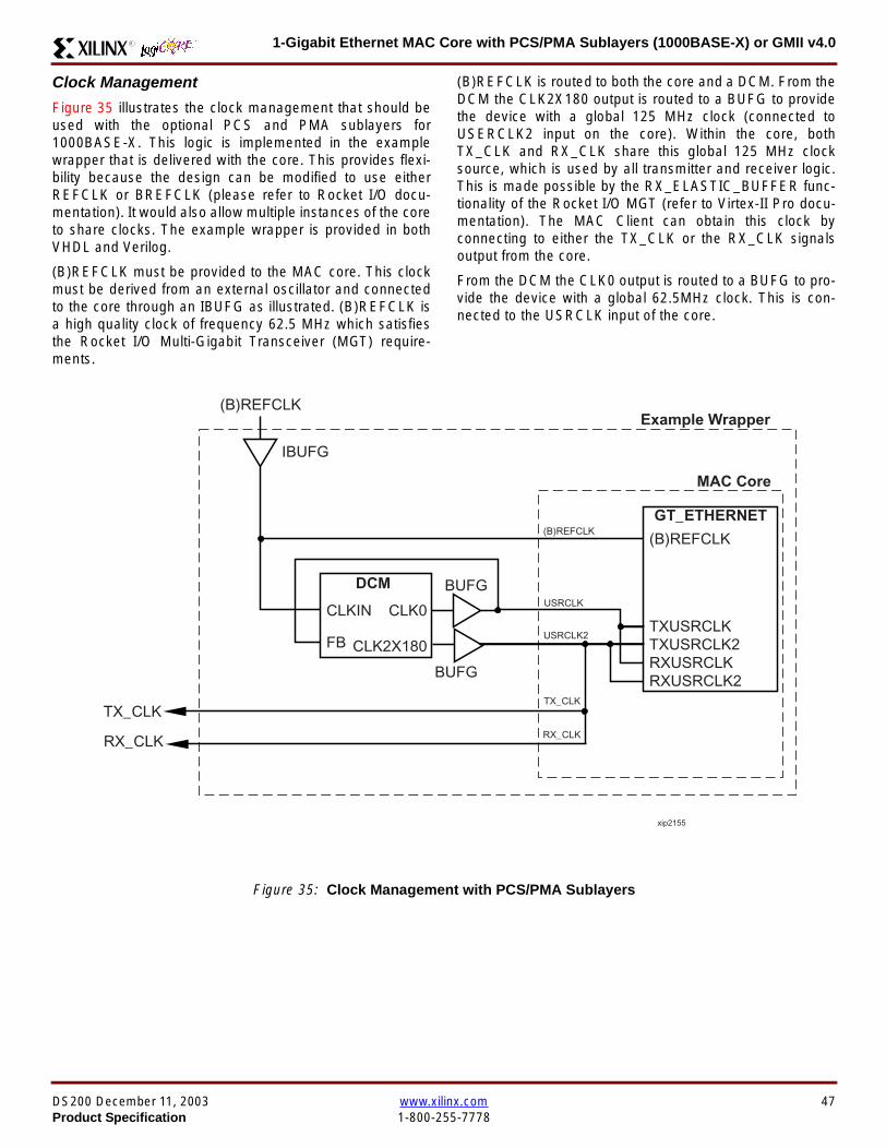
1-Gigabit Ethernet MAC Core with PCSPMA Sublayers (1000BASE-X) or GMII v40R
Clock Management
Figure 35 illustrates the clock management that should beused with the optional PCS and PMA sublayers for1000BASE-X This logic is implemented in the examplewrapper that is delivered with the core This provides flexi-bility because the design can be modified to use eitherREFCLK or BREFCLK (please refer to Rocket IO docu-mentation) It would also allow multiple instances of the coreto share clocks The example wrapper is provided in bothVHDL and Verilog
(B)REFCLK must be provided to the MAC core This clockmust be derived from an external oscillator and connectedto the core through an IBUFG as illustrated (B)REFCLK isa high quality clock of frequency 625 MHz which satisfiesthe Rocket IO Multi-Gigabit Transceiver (MGT) require-ments
(B)REFCLK is routed to both the core and a DCM From theDCM the CLK2X180 output is routed to a BUFG to providethe device with a global 125 MHz clock (connected toUSERCLK2 input on the core) Within the core bothTX_CLK and RX_CLK share this global 125 MHz clocksource which is used by all transmitter and receiver logicThis is made possible by the RX_ELASTIC_BUFFER func-tionality of the Rocket IO MGT (refer to Virtex-II Pro docu-mentation) The MAC Client can obtain this clock byconnecting to either the TX_CLK or the RX_CLK signalsoutput from the core
From the DCM the CLK0 output is routed to a BUFG to pro-vide the device with a global 625MHz clock This is con-nected to the USRCLK input of the core
Figure 35 Clock Management with PCSPMA Sublayers
DCM
CLKIN CLK0
CLK2X180FB
BUFG
BUFG
IBUFG
TX_CLK
RX_CLK
(B)REFCLK
TXUSRCLK
(B)REFCLK
TXUSRCLK2RXUSRCLKRXUSRCLK2
GT_ETHERNET
Example Wrapper
xip2155
MAC Core
(B)REFCLK
USRCLK
USRCLK2
TX_CLK
RX_CLK
DS200 December 11 2003 wwwxilinxcom 47Product Specification 1-800-255-7778
1-Gigabit Ethernet MAC Core with PCSPMA Sublayers (1000BASE-X) or GMII v40 R
Clock Sharing between Multiple Cores
Figure 36 illustrates how it is possible to share clockresources across multiple instantiations of the core whenusing the optional PCSPMA sublayers For each coreUSERCLK and USERCLK2 must always be derived asshown from the BREFCLK or REFCLK used by that core
Note that when using the fixed routing resources of BREF-CLK Rocket IO MGTs along the top edge of the devicemust use a separate BREFCLK routing resource to thosealong the bottom edge of the device (Refer to Virtex-II Prodocumentation)
Although not illustrated if the optional Management Inter-face is used HOST_CLK can also be shared betweencores
Figure 36 Clock Management with multiple instances of the MAC with PCS and PMA sublayers
Reset circuit
The reset circuits within the MAC when the PCS and PMA sublayers are implemented is the same as that in the GMII casedetails of these circuits can be found on page 42
DCM
CLKIN CLK0
CLK2X180FB
BUFG
BUFG
IBUFG
(B)REFCLK
TXUSRCLK
(B)REFCLK
TXUSRCLK2RXUSRCLKRXUSRCLK2
GT_ETHERNET(B)REFCLK
USERCLK
USERCLK2
MAC core
TXUSRCLK
(B)REFCLK
TXUSRCLK2RXUSRCLKRXUSRCLK2
GT_ETHERNET(B)REFCLK
USERCLK
USERCLK2
MAC core
48 wwwxilinxcom DS200 December 11 20031-800-255-7778 Product Specification
1-Gigabit Ethernet MAC Core with PCSPMA Sublayers (1000BASE-X) or GMII v40R
PCS Managed Register Block (physical_interface = tbi or phy)The PCS in both the TBI interface and the PCSPMA (usingthe Virtex-II Pro Rocket IO) versions contain the full Man-aged Register Block defined in IEEE 8023-2002 clause 37
This utilizes ten dedicated management registersaccessed via the MDIO interface These are defined inTable 25 to Table 33 inclusive
Table 25 Control Register (Register 0)
Bit(s) Name Description Attributes Default Value
015 Reset1 = PCSPMA reset
0 = Normal Operation
ReadWrite
Self Clearing0
014 Loopback1 = Enable Loopback Mode
0 = Disable Loopback ModeReadWrite 0
013SpeedSelection (LSB)
The core always returns a 0 for this bitTogether with bit 06 speed selection of 1000Mbs is identified
Returns 0 0
012Auto-NegotiationEnable
1 = Enable Auto-Negotiation Process
0 = Disable Auto-Negotiation ProcessReadWrite 1
011 Power Down
1 = Power down
0 = Normal operation
When set to ldquo1rdquo the Rocket IO MGT is placedin a low power state This bit requires a reset(see bit 015) to clear
Read Write 0
010 Isolate1 = Electrically Isolate PHY from GMII
0 = Normal operationReadWrite 1
09Restart Auto-Negotiation
1 = Restart Auto-Negotiation Process
0 = Normal Operation
ReadWrite
Self Clearing0
08 Duplex ModeThe core always returns a 1 for this bit tosignal Full-Duplex Mode
Returns 1 1
07 Collision TestThe core always returns a 0 for this bit todisable COL test
Returns 0 0
06SpeedSelection(MSB)
The core always returns a 1 for this bitTogether with bit 013 speed selection of1000 Mbs is identified
Returns 1 1
050 Reserved Always returns 0rsquos writes ignored Returns 0rsquos 000000
DS200 December 11 2003 wwwxilinxcom 49Product Specification 1-800-255-7778
1-Gigabit Ethernet MAC Core with PCSPMA Sublayers (1000BASE-X) or GMII v40 R
Table 26 Status Register (Register 1)
Bit(s) Name Description Attributes Default Value
115 100BASE-T4The core always returns a 0 for this bitbecause 100BASE-T4 is not supported
Returns 0 0
114100BASE-XFullDuplex
The core always returns a 0 for this bitbecause 100BASE-X Full Duplex is notsupported
Returns 0 0
113100BASE-XHalf Duplex
The core always returns a 0 for this bitbecause 100BASE-X Half Duplex is notsupported
Returns 0 0
11210 Mbs FullDuplex
The core always returns a 0 for this bitbecause 10 Mbs Full Duplex is notsupported
Returns 0 0
11110 Mbs HalfDuplex
The core always returns a 0 for this bitbecause 10 Mbs Half Duplex is notsupported
Returns 0 0
110100BASE-T2Full Duplex
The core always returns a 0 for this bitbecause 100BASE-T2 Full Duplex is notsupported
Returns 0 0
19100BASE-T2Half Duplex
The core always returns a 0 for this bitbecause 100BASE-T2 Half Duplex is notsupported
Returns 0 0
18ExtendedStatus
The core always returns a 1 for this bit toindicate the presence of the ExtendedRegister (Register 15)
Returns 1 1
17 Reserved Always return 0 writes ignored Returns 0 0
16MF PreambleSuppression
The core always returns a 1 for this bit toindicate that Management Frame PreambleSuppression is supported
Returns 1 1
15Auto-NegotiationComplete
1 = Auto-Negotiation process completed
0 = Auto-Negotiation process not completedRead Only 0
14 Remote Fault1 = Remote fault condition detected
0 = No remote fault condition detected
Read Only
Self Clearing on read0
13Auto-NegotiationAbility
The core always returns a 1 for this bit toindicate that the PHY is capable ofAuto-Negotiation
Returns 1 1
12 Link Status1 = Link is up
0 = Link is down
Read Only
Self Clearing on read0
11 Jabber DetectThe core always returns a 0 for this bitbecause Jabber Detect is not supported
Returns 0 0
10ExtendedCapability
The core always returns a 0 for this bitbecause no extended register set issupported
Returns 0 0
50 wwwxilinxcom DS200 December 11 20031-800-255-7778 Product Specification
1-Gigabit Ethernet MAC Core with PCSPMA Sublayers (1000BASE-X) or GMII v40R
Table 27 PHY Identifier (Registers 2 and 3)
Bit(s) Name Description Attributes Default Value
2150OrganizationallyUniqueIdentifier
Always returns 0s Returns 0s 0000000000000000
31510OrganizationallyUniqueIdentifier
Always returns 0s Returns 0s 000000
394Manufacturerrsquosmodel number
Always returns 0s Returns 0s 000000
330RevisionNumber
Always returns 0s Returns 0s 0000
Table 28 Auto-Negotiation Advertisement Register (Register 4)
Bit(s) Name Description Attributes Default Value
415 Next Page1 = Next Page functionality is advertised
0 = Next Page functionality is not advertisedReadWrite 0
414 Reserved Always returns 0 writes ignored Returns 0 0
41312 Remote Fault
00 = No Error
01 = Offline
10 = Link Failure
11 = Auto-Negotiation Error
ReadWrite
Self clearing to 00afterAuto-Negotiation
00
4119 Reserved Always return 0 writes ignored Returns 0 0
487 Pause
00 = No PAUSE
01 = Asymmetric PAUSE towards linkpartner
10 = Symmetic PAUSE
11 = Both Symmetric PAUSE andAsymmetric PAUSE towards link partner
ReadWrite 11
46 Half DuplexThe core always returns a 0 for this bitbecause Half Duplex Mode is not supported
Returns 0 0
45 Full Duplex1 = Full Duplex Mode is advertised
0 = Full Duplex Mode is not advertisedReadWrite 1
440 Reserved Always returns 0s writes ignored Returns 0s 00000
DS200 December 11 2003 wwwxilinxcom 51Product Specification 1-800-255-7778
1-Gigabit Ethernet MAC Core with PCSPMA Sublayers (1000BASE-X) or GMII v40 R
Table 29 Auto-Negotiation Link Partner Ability Base Register (Register 5)
Bit(s) Name Description Attributes Default Value
515 Next Page1 = Next Page functionality is supported
0 = Next Page functionality is not supportedRead Only 0
514 AcknowledgeUsed by Auto-Negotiation function toindicate reception of a link partnerrsquos base ornext page
Read Only 0
51312 Remote Fault
00 = No Error
01 = Offline
10 = Link Failure
11 = Auto-Negotiation Error
Read Only 00
5119 Reserved Always returns 0s Returns 0s 000
587 Pause
00 = No PAUSE
01 = Asymmetric PAUSE supported
10 = Symmetic PAUSE supported
11 = Both Symmetric PAUSE andAsymmetric PAUSE supported
Read Only 00
56 Half Duplex1 = Half Duplex Mode is supported
0 = Half Duplex Mode is not supportedRead Only 0
55 Full Duplex1 = Full Duplex Mode is supported
0 = Full Duplex Mode is not supportedRead Only 0
540 Reserved Always returns 0s Returns 0s 00000
Table 30 Auto-Negotiation Expansion Register (Register 6)
Bit(s) Name Description Attributes Default Value
6153 Reserved Always returns 0s Returns 0s 0000000000000
62 Next Page AbleThe core always returns a 1 for this bitbecause the device is Next Page Able
Returns 1 1
61 Page Received1 = A new page has been received
0 = A new page has not been received
Read Only
Self Clearing on read0
60 Reserved Always returns 0s Returns 0s 0000000
52 wwwxilinxcom DS200 December 11 20031-800-255-7778 Product Specification
1-Gigabit Ethernet MAC Core with PCSPMA Sublayers (1000BASE-X) or GMII v40R
Table 31 Auto-Negotiation Next Page Transmit Register (Register 7)
Bit(s) Name Description Attributes Default Value
715 Next Page1 = Additional Next Page(s) will follow
0 = Last pageReadWrite 0
714 Reserved Always returns 0 Returns 0 0
713 Message Page1 = Message Page
0 = Unformatted PageReadWrite 1
712 Acknowledge 21 = Will comply with message
0 = Cannot comply with messageReadWrite 0
711 ToggleValue will toggle between subsequent NextPages
Read Only 0
7100Message UnformattedCode Field
Message Code Field or Unformatted PageEncoding as dictated by 713
ReadWrite00000000001
(Null Message Code)
Table 32 Auto-Negotiation Next Page Receive Register (Register 8)
Bit(s) Name Description Attributes Default Value
815 Next Page1 = Additional Next Page(s) follows
0 = Last pageRead Only 0
814 AcknowledgeUsed by Auto-Negotiation function toindicate reception of a link partnerrsquos base ornext page
Read Only 0
813 Message Page1 = Message Page
0 = Unformatted PageRead Only 0
812 Acknowledge 21 = Will comply with message
0 = Cannot comply with messageRead Only 0
811 ToggleValue toggles between subsequent andNext Pages
Read Only 0
8100Message UnformattedCode Field
Message Code Field or Unformatted PageEncoding as dictated by 813
Read Only 00000000000
DS200 December 11 2003 wwwxilinxcom 53Product Specification 1-800-255-7778
1-Gigabit Ethernet MAC Core with PCSPMA Sublayers (1000BASE-X) or GMII v40 R
)
Referencesbull IEEE 8023-2002
bull Virtex-E User Guide
bull Spartan-II E User Guide
bull Virtex-II User Guide
bull Virtex-II Pro User Guide
Related InformationXilinx products are not intended for use in life support appli-ances devices or systems Use of a Xilinx product in suchapplications without the written consent of the appropriateXilinx officer is prohibited
Ordering InformationThis Xilinx LogiCORE module is provided under theSignOnce IP Site License A free evaluation version of themodule is available
Once purchased the core may be downloaded from the Xil-inx IP Center for use with the Xilinx CORE Generator Sys-temtrade v61i SP3 and later The Xilinx CORE GeneratorSystem tool is bundled with all Alliance Series Softwarepackages at no additional charge
Please contact your local Xilinx sales representative or visitthe Xilinx Silicon Xpresso Cafe for pricing and availability onXilinx LogiCORE modules and software Information onadditional Xilinx LogiCORE modules is available on the Xil-inx IP Center
Revision HistoryThe following table shows the revision history for this document
Table 33 Extended Status Register (Register 15)
Bit(s) Name Description Attributes Default Value
15151000BASE-XFull Duplex
The core always returns a 1 for this bitbecause 1000BASE-X Full Duplex issupported
Returns 1 1
15141000BASE-XHalf Duplex
The core always returns a 0 for this bitbecause 1000BASE-X Half Duplex is notsupported
Returns 0 0
15131000BASE-TFull Duplex
The core always returns a 0 for this bitbecause 1000BASE-T Full Duplex is notsupported
Returns 0 0
15121000BASE-THalf Duplex
The core always returns a 0 for this bitbecause 1000BASE-T Half Duplex is notsupported
Returns 0 0
15110 Reserved Always returns 0s Returns 0s 000000000000
Date Version Revision
032803 11 Revision History added to document
043003 20 Revised to v30 standards
121103 30 Updated to v40 release
54 wwwxilinxcom DS200 December 11 20031-800-255-7778 Product Specification
- 1-Gigabit Ethernet MAC Core with PCSPMA Sublayers (1000BASE-X) or GMII v40
-
- Features
- MAC Overview
- Xilinx CORE Generator
- GUI Interface
- Parameter Values in the XCO File
- Output Generation
- Device Utilization
- Interface Description
- Interface Signals for MAC with physical_interface=gmii and management_interface=true
- Interface Signals for MAC with physical_interface=gmii and management_interface=false
- Interface Signals for MAC with physical_interface=tbi and management_interface=true
- Interface Signals for MAC with physical_interface=tbi and management_interface=false
- Interface Signals for MAC with physical_interface=phy and management_interface=true
- Interface Signals for MAC with physical_interface=phy and management_interface=false
- Client Side Interface Signal Definition
- Physical Interface Signal Definition
- Functional Description
- Client Interface
- Transmitter
- Receiver
- Flow Control
- Optional Management Interface (management_interface=true)
- Optional Configuration Vector (management_interface = false)
- Optional GMII (physical_interface=gmii)
- Optional PCS with Ten-Bit Interface (TBI) for 1000BASE-X (physical_interface=tbi)
- Optional PCS and PMA Sublayers for 1000BASE-X (physical_interface=phy)
- PCS Managed Register Block (physical_interface = tbi or phy)
- References
- Related Information
- Ordering Information
- Revision History
-
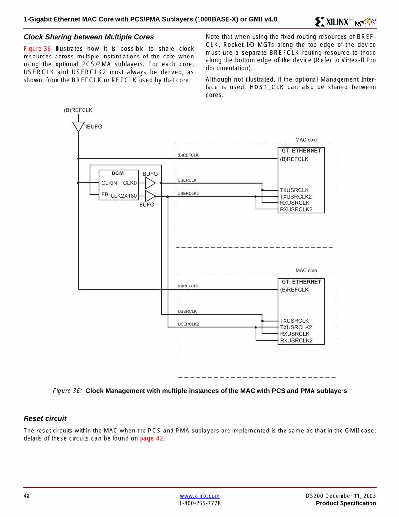
1-Gigabit Ethernet MAC Core with PCSPMA Sublayers (1000BASE-X) or GMII v40 R
Clock Sharing between Multiple Cores
Figure 36 illustrates how it is possible to share clockresources across multiple instantiations of the core whenusing the optional PCSPMA sublayers For each coreUSERCLK and USERCLK2 must always be derived asshown from the BREFCLK or REFCLK used by that core
Note that when using the fixed routing resources of BREF-CLK Rocket IO MGTs along the top edge of the devicemust use a separate BREFCLK routing resource to thosealong the bottom edge of the device (Refer to Virtex-II Prodocumentation)
Although not illustrated if the optional Management Inter-face is used HOST_CLK can also be shared betweencores
Figure 36 Clock Management with multiple instances of the MAC with PCS and PMA sublayers
Reset circuit
The reset circuits within the MAC when the PCS and PMA sublayers are implemented is the same as that in the GMII casedetails of these circuits can be found on page 42
DCM
CLKIN CLK0
CLK2X180FB
BUFG
BUFG
IBUFG
(B)REFCLK
TXUSRCLK
(B)REFCLK
TXUSRCLK2RXUSRCLKRXUSRCLK2
GT_ETHERNET(B)REFCLK
USERCLK
USERCLK2
MAC core
TXUSRCLK
(B)REFCLK
TXUSRCLK2RXUSRCLKRXUSRCLK2
GT_ETHERNET(B)REFCLK
USERCLK
USERCLK2
MAC core
48 wwwxilinxcom DS200 December 11 20031-800-255-7778 Product Specification
1-Gigabit Ethernet MAC Core with PCSPMA Sublayers (1000BASE-X) or GMII v40R
PCS Managed Register Block (physical_interface = tbi or phy)The PCS in both the TBI interface and the PCSPMA (usingthe Virtex-II Pro Rocket IO) versions contain the full Man-aged Register Block defined in IEEE 8023-2002 clause 37
This utilizes ten dedicated management registersaccessed via the MDIO interface These are defined inTable 25 to Table 33 inclusive
Table 25 Control Register (Register 0)
Bit(s) Name Description Attributes Default Value
015 Reset1 = PCSPMA reset
0 = Normal Operation
ReadWrite
Self Clearing0
014 Loopback1 = Enable Loopback Mode
0 = Disable Loopback ModeReadWrite 0
013SpeedSelection (LSB)
The core always returns a 0 for this bitTogether with bit 06 speed selection of 1000Mbs is identified
Returns 0 0
012Auto-NegotiationEnable
1 = Enable Auto-Negotiation Process
0 = Disable Auto-Negotiation ProcessReadWrite 1
011 Power Down
1 = Power down
0 = Normal operation
When set to ldquo1rdquo the Rocket IO MGT is placedin a low power state This bit requires a reset(see bit 015) to clear
Read Write 0
010 Isolate1 = Electrically Isolate PHY from GMII
0 = Normal operationReadWrite 1
09Restart Auto-Negotiation
1 = Restart Auto-Negotiation Process
0 = Normal Operation
ReadWrite
Self Clearing0
08 Duplex ModeThe core always returns a 1 for this bit tosignal Full-Duplex Mode
Returns 1 1
07 Collision TestThe core always returns a 0 for this bit todisable COL test
Returns 0 0
06SpeedSelection(MSB)
The core always returns a 1 for this bitTogether with bit 013 speed selection of1000 Mbs is identified
Returns 1 1
050 Reserved Always returns 0rsquos writes ignored Returns 0rsquos 000000
DS200 December 11 2003 wwwxilinxcom 49Product Specification 1-800-255-7778
1-Gigabit Ethernet MAC Core with PCSPMA Sublayers (1000BASE-X) or GMII v40 R
Table 26 Status Register (Register 1)
Bit(s) Name Description Attributes Default Value
115 100BASE-T4The core always returns a 0 for this bitbecause 100BASE-T4 is not supported
Returns 0 0
114100BASE-XFullDuplex
The core always returns a 0 for this bitbecause 100BASE-X Full Duplex is notsupported
Returns 0 0
113100BASE-XHalf Duplex
The core always returns a 0 for this bitbecause 100BASE-X Half Duplex is notsupported
Returns 0 0
11210 Mbs FullDuplex
The core always returns a 0 for this bitbecause 10 Mbs Full Duplex is notsupported
Returns 0 0
11110 Mbs HalfDuplex
The core always returns a 0 for this bitbecause 10 Mbs Half Duplex is notsupported
Returns 0 0
110100BASE-T2Full Duplex
The core always returns a 0 for this bitbecause 100BASE-T2 Full Duplex is notsupported
Returns 0 0
19100BASE-T2Half Duplex
The core always returns a 0 for this bitbecause 100BASE-T2 Half Duplex is notsupported
Returns 0 0
18ExtendedStatus
The core always returns a 1 for this bit toindicate the presence of the ExtendedRegister (Register 15)
Returns 1 1
17 Reserved Always return 0 writes ignored Returns 0 0
16MF PreambleSuppression
The core always returns a 1 for this bit toindicate that Management Frame PreambleSuppression is supported
Returns 1 1
15Auto-NegotiationComplete
1 = Auto-Negotiation process completed
0 = Auto-Negotiation process not completedRead Only 0
14 Remote Fault1 = Remote fault condition detected
0 = No remote fault condition detected
Read Only
Self Clearing on read0
13Auto-NegotiationAbility
The core always returns a 1 for this bit toindicate that the PHY is capable ofAuto-Negotiation
Returns 1 1
12 Link Status1 = Link is up
0 = Link is down
Read Only
Self Clearing on read0
11 Jabber DetectThe core always returns a 0 for this bitbecause Jabber Detect is not supported
Returns 0 0
10ExtendedCapability
The core always returns a 0 for this bitbecause no extended register set issupported
Returns 0 0
50 wwwxilinxcom DS200 December 11 20031-800-255-7778 Product Specification
1-Gigabit Ethernet MAC Core with PCSPMA Sublayers (1000BASE-X) or GMII v40R
Table 27 PHY Identifier (Registers 2 and 3)
Bit(s) Name Description Attributes Default Value
2150OrganizationallyUniqueIdentifier
Always returns 0s Returns 0s 0000000000000000
31510OrganizationallyUniqueIdentifier
Always returns 0s Returns 0s 000000
394Manufacturerrsquosmodel number
Always returns 0s Returns 0s 000000
330RevisionNumber
Always returns 0s Returns 0s 0000
Table 28 Auto-Negotiation Advertisement Register (Register 4)
Bit(s) Name Description Attributes Default Value
415 Next Page1 = Next Page functionality is advertised
0 = Next Page functionality is not advertisedReadWrite 0
414 Reserved Always returns 0 writes ignored Returns 0 0
41312 Remote Fault
00 = No Error
01 = Offline
10 = Link Failure
11 = Auto-Negotiation Error
ReadWrite
Self clearing to 00afterAuto-Negotiation
00
4119 Reserved Always return 0 writes ignored Returns 0 0
487 Pause
00 = No PAUSE
01 = Asymmetric PAUSE towards linkpartner
10 = Symmetic PAUSE
11 = Both Symmetric PAUSE andAsymmetric PAUSE towards link partner
ReadWrite 11
46 Half DuplexThe core always returns a 0 for this bitbecause Half Duplex Mode is not supported
Returns 0 0
45 Full Duplex1 = Full Duplex Mode is advertised
0 = Full Duplex Mode is not advertisedReadWrite 1
440 Reserved Always returns 0s writes ignored Returns 0s 00000
DS200 December 11 2003 wwwxilinxcom 51Product Specification 1-800-255-7778
1-Gigabit Ethernet MAC Core with PCSPMA Sublayers (1000BASE-X) or GMII v40 R
Table 29 Auto-Negotiation Link Partner Ability Base Register (Register 5)
Bit(s) Name Description Attributes Default Value
515 Next Page1 = Next Page functionality is supported
0 = Next Page functionality is not supportedRead Only 0
514 AcknowledgeUsed by Auto-Negotiation function toindicate reception of a link partnerrsquos base ornext page
Read Only 0
51312 Remote Fault
00 = No Error
01 = Offline
10 = Link Failure
11 = Auto-Negotiation Error
Read Only 00
5119 Reserved Always returns 0s Returns 0s 000
587 Pause
00 = No PAUSE
01 = Asymmetric PAUSE supported
10 = Symmetic PAUSE supported
11 = Both Symmetric PAUSE andAsymmetric PAUSE supported
Read Only 00
56 Half Duplex1 = Half Duplex Mode is supported
0 = Half Duplex Mode is not supportedRead Only 0
55 Full Duplex1 = Full Duplex Mode is supported
0 = Full Duplex Mode is not supportedRead Only 0
540 Reserved Always returns 0s Returns 0s 00000
Table 30 Auto-Negotiation Expansion Register (Register 6)
Bit(s) Name Description Attributes Default Value
6153 Reserved Always returns 0s Returns 0s 0000000000000
62 Next Page AbleThe core always returns a 1 for this bitbecause the device is Next Page Able
Returns 1 1
61 Page Received1 = A new page has been received
0 = A new page has not been received
Read Only
Self Clearing on read0
60 Reserved Always returns 0s Returns 0s 0000000
52 wwwxilinxcom DS200 December 11 20031-800-255-7778 Product Specification
1-Gigabit Ethernet MAC Core with PCSPMA Sublayers (1000BASE-X) or GMII v40R
Table 31 Auto-Negotiation Next Page Transmit Register (Register 7)
Bit(s) Name Description Attributes Default Value
715 Next Page1 = Additional Next Page(s) will follow
0 = Last pageReadWrite 0
714 Reserved Always returns 0 Returns 0 0
713 Message Page1 = Message Page
0 = Unformatted PageReadWrite 1
712 Acknowledge 21 = Will comply with message
0 = Cannot comply with messageReadWrite 0
711 ToggleValue will toggle between subsequent NextPages
Read Only 0
7100Message UnformattedCode Field
Message Code Field or Unformatted PageEncoding as dictated by 713
ReadWrite00000000001
(Null Message Code)
Table 32 Auto-Negotiation Next Page Receive Register (Register 8)
Bit(s) Name Description Attributes Default Value
815 Next Page1 = Additional Next Page(s) follows
0 = Last pageRead Only 0
814 AcknowledgeUsed by Auto-Negotiation function toindicate reception of a link partnerrsquos base ornext page
Read Only 0
813 Message Page1 = Message Page
0 = Unformatted PageRead Only 0
812 Acknowledge 21 = Will comply with message
0 = Cannot comply with messageRead Only 0
811 ToggleValue toggles between subsequent andNext Pages
Read Only 0
8100Message UnformattedCode Field
Message Code Field or Unformatted PageEncoding as dictated by 813
Read Only 00000000000
DS200 December 11 2003 wwwxilinxcom 53Product Specification 1-800-255-7778
1-Gigabit Ethernet MAC Core with PCSPMA Sublayers (1000BASE-X) or GMII v40 R
)
Referencesbull IEEE 8023-2002
bull Virtex-E User Guide
bull Spartan-II E User Guide
bull Virtex-II User Guide
bull Virtex-II Pro User Guide
Related InformationXilinx products are not intended for use in life support appli-ances devices or systems Use of a Xilinx product in suchapplications without the written consent of the appropriateXilinx officer is prohibited
Ordering InformationThis Xilinx LogiCORE module is provided under theSignOnce IP Site License A free evaluation version of themodule is available
Once purchased the core may be downloaded from the Xil-inx IP Center for use with the Xilinx CORE Generator Sys-temtrade v61i SP3 and later The Xilinx CORE GeneratorSystem tool is bundled with all Alliance Series Softwarepackages at no additional charge
Please contact your local Xilinx sales representative or visitthe Xilinx Silicon Xpresso Cafe for pricing and availability onXilinx LogiCORE modules and software Information onadditional Xilinx LogiCORE modules is available on the Xil-inx IP Center
Revision HistoryThe following table shows the revision history for this document
Table 33 Extended Status Register (Register 15)
Bit(s) Name Description Attributes Default Value
15151000BASE-XFull Duplex
The core always returns a 1 for this bitbecause 1000BASE-X Full Duplex issupported
Returns 1 1
15141000BASE-XHalf Duplex
The core always returns a 0 for this bitbecause 1000BASE-X Half Duplex is notsupported
Returns 0 0
15131000BASE-TFull Duplex
The core always returns a 0 for this bitbecause 1000BASE-T Full Duplex is notsupported
Returns 0 0
15121000BASE-THalf Duplex
The core always returns a 0 for this bitbecause 1000BASE-T Half Duplex is notsupported
Returns 0 0
15110 Reserved Always returns 0s Returns 0s 000000000000
Date Version Revision
032803 11 Revision History added to document
043003 20 Revised to v30 standards
121103 30 Updated to v40 release
54 wwwxilinxcom DS200 December 11 20031-800-255-7778 Product Specification
- 1-Gigabit Ethernet MAC Core with PCSPMA Sublayers (1000BASE-X) or GMII v40
-
- Features
- MAC Overview
- Xilinx CORE Generator
- GUI Interface
- Parameter Values in the XCO File
- Output Generation
- Device Utilization
- Interface Description
- Interface Signals for MAC with physical_interface=gmii and management_interface=true
- Interface Signals for MAC with physical_interface=gmii and management_interface=false
- Interface Signals for MAC with physical_interface=tbi and management_interface=true
- Interface Signals for MAC with physical_interface=tbi and management_interface=false
- Interface Signals for MAC with physical_interface=phy and management_interface=true
- Interface Signals for MAC with physical_interface=phy and management_interface=false
- Client Side Interface Signal Definition
- Physical Interface Signal Definition
- Functional Description
- Client Interface
- Transmitter
- Receiver
- Flow Control
- Optional Management Interface (management_interface=true)
- Optional Configuration Vector (management_interface = false)
- Optional GMII (physical_interface=gmii)
- Optional PCS with Ten-Bit Interface (TBI) for 1000BASE-X (physical_interface=tbi)
- Optional PCS and PMA Sublayers for 1000BASE-X (physical_interface=phy)
- PCS Managed Register Block (physical_interface = tbi or phy)
- References
- Related Information
- Ordering Information
- Revision History
-
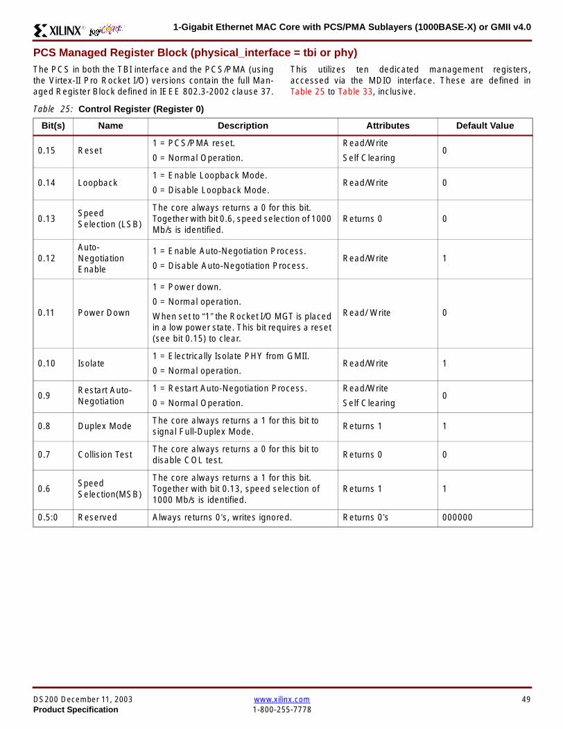
1-Gigabit Ethernet MAC Core with PCSPMA Sublayers (1000BASE-X) or GMII v40R
PCS Managed Register Block (physical_interface = tbi or phy)The PCS in both the TBI interface and the PCSPMA (usingthe Virtex-II Pro Rocket IO) versions contain the full Man-aged Register Block defined in IEEE 8023-2002 clause 37
This utilizes ten dedicated management registersaccessed via the MDIO interface These are defined inTable 25 to Table 33 inclusive
Table 25 Control Register (Register 0)
Bit(s) Name Description Attributes Default Value
015 Reset1 = PCSPMA reset
0 = Normal Operation
ReadWrite
Self Clearing0
014 Loopback1 = Enable Loopback Mode
0 = Disable Loopback ModeReadWrite 0
013SpeedSelection (LSB)
The core always returns a 0 for this bitTogether with bit 06 speed selection of 1000Mbs is identified
Returns 0 0
012Auto-NegotiationEnable
1 = Enable Auto-Negotiation Process
0 = Disable Auto-Negotiation ProcessReadWrite 1
011 Power Down
1 = Power down
0 = Normal operation
When set to ldquo1rdquo the Rocket IO MGT is placedin a low power state This bit requires a reset(see bit 015) to clear
Read Write 0
010 Isolate1 = Electrically Isolate PHY from GMII
0 = Normal operationReadWrite 1
09Restart Auto-Negotiation
1 = Restart Auto-Negotiation Process
0 = Normal Operation
ReadWrite
Self Clearing0
08 Duplex ModeThe core always returns a 1 for this bit tosignal Full-Duplex Mode
Returns 1 1
07 Collision TestThe core always returns a 0 for this bit todisable COL test
Returns 0 0
06SpeedSelection(MSB)
The core always returns a 1 for this bitTogether with bit 013 speed selection of1000 Mbs is identified
Returns 1 1
050 Reserved Always returns 0rsquos writes ignored Returns 0rsquos 000000
DS200 December 11 2003 wwwxilinxcom 49Product Specification 1-800-255-7778
1-Gigabit Ethernet MAC Core with PCSPMA Sublayers (1000BASE-X) or GMII v40 R
Table 26 Status Register (Register 1)
Bit(s) Name Description Attributes Default Value
115 100BASE-T4The core always returns a 0 for this bitbecause 100BASE-T4 is not supported
Returns 0 0
114100BASE-XFullDuplex
The core always returns a 0 for this bitbecause 100BASE-X Full Duplex is notsupported
Returns 0 0
113100BASE-XHalf Duplex
The core always returns a 0 for this bitbecause 100BASE-X Half Duplex is notsupported
Returns 0 0
11210 Mbs FullDuplex
The core always returns a 0 for this bitbecause 10 Mbs Full Duplex is notsupported
Returns 0 0
11110 Mbs HalfDuplex
The core always returns a 0 for this bitbecause 10 Mbs Half Duplex is notsupported
Returns 0 0
110100BASE-T2Full Duplex
The core always returns a 0 for this bitbecause 100BASE-T2 Full Duplex is notsupported
Returns 0 0
19100BASE-T2Half Duplex
The core always returns a 0 for this bitbecause 100BASE-T2 Half Duplex is notsupported
Returns 0 0
18ExtendedStatus
The core always returns a 1 for this bit toindicate the presence of the ExtendedRegister (Register 15)
Returns 1 1
17 Reserved Always return 0 writes ignored Returns 0 0
16MF PreambleSuppression
The core always returns a 1 for this bit toindicate that Management Frame PreambleSuppression is supported
Returns 1 1
15Auto-NegotiationComplete
1 = Auto-Negotiation process completed
0 = Auto-Negotiation process not completedRead Only 0
14 Remote Fault1 = Remote fault condition detected
0 = No remote fault condition detected
Read Only
Self Clearing on read0
13Auto-NegotiationAbility
The core always returns a 1 for this bit toindicate that the PHY is capable ofAuto-Negotiation
Returns 1 1
12 Link Status1 = Link is up
0 = Link is down
Read Only
Self Clearing on read0
11 Jabber DetectThe core always returns a 0 for this bitbecause Jabber Detect is not supported
Returns 0 0
10ExtendedCapability
The core always returns a 0 for this bitbecause no extended register set issupported
Returns 0 0
50 wwwxilinxcom DS200 December 11 20031-800-255-7778 Product Specification
1-Gigabit Ethernet MAC Core with PCSPMA Sublayers (1000BASE-X) or GMII v40R
Table 27 PHY Identifier (Registers 2 and 3)
Bit(s) Name Description Attributes Default Value
2150OrganizationallyUniqueIdentifier
Always returns 0s Returns 0s 0000000000000000
31510OrganizationallyUniqueIdentifier
Always returns 0s Returns 0s 000000
394Manufacturerrsquosmodel number
Always returns 0s Returns 0s 000000
330RevisionNumber
Always returns 0s Returns 0s 0000
Table 28 Auto-Negotiation Advertisement Register (Register 4)
Bit(s) Name Description Attributes Default Value
415 Next Page1 = Next Page functionality is advertised
0 = Next Page functionality is not advertisedReadWrite 0
414 Reserved Always returns 0 writes ignored Returns 0 0
41312 Remote Fault
00 = No Error
01 = Offline
10 = Link Failure
11 = Auto-Negotiation Error
ReadWrite
Self clearing to 00afterAuto-Negotiation
00
4119 Reserved Always return 0 writes ignored Returns 0 0
487 Pause
00 = No PAUSE
01 = Asymmetric PAUSE towards linkpartner
10 = Symmetic PAUSE
11 = Both Symmetric PAUSE andAsymmetric PAUSE towards link partner
ReadWrite 11
46 Half DuplexThe core always returns a 0 for this bitbecause Half Duplex Mode is not supported
Returns 0 0
45 Full Duplex1 = Full Duplex Mode is advertised
0 = Full Duplex Mode is not advertisedReadWrite 1
440 Reserved Always returns 0s writes ignored Returns 0s 00000
DS200 December 11 2003 wwwxilinxcom 51Product Specification 1-800-255-7778
1-Gigabit Ethernet MAC Core with PCSPMA Sublayers (1000BASE-X) or GMII v40 R
Table 29 Auto-Negotiation Link Partner Ability Base Register (Register 5)
Bit(s) Name Description Attributes Default Value
515 Next Page1 = Next Page functionality is supported
0 = Next Page functionality is not supportedRead Only 0
514 AcknowledgeUsed by Auto-Negotiation function toindicate reception of a link partnerrsquos base ornext page
Read Only 0
51312 Remote Fault
00 = No Error
01 = Offline
10 = Link Failure
11 = Auto-Negotiation Error
Read Only 00
5119 Reserved Always returns 0s Returns 0s 000
587 Pause
00 = No PAUSE
01 = Asymmetric PAUSE supported
10 = Symmetic PAUSE supported
11 = Both Symmetric PAUSE andAsymmetric PAUSE supported
Read Only 00
56 Half Duplex1 = Half Duplex Mode is supported
0 = Half Duplex Mode is not supportedRead Only 0
55 Full Duplex1 = Full Duplex Mode is supported
0 = Full Duplex Mode is not supportedRead Only 0
540 Reserved Always returns 0s Returns 0s 00000
Table 30 Auto-Negotiation Expansion Register (Register 6)
Bit(s) Name Description Attributes Default Value
6153 Reserved Always returns 0s Returns 0s 0000000000000
62 Next Page AbleThe core always returns a 1 for this bitbecause the device is Next Page Able
Returns 1 1
61 Page Received1 = A new page has been received
0 = A new page has not been received
Read Only
Self Clearing on read0
60 Reserved Always returns 0s Returns 0s 0000000
52 wwwxilinxcom DS200 December 11 20031-800-255-7778 Product Specification
1-Gigabit Ethernet MAC Core with PCSPMA Sublayers (1000BASE-X) or GMII v40R
Table 31 Auto-Negotiation Next Page Transmit Register (Register 7)
Bit(s) Name Description Attributes Default Value
715 Next Page1 = Additional Next Page(s) will follow
0 = Last pageReadWrite 0
714 Reserved Always returns 0 Returns 0 0
713 Message Page1 = Message Page
0 = Unformatted PageReadWrite 1
712 Acknowledge 21 = Will comply with message
0 = Cannot comply with messageReadWrite 0
711 ToggleValue will toggle between subsequent NextPages
Read Only 0
7100Message UnformattedCode Field
Message Code Field or Unformatted PageEncoding as dictated by 713
ReadWrite00000000001
(Null Message Code)
Table 32 Auto-Negotiation Next Page Receive Register (Register 8)
Bit(s) Name Description Attributes Default Value
815 Next Page1 = Additional Next Page(s) follows
0 = Last pageRead Only 0
814 AcknowledgeUsed by Auto-Negotiation function toindicate reception of a link partnerrsquos base ornext page
Read Only 0
813 Message Page1 = Message Page
0 = Unformatted PageRead Only 0
812 Acknowledge 21 = Will comply with message
0 = Cannot comply with messageRead Only 0
811 ToggleValue toggles between subsequent andNext Pages
Read Only 0
8100Message UnformattedCode Field
Message Code Field or Unformatted PageEncoding as dictated by 813
Read Only 00000000000
DS200 December 11 2003 wwwxilinxcom 53Product Specification 1-800-255-7778
1-Gigabit Ethernet MAC Core with PCSPMA Sublayers (1000BASE-X) or GMII v40 R
)
Referencesbull IEEE 8023-2002
bull Virtex-E User Guide
bull Spartan-II E User Guide
bull Virtex-II User Guide
bull Virtex-II Pro User Guide
Related InformationXilinx products are not intended for use in life support appli-ances devices or systems Use of a Xilinx product in suchapplications without the written consent of the appropriateXilinx officer is prohibited
Ordering InformationThis Xilinx LogiCORE module is provided under theSignOnce IP Site License A free evaluation version of themodule is available
Once purchased the core may be downloaded from the Xil-inx IP Center for use with the Xilinx CORE Generator Sys-temtrade v61i SP3 and later The Xilinx CORE GeneratorSystem tool is bundled with all Alliance Series Softwarepackages at no additional charge
Please contact your local Xilinx sales representative or visitthe Xilinx Silicon Xpresso Cafe for pricing and availability onXilinx LogiCORE modules and software Information onadditional Xilinx LogiCORE modules is available on the Xil-inx IP Center
Revision HistoryThe following table shows the revision history for this document
Table 33 Extended Status Register (Register 15)
Bit(s) Name Description Attributes Default Value
15151000BASE-XFull Duplex
The core always returns a 1 for this bitbecause 1000BASE-X Full Duplex issupported
Returns 1 1
15141000BASE-XHalf Duplex
The core always returns a 0 for this bitbecause 1000BASE-X Half Duplex is notsupported
Returns 0 0
15131000BASE-TFull Duplex
The core always returns a 0 for this bitbecause 1000BASE-T Full Duplex is notsupported
Returns 0 0
15121000BASE-THalf Duplex
The core always returns a 0 for this bitbecause 1000BASE-T Half Duplex is notsupported
Returns 0 0
15110 Reserved Always returns 0s Returns 0s 000000000000
Date Version Revision
032803 11 Revision History added to document
043003 20 Revised to v30 standards
121103 30 Updated to v40 release
54 wwwxilinxcom DS200 December 11 20031-800-255-7778 Product Specification
- 1-Gigabit Ethernet MAC Core with PCSPMA Sublayers (1000BASE-X) or GMII v40
-
- Features
- MAC Overview
- Xilinx CORE Generator
- GUI Interface
- Parameter Values in the XCO File
- Output Generation
- Device Utilization
- Interface Description
- Interface Signals for MAC with physical_interface=gmii and management_interface=true
- Interface Signals for MAC with physical_interface=gmii and management_interface=false
- Interface Signals for MAC with physical_interface=tbi and management_interface=true
- Interface Signals for MAC with physical_interface=tbi and management_interface=false
- Interface Signals for MAC with physical_interface=phy and management_interface=true
- Interface Signals for MAC with physical_interface=phy and management_interface=false
- Client Side Interface Signal Definition
- Physical Interface Signal Definition
- Functional Description
- Client Interface
- Transmitter
- Receiver
- Flow Control
- Optional Management Interface (management_interface=true)
- Optional Configuration Vector (management_interface = false)
- Optional GMII (physical_interface=gmii)
- Optional PCS with Ten-Bit Interface (TBI) for 1000BASE-X (physical_interface=tbi)
- Optional PCS and PMA Sublayers for 1000BASE-X (physical_interface=phy)
- PCS Managed Register Block (physical_interface = tbi or phy)
- References
- Related Information
- Ordering Information
- Revision History
-

1-Gigabit Ethernet MAC Core with PCSPMA Sublayers (1000BASE-X) or GMII v40 R
Table 26 Status Register (Register 1)
Bit(s) Name Description Attributes Default Value
115 100BASE-T4The core always returns a 0 for this bitbecause 100BASE-T4 is not supported
Returns 0 0
114100BASE-XFullDuplex
The core always returns a 0 for this bitbecause 100BASE-X Full Duplex is notsupported
Returns 0 0
113100BASE-XHalf Duplex
The core always returns a 0 for this bitbecause 100BASE-X Half Duplex is notsupported
Returns 0 0
11210 Mbs FullDuplex
The core always returns a 0 for this bitbecause 10 Mbs Full Duplex is notsupported
Returns 0 0
11110 Mbs HalfDuplex
The core always returns a 0 for this bitbecause 10 Mbs Half Duplex is notsupported
Returns 0 0
110100BASE-T2Full Duplex
The core always returns a 0 for this bitbecause 100BASE-T2 Full Duplex is notsupported
Returns 0 0
19100BASE-T2Half Duplex
The core always returns a 0 for this bitbecause 100BASE-T2 Half Duplex is notsupported
Returns 0 0
18ExtendedStatus
The core always returns a 1 for this bit toindicate the presence of the ExtendedRegister (Register 15)
Returns 1 1
17 Reserved Always return 0 writes ignored Returns 0 0
16MF PreambleSuppression
The core always returns a 1 for this bit toindicate that Management Frame PreambleSuppression is supported
Returns 1 1
15Auto-NegotiationComplete
1 = Auto-Negotiation process completed
0 = Auto-Negotiation process not completedRead Only 0
14 Remote Fault1 = Remote fault condition detected
0 = No remote fault condition detected
Read Only
Self Clearing on read0
13Auto-NegotiationAbility
The core always returns a 1 for this bit toindicate that the PHY is capable ofAuto-Negotiation
Returns 1 1
12 Link Status1 = Link is up
0 = Link is down
Read Only
Self Clearing on read0
11 Jabber DetectThe core always returns a 0 for this bitbecause Jabber Detect is not supported
Returns 0 0
10ExtendedCapability
The core always returns a 0 for this bitbecause no extended register set issupported
Returns 0 0
50 wwwxilinxcom DS200 December 11 20031-800-255-7778 Product Specification
1-Gigabit Ethernet MAC Core with PCSPMA Sublayers (1000BASE-X) or GMII v40R
Table 27 PHY Identifier (Registers 2 and 3)
Bit(s) Name Description Attributes Default Value
2150OrganizationallyUniqueIdentifier
Always returns 0s Returns 0s 0000000000000000
31510OrganizationallyUniqueIdentifier
Always returns 0s Returns 0s 000000
394Manufacturerrsquosmodel number
Always returns 0s Returns 0s 000000
330RevisionNumber
Always returns 0s Returns 0s 0000
Table 28 Auto-Negotiation Advertisement Register (Register 4)
Bit(s) Name Description Attributes Default Value
415 Next Page1 = Next Page functionality is advertised
0 = Next Page functionality is not advertisedReadWrite 0
414 Reserved Always returns 0 writes ignored Returns 0 0
41312 Remote Fault
00 = No Error
01 = Offline
10 = Link Failure
11 = Auto-Negotiation Error
ReadWrite
Self clearing to 00afterAuto-Negotiation
00
4119 Reserved Always return 0 writes ignored Returns 0 0
487 Pause
00 = No PAUSE
01 = Asymmetric PAUSE towards linkpartner
10 = Symmetic PAUSE
11 = Both Symmetric PAUSE andAsymmetric PAUSE towards link partner
ReadWrite 11
46 Half DuplexThe core always returns a 0 for this bitbecause Half Duplex Mode is not supported
Returns 0 0
45 Full Duplex1 = Full Duplex Mode is advertised
0 = Full Duplex Mode is not advertisedReadWrite 1
440 Reserved Always returns 0s writes ignored Returns 0s 00000
DS200 December 11 2003 wwwxilinxcom 51Product Specification 1-800-255-7778
1-Gigabit Ethernet MAC Core with PCSPMA Sublayers (1000BASE-X) or GMII v40 R
Table 29 Auto-Negotiation Link Partner Ability Base Register (Register 5)
Bit(s) Name Description Attributes Default Value
515 Next Page1 = Next Page functionality is supported
0 = Next Page functionality is not supportedRead Only 0
514 AcknowledgeUsed by Auto-Negotiation function toindicate reception of a link partnerrsquos base ornext page
Read Only 0
51312 Remote Fault
00 = No Error
01 = Offline
10 = Link Failure
11 = Auto-Negotiation Error
Read Only 00
5119 Reserved Always returns 0s Returns 0s 000
587 Pause
00 = No PAUSE
01 = Asymmetric PAUSE supported
10 = Symmetic PAUSE supported
11 = Both Symmetric PAUSE andAsymmetric PAUSE supported
Read Only 00
56 Half Duplex1 = Half Duplex Mode is supported
0 = Half Duplex Mode is not supportedRead Only 0
55 Full Duplex1 = Full Duplex Mode is supported
0 = Full Duplex Mode is not supportedRead Only 0
540 Reserved Always returns 0s Returns 0s 00000
Table 30 Auto-Negotiation Expansion Register (Register 6)
Bit(s) Name Description Attributes Default Value
6153 Reserved Always returns 0s Returns 0s 0000000000000
62 Next Page AbleThe core always returns a 1 for this bitbecause the device is Next Page Able
Returns 1 1
61 Page Received1 = A new page has been received
0 = A new page has not been received
Read Only
Self Clearing on read0
60 Reserved Always returns 0s Returns 0s 0000000
52 wwwxilinxcom DS200 December 11 20031-800-255-7778 Product Specification
1-Gigabit Ethernet MAC Core with PCSPMA Sublayers (1000BASE-X) or GMII v40R
Table 31 Auto-Negotiation Next Page Transmit Register (Register 7)
Bit(s) Name Description Attributes Default Value
715 Next Page1 = Additional Next Page(s) will follow
0 = Last pageReadWrite 0
714 Reserved Always returns 0 Returns 0 0
713 Message Page1 = Message Page
0 = Unformatted PageReadWrite 1
712 Acknowledge 21 = Will comply with message
0 = Cannot comply with messageReadWrite 0
711 ToggleValue will toggle between subsequent NextPages
Read Only 0
7100Message UnformattedCode Field
Message Code Field or Unformatted PageEncoding as dictated by 713
ReadWrite00000000001
(Null Message Code)
Table 32 Auto-Negotiation Next Page Receive Register (Register 8)
Bit(s) Name Description Attributes Default Value
815 Next Page1 = Additional Next Page(s) follows
0 = Last pageRead Only 0
814 AcknowledgeUsed by Auto-Negotiation function toindicate reception of a link partnerrsquos base ornext page
Read Only 0
813 Message Page1 = Message Page
0 = Unformatted PageRead Only 0
812 Acknowledge 21 = Will comply with message
0 = Cannot comply with messageRead Only 0
811 ToggleValue toggles between subsequent andNext Pages
Read Only 0
8100Message UnformattedCode Field
Message Code Field or Unformatted PageEncoding as dictated by 813
Read Only 00000000000
DS200 December 11 2003 wwwxilinxcom 53Product Specification 1-800-255-7778
1-Gigabit Ethernet MAC Core with PCSPMA Sublayers (1000BASE-X) or GMII v40 R
)
Referencesbull IEEE 8023-2002
bull Virtex-E User Guide
bull Spartan-II E User Guide
bull Virtex-II User Guide
bull Virtex-II Pro User Guide
Related InformationXilinx products are not intended for use in life support appli-ances devices or systems Use of a Xilinx product in suchapplications without the written consent of the appropriateXilinx officer is prohibited
Ordering InformationThis Xilinx LogiCORE module is provided under theSignOnce IP Site License A free evaluation version of themodule is available
Once purchased the core may be downloaded from the Xil-inx IP Center for use with the Xilinx CORE Generator Sys-temtrade v61i SP3 and later The Xilinx CORE GeneratorSystem tool is bundled with all Alliance Series Softwarepackages at no additional charge
Please contact your local Xilinx sales representative or visitthe Xilinx Silicon Xpresso Cafe for pricing and availability onXilinx LogiCORE modules and software Information onadditional Xilinx LogiCORE modules is available on the Xil-inx IP Center
Revision HistoryThe following table shows the revision history for this document
Table 33 Extended Status Register (Register 15)
Bit(s) Name Description Attributes Default Value
15151000BASE-XFull Duplex
The core always returns a 1 for this bitbecause 1000BASE-X Full Duplex issupported
Returns 1 1
15141000BASE-XHalf Duplex
The core always returns a 0 for this bitbecause 1000BASE-X Half Duplex is notsupported
Returns 0 0
15131000BASE-TFull Duplex
The core always returns a 0 for this bitbecause 1000BASE-T Full Duplex is notsupported
Returns 0 0
15121000BASE-THalf Duplex
The core always returns a 0 for this bitbecause 1000BASE-T Half Duplex is notsupported
Returns 0 0
15110 Reserved Always returns 0s Returns 0s 000000000000
Date Version Revision
032803 11 Revision History added to document
043003 20 Revised to v30 standards
121103 30 Updated to v40 release
54 wwwxilinxcom DS200 December 11 20031-800-255-7778 Product Specification
- 1-Gigabit Ethernet MAC Core with PCSPMA Sublayers (1000BASE-X) or GMII v40
-
- Features
- MAC Overview
- Xilinx CORE Generator
- GUI Interface
- Parameter Values in the XCO File
- Output Generation
- Device Utilization
- Interface Description
- Interface Signals for MAC with physical_interface=gmii and management_interface=true
- Interface Signals for MAC with physical_interface=gmii and management_interface=false
- Interface Signals for MAC with physical_interface=tbi and management_interface=true
- Interface Signals for MAC with physical_interface=tbi and management_interface=false
- Interface Signals for MAC with physical_interface=phy and management_interface=true
- Interface Signals for MAC with physical_interface=phy and management_interface=false
- Client Side Interface Signal Definition
- Physical Interface Signal Definition
- Functional Description
- Client Interface
- Transmitter
- Receiver
- Flow Control
- Optional Management Interface (management_interface=true)
- Optional Configuration Vector (management_interface = false)
- Optional GMII (physical_interface=gmii)
- Optional PCS with Ten-Bit Interface (TBI) for 1000BASE-X (physical_interface=tbi)
- Optional PCS and PMA Sublayers for 1000BASE-X (physical_interface=phy)
- PCS Managed Register Block (physical_interface = tbi or phy)
- References
- Related Information
- Ordering Information
- Revision History
-
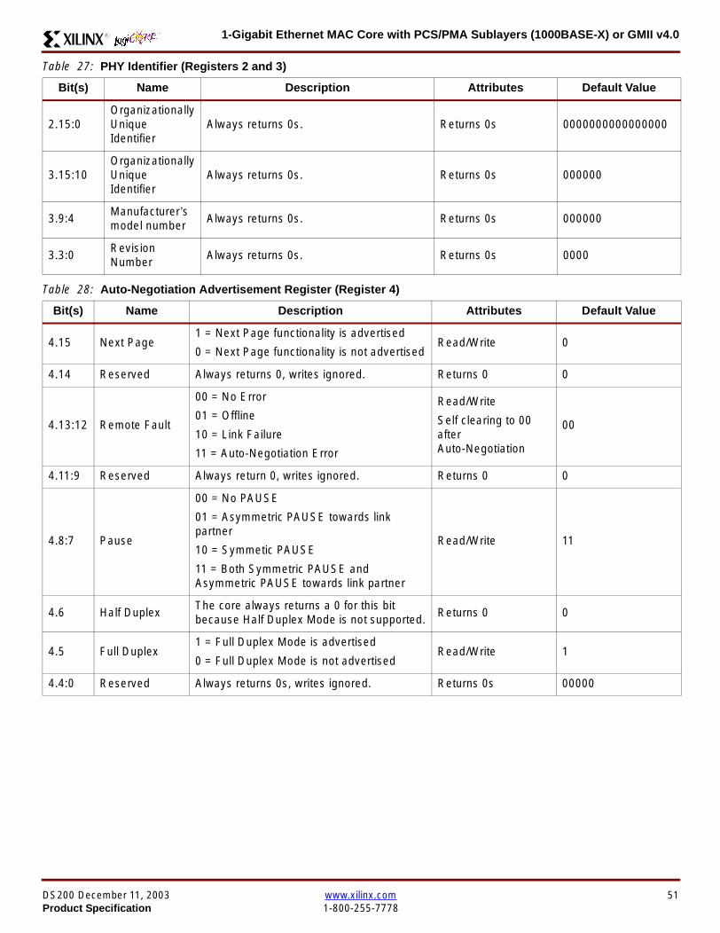
1-Gigabit Ethernet MAC Core with PCSPMA Sublayers (1000BASE-X) or GMII v40R
Table 27 PHY Identifier (Registers 2 and 3)
Bit(s) Name Description Attributes Default Value
2150OrganizationallyUniqueIdentifier
Always returns 0s Returns 0s 0000000000000000
31510OrganizationallyUniqueIdentifier
Always returns 0s Returns 0s 000000
394Manufacturerrsquosmodel number
Always returns 0s Returns 0s 000000
330RevisionNumber
Always returns 0s Returns 0s 0000
Table 28 Auto-Negotiation Advertisement Register (Register 4)
Bit(s) Name Description Attributes Default Value
415 Next Page1 = Next Page functionality is advertised
0 = Next Page functionality is not advertisedReadWrite 0
414 Reserved Always returns 0 writes ignored Returns 0 0
41312 Remote Fault
00 = No Error
01 = Offline
10 = Link Failure
11 = Auto-Negotiation Error
ReadWrite
Self clearing to 00afterAuto-Negotiation
00
4119 Reserved Always return 0 writes ignored Returns 0 0
487 Pause
00 = No PAUSE
01 = Asymmetric PAUSE towards linkpartner
10 = Symmetic PAUSE
11 = Both Symmetric PAUSE andAsymmetric PAUSE towards link partner
ReadWrite 11
46 Half DuplexThe core always returns a 0 for this bitbecause Half Duplex Mode is not supported
Returns 0 0
45 Full Duplex1 = Full Duplex Mode is advertised
0 = Full Duplex Mode is not advertisedReadWrite 1
440 Reserved Always returns 0s writes ignored Returns 0s 00000
DS200 December 11 2003 wwwxilinxcom 51Product Specification 1-800-255-7778
1-Gigabit Ethernet MAC Core with PCSPMA Sublayers (1000BASE-X) or GMII v40 R
Table 29 Auto-Negotiation Link Partner Ability Base Register (Register 5)
Bit(s) Name Description Attributes Default Value
515 Next Page1 = Next Page functionality is supported
0 = Next Page functionality is not supportedRead Only 0
514 AcknowledgeUsed by Auto-Negotiation function toindicate reception of a link partnerrsquos base ornext page
Read Only 0
51312 Remote Fault
00 = No Error
01 = Offline
10 = Link Failure
11 = Auto-Negotiation Error
Read Only 00
5119 Reserved Always returns 0s Returns 0s 000
587 Pause
00 = No PAUSE
01 = Asymmetric PAUSE supported
10 = Symmetic PAUSE supported
11 = Both Symmetric PAUSE andAsymmetric PAUSE supported
Read Only 00
56 Half Duplex1 = Half Duplex Mode is supported
0 = Half Duplex Mode is not supportedRead Only 0
55 Full Duplex1 = Full Duplex Mode is supported
0 = Full Duplex Mode is not supportedRead Only 0
540 Reserved Always returns 0s Returns 0s 00000
Table 30 Auto-Negotiation Expansion Register (Register 6)
Bit(s) Name Description Attributes Default Value
6153 Reserved Always returns 0s Returns 0s 0000000000000
62 Next Page AbleThe core always returns a 1 for this bitbecause the device is Next Page Able
Returns 1 1
61 Page Received1 = A new page has been received
0 = A new page has not been received
Read Only
Self Clearing on read0
60 Reserved Always returns 0s Returns 0s 0000000
52 wwwxilinxcom DS200 December 11 20031-800-255-7778 Product Specification
1-Gigabit Ethernet MAC Core with PCSPMA Sublayers (1000BASE-X) or GMII v40R
Table 31 Auto-Negotiation Next Page Transmit Register (Register 7)
Bit(s) Name Description Attributes Default Value
715 Next Page1 = Additional Next Page(s) will follow
0 = Last pageReadWrite 0
714 Reserved Always returns 0 Returns 0 0
713 Message Page1 = Message Page
0 = Unformatted PageReadWrite 1
712 Acknowledge 21 = Will comply with message
0 = Cannot comply with messageReadWrite 0
711 ToggleValue will toggle between subsequent NextPages
Read Only 0
7100Message UnformattedCode Field
Message Code Field or Unformatted PageEncoding as dictated by 713
ReadWrite00000000001
(Null Message Code)
Table 32 Auto-Negotiation Next Page Receive Register (Register 8)
Bit(s) Name Description Attributes Default Value
815 Next Page1 = Additional Next Page(s) follows
0 = Last pageRead Only 0
814 AcknowledgeUsed by Auto-Negotiation function toindicate reception of a link partnerrsquos base ornext page
Read Only 0
813 Message Page1 = Message Page
0 = Unformatted PageRead Only 0
812 Acknowledge 21 = Will comply with message
0 = Cannot comply with messageRead Only 0
811 ToggleValue toggles between subsequent andNext Pages
Read Only 0
8100Message UnformattedCode Field
Message Code Field or Unformatted PageEncoding as dictated by 813
Read Only 00000000000
DS200 December 11 2003 wwwxilinxcom 53Product Specification 1-800-255-7778
1-Gigabit Ethernet MAC Core with PCSPMA Sublayers (1000BASE-X) or GMII v40 R
)
Referencesbull IEEE 8023-2002
bull Virtex-E User Guide
bull Spartan-II E User Guide
bull Virtex-II User Guide
bull Virtex-II Pro User Guide
Related InformationXilinx products are not intended for use in life support appli-ances devices or systems Use of a Xilinx product in suchapplications without the written consent of the appropriateXilinx officer is prohibited
Ordering InformationThis Xilinx LogiCORE module is provided under theSignOnce IP Site License A free evaluation version of themodule is available
Once purchased the core may be downloaded from the Xil-inx IP Center for use with the Xilinx CORE Generator Sys-temtrade v61i SP3 and later The Xilinx CORE GeneratorSystem tool is bundled with all Alliance Series Softwarepackages at no additional charge
Please contact your local Xilinx sales representative or visitthe Xilinx Silicon Xpresso Cafe for pricing and availability onXilinx LogiCORE modules and software Information onadditional Xilinx LogiCORE modules is available on the Xil-inx IP Center
Revision HistoryThe following table shows the revision history for this document
Table 33 Extended Status Register (Register 15)
Bit(s) Name Description Attributes Default Value
15151000BASE-XFull Duplex
The core always returns a 1 for this bitbecause 1000BASE-X Full Duplex issupported
Returns 1 1
15141000BASE-XHalf Duplex
The core always returns a 0 for this bitbecause 1000BASE-X Half Duplex is notsupported
Returns 0 0
15131000BASE-TFull Duplex
The core always returns a 0 for this bitbecause 1000BASE-T Full Duplex is notsupported
Returns 0 0
15121000BASE-THalf Duplex
The core always returns a 0 for this bitbecause 1000BASE-T Half Duplex is notsupported
Returns 0 0
15110 Reserved Always returns 0s Returns 0s 000000000000
Date Version Revision
032803 11 Revision History added to document
043003 20 Revised to v30 standards
121103 30 Updated to v40 release
54 wwwxilinxcom DS200 December 11 20031-800-255-7778 Product Specification
- 1-Gigabit Ethernet MAC Core with PCSPMA Sublayers (1000BASE-X) or GMII v40
-
- Features
- MAC Overview
- Xilinx CORE Generator
- GUI Interface
- Parameter Values in the XCO File
- Output Generation
- Device Utilization
- Interface Description
- Interface Signals for MAC with physical_interface=gmii and management_interface=true
- Interface Signals for MAC with physical_interface=gmii and management_interface=false
- Interface Signals for MAC with physical_interface=tbi and management_interface=true
- Interface Signals for MAC with physical_interface=tbi and management_interface=false
- Interface Signals for MAC with physical_interface=phy and management_interface=true
- Interface Signals for MAC with physical_interface=phy and management_interface=false
- Client Side Interface Signal Definition
- Physical Interface Signal Definition
- Functional Description
- Client Interface
- Transmitter
- Receiver
- Flow Control
- Optional Management Interface (management_interface=true)
- Optional Configuration Vector (management_interface = false)
- Optional GMII (physical_interface=gmii)
- Optional PCS with Ten-Bit Interface (TBI) for 1000BASE-X (physical_interface=tbi)
- Optional PCS and PMA Sublayers for 1000BASE-X (physical_interface=phy)
- PCS Managed Register Block (physical_interface = tbi or phy)
- References
- Related Information
- Ordering Information
- Revision History
-

1-Gigabit Ethernet MAC Core with PCSPMA Sublayers (1000BASE-X) or GMII v40 R
Table 29 Auto-Negotiation Link Partner Ability Base Register (Register 5)
Bit(s) Name Description Attributes Default Value
515 Next Page1 = Next Page functionality is supported
0 = Next Page functionality is not supportedRead Only 0
514 AcknowledgeUsed by Auto-Negotiation function toindicate reception of a link partnerrsquos base ornext page
Read Only 0
51312 Remote Fault
00 = No Error
01 = Offline
10 = Link Failure
11 = Auto-Negotiation Error
Read Only 00
5119 Reserved Always returns 0s Returns 0s 000
587 Pause
00 = No PAUSE
01 = Asymmetric PAUSE supported
10 = Symmetic PAUSE supported
11 = Both Symmetric PAUSE andAsymmetric PAUSE supported
Read Only 00
56 Half Duplex1 = Half Duplex Mode is supported
0 = Half Duplex Mode is not supportedRead Only 0
55 Full Duplex1 = Full Duplex Mode is supported
0 = Full Duplex Mode is not supportedRead Only 0
540 Reserved Always returns 0s Returns 0s 00000
Table 30 Auto-Negotiation Expansion Register (Register 6)
Bit(s) Name Description Attributes Default Value
6153 Reserved Always returns 0s Returns 0s 0000000000000
62 Next Page AbleThe core always returns a 1 for this bitbecause the device is Next Page Able
Returns 1 1
61 Page Received1 = A new page has been received
0 = A new page has not been received
Read Only
Self Clearing on read0
60 Reserved Always returns 0s Returns 0s 0000000
52 wwwxilinxcom DS200 December 11 20031-800-255-7778 Product Specification
1-Gigabit Ethernet MAC Core with PCSPMA Sublayers (1000BASE-X) or GMII v40R
Table 31 Auto-Negotiation Next Page Transmit Register (Register 7)
Bit(s) Name Description Attributes Default Value
715 Next Page1 = Additional Next Page(s) will follow
0 = Last pageReadWrite 0
714 Reserved Always returns 0 Returns 0 0
713 Message Page1 = Message Page
0 = Unformatted PageReadWrite 1
712 Acknowledge 21 = Will comply with message
0 = Cannot comply with messageReadWrite 0
711 ToggleValue will toggle between subsequent NextPages
Read Only 0
7100Message UnformattedCode Field
Message Code Field or Unformatted PageEncoding as dictated by 713
ReadWrite00000000001
(Null Message Code)
Table 32 Auto-Negotiation Next Page Receive Register (Register 8)
Bit(s) Name Description Attributes Default Value
815 Next Page1 = Additional Next Page(s) follows
0 = Last pageRead Only 0
814 AcknowledgeUsed by Auto-Negotiation function toindicate reception of a link partnerrsquos base ornext page
Read Only 0
813 Message Page1 = Message Page
0 = Unformatted PageRead Only 0
812 Acknowledge 21 = Will comply with message
0 = Cannot comply with messageRead Only 0
811 ToggleValue toggles between subsequent andNext Pages
Read Only 0
8100Message UnformattedCode Field
Message Code Field or Unformatted PageEncoding as dictated by 813
Read Only 00000000000
DS200 December 11 2003 wwwxilinxcom 53Product Specification 1-800-255-7778
1-Gigabit Ethernet MAC Core with PCSPMA Sublayers (1000BASE-X) or GMII v40 R
)
Referencesbull IEEE 8023-2002
bull Virtex-E User Guide
bull Spartan-II E User Guide
bull Virtex-II User Guide
bull Virtex-II Pro User Guide
Related InformationXilinx products are not intended for use in life support appli-ances devices or systems Use of a Xilinx product in suchapplications without the written consent of the appropriateXilinx officer is prohibited
Ordering InformationThis Xilinx LogiCORE module is provided under theSignOnce IP Site License A free evaluation version of themodule is available
Once purchased the core may be downloaded from the Xil-inx IP Center for use with the Xilinx CORE Generator Sys-temtrade v61i SP3 and later The Xilinx CORE GeneratorSystem tool is bundled with all Alliance Series Softwarepackages at no additional charge
Please contact your local Xilinx sales representative or visitthe Xilinx Silicon Xpresso Cafe for pricing and availability onXilinx LogiCORE modules and software Information onadditional Xilinx LogiCORE modules is available on the Xil-inx IP Center
Revision HistoryThe following table shows the revision history for this document
Table 33 Extended Status Register (Register 15)
Bit(s) Name Description Attributes Default Value
15151000BASE-XFull Duplex
The core always returns a 1 for this bitbecause 1000BASE-X Full Duplex issupported
Returns 1 1
15141000BASE-XHalf Duplex
The core always returns a 0 for this bitbecause 1000BASE-X Half Duplex is notsupported
Returns 0 0
15131000BASE-TFull Duplex
The core always returns a 0 for this bitbecause 1000BASE-T Full Duplex is notsupported
Returns 0 0
15121000BASE-THalf Duplex
The core always returns a 0 for this bitbecause 1000BASE-T Half Duplex is notsupported
Returns 0 0
15110 Reserved Always returns 0s Returns 0s 000000000000
Date Version Revision
032803 11 Revision History added to document
043003 20 Revised to v30 standards
121103 30 Updated to v40 release
54 wwwxilinxcom DS200 December 11 20031-800-255-7778 Product Specification
- 1-Gigabit Ethernet MAC Core with PCSPMA Sublayers (1000BASE-X) or GMII v40
-
- Features
- MAC Overview
- Xilinx CORE Generator
- GUI Interface
- Parameter Values in the XCO File
- Output Generation
- Device Utilization
- Interface Description
- Interface Signals for MAC with physical_interface=gmii and management_interface=true
- Interface Signals for MAC with physical_interface=gmii and management_interface=false
- Interface Signals for MAC with physical_interface=tbi and management_interface=true
- Interface Signals for MAC with physical_interface=tbi and management_interface=false
- Interface Signals for MAC with physical_interface=phy and management_interface=true
- Interface Signals for MAC with physical_interface=phy and management_interface=false
- Client Side Interface Signal Definition
- Physical Interface Signal Definition
- Functional Description
- Client Interface
- Transmitter
- Receiver
- Flow Control
- Optional Management Interface (management_interface=true)
- Optional Configuration Vector (management_interface = false)
- Optional GMII (physical_interface=gmii)
- Optional PCS with Ten-Bit Interface (TBI) for 1000BASE-X (physical_interface=tbi)
- Optional PCS and PMA Sublayers for 1000BASE-X (physical_interface=phy)
- PCS Managed Register Block (physical_interface = tbi or phy)
- References
- Related Information
- Ordering Information
- Revision History
-
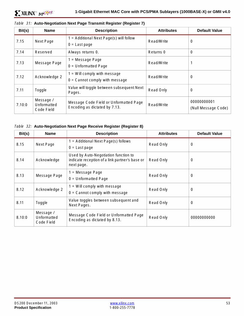
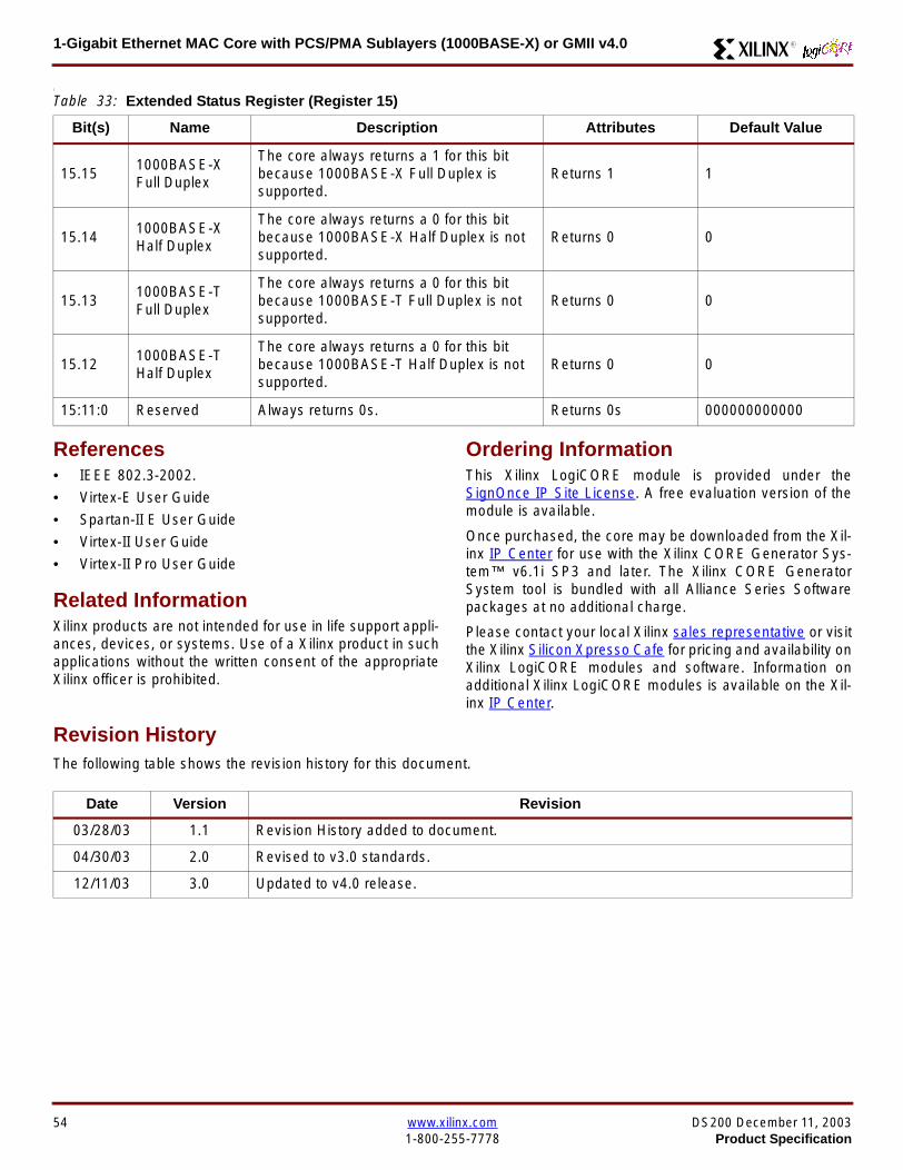