1 engg 1203 tutorial sequential logic (ii) and electrical circuit (i) 22 feb learning objectives ...
TRANSCRIPT
1
ENGG 1203 Tutorial
Sequential Logic (II) and Electrical Circuit (I) 22 Feb Learning Objectives
Design a finite state machine Analysis circuits through circuit laws (Ohm’s Law, KCL
and KVL) News
HW1 (Feb 22, 2013, 11:55pm) Ack.: ISU CprE 281x, HKU ELEC1008, MIT 6.111,
MIT 6.01

2
Quick CheckingNOT always true
Always True
If , then
If , then
32
4 5
RRR R
6 0i
2 3 4 5i i i i
2 6 3i i i
4
1 02 4
Re VR R
6 0i
32
2 4 3 5
RRR R R R

A FSM design for a Vending machine (Revisited) Vending Machine
Collect money, deliver product and change Vending machine may get three inputs
Inputs are nickel (5c), dime (10c), and quarter (25c) Only one coin input at a time Product cost is 40c Does not accept more than 50c Returns 5c or 10c back Exact change appreciated
3

Solution
We are designing a state machine which output depends on both current state and inputs.
Suppose we ask the machine to directly return the coin if it cannot accept an input coin.
Input specification: I1 I2 Represent the coin inserted 00 - no coin (0 cent), 01 – nickel (5 cents), 10 – dime (10 cents),
11 – quarter (25 cents)
Output specification: C1C2P C1C2 represent the coin returned – 00, 01, 10, 11 P indicates whether to deliver product – 0, 1
4
Solution
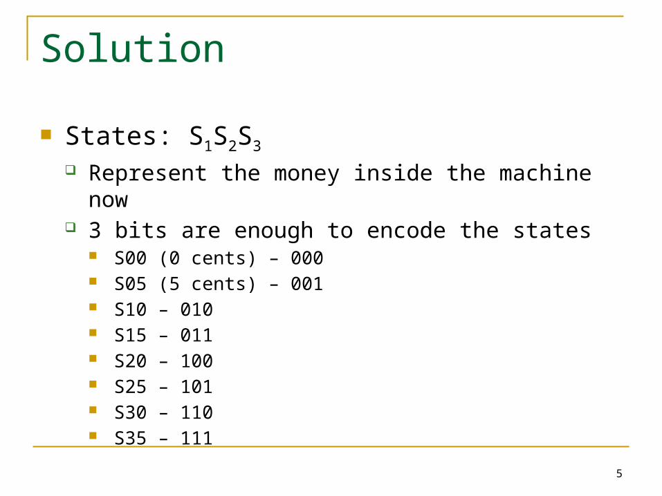
States: S1S2S3 Represent the money inside the machine now 3 bits are enough to encode the states
S00 (0 cents) – 000 S05 (5 cents) – 001 S10 – 010 S15 – 011 S20 – 100 S25 – 101 S30 – 110 S35 – 111
5

Solution
6

Solution
7
S3511/110 S3510/011 S00 01/001 S00
11/11011/00001/00010/000
S35: Currently the machine has 35 cents e.g. 11/110 : If we insert a quarter (11), then the machine
should return one quarter and zero product (110) 35c (35 cents inside the machine now) + 25c (insert 25 cents)
= 35c (35 cents inside the machine in the next state) + 25c (return 25 cents) + 0c (return no product)
Input
Output
Next state
00/000 S35
Solution
8
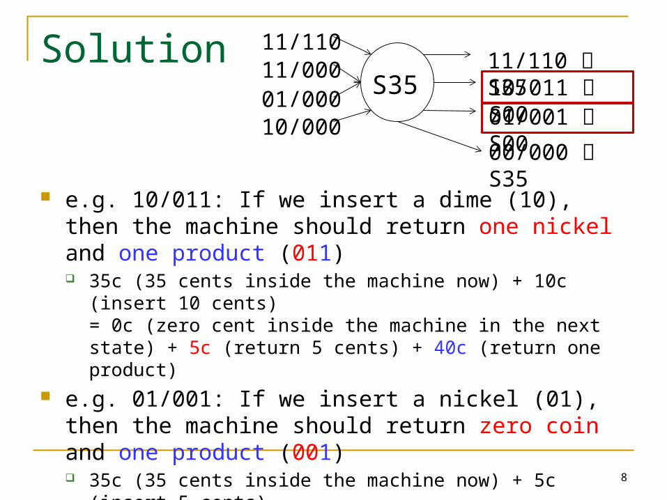
S3511/110 S3510/011 S0001/001 S00
11/11011/00001/00010/000
e.g. 10/011: If we insert a dime (10), then the machine should return one nickel and one product (011) 35c (35 cents inside the machine now) + 10c (insert 10 cents)
= 0c (zero cent inside the machine in the next state) + 5c (return 5 cents) + 40c (return one product)
e.g. 01/001: If we insert a nickel (01), then the machine should return zero coin and one product (001) 35c (35 cents inside the machine now) + 5c (insert 5 cents)
= 0c (zero cent inside the machine in the next state) + 0c (return zero cent) + 40c (return one product)
00/000 S35

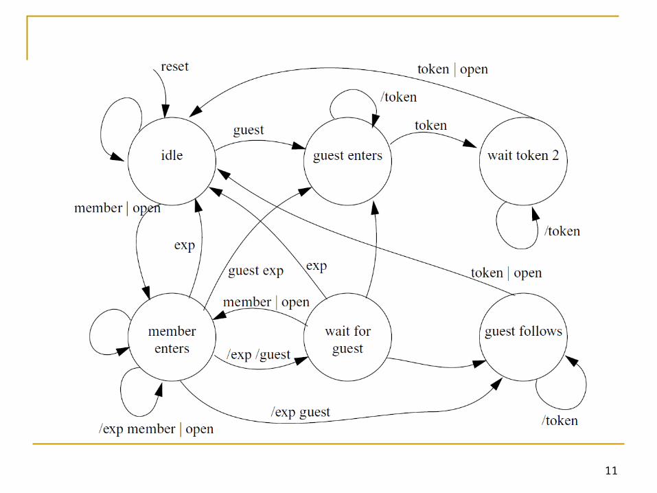
A Parking Ticket FSM
At Back Bay garage, Don and Larry are thinking of using an automated parking ticket machine to control the number of guest cars that a member can bring. The card reader tells the controller whether the car is a member or a guest car. Only one guest car is allowed per member at a discount rate only when s/he follows out the member at the exit (within the allotted time). The second guest must pay the regular parking fees. You have been hired to implement the control system for the machine which is located at the exit.
Using your expertise on FSMs, design a FSM for the control system.
9

Solution
Specifications Signals from the card reader: MEMBER and GUEST Signals from the toll booth: TOKEN (meaning one toke
received), EXP (time for discounted guest payment has expired).
Signal to the gate: OPEN. Fee: Members are free, Guest with a Member is 1
Token, Regular Guest is 2 Tokens.
10
11

Solution
The truth table that corresponds to the FSM The state labels can be mapped to a three bit state
variable. All entries not entered below are illegal.
12

Solution
13

14
Rules Governing Currents and Voltages Rule 1: Currents flow in loops
The same amount of current flows into the bulb (top path) and out of the bulb (bottom path)
Rule 2: Like the flow of water, the flow of electrical current (charged particles) is incompressible Kirchoff’s Current Law (KCL): the sum of the currents into a
node is zero Rule 3: Voltages accumulate in loops
Kirchoff’s Voltage Law (KVL): the sum of the voltages around a closed loop is zero
15
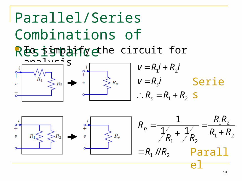
Parallel/Series Combinations of Resistance To simplify the circuit for analysis
1 2
1 2
s
s
v R i R i
v R i
R R R
1 2
1 21 2
1 2
11 1
//
p
R RR
R RR R
R R
Series
Parallel

16
Voltage/Current Divider
1 2
11 1
1 2
22 2
1 2
VI
R R
RV R I V
R R
RV R I V
R R
1 2
1 2 21
1 1 1 2
12
1 2
//
//
V R R I
R R RVI I I
R R R R
RI I
R R
Voltage Divider
Current Divider
17
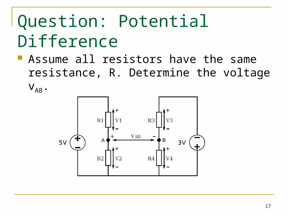
Question: Potential Difference Assume all resistors have the same resistance,
R. Determine the voltage vAB.

18
Solution
Determine VAB
We assign VG=0
2
1 2
4
3 4
5 2.5
3 1.5
A
B
RV V
R R
RV V
R R
2.5 1.5 4AB A BV V V V
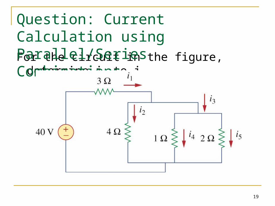
For the circuit in the figure, determine i1 to i5.
19
Question: Current Calculation using Parallel/Series Combinations

20
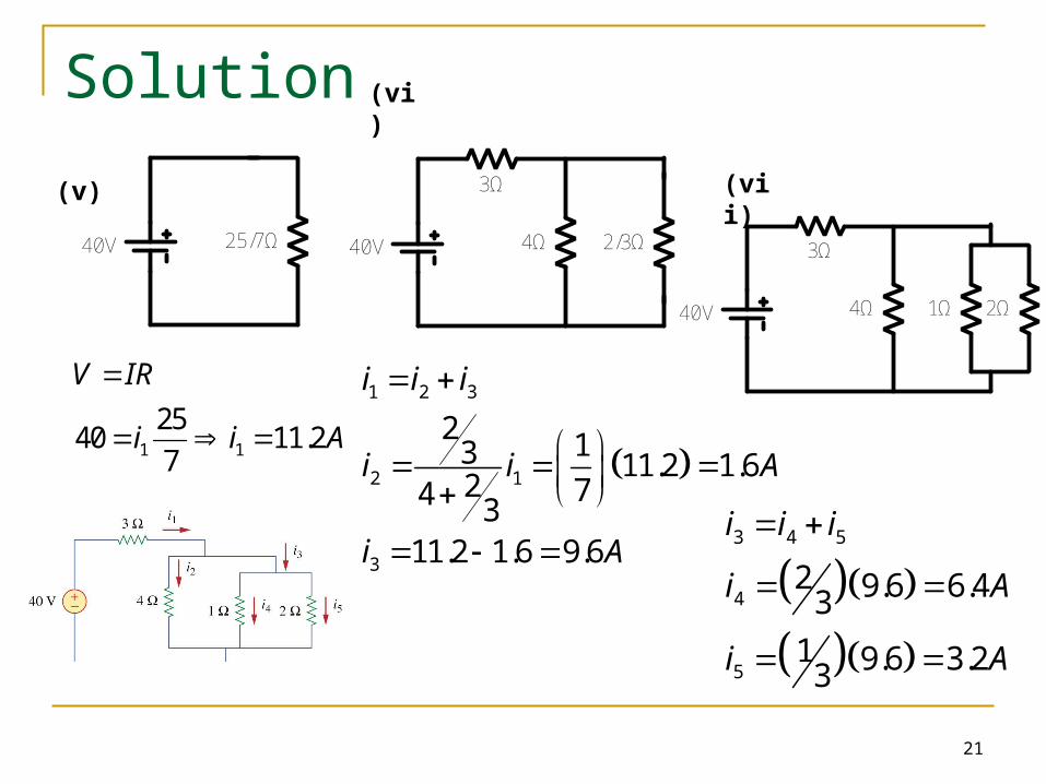
Solution
21 // 2
3
2 44 //
3 7
4 253 //
7 7
40V
3Ω
4Ω 1Ω 2Ω
40V
3Ω
4Ω 2/3Ω
40V
3Ω
4/7Ω
40V 25/7Ω
(i)
(iii)
(ii)
(iv)
We apply: V = IR Series / Parallel Combinations Current Divider
21
Solution
1 1
2540 11.2
7
V IR
i i A
1 2 3
2 1
3
2 13 11.2 1.62 74 3
11.2 1.6 9.6
i i i
i i A
i A
3 4 5
4
5
2 9.6 6.43
1 9.6 3.23
i i i
i A
i A
40V 25/7Ω
(v)
(vi)
(vii)
40V
3Ω
4Ω 2/3Ω
40V
3Ω
4Ω 1Ω 2Ω
22
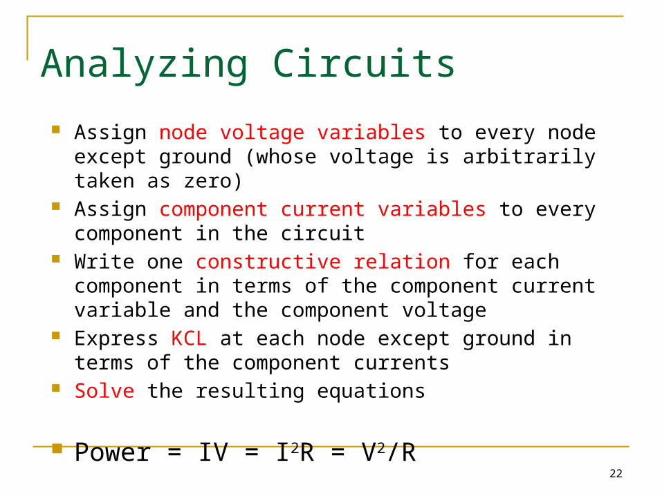
Analyzing Circuits
Assign node voltage variables to every node except ground (whose voltage is arbitrarily taken as zero)
Assign component current variables to every component in the circuit
Write one constructive relation for each component in terms of the component current variable and the component voltage
Express KCL at each node except ground in terms of the component currents
Solve the resulting equations
Power = IV = I2R = V2/R

23
R1 = 80Ω, R2 = 10Ω, R3 = 20Ω,R4 = 90Ω, R5 = 100Ω
Battery: V1 = 12V, V2 = 24V, V3 = 36V
Resistor: I1, I2, …, I5 = ? P1, P2, …, P5 = ?
Question: Circuit Analysis
Step 1, Step 2

24
Solution a
VN = 0
I1: M R5 V1 R1 B
I2: M V3 R3 R2 B
I4: M V2 R4 B
Step 1, Step 2
25
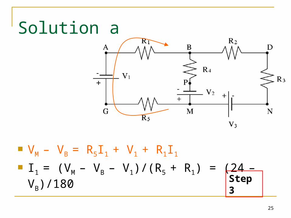
Solution a
VM – VB = R5I1 + V1 + R1I1
I1 = (VM – VB – V1)/(R5 + R1) = (24 – VB)/180Step 3
26
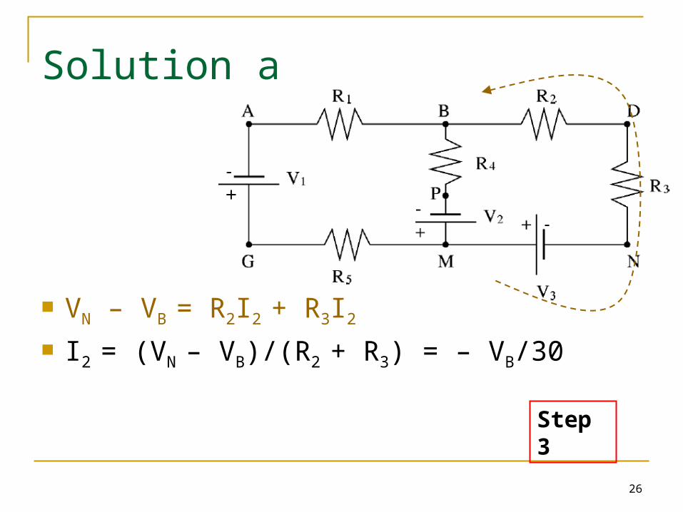
Solution a
VN – VB = R2I2 + R3I2
I2 = (VN – VB)/(R2 + R3) = – VB/30
Step 3
27
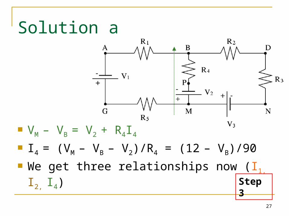
Solution a
VM – VB = V2 + R4I4
I4 = (VM – VB – V2)/R4 = (12 – VB)/90
We get three relationships now (I1, I2, I4)Step 3
28
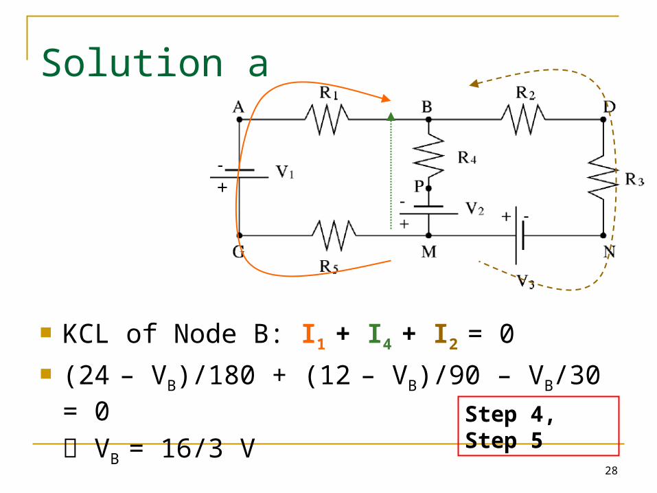
Solution a
KCL of Node B: I1 + I4 + I2 = 0
(24 – VB)/180 + (12 – VB)/90 – VB/30 = 0
VB = 16/3 V Step 4, Step 5
29
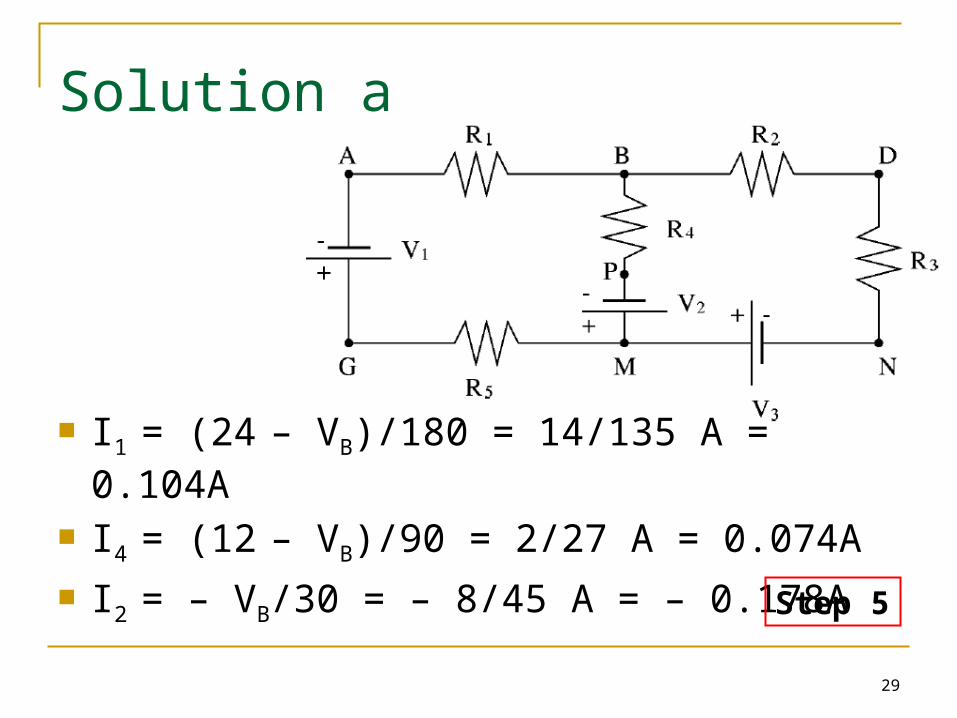
Solution a
I1 = (24 – VB)/180 = 14/135 A = 0.104A
I4 = (12 – VB)/90 = 2/27 A = 0.074A
I2 = – VB/30 = – 8/45 A = – 0.178AStep 5

30
Solution a
P = I2R = P1 = (0.104)2 80 = 0.86528W
P4 = (0.074)2 90 = 0.49284W = VR42 / R
(6.66V, 90Ω)
31
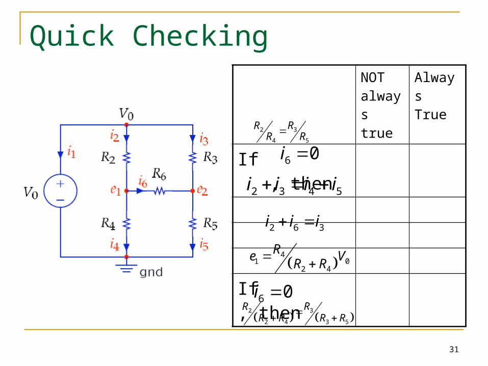
Quick CheckingNOT always true
Always True
If , then
If , then
32
4 5
RRR R
6 0i
2 3 4 5i i i i
2 6 3i i i
4
1 02 4
Re VR R
6 0i
32
2 4 3 5
RRR R R R

32
Quick CheckingNOT always true
Always True
If , then
If , then
32
4 5
RRR R
6 0i
2 3 4 5i i i i
2 6 3i i i
4
1 02 4
Re VR R
6 0i
32
2 4 3 5
RRR R R R
√
√
√
√
√
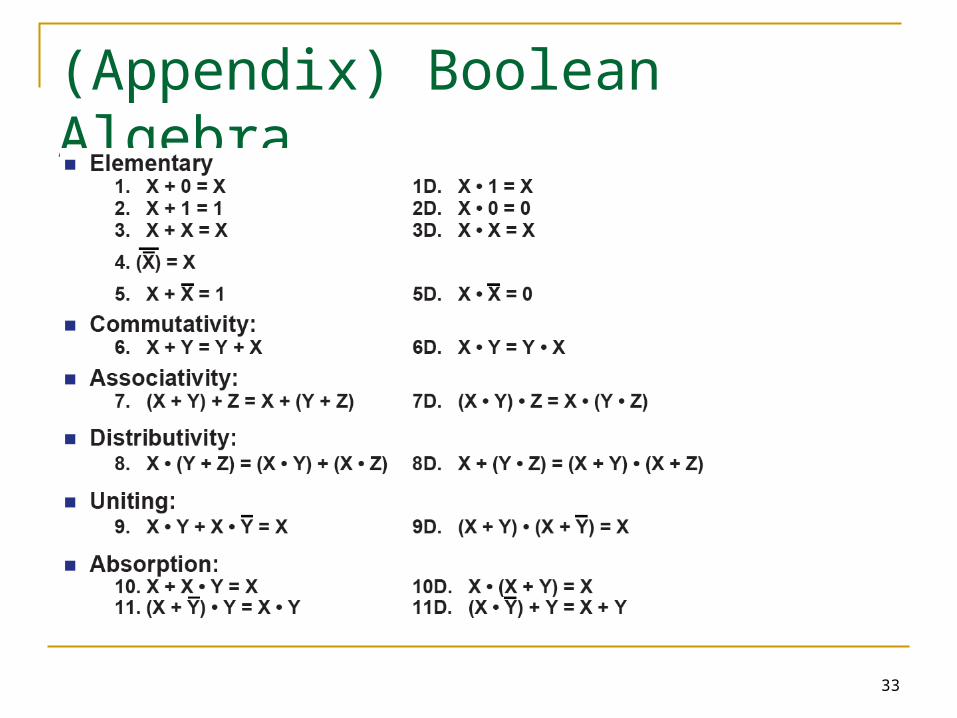
(Appendix) Boolean Algebra
33
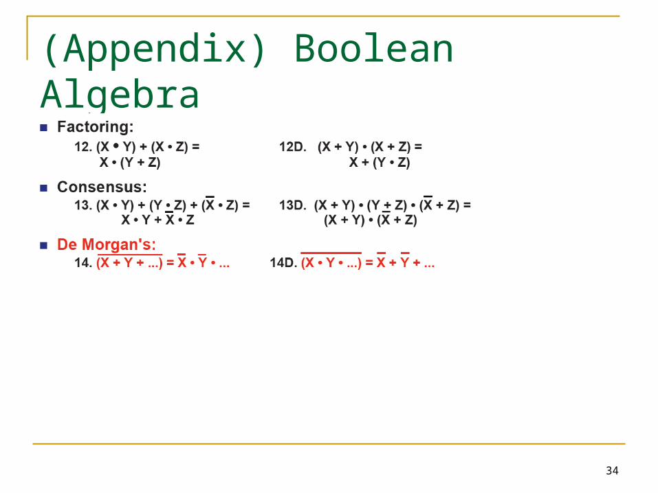
(Appendix) Boolean Algebra
34

35
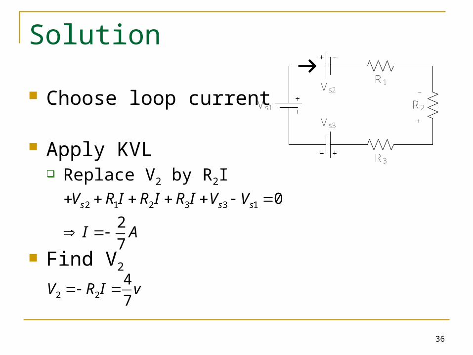
(Appendix) Question: Voltage Calculation Find V2 using single loop analysis
Without simplifying the circuit Simplifying the circuit
1 2 3 1 2 32 , 2 , 2 , 1 , 2 , 4s s sV v V v V v R R R
R1
Vs1
Vs3
Vs2
R3
-R2
+
36
Solution
Choose loop current
Apply KVL Replace V2 by R2I
Find V2
R1
Vs1
Vs3
Vs2
R3
-R2
+
2 1 2 3 3 1 0
2
7
s s sV R I R I R I V V
I A
2 2
4
7V R I v
37
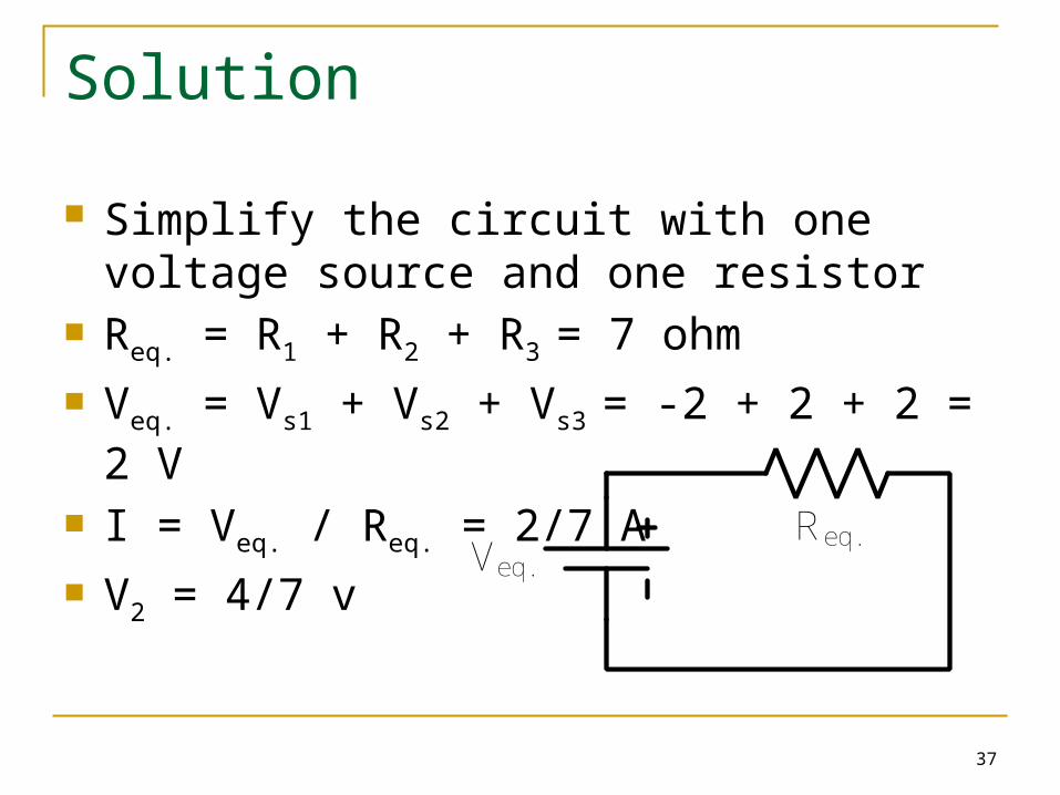
Solution
Simplify the circuit with one voltage source and one resistor
Req. = R1 + R2 + R3 = 7 ohm
Veq. = Vs1 + Vs2 + Vs3 = -2 + 2 + 2 = 2 V
I = Veq. / Req. = 2/7 A
V2 = 4/7 v Veq.
Req.