1 drowsy caches simple techniques for reducing leakage power krisztián flautner nam sung kim steve...
Post on 21-Dec-2015
214 views
TRANSCRIPT

1
Drowsy Caches
Simple Techniques for Reducing Leakage Power
Krisztián Flautner
Nam Sung Kim
Steve Martin
David Blaauw
Trevor Mudge
2
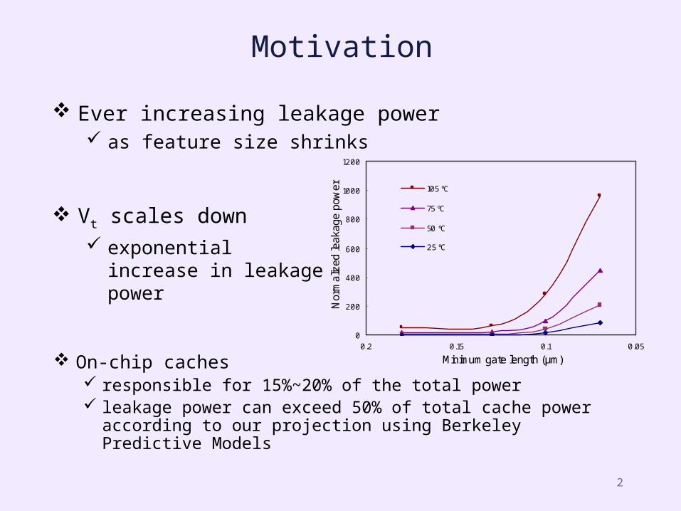
Motivation
0
200
400
600
800
1000
1200
0.050.10.150.2
Minimum gate length (μm)
Nor
mal
ized
leak
age
pow
er 105 ºC
75 ºC
50 ºC
25 ºC
On-chip caches responsible for 15%~20% of the total power leakage power can exceed 50% of total cache power
according to our projection using Berkeley Predictive Models
Ever increasing leakage power as feature size shrinks
Vt scales down exponential increase in
leakage power

3
Processor power trends
• Based on ITRS roadmap and transistor count estimates.• Total power in this projection cannot come true.
0
200
400
600
800
1000
Pentium II Pentium III Pentium 4 One Gen Two Gen Three Gen
Processor Generation
Po
we
r C
on
su
mp
tio
n (
W)
Dynamic Power
Leakage Power

4
0%
10%
20%
30%
40%
50%
crafty vortex bzip vpr mcf parser gcc facerec equake mesa
An observation about data caches
L1 data caches• Working set: fraction of cache lines accessed in a time window.
• Window size = 2000 cycles.
• Only a small fraction of lines are accessed in a window.
Working set of current window
Working set of current + 1, 8, and 32 previous windows

5
The Drowsy Cache approach
• Optimize across circuit-microarchitecture boundary:– Use of the appropriate circuit technique enables simplified
microarchitectural control.
• Requirement: state preservation in low leakage mode.
Instead of being sophisticated about predicting the working set, reduce the penalty for being wrong.
Algorithm:• Periodically put all lines in cache into drowsy mode.• When accessed, wake up the line.
6
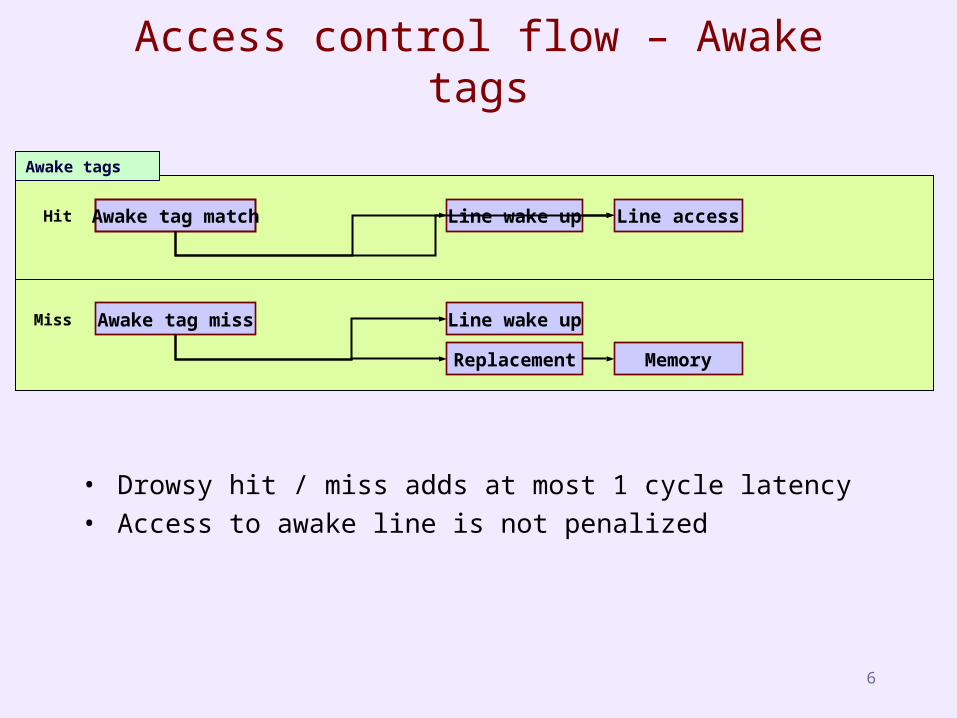
Access control flow – Awake tags
Awake tag match Line wake up Line access
Memory
Awake tag miss
Replacement
Line wake up
Awake tags
Hit
Miss
• Drowsy hit / miss adds at most 1 cycle latency• Access to awake line is not penalized
7
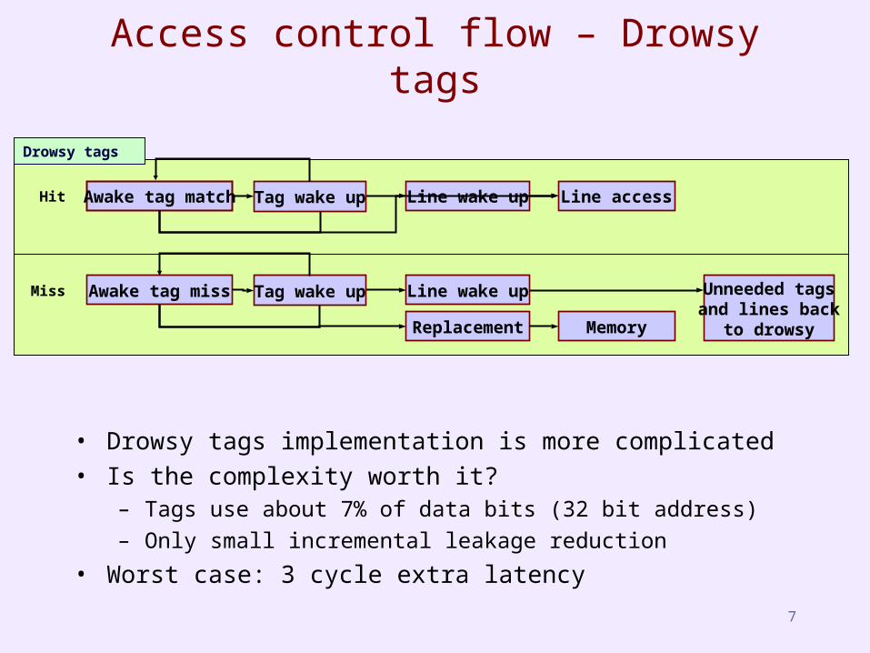
• Drowsy tags implementation is more complicated• Is the complexity worth it?
– Tags use about 7% of data bits (32 bit address)
– Only small incremental leakage reduction
• Worst case: 3 cycle extra latency
Access control flow – Drowsy tags
Awake tag match Line wake up Line access
Memory
Awake tag miss
Replacement
Line wake up
Drowsy tags
Hit
Miss
Tag wake up
Tag wake up Unneeded tagsand lines back
to drowsy
8
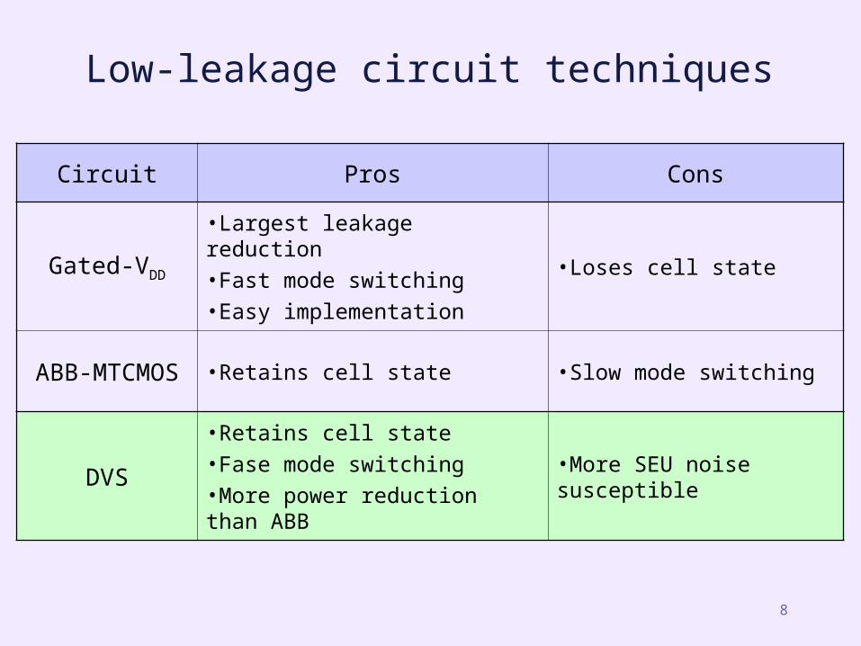
Low-leakage circuit techniques
Circuit Pros Cons
Gated-VDD
•Largest leakage reduction
•Fast mode switching
•Easy implementation
•Loses cell state
ABB-MTCMOS •Retains cell state •Slow mode switching
DVS•Retains cell state
•Fase mode switching
•More power reduction than ABB
•More SEU noise susceptible

9
Drowsy memory using DVS
• Low supply voltage for inactive memory cells– Low voltage reduces leakage current too! – Quadratic reduction in leakage power
leakage path
supply voltage for drowsy mode
supply voltage for normal mode
PP = I = I V V

10
0.2V
0.25V
0.3V
0.35V
85%
90%
95%
100%
76% 78% 80% 82% 84% 86% 88% 90% 92% 94%
Leakage reduction
Per
form
ance
Leakage reduction using DVS
• High-Vt devices for access transistors
reduce leakage power increase access time of cache
Right Trade-off point 91% leakage reduction 6% cycle time increase
Projections for 0.07μm process

11
Drowsy cache line architecture
VDD (1V)
VDDLow (0.3V)
drowsy (set)
drowsy signal
SRAMs
row
de
co
de
r
wo
rd l
ine
dri
ve
rvoltage controller
word line
word line
power line
word line gate
wake up (reset)
drowsy bit
drowsy
drowsy

12
Energy reduction
• Projections for 0.07μm process• High leakage: lines have to be powered up when accessed.• Drowsy circuit
– Without high vt device (in SRAM): 6x leakage reduction, no access delay.– With high vt device: 10x leakage reduction, 6% access time increase.
DynamicDynamic
High leakage
Leakage
Drow sy
0%
20%
40%
60%
80%
100%
Regular Cache Drowsy Cache
Drowsy

13
1 cycle vs. 2 cycle wake up
• Fast wakeup is important – but easy to accomplish !
– Cache access time: 0.57ns (for 0.07μm from CACTI using 0.18μm baseline).
– Speed dependent on voltage controller size: 64 x Leff – 0.28ns (half cycle at 4 GHz), 32 x Leff – 0.42ns, 16 x Leff – 0.77ns.
• Impact of drowsy tags are quite similar to double-cycle wake up.
70%
75%
80%
85%
90%
95%
100%
0.00% 0.20% 0.40% 0.60% 0.80% 1.00% 1.20% 1.40% 1.60% 1.80% 2.00% 2.20%
Run-time increase
Dro
wsy
fra
ctio
n
ammp00 applu00apsi00 art00bzip200 crafty00eon00 equake00facerec00 fma3d00galgel00 gap00gcc00 gzip00lucas00 mcf00mesa00 mgrid00parser00 sixtrack00swim00 twolf00vortex00 vpr00wupwise00
1 cycle vs. 2 cycle wakup
simple policy, awake tags,4000 cycle window
14
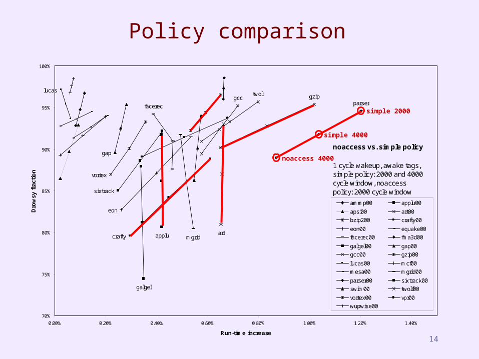
Policy comparison
applu artcrafty
eon
facerec
galgel
gap
gcc gziplucas
mgrid
parser
sixtrack
twolf
vortex
70%
75%
80%
85%
90%
95%
100%
0.00% 0.20% 0.40% 0.60% 0.80% 1.00% 1.20% 1.40%
Run-time increase
Dro
wsy
fra
ctio
n
ammp00 applu00
apsi00 art00
bzip200 crafty00
eon00 equake00
facerec00 fma3d00
galgel00 gap00
gcc00 gzip00
lucas00 mcf00
mesa00 mgrid00
parser00 sixtrack00
swim00 twolf00
vortex00 vpr00
wupwise00
noaccess vs. simple policy
1 cycle wakeup, awake tags,simple policy: 2000 and 4000 cycle window, noaccess policy: 2000 cycle window
simple 2000
simple 4000
noaccess 4000
15
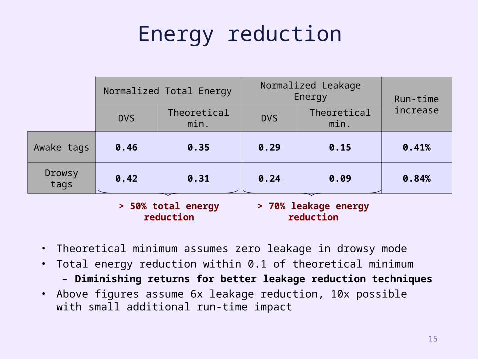
Energy reduction
• Theoretical minimum assumes zero leakage in drowsy mode
• Total energy reduction within 0.1 of theoretical minimum– Diminishing returns for better leakage reduction techniques
• Above figures assume 6x leakage reduction, 10x possible with small additional run-time impact
Normalized Total Energy Normalized Leakage EnergyRun-time increase
DVS Theoretical min. DVS Theoretical min.
Awake tags 0.46 0.35 0.29 0.15 0.41%
Drowsy tags 0.42 0.31 0.24 0.09 0.84%
> 50% total energy reduction > 70% leakage energy reduction
16
Conclusions
• Simple circuit technique– Need high-Vt transistors, low Vdd supply
• Simple architecture– No need to keep counter/predictor state for each line– Periodic global counter asserts drowsy signal– Window size (for periodic drowsy transition) depends on
core: ~4000 cycles has good E-delay trade-off
• Technique also works well on in-order procesors– Memory subsystem is already latency tolerant
• Drowsy circuit is good enough– Diminishing returns on further leakage reduction– Focus is again on dynamic energy