1 /epachagrin.epa.ohio.gov/edoc/images/dswnov20130927/... · non-contact cooling water flows...
TRANSCRIPT

Violation Date Sth1JOI ReportingCode
4/15/2012 001 1 005504/1/2012 001 I 00550
Oil and Grease, TotalOil and Grease, Total
Parameter Limit Type I Limit ValueI ' 'lOConc 3394 163,
300 Conc 11.34 46.6
. 1 /EPAoving forward
Mary Taylor, Lt. GovernorScott J. Nally, Director
Re: Mercer CountyCelina Aluminum Precision TechnologyIndirect Discharge Permit
September 25, 2013
Mr. Steve WebbCelina Aluminum Precision Technology7059 Staeger RoadCelina, Ohio 45822
Dear Mr. Webb:
On September 10, 2013, a pretreatment compliance inspection was conducted at your facUlty. A tour of thefacility was given and you provided answers for our inspection checklist. Our inspection indicated compliancewith the pretreatment rules at this time.
The new piston Line was being installed during the inspection and should be in operation within the next 12months. This line will have one washer at the end of the line that will discharge up to 720 gallons per day ifproduction is running 24 hours. Due to issues with using recycled water in production, the facility has goneback to discharging all of their water. The facility discharges an average of 42,149 gallons per day.
During the inspection, a pH probe issue in the wastewater treatment process was causing solids to bedischarged instead of settling properly. The probe had been replaced and a sample taken showed that thesolids were settling properly.
A review of your monthly reports from January 2012 through June 2013 indicates violations of the terms andconditions of your indirect discharqe permit, The specific instances of noncompliance are below:
A copy of the inspection report is enclosed. If you have any questions, please contact me at 419-373-3019.
Sincerely,
Michelle Mix
o\'4
Division of Surface Water
fjlmEnclosuresPC- Kerry Duncan, Superintendent, Celina WV\/TP
05W, COTracking
Northwest District Office • 347 North Dunbridge Road Bowling Green e OH 43402-9398www.epa.ohio.gov (419) 352-8461 (419) 352-8468 (fax)

Defoamer ,Emulsion
Polymer
Plate Settler
SANDTANK
BYPASS
f
HOLDING 1TANK RJLJ
LC5033
2nd Stage 3rd Stage
pH adjust Floculation
Plant Wastewater
15,000 Gal 15,000 GalEqualization Equalization
Tank I Tank
3000
1st StagePrimary
Coagulation
Filter PressSludge
Thickener -wdiwTha Ho!Sng Tnk7,9t gllrr 7531 gallons
EffluentWeir Box To POTW
Heat Escnangar
Filter Cake to Landfill
rLEGEND
1- Process Flow
S:ComplfancelEHS Group\Environmenffil CompiianceFPA - Water1201 I indirect Discharge Permit Renewal Application 12011 Permit renewal information lProcess Row Diagrams\Copy of IiVINPT flowschematic

CAPT WASTE WATER PROCESS FLOW SUMMARYAVG FLOW MAX. FLOW (C )ontinuous Frequency
DEPT Process Name Process Description Flow Type (GPD) (GPO) OR (B)atch of Discharge
One quench tank for each casting toe (4 lines total). Pistons Regulated 1100 1500 C Dailyare quenched immediately after casting before having the
Piston Casting Quench risers cut off. Quench tanks are closed-loop systems WIfiltration and chilling. Still have drag out. Quench tanks Stilldrained weekly. Regulated 200 200 B Weekly
In-line wash station after machine line #1 used to removePiston Wash MIC 1 Unregulated 2580 1000 C Daily
coolant and shavings.
In-line wash station after machine line #2 used to removePiston Wash MIC 2 Unregulated 630 1000 C Daily
coolant and shavings.
In-line wash station after machine line #3 used to removePiston Wash MIC 3 Unregulated 19000 750 C Daily
coolant and shavings.
In-line wash station after machine line #4 used to removePiston Wash MIC 4 Unregulated 617 2500 C Daily
coolant and shavings.
Piston Heat Treat QuenchOne quench tank. Baskets of pistons are dumped into hot Regulated 4000 3000 C Dailywater in between the 2 furnaces for proper curing.
QC Check TablesQuality check tables that has continuous water overflow.
Piston However, these tables are closed-loop systems. Drained at Unregulated 0 200 B Semi-Annual(Line 1-4)
shutdowns.
CAPT installed a new RU System to supply water to PistonPiston RU System Machining. This system sends approximately 1,500 gallday Dilute 2200 3000 B Daily
to WWPT.
Non-contact cooling water flows through piston casting pins.Normally, closed loop system with chiller and filtration so no Daily
PistonNon-Contact Cooling - discharge to WWTP. Under abnormal circumstances Dilute 0 57600 C (Abnormal-Piston DCM (repair), closed-loop system is by-passed and city water repair only)
used for cooling that is sent to WWTP. Avg frequency1x/ysr for j day -2 weeks.
New parts Casting QuenchAfter casting, parts are quenched in water lank. To clarity Regulated 0 4000 C
Intermittent
(Tech Bldg) and temperature, water flow is continuous overflow. (R&D)
New parts Die Cooling IntermittentNon-contact cooling for die cast machine. Dilute 0 2500 C
(Tech Bldg) (Non-contact) (R&D)
1 of 4stcorflpllSnCelEHS GrooptSrnIronmaaW1 compliwvwlePA - WSlerl2Ol I Indirect Oisclrergo Permit RmrewaiAppflicelionl2Ol PSrWit renewal kifermeliontCAPTW law Process Flow Stenmery 11-1041505811 Rev. 3128/2012

CAPT WASTE WATER PROCESS FLOW SUMMARYAVG FLOW MAX. FLOW (C )ontinuous Frequency
DEPT Process Name Process Description Flow Type (GPO) (GPO) OR (B)atch of Discharge
Non-contact cooling water flows through die channels in C/I-Idies. Normally, closed loop system with chiller and filtration Daily
Non-Contact Cooling - no discharge to WWPT. Under abnormal circumstances Dilute 0 51,840 C (Abnormal -Cylinder -lead CH 0CM(repair), closed-loop could be by-passed and city water used repair only)
for cooling that is sent to WWPT.
Wastewater associated with recharging (demineralizerWater SoftenerCylinder Head (Die Cooling System) backwash) and blowdown (high conductivity) of water Dilute 200 400 B Monthly
softener.
Baskets of cylinder heads and water passage are 'dippedCylinder Head Heat Treat 91 Quench into hot quench tank between the age & solution furnaces Regulated C Daily
(heat treat). 1300 2800
Heat Treat #1 Pumps Water is used to cool' the pump seals. Some contact with Regulated C DailyCylinder Head (Sand Separation) quench lank bath occurs.
Baskets of cylinder heads and water passage are dipped'Cylinder Head Heat Treat #2 Quench into hot quench tank between the age & solution furnaces Regulated C Daily
(heat treat). 3900 2600
Heat Treat #2 Pumps Water is used to 'cool the pump seals. Some contact with Regulated C DailyCylinder Head (Sand Separation) quench tank bath occurs.
In-line parts washer rinse coolant and chips" from cylinder
Cylinder Head FL #1 Parts Washer 3 head units. Selanoid valves added to drain 25 gallons per Unregulated 600 750 C Daily
hour.
In-line parts washer rinse coolant and 'chips" from cylinder
Cylinder Head FL #1 Parts Washer 4 head units. Selanoid valves added to drain 25 gallons per Unregulated 600 750 C Daily
hour.
Cylinder Heads are submerged in tank of water 10 test For 500 1500 C Dailyleaks. Some overflow exist during normal operation to keep Unregulated
Cylinder Head Leak Test #1 water clean. Every few months, the tank is drainedcompletely for maintenance or cleaning. 225 225 13 El-monthly
2 014S:tComp!iecaFEl1S GwptEnvironman(al compiiawelEPA - Walsi12O1 IndirectDistharje Permit Ranawai AppIiC limll2Oil Permilrenawe/in(ormeliOnlc,4PTWWNPFOCeSS rtowSimwey lr-tS-tl$heati Rev. 3/2812012

CAPT WASTE WATER PROCESS FLOW SUMMARYAVG FLOW MAX. FLOW (C )ontinuous Frequency
DEPT Process Name Process Description Flow Type (GPO) (GPO) OR (B)atch of Discharge
Later Passage Wash M/C #1
unregulated 175 175 BIn-line pails washer washes coolant and chips from waterpassages.
C/H, Piston, Air Scrubber Water used in CAPTa wet scrubber system is a closed-loop
W/P. 1/B Clarifier Tank system, However, approximately 100 -200 gallons per day Regulated 100 200 C DailyIs drained off and replenished with clean water.
Process involves using a red penetrant and developer toALL Color Check look for cracks" in the parts. Using a 2-compartment sink, Unregulated 250 500 B Daily
water is run 4 -5 times per shift for 1-2 minutes each time.
CAPT uses one rider-type and one walk-behind floorscrubber. The floor scrubber picks up water, coolant andALL Floor Scrubber Unregulated 50 100 B Dailydust. The wastewater is dumped into CAPT's WWPTsystem.
Lower Block Wash MIC 1 la-tine wash station used to remove coolant and shavings. Unregulated 1250 1500 C Daily
Lower blocks are submerged in tank of water to test for 0 50 C Dailyleaks. Some overflow exist during normal operation to keep UnregulatedLower Block Leak Test (off-line) water clean. Every month, the tank is drained completely formaintenance or cleaning. 225 225 S Monthly
Die Maintenance High pressure wash to clean dies after each die change.Lower Block Unregulated 50 100 B WeeklyWash Each manual wash lakes approximately 1 hour.
Lower Block Non-Contact Cooling - Closed-loop system for die cooling. Blow down will occur if Dilute 200 300 B MonthlyDCM #1 conductivity is too high.
Lower Block Non-Contact Cooling - Closed-loop system for die cooling. Blow down will occur if Dilute 200 300 B MonthlyDCM /12 conductivity is too high.
Water Softener Wastewater associated with recharging (demineralizerLower Block
backwash) and blowdown (high conductivity) of water Dilute 250 500 B Monthly(Die Cooling System) softener.
Die lube (diluted) sprayed onto high-pressure casting dies.Lower Block Die Lube System Spray collected in sump with level control. Pumped Regulated 100 150 8 Daily
intermittently to WWPT. Est volumes include both DCMs.
Heat Treat Quench Baskets of knuckle pails are 'dipped' into hOt quench tankKnuckle Regulated 2500 3000 C DailyTanlc#1 between the age & solution furnaces (heat treat).
Heal Treat Quench Baskets of knuckle parts are "dipped" into hot quench tankKnuckle Regulated 2500 3000 C DailyTank92 between the age & solution furnaces (heat treat).
Knuckle pails are dipped in zyglo fluorescent penetrant for -Knuckle Zyglo Inspection 1 quality inspection process. After 5 min dry, pails are rinsed Unregulated 4320 4320 C Daily
with water which is reused then overflows to WWPT.
3o14S:lcompliancelErtS GrouplEiivwinmnlsI CawpliancelEPA - Watei\201 I indrrcI DiSchIr5e FarmS Renewal Appi(nal(oni20I I Permit reaawalisiformaaorilcAPrW lw/Process Flow Summary I /-/a-/lshaall Rev. 3/28/2012
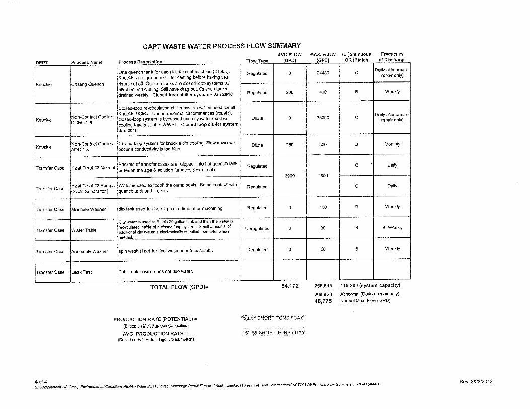
CAPT WASTE WATER PROCESS FLOW SUMMARYAVG FLOW MAX. FLOW (C )ontinuous Frequency
DEPT Process Name Process Description Flow Type (GPD) (GPD) OR (B)atch of Discharge
One quench tank for each tilt die cast machine (8 total). Regulated 0 24480 CDaily (Abnormal -
Knuckles are quenched after casting before having the repair only)
Knuckle Casting Quench risers cut off. Quench tanks are closed-loop systems WIfiltration and chilling. Still have drag Out. Quench tanksdrained weekly. Closed loop chiller system - Jan 2010 Regulated 200 400 13 Weekly
Closed-loop re-circulation chiller system wfil be used for allKnuckle OCMs. Under abnormal circumstances (repair),
Non-Contact Cooling closed-loop system is bypassed and city water used for Dilute 0 76000 CDaily (Abnormal -
KnuckleDCM #1-8
repair only)cooling that is sent to WWPT. Closed loop chiller systemJan 2010
Non-Contact Cooling - Closed-loop system for knuckle die cooling. Slow down willKnuckle Dilute 250 500 B Monthly
ADO 1-8 occur if conductivity is too high.
Transfer Case Heat Treat #2 QuenchBaskets of transfer cases are dtpped' into hot quench tank Regulated C Dailybetween the age & solution furnaces (heat treat).
3900 2600
Heat Treat 92 Pumps Water is used to cool the pump seals. Some contact withTransfer Case Regulated C Daily
(Sand Separation) quench tank bath occurs.
Transfer Case Machine Washer dip tank used to rinse 2 peat a time after machining Regulated 0 100 B Weekly
City water is used to fi]l INs 30 gallon tank and hen the waler in
recirculated inside of a closed-loop system. Small amounts of Unregulated 0 30 B Bi-WeoklyTransfer Case Water Table additional city water is electronically supplied thereafter when
needed.
Transfer Case Assembly Washer spin wash (Ipo) for final wash prior to assembly Regulated 0 50 13 Weekly
Transfer Case Leak Test This Leak Tester does not use water.
TOTAL FLOW (GPO)
PRODUCTION RATE (POTENTIAL)(Based on Melt Furnace Capacilias)
AVG. PRODUCTION RATE(Based on Est, Actual Ingot Consumption)
54,172
20.4 SHORT TONSI DAY
15255 SIQRF TONS / DAY
256,695 ii s,ou isystem capacity)
289,920 Abnormal (During repair only)
46,775 Normal Max. Flow (GPO)
4 of 4S:lCompYencetEHS GrouptEnvironmeolaf CompINnrelEPA - W5ler20 1 JndDSCl Di$CMWge Pamel Renewal Appkce&ont2Ol I Purmitrenewel informaIlonICAPTWW'N ProcSss Flow 5u117m 11 IF I 1-15-1 ISheaII
Rev. 512812012
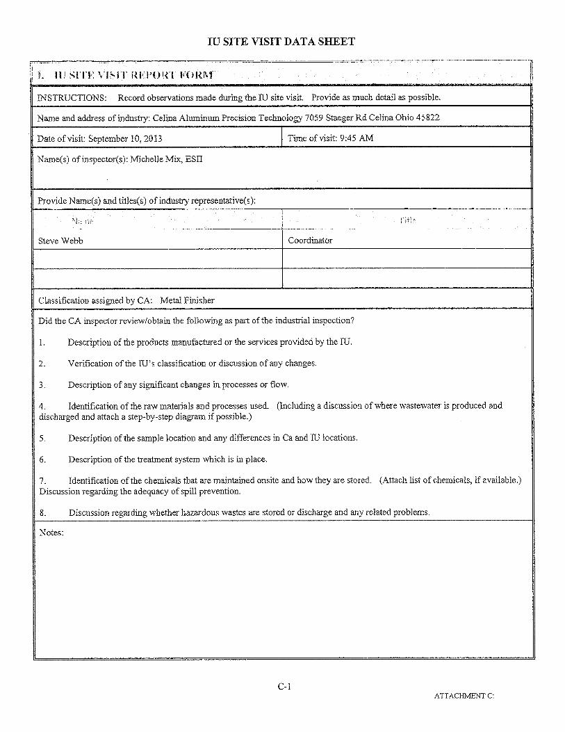
JIJ SITE VISIT DATA SHEET
I. IL T 14TE \ ISI REl'4JT FOR'i
INSTRUCTIONS: Record observations made during the IU site visit. Provide as much detail as possible.
Name and address of industry: Celina Aluminum Precision Technology 7059 Staeger Rd Celina Ohio 45822
Date of visit: September 10, 2013 Time of visit: 9:45 AM
Name(s) of inspector(s): Michelle Mix, ESU
Provide Name(s) and titles(s) of industry representative(s):
N IIfl
Steve Webb Coordinator
Classification assigned by CA: Metal Finisher
Did the CA inspector review/obtain the following as part of the industrial inspection?
I. Description of the products manufactured or the services provided by the [U.
2. Verification of the [U's classification or discussion of any changes.
3. Description of any significant changes in processes or flow.
4. Identification of the raw materials and processes used. (Including a discussion of where wastewater is produced anddischarged and attach a step-by-step diagram if possible.)
5. Description of the sample location and any differences in Ca and [U locations.
6. Description of the treatment system which is in place.
7. Identification of the chemicals that are maintained onsite and how they are stored. (Attach list of chemicals, if available.)Discussion regarding the adequacy of spill prevention.
8. Discussion regarding whether hazardous wastes are stored or discharge and any related problems.
Notes:
C-IATTACHMENT C:

WORKSHEETS
(revised November 1996)
IU SITE VISIT DATA SHEET (Continued)
Hi SITE VISIT REPORT FORM COMPLETED BY: Michelle Mix DATE: September 18, 2013TITLE: ESH
TELEPHONE: 419-373-3019
C-2ATTACH1ENT C:
WORKSHEETS
(revised November 1996)

INDUSTRIAL USER INSPECTION CHECKLIST
Facility: Celina Aluminum Precision Technology
Date of inspection: September 10, 2013
OH Number: OHP000025
IDP Number: 2DP00007
Facility Representative: Steve Webb
lnspector(s):Michelle Mix
CDMPLIAI4CE
Date of Last pretreatment inspection: March 29, 2012
Has the facility been in compliance with its permit limits since the last inspection?If no, explain:
3. Is the facility in compliance with all other requirements?Sampling proceduresReporting (late reporting, failure to report, etc)Compliance schedulesSubmitted BMR and 90 day compliance reportsAny other requirements
If any of the above five answers is no, explain:
Was the facility required to perform any actions as a result of the last inspection?Explain any unresolved actions:
FACILITY OPERATIONAL CHARACTERISTICS
Y
'1'
NANANA
lI
5. Number of Employees: 591
7, Production Days/Year: 250
9. Any production changes since the last inspection?If yes, explain:
10. General facility description and operations:Aluminum foundry with some machining.
6. Shifts/Day: 3 Shifts
8. Hours/shift: 8 hours
II

-- FACUJTY OPERATIONAL CHARACTERISTICS CONTINUED
11. Any change in materials used in production since the last inspection? NIf yes, explain:
12. Any expansion or production increase expected within the next year?
YIf yes, explain:Installation of new piston line within the next 12 months.
- WASTEWATER TREATMENT -13. Provide a schematic diagram and description of the wastewater treatment system:
See Attached
14. Was a PTI issued for the treatment system? Y
15. Were there any modifications to the treatment system since the previous inspection? N
If yes, was a FTI obtained?
old
PTI Number:
Date:
15. What is the treatment mode of operation? Continuous
If batch, list the frequency and duration:
17. Who is responsible for operating the treatment system?
Lonnie Jones, Bill Gasher. and Bob Kirkpatrick is being trained to re place Lonnie Jones on the first shift.Technicians check on the system during other shifts.
18. Row often is the treatment system checked?Several times a shift.

WASTEWATER TREATMENT CONTINUED
19. Is there an alarm system for the system? YExplain:
Some high level alarms and pH alarms.
20. Is there an operations and maintenance manual?
Y
21. Is an inventory of critical spare parts maintained?
YIf yes, list:Pump parts, PH meters, probes, and mixers.
22. Are there any bypasses in the system?If yes describe the location:
Have bypasses occurred since the last inspection?
NA
Was the P01W notified?
NA
23, Are residuals or sludges generated?
Y
Method of disposal:Cherokee Run Landfill
Frequency and amount of disposal:1-20 cubic yard rolloff approximately 3 times per
Name of hauler/landfill/disposal facility:Allied Waste
Is any sludge generated subject to RCRA regulations?
If land applying sludge, is there a sludge management plan?
NA
3

- PROCESS AND WASTEWATER INFORMATION
24, List all processes generating wastewater, current wastewater flows, and where applicable, productionrates as well as values on which the permit limits are based:
uJLIIiI' 220104*
SAMPLE WASTEWATER FLOW
PRODUCTION DATALOCATION (GPD)
(SPECIFY UNITS)
Permit I Current Permit I Current
See Attached
Total Regulated Process Flow
Noncontact Cooling
Blowdown
Reverse Osmosis Condensate
Demineralizer Regeneration_-
Filter Backwash
Compressor Condensate
Storm water
Other Dilute Flows
Unregulated FIows(provide list)
Sanitary
TOTAL FLOW
25, For the above flows not discharged to the POTW, list point of discharge and permit (if any).
None
4

SELF MONITORING
26. Sample location(s) described in the facility's permit:Weir box.
27. Is the facility sampling at the location(s) described in the permit?If no, describe the actual location:
28. is the location(s) where the facility is sampling representative?
I'iIf no, indicate a representative location:
Measured29, is the flow measured or estimated?
If measured, how often is the meter calibrated?Monthly
If estimated, describe method of estimation:
30. Is pH monitored continuously?If yes, how often is the meter calibrated?Once per week.
31. Does the facility collect its own samples?If no, specify the sample collector:Alloway
32. Are appropriate sampling procedures followed?Monitoring frequenciesSample collection (grab for pH, O&G, ON, phenols, VOCs)Flow proportioned samplesProper preservation techniquesSample holding timesChainofcustody forms
33. Are samples analyzed in accordance with 40 CFR 136?
34. Laboratory conducting analyses:Alloway
I]
YY
NA
YY
ro
5

TOXICS MANAGEMENT
35. Are any listed toxic organics used in the facility?
NIf yes, identify organics:
36. Does the facility have a current toxic organic management plan(TOMP)? NA
If yes, is it being implemented? Facility tests O&G in hue of TTO
NA
37. Has the facility had any uncontrolled releases or spills to the POTW sincethe previous inspection? If yes, please explain:
38. Does the facility need a spill prevention plan or slug discharge control plan? Y
If yes, does the facility have a written plan? Has SPCC for oil
Y
39. Identify any potential slug load or spill areas:
REQUIRED FOLLOW-UP ACTIONS